SINUMERIK 840D sl. Training. Operate - Turning (2016-2020) - page 8
General information on workpiece production
2.10
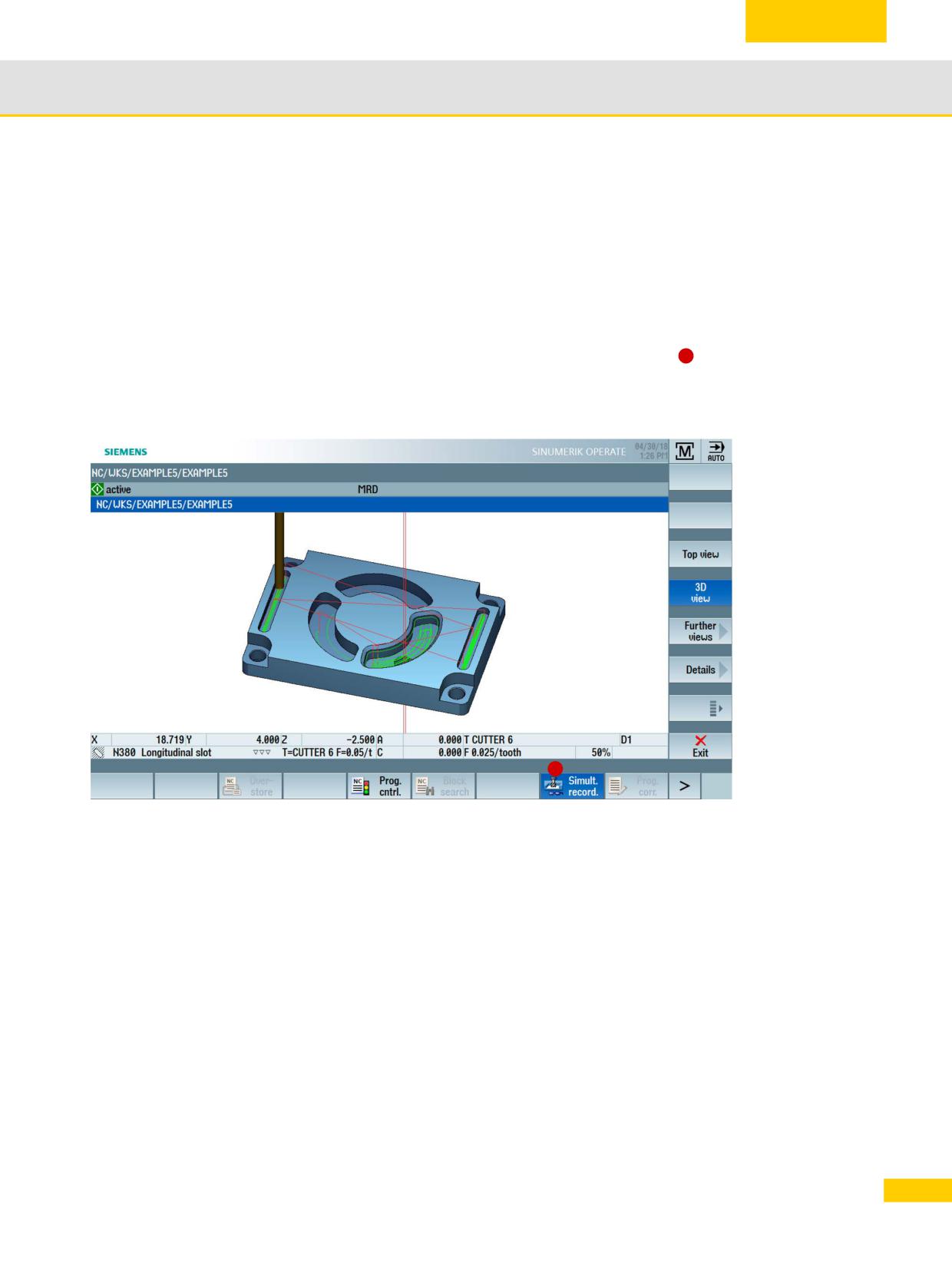
2.10.3 Simultaneous recording
In Automatic mode, i.e. during the program execution on the machine, the tool movements can
be simultaneously recorded in the top view, the three-side view or in the 3D view (with the 3D
simulation option). This option is especially useful when the working area of the machine cannot
be viewed clearly. During simultaneous recording, similar functions are available as for
simulation.
Activating simultaneous recording:
X Before starting the NC program, press the Sim. rec. softkey
1
X The execution of the program is simultaneously recorded after pressing CYCLE START. You
can display the tool paths and the workpiece machining in parallel to the machining.
→ Top view
→ 3D view
→ Side views
→ Zoom, magnify,
turn, cut
→ Displaying the
tool
1
63
© Siemens AG All rights reserved SINUMERIK, Manual, Mold-Making with 3- to 5-Axis Simultaneous Milling
General information on workpiece production
2.11
2.11
Executing programs (AUTOMATIC)
SINUMERIK Operate provides functions that support the workflow during the execution of mold-
making programs.
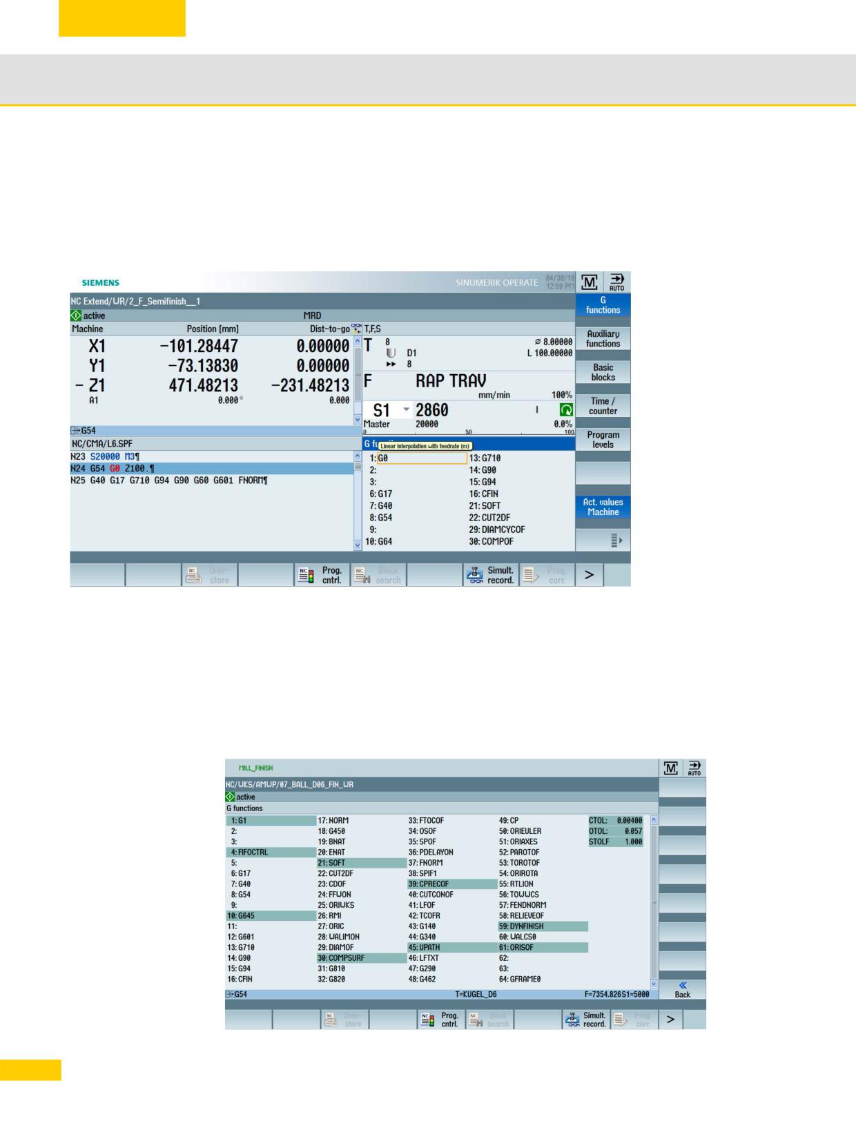
2.11.1 Display all relevant mold-making functions
→ Active
G functions
→ M functions
→ Basic blocks
→ Running time,
→ Program levels
→ All
G functions
Selection of the various displays during the execution:
Active G and M functions of up to 16 G groups.
Basic blocks, running time and workpiece counters
Program level for nested subprogram calls
Current position and distance-to-go display to the target position
All relevant G code functions for mold-making (Advanced Surface) can be displayed via the
expanded softkey bar with the All G functions softkey. The G functions are color coded, e.g.
CTOL, OTOL for the tolerances.
64
© Siemens AG All rights reserved SINUMERIK, Manual, Mold-Making with 3- to 5-Axis Simultaneous Milling
General information on workpiece production
2.11
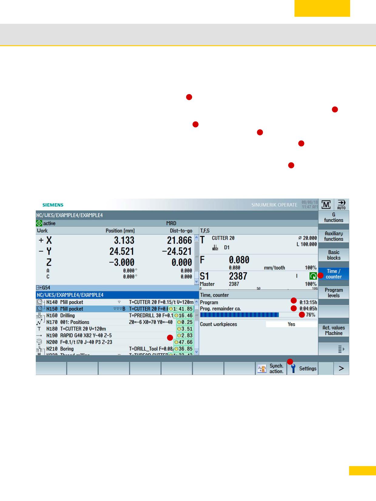
2.11.2 Program running time
To gain an overview of the program running time and the number of machined workpieces, use
the Times/counters functions
1
Pressing the softkey the first time shows how long the program has already been running
2
. At
every further start of the program, the time required to run the entire program the first time and
the remaining time are displayed
3
. In addition, you can follow how much of the current
program has been completed in percent on a progress bar
4
The running times can be displayed block-by-block/non-modally and saved
5
. The running
times determined by the simulation are shown with a blue backg8round. After the first processing,
the actually determined times are shown with a green backg8round. The Settings softkey is used
to configure whether the running times should be displayed and saved.
6
When a program is executed for the first time, its progress is estimated based on the program
size and the actual program offset; this means it can differ from the actual running time.
1
2
3
4
5
6
65
© Siemens AG All rights reserved SINUMERIK, Manual, Mold-Making with 3- to 5-Axis Simultaneous Milling
General information on workpiece production
2.11
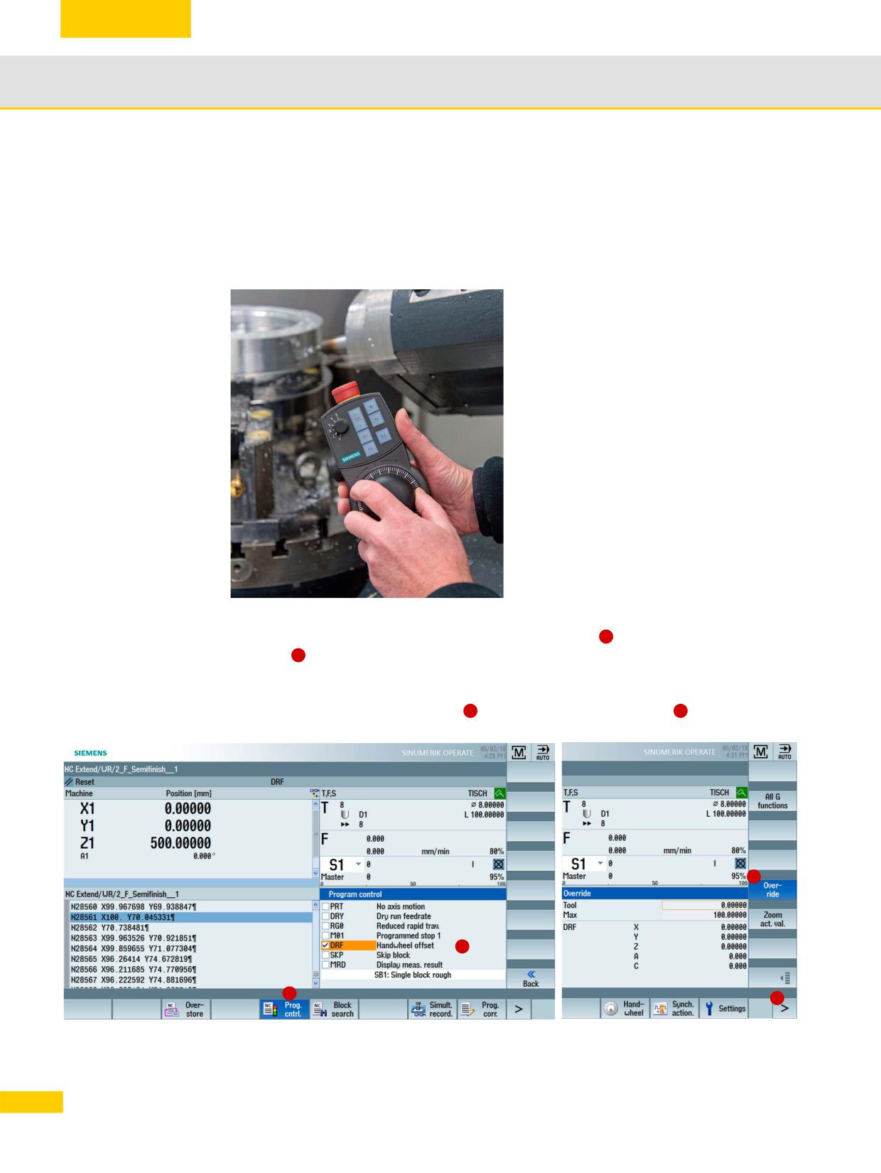
2.11.3 Handwheel override
In the AUTOMATIC mode, while executing a program, small compensations and override feed of
the tool in the tool direction are possible using a handwheel. When the orientation of the tool
changes, the handwheel override that has been accumulated is also rotated. The manual
compensation acts as override to the traversing motions from the NC program.
Handwheel override
Override with handwheel:
Handwheel override of axes
(DRF offset)
Handwheel override in the tool direction
(TOFFON function)
Traverse axes in increments only
Active in the following states:
NC/CYCLE stop
Single block mode
Override 0% and higher
Programmed STOP M0
A typical application is, for example, changing
the swivel head position (rotary axes) or the
infeed depth in the tool direction, in order for
example to mill a workpiece with tolerance.
Activating override
X In AUTOMATIC mode, press the Program control softkey
and activate DRF handwheel
1
offset
2
Displaying override
X Open the expanded softkey bar >>
and then the Overrides softkey
3
4
4
2
1
3
66
© Siemens AG All rights reserved SINUMERIK, Manual, Mold-Making with 3- to 5-Axis Simultaneous Milling
General information on workpiece production
2.11
2.11.4 Block search
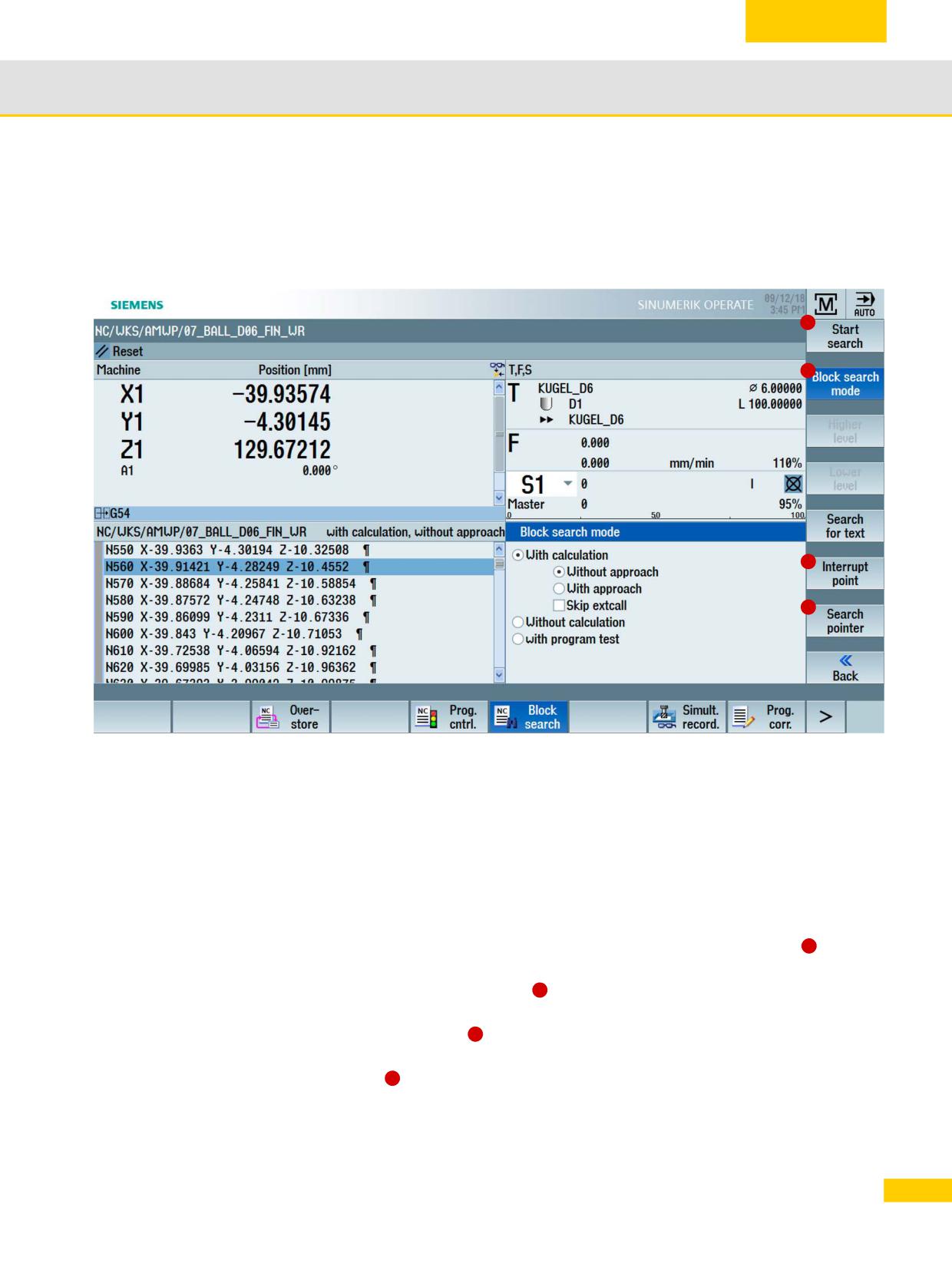
You can perform a block search in the Reset machine state. The program data is prepared in
such a way that all relevant parameters (tool, zero offsets, M functions, etc.) are available when
accessing the program.
4
1
2
3
Possible search variants:
Precise return to the point of interruption, even after power off
To any CNC block in the DIN/ISO programs
To any subprogram levels in DIN/ISO programs
Machining step programs and position patterns in ShopMill
Accelerated block search in large mold-making programs
To use the block search:
X The block search can be configured individually using the Search mode softkey
e.g. with
1
and without calculation or with/without approach.
X Using the Interruption point softkey
a jump is made to the last executed line of the NC
2
program.
X Using the Search pointer
you can define the search target within an NC program,
3
e.g. specific line number, mark or text.
X Start search
performs the search; CYCLE START executes the program at the search
4
location.
67
© Siemens AG All rights reserved SINUMERIK, Manual, Mold-Making with 3- to 5-Axis Simultaneous Milling
General information on workpiece production
2.12
2.12
Collision avoidance
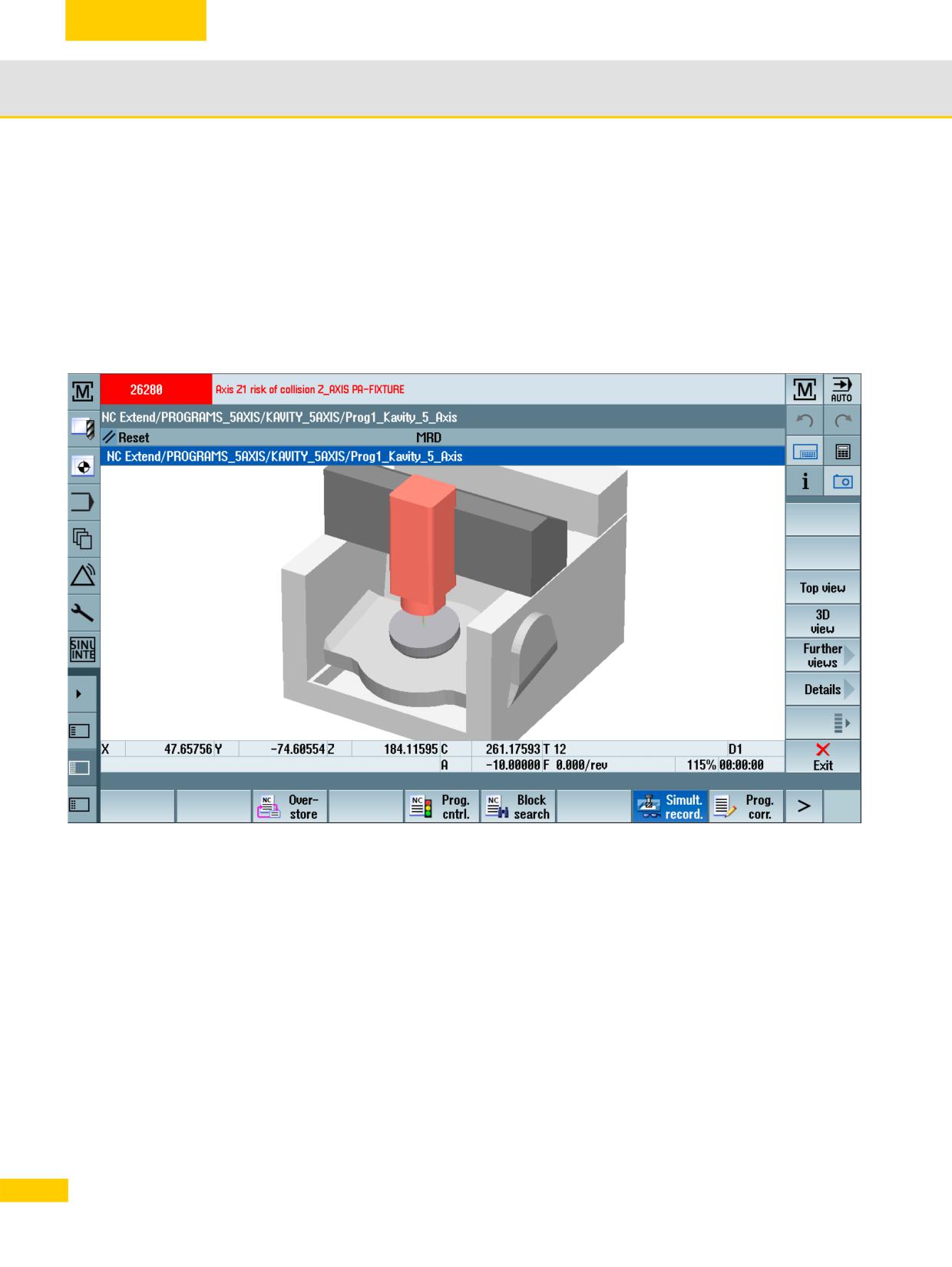
The improved collision avoidance available in three variants on the control prevents the collision
of moving machine components with static components; it is active in setup operation and in
automatic operation.
Collision avoidance is based on a machine model. The kinematics of the machine are described
as a kinematic chain. Protection areas are attached to these chains for the protected machine
parts. The geometry of the protection areas is defined using protection area elements. Protection
areas are, for example, spindles, tools, tool table and machine covers.
The "Collision avoidance" function regularly calculates the clearance from these protection
areas. When two protection areas approach one another and a specific safety clearance is
reached, an alarm is displayed and the program is stopped before the corresponding traversing
block and/or the traversing motion is stopped.
68
© Siemens AG All rights reserved SINUMERIK, Manual, Mold-Making with 3- to 5-Axis Simultaneous Milling
General information on workpiece production
2.12
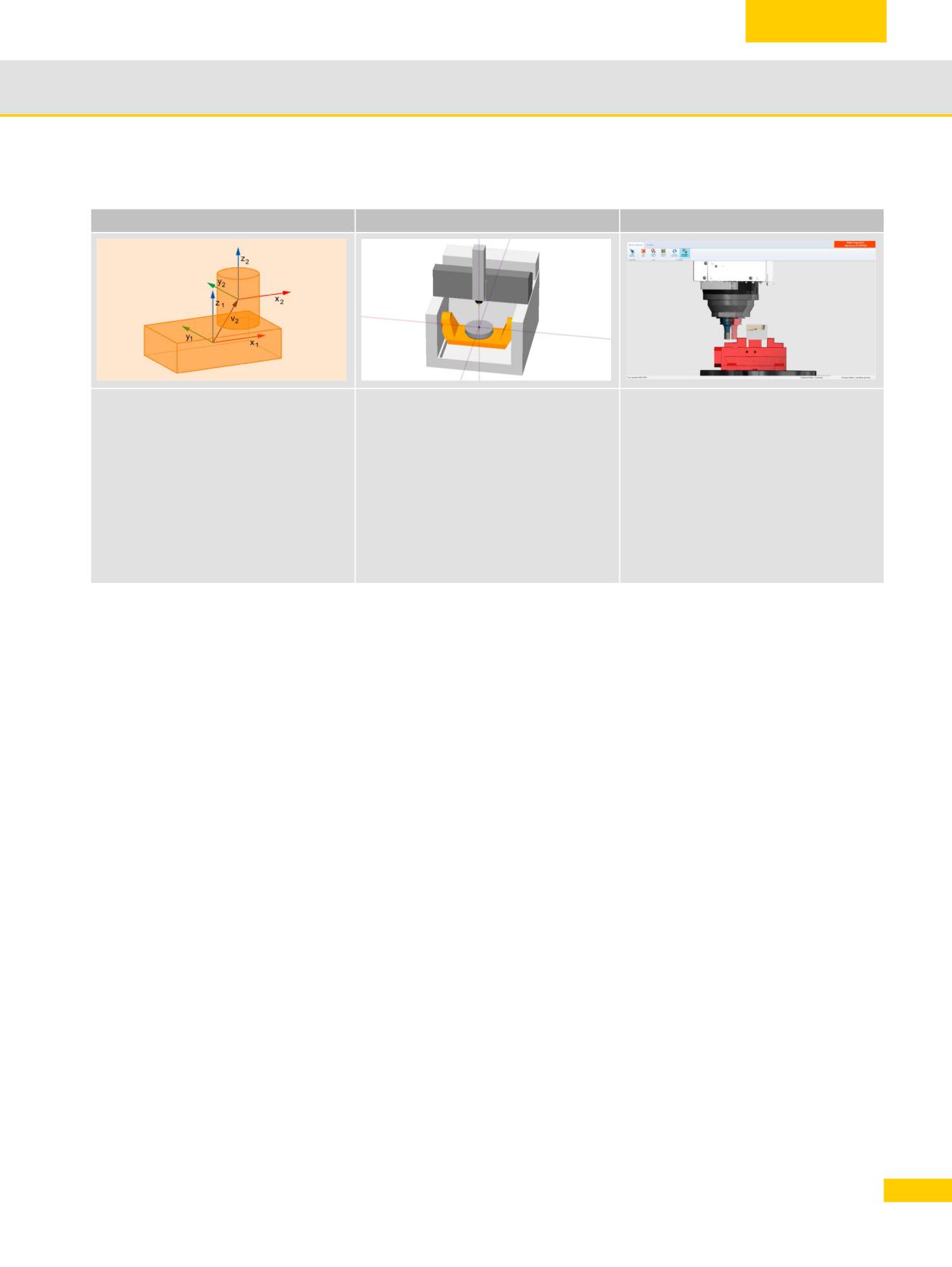
Overview of the Collision Avoidance variants
Collision Avoidance ECO
Collision Avoidance
Collision Avoidance ADVANCED
Components / protection areas are
Includes Collision Avoidance ECO
In addition, tools and workpiece
described with simple geometric
material removal for collision
More protection area elements
bodies.
monitoring are considered.
Components/elements are modeled
The collision locations are
Further software from third-parties
as STL files.
visualized directly from the CNC
on an external PC in real-time is
X The collision of moving machine
user interface.
used to match position values,
components with static components
setup data and tool geometries (e.g.
X The collision of moving machine
is prevented thanks to the more
ModulWorks Corp.).
components with static components
exact geometry description of the
is prevented, e.g. spindle with the
X Machine, tool and workpiece are
components.
machine covers.
protected dynamically.
69
© Siemens AG All rights reserved SINUMERIK, Manual, Mold-Making with 3- to 5-Axis Simultaneous Milling

General information on workpiece production
2.12
70
© Siemens AG All rights reserved SINUMERIK, Manual, Mold-Making with 3- to 5-Axis Simultaneous Milling

Important functions for 3- to 5-axis
machining
Content
Page
3.1
Introduction
72
3.2
Explanation of the terms: swivel, frames and TRAORI
73
3.3
Transforming coordinate systems - Frames
74
3.4
Swivel - CYCLE800
75
3.5
TRAORI 5-axis transformation
81
3.6
High Speed Settings - CYCLE832
102
3.7
Advanced Surface and Top Surface
110
3.8
Milling radius compensation 2D/3D-WRK
120
3.9
Volumetric Compensation System (VCS)
130
3.10
VNCK - virtual machine
131
Important functions for 3- to 5-axis machining
3.1
3.1
Introduction
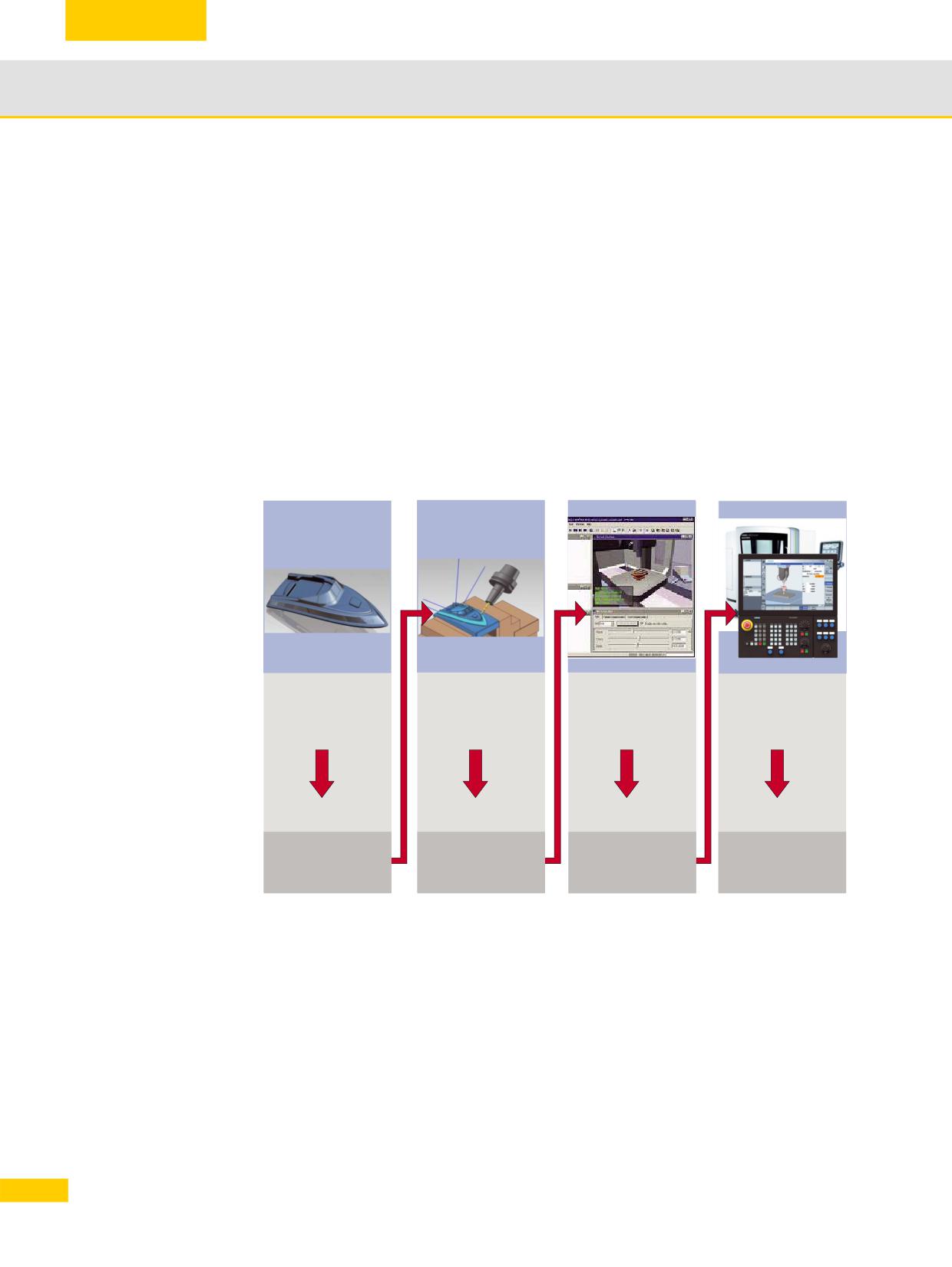
Especially within the context of mold-making machining, the entire CAD/CAM/CNC process
chain plays a major role in terms of ensuring optimum results on the machine.
The CAD system generates the geometry of the desired workpiece. Based on this geometry file,
the CAM system generates the corresponding machining strategy with the associated
technology information.
The data format output from the CAM system is generally an APT or CL data file. This is
converted into an executable NC code in the postprocessor.
The upstream postprocessor must support the programmable functions of the SINUMERIK
control in order to use the performance capability of SINUMERIK controls to the full.
The postprocessor should ensure that the higher-order functions of SINUMERIK controls (as
described in this section) are activated in the best possible way. An overview of all higher-order
SINUMERIK functions is provided in the following sections.
CAD
CAM
PP
CNC
(Design)
(NC Programming)
(NC Programming)
(Machining)
Geometry
Tool path
NC program
Workpiece
APT source
72
© Siemens AG All rights reserved SINUMERIK, Manual, Mold-Making with 3- to 5-Axis Simultaneous Milling
Important functions for 3- to 5-axis machining
3.2
3.2
Explanation of the terms: swivel, frames and
TRAORI
The swivel (CYCLE800) and TRAORI features can be used to control rotary axes and angle the
tool in relation to the machining surface. During swiveling, the rotary axes are positioned once
and the linear axes X, Y, Z move during machining. The tool is oriented from a start position
through to an end position and will then only work with the three linear axes. It is aligned in
relation to the surface by means of a static process.
In contrast to swiveling, TRAORI is a dynamic process. The rotary and linear axes can be
traversed simultaneously during machining. The orientation of the tool in space can be changed
continuously. All axes (rotary and linear axes) are interpolated at the same time.
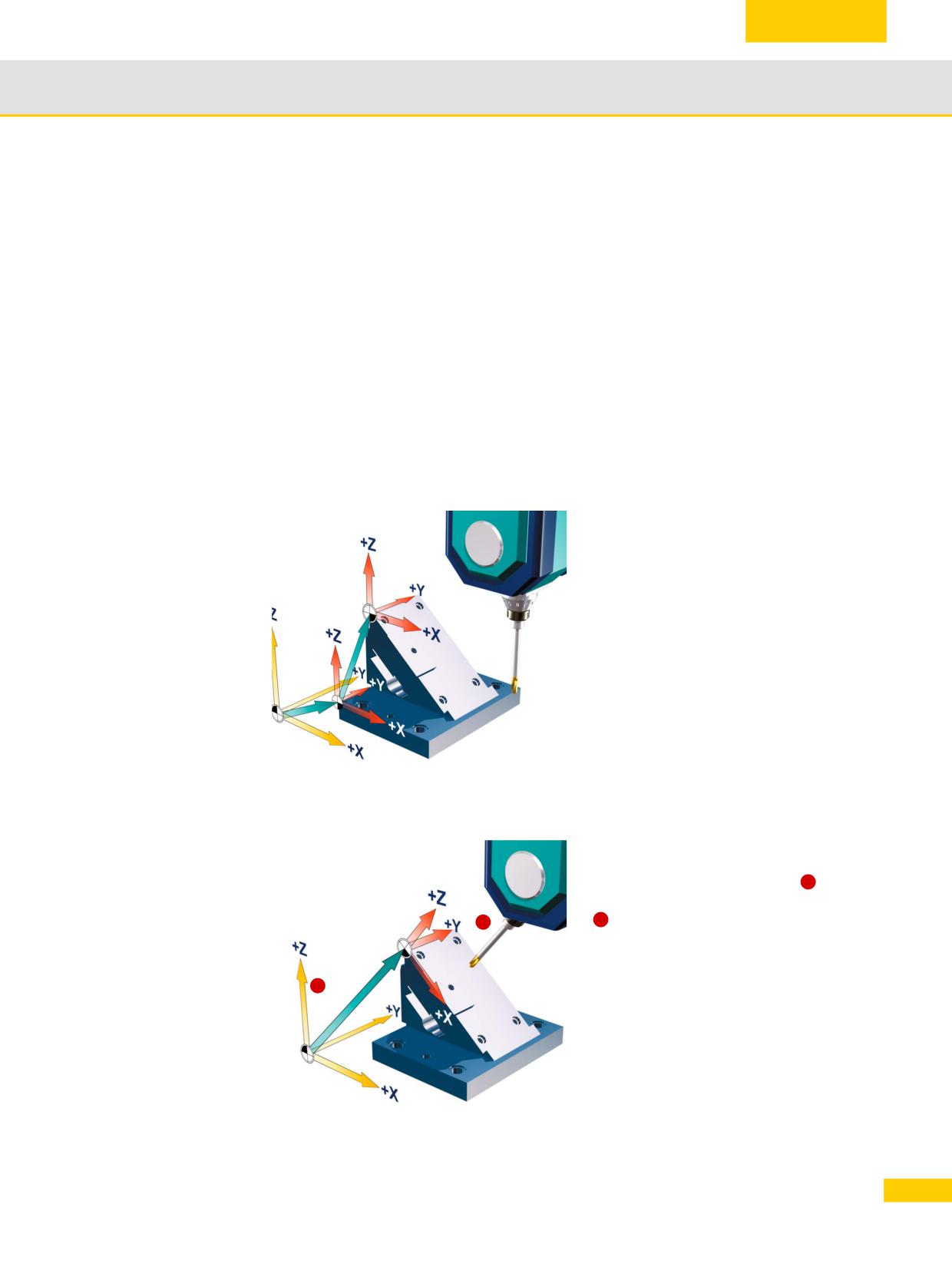
Frames affect only the coordinate system and only the coordinate system is modified,
for example, rotated, scaled or moved. CYCLE800 takes the machine kinematics into account
during swiveling, i.e. attention is paid to tool compensations and zero points. In the case of
frames (e.g. ROT), these must be taken into account by the user.
Frames
The frame is a self-contained arithmetic rule
that transforms one Cartesian coordinate
system into another Cartesian coordinate
system.
In the example, the coordinate system is twice
subjected to translatory movement. This is the
case, for example, if you set the zero point at
the corner of the workpiece by means of zero
offset.
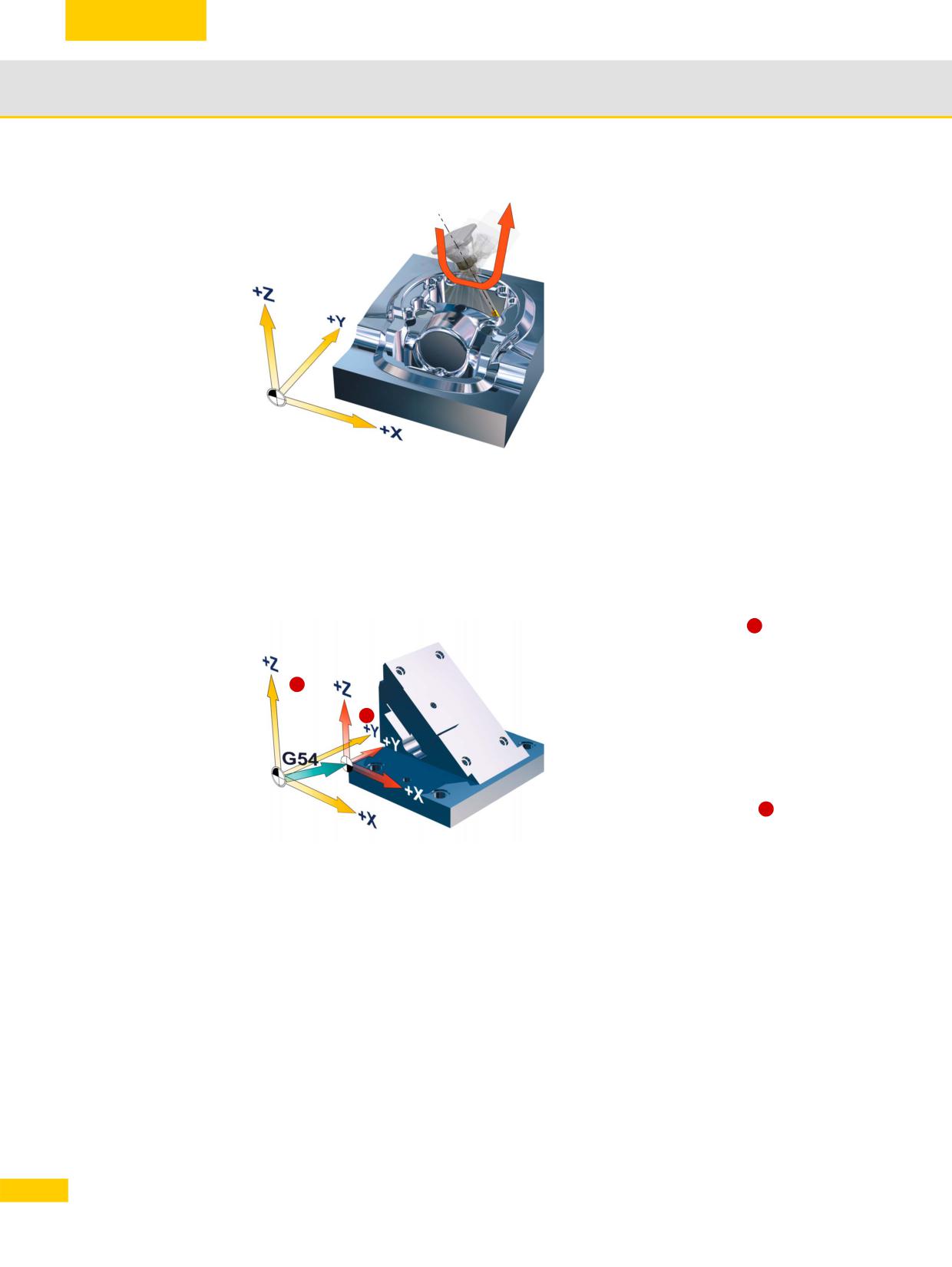
Swivel
The tool is aligned with the machining surface
by moving the rotary axes. This example
involves rotation of rotary axis B
and the
1
tool is positioned in relation to the XY plane
2
2
. Machining then takes place in this plane.
1
73
© Siemens AG All rights reserved SINUMERIK, Manual, Mold-Making with 3- to 5-Axis Simultaneous Milling
Important functions for 3- to 5-axis machining
3.3
TRAORI
The tool is aligned with the machining surface
dynamically during the milling process by
means of linear and rotary axis interpolation.
The tool length is taken into account and the
kinematic compensatory movements are
initiated by the TRAORI function when the
rotary axes are rotated.
3.3
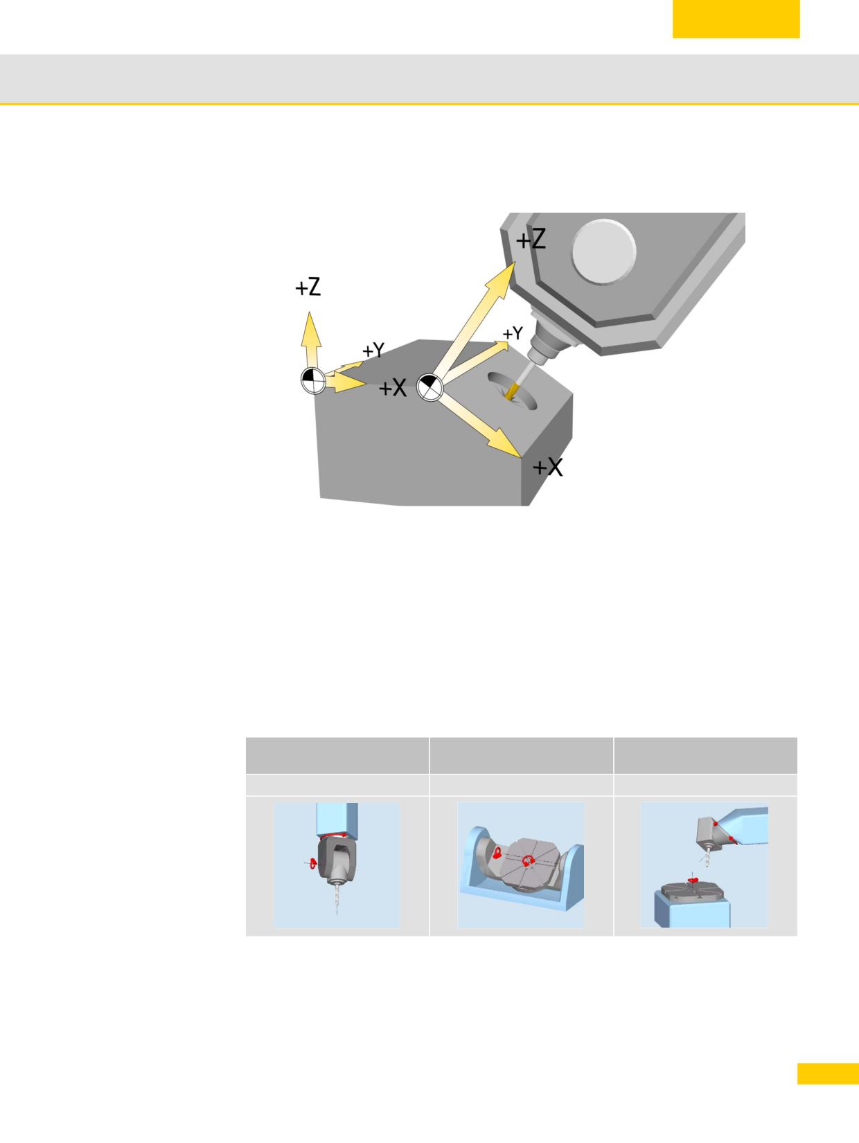
Transforming coordinate systems - Frames
Coordinate systems
Machine coordinate system
with reference
1
point and zero offset (G54, G55, etc.) are
familiar terms.
1
Using frames, the coordinate systems can be
shifted, rotated, mirrored and scaled so that
2
they can be aligned with any workpiece
surface. This allows the programming
overhead to be reduced to a minimum.
With frames, starting from the current
workpiece coordinate system
, the position
2
of a target coordinate system is defined by
specifying coordinates and angles.
Possible frames include
Basic frame (basic offset, G500)
Settable frames (G54, G55, etc.)
Programmable frames (TRANS, ROT,
etc.)
Using frames it is possible to machine surfaces that can be shifted and rotated in space as
required. All subsequent traversing commands now relate to the new workpiece coordinate
system shifted using frames.
74
© Siemens AG All rights reserved SINUMERIK, Manual, Mold-Making with 3- to 5-Axis Simultaneous Milling
Important functions for 3- to 5-axis machining
3.4
3.4
Swivel - CYCLE800
Function
You can use swivel heads or swivel tables to set up and machine inclined planes. Swiveling is
possible in JOG mode and AUTOMATIC mode. Swivel operation parameter assignment and
programming are facilitated by the clearly laid out graphics. You can either program all the swivel
axes directly on the machine (A, B, C) or you can simply specify the rotations around the
geometry axes (X, Y, Z) of the workpiece coordinate system as described in the relevant
workpiece drawing. The rotation of the workpiece coordinate system in the program is then
automatically converted to a rotation of the relevant swivel axis of the machine during machining.
The swivel axes are always rotated in such a way that the machining plane is perpendicular to
the tool axis for machining. The machining plane then remains fixed during machining.
When the axes are swiveled, the active zero points and tool compensations are automatically
converted for the swiveled state; this results in a new coordinate system.
Machine kinematics
Swivel head
Swivel table
Swivel head + swivel table
(type T)
(type P)
(type M)
Swiveling tool carrier
Swiveling workpiece holder
Mixed kinematics
75
© Siemens AG All rights reserved SINUMERIK, Manual, Mold-Making with 3- to 5-Axis Simultaneous Milling
Important functions for 3- to 5-axis machining
3.4
Procedure for programming swivel movement and subsequent machining:
X Swivel the coordinate system into the plane to be machined.
X Program the machining process as usual in the X/Y plane.
X Swivel the coordinate system back to its original position.
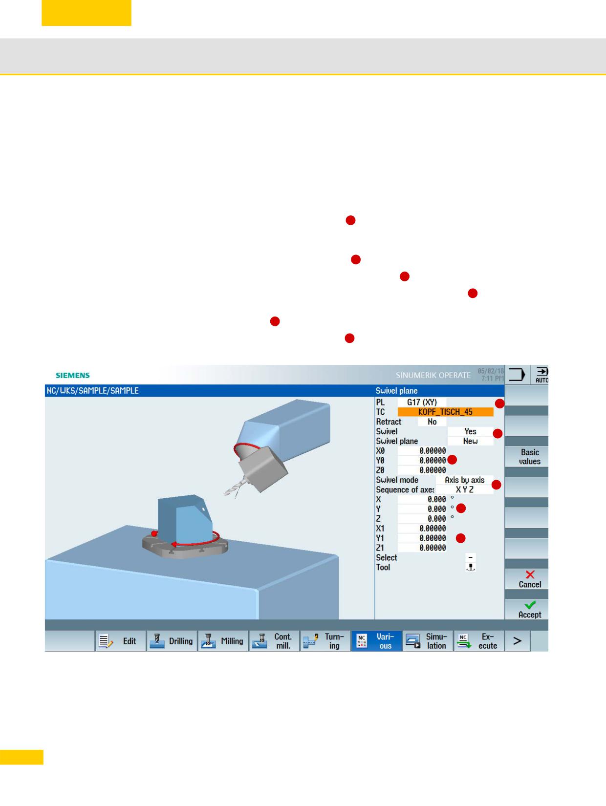
Basic procedure for using the swivel cycle
X Call the Swivel function in the program.
X Select the name of the swivel data record
1
X Select "yes" for swivel if you wish to perform a swivel movement. Select "new" as swivel
movement if you wish to perform a new swivel movement, or "additive" if you wish to base the
movement on a previous swivel movement
2
X Specify the reference point before rotation (X0, Y0, Z0)
3
X Select the "axis-by-axis" swivel mode directly or via the projection angle
4
X Enter the angle through which the axis should swivel. In the axis-by-axis mode, you can enter
the angle for each axis
5
X Shift the zero point on the swiveled plane
6
1
2
3
4
5
6
76
© Siemens AG All rights reserved SINUMERIK, Manual, Mold-Making with 3- to 5-Axis Simultaneous Milling
Important functions for 3- to 5-axis machining
3.4
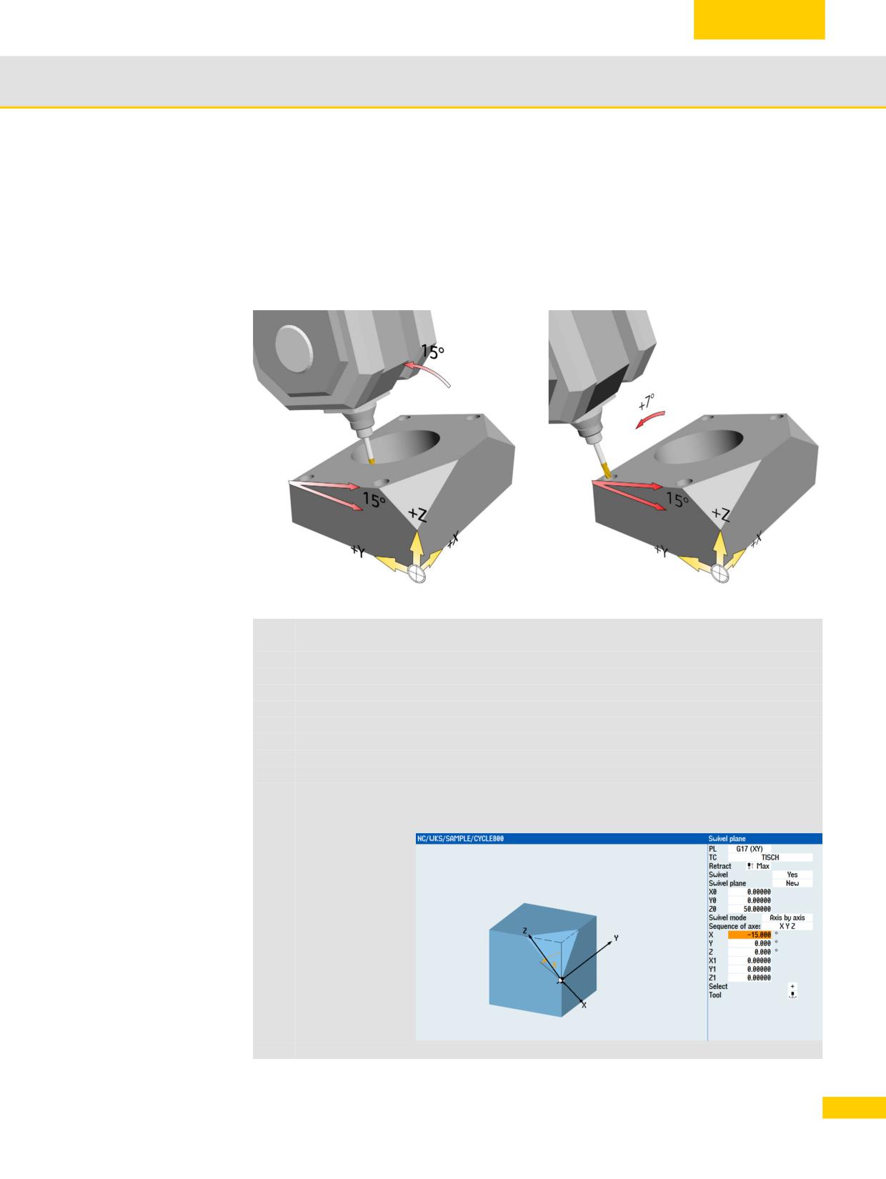
Example program for swiveling in programGUIDE
Standard milling and drilling cycles are applied to swiveled machining surfaces in the following
example.
X Face milling of the workpiece.
X Swiveling the machining plane by X=-15 degrees and milling a circular pocket.
X Swiveling by Y=-7 or +7 degrees, face grooving with milling cutter for the holes and creating
two holes at angles of +7 degrees and two holes at -7 degrees.
N100
; Swivel the plane to the basic position
N110
CYCLE800(4,"TABLE",200000,57,0,0,0,0,0,0,0,0,0,1,,1)
N120
; Raw part definition for simulation
N130
WORKPIECE(,,,"BOX",112,0,51,-80,-2.5,-2.5,102.5,102.5)
N140
T10 D1; T="CUTTER_D32"
N150
M06
N160
S5000 M03
N170
G0 G54 X0 Y0
N180
TRANS Z50 ;Zero offset in Z workpiece upper edge
N190
;Face milling of workpiece in basic position
N200
CYCLE61(10,1,5,0,0,0,100,100,1,20,0,2000,32,0,1,0)
N210
;Swiveling into the plane_1 X=-15 DEGREES
N220
CYCLE800(4,"TABLE",200000,57,0,0,50,-15,0,0,0,0,0,1,,1)
N230
;Face milling of workpiece in Plane_1
77
© Siemens AG All rights reserved SINUMERIK, Manual, Mold-Making with 3- to 5-Axis Simultaneous Milling
Important functions for 3- to 5-axis machining
3.4
N240
CYCLE61(35,25.8,5,0,0,0,100,103.6,5,20,0.2,2000,31,0,1,0)
N250
T11 D1; T="CUTTER_D16"
N260
M06
N270
S8000 M03
N280
G54 X50 Y51.76 M08; Pre-position on center of pocket
N290
; Circular pocket roughing and finishing Plane_1
N300
POCKET4(10,0,2,-
15,40,50,51.76,5,0.1,0.1,2000,2000,0,21,80,0,,10,2.5,0,,,10100,111,10)
N310
POCKET4(10,0,2,-
15,40,50,51.76,15,0.1,0.1,1000,1000,0,22,80,0,,5,2.5,0,,,10100,111,10)
N320
T12 D1; T="CUTTER_D10"
N330
M06
N340
S6000 M03 F500
N350
G54 X0 Y0 M08
N360
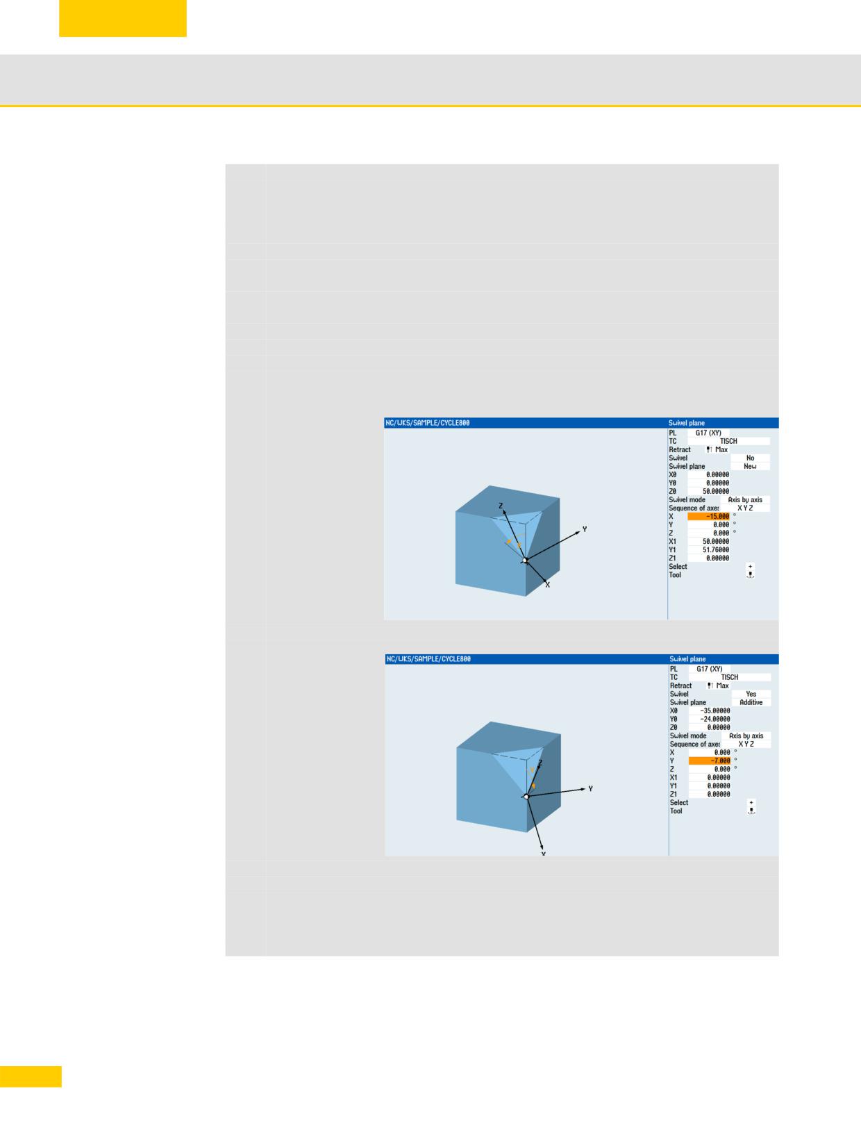
; Calculate swiveling Plane_1 with new center point X1, Y1 X=-15 degrees
N370
CYCLE800(4,"TABLE",220000,57,0,0,50,-15,0,0,50,51.76,0,0,,1)
N380
; Swiveling Plane_1 additive Y=-7 degrees
N390
CYCLE800(4,"TABLE",200001,57,-35,-24,0,0,-7,0,0,0,0,1,,1))
N400
; Area -7 degrees with milling cutter face grooving so that the drill inserts vertically later
N410
MCALL CYCLE82(10,0,5,-3,,1,0,1,12)
N420
G0 X0 Y0 M8
N430
X0 Y60
N440
MCALL
N450
; Calculate swiveling Plane_1 with new center point X1, Y1 X=-15 degrees
78
© Siemens AG All rights reserved SINUMERIK, Manual, Mold-Making with 3- to 5-Axis Simultaneous Milling
Important functions for 3- to 5-axis machining
3.4
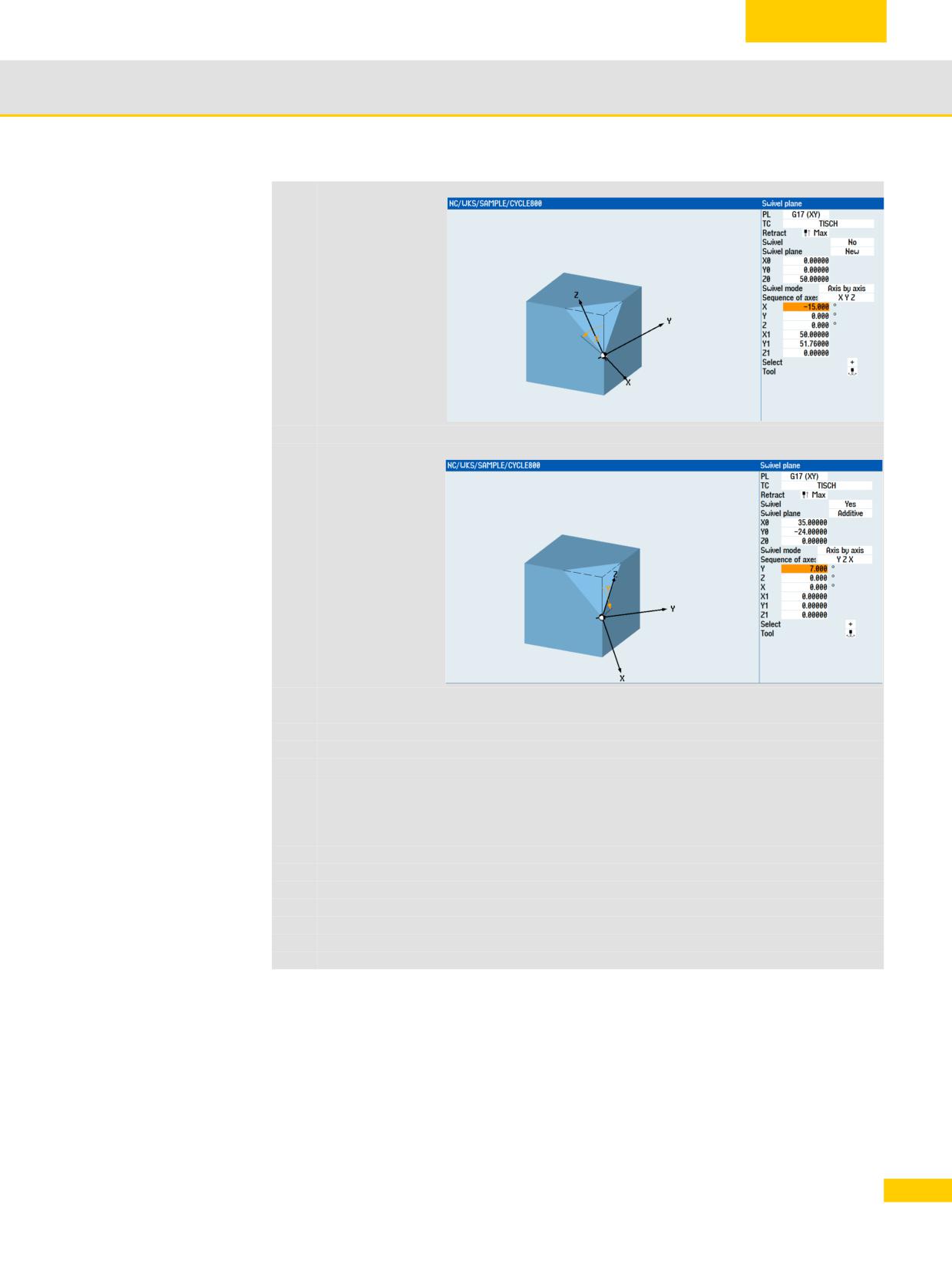
N460
N141 CYCLE800(4,"TABLE",220000,57,0,0,50,-15,0,0,50,51.76,0,0,,1)
N465
; Swiveling Plane_1 additive Y=+7 degrees
N470
CYCLE800(4,"TABLE",200001,30,35,-24,0,7,0,0,0,0,0,1,,1)
N480
; Surface +7 degrees with milling cutter face grooving so that the drill later inserts
vertically
N490
MCALL CYCLE82(10,0,5,-3,,1,0,1,12)
N500
G0 X0 Y0 M8
N510
X0 Y60
N520
MCALL
N530
T13 D1; T="DRILL_D8.5"
N540
M6
N550
S4000 M3 F500 D1
N560
G54 G0 X0 Y0 M8
N570
; Deep-hole drilling D8.5 Y=+7 degrees
N580
MCALL CYCLE83(10,0,2,-20,,-5,,054,0,100,0,0,4,1,0,0,0,1,11121112)
N590
G0 X0 Y0
N600
X0 Y60
N610
MCALL
N615
; Calculate swiveling Plane_1 with new center point X1, Y1 X=-15 degrees
79
© Siemens AG All rights reserved SINUMERIK, Manual, Mold-Making with 3- to 5-Axis Simultaneous Milling
Important functions for 3- to 5-axis machining
3.4
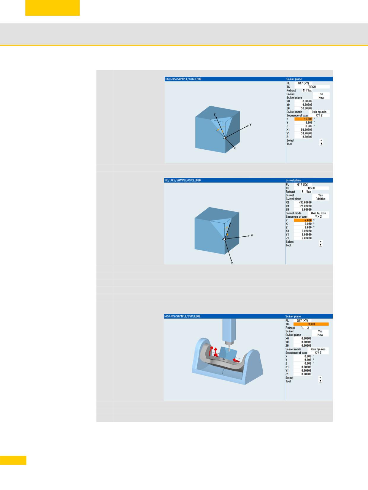
N620
CYCLE800(4,"TABLE",220000,57,0,0,50,-15,0,0,50,51.76,0,0,,1)
N625
; Swiveling Plane_1 additive Y=-7 degrees
N630
CYCLE800(4,"TABLE",200001,54,-35,-24,0,-7,0,0,0,0,0,1,,1)
N640
; Deep-hole drilling D8.5 with -7 degrees
N650
MCALL CYCLE83(10,0,2,-20,,-5,,054,0,100,0,0,4,1,0,0,0,1,11121112)
N660
G0 X0 Y0
N670
X0 Y60
N680
MCALL
N690
; Swivel the plane to the basic position
N700
CYCLE800(2,"TABLE",200000,57,0,0,0,0,0,0,0,0,0,1,,1)
N710
; Deselection CYCLE800
N720
CYCLE800()
N730
M30; end of program
80
© Siemens AG All rights reserved SINUMERIK, Manual, Mold-Making with 3- to 5-Axis Simultaneous Milling
Important functions for 3- to 5-axis machining
3.5
3.5
TRAORI 5-axis transformation
Inclined planes can be machined with the aid of CYCLE800. The tool is inclined relative to the
workpieces so that inclined workspaces can be machined. The inclination is performed at the
start of the machining and is not changed during the machining of the inclined plane. However, in
many case this static inclined position is not sufficient. A constantly changing tool orientation
relative to the workpiece is required. So that this can be performed in a clear and user-friendly
way, the 5-axis transformation, which is activated by the TRAORI command, has been
introduced.
3.5.1
Basics of simultaneous 5-axis machining
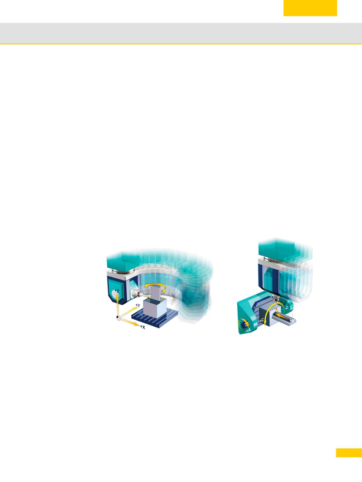
The various kinematics of 5-axis machines were described in Section 1.5. A distinction is made
between three basic types.
Machines with a rotatable tool which is swiveled by means of two rotary axes.
Machines with a rotatable workpiece which is swiveled while the orientation of the tool
remains fixed in space.
Machines of the "mixed" type on which one rotary axis rotates the tool and the second rotary
axis swivels the workpiece.
Machine kinematics and machine movement
Motion sequence for head/head kinematics
Motion sequence for table/table kinematics
A semicircle must be described in the X/Y
At the start, the A axis must be rotated through
plane for one cycle. At the same time, the tool
90°. The tool is then perpendicular to the
must be rotated through 180° around Z if the
surface. For one cycle, the C axis swivels from
tool is always to be perpendicular to the
+90° to -90°. Therefore, for one cycle (a
surface. Therefore, for the machining of one
semicircle), only the C axis moves.
cycle, 3 axes, X, Y and C must move.
It is clear from the example that totally different machine movements produce the same
machining result. If we look at the movements more exactly, we can see that in both cases the
movement of the tool tip on the workpiece and the tool orientation relative to the surface are
identical.
81
© Siemens AG All rights reserved SINUMERIK, Manual, Mold-Making with 3- to 5-Axis Simultaneous Milling
Important functions for 3- to 5-axis machining
3.5
Effect of the tool length on the machine movement
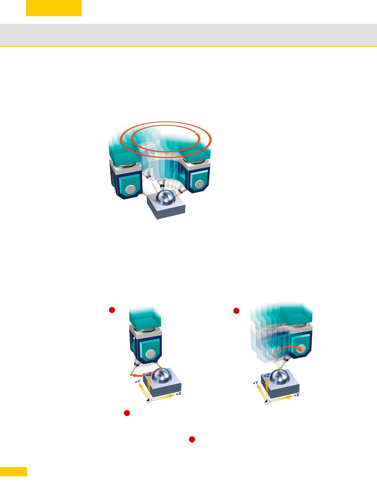
To investigate the effect of the tool length on the machine movement, let us consider a further
example. The base circle of the half sphere shown in the graphic is to be machined with an
inclined tool.
In the graphic, you can see that different tool
lengths result in different machine
movements. To machine the circle on the
lower part of the half sphere, traversing must
be performed in a circle in the X-Y plane and
also the C axis must be rotated through 360°
during the circular movement. Whereas the
circle for the tool tip always remains the same
size irrespective of the tool length, the circle
that the machine axes must describe
increases with the tool length. This is indicated
by the two red circles that are produced with
different tool lengths.
It is clear that when programming machine
axis positions, a different program must be
created for each tool length, while the
movement of the tool tip always remains the
same.
Rotary axis movement and tool orientation
The rotary axes in 5-axis machines are used to enable the various orientations of the tool relative
to the workpiece. The movement of a rotary axis normally not only changes the tool orientation,
but also the position of the tool tip in relation to the workpiece surface if this is not prevented by a
suitable mechanism.
Tool tip moves
Tool tip fixed in space
1
2
Example
shows that the movement of the A axis not only changes the tool orientation to the
1
workpiece. At the same time, the tool tip moves in space, a circular path in the Z-X plane in our
example. This is an unwanted side effect.
Generally, the movement shown in
is desirable, in which compensatory movements of the
2
linear axes ensure that the tool tip is fixed in space during rotary axis movements.
82
© Siemens AG All rights reserved SINUMERIK, Manual, Mold-Making with 3- to 5-Axis Simultaneous Milling
Important functions for 3- to 5-axis machining
3.5
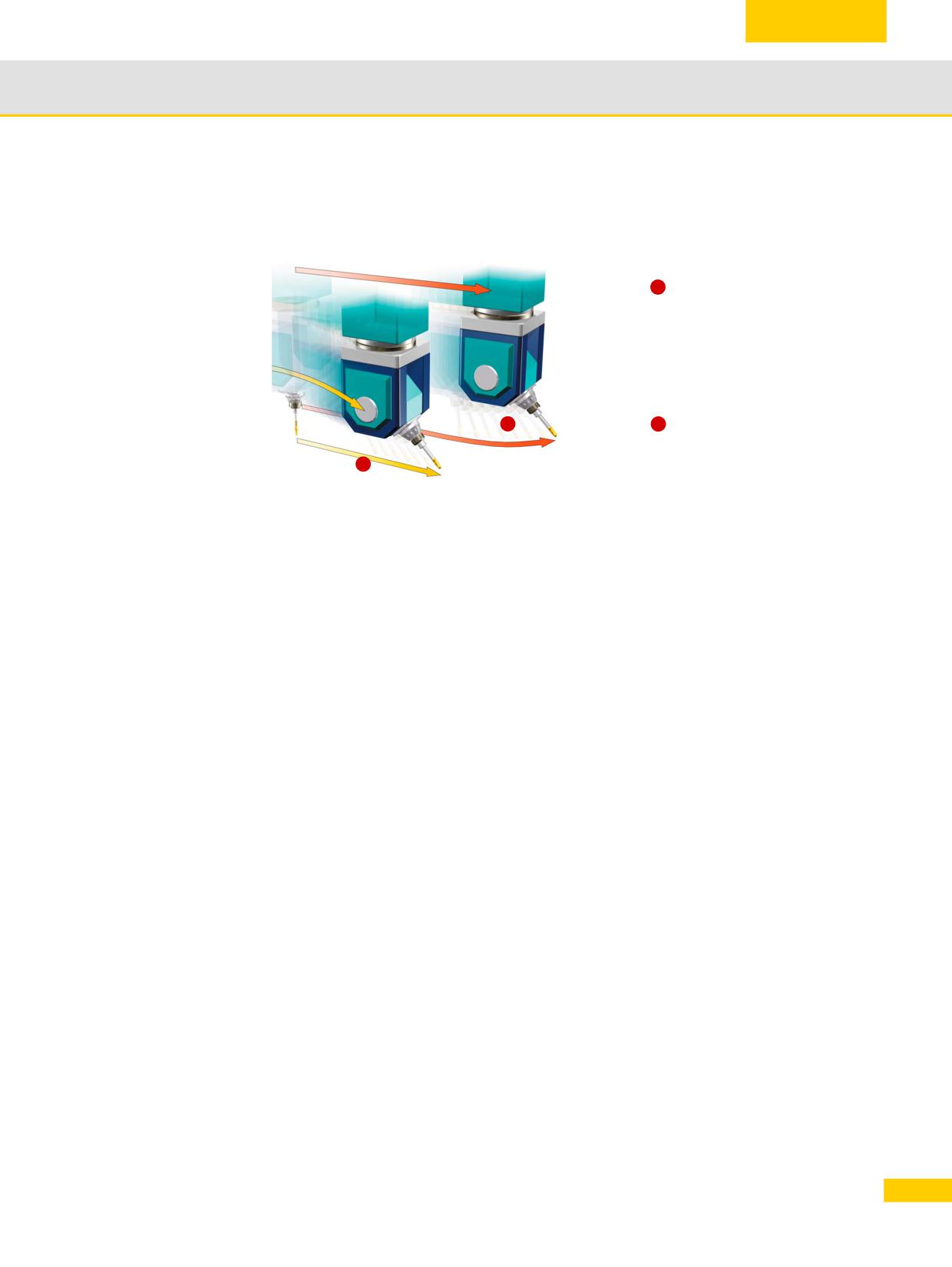
Simultaneous movement of linear/rotary axes
This effect is also shown during simultaneous movement of linear and rotary axes.
The graphic shows the simultaneous
Y
movement of the A axis and the Y axis. In
situation
1
, both axes move synchronously;
they are interpolated linearly with one another.
A straight path of machine axes Y and A has
been programmed. Such a traversal command
G1 Y… A… produces the red, curved path for
the tool tip.
A
As a rule however, the behavior shown in
1
situation
2
is wanted. A straight line with
regard to the tool tip is wanted for the G1
programming even when the A axis moves
2
simultaneously. In this case, the machine axis
movement follows the curved path. The Z axis
also moves to hold the tool tip in a straight
line.
83
© Siemens AG All rights reserved SINUMERIK, Manual, Mold-Making with 3- to 5-Axis Simultaneous Milling
Important functions for 3- to 5-axis machining
3.5
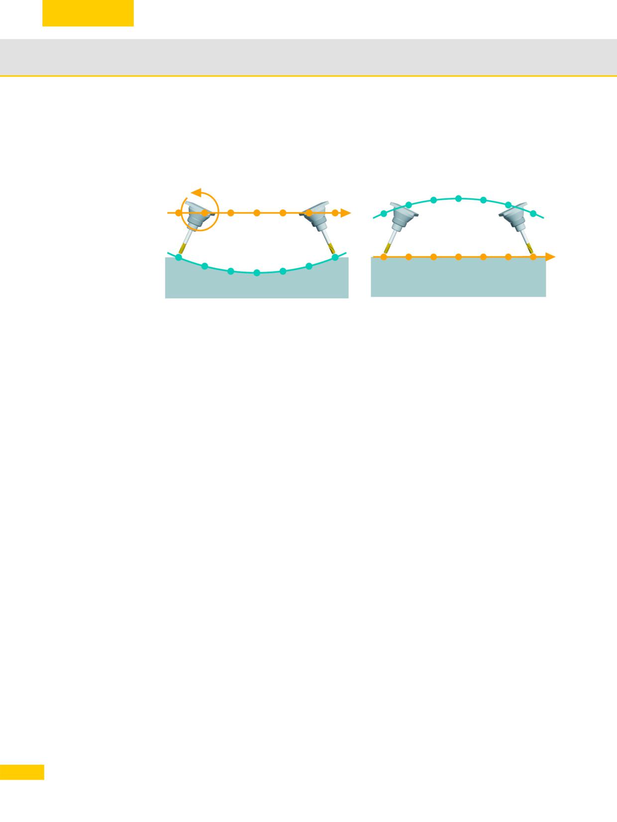
Chord error
The following graphic illustrates the so-called chord error which occurs when movements that
should be defined with regard to the tool tip, are programmed for the machine axes.
The graphic on the left shows the result of the simultaneous change of the tool orientation
through movement of the A axis and the Y axis via linear interpolation of both axes. The orange
line is the programmed straight line in the Y direction. If the A axis is also moved, this results in
the green line for the movement of the tool tip. If a certain path is to be maintained for the tool tip
as in the example on the right-hand side, then position changes to the tool tip that result from
movements of the rotary axis must be compensated.
Summary of simultaneous 5-axis machining
The simultaneous 5-axis machining enables the adaptation of the tool orientation synchronously
to the linear movement in space. Without the additional control functionality of the 5-axis
transformation, this produces some unwanted side effects.
New NC programs for identical workpieces must be created for each machine type.
The NC program must be adapted for changes to the tool length.
During the programming of the machine axes, overlaid movements of the rotary and linear
axes occur which cause a linearization error for the path of the tool tip, the chord error.
Tool orientations are programmed and changed via the positions of the swivel axes. An
orientation programming and interpolation in workpiece coordinates is not possible without
suitable control functions.
Technologically, feedrates should always refer to the relative movement between the
workpiece and tool, which is not the case without 5-axis transformation. The programmed
feedrates refer to the velocity of the machine axis movements.
Normally, NC programs are created in relation to the workpiece, i.e. all the tool positions relate to
the workpiece coordinate system (WCS). In order for an NC program to be executed on the
machine, the positions must be transformed into axis movements, i.e. converted into the
machine coordinate system (MCS). The SINUMERIK is equipped with the TRAORI function to
enable this kind of transformation.
84
© Siemens AG All rights reserved SINUMERIK, Manual, Mold-Making with 3- to 5-Axis Simultaneous Milling

Important functions for 3- to 5-axis machining
3.5
3.5.2
The TRAORI command
The TRAORI command activates the 5-axis transformation. This enables the simultaneous 5-
axis machining without the disadvantages described in the previous section. The programming of
TRAORI changes the reference variables in the NC program. The coordinates of the X, Y, Z
linear axes now refer to the position of the tool tip.
If orientation changes are programmed in addition to the linear positions, the effects of the rotary
axis movements on the position of the tool tip are compensated by movements of the linear axes.
In addition to the explicit programming of swivel axis positions, TRAORI enables the use of
orientation information which allows also the orientation to be programmed and interpolated
independently of the kinematics.
If tools are used with a different length, the new tool data is automatically taken from the tool
table, calculated and the programmed feedrate always refers to the movement of the tool tip
relative to the workpiece.
Programming
TRAORI(n)
; Transformation On
TRAFOOF
; Transformation Off
Explanation of the commands
TRAORI
Activates the first configured orientation transformation. The
command must be programmed alone in an NC block.
TRAORI(n)
Activates the orientation transformation configured with n.
n
The number of the transformation (n = 1 or 2), TRAORI(1)
corresponds to TRAORI.
TRAFOON(<transformatio
If TRAORI is defined via a kinematic chain, TRAORI can also be
n name>)
activated with TRAFOON(<transformation name>).
TRAFOOF
Deactivate transformation
Depending on the configuration (depending on the machine manufacturer), TRAORI can
reset the active zero offset (e.g. G54) and the tool edge compensation (D1). Therefore it is
recommended that the zero offset and the tool edge compensation be activated again
after TRAORI is called up.
85
© Siemens AG All rights reserved SINUMERIK, Manual, Mold-Making with 3- to 5-Axis Simultaneous Milling
Important functions for 3- to 5-axis machining
3.5
3.5.3
Programming the tool orientation
For an active 5-axis transformation, the orientation of the tool relative to the workpiece must be
programmed in addition to the position of the tool tip. This can be performed in several ways.
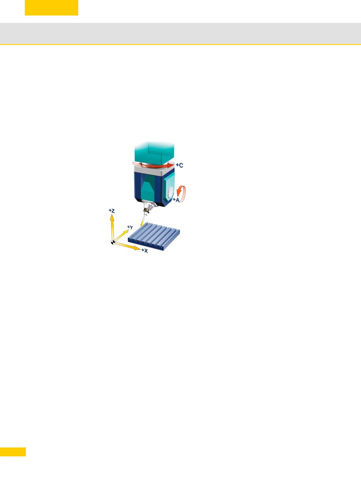
Rotary axis positions (A=<value> B=<value> C=<value>)
The most common way is to program the positions of the swivel axes directly. In this way, the tool
orientations are always specified implicitly, which however are directly dependent on the
machine kinematics.
Programming rotary
The tool orientation in space is clearly defined
axes
through the specification of the rotary axis
positions for the C and A axes.
However, this also depends on the kinematics
type.
The NC program would then appear as
follows:
N020 TRAORI
…
N140 G1 A-45 C0
A commonly used machine type is shown in the graphic. However, there are also other basic
kinematics with the C and A axes as table axes or in a mixed arrangement, and in each of these
machine types different tool orientations are associated with the specified pair of C and A axis
positions. This means that the same problem exists with regard to the tool orientation as for the
linear movements. The solution there was that TRAORI enables the position of the tool tip to be
programmed independently of the machine kinematics. In the same way, kinematic-independent
options have been introduced for the tool orientation programming.
86
© Siemens AG All rights reserved SINUMERIK, Manual, Mold-Making with 3- to 5-Axis Simultaneous Milling
Important functions for 3- to 5-axis machining
3.5
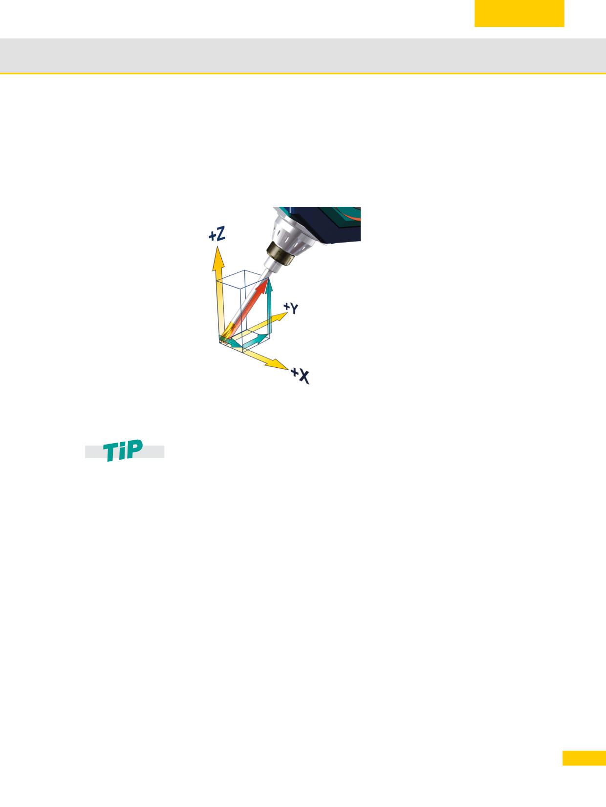
Direction vector (A3=<value> B3=<value> C3=<value>)
The components of a vector in space are programmed during the programming of direction
vectors. Whereby A3 is associated with the X component, B3 is associated with the Y component
and C3 is associated with the Z component; the length of the vector is of no significance. For
example, A3=1 B3=1 C3=1 defines a vector with the components (1,1,1) which points in the
direction of the spatial diagonal of the coordinate system.
Programming direction
The components of the direction vector are
vector
programmed with A3, B3, and C3. The vector
points towards the tool adapter; the length of
the vector is of no significance. Vector
components that have not been programmed
are set equal to zero.
C3
N020 TRAORI
N035 G54
N040 G1 X0 Y0 Z0 A3=1 B3=1 C3=1 F10000
B3
A3
The example shows the tool tip in the position
(0,0,0), and the tool shank is the diagonal of a
cube (35.26° in relation to X-Y plane).
The vectors clearly correspond to the I, J, K vectors used in CAM systems. However, as I, J, K
are reserved for the circle parameters in the CNC standard, the addresses A3, B3 and C3 are
used for the vector components in SINUMERIK.
The use of the direction vector is recommended. The accuracy level selected should be as
high as possible. As far as 5-axis programs are concerned, practical experience has
shown that good results can be achieved by using 5 decimal places for linear axes and
6 decimal places for the direction vector.
87
© Siemens AG All rights reserved SINUMERIK, Manual, Mold-Making with 3- to 5-Axis Simultaneous Milling
Important functions for 3- to 5-axis machining
3.5
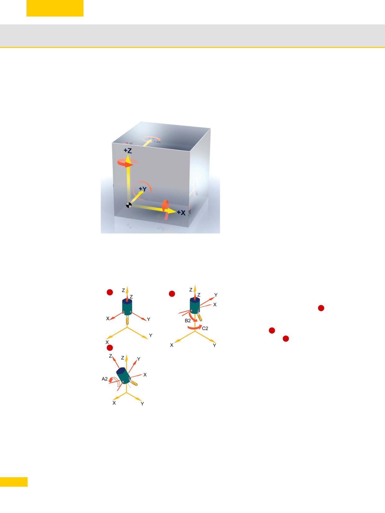
Use of Euler or RPY angles (A2=<value> B2=<value> C2=<value>)
Instead of direct vector programming, abstract rotation angles can be used for the orientation
description. Normally, Euler angles or RPY angles (roll, pitch, yaw) are used to rotate coordinate
systems around the coordinate axes.
Euler and RPY
With Euler angles, rotation is first around the Z
axis, then around the rotated X axis and finally
around the resulting Z axis. There are different
definitions for RPY angles.
The following is used in SINUMERIK: The first
rotation is around the Z axis, the second
around the rotated Y axis and the third around
the rotated X axis.
They can also be used accordingly for the definition of a vector. This is based on a vector in the Z
direction of the coordinate system that is rotated using Euler or RPY angles. The resulting vector
is the new tool vector. The NC addresses A2, B2 and C2 are used to program the rotation
angles. The meaning of the angles, i.e. whether they are Euler angles or RPY angles, is specified
via the G codes ORIEULER and ORIRPY. This results in the following definitions:
The values programmed with A2, B2, and C2
Programming
1
2
during orientation programming are
RPY angles
interpreted as RPY angles (in degrees).
Starting from the basic position
1
:
The orientation vector is obtained by first
rotating a vector in the Z direction around the
Z axis with C2
2
, then rotating it around the
new Y axis with B2,
3
and finally rotating it
around the new X axis with A2 (Z, Y', X"). In
3
With C2=90°:
contrast to Euler angle programming, all three
rotated around
values here have an effect on the orientation
Z axis
vector.
With B2=45°:
Example:
rotated around
N020 TRAORI
N030 G54
N040 G0 X0 Y0 Z0
N050 C2=0 B2=0 A2=0 F10000
With A2=30°:
N060 C2=90 B2=45 A2=30
rotated around
N070 ...
X axis that is rotated
88
© Siemens AG All rights reserved SINUMERIK, Manual, Mold-Making with 3- to 5-Axis Simultaneous Milling
Important functions for 3- to 5-axis machining
3.5
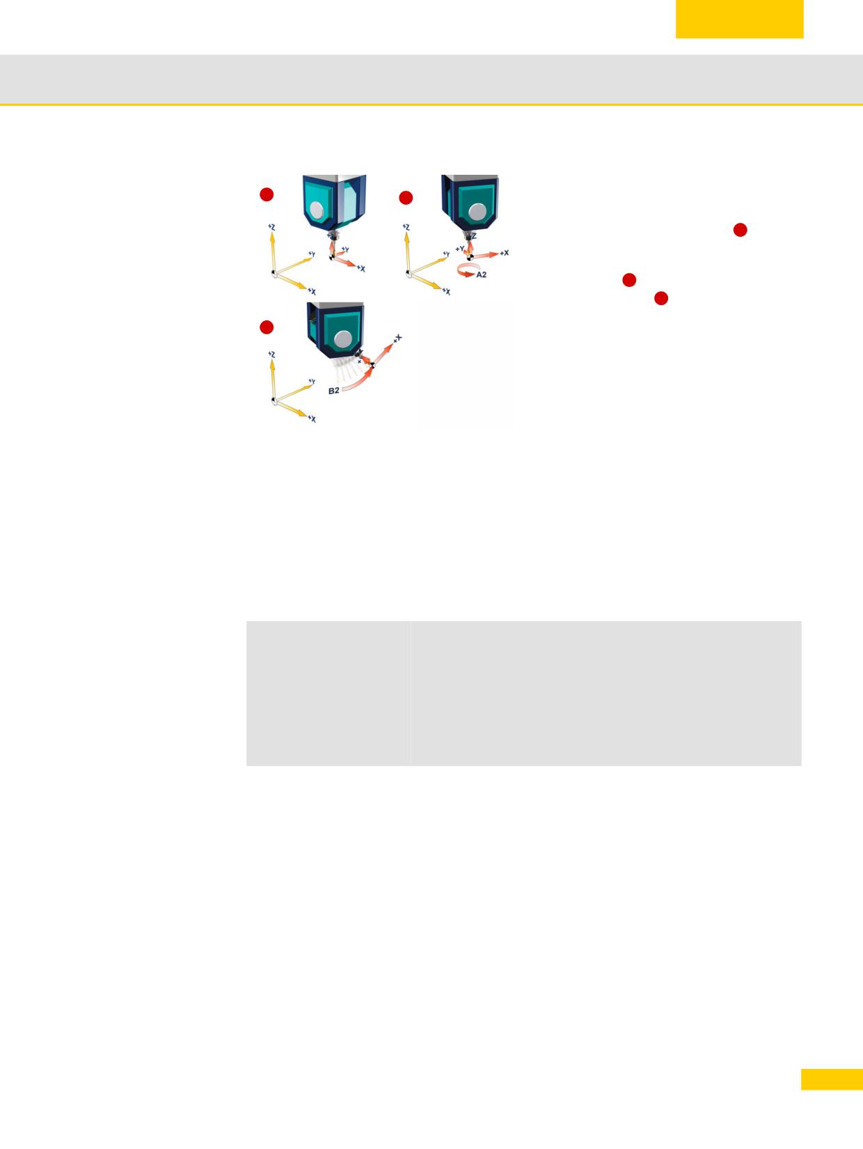
The values programmed with A2, B2, and C2
Programming
1
2
during orientation programming are
Euler angles
interpreted as Euler angles (in degrees).
Starting from the basic position
1
:
The orientation vector is obtained by first
rotating a vector in the Z direction around the
Z axis with A2
2
, then rotating it around the
new X axis with B2,
3
and finally, rotating it
With A2=90°
around the new Z axis with C2 (Z, X', Z").
3
rotated
around Z axis
Example:
N020 TRAORI
N030 G54
N040 G0 X0 Y0 Z0
N050 G1 A2=0 B2=0 F1000
N060 G1 A2=90 B2=45
With B2=45°:
N070 ...
rotated around
In this case, the value of C2 (rotation around
Y axis that is
the Z axis) is meaningless and does not have
to be programmed.
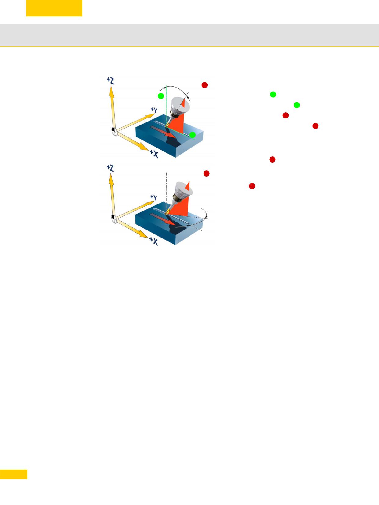
Lead and tilt angles (LEAD/TILT)
In conjunction with LEAD and TILT, the orientation is programmed via a lead angle and a tilt
angle. This is the only orientation programming variant that is linked to a certain orientation
interpolation for the type of orientation definition, namely ORIPATH.
LEAD
Lead angle for programming tool orientation.
Angle relative to the surface normal vector in the plane put up by
the path tangent and the surface normal vector.
TILT
Tilt angle for programming tool orientation.
The TILT angle defines the rotation of the lead angle around the
surface normal vector
89
© Siemens AG All rights reserved SINUMERIK, Manual, Mold-Making with 3- to 5-Axis Simultaneous Milling
Important functions for 3- to 5-axis machining
3.5
LEAD and TILT
The resultant tool orientation is determined
1
from:
Path tangent
A
B
Surface normal vector
B
Lead angle LEAD
1
Tilt angle TILT at end of block
2
A
LEAD describes the angle between the sur-
face normals and the new tool orientation in
the plane set up by the path tangent and the
surface normals
1
The tilt angle corresponds to a rotation of the
2
tool in the plane perpendicular to the surface
normals
2
The lead angle is often used to orient the tool
at a fixed setting angle to the machining plane.
This increases the cutting performance. For
example, a ball mill touches the surface to be
machined precisely with the tool tip when the
orientation is perpendicular. However, the
rotation and therefore the cutting speed is 0 at
this point of the milling cutter.
The following program sequence corresponds
approximately to that shown in the graphic.
N10 TRAORI
N20 G1 X=0 Y0 A3=0 B3=0 C3=1
N30 ORIPATH
N40 X10 LEAD=30 TILT=10 C5=1
90
© Siemens AG All rights reserved SINUMERIK, Manual, Mold-Making with 3- to 5-Axis Simultaneous Milling
Important functions for 3- to 5-axis machining
3.5
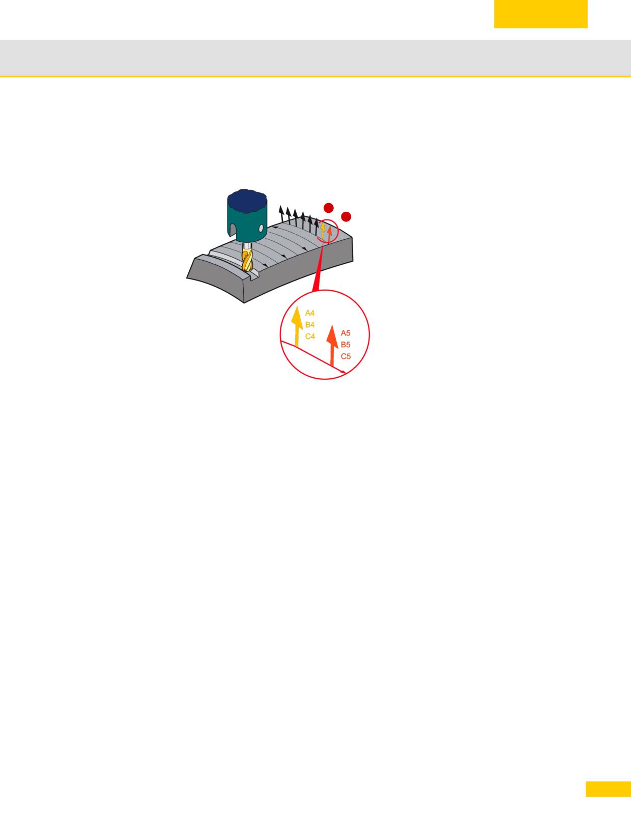
As already mentioned, the lead and tilt angles are only defined in conjunction with the surface
normal vector. This is defined in the same way as the orientation vector with the components A4,
B4, C4 or A5, B5, C5: The first designate the normal vector at the start of the block, the latter at
the end of the block.
The surface normal vector is perpendicular
to the machining surface.
1
2
The start vector at the start of the block is
programmed with A4, B4, C4. The vector at
the end of the block is programmed with A5,
B5, C5.
91
© Siemens AG All rights reserved SINUMERIK, Manual, Mold-Making with 3- to 5-Axis Simultaneous Milling
Important functions for 3- to 5-axis machining
3.5
3.5.4
Orientation interpolation and orientation reference
In the NC program, the tool orientation relative to the workpiece is specified block-by-block by
vectors (A3, B3, C3) or angles ((axis positions A, B, C), Euler or RPY angles (A2, B2, C2) or
(LEAD/TILT)). In 5-axis simultaneous machining, these normally change in each block. If the
machine is now to be moved in accordance with the specifications of the NC program, the
orientation must be continuously changed synchronous to the path motion.
Motion interpolation in the 3-axis area
New X, Y and Z coordinates are specified block-by-block. However, there are obviously
numerous ways to move a tool from one position to the next. This can be performed along a
straight line (G1), on an arc (G2, G3) or also on a spline curve (ASPLINE, BSPLINE, CSPLINE).
In each case, there is a different movement although the programmed coordinates are identical.
Therefore, to clearly describe the desired movement, it is not sufficient to only specify the
coordinates, the way in which traversing is performed from one coordinate to the next must also
be specified. This is performed using the G codes of group 1.
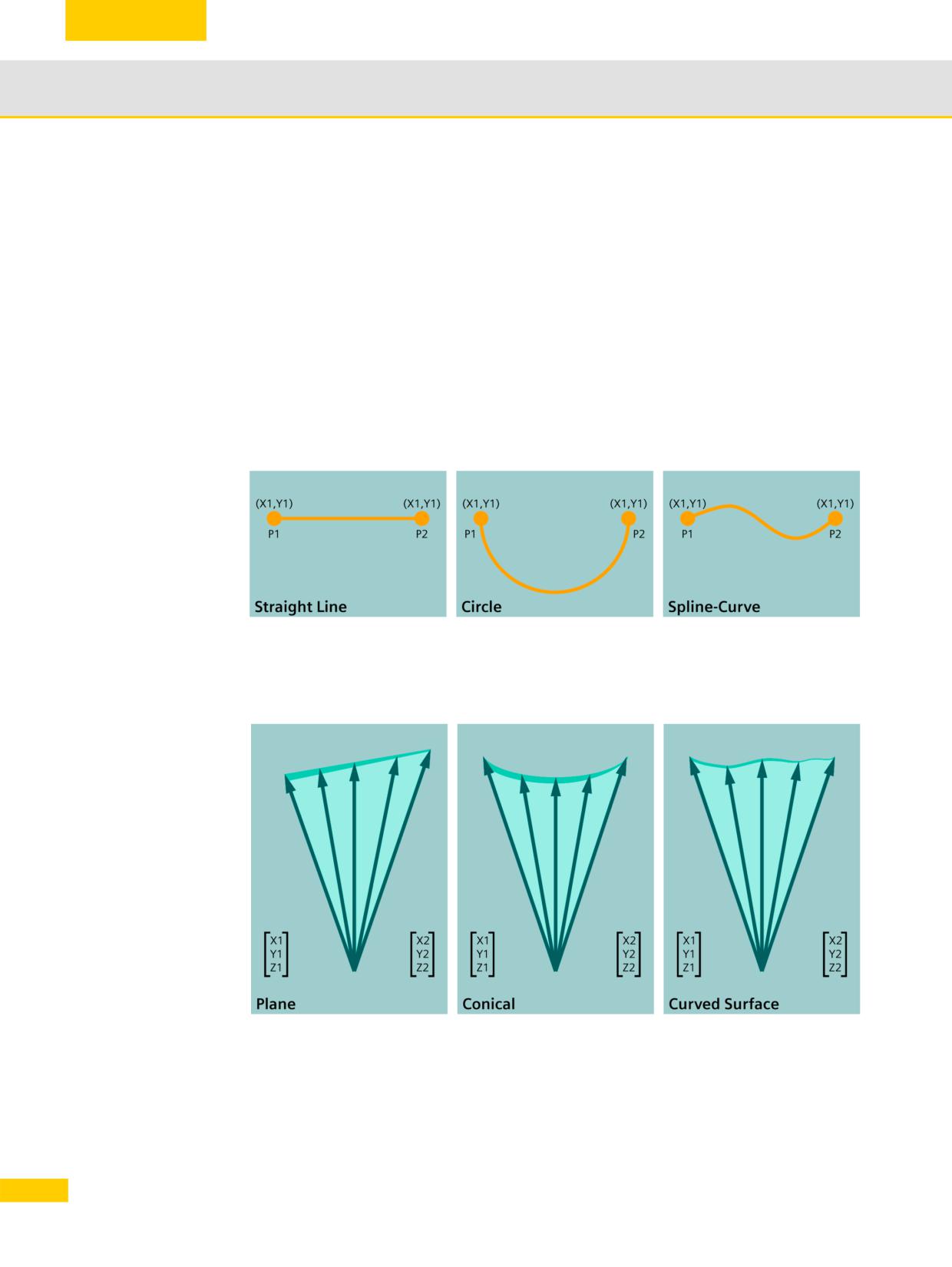
Interpolation of the tool orientation in a point
In the same way, there are numerous ways to move from one tool orientation (X1, Y1, Z1) to the
next (X2, Y2, Z2). This can be performed by moving the vector in a plane, on a conical surface or
an otherwise curved surface. These are shown in the following graphics.
92
© Siemens AG All rights reserved SINUMERIK, Manual, Mold-Making with 3- to 5-Axis Simultaneous Milling
Important functions for 3- to 5-axis machining
3.5
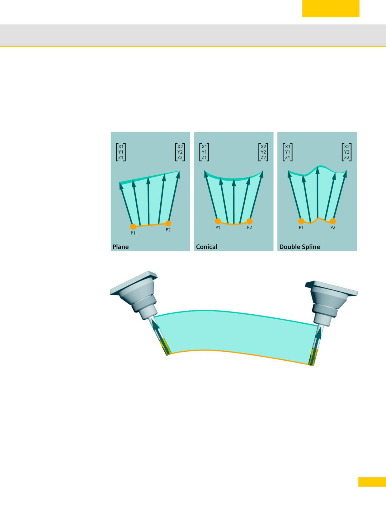
Tool orientation in the 5-axis area
To change a tool orientation from the start orientation of the start block (X1, Y1, Z1) to the target
orientation of the next block (X2, Y2, Z2), it is also not sufficient to only specify the coordinates.
How the vectors move must also be defined. In a plane, on a conical surface or an otherwise
curved surface. The G codes of group 51, ORIVECT, ORIAXES, ORICONXX, ORICURVE, etc.
are used for this purpose.
This is best seen when the position of the tool tip and the tool orientation are changed
simultaneously. This can generally be described by two curves. The orange line describes the
movement of the tool tip while the green line defines the movement of a second point on the tool.
These two curves clearly describe the surface on which the tool moves. This fact is used for the
3D spline interpolation ORICURVE by displaying the orange and the green lines through spline
curves.
93
© Siemens AG All rights reserved SINUMERIK, Manual, Mold-Making with 3- to 5-Axis Simultaneous Milling
Important functions for 3- to 5-axis machining
3.5
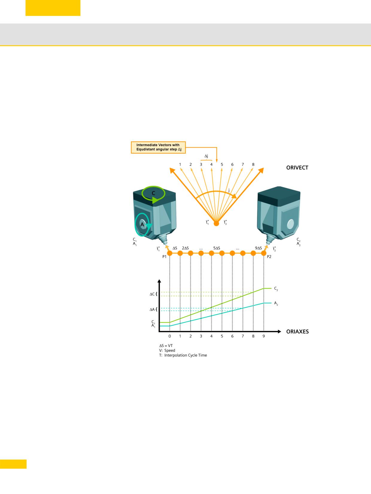
Comparison of ORIVECT and ORIAXES
To illustrate the differences more clearly, let us consider the two most commonly used cases
ORIVECT and ORIAXES. As already mentioned, ORIAXES is the standard interpolation type
that is most commonly used. The rotary axes are interpolated linearly synchronous to the
movement of the tool tip. Let us consider the following situation to illustrate this type.
The following figure shows the movement of a fork head machine with C and A axes along an NC
block.
We will begin at the start of the block with position P1, the tool vector t1 and the corresponding
rotary axes positions C1 and A1. The position, the tool vector and the rotary axes positions at the
end of the block are specified with P2, t2, C2 and A2. For the interpolation of the tool tip with the
programmed velocity, the distance to the end point is divided into sections of equal size, whose
length ΔS corresponds to the interpolation cycle and the programmed feedrate. The increment is
ΔS = VT, whereby V is the velocity and T the interpolation cycle time. At constant velocity, the
entire traversing distance D between P1 and P2 is divided into nine equidistant interpolation
increments.
In the same way with ORIAXES, the difference of the rotary axis positions C2-C1 and A2 - A1 is
divided into 9 equidistant increments C and A. This means that the curve of the rotary axis
positions linearly follows the path motion.
94
© Siemens AG All rights reserved SINUMERIK, Manual, Mold-Making with 3- to 5-Axis Simultaneous Milling

Important functions for 3- to 5-axis machining
3.5
The circumstances are different with ORIVECT. The vector is interpolated and not the rotary
axes. For this purpose, the differential angle J between the start vector t1 and the end vector t2 is
considered. This is divided into 9 equidistant increments ΔJ in accordance with the path motion.
The intermediate vectors defined as a result are all in a plane set up by t1 and t2. A surface is
therefore defined in workpiece coordinates, in this case a plane, on which the orientation vector
moves. The possible orientation interpolations are described in the following section.
Orientation reference to the coordinate system (ORIMKS, ORIWKS)
The reference for the rotary axis interpolation is defined using the G code commands ORIMKS/
ORIWKS.
ORIMKS Tool orientation in the machine coordinate system.
With ORIMKS, the programmed orientation relates to the coordinate system defined by the
machine axes. Rotations through frames are not taken into consideration here.
ORIWKS Tool orientation in the workpiece coordinate system.
With ORIWKS, the programmed orientation relates to the workpiece coordinate system that may
be rotated in relation to the machine coordinate system using a frame.
Orientation reference
ORIMKS
The reference system for the orientation vector is the machine
coordinate system.
ORIWKS
The reference system for the orientation vector is the workpiece
(recommended)
coordinate system. Machine data is used to determine precisely
what happens.
95
© Siemens AG All rights reserved SINUMERIK, Manual, Mold-Making with 3- to 5-Axis Simultaneous Milling
Important functions for 3- to 5-axis machining
3.5
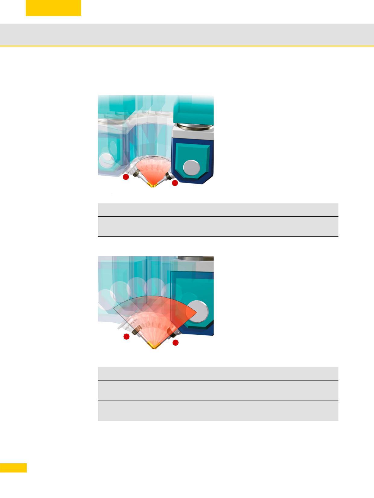
Orientation interpolation of the axes
Linear interpolation (ORIAXES)
Linear interpolation
The rotary axes are interpolated linearly syn-
(ORIAXES)
chronous to the path motion. In this interpola-
tion type, the orientation curve depends on the
machine kinematics. It can be used in all
cases in which it is not necessary that the tool
moves on a precisely defined surface in the
workpiece coordinate system. This is the
case, for example, in mold-making when ball
mills are used.
1
2
Axis/linear interpolation
ORIAXES
Linear interpolation of the machine axes
(recommended)
Vector interpolation (ORIVECT/ORIPLANE)
The tool vector always moves in a plane set
Vector interpolation
up by the start and end vectors. The
Large circle
interpolation type is frequently used in the
interpolation
milling of aircraft structures because the
(ORIVECT/ORIPLANE)
pockets mostly have flat and inclined walls. It
is also recommended when using toroidal
millers for face milling.
1
2
Vector interpolation
ORIVECT
Interpolation of the orientation vector in a plane (large circle
interpolation)
ORIPLANE
Interpolation in a plane (large circle interpolation), identical to
ORIVECT
96
© Siemens AG All rights reserved SINUMERIK, Manual, Mold-Making with 3- to 5-Axis Simultaneous Milling
Important functions for 3- to 5-axis machining
3.5
Cone surface interpolation (ORICONxx)
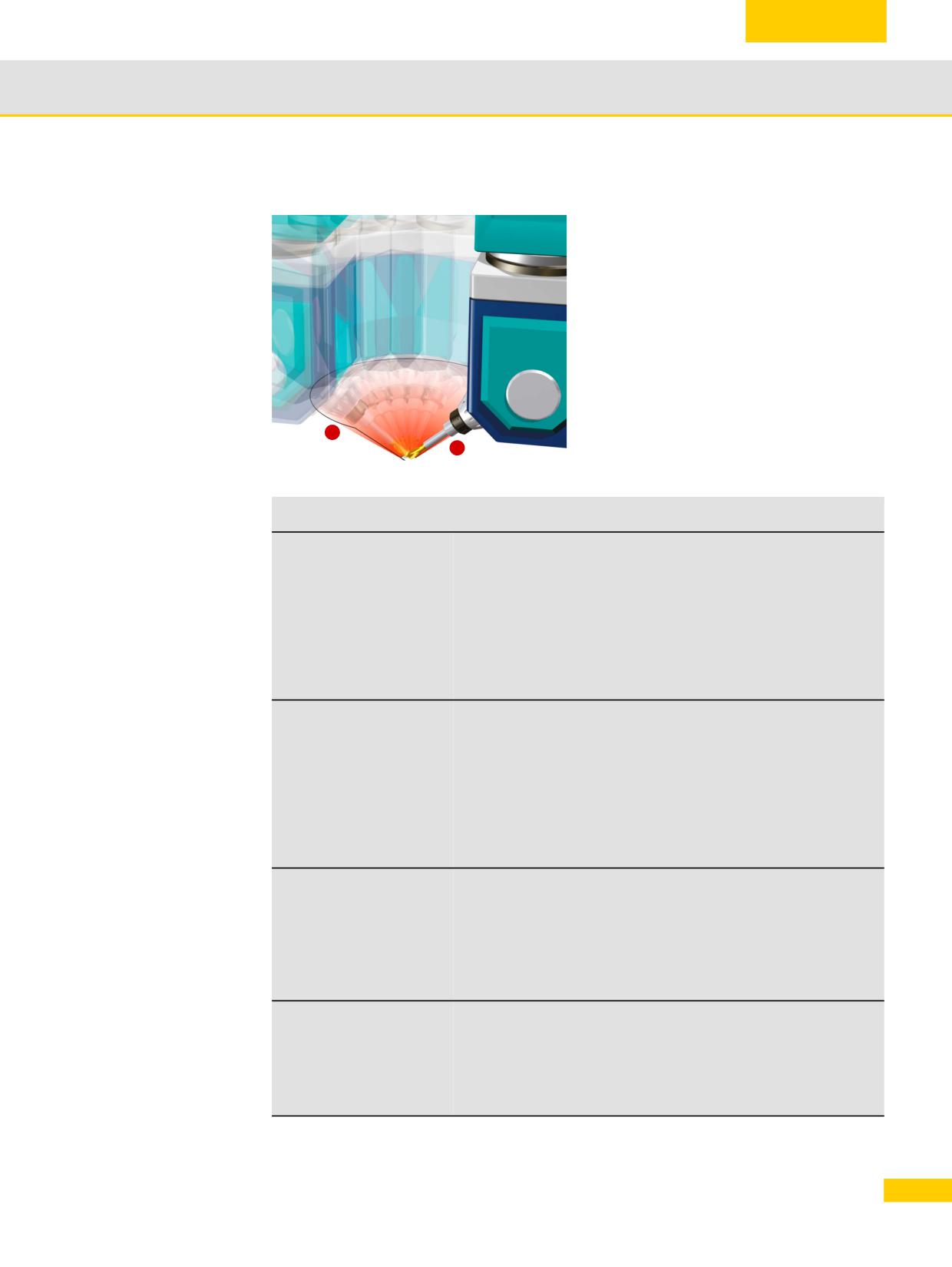
With cone surface interpolation, during
Cone surface
reorientation the tool moves on a
interpolation
programmable peripheral surface of a cone
(ORICONCW)
located anywhere in space.
1
2
Vector interpolation
ORICONCW
Interpolation on the peripheral surface of a cone in the clockwise
direction
Programming:
Circle end position with radius: G2 X.. Y.. Z.. CR=
End orientation vector: A3= B3= C3= or A2= B2= C2=
Vector of the cone's axis of rotation: A6= B6= C6=
Opening angle of the cone (PSI), value 0 -180 degrees:
GROOVE=
ORICONCCW
Interpolation on a peripheral surface of a cone in the
counterclockwise direction
Programming:
Circle end position with radius: G3 X.. Y.. Z.. CR=
End orientation vector: A3= B3= C3= or A2= B2= C2=
Vector of the cone's axis of rotation: A6= B6= C6=
Opening angle of the cone (PSI), value 0 -180 degrees:
GROOVE=
ORICONIO
Intermediate orientation via A7=… B7=…, C7=….
Programming:
Circle end position: CIP X.. Y.. Z..
Circle intermediate point: I1=... J2=.. K1=..
Intermediate orientation vector: A7=.. B7=.. C7=..
End orientation vector: A3= B3= C3= or A2= B2= C2=
ORICONTO
Interpolation on a peripheral surface of a cone with tangential
transition.
Programming:
Circle end position: CT X.. Y.. Z..
End orientation vector: A3= B3= C3= or A2= B2= C2=
97
© Siemens AG All rights reserved SINUMERIK, Manual, Mold-Making with 3- to 5-Axis Simultaneous Milling
Important functions for 3- to 5-axis machining
3.5
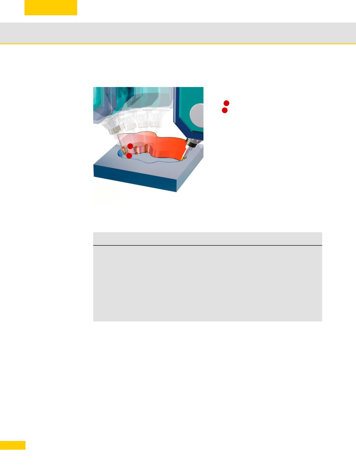
Spline interpolation (double spline ORICURVE)
Spline interpolation
With spline interpolation, the movement of the
Curve interpolation
orientation vector is defined by the tool tip's
(ORICURVE)
path
1
and the path of a second point on the
tool
2
If, for example, you wanted to use
circumferential milling to create an inclined
surface, you would define the surface on
which the milling cutter should move using two
2
spline curves at the top and bottom ends of
the tool (1, 2).
1
The advantage of this is that it enables you to
define a wide variety of surfaces for machining
with a high degree of precision.
Spline interpolation is the best type of
interpolation available, but it is also the most
involved and calls for special syntax in the NC
program that must be supported by the CAM
system.
Spline / double spline interpolation
ORICURVE
Orientation interpolation with specification of the tool tip motion
and that of a second point on the tool. The path of the second
point is defined via XH=… YH=… ZH=…, in conjunction with
BSPLINE as a control polygon with POLY as polynomial:
PO[XH] = (xe, x2, x3, x4, x5)
PO[YH] = (ye, y2, y3, y4, y5)
PO[ZH] = (ze, z2, z3, z4, z5)
If the BSPLINE or POLY additional information is omitted,
straightforward linear interpolation will be performed accordingly
between the start and the end orientation.
98
© Siemens AG All rights reserved SINUMERIK, Manual, Mold-Making with 3- to 5-Axis Simultaneous Milling
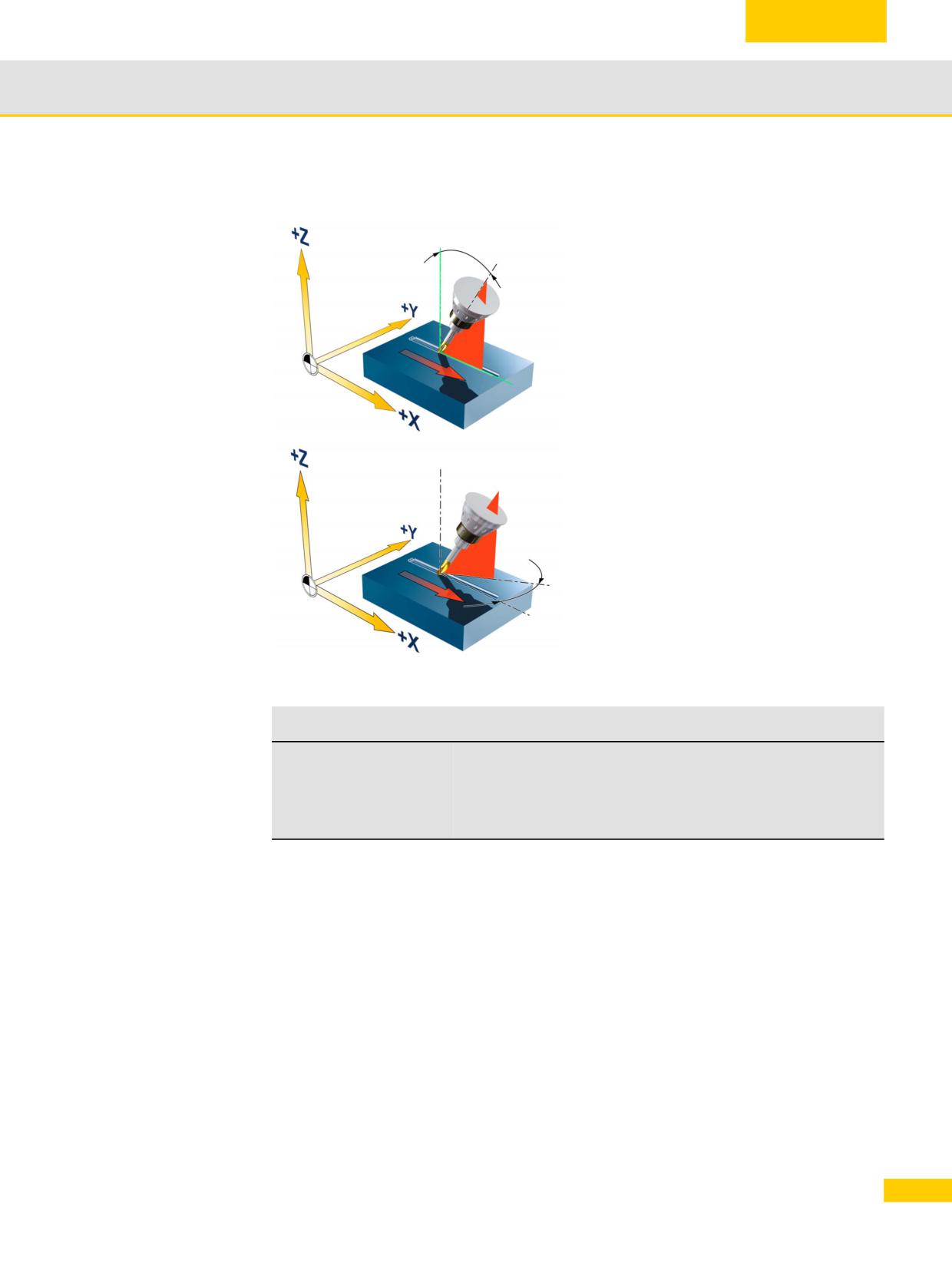
Important functions for 3- to 5-axis machining
3.5
Path-related interpolation (ORIPATH)
Path-related
The orientation vector is set relative to the
interpolation
path and to the surface normals. The
programming is performed using the LEAD
FN
angle and the TILT angle in conjunction with
fsfsf
the surface normal vector. LEAD describes a
rotation around the direction perpendicular to
the tangents and normals while TILT
describes a rotation of the orientation around
the surface normal vector.
The orientation interpolation with ORIPATH is
TB
recommended when programming on the
CAM system during the machining of free-
form surfaces in tool and mold-making. The
prerequisite for this is support of the issuing of
surface normals of your CAM system.
Path-related interpolation
ORIPATH
Tool orientation in relation to the path.
This is used with the commands LEAD and TILT and the
specification of the surface normals with A4, B4, C4 and A5, B5,
C5.
99
© Siemens AG All rights reserved SINUMERIK, Manual, Mold-Making with 3- to 5-Axis Simultaneous Milling
Important functions for 3- to 5-axis machining
3.5
3.5.5
Example application involving TRAORI and frames
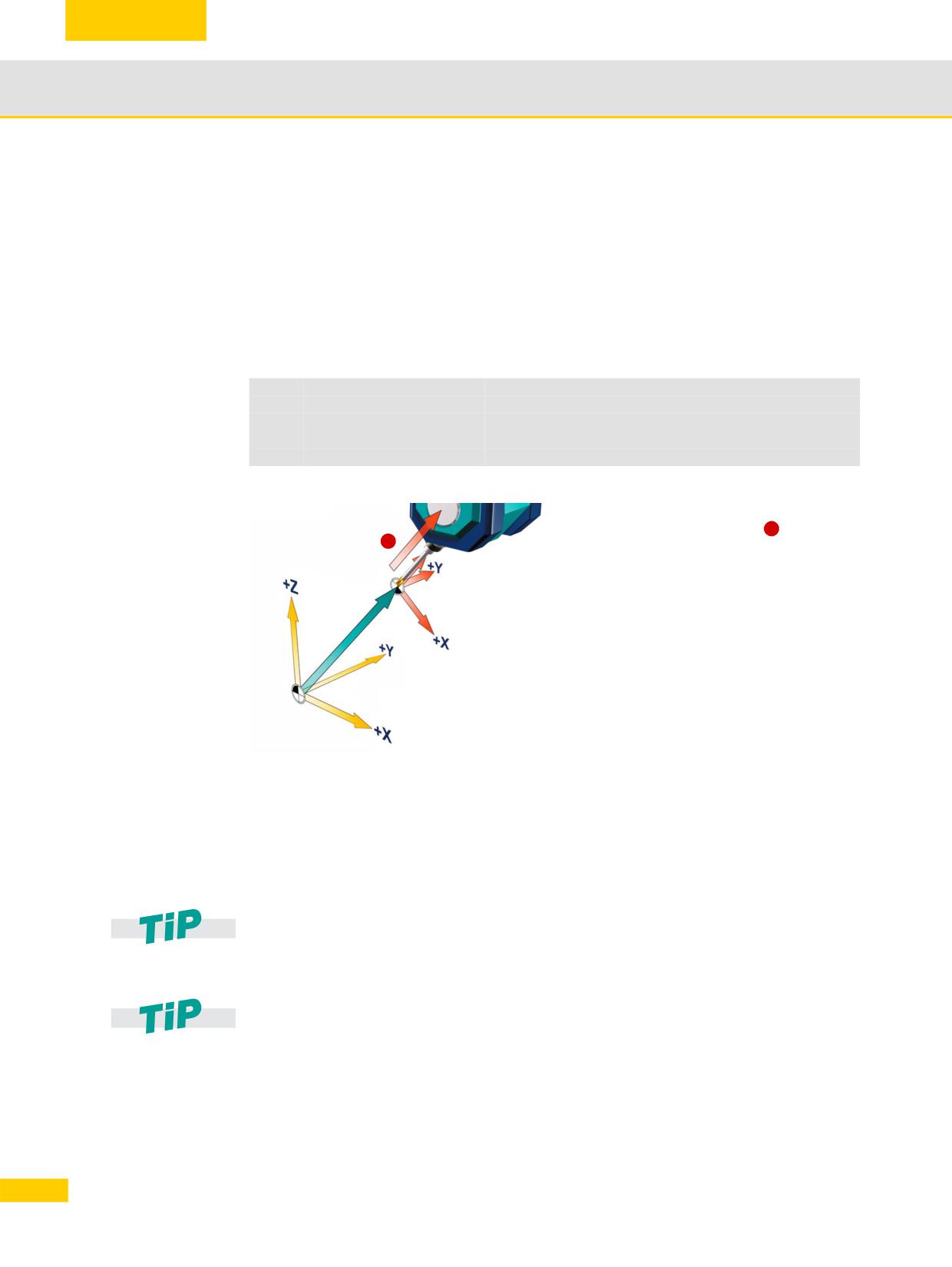
Example TOROT - Retraction from a slanted hole
When 5-axis transformation is active, TOROT generates a frame whose Z axis coincides with the
current tool orientation. This function can be used with a 5-axis program, for example, to retract
the tool after a tool breakage without collision, simply by returning the Z axis. Following tool
orientation with TOROT, all the geometry axis movements programmed will relate to the frame
generated as a result of this function.
Programming TOROT in MDI
N110
TRAORI
; Activate TRAFO
N120
TOROT
; Calculate and select return frame
N130
G1 G91 Z50 F500
; Return movement by 50 mm in Z direction in a straight
line
N140
M17
; End of subprogram
A frame containing the current tool orientation
in the Z direction is generated
This means
1
1
that in JOG mode, the tool can be returned
from the workpiece in the Z direction.
As an alternative to traversing incrementally in
MDI mode, in JOG mode you can use the
direction key to enable return in the tool
direction.
Notice:
Return is possible only in JOG mode if the
machine has been configured accordingly (Z
axis serves as the geometry axis).
TOROT to machining plane
TOROT for G17
TOROTY for G18 -> tool axis Y
TOROTX for G19 -> tool axis X
TOROT must be deselected prior to the next program start: TOROTOF.
A similar function is available in JOG with the manual retraction. After an interruption of a
tapping operation (G33/G331/G332) or a general drilling operation (tools 200 to 299) due to
power loss or a RESET at the machine control panel, you have the possibility to retract
the tool in the tool direction without damaging the tool or the workpiece.
100
© Siemens AG All rights reserved SINUMERIK, Manual, Mold-Making with 3- to 5-Axis Simultaneous Milling
Important functions for 3- to 5-axis machining
3.5
3.5.6
Useful NC commands for active TRAORI
In conjunction with the programming of TRAORI, the following NC commands can help to
simplify programming.
ORIRESET Approach basic position of the tool orientation (ORIRESET)
Through ORIRESET(.,.,.), the orientation axes of the relevant machine kinematics are traversed
linearly and synchronously from their current positions to the programmed basic positions. If a
basic position is not programmed for an axis, the position from the associated machine data
$MC_TRAFO5_ROT_AX_OFFSET_1/2 is used.
Programming:
Example of machine kinematics CA (channel axis names C, A).
ORIRESET(90, 45)
; C to 90 degrees, A to 45 degrees
ORIRESET(, 30)
; C from $MC_TRAFO5_ROT_AX_OFFSET_1/2[0], A to 30 degrees
ORIRESET( )
; C from $MC_TRAFO5_ROT_AX_OFFSET_1/2[0], A to
$MC_TRAFO5_ROT_AX_OFFSET_1/2[1]
STAT Defining the preferred direction for active TRAORI with STAT
For active TRAORI, the control automatically executes compensatory movements of the rotary
axes to achieve specific positions of the tool positioning. Because these compensatory
movements are made by the control in negative and positive rotary axis positions, the preferred
direction can be hard coded with the STAT command. The rotary axes are then moved only in
the positive or negative direction to reach the target position. For example, STAT can be used
instead of prepositioning with CYCLE800.
Programming:
STAT is programmed for ORIWKS and ORIAXES
STAT=-1; (axis remains at - position. Only for ORIAXES)
STAT=1; (axis remains at + position. Only for ORIAXES)
101
© Siemens AG All rights reserved SINUMERIK, Manual, Mold-Making with 3- to 5-Axis Simultaneous Milling
Important functions for 3- to 5-axis machining
3.6
3.6
High Speed Settings - CYCLE832
Application
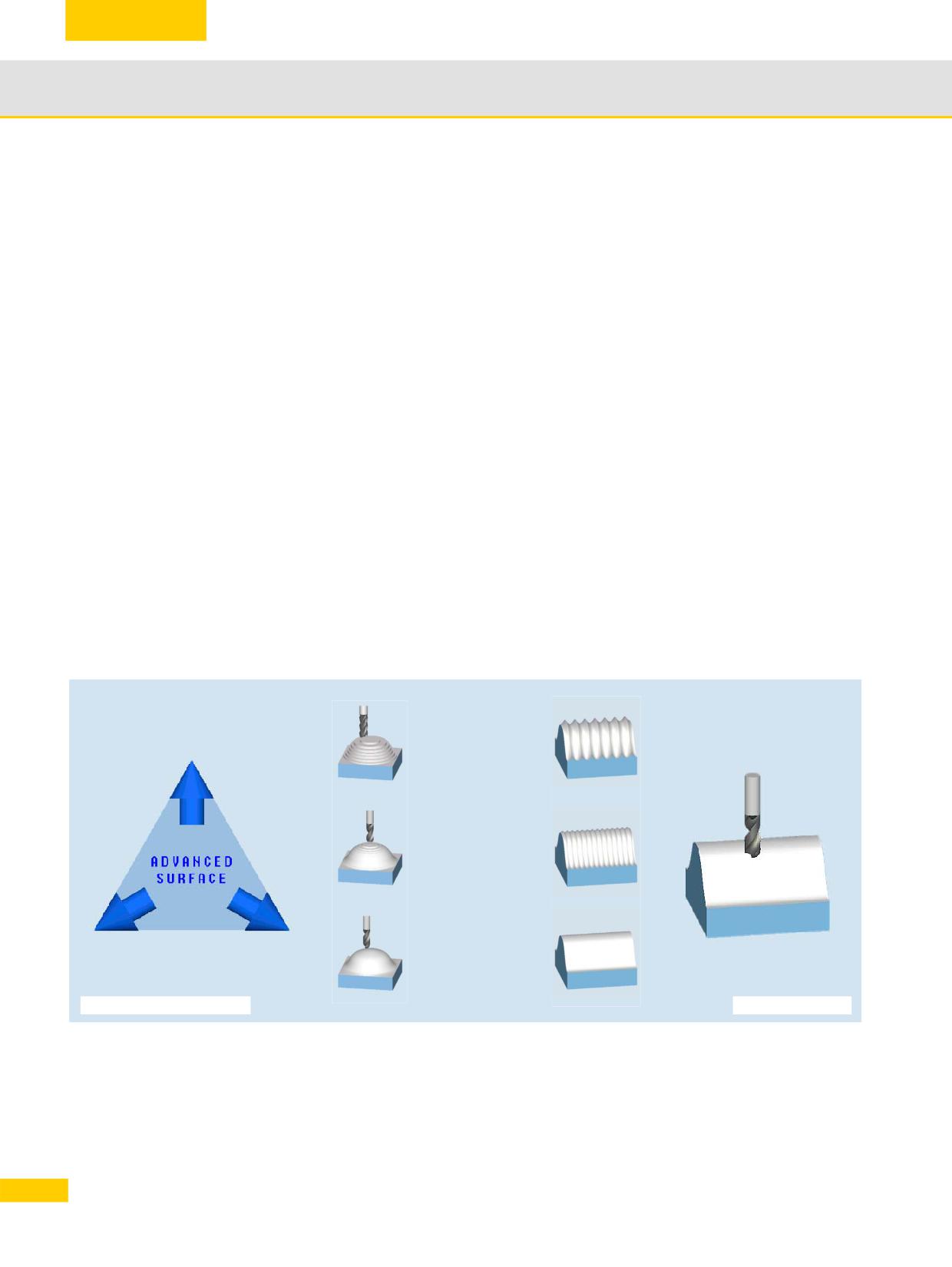
You can influence the sequence of CAM programs using SINUMERIK CYCLE832. It provides
technological support for 3- and 5-axis machining in the high-speed cutting (HSC) range.
When executing CAM programs in the HSC range, the control needs to achieve high machining
feedrates. By applying different machining strategies, you can use CYCLE832 to fine-tune the
program for execution.
When roughing, the emphasis is on velocity due to the smoothing of the contour.
When finishing, the emphasis is on surface quality and accuracy.
In both cases, specifying a tolerance ensures that the correct machining contour is achieved in
order to obtain the desired surface quality and accuracy. Generally, for roughing the tolerance is
greater than for finishing.
Advanced Surface and Top Surface
For CYCLE832, as of software release V4.7 SP2, you can select between Advanced Surface
and option Top Surface.
Top Surface is an option of CYCLE832 - and is based on the COMPSURF compressor. This has
been improved for machining demanding CAD/CAM programs. The new compressor especially
compensates the potential negative impact on the surface quality for an inhomogeneous point
distribution, as is the case for inclined line-by-line finishing programs and for bidirectional milling.
The result is a uniformly perfect surface, which is essentially independent of the quality of the
CAD/CAM data.
Surface quality
Roughing
▼
Semi-finishing
▼▼
Accuracy
Velocity
Finishing
▼▼▼
Advanced Surface
Top Surface
102
© Siemens AG All rights reserved SINUMERIK, Manual, Mold-Making with 3- to 5-Axis Simultaneous Milling
Important functions for 3- to 5-axis machining
3.6
3.6.1
Parameters for CYCLE832
CYCLE832 can be set by the machine operator or, within the context of NC program generation,
by the postprocessor or programmer. Dynamic values and NC commands are adapted to
address specific user requirements and they depend on the settings of the machine data
(machine machine manufacturer).
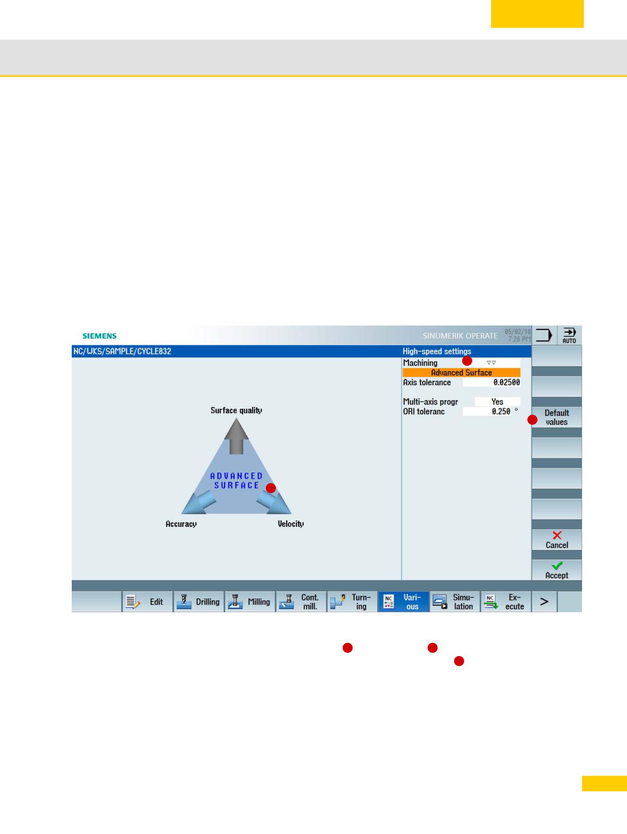
In CYCLE832, the operator can select between the four different types of machining of the
technology group Dynamic G group 59 and activate their dynamic parameters.
CYCLE832 with Advanced Surface based on the well proven COMPCAD compressor. The new
COMPSURF compressor is used for Top Surface. Top Surface when milling inclined line-by-line
contours.
With innovated lookahead functionality, as well as harmonizing velocity profiles of adjacent paths
and optimized acceleration and jerk behavior, CYCLE832 guarantees extremely good surface
quality with short machining times.
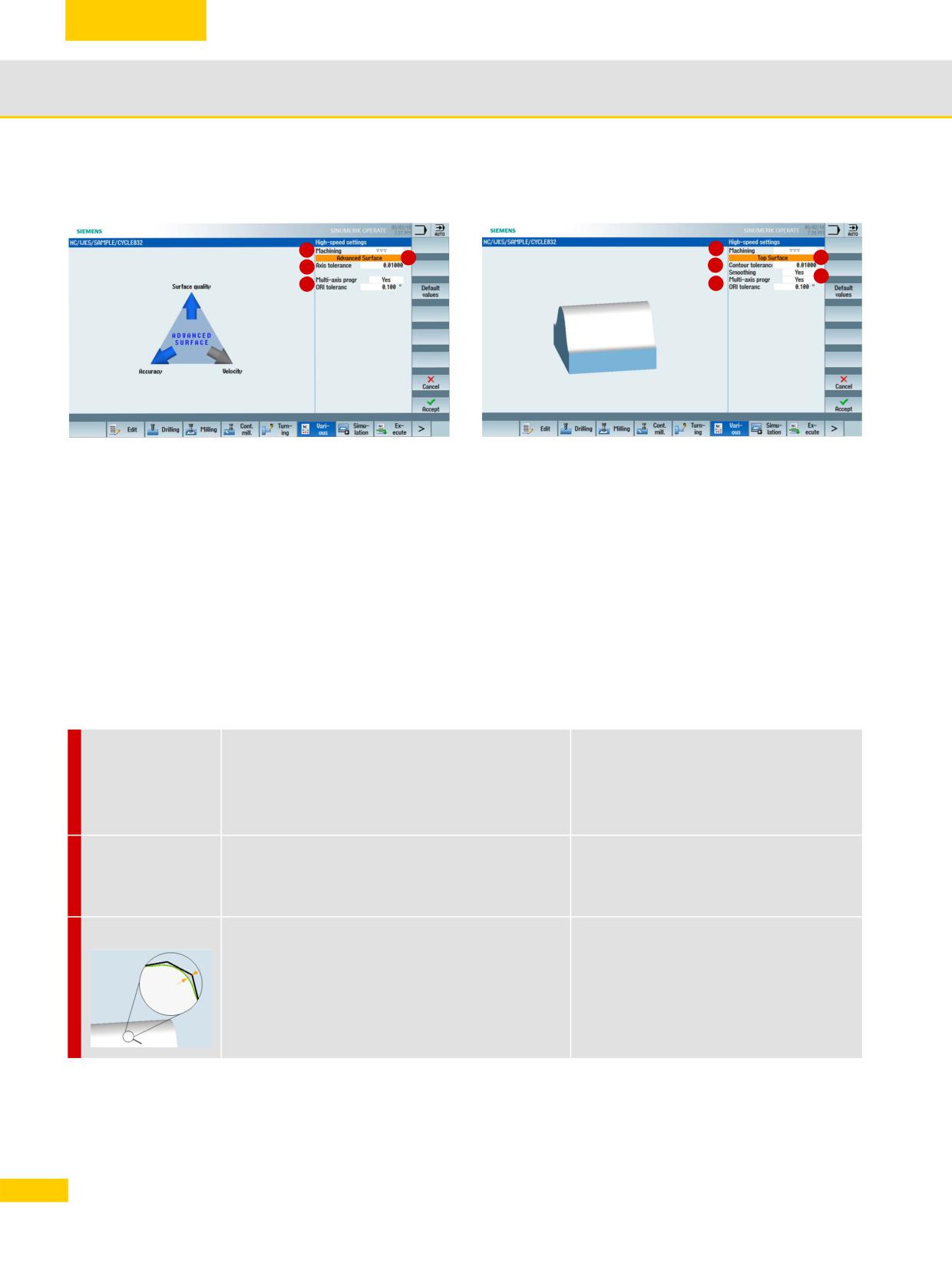
1
3
2
By selecting the machining strategy, the CAM program execution is optimized for the machine.
Depending on the selected machining
1
the blue arrows
2
point in the Velocity, Surface
quality or Accuracy direction. Using the Default values softkey
3
preassigns the cycle
parameters, depending on the selected machining.
103
© Siemens AG All rights reserved SINUMERIK, Manual, Mold-Making with 3- to 5-Axis Simultaneous Milling
Important functions for 3- to 5-axis machining
3.6
Parameters for the High Speed Setting cycle
Advanced Surface
Top Surface
1
1
2
2
3
3
5
4
4
Parameterizing CYCLE832
X At Machining, select one of the deselection, finishing, semi-finishing and roughing
parameters.
X If the Top Surface option is activated, then you can select between the two motion controls.
Advanced Surface is the default setting.
X Enter a value in the Axis/contour tolerance field.
X For multi-axis programs, as of SW 4.5, you can smooth the orientation characteristic in the
cycle and apply an ORI tolerance.
X For Top Surface, smoothing can also be activated via a setting data item. When smoothing,
inhomogeneous areas along the path are smoothed.
CYCLE832 parameters (as of SW 4.7 SP2)
Machining
Finishing (_FINISH)
Selection for 3-axis programs with plain
text.
Semi-finishing (_SEMIFIN)
Choosing "Deselection" resets the values to
Roughing (_ROUGH)
the default values.
Deselection (_OFF)
Finishing (_ORI_FINISH)
Selection for multi-axis programs with
orientation tolerance in plain text.
Semi-finishing (_ORI_SEMIFIN)
Roughing (_ORI_ROUGH)
Tolerance_tol.
Chord tolerance, contour tolerance, axis
Tolerance of the linear axes
tolerance
(Chord tolerance must be imported from the CAM
system 1:1)
104
© Siemens AG All rights reserved SINUMERIK, Manual, Mold-Making with 3- to 5-Axis Simultaneous Milling
Important functions for 3- to 5-axis machining
3.6
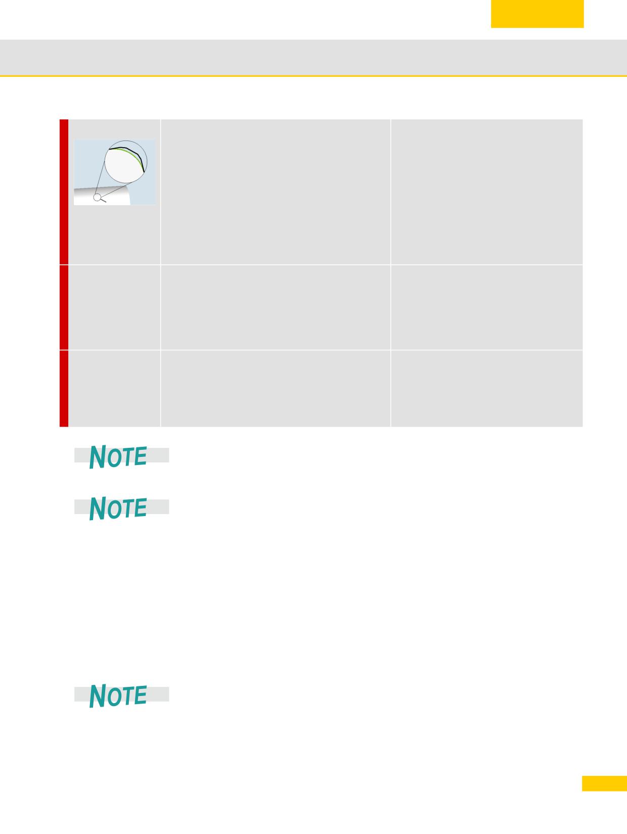
Smoothing
Yes (_TOP_SURFACE_SMOOTH_ON)
Yes: Optimized path within the contour
(can be set via setting data item)
tolerance
Inhomogeneous areas in the path in the
No (_TOP_SURFACE_SMOOTH_OFF)
standard tolerance range of 10 µm are
reliably smoothed. The workpiece assumes
a shiny surface.
No: Close-contour path
The specified contour is precisely followed.
Engraving and geometries with a depth <=
0.005 mm = 5 µm are visible on the
workpiece surface.
Multi-axis
No
No: For 3-axis programs without rotary
program
(can be set via setting data item)
axes. The value 1 is entered automatically
Yes
Yes: For multi-axis programs with rotary
axes. The orientation smoothing is
activated; ORI tolerance > 0° must be
entered.
ORI tolerance
OTOL tolerance
Has two meanings:
Smoothing tolerance of the rotary axes
(approx. factor 10 of the linear tolerance)
for 5-axis transformation TRAORI
Orientation tolerance for the smoothing
of vectors with active ORISON
CYCLE832 is based on the use of G1 blocks, also G0, G2 and G3, depending on the
machine setting.
When using the ORI tolerance, only for Advance Surface, after calling CYCLE832 does
orientation smoothing activation have to be programmed using ORISON. You should not
program ORISON for 5-axis hobbing/circumferential milling as this can result in contour
errors. ORISON is deactivated automatically for Top Surface (COMPSURF).
CYCLE832 structure
CAM systems frequently specify via the postprocessor that CYCLE832 is output directly in the
geometry program. Therefore, make sure that CYCLE832 is programmed in the geometry
program for your start program. CYCLE832 is then automatically selected and deselected in the
subprogram. The start program then only contains the calls of the subprograms with the
geometry data.
This means that you can apply the cycle to the complete geometry or - depending on the
transparency of the CAM program - to individual program sections or free-form surfaces.
Program CYCLE832 after the tool change. After calling CYCLE832, only the geometry data
should still be programmed.
105
© Siemens AG All rights reserved SINUMERIK, Manual, Mold-Making with 3- to 5-Axis Simultaneous Milling

Important functions for 3- to 5-axis machining
3.6
CYCLE832(tolerance, technology, ORI tolerance)
Programming the cycle:
Tolerance (chord tolerance)
Technology
0 = Deselection
1 = Finishing (_FINISH)▼▼▼
2 = Semi-finishing (_SEMIFIN)▼▼
3 = Roughing (_ROUGH)▼
11 = Finishing multi-axis program (_ORI_FINISH)▼▼▼
12 = Semi-finishing multi-axis program (_ORI_SEMIFIN)▼▼
13 = Roughing multi-axis program (_ORI_ROUGH)▼
1000000 = Top Surface without smoothing
2000000 = Top Surface with smoothing
ORI tolerance
Orientation tolerance or version identifier CYCLE832. Is required
when executing an HSC program on machines with dynamic
orientation transformation (e.g. 5-axis machining). Parameter
S_OTOL must be programmed. This also applies for applications
on 3-axis machines for programs without orientation of the tool
(S_OTOL = 1).
CYCLE832(0.05,12,0.5)
CYCLE832 for semi-finishing with tolerance 0.05 with orientation
smoothing and ORI tolerance 0.5.
CYCLE832(0.01,_TOP_SURFACE_SMOOTH_OFF+_ORI_FINISH,0.1)
CYCLE832 for finishing with 0.01 tolerance, Top Surface activated,
smoothing off and orientation smoothing with ORI tolerance 0.1
CYCLE832 Advanced Surface programming example
N10
T1 D1
; Tool selection
N20
G54
; Select tool zero
N30
M3 S1200
; Clockwise spindle rotation and speed
N40
CYCLE832(0.1,3,1)
; 3-axis program, tolerance value 0.1
N50
; [3] = Roughing, [1] = Standard without ORI
N60
EXTCALL "CAM_ROUGH_0"
; Call subprogram CAM_ROUGH_0
N65
CYCLE832(0,_OFF,1)
; Deselection CYCLE832
N70
CYCLE832(0.1,_ROUGH,1)
; 3-axis program, tolerance value 0.1
N80
; [_ROUGH] = Roughing as plain text, [1] = Standard without ORI
N90
EXTCALL "CAM_ROUGH_1"
; Call subprogram CAM_ROUGH_1
N95
CYCLE832(0,_OFF,1)
; Deselection CYCLE832
N100
CYCLE832(0.01,11,0.1)
; 5-axis program (with orientation), tolerance value 0.01
N110
; [11] = finishing, [0.1]= ORI tolerance 0.1
N120
ORISON
; Activation of the orientation smoothing
N130
EXTCALL "CAM_FINISH_0"
; call subprogram CAM_FINISH_0
N135
CYCLE832(0,_OFF,1)
; Deselection CYCLE832
N140
CYCLE832(0.005,_ORI_FINISH,0.05)
; 5-axis program (with orientation), tolerance value 0.005
N150
; [_ORI_FINISH] = finishing as plain text, [0.05]= ORI tolerance 0.05
N160
ORISON
; Activation of the orientation smoothing
N170
EXTCALL "CAM_FINISH_1"
; call subprogram CAM_FINISH_1
N180
CYCLE832(0,_OFF,1)
; Deselection CYCLE832
N200
M30
; End of program
106
© Siemens AG All rights reserved SINUMERIK, Manual, Mold-Making with 3- to 5-Axis Simultaneous Milling

Important functions for 3- to 5-axis machining
3.6
CYCLE832 Top Surface programming example
N10
T1 D1
; Tool selection
N20
G54
; Select tool zero
N30
M3 S1200
; Clockwise spindle rotation and speed
N40
CYCLE832(0.1,_TOP_SURFACE_SMOOTH_OFF+_ROUGH,1)
N50
; 3-axis program, tolerance value 0.1, [_TOP_SURFACE_SMOOTH_OFF] = Top Surface active, smoothing off
N55
; [_ROUGH] = roughing, [1] = standard without ORI
N60
EXTCALL "CAM_ROUGH_0"
; Call subprogram CAM_ROUGH_0
N65
CYCLE832(0,_OFF,1)
; Deselection CYCLE832
N70
CYCLE832(0.05,_TOP_SURFACE_SMOOTH_OFF+_SEMIFIN,1)
N80
; 3-axis program, tolerance value 0.05, [_TOP_SURFACE_SMOOTH_OFF] = Top Surface active, smoothing off
N85
; [_SEMIFIN] = semi-finishing, [1] = standard without ORI
N90
EXTCALL "CAM_SEMIF_1"
; Call subprogram CAM_SEMIF_1
N95
CYCLE832(0,_OFF,1)
; Deselection CYCLE832
N100
CYCLE832(0.001,_TOP_SURFACE_SMOOTH_ON+_ORI_FINISH,0.01)
N110
; 5-axis program, tolerance value 0.001, [_TOP_SURFACE_SMOOTH_ON] = Top Surface active, smoothing on
N120
; [_ORI_FINISH] = 5-axis finishing as plain text, [0.01]= ORI tolerance 0.01
N130
EXTCALL "CAM_FINISH_0"
; Call subprogram CAM_FINISH_0
N135
CYCLE832(0,_OFF,1)
; Deselection CYCLE832
N200
M30
; End of program
Before the functions listed here can be used, the machine manufacturer must have
optimized the CNC machine correctly.
107
© Siemens AG All rights reserved SINUMERIK, Manual, Mold-Making with 3- to 5-Axis Simultaneous Milling
Important functions for 3- to 5-axis machining
3.6
CYLCE832 in older software releases
Because of the continuous further development of CYCLE832, the syntax and also the functional
scope of the cycle differs between the software releases. Therefore, note the new syntax of
CYCLE832 when using older programs. A compatibility mode can be set via a machine data
item. Contact the machine manufacturer if you have any questions on compatibility.
Software release
NC code
SINUMERIK up to SW 7.5
CYCLE832(tolerance, technology)
CYCLE832(0.01,112101)
SINUMERIK Operate SW 2.6
CYCLE832(tolerance, machining, version ID)
CYCLE832(0.1,3,1)
SINUMERIK Operate
CYCLE832(tolerance, machining, version ID) and ORISON
SW 2.7 to SW 4.4
can be programmed separately
CYCLE832(0.005,1,1)
ORISON
OTOL=0.05
When using the ORI tolerance, the activation of the orientation
smoothing with ORISON must be explicitly programmed after
the call of CYCLE832.
SINUMERIK Operate
CYCLE832(tolerance, machining, ORI tolerance) and
SW 4.5
ORISON can be separately programmed
CYCLE832(0.005,_ORI_FINISH,0.5)
ORISON
When using the ORI tolerance in the CYCLE832, depending
on the configuration of CUST_832, after calling CYCLE832,
the activation of orientation smoothing must be programmed
with ORISON.
108
© Siemens AG All rights reserved SINUMERIK, Manual, Mold-Making with 3- to 5-Axis Simultaneous Milling

Important functions for 3- to 5-axis machining
3.6
3.6.2
CYCLE832 and CUST_832
The manufacturer cycle CUST_832 is available for individual adaptation of CYCLE832. This is
individually adapted according to the machine by the machine manufacturer. Special NC
commands for machining are also set in CUST_832. As a consequence, the parameters in the
CYCLE832 dialog can deviate from the descriptions in Section 3.6.1 if the machine manufacturer
has made specific adaptations.
NC commands in connection with Advanced Surface and Top Surface
The following NC code commands are preset in CUST_832.SPF and are activated when the
technology groups are selected in CYCLE832:
DYNNORM, DYNROUGH, DYNSEMIFIN, DYNFINISH (G code group 59).
COMPCAD makes it possible to combine part programs with short linear blocks (G1), with
the associated tolerance, using polynomials.
COMPSURF, compressor ensures a better workpiece surface for inclined line-by-line
finishing programs, poor data quality - or for example, irregular point distribution in NC
programs from the CAD/CAM system.
SOFT (G code group 21) activates the jerk-limited velocity control.
G645 (G code group 10) switches to the continuous-path mode (Look Ahead).
FIFOCTRL (G code group 4) switches to the automatic pre-processing memory control.
FFWON (G code group 24) switches to the parameterized feedforward control (speed or
acceleration feedforward control). Can be optionally activated in CUST_832.
Important NC commands for 5-axis machining
In CUST_832.SPF, the following NC code commands can be preset by the machine
manufacturer.
TRAORI activates the 5-axis transformation set in the transformer machine data and must be
programmed alone in the block.
UPATH (G code group 45) ensures synchronous movements of the rotary and linear axes in
5-axis spline interpolation, as performed with active compressor, for example.
ORIAXES (G code group 51) linearly interpolates the orientation axes in the block up to the
end of block.
ORIWKS (G code group 25) defines the workpiece coordinate system for orientation
programming.
ORISON (G code group 61) activates the orientation smoothing for 5-axis machining with
active 5-axis transformation (TRAORI).
You can see which functions of CYCLE832 are currently active during processing in the
"All G functions" display.See "Executing programs (AUTOMATIC)" on page 64.
In the following sections, you will find the relevant machine functions such as Compressor and
Look Ahead, which are only explained briefly here, because they are automatically called up with
optimal values by CYCLE832 or CUST_832.
109
© Siemens AG All rights reserved SINUMERIK, Manual, Mold-Making with 3- to 5-Axis Simultaneous Milling
Important functions for 3- to 5-axis machining
3.7
3.7
Advanced Surface and Top Surface
SINUMERIK bundles a range of special mold-making functions under Advanced Surface and
Top Surface. This intelligent motion control achieves optimum workpiece surfaces while at the
same time providing maximum machining velocity. Advanced Surface or Top Surface are
activated automatically when you work with CYCLE832.
When the new motion control is used, an optimized Look Ahead function contributes to perfect
surface quality through reproducible results in adjacent milling paths, accuracy and increased
velocity. The compressor ensures precise contour accuracy and maximum machining velocity.
Intelligent jerk limitation reduces the stress on the machines mechanical system and allows soft
acceleration and braking of the axes, therefore extending the machine service life.
One important advance is the automatic harmonization of the velocity profiles on adjacent milling
paths by means of CNC. It also works for the forward/backward line-by-line milling of contours
and free-form surfaces and it directly leads to increased surface quality.
Top Surface is based on the COMPSURF compressor. This has been improved for machining
demanding CAD/CAM programs.
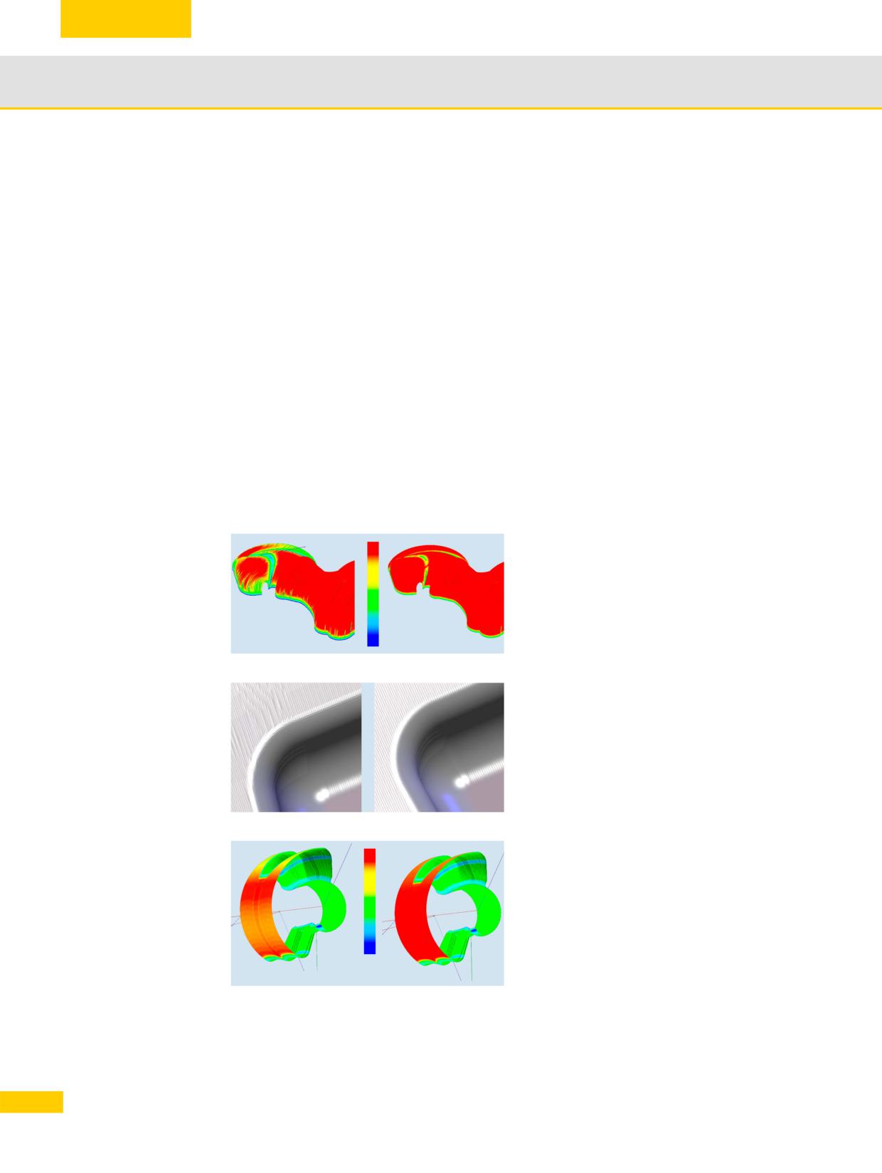
Without
With
Advanced Surface
Advanced Surface
Top Surface
Top Surface
Increased machining velocity due to an
improved velocity profile. The red areas show
the maximum velocity.
Perfect surface quality thanks to reproducible
results in adjacent milling paths. The surface
is much more homogeneous.
The compressor does not only work via G1
blocks. It also compresses rapid traverse
movements G0 using smoothing. The velocity
remains at a constant high level during the
entire machining process (red areas).
110
© Siemens AG All rights reserved SINUMERIK, Manual, Mold-Making with 3- to 5-Axis Simultaneous Milling
Important functions for 3- to 5-axis machining
3.7
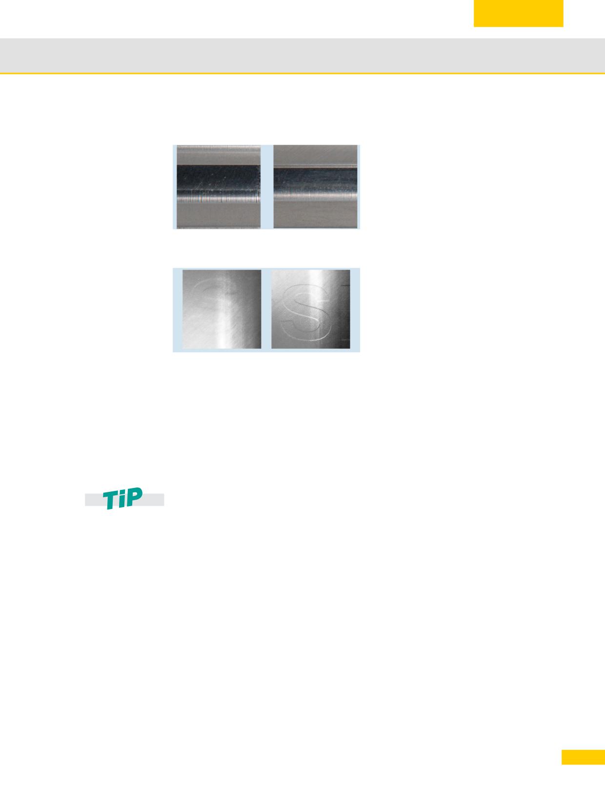
Without
With
Top Surface
Top Surface
Significantly better workpiece surfaces for
bidirectional milling using direction-
independent identical smoothing of the milling
paths - and essentially independent of the
CAM data quality.
Top Surface
Top Surface
smoothing on
smoothing off
When smoothing is active, unevenness in the
micrometer range is smoothed within the
tolerance.
If smoothing is set to "no", then the specified
contour is precisely machined.
Advanced Surface validation / Top Surface machine data
A check program is available to validate the correctly set machine data. This program provides
support to set the machine data for Advanced Surface and Top Surface as recommended. It
checks the machine data and writes an overview of the machine data with details of the values
that differ from the recommended values.
The check program and the associated documentation can be downloaded from the
Industry Online Support Portal.
111
© Siemens AG All rights reserved SINUMERIK, Manual, Mold-Making with 3- to 5-Axis Simultaneous Milling
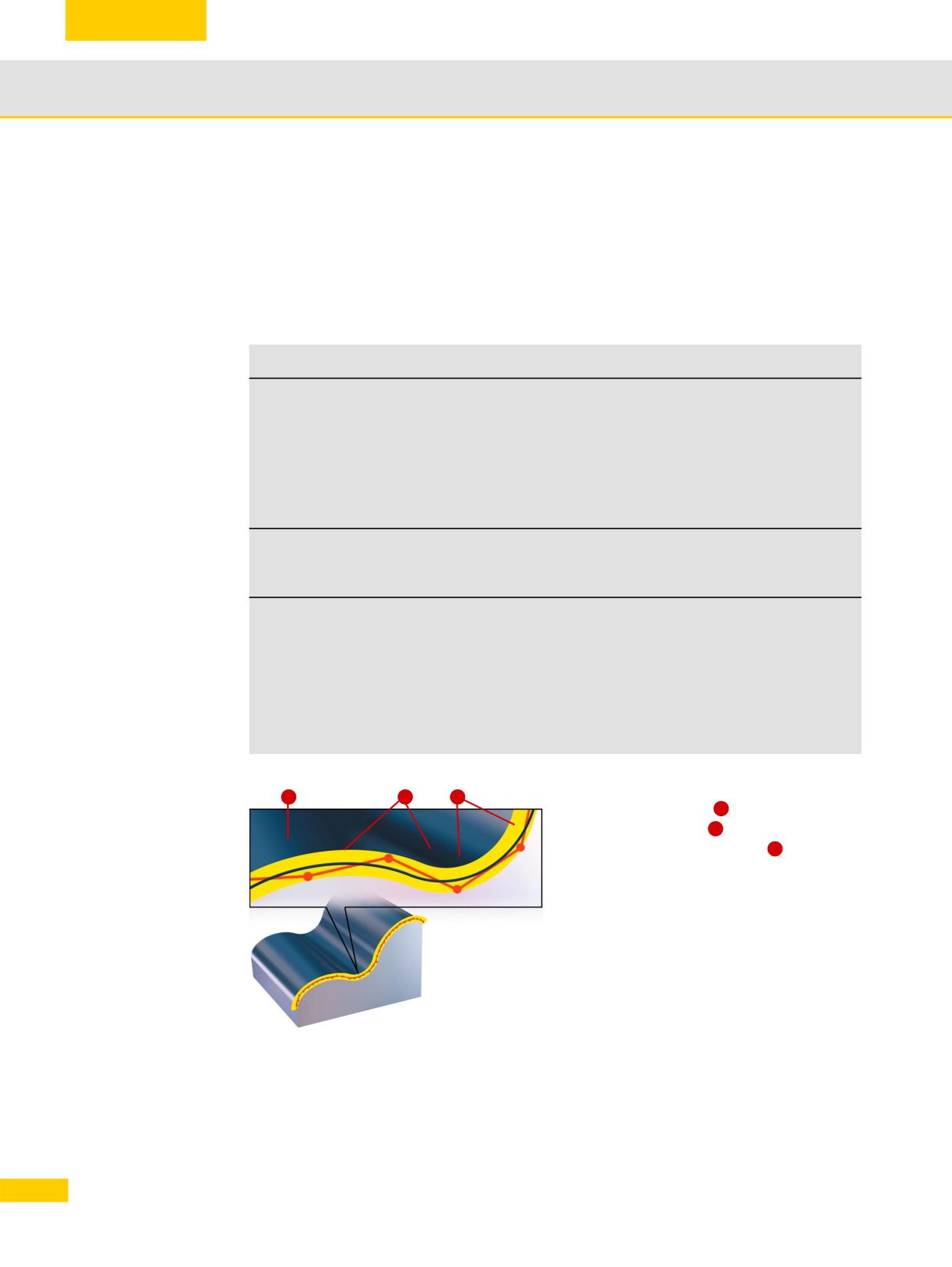
Important functions for 3- to 5-axis machining
3.7
3.7.1
Compressor (COMPCAD, COMPSURF)
The compressor is called in CYCLE832. If it is to be programmed separately, then proceed as
described below. The common objective of compressor functions is to optimize the surface
quality and machining velocity by achieving continuous block transitions and increasing the path
length for each block. You can use machine data to set whether only G1 blocks or G2/G3 or G0
blocks should also be compressed.
Explanation of the commands
COMPOF
Compressor off
COMPCAD
Compressor on - surface quality and velocity are further
(default for
optimized.
Advanced Surface)
COMPCAD smooths the points along the characteristic before
approximation
(B spline) and offers, at a high path velocity, the highest degree of
accuracy with transitions that have a constant acceleration rate.
Preferably used to mill free-form surfaces (recommended).
COMPCURV
Compressor on.
(do not use anymore)
Blocks are approached using a polynomial. Block transitions are
jerk-free. Preferably used for circumferential milling.
COMPSURF
Compressor on.
(default for
The COMPSURF compressor ensures a significantly improved
Top Surface)
workpiece surface for inclined line-by-line finishing programs,
poor data quality - or for example, irregular point distribution in NC
programs from the CAD/CAM system. Further, COMPSURF
improves complying with acceleration and jerk limits. As a
consequence, machine-specific dynamic parameters can be
increased.
Operating principle of the compressor
In accordance with the specified tolerance
1
2
3
band, the compressor
1
takes a sequence
of motion commands
2
combines them and
compresses them into a spline
3
, which can
be directly executed by the control. A new
contour is created whose characteristic lies
within the specified tolerance range.
The compressor generates smooth paths and
paths with constant curvature. The constant
curvature results in a steady velocity and
acceleration characteristic, meaning that the
machine can run at higher velocities, thereby
increasing productivity.
112
© Siemens AG All rights reserved SINUMERIK, Manual, Mold-Making with 3- to 5-Axis Simultaneous Milling
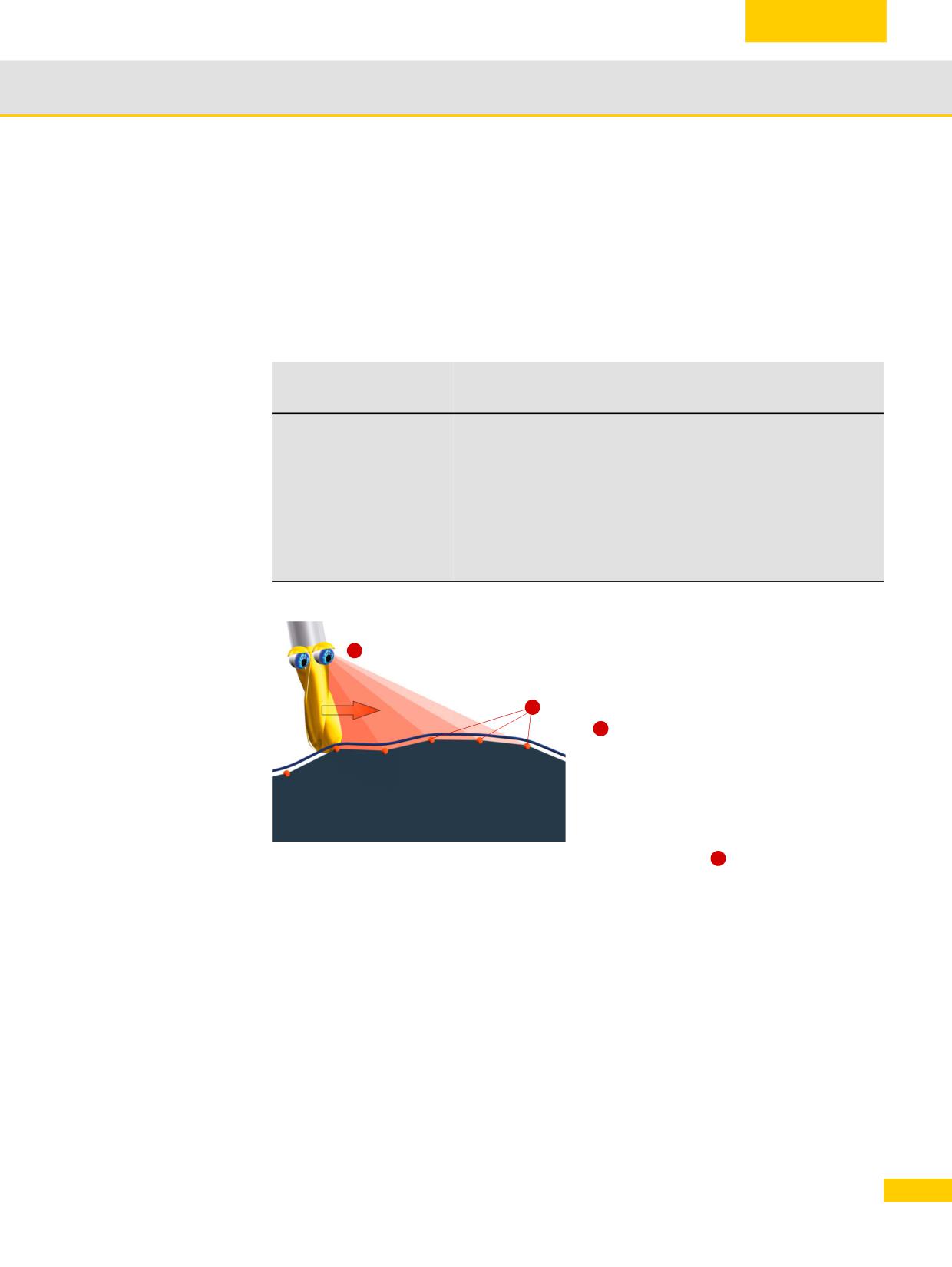
Important functions for 3- to 5-axis machining
3.7
3.7.2
Continuous-path mode, Look Ahead - G64, G645
In continuous-path mode, the path velocity at the end of the block (for the block change) is not
decelerated to a level which would permit the fulfillment of an exact stop criterion. The objective
of this mode is, in fact, to avoid rapid deceleration of the path axes at the block-change point so
that the axis velocity remains as constant as possible when the program moves to the next block.
To achieve this objective, the Look Ahead function is also activated when the continuous-path
mode is selected.
Explanation of the commands
G64
Continuous-path mode - Look Ahead where the axis only brakes
at corners
G645
Continuous-path mode with corner smoothing and tangential
(recommended)
block transitions within the defined tolerances.
With G645, the smoothing movement is defined so that the
acceleration of all axes involved remains smooth (no jumps) and
the parameterized maximum deviations from the original contour
are not exceeded.
In connection with Advanced Surface, it is recommended that
you only work with G645.
Application of G64, G645
The objective of continuous-path mode is to
increase the velocity and harmonize the
1
traversing behavior. This is implemented by
two functions.
2
Look Ahead - anticipatory velocity control
1
G1
The control calculates several NC blocks in
G1
G1
G1
G1
G1
advance and determines a modal velocity
profile. The way in which this velocity control is
calculated can be set using the functions G64,
etc.
Corner rounding
2
The Look Ahead function also means that the
control is able to smooth the corners that it
identifies. This means that the programmed
corner points are, therefore, not approached
exactly. Sharp corners can be rounded.
These two functions mean that the contour is
created with a uniform path velocity profile.
This results in improved cutting conditions,
increases the surface quality and reduces the
machining time.
113
© Siemens AG All rights reserved SINUMERIK, Manual, Mold-Making with 3- to 5-Axis Simultaneous Milling
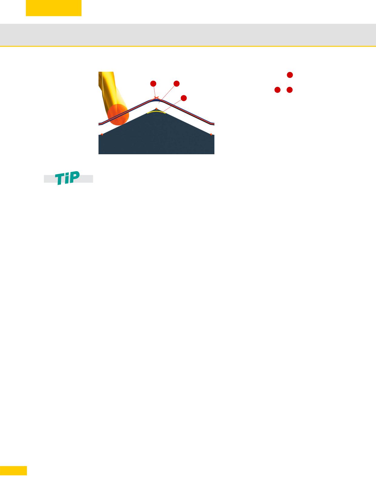
Important functions for 3- to 5-axis machining
3.7
To round sharp corners,
3
for example, the
continuous-path command G645 forms
3
1
transition elements
1
,
2
at the block
2
boundaries. The continuous-path commands
differ in terms of how they form these
transition elements.
With G645, rounding blocks are also
G1
G1
generated on tangential block transitions if the
curvature of the original contour exhibits a
jump in at least one axis.
We recommend G645 for free-form surface applications.
114
© Siemens AG All rights reserved SINUMERIK, Manual, Mold-Making with 3- to 5-Axis Simultaneous Milling
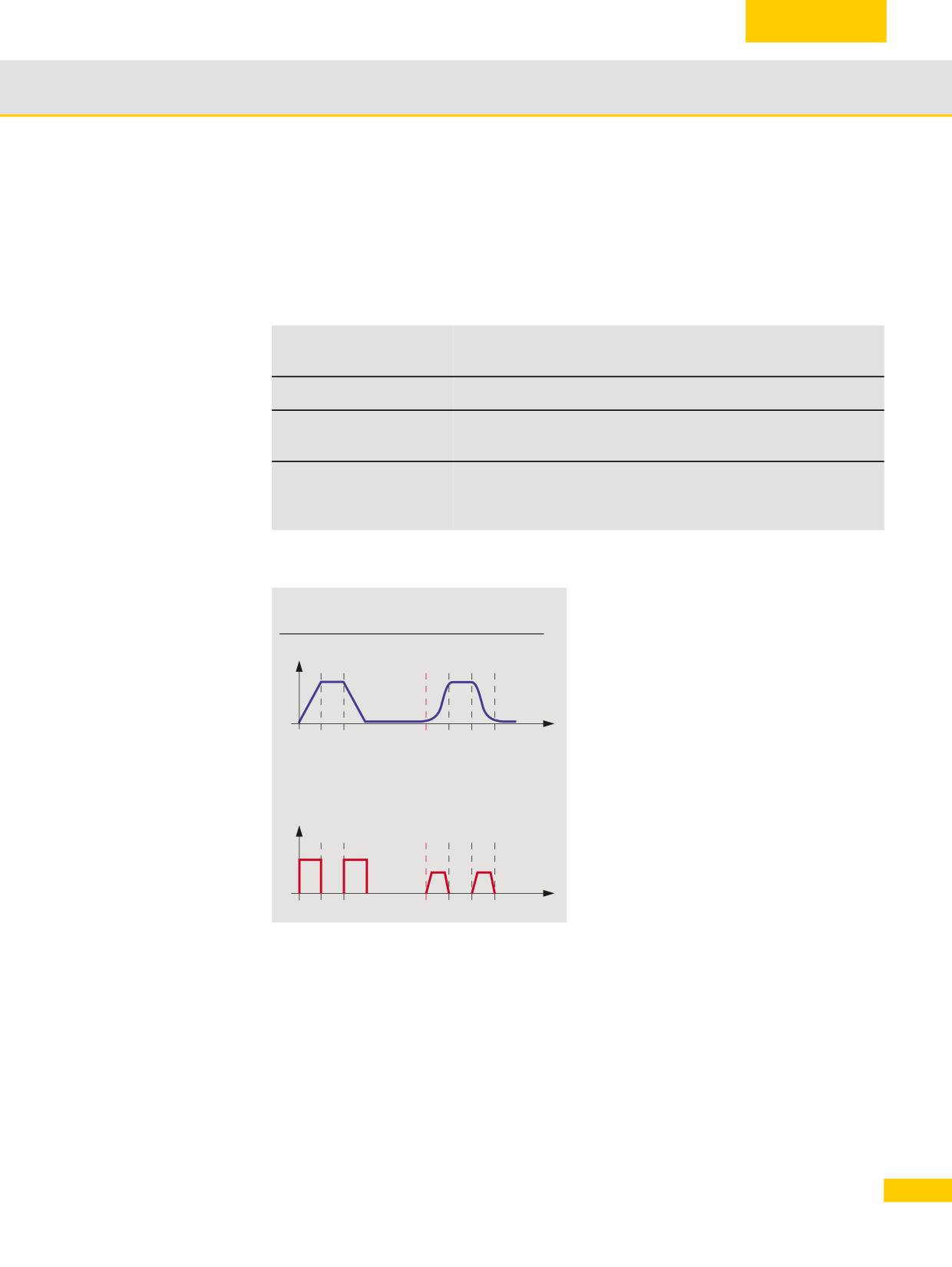
Important functions for 3- to 5-axis machining
3.7
3.7.3
Feedforward control and jerk limitation - FFWON,
SOFT, ...
Feedforward control and jerk limitation are called in CUST_832 on a combined basis. This is
because this combination offers ideal conditions for free-form surface milling. These functions
are set by the machine manufacturer.
Explanation of the commands
FFWON
Feedforward control "on"
(recommended)
FFWOF
Feedforward control "off"
BRISK
Without jerk limitation
(not recommended)
Path axes accelerate abruptly
SOFT
With jerk limitation
(recommended)
Jerk-limited acceleration of the path axes
Axial jerk limitation
Jerk limitation function
To make acceleration as smooth on the
Velocity profile
machine as possible, the acceleration profile
of the axes can be influenced using the
commands Soft and Brisk. If Soft is
BRISK
SOFT
activated, the acceleration behavior does not
V
change abruptly but is increased in the form of
a linear characteristic. This helps to protect the
machine and improves the surface quality of
t
workpieces, as much less machine resonance
time-optimized
spares the mechanical parts
is generated.
BRISK:
Acceleration behavior: Path axes accelerate
abruptly in accordance with the set machine
Acceleration profile
data.
The axis slides accelerate at the maximum
a
rate until the feedrate is achieved. BRISK
enables time-optimized machining, but with
jumps in the acceleration curve..
t
SOFT:
Acceleration behavior: Jerk-limited
acceleration of the path axes.
The axis slides accelerate at a constant rate
until the feedrate is achieved. As a result of
the jerk-free acceleration characteristic, SOFT
permits a higher path accuracy and less stress
on the machine.
115
© Siemens AG All rights reserved SINUMERIK, Manual, Mold-Making with 3- to 5-Axis Simultaneous Milling

Important functions for 3- to 5-axis machining
3.7
Feedforward control.
In cases where axes are not feedforward-con-
trolled, the following error results in a contour
error whose severity is determined by the
2
velocity
1
. Generally, this will manifest itself
in the form of a narrowing of the radius
3
on
curved contours. The following error depends
3
on the servo gain factor that is set (dependent
on mechanics) and the axis velocity.
1
The FFWON feedforward control function
brings the velocity-dependent following error
down toward zero during path traversal. Tra-
versing with feedforward control permits
higher path accuracy and thus improved
machining results.
3.7.4
Smoothing tolerance CTOL, OTOL, ATOL
The tolerance for linear and rotary axes for smoothing was previously set with CYCLE832. As of
SW 2.7 this is implemented via the functions CTOL (contour tolerance), OTOL (orientation
tolerance), and ATOL (axis-specific tolerance).
The CTOL, OTOL, and ATOL commands can be used to adapt the machining tolerances defined
for the compressor functions (COMPCAD), the smoothing types G645, and the orientation
ORISON using machine and setting data in the NC program.
The tolerance value for CTOL is set by CYCLE832. OTOL is calculated in the cycle. Since OTOL
also has an effect on ORISON by default, it is important when activating ORISON in the cycle (or
manually) to ensure that the orientation tolerance is not too great, because otherwise too much
orientation smoothing will result. In most cases, over-smoothing occurs during roughing
operations.
3.7.5
Path reference UPATH/SPATH
During polynomial interpolation, there may be a requirement for two different relationships
between the velocity-determining FGROUP axes and the other path axes. The path axes that are
not included in the FGROUP should either be routed synchronously to the path of the FGROUP
axes or to the curve parameters. Therefore, for the axes that are not contained in FGROUP,
there are two ways to follow the path:
SPATH synchronous to path S
UPATH synchronous to the curve parameter
Both types of path interpolation are needed for different applications and can be changed over
via G codes SPATH and UPATH.
UPATH is recommended for programming with active 5-axis transformation (TRAORI) and
is preset in the manufacturer cycle CUST_832.
116
© Siemens AG All rights reserved SINUMERIK, Manual, Mold-Making with 3- to 5-Axis Simultaneous Milling
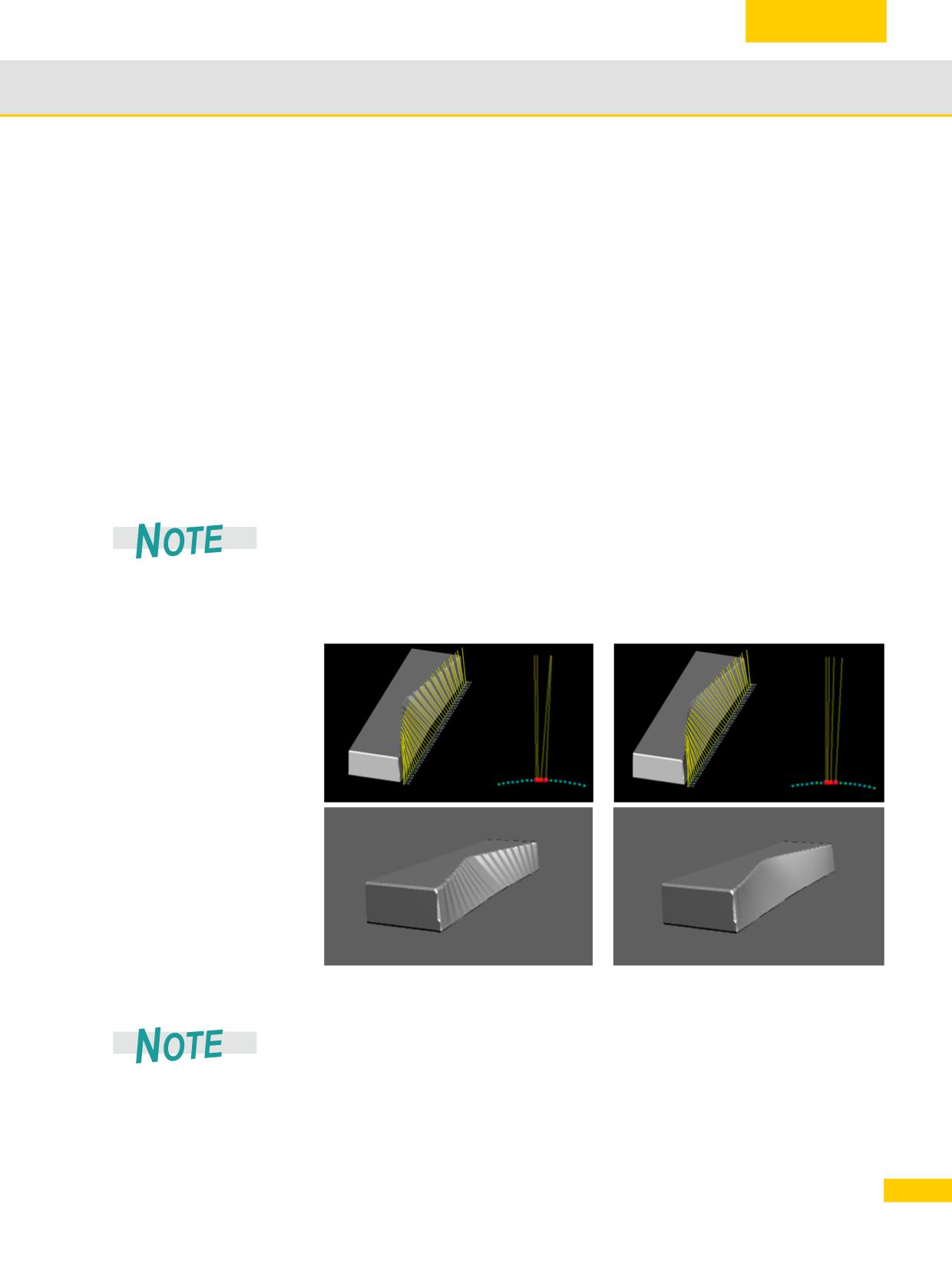
Important functions for 3- to 5-axis machining
3.7
3.7.6
Smoothing the orientation characteristic (ORISON,
ORISOF)
The ORISON function can be used to smooth fluctuating orientation across several blocks. The
aim is to achieve a smooth characteristic for the orientation and therefore a more harmonious
movement of the axes.
For 5-axis programs generated by CAD/CAM systems in which the milling paths and direction
vectors are specified for the tool, the programs often contain inharmonic changes of the tool
orientation which cause sudden movements of the rotary axes and therefore, because of the
compensatory movements, also of the linear axes. Even if these deviations are only minimal,
they will lead to compensatory movements in the linear axes, which will manifest themselves in
slowed movements or even stopping in the path. The consequences are visible traces on the
workpiece surface and longer machining time.
With ORISON, the orientation is smoothed irrespective of the contour because the movement of
the rotary axes and the linear axes is much more harmonious. This results in higher machining
velocities and shorter machining times.
Up to SW 4.5, ORISON orientation smoothing is not part of CYCLE832 and it must therefore be
programmed separately with the desired vector smoothing in the NC program in the case of a 5-
axis program with orientation interpolation. If the ORISON function is to be activated
automatically with active 5-axis transformation, then this setting can be made in CUST_832 by
the OEM. Depending on the orientation tolerance, the NC command ORISON is activated in the
manufacturer cycle CUST_832 and is then also available as multi-axis program parameter
with ORI tolerance in CYCLE832.
ORISOF smoothing off
ORISON smoothing on
ORISON is deactivated automatically when using Top Surface (COMPSURF). Therefore,
after CYCLE832 with Top Surface do not program ORISON.
117
© Siemens AG All rights reserved SINUMERIK, Manual, Mold-Making with 3- to 5-Axis Simultaneous Milling

Important functions for 3- to 5-axis machining
3.7
ORISON programming (without CYCLE832)
N110
TRAORI
; Activation of orientation transformation.
N120
CYCLE832(0.005,1,1)
N130
ORISON
; Activation of orientation smoothing
N140
OTOL=0.5
; Specify tolerance
N150
G1 X10 A3=1 B3=0 C3=1
; Geometry program
N990
ORISOF
; Deactivation of orientation smoothing
ORISON programming (with CYCLE832)
N110
TRAORI
; Activation of orientation transformation.
N120
CYCLE832(0.005,_ORI_FINISH,0.5)
N130
ORISON
; Activation of the orientation smoothing
N140
G1 X10 A3=1 B3=0 C3=1
; Geometry program
N990
M30
; End of program
3.7.7
Technology G groups
Using the "Technology" G group, the appropriate dynamic response can be activated on the
machine for 5 varying technological machining operations. The dynamic values and G codes are
configured and set by the machine manufacturer.
Five dynamic response settings are available in the Technology G code group:
DYNORM for standard dynamic response
DYNPOS for positioning mode, tapping
DYNROUGH for roughing
DYNSEMIFIN for semi-finishing
DYNFINISH for finishing
The G groups are switched and activated automatically when the machining method (e.g.
finishing or roughing with CYCLE832 or CUST_832) is selected.
Dynamic parameters can be adapted to the respective machining operation with the technology
G groups. Using the commands of technology G group 59, the value of channel and axis-specific
machine data is activated using the corresponding array index. These are, for example, jerk and
acceleration values.
118
© Siemens AG All rights reserved SINUMERIK, Manual, Mold-Making with 3- to 5-Axis Simultaneous Milling
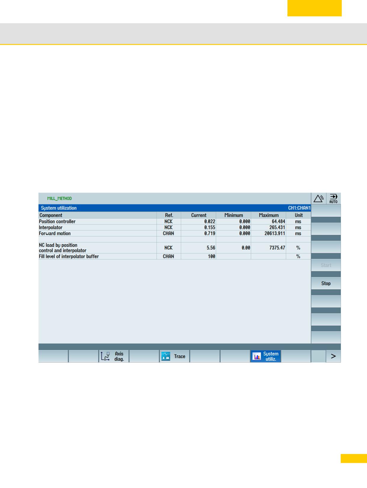
Important functions for 3- to 5-axis machining
3.7
3.7.8
Pre-processing memory control FIFOCTRL
Mold-making programs are generally executed directly from the hard drive or an external storage
medium (e.g. USB flash drive, CF card). The maximum number of NC blocks that are loaded in
the NC memory can be set via machine data.
During processing of these NC programs, the interpolation memory may run out. In this case, the
NC will stop until data is reloaded. To counter this, the pre-processing memory control
FIFOCTRL is used. For very small distances between points in a mold-making program, it is
necessary to keep the fill level as high as possible in order prevent dropping to 0% (interpolation
dip).
The pre-processing memory control FIFOCTRL is automatically called up by CYCLE832 or
CUST_832. It is deselected with STARTFIFO.
You can open the fill level of the interpolation buffer as follows:
X In the Diagnostics menu > select the System utilization softkey.
119
© Siemens AG All rights reserved SINUMERIK, Manual, Mold-Making with 3- to 5-Axis Simultaneous Milling
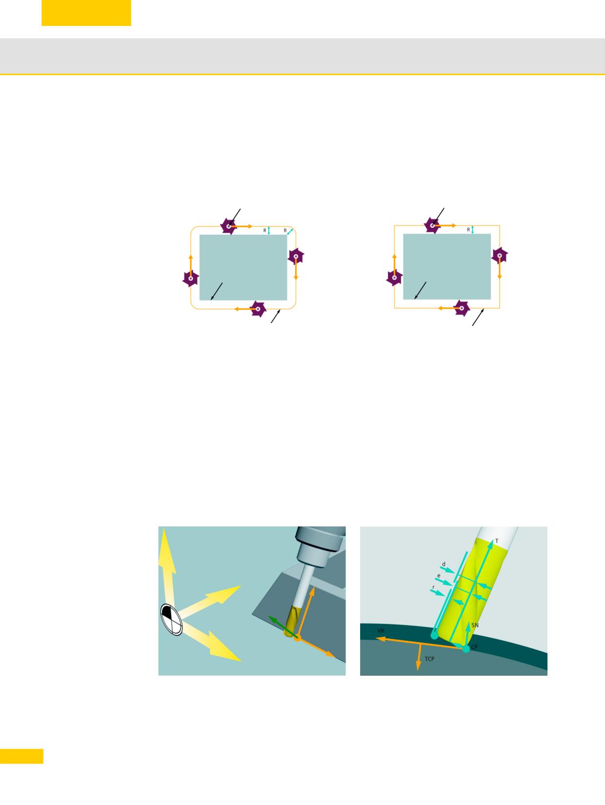
Important functions for 3- to 5-axis machining
3.8
3.8
Milling radius compensation 2D/3D-WRK
In the following, we will consider the expansion of the conventional 2-dimensional cutter radius
compensation to three dimensions. Normally the compensation is activated by the G codes G41/
G42 (left or right) and deactivated by G40. After activation, the control calculates an offset curve
with an offset the size of the cutter radius.
2-dimensional cutter
Center-point path
Center-point path
radius compensation
cutter
cutter
Contour
Contour
G41/G450
G41/G451
3.8.1
3D-WRK cutter radius compensation for
circumferential and face milling
The 3-dimensional case is more complicated. In two dimensions, it is implicitly clear that the tool
(standard tool) is aligned perpendicular to the compensation plane and therefore the
compensated path is always perpendicular to the path tangent in the X-Y plane. In three
dimensions, the tool orientation normally changes continuously and therefore the compensation
direction must also change. It is now defined by a vector in space. We must distinguish between
two situations. On the one hand, the circumferential milling for structural parts, and on the other
hand, the face milling for free-form surfaces that only requires a constant compensation value for
the Z axis in the 2-dimensional case.
CUT3DC/CUT3DCD circumferential milling
CUT3DF/CUT3DFD face milling
3-dimensional cutter
Green: Direction of compensation
radius compensation
Because in practice, suitable standard tools are often not available, a tool that does not deviate
too much from a standard tool (up to 10%) can be used.
120
© Siemens AG All rights reserved SINUMERIK, Manual, Mold-Making with 3- to 5-Axis Simultaneous Milling

Important functions for 3- to 5-axis machining
3.8
3.8.2
CUT3DC/CUT3DCD circumferential milling
In circumferential milling, the direction of compensation is always perpendicular to the plane on
which the cutter is moving. This is always defined by the current path tangent and the tool vector
and normally changes in each interpolation increment. It is defined with CUT3DC/CUT3DCD and
activated with G41/G42 (left/right).
The properties of the compensations for circumferential milling are compared in the table.
CUT3DC
CUT3DCD
(SINUMERIK 840D sl and powerline)
(SINUMERIK 840D sl as of V4.7 SP3 HF1)
Calculation of the tool compensation in the
Calculation of the tool compensation /
control/CNC
standard tool in CAD/CAM and calculation
of the difference by entering the wear in the
control/CNC.
Supplementary conditions
Supplementary conditions
Can be used only to a limited extent
Can be used with compressor:
COMPCAD - Advanced Surface
Can be used only to a limited extent with
COMPSURF - Top Surface
compressor:
COMPCAD - Advanced Surface
The tools should have maximum 5-10%
COMPSURF - Top Surface
negative wear of the standard tool.
We recommend the use of the CUT3DCD function for circumferential milling.
Programming circumferential milling with CUT3DCD
3D TRC for circumferential milling referred to a differential tool is activated via the CUT3DCD
command. It should be applied if the programmed contour refers to the center-point path of a
differential tool, and a tool other than a differential tool is used for machining.
When calculating the 3D tool radius compensation, only the wear value of the radius of the
active tool ($TC_DP15,$TC_DP16) and any programmed tool compensation offsets OFFN
and TOFFR/TOFFL are taken into account. The basic radius ($TC_DP6) of the active tool is
not taken into account. Additional information, basic length = $TC_DP3.
CUT3DCD can be used with various types of tool orientation (TRAORI active!)
Direction vector
CUT3DCD G41 G01 X145.983 Y99.000 Z-20.876 A3=0.5 B3=0 C3=1
Round axis values
CUT3DCD G41 G01 X145.983 Y99.000 Z-20.876 B-26.56 C0
The CUT3DCD 3D radius compensation is restricted to cylindrical tools.
121
© Siemens AG All rights reserved SINUMERIK, Manual, Mold-Making with 3- to 5-Axis Simultaneous Milling

Important functions for 3- to 5-axis machining
3.8
CUT3DCD programming Finishing NC program, 5-axis program
example
N1 G17 G40 G90
N2 CYCLE800()
N3 TRAFOOF
N4 T="CUTTER_10"
N5 M6
N6 S15061 M3
N7 CYCLE800(0,"TISCH",100000,27,0,0,0,288.079,0,-10.196,0,0,0,-1,0,1)
N8 G00 X-13.532 Y-24.856 M03
N9 TRAORI
N10 ORIWKS ORIAXES
N11 G54
N12 TOFFL=0
N13 TOFFR=0
N14 CYCLE800()
N15 CYCLE832(0.05,_TOP_SURFACE_SMOOTH_ON+_ORI_SEMIFIN,0.1)
N16 G0 X0 Y0 Z100.0
N17 CUT3DCD
N18 G41
N19 G1 X-5.945 Y-60.546 A3=0.021144 B3=0.341366 C3=0.939693 F2500
N20 Z5.502 A3=0.021144 B3=0.341366 C3=0.939693
N21 G1 Z0.502 A3=0.021144 B3=0.341366 C3=0.939693 F2500
N22 G1 X-5.743 Y-59.698 A3=0.021144 B3=0.341366 C3=0.939693 F500
……
N17525 g40 X0 Y0
N17526 CYCLE832(0,_OFF,1)
N17528 TRAFOOF
N17529 M17
3.8.3
CUT3DF/CUT3DFD face milling
The situation is also more complicated with face milling. Since the tool is not always
perpendicular to the plane to be machined as with two dimensions, a constant offset is no longer
sufficient. The compensation value and the compensation direction now depend on the tool
radius, the rounding radius and of course on the tool orientation relative to the workpiece surface.
This means that we require additional information about the surface. This is defined by
programming the normal vectors A4, B4, C4 (start of block) and A5, B5, C5 (end of block -
recommended programming).
The compensation is defined with CUT3DF/CUT3DFD and activated with G41/G42, whereby
there is no difference between G41 and G42 in this case.
The activation must be performed in a linear block (G0/G1). Switching off with G40 can be made
in a linear block or in a separate NC block. A change of the 3D TRC variant with active tool radius
compensation is ignored without alarm.
Before switching on CUT3DFD with G41/G42, Top Surface / COMPSURF / CYCLE832 must be
activated, not immediately before tooling, but rather approximately 1000 x CTOL = path before
the tooling or G41/G42 programmed, e.g. 1000 x 0.01 mm = 10 mm.
For traversing motions in the orientation direction of the tool, alarm 10769 is triggered and
machining stopped. As workaround, a G40 and then a G41/G42 can be programmed again for
the machining.
122
© Siemens AG All rights reserved SINUMERIK, Manual, Mold-Making with 3- to 5-Axis Simultaneous Milling

Important functions for 3- to 5-axis machining
3.8
The properties of the compensations for face milling are compared in the table.
CUT3DF
CUT3DFD
(SINUMERIK 840D sl and powerline)
(SINUMERIK 840D sl as of V4.8 SP2)
Calculation of the tool compensation in the
Calculation of the tool compensation /
control/CNC
standard tool in CAD/CAM and calculation
of the difference by entering the wear in the
control/CNC.
Supplementary conditions
Supplementary conditions
Can be used with G64/G642/G645
Can be used only with compressor:
COMPSURF - Top Surface
Can be used only to a limited extent with
compressor:
The tools should have maximum 5-10%
COMPCAD - Advanced Surface
negative wear of the standard tool.
COMPSURF - Top Surface
We recommend the use of the CUT3DFD function for face milling.
Programming face milling with CUT3DFD
CUT3DFD can be used without additional tool orientation as 3-axis program, purely based
on the surface normal vector.
CUT3DFD G41 G01 X145.983 Y99.000 Z-20.876 A5=0.643 B5=0 C5=0.357
CUT3DFD can be used as 5-axis program with various types of tool orientation (TRAORI
active!)
Direction vector
CUT3DFD G41 G01 X145.983 Y99.000 Z-20.876 A3=0.5 B3=0 C3=1 A5=0.643 B5=0
C5=0.357
Round axis values
CUT3DFD G41 G01 X145.983 Y99.000 Z-20.876 B-26.56 C0 A5=0.643 B5=0 C5=0.357
The CUT3DFD 3D radius compensation acts for all tool types for machining free-form
surfaces.
123
© Siemens AG All rights reserved SINUMERIK, Manual, Mold-Making with 3- to 5-Axis Simultaneous Milling
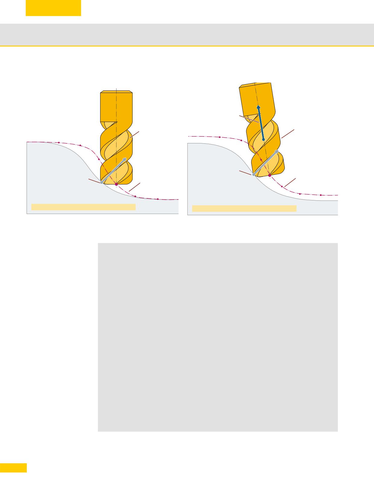
Important functions for 3- to 5-axis machining
3.8
Face milling with perpendicular tool orientation
Face milling with any tool orientation
'LUHFWLRQ YHFWRU RU URWDU\
D[LV GLUHFWO\ RI WKH WRRO LQ
WKH &1& EORFN
1RUPHG WRRO IRU WKH
1RUPHG WRRO IRU WKH
&$0 RXSXW
&$0 RXWSXW
6XUIDFH QRUPDO YHFWRU LQ
WKH FRQWDFW SRLQW LQ WKH
6XUIDFH QRUPDO YHFWRU LQ
&1& EORFN
3URJUDPPHG
3URJUDPPHG
1& &RGH LQ WKH
WKH FRQWDFW SRLQW LQ WKH
1& &RGH LQ
SDUWSURJUDPP
&1& EORFN
SDUWSURJUDPP
&87 ')' )DFH PLOOLQJ LQ YHUWLFDO WRRO RULHQWDWLRQ
&87 ')' )DFH PLOOLQJ LQ DQ\ RULHQWDWLRQ
CUT3DFD programming Finishing NC program, 3-axis program
example
N1 G17 G40 G90
N2 T="BALL_D16" D1
N3 M6
N4 S15061 M3
N5 G54
N6 TOFFL=0
N7 TOFFR=0
N8 CYCLE832(0.01,_TOP_SURFACE_SMOOTH_ON+_FINISH,1)
N9 R2=5000
N10 R3=5000
N11 R4=35000
N12 G0 X-11.0000 Y0.0000 Z74.0000
N13 M3
N14 G0 X-11.0000 Y0.0000 Z-26.0000
N15 G41 CUT3DFD
N16 G1 X-10.2235 Z-25.8978 A5=0.0000000 B5=0.0000000 C5=1.0000000 F=R2
N17 G1 X-9.5000 Z-25.5981 A5=0.0000000 B5=0.0000000 C5=1.0000000
N18 G1 X-8.8787 Z-25.1213 A5=0.0000000 B5=0.0000000 C5=1.0000000
N19 G1 X-8.4019 Z-24.5000 A5=0.0000000 B5=0.0000000 C5=1.0000000
N20 G1 X-8.1022 Z-23.7765 A5=0.0000000 B5=0.0000000 C5=1.0000000
N21 G1 X-8.0000 Z-23.0000 A5=-1.0000000 B5=0.0000000 C5=0.0000000
N22 G1 X-8.0000 Z-18.0000 A5=-1.0000000 B5=0.0000000 C5=0.0000000 F=R3
N23 G1 X-7.9904 Z-17.6075 A5=-0.9987955 B5=0.0000000 C5=0.0490677
N38 G01 G40 X-20.168 Y7.651 Z23.355
N39 G01 X-17.453 Y8.537 Z39.237
N40 G00 X-14.929 Y9.361 Z54.001
N41 CYCLE832(0,_OFF,1)
N42 TRAFOOF
N43 M30
124
© Siemens AG All rights reserved SINUMERIK, Manual, Mold-Making with 3- to 5-Axis Simultaneous Milling

Important functions for 3- to 5-axis machining
3.8
CUT3DFD programming Finishing NC program, 5-axis program
example
N1 G17 G40 G90
N2 CYCLE800()
N3 TRAFOOF
N4 T="BALL_D6" D1
N5 M6
N6 S15061 M3
N7 CYCLE800(0,"TABLE",100000,27,0,0,0,288.079,0,-10.196,0,0,0,-1,0,1)
N8 G00 X-13.532 Y-24.856 M03
N9 TRAORI
N10 ORIWKS ORIAXES
N11 G54
N12 TOFFL=0
N13 TOFFR=0
N14 CYCLE800()
N15 CYCLE832(0.05,_TOP_SURFACE_SMOOTH_ON+_ORI_SEMIFIN,1)
N16 G00 X-18.974 Y8.041 Z54.001 A-10.196 C=DC(+288.079)
N17 G00 X-19.647 Y7.821 Z50.064 A-10.196 C=DC(+288.079)
N18 G01 X-20.168 Y7.651 Z47.016 F1485.4
N19 G41 CUT3DFD
N20 G01 X-20.505 Y7.541 Z45.047 A3=+.168277208 B3=+.054933772 C3=+.984207835
A5=+1. B5=-.000003008 C5=+.000000718
N21 G01 X-20.506 Y7.365 Z45.047 A3=+.168631651 B3=+.053835903 C3=+.984207835
A5=+1. B5=+.000004199 C5=+.000000719
N22 G01 X-20.507 Y7.194 Z45.047 A3=+.168973327 B3=+.052753699 C3=+.984207835
A5=+1. B5=-.000007571 C5=+.000000721
N23 G01 X-20.508 Y7.025 Z45.047 A3=+.169308954 B3=+.051666392 C3=+.984207835
A5=+1. B5=-.000002005 C5=+.000000722
N38 G01 G40 X-20.168 Y7.651 Z23.355
N39 G01 X-17.453 Y8.537 Z39.237
N40 G00 X-14.929 Y9.361 Z54.001
N41 CYCLE832(0,_OFF,1)
N42 TRAFOOF
N43 M30
125
© Siemens AG All rights reserved SINUMERIK, Manual, Mold-Making with 3- to 5-Axis Simultaneous Milling
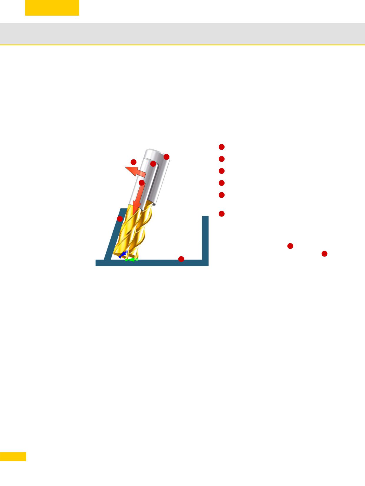
Important functions for 3- to 5-axis machining
3.8
3.8.4
Circumferential milling with limiting surfaces
(CUT3DCC/CUT3DCCD)
A combination of these two methods is used when machining special structural components in
the aviation industry. Pockets are machined where the wall inclination forms an acute angle to
the floor. The wall is machined with 5-axis circumferential milling with simultaneous contact with
the floor. If a large cutter is used in this situation, compensation must be performed
simultaneously perpendicular to the wall and along the cutter axis in order to avoid contour
violations of the floor.
Circumferential milling
1
Standard tool (tool from CAM)
with limiting surfaces
1
Tool with smaller radius
2
5
2
3
Machining surface, inner surface
6
4
Limiting surface of pocket floor
Compensation in relation to machining
5
surface
6
Compensation in relation to limiting
3
surface
The control recognizes the fact that it is not
just a question of compensating in the
machining surface direction
5
, but also of
making an adjustment in the tool direction
6
4
, so that the point of action (green) is at the
same level as the pocket floor. This results in
a shift in the cutter tip (blue) in the direction of
the pocket floor.
This compensation variant is called Circumferential milling with limiting surfaces. It is
selected via the code CUT3DCC or CUT3DCCD and activated with G41/42 as for CUT3DC.
With CUT3DCC, the coordinates in the NC program refer to the contour and consequently the full
miller radius is compensated. For the compensation radius this results in R = $TC_DP6 plus the
programmable offset that is defined by OFFN=…., and for the face milling on the floor, the corner
radius $TC_DP7. This results in R' = $TC_DP6 + $TC_DP15 + OFFN for the circumferential
milling component and r' = $TC_DP7 + $TC_DP16 for the face milling with the other cutter side.
For CUT3DCCD, the programmed path refers to the standard tool (zero tool). The compensation
value is then the difference between the zero tool and the reground current tool, i.e. the tool wear
value from the $TC_DP15 tool data table plus the offset OFFN=….
As with face milling, the normal vector of the limiting surface must be programmed via A4, B4, C4
or A5, B5, C5. If no normal vector is programmed, the Z direction of the current coordinate
system is assumed for the CUT3DF.
126
© Siemens AG All rights reserved SINUMERIK, Manual, Mold-Making with 3- to 5-Axis Simultaneous Milling
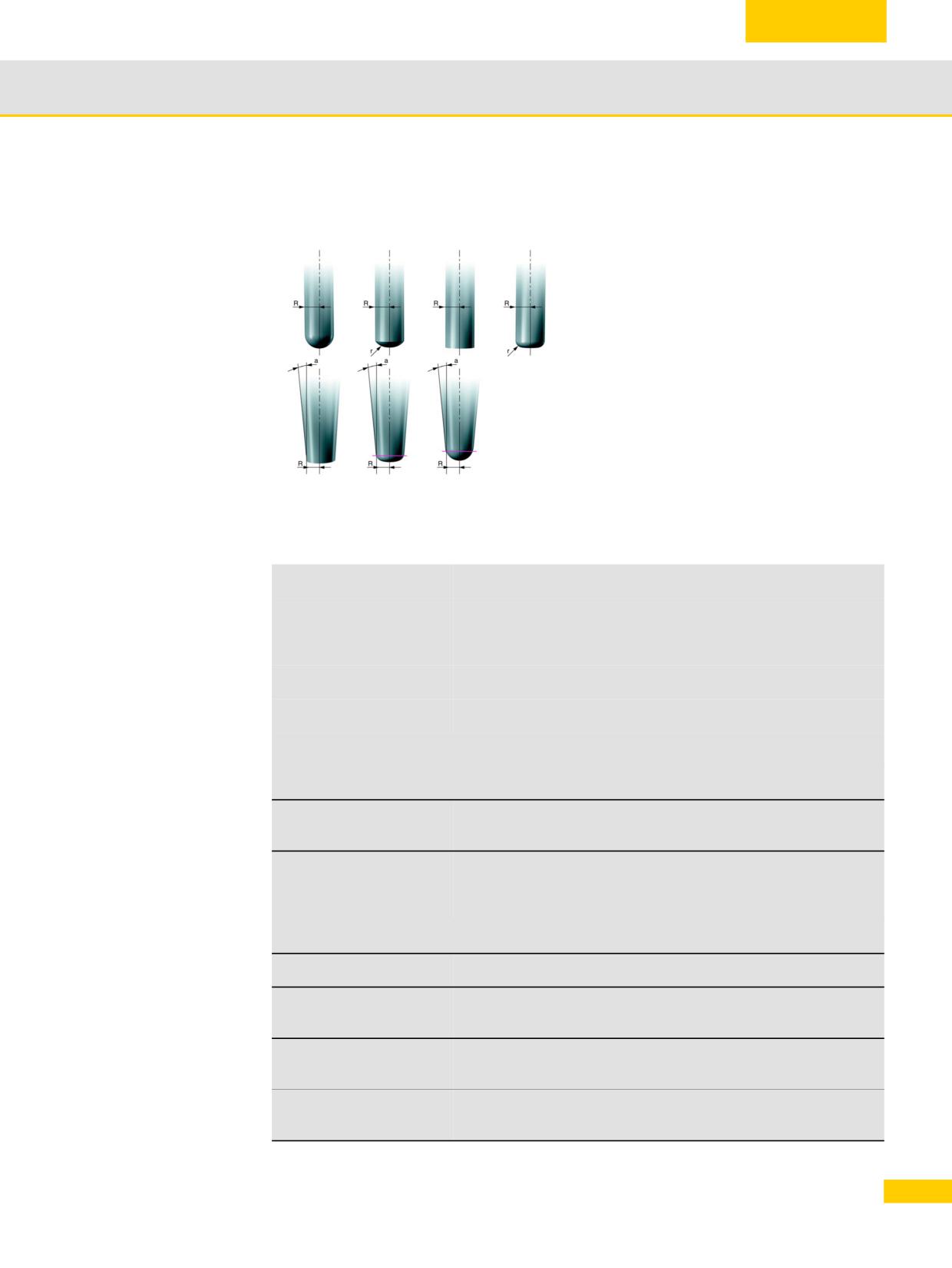
Important functions for 3- to 5-axis machining
3.8
3.8.5
Overview of the tool types for the 3D
compensations.
The following figure shows the tool types that
are permitted in conjunction with the 3D
compensations. For the circumferential milling
(also with limiting surfaces), only cylindrical
types (top row), for face milling, also the
conical types of the bottom row.
3.8.6
Explanation of the commands
G40
Deactivation of all variants
G41
Activation for circumferential milling, compensation direction left
G42
Activation for circumferential milling, compensation direction right
G450
Circles at external corners (all compensation types)
G451
Intersection method at external corners (all compensation types)
2 ½D circumferential milling
CUT2D
2 1/2D COMPENSATION with compensation plane determined
using G17 - G19
CUT2DF
2 1/2D COMPENSATION with compensation plane determined
using a frame
3D circumferential milling
CUT3DC
Compensation perpendicular to path tangent and tool orientation.
CUT3DCD
Activating the 3D radius compensation referred to a differential
tool for circumferential milling.
ISD
The clearance between the milling tool tip (FS) and the milling tool
construction point (FH) are specified using the command ISD.
ORID
No changes in orientation in inserted circular blocks at external
corners. Orientation motion is performed in the linear blocks.
127
© Siemens AG All rights reserved SINUMERIK, Manual, Mold-Making with 3- to 5-Axis Simultaneous Milling

Important functions for 3- to 5-axis machining
3.8
ORIC
Travel path is extended by means of circles. The change in
orientation is also performed proportionately in the circle.
Face milling
CUT3DFS
Constant orientation (3-axis). Tool points in the Z direction of the
coordinate system defined via G17 - G19. Frames do not have
any effect.
CUT3DFF
Constant orientation (3-axis). Tool in Z direction of the coordinate
system currently defined via the frame.
CUT3DF
5-axis with variable tool orientation.
CUT3DFD
Activating the 3D radius compensation based on a differential tool
for face milling.
3D circumferential milling with limiting surface (combined circumferential/face milling)
CUT3DCC
CNC program relates to the contour on the machining surface.
CUT3DCCD
The CNC program relates to the tool center point path.
128
© Siemens AG All rights reserved SINUMERIK, Manual, Mold-Making with 3- to 5-Axis Simultaneous Milling
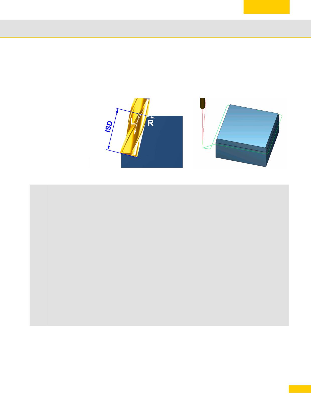
Important functions for 3- to 5-axis machining
3.8
3.8.7
Programming example for circumferential milling
A workpiece contour needs to be milled at the circumference. Programming is to be from the top
edge of the workpiece and the insertion depth ISD is to be taken into account. In the example,
compensation is performed to the right of the contour with an ISD of 20.
CUT3DC example
N100
CYCLE800(2,"TABLE",200000,57,0,0,0,0,0,0,0,0,0,1,,1)
N101
CYCLE800()
N102
G54
N103
WORKPIECE(,,"","BOX",112,0,-50,-80,0,0,100,100)
N104
T="MILLER_12"
N105
M6
N106
S6000 M3
N108
TRAORI; activate 5-axis transformation
N109
ORIWKS; orientation reference is the WCS
N110
ORIVECT
N111
CUT3DC; 3D tool radius compensation for circumferential milling
N112
G54 G0 X-20 Y-20 D1
N113
G0 Z10
N114
G1 Z-10 F1000 M8
N115
G41 X0 A3=1.7632698 B3=0 C3=10; activate tool radius compensation to the right of the contour
and approach
N116
G1 Y100
N117
G1 A3=0 B3=-1.7632698 C3=10
N118
G1 X100
N119
G1 A3=-1.7632698 B3=0 C3=10
N120
G1 Y0
N121
G1 A3=0 B3=1.7632698 C3=10
N122
G1 X0
N123
G40 X-20 Y-20 A3=0 B3=0 C3=1; deactivate tool radius compensation and retract
N124
G0 Z100
N125
TRAFOOF
N126
M30
129
© Siemens AG All rights reserved SINUMERIK, Manual, Mold-Making with 3- to 5-Axis Simultaneous Milling
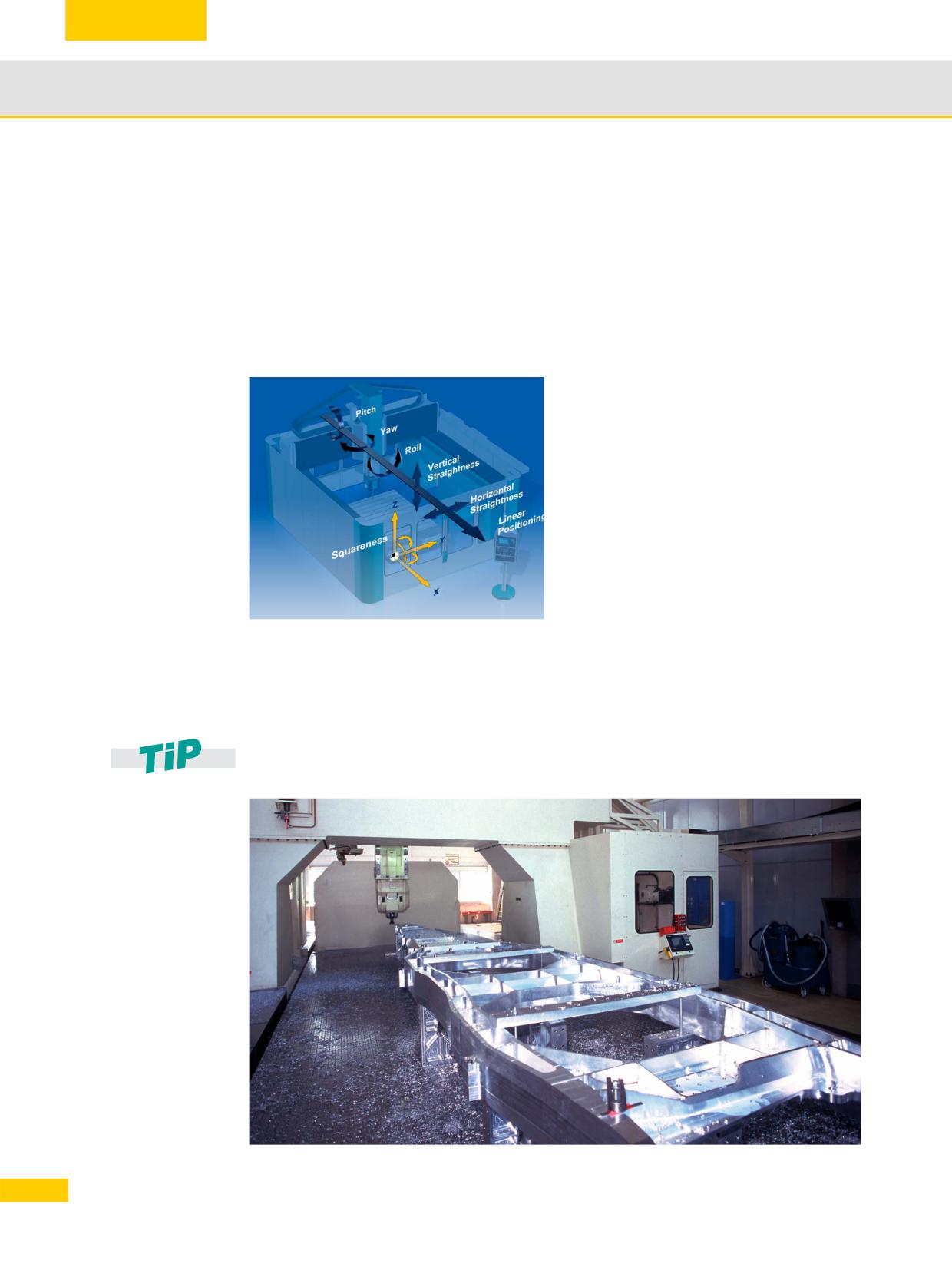
Important functions for 3- to 5-axis machining
3.9
3.9
Volumetric Compensation System (VCS)
As far as the production of large workpieces is concerned, e.g. structural parts on gantry-type
milling machines, it is very difficult to achieve the necessary level of machine positioning
accuracy due to the large dimensions of the working area. Errors due to sagging, buckling, etc. in
particular can only be remedied mechanically with a great deal of effort.
The volumetric compensation system for the SINUMERIK is a tool for correcting geometric
distortions of the machine mechanics. It reduces the effects of machine errors on the tool center
point (TCP) systematically, thereby increasing the accuracy of the machine.
Types of VCS
Below are some examples of the kinds of
compensation
error source that can be compensated:
Linear position deviation
Straightness of axes
Unintentional axis rotations
Roll, pitch, and yaw
Squareness of axes in relation to one
another
Tool orientation errors involving swivel
heads
As part of this process, the machine errors are detected on the basis of measurements and an
error file is generated. VCS then implements the compensation values automatically. To increase
the level of accuracy, calibration and testing with the compensation values can be performed
using an iterative method. VCS automatically compensates the detected errors in conjunction
with TRAORI.
As regards the VCS commissioning process and machine calibration, please contact your
machine manufacturer.
130
© Siemens AG All rights reserved SINUMERIK, Manual, Mold-Making with 3- to 5-Axis Simultaneous Milling
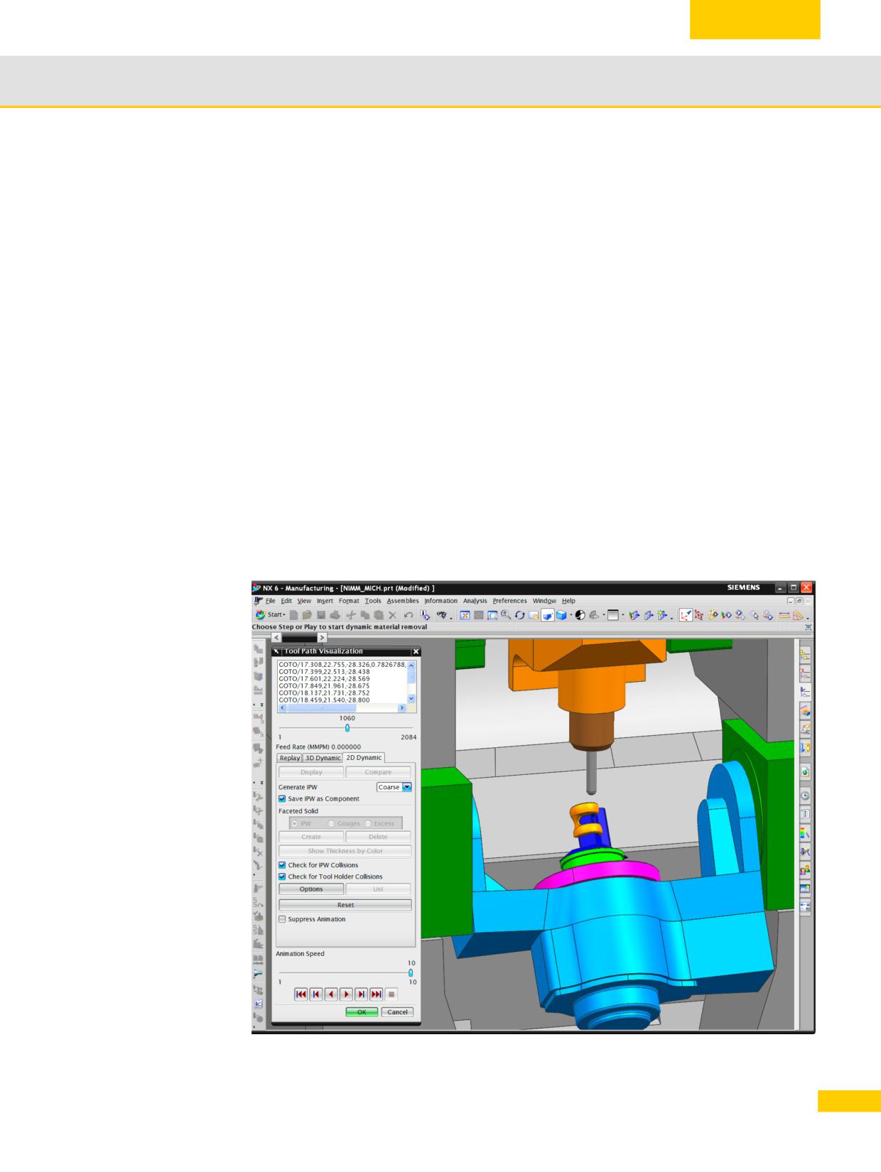
Important functions for 3- to 5-axis machining
3.10
3.10
VNCK - virtual machine
Due to the level of complexity and machining time associated with 5-axis milled workpieces, a
deliberate effort is made to check that the programs are free of errors before actual production
commences. To ensure that the data obtained is as realistic as possible, virtual models of the
machine and control are created and simulated. Siemens provides the following basic modules
for this purpose:
The virtual NC kernel (VNCK)
Using these basic modules and other components, such as the CAD data for the real machine,
the machine manufacturer or CAM system manufacturer can create a virtual machine that
resembles the real machine as closely as possible.
Using the virtual machine in conjunction with the SIEMENS VNCK offers many advantages:
Programming errors are detected immediately.
Program simulation with calculation of the actual time so that production effort can be
estimated more easily.
Collision checking with actual tools, clamping devices, and machine geometries.
While the current production process is underway, the workpiece can be programmed,
optimized and then implemented on the machine immediately.
Shorter setup times.
Can be used for training and instruction. New machines can be programmed without any risk.
131
© Siemens AG All rights reserved SINUMERIK, Manual, Mold-Making with 3- to 5-Axis Simultaneous Milling