SINUMERIK 840D sl. Training. Operate - Turning (2016-2020) - page 7
How fit are you in ShopMill?
12
12.1
Introduction
The following four exercises are the basis for a personal test of your work with ShopMill. You will
be assisted in all four exercises with an indication of one possible process plan each. The
specified times are based on proceeding in accordance with this process plan. Consider the
specified times as a rough guideline for your answer to the question above.
Easy milling with ShopMill
Training Documents, 05/2020, 6FC5095-0AB50-1BP2
217
How fit are you in ShopMill?
12.2 Exercise 1
12.2
Exercise 1
Will you manage this task using ShopMill within 15 minutes?
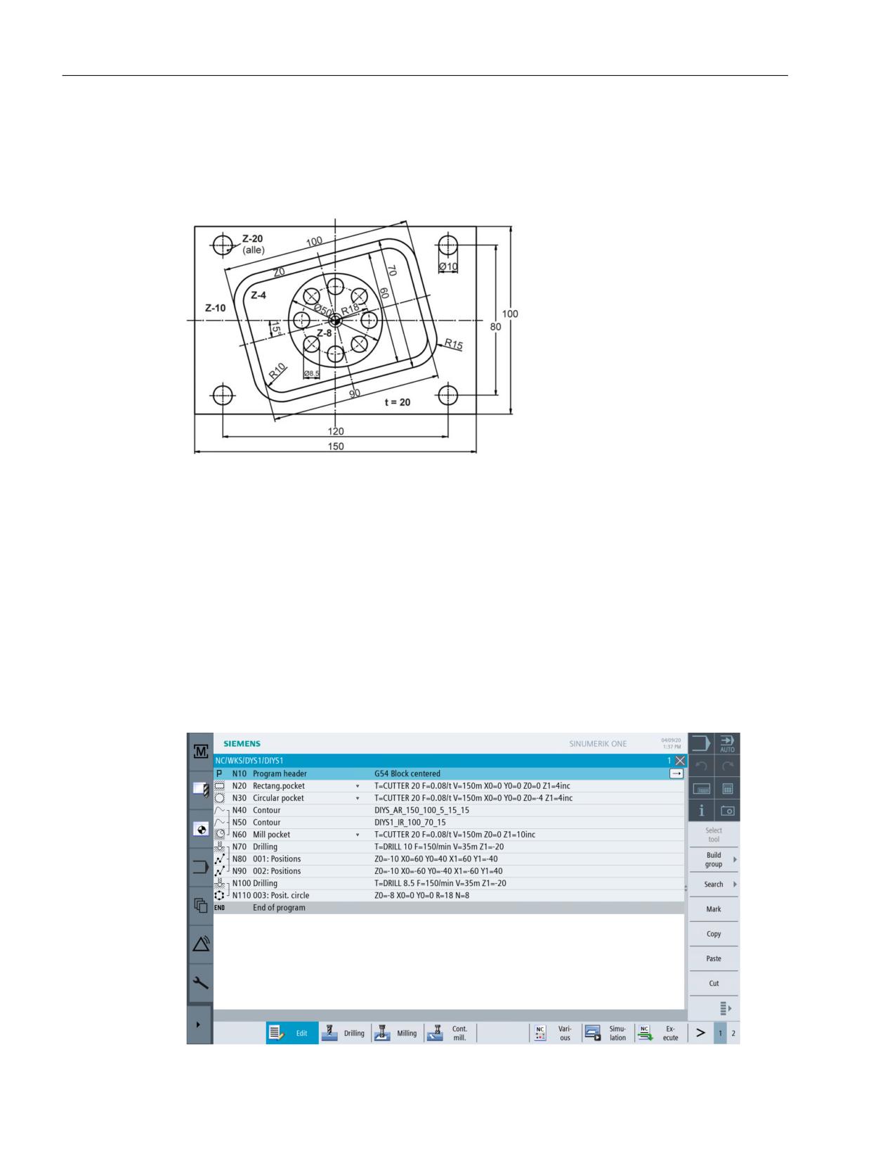
Figure 12-1
Workshop drawing DIYS1
Notes
The rotated rectangular pocket shown above has been designed in the original coordinate
system. The starting point lies first on zero. Subsequently, an auxiliary straight line is
programmed at an angle of 15° to the edge of the pocket. The coordinates of this end point are
the starting point for the actual construction. The auxiliary straight line must be deleted.
ShopMill also provides other paths to the objective, e.g. with the "Rotation" function or the
"Rectangular spigot" cycle. Test how you achieve the objective fastest and with which method
you achieve the shortest machining time.
Model
Easy milling with ShopMill
218
Training Documents, 05/2020, 6FC5095-0AB50-1BP2
How fit are you in ShopMill?
12.2 Exercise 1
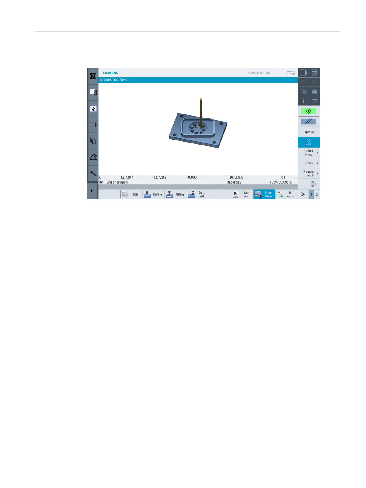
Figure 12-2
Process plan
Figure 12-3
Workpiece simulation
Easy milling with ShopMill
Training Documents, 05/2020, 6FC5095-0AB50-1BP2
219
How fit are you in ShopMill?
12.3 Exercise 2
12.3
Exercise 2
Will you manage this task using ShopMill within 20 minutes?
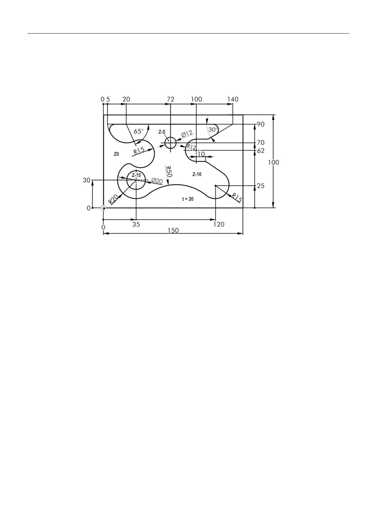
Figure 12-4
Workshop drawing COMPLEX_POCKET
Notes
Even though it looks complex: This contour is no problem with ShopMill. And automatic removal
of residual material can here be applied optimally. Compare the machining times if you were to
use CUTTER10 for stock removal.
Notes regarding the contour:
• Design the contour in the counterclockwise direction.
• The aperture angle of the top left arc is 115°.
Easy milling with ShopMill
220
Training Documents, 05/2020, 6FC5095-0AB50-1BP2
How fit are you in ShopMill?
12.3 Exercise 2
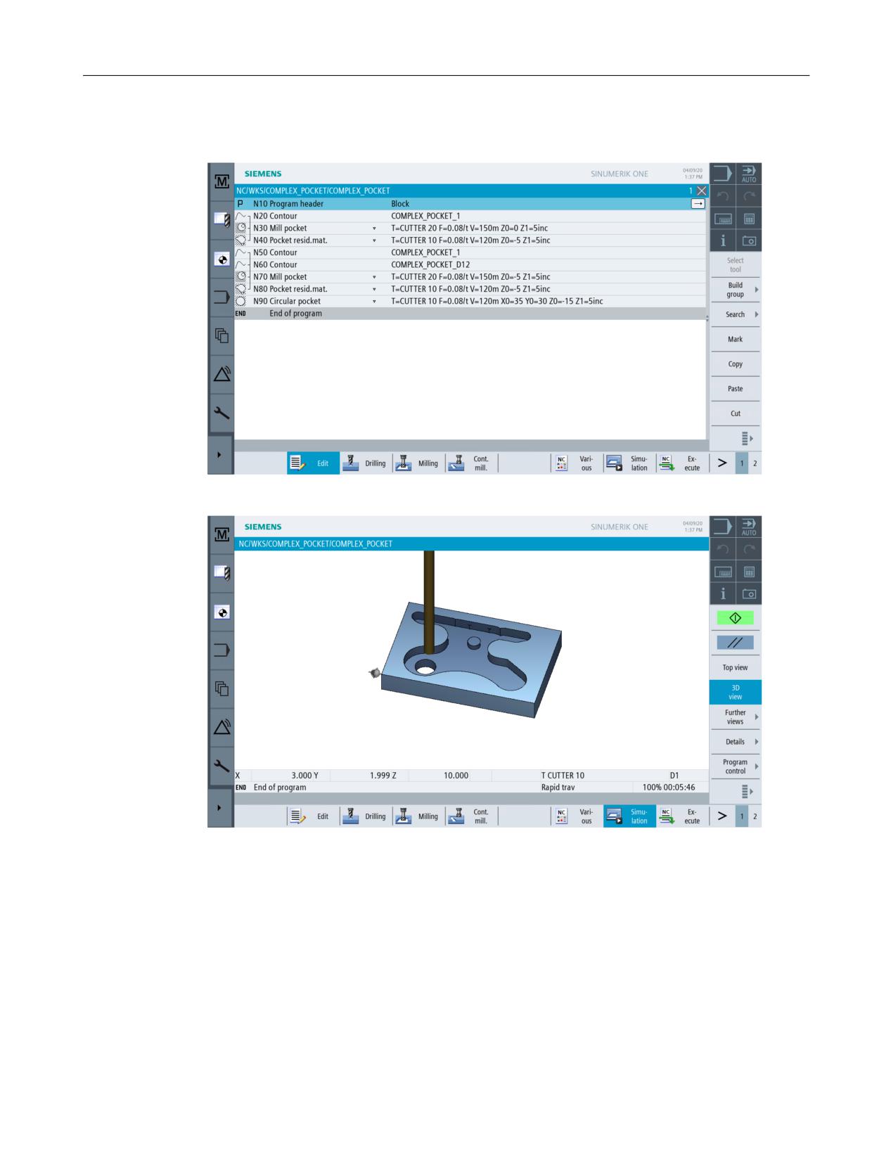
Model
Figure 12-5
Process plan
Figure 12-6
Workpiece simulation
Easy milling with ShopMill
Training Documents, 05/2020, 6FC5095-0AB50-1BP2
221
How fit are you in ShopMill?
12.4 Exercise 3
12.4
Exercise 3
Will you manage this task using ShopMill within 30 minutes?
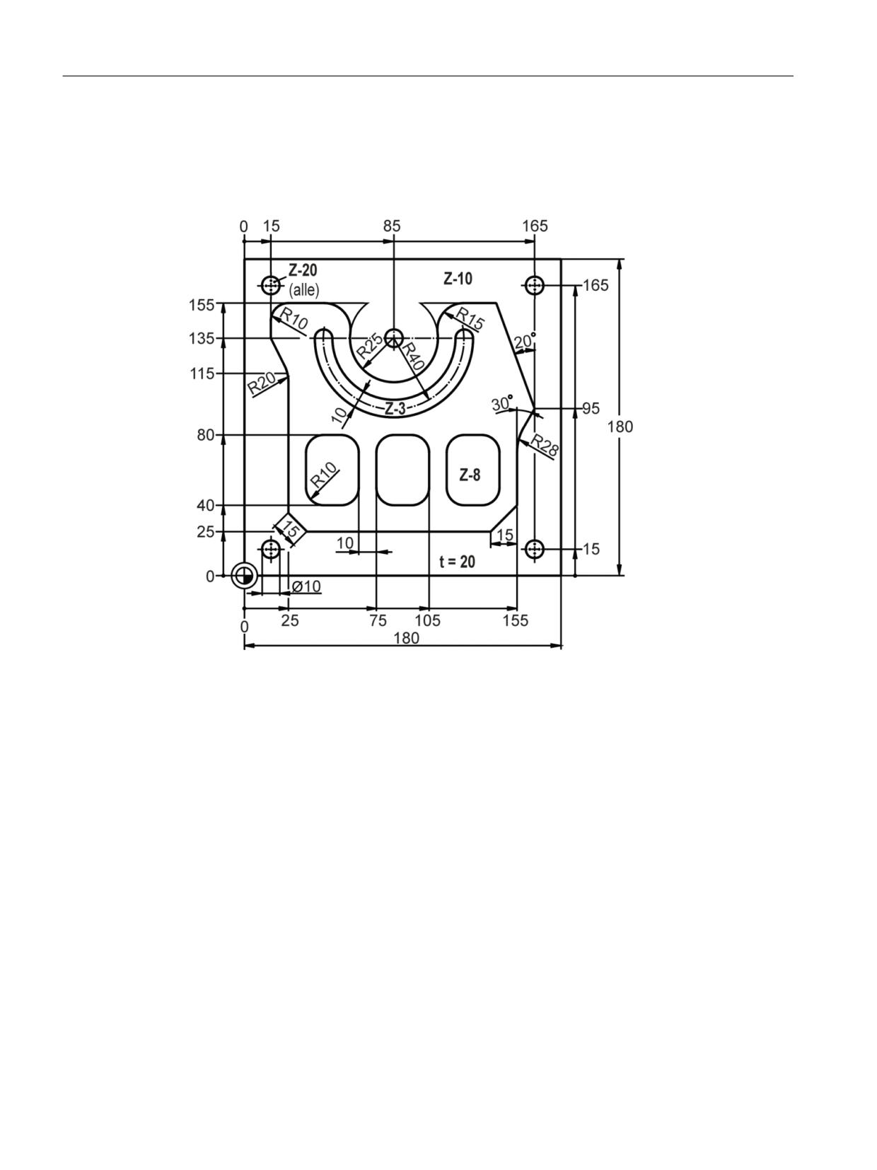
Figure 12-7
Workshop drawing PLATE
Notes
In this sample process plan, the area around the island has first been premilled roughly using the
"Rectangular spigot" cycle from the "Milling" menu. The rectangle described in this cycle is
approached along a circle and will reach the contour at the point described by the length and
angle of rotation. The rectangle is traveled completely once and left at the same point again
along a circle. Approach and retraction radii result from the geometry of the residual spigot.
Easy milling with ShopMill
222
Training Documents, 05/2020, 6FC5095-0AB50-1BP2
How fit are you in ShopMill?
12.4 Exercise 3
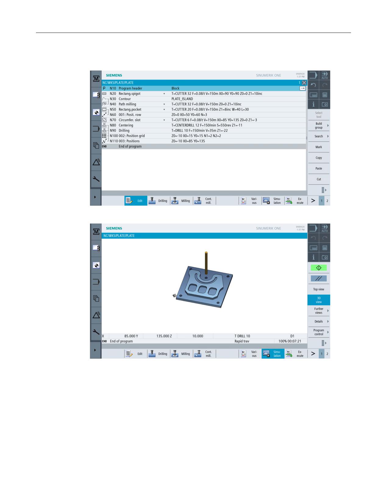
Model
Figure 12-8
Process plan
Figure 12-9
Workpiece simulation
Easy milling with ShopMill
Training Documents, 05/2020, 6FC5095-0AB50-1BP2
223
How fit are you in ShopMill?
12.5 Exercise 4
12.5
Exercise 4
Will you manage this task using ShopMill within 30 minutes?
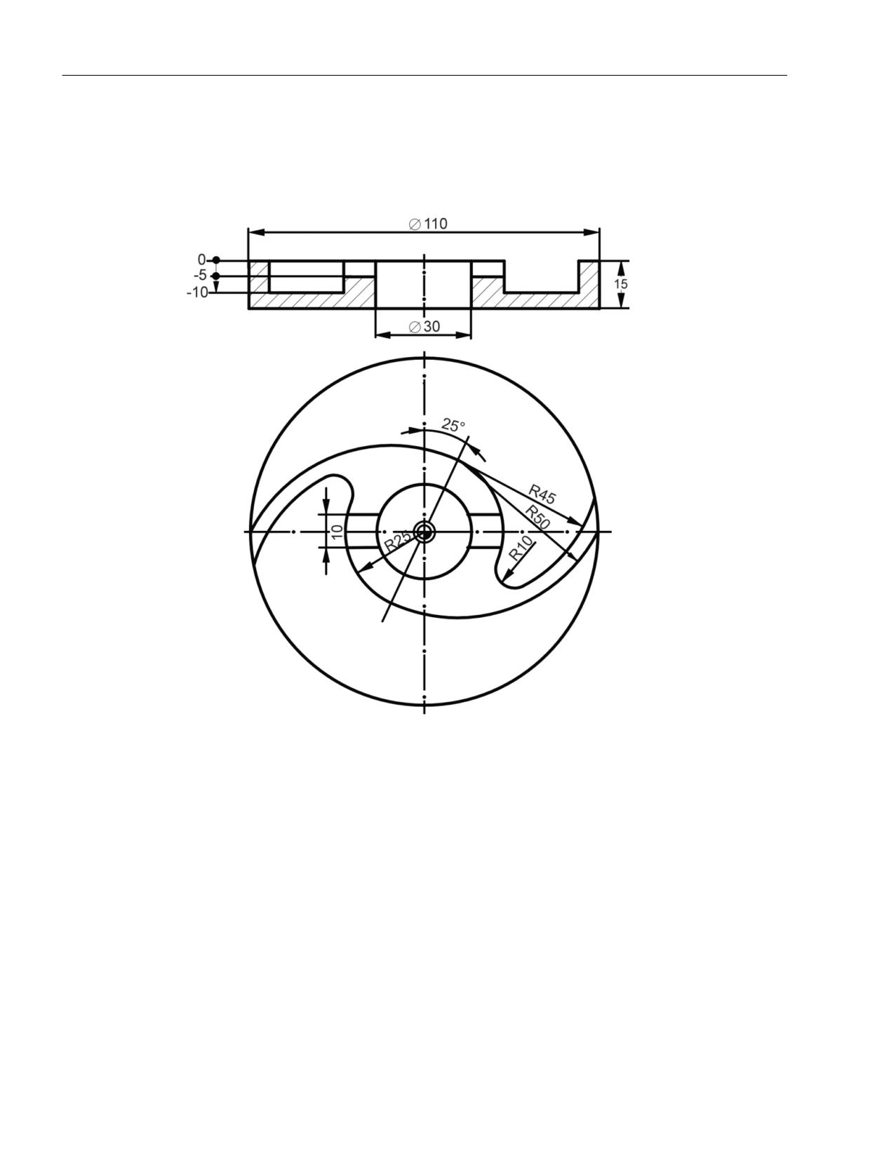
Figure 12-10
Workshop drawing WING
Notes
In this sample process plan, the circular outside contour is milled using the "Circular spigot" cycle.
The functioning corresponds mainly to that of the rectangular spigot (see Sample Pattern
Process Plan for Exercise 3). The common center point of the two arcs R45 and R50 (= starting
point for the actual construction) is specified using polar coordinates (25 mm at 65° referred to
the pole point at X0/Y0).
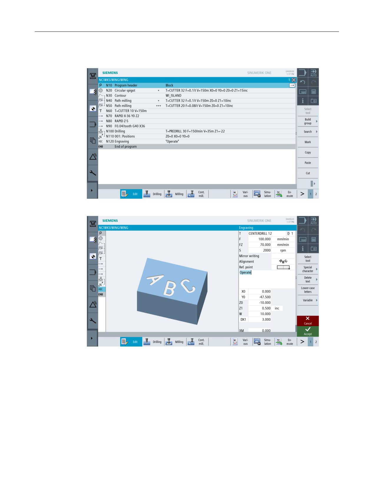
With software version V6.4 and higher, the "Milling" menu also provides a flexible "Engraving"
cycle.
Easy milling with ShopMill
224
Training Documents, 05/2020, 6FC5095-0AB50-1BP2
How fit are you in ShopMill?
12.5 Exercise 4
Model
Figure 12-11
Process plan
Figure 12-12
Specifying engraving
Easy milling with ShopMill
Training Documents, 05/2020, 6FC5095-0AB50-1BP2
225
How fit are you in ShopMill?
12.5 Exercise 4
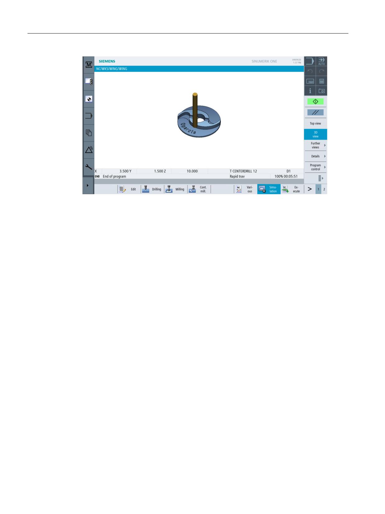
Figure 12-13
Workpiece simulation
Easy milling with ShopMill
226
Training Documents, 05/2020, 6FC5095-0AB50-1BP2

1
Basic information
General information on
2
workpiece production
Milling with SINUMERIK
Mold-making with 3- to 5-axis simultaneous milling
Important functions for 3- to
3
5-axis machining
Manual
Aerospace, structural parts
4
Engine and turbine
5
components
Valid for:
Control
Complex free-form surfaces
6
SINUMERIK 828D
SINUMERIK 840D sl
Difference between 3, 3+2
and 5 axes
7
Edition 09.2018
Reference section
8
Document Order No. 6FC5095-0AB10-0BP5
Introduction
Content
0
Content
0
Introduction
Page
1
Basic information
9
1.1
Introduction
10
1.2
SINUMERIK MDynamics milling technology packages
11
1.3
SINUMERIK Operate user interface
12
1.3.1
Operating and setup functions
12
1.3.2
SINUMERIK Operate - Multitouch
13
1.4
Requirements for milling
16
1.5
Linear axes, rotary axes and kinematics
17
1.5.1
Axes and programming
17
1.5.2
Kinematics of 5-axis machining centers
19
1.6
Surface quality, velocity, accuracy
20
1.7
Additional software
22
1.7.1
SinuTrain
22
1.7.2
VNC Viewer - remote control on an external PC
23
1.7.3
Analyze MyWorkpiece /Toolpath additional software
24
2
General information on workpiece production
25
2.1
Process chain for producing 3- to 5-axis workpieces
26
2.2
CAM systems
27
2.2.1
Tolerance and accuracy
28
2.3
Program structure for milling
29
2.4
Programs, data transfer and editor
33
2.4.1
Program manager
33
2.4.2
External storage media - data transfer
34
2.4.3
EES - Execution from External Storage (NC Extend)
35
2.4.4
Graphic and file formats in the program manager
36
2.4.5
Program editor - useful functions
37
2.5
JOG mode, zeros, tools
38
2.5.1
Zero offsets
38
2.5.2
Tool management
39
2.5.3
Manual retraction - return
40
2.6
Fundamentals, measuring in JOG and AUTOMATIC
41
2.6.1
Measurement logs in JOG
42
2.6.2
Measurement logs in AUTOMATIC
44
2.7
Measuring workpiece/tool in JOG
46
2.7.1
Workpiece measuring in JOG
46
2.7.2
Workpiece measuring functions in JOG
46
2.7.3
Example for measuring a workpiece in JOG
47
2.7.4
Measure tool in JOG
48
5
© Siemens AG All rights reserved SINUMERIK, Manual, Mold-Making with 3- to 5-Axis Simultaneous Milling

Introduction
0
Content
Page
2.7.5
Tool reference point
48
2.7.6
Example: Measure tool in JOG
50
2.8
Measure workpiece/tool in AUTOMATIC - process measuring
52
2.8.1
Measure workpiece in AUTOMATIC
52
2.8.2
Workpiece measuring cycles in AUTOMATIC
52
2.8.3
Example for measuring a workpiece in AUTOMATIC
53
2.8.4
Tool measuring in AUTOMATIC - process measuring
54
2.8.5
Example for measuring tools in the AUTOMATIC mode
54
2.9
Checking and measuring machine/spindle
56
2.9.1
Spindle 3D angular deviation CYCLE995
56
2.9.2
Checking/measuring the machine with the kinematics measuring
cycle CYCLE996
57
2.9.3
CYCLE9960 measure kinematics completely
59
2.10
Workpiece visualization
60
2.10.1 Simulation
60
2.10.2 Quick viewer for mold-making
61
2.10.3 Simultaneous recording
63
2.11
Executing programs (AUTOMATIC)
64
2.11.1 Display all relevant mold-making functions
64
2.11.2 Program running time
65
2.11.3 Handwheel override
66
2.11.4 Block search
67
2.12
Collision avoidance
68
3
Important functions for 3- to 5-axis machining
71
3.1
Introduction
72
3.2
Explanation of the terms: swivel, frames and TRAORI
73
3.3
Transforming coordinate systems - Frames
74
3.4
Swivel - CYCLE800
75
3.5
TRAORI 5-axis transformation
81
3.5.1
Basics of simultaneous 5-axis machining
81
3.5.2
The TRAORI command
85
3.5.3
Programming the tool orientation
86
3.5.4
Orientation interpolation and orientation reference
92
3.5.5
Example application involving TRAORI and frames
100
3.5.6
Useful NC commands for active TRAORI
101
3.6
High Speed Settings - CYCLE832
102
3.6.1
Parameters for CYCLE832
103
3.6.2
CYCLE832 and CUST_832
109
6
© Siemens AG All rights reserved SINUMERIK, Manual, Mold-Making with 3- to 5-Axis Simultaneous Milling
Content
3.7
Advanced Surface and Top Surface
110
3.7.1
Compressor (COMPCAD, COMPSURF)
112
3.7.2
Continuous-path mode, Look Ahead - G64, G645
113
3.7.3
Feedforward control and jerk limitation - FFWON, SOFT,
115
3.7.4
Smoothing tolerance CTOL, OTOL, ATOL
116
3.7.5
Path reference UPATH/SPATH
116
3.7.6
Smoothing the orientation characteristic (ORISON, ORISOF)
117
3.7.7
Technology G groups
118
3.7.8
Pre-processing memory control FIFOCTRL
119
3.8
Milling radius compensation 2D/3D-WRK
120
3.8.1
3D-WRK cutter radius compensation for circumferential and face milling
120
3.8.2
CUT3DC/CUT3DCD circumferential milling
121
3.8.3
CUT3DF/CUT3DFD face milling
122
3.8.4
Circumferential milling with limiting surfaces (CUT3DCC/CUT3DCCD)
126
3.8.5
Overview of the tool types for the 3D compensations
127
3.8.6
Explanation of the commands
127
3.8.7
Programming example for circumferential milling
129
3.9
Volumetric Compensation System (VCS)
130
3.10
VNCK - virtual machine
131
4
Aerospace, structural parts
133
4.1
Special functions for structural parts
134
4.2
Programming example for the pocket on a structural part
135
5
Engine and turbine components
139
5.1
Special functions for engine and turbine components
140
5.2
Example: Turbine blade
141
6
Complex free-form surfaces
145
6.1
Special functions for free-form surfaces
146
6.2
Example: Milling a manta ray
147
7
Difference between 3, 3+2 and 5 axes
151
7.1
5-axis simultaneous or 3+2-axes
152
7.2
Example workpiece milled by 3 to 3+2 axes
153
7.3
Example with 3 axes milled
155
7.4
Example with 3+1 axes milled
156
7.5
Example with 3+2 axes milled
157
7.6
Comparison of the three variants
158
7
© Siemens AG All rights reserved SINUMERIK, Manual, Mold-Making with 3- to 5-Axis Simultaneous Milling

Content
8
Reference section
159
8.1
Overview of higher-order functions
160
8.1.1
Motion commands
160
8.1.2
Dynamic response
162
8.1.3
5-axis functionality
164
8.2
Further information/documentation
170
8.3
Index
172
8
© Siemens AG All rights reserved SINUMERIK, Manual, Mold-Making with 3- to 5-Axis Simultaneous Milling

Basic information
1.1
1.1
Introduction
With mold-making, the main objectives are to achieve perfect surface quality, precision, and
velocity without any need for remachining. Within this context, workflow is typically characterized
by the CAD-CAM-CNC process chain. From the CAD system right through to the control,
Siemens can offer an integrated solution for these requirements in the form of its SINUMERIK
products.
SINUMERIK controls have powerful, highly-developed functions which, if intelligently used,
significantly simplify the complete operation involving programming and milling, and at the same
time the production result is improved.
This manual is a compact resource aimed at experts working in machining environments who
need to get acquainted with the most important basic principles of milling. Based on this, it also
provides machine users with practical tips so that they can organize their work efficiently and
provides programmers with an insight into the functions of the control and the CAD/CAM system.
As regards the various application areas of machining, the dedicated functions that have been
specifically developed for each area are briefly introduced and considered in context.
Although, many aspects cannot be covered in depth by this manual, additional information can
be found in the appropriate SINUMERIK documentation and relevant literature, See "Further
information/documentation" on page 170.
Range of
milling
Blow mold for plastic bottles
Turbine impeller
10
© Siemens AG All rights reserved SINUMERIK, Manual, Mold-Making with 3- to 5-Axis Simultaneous Milling

Basic information
1.2
1.2
SINUMERIK MDynamics milling technology
packages
SINUMERIK MDynamics bundles SINUMERIK CNC hardware, intelligent CNC functions and our
unique CAD/CAM/CNC process chain in technology packages for 3-axis and 5-axis milling. The
SINUMERIK MDynamics 3/3+2 or 5-axis milling packages are available for the SINUMERIK
828D and SINUMERIK 840D sl CNC systems.
SINUMERIK 828D
SINUMERIK 828D integrates the milling
package for 3 axes. The basic scope can be
expanded via optional functions (see also the
3-axis milling package for SINUMERIK 840D
sl)
Basic scope, 3/3+2 axes (excerpt):
Advanced Surface
User memory expansion on the user's CF
card
Additional options, 3/3+2 axes (excerpt):
Top Surface
DXF reader
EES
ShopMill machining step programming
3D simulation
SINUMERIK 840D sl
For SINUMERIK 840D sl, you can choose
between two milling packages for 3-axis and
5-axis machining. The basic scope of the
packages includes all the functions needed for
the associated machining tasks and can be
expanded.
Basic scope, 3/3+2 axes (excerpt):
Advanced Surface
Spline interpolation
Transmit and peripheral surface
transformation
AUTOMATIC measuring cycles
3D simulation
Residual material identification
ShopMill machining step programming...
Additional options (excerpt):
The 5-axis package additionally includes:
Top Surface
5-axis machining package TRAORI
DXF reader
3D tool radius compensation
EES
Measure kinematics CYCLE996/9960
11
© Siemens AG All rights reserved SINUMERIK, Manual, Mold-Making with 3- to 5-Axis Simultaneous Milling
Basic information
1.3
1.3
SINUMERIK Operate user interface
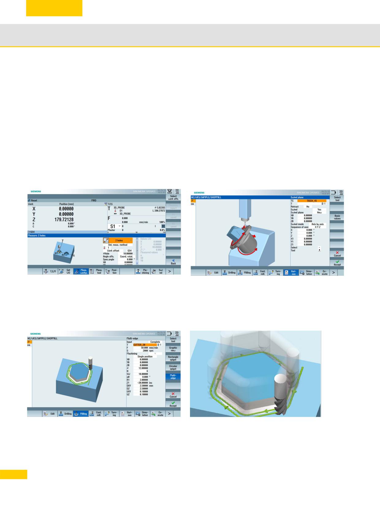
The new SINUMERIK Operate user interface is well laid out and easy to use. It combines the
known features of HMI Advanced, ShopMill and ShopTurn in a seamlessly integrated, innovative
user and programming interface. This allows machining step programming to be combined with
high-level language programming, resulting in rational and intuitive NC programming and
production planning.
1.3.1
Operating and setup functions
The machine setup display is clear and manageable thanks to graphical support. Complex
workpieces can be quickly and easily machined in one clamping operation. Various kinematics
can be easily set up thanks to the cycle support.
Wide range of setup functions
Support for many kinematics
Animated elements clarify the parameters, for example during programming
Using animated elements, the SINUMERIK CNC achieves a unique level of user friendliness for
operating and programming - even for technological cycles.
Cycle multi-edge in the programGUIDE
Animated elements - Moving image sequence
12
© Siemens AG All rights reserved SINUMERIK, Manual, Mold-Making with 3- to 5-Axis Simultaneous Milling
Basic information
1.3
1.3.2
SINUMERIK Operate - Multitouch
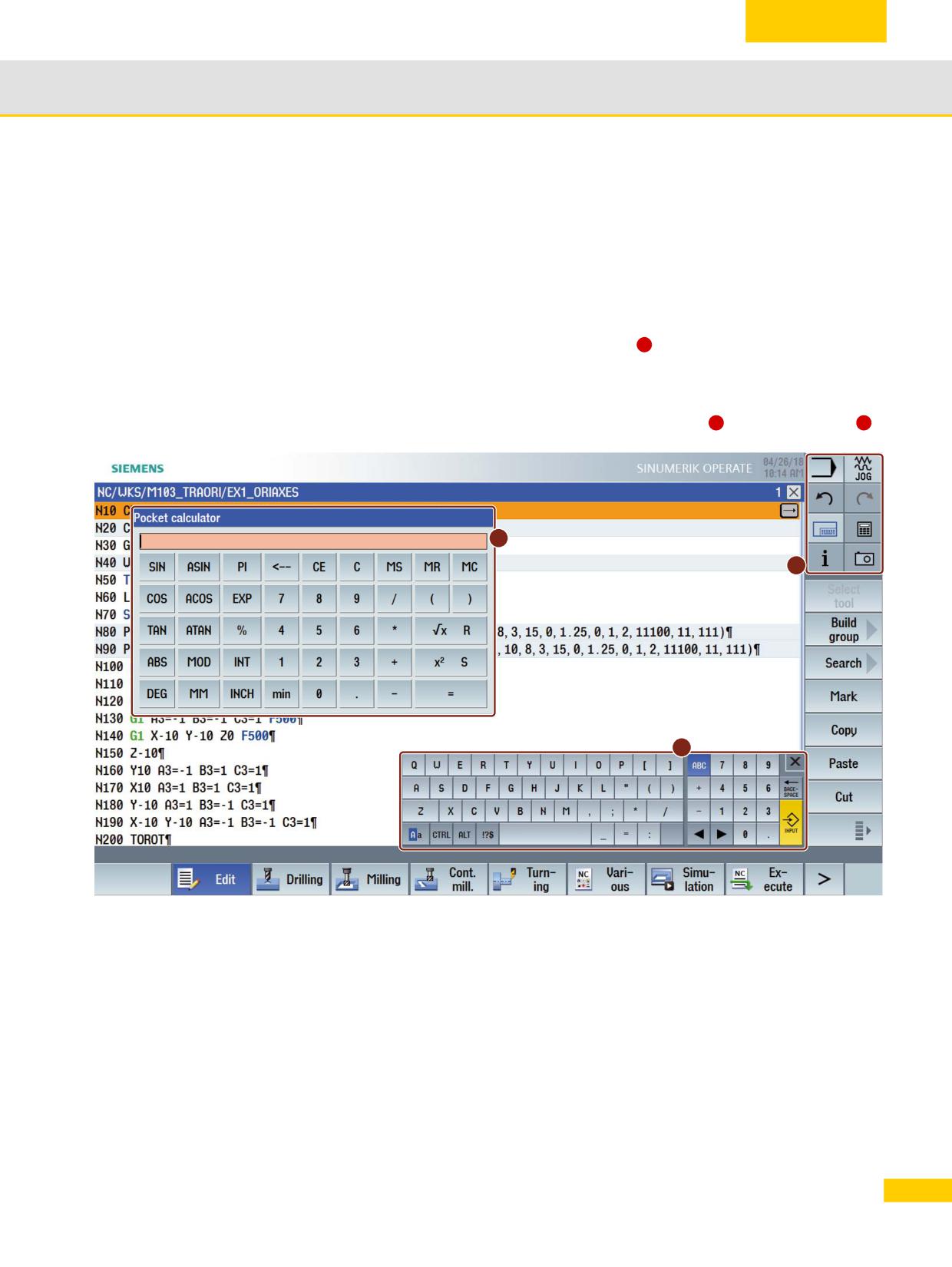
SmartOperation permits an intelligent CNC operation in SINUMERIK Operate using current
technologies, such as multitouch and widescreen displays. The Display Manager permits you to
see a lot of information at a glance.
Multitouch operation
SINUMERIK Operate provides additional operator functions for multitouch panels.
Extended control elements via the function key block
1
Gesture operation (e.g. wiping, moving and zoom functions)
The selected functions can be activated directly via the function key block. These are, for
example, undo changes or restore and activate the virtual keyboard
or of the calculator
2
3
13
© Siemens AG All rights reserved SINUMERIK, Manual, Mold-Making with 3- to 5-Axis Simultaneous Milling
Basic information
1.3
SINUMERIK Operate expansion using a sidescreen
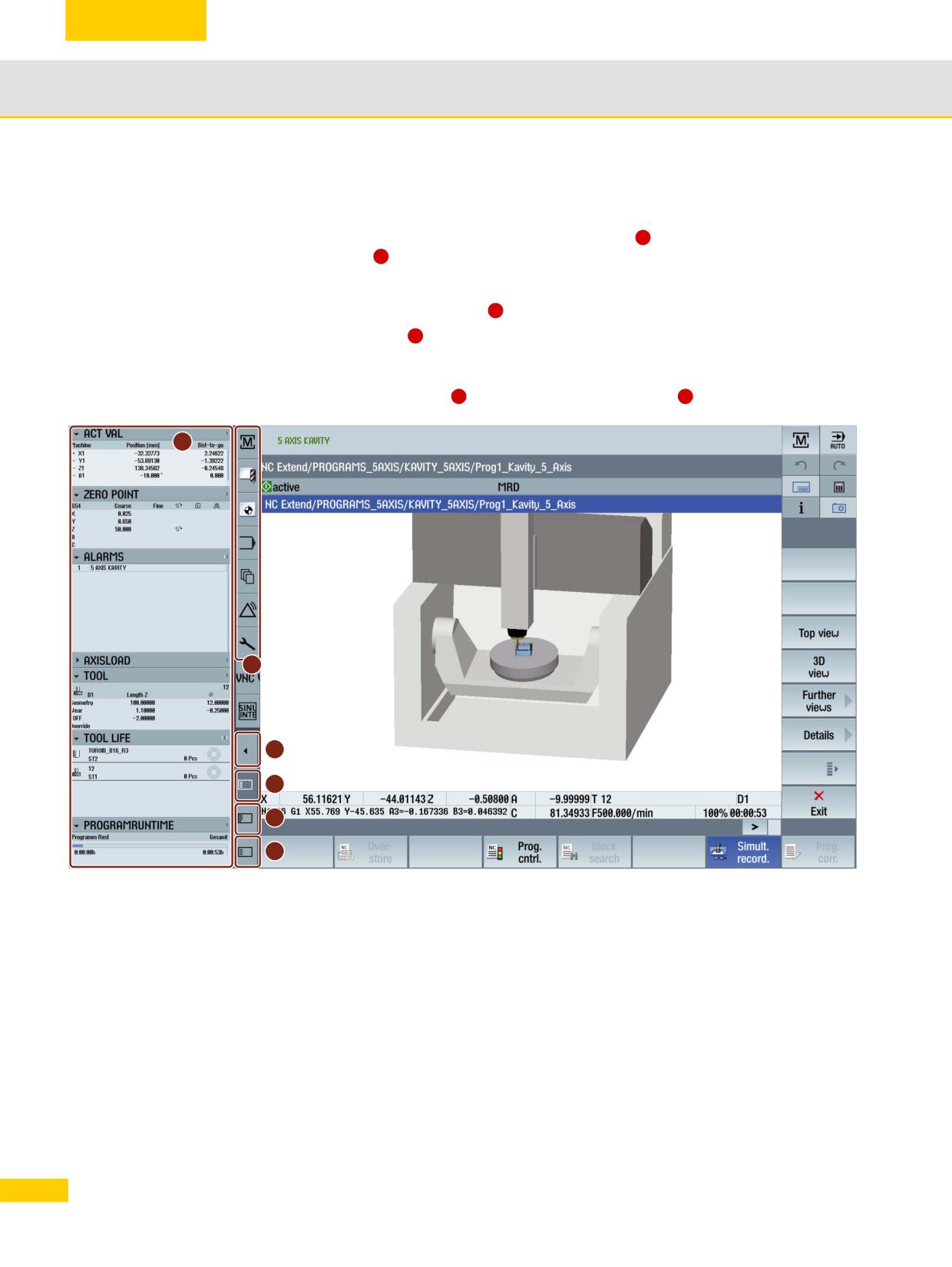
Widescreen format panels offer the option of using the additional area for the faster display of
additional elements and operating. Using the navigation bar
1
the so-called sidescreen is
shown and hidden
2
You can display the following elements via the navigation bar:
Machine function direct selection
1
e.g. machine, tool list, zero offsets or program.
Displaying (widgets)
3
Standard widgets are for example, zeros, alarms, tool service life and program run time.
Virtual keys (pages)
Activate the ABC keyboard
or of the machine control panel
4
5
14
© Siemens AG All rights reserved SINUMERIK, Manual, Mold-Making with 3- to 5-Axis Simultaneous Milling
Basic information
1.3
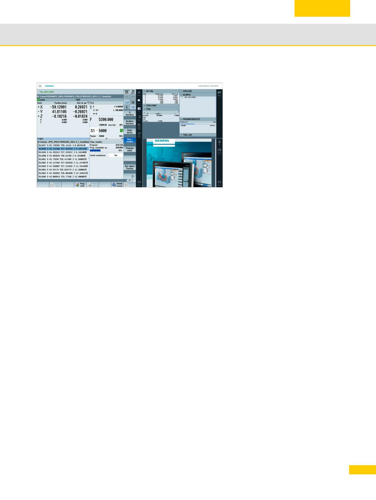
Display Manager (at least 22 inch Full HD SINUMERIK blackline plus panel)
With the Display Manager, the screen area is
divided into several display areas.
In addition to SINUMERIK Operate, widgets,
keyboards, a machine control panel and
various applications are provided in the
various areas.
15
© Siemens AG All rights reserved SINUMERIK, Manual, Mold-Making with 3- to 5-Axis Simultaneous Milling

Basic information
1.4
1.4
Requirements for milling
Free-form surfaces
Design standards in all application areas are
Mold-making
becoming increasingly demanding.
Expectations in terms of ergonomics, the air
drag coefficient (CW value) or simply aesthetic
appeal are creating a need for more complex
surface geometries to be achieved quicker
and with greatest precision. The design prima-
rily comes from CAD systems, the machining
programs from CAM systems.
Engine and turbine
With SINUMERIK, Siemens can provide CNC
components
systems that are perfectly suited to the
e.g. impellers
demands of 3- to 5-axis machining as well as
HSC (High Speed Cutting) and HPC (High
Performance Cutting) applications:
Simple to operate
User-friendly programming at the machine
Optimum performance throughout the
CAD-CAM-CNC process chain
Optimized 5-axis functions
Structural parts
Depending on the application, the
Aviation industry
requirements imposed on the control will vary
and a whole range of different functions may
be demanded.
Within this context, milling can be broken
down into three broad areas:
Free-form surfaces (mold-making)
Turbine and engine components
(impellers, blisks)
Structural parts (aviation industry)
SINUMERIK can provide optimum support for
each of these areas.
16
© Siemens AG All rights reserved SINUMERIK, Manual, Mold-Making with 3- to 5-Axis Simultaneous Milling
Basic information
1.5
1.5
Linear axes, rotary axes and kinematics
1.5.1
Axes and programming
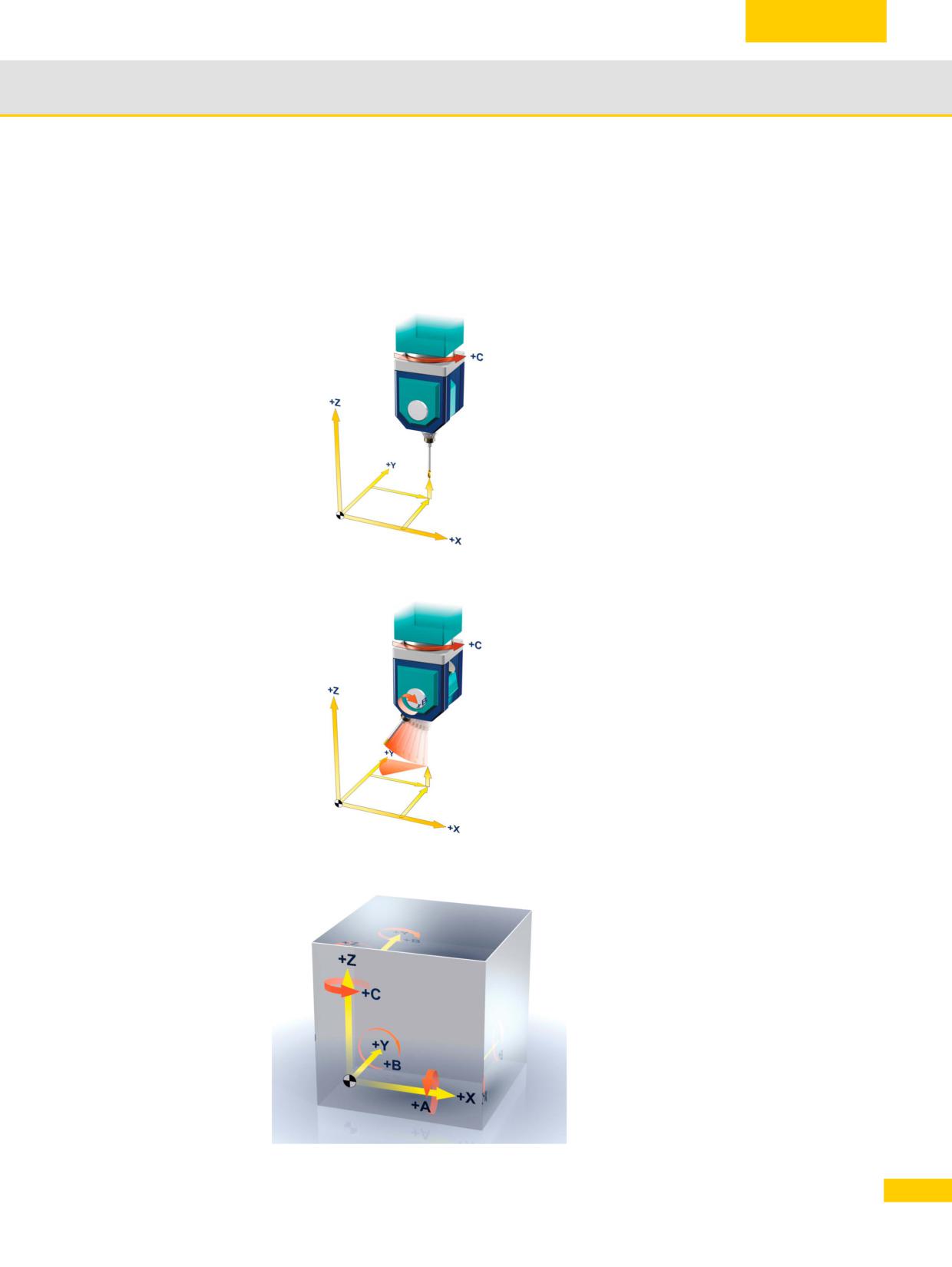
Tool tip motion
3-axis area
The tool position is approached in space using
linear axes X, Y and Z. This enables the tool
center point to adopt any position.
With 3-axis machining, you program the three
linear axes to achieve the desired machining
operations. The contour is milled line-by-line
by moving the three linear axes.
If the tool also has to be set at an angle, you
will need rotary axes as well.
Setting the tool at an
5(3+2)-axis area
angle
The inclination of the tool (i.e. the tool
orientation) is changed using two axes of
rotation, e.g. B and C.
This is necessary, for example, if the tool
needs to be angled in relation to the
machining surface or if you want to mill a
pocket with inclined walls within the context of
circumferential milling.
Using three linear axes and two rotary axes,
theoretically any point in space can be
approached with any tool orientation. This is
the basis of 5-axis machining.
Linear and rotary axes
5-axis simultaneous
To accommodate machining scenarios
involving tools set at an angle or in order to
mill undercuts or geometries located
anywhere in space, the three linear axes X, Y
and Z are required along with two of the rotary
axes A, B or C. It must be possible to control
the axes simultaneously.
17
© Siemens AG All rights reserved SINUMERIK, Manual, Mold-Making with 3- to 5-Axis Simultaneous Milling
Basic information
1.5
CNC programming options in the 5-axis area
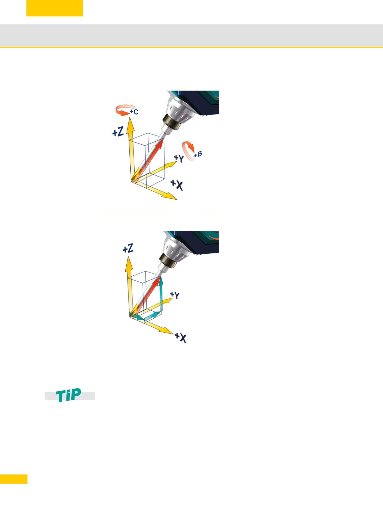
Programming rotary
For the purpose of 5-axis machining, the
axes
orientation of the tool needs to be defined in
addition to the position setpoint of the
machining point. The position setpoint is
defined in the CNC program by means of the
coordinate axes X, Y, and Z.
The tool orientation can be specified on the
basis of the rotary axis positions. This enables
the position setpoint and tool orientation to be
defined in a unique manner.
The example below shows the tool tip in the
position (0,0,0), and the tool shank is the
diagonal of a cube (35.26° relative to the X-Y
plane).
N100 G1 X0 Y0 Z0 B=54.73561 C=45
Programming direction
When describing the tool orientation, it also
vector
makes sense to specify the direction vectors
A3, B3, and C3 so that the orientation can be
programmed independently of the machine
kinematics.
The programming of the example above would
C3
look like the following after specifying the
rotary axis positions:
N100 G1 X0 Y0 Z0 A3=1 B3=1 C3=1
B3
A3
In addition to programming based on the direction vector and rotary axis positions, there are also
other forms of angle programming. These include, for example, Euler or RPY angles. Further
information regarding this topic can be found in Section "Programming the tool orientation" on
page 86.
18
© Siemens AG All rights reserved SINUMERIK, Manual, Mold-Making with 3- to 5-Axis Simultaneous Milling
Basic information
1.5
1.5.2
Kinematics of 5-axis machining centers
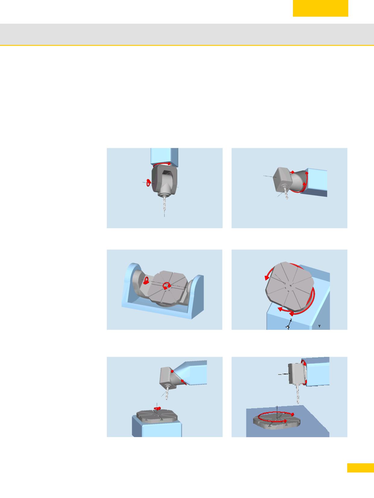
A 5-axis machine can control tool motion in five axes. These are the three linear axes (with which
you will already be familiar) and two additional rotary axes. There are different kinematic
solutions for the two rotary axes. We will present the most common of these schematically. With
SINUMERIK controls, even special kinematics can be controlled on the basis of the integrated,
kinematic transformation feature. Special cases such as hexapods, etc. will not be explored in
further detail here.
Two rotary axes in the head
Fork head
Head kinematics nutated *
Two rotary axes in the table
Rotary/swiveling table
Rotary/swiveling table nutated *
*: If the axis of rotation is not perpendicular to a linear axis, then this is known as a "nutated" axis.
Mixed kinematics
19
© Siemens AG All rights reserved SINUMERIK, Manual, Mold-Making with 3- to 5-Axis Simultaneous Milling
Basic information
1.6
1.6
Surface quality, velocity, accuracy
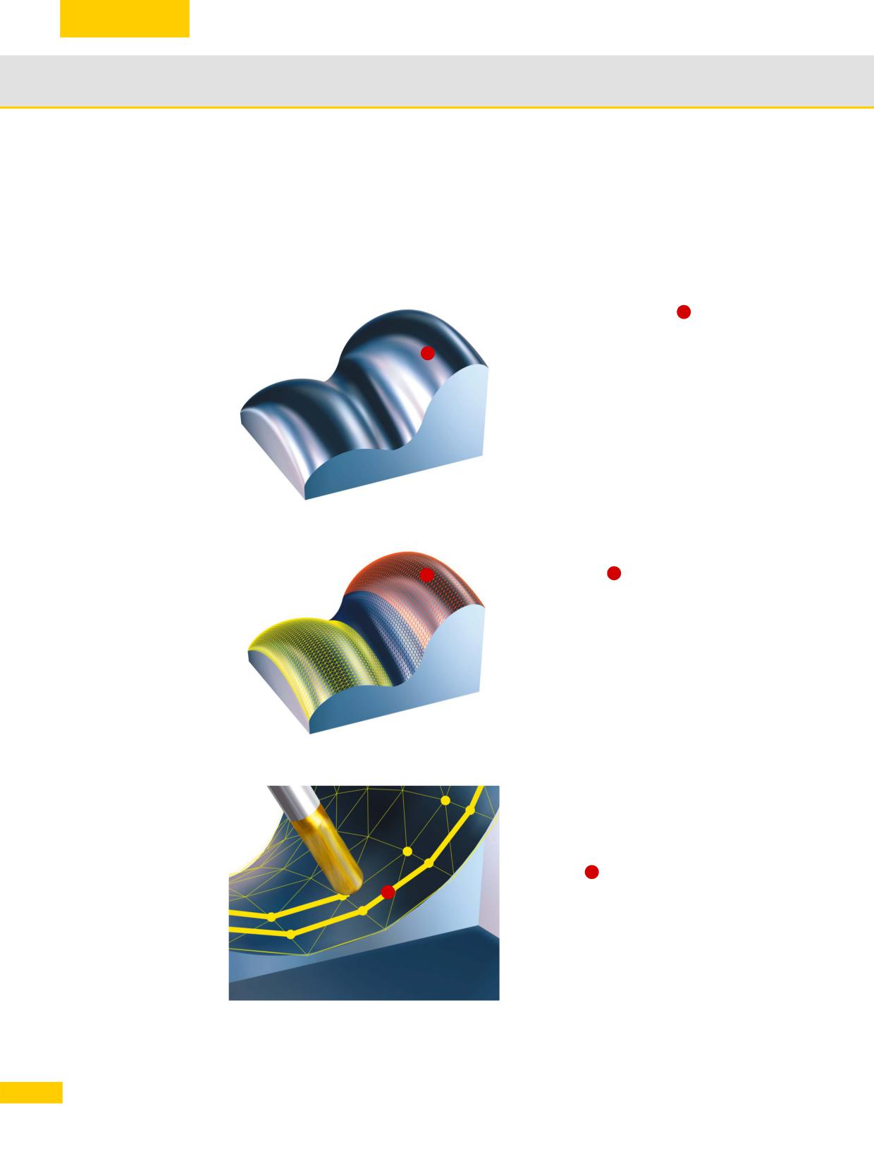
Special attention must be paid to the CAD -> CAM -> (postprocessor) -> CNC process chain
when machining three-dimensional geometries, e.g. free-form surfaces. CAM systems generate
NC programs for free-form surface machining. The CAM system receives the workpiece
geometry from a CAD system. The CNC machine has to process the NC data generated and
convert it into axis movements.
In CAD systems, surfaces
of higher orders
1
are constructed (free-form surfaces).
For example, in order to be able to mill an
1
entire surface - or for collision checking - the
CAM system generally converts the CAD free-
form surface into a polyhedron.
This means that the smooth design surface is
2
approximated
2
by a number of individual
small planes.
This produces deviations from the original
free-form surface.
The CAM programmer overlays this
polyhedron with tool paths. From these, the
postprocessor generates NC blocks within the
specified error tolerances. These usually
G1
comprise many short straight line elements,
G1 X Y Z.
3
1
G1
3
Thus, the machining result is no longer a free-
form surface, but a polyhedron. The small
planes of the polyhedron can be visibly
G1
G1
mapped on the surface.
This can result in undesirable remachining.
20
© Siemens AG All rights reserved SINUMERIK, Manual, Mold-Making with 3- to 5-Axis Simultaneous Milling
Basic information
1.6
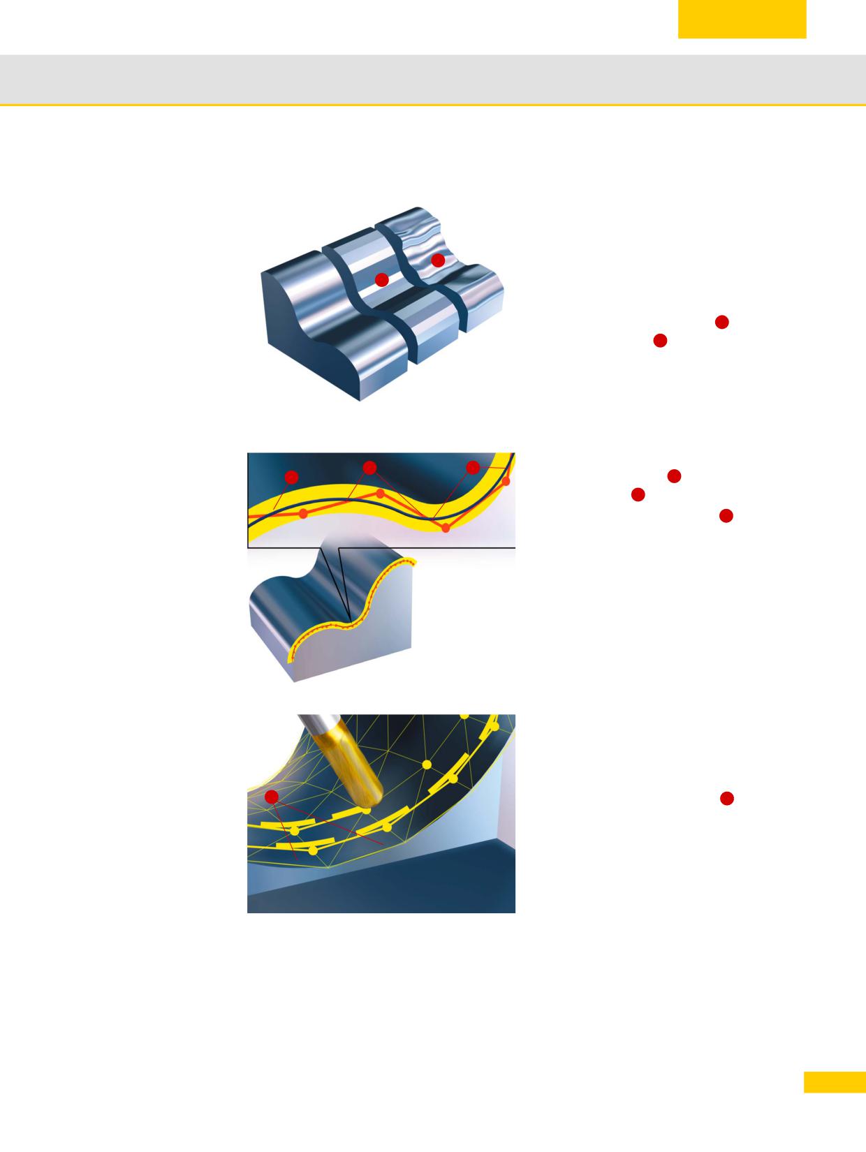
SINUMERIK controls offer various functions so that remachining can be avoided:
Compressor function
(COMPCAD/COMPSURF)
At the block transitions, the interpolation leads
2
to step changes in velocity in the machine
1
axes, which in turn can cause resonance in
the machine elements and can ultimately be
detected as a beveled pattern
1
or as the
effects of vibrations
2
on the workpiece sur-
face.
In accordance with the specified tolerance
2
3
1
band, the compressor
1
takes a sequence of
NC commands, 2 combines them and
compresses them into a spline
, which can
3
be directly executed by the control.
The compressor generates smooth paths and
paths with constant curvature. The constant
curvature results in a steady velocity and
acceleration characteristic. The surface quality
is improved and the machine can run at higher
velocities, thereby increasing productivity.
Programmable smoothing (G645)
Discontinuous block transitions can be
blended using the smoothing function to
create steady characteristics. This involves
4
inserting geometrical elements
4
at the
corners (block transitions).
The tolerance of these geometrical elements
can be adjusted (see also 3.6).
21
© Siemens AG All rights reserved SINUMERIK, Manual, Mold-Making with 3- to 5-Axis Simultaneous Milling
Basic information
1.7
1.7
Additional software
1.7.1
SinuTrain
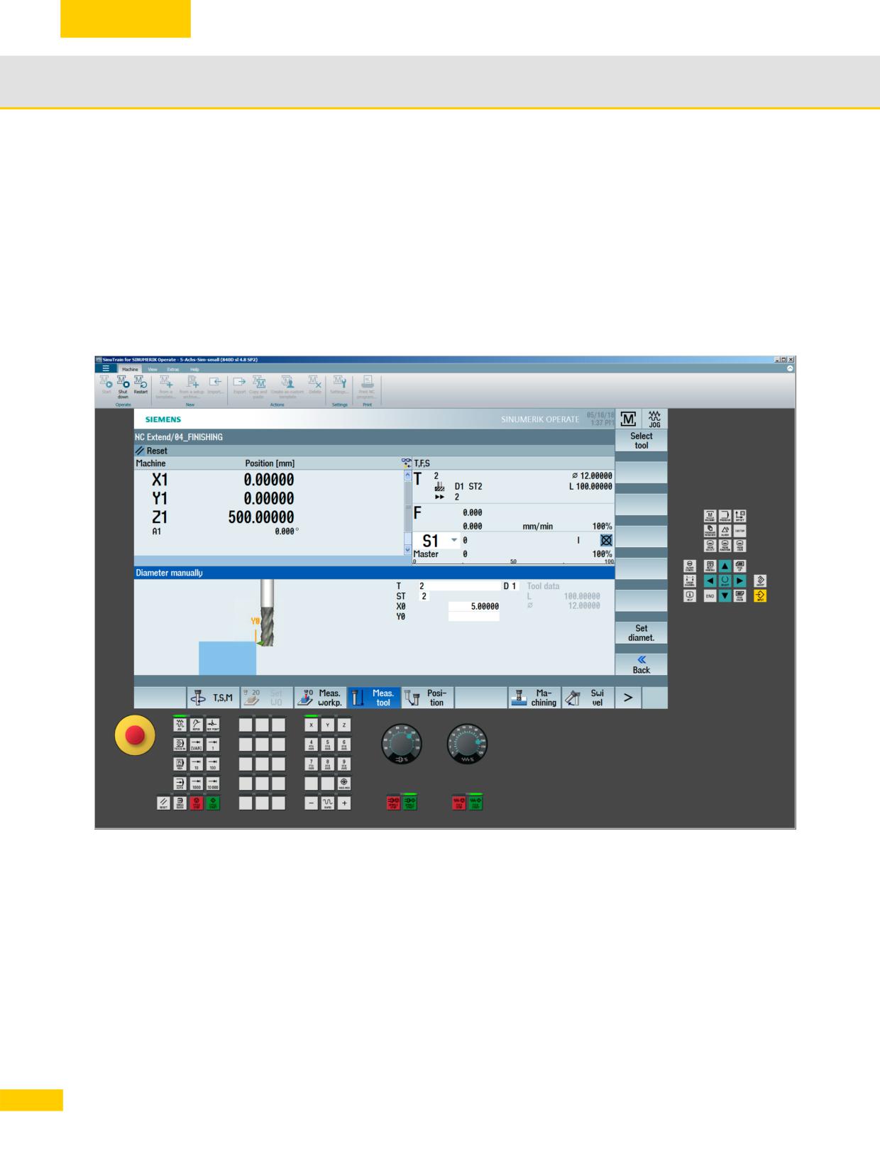
SinuTrain provides for SINUMERIK controls an intuitive PC-based solution that consists of
control-identical software. SinuTrain allows practical offline programming at a PC; these NC
programs can be transferred directly to the CNC. Using SINUMERIK Operate and the original
SINUMERIK CNC kernel, all operating and programming operations can be used and CNC
programs executed, without any restrictions.
Advantages at a glance
Almost 100-percent offline verification/evaluation of the NC programs thanks to the original
CNC kernel.
Use as optimum programming station by adaptation to the real machine (e. g. by the machine
manufacturer).
Perfectly tailored packages for training and production planning.
Operating, programming and simulating exactly as for the real SINUMERIK.
22
© Siemens AG All rights reserved SINUMERIK, Manual, Mold-Making with 3- to 5-Axis Simultaneous Milling
Basic information
1.7
1.7.2
VNC Viewer - remote control on an external PC
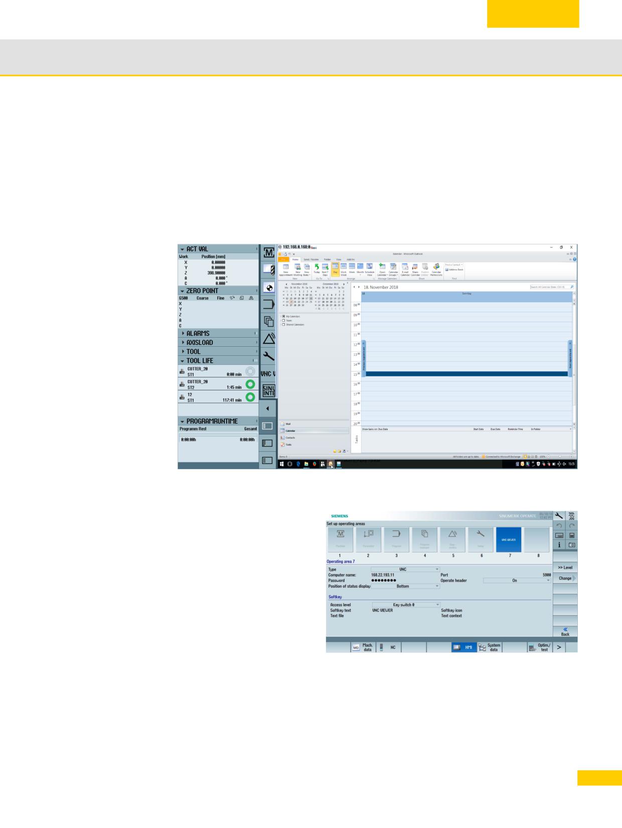
In SINUMERIK Operate, a VNC (Virtual Network Computing) Viewer can be integrated in the
operating area to access a remote PC located in the network of the control. This access allows
applications on the PC to be operated directly from the control. For example, missing information
can be fetched from a CAD/CAM system or from the production planning, or process participants
informed about changed production parameters.
After a one-off configuration of the connection, a switch can be made to the remote connected
PC by pressing a key.
Access to an application
of the external computer
VNC area configuration on the user interface
Remote access to a PC in the
network is possible via the inter-
faces, e.g. X130.
The configuration is performed
in SINUMERIK Operate.
Further information can be
found in the manuals with the
keyword VNC or obtained from
the machine manufacturer.
23
© Siemens AG All rights reserved SINUMERIK, Manual, Mold-Making with 3- to 5-Axis Simultaneous Milling

Basic information
1.7
1.7.3
Analyze MyWorkpiece /Toolpath additional
software
After the processing, the Analyze MyWorkpiece /Toolpath 3D visualization tool allows the
completed geometry from the CAD system, the NC program as well as the recording of the tool
path to be represented concurrently in three dimensions and compared with each other. Filters
and color assignments highlight any potentially problematic areas. They shows immediately
whether the errors are in the NC program or were caused by the machine kinematics or the
clamping.
Optimizations and compensations are possible even before production of a workpiece. For
example, any discrepancies in the NC program caused by an irregular distribution of points,
differences for the travel velocities of neighboring milling paths or tool paths not appropriate for
fine machining are shown.
Missing points in the curvature path
4D evaluation:
Color switching in the curvature path
The capability to measure points with micrometer accuracy makes it possible to evaluate
whether errors are surface-relevant. This saves valuable machine time for the production of
faulty parts because corrective work is reduced to a minimum.
24
© Siemens AG All rights reserved SINUMERIK, Manual, Mold-Making with 3- to 5-Axis Simultaneous Milling

General information on workpiece
production
Content
Page
2.1
Process chain for producing 3- to 5-axis workpieces
26
2.2
CAM systems
27
2.3
Program structure for milling
29
2.4
Programs, data transfer and editor
33
2.5
JOG mode, zeros, tools
38
2.6
Fundamentals, measuring in JOG and AUTOMATIC
41
2.7
Measuring workpiece/tool in JOG
46
2.8
Measure workpiece/tool in AUTOMATIC - process
52
measuring
2.9
Checking and measuring machine/spindle
56
2.10
Workpiece visualization
60
2.11
Executing programs (AUTOMATIC)
64
2.12
Collision avoidance
68
General information on workpiece production
2.1
2.1
Process chain for producing 3- to 5-axis workpieces
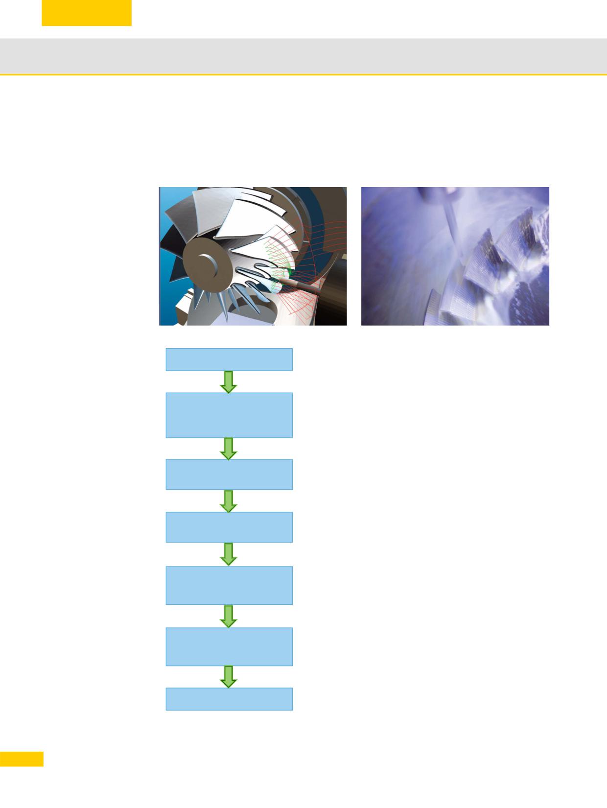
The production process chain generally starts with workpiece design. The data generated at this
stage provides the basis for further processing and, ultimately, for production.
CAD/CAM
Production
Creating a CAD model
CAD model
Use of the CAM-internal strategies and methods to
CAM strategies
generate the individual machining steps and calculate
Calculation
the paths.
of tool paths
Simulation of the calculated tool paths with collision
Simulation
checking.
of tool paths
Generation of the NC code in the postprocessor.
Postprocessor
Generally, the path at the tool tip (TTP) is output in NC
code.
Data transfer of the NC programs and setting up of the
tool and workpiece. If required, creation of a main
Setting up the machine
program that calls the generated geometry programs.
Specification of the high-speed settings, e.g. in
CYCLE832, if this is not already taken into account by the
Quality
postprocessor. These are tolerance, compressor, path
control, smoothing, jerk and velocity.
Manufacture of the workpiece on the machine.
Machining
26
© Siemens AG All rights reserved SINUMERIK, Manual, Mold-Making with 3- to 5-Axis Simultaneous Milling
General information on workpiece production
2.2
2.2
CAM systems
Within the context of the process chain, it is the CAM system that is responsible for the key task
of generating the NC programs. The quality of this data plays a decisive role in determining the
results of workpiece production.
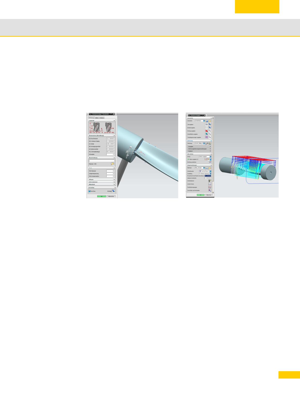
This section outlines the procedure for generating the NC programs. Given the diverse range of
systems available on the market, only a brief summary can be provided.
Tool definition
Plane roughing strategy
Procedure when working with a CAM system:
X CAD data
Fetch CAD data into the CAM system. When reading the data in, a check should be
performed to ensure that the surface geometries are free from defects, i.e. that there are no
steps or jumps. Flaws in the data such as these will manifest themselves on the surface of
the finished workpiece.
X Clamping situation
Define the clamping situation and the geometry that can be freely machined in a clamping
device. Define geometries such as a zero.
X Specify tools
Define the necessary tools on the basis of the machining task at hand and enter the technol-
ogy data. As a general rule, CAM systems are able to read the data in from tool databases.
Amongst other things, the tools determine which subsequent machining strategies can be
used, e.g. whether plunge cutting is possible with the tool.
X Specify machining strategies
Define the machining process for the various workpiece geometries using the appropriate
strategies. First of all, roughing strategies are applied, e.g. roughing in the Z plane or equidis-
tant from the surface geometry. CAM systems offer various options from 2 1/2-axis to 5-axis
machining.
The tool paths can be generated automatically or defined manually; these include, for exam-
ple, approach and retract strategies or special milling strategies such as trochoidal milling.
The machining strategies are gradually introduced in stages as part of this procedure and are
supported by automatic residual material detection, for example.
27
© Siemens AG All rights reserved SINUMERIK, Manual, Mold-Making with 3- to 5-Axis Simultaneous Milling

General information on workpiece production
2.2
X Calculation and simulation
When simulating the calculated tool paths / machine movements, different levels of quality
can be used. From straightforward simulation of the tool paths through to complete simulation
of the G and M codes that takes account of all machine-specific and control-specific data.
Here, potential collisions can be detected and avoided, for example, and the machine's maxi-
mum axis traversing ranges can be taken into account.
X Output of the NC code with the postprocessor
The postprocessor converts the sequences into NC programs taking into account the control-
specific syntax and the control's special functions. For this purpose, CAM systems make use
of universal postprocessors or special postprocessors that have been optimized for the
SINUMERIK system. Manufacturer-specific functions such as separate coolant strategies
must be implemented in the postprocessor in consultation with the machine manufacturer.
2.2.1
Tolerance and accuracy
When working with CAD/CAM systems, certain tolerances and levels of accuracy that will have
an impact on subsequent machining must be observed.
Tolerance The CAM system uses the CAD surface (spline) to generate a contour consisting of linear
traversing blocks (straight line elements). The extent to which the linear contour deviates from
the real contour from the CAD system is known as the chord error or chord tolerance. This
tolerance depends on the strategy and on the workpiece. The tolerance for roughing strategies is
greater than for finishing strategies. When the NC programs are executed on the machine, the
tolerance is specified by the CAM system in CYCLE832 so that optimum results can be achieved
in terms of surface quality and contour accuracy.
Tolerance guide values
Technology
Recommended values
Roughing
Tolerance 0.05 - 0.1 mm - with 5-axes OTOL = 0.3
Semi-finishing
Tolerance 0.01 - 0.05 mm - with 5 axes OTOL = 0.15
Finishing
Tolerance 0.002 mm - max. point separation 0.3 - 0.5 mm
with 5-axes OTOL = 0.01 - 0.1
Accuracy When outputting the NC blocks from the CAM system, you can specify the number of decimal
places. The required level of accuracy is dependent on the type of interpolation.
Accuracy guide values
Axes interpolation
Recommended values
Linear axes
for 3-axis programs, at least 4 decimal places
(X Y Z)
Rotary axis positions
for 5-axis programs, at least 6 decimal places in linear and rotary axes
(A B C)
for optimum surface quality
Direction vector
4 decimal places in linear axes and at least 7 decimal places for
(A3 B3 C3)
direction vectors
28
© Siemens AG All rights reserved SINUMERIK, Manual, Mold-Making with 3- to 5-Axis Simultaneous Milling
General information on workpiece production
2.3
2.3
Program structure for milling
CYCLE832 can be programmed in the main program or in thesubprogram for the geometry
data. Both versions are briefly described.
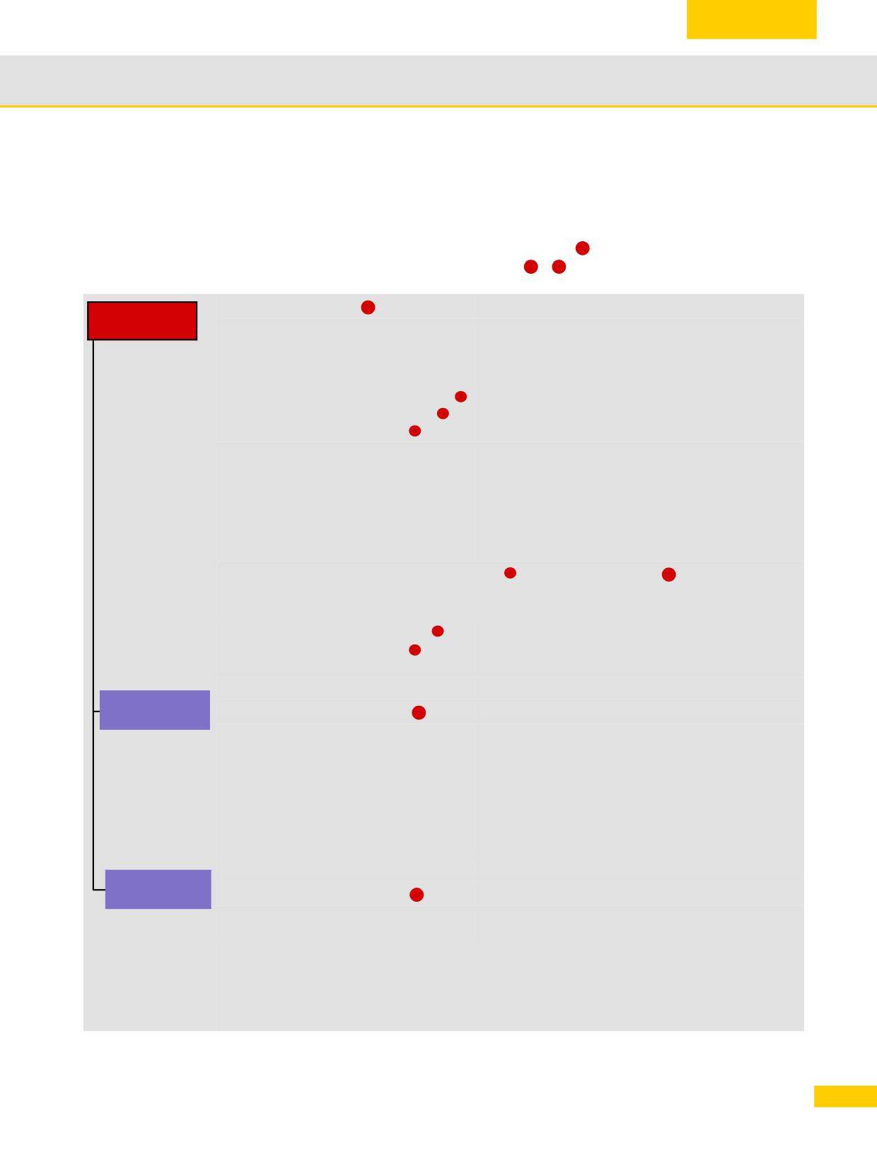
CYCLE832 in the main For machining purposes, a main program is generated
that includes all technology data. The
1
program main program calls one or more subprograms
,
that contain only the pure geometric data
2
3
of the workpiece. The tool change defines how the content is divided into subprograms.
MAINPROGRAM.MPF
1
Main program
N10
T1 D1
N20
M6
; Tool change
N30
S10000 M3
N40
G54
N50
CYCLE832 (0.1,_ROUGH,1)
4
; High Speed Settings
N60
EXTCALL "CAM_rough"
5
; Call subprogram
N65
CYCLE832(0,_OFF,1)
4
; Deselect CYCLE832
N70
T2 D1
N80
M6
; Tool change
N90
S15000 M3
N100
G54
N110
TRAORI
; Only for 5-axis
N120
ORIWKS ORIAXES
; Orientation reference and orientation;
N130
; interpolation, switched optionally in CYCLE832
N140
CYCLE832(0.005,_ORI_FINISH,0.5)
4
; High Speed Settings
6
N150
ORISON
; Orientation smoothing activation
N160
; switched optionally already in CYCLE832
N170
EXTCALL "CAM_finish"
5
; Call subprogram
N180
; Deselect CYCLE832
CYCLE832(0,_OFF,1)
4
N190
; End of program
M30
Subprogram
CAM_rough.SPF subprogram
2
N10
G0 X0 Y0 Z10
N20
G1 Z0 F500
N30
G1 X-1.45345 Y0.67878 F10000
G1 Z-2.13247 Y=0.34202 F800
N5046
N5047
M17
N6580
Subprogram
CAM_finish.SPF subprogram
3
N10
G0 X0 Y0 Z10 A3=0 B3=0 C3=0
N20
G1 Z0 F500
N5050
G1 X7.60978 Y3.55541 A3=0.34202 B3=0 C3=-0.9396
N5060
G0 Z50 A3=0.34202 B3=0 C3=0.93969
N6570
TRAFOOF
N6580
M17
29
© Siemens AG All rights reserved SINUMERIK, Manual, Mold-Making with 3- to 5-Axis Simultaneous Milling
General information on workpiece production
2.3
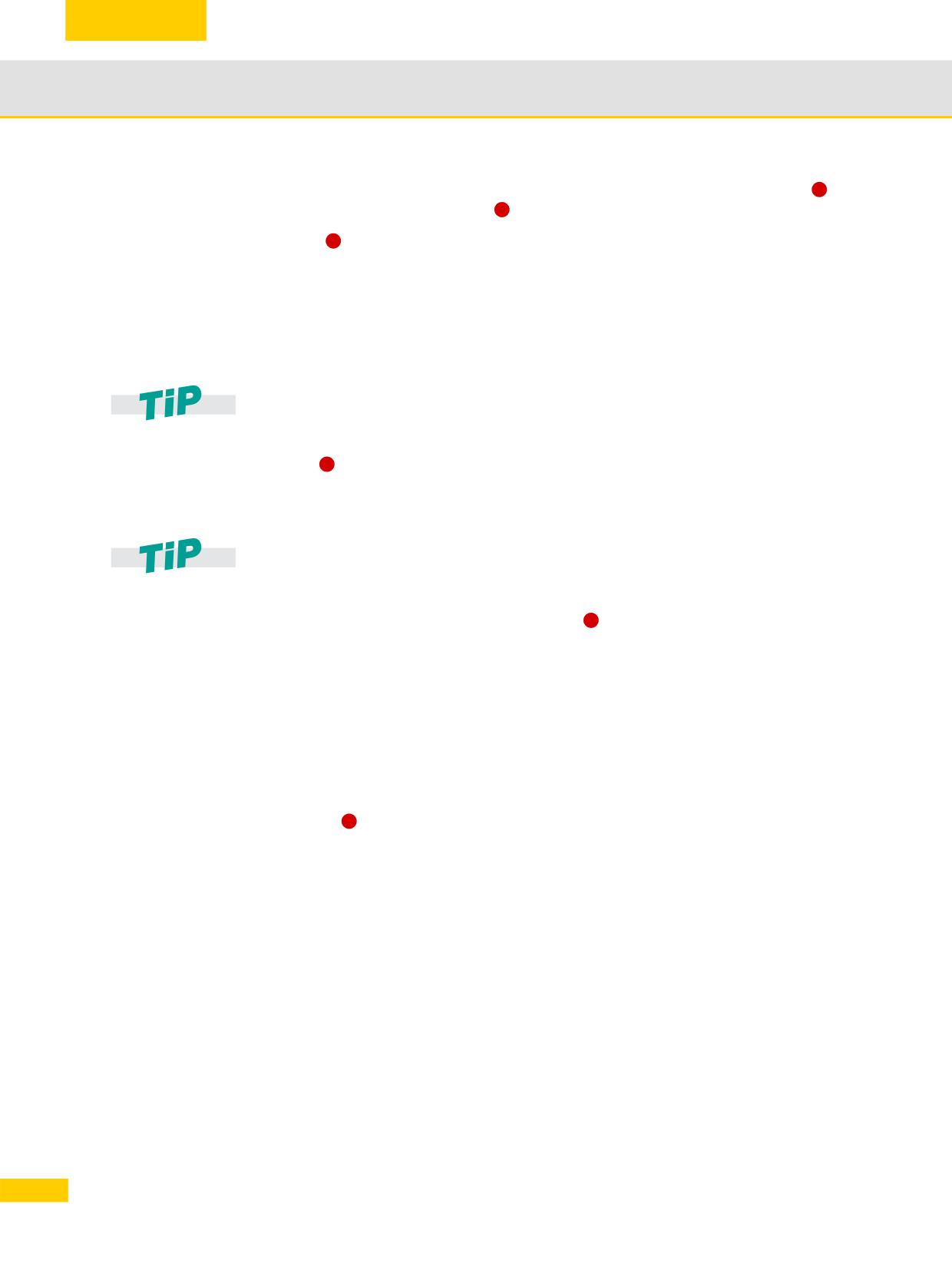
Main program: The main program includes the two key functions for milling, CYCLE832
4
and
subprogram call (e.g. with EXTCALL)
5
CYCLE832
: CYCLE832 was specifically adapted for the program structure shown, where
4
technology data and geometry data are separated. It brings together all the key commands and
activates control functions. The machining technology for milling is defined in CYCLE832. For the
roughing program "CAM_rough" using T1, the parameters in CYCLE832 were set towards
achieving a high velocity. For the finishing program "CAM_Finish", the parameters were set
towards achieving high surface quality and accuracy. CYCLE832 is deselected at the end of the
geometry blocks. More information is available on the individual parameters in Section
CYCLE832 (See "High Speed Settings - CYCLE832" on page 102.)
The call syntax changes if the Top Surface option is active.
EXTCALL
: CAM programs are generally extremely large, which is why they are stored in an
5
external memory. The EXTCALL command is used to call the subprograms from various
locations, including external memories. All programs should be located in the same directory. If
this is not the case, the paths must also be specified during the call.
If option EES is active, then the subprogram call is made without EXTCALL. (See "EES -
Execution from External Storage (NC Extend)" on page 35.)
ORISON (only for Advanced Surface COMPCAD)
: The NC command ORISON is a vector
6
smoothing function that has been specially developed for the 5-axis area. This function can be
used to smooth fluctuating orientation across several blocks. The aim is to achieve a smooth
characteristic for the orientation and a more harmonious movement of the axes. As of SW 4.5,
this command can be part of CYCLE832 (_ORI_ROUGH, _ORI_SEMIFIN, _ORI_FINISH). With
older software versions, it is recommended that ORISON is programmed after CYCLE832.
The OTOL command can be used to define the orientation tolerance for vector smoothing with
ORISON. The value is entered in degrees. The set value depends on the component.
Subprogram: The subprogram contains the geometry blocks. In our example, these initially take
the form of blocks for 3-axis milling, which are then followed by the blocks for 5-axis
simultaneous
milling. These are designated A3, B3, and C3.
7
30
© Siemens AG All rights reserved SINUMERIK, Manual, Mold-Making with 3- to 5-Axis Simultaneous Milling
General information on workpiece production
2.3
CYCLE832 in the For machining purposes, a main program is generated
, which only serves as call program for
1
subprogram the individual subprograms. The main program calls one or more subprograms
2
,
3
which
contain all the technological and geometric data for the production of the workpiece.
This program structure is suitable for the use of CAM systems whose postprocessors support the
SINUMERIK cycles, output these completely with the cycle call and deselect them during the
program generation. The descriptions for 4 to
7
are identical (see page 30).
MAINPROGRAM.MPF
1
Main program
N10
CYCLE800(4,"TABLE",200000,57,0,0,0,0,0,0,0,0,0,1,,1)
; Swivel basic position
N20
CYCLE800()
; Deselect swivel
N30
WORKPIECE(,,,"CYLINDER",0,0,-32,-80,46)
; Define blank
N40
EXTCALL "CF_CARD:/PROG/CAM_ROUGH.SPF"
5
; Call subprogram
N50
STOPRE
; Stop preprocessing
N60
EXTCALL "CF_CARD:/PROG/CAM_FINISH.SPF"
5
; Call subprogram
N65
STOPRE
; Deselect CYCLE832
N70
; Further subprograms
N200
M30
; End of program
Subprogram
CAM_ROUGH.SPF subprogram
2
N10
T1 D1
; Tool call
N20
M6
; Tool change
N30
S10000 M3
; Technological data
N40
G54
; Zero offset
N50
CYCLE832 (0.1,_ROUGH,1)
4
; CYCLE832 roughing
N60
G0 X0 Y0 Z10
; 3-axis
N70
G1 Z0 F500
N80
G1 X-1.45345 Y0.67878 F10000
N90
N6000
CYCLE832(0,_OFF,1)
; Deselect CYCLE832
N6010
M17
; End of subprogram
Subprogram
CAM_FINISH.SPF subprogram
3
N10
T2 D1
; Tool call
N20
M6
; tool replacement
N30
S15000 M3
; technological data
N40
TRAORI
; TRAORI for 5-axis On
N50
ORIWKS
; Orientation reference
N60
ORIAXES
; Orientation interpolation, switched optionally already in CYCLE832
N70
G54
; Zero offset
N80
CYCLE832(0.005,_ORI_FINISH,0.5)
4
; CYCLE832 5-axis finishing
N90
ORISON
6
; Orientation smoothing activation
N95
; switched optionally already in CYCLE832
N100
G0 X0 Y0 Z10 A3=0 B3=0 C3=0
N110
G1 Z0 F500
N120
G1 X7.60978 Y3.55541 A3=0.34202 B3=0 C3=-0.9396
N130
G0 Z50 A3=0.34202 B3=0 C3=0.93969
7
N140
N6000
TRAFOOF
; TRAORI Off
N6010
CYCLE832(0,_OFF,1)
; Deselect CYCLE832
N6020
M17
; End of subprogram
CYCLE832 guidelines When CYCLE832 is used, the sequence of the NC commands in the program must be observed.
31
© Siemens AG All rights reserved SINUMERIK, Manual, Mold-Making with 3- to 5-Axis Simultaneous Milling

General information on workpiece production
2.3
Whereby:
CYLCE832 must be called immediately before the mold-making program.
After selection of CYCLE832, only motion commands (G0, G1, G2, G3) should be
programmed.
Manufacturer-specific subprograms, e.g. for tool change or swivel, can overwrite settings of
the CYCLE832 and must be programmed outside the CYCLE832 selection and deselection.
Programming overview
Description
T1 D1 M6
Tool change
CYCLE800(4,"HEAD",200000,57,0,0,0,0,0,0,0,0,0,1,,1)
Settings,
e.g. swivel
CYCLE832 (0.1,_ROUGH,1)
Select CYCLE832
...G1 X-1.45345 Y0.67878 F10000...
Mold-making program
CYCLE832(0,_OFF,1)
Deselect CYCLE832
CYCLE800()
Deselect CYCLE800
Example, NC commands in the 5-axis program sequence
CYCLE800()
TRAFOOF
T="CUTTER_10"
M6
S15061 M3
CYCLE800(0,"TABLE",100000,27,0,0,0,288.079,0,-10.196,0,0,0,-1,0,1)
G00 X-13.532 Y-24.856 M03
TRAORI
ORIWKS ORIAXES
G54
TOFFL=0
TOFFR=0
CYCLE800()
CYCLE832(0.05,_TOP_SURFACE_SMOOTH_ON+_ORI_SEMIFIN,1)
32
© Siemens AG All rights reserved SINUMERIK, Manual, Mold-Making with 3- to 5-Axis Simultaneous Milling
General information on workpiece production
2.4
2.4
Programs, data transfer and editor
2.4.1
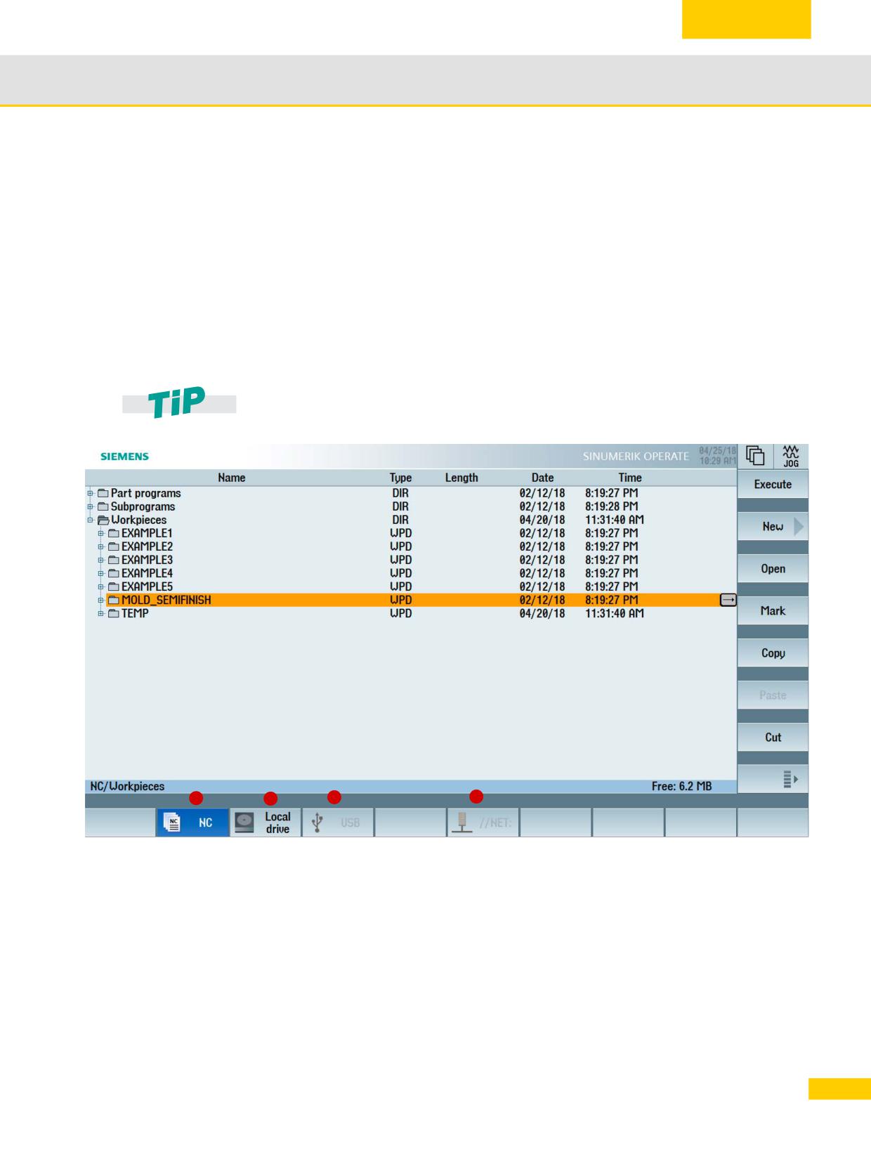
Program manager
The program manager offers an optimum overview of the directories and programs, and very
easy-to-use file handling. It supports plain names of up to 24 characters for directories and files.
Subdirectories can also be managed on external storage media such as CF cards, USB sticks
and on the NC.
All storage media including the network drives are displayed in the program manager. The part
programs can be edited in all media. You can create, paste, copy, delete and cut programs via
the horizontal softkey bar.
In the program manager, you can use standard Windows short-cuts such as CTRL+C,
CTRL+X, and CTRL+V.
1
2
3
4
Possible storage locations for programs are:
1. NC
2. Local drive (CompactFlash card or hard drive)
3. USB drives
4. Network drives
33
© Siemens AG All rights reserved SINUMERIK, Manual, Mold-Making with 3- to 5-Axis Simultaneous Milling

General information on workpiece production
2.4
2.4.2
External storage media - data transfer
NC programs are stored in the control, if required, downloaded to the working memory, and
executed on the machine.
Mold-making programs are often too large for the NC memory or they cannot be processed.
Therefore these are swapped to an external memory and processed successively. In the main
program, an EXTCALL command is programmed, which calls up the program according to the
network path on the server, the USB interface, hard drive, etc.
Procedure when calling the geometry program with EXTCALL/CALL
X Program the geometry program call, e.g. SAMPLE in the main program. The call differs
depending on the control and where the data is stored.
Subprogram is on the HMI user memory (NC)
CALL "SAMPLE"
Subprogram is in the directory on the CompactFlash card
EXTCALL "CF_CARD:/PROGRAMS/SAMPLE.SPF"
Subprogram is on a local drive
EXTCALL "LOCAL_DRIVE:/PROGRAMS/SAMPLE.SPF"
Subprogram is on a USB stick
EXTCALL "USB:/MOLD_DIE/CAM_ROUGH.SPF"
Network connected with Ethernet and path in the machine data SD 42700, e.g. on a server
"//R4711/workpieces/subprograms". The default setting is optional. The directory can first
be specified when making the call with EXTCALL.
EXTCALL "SAMPLE.SPF"
Processing of USB flash drive / CF card
On the control, there is a USB port on the front, and on the SINUMERIK 828D, there is a USB
port on the front and on the rear. The slot for a CompactFlash card on the SINUMERIK 828D is
on the front.
Storage media can be inserted or removed during operation, i.e. the machine does not have
to be restarted in order for the storage medium to be recognized
Loading, editing and executing of part programs from the storage medium.
When executing part programs from a storage medium there is no loss of velocity (DNC
operation), in which case executing from a CF card is recommended.
No special software is necessary for reading from or writing to the storage medium on the
PC.
Direct execution from a USB FlashDrive is not recommended. Disconnecting during
operation will stop machining and, under certain circumstances, cause damage to the
workpiece.
34
© Siemens AG All rights reserved SINUMERIK, Manual, Mold-Making with 3- to 5-Axis Simultaneous Milling
General information on workpiece production
2.4
2.4.3
EES - Execution from External Storage (NC Extend)
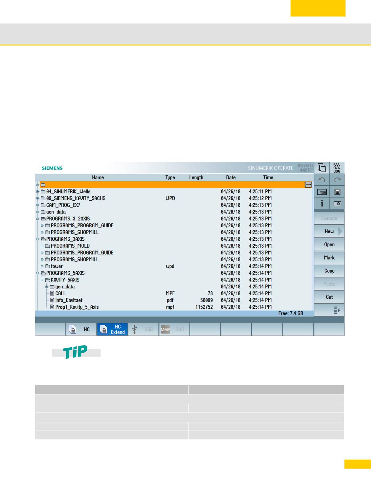
Using function EES - Execution from External Storage (as of SW 4.7 SP2) you can call and
execute part programs by the NC directly from all connected data storage devices (e.g. local
drive, PCU50, USB global and at the TCU, network). The behavior is the same as that for
processing from the NC part program memory without the restrictions that apply to "processing
external".
With this function, there is practically no longer a restriction regarding the part program size. This
is only limited by the capacity of the external data storage. There is a standard syntax for all
subprogram calls, independent of where the subprogram is archived. Program compensation for
NC stop is possible.
The EES function makes EXTCALL calls superfluous. If required, existing EXTCALL calls
can be converted.
Syntax example for a call with/without option EES
Without EES
With EES
Call subprogram in another folder in the local drive
EXTCALL "//LOCAL_DRIVE: /CAM_PRG/ROUGH_01.SPF"
CALL "//LOCAL_DRIVE: /CAM_PRG/ROUGH_01.SPF"
Subprogram call from the main program in the local drive (main and subprogram in the same folder)
EXTCALL "ROUGH_01.SPF"
CALL "ROUGH_01.SPF"
EXTCALL "ROUGH_01.SPF"
ROUGH_01.SPF
35
© Siemens AG All rights reserved SINUMERIK, Manual, Mold-Making with 3- to 5-Axis Simultaneous Milling
General information on workpiece production
2.4
2.4.4
Graphic and file formats in the program manager
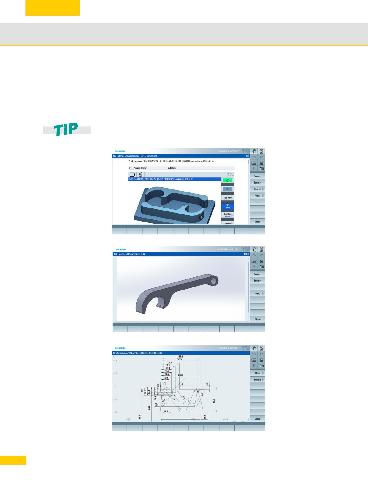
In addition to the standard NC formats (*.mpf, *.spf), the program manager also directly displays
additional graphic and file formats at the control. This means that you can archive and
display, for example, production documentation as PDFs, photographs of the clamping situation
or also CAD drawings (DXF). This means that you have all information in the production
environment directly available at the control - a paperless production environment.
An existing DXF file can be read into the contour editor as contour (DXF reader option).
Syntax documents TXT, PDF
Pixel files BMP, PNG, GIF, JPG
Vector graphic DXF
36
© Siemens AG All rights reserved SINUMERIK, Manual, Mold-Making with 3- to 5-Axis Simultaneous Milling
General information on workpiece production
2.4
2.4.5
Program editor - useful functions
In the program editor, you can conveniently open larger mold-making programs yourself; you can
also edit these and this, independent of the archiving location (NC, CF card, USB stick...). In
addition to standard functions, it offers additional helpful functions such as cut out, copy, paste
and renumber for effectively programming and displaying large programs.
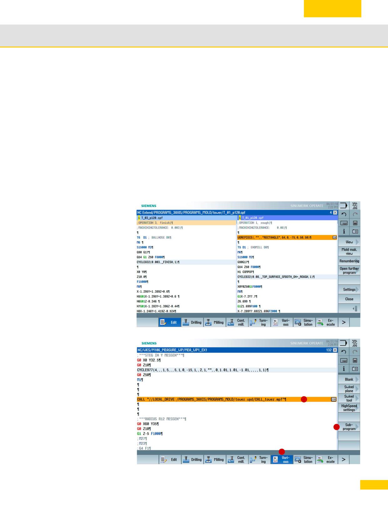
Program editor supplementary functions
Dual editor - two programs can be simultaneously opened next to one another
Structuring large programs by creating blocks (blocks are opened and closed)
Scalable display, changing the font size
Syntax highlighting, color coding NC functions
Determine machining times through simulation and display block-by-block/non-modally
Subprogram calls, including path information, directly using the Various softkey
Dual editor and syntax
highlighting
Subprogram call with
transfer of the complete path
3
2
1
37
© Siemens AG All rights reserved SINUMERIK, Manual, Mold-Making with 3- to 5-Axis Simultaneous Milling
General information on workpiece production
2.5
2.5
JOG mode, zeros, tools
2.5.1
Zero offsets
After reference point approach, the actual value display for the axis coordinates is based on the
machine zero (M) of the machine coordinate system (MCS). The program for machining the
workpiece, however, is based on the workpiece zero (W) of the workpiece coordinate system
(WCS). The machine zero and workpiece zero are not necessarily identical. The distance
between the machine zero and the workpiece zero depends on the workpiece type and how it is
clamped. This zero offset is taken into account during the program execution and can be a
combination of different offsets.
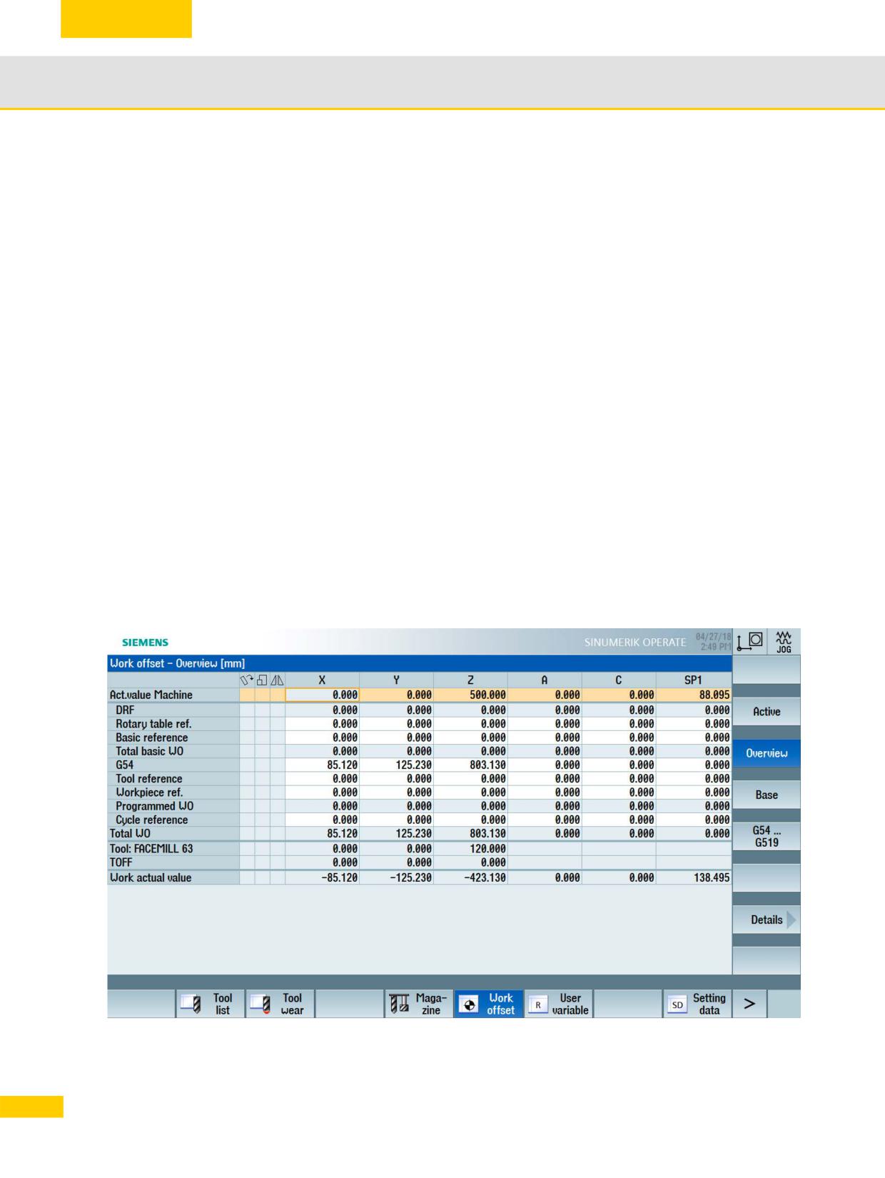
When setting up the workpiece, set the workpiece zero as zero offset, e.g. G54. Using the Zero
offsets softkey, open the list where you can select various views using the vertical softkeys.
Active
zero offsets, for which active offsets are included or for which values, settable zero offsets
and total zero offset are entered
Overview
The active offsets or system offsets are displayed for all set-up axes. In addition to the offset
(course and fine), the rotation, scaling and mirroring defined using this are also displayed.
Base
The defined channel-specific and global base offsets, divided into coarse and fine offsets, are
displayed for all set-up axes.
G54..G57
All of the settable offsets, divided into coarse and fine offsets, are displayed along with
rotations, scaling and mirroring.
38
© Siemens AG All rights reserved SINUMERIK, Manual, Mold-Making with 3- to 5-Axis Simultaneous Milling
General information on workpiece production
2.5
2.5.2
Tool management
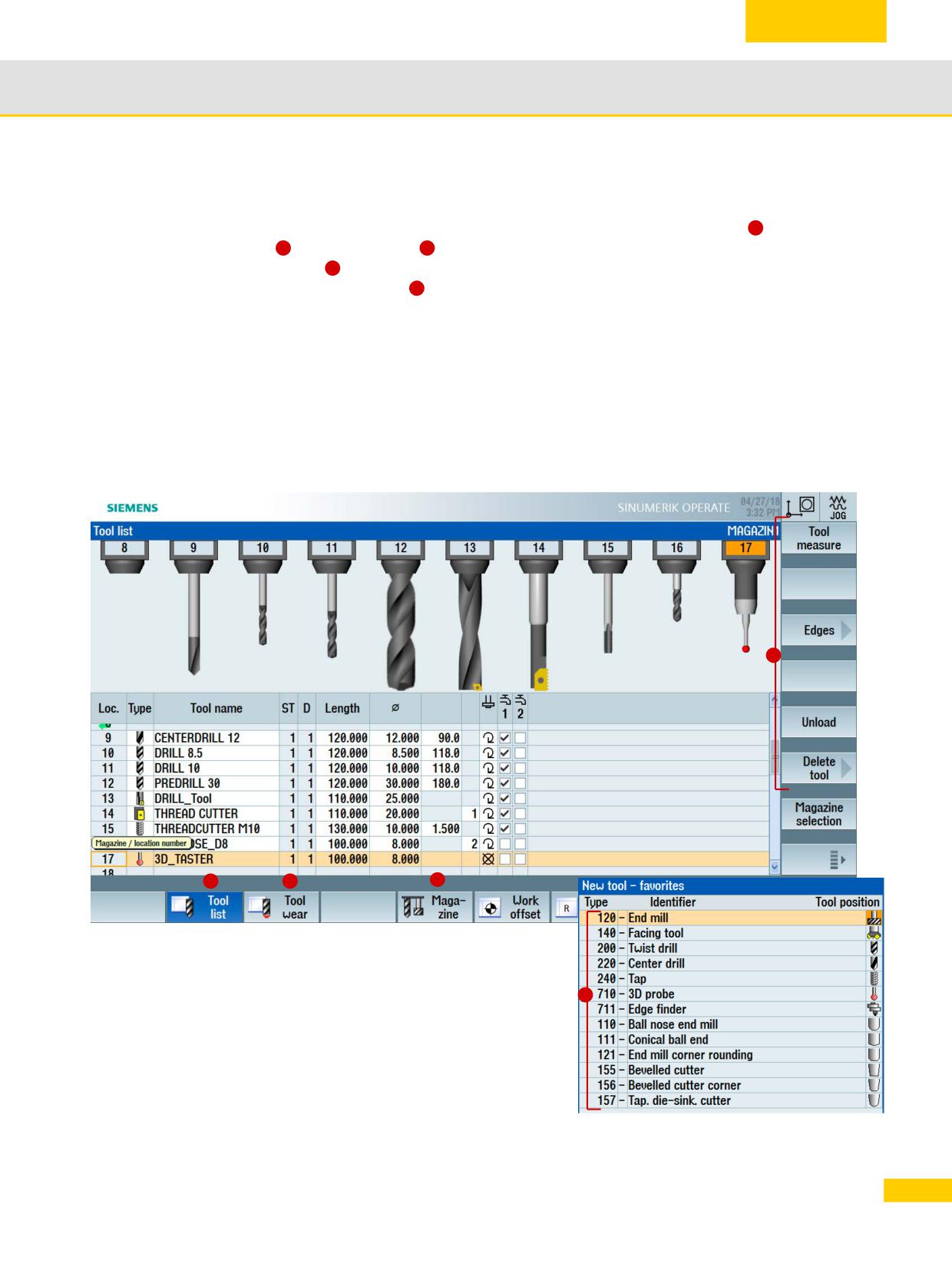
For tool management, SINUMERIK Operate provides you with the tool list
1
, the tool wear list
2
and the magazine
3
displays. All of the relevant tool data is displayed in the tool list. Using
softkey
4
you can create, delete, load or unload tools and directly load them into the program.
With the tool catalog
5
, which is displayed when new tools are created, you can quickly create
tools with the aid of pre-defined tool types.
For the milling technology, schematic diagrams of the tools are displayed above the tool list. The
display can be configured. You can switch this on and off via the >> > Settings expanded
softkey bar (not for multitasking machines).
For automatic tool monitoring, you can define the wear limits and service life. Providing a new
tool or the disabling of a worn tool is done automatically, based on the specified wear values.
Magazine-related data is displayed in the magazine. For example, you can disable locations or
assign tools to locations.
4
1
2
3
5
39
© Siemens AG All rights reserved SINUMERIK, Manual, Mold-Making with 3- to 5-Axis Simultaneous Milling
General information on workpiece production
2.5
2.5.3
Manual retraction - return
After an interruption of a tapping operation (G33/G331/G332) or a general drilling operation
(tools 200 to 299) due to power loss or a RESET at the machine control panel, you have the
possibility to retract the tool in the JOG mode in the tool direction without damaging the tool or
the workpiece.
The retraction function is especially useful when the coordinate system is swiveled, i.e. the infeed
axis is not perpendicular.
An active CYCLE800 and TRAORI are taken into account, and for tapping, the spindle is
interpolated in the Z axis for return movement.
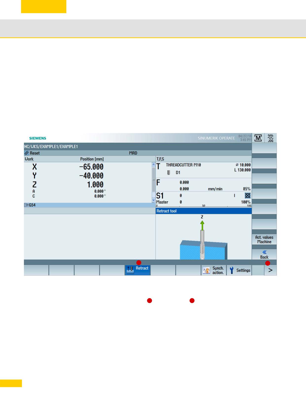
2
1
Procedure
X After a power failure, switch on the machine again and select the JOG operating MODE.
X Press the menu forward key.
1
and then return
2
X Select the WCS coordinate system at the machine control panel and traverse the tool
corresponding to the return axis displayed in window Return tool (e.g. Z+).
40
© Siemens AG All rights reserved SINUMERIK, Manual, Mold-Making with 3- to 5-Axis Simultaneous Milling
General information on workpiece production
2.6
2.6
Fundamentals, measuring in JOG and AUTOMATIC
Measuring in JOG
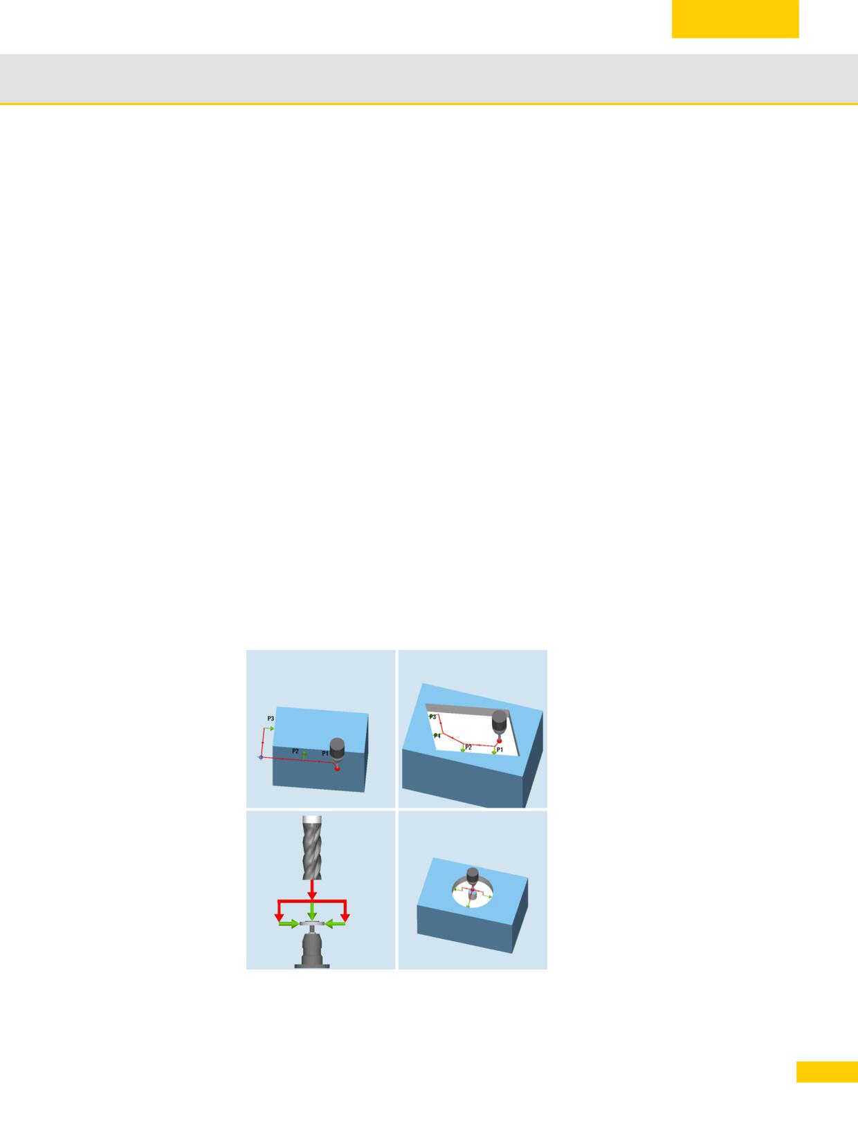
When measuring in JOG (setup), the machine is prepared for machining. This involves
determining the dimensions of the workpiece and the tool which are still unknown.
Manual measurement is used to prepare the machine for machining.
Manual measurement is used to determine unknown workpiece or tool geometries.
The operator interacts with the machine during manual mode in order to perform the
measurement.
The reference point for programming a workpiece is always the workpiece zero. When setting-up
a clamped workpiece its workpiece zero is determined. The workpiece elements - edge, corner,
pocket/hole, lug, plane - can be used when setting-up. When completed, the workpiece zero is
defined as the result of the linear and rotary compensations of the coordinate system that have
been determined.
Measuring in AUTOMATIC (process measuring)
In process measuring, workpiece tolerances are determined within the production process and
tool parameters are monitored. The nominal dimensions of the tool and workpiece are already
known.
Process measuring is performed to check that the workpiece measurements conform to
specifications.
Process measuring is performed to correct known workpiece and tool geometries.
The measurement is performed by calling a measuring cycle in the machining program.
Measuring cycles/functions for all measuring tasks
The SINUMERIK features an extensive
Examples of measuring
pool of practical measuring cycles/
cycles/functions
functions for measuring tasks in JOG
and AUTOMATIC modes. These
measuring cycles/functions enable you
to measure workpieces and tools using
a graphically supported process.
The measuring tasks are performed
with switching probes and
dynamometers or laser measuring
systems.
When measuring in JOG, the
measuring functions can also be used
with edge probes or tools with known
dimensions. During the measurement,
the measuring points are manually
approached and the current position is
saved in the measuring function via a
softkey.
41
© Siemens AG All rights reserved SINUMERIK, Manual, Mold-Making with 3- to 5-Axis Simultaneous Milling
General information on workpiece production
2.6
2.6.1
Measurement logs in JOG
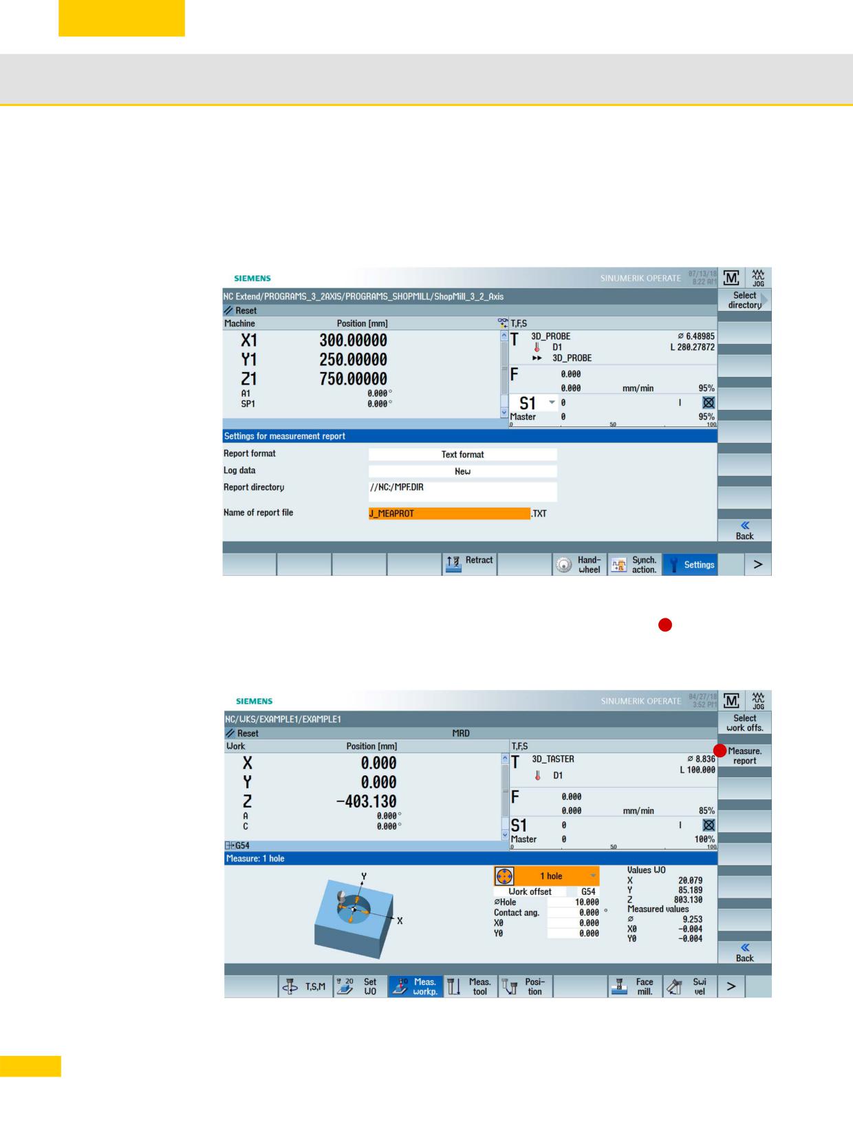
When measuring the workpiece zero and the tool, you can save the values determined in a
standard log. For a standard log, you can first configure the log format (TXT, CSV), log data,
archive location and the names.
After the measurement has been performed, the Measurement log softkey
becomes active,
1
and you can save the measured values. Measurement logs can be generated only when using
switching probes or dynamometers.
1
42
© Siemens AG All rights reserved SINUMERIK, Manual, Mold-Making with 3- to 5-Axis Simultaneous Milling
General information on workpiece production
2.6
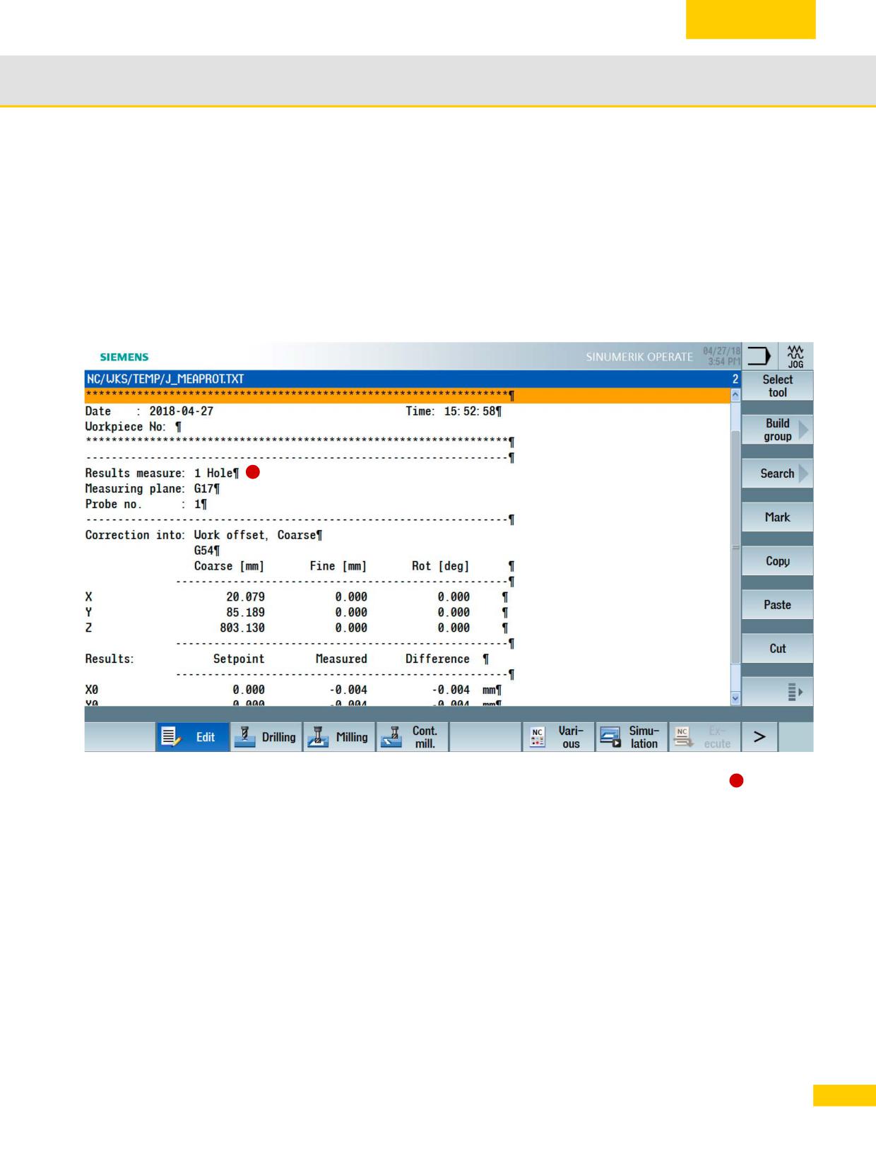
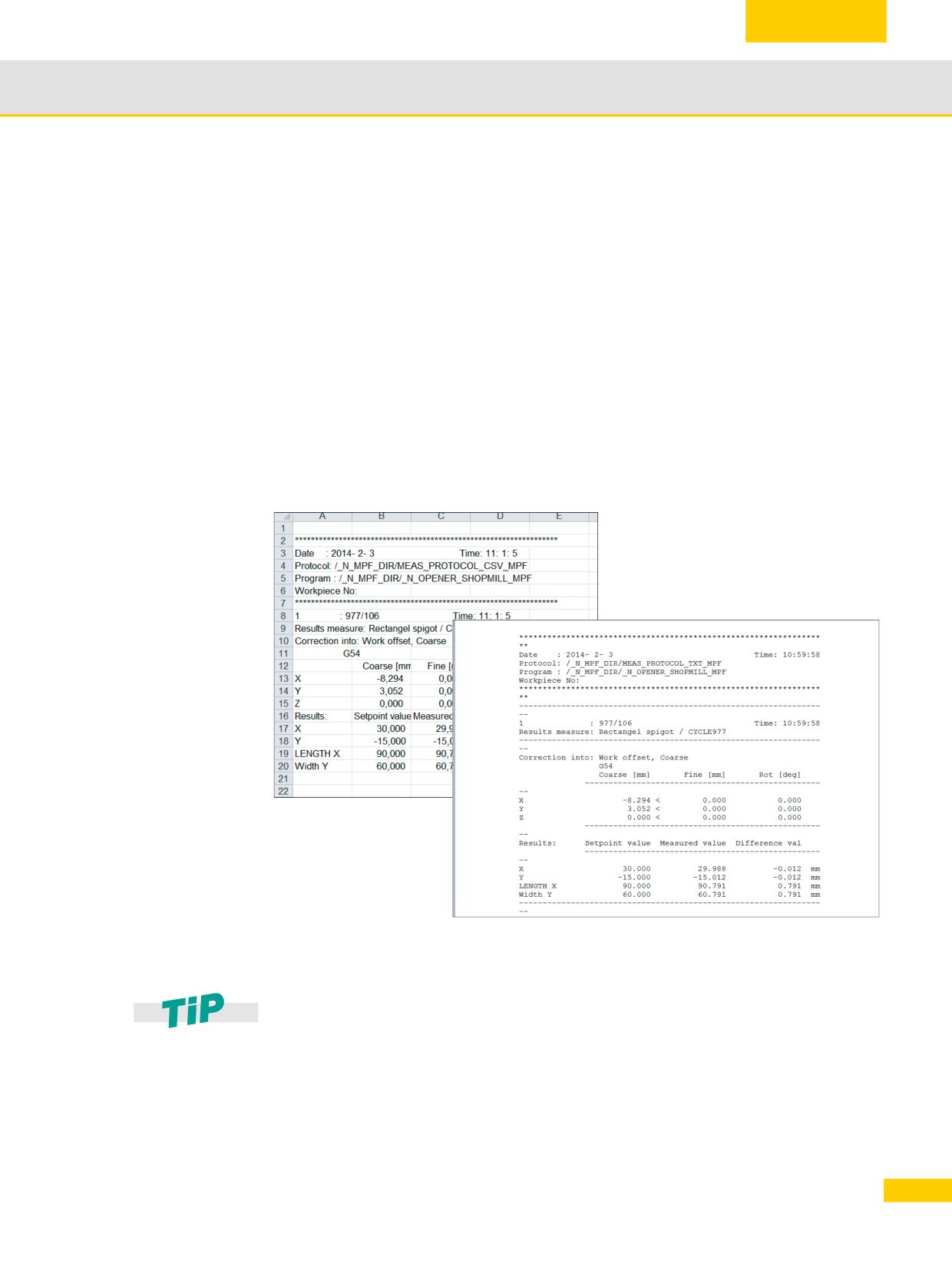
The following data is determined and logged:
Date/time
Log name with path
Measuring variant
Input values
Compensation target
Setpoints, measured values and differences
2
Example of a log file for workpiece measurement using measuring variant 1 hole.
2
43
© Siemens AG All rights reserved SINUMERIK, Manual, Mold-Making with 3- to 5-Axis Simultaneous Milling
General information on workpiece production
2.6
2.6.2
Measurement logs in AUTOMATIC
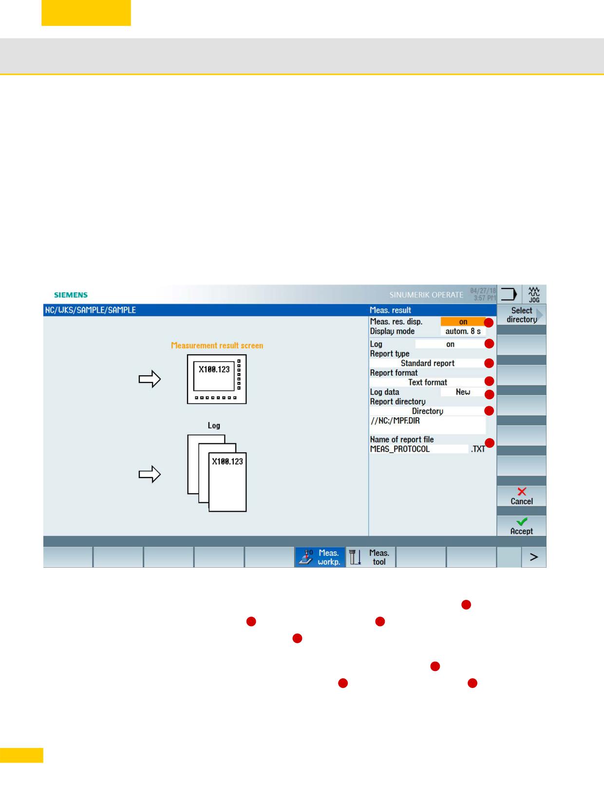
As of SW 4.7 SP2, standard logs can be used to save measurement results. Standard logs
display the results from measuring cycles in a clear log structure. The output is possible in text or
tabular format. Contents and structure are predefined.
The call of the control CYCLE150 is always at the start of the program. You can then optionally
create user-defined texts and program the various measuring cycle calls.
In comparison to the standard log in JOG, additional data is captured:
Name of the part program from which the measuring function was called
Workpiece number
Measuring point, measuring variant and time of measurement
1
2
3
4
5
6
7
Procedure
X Select the display and display mode of the measurement result screen
1
X Switch on logging
2
and select the standard log
3
X Select the format (TXT, CSV)
4
X Configure whether the log should be recreated after each measurement or the
measurements should be saved consecutively in the same file.
5
X Select the storage location (NC, USB...)
6
and the name of the log file
7
X Parameterize the measuring functions and supplement optional user data with
S_PROTTXT[.].
44
© Siemens AG All rights reserved SINUMERIK, Manual, Mold-Making with 3- to 5-Axis Simultaneous Milling
General information on workpiece production
2.6
X If you have supplemented the standard log to include user data, you must program
CYCLE160 so that the user data is written to the log file.
G code program example with call and a measurement function
N50 CYCLE150(10,1001,"MEAS_PROTOCOL.TXT")
N51 S_PROTTXT[0]=REP("") ; field, delete all data
N52 S_PROTTXT[1]=" Measure workpiece 1234" ; write user data
N70 CYCLE160 ; write user data to the log
N80 CYCLE997(109,1,1,10,1,5,0,45,0,0,0,5,5,5,10,10,10,0,1,,0,)
The standard logs can be saved as CSV or text file.
You can use CYCLE150, also without measuring functions, for example, to display texts
for the operator on the complete screen.
45
© Siemens AG All rights reserved SINUMERIK, Manual, Mold-Making with 3- to 5-Axis Simultaneous Milling
General information on workpiece production
2.7
2.7
Measuring workpiece/tool in JOG
2.7.1
Workpiece measuring in JOG
Once the machine has been powered up and the reference point approached, the axis positions
relate to the machine coordinate system. The zero offset signals to the control the position of the
workpiece in the machine coordinate system.
2.7.2
Workpiece measuring functions in JOG
Using the semi-automatic "Measuring in JOG", the required measuring function is selected on the
control using the appropriate softkeys. The displayed input screens are used for assigning the
function parameters. You must bring the tool or probe into a permissible starting position for the
measurement task concerned, e.g. using the traversing keys or handwheel (manual traversing).
The measuring functions permit the following functions:
Calibrating a probe
Detecting dimensions and position of workpiece geometries, e.g. in order to set up the
workpiece.
Requirements for using measuring functions
The probe is calibrated and active; the tool compensation is activated.
Practical measuring functions are provided to facilitate measurements
Measuring functions in
JOG
→ Calibrate probe
→ Measure edge
→ Aligning an edge
→ Measure corner
→ Measure pocket/hole
→ Measure spigot/hole
→ Align plane
→ Back (exit measuring in
JOG)
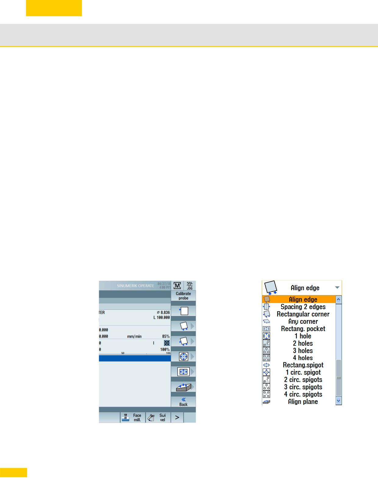
The measuring functions can be selected directly via the softkeys. The softkeys can be freely
assigned as of the third softkey and the assignments are based on the last selected cycles. After
selecting a measuring function, you can select additional measuring functions via a selection list
(see figure on the right).
46
© Siemens AG All rights reserved SINUMERIK, Manual, Mold-Making with 3- to 5-Axis Simultaneous Milling
General information on workpiece production
2.7
2.7.3
Example for measuring a workpiece in JOG
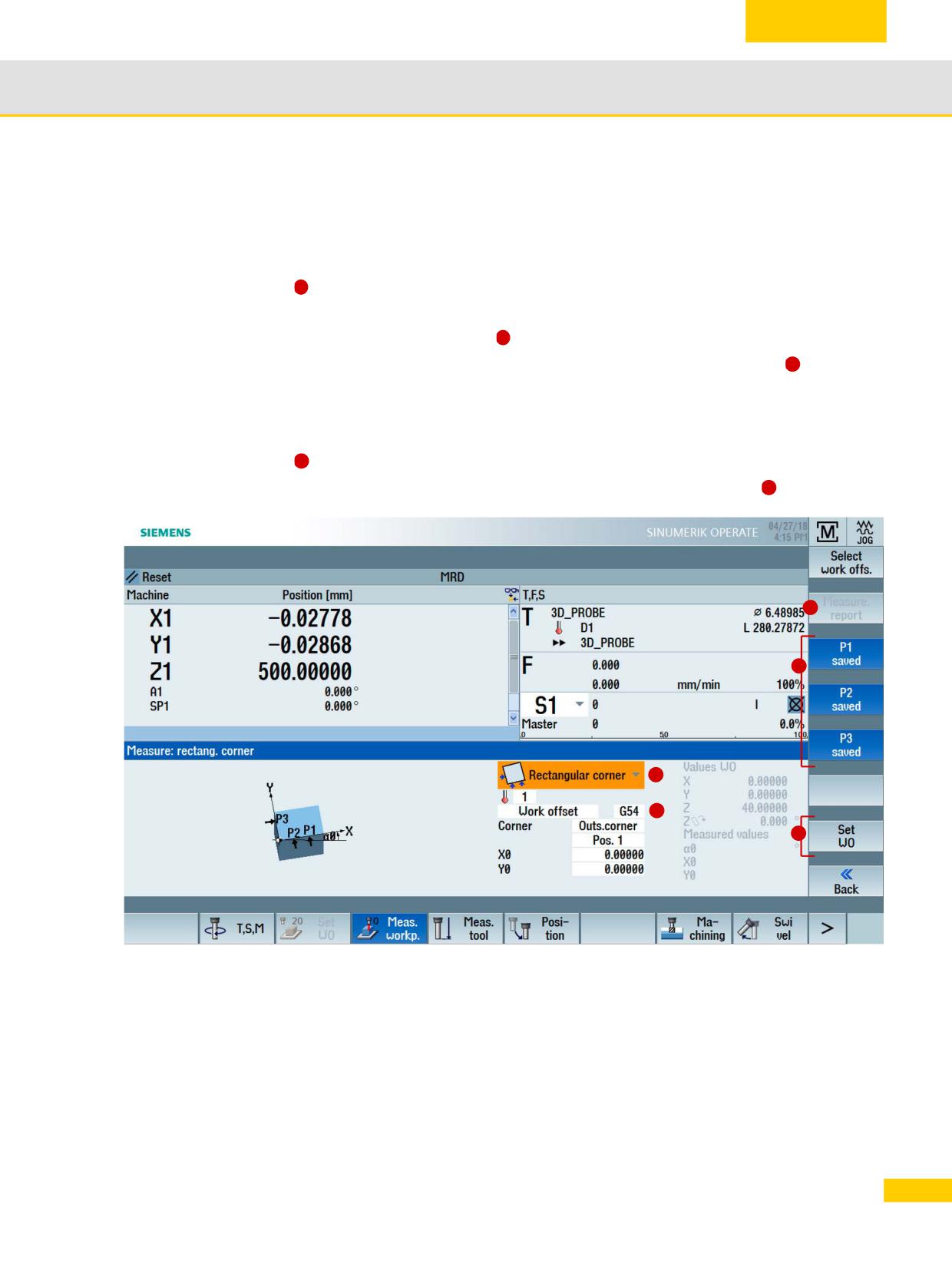
The workpiece should be setup with the Right-angled corner measuring function. The
compensation should be made in zero offset G54.
X Select the Right-angled corner softkey. You can also select the cycle from the selection list
1
X Traverse the probe to measuring point P1.
X Select the zero offset, e.g. G54
2
X When you press "NC Start", the associated measuring points P1, P2, and P3 3 are
automatically approached starting from the manually assumed preliminary position. This
means that the probe approaches the workpiece, is triggered and then returns to the start
position.
X After each measuring process, the measured values can be saved in a measurement log
the measurement log can be configured in advance.
5
X Once all measuring points have been approached, press Set zero offset
4
5
3
1
2
4
X The corner point now corresponds to the setpoint position. The calculated offset is stored in
the zero offset.
47
© Siemens AG All rights reserved SINUMERIK, Manual, Mold-Making with 3- to 5-Axis Simultaneous Milling
General information on workpiece production
2.7
2.7.4
Measure tool in JOG
When executing a program, the various tool geometries must be taken into account. These are
stored as tool compensation data in the tool list. When the tool is called, the control considers the
tool compensation data.
You can determine the tool compensation data (i.e. the length and radius or diameter) either via
special tool pre-setting devices or with the aid of the measuring functions on the machine.
2.7.5
Tool reference point
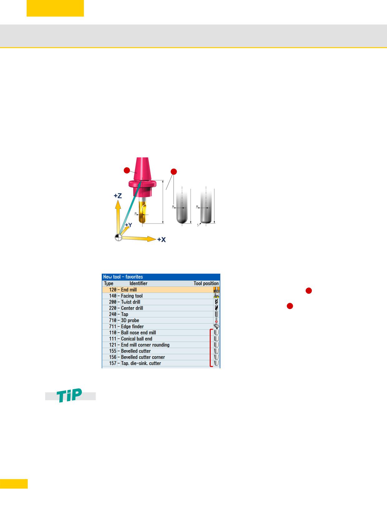
The CAM system usually takes into account
T1
the tool diameter when the geometry program
1
Taper base2
is being created. The calculated tool path
usually refers to the miller center point and the
tool tip (TTP) (center point path).
L1
L1
L1
This means that to measure the length of the
tool, you must use the same reference point
(TTP) as the CAM system. For the purpose of
determining the tool length, always remember
TTP
TTP
TTP
to check the reference point the CAM
programmer used to measure L1. The TTP is
on the tool tip. The TCP (Tool Center Point)
can be further up in the milling tool - e.g. for
TTP = Tool Tip Point
radius end mills at the center of the radius.
The tool magazine is equipped as usual. The
tool numbers (T1...) or the plain text name
(MILLING_12...) of the tools
are entered
1
into the tool table and the tools are assigned a
tool compensation D
, consisting of radius
2
"R" and length "L1".
The typical milling tools are available for
selection in the tool catalog. You only have to
insert these and enter the necessary
compensation data.
CAM systems define the position of the reference point differently depending on the tool
shape. Generally it is assumed that the output tool path refers to the tip of the milling
cutter (TTP). If the CAM system specifies a different reference point, then this difference
must be taken into account when specifying the tool length. You can perform this, for
example, via the TOFFL command in the NC program.
48
© Siemens AG All rights reserved SINUMERIK, Manual, Mold-Making with 3- to 5-Axis Simultaneous Milling
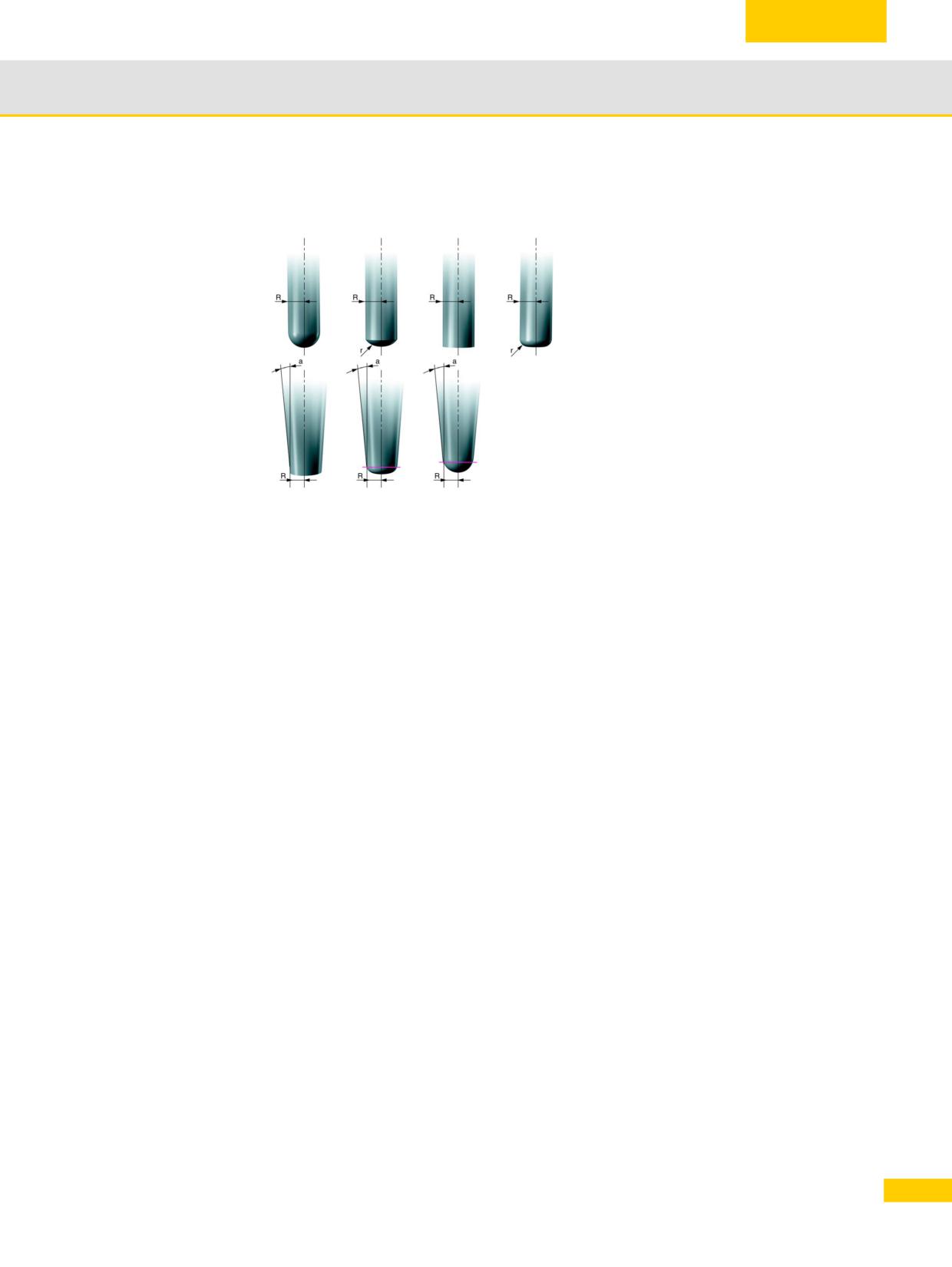
General information on workpiece production
2.7
Ball end mill
Cylindrical die- End mill
End mill with
Specify additional tool data depending on the
Type 110
sinking cutter
Types 120,
corner rounding
Type 111
Types 121, 131
tool type (e.g. conical tools).
In an NC program, the control uses this data
and path compensations G41, G42 - defined
in the program - to execute the necessary path
and length compensations.
Bevel cutter
Bevel cutter with
Tapered
Type 155
corner rounding
die-sinking
Type 156
cutter
Programmable tool compensation (TOFFL, TOFFR)
The TOFFL/TOFF or TOFFR commands can be used to change the effective tool length
(TOFFL/TOFF) or the effective radius (TOFFR) in the NC program without changing the tool
compensations. Additional information on this topic is provided in the Programming Manuals.
Tool length offset:
TOFFL=<value>
Tool radius offset:
TOFFR=<value>
49
© Siemens AG All rights reserved SINUMERIK, Manual, Mold-Making with 3- to 5-Axis Simultaneous Milling
General information on workpiece production
2.7
2.7.6
Example: Measure tool in JOG
Function
You can execute the following functions with "Measure tool":
Calibrate a dynamometer
Determine the tool length or the radius of milling tools or the tool length of drills, and enter this
data into the tool compensation memory.
Requirements for using measuring functions
The tool must have been loaded.
The dynamometer is calibrated and active.
Procedure
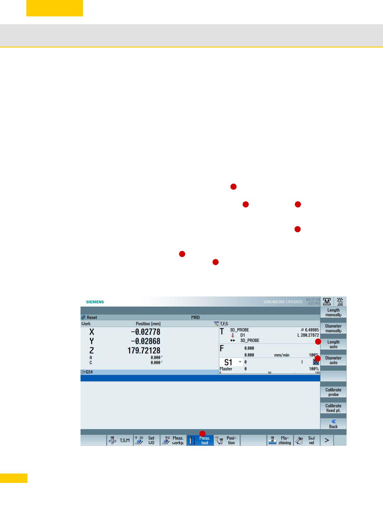
X In JOG mode, select the Measure tool softkey
. In the horizontal softkey bar, select
1
whether you want to measure automatically or manually.
X Click the associated Radius/diameter auto softkey
or Length auto
and enter the
2
3
offset, especially for tools with rounded cuts, for example.
X As of SW 4.5, you can specifically measure individual teeth of the tool in order, for example,
to identify a broken cutting edge. The single cutting edge measurement
4
can be used for
remeasuring and initial measuring. A check is made as to whether the measured values of all
cutting edges are within a defined tolerance range.
X As of SW 4.7, a tool offset
5
can be specified in the +/- direction. When measuring the tool
in automatic mode, a measurement log
6
can be created after each measuring process.
X Click NC Start to initiate the measuring process; the tool compensations for radius and length
1 will be entered in the active tool compensation data.
Measuring function: Measure tool in JOG
3
2
1
50
© Siemens AG All rights reserved SINUMERIK, Manual, Mold-Making with 3- to 5-Axis Simultaneous Milling
General information on workpiece production
2.7
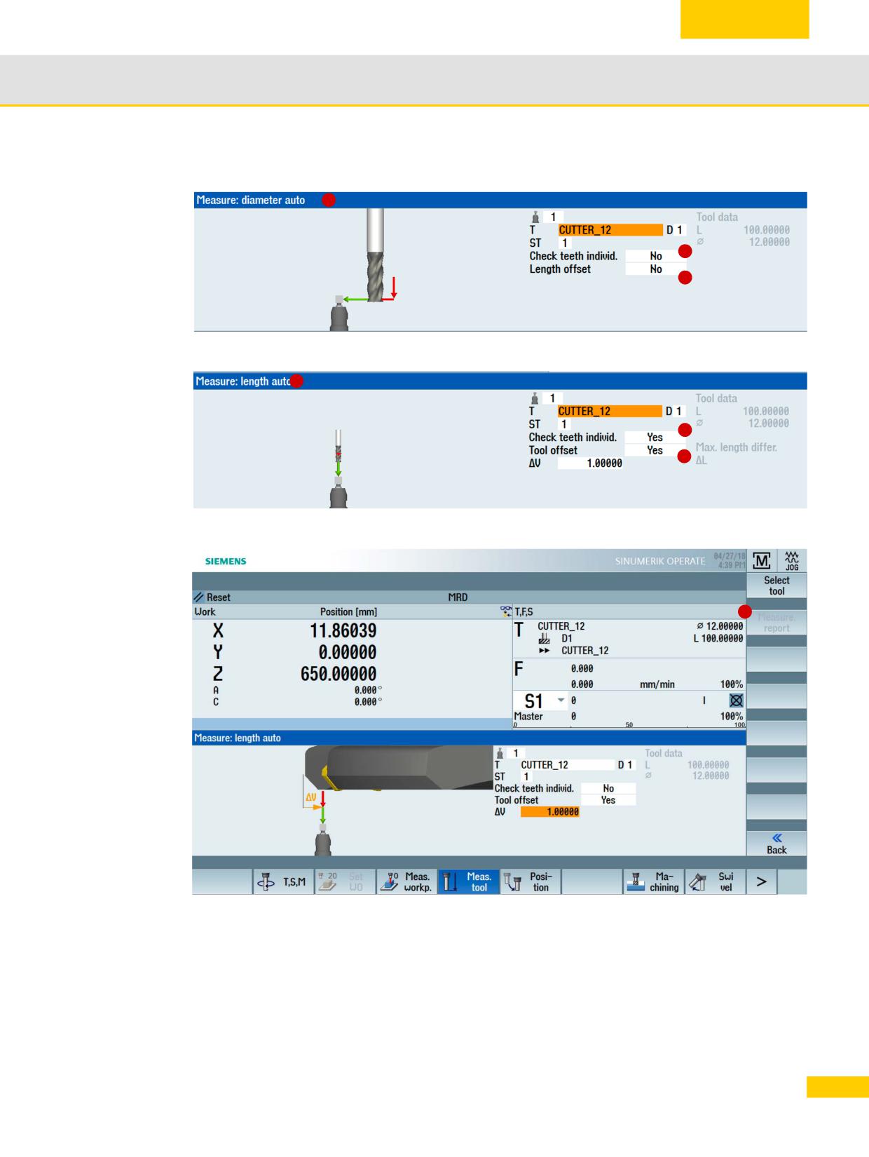
Measure diameter/radius
2
4
5
Measure length
3
4
5
Measurement log
6
51
© Siemens AG All rights reserved SINUMERIK, Manual, Mold-Making with 3- to 5-Axis Simultaneous Milling
General information on workpiece production
2.8
2.8
Measure workpiece/tool in AUTOMATIC - process
measuring
2.8.1
Measure workpiece in AUTOMATIC
For process measuring in Automatic mode, measuring cycles are specifically parameterized for
the measuring task. The input screens of the program editor are used for parameter assignment.
The measuring points to be approached and the measuring task are automatically implemented
in accordance with the measuring program.
The workpiece is measured to determine workpiece tolerances in the production process.
Depending on the measuring cycle used, you can select the following options as the result of
workpiece measurement:
Measurement only without compensations (actual value is measured)
Zero offset compensation (setpoint - actual value deviation)
Tool data compensation (setpoint - actual value deviation)
2.8.2
Workpiece measuring cycles in AUTOMATIC
Practical measuring cycles are provided to facilitate process measuring.
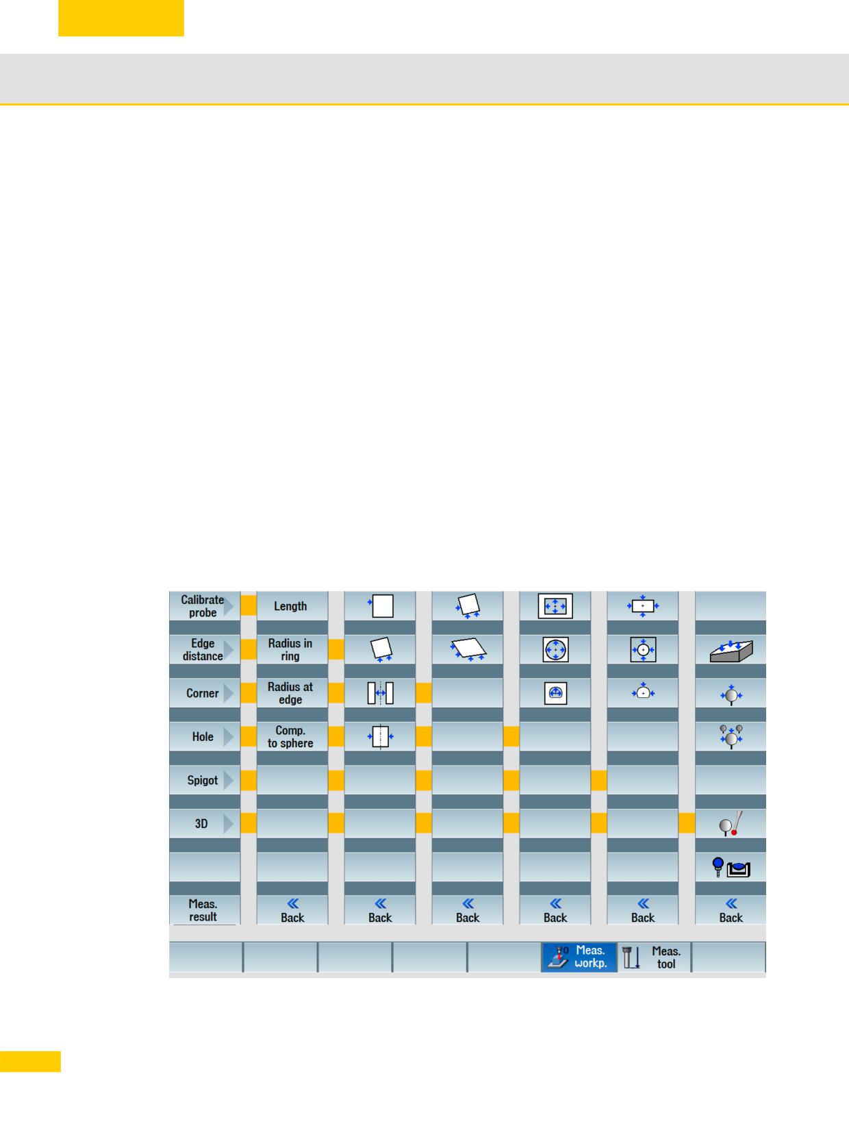
X You can select the measuring cycles within the NC program using the Measure mill >
Measure workpiece softkeys.
Calibrate probe
Edge,
measure
Measure corner
Measure hole
Measure spigot
Measure plane,
angle deviation
kinematics
52
© Siemens AG All rights reserved SINUMERIK, Manual, Mold-Making with 3- to 5-Axis Simultaneous Milling
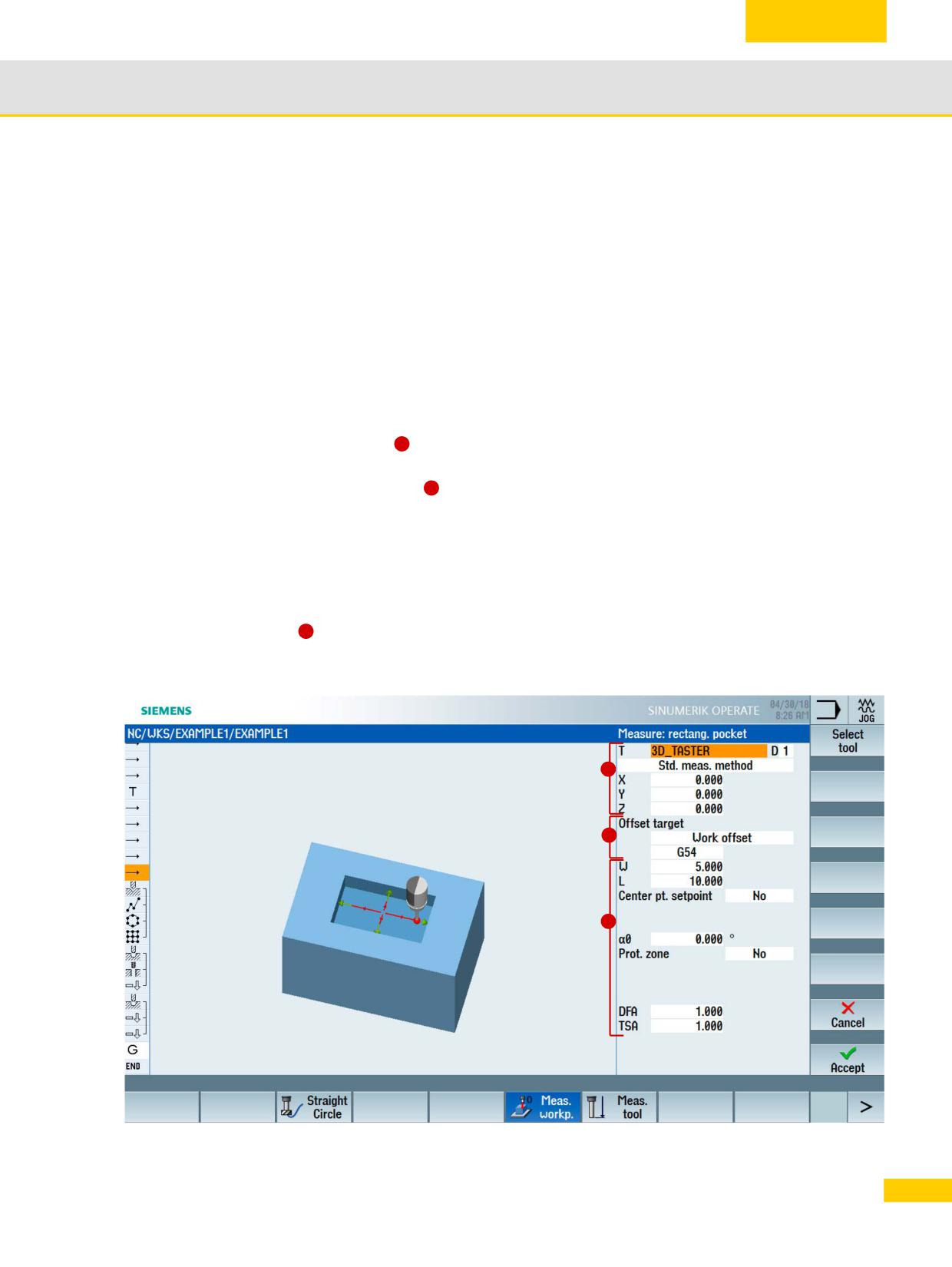
General information on workpiece production
2.8
2.8.3
Example for measuring a workpiece in AUTOMATIC
The procedure is illustrated on the basis of the Measure pocket function. The cycle
automatically measures the right-angled pocket and enters the values in the zero offset.
Requirements for using cycles
The probe is calibrated and active; the tool compensation is activated.
Determining zero offset via Measure right-angled pocket:
X Create a new program for measuring the workpiece or edit an existing one.
X In the expanded softkey bar, select the Measure workpiece > Hole > Right-angled pocket
softkeys.
X Select the tool (3D probe), specify the measuring technique and enter the starting point of the
measurement.
1
X You can define whether the result of the measurement should be a compensation or merely a
measuring process
2
Compensation in the zero offset with specification of the zero offset
Compensation in the tool compensation data
Measurement only
As you are setting up the workpiece here, the compensation is made in the zero offset.
X Enter the setpoints of the right-angled pocket and parameterize additional cycle parameters
3
After the measurement, the measured values are compensated in the active zero offset
frame.
1
2
3
53
© Siemens AG All rights reserved SINUMERIK, Manual, Mold-Making with 3- to 5-Axis Simultaneous Milling
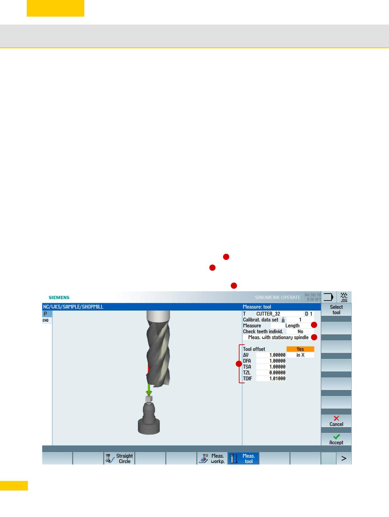
General information on workpiece production
2.8
2.8.4
Tool measuring in AUTOMATIC - process measuring
A practical measuring cycle is provided to facilitate the process measuring of tools. The cycle
determines the length and the diameter of the tool using a calibrated dynamometer.
X You can access the measuring cycles in the NC program by selecting the Measure mill >
Measure tool softkeys from the expanded softkey bar.
Requirements
The dynamometer is calibrated
The tool is clamped
In automatic mode, you can automatically measure the tool data or enter it as tool compensation.
2.8.5
Example for measuring tools in the AUTOMATIC
mode
In the following example, you will generate a program that determines the tool length and the
radius and enters this data into the tool compensation.
Determining the tool length:
X Create a new program for measuring the tool.
X Select Measure tool measuring cycle.
X The measuring process is performed with stationary spindle and the measured values are
entered into the tool geometry component
1
X Select the length as measured value
2
. Each tooth can be individually measured to check
for tool breakage.
X Assign parameters to the measuring process
3
2
1
3
54
© Siemens AG All rights reserved SINUMERIK, Manual, Mold-Making with 3- to 5-Axis Simultaneous Milling
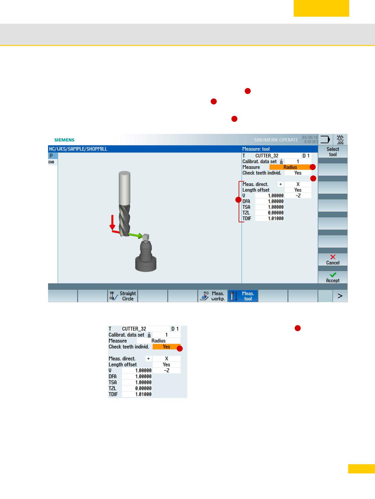
General information on workpiece production
2.8
Determining the tool radius:
X The measuring process is performed with rotating spindle and the setpoint - actual value
deviation is entered optionally into the radius wear
1
X Select the radius as measured value
2
. Each tooth can be individually measured to check
for tool breakage.
X Assign parameters to the measuring process
3
2
1
3
Single cutting edge measurement (as of SW 4.5)
The single cutting edge measurement
can be used for
4
remeasuring (compensation in the wear) and initial
measuring (compensation in the geometry). Milling tools
4
with up to 100 cutting edges can be measured.
The cycle checks whether the measured values of all cutting
edges are within a defined tolerance range. If the measured
values are outside the tolerance range, an alarm is output.
If the measured value of the longest cutting edge is within
the tolerance range, this is entered in the tool management.
55
© Siemens AG All rights reserved SINUMERIK, Manual, Mold-Making with 3- to 5-Axis Simultaneous Milling
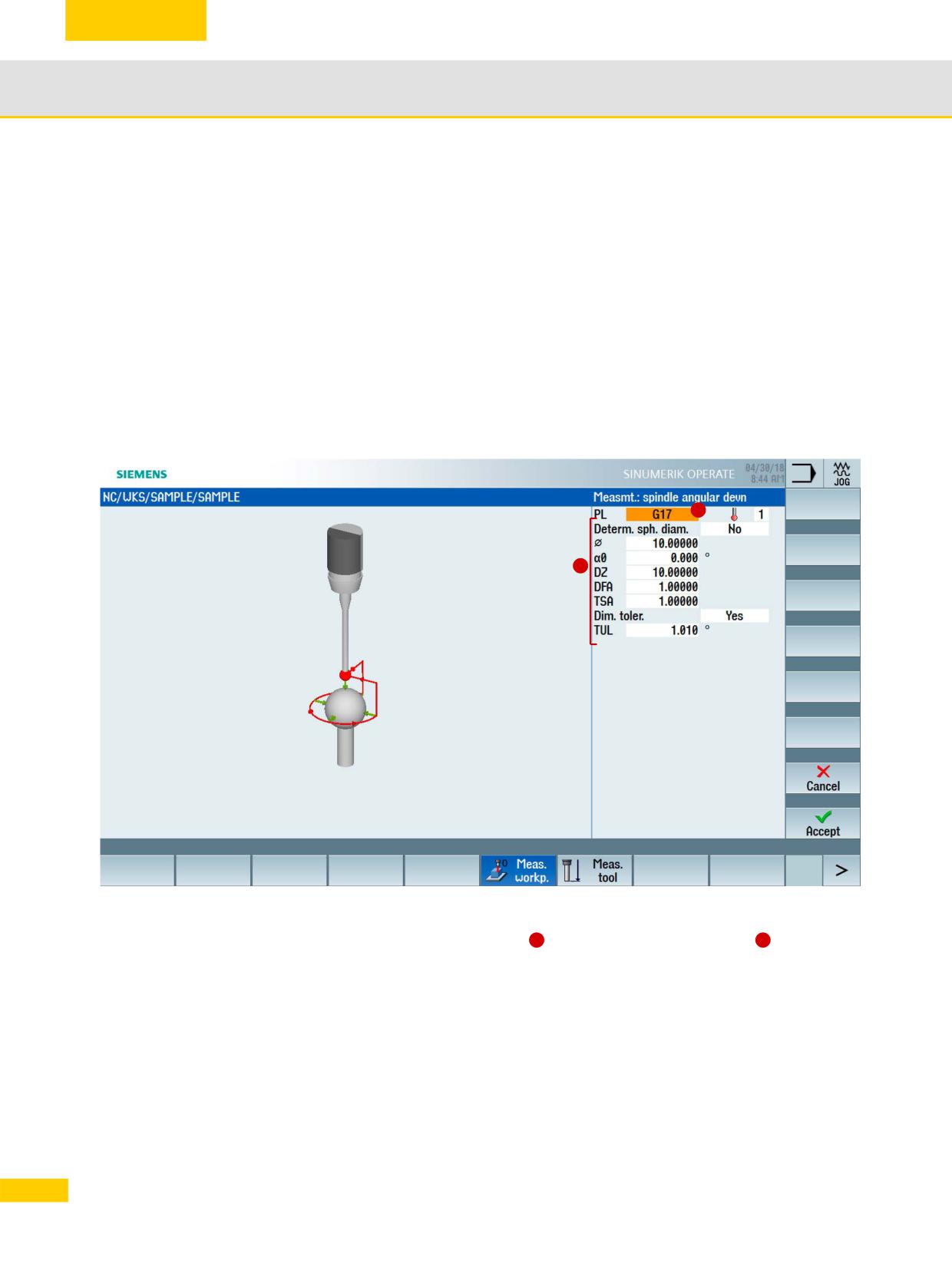
General information on workpiece production
2.9
2.9
Checking and measuring machine/spindle
2.9.1
Spindle 3D angular deviation CYCLE995
With this measuring variant, the angularity (parallelism) of a spindle to the machine tool is
measured on a calibration ball. The measurement is performed by combining the sphere
CYCLE997 and outer circle segment CYCLE979 measuring variants.
Based on the measured values, the angular deviation of the spindle to the axis of the plane is
calculated. With the measured angular deviations, the spindle can be mechanically aligned
parallel to the tool axis or the corresponding tables for sag compensation can be updated.
If there are rotary axes, the determined angular data can be used to align the rotary axis. To do
this, the result parameter (_OVR) of CYCLE995 must be used.
1
2
Checking the 3D angular deviation with CYCLE995
X Select the appropriate machining plane
and the measuring parameters
1
2
The 1st measurement of the calibration ball is performed with CYCLE997 and the
measurement is repeated. From two measuring points along the circumference and one
measuring point at the "north pole" of the sphere (highest point), the center point (position of
the ball) is determined. In addition, the diameter of the calibration ball can be determined.
The second measurement is performed with CYCLE979 at the shank of the probe at a
distance of DZ. The center point of the probe shaft in the plane is determined. The angular
deviation in XY is calculated from the results of the two center points in XY and the distance
between the two measurements in Z (for G17).
56
© Siemens AG All rights reserved SINUMERIK, Manual, Mold-Making with 3- to 5-Axis Simultaneous Milling
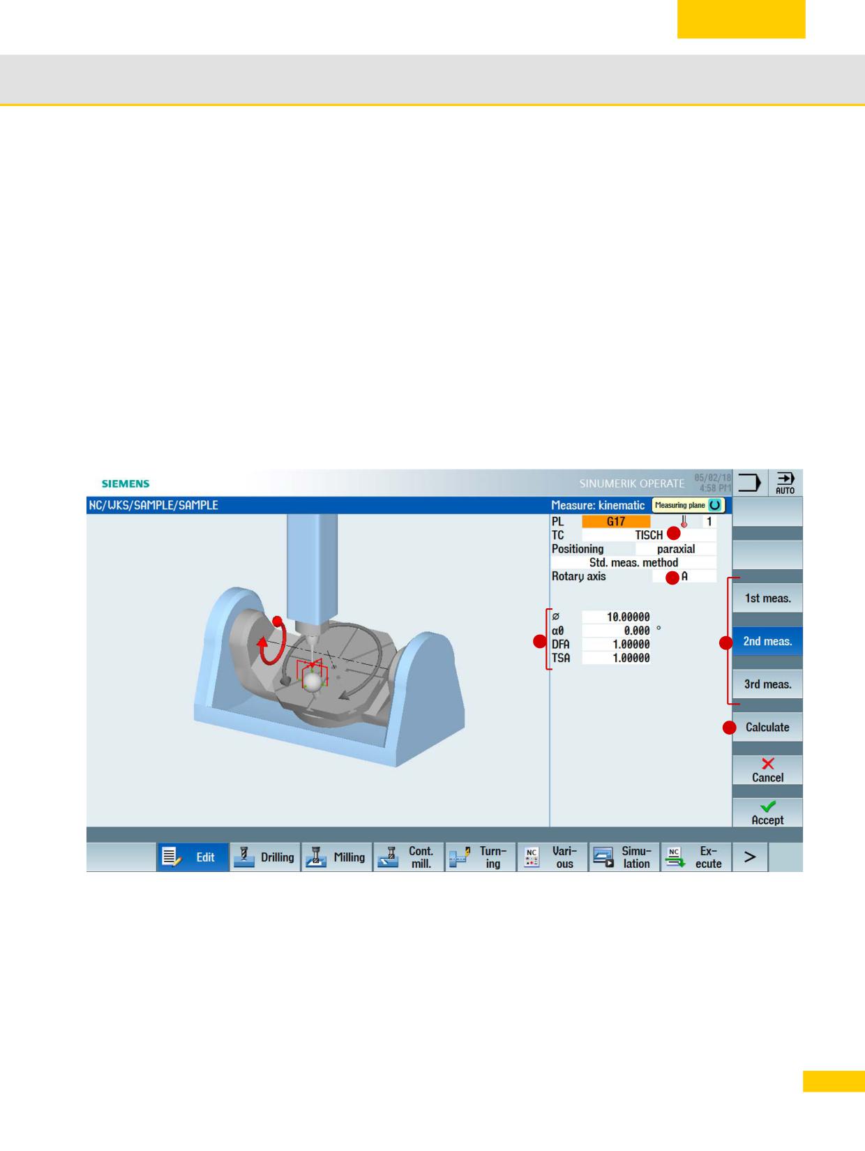
General information on workpiece production
2.9
2.9.2
Checking/measuring the machine with the
kinematics measuring cycle CYCLE996
The requirements associated with 5-axis machining can only be met by means of high-precision
machines. As regard to the kinematic transformation, this means that the centers of rotation and
the vectors for NC-controlled or manually alignable rotary axes must be determined and entered
into the control. CYCLE996 is a special measuring cycle that has been designed specifically for
this purpose. It uses a calibration sphere and a calibrated probe to measure the rotary axis
vectors automatically. In practical applications, the cycle makes control easier and improves the
quality of the process, as compensations of the rotary axis vectors (due, for example, to
temperature fluctuations, or other influential factors) can be checked automatically.
For measurement purposes, a calibration sphere is mounted on the table. The sphere is
measured with the probe at three separate swivel positions of the rotary axis and the values
obtained are recorded. CYCLE996 must be called three times for each rotary axis using different
rotary axis positions. The kinematics calculation is performed in full once all the rotary axes have
been measured.
1
2
3
4
5
57
© Siemens AG All rights reserved SINUMERIK, Manual, Mold-Making with 3- to 5-Axis Simultaneous Milling
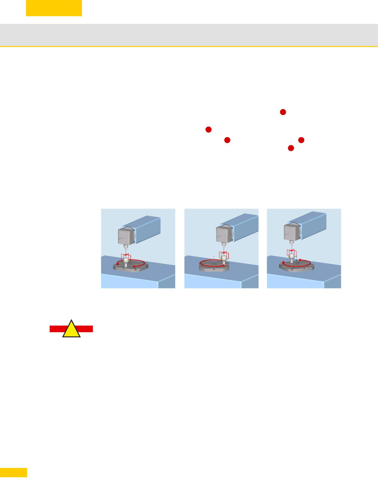
General information on workpiece production
2.9
Checking the machine with CYCLE996:
X Create a new program to measure the kinematics.
X In the part program editor, select the >> MEASURE MILL > MEASURE WORKPIECE > 3D
> KINEMATICS softkeys in the Programs operating area.
X Create a new swivel data record (where the rotary axis is swiveled)
1
. Ideally, the swivel
positions should create an equilateral triangle, i.e. each one should involve a swivel of 120°.
X Select the rotary axis to be measured
2
X Assign parameters to the measuring process
3
for measurements 1 to 3
4
Press the Calculate softkey once all rotary axes have been measured
5
After pressing the softkey, the Calculate kinematics dialog opens. The following options are
available in terms of how you then utilize the measurement results:
Measure only (measure and calculate vectors)
Enter (measure, calculate vectors, and enter vectors in swivel data record for compensation
purposes)
1st measurement
2nd measurement
3rd measurement
Please take care when modifying the swivel data. This affects the kinematics directly and
if an error is made with regard to the compensation value, this can result in damage to the
!
machine during operation.
58
© Siemens AG All rights reserved SINUMERIK, Manual, Mold-Making with 3- to 5-Axis Simultaneous Milling
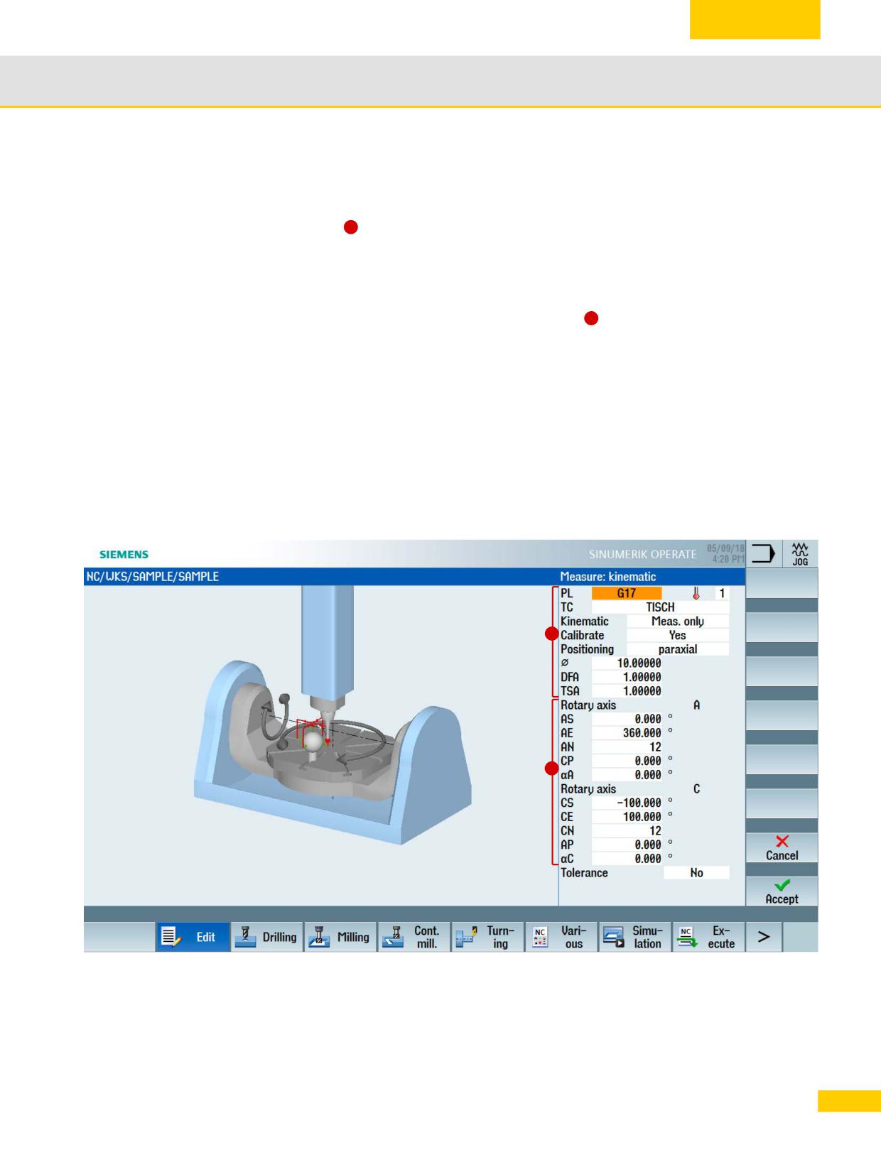
General information on workpiece production
2.9
2.9.3
CYCLE9960 measure kinematics completely
CYCLE9960 corrects or checks the geometric vectors for defining the kinematic 5-axis
transformation
based on kinematic chains and the tool carrier (classically via $TC_CARR).
1
With only one call of the cycle, the kinematics are measured, and the determined values and
deviations are represented in the measurement result screen.
For the measurement, up to twelve positions of a measuring sphere on each rotary axis are
sensed using workpiece probes. The sphere positions are defined in a specified rotary axis area
in accordance with the geometric ratios on the machine
. The sphere position is set via the
2
automatic repositioning of each rotary axis to be measured.
With CYCLE9960, it is also possible to measure the deviation on the tool tip (TCP) with active
transformation for various rotary axis positions, after the measurement and compensation of the
kinematics. These deviations can be compensated with VCS (Volumetric Compensation
System).
Possible fields of application
Check and correct the machine kinematics, e.g. during the machining process or for collision.
Measure and adapt the reference, e.g. for kinematics with changeable heads.
Measure and correct interpolation points, e.g. for compensation of the TCP via VCS Rotary.
1
2
59
© Siemens AG All rights reserved SINUMERIK, Manual, Mold-Making with 3- to 5-Axis Simultaneous Milling
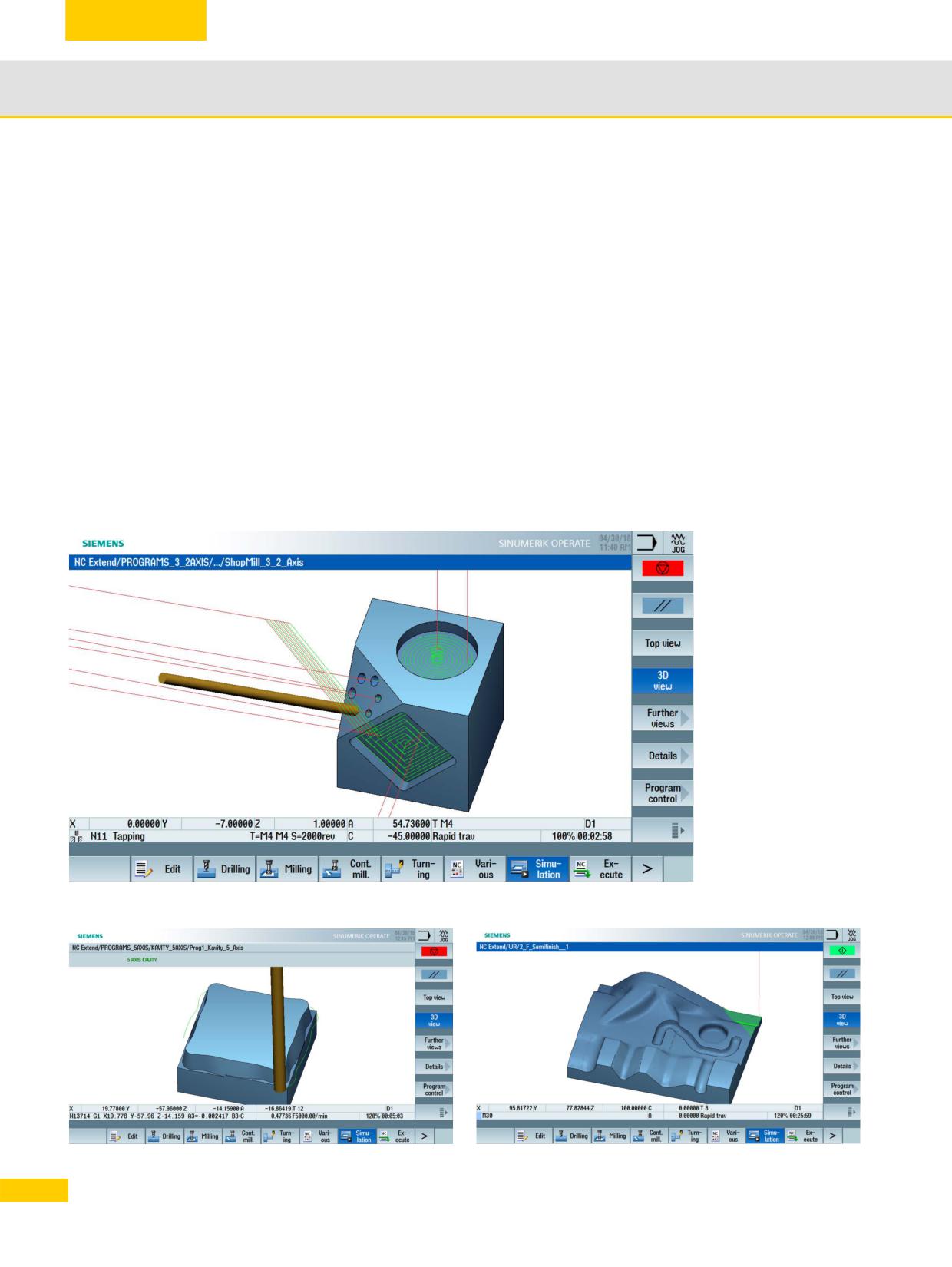
General information on workpiece production
2.10
2.10
Workpiece visualization
2.10.1 Simulation
You can detect any programming errors even before production by means of the finished part
simulation in the form of a 3D volume model or as a 3-plane view. Using the complete 3D
simulation, you simulate the programs before production, even on swiveled planes and by means
of 5-axis simultaneous simulation.
Opening a simulation:
X Open the NC program in the program editor.
X Press the Simulation softkey. The execution of the NC program is simulated.
X During simulation, you can change, turn and zoom the display. For a better display, you can
place the cuts in the workpiece.
X Via the shortcuts SHIFT+[cursor keys], you can move or rotate the display or move the cutout
and control the override using CTRL+[cursor keys].
→ Start simulation
→ Reset
→ Top view
→ 3D view
→ Side views
→ Zoom, magnify,
turn, cut
→ Override, single
block
→ Display tool paths
5-axis simultaneous simulation
3-axis workpiece simulation
60
© Siemens AG All rights reserved SINUMERIK, Manual, Mold-Making with 3- to 5-Axis Simultaneous Milling
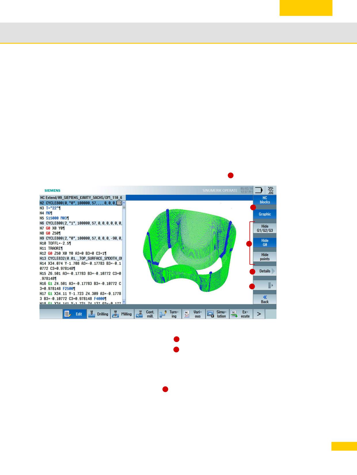
General information on workpiece production
2.10
2.10.2 Quick viewer for mold-making
The mold-making quick view allows the visualization of the processing paths of large part
programs, e.g. from CAM systems. By means of the quick view, you can get a quick overview of
the program, e.g. the shape of the workpiece or traversing errors or check approach and
retraction paths.
The mold-making view supports such blocks as those with G0, G1, G2 and G3, as well as the
display of vectors as rotary axis or vector programming. Non-interpretable NC blocks are skipped
and not displayed in the graphic.
Opening the mold-making view:
X Open the NC program in the program editor.
X Press the >> softkeys and then mold-making view. The NC program and the graphic are
displayed in parallel.
X By pressing the NC blocks or Graphic softkeys
, you can display and hide the views.
1
→ Display NC
blocks
1
→ Display graphic
→ Hide G1, G2, G3
4
→ Hide G0
→ Hide points
2
→ Zoom and cutout
→ Select program
3
block
Zoom and cutout:
X Press the Details softkey
2
and then Zoom+ or Zoom- to zoom the views.
X Press the Details softkey
2
and then Magnify+ or Magnify- to enlarge or shrink the cutout.
Using the cursor keys, you can move the cutout.
Select erroneous NC block:
If there are errors in the graphic, you can directly select the NC block in the program.
X Press the >> softkey
and then Select point.
3
X Using the cursor keys, move the displayed cross-hairs to the appropriate position in the
graphic.
X Press the "Select NC block" softkey. The erroneous NC block is highlighted in the editor.
61
© Siemens AG All rights reserved SINUMERIK, Manual, Mold-Making with 3- to 5-Axis Simultaneous Milling
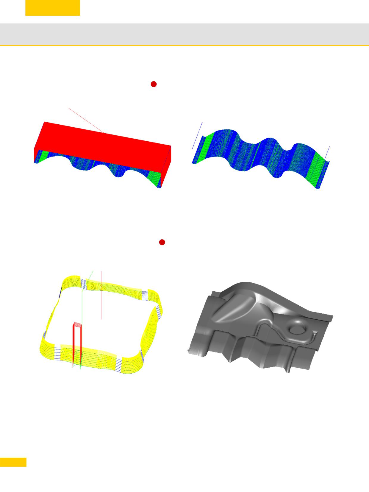
General information on workpiece production
2.10
Hide G0, G1, G2, G3 lines:
X With the softkeys
you can hide G0, G1, G2, G3 or points so that the graphic lines are
4
shown clearly. In the example, the rapid traverse movements G0 are hidden.
Lines G0, G1, G2, G3 shown
Hide G0 lines
Display vectors, surfaces and curvature:
In addition to the classic view, for mold-making programs, you can also display the rotary axis
vectors and grid mesh (surface, mesh), for example.
X Press the >> softkey
and then Vectors or Surface or curvature. The appropriate view is
3
displayed.
Vectors
Surface (mesh)
62
© Siemens AG All rights reserved SINUMERIK, Manual, Mold-Making with 3- to 5-Axis Simultaneous Milling