SINUMERIK 840D sl. Training. Operate - Turning (2016-2020) - page 5
Example 1: Longitudinal guide
6.5 Creating drill holes and position repetitions
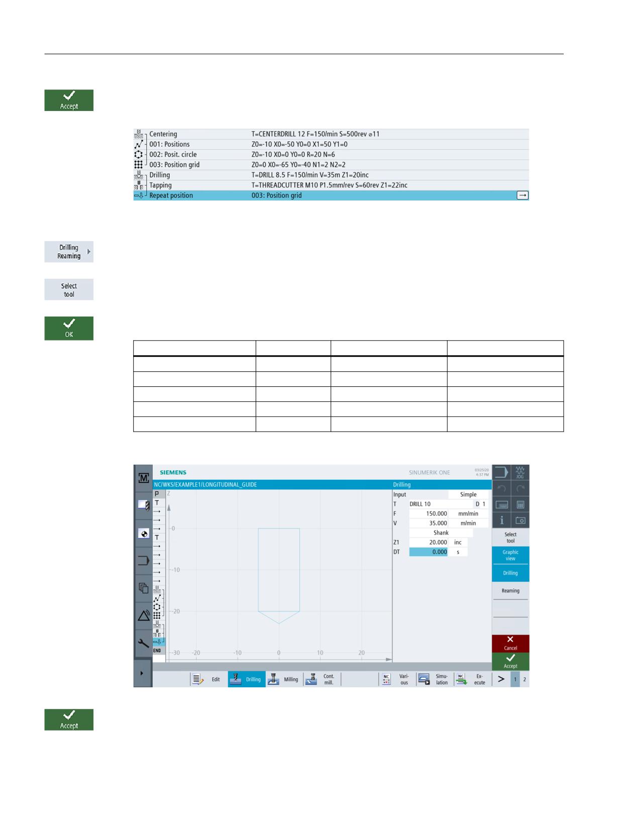
Press "Accept" to apply the values entered. After accepting the values, you will see the linking of
the work steps in the work step editor.
Figure 6-29
Linking of work steps
Select the Drilling Reaming softkey.
Open the tool list. Use the cursor key to select the DRILL 10 tool.
Accept the tool into your program. After accepting the tool, enter the following values:
Field
Value
Toggle field
Notes
F
150 mm/min
X
V
35 m/min
X
Shank/tip
Shank
X
Z1
20 inc
X
DT
0
X
Figure 6-30
10mm drill holes
Press "Accept" to apply the values entered.
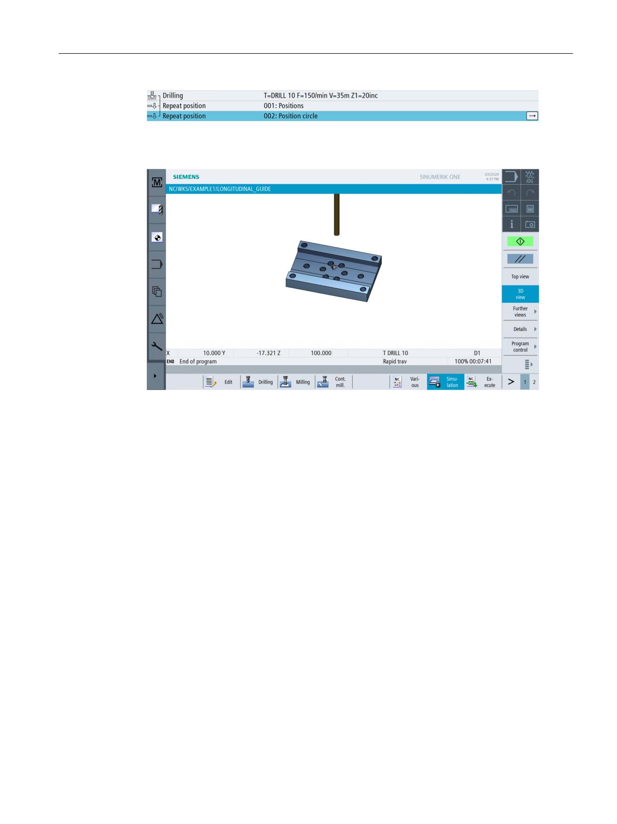
Last, repeat the positions 001 and 002 for the 10mm drill.
Easy milling with ShopMill
78
Training Documents, 05/2020, 6FC5095-0AB50-1BP2
Example 1: Longitudinal guide
6.5 Creating drill holes and position repetitions
Figure 6-31
Repeat the positions 001 and 002 in the work step editor.
Call the simulation for checking.
Figure 6-32
3D simulation
Easy milling with ShopMill
Training Documents, 05/2020, 6FC5095-0AB50-1BP2
79
Example 1: Longitudinal guide
6.5 Creating drill holes and position repetitions
Easy milling with ShopMill
80
Training Documents, 05/2020, 6FC5095-0AB50-1BP2
Example 2: Injection mold
7
7.1
Overview
Learning objectives
In this section you will learn the following new functions. You will learn how to...
• specify straight lines and circular paths using polar coordinates;
• create rectangular pockets;
• apply circular pockets to position patterns.
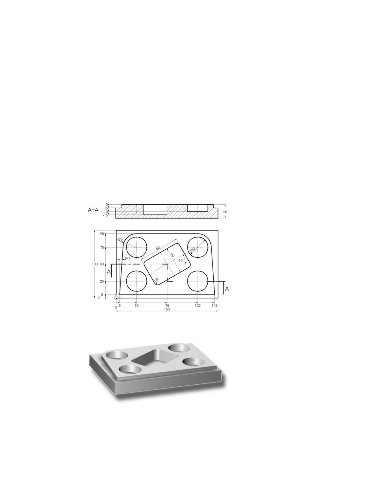
Task
Figure 7-1
Workshop drawing - Example 2:
Figure 7-2
Workpiece - Example 2:
Easy milling with ShopMill
Training Documents, 05/2020, 6FC5095-0AB50-1BP2
81
Example 2: Injection mold
7.1 Overview
Preparation
Perform the following steps without help:
1. Create a new workpiece with the name 'EXAMPLE2'.
2. Create a new step sequence program with the name 'INJECTION_FORM' .
3. Specify the blank dimensions (for the procedure, see example 1).
Note
Observe the new zero position.
4. Switch to the 20mm milling cutter (F = 80 m/min).
5. Position the tool to the point X-12/ X-12/ Z-5 at rapid traverse.
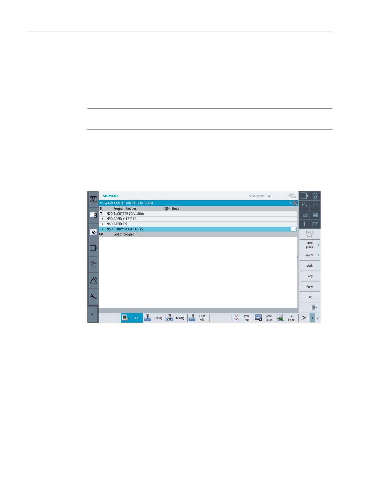
6. Define the starting point of the contour on X5; Y5. The starting point is approached along a
straight line (F 100 mm/min, cutter radius compensation left). After you have entered the
traversing blocks, your process plan should look like this:
Figure 7-3
Machining step program
Easy milling with ShopMill
82
Training Documents, 05/2020, 6FC5095-0AB50-1BP2
Example 2: Injection mold
7.2 Straight lines and circular paths by way of polar coordinates
7.2
Straight lines and circular paths by way of polar coordinates
Operating sequences
Before you start entering the contour, observe the following note:
Note
You can describe the end point of a traversing block not only by way of its X and Y coordinates,
but if necessary also via its polar reference point.
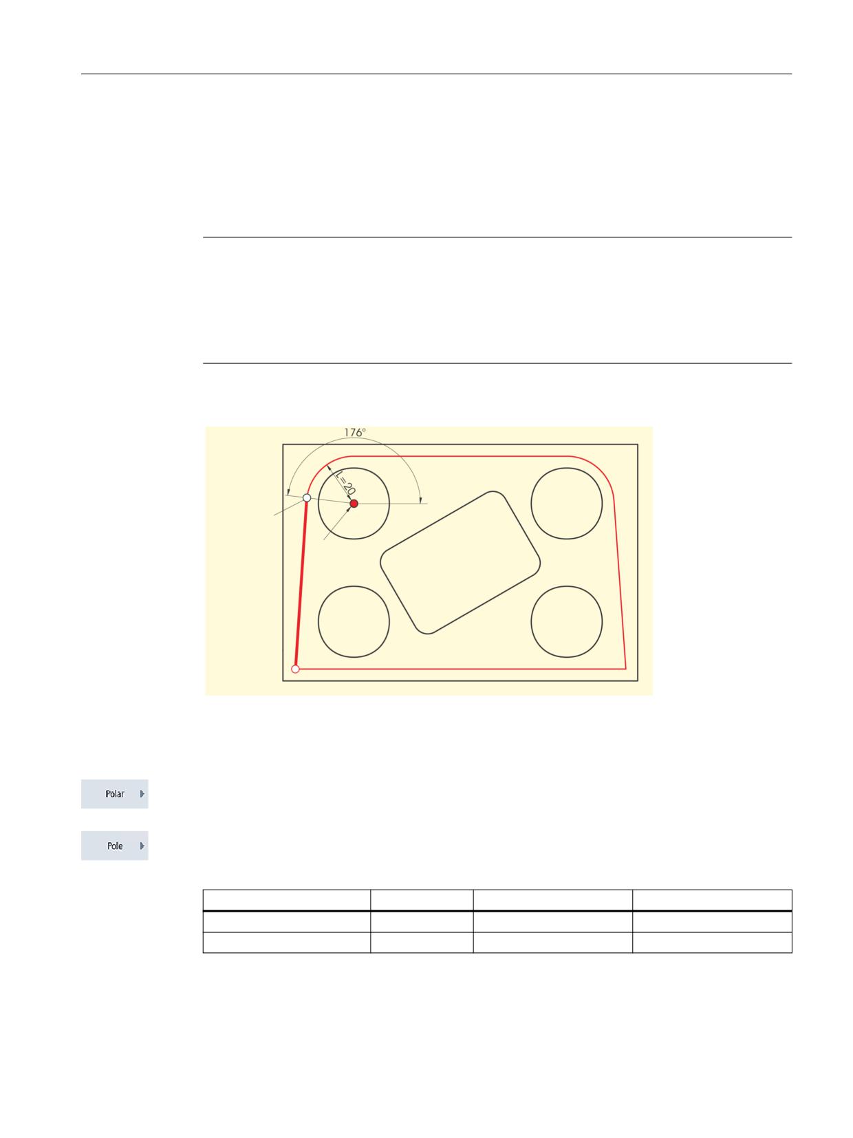
X and Y are not known in our example. However, you can determine the point indirectly: It lies
20 mm away from the center of the circular pocket which highlights the pole here. The polar
angle 176° results from the calculation 180° - 4° (see workshop drawing).
(QG SRLQW
;" <"
3ROH
;
<
6WDUWLQJ
SRLQW
;
<
Figure 7-4
Determination of end point and polar angle
Proceed as follows to enter the contour:
Select the Polar softkey.
Select the Pole softkey.
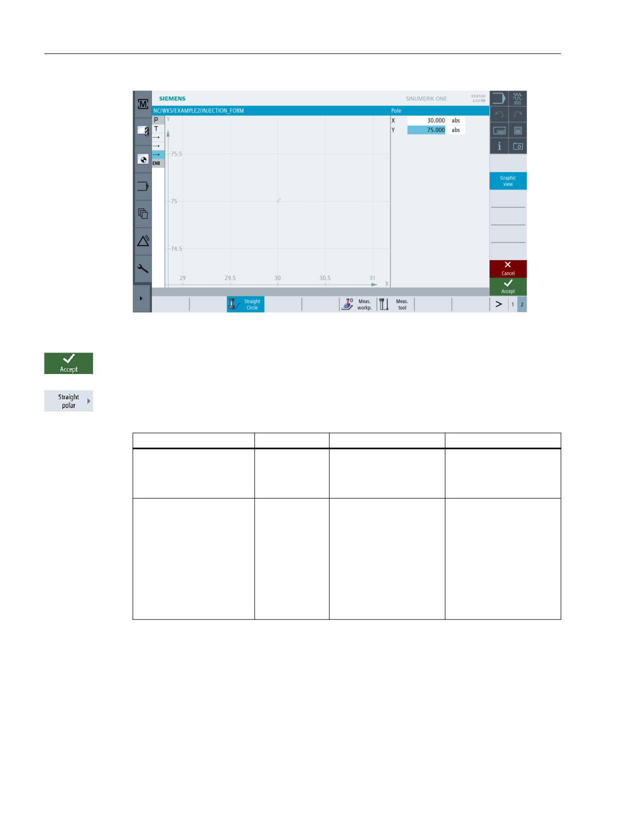
Enter the following values in the interactive screenform:
Field
Value
Toggle field
Notes
X
30 abs
X
Y
75 abs
X
Easy milling with ShopMill
Training Documents, 05/2020, 6FC5095-0AB50-1BP2
83
Example 2: Injection mold
7.2 Straight lines and circular paths by way of polar coordinates
Figure 7-5
Specifying the pole
Press "Accept" to apply the values entered.
Select the Straight line / polar softkey.
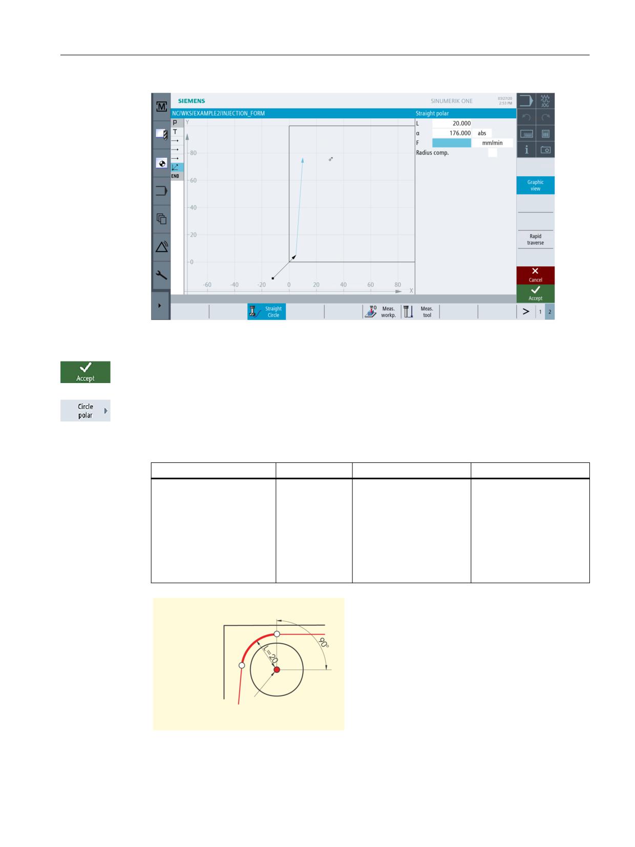
Enter the following values in the interactive screenform:
Field
Value
Toggle field
Notes
L
20
The length L specifies the
distance of the end point
of the straight line from
the pole.
α
176
The polar angle specifies
how far the length L must
be rotated around the pole
to reach the end point of
the straight line.
You may specify the polar
angle either in the coun-
terclockwise (176°) or also
in the clockwise direction
(-184°).
Easy milling with ShopMill
84
Training Documents, 05/2020, 6FC5095-0AB50-1BP2
Example 2: Injection mold
7.2 Straight lines and circular paths by way of polar coordinates
Figure 7-6
Specifying the straight line using polar coordinates
Press "Accept" to apply the values entered.
Select the Circle / polar softkey.
A circular path can also be specified using polar coordinates.
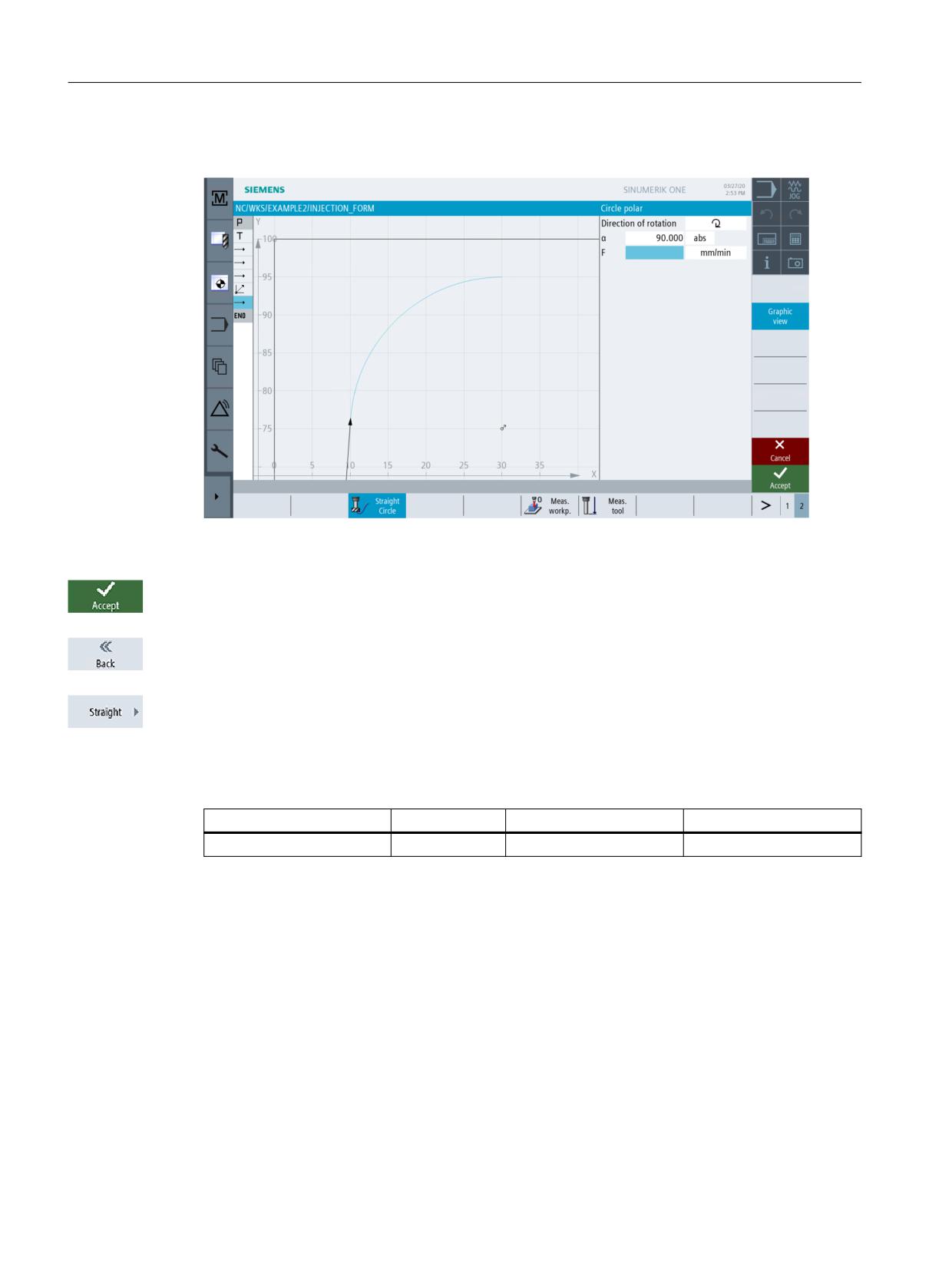
Enter the following value in the interactive screenform:
Field
Value
Toggle field
Notes
α
90 abs
Since the pole applies
both for the circular path
and for the straight line, it
need not be entered once
more.
The polar angle is 90° in
this case.
(See illustration below)
(QG SRLQW
6WDUWLQJ
SRLQW
3ROH
;
<
Figure 7-7
Pole starting / end points
Easy milling with ShopMill
Training Documents, 05/2020, 6FC5095-0AB50-1BP2
85
Example 2: Injection mold
7.2 Straight lines and circular paths by way of polar coordinates
Figure 7-8
Specifying the circular path
Press "Accept" to apply the values entered.
Select the Back softkey.
Select the Straight line softkey.
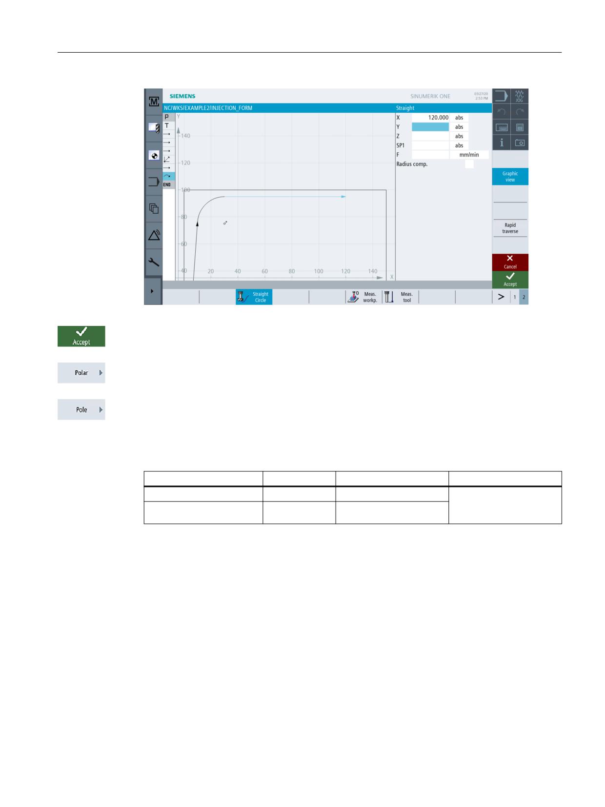
Since the end point of the straight line is known unambiguously, you may here use the Straight
line function.
Enter the following value in the interactive screenform:
Field
Value
Toggle field
Notes
X
120 abs
X
Easy milling with ShopMill
86
Training Documents, 05/2020, 6FC5095-0AB50-1BP2
Example 2: Injection mold
7.2 Straight lines and circular paths by way of polar coordinates
Figure 7-9
Specifying a straight line
Press "Accept" to apply the values entered.
Select the Polar softkey.
Select the Pole softkey.
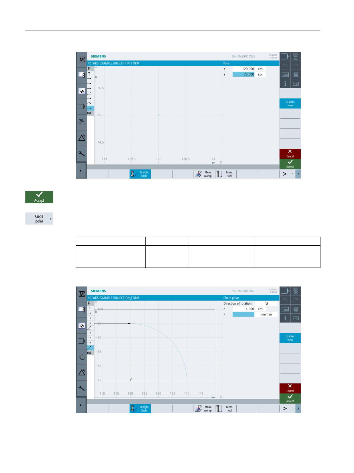
Since the end point of the next circular path is not known, you must here work with
polar coordinates again.
Enter the following values in the interactive screenform:
Field
Value
Toggle field
Notes
X
120 abs
X
The pole of the circular
path is known from the
Y
75 abs
X
drawing.
Easy milling with ShopMill
Training Documents, 05/2020, 6FC5095-0AB50-1BP2
87
Example 2: Injection mold
7.2 Straight lines and circular paths by way of polar coordinates
Figure 7-10
Specifying the pole for the circular path
Press "Accept" to apply the values entered.
Select the Circle / polar softkey.
Enter the following value in the interactive screenform:
Field
Value
Toggle field
Notes
α
4 abs
X
The polar angle is also
known because of the
symmetry.
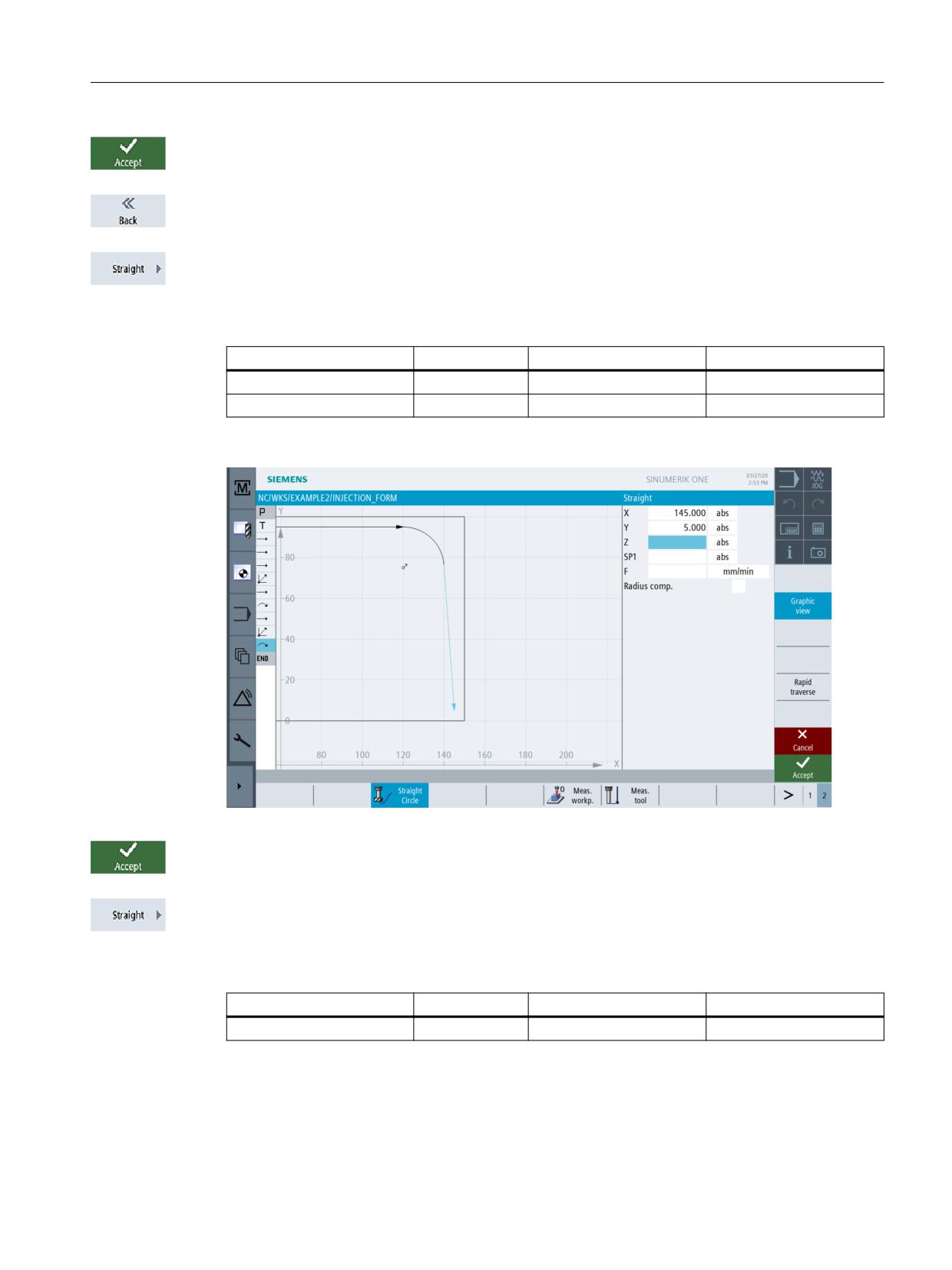
Figure 7-11
Specifying the circular path using polar coordinates
Easy milling with ShopMill
88
Training Documents, 05/2020, 6FC5095-0AB50-1BP2
Example 2: Injection mold
7.2 Straight lines and circular paths by way of polar coordinates
Press "Accept" to apply the values entered.
Select the Back softkey.
Select the Straight line softkey.
The end point of the straight line is known so that you can enter it directly.
Enter the following values in the interactive screenform:
Field
Value
Toggle field
Notes
X
145 abs
X
Y
5 abs
X
Figure 7-12
Specifying a straight line
Press "Accept" to apply the values entered.
Select the Straight line softkey.
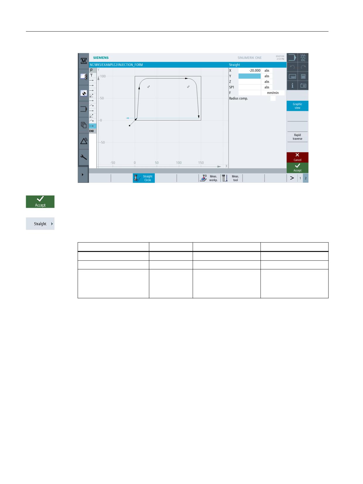
The whole contour has been milled once with the last straight line.
Enter the following value in the interactive screenform:
Field
Value
Toggle field
Notes
X
-20 abs
X
Easy milling with ShopMill
Training Documents, 05/2020, 6FC5095-0AB50-1BP2
89
Example 2: Injection mold
7.2 Straight lines and circular paths by way of polar coordinates
Figure 7-13
Specifying a straight line
Press "Accept" to apply the values entered.
Select the Straight line softkey.
Enter the following values in the interactive screenform:
Field
Value
Toggle field
Notes
X
-12 abs
X
Y
-12 abs
X
Radius compensation
off
X
The last motion is travers-
ing to the safety clear-
ance, disabling the radius
compensation.
Easy milling with ShopMill
90
Training Documents, 05/2020, 6FC5095-0AB50-1BP2
Example 2: Injection mold
7.2 Straight lines and circular paths by way of polar coordinates
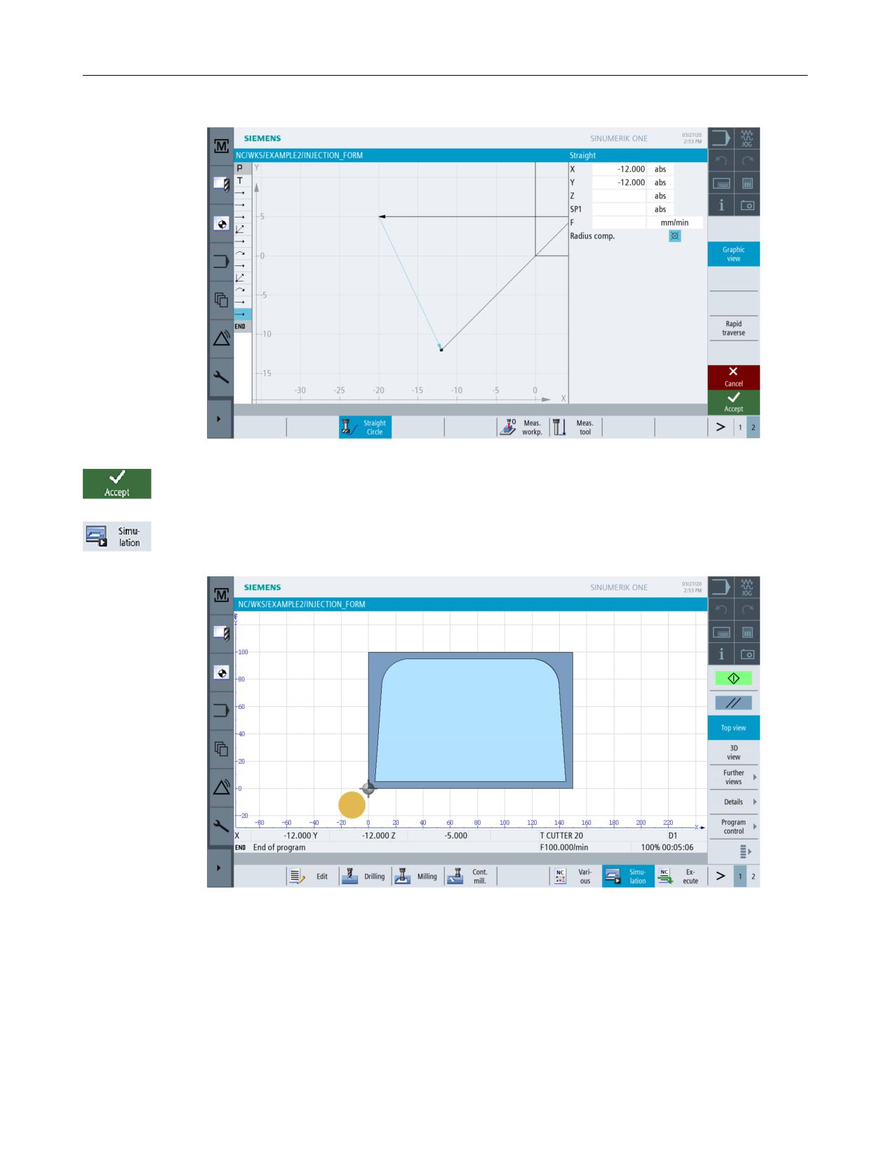
Figure 7-14
Specifying a straight line - Safety clearance
Press "Accept" to apply the values entered.
The following simulation shows the manufacturing sequence for you to check before
manufacturing the workpiece.
Figure 7-15
Simulation - Top view
Easy milling with ShopMill
Training Documents, 05/2020, 6FC5095-0AB50-1BP2
91
Example 2: Injection mold
7.2 Straight lines and circular paths by way of polar coordinates
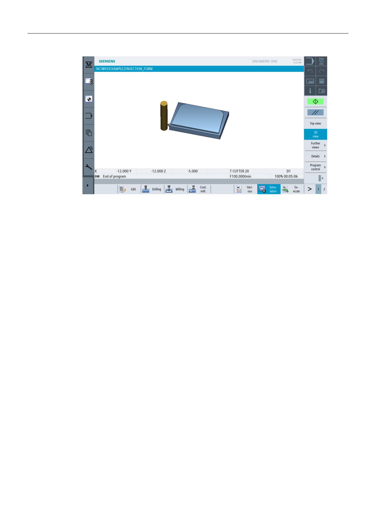
Figure 7-16
Simulation - 3D view
Easy milling with ShopMill
92
Training Documents, 05/2020, 6FC5095-0AB50-1BP2
Example 2: Injection mold
7.3 Rectangular pocket
7.3
Rectangular pocket
Operating sequences
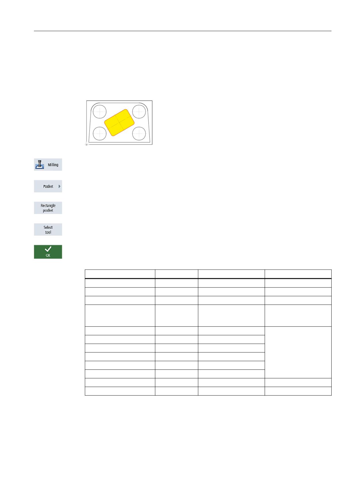
Proceed as follows to enter the rectangular pocket:
Figure 7-17
Rectangular pocket - Example 2
Select the Milling softkey.
Select the Pocket softkey.
Select the Rectangular pocket softkey.
Open the tool list and select CUTTER 10.
Accept the tool into your program.
After accepting the tool, enter the following values:
Field
Value
Toggle field
Notes
F
0.15 mm/tooth
X
V
120 m/min
X
Reference point
Center
X
Machining
Roughing
X
Ensure that the toggle
field stands on Single posi-
tion.
X0
75
Specify the geometrical
data for the rectangular
Y0
50
pocket in these fields:
Z0
0
Position, width and
W
40
length, ...
L
60
R
6
α0
30
Z1
-15 abs
X
Easy milling with ShopMill
Training Documents, 05/2020, 6FC5095-0AB50-1BP2
93
Example 2: Injection mold
7.3 Rectangular pocket
Field
Value
Toggle field
Notes
DXY
80%
X
The max. infeed in the
plane (DXY) specifies at
which width the material
is removed. This can be
specified either as a per-
centage of the milling di-
ameter or directly in mm.
The maximum infeed in
the lane is specified in %
here.
DZ
2.5
UXY
0.3
UZ
0.3
Insertion
Helical
X
Select "helical insertion" if
not yet set (see below In-
sertion).
EP
2 mm/rev
X
ER
2
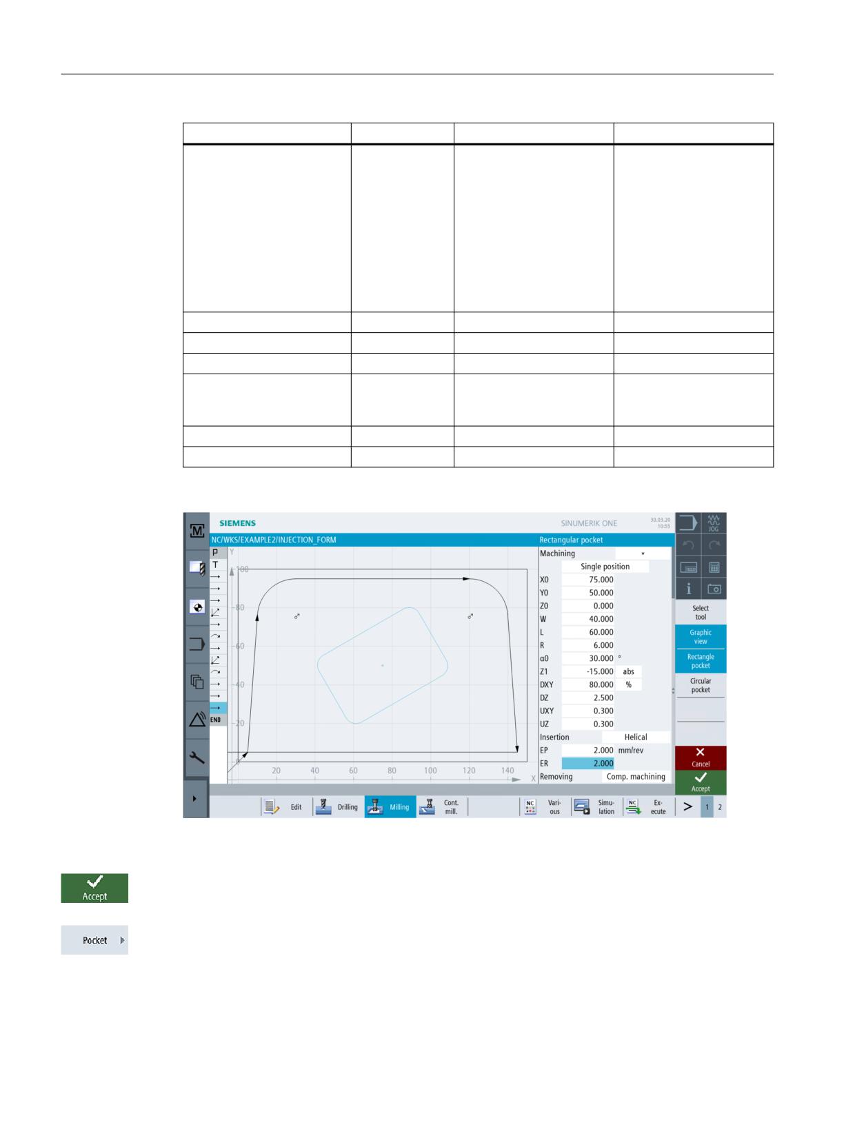
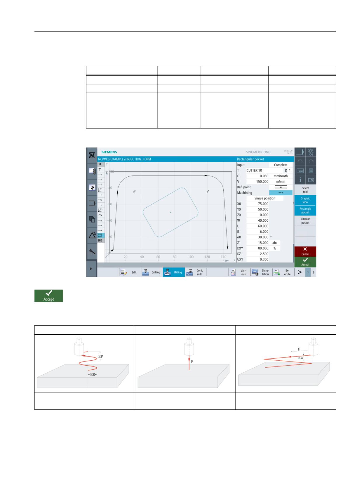
Figure 7-18
Roughing a rectangular pocket
Press "Accept" to apply the values entered.
Select the Pocket softkey.
Easy milling with ShopMill
94
Training Documents, 05/2020, 6FC5095-0AB50-1BP2
Example 2: Injection mold
7.3 Rectangular pocket
Enter the following values in the interactive screenform:
Field
Value
Toggle field
Notes
F
0.08 mm/tooth
X
V
150 m/min
X
Machining
Finishing
X
Margin and base are finish-
ed using these settings. Al-
ternatively, you may also
only finish the margin or
chamfer the pocket.
Figure 7-19
Finishing a rectangular pocket
Press "Accept" to apply the values entered.
Insertion
Helical insertion
Vertical insertion
Oscillating insertion
EP = insertion pitch
EW = insertion angle
ER = insertion radius
Easy milling with ShopMill
Training Documents, 05/2020, 6FC5095-0AB50-1BP2
95
Example 2: Injection mold
7.4 Circular pockets on a position pattern
7.4
Circular pockets on a position pattern
Operating sequences
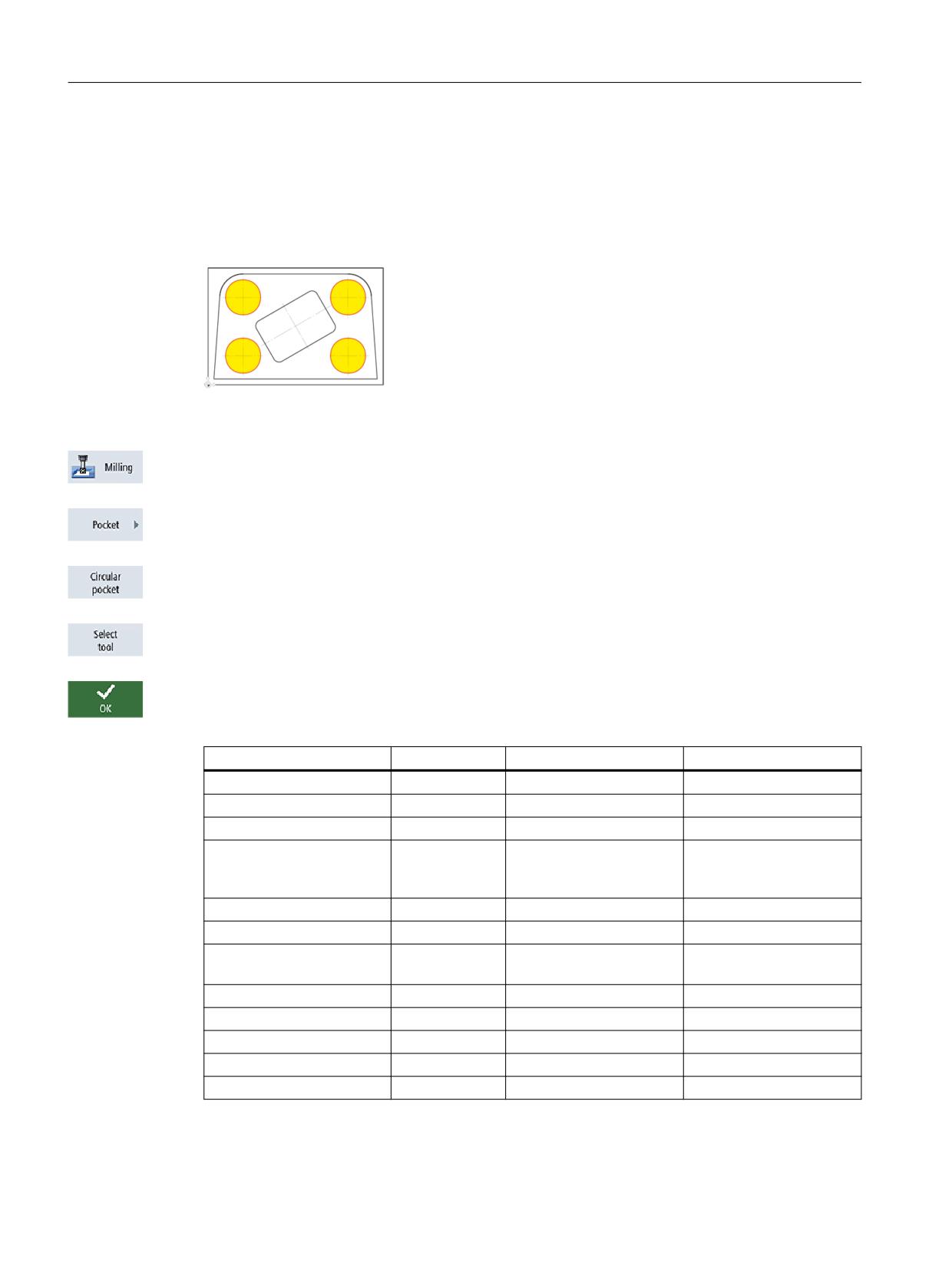
Proceed as follows to enter the rectangular pockets:
Figure 7-20
Rectangular pocket - Example 2
Select the Milling softkey.
Select the Pocket softkey.
Select the Circular pocket softkey.
Open the tool list and select CUTTER 10.
Accept the tool into your program.
After accepting the tool, enter the following values:
Field
Value
Toggle field
Notes
F
0.15 mm/tooth
X
V
120 m/min
X
Machining
Roughing
X
Position pattern
X
Similar to drilling, you can
also apply a position pat-
tern to pockets.
∅
30
Z1
-10 abs
X
DXY
80%
X
Specify the maximum in-
feed in the plane in %.
DZ
5
UXY
0.3
UZ
0.3
Insertion
Helical
X
EP
2 mm/rev
X
Easy milling with ShopMill
96
Training Documents, 05/2020, 6FC5095-0AB50-1BP2
Example 2: Injection mold
7.4 Circular pockets on a position pattern
Field
Value
Toggle field
Notes
ER
2
Solid machining
Complete ma-
X
chining
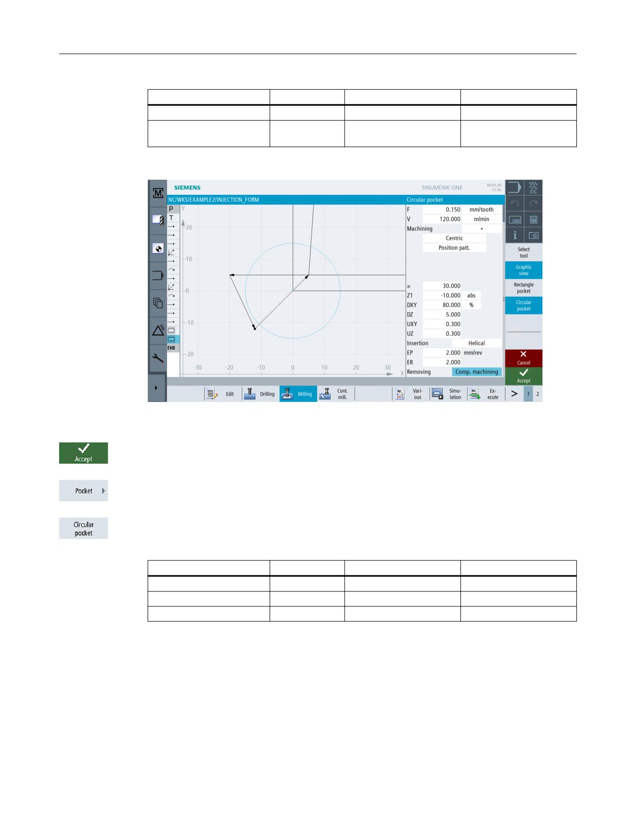
Figure 7-21
Roughing a circular pocket
Press "Accept" to apply the values entered.
Select the Pocket softkey.
Select the Circular pocket softkey.
Enter the following values:
Field
Value
Toggle field
Notes
F
0.08 mm/tooth
X
V
150 m/min
X
Machining
Finishing
X
Easy milling with ShopMill
Training Documents, 05/2020, 6FC5095-0AB50-1BP2
97
Example 2: Injection mold
7.4 Circular pockets on a position pattern
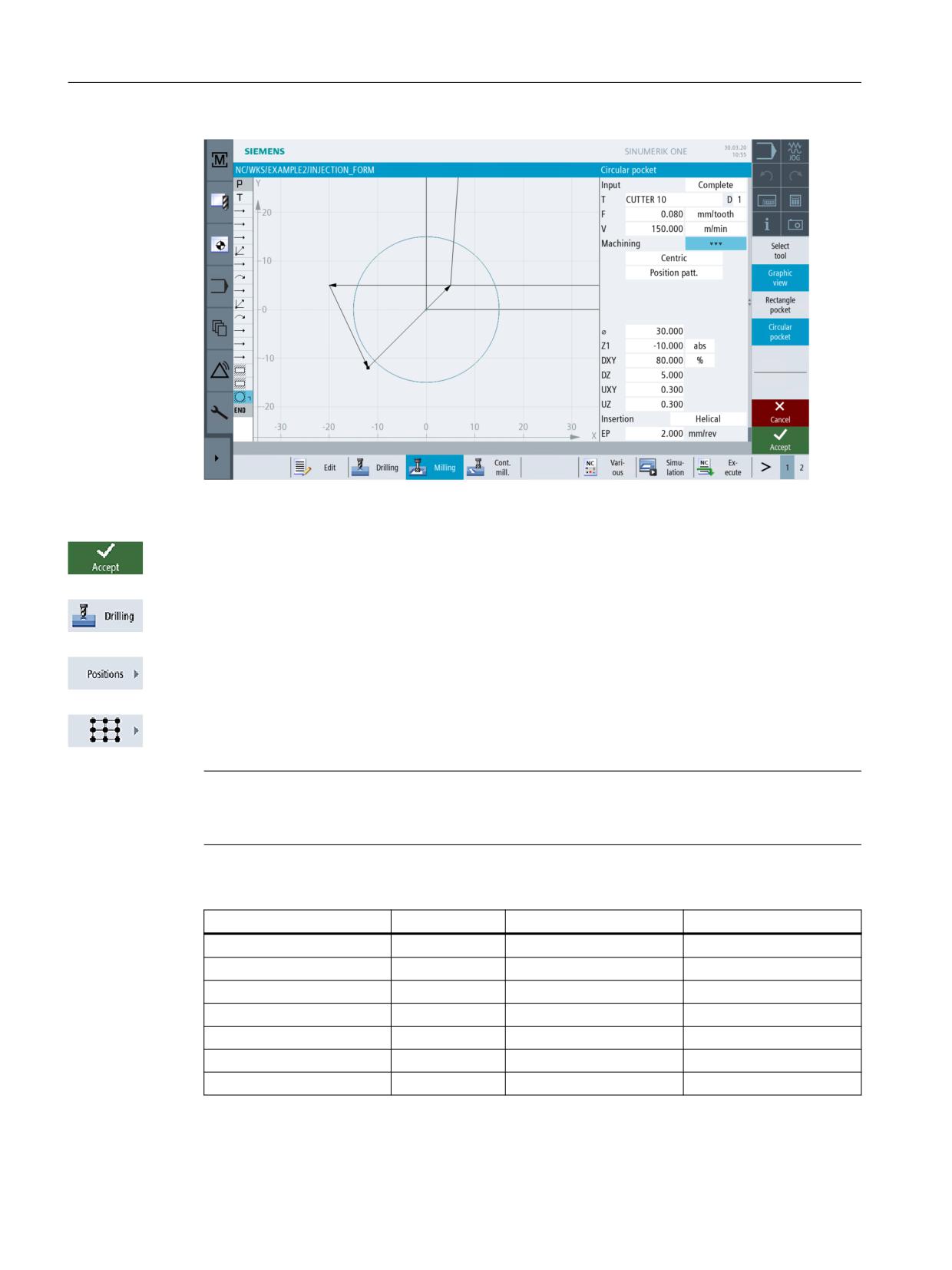
Figure 7-22
Finishing a circular pocket
Press "Accept" to apply the values entered.
Select the Drilling softkey.
Select the Positions softkey.
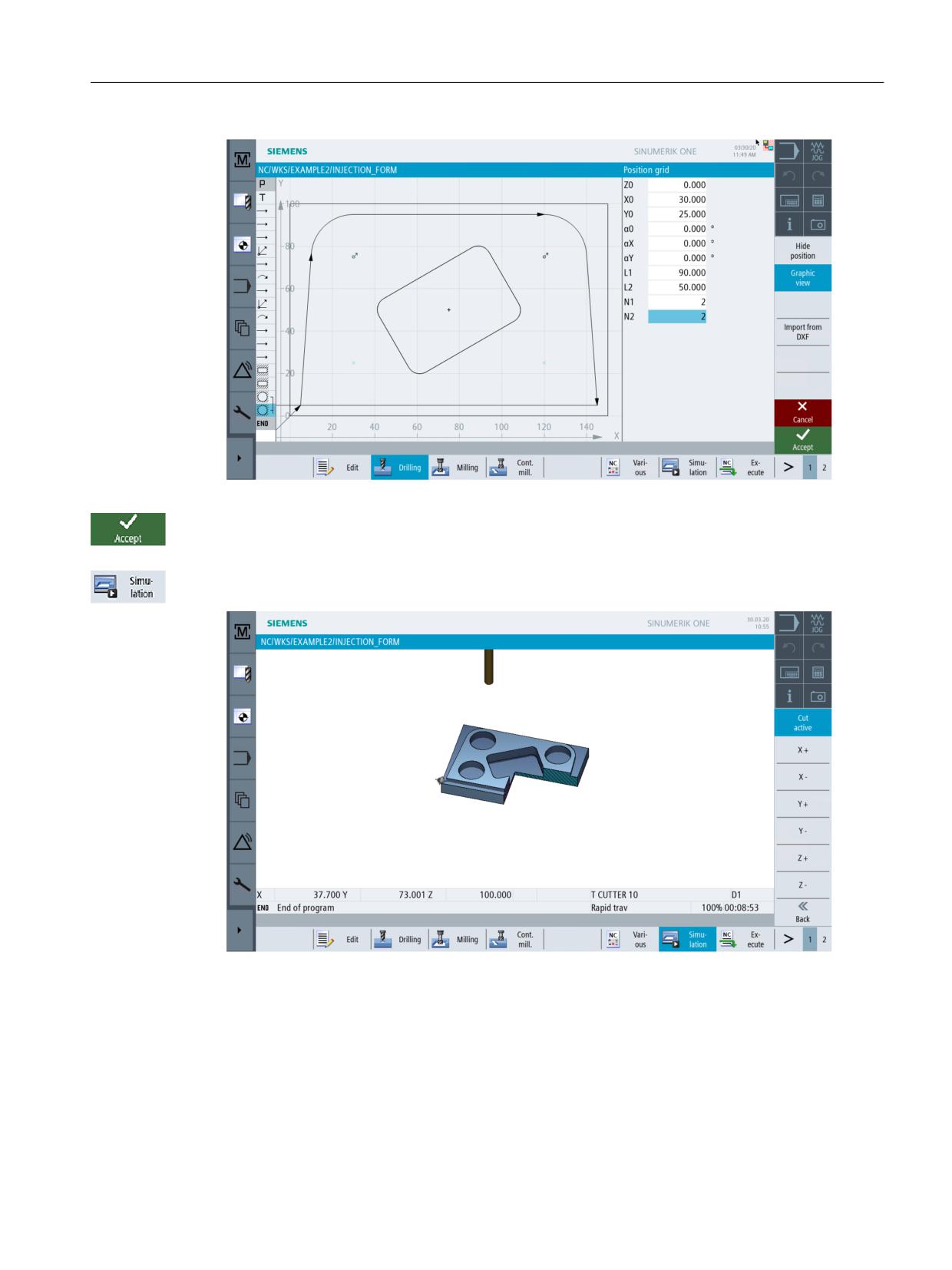
Select the position grid softkey.
Note
Position patterns are described in the Drilling menu with the Positions submenu (independent
of the machining method).
Enter the following values:
Field
Value
Toggle field
Notes
X0
30
Y0
25
α0
0
L1
90
L2
50
N1
2
N2
2
Easy milling with ShopMill
98
Training Documents, 05/2020, 6FC5095-0AB50-1BP2
Example 2: Injection mold
7.4 Circular pockets on a position pattern
Figure 7-23
Positions of the circular pockets
Press "Accept" to apply the values entered.
Start simulation.
Figure 7-24
Simulation - Cut active
Easy milling with ShopMill
Training Documents, 05/2020, 6FC5095-0AB50-1BP2
99
Example 2: Injection mold
7.4 Circular pockets on a position pattern
Easy milling with ShopMill
100
Training Documents, 05/2020, 6FC5095-0AB50-1BP2
Example 3: Mold plate
8
8.1
Overview
Learning objectives
In this section you will learn the following new functions, in particular the contour calculator.
You will learn how to...
• mill open contours;
• remove contour pockets from the solid, machine residual material and finish;
• apply machining methods on several planes;
• take into account obstacles.
Task
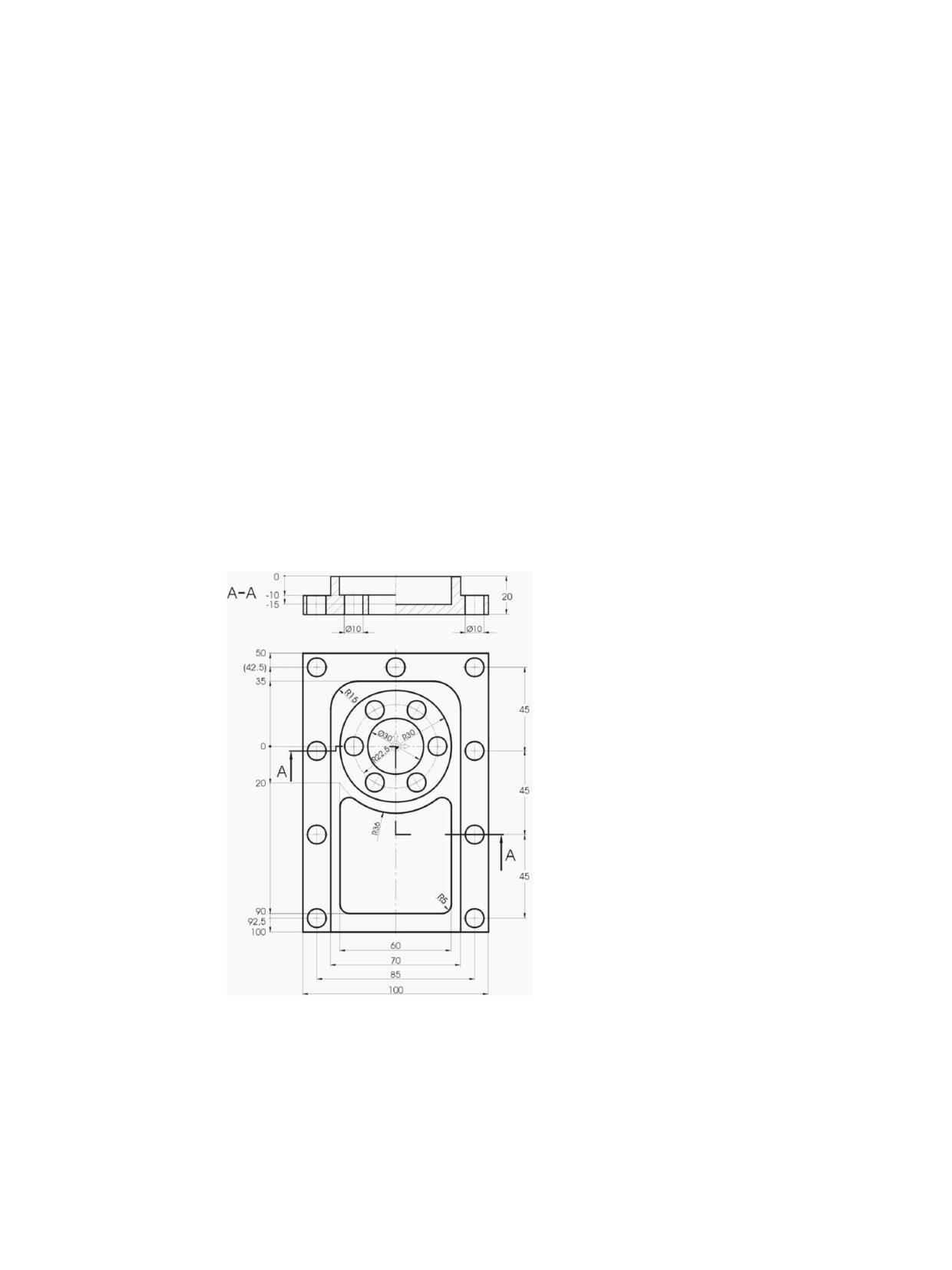
Figure 8-1
Workshop drawing - Example 3:
Easy milling with ShopMill
Training Documents, 05/2020, 6FC5095-0AB50-1BP2
101
Example 3: Mold plate
8.1 Overview
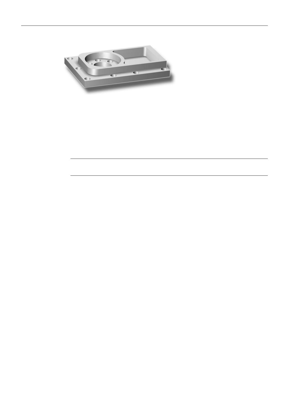
Figure 8-2
Workpiece - Example 3:
Preparation
Perform the following steps without help:
1. Create a new workpiece with the name 'Example3'.
2. Create a new process plan with the name 'MOLD_PLATE' .
3. Specify the blank dimensions (for the procedure, see example 1).
Note
Observe the new zero position.
Easy milling with ShopMill
102
Training Documents, 05/2020, 6FC5095-0AB50-1BP2
Example 3: Mold plate
8.2 Path milling of open contours
8.2
Path milling of open contours
Contour calculator
With the contour calculator integrated into ShopMill for entering complex contours, you can
enter even the most complicated contours easily.
With the graphical contour calculator, you can en-
ter the contours faster and more easily than with
conventional programming - and even without
any mathematical knowledge.
Operating sequences
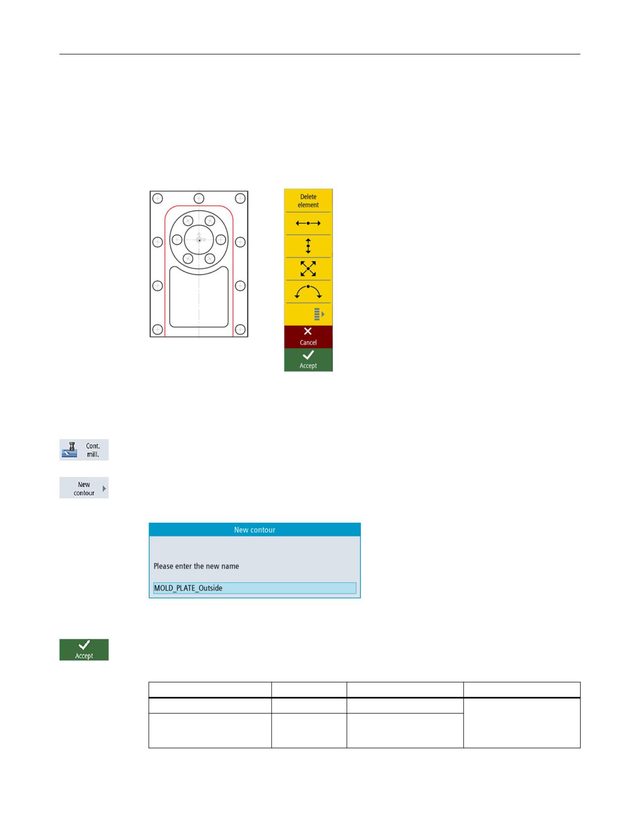
Proceed as follows to enter the contour:
Select the Contour milling softkey.
Select the New contour softkey. Type the name MOLD_PLATE_Outside for the contour.
Each contour is assigned its own name. This provides for better legibility of the programs.
Figure 8-3
Creating the 'MOLD_PLATE_Outside' contour
Press "Accept" to apply your input.
In the interactive screenform, enter the following values for the starting point of the contour line:
Field
Value
Toggle field
Notes
X
-35
The starting point for con-
struction is also the start-
Y
-100
ing point for later machin-
ing of the contour.
Easy milling with ShopMill
Training Documents, 05/2020, 6FC5095-0AB50-1BP2
103
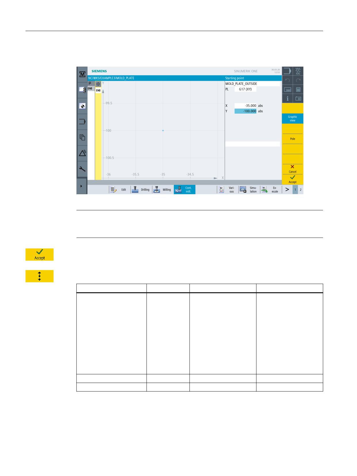
Example 3: Mold plate
8.2 Path milling of open contours
Figure 8-4
Specifying the starting point
Note
Here you only describe the workpiece contour; the approach and retraction travels will only be
defined later.
Press "Accept" to apply the values entered.
Enter the following values for the straight line in the interactive screenform:
Field
Value
Toggle field
Notes
Y
35 abs
X
The first contour element
is a vertical straight line
with the end point at
Y=20.
You can specify the subse-
quent circle contour very
easily in this dialog - as a
transition element to the
next straight line. There-
fore, the theoretical end
point of the straight line
lies at Y=35.
Transition to next element
Radius
X
R
15
Easy milling with ShopMill
104
Training Documents, 05/2020, 6FC5095-0AB50-1BP2
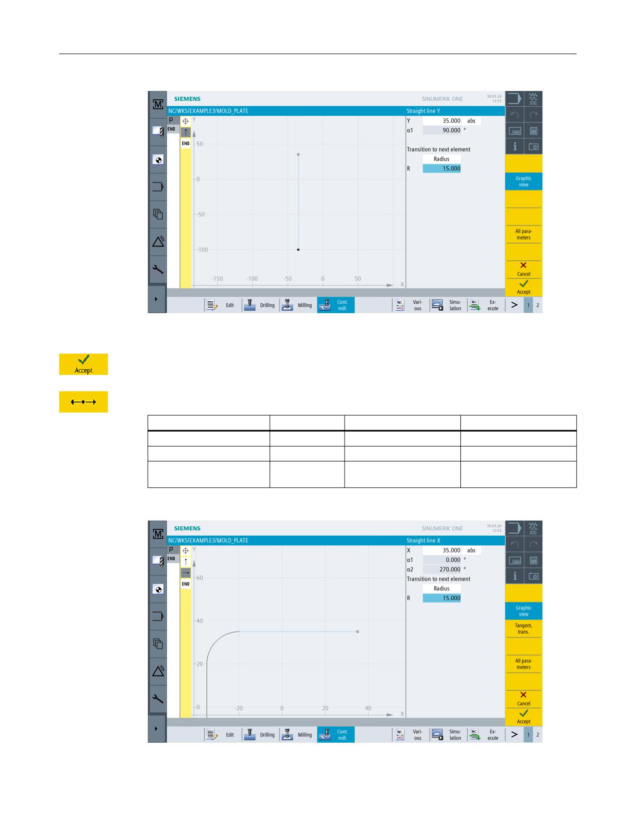
Example 3: Mold plate
8.2 Path milling of open contours
Figure 8-5
Specifying the vertical contour straight line
Press "Accept" to apply the values entered.
Enter the following values for the horizontal straight line in the interactive screenform:
Field
Value
Toggle field
Notes
X
35 abs
X
Transition to next element
Radius
X
R
15
The radius is entered as a
rounding again.
Easy milling with ShopMill
Training Documents, 05/2020, 6FC5095-0AB50-1BP2
105
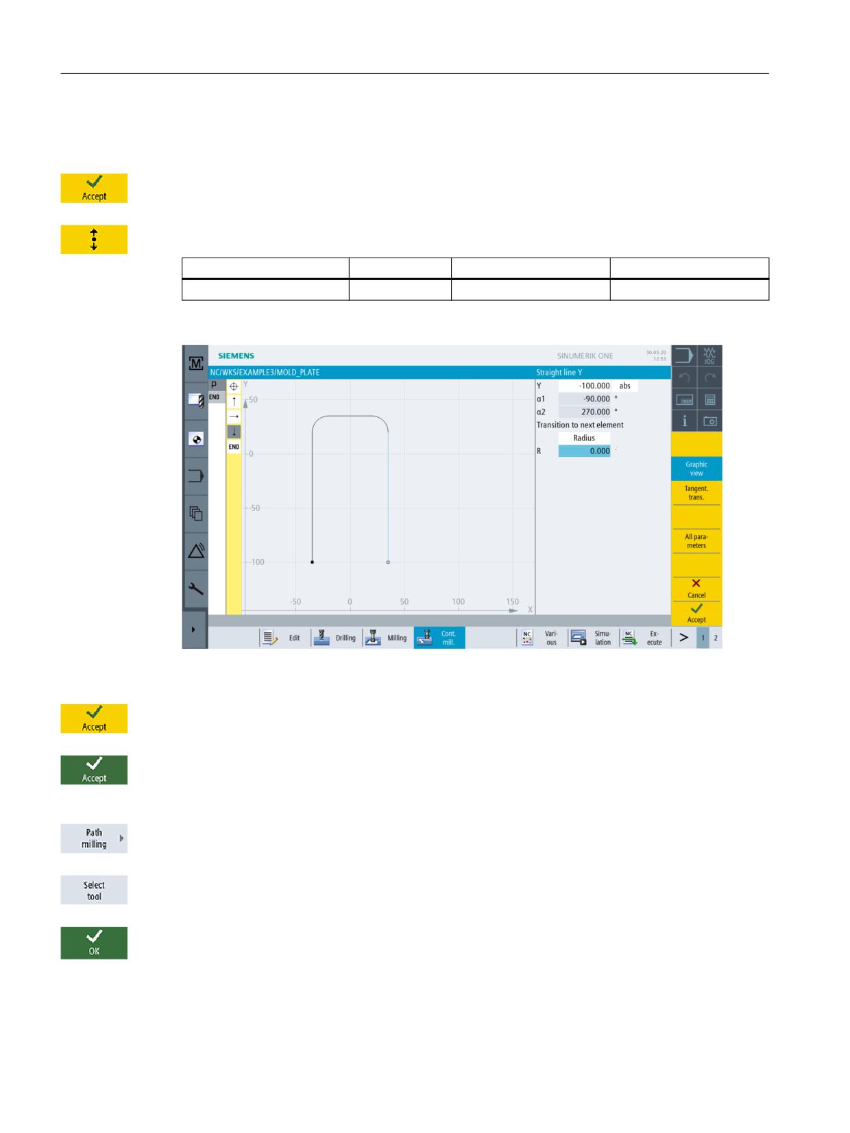
Example 3: Mold plate
8.2 Path milling of open contours
Figure 8-6
Specifying the horizontal contour straight line
Press "Accept" to apply the values entered.
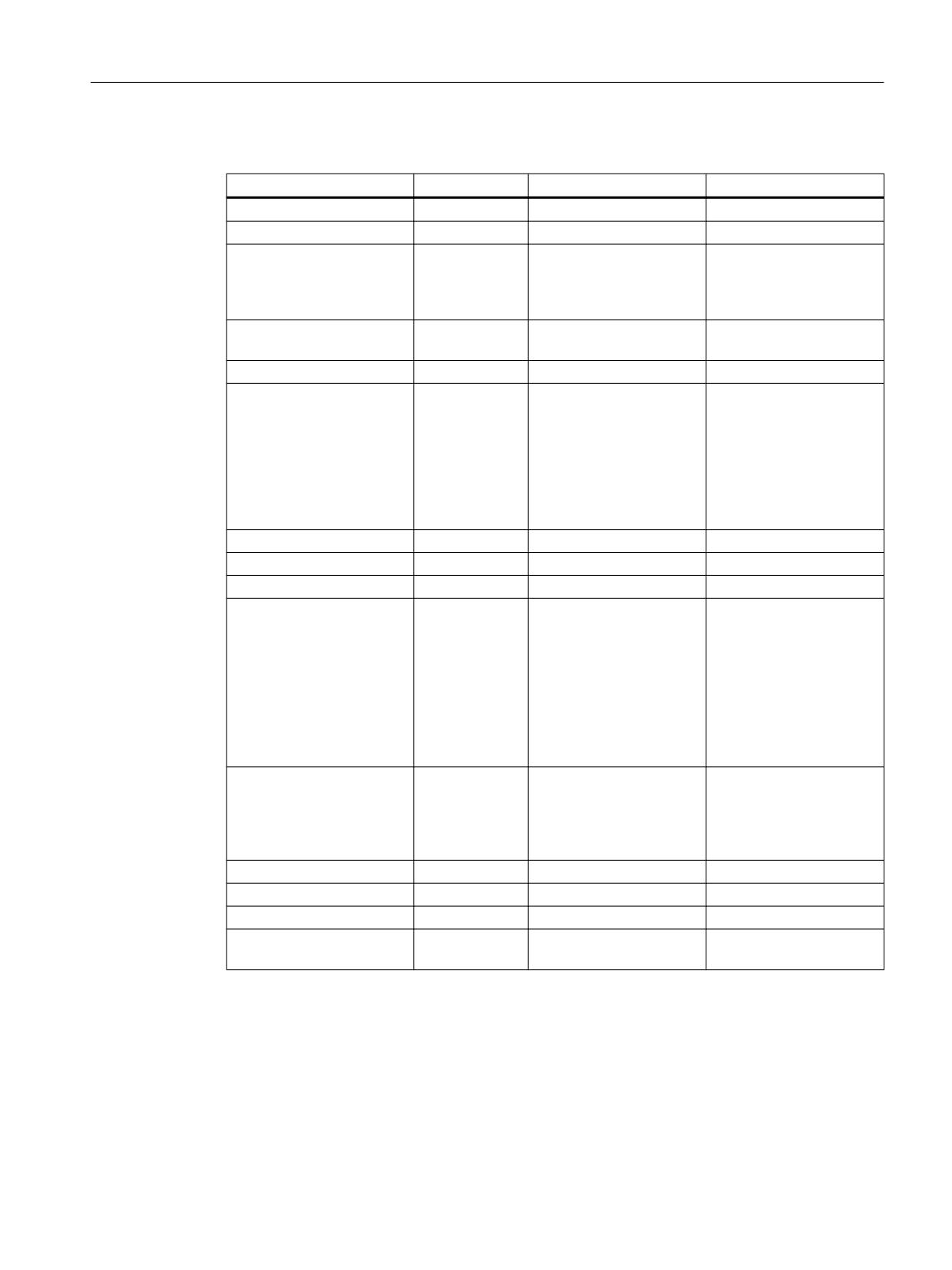
Enter the following values for the vertical straight line in the interactive screenform:
Field
Value
Toggle field
Notes
Y
-100 abs
X
Figure 8-7
Specifying the vertical contour straight line
"Apply" the set values.
Accept the contour into your process plan.
To be able to machine the created contour, you must now create the following work steps. To this
end, proceed as follows:
Select the Path milling softkey.
Open the tool list and select CUTTER 32.
Accept the tool into your program.
Easy milling with ShopMill
106
Training Documents, 05/2020, 6FC5095-0AB50-1BP2
Example 3: Mold plate
8.2 Path milling of open contours
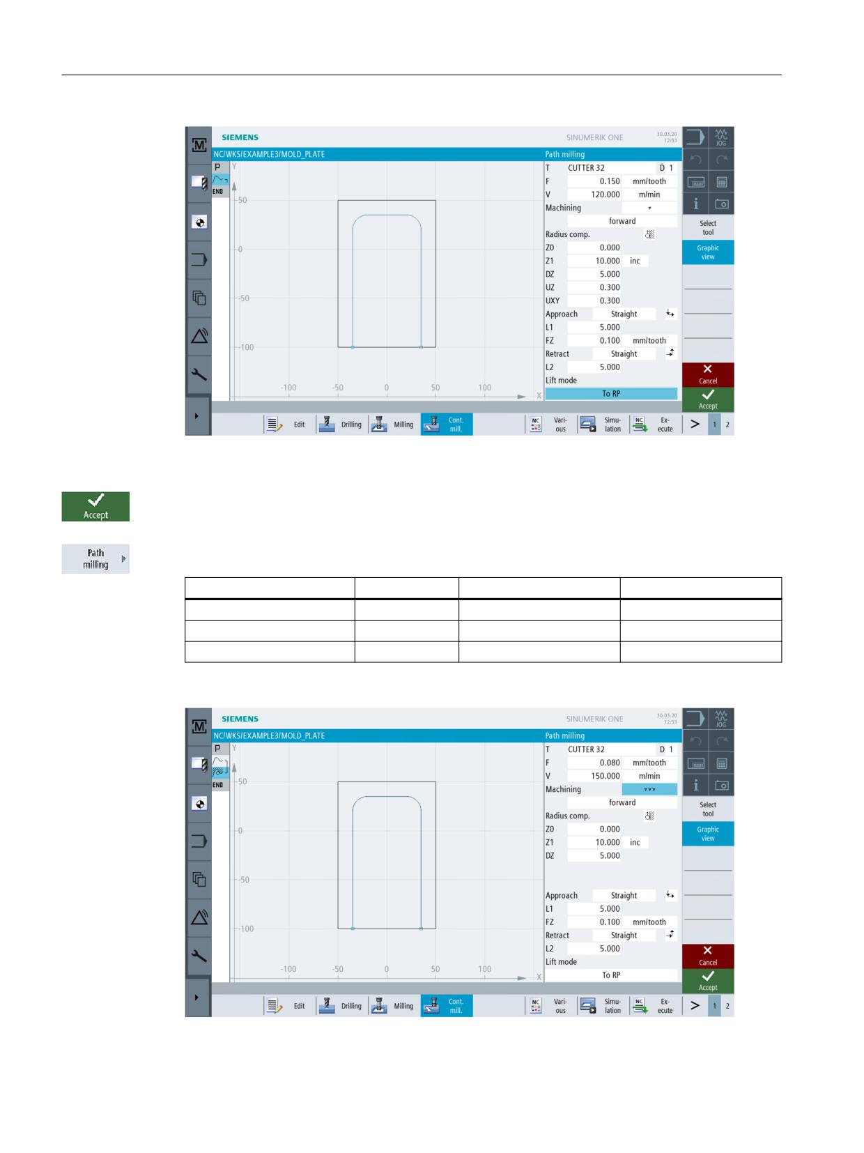
Enter the following values for roughing in the interactive screenform:
Field
Value
Toggle field
Notes
F
0.15 mm/tooth
X
V
120 m/min
X
Machining
Roughing
X
With ShopMill V6.4 and
forward
X
higher, you may also mill
reverse against the engi-
neering direction.
Radius compensation
Left
X
The tool is to traverse to
the left of the contour.
Z0
0
Z1
10 inc
X
Switch the depth Z1 to
"inc". This provides the ad-
vantage that in all cases
only the actual depth of
the pocket can be entered.
This makes input easier for
you, in particular with nes-
ted pockets.
DZ
5
UZ
0.3
UXY
0.3
Approach
Straight line
X
Approaching can be per-
formed either along a
quarter, semicircle, verti-
cally or along a straight
line.
In this case, it is reasona-
ble to approach the con-
tour tangentially along a
straight line.
L1
5
The cutter radius need not
be taken into account in
the approach length L1; it
is calculated by ShopMill
automatically.
FZ
0.1 mm/tooth
X
Retraction
Straight line
X
L2
5
Lift mode
To retraction
X
plane
Easy milling with ShopMill
Training Documents, 05/2020, 6FC5095-0AB50-1BP2
107
Example 3: Mold plate
8.2 Path milling of open contours
Figure 8-8
Roughing the contour
Press "Accept" to apply the values entered.
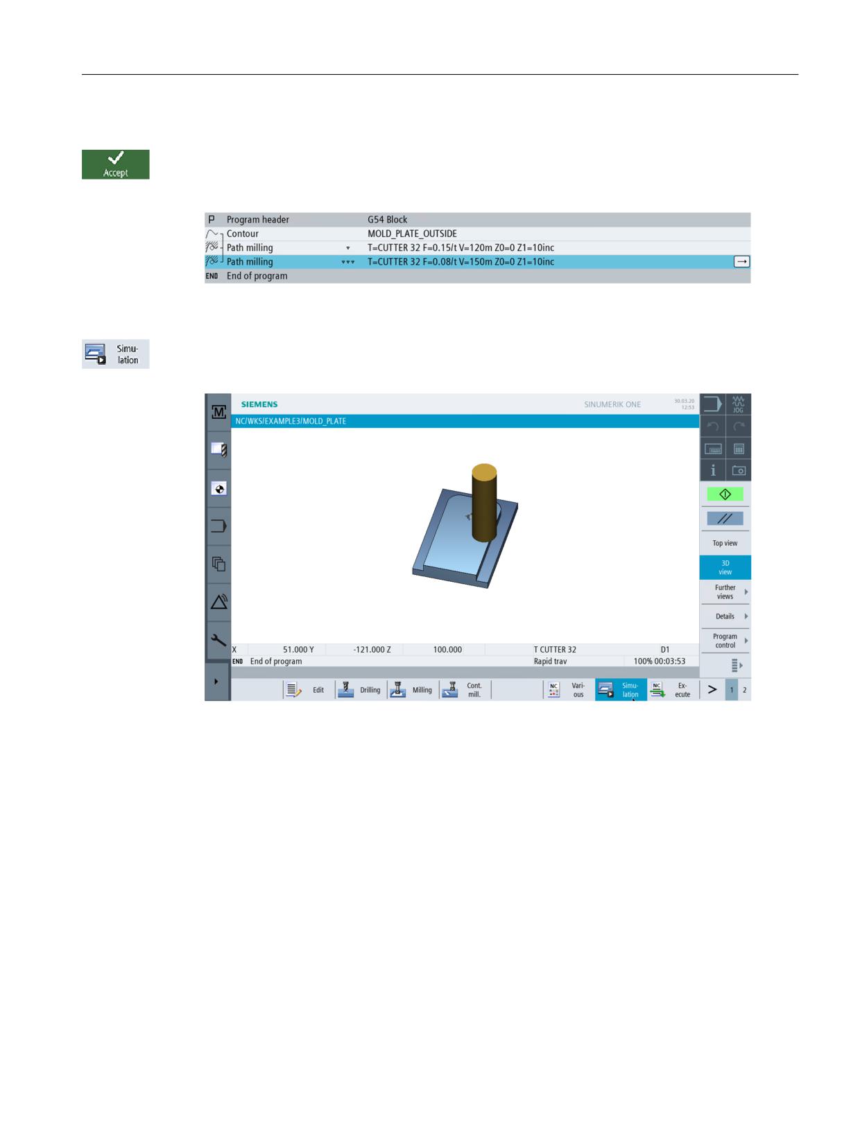
Enter the following values for finishing in the interactive screenform:
Field
Value
Toggle field
Notes
F
0.08 mm/tooth
X
V
150 m/min
X
Machining
Finishing
X
Figure 8-9
Finishing the contour
Easy milling with ShopMill
108
Training Documents, 05/2020, 6FC5095-0AB50-1BP2
Example 3: Mold plate
8.2 Path milling of open contours
Press "Accept" to apply the values entered.
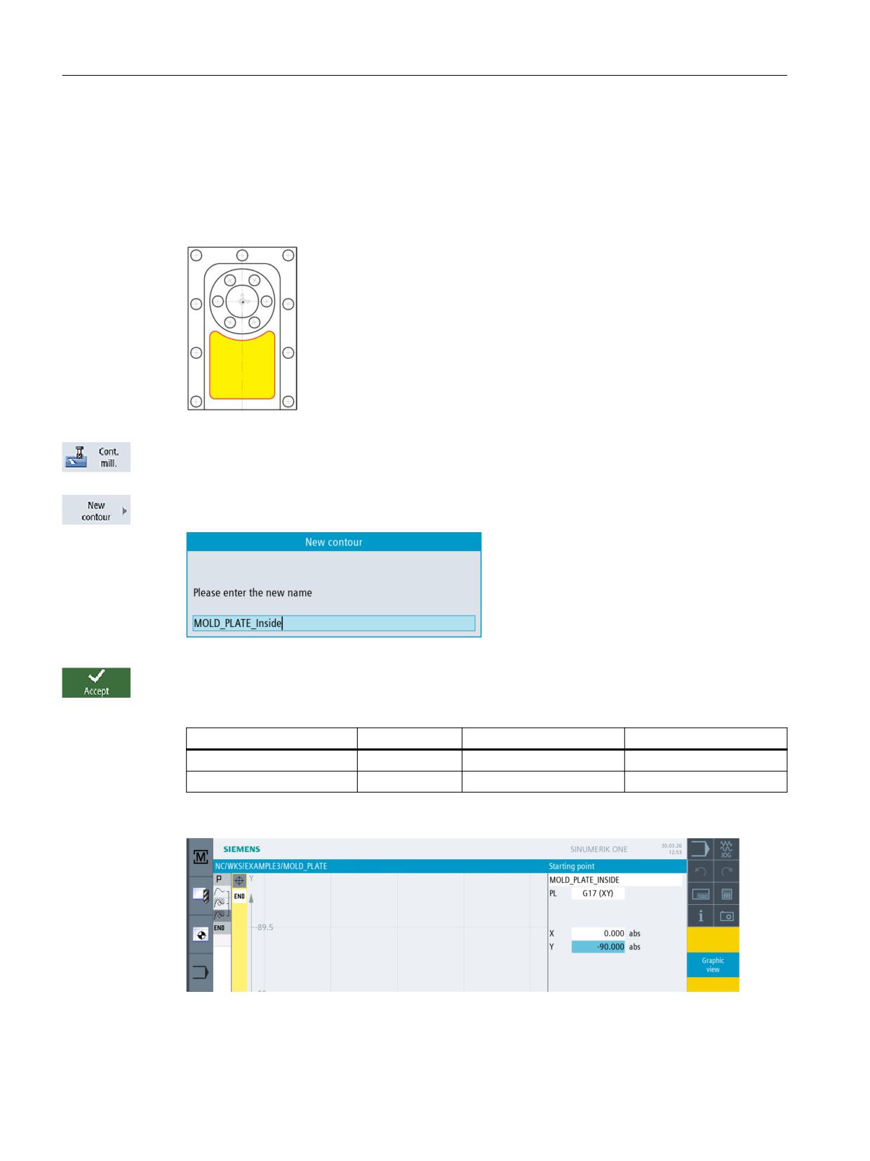
The two machining steps are linked in the work step editor.
Figure 8-10
Linking of the work steps in the process plan
The following simulation shows the manufacturing sequence for you to check before
manufacturing the workpiece.
Figure 8-11
Simulation - External contour
Easy milling with ShopMill
Training Documents, 05/2020, 6FC5095-0AB50-1BP2
109
Example 3: Mold plate
8.3 Solid machining and residual material; finishing of contour pockets
8.3
Solid machining and residual material; finishing of contour pockets
Operating sequences
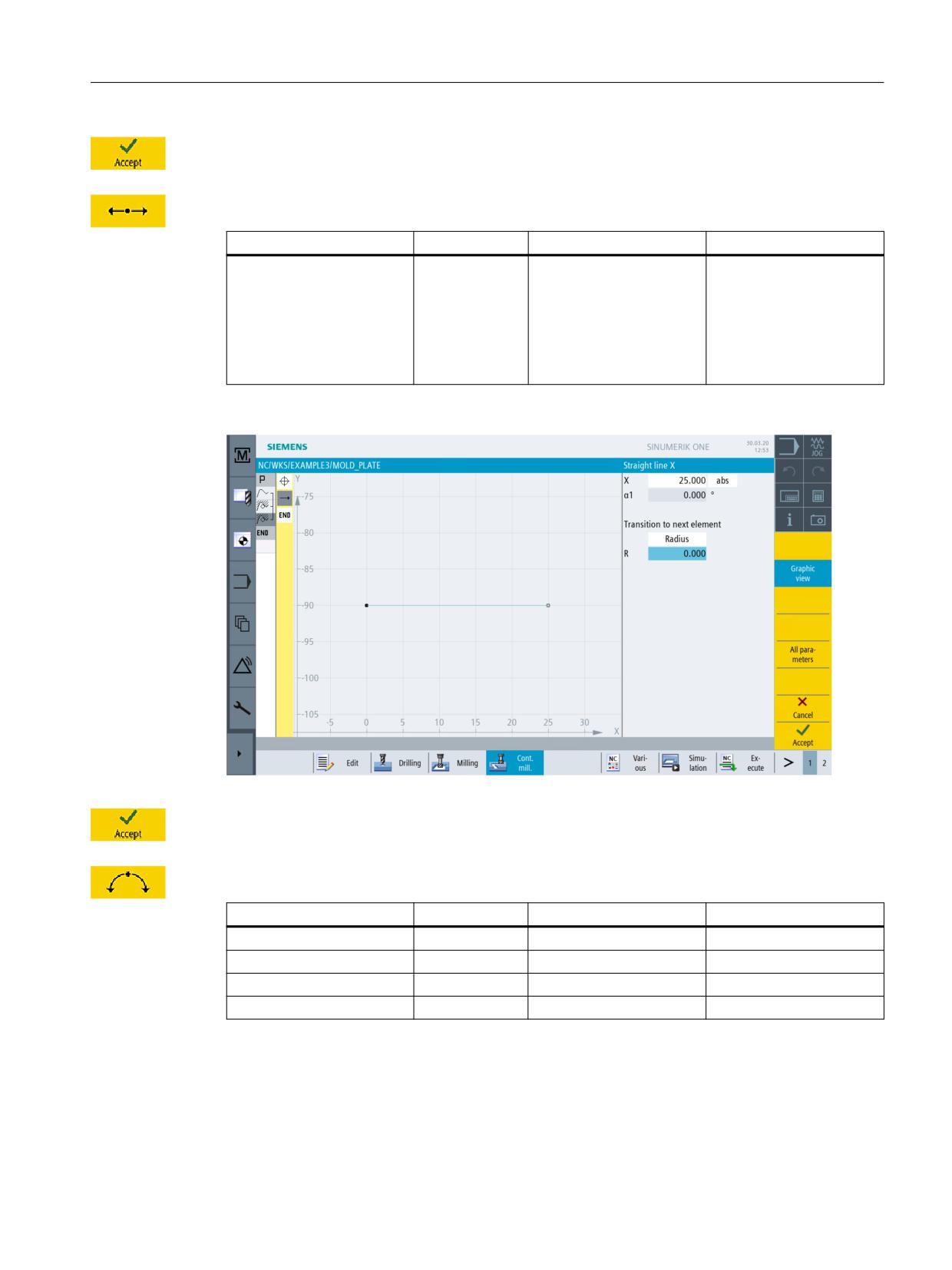
Proceed as follows to enter the pocket contour: Remove the pocket from the solid and finish.
Figure 8-12
Pocket contour
Select the Contour milling softkey.
Select the New contour softkey. Type the name 'MOLD_PLATE_Inside' for the contour.
Figure 8-13
Creating the 'MOLD_PLATE_Inside' contour
Press "Accept" to apply your input.
Enter the following values for the starting point in the interactive screenform:
Field
Value
Toggle field
Notes
X
0
Y
-90
Figure 8-14
Specifying the starting point
Easy milling with ShopMill
110
Training Documents, 05/2020, 6FC5095-0AB50-1BP2
Example 3: Mold plate
8.3 Solid machining and residual material; finishing of contour pockets
Press "Accept" to apply the values entered.
Enter the following values for the horizontal straight line in the interactive screenform:
Field
Value
Toggle field
Notes
X
25 abs
X
Within the framework of
this exercise, do not speci-
fy the arc as a rounding,
but as a separate element.
Therefore, design the
straight line only up to
X25.
Figure 8-15
Specifying the horizontal contour straight line
Press "Accept" to apply the values entered.
Enter the following values for the arc in the interactive screenform:
Field
Value
Toggle field
Notes
Direction of rotation
Left
X
R
5
X
30 abs
X
Y
-85 abs
X
Easy milling with ShopMill
Training Documents, 05/2020, 6FC5095-0AB50-1BP2
111
Example 3: Mold plate
8.3 Solid machining and residual material; finishing of contour pockets
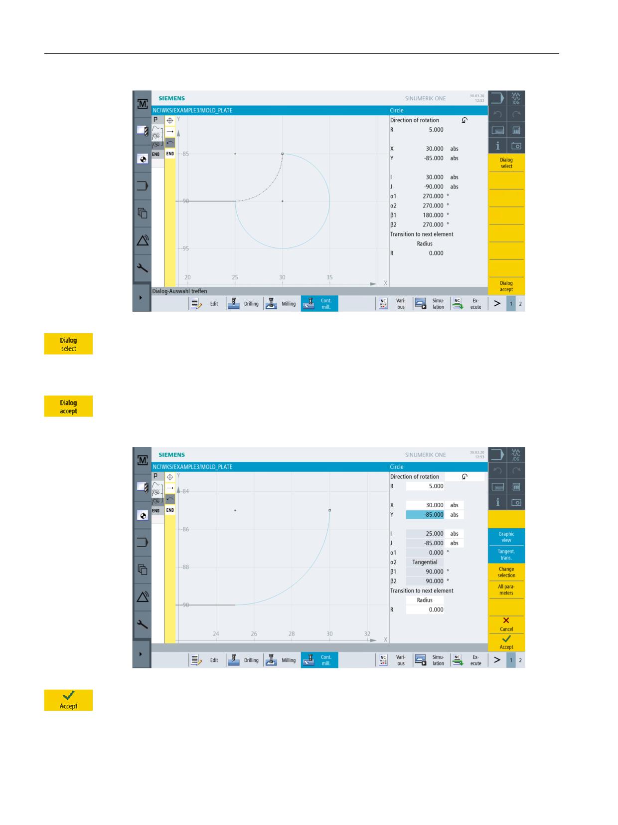
Figure 8-16
Arc contour (bottom right)
Two design solutions result after entering the Y end point. Select the desired solution using the
Select dialog softkey. Subsequently, the selected solutions turns to orange, and the alternative
solution is displayed with black points.
Accept your selection. The geometry processor automatically detects that the programmed arc
is connected tangentially to the straight line. The Tangent to prec.elem. is displayed inversely
(i.e. held down).
Figure 8-17
Arc contour - after selection
Press "Accept" to apply the values entered.
Easy milling with ShopMill
112
Training Documents, 05/2020, 6FC5095-0AB50-1BP2
Example 3: Mold plate
8.3 Solid machining and residual material; finishing of contour pockets
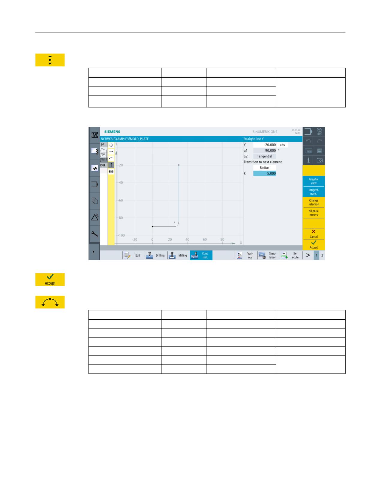
Enter the following values for the straight line in the interactive screenform:
Field
Value
Toggle field
Notes
Y
-20 abs
X
Enter the end point of the
straight line. The transi-
Transition to next element
Radius
X
tion to R36 is rounded
R
5
with R5.
Figure 8-18
Specifying the vertical contour straight line
Press "Accept" to apply the values entered.
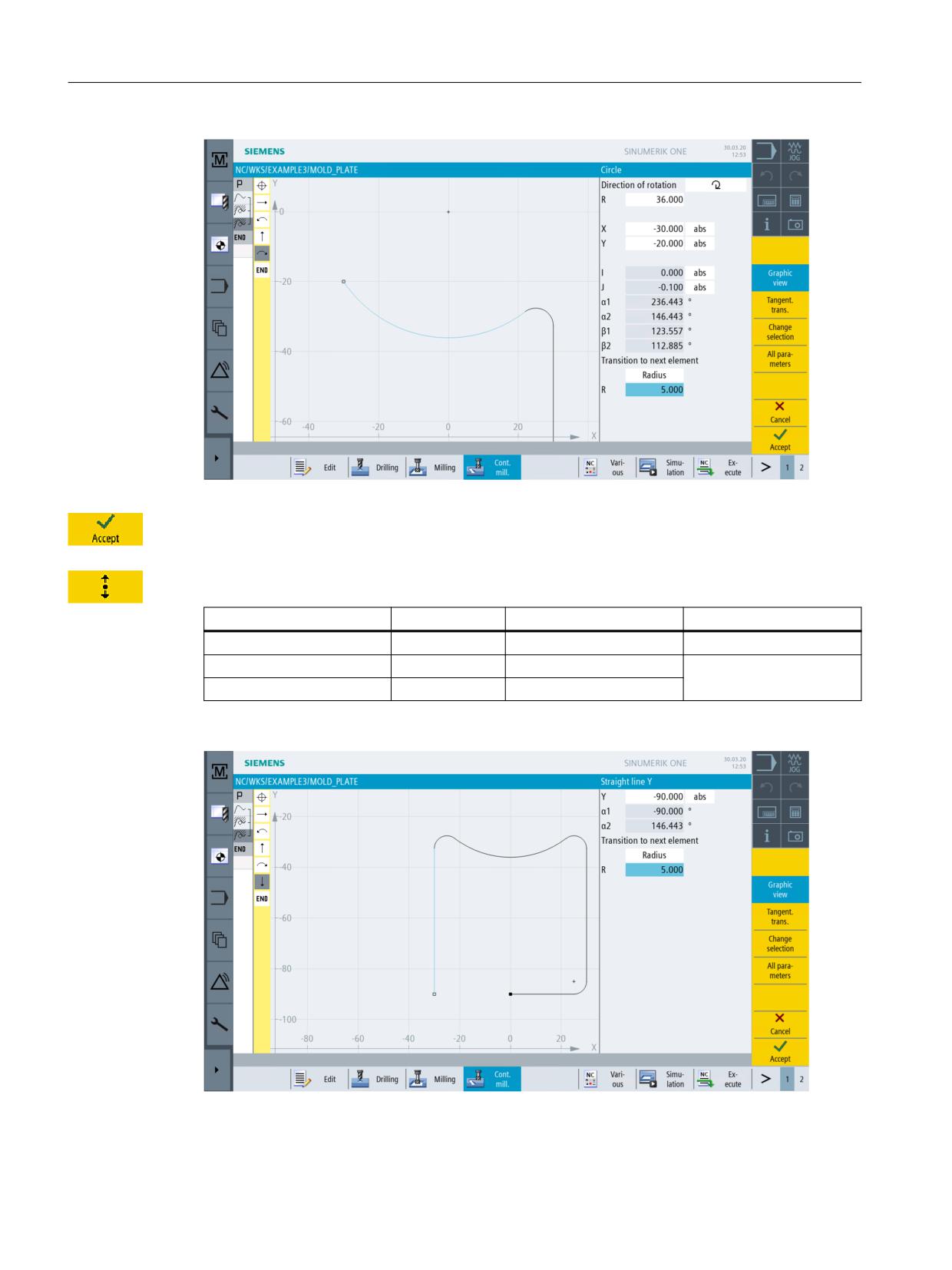
Enter the following values for the arc in the interactive screenform:
Field
Value
Toggle field
Notes
Direction of rotation
Clockwise
X
R
36
X
-30 abs
X
Y
-20 abs
X
Transition to next element
Radius
X
Specify the radius R5 as a
rounding.
R
5
Easy milling with ShopMill
Training Documents, 05/2020, 6FC5095-0AB50-1BP2
113
Example 3: Mold plate
8.3 Solid machining and residual material; finishing of contour pockets
Figure 8-19
Specifying the contour arc
Press "Accept" to apply the values entered.
Enter the following values for the straight line in the interactive screenform:
Field
Value
Toggle field
Notes
Y
-90 abs
X
Transition to next element
Radius
X
Specify the radius R5 as a
rounding.
R
5
Figure 8-20
Specifying the vertical contour straight line
Easy milling with ShopMill
114
Training Documents, 05/2020, 6FC5095-0AB50-1BP2
Example 3: Mold plate
8.3 Solid machining and residual material; finishing of contour pockets
Press "Accept" to apply the values entered.
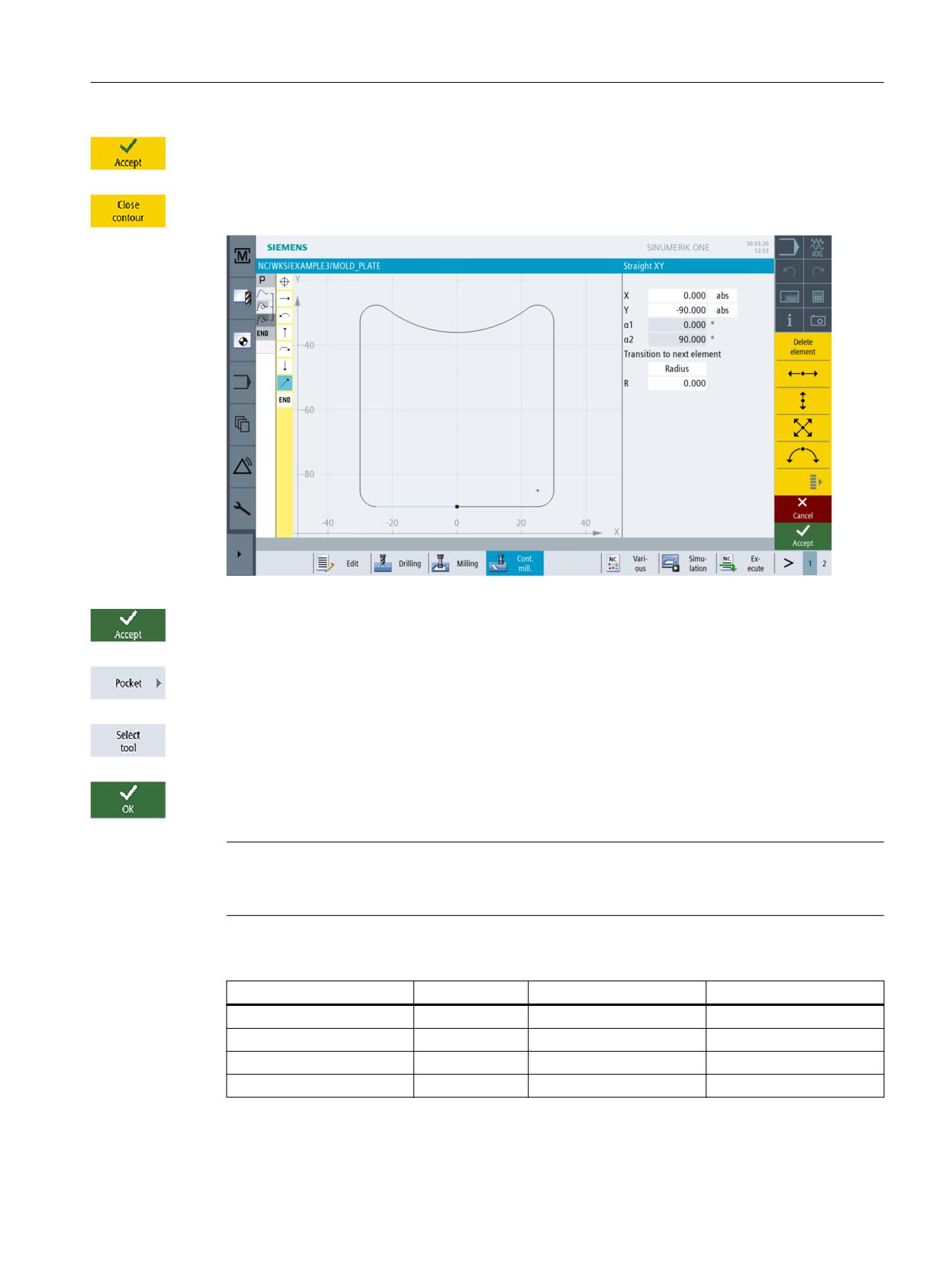
Close the contour. Thus, the pocket contour is described completely.
Figure 8-21
Closing the contour
Accept the contour into your process plan.
Select the Pocket softkey.
Open the tool list and select CUTTER 20.
Accept the tool into your program.
Note
The manufacturing direction of the pocket has already been defined in the program header. The
"Synchronous" setting was selected in this case.
Enter the following values for roughing in the interactive screenform:
Field
Value
Toggle field
Notes
F
0.15 mm/tooth
X
V
120 m/min
X
Machining
Roughing
X
Z0
0
Easy milling with ShopMill
Training Documents, 05/2020, 6FC5095-0AB50-1BP2
115
Example 3: Mold plate
8.3 Solid machining and residual material; finishing of contour pockets
Field
Value
Toggle field
Notes
Z1
15 inc
X
If you specify the machin-
ing depth with incremen-
tal , you must specify a
positive value for the
depth.
DXY
50%
X
DZ
5
UXY
0.3
UZ
0.3
Starting point
Automatic
X
If you select the Autom set-
ting for the starting point
(insertion), the starting
point is specified by Shop-
Mill.
Insertion
Helical
X
Set insertion to Helical
with 2mm for both pitch
EP
2 mm/rev
X
and radius.
ER
2
Lift mode
To retraction
X
plane
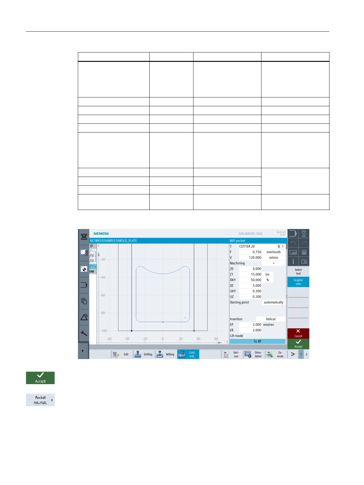
Figure 8-22
Roughing a pocket
Press "Accept" to apply the values entered.
Select the Pocket Resid.mat. softkey. As the 20mm cutter cannot machine R5 radii, material will
remain in the corners. Use the Pocket Resid. mat. to remove areas not yet machined by
roughing with pinpoint accuracy.
Easy milling with ShopMill
116
Training Documents, 05/2020, 6FC5095-0AB50-1BP2
Example 3: Mold plate
8.3 Solid machining and residual material; finishing of contour pockets
Open the tool list and select CUTTER 10.
Accept the tool into your program.
Enter the following values in the interactive screenform:
Field
Value
Toggle field
Notes
F
0.1 mm/tooth
X
V
120 m/min
X
Machining
Roughing
X
DXY
50%
X
The maximum infeed in
the plane must be 50 %.
DZ
5
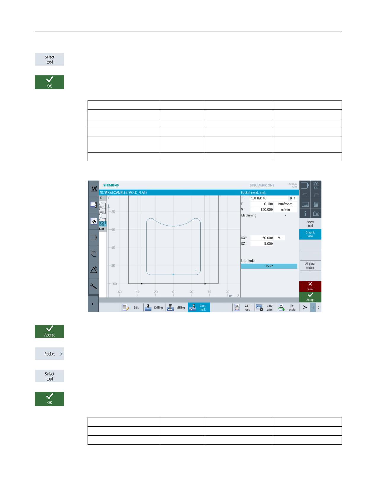
Figure 8-23
Machining residual material of the pocket
Press "Accept" to apply the values entered.
Select the Pocket softkey.
Open the tool list and select CUTTER 10.
Accept the tool into your program.
Enter the following values for the reworking the pocket in the interactive screenform:
Field
Value
Toggle field
Notes
F
0.08 mm/tooth
X
V
150 m/min
X
Easy milling with ShopMill
Training Documents, 05/2020, 6FC5095-0AB50-1BP2
117
Example 3: Mold plate
8.3 Solid machining and residual material; finishing of contour pockets
Field
Value
Toggle field
Notes
Machining
Base
X
UXY
The allowance which you
have previously entered
UZ
for roughing must remain
set for the values in the
"Finishing allowance fields
in the plane (UXY)" and
"Finishing allowance in
the depth (UZ)" fields. This
value is important for au-
tomatic calculation of the
distances to be trav-
ersed.
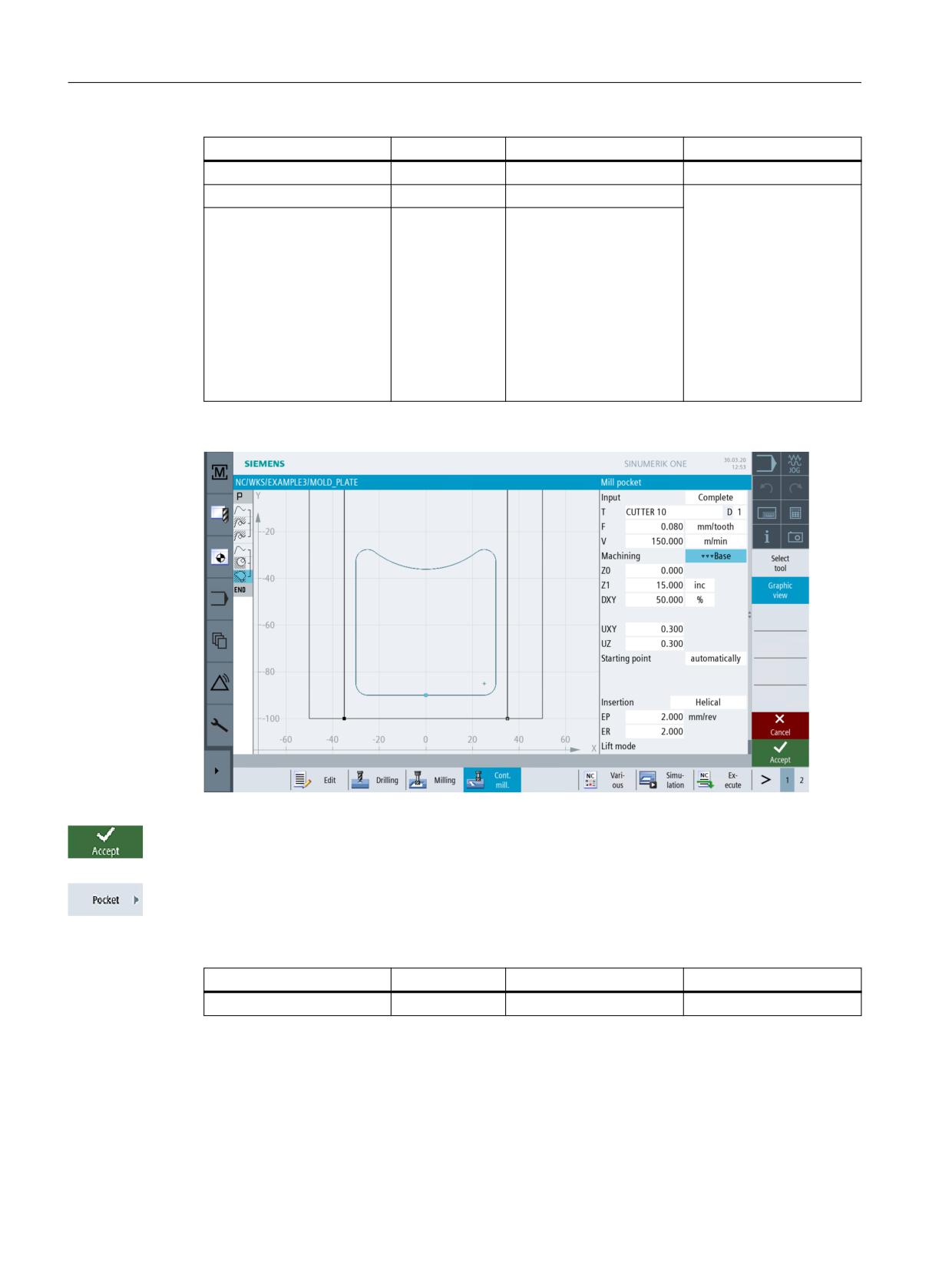
Figure 8-24
Finishing a pocket
Press "Accept" to apply the values entered.
Select the Pocket softkey.
In the interactive screenform, specify the following value for removing the residual material of
the contour:
Field
Value
Toggle field
Notes
Machining
Edge
X
Easy milling with ShopMill
118
Training Documents, 05/2020, 6FC5095-0AB50-1BP2
Example 3: Mold plate
8.3 Solid machining and residual material; finishing of contour pockets
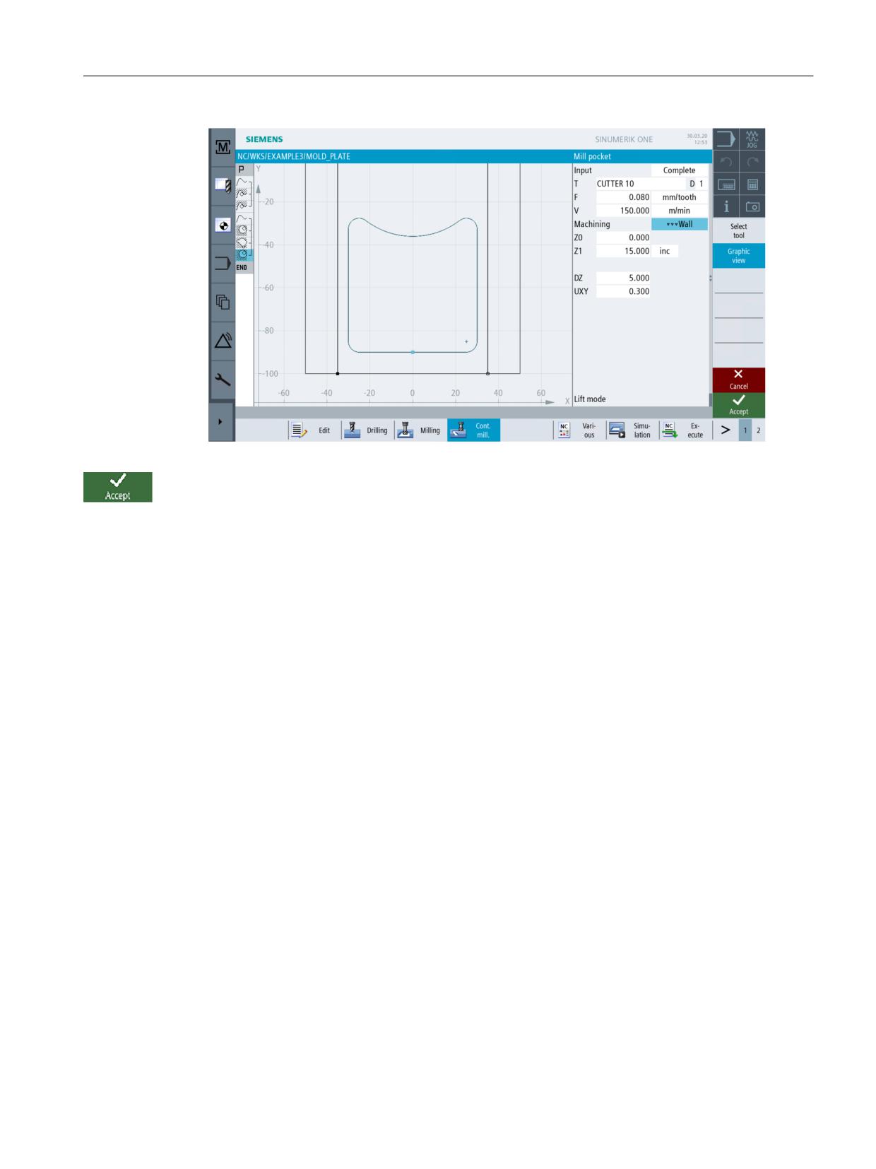
Figure 8-25
Finishing the edge
Press "Accept" to apply the values entered.
Easy milling with ShopMill
Training Documents, 05/2020, 6FC5095-0AB50-1BP2
119
Example 3: Mold plate
8.4 Machining on several planes
8.4
Machining on several planes
Operating sequences
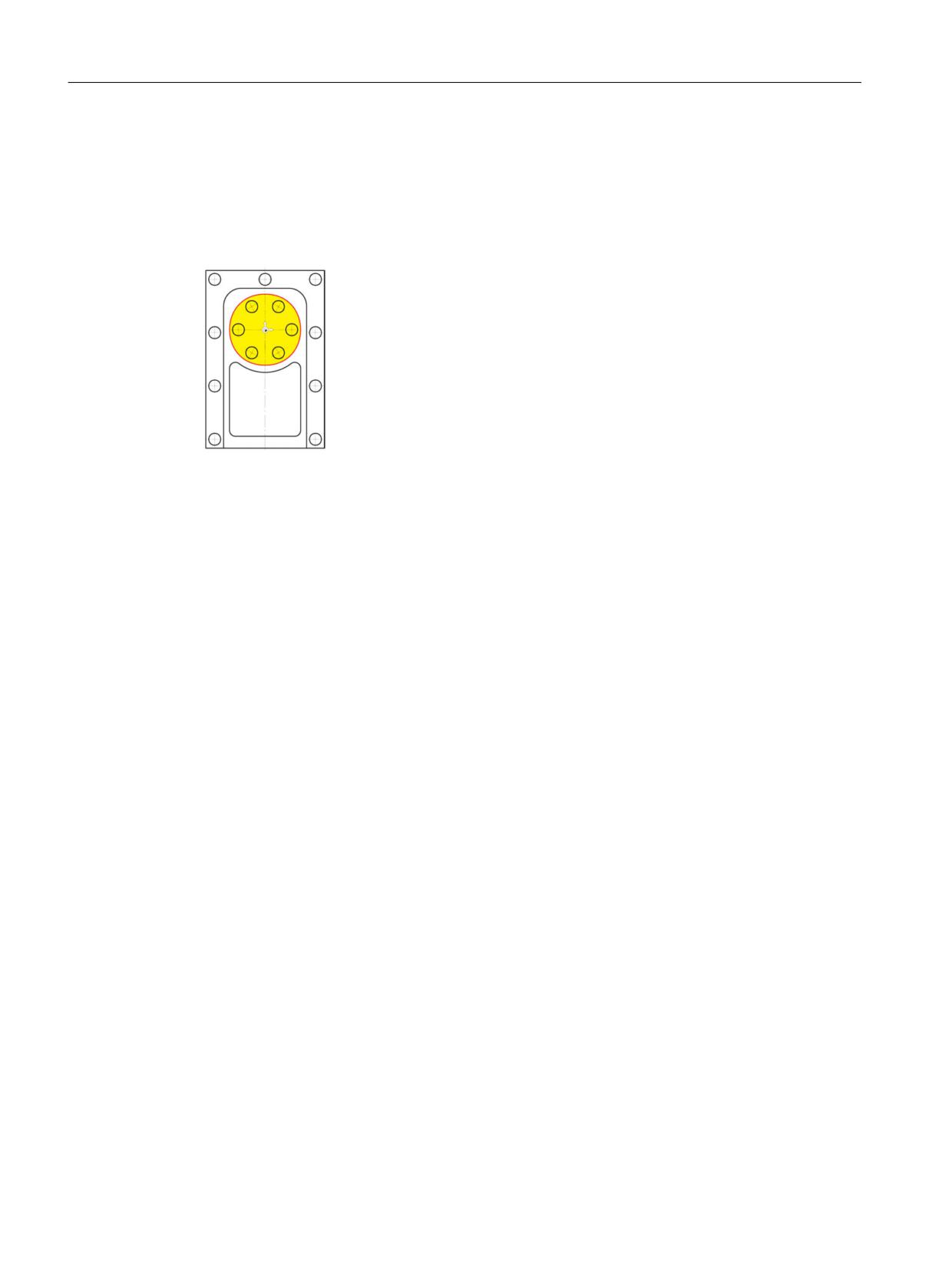
Mill a 60mm circular pocket in two work steps as described in the example 'INJECTION_FORM' .
Figure 8-26
Circular pocket
Easy milling with ShopMill
120
Training Documents, 05/2020, 6FC5095-0AB50-1BP2
Example 3: Mold plate
8.4 Machining on several planes
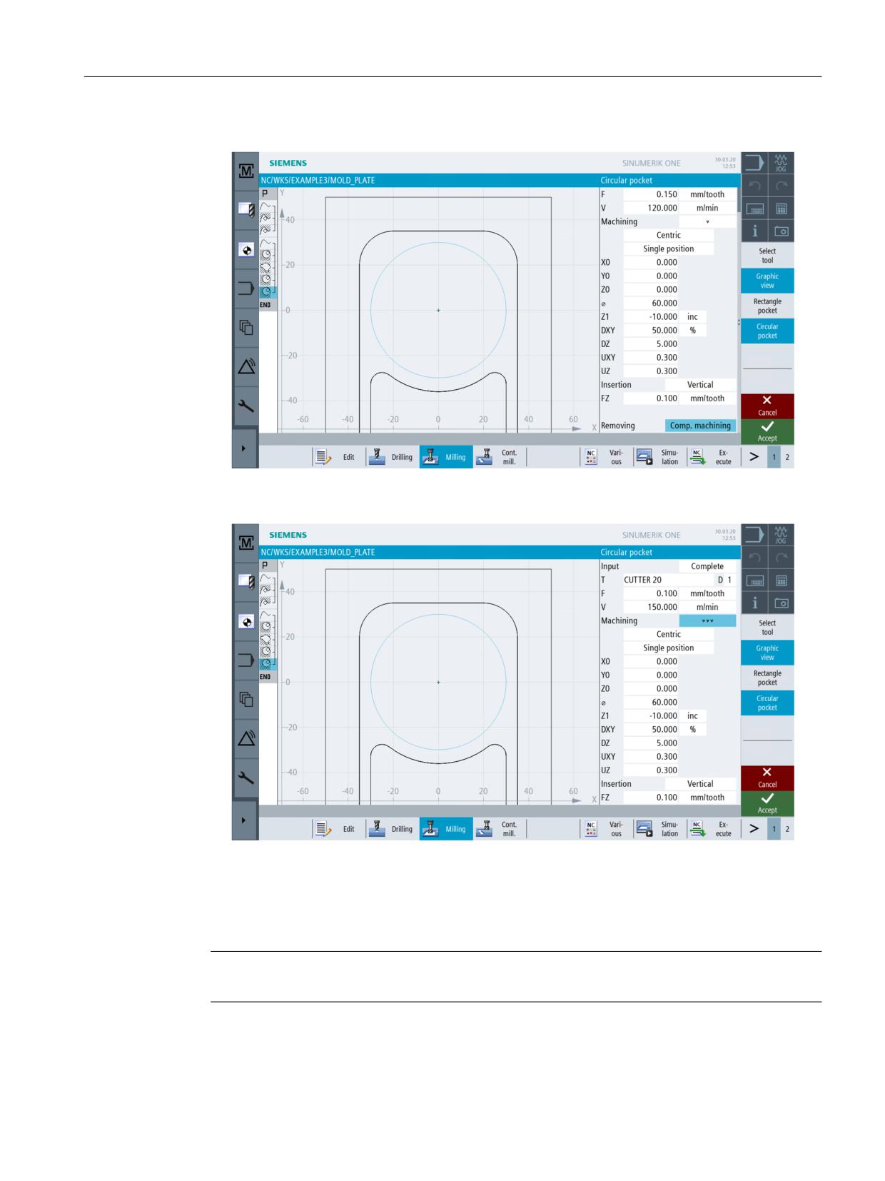
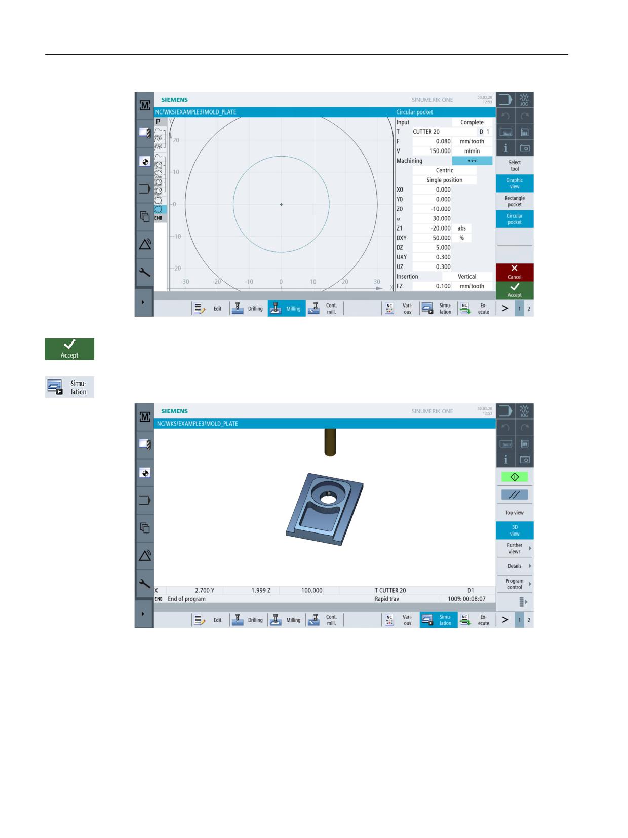
1. In the first work step, the pocket is machined by roughing up to -9.7 mm using a 20 mm cutter.
Figure 8-27
Roughing a circular pocket
2. In the second work step, the pocket is finished using the same tool.
Figure 8-28
Finishing a circular pocket
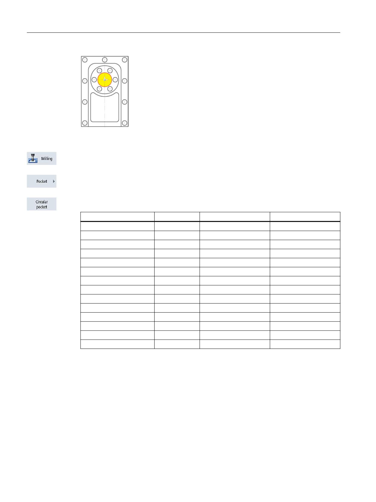
To specify how the inside circular pocket is machined, proceed as follows: Machine the circular
pocket down to a depth of -20 mm.
Note
Now the starting depth is no longer at 0 mm, but at -10 mm.
Easy milling with ShopMill
Training Documents, 05/2020, 6FC5095-0AB50-1BP2
121
Example 3: Mold plate
8.4 Machining on several planes
Figure 8-29
Inside circular pocket
Select the Milling softkey.
Select the Pocket softkey.
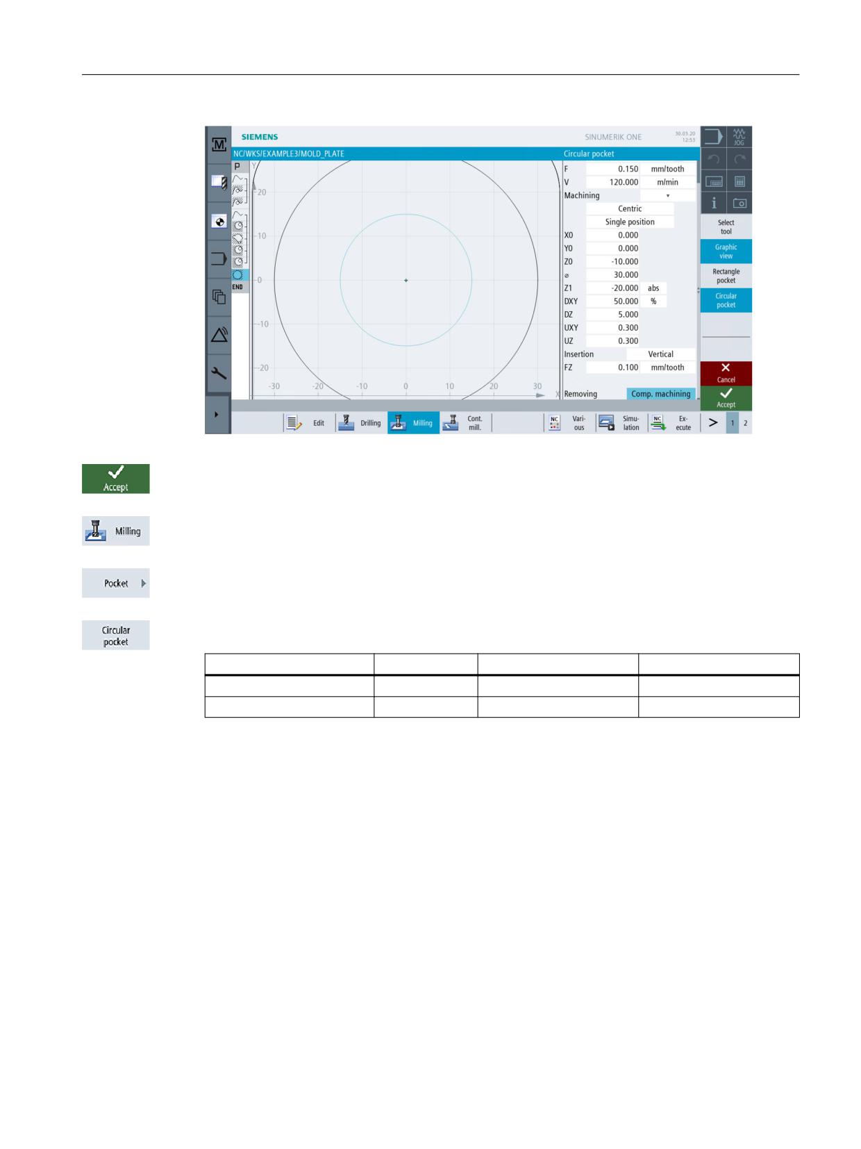
Enter the following values for machining of the circular pocket in the interactive screenform:
Field
Value
Toggle field
Notes
F
0.15 mm/tooth
X
V
120 m/min
X
Machining
Roughing
X
X0
0
Y0
0
Z0
-10
∅
30
Z1
-20 abs
X
DXY
50%
X
DZ
5
UXY
0.3
UZ
0.3
Insertion
Vertical
X
FZ
0.1 mm/tooth
X
Easy milling with ShopMill
122
Training Documents, 05/2020, 6FC5095-0AB50-1BP2
Example 3: Mold plate
8.4 Machining on several planes
Figure 8-30
Roughing the inside circular pocket
Press "Accept" to apply the values entered.
Select the Milling softkey.
Select the Pocket softkey.
Enter the following values for machining of the circular pocket in the interactive screenform:
Field
Value
Toggle field
Notes
F
0.08 mm/tooth
X
V
150 m/min
X
Easy milling with ShopMill
Training Documents, 05/2020, 6FC5095-0AB50-1BP2
123
Example 3: Mold plate
8.4 Machining on several planes
Figure 8-31
Finishing the inside circular pocket
Press "Accept" to apply the values entered.
Start simulation.
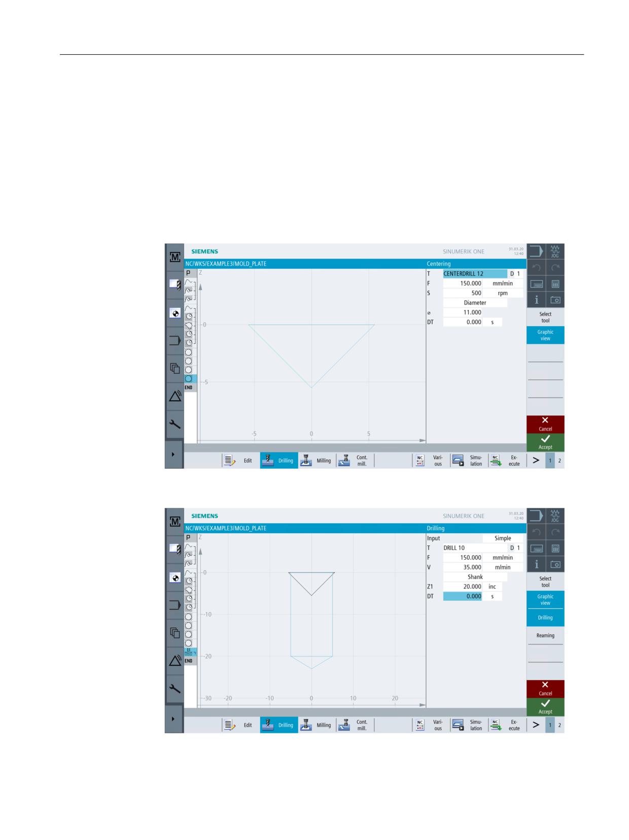
Figure 8-32
Simulation in 3D display
Easy milling with ShopMill
124
Training Documents, 05/2020, 6FC5095-0AB50-1BP2
Example 3: Mold plate
8.5 Taking into account obstacles
8.5
Taking into account obstacles
Operating sequences
As you have already seen in example 1, different drill patterns can also be interlinked in the case
of this workpiece. However, you should take into account that one or several obstacles must be
bypassed - depending on the sequence of machining. Traverse either to safety clearance or to
the machining plane between the drill holes - depending on the settings you have made.
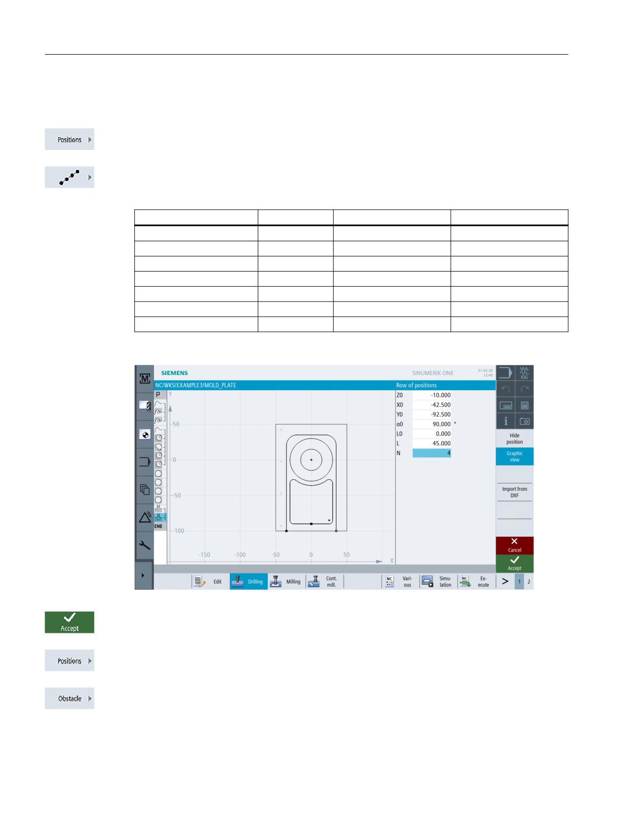
First create the work steps 'Centering' and 'Drilling' as done in example 1.
1. Centering
Figure 8-33
Work step 'Centering'
2. Drilling
Figure 8-34
Work step 'Drilling'
Easy milling with ShopMill
Training Documents, 05/2020, 6FC5095-0AB50-1BP2
125
Example 3: Mold plate
8.5 Taking into account obstacles
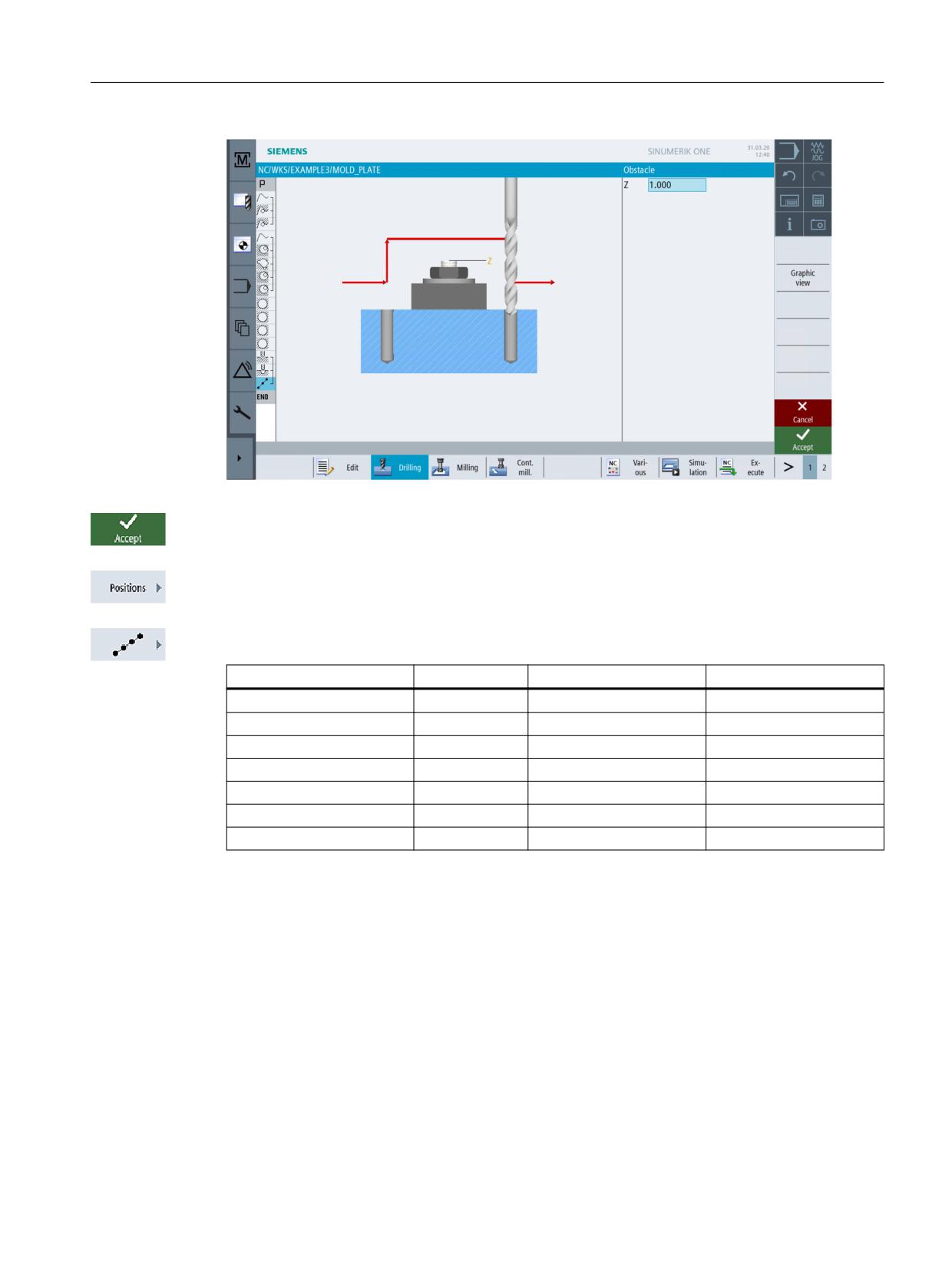
Proceed as follows to enter the relevant drilling positions:
Select the Positions softkey.
First create the left line of holes in the sequence from bottom to top.
Enter the following values in the interactive screenform:
Field
Value
Toggle field
Notes
Z0
-10
X0
-42.5
Y0
-92.5
α0
90
L0
0
L
45
N
4
Figure 8-35
Specifying the line of holes
Press "Accept" to apply the values entered.
Select the Positions softkey.
Use the "Obstacle" function to specify a distance of 1 mm to be traversed, as the right-hand line
of holes must also be drilled from bottom to top for the purposes of an exercise. The obstacle
only needs to be entered if you have first switched the "Retraction position pattern" toggle field
to "Optimized".
Easy milling with ShopMill
126
Training Documents, 05/2020, 6FC5095-0AB50-1BP2
Example 3: Mold plate
8.5 Taking into account obstacles
Figure 8-36
Specifying an obstacle
Press "Accept" to apply the values entered.
Select the Positions softkey.
Enter the following values for the second line of holes in the interactive screenform:
Field
Value
Toggle field
Notes
Z0
-10
X0
42.5
Y0
-92.5
α0
90
L0
0
L
45
N
4
Easy milling with ShopMill
Training Documents, 05/2020, 6FC5095-0AB50-1BP2
127
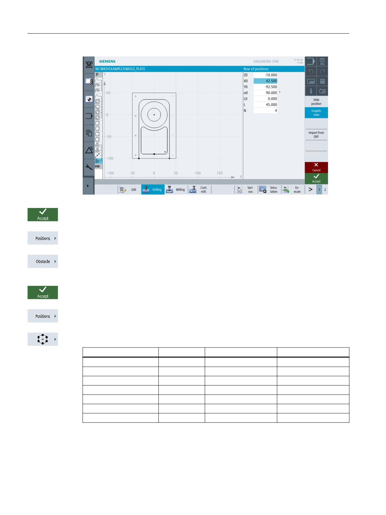
Example 3: Mold plate
8.5 Taking into account obstacles
Figure 8-37
Specifying the line of holes
Press "Accept" to apply the values entered.
Select the Positions softkey.
To get to the next drill pattern - the circle of holes -, another obstacle must be bypassed. Enter
Z=1.
Press "Accept" to apply the value entered.
Select the Positions softkey.
In the interactive screenform, enter the following values for the 6 drill holes in the full circle:
Field
Value
Toggle field
Notes
Z0
-10
X0
0
Y0
0
α0
0
R
22.5
N
6
Positioning
Straight line
X
Easy milling with ShopMill
128
Training Documents, 05/2020, 6FC5095-0AB50-1BP2
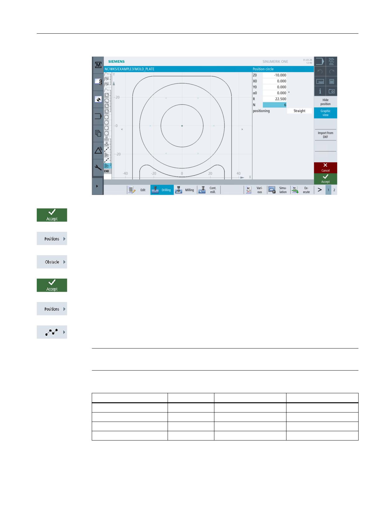
Example 3: Mold plate
8.5 Taking into account obstacles
Figure 8-38
Specifying the drill holes in the full circle
Press "Accept" to apply the values entered.
Select the Positions softkey.
To make the last drill hole, another obstacle must be bypassed. Enter Z=1.
Press "Accept" to apply the value entered.
Select the Positions softkey.
Enter the following values for the last drilling positions in the interactive screenform:
Note
If necessary delete any existing positions using the DEL key.
Field
Value
Toggle field
Notes
Pattern
Rectangular
X
Z0
-10
X0
0
Y0
42.5
Easy milling with ShopMill
Training Documents, 05/2020, 6FC5095-0AB50-1BP2
129
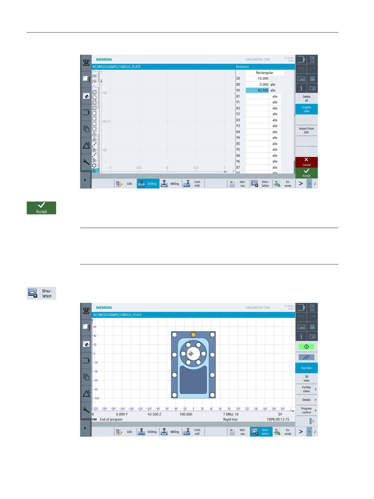
Example 3: Mold plate
8.5 Taking into account obstacles
Figure 8-39
Specifying the drilling positions
Press "Accept" to apply the values entered.
Note
This programming example is intended to familiarize you with the "Obstacle" function. There are
naturally more elegant methods of programming drilling positions, including only one obstacle.
Try out different strategies and decide which is the best for you.
Start simulation.
Figure 8-40
Simulation - Top view
Easy milling with ShopMill
130
Training Documents, 05/2020, 6FC5095-0AB50-1BP2
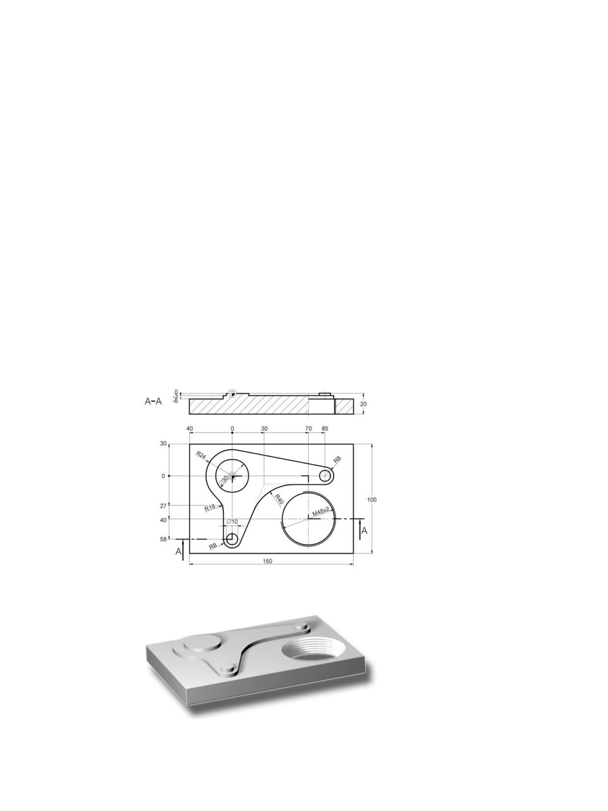
Example 4: Lever
9
9.1
Overview
Learning objectives
In this section you will learn the following new functions. You will learn how to...
• perform face milling;
• create edges (auxiliary pockets) for removing material from the solid around islands;
• create and copy circular islands;
• work with the work step editor and machine islands;
• perform deep-hole drilling, helix milling, boring and thread milling;
• Programming a contour using polar coordinates.
Task
Figure 9-1
Workshop drawing - Example 4:
Figure 9-2
Workpiece - Example 4:
Easy milling with ShopMill
Training Documents, 05/2020, 6FC5095-0AB50-1BP2
131
Example 4: Lever
9.1 Overview
Preparation
Perform the following steps without help:
1. Create a new workpiece with the name 'Example4'.
2. Create a new process plan with the name 'LEVER' .
3. Specify the blank dimensions (for the procedure, see example 1).
Note
The thickness of the blank will be 25 mm; therefore, it is imperative to set ZA to 5 mm.
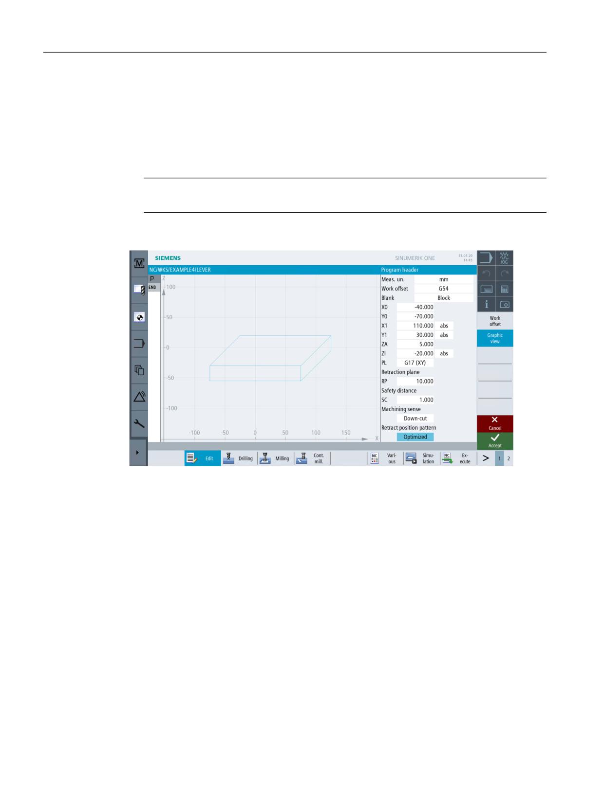
After input of the data, the program header should look as in the screen below.
Figure 9-3
Workpiece dimensions as in the program header
Easy milling with ShopMill
132
Training Documents, 05/2020, 6FC5095-0AB50-1BP2

Example 4: Lever
9.2 Face milling
9.2
Face milling
Operating sequences
Select the Milling softkey.
Select the Face milling softkey.
Open the tool list and select FACEMILL 63.
Accept the tool into your program.
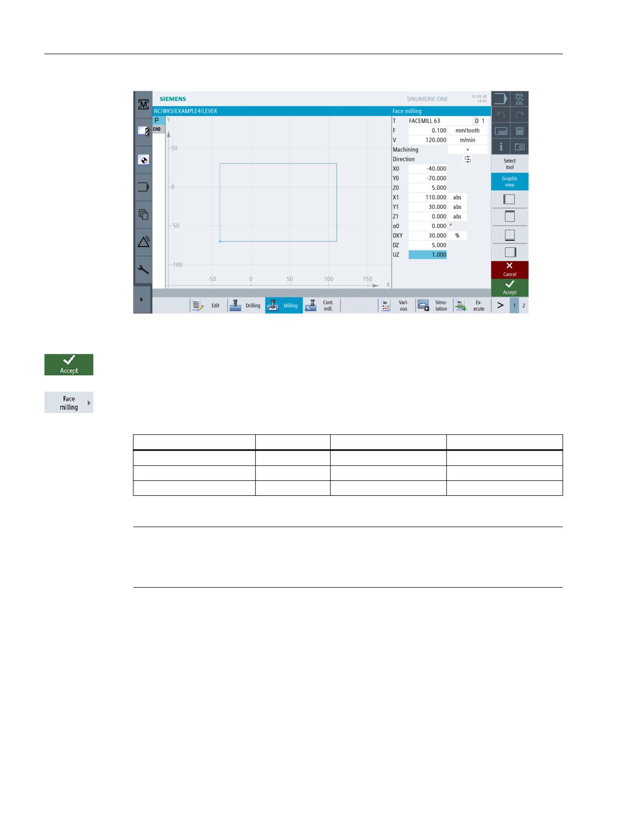
Enter the following values for roughing in the interactive screenform:
Field
Value
Toggle field
Notes
F
0.1 mm/tooth
X
V
120 m/min
X
Machining
Roughing
X
Direction
Alternating
X
X0
-40
Y0
-70
Z0
5
X1
110 abs
X
Y1
30 abs
X
Z1
0 abs
X
DXY
30%
X
DZ
5
UZ
1
Easy milling with ShopMill
Training Documents, 05/2020, 6FC5095-0AB50-1BP2
133
Example 4: Lever
9.2 Face milling
Figure 9-4
Roughing a surface
Press "Accept" to apply the values entered.
Select the Face milling softkey.
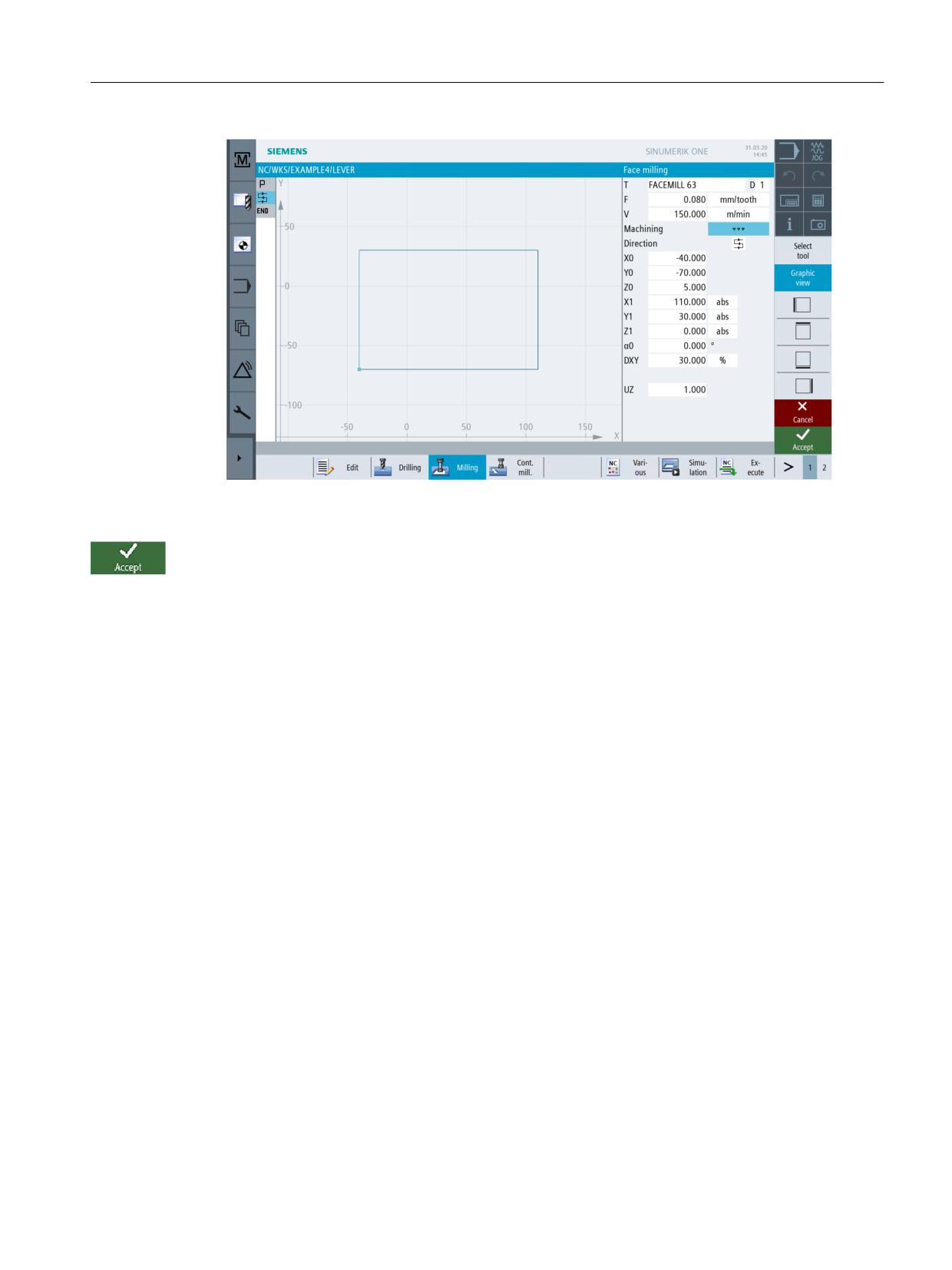
Enter the following values for finishing in the interactive screenform:
Field
Value
Toggle field
Notes
F
0.08 mm/tooth
X
V
150 m/min
X
Machining
Finishing
X
Note
The values for the finishing allowance must be identical for both roughing and finishing, as this
value specifies the allowance for the subsequent machining by finishing, and then when
finishing, the thickness of the material to be removed is meant.
Easy milling with ShopMill
134
Training Documents, 05/2020, 6FC5095-0AB50-1BP2
Example 4: Lever
9.2 Face milling
Figure 9-5
Finishing a surface
Press "Accept" to apply the values entered.
Easy milling with ShopMill
Training Documents, 05/2020, 6FC5095-0AB50-1BP2
135
Example 4: Lever
9.3 Creating an edge for the lever island
9.3
Creating an edge for the lever island
Operating sequences
Note
Islands are described - like pockets - as a contour in the graphical contour calculator. They only
become islands through linking in the process plan. The first contour in the process plan always
describes the pocket. One or several of the subsequent contours are interpreted as islands.
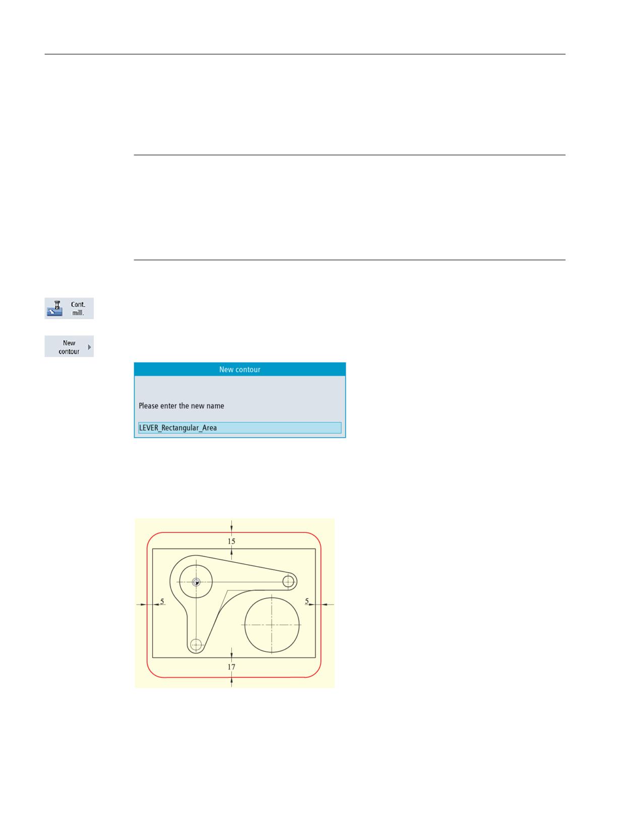
Since no pocket exists in the case of the 'LEVER' example, you must create a fictitious auxiliary
pocket around the external contour. This serves as a necessary outside boundary for the
traversing paths and thus forms a frame in which the tool motions take place.
Select the Contour milling softkey.
Create a new contour with the name 'LEVER_Rectangular_Area'.
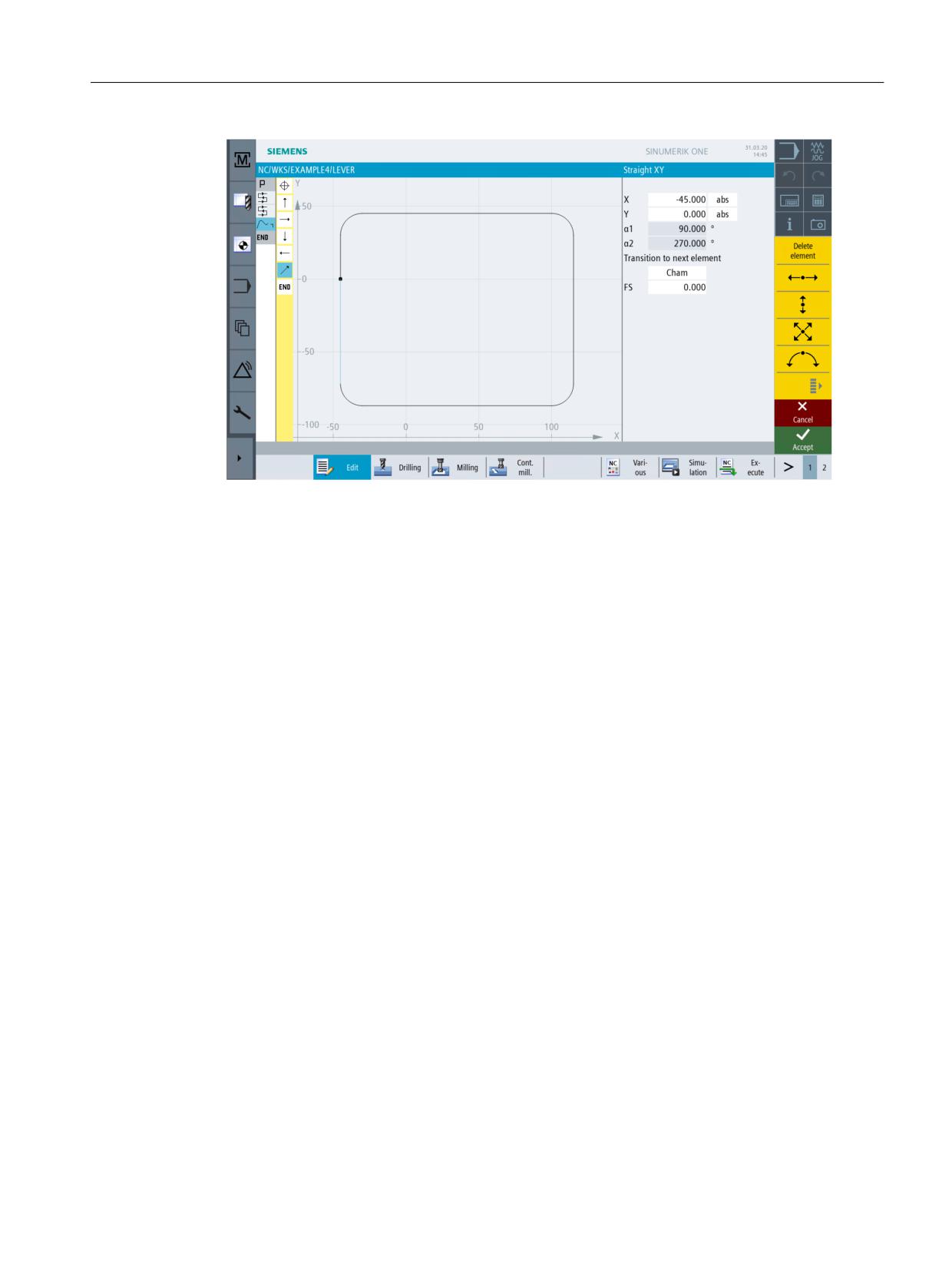
Figure 9-6
Creating the contour
Create the following contour without help. Round the corners with R15. Select such values that
the workpiece corners are covered by the pocket.
Figure 9-7
Edge for the lever island
Compare your contour with the screen below.
Easy milling with ShopMill
136
Training Documents, 05/2020, 6FC5095-0AB50-1BP2
Example 4: Lever
9.3 Creating an edge for the lever island
Figure 9-8
Readily designed contour
Easy milling with ShopMill
Training Documents, 05/2020, 6FC5095-0AB50-1BP2
137
Example 4: Lever
9.4 Machining the lever
9.4
Machining the lever
Operating sequences
Proceed as follows to enter the contour:
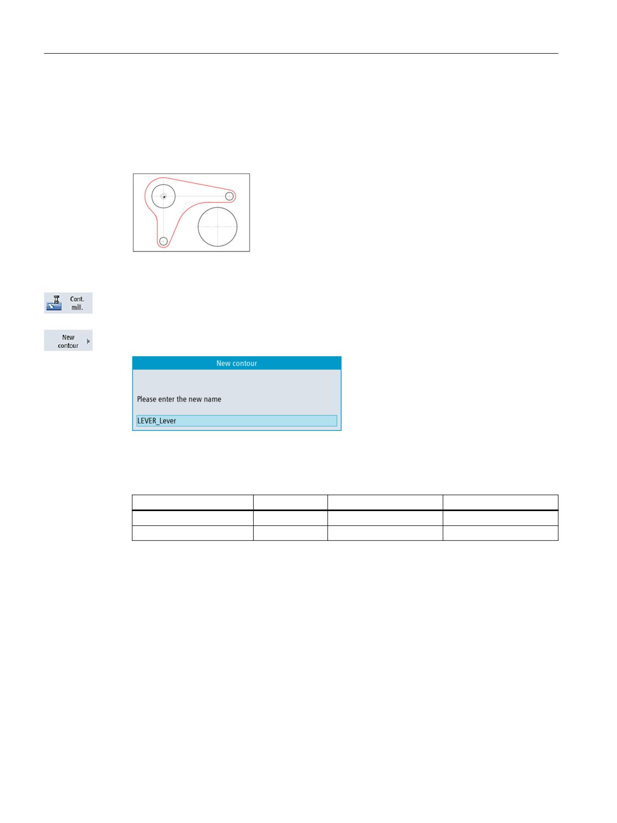
Figure 9-9
Lever contour
Select the Contour milling softkey.
Create a new contour with the name 'LEVER_Lever'.
Figure 9-10
Creating the contour
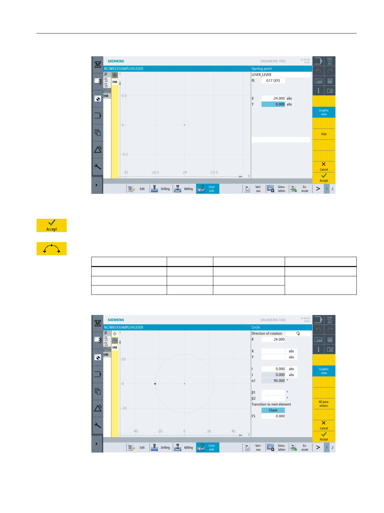
In the interactive screenform, enter the following values for the starting point of the contour line:
Field
Value
Toggle field
Notes
X
-24 abs
Y
0 abs
Easy milling with ShopMill
138
Training Documents, 05/2020, 6FC5095-0AB50-1BP2
Example 4: Lever
9.4 Machining the lever
Figure 9-11
Specifying the starting point
Press "Accept" to apply the values entered.
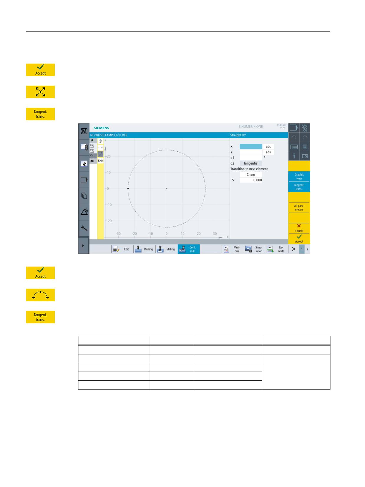
Enter the following values for the first arc in the interactive screenform:
Field
Value
Toggle field
Notes
Direction of rotation
Clockwise
X
R
24
Radius and center point
are known.
I
0
X
Figure 9-12
Arc contour
Easy milling with ShopMill
Training Documents, 05/2020, 6FC5095-0AB50-1BP2
139
Example 4: Lever
9.4 Machining the lever
Press "Accept" to apply the values entered.
Create the inclined straight line connected tangentially to the preceding element.
Select the Tangent to prec.elem. softkey.
Figure 9-13
Inclined straight line contour
Press "Accept" to apply your input.
Enter the arc connected tangentially.
Select the Tangent to prec.elem. softkey.
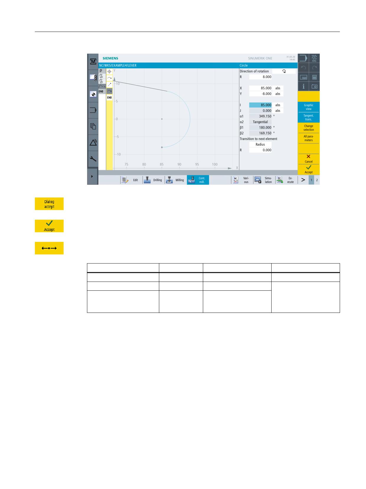
Enter the following values for the arc in the interactive screenform:
Field
Value
Toggle field
Notes
Direction of rotation
Clockwise
X
R
8
Radius, center point and
end point are known.
X
85 abs
X
Y
-8 abs
X
I
85 abs
X
Easy milling with ShopMill
140
Training Documents, 05/2020, 6FC5095-0AB50-1BP2
Example 4: Lever
9.4 Machining the lever
Figure 9-14
Arc contour
Press ENTER to confirm the suggested contour.
Press "Accept" to apply the values entered.
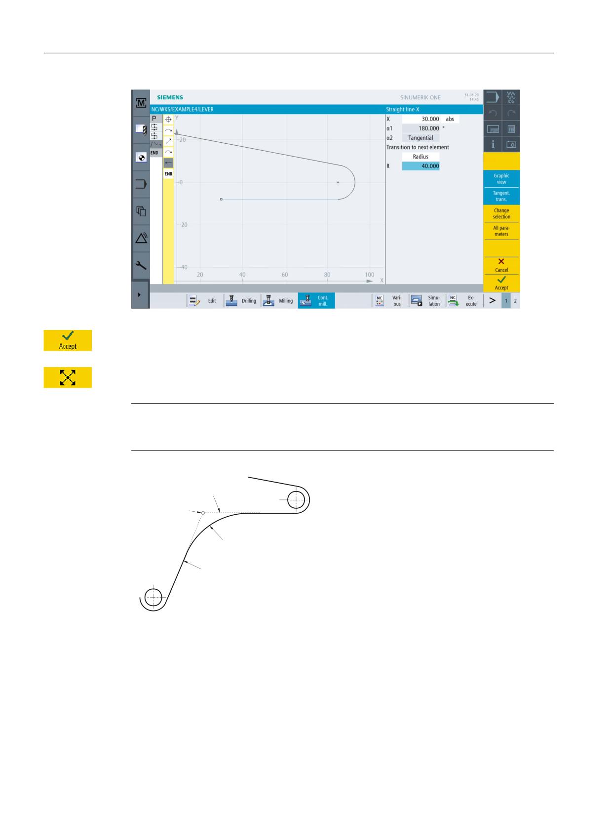
Enter the following values for the horizontal straight line up to end point X30 in the interactive
screenform:
Field
Value
Toggle field
Notes
X
30 abs
X
Transition to next element
Radius
X
Enter 40 mm for the radius
to the subsequent ele-
R
40
ment.
Easy milling with ShopMill
Training Documents, 05/2020, 6FC5095-0AB50-1BP2
141
Example 4: Lever
9.4 Machining the lever
Figure 9-15
Horizontal straight line contour
Press "Accept" to apply the values entered.
Observe the following note for the next inclined straight line:
Note
The tangential transition is always only referred to the main element, i.e. in this case, the straight
is not connected tangentially (see screenform below).
0DLQ HOHPHQW
QRW WDQJHQWLDO
5RXQGLQJ
0DLQ HOHPHQW
Easy milling with ShopMill
142
Training Documents, 05/2020, 6FC5095-0AB50-1BP2
Example 4: Lever
9.4 Machining the lever
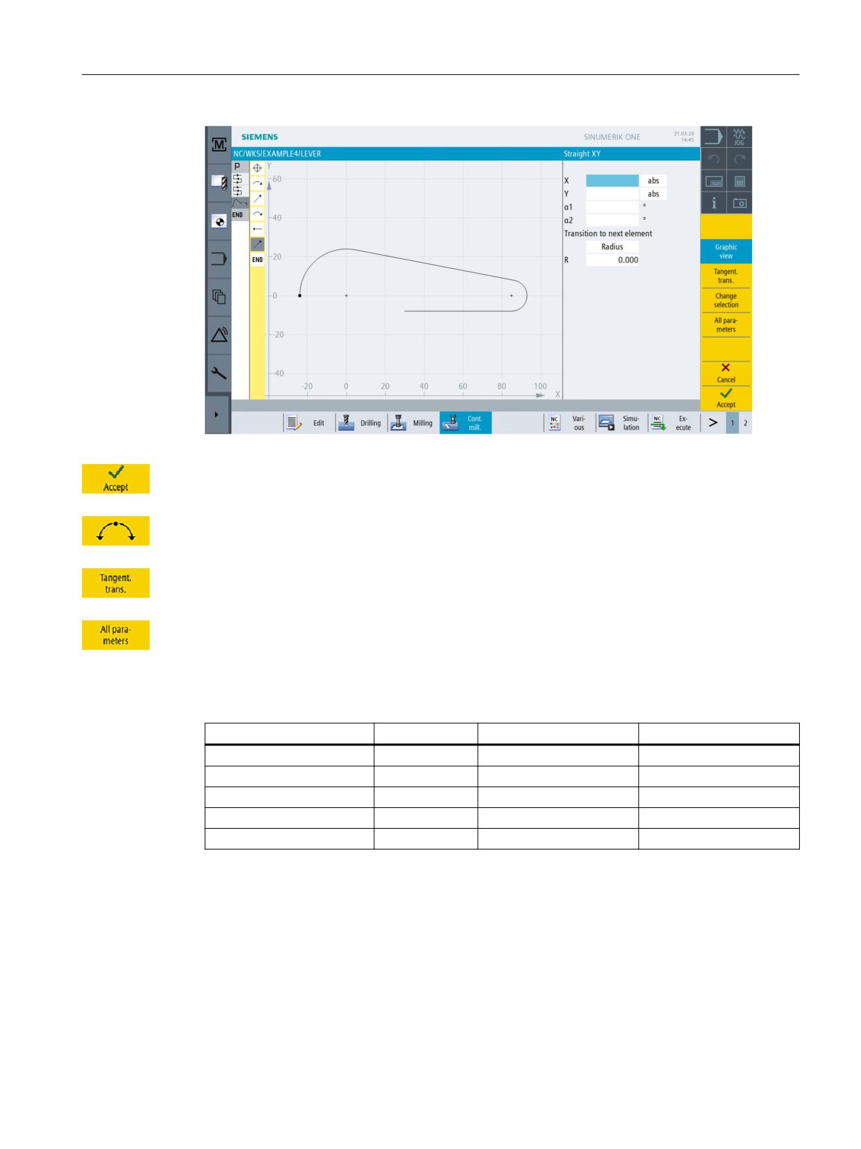
Figure 9-16
Inclined straight line contour
Press "Accept" to apply your input.
Enter the arc connected tangentially.
Select the Tangent to prec.elem. softkey.
Select the All parameters softkey.
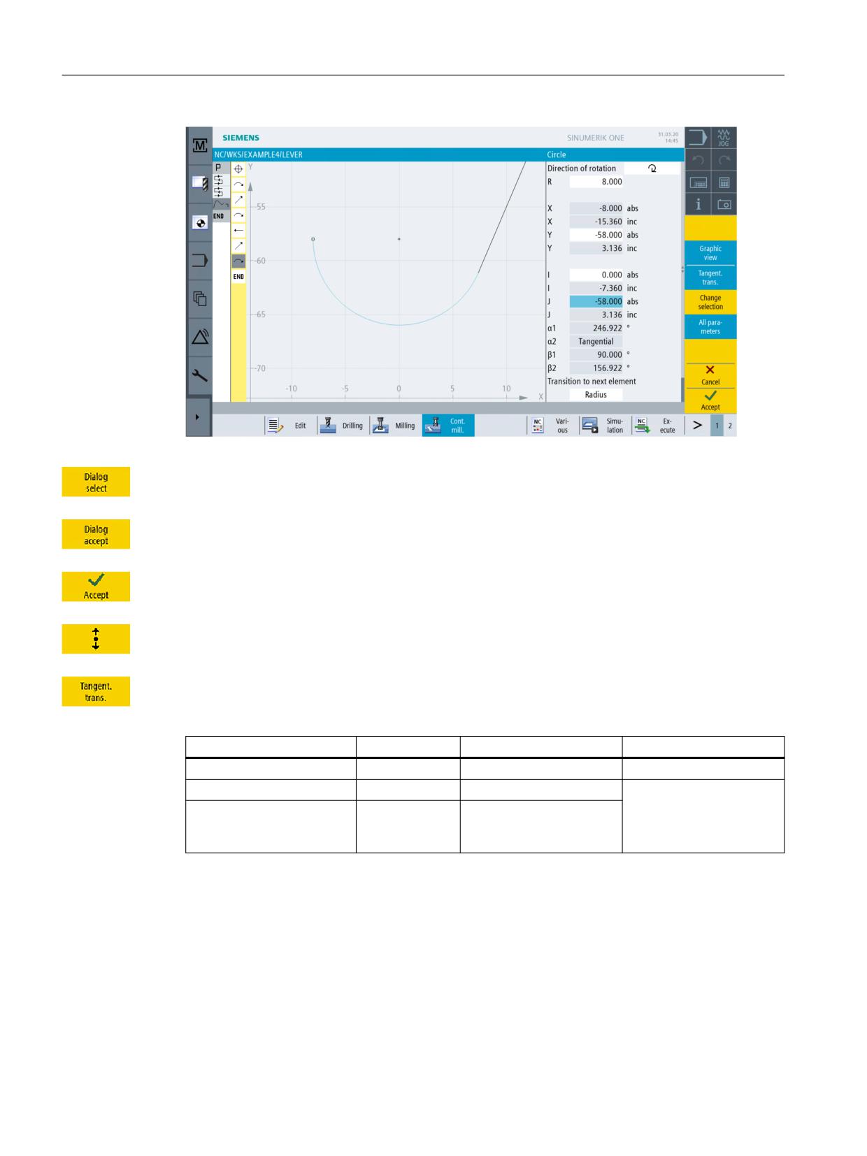
Use the All parameters function to display detailed information on the arc. This can serve to
check the entered values, for example (e.g.: Does the arc end vertically ...?).
Enter the following values for the arc in the interactive screenform:
Field
Value
Toggle field
Notes
Direction of rotation
Clockwise
X
R
8
Y
-58 abs
I
0 abs
J
-58 abs
Easy milling with ShopMill
Training Documents, 05/2020, 6FC5095-0AB50-1BP2
143
Example 4: Lever
9.4 Machining the lever
Figure 9-17
Arc contour
Select the desired contour suggestion.
Press ENTER to confirm the suggested contour.
Press "Accept" to apply your input.
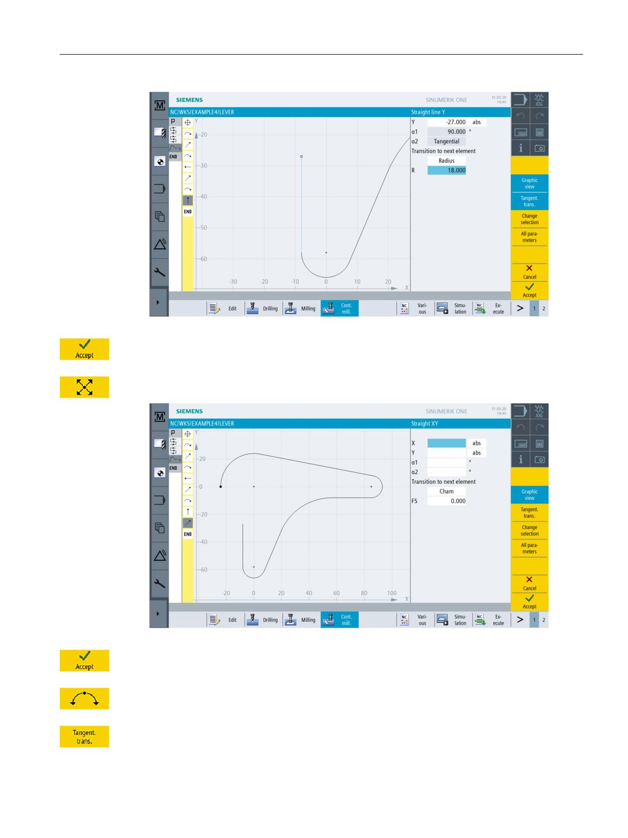
Specify the vertical straight line (automatically tangential) up to the end point Y-27.
Select the Tangent to prec.elem. softkey.
Enter the following values in the interactive screenform:
Field
Value
Toggle field
Notes
Y
-27 abs
X
Transition to next element
Radius
X
Round the transition to
the subsequent straight
R
18
X
line using R18.
Easy milling with ShopMill
144
Training Documents, 05/2020, 6FC5095-0AB50-1BP2
Example 4: Lever
9.4 Machining the lever
Figure 9-18
Vertical straight line contour
Press "Accept" to apply the values entered.
Specify the inclined straight line.
Figure 9-19
Inclined straight line contour
Press "Accept" to apply your input.
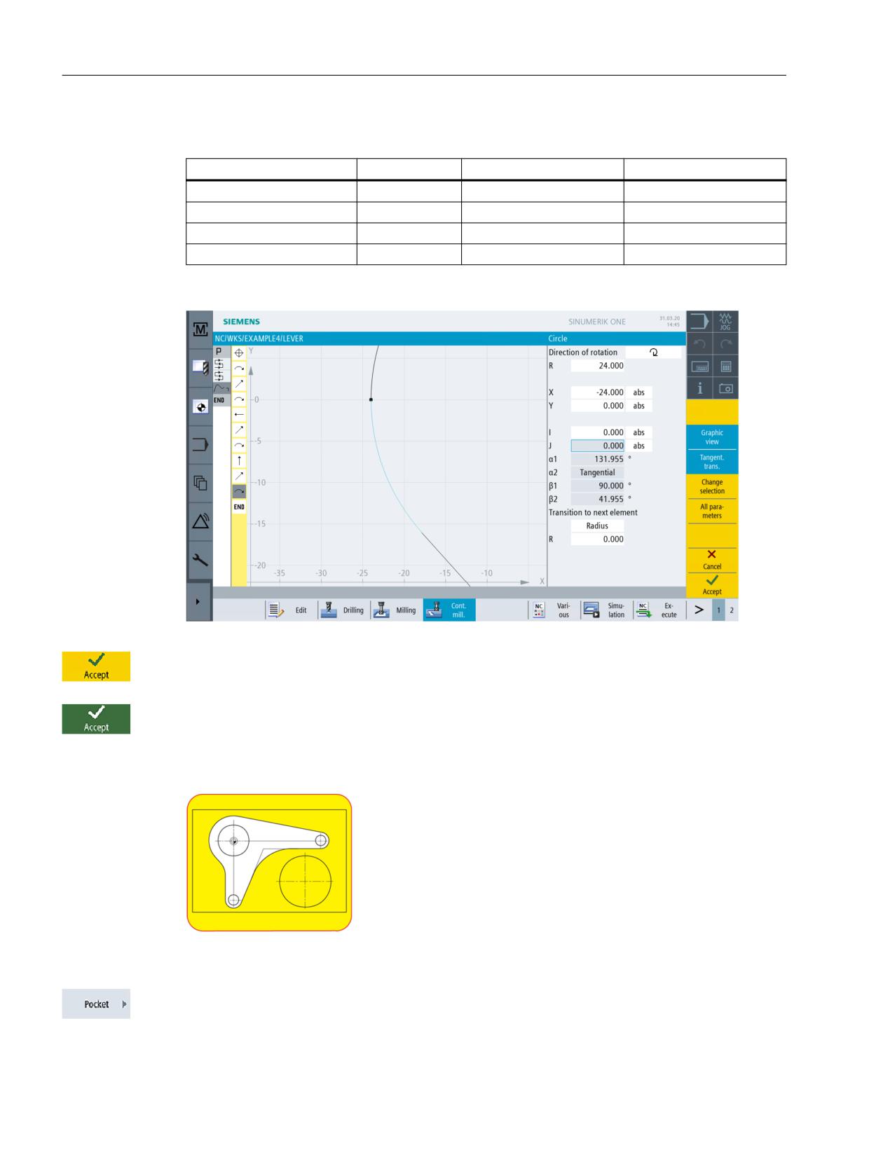
Close the contour to the starting point with an arc.
Select the Tangent to prec.elem. softkey.
Easy milling with ShopMill
Training Documents, 05/2020, 6FC5095-0AB50-1BP2
145
Example 4: Lever
9.4 Machining the lever
In the interactive screenform, enter the following values for the starting point of the contour line:
Field
Value
Toggle field
Notes
R
24
X
-24
X
Y
0
X
I
0
X
Figure 9-20
Arc contour
Press "Accept" to apply the values entered.
Accept the contour.
Proceed as follows to rough and finish the pocket taking into account the lever contour:
Figure 9-21
Roughing and finishing around the lever
Select the Pocket softkey.
Easy milling with ShopMill
146
Training Documents, 05/2020, 6FC5095-0AB50-1BP2