SINUMERIK 840D sl. Training. Operate - Turning (2016-2020) - page 4
Introduction
SINUMERIK ONE - Run MyVirtual Machine
Run MyVirtual Machine is an NC programming workstation with identical controls on the PC
specially designed for machine tools using SINUMERIK ONE.
The offline programming workstation - Run MyVirtual Machine /Operate - simulates a machine
tool controlled by SINUMERIK ONE. SINUMERIK Operate, together with an animated machine
control panel, ensures realistic operation and programming on the PC. You do not need any
additional programming knowledge.
Run MyVirtual Machine /Operate enables practice-oriented offline programming on the PC
based on the DIN 66025 programming language, the ShopMill and ShopTurn options,
SINUMERIK-type voice commands, and the direct transfer of NC programs to the CNC. By using
the original SINUMERIK CNC software you can test NC programs and verify their NC syntax. It
does not matter whether an NC program has been created with Run MyVirtual Machine /Operate
or with CAM software. Thanks to its seamless integration into the process chain, from the idea
to the workpiece, Run MyVirtual makes an essential contribution to increasing productivity and
safety.
Run MyVirtual Machine /Operate also facilitates learning and professional training without the
need for actual hardware or machines. For this purpose, preconfigured sample machines are
available for immediate use. Using SINUMERIK Operate and the original SINUMERIK CNC kernel,
all operating processes and NC programming operations can be used and CNC programs
executed, without any restrictions. New functions and programming options can thus be
learned, tested and demonstrated in a secure environment.
To obtain the greatest possible match with the actual machine, you can import your own
configurations created using Create MyVirtual Machine /Operate directly into Run MyVirtual
Machine /Operate.
Thanks to the user interface that is also supplied you can manage different machine
configurations and SINUMERIK CNC software states. This way, you can map the job planning for
several machines in one offline programming station (1:n).
Note
The training documentation was created based on a SINUMERIK ONE with the operator interface
"SINUMERIK Operate Generation 2". You can choose to take the training on a SINUMERIK ONE,
SINUMERIK 840D sl, SINUMERIK 828D with SINUMERIK Operate, with Sinutrain or with Run
MyVirtual Machine. The basic operation of SINUMERIK Operate is identical in all cases.
Easy milling with ShopMill
8
Training Documents, 05/2020, 6FC5095-0AB50-1BP2
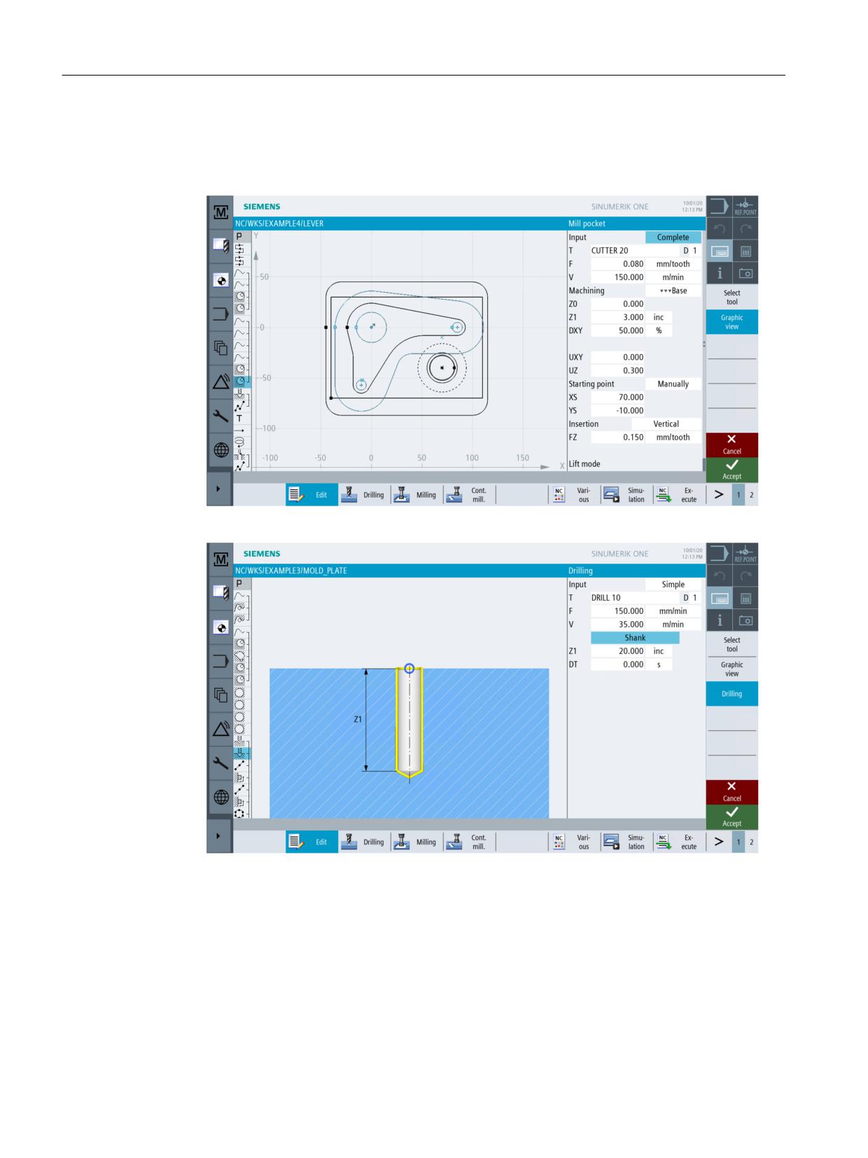
Advantages of ShopMill
2.1 You will save time for training
2.1
You will save time for training
• ShopMill does not use any foreign-language terms you would otherwise have to learn. All
required inputs are requested in plain text.
• When working with ShopMill, you are assisted optimally by colored help displays.
Easy milling with ShopMill
10
Training Documents, 05/2020, 6FC5095-0AB50-1BP2
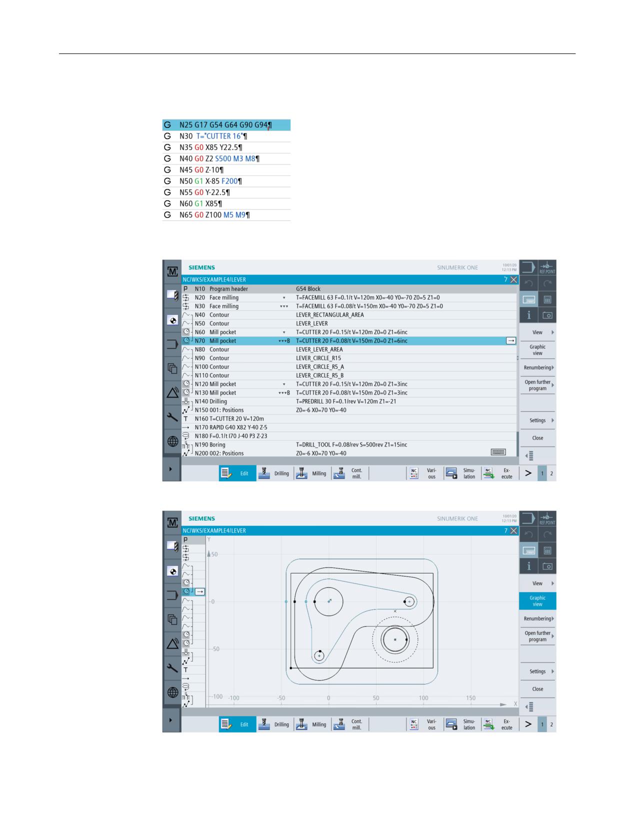
Advantages of ShopMill
2.1 You will save time for training
• You can also integrate DIN/ISO commands into the Process Plan of ShopMill. You may also
program in DIN/ISO 66025 and use DIN cycles.
• You may switch between the individual work step and the workpiece graphic at any time
when creating a process plan.
Figure 2-1
Work step in a process plan
Figure 2-2
Graphic view
Easy milling with ShopMill
Training Documents, 05/2020, 6FC5095-0AB50-1BP2
11
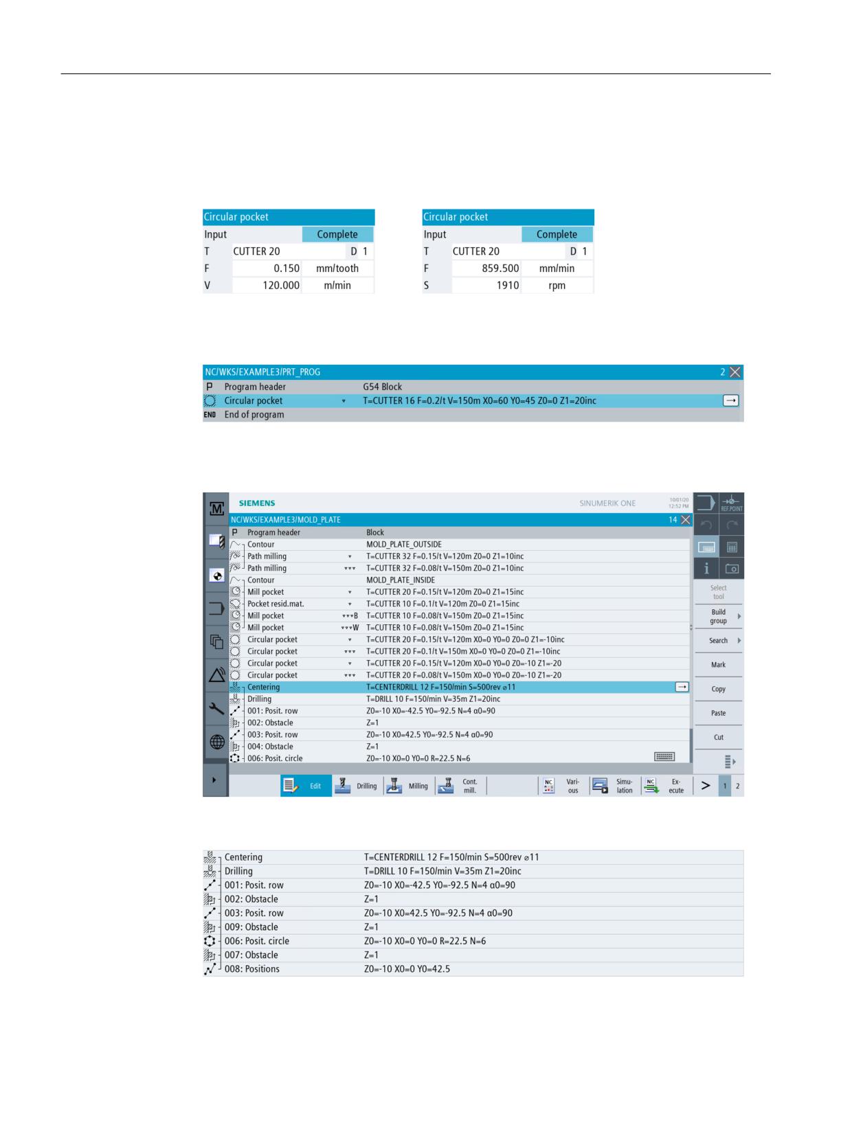
Advantages of ShopMill
2.2 You will save time for programming...
2.2
You will save time for programming...
• ShopMill already assists you in entering the technological values: You will only have to enter
the handbook values feed/tooth and cutting rate - speed and feedrate are calculated by
ShopMill automatically.
• ShopMill enables you to describe a complete machining sequence using only one work step,
and the required positioning motions (in this case, from the tool change point to the
workpiece and reverse) are created automatically.
• All work steps are represented by ShopMill in a compact and clear fashion in the Graphical
Process Plan. This provides you a complete overview and thus better editing possibilities
even if comprehensive manufacturing sequences are to be performed.
• In drilling, for example, several machining operations can be connected together so that they
need not be called repeatedly.
Easy milling with ShopMill
12
Training Documents, 05/2020, 6FC5095-0AB50-1BP2
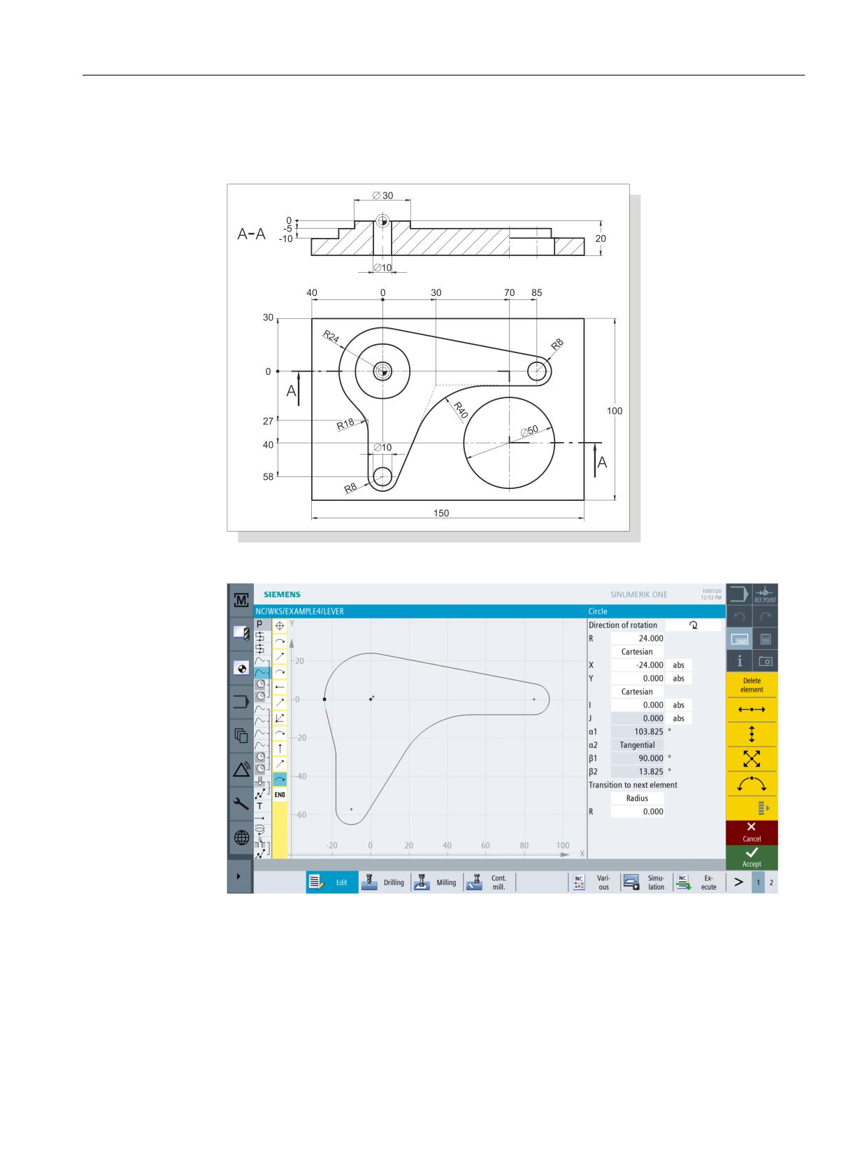
Advantages of ShopMill
2.2 You will save time for programming...
• The integrated contour calculator can process all standard dimensions (Cartesian, polar); it
is nevertheless very easy to handle and understand - thanks to colloquial input and graphic
support.
Figure 2-3
Technical drawing
Figure 2-4
Screenform
Easy milling with ShopMill
Training Documents, 05/2020, 6FC5095-0AB50-1BP2
13
Advantages of ShopMill
2.2 You will save time for programming...
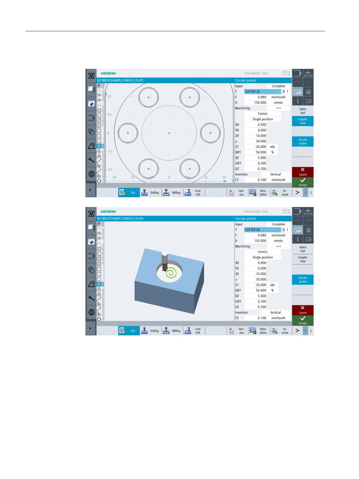
• You may switch between the graphic view and parameter screenform with help display at any
time.
Figure 2-5
Parameter screen with help display
• Process plan and manufacturing do not exclude each other. With ShopMill, you can create a
new process plan parallel to manufacturing.
Easy milling with ShopMill
14
Training Documents, 05/2020, 6FC5095-0AB50-1BP2
Advantages of ShopMill
2.3 You will save time for manufacturing...
2.3
You will save time for manufacturing...
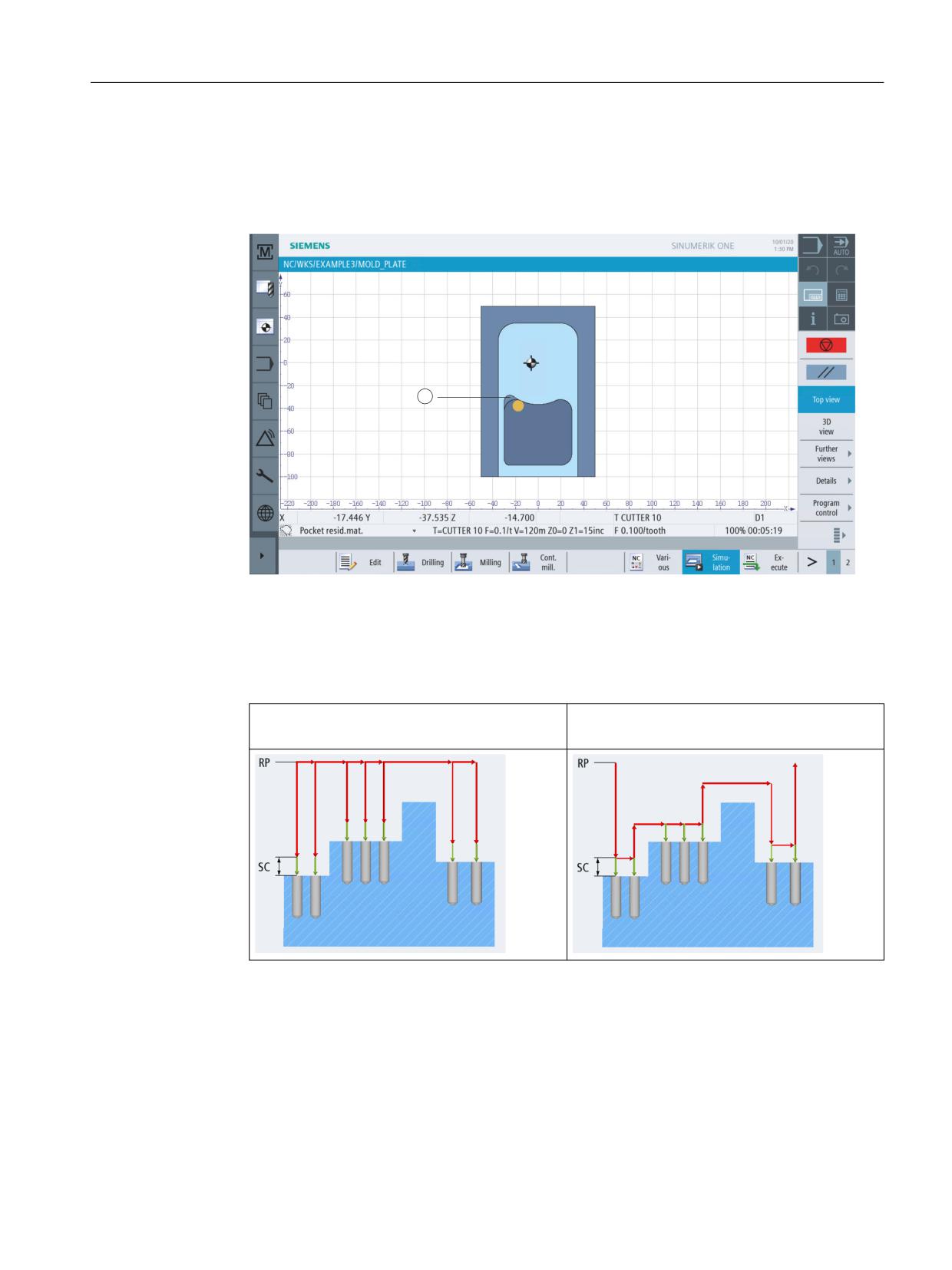
• You need not take into account the pocket radii when selecting the milling cutter for
removing the contour pockets from the solid: Any residual material ① is detected and
removed automatically using a smaller milling cutter.
1
• There are no unnecessary infeed motions between retraction and machining planes when
positioning the tool. This is made possible by the settings Retract to retraction plane (RP)
and Optimized retraction.
The Optimized retraction setting is to be made by a skilled worker in the program header.
He must take into account obstacles, such as clamping elements.
Retraction to retraction plane (RP)
Retraction to retraction planes = time saved in
manufacturing
Easy milling with ShopMill
Training Documents, 05/2020, 6FC5095-0AB50-1BP2
15
Advantages of ShopMill
2.3 You will save time for manufacturing...
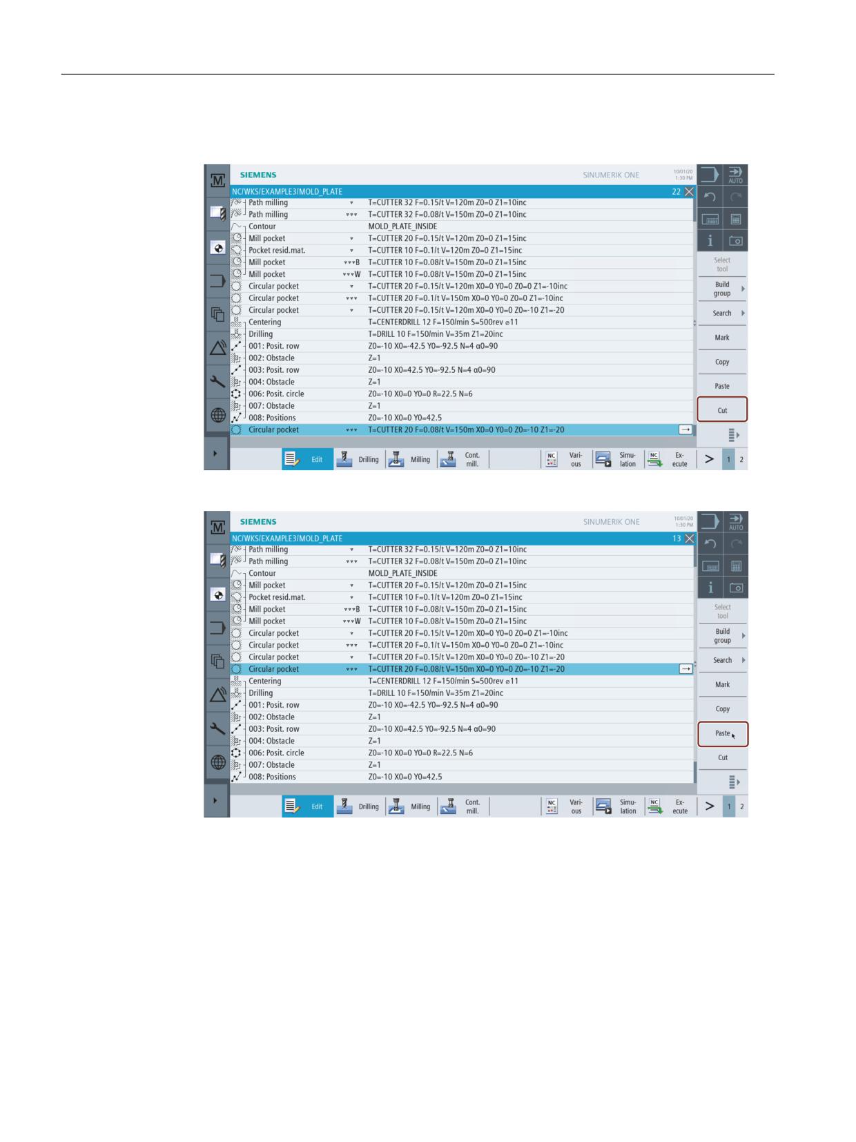
• You can optimize your machining sequence with a minimum of work - thanks to the compact
structure of the process plan (in this case, by saving of a tool change, for example).
Figure 2-6
Original machining sequence
Figure 2-7
Optimized machining sequence with cutting and pasting a work step
• With ShopMill, you can achieve extremely high feedrates with optimum repeat accuracy
based on consistent digital technology (SINAMICS drives,
, SINUMERIK control systems).
Easy milling with ShopMill
16
Training Documents, 05/2020, 6FC5095-0AB50-1BP2
To make everything function smoothly...
3
In this chapter, you will be familiarized with the fundamentals of multitouch operation with the
"SINUMERIK Operate Generation 2" user interface and the operating areas of SINUMERIK
Operate based on a number of examples.
Easy milling with ShopMill
Training Documents, 05/2020, 6FC5095-0AB50-1BP2
17
To make everything function smoothly...
3.1 Multitouch operation of SINUMERIK Operate
3.1
Multitouch operation of SINUMERIK Operate
3.1.1
Screen layout
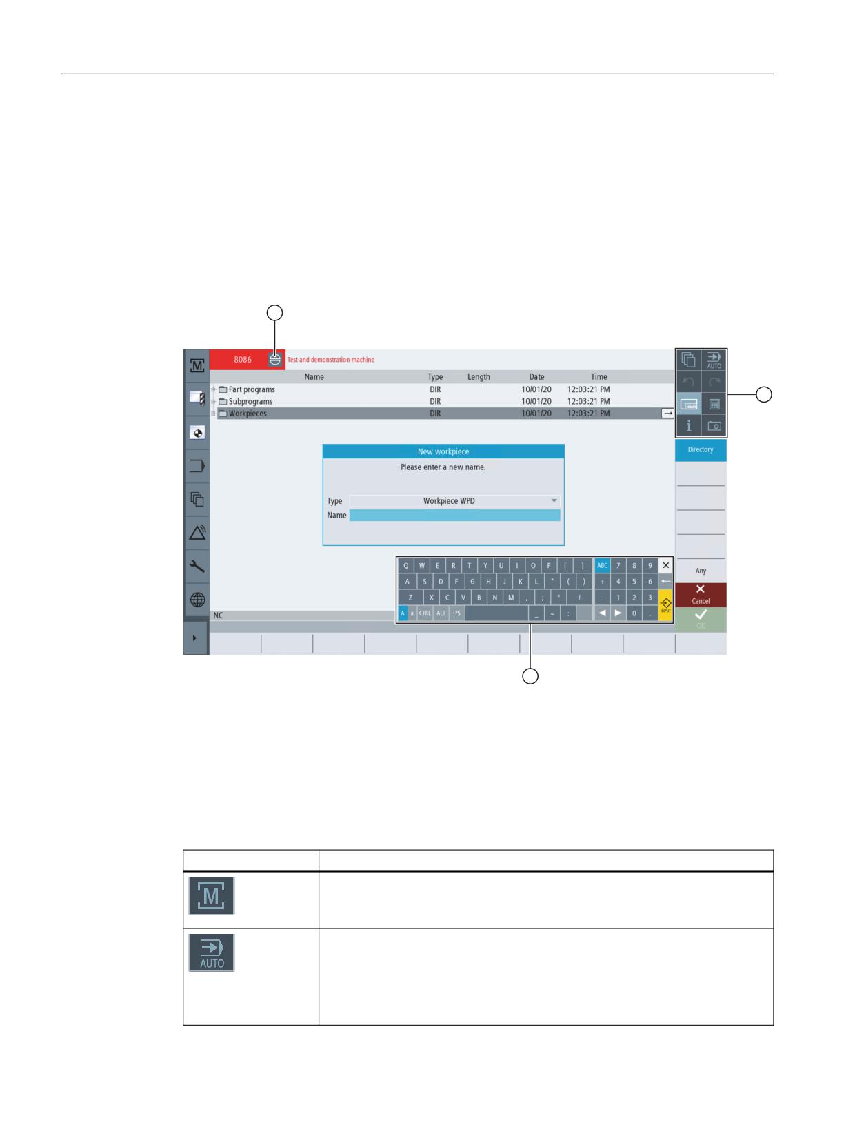
Touch and gesture operator controls for SINUMERIK Operate with the "SINUMERIK Operate
Generation 2" user interface.
① Cancel alarms
② Function key block
③ Virtual keyboard
3.1.2
Function key block
Operator control
Function
Switch operating area
Tap the current operating area, and select the desired operating area from the
operating area bar.
Switch operating mode
The operating mode is only displayed.
To switch the operating mode, tap the operating area and select the operating
area from the vertical softkey bar.
The selection for the functions available for the operating mode is opened.
Easy milling with ShopMill
18
Training Documents, 05/2020, 6FC5095-0AB50-1BP2
To make everything function smoothly...
3.1 Multitouch operation of SINUMERIK Operate
Operator control
Function
Close the selection
The selection for the functions available for the operating mode is closed.
Undo
Multiple changes are undone one by one.
As soon as a change has been completed in an input field, this function is no
longer available.
Restoring
Multiple changes are restored one by one.
As soon as a change has been completed in an input field, this function is no
longer available.
Virtual keyboard
Activates the virtual keyboard.
Calculator
Displays a calculator.
Online help
Opens the online help.
Camera
Generates a screenshot.
3.1.3
Further operator touch controls
Operator control
Function
Advances to the next horizontal softkey bar.
When page 2 of the menu is called, the arrow appears
on the right.
Advances to the higher-level menu.
Advances to the next vertical softkey bar.
Tapping the Cancel alarm symbol clears all queued can-
cel alarms.
Easy milling with ShopMill
Training Documents, 05/2020, 6FC5095-0AB50-1BP2
19
To make everything function smoothly...
3.1 Multitouch operation of SINUMERIK Operate
3.1.4
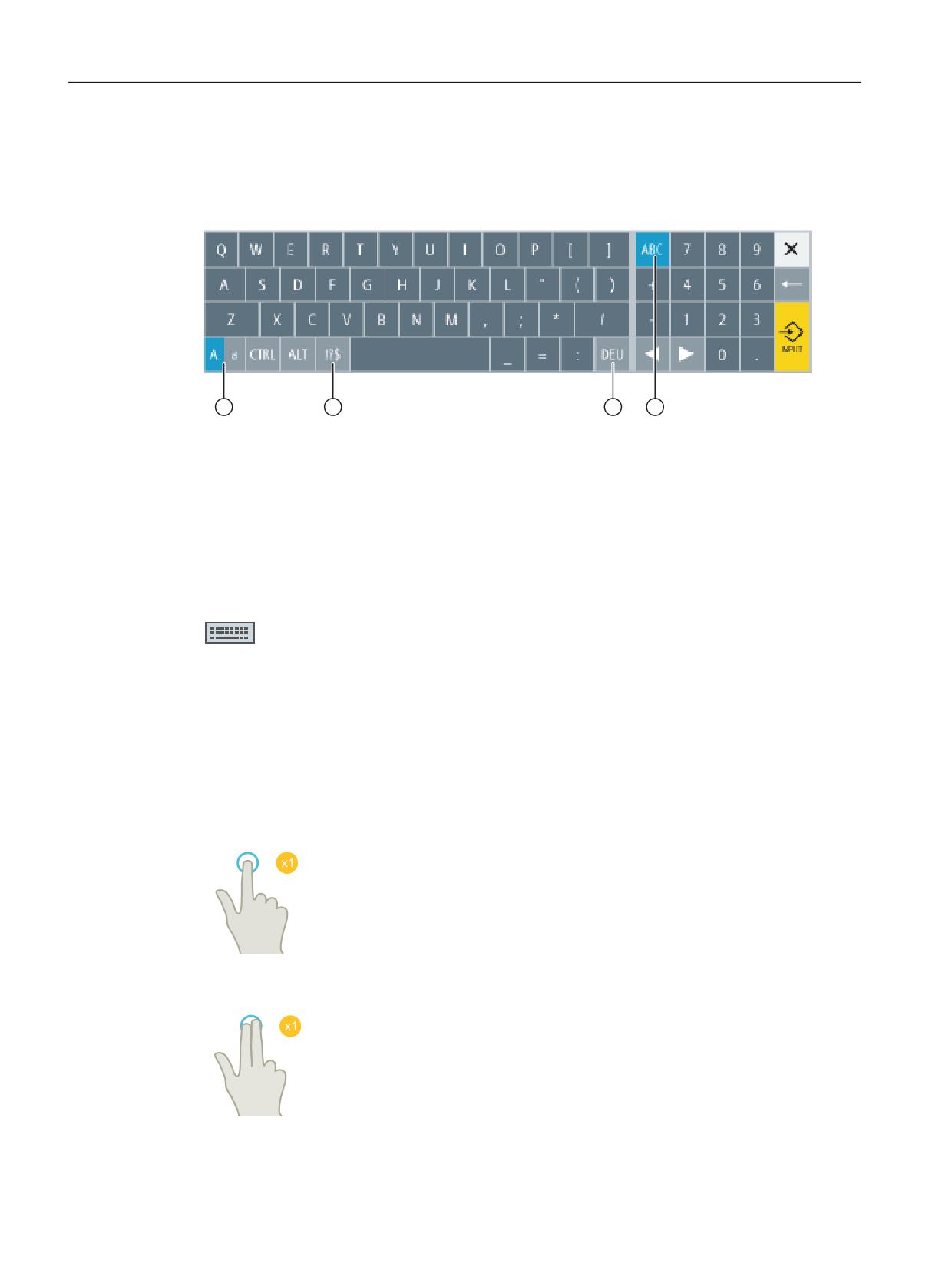
Virtual keyboard
If you called the virtual keyboard using the function key block, then you have the option of
adapting the key assignment using the shift keys.
① Shift key for uppercase and lowercase letters
② Shift key for letters and special characters
③ Shift key for country-specific keyboard assignment
④ Shift key for full keyboard and numerical key block
Hardware keyboard
If a real keyboard is connected, the icon of a minimized keyboard appears in place of the virtual
keyboard.
Use the icon to open the virtual keyboard again.
3.1.5
Finger gestures
Finger gestures
Tap
• Select window
• Select object (e.g. NC set)
• Activate entry field
- Enter or overwrite value
- Tap again to change the value
Tap with 2 fingers
• Call the shortcut menu (e.g. copy, paste)
Easy milling with ShopMill
20
Training Documents, 05/2020, 6FC5095-0AB50-1BP2

To make everything function smoothly...
3.1 Multitouch operation of SINUMERIK Operate
Flick vertically with one finger
• Scroll in lists (e.g. programs, tools, zero points)
• Scroll in files (e.g. NC program)
Flick vertically with two fingers
• Page-scroll in lists (e.g. ZO)
• Page-scroll in files (e.g. NC programs)
Flick vertically with three fingers
• Scroll to the start or end of lists
• Scroll to the start or end of files
Flick horizontally with one finger
• Scroll in lists with many columns
Spread
• Zoom in on graphic contents (e.g. simulation, mold mak-
ing view)
Pinch
• Zoom out from graphic contents (e.g. simulation, mold
making view)
Easy milling with ShopMill
Training Documents, 05/2020, 6FC5095-0AB50-1BP2
21

To make everything function smoothly...
3.1 Multitouch operation of SINUMERIK Operate
Pan with one finger
• Move graphic contents (e.g. simulation, mold making
view)
• Move list contents
Pan with two fingers
• Rotate graphic contents (e.g. simulation, mold making
view)
Tap and hold
• Open input fields to change
• Activate or deactivate edit mode (e.g. current block dis-
play)
Tap and hold using 2 fingers
• Open cycles line by line to change (without input screen
form)
Tap with two index fingers
• Tap with two fingers simultaneously in the lower right- and
left-hand corners to open the TCU menu.
The menu has to be opened for service purposes.
Note
Flicking gestures with several fingers
The gestures only function reliably if you hold your fingers sufficiently far apart. The fingers
should be at least 1 cm apart.
Easy milling with ShopMill
22
Training Documents, 05/2020, 6FC5095-0AB50-1BP2
To make everything function smoothly...
3.2 The operating areas
3.2
The operating areas
3.2.1
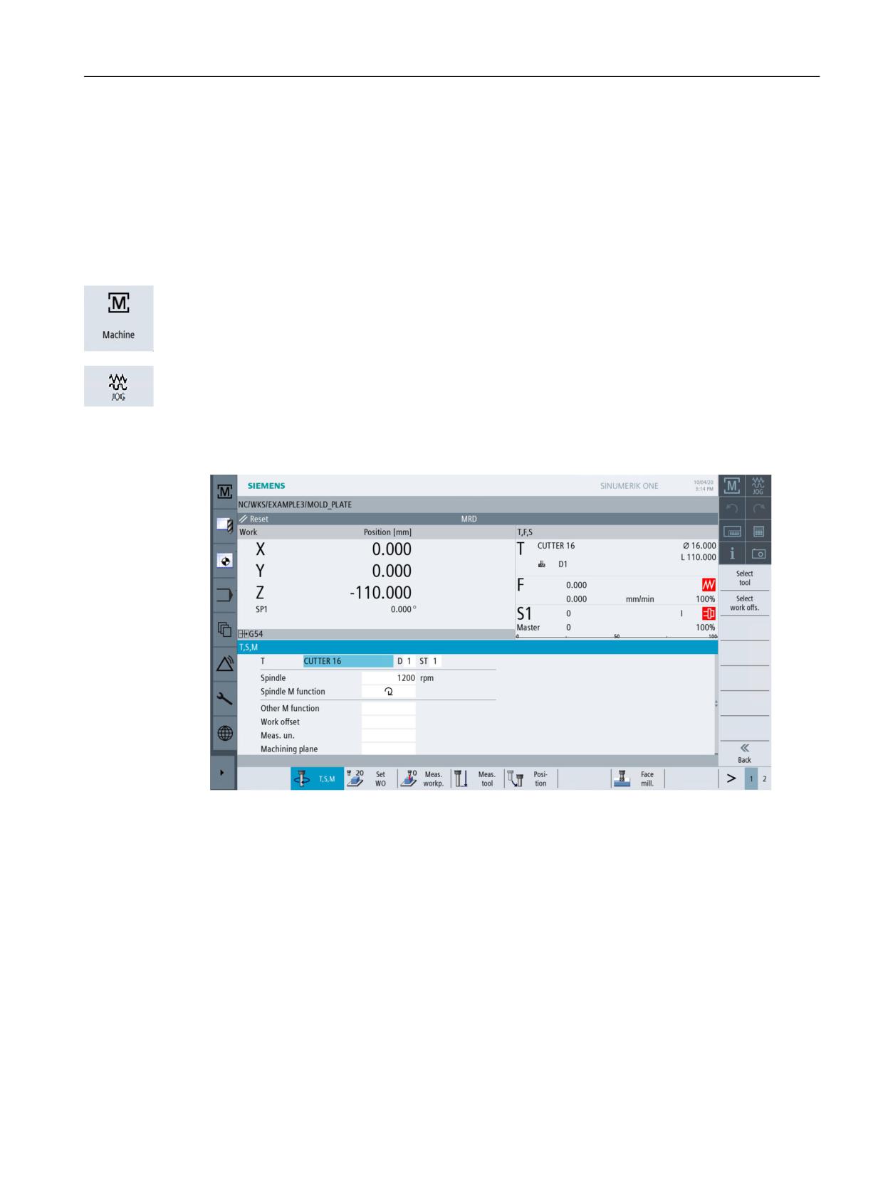
Machine
Machine - Manual
Select the "Machine" softkey.
Switch to "JOG" mode.
In this mode, the machine is set up; the tool is traversed in the MANUAL mode. It is also possible
to gauge tools and to set workpiece zeros.
Figure 3-1
Call of a tool and input of technological values
Easy milling with ShopMill
Training Documents, 05/2020, 6FC5095-0AB50-1BP2
23
To make everything function smoothly...
3.2 The operating areas
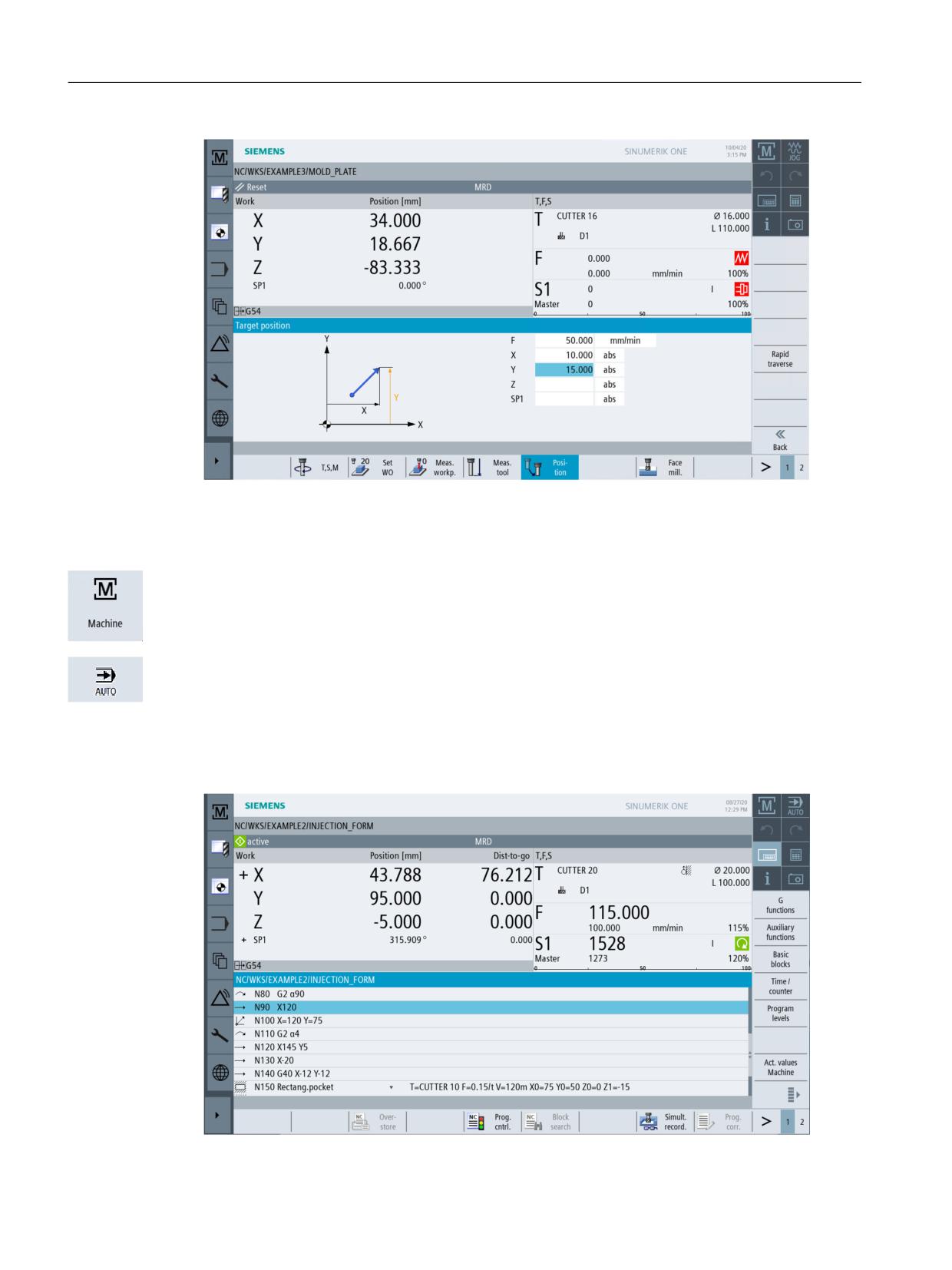
Figure 3-2
Input of a target position
Machine - AUTO
Select the "Machine" softkey.
Switch to "AUTO" mode.
During manufacturing, the current work step is displayed. It is possible to switch to a running
simulation using the relevant key ("Simultaneous recording"). When executing a process plan,
you may insert work steps and/or create a new process plan.
Easy milling with ShopMill
24
Training Documents, 05/2020, 6FC5095-0AB50-1BP2
To make everything function smoothly...
3.2 The operating areas
3.2.2
Parameters
Parameter lists
This key can be used to edit data for the tool management and for programs.
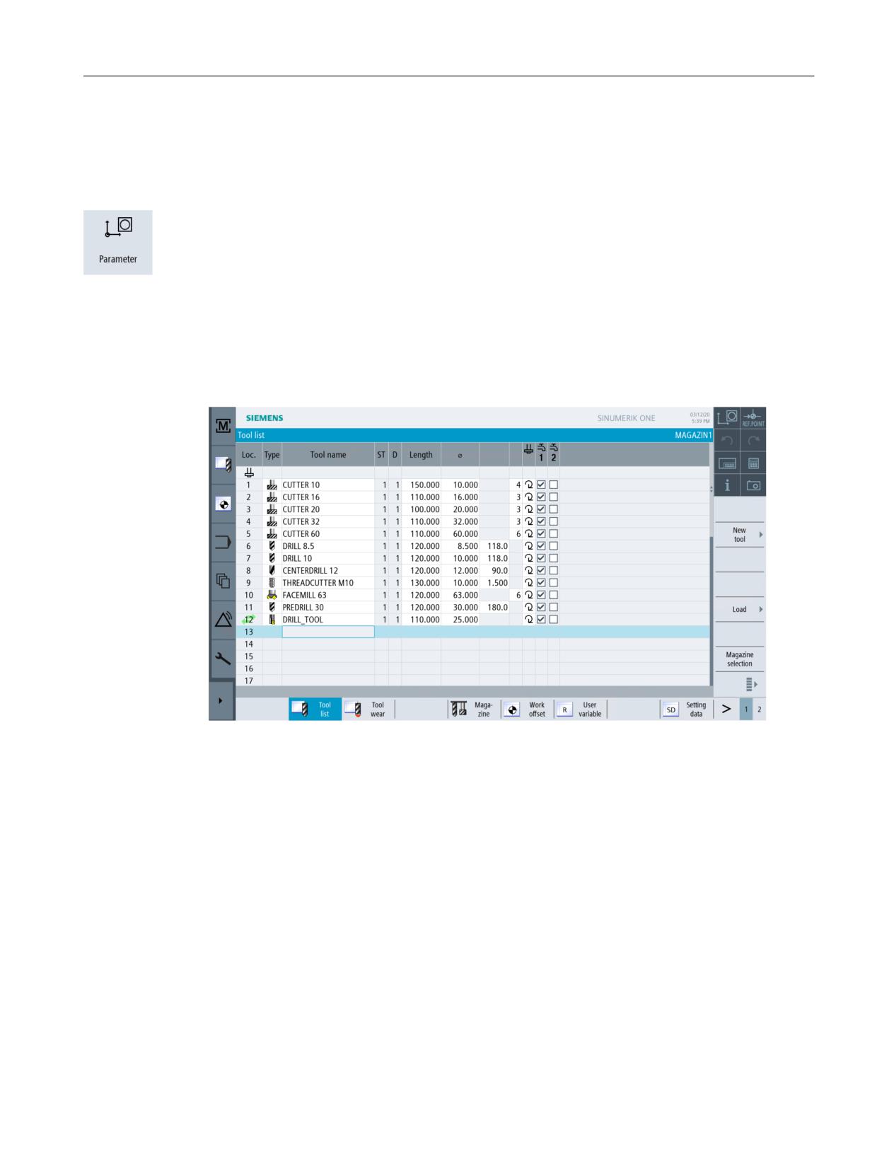
Tool lists
No cutting without tools.
The tools can be managed in a tool list.
Figure 3-3
Tool list
Easy milling with ShopMill
Training Documents, 05/2020, 6FC5095-0AB50-1BP2
25
To make everything function smoothly...
3.2 The operating areas
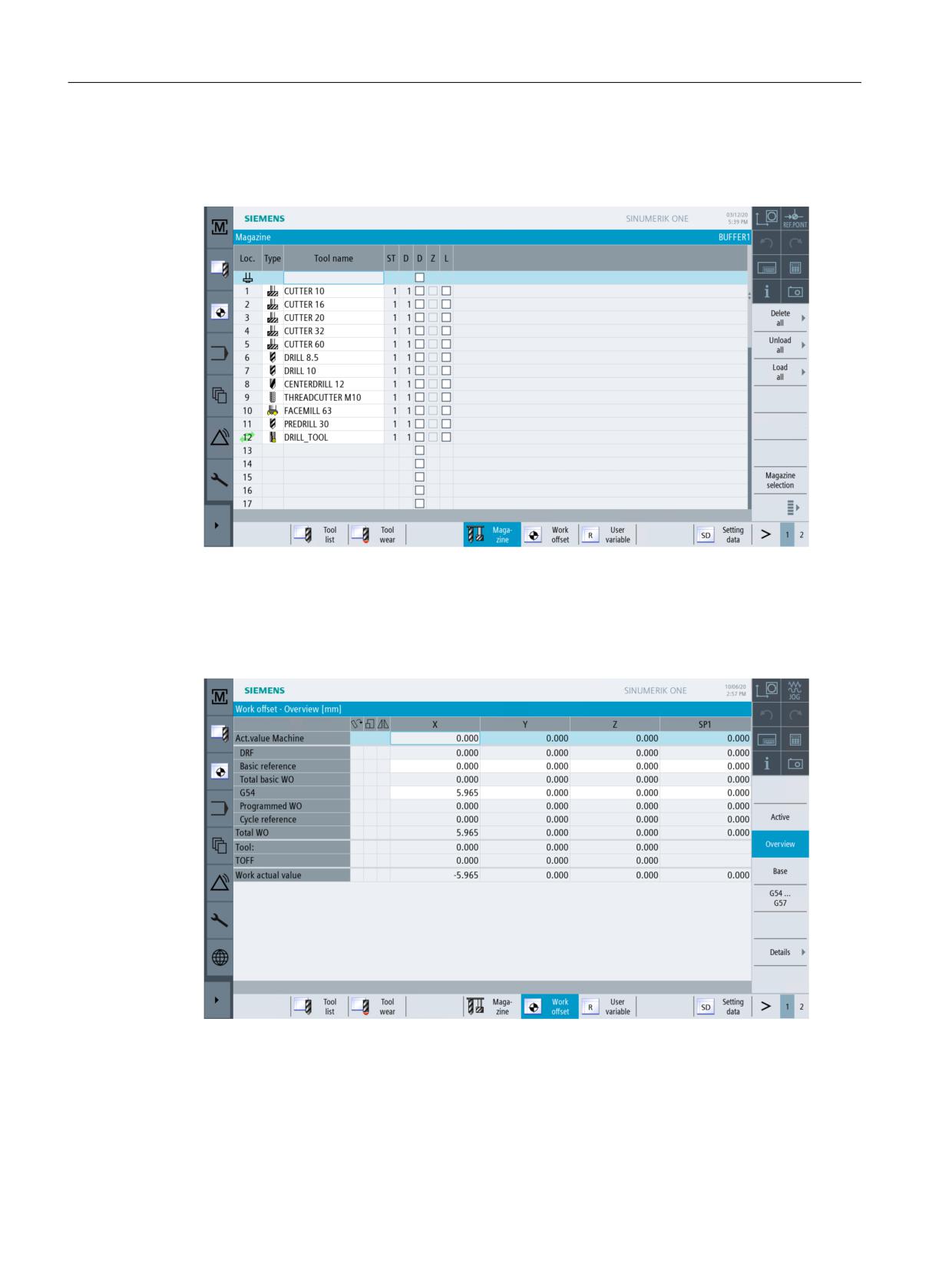
Magazine
Tools can be organized into a magazine.
Figure 3-4
Magazine
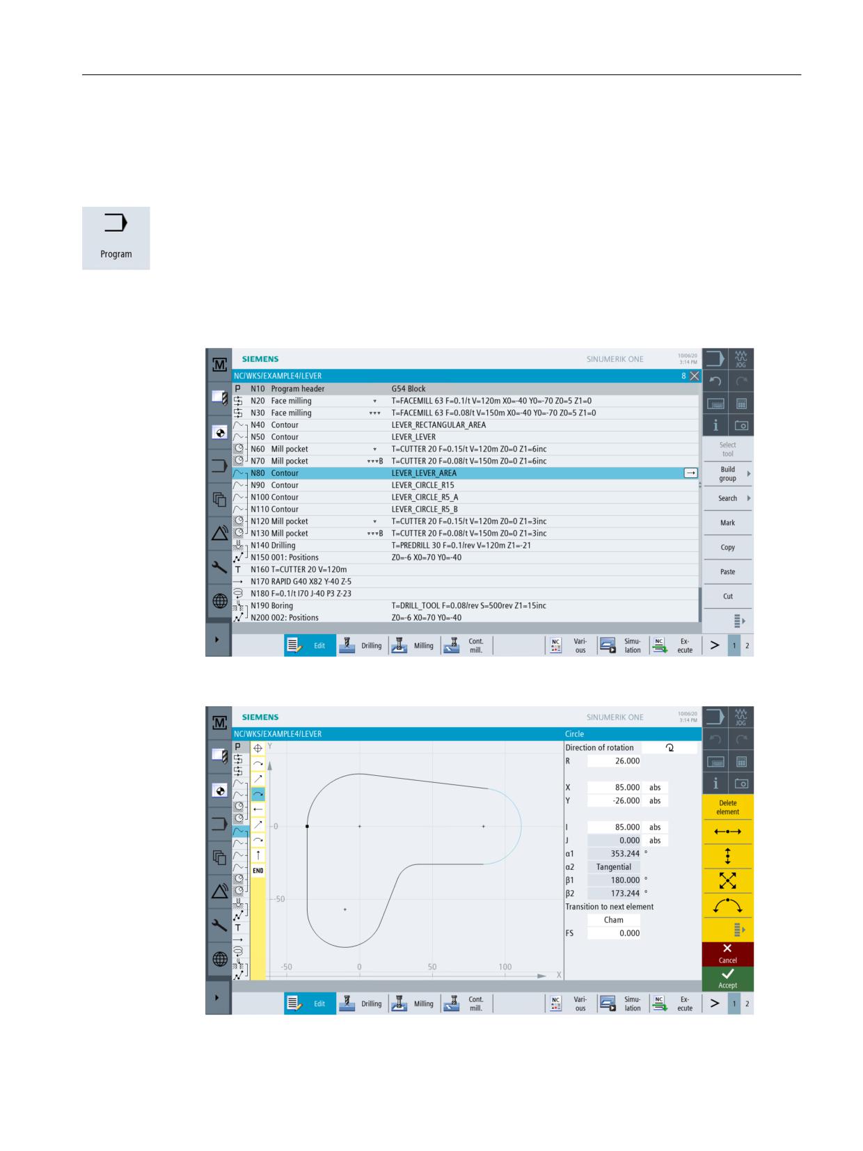
Work offsets
Zero points are saved in a clearly laid-out zero-point table.
Figure 3-5
Work offsets
Easy milling with ShopMill
26
Training Documents, 05/2020, 6FC5095-0AB50-1BP2
To make everything function smoothly...
3.2 The operating areas
3.2.3
Program
Editing programs
This key can be used to edit programs.
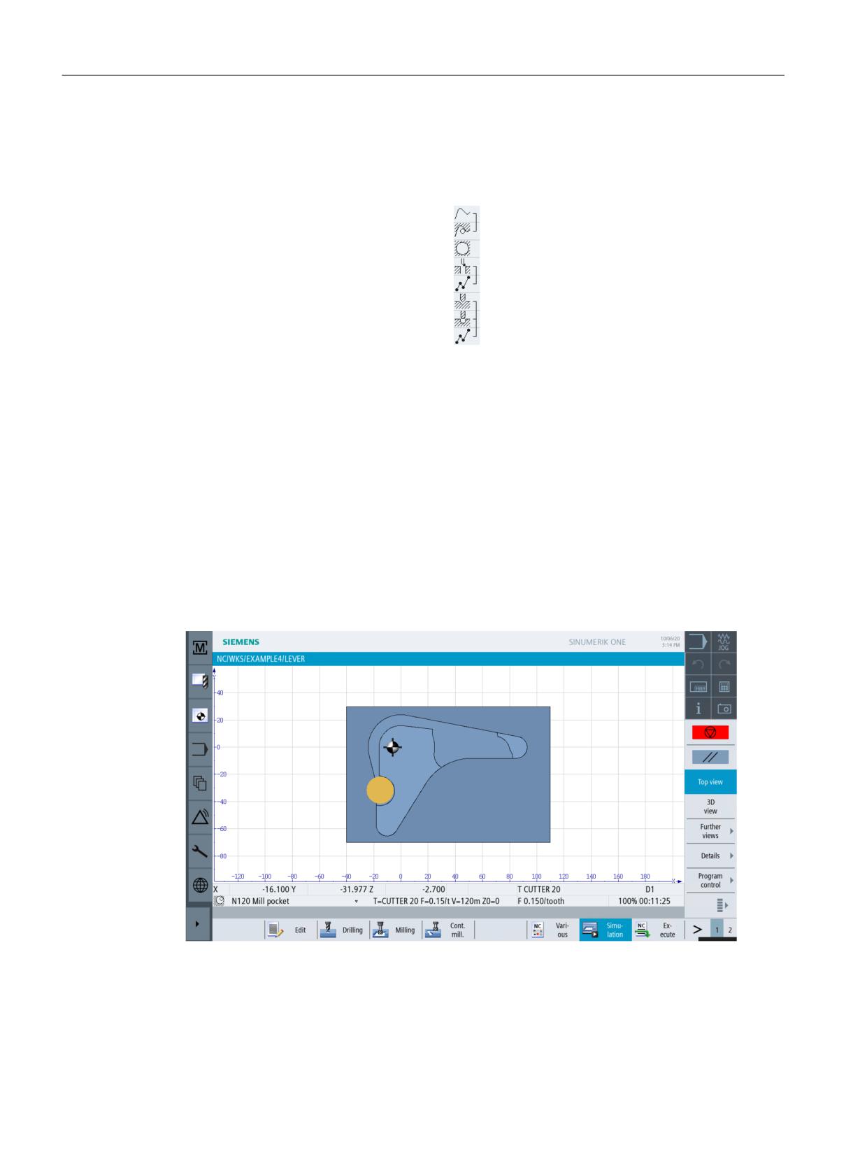
If you have created a ShopMill program in the Program Manager, you can now create the
process plan with the complete machining sequence for the appropriate workpiece.
Prerequisites for the optimum order of sequence are the experience and knowledge of the
skilled worker.
The contour to be machined is entered graphically as a machining step.
Easy milling with ShopMill
Training Documents, 05/2020, 6FC5095-0AB50-1BP2
27
To make everything function smoothly...
3.2 The operating areas
Geometry and technology constitute a unit in programming. The subsequent technological
machining operations are applied to the contour.
Example for the dovetailing of geometry and technology:
&RQWRXU
3DWK PLOOLQJ LQFO DSSURDFK DQG UHWUDFW VWUDWHJLHV
&LUFXODU SRFNHW LQFO WHFKQRORJ\ DQG SRVLWLRQ
%RULQJ WHFKQRORJ\
3RVLWLRQ IRU ERULQJ
&HQWHULQJ WHFKQRORJ\
'ULOOLQJ WHFKQRORJ\
3RVLWLRQV IRU FHQWHULQJ DQG GULOOLQJ
This geometrical-technological interrelation is represented very clearly in the graphical display
of the work steps by putting the appropriate symbols in brackets. The brackets mean linking of
geometry and technology to one work step.
Simulating programs
Before machining a workpiece on the machine, it is possible to display the program execution
graphically on the screen.
• To this end, select the "Simulation" and "Start" softkeys.
• To stop simulation, select the "Stop" softkey.
• To cancel simulation, use the "Reset" softkey.
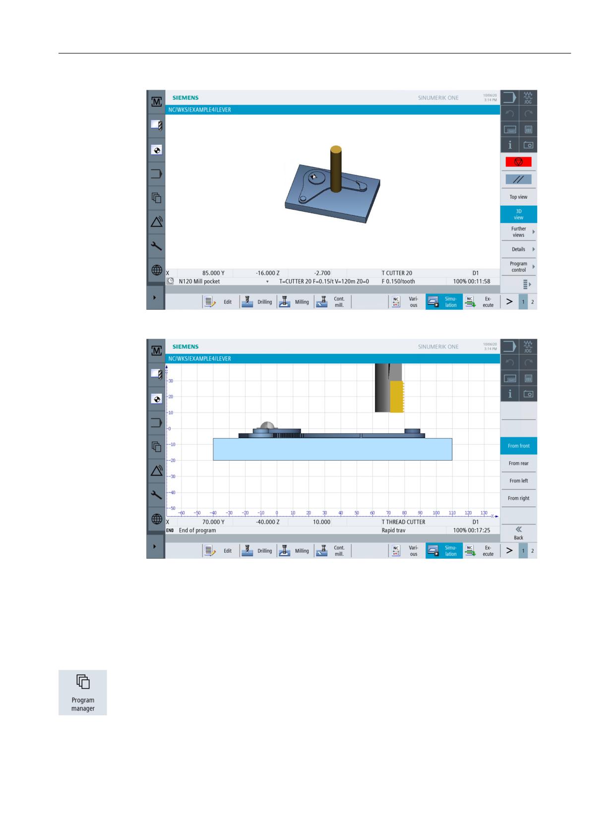
The following views are available for simulation:
Figure 3-6
Top view
Easy milling with ShopMill
28
Training Documents, 05/2020, 6FC5095-0AB50-1BP2
To make everything function smoothly...
3.2 The operating areas
Figure 3-7
3D view
Figure 3-8
Side view
3.2.4
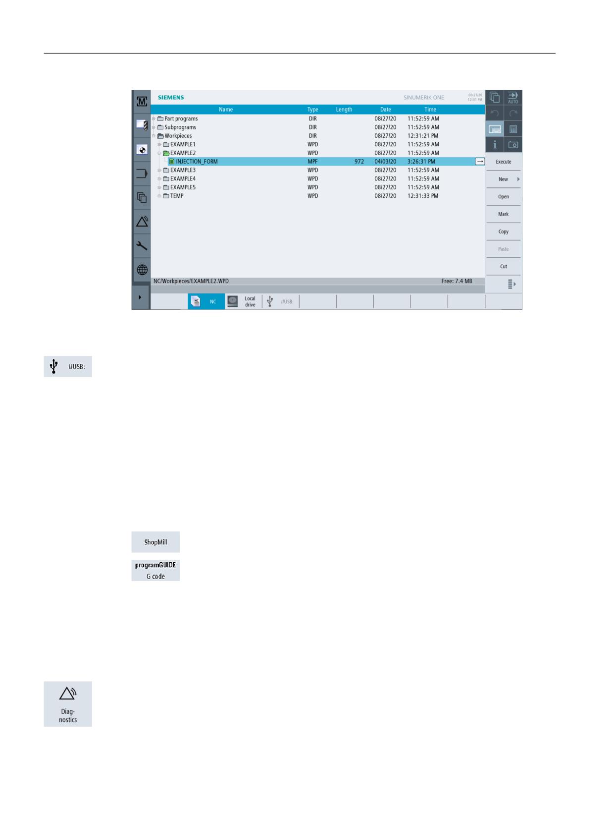
Program Manager
Managing programs
With the Program Manager, you can create new programs at any time. You can similarly open
existing programs to execute, modify, copy or rename them. Programs no longer required can
be deleted.
Easy milling with ShopMill
Training Documents, 05/2020, 6FC5095-0AB50-1BP2
29
To make everything function smoothly...
3.2 The operating areas
Active programs are marked with a green symbol.
USB flash drives can be used for data exchange. For example, programs which were created on
an external device can be copied and executed on the NC.
Creating a new workpiece
You can manage your programs and other files, such as tool data, zero points, magazine
mapping, in a workpiece.
Creating a new program
If you create a new program, you can specify the type of programming using the following
softkeys:
ShopMill program
G code program
3.2.5
Diagnosis
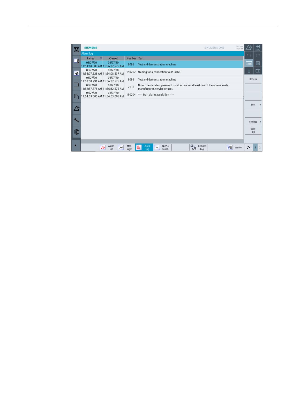
Alarms and messages
Here you can see alarm lists, messages and alarm logs.
Easy milling with ShopMill
30
Training Documents, 05/2020, 6FC5095-0AB50-1BP2
To make everything function smoothly...
3.2 The operating areas
Figure 3-9
Alarm log
Easy milling with ShopMill
Training Documents, 05/2020, 6FC5095-0AB50-1BP2
31
To make everything function smoothly...
3.2 The operating areas
Easy milling with ShopMill
32
Training Documents, 05/2020, 6FC5095-0AB50-1BP2
Geometrical basics
4
This chapter will explain the general basics of the geometry and technology for milling. No
inputs for ShopMill are planned yet.
Easy milling with ShopMill
Training Documents, 05/2020, 6FC5095-0AB50-1BP2
33
Geometrical basics
4.1 Tool axes and work planes
4.1
Tool axes and work planes
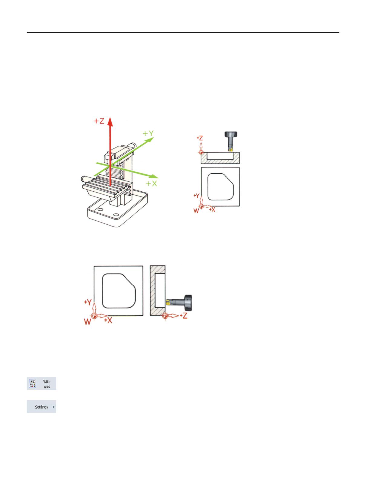
On universal milling machines, the tool can be mounted parallel to any of the three main axes.
These perpendicular axes are aligned to the main guideway of the machine according to DIN
66217 or ISO 841.
The appropriate working plane results from the mounting position of the tool. Z is the tool axis
in most cases.
Figure 4-1
Vertical spindle
On modern machines, the tool mounting position is changed without any modification and in
a few seconds by way of a universal swivel head.
Figure 4-2
Horizontal spindle
If the coordinate system shown on the previous page is rotated accordingly, the axes and their
directions in the appropriate working plane (DIN 66217) will change.
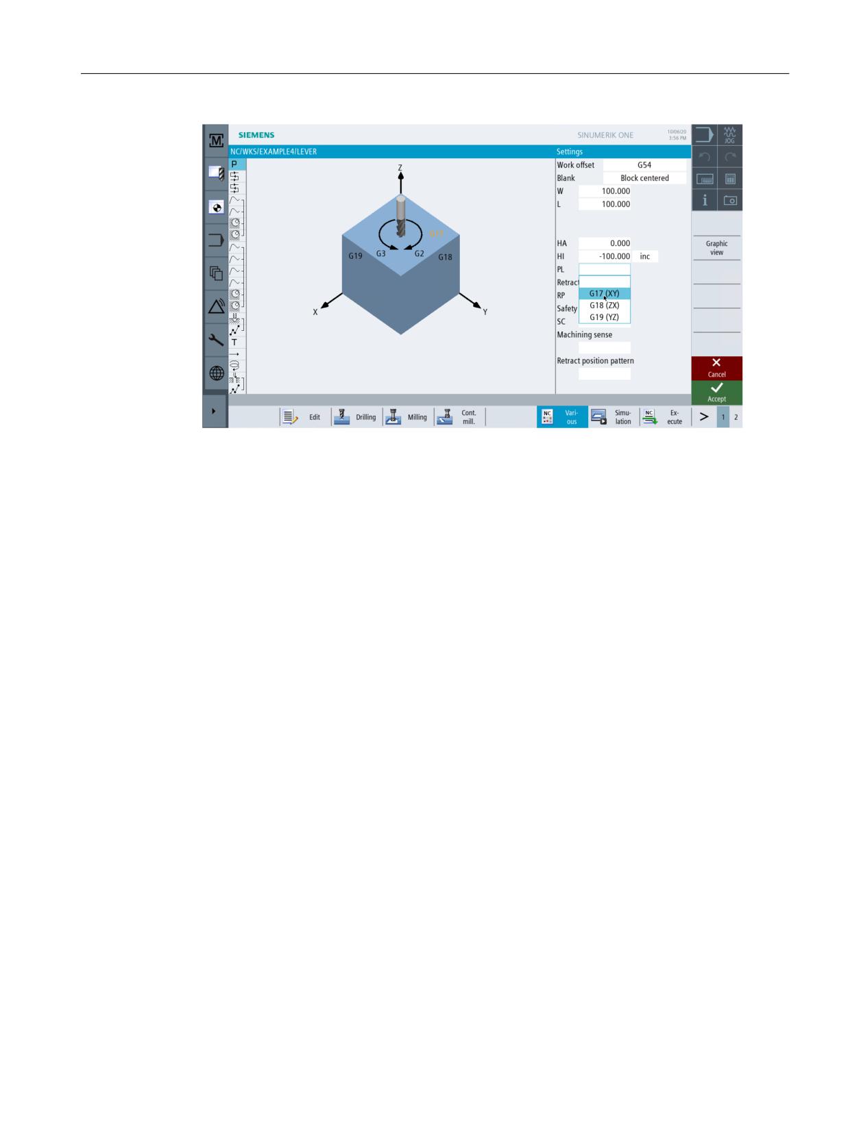
With the "Various" and "Settings" softkeys, you can call a parameter screenform in which you can
specify the working planes in the program header.
Select the "Various" softkey.
Select the "Settings" softkey.
Easy milling with ShopMill
34
Training Documents, 05/2020, 6FC5095-0AB50-1BP2
Geometrical basics
4.1 Tool axes and work planes
Figure 4-3
The "Working planes" parameter screenform
Easy milling with ShopMill
Training Documents, 05/2020, 6FC5095-0AB50-1BP2
35
Geometrical basics
4.2 Points in the work space
4.2
Points in the work space
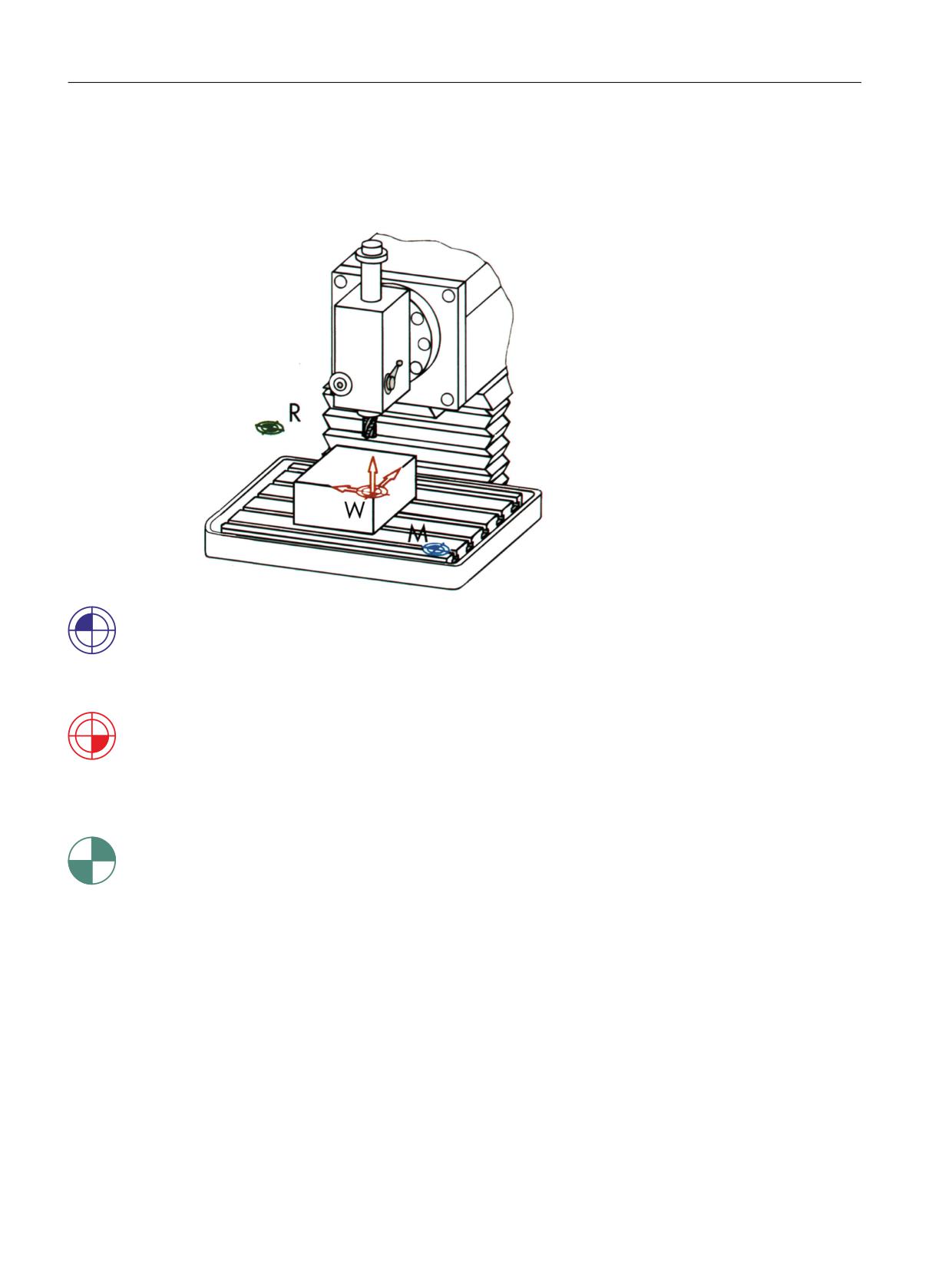
Various important reference points are provided for a CNC - such as the SINUMERIK 828D with
ShopMill - for orientation in the working space by way of the measuring system.
Machine zero (M)
The machine zero (M) is specified by the manufacturer and cannot be changed. It lies in the
origin of the machine coordinate system.
Workpiece zero (W)
The workpiece zero (W) - also called program zero - is the origin of the workpiece coordinate
system. It can be selected freely and should be located at a point from which the most
dimensions start in the drawing.
Reference point (R)
The reference point (R) is approached to set the measuring system to zero, as the machine zero
cannot be approached in most cases. Thus, the control system finds the start of counting in the
position measuring system.
Easy milling with ShopMill
36
Training Documents, 05/2020, 6FC5095-0AB50-1BP2
Geometrical basics
4.3 Absolute and incremental dimensioning
4.3
Absolute and incremental dimensioning
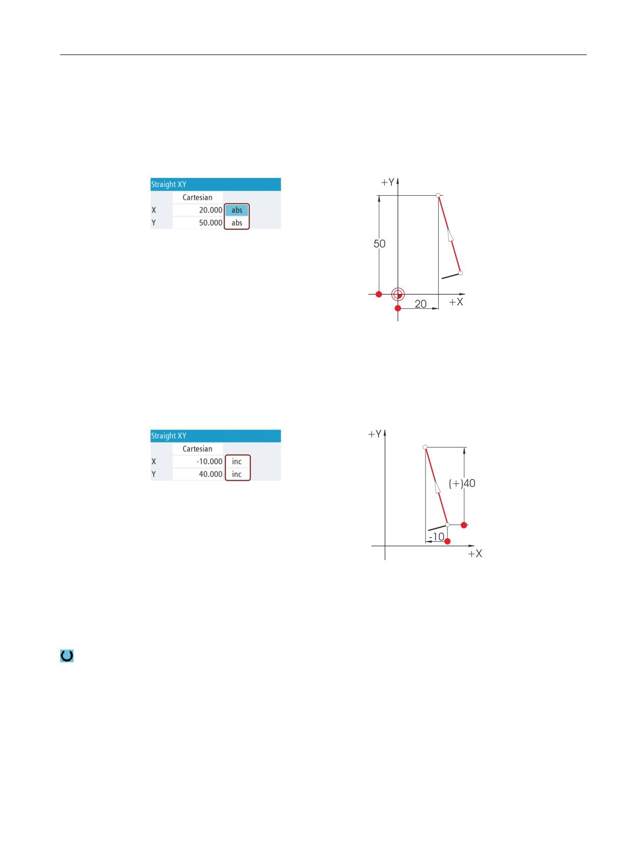
Absolute input
The entered values refer to the workpiece zero.
With absolute inputs, the absolute coordinate values of the end point must always be entered
(the starting point is not taken into account).
Incremental input
The entered values refer to the starting point.
With incremental inputs, the difference values between starting point and end point must
always be entered, observing the direction.
Click on the toggle field to switch between the absolute and incremental input.
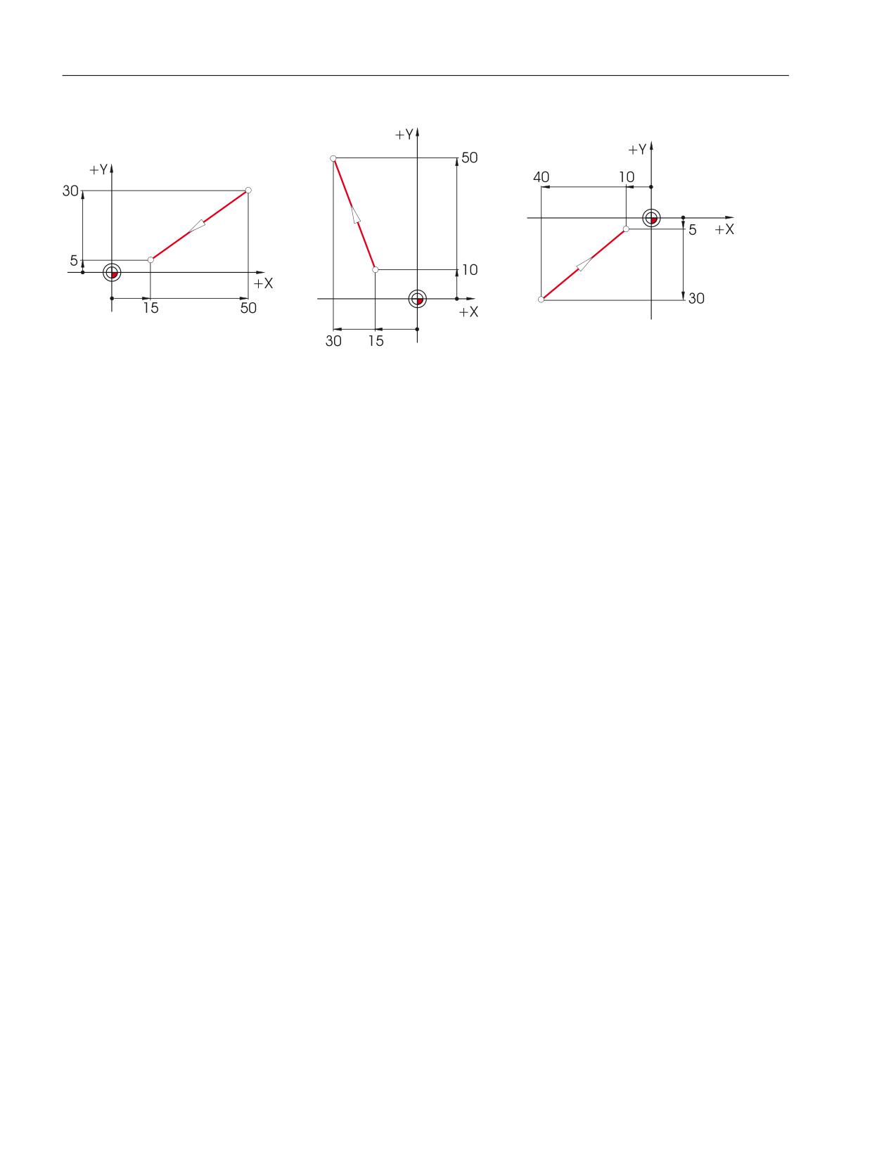
A few examples for the absolute/incremental combination can be found below:
Easy milling with ShopMill
Training Documents, 05/2020, 6FC5095-0AB50-1BP2
37
Geometrical basics
4.3 Absolute and incremental dimensioning
$EVROXWH
$EVROXWH
$EVROXWH
;
<
;
<
;
<
,QFUHPHQWDO
,QFUHPHQWDO
,QFUHPHQWDO
;
<
;
<
;
<
Easy milling with ShopMill
38
Training Documents, 05/2020, 6FC5095-0AB50-1BP2
Geometrical basics
4.4 Linear motions
4.4
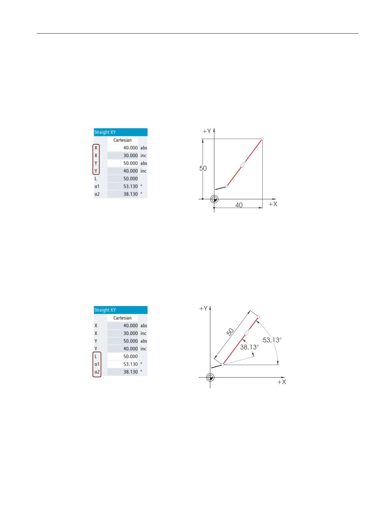
Linear motions
Two specifications are required to define an end point unambiguously. These specifications
could be:
Cartesian
Input of the X and Y coordinates.
Polar
Input of the length and an angle.
Angle 38.13° = angle with reference to the previous element
or
angle 53.13° = starting angle with reference to the positive X axis
Easy milling with ShopMill
Training Documents, 05/2020, 6FC5095-0AB50-1BP2
39
Geometrical basics
4.4 Linear motions
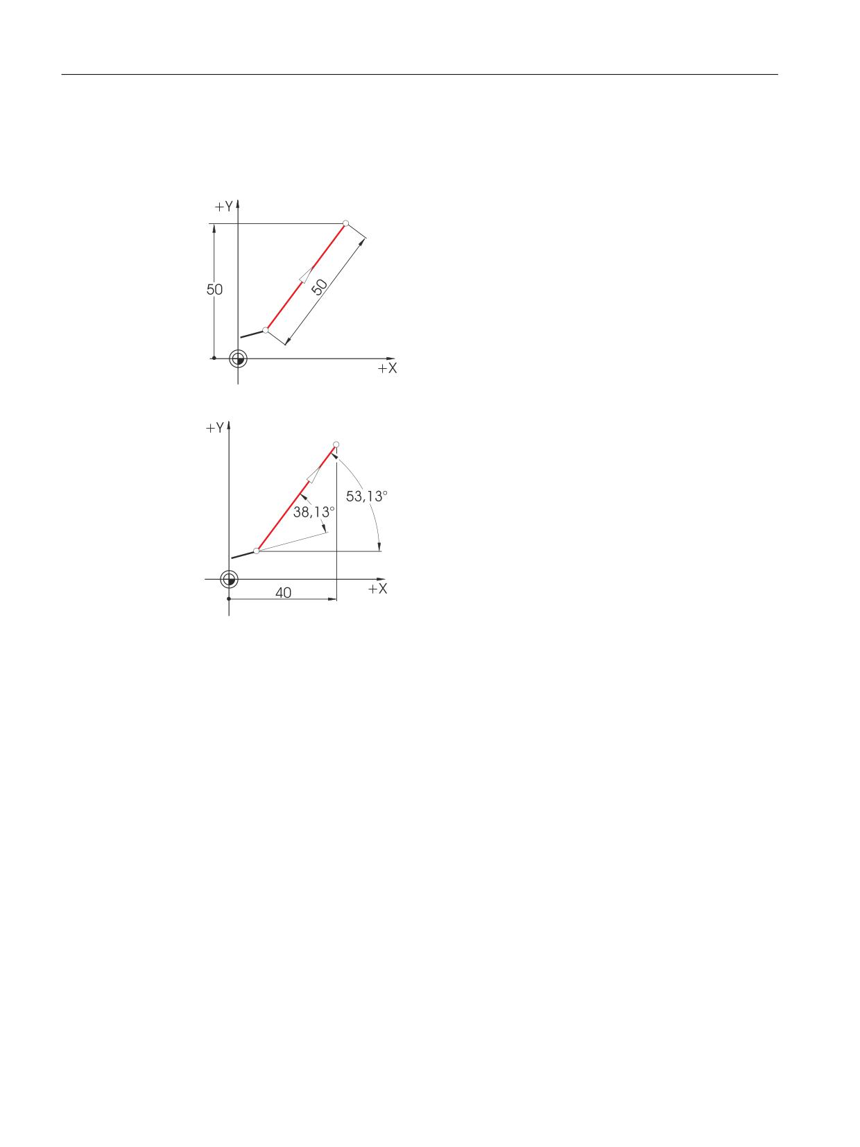
Cartesian and polar
It is possible to combine Cartesian and polar inputs, e.g.:
• Input of the end point in Y and the length.
• Input of the end point in X and of an angle (either 38.13° or 53.13°)
Easy milling with ShopMill
40
Training Documents, 05/2020, 6FC5095-0AB50-1BP2
Geometrical basics
4.5 Circular motions
4.5
Circular motions
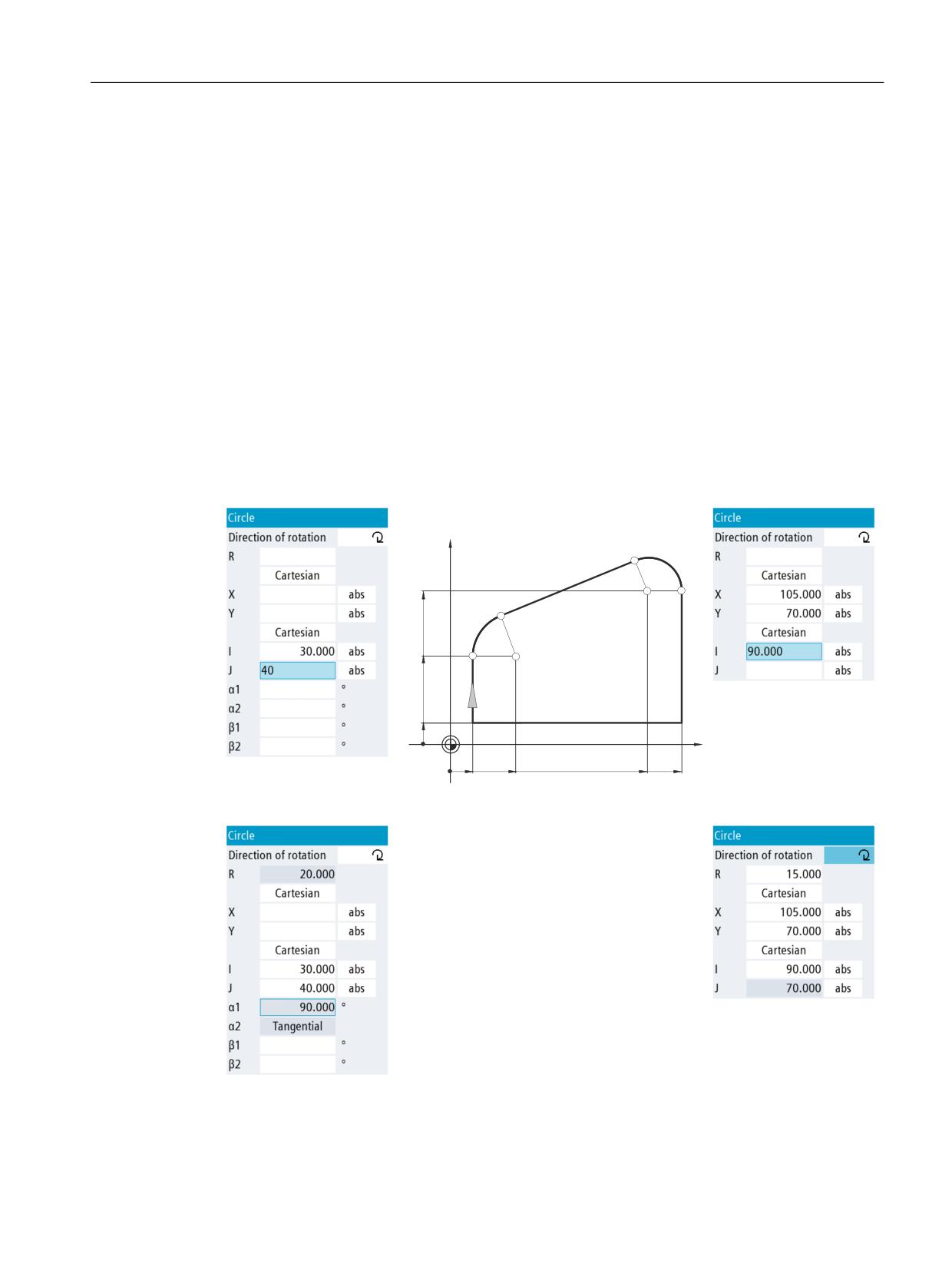
In the case of arcs, X and Y specify the end point; the circle center is specified with I and J. In
ShopMill, these four values can be entered separately - either as absolute or incremental
dimensions.
While X and Y are entered as absolute dimensions, the center point is specified with I and J as an
incremental dimension in the most control systems. Not only the difference from the starting
point A to the center M must be determined (often even in combination with mathematic
calculations), but also the direction and thus the sign.
When working with ShopMill, however, you need not perform any calculations thanks to the
possibility of entering the center point as an absolute dimension - even the most complicated
contour can be determined easily using the graphical contour calculator.
Input of the center point (absolute)
Values (here: radii) which result from data already entered are calculated by ShopMill
automatically.
<
$
0
(
(
$
0
;
After the input:
After the input:
Easy milling with ShopMill
Training Documents, 05/2020, 6FC5095-0AB50-1BP2
41
Geometrical basics
4.5 Circular motions
Display of all parameters
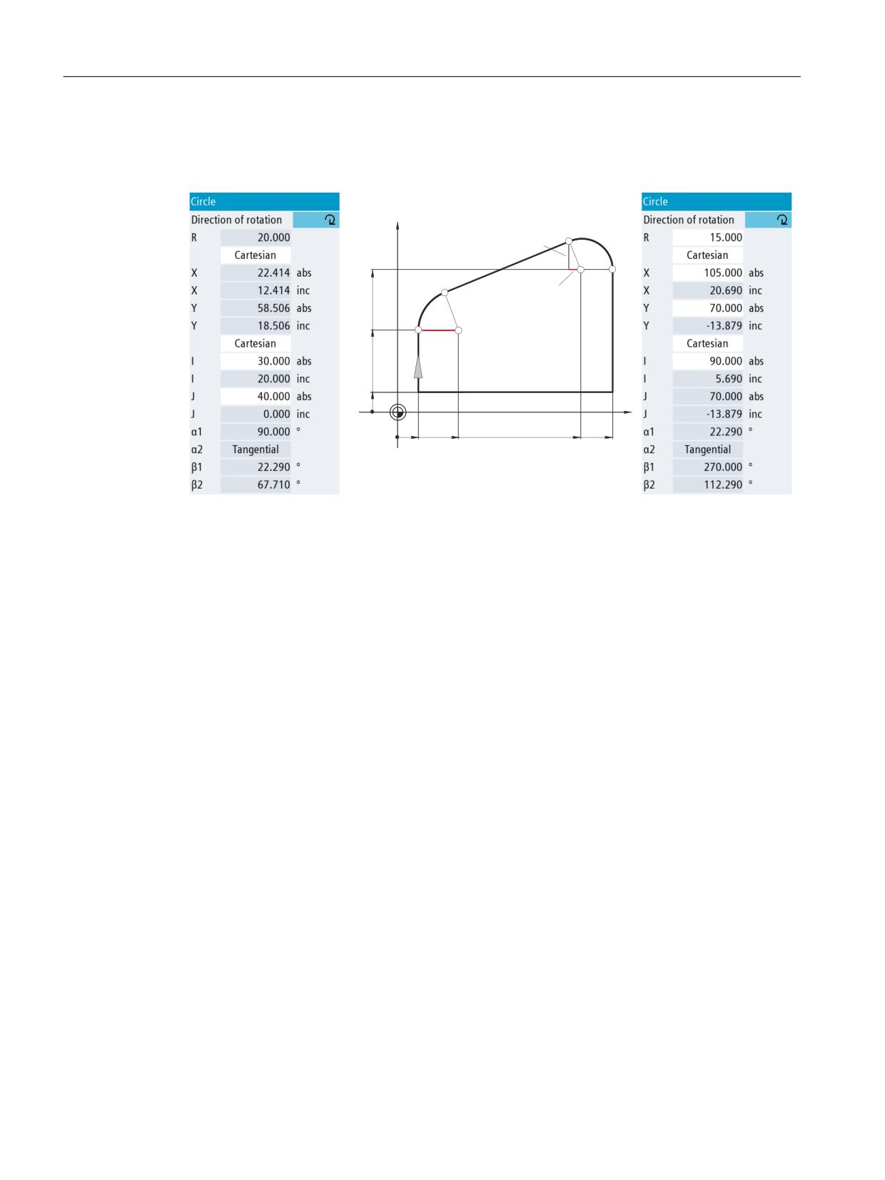
ShopMill also allows to display all possible geometry values:
<
$
-
0
(
(
,
$
0
-
,
;
A further advantage of absolute center-point dimensioning: You need not recalculate the values
for I and J when reversing the milling direction.
Easy milling with ShopMill
42
Training Documents, 05/2020, 6FC5095-0AB50-1BP2
Well equipped
5
In this section you will learn how to create the tools required for the examples in the following
sections. Furthermore, it is explained how to take into account the tool lengths and how to set
the workpiece zero.
Easy milling with ShopMill
Training Documents, 05/2020, 6FC5095-0AB50-1BP2
43
Well equipped
5.1 Tool management
5.1
Tool management
ShopMill offers three lists for tool management:
• Tool list (Page 44)
• Tool wear list (Page 45)
• Magazine list (Page 46)
5.1.1
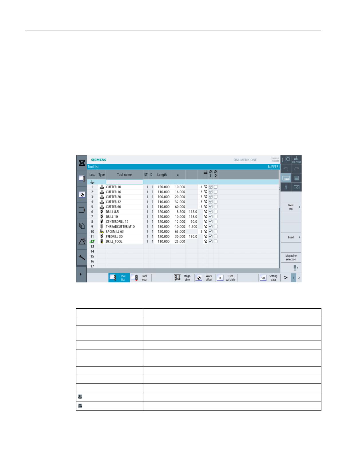
Tool list
The tool list displays all parameters and functions required to create and set up the tools.
Figure 5-1
Example for tool lists
Meaning of the most important parameters in the tool list:
Location
Location number
Type
Tool type
Tool name
The tool is identified by the name and the replacement tool number. You
may enter the names as text or numbers.
ST
Replacement tool number (for replacement tool strategy)
D
Cutting edge number
Length
Tool length
Diameter
Tool diameter
Point angle or lead
Point angle or lead
N
Number of teeth
Direction of spindle rotation
Coolants 1 and 2 (e.g. internal and external cooling)
Easy milling with ShopMill
44
Training Documents, 05/2020, 6FC5095-0AB50-1BP2
Well equipped
5.1 Tool management
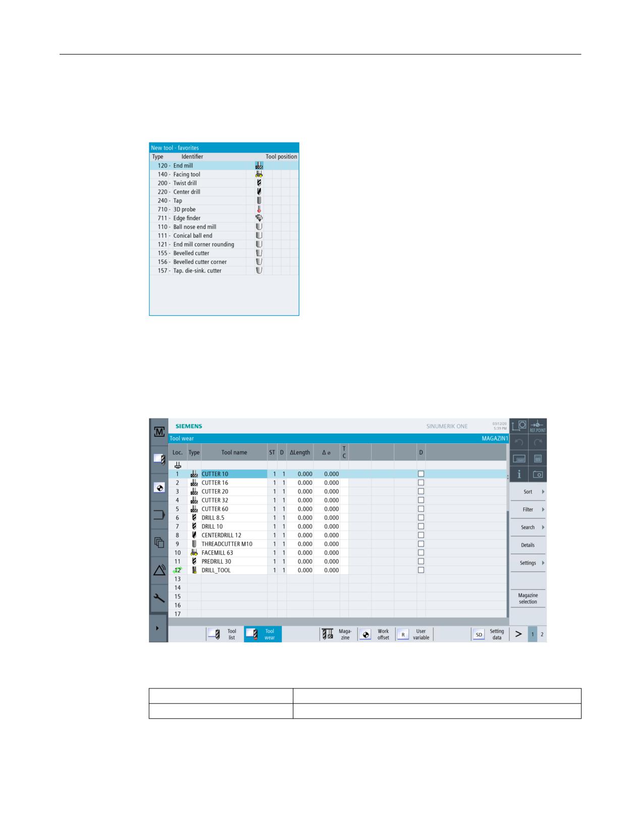
ShopMill provides various tool types (favorites, milling cutters, drills, and special tools). Tools
can be created in the tool list by means of a predefined tool catalog. The geometrical parameters
(e.g. angle specifications for drills) are different for each tool type.
Figure 5-2
Example of Favorites list
5.1.2
Tool wear list
The wearing data for the appropriate tools are defined here.
Figure 5-3
Tool wear list
The most important tool wearing parameters are:
Δ Length
Length wear
Δ Radius
Radius wear
Easy milling with ShopMill
Training Documents, 05/2020, 6FC5095-0AB50-1BP2
45
Well equipped
5.1 Tool management
TC
Selection of tool monitoring
• by tool life (T)
• by count (C)
• by wear (W)
Tool life or
Tool life
workpiece count or
Number of workpieces
wear *
Tool wear
*Parameter depends on selec-
tion in TC
Setpoint
Setpoint for tool life, workpiece count, or wear
Prewarning limit
Specification of the tool life, workpiece count or wear at which a
warning is displayed.
G
The tool is disabled when the checkbox is selected.
5.1.3
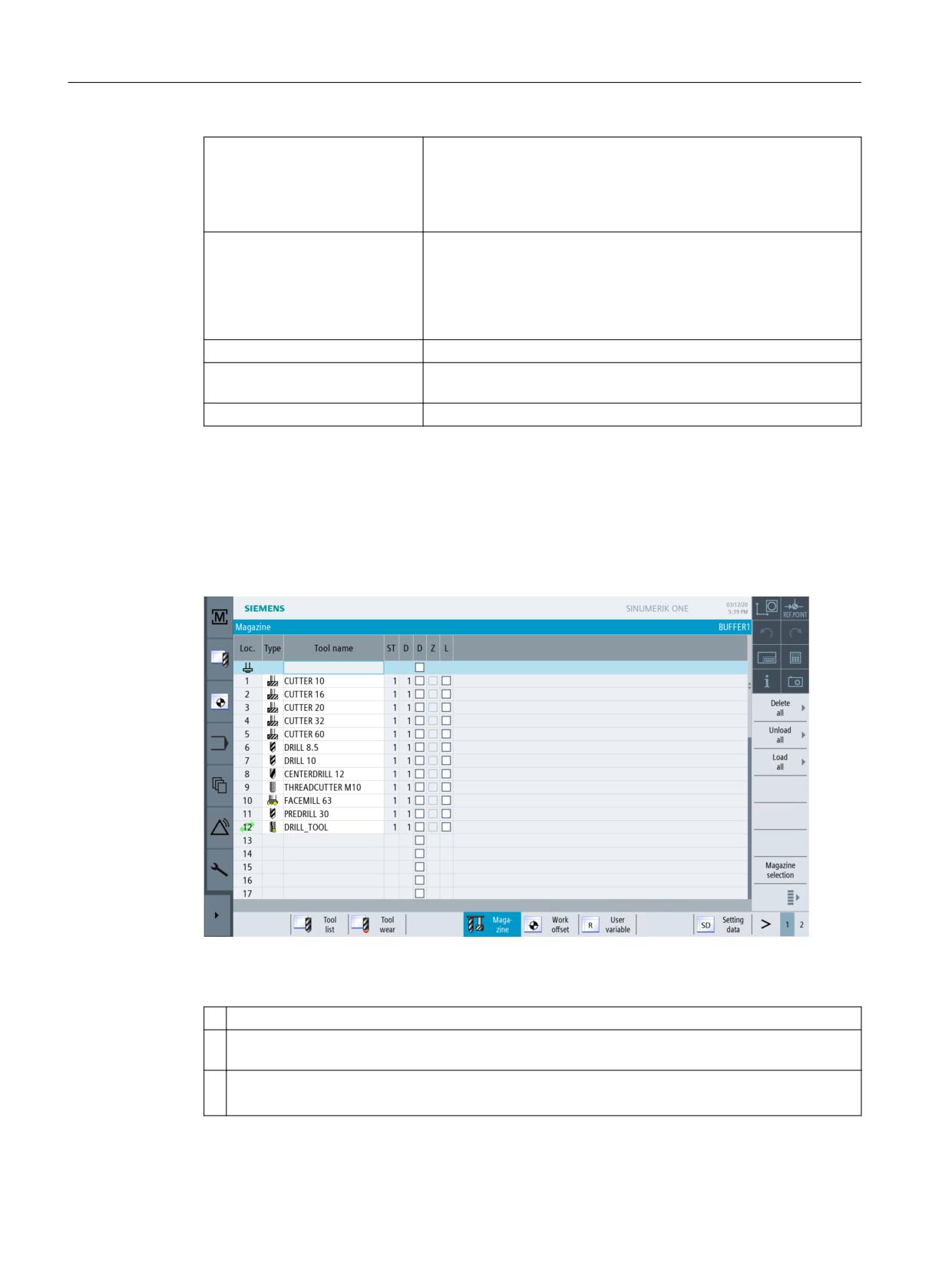
Magazine list
All tools that are assigned to one or several tool magazines are contained in the magazine list.
This list displays the condition of each tool. Individual magazine locations can be reserved or
disabled for existing tools.
Figure 5-4
Magazine list
Meanings of the most important parameters:
G
Disabling of the magazine location
Ü
Marking of a tool as oversized. The tool occupies two half locations left, two half locations right, one
half location top and one half location bottom in a magazine.
P
Fixed location coding
The tool is permanently assigned to this magazine location.
Easy milling with ShopMill
46
Training Documents, 05/2020, 6FC5095-0AB50-1BP2
Well equipped
5.2 Tools used
5.2
Tools used
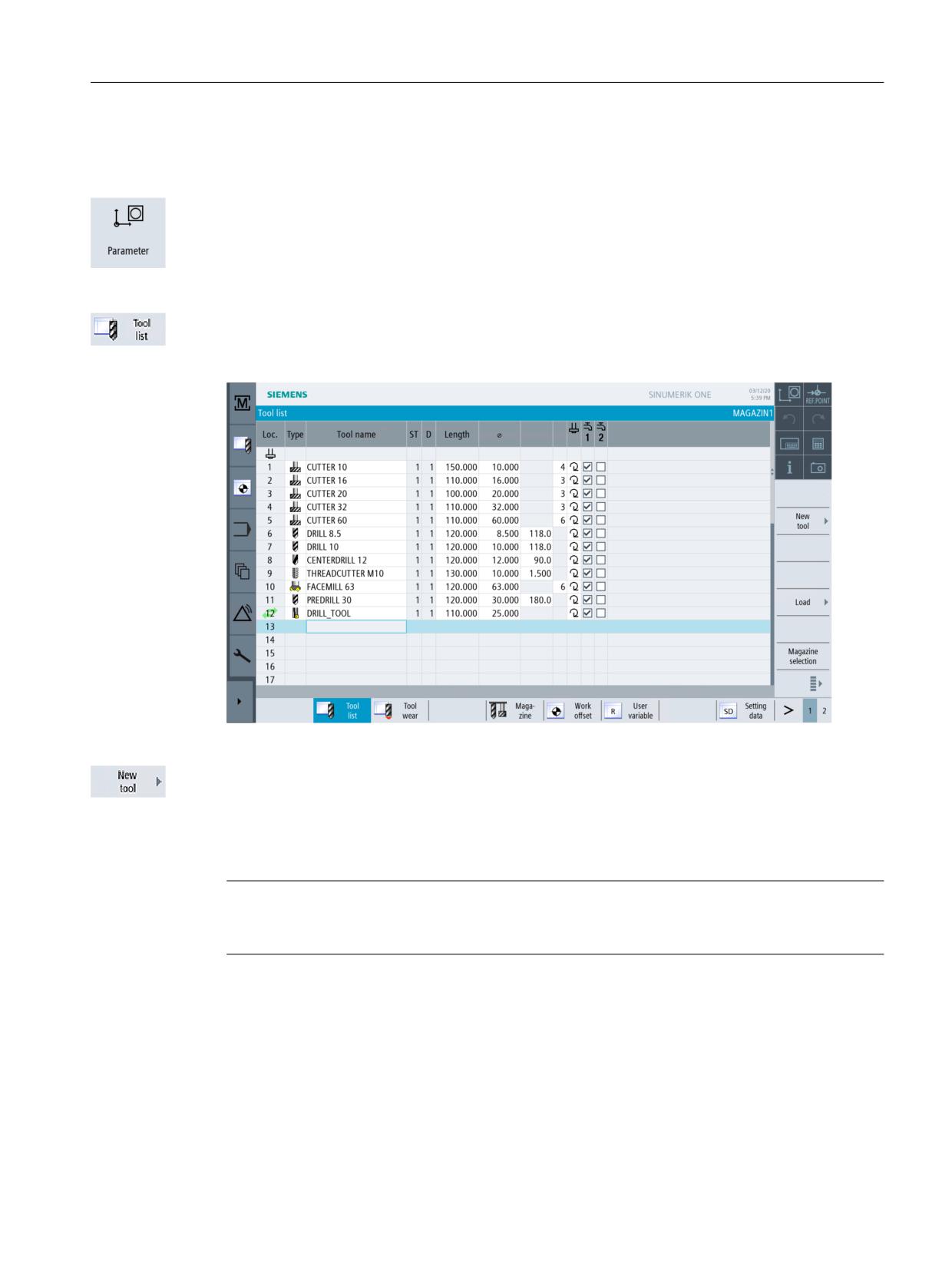
In this section you will learn how to enter tools required for the later machining in the tool list.
Select the "Parameters" area in the main menu.
Select the "Tool list” softkey.
To create a new tool, call the tool list and search for a free location.
Select the "New tool" softkey.
Select the desired tool type from the tool catalog displayed. This tool type is inserted in the tool
list and you can enter the data of the tool.
Note
The milling cutters with the diameters 6, 10, 20 and 32 (Cutter6, 10, 20 and 32) must immerse,
as they will also be used for the milling of pockets in the following examples.
Easy milling with ShopMill
Training Documents, 05/2020, 6FC5095-0AB50-1BP2
47
Well equipped
5.3 Tools in the magazine
5.3
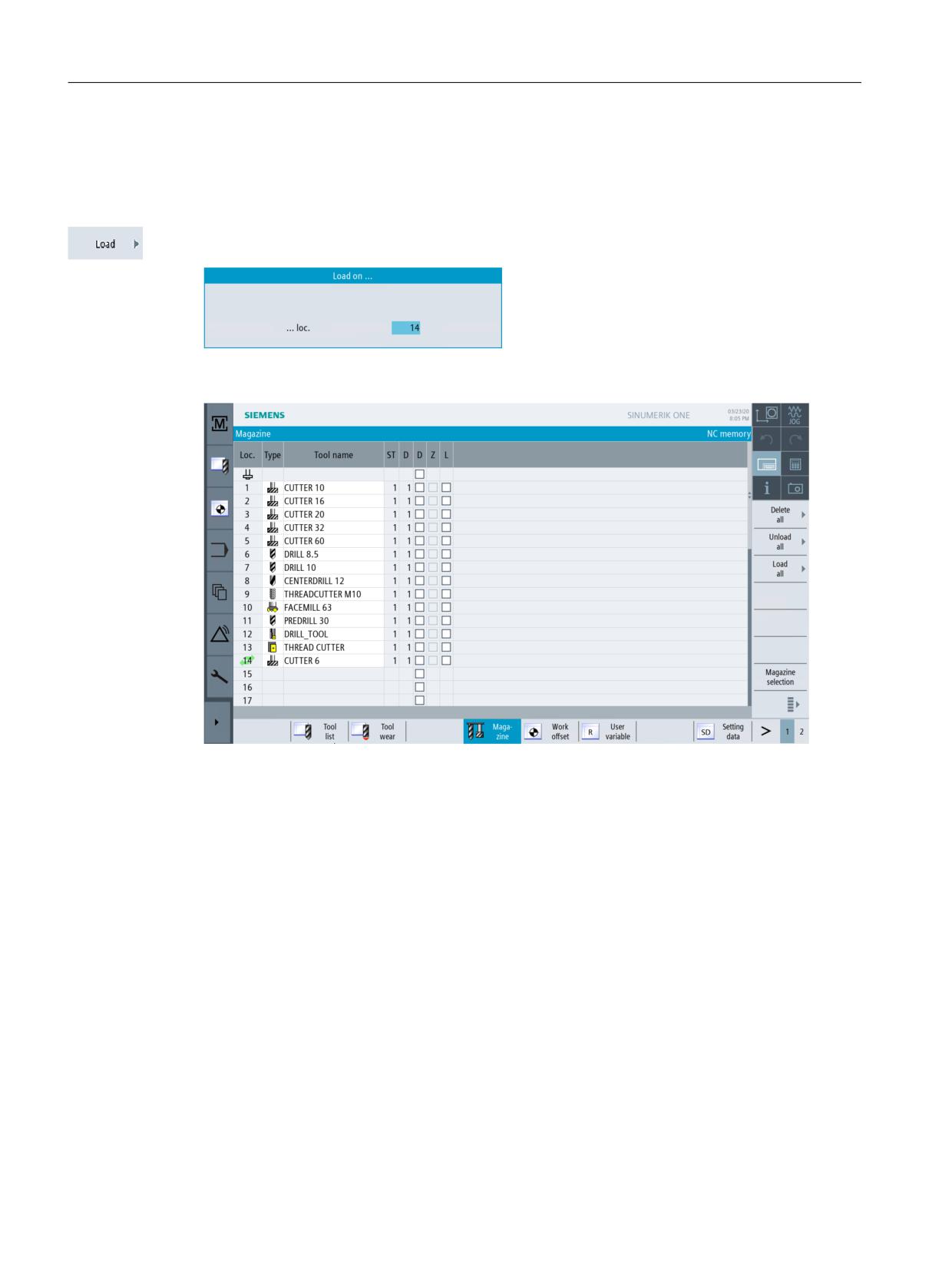
Tools in the magazine
In the following you will learn how to insert the tools into the magazine.
Select a tool without location number from the tool list and select the "Load" softkey.
The following dialog offers the first free magazine location for you to change or accept directly.
The magazine for the following exercises could look like the one in the screen below:
Easy milling with ShopMill
48
Training Documents, 05/2020, 6FC5095-0AB50-1BP2
Well equipped
5.4 Gauging tools
5.4
Gauging tools
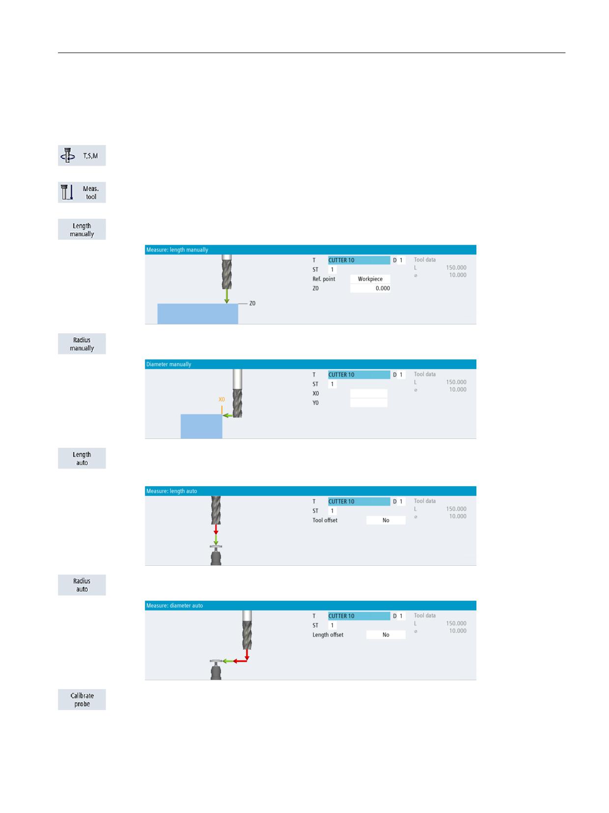
In the following you will learn how to calculate tools.
Insert a tool from the tool list into the spindle using the "T,S,M" softkey.
Then switch to the "Gauge tool" menu.
The tool is measured in the Z direction using the Length, manual function.
The diameter of the tool is measured using the Diameter, manual function.
The Length, autom. function can be used to measure the tool in the Z direction using a tool
probe.
The Diameter, autom. function is used to measure the diameter of the tool using a tool probe.
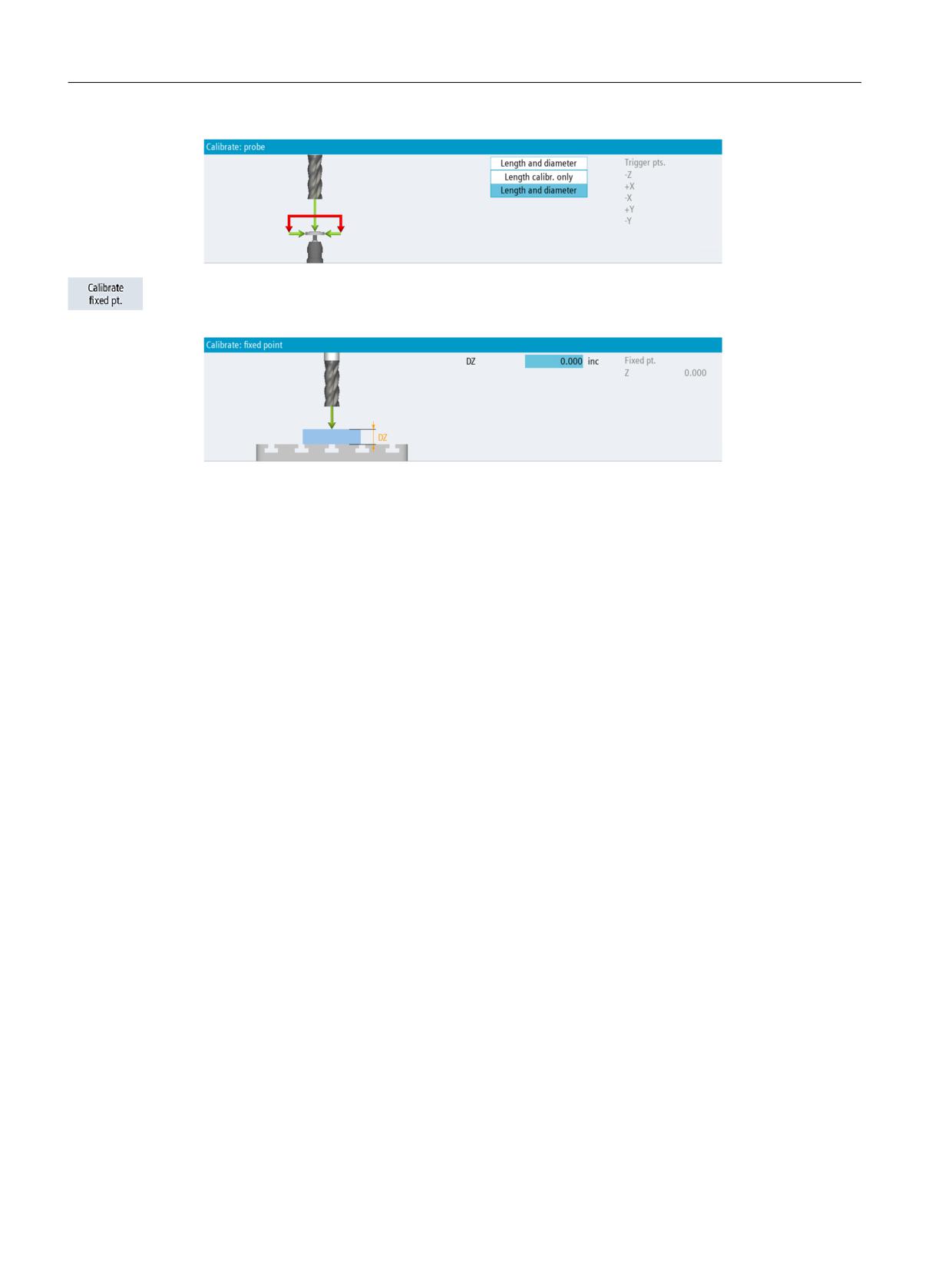
The Calibrate probe function is used to determine the position of the sensing probe on the
machine table with reference to the machine zero.
Easy milling with ShopMill
Training Documents, 05/2020, 6FC5095-0AB50-1BP2
49
Well equipped
5.4 Gauging tools
The Fixed-point calibration function is used to determine the fixed point used as the reference
point for measuring the tool length manually.
Easy milling with ShopMill
50
Training Documents, 05/2020, 6FC5095-0AB50-1BP2
Well equipped
5.5 Setting the workpiece zero
5.5
Setting the workpiece zero
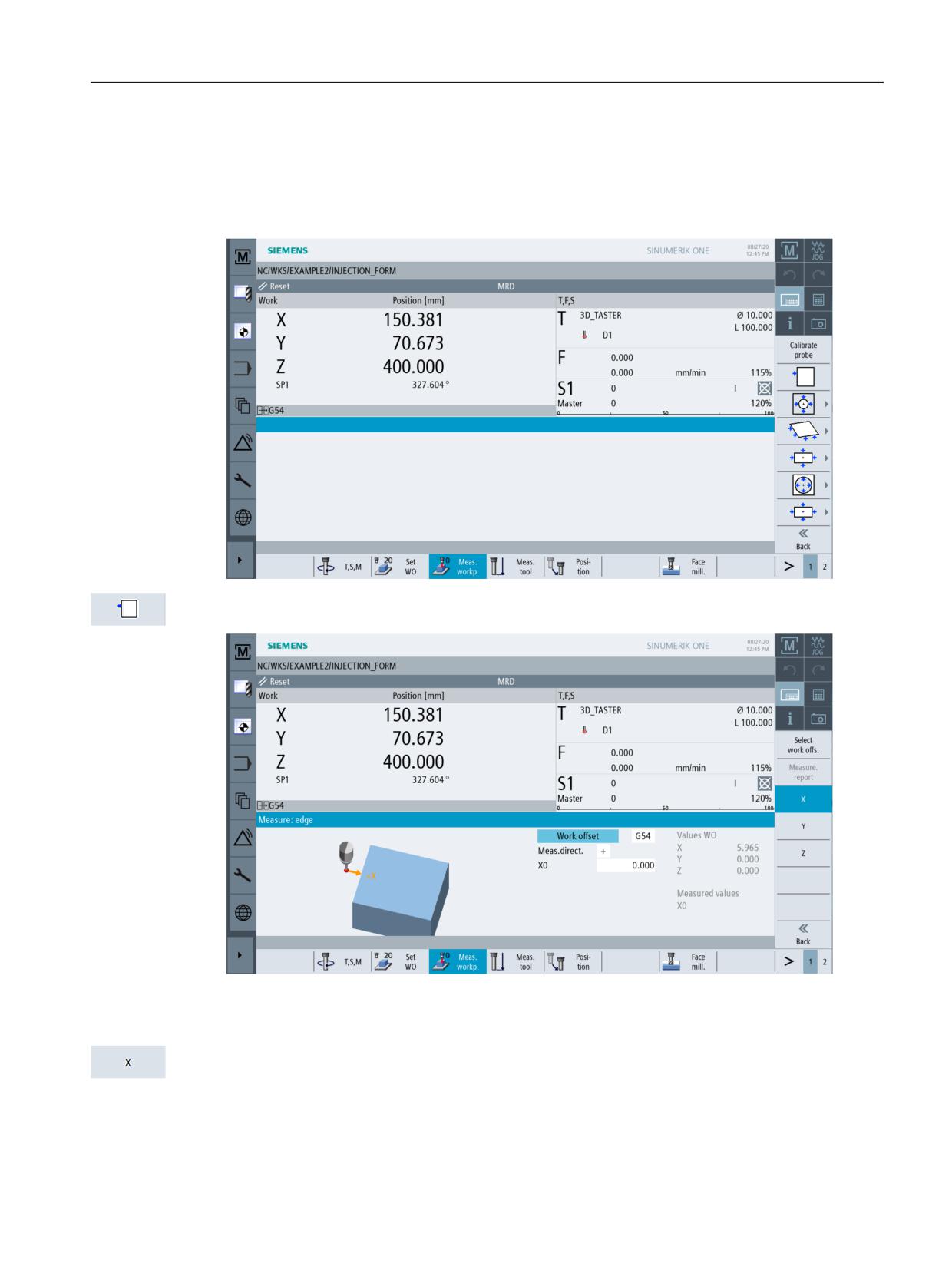
To set the workpiece zero, switch to the Machine - Manual mode in the main menu.
The submenu of the Workp. zero option offers various possibilities to set the workpiece zero.
The zero point of a workpiece edge will be set in the following example using a 3D probe.
Step 1: Selecting the edge
Define the sampling direction for the probe: LH (+) or (-). The X0 parameter can be used to
specify an offset for the workpiece zero if the zero is not to lie on the edge of the workpiece.
Step 2: Sampling the workpiece edge
Easy milling with ShopMill
Training Documents, 05/2020, 6FC5095-0AB50-1BP2
51
Well equipped
5.5 Setting the workpiece zero
Step 3: Set the workpiece zero taking into account the edge probe diameter (5 mm). Now this
process of calculation must be repeated for Y using the edge probe and for Z (in most cases, with
the milling cutter).
Since the workpieces to be machined are not always present in the form of a cuboid or can be
clamped at right angles, further calculation possibilities are provided:
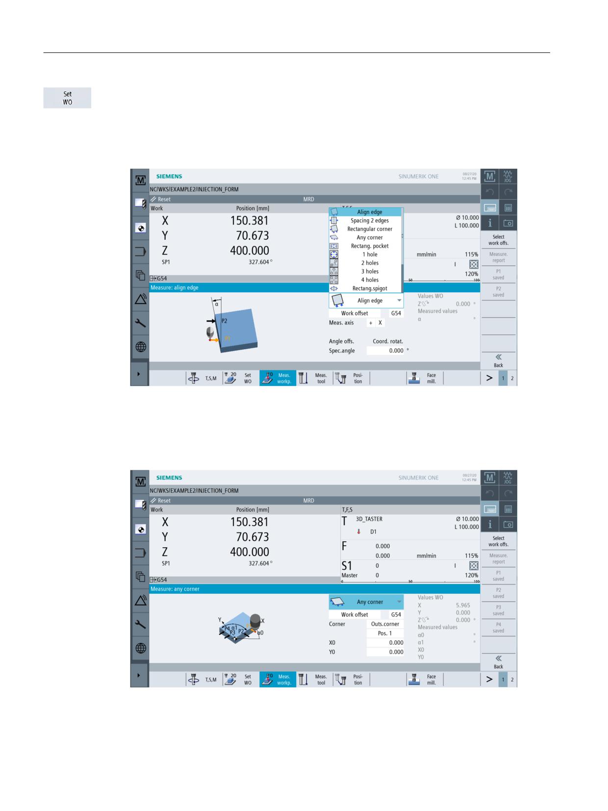
Example 1: Any corner
If the workpiece is positioned as shown here, the position/corner of the workpiece can be
determined by approaching four points.
Easy milling with ShopMill
52
Training Documents, 05/2020, 6FC5095-0AB50-1BP2
Well equipped
5.5 Setting the workpiece zero
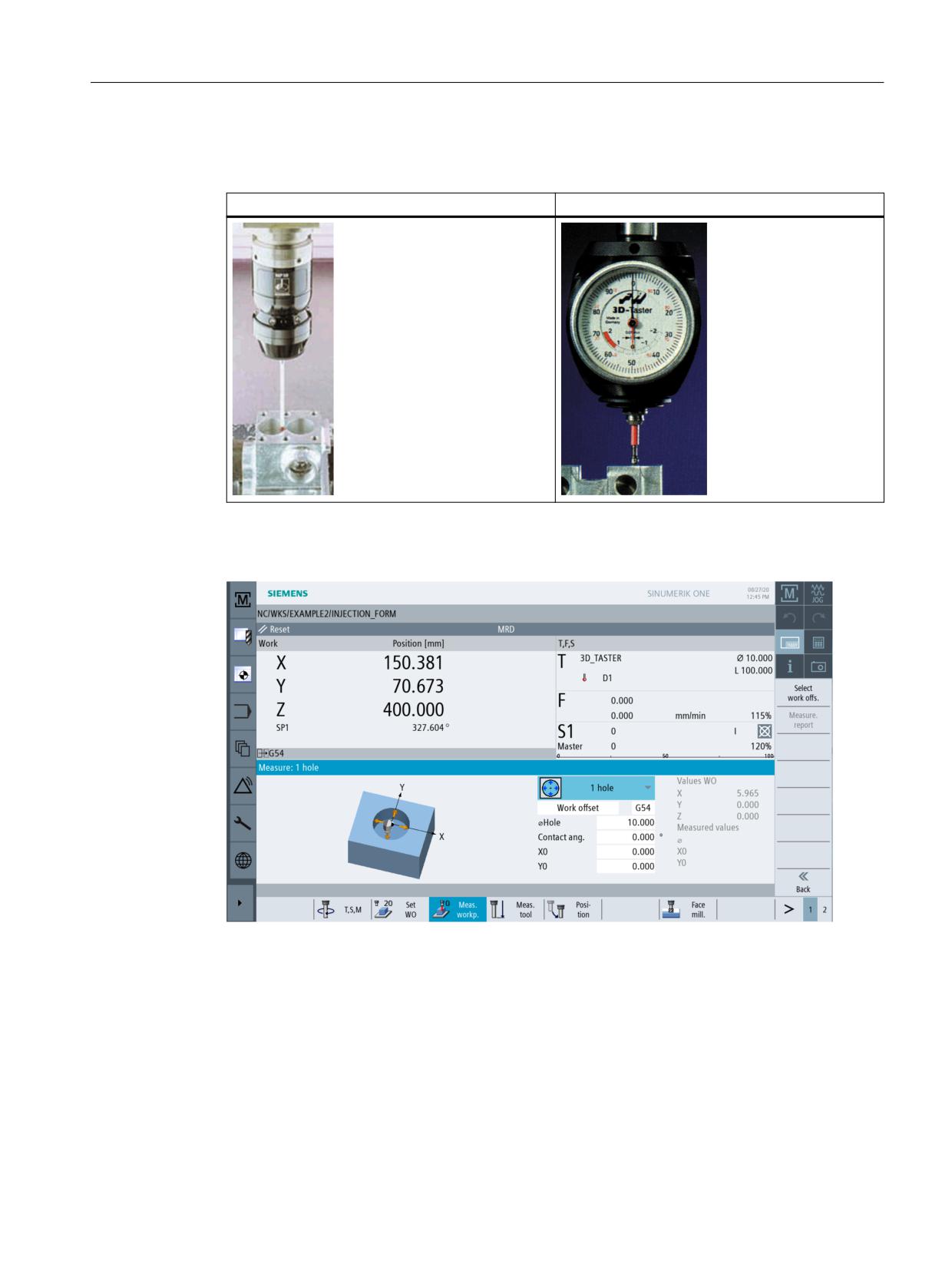
3D probes are offered in both the electronic and mechanical variants. The signals issued by
electronic probes can be processed by the control system directly.
3D probe, electronic
3D probe, mechanical
Example 2: Calculating a drill hole
Easy milling with ShopMill
Training Documents, 05/2020, 6FC5095-0AB50-1BP2
53
Well equipped
5.5 Setting the workpiece zero
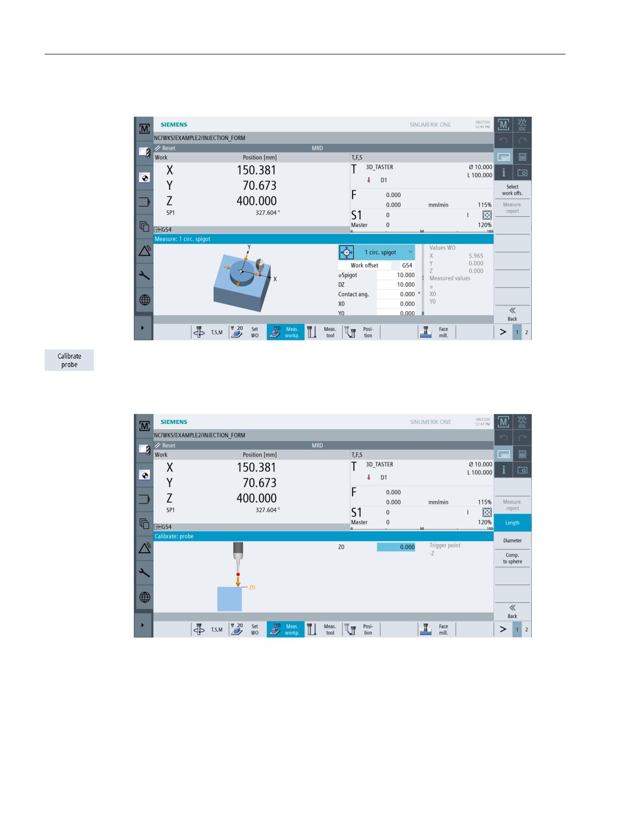
Example 3: Calculating a circular spigot
If an electronic 3D probe from the tool magazine is inserted into the spindle, clamping tolerances
will occur. This would lead to incorrect results in further measurements. This can be avoided by
calibration of the 3D probe at any reference surface or in any reference drill hole using the
Calibrate probe cycle.
Figure 5-5
Calibrating the probe for the length
Easy milling with ShopMill
54
Training Documents, 05/2020, 6FC5095-0AB50-1BP2
Well equipped
5.5 Setting the workpiece zero
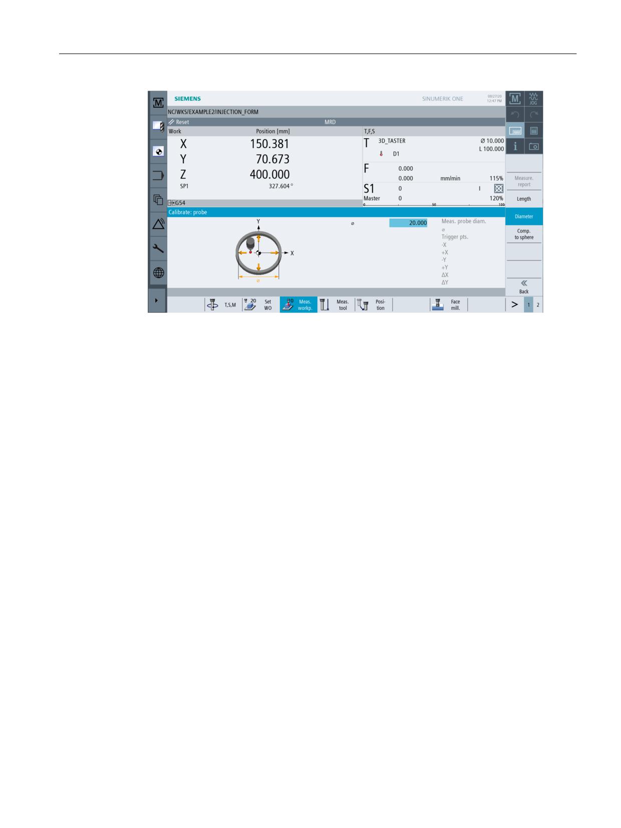
Figure 5-6
Calibrating the probe for the radius
Easy milling with ShopMill
Training Documents, 05/2020, 6FC5095-0AB50-1BP2
55
Well equipped
5.5 Setting the workpiece zero
Easy milling with ShopMill
56
Training Documents, 05/2020, 6FC5095-0AB50-1BP2
Example 1: Longitudinal guide
6
6.1
Overview
Learning objectives
This section will explain the first steps to create a workpiece in detail. You will learn how to...
• create and manage programs;
• call tools and perform a cutter radius compensation;
• enter traversing paths;
• create drill holes and handle position repetitions.
Task
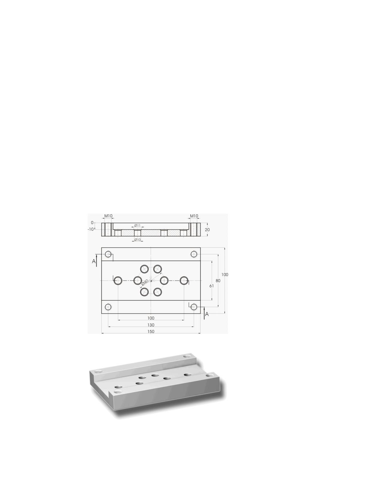
Figure 6-1
Workshop drawing - Example 1:
Figure 6-2
Workpiece - Example 1:
Easy milling with ShopMill
Training Documents, 05/2020, 6FC5095-0AB50-1BP2
57
Example 1: Longitudinal guide
6.1 Overview
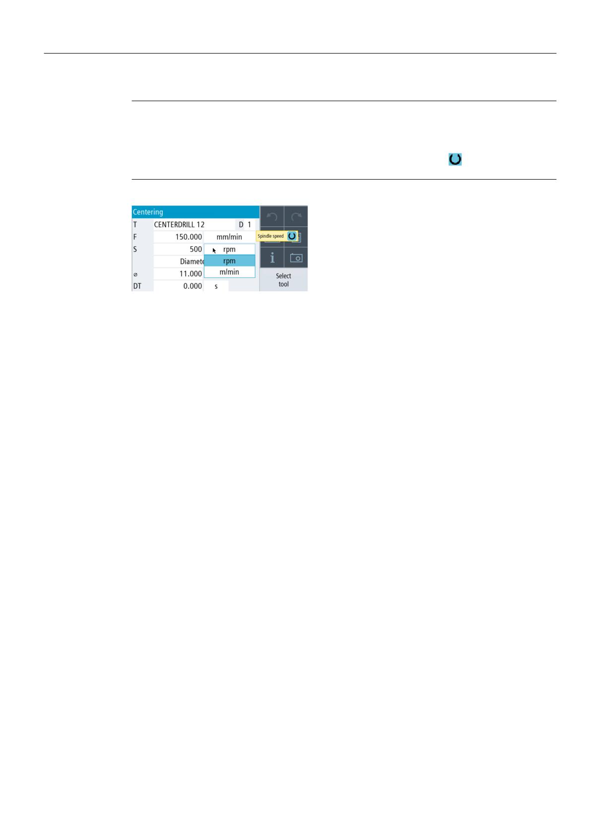
Note
ShopMill always saves the last setting selected with the toggle field. Therefore, make sure that
all units, texts and symbols are specified as in the dialog boxes shown here in all toggle fields.
Whenever it is possible to switch, this is indicated in the help text by the
icon (see screenshot
below).
Figure 6-3
Toggle field with help text
Easy milling with ShopMill
58
Training Documents, 05/2020, 6FC5095-0AB50-1BP2
Example 1: Longitudinal guide
6.2 Program management / creating programs
6.2
Program management / creating programs
Operating sequences
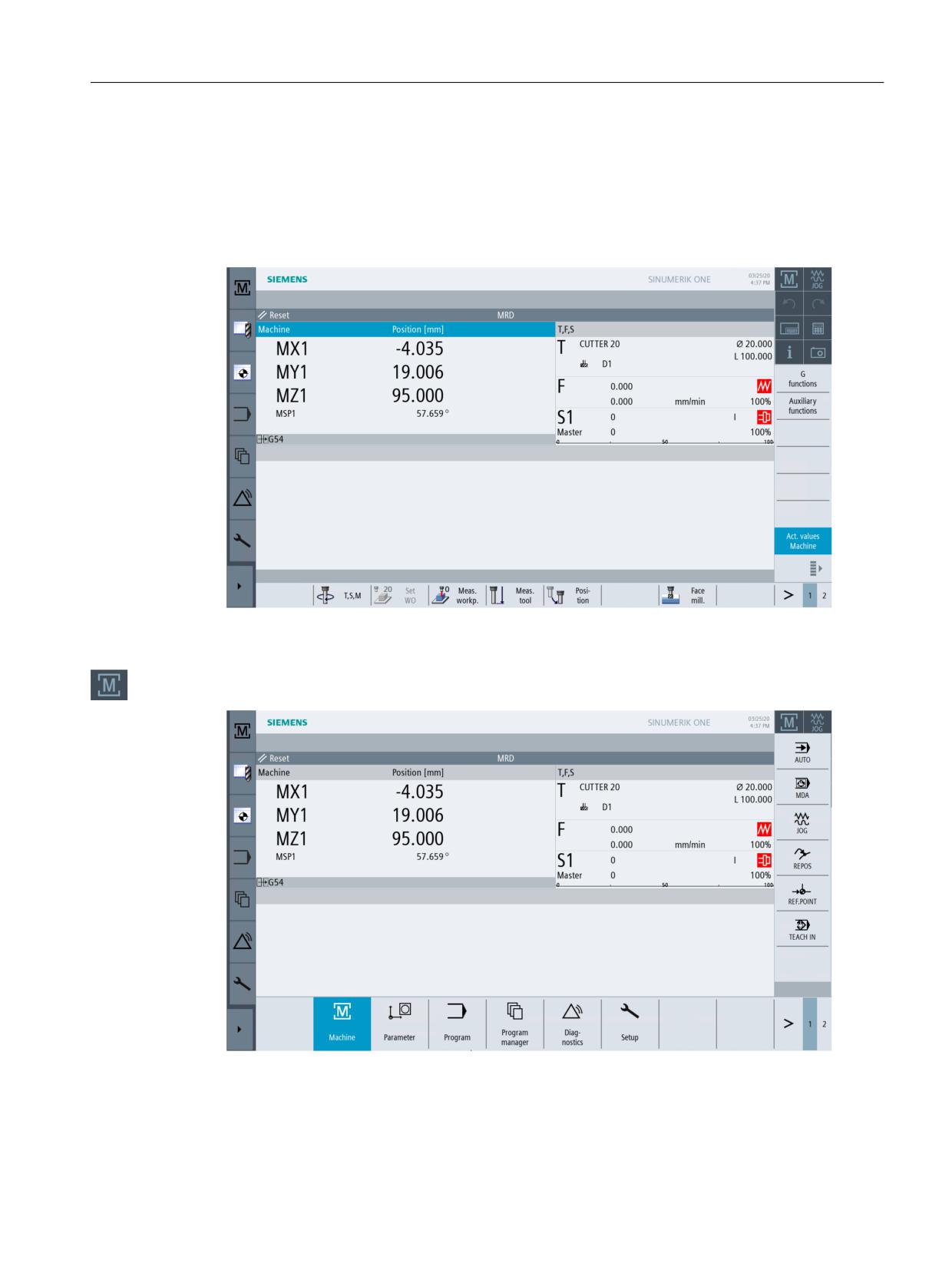
After power-up of the control system, you are in the main menu.
Figure 6-4
Main screen
Open the basic menu. In the main menu, you may call various areas of ShopMill.
Figure 6-5
Main menu
Easy milling with ShopMill
Training Documents, 05/2020, 6FC5095-0AB50-1BP2
59
Example 1: Longitudinal guide
6.2 Program management / creating programs
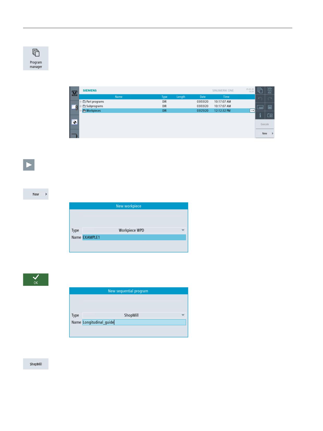
Select the Program Manager softkey. The Program Manager is opened.
In the Program Manager, you can manage process plans and contours (e.g. "New", "Open",
"Copy", ...).
Use the cursor key or right-click to select the 'Workpieces' directory.
Figure 6-6
Program Manager
Open the "Workpieces" directory.
Enter the name 'EXAMPLE1' for the workpiece.
Figure 6-7
Creating a workpiece
Confirm your input. The following dialog box is opened:
Figure 6-8
Creating a step sequence program
Select the input format using the ShopMill and ProgramGUIDE G code softkeys.
Via the ShopMill softkey, you specify the program type.
Specify the name of the process plan, in this case 'Longitudinal_guide'.
Easy milling with ShopMill
60
Training Documents, 05/2020, 6FC5095-0AB50-1BP2
Example 1: Longitudinal guide
6.2 Program management / creating programs
Press "Accept" to apply your input.
After confirming, the following interactive screenform is displayed to enter the workpiece data.
Figure 6-9
Program header - Help display
Enter the workpiece data and general program specifications in the program header.
Enter the following values:
Field
Value
Toggle field
Notes
Unit of measurement
mm
X
Work offset
G54
X
Blank
Cuboid
X
X0
-75
Since the workpiece zero
lies centrally on the work-
Y0
-50
piece surface, the coordi-
nates of the left workpiece
corner have negative val-
ues.
X1
150 inc
X (for selection of inc/abs)
Y1
100 inc
X (for selection of inc/abs)
ZA
0
ZI
-20 abs
X (for selection of inc/abs)
PL
G17 (XY)
X
Retraction plane
100
Safety clearance
1
Machining direction
Synchronous
X
Retraction position pattern
Optimized
X
See below Retraction posi-
tion pattern
Easy milling with ShopMill
Training Documents, 05/2020, 6FC5095-0AB50-1BP2
61
Example 1: Longitudinal guide
6.2 Program management / creating programs
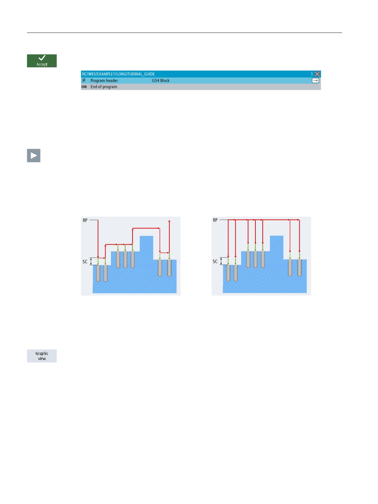
Press "Accept" to apply the values entered. After confirming, the program header is displayed.
Figure 6-10
Program header, example 1 - Work step editor
Now the program has been created as the basis for further machining steps. It has a name, a
program header (pictogram "P") and a program end (pictogram "END"). The individual
machining steps and contours are stored in the program one beneath the other. The later
machining is performed from top to bottom.
You may call the program header again at any time to make changes or check the values.
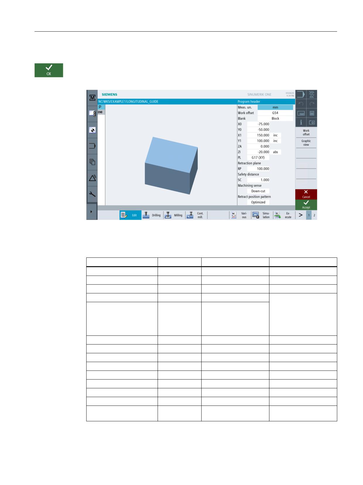
Retraction position pattern
The position pattern can be set to "Optimized" (= time-optimized traversing distances) or
"Retraction plane".
Optimized retraction
To retraction plane (standard)
The tool traverses over the workpiece at the
The tool traverses back to the retraction plane
safety clearance in accordance with the speci-
and performs infeed to the new position.
fied contour.
Softkeys
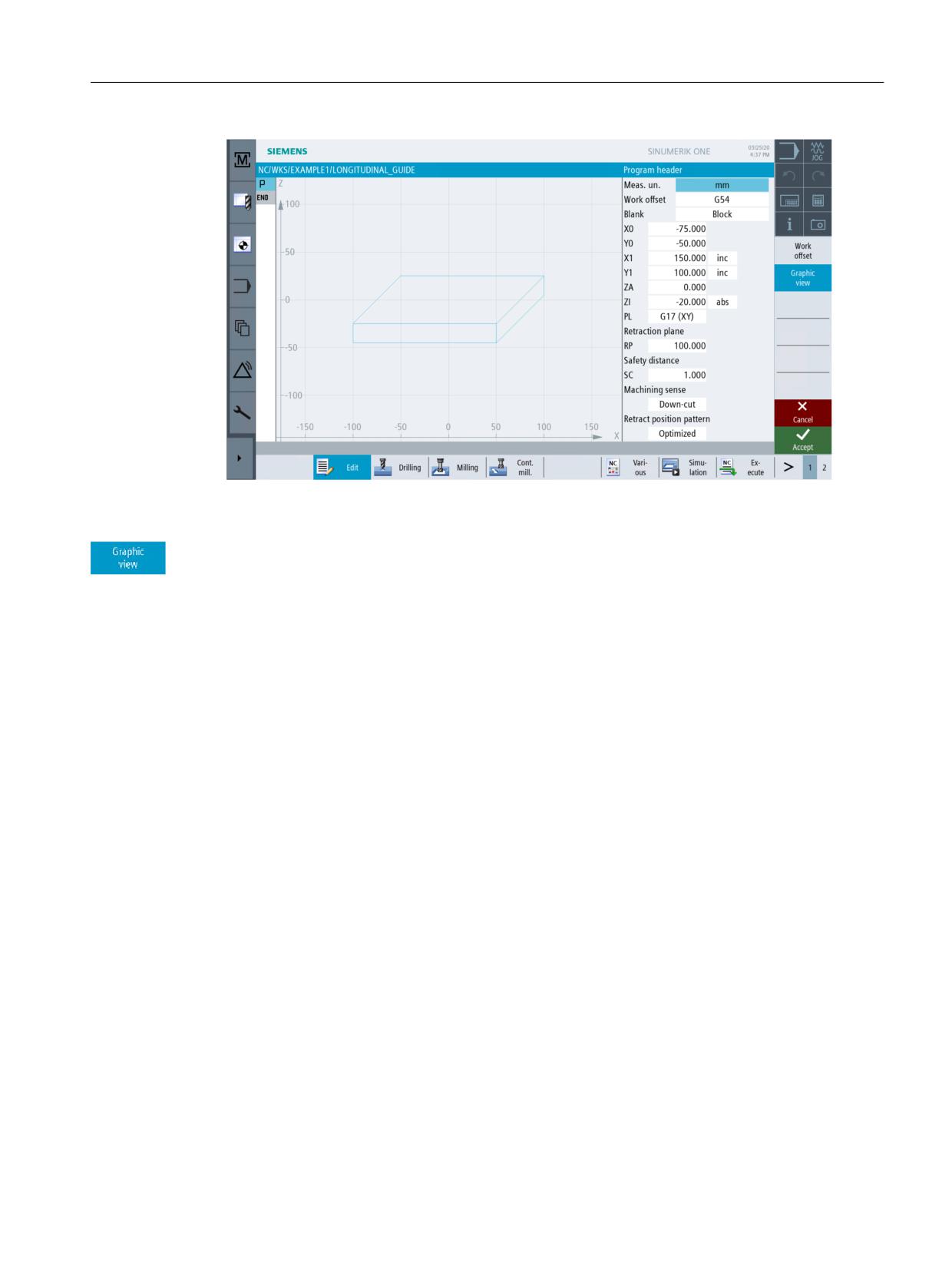
Use this softkey to switch to the online graphic of the workpiece (see screenform below).
Easy milling with ShopMill
62
Training Documents, 05/2020, 6FC5095-0AB50-1BP2
Example 1: Longitudinal guide
6.2 Program management / creating programs
Figure 6-11
Program header - graphical view
Use this softkey to switch back to the help display.
Easy milling with ShopMill
Training Documents, 05/2020, 6FC5095-0AB50-1BP2
63
Example 1: Longitudinal guide
6.3 Calling a tool and specifying cutter radius compensation
6.3
Calling a tool and specifying cutter radius compensation
Operating sequences
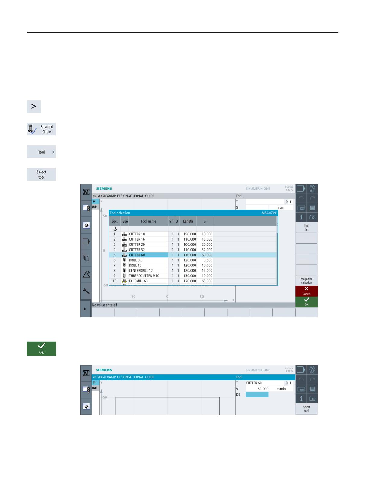
To call the required tool, proceed as follows:
Use this key to extend the horizontal softkey menu.
Select the Straight line Circle softkey.
Select the Tool softkey.
Open the tool list. Select the CUTTER 60 tool.
Figure 6-12
Tool list
Accept the tool into your program. After accepting the tool, specify the cutting rate 80 m/min (if
necessary, change the unit using the toggle field).
Figure 6-13
Tool cutting rate
Easy milling with ShopMill
64
Training Documents, 05/2020, 6FC5095-0AB50-1BP2
Example 1: Longitudinal guide
6.3 Calling a tool and specifying cutter radius compensation
Press "Accept" to apply the value entered.
Easy milling with ShopMill
Training Documents, 05/2020, 6FC5095-0AB50-1BP2
65
Example 1: Longitudinal guide
6.4 Specifying the distance to be traversed
6.4
Specifying the distance to be traversed
Operating sequences
Now enter the distances to be traversed:
Select the "Straight line" softkey.
Select the "Rapid traverse" softkey.
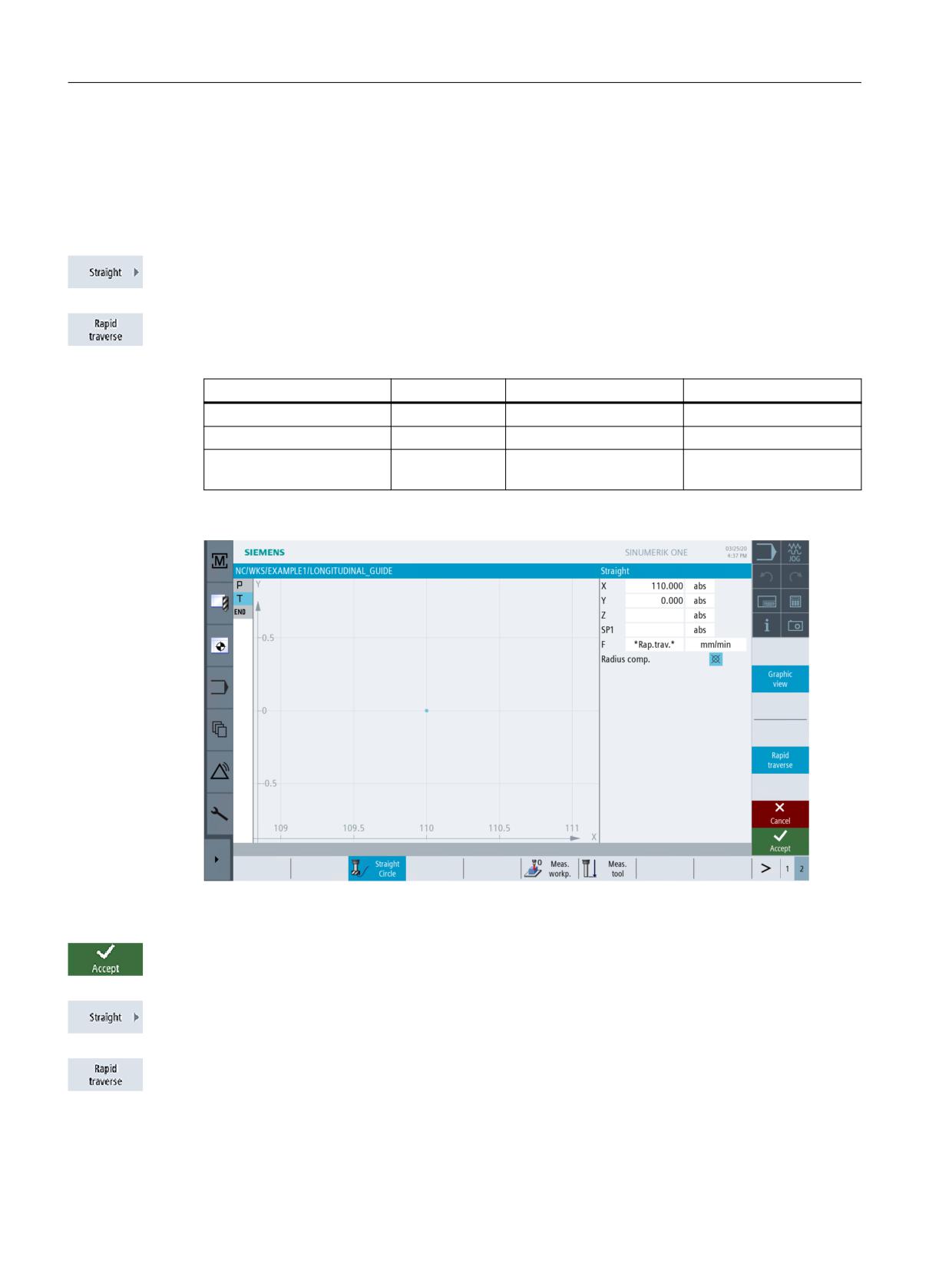
Enter the following values in the interactive screenform:
Field
Value
Toggle field
Notes
X
110 abs
X
Y
0 abs
X
Radius compensation
off
X
See below Radius compen-
sation
Figure 6-14
Specifying the distance to be traversed - Radius compensation
Press "Accept" to apply the values entered.
Select the "Straight line" softkey.
Select the "Rapid traverse" softkey.
Easy milling with ShopMill
66
Training Documents, 05/2020, 6FC5095-0AB50-1BP2
Example 1: Longitudinal guide
6.4 Specifying the distance to be traversed
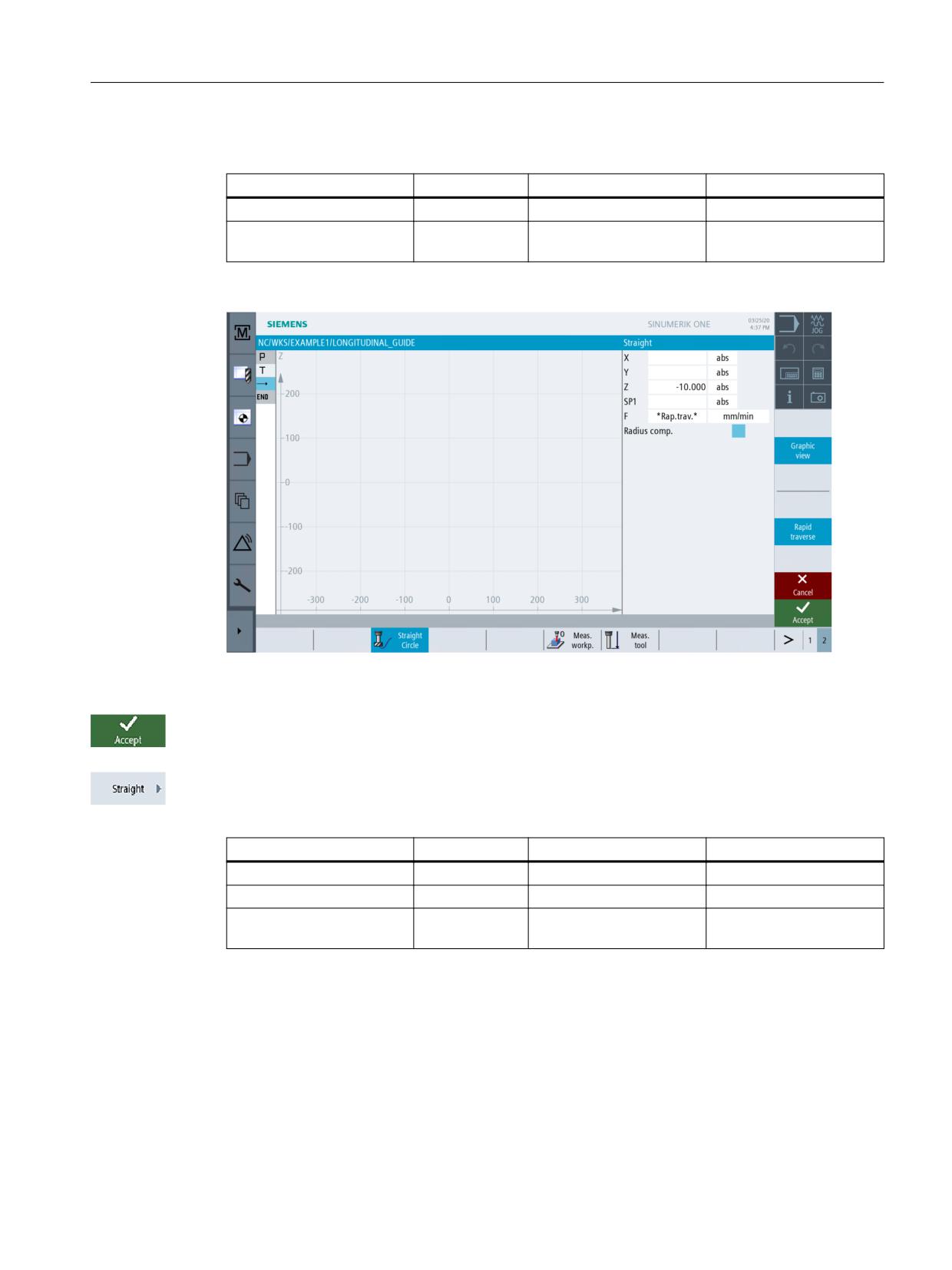
Enter the following values in the interactive screenform:
Field
Value
Toggle field
Notes
Z
-10 abs
X
Radius compensation
Empty field
X
See below Radius compen-
sation
Figure 6-15
Specifying the distance to be traversed - Tool positioned in Z
Press "Accept" to apply the values entered.
Select the "Straight line" softkey.
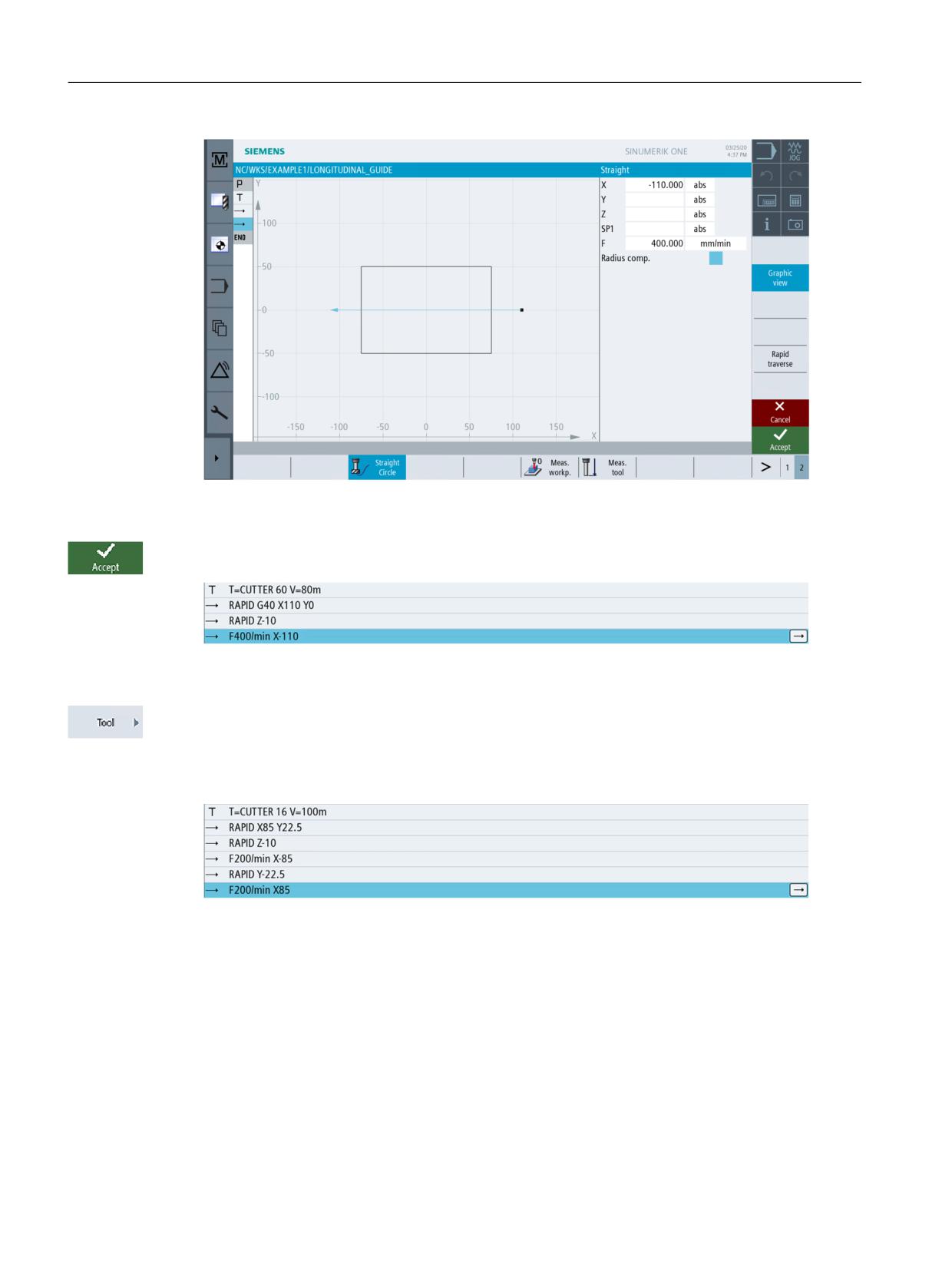
Enter the following values in the interactive screenform:
Field
Value
Toggle field
Notes
X
- 110 abs
X
F
400 mm/min
X
Radius compensation
Empty field
X
See below Radius compen-
sation
Easy milling with ShopMill
Training Documents, 05/2020, 6FC5095-0AB50-1BP2
67
Example 1: Longitudinal guide
6.4 Specifying the distance to be traversed
Figure 6-16
Specifying the distance to be traversed - First machining path
Press "Accept" to apply the values entered. After acceptance, the list of work steps looks like this:
Figure 6-17
Specifying the distance to be traversed - List of work steps
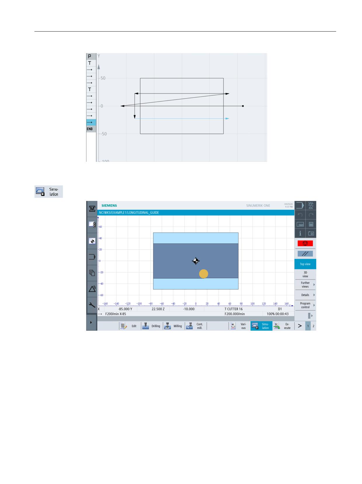
Select the "Tools" softkey and perform the following work steps without help.
Load the next tool CUTTER 16. After accepting the tool, specify the cutting rate 100 m/min.
Create the distance to be traversed according to the following list of work steps.
Figure 6-18
Specifying the distance to be traversed - Work step list
Easy milling with ShopMill
68
Training Documents, 05/2020, 6FC5095-0AB50-1BP2
Example 1: Longitudinal guide
6.4 Specifying the distance to be traversed
Figure 6-19
Specifying the distance to be traversed - Complete
Start simulation.
Figure 6-20
Simulation of the distance to be traversed
You may end simulation by selecting either the Simulation softkey again or any other softkey.
Easy milling with ShopMill
Training Documents, 05/2020, 6FC5095-0AB50-1BP2
69
Example 1: Longitudinal guide
6.4 Specifying the distance to be traversed
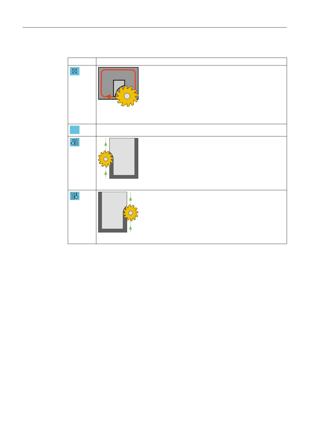
Radius compensation
Selection
Result
Radius compensation is disabled. The milling cutter traverses with its center point along the
created contour.
The existing settings for the radius compensation is maintained.
The compensation is performed to the left of the contour in the milling direction.
The compensation is performed to the right of the contour in the milling direction.
Easy milling with ShopMill
70
Training Documents, 05/2020, 6FC5095-0AB50-1BP2
Example 1: Longitudinal guide
6.5 Creating drill holes and position repetitions
6.5
Creating drill holes and position repetitions
Operating sequences
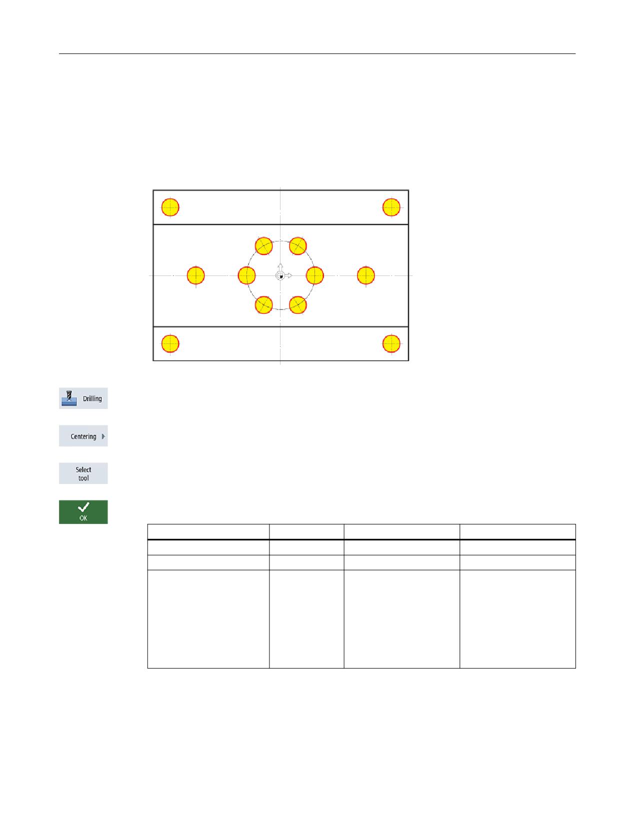
Now enter the values for the drill holes and position repetitions. You will have to center, through-
drill and make threads for 12 drill holes.
Figure 6-21
Drilling positions
Select the Drilling softkey.
Select the Center softkey.
Open the tool list. Use the cursor key to select the CENTERDRILL 12 tool.
Accept the tool into your program. After accepting the tool, enter the following values:
Field
Value
Toggle field
Notes
F
150 mm/min
X
S
500 rpm
X
Diameter/tip
Diameter
X
Centering can be entered
with reference either to
the diameter or to the
depth (tip).
Since the drill holes pos-
sess a 0.5 mm chamfer,
you may specify a diame-
ter of 11 mm.
Easy milling with ShopMill
Training Documents, 05/2020, 6FC5095-0AB50-1BP2
71
Example 1: Longitudinal guide
6.5 Creating drill holes and position repetitions
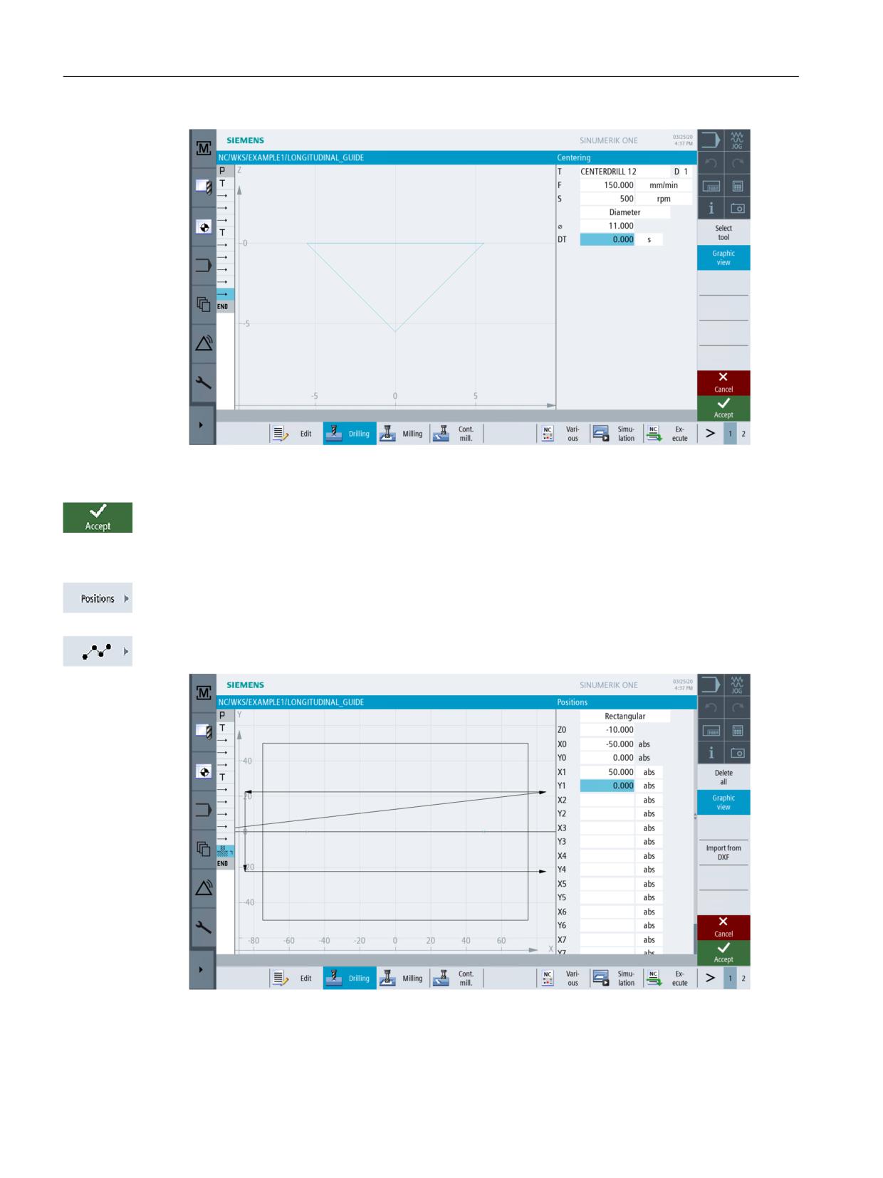
Figure 6-22
Centering
Press "Accept" to apply the values entered.
Proceed as follows to specify and link the drilling positions with the cutting data:
Select the Positions softkey.
Select the Positions softkey for the position pattern.
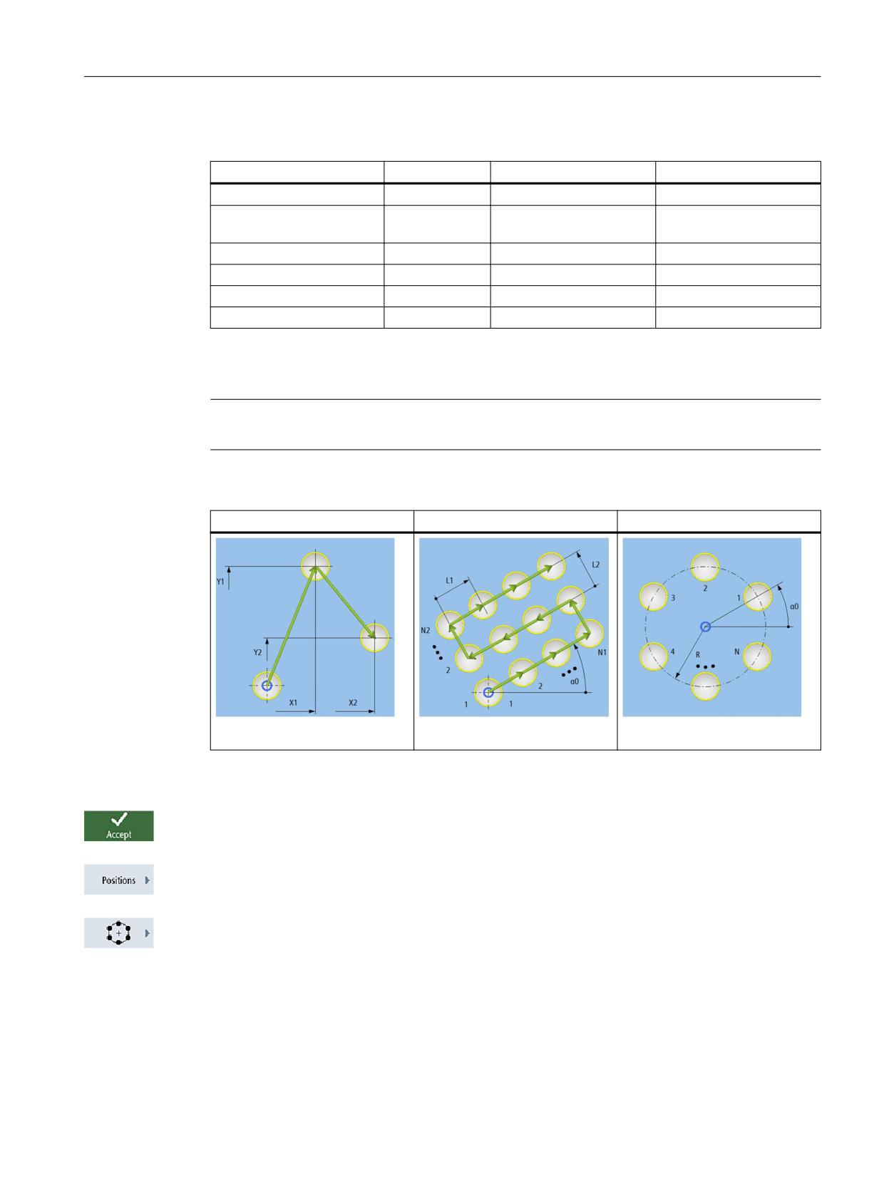
Figure 6-23
Positions - Individual drill holes
Easy milling with ShopMill
72
Training Documents, 05/2020, 6FC5095-0AB50-1BP2
Example 1: Longitudinal guide
6.5 Creating drill holes and position repetitions
Enter the following values for the two individual drill holes:
Field
Value
Toggle field
Notes
Coordinate system
Rectangular
X
Z0
-10
The starting depth is
-10mm.
X0
-50
Y0
0
X1
50 abs
X
Y1
0 abs
X
Note
If you deselect the Graphic view softkey, detailed help displays are displayed (see table below).
Positions
Position grid
Position circle
Help displays - Positions
Press "Accept" to apply the values entered.
Select the Positions softkey.
Select the Position circle softkey.
Easy milling with ShopMill
Training Documents, 05/2020, 6FC5095-0AB50-1BP2
73
Example 1: Longitudinal guide
6.5 Creating drill holes and position repetitions
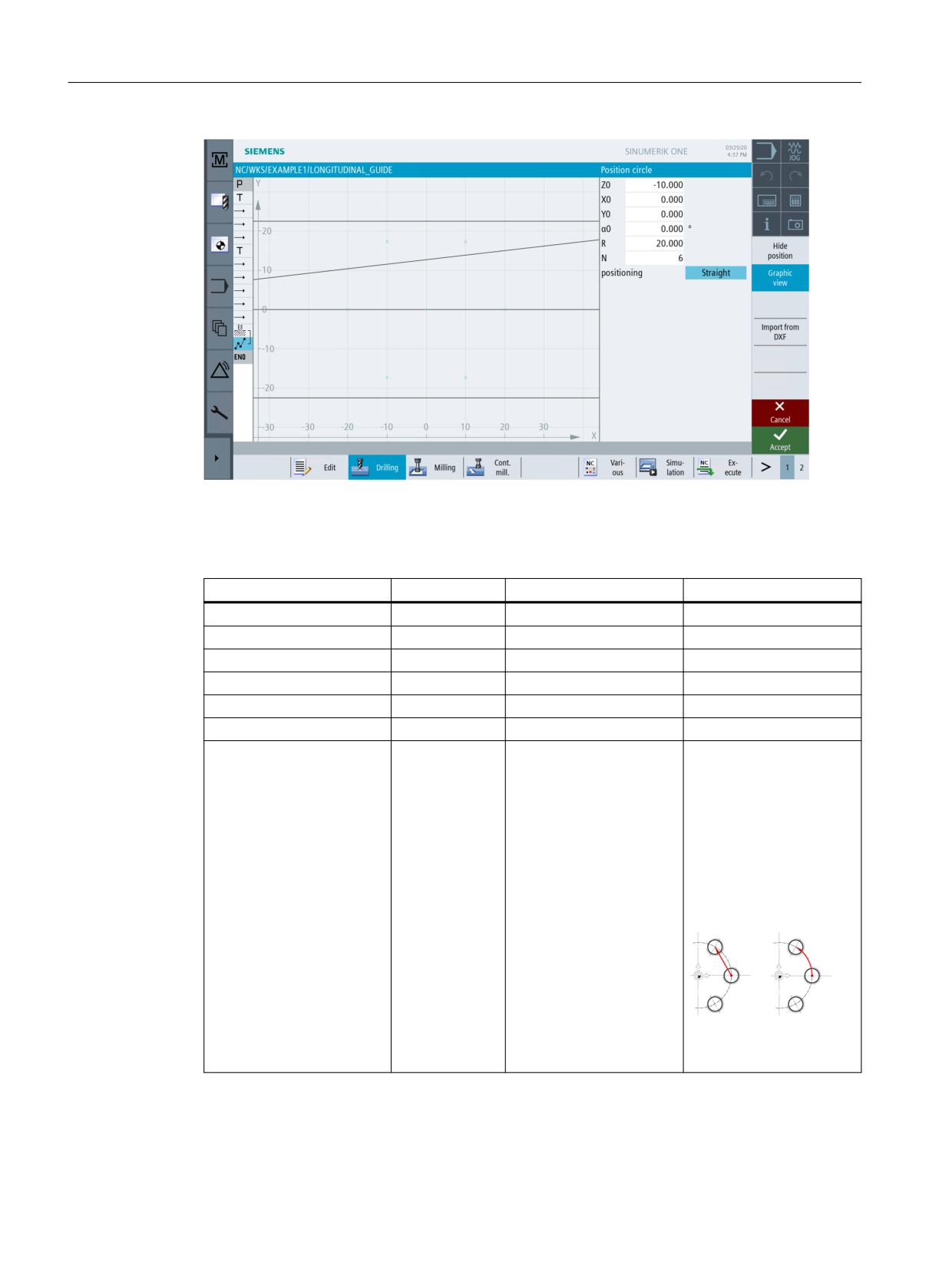
Figure 6-24
Position circle
Enter the following values:
Field
Value
Toggle field
Notes
Z0
-10
X0
0
Y0
0
α1
0
R
20
N
6
Positioning
Straight line
X
Use the "Positioning" field
to define how to approach
the drill holes within the
drill pattern. If the drill
holes lie in a circumferen-
tial groove, for example,
do not use "Positioning -
Straight line"; otherwise, a
contour violation would
result.
Along a straight line,
along a circle
Easy milling with ShopMill
74
Training Documents, 05/2020, 6FC5095-0AB50-1BP2
Example 1: Longitudinal guide
6.5 Creating drill holes and position repetitions
Press "Accept" to apply the values entered.
Select the Positions softkey.
Select the position grid softkey.
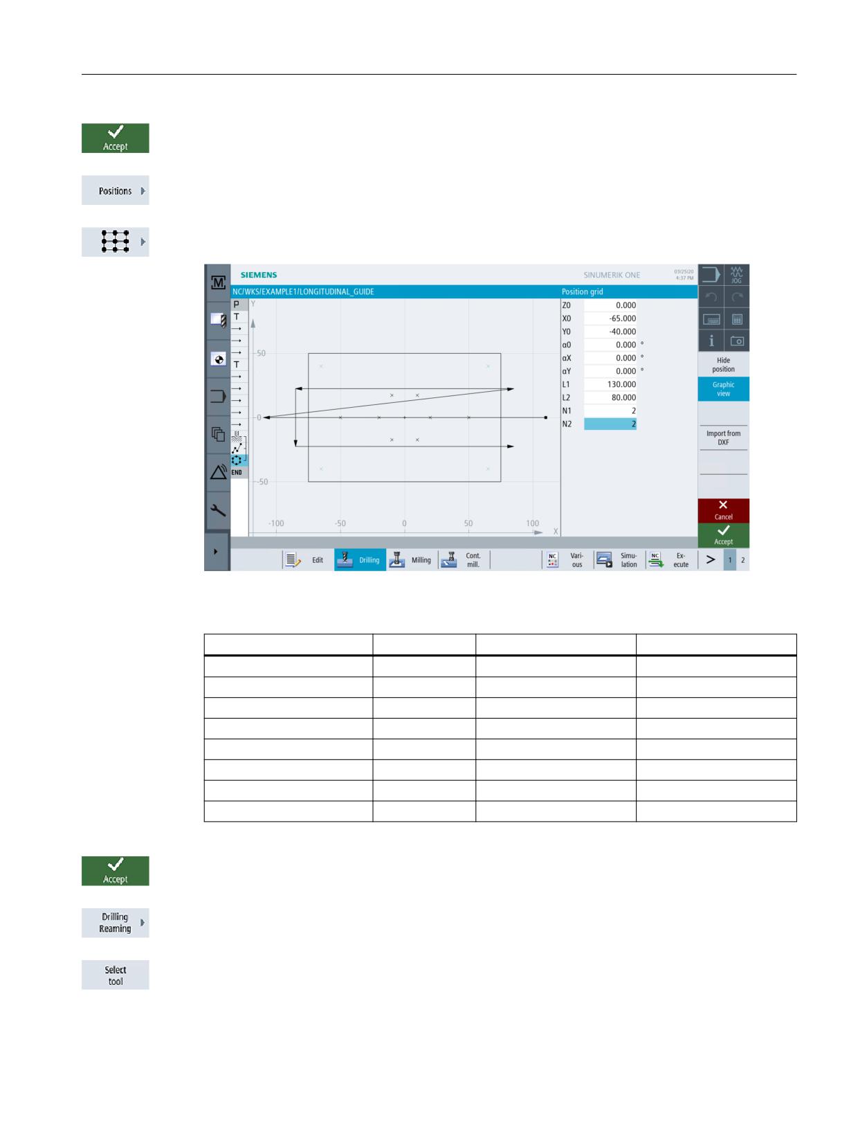
Figure 6-25
Position grid
Enter the following values:
Field
Value
Toggle field
Notes
Z0
0
X0
-65
Y0
-40
α0
0
L1
130
L2
80
N1
2
N2
2
Press "Accept" to apply the values entered.
Select the Drilling Reaming softkey.
Open the tool list. Use the cursor key to select the DRILL 8.5 tool.
Easy milling with ShopMill
Training Documents, 05/2020, 6FC5095-0AB50-1BP2
75
Example 1: Longitudinal guide
6.5 Creating drill holes and position repetitions
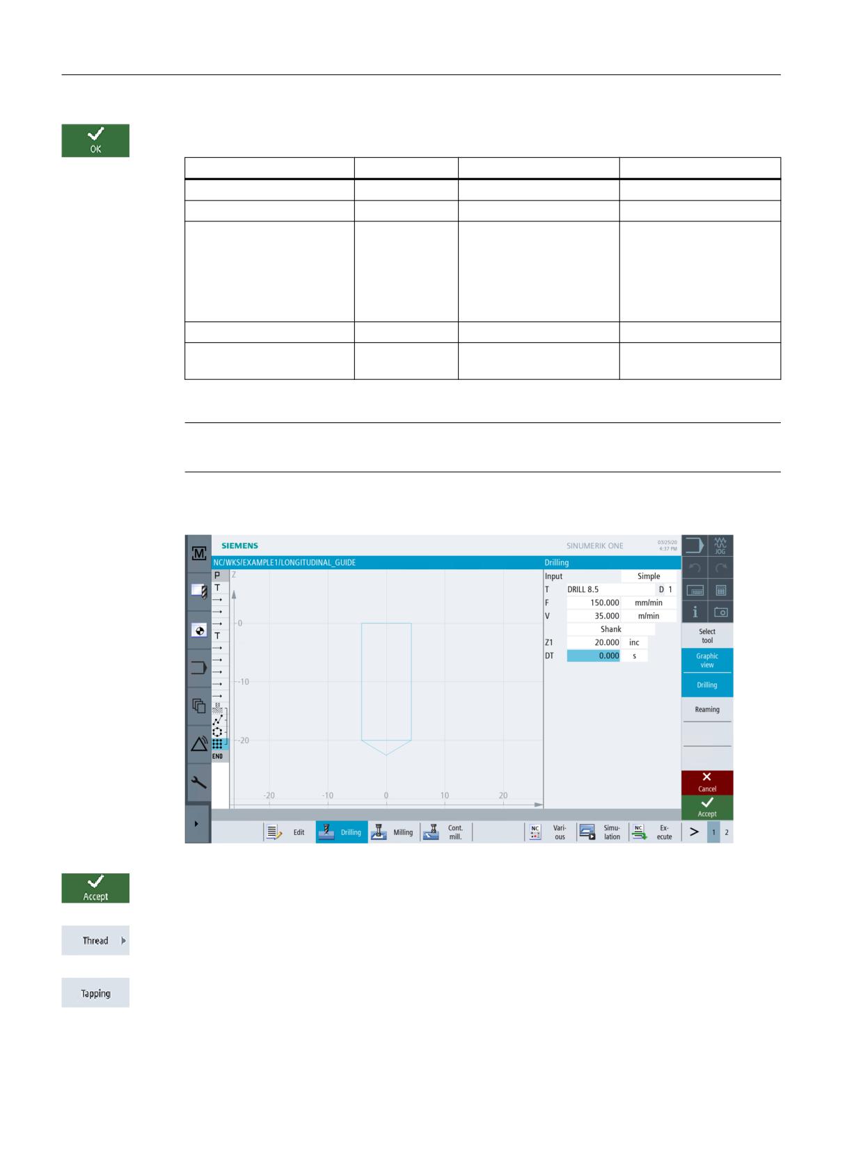
Accept the tool into your program. After accepting the tool, enter the following values:
Field
Value
Toggle field
Notes
F
150 mm/min
X
V
35 m/min
X
Shank/tip
Shank
X
Specify the depth with ref-
erence to the shank incre-
mentally. In other words:
The 1/3 D drill tip is taken
into account automatical-
ly.
Z1
20 inc
X
DT
0 s
X
Drilling is performed with-
out a dwell time.
Note
The work steps 'Centering', 'Drilling' and 'Tapping' are linked with each other automatically.
Figure 6-26
Drilling
Press "Accept" to apply the values entered.
Select the Thread softkey.
Select the Tapping softkey.
Easy milling with ShopMill
76
Training Documents, 05/2020, 6FC5095-0AB50-1BP2
Example 1: Longitudinal guide
6.5 Creating drill holes and position repetitions
Open the tool list. Use the cursor key to select the THREADCUTTER M10 tool.
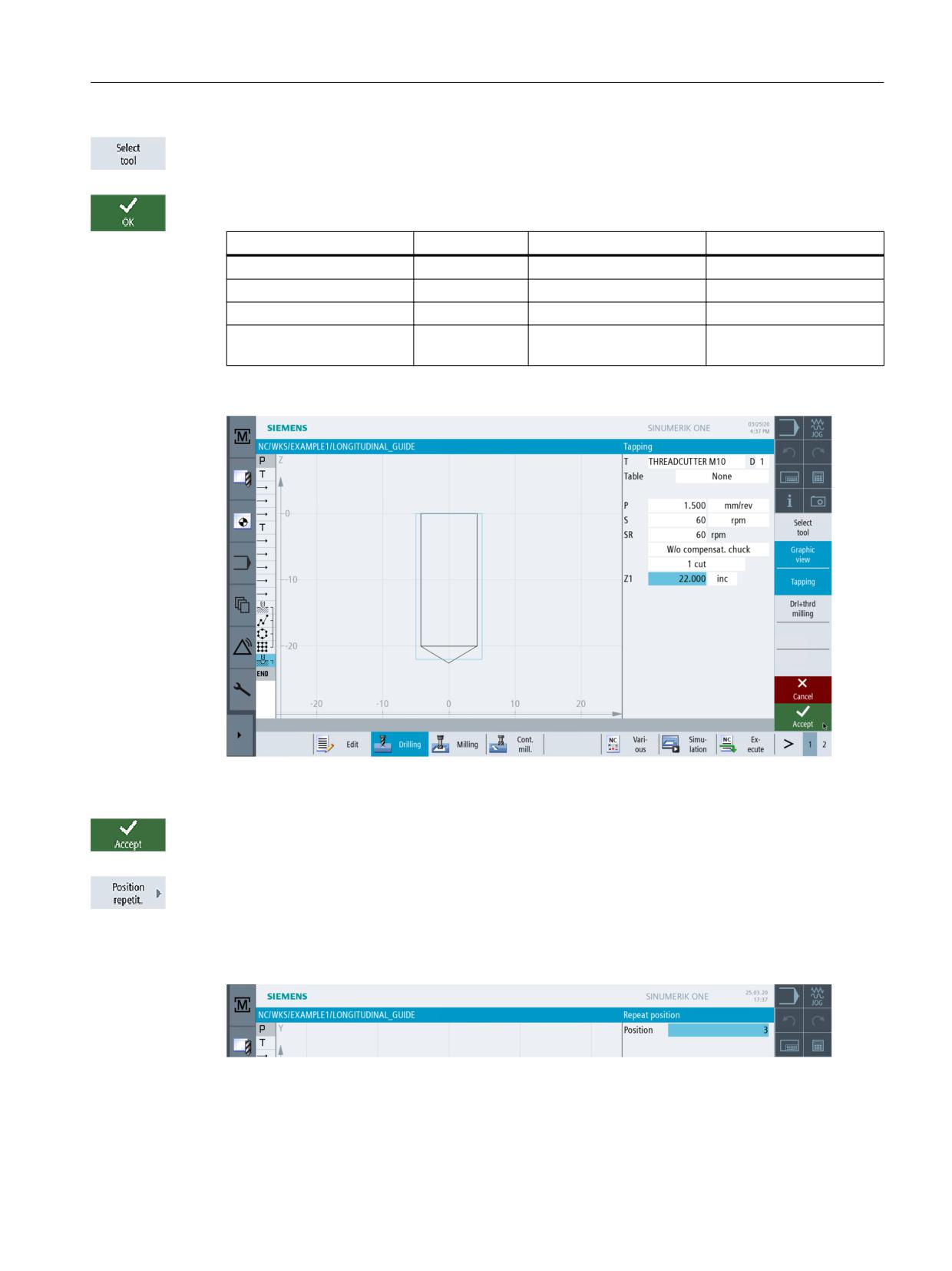
Accept the tool into your program. After accepting the tool, enter the following values:
Field
Value
Toggle field
Notes
P
1.5 mm/rev
X
S
60 rpm
X
SR
60 rpm
X
Z1
22 inc
X
The cutting depth must be
entered incrementally.
Figure 6-27
Thread
Press "Accept" to apply the values entered.
Select the Repeat position softkey.
The drilling positions are numbered consecutively during creation. The appropriate number is to
be found directly after the block number of the corresponding position pattern. Specify "Hole
matrix" for position 3.
Figure 6-28
Repeating a position
Easy milling with ShopMill
Training Documents, 05/2020, 6FC5095-0AB50-1BP2
77