SINUMERIK 840D sl. Training. Operate - Turning (2016-2020) - page 6
Example 4: Lever
9.4 Machining the lever
Open the tool list and select CUTTER 20.
Accept the tool into your program.
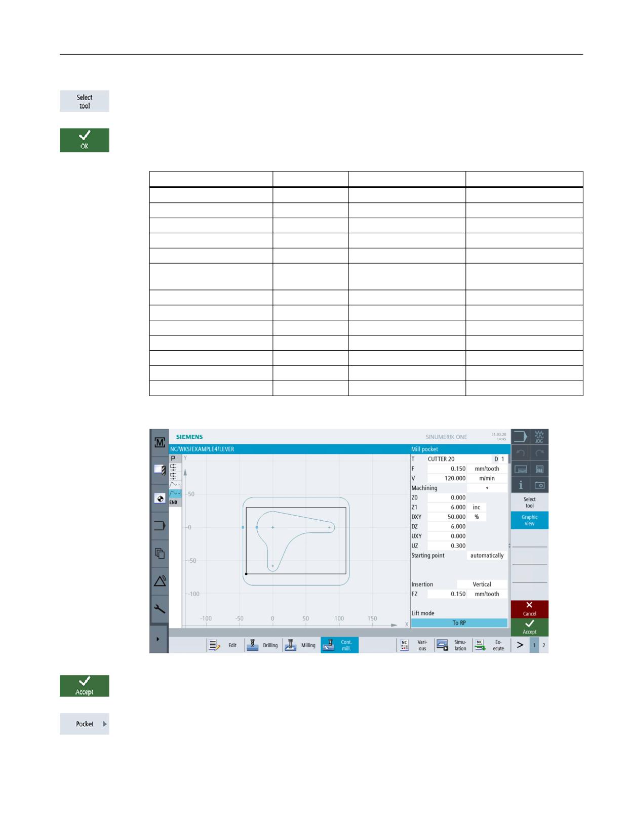
Enter the following values for roughing in the interactive screenform:
Field
Value
Toggle field
Notes
F
0.15 mm/tooth
X
V
120 m/min
X
Machining
Roughing
X
Z0
0
Z1
6 inc
X
DXY
50%
X
Specify the maximum in-
feed in the plane in %.
DZ
6
UXY
0
UZ
0.3
Starting point
Automatic
X
Insertion
Vertical
X
FZ
0.15 mm/tooth
X
Lift mode
To RP
X
Figure 9-22
Roughing the contour
Press "Accept" to apply the values entered.
Select the Pocket softkey.
Easy milling with ShopMill
Training Documents, 05/2020, 6FC5095-0AB50-1BP2
147
Example 4: Lever
9.4 Machining the lever
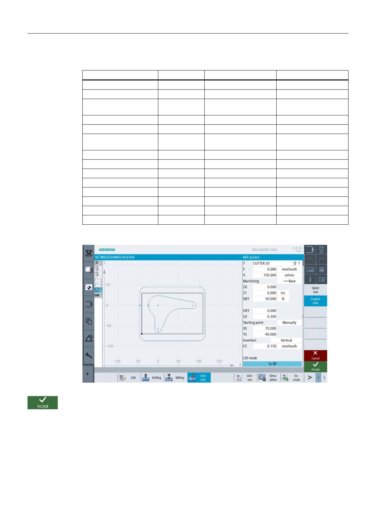
Enter the following values for finishing in the interactive screenform:
Field
Value
Toggle field
Notes
F
0.08 mm/tooth
X
V
150 m/min
X
Machining
Finishing the
X
base
Z0
0
Z1
6 inc
X
DXY
50%
X
Specify the maximum in-
feed in the plane in %.
UXY
0
UZ
0.3
Starting point
Manual
X
XS
70
YS
-40
Insertion
Vertical
X
FZ
0.15 mm/tooth
X
Lift mode
To RP
X
Figure 9-23
Finishing the base
Press "Accept" to apply the values entered.
Easy milling with ShopMill
148
Training Documents, 05/2020, 6FC5095-0AB50-1BP2
Example 4: Lever
9.5 Creating an edge for the circular island
9.5
Creating an edge for the circular island
Operating sequences
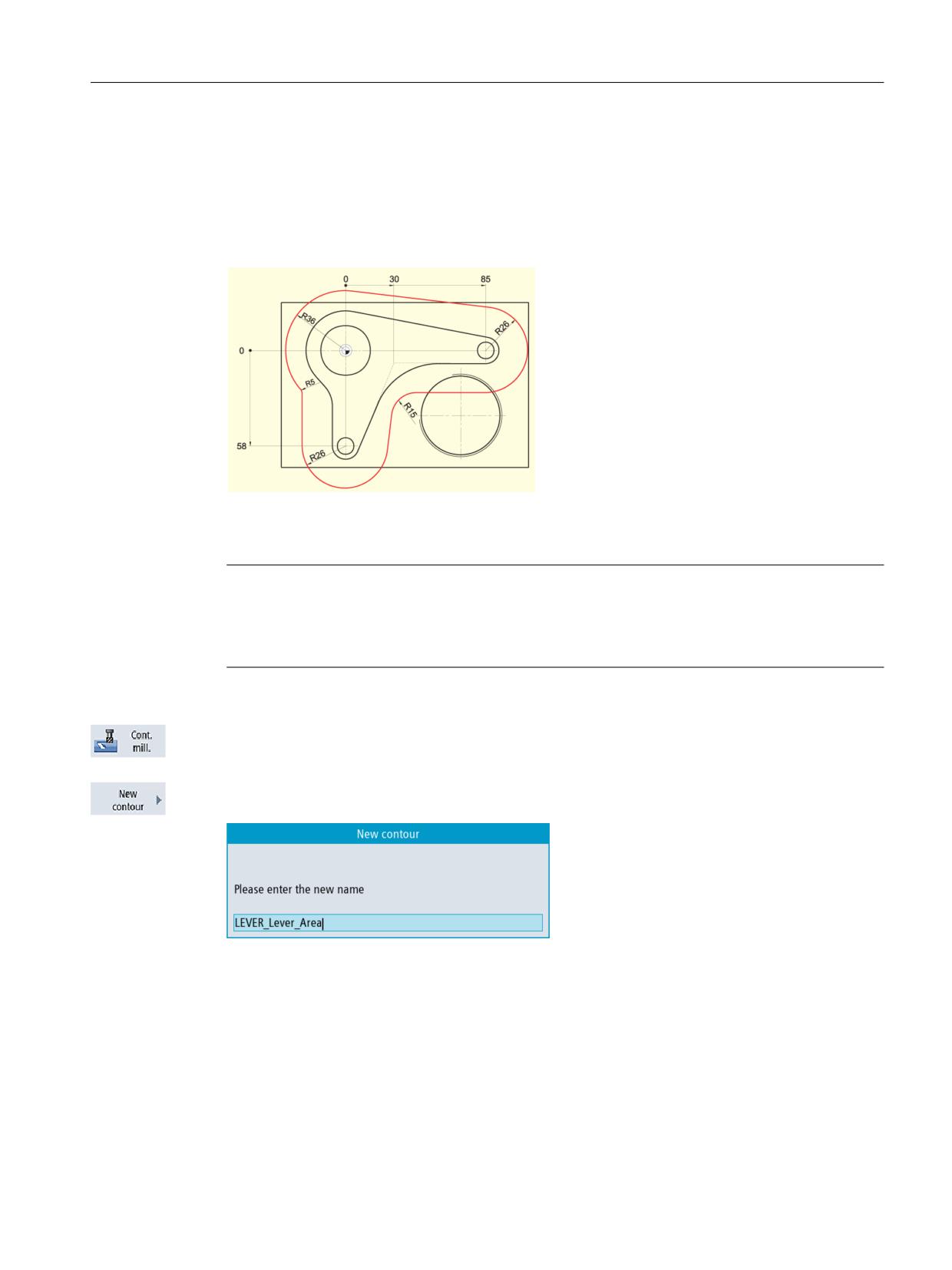
Create an edge for boundary when milling without help. Mill down to a depth of -3.
Figure 9-24
Edge contour for the circular islands
Note
The values R36 and R26 result from the corresponding island radius + cutter diameter (here: 20
mm + 1 mm allowance).
The radii R5 and R15 are selected freely.
Select the Contour milling softkey.
Create a new contour with the name 'LEVER_Lever_Area'.
Figure 9-25
Creating the contour
Design the boundary for the traversing paths around the workpiece contour as described above
such that the 20mm milling cutter fits everywhere between the boundary and the islands. Enter
this boundary contour in the same way as the lever contour.
Easy milling with ShopMill
Training Documents, 05/2020, 6FC5095-0AB50-1BP2
149
Example 4: Lever
9.5 Creating an edge for the circular island
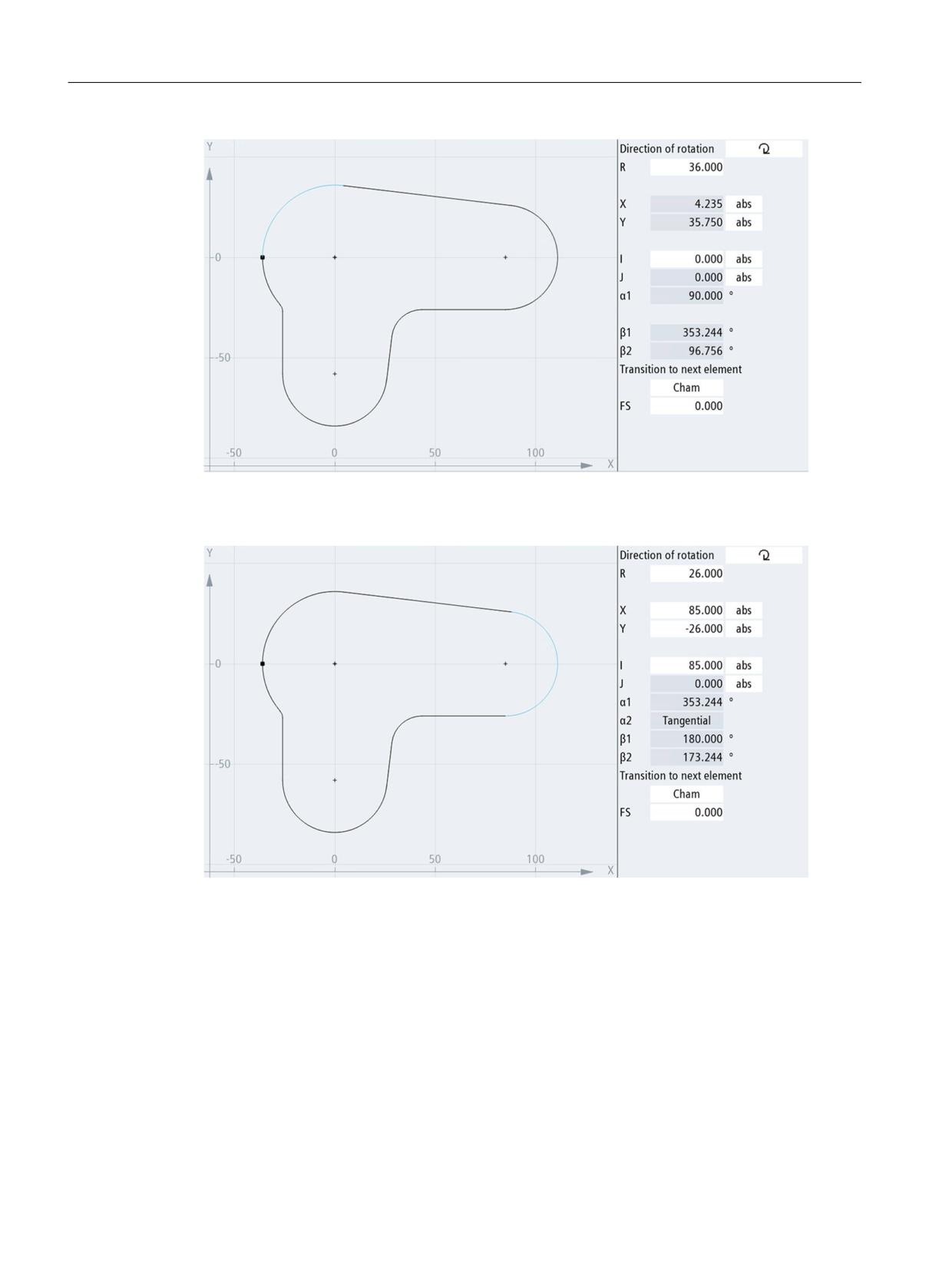
Figure 9-26
Arc contour section, left
Figure 9-27
Arc contour section, right
Easy milling with ShopMill
150
Training Documents, 05/2020, 6FC5095-0AB50-1BP2
Example 4: Lever
9.6 Creating a 30mm circular island
9.6
Creating a 30mm circular island
Operating sequences
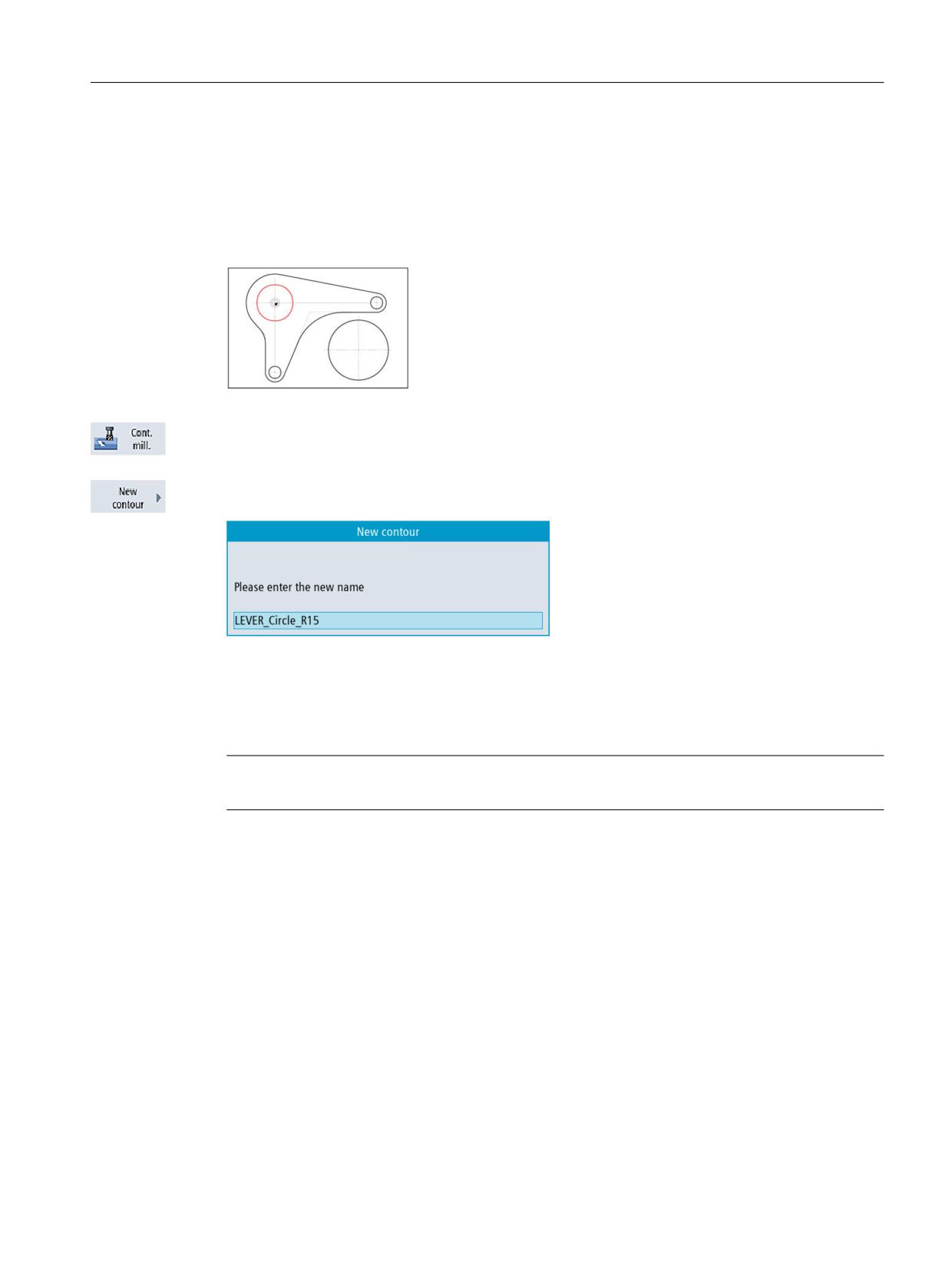
To create the 30mm circular island, I will proceed as follows:
Figure 9-28
30mm circular island
Select the Contour milling softkey.
Create a new contour with the name 'LEVER_Circle_R15'.
Figure 9-29
Creating the contour
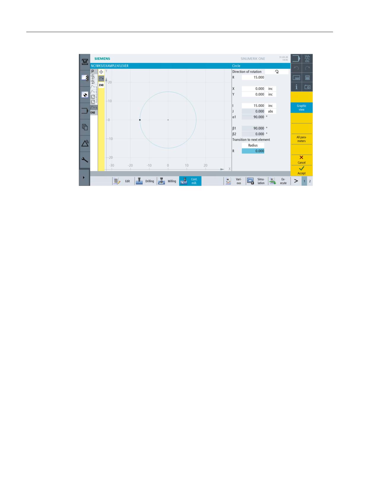
Create a circular contour without help (see illustration below). The starting point of the circular
construction lies at X-15; Y0.
Note
Ensure that various values must be dimensioned incrementally.
Easy milling with ShopMill
Training Documents, 05/2020, 6FC5095-0AB50-1BP2
151
Example 4: Lever
9.6 Creating a 30mm circular island
Figure 9-30
Circular island contour
Easy milling with ShopMill
152
Training Documents, 05/2020, 6FC5095-0AB50-1BP2
Example 4: Lever
9.7 Creating a 10mm circular island
9.7
Creating a 10mm circular island
Operating sequences
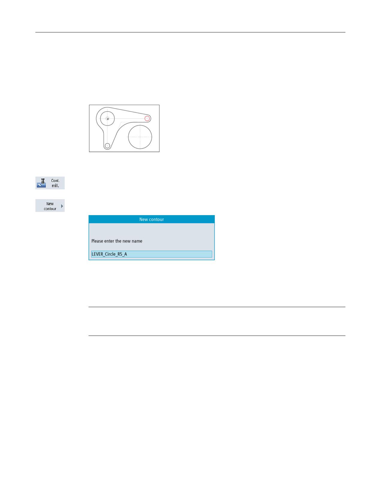
To create the 10mm circular island, proceed as follows:
Figure 9-31
10mm circular island
Select the Contour milling softkey.
Create a new contour with the name 'LEVER_Circle_R5_A'.
Figure 9-32
Creating the contour
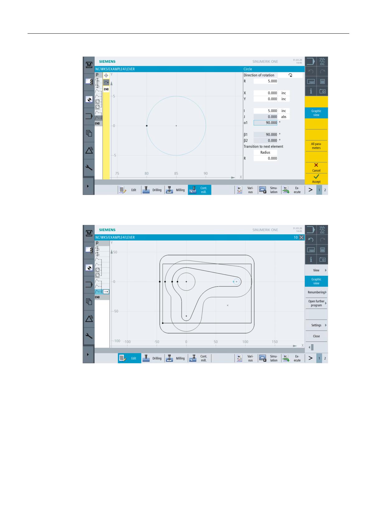
Create a circular contour without help (see illustration below). The starting point of the circular
construction lies at X80; Y0.
Note
Since this circular island will be copied in the next step, you must specify the contour
incrementally so that you only need to change the starting point when copying.
Easy milling with ShopMill
Training Documents, 05/2020, 6FC5095-0AB50-1BP2
153
Example 4: Lever
9.7 Creating a 10mm circular island
Figure 9-33
10mm circular island contour
After entering the circle, the broken-line graphics looks like this.
Figure 9-34
Broken-line graphics
Easy milling with ShopMill
154
Training Documents, 05/2020, 6FC5095-0AB50-1BP2
Example 4: Lever
9.8 Copying the 10mm circular island
9.8
Copying the 10mm circular island
Operating sequences
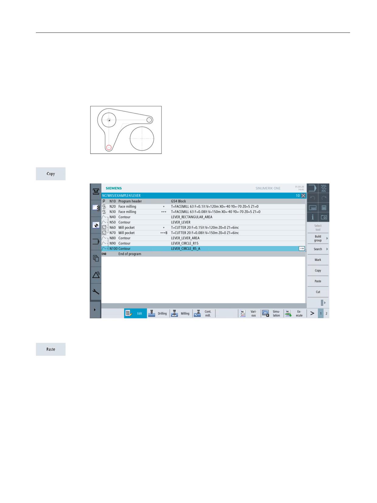
To copy the circular island created in the previous step, proceed as follows:
Figure 9-35
10mm circular island
Navigate and copy the 'LEVER_Circle_R5_A' contour.
Figure 9-36
Copying the contour
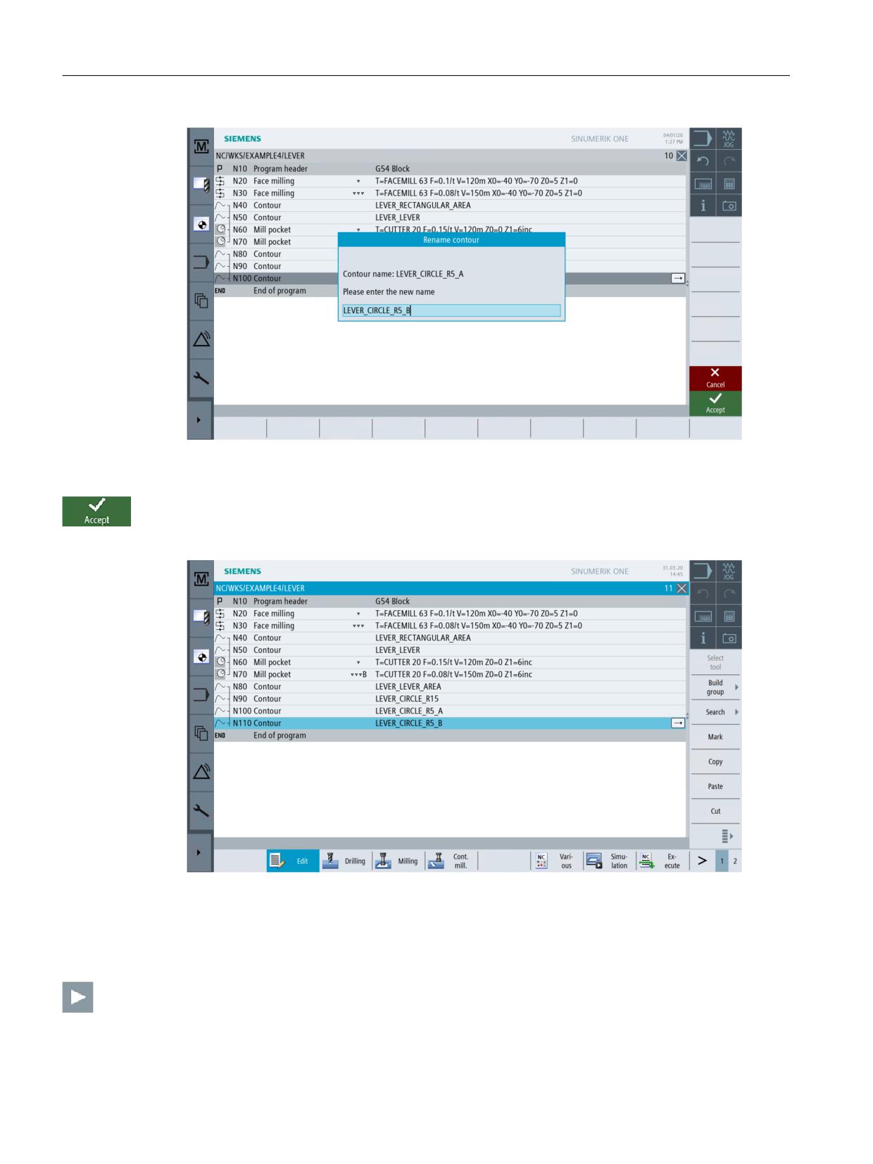
Paste the copied contour and give it the name 'LEVER_Circle_R5_B'.
Easy milling with ShopMill
Training Documents, 05/2020, 6FC5095-0AB50-1BP2
155
Example 4: Lever
9.8 Copying the 10mm circular island
Figure 9-37
Specifying the name for the copied contour
Press "Accept" to apply your input.
After accepting the values, your process plan should look like this:
Figure 9-38
Pasted contour in the work step editor
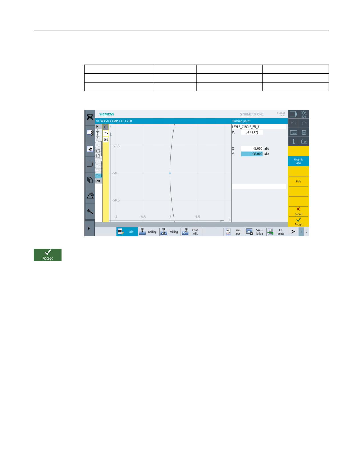
Now you must only change the starting point, as you have specified the contour incrementally.
Open the contour. This key can then also be used in the open contour to open the selected
geometry element for changing.
Easy milling with ShopMill
156
Training Documents, 05/2020, 6FC5095-0AB50-1BP2
Example 4: Lever
9.8 Copying the 10mm circular island
In the interactive screenform, enter the following values for the starting point of the contour line:
Field
Value
Toggle field
Notes
X
-5
Y
-58
Figure 9-39
Changing the starting point
Press "Accept" to apply the values entered.
Easy milling with ShopMill
Training Documents, 05/2020, 6FC5095-0AB50-1BP2
157
Example 4: Lever
9.9 Machining the circular island using the editor
9.9
Machining the circular island using the editor
Operating sequences
To machine the three circular islands, proceed as follows: When machining the circular islands,
you will learn further functions of the work step editor, helping you understand how to use parts
of the process plans several times and how to manage the process plan (see Functions of the
work step editor).
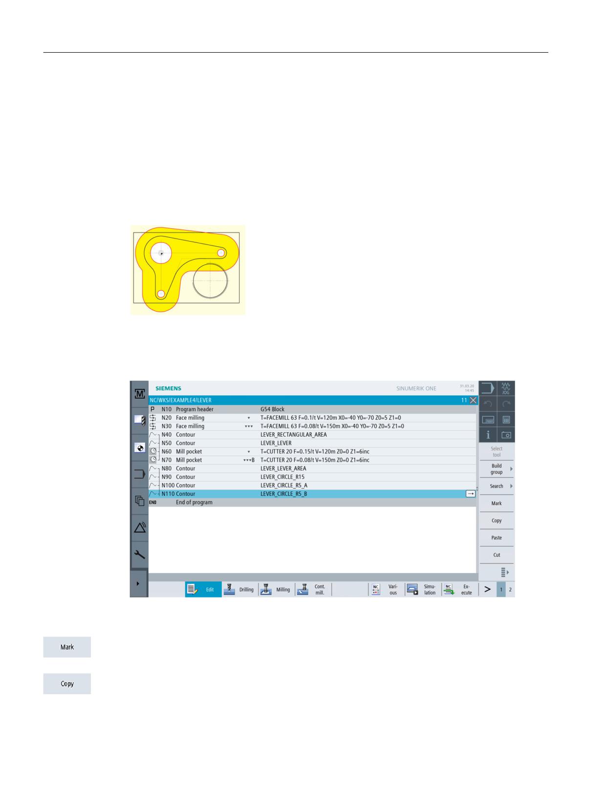
The following contour serves the boundary of the traversing path during manufacturing.
Figure 9-40
Boundary of the traversing path
Your process plan will look as follows:
Figure 9-41
Process plan
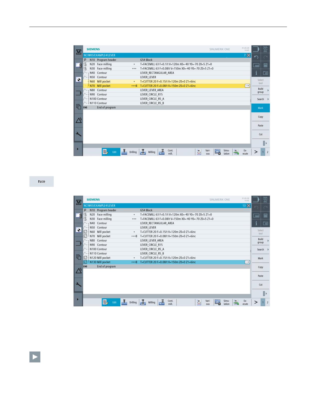
Highlight the two work steps for roughing and finishing of the pocket.
Copy the highlighted work steps.
Easy milling with ShopMill
158
Training Documents, 05/2020, 6FC5095-0AB50-1BP2
Example 4: Lever
9.9 Machining the circular island using the editor
Figure 9-42
Highlighted machining steps
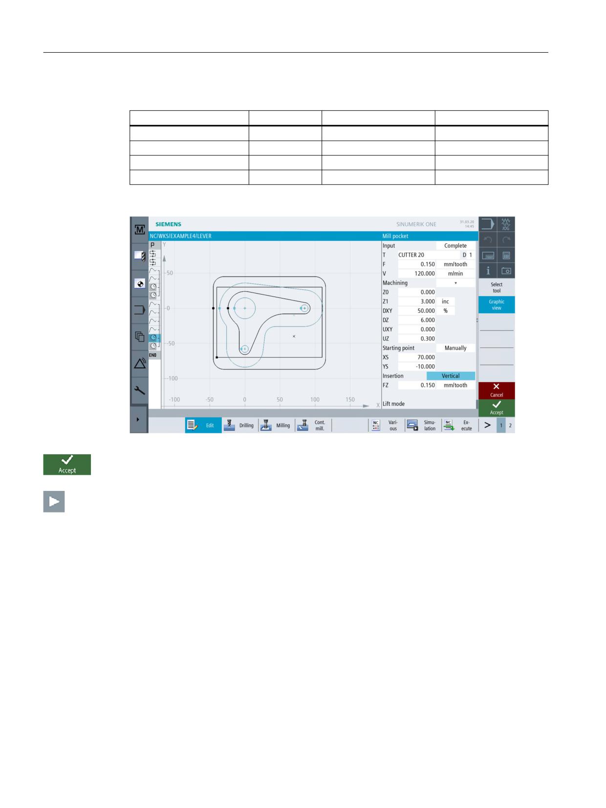
Paste the work steps beneath the contours. This will link the technologies for removing material
from the solid with the contours.
Figure 9-43
Pasted machining steps
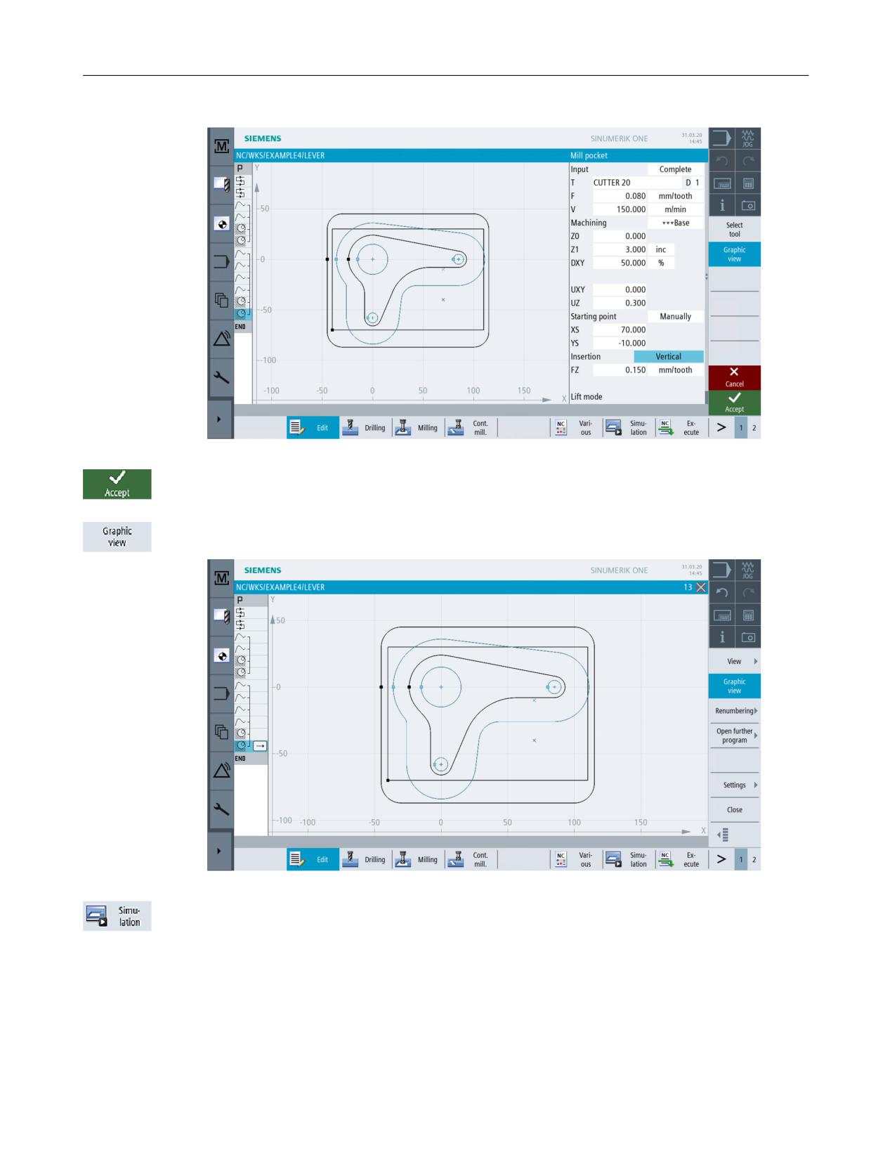
Now you must only adapt the technologies solid 'roughing' and 'finishing' for removing material
from the solid to the new machining depth:
Open the work step for roughing.
Easy milling with ShopMill
Training Documents, 05/2020, 6FC5095-0AB50-1BP2
159
Example 4: Lever
9.9 Machining the circular island using the editor
Enter the following values for roughing in the interactive screenform:
Field
Value
Toggle field
Notes
Z1
3 inc
X
Starting point
Manual
X
XS
70
YS
-10
Figure 9-44
Adaptations for roughing
Press "Accept" to apply the values entered.
Open the work step for finishing. Change the values similar to roughing.
Easy milling with ShopMill
160
Training Documents, 05/2020, 6FC5095-0AB50-1BP2
Example 4: Lever
9.9 Machining the circular island using the editor
Figure 9-45
Adaptations for finishing
Press "Accept" to apply the values entered.
The screenform above shows which geometries are used in finishing (process plan graphic).
Figure 9-46
Broken-line graphics
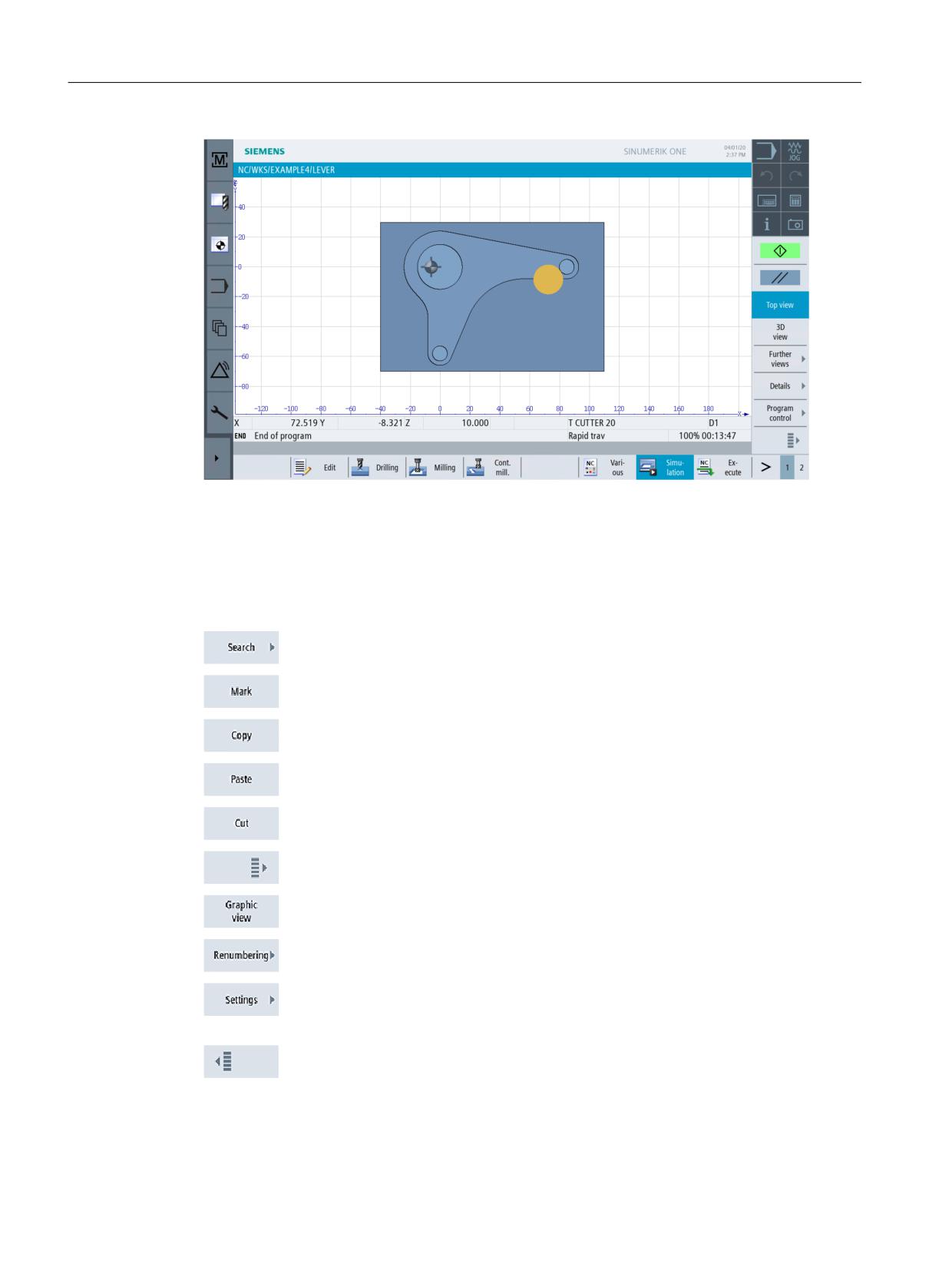
Check your intermediate result by way of simulation.
Easy milling with ShopMill
Training Documents, 05/2020, 6FC5095-0AB50-1BP2
161
Example 4: Lever
9.9 Machining the circular island using the editor
Figure 9-47
Simulation - Top view
Functions of the work step editor
The following information provides you with an overview of the functions of the work step
editor.
Use this softkey to search for texts in the program.
Use this softkey to select several work steps for further processing (e.g.,
"Copy" or "Cut").
Use this softkey to copy work steps to the clipboard.
Use this softkey to paste work steps from the clipboard to the process plan.
The copied step is always inserted after the currently highlighted step.
Use this softkey to copy work steps to the clipboard; at the same time, it is
deleted at its origin. This softkey can also be used for "pure" deletion.
Use this softkey to switch to the extended menu.
Use this softkey to switch to the broken-line graphics.
Use this softkey to renumber the work steps.
Use this softkey to open the "Settings" dialog. Here you can specify, e.g.
automatic numbering or whether you wish the end of the block to be
represented as a symbol.
Use this softkey to return to the previous menu.
Easy milling with ShopMill
162
Training Documents, 05/2020, 6FC5095-0AB50-1BP2
Example 4: Lever
9.10 Deep hole drilling
9.10
Deep hole drilling
Operating sequences
Proceed as follows for rough-boring:
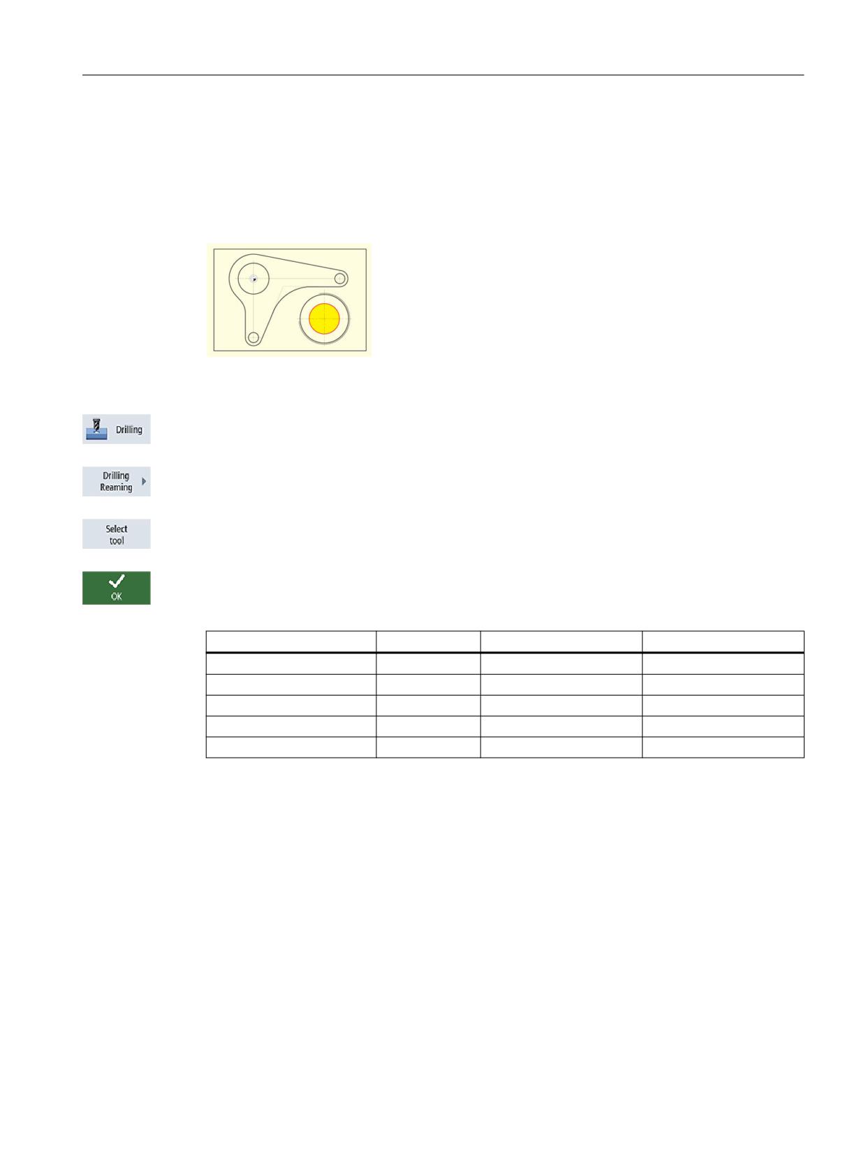
Figure 9-48
Deep hole drilling
Select the Drilling softkey.
Select the Drilling Reaming softkey.
Open the tool list and select PREDRILL 30.
Accept the tool into your program.
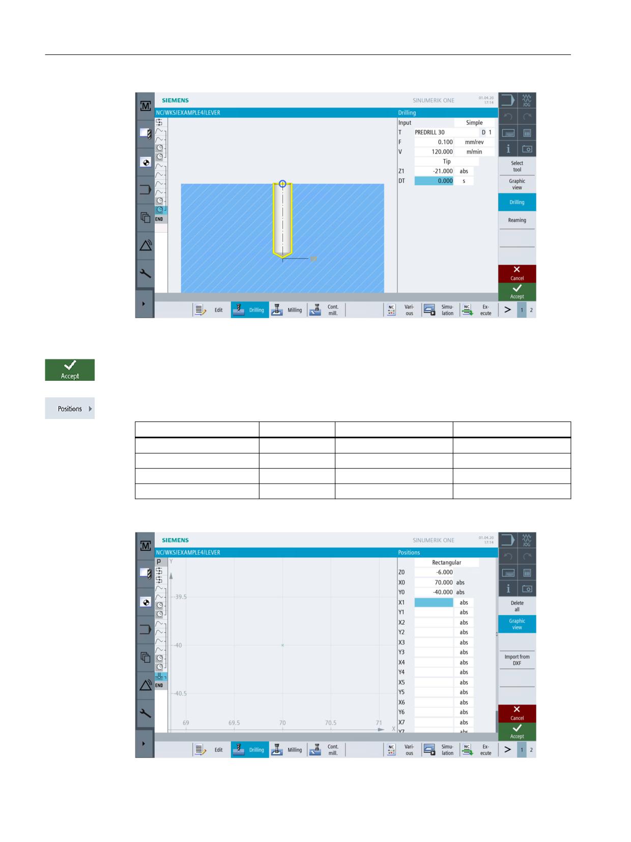
Enter the following values for deep hole drilling in the interactive screenform:
Field
Value
Toggle field
Notes
F
0.1 mm/rev
X
V
120 m/min
X
Depth reference
Tip
X
Z1
-21 abs
X
DT
0 s
X
Easy milling with ShopMill
Training Documents, 05/2020, 6FC5095-0AB50-1BP2
163
Example 4: Lever
9.10 Deep hole drilling
Figure 9-49
Specifying the drill hole
Press "Accept" to apply the values entered.
Enter the following values for the drilling position in the interactive screenform:
Field
Value
Toggle field
Notes
Positions
Rectangular
X
Z0
-6
X0
70
Y0
-40
Easy milling with ShopMill
164
Training Documents, 05/2020, 6FC5095-0AB50-1BP2
Example 4: Lever
9.10 Deep hole drilling
Figure 9-50
Entering the position
Press "Accept" to apply the values entered.
Easy milling with ShopMill
Training Documents, 05/2020, 6FC5095-0AB50-1BP2
165
Example 4: Lever
9.11 Milling a helix
9.11
Milling a helix
Operating sequences
Proceed as follows to remove the residual material of the circular ring remaining after the drilling
by way of a helical motion ("helix"):
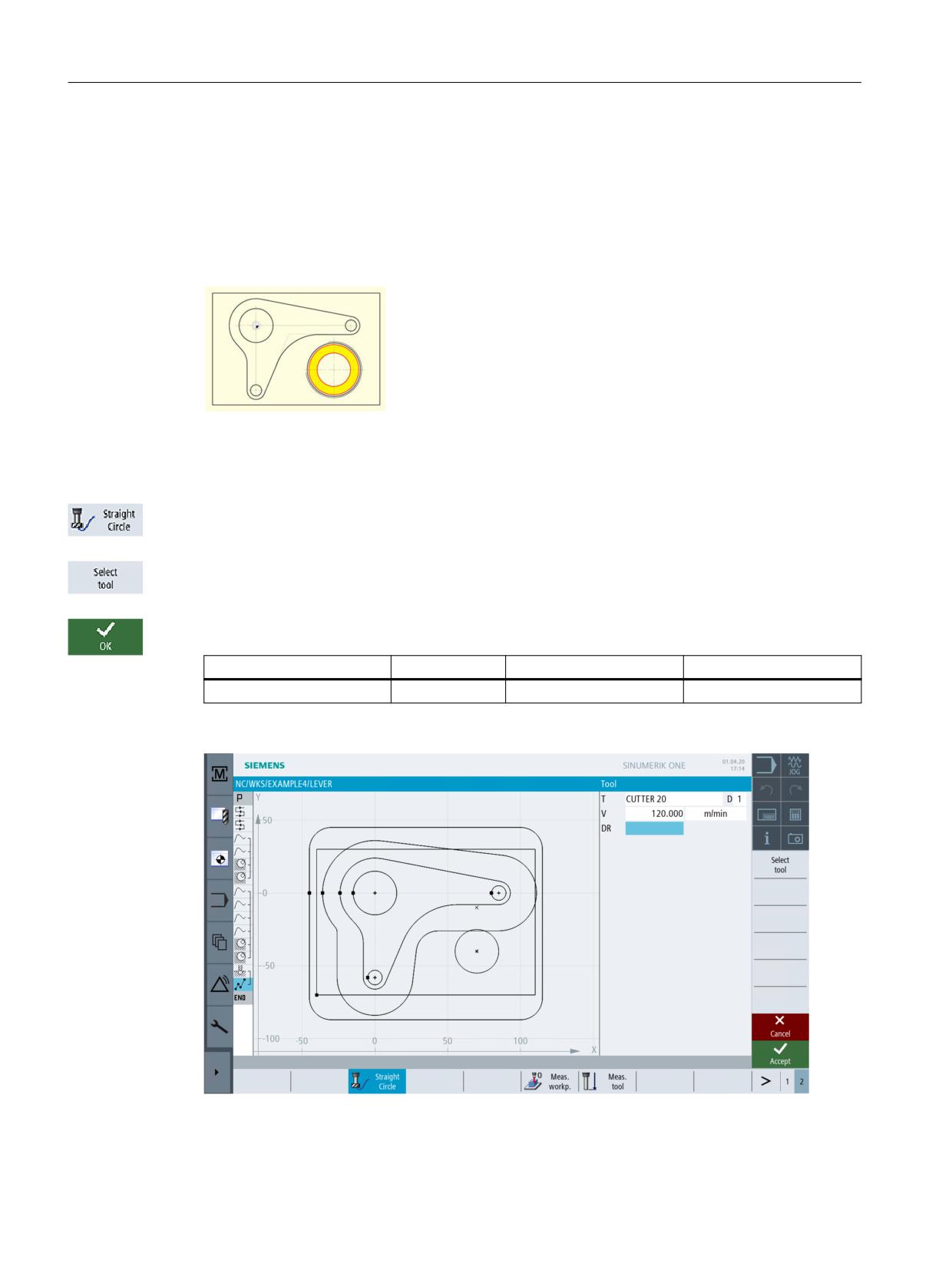
Figure 9-51
Milling a helix
Select the Straight line Circle softkey.
Open the tool list and select CUTTER 20 .
Accept the tool into your program. Enter the following value in the interactive screenform:
Field
Value
Toggle field
Notes
V
120 m/min
X
Figure 9-52
Milling a helix
Easy milling with ShopMill
166
Training Documents, 05/2020, 6FC5095-0AB50-1BP2
Example 4: Lever
9.11 Milling a helix
Press "Accept" to apply your input.
Select the Straight line softkey.
Select the Rapid traverse softkey.
In the interactive screenform, enter the following values for the starting point of the contour line:
Note
Since milling is performed without cutter radius compensation here, you must position the
cutter with its circumference to the tap hole diameter (here: 45.84 mm) minus finishing
allowance.
Field
Value
Toggle field
Notes
X
82 abs
X
Y
-40 abs
X
Z
-5 abs
X
Radius compensation
off
X
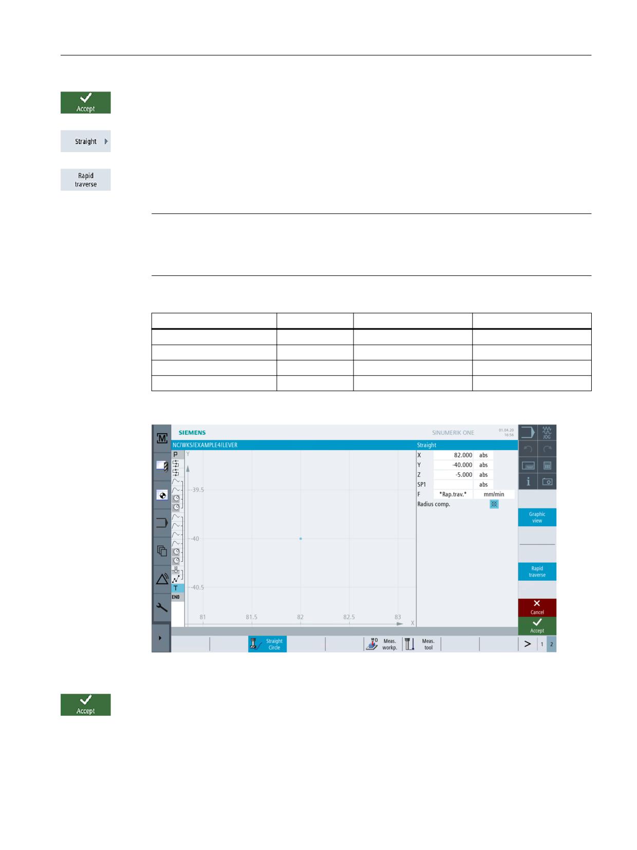
Figure 9-53
Positioning
Press "Accept" to apply the values entered.
Easy milling with ShopMill
Training Documents, 05/2020, 6FC5095-0AB50-1BP2
167
Example 4: Lever
9.11 Milling a helix
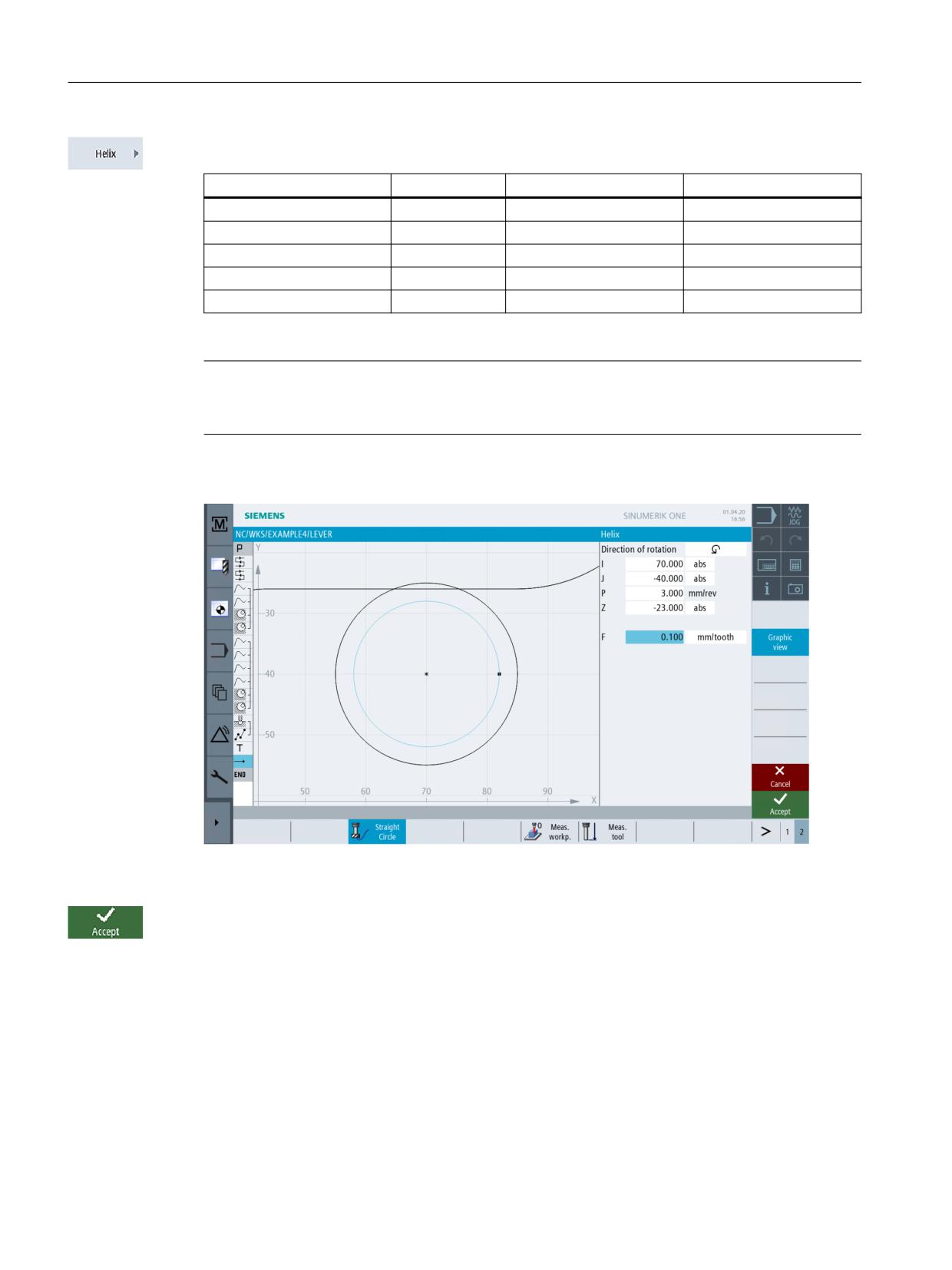
Select the Helix softkey. Enter the following values for the helix in the interactive screenform:
Field
Value
Toggle field
Notes
I
70 abs
X
J
-40 abs
X
P
3 mm/rev
The pitch of the helix is 3.
Z
-23 abs
X
F
0.1 mm/tooth
X
Note
Since the tool traverses along an inclined path, 6 revolutions are created here to avoid that no
residual material remains (even though the final depth is already reached after 5 revolutions).
Figure 9-54
Specifying the helix
Press "Accept" to apply the values entered.
Easy milling with ShopMill
168
Training Documents, 05/2020, 6FC5095-0AB50-1BP2
Example 4: Lever
9.12 Boring
9.12
Boring
Operating sequences
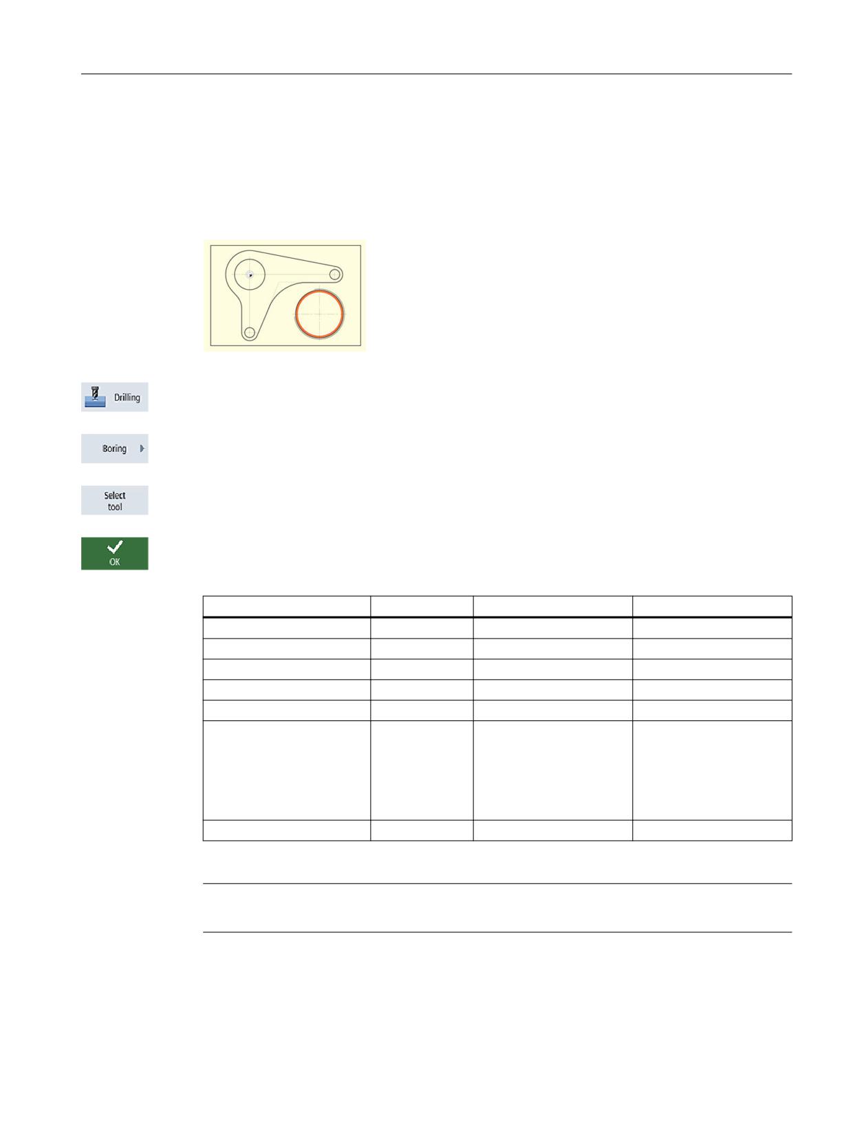
Proceed as follows to machine the circular pocket to the required dimensions using a boring tool:
Figure 9-55
Boring a circular pocket
Select the Drilling softkey.
Select the Boring softkey.
Open the tool list and select the boring tool DRILL_TOOL.
Accept the tool into your program.
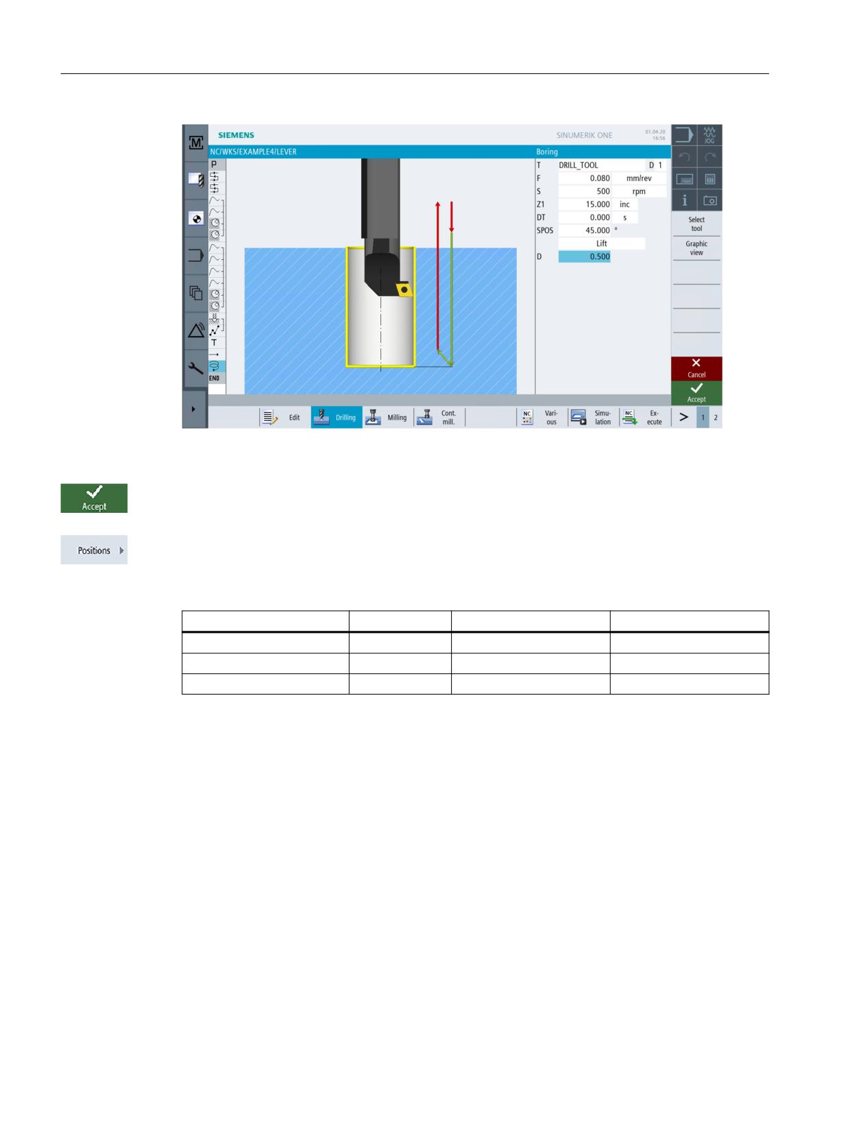
Enter the following values for the processing in the interactive screenform:
Field
Value
Toggle field
Notes
F
0.08 mm/rev
X
S
500 rpm
X
Z1
15 inc
X
DT
0 s
X
SPOS
45
Lift mode
Lifting
X
The Lift option withdraws
the tool from the contour
before it retracts from the
drill hole. This option may
only be used with single-
edge tools.
D
0.5
Note
The angular position of the tool during lifting is specified by the machine manufacturer.
Easy milling with ShopMill
Training Documents, 05/2020, 6FC5095-0AB50-1BP2
169
Example 4: Lever
9.12 Boring
Figure 9-56
Boring
Press "Accept" to apply the values entered.
Position the tool to the drill hole center. The dimension 45.84 mm is specified by the set tool
diameter. Instead of entering the position, you can also use the Repeat position function here.
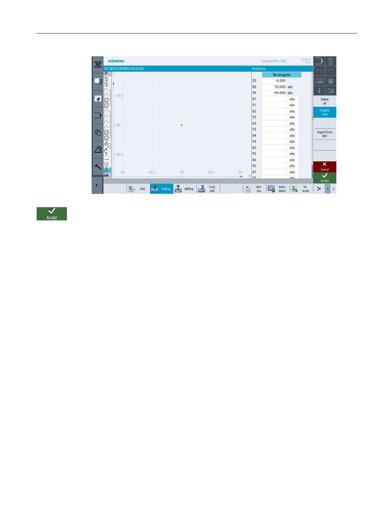
Enter the following values for the position in the interactive screenform:
Field
Value
Toggle field
Notes
Z0
-6
X0
70
Y0
-40
Easy milling with ShopMill
170
Training Documents, 05/2020, 6FC5095-0AB50-1BP2
Example 4: Lever
9.12 Boring
Figure 9-57
Positioning
Press "Accept" to apply the values entered.
Easy milling with ShopMill
Training Documents, 05/2020, 6FC5095-0AB50-1BP2
171
Example 4: Lever
9.13 Thread milling
9.13
Thread milling
Operating sequences
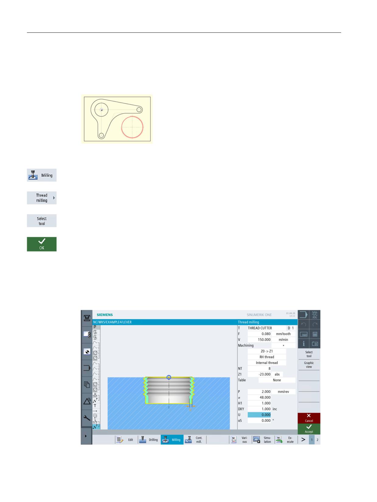
Figure 9-58
Thread milling
Select the Milling softkey.
Select the Thread milling softkey.
Open the tool list and select THREAD CUTTER .
Accept the tool into your program.
Mill the thread from the top to the bottom. To this end, use the THREAD CUTTER (F = 0.08 mm/
tooth, v = 150 m/min and a pitch of 2 mm). A rectangular thread is to be milled absolutely to
Z-23. Due to the overtravel of 3 mm, the thread is always milled cleanly down to the workpiece
lower edge even if the lowest tooth is slightly worn.
The help displays are very useful for your inputs.
Compare your inputs with the screen below.
Figure 9-59
Thread milling
Easy milling with ShopMill
172
Training Documents, 05/2020, 6FC5095-0AB50-1BP2
Example 4: Lever
9.13 Thread milling
Press "Accept" to apply the values entered.
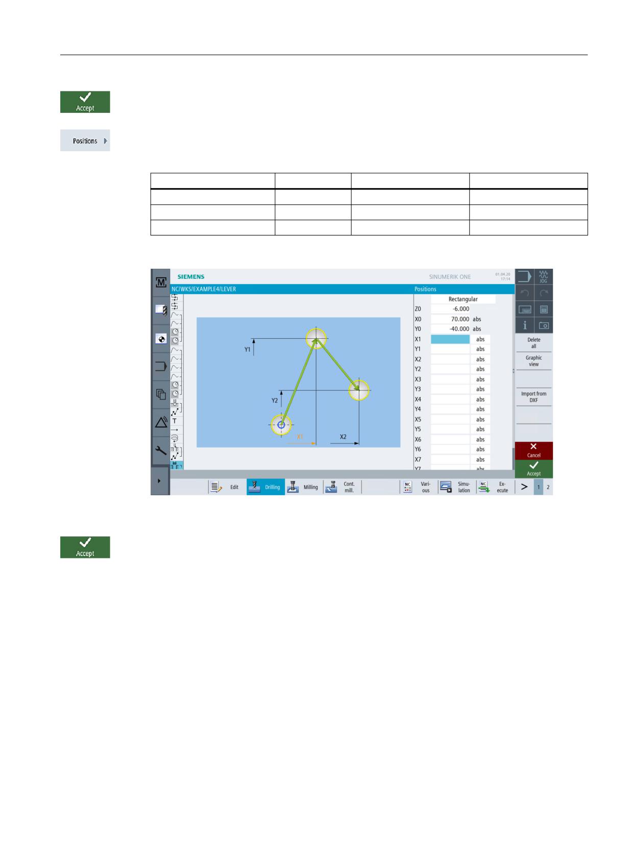
Specify the position for the thread.
Enter the following values in the interactive screenform:
Field
Value
Toggle field
Notes
Z0
-6
X0
70
Y0
-40
Figure 9-60
Entering the position
Press "Accept" to apply the values entered.
Easy milling with ShopMill
Training Documents, 05/2020, 6FC5095-0AB50-1BP2
173
Example 4: Lever
9.14 Programming a contour using polar coordinates
9.14
Programming a contour using polar coordinates
Programming with polar coordinates
Contour elements in workpiece drawings often refer to a pole. In this case, you do not know the
Cartesian coordinates (X/Y), but the polar coordinates, i.e. the distance and the angle to this
pole.
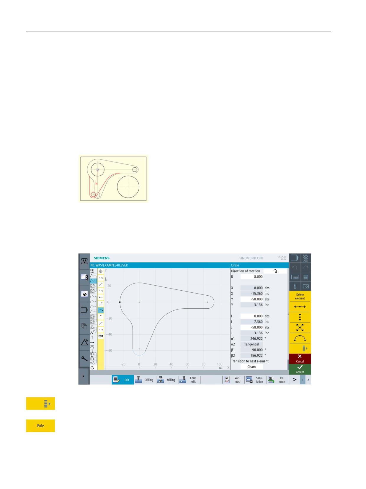
Now we will slightly modify the lever as a further exercise: The lower "lever arm" no longer lies
vertically to zero at X0, but is rotated CW by 10°.
In this example you will learn how this is programmed graphically without using the pocket
calculator or any auxiliary constructions.
Figure 9-61
Programming the lever using polar coordinates
Operating sequences
Move the cursor first to the arc to redimension its center (see screenform below).
Figure 9-62
Positioning the cursor on the arc
Extend the menu.
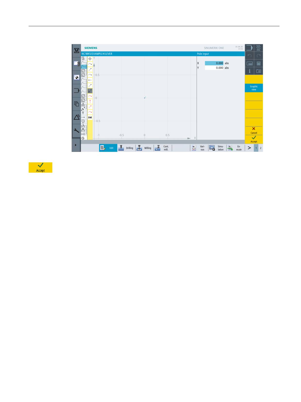
Position the cursor on the element in front of the arc and paste the pole at this point. Apply the
pole to the zero point.
Easy milling with ShopMill
174
Training Documents, 05/2020, 6FC5095-0AB50-1BP2
Example 4: Lever
9.14 Programming a contour using polar coordinates
Figure 9-63
Specifying the pole
Press "Accept" to apply your input.
Easy milling with ShopMill
Training Documents, 05/2020, 6FC5095-0AB50-1BP2
175
Example 4: Lever
9.14 Programming a contour using polar coordinates
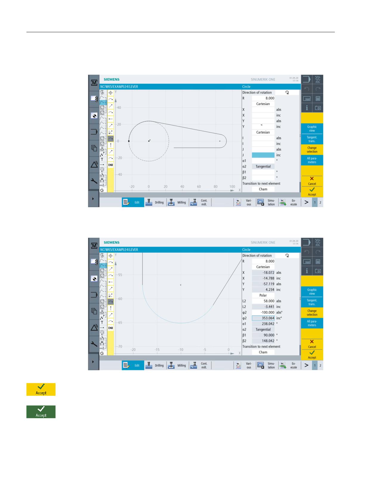
Subsequently, change the values matching the arc:
1. In the arc dialog box, delete the values Y-58, I0 and J-58 which are no longer valid.
Figure 9-64
Deleting the values
2. To be able to specify the center point, switch the coordinates from "Cartesian" to "Polar". Enter
the distance to the pole and specify the polar angle (see screenform below).
Figure 9-65
Entering the distance to the pole and specifying the polar angle
Press "Accept" to apply your input.
Apply the change.
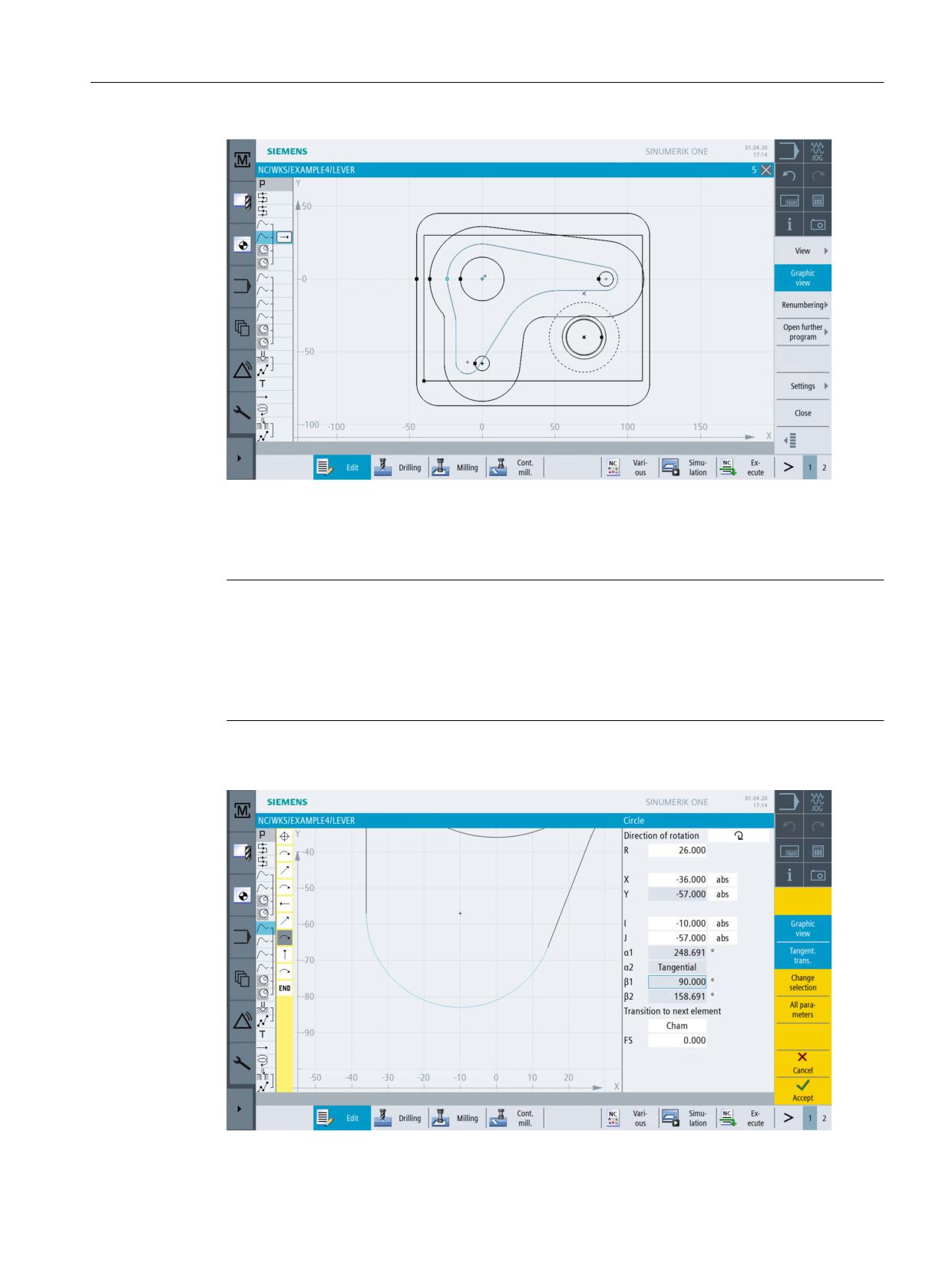
The broken-line graphics shows that the auxiliary pocket LEVER_Lever_Area and the circular
island LEVER_Circle_R5_B must also be adapted in the same way.
Easy milling with ShopMill
176
Training Documents, 05/2020, 6FC5095-0AB50-1BP2
Example 4: Lever
9.14 Programming a contour using polar coordinates
Figure 9-66
Broken-line graphics after shifting
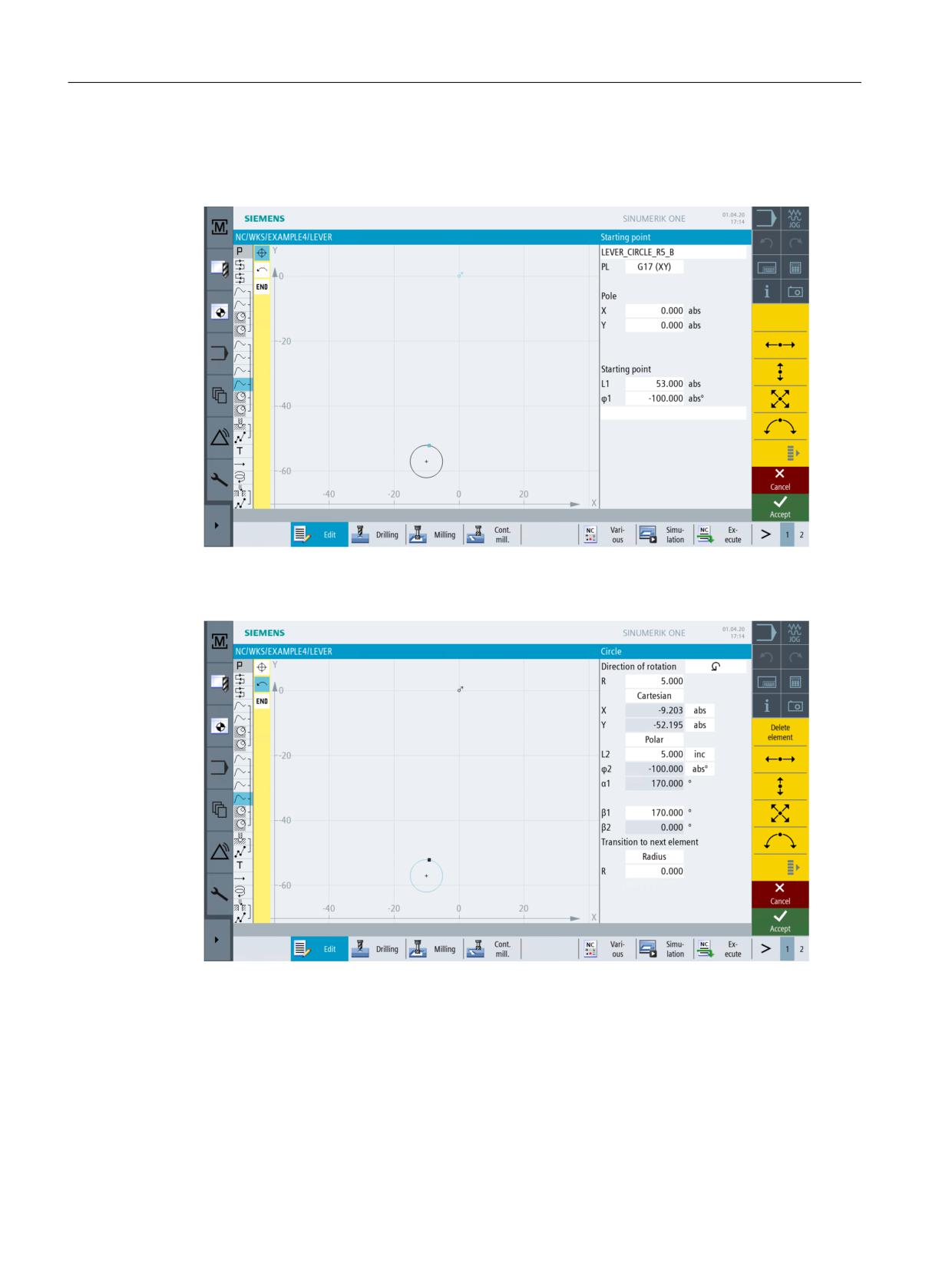
Change these two contours without help. Note the following:
Note
As far as the auxiliary pocket is concerned, you may naturally proceed a bit "rougher" and
approach the center of the arc R26 dimensioned with polar coordinates to Cartesian
dimensioning (X-10/Y-57). Then, the contour can be continued directly with a vertical line.
The starting point for the circular island is already dimensioned with polar coordinates. Only the
center point of the full-circle arc must be changed.
Easy milling with ShopMill
Training Documents, 05/2020, 6FC5095-0AB50-1BP2
177
Example 4: Lever
9.14 Programming a contour using polar coordinates
Figure 9-67
Adapting the edge
Figure 9-68
Defining the start point as a pole
Figure 9-69
Adapting the circular island
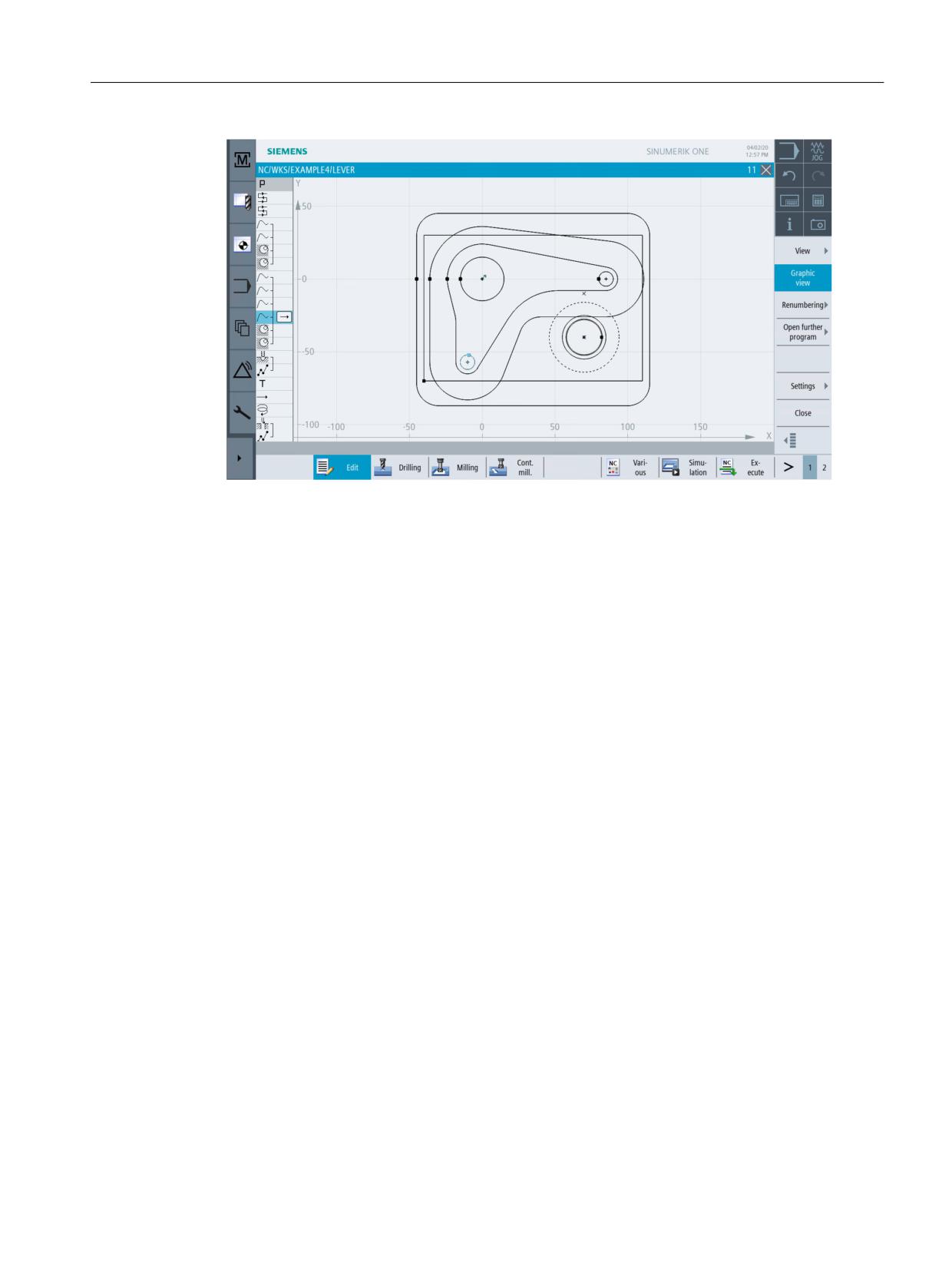
After successful adaptation, your broken-line graphics looks like this:
Easy milling with ShopMill
178
Training Documents, 05/2020, 6FC5095-0AB50-1BP2
Example 4: Lever
9.14 Programming a contour using polar coordinates
Figure 9-70
Broken-line graphics
Easy milling with ShopMill
Training Documents, 05/2020, 6FC5095-0AB50-1BP2
179
Example 4: Lever
9.14 Programming a contour using polar coordinates
Easy milling with ShopMill
180
Training Documents, 05/2020, 6FC5095-0AB50-1BP2
Example 5: Flange
10
10.1
Overview
Learning objectives
In this chapter you will learn how to ...
• create a subroutine;
• mirror work steps;
• chamfer any contours, and
• create longitudinal and circular grooves.
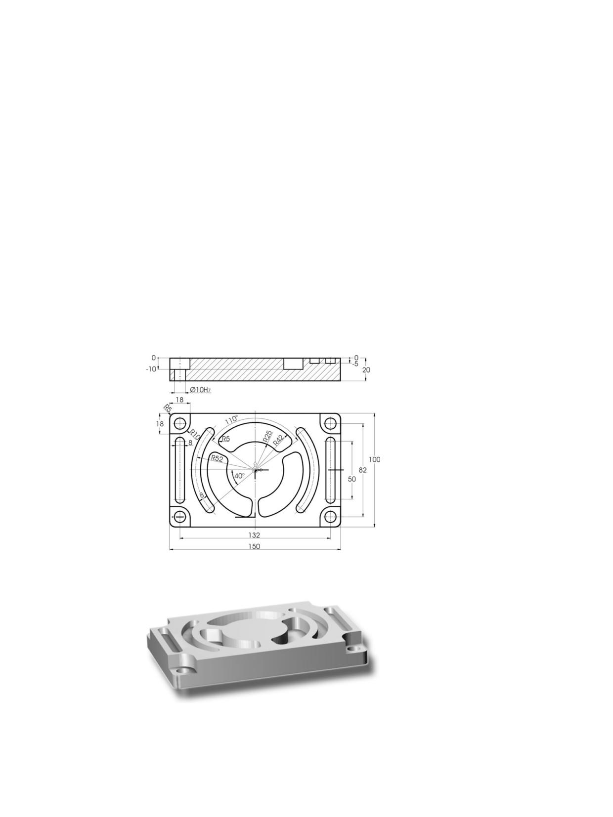
Task
Figure 10-1
Workshop drawing - Example 5:
Figure 10-2
Workpiece - Example 5:
Easy milling with ShopMill
Training Documents, 05/2020, 6FC5095-0AB50-1BP2
181
Example 5: Flange
10.1 Overview
Note
All work steps were explained in the previous examples and nearly all softkeys / keys to be
selected / pressed were indicated. In the following example, the whole sequence of inputs will
no longer be specified, but instead only essential information and the most important softkeys
and keys to be pressed.
Easy milling with ShopMill
182
Training Documents, 05/2020, 6FC5095-0AB50-1BP2
Example 5: Flange
10.2 Creating a subroutine
10.2
Creating a subroutine
Operating sequences
The creation and functioning of subroutines will be explained taking the example of the
workpiece CORNER_MACHINING.
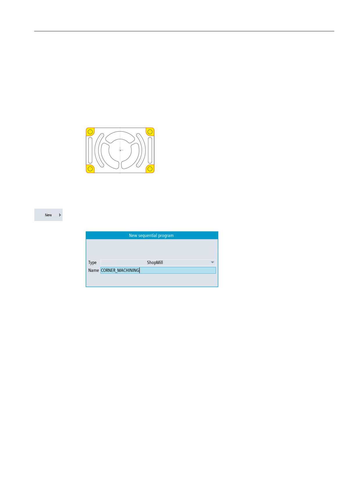
The four corners will be machined by way of the following steps using a subroutine and the
"Mirror" function.
Figure 10-3
Contour of the four corners
Create a new step sequence program with the name CORNER_MACHINING. Later you will embed
this program as a subroutine.
Figure 10-4
Creating a subroutine
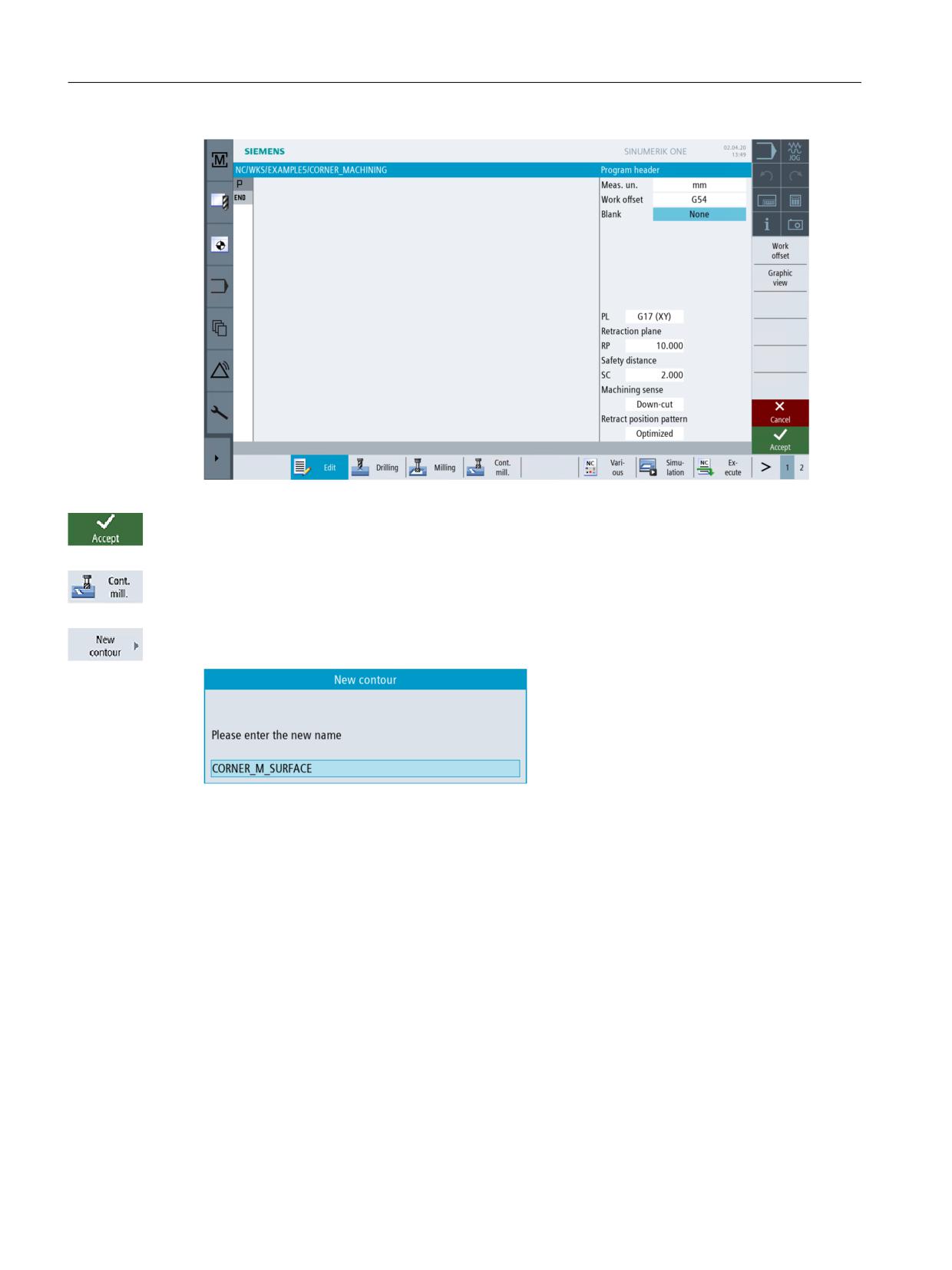
Enter the following data for the program header. The blank dimensions will be specified later
centrally in the main program.
Easy milling with ShopMill
Training Documents, 05/2020, 6FC5095-0AB50-1BP2
183
Example 5: Flange
10.2 Creating a subroutine
Figure 10-5
Entering the data for the subroutine program header
Press "Accept" to apply the values entered.
Select the Contour milling softkey.
Create a new contour with the name CORNER_M_SURFACE .
Figure 10-6
Creating the contour
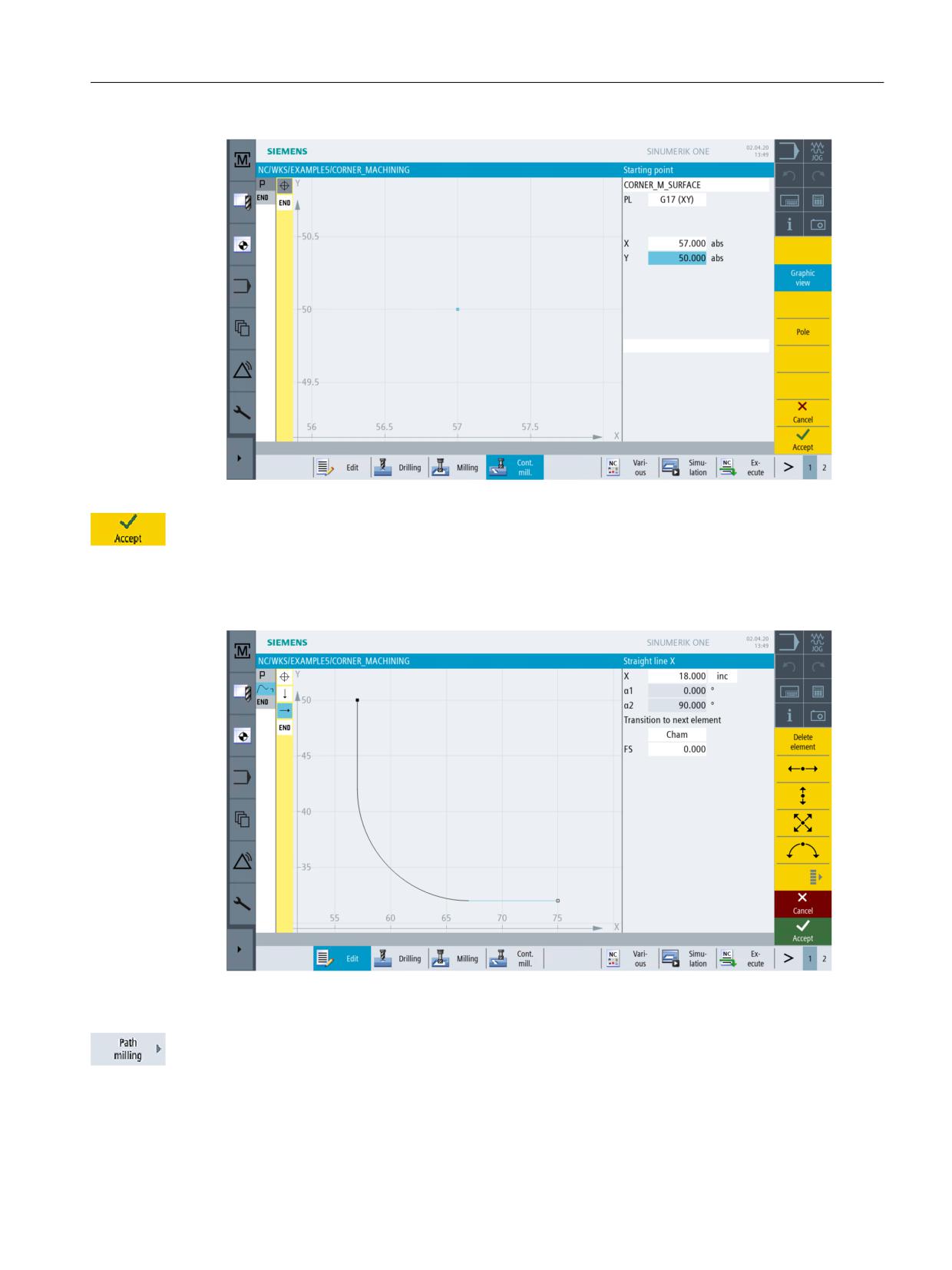
Specify the starting point. The top right corner, for example, will be designed.
Easy milling with ShopMill
184
Training Documents, 05/2020, 6FC5095-0AB50-1BP2
Example 5: Flange
10.2 Creating a subroutine
Figure 10-7
Specifying the starting point
Press "Accept" to apply the values entered.
Create the contour. After entering the two contour elements, your screen should look like this:
Accept the contour into your process plan.
Figure 10-8
Contour subroutine, top right corner
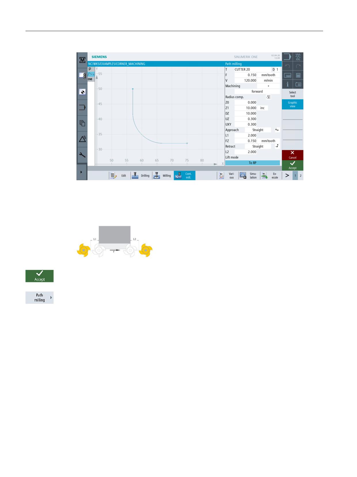
The contour is to be roughed using an R20 milling cutter (F = 0.15 mm/tooth and v = 120 m/min).
Easy milling with ShopMill
Training Documents, 05/2020, 6FC5095-0AB50-1BP2
185
Example 5: Flange
10.2 Creating a subroutine
Figure 10-9
Roughing the contour
The approach and retract paths are approached along a straight line. The length values are the
distances between the cutter edge and the workpiece.
Figure 10-10
Approach and retract paths along a straight line
Press "Accept" to apply the values entered.
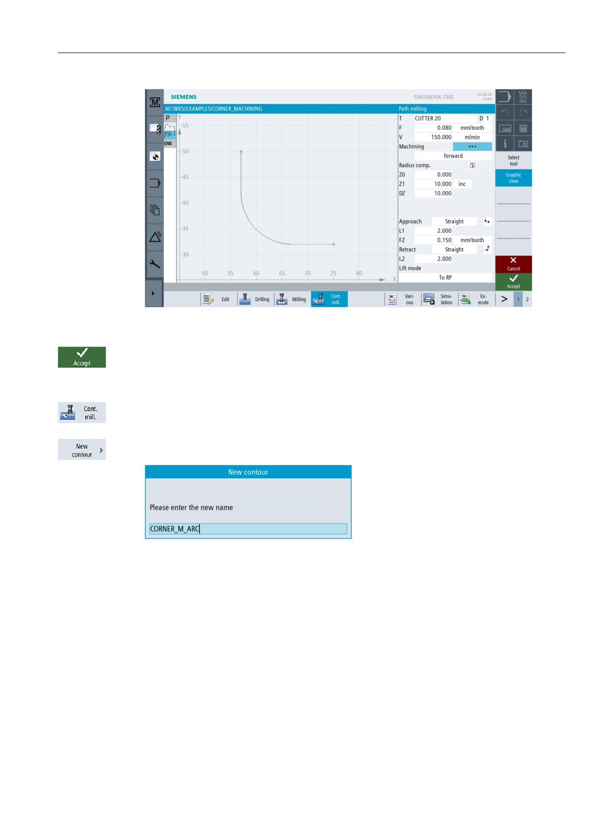
The contour is to be finished using the same milling cutter (F = 0.08 mm/tooth and v = 150 m/
min).
Easy milling with ShopMill
186
Training Documents, 05/2020, 6FC5095-0AB50-1BP2
Example 5: Flange
10.2 Creating a subroutine
Figure 10-11
Finishing the contour
Press "Accept" to apply the values entered.
In the next few steps, the corner of the blank cuboid is to be rounded using R5:
Select the Contour milling softkey.
Create a new contour with the name CORNER_M_ARC .
Figure 10-12
Creating the contour
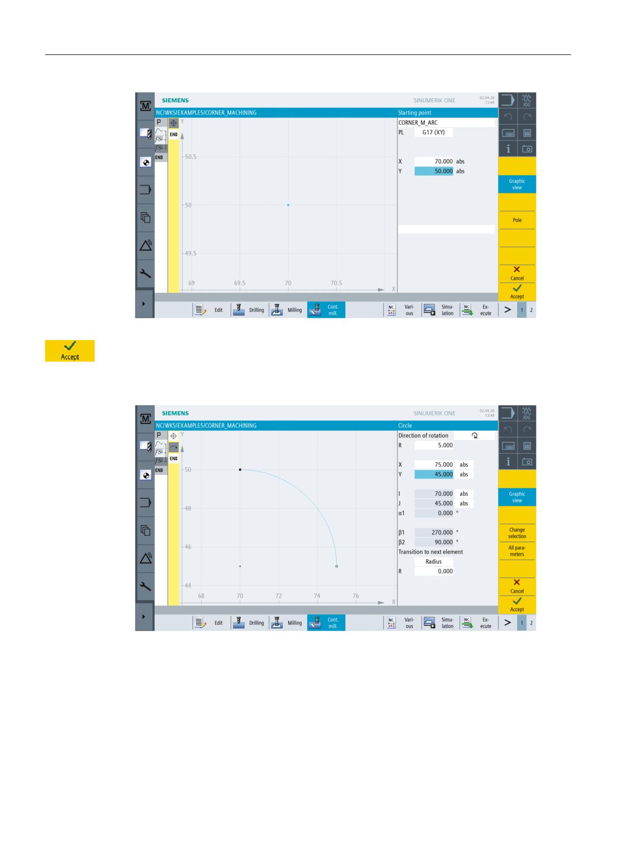
Specify the starting point.
Easy milling with ShopMill
Training Documents, 05/2020, 6FC5095-0AB50-1BP2
187
Example 5: Flange
10.2 Creating a subroutine
Figure 10-13
Specifying the starting point
Press "Accept" to apply the values entered.
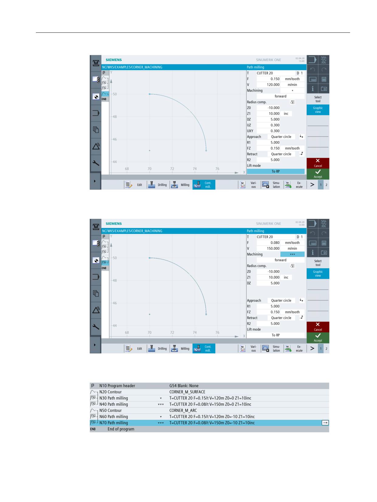
Subsequently, specify the contour and the relevant work steps:
Figure 10-14
Specifying the geometry
Easy milling with ShopMill
188
Training Documents, 05/2020, 6FC5095-0AB50-1BP2
Example 5: Flange
10.2 Creating a subroutine
Figure 10-15
Roughing the contour
Figure 10-16
Finishing the contour
Figure 10-17
Complete subroutine in the work step editor
Easy milling with ShopMill
Training Documents, 05/2020, 6FC5095-0AB50-1BP2
189
Example 5: Flange
10.3 Mirroring work steps
10.3
Mirroring work steps
Task
When you have finished the subroutine, create the main program. You may use the subroutine
for all workpiece corners using the "Mirror" function in the "Transformation" menu.
Mirroring can be performed in two different ways:
• New:
Mirroring is performed from the point at which the 1st processing operation was performed.
• Additive:
Mirroring is performed from the point last machined.
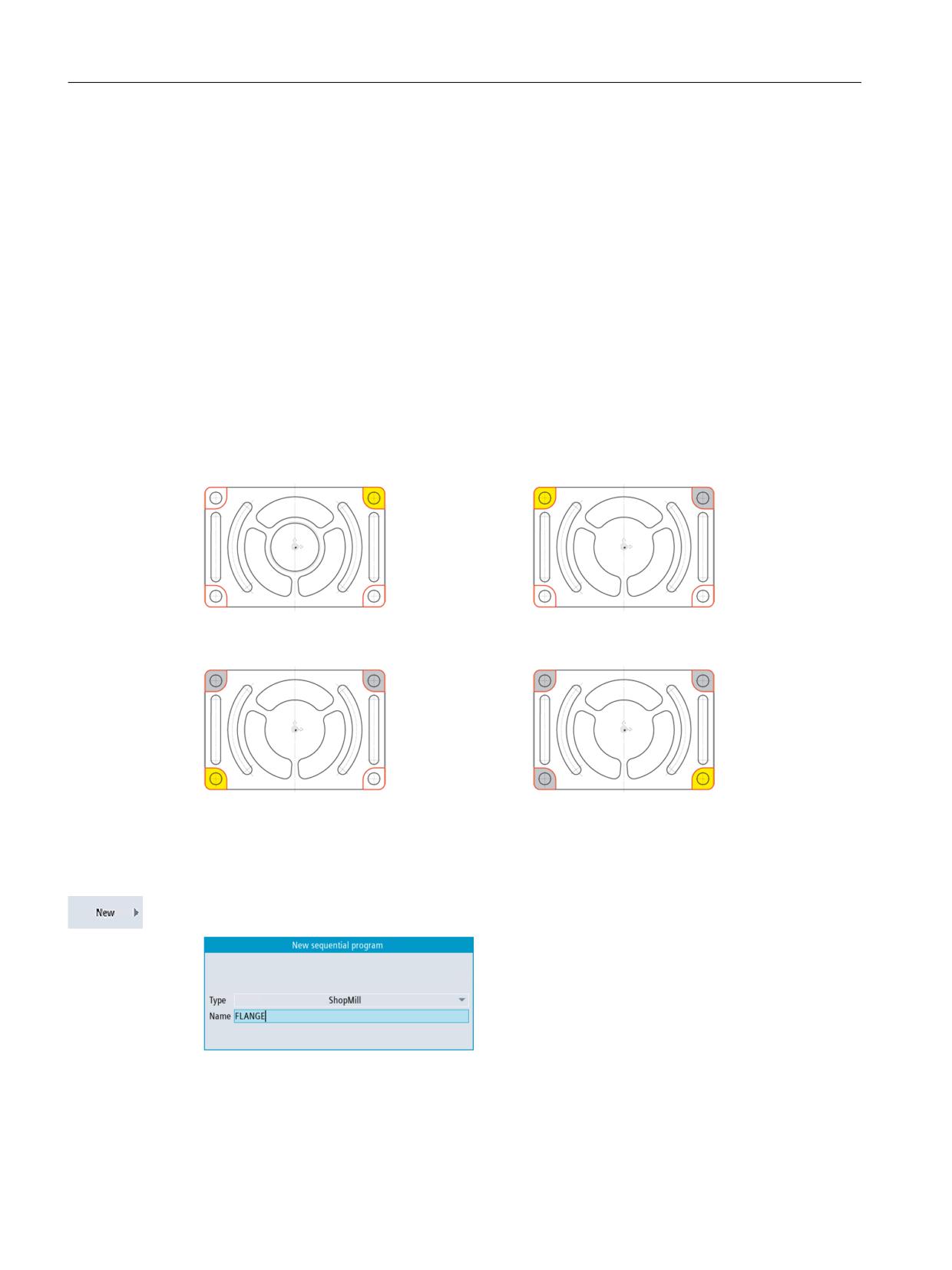
The sequence of processing with the setting New is shown below in the form of drawings:
1. Processing (see subroutine)
2. Processing: Mirroring the X axis
(the X values are mirrored here)
3. Processing: Mirroring the X and Y axes
4. Processing: Mirroring the Y axis
(the X and Y values are mirrored here)
(the Y values are mirrored here)
Operating sequences
Create the main program with the name FLANGE .
Figure 10-18
Creating the main program
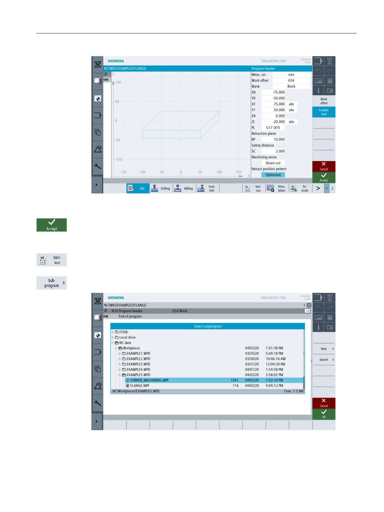
Enter the program header.
Easy milling with ShopMill
190
Training Documents, 05/2020, 6FC5095-0AB50-1BP2
Example 5: Flange
10.3 Mirroring work steps
Figure 10-19
Specifying the program header of the main program
Press "Accept" to apply the values entered.
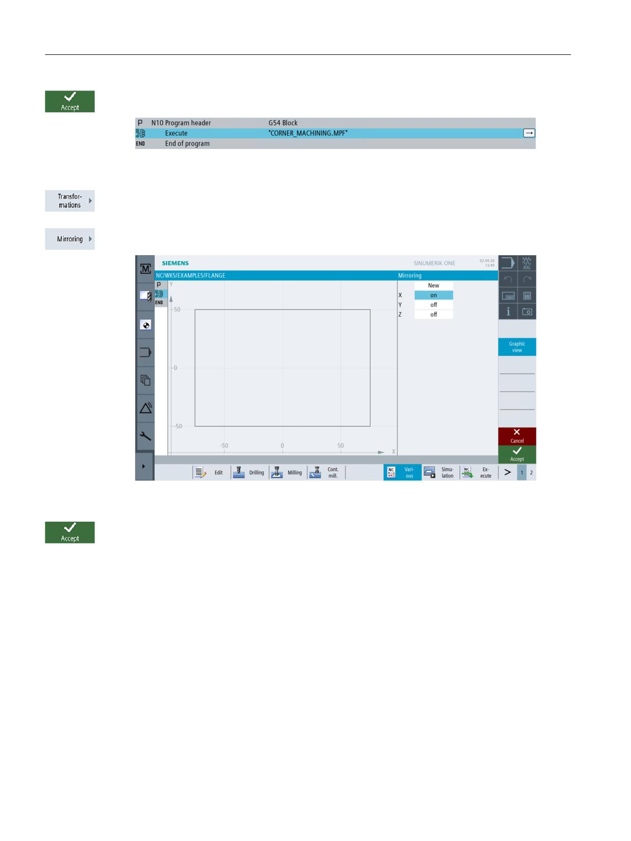
Select the Miscellaneous softkey.
Select the CORNER_MACHINING subprogram.
Figure 10-20
Selecting the subprogram
Easy milling with ShopMill
Training Documents, 05/2020, 6FC5095-0AB50-1BP2
191
Example 5: Flange
10.3 Mirroring work steps
Accept your selection. After acceptance, your work step program looks like this:
Figure 10-21
Subroutine pasted into the main program
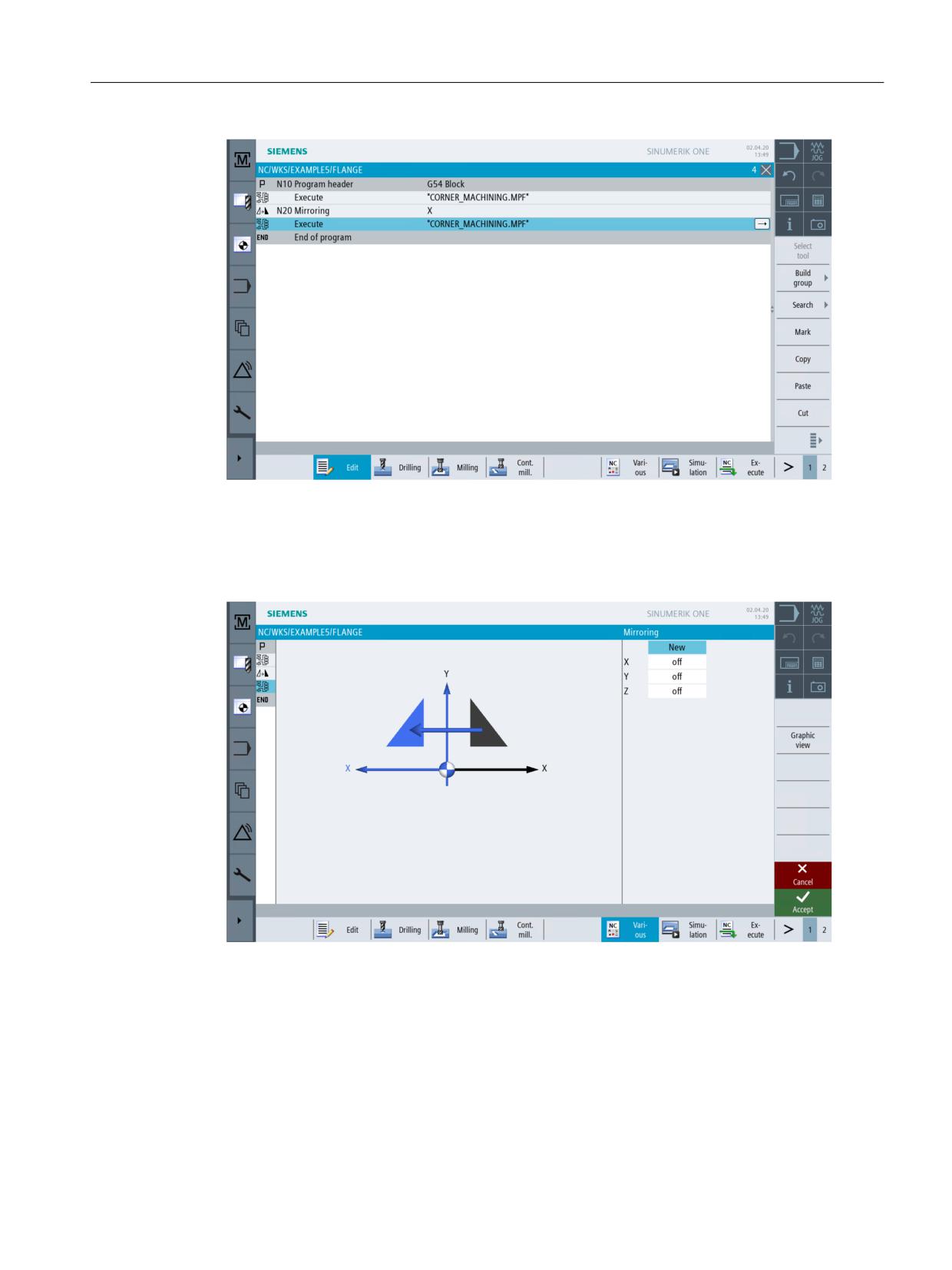
The Transformation softkey can be used to shift, rotate, etc. the axes.
Preparing the 2nd processing: Mirror the X values.
Figure 10-22
Mirroring
Press "Accept" to apply your input.
To mirror the remaining processing operations, proceed as follows:
Copy the subroutine after the "Mirror" work step. The 2nd processing follows.
Then you must repeat the processes Mirror and Subroutine call for the two other corners.
Easy milling with ShopMill
192
Training Documents, 05/2020, 6FC5095-0AB50-1BP2
Example 5: Flange
10.3 Mirroring work steps
Figure 10-23
Copying the subroutine
The help display illustrating this procedure will help you. After you have entered all 4 processing
operations, disable mirroring for all three axes.
Figure 10-24
Mirroring help display
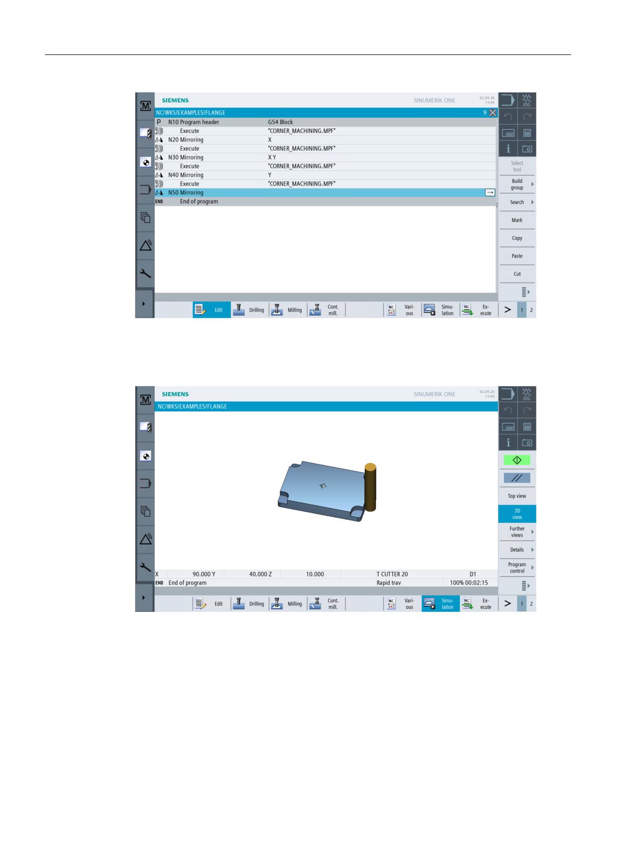
Your process plan will look as follows:
Easy milling with ShopMill
Training Documents, 05/2020, 6FC5095-0AB50-1BP2
193
Example 5: Flange
10.3 Mirroring work steps
Figure 10-25
Complete mirroring in the work step editor
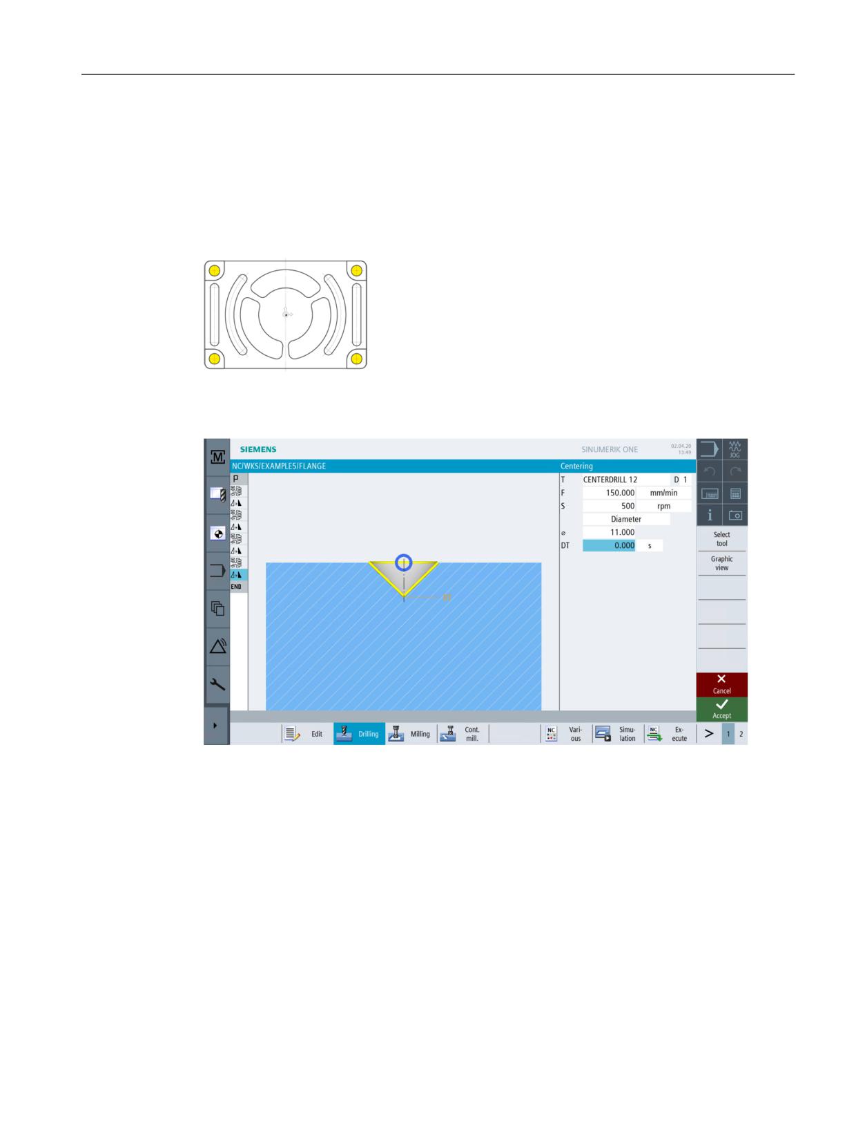
Check your work by now using the simulation.
Figure 10-26
Simulation in 3D display
Easy milling with ShopMill
194
Training Documents, 05/2020, 6FC5095-0AB50-1BP2
Example 5: Flange
10.4 Holes
10.4
Holes
Operating sequences
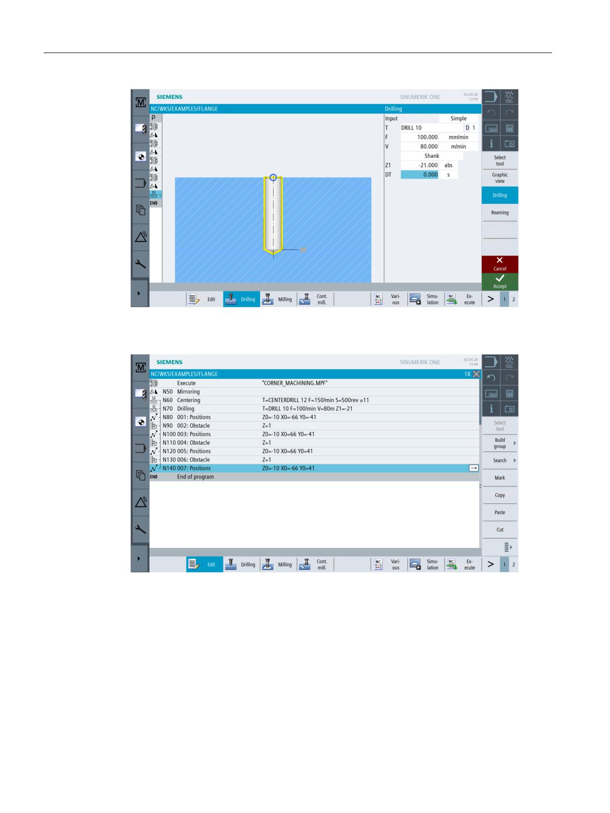
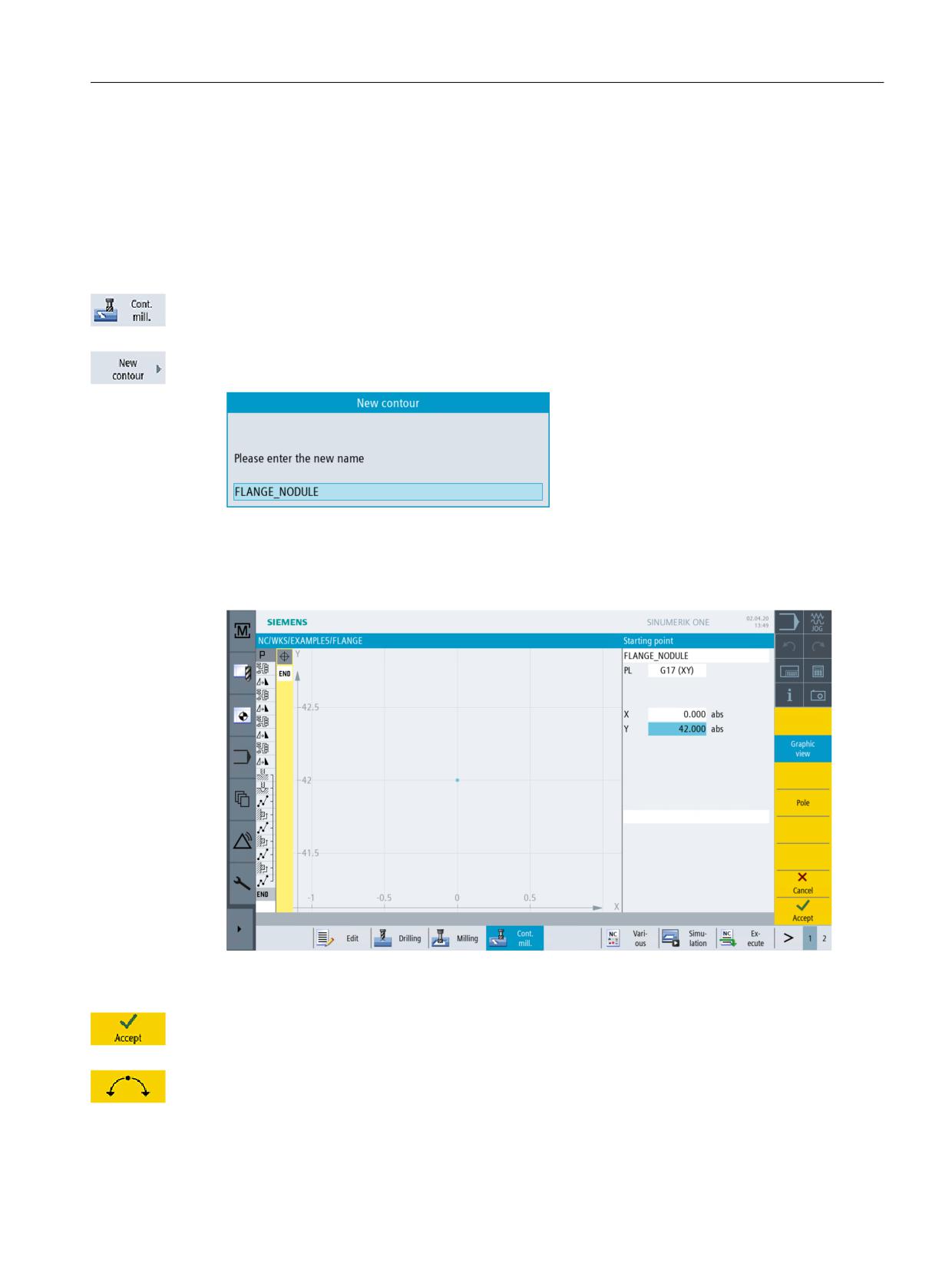
With the next few work steps, you will create four drill holes in the corners. Since an obstacle lies
between the individual drill holes, it must be specified between the positions.
Figure 10-27
Holes
Figure 10-28
Centering
Easy milling with ShopMill
Training Documents, 05/2020, 6FC5095-0AB50-1BP2
195
Example 5: Flange
10.4 Holes
Figure 10-29
Drilling
Figure 10-30
Specifying the positions of the obstacles
Easy milling with ShopMill
196
Training Documents, 05/2020, 6FC5095-0AB50-1BP2
Example 5: Flange
10.5 Rotation of pockets
10.5
Rotation of pockets
Operating sequences
To program the contour and the processing for the pocket highlighted yellow, proceed as
described in the following.
By rotating the coordinate system, subsequently the other two pockets are created.
Select the Contour milling softkey.
Create a new contour with the name 'FLANGE_NODULE' .
Figure 10-31
Creating a new contour
Specify the starting point.
Figure 10-32
Specifying the starting point
Press "Accept" to apply the values entered.
Select the Arc softkey.
Easy milling with ShopMill
Training Documents, 05/2020, 6FC5095-0AB50-1BP2
197
Example 5: Flange
10.5 Rotation of pockets
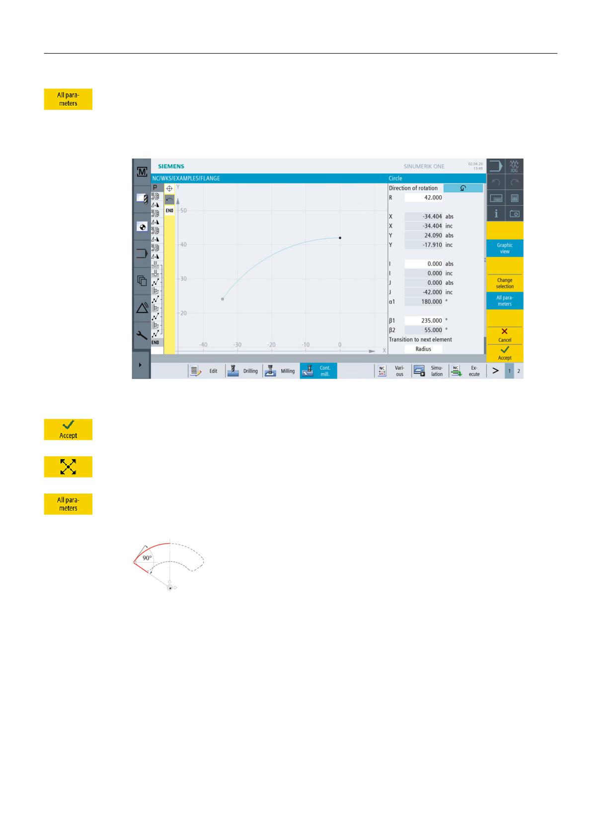
Select the All parameters softkey.
The arc R42 is described unambiguously, e.g. via the radius, the center point in X and the runout
angle. Design in the counterclockwise direction to ensure that the pocket can also be finished by
synchronized milling.
Figure 10-33
Specifying the arc
Press "Accept" to apply the values entered.
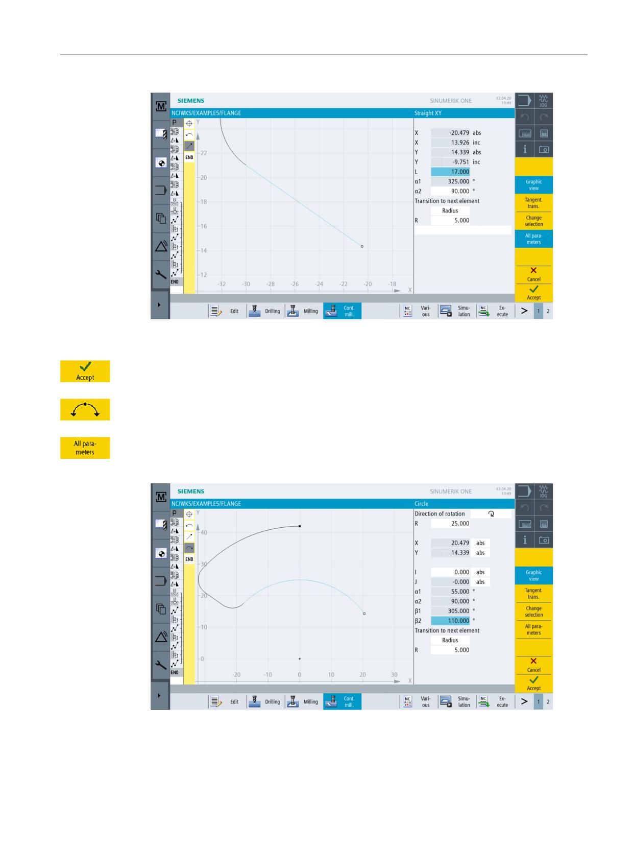
Select the Diagonal softkey.
Select the All parameters softkey.
Create the diagonal straight line.
Easy milling with ShopMill
198
Training Documents, 05/2020, 6FC5095-0AB50-1BP2
Example 5: Flange
10.5 Rotation of pockets
Figure 10-34
Specifying the diagonal
Press "Accept" to apply the values entered.
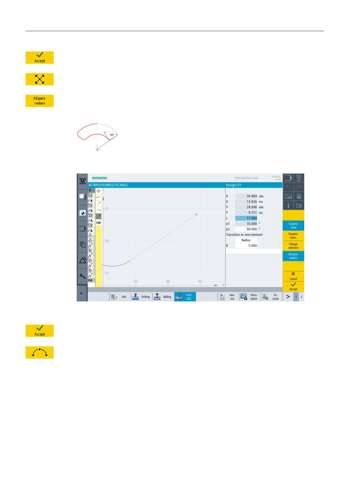
Select the Arc softkey.
Select the All parameters softkey.
Create the 2nd arc.
Figure 10-35
Specifying the arc
Easy milling with ShopMill
Training Documents, 05/2020, 6FC5095-0AB50-1BP2
199
Example 5: Flange
10.5 Rotation of pockets
Press "Accept" to apply the values entered.
Select the Diagonal softkey.
Select the All parameters softkey.
Create the 2nd diagonal straight line.
Figure 10-36
Specifying the diagonal
Press "Accept" to apply the values entered.
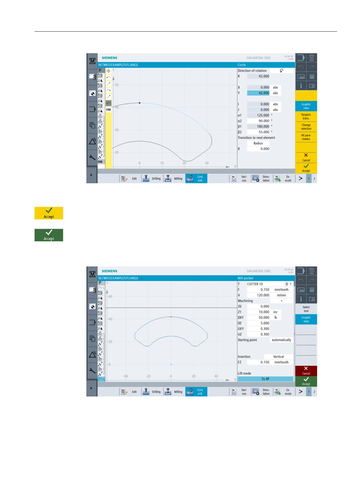
Select the Arc softkey.
Create the final arc.
Easy milling with ShopMill
200
Training Documents, 05/2020, 6FC5095-0AB50-1BP2
Example 5: Flange
10.5 Rotation of pockets
Figure 10-37
Specifying the final arc
Press "Accept" to apply the values entered.
Accept the contour pocket into your process plan.
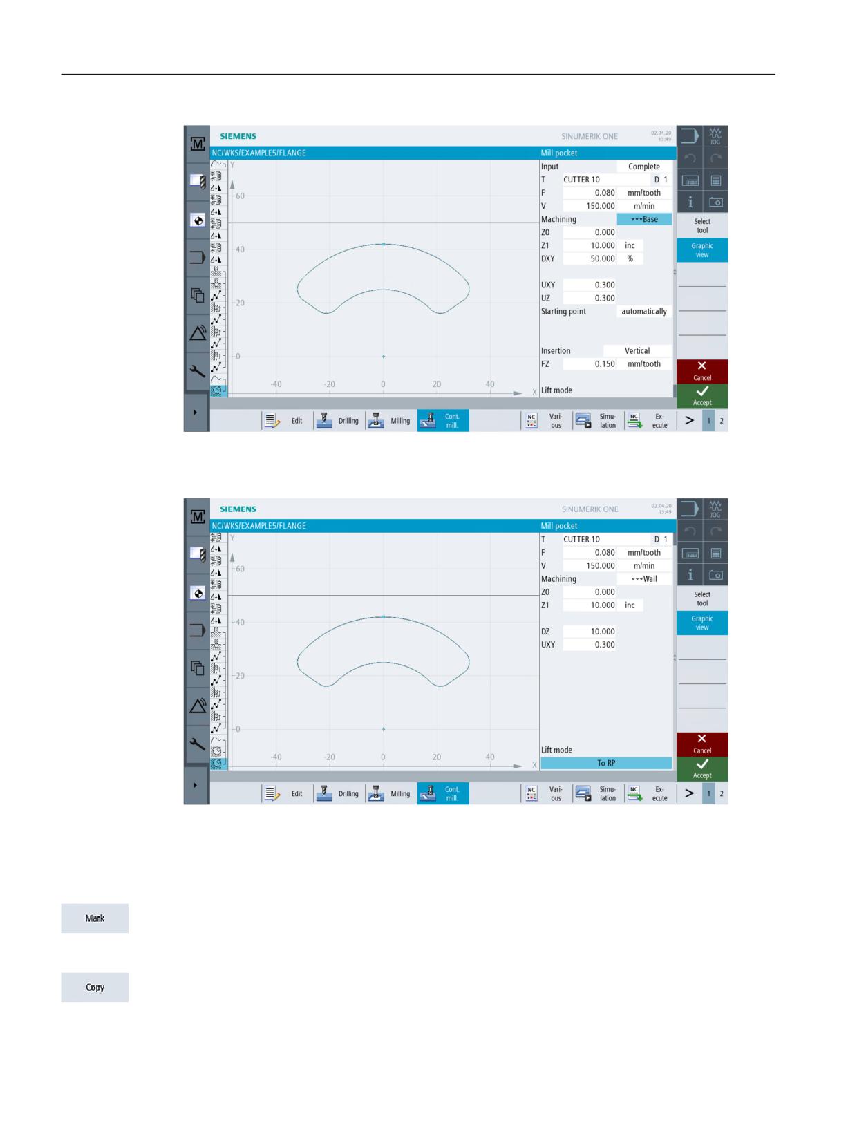
Create the following work steps without help:
Figure 10-38
Roughing pockets
Easy milling with ShopMill
Training Documents, 05/2020, 6FC5095-0AB50-1BP2
201
Example 5: Flange
10.5 Rotation of pockets
Figure 10-39
Finishing the pocket base
Figure 10-40
Finishing the pocket edge
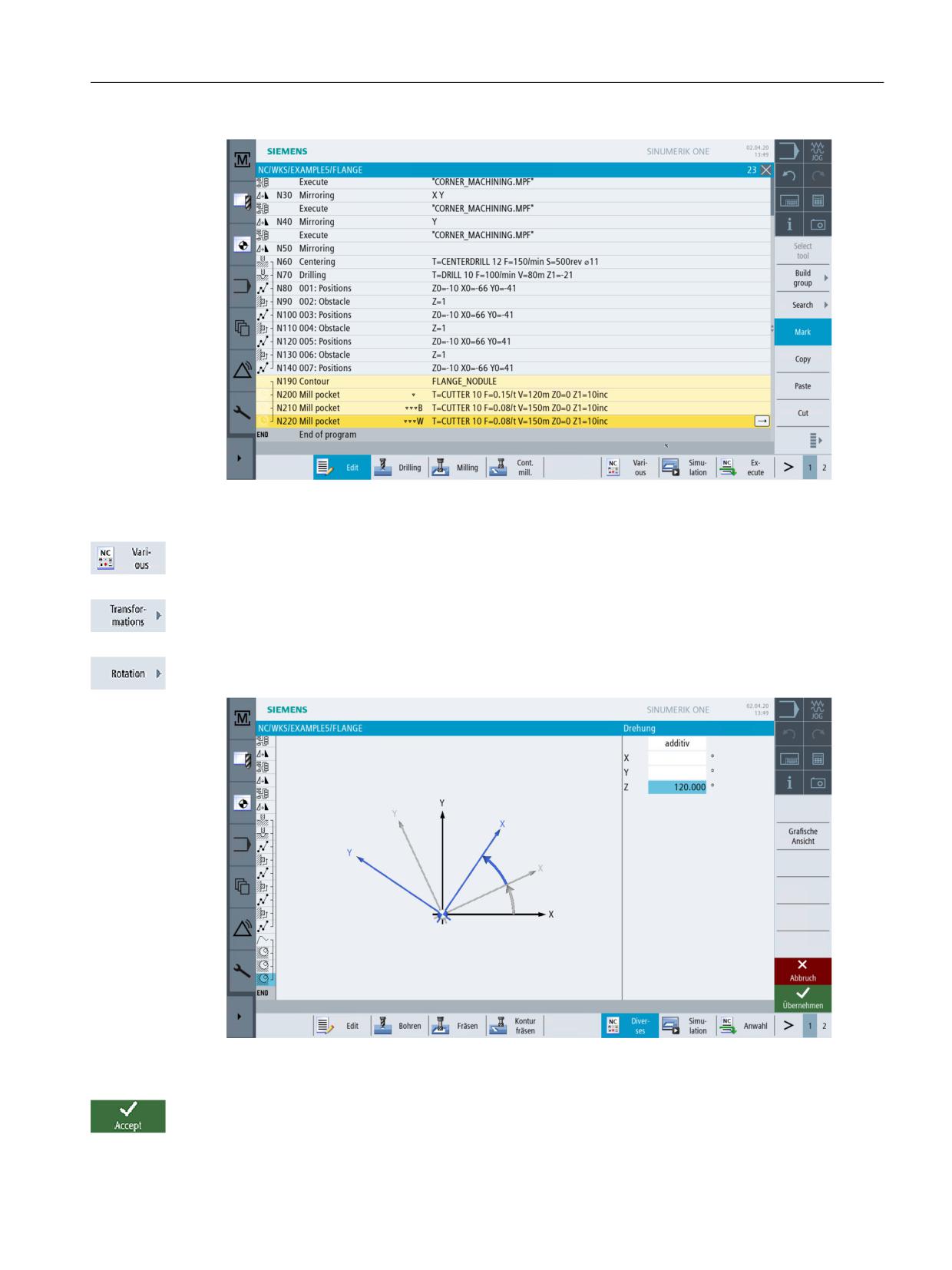
To copy the created work step sequence for the machining of the three pockets, proceed as
follows:
Now highlight the complete work step sequence describing machining of the pocket in the work
step editor.
Copy the work step sequence to the clipboard.
Easy milling with ShopMill
202
Training Documents, 05/2020, 6FC5095-0AB50-1BP2
Example 5: Flange
10.5 Rotation of pockets
Figure 10-41
Copying the work steps
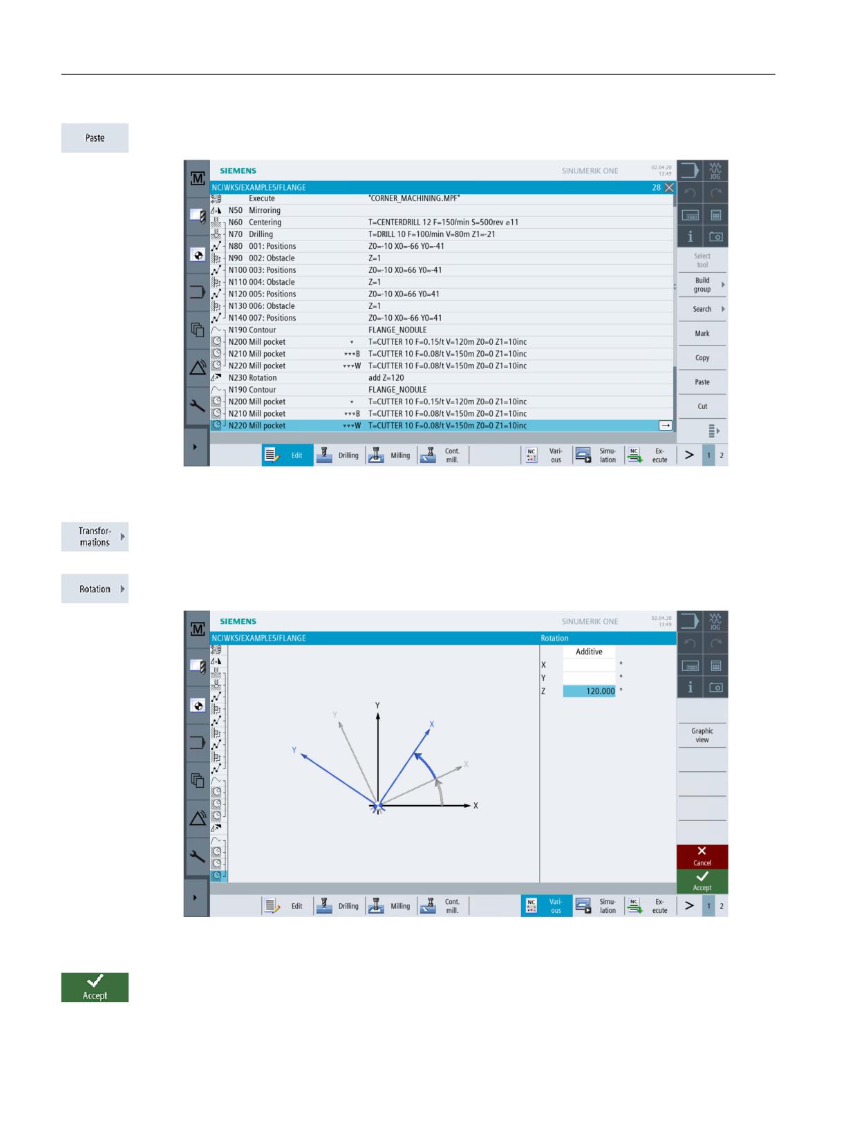
Select the Miscellaneous softkey.
Select the Transformations softkey.
The coordinate system is rotated around the Z axis by 120°.
Figure 10-42
Rotation around the Z axis
Press "Accept" to apply your input.
Easy milling with ShopMill
Training Documents, 05/2020, 6FC5095-0AB50-1BP2
203
Example 5: Flange
10.5 Rotation of pockets
Paste the copied work steps.
Figure 10-43
Pasting the copied work steps
Select the Transformations softkey.
Enter another rotation by 120°.
Figure 10-44
Rotation around the Z axis
Press "Accept" to apply your input.
Easy milling with ShopMill
204
Training Documents, 05/2020, 6FC5095-0AB50-1BP2
Example 5: Flange
10.5 Rotation of pockets
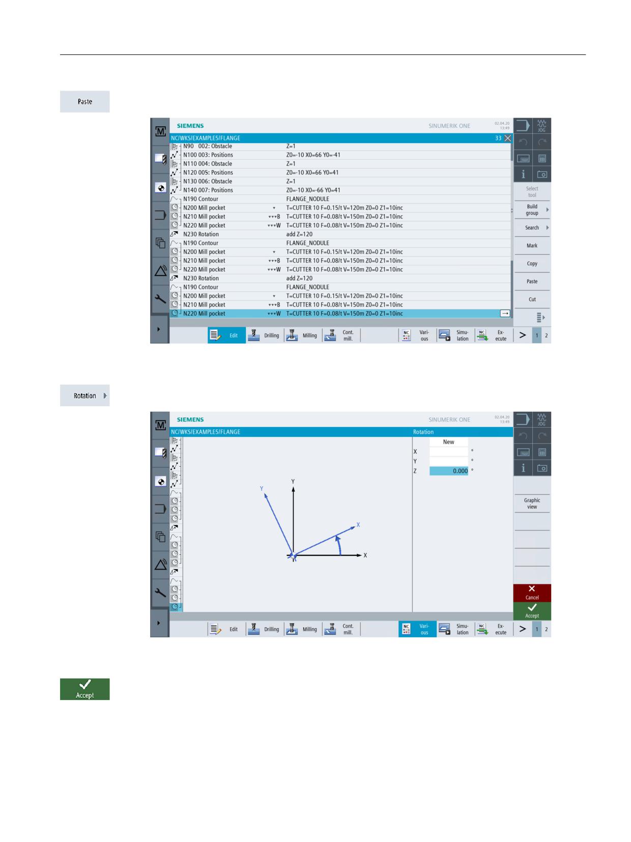
Paste the copied work steps.
Figure 10-45
Pasting the copied work steps
Select New and specify the value 0° to undo the rotation.
Figure 10-46
Undoing the rotation
Press "Accept" to apply your input.
Easy milling with ShopMill
Training Documents, 05/2020, 6FC5095-0AB50-1BP2
205
Example 5: Flange
10.6 Chamfering contours
10.6
Chamfering contours
Operating sequences
Chamfer the circular pocket last machined without help.
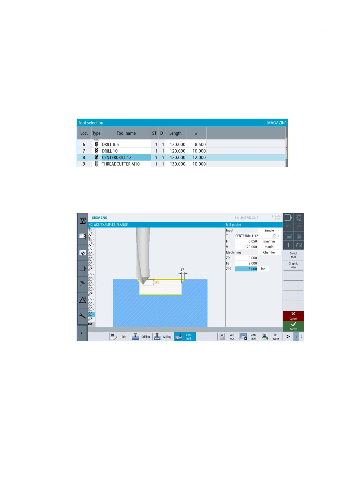
For chamfering, you will need a tool type which allows entering of an acute angle, in the
example CENTERDRILL12.
Figure 10-47
Center drill
Select Chamfering for machining. The machining of the chamfer is programmed via the chamfer
width (FS) and the insertion depth of the tool tip (ZFS).
Figure 10-48
Chamfering
Easy milling with ShopMill
206
Training Documents, 05/2020, 6FC5095-0AB50-1BP2
Example 5: Flange
10.6 Chamfering contours
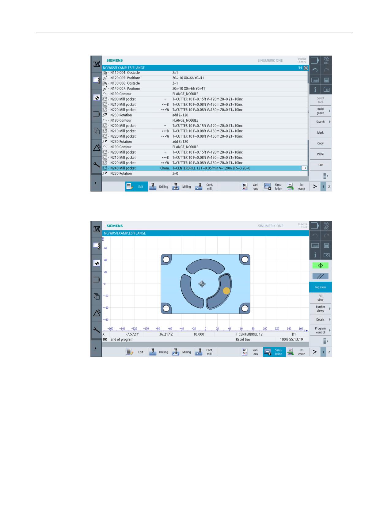
Figure 10-49
Work step "Chamfering" in the work step editor
Figure 10-50
Top view on the chamfered contour
Easy milling with ShopMill
Training Documents, 05/2020, 6FC5095-0AB50-1BP2
207
Example 5: Flange
10.7 Longitudinal and circular grooves
10.7
Longitudinal and circular grooves
Operating sequences
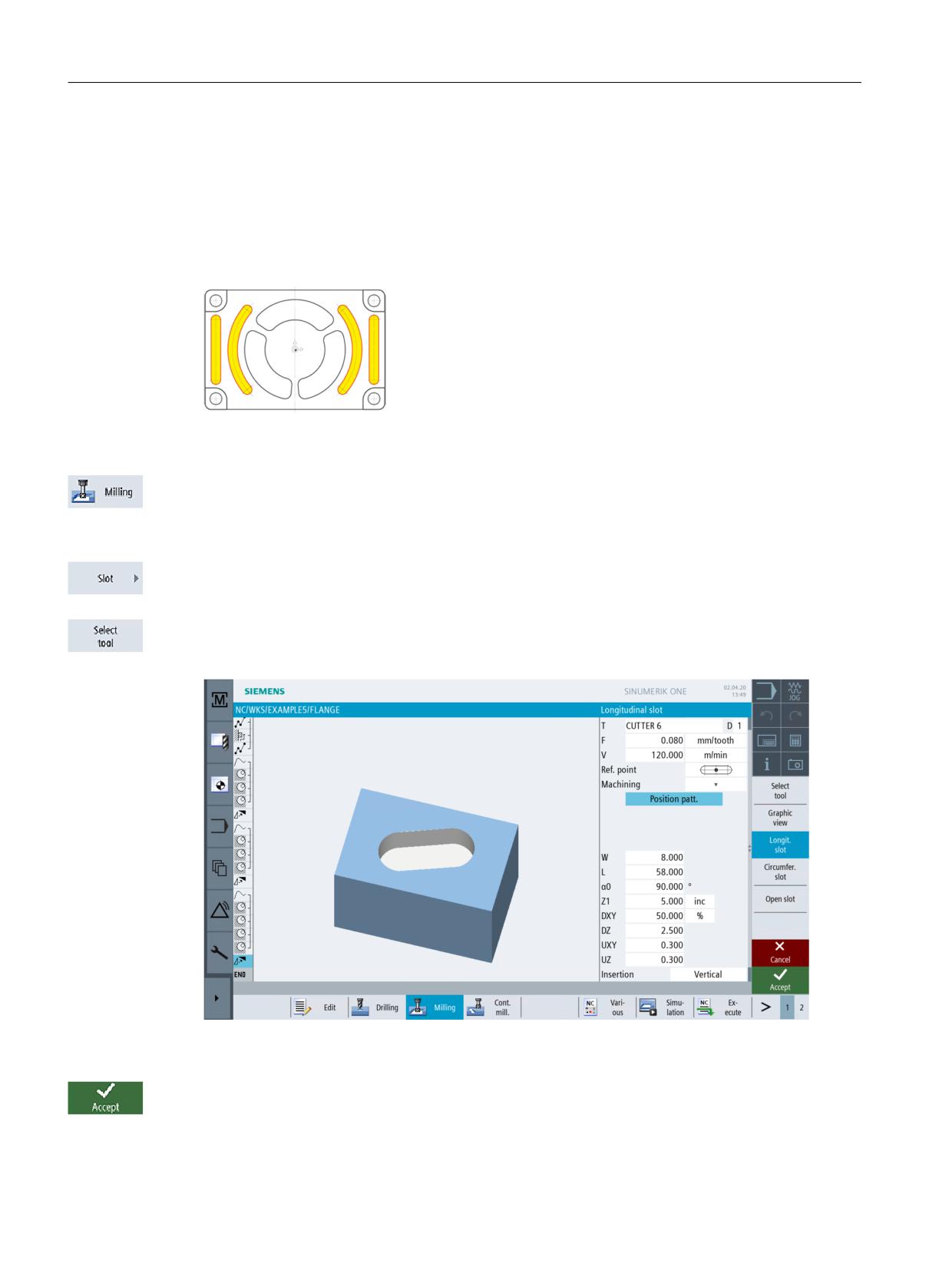
Finally, program the grooves. They will be positioned to the correct point by way of Position
pattern and Positioning to full circle.
Figure 10-51
Longitudinal and circular grooves
Select the Milling softkey.
Select the Groove softkey.
Use the tool CUTTER 6 (F = 0.08 mm/tooth and v = 120 m/min) for the roughing of the
longitudinal grooves.
Figure 10-52
Roughing a longitudinal groove
Press "Accept" to apply the values entered.
Easy milling with ShopMill
208
Training Documents, 05/2020, 6FC5095-0AB50-1BP2
Example 5: Flange
10.7 Longitudinal and circular grooves
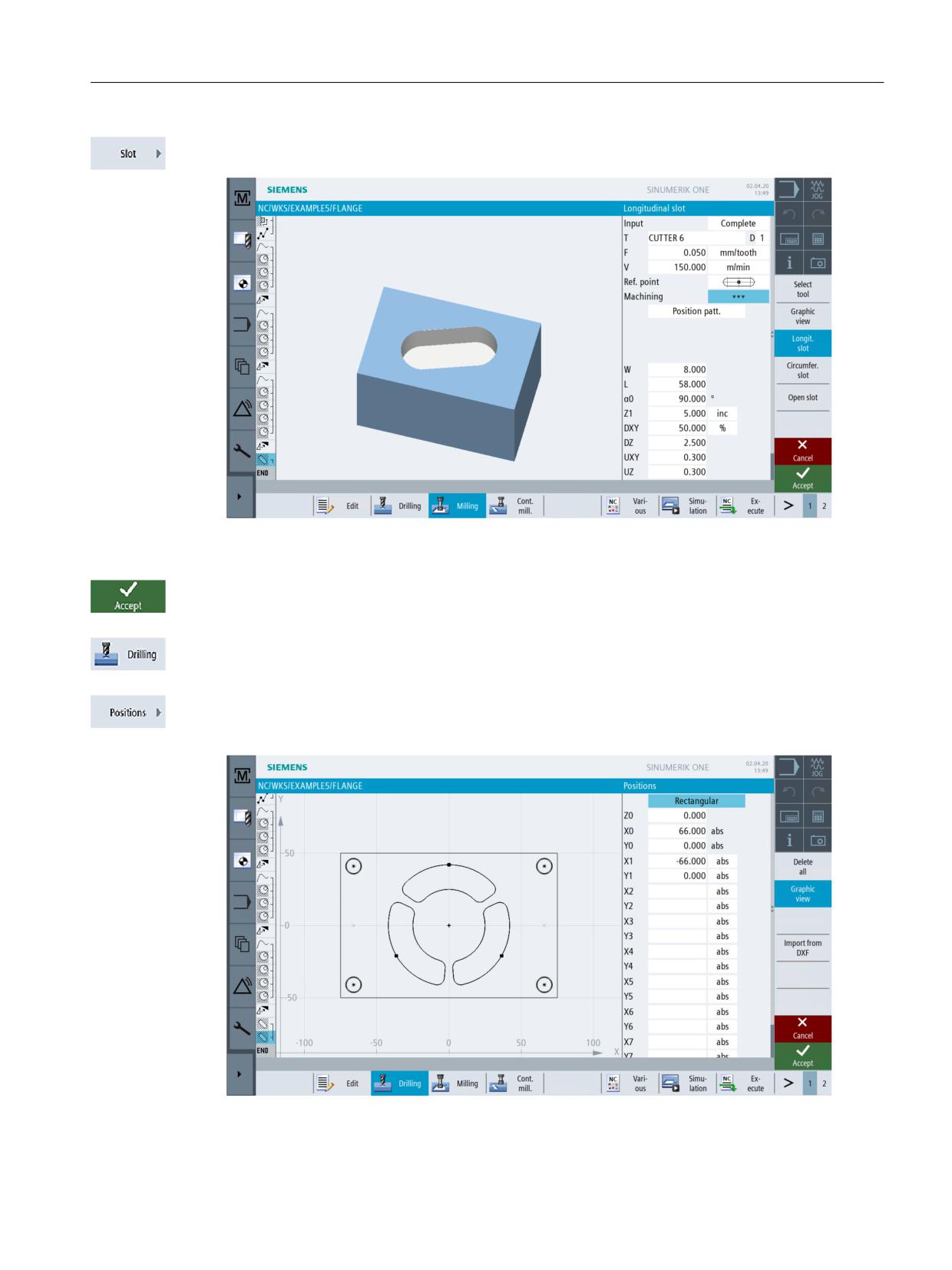
Use the same tool (F = 0.05 mm/tooth and v = 150 m/min) for finishing.
Figure 10-53
Finishing a longitudinal groove
Press "Accept" to apply the values entered.
Select the Drilling softkey.
Subsequently, specify the positions of the longitudinal grooves. The reference point lies in the
groove center.
Figure 10-54
Specifying the positions for the longitudinal groove
Easy milling with ShopMill
Training Documents, 05/2020, 6FC5095-0AB50-1BP2
209
Example 5: Flange
10.7 Longitudinal and circular grooves
Press "Accept" to apply the values entered.
Select the Milling softkey.
Select the Groove softkey.
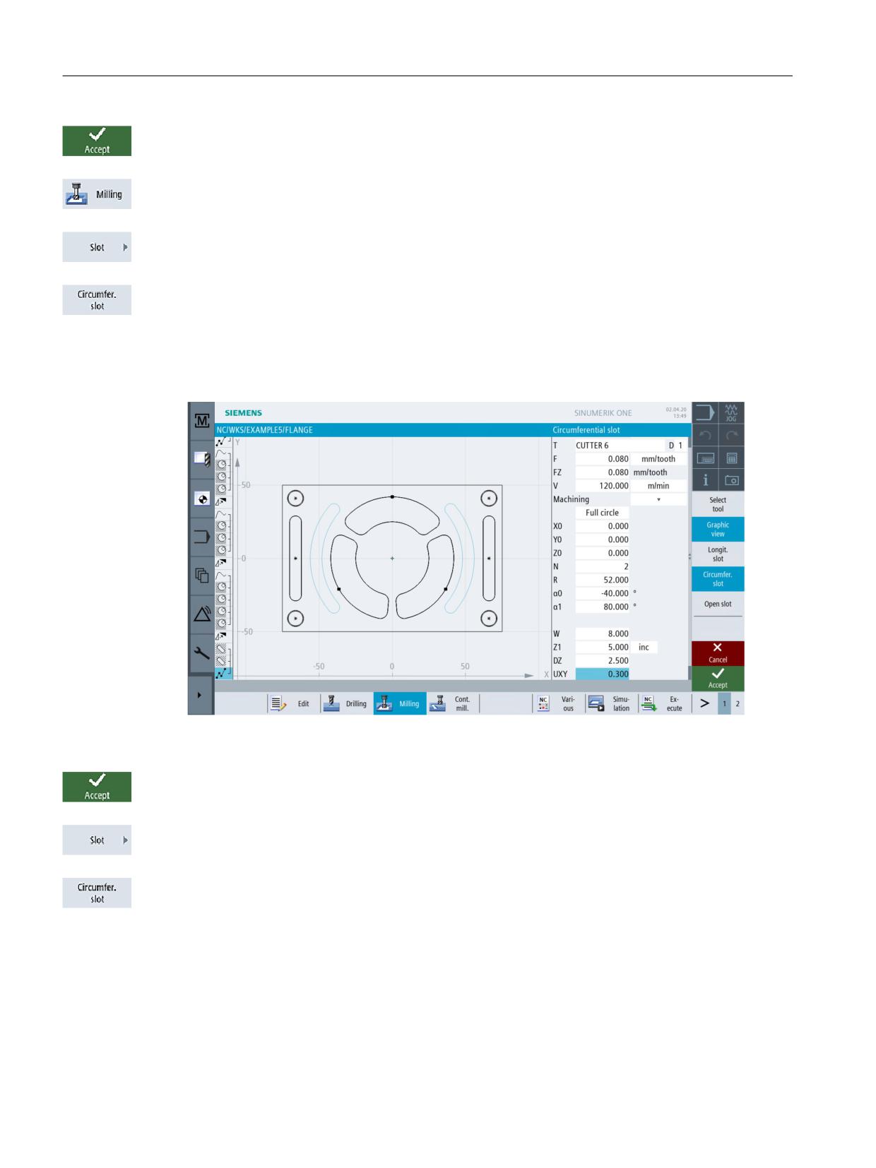
Use the tool CUTTER 6 (F = 0.08 mm/tooth, FZ = 0.08 mm/tooth and v = 120 m/min) for the
roughing of the circular grooves.
Thanks to the Full circle option, the circular grooves are positioned to each other automatically
at the same distance. The reference point in X/Y/Z refers to the center point of the circular
grooves.
Figure 10-55
Roughing a circular groove
Press "Accept" to apply the values entered.
Select the Groove softkey.
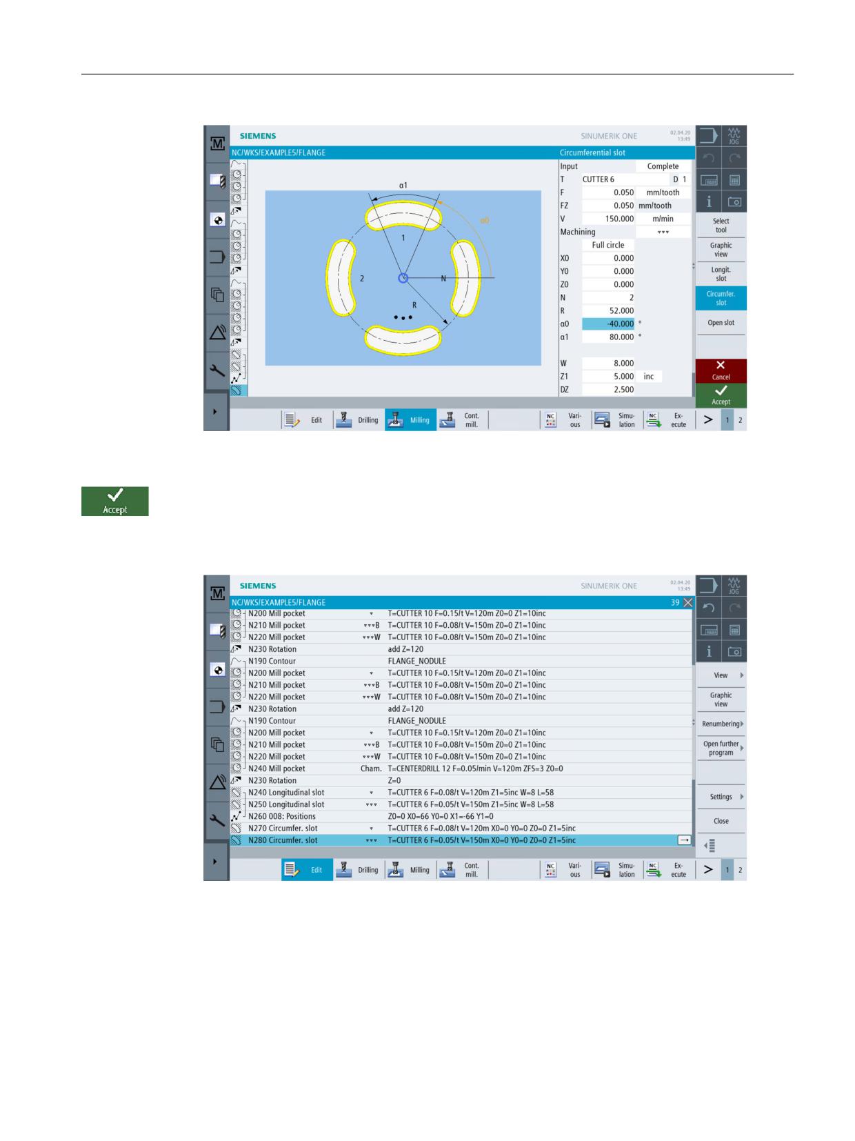
Use the same tool (F = 0.05 mm/tooth,FZ = 0.05 mm/tooth and v = 150 m/min) for finishing.
Easy milling with ShopMill
210
Training Documents, 05/2020, 6FC5095-0AB50-1BP2
Example 5: Flange
10.7 Longitudinal and circular grooves
Figure 10-56
Finishing the circular groove
Press "Accept" to apply the values entered.
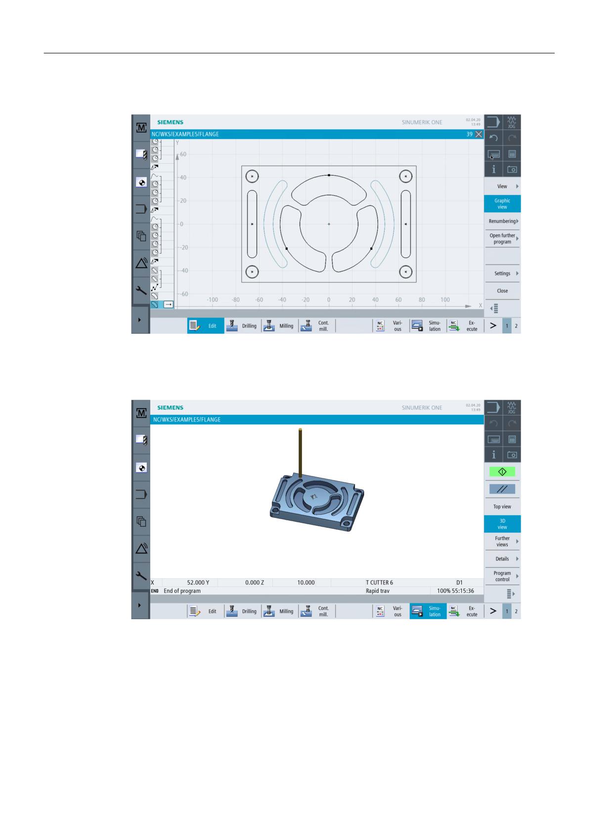
Process plan
Figure 10-57
Extract from process plan
Easy milling with ShopMill
Training Documents, 05/2020, 6FC5095-0AB50-1BP2
211
Example 5: Flange
10.7 Longitudinal and circular grooves
Broken-line graphics
Figure 10-58
Broken-line graphics
Simulation in 3D display
Figure 10-59
3D view
Easy milling with ShopMill
212
Training Documents, 05/2020, 6FC5095-0AB50-1BP2
And now you can start manufacturing!
11
After you have acquired well-founded knowledge of the creation of process plans in ShopMill by
working with the examples, we will now machine workpieces.
To machine a workpiece, proceed as follows:
Approaching reference point
After turning on the control system and before traversing the axes according to the process plans
or traversing manually, you will have to approach the reference point of the machine. In this way,
ShopMill will find the start for counting in the position measuring system of the machine.
Since approaching of the reference point is different depending on machine type and
manufacturer, only a few hints can be given here for orientation:
1. If necessary traverse the tool to a free point in the work space from which traversing is
possible in all directions without collision. Make sure that the tool is then not beyond the
reference point of the corresponding axis (since reference point approach is only performed
in one direction for each axis; otherwise, this point cannot be reached).
2. Perform the reference point approach exactly according to the specifications of the machine
manufacturer.
Clamping the workpiece
To guarantee machining in accordance with the specified dimensions and, naturally, also for
your own safety, it is imperative to clamp the workpiece tightly. As a rule, machine jaw vices or
clamps are used.
Setting the workpiece zero
Since ShopMill cannot guess where in the work space the workpiece is located, you must
determine the workpiece zero.
In the plane, the workpiece zero is set in most cases
• using either a 3D probe or
• an edge probe
through sampling.
In the tool axis, the workpiece zero is set in most cases
• using the 3D probe through sampling or
• using a tool through sampling
Easy milling with ShopMill
Training Documents, 05/2020, 6FC5095-0AB50-1BP2
213
And now you can start manufacturing!
Note
When working with the measuring devices and measuring cycles, observe the manufacturer
specifications.
Executing the process plan
Now the machine is prepared, the workpiece is set up, and the tools are gauged. At last we can
start!
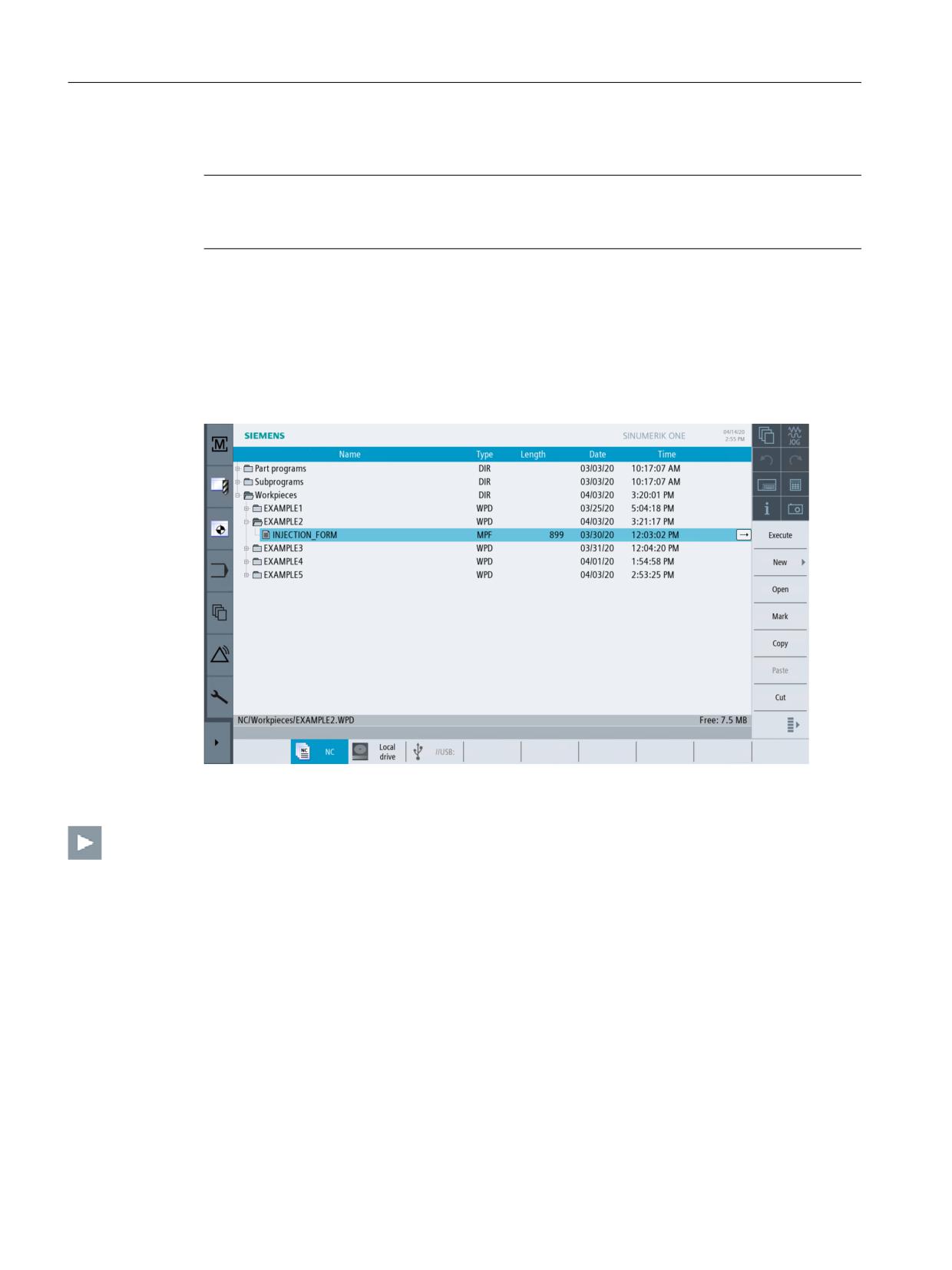
First select the program you want to execute in the Program Manager, e.g. INJECTION_FORM.
Figure 11-1
Selecting the program
Open the program.
Easy milling with ShopMill
214
Training Documents, 05/2020, 6FC5095-0AB50-1BP2
And now you can start manufacturing!
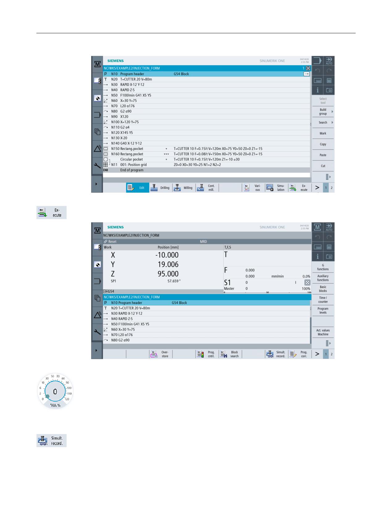
Figure 11-2
Opening the process plan
Select the NC selection softkey.
Figure 11-3
Executing
Due to the fact that the process plan has not yet been executed with control, turn the feedrate
potentiometer to zero position to ensure that you keep everything under control from the
beginning.
If you also want to see a simulation during machining, select the Drawing softkey before
starting. Only then are all traversing paths and their effects are displayed.
Easy milling with ShopMill
Training Documents, 05/2020, 6FC5095-0AB50-1BP2
215