SINUMERIK 840D sl. Service - Safety Integrated. Manual (2020) - page 19

Actions for hardware replacement and modifications
6.2 Effect of the acceptance test for specific measures
Measure
Documentation
Function test
Function test
Supplemen-
Completion of
Part 1
Part 2
tary meas-
the report
ures
Changing an individual limit
Inclusion of SI function
No
Yes, only test
No
Document
value (e.g. SLS limit)
per axis
changed check-
of the corre-
sum
sponding
function at
the axes in-
volved
Function expansion or new
Inclusion of the SI func-
Yes, only for
Yes, only
No
Document
functions (e.g. additional ac-
tion per axis, function ta-
the tests influ-
changed check-
tests influ-
tuator, additional SLS level)
ble
enced by the
sum
enced by the
function ex-
function ex-
pansion
pansion
Change the safety program
Inclusion of SI function
Yes,
No
No
Document
per axis, function table,
only Points
changed check-
safety summary
2.4, 2.5 and
sum
2.6 (Page 115)
Data transferred to additional
Include machine descrip-
Yes
No
Points 4.1
Document
machines via series commis-
tion (check the SW ver-
and 4.5
changed check-
sioning
sion)
(Page 115)
sum
1) Regarding the acceptance test, the notes in the documentation of the SW upgrade must be
carefully observed.
2) An update involves an update to a new Service Pack (SP) or a new Hotfix (HF) within a software
line, e.g.:
04.07.02.00 (02=Service Pack; 00=Hotfix) auf 04.07.03.00 (does not take into account any
change of the Safety functionality).
3) An upgrade involves an upgrade to a new software release, e.g.:
04.07.xx.xx to 04.08.xx.xx (does not take into account any change to the safety functionality).
4) If no drive checksums have changed, then a complete function test Part 2 does not have to be
performed. However, a test should be performed with reduced test scope.
Note
Test with reduced test scope
Test of Safety Integrated Functions at any axis (each MCU and each NX) and a comparison with
the test results before the upgrade.
Note
If the results of function test, Part 2 are taken from another identical machine, then this is the
sole responsibility of the machine manufacturer and should be appropriately commented in the
acceptance report.
SINUMERIK Operate acceptance test
100
Function Manual, 10/2020, 6FC5397-3HP40-0BA1

Actions for hardware replacement and modifications
6.2 Effect of the acceptance test for specific measures
6.2.5
Effects with SINUMERIK 840D sl Safety Integrated (system-integrated)
The effects of the acceptance test with certain measures are described in the following table.
Function test parts 1 and 2, as well as the supplementary measures relate to Chapter Example
contents of the acceptance test (Page 117).
Measure
Documentation
Function test
Function test
Supplementary
Completion of the
Part 1
Part 2
measures
report
Replacement of
Supplement hard-
No
No
Point 4.1
Document the
the encoder system
ware data
(Page 117)
modified check-
sum. From soft-
ware release 4.5
SP6, the modified
checksum is docu-
mented in the log
file.
Replacing an SMC,
Supplement hard-
No
No
Point 4.1
Document the
SME module
ware data/ soft-
(Page 117)
modified check-
ware version data
sum. From soft-
ware release 4.5
SP6, the modified
checksum is docu-
mented in the log
file.
Replacing a motor
Inclusion of hard-
No
No
Point 4.1
Document the
equipped with
ware data/ soft-
(Page 117)
modified check-
DRIVE-CLiQ
ware version data
sum. From soft-
ware release 4.5
SP6, the modified
checksum is docu-
mented in the log
file.
Replacing a Motor
Supplement hard-
Yes, only Points 2.1
No
Point 4.1
No
Module
ware data/ soft-
and 2.2 (Page 117)
(Page 117)
ware version data
Replacing the NCU
Inclusion of hard-
Yes, only Points
No
Point 4.1
No
hardware
ware data/ soft-
2.1, 2.2, 2.3 and
(Page 117)
ware version data
2.5 (Page 117)
(without trace re-
cording)
Replacing the NX
Inclusion of hard-
Yes, only Points 2.1
No
Point 4.1
No
hardware
ware data/ soft-
and 2.2 (Page 117)
(Page 117), only
ware version data
for axes controlled
by the NX
Hardware replace-
No
No
Point 4.2
No
ment, PROFIsafe
(Page 117)
I/O
Change system
Supplement con-
No
Yes
No
Document
clock cycle (SI clock
figuration data
changed checksum
cycle changes)
Changed system
Supplement con-
No
Yes
No
No
clock cycle (SI clock
figuration data
cycle, IPO remains
the same)
SINUMERIK Operate acceptance test
Function Manual, 10/2020, 6FC5397-3HP40-0BA1
101

Actions for hardware replacement and modifications
6.2 Effect of the acceptance test for specific measures
Measure
Documentation
Function test
Function test
Supplementary
Completion of the
Part 1
Part 2
measures
report
Changed IPO clock
Supplement con-
No
Yes
No
Document
cycle (checksum
figuration data
changed checksum
NCK 0 changes)
Change to the SI
Supplement con-
No
Yes
No
Document
clock cycle
figuration data
changed checksum
Changed PROFI-
Supplement con-
Yes, only Point 2.7
No
No
Document
safe clock cycle
figuration data
(Page 117)
changed checksum
Changes to the
Adapt configura-
Yes, only Point 2.6
No
Point 4.1
Document
drive assignment
tion diagram
(Page 117) for the
(Page 117)
changed checksum
changed axes
Changed
Supplement, SI
Yes, only for the
Yes, only for the
No
Document
SAFE_USER_DATA
function per axis,
tests influenced by
tests influenced by
changed checksum
function table
the function ex-
the function ex-
pansion
pansion
Reconfigured PRO-
Supplement con-
No
No
Only test the modi-
Document
FIsafe I/O in S7
figuration data
fied configuration
changed checksum
Changed within
Supplement con-
Yes, only Points 2.6
No
No
Document
the scope of "mod-
figuration diagram
and 2.7 (Page 117)
changed checksum
ular PROFIsafe"
and function table
Change within the
Supplement con-
Yes, only Points 2.6
No
No
Document
scope of “F_SEND/
figuration diagram
and 2.7 (Page 117)
changed checksum
F_RECEIVE"
and function table
SW upgrade 2(NCU/
Supplementary
No 1
No 1
No 1
Document
drive/PLC)
software version
changed checksum
Changed jerk
No 1
No 1
Yes, only Point 4.3
No
and/or acceleration
(Page 117)
SW upgrade 3
Supplementary
No 1
No 1, 4
Points 4.3 and 4.4
Document
software version
(Page 117)
changed checksum
(NCU/drive/PLC)
Software upgrade
Supplementary
No
No
No
No
(HMI)
software version
Changing an indi-
Inclusion of SI func-
No
Yes, only test the
No
Document
vidual limit value
tion per axis
corresponding
changed checksum
(e.g. SG limit)
functions at the ax-
es involved
Expanded function
Inclusion of the SI
Yes, only for the
Yes, only for the
No
Document
(e.g. additional ac-
function per axis,
tests influenced by
tests influenced by
changed checksum
tuator, additional
function table
the function ex-
the function ex-
SG stage)
pansion
pansion
SPL change
Inclusion of the SI
Yes, only Point 2.6
No
No
Document
function per axis,
(Page 117)
changed checksum
function table
Data transferred to
Possibly supple-
Yes
No
Points 4.1 and 4.5
Document
additional ma-
ment, machine de-
(Page 117)
changed checksum
chines with series
scription (check
commissioning
the SW version)
1
Regarding the acceptance test, the notes in the documentation of the SW upgrade must be carefully observed.
2
An update involves an update to a new Service Pack (SP) or a new Hotfix (HF) within a software line, e.g. 02.05.01.03 (01 =
Service Pack; 03 = Hotfix) to 02.05.02.03 (does not take into account any change of the Safety functionality).
SINUMERIK Operate acceptance test
102
Function Manual, 10/2020, 6FC5397-3HP40-0BA1
Actions for hardware replacement and modifications
6.2 Effect of the acceptance test for specific measures
3
An upgrade involves an upgrade to a new software release, e.g. 02.05.xx.xx to 02.06.xx.xx or 02.xx.xx.xx. to 03.xx.xx.xx
(does not take into account any change of the Safety functionality).
4
If no checksums have changed, then a complete function test, Part 2 does not have to be performed. However, a test should
be performed with reduced test scope.
Note
Test with reduced test scope
Test of Safety Integrated Functions at any axis (each NCU and each NX) and a comparison with
the test results before the upgrade.
Note
If the results of function test, Part 2 are taken from another identical machine, then this is the
sole responsibility of the machine manufacturer and should be appropriately commented in the
acceptance report.
SINUMERIK Operate acceptance test
Function Manual, 10/2020, 6FC5397-3HP40-0BA1
103
Actions for hardware replacement and modifications
6.2 Effect of the acceptance test for specific measures
SINUMERIK Operate acceptance test
104
Function Manual, 10/2020, 6FC5397-3HP40-0BA1
Tips and tricks
7
Trace does not start n < nx
System:
SINUMERIK 840D sl with Safety Integrated
Version:
CNC software V4.7 or higher
Description:
If n < nx, then the trace cannot start.
The most common reason for this is the machine data MD36060 (n<nmin). The machine data is
not Safety machine data, is seldom used, and is therefore overlooked.
The default value is 5 mm/min or 1 rpm. Reduce the size of the data item.
Remedy:
The trace start will commence if the following prerequisite is met:
V > 2 * [MD36060]
Trace does not start, axis oscillating
System:
SINUMERIK 840D sl with Safety Integrated
Version:
CNC software V4.7 or higher
Description:
The trace is stopped at V < [MD36060].
A motor exhibiting intense vibrations (e.g. single encoder system in the motor and rack-and-
pinion drive) can generate a start and immediate stop trigger. This will produce the same result.
Remedy:
Optimize the drive.
Trace does not start (wrong direction of rotation)
System:
SINUMERIK 840D sl with Safety Integrated
SINUMERIK Operate acceptance test
Function Manual, 10/2020, 6FC5397-3HP40-0BA1
105
Tips and tricks
Version:
CNC software V4.7 or higher
Description:
If the safe actual values (NCK/drive) run contrary to the MCS actual value, then the trace cannot
start.
Remedy:
Change the direction of rotation and start the trace again.
Trace does not start (gantry and leading/following axis)
System:
SINUMERIK 840D sl with Safety Integrated
Version:
CNC software V4.7 or higher
Description:
Limit value was exceeded for one axis only as a result of mechanical occurrences or disparate
parameterization for both axes. The limit value in this regard would not necessarily have to be
exceeded for the tested axis.
Remedy:
Check the alarm messages. If the limit value was not exceeded for the axis to be tested, adapt
the parametrization.
Inserting a blank line into the template
Description:
Normal editors use the Enter key to enter a new blank line.
But if you press on the Enter key in the template editor, the next input field becomes active.
Remedy:
1. Move the cursor to the beginning of a line.
2. Press the "Ctrl + Return" key combination.
The new blank line is inserted in front of the line that is highlighted with the cursor.
Performing a trace for the test type "Function relations"
To ensure that a trace can be carried out for the test type "Function relationships (Page 28)", the
following precondition is necessary:
The trace definition for this type of test must be saved in the "Acceptance test/Trace" folder.
SINUMERIK Operate acceptance test
106
Function Manual, 10/2020, 6FC5397-3HP40-0BA1
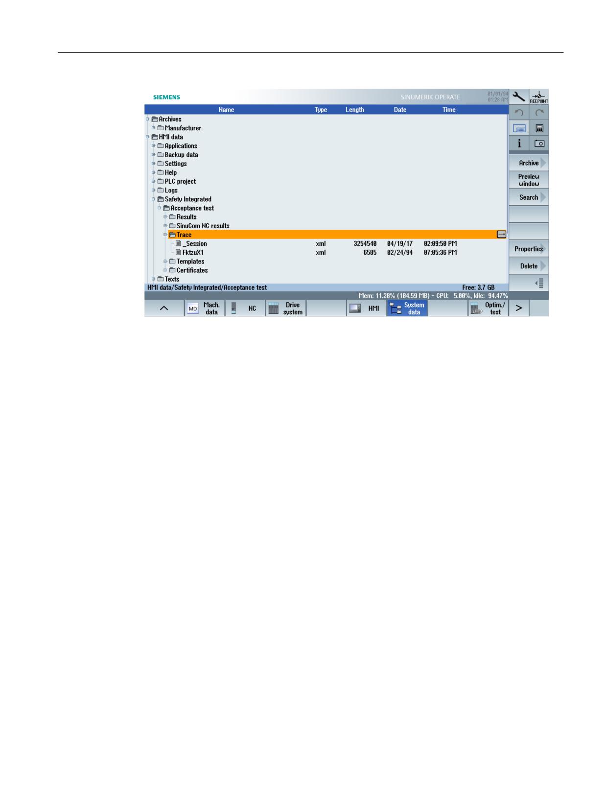
Tips and tricks
Figure 7-1
Folder for traces
Testing the safe limit positions
System:
SINUMERIK 840D sl with Safety Integrated
SINUMERIK 840D sl with Safety Integrated plus
Note:
If you switch between the 1st and the 2nd software limit switch during the test of the safe limit
position SLP, you must trigger a channel reset before starting the acceptance test case.
Otherwise, deactivation of the software limit switch is not applied.
SINUMERIK Operate acceptance test
Function Manual, 10/2020, 6FC5397-3HP40-0BA1
107
Tips and tricks
SINUMERIK Operate acceptance test
108
Function Manual, 10/2020, 6FC5397-3HP40-0BA1
Appendix
A
A.1
Example contents of the acceptance test
A.1.1
Overview
Note
This chapter includes exemplary acceptance tests for drive-based safety for the SINUMERIK
828D, SINUMERIK 840D sl, SINUMERIK ONE and SINUMERIK MC, as well as an exemplary
acceptance test for system-integrated Safety for the SINUMERIK 840D sl.
The machine manufacturer is responsible for carrying out and documenting an acceptance test.
A.1.2
SINUMERIK 828D/840D sl/ONE/MC - drive-based safety functions
A.1.2.1
SINUMERIK 828D with Safety Integrated
1)
DOCUMENTATION
Documentation of the machine including the safety functions
1.1 Machine description (with overview diagram)
1.2 Details about the control system
1.3 Configuration diagram
1.4 Function table
Active monitoring functions depending on the operating mode, the protective doors and
other sensors.
It makes sense that this table is part of the documentation of the engineering work that
has been carried out.
1.5 SI functions per axis
1.6 Information and data about safety equipment
2)
FUNCTION TEST PART 1
General function test, including a check of the wiring/configuring
2.1 Testing the switch-off signal paths
Testing the forced checking procedure of the switch-off signal paths
2.2 Testing the forced checking procedure of the inputs and outputs
2.3 Testing the Emergency Stop function and the safety circuits
2.4 Testing the function table
SINUMERIK Operate acceptance test
Function Manual, 10/2020, 6FC5397-3HP40-0BA1
109
Appendix
A.1 Example contents of the acceptance test
2.5
Testing the control signals of the drive groups of TM54F
3)
FUNCTION TEST PART 2
Detailed function test incl. checking the values of the individual SI functions used
3.1
Testing the SI Safe Torque Off function (safe operating stop, SBH) - STO
3.2
Testing the SI function Safe Stop 1 - SS1
3.3
Testing the SI function Safe Stop 2 - SS2
3.4
Testing the SI function Safe Operating Stop - SOS
(with evaluated measurement diagram or measured values)
3.5
Testing the SI function Safely-Limited Speed - SLS
(with evaluated measurement diagram or measured values)
3.6
Testing the SI function Safe Speed Monitor - SSM
(with evaluated measurement diagram or measured values)
3.7
Testing the SI function Safely-Limited Position - SLP
(with evaluated measurement diagram or measured values)
3.8
Testing the SI function Safe Direction - SDI
(with evaluated measurement diagram or measured values)
3.9
Testing the SI function Safe Brake Control/Safe Brake Test - SBC/SBT
(with evaluated measurement diagram or measured values)
4)
Supplementary measures
4.1
Function test, actual value sensing
• General testing of the actual value sensing
After replacing a component, the system is switched on and briefly operated in both
directions.
• Check of the safe actual value acquisition
With the motion monitoring functions activated, the drive is briefly moved in both
directions.
4.2
Checking the SGE/SGA signals of the relevant module
4.3
After changing the acceleration behavior/jerk, axis-specific tests are carried out of Func-
tion Test Part 2
4.4
Testing the new safety functionality
4.5
Checking checksums and software versions, comparing whether checksums and soft-
ware versions are identical with the reference machine.
5)
COMPLETION OF THE REPORT
A report of the commissioning status that was checked is generated with the appropriate
counter-signatures
5.1
Checking SINAMICS Safety Integrated parameters
5.2
Checking SINAMICS software releases
5.3
Logging and documenting SINAMICS Safety Integrated checksums
5.4
Verifying data archiving
5.5
Countersignature
APPENDIX
Reports/measurement plots for FUNCTION TEST PARTS 1/2
• Archiving SI-relevant drive parameters
SINUMERIK Operate acceptance test
110
Function Manual, 10/2020, 6FC5397-3HP40-0BA1
Appendix
A.1 Example contents of the acceptance test
A.1.2.2
SINUMERIK 840D sl with Safety Integrated plus
1)
DOCUMENTATION
Documentation of the machine including the safety functions
1.1
Machine description (with overview diagram)
1.2
Details about the control system
1.3
Configuration diagram
1.4
Function table
Active monitoring functions depending on the operating mode, the protective doors and
other sensors/CPU-CPU communication.
It makes sense that this table is part of the documentation of the engineering work that
has been carried out.
1.5
SI functions per axis
1.6
Information and data about safety equipment
1.7
Safety summary of the F-PLC
2)
FUNCTION TEST PART 1
General function test, including a check of the wiring/configuring
2.1
Test of the SI function "Safe Torque Off" (STO)
• Required when used in Basic and/or Extended Functions.
• You do not need to prepare a trace recording for this test.
2.2
Test of the SI function "Safe Brake Control" (SBC)
• Required when using Basic and/or Extended Functions.
• You do not need to prepare a trace recording for this test.
2.3
Testing the forced checking procedure of the inputs and outputs
2.4
Testing the Emergency Stop function and the safety circuits
2.5
Test of all of the switching states of the safety-related sensors and actuators and associ-
ated input/output signals (test of the function table)
2.6
Test of the PROFIsafe input/output signals
2.7
Check of the monitoring and delay times based on the safety summary
3)
FUNCTION TEST PART 2
Detailed function test incl. checking the values of the individual SI functions used
3.1
Test of the SI function Safe Operating Stop (SOS)
(with the evaluated measurement diagram or measured values in each case)
3.2
Test of the SI function Safely-Limited Speed (SLS)
(with the evaluated measurement diagram or measured values in each case)
3.3
Test of the SI function Safe Speed Monitor (SSM)
(with the evaluated measurement diagram or measured values in each case)
3.4
Test of the SI function Safely-Limited Position (SLP)
(with the evaluated measurement diagram or measured values in each case)
3.5
Test of the SI function Safe Cam (SCA) (check via
diagnostics display or assigned SGA or with the evaluated measurement diagram or
measured values in each case)
SINUMERIK Operate acceptance test
Function Manual, 10/2020, 6FC5397-3HP40-0BA1
111
Appendix
A.1 Example contents of the acceptance test
3.6
Test of the SI function Safe Direction SDI
(with the evaluated measurement diagram or measured values in each case)
3.7
Test of the SI function Safe Stop 1 (SS1)
(with the evaluated measurement diagram or measured values in each case)
3.8
Test of the SI function Safe Stop 2 (SS2)
(with the evaluated measurement diagram or measured values in each case)
3.9
Test of the SI function Safe Stop 2 (SS2E)
(with the evaluated measurement diagram or measured values in each case)
3.10
Test of the SI function Safe Stop 2 Extended Stop and Retract (SS2ESR)
(with evaluated measurement diagram or measured values)
3.11
Testing the SI function Safe Brake Control/Safe Brake Test - SBC/SBT
(with evaluated measurement diagram or measured values)
4)
Supplementary measures
4.1
Function test, actual value sensing
• General testing of the actual value sensing
After replacing a component, the system is switched on and briefly operated in both
directions.
• Check of the safe actual value acquisition
With the motion monitoring functions activated, the drive is briefly moved in both
directions.
4.2
Check of the input/output signals of the relevant module
4.3
After changing the acceleration behavior/jerk, axis-specific tests are carried out of Func-
tion Test Part 2
4.4
Testing the new safety functionality
4.5
Checking checksums and software versions, comparing whether checksums and soft-
ware versions are identical with the reference machine. Hardware checksum p9729[2] is
always different from that of the reference machine.
5)
COMPLETION OF THE REPORT
A report of the commissioning status that was checked is generated with the appropriate
counter-signatures
5.1
Check the SI parameterization
5.2
Check of the hardware configuration of the PROFIsafe peripherals
5.3
Logging of the checksums (SINAMICS parameters, PROFIsafe peripherals, FOverallsigna-
ture, Signature of the F-blocks with F-attribute)
5.4
Verifying data archiving
5.5
Countersignature
APPENDIX
Reports/measurement plots for FUNCTION TEST PARTS 1/2
• Alarm logs/servo trace measurements
• Archiving of the following safety-related data:
- Drive parameters
- Safety program of the F-PLC
- PLC project (if existing)
SINUMERIK Operate acceptance test
112
Function Manual, 10/2020, 6FC5397-3HP40-0BA1
Appendix
A.1 Example contents of the acceptance test
A.1.2.3
SINUMERIK ONE with Safety Integrated
1)
DOCUMENTATION
Documentation of the machine including the safety functions
1.1
Machine description (with overview diagram)
1.2
Details about the control system
1.3
Configuration diagram
1.4
Function table
Active monitoring functions depending on the operating mode, the protective doors and
other sensors/CPU-CPU communication.
It makes sense that this table is part of the documentation of the engineering work that
has been carried out.
1.5
SI functions per axis
1.6
Information and data about safety equipment
1.7
Safety summary of the F-PLC
2)
FUNCTION TEST PART 1
General function test, including a check of the wiring/configuring
2.1
Test of the SI function "Safe Torque Off" (STO)
• Required when used in Basic and/or Extended Functions.
• You do not need to prepare a trace recording for this test.
2.2
Test of the SI function "Safe Brake Control" (SBC)
• Required when using Basic and/or Extended Functions.
• You do not need to prepare a trace recording for this test.
2.3
Testing the forced checking procedure of the inputs and outputs
2.4
Testing the Emergency Stop function and the safety circuits
2.5
Test of all of the switching states of the safety-related sensors and actuators and associ-
ated input/output signals (test of the function table)
2.6
Test of the PROFIsafe input/output signals
2.7
Check of the monitoring and delay times based on the safety summary
3)
FUNCTION TEST PART 2
Detailed function test incl. checking the values of the individual SI functions used
3.1
Test of the SI function Safe Operating Stop (SOS)
(with the evaluated measurement diagram or measured values in each case)
3.2
Test of the SI function Safely-Limited Speed (SLS)
(with the evaluated measurement diagram or measured values in each case)
3.3
Test of the SI function Safe Speed Monitor (SSM)
(with the evaluated measurement diagram or measured values in each case)
3.4
Test of the SI function Safely-Limited Position (SLP)
(with the evaluated measurement diagram or measured values in each case)
3.5
Test of the SI function Safe Cam (SCA) (check via
diagnostics display or assigned SGA or with the evaluated measurement diagram or
measured values in each case)
SINUMERIK Operate acceptance test
Function Manual, 10/2020, 6FC5397-3HP40-0BA1
113
Appendix
A.1 Example contents of the acceptance test
3.6
Test of the SI function Safe Direction SDI
(with the evaluated measurement diagram or measured values in each case)
3.7
Test of the SI function Safe Stop 1 (SS1)
(with the evaluated measurement diagram or measured values in each case)
3.8
Test of the SI function Safe Stop 2 (SS2)
(with the evaluated measurement diagram or measured values in each case)
3.9
Test of the SI function Safe Stop 2 (SS2E)
(with the evaluated measurement diagram or measured values in each case)
3.10
Test of the SI function Safe Stop 2 Extended Stop and Retract (SS2ESR)
(with evaluated measurement diagram or measured values)
3.11
Testing the SI function Safe Brake Control/Safe Brake Test - SBC/SBT
(with evaluated measurement diagram or measured values)
4)
Supplementary measures
4.1
Function test, actual value sensing
• General testing of the actual value sensing
After replacing a component, the system is switched on and briefly operated in both
directions.
• Check of the safe actual value acquisition
With the motion monitoring functions activated, the drive is briefly moved in both
directions.
4.2
Check of the input/output signals of the relevant module
4.3
After changing the acceleration behavior/jerk, axis-specific tests are carried out of Func-
tion Test Part 2
4.4
Testing the new safety functionality
4.5
Checking checksums and software versions, comparing whether checksums and soft-
ware versions are identical with the reference machine. Hardware checksum p9729[2] is
always different from that of the reference machine.
5)
COMPLETION OF THE REPORT
A report of the commissioning status that was checked is generated with the appropriate
counter-signatures
5.1
Check the SI parameterization
5.2
Check of the hardware configuration of the PROFIsafe peripherals
5.3
Logging of the checksums (SINAMICS parameters, PROFIsafe peripherals, FOverallsigna-
ture, Signature of the F-blocks with F-attribute)
5.4
Verifying data archiving
5.5
Countersignature
APPENDIX
Reports/measurement plots for FUNCTION TEST PARTS 1/2
• Alarm logs/servo trace measurements
• Archiving of the following safety-related data:
- Drive parameters
- Safety program of the F-PLC
- PLC project (if existing)
SINUMERIK Operate acceptance test
114
Function Manual, 10/2020, 6FC5397-3HP40-0BA1
Appendix
A.1 Example contents of the acceptance test
A.1.2.4
SINUMERIK MC with Safety Integrated
1)
DOCUMENTATION
Documentation of the machine including the safety functions
1.1
Machine description (with overview diagram)
1.2
Details about the control system
1.3
Configuration diagram
1.4
Function table
Active monitoring functions depending on the operating mode, the protective doors and
other sensors/CPU-CPU communication.
It makes sense that this table is part of the documentation of the engineering work that
has been carried out.
1.5
SI functions per axis
1.6
Information and data about safety equipment
1.7
Safety summary of the F-PLC
2)
FUNCTION TEST PART 1
General function test, including a check of the wiring/configuring
2.1
Test of the SI function "Safe Torque Off" (STO)
• Required when used in Basic and/or Extended Functions.
• You do not need to prepare a trace recording for this test.
2.2
Test of the SI function "Safe Brake Control" (SBC)
• Required when using Basic and/or Extended Functions.
• You do not need to prepare a trace recording for this test.
2.3
Testing the forced checking procedure of the inputs and outputs
2.4
Testing the Emergency Stop function and the safety circuits
2.5
Test of all of the switching states of the safety-related sensors and actuators and associ-
ated input/output signals (test of the function table)
2.6
Test of the PROFIsafe input/output signals
2.7
Check of the monitoring and delay times based on the safety summary
3)
FUNCTION TEST PART 2
Detailed function test incl. checking the values of the individual SI functions used
3.1
Test of the SI function Safe Operating Stop (SOS)
(with the evaluated measurement diagram or measured values in each case)
3.2
Test of the SI function Safely-Limited Speed (SLS)
(with the evaluated measurement diagram or measured values in each case)
3.3
Test of the SI function Safe Speed Monitor (SSM)
(with the evaluated measurement diagram or measured values in each case)
3.4
Test of the SI function Safely-Limited Position (SLP)
(with the evaluated measurement diagram or measured values in each case)
3.5
Test of the SI function Safe Cam (SCA) (check via
diagnostics display or assigned SGA or with the evaluated measurement diagram or
measured values in each case)
SINUMERIK Operate acceptance test
Function Manual, 10/2020, 6FC5397-3HP40-0BA1
115
Appendix
A.1 Example contents of the acceptance test
3.6
Test of the SI function Safe Direction SDI
(with the evaluated measurement diagram or measured values in each case)
3.7
Test of the SI function Safe Stop 1 (SS1)
(with the evaluated measurement diagram or measured values in each case)
3.8
Test of the SI function Safe Stop 2 (SS2)
(with the evaluated measurement diagram or measured values in each case)
3.9
Test of the SI function Safe Stop 2 (SS2E)
(with the evaluated measurement diagram or measured values in each case)
3.10
Test of the SI function Safe Stop 2 Extended Stop and Retract (SS2ESR)
(with evaluated measurement diagram or measured values)
3.11
Testing the SI function Safe Brake Control/Safe Brake Test - SBC/SBT
(with evaluated measurement diagram or measured values)
4)
Supplementary measures
4.1
Function test, actual value sensing
• General testing of the actual value sensing
After replacing a component, the system is switched on and briefly operated in both
directions.
• Check of the safe actual value acquisition
With the motion monitoring functions activated, the drive is briefly moved in both
directions.
4.2
Check of the input/output signals of the relevant module
4.3
After changing the acceleration behavior/jerk, axis-specific tests are carried out of Func-
tion Test Part 2
4.4
Testing the new safety functionality
4.5
Checking checksums and software versions, comparing whether checksums and soft-
ware versions are identical with the reference machine. Hardware checksum p9729[2] is
always different from that of the reference machine.
5)
COMPLETION OF THE REPORT
A report of the commissioning status that was checked is generated with the appropriate
counter-signatures
5.1
Check the SI parameterization
5.2
Check of the hardware configuration of the PROFIsafe peripherals
5.3
Logging of the checksums (SINAMICS parameters, PROFIsafe peripherals, FOverallsigna-
ture, Signature of the F-blocks with F-attribute)
5.4
Verifying data archiving
5.5
Countersignature
APPENDIX
Reports/measurement plots for FUNCTION TEST PARTS 1/2
• Alarm logs/servo trace measurements
• Archiving of the following safety-related data:
- Drive parameters
- Safety program of the F-PLC
- PLC project (if existing)
SINUMERIK Operate acceptance test
116
Function Manual, 10/2020, 6FC5397-3HP40-0BA1
Appendix
A.1 Example contents of the acceptance test
A.1.3
SINUMERIK 840D sl - system-integrated safety functions
A.1.3.1
SINUMERIK 840D sl with Safety Integrated (system-integrated)
1) DOCUMENTATION
Documentation of the machine including the safety functions
1.1
Machine description (with overview diagram)
1.2
Details about the control system
1.3
Configuration diagram
1.4
Function table
Active monitoring functions depending on the operating mode, the protective doors and
other sensors/CPU-CPU communication
Ideally, this table should be the objective and result of the configuring work.
1.5
SI functions per axis
1.6
Information and data about safety equipment
2) FUNCTION TEST PART 1
General function check incl. checking the wiring/programming/configuring
2.1
Testing the switch-off signal paths
(check the forced checking procedure of the switch-off signal paths)
2.2
Test the external stops
2.3
Test of the holding torque
2.4
Testing the forced checking procedure of the inputs and outputs
2.5
Testing the Emergency Stop function and the safety circuits
2.6
Test all SPL switching states and associated input/output signals
(test of the function table)
2.7
Test of the PROFIsafe input/output signals
Recommendation:
A forced checking procedure should be automatically performed each time that the control
system runs up.
3) FUNCTION TEST PART 2
Detailed function test incl. checking the values of the individual SI functions used
3.1
Test of the SI function Safe Operating Stop - SBH
(with evaluated measurement diagram or measured values)
3.2
Test of the SI function safely reduced speed - SG
(with the evaluated measurement diagram or measured values)
3.3
Test of the SI function safety-related output n < nx
(with evaluated measurement diagram or measured values)
3.4
Test the SI function safe limit positions - SE
(with evaluated measurement diagram or measured values)
3.5
Test of the SI function Safe Cams - SN
(check using the diagnostics display or assigned SGAs or with the evaluated measuring
diagrams and measured values)
SINUMERIK Operate acceptance test
Function Manual, 10/2020, 6FC5397-3HP40-0BA1
117
Appendix
A.1 Example contents of the acceptance test
3.6
If necessary, test the SI function external stops
(with evaluated measurement diagram or measured values)
3.7
Test the SI function SBC/SBT
(with evaluated measurement diagram or measured values / PROFIsafe I/O)
4) Supplementary measures
4.1
Function test, actual value sensing
After replacing a component, the system is switched on and briefly operated in both
directions.
Warning
During this process, all personnel must keep out of the danger area.
With the motion monitoring functions are activated, check that the SI encoder evaluation
and count direction match the encoder evaluation and count direction of SINUMERIK.
4.2
Checking the SGE/SGA signals of the relevant module
4.3
After changing the acceleration behavior/jerk, axis-specific tests are carried out of Func-
tion Test Part 2
4.4
Test the new safety functionality
4.5
Checking checksums and software versions, comparing whether checksums and soft-
ware versions are identical with the reference machine. Hardware checksum 36998[1] is
always different from that of the reference machine.
5) COMPLETING THE REPORT
Documenting and reporting the tested commissioning state
5.1
Check the SI machine data
5.2
Check the hardware configuration of the PROFIsafe I/O
5.3
Check the NCK and SINAMICS software releases
5.4
Log of the checksums (axis MD / SPL / PROFIsafe I/O)
5.5
Completing the NCK commissioning (protect synchronized actions)
5.6
Complete the PLC commissioning
5.7
Verifying data archiving
APPENDIX
SINUMERIK Operate acceptance test
118
Function Manual, 10/2020, 6FC5397-3HP40-0BA1

Appendix
A.3 Abbreviations
A.3
Abbreviations
The most important abbreviations are listed alphabetically.
Abbreviation
Derivation of the abbreviation
Meaning
1v1
1 von 1 Auswertung
Encoder signal is available through one channel, is read
once
2v2
2 von 2 Auswertung
Encoder signal is available through one channel, is read
twice and compared
A...
Alarm
Warning about a possible or expected error state detected
by the drive.
AB
Ausgangsbyte
Output byte
ACX
Accessdescription Compressed and eXtensible
Binary format to describe data
ASIC
Application Specific Integrated Circuit
Semiconductor module developed for special applica-
tions
ASUP
Asynchrones Unterprogramm
Asynchronous subprogram
AUS3
Antrieb wird an der AUS3-Rampe (p1135) ab-
Control command which a drive uses to brake its motor
gebremst
with the AUS3 return time and to switch it off during
standstills.
BAG
Betriebsartengruppe
Mode group
BAG-STOP
Stop in der entsprechenden Betriebsarten-
Stop in corresponding mode group
gruppe
β
Susceptibility to common cause failure
Prone to faults due to common cause
BG
Berufsgenossenschaft
Employer's Liability Insurance Association
Bgr.
Baugruppe
Module
BHG
Bedienhandgerät
Handheld unit
BICO
Binector Connector Technology
Binector connector technology
Method for freely interconnecting process data via "stand-
ard" drive parameterization.
BI
Binector Input
Binector input
BO
Binector Output
Binector output
BOF
Bedienoberfläche
User interface
BTSS
Bedientafel-Schnittstelle
Operator panel interface
CCF
Common cause failure
Failure due to common cause
CFG
Konfigurations-Telegramm
Configuration telegram
CI
Connector Input
Connector input
CO
Connector Output
Connector output
CPU
Central Processing Unit
Central processing unit
CRC
Cyclic Redundancy Check
Checksum test
CU
Control Unit
Control unit of the drive unit
DA
Digitaler Ausgang
Digital output
DAU
Digital-Analog-Umsetzer
Digital/analog converter
DB
Datenbaustein
Data block
DC
Diagnostic coverage
Diagnostics coverage
DDS
DRIVE DATA SET
Drive parameters that can be changed over together as a
set
DI
Digital Input
Digital input
SINUMERIK Operate acceptance test
120
Function Manual, 10/2020, 6FC5397-3HP40-0BA1

Appendix
A.3 Abbreviations
Abbreviation
Derivation of the abbreviation
Meaning
DO
Digital Output
Digital output
DKE-AK
Deutsche elektrotechnische Kommission-Ar-
German Electrotechnical Working Committee
beitskreis
DL
Datum Links
Data left
DMS
Direct Measure System
Direct measuring system
DP
Dezentrale Peripherie
Distributed I/O
DPM
DP-Master
Central component in the PROFIBUS DP data bus
DPR
Dual Port RAM
Dual port memory
DR
Datum rechts
Data right
DRIVE-CLiQ
DRIVE Component Link with IQ
Communication system of the SINAMICS drive technolo-
gy for connecting the different drive components.
DW
Datenwort
Data word
EB
Eingangsbyte
Input byte
EMK
Elektromagnetische Kraft
Electromagnetic force
EN
Europäische Norm
European standard
ENDAT
Encoder Data
Interface for absolute encoder
EP
Enable Pulses
Pulse enable
EQN/ERN
Teil einer Bestellbezeichnung von absoluten/
Part of an order code for absolute/incremental encoders
inkrementellen Gebern der Fa. Heidenhain
made by Heidenhain
E/R
Einspeise-/Rückspeiseeinheit
Infeed/regenerative feedback unit
ESD
Electro Static Discharge
Electrostatic discharge
ESR
Erweitertes Stillsetzen und Rückziehen
Extended stop and retract
F...
Fault
Fault
Event which interrupts the proper operation of a techni-
cal component.
F-
Failsafe-...
Fail-safe
F-DI
Failsafe Digital Input
Failsafe input module
F-DO
Failsafe Digital Output
Failsafe output module
F_RCVDP
Fehlersichere Anlagenkommunikation (SIMAT-
Failsafe system communication (SIMATIC)
IC)
F_RECVDP
Fehlersichere Anlagenkommunikation, Emp-
Failsafe system communication, receiver (SINUMERIK)
fänger (SINUMERIK)
F_SENDDP
Fehlersichere Anlagenkommunikation, Sender
Failsafe system communication, sender (SINUMERIK, SI-
(SINUMERIK, SIMATIC)
MATIC)
FOC
Force Control
Travel with limited torque/force
FSR
F_SENDDP/F_RECVDP
F_SENDDP/F_RECVDP
FV
Failsafe Values
Fail-safe values
FXS
Fixed stop
Travel to fixed stop
GSD
Geräte-Stammdaten
Device master data
GSTR
Geberstrichzahl
Number of encoder pulses
HMS
Hochauflösendes Messsystem
High-resolution measuring system
HSA
Hauptspindel-Antrieb
Main spindle drive
HW
Hardware
Hardware
IBN
Inbetriebnahme
Commissioning
SINUMERIK Operate acceptance test
Function Manual, 10/2020, 6FC5397-3HP40-0BA1
121

Appendix
A.3 Abbreviations
Abbreviation
Derivation of the abbreviation
Meaning
IE
Industrial Ethernet
Industrial Ethernet
IEC
International Electrotechnical Commision
International Electrotechnical Commission
IFA
Institut für Arbeitssicherheit
Institute for work safety
IMP
Impulssperre
Pulse inhibit
IMS
Indirect Measure System
Indirect measuring system
INSE
Eingangsdaten der Sicheren programmierbaren
Input data of the safe programmable logic (SPL) from the
Logik (SPL) von der Peripherie
I/O
INSI
Eingangsdaten der Sicheren programmierbaren
Input data of the safe programmable logic (SPL) from the
Logik (SPL) aus Ausgangsdaten der achsspezifi-
output data of the axis-specific monitoring functions
schen Überwachungsfunktionen
IPO
Interpolator
Interpolator
I/O
Input/Output
Input/output
Kanal_1-Reset
Kanal-Reset im 1. Kanal der NCU bwz. MCU
Channel reset in the 1st channel of the NCU or MCU
KDV
Kreuzweiser Datenvergleich
Crosswise data comparison
λ
Failure rate
Error rate
LSB
Least Significant Bit
Least significant bit
LIFTFAST
Schnellabheben von der Kontur
Fast retraction from the contour
MAKSIP
Maschinen-Koordinaten-System-Istposition
Machine coordinate system actual position
MCP
Machine Control Panel = Maschinensteuertafel
Machine Control Panel
MD
Maschinendaten bzw. Merkerdoppelwort
Machine Data or marker doubleword
MDD
Maschinendaten-Dialog
Machine Data Dialog
Mixed-IO
E/A-Baugruppe mit analogen und digitalen Sig-
I/O module with analog and digital signals
nalen
MLFB
Maschinenlesbare Fabrikate-Bezeichnung
Machine-readable product designation
MM
Motor Module
Power module/power output module
MMC
Man Machine Communication
User interface for man-machine communication
MRL
Maschinenrichtlinie
Machinery directive
MSB
Most Significant Bit
Most significant bit
MTTFd
Mean time to dangerous failure
Mean time to dangerous failure
N...
Keine oder Interne Meldung
No message or internal message
NC
Öffner
Normally closed contact
NC
Numerical Control
Numerical control
NE
Netzeinspeisung
Line infeed
Node-Id
Node-Identification Code
Unique identifier of each DRIVE-CLiQ node
NST
Nahtstellensignal
Interface signal
OA
Operator Acknowledge
User know-how
OB
Organisationsbaustein
Organization block
OG
Obere Grenze
Upper limit
OP
Operator Panel
Operator panel
p...
Einstellparameter
Setting parameters
PAA
Prozessabbild Ausgänge
Process image, outputs
PAE
Prozessabbild Eingänge
Process image, inputs
PFHD
Probability of dangerous failure per hour
Probability of hazardous faults per hour
PL
Performance Level
Performance level
SINUMERIK Operate acceptance test
122
Function Manual, 10/2020, 6FC5397-3HP40-0BA1

Appendix
A.3 Abbreviations
Abbreviation
Derivation of the abbreviation
Meaning
PLC
Programmable Logic Control
Programmable Logic Controller
PM E-F
Powermodul Elektronic Failsafe
Power Module Electronic Failsafe
PNO
PROFIBUS Nutzerorganisation
PROFIBUS user organization
PROFIBUS
Bussystem zur Kommunikation zwischen Au-
Bus system for communication between automation
tomatisierungskomponenten
components
PROFIsafe
Kommunikationsprofil auf PROFIBUS-Basis zur
Communication profile based on PROFIBUS for safety-re-
sicherheitsgerichteten Kommunikation
lated communications
PST
PROFIsafe-Takt
PROFIsafe clock cycle
QVK
Querverkehr
Direct data exchange (peer-to-peer communication)
SA-Link
Sensor-Aktor-Link
Sensor-Actuator link
SAM
Safe Acceleration Monitor
Safe Acceleration Monitor
Monitors the motor speed and triggers an STO at a spe-
cific speed.
SBC
Safe Brake Control
Safe Brake Control
Provides safe output signals for activating external
brakes.
SBM
Safe Brake Management
Safe Brake Management
Combines SBC and SBM.
SBR
Safe Brake Ramp
Safe brake ramp monitoring
SBT
Safe Brake Test
Safe brake test (diagnostic function)
The function checks whether the expected holding tor-
que is still available.
SCA
Safe Cam
Safe Cams
SCC
Safety Control Channel
Safety Control Channel
SDI
Safe Direction
Safe Direction
Prevents unintentional direction of the motor shaft.
SG
Sicher reduzierte Geschwindigkeit
Safely reduced speed
SGA
Sicherheitsgerichteter Ausgang
Safety-related output
SGE
Sicherheitsgerichteter Eingang
Safety-related input
SH
Sicherer Halt
Safe standstill
SI
Safety Integrated®
Integrated safety technology from SIEMENS.
SIC
Safety Info Channel
Safety Information Channel
SIL
Safety Integrity Level
Safety Integrity Level
SILCL
SIL claim limit
Name of a Safety Integrity Level
SK
Softkey
Softkey
SLP
Safely-Limited Position
Safely Limited Position
SLS
Safely-Limited Speed
Safely-Limited Speed
SMC
Sensor Module Cabinet Mounted
External adapter box to connect an encoder to DRIVE-CLiQ
SME
Sensor Module Externally Mounted
Sensor Module with a high degree of protection for
mounting outside the electrical/control cabinet
SMI
Sensor Module Integrated
External adapter box to connect an encoder to DRIVE-
CLiQ, integrated in the motor
SMM
Safe Motion Monitoring
Safe motion monitoring
SMx
Zusammenfassung für SMI, SMC und SME
Common term for SMI, SMC and SME
SINUMERIK Operate acceptance test
Function Manual, 10/2020, 6FC5397-3HP40-0BA1
123

Appendix
A.3 Abbreviations
Abbreviation
Derivation of the abbreviation
Meaning
SN
Sicherer Software-Nocken, Sichere Nockenspur
Safe software cam, Safe Cam Track
SOS
Safe Operating Stop
Safe Operating Stop
Limits the stop position of the motor.
SPL
Sichere programmierbare Logik
Safe Programmable Logic
SPS
Speicherprogrammierbare Steuerung
Programmable Logic Controller
SS1
Safe Stop 1
Safe Stop 1
Stops the motor safely and quickly and then switches it to
a torque-free state.
SS2
Safe Stop 2
Safe Stop 2
SS2E
Safe Stop 2 mit externem Stop
Safe Stop 2 with external stop
SS2ESR
Safe Stop 2 Erweitertes Stillsetzen und Rückzie-
Safe Stop 2 Extended Stop and Retract
hen
SSM
Safe Speed Monitor
Safe Speed Monitor
Checks whether the motor is operating below a defined
speed limit.
STO
Safe Torque Off
Safe Torque Off
No power that might cause a rotation is supplied to the
motor.
STOP A, B, C, D,
Stopreaktion
In the event of a fault, the system responds correspond-
E, F
ing to the configured stop response
SSFK
Spindelsteigungs-Fehlerkompensation
Leadscrew Error Compensation
SV
Stromversorgung
Power supply
SW
Software
Software
T1
Lifetime
Service life (tech.)
T2
Diagnostic test interval
Time of the test interval
TCP
Tool Center Point
Tool center point
TEA
Testing Data Active
Identifier for machine data
UG
Untere Grenze
Lower limit
UPM
Umdrehungen pro Minute
Revolutions per minute
Ü
Übersetzung
Transmission ratio
VSA
Vorschub-Antrieb
Feed drive
WZM
Werkzeugmaschine
Machine tool
SINUMERIK Operate acceptance test
124
Function Manual, 10/2020, 6FC5397-3HP40-0BA1

1
Introduction
Fundamental safety
2
instructions
General information about
3
SINAMICS Safety Integrated
SINAMICS
Overview of Safety
4
Integrated functions
S120
Safety Integrated
Description of Safety
5
Integrated functions
6
Control of the safety functions
Function Manual
7
Commissioning
8
Acceptance test
9
System features
10
Standards and regulations
11
Maintenance
A
Appendix
Valid as of:
Firmware Version 5.2 SP3
06/2020
6SL3097-5AR00-0BP3
Table of contents
1
Introduction
11
1.1
The SINAMICS converter family
11
1.2
General information about SINAMICS documentation
12
1.3
Usage phases and their documents/tools
15
1.4
Where can the various topics be found?
16
1.5
Training and support
17
1.6
Using OpenSSL
18
1.7
General Data Protection Regulation
19
2
Fundamental safety instructions
21
2.1
Fundamental safety instructions
21
2.1.1
General safety instructions
21
2.1.2
Warranty and liability for application examples
21
2.1.3
Security information
21
2.2
Fundamental safety instructions for Safety Integrated
23
2.3
Residual risk
26
3
General information about SINAMICS Safety Integrated
29
3.1
Supported functions
29
3.1.1
Safety Integrated Basic Functions
30
3.1.2
Safety Integrated Extended Functions
31
3.1.3
Safety Integrated Advanced Functions
32
3.2
Supported functions: HLA module
33
3.2.1
HLA: Safety Integrated Basic Functions
33
3.2.2
HLA: Safety Integrated Extended Functions
34
3.2.3
HLA: Safety Integrated Advanced Functions
35
3.3
Drive products with integrated safety functions
36
3.4
Examples of how the safety/diagnostic functions can be applied
37
3.5
General information about operating components with Safety Integrated activated
39
3.6
Drive monitoring with or without encoder
40
4
Overview of Safety Integrated functions
43
4.1
Safety Integrated Basic Functions
43
4.1.1
Safe Torque Off (STO)
44
4.1.2
Safe Stop 1 (SS1)
45
4.1.3
Safe Brake Control (SBC)
46
4.2
Safety Integrated Extended Functions
48
4.2.1
Preconditions for Safety Integrated Extended Functions
49
4.2.2
Control possibilities
50
Safety Integrated
Function Manual, 06/2020, 6SL3097-5AR00-0BP3
3
Table of contents
4.2.3
Safe Torque Off (STO)
50
4.2.4
Safe Stop 1 (SS1)
50
4.2.5
Safe Operating Stop (SOS)
53
4.2.6
Safe Stop 2 (SS2)
54
4.2.7
Safely Limited Speed (SLS)
56
4.2.7.1
Selecting SLS when the motor is switched on
58
4.2.7.2
Selecting SLS at low velocities
60
4.2.7.3
Switching between monitoring thresholds
60
4.2.8
Safe Speed Monitor (SSM)
63
4.2.9
Safe Direction (SDI)
65
4.2.10
Safely-Limited Acceleration (SLA)
67
4.2.11
Safe Brake Test (SBT)
68
4.3
Safety Integrated Advanced Functions
69
4.3.1
Preconditions for Safety Integrated Advanced Functions
69
4.3.2
Safely-Limited Position (SLP)
70
4.3.3
Transferring safe position values (SP)
71
4.3.4
Safe referencing
71
4.3.5
Safe Cam (SCA)
73
5
Description of Safety Integrated functions
75
5.1
Safety Integrated basic functions
76
5.1.1
Safe Torque Off (STO)
76
5.1.1.1
Safe Torque Off (STO) for SINAMICS HLA
80
5.1.2
Safe Stop 1 (SS1, time controlled)
81
5.1.2.1
SS1 with OFF3
81
5.1.2.2
SS1 with external stop
83
5.1.2.3
Function diagrams and parameters
84
5.1.3
Safe Brake Control (SBC)
84
5.1.3.1
Description SBC
85
5.1.3.2
SBC for Motor Modules in the chassis format
87
5.1.3.3
Hardware required for SBC
89
5.1.3.4
Function diagrams and parameters
91
5.1.4
Safety faults
92
5.1.5
Forced checking procedure (test stop)
93
5.1.5.1
Forced checking procedure or test of the switch-off signal paths (test stop) for Safety
Integrated Basic
93
5.1.5.2
Forced checking procedure (test stop) with POWER ON
94
5.1.6
Function diagrams and parameters
95
5.2
Safety Integrated Extended Functions
96
5.2.1
License for Extended Functions or Advanced Functions
96
5.2.2
Differences between Extended Functions "with encoder" and "without encoder"
96
5.2.2.1
Specifics relating to Safety Integrated Functions "without encoder"
98
5.2.3
Safe Torque Off (STO)
103
5.2.4
Safe Stop 1 (SS1)
103
5.2.4.1
Safe Stop 1 with encoder
103
5.2.4.2
Safe Stop 1 without encoder
106
5.2.4.3
Safe Stop 1 with external stop
107
5.2.4.4
Function diagrams and parameters
108
5.2.5
Safe Brake Control (SBC)
108
5.2.6
Safe Operating Stop (SOS)
109
5.2.7
Safe Stop 2 (SS2)
111
Safety Integrated
4
Function Manual, 06/2020, 6SL3097-5AR00-0BP3
Table of contents
5.2.7.1
SS2 with external stop (SS2E)
113
5.2.7.2
Safe Stop 2 Extended Stop and Retract (SS2ESR)
115
5.2.7.3
Overview of important parameters
117
5.2.7.4
Interaction with EPOS
118
5.2.8
Safely-Limited Speed (SLS)
118
5.2.8.1
Safely Limited Speed (SLS)
120
5.2.8.2
Safely Limited Speed without encoder
123
5.2.8.3
Safely-Limited Speed without selection
124
5.2.8.4
Function diagrams and parameters
126
5.2.8.5
EPOS and safe setpoint velocity limitation
127
5.2.9
Safe Speed Monitor (SSM)
127
5.2.9.1
Safe Speed Monitor with encoder
129
5.2.9.2
Safe Speed Monitor without encoder
131
5.2.9.3
Function diagrams and parameters
134
5.2.10
Safe Direction (SDI)
134
5.2.10.1
Safe Direction with encoder
135
5.2.10.2
Safe Direction without encoder
137
5.2.10.3
Safe Direction without selection
139
5.2.10.4
Function diagrams and parameters
140
5.2.11
Safely Limited Acceleration (SLA)
140
5.2.11.1
Principle of operation
142
5.2.11.2
Transmission via PROFIsafe or SIC
143
5.2.12
Safe Brake Test (SBT)
144
5.2.12.1
Communication via SIC/SCC
152
5.2.12.2
Function diagrams and parameters
154
5.2.13
Safe Acceleration Monitor (SAM)
155
5.2.13.1
Description
155
5.2.13.2
Calculating the SAM tolerance of the actual velocity
156
5.2.13.3
Function diagrams and parameters
156
5.2.14
Safe Brake Ramp (SBR)
157
5.2.14.1
Introduction
157
5.2.14.2
Time response
158
5.2.14.3
Parameterization
159
5.2.14.4
Function diagrams and parameters
160
5.2.15
Reliable actual value acquisition with encoder system
160
5.2.15.1
Single-encoder system
160
5.2.15.2
2-encoder system
161
5.2.15.3
Encoder types for single and 2-encoder systems
163
5.2.15.4
Actual value synchronization
166
5.2.15.5
Safe motion monitoring
166
5.2.16
Safe actual value sensing without encoder
167
5.2.16.1
Evaluation delay time without encoder
168
5.2.16.2
Fault tolerance actual value acquisition without encoder
168
5.2.16.3
Voltage tolerance acceleration
169
5.2.16.4
Checking the settings
169
5.2.16.5
Overview of important parameters
170
5.2.17
Safe gearbox switchover
170
5.2.17.1
Gearbox switchover without increased position tolerance
172
5.2.17.2
Gearbox switchover with increased position tolerance
172
5.2.17.3
Overview of important parameters
174
5.2.18
Forced checking procedure (test stop)
174
5.2.18.1
General
174
Safety Integrated
Function Manual, 06/2020, 6SL3097-5AR00-0BP3
5
Table of contents
5.2.18.2
Performing a forced checking procedure (test stop)
175
5.2.18.3
Safety devices
176
5.2.18.4
Forced checking procedure (test stop) F-DI/F-DO of TM54F
176
5.3
Safety Integrated Advanced Functions
181
5.3.1
Note regarding PFH values
181
5.3.2
License for Extended Functions or Advanced Functions
181
5.3.3
Safely-Limited Position (SLP)
181
5.3.3.1
Controlling the Safely-Limited Position function
183
5.3.3.2
Retraction
185
5.3.3.3
Function diagrams and parameters
187
5.3.4
Transferring safe position values (SP)
188
5.3.4.1
Ranges of values
190
5.3.4.2
Synchronous transfer of safe position values
191
5.3.4.3
Function diagrams and parameters
192
5.3.5
Safe referencing
192
5.3.5.1
General
192
5.3.5.2
Referencing types
194
5.3.5.3
Function diagrams and parameters
196
5.3.6
Safe Cam (SCA)
196
5.3.7
Forced checking procedure (test stop)
199
5.3.7.1
Performing a forced checking procedure (test stop)
200
5.3.7.2
Safety devices
201
5.3.7.3
Forced checking procedure (test stop) F-DI/F-DO of TM54F
201
6
Control of the safety functions
207
6.1
Control possibilities
207
6.2
Control signals by way of terminals on the Control Unit and Motor / Power Module
208
6.2.1
Description of the two-channel structure
209
6.2.2
Grouping drives
210
6.2.3
Simultaneity and tolerance time of the two monitoring channels
211
6.2.3.1
Tolerance time
212
6.2.3.2
Overview of important parameters
213
6.2.4
Bit pattern test
214
6.2.5
STO via terminals of the Power Modules Blocksize
215
6.2.5.1
Terminals STO_A/STO_B and DIP switch
217
6.3
Activation via PROFIsafe
218
6.3.1
Assigning Safety Integrated Functions to PROFIsafe
218
6.3.2
Enabling of the control via PROFIsafe
219
6.3.3
Selecting a PROFIsafe telegram
220
6.3.4
Telegram format
221
6.3.5
Process data
224
6.3.5.1
S_STW1 and S_ZSW1 (Basic Functions)
224
6.3.5.2
S_STW2 and S_ZSW2 (Basic Functions)
226
6.3.5.3
S_STW1 and S_ZSW1 (Extended/Advanced Functions)
228
6.3.5.4
S_STW2 and S_ZSW2 (Extended/Advanced Functions)
230
6.3.5.5
Additional process data
234
6.3.6
Function diagrams and parameters
237
6.4
Control via TM54F
238
6.4.1
Assigning Safety Integrated Functions to the F-DI/TM54F
239
6.4.2
Fault acknowledgment
239
Safety Integrated
6
Function Manual, 06/2020, 6SL3097-5AR00-0BP3
Table of contents
6.4.3
Overview of the F-DIs
239
6.4.4
Function of the F-DO
242
6.4.4.1
Overview of the F-DOs
242
6.4.4.2
Signal sources
242
6.4.4.3
Function diagrams and parameters
243
6.5
Communication failure via PROFIsafe or with TM54F
245
6.5.1
STOP B as response to communication failure with PROFIsafe control
245
6.5.2
Initiating ESR for a communication failure
246
6.6
Control of the Extended/Advanced Functions via F-DI (for CU310-2)
248
6.6.1
Assigning Safety Integrated Functions to the F-DI/TM54F
249
6.6.2
F-DI function
249
6.6.2.1
Description
249
6.6.2.2
F-DI features
250
6.6.2.3
Function diagrams and parameters
252
6.6.3
Function of the F-DO
252
6.6.3.1
Description
252
6.6.3.2
Signal sources for the F-DO
253
6.6.3.3
Safe state signal selection
253
6.6.3.4
Function diagrams and parameters
254
6.7
Motion monitoring without selection
255
6.8
Safety Info Channel and Safety Control Channel
257
6.8.1
Safety Info Channel (SIC)
257
6.8.2
Safety Control Channel (SCC)
257
6.8.3
Possible telegram configuration (700, 701)
257
6.8.4
Configuring
259
6.8.5
Applications
262
6.8.6
Send data for SIC and SCC
264
6.8.7
Receive data for SCC
267
7
Commissioning
269
7.1
Safety Integrated firmware versions
269
7.2
Parameters, checksum, version
270
7.3
Handling the Safety password
272
7.4
DRIVE-CLiQ rules for Safety Integrated Functions
275
7.5
Forced checking procedure (test stop)
277
7.5.1
Setting the forced checking procedure (test stop)
277
7.5.2
Executing the forced checking procedure (test stop)
278
7.5.3
Examples for the instants in time that the forced checking procedure (test stop) is
performed
279
7.6
Safety Integrated and ESR
280
7.7
Commissioning Safety Integrated functions
282
7.7.1
General information
282
7.7.2
Notes
283
7.7.3
Prerequisites for commissioning the Safety Integrated functions
284
7.7.4
Default settings for commissioning Safety Integrated functions without encoder
284
7.7.5
Setting the sampling times
286
7.7.5.1
Rules
286
Safety Integrated
Function Manual, 06/2020, 6SL3097-5AR00-0BP3
7
Table of contents
7.7.5.2
Overview of important parameters
287
7.8
Commissioning: Basic procedure
288
7.8.1
Making basic settings
288
7.8.1.1
Starting the safety commissioning
288
7.8.1.2
Making basic safety settings
288
7.8.1.3
Accepting the settings in the drive
291
7.8.1.4
Changing the safety password
291
7.8.2
Basic Functions
293
7.8.2.1
Commissioning with Startdrive
293
7.8.2.2
Commissioning via direct parameter access
295
7.8.3
Extended and Advanced Functions
297
7.8.3.1
SS1 (Extended Functions)
298
7.8.4
General settings
299
7.8.4.1
Parameterizing the actual value acquisition / mechanical system
299
7.8.4.2
Configuring the control of the safety functions
302
7.8.4.3
Forced checking procedure (test stop)
304
7.8.4.4
Function status of the Safety Integrated settings
306
7.9
Commissioning CU310-2
308
7.9.1
Basic sequence of commissioning
308
7.9.2
Forced checking procedure (test stop) of the CU310-2
308
7.9.2.1
Test mode 1: Evaluation of internal diagnostic signal (passive load)
310
7.9.2.2
Test mode 2: Read back F-DO in DI (relay circuit)
311
7.9.2.3
Test mode 3: Read back F-DO into the DI (actuator with feedback signal)
312
7.9.2.4
Test stop mode parameters
313
7.10
Commissioning TM54F
314
7.10.1
Basic sequence of commissioning
314
7.10.2
Forced checking procedure (test stop) of the TM54F
314
7.10.2.1
Performing test stop
316
7.10.2.2
Test mode 1: Evaluation of internal diagnostic signal (passive load)
317
7.10.2.3
Test mode 2: Read back F-DO in DI (relay circuit)
318
7.10.2.4
Test mode 3: Read back F-DO into the DI (actuator with feedback signal)
319
7.10.2.5
Test stop mode: Function diagrams and parameters
320
7.11
PROFIsafe communication
321
7.11.1
PROFIsafe via PROFIBUS
321
7.11.2
PROFIsafe via PROFINET
322
7.11.3
PROFIsafe configuration with Startdrive
322
7.11.3.1
Selecting a PROFIsafe telegram
323
7.12
Modular machine concept Safety Integrated
325
7.13
Information pertaining to series commissioning
326
7.14
Application examples
328
8
Acceptance test
331
8.1
General information about the acceptance test
332
8.1.1
Requirements
332
8.1.2
Requirements for the acceptance test
333
8.1.3
Parts of the acceptance test
333
8.1.4
Documentation
333
8.1.5
More information
334
8.1.6
Acceptance test mode
334
Safety Integrated
8
Function Manual, 06/2020, 6SL3097-5AR00-0BP3
Table of contents
8.2
Contents and depth of the acceptance test
335
8.2.1
Content of the complete acceptance test
335
8.2.2
Content of the partial acceptance test
337
8.2.3
Test scope for specific measures
339
8.2.4
Relevant checksums for the acceptance
340
8.3
Acceptance test with Startdrive
343
8.3.1
Notes
343
8.3.2
Preparing the acceptance test
344
8.3.3
Performing the acceptance test (example)
345
8.3.4
Completing the acceptance test with report
346
8.3.5
Transferring acceptance test results
348
8.4
Safety logbook
349
9
System features
351
9.1
Latest information
351
9.2
Certification
353
9.3
Probability of failure of the safety functions (PFH value)
354
9.4
Response times
355
9.4.1
STO and SBC via terminals of the Power Modules Blocksize
356
9.4.2
Control of Basic Functions via terminals on the Control Unit and Motor Module (CU310-2
and CU320-2)
357
9.4.3
Control of Basic Functions via PROFIsafe (CU310-2 and CU320-2)
358
9.4.4
Control of Basic Functions via TM54F
359
9.4.5
Control of Extended Functions with encoder via PROFIsafe (CU310-2 and CU320-2)
360
9.4.6
Control of Extended Functions with encoder via TM54F (CU310-2 and CU320-2)
362
9.4.7
Control of Extended Functions with encoder via terminals (only CU310-2)
363
9.4.8
Control of Extended Functions without encoder via PROFIsafe (CU310-2 and CU320-2)
364
9.4.9
Control of Extended Functions without encoder via terminals (only CU310-2)
366
9.4.10
Control of Extended Functions without encoder via TM54F (CU310-2 and CU320-2)
367
9.4.11
Control of Advanced Functions with encoder via PROFIsafe (CU310-2 and CU320-2)
368
9.4.12
Control of Advanced Functions with encoder via TM54F (CU310-2 and CU320-2)
369
9.4.13
Control of Advanced Functions with encoder via terminals (only CU310-2)
370
9.4.14
Advanced Functions without encoder via PROFIsafe (CU310-2 and CU320-2)
371
10
Standards and regulations
373
10.1
General information
373
10.1.1
Aims
373
10.1.2
Functional safety
374
10.2
Safety of machinery in Europe
375
10.2.1
Machinery Directive
375
10.2.2
Harmonized European Standards
376
10.2.3
Standards for implementing safety-related controllers
377
10.2.4
DIN EN ISO 13849-1
379
10.2.5
EN 62061
379
10.2.6
Series of standards IEC 61508 (VDE 0803)
381
10.2.7
Risk analysis/assessment
382
10.2.8
Risk reduction
384
10.2.9
Residual risk
384
10.2.10
EC declaration of conformity
384
Safety Integrated
Function Manual, 06/2020, 6SL3097-5AR00-0BP3
9
Table of contents
10.3
Machine safety in the USA
385
10.3.1
Minimum requirements of the OSHA
385
10.3.2
NRTL listing
386
10.3.3
NFPA 79
387
10.3.4
ANSI B11
387
10.4
Machine safety in Japan
388
10.5
Equipment regulations
389
10.6
Other safety-related issues
390
10.6.1
Information sheets issued by the Employer's Liability Insurance Association
390
10.6.2
Additional references
390
11
Maintenance
391
11.1
Information pertaining to component replacements
391
11.1.1
Details on the replacement of individual components
391
11.1.2
Replacing motors for safety without encoder
393
11.1.3
Parameters and function diagrams
393
11.2
Note regarding firmware update
394
11.3
Safety faults
395
11.3.1
Stop responses
395
11.3.2
Stop response priorities
398
11.3.3
Acknowledging safety faults
400
11.4
Message buffer
402
A
Appendix
405
A.1
Modules available in Startdrive
405
A.2
List of abbreviations
406
A.3
Documentation overview
418
A.4
Change history
419
A.5
Stop versions
420
Index
423
Safety Integrated
10
Function Manual, 06/2020, 6SL3097-5AR00-0BP3
Introduction
1
1.1
The SINAMICS converter family
With the SINAMICS converter family, you can solve any individual drive task in the low-voltage,
medium-voltage and DC voltage range. From converters to motors and controllers, all Siemens
drive components are perfectly matched to each other and can be easily integrated into your
existing automation system. With SINAMICS you are prepared for digitization. You benefit from
highly efficient engineering with a variety of tools for the entire product development and
production process. And you also save space in the control cabinet - thanks to the integrated
safety technology.
You can find additional information about SINAMICS at the following address (http://
Safety Integrated
Function Manual, 06/2020, 6SL3097-5AR00-0BP3
11
Introduction
1.2 General information about SINAMICS documentation
1.2
General information about SINAMICS documentation
SINAMICS documentation
The SINAMICS documentation is organized in the following categories:
● General documentation/catalogs
● User documentation
● Manufacturer/service documentation
Standard scope
The scope of the functionality described in this document can differ from that of the drive system
that is actually supplied.
● Other functions not described in this documentation might be able to be executed in the
drive system. However, no claim can be made regarding the availability of these functions
when the equipment is first supplied or in the event of service.
● The documentation can also contain descriptions of functions that are not available in a
particular product version of the drive system. Please refer to the ordering documentation
only for the functionality of the supplied drive system.
● Extensions or changes made by the machine manufacturer must be documented by the
machine manufacturer.
For reasons of clarity, this documentation does not contain all of the detailed information on all
of the product types, and cannot take into consideration every conceivable type of installation,
operation and service/maintenance.
Target group
This documentation is intended for machine manufacturers, commissioning engineers, and
service personnel who use the SINAMICS drive system.
Benefits
This manual provides all of the information, procedures and operator actions required for the
particular usage phase.
Siemens MySupport/Documentation
You can find information on how to create your own individual documentation based on
Siemens content and adapt it for your own machine documentation at the following address
Safety Integrated
12
Function Manual, 06/2020, 6SL3097-5AR00-0BP3

Introduction
1.3 Usage phases and their documents/tools
1.3
Usage phases and their documents/tools
Usage phase
Document/tool
Orientation
SINAMICS S Sales Documentation
Planning/configuration
● SIZER Engineering Tool
● Configuration Manuals, Motors
Deciding/ordering
SINAMICS S120 catalogs
●
SINAMICS S120 and SIMOTICS (Catalog D 21.4)
●
SINAMICS Converters for Single-Axis Drives and SIMOTICS Motors (Catalog D 31)
●
SINAMICS Converters for Single-Axis Drives - Built-In Units (D 31.1)
●
SINAMICS Converters for Single-Axis Drives - Distributed Converters (D 31.2)
●
SINAMICS S210 Servo Drive System (D 32)
●
SINUMERIK 840 Equipment for Machine Tools (Catalog NC 62)
Installation/assembly
●
SINAMICS S120 Equipment Manual for Control Units and Supplementary System
Components
●
SINAMICS S120 Equipment Manual for Booksize Power Units
●
SINAMICS S120 Equipment Manual for Chassis Power Units
●
SINAMICS S120 Equipment Manual for Chassis Power Units, Liquid-cooled
●
SINAMICS S120 Equipment Manual water-cooled chassis power units for common
cooling circuits
●
SINAMICS S120 Equipment Manual for Chassis Power Units, Air-cooled
●
SINAMICS S120 Equipment Manual for AC Drives
●
SINAMICS S120 Equipment Manual Combi
●
SINAMICS S120M Equipment Manual Distributed Drive Technology
●
SINAMICS HLA System Manual Hydraulic Drives
Commissioning
●
Startdrive Commissioning Tool
●
SINAMICS S120 Getting Started with Startdrive
●
SINAMICS S120 Commissioning Manual with Startdrive
●
SINAMICS S120 Function Manual Drive Functions
●
SINAMICS S120 Safety Integrated Function Manual
●
SINAMICS S120 Function Manual Communication
●
SINAMICS S120/S150 List Manual
●
SINAMICS HLA System Manual Hydraulic Drives
Usage/operation
●
SINAMICS S120 Commissioning Manual with Startdrive
●
SINAMICS S120/S150 List Manual
●
SINAMICS HLA System Manual Hydraulic Drives
Maintenance/servicing
●
SINAMICS S120 Commissioning Manual with Startdrive
●
SINAMICS S120/S150 List Manual
References
●
SINAMICS S120/S150 List Manual
Safety Integrated
Function Manual, 06/2020, 6SL3097-5AR00-0BP3
15

Introduction
1.4 Where can the various topics be found?
1.4
Where can the various topics be found?
Software
Manual
Alarms
Described in order of ascending numbers
SINAMICS S120/S150 List Manual
Parameters
Described in order of ascending numbers
SINAMICS S120/S150 List Manual
Function block di-
Sorted according to topic
SINAMICS S120/S150 List Manual
agrams
Described in order of ascending numbers
Drive functions
SINAMICS S120 Function Manual Drive Functions
Communication topics
SINAMICS S120 Function Manual Communication2)
Safety Integrated
Basic and Extended Functions
SINAMICS S120 Safety Integrated Function Manual
Basic Functions
SINAMICS S120 Function Manual Drive Functions
Commissioning
Of a simple SINAMICS S120 drive with
Getting Started1)
STARTER
Commissioning
With STARTER
SINAMICS S120 Commissioning Manual1)
Commissioning
Of a simple SINAMICS S120 drive with
Getting Started with Startdrive2)
Startdrive
Commissioning
With Startdrive
SINAMICS S120 Commissioning Manual with Startdrive2)
Web server
SINAMICS S120 Function Manual Drive Functions
Hardware
Manual
Control Units
● Control Units
● DRIVE-CLiQ HUB
SINAMICS S120 Equipment Manual for Control Units
and expansion
Modules
and Supplementary System Components
● Option Boards
components
● VSM10
● Terminal Modules
● Encoder system
connection
Booksize
● Line connection
● DC link compo-
SINAMICS S120 Equipment Manual for Booksize
power units
nents
Power Units
● Line Modules
● Braking resistors
● Motor Modules
● Control cabinet de-
sign
Chassis power units
SINAMICS S120 Equipment Manual for Chassis Power
Units, air, liquid or water cooled
AC drive components
SINAMICS S120 Equipment Manual for AC Drives
S120 Combi components
SINAMICS S120 Equipment Manual Combi
Diagnostics via
STARTER
SINAMICS S120 Commissioning Manual1)
LEDs
Startdrive
SINAMICS S120 Commissioning Manual with Start-
drive2)
Meaning of the LEDs
Equipment Manuals
High Frequency Drive components
SINAMICS S120 System Manual High Frequency Drives
1)
Up to firmware version 5.1 SP1
2)
From firmware version 5.2
Safety Integrated
16
Function Manual, 06/2020, 6SL3097-5AR00-0BP3
Introduction
1.5 Training and support
1.5
Training and support
Training
You can find information on SITRAIN at the following address (http://www.siemens.com/
sitrain). SITRAIN offers training courses for products, systems and solutions in drive and
automation technology from Siemens.
Technical Support
To ask a technical question or create a support request, click on "Support Request" at the
"Create Request".
Safety Integrated
Function Manual, 06/2020, 6SL3097-5AR00-0BP3
17
Introduction
1.6 Using OpenSSL
1.6
Using OpenSSL
Many SINAMICS products include OpenSSL. The following applies to these products:
OpenSSL project for use in the OpenSSL toolkit.
● This product contains cryptographic software (mailto:eay@cryptsoft.com) created by Eric
Young.
● This product contains software (mailto:eay@cryptsoft.com) developed by Eric Young.
Safety Integrated
18
Function Manual, 06/2020, 6SL3097-5AR00-0BP3
Introduction
1.7 General Data Protection Regulation
1.7
General Data Protection Regulation
Compliance with the General Data Protection Regulation
Siemens respects the principles of data protection, in particular the data minimization rules
(privacy by design).
For this product, this means:
The product does not process neither store any person-related data, only technical function
data (e.g. time stamps). If the user links these data with other data (e.g. shift plans) or if he
stores person-related data on the same data medium (e.g. hard disk), thus personalizing these
data, he has to ensure compliance with the applicable data protection stipulations.
Safety Integrated
Function Manual, 06/2020, 6SL3097-5AR00-0BP3
19
Introduction
1.7 General Data Protection Regulation
Safety Integrated
20
Function Manual, 06/2020, 6SL3097-5AR00-0BP3

Fundamental safety instructions
2
2.1
Fundamental safety instructions
2.1.1
General safety instructions
WARNING
Danger to life if the safety instructions and residual risks are not observed
If the safety instructions and residual risks in the associated hardware documentation are not
observed, accidents involving severe injuries or death can occur.
● Observe the safety instructions given in the hardware documentation.
● Consider the residual risks for the risk evaluation.
WARNING
Malfunctions of the machine as a result of incorrect or changed parameter settings
As a result of incorrect or changed parameterization, machines can malfunction, which in turn
can lead to injuries or death.
● Protect the parameterization against unauthorized access.
● Handle possible malfunctions by taking suitable measures, e.g. emergency stop or
emergency off.
2.1.2
Warranty and liability for application examples
Application examples are not binding and do not claim to be complete regarding configuration,
equipment or any eventuality which may arise. Application examples do not represent specific
customer solutions, but are only intended to provide support for typical tasks.
As the user you yourself are responsible for ensuring that the products described are operated
correctly. Application examples do not relieve you of your responsibility for safe handling when
using, installing, operating and maintaining the equipment.
2.1.3
Security information
Siemens provides products and solutions with industrial security functions that support the
secure operation of plants, systems, machines and networks.
Safety Integrated
Function Manual, 06/2020, 6SL3097-5AR00-0BP3
21

Fundamental safety instructions
2.1 Fundamental safety instructions
In order to protect plants, systems, machines and networks against cyber threats, it is
necessary to implement - and continuously maintain - a holistic, state-of-the-art industrial
security concept. Siemens’ products and solutions constitute one element of such a concept.
Customers are responsible for preventing unauthorized access to their plants, systems,
machines and networks. Such systems, machines and components should only be connected
to an enterprise network or the internet if and to the extent such a connection is necessary and
only when appropriate security measures (e.g. firewalls and/or network segmentation) are in
place.
For additional information on industrial security measures that may be implemented, please
visit
Siemens’ products and solutions undergo continuous development to make them more secure.
Siemens strongly recommends that product updates are applied as soon as they are available
and that the latest product versions are used. Use of product versions that are no longer
supported, and failure to apply the latest updates may increase customer’s exposure to cyber
threats.
To stay informed about product updates, subscribe to the Siemens Industrial Security RSS
Feed under
services/cert.html#Subscriptions).
Further information is provided on the Internet:
Industrial Security Configuration Manual (https://support.industry.siemens.com/cs/ww/en/
view/108862708)
WARNING
Unsafe operating states resulting from software manipulation
Software manipulations, e.g. viruses, Trojans, or worms, can cause unsafe operating states
in your system that may lead to death, serious injury, and property damage.
● Keep the software up to date.
● Incorporate the automation and drive components into a holistic, state-of-the-art industrial
security concept for the installation or machine.
● Make sure that you include all installed products into the holistic industrial security concept.
● Protect files stored on exchangeable storage media from malicious software by with
suitable protection measures, e.g. virus scanners.
● On completion of commissioning, check all security-related settings.
Safety Integrated
22
Function Manual, 06/2020, 6SL3097-5AR00-0BP3

Fundamental safety instructions
2.2 Fundamental safety instructions for Safety Integrated
2.2
Fundamental safety instructions for Safety Integrated
Additional safety information and residual risks not specified in this chapter are included in the
relevant sections of this Function Manual.
DANGER
Risk minimization through Safety Integrated
Safety Integrated can be used to minimize the level of risk associated with machines and
plants.
Machines and plants can only be operated safely in conjunction with Safety Integrated,
however, when the machine manufacturer:
● Precisely knows and observes this technical user documentation - including the
documented limitations, safety information and residual risks.
● Carefully constructs and configures the machine/plant. A careful and thorough acceptance
test must then be performed by qualified personnel and the results documented.
● Implements and validates all the measures required in accordance with the machine/plant
risk analysis by means of the programmed and configured Safety Integrated Functions or
by other means.
The use of Safety Integrated does not replace the machine/plant risk assessment carried out
by the machine manufacturer as required by the EC machinery directive.
In addition to using Safety Integrated Functions, further risk reduction measures must be
implemented.
NOTICE
Danger to life as a result of inactive Safety Integrated Functions after powering up
The Safety Integrated Functions are only activated after the system has completely powered
up. System startup is a critical operating state with increased risk. When accidents occur, this
can result in death or severe injury.
● Make sure that the machine is safe during the system start-up.
WARNING
Danger to life as a result of undesirable motor movement when automatically restarting
The Emergency Stop function must bring the machine to a standstill according to Stop
Category 0 or 1 (STO or SS1) (EN 60204-1).
It is not permissible that the motor automatically restarts after an Emergency Stop, as this
represents danger to life as a result of the associated undesirable motor motion.
When individual safety functions (Safety Integrated Extended Functions or Safety Integrated
Advanced Functions) are deactivated, an automatic restart is permitted under certain
circumstances depending on the risk analysis (except when Emergency Stop is reset). An
automatic start is permitted when a protective door is closed, for example.
● For the cases listed above, ensure that an automatic restart is absolutely not possible.
Safety Integrated
Function Manual, 06/2020, 6SL3097-5AR00-0BP3
23

Fundamental safety instructions
2.2 Fundamental safety instructions for Safety Integrated
WARNING
Danger to life as a result of undesirable motor motion when the system powers up and the
drives are activated after changing or replacing hardware and/or software
After hardware and/or software components have been modified or replaced, it is only
permissible for the system to run up and the drives to be activated with the protective devices
closed. Personnel shall not be present within the danger zone.
● It may be necessary to carry out a partial or complete acceptance test or a simplified
functional test after having made certain changes or replacements.
● Before personnel may re-enter the hazardous area, all of the drives should be tested to
ensure that they exhibit stable control behavior by briefly moving them in both the plus and
minus directions (+/-).
● When switching on carefully observed the following:
The Safety Integrated Functions are only available and can only be selected after the
system has completely powered up.
WARNING
Parameterizing the encoder system
Encoder faults are detected using different hardware and software monitoring functions.
● It is not permissible to disable these monitoring functions (i.e. the encoder monitoring in the
Sensor Module) and they must be parameterized carefully. Depending on the fault type
and responding monitoring function, stop function Category 0 or 1 in accordance with
EN 60204-1 (fault response functions STOP A or STOP B in accordance with Safety
Integrated) is selected (see "Table 11-1 Overview of stop responses (Page 395)").
Note
EDS switchover for safe motion monitoring
An encoder which is used for safety functions must not be switched over when a drive data set
(DDS) is switched over.
The safety functions check the safety-relevant encoder data for changes when data sets are
switched over. If a change is detected, fault F01670 is displayed with a fault value of 10, which
results in a non-acknowledgeable STOP A.
● The safety-relevant encoder data in the various data sets must therefore be identical.
Safety Integrated
24
Function Manual, 06/2020, 6SL3097-5AR00-0BP3

Fundamental safety instructions
2.2 Fundamental safety instructions for Safety Integrated
WARNING
Converter operation despite active messages
With activated safety functions, there are a number of system messages that still permit the
drive to be traversed. In these cases, you must ensure that the causes of the messages are
corrected immediately. These messages include, among others, the following:
● A01774 SI Motion CU: Test stop required
A01697 SI Motion: Motion monitoring test required
Perform the required test stop.
● F13000 licensing is insufficient.
Purchase the license required for operation of the Extended/Advanced Functions or
activate a Trial License.
● A01669 (F, N) SI Motion: Unsuitable combination of motor and power unit.
The motor / power unit combination can result in decreased robustness (incorrect
detection of errors) in the system when operating with SI Motion.
Safety Integrated
Function Manual, 06/2020, 6SL3097-5AR00-0BP3
25

Fundamental safety instructions
2.3 Residual risk
2.3
Residual risk
The fault analysis enables machine manufacturers to determine the residual risk at their
machine with regard to the drive unit. The following residual risks are known:
WARNING
Danger due to short, limited movements
If two power transistors simultaneously fail in the power unit (one in the upper and one in the
lower inverter bridge), then this can cause cause brief, limited movement.
The maximum movement can be:
● Synchronous rotary motors: Max. movement = 180° / no. of pole pairs
● Synchronous linear motors: Max. movement = pole width
NOTICE
Material damage due to overshooting the speed or position that briefly violates the limit value.
Violation of limits may briefly lead to a speed higher than the speed setpoint, or the axis may
pass the defined position to a certain extent, depending on the dynamic response of the drive
and on parameter settings.
● Design your machine appropriately.
Safety Integrated
26
Function Manual, 06/2020, 6SL3097-5AR00-0BP3

Fundamental safety instructions
2.3 Residual risk
WARNING
Residual risk for a single-encoder system
Within a single-encoder system:
a) A single electrical fault in the encoder
b) A break of the encoder shaft (or loose encoder shaft coupling), or a loose encoder housing
will cause the encoder signals to remain static (that is, they no longer follow a movement while
still returning a correct level), and prevent fault detection while the drive is in stop state (for
example, drive in SOS state).
Generally, the drive is held by the active closed-loop control. Especially for drives with
suspended load, from a closed-loop control perspective, it is conceivable that drives such as
these move without this being detected.
The risk of an electrical fault in the encoder as described under a) is only present for few
encoder types employing a specific principal of operation.
● All of the faults described above must be included in the risk analysis of the machine
manufacturer. Additional safety measures have to be taken for drives with suspended/
vertical or pulling loads - e.g. in order to exclude faults under a):
- Use of an encoder with analog signal generation
- Use of a two-encoder system
● Failsafe detection of slip on the encoder shaft - or a broken encoder shaft connection.
You can implement failsafe detection of slip on the encoder shaft or a broken motor-
encoder shaft by checking the plausibility of the acquired safety-relevant actual value with
respect to the expected setpoint. If the actual value does not lie within a configurable
tolerance bandwidth around the setpoint within a defined time, then it can be assumed that
there is either slip - or that there is a broken connection between the encoder and the
motor. You must ensure this monitoring functionality in the safety user program according
to SIL 2 or PL d.
● For excluding the fault under b):
- Perform an FMEA regarding encoder shaft breakage (or slip of the encoder shaft
coupling) as well as loose encoder housings and use a fault exclusion process
according to IEC 61800-5-2, or
- Implementation of a two-encoder system (the encoders must not be mounted on the
same shaft).
Safety Integrated
Function Manual, 06/2020, 6SL3097-5AR00-0BP3
27
Fundamental safety instructions
2.3 Residual risk
Safety Integrated
28
Function Manual, 06/2020, 6SL3097-5AR00-0BP3
General information about SINAMICS Safety
Integrated
3
3.1
Supported functions
All of the Safety Integrated Functions available under SINAMICS S120 are listed in this chapter.
The safety functions listed here conform to:
● Safety Integrity Level (SIL) 2 according to IEC 61508
● Category 3 according to DIN EN ISO 13849-1
● Performance level (PL) d according to DIN EN ISO 13849-1
The safety functions correspond to the functions according to DIN EN 61800-5-2 (under the
assumption that they are defined there).
Note
Parallel use of Safety Integrated Functions
All Safety Integrated Functions can be used simultaneously.
Exception: If SOS and SLS are activated simultaneously, SOS has higher priority and overrides
the SLS reaction.
SINAMICS makes a distinction between the following function groups:
● Safety Integrated Basic Functions (Page 30)
● Safety Integrated Extended Functions (Page 31)
● Safety Integrated Advanced Functions (Page 32)
Safety Integrated
Function Manual, 06/2020, 6SL3097-5AR00-0BP3
29
General information about SINAMICS Safety Integrated
3.1 Supported functions
3.1.1
Safety Integrated Basic Functions
The Safety Integrated Basic Functions are part of the standard scope of the drive and can be
used without an additional license. These functions are always available. These functions do
not require an encoder and/or do not place any special requirements on the encoder used.
● Safe Torque Off (STO)
Safe Torque Off is a safety function to avoid unexpected startup in accordance with
EN 60204-1. STO prevents the supply of power to the motor, which can produce a torque.
This is equivalent to stop category 0.
● Safe Stop 1 (SS1, time-controlled)
Safe Stop 1 is based on the "Safe Torque Off" function. This means that a Category 1 stop
in accordance with EN 60204-1 can be implemented.
● Safe Brake Control (SBC)
Safe Brake Control is used to safely control a holding brake.1) 2)
1) Note regarding Power/Motor Modules in the chassis format: For the chassis format, SBC is
only supported by Power/Motor Modules with article number ...3 or higher. A Safe Brake
Adapter is also needed for this design.
2) Note regarding Power/Motor Modules in the blocksize format: Blocksize Power Modules also
require a Safe Brake Relay for this function.
Safety Integrated
30
Function Manual, 06/2020, 6SL3097-5AR00-0BP3
General information about SINAMICS Safety Integrated
3.1 Supported functions
3.1.2
Safety Integrated Extended Functions
The Safety Integrated Extended Functions require an additional Safety Extended license.
Extended Functions with encoder require an encoder with safety capability (see Chapter
"Reliable actual value acquisition with encoder system (Page 160)").
●
Safe Torque Off (STO)
Safe Torque Off is a safety function to avoid unexpected starting in accordance with
EN 60204-1.
●
Safe Stop 1 (SS1, time and acceleration controlled)
Safe Stop 1 is based on the "Safe Torque Off" function. This means that a Category 1 stop
in accordance with EN 60204-1 can be implemented.
●
Safe Brake Control (SBC)
Safe Brake Control is used to safely control a holding brake.1) 2)
●
Safe Operating Stop (SOS)
Safe Operating Stop is used to protect against unintentional movement. The drive is in
closed-loop control mode and is not disconnected from the power supply.
●
Safe Stop 2 (SS2)
Safe Stop 2 is used to safely brake the motor with a subsequent transition into the "Safe
Operating Stop" state (SOS). This means that a Category 2 stop in accordance with EN
60204-1 can be implemented.
●
Safely-Limited Speed (SLS)
Safely-Limited Speed ensures that the drive does not exceed a preset speed/velocity limit.
●
Safe Speed Monitor (SSM)
Safe Speed Monitor is used for safely identifying when a speed limit is undershot in both
directions of motion, e.g. to identify zero speed. A failsafe output signal is available for
further processing.
●
Safe Direction (SDI)
Safe Direction is used to safely monitor the direction of motion.
●
Safe gearbox stage switchover
The "Safe gearbox stage switchover" function facilitates reliable switching between different
gearbox stages. The switchover is only possible via PROFIsafe.
●
Safely-Limited Acceleration (SLA)
Safely-Limited Acceleration monitors (the same as SLS) the acceleration, and intervenes
when a limit value is violated. SLA cannot prevent that the acceleration threshold is briefly
exceeded.
●
Safe Brake Test (SBT)
The diagnostic function "Safe Brake Test" function (SBT) checks the required holding
torque of a brake (operating or holding brake).
1) Note regarding Power/Motor Modules in the chassis format: For the chassis format, SBC is
only supported by Power/Motor Modules with article number ...3 or higher. A Safe Brake
Adapter is also needed for this design.
2) Note regarding Power/Motor Modules in the blocksize format: Blocksize Power Modules also
require a Safe Brake Relay for this function.
Safety Integrated
Function Manual, 06/2020, 6SL3097-5AR00-0BP3
31
General information about SINAMICS Safety Integrated
3.1 Supported functions
3.1.3
Safety Integrated Advanced Functions
The Safety Integrated Advanced Functions require an additional Safety Advanced license.
Advanced Functions with encoder require an encoder with safety capability (see Chapter
"Reliable actual value acquisition with encoder system (Page 160)").
● Safely Limited Position (SLP)
Safely Limited Position ensures that a freely definable traversing range is not left.
● Transferring safe position values (SP)
The "Transfer safe position values (SP)" function enables you to transfer a safe position to
the higher-level control via PROFIsafe.
● Safe Cam (SCA)
The "Safe Cam" function outputs a safe signal if the drive is within a specified position range.
It facilitates the realization of safe axis-specific range detection.
Safety Integrated
32
Function Manual, 06/2020, 6SL3097-5AR00-0BP3
General information about SINAMICS Safety Integrated
3.2 Supported functions: HLA module
3.2
Supported functions: HLA module
SINAMICS HLA supports the following Safety Integrated Functions:
● Safety Integrated Basic Functions
● Safety Integrated Extended Functions
● Safety Integrated Advanced Functions
Note
Only "linear" axis type permitted
For SINAMICS HLA, only the "linear" axis type is permitted.
Note
Commissioning
SINAMICS HLA can only be commissioned with STARTER.
Comparison, description of electric ↔ hydraulic drives
In the Safety Integrated Function Manual, Safety Integrated Functions are described from the
perspective of an electric drive. However, these descriptions essentially also apply in the same
way for hydraulic systems. You will find parameters and messages for the drive object HLA in
the SINAMICS S120/S150 List Manual.
See also
HLA: Safety Integrated Basic Functions (Page 33)
HLA: Safety Integrated Extended Functions (Page 34)
HLA: Safety Integrated Advanced Functions (Page 35)
3.2.1
HLA: Safety Integrated Basic Functions
The Safety Integrated Basic Functions are part of the standard scope of the drive and can be
used without an additional license. These functions are always available. These functions do
not require an encoder and/or do not place any special requirements on the encoder used.
● Safe Torque Off (STO)
Safe Torque Off is a safety function to avoid unexpected startup in accordance with
EN 60204-1. STO prevents the supply of power to the valve, which can produce a force. It
is equivalent to Stop Category 0.
● Safe Stop 1 (SS1, time-controlled)
Safe Stop 1 is based on the "Safe Torque Off" function. This means that a Category 1 stop
in accordance with EN 60204-1 can be implemented.
Safety Integrated
Function Manual, 06/2020, 6SL3097-5AR00-0BP3
33
General information about SINAMICS Safety Integrated
3.2 Supported functions: HLA module
3.2.2
HLA: Safety Integrated Extended Functions
SINAMICS HLA supports the following Safety Integrated Functions:
● The Safety Integrated Extended Functions require an additional Safety Extended license.
Extended Functions with encoder require an encoder with safety capability (see Chapter
"Reliable actual value acquisition with encoder system (Page 160)").
Note
Only Safety Integrated with encoder is possible
SINAMICS HLA only supports Safety Integrated Extended Functions with encoder.
These functions require an additional safety license. Extended Functions with encoder
require an encoder with safety capability.
Note
Encoder types for SINAMICS HLA
The following encoder types are permissible for SINAMICS HLA:
● Single-encoder systems
- DRIVE-CLiQ encoder with safety capability
- sin/cos encoder connected via SME20/25, SME120/125 or SMC20 (1 VPP, pure
analog signal processing)
●
2-encoder systems
- Encoders with DRIVE-CLiQ connection
- sin/cos encoder connected via SME20/25, SME120/125 or SMC20 (1 VPP, pure
analog signal processing)
- HTL/TTL encoder connected via SMC30 (not in connection with SINUMERIK)
- TTL encoder connected via the onboard interface of the HLA module (not in
connection with SINUMERIK)
- Safe Torque Off (STO)
Safe Torque Off is a safety function to avoid unexpected startup in accordance with
EN 60204-1.
- Safe Stop 1 (SS1, time and acceleration controlled)
Safe Stop 1 is based on the "Safe Torque Off" function. This means that a Category 1
stop in accordance with EN 60204-1 can be implemented.
- Safe Operating Stop (SOS)
Safe Operating Stop provides protection against unwanted movements. The drive is in
closed-loop control mode and is not disconnected from the power supply.
- Safe Stop 2 (SS2)
Safe Stop 2 is used to safely brake the valve with a subsequent transition into the "Safe
Operating Stop" state (SOS). This means that a Category 2 stop in accordance with EN
60204-1 can be implemented.
- Safely-Limited Speed (SLS)
Safely-Limited Speed ensures that the drive does not exceed a preset speed limit.
Safety Integrated
34
Function Manual, 06/2020, 6SL3097-5AR00-0BP3
General information about SINAMICS Safety Integrated
3.2 Supported functions: HLA module
- Safe Speed Monitor (SSM)
Safe Speed Monitor is used for safely identifying when a speed limit is undershot in both
directions of motion, e.g. to identify zero speed. A failsafe output signal is available for
further processing.
- Safe Direction (SDI)
Safe Direction is used to safely monitor the direction of motion.
- Safely-Limited Acceleration (SLA)
Safely-Limited Acceleration monitors (the same as SLS) the acceleration, and
intervenes when a limit value is violated. SLA cannot prevent that the acceleration
threshold is briefly exceeded.
3.2.3
HLA: Safety Integrated Advanced Functions
The Safety Integrated Advanced Functions require an additional Safety Advanced license.
Advanced Functions with encoder require an encoder with safety capability (see Chapter
"Reliable actual value acquisition with encoder system (Page 160)").
● Safely Limited Position (SLP)
Safely Limited Position ensures that a freely definable traversing range is not left.
● Transferring safe position values (SP)
The "Transfer safe position values (SP)" function enables you to transfer a safe position to
the higher-level control via PROFIsafe.
● Safe Cam (SCA)
The "Safe Cam" function outputs a safe signal if the drive is within a specified position range.
It facilitates the realization of safe axis-specific range detection.
Safety Integrated
Function Manual, 06/2020, 6SL3097-5AR00-0BP3
35
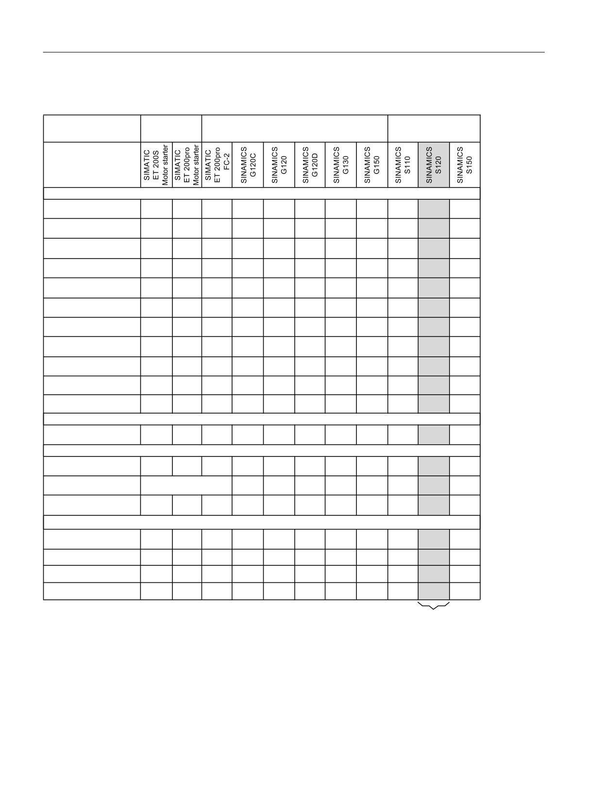
General information about SINAMICS Safety Integrated
3.3 Drive products with integrated safety functions
3.3
Drive products with integrated safety functions
$SSOLFDWLRQV
$SSOLFDWLRQV ZLWK YDULDEOH VSHHG
+LJK 3HUIRUPDQFH DQG
ZLWK IL[HG
0RWLRQ &RQWURO
VSHHG
$SSOLFDWLRQV
,QWHJUDWHG VDIHW\ IXQFWLRQV DFFRUGLQJ WR ,(&
672
<HV
<HV
<HV
<HV
<HV
<HV
<HV
<HV
<HV
<HV
<HV
6DIH 7RUTXH 2II
66
<HV
<HV
<HV
<HV
<HV
<HV
<HV
6DIH 6WRS
6%&
<HV
<HV
<HV
<HV
<HV
<HV
6DIH %UDNH &RQWURO
626
<HV
<HV
<HV
<HV
<HV
6DIH 2SHUDWLQJ 6WRS
66
<HV
<HV
<HV
<HV
<HV
6DIH 6WRS
6/6
<HV
<HV
<HV
<HV
<HV
<HV
<HV
6DIHO\ /LPLWHG 6SHHG
660
<HV
<HV
<HV
<HV
<HV
<HV
<HV
6DIH 6SHHG 0RQLWRU
6',
<HV
<HV
<HV
<HV
<HV
<HV
<HV
6DIH 'LUHFWLRQ
6/3
<HV
<HV
<HV
<HV
6DIHO\ /LPLWHG 3RVLWLRQ
6&$
<HV
<HV
<HV
<HV
6DIH &DP
6/$
<HV
<HV
6DIHO\ /LPLWHG $FFHOHUDWLRQ
,QWHJUDWHG VDIH GLDJQRVWLF IXQFWLRQ
6%7
<HV
<HV
<HV
<HV
6DIH %UDNH 7HVW
)DLO VDIH LQWHUIDFHV
352),%86 352),1(7 ZLWK
<HV
<HV
<HV
<HV
<HV
<HV
<HV
<HV
<HV
<HV
<HV
352),VDIH SURILOH
<HV ZLWK H[WHUQDO
)DLO VDIH LQSXWV
<HV
<HV
<HV
<HV
<HV
<HV
<HV
<HV
FRPSRQHQWV
)DLO VDIH RXWSXWV
<HV
<HV
<HV
<HV
<HV
<HV
<HV
&HUWLILFDWLRQV
&DW
&DW
&DW
&DW
&DW
&DW
&DW
&DW
&DW
&DW
(1 ,62
<HV
3/ H
3/ H
3/ G
3/ G
3/ G
3/ G
3/ G
3/ G
3/ G
3/ G
,(&
6,/
6,/
6,/
6,/
6,/
6,/
6,/
6,/
6,/
6,/
6,/
1)3$
<HV
<HV
<HV
<HV
<HV
<HV
157/ OLVWHG
<HV
<HV
<HV
2QO\ IRU 6,1$0,&6 6
%RRNVL]H
2QO\ IRU &8
6
ZLWK 6DIH %UDNH 5HOD\
&RQWHQW RI
:LWK &KDVVLV DQG &DELQHW 0RGXOHV ZLWK 6DIH %UDNH $GDSWHU
WKLV
&8
&8
6,027,21 '
&8$
&8$
:LWK 6DIH %UDNH 5HOD\
PDQXDO
&8
*
*
:LWK XVH RI WKH 70
)
&8
2QERDUG LQWHUIDFHV RU 70
)
1RW DYDLODEOH IRU 6,1$0,&6 +/$
672 YLD WHUPLQDOV RI 3RZHU 0RGXOH 30
&DW
3/ H 6,/
672 YLD WKH &RQWURO 8QLW WHUPLQDOV DQG DOO RWKHU VDIHW\ IXQFWLRQV &DW
3/ G 6,/
2QO\ ZLWK &8
6
&RQWURO 8QLW
Safety Integrated
36
Function Manual, 06/2020, 6SL3097-5AR00-0BP3

General information about SINAMICS Safety Integrated
3.4 Examples of how the safety/diagnostic functions can be applied
3.4
Examples of how the safety/diagnostic functions can be applied
Safety function
Application examples
Possible solution
STO
It is only permissible to open a protective door if
● Select STO in the converter via a terminal
the motor torque has been switched off.
or via PROFIsafe.
● The pulses are suppressed and the motor
coasts to a standstill.
A central Emergency Stop button ensures that
Evaluating the Emergency Stop button in a
several drives cannot unintentionally start.
central controller, selecting STO in the convert-
er via PROFIsafe.
SS1
A drive must brake as quickly as possible after the
Select SS1 in the converter using a failsafe in-
Emergency Stop button has been pressed. It is not
put or via PROFIsafe .
permissible that the stationary motor undesirably
accelerates.
SBC
Safe control of a motor holding brake must be
SBC is (if configured) initiated together with
guaranteed to guarantee the motor is at a stand-
STO. The Motor Module / Safe Brake Relay /
still.
Safe Brake Adapter then carries out the action
and safely controls the outputs for the brake.
SOS
The standstill position of the motor must be moni-
Select SOS, e.g. through SS2, in order to mon-
tored and ensured.
itor the standstill position of the motor after
braking.
SS2
A drive must brake as quickly as possible after the
Select SS2 in the converter using a failsafe in-
Emergency Stop button has been pressed. The
put or via PROFIsafe.
standstill position of the motor must be monitored
and ensured.
SLS
The machine operator must be able to enter the
Selecting SLS in the converter. The converter
machine after the protective door has been
limits and monitors the velocity of the horizontal
opened and slowly move a horizontal conveyor
conveyor.
with an acknowledgment button in the danger
zone.
A spindle drive, depending on the selection of the
Selecting SLS and the corresponding SLS lev-
cutting tool, must not exceed a specific maximum
el in the converter via PROFIsafe.
speed.
SSM
A centrifuge may only be filled below a velocity
If the Extended Functions are enabled, SSM is
defined by the user.
always available1). The function does not have
to be selected.
The converter safely monitors the centrifuge
speed and enables the process to advance to
the next step using the "SSM status" bit.
1) Exception: Motion monitoring without selec-
tion (Page 255)
Safety Integrated
Function Manual, 06/2020, 6SL3097-5AR00-0BP3
37

General information about SINAMICS Safety Integrated
3.4 Examples of how the safety/diagnostic functions can be applied
Safety function
Application examples
Possible solution
SDI
A protective door must only be opened if a drive
Selecting SDI in the converter; enable the pro-
moves in the safe direction (away from the opera-
tective doors via status bit (PROFIsafe) of the
tor).
converter.
When replacing the plates of the pressure cylin-
Selecting SDI in the converter. Disabling the
ders, the drive must only move in the safe direction
hazardous direction of rotation.
of rotation.
Once the protection against jamming has been
triggered, a roller shutter gate must only be able to
start moving in one direction.
At an operational limit switch, the trolley of a crane
must only start in the opposite direction.
Safe gearbox stage
For a machine equipped with selector gearbox it
The "Safe gearbox stage switchover" function
switchover
must be ensured that the switchover is actually
ensures safe switchover between the gearbox
performed.
stages.
SLA
In the setup mode, it is not permissible that the
Selecting SLA in the converter. The converter
drive exceeds the permissible acceleration.
limits and monitors the acceleration of the ma-
chine.
SLP
The drive must not exit the specified position rang-
Selection of SLP in the converter; inhibits the
es.
range that is not permitted.
SP
It is necessary to transmit a "safe position," for ex-
The selection of SP in the converter enables
ample, in the following use cases:
you to transfer a safe position (i.e. absolute or
relative position) to the higher-level controller
● Safe cam sequencer
via PROFIsafe.
● Calculation of the safe velocity
● Safety concepts across axes
- Multi-dimensional protection areas
● Zone concepts
- Safe response depending on the position
of the axes
- Different reaction to sensors
SCA
It is only permissible that a protective door is
● Select SCA
opened if a drive is in a certain position range.
● Interlock protective door in response to the
SCA feedback signals via PROFIsafe
The drive must only be traversed with reduced
● Select SCA
speed when it located in a certain position range.
● Activate a SLS stage in response to the
SCA feedback signals via PROFIsafe
Diagnostic function
Application examples
Possible solution
SBT
The effect of a brake is reduced through wear.
The diagnostic function "Safe Brake Test SBT"
detects whether a brake is provided the re-
quired braking effect.
Safety Integrated
38
Function Manual, 06/2020, 6SL3097-5AR00-0BP3
General information about SINAMICS Safety Integrated
3.5 General information about operating components with Safety Integrated activated
3.5
General information about operating components with Safety
Integrated activated
It is not permissible to withdraw and insert components. Malfunctions can occur when
components are withdrawn or inserted that are used for Safety Integrated. However, this does
not mean that the fail-safe state is exited. For example, PROFIsafe communication is not
reestablished after this event.
Withdrawing and inserting components used for Safety Integrated (power units, Sensor
Modules, TM54F) during operation and in the deactivated state is not permissible. Activating
the components always requires a POWER ON (see Chapter "Modular machine concept
Safety Integrated (Page 325)").
Safety Integrated
Function Manual, 06/2020, 6SL3097-5AR00-0BP3
39

General information about SINAMICS Safety Integrated
3.6 Drive monitoring with or without encoder
3.6
Drive monitoring with or without encoder
If motors without a (safety-capable) encoder are being used, not all Safety Integrated Functions
can be used.
Note
Definition: "Without encoder"
When "without encoder" is used in this manual, then this always means that either no encoder
or no safety-capable encoder is being used.
In operation without encoder the actual speed values are calculated from the measured
electrical actual values. Therefore, speed monitoring is also possible during operation without
encoder.
Table 3-1
Overview of Safety Integrated Functions
Functions
Abbr.
With
With-
Brief description
en-
out en-
coder
coder
Basic
Safe Torque Off
STO
Yes
Yes
Safe torque off
Functions
Safe Stop 1
SS1
Yes
Yes
Safe stopping process in accordance with Stop Cat-
egory 1
Safe Brake Control
SBC
Yes
Yes
Safe brake control
Extended
Safe Torque Off
STO
Yes
Yes1)
Safe torque off
Functions
Safe Stop 1
SS1
Yes
Yes1)
Safe stopping process in accordance with Stop Cat-
egory 1
Safe Brake Control
SBC
Yes
Yes1)
Safe brake control
Safe Operating Stop
SOS
Yes
No
Safe monitoring of the standstill position
Safe Stop 2
SS2
Yes
No
Safe stopping process in accordance with Stop Cat-
egory 2
Safely-Limited Speed
SLS
Yes
Yes1)
Safe monitoring of the maximum speed
Safe Speed Monitor
SSM
Yes
Yes1)
Safe monitoring of the minimum speed
Safe Direction
SDI
Yes
Yes1)
Safe monitoring of the direction of motion
Safe gearbox stage switchover
-
Yes
No
-
Safe referencing
SR
Yes
No
Safe referencing
Safely-Limited Acceleration
SLA
Yes
No
Safely limited acceleration
Safe Acceleration Monitor
SAM
Yes
Yes1)
Safe monitoring of drive acceleration
Safe Brake Ramp
SBR
Yes
Yes1)
Safe braking ramp
Diagnostic function Safe
SBT
Yes
No
Safe test of the required holding torque
Brake Test
of a brake
Safety Integrated
40
Function Manual, 06/2020, 6SL3097-5AR00-0BP3

General information about SINAMICS Safety Integrated
3.6 Drive monitoring with or without encoder
Functions
Abbr.
With
With-
Brief description
en-
out en-
coder
coder
Advanced
Safely-Limited Position
SLP
Yes
No
Safely limited position
Functions Transfer safe
SP
Yes
Yes1)
Transfer safe position values
position values
Safe Cam
SCA
Yes
No
Safe cam
1)
The use of this safety function without an encoder is permitted only for the following motors:
- Induction motors
- SIMOTICS A-1FU synchronous motors (previously: SIEMOSYN)
- Synchronous reluctance motors
The configuration of the Safety Integrated Functions and the selection of monitoring with or
without encoder is realized in the safety screens of the Startdrive commissioning tool.
Safety Integrated
Function Manual, 06/2020, 6SL3097-5AR00-0BP3
41
General information about SINAMICS Safety Integrated
3.6 Drive monitoring with or without encoder
Safety Integrated
42
Function Manual, 06/2020, 6SL3097-5AR00-0BP3

Overview of Safety Integrated functions
4
4.1
Safety Integrated Basic Functions
Note
Basic Functions do not require an encoder
The Safety Integrated Basic Functions are functions for safely stopping the drive. You do not
require an encoder.
Note
Application of the Basic Functions
Basic Functions are available in all control modes with and without encoder for synchronous
and induction motors without any restrictions.
Note
Control via TM54F
If you want to control the Safety Integrated Basic Functions via TM54F, set p9601.6 = 1.
This chapter should provide first users with a quick overview of the principle mode of operation
of safety functions.
The entry into the description of the safety functions is based on the definition according to
standard EN 61800-5-2 and some simple examples for using the function.
The description of the functions is simplified, as far as possible to clearly shown essential
properties and setting options.
You will find more information on the functions in the following chapters:
● Safe Torque Off (STO) (Page 44)
● Safe Stop 1 (SS1) (Page 45)
● Safe Brake Control (SBC) (Page 46)
Safety Integrated
Function Manual, 06/2020, 6SL3097-5AR00-0BP3
43
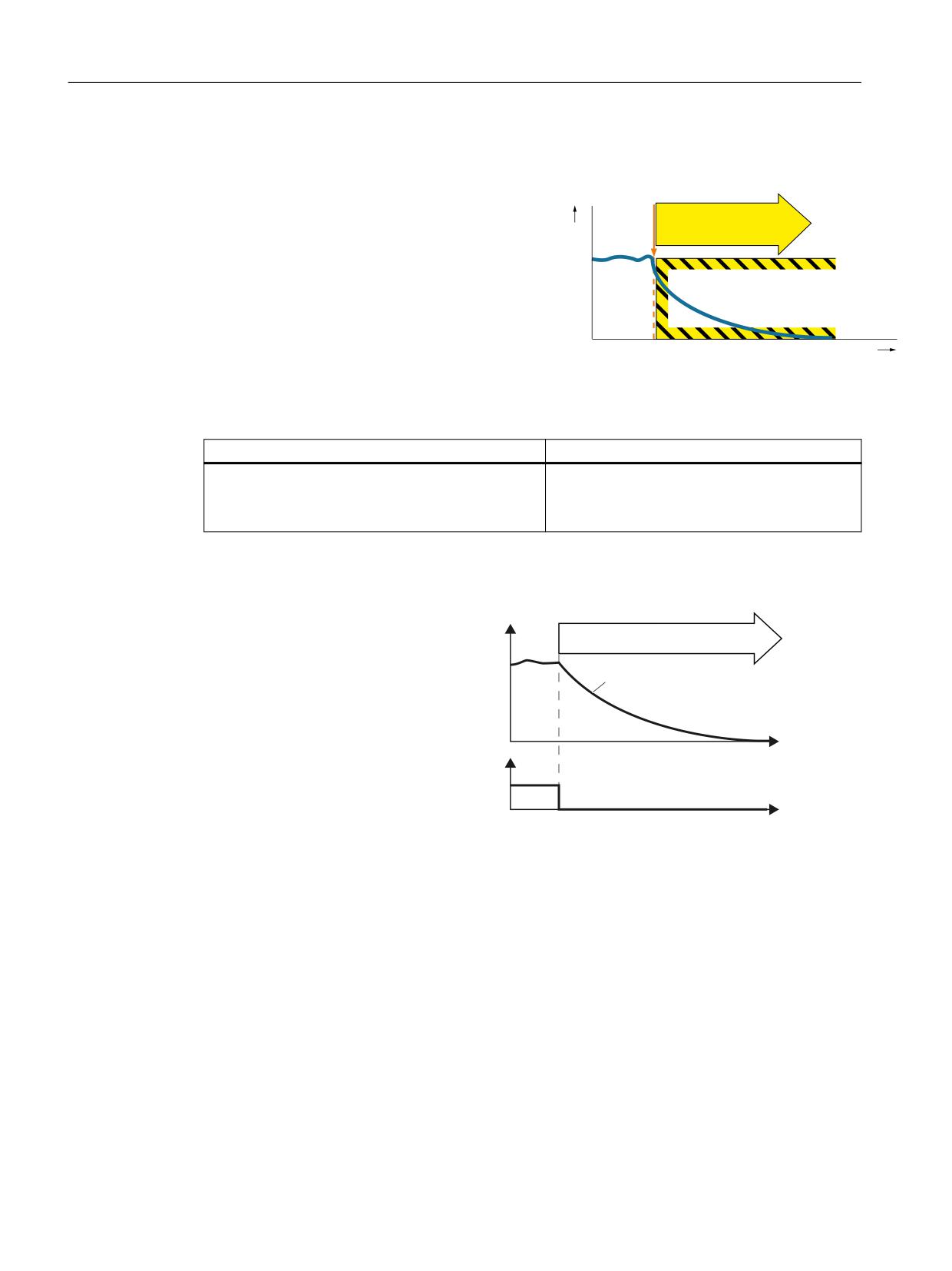
Overview of Safety Integrated functions
4.1 Safety Integrated Basic Functions
4.1.1
Safe Torque Off (STO)
Definition according to EN 61800-5-2:
"The STO function prevents energy from being
STO
v
supplied to the motor, which can generate a tor-
que."
t
Examples of how the function can be used
Example
Possible solution
It is only permissible to open a protective door if the
● Select STO in the converter.
motor torque has been switched off.
● The pulses are suppressed and the motor
coasts to a standstill.
How does STO function in detail?
The converter recogni-
6SHHG
zes the selection of-
672
STO via a fail-safe in-
put or via the safe com-
7KH PRWRU WRUTXH LV
VZLWFKHG RII
municationPROFI-
safe.
The converter then
W
safely switches off the
'HVHOHFW 672
torque of the connected
) ', RU
352),VDIH FRQWURO
motor.
ZRUG
W
Details and parameterization
For further details and information on how to parameterize this function, refer to Chapter "Safe
Torque Off (STO) (Page 76)".
Safety Integrated
44
Function Manual, 06/2020, 6SL3097-5AR00-0BP3
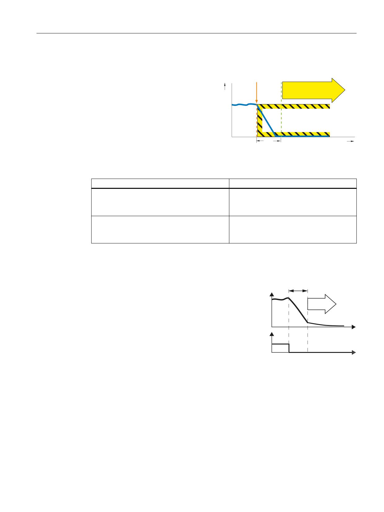
Overview of Safety Integrated functions
4.1 Safety Integrated Basic Functions
4.1.2
Safe Stop 1 (SS1)
Definition according to EN 61800-5-2:
"The function SS1 brakes the motor and
STO
v
trips the function STO after a delay time."
∆t
t
Example of how the function can be used
Example
Possible solution
After an Emergency Stop button has been pressed,
● Wire the Emergency Stop button with a fail-
the drive must be braked as quickly as possible and
safe input.
brought into the STO state.
● Select SS1 via the fail-safe input.
A central Emergency Stop button ensures that sev-
● Evaluating an emergency stop pushbutton in
eral drives are braked as quickly as possible and
a central control.
brought into the STO state.
● Select SS1 via PROFIsafe.
How does SS1 function in detail?
Overview
6DIH 6WRS GHOD\
WLPH
The drive decelerates once "Safe Stop 1" has
6SHHG
been selected, and goes into the "Safe Torque
Off" state once the delay time has expired.
672
W
'HVHOHFW 66
7HUPLQDOV RU
352),VDIH
FRQWURO ZRUG
W
Select SS1
As soon as the converter identifies that SS1 has been selected via a terminal or via the
PROFIsafe safe communication, the following happens:
● If, when selecting SS1, the motor is already switched off, then until the SS1 delay time
expires, there is no response. STO becomes active after the time expires.
● If the motor is switched on when SS1 is selected, the inverter brakes the motor with the
OFF3 ramp-down time. After the delay time, STO is triggered automatically.
Safety Integrated
Function Manual, 06/2020, 6SL3097-5AR00-0BP3
45
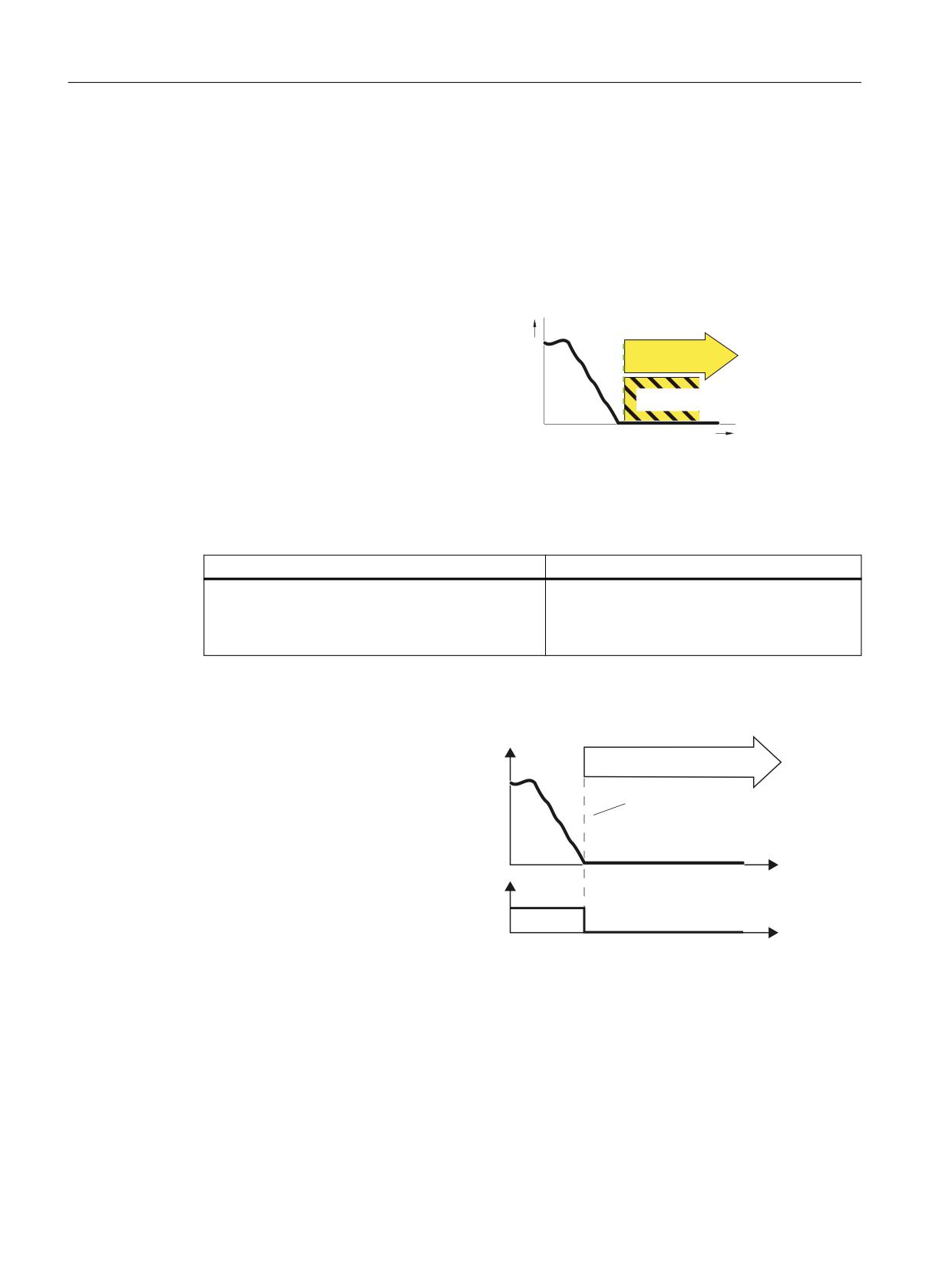
Overview of Safety Integrated functions
4.1 Safety Integrated Basic Functions
Details and parameterization
For further details and information on how to parameterize this function, see Section "Safe Stop
1 (SS1, time controlled) (Page 81)".
4.1.3
Safe Brake Control (SBC)
Definition according to EN 61800-5-2:
v
"The SBC function supplies a safe output
STO
signal to control a holding brake."
SBC
t
Safe Brake Control (SBC)
Example of how the function can be used
Example
Possible solution
The safe control of a motor holding brake must be
SBC is (if configured) initiated together with
guaranteed in order to guarantee the motor is at a
STO. The Motor Module / Safe Brake Relay /
standstill.
Safe Brake Adapter then carries out the action
and safely controls the outputs for the brake.
How does SBC function in detail?
The converter recogni-
6SHHG
zes the selection of-
672 6%&
STO via a fail-safe in-
put or via the safe com-
7KH PRWRU WRUTXH LV VZLWFKHG RII
municationPROFI-
6%& FRQWUROV D EUDNH VDIHO\
safe.
The converter then
W
safely switches off the
672 GHVHOHFWLRQ
torque of the connected
) ', RU
352),VDIH FRQWURO
motor.
ZRUG
W
SBC is (if configured) in-
itiated together with
STO. The Motor Mod-
ule / Safe Brake Relay /
Safe Brake Adapter
then carries out the ac-
tion and safely controls
the outputs for the
brake.
Safety Integrated
46
Function Manual, 06/2020, 6SL3097-5AR00-0BP3
Overview of Safety Integrated functions
4.1 Safety Integrated Basic Functions
Details and parameterization
For further details and information on how to parameterize this function, see Section "Safe
Brake Control (SBC) (Page 84)".
Safety Integrated
Function Manual, 06/2020, 6SL3097-5AR00-0BP3
47
Overview of Safety Integrated functions
4.2 Safety Integrated Extended Functions
4.2
Safety Integrated Extended Functions
This chapter should provide first users with a quick overview of the principle mode of operation
of safety functions.
The entry into the description of the safety functions is based on the definition according to
standard EN 61800-5-2 and some simple examples for using the function.
The description of the functions is simplified, as far as possible to clearly shown essential
properties and setting options.
You will find more information on the functions in the following chapters:
● Safe Torque Off (STO) (Page 50)
● Safe Stop 1 (SS1) (Page 50)
● Safe Operating Stop (SOS) (Page 53)
● Safe Stop 2 (SS2) (Page 54)
● Safely Limited Speed (SLS) (Page 56)
● Safe Speed Monitor (SSM) (Page 63)
● Safe Direction (SDI) (Page 65)
● Safe Brake Test (SBT) (Page 68)
● Safely-Limited Acceleration (SLA) (Page 67)
Safety Integrated
48
Function Manual, 06/2020, 6SL3097-5AR00-0BP3