SINUMERIK 840D sl. Service - Safety Integrated. Manual (2020) - page 20
Overview of Safety Integrated functions
4.2 Safety Integrated Extended Functions
4.2.1
Preconditions for Safety Integrated Extended Functions
● For operation of the Safety Integrated Extended Functions, one license is required for each
axis.
● To use Safety Integrated Advanced Functions, one license is required for each axis. The
license for Safety Integrated Advanced Functions also includes the license for Safety
Integrated Extended Functions.
● Overview of hardware components that support the Extended/Advanced Functions:
- Control Unit CU320-2
- Control Unit CU310-2
- SINAMICS HLA
- Motor Modules Booksize Compact
- Motor Modules booksize C/D type with article No.: -..C. or -..D.
- Motor Modules booksize with an article number ending: -...3 or higher
- Motor Modules chassis with an article number ending: -...3 or higher
- Motor Modules cabinet with an article number ending: -...2 or higher
- Power Modules blocksize
- Control Unit Adapter CUA31 as of article number: 6SL3040-0PA00-0AA1
- Control Unit Adapter CUA32 as of article number: 6SL3040-0PA01-0AA0
- For the safety functions with encoder:
Motors with sin/cos encoder and encoder evaluation with DRIVE-CLiQ interface or via
Sensor Module SMC20, SME20/25/120/125, square wave signal encoder with SMC30,
EnDat-2.2 encoder with SMC40
The list of approved encoders can be found on the Internet at:
Enter the number 33512621 there as search term or contact your local Siemens office.
Safety Integrated
Function Manual, 06/2020, 6SL3097-5AR00-0BP3
49
Overview of Safety Integrated functions
4.2 Safety Integrated Extended Functions
4.2.2
Control possibilities
The following options are available for controlling Safety Integrated Extended Functions:
● PROFIsafe
● TM54F
● Onboard F-DI (CU310-2)
● Permanent selection (Safety Integrated Functions without selection)
Details on the control options can be found in Chapter "Control of the safety functions
(Page 207)".
4.2.3
Safe Torque Off (STO)
For the control options and the functionality for "Safe Torque Off" (STO), see Section "Safe
Torque Off (STO) (Page 76)".
4.2.4
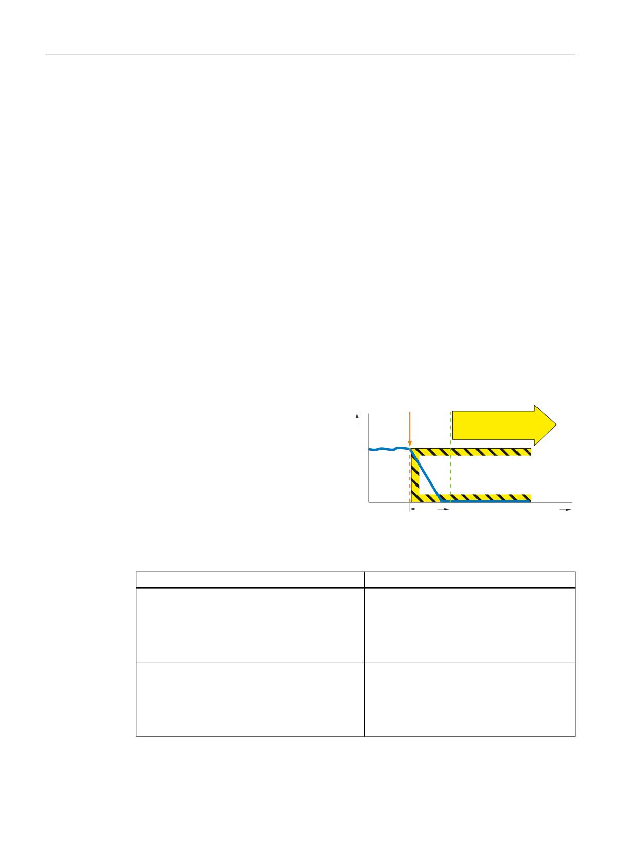
Safe Stop 1 (SS1)
Definition according to EN 61800-5-2:
"The function SS1 brakes the motor, moni-
STO
v
tors the magnitude of the motor deceleration
within specified limits, and after a delay time
or violation of a speed threshold, initiates
the STO function."
∆t
t
Example of how the function can be used
Example
Possible solution
After an Emergency Stop button has been pressed,
● Wire the Emergency Stop button with a fail-
the drive must be braked as quickly as possible and
safe input.
brought into the STO state.
● Select SS1 via the fail-safe input.
● SS1 brakes the drive and then brings it into
the STO state.
A central Emergency Stop button ensures that sev-
● Evaluating an emergency stop pushbutton in
eral drives are braked as quickly as possible and
a central control.
brought into the STO state.
● Select SS1 via PROFIsafe.
● SS1 brakes the drives and then brings them
into the STO state.
Safety Integrated
50
Function Manual, 06/2020, 6SL3097-5AR00-0BP3
Overview of Safety Integrated functions
4.2 Safety Integrated Extended Functions
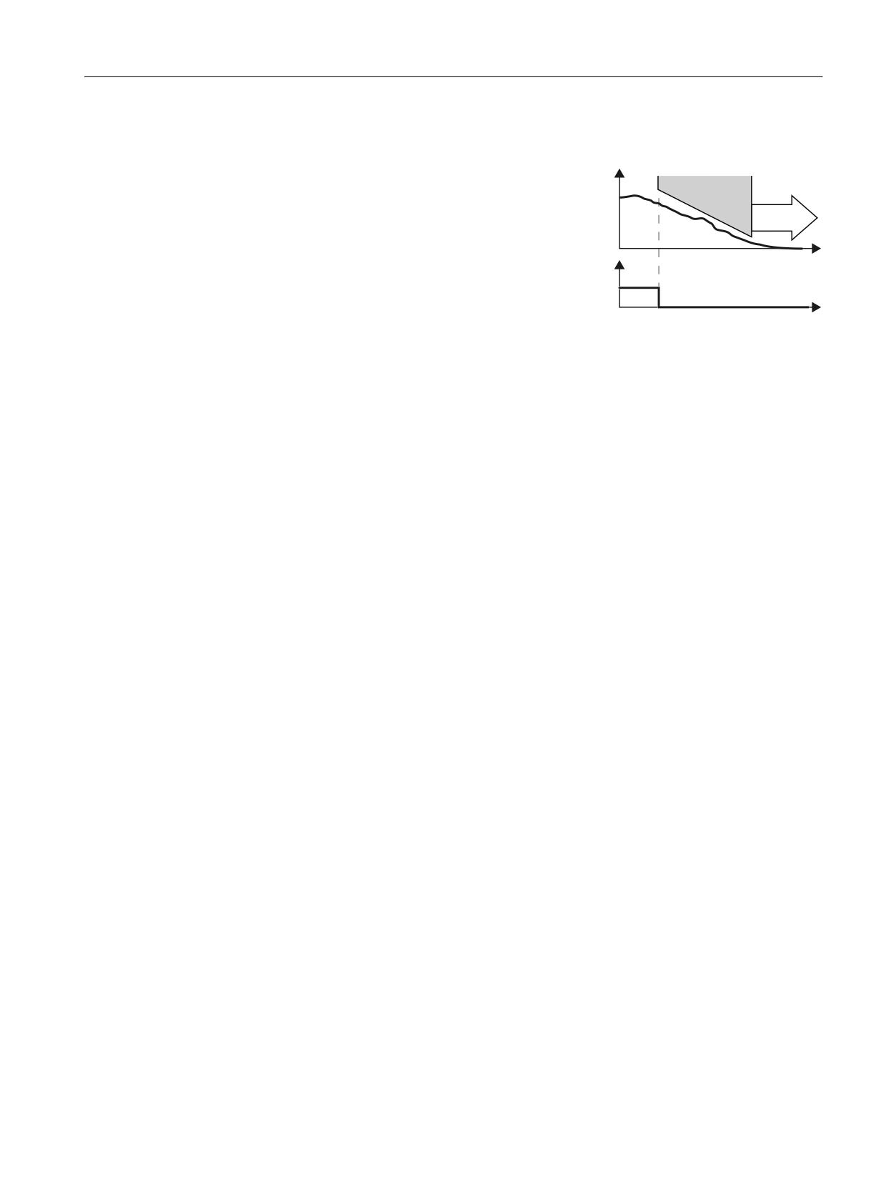
How does SS1 function in detail?
Overview
6SHHG
0RQLWRULQJ
Using the SS1 function, the converter brakes
the motor and monitors the absolute speed.
672
If the motor speed is low enough or the delay
time has expired, the converter safely switches
W
'HVHOHFW 66
off the motor torque using STO .
) ', RU
352),VDIH
FRQWURO ZRUG
W
Select SS1
As soon as the converter identifies that SS1 has been selected via a failsafe input or via
PROFIsafe safe communication, the following happens:
● If the motor has already been switched off when selecting SS1 then the converter safely
switches off the motor torque (STO).
● If the motor is switched on when SS1 is selected, the converter brakes the motor with the
AUS3 ramp-down time.
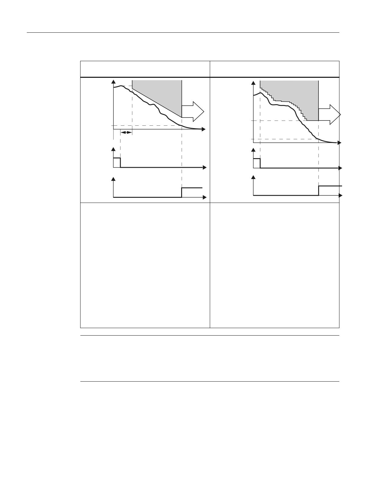
Monitoring modes
For the Extended Functions with or without encoder, you can choose between 2 different
monitoring modes of the function SS1:
● Safe Brake Ramp (SBR)
● Safe Acceleration Monitor (SAM)
Safety Integrated
Function Manual, 06/2020, 6SL3097-5AR00-0BP3
51
Overview of Safety Integrated functions
4.2 Safety Integrated Extended Functions
Brake ramp monitoring
Acceleration monitoring
(with or without encoder)
(with or without encoder)
6SHHG
6SHHG
6%5
6$0
6WDQGVWLOO
672
6KXWGRZQ
672
PRQLWRULQJ
VSHHG
W
6KXWGRZQ
'HOD\ WLPH IRU EUDNLQJ
VSHHG 66
W
'HVHOHFW
UDPS
66
66
GHVHOHFWLRQ
) ', RU
) ', RU
352),VDIH
W
352),VDIH
W
FRQWURO ZRUG
FRQWURO ZRUG
672
672 DFWLYH
DFWLYH
) '2 RU
) '2 RU
352),VDIH
352),VDIH
W
W
VWDWXV ZRUG
VWDWXV ZRUG
● Using the SBR (Safe Brake Ramp) function,
● The converter monitors the speed of the motor
the converter monitors whether the motor
with the SAM function.
speed decreases.
● The converter prevents the motor from accel-
● The gradient of the SBR function can be set via
erating again by having the monitoring function
the reference velocity and the ramp-down time.
continuously track the speed as it decreases.
The SBR function only starts after the "Delay
● The converter reduces the monitoring thresh-
for braking ramp".
old until the "Shutdown speed" has been
● The SBR function starts with the speed set-
reached.
point, which was present at the instant in time
● The converter safely switches off the motor tor-
that SS1 was selected.
que (STO), if one of the following conditions is
● If the converter detects that the speed has fall-
fulfilled:
en below the speed threshold (standstill moni-
- The speed has fallen below the shutdown
toring), it safely switches off the motor torque
speed SS1.
(STO).
- The maximum time until the torque is
switched off has expired.
Note
SS1 with external stop (SS1E)
If you use SS1E, neither of the two monitoring functions (SBR, SAM) is active. The drive must
be shut down in SS1E within the delay time, for example, by a user program of a CPU. STO
becomes active after the delay time expires.
Details and parameterization
For further details and information on how to parameterize this function, see Chapter "Safe
Stop 1 (SS1) (Page 103)".
Safety Integrated
52
Function Manual, 06/2020, 6SL3097-5AR00-0BP3
Overview of Safety Integrated functions
4.2 Safety Integrated Extended Functions
4.2.5
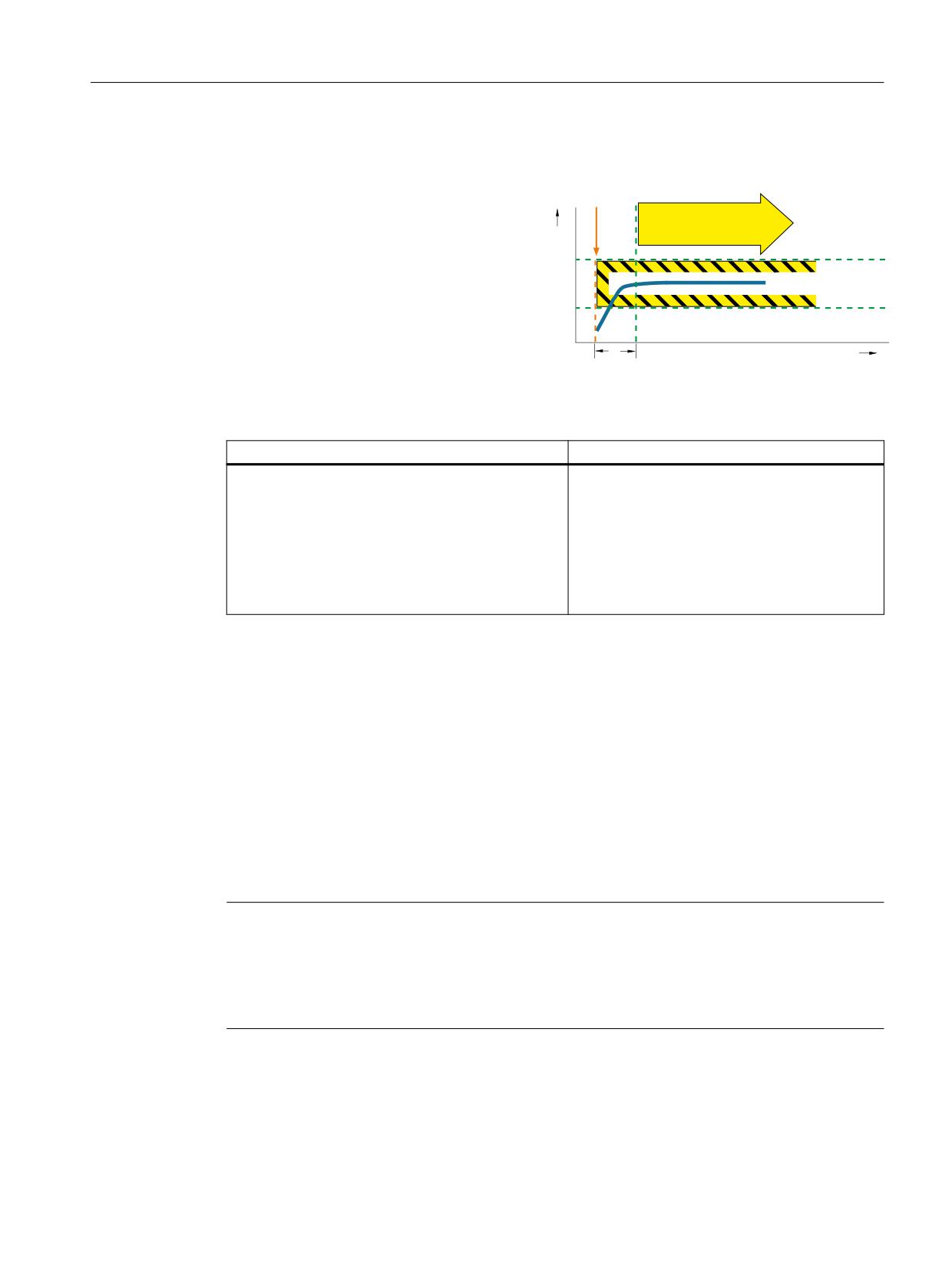
Safe Operating Stop (SOS)
Definition according to EN 61800-5-2:
"This SOS function is used for safe monitor-
SOS
s
ing of the standstill position of a drive."
∆t
t
Example of how the function can be used
Example
Possible solution
A protective door must only be opened if a motor is in
● Select SOS
the safe standstill state.
● A higher-level controller brakes the axis (e.g.
position-controlled) down to standstill within
the configured time between the selection of
SOS and when it becomes active.
● Standstill is then safely monitored via the
SOS function.
How does SOS function in detail?
The protected machine areas can be entered without having to shut down the machine as long
as SOS is active.
After SOS has been selected it becomes active after the parameterizable delay time has
expired. The drive must be braked to standstill within this delay time (e.g. by the controller).
Drive stopping is monitored using an SOS tolerance window. At the instant this function
becomes active, the current actual position is stored as the comparison position until SOS is
deselected again. Any delay time is cleared after SOS is deselected and the drive can be
immediately moved.
The drive is stopped with SS1 when the standstill tolerance window is violated.
Note
Contrary to SS1 and SS2, SOS does not automatically brake the drive
The control still enters the setpoint.
This means that in the user program of the control system, the system must respond to the
"SOS selected" bit so that the control system brings the drive to a standstill within the delay time.
Safety Integrated
Function Manual, 06/2020, 6SL3097-5AR00-0BP3
53
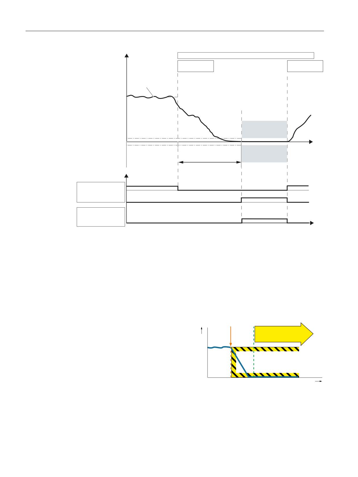
Overview of Safety Integrated functions
4.2 Safety Integrated Extended Functions
2SHUDWRU DFWLRQV
;DFW
6HOHFW 626
'HVHOHFW 626
$FWXDO SRVLWLRQ
626
6WDQGVWLOO WROHUDQFH
W
626
'HOD\ WLPH 626
'LDJQRVWLFV
'HVHOHFW 626
626 DFWLYH
352),VDIH
626 DFWLYH
6WDWXV ZRUG ELW
W
Figure 4-1
Standstill tolerance
Details and parameterization
For further details and information on how to parameterize this function, see Chapter "Safe
Operating Stop (SOS) (Page 109)".
4.2.6
Safe Stop 2 (SS2)
Definition according to EN 61800-5-2:
"The function SS2 brakes the motor, moni-
SOS
v
tors the magnitude of the motor decelera-
tion, and after a delay time, initiates the SOS
function."
t
Safety Integrated
54
Function Manual, 06/2020, 6SL3097-5AR00-0BP3
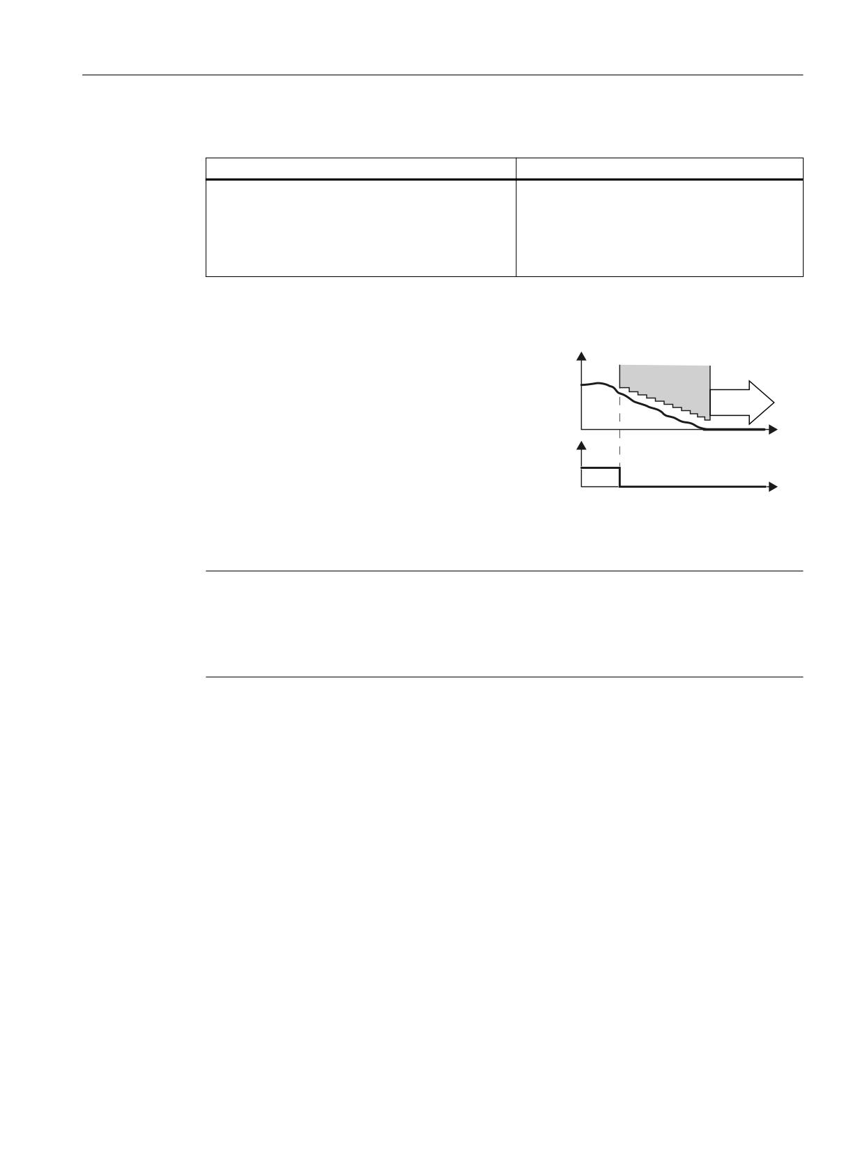
Overview of Safety Integrated functions
4.2 Safety Integrated Extended Functions
Example of how the function can be used
Example
Possible solution
A protective door must only be opened if a motor is in
● Select SS2 in the converter via a terminal or
the safe standstill state.
via PROFIsafe .
● After braking, the converter goes into the
SOS state. Only then may the protective
door be released.
How does SS2 function in detail?
The safety function SS2 monitors the
6SHHG
load speed and initiates the SOS function
0RQLWRULQJ
if the SS2 delay time has expired.
626
With SS2, braking is monitored on the
OFF3 ramp. A faulty acceleration is de-
W
'HVHOHFW 66
tected and the drive then shuts down with
) ', RU
STO.
352),VDIH
FRQWURO ZRUG
W
If you are operating the motor with closed-loop torque control, the converter switches to the
closed-loop speed control mode when SS2 is selected.
Note
SS2 with external stop (SS2E)
If you use SS2E, neither of the two monitoring functions (SBR, SAM) is active. The drive must
be shut down in SS2E within the delay time, for example, by a user program of a CPU. SOS
becomes active after the delay time expires.
Time response in detail
The failsafe logic (e.g. F-CPU) selects the SS2 safety function via a failsafe input or via the
PROFIsafe safe communication.
● If, when selecting SS2, the motor is already at a standstill, after a delay time, the converter
activates the Safe Operating Stop function (SOS).
● If the drive is not at standstill when SS2 is selected, it is braked along the OFF3 ramp.
Braking is monitored with one of the following functions, depending on the setting in p9506:
- "Safe Acceleration Monitor (SAM)"
A faulty acceleration is therefore detected.
- "Safe Brake Ramp (SBR)"
In this way, a violation of the braking ramp is detected.
After a delay time, the converter activates the Safe Operating Stop function (SOS). This
function monitors the safe standstill of the drive.
Safety Integrated
Function Manual, 06/2020, 6SL3097-5AR00-0BP3
55
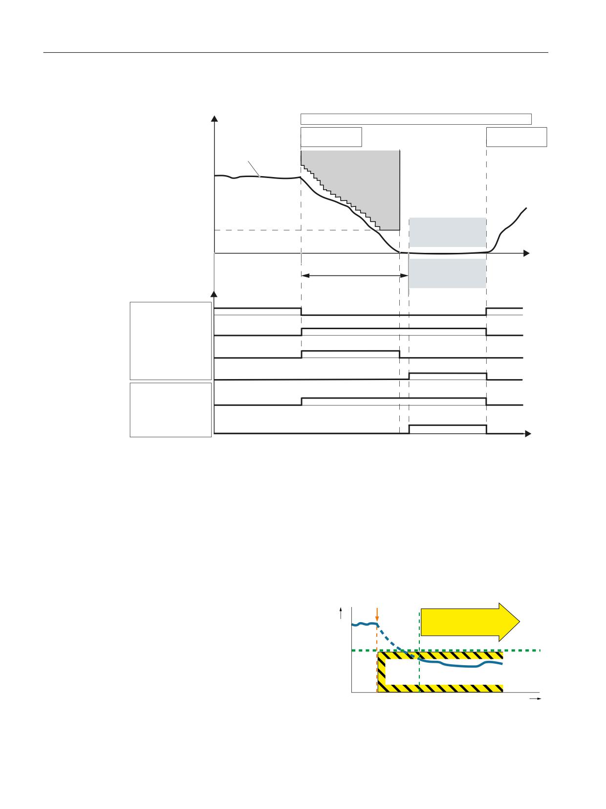
Overview of Safety Integrated functions
4.2 Safety Integrated Extended Functions
Braking behavior
/RDG VSHHG
2SHUDWRU DFWLRQV
6HOHFW 66
'HVHOHFW 66
$FWXDO YDOXH
6$0
6$0 VSHHG OLPLW
626
W
626
'HOD\ WLPH 66
'LDJQRVWLFV
'HVHOHFW 66
66
DFWLYH
6$0 6%5 DFWLYH
626 DFWLYH
352),VDIH
66
DFWLYH
6WDWXV ZRUG ELW
626 DFWLYH
6WDWXV ZRUG ELW
W
Figure 4-2
Braking behavior and diagnostics of the safety function SS2 (example of SS2 with SAM)
Details and parameterization
For further details and information on how to parameterize this function, see Chapter "Safe
Stop 2 (SS2) (Page 111)".
4.2.7
Safely Limited Speed (SLS)
Definition according to EN 61800-5-2:
"The SLS function prevents the motor from
v
SLS
exceeding the specified speed limit."
t
Safety Integrated
56
Function Manual, 06/2020, 6SL3097-5AR00-0BP3
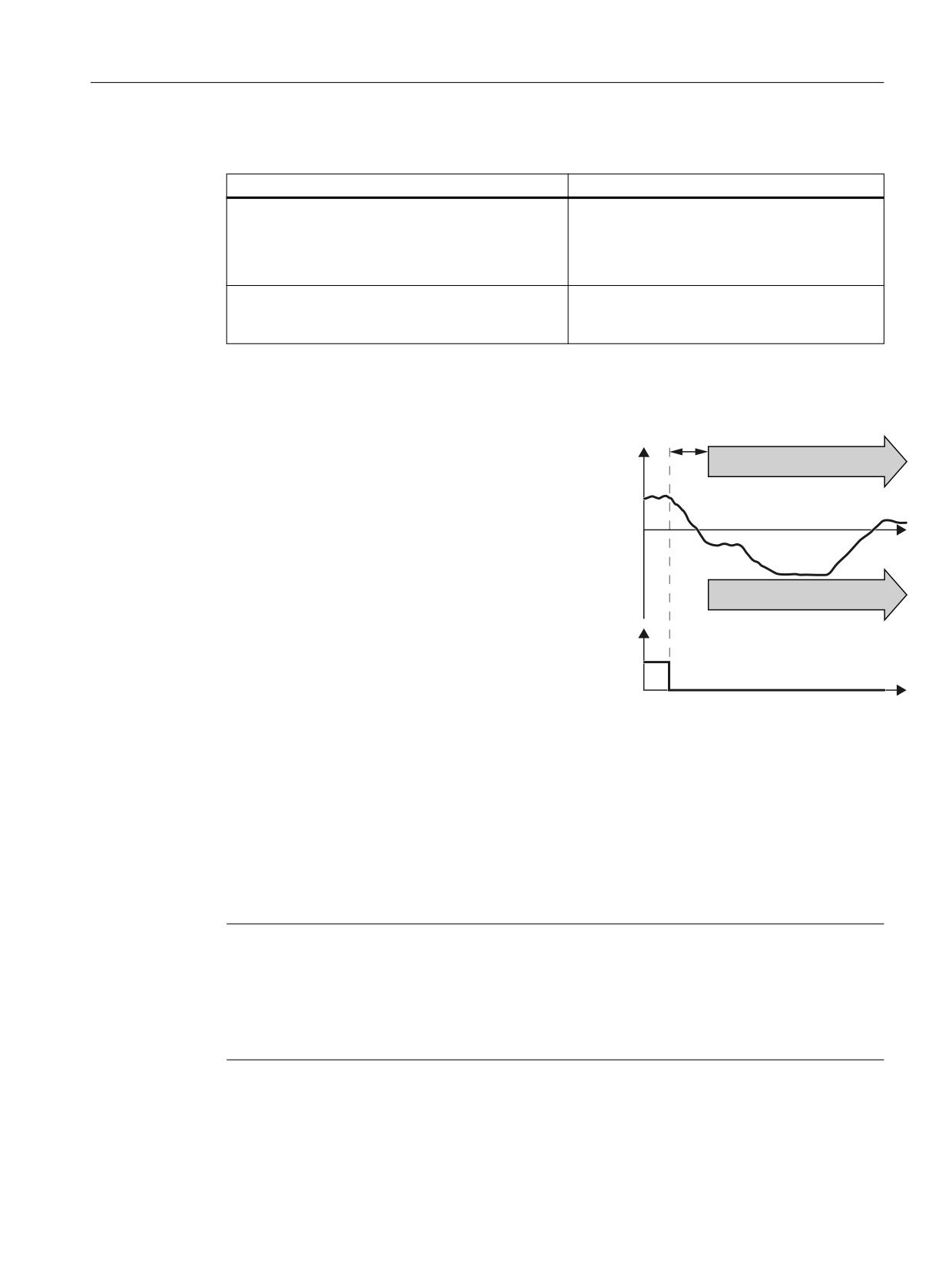
Overview of Safety Integrated functions
4.2 Safety Integrated Extended Functions
Examples of how the function can be used
Example
Possible solution
The machine operator must be able to enter the ma-
● Select SLS in the converter via a fail-safe
chine after the protective door has been opened and
input or PROFIsafe .
slowly move a horizontal conveyor with an acknowl-
● The converter limits and monitors the veloci-
edgment button in the danger zone.
ty of the horizontal conveyor.
A spindle drive, depending on the selection of the
● Select SLS and the corresponding SLSlevel
cutting tool, must not exceed a specific maximum
in the converter via PROFIsafe.
velocity.
How does SLS function in detail?
1. The inverter recognizes the selection
'HOD\ WLPH 6/6
of SLS via a failsafe input or via the
6SHHG
6/6
PROFIsafe safe communication.
2. SLS allows a motor to reduce its pos-
sibly inadmissibly high speed within a
defined time.
W
SLS monitors the current speed.
The SLS setpoint limit can be trans-
ferred to the higher-level motion con-
6/6
troller (e.g. SIMOTION), where the
speed setpoint can be limited.
'HVHOHFW 6/6
) ', RU
352),VDIH
FRQWURO ZRUG
W
In addition, you can configure the setpoint limit provided by SLS as maximum speed in the
ramp-function generator. In this case, SLS limits the speed setpoint.
3. SLS monitors the absolute value of the current speed.
The SLS setpoint limit can be transferred to the higher-level motion controller (e.g. SIMO-
TION), where the speed setpoint can be limited.
In addition, you can configure the setpoint limit provided by SLS as maximum speed in the
ramp-function generator. In this case, SLS limits the speed setpoint.
Note
SLS without selection
As an alternative to controlling via terminals and/or PROFIsafe, there is also the option to
parameterize the SLS function without selection. In this case, the SLS function is permanently
active after POWER ON. Details are provided in Chapter "Safely-Limited Speed without
selection (Page 124)".
Safety Integrated
Function Manual, 06/2020, 6SL3097-5AR00-0BP3
57
Overview of Safety Integrated functions
4.2 Safety Integrated Extended Functions
Details and parameterization
For further details and information on how to parameterize this function, see Chapter "Safely-
Limited Speed (SLS) (Page 118)".
4.2.7.1
Selecting SLS when the motor is switched on
Selecting SLS when the motor is switched on
As soon as the converter detects the selection of SLS via a failsafe input or via PROFIsafe safe
communication, the following happens:
● To avoid a limit value being violated, the setpoint limit can be transferred to the higher-level
motion controller (e.g. SIMOTION). The higher-level motion controller can then limit the
velocity setpoint.
● If the speed setpoint limitation is interconnected to the ramp-function generator, the
converter limits the speed to a value below the SLS monitoring.
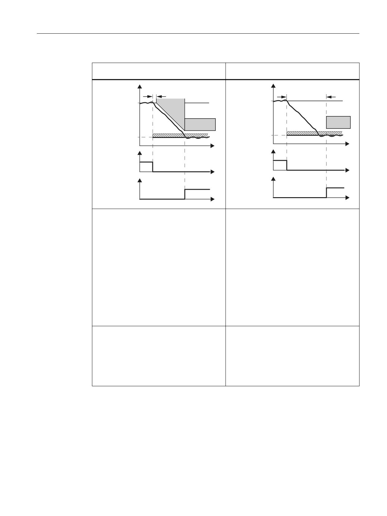
● For SLS without encoder, you can select whether the converter monitors motor braking
using the function SBR (Safe Brake Ramp) or not. For SLS with encoder, the SBR function
cannot be selected.
Safety Integrated
58
Function Manual, 06/2020, 6SL3097-5AR00-0BP3
Overview of Safety Integrated functions
4.2 Safety Integrated Extended Functions
With braking ramp monitoring1)
Without braking ramp monitoring
(only without encoder)
(with or without encoder)
6SHHG
'HOD\ WLPH IRU EUDNLQJ
6SHHG
'HOD\ WLPH IRU 6/6
UDPS
FKDQJHRYHU
6HWSRLQW
6HWSRLQW
6%5
6/6
6/6
/LPLWDWLRQ
/LPLWDWLRQ
W
'HVHOHFW 6/6
W
'HVHOHFW 6/6
) ', RU
) ', RU
352),VDIH FRQWURO
352),VDIH FRQWURO
ZRUG
ZRUG
W
W
6/6 DFWLYH
6/6 DFWLYH
) '2 RU
) '2 RU
352),VDIH VWDWXV
352),VDIH VWDWXV
ZRUG
ZRUG
W
W
● After the adjustable "delay time for the braking
● The converter monitors the load velocity after
ramp", using the SBR (Safe Brake Ramp) func-
the "delay time for SLS switchover" has ex-
tion, the converter monitors whether the veloc-
pired.
ity decreases.
● The converter switches from SBR to SLS as
soon as one of the following two conditions is
fulfilled:
- The SBR monitoring ramp has reached the
value of the SLS monitoring.
This case is shown in the diagram above.
- After the actual velocity has reached the
value of the SLS monitoring threshold, the
system again waits for the "delay time for
braking ramp" until SLS becomes active.
Advantages:
Advantage:
● Already when braking, the converter detects as
● Commissioning is simplified, because instead
to whether the load velocity decreases too
of the subfunction SBR or SAM of the alterna-
slowly.
tive brake ramp monitoring, you only have to
set the delay time.
● The feedback signal "SLS active" generally
comes earlier than without acceleration moni-
toring.
1)
The automatic reduction of the speed only takes effect when the ramp-function generator is
interconnected to the speed setpoint limitation.
Safety Integrated
Function Manual, 06/2020, 6SL3097-5AR00-0BP3
59
Overview of Safety Integrated functions
4.2 Safety Integrated Extended Functions
4.2.7.2
Selecting SLS at low velocities
Selecting SLS at low velocities
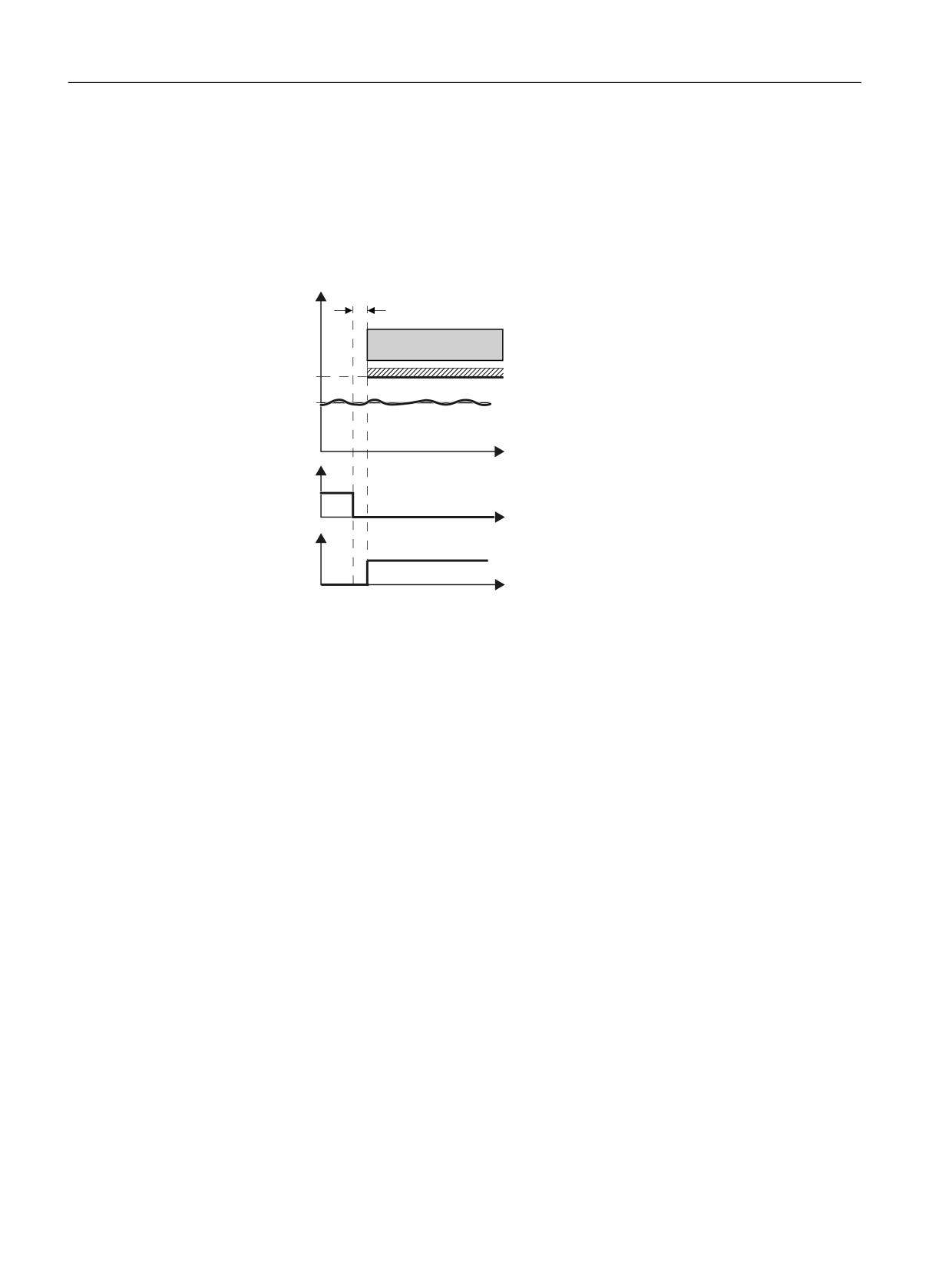
If the motor velocity when selecting SLS is less than the SLSlimit, then the drive responds as
follows:
9HORFLW\
'HOD\ WLPH 6/6
6/6
/LPLWLQJ
6HWSRLQW
W
'HVHOHFW 6/6
) ', RU
352),VDIH FRQWURO
ZRUG
W
6/6 DFWLYH
) '2 RU
352),VDIH VWDWXV
ZRUG
W
Deselecting SLS
If the higher-level controller deselects SLS , then the converter deactivates limiting and
monitoring.
4.2.7.3
Switching between monitoring thresholds
Switching over monitoring limits
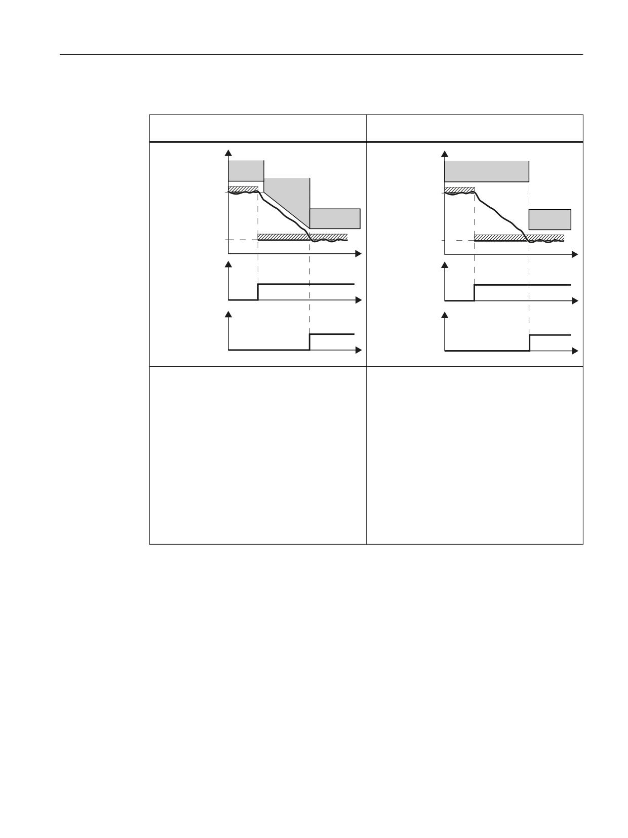
When SLS is active, you can switchover between 4 different speed levels. An exception is "SLS
without selection": In this case, there is only one limit.
Safety Integrated
60
Function Manual, 06/2020, 6SL3097-5AR00-0BP3
Overview of Safety Integrated functions
4.2 Safety Integrated Extended Functions
Switching to a lower speed level
With braking ramp monitoring1)
Without braking ramp monitoring
(only without encoder)
(with or without encoder)
9HORFLW\
9HORFLW\
6/6
6/6
/LPLW OHYHO
6%5
/LPLW OHYHO
6/6
6/6
/LPLW OHYHO
/LPLW OHYHO
6HOHFW
W
6HOHFW
W
6/6 OHYHO
6/6 OHYHO
352),VDIH
/HYHO
352),VDIH
/HYHO
/HYHO
/HYHO
FRQWURO ZRUG
FRQWURO ZRUG
W
W
$FWLYH
$FWLYH
6/6 OHYHO
6/6 OHYHO
352),VDIH
352),VDIH
/HYHO
/HYHO
/HYHO
/HYHO
VWDWXV ZRUG
VWDWXV ZRUG
W
W
●
Once the "delay time for braking ramp" has
● The converter monitors the velocity with the
elapsed, the converter monitors the motor ve-
lower SLS level after the "delay time for SLS
locity using the function SBR (Safe Brake
changeover" has expired (this is the same de-
Ramp).
lay time that applies after selecting the function
SLS).
●
The converter switches over from SBR moni-
toring to level 2 of SLS monitoring as soon as
one of the following conditions is fulfilled:
- The SBR monitoring ramp has reached the
value of the SLS monitoring.
This case is shown in the diagram above.
- The load velocity has decreased down to
the value SLS monitoring and the "delay
time for braking ramp" has expired.
1)
The automatic reduction of the speed only takes effect when the ramp-function generator is
interconnected to the speed setpoint limitation.
Safety Integrated
Function Manual, 06/2020, 6SL3097-5AR00-0BP3
61
Overview of Safety Integrated functions
4.2 Safety Integrated Extended Functions
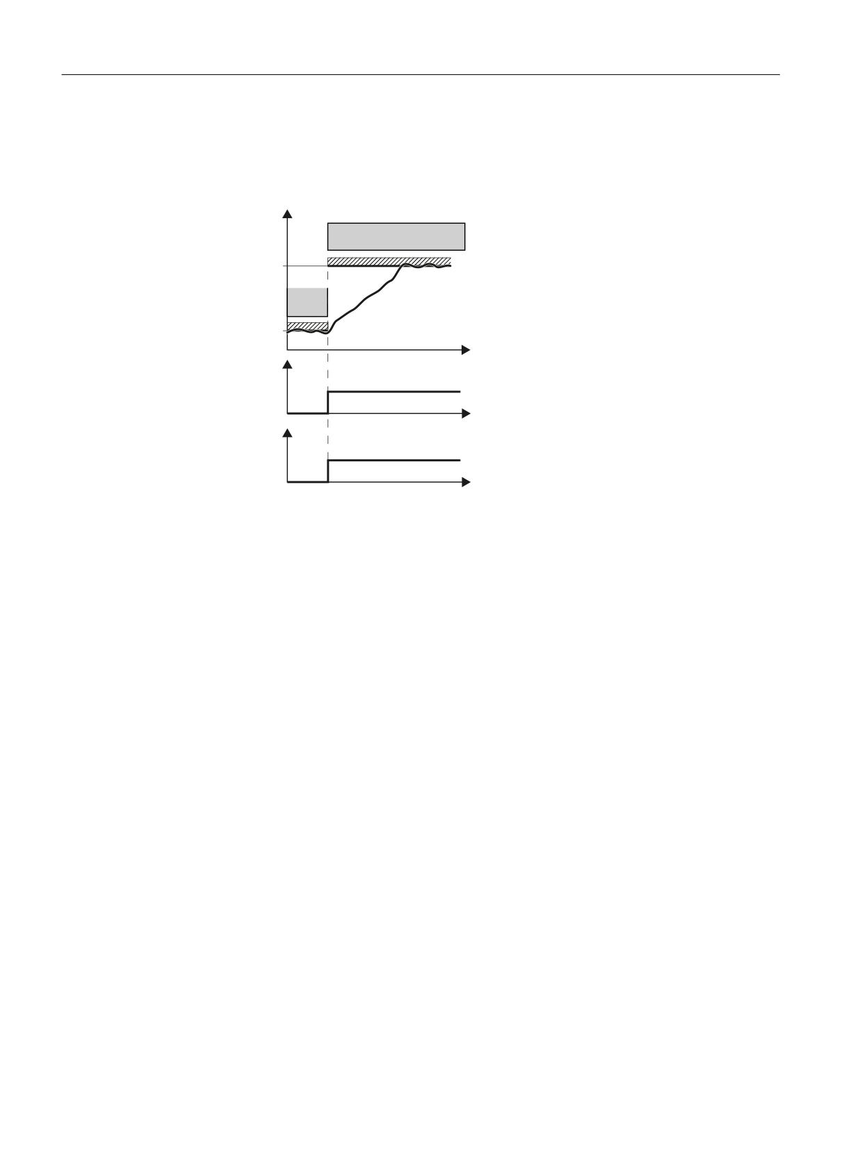
Switching to a higher speed level
If you switch over from a lower to a higher speed level, the converter immediately monitors the
actual velocity against the higher velocity.
6SHHG
6/6
/LPLW OHYHO
6/6
/LPLW OHYHO
6/6 OHYHO
W
VHOHFWLRQ
352),VDIH
/HYHO
/HYHO
FRQWURO ZRUG
W
$FWLYH
6/6 OHYHO
352),VDIH
/HYHO
/HYHO
VWDWXV ZRUG
W
Safety Integrated
62
Function Manual, 06/2020, 6SL3097-5AR00-0BP3
Overview of Safety Integrated functions
4.2 Safety Integrated Extended Functions
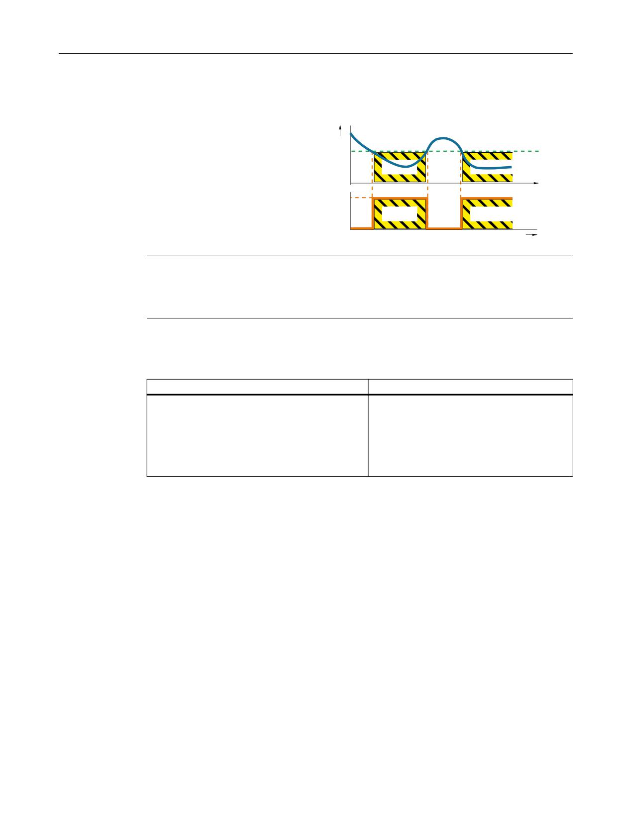
4.2.8
Safe Speed Monitor (SSM)
Definition according to EN 61800-5-2:
v
"The SSM function supplies a safe out-
put signal to indicate whether the motor
speed is below a specified limit value."
1
0
t
Note
SSM is a pure signaling function
Contrary to other Safety Integrated functions, a violation of the SSM limit does not result in a
drive-based stop response.
Example of how the function can be used
Example
Possible solution
A centrifuge may only be filled below a velocity de-
● SSM is activated by configuring the Safety
fined by the user.
Integrated Extended Functions.
● The converter safely monitors the centrifuge
speed and enables the process to advance
to the next step using the "Status SSM" sta-
tus bit.
How does SSM function in detail?
Requirements
The safety function SSM cannot be selected or deselected using external control signals. SSM
is active when you have set a monitoring velocity > 0 for SSM .
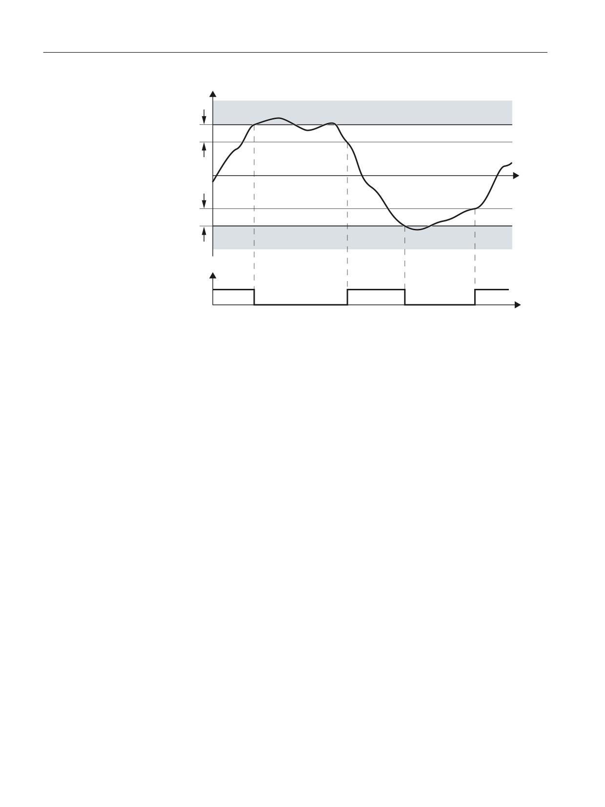
Evaluating the speed
The converter compares the load speed with the speed limit and signals if the limit value is
undershot to the high-level control.
Parameterizable hysteresis
The parameterizable hysteresis ensures that the SSM output signal does not jump between the
values "0" and "1" in the limit range.
Safety Integrated
Function Manual, 06/2020, 6SL3097-5AR00-0BP3
63
Overview of Safety Integrated functions
4.2 Safety Integrated Extended Functions
6SHHG
660
+\VWHUHVLV
W
+\VWHUHVLV
660
6SHHG EHORZ OLPLW
YDOXH
) '2 RU
352),VDIH VWDWXV ZRUG
W
Figure 4-3
Time response of the safety function SSM (Safe Speed Monitor)
Details and parameterization
For further details and information on how to parameterize this function, see Section "Safe
Speed Monitor (SSM) (Page 127)".
Safety Integrated
64
Function Manual, 06/2020, 6SL3097-5AR00-0BP3
Overview of Safety Integrated functions
4.2 Safety Integrated Extended Functions
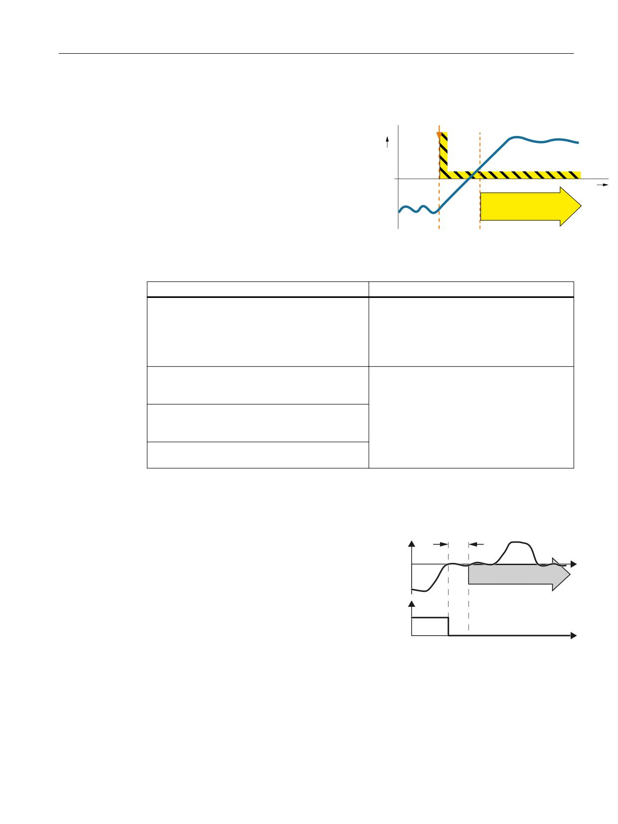
4.2.9
Safe Direction (SDI)
Definition according to EN 61800-5-2:
"The SDI function prevents the motor shaft mov-
v
ing in the wrong direction."
t
SDI
Examples of how the function can be used
Example
Possible solution
A protective door must only be opened if a drive
● Select SDI in the converter using a fail-safe
moves in the safe direction (away from the operator).
input or PROFIsafe .
● Enable the locking mechanism of the protec-
tive doors via the PROFIsafe status bit of the
converter.
When replacing the pressure cylinders of the plates,
● Select SDI in the converter using a fail-safe
the drive must only move in the safe direction of ro-
input or PROFIsafe .
tation.
● In the converter, inhibit the direction of rota-
Once the protection against jamming has been trig-
tion that is not permitted.
gered, a roller shutter gate must only be able to start
moving in one direction.
At an operational limit switch, the trolley of a crane
must only be able to start in the opposite direction.
How does SDI function in detail?
SDI monitors the actual direction of rota-
6', GHOD\
WLPH
tion.
6SHHG
The SDI setpoint limit can be transmitted
to the higher-level motion controller (e.g.
6',
W
SIMOTION) to enable limitation of the ve-
locity setpoint there.
6', GHVHOHFW
In addition, you can configure the set-
) ', RU
point limit provided by SDI as maximum
352),VDIH
speed in the ramp-function generator. In
FRQWURO ZRUG
this case, SDI limits the speed setpoint to
W
the permissible direction.
You can select to block either the positive or the negative direction of rotation via 2 fail-safe
signals (F-DIs or PROFIsafe).
Safety Integrated
Function Manual, 06/2020, 6SL3097-5AR00-0BP3
65
Overview of Safety Integrated functions
4.2 Safety Integrated Extended Functions
Selecting and deselecting SDI
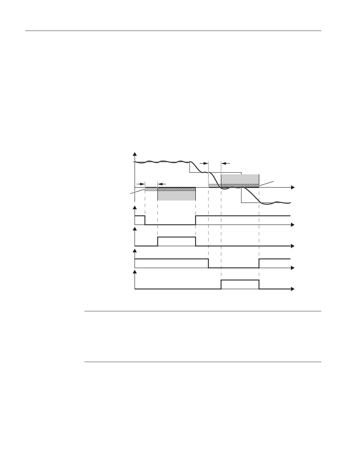
As soon as the converter identifies that SDI has been selected via a failsafe input or via
PROFIsafe safe communication, the following happens:
●
You can also set a delay time, within which you can ensure that the converter moves in the
enabled (safe) direction.
●
You can also set a tolerance, within which the converter tolerates movement in the direction
that has not been enabled (unsafe). You can avoid the triggering of faults during braking
(overshoot) as well as in controlled standstill.
●
After the delay time has expired, the converter monitors the direction of rotation of the motor.
●
If the converter now moves in the blocked direction by more than the configured tolerance,
a message will be output and the defined stop response will be initiated.
6SHHG
'HOD\
6HWSRLQW
'HOD\
/LPLWDWLRQ WR
6',
VSHHGV
W
/LPLWDWLRQ WR VSHHGV
6',
!
6', GHVHOHFW
) ', RU
352),VDIH FRQWURO ZRUG
W
6', DFWLYH
) '2 RU
352),VDIH VWDWXV ZRUG
W
'HVHOHFW 6',
) ', RU
352),VDIH FRQWURO ZRUG
W
6', DFWLYH
) '2 RU
352),VDIH VWDWXV ZRUG
W
Figure 4-4
Time response of the safety function SDI (Safe Direction)
Note
SDI without selection
As an alternative to controlling via terminals and/or PROFIsafe, there is also the option of
parameterizing SDI without selection. In this case, SDI will be permanently active after
POWER ON. You will find details about this in Section "Safe Direction without selection
(Page 139)".
Details and parameterization
For further details and information on how to parameterize this function, see Section "Safe
Direction (SDI) (Page 134)".
Safety Integrated
66
Function Manual, 06/2020, 6SL3097-5AR00-0BP3
Overview of Safety Integrated functions
4.2 Safety Integrated Extended Functions
4.2.10
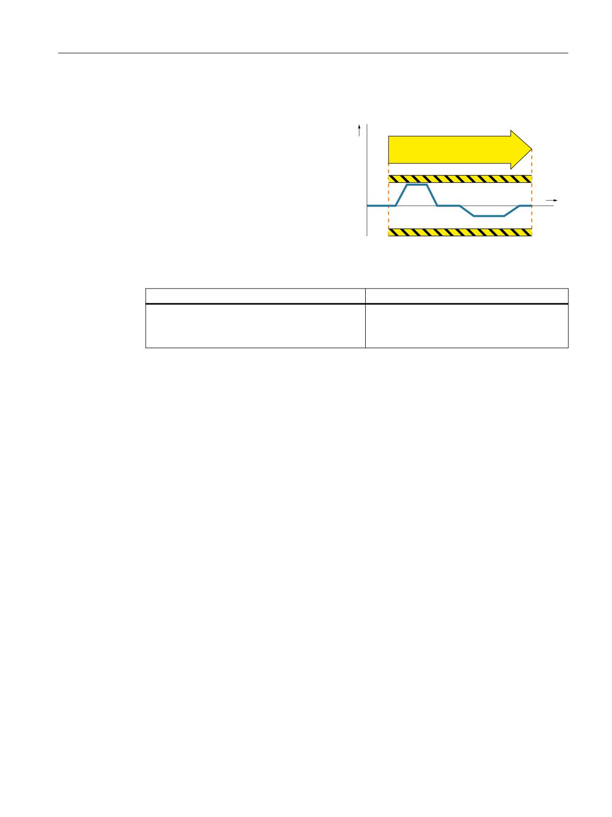
Safely-Limited Acceleration (SLA)
Definition according to EN 61800-5-2:
a
"The SLA function prevents the motor from
SLA
exceeding the defined acceleration limit."
t
Examples of how the function can be used
Example
Possible solution
In the setup mode, it is not permissible that the drive
● Select SLA in the converter via PROFIsafe.
exceeds the permissible acceleration.
● The converter limits and monitors the accel-
eration of the machine.
Details and parameterization
For further details and information on how to parameterize this function, see Chapter "Safely
Limited Acceleration (SLA) (Page 140)".
Safety Integrated
Function Manual, 06/2020, 6SL3097-5AR00-0BP3
67
Overview of Safety Integrated functions
4.2 Safety Integrated Extended Functions
4.2.11
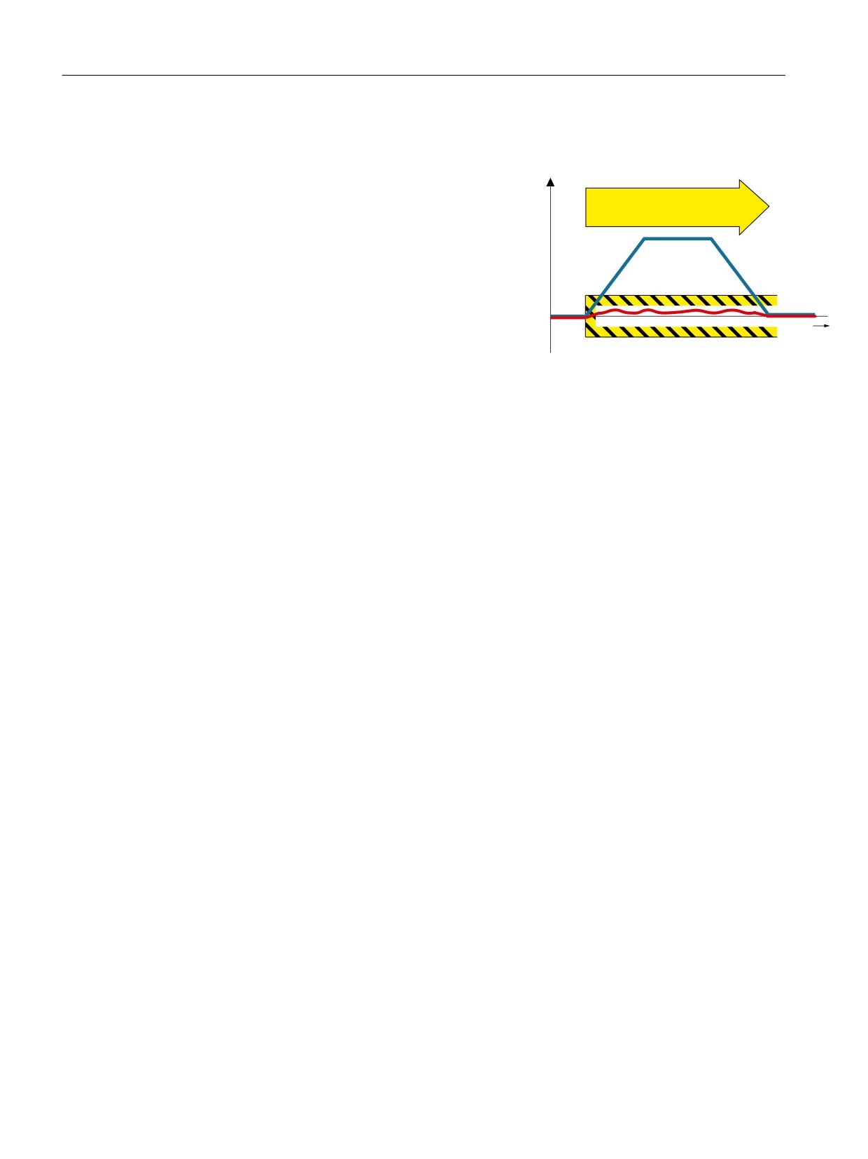
Safe Brake Test (SBT)
The diagnostic function "Safe Brake Test" func-
0 V
tion (SBT) checks the required holding torque of
6%7
a brake (operating or holding brake).
W
How does the SBT function in detail?
You can test linear axes and rotary axes. The drive purposely generates a force/torque against
the applied brake. If the brake is operating correctly, the axis motion remains within a
parameterized tolerance. If, however, a larger axis motion is detected, it must be assumed that
the braking force/torque has deteriorated and maintenance is required.
The "Safe Brake Test" function allows a safe test of up to two brakes:
●
1 motor holding brake and 1 external brake
●
2 external brakes
●
1 motor holding brake
●
1 external brake
The "Safe Brake Test" (SBT) diagnostic function is suitable for safety functions up to Category 2
according to ISO 13849-1.
Details and parameterization
For further details and information on how to parameterize this function, see Chapter "Safe
Brake Test (SBT) (Page 144)".
Safety Integrated
68
Function Manual, 06/2020, 6SL3097-5AR00-0BP3
Overview of Safety Integrated functions
4.3 Safety Integrated Advanced Functions
4.3
Safety Integrated Advanced Functions
This chapter should provide first users with a quick overview of the principle mode of operation
of safety functions.
The entry into the description of the safety functions is based on the definition according to
standard EN 61800-5-2 and some simple examples for using the function.
The description of the functions is simplified, as far as possible to clearly shown essential
properties and setting options.
You will find more information on the functions in the following chapters,
e.g. "Safety Integrated Advanced Functions (Page 181)".
4.3.1
Preconditions for Safety Integrated Advanced Functions
● For operation of the Safety Integrated Extended Functions, one license is required for each
axis.
● To use Safety Integrated Advanced Functions, one license is required for each axis. The
license for Safety Integrated Advanced Functions also includes the license for Safety
Integrated Extended Functions.
● Overview of hardware components that support the Extended/Advanced Functions:
- Control Unit CU320-2
- Control Unit CU310-2
- SINAMICS HLA
- Motor Modules Booksize Compact
- Motor Modules booksize C/D type with article No.: -..C. or -..D.
- Motor Modules booksize with an article number ending: -...3 or higher
- Motor Modules chassis with an article number ending: -...3 or higher
- Motor Modules cabinet with an article number ending: -...2 or higher
- Power Modules blocksize
- Control Unit Adapter CUA31 as of article number: 6SL3040-0PA00-0AA1
- Control Unit Adapter CUA32 as of article number: 6SL3040-0PA01-0AA0
- For the safety functions with encoder:
Motors with sin/cos encoder and encoder evaluation with DRIVE-CLiQ interface or via
Sensor Module SMC20, SME20/25/120/125, square wave signal encoder with SMC30,
EnDat-2.2 encoder with SMC40
The list of approved encoders can be found on the Internet at:
Enter the number 33512621 there as search term or contact your local Siemens office.
Safety Integrated
Function Manual, 06/2020, 6SL3097-5AR00-0BP3
69
Overview of Safety Integrated functions
4.3 Safety Integrated Advanced Functions
4.3.2
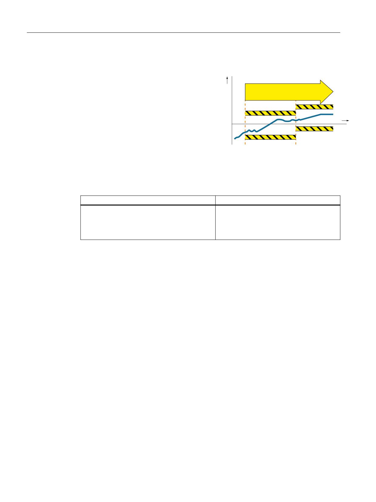
Safely-Limited Position (SLP)
Definition according to EN 61800-5-2:
s
"The SLP function prevents the motor shaft from
SLP
exceeding the specified position limit(s)."
t
The Safely-Limited Position function (SLP) is used to safely monitor the limits of two traversing
and/or positioning ranges, which are toggled between using a safe signal.
Examples of how the function can be used
Example
Possible solution
The drive must not exit the specified position ranges.
● Selection of SLP in the converter; inhibiting
the range that is not permitted.
● After the enabled range has been exited, a
parameterizable stop response is initiated.
Features
● Selection via terminals or PROFIsafe
●
2 position ranges, each defined by a limit switch pair
● Safe switchover between the two position ranges
● Settable stop response
● To run the motor out of the prohibited range, you must perform a special sequence (see
Chapter "Retraction (Page 185)").
Preconditions
● The function is only available with a suitable encoder.
● The drive has to be safely referenced (see Chapter "Safe referencing (Page 71)").
Details and parameterization
For further details and information on how to parameterize this function, see Section "Safely-
Limited Position (SLP) (Page 181)".
Safety Integrated
70
Function Manual, 06/2020, 6SL3097-5AR00-0BP3
Overview of Safety Integrated functions
4.3 Safety Integrated Advanced Functions
4.3.3
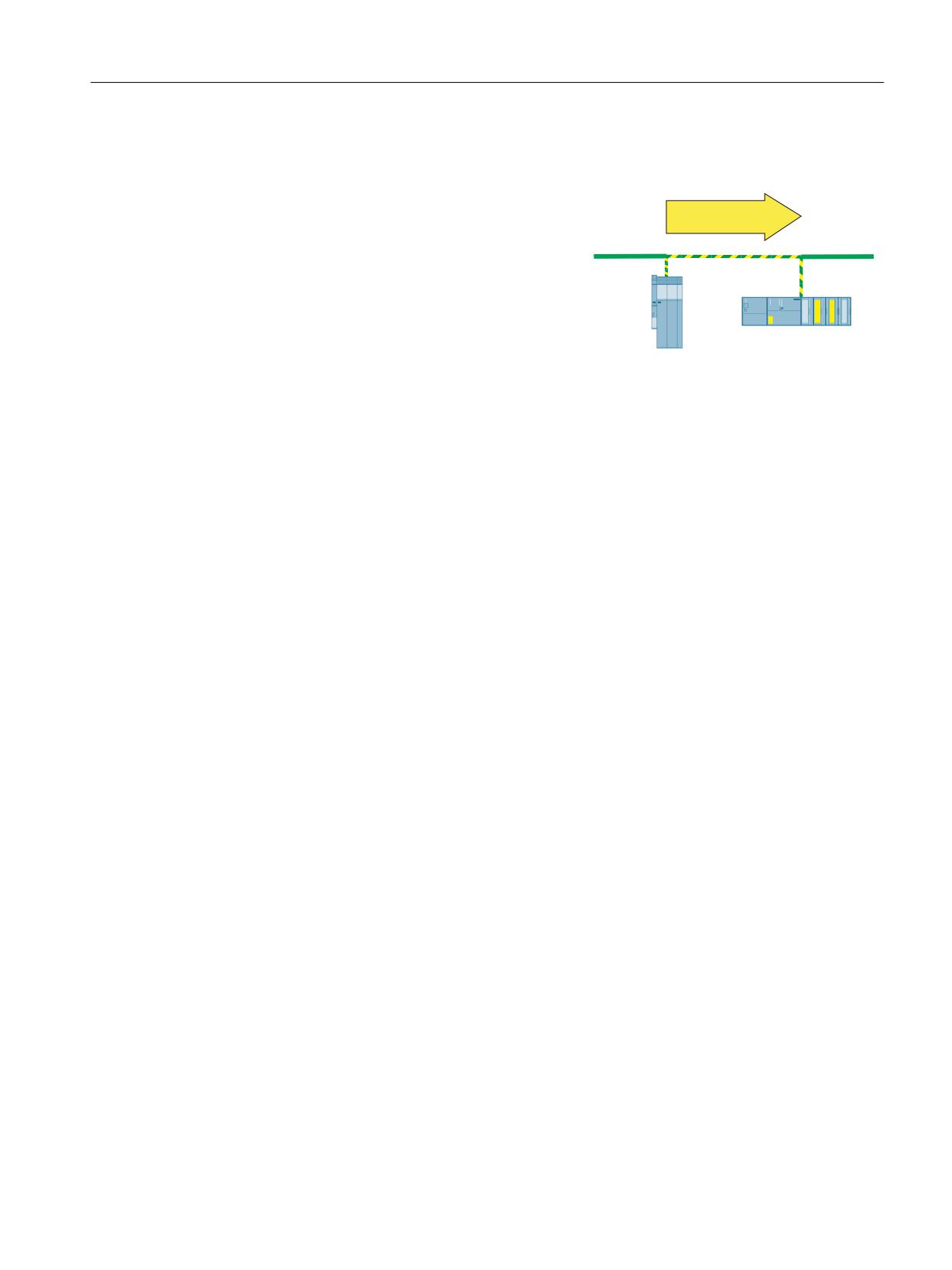
Transferring safe position values (SP)
The "Safe Position (SP)" function enables you to
transfer safe position values to the higher-level
SP
fail-safe controller (F-CPU) via PROFIsafe (tele-
gram 901 or 902).
How does the SP function in detail?
On the F-CPU side, you can also calculate the current speed from the change in position per
time. In telegram 902, the values are transferred in 32-bit format, in telegram 901, in 16-bit
format.
After parameter assignment, enabling and POWER ON, the function is automatically selected.
The drive transfers the value. Please observe the following:
● For use as the safe absolute position, the "Absolute position" must also be enabled and then
safely referenced.
● To allow the controller to continue using the transferred position, the actual position value
must be valid.
Using the time stamp that is also transferred, you can also calculate the velocity from the
position values. If you only want to calculate the speed, just enable the "Transfer of safe
position values" without the "Absolute position."
Details and parameterization
For further details and information on how to parameterize this function, see Chapter
"Transferring safe position values (SP) (Page 188)".
4.3.4
Safe referencing
The "safe referencing" function allows a safe absolute position to be defined. This safe position
is used for the following functions:
● Safely-Limited Position (SLP) (Page 70)
● Transferring safe position values (SP) (Page 71)
● Safe Cam (SCA) (Page 73)
Safety Integrated
Function Manual, 06/2020, 6SL3097-5AR00-0BP3
71
Overview of Safety Integrated functions
4.3 Safety Integrated Advanced Functions
General description
In most cases, an external control performs referencing to an absolute position. The converter
only performs this task in special cases (for example, EPOS).
● Referencing using an external control
Requirement: No movement of the drive
The reference position determined by the control is entered into parameter p9572 and is
declared to be valid using p9573 = 89.
● Referencing by EPOS
The SINAMICS EPOS function transfers, when referencing, the determined position directly
to Safety Integrated. This can also take place during motion.
● User agreement
The user agreement must be set (p9726 = p9740 = AC hex) within a certain time interval
after referencing (see Chapter "Referencing types (Page 194)").
Safety Integrated only evaluates the reference position if this is required by a function that has
been enabled (e.g. SLP). Using diagnostics bit r9723.17, Safety Integrated indicates whether
the drive has been referenced. Safety Integrated indicates the position of the drive in diagnostic
parameters r9708 and r9713. Bit r9722.23 is set when the axis is safely referenced.
Safety Integrated
72
Function Manual, 06/2020, 6SL3097-5AR00-0BP3
Overview of Safety Integrated functions
4.3 Safety Integrated Advanced Functions
4.3.5
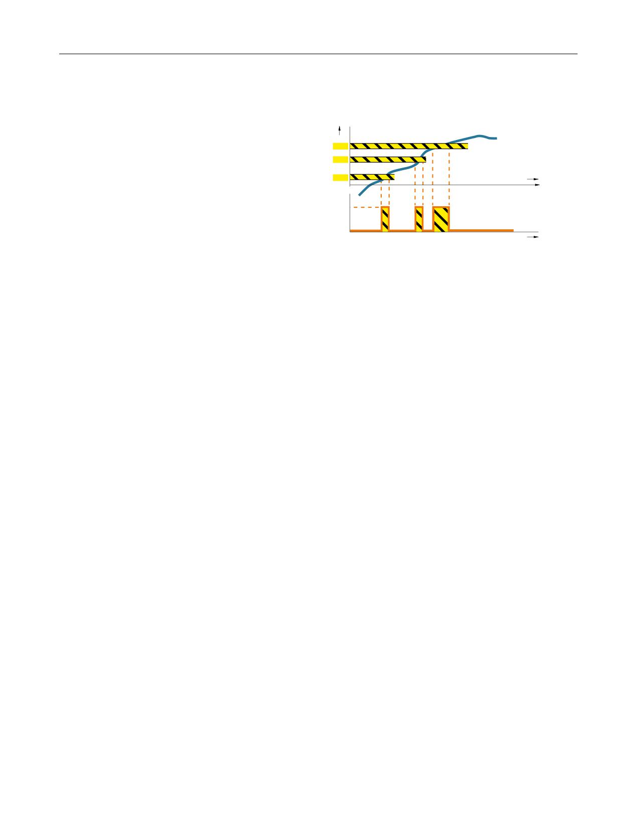
Safe Cam (SCA)
Definition according to EN
s
61800-5-2:
SCA 3
The function "Safe Cam" (SCA) safe
SCA 2
supplies a safety-related output sig-
SCA 1
t
nal to indicate whether the motor
shaft position is within a defined
1
range.
0
t
How does the SCA function in detail?
The "Safe Cam" function outputs a safe signal if the drive is within a specified position range.
It facilitates the realization of safe range detection for each individual axis.
Details and parameterization
For further details and information on how to parameterize this function, see Chapter "Safe
Cam (SCA) (Page 196)".
Safety Integrated
Function Manual, 06/2020, 6SL3097-5AR00-0BP3
73
Overview of Safety Integrated functions
4.3 Safety Integrated Advanced Functions
Safety Integrated
74
Function Manual, 06/2020, 6SL3097-5AR00-0BP3
Description of Safety Integrated functions
5
Two-channel parameterization
Parameterization of the Safety Integrated Functions must be performed in two channels; i.e.
there is one parameter each for the 1st and 2nd channel. These two parameters must be
identically parameterized.
For safety reasons, when using the Startdrive commissioning tool, only set the safety-related
parameters of the 1st channel while offline. Startdrive copies the parameter of the 2nd channel
automatically.
Because Startdrive sets the safety-related parameters of the 2nd channel by copying, only the
parameters of the 1st channel are given in this manual. You will find the relevant parameters of
the 2nd channel in the parameter description, e.g. in SINAMICS S120/S150 List Manual.
On faults and alarms, only the error number of the 1st channel is stated.
Safety Integrated
Function Manual, 06/2020, 6SL3097-5AR00-0BP3
75

Description of Safety Integrated functions
5.1 Safety Integrated basic functions
5.1
Safety Integrated basic functions
Note
Basic Functions do not require an encoder
The Safety Integrated Basic Functions are functions for safely stopping the drive. You do not
require an encoder.
Note
Application of the Basic Functions
Basic Functions are available in all control modes with and without encoder for synchronous
and induction motors without any restrictions.
Note
Control via TM54F
If you want to control the Safety Integrated Basic Functions via TM54F, set p9601.6 = 1.
Note
PFH values
The PFH values of the individual SINAMICS S120 safety components can be found at:
5.1.1
Safe Torque Off (STO)
In conjunction with a machine function or in the event of a fault, the "Safe Torque Off" (STO)
function is used to safely disconnect the torque-generating energy supply to the motor.
A restart is prevented by the two-channel pulse suppression. The switching on inhibited
prevents an automatic restart after deselection of STO.
The two-channel pulse suppression function integrated in the Motor Modules / Power Modules
is the basis for this function.
Functional features of "Safe Torque Off"
● The function is completely integrated in the drive. It can be selected via terminals, TM54F
or PROFIsafe from an external source.
● The function is drive-specific, i.e. it is available for each drive and must be individually
commissioned.
● The function must be enabled via parameter.
Safety Integrated
76
Function Manual, 06/2020, 6SL3097-5AR00-0BP3

Description of Safety Integrated functions
5.1 Safety Integrated basic functions
● When the "Safe Torque Off" function is selected, the following applies:
- The motor cannot be started accidentally.
- The pulse suppression safely disconnects the torque-generating energy supply to the
motor.
- The power unit and motor are not electrically isolated.
● The selection/deselection of the STO function also acknowledges the safety faults when the
Basic Functions are used. The standard acknowledgment mechanism must also be
performed.
● Extended acknowledgement:
The selection/deselection of STO can also acknowledge the safety messages of the
extended safety functions. This requires that the extended message acknowledgement is
configured (p9507.0 = 1).
If in addition to the "Extended Functions", the "Basic Functions via terminals" are also
enabled, in addition to selection/deselection of STO via PROFIsafe or TM54F,
acknowledgement is also possible by selection/deselection of STO via terminals.
● The status of the "Safe Torque Off" function is displayed using parameters (r9772, r9872,
r9773 and r9774).
● Effect on the "Setpoint speed limit effective" (r9733[0...2]):
For STO (≙ STOP A), a setpoint of 0 is specified in r9733[0...2].
WARNING
Unplanned motor motion
After the energy feed has been disconnected (STO active) the motor can undesirably move
(e.g. the motor can coast down), therefore presenting risk to persons.
● Take suitable measures to prevent undesirable movement, e.g. by using a brake with
safety-relevant monitoring. For additional information, see Chapter "Safe Brake Control
(SBC) (Page 84)".
WARNING
Danger due to short, limited movements
If two power transistors simultaneously fail in the power unit (one in the upper and one in the
lower inverter bridge), then this can cause cause brief, limited movement.
The maximum movement can be:
● Synchronous rotary motors: Max. movement = 180° / no. of pole pairs
● Synchronous linear motors: Max. movement = pole width
Safety Integrated
Function Manual, 06/2020, 6SL3097-5AR00-0BP3
77
Description of Safety Integrated functions
5.1 Safety Integrated basic functions
Enabling the "Safe Torque Off" function (Basic Functions)
The "Safe Torque Off" function is enabled via parameter p9601:
● STO for the Safety Integrated Basic Functions:
- p9601 = 1 hex (Basic Functions via onboard terminals)
- p9601 = 8 hex (Basic Functions via PROFIsafe)
- p9601 = 9 hex (Basic Functions via PROFIsafe and onboard terminals)
- p9601 = 40 hex (basic functions via TM54F)
- p9601 = 41 hex (basic functions via TM54F and onboard terminals)
Enabling the "Safe Torque Off" function (Extended Functions)
The "Safe Torque Off" function is enabled via parameter p9601:
● STO in the Safety Integrated Extended Functions (EF):
- p9601 = 4 hex (EF via TM54F)
- p9601 = 5 hex (EF via TM54F and basic functions via onboard terminals)
- p9601 = C hex (EF via PROFIsafe)
- p9601 = D hex (EF via PROFIsafe via onboard terminals)
- p9601 = 25 hex (EF without selection and basic functions via onboard terminals)
Selecting/deselecting "Safe Torque Off"
The following is executed when "Safe Torque Off" is selected:
● Each monitoring channel triggers safe pulse suppression via its switch-off signal path.
● A motor holding brake is closed (if connected and configured).
Deselecting "Safe Torque Off" represents an internal safety acknowledgment. The following is
executed if the cause of the fault has been removed:
● Each monitoring channel cancels safe pulse suppression via its switch-off signal path.
● The Safety requirement "Close motor holding brake" is canceled.
● Any pending STOP F or STOP A commands are canceled (see r9772).
● The messages in the fault memory must also be reset using the general acknowledgment
mechanism.
Note
No message for selection/deselection within the tolerance time (p9650)
If "Safe Torque Off" is selected and deselected through one channel within the tolerance
time p9650, the pulses are suppressed without a message being output.
However, if you want a message to be displayed, then you must reconfigure N01620 as an
alarm or fault using p2118 and p2119.
Safety Integrated
78
Function Manual, 06/2020, 6SL3097-5AR00-0BP3
Description of Safety Integrated functions
5.1 Safety Integrated basic functions
Restart after the "Safe Torque Off" function has been selected
1. Deselect the function.
2. Set drive enables.
3. After deselecting STO, wait until the converter is "ready to switch on".
4. Cancel the "switching on inhibited" and switch the drive back on.
-
1/0 edge at input signal "ON/OFF1" (cancel "switching on inhibited")
-
0/1 edge at input signal "ON/OFF1" (switch on drive)
Status for "Safe Torque Off"
The status of the function STO is displayed via r9772, r9872, r9773, and r9774. Alternatively,
you can display the status of the function via the configurable message N01620 (configuration
via p2118 and p2119).
Response time for the "Safe Torque Off" function
For the response times when the function is selected/deselected via input terminals, see the
table in Chapter "Response times (Page 355)".
Internal armature short-circuit with the "Safe Torque Off" function
The function "internal armature short-circuit" can be configured together with the "STO"
function.
The "STO" safety function has the higher priority when simultaneously selected. If the "STO"
function is initiated, then an activated "internal armature short-circuit" is disabled.
Function diagrams (see SINAMICS S120/S150 List Manual)
●
2810
SI Basic Functions - STO (Safe Torque Off), SS1 (Safe Stop 1)
●
2811
SI Basic Functions - STO (Safe Torque Off), safe pulse suppression
Overview of important parameters (see SINAMICS S120/S150 List Manual)
● p9601
SI enable functions integrated in the drive (Control Unit)
● r9720
CO/BO: SI Motion drive-integrated control signals
● r9722
CO/BO: SI Motion drive-integrated status signals (Control Unit)
● r9772
CO/BO: SI Status (Control Unit)
● r9773
CO/BO: SI Status (Control Unit + Motor Module)
● r9774
CO/BO: SI Status (group STO)
Safety Integrated
Function Manual, 06/2020, 6SL3097-5AR00-0BP3
79
Description of Safety Integrated functions
5.1 Safety Integrated basic functions
5.1.1.1
Safe Torque Off (STO) for SINAMICS HLA
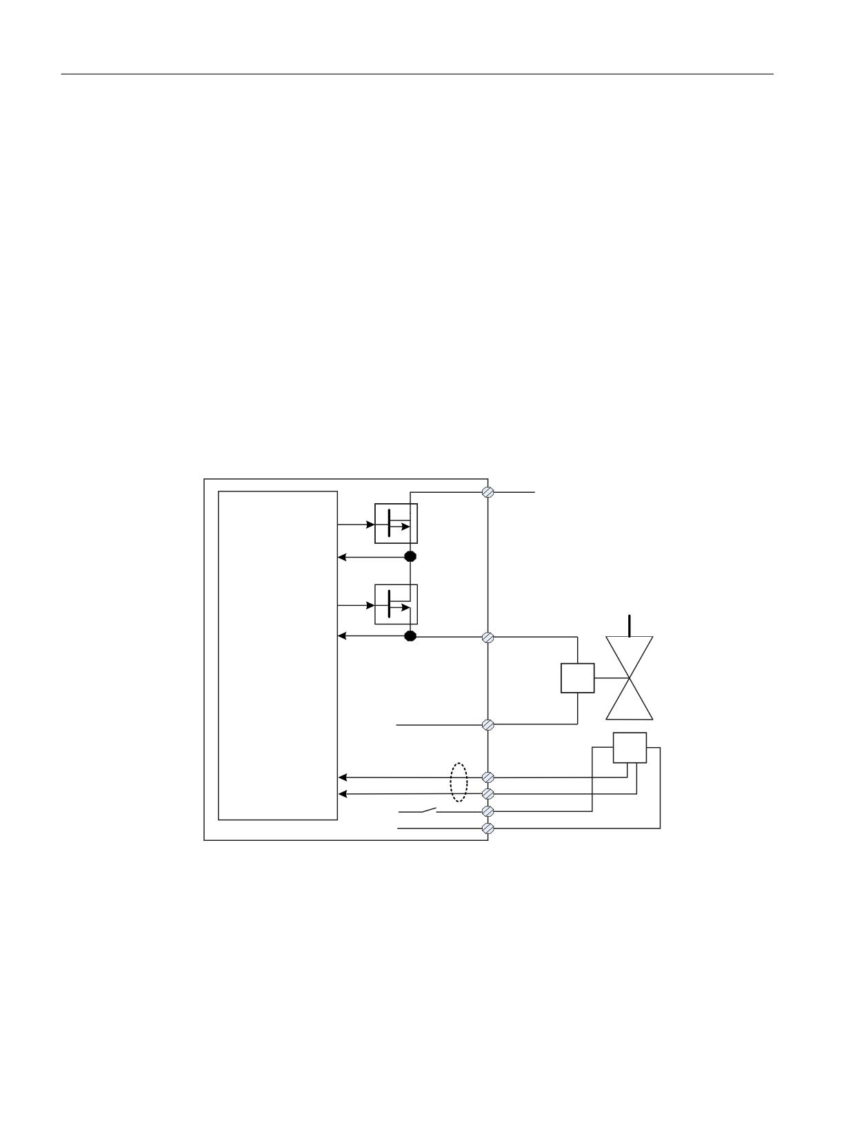
For the HLA module, safe torque off (STO) corresponds to shutting off a safety-relevant shutoff
valve.
Special features of STO for HLA
●
The shutoff valve controls the infeed to the hydraulic circuit. The shutoff valve is controlled
via an F-DO of SINAMICS HLA.
●
For Safety Integrated Functions, it is absolutely necessary that a shutoff valve is connected
with the associated feedback signals.
●
You configure the feedback signal contacts of the shutoff valve using parameter p9626.
●
You can take into account the response times of the feedback signals using parameter
p9625.
●
The shutoff valve is safely closed by selecting STO. If the shutoff valve signals a safe state
via the feedback signal(s), the "STO active/Power removed" state is displayed, and is output
at the configured safety-related output (PROFIsafe feedback signal telegram, F-DO on
TM54F).
9 H[W
;
) '2
'LDJ '2
) '2
;
'LDJ '2
&RQWURO
6KXW RII YDOYH
;
0
)HHGEDFN
VLJQDOV
1& FRQWDFW 12 FRQWDFW
;
',
',
9
0
Figure 5-1
Interconnecting the shutoff valve (for an axis)
●
F-DO is dynamized each time that STO is selected/deselected: "Diag DO+" and "Diag DO-"
are checked when switching F-DO+ and F-DO-.
●
This makes it unnecessary to select forced checking procedure (test stop) explicitly.
●
If an error occurs in the forced checking procedure (test stop), the converter will issue fault
F01632 or F30632.
Safety Integrated
80
Function Manual, 06/2020, 6SL3097-5AR00-0BP3
Description of Safety Integrated functions
5.1 Safety Integrated basic functions
Function diagrams (see SINAMICS S120/S150 List Manual)
●
2810
SI Basic Functions - STO (Safe Torque Off), SS1 (Safe Stop 1)
●
2811
SI Basic Functions - STO (Safe Torque Off), safe pulse cancellation
Overview of important parameters (see SINAMICS S120/S150 List Manual)
● p9625[0...1]
SI HLA shutoff valve wait time (CU)
● p9626
SI HLA shutoff valve feedback contacts configuration (CU)
● r9773
CO/BO: SI Status (Control Unit + Hydraulic Module)
● r9774
CO/BO: SI Status (group STO)
● r9780
SI monitoring cycle (Control Unit)
5.1.2
Safe Stop 1 (SS1, time controlled)
5.1.2.1
SS1 with OFF3
The "Safe Stop 1" (SS1) function allows the drive to be stopped in accordance with EN 60204-1,
Stop Category 1. The drive decelerates with the OFF3 ramp (p1135) once "Safe Stop 1" is
selected and switches to "Safe Torque Off" (STO) once the delay time set in p9652 has elapsed.
Note
Selection via terminals
The selection of the "Safe Stop 1" (time-controlled) function via terminals is parameterized by
setting a delay > 0 in p9652. In this case, the STO function can no longer be selected directly
via terminals, i.e. either STO or SS1 can be selected via terminals.
If the "Safe Stop 1" (time-controlled) function has been selected by parameterizing a delay time
in p9652, STO can no longer be selected directly via terminals.
Precondition
● The Basic Functions are enabled via terminals and/or PROFIsafe:
- p9601 = 1, 8 or 9 (hex)
● Enabling Basic Functions via TM54F
- p9601.6 = 1
● In order that the drive can brake down to a standstill even when selected through one
channel, the time in p9652 must be shorter than the sum of the parameters for the data
cross-check (p9650 and p9658). Otherwise the drive will coast down after the time
p9650 + p9658 has elapsed.
Safety Integrated
Function Manual, 06/2020, 6SL3097-5AR00-0BP3
81
Description of Safety Integrated functions
5.1 Safety Integrated basic functions
Functional features of Safe Stop 1
SS1 is enabled by p9652 (delay time) ≠ 0.
● Setting parameter p9652 has the following effect:
- p9652 = 0
SS1 is not enabled. Only STO can be selected via TM54F, the onboard terminals and/or
PROFIsafe.
- p9652 > 0
SS1 is enabled. Only SS1 can be selected via the onboard terminals; with PROFIsafe,
a selection of SS1 and STO is possible.
● When SS1 is selected, the drive is braked along the OFF3 ramp (p1135) and STO/SBC is
automatically initiated after the delay time has expired (p9652).
After the function has been selected, the delay timer runs down - even if the function is
deselected during this time. In this case, after the delay time has expired, the STO/SBC
function is selected and then again deselected immediately.
Note
Setting the delay time
So that the drive is able to travel down the OFF3 ramp completely and any motor holding
brake present can be applied, before the pulses have been safely deleted, the delay time
should be set as follows:
● Motor holding brake parameterized: Delay time p9652 ≥ p1135 + p1228 + p1217
● Motor holding brake not parameterized: Delay time p9652 ≥ p1135 + p1228
● The setting of parameter p1135 must be oriented towards the actual braking capability
of the drive.
● The timer (p9652) after whose expiration STO is activated, is implemented with two
channels, although deceleration along the OFF3 ramp is only one channel.
● Effect on "Speed setpoint limit effective" (r9733[0...2]):
If SS1 (≙ STOP B), setpoint 0 is specified in r9733[0...2].
Status of Safe Stop 1
The status of the "Safe Stop 1" (SS1) function is displayed using the parameters r9772, r9872,
r9773 and r9774.
As an alternative, the status of the function can be displayed using the configurable message
N01621 (configured using p2118 and p2119).
Safety Integrated
82
Function Manual, 06/2020, 6SL3097-5AR00-0BP3
Description of Safety Integrated functions
5.1 Safety Integrated basic functions
5.1.2.2
SS1 with external stop
In drive line-ups (e.g. drives that are mechanically connected via the material), the drive-
independent braking on the respective OFF3 ramp can cause problems. If the SS1E function
is used, the safe delay time (p9652) is started when the function is selected, but no OFF3 is
triggered. The higher-level controller still enters the setpoint. The controller receives the
information that SS1E has been selected via the Safety Info Channel.
WARNING
Any axis motion is possible
During the delay time (p9652), for "Safe Stop 1 (time-controlled) with external stop", any axis
movements are possible.
Differences between "SS1 with OFF3" and "SS1 with external stop"
"SS1 with OFF3" and "SS1 with external stop" have the following differences:
● In order to activate "Safe Stop 1 with external stop", additionally set p9653 = 1.
● When SS1E is selected, the drive is not braked along the OFF3 ramp, but after the delay
time has expired (p9652), only STO/SBC is automatically initiated.
Safety Integrated
Function Manual, 06/2020, 6SL3097-5AR00-0BP3
83
Description of Safety Integrated functions
5.1 Safety Integrated basic functions
5.1.2.3
Function diagrams and parameters
Function diagrams (see SINAMICS S120/S150 List Manual)
●
2810
SI Basic Functions - STO (Safe Torque Off), SS1 (Safe Stop 1)
●
2811
SI Basic Functions - STO (Safe Torque Off), safe pulse cancellation
Overview of important parameters (see SINAMICS S120/S150 List Manual)
● p1135[0...n]
OFF3 ramp-down time
● p1217
Motor holding brake closing time
● p1228
Pulse suppression delay time
● p9601
SI enable functions integrated in the drive (Control Unit)
● p9652
SI Safe Stop 1 delay time (Control Unit)
● r9772.0...23
CO/BO: SI Status (Control Unit)
● r9773.0...31
CO/BO: SI Status (Control Unit + Motor Module)
● r9774.0...31
CO/BO: SI Status (group STO)
Only for "Safe Stop 1 (time-controlled) with external stop"
● p9653
SI Safe Stop 1 drive-based braking response
5.1.3
Safe Brake Control (SBC)
The "Safe Brake Control" function (SBC) is used to safely control holding brakes that function
according to the closed-circuit principle (e.g. motor holding brake).
The opening and closing of the brake is controlled by the Motor Module / Power Module.
Terminals are available for this on the device in booksize format. A Safe Brake Relay is also
required for the "Safe Brake Control" in the blocksize format. A Safe Brake Adapter is required
in the chassis format (starting with article numbers ending with ...3). When the Power Module
is configured automatically, the Safe Brake Relay is detected and the motor holding brake type
is defaulted (p1278 = 0).
Brake activation via the brake connection on the Motor Module / Safe Brake Relay (SBR) / Safe
Brake Adapter (SBA) involves a safe, two-channel method.
Note
No SBC for SINAMICS HLA
SINAMICS HLA does not support Safe Brake Control.
Note
Controlling the brake via a relay for "Safe Brake Control"
If you use the "Safe Brake Control (SBC)" function, the use of relays/contactors can cause
faults in the brake control when brakes are switched.
Safety Integrated
84
Function Manual, 06/2020, 6SL3097-5AR00-0BP3
Description of Safety Integrated functions
5.1 Safety Integrated basic functions
WARNING
Undesirable motor motion due to defective brake
"Safe Brake Control" does not detect mechanical defects of the brake.
A cable break or a short-circuit in the brake winding is only detected when the state changes,
i.e. when the brake either opens and/or closes. In SINAMICS S120M, a cable break is only
identified when opening the brake.
For devices in chassis format with connected Safe Brake Adapter, the connecting cable
between the Safe Brake Adapter and the motor brake is not monitored for cable break or short-
circuit.
The aforementioned defects may trigger unwanted motor motion, which may result in physical
injury or death.
● In particular, ensure the brake is not powered from an external source. Information on this
topic can be found in EN 61800-5-2, Appendix D.
● During commissioning, test the brake using the diagnostic function "Safe Brake Test
(SBT)" (Extended Function): Additional information is provided in Chapter "Safe Brake
Test (SBT) (Page 144)".
5.1.3.1
Description SBC
Functional features of "Safe Brake Control"
● SBC is executed when "Safe Torque Off" (STO) is selected.
● In contrast to conventional brake control, SBC is executed via two channels.
● SBC is executed regardless of the brake control or mode set in p1215. However, SBC does
not make sense for p1215 = 0 or 3.
● The function must be enabled using parameters.
● When the state changes, electrical faults, such as a short-circuit in the brake winding or wire
breakage can be detected.
Enabling the "Safe Brake Control" function
The "Safe Brake Control" function is enabled via parameter p9602.
The SBC function can be used only together with STO. The selection of SBC alone is not
possible.
Safety Integrated
Function Manual, 06/2020, 6SL3097-5AR00-0BP3
85
Description of Safety Integrated functions
5.1 Safety Integrated basic functions
2-channel brake control
Note
Connecting the brake
The brake cannot be directly connected to the Motor Module in chassis format. A Safe Brake
Adapter is also required.
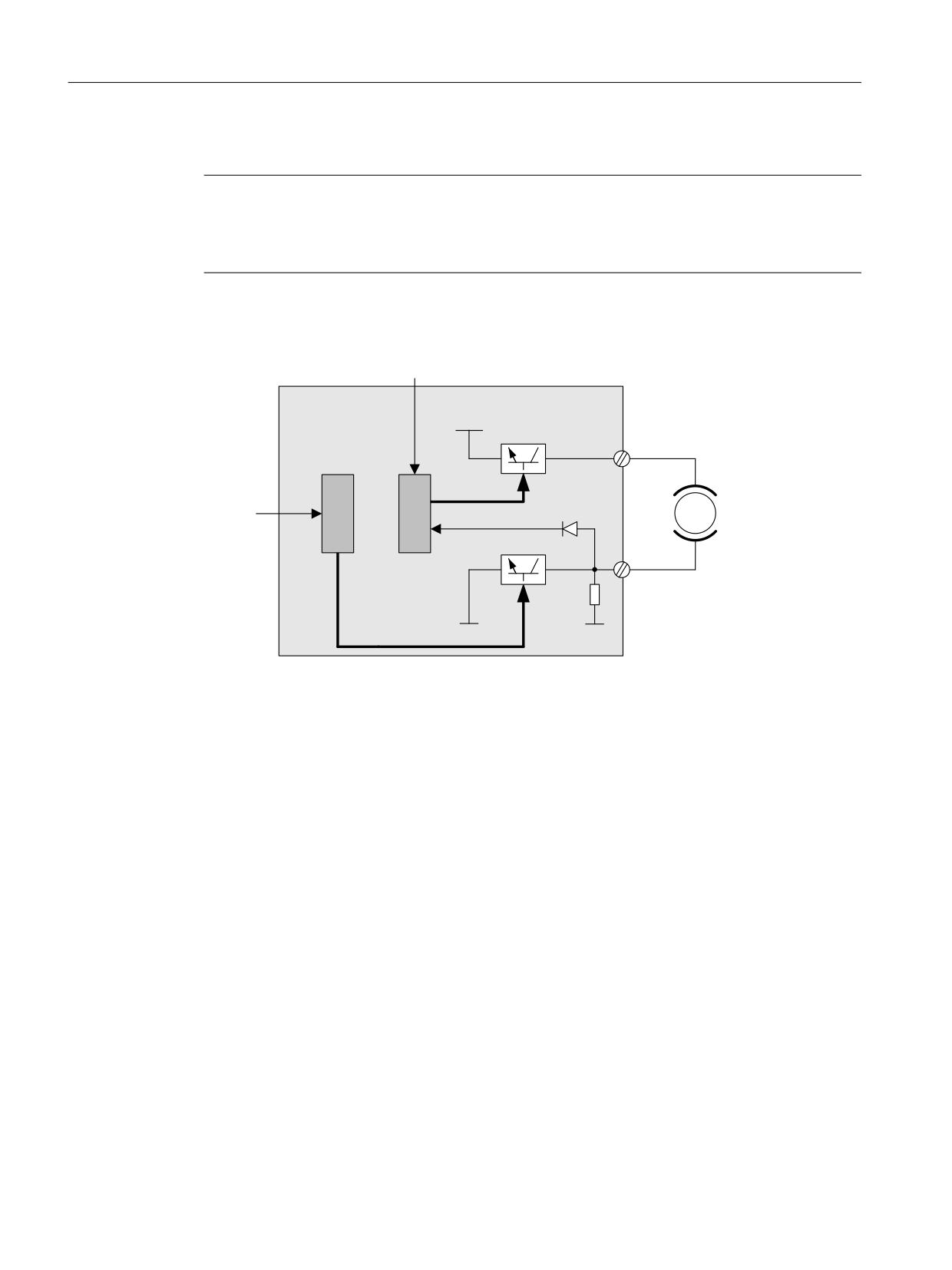
The brake is controlled from the Control Unit. Two signal paths are available for applying the
brake.
&RQWURO WHUPLQDO
&RQWURO 8QLW 0RWRU
0RGXOH 6DIH %UDNH
3
5HOD\
7%
&ORVHG FLUFXLW EUDNH
%5
&RQWURO
%5
WHUPLQDO
0RWRU
%UDNH GLDJQRVWLFV
7%
%5
0
0
%5
Figure 5-2
2-channel brake control, blocksize (example)
The Motor / Power Module carries out a check to ensure that the "Safe Brake Control" function
is working properly and ensures that, if the Control Unit fails or is faulty, the brake current is
interrupted and the brake applied.
The brake diagnosis can only reliably detect a malfunction in either of the switches (TB+, TB-)
when the status changes, i.e. when the brake is released or applied.
If the Motor Module or Control Unit detects a fault, the brake current is switched off. The brake
then closes and a safe state is reached.
Safety Integrated
86
Function Manual, 06/2020, 6SL3097-5AR00-0BP3
Description of Safety Integrated functions
5.1 Safety Integrated basic functions
5.1.3.2
SBC for Motor Modules in the chassis format
To be able to set higher power in the brakes of devices of this format, an additional Safe Brake
Adapter (SBA) module is needed. For more information about connecting and wiring the Safe
Brake Adapter, refer to the "SINAMICS G130/G150/S120 Chassis/S120 Cabinet Modules/
S150 Safety Integrated" Function Manual.
Using parameter p9621, you can define via which digital input the relay (NO contacts) feedback
signal of the Safe Brake Adapter is routed to the Control Unit.
To evaluate the feedback signal contacts, you must maintain the wait times caused by the SBA.
Parameter p9622 is pre-assigned with the SBA-relay wait times:
● p9622[0] ≙ wait time, switching on
● p9622[1] ≙ wait time, switching off
Further functionality and the activation of the brake, i.e. reaching the safe status, are in this case
the same as the above described procedure for booksize devices.
Safe Brake Control with power units in a parallel connection
Note
SBC for parallel connection of power units
Safe Brake Control with power units in a parallel connection is available if r9771.14 = 1.
If you wish to use SBC with SBA for chassis format power units connected in parallel, then it is
only permissible that you connect precisely one SBA to a power unit in the parallel connection.
The Safe Brake Adapter and therefore the brake are controlled via this power unit.
There are two options for registering this power unit with the system:
● Automatic brake identification when commissioning the system for the first time
- Requirements:
- No Safety Integrated functions enabled
- p1215 = 0 (no motor holding brake available)
- During the first commissioning, SINAMICS checks at which power unit an SBA is
connected. If precisely one SBA is found, the number of the power unit is entered into
parameter p7015.
If several SBAs are found at the parallel-connected power units, message "F07935
drive: Motor holding brake configuration error" is output.
- For devices in the chassis format, if the SBA feedback signal (SBA_DIAG) is read in via
an input of the power unit, then in addition, this digital input is automatically entered into
parameter p9621.
● Manually defining the power unit
- Enter the component number of the power unit, to which the SBA is connected, into
parameter p7015. If no SBA is connected to the power unit, faults are detected when
controlling the motor holding brake and fault F01630 is output.
- In parameter p9621 (p9621 = BICO interconnection to r9872.3), enter the digital input of
the power unit to which the SBA is connected and via which the SBA feedback signal
(SBA_DIAG) is read in.
Safety Integrated
Function Manual, 06/2020, 6SL3097-5AR00-0BP3
87
Description of Safety Integrated functions
5.1 Safety Integrated basic functions
Note
Disconnecting the brake cable for service purposes
As long as the brake is permanently released and not actuated, it is possible to briefly
disconnect the brake cable, e.g. for service purposes, and not receive fault messages. In the
case of a fault, message F07935 is only output when the brake is controlled.
Safety Integrated
88
Function Manual, 06/2020, 6SL3097-5AR00-0BP3
Description of Safety Integrated functions
5.1 Safety Integrated basic functions
5.1.3.3
Hardware required for SBC
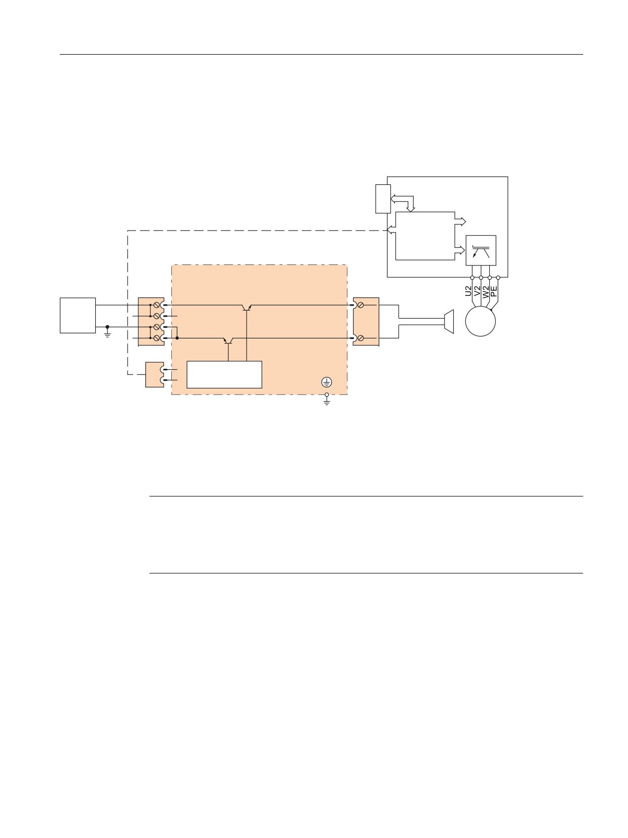
● Safe Brake Relay
The command for releasing or applying the brake is transferred to the Motor Module / Power
Module via DRIVE-CLiQ. The Motor Module / Safe Brake Relay then carries out the action
and appropriately activates the outputs for the brake.
3RZHU 0RGXOH
30 ,) LQWHUIDFH
&DEOH KDUQHVV
6DIH %UDNH 5HOD\
H[W
%5
0
9
0
0
a
0
%5
&75/
Figure 5-3
Interconnecting the Safe Brake Relay using Blocksize as an example
● Safe Brake Adapter
The brake cannot be directly connected to the Motor Module in the chassis format. The
connection terminals are only designed for 24 V DC with 150 mA; the Safe Brake Adapter
is required for higher currents and voltages.
Note
Additionally required hardware for other formats
A Safe Brake Relay is also required for the "Safe Brake Control" in the blocksize format. With
the chassis format (article numbers ending ...3 or higher), a Safe Brake Adapter is required. The
Safe Brake Adapter is available for a 230 V AC brake control voltage.
Safety Integrated
Function Manual, 06/2020, 6SL3097-5AR00-0BP3
89
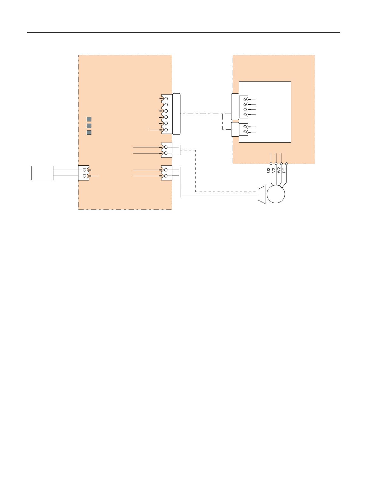
Description of Safety Integrated functions
5.1 Safety Integrated basic functions
Safe Brake Adapter
Motor Module /
SBA
Power Module
230 V AC
Control Interface
-X11
Module (CIM)
-X46
BR+
1
1
BR output+
BR- 2
Connecting cable
2
BR output-
FB+ 3
6SL3060-4DX04-0AA0
3
FB input+
LEDs
FB- 4
4
FB input-
230 V OK
P24 5
-X42
K1 ON
M
6
2
P24
K2 ON
3
M
-X15
External
AUX1
1
Fast
power supply
AUX2
2
de-
excitation
-X12
-X14
1
L
SBA_BR_L
1
230 V CA
2
N
SBA_BR_N
2
M
3 ~
Figure 5-4
Interconnecting the Safe Brake Adapter
Safety Integrated
90
Function Manual, 06/2020, 6SL3097-5AR00-0BP3
Description of Safety Integrated functions
5.1 Safety Integrated basic functions
5.1.3.4
Function diagrams and parameters
Function diagrams (see SINAMICS S120/S150 List Manual)
●
2814
SI Basic Functions - SBC (Safe Brake Control), SBA (Safe Brake
Adapter)
Overview of important parameters (see SINAMICS S120/S150 List Manual)
● p0799
CU inputs/outputs, sampling time
● p1215
Motor holding brake configuration
● p7015
Par_circuit holding brake power unit data set
● p9602
SI enable safe brake control (Control Unit)
● p9621
BI: SI Safe Brake Adapter signal source (Control Unit)
● p9622[0...1]
SI SBA relay wait times (Control Unit)
● r9771.14
SI common functions (Control Unit): SBC supported for parallel con-
nection
● r9780
SI monitoring cycle (Control Unit)
Safety Integrated
Function Manual, 06/2020, 6SL3097-5AR00-0BP3
91

Description of Safety Integrated functions
5.1 Safety Integrated basic functions
5.1.4
Safety faults
The fault messages of the Safety Integrated Basic Functions are saved in the standard
message buffer and can be read out from there. By contrast, the fault messages of the Safety
Integrated Extended Functions are stored in a separate Safety message buffer (see Chapter
"Message buffer (Page 402)").
When faults associated with Safety Integrated Basic Functions occur, the following stop
responses can be initiated:
Table 5-1
Stop responses for Safety Integrated Basic Functions
Stop response
Triggered ...
Action
Effect
STOP A cannot
For all Safety faults with pulse
Trigger safe pulse suppression
The motor coasts to a standstill or is
be acknowl-
suppression that cannot be ac-
via the switch-off signal path for
braked by the holding brake.
edged
knowledged
the relevant monitoring channel.
During operation with SBC:
STOP A
For all acknowledgeable Safety
Apply motor holding brake.
faults
As a follow-up reaction of STOP
F
STOP A corresponds to Stop Category 0 in accordance with EN 60204-1.
With STOP A, the motor is switched directly to zero torque via the "Safe Torque Off (STO)" function.
A motor at standstill cannot be started again accidentally.
A moving motor coasts to standstill. This can be prevented by using external braking mechanisms, e.g.
holding or operating brake.
When STOP A is present, "Safe Torque Off" (STO) is active.
STOP F
If an error occurs in the data
Transition to STOP A.
Follow-up response STOP A
cross-check.
with adjustable delay (factory setting
without delay) if one of the safety
functions is selected
STOP F is permanently assigned to the data cross-check (DCC). In this way, errors are detected in the
monitoring channels.
After STOP F, STOP A is triggered.
When STOP A is present, "Safe Torque Off" (STO) is active.
WARNING
Uncontrolled movement of the axis.
With a vertical axis or a pulling load, there is a danger of uncontrolled movement of the axis
when STOP A/F if triggered.
This can cause serious injury or death to persons in the danger zone.
● If there is a hazard due to unwanted movement in your application, take measures to
counter it, for example, by using a brake with safe monitoring. For additional information,
see Chapter "Safe Brake Control (SBC) (Page 84)".
Safety Integrated
92
Function Manual, 06/2020, 6SL3097-5AR00-0BP3
Description of Safety Integrated functions
5.1 Safety Integrated basic functions
Acknowledging the Safety faults
There are several ways to acknowledge Safety faults:
● Acknowledgment through deselection of STO or SS1:
- Remove the cause of the fault.
- Deselect "Safe Torque Off" (STO) or "Safe Stop 1" (SS1).
- Acknowledge the fault.
If the Safety commissioning mode is exited when the Safety functions are switched off
(p0010 ≠ 95 when p9601 = 0), all Safety faults can be acknowledged.
Once safety commissioning mode has been selected again (p0010 = 95), all the faults that
were previously present reappear.
● The higher-level controller sets the signal "Internal Event ACK" via the PROFIsafe telegram
(STW bit 7). A falling edge in this signal resets the status "Internal Event" and so
acknowledges the fault.
● Acknowledgment by switching the drive unit off/on
Safety faults can also be acknowledged (as with all other faults) by switching the drive unit
off and then on again (POWER ON). If this action has not eliminated the fault cause, the fault
is displayed again immediately after power-up.
Description of faults and alarms
Note
References
The faults and alarms for SINAMICS Safety Integrated Functions are described in the following
document:
References: SINAMICS S120/S150 List Manual
5.1.5
Forced checking procedure (test stop)
5.1.5.1
Forced checking procedure or test of the switch-off signal paths (test stop) for Safety
Integrated Basic
The forced checking procedure (test stop) at the switch-off signal paths is used to detect
software/hardware faults at both monitoring channels in time and is automated by means of
activation/deactivation of the "Safe Torque Off" (STO) or "Safe Stop 1" (SS1) function.
To fulfill the requirements of ISO 13849-1 regarding timely error detection, the two switch-off
signal paths must be tested at least once within a defined time to ensure that they are
functioning properly. This functionality must be implemented using the forced checking
procedure (test stop), triggered either in the manual mode or by the automated process.
A timer ensures that forced checking procedure (test stop) is carried out in a timely fashion.
● p9659 SI forced checking procedure, timer.
Safety Integrated
Function Manual, 06/2020, 6SL3097-5AR00-0BP3
93
Description of Safety Integrated functions
5.1 Safety Integrated basic functions
A forced checking procedure (test stop) must be performed on the switch-off signal paths at
least once during the time set in this parameter.
Once this time has elapsed, an alarm is output and remains active until forced checking
procedure (test stop) is carried out.
The timer returns to the set value each time the STO/SS1 function is deactivated.
Note
Resetting the timer of the Basic Functions
When simultaneously using the Extended Functions, if the forced checking procedure (test
stop) is performed, then the timer of the Basic Functions is also reset.
While STO is selected by the Extended Functions, the terminals for the selection of the Basic
Functions are not checked for discrepancy. This means that the forced checking procedure
(test stop) of the Basic Functions must always be performed without the selection of STO or
SS1 by the Extended Functions. It is otherwise not possible to verify the correct control by the
terminals.
When the appropriate safety devices are implemented (e.g. protective doors), it can be
assumed that running machinery will not pose any risk to personnel. The user is therefore only
informed that the forced checking procedure (test stop) is due in the form of an alarm, which
requests the user to perform forced checking procedure (test stop) at the next possible
opportunity. This alarm does not affect machine operation.
The user must set the time interval for carrying out forced checking procedure (test stop) to
between 0.00 and 9000.00 hours depending on the application (factory setting: 8.00 hours).
Examples of when the forced checking procedure (test stop) must be performed:
● When the drives are at a standstill after the system has been switched on (POWER ON).
● When the protective door is opened.
● At defined intervals (e.g. every 8 hours).
● In automatic mode (time and event dependent).
● The maximum time interval is one year (8760 hours).
5.1.5.2
Forced checking procedure (test stop) with POWER ON
Forced checking procedure (test stop) can be automatically executed at POWER ON.
● If the forced checking procedure (test stop) as well as the test of the F-DO for the CU310-2
are to be executed automatically, then set p9507.6 = 1. When testing the F-DO of the
CU310-2, you must parameterize p10042 and activate the test in p10046.
● If the forced checking procedure (test stop) of the F-DI and F-DO of the TM54F is to be
executed automatically, then set p10048 = 1.
● If you have parameterized the forced checking procedure (test stop) for POWER ON, you
can still initiate a forced checking procedure (test stop) at any time as part of the engineered
application.
Safety Integrated
94
Function Manual, 06/2020, 6SL3097-5AR00-0BP3
Description of Safety Integrated functions
5.1 Safety Integrated basic functions
● If the automatically initiated function cannot be correctly completed as a result of a problem
(e.g. communication failure), then after the problem has been resolved, the function is
automatically restarted.
● After the forced checking procedure (test stop) has been performed successfully, the
converter goes into the "Ready" state.
● Timer p9659 is automatically reset as a result of the forced checking procedure (test stop).
● The automatic forced checking procedure (test stop) for POWER ON does not influence the
Safety Integrated Functions.
5.1.6
Function diagrams and parameters
Function diagrams (see SINAMICS S120/S150 List Manual)
●
2800
SI Basic Functions - Parameter manager
●
2802
SI Basic Functions - Monitoring functions and faults/alarms
●
2890
SI TM54F - Overview
●
2891
SI TM54F - Parameter manager
●
2900
SI TM54F - Basic Functions control interface (p9601.2/3 = 0, p9601.6
= 1)
●
2901
SI TM54F - Basic Functions Safe State selection
●
2902
SI TM54F - Basic Functions assignment (F-DO 0 ... F-DO 3)
Safety Integrated
Function Manual, 06/2020, 6SL3097-5AR00-0BP3
95
Description of Safety Integrated functions
5.2 Safety Integrated Extended Functions
5.2
Safety Integrated Extended Functions
Note
PFH values
The PFH values of the individual SINAMICS S120 safety components can be found at:
5.2.1
License for Extended Functions or Advanced Functions
● One license is required for each axis that is operated with Safety Integrated Extended or
Advanced Functions. You enter the associated license key with the "License Key" button in
Startdrive. Then activate the license key via "Activate".
As an alternative, you can enter the license key into parameter p9920 in the ASCII code. The
license key is activated using parameter p9921 = 1.
● For information on how to generate the license key for the product "SINAMICS Safety
Integrated Extended Functions" or "SINAMICS Safety Integrated Advanced Functions"
read the section "Licensing" in the SINAMICS S120 Function Manual. An insufficient license
is indicated via the following fault and LED:
- F13000 → licensing not sufficient
- LED RDY → flashes red with 2 Hz
● When purchasing your drive, you can already decide to use Safety Integrated Functions,
and you will then be provided with the required license(s) on the memory card supplied. In
this case, you do not have to explicitly activate the licenses.
● A trial license is available for test purposes; this allows you to use Safety Integrated
functions for a specific time without having a valid license.
Details on the trial license can be found in the "SINAMICS S120 Function Manual Drive
Functions", Chapter "Licensing".
5.2.2
Differences between Extended Functions "with encoder" and "without encoder"
If motors without a (safety-capable) encoder are being used, not all Safety Integrated Functions
can be used. You will find general information on this distinction in Chapter "Drive monitoring
with or without encoder (Page 40)."
Safety Integrated
96
Function Manual, 06/2020, 6SL3097-5AR00-0BP3
Description of Safety Integrated functions
5.2 Safety Integrated Extended Functions
Activation
For activation of the Safety Integrated Extended Functions "with encoder" and "without
encoder", set the parameters p9306 and p9506 (factory setting = 0). You can also make this
setting by selecting "with encoder" or "without encoder" on the Safety-Integrated Startdrive
screen. To do this, in Startdrive, in the secondary navigation of the drive axis, select the "Drive
functions > Safety Integrated > Function selection" menu item
● Operation with encoder
p9506 = 0
or
p9506 = 2
● Operation without encoder
p9506 = 1
or
p9506 = 3
Monitoring with an encoder
The Safety Integrated Functions with encoder are configured with p9506 = 0 (factory setting)
or p9506 = 2 in the expert list or by selecting "with encoder" in the Safety screen.
● If p9506 = 0:
Braking is monitored with the "Safe Acceleration Monitor" function.
● If p9506 = 2:
Here, also for SS1, the monitoring function "Safe Brake Ramp" is active.
More detailed information on actual value acquisition with encoder can be found in Section
"Reliable actual value acquisition with encoder system (Page 160)".
Monitoring without an encoder
The Safety Integrated Functions without encoder are configured in the expert list using p9506
= 1 or p9506 = 3 or by selecting "without encoder" in the Safety screen form.
● For p9506 = 1, the following applies:
Here, also for SS1, the monitoring function "Safe Brake Ramp" is active.
● For p9506 = 3, the following applies:
Braking is monitored with the "Safe Acceleration Monitor" function. The behavior
corresponds to "monitoring with encoder".
Taking into account the slip of an induction motor
For Safety Integrated without encoder (depending on the drive load), as a result of slip
(deviations between electrical and mechanical speed), deviations can occur between the safely
determined electrical speed and the mechanical speed at the motor shaft.
Note
Sudden changes in the current and voltage curve (e.g. sudden change in the setpoint setting
and load) and very small absolute values with a high proportion of noise generally result in faults
of the safe encoderless actual value acquisition and must be avoided.
Safety Integrated
Function Manual, 06/2020, 6SL3097-5AR00-0BP3
97

Description of Safety Integrated functions
5.2 Safety Integrated Extended Functions
More detailed information on actual value acquisition without encoder can be found in Section
"Safe actual value sensing without encoder (Page 167)".
Note
Scope of functions
There are fewer Safety Integrated Extended Functions available "without encoder" than "with
encoder" (see Section "Drive monitoring with or without encoder (Page 40)").
Note
Safety Integrated Functions "without encoder" for group drives
The Safety Integrated Functions "without encoder" are also permissible for group drives
(multiple motors connected to one power unit).
"Parking" state for Safety Integrated Extended Functions with encoder
Note
Extended Functions with encoder and "parking"
When a drive object, for which Safety Integrated Extended Functions with encoder are enabled,
is switched to "Park" mode, the Safety Integrated software responds by selecting STO without
generating a separate message. This internal STO selection is displayed in parameter
r9772.19.
5.2.2.1
Specifics relating to Safety Integrated Functions "without encoder"
Basic Functions
● Basic Functions are available in all control modes with and without encoder for synchronous
and induction motors without any restrictions.
● A safety-related encoder is not required for Basic Functions.
● The Safety Integrated Functions "without encoder" are also permitted for group drives
(multiple motors connected to one power unit).
Extended Functions
Extended Functions SS1, SLS, SDI, and SSM "without encoder" do not require safety-related
speed actual value sensing. If an encoder is used for the drive control, this has no influence on
the sensorless safety functions. You can use Extended Functions "without encoder" with the
following motor types:
● Induction motor in all control modes
● SIMOTICS A-1FU synchronous motors (previously: SIEMOSYN) with U/f control
● Synchronous reluctance motors in vector control
Safety Integrated
98
Function Manual, 06/2020, 6SL3097-5AR00-0BP3
Description of Safety Integrated functions
5.2 Safety Integrated Extended Functions
The Safety Integrated Functions "without encoder" are also permitted for group drives (multiple
motors connected to one power unit).
Note
Taking into account the slip of an induction motor
For Safety Integrated without encoder, the safely determined electrical speed (depending on
the drive load) may deviate from the mechanical speed at the motor shaft as a result of the slip
for induction motors (deviations between electrical and mechanical speed).
Restrictions
When using Extended Functions, observe the following restrictions:
Synchronous reluctance motors with Safety Integrated Functions "without encoder"
SINAMICS S120 supports synchronous reluctance motors with Safety Integrated Functions
"without encoder". Note the following information for this application case:
● Synchronous reluctance motors may only be operated with vector control.
● From the perspective of Safety Integrated, synchronous reluctance motors fall into the
"asynchronous motor" category.
● Technical details:
- Synchronous reluctance motors have no slip: The note "Slip of an induction motor must
be taken into account" mentioned above does not apply to synchronous reluctance
motors.
- The setting "Closed-loop controlled operation down to f = 0 Hz with test signal"
(p1750.5 = 1) is not permissible.
- If you activate the function "Closed-loop controlled operation down to f = 0 Hz with test
signal" (p1750.5 = 1), synchronous reluctance motors do not require current injection.
- Compared to induction motors, synchronous reluctance motors require a shorter time for
magnetization: This reduces the wait time when starting with active encoderless safety
monitoring, e.g. for SLS.
Inadmissible operating modes for Safety Integrated Functions "without encoder"
● No operation with SINAMICS Hydraulic Drive (HLA)
● Current controller clock cycles 31.25 µs and 62.5 μs (for Double Motor Modules with two
configured safety drives) are not permissible.
Safety Integrated
Function Manual, 06/2020, 6SL3097-5AR00-0BP3
99
Description of Safety Integrated functions
5.2 Safety Integrated Extended Functions
● For the independent setting of current controller clock cycle and pulse frequency in
conjunction with Safety Integrated "without encoder", the following system clock cycles are
not permitted:
- Double Motor Module: < 125 μs
- All other components: < 62.5 μs
- p9589 must be set = 3300 to allow the current controller clock cycle and pulse frequency
to be independently set.
● For all designs: Safety Integrated Functions "without encoder" only with parameter p1810 =
factory setting, this includes:
- No wobbling
- No fine setting of the pulse frequency
● For chassis format devices, the following also applies:
- For chassis format devices, operation without encoder is only permissible for induction
motors, however not for synchronous motors.
- No operation involving parallel connections
- Optimized pulse patterns cannot be selected for SIMOTICS FD
● No "shaft generator" functionality
● Induction motors up to 1000 kW
On very large machines, it may also be necessary to adjust the parameter p9585.
Critical operating modes for Safety Integrated Functions "without encoder"
When the safety functions are deactivated, the following technology functions are not
negatively influenced.
Using the following operating modes with the Safety Integrated Functions activated without
encoder can result in errors in the encoderless safe actual value sensing (see messages
C01711, C30711 with fault values 1040 ff.).
Safe, encoderless actual value sensing is based on the measurement of current and voltage
variables, which can influence the following functions. This does not result in unsafe states.
However, this fault can be expected to have a negative impact on availability.
Note
Irregular operating states
Note that in irregular operating states (e.g. "stalled motor"), the converter can fail with safety
faults. However, under no circumstances is an unsafe state reached.
Safety Integrated
100
Function Manual, 06/2020, 6SL3097-5AR00-0BP3

Description of Safety Integrated functions
5.2 Safety Integrated Extended Functions
●
Current limiting of the power unit
When the current limiting of the power unit responds, then it can be assumed that this will
result in errors in the encoderless safe actual value sensing and in turn with an associated
stop response.
Note
When engineering the drive and when the parameterizing the current and torque limits, it
must be ensured that the power unit current limiting does not respond.
●
Operation with pulling loads
It is not permissible that the converter is forced into regenerative operation as a result of
external forces.
Note
If a coupled drive comprises an electric drive that motors and one that regenerates (e.g. a
test stand), and the speeds of both drives are safely monitored, safety functions without
encoder can be used. This is because in the case of a fault, the motoring drive recognizes
when a limit value is violated. If, in this example, the motoring drive is an internal combustion
engine, which is not safely monitored, use of safety functions without an encoder for the
braking drive is not permissible.
Winders with a motoring and a braking drive can be assessed in the same way (both drives
are monitored).
●
Motor data identification
When using the measuring functions (stationary and rotating measurement) to determine
the motor data, then it can be assumed that the encoderless safe actual value sensing will
have an error.
Note
The motor data identification should always be performed before commissioning the Safety
Integrated Functions.
●
Data set switchover
The motor and drive data switchover can always be used for safety functions without
encoder. It is not possible to switch over between induction and synchronous motors (this
is interlocked). For several motor data sets it must be ensured that all motors have the same
number of pole pairs. If the number of pole pairs in r0313 is not the same value that was
taken into account when configuring the safe actual value sensing (gearbox), then the
calculated, safe actual speed no longer corresponds to the mechanical speed of the shaft.
When SLS is activated, the shaft can rotate faster than the configured limits.
●
Alternating acceleration/deceleration
For alternating acceleration and deceleration, it must be ensured that the following
conditions are maintained.
- Within 1 s, only one acceleration and one braking ramp are permitted.
Therefore, for a cycle 0 → +nset → -nset → 0 - one period of at least 2 s is required.
●
This also applies to positioning operation; it may be necessary that the position control
settings and traversing profiles must be adapted so that no overshoots occur in the speed
characteristic (e.g. reduce the dynamic response, use flatter braking ramps).
Safety Integrated
Function Manual, 06/2020, 6SL3097-5AR00-0BP3
101

Description of Safety Integrated functions
5.2 Safety Integrated Extended Functions
●
Flying restart
A flying restart should not be performed in operation with the Safety Integrated Functions
active.
Note
If you must use this function, then before the flying restart, you can deactivate the Safety
Integrated Functions, and then reactivate them again after the flying restart has been
completed.
In this case, the user must check as to whether it is permissible that the safety functions are
deactivated during the flying restart.
It is only permissible to activate and deactivate Safety Integrated Functions using failsafe
signals.
●
DC brake
When using this function, DC current is impressed to brake the drive: This can result in an
error in the encoderless, safe actual value sensing and in turn in an associated stop
response.
Note
If you must use this function, then before braking, you can deactivate the Safety Integrated
Functions, and then reactivate them again after braking has been completed.
In this case, the user must check as to whether it is permissible that the safety functions are
deactivated during braking.
It is only permissible to activate and deactivate Safety Integrated Functions using failsafe
signals.
●
Closed-loop controlled operation down to f = 0 Hz with test signal (see corresponding
chapter in the SINAMICS S120 Function Manual Drive Functions)
If you use Safety Integrated without encoder simultaneously with the function "Closed-loop
controlled operation down to f = 0 Hz with test signal", the drive may react with an undesired
safety message and a stop reaction. In this case, you cannot use the combination described.
Recommendations for stable operation with active Extended Functions without encoder
The following preconditions must be fulfilled to avoid fault messages from the safe actual value
sensing without encoder:
● The motor and the power unit are adequately dimensioned for this application.
● Motor and power unit should fulfill the following condition: The ratio between the rated power
unit current (r0207[0]) and rated motor current (p0305) should be less than 5.
● Before commissioning the safety functions, we recommend that the motor data are
identified at standstill and a rotating measurement is carried out.
● For the basic commissioning, i.e. before the safety commissioning, the closed-loop control
should be optimally set. The following effects should be avoided:
- speed overshoots
- current peaks and/or discontinuous/unsteady current actual value over time
- voltage peaks and/or discontinuous/unsteady voltage actual value over time
- the lowest possible amount of noise in the current and voltage
Safety Integrated
102
Function Manual, 06/2020, 6SL3097-5AR00-0BP3

Description of Safety Integrated functions
5.2 Safety Integrated Extended Functions
Safety Integrated Extended Functions without encoder for Control Unit Adapter CUA31 and CUA32
In the case of the Control Unit Adapters CUA31 and CUA32, the Safety Integrated Extended
Functions without encoder are available as follows:
Control
Article number
Safety Integrated without encoder
Unit
Not available for
Available for
Adapter
CUA31
6SL3040-0PA01-0AA1
Version (function states)
Version D or newer
A, B and C
CUA32
6SL3040-0PA01-0AA0
Version (function states)
Version C or newer
A and B
5.2.3
Safe Torque Off (STO)
For the control options and the functionality for "Safe Torque Off" (STO), see Section "Safe
Torque Off (STO) (Page 76)".
5.2.4
Safe Stop 1 (SS1)
5.2.4.1
Safe Stop 1 with encoder
For function SS1 of the Extended Safety Functions, braking monitoring is included.
● If p9506 = 0:
Braking is monitored with the "Safe Acceleration Monitor" function (see Chapter
"Description (Page 155)").
In this case, we also talk about "SS1 (time and acceleration controlled)".
● If p9506 = 2:
Here, also for SS1, the monitoring function "Safe Brake Ramp" is active (see Chapter "Safe
Brake Ramp (SBR) (Page 157)").
In this case, we also talk about "SS1 (speed controlled)".
The "Safe Stop 1" (SS1) function allows the drive to be stopped in accordance with EN 60204-1,
Stop Category 1. The drive brakes with the OFF3 ramp (p1135) once "Safe Stop 1" is selected
and switches to "Safe Torque Off" (STO) once the delay time has elapsed (p9556) or when the
shutdown speed is fallen below (p9560).
Functional features of Safe Stop 1 with encoder
● The delay time starts after the function has been selected. If SS1 is deselected within this
time, after the delay time has elapsed or after the velocity has fallen below the shutdown
speed, the STO function is selected and deselected again immediately; i.e. the SS1 function
is ended completely normally. It cannot be interrupted.
● Selection and monitoring of the acceleration (SAM) or the monitoring function "Safe Brake
Ramp" are implemented in two channels, but braking along the OFF3 ramp is only
implemented in one channel.
Safety Integrated
Function Manual, 06/2020, 6SL3097-5AR00-0BP3
103

Description of Safety Integrated functions
5.2 Safety Integrated Extended Functions
Note
Interrupting the ramp function with OFF2 by the higher-level controller
Activating SS1 can mean that the higher-level controller (PLC, motion controller), which
specifies the speed setpoint, interrupts the ramp function (e.g. with OFF2). The device behaves
in this way as a result of a fault reaction triggered by OFF3 activation. This fault reaction must
be avoided by assigning appropriate parameters or configurations.
Note
No OFF2 with SS1 and EPOS
If you use SS1 together with EPOS, the fault reaction to F07490 (EPOS: enable withdrawn
while traversing) OFF2 is not permitted. The response to this error message (OFF1, OFF2 or
OFF3) can be configured via p2100/p2101.
● Effect on "Speed setpoint limit effective" (r9733[0...2]):
If SS1 (≙ STOP B), setpoint 0 is specified in r9733[0...2].
Commissioning
The delay time (SS1 time) is set by entering parameter p9556. The wait time until safe pulse
suppression (STO) can be shortened by specifying a shutdown speed in p9560.
To enable the drive to brake to standstill after selection, the time in p9556 must be selected to
be large enough for the drive to be able to brake along the OFF3 ramp (p1135) from any speed
of the work process to below the shutdown speed (p9560).
Note
Setting the delay time
To enable the drive to travel the entire OFF3 ramp and close any existing motor holding brake,
you must set the delay time as follows:
● Motor holding brake parameterized: Delay time ≥ p1135 + p1228 + p1217
● Motor holding brake not parameterized: Delay time ≥ p1135 + p1228
The shutdown speed defined in p9560 must be set in such a way that coasting down (due to the
subsequent STO function) does not represent any risk for man and machine.
Responses: System error
1. STOP F with subsequent STOP B, followed by STOP A
2. Safety message C01711
Safety Integrated
104
Function Manual, 06/2020, 6SL3097-5AR00-0BP3
Description of Safety Integrated functions
5.2 Safety Integrated Extended Functions
Status for "Safe Stop 1"
The status of the "Safe Stop 1" function is displayed using the following parameters:
● r9722.1 CO/BO: SI Motion drive-integrated status signals, SS1 active
● r9722.0 CO/BO: SI Motion drive-integrated status signals, STO or safe pulse suppression
active
Safety Integrated
Function Manual, 06/2020, 6SL3097-5AR00-0BP3
105
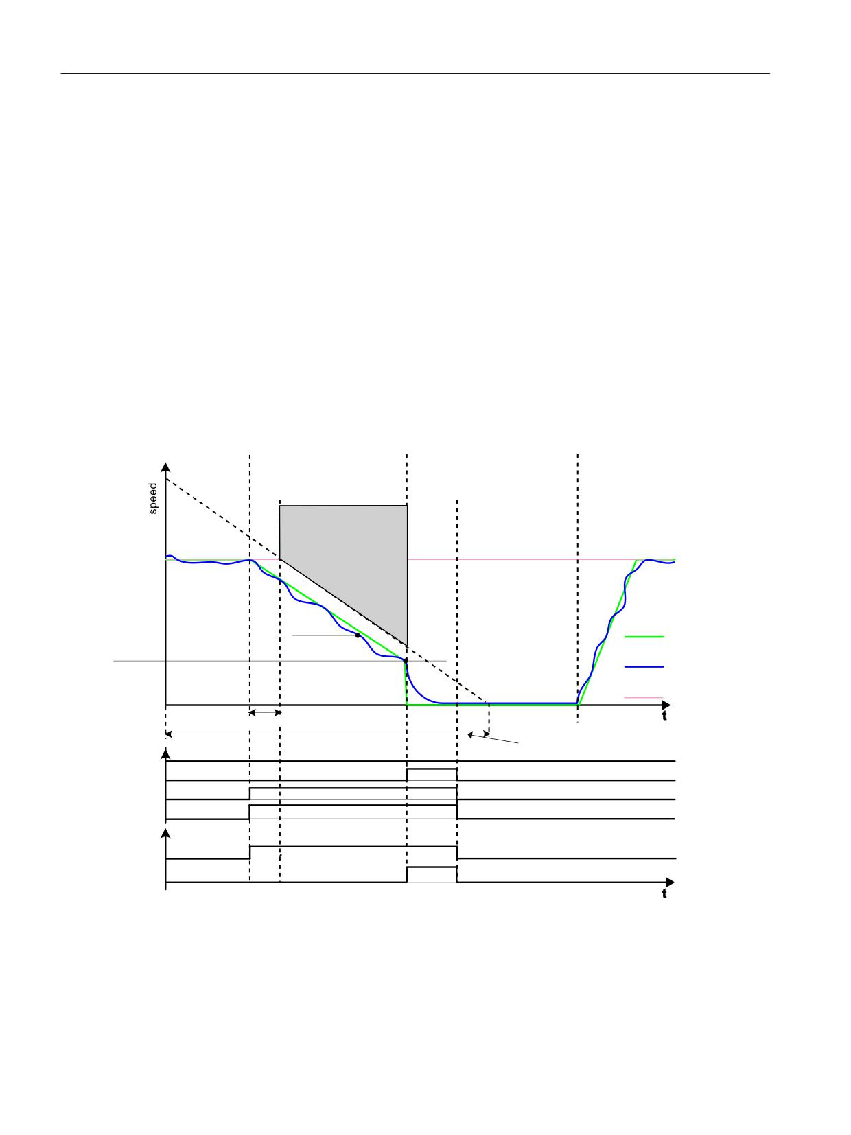
Description of Safety Integrated functions
5.2 Safety Integrated Extended Functions
5.2.4.2
Safe Stop 1 without encoder
Two encoderless Safe Stop 1 (SS1) monitoring functions can be set with parameter p9506:
● p9506 = 3: Safe monitoring of acceleration (SAM) / delay time
The function is identical to "Safe Stop 1" with encoder, which was described in the previous
section.
In this case, we also talk about "SS1 (time and acceleration controlled)".
● p9506 = 1: Safe brake ramp monitoring (SBR)
In this case, there is no SS1 delay time active. The transition from SS1 to STO depends
entirely on the speed falling below the shutdown speed (p9560). You will find more
information on the function "Safe Brake Ramp (SBR)" in Chapter "Safe Brake Ramp (SBR)
(Page 157)." In this case, we also talk about "SS1 (speed controlled)".
Time sequence
6HOHFWLQJ WKH 66 UDPS
$FWLYDWLRQ RI 672
6WDUW GULYH 8VHU DFWLRQ
8VHU DFWLRQ
8VHU DFWLRQ
6HW 2))
21 VLJQDO
6HW 66
VLJQDO
1RQH
5HIHUHQFH
YHORFLW\
$FWLYDWLRQ RI 66 UDPS
'HVHOHFWLQJ WKH 66 UDPS
8VHU DFWLRQ
8VHU DFWLRQ
1RQH
5HVHW 66
VLJQDO
(QYHORSH
PRQLWRULQJ UDPS
6WDWRU
VSHHG
2)) UDPS
5RWRU
=HUR VSHHG
672
VSHHG
GHWHFWLRQ
6HWSRLQW
VSHHG
W
6%5 GHOD\ WLPH S
'LDJQRVWLFV
0RQLWRULQJ UDPS 'URSRXW WLPH
672 VHOHFWHG
672 DFWLYH
66 VHOHFWHG
66 DFWLYH
352),VDIH
66 DFWLYH
3RZHU UHPRYHG
W
Figure 5-5
Sequence for "Safe Stop 1" without encoder with SBR monitoring (p9506 = 1)
Safety Integrated
106
Function Manual, 06/2020, 6SL3097-5AR00-0BP3
Description of Safety Integrated functions
5.2 Safety Integrated Extended Functions
Functional feature of Safe Stop 1 without encoder
● Selection and monitoring of the brake ramp (SBR) or the acceleration (SAM) are
implemented in two channels, however braking at the OFF3 ramp is only through one
channel.
5.2.4.3
Safe Stop 1 with external stop
General description
NOTICE
Any axis motion is possible
During the delay time (p9652), for "Safe Stop 1 (time-controlled) with external stop", any axis
movements are possible.
● If there is a hazard due to unwanted motion in your application, take measures to counter
it, for example, by using a brake with safe monitoring. Further information can be found in
Section "Safe Brake Control (Page 108)".
With external stop, "Safe Stop 1" basically works exactly as described in the previous Chapters
"Safe Stop 1 with encoder (time and acceleration controlled)" and "Safe Stop 1 without encoder
(speed controlled)." Note, however, the following differences:
Differences between "Safe Stop 1 with OFF3" and "SS1 with external stop"
● In order to activate "Safe Stop 1 with external stop", additionally set p9507.3 = 1.
● When SS1 with external stop is selected, the drive is not braked along the OFF3 ramp: You
are responsible in applying suitable measures to brake the drive. After the delay time has
expired (p9556), only STO/SBC are automatically initiated. After the function has been
selected, the delay timer runs down - even if the function is deselected during this time. In
this case, after the delay time has expired, the STO/SBC function is selected and then again
deselected immediately.
● The brake ramp (SBR) and the acceleration (SAM) are not monitored and there is no
standstill detection.
● With this configuration, STO becomes active after the SS1 timer p9556 has expired; this
also applies if SBR has been configured.
● For additional information, see Chapter "Stop responses (Page 395)".
Safety Integrated
Function Manual, 06/2020, 6SL3097-5AR00-0BP3
107
Description of Safety Integrated functions
5.2 Safety Integrated Extended Functions
5.2.4.4
Function diagrams and parameters
Function diagrams (see SINAMICS S120/S150 List Manual)
●
2819
SI Extended Functions - SS1, SS2, SOS, internal STOP B, C, D, F
Overview of important parameters (see SINAMICS S120/S150 List Manual)
● p1135[0...n]
OFF3 ramp-down time
● p9501
SI Motion enable safety functions (Control Unit)
● p9506
SI Motion function specification (Control Unit)
● p9560
SI Motion STO shutdown speed (Control Unit)
● r9722.0...31
CO/BO: SI Motion drive-integrated status signals
Only for SS1 (Extended Functions) with external stop
● p9507
SI Motion function configuration (Control Unit)
5.2.5
Safe Brake Control (SBC)
For the control options and the functionality for "Safe Brake Control" (STO), see Section "Safe
Brake Control (SBC) (Page 84)".
Note
No SBC for SINAMICS HLA
SINAMICS HLA does not support Safe Brake Control.
Safety Integrated
108
Function Manual, 06/2020, 6SL3097-5AR00-0BP3

Description of Safety Integrated functions
5.2 Safety Integrated Extended Functions
5.2.6
Safe Operating Stop (SOS)
This function serves for failsafe monitoring of the standstill position of a drive.
WARNING
Drive can be forced out of the SOS position by mechanical forces
A drive under position control can be forced out of the "Safe Operating Stop" (SOS) position
by mechanical forces that are greater than the maximum torque of the drive. This unwanted
drive movement then triggers a Category 1 Stop function according to EN 60204-1 (fault
response function STOP B). The alarms for SS1 and STO must be observed.
● If there is a hazard due to unwanted motion in your application, take measures to counter
it, for example, by using a brake with safe monitoring. For additional information, see
Chapter "Safe Brake Control (SBC) (Page 84)".
Note
In particular, the motor is energized while the SOS function is performing position control.
● Ensure that the motor cannot be touched while it is in the SOS state.
● Drive stopping is monitored using an SOS tolerance window (p9530).
● Effect on the "Setpoint speed limit effective" (r9733[0...2]):
If SOS is selected, setpoint 0 is specified in r9733[0...2].
Note
Size of the tolerance window
The size of the tolerance window should be slightly above the standard standstill monitoring
limit, otherwise the standard monitoring functions will no longer be effective.
Parameter r9731 displays the safe position accuracy (load side) that can be achieved as a
maximum, based on the acquisition of the actual value for the safe motion monitoring functions.
STOP B is the stop response after the standstill tolerance window has been violated.
When does SOS become effective
The SOS function comes into effect in the following cases:
● After SOS is selected and the delay time in p9551 has elapsed
The drive must be braked to standstill within this delay time (e.g. by the controller).
● As a consequence of SS2
● As a consequence of STOP C (corresponds to selection of SS2)
● As a consequence of STOP D (corresponds to selection of SOS)
● As a consequence of STOP E (corresponds to selecting SOS with additional activation of
the standard "Extended stop and retract (ESR)" function)
Safety Integrated
Function Manual, 06/2020, 6SL3097-5AR00-0BP3
109
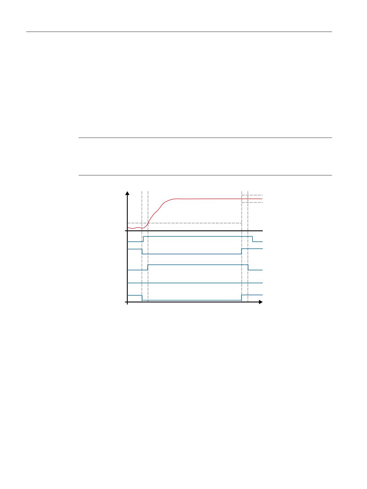
Description of Safety Integrated functions
5.2 Safety Integrated Extended Functions
Responses
● Standstill tolerance violated in p9530
- STOP B with subsequent STOP A
- Safety message C01707
● System error
- STOP F
- Safety message C01711
Note
Deactivating SOS during an external STOP A
If "Deactivating SOS/SLS during an external STOP A" (p9501.23 = 1) is released and SOS is
selected, SOS is deactivated during a STOP A.
3RVLWLRQ YDOXHV RQ
S
ORDG VLGH
7ROHUDQFH
S
7ROHUDQFH
U
3XOVH FDQFHOODWLRQ
U
672 GHVHOHFWHG
U
672 DFWLYH
U
626 GHVHOHFWHG
U
626 DFWLYH
W
Figure 5-6
Signal flow: Deactivating SOS during an external STOP A
Function diagrams (see SINAMICS S120/S150 List Manual)
●
2819
SI Extended Functions - SS1, SS2, SOS, internal STOP B, C, D, F
Overview of important parameters (see SINAMICS S120/S150 List Manual)
● p9501
SI Motion enable safety functions (Control Unit)
● p9530
SI Motion standstill tolerance (Control Unit)
● p9551
SI Motion SLS(SG) switchover/SOS(SBH) delay time (CU)
● r9722.0...31
CO/BO: SI Motion drive-integrated status signals
● r9731
SI Motion safe positioning accuracy
Safety Integrated
110
Function Manual, 06/2020, 6SL3097-5AR00-0BP3
Description of Safety Integrated functions
5.2 Safety Integrated Extended Functions
5.2.7
Safe Stop 2 (SS2)
Note
The "Safe Stop 2" (SS2) safety function can only be used with an encoder.
The safety function "Safe Stop 2" (SS2) is used to brake the motor of the OFF3 deceleration
ramp (p1135) safely with transition after the delay time (p9552) has expired in to the SOS state
(see Chapter "Safe Operating Stop (SOS) (Page 109)"). The delay time set must allow the drive
to brake to a standstill from every speed of the operating process within this time. The standstill
tolerance (p9530) may not be violated after this time.
After braking, the drives remain in speed control mode with the speed setpoint n = 0. The full
torque is available.
The default setpoint (e.g. from the setpoint channel, or from a higher-level controller) remains
inhibited as long as SS2 is selected.
The selection and monitoring of the acceleration (SAM) are realized through two channels -
however, braking along the OFF3 ramp, only through one channel.
● Effect on the "Setpoint speed limit effective" (r9733[0...2]):
If SS2 (≙ STOP C), setpoint 0 is specified in r9733[0...2].
Monitoring during braking
During braking, one of the following functions is active:
● If p9506 = 0:
Braking is monitored with the "Safe Acceleration Monitor" function (see Chapter
"Description (Page 155)").
● If p9506 = 2:
Here, also for SS1, the monitoring function "Safe Brake Ramp" is active (see Chapter "Safe
Brake Ramp (SBR) (Page 157)").
Interruption of the ramp function with OFF2
Activating SS2 can mean that the higher-level controller (PLC, motion controller) which
specifies the speed setpoint, interrupts the ramp function (e.g. with OFF2). The device behaves
in this way as a result of a fault reaction triggered by OFF3 activation. This fault reaction must
be avoided by assigning appropriate parameters or configurations.
Safety Integrated
Function Manual, 06/2020, 6SL3097-5AR00-0BP3
111
Description of Safety Integrated functions
5.2 Safety Integrated Extended Functions
Responses
● Speed limit violated (SAM):
- STOP A
- Safety message C01706
● Standstill tolerance violated in p9530 (SOS):
- STOP B with subsequent STOP A
- Safety message C01707
● System fault:
- STOP F with subsequent STOP A
- Safety message C01711
Function diagrams (see SINAMICS S120/S150 List Manual)
●
2814
SI Basic Functions - SBC (Safe Brake Control), SBA (Safe Brake Adapter)
Overview of important parameters (see SINAMICS S120/S150 List Manual)
● p1135[0...n]
OFF3 ramp-down time
● p9501
SI Motion enable safety functions (Control Unit)
● p9530
SI Motion standstill tolerance (Control Unit)
● p9548
SI Motion SAM actual speed tolerance (Control Unit)
● p9552
SI Motion transition time STOP C to SOS (SBH) (Control Unit)1)
● r9722.0...31
CO/BO: SI Motion drive-integrated status signals
1) STOP C corresponds to SS2.
See also
Safety Integrated and ESR (Page 280)
Safety Integrated
112
Function Manual, 06/2020, 6SL3097-5AR00-0BP3
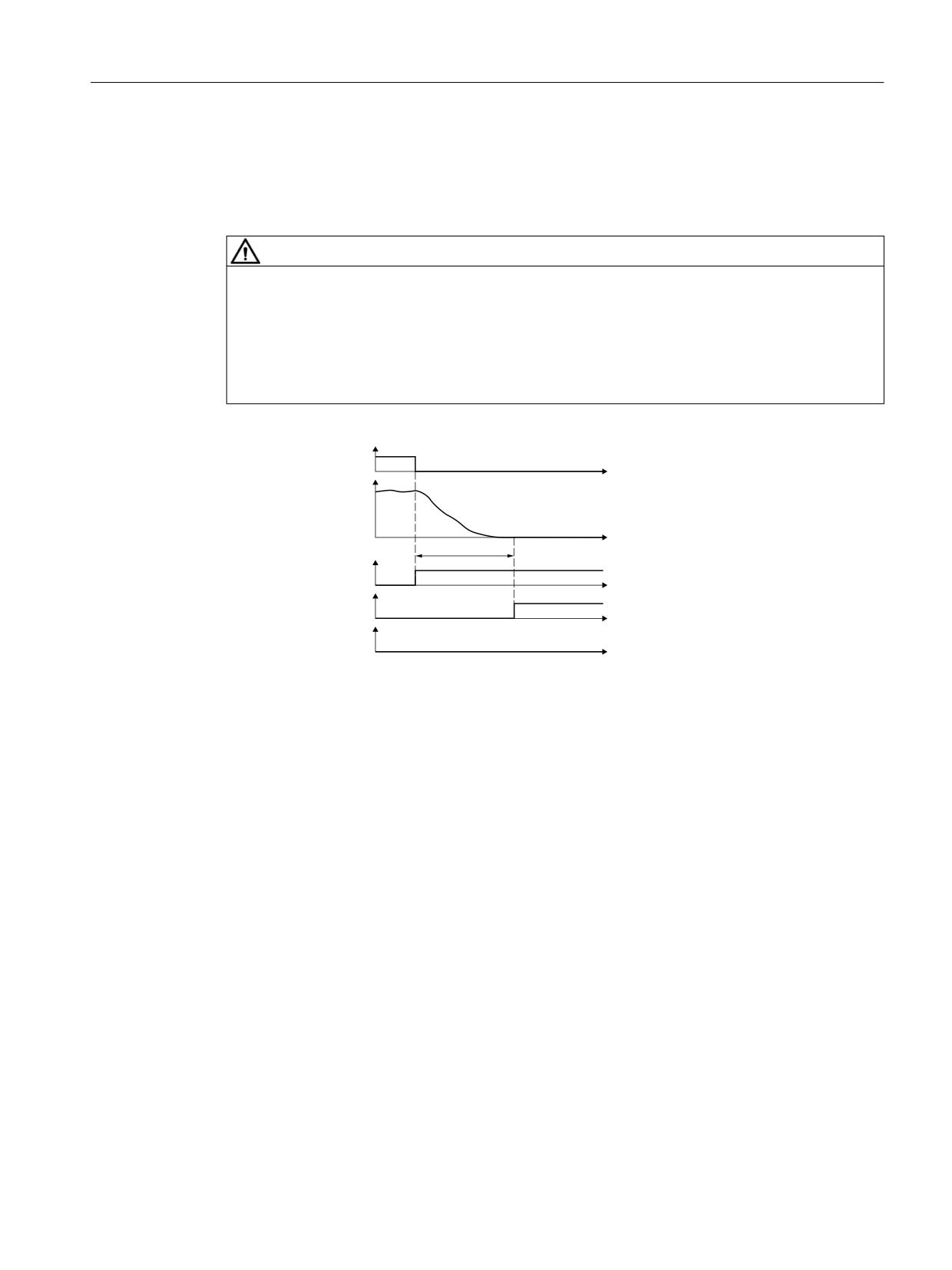
Description of Safety Integrated functions
5.2 Safety Integrated Extended Functions
5.2.7.1
SS2 with external stop (SS2E)
Selecting SS2E
WARNING
Unexpected axis motion
When function "Safe Stop 2 with external stop" (SS2E) is active, during the delay time (p9553)
the speed follows the setpoint issued from the higher-level control system. As a consequence,
unexpected axis motion is possible, which can lead to severe injury and death.
● Prevent persons from entering the danger zone of the machine or plant during the delay
time (p9553), for example, by keeping protective devices interlocked.
66 ( GHVHOHFWLRQ
W
6SHHG
W
S
66 ( DFWLYH
W
626 DFWLYH
W
6$0 6%5 DFWLYH
W
Figure 5-7
Selecting SS2E
With external stop, "Safe Stop 2" functions in principle exactly the same way as described in the
previous sections. Note, however, the following differences:
Differences between "Safe Stop 2 with OFF3" and "SS2 with external stop (SS2E)"
● If SS2 with external stop is selected, the drive does not brake the motor autonomously, but
follows the defined speed setpoint.
● During delay time p9553, the brake ramp (SBR) and the acceleration (SAM) are not
monitored and there is no standstill detection.
● SOS becomes active after the delay time p9553 expires.
When function SS2E is active, the higher-level control must issue the speed setpoint so that
at the latest after delay time p9553 expires, the motor has come to a complete standstill.
● In order to activate "Safe Stop 2 with external stop", set p9501.18 = 1.
● The PROFIsafe control word S_STW2.28 selects the SS2E function. PROFIsafe
S_STW2.28 is contained in telegrams 31, 901, 902, and 903.
Safety Integrated
Function Manual, 06/2020, 6SL3097-5AR00-0BP3
113
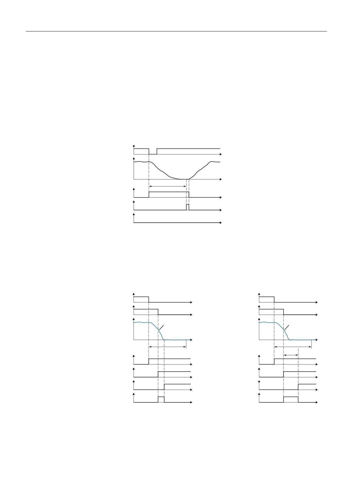
Description of Safety Integrated functions
5.2 Safety Integrated Extended Functions
● The PROFIsafe status word S_ZSW2.28 indicates whether the SS2E function is active.
PROFIsafe status word S_ZSW2.28 is contained in telegrams 31, 901, 902 and 903. The
associated diagnostics parameter is r9722.28.
In the "Safety Info Channel", status word S_ZSW3B.11 indicates whether function SS2E is
active. The associated diagnostics parameter is r10234.11.
Diagnostic parameters p9722.28 and p10234.11 are also set during an internal STOP D.
● Effect on the "Setpoint speed limit effective" (r9733[0...2]):
For SS2E (≙ STOP D), setpoint 0 is specified in r9733[0...2].
Deselecting SS2E while SS2E is active
66 ( GHVHOHFWLRQ
W
6SHHG
S
W
66 ( DFWLYH
W
626 DFWLYH
W
6$0 6%5 DFWLYH
W
Figure 5-8
Deselecting SS2E while SS2E is active
After the function has been selected, the delay time starts to expire - even if the function is
deselected during this time. In this case, after the delay time has expired, the SOS function is
briefly active. Afterwards, the drive may accelerate the motor back to the speed setpoint.
Interrupting active SS2E with SS1 and SS2
'HVHOHFW 66 (
'HVHOHFW 66 (
W
W
'HVHOHFW 66
'HVHOHFW 66
W
W
6SHHG
6SHHG
2)) UDPS
2)) UDPS
W
W
S
S
S
66 ( DFWLYH
66 ( DFWLYH
W
W
66 DFWLYH
66
DFWLYH
W
W
672 DFWLYH
626 DFWLYH
W
W
6$0 6%5 DFWLYH
6$0 6%5 DFWLYH
W
W
Figure 5-9
Interrupting SS2E using SS1 (shown at the left) and SS2 (shown at the right)
When selecting SS1, the drive brakes the motor along the OFF3 ramp and monitors the speed
using the SAM function. Function STO becomes active when the motor is at a standstill.
Safety Integrated
114
Function Manual, 06/2020, 6SL3097-5AR00-0BP3
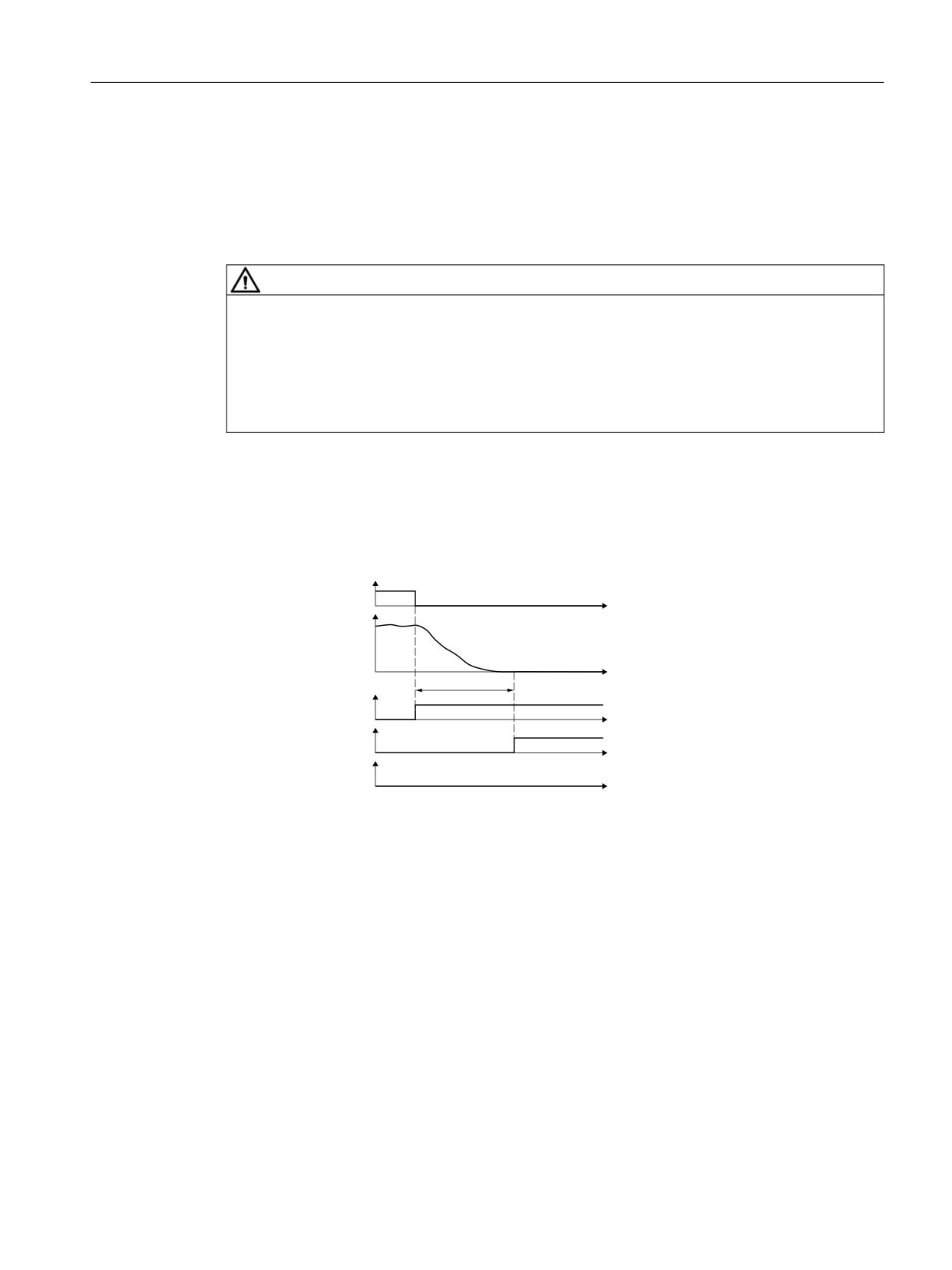
Description of Safety Integrated functions
5.2 Safety Integrated Extended Functions
When selecting SS2, the drive also brakes the motor along the OFF3 ramp and monitors the
speed using the SAM function. Function SOS becomes active after time p9552.
5.2.7.2
Safe Stop 2 Extended Stop and Retract (SS2ESR)
WARNING
Unexpected axis motion
When function SS2ESR is active, during the delay time (p9554) the speed follows the setpoint
issued from the higher-level control system. As a consequence, unexpected axis motion is
possible, which can lead to severe injury and death.
● Prevent persons from entering the danger zone of the machine or system during the delay
time (p9554), for example, by keeping protective devices closed and interlocked.
In principle, Safe Stop 2 Extended Stop and Retract (SS2ESR) functions in exactly the same
way as SS2 described in the previous sections. Note, however, the following differences.
Selecting SS2ESR
'HVHOHFW 66 (65
W
6SHHG
W
S
66 (65 DFWLYH
W
626 DFWLYH
W
6$0 6%5 DFWLYH
W
Figure 5-10
Selecting function SS2ESR
Differences between "Safe Stop 2 with OFF3" and SS2ESR
● If SS2ESR with external stop is selected, the drive does not brake the motor automatically,
but instead follows the defined speed setpoint: This can also result in fast retraction motion.
● During the delay time p9554, the brake ramp (SBR) and the acceleration (SAM) are not
monitored, and there is no standstill detection.
● SOS becomes active after the delay time p9554 has expired. If function SS2ESR is active,
the higher-level control system must define the speed setpoint such that the motor is
stopped no later than after the delay time p9554 has expired.
● To enable SS2ESR, set p9501.4 = 1.
● PROFIsafe control word S_STW2.29 selects function SS2ESR. PROFIsafe S_STW2.29 is
contained in telegrams 31, 901, 902 and 903.
Safety Integrated
Function Manual, 06/2020, 6SL3097-5AR00-0BP3
115
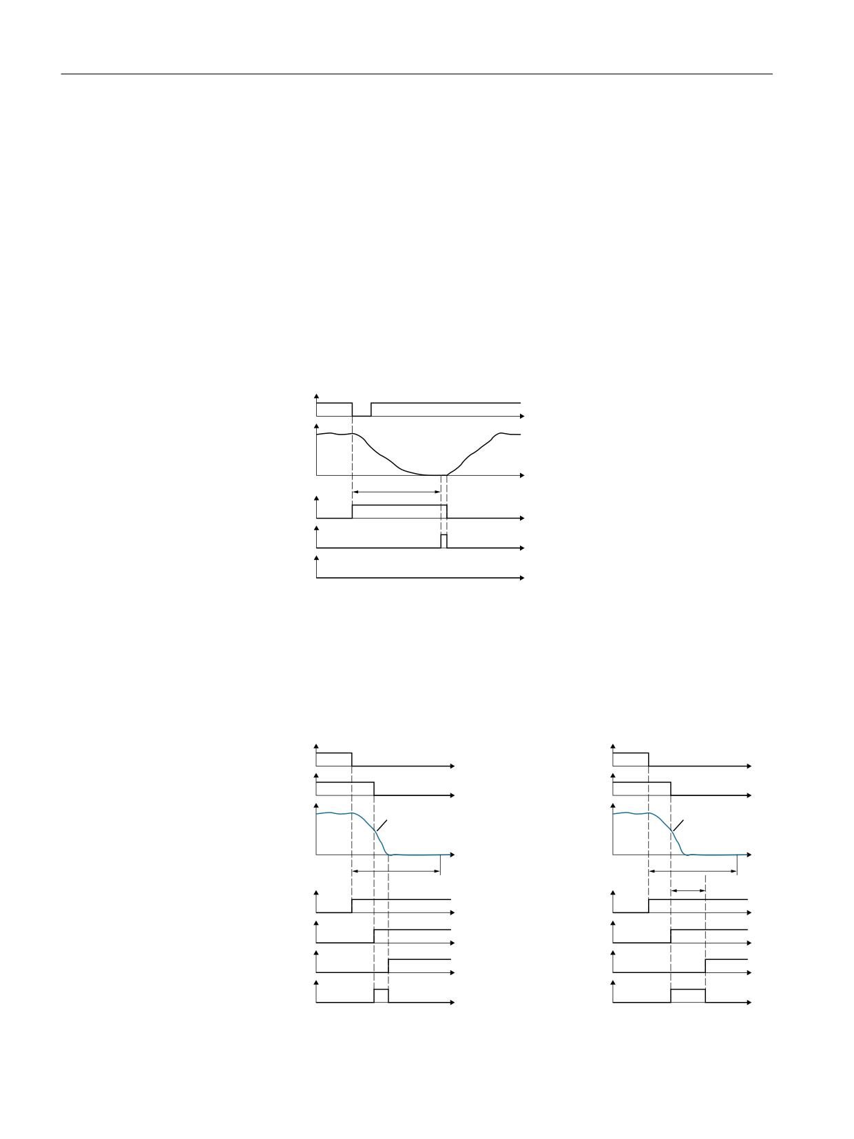
Description of Safety Integrated functions
5.2 Safety Integrated Extended Functions
● PROFIsafe status word S_ZSW2.27 indicates whether function SS2ESR is active.
PROFIsafe status word S_ZSW2.27 is contained in telegrams 31, 901, 902 and 903. The
associated diagnostics parameter is r9722.27. In the "Safety Info Channel," status word
S_ZSW3B.12 indicates whether the SS2ESR function is active. The associated diagnostics
parameter is r10234.12.
● In addition, in the "Safety Info Channel", status word S_ZSW1B.14 = 1 is set. This bit
corresponds to diagnostic parameter r9734.14.
● You can use p0890[1] to interconnect to an ESR integrated in the drive.
● SS2ESR has no effect on the "Setpoint speed limit effective" (r9733[0...2]). If SS2ESR is
enabled in p9501.4, then also a STOP E has no effect on r9733[0...2].
Deselecting SS2ESR while SS2ESR is active
'HVHOHFW 66 (65
W
6SHHG
S
W
66 (65 DFWLYH
W
626 DFWLYH
W
6$0 6%5 DFWLYH
W
Figure 5-11
Deselecting SS2ESR while SS2ESR is active
After the function has been selected, the delay time starts to expire - even if the function is
deselected during this time. In this case, after the delay time has expired, the SOS function is
briefly active. Afterwards, the drive may accelerate the motor back to the speed setpoint.
Interrupting active SS2ESR with SS1 and SS2
'HVHOHFW 66 (65
'HVHOHFW 66 (65
W
W
'HVHOHFW 66
'HVHOHFW 66
W
W
6SHHG
6SHHG
2)) UDPS
2)) UDPS
W
W
S
S
S
66 (65 DFWLYH
66 (65 DFWLYH
W
W
66 DFWLYH
66
DFWLYH
W
W
672 DFWLYH
626 DFWLYH
W
W
6$0 6%5 DFWLYH
6$0 6%5 DFWLYH
W
W
Safety Integrated
116
Function Manual, 06/2020, 6SL3097-5AR00-0BP3
Description of Safety Integrated functions
5.2 Safety Integrated Extended Functions
Figure 5-12
Interruption of function SS2ESR using functions SS1 (shown at the left) and SS2 (shown
at the right)
When selecting SS1, the drive brakes the motor along the OFF3 ramp and monitors the speed
using function SAM/SBR. Function STO becomes active when the motor is at a standstill.
When selecting SS2, the drive also brakes the motor along the OFF3 ramp and monitors the
speed using the SAM function. Function SOS becomes active after time p9552.
5.2.7.3
Overview of important parameters
Overview of important parameters (see SINAMICS S120/S150 List Manual)
● p2573
EPOS maximum delay
● p2594
CI: EPOS maximum speed, externally limited
● p2640
BI: EPOS intermediate stop (0 signal)
● p2645
CI: EPOS direct setpoint input/MDI, deceleration override
● p9551
SI Motion SLS(SG) switchover/SOS(SBH) delay time (CU)
● p9552
SI motion transition time STOP C to SOS (SBH) (Control Unit)
● p9553
SI motion transition time STOP D to SOS (SBH) (Control Unit)
● p9554
SI Motion transition time STOP E to SOS (SBH) (Control Unit)
● r9720.0...27
CO/BO: SI Motion drive-integrated control signals
● r9733[0...2]
CO: SI Motion speed setpoint limit active
Safety Integrated
Function Manual, 06/2020, 6SL3097-5AR00-0BP3
117