SINUMERIK 840D sl. Service - Safety Integrated. Manual (2020) - page 17
Data descriptions
11.6 Process data
11.6
Process data
11.6.1
Overview: Process data in telegrams
Table 11-18 Process data from PROFIsafe telegrams
Telegram
30
31
901
902
903
Process data
Safety control word 1
PZD1
-
-
-
-
S_STW1
Safety status word 1
PZD1
-
-
-
-
S_ZSW1
Safety control word 2
-
PZD1…2
PZD1…2
PZD1…2
PZD1…2
S_STW2
Safety status word 2
-
PZD1…2
PZD1…2
PZD1…2
PZD1…2
S_ZSW2
SLS limit value input
-
-
PZD3
PZD3
PZD3
S_SLS_LIMIT_A
Active SLS limit value
-
-
PZD3
PZD3
PZD5
S_SLS_LIMIT_A_ACTIVE
Counter for the safety cycle
-
-
PZD4
PZD4
-
S_CYCLE_COUNT
Actual position value (16 bits)
-
-
PZD5
-
-
S_XIST16
Actual position value (32 bits)
-
-
-
PZD5…6
-
S_XIST32
Safe Cam status word
-
-
-
-
PZD3…4
S_ZSW_CAM1
Detailed information about the process data of these telegrams is provided in Chapter
"PROFIsafe process data (Page 354)".
Table 11-19 Process data from SIEMENS telegram 701 (SIC/SCC)
Telegram
701
Process data
Safety Control Channel control word 1
PZD1
S_STW1B
SI Motion Safety Info Channel status word
PZD1
S_ZSW1B
Safety Info Channel status word 2
PZD2
S_ZSW2B
Safety Control Channel control word 3
PZD2
S_STW3B
Safety Integrated plus
Commissioning Manual, 10/2020, 6FC5397-1FP40-6BA4
353

Data descriptions
11.6 Process data
Telegram
701
Process data
SLS setpoint speed limiting (32 bit)
PZD3…4
S_V_LIMIT_B
Safety Info Channel status word 3
PZD5
S_ZSW3B
Detailed information about the process data of telegram 701 is provided in Chapter "SIC/SCC
(PROFIdrive) process data (Page 369)".
11.6.2
PROFIsafe process data
Note
Additional information in the function block diagrams
Generally, for the subsequent descriptions, reference is made to a function block diagram. You
can find the function block diagram mentioned in the SINAMICS S120/S150 List Manual.
Note
Reserved control/status bits
A series of control and/or status bits are listed as reserved in the following tables. The reason for
this is that various Safety Integrated Functions will only be implemented at a later point in time.
The bits are reserved for future functions.
Safety Integrated plus
354
Commissioning Manual, 10/2020, 6FC5397-1FP40-6BA4

Data descriptions
11.6 Process data
11.6.2.1
S_STW1: Safety control word 1
S_STW1 (Basic Functions)
Safety control word 1 (S_STW1)
S_STW1, output signals
see function chart [2806].
Table 11-20 Description of safety-control word1 (S_STW1)
Byte
Bit
Meaning
Remarks
0
0
STO
1
Deselect STO
0
Select STO
1
SS1
1
Deselect SS1
0
Select SS1
2
SS2
0
-1)
3
SOS
0
-1)
4
SLS
0
-1)
5
Reserved
-
-
6
SLP
0
-1)
7
Internal Event ACK
1/0
Acknowledgment
0
No acknowledgment
1
0
SLA
0
-1)
1
Select SLS bit 0
0
-1)
2
Select SLS bit 1
0
3
Reserved
-
-
4
SDI positive
0
-1)
5
SDI negative
0
6, 7
Reserved
-
-
1)
Signals not relevant for Basic Functions: Should be set to "0".
Safety Integrated plus
Commissioning Manual, 10/2020, 6FC5397-1FP40-6BA4
355

Data descriptions
11.6 Process data
S_STW1 (Extended Functions)
Safety control word 1 (S_STW1)
S_STW1, output signals
see function chart [2842].
Table 11-21 Description of safety-control word1 (S_STW1)
Byte
Bit
Meaning
Remarks
0
0
STO
1
Deselect STO
0
Select STO
1
SS1
1
Deselect SS1
0
Select SS1
2
SS2
1
Deselect SS2
0
Select SS2
3
SOS
1
Deselect SOS
0
Select SOS
4
SLS
1
Deselect SLS
0
Select SLS
5
Reserved
-
-
6
SLP1)
1
Deselect SLP
0
Select SLP
7
Internal Event ACK
1/0
Acknowledgment
0
No acknowledgment
1
0
SLA
1
Deselect SLA
0
Select SLA
1
Select SLS bit 0
-
Selection of the speed limit for SLS (2 bits)
2
Select SLS bit 1
-
3
Reserved
-
-
4
SDI positive
1
Deselect SDI positive
0
Select SDI positive
5
SDI negative
1
Deselect SDI negative
0
Select SDI negative
6, 7
Reserved
-
-
1)
Signals not relevant for Extended Functions: Must not be evaluated.
Safety Integrated plus
356
Commissioning Manual, 10/2020, 6FC5397-1FP40-6BA4

Data descriptions
11.6 Process data
11.6.2.2
S_ZSW1: Safety status word 1
S_ZSW1 (Basic Functions)
Safety status word 1 (S_ZSW1)
S_ZSW1, input signals
see function diagram [2806].
Table 11-22 Description of safety status word 1 (S_ZSW1)
Byte
Bit
Meaning
Remarks
0
0
STO active
1
STO active
0
STO not active
1
SS1 active
1
SS1 active
0
SS1 not active
2
SS2 active
0
-1)
3
SOS active
0
-1)
4
SLS active
0
-1)
5
Reserved
-
-
6
SLP active
0
-1)
7
Internal Event
1
Internal event
0
No internal event
1
0
SLA active
0
-1)
1
Active SLS level bit 0
0
-1)
2
Active SLS level bit 1
0
3
SOS selected
0
-1)
4
SDI positive active
0
-1)
5
SDI negative active
0
-1)
6
Reserved
-
-
7
SSM (speed below limit value)
0
-1)
1)
Signals not relevant for Basic Functions: Must not be evaluated.
Safety Integrated plus
Commissioning Manual, 10/2020, 6FC5397-1FP40-6BA4
357

Data descriptions
11.6 Process data
S_ZSW1 (Extended Functions)
Safety status word 1 (S_ZSW1)
S_ZSW1, input signals
see function diagram [2842].
Table 11-23 Description of safety status word 1 (S_ZSW1)
Byte
Bit
Meaning
Remarks
0
0
STO active
1
STO active
0
STO not active
1
SS1 active
1
SS1 active
0
SS1 not active
2
SS2 active
1
SS2 active
0
SS2 not active
3
SOS active
1
SOS active
0
SOS not active
4
SLS active
1
SLS active
0
SLS not active
5
Reserved
-
-
6
SLP active1)
1
SLP active
0
SLP not active
–
The status signal "SLP active" is not the same as
the diagnostic signal "SLP active" (r9722.6), but is
the AND logic operation of "SLP active" (r9722.6)
and "safely referenced" (r9722.23).
7
Internal Event
1
Internal event
0
No internal event
1
0
SLA active
1
SLA active
0
SLA not active
1
Active SLS level bit 0
-
Display of the speed limit for SLS (2 bits)
2
Active SLS level bit 1
-
3
SOS selected
1
SOS selected
0
SOS deselected
4
SDI positive active
1
SDI positive active
0
SDI positive not active
5
SDI negative active
1
SDI negative active
0
SDI negative not active
6
Reserved
-
-
7
SSM (speed)
1
SSM (speed below limit value)
0
SSM (speed higher than/equal to limit)
1)
Signals not relevant for Extended Functions: Must not be evaluated.
Safety Integrated plus
358
Commissioning Manual, 10/2020, 6FC5397-1FP40-6BA4

Data descriptions
11.6 Process data
11.6.2.3
S_STW2: Safety control word 2
S_STW2 (Basic Functions)
Safety control word 2 (S_STW2)
S_STW2, output signals
see function diagram [2806].
Table 11-24 Description of safety-control word 2 (S_STW2)
Byte
Bit
Meaning
Remarks
0
0
STO
1
Deselect STO
0
Select STO
1
SS1
1
Deselect SS1
0
Select SS1
2
SS2
0
-1)
3
SOS
0
-1)
4
SLS
0
-1)
5
Reserved
-
-
6
SLP
0
-1)
7
Internal Event ACK
1/0
Acknowledgment
0
No acknowledgment
1
0
SLA active
0
-1)
1
Select SLS bit 0
0
-1)
2
Select SLS bit 1
0
3
Reserved
-
-
4
SDI positive
0
-1)
5
SDI negative
0
-1)
6, 7
Reserved
-
-
2
0 ... 2
Reserved
-
-
3
Select SLP position range
0
-1)
4 ... 6
Reserved
-
-
7
SCA
0
-1)
3
0
Select gearbox stage, bit 0
0
-1)
1
Select gearbox stage, bit 1
0
-1)
2
Select gearbox stage, bit 2
0
-1)
3
Gearbox stage switchover
0
-1)
4
SS2E
0
-1)
5
SS2ESR
0
-1)
6, 7
Reserved
-
-
1)
Signals not relevant to Basic Functions should be set to "0".
Safety Integrated plus
Commissioning Manual, 10/2020, 6FC5397-1FP40-6BA4
359

Data descriptions
11.6 Process data
S_STW2 (Extended Functions)
Safety control word 2 (S_STW2)
S_STW2, output signals
see function diagram [2843].
Table 11-25 Description of safety-control word 2 (S_STW2)
Byte
Bit
Meaning
Remarks
0
0
STO
1
Deselect STO
0
Select STO
1
SS1
1
Deselect SS1
0
Select SS1
2
SS2
1
Deselect SS2
0
Select SS2
3
SOS
1
Deselect SOS
0
Select SOS
4
SLS
1
Deselect SLS
0
Select SLS
5
Reserved
-
-
6
SLP
1
Deselect SLP
0
Select SLP
7
Internal Event ACK
1/0
Acknowledgment
0
No acknowledgment
1
0
SLA
1
Deselect SLA
0
Select SLA
1
Select SLS bit 0
-
Selection of the speed limit for SLS (2 bits)
2
Select SLS bit 1
-
3
Reserved
-
-
4
SDI positive
1
Deselect SDI positive
0
Select SDI positive
5
SDI negative
1
Deselect SDI negative
0
Select SDI negative
6, 7
Reserved
-
-
2
0 ... 2
Reserved
-
-
3
Select SLP position range1)
1
Select SLP area 2 (SLP2)
0
Select SLP area 1 (SLP1)
4 ... 6
Reserved
-
-
7
SCA
1
Deselect SCA
0
Select SCA
Safety Integrated plus
360
Commissioning Manual, 10/2020, 6FC5397-1FP40-6BA4

Data descriptions
11.6 Process data
Byte
Bit
Meaning
Remarks
3
0
Select gearbox stage, bit 0
-
Select gearbox stage (3 bits)
1
Select gearbox stage, bit 1
-
2
Select gearbox stage, bit 2
-
3
Gearbox stage switchover
1
With increased position tolerance
0
Without increased position tolerance
4
SS2E
1
Deselect SS2E
0
Select SS2E
5
SS2ESR
1
Deselect SS2ESR
0
Select SS2ESR
6, 7
Reserved
-
-
1)
Signals not relevant for Extended Functions: Must not be evaluated.
11.6.2.4
S_ZSW2: Safety status word 2
S_ZSW2 (Basic Functions)
Safety status word 2 (S_ZSW2)
S_ZSW2, input signals
see function diagram [2806].
Table 11-26 Description of safety status word 2 (S_ZSW2)
Byte
Bit
Meaning
Remarks
0
0
STO active
1
STO active
0
STO not active
1
SS1 active
1
SS1 active
0
SS1 not active
2
SS2 active
0
-1)
3
SOS active
0
-1)
4
SLS active
0
-1)
5
Reserved
-
-
6
SLP active
0
-1)
7
Internal Event
1
Internal event
0
No internal event
Safety Integrated plus
Commissioning Manual, 10/2020, 6FC5397-1FP40-6BA4
361

Data descriptions
11.6 Process data
Byte
Bit
Meaning
Remarks
1
0
SLA active
0
-1)
1
Active SLS level, bit 0
0
-1)
2
Active SLS level, bit 1
0
3
Reserved
-
-
4
SDI positive active
0
-1)
5
SDI negative active
0
-1)
6
Reserved
-
-
7
SSM (speed)
0
-1)
2
0 ... 2
Reserved
-
-
3
SLP active position range
0
-1)
4, 5
Reserved
-
-
6
Safe position valid
0
-1)
7
Safely referenced
0
-1)
3
0 ... 2
F-DI 0 ... 22)
0
-1)
3
SS2ESR active
0
-1)
4
SS2E active
0
-1)
5
SOS selected
0
-1)
6
SLP upper limit maintained
0
-1)
7
SLP lower limit maintained
0
-1)
1)
Signals not relevant for Basic Functions: Must not be evaluated.
2)
Only valid for CU310-2.
Safety Integrated plus
362
Commissioning Manual, 10/2020, 6FC5397-1FP40-6BA4
Data descriptions
11.6 Process data
S_ZSW2 (Extended Functions)
Safety status word 2 (S_ZSW2)
S_ZSW2, input signals
see function diagram [2843].
Table 11-27 Description of safety status word 2 (S_ZSW2)
Byte
Bit
Meaning
Remarks
0
0
STO active
1
STO active
0
STO not active
1
SS1 active
1
SS1 active
0
SS1 not active
2
SS2 active
1
SS2 active
0
SS2 not active
3
SOS active
1
SOS active
0
SOS not active
4
SLS active
1
SLS active
0
SLS not active
5
Reserved
-
-
6
SLP active1
1
SLP active
0
SLP not active
–
The status signal "SLP active" is not the same as
the diagnostic signal "SLP active" (r9722.6), but is
the AND logic operation of "SLP active" (r9722.6)
and "safely referenced" (r9722.23).
7
Internal Event
1
Internal event
0
No internal event
1
0
SLA active
1
SLA active
0
SLA not active
1
Active SLS level bit 0
-
Display of the speed limit for SLS (2 bits)
2
Active SLS level bit 1
-
3
Reserved
-
-
4
SDI positive active
1
SDI positive active
0
SDI positive not active
5
SDI negative active
1
SDI negative active
0
SDI negative not active
6
Reserved
-
-
7
SSM (speed)
1
SSM (speed below limit value)
0
SSM (speed higher than/equal to limit)
Safety Integrated plus
Commissioning Manual, 10/2020, 6FC5397-1FP40-6BA4
363

Data descriptions
11.6 Process data
Byte
Bit
Meaning
Remarks
2
0 ... 2
Reserved
-
-
3
SLP active position range1)
1
SLP area 2 (SLP2) active
0
SLP area 1 (SLP1) active
-
The status signal "SLP active position range" al-
ways corresponds to the diagnostic signal "SLP
active position range" (r9722.19).
4, 5
Reserved
-
-
6
Safe position valid
1
Safe position valid
0
Safe position invalid
7
Safely referenced
1
Safe position is applicable as "safely referenced"
0
Safe position is not applicable as "safely refer-
enced"
1)
Signals not relevant for Extended Functions: Must not be evaluated.
Safety Integrated plus
364
Commissioning Manual, 10/2020, 6FC5397-1FP40-6BA4

Data descriptions
11.6 Process data
Byte
Bit
Meaning
Remarks
3
0
F-DI 02)
1
F-DI 0 inactive
0
F-DI 0 active
1
F-DI 12)
1
F-DI 1 inactive
0
F-DI 1 active
2
F-DI 22)
1
F-DI 2 inactive
0
F-DI 2 active
3
SS2ESR active
1
SS2ESR active
0
SS2ESR not active
4
SS2E active
1
SS2E active
0
SS2E not active
5
SOS selected
1
SOS selected
0
SOS deselected
6
SLP upper limit maintained
1
SLP: Upper limit maintained
0
SLP: Upper limit not maintained
–
The status signal "upper SLP limit maintained" al-
ways corresponds to the diagnostic signal "upper
SLP limit maintained" (r9722.30).
7
SLP lower limit maintained
1
SLP: Lower limit maintained
0
SLP: Lower limit not maintained
-
The status signal "lower SLP limit maintained" al-
ways corresponds to the diagnostic signal "lower
SLP limit maintained" (r9722.31).
1)
Signals not relevant for Extended Functions: Must not be evaluated.
2)
Only valid for CU310-2.
11.6.2.5
S_SLS_LIMIT_A: SLS limit value input
S_SLS_LIMIT_A
• PZD3 in telegram 901, 902, 903, output signals
• SLS limit value input
• Value range 1 ... 32767; 32767 ≙ 100% of the 1st SLS level
11.6.2.6
S_SLS_LIMIT_A_ACTIVE: Active SLS limit value
S_SLS_LIMIT_A_ACTIVE
• PZD3 in telegram 901, 902, 903, input signals
• Active SLS limit value
Safety Integrated plus
Commissioning Manual, 10/2020, 6FC5397-1FP40-6BA4
365
Data descriptions
11.6 Process data
• Value range 1 ... 32767; 32767 ≙ 100%
• Must only be evaluated if SLS 1 active and p9501.24 = 1.
11.6.2.7
S_CYCLE_COUNT: Counter for the safety cycle
S_CYCLE_COUNT
• PZD4 in telegrams 901 and 902, input signals
• Counter for the safety cycle
• Value range -32768 ... +32767
• May only be evaluated if the transfer of safe position values is active (p9501.25 = 1) and the
position value is valid (r9722.22 = r9722.23 = 1).
11.6.2.8
S_XIST16: Current actual position value (16 bits)
S_XIST16
• PZD5 in telegram 901, input signals
• Current actual position value (16 bits)
• Value range ±32767
• Scaling using p9574
Note
Scaling
It is not permissible that the position value transferred in S_XIST16 exceeds the value range
that can be represented. This is the reason that the safe position value of the drive (r9713[0])
can be allocated a scaling factor. The position value is divided by this factor before transfer.
As a consequence, a wider value range can be transferred with a reduced accuracy.
Example: For a position of -29.999 mm signaled in r9708[0] and r9708[1] and a scaling
factor of p9x74 = 1000, a numerical value of -29 is signaled to the controller.
• May only be evaluated if the transfer of safe position values is active (p9501.25 = 1) and the
position value is valid (r9722.22 = r9722.23 = 1).
11.6.2.9
S_XIST32: Current actual position value (32 bits)
S_XIST32
• PZD5 and PZD6 in telegram 902, input signals
• Current actual position value (32 bits)
• Value range ±737280000
Safety Integrated plus
366
Commissioning Manual, 10/2020, 6FC5397-1FP40-6BA4

Data descriptions
11.6 Process data
• Unit: 1 μm (linear axis), 0.001 ° (rotary axis)
• May only be evaluated if the transfer of safe position values is active (p9501.25 = 1) and the
position value is valid (r9722.22 = r9722.23 = 1).
11.6.2.10
S_ZSW_CAM1
S_ZSW_CAM1
S_ZSW_CAM1, Safe Cam
see function diagram [2844].
Table 11-28 Description of Safety status word Safe Cam (S_ZSW_CAM1)
Byte
Bit
Meaning
Remarks
0
0
Position at cam 1
1
Position is at cam 1
0
Position is not at cam 1
1
Position at cam 2
1
Position is at cam 2
0
Position is not at cam 2
2
Position at cam 3
1
Position is at cam 3
0
Position is not at cam 3
3
Position at cam 4
1
Position is at cam 4
0
Position is not at cam 4
4
Position at cam 5
1
Position is at cam 5
0
Position is not at cam 5
5
Position at cam 6
1
Position is at cam 6
0
Position is not at cam 6
6
Position at cam 7
1
Position is at cam 7
0
Position is not at cam 7
7
Position at cam 8
1
Position is at cam 8
0
Position is not at cam 8
Safety Integrated plus
Commissioning Manual, 10/2020, 6FC5397-1FP40-6BA4
367

Data descriptions
11.6 Process data
Byte
Bit
Meaning
Remarks
1
0
Position at cam 9
1
Position is at cam 9
0
Position is not at cam 9
1
Position at cam 10
1
Position is at cam 10
0
Position is not at cam 10
2
Position at cam 11
1
Position is at cam 11
0
Position is not at cam 11
3
Position at cam 12
1
Position is at cam 12
0
Position is not at cam 12
4
Position at cam 13
1
Position is at cam 13
0
Position is not at cam 13
5
Position at cam 14
1
Position is at cam 14
0
Position is not at cam 14
6
Position at cam 15
1
Position is at cam 15
0
Position is not at cam 15
7
Position at cam 16
1
Position is at cam 16
0
Position is not at cam 16
2
0
Position at cam 17
1
Position is at cam 17
0
Position is not at cam 17
1
Position at cam 18
1
Position is at cam 18
0
Position is not at cam 18
2
Position at cam 19
1
Position is at cam 19
0
Position is not at cam 19
3
Position at cam 20
1
Position is at cam 20
0
Position is not at cam 20
4
Position at cam 21
1
Position is at cam 21
0
Position is not at cam 21
5
Position at cam 22
1
Position is at cam 22
0
Position is not at cam 22
6
Position at cam 23
1
Position is at cam 23
0
Position is not at cam 23
7
Position at cam 24
1
Position is at cam 24
0
Position is not at cam 24
Safety Integrated plus
368
Commissioning Manual, 10/2020, 6FC5397-1FP40-6BA4
Data descriptions
11.6 Process data
Byte
Bit
Meaning
Remarks
3
0
Position at cam 25
1
Position is at cam 25
0
Position is not at cam 25
1
Position at cam 26
1
Position is at cam 26
0
Position is not at cam 26
2
Position at cam 27
1
Position is at cam 27
0
Position is not at cam 27
3
Position at cam 28
1
Position is at cam 28
0
Position is not at cam 28
4
Position at cam 29
1
Position is at cam 29
0
Position is not at cam 29
5
Position at cam 30
1
Position is at cam 30
0
Position is not at cam 30
6
Safe Cam active
1
Safe Cam is active
0
Safe Cam is not active
7
Validity of the values of Safe Cam
1
Values of Safe Cam apply
0
Values of Safe Cam do not apply
11.6.3
SIC/SCC (PROFIdrive) process data
11.6.3.1
S_STW1B: Safety Control Channel control word 1
S_STW1B
Safety Control Channel control word 1
Table 11-29 Description of S_STW1B
Bit
Meaning
Remarks
Parameter
0...7
Reserved
-
-
-
8
Extended Functions test stop/forced
1
Extended Functions test stop/forced checking pro-
r10251.8
checking procedure
cedure selected
0
Extended Functions test stop/forced checking pro-
cedure deselected
9...12
Reserved
-
-
-
13
Close brake from control
1
"Close brake from control" selected
r10251.13
0
"Close brake from control" deselected
14, 15
Reserved
-
-
-
Safety Integrated plus
Commissioning Manual, 10/2020, 6FC5397-1FP40-6BA4
369

Data descriptions
11.6 Process data
11.6.3.2
S_ZSW1B: SI Motion / Safety Info Channel status word
S_ZSW1B
SI Motion Safety Info Channel status word
Table 11-30 Description S_ZSW1B
Bit
Meaning
Remarks
Parameter
0
STO active
1
STO active
r9734.0
0
STO not active
1
SS1 active
1
SS1 active
r9734.1
0
SS1 not active
2
SS2 active
1
SS2 active
r9734.2
0
SS2 not active
3
SOS active
1
SOS active
r9734.3
0
SOS not active
4
SLS active
1
SLS active
r9734.4
0
SLS not active
5
SOS selected
1
SOS selected
r9734.5
0
SOS deselected
6
SLS selected
1
SLS selected
r9734.6
0
SLS deselected
7
Internal event
1
Internal event
r9734.7
0
No internal event
8
SLA selected
1
SLA selected
r9734.8
0
SLA deselected
9
Active SLS level bit 0
-
Display of the velocity limit for SLS (2 bits)
r9734.9
10
Active SLS level bit 1
-
r9734.10
11
Reserved
-
-
-
12
SDI positive selected
1
SDI positive selected
r9734.12
0
SDI positive deselected
13
SDI negative selected
1
SDI negative selected
r9734.13
0
SDI negative deselected
14
ESR retract requested
1
ESR retract requested
r9734.14
0
ESR retract not requested
15
Safety message effective
1
Safety message effective
r9734.15
0
No Safety message effective
Safety Integrated plus
370
Commissioning Manual, 10/2020, 6FC5397-1FP40-6BA4

Data descriptions
11.6 Process data
11.6.3.3
S_ZSW2B: Safety Info Channel status word 2
S_ZSW2B
Safety Info Channel status word 2
Table 11-31 Description of S_ZSW2B
Bit
Meaning
Remarks
Parameter
0...3
Reserved
-
-
-
4
SLP selected position range
1
SLP area 2 selected
r9743.4
0
SLP area 1 selected
5, 6
Reserved
-
-
-
7
SLP selected and user agreement
1
SLP selected and user agreement set
r9743.7
0
SLP selected or user agreement not set
8
SDI positive
1
SDI positive selected
r9743.8
0
SDI positive deselected
9
SDI negative
1
SDI negative selected
r9743.9
0
SDI negative deselected
10, 11
Reserved
-
-
-
12
Test stop active
1
Test stop active
r9743.12
0
Test stop not active
13
Test stop required
1
Test stop required
r0743.13
0
Test stop not required
14, 15
Reserved
-
-
-
11.6.3.4
S_STW3B: Safety Control Channel control word 3
S_STW3B
Safety Control Channel control word 3
Table 11-32 Description of S_STW3B
Bit
Meaning
Remarks
Parameter
0
Select brake test
1
Brake test selected
r10231.0
0
Brake test deselected
1
Start brake test
1
Start brake test requested
r10231.1
0
Start brake test not requested
2
Brake selection
1
Test brake 2 selected
r10231.2
0
Test brake 1 selected
3
Select direction of rotation
1
Negative direction selected
r10231.3
0
Positive direction selected
Safety Integrated plus
Commissioning Manual, 10/2020, 6FC5397-1FP40-6BA4
371

Data descriptions
11.6 Process data
Bit
Meaning
Remarks
Parameter
4
Select test sequence
1
Test sequence 2 selected
r10231.4
0
Test sequence 1 selected
5
Status of external brake
1
External brake closed
r10231.5
0
External brake open
6...15
Reserved
-
-
-
11.6.3.5
S_ZSW3B: Safety Info Channel status word 3
S_ZSW3B
Safety Info Channel status word 3
Table 11-33 Description of S_ZSW3B
Bit
Meaning
Remarks
Parameter
0
Brake test
1
Brake test selected
r10234.0
0
Brake test deselected
1
Setpoint input, drive/external1)
1
Setpoint specification for the drive
r10234.1
0
Setpoint specification, external (controller)
2
Active brake
1
Test brake 2 active
r10234.2
0
Test brake 1 active
3
Brake test active
1
Test active
r10234.3
0
Test inactive
4
Brake test result
1
Test successful
r10234.4
0
Test error
5
Brake test completed
1
Test run
r10234.5
0
Test incomplete
6
External brake request
1
Close brake
r10234.6
0
Open brake
7
Current load sign
1
Negative sign
r10234.7
0
Positive sign
8...10
Reserved
-
-
-
11
SS2E active
1
SS2E active
r10234.11
0
SS2E inactive
12
SS2ESR active
1
SS2ESR active
r10234.12
0
SS2ESR inactive
13
Reserved
-
-
-
14
Acceptance test SLP (SE) selected
1
Acceptance test SLP (SE) selected
r10234.14
0
Acceptance test SLP (SE) deselected
15
Acceptance test mode selected
1
Acceptance test mode selected
r10234.15
0
Acceptance test mode deselected
1)
Setpoint input for the drive: The speed setpoint is entered by the function SBT.
External setpoint input (open-loop control): The "normal" speed setpoint is effective.
Safety Integrated plus
372
Commissioning Manual, 10/2020, 6FC5397-1FP40-6BA4

Data descriptions
11.6 Process data
11.6.3.6
S_V_LIMIT_B: Safety Info Channel setpoint velocity limiting
S_V_LIMIT_B
SLS speed limit with a 32-bit resolution with sign bit.
Table 11-34 Description S_V_LIMIT_B
Parameter
Meaning
r9733[2]
SLS speed limit
p2000
Scaling of the SLS speed limit
S_V_LIMIT_B = 4000 0000 hex ≐ speed in p2000
Safety Integrated plus
Commissioning Manual, 10/2020, 6FC5397-1FP40-6BA4
373
Data descriptions
11.7 Interface signals: Axis/spindle signals
11.7
Interface signals: Axis/spindle signals
As PLC user interface, certain axis-specific signals are mapped from the SIC/SCC (Page 205) in
the axis DB (Page 206):
• DB31 … DB61, Safety Info Channel (SIC)
• DB31 … DB61, Safety Control Channel (SCC)
This means, for example, that you can perform the brake test via the PLC user program.
Additional information
List Manual "SINUMERIK 840D sl, NC Variables and Interface Signals".
Safety Integrated plus
374
Commissioning Manual, 10/2020, 6FC5397-1FP40-6BA4
System features
12
12.1
Latest information
Important note for maintaining the operational safety of your system:
Note
Requirements for operational safety
Systems with safety-related characteristics are subject to special operational safety
requirements on the part of the operating company. The supplier is also obliged to comply with
special product monitoring measures. For this reason, we publish a special newsletter
containing information on product developments and features that are (or could be) relevant
when operating safety-related systems.
• You should subscribe to the corresponding newsletter in order to obtain the latest
information and to allow you to modify your equipment accordingly.
Subscribing to the Safety Integrated Newsletter
1. Go to the following Internet address in your browser:
Safety Integrated Newsletter (https://new.siemens.com/global/de/produkte/
automatisierung/themenfelder/safety-integrated/fertigungsautomatisierung/
newsletter.html)
2. Select the desired language for the Web page.
3. Enter your address data on the Newsletter page.
4. Select your areas of interest in the Safety Integrated domain.
5. Activate the consent.
6. Click on "Send".
Safety Integrated plus
Commissioning Manual, 10/2020, 6FC5397-1FP40-6BA4
375

System features
12.2 Response times
12.2
Response times
The Basic Functions are executed in the monitoring cycle (p9780). PROFIsafe telegrams are
evaluated in the PROFIsafe scan cycle, which corresponds to twice the monitoring clock cycle
(PROFIsafe scan cycle = 2 · r9780).
Note for understanding the tables
The drive system is the component that provides the safety functions. The designation "fault-
free drive system" means that the component that provides the safety functions does not have
a defect itself:
• Worst case for a fault-free drive system
For faults outside the drive system, such as e.g. faulty setpoint input from a control system,
limit value violations as a result of the behavior of the motor, closed-loop control, load, etc.,
the "Worst case for a fault-free drive system" response time is guaranteed.
• Worst case when a fault exists
For a single fault within the drive system, such as a defect in a switch-off signal path of the
power unit, a defect in an encoder actual value measurement, a defect in a microprocessor
(Control Unit or Motor Module) etc., the "Worst case when a fault exists" response time is
guaranteed.
12.2.1
Controlling Basic Functions via terminals on the Control Unit and Motor
Module
The following table lists the response times from the control via terminals until the response
actually occurs.
Table 12-1
Response times for control via terminals on the Control Unit and the Motor Module.
Function
Worst case for
Drive system has no fault
A fault is present
STO
2 · r9780 + t_E1)
3 · r9780 + t_E1)
SBC
4 · r9780 + t_E1)
8 · r9780 + t_E1)
SS1/SS1E (time-controlled)
Selection until STO is initiated
2 · r9780 + p9652 + t_E1)
3 · r9780 + p9652 + t_E1)
SS1/SS1E (time-controlled)
Selection until SBC is initiated
4 · r9780 + p9652 + t_E1)
8 · r9780 + p9652 + t_E1)
SS1 (time-controlled)
Selection until braking is initiated
3 · r9780 + 2 ms + t_E1)
4 · r9780 + 2 ms + t_E1)
1)
The following applies for t_E (debounce time of the digital input being used):
p9651 = 0
t_E = 2 · p0799 (default = 4 ms)
p9651 ≠ 0
t_E = p9651 + p0799 + 1 ms
The minimum time for t_E is t_E_min = 2 ms.
Safety Integrated plus
376
Commissioning Manual, 10/2020, 6FC5397-1FP40-6BA4

System features
12.2 Response times
12.2.2
Controlling the Basic Functions via PROFIsafe
The following table lists the response times1) from receiving the PROFIsafe Telegram in the drive
up to initiating the particular response.
Table 12-2
Response times when controlling via PROFIsafe
Function
Worst case for
Drive system has no fault
A fault is present
STO
5 · r9780 + t_E2)
5 · r9780 + t_E2)
SBC
6 · r9780 + t_E2)
10 · r9780 + t_E2)
SS1/SS1E (time-controlled)
Selection until STO is initiated
5 · r9780 + p9652 + t_K2)
5 · r9780 + p9652 + t_K2)
SS1/SS1E (time-controlled)
Selection until SBC is initiated
6 · r9780 + p9652 + t_K2)
10 · r9780 + p9652 + t_K2)
SS1 (time-controlled)
Selection until braking is initiated
5 · r9780 + 2 ms + t_K2)
5 · r9780 + 2 ms + t_K2)
1)
The specified response times involve internal SINAMICS response times. Program run times in the F-host and the transmission
time via PROFIBUS or PROFINET are not taken into account. When calculating the response times between the F-CPU and the
converter, you must take into account that faults in the communication can result in a safety function only being selected after
the PROFIsafe monitoring time (F_WD_Time) has expired. The PROFIsafe monitoring time (F_WD_Time) must also be
included in the calculation when an error occurs.
2)
t_K is the time for internal communication within the SINAMICS module; t_K can be determined as follows:
t_K = To (for To, see parameter r2064[4])
12.2.3
Controlling the Extended Functions via PROFIsafe
The following table lists the response times1) 2) from receiving the PROFIsafe Telegram in the
drive up to initiating the particular response.
Table 12-3
Response times when controlling via PROFIsafe
Function
Worst case for
Drive system has no fault
A fault is present
STO
5 · p95008) + r9780 + t_K6)
5 · p95008) + 2 · r9780 + t_K6)
SBC
5 · p95008) + 2 · r9780 + t_K6)
5 · p95008) + 6 · r9780 + t_K6)
SS1 (time controlled), SS1E, SS2E: Time from selecting
up to starting the safe timer
SS1 (acceleration controlled), SS2: Time from selecting
up to initiating braking
5 · p95008) + 2 ms + t_K6)
5 · p95008) + 2 ms + t_K6)
SOS: Time from selecting up to starting standstill mon-
itoring
SBR or SAM (limit value violation until STO active)
2 · p9500 + r9780
2.5 · p9500 + r9780 + t_ACT5)
SOS standstill tolerance window violated
1.5 · p9500 + 2 ms
3 · p9500 + 2 ms + t_ACT5)
SLS speed limit violated 3)
2 · p9500 + 2 ms
3.5 · p9500 + 2 ms + t_ACT5)
SSM4)
4 · p9500
4.5 · p9500 + t_ACT5)
SDI (limit value violation until braking is initiated)
1.5 · p9500 + 2 ms
3 · p9500 + 2 ms + t_ACT5)
Safety Integrated plus
Commissioning Manual, 10/2020, 6FC5397-1FP40-6BA4
377

System features
12.2 Response times
Function
Worst case for
Drive system has no fault
A fault is present
SLA 9): Selection or deselection
5 · p95008) + t_K
5 · p95008) + t_K
3 · p9500 + 2 ms
4 · p9500 + 2 ms + t_act
SLA: Limit value violation
SLP (limit value violation until a response is initiated)
1.5 · p9500 + 2 ms
3 · p9500 + 2 ms + t_ACT5)
SCA: Time between violation of a cam start or end po-
sition and output of the feedback message in
3.5 · p9500
4 · p9500 + t_ACT5)
S_ZSW_CAM1
SP7) with isochronous PROFIsafe telegram
3 · p9500
3 · p9500 + t_ACT5)
1)
The specified response times are valid for Extended Functions with and without selection.
2)
The specified response times involve internal SINAMICS response times. Program run times in the F-host and the transmission
time via PROFIBUS or PROFINET are not taken into account. When calculating the response times between the F-CPU and the
converter, you must take into account that faults in the communication can result in a safety function only being selected after
the PROFIsafe monitoring time (F_WD_Time) has expired. The PROFIsafe monitoring time (F_WD_Time) must also be
included in the calculation when an error occurs.
3)
SLS: Specification of the response time required to initiate a braking response in the drive - or for the output of the "SOS
selected" message to the motion control system.
4)
SSM: The data corresponds to the times between the limit value being undershot up to sending the information via PROFIsafe.
5)
t_ACT:
For p9511 ≠ 0
t_ACT = p9511
For p9511 = 0
t_ACT = PROFIBUS cycle
6)
t_K is the time for internal communication within the SINAMICS module; t_K can be determined as follows:
t_K = To (for To, see parameter r2064[4])
7)
SP: The data corresponds to the times between acquisition of the safe position and transfer of the safe position via PROFIsafe.
8)
For the best possible execution (relating to time) on the F-CPU this component is reduced from 5 · p9500 to 3 · p9500.
9)
In SINUMERIK Operate, the settings for SLA can only be made via the parameter list.
Safety Integrated plus
378
Commissioning Manual, 10/2020, 6FC5397-1FP40-6BA4
Switching over from SINUMERIK Safety Integrated
13
13.1
Overview
If you previously worked with the "SINUMERIK Safety Integrated (SPL)" mode, then the
information provided in this chapter can simplify the switchover to "SINUMERIK Safety
Integrated plus (F-PLC)":
• Comparison of the safety functions (Page 380)
• Additional differences when commissioning (Page 385)
• Procedure when switching over between systems (Page 395)
Safety Integrated plus
Commissioning Manual, 10/2020, 6FC5397-1FP40-6BA4
379

Switching over from SINUMERIK Safety Integrated
13.2 Comparison of the safety functions
13.2
Comparison of the safety functions
13.2.1
Overview
In some instances, the "SINUMERIK Safety Integrated" safety functions use their own function
names. The designations of "SINUMERIK Safety Integrated plus" safety functions correspond to
SINAMICS Safety Functions, and are therefore based on DIN EN 60204-1.
These names are compared in this chapter.
For "SINUMERIK Safety Integrated plus", the safety functions (STO, SBC, SS1) available with
"SINUMERIK Safety Integrated" and integrated in the drive, belong to the Basic Functions, and are
available under the same function names. These are not listed here.
Table 13-1
Comparison of the "SINUMERIK Safety Integrated" safety functions and the "SINUMERIK Safety Integrated plus"
Extended Functions.
SINUMERIK Safety Integrated
SINUMERIK Safety Integrated plus
More information
External STOP A
Stop A/SH
Safe Torque Off
STO
(Safe Torque Off)
Safe Stop 1
SS1
(Safe stop in accordance with
stop Category 1)
Ext. STOP C
STOP C
Safe Stop 2
SS2
(Safe stop in accordance with
stop Category 2)
Ext. STOP D
STOP D
Safe Stop 2 with external stop
SS2E
(Safe Stop 2 with external stop)
Ext. STOP E
STOP E
Safe Stop 2 Extended Stop and
SS2ES
Retract
R
(Safe Stop 2 Extended Stop and
Retract)
Safe Operating Stop
SBH
Safe Operating Stop
SOS
(Safe Operating Stop)
Safely-Limited Speed
SG
Safely-Limited Speed
SLS
(Safely-Limited Speed)
SG override
Override
SLS Override
Enters the correction factor in the
for SG
safety program via PROFIsafe
(32 SG levels can be selected via
(Page 382)
SPL)
Safe Acceleration Monitoring
SBR
Safe Acceleration Monitor
SAM
(Safe Acceleration Monitoring)
--
--
Safe Brake Ramp
SBR
(Safe brake ramp monitoring)
Safety-related output signal
n<nx
Safe Speed Monitor
SSM
n<nx
(Safe Speed Monitor)
--
--
Safe Direction
SDI
(Safe motion direction)
Safety Integrated plus
380
Commissioning Manual, 10/2020, 6FC5397-1FP40-6BA4

Switching over from SINUMERIK Safety Integrated
13.2 Comparison of the safety functions
SINUMERIK Safety Integrated
SINUMERIK Safety Integrated plus
More information
Safe Limit Positions
SE
Safely-Limited Position
SLP
(Safely-Limited Position)
Safe Brake Test
SBT
--
--
(SI_BrakeTest [FB11])
Safe Brake Test
SBT
Safe Brake Test
SBT
(SIC/SCC)
(Safe Brake Test)
Safe Cams/cam track
SN
Safe Position
SP
Safe Cams (Page 383)
(Safe position)
Safe Cam
SCA
(Safe Cams)
Internal SOS deselection
--
Internal SOS deselection
--
Dyn. Stop D
--
--
--
--
--
Additional operations for the
--
See also: Instructions for the safety
safety program of the F-PLC
program (Page 58)
See also
STOP E (Page 381)
13.2.2
STOP E
SINUMERIK Safety Integrated
"SINUMERIK Safety Integrated" facilitate the initiation of STOP E with a transition to SBH. To
achieve this, the initiation of ESR must be programmed, taking into account system variables
$AC_ESR_TRIGGER=1 and $VA_STOPSI or $VA_STOPESI. The timer can be parameterized in
p9554 "SI Motion transition time from STOP E to SBH" (drive monitoring channel) and in the
MD36954 $MA_SAFE_STOP_SWITCH_TIME_E (NC monitoring channel).
The initiation of STOP E - as a result of a fault - can be realized using PLC-SPL-CDC, FSEND-FRECV
communication or F-I/O fault (Page 392). The acknowledgment or the deselection can be
realized, either using a NC RESET or e.g. in the PLC program using SGE "Deselect ext. STOP E" in
"<axis DB>.DBX32.5".
SINUMERIK Safety Integrated plus
"SINUMERIK Safety Integrated plus" only supports STOP E as parameterizable fault response of
safety functions SLS and SLP. All safety functions can be parameterized in dedicated SINUMERIK
Operate screen forms. In the screen forms you can also set the fault response and the delay time.
Safety Integrated plus
Commissioning Manual, 10/2020, 6FC5397-1FP40-6BA4
381
Switching over from SINUMERIK Safety Integrated
13.2 Comparison of the safety functions
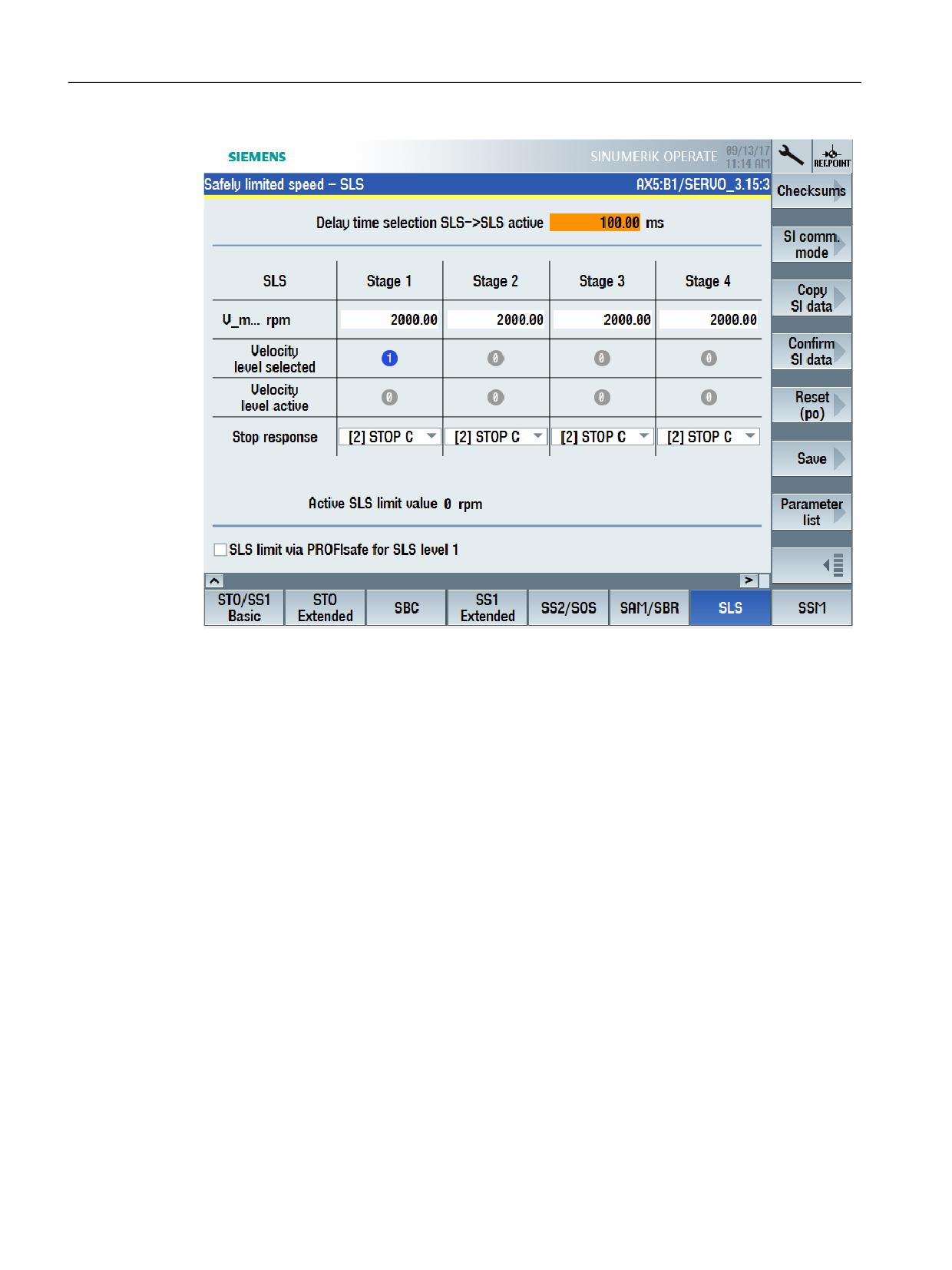
Figure 13-1
Selecting STOP E as stop response for SLS
SLS is acknowledged or deselected with STOP E in the safety program of the F-PLC by resetting
the corresponding bits in the drive addresses (via PROFIsafe telegram) - and additional safety-
related acknowledgment (PROFIsafe IEACK) along with a PROFIdrive reset.
See also: Acknowledgment (Page 331), Deselecting safety functions integrated in the drive
(Page 232).
For "SINUMERIK Safety Integrated plus", system variables $VA_STOPSI and $VA_STOPESI are also
supplied.
13.2.3
SG override
SINUMERIK Safety Integrated
"SINUMERIK Safety Integrated" allows up to 4 safety-related velocity values to be used. Safety-
related velocities SG2 and SG4 can also be assigned 16 different percentage values, so that 34
different velocity values are available for each axis.
SINUMERIK Safety Integrated plus
"SINUMERIK Safety Integrated plus" also has 4 safety-related velocity values. You can set these
4 values in the function-specific SINUMERIK Operate screen form.
In addition, the 1st safety-related velocity level can be assigned percentage values between 0
and 100% - to achieve a high level of granularity. To do this, in the associated screen form,
Safety Integrated plus
382
Commissioning Manual, 10/2020, 6FC5397-1FP40-6BA4

Switching over from SINUMERIK Safety Integrated
13.2 Comparison of the safety functions
activate option "SLS limit via PROFIsafe for SLS level 1" - and in the safety program, access the
corresponding bit using the PROFIsafe telegram.
This means that theoretically more than a 32,000 values can be defined.
13.2.4
Safe Cams
SINUMERIK Safety Integrated
Depending on the specific application, with "SINUMERIK Safety Integrated" you use safety
function "Safe software cams" or "Safe cam track".
• With "Safe software cams", up to 4 cam pairs are available for each axis. Here, the
precondition is that the axes involved are safely referenced.
• Alternatively, the "Safe Cam Track" function can be used, which can be used to evaluate a
total of 30 cams. Here, up to 4 cam tracks - with a maximum of 15 cams per cam track - are
available.
In both cases, you must configure the cams using the appropriate machine data or drive
parameters. SGA with information about the cams can be evaluated using Safe Programmable
Logic (SPL).
SINUMERIK Safety Integrated plus
"SINUMERIK Safety Integrated plus" facilitates the implementation of safe cams using two
different safety functions:
• Safety function SCA (Safe Cam) allows up to 30 safety-related cams per axis to be directly
configured in a function-specific SINUMERIK Operate screen form. To use this safety function,
you require process data S_ZSW_CAM1, which is only available in SIEMENS telegram 903.
• SP (Safe Position) allows safety-related position values to be transferred (process data
S_XIST32) in SIEMENS telegram 902. The safety-related position values can be evaluated in
the F-PLC safety program to implement safety-related cams.
13.2.5
Parameterizing EMERGENCY STOP
For EMERGENCY STOP shutdowns, for "SINUMERIK Safety Integrated", the PLC basic program
block "SI_relay [FB10]" was used in conjunction with the corresponding NC SPL syntax for SI relay.
For example, when actuating an EMERGENCY STOP pushbutton, a STOP C or STOP D can be
initiated with delayed STOP A. The same EMERGENCY STOP shutdown operations can also be
implemented for "SINUMERIK Safety Integrated plus":
Table 13-2
Examples of parameterizable EMERGENCY STOP shutdown operations in SINUMERIK Safety
Integrated and SINUMERIK Safety Integrated plus
SINUMERIK Safety Integrated
SINUMERIK Safety Integrated plus
Ext. Stop C → Δt → STOP A
SS1
Ext. Stop D → Δt → STOP A
SS2e → Δt → STO
Safety Integrated plus
Commissioning Manual, 10/2020, 6FC5397-1FP40-6BA4
383
Switching over from SINUMERIK Safety Integrated
13.2 Comparison of the safety functions
Further, for "SINUMERIK Safety Integrated", external I/O were able to be shut down in a safety-
related fashion using an SI relay.
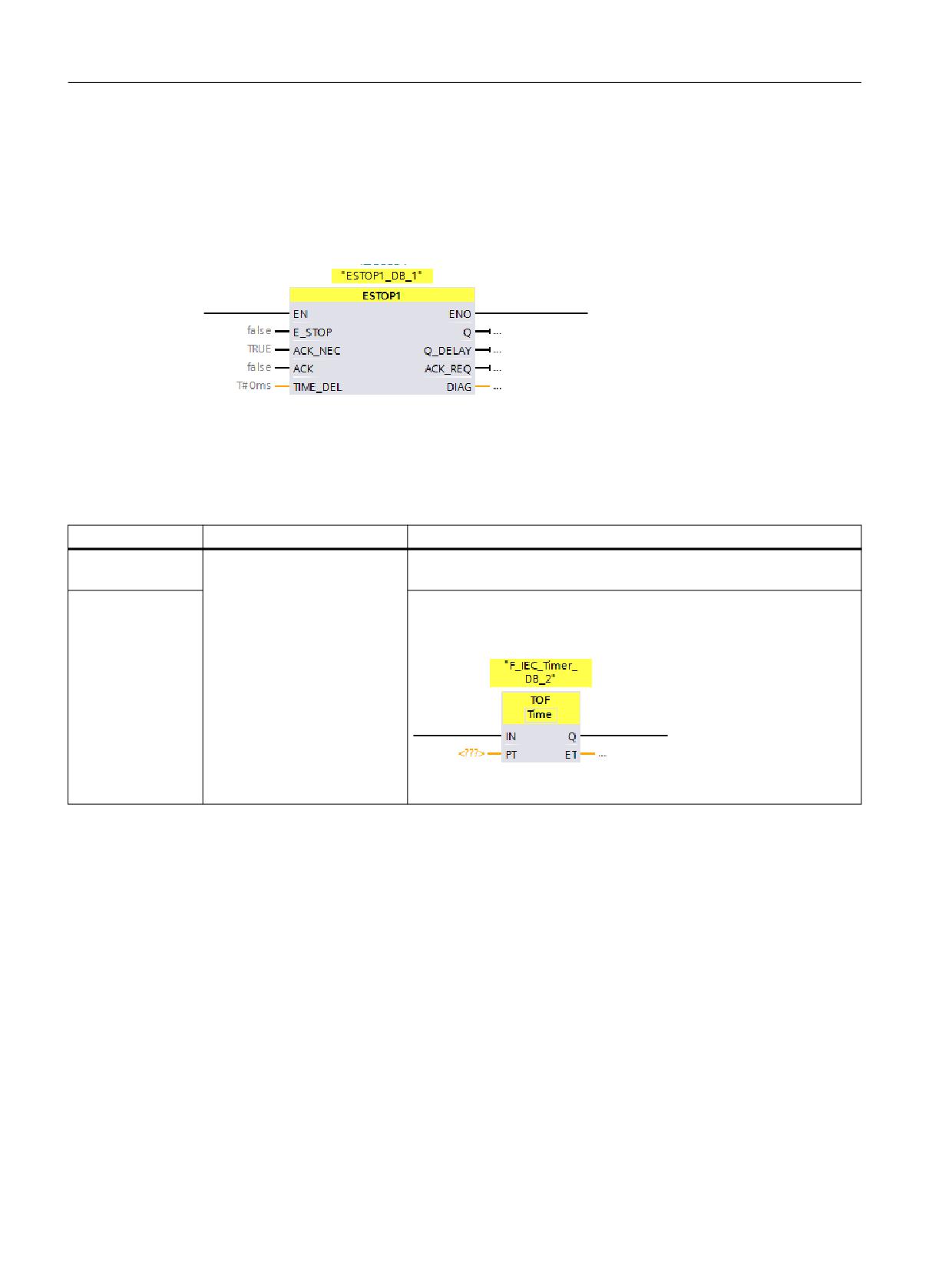
Instead, for "SINUMERIK Safety Integrated plus", the certified ESTOP1 instruction is available.
Instruction ESTOP1 can be used to control the required stopping requirements in SINAMICS
Safety Integrated as well as the F-I/O.
The following differences exist when parameterizing the switch-off delay time of the
EMERGENCY STOP signal:
Table 13-3
Parameterizing the delay time of the EMERGENCY STOP signal
Delay time
SINUMERIK Safety Integrated
SINUMERIK Safety Integrated plus
Drive components
The safety relay block has 3
Parameterize the switch-off delay time directly in the SINUMERIK Oper-
timers for different delay times.
ate screen form for the corresponding safety function.
F-I/O
You can specify 1 time in parameter Q_DELAY of the ESTOP1 operation.
You can use the TOF operation for each additional delay time that is
required.
Safety Integrated plus
384
Commissioning Manual, 10/2020, 6FC5397-1FP40-6BA4

Switching over from SINUMERIK Safety Integrated
13.3 Additional differences when commissioning
13.3
Additional differences when commissioning
13.3.1
Overview
Several commissioning steps and functions of "SINUMERIK Safety Integrated plus" are
subsequently compared with the corresponding functions of "SINUMERIK Safety Integrated".
Commissioning step
SINUMERIK Safety Integrated
SINUMERIK Safety Integrated plus (F-PLC)
(SPL)
Maximum number of axes that are
31 axes per NCU, of which, a maxi-
31 axes per NCU, of which, a maximum of 4 can
supported
mum of 6 can be connected to one
be connected to one DRIVE CLiQ line.
DRIVE CLiQ line.
See also: Interconnecting DRIVE-CLiQ compo-
nents (Page 33)
Commissioning the F-I/O
Configuring in STEP 7 and parame-
Configuring and parameterizing the F-I/O in
terizing - partially redundantly - in
STEP 7 (TIA Portal).
STEP 7 and in SINUMERIK Operate
See: Commissioning the F-I/O (Page 386)
using machine data.
Commissioning the safety functions
Commissioning in SINUMERIK Oper-
SI drives and drive-integrated safety functions
ate using machine data that can be
are commissioned using function-specific
filtered and in some instances using
screen forms in SINUMERIK Operate
function-specific screen forms.
See: Parameterizing the safety functions
(Page 389)
Programming the safety logic
Redundant programming as NC-SPL
The complete safety program is programmed in
program (SAFE.SPF) and PLC-SPL
the TIA Portal using the operating concepts
program.
known from standard PLC user programs. LAD
and FBD programming languages are used with
a scope of operations adapted to F-blocks.
F-I/O are accessed using system var-
F-I/O and drive telegrams are accessed via the
iables or data block "SPL [DB18]";
process image in the safety program and PLC
safety functions of the drives are ac-
user program. Some system variables are also
cessed (axis-specific SGE/SGA) via
used.
system variables or axis-DBs
See: Accessing status/control information
(Page 394)
Accessing status/control signals
Access is mainly realized via axis/
Access to process data of the telegrams, the
channel DB, SPL [DB18] and NC/
process image and F-I/O DB.
system variables.
See: Accessing status/control information
(Page 394)
Fault response to F-I/O faults
A fault message is displayed fol-
A fault message is displayed, the stop response
lowed by a stop response for all axes
has to be configured depending on the specific
situation.
Configuring a fault response to com-
Passivation, provision of substitute
Passivation of the F-I/O or drive components in-
munication faults/errors
values for FSEND/FRECV, system-re-
volved, provision of substitute values (FSEND/
lated STOP D/E response can be par-
FRECV), additional response can be configured.
ameterized, additional response can
See: Fault response and acknowledgment for F-
be configured.
I/O faults (Page 392)
Safety Integrated plus
Commissioning Manual, 10/2020, 6FC5397-1FP40-6BA4
385

Switching over from SINUMERIK Safety Integrated
13.3 Additional differences when commissioning
Commissioning step
SINUMERIK Safety Integrated
SINUMERIK Safety Integrated plus (F-PLC)
(SPL)
Acknowledging after a communica-
User acknowledgment using inter-
User acknowledgment by configuring an ac-
tion faults/errors
face signal DB18.FRDP_ACK_REI -
knowledgment button with assignment to the
and via a channel_1 reset.
corresponding F-I/O DB variable ("ACK_GL" or
"ACK_GLOB") and channel_1 reset (PROFIdrive
reset).
See: Fault response and acknowledgment for F-
I/O faults (Page 392)
See also: Implementing user acknowledgment
for global reintegration (Page 228).
Evaluating alarms using the NC
The NC checks safety alarms, and if
As Safety Integrated plus uses the safety func-
necessary suppresses an alarm, pri-
tions integrated in the drive, the NC does not
oritizes an alarm - or checks alarm
suppress alarms, prioritize alarms or check
numbers.
alarm numbers of safety messages of the drive.
See also: General information about
displaying and evaluating diagnos-
tic information (Page 317)
13.3.2
Commissioning the F-I/O
SINUMERIK Safety Integrated
Initially, you configure and parameterize the F-I/O in STEP 7. You then load the configuration to
the NCU, and also enter some settings in the machine data:
• F-source addresses (PROFIsafe addresses of the F-master)
• F-destination addresses (PROFIsafe addresses of the F-DI-/F-DO modules)
• Allocate symbolic names for F-modules (optional)
• Distribution of the computational load on the NC side
• Select F-user data signals to be transferred in the SPL (F-user data filter)
• Assign F-user data signals to be transferred to the SPL-SGE/SGA
SINUMERIK Safety Integrated plus
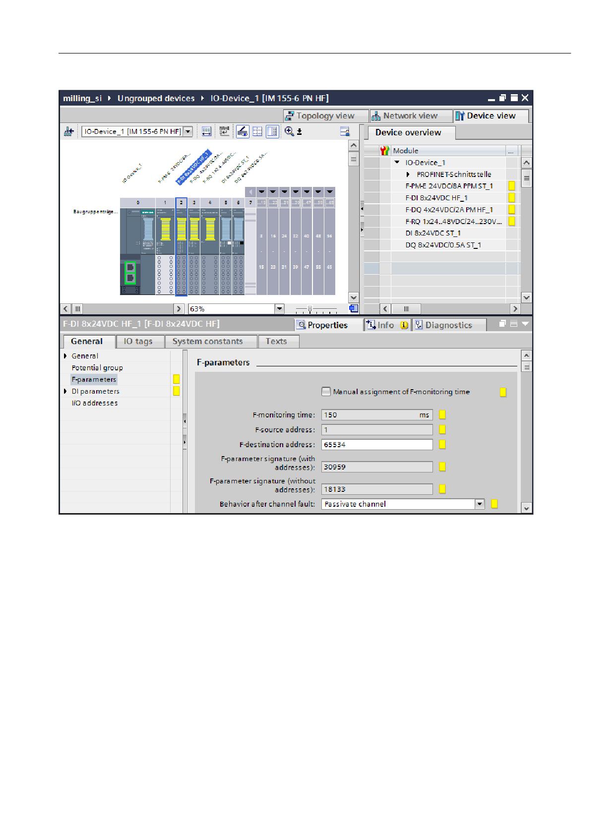
You configure and parameterize the F-I/O completely in STEP 7 (TIA Portal).
Safety Integrated plus
386
Commissioning Manual, 10/2020, 6FC5397-1FP40-6BA4
Switching over from SINUMERIK Safety Integrated
13.3 Additional differences when commissioning
Figure 13-2
F-parameters of an F-DI
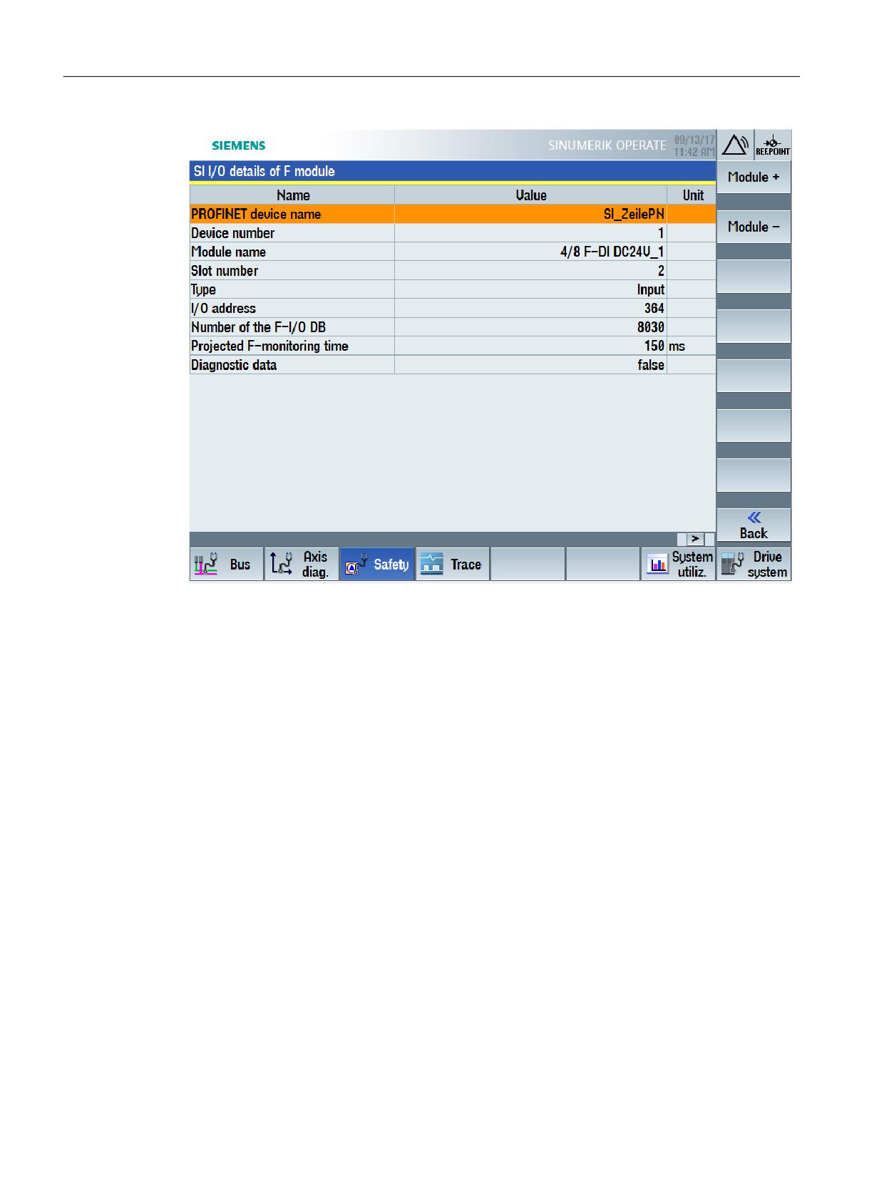
After you have loaded the configuration to the NCU, the F-I/O parameterization is automatically
accepted, and you can, for example, display detailed and diagnostic information relating to the
F-I/O directly in SINUMERIK Operate.
Safety Integrated plus
Commissioning Manual, 10/2020, 6FC5397-1FP40-6BA4
387
Switching over from SINUMERIK Safety Integrated
13.3 Additional differences when commissioning
Figure 13-3
Parameterization of an F-module taken from the TIA Portal configuration
Safety Integrated plus
388
Commissioning Manual, 10/2020, 6FC5397-1FP40-6BA4
Switching over from SINUMERIK Safety Integrated
13.3 Additional differences when commissioning
13.3.3
Parameterizing the safety functions
SINUMERIK Safety Integrated
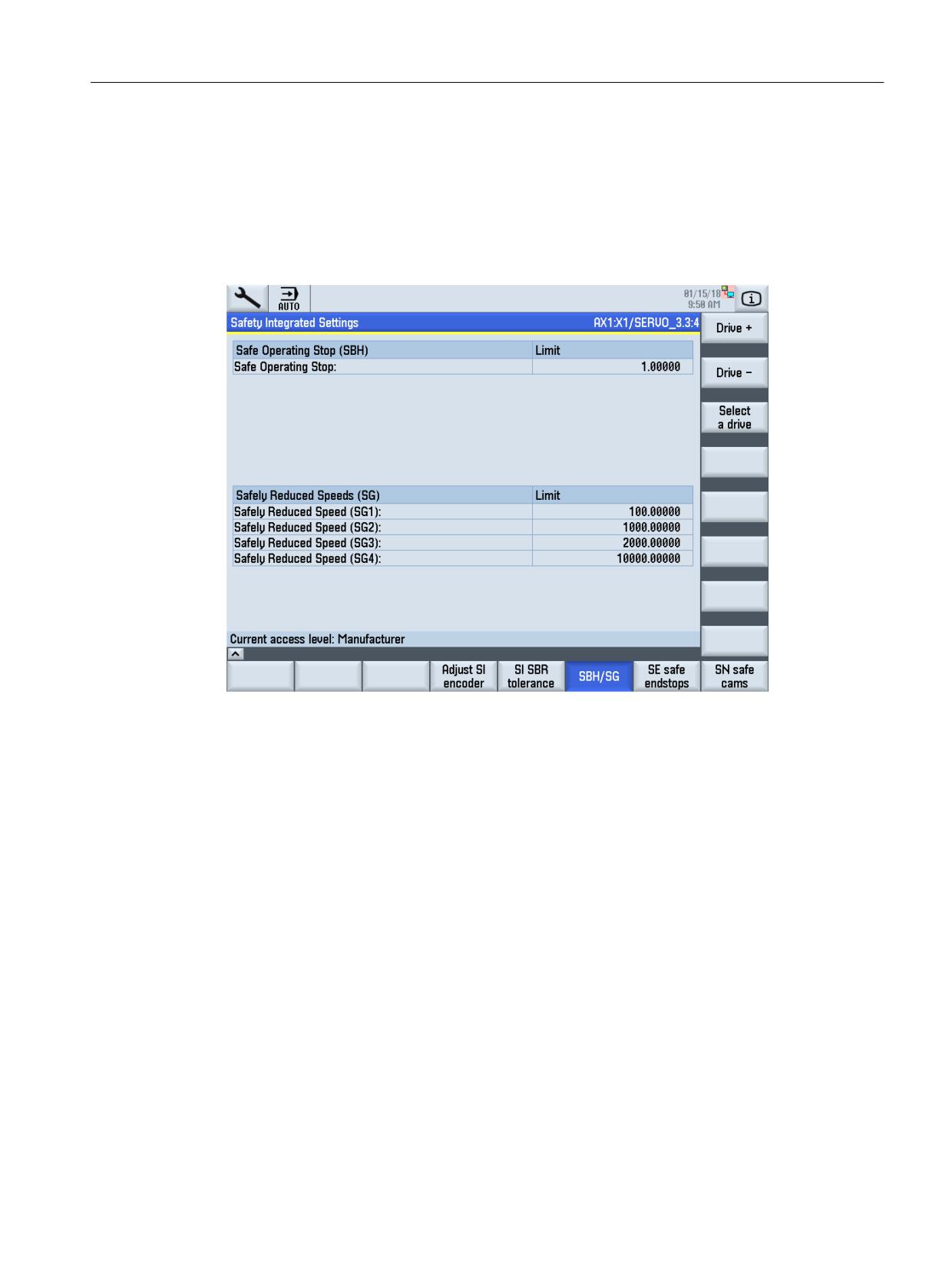
SINUMERIK Operate has function-specific (generally tabular) screen forms to enter some general
safety-related settings - as well as for the safety functions SBR, SBH/SG, SBC, safety-related end
positions and safety-related cams.
Figure 13-4
Parameterizing a safety function (SBH/SG)
Additional settings and safety functions should be configured in SINUMERIK Operate using
machine data and drive parameters that can be filtered.
Safety Integrated plus
Commissioning Manual, 10/2020, 6FC5397-1FP40-6BA4
389
Switching over from SINUMERIK Safety Integrated
13.3 Additional differences when commissioning
Figure 13-5
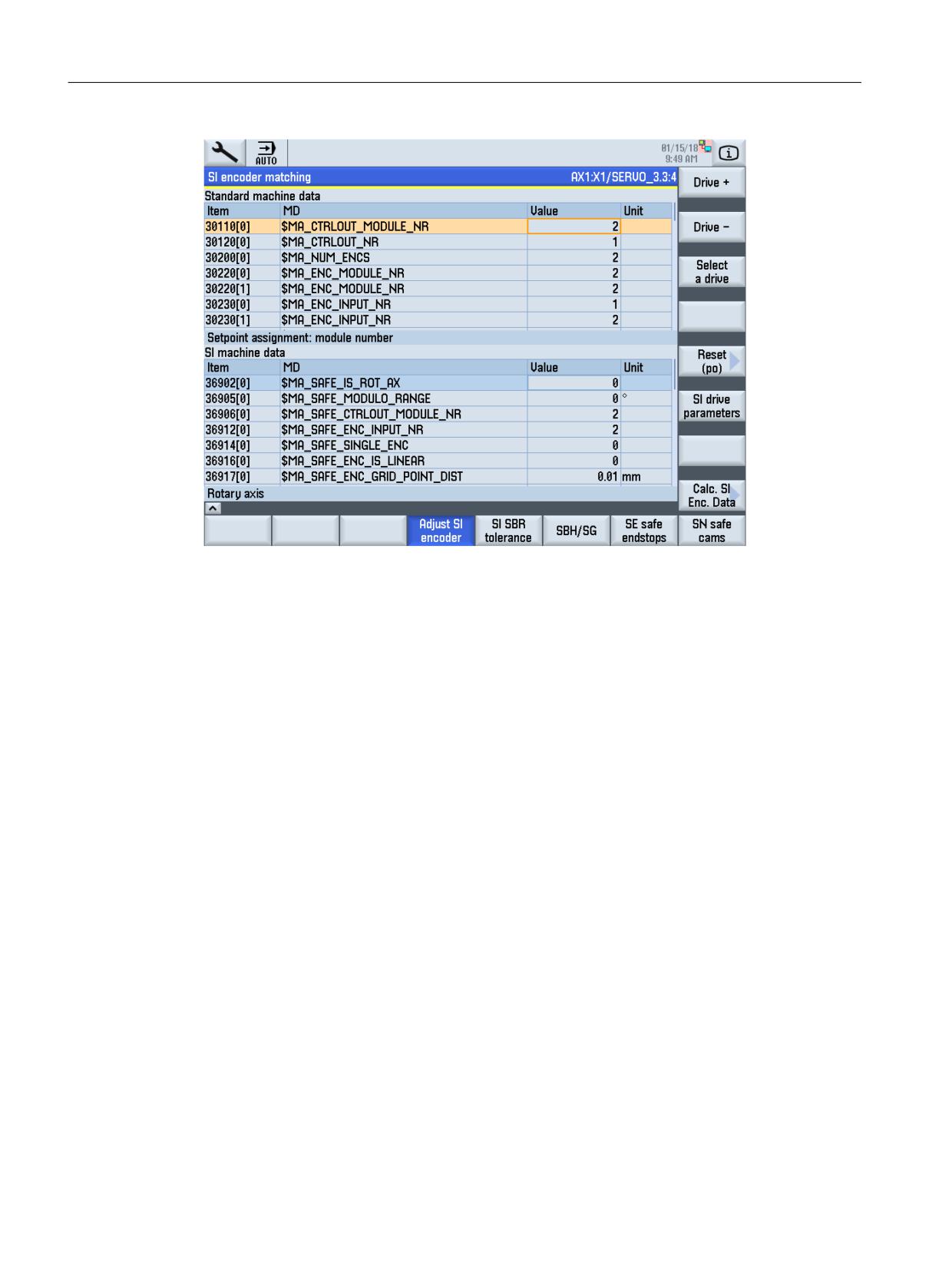
Parameterizing using machine data (SI encoder adaptation)
SINUMERIK Safety Integrated plus
All of the drive-integrated safety functions as well as higher-level or general settings can be
configured using function-specific graphic SINUMERIK Operate screen forms.
Safety Integrated plus
390
Commissioning Manual, 10/2020, 6FC5397-1FP40-6BA4
Switching over from SINUMERIK Safety Integrated
13.3 Additional differences when commissioning
Figure 13-6
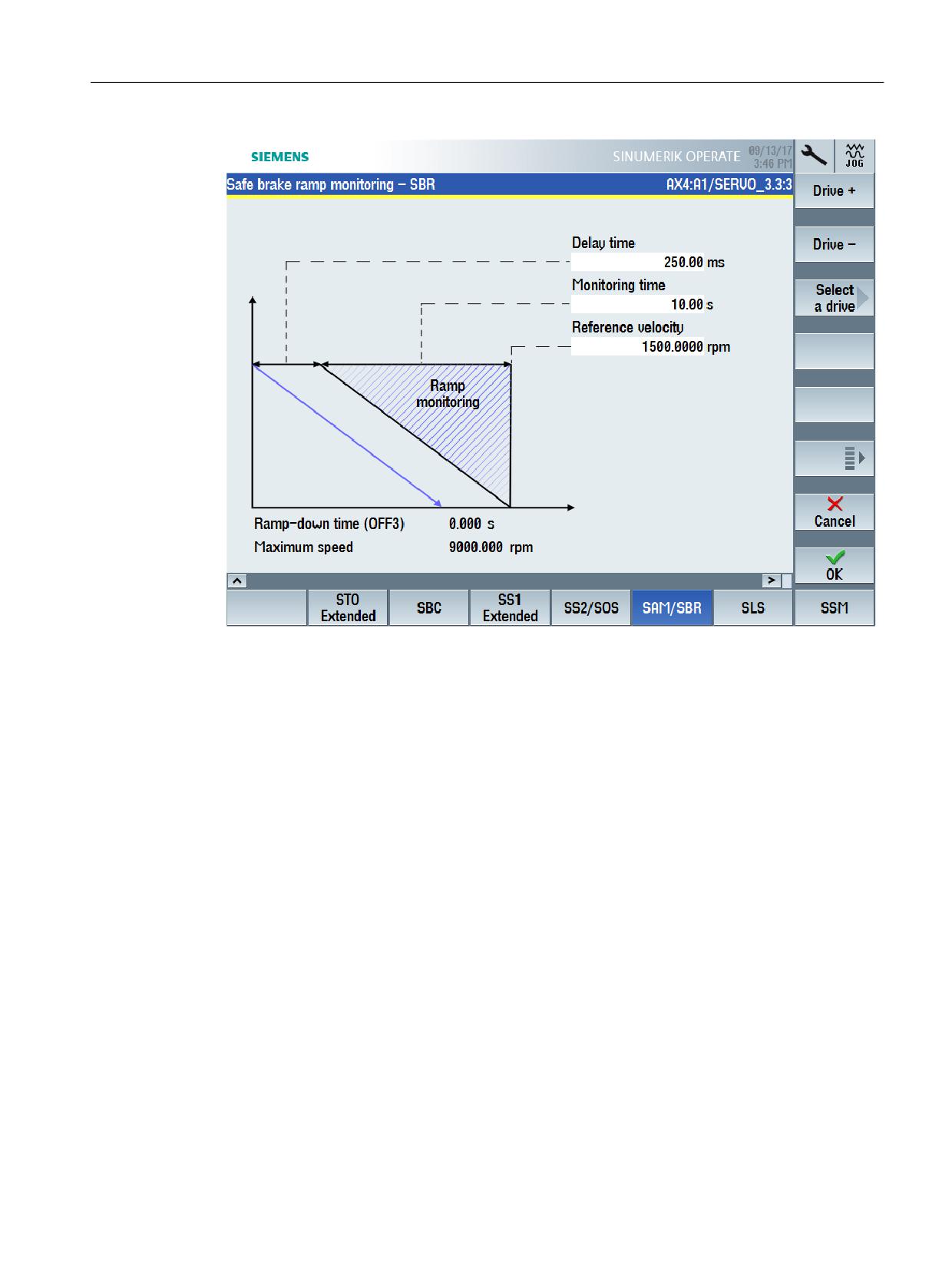
Parameterizing a safety function (SBR)
The "Recommended values" softkey is available as supplementary function; this allows
recommended values to be automatically calculated and entered. The basis for the calculated
recommended values is the corresponding equations to be taken into account for manual
parameterization.
Alternatively, all safety-related settings can be made in tabular expert lists ("Parameter list"
softkey), in which all parameters are listed which involve the corresponding safety function
Safety Integrated plus
Commissioning Manual, 10/2020, 6FC5397-1FP40-6BA4
391

Switching over from SINUMERIK Safety Integrated
13.3 Additional differences when commissioning
13.3.4
Fault response and acknowledgment for F-I/O faults
SINUMERIK Safety Integrated
In the context of "SINUMERIK Safety Integrated", F-I/O faults are identified by evaluating the
PROFIsafe status of F-I/O devices. A system response is initiated if such a fault occurs:
Error detected by
System response
Drive/NC-CDC
STOP F
SPL-CDC
STOP D/E
(Redundant configuration of the stop response to be initiated in the machine
data and in data block SPL [DB18].)
Communication CDC
The SGE/SGA involved are brought into a failsafe state (substitute values are
provided). Substitute values can be specified.
Additional system-specific responses can be configured by reading out
DB18.DBX119.5.
Generally, the system response can involve passivation of all of the F-I/O modules - or only those
of the channel involved. The cause of the fault must be removed and acknowledged in order to
remove the fault and to reset the system response.
SINUMERIK Safety Integrated plus
"SINUMERIK Safety Integrated plus" responds to F-I/O faults by providing substitute values, i.e.
passivation is realized.
Safety Integrated plus
392
Commissioning Manual, 10/2020, 6FC5397-1FP40-6BA4
Switching over from SINUMERIK Safety Integrated
13.3 Additional differences when commissioning
The following options exist to adapt and supplement the response:
• Passivate all of the F-I/O modules - or only those of the channel involved.
• Reintegration (depassivation) of the F-I/O automatically, depending on the configuration,
with a user acknowledgment.
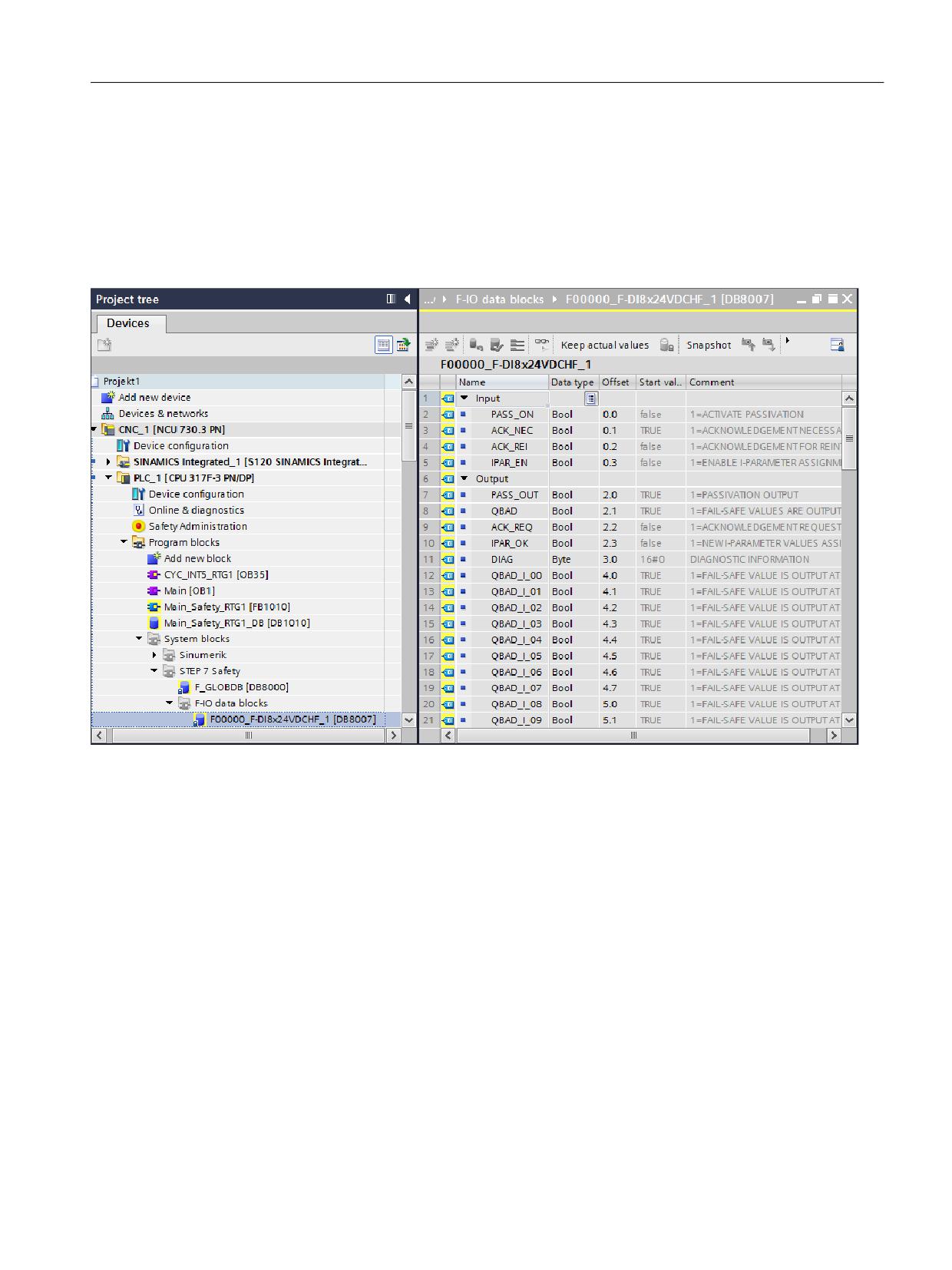
• In addition, each F-I/O has its own F-I/O DB. This means that you can access status
information and program user-specific system responses.
Figure 13-7
Example of an F-I/O DB
Additional information
• Implementing user acknowledgment for global reintegration (Page 228)
• System alarms and diagnostic screens for F-PLC and F-I/O. (Page 302)
Safety Integrated plus
Commissioning Manual, 10/2020, 6FC5397-1FP40-6BA4
393

Switching over from SINUMERIK Safety Integrated
13.3 Additional differences when commissioning
13.3.5
Accessing status/control information
As the safety functions of the two safety operating modes are implemented using different
subcomponents, there are some fundamental differences regarding the control options:
Access from → to
SINUMERIK Safety Integrated
SINUMERIK Safety Integrated
plus
PLC program → F-I/O
SPL [DB18]
Process image
PLC program → drive
PLC program → safety function
Axis-specific signals for the sys-
Process data in telegrams (PROFI-
tem-integrated safety functions
safe, SIC/SCC)
PLC program → safety-related set-
in <axis DB>.DB22 … <axis
ting
DB>.DB125.
Axis-specific signals for drive-integrated safety functions in <axis
DB>.DB140 … <axis DB>.DB187 (mapped from SIC).
Control via terminals for drive-integrated safety functions (Basic
Functions)
∼ 20 NC variables
5 NC variables (mapped from SIC)
NC part program → safety func-
∼ 50 system variables
2 system variables (mapped from
tion
SIC)
NC part program → safety-rela-
ted setting
SINUMERIK Safety Integrated
For Safety Integrated, the basic PLC program automatically connects the I/O (F-user data) of an
F-module to the SPL interface in data block SPL [DB18]. It is not possible to connect them in a PLC
user program.
The safety functions are accessed on an axis-for-axis basis.
SINUMERIK Safety Integrated plus
For Safety Integrated plus, F-I/O and safety-related drive telegrams are accessed via the process
image, as is the case for the standard I/O. The PLC user program can access this status/control
information, therefore allowing functional expansions to be made.
Safety functions are accessed on an axis-for-axis basis.
Safety Integrated plus
394
Commissioning Manual, 10/2020, 6FC5397-1FP40-6BA4
Switching over from SINUMERIK Safety Integrated
13.4 Procedure when switching over between systems
13.4
Procedure when switching over between systems
The transition from "SINUMERIK Safety Integrated" to "SINUMERIK Safety Integrated plus" cannot
be carried out within the scope of an automatic migration of the existing safety functions.
• The safety-related program code used in the two safety modes differs significantly. This
relates to the programming language and operations - as well as the positions and/or blocks
from where the safety program can be called.
• Instead of the safety functions of "SINUMERIK Safety Integrated" integrated in the system, for
"SINUMERIK Safety Integrated plus", the drive-based safety functions of SINAMICS Safety
Integrated are used; although they are functionally comparable, they use different
parameters and values however.
However, the existing risk analysis and the safety concept can be used to create a new safety
program on this basis - and to configure the drive-integrated safety functions.
Fundamental approach when switching over
The procedure can be roughly split-up into the following steps:
1. Migrating a STEP 7 V5.x project to the TIA Portal
"SINUMERIK Safety Integrated plus" is supported from SINUMERIK STEP 7 toolbox V14 (TIA
Portal) and higher.
Information about migrating the standard components of a STEP 7 5.x project into the
TIA Portal is provided in the TIA Portal online help, search terms "Migrating SINUMERIK PLC
projects" and "Migrating PLC project".
2. Deleting components of the Safety Integrated (SPL) program from the TIA Portal project:
- Remove the access operations to SPL function blocks or functions - and to SPL data blocks
signals from your PLC user program.
(you can use the following commands to find these locations: "Cross-references" in the
shortcut menu of an SPL block, "Browse project" in the shortcut menu of the program
block folder)
- Delete the Safety Integrated (SPL) blocks used in the project:
SI_relay [FB10]
SI_BrakeTest [FB11]
SPL [DB18]
Additional blocks (e.g. test stop blocks "SI Pulse Teststop SL [FC264]", "SI External Stop SL
[FC265]")
3. Adapting the configuration (Page 214)
4. Setting the safety program (Page 223)
5. Commissioning safety functions integrated in the drive
- Comparison of the functions (Page 380)
- Configuring NC and drive-specific safety settings (Page 237)
- Safety functions integrated in the drive (Page 79)
Safety Integrated plus
Commissioning Manual, 10/2020, 6FC5397-1FP40-6BA4
395

Preface
Fundamental safety
1
instructions
2
Introduction
SINUMERIK
3
Acceptance test wizard
SINUMERIK 840D sl / ONE / MC (mit
SINAMICS S120)
Managing templates and
4
results
SINUMERIK Operate acceptance
test
5
Template editor
Function Manual
Actions for hardware
replacement and
6
modifications
7
Tips and tricks
A
Appendix
Valid for
SINUMERIK 840D sl, SW V4.94
SINUMERIK ONE, SW V6.14
SINUMERIK MC (with SINAMICS S120), SW V1.14
10/2020
6FC5397-3HP40-0BA1
Table of contents
Preface
3
1
Fundamental safety instructions
7
1.1
General safety instructions
7
1.2
Warranty and liability for application examples
8
1.3
Security information
9
2
Introduction
11
2.1
Purpose and requirements
11
2.2
Preconditions for the acceptance test
12
2.3
Documentation, data archiving and authorized persons
14
3
Acceptance test wizard
15
3.1
Introduction
15
3.2
SINUMERIK 828D/840D sl/ONE/MC - drive-based safety functions
21
3.2.1
Criteria for conducting an acceptance test
21
3.2.2
Acceptance test Wizard
22
3.2.3
Test types
24
3.2.3.1
Overview
24
3.2.3.2
Test type not required
26
3.2.3.3
Switch-off signal path
28
3.2.3.4
Function relations
28
3.2.4
Application example
29
3.2.4.1
Configuring and performing an acceptance test
29
3.2.4.2
Generating and saving an acceptance report/certificate
41
3.2.5
Acceptance test mode
42
3.2.6
Safety summary (TIA Portal)
44
3.2.6.1
Comparing Safety Programs
46
3.2.7
Manufacturer-specific configurations (slatw.ini)
48
3.3
SINUMERIK 840D sl - system-integrated Safety Functions
51
3.3.1
Criteria for conducting an acceptance test
51
3.3.2
Acceptance test Wizard
51
3.3.3
Test types
54
3.3.3.1
Overview
54
3.3.3.2
Test type not required
55
3.3.3.3
Switch-off signal path
57
3.3.3.4
Function relations
57
3.3.4
Application example
58
3.3.4.1
Configuring and performing an acceptance test
58
3.3.4.2
Generating and saving an acceptance report/certificate
69
3.3.5
Acceptance test mode
70
3.3.6
Manufacturer-specific configurations (slatw.ini)
71
SINUMERIK Operate acceptance test
Function Manual, 10/2020, 6FC5397-3HP40-0BA1
5
Table of contents
4
Managing templates and results
75
4.1
Customizing templates
76
4.1.1
Template editor
76
4.1.2
Customizing templates
76
4.1.3
Customizing template (SinuComNC)
77
4.2
Result file
78
4.3
Certificate template
81
4.4
Certificate
83
5
Template editor
85
5.1
Introduction
85
5.2
Working with the template editor
86
5.3
Example of SOS - Safe Operating Stop
88
6
Actions for hardware replacement and modifications
91
6.1
Necessity of a new acceptance test
91
6.2
Effect of the acceptance test for specific measures
93
6.2.1
Effects with SINUMERIK 828D Safety Integrated
93
6.2.2
Effects with SINUMERIK 840D sl Safety Integrated plus
94
6.2.3
Effects for SINUMERIK ONE Safety Integrated
97
6.2.4
Effects for SINUMERIK MC Safety Integrated
99
6.2.5
Effects with SINUMERIK 840D sl Safety Integrated (system-integrated)
101
7
Tips and tricks
105
A
Appendix
109
A.1
Example contents of the acceptance test
109
A.1.1
Overview
109
A.1.2
SINUMERIK 828D/840D sl/ONE/MC - drive-based safety functions
109
A.1.2.1
SINUMERIK 828D with Safety Integrated
109
A.1.2.2
SINUMERIK 840D sl with Safety Integrated plus
111
A.1.2.3
SINUMERIK ONE with Safety Integrated
113
A.1.2.4
SINUMERIK MC with Safety Integrated
115
A.1.3
SINUMERIK 840D sl - system-integrated safety functions
117
A.1.3.1
SINUMERIK 840D sl with Safety Integrated (system-integrated)
117
A.2
Documentation overview
119
A.3
Abbreviations
120
Index
125
SINUMERIK Operate acceptance test
6
Function Manual, 10/2020, 6FC5397-3HP40-0BA1

Fundamental safety instructions
1
1.1
General safety instructions
WARNING
Danger to life if the safety instructions and residual risks are not observed
If the safety instructions and residual risks in the associated hardware documentation are not
observed, accidents involving severe injuries or death can occur.
• Observe the safety instructions given in the hardware documentation.
• Consider the residual risks for the risk evaluation.
WARNING
Malfunctions of the machine as a result of incorrect or changed parameter settings
As a result of incorrect or changed parameterization, machines can malfunction, which in turn
can lead to injuries or death.
• Protect the parameterization against unauthorized access.
• Handle possible malfunctions by taking suitable measures, e.g. emergency stop or
emergency off.
SINUMERIK Operate acceptance test
Function Manual, 10/2020, 6FC5397-3HP40-0BA1
7
Fundamental safety instructions
1.2 Warranty and liability for application examples
1.2
Warranty and liability for application examples
Application examples are not binding and do not claim to be complete regarding configuration,
equipment or any eventuality which may arise. Application examples do not represent specific
customer solutions, but are only intended to provide support for typical tasks.
As the user you yourself are responsible for ensuring that the products described are operated
correctly. Application examples do not relieve you of your responsibility for safe handling when
using, installing, operating and maintaining the equipment.
SINUMERIK Operate acceptance test
8
Function Manual, 10/2020, 6FC5397-3HP40-0BA1
Fundamental safety instructions
1.3 Security information
1.3
Security information
Siemens provides products and solutions with industrial security functions that support the
secure operation of plants, systems, machines and networks.
In order to protect plants, systems, machines and networks against cyber threats, it is necessary
to implement - and continuously maintain - a holistic, state-of-the-art industrial security
concept. Siemens’ products and solutions constitute one element of such a concept.
Customers are responsible for preventing unauthorized access to their plants, systems,
machines and networks. Such systems, machines and components should only be connected to
an enterprise network or the internet if and to the extent such a connection is necessary and only
when appropriate security measures (e.g. firewalls and/or network segmentation) are in place.
For additional information on industrial security measures that may be implemented, please
visit
Siemens’ products and solutions undergo continuous development to make them more secure.
Siemens strongly recommends that product updates are applied as soon as they are available
and that the latest product versions are used. Use of product versions that are no longer
supported, and failure to apply the latest updates may increase customer’s exposure to cyber
threats.
To stay informed about product updates, subscribe to the Siemens Industrial Security RSS Feed
under
services/cert.html#Subscriptions).
Further information is provided on the Internet:
Industrial Security Configuration Manual (https://support.industry.siemens.com/cs/ww/en/
view/108862708)
WARNING
Unsafe operating states resulting from software manipulation
Software manipulations, e.g. viruses, Trojans, or worms, can cause unsafe operating states in
your system that may lead to death, serious injury, and property damage.
• Keep the software up to date.
• Incorporate the automation and drive components into a holistic, state-of-the-art industrial
security concept for the installation or machine.
• Make sure that you include all installed products into the holistic industrial security concept.
• Protect files stored on exchangeable storage media from malicious software by with suitable
protection measures, e.g. virus scanners.
• On completion of commissioning, check all security-related settings.
SINUMERIK Operate acceptance test
Function Manual, 10/2020, 6FC5397-3HP40-0BA1
9
Introduction
2
2.1
Purpose and requirements
The goal of the acceptance test is to check the correct parameterization and mode of operation
of the safety functions and to detect potential configuration errors or to document the
correctness of the configuration.
During the acceptance test, the limit values entered for all of the activated safety functions must
be violated so that the proper execution of the function can be checked and verified.
WARNING
Unwanted motion due to incorrect parameter changes
Changes to accepted safety functions may lead to faults or to unwanted motion and thus to
serious injuries or death.
• Perform a new acceptance test as soon as changes have been made to any of the safety
functions.
• Also create an appropriate acceptance report.
See also: Measures for hardware replacement & modifications (Page 91)
Responsibility for the acceptance test
The machine manufacturer is responsible for carrying out and documenting an acceptance test.
Examples of complete acceptance tests are provided in the Appendix (Example contents of the
acceptance test (Page 109)).
Use of the results of the acceptance tests for any other purpose is not permitted!
The values (e.g. distance, time) measured and the system behavior (e.g. initiation of a specific
stop) determined during the acceptance test are used for a plausibility check of the configured
safety functions. The recorded measured values are typical and are not worst-case values. They
represent the behavior of the machine at the time of measurement. These measurements
cannot be used to derive real values (e.g. maximum paths for over-travel).
Requirements laid down in the EC Machinery Directive and DIN EN ISO 13849-1
The requirements laid down in the EC Machinery Directive and DIN EN ISO 13849-1 mean that
machine builders (OEMs) are responsible in carrying out the following measures:
• Performing an acceptance test to check the safety-relevant functions and machine parts
• Documenting the acceptance test using an acceptance report, which lists the test results
SINUMERIK Operate acceptance test
Function Manual, 10/2020, 6FC5397-3HP40-0BA1
11

Introduction
2.2 Preconditions for the acceptance test
2.2
Preconditions for the acceptance test
Before you can perform an acceptance test, the following requirements must be met:
•
The commissioning and configuration have been completed.
Commissioning of the open-loop and closed-loop control must be completed, as e.g. the
over-travel distance may otherwise change as a result of a changed dynamic response of the
drive control.
Observe all of the warnings in the SIMATIC Safety Programming and Operating Manual
Note
Configuring and programming
The configuration and programming must be carried out as described in the associated
documentation.
• SINUMERIK 828D Safety Integrated, SINUMERIK 840D sl Safety Integrated plus,
SINUMERIK ONE Safety Integrated, SINUMERIK MC (only with SINAMICS S120) Safety
Integrated:
The F-PLC (for SINUMERIK 840D sl, SINUMERIK ONE, SINUMERIK MC only) or fail-safe I/O
must be configured in the hardware and network editor of the TIA Portal. F-blocks must
be created with the program editor of the TIA Portal.
For the system acceptance test, you must use the safety summary that was created as per
the documentation.
• SINUMERIK 840D sl Safety Integrated (system-integrated):
The fail-safe I/O and creation of the F-blocks must be configured in STEP 7 or in TIA Portal.
There is no safety summary.
No other procedures are permitted.
Note
Commissioning via SINUMERIK Operate required
The commissioning and parameterization of all of the drive-integrated safety functions and
associated settings to be used must be done via SINUMERIK Operate. Each SI function must
be tested and the results documented and signed in the acceptance report by an authorized
person.
No other procedures are permitted.
Note
System of units of NC
The acceptance test with SINUMERIK Operate can only be performed with the metric system
of units. Set the machine data MD10240 for the metric system of units of the NC to 1 (metric).
•
The machine is properly wired
SINUMERIK Operate acceptance test
12
Function Manual, 10/2020, 6FC5397-3HP40-0BA1
Introduction
2.2 Preconditions for the acceptance test
• All of the safety equipment (e.g. protective door monitoring devices, light barriers and
emergency limit switches or similar) are connected and ready for operation
• No one is lingering in the danger zone.
WARNING
Unexpected axis motion during the acceptance test
If a speed setpoint ≠ 0 is present, the active stop function SS2 is set, and the motor is at a
standstill (active SOS), the axis starts to move as soon as the acceptance test is activated. If
persons are in the danger zone, accidents causing death or severe injury can occur.
• Take suitable measures to ensure that nobody is in the danger zone during the
acceptance test.
SINUMERIK Operate acceptance test
Function Manual, 10/2020, 6FC5397-3HP40-0BA1
13
Introduction
2.3 Documentation, data archiving and authorized persons
2.3
Documentation, data archiving and authorized persons
Documentation
The results of the acceptance test as well as all hardware and software changes must be
documented in a suitable form (as an acceptance report).
Within the scope of the acceptance report, the alarm displays must be checked or the alarm logs
must be incorporated into the acceptance report.
The following changes are acquired using the "Safety logbook" function of SINAMICS S120 with
Safety Integrated. SINUMERIK Operate outputs the corresponding parameters in the acceptance
report.
• Functional changes are recorded in the checksum r9781[0]:
- Functional CRC of the motion monitoring functions (p9729[0..1]), axis-specific
- Functional cyclic redundancy checks of the basic safety functions integrated in the drive
(p9799, SI setpoint checksum SI parameters CU), axis-specific
- Functional CRC of the TM54F (p10005[0]), global (only relevant for SINUMERIK 828D)
- Enable drive-integrated functions (p9601), for each axis
• Hardware-dependent changes are recorded in the checksum r9781[1]:
- Hardware-dependent CRC of the motion monitoring functions (p9729[2]), for each axis
- Hardware-dependent CRC of the TM54F (p10005[1]), global (only relevant for
SINUMERIK 828D)
Archiving
In addition to the acceptance report, the following safety-related data must be archived:
• NC machine data (only for SINUMERIK 840D sl with Safety Integrated (integrated in the
system))
• Drive parameters
• Complete safety summary (for SINUMERIK 840D sl with Safety Integrated plus, for
SINUMERIK ONE with Safety Integrated, and for SINUMERIK MC with Safety Integrated)
Note: You create the safety summary in the TIA Portal.
• PLC project
The access right to SI parameters must be protected by a password. This procedure must be
documented in the acceptance report; the password itself must not appear there.
The acceptance report and all of the associated safety-related data must be kept in a safe place.
Authorized persons
Personnel from the machine manufacturer who, on account of their technical qualifications and
knowledge of the safety functions, are in a position to perform the acceptance test in the correct
manner, are authorized to carry out an acceptance.
The person that carries out the acceptance test must also sign the acceptance report.
SINUMERIK Operate acceptance test
14
Function Manual, 10/2020, 6FC5397-3HP40-0BA1

Acceptance test wizard
3
3.1
Introduction
Note
SINUMERIK MC with SINAMICS S120
SINUMERIK MC with SINAMICS S120 is configured with the SINUMERIK ONE Commissioning
Tool. The description of the acceptance test wizard applies analogously to the SINUMERIK ONE
Commissioning Tool.
This chapter describes the acceptance test wizard of SINUMERIK Operate. A distinction is made
here between the drive-based safety for SINUMERIK 828D, SINUMERIK 840D sl, SINUMERIK ONE,
and SINUMERIK MC and the system-integrated safety for SINUMERIK 840D sl.
The following table provides you an overview of the available test types, depending on the
respective SINUMERIK control systems.
Overview of the test types for drive-based safety
SINUMERIK control system
SINUMERIK
SINUMERIK ONE
SINUMERIK
840D sl
and
828D
SINUMERIK MC
Option package/Functions
Safety Integrated
Safety Integrated
Safety Integrated
plus
Basic functions
Safe Torque Off (STO)
x
x
x
Testing of the Safe Torque Off (STO) verifies the following
points for an axis/drive:
• Principle of operation of the hardware
• Wiring of the switch-off signal paths
• Assignment of the terminals for STO on the Control Unit
• STO grouping (if available)
• Parameterizing the STO function
In addition, the following points are verified if Safe Brake
Control (SBC) is configured for the axis/drive:
• Connecting the brake
• Principle of operation of the hardware
• Parameterizing the SBC function
• Forced checking procedure for the brake control
SINUMERIK Operate acceptance test
Function Manual, 10/2020, 6FC5397-3HP40-0BA1
15

Acceptance test wizard
3.1 Introduction
SINUMERIK control system
SINUMERIK
SINUMERIK ONE
SINUMERIK
840D sl
and
828D
SINUMERIK MC
Safe Stop 1 (SS1)
x
x
x
Testing of the SS1 - Safe Stop 1 (SS1) verifies the following
points for an axis/drive:
• Principle of operation of the hardware
• Wiring of the switch-off signal paths
• Assignment of the terminals for SS1 on the Control Unit
• SS1 grouping (if available)
• Parameterizing the SS1 function
In addition, the following points are verified if Safe Brake
Control (SBC) is configured for the axis/drive:
• Connecting the brake
• Principle of operation of the hardware
• Parameterizing the SBC function
• Forced checking procedure for the brake control
Extended Functions
Switch-off signal path
x
x
x
This test checks the switch-off signal paths for the drives with
Safety Integrated by way of a forced checking procedure
(forced dormant error detection).
Functional relationships
x
x
x
Functional relationships of the safety applications are
checked and documented with this test.
Position alignment
x
x
x
This test verifies the following points:
• Encoder evaluations of the SI monitoring channels corre-
spond with the positions of the higher-level control sys-
tem
• The motion direction of the machine (MCS) corresponds
to the motion direction of the monitoring channels (safe
actual positions)
SINUMERIK Operate acceptance test
16
Function Manual, 10/2020, 6FC5397-3HP40-0BA1

Acceptance test wizard
3.1 Introduction
SINUMERIK control system
SINUMERIK
SINUMERIK ONE
SINUMERIK
840D sl
and
828D
SINUMERIK MC
Safe Torque Off (STO)
x
x
x
Testing of the Safe Torque Off (STO) verifies the following
points for an axis/drive:
• Principle of operation of the hardware
• STO grouping (if available)
• Parameterizing the STO function
In addition, the following points are verified if Safe Brake
Control (SBC) is configured for the axis/drive:
• Connecting the brake
• Principle of operation of the hardware
• Parameterizing the SBC function
• Forced checking procedure for the brake control
Safe Stop 1 (SS1)
x
x
x
Testing of the SS1 - Safe Stop 1 (SS1) verifies the following
points for an axis/drive:
• Principle of operation of the hardware
• SS1 grouping (if available)
• Parameterizing the SS1 function
In addition, the following points are verified if Safe Brake
Control (SBC) is configured for the axis/drive:
• Connecting the brake
• Principle of operation of the hardware
• Parameterizing the SBC function
• Forced checking procedure for the brake control
Safe Stop 2 (SS2)
x
x
x
This test verifies the following points:
• Initiating Safe Stop 2 (SS2) is detected
• The associated axis/drive brakes
• Monitoring for Safe Operating Stop (SOS) for this axis/
drive is activated when the parameterized transition time
elapses
Safe Stop 2 External (SS2E)
x
x
-
Testing of the Safe Stop 2 External (SS2E) verifies the follow-
ing points for an axis/drive:
• Triggering of Safe Stop 2 External (SS2E) is detected
• The associated axis/drive brakes
• Monitoring for Safe Operating Stop (SOS) for this axis/
drive is activated, or a safe stop (STO) is initiated by the
application once the parameterized transition time has
elapsed
SINUMERIK Operate acceptance test
Function Manual, 10/2020, 6FC5397-3HP40-0BA1
17

Acceptance test wizard
3.1 Introduction
SINUMERIK control system
SINUMERIK
SINUMERIK ONE
SINUMERIK
840D sl
and
828D
SINUMERIK MC
Safe Stop 2 Extended Stop and Retract (SS2ESR)
x
x
-
Testing of the Safe Stop 2 Extended Stop and Retract
(SS2ESR) verifies the following points for an axis/drive:
• Triggering of Safe Stop 2 Extended Stop and Retract
(SS2ESR) is detected
• The associated axis/drive brakes
• Monitoring for Safe Operating Stop (SOS) for this axis/
drive is activated, or a safe stop (STO) is initiated by the
application once the parameterized transition time has
elapsed
Safe Operating Stop (SOS)
x
x
x
When the standstill tolerance for Safe Operating Stop (SOS)
is violated, the test verifies whether the following points oc-
cur:
• The drive is stopped
• Stop responses and alarms of both monitoring channels
are initiated
• Response times and over-travel comply with the require-
ments
Safely-Limited Speed (SLS)
x
x
x
This test checks whether an overshoot of the Safely Limited
Speed (SLS) is detected.
For SLS limit val-
For SLS limit val-
If a configured SLS limit value is exceeded, the configured
ue 1, an override
ue 1, an override
stop responses and alarms should be triggered for both mon-
can additionally be
can additionally be
itoring channels. The response times and over-travel should
specified via the
specified via the
comply with the requirements.
fail-safe PLC.
fail-safe PLC.
Safe Speed Monitor (SSM)
x
x
x
Testing the Safe Speed Monitor (SSM) verifies the following
points for an axis/drive:
• It is detected if the limit value of the Safe Speed Monitor
is exceeded
• A message is output
Safety Activation Test
x
x
-
This test checks and documents the functions of the safety
application. It checks how the active monitoring function of
the axis/drive relates to the relevant operating mode/sensor
technology.
All relevant signals must be described in an input and reac-
tion table. The required start and end signal states must be
specified when the signals are included in the table.
SINUMERIK Operate acceptance test
18
Function Manual, 10/2020, 6FC5397-3HP40-0BA1

Acceptance test wizard
3.1 Introduction
SINUMERIK control system
SINUMERIK
SINUMERIK ONE
SINUMERIK
840D sl
and
828D
SINUMERIK MC
Safely-Limited Position (SLP)
x
x
x
This test verifies the following points:
• It is detected if the upper or lower limit value of the Safely-
Limited Position (SLP) is exceeded
• The monitoring limit values for SLP correspond with the
required machine positions
• The configured stop responses and alarms of both moni-
toring channels are initiated when an SLP limit value is
violated (exceeded or fallen below)
Safe Brake Test (SBT)
x
x
x
The Safe Brake Test (SBT) diagnostic function verifies wheth-
er the brake is functioning correctly and that the required
holding torque is observed.
SCA Safe Cam
x
x
-
The SCA acceptance test must be performed separately for
each axis/drive. Plus and minus cams must be checked inde-
pendently of each other.
Safe Direction (SDI)
x
x
x
Testing the Safe Direction (SDI) verifies for an axis/drive
whether the following points occur when the configured SDI
tolerance is exceeded in the blocked direction:
• The drive is stopped
• Configured stop responses and alarms of both monitor-
ing channels are initiated
• Response times and over-travel comply with the require-
ments
Overview of the test types for system-integrated safety
SINUMERIK control system
SINUMERIK 840D sl
Option package/Functions
Safety Integrated (system-inte-
grated)
Switch-off signal path
x
This test checks the switch-off signal paths for the drives with Safety Integrated by way
of a forced checking procedure (forced dormant error detection).
Functional relationships
x
Functional relationships of the safety applications are checked and documented with
this test.
External stops
x
This test checks whether all applied external stops are tested separately in the drive and
NCK is tested by way of a forced checking procedure (forced dormant error detection).
SINUMERIK Operate acceptance test
Function Manual, 10/2020, 6FC5397-3HP40-0BA1
19

Acceptance test wizard
3.1 Introduction
SINUMERIK control system
SINUMERIK 840D sl
SPL inputs/outputs
x
This test checks whether the I/O actuated by the SPL inputs/outputs are tested by way of
a forced checking procedure, an error is detected and the alarms and reactions desig-
nated for an error are triggered.
Emergency Stop
x
This test checks the response of the EMERGENCY STOP function for axes if the EMER-
GENCY STOP response was implemented via the external stops of the safe programma-
ble logic (SPL).
Safe Brake Test (SBT)
x
The Safe Brake Test (SBT) function verifies whether the brake is functioning correctly and
that the required holding torque is observed.
Safe Operating Stop (SBH)
x
When the standstill tolerance is exceeded for the Safe Operating Stop (SBH), this test
verifies whether the following points occur:
• The drive is stopped
• Stop responses and alarms of both monitoring channels are initiated
• Response times and over-travel comply with the requirements
Safely reduced speed (SG)
x
This test verifies that the system detects when "Safely reduced speed" (SG) is exceeded.
Safe software limit switches (SE)
x
This test verifies the following points:
• It is detected if the upper or lower limit value of the safe software limit switch (SE) is
exceeded
• The monitoring limit values for SE correspond to the required machine positions
• The configured stop responses and alarms of both monitoring channels are initiated
when an SE limit value is violated (exceeded or fallen below)
SINUMERIK Operate acceptance test
20
Function Manual, 10/2020, 6FC5397-3HP40-0BA1
Acceptance test wizard
3.2 SINUMERIK 828D/840D sl/ONE/MC - drive-based safety functions
3.2
SINUMERIK 828D/840D sl/ONE/MC - drive-based safety functions
3.2.1
Criteria for conducting an acceptance test
The criteria for performing an acceptance test are obtained from the requirements laid down in
the specified directives and standards. The acceptance test is used to specifically check that all
safety, monitoring and stop functions - which are used in the NCK, PLC and drive - have been
correctly configured:
• Check the hardware configuration for completeness, correctness, and mode of operation
• Testing of safety program (not for 828D)
- Agreement of the elements of the system library used in the safety program with the TÜV
certificate
- Correct functioning of the safety functions
- Consistency of the online safety program
• Test the safety functions integrated in the drive
- Testing of the implemented test mechanisms (forced checking procedure measures)
- Provoking of the individual monitoring functions to respond by specifically violating
tolerance limits
• Test the communication
- Correctness of the communication configuration
- Correct functioning of the communication relationships
• Test other properties
- Software versions
- NC machine data
- Drive parameters
- ...
During the acceptance test, standard NC monitoring functions (e.g. standstill monitoring or
software limit switches) are in some instances deactivated. The function sequences can be
captured and listed using the servo trace function or using the D/A converter output.
For acceptance of the plant, all relevant user-specific standards must be complied with. This also
applies to systems that do not legally require acceptance.
Additional information
• Details related to possible test/check criteria are provided in Chapter Example contents of the
acceptance test (Page 109).
• PFH values of the individual SINAMICS S120 safety components can be found in the SIOS
SINUMERIK Operate acceptance test
Function Manual, 10/2020, 6FC5397-3HP40-0BA1
21
Acceptance test wizard
3.2 SINUMERIK 828D/840D sl/ONE/MC - drive-based safety functions
• PFH and PFD
avg
values from F-CPUs, fail-safe I/O and SIMATIC components can be found in the
The values of SIMATIC CPU 317F-2 PN/DP apply for the integrated F-PLC 317F-3 PN/DP.
• Specific information regarding how you can identify and document the correctness of the
properties or components involved is provided in the SIMATIC Safety manual.
Programming and Operating Manual - SIMATIC Safety - Configuring and Programming
• When conducting the acceptance test, you must carefully observe the regulations in the
report associated with the certificate:
Annex 1 of the Report to the Certificate for SIMATIC Safety System (https://
support.industry.siemens.com/cs/ww/en/view/57141289)
3.2.2
Acceptance test Wizard
SINUMERIK Operate has an acceptance test wizard, which uses specific input screens to guide
the person authorized by the machine manufacturer through the acceptance test. After all of the
relevant data has been entered and the test cases are concluded, a log template is generated,
which must be completely filled in, checked, and signed. You can find examples of a complete
acceptance test in the annex Example contents of the acceptance test (Page 109).
The acceptance test integrated in SINUMERIK Operate, is used to support the user (test
engineer) for the following tasks as part of an acceptance test:
• Coordination and execution of SI function tests
• Generation of a certificate (Page 83) (acceptance report) to document the state of all SI-
relevant functions when the equipment is shipped.
Note
Automation
In compliance with the relevant directives, the result status of a test (successful/not successful)
must be determined by the user. As a consequence, the acceptance test cannot be completely
automated.
The acceptance test can be modified in the template editor of the acceptance test wizard. For
instance, you can define test cases and default settings for a certain machine type.
SINUMERIK Operate acceptance test
22
Function Manual, 10/2020, 6FC5397-3HP40-0BA1
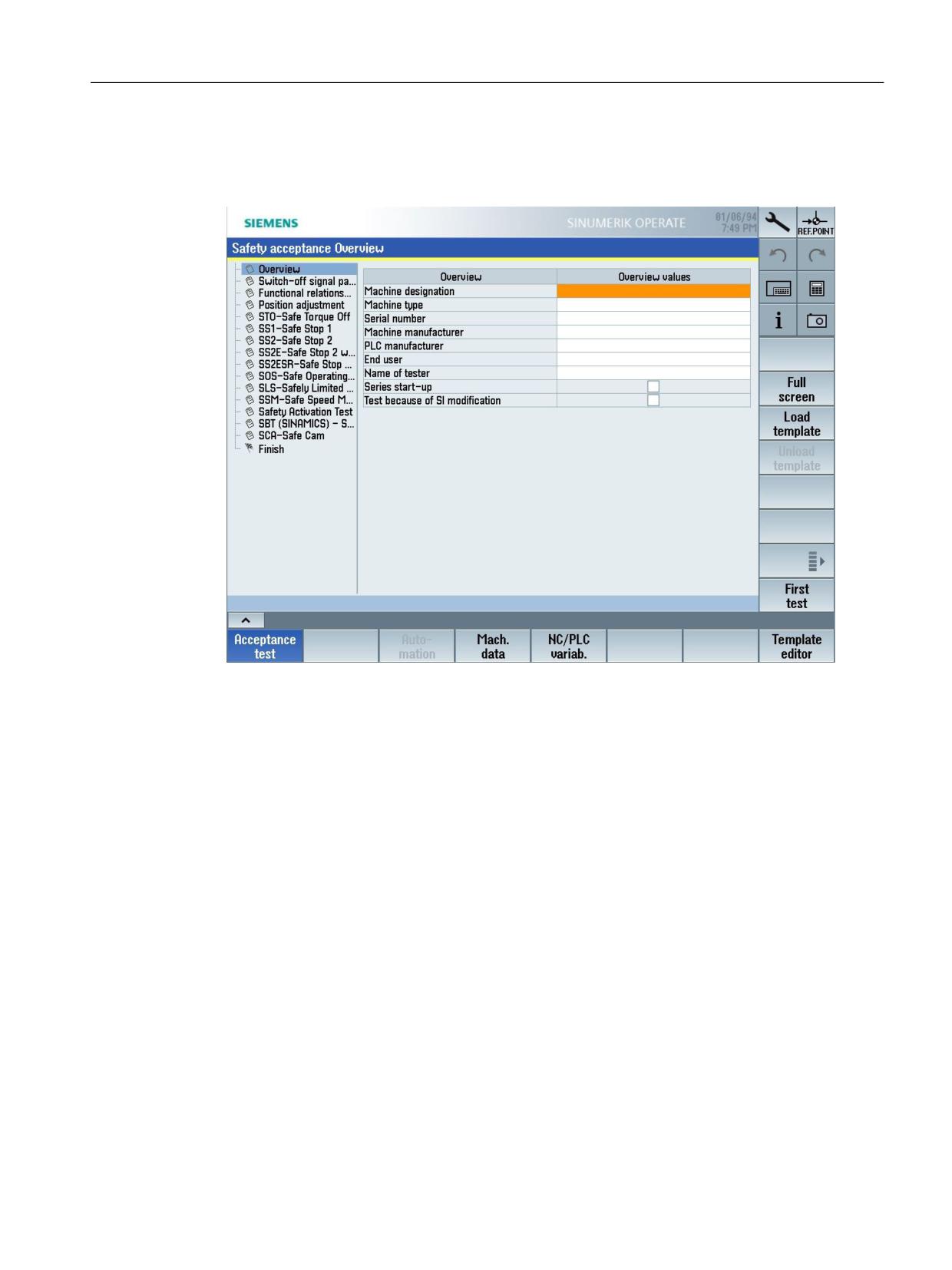
Acceptance test wizard
3.2 SINUMERIK 828D/840D sl/ONE/MC - drive-based safety functions
Calling the acceptance test wizard
MENU SELECT > Commissioning > Safety > Acceptance test
Figure 3-1
SINUMERIK Operate - Acceptance test wizard (example)
Descriptions of the individual test cases and information to be entered in the acceptance test
wizard can be found directly in the respective input screens.
Working with the acceptance test wizard
With the acceptance test, tests can be carried out with safety functions integrated in the system
(SINUMERIK Safety Integrated) as well as for axes with safety functions integrated in the drives
(SINAMICS Basic and Extended Functions). The test results for both versions are included in the
certificate that is finally generated.
Available test types/setting ranges
In the left-hand section of the acceptance test basic screen, the test types (switch-off signal path,
function relationships, STO, SS1, SOS, etc.) of the SI functions, currently configured in the
system, are displayed in a selection list. Test instances can only be created for these - or tests
carried out for these.
Access rights
In order that the acceptance test can be started, for all of the components within the scope of
the SI functions to be tested (NC, drive) access rights that permit changes to be made to machine
data and parameters must be active.
SINUMERIK Operate acceptance test
Function Manual, 10/2020, 6FC5397-3HP40-0BA1
23
Acceptance test wizard
3.2 SINUMERIK 828D/840D sl/ONE/MC - drive-based safety functions
Special cases
Gantry axes
As part of an acceptance test, when compared to "standard" SI axes, gantry axes are not handled
in a special way, and are also not specifically designated in the acceptance test user interface.
The following supplementary conditions must be observed:
• Every SI axis of a gantry group is individually tested.
• If it is necessary for a following axis to be traversed for a test, then the leading axis must also
be traversed.
• If the acceptance test mode has to be active when testing an axis of a gantry group, then the
acceptance test mode is active for all SI axes of the gantry group.
Leading/following axes
In the acceptance test, leading/following axes are not handled in a special way that is different
from "standard" SI axes, and are also not specifically identified in the acceptance test user
interface.
The following supplementary conditions must be observed:
• Every SI axis of a leading/following axis group is individually tested.
• If a following axis has to be traversed for a test, the leading axis must also be traversed.
• If the acceptance test mode has to be active when an axis of a leading/following group is
tested, the acceptance test mode is active for all SI axes of the leading/following group.
3.2.3
Test types
3.2.3.1
Overview
The "Overview" setting area is automatically activated after the acceptance test function is
called. In this setting area, you can either manually enter the required overview values, or load
the content of a template ("Load template" softkey) to the setting area.
The following overview values can be entered:
SINUMERIK Operate acceptance test
24
Function Manual, 10/2020, 6FC5397-3HP40-0BA1
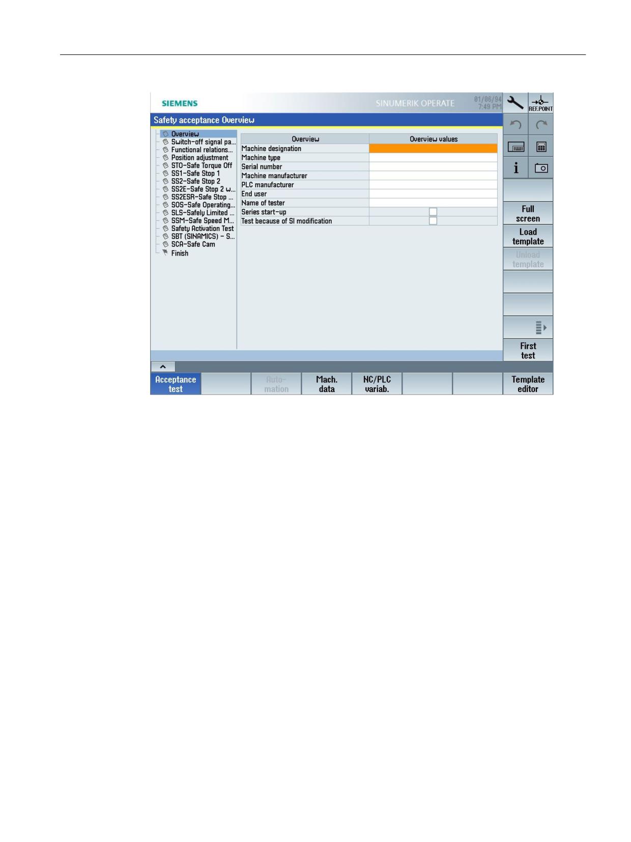
Acceptance test wizard
3.2 SINUMERIK 828D/840D sl/ONE/MC - drive-based safety functions
Figure 3-2
Test type/setting area overview
Series commissioning
If you set the check mark in the "Overview" setting area for "Series commissioning" under the
overview values, this has no effect in terms of function. This entry is for information purposes
only.
Test as a result of an SI change
If you set the checkmark in the setting area "Overview" for "Test as a result of an SI change" under
the overview values, then this has no effect from a functional perspective.
SINUMERIK Operate acceptance test
Function Manual, 10/2020, 6FC5397-3HP40-0BA1
25
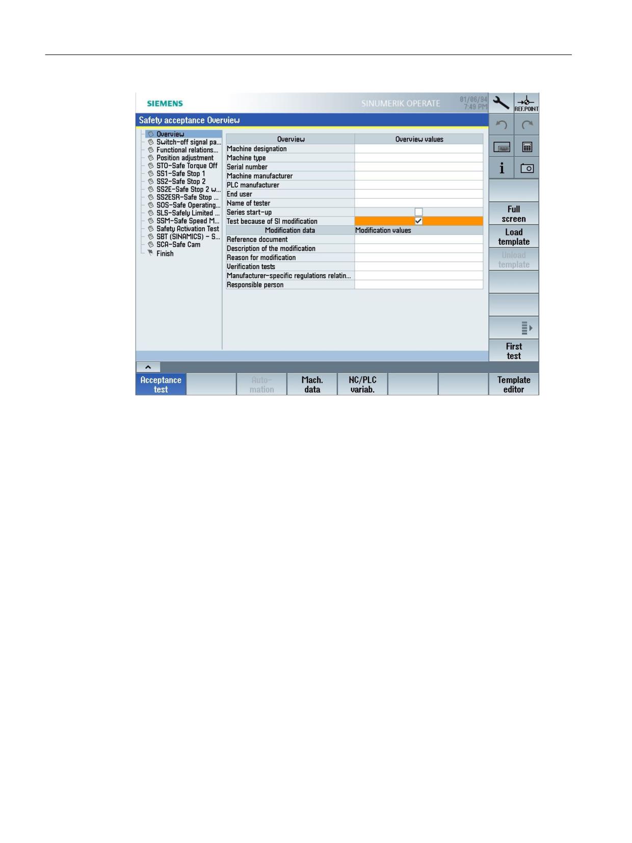
Acceptance test wizard
3.2 SINUMERIK 828D/840D sl/ONE/MC - drive-based safety functions
Figure 3-3
Test as a result of an SI change - change values
Here, you document the changes:
• Description of the change
• Reason for the change
• Verification tests required
• Manufacturer-specific regulations taken into account
• Responsibility
3.2.3.2
Test type not required
An acceptance test can be carried out for every safety function used on the machine. Not all of
the Safety functions listed in the dialog are used on the machine. Therefore, in the acceptance
test wizard, you can set the acceptance test (test type) for individual Safety Functions to not
required.
A test can be predefined using a customizing template. You can also hide test types from the
customized template as required.
SINUMERIK Operate acceptance test
26
Function Manual, 10/2020, 6FC5397-3HP40-0BA1
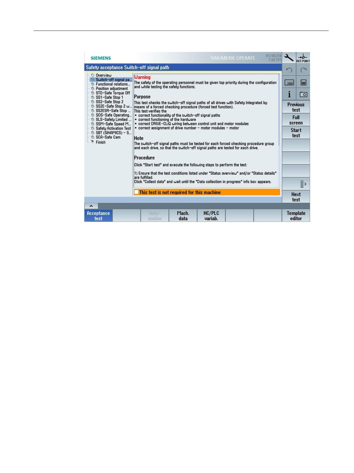
Acceptance test wizard
3.2 SINUMERIK 828D/840D sl/ONE/MC - drive-based safety functions
Figure 3-4
Setting the test type to not required
If the test type is not required, set the checkmark for "This test is not required for this machine".
Press the "Next test" softkey.
This information is listed in the certificate accordingly.
SINUMERIK Operate acceptance test
Function Manual, 10/2020, 6FC5397-3HP40-0BA1
27
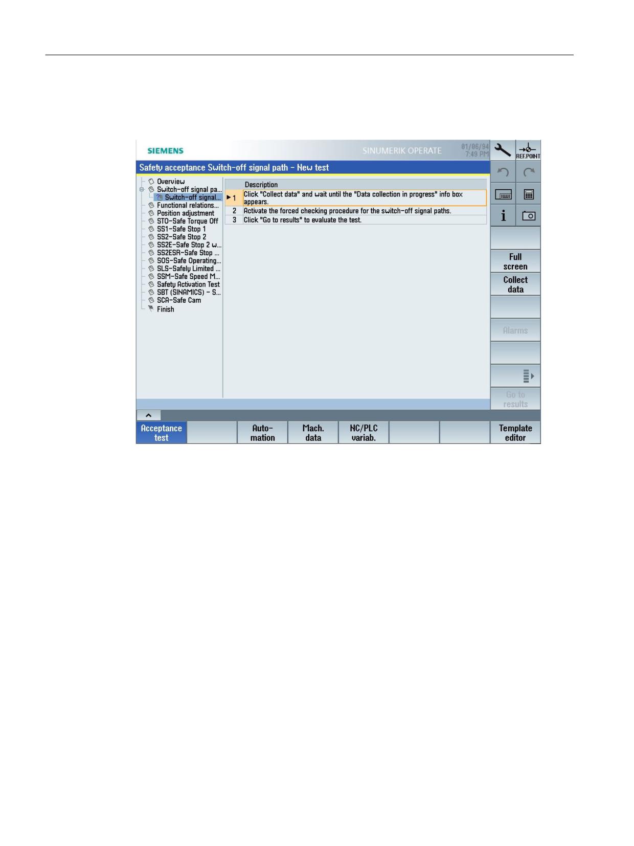
Acceptance test wizard
3.2 SINUMERIK 828D/840D sl/ONE/MC - drive-based safety functions
3.2.3.3
Switch-off signal path
To test the switch-off signal paths, carefully follow the instructions in the detailed display.
Figure 3-5
Test type/setting range switch-off signal path
You can make the following settings here, for example:
• Enter conditions to initiate the test
• Select acquired alarms that should appear in the report
• Confirm a test result
3.2.3.4
Function relations
User-specific test cases for safety-related functions can be saved in test type "Function relations".
After the test case has started, the user executes the steps required at the system itself. He
observes the response/behavior, and documents the test result that has been monitored.
Example of a function to be tested
When the machining area door is opened, safety function "Safe Operating Stop" (SOS) must be
selected for all axes of mode group 1.
Trace
When creating a test instance, a user-defined trace can be activated, which documents the
signal characteristic of the signals that are relevant for the particular test case.
SINUMERIK Operate acceptance test
28
Function Manual, 10/2020, 6FC5397-3HP40-0BA1

Acceptance test wizard
3.2 SINUMERIK 828D/840D sl/ONE/MC - drive-based safety functions
The trace is parameterized using the standard SINUMERIK Operate function and saved as trace
template (XML file).
The trace template must be available in directory ...\safety\atw\trace so that the trace template
can be selected for a particular test case.
Table 3-1
File information
File name:
<name>.xml
Path:
...\user\sinumerik\hmi\data\safety\atw\trace
Note
Default path for the trace template: ...\user\sinumerik\hmi\data\trace
Axis-specific trace variables
The trace file is parameterized for a specific axis. Before you start recording, you can however
select another safety-related axis. The data associated with this axis are then marked in the trace.
Only the servo signals are replaced by signals of the selected axis.
If an axis is not selected for the test case, then the data of the axis parameterized in the trace
template are recorded.
Note
If you select a drive trace file together with an axis in order to test the functional
interrelationships, note the following peculiarity.
During the test, the axis-specific signals contained in the drive trace file are adapted to the axis
selected for the test. The trace sampling interval is also adapted to the safety monitoring cycle
of the axis selected for the test. With this automatic adaptation, the trace sampling interval can
be modified by a factor > 10.
If you have selected the "If memory full" option in the trace settings, the recording duration of
the trace is also modified by adaptation of the trace sampling interval.
3.2.4
Application example
3.2.4.1
Configuring and performing an acceptance test
The following example shows the typical procedure for configuring and performing an
acceptance test.
SINUMERIK Operate acceptance test
Function Manual, 10/2020, 6FC5397-3HP40-0BA1
29
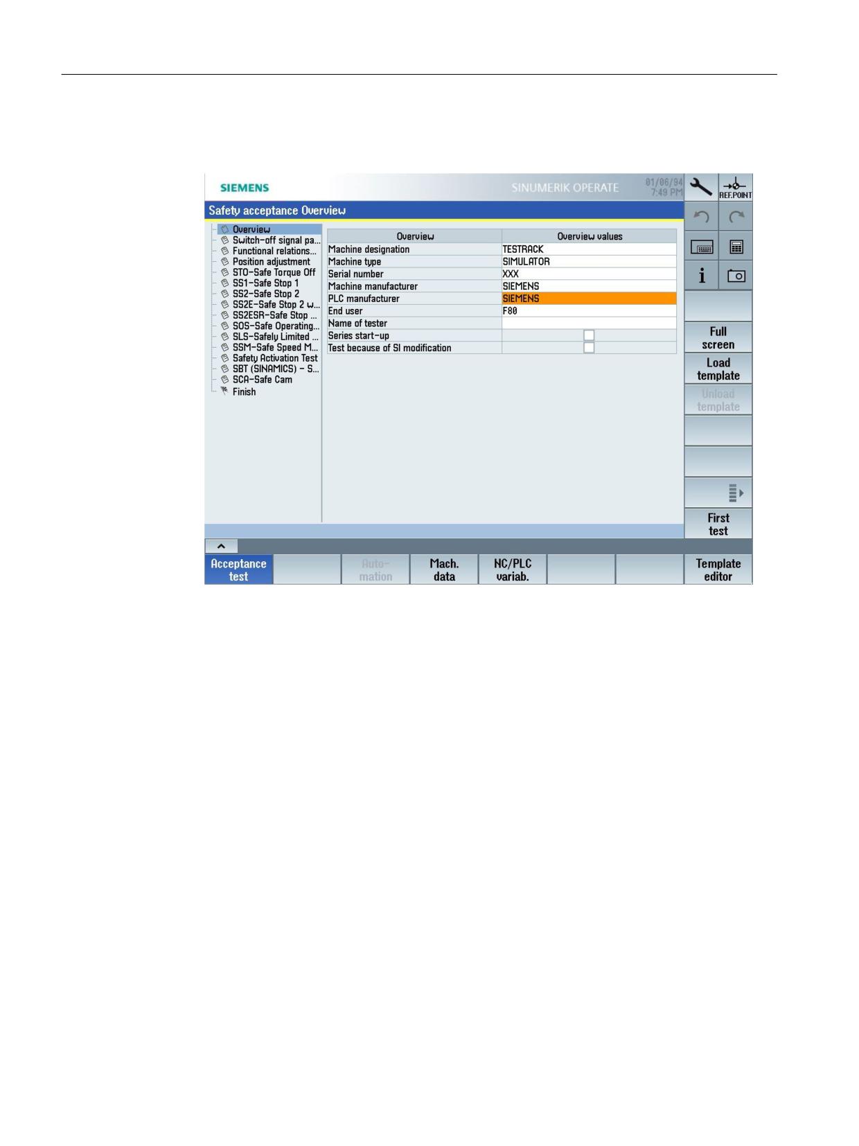
Acceptance test wizard
3.2 SINUMERIK 828D/840D sl/ONE/MC - drive-based safety functions
Procedure:
1. Enter the information required for the machine in the "Overview" setting area.
Figure 3-6
Example - Safety acceptance test: Overview
2. Press the "First test" softkey.
The "Switch-off signal path" setting area/test type becomes active.
If you do not wish to use this test, in this setting area, activate option "This test type is not
required for this machine". Also in other setting areas you can deactivate the particular test
in the same way.
SINUMERIK Operate acceptance test
30
Function Manual, 10/2020, 6FC5397-3HP40-0BA1