SINUMERIK 840D sl. Service - Safety Integrated. Manual (2020) - page 15
Commissioning and configuring
7.2 Configuring safety-relevant components
Procedure
To change the Safety Integrated mode, proceed as follows:
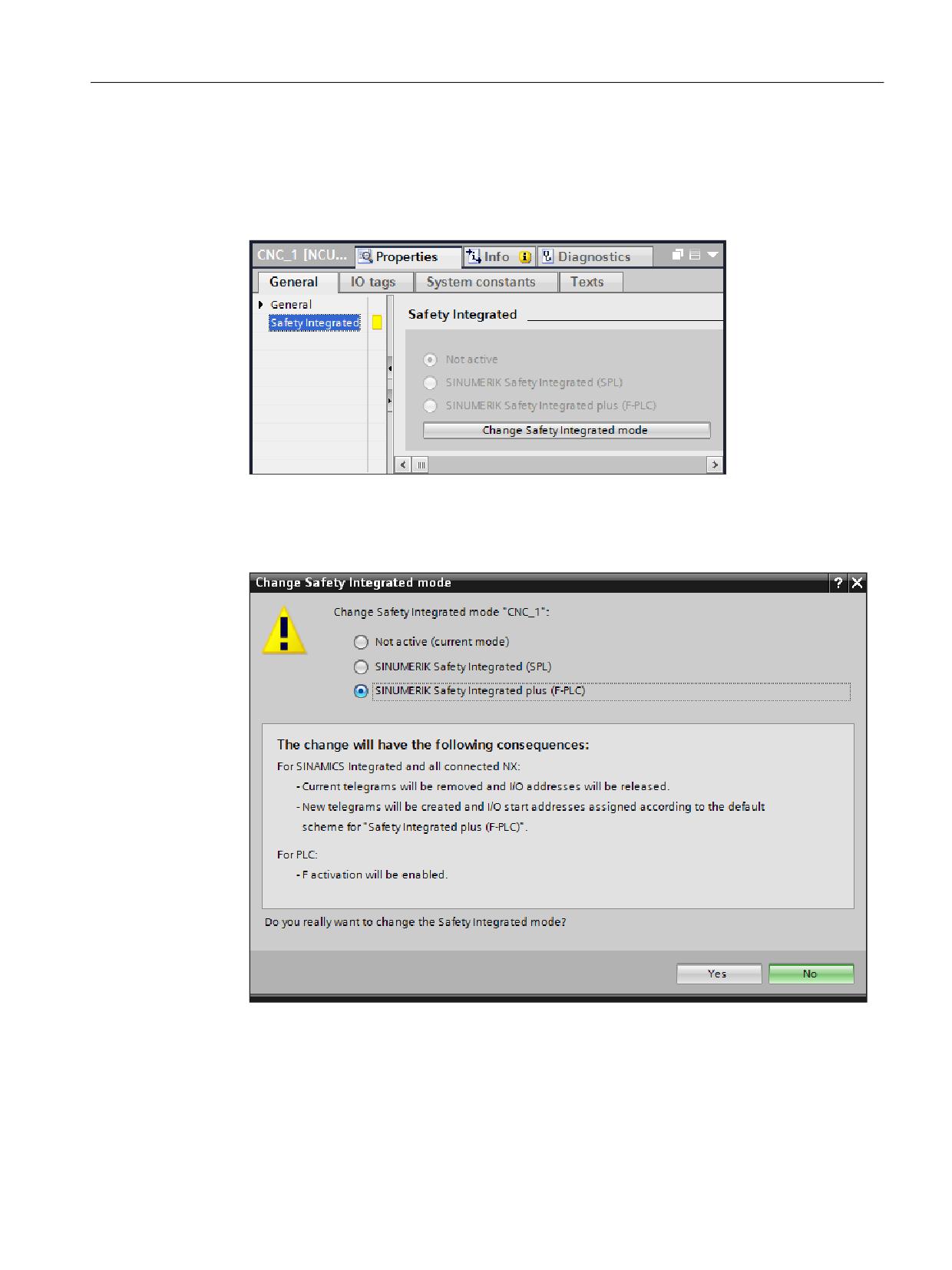
1. Click the NCU in the network or device view and select the "Safety Integrated" entry in the
"Properties" inspector window at "General".
Figure 7-1
Inspection window "Properties" - Safety Integrated
2. Click the "Change Safety Integrated mode" button.
The "Change Safety Integrated mode" dialog opens. If you select an option, the effects of the
mode change are performed here.
Figure 7-2
"Change Safety Integrated mode" dialog
3. Select the required Safety Integrated mode and confirm the reconfiguration with "Yes".
Result
The Safety Integrated mode has been changed.
Safety Integrated plus
Commissioning Manual, 10/2020, 6FC5397-1FP40-6BA4
215
Commissioning and configuring
7.2 Configuring safety-relevant components
If problems occur during the changeover, you can find further information in the "Info" inspector
window at "General".
Note
Effects on telegram configuration
The Safety Integrated mode affects the telegram configuration because, in the "Safety Integrated
plus (F-PLC)" mode, different telegrams are used than in the inactivated Safety Integrated or the
Safety Integrated (SPL) modes.
Telegrams that are added or changed are kept, however, as long as they are compatible with the
newly selected Safety Integrated mode.
Ensure, if applicable, that any adaptations are still available following the change of mode in
the telegram configuration (Page 253).
7.2.3
Configuring additional safety-related components
Basic procedure
After you have activated Safety Integrated, you can insert and configure optional F-I/Os as well
as failsafe modules/submodules and telegrams.
You can find further information in the documentation for SIMATIC Safety.
7.2.4
Loading the configuration into the controller
If you have changed an existing hardware configuration, then you must first load the actual
configuration to the device. This ensures that the same configuration is set on the PG/PC and the
physical device itself.
Requirements
• The PLC is in the STOP operating state.
Using the TIA Portal, you can stop and then restart the PLC before the loading. However, the
other subcomponents of the control system are not stopped or started.
• There is a network connection between the PG/PC and the control system.
Procedure
Proceed as follows to load the hardware configuration into the control system:
1. Select the PLC in the project navigation and call shortcut menu "Load to device > Hardware
configuration".
The "Extended download" dialog opens.
2. Select the PG/PC interface type (the network card being used), e.g. "Intel[R] Ethernet
Connection I217-V".
Safety Integrated plus
216
Commissioning Manual, 10/2020, 6FC5397-1FP40-6BA4
Commissioning and configuring
7.2 Configuring safety-relevant components
3. Select the slot for the connection with interface/subnet, e.g. "Directly at slot '2 X120'
4. Click "Start search".
A search is made for the target devices, and they are displayed in the dialog.
5. Select the appropriate target device, e.g. based on the IP address, and confirm with "Load".
If several F-CPUs can be accessed from a PG/PC via a network, then carefully observe the notes
in Manual SIMATIC Safety - Configuring and Programming (https://
support.industry.siemens.com/cs/products?search=SIMATIC
%20Safety&dtp=Manual&pnid=24471&lc=en-WW).
6. Check the information in the "Load preview" dialog and confirm with "Load".
7. In the "Results of the load procedure" dialog, select whether the PLC should be restarted, and
then confirm with "Complete".
7.2.5
Allocating and assigning a PROFINET device name
Before a PROFINET IO device can be addressed by an I/O controller, it must have a device name.
Additional general information about PROFINET device names is provided in the TIA Portal
online help.
Precondition
• The PROFINET IO device can be accessed in the network.
Procedure
In order to assign a device name to a PROFINET IO device, proceed as follows:
1. In the device properties, in field "Name", enter the required device name.
2. Click in the network view, right-click on the device and select command "Assign name".
Safety Integrated plus
Commissioning Manual, 10/2020, 6FC5397-1FP40-6BA4
217
Commissioning and configuring
7.2 Configuring safety-relevant components
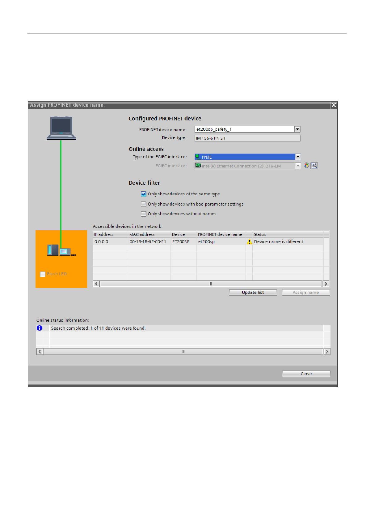
3. Make the following settings in dialog "Assign PROFINET device name":
- PG/PC interface type: PN/IE
- PG/PC interface: Network card used, e.g. "Intel(R) 82579V Gigabit Network Connection"
The list of accessible nodes is updated in the dialog.
Figure 7-3
Dialog "Assigning a PROFINET device name"
4. Select the appropriate target device, e.g. based on the device type and IP address, and
confirm with "Name".
Safety Integrated plus
218
Commissioning Manual, 10/2020, 6FC5397-1FP40-6BA4
Commissioning and configuring
7.2 Configuring safety-relevant components
7.2.6
Assigning F-destination addresses, address type 1
The F-target addresses of the F-I/O from PROFIsafe address type 1 are assigned to the module
using a DIL switch or via drive parameters (for SINAMICS).
Information on how you can set the F-destination address for F-I/O using DIL switches is provided
in the documentation for the F-I/O.
Unique PROFIsafe addresses
To ensure safe communication, unique PROFIsafe addresses are required throughout the CPU
and the network.
The failsafe I/O of PROFIsafe address type 1 is uniquely addressed by its failsafe destination
address (e.g. using the position of the address switch) (see Chapter "Checking the PROFIsafe
address").
The F-destination address (and therefore also the setting at the address switch) of the F-I/O must
be unique for the entire F-I/O throughout the network and the CPU (system-wide). The F-I/O of
PROFIsafe address type 2 should be taken into account.
See the help for SIMATIC Safety at:
• DIL switch setting
• Special considerations when configuring the F-system
• Recommendation for allocating PROFIsafe addresses
• PROFIsafe addresses for F-I/O of PROFIsafe address type 1
• Configurations supported by the SIMATIC Safety F-safety
• Completeness and correctness of the hardware configuration
7.2.7
Assigning F-destination addresses, address type 2
For the F-I/O of PROFIsafe address type 2, you can adapt the F-destination address in the module
properties - and then use command "Assign F-destination address".
As an alternative to this procedure, you can use the F-IO Connect commissioning software:
SINUMERIK F-IO Connect in SIOS (http://support.industry.siemens.com/cs/document/
109744986/)
Unique PROFIsafe addresses
To ensure safe communication, unique PROFIsafe addresses are required throughout the CPU
and the network.
F-I/O of PROFIsafe address type 2 is uniquely addressed using a combination of F-source address
("Basis for PROFIsafe addresses of the assigned F-CPU" parameter) and F-destination address.
The combination of F-source address and F-destination address for each F-I/O must be unique
throughout the network and CPU (system-wide). In addition, the F-destination address must not
be occupied by F-I/O of PROFIsafe address type 1.
To ensure that addresses are unique across F-CPUs for supported configurations, you must
ensure that the parameter "Basis for PROFIsafe addresses" is unique for all F-CPUs in the
Safety Integrated plus
Commissioning Manual, 10/2020, 6FC5397-1FP40-6BA4
219
Commissioning and configuring
7.2 Configuring safety-relevant components
network*. This is achieved by having different settings for the "Basis for PROFIsafe addresses"
parameter of the F-CPUs.
See the help for SIMATIC Safety at:
• Special considerations when configuring the F-system
• Recommendation for allocating PROFIsafe addresses
• PROFIsafe addresses for F-I/O, PROFIsafe address type 2
• Configurations supported by the SIMATIC Safety F-safety
• Completeness and correctness of the hardware configuration
Requirements
• The F-I/O device can be accessed in the network.
• A device name has been assigned to the F-I/O.
• The hardware configuration has been loaded to the device.
Procedure
Proceed as follows, to assign the configured F-destination address to F-I/O, PROFIsafe address
type 2:
1. Click in the network view, right-click on the F-I/O device and click on "Assign F-destination
address".
2. Make the following settings in the "Extended load" dialog:
- PG/PC interface type: PN/IE
- PG/PC interface: Network card used, e.g. "Intel[R] Ethernet Connection I217-V"
- Connection with interface/subnet: Directly at slot '1 X150'
3. Under "Identification" select how you wish to identify the F-modules:
- "By flashing the LEDs"
This is the default setting. During identification, the STATUS LEDs of the F-modules to be
identified flash.
- "Using the serial number"
If you cannot see the F-modules clearly, you can identify them by the serial number of the
interface module.
Note
The displayed serial number may have a year number added to it compared with the serial
number printed on the interface module. The serial numbers are nevertheless identical.
4. In column "Assign" select all F-modules where you wish to assign an F-destination address.
Safety Integrated plus
220
Commissioning Manual, 10/2020, 6FC5397-1FP40-6BA4
Commissioning and configuring
7.2 Configuring safety-relevant components
5. Click the "Identification" button.
- If you have selected LED flashing for the identification type, then check whether the status
LEDs of that F-module flash green whose F-destination address you wish to assign.
- If you have selected the serial number for the identification type, compare the displayed
serial number with the serial number of the module.
6. Confirm successfully identified F-modules in the "Confirm" column of the table.
7. Using button "Assign F-destination address" assign the configured F-destination addresses to
the F-modules, and confirm dialog "Acknowledge assignment" (within 60 seconds).
8. Close the dialog.
7.2.8
Checking the PROFIsafe address
To ensure safe communication, unique PROFIsafe addresses are required throughout the CPU
and the network. For this reason, it is also necessary that you check the settings of the PROFIsafe
addresses carefully.
WARNING
Incorrect assignment of the safety functions of an axis
An incorrect assignment of a (valid) F-address results in an incorrect assignment of the safety
functions to the corresponding axis. The system does not identify this incorrect assignment (in
the CPU and in the network). As a consequence, the safety functions can act in a way that was
not intended, which in turn can result in death and serious injury.
• Uniquely address the F-destination address of the F-I/O of PROFIsafe address type 1.
• Ensure that the F-destination address of the F-I/O (the drive units in this case) is unique for
the entire failsafe I/O throughout the network and the CPU (system-wide). When doing this,
also take into account the F-I/O of PROFIsafe address type 2, e.g. modules of the ET 200SP
type.
• Note also the corresponding documentation in the TIA Portal online help in the section
"SIMATIC Safety - Configuration and programming".
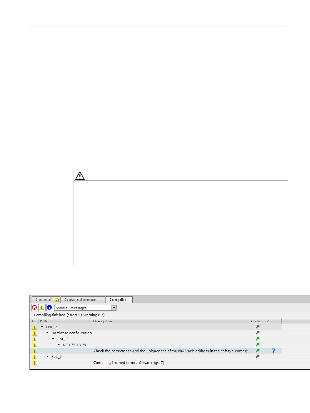
During compilation of the safety program, a warning indicates the importance of unique
PROFIsafe addresses:
Safety Integrated plus
Commissioning Manual, 10/2020, 6FC5397-1FP40-6BA4
221
Commissioning and configuring
7.2 Configuring safety-relevant components
Figure 7-4
Warning when compiling the safety program
Precondition
• F-destination addresses have been configured and assigned.
• Hardware and software have been compiled.
Procedure
Proceed as follows to check PROFIsafe addresses:
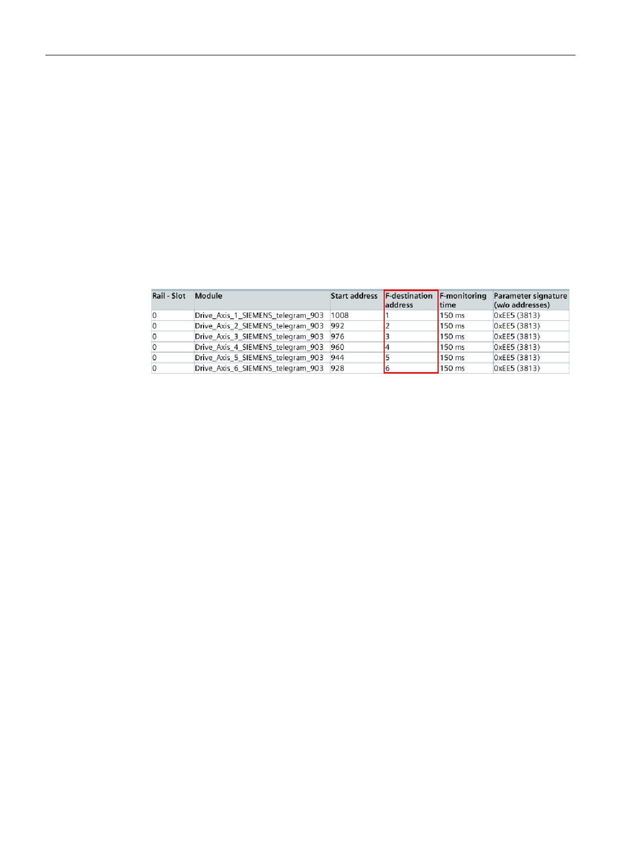
1. Right-click on "Safety Administration > Print", select a printer or a PDF application and
confirm with "OK".
The safety printout is generated.
Figure 7-5
F-target addresses of SINAMICS Safety Integrated drive objects in the safety printout
(example)
2. Check the PROFIsafe addresses listed in the safety printout:
- Compare the F-target addresses of the drive objects of SINAMICS Safety Integrated and NX
modules with the values of the p9610 drive parameter
- In the safety printout compare the F-destination addresses of the individual modules with
those of all other modules or participants, and ensure that the addresses are unique.
Safety Integrated plus
222
Commissioning Manual, 10/2020, 6FC5397-1FP40-6BA4

Commissioning and configuring
7.3 Generating a safety program
7.3
Generating a safety program
7.3.1
Overview
Precondition
• Safety Integrated plus (F-PLC) is active.
• The F-components have been configured and parameterized.
Example of a handling overview
Step
Description
1
Create receive/send data as PLC tags (Page 223)
2
Adapting the settings of the F-runtime group (optional) (Page 225)
3
Setting up access protection (Page 226)
4
Parameterizing EMERGENCY STOP (Page 227)
5
Implementing user acknowledgment for global reintegration (Page 228)
6
Acknowledging messages related to safety functions integrated in the drive (Page 229)
7
Deselecting safety functions integrated in the drive (Page 232)
8
Initiate a forced checking procedure (test stop) (Page 233)
9
Programming the wiring test (Page 233)
7.3.2
Create receive/send data as PLC tags
In order that you can access the required drive data symbolically in the safety program, in the TIA
Portal create PLC tags with the corresponding drive addresses.
You can create all the PLC tags required before you start programming - or you can always add
your PLC tags if you wish to access new drive data. If you address the drive data with absolute
values instead, tag names are automatically assigned that are subsequently difficult to
comprehend.
You can import or export PLC tags in the XLSX, SDF or XML formats. You can copy PLC tag tables
as copy templates in global libraries.
Procedure
Proceed as follows to create PLC tag tables with the required drive data.
1. In the project navigation, double-click below "PLC tags " on "Add new tag table", e.g. "CNC_1
> PLC_1 > PLC tags > Add new tag table".
2. Right-click on the new tag table, select "Rename" and assign a name, e.g. "Safety status data"
or "Safety control data".
Safety Integrated plus
Commissioning Manual, 10/2020, 6FC5397-1FP40-6BA4
223

Commissioning and configuring
7.3 Generating a safety program
3. Double-click on the new tag table to open it.
4. In the "Name" column, click on "Add" and enter the tag properties:
Property
Meaning
Name
Enter a meaningful name, e.g. <drive name>-<process data>-<where relevant,
bit identifier>.
Example 1: drive1SpValid
Example 2: drive2SlsLimitA
Data type
Specify with which data type the process data is addressed.
• Bool: S_STW1, S_ZSW1, S_STW2, S_ZSW2, S_ZSW_CAM1
• Int: S_SLS_LIMIT_A, S_SLS_LIMIT_A_ACTIVE, S_CYCLE_COUNT, S_XIST16
• DInt: S_XIST32
Example 1: Bool
Example 2: Int
Address
In the "Address" column, click on the drop-down list symbol - and enter the
properties:
Address identifier
Status/input data: I
Control/output data: Q
Address
Enter the I/O address to which the specific process data is transferred.
This is obtained from the telegram start address and the PZD range within the
telegram, where the process data starts.
• You can see the start address for a specific drive telegram in the telegram
configuring of SINAMICS Safety Integrated. The standard start addresses are
also listed in Tables (Page 347).
• Refer to the telegram structure (Page 350) to identify in which PZD range (1
PZD = 1 word = 2 byte) within the telegram the required drive data is con-
tained.
Bit number
For data type "Bool" - or if you address a bit - then in addition, specify the bit
number that you take from the process data description (Page 353).
Example 1: %I1010.6
Example 2: %QW996
Comment
Optionally, you can formulate a user-defined note for each tag that is added - or
take this from the manual.
Safety Integrated plus
224
Commissioning Manual, 10/2020, 6FC5397-1FP40-6BA4
Commissioning and configuring
7.3 Generating a safety program
Result
The PLC tags were added.
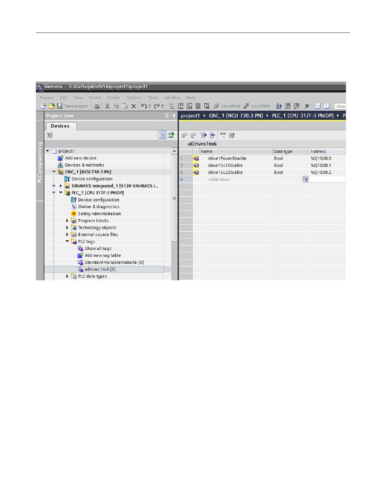
Figure 7-6
Example of a user-defined tag table, with the drive addresses required in the programming
7.3.3
Adapting the settings of the F-runtime group (optional)
An F-runtime group is automatically created when you activate "Safety Integrated plus (F-PLC)"
mode. The associated F-blocks are provided in folder "Program blocks" - or in the Safety
Administration Editor under "F-blocks":
• CYC_INT5[OB35]
• Main_Safety[FB1010]
• Main_Safety_DB[DB1010]
You can adapt the default settings of the F-runtime group and the associated blocks, as
described here.
Optionally, you can also create a second F-runtime group; for example, to organize safety-
related program sections that are executed quickly, in their own dedicated F-runtime group.
Precondition
• Safety Integrated plus (F-PLC) is active.
Safety Integrated plus
Commissioning Manual, 10/2020, 6FC5397-1FP40-6BA4
225

Commissioning and configuring
7.3 Generating a safety program
Procedure
Proceed as follows to view the settings of an F-runtime group - or to adapt them:
1. In the project navigation, double-click below the PLC involved on "Safety Administration",
e.g. "CNC_1 > PLC_1 > Safety Administration".
2. In the Safety Administration Editor switch to "F-runtime group".
3. If necessary, adapt the following settings.
Setting
Purpose
Calling block
Per default setting, CYC_INT5_RTG1[OB35] is set. This block is a cyclic
interrupt OB, which means that within an execution time, the safety
program is called at fixed intervals in time.
In the drop-down list you can define a block other than the calling block:
• If you select an LAD, FBD or STL block, then the call in the block is
automatically updated.
• If you select a block in another programming language, then you
must adapt the call yourself.
Main safety block
Default setting: Main_Safety_RTG1[FB1010]
In the drop-down list you can select a block other than the previously
created F-block.
The following main safety block numbers are intended for SINUMERIK
Safety Integrated plus: 1010..1019.
I-DB for the main safety
Default setting: Main_Safety_RTG1_DB[DB1010]
block
If the main safety block is an FB, then in the drop-down list you can
adapt the associated I-DB.
The following I-DB block numbers are intended for SINUMERIK Safety
Integrated plus: 1010..1019.
Execution time of the call-
If, as executing block, you use a cyclic interrupt OB 3x, then the para-
ing block
meterized execution time is displayed here.
You can change this execution time in the properties of the PLC under
"Alarms > Cyclic interrupts".
Maximum cycle time of the
The F-CPU monitors the F-cycle time in the F-runtime group.
F-runtime group
For "Maximum cycle time of the F-runtime group", select the maximum
time that may elapse between two calls of this F-runtime group.
DB for F-runtime group
If one F-runtime group is to provide variables for evaluation to another
communication
F-runtime group of the safety program, assign a DB for F-runtime group
communication.
Additional information is provided in the help for SIMATIC Safety under
"Safety-related communication between the F-runtime groups".
7.3.4
Setting up access protection
In productive operation, it is absolutely crucial that an F-system is provided with access
protection.
For test purposes, commissioning etc., initially access protection is not required; this means that
you can execute all offline and online actions without access protection, i.e. without a password
prompt.
Safety Integrated plus
226
Commissioning Manual, 10/2020, 6FC5397-1FP40-6BA4
Commissioning and configuring
7.3 Generating a safety program
In the safety mode, when changing the standard user program it is not permissible that access
authorization exists based on the CPU password - as in this case, the safety program can also be
changed. To rule this out, you must configure protection level "Write protection for failsafe
blocks" - and a password for the F-CPU. If only one person is authorized to change both the
standard user program and the safety program, then the protection level "Write protection" or
"Read/write protection" should be configured so that other persons are only given a restricted or
no access to the complete user program (standard and safety program).
For additional information, refer to the "Access protection" chapter in the SIMATIC Safety -
Configuring and Programming (https://support.industry.siemens.com/cs/products?
search=SIMATIC%20Safety&dtp=Manual&pnid=24471) Manual.
Procedure
To set up access protection for productive operation, follow these steps:
1. In the project navigation, double-click below the PLC involved on "Safety Administration",
e.g. "CNC_1 > PLC_1 > Safety Administration".
2. In the Safety Administration Editor switch to "Access protection".
3. Assign passwords for the two access protection types:
- Under "Offline safety program protection", click on "Setup", assign a password and confirm
with OK.
- Under "F-CPU access protection", click the link "Go to the "Protection" area of the F-CPU".
Select the setting "Write protection for fail-safe blocks" in the called properties and assign
the "Password for write/read access".
4. Load the hardware and software to the device.
Result
Two different access protection types are setup:
• Protection of the safety program
• Protection of the F-CPU
7.3.5
Parameterizing EMERGENCY STOP
Instruction "ESTOP1" implements an EMERGENCY STOP shutdown with acknowledgment for
stop Categories 0 and 1.
Procedure
Proceed as follows to program an EMERGENCY STOP shutdown:
1. Open the F-block involved.
2. From the task card "Instructions", insert operation "Basic instructions > Safety functions >
ESTOP1".
Safety Integrated plus
Commissioning Manual, 10/2020, 6FC5397-1FP40-6BA4
227

Commissioning and configuring
7.3 Generating a safety program
3. Supply the inputs and outputs of the operation.
Parameter
Declaration
Description
E_STOP
Input
EMERGENCY STOP/EMERGENCY OFF
ACK_NEC
1= acknowledgment required
ACK
1=acknowledgment
TIME_DEL
Delay time
Q
Output
1=enable
Q_DELAY
Enabling of the OFF delay for F-I/O
The enabling signal Q_DELAY is reset to 0 after the delay time has
been set at the TIME_DEL input.
Do not use Q_DELAY for drive components; instead use the corre-
sponding setting of the relevant drive-integrated safety function.
ACK_REQ
1= acknowledgment required
DIAG
Non failsafe service information
4. Link the F-DOs for the I/O shutdown or the safety function in the specific drive with the
outputs.
Additional information
You can find more information about the instruction in the online help for the instruction or in
the manual for SIMATIC Safety.
7.3.6
Implementing user acknowledgment for global reintegration
If an F-I/O error is detected by the fail-safe system, the affected F-I/O and/or drive components
are passivated.
With the passivation of a failsafe component, for the components involved, substitute values
are provided or are transferred instead of the active process values or output values.
After resolving the cause of the fault, the component involved must be reintegrated, i.e. a
switchover from substitute values to process values or output values.
Depending on the fault type or the component, in which the fault occurs, you can set passivation
and reintegration differently:
Fault type
Passivation
Reintegration
Communication
All channels of the module
After a communication error, user acknowledg-
ment is always required.
F-I/O
dependent on the F-I/O DB parameter:
or Drive
• ACK_NEC=1:
Channel
Depending on F-parameter "Be-
user acknowledgment required
havior after channel fault" of the
• ACK_NEC=0
module:
automatic reintegration
• Passivation of the channel
• Passivation of the complete
module
Safety Integrated plus
228
Commissioning Manual, 10/2020, 6FC5397-1FP40-6BA4

Commissioning and configuring
7.3 Generating a safety program
You implement reintegration after user acknowledgment by interconnecting the signal,
generated by the operator action, with one of the following parameters:
• F-I/O DB parameter "ACK_REI": Reintegration of the corresponding module (all channels)
• Operation "ACK_GL" (parameter "ACK_GLOB"): Reintegration of all modules of a F-runtime
group
Procedure
Proceed as follows to implement a user acknowledgment for global reintegration:
1.
Insert operation "ACK_GL" in that F-runtime group, whose F-I/O should be globally
acknowledged by the user acknowledgment.
2.
In operation "ACK_GL", assign input "ACK_GLOB" to the input of the acknowledgment button.
3.
If necessary, carry out the optional steps:
Setting
Procedure
Evaluation of the acknowl-
You can evaluate the F-I/O DB tag "ACK_REQ" in the standard user
edgment request
program or on an operation and monitoring system, to interrogate as
to whether a user acknowledgment is required.
• ACK_REQ = 0: No acknowledgment request
• ACK_REQ = 1: Acknowledgment request for reintegration (this is
set by the F-system after the fault has been resolved)
Controlling a signal light or
In the case of a fault, you can control a signal light and/or output
output of a signal
messages/signals in the standard user program, by evaluating the
following:
• F-I/O DB tags:
- QBAD
- QBAD_I_xx/QBAD_O_xx
- DIAG
• Diagnostics buffer of the F-PLC
Automatic or manual reinte-
You can parameterize the F-I/O DB tag "ACK_NEC" if, after an F-I/O/
gration for F-I/O/channel
channel fault, automatic reintegration should take place without user
faults
acknowledgment.
• ACK_NEC = 1 (start value): User acknowledgment required
• ACK_NEC = 0: Automatic reintegration
A user acknowledgment is always required after a communication
error.
Parameterizing tags ACK_NEC = 0 is only permitted, if, from a safety-relevant perspective
automatic reintegration is permissible for the process involved. (S010)
7.3.7
Acknowledging messages related to safety functions integrated in the drive
You program PROFIsafe acknowledgment in the safety program of the F-PLC by setting the
"Internal Event ACK" signal - separately for each drive object - via the PROFIsafe telegram
(S_STW1/S_STW2 bit 7).
Safety Integrated plus
Commissioning Manual, 10/2020, 6FC5397-1FP40-6BA4
229

Commissioning and configuring
7.3 Generating a safety program
Safety messages cannot be acknowledged collectively by the F-PLC, but instead have to be
individually acknowledged for each drive object. A falling edge of the "Internal Event ACK" signal
resets the status "Internal Event" in the particular drive, and thus acknowledges the fault.
In the safety program, logically combine all channel reset signals of channels that contain drive
objects with safety functions, with the "Internal Event ACK" signal for each drive object involved.
WARNING
Unexpected restart for safety-related acknowledgment without MCP reset!
If a STOP response is acknowledged in a safety-related fashion by the machine operator, but
without PROFIdrive RESET acknowledgment, then the part program is not canceled and is
continued with the acknowledgment. When the machine restarts unexpectedly, this can put
people in dangerous situations or cause material damage.
• In the safety program logically combine safe acknowledgment (PROFIsafe IEACK) with a
RESET at the machine control panel (PROFIdrive RESET).
Precondition
• PLC variables for the "Internal Event ACK" signal are added for each drive object.
Safety Integrated plus
230
Commissioning Manual, 10/2020, 6FC5397-1FP40-6BA4
Commissioning and configuring
7.3 Generating a safety program
Procedure
In order to logically combine the reset signal of the machine control panel with the safety-related
acknowledgment in the safety program for a channel, proceed as follows:
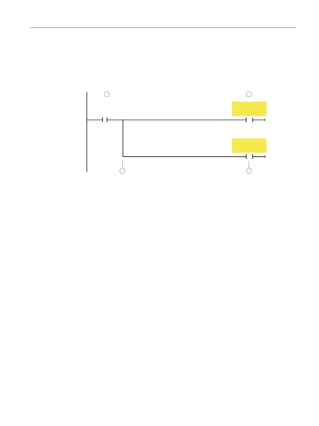
1. Open the corresponding F-runtime group, e.g. Main_Safety_RTG1 [FB1010].
2. Insert a new network, in which you logically combine the signals:
1
2
&KDQ
!
'2!B
$B5HVHW
,17(51$/B
(9(17B$&.
'2!B
,17(51$/B
(9(17B$&.
3
3a
No.
Instruction/variable
Purpose/procedure
(1)
---| |---NO contact:
The channel reset must be active, i.e. the in-
"<Channel DB name>".A_Reset
terface signal in the corresponding channel
DB must be 1.
(2)
---( )--- Assignment
Assign the logic operation result to the corre-
sponding PLC variable, that you created for
the "Internal Event ACK" signal of the appro-
<PLC variable>
priate drive.
Example:
"drive1InternalEventAck"
(3)
Branch
If you are using several safety-related drive
objects, for each drive object insert a branch
together with the operation (see 3a).
(3a)
---( )--- Assignment
Assign the logic operation result to the corre-
sponding PLC variable.
<PLC variable>
Example:
"drive2InternalEventAck"
Figure 7-7
Inserting a new network
Result
The channel reset signal of the channel involved was logically combined with the safety-related
acknowledgment of faults in the individual drive objects.
Safety Integrated plus
Commissioning Manual, 10/2020, 6FC5397-1FP40-6BA4
231
Commissioning and configuring
7.3 Generating a safety program
7.3.8
Deselecting safety functions integrated in the drive
You deselect safety functions integrated in the drive by accessing the corresponding drive
addresses in the safety program and then set/reset the relevant bits.
Precondition
• PLC variables for the signals required have been added.
Procedure
Proceed as follows to select or deselect a safety function integrated in the drive in the safety
program:
1. Open the F-block, e.g. Main_Safety_RTG1 [FB1010].
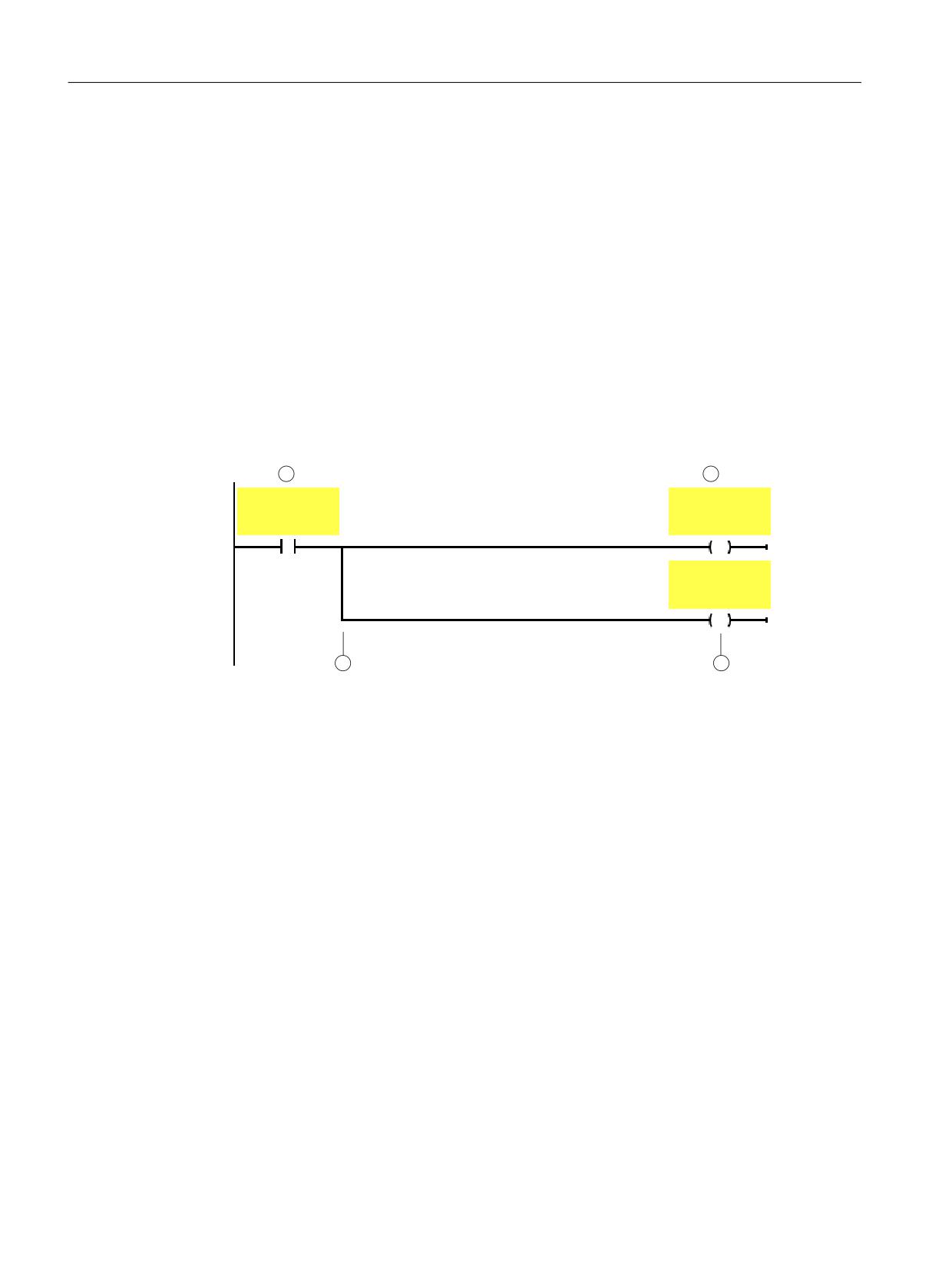
2. Insert a new network, and in the network, link (logically combine) the signals:
1
2
'HVHOHFWLRQB
'5B 1U !B
6DIHW\
6DIHW\
IXQFWLRQ!
IXQFWLRQ!
'5B 1U !B
6DIHW\
IXQFWLRQ!
3
3a
No.
Instruction/variable
Purpose/procedure
(1)
---| |---NO contact:
Address the PLC variable "Deselection_<safety
"Deselection_<safety function>"
function>" or the drive I/O address, which
transfers the associated bit of the safety con-
Example: "deselectionSs1"
trol word.
or
Drive I/O address with ZSW bit
(2)
---( )--- Assignment:
Assign the logic operation result to the safety
"DR_<drive number>_<safety function>"
function in the drive involved.
Example: "drive1Ss1Disable"
or
Drive I/O address with STW bit
(3)
Branch
If you deselect the safety function involved for
several drives, insert a branch and operation
for each drive (see 3a).
(3a)
---( )--- Assignment:
Assign the logic operation result to the safety
"DR_<drive number>_<safety function>"
function in the drive involved.
Example: "drive2Ss1Disable"
or
Drive I/O address with ZSW bit
Figure 7-8
Inserting a new network
Safety Integrated plus
232
Commissioning Manual, 10/2020, 6FC5397-1FP40-6BA4
Commissioning and configuring
7.3 Generating a safety program
7.3.9
Initiate a forced checking procedure (test stop)
Basic procedure
Functions and switch-off signal paths must be regularly tested using the forced checking
procedure (test stop). The forced checking procedure should be performed each time that the
control system runs up and must, however, be performed at least once a year.
The forced checking procedure is not performed in the safety program but in the standard PLC
program. This means that you insert the affected program code in your PLC user program in order
to trigger the forced check procedure during run-up of the controller.
7.3.10
Programming the wiring test
Basic procedure
You must program a wiring test in order that your F-I/O devices can be correctly addressed. For
the wiring test, use a tag QBAD of the F-I/O DB of the corresponding F-I/O. You can perform a
wiring test jointly for all F-I/O modules of an F-runtime group.
Therefore, configure the F-I/O in such a way that the modules themselves perform the test.
Further information
Further information may be found in the SIMATIC Safety manual.
Safety Integrated plus
Commissioning Manual, 10/2020, 6FC5397-1FP40-6BA4
233
Commissioning and configuring
7.4 Loading the configuration to the control system
7.4
Loading the configuration to the control system
7.4.1
Load the configuration
Precondition
• There is a network connection between the configuring PG/PC and SINUMERIK 840D sl.
Procedure
Proceed as follows to load the hardware and software configuration into the SINUMERIK 840D
sl:
1. In the project navigation, right-click the NCU and select the "Load to device > Hardware and
software (only changes)" command.
2. Make the following settings in the "Extended load" dialog:
- PG/PC interface: Network card used, e.g. "Intel(R) 82579V Gigabit Network Connection"
- Connection with interface/subnet: "PN/IE_2"
Safety Integrated plus
234
Commissioning Manual, 10/2020, 6FC5397-1FP40-6BA4
Commissioning and configuring
7.4 Loading the configuration to the control system
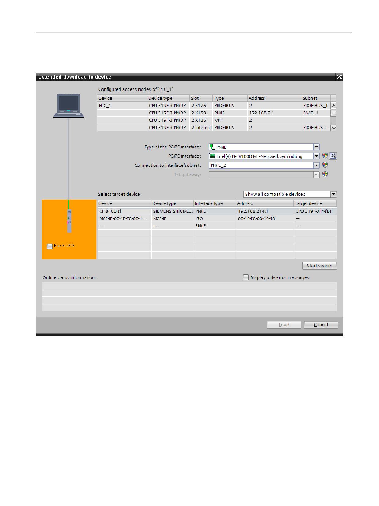
3. Click "Start search".
A search is made for the target devices, and they are displayed in the dialog.
Figure 7-9
"Extended download" dialog
4. Select the appropriate target device, e.g. based on the IP address, and confirm with "Load".
5. Check the information in the "Load preview" dialog and confirm with "Load".
6. In the "Results of the load procedure" dialog, select whether the PLC should be restarted, and
then confirm with "Complete".
7.4.2
Transferring the safety mode from the configuration
Precondition
• The configuration has been loaded (Page 234).
Safety Integrated plus
Commissioning Manual, 10/2020, 6FC5397-1FP40-6BA4
235
Commissioning and configuring
7.4 Loading the configuration to the control system
Procedure
To apply the safety mode in SINUMERIK Operate, proceed as follows:
1. In SINUMERIK Operate, switch to the commissioning area (start-up area) using "MENU
SELECT > Commissioning".
2. Press the "Reset (po)" softkey and confirm with "Yes".
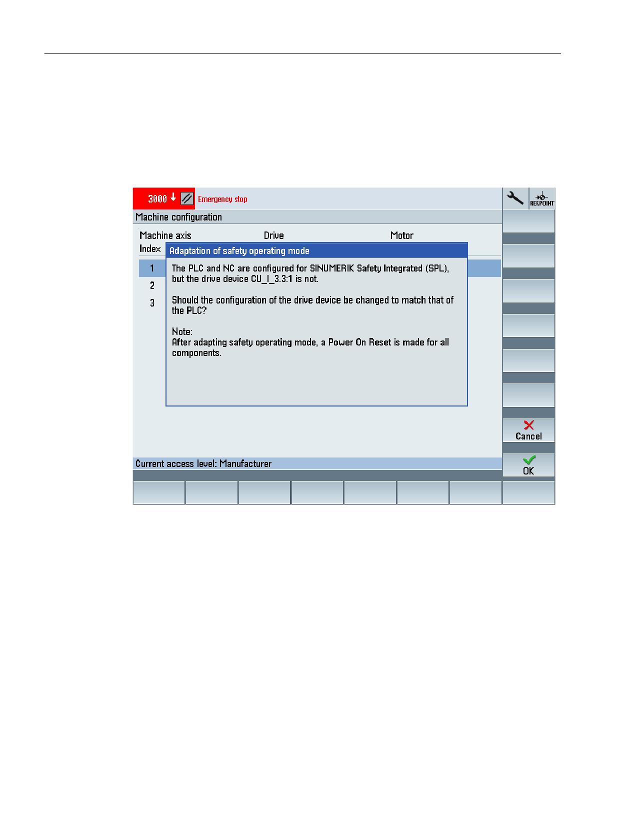
The NCU is restarted, and the "Adaptation of safety operating mode" dialog is then displayed.
3. Confirm the adaption of the safety mode with "OK".
Safety Integrated plus
236
Commissioning Manual, 10/2020, 6FC5397-1FP40-6BA4

Commissioning and configuring
7.5 Configuring NC and drive-specific safety settings
7.5
Configuring NC and drive-specific safety settings
7.5.1
Overview
Higher-level safety settings are described in this chapter, which you specifically configure for
each drive.
Requirement
• Access rights of access level 2 (service) are available in SINUMERIK Operate.
• The commissioning of the (non-safety-related) default drive functions has been completed.
• The configuration (hardware and software) is loaded in the NCU (Page 234).
• The transfer of the Safety Integrated mode from the configuration has been completed.
(Page 235)
Example handling overview
Step
Description
1
Setting software options (Page 238)
2
Activating the safety commissioning mode (Page 238)
3
Selecting the safety functional scope (Page 240)
4
Parameterizing the setpoint speed limiting (Page 241)
5
Parameterizing reaction of the stop response (Page 243)
6
Parameterizing an encoder (Page 244) or Configuring encoderless operation (Page 248)
7
Configuring telegrams (Page 253)
8
Using the fault buffer, message buffer and alarm buffer (Page 328)
Safety Integrated plus
Commissioning Manual, 10/2020, 6FC5397-1FP40-6BA4
237

Commissioning and configuring
7.5 Configuring NC and drive-specific safety settings
7.5.2
Setting software options
Procedure
Proceed as follows to set the software options for Safety Integrated plus:
1. In SINUMERIK Operate switch to licensing via "MENU SELECT > Commissioning > Menu
forward key > Licenses".
2. Press softkey "All options".
3. Set the safety software options required for your particular machine configuration:
Software option
Article No.
Purpose
SINUMERIK 840D sl
6FC5800-0AS60-0YB0
Activate the F-PLC in SINUMERIK 840D sl in or-
der to process the failsafe sensors and actuators
Safety Integrated plus
in an F-program.
/SI logic
SINUMERIK 840D sl
6FC5800-0AK00-0YB0
Use the motion control functions of the SINAM-
Safety Integrated plus
ICS Safety Integrated in the SINUMERIK Safety
/ SI axis/spindle
Integrated plus (F-PLC) mode.
License for 1 axis/spindle, multiple licensing in
order to be able to use additional axes/spindles.
SINUMERIK 840D sl
6FC5800-0AS61-0YB0
Use the motion control functions of the SINAM-
Safety Integrated plus
ICS Safety Integrated in the SINUMERIK Safety
/SI multi-axis package
Integrated plus (F-PLC) mode.
License for any number of axes/spindles.
Result
The software options were set.
The individual software options to be licensed for the machine can be displayed using softkey
"Missing licenses/options", which you can then order, e.g. through the Siemens Industry Mall.
See also
Licensing axes/spindles and F-PLC (Page 39)
7.5.3
Activating the safety commissioning mode
Changes to the safety-relevant drive parameterization are only possible if the corresponding
drive is in the Safety Integrated commissioning mode. After parameterization, the Safety
Integrated commissioning mode must be deactivated and the actual checksums must be
transferred into the reference checksums.
Safety Integrated plus
238
Commissioning Manual, 10/2020, 6FC5397-1FP40-6BA4
Commissioning and configuring
7.5 Configuring NC and drive-specific safety settings
Precondition
• The commissioning of the (non-safety-relevant) standard drive functions must have been
completed.
• The configuration (hardware and software) has been loaded to the NCU (Page 234).
• Transferring the Safety Integrated mode from the configuration has been completed
(Page 235).
Procedure
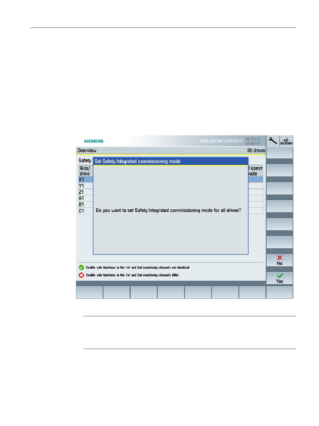
Proceed as follows to activate the Safety Integrated commissioning mode for all drives:
1. In SINUMERIK Operate, go to "MENU SELECT > Commissioning > Menu forward key > Safety".
Figure 7-10
Activating the Safety Integrated commissioning mode for individual drives
Note
Activating the Safety Integrated commissioning mode for individual drives
To activate the mode for an individual drive only, instead, switch to "MENU SELECT >
Commissioning > Menu forward key > Safety > Settings > Options".
2. Select the softkey "Set SI Commissioning", then "Activate/deactivate drive commissioning"
and confirm with "Yes".
Safety Integrated plus
Commissioning Manual, 10/2020, 6FC5397-1FP40-6BA4
239
Commissioning and configuring
7.5 Configuring NC and drive-specific safety settings
7.5.4
Selecting the safety functional scope
Before you parameterize the various safety functions of the drive, make the following basic
settings for the corresponding drives:
• Scope of the safety functions used (Basic or Extended)
• Control (PROFIsafe, terminals, without selection)
• Use of a safety-relevant encoder
You must make these settings one after the other for each drive where you wish to use the drive-
integrated safety functions.
Precondition
• The commissioning of the (non-safety-relevant) standard drive functions must have been
completed.
• The configuration (hardware and software) has been loaded to the NCU (Page 234).
• Transferring the Safety Integrated mode from the configuration has been completed
(Page 235).
• The safety commissioning mode is activated for the drive to be configured (Page 238).
Procedure
Proceed as follows to set the safety functional scope for a drive:
1. In SINUMERIK Operate, switch to the safety settings of the drive via "MENU SELECT >
Commissioning > Menu forward key > Safety > Settings > Options".
2. Switch to the corresponding drive, e.g. using softkey "Select a drive".
3. Under "Select safety function" select the functional scope:
- Basic Functions via onboard terminals
- Basic Functions via PROFIsafe
- Basic Functions via PROFIsafe and onboard terminals
- Extended Functions via PROFIsafe
- Extended Functions via PROFIsafe and Basic Functions via onboard terminals
- Extended Functions without selection
- Extended Functions without selection and Basic Functions via onboard terminals
Safety Integrated plus
240
Commissioning Manual, 10/2020, 6FC5397-1FP40-6BA4
Commissioning and configuring
7.5 Configuring NC and drive-specific safety settings
4. Make additional settings, when using the extended functional scope:
- Safety with encoder and acceleration monitoring (SAM)
- Safety without encoder with braking ramp (SBR) - can only be set for induction motors
- Safety without encoder with acceleration monitoring (SAMR) - can only be set for
induction motors
See also: Supported axis types (Page 33), Overview of safety functions integrated in the drive
(Page 256), Control options (Page 197)
5. Press softkey "OK".
Note
When the selected safety function is saved, the enable signal for referencing via SIC/SCC
(p9501.27) is automatically set via SINUMERIK Operate.
7.5.5
Parameterizing the setpoint speed limiting
During the runtime, the setpoint speed limiting of the drive (p9533) is evaluated with the
selected evaluation factor of the NC, and issued to the interpolator as setpoint limit.
Precondition
• The safety functional scope of the drive has been selected. (Page 240)
Safety Integrated plus
Commissioning Manual, 10/2020, 6FC5397-1FP40-6BA4
241
Commissioning and configuring
7.5 Configuring NC and drive-specific safety settings
Procedure
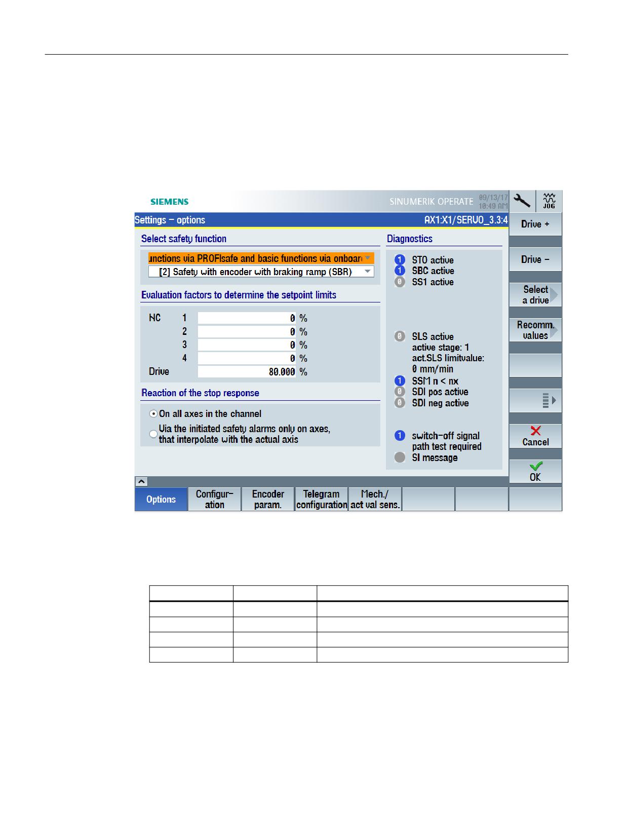
Proceed as follows, to parameterize the evaluation factors of the NC to define the setpoint limits:
1. In SINUMERIK Operate, switch to the safety settings of the drive via "MENU SELECT >
Commissioning > Menu forward key > Safety > Settings > Options".
2. Switch to the corresponding drive, e.g. using softkey "Select a drive".
The parameterization is displayed for the selected drive.
3. Parameterize 4 evaluation factors for defining the setpoint limits
MD36933 $MA_SAFE_DES_VELO_LIMIT includes 4 values (indices 0…3). Using the axis-
specific PLC user interface, in the PLC program you can select which of these values is active
(DBX34.0…DBX34.1 in axis1 [DB31]…axis31[DB61]).
Bit 0
Bit 1
active setpoint limiting factor
= 0
= 0
SAFE_DES_VELO_LIMIT[0]
= 1
= 0
SAFE_DES_VELO_LIMIT[1]
= 1
= 1
SAFE_DES_VELO_LIMIT[2]
= 1
= 1
SAFE_DES_VELO_LIMIT[3]
Select the active setpoint limiting factor using DBX34.0..DBX34.1 in axis1 [DB31]…axis31[DB61]
4. Enter the 4 required evaluation factors.
To optimally set this MD, it is possible that several changes must be made in order to take into
account the dynamic response of the drives.
You can use 80% as recommended value, for example.
Safety Integrated plus
242
Commissioning Manual, 10/2020, 6FC5397-1FP40-6BA4
Commissioning and configuring
7.5 Configuring NC and drive-specific safety settings
Result
The evaluation factors of the NC were parameterized, and are active after an operator panel
reset.
During the runtime, the setpoint speed limiting of the drive (p9533) is evaluated with the
selected (in the PLC user program) evaluation factor of the NC, and issued to the interpolator as
setpoint limit.
The value in MD36933[0] becomes active if a specific value is not selected in the PLC user
program.
7.5.6
Parameterizing reaction of the stop response
If a stop response is initiated, then this has effects on all of the other axes in the channel. The
effect on the other axes in the channel can be influenced using MD36964
$MA_SAFE_IPO_STOP_GROUP. This allows, for example, the pulses of the spindle to be safely
cancelled. This means that the spindle can be manually rotated and the axes can still be safely
monitored while it is moving.
Safety Integrated plus
Commissioning Manual, 10/2020, 6FC5397-1FP40-6BA4
243
Commissioning and configuring
7.5 Configuring NC and drive-specific safety settings
Procedure
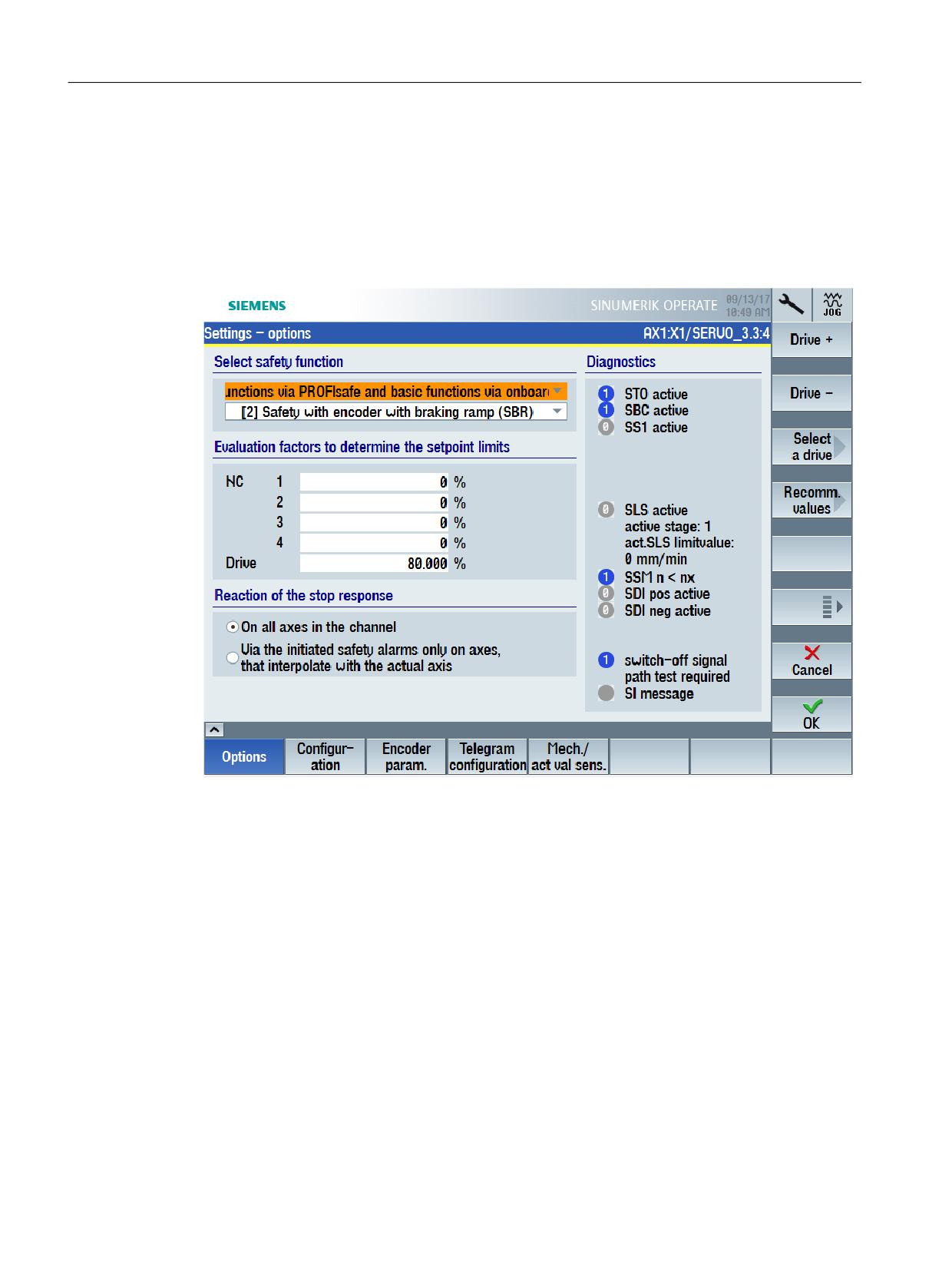
Proceed as follows to assign parameters for the reaction of the stop response:
1. In SINUMERIK Operate, go to the safety settings of the drive via "MENU SELECT >
Commissioning > Menu forward key > Safety > Settings > Options".
2. Go to the corresponding drive, for example, using the "Select drive" softkey.
The parameter assignment is displayed for the selected drive.
3. Select one of the following options as desirable reaction to the stop response:
- On all axes in the channel
- Via the triggered safety alarms only on axes that interpolate with the current axis.
The reaction to the stop response is saved in MD36964 $MA_SAFE_IPO_STOP_GROUP.
7.5.7
Parameterizing an encoder
Precondition
• The SI commissioning mode (Page 238) is active for the drive to be configured.
• The drive is configured for operation with an encoder.
Safety Integrated plus
244
Commissioning Manual, 10/2020, 6FC5397-1FP40-6BA4
Commissioning and configuring
7.5 Configuring NC and drive-specific safety settings
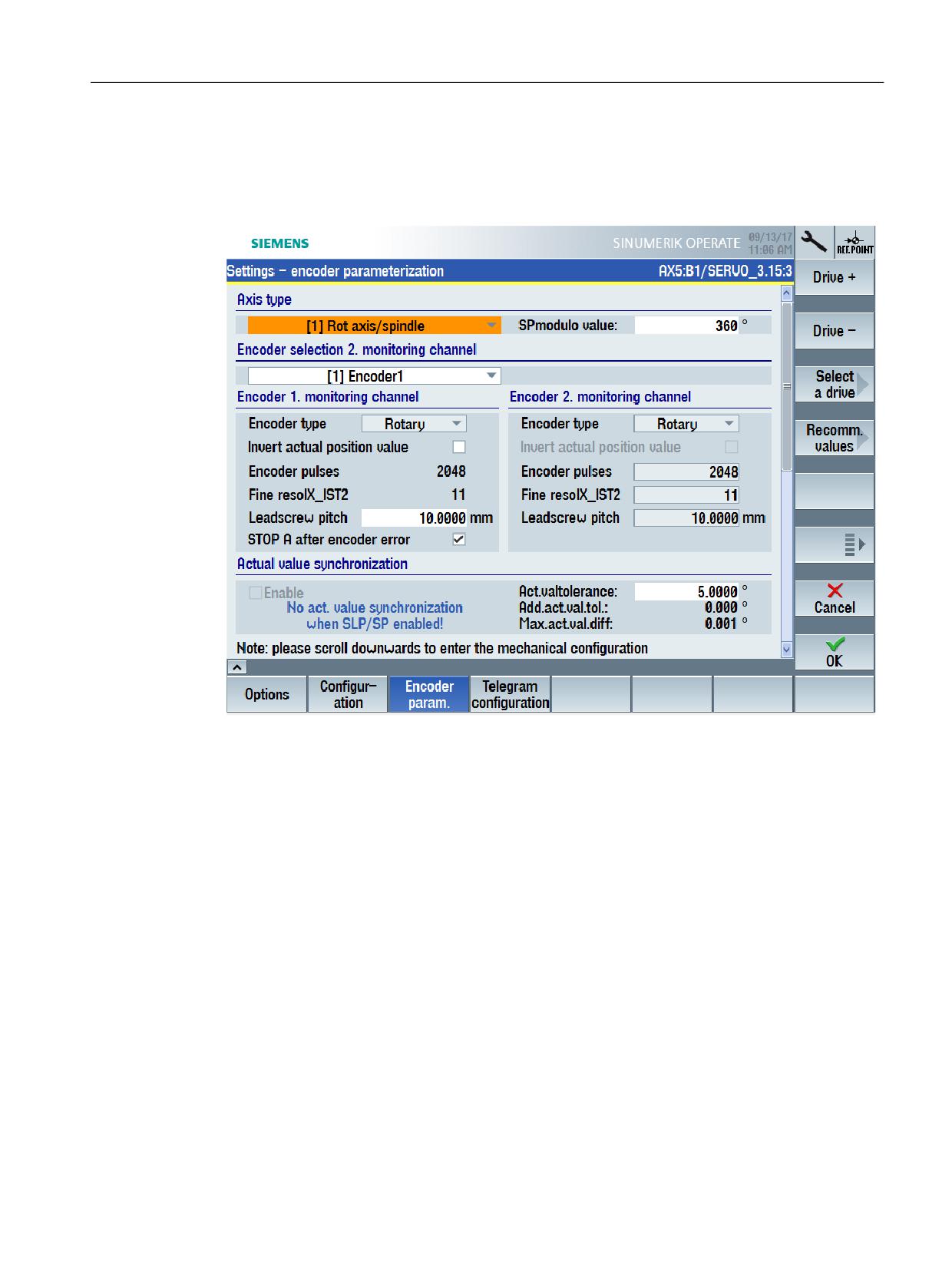
Call the "Encoder parameterization" startup screen form
MENU SELECT > Commissioning > Menu forward key > Safety > Settings > Encoder
parameterization
Safety Integrated plus
Commissioning Manual, 10/2020, 6FC5397-1FP40-6BA4
245
Commissioning and configuring
7.5 Configuring NC and drive-specific safety settings
Softkey
Purpose
Drive +
The settings are specific to a certain drive. Switch to the corresponding drive
using the appropriate softkey before configuring.
Drive -
Select a drive
Recommended val-
You can automatically assign defaults to the encoder settings of the specific drive
ues
using the "Recommended values" softkey. Check the individual suggested values.
Safety Integrated plus
246
Commissioning Manual, 10/2020, 6FC5397-1FP40-6BA4

Commissioning and configuring
7.5 Configuring NC and drive-specific safety settings
Making the settings
Table 7-1
Parameterizing an encoder (setting - encoder parameterization)
Setting
Meaning
Axis type
Sets the axis type (linear axis or rotary axis/spindle).
SP modulo value
Sets the modulo value in degrees for rotary axes for the "Safe position"
function.
This modulo value is taken into account for safe referencing and for the
transfer of the safe position via PROFIsafe when absolute position is ena-
bled. The value should be set so that it lies precisely at 2^n revolutions, so
that when the range that can be represented overflows (+/-2048), then the
position actual value does not exhibit a step (jump).
The modulo function is deactivated for a value = 0.
Encoder selection 2nd
Selects a configured encoder as the encoder that is used by the second
monitoring channel
channel (control, Motor Module) for safe motion monitoring.
Table 7-2
Encoder-monitoring channel (settings - encoder parameterization)
Setting
Meaning
Encoder type
Sets the motor encoder as either rotary or linear encoder.
Invert position actual value
Activates/deactivates the inversion of the position actual value (sign
change).
Encoder pulses
Displays the number of encoder pulses per revolution for rotary encoders.
Fine resolution X_IST2
Displays the fine resolution for G1_XIST1 in bits.
Leadscrew pitch
Sets the ratio between the encoder and load in mm/revolutions for a linear
axis with rotary encoder.
Table 7-3
Actual value synchronization (settings - encoder parameterization)
Setting
Meaning
Enable
Enables/inhibits actual value synchronization.
It is not permissible to enable actual value synchronization and SLP/SP for
the same drive.
Actual value tolerance
Sets the tolerance for the crosswise comparison of the actual position be-
tween the two monitoring channels.
Additional actual value tol-
Displays the maximum additional difference between the load-side actual
erance
position value on the Control Unit and the load-side actual position value on
the second channel, which can occur due to the delay of the actual value
acquisition in the EnDat 2.2 converter.
Maximum actual value tol-
Displays the maximum difference between the load-side position actual
erance
value on the Control Unit and the load-side position actual value on the
second channel.
Safety Integrated plus
Commissioning Manual, 10/2020, 6FC5397-1FP40-6BA4
247

Commissioning and configuring
7.5 Configuring NC and drive-specific safety settings
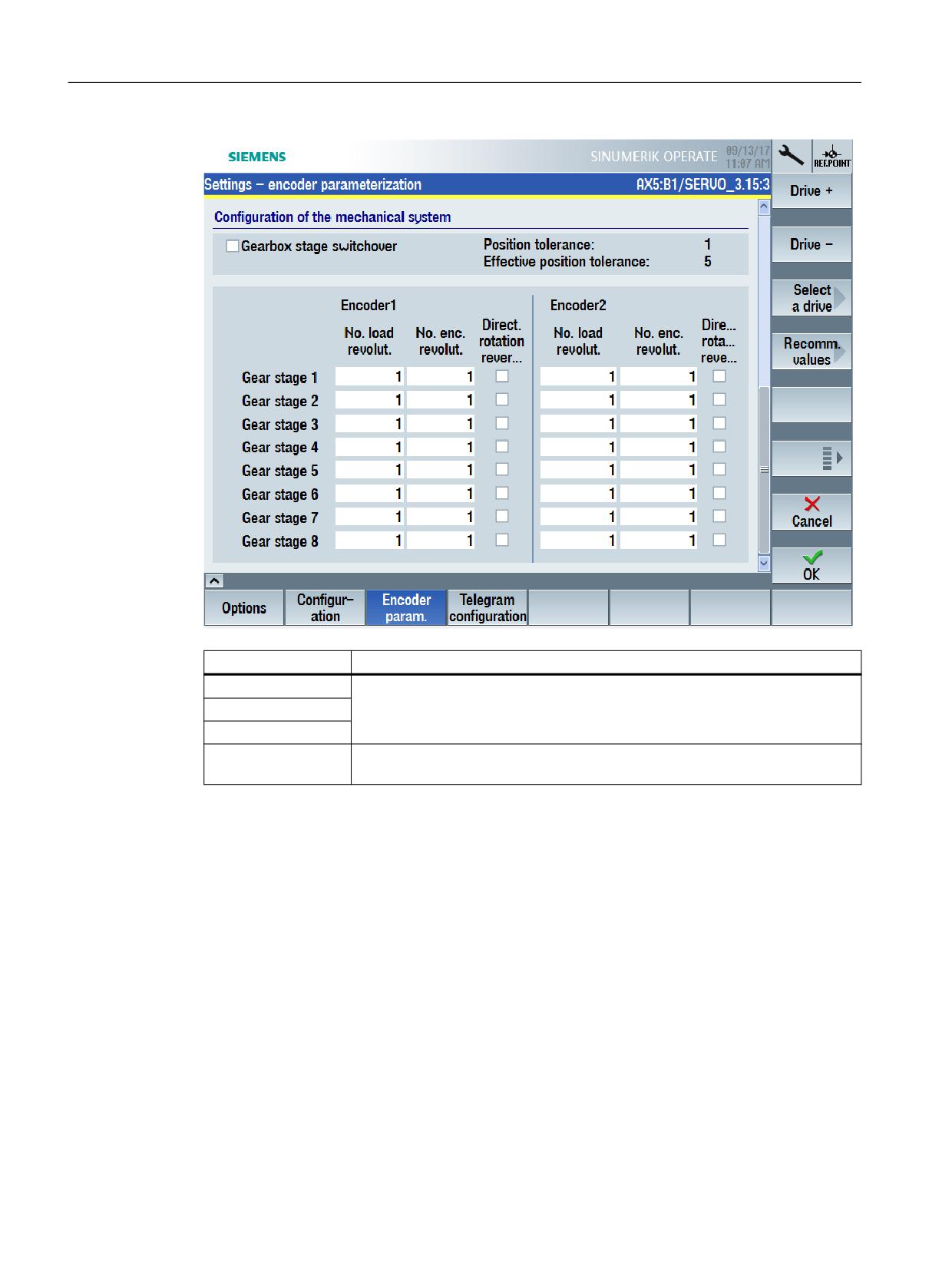
Table 7-4
Mechanical configuration (settings - encoder parameterization)
Setting
Gearbox stage switchover
Enables/inhibits safety-relevant gearbox stage switchover.
When enabled, you can parameterize up to 8 ratios, and switchover the
active gearbox stage via PROFIsafe.
Position tolerance
Sets the factor to increase the tolerance for the crosswise data comparison
of the actual position between the two monitoring channels while the
gearbox stage is being switched over.
This factor is active when actual value synchronization is both activated as
well as also deactivated.
It is obtained, depending on the following tolerance:
• Actual value synchronization activated: p9549 * position tolerance
• Actual value synchronization deactivated: Actual value tolerance * po-
sition tolerance
Active position tolerance
Displays the active position tolerance. (product from the position tolerance
and actual value tolerance or velocity tolerance)
Number of load revolutions
Sets the denominator for the gearbox between the encoder and load.
Number of encoder revolu-
Sets the numerator for the gearbox between the encoder and load.
tions
Direction reversal
Activates/deactivates the direction of reversal for the gearbox.
7.5.8
Configuring encoderless operation
Precondition
• The SI commissioning mode (Page 238) is active for the drive to be configured.
• The drive is configured for operation without an encoder.
Safety Integrated plus
248
Commissioning Manual, 10/2020, 6FC5397-1FP40-6BA4
Commissioning and configuring
7.5 Configuring NC and drive-specific safety settings
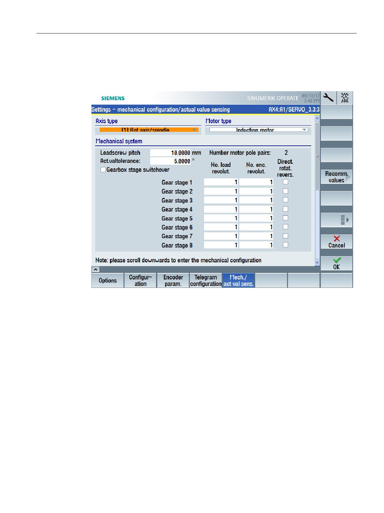
Call the startup screen form "Configuration mechanical/actual value sensing"
MENU SELECT > Commissioning > Menu forward key > Safety > Settings > Mechanical /actual
value sensing
Safety Integrated plus
Commissioning Manual, 10/2020, 6FC5397-1FP40-6BA4
249
Commissioning and configuring
7.5 Configuring NC and drive-specific safety settings
Softkey
Purpose
Drive +
The settings are specific to a certain drive. Switch to the corresponding drive
using the appropriate softkey before configuring.
Drive -
Select a drive
Recommended val-
Using softkey "Recommended values", you can automatically preassign the val-
ues
ues of the particular startup screen form. Check the individual suggested values.
Adapting settings
Table 7-5
(Settings - mechanical configuration/actual value sensing)
Setting
Meaning
Leadscrew pitch
Sets the ratio between the encoder and load in mm/revolutions for a linear
axis with rotary encoder.
Actual value tolerance
Sets the tolerance for the crosswise comparison of the actual position be-
tween the two monitoring channels.
The tolerance must be set higher (e.g. 12 degrees rotary and 1 mm linear)
for encoderless motion monitoring functions.
Safety Integrated plus
250
Commissioning Manual, 10/2020, 6FC5397-1FP40-6BA4

Commissioning and configuring
7.5 Configuring NC and drive-specific safety settings
Table 7-6
Gearbox stages switchover (Settings - mechanical configuration/actual value sensing)
Setting
Meaning
Gearbox stage switchover
Enables/inhibits safety-relevant gearbox stage switchover.
When enabled, you can parameterize up to 8 ratios, and switchover the
active gearbox stage via PROFIsafe.
Number of load revolutions
Sets the denominator for the gearbox between the motor and load. The
active gearbox stage can be switched over via PROFIsafe.
Number of encoder revolu-
Sets the denominator for the gearbox between the motor and load. The
tions
active gearbox stage can be switched over via PROFIsafe.
For encoderless monitoring functions, the numerator of the gear ratio must
be multiplied by the number of pole pairs (see below).
Example:
Gearbox ratio 1:4, number of pole pairs = 2
Number of load revolutions = 1, number of encoder revolutions = 8 (4 x 2)
Direction reversal
Activates/deactivates the direction of reversal for the gearbox.
Motor pole pair number
Displays the number of motor pole pairs.
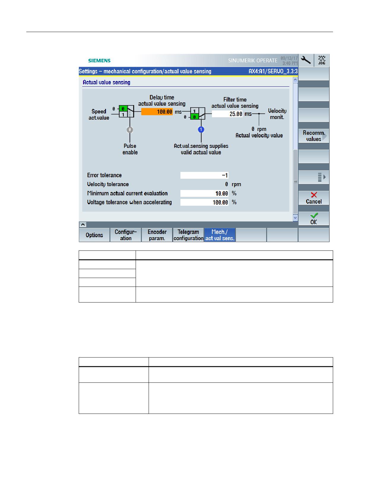
Table 7-7
Actual value sensing (Settings - mechanical configuration/actual value sensing)
Setting
Meaning
Delay time actual value
Sets the delay time for evaluating the encoderless actual value sensing after
sensing
the pulses have been enabled.
The value should be greater than or equal to the magnetization time of the
motor (p0346).
The set time is internally rounded off to an integer multiple of the moni-
toring clock cycle.
Caution: The safety functions are not fully effective until this time has
elapsed.
Notice: Reducing this value can have a negative impact on the actual value
acquisition and plausibility check - and result in safety message C01711
with message value 1041 or 1042.
Dependencies: C01711
Filter time actual value
Sets the filter time for the actual value smoothing for actual value acquisi-
sensing
tion without encoder.
Notice: A higher filter time results in a longer response time.
The smoothing is realized using a 1st order lowpass filter.
For a minimum value, the filter is deactivated.
The set time is internally rounded off to an integer multiple of the moni-
toring clock cycle.
Pulse enable
Display: Enable power
Actual value sensing sup-
Display: Actual value sensing supplies valid actual value
plies valid actual value
Actual speed value
Displays actual speed values for motion monitoring on the Control Unit.
Index [0] = load side actual speed value on the Control Unit
Safety Integrated plus
Commissioning Manual, 10/2020, 6FC5397-1FP40-6BA4
251

Commissioning and configuring
7.5 Configuring NC and drive-specific safety settings
Setting
Meaning
Fault tolerance
Setting of the plausibility monitoring tolerance for the current and the volt-
age angle.
A higher value makes the drive more stable when it is reversing at low
speeds - or when the load changes abruptly in the field-weakening range.
An increase brings advantages when the current or voltage at the motor
becomes small.
Increasing the value results in a longer evaluation delay - and to a higher
speed tolerance (see below).
Notice: Reducing this value can have a negative impact on the actual value
acquisition and the plausibility check.
For synchronous motors, the value must be set to 4.
For value = -1:
- for synchronous motors, the calculation automatically uses a value of 4
- for induction motors, the calculation automatically uses a value of 0 (if the
code number of the power unit p0201[0] is < 14000, otherwise a value of
2 is used).
Dependencies: F01681, C01711
Speed tolerance
Displays the actual speed deviation for encoderless actual value acquisition.
This value is calculated when setting the error tolerance (see above).
Safety Integrated plus
252
Commissioning Manual, 10/2020, 6FC5397-1FP40-6BA4

Commissioning and configuring
7.5 Configuring NC and drive-specific safety settings
Setting
Meaning
Minimum actual current
Sets the minimum current for encoderless actual value acquisition referred
evaluation
to 1 A (i.e. 1 % = 10 mA).
• The value must be increased if C01711 is output with message value
1042.
• The value must be decreased if C01711 is output with message value
1041.
For synchronous motors, the following condition must be satisfied:
|p0305 x p9783| >= minimum current actual value acquisition x 1.2
Recommendation: If necessary, to determine the correct value, the mini-
mum motor current must be measured.
Notice: An excessive reduction of this percentage value can result in a safety
message and in an inaccurate actual value.
Dependencies: r9785, C01711
Acceleration voltage toler-
Sets the acceleration limit to filter discontinuities in the speed/velocity. The
ance
filter is deactivated when setting the maximum value.
An increase in this percentage value means that velocity peaks can occur
when accelerating, which do not reflect the real velocity characteristic.
A decrease in this value dampens velocity peaks when accelerating.
• The value must be increased if message C01711 is output with the value
1043.
• The value must be decreased if acceleration has resulted in an excessive
safety actual velocity.
Recommendation: This parameter setting depends on the motor and
closed-loop control, and must be redetermined for each configuration.
To do this, a measurement must be made while the actual value is changing
(step function/jump), and the limit should be set so low in r9785[0] via
p9589 that it is not exceeded more than four times per second by the value
set in r9785[1]. At this point in time, the actual value correction filter in-
tervenes. The step is no longer so drastic.
Dependencies: r9784, C01711
See also
Selecting the safety functional scope (Page 240)
7.5.9
Configuring telegrams
Precondition
• The SI commissioning mode (Page 238) is active for the drive to be configured.
• Extended Functions or Basic Functions via PROFIsafe are set (Page 240) for the drive to be
configured.
Safety Integrated plus
Commissioning Manual, 10/2020, 6FC5397-1FP40-6BA4
253
Commissioning and configuring
7.5 Configuring NC and drive-specific safety settings
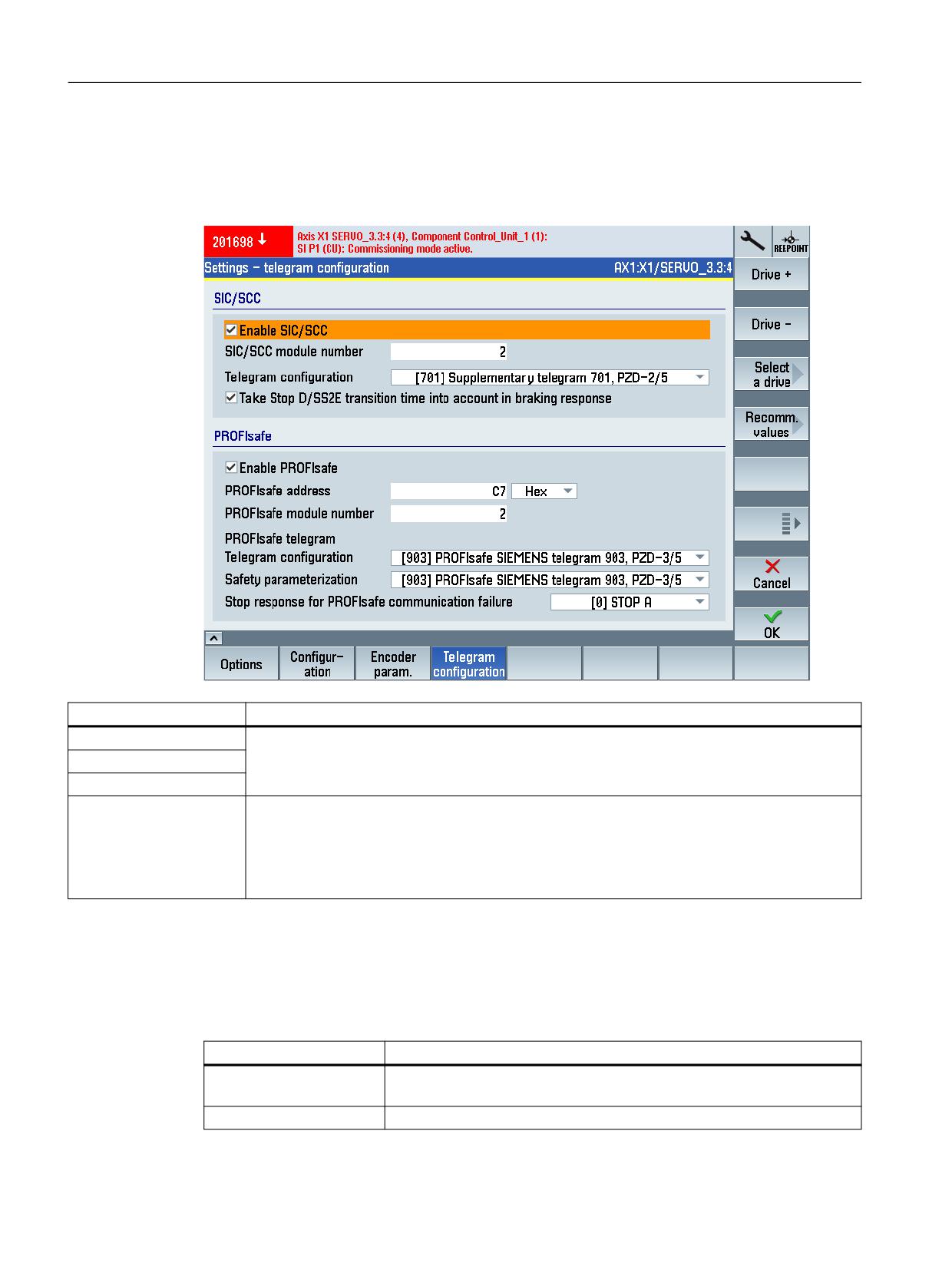
Call up "Telegram configuration" commissioning screen
MENU SELECT > Commissioning > Menu forward key > Safety > Settings > Telegram
configuration
Softkey
Purpose
Drive +
The settings are specific to a certain drive. Switch to the corresponding drive using the appropriate
softkey before configuring.
Drive -
Select a drive
Recommended values
Using softkey "Recommended values", you can automatically preassign the values of the particular
startup screen form.
For example, in the startup screen form "Telegram configuration", the telegram types from the
configuration belong to the settings that can be assigned as default.
Check the individual suggested values.
Making the settings
Table 7-8
SIC/SCC telegram settings (Settings - telegram configuration)
Setting
Meaning
Enable SIC/SCC
Enables/inhibits the evaluation of the Safety Info Channel / Safety Control
Channel (SCC/SIC).
SIC/SCC module number
Sets the SIC/SCC module number.
Safety Integrated plus
254
Commissioning Manual, 10/2020, 6FC5397-1FP40-6BA4

Commissioning and configuring
7.5 Configuring NC and drive-specific safety settings
Setting
Meaning
Telegram configuration
Sets the telegram type for the Safety Info Channel (SIC)/Safety Control
Channel (SCC)
Takes into account the stop
Activates the adaptation of the braking ramp for stop D/SS2E
D/SS2E transition time in
the braking response
Table 7-9
PROFIsafe telegram settings (Settings - telegram configuration)
Setting
Meaning
Enable PROFIsafe
Enables/inhibits PROFIsafe communication between F-PLC and drive
PROFIsafe address
Sets the PROFIsafe address for the Control Unit.
PROFIsafe module number
Sets the PROFIsafe module number.
Telegram configuration
Sets the PROFIsafe telegram type.
Safety parameter assign-
Sets the PROFIsafe telegram type for the Control Unit.
ment
Safety Integrated plus
Commissioning Manual, 10/2020, 6FC5397-1FP40-6BA4
255

Commissioning and configuring
7.6 Configuring safety functions integrated in the drive
7.6
Configuring safety functions integrated in the drive
7.6.1
Overview
SINUMERIK Operate screen forms and settings to commission the various safety functions are
described in this chapter.
Basic procedure
Call the appropriate startup screen forms in SINUMERIK Operate and configure the safety
functions for the individual drives.
Table 7-10
Startup screen forms and function descriptions
Startup screen form
Detailed function description
STO/SS1 Basic (Page 257)
Safe Torque Off (Page 91) / Safe Stop 1 (Page 80)
STO Extended (Page 258)
Safe Torque Off (Page 91)
SBC (Page 260)
Safe Brake Control (Page 97)
SS1 Extended (Page 261)
Safe Stop 1 (Page 84)
SS2/SOS (Page 263)
Safe Stop 2 (Page 104) / Safe Operating Stop (Page 114)
SLS (Page 269)
Safely-Limited Speed (Page 118)
SSM (Page 272)
Safe Speed Monitor (Page 131)
SAM (Page 265)
Safe Acceleration Monitor (Page 137)
SBR (Page 268)
Safe Brake Ramp (Page 139)
SDI (Page 275)
Safe Direction (Page 143)
SLP/SP (Page 276)
Safely-Limited Position (Page 151) / Safe Position (Page 156)
SBT (Page 279)
Safe Brake Test (Page 160)
SCA (Page 282)
Safe Cam (Page 172)
Can only be parameterized via
Safely-Limited Acceleration (Page 175)
the parameter list
SS2E (Page 284)
Safe Stop 2 with external stop (Page 107)
Safety Integrated plus
256
Commissioning Manual, 10/2020, 6FC5397-1FP40-6BA4
Commissioning and configuring
7.6 Configuring safety functions integrated in the drive
Startup screen form
Detailed function description
SS2ESR (Page 286)
Safe Stop 2 extended stop and retract (Page 111)
Safe referencing (Page 288)
Safe referencing (Page 179)
You can find additional information on the function sequence of parameterization in the
Function Description.
In many cases, using the "Recommended values" softkey, you can automatically preassign the
values of the particular startup screen form.
Alternative to the commissioning screen forms, you can switch to "Parameter list", where all of
the parameters are listed in tabular form that are relevant for the particular safety function.
7.6.2
STO/SS1 Basic
Precondition
• The SI commissioning mode (Page 238) is active for the drive to be configured.
• One of the basis functions (Page 240) is is selected.
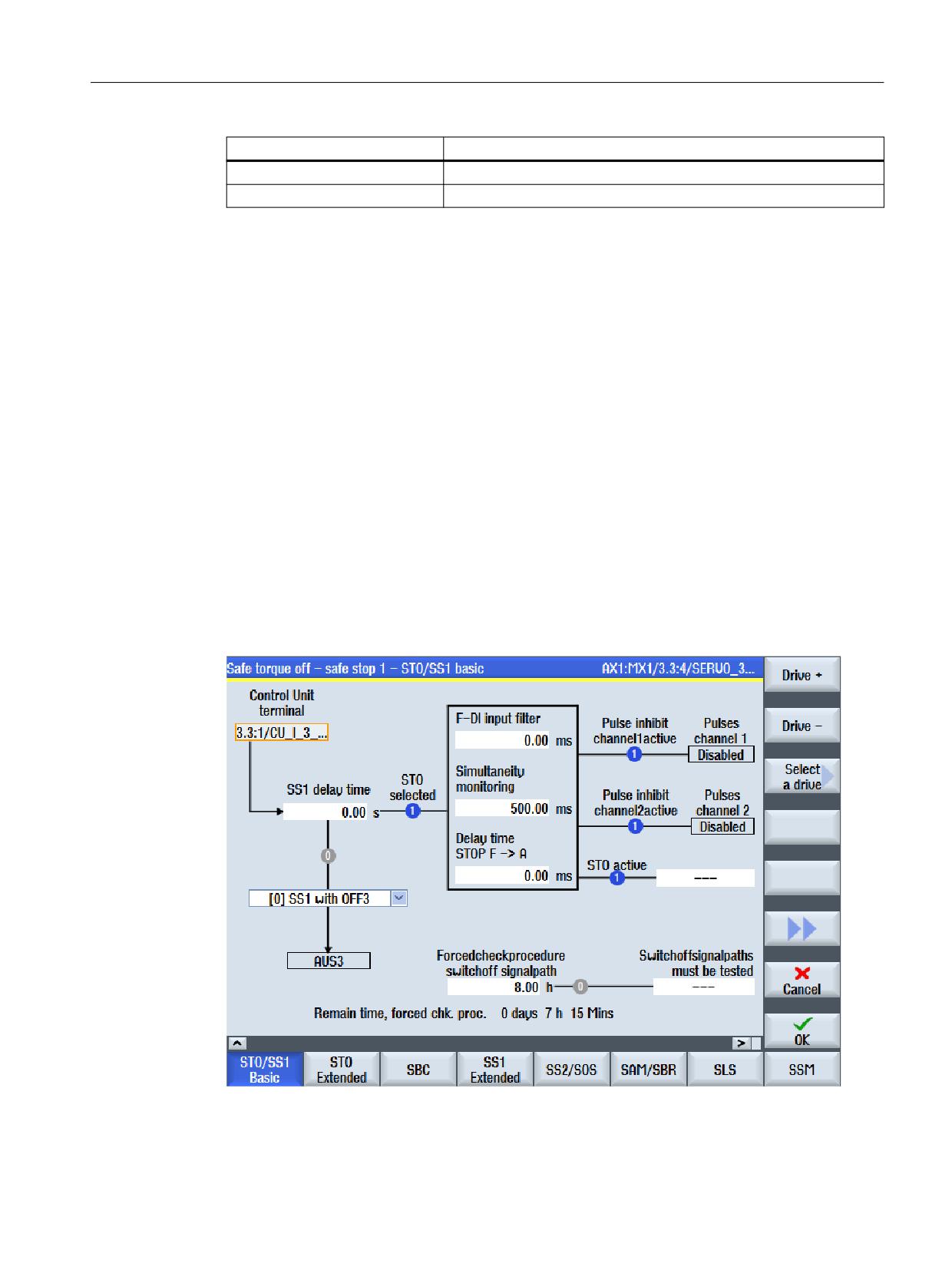
Displaying the "Safe torque off - STO/SS1 Basic" commissioning screen
MENU SELECT > Commissioning > Menu forward key > Safety > Functions > STO/SS1 Basic
Figure 7-11
Safe Torque Off - Safe Stop 1 - STO/SS1 Basic
Safety Integrated plus
Commissioning Manual, 10/2020, 6FC5397-1FP40-6BA4
257

Commissioning and configuring
7.6 Configuring safety functions integrated in the drive
Status information
For the following parameters, the status symbols indicate the actual state (blue = active; gray =
inactive):
Status
Meaning
STO selected (r9772.0)
"STO selected in the drive" setting
No text (brake reaction) (r9773.2)
Setting "SS1 Delay time active in the drive"
Pulse inhibit channel 1 active (r9772.1)
Setting "STO or safe pulse cancellation active on the CU"
Pulse inhibit channel 2 active (r9872.1)
Setting "STO on Motor Module active"
STO active (r9773.1)
Setting "STO active in the drive"
Switch-off signal paths must be tested
Setting "Switch-off signal paths must be tested"
(r9773.31)
Settings
Setting
Meaning
Control Unit terminal (p9620[0])
Sets the signal source for the STO, SBC and SS1 functions of the Control Unit.
This is only relevant if a basic function via terminal is set in the options.
Otherwise, the input field is deactivated.
SS1 delay time (p9652)
Sets the delay time of the pulse cancellation in seconds for the function "Safe
Stop 1" (SS1) on the Control Unit to brake along the OFF3 down ramp
(p1135).
Braking response for SS1 (p9653)
Select a predefined braking response below the input field "SS1 delay time".
Parameter p9653 is preassigned depending on the selected braking re-
sponse.
F-DI input filter (p9651)
Setting the debounce time in ms for the failsafe digital inputs to control STO/
SBC/SS1.
Simultaneity monitoring (p9650)
Sets the discrepancy time in ms for the switchover of the safety-relevant
inputs (SGE) on the Control Unit.
Delay time STOP F -> STOP A (p9658)
Sets the transition time from STOP F to STOP A in ms on the Control Unit.
Forced checking procedure of the switch-off
Sets the time interval in hours for carrying out the forced checking procedure
signal paths (p9659)
and testing the switch-off signal paths.
Switch-off signal paths must be tested
To evaluate whether the switch-off signal paths must be tested, the status of
(r9773.31)
r9773.31 “Switch-off signal path must be tested" can be interconnected with
a parameter via the BICO editor.
7.6.3
STO Extended
Precondition
• The SI commissioning mode (Page 238) is active for the drive to be configured.
• The drive is configured for operation with an encoder and Extended Functions.
Safety Integrated plus
258
Commissioning Manual, 10/2020, 6FC5397-1FP40-6BA4
Commissioning and configuring
7.6 Configuring safety functions integrated in the drive
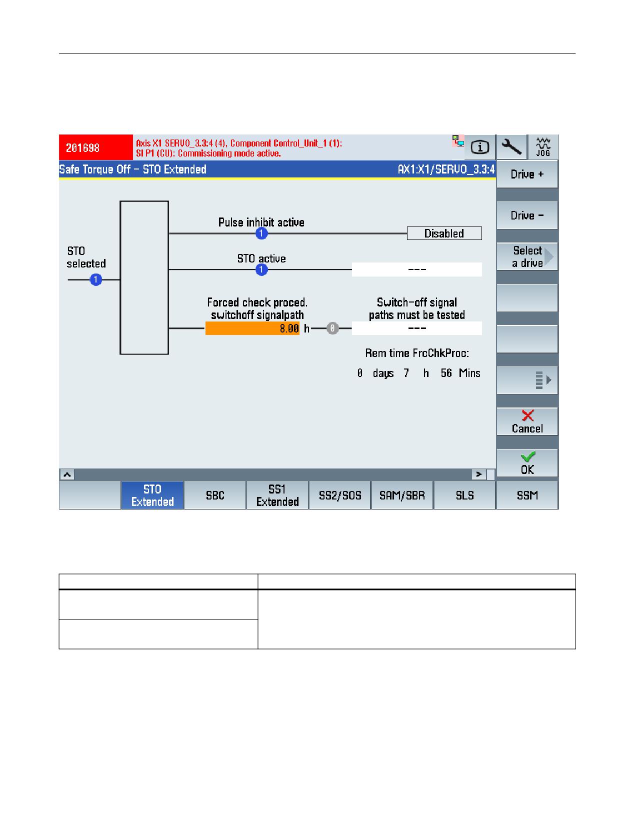
Display commissioning screen "Safe torque off - STO Extended"
MENU SELECT > Commissioning > Menu forward key > Safety > Functions > STO Extended
Figure 7-12
Safe Torque Off - STO Extended
Status information
Status
Meaning
STO active
Safety Integrated status of the drive (Control Unit and MM).
r9773.1
Test stop required
r9773.31
Safety Integrated plus
Commissioning Manual, 10/2020, 6FC5397-1FP40-6BA4
259
Commissioning and configuring
7.6 Configuring safety functions integrated in the drive
Settings
Setting
Meaning
Forced checking procedure of the switch-off
Sets the time interval for performing the forced checking procedure and test-
signal paths
ing the safety switch-off signal paths. Within the parameterized time, STO
must have been deselected at least once. The monitoring time is reset at
p9659
every STO deselection.
7.6.4
SBC
Precondition
• The SI commissioning mode (Page 238) is active for the drive to be configured.
• At least one safety monitoring function is enabled for the drive.
• A motor holding brake has been configured for the drive.
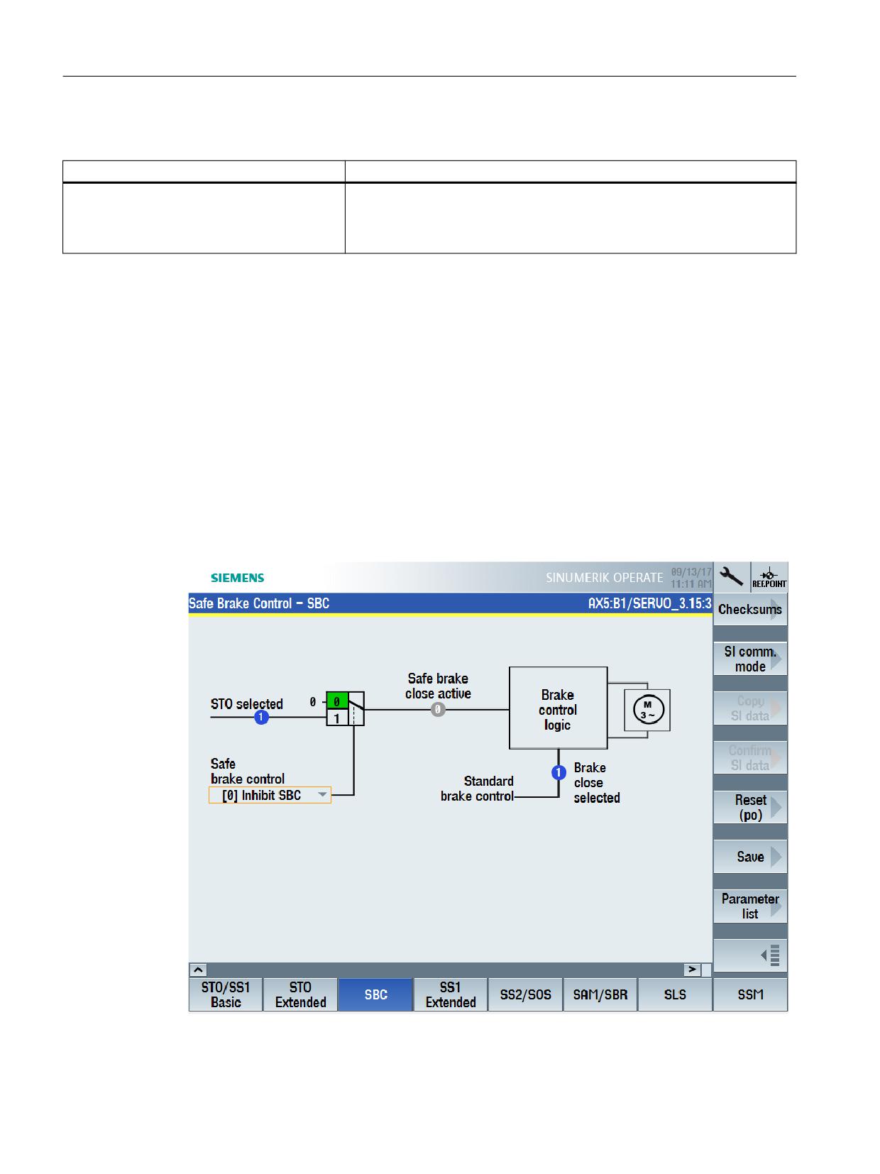
Display "Safe brake control - SBC" commissioning screen
MENU SELECT > Commissioning > Menu forward key > Safety > Functions > SBC
Figure 7-13
Safe Brake Control - SBC
Safety Integrated plus
260
Commissioning Manual, 10/2020, 6FC5397-1FP40-6BA4

Commissioning and configuring
7.6 Configuring safety functions integrated in the drive
Status information
Status
Meaning
STO selected
Display and BICO output for the status of Safety Integrated on the drive (Con-
trol Unit + Motor Module):
r9773.0
STO selected in the drive
Switching element
See "Safe brake control" setting
Safe brake close active
Display and BICO output for the status of Safety Integrated on the drive (Con-
trol Unit + Motor Module):
r9773.4
SBC requested
Close brake selected
Display and BICO output for the status word of the sequence control:
r0899.13
Command, close holding brake
Settings
Setting
Meaning
Safe brake control
Sets the enable signal for the "Safe brake control" (SBC) function on the Con-
trol Unit.
p9602
•
[0] Inhibit SBC
•
[1] Enable SBC
7.6.5
SS1 Extended
Precondition
• The SI commissioning mode (Page 238) is active for the drive to be configured.
• The drive is configured for operation with an encoder and Extended Functions.
Safety Integrated plus
Commissioning Manual, 10/2020, 6FC5397-1FP40-6BA4
261
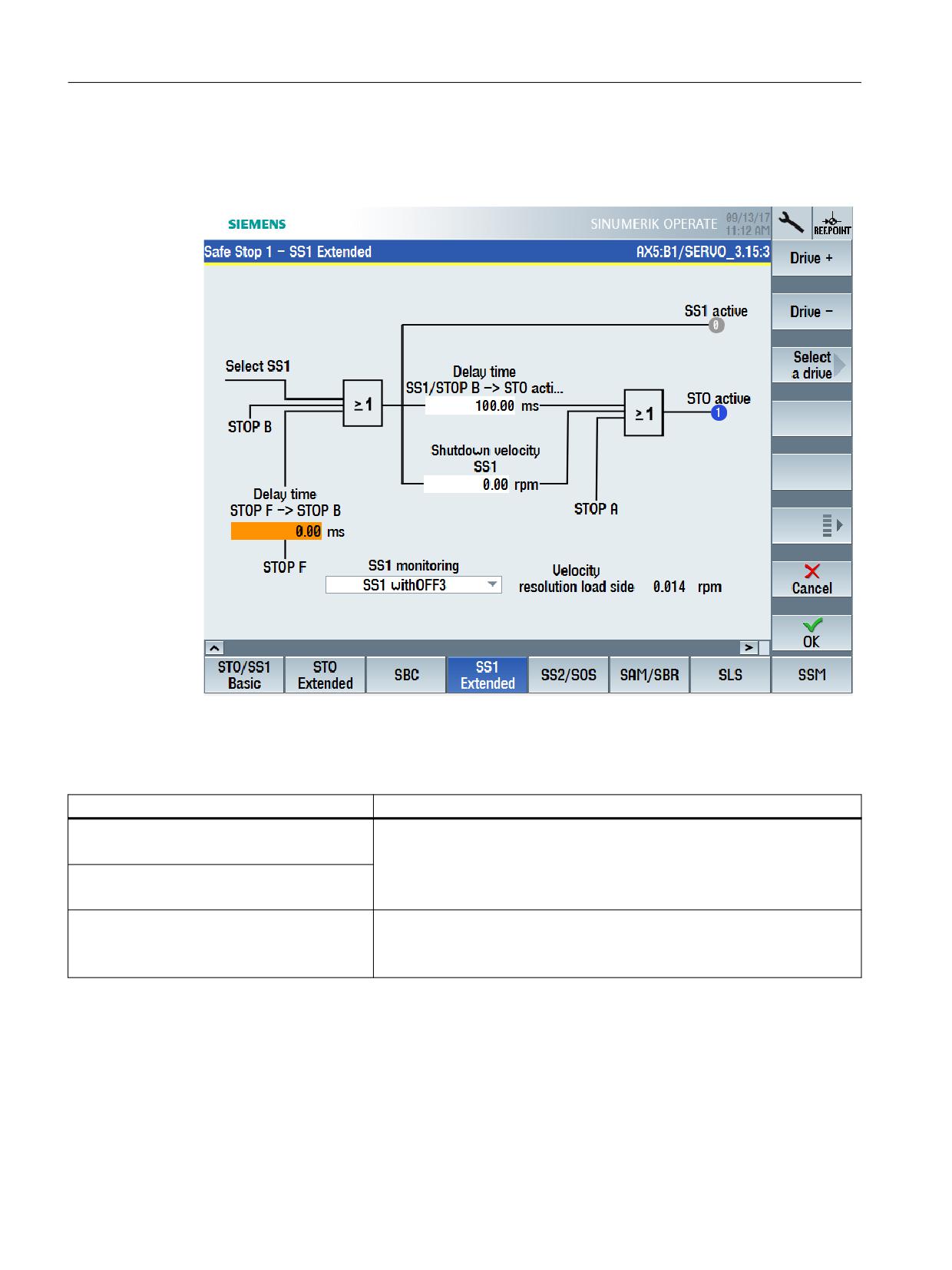
Commissioning and configuring
7.6 Configuring safety functions integrated in the drive
Display "Safe Stop 1 - SS1 Extended" commissioning screen
MENU SELECT > Commissioning > Menu forward key > Safety > Functions > SS1 Extended
Figure 7-14
Safe Stop 1 - SS1 Extended
Status information
Status
Meaning
SS1 active
Status signals for the safety motion monitoring functions integrated in the
drive on monitoring channel 1.
r9722.1
STO active
r9722.0
Velocity resolution
Displays the safe velocity resolution (load side). Velocity limits that are speci-
fied - or parameter changes for velocities below this threshold - have no effect.
Load side
r9732[0]
Safety Integrated plus
262
Commissioning Manual, 10/2020, 6FC5397-1FP40-6BA4

Commissioning and configuring
7.6 Configuring safety functions integrated in the drive
Settings
Setting
Meaning
Delay time STOP F -> STOP B
Sets the transition time from STOP F to STOP B
p9555
The set time is internally rounded off to an integer multiple of the monitoring
clock cycle.
SS1 monitoring
Selects the stop response, which is initiated when selecting function SS1 or
activating a STOP B.
p9507.3=0
• SS1 with OFF3
SS1 with OFF3 braking response integrated in the drive
• SS1E external stop
Stop to be externally initiated. Braking monitoring (SBR, SAM) is deacti-
vated.
Delay time, SS1/STOP B -> STO active
Sets the delay time for STOP A to STOP B.
p9556
The set time is internally rounded off to an integer multiple of the monitoring
clock cycle.
Shutdown speed SS1
Sets the shutdown velocity for activating STO. "Standstill" is assumed below
this velocity, and for STOP B / SS1, an STO is selected.
p9560
In the case of encoderless motion monitoring functions, this parameter must
be > 0 (10 is recommended).
(only for SS1 with OFF3)
Note: The shutdown velocity has no effect for a value = 0.
7.6.6
SS2/SOS
Precondition
• The SI commissioning mode (Page 238) is active for the drive to be configured.
• The drive is configured for operation with an encoder and Extended Functions.
Safety Integrated plus
Commissioning Manual, 10/2020, 6FC5397-1FP40-6BA4
263
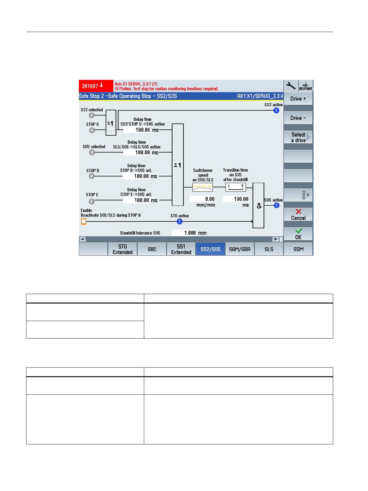
Commissioning and configuring
7.6 Configuring safety functions integrated in the drive
Display "Safe Stop 2 - Safe Operating Stop - SS2/SOS" commissioning screen
MENU SELECT > Commissioning > Menu forward key > Safety > Functions > SS2/SOS
Figure 7-15
Safe Stop 2 - Safe Operating Stop - SS2/SOS
Status information
Status
Meaning
SS2 active
Status signals for the safety motion monitoring functions integrated in the
drive on monitoring channel 1.
r9722.2
SOS active
r9722.3
Settings
Setting
Meaning
Delay time for SS2/STOP C -> SOS active
Sets the transition time from STOP C to "Safe Operating Stop" (SOS).
p9552
Delay time, SLS/SOS - SLS/SOS active
Sets the delay time for the SLS changeover and for the activation of SOS for
the functions "Safely-Limited Speed" (SLS) and "Safe Operating Stop" (SOS).
p9551
When transitioning from a higher to a lower Safely-Limited Speed stage and
when activating a Safe Operating Stop (SOS), the "old" speed stage remains
active for this delay time. A delay is also occurred when activating SLS from
the "SOS and SLS inactive" state - and when activating SOS from the "SOS
inactive" state.
Safety Integrated plus
264
Commissioning Manual, 10/2020, 6FC5397-1FP40-6BA4

Commissioning and configuring
7.6 Configuring safety functions integrated in the drive
Setting
Meaning
Delay time, STOP D -> SOS active
Sets the transition time from STOP D to "Safe Operating Stop" (SOS)
p9553
Delay time, STOP E -> SOS active
Sets the transition time from STOP E to "Safe Operating Stop" (SOS)
p9554
Switchover speed to SOS/SLS
Sets the switchover speed to SOS/SLS in mm/min.
p9567
Transition time to SOS after standstill
Sets the transition time to SOS after standstill in ms.
p9569
Enable deactivation of SOS/SLS during an ex-
Using the checkbox, "Enable deactivation SOS/SLS during an external STOP A"
ternal STOP A
can be activated.
p9501.23
Standstill tolerance SOS
Sets the tolerance for the "Safe operating stop" function (SOS).
p9530
7.6.7
SAM
Precondition
• The SI commissioning mode (Page 238) is active for the drive to be configured.
• The drive is configured for operation with an encoder and Extended Functions.
Safety Integrated plus
Commissioning Manual, 10/2020, 6FC5397-1FP40-6BA4
265
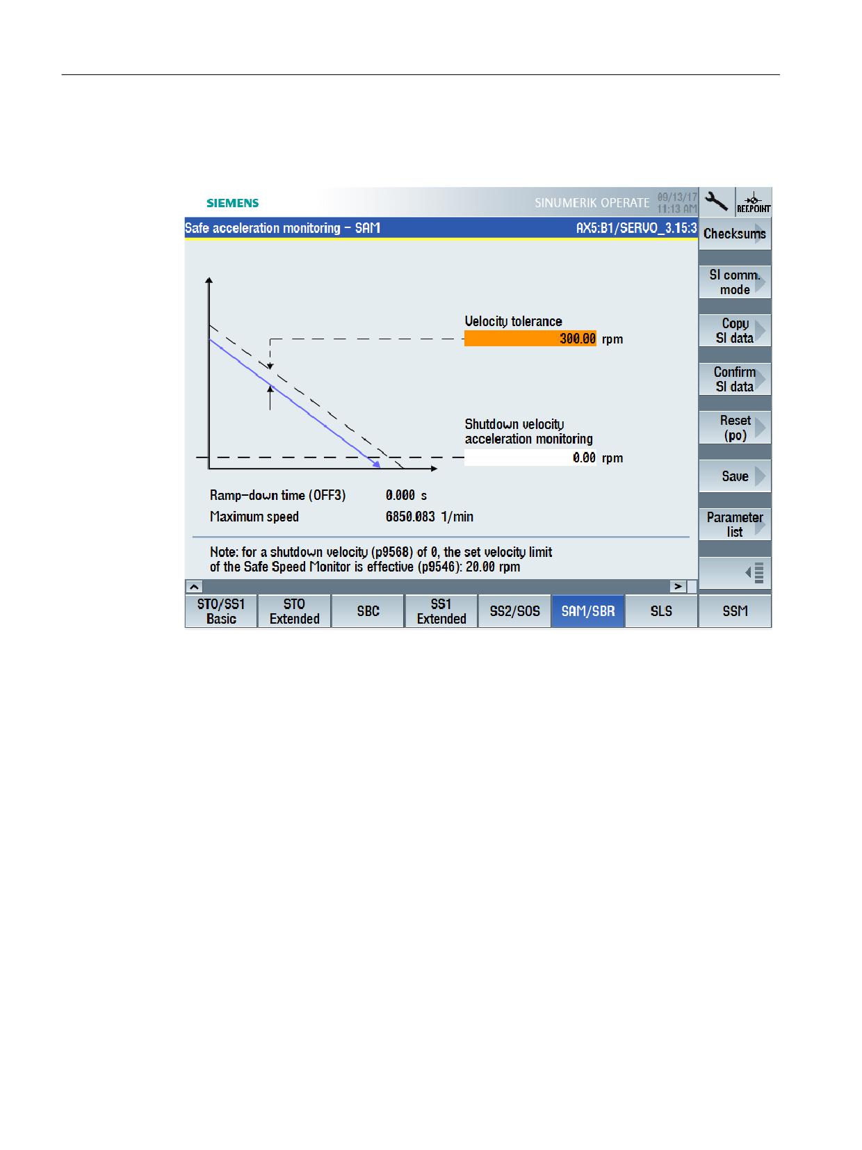
Commissioning and configuring
7.6 Configuring safety functions integrated in the drive
Display "Safe Acceleration Monitoring - SAM" commissioning screen
MENU SELECT > Commissioning > Menu forward key > Safety > Functions > SAM/SBR
Figure 7-16
Safe Acceleration Monitoring - SAM
Safety Integrated plus
266
Commissioning Manual, 10/2020, 6FC5397-1FP40-6BA4

Commissioning and configuring
7.6 Configuring safety functions integrated in the drive
Settings
Setting
Meaning
Velocity tolerance
p9548
During the down ramp, the converter continually adds the speed tolerance to
the actual speed. The converter reduces the monitoring threshold until the
"Shutdown speed" has been reached.
• If the speed temporarily increases, the monitoring threshold remains at
the last value.
• If the drive accelerates by the velocity tolerance, then SAM identifies this,
and a STOP A is initiated.
Calculation
• The following applies when parameterizing the SAM tolerance:
- The maximum speed increase after SS1 or SS2 is triggered results from
the effective acceleration (a) and the duration of the acceleration
phase.
- The duration of the acceleration phase is equivalent to one monitor-
ing clock cycle (delay from detecting an SS1/SS2 until nset = 0):
• Calculating the velocity tolerance:
Actual speed for SAM = acceleration × acceleration duration
The following setting rule is obtained:
- For linear axes:
SAM tolerance [mm/min] = a [m/s2] x MC [s] x 1000 [mm/m] x 60 [s/
min]
- For rotary axes:
SAM tolerance [rpm] = a [rev/s2] x MC [s] x 60 [s/min]
• Recommendation
The SAM tolerance value entered should be approx. 20 % higher than the
calculated value.
• With the tolerance, the "overshoot", which is automatically obtained
when reaching standstill when braking along the OFF3 ramp, must be
tolerated. However, it cannot be calculated as to just how high this is.
Shutdown speed acceleration monitoring
Sets the speed limit for the "SAM" and "SBR" functions.
p9568
SAM is deactivated once the set velocity limit has been fallen below. SBR is
deactivated if the safe braking ramp falls below the set speed limit.
Ramp-down time (OFF3)
Sets the ramp down time from the maximum velocity or maximum speed to
standstill for the OFF3 command.
p1135[0]
This time can be exceeded if the maximum the DC link voltage is reached.
Maximum velocity or maximum speed
Sets the highest possible velocity or speed.
(linear axis or rotary axis/spindle)
p1082[0]
Safety Integrated plus
Commissioning Manual, 10/2020, 6FC5397-1FP40-6BA4
267
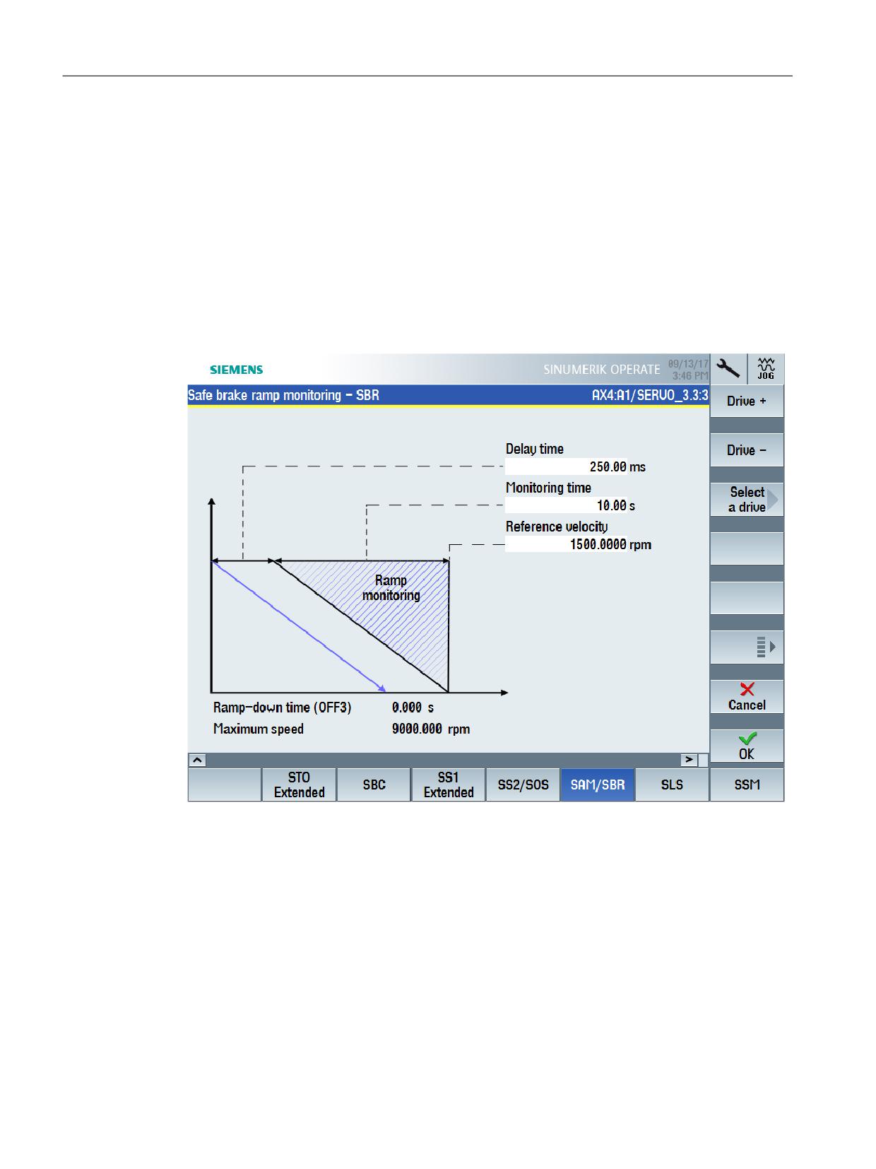
Commissioning and configuring
7.6 Configuring safety functions integrated in the drive
7.6.8
SBR
Precondition
• The SI commissioning mode (Page 238) is active for the drive to be configured.
• Safety function SS1 with stop response OFF3 is configured for the drive.
Displaying the "Safe brake ramp - SBR" startup screen form
MENU SELECT > Commissioning > Menu forward key > Safety > Functions > SAM/SBR
Figure 7-17
Safe Brake Ramp - SBR
Safety Integrated plus
268
Commissioning Manual, 10/2020, 6FC5397-1FP40-6BA4

Commissioning and configuring
7.6 Configuring safety functions integrated in the drive
Settings
Setting
Meaning
Delay time
Set the delay time for monitoring the braking ramp.
p9582
Time that lapses after initiating SS1, selecting SLS or SLS level changeover
and the start of brake ramp monitoring.
The delay time has a minimum value of 2 safety monitoring clock cycles. (if
the parameterized delay time is less than 2 safety monitoring clock cycles,
then internally, a delay time of 2x monitoring clock cycles is used.)
Monitoring time
Sets the monitoring time to determine the braking ramp.
p9583
The gradient of the braking ramp depends on the reference velocity (refer-
ence value) and the monitoring time.
Reference velocity
Sets the reference value to determine the braking ramp.
p9581
The gradient of the braking ramp depends on the reference velocity (refer-
ence value) and the monitoring time.
Ramp-down time (OFF3)
Sets the ramp down time from the maximum velocity or maximum speed to
standstill for the OFF3 command.
p1135[0]
This time can be exceeded if the maximum the DC link voltage is reached.
Maximum velocity or maximum speed
Sets the highest possible velocity or speed.
(linear axis or rotary axis/spindle)
p1082[0]
7.6.9
SLS
Precondition
• The SI commissioning mode (Page 238) is active for the drive to be configured.
• The drive is configured for operation with an encoder and Extended Functions.
Note
Transferring process data for SLS in PROFIsafe telegrams
PROFIsafe telegram 901, 902 or 903 can be used to transfer process data. The default setting is
telegram 903.
Safety Integrated plus
Commissioning Manual, 10/2020, 6FC5397-1FP40-6BA4
269
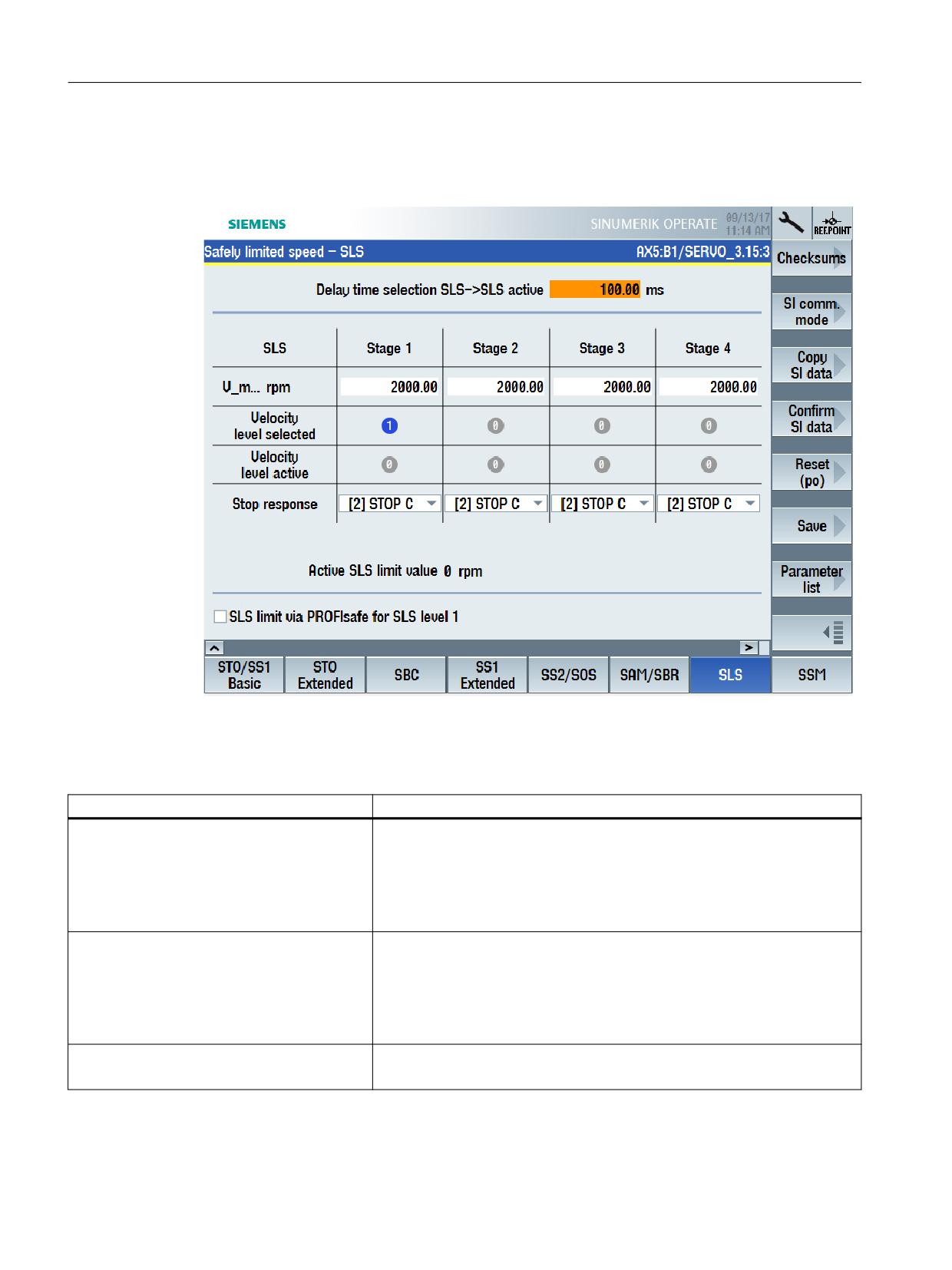
Commissioning and configuring
7.6 Configuring safety functions integrated in the drive
Display "Safely Limited Speed - SLS" commissioning screen
MENU SELECT > Commissioning > Menu forward key > Safety > Functions > SLS
Figure 7-18
Safely-Limited Speed - SLS
Status information
Status
Meaning
Velocity level selected
Indicates which parameterized velocity level is currently selected.
Level 1: r9720.9=0 and r9720.10=0
Level 2: r9720.9=1 and r9720.10=0
Level 3: r9720.9=0 and r9720.10=1
Level 4: r9720.9=1 and r9720.10=1
Velocity level active
If one of the velocity levels is currently active, then this is displayed in the
corresponding column.
Level 1: r9722.9=0 and r9722.10=0
Level 2: r9722.9=1 and r9722.10=0
Level 3: r9722.9=0 and r9722.10=1
Level 4: r9722.9=1 and r9722.10=1
Active SLS limit value
Displays the load-side velocity actual value of the CU.
r9714.0
The display is updated in the safety monitoring cycle clock.
Safety Integrated plus
270
Commissioning Manual, 10/2020, 6FC5397-1FP40-6BA4

Commissioning and configuring
7.6 Configuring safety functions integrated in the drive
Settings
Setting
Meaning
Delay time when selecting SLS -> SLS active
Sets the delay time for SLS switchover.
p9551
This delay time is active in the following cases:
• Selecting SLS:
Monitoring only becomes active after the configurable delay time has
elapsed. Within this time, the actual speed must be below the (selected)
limit.
• This delay time is also incurred when activating SLS from the "SOS and SLS
in active" state.
• Reducing the 1st limit value via PROFIsafe - or switching over to a lower
maximum velocity level:
The actual velocity of the drive must have dropped below the new limit
within the delay time. The existing limit remains active during the delay
time. The lower limit value becomes active after the delay time expires.
The delay time is not active in the following cases:
• Deselecting SLS
• Switching over to a higher limit value:
The higher limit value immediately becomes active.
In operation, the parameterized delay time cannot be changed. If you require
various delay times in your application, then you must realize this using a
time-delayed transfer of the SLS limit value using the F-PLC.
Maximum velocity (V_max) level 1
Up to 4 parameterizable SLS velocity limit values must be specified based on
the results of the risk analysis. Also when SLS is activated, these limit values
p9531[0]
can be toggled between.
Maximum velocity (V_max) level 2
Depending on the particular situation, when switching over the "Delay time,
p9531[1]
selecting SLS -> SLS active" is active (see above).
Maximum velocity (V_max) level 3
Switchover between these 4 values
p9531[2]
The value of a selected maximum velocity level 1 is transferred via PROFIsafe
Maximum velocity (V_max) level 4
if check box "SLS limit via PROFIsafe for SLS level 1" is active.
p9531[3]
Safety Integrated plus
Commissioning Manual, 10/2020, 6FC5397-1FP40-6BA4
271

Commissioning and configuring
7.6 Configuring safety functions integrated in the drive
Setting
Meaning
Stop response level 1
Sets the specific stop response for the appropriate maximum velocity level:
p9563[0]
• STOP A
Stop response level 2
• STOP B
p9563[1]
• STOP C
Stop response level 3
• STOP D
p9563[2]
• STOP E
Stop response level 4
• STOP A with delayed STO when the bus fails
p9563[3]
• STOP B with delayed STO when the bus fails
• STOP C with delayed STO when the bus fails
• STOP D with delayed STO when the bus fails
• STOP E with delayed STO when the bus fails
Using the settings without delayed STO, when the bus fails, protection for
persons can be implemented - with delayed STO, when the bus fails, protec-
tion for machinery can be implemented.
Here, in a wider sense, bus failure should be understood as a communication
error relating to the signals that are used to control the safety functions (e.g.
via PROFIsafe).
SLS limit value via PROFIsafe for SLS level 1
Setting to transfer the maximum velocity level 1 via PROFIsafe.
The transfer of maximum velocity level 1 via PROFIsafe can also be used to
parameterize (fixed) maximum velocity levels 2, 3 and 4.
When activated, the value is transferred using PROFIsafe in control word
S_SLS_LIMIT_A, assuming that level 1 is currently selected. S_SLS_LIMIT_A
has the value range 1 ... 32767; where the following applies:
•
32767 ≙ 100 % of the 1st SLS level
• The actually monitored limit value is calculated as follows:
SLS limit value = (S_SLS_LIMIT_A/32767) × "maximum velocity level 1"
If an incorrect SLS limit value is transferred, then the converter responds with
the parameterized "Stop response level 1".
7.6.10
SSM
Precondition
• The SI commissioning mode (Page 238) is active for the drive to be configured.
• The drive is configured for operation with Extended Functions.
Safety Integrated plus
272
Commissioning Manual, 10/2020, 6FC5397-1FP40-6BA4
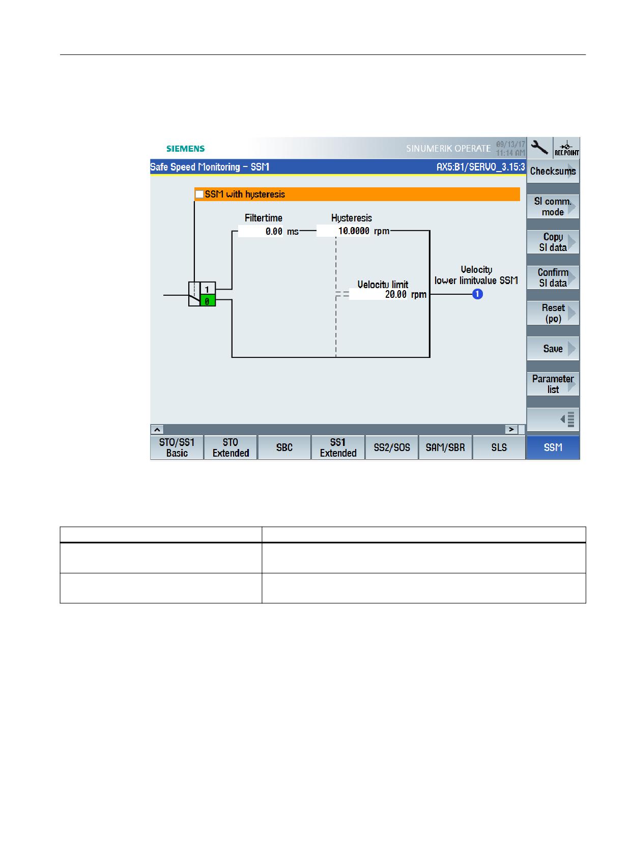
Commissioning and configuring
7.6 Configuring safety functions integrated in the drive
Display "Safe Speed Monitoring - SSM" commissioning screen
MENU SELECT > Commissioning > Menu forward key > Safety > Functions > SSM
Figure 7-19
Safe Speed Monitor - SSM
Status information
Status
Meaning
Switching element (SSM with hysteresis)
Indicates whether the "Hysteresis" and "Filter time" functions are active.
p9501.16
Speed below SSM limit value
Indicates whether the current velocity is below the parameterized velocity
limit.
r9722.15
Safety Integrated plus
Commissioning Manual, 10/2020, 6FC5397-1FP40-6BA4
273

Commissioning and configuring
7.6 Configuring safety functions integrated in the drive
Settings
Setting
Meaning
SSM with hysteresis
Activates the "Hysteresis" and "Filter time" functions for SSM.
p9501.16
If the "SSM with hysteresis" function is enabled, the SSM function is evaluated
as an active monitoring function, and after a STOP F, also results in a subse-
quent STOP B / STOP A response.
Filter time
Sets a filter time (PT1 filter) to smooth the output signal for SSM.
p9545
As filtering characteristic, for output signal SSM, a time-delayed SSM feedback
signal occurs for the axes.
Hysteresis
Parameterizing hysteresis for SSM
p9547
In this way, a more stable SSM signal characteristic can be achieved at veloc-
ities close to the "Velocity limit" (monitoring threshold).
The velocity (or speed) determined by both channels may differ as a maxi-
mum by the difference between "Velocity/speed limit" and "Hysteresis". Oth-
erwise, it would be theoretically possible that for SSM one channel returns a
HIGH signal and the other a LOW signal.
Take into account the following rule when parameterizing:
• Hysteresis p9547 ≤ 0.75 · velocity limit p9546
If actual value synchronization is enabled (Settings - encoder parameteriza-
tion (Page 244)), then you must also comply with the following rule:
• "SI Motion slip velocity tolerance" (p9549) ≤ hysteresis
Velocity limit
Sets the velocity limit for the SSM feedback signal to detect standstill (n < nx).
p9546
If the velocity limit is fallen below, then the signal "Safe Speed Monitor feed-
back signal active" (SGA n < n_x) is set.
The abbreviation SGA n < nx stands for the safety function required for de-
termining an output signal when a parameterizable velocity limit has been
undershot.
This value is also active for safety function SAM as "Shutdown velocity accel-
eration monitoring" - assuming that this shutdown velocity is parameterized
with "0". In this case, the effects of Safe Acceleration Monitoring are therefore
restricted if a relatively high SSM velocity limit is set when using the SS1 and
SS2 stop functions.
Feedback signal SSM active for pulse inhibit
Sets the response during pulse cancellation in encoderless operation.
(only in encoderless operation)
For Safe Speed Monitor without encoder, after pulse suppression the drive is
unable to determine the current velocity. 2 responses can be selected for this
p9509.0
operating state:
• The status signal (SSM feedback signal) indicates "0" (factory setting).
• The status signal (SSM feedback signal) is frozen. "Safe Torque Off" (STO)
is selected internally.
See also: Signal characteristic for setting "Feedback signal SSM for pulse in-
hibit " (Page 134)
Safety Integrated plus
274
Commissioning Manual, 10/2020, 6FC5397-1FP40-6BA4
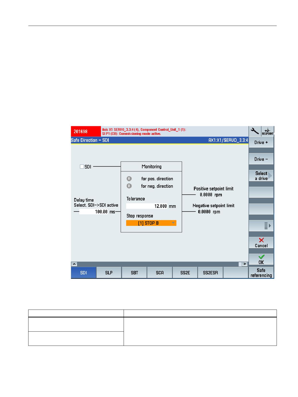
Commissioning and configuring
7.6 Configuring safety functions integrated in the drive
7.6.11
SDI
Precondition
• The SI commissioning mode (Page 238) is active for the drive to be configured.
• The drive is configured for operation with Extended Functions.
Display "Safe Direction - SDI" commissioning screen
MENU SELECT > Commissioning > Menu forward key > Safety > Functions > Menu forward key
> SDI
Figure 7-20
Safe Direction - SDI
Status information
Status
Meaning
for positive direction
Status signals for the safety motion monitoring functions integrated in the
drive on monitoring channel 1.
r9722.12
for negative direction
r9722.13
Safety Integrated plus
Commissioning Manual, 10/2020, 6FC5397-1FP40-6BA4
275

Commissioning and configuring
7.6 Configuring safety functions integrated in the drive
Settings
Setting
Meaning
SDI
Activating/deactivating (enable) SDI.
p9501.17
Delay time, selection SDI -> SDI active
Sets the delay time.
p9565
After selecting function SDI, motion in the monitored direction is permissible,
as a maximum for this time. Therefore, this time can be used to brake active
motion.
Tolerance
Sets the tolerance.
p9564
This motion is still permissible in the monitored direction before safety mes-
sage C01716 is initiated.
Stop response
Sets the stop response. This setting applies to both directions of motion.
p9566
•
[0] STOP A
•
[1] STOP B
•
[2] STOP C
•
[3] STOP D
•
[4] STOP E
•
[10] STOP A with delayed stop response when the bus fails
•
[11] STOP B with delayed stop response when the bus fails
•
[12] STOP C with delayed stop response when the bus fails
•
[13] STOP D with delayed stop response when the bus fails
•
[14] STOP E with delayed stop response when the bus fails
In encoderless operation, only settings "[0] STOP A" and "[1] STOP B" can be
selected.
Feedback signal SDI active for pulse inhibit
Activates/deactivates SDI during pulse cancellation in encoderless operation.
p9509.8
(only in encoderless operation)
7.6.12
SLP/SP
Precondition
• The SI commissioning mode (Page 238) is active for the drive to be configured.
• The drive is configured for operation with an encoder and Extended Functions.
• Telegram 902 (using SLP/SP) or telegram 903 (using only SLP) is set
• Actual value synchronization is not enabled (p9501.3 != 0).
Safety Integrated plus
276
Commissioning Manual, 10/2020, 6FC5397-1FP40-6BA4
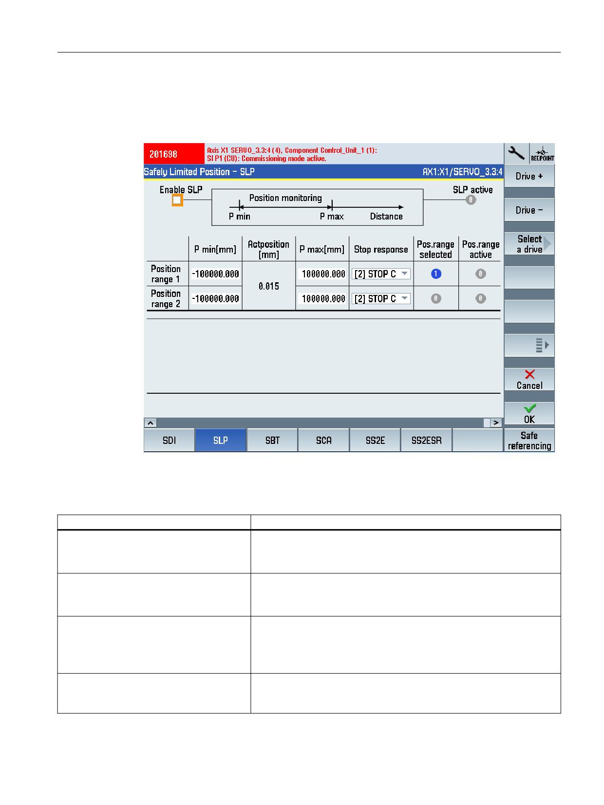
Commissioning and configuring
7.6 Configuring safety functions integrated in the drive
Display "Safe Limit Positions - Safe Position - SLP/SP" commissioning screen
MENU SELECT > Commissioning > Menu forward key > Safety > Functions > Menu forward key
> SLP/SP
Figure 7-21
Example of the "SLP" commissioning screen, that is, with telegram 903 being set
Status information
Status
Meaning
Positioning range selected
Displays whether positioning range 1 or 2 is currently selected.
Range 1: r9720.19=0 & r9720.6=0
Range 2: r9720.19=1 & r9720.6=0
Positioning range active
Displays whether positioning range 1 or 2 is currently active.
Range 1: r9722.19=0 & r9722.6=1
Range 2: r9722.19=1 & r9722.6=1
Actual position value
Displays the actual load-side actual value via PROFIsafe.
r9708[4]
(only PROFIsafe)
Safety-relevant position valid
Status signals for the safety motion monitoring functions integrated in the
drive on monitoring channel 1.
r9722.22
SP valid
Safety Integrated plus
Commissioning Manual, 10/2020, 6FC5397-1FP40-6BA4
277

Commissioning and configuring
7.6 Configuring safety functions integrated in the drive
Status
Meaning
Safety reference position confirmed
Displays the internal status of the user agreement
r9727
Drive reference.
Display: Position referenced
r9723.17
Safely ref.
Display: SP valid
r9722.23
Settings
Setting
Meaning
SLP
Enable/inhibit SLP.
p9501.1
P min [mm]
Sets the lower and upper limit values for position range 1 or 2 of the SLP
function.
Range 1: p9535[0]
For the setting, these limit values apply:
Range 2: p9535[1]
• P max > P min
P min [mm]
Range 1: p9534[0]
• The limit values must lie in the valid traversing range (-737280 …
737280).
Range 2: p9534[1]
See also: C01715
Stop response
Sets the stop response for position range 1 or 2 of the SLP function.
Range 1: p9562[0]
•
[0] STOP A
Range 2: p9562[1]
•
[1] STOP B
•
[2] STOP C
•
[3] STOP D
•
[4] STOP E
•
[10] STOP A with delayed stop response when the bus fails
•
[11] STOP B with delayed stop response when the bus fails
•
[12] STOP C with delayed stop response when the bus fails
•
[13] STOP D with delayed stop response when the bus fails
•
[14] STOP E with delayed stop response when the bus fails
Safe position
Enables/inhibits the transfer of the safe position via PROFIsafe
p9501.25
(only for telegram 902)
(only for PROFIsafe)
Safe absolute position
Enables/inhibits the safe absolute position.
p9501.27
(only for telegram 902)
(only for PROFIsafe)
Safety Integrated plus
278
Commissioning Manual, 10/2020, 6FC5397-1FP40-6BA4

Commissioning and configuring
7.6 Configuring safety functions integrated in the drive
Setting
Meaning
SP scaling
Sets the scaling factor to transfer the safe position via PROFIsafe in the 16-bit
format. The parameter is only active when PROFIsafe telegram 901 is selec-
p9574
ted, see S_XIST16: Current actual position value (16 bits) (Page 366).
(only for telegram 902)
Scaling is realized by dividing the 32-bit position actual value r9713[0] with
(only for PROFIsafe)
this scaling factor. If, during operation, a position actual value is determined
that cannot be scaled, then this results in message C0711 with value 7001 -
as well as STOP F.
Tolerance of the position actual values (refer-
Sets the tolerance for checking the actual values.
encing)
For an incremental encoder, the actual values are checked after referencing,
p9544
for an absolute encoder, when switching on.
(only for telegram 902)
7.6.13
SBT
Precondition
• The SI commissioning mode (Page 238) is active for the drive to be configured.
• The drive is configured for operation with Extended Functions.
Safety Integrated plus
Commissioning Manual, 10/2020, 6FC5397-1FP40-6BA4
279
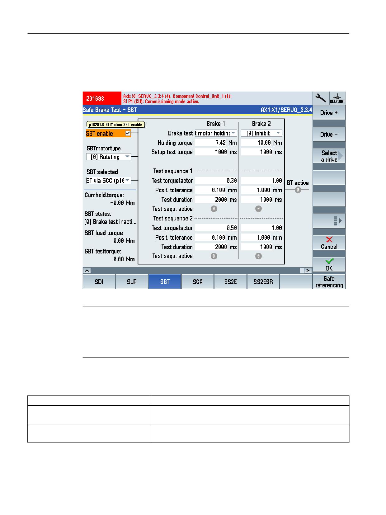
Commissioning and configuring
7.6 Configuring safety functions integrated in the drive
Display "Safe Brake Test - SBT" commissioning screen
MENU SELECT > Commissioning > Menu forward key > Safety > Functions > Menu forward key
> SBT
Figure 7-22
Safe Brake Test - SBT
Note
Additional commissioning support
The following SINUMERIK Operate screen forms are available to commission SBT:
• "Graphic" softkey: Displays a torque-time diagram or a force-time diagram
• "Trace" softkey: Starts a drive trace session with various options.
Status information
Status
Meaning
Actual holding torque or force
Displays the torque actual value or force actual value (unsmoothed).
r0080
SBT state
Displays the current status of the Safe Brake Test.
r10242
Safety Integrated plus
280
Commissioning Manual, 10/2020, 6FC5397-1FP40-6BA4

Commissioning and configuring
7.6 Configuring safety functions integrated in the drive
Status
Meaning
SBT load torque or force
Displays the load torque or the load force for the Safe Brake Test. This load
torque or this load force is available at the drive when initializing the brake
r10241
test. The displayed value is kept until the brake test is deselected.
SBT test torque or force
Displays the maximum test force or the maximum test torque available on the
motor side. The displayed value remains until the start of the next test se-
r10240
quence.
Settings
Setting
Meaning
SBT enable
Enables/inhibits SBT.
p10201.0
SBT motor type
Selects the motor type for the Safe Brake Test.
p10204
•
0: Rotary
•
1: Linear
SBT selection
Selects the control type
p10203
•
0: SBT via SCC (p10235)
•
1: SBT via BICO (p10230)
•
2: SBT for test stop selection (p9705/p10250.8)
For integrated drives (CU_I, CU_NX), only "SBT via SCC" is permissible.
Brake test
Selects the brakes to be tested.
Brake 1: p10202[0]
•
0: Inhibit
Brake 2: p10202[1]
•
1: Test motor holding brake
•
2: Test external brake
It is not possible to test two motor holding brakes.
Actual holding torque or force
Sets the effective holding torque or holding force of the brakes to be tested on
the motor side.
Brake 1: p10209[0]
Brake 2: p10209[1]
Establish the test torque or test force
Sets the time during which the test torque or the test force is ramped up
against the closed brake. After the Safe Brake Test, the test torque or the test
Brake 1: p10208[0]
force is ramped-down again.
Brake 2: p10208[1]
Test torque factor or test force factor
Sets the factor for the test torque or the test force of test sequence 1 or 2 for
the Safe Brake Test. The factor is referred to the brake holding torque or the
Test sequence 1, brake 1: p10210[0]
brake holding force (see above, p10209).
Test sequence 1, brake 2: p10210[1]
Test sequence 2, brake 1: p10220[0]
Test sequence 2, brake 2: p10220[1]
Safety Integrated plus
Commissioning Manual, 10/2020, 6FC5397-1FP40-6BA4
281

Commissioning and configuring
7.6 Configuring safety functions integrated in the drive
Setting
Meaning
Position tolerance
Sets the tolerated position deviation for test sequence 1 or 2 for the Safe Brake
Test.
Test sequence 1, brake 1: p10212[0]
Test sequence 1, brake 2: p10212[1]
Test sequence 2, brake 1: p10222[0]
Test sequence 2, brake 2: p10222[1]
Test duration
Sets the test duration for test sequence 1 or 2 for the Safe Brake Test. The test
torque or the test force is applied to the closed brake for this time.
Test sequence 1, brake 1: p10211[0]
Test sequence 1, brake 2: p10211[1]
Test sequence 2, brake 1: p10221[0]
Test sequence 2, brake 2: p10221[1]
Note
Using MD36968.2 to select the parameter assignment behavior at the end of SBT
You can parameterize the positioning behavior after the brake test via the expert list using
MD36968.2 $MA_SAFE_BRAKETEST_CONTROL, bit 2:
•
0: Positioning at the actual axis position
To conclude the brake test, the actual axis position for the next path motion is used.
(MD36968 $MA_SAFE_BRAKETEST_CONTROL bit 2 = 0). This results in motion to the last
programmed axis position on the path.
•
1: Positioning to the last programmed axis position
Acceptance of the actual axis position is not carried out. After the axis has been pressed
against the brake, the closed-loop position controller withdraws the axis to the last
programmed position.
Vertical axes can thus be prevented from sagging as a result of a repeated brake test. It is also
possible to briefly exceed the software limit switch while pressing against the brake without
initiating an alarm.
7.6.14
SCA
Precondition
• The SI commissioning mode (Page 238) is active for the drive to be configured.
• The drive is configured for operation with an encoder and Extended Functions.
Safety Integrated plus
282
Commissioning Manual, 10/2020, 6FC5397-1FP40-6BA4
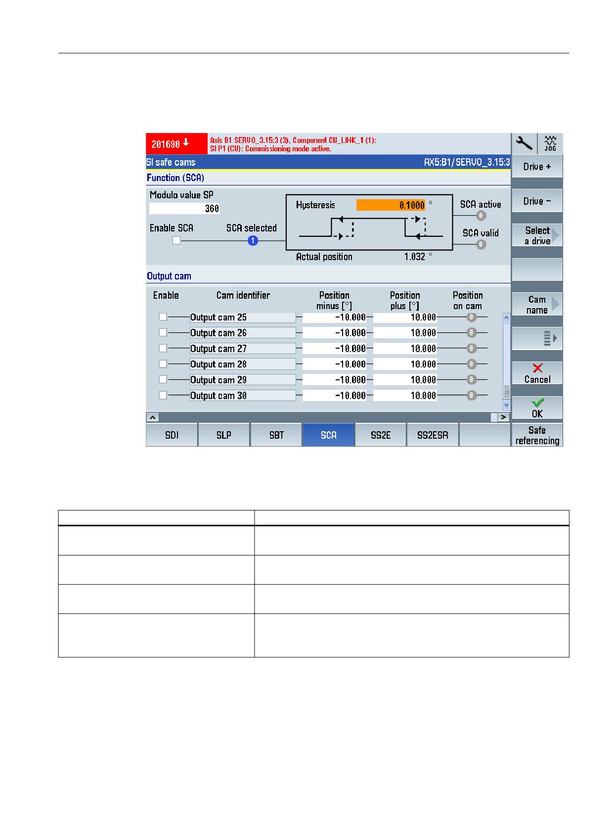
Commissioning and configuring
7.6 Configuring safety functions integrated in the drive
Display "SI Safe Cams" commissioning screen
MENU SELECT > Commissioning > Menu forward key > Safety > Functions > SCA
Figure 7-23
Safe Brake Test - SBT
Status information
Status
Meaning
SCA selected
SI Motion control signals integrated in the drive: Deselect SCA
r9720.23
SCA active
SI Motion SCA status signal (Control Unit)
r9703.30
SCA valid
SI Motion SCA status signal (Control Unit)
r9703.31
Position at cam
SI Motion SCA status signal (Control Unit)
r9703.0
Safety Integrated plus
Commissioning Manual, 10/2020, 6FC5397-1FP40-6BA4
283