SINUMERIK 840D sl. Service - Safety Integrated. Manual (2020) - page 14
Safety functions integrated in the drive
5.12 SDI
Enabling function "Safe Direction"
The "Safe Direction" function is enabled with p9501.17 = 1.
6HOHFWLRQ
$FWLYDWLRQ
'HVHOHFWLRQ
6', SRVLWLYH
6', SRVLWLYH
6', SRVLWLYH
$FWXDO YHORFLW\ YDOXH
9HORFLW\ VHWSRLQW
W
6', GHOD\ WLPH
'LUHFWLRQ PRQLWRULQJ
'HVHOHFW 6',
SRVLWLYH
6', SRVLWLYH DFWLYH
'HVHOHFW 6', QHJDWLYH
6', QHJDWLYH DFWLYH
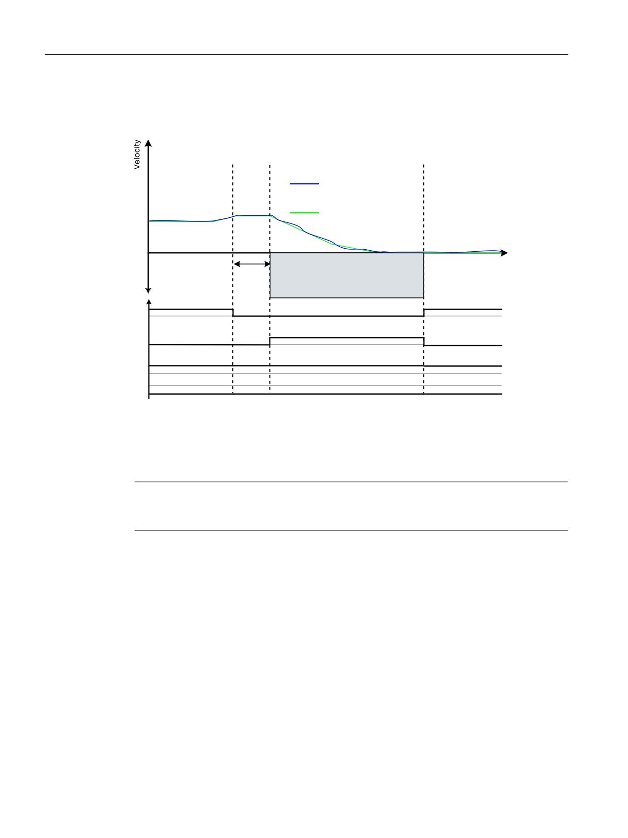
Figure 5-22
Functional principle SDI with encoder
5.12.1.2
Safe Direction without encoder
Note
You can find the parameterization for operation without encoder (p9506 = 1 or p9506 = 3) in the
commissioning screen form for the safety functional scope.
Differences between Safe Direction with encoder and Safe Direction without encoder
• For Safe Direction without encoder, after pulse suppression the drive is unable to determine
the current speed. For this operating state, the behavior is defined using parameter p9509.8:
- p9509.8 = 1
The status signal displays "inactive".
- p9509.8 = 0
The status signal displays "active", and the drive takes on the state STO.
• Due to the less precise position recognition, "Safe Direction without encoder" requires a
larger tolerance (p9564) compared with the function with encoder.
Safety Integrated plus
146
Commissioning Manual, 10/2020, 6FC5397-1FP40-6BA4

Safety functions integrated in the drive
5.12 SDI
Note
No detection of a change of direction with the aid of p1820 or p1821
If the direction of rotation is reversed via p1820 or p1821, then safe monitoring is still possible:
However, in this case, the setpoint limitation r9733 is calculated with the wrong direction of
rotation. A reversal of the rotational direction with p1820 or p1821 therefore does not make
sense.
Restart after pulse cancellation for p9509.8 = 0
If the drive has been switched off via OFF1/OFF2/STO etc., the following steps need to be carried
out before a restart can be performed:
1. Case
•
State after switching on
• SDI selected
• STO selected
• Pulse suppression active
•
Deselect STO
•
The drive enable must be issued within 5 seconds via a positive edge at OFF1, otherwise
STO is reactivated.
2. Case
•
Situation
• Traversing to standstill with SDI selected
• Initiate OFF1
• Pulses are canceled; internal selection STO becomes active
•
Select STO
•
Deselect STO
STO activated internally via pulse suppression: This activation must be undone by selecting/
deselecting STO.
•
The drive enable must be issued within 5 seconds via a positive edge at OFF1, otherwise
STO is reactivated.
3. Case
•
Situation
• Traversing to standstill with SDI selected
• Initiate OFF1
• Pulses are canceled; internal selection STO becomes active
•
Deselect SDI
STO activated internally via pulse suppression: This activation must be undone by dese-
lecting SDI.
•
Select SDI
The drive enable must be issued within 5 seconds via a positive edge at OFF1, otherwise
STO is reactivated.
Safety Integrated plus
Commissioning Manual, 10/2020, 6FC5397-1FP40-6BA4
147

Safety functions integrated in the drive
5.12 SDI
4. Case
• Situation
• All Safety Integrated functions are deselected.
• After this the drive enable must be given by a positive edge at OFF1.
• In this case, the motor is not started safely.
When acknowledging SDI with STOP C, you must maintain the following sequence:
1. Correct the incorrect setpoint input.
2. Deselect SDI.
While the safety STOP is active, this ensures that the motor cannot travel in the direction that
has not been enabled while the SDI function is deselected.
3. Select SDI again.
The SDI limits are then set again.
4. Cancel the safety STOP as a result of "safe acknowledgment".
5.12.1.3
Safe Direction without selection
Differences between Safe Direction with and without selection
• As an alternative to controlling via terminals and/or PROFIsafe, there is also the option of
parameterizing SDI without selection. In this case, SDI will be permanently active after
POWER ON (with encoder) or will be active after switch-on (without encoder).
• The "SDI without selection" function is activated as follows:
- p9512.12 = 1 (SDI positive static active)
- p9512.13 = 1 (SDI negative static active)
• The stop response is parameterized with p9566[0].
Safety Integrated plus
148
Commissioning Manual, 10/2020, 6FC5397-1FP40-6BA4
Safety functions integrated in the drive
5.12 SDI
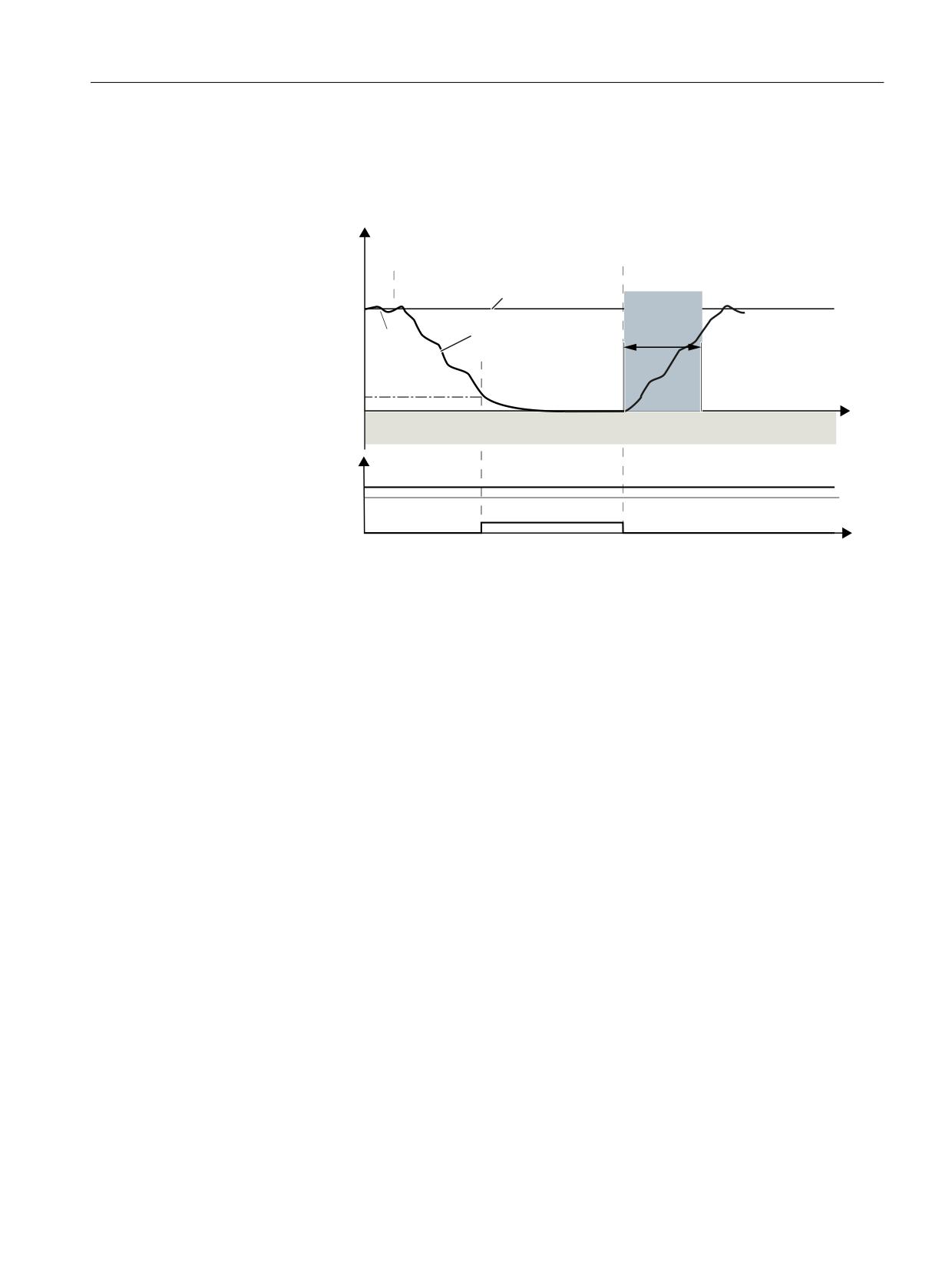
Switching the motor on and off (without encoder)
The time response and diagnostic options are as follows in this SDI version:
/RDG VSHHG
2SHUDWRU DFWLRQV
6ZLWFK RII PRWRU
6ZLWFK RQ PRWRU
2)) FRPPDQG
21 FRPPDQG
6HWSRLQW
5DPS IXQFWLRQ JHQHUDWRU
$FWXDO
VHFRQGV
UDPS GRZQ WLPH
YDOXH
6WDQGVWLOO
GHWHFWLRQ
W
6',
'LDJQRVWLFV
6', DFWLYH
6DIH SXOVH
FDQFHOODWLRQ
W
DFWLYH
Figure 5-23
Time response of SDI without selection (example: Switching the motor on and off (without
encoder))
"SDI without selection" behaves as follows when switching off and switching on again:
• After switch-off, the motor behaves in accordance with the canceled signal (OFF1, OFF2 or
OFF3).
• STO (≙ safe pulse cancellation) becomes active after the standstill limit is undershot.
• After the ON command, the converter cancels the "safe pulse suppression" state and the start
procedure is initiated.
• If the minimum current has not been reached after 5 seconds, the converter returns to the
"safe pulse suppression" state and initiates the safety message C01711(1041).
Safety Integrated plus
Commissioning Manual, 10/2020, 6FC5397-1FP40-6BA4
149
Safety functions integrated in the drive
5.12 SDI
5.12.1.4
Function diagrams and parameters
Function diagrams (see SINAMICS S120/S150 List Manual)
•
2824
SI Extended Functions - SDI (Safe Direction)
•
2840
SI Extended Functions - SI Motion drive-integrated control signals/status signals
Overview of important parameters (see SINAMICS S120/S150 List Manual)
• p1820[0...n]
Reverse the output phase sequence
• p1821[0...n]
Direction of rotation
• p9501.17
SI Motion enable safety functions (Control Unit): Enable SDI
• p9506
SI Motion function specification (Control Unit)
• p9509
SI Motion behavior during pulse suppression (Control Unit)
• p9564
SI Motion SDI tolerance (Control Unit)
• p9565
SI Motion SDI delay time (Control Unit)
• p9566
SI Motion SDI stop response (Control Unit)
• p9580
SI Motion pulse suppression delay bus failure (Control Unit)
• r9720.0...27
CO/BO: SI Motion drive-integrated control signals
• r9722.0...31
CO/BO: SI Motion drive-integrated status signals (Control Unit)
• r9733[0...2]
CO: SI Motion speed setpoint limit active
• p10017
SI Motion digital inputs debounce time (processor 1)
• p10030[0...3]
SI Motion SDI positive input terminal (processor 1)
• p10031[0...3]
SI Motion SDI negative input terminal (processor 1)
• p10039[0...3]
SI Motion safe state signal selection (processor 1)
• p10042[0...5]
SI Motion F-DO signal sources (processor 1)
• p10043[0...5]
SI F-DO 1 signal sources
• p10044[0...5]
SI F-DO 2 signal sources
• p10045[0...5]
SI F-DO 3 signal sources
Safety Integrated plus
150
Commissioning Manual, 10/2020, 6FC5397-1FP40-6BA4
Safety functions integrated in the drive
5.13 SLP
5.13
SLP
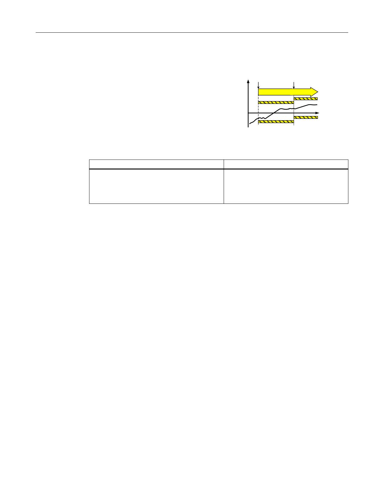
Definition according to EN 61800-5-2:
Y
6HOHFWLRQ
6ZLWFKRYHU
Function "Safely-Limited Position (SLP)" prevents
6/3
the motor shaft from exceeding the specified po-
6 BR
sition limit(s).
6 BR
W
6 BX
6 BX
Examples of how the function can be used
Example
Possible solution
It is not permissible that the drive exits the specified
• Select SLP in the converter; inhibit the range
position ranges.
that is not permitted.
• After the enabled range has been exited, a
parameterizable stop response is initiated.
Function "Safely-Limited Position (SLP)" is used to safely monitor the limits of two traversing and/
or positioning ranges, which can be switched over using a safety-related signal.
Features
• Selection via terminals or PROFIsafe
•
2 position ranges, each defined by a limit switch pair
• Safe switchover between the two position ranges
• Adjustable stop response
• To move the motor out of the unauthorized range, you must execute a special sequence (see
"Retraction (Page 154)").
5.13.1
Details and parameterization
Function "Safely-Limited Position (SLP)" is used to safely monitor the limits of two traversing or
positioning ranges, which can be switched over using a safety-related signal.
Requirements
For function "Safely-Limited Position (SLP)", the following requirements must be met:
• The use of one or two suitable encoders for the extended safety functions with encoder (see
also Chapter "Safe actual value sensing with encoder system (Page 183)")
• Determining the absolute position of the drive by referencing during commissioning and
after all actions after which a safe absolute reference can no longer be guaranteed (POWER
ON, parking)
Safety Integrated plus
Commissioning Manual, 10/2020, 6FC5397-1FP40-6BA4
151
Safety functions integrated in the drive
5.13 SLP
A description of safe referencing is provided in Chapter "Safe referencing (Page 179)".
Principle of operation
As soon as SLP is active, maintaining the limits of the active positioning range is safely
monitored. With a safety signal you can switch between 2 position ranges. Each position range
is limited by its previously defined limit switch pair. When passing the position of one of the two
limit switches, a parameterizable stop response (STOP A, STOP B, STOP C, STOP D or STOP E) is
triggered and safety message C01715 is output.
To acknowledge this fault, you can either switch over to a range whose limits have not been
violated, or you can deselect the SLP function. After acknowledgment, the drive can then be
traversed again in the permissible range.
Traversing in the permissible range can be realized in a safety-related fashion using the "Retract"
function (see Chapter "Retracting (Page 154)").
Features
• Selection via safe terminals (onboard F-DI) or PROFIsafe
• Definition of the position range using 2 limit switch pairs (p9534 and p9535)
• Safe switchover between 2 different position ranges (not available for PROFIsafe telegram 30)
• Adjustable stop response (p9562)
Enabling function "Safely-Limited Position (SLP)"
• Function "Safely-Limited Position (SLP)" is enabled with p9501.1 = 1.
• After the enable, POWER ON at the converter.
Note
No actual value synchronization for SLP
It is not permissible to simultaneously enable function "SLP" and the actual value
synchronization (p9501.3 = 1). In this case, the drive outputs fault F01688.
Safety Integrated plus
152
Commissioning Manual, 10/2020, 6FC5397-1FP40-6BA4
Safety functions integrated in the drive
5.13 SLP
Control and status signals from the SLP
Selecting SLP and switching over between the position ranges is performed via a PROFIsafe
control bit. SLP selection can be checked using parameter r9720.6. The selected position range
can be checked using parameter r9720.19. Status bit r9722.6 is set if SLP is active. The active
position range is displayed by r9722.19. Maintaining the upper or lower active SLP limit can be
checked using r9722.30 and r9722.31.
Note
Jumps in the display
There is no hysteresis available for r9722.30 and r9722.31. Small fluctuations in the area around
the range limit can result in the display jumping back and forth.
Controlling the Safely-Limited Position function
You have 2 options to select/deselect function "Safely-Limited Position (SLP)" and to switch over
the range limits:
• PROFIsafe
- SLP is selected/deselected using control words S_STW1.6 or S_STW2.6.
- Switchover between the two limit switch pairs using control word S_STW2.19.
- S_ZSW2.23 indicates whether the actual position is "safe"; for instance, the bit is only set
after the axis was "safely referenced".
- Whether SLP is active is indicated in bit 6 of the status words S_ZSW1.6 or S_ZSW2.6. The
bit is not set until SLP is selected and the axis is in the "safely referenced" state.
- Which SLP limit switch pair is active is indicated in status word S_ZSW2.19. This indication
is only valid if SLP is itself active.
- S_ZSW2.30 and S_ZSW2.31 indicate whether the upper or lower limit of the active
position range is maintained.
Note
Extended Functions via PROFIsafe
The status signal "SLP active" (S_ZSW1.6 or S_ZSW2.6) is not the same as the diagnostic signal
"SLP active" (r9722.6), but is the AND logic operation of "SLP active" (r9722.6) and "safely
referenced" (r9722.23).
The other SLP status signals S_ZSW2.19 "SLP active position range", S_ZSW2.30 "upper SLP limit
maintained" and S_ZSW2.31 "lower SLP limit maintained" match the corresponding bits in
r9722.
Safety Integrated plus
Commissioning Manual, 10/2020, 6FC5397-1FP40-6BA4
153
Safety functions integrated in the drive
5.13 SLP
Note
Restrictions for PROFIsafe telegram 30
The use of PROFIsafe telegram 30 (with 16-bit words S_STW1 and S_ZSW1) has the following
restrictions:
• Only position range 1 is available.
• A switchover to position range 2 is not possible.
• The status feedback signals "safely referenced", "active position range", "upper SLP limit
maintained" and "lower SLP limit maintained" are not available.
Note
Response to bus failure
If p9580 ≠ 0 and SLP is active, in the event of communication failure the parameterized ESR
reaction is only realized if, as an SLP response, a STOP with delayed pulse cancellation when the
bus fails has been parameterized (p9562[0...1] ≥ 10).
5.13.1.1
Retraction
After a limit of the active traversing range has been exceeded, the drive must be brought back
to the permissible range. A safety acknowledgment would, in this case, only retrigger the safety
messages; the drive would be prevented from moving. If a switchover to the other traversing
range doesn't come into question, then the only thing that remains is to deselect SLP. However,
this would have the disadvantage that it is not monitored as to whether the drive is moving in
the direction of the permissible traversing range.
Therefore, it is recommended that a retract function is implemented as follows:
Safety commissioning
1. Completely parameterize SLP.
2. Completely parameterize SDI.
3. Perform an acceptance test for both functions.
The next steps differ depending on the control type:
Safety Integrated plus
154
Commissioning Manual, 10/2020, 6FC5397-1FP40-6BA4
Safety functions integrated in the drive
5.13 SLP
Control via PROFIsafe
• Implement a user program in your F-CPU with the following steps to implement a retract
function:
- Select SDI positive in the case that the lower SLP limit is violated, or SDI negative if the
upper SLP limit is violated
- Wait until the selected SDI is active, then deselect SLP
- Safe acknowledgment of the limit violation
- Movement of the drive with suitable setpoint inputs in the range that has been enabled
- Select SLP
- Wait until SLP is active, then deselect SDI
Note
FAQ retraction
A description of how retraction can be implemented via a failsafe control and PROFIsafe
communication is provided in the Internet at:
5.13.1.2
Function diagrams and parameters
Function diagrams (see SINAMICS S120/S150 List Manual)
•
2822
SI Extended Functions - SLP (Safely-Limited Position)
•
2840
SI Extended Functions - SI Motion drive-integrated control signals/status sig-
nals
Overview of important parameters (see SINAMICS S120/S150 List Manual)
• p9501
SI Motion enable safety functions (Control Unit)
• p9534[0...1]
SI Motion SLP (SE) upper limit values (Control Unit)
• p9535[0...1]
SI Motion SLP (SE) lower limit values (Control Unit)
• p9544
SI Motion actual value comparison tolerance (referencing) (CU)
• p9562[0...1]
SI Motion SLP (SE) stop response (Control Unit)
Safety Integrated plus
Commissioning Manual, 10/2020, 6FC5397-1FP40-6BA4
155
Safety functions integrated in the drive
5.14 SP
5.14
SP
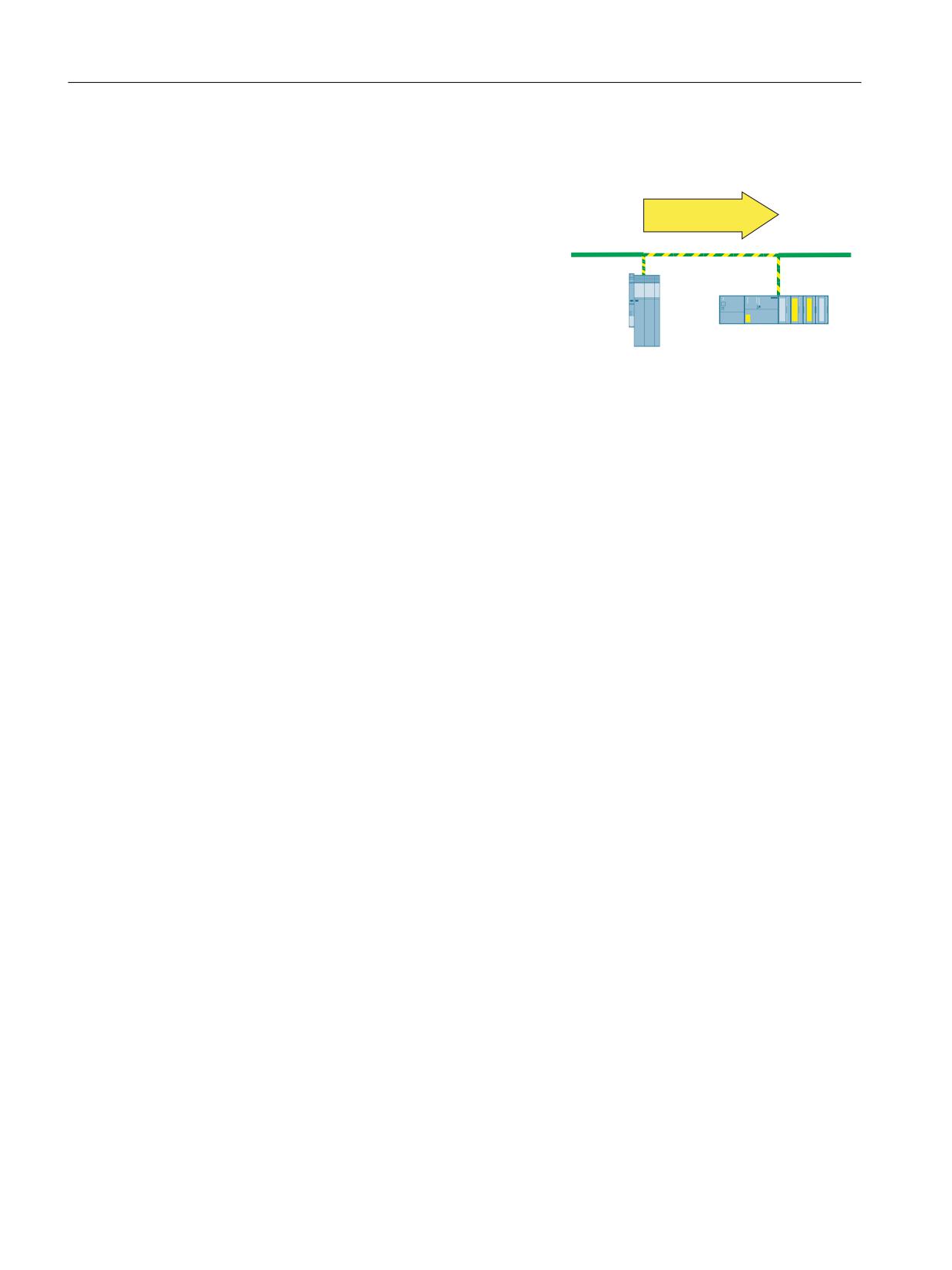
Function "Safe Position (SP)" allows safe position
values to be transferred to the F-PLC via PROFI-
SP
safe (telegram 901 or 902).
From the position change over a specific time,
the F-PLC can also calculate the actual velocity. In
telegram 902, the values are transferred in 32-
bit format, in telegram 901, in 16-bit format.
The position actual value is not transferred in
PROFIsafe telegram 903, which is preset for SIN-
UMERIK.
See also: Overview of process data telegrams
(Page 199)
After parameter assignment, release and POWER ON, the function is automatically selected and
the values transferred. Please observe the following:
• For use as the safe absolute position, the "Absolute position" must also be enabled and then
safely referenced.
• In order that the transferred position can be used, the actual position value must be valid.
Using the time stamp that is also transferred, you can also calculate the velocity from the
position values. If you only want to calculate the velocity, it is sufficient to enable the "Transfer
of safe position values" without the "Absolute position."
5.14.1
Details and parameterization
Function "Safe Position (SP)" allows a safe position (i.e. absolute or relative position) to be
transferred to the F-PLC via PROFIsafe. Transferring a safe relative position can be used to
calculate the safe speed/velocity in the F-PLC. Its use for safe position monitoring is only
permissible if the reference to the absolute position was established at the control level. In this
case, the "safely referenced" bit of SINAMICS S120 (r9722.23) cannot be used.
Safety Integrated plus
156
Commissioning Manual, 10/2020, 6FC5397-1FP40-6BA4
Safety functions integrated in the drive
5.14 SP
Enabling the "Transfer safe position values" function
The following steps are required to enable function "Safe Position (SP)":
• Enable the Safety Integrated Extended Functions
- p9601 = 12 = C hex (≙ Extended Functions via PROFIsafe)
or
- p9601 = 13 = D hex (≙ Extended Functions via PROFIsafe and Basic Functions via onboard
terminals)
• Enable "Transfer the safe absolute position with the possibility of calculating the velocity by
the controller"
- Select one of the PROFIsafe telegrams 901 or 902 (p60022, p9611, p9811)
- p9501.2 = 1 (≙ enable absolute position)
- p9501.25 = 1 (≙ enable transfer of safe position via PROFIsafe)
Note
No actual value synchronization when SP is enabled
If the transfer safe position value function is used, it is not permissible to enable actual value
synchronization (p9501.3 = 1): In this case, the drive outputs fault F01688.
• Enable the "Transfer safe relative position" only to calculate the speed by the controller
- Select one of the PROFIsafe telegrams 901 or 902
- p9501.25 = 1
• After the enable, POWER ON the converter.
Principle of operation
After parameter assignment, release and POWER ON, the function is automatically selected and
the values transferred. Please observe the following:
• Transfer of safe absolute position values
- If the transfer of the safe relative position has been enabled through p9501.25 = 1 and
p9501.2 = 0, the validity of the safe relative position is displayed by the set bit S_ZSW2.22.
- If the transfer of the safe absolute position has been enabled using p9501.25 = 1 and
p9501.2 = 1, S_ZSW2.22 is only set when the drive has also been safely referenced.
• Transfer of safe relative position values (e.g. for calculating the velocity)
- Only S_ZSW2.22 (r9722.22, actual position value valid) must be set to calculate the
speed.
Safety Integrated plus
Commissioning Manual, 10/2020, 6FC5397-1FP40-6BA4
157

Safety functions integrated in the drive
5.14 SP
Setting the modulo value for rotary axes
• p9505 is used to define the modulo range of a safety rotary axis (p9502 = 1) when the
transfer of a safe absolute position (p9501.2 = 1 and p9501.25 = 1) is enabled.
Parameterizing the modulo value can result in a jump in the position actual value if the range
that can be represented overflows. p9505 must therefore only be parameterized in steps of
2n × 360° (n = 1, 2, 3, …). In all other cases, the converter issues alarm A01794. This alarm
can be hidden in the case that the possible jump in the position actual value can be tolerated
in the particular application - or this does not present a problem.
• The modulo function is deactivated if p9505 = 0. This parameter has no relevance for a safety
linear axis (p9502 = 0) or when the transfer of a safe relative position (p9501.2 = 0 and
p9501.25 = 1) is enabled.
• If SLP is also enabled (p9501.1 = 1), the modulo function must be deactivated (p9505 = 0).
Transfer formats and value range
•
32-bit
The values are transferred in telegram 902 as 32-bit values with the following value ranges:
Table 5-2
Value range and resolution (32 bits)
Linear axis
Rotary axis
Position values
±737280000
±737280000
Unit
1 μm
0.001 °
Comment
Monitoring ±737.280 m
≙ 2048 revolutions
with an accuracy of 1 μm
•
16-bit
To transfer the position values in telegram 901 in the 16-bit format, you must scale the values
using p9574. In this case, you must select the scaling factor so that the value of the actual
position value does not exceed the 16-bit format. If the actual position value exceeds the
range that can be displayed with 16 bits (±32767), a STOP F is initiated and message C01711
is output with fault value 7001. Depending on the scaling factor, this means that ranges with
different sizes can be monitored with varying accuracy. Example:
- Scaling factor: 1000
- Unit: 1 μm (linear axis)
- Position value: ±32767 mm
It may therefore be precisely monitored in a range of ±32.767 m to an accuracy of 1 mm.
Note
Scaling to 16 bits
The scaling is performed by dividing the mean value of r9708[0] and r9708[1] with this
scaling factor.
Example: For a position of -29.999 mm signaled in r9708[0] and r9708[1] and a scaling
factor of p9574 = 1000, a numerical value of -29 is signaled to the controller.
Safety Integrated plus
158
Commissioning Manual, 10/2020, 6FC5397-1FP40-6BA4

Safety functions integrated in the drive
5.14 SP
Value range r9708
The diagnostics information in parameter r9708 is displayed with the following properties:
Table 5-3
Value range and resolution (32 bits)
Linear axis
Rotary axis
Position values
±737280000
±737280000
Unit
1 μm
0.001 °
Comment
Monitoring ±737.280 m
≙ 2048 revolutions
with an accuracy of 1 μm
What is shown in parameter r9713 is identical to the values of r9708; however, in SINAMICS-
internal calculation units.
Speed calculation
The control must calculate the speed from the position change:
• Pos diff = Pos new - Pos old
• Cycle diff = cycle counter new - cycle counter old
• Timediff = Cyclediff × Safetycycle
(If Cyclediff = 0, the speed that was last calculated must be used.)
• v = Pos diff/time diff
• Format v
Acceptance test
An acceptance test is not required for function "Safe Position (SP)", but the function that was
implemented using SP must be accepted in the higher-level control system.
5.14.1.1
Function diagrams and parameters
Function diagrams (see SINAMICS S120/S150 List Manual)
•
2840
SI Extended Functions - SI Motion drive-integrated control signals/status signals
Overview of important parameters (see SINAMICS S120/S150 List Manual)
• p9501
SI Motion enable safety functions (Control Unit)
• p9505
SI Motion SP modulo value (Control Unit)
• p9542
SI Motion actual value comparison tolerance (crosswise) (Control Unit)
• p9601
SI enable functions integrated in the drive (Control Unit)
• r9708[0...5]
SI Motion diagnostics safe position
• r9713[0...5]
CO: SI Motion diagnostics actual position value load side
Safety Integrated plus
Commissioning Manual, 10/2020, 6FC5397-1FP40-6BA4
159
Safety functions integrated in the drive
5.15 SBT
5.15
SBT
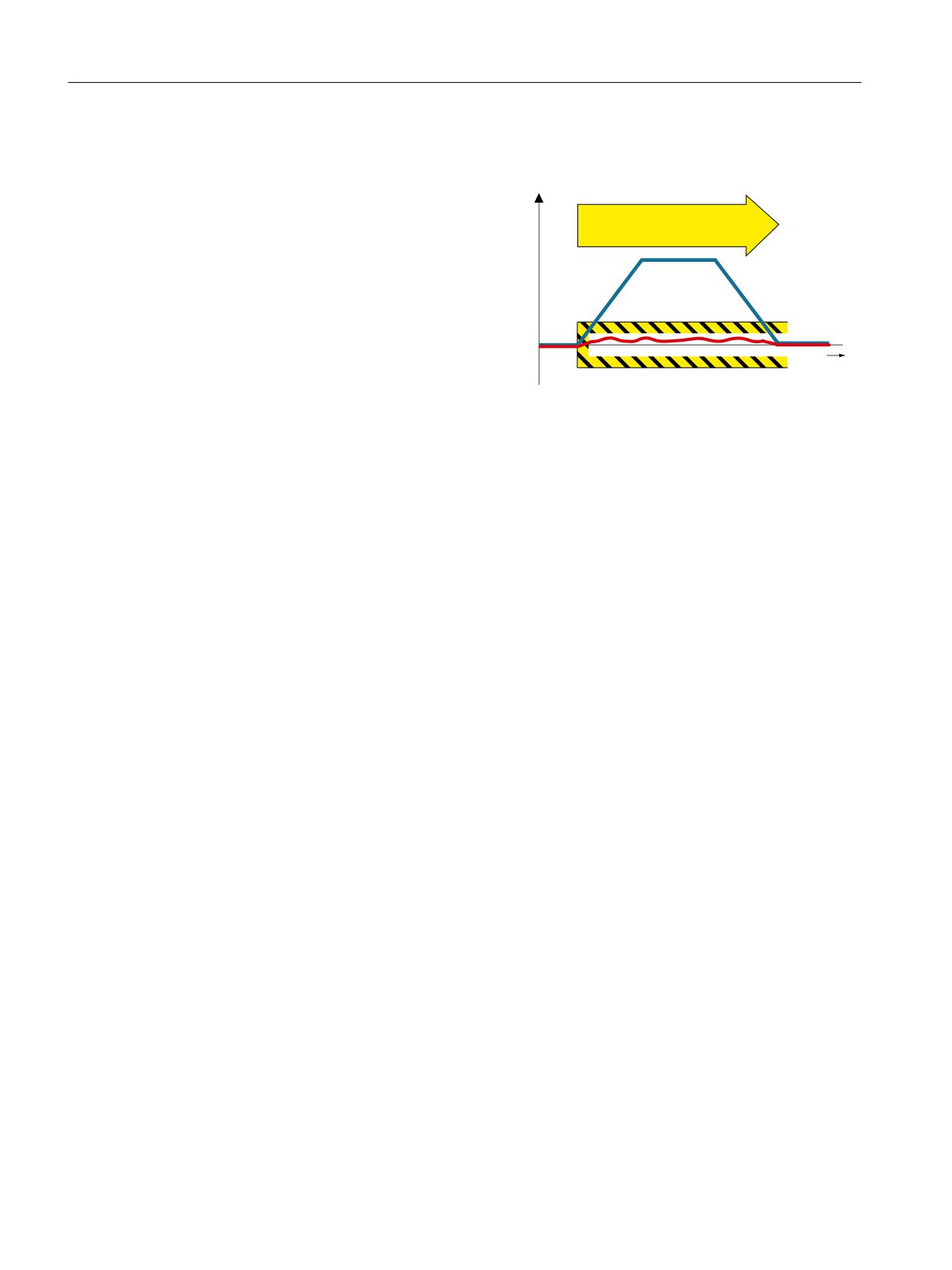
Diagnostic function "Safe Brake Test
0 V
(SBT)" checks the required holding torque
6%7
of a brake (operating or holding brake).
You can test linear and rotary brakes. The
drive purposely generates a force/torque
against the applied brake. If the brake is
operating correctly, the axis motion re-
mains within a parameterized tolerance.
If, however, a larger axis motion is detec-
W
ted, it must be assumed that the braking
force/torque has deteriorated and mainte-
nance is required.
Diagnostic function "Safe Brake Test" allows a safe test of up to 2 brakes:
•
1 motor holding brake and 1 external brake
•
2 external brakes
•
1 motor holding brake
•
1 external brake
Diagnostic function "Safe Brake Test" (SBT) function meets the requirements for Category 2
according to EN ISO 13849-1.
5.15.1
Features
Diagnostic function "Safe Brake Test" has the following properties:
• The parameters of diagnostic function "Safe Brake Test" are protected by the Safety password,
and can only be changed in the Safety commissioning mode.
• Using this function, brakes can be tested that are directly connected to SINAMICS S120
(integrated brake control), but also externally controlled brakes (e.g. via a PLC).
• A maximum of 2 brakes can be tested:
- A motor holding brake, controlled by the integrated brake control of the SINAMICS, and
in addition, an externally controlled brake.
- Two externally controlled brakes
- A motor holding brake, controlled by the integrated brake control of the SINAMICS.
- One externally controlled brake
• Diagnostic function "Safe Brake Test" complies with SIL 1 according to IEC 61508 or PL d/Cat.
2 according to EN ISO 13894-1.
Safety Integrated plus
160
Commissioning Manual, 10/2020, 6FC5397-1FP40-6BA4
Safety functions integrated in the drive
5.15 SBT
5.15.2
Connection to NC and PLC programs
Diagnostic function "Safe Brake Test" integrated in the drive does not require a setpoint input
from the PLC or NC, but only enable signals from the NC and control via the PLC user program.
The relevant signals when executing the brake test (SBT) are communicated between the PLC
and drive via the Safety Info Channel (SIC) and the Safety Control Channel (SCC).
• SIC/SCC communication is realized using telegram 701 (Page 205). In the TIA Portal
configuring, telegram 701 is automatically inserted if you activate the "Safety Integrated plus
(F-PLC)" mode.
• The SIC/SCC signals (to control SBT) are mapped in the axis DB
(axis 1 [DB31] ... axis 31 [DB61]). Bits (DBX11.0 and DBX71.0) in the relevant axis DB are used
to control SBT. As a consequence, you can execute the SBT via PLC user program.
See: Interface signals: Axis/spindle signals (Page 374).
Note
Information for those switching over from a different system: Block required for SBT (Safe
Brake Test)
The relevant axis DB is used to control SBT. Block SI_BrakeTest [FB11], known from the "Safety
Integrated (SPL)" mode, is no longer used in the "Safety Integrated plus (F-PLC)" mode.
5.15.3
Details and parameterization
5.15.3.1
Requirements
NC
The following preconditions must be complied with before the brake test is enabled by the NC:
• The axis must be at a standstill, and be in a safe axis position.
• The NC must have issued the controller enable and pulse enable.
DRV
The following preconditions must be satisfied for the DRV to use diagnostic function "Safe Brake
Test":
• The Safety Integrated Extended Functions must be enabled; also available for the Safety
Integrated Extended Functions without selection.
• Safe Brake Control must be enabled when testing a brake controlled by SINAMICS (motor
holding brake).
Safety Integrated plus
Commissioning Manual, 10/2020, 6FC5397-1FP40-6BA4
161

Safety functions integrated in the drive
5.15 SBT
• Safety Integrated Extended Functions with encoder have been enabled.
You can find information about possible encoder concepts in Chapter "Safe actual value
acquisition (Page 183)".
Note
SBT only with encoder
The "Safe Brake Test" (SBT) diagnostic function can only be used with an encoder.
• Speed control with encoder (p1300 = 21).
SBT is not possible with encoderless speed control (e.g. vector V/f control) and torque control.
In this case, alarm A01784 is output.
• The pulses must be enabled when SBT is selected. The actual speed value must not exceed
1 % of the maximum speed (p1082) when SBT is selected and over the complete time that
SBT is active.
• The brake(s) must be open
Note
SBT and HLA
Diagnostic function "Safe Brake Test" is not available for SINAMICS HLA.
5.15.3.2
Handling overview
Table 5-4
Selecting SBT
Step
Procedure
1st
In the associated axis DB, set bit "Start brake test" DBX11.0 = 1.
→
The NC checks that the appropriate conditions are satisfied:
• If the conditions are satisfied, then the "Brake test active" bit is set to 1 (DBX71.0 = 1).
• Alarm 27830 is output if the conditions are not satisfied.
2nd
Check whether the "Brake test active" bit (DBX71.0) is set to 1. It this is not the case, then it is
not permissible that you perform the SBT In this case, ensure that the requirements
(Page 161) are satisfied, and start again with step 1.
3rd
Select SBT via SCC by setting bit 0 "SELECTION_SBT" to 1 in STW3 (signal edge 0 => 1).
See also: Selection (Page 166)
→
In ZSW3, bit 1 "SETPOINT_SETTING_DRIVE" is set to 1 - which in the SIC signals that the NC no
longer enters the setpoint, but instead, DRV. The monitoring functions are deactivated in the
NC, and the setpoint is set the same as the actual value.
The brake test sequence is executed.
See also: Sequence (Page 167)
Safety Integrated plus
162
Commissioning Manual, 10/2020, 6FC5397-1FP40-6BA4

Safety functions integrated in the drive
5.15 SBT
Table 5-5
Deselecting SBT
Step
Procedure
1st
Select SBT via SCC by setting bit 0 "SELECTION_SBT" to 0 in STW3 (signal edge 1 => 0).
See also: Selection (Page 166)
→
DRV initiates the de-selection process, and then in ZSW3 bit 1 "SETPOINT_SETTING_DRIVE" is
set to 0. The setpoint circuit from the NC is synchronized to the actual values (setpoint position
= actual position), the position is aligned and the contour and standstill monitoring are reac-
tivated.
See also: Sequence (Page 167)
2nd
In the associated axis DB, set bit "Start brake test" DBX11.0 = 0.
→
The "Brake test active" bit is set to 0 (DBX71.0 = 0) by the NC.
Canceling the brake test sequence (SBT)
If the brake test sequence (SBT) is canceled due to errors, then you can carry out the evaluation
and implement the resulting measures via the corresponding PLC interface signals.
See also: Cancellation/deselection and acknowledgment (SBT) (Page 168)
Note
Using MD36968.2 to select the parameter assignment behavior at the end of SBT
You can parameterize the positioning behavior after the brake test via the expert list using
MD36968.2 $MA_SAFE_BRAKETEST_CONTROL, bit 2:
•
0: Positioning at the actual axis position
To conclude the brake test, the actual axis position for the next path motion is used.
(MD36968 $MA_SAFE_BRAKETEST_CONTROL bit 2 = 0). This results in motion to the last
programmed axis position on the path.
•
1: Positioning to the last programmed axis position
Acceptance of the actual axis position is not carried out. After the axis has been pressed
against the brake, the closed-loop position controller withdraws the axis to the last
programmed position.
Vertical axes can thus be prevented from sagging as a result of a repeated brake test. It is also
possible to briefly exceed the software limit switch while pressing against the brake without
initiating an alarm.
Safety Integrated plus
Commissioning Manual, 10/2020, 6FC5397-1FP40-6BA4
163

Safety functions integrated in the drive
5.15 SBT
5.15.3.3
Enabling the function
Proceed as follows to enable diagnostic function "Safe Brake Test":
1. Enable function "Safe Brake Control (SBC)" when using an internal motor holding brake
(MHB): p9602 = 1.
2. Select the SBT selection type:
p10203
Selects SBT
= 0
Via SCC
= 1
Via BICO
= 2
For test stop / forced checking procedure
3. Check the motor type; the following must apply: p10204 = r0108.12
For testing brake 1 [index 0] or 2 [index 1], initially, those values must be entered, which apply
to both test sequences:
•
Brake type
p10202[0,1] SI Motion SBT brake selection
= 0
Inhibit
This must be set if one of the brakes is either not available or is not to be
tested.
= 1
Testing the motor holding brake
Here, in addition p1215 must be set to = 1
= 2
Setting an external brake
•
You define the holding torque of brakes using p10209.
•
Test torque ramp time p10208[0,1]
Within this time, before starting the test sequence, the test torque is ramped up - and at the
end of the sequence, is ramped down again.
Note
When testing an external brake, whose mechanical design exhibits backlash (e.g. if there is
a gearbox located between the motor and external brake), it can make sense to extend the
ramp time (p10208) when ramping up and ramping down the test torque.
•
The interconnection of the parameters for the telegram extension, relevant for SCC/SIC, can
be performed automatically by setting p60122 = 701. However, the telegram extension must
have been previously created. More detailed information on this can be found in Chapter
"Safety Info Channel and Safety Control Channel (SIC/SCC) (Page 205)".
•
The following parameters must also be set if you control the brake test using BICO signals
(p10203 = 1):
p10230.0
Signal for selecting the brake test
p10230.1
Signal for starting the test sequence
p10230.2
Signal for selecting the brake to be tested
(= 0: Brake 1; = 1: Brake 2)
Safety Integrated plus
164
Commissioning Manual, 10/2020, 6FC5397-1FP40-6BA4
Safety functions integrated in the drive
5.15 SBT
p10230.3
Signal for selecting the sign of the test torque
(= 0: positive; = 1: negative)
p10230.4
Signal to select the test sequence (= 0: sequence 1; = 1: sequence 2)
p10230.5
Feedback signal for the state of the external brake
(= 0: external brake open; = 1: external brake closed)
You can parameterize 2 test sequences for each brake. Each test sequence is characterized by the
following setting values:
• Brake test sequence 1
p10210[0,1] Test torque to be generated in % of the brake holding torque
p10211[0,1] Test duration in ms
p10212[0,1] Positional deviation to be tolerated in mm/degrees during the test
• Brake test sequence 2
p10220[0,1] Test torque to be generated in % of the brake holding torque
p10221[0,1]
Test duration in ms
p10222[0,1]
Positional deviation to be tolerated in mm/degrees during the test
• Perform a POWER ON after commissioning
Note
SBT and DSC
If SBT is used with DSC, parameter r10234 (S_ZSW3B) must be evaluated and Safety Control
Channel control word 3B (S_STW3B) must be activated. In the PLC, r10234.1 specifies that no
position monitoring may be active during the brake test (the same applies of course for
traversing).
Safety Integrated plus
Commissioning Manual, 10/2020, 6FC5397-1FP40-6BA4
165
Safety functions integrated in the drive
5.15 SBT
5.15.3.4
Selection
You have the following options for the selection of the Safe Brake Test:
• Safety Control Channel (SCC) via PROFIBUS or PROFINET (integrated drives, external
drives)
Using SCC, the SBT function can be directly controlled from a higher-level control system.
Select the brake test sequence with a 0/1 edge in S_STW3B bit 0
See also: Safety Info Channel and Safety Control Channel (SIC/SCC) (Page 205), SBT:
Communication via SIC/SCC (Page 169)
• Selection via BICO (only external drives)
BICO interconnection; here, digital signals (e.g. DIs) are used to operate the SBT function.
You cannot select SBT for integrated drives of the NCU (SINAMICS Integrated, NX modules)
via BICO, but only via SCC.
Selected using 0/1 edge at DI for p10230[0]
• Selected using test stop/forced checking procedure of the Extended Functions
Automatic execution when selecting the test stop/forced checking procedure; restricted test
options; however, no additional signals are required for the control.
Selected using a 0/1 edge in the S_STW1B bit 8 (integrated drives, external drives) or at the
DI for p9705 (only external drives).
After selection, initially SBT is automatically performed, followed by the test stop/forced
checking procedure.
Note
Only brake 1 when selecting using test stop/forced checking procedure
When selecting using test stop/forced checking procedure, only the internal motor holding
brake parameterized as brake 1 is tested with test sequence 1 in the direction parameterized
in p10218.
5.15.3.5
Start of the Safe Brake Test sequence
• Make the following decisions before starting the brake test sequence:
- The brake to be tested using DI for p10230[2] or S_STW3B bit 2
- Positive or negative direction of the test torque using DI for p10230[3] or S_STW3B bit 3
- Brake test sequence 1 or 2 using DI for p10230[4] or S_STW3B bit 4.
• Start the brake test sequence using a 0/1 edge at the DI for p10230[1] or in S_STW3B bit 1.
Safety Integrated plus
166
Commissioning Manual, 10/2020, 6FC5397-1FP40-6BA4
Safety functions integrated in the drive
5.15 SBT
5.15.3.6
Sequence
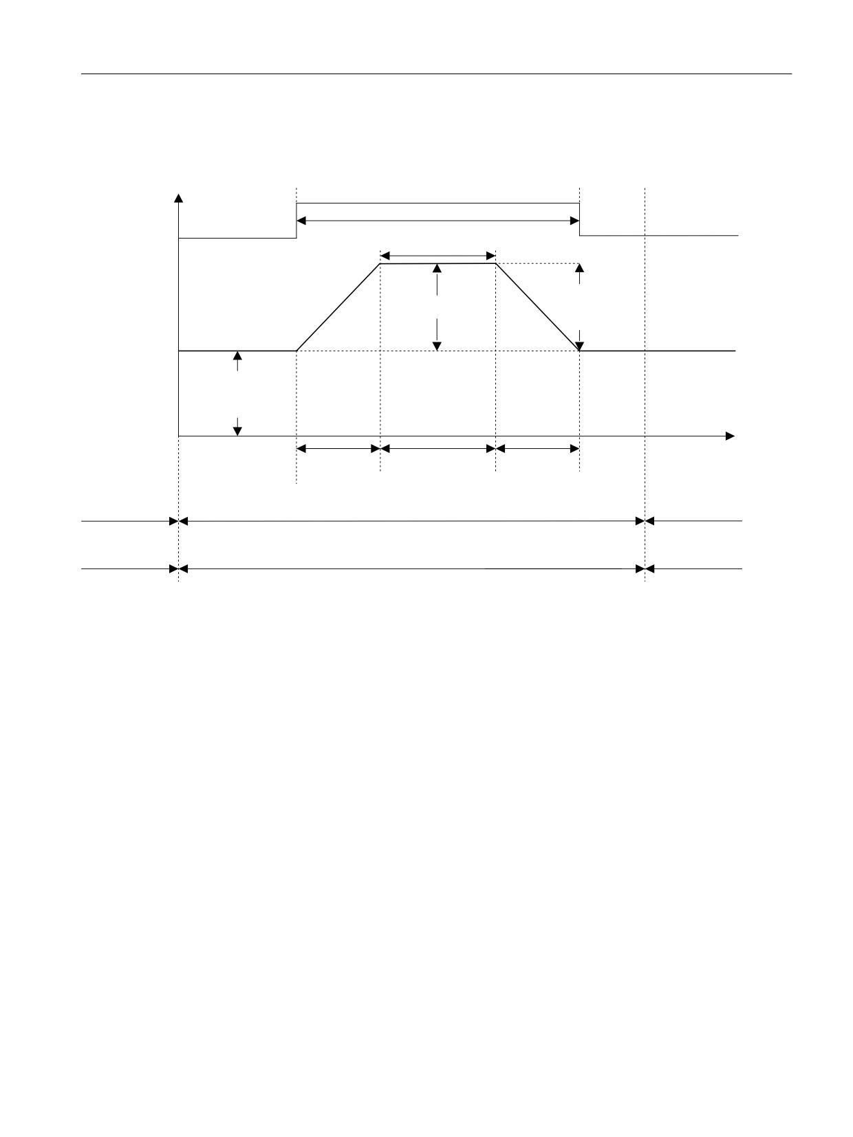
SBT has the following basic sequence:
0
%UDNH FORVHG
VHW
0RQLWRU SRVLWLRQ WROHUDQFH
7HVW WRUTXH
PRQLWRULQJ
'LDJQRVWLFV
%UDNH WHVW WRUTXH
PD[ WHVW
WRUTXH
0
ORDG
'LDJQRVLV
7HVW WRUTXH
6WDWLF
6LJQ
ORDG WRUTXH
VHOHFW SRVLWLYH
W
5DPS WLPH
7HVW
5DPS WLPH
GXUDWLRQ
6WDUW EUDNH WHVW
(QDEOH
(QDEOH
RSHUDWLRQ
%UDNH WHVW VHOHFWHG
RSHUDWLRQ
6HWSRLQW LQSXW
6HWSRLQW LQSXW
6HWSRLQW LQSXW GULYH
([WHUQDO
QVHW
([WHUQDO
6HOHFW EUDNH WHVW
'HVHOHFW EUDNH WHVW
Figure 5-24
SBT: Time sequence
• After the user selects the brake test (0/1 edge in r10231.0), the static hanging load is
determined. For this reason, all brakes must be open and the pulses enabled when the brake
test is selected.
- When testing a motor holding brake, which is directly controlled from SINAMICS, the
brake is automatically opened when the pulses are enabled and p1215=1.
- When testing an external brake, via p10234.6 or for SIC/SCC, via S_ZSW3B.6, a value of 0
indicates that the external brake must be opened. This must occur within 11 seconds,
otherwise the test is canceled and a fault is output.
• The brake, the test sequence and the test direction are then selected by the user.
• When the brake test is active after the start of the brake test / brake test sequence by the user
(0/1 edge in r10231.1), the holding brake (MHB) is closed or there is a prompt to close the
external brake. The request to close the brake is again indicated with p10234.6 = 1 or
S_ZSW3B.6 = 1. Also in this case, only a maximum of 11 seconds must elapse, otherwise a
fault is issued.
• The test torque (test torque ± load torque for a vertical axis) is specified during the SBT. When
n = 0 is entered, the controller builds up an appropriate test torque against the closed brake.
The test torque is built up along a ramp. The ramp is defined by the time of p10208.
• At the end of the test sequence, the brake is opened or there is a prompt to open the brake.
Safety Integrated plus
Commissioning Manual, 10/2020, 6FC5397-1FP40-6BA4
167
Safety functions integrated in the drive
5.15 SBT
• After deselection of the test sequence (test sequence is switched off), another test sequence
can be started, e.g. with a different brake in a different direction, assuming that the brake test
is still selected.
• When the test sequence is active, the brake that is not being tested must remain open.
• After deselection of the SBT, the original speed setpoint takes effect again.
5.15.3.7
Cancellation/deselection and acknowledgment (SBT)
An active brake test is cancelled through deselection of the test sequence or deselection of the
brake test. Alarm A01782 is output.
Acknowledging alarms
The alarms relevant for the brake test can only be safely acknowledged (failsafe acknowledge),
and under certain circumstances only acknowledged, when the brake test is deselected. For
"motion monitoring without selection", a POWER ON is required - or STO/SS1 must be selected/
deselected (for a configured extended alarm acknowledgment).
Safety Integrated plus
168
Commissioning Manual, 10/2020, 6FC5397-1FP40-6BA4
Safety functions integrated in the drive
5.15 SBT
5.15.3.8
Communication via SIC/SCC
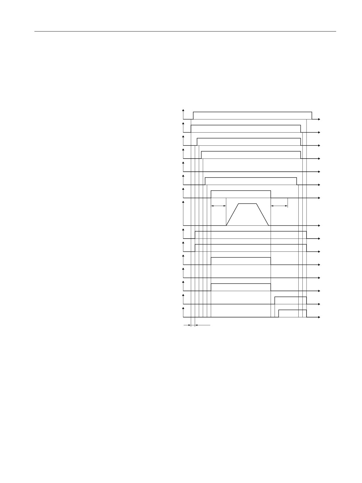
Test of a motor holding brake
The following figure shows the communication via SIC and SCC during the test of a motor
holding brake:
21 2))
W
6HOHFW EUDNH WHVW
6B67: %
W
6HOHFW GLUHFWLRQ RI URWDWLRQ
6B67: %
W
6HOHFW WHVW VHTXHQFH
6B67: %
W
%UDNH VHOHFWLRQ
6B67: %
W
6WDUW EUDNH WHVW
6B67: %
W
&ORVH PRWRU KROGLQJ EUDNH
W
7HVWPRPHQW
S
S
W
%UDNH WHVW VHOHFWHG
6B=6: %
W
7HVW WRUTXH
6B=6: %
W
%UDNH WHVW DFWLYH
6B=6: %
W
$FWLYH EUDNH
6B=6: %
W
$FWXDO ORDG VLJQ
6B=6: %
W
%UDNH WHVW UHVXOW
6B=6: %
W
6HWSRLQW LQSXW GULYH H[WHUQDO
6B=6: %
W
S
Figure 5-25
Testing a motor holding brake
Safety Integrated plus
Commissioning Manual, 10/2020, 6FC5397-1FP40-6BA4
169
Safety functions integrated in the drive
5.15 SBT
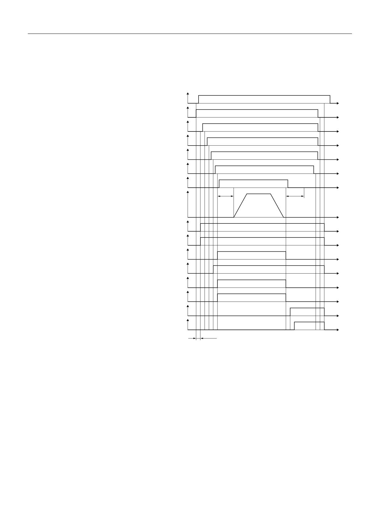
Test of an external brake
The following figure shows the communication via SIC and SCC during the test of an external
brake:
21 2))
W
6HOHFW EUDNH WHVW
6B67: %
W
6HOHFW GLUHFWLRQ RI URWDWLRQ
6B67: %
W
6HOHFW WHVW VHTXHQFH
6B67: %
W
%UDNH VHOHFWLRQ
6B67: %
W
6WDUW EUDNH WHVW
6B67: %
W
&ORVH H[WHUQDO EUDNH
W
7HVW WRUTXH
S
S
W
%UDNH WHVW VHOHFWHG
6B=6: %
W
6HWSRLQW LQSXW GULYH H[WHUQDO
6B=6: %
W
%UDNH WHVW DFWLYH
6B=6: %
W
$FWLYH EUDNH
6B=6: %
W
5HTXHVW FORVH EUDNH
6B=6: %
W
$FWXDO ORDG VLJQ
6B=6: %
W
%UDNH WHVW UHVXOW
6B=6: %
W
%UDNH WHVW FRPSOHWHG
6B=6: %
W
S
Figure 5-26
Testing an external brake
Safety Integrated plus
170
Commissioning Manual, 10/2020, 6FC5397-1FP40-6BA4
Safety functions integrated in the drive
5.15 SBT
5.15.3.9
Function diagrams and parameters
Function diagrams (see SINAMICS S120/S150 List Manual)
•
2836
SI Extended Functions - SBT (Safe Brake Test)
•
2837
SI Extended Functions - selection of active control word
Overview of important parameters (see SINAMICS S120/S150 List Manual)
•
p1215
Motor holding brake configuration
•
p1216
Motor holding brake opening time
•
p1217
Motor holding brake closing time
•
p9501
SI Motion enable safety functions (Control Unit)
•
p9601
SI enable functions integrated in the drive (Control Unit)
•
p9602
SI enable safe brake control (Control Unit)
•
p10201
SI Motion SBT enable
•
p10202[0...1]
SI Motion SBT brake selection
•
p10203
SI Motion SBT control selection
•
p10204
SI Motion SBT motor type
•
p10208[0...1]
SI Motion SBT test torque ramp time
•
p10209[0...1]
SI Motion SBT brake holding torque
•
p10210[0...1]
SI Motion SBT test torque factor sequence 1
•
p10211[0...1]
SI Motion SBT test duration sequence 1
•
p10212[0...1]
SI Motion SBT position tolerance sequence 1
•
p10218
SI Motion SBT test torque sign
•
p10220[0...1]
SI Motion SBT test torque factor sequence 2
•
p10221[0...1]
SI Motion SBT test duration sequence 2
•
p10222[0...1]
SI Motion SBT position tolerance sequence 2
•
p10230[0...5]
BI: SI Motion SBT control word
•
r10231
SI Motion SBT control word diagnostics
•
r10234.0...15
CO/BO: SI Safety Info Channel status word S_ZSW3B
•
p10235
CI: Safety Control Channel control word S_STW3B
•
r10240
SI Motion SBT test torque diagnostics
•
r10241
SI Motion SBT load torque diagnostics
•
p60122
IF1 PROFIdrive SIC/SCC telegram selection
Safety Integrated plus
Commissioning Manual, 10/2020, 6FC5397-1FP40-6BA4
171
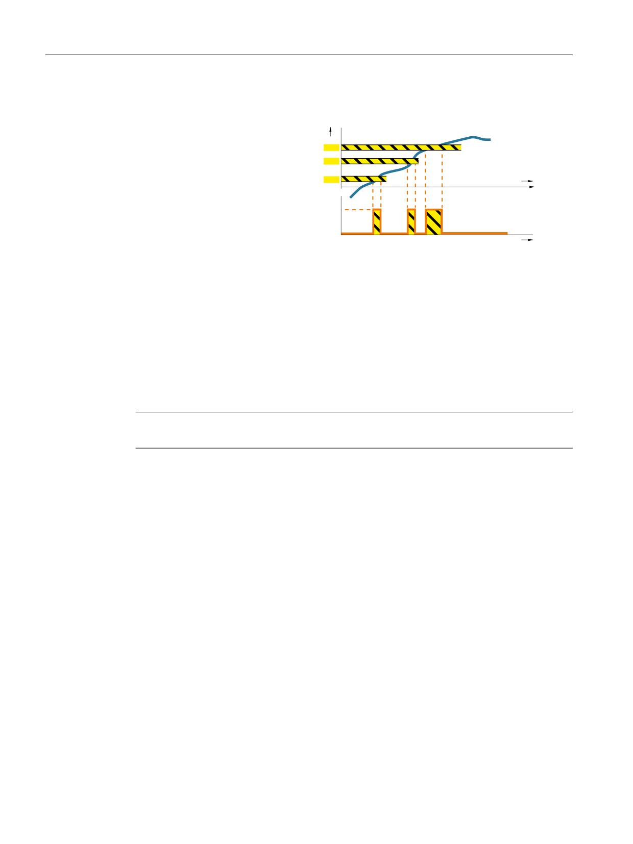
Safety functions integrated in the drive
5.16 SCA
5.16
SCA
Definition according to EN
s
61800-5-2:
SCA 3
Function "Safe Cam (SCA)" supplies a
SCA 2
safety-related output signal to indi-
SCA 1
t
cate whether the motor shaft posi-
tion is within a defined range.
1
0
t
Function "Safe Cam" outputs a safety-related signal if the drive is within a specified position
range. It facilitates the realization of safe range detection for each individual axis.
5.16.1
Details and parameterization
Using function "Safe Cam (SCA)", you can implement safe electronic cams, safe zone sensing or
a working area limitation/protection zone delimitation for a specific axis, therefore replacing a
hardware-based solution. You parameterize up to 30 output cams for each axis. You enable each
output cam individually.
Note
Safety function "Safe Cam (SCA)" can only be used with an encoder.
Safety Integrated plus
172
Commissioning Manual, 10/2020, 6FC5397-1FP40-6BA4
Safety functions integrated in the drive
5.16 SCA
Defining the output cam positions
• You define the output cam positions to be monitored using the parameters p9536[x] and
p9537[x] (where x = 0 ... 29).
Note that the defined output cams must have a certain minimum length: p9536[x] -
p9537[x] ≥ p9540 + p9542
If you violate this rule, the drive will output the message F01686 ("SI Motion: Output cam
position parameterization not permissible").
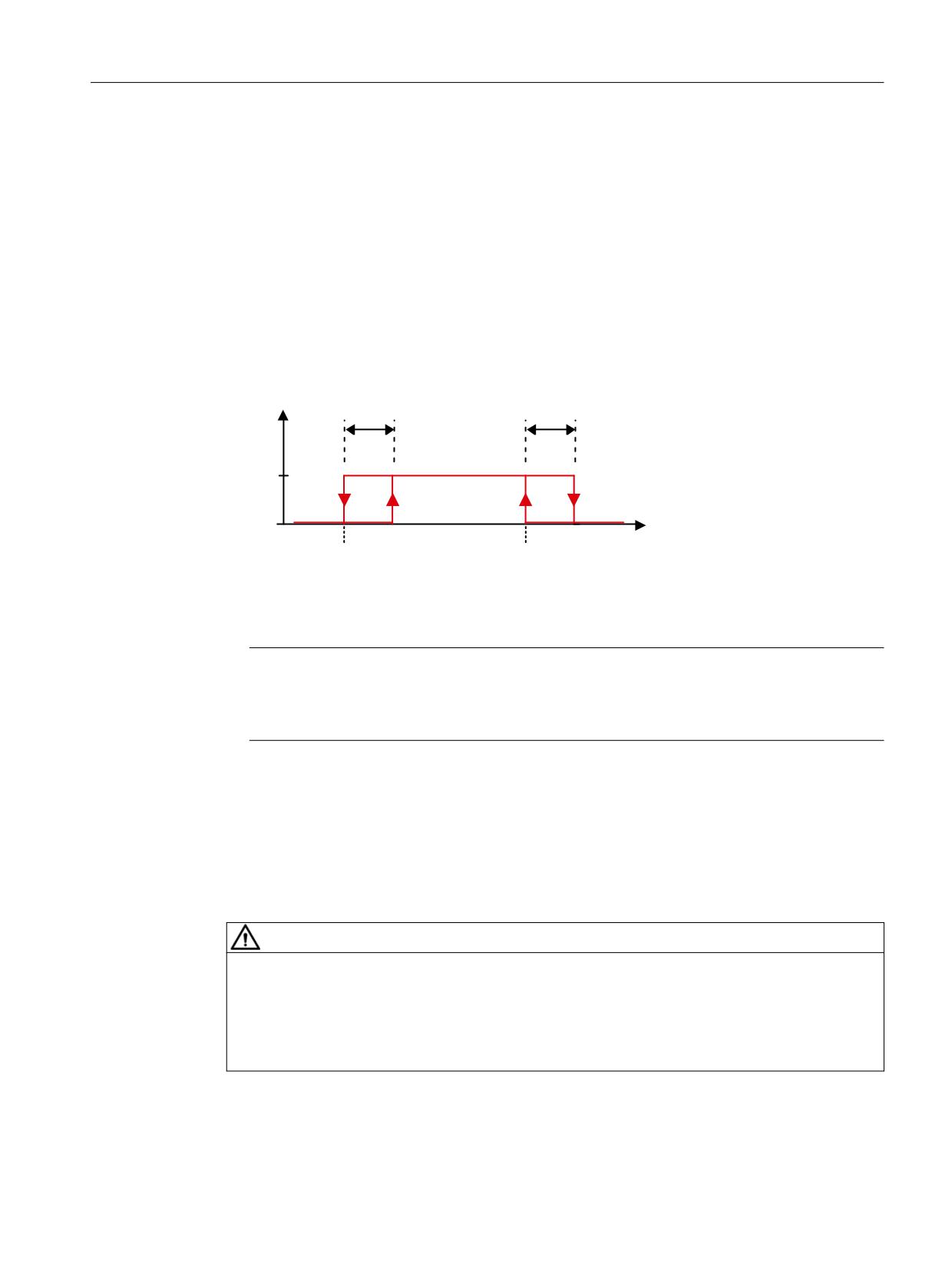
• Owing to variations in the cycle and signal propagation times, the output cam signals of the
two monitoring channels do not switch simultaneously and not precisely at the same
position. For this reason, enter a tolerance band for all output cam types via parameter
p9540. Within this tolerance band, the monitoring channels can have different signal states
for the same output cam:
U
6&$ WROHUDQFH
6&$ WROHUDQFH
S
S
[
S
>[@
S
>[@
3RVLWLRQ
3RVLWLRQ
0LQXV FDP
3OXV FDP
Figure 5-27
Parameterize output cam and tolerance
Note
The smallest possible tolerance band should be selected for the SCA function (<5 ... 10 mm).
It makes sense to parameterize the output cam tolerance to be greater than or equal to the
actual value tolerance.
• Reference the axis using the "Safe referencing (Page 179)" function.
Enable SCA
• Enable function "Safe Cam (SCA)" with p9501.28 = 1.
• You enable each output cam individually with p9503.x = 1 (where x = 0 ... 29).
WARNING
Unexpected speed of the machine component as the axis was not referenced
The enabled cam signals are immediately output after POWER ON. However, the output is only
safety-related after safety-related referencing People can be put into a dangerous situation or
material damage can result if the axis is not referenced in a safety-related way.
• Reference the axis using the "Safe referencing (Page 179)" function.
Safety Integrated plus
Commissioning Manual, 10/2020, 6FC5397-1FP40-6BA4
173
Safety functions integrated in the drive
5.16 SCA
Select SCA
Select function "Safe Cam (SCA)" using PROFIsafe control word S_STW2.23. For SCA, you must
use telegram 903, in which control word S_STW2 and status word S_ZSW_CAM1 are available
for SCA.
Cam synchronization
For transmission of the cam status word via PROFIsafe to the F host, the cam signals of the two
monitoring channels are synchronized. Monitoring is also performed as to whether a different
output cam signal from the second channel is plausible. If the drive detects an error, it outputs
the message C01711 with the fault value 1014.
As the position tolerance for monitoring the output cam positions, the tolerance for the cross-
check of the actual position between the two monitoring channels in p9542 ("Actual value
comparison tolerance") is used.
Transmission via PROFIsafe
After SCA has been parameterized and selected, the monitoring results are transmitted in status
word S_ZSW_CAM1 (see Chapter "S_ZSW_CAM1 (Page 367)").
5.16.1.1
Function diagrams and parameters
Function diagrams (see SINAMICS S120/S150 List Manual)
•
2826
SCA (Safe Cam)
•
2844
S_ZSW_CAM1 Safety status word Safe Cam 1
Overview of important parameters (see SINAMICS S120/S150 List Manual)
• p9501
SI Motion enable safety functions (Control Unit)
• p9503
SI Motion SCA (SN) enable (Control Unit)
• p9505
SI Motion SP modulo value (Control Unit)
• p9536[0...29]
SI Motion SCA (SN) plus cam position (Control Unit)
• p9537[0...29]
SI Motion SCA (SN) minus cam position (Control Unit)
• p9540
SI Motion SCA (SN) tolerance (Control Unit)
• p9542
SI Motion actual value comparison tolerance (crosswise) (Control Unit)
• r9703.0...31
CO/BO: SI Motion SCA status signal (Control Unit)
• r9708[0...5]
SI Motion diagnostics safe position
• r9720.23
CO/BO: SI Motion drive-integrated control signals:
Deselect SCA
• r9727
SI Motion user agreement inside the drive
• r9771.22
SI shared functions: SCA supported
Safety Integrated plus
174
Commissioning Manual, 10/2020, 6FC5397-1FP40-6BA4
Safety functions integrated in the drive
5.17 SLA
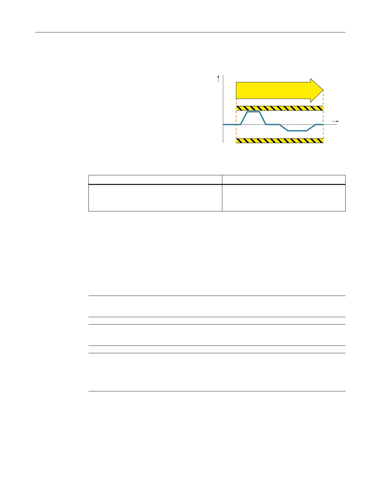
5.17
SLA
Definition according to EN 61800-5-2:
a
Function "Safely-Limited Acceleration (SLA)"
SLA
prevents the motor from exceeding the
specified acceleration limit.
t
Examples of how the function can be used
Example
Possible solution
In the setup mode, it is not permissible that the drive
• Select SLA in the converter via PROFIsafe.
exceeds the permissible acceleration.
• The converter limits and monitors the accel-
eration of the machine.
5.17.1
Description
Function "Safely-Limited Acceleration (SLA)" monitors that the motor does not exceed the
defined acceleration limit (e.g. in setup mode). SLA detects early on whether the speed is
increasing at an inadmissible rate (the drive accelerates uncontrollably) and initiates the stop
response.
SLA is effective when accelerating, however, not when braking.
Note
Safety function "Safely-Limited Acceleration (SLA)" can only be used with an encoder.
Note
Safety function "Safely-Limited Acceleration (SLA)" can only be used for 1-encoder systems.
Note
Configuration only possible in the parameter list
Contrary to other Safety Integrated Functions, there is no configuration screen form in
SINUMERIK Operate for SLA. Therefore, parameterize this function in the parameter list.
Enabling SLA
• Enable function "Safely-Limited Acceleration (SLA)" with p9501.20 = 1.
Safety Integrated plus
Commissioning Manual, 10/2020, 6FC5397-1FP40-6BA4
175
Safety functions integrated in the drive
5.17 SLA
Selecting SLA
Select function "Safely-Limited Acceleration (SLA)" using PROFIsafe control word S_STW1.8 or
S_STW2.8. Which control word you use depends on the PROFIsafe telegram that you configured.
Once selected, the SLA function becomes immediately active without any delay.
You can use telegrams 30, 31, 901, 902 and 903 for SLA. These telegrams contain the control
words S_STW1.8 and S_STW2.8 and status words S_ZSW1.8 and S_ZSW2.8 for SLA.
Acceleration limit
• You define the acceleration limit to be monitored using parameter p9578. This limit value is
applicable for both the positive and negative directions of rotation.
• When setting p9578, the following rule must be complied with:
- p9578 ≥ 10 · r9790[1]
• The possible acceleration resolution is shown by the drive in r9790:
- r9790[0] = resolution, coarse
- r9790[1] = resolution, fine
The actual accuracy of the acceleration detection depends on the type of actual value
acquisition, the gear ratios as well as the quality of the encoder being used.
• The drive indicates the velocity limit corresponding to the actual acceleration in r9714[3].
• r9789 allows the finer resolution acceleration monitoring to be diagnosed. Index 0 indicates
the actual acceleration determined. Index 1 and 2 indicate the current limit values of the SLA
monitoring.
Filter time
If the determination of the acceleration leads to very noisy signals, the drive cannot reasonably
monitor the acceleration.
Remedy
• In this case, increase the "SLA filter time" (p9576).
Note that SLA reacts with a delay when you increase the filter time.
Stop response
If the SLA subsequently detects violation of the acceleration limit, the drive initiates the stop
response configured using p9579.
Safety Integrated plus
176
Commissioning Manual, 10/2020, 6FC5397-1FP40-6BA4
Safety functions integrated in the drive
5.17 SLA
5.17.2
Details and parameterization
Principle of operation
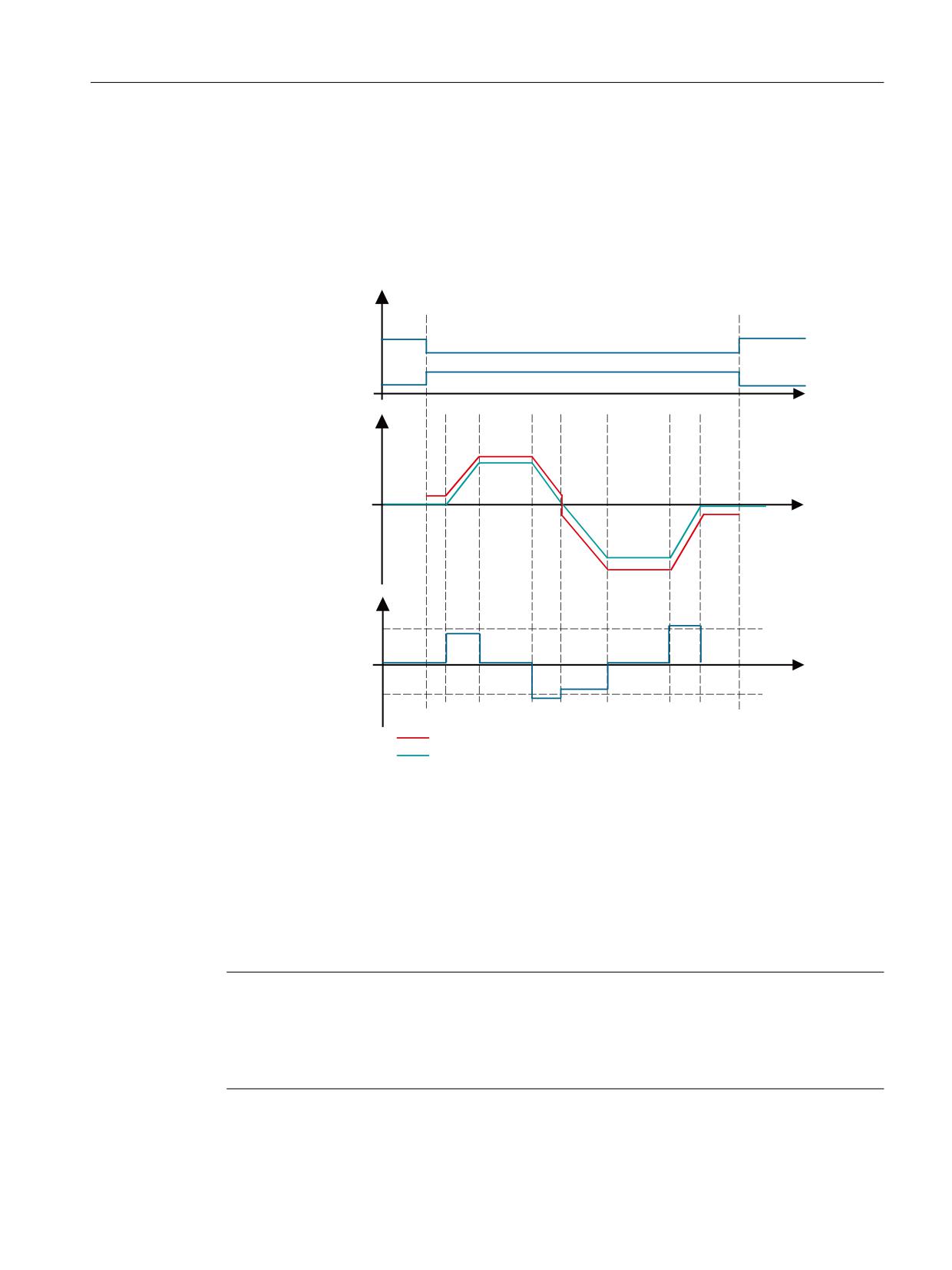
The following diagram shows the principle of operation of SLA:
352),VDIH DQG
GLDJQRVWLFV 6HOHFWLRQ 6/$
'HVHOHFWLRQ 6/$
6B67:
RU U
'HVHOHFWLRQ 6/$
6B=6:
RU U
6/$ DFWLYH
W
9HORFLW\
!
!
!
!
!
$FFHOHUDWLRQ
! %UDNLQJ
W
$FFHOHUDWLRQ
S
ದS
$FWXDO YHORFLW\ OLPLW 6/$
9HORFLW\
Figure 5-28
Safely-Limited Acceleration (SLA): Principle
5.17.2.1
Transmission via PROFIsafe or SIC
Transmission via PROFIsafe
Once SLA has been parameterized and selected, the monitoring results are transmitted in status
words S_ZSW1.8 or S_ZSW2.8.
Note
Response to bus failure
If p9580 ≠ 0 and SLA is active, in the event of a communication failure, the parameterized ESR
reaction only occurs if a STOP with delayed pulse suppression when the bus fails has been
parameterized as the SLA response (p9579 ≥ 10).
Safety Integrated plus
Commissioning Manual, 10/2020, 6FC5397-1FP40-6BA4
177
Safety functions integrated in the drive
5.17 SLA
Transfer via SIC
Once SLA has been parameterized and selected, the monitoring results are also transmitted in
SIC in status word S_ZSW1B.8. You will find this status word in telegrams 700 and 701.
5.17.2.2
Function diagrams and parameters
Function diagrams (see SINAMICS S120/S150 List Manual)
•
2838
SLA (Safely-Limited Acceleration)
Overview of important parameters (see SINAMICS S120/S150 List Manual)
• p9501
SI Motion enable safety functions (Control Unit)
• p9576
SI Motion SLA filter time (CU)
• p9578
SI Motion SLA acceleration limit (CU)
• p9579
SI Motion SLA stop response (Control Unit)
• r9714[3]
CO: SI Motion diagnostics velocity: Actual SLA velocity limit on the
Control Unit
• r9719.17
CO/BO: SI Motion control signals 2: Deselect SLA
• r9720.8
CO/BO: SI Motion drive-integrated control signals: Deselect SLA
• r9721.11
CO/BO: SI Motion status signals (Control Unit): SLA active
• r9722.8
CO/BO: SI Motion drive-integrated status signals (Control Unit): SLA
active
• r9789
CO: SI Motion SLA acceleration acceleration diagnostics
• r9790
SI Motion acceleration resolution
Safety Integrated plus
178
Commissioning Manual, 10/2020, 6FC5397-1FP40-6BA4
Safety functions integrated in the drive
5.18 Safe referencing
5.18
Safe referencing
The "safe referencing" function allows a safe absolute position to be defined. This safe position
is used for the following functions:
• SLP (Page 151)
• SP (Page 156)
• SCA (Page 172)
General description
Referencing to an absolute position is performed by the motion control of the NC. The
functionality SIC/SCC is used for this.
For SINUMERIK Safety Integrated or SINUMERIK Safety Integrated plus, the current absolute NC
actual position (also in motion) is transferred to the drive as the "reference position" for the safe
actual value system. This process is carried out on the system side for each referencing of the NC
actual position system. This requires the enabling of SIC/SCC and the "Reference via SCC"
function (p9501.27). The "safely referenced" state is reached when user agreement has been
set.
Referencing methods
SINAMICS distinguishes between 2 types of referencing:
• Initial referencing
For initial safe referencing, or in the event of a fault during a subsequent referencing, the
following steps are necessary:
- Perform referencing by the NC
- Setting user agreement
• Subsequent referencing
Subsequent referencing involves referencing with a safety-relevant history (i.e. with an
internally buffered user agreement) after a POWER ON or after deselecting "parking axis".
- After the drive has been referenced, Safety Integrated automatically performs a
plausibility check.
- If the deviation between the current absolute position and the previous position saved by
Safety Integrated is within the tolerance of p9544, then the drive goes into the "safely
referenced" state.
5.18.1
User agreement
Description
With a user agreement, an appropriately authorized person confirms that the currently displayed
SI actual position of an axis corresponds to the actual position at the machine.
Safety Integrated plus
Commissioning Manual, 10/2020, 6FC5397-1FP40-6BA4
179
Safety functions integrated in the drive
5.18 Safe referencing
You can check this by traversing the axis to a known position (e.g. a visual mark) or adjusting/
calibrating the axis and then comparing the SI actual position with the "user agreement" screen.
An axis/spindle with integrated safety functions can have the following status:
• User agreement = yes, or
• User agreement = no
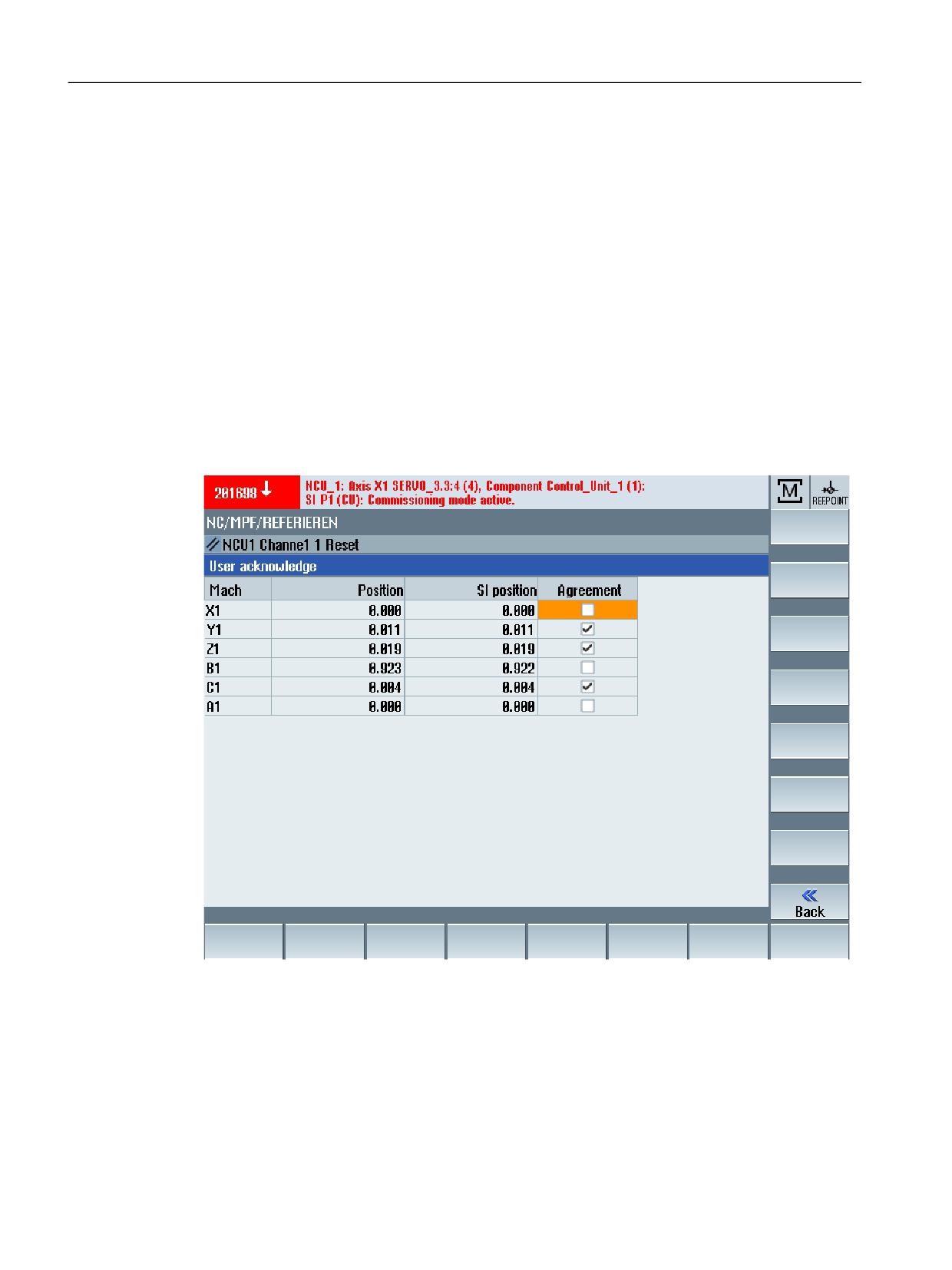
All safety axes that require user agreement to be set are listed in the HMI display "user
agreement".
The following data are displayed:
• Machine axis name
• Position
• SI position
• User agreement
Figure 5-29
User agreement
The user agreement can only be set by an authorized user.
User agreement can be canceled in the following ways:
• By the user
• By selecting a function (e.g. a new gear stage)
• By a fault state (e.g. user acceptance inconsistency in the monitoring channels)
Safety Integrated plus
180
Commissioning Manual, 10/2020, 6FC5397-1FP40-6BA4
Safety functions integrated in the drive
5.18 Safe referencing
When user agreement is canceled, the "safely referenced" state is always reset.
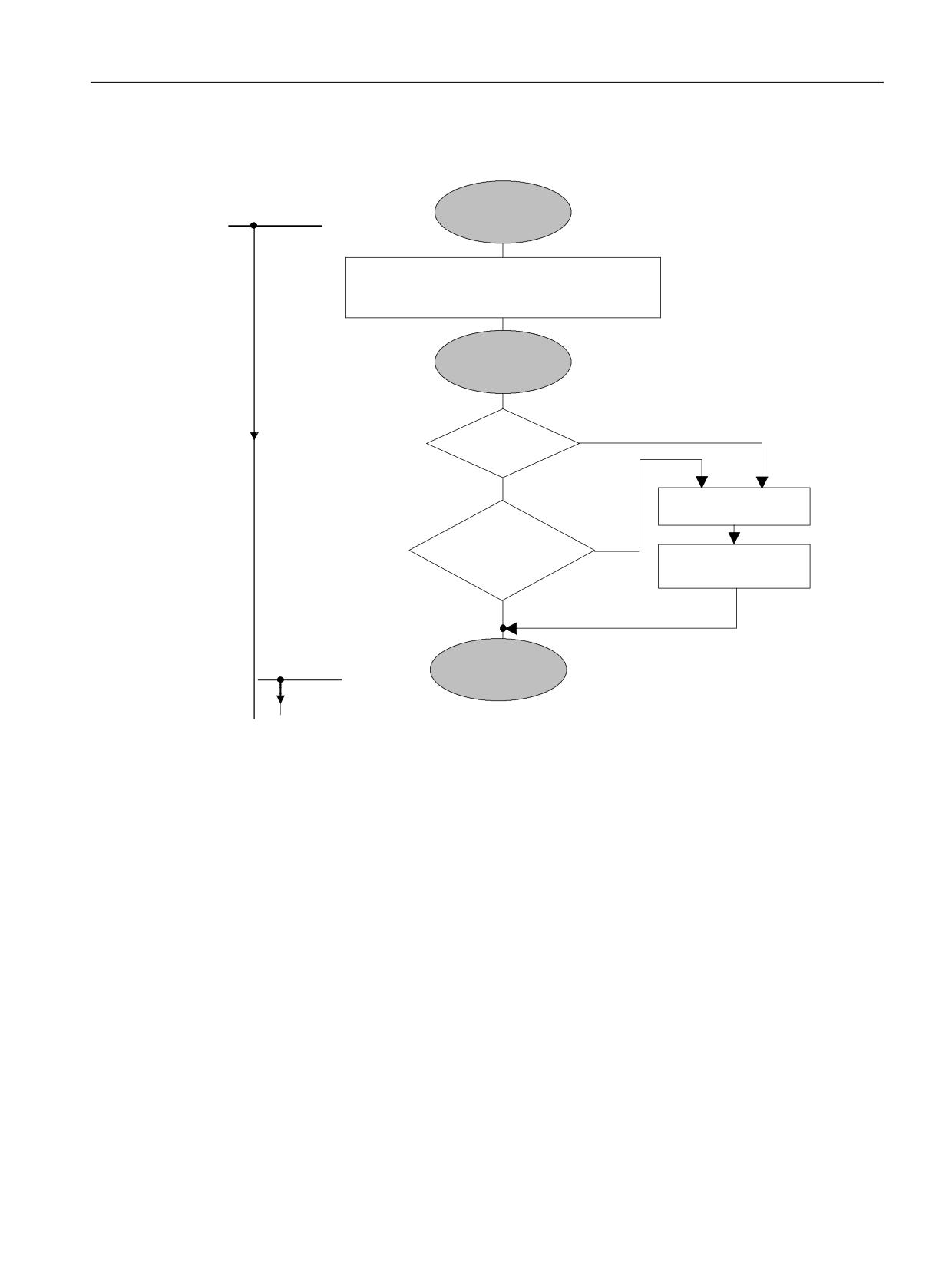
626 6/6 LV VDIH
$[LV VWDWXV LV GLVSOD\HG E\ WKH LQWHUIDFH
IURP WKLV D[LV
VLJQDO
$[LV QRW UHIHUHQFHG
VWDWXV RQZDUG
5HIHUHQFH SRLQW UHDFKHG
$[LV VWDWXV
(41 5HDG WKH DEVROXWH YDOXH IURP WKH HQFRGHU
(51 5HIHUHQFH SRLQW DSSURDFK
,QWHUIDFH VLJQDO
$[LV UHIHUHQFHG
5HIHUHQFH SRLQW UHDFKHG
$[LV VWDWXV
8VHU
1R
DJUHHPHQW
<HV
8VHU FKHFNV WKH SRVLWLRQ
&KHFN QRW
2.
&KHFN DFWXDO SRVLWLRQ
VDYHG VWDQGVWLOO
8VHU DJUHHPHQW
SRVLWLRQ
6RIWNH\
&KHFN 2.
6/3 63 6&$ LV VDIH
IURP WKLV D[LV VWDWXV
VDIHO\ UHIHUHQFHG
$[LV VWDWXV
VDIHO\ UHIHUHQFHG
Figure 5-30
Axis states when referencing
Interlocking the user agreement
Before a user agreement can be issued, the interlock must first be canceled:
• Keyswitch: In position 3 → User agreement can be issued
After user agreement has been issued, you must reactivate the interlock (e.g. keyswitch position
3 must be left and the key withdrawn).
5.18.2
Function diagrams and parameters
Function diagrams (see SINAMICS S120/S150 List Manual)
•
2821
SI Extended Functions - Safe referencing
Safety Integrated plus
Commissioning Manual, 10/2020, 6FC5397-1FP40-6BA4
181
Safety functions integrated in the drive
5.18 Safe referencing
Overview of important parameters (see SINAMICS S120/S150 List Manual)
• p9572
SI Motion reference position (Control Unit)
• p9573
Accept SI Motion reference position (Control Unit)
• r9708[0...5]
SI Motion diagnostics safe position
• r9713[0...5]
CO: SI Motion diagnostics actual position value load side
• r9722.0...31
CO/BO: SI Motion drive-integrated status signals (Control Unit)
• r9723.0...17
CO/BO: SI Motion diagnostics signals integrated in the drive
• p9726
SI motion, user agreement, select/deselect
• p9740
SI motion, user agreement, select/deselect MM
Safety Integrated plus
182
Commissioning Manual, 10/2020, 6FC5397-1FP40-6BA4
Safety functions integrated in the drive
5.19 Safe actual value acquisition
5.19
Safe actual value acquisition
Supported encoder systems
The following encoder systems can in principle be used for safety-related speed/position
acquisition:
• Single-encoder systems
or
•
2-encoder systems
Note
Rules for connecting an encoder
Note when connecting an encoder the valid rules: See SINAMICS S120 Drive Functions Function
Manual.
Single-encoder system
In a single-encoder system, only the motor encoder is used to safely acquire the drive actual
values. This motor encoder must be appropriately suitable (see encoder types). The actual
values are generated in a safety-related fashion either directly in the encoder or in the Sensor
Module and are transferred to the Control Unit via DRIVE-CLiQ.
For motors without a DRIVE-CLiQ interface, the connection is made using additional Sensor
Modules.
Even if the drive is operating in the closed-loop torque controlled mode, motion monitoring
functions may be selected as long as it is guaranteed that the encoder signals can be evaluated.
Note
No "Safe Acceleration Monitoring" for encoder faults in a 1-encoder system
For an encoder fault in a 1-encoder system, the "Safe Acceleration Monitoring" function
(p9506 = 3) is not active.
A stop response of category 0 or 1 (EN 60204-1) can be set with parameter p9516.4.
Safety Integrated plus
Commissioning Manual, 10/2020, 6FC5397-1FP40-6BA4
183
Safety functions integrated in the drive
5.19 Safe actual value acquisition
Special feature in the case of linear motors
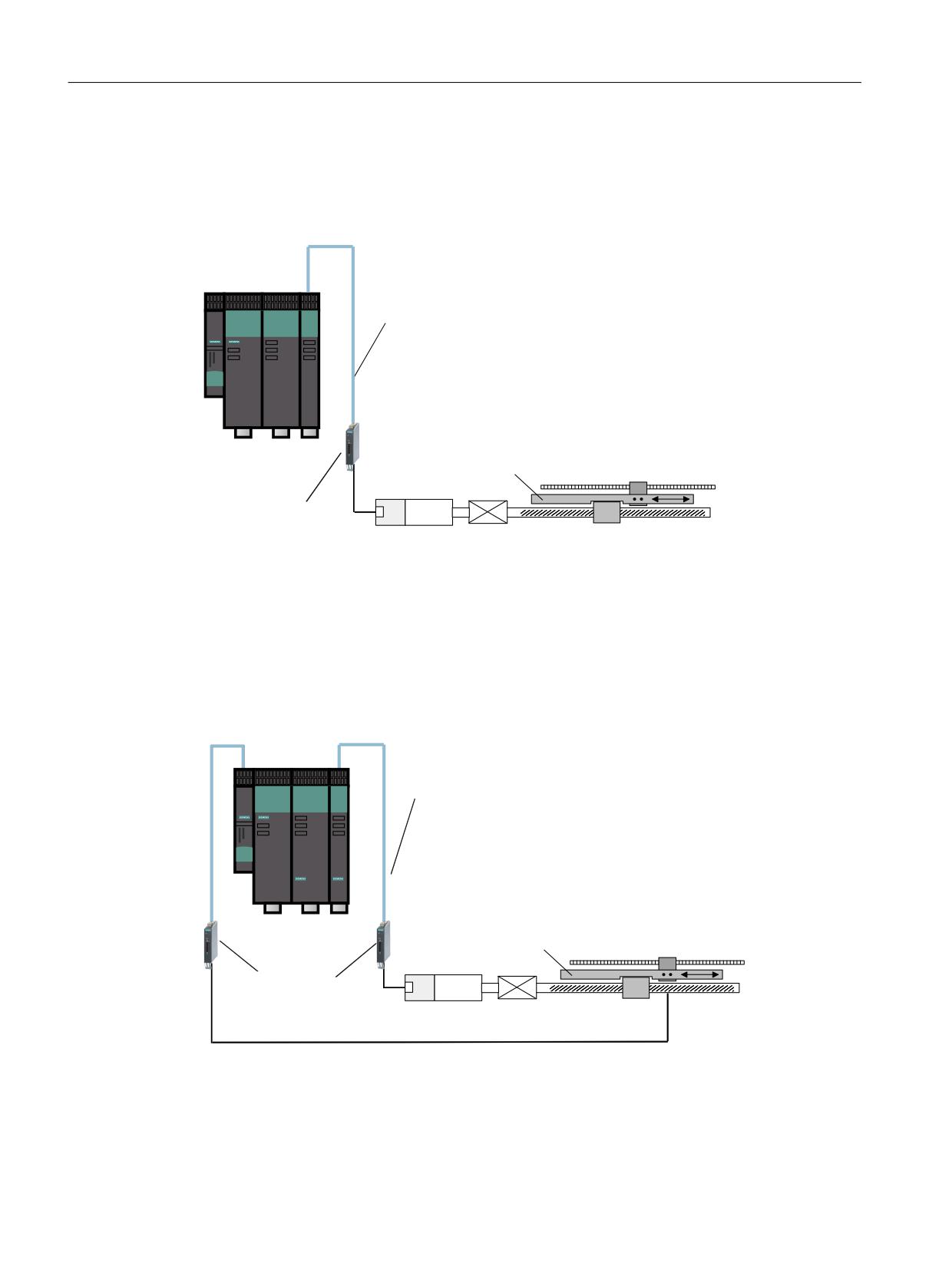
The motor encoder (linear scale) of linear motors also acts as load measuring system. Only one
measuring system is required for this reason. The system is connected by means of a Sensor
Module or directly via DRIVE-CLiQ.
( (QFRGHU
'5,9( &/L4
0 0RWRU
0DFKLQH WDEOH
/LQHDU VFDOH
6HQVRU 0RGXOH
(
0
QRW DSSOLFDEOH IRU PRWRU ZLWK
%DFNODVK
'5,9( &/L4 LQWHUIDFH
Figure 5-31
Example of a single-encoder system
2-encoder system
The failsafe actual values for a drive are provided by 2 separate encoders. The actual values are
transferred to the Control Unit via DRIVE-CLiQ.
For motors without a DRIVE-CLiQ interface, the connection is made using additional Sensor
Modules (see encoder types).
( (QFRGHU
'5,9( &/L4
0 0RWRU
0DFKLQH WDEOH
/LQHDU VFDOH
(
6HQVRU 0RGXOH
(
0
QRW DSSOLFDEOH IRU PRWRU ZLWK
%DFNODVK
'5,9( &/L4 LQWHUIDFH
Figure 5-32
Example of a 2-encoder system on a linear axis via a ball screw
Safety Integrated plus
184
Commissioning Manual, 10/2020, 6FC5397-1FP40-6BA4
Safety functions integrated in the drive
5.19 Safe actual value acquisition
( (QFRGHU
0 0RWRU
'5,9( &/L4
(
0
6HQVRU 0RGXOH
QRW DSSOLFDEOH IRU PRWRU ZLWK
'5,9( &/L4 LQWHUIDFH
(
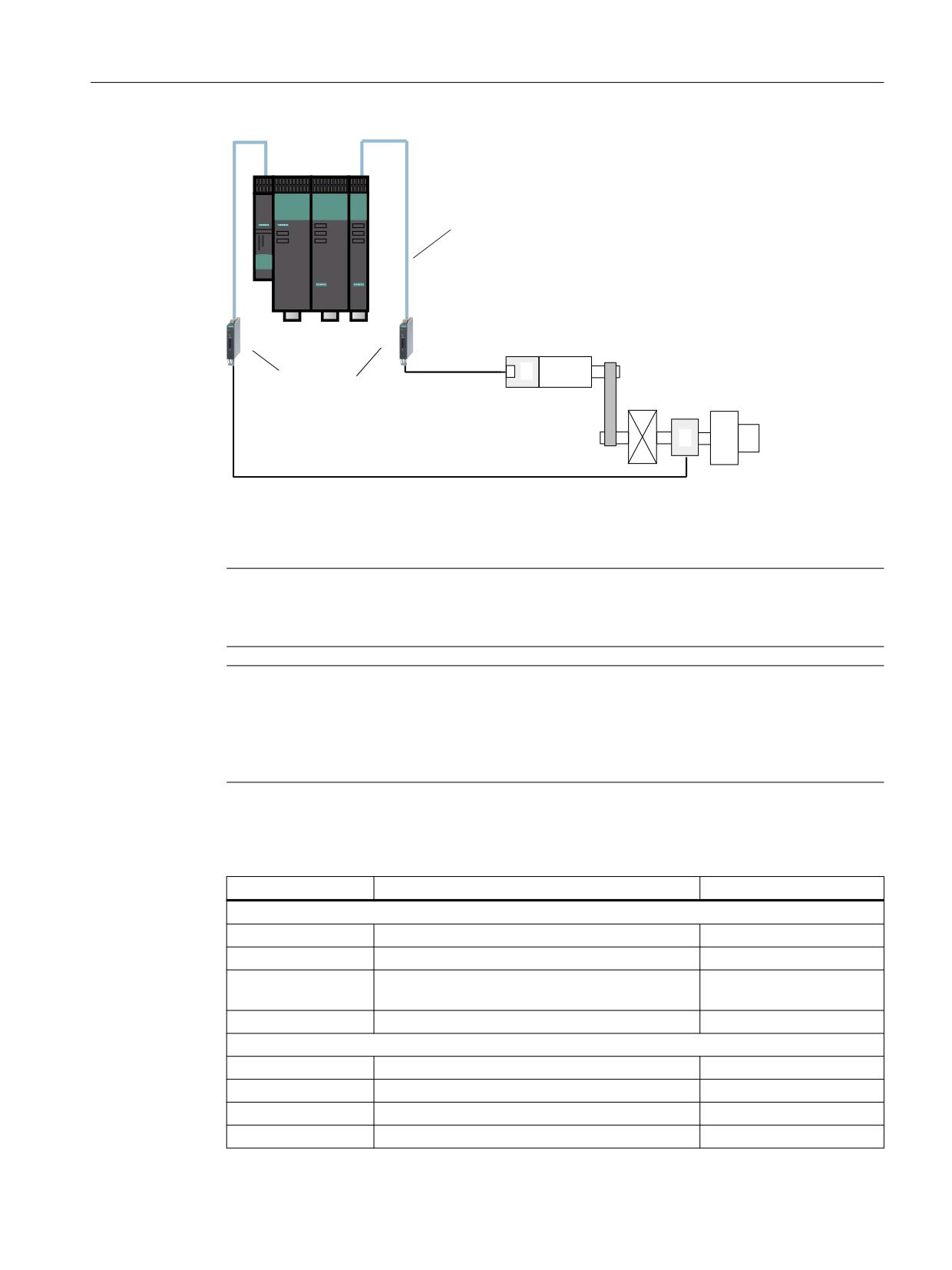
Figure 5-33
Example of a 2-encoder system on a rotary axis
When parameterizing a 2-encoder system with Safety Integrated, you must align parameters
p9315 to p9329 with parameters r0401 to r0474.
Note
Assignment of the encoder parameters
Parameters p95xx are assigned to the 1st encoder; parameters p93xx to the 2nd encoder.
Note
Transfer of the values from the encoder commissioning
To accept the values from the parameters filled during the encoder commissioning to the safety
parameterization, set parameter p9700 = 46 (2E hex). This copy function is only possible if you
are connected online with the drive unit.
Table 5-6
Encoder parameters and corresponding safety parameters for 2-encoder systems
Safety parameters
Designation
Encoder parameters
p9315/p9515 SI Motion coarse position value configuration
p9315.0/p9515.0
Up-counter
r0474[x].0
p9315.1/p9515.1
Encoder CRC, least significant byte first
r0474[x].1
p9315.2/p9515.2
Redundant coarse position value, most significant
r0474[x].2
bit left-justified
p9315.16/p9515.16
DRIVE-CLiQ encoder
p0404[x].10
p9316/p9516 SI Motion encoder configuration, safety functions
p9316.0/p9516.0
Motor encoder, rotary/linear
p0404[x].0
p9316.1/p9516.1
Actual position value, sign change
p0410[x]
p9317/p9517
SI Motion linear scale grid division
p0407
p9318/p9518
SI Motion encoder pulses per revolution
p0408
Safety Integrated plus
Commissioning Manual, 10/2020, 6FC5397-1FP40-6BA4
185

Safety functions integrated in the drive
5.19 Safe actual value acquisition
Safety parameters
Designation
Encoder parameters
p9319/p9519
SI Motion fine resolution G1_XIST1
p0418
p9320/p9520
SI Motion leadscrew pitch
Encoder parameterizing
screen form
p9321/p9521
SI Motion gearbox encoder
Encoder parameterizing
screen form
p9322/p9522
SI Motion gearbox encoder
Encoder parameterizing
screen form
p9323/p9523
Redundant coarse position value valid bits
r0470
p9324/p9524
Redundant coarse position value fine resolution
r0471
bits
p9325/p9525
Redundant coarse position value relevant bits
r0472
p9326/p9526
SI Motion encoder assignment
Encoder parameterizing
screen form
p9328/p9528
SI Motion Sensor Module node identifier
p9329/p9529
Gx_XIST1 coarse position safety most significant
p0415 = r0470 - r0471
bit
Encoder types for single and 2-encoder systems
Incremental encoders or absolute encoders can be used for safe acquisition of the position
values on a drive.
The absolute position values can be transferred via the serial EnDat interface or an SSI interface
to the controller. However, these are not evaluated by the safety functions.
In systems with encoders with SINAMICS Safety Integrated (single and 2-encoder systems), the
following encoders are permitted for safe actual value acquisition:
• Encoders with sin/cos 1 Vpp signals
- Single and 2-encoder systems
- Connected to the SINAMICS SME20/25, SME120/125 and SMC20 Sensor Modules
- The encoders must contain purely analog signal processing and creation. This is
necessary to be able to prevent the A/B track signals with valid levels from becoming static
("freezing").
• HTL/TTL encoders
- Can only be used for 2-encoder systems. In this case, one encoder must be an HTL/TTL
encoder. The other encoder can be a sin/cos encoder or an HTL/TTL encoder.
- Connected to an SMC30 Sensor Module Cabinet or to SINAMICS HLA or
SINAMICS S120 Combi.
- An HTL/TTL encoder connected to SINAMICS HLA or SINAMICS S120 Combi must not be
operated as first encoder.
- Note the lowest possible velocity resolution (r9732[1]) for an HTL/TTL encoder system.
Safety Integrated plus
186
Commissioning Manual, 10/2020, 6FC5397-1FP40-6BA4

Safety functions integrated in the drive
5.19 Safe actual value acquisition
Note
Encoders with integrated DRIVE-CLiQ interface
These encoders must be certified at least according to IEC 61800-5-2 (SIL2) or ISO 13849-1
(Performance Level d / Category 3).
A fault mode effect analysis (FMEA) for securing the encoder on the motor shaft or on the linear
drive must be performed. The result must be that the risk of the encoder mounting loosening is
defined as a fault that can be ruled out (see DIN EN 61800-5-2, 2008, Table D.16). The encoder
would no longer correctly map the motion if its mounting were to become loose.
It should be noted that the machine manufacturer has sole responsibility for the fulfillment of
the above-described requirements. Information on the internal realization of the encoder must
come from the encoder manufacturer. The FMEA must be created by the machine manufacturer.
Information about Siemens motors with and without DRIVE-CLiQ connection, which can be used
for Safety Integrated Functions, is available in the SIOS Portal:
Suitable motors and encoders (https://support.industry.siemens.com/cs/ww/en/view/
33512621)
For these motors, the encoder mounting on the motor shaft can be considered to be safety
relevant, and faults associated with an encoder becoming loose ruled out.
Note
Basic absolute encoders with EnDat interface and additional sin/cos tracks
Basic absolute encoders (e.g. EQI) that offer an EnDat interface with additional sin/cos tracks,
but operate according to an inductive measuring principle internally, are not permitted for
SINAMICS Safety Integrated.
Note
Encoder types for SINAMICS HLA
The following encoder types are permissible for SINAMICS HLA:
• Single-encoder systems
- DRIVE-CLiQ encoder with safety capability
- sin/cos encoder connected via SME20/25, SME120/125 or SMC20 (1Vpp, pure analog
signal processing)
•
2-encoder systems
- Encoders with DRIVE-CLiQ connection
- sin/cos encoder connected via SME20/25, SME120/125 or SMC20 (1Vpp, pure analog
signal processing)
- HTL/TTL encoder connected via SMC30 (not in connection with SINUMERIK)
- TTL encoder connected via the onboard interface of the HLA module (not in connection
with SINUMERIK)
Safety Integrated plus
Commissioning Manual, 10/2020, 6FC5397-1FP40-6BA4
187
Safety functions integrated in the drive
5.19 Safe actual value acquisition
Actual value synchronization
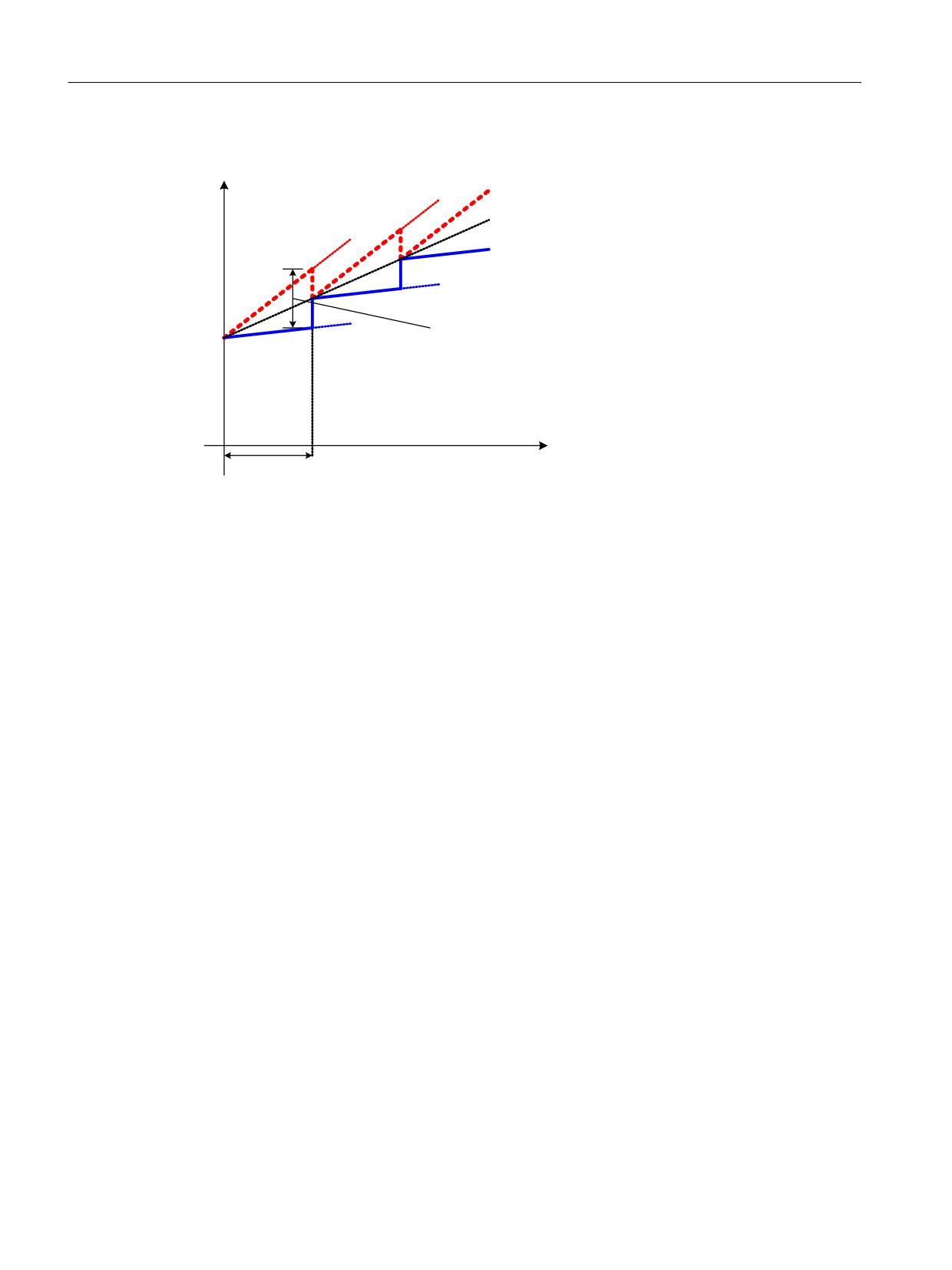
6DIH SRVLWLRQ DFWXDO YDOXH
$FWXDO SRVLWLRQ YDOXH
ORDG VLGH
(QFRGHU
$FWXDO SRVLWLRQ YDOXH
(QFRGHU
'HYLDWLRQ EHWZHHQ
SRVLWLRQ DFWXDO YDOXHV QRW
KLJKHU WKDQ VOLS
SHU &'& F\FOH S
U
W
&'& F\FOH U
1)
This deviation cannot be larger than the position difference that can occur at maximum slip
(p9549) during a cross-check cycle (r9724).
Figure 5-34
Example diagram of actual value synchronization
The mean value of the actual values of both channels is calculated cyclically after actual value
synchronization (p9301.3 = 1) has been activated, for example, for systems or machines with
slip. The maximum slip defined in p9549 is monitored in the cross-check cycle (r9724). If "actual
value synchronization" is not enabled, the value parameterized in p9542 is used as tolerance
value for the crosswise comparison.
Safe motion monitoring
The properties of the actual value acquisition determine not only the encoders used, but also the
values for safe motion monitoring that can be achieved in the best case.
• Safe maximum speed (r9730)
The maximum speed (load side) that is permissible due to the acquisition of actual values for
safe motion monitoring functions is indicated in r9730. This parameter shows up to which
load velocity the safety-related encoder actual values (redundant coarse encoder position)
can still be correctly sensed as a result of the particular encoder parameterization.
The actual value acquisition clock (p9511) determines the frequency at which the actual
values are acquired. The longer the clock cycle, the higher the "safe maximum velocity." On
the other hand, a longer actual value acquisition clock cycle places a greater load on the
Control Unit. You must consider this when setting the optimum for your particular
application.
• Safe positioning accuracy (r9731)
This positioning accuracy can be achieved in the best case by acquiring the actual values. If
a 2-encoder system is used, the accuracy of the poorer encoder is indicated based on the
number of encoder pulses.
Safety Integrated plus
188
Commissioning Manual, 10/2020, 6FC5397-1FP40-6BA4
Safety functions integrated in the drive
5.19 Safe actual value acquisition
5.19.1
Important parameters
Overview of important parameters - with encoder system (see SINAMICS S120/S150 List Manual)
•
p9501.3
SI Motion enable safety functions (Control Unit),
enable actual value synchronization
•
p9502
SI Motion axis type (Control Unit)
•
p9511
SI Motion actual value acquisition clock (Control Unit)
•
p9515
SI Motion encoder coarse position value configuration (Control Unit)
•
p9516
SI Motion encoder configuration safety functions (Control Unit)
•
p9517
SI Motion linear encoder grid division (Control Unit)
•
p9518
SI Motion encoder pulses per revolution (Control Unit)
•
p9519
SI Motion fine resolution G1_XIST1 (Control Unit)
•
p9520
SI Motion leadscrew pitch (Control Unit)
•
p9521[0...7]
SI Motion gearbox encoder (motor)/load denominator (Control Unit)
•
p9522[0...7]
SI Motion gearbox encoder (motor)/load numerator (Control Unit)
•
p9523
SI Motion redundant coarse position value valid bits (Control Unit)
•
p9524
SI Motion redundant coarse position value, fine resolution (Control
Unit)
•
p9525
SI Motion redundant coarse position relevant bits (Control Unit)
•
p9526
SI Motion encoder assignment second channel
•
p9542
SI Motion actual value comparison tolerance (crosswise) (Control Unit)
•
p9549
SI Motion slip velocity tolerance (Control Unit)
•
p9700
SI Motion copy function
•
r9713[0...5]
SI Motion diagnostics actual position value load side
•
r9714[0...2]
SI Motion diagnostics velocity
•
r9724
SI Motion, cross-check cycle
•
r9730
SI Motion safe maximum speed
•
r9731
SI Motion safe positioning accuracy
•
r9732[0...1]
SI Motion velocity resolution
Overview of important parameters - without encoder system
• p9585
SI Motion actual value acquisition without encoder fault tolerance (CU)
• p9586
SI Motion actual value acquisition without encoder delay time (CU)
• p9587
SI Motion actual value acquisition without encoder filter time (CU)
• p9588
SI Motion actual value acquisition without encoder minimum current
(CU)
• p9589
SI Motion actual value acquisition without encoder acceleration limit
(CU)
• p9700
SI Motion copy function
• r9732[0...1]
SI Motion velocity resolution
Safety Integrated plus
Commissioning Manual, 10/2020, 6FC5397-1FP40-6BA4
189
Safety functions integrated in the drive
5.20 Safe gearbox stage switchover
5.20
Safe gearbox stage switchover
"Safe gearbox switchover" allows you to switch between 8 gearbox ratios in operation.
Switchover between gearbox ratios is only possible via PROFIsafe (p9601.3 = 1).
Parameterization
Before you can use "Safe gearbox switchover", you must parameterize the following values:
• Gear ratios
You can set up to 8 different gearbox ratios using parameter p9521 (denominator) and
p9522 (numerator).
• Direction reversal
Using parameter p9539, you can set as to whether a direction of rotation reversal is involved
for the particular gearbox.
• Position tolerance
As a result of the motion that can possibly occur when switching over the gearbox, it may be
necessary to increase the tolerance threshold for the duration of the switchover operation.
Using parameter p9539, you set how the tolerance is calculated when switching over the
gearbox:
- Without actual value synchronization: p9542 × p9543
- With actual value synchronization: p9549 × p9543
Selection
Proceed as follows to enable the "Safe gearbox switchover" function:
1. Set p9501.26 = 1
- If control via PROFIsafe is not parameterized, then the converter outputs fault F01681
with the appropriate fault value.
- If you activate the "Safe gearbox switchover" function on a converter, which does not
support the function, then the converter outputs fault F01682 with fault value 39.
2. Switch off the drive unit and then on again (POWER ON).
Safety Integrated plus
190
Commissioning Manual, 10/2020, 6FC5397-1FP40-6BA4
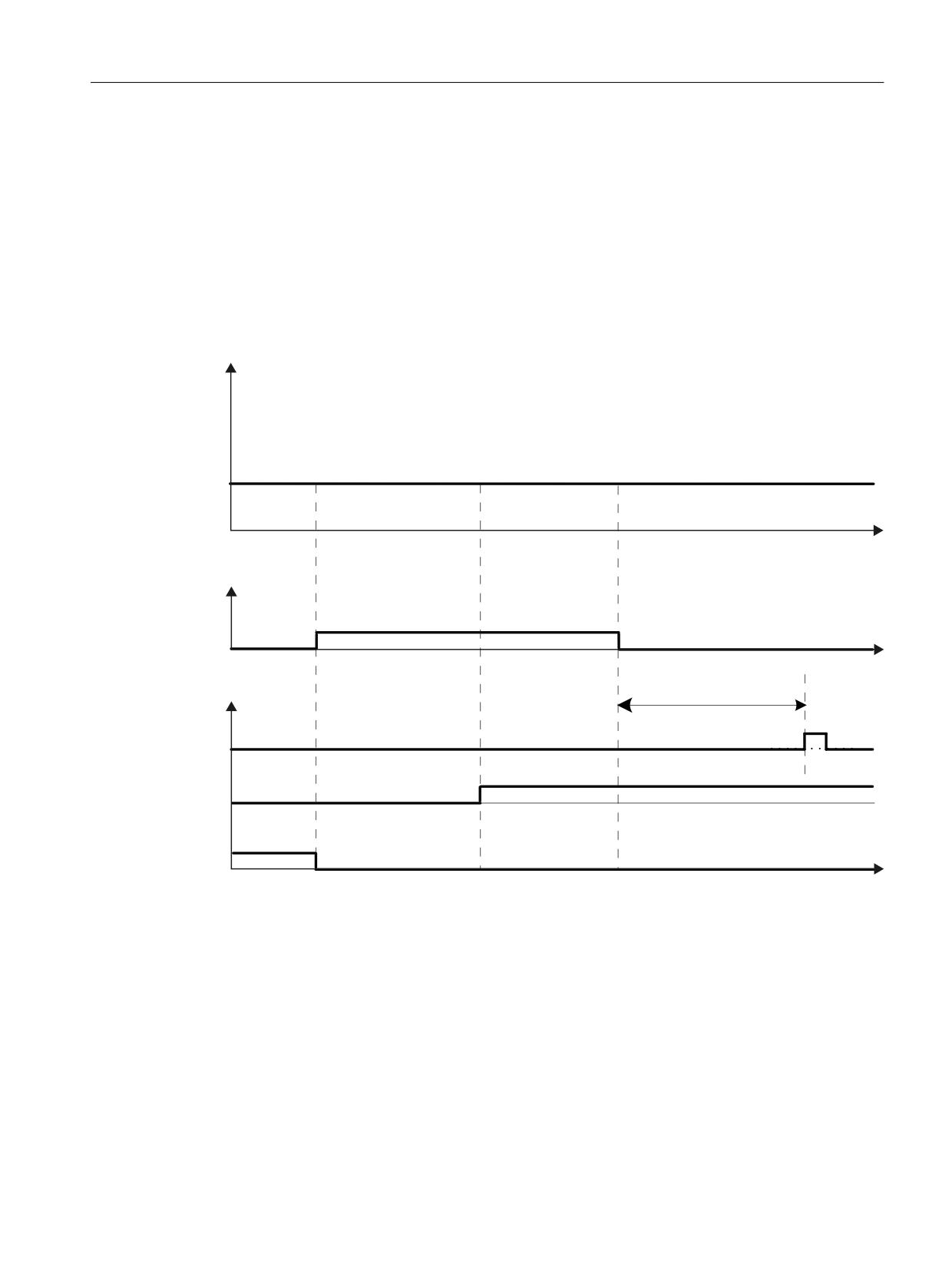
Safety functions integrated in the drive
5.20 Safe gearbox stage switchover
Gearbox switchover without increased position tolerance
In order to switch over the gearbox stage, where no increased tolerance is required for the
crosswise comparison of the actual positions, proceed as follows:
1. Set the new gearbox stage using bits 0 to 2 in byte 3 of S_STW2.
- The actual values are then synchronized once automatically. This synchronization is used
to compensate any possible difference that occurs between the position actual values of
the two monitoring channels as a result of the switchover operation.
- The new gearbox stage is then active.
3RVLWLRQ WROHUDQFH
,QFUHDVHG
6WDQGDUG
W
352),VDIH 6B67:
*HDUER[ VWDJH FKDQJH
E\WH ELW
W
6DIHW\ 0RWLRQ 0RQLWRULQJ
0D[LPXP U
6LQJOH
DFWXDO YDOXH
V\QFKURQL]DWLRQ
&RQYHUVLRQ WR WKH
ORDG VLGH ZLWK QHZ
JHDUER[ IDFWRUV
6DIHO\
UHIHUHQFHG
W
Figure 5-35
Gearbox switchover from stage "0" to "1" without increased position tolerance
Safety Integrated plus
Commissioning Manual, 10/2020, 6FC5397-1FP40-6BA4
191
Safety functions integrated in the drive
5.20 Safe gearbox stage switchover
Gearbox switchover with increased position tolerance
In order to switch over the gearbox stage, where increased tolerance is required for the crosswise
comparison of the actual positions, proceed as follows:
Note
Maximum duration of the increased position tolerance
It is not permissible that the increased position tolerance is set for longer than 2 min. If this time
is exceeded, then the converter outputs alarm C01711 with fault value 1015 (≙ STOP F).
1. Set the increased position tolerance using bit 3 (= 1) in byte 3 of S_STW2.
2. Set the new gearbox stage using bits 0 to 2 in byte 3 of S_STW2.
3. Set the position tolerance back to the normal value using bit 3 (= 0) in byte 3 of S_STW2.
- The actual values are then synchronized once automatically. This synchronization is used
to compensate any possible difference that occurs between the position actual values of
the two monitoring channels as a result of the switchover operation.
- The new gearbox stage is then active.
Safety Integrated plus
192
Commissioning Manual, 10/2020, 6FC5397-1FP40-6BA4
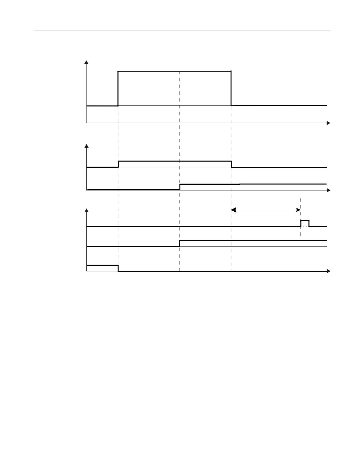
Safety functions integrated in the drive
5.20 Safe gearbox stage switchover
3RVLWLRQ WROHUDQFH
,QFUHDVHG
6WDQGDUG
W
352),VDIH 6B67:
*HDUER[ VWDJH FKDQJH
E\WH ELW
*HDUER[ VWDJH
E\WH ELW
W
6DIHW\ 0RWLRQ 0RQLWRULQJ
0D[LPXP U
6LQJOH
DFWXDO YDOXH
V\QFKURQL]DWLRQ
&RQYHUVLRQ WR WKH
ORDG VLGH ZLWK QHZ
JHDUER[ IDFWRUV
6DIHO\
UHIHUHQFHG
W
Figure 5-36
Gearbox switchover with increased position tolerance
Diagnostics
The selected gearbox stage is displayed for diagnostic purposes in parameter r9720, bits 24 to
26.
The selected gearbox stage is displayed for diagnostic purposes in parameter r9720, bit 27.
Safe gearbox switchover and referencing
The gearbox stage switchover means that the reference position and the user agreement are
lost. This means that after a gearbox switchover, initial referencing is required, in order to return
to the "safely referenced" state (see Chapter Safe referencing (Page 179)).
Safety Integrated plus
Commissioning Manual, 10/2020, 6FC5397-1FP40-6BA4
193
Safety functions integrated in the drive
5.20 Safe gearbox stage switchover
5.20.1
Important parameters
Overview of important parameters (see SINAMICS S120/S150 List Manual)
• p9501.26
SI Motion enable safety functions (Control Unit): Enable reliable gear-
box switchover
• p9521[0...7]
SI Motion gearbox encoder (motor)/load denominator (Control Unit)
• p9522[0...7]
SI Motion gearbox encoder (motor)/load numerator (Control Unit)
• p9539[0...7]
SI Motion gearbox direction of rotation reversal (Control Unit)
• p9542
SI Motion actual value comparison tolerance (crosswise) (Control Unit)
• p9543
SI Motion gearbox switching position tolerance factor (CU)
• p9549
SI Motion slip velocity tolerance (Control Unit)
• r9720.0...27
CO/BO: SI Motion drive-integrated control signals
Safety Integrated plus
194
Commissioning Manual, 10/2020, 6FC5397-1FP40-6BA4
Safety functions integrated in the drive
5.21 Forced checking procedure
5.21
Forced checking procedure
The functions and switch-off signal paths must be tested at least once within a defined period to
establish whether they are working properly in order to meet the requirements of EN ISO
13849-1 and IEC 61508 in terms of timely error detection.
The maximum permissible interval for a test stop/forced checking procedure for Basic and
Extended Functions is 8760 hours; i.e. the forced checking procedure must be performed at
least once per year.
This functionality must be implemented by initiating a test stop/forced checking procedure
either in the cyclic manual mode or as part of an automated process.
The test stop cycle is monitored. When the parameterized timer expires (also after POWER ON /
warm restart), alarm A01697: "SI Motion: Test of motion monitoring required" is generated and
a status bit is set which can be transferred to an output or to a PZD bit via BICO. This alarm does
not affect machine operation.
5.21.1
Examples for when the forced checking procedure is carried out
When the appropriate safety devices are implemented (e.g. protective doors), it can be assumed
that running machinery will not pose any risk to personnel. For this reason, an alarm is only
output to inform the user that a forced checking procedure run is due and to request that this be
carried out at the next available opportunity.
Examples of when to carry out forced checking procedure:
• When the drives are at a standstill after the system has been switched on (POWER ON).
• Before the protective door is opened.
• At defined intervals (e.g. every eight hours).
• In automatic mode (time and event dependent).
5.21.2
Options and control
Note
Requirements
STO is triggered when a test stop is carried out for the Safety Integrated Functions. It is not
permissible that STO is selected before selecting the test stop.
When blocksize Power Modules are used, the test stop must be triggered under controlled
standstill conditions (speed setpoint setting 0, current is flowing through the motor).
Safety Integrated plus
Commissioning Manual, 10/2020, 6FC5397-1FP40-6BA4
195
Safety functions integrated in the drive
5.21 Forced checking procedure
The forced checking procedure (test stop) can be triggered at any time by an application. The
parameter assignment and control are performed as follows:
• Controlled via SCC (integrated drives, external drives), programmed in the application
You can perform the test stop via SCC, programmed in the application itself. The following
parameters are relevant:
- p9559 SI Motion Forced checking procedure timer (Control Unit)
- p9705 BI: SI Motion Test stop signal source
- r9723.0 CO/BO: SI Motion diagnostics signals integrated in the drive
See: Safety Info Channel and Safety Control Channel (SIC/SCC) (Page 205)
If the test stop is executed as described, the action does not require a POWER ON. The
acknowledgment is set by canceling the test stop request.
Safety Integrated plus
196
Commissioning Manual, 10/2020, 6FC5397-1FP40-6BA4

Controlling safety functions integrated in the drive
6
6.1
Control possibilities
The following options are available for controlling safety functions integrated in the drive:
Table 6-1
Controlling the Safety Integrated Functions
Scope
Basic Functions
Extended Functions
Control type
Telegrams to control process data via PROFIsafe and
Yes
Yes
SIC/SCC (PROFIdrive)
See:
• Overview of telegram/process data (Page 198)
• Controlling via PROFIsafe (Page 201)
• SIC/SCC (Page 205)
Controlling via terminals (on the Control Unit and on
Yes
No
the Motor/Power Module)
See: Control via terminals on the Control Unit (Page 207)
Note
Term "Control Unit" in this documentation
In the Safety Integrated environment and in this documentation the term "Control Unit"
designates the SINUMERIK NCU.
Safety Integrated plus
Commissioning Manual, 10/2020, 6FC5397-1FP40-6BA4
197
Controlling safety functions integrated in the drive
6.2 Overview of telegrams
6.2
Overview of telegrams
You can use the following safety-oriented telegrams.
• PROFIsafe telegram 30
PROFIsafe standard telegram
• PROFIsafe telegram 31
Extended PROFIsafe standard telegram
• SIEMENS telegram 701
Manufacturer-specific telegram for SIC/SCC communication. With SINUMERIK, SIC/SCC
communication only takes place via telegram 701.
• SIEMENS telegram 901
Extended manufacturer-specific telegram with 16-bit position value.
• SIEMENS telegram 902
Extended manufacturer-specific telegram with 32-bit position value.
• SIEMENS telegram 903
Extended manufacturer-specific telegram with 32-bit Safe Cam (S_ZSW_CAM1). Default
setting for internal NC drives.
The following overview shows which process data is transferred in which telegram types.
Safety Integrated plus
198
Commissioning Manual, 10/2020, 6FC5397-1FP40-6BA4

Controlling safety functions integrated in the drive
6.3 Overview: Process data in telegrams
6.3
Overview: Process data in telegrams
Table 6-2
Process data from PROFIsafe telegrams
Telegram
30
31
901
902
903
Process data
Safety control word 1
PZD1
-
-
-
-
S_STW1
Safety status word 1
PZD1
-
-
-
-
S_ZSW1
Safety control word 2
-
PZD1…2
PZD1…2
PZD1…2
PZD1…2
S_STW2
Safety status word 2
-
PZD1…2
PZD1…2
PZD1…2
PZD1…2
S_ZSW2
SLS limit value input
-
-
PZD3
PZD3
PZD3
S_SLS_LIMIT_A
Active SLS limit value
-
-
PZD3
PZD3
PZD5
S_SLS_LIMIT_A_ACTIVE
Counter for the safety cycle
-
-
PZD4
PZD4
-
S_CYCLE_COUNT
Actual position value (16 bits)
-
-
PZD5
-
-
S_XIST16
Actual position value (32 bits)
-
-
-
PZD5…6
-
S_XIST32
Safe Cam status word
-
-
-
-
PZD3…4
S_ZSW_CAM1
Detailed information about the process data of these telegrams is provided in Chapter
"PROFIsafe process data (Page 354)".
Table 6-3
Process data from SIEMENS telegram 701 (SIC/SCC)
Telegram
701
Process data
Safety Control Channel control word 1
PZD1
S_STW1B
SI Motion Safety Info Channel status word
PZD1
S_ZSW1B
Safety Info Channel status word 2
PZD2
S_ZSW2B
Safety Control Channel control word 3
PZD2
S_STW3B
SLS setpoint speed limiting (32 bit)
PZD3…4
S_V_LIMIT_B
Safety Info Channel status word 3
PZD5
S_ZSW3B
Safety Integrated plus
Commissioning Manual, 10/2020, 6FC5397-1FP40-6BA4
199
Controlling safety functions integrated in the drive
6.3 Overview: Process data in telegrams
Detailed information about the process data of telegram 701 is provided in Chapter "SIC/SCC
(PROFIdrive) process data (Page 369)".
Safety Integrated plus
200
Commissioning Manual, 10/2020, 6FC5397-1FP40-6BA4

Controlling safety functions integrated in the drive
6.4 Controlling via PROFIsafe
6.4
Controlling via PROFIsafe
6.4.1
Selecting the PROFIsafe telegram
You can use telegrams 903, 902, 901, 31 or 30 for PROFIsafe communication via PROFIBUS and
PROFINET. SIEMENS telegram 903 is the default setting for internal NC drives.
You make the settings for the F-PLC (F-host) in the TIA Portal; the settings for the individual drives
(F-slaves or F-devices), in SINUMERIK Operate (p60022, p9611, p9811).
Table 6-4
Parameter to select the PROFIsafe telegram
Parameter/name
Setting
Meaning
p60022 PROFIsafe telegram selection / Ps tel-
903
• PROFIsafe SIEMENS telegram 903
egr_sel
• Extended manufacturer-specific telegram with 32-bit
Safe Cam
• Default setting for internal NC drives
p9611 SI PROFIsafe telegram selection (Con-
902
• PROFIsafe SIEMENS telegram 902, PZD-3/6
trol Unit) / SI Ps telegr CU
• Extended PROFIsafe telegram with 32-bit position value
901
• PROFIsafe SIEMENS telegram 901, PZD-3/5
• Extended PROFIsafe telegram with 16-bit position value
p9811 SI PROFIsafe telegram selection (Motor
Module) / SI Ps telegram MM
31
• PROFIsafe standard telegram 31, PZD-2/2
• Extended standard PROFIsafe telegram
30
• PROFIsafe standard telegram 30, PZD-1/1
• Standard PROFIsafe telegram
Detailed information about the structure of the telegrams is provided in Chapter "Telegram
structure and data (Page 350)".
The PROFIsafe telegram received at the Control Unit is indicated in r9768, and the PROFIsafe
telegram to be sent, in parameter r9769.
Note
Timing between the switching operations
Message F01611 with fault value 1000 indicates that the switching operations occur too
frequently.
• STO is being permanently initiated via PROFIsafe (also as subsequent response).
Within the time 5 × p9650, there must be at least two switching operations via PROFIsafe with
a minimum time between them of p9650.
Safety Integrated plus
Commissioning Manual, 10/2020, 6FC5397-1FP40-6BA4
201

Controlling safety functions integrated in the drive
6.4 Controlling via PROFIsafe
6.4.2
Enabling PROFIsafe control
Control via PROFIsafe is available for both Safety Integrated Basic Functions and Safety
Integrated Extended Functions, and must be enabled in p9601
Table 6-5
Parameter to enable the PROFIsafe control
Parame-
Name
Setting
Meaning
ters
p9601
SI enable functions
0008 hex
Basic Functions are enabled via PROFIsafe (permissible for r9771.6 = 1).
integrated in the
0009 hex
Basic Functions are enabled via PROFIsafe and onboard terminals (permis-
drive (Control Unit) /
sible for r9771.6 = 1).
SI enable fct CU
000C hex
Extended Functions are enabled via PROFIsafe (permissible for r9771.4 = 1).
000D hex
Extended Functions are enabled via PROFIsafe - and Basic Functions via
onboard terminals (permissible for r9771.4 = 1).
p9601.0 = 1
Enable STO (SH) via terminals (CU)
Comment: Safety Integrated Basic Functions via PROFIsafe and via termi-
nals
Control of the Basic Functions via terminals on the Control Unit and on the
Motor/Power Module (parameters p9601.0 = 1) may be enabled in parallel.
In order to be able to select SS1, an SS1 delay time p9652 > 0 must be
configured. With PROFIsafe, both SS1 and STO can be selected. Only SS1 is
available for control via terminal.
STO takes priority over SS1, i.e. STO becomes active if SS1 and STO are
simultaneously selected.
r9771
SI common func-
r9771.4 = 1
Extended Functions, PROFIsafe supported
tions (Control Unit) /
r9771.6 = 1
Basic Functions, PROFIsafe supported
SI common fct CU
Safety Integrated plus
202
Commissioning Manual, 10/2020, 6FC5397-1FP40-6BA4
Controlling safety functions integrated in the drive
6.4 Controlling via PROFIsafe
6.4.3
ESR response in the event of a communication error
The response of the SINAMICS S drive in the case of a communication error when the "Extended
stop and retract (ESR)" function module is simultaneously enabled is described in the
following.
Requirement
• The Safety Integrated Extended Functions are controlled via PROFIsafe
• The function module "Extended stop and retract" is activated and enabled
Communication failure
Under communication failure in this context, we understand one of the following possibilities:
• Interruption/fault of the PROFIBUS or PROFINET connection for control via PROFIsafe
• STOP response of the F-PLC
Drive response
In the event of a communication failure, SINAMICS S makes a distinction between the following
responses:
• If p9580 ≠ 0 and ESR has been enabled, in the event of a communication failure, the
parameterized ESR response is realized.
• If p9580 ≠ 0 and SLS is active, in the event of communication failure, the parameterized ESR
reaction is only realized if, as SLS response, a STOP with delayed pulse cancellation when the
bus fails has been parameterized (p9563[0...3] ≥ 10).
• If p9580 ≠ 0 and SDI is active, in the event of communication failure, the parameterized ESR
reaction is only realized if, as SDI response, a STOP with delayed pulse cancellation when the
bus fails has been parameterized (p9566[0...3] ≥ 10).
• If p9580 ≠ 0 and SLP is active, in the event of communication failure, the parameterized ESR
reaction is only realized if, as SLP response, a STOP with delayed pulse cancellation when the
bus fails has been parameterized (p9562[0...1] ≥ 10).
Note
Maximum response time for interruption in communication
When a safety-relevant communication is interrupted, Safety Integrated only permits a response
time (p9580) of max. 800 ms. The drive changes into the "fail safe state" once this time expires.
In this case, S_STW1/2 is assumed to be 0. This means that all safety functions are selected. STO
has in this case the highest priority, i.e. the pulses are safely canceled.
Safety Integrated plus
Commissioning Manual, 10/2020, 6FC5397-1FP40-6BA4
203
Controlling safety functions integrated in the drive
6.4 Controlling via PROFIsafe
6.4.4
Function diagrams and parameters
Function diagrams (see SINAMICS S120/S150 List Manual)
•
2840
SI Extended Functions - SI Motion drive-integrated control signals/status signals
•
2858
SI Extended Functions - control via PROFIsafe (p9601.2 = p9601.3 = 1)
Overview of important parameters (see SINAMICS S120/S150 List Manual)
• p9563[0...3]
SI Motion SLS (SG)-specific stop response (Control Unit)
• p9566
SI Motion SDI stop response (Control Unit)
• p9580
SI Motion STO delay bus failure (Control Unit)
• p9601
SI enable functions integrated in the drive (Control Unit)
• p9610
SI PROFIsafe address (Control Unit)
• p9611
SI PROFIsafe telegram selection (Control Unit)
• p60022
Selecting a PROFIsafe telegram
Safety Integrated plus
204
Commissioning Manual, 10/2020, 6FC5397-1FP40-6BA4
Controlling safety functions integrated in the drive
6.5 Safety Info Channel and Safety Control Channel (SIC/SCC)
6.5
Safety Info Channel and Safety Control Channel (SIC/SCC)
6.5.1
Introduction
In the "SINUMERIK Safety Integrated plus (F-PLC)" mode, status and control signals of the drive-
based motion monitoring functions are connected to the PLC and NC:
• Via the Safety Control Channel (SCC), control signals are sent from the PLC and NC to the drive
(e.g. to start the "Safe Brake Test (SBT)" diagnostic function in the drive - and to influence it).
• Via the Safety Info Channel (SIC), status signals of the drive are sent to the PLC (e.g. for the
brake test).
• For a STOP response of the drive, status signals are transferred to the NC as well as to the PLC.
The motion control in the NC automatically responds to the drive STOP response by no longer
issuing additional setpoints for the path, for example. As a consequence, alarms to be
acknowledged are avoided, such as "Contour monitoring" or "Positioning monitoring".
You can parameterize SIC/SCC as follows, and access the signals:
• You activate SIC/SCC while commissioning the drive in SINUMERIK Operate.
• The SIC/SCC signals are mapped in the PLC user interface, and can therefore be accessed via
axis DBs.
See: PLC user interface (DB3x) (Page 206), Interface signals: Axis/spindle signals (Page 374)
Note
SIC and SCC must always be jointly configured and/or parameterized.
6.5.2
Safety Info Channel (SIC)
Status information of the Safety Integrated functionality of the drive (S_ZSW1B, S_ZSW2B,
S_ZSW3B and S_V_LIMIT_B) can be transferred to the F-PLC and NC using the Safety Info Channel
(SIC).
6.5.3
Safety Control Channel (SCC)
Control information (S_STW1B and S_STW3B) can be transferred from the F-PLC and the NC to
the safety functions of the drive using the Safety Control Channel (SCC).
6.5.4
SIC/SCC communication using telegram 701
SIC/SCC communication can always be transferred using the predefined PROFIdrive telegrams
700 or 701. For SINUMERIK, only telegram 701 (Page 350) is used.
Safety Integrated plus
Commissioning Manual, 10/2020, 6FC5397-1FP40-6BA4
205
Controlling safety functions integrated in the drive
6.5 Safety Info Channel and Safety Control Channel (SIC/SCC)
If another telegram is configured for SIC/SCC, then cyclic SIC/SCC communication is inhibited,
and Alarm 27811 is output.
6.5.5
PLC user interface (DB3x)
In the Safety Integrated plus (F-PLC) mode, additional axis-specific data from the axis DB
(axis 1 [DB31] ... axis 31 [DB61]) are relevant, which are mapped from the SIC/SCC.
Additional information
• You can find the significance of the individual axis DB signals and the precise addresses
at Interface signals: Axis/spindle signals (Page 374).
• See also: SBT: Connection to NC and PLC programs (Page 161)
6.5.6
Important parameters
Overview of important parameters (see SINAMICS S120/S150 List Manual)
• r9733[0...2]
CO: SI Motion speed setpoint limit active
• r9734.0...15
CO/BO: SI Safety Info Channel status word S_ZSW1B
• r9743.4...15
CO/BO: SI Safety Info Channel status word S_ZSW2B
• r10231
SI Motion SBT control word diagnostics
• r10234.0...15
CO/BO: SI Safety Info Channel status word S_ZSW3B
• p10235
CI: SI Safety Control Channel control word S_STW3B
• p10250
CI: SI Safety Control Channel control word S_STW1B
• r10251.8...12
CO/BO: SI Safety Control Channel control word S_STW1B diagnostics
• p60122
IF1 PROFIdrive SIC/SCC telegram selection
Safety Integrated plus
206
Commissioning Manual, 10/2020, 6FC5397-1FP40-6BA4

Controlling safety functions integrated in the drive
6.6 Control via terminals on the Control Unit
6.6
Control via terminals on the Control Unit
6.6.1
Features
• Control via terminals is only available for Basic Functions.
• Dual-channel structure via 2 digital inputs (Control Unit/power unit)
• In order to prevent nuisance trips as a result of signal disturbances or non-symmetrical test
signals, the signals can be debounced at the terminals of the connected components
(pushbuttons, switches etc.).
You can specify these debounce times in the following parameters:
- p9651 SI STO/SBC/SS1 debounce time (Control Unit) / SI STO t_debou CU
- p9851 SI STO/SBC/SS1 debounce time (Motor Module) / SI STO t_debou MM
• Different terminal blocks depending on the format.
• Automatic ANDing of up to 8 digital inputs (p9620[0...7]) on the Control Unit with parallel
configuration of power units in the chassis format is not supported.
The various SINUMERIK components and SINAMICS power unit formats have different terminal
designations for the inputs used for the safety functions. These are shown in the following table.
Table 6-6
Inputs for safety functions
Component
1st switch-off signal path
2nd switch-off signal path (EP termi-
(p9620[0])
nals)
NCU
Selected using BICO intercon-
nection (BI: p9620[0]):
Digital input DI 0…7
NX module
Selected using BICO intercon-
nection (BI: p9620[0]):
Digital input DI 0…3
Single Motor Module Book-
X122.1
6/X132.1…6DI
EP terminals X21.3 and X21.4
size/Booksize Compact
0...7/16/17/20/21
(on the Motor Module)
Single Motor Module/
X122.1
6/X132.1…6DI
EP terminals X41.1 and X41.2
Power Module Chassis
0...7/16/17/20/21
Double Motor Module Book-
X122.1
6/X132.1…6DI
EP terminals on the Motor Module:
size/Booksize Compact
0...7/16/17/20/21
X21.3 and X21.4 (motor connection X1)
X22.3 and X22.4 (motor connection X2)
Power Module Blocksize
X122.1
6/X132.1…6DI
X210.3 and X210.4 (on the CUA31/
with CUA31/CUA32
0...7/16/17/20/21
CUA32)
Control Unit CU320-2
X122.1
6/X132.1…6DI
0...7/16/17/20/21
For further information about the terminals, see the Equipment Manuals.
Safety Integrated plus
Commissioning Manual, 10/2020, 6FC5397-1FP40-6BA4
207
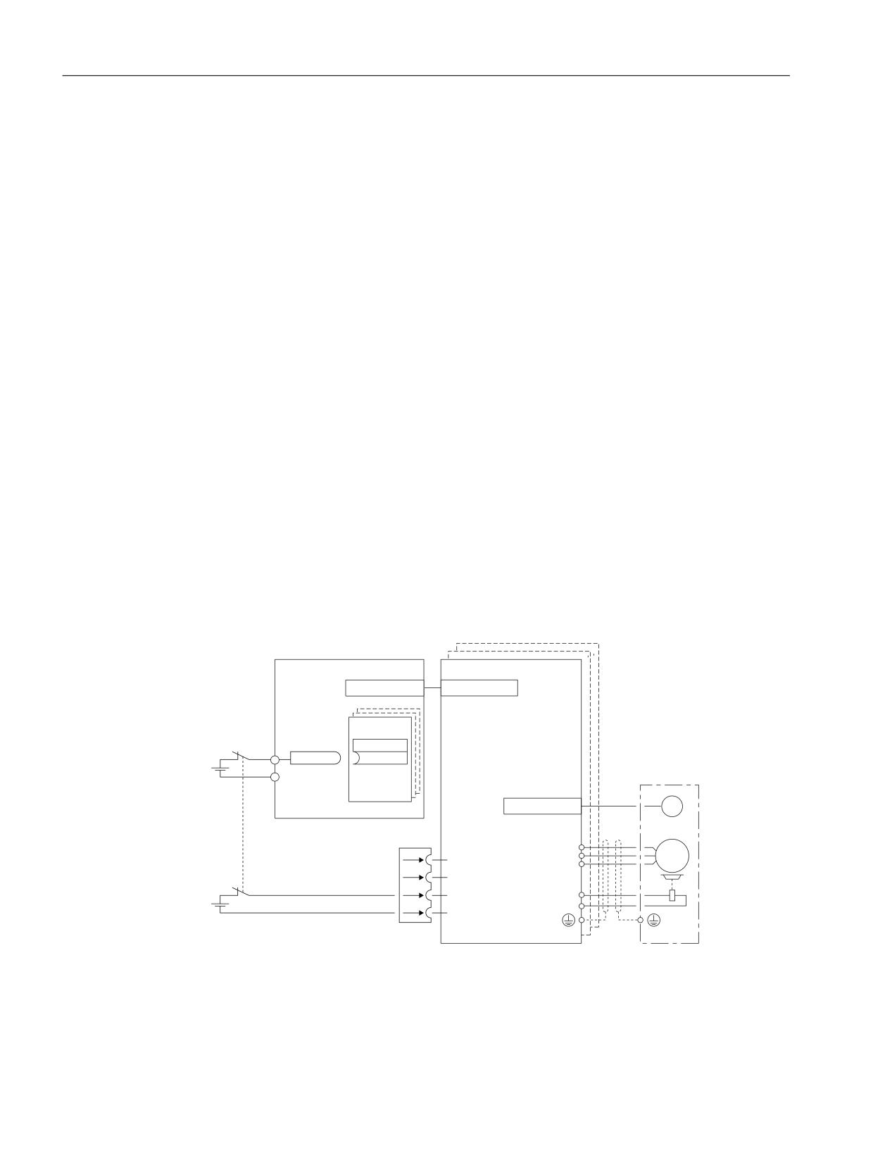
Controlling safety functions integrated in the drive
6.6 Control via terminals on the Control Unit
6.6.2
Terminals for STO, SS1 (time-controlled), SBC
Safety functions STO, SS1 (time-controlled) and SBC are selected/deselected separately for each
drive using 2 terminals.
Basic procedure
The functions are separately selected/deselected for each drive using two terminals.
1. Switch-off signal path, Control Unit:
- Input terminal for Safe Torque Off (STO):
Selected using BICO interconnection (BI: p9620[0]).
- Possible signal sources:
NCU: Digital input DI 0…7
NX modules: Digital input DI 0…3
2. Motor Module switch-off signal path:
The input terminal is the "EP" terminal ("Enable Pulses").
The EP terminal is periodically interrogated with a sampling time, which is rounded off to an
integer multiple of the current controller cycle; however, it is a minimum of 1 ms. (Example: ti
= 400 µs, tEP => 3x, ti = 1.2 ms)
Both terminals must be energized within the tolerance time p9650/p9850 (Page 210),
otherwise a fault is output.
Example: Terminals for STO
1&8
[
0RWRU 0RGXOH
'5,9( &/L4
'5,9( &/L4
%O
1&8 [
', [
S
U
[
0
'5,9( &/L4
*
0RQLWRULQJ FKDQQHO
&RQWURO 8QLW
[
[
8
0
9
7HPS
a
:
0RQLWRULQJ FKDQQHO
7HPS
0RWRU 0RGXOH
(3
9
%5
(3 0
%5
Figure 6-1
Example: Terminals for STO for an NCU 17x0 and a Motor Module in the booksize format
Safety Integrated plus
208
Commissioning Manual, 10/2020, 6FC5397-1FP40-6BA4

Controlling safety functions integrated in the drive
6.6 Control via terminals on the Control Unit
6.6.3
Grouping drives
To ensure that the safety function for several drives can be initiated simultaneously, you must
group the terminals for the corresponding drives.
Note
Response of the "STO" safety function when grouping
If a fault in a drive results in a "Safe Torque Off" (STO), this does not automatically mean that the
other drives in the same group also switch to "Safe Torque Off" (STO).
Basic procedure
Proceed as follows to group the corresponding drives:
1. Switch-off signal path, Control Unit
Group by appropriately interconnecting the binector input to the common input terminal for
the drives belonging to a group.
2. Motor Module switch-off signal path
Group by appropriately connecting terminal "EP" for the individual Motor Modules belonging
to a group.
Note
Parameterization of the grouping
The grouping must be set the same in both monitoring channels.
The assignment is checked during the test for the switch-off signal paths. The operator selects
the STO safety function for each group. The check is drive-specific.
Example: Terminal groups
It must be possible to select/deselect safety function STO separately for group 1 (drives 1 and 2)
and group 2 (drives 3 and 4).
For this purpose, the same grouping for STO must be realized both for the Control Unit and the
Motor Modules.
Safety Integrated plus
Commissioning Manual, 10/2020, 6FC5397-1FP40-6BA4
209
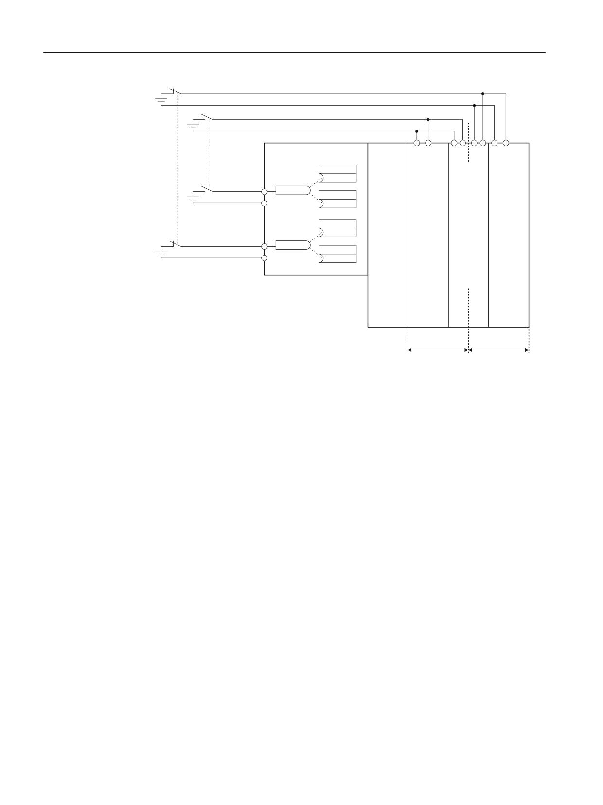
Controlling safety functions integrated in the drive
6.6 Control via terminals on the Control Unit
6HOHFWLQJ GH
VHOHFWLQJ
1&8 [
0
(3
0
0
0 (3
6HOHFWLQJ GH
*URXS
'ULYH
(3
(3
VHOHFWLQJ
S
*URXS
'O
'ULYH
/LQH
6LQJOH
'RXEOH
6LQJOH
U
S
0RGXOHV
0RWRU
0RWRU
0RWRU
0
0RGXOHV
0RGXOHV
0RGXOHV
'ULYH
S
'O
;
'ULYH
U
S
0
'ULYH
'ULYH
'ULYH
*URXS
*URXS
Figure 6-2
Example: Grouping the terminals for Motor Modules, booksize format
6.6.4
Simultaneity and tolerance time of the two monitoring channels
The "Safe Torque Off" (STO) safety function must be selected/deselected simultaneously in both
monitoring channels using the input terminals, and is only effective for the associated drive.
•
1 signal: Deselecting the function
•
0 signal: Selecting the function
Parameterization of the tolerance time
Even when simultaneously selecting/deselecting, a certain time delay cannot be avoided, e.g. as
a result of mechanical switching operations. Therefore, in the following parameters, define the
tolerance times, within which selection/deselection in both monitoring channels is considered
to be simultaneously valid.
• p9650 SI SGE switchover tolerance time (Control Unit)
• p9850 SI SGE switchover tolerance time (Motor Module)
In order to avoid that faults are incorrectly initiated, at these inputs the tolerance time must
always be set shorter than the shortest time between two switching events (ON/OFF, OFF/ON).
Safety Integrated plus
210
Commissioning Manual, 10/2020, 6FC5397-1FP40-6BA4
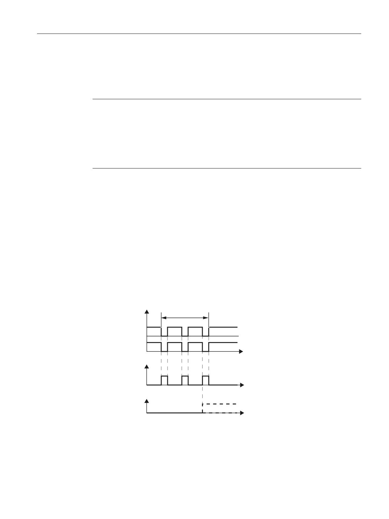
Controlling safety functions integrated in the drive
6.6 Control via terminals on the Control Unit
Fault F01611
If the "Safe Torque Off" function is not selected/deselected within the tolerance time, this is
detected by the cross-comparison, and fault F01611 (STOP F) is output. In this case, the pulses
have already been canceled as a result of the selection of "Safe Torque Off" on one channel.
Note
Timing between the switching operations
Message F01611 with fault value 1000 indicates that the switching operations occur too
frequently.
• STO is being permanently initiated via PROFIsafe (also as subsequent response).
Within the time 5 × p9650, there must be at least two switching operations via PROFIsafe with
a minimum time between them of p9650.
Additional notes regarding setting the discrepancy time are included in the "SINAMICS S120/
S150 List Manual" for the C01770 and F01611 safety messages.
6.6.5
Bit pattern test
Bit pattern test of failsafe outputs
The converter normally responds immediately to signal changes in its failsafe inputs. This is not
desired in the following case: Several control modules test their failsafe outputs using bit pattern
tests (on/off tests), in order to identify faults due to either short-circuit or cross-circuit faults.
When you interconnect a failsafe input of the converter with a failsafe output of a control
module, the converter responds to these test signals.
,QSXW VLJQDOV
%LW SDWWHUQ WHVW
) ',
W
6DIHW\ IXQFWLRQ
$FWLYH
,QDFWLYH
W
)DXOW )
W
Figure 6-3
Converter response to a bit pattern test
Safety Integrated plus
Commissioning Manual, 10/2020, 6FC5397-1FP40-6BA4
211
Controlling safety functions integrated in the drive
6.6 Control via terminals on the Control Unit
Note
Debounce time for unwanted triggering of Safety Integrated Functions
If the test pulses cause an unwanted triggering of the Safety Integrated Functions, these test
pulses can be suppressed with the aid of the F-DI input filter (p9651). To do this, a value must be
entered in p9651 that is greater than the duration of a test pulse.
Overview of important parameters
• p9651
SI STO/SBC/SS1 debounce time (Control Unit)
Safety Integrated plus
212
Commissioning Manual, 10/2020, 6FC5397-1FP40-6BA4
Commissioning and configuring
7
7.1
Commissioning sequence
Safety Integrated plus is partially commissioned in the TIA Portal - and partially in SINUMERIK
Operate. Commissioning can be roughly subdivided into the following steps:
• Configuring safety-relevant components (Page 214)
• Generating a safety program (Page 223)
• Loading the configuration to the control system (Page 234)
• Configuring NC and drive-specific safety settings (Page 237)
• Configuring safety functions integrated in the drive (Page 256)
• Finalizing commissioning (Page 291)
Detailed action overviews can found in the linked sections.
Safety Integrated plus
Commissioning Manual, 10/2020, 6FC5397-1FP40-6BA4
213

Commissioning and configuring
7.2 Configuring safety-relevant components
7.2
Configuring safety-relevant components
7.2.1
Overview
The following handling overview (as example) and the associated descriptions illustrate the
features when configuring Safety Integrated plus (F-PLC) with a SINUMERIK NCU compared to a
CPU S7-300. Consequently, the overview serves only as an introduction to the configuring and
programming of STEP 7 Safety Advanced with SINUMERIK.
Requirements
• The following TIA Portal software is installed and licensed:
- SIMATIC STEP 7 Professional V16
SIMATIC STEP 7 Safety Advanced V16
- SINUMERIK 840D sl STEP 7 Toolbox V16 Update 2
• The non-safety-related components have been configured.
• The NCU (firmware version ≥ 4.8) is inserted.
• SINUMERIK PLC basic program and standard PLC user program exist in a project.
• The devices are networked with one another using the specified interfaces (PROFINET or
PROFIBUS).
You can also connect devices at the interfaces of both types (PROFINET and PROFIBUS) - and
then operate them in the Safety Integrated plus mode (F-PLC).
Procedure:
Step
Description
1
Activating SINUMERIK Safety Integrated plus (Page 214)
2
Configuring additional safety-related components (Page 216)
3
Loading the configuration into the controller (Page 216)
4
Allocating and assigning a PROFINET device name (Page 217)
5
Assigning F-destination addresses, address type 1 (Page 219) or Assigning F-destination ad-
dresses, address type 2 (Page 219)
6
Checking the PROFIsafe address (Page 221)
After completing the configuration, generate the safety program of the F-PLC (Page 223).
7.2.2
Activating SINUMERIK Safety Integrated plus
Precondition
• The "SIMATIC STEP 7 Safety Advanced" option package has been installed.
Safety Integrated plus
214
Commissioning Manual, 10/2020, 6FC5397-1FP40-6BA4