SINUMERIK 840D sl. Service - Safety Integrated. Manual (2020) - page 12
Table of contents
Preface
3
1
Fundamental safety instructions
15
1.1
General safety instructions
15
1.2
Warranty and liability for application examples
16
1.3
Security information
17
2
Introduction
19
2.1
Introduction
19
2.2
About this documentation
20
2.3
Basic knowledge requirements
22
3
Fundamentals
23
3.1
Safety functions of the F-PLC
23
3.2
Safety functions integrated in the drive
24
3.3
Approvals
27
3.4
Safety-relevant processing using NCU components
28
3.5
Hardware components
31
3.5.1
F-I/O for PROFIBUS DP
32
3.5.2
F-I/O for PROFINET IO
32
3.5.3
Drive components
33
3.5.3.1
Interconnecting DRIVE-CLiQ components
33
3.5.3.2
Drive monitoring with or without encoder
34
3.5.3.3
Induction motors and synchronous motors
36
3.5.3.4
SINAMICS HLA
36
3.6
Safety components and licensing
39
3.6.1
Software components required
39
3.6.2
Licensing axes/spindles and F-PLC
39
3.7
Components and basic configuration in the TIA Portal
41
3.7.1
Structure of a project view in the TIA Portal
41
4
Safety program of the F-PLC
45
4.1
Structure of the safety program
47
4.2
Fail-Safe Blocks
50
4.3
Safety Administration Editor
51
4.4
Restrictions in the programming languages FBD/LAD
52
4.5
Instructions for the safety program
58
4.6
F-runtime groups
60
4.6.1
Rules for F-Runtime Groups of the Safety Program
60
Safety Integrated plus
Commissioning Manual, 10/2020, 6FC5397-1FP40-6BA4
7
Table of contents
4.6.2
Procedure when defining an F-runtime group
60
4.6.3
F-global DB
64
4.7
Creating F-blocks
66
4.8
Using libraries
68
4.9
Safety-relevant communication
69
4.10
Access to SI-drives and F-I/O
70
4.11
Programming startup protection
72
4.12
Implementing a user acknowledgment
73
4.13
Data exchange between the standard user program and safety program
74
4.13.1
Data Transfer from the Safety Program to the Standard User Program
75
4.13.2
Data Transfer from Standard User Program to Safety Program
76
5
Safety functions integrated in the drive
79
5.1
Introduction to Safety Integrated Functions
79
5.2
SS1 Basic:
80
5.2.1
Details and parameterization
81
5.2.1.1
SS1 with OFF3
81
5.2.1.2
SS1 with external stop (SS1E)
82
5.2.1.3
Function diagrams and parameters
83
5.3
SS1
84
5.3.1
Details and parameterization
86
5.3.1.1
Safe Stop 1 (SS1, time and acceleration controlled)
86
5.3.1.2
Safe Stop 1 without encoder
87
5.3.1.3
SS1 (Extended Functions) with external stop
89
5.3.1.4
Function diagrams and parameters
90
5.4
STO (Basic/Extended)
91
5.4.1
Details and parameterization
91
5.4.1.1
Safe Torque Off (STO) for SINAMICS HLA
94
5.4.1.2
Function diagrams and parameters
96
5.5
SBC (Basic/Extended)
97
5.5.1
Hardware required
98
5.5.2
Details and parameterization
99
5.5.2.1
SBC for Motor Modules in the chassis format
101
5.5.2.2
Function diagrams and parameters
103
5.6
SS2
104
5.6.1
Details and parameterization
106
5.6.1.1
SS2 with external stop (SS2E)
107
5.6.1.2
Dynamic response adaptation for SS2E
109
5.6.1.3
Safe Stop 2 Extended Stop and Retract (SS2ESR)
111
5.6.1.4
Function diagrams and parameters
113
5.7
SOS
114
5.7.1
Safe Operating Stop (SOS)
114
5.7.2
Details and parameterization
115
5.7.2.1
Function diagrams and parameters
117
5.8
SLS
118
Safety Integrated plus
8
Commissioning Manual, 10/2020, 6FC5397-1FP40-6BA4
Table of contents
5.8.1
Details and parameterization
123
5.8.1.1
Connection to the motion control in the NC
124
5.8.1.2
Safely Limited Speed (SLS)
124
5.8.1.3
Safely Limited Speed without encoder
127
5.8.1.4
Safely-Limited Speed without selection
129
5.8.1.5
Function diagrams and parameters
130
5.9
SSM
131
5.9.1
Details and parameterization
131
5.9.1.1
Signal characteristic (with encoder)
133
5.9.1.2
Differences in operation without encoder
133
5.9.1.3
Signal characteristic (without encoder)
134
5.9.1.4
Function diagrams and parameters
136
5.10
SAM
137
5.11
SBR
139
5.11.1
Important parameters
142
5.12
SDI
143
5.12.1
Details and parameterization
145
5.12.1.1
Safe Direction with encoder
145
5.12.1.2
Safe Direction without encoder
146
5.12.1.3
Safe Direction without selection
148
5.12.1.4
Function diagrams and parameters
150
5.13
SLP
151
5.13.1
Details and parameterization
151
5.13.1.1
Retraction
154
5.13.1.2
Function diagrams and parameters
155
5.14
SP
156
5.14.1
Details and parameterization
156
5.14.1.1
Function diagrams and parameters
159
5.15
SBT
160
5.15.1
Features
160
5.15.2
Connection to NC and PLC programs
161
5.15.3
Details and parameterization
161
5.15.3.1
Requirements
161
5.15.3.2
Handling overview
162
5.15.3.3
Enabling the function
164
5.15.3.4
Selection
166
5.15.3.5
Start of the Safe Brake Test sequence
166
5.15.3.6
Sequence
167
5.15.3.7
Cancellation/deselection and acknowledgment (SBT)
168
5.15.3.8
Communication via SIC/SCC
169
5.15.3.9
Function diagrams and parameters
171
5.16
SCA
172
5.16.1
Details and parameterization
172
5.16.1.1
Function diagrams and parameters
174
5.17
SLA
175
5.17.1
Description
175
5.17.2
Details and parameterization
177
5.17.2.1
Transmission via PROFIsafe or SIC
177
Safety Integrated plus
Commissioning Manual, 10/2020, 6FC5397-1FP40-6BA4
9
Table of contents
5.17.2.2
Function diagrams and parameters
178
5.18
Safe referencing
179
5.18.1
User agreement
179
5.18.2
Function diagrams and parameters
181
5.19
Safe actual value acquisition
183
5.19.1
Important parameters
189
5.20
Safe gearbox stage switchover
190
5.20.1
Important parameters
194
5.21
Forced checking procedure
195
5.21.1
Examples for when the forced checking procedure is carried out
195
5.21.2
Options and control
195
6
Controlling safety functions integrated in the drive
197
6.1
Control possibilities
197
6.2
Overview of telegrams
198
6.3
Overview: Process data in telegrams
199
6.4
Controlling via PROFIsafe
201
6.4.1
Selecting the PROFIsafe telegram
201
6.4.2
Enabling PROFIsafe control
202
6.4.3
ESR response in the event of a communication error
203
6.4.4
Function diagrams and parameters
204
6.5
Safety Info Channel and Safety Control Channel (SIC/SCC)
205
6.5.1
Introduction
205
6.5.2
Safety Info Channel (SIC)
205
6.5.3
Safety Control Channel (SCC)
205
6.5.4
SIC/SCC communication using telegram 701
205
6.5.5
PLC user interface (DB3x)
206
6.5.6
Important parameters
206
6.6
Control via terminals on the Control Unit
207
6.6.1
Features
207
6.6.2
Terminals for STO, SS1 (time-controlled), SBC
208
6.6.3
Grouping drives
209
6.6.4
Simultaneity and tolerance time of the two monitoring channels
210
6.6.5
Bit pattern test
211
7
Commissioning and configuring
213
7.1
Commissioning sequence
213
7.2
Configuring safety-relevant components
214
7.2.1
Overview
214
7.2.2
Activating SINUMERIK Safety Integrated plus
214
7.2.3
Configuring additional safety-related components
216
7.2.4
Loading the configuration into the controller
216
7.2.5
Allocating and assigning a PROFINET device name
217
7.2.6
Assigning F-destination addresses, address type 1
219
7.2.7
Assigning F-destination addresses, address type 2
219
7.2.8
Checking the PROFIsafe address
221
7.3
Generating a safety program
223
Safety Integrated plus
10
Commissioning Manual, 10/2020, 6FC5397-1FP40-6BA4
Table of contents
7.3.1
Overview
223
7.3.2
Create receive/send data as PLC tags
223
7.3.3
Adapting the settings of the F-runtime group (optional)
225
7.3.4
Setting up access protection
226
7.3.5
Parameterizing EMERGENCY STOP
227
7.3.6
Implementing user acknowledgment for global reintegration
228
7.3.7
Acknowledging messages related to safety functions integrated in the drive
229
7.3.8
Deselecting safety functions integrated in the drive
232
7.3.9
Initiate a forced checking procedure (test stop)
233
7.3.10
Programming the wiring test
233
7.4
Loading the configuration to the control system
234
7.4.1
Load the configuration
234
7.4.2
Transferring the safety mode from the configuration
235
7.5
Configuring NC and drive-specific safety settings
237
7.5.1
Overview
237
7.5.2
Setting software options
238
7.5.3
Activating the safety commissioning mode
238
7.5.4
Selecting the safety functional scope
240
7.5.5
Parameterizing the setpoint speed limiting
241
7.5.6
Parameterizing reaction of the stop response
243
7.5.7
Parameterizing an encoder
244
7.5.8
Configuring encoderless operation
248
7.5.9
Configuring telegrams
253
7.6
Configuring safety functions integrated in the drive
256
7.6.1
Overview
256
7.6.2
STO/SS1 Basic
257
7.6.3
STO Extended
258
7.6.4
SBC
260
7.6.5
SS1 Extended
261
7.6.6
SS2/SOS
263
7.6.7
SAM
265
7.6.8
SBR
268
7.6.9
SLS
269
7.6.10
SSM
272
7.6.11
SDI
275
7.6.12
SLP/SP
276
7.6.13
SBT
279
7.6.14
SCA
282
7.6.15
SS2E
284
7.6.16
SS2ESR
286
7.6.17
Safe referencing
288
7.6.18
Further safety functions
290
7.7
Finalizing commissioning
291
7.7.1
Confirming settings
291
7.7.2
Assigning a Safety Integrated password
292
7.8
Series commissioning
293
7.9
Interaction with other functions
294
7.9.1
Gantry axes
294
7.9.2
Leading/following axis
294
Safety Integrated plus
Commissioning Manual, 10/2020, 6FC5397-1FP40-6BA4
11
Table of contents
7.9.3
Brake tests for axis groups
294
7.9.4
SERVCOUP special solution
295
7.9.5
Closing the internal motor brake using SCC
295
8
Acceptance test
297
8.1
Purpose and requirements
297
9
Diagnostics
299
9.1
Diagnostics guide
300
9.2
System alarms and diagnostic screens for F-PLC and F-I/O
302
9.3
Diagnostic functions in SINUMERIK Operate
304
9.3.1
Safety Integrated diagnostics overview
304
9.3.2
SI drives status
305
9.3.3
SI telegrams overview
307
9.3.4
SI telegrams PROFIsafe
308
9.3.5
PROFIdrive SI telegrams
309
9.3.6
SI checksums
310
9.3.7
SI alarms
312
9.3.8
SI Safe Cams
313
9.3.9
SI integrated F-PLC
314
9.3.10
SI I/O
315
9.4
Display and evaluation of diagnostic information
317
9.5
Checksums
318
9.5.1
Calculating the global checksums/master checksums
318
9.5.2
SINAMICS checksums
320
9.6
Stop responses
321
9.6.1
Overview
321
9.6.2
Basic Functions
321
9.6.3
Extended Functions
323
9.6.4
Definitions and effects in the NC
326
9.6.5
Priorities
326
9.7
Using the fault buffer, message buffer and alarm buffer
328
9.7.1
Configuring the standard alarm buffer
329
9.7.2
Configuring the safety message buffer
329
9.8
Acknowledgment
331
9.8.1
Overview
331
9.8.2
Acknowledgment via PROFIsafe
332
9.8.3
Additional acknowledgment via PROFIdrive RESET
332
9.8.4
Acknowledgment using POWER ON
333
9.8.5
Extended acknowledgment (deselecting STO/SS1)
333
9.8.6
Additional acknowledgment when the safety message buffer is inactive
333
10
Component replacement (software/hardware)
335
10.1
Software, F-CPU, F-I/O
336
10.2
SINAMICS components
338
10.3
Messages when components are replaced after Safety Integrated has been commissioned... 340
10.4
Important parameters
341
Safety Integrated plus
12
Commissioning Manual, 10/2020, 6FC5397-1FP40-6BA4
Table of contents
11
Data descriptions
343
11.1
Machine data
343
11.2
NC variables
345
11.3
System variables
346
11.4
Standard telegram start addresses
347
11.4.1
PROFIsafe/PROFIdrive telegrams for Safety Integrated plus (F-PLC)
347
11.5
Telegram structure and data
350
11.5.1
PROFIsafe telegram 30
350
11.5.2
PROFIsafe telegram 31
350
11.5.3
SIEMENS telegram 701
350
11.5.4
SIEMENS telegram 901
351
11.5.5
SIEMENS telegram 902
352
11.5.6
SIEMENS telegram 903
352
11.6
Process data
353
11.6.1
Overview: Process data in telegrams
353
11.6.2
PROFIsafe process data
354
11.6.2.1
S_STW1: Safety control word 1
355
11.6.2.2
S_ZSW1: Safety status word 1
357
11.6.2.3
S_STW2: Safety control word 2
359
11.6.2.4
S_ZSW2: Safety status word 2
361
11.6.2.5
S_SLS_LIMIT_A: SLS limit value input
365
11.6.2.6
S_SLS_LIMIT_A_ACTIVE: Active SLS limit value
365
11.6.2.7
S_CYCLE_COUNT: Counter for the safety cycle
366
11.6.2.8
S_XIST16: Current actual position value (16 bits)
366
11.6.2.9
S_XIST32: Current actual position value (32 bits)
366
11.6.2.10
S_ZSW_CAM1
367
11.6.3
SIC/SCC (PROFIdrive) process data
369
11.6.3.1
S_STW1B: Safety Control Channel control word 1
369
11.6.3.2
S_ZSW1B: SI Motion / Safety Info Channel status word
370
11.6.3.3
S_ZSW2B: Safety Info Channel status word 2
371
11.6.3.4
S_STW3B: Safety Control Channel control word 3
371
11.6.3.5
S_ZSW3B: Safety Info Channel status word 3
372
11.6.3.6
S_V_LIMIT_B: Safety Info Channel setpoint velocity limiting
373
11.7
Interface signals: Axis/spindle signals
374
12
System features
375
12.1
Latest information
375
12.2
Response times
376
12.2.1
Controlling Basic Functions via terminals on the Control Unit and Motor Module
376
12.2.2
Controlling the Basic Functions via PROFIsafe
377
12.2.3
Controlling the Extended Functions via PROFIsafe
377
13
Switching over from SINUMERIK Safety Integrated
379
13.1
Overview
379
13.2
Comparison of the safety functions
380
13.2.1
Overview
380
13.2.2
STOP E
381
Safety Integrated plus
Commissioning Manual, 10/2020, 6FC5397-1FP40-6BA4
13
Table of contents
13.2.3
SG override
382
13.2.4
Safe Cams
383
13.2.5
Parameterizing EMERGENCY STOP
383
13.3
Additional differences when commissioning
385
13.3.1
Overview
385
13.3.2
Commissioning the F-I/O
386
13.3.3
Parameterizing the safety functions
389
13.3.4
Fault response and acknowledgment for F-I/O faults
392
13.3.5
Accessing status/control information
394
13.4
Procedure when switching over between systems
395
A
Appendix
397
A.1
Documentation overview SINUMERIK 840D sl
397
A.2
Abbreviations
398
A.3
Additional information on safety topics
401
A.3.1
Information sheets issued by the Employer's Liability Insurance Association
401
A.3.2
Further information
401
Index
403
Safety Integrated plus
14
Commissioning Manual, 10/2020, 6FC5397-1FP40-6BA4

Fundamental safety instructions
1
1.1
General safety instructions
WARNING
Danger to life if the safety instructions and residual risks are not observed
If the safety instructions and residual risks in the associated hardware documentation are not
observed, accidents involving severe injuries or death can occur.
• Observe the safety instructions given in the hardware documentation.
• Consider the residual risks for the risk evaluation.
WARNING
Malfunctions of the machine as a result of incorrect or changed parameter settings
As a result of incorrect or changed parameterization, machines can malfunction, which in turn
can lead to injuries or death.
• Protect the parameterization against unauthorized access.
• Handle possible malfunctions by taking suitable measures, e.g. emergency stop or
emergency off.
Safety Integrated plus
Commissioning Manual, 10/2020, 6FC5397-1FP40-6BA4
15
Fundamental safety instructions
1.2 Warranty and liability for application examples
1.2
Warranty and liability for application examples
Application examples are not binding and do not claim to be complete regarding configuration,
equipment or any eventuality which may arise. Application examples do not represent specific
customer solutions, but are only intended to provide support for typical tasks.
As the user you yourself are responsible for ensuring that the products described are operated
correctly. Application examples do not relieve you of your responsibility for safe handling when
using, installing, operating and maintaining the equipment.
Safety Integrated plus
16
Commissioning Manual, 10/2020, 6FC5397-1FP40-6BA4
Fundamental safety instructions
1.3 Security information
1.3
Security information
Siemens provides products and solutions with industrial security functions that support the
secure operation of plants, systems, machines and networks.
In order to protect plants, systems, machines and networks against cyber threats, it is necessary
to implement - and continuously maintain - a holistic, state-of-the-art industrial security
concept. Siemens’ products and solutions constitute one element of such a concept.
Customers are responsible for preventing unauthorized access to their plants, systems,
machines and networks. Such systems, machines and components should only be connected to
an enterprise network or the internet if and to the extent such a connection is necessary and only
when appropriate security measures (e.g. firewalls and/or network segmentation) are in place.
For additional information on industrial security measures that may be implemented, please
visit
Siemens’ products and solutions undergo continuous development to make them more secure.
Siemens strongly recommends that product updates are applied as soon as they are available
and that the latest product versions are used. Use of product versions that are no longer
supported, and failure to apply the latest updates may increase customer’s exposure to cyber
threats.
To stay informed about product updates, subscribe to the Siemens Industrial Security RSS Feed
under
services/cert.html#Subscriptions).
Further information is provided on the Internet:
Industrial Security Configuration Manual (https://support.industry.siemens.com/cs/ww/en/
view/108862708)
WARNING
Unsafe operating states resulting from software manipulation
Software manipulations, e.g. viruses, Trojans, or worms, can cause unsafe operating states in
your system that may lead to death, serious injury, and property damage.
• Keep the software up to date.
• Incorporate the automation and drive components into a holistic, state-of-the-art industrial
security concept for the installation or machine.
• Make sure that you include all installed products into the holistic industrial security concept.
• Protect files stored on exchangeable storage media from malicious software by with suitable
protection measures, e.g. virus scanners.
• On completion of commissioning, check all security-related settings.
Safety Integrated plus
Commissioning Manual, 10/2020, 6FC5397-1FP40-6BA4
17
Introduction
2
2.1
Introduction
The "Safety Integrated (plus)" safety solution combines various safety functions in the
SINUMERIK control system:
• F-I/O are connected via the F-capable PLC of the SINUMERIK control system:
• F-blocks are programmed with F-logic using F-FBD or F-LAD editors
• Configurations and the F-library are handled in the same way as for SIMATIC F-CPUs
• Configuration using the Safety Administration Editor (Page 51)
• Controlling the safety functions integrated in the drive (via SINAMICS Integrated):
- Safety Integrated Basic Functions
- Safety Integrated Extended Functions
Safety Integrated plus
Commissioning Manual, 10/2020, 6FC5397-1FP40-6BA4
19
Introduction
2.2 About this documentation
2.2
About this documentation
This documentation provides a description of functions and data about the SINUMERIK Safety
Integrated plus (F-PLC) mode - as well as more general information relating to commissioning,
acceptance, maintenance and diagnostics with SINUMERIK Operate and the TIA Portal.
This includes the Safety Integrated Extended Functions and the Safety Integrated Basic
Functions in conjunction with the integrated drives of the NCU or PLC-controlled NC axes - or
external drives, which are assigned to an NC axis.
Drives without NC axis assignment are not taken into account in this documentation.
You can find information about the "SINUMERIK Safety Integrated (system-integrated)" mode in
separate documentation:
• Function Manual SINUMERIK Safety Integrated (FBSIsl) (https://
support.industry.siemens.com/cs/ww/en/view/109736195)
Information about F-PLC, F-I/O, the safety program and/or SIMATIC Safety in this manual serves
as entry-level information only - and describes the special features relating to SINUMERIK.
Note
Important additional information
For space reasons, the information described in this manual cannot replace a complete SIMATIC
Safety Manual.
Therefore, when configuring these safety programs, it is crucial that you carefully follow the
information provided in the TIA Portal help on SIMATIC Safety or in manual "SIMATIC Safety -
Configuring and Programming (https://support.industry.siemens.com/cs/ww/en/view/
54110126)".
Note
Validity and scope of the information about SIMATIC STEP 7 Safety
This handling overview provided as example only serves as an introduction to configuring and
programming of SIMATIC STEP 7 Safety with SINUMERIK in the TIA Portal. It cannot always be
used in regular and effective operation.
The following documentation is the main source of all information regarding functional safety
relating to configuring and programming in the TIA portal:
• Programming and operating manual - SIMATIC Safety - Configuring and Programming
This also applies in the case of discrepancies between this manual and the SIMATIC STEP 7 Safety
manual.
The warnings and other notes contained in that manual must be observed, even when they are
not repeated in this document!
Safety Integrated plus
20
Commissioning Manual, 10/2020, 6FC5397-1FP40-6BA4

Introduction
2.2 About this documentation
Note
Carefully comply with the applicable standards and regulations
Depending on the application area, the SINUMERIK NCU, being part of plants and systems,
requires that special standards and regulations are carefully observed. It is absolutely crucial that
you observe the appropriate safety and accident prevention regulations, e.g. IEC 60204-1
(general requirements placed on the safety of machines).
Note
Important additional information
Note also the information in the SINAMICS S120 Safety Integrated Function Manual (https://
support.industry.siemens.com/cs/ww/en/view/109760403).
Note
Information for those switching over from "Safety Integrated (SPL)" to Safety Integrated
plus (F-PLC).
Additional information, which is relevant for users that previously worked with Safety Integrated
(system-integrated) is provided in Chapter "Switching over from SINUMERIK Safety Integrated
(Page 379)".
Safety Integrated plus
Commissioning Manual, 10/2020, 6FC5397-1FP40-6BA4
21
Introduction
2.3 Basic knowledge requirements
2.3
Basic knowledge requirements
General basic knowledge of automation engineering is needed to understand this
documentation. Basic knowledge of the following is also necessary:
• Failsafe automation systems
• S7-300/400 automation systems
• Distributed I/O systems on PROFIBUS DP/PROFINET IO
• Totally Integrated Automation Portal, including:
- Hardware configuration with hardware and network editor
- Programming in the LAD and FBD programming languages using the program editor
- Communication between CPUs
- Configuring and programming failsafe systems with SIMATIC Safety
- Configuring and programming with SINUMERIK hardware and the SINUMERIK PLC basic
program
• Commissioning SINUMERIK 840D sl with SINUMERIK Operate
• Commissioning drives with SINUMERIK Operate
Safety Integrated plus
22
Commissioning Manual, 10/2020, 6FC5397-1FP40-6BA4
Fundamentals
3
3.1
Safety functions of the F-PLC
The safety functions of the F-PLC are predominantly implemented in the software. The safety
functions are executed by the F-system to bring the system into a safe state if a hazardous event
takes place - and to maintain it in this safe state.
These safety functions are mainly included in the following components:
• In the safety-relevant user program (safety program) in the PLC with active F-capability
(F-PLC)
Users only program the user safety function. The safety function for the process itself can be
implemented using a user safety function - or a fault response function. If, in the case of a
fault, the F-system can no longer execute the actual user safety function, then it executes the
fault response function: for example, the associated outputs are shut down, and the F-PLC
goes into the STOP mode, if necessary.
• In the failsafe inputs and outputs (F-I/O)
The F-I/O guarantees the safety-relevant processing of information from the field (sensors:
e.g. EMERGENCY STOP pushbuttons, light barriers; actuators, e.g. motor controls). It has all
of the necessary hardware and software components for safety-relevant processing,
corresponding to the specified safety class.
Safety Integrated plus
Commissioning Manual, 10/2020, 6FC5397-1FP40-6BA4
23

Fundamentals
3.2 Safety functions integrated in the drive
3.2
Safety functions integrated in the drive
Safety Integrated supports, through SINAMICS Integrated (as subcomponent of the SINUMERIK
control system), the SINAMICS Safety Integrated Functions (Page 79). These safety functions
integrated in the drive can communicate with the process via safety-related input/output
signals. They can be implemented for each individual axis and spindle.
Differentiation by scope
Based on the scope of the available functions and the licensing required, a distinction is made
between "Basic Functions" and "Extended Functions":
• Safety Integrated Basic Functions are always included as part of the standard scope of the
drive, and can be used without an additional license. These functions do not require an
encoder and/or do not place any special requirements on the encoder used.
• Safety Integrated Extended Functions require an additional license (Page 39). Extended
Functions with encoder require a safety-related encoder concept (Page 183).
Differentiation by application
Based on the specific application, safety functions integrated in the drive can be split up into
three main classes:
• Functions for safely stopping the drive, without having to disconnect the power from the line
supply
• Functions for safely monitoring the motion of a drive
• Functions for safely monitoring the position of a drive
Listing of all functions by application
Table 3-1
Functions for safely stopping the drive, without having to disconnect the power from the line supply
Safety Function
Scope
Brief description
Configuration via
Safe Torque Off
Basic/
Safe Torque Off is a safety function that prevents the drive from re-
STO (Basic/Exten-
(STO)
Extended
starting unexpectedly in accordance with EN- 60204-1. STO prevents
ded) (Page 91)
the supply of power to the motor, which can produce a torque. This is
equivalent to stop Category 0.
Safe Stop 1 (SS1,
Basic
Safe Stop 1 is based on the "Safe Torque Off" function. This means that
SS1 Basic
time-controlled)
a Category 1 stop in accordance with EN 60204-1 can be implemented.
(Page 80)
Safe Stop 1 (SS1,
Extended
SS1 Extended
time and accelera-
(Page 84)
tion controlled)
Safe Brake Control
Basic/
Safe Brake Control is used to safely control a holding brake.1) 2)
SBC (Basic/Exten-
(SBC)
Extended
ded) (Page 97)
Safe Brake Test
Extended
The diagnostic function "Safe Brake Test" function (SBT) checks the
SBT (Page 160)
(SBT)
required holding torque of a brake (operating or holding brake). 3)
This function is in conformance with SIL 1 according to IEC 61508 and
to PLd/Cat. 2 according to EN ISO 13849-1.
Safe Stop 2 (SS2)
Extended
Safe Stop 2 is used to safely brake the motor with a subsequent tran-
SS2 (Page 104)
sition into the "Safe Operating Stop" state (SOS). This means that a
Category 2 stop in accordance with EN 60204-1 can be implemented.
Safety Integrated plus
24
Commissioning Manual, 10/2020, 6FC5397-1FP40-6BA4

Fundamentals
3.2 Safety functions integrated in the drive
Safety Function
Scope
Brief description
Configuration via
Safe Stop 2 with ex-
Extended
The 'Safe Stop 2 with external stop' (SS2E) safety function is used to
SS2E (Page 107)
ternal stop (SS2E)
brake the motor safely. The drive does not automatically brake the
motor, but instead follows the specified speed setpoint.
Safe Stop 2 Exten-
Extended
The "Safe Stop 2 Extended Stop and Retract (SS2ESR)" safety function is
SS2ESR (Page 111)
ded Stop and Re-
used to brake the motor safely. The drive does not automatically brake
tract (SS2ESR)
the motor, but instead follows the specified speed setpoint. This can
also result in fast retraction motion. During the delay time p9554, the
brake ramp (SBR) and the acceleration (SAM) are not monitored, and
there is no standstill detection. SOS becomes active after delay time
p9554 has expired.
Safe Operating
Extended
Safe Operating Stop is used to protect against unintentional move-
SOS (Page 114)
Stop (SOS)
ment. The drive is in closed-loop control mode and is not disconnected
from the power supply.
1)
Note regarding Power/Motor Modules in the chassis format:
For the chassis format, SBC is only supported by Power/Motor Modules with the number 3 or higher at the last position of the
Article number. For this design, a Safe Brake Adapter is also required.
2)
Note regarding Power/Motor Modules in blocksize format:
blocksize Power Modules additionally require a Safe Brake Relay for this function.
3)
The Safe Brake Test is purely a diagnostic function, but for organizational reasons is included in the list of Safety Integrated
Extended Functions.
Table 3-2
Functions for safely monitoring the motion of a drive
Safety Function
Scope
Brief description
Configuration via
Safely-Limited
Extended
Safely-Limited Speed monitors that the drive does not exceed a preset
SLS (Page 118)
Speed (SLS)
speed/velocity limit.
Safely-Limited Ac-
Extended
Safely-Limited Acceleration monitors (the same as SLS) the accelera-
SLA (Page 175)
celeration (SLA)
tion, and intervenes when a limit value is violated.
Safe Speed Monitor
Extended
Safe Speed Monitor is used for safely identifying when a speed limit is
SSM (Page 131)
(SSM)
fallen below in both directions of motion, e.g. to identify zero speed. A
failsafe output signal is available for further processing.
Safe Direction (SDI)
Extended
Safe Direction is used to safely monitor the direction of motion.
SDI (Page 143)
Table 3-3
Functions for safely monitoring the position of a drive
Safety Function
Scope
Brief description
Configuration via
Safely-Limited Posi-
Extended
Safely-Limited Position ensures that a freely definable traversing range
SLP (Page 151)
tion (SLP)
is not left.
Transferring safe
Extended
The "Transfer safe position values (SP)" function enables you to transfer
SP (Page 156)
position values (SP)
a safe position to a higher-level control via PROFIsafe.
Safe cams (SCA)
Extended
Safe electronic cams enable a secure, axis-specific range detection or a
SCA (Page 172)
work zone / protection zone delimitation.
Safety Integrated plus
Commissioning Manual, 10/2020, 6FC5397-1FP40-6BA4
25
Fundamentals
3.2 Safety functions integrated in the drive
Note
In SINAMICS as "Advanced"
The 3 position monitoring functions in SINUMERIK belong to Extended Functions. However, in
SINAMICS they are encrypted and belong there to the Advanced Functions (which require their
own license). For reasons of transparency, in this manual they are still called Extended
Functions.
Safety Integrated plus
26
Commissioning Manual, 10/2020, 6FC5397-1FP40-6BA4
Fundamentals
3.3 Approvals
3.3
Approvals
The classification of the functional safety always refers to the overall safety system. The
maximum safety requirements that can be achieved for an overall system are obtained from the
lowest achievable safety requirement of the individual safety-related components.
The "SINUMERIK Safety Integrated plus" safety system with the F-PLC and SINAMICS Integrated
safety-related components can be used up to the following safety requirements:
• SINAMICS Safety Integrated Functions:
- SIL2 - safety class (Safety Integrity Level) according to IEC 61508
- Performance level (PL) d according to DIN EN ISO 13849-1
- Category 3 to DIN EN ISO 13849-1
• F-PLC:
- SIL3 - safety class (Safety Integrity Level) according to IEC 61508
Note
F-system SIMATIC Safety/Safety Integrated is used to control processes, where a safe state can
be immediately achieved by shutting down.
It is only permissible to use SIMATIC Safety/Safety Integrated to control processes, where an
immediate shutdown does not represent any risk to persons and the environment.
Additional information
Information about the maximum safety requirements that can be achieved for the individual
safety-related components is provided in the relevant documentation.
• Programming and Operating Manual - SIMATIC Safety - Configuring and Programming
• SINAMICS S120 Safety Integrated Function Manual (https://
support.industry.siemens.com/cs/ww/en/view/109760403)
Safety Integrated plus
Commissioning Manual, 10/2020, 6FC5397-1FP40-6BA4
27
Fundamentals
3.4 Safety-relevant processing using NCU components
3.4
Safety-relevant processing using NCU components
In the "SINUMERIK Safety Integrated plus (F-PLC)" mode, safety-related internal and external
signals are processed in the safety-related user program (safety program) of the F-PLC:
• F-I/O is connected to the F-PLC, and directly controlled via PROFIsafe.
The safety functions are mainly embedded in the safety program (F-PLC) - and in the failsafe
inputs and outputs (F-I/O).
• Safety functions integrated in the drive are also controlled via PROFIsafe:
The PROFIsafe telegrams (for example, SIEMENS telegram 903) are transferred to the
DP Integrated interface from the PLC to the SINAMICS Integrated (DRIVE) for this purpose.
Status and control information are transferred using SIC/SCC (Safety Info Channel/Safety Control
Channel) between the integrated subcomponents of the NCU (PLC, NC and SINAMICS
Integrated).
PROFIsafe communication is only possible between F-components. As a consequence, for the
SINUMERIK NCU, PROFIsafe communication is established between the following components:
• F-PLC as PROFIsafe host
• SINAMICS Integrated (DRIVE) as PROFIsafe slave/device
• F-I/O as PROFIsafe slave/device
Safety Integrated plus
28
Commissioning Manual, 10/2020, 6FC5397-1FP40-6BA4
Fundamentals
3.4 Safety-relevant processing using NCU components
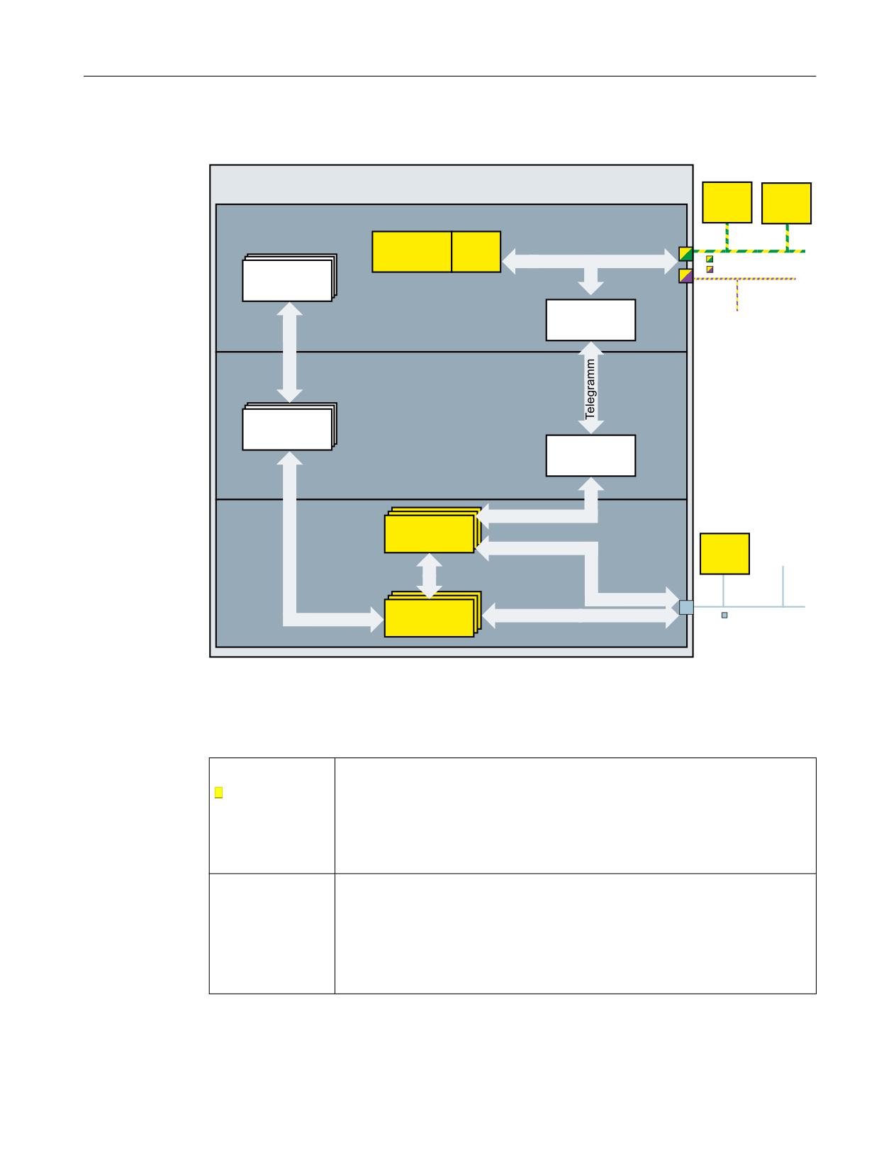
Details on internal processing of safety-related communication
1&8
) ',
&8
) '2
) 3/&
6DIHW\
3$(
SURJUDP
3$$
352),1(7 352),VDIH
'%
'%
352),%86 352),VDIH
6,& 6&&
7UDQVIHU
352),VDIH
,I UHTXLUHG DGGLWLRQDO
GLVWULEXWHG , 2 V\VWHPV
IDLOVDIH '3 VWDQGDUG
VODYHV
1&
7UDQVIHU
$;
$;
6,& 6&&
7UDQVIHU
352),VDIH
'5,9(
352),VDIH
$;
$;
,I UHTXLUHG
00
DGGLWLRQDO
$;
GULYHV
0RQLWRULQJ
'5,9( &/L4
$;
$;
Figure 3-1
Component diagram for processing safety-related information and data
Table 3-4
Subcomponents of the NCU
F-PLC
• Processing safety-related internal and external signals in the safety-related user
PROFIsafe host
program (safety program)
See: Safety program of the F-PLC (Page 45)
• Processing status and control signals (SIC/SCC) via the corresponding axis DB
(axis1 [DB31] ... axis 31 [DB61])
See: PLC user interface (DB3x) (Page 206), SIC/SCC (Page 205)
NC
• Transfers status and control information (SIC/SCC, axis DB) between the F-PLC
and DRIVE
• Transfers PROFIsafe telegrams (safety program, PAE/PAA) between F-PLC and
DRIVE
• Reads-in safety-related messages/signals from the message buffers of SINAM-
ICS Integrated into the NC alarm buffer
Safety Integrated plus
Commissioning Manual, 10/2020, 6FC5397-1FP40-6BA4
29

Fundamentals
3.4 Safety-relevant processing using NCU components
HMI
• Displays safety-related messages/alarms from the NCK alarm buffer
• Reads out and displays additional safety-related diagnostics information di-
rectly from the drive
• Displays a safety delete symbol for active safety messages
See: Diagnostics (Page 299)
DRIVE (SINAMICS
• Safety-related motion monitoring of NC-controlled drives (connected at the
Integrated)
DRIVE-CLiQ interface)
PROFIsafe slave
See: Safety functions integrated in the drive (Page 24)
• Executes fault response functions or user safety functions
Table 3-5
I/O and drives
F-I/O
The F-I/O guarantees the safety-related processing of information from the field
(sensors: e.g. EMERGENCY STOP pushbuttons, light barriers; actuators, e.g. mo-
PROFIsafe slave
tor controls). The safety function for the process itself can be implemented using
a user safety function - or a fault response function.
See: PLC user interface (DB3x) (Page 206), F-I/O for PROFIBUS DP (Page 32), F-
I/O for PROFINET IO (Page 32)
NC-controlled drives
For each individual axis and spindle, safety functions integrated in the drive can
be implemented, which can communicate via safety-related input/output signals
with the process.
See: Safety functions integrated in the drive (Page 24), Drive components
(Page 33)
Safety Integrated plus
30
Commissioning Manual, 10/2020, 6FC5397-1FP40-6BA4
Fundamentals
3.5 Hardware components
3.5
Hardware components
Overview
The "SINUMERIK Safety Integrated plus (F-PLC)" safety solution places specific requirements on
the hardware components that are used.
Independent of the scope of the Safety Functions used, you can use failsafe SIMATIC and
standard I/O for PROFIBUS DP (Page 32) or PROFINET IO (Page 32) - as known from SIMATIC
Safety.
The drive system that you can use (Page 33) depends on whether a safety-related encoder is
used - and which axis type is to be used.
Hardware components
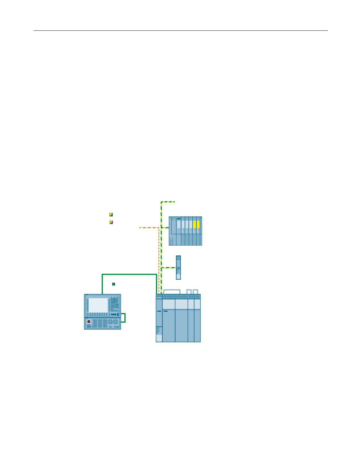
The following diagram shows an overview of a possible structure with failsafe hardware
components.
SRVVLEO\ RWKHU GLVWULEXWHG , 2
V\VWHPV IDLOVDIH , 2 VWDQGDUG
GHYLFHV '3 VWDQGDUG VODYHV
PROFINET/PROFIsafe
PROFIBUS/PROFIsafe
'LVWULEXWHG , 2
V\VWHP H J
(7
63
&8
ZLWK H[WHUQDO GULYH
Industrial Ethernet
SINUMERIK
Operator panel front with TCU
SINUMERIK control system
Figure 3-2
Configuration diagram: Hardware structure with Safety Integrated
Safety Integrated plus
Commissioning Manual, 10/2020, 6FC5397-1FP40-6BA4
31
Fundamentals
3.5 Hardware components
3.5.1
F-I/O for PROFIBUS DP
You can use the following failsafe components in SINUMERIK Safety F-systems on PROFIBUS DP:
• F-CPUs with DP interface
• Failsafe inputs and outputs (F-I/O), such as:
- S7-300 failsafe signal modules in ET 200M
- ET 200MP failsafe modules
- ET 200SP failsafe modules
- ET 200S failsafe modules
- ET 200pro failsafe modules
- ET 200iSP failsafe modules
- ET 200eco failsafe I/O module
- Failsafe GSD based DP slaves (light grid, laser scanner, etc.)
You have the option to expand the configuration with standard I/O.
3.5.2
F-I/O for PROFINET IO
You can use the following failsafe components in SINUMERIK Safety F-systems on PROFINET IO:
• F-CPUs with PN interface
• Failsafe inputs and outputs (F-I/O), such as:
- S7-300 failsafe signal modules in ET 200M
- ET 200MP failsafe modules
- ET 200SP failsafe modules
- ET 200S failsafe modules
- ET 200pro failsafe modules
- ET 200iSP failsafe modules
- ET 200eco PN failsafe I/O modules
- Failsafe GSD based I/O devices (light grid, laser scanner, etc.)
You have the option to expand the configuration with standard I/O.
Safety Integrated plus
32
Commissioning Manual, 10/2020, 6FC5397-1FP40-6BA4

Fundamentals
3.5 Hardware components
3.5.3
Drive components
The drive system that you can use depends on whether a safety-relevant encoder is used - and
which axis type is to be used.
Table 3-6
Supported axis types as a function of the drive type and the use of a safety-relevant encoder
Spindle
Rotary axis
Linear axis
Induction motor with encoder
Yes
Yes
Yes
Induction motor without encoder
Yes
No
No
Synchronous motor with encoder
Yes
Yes
Yes
Synchronous motor without en-
No
No
No
coder
SINAMICS HLA with encoder
No
No
Yes1)
SINAMICS HLA without encoder
No
No
No
1) Not all Basic or Extended Functions are supported, see SINAMICS HLA (Page 36) or SINAMICS
HLA (Page 36).
3.5.3.1
Interconnecting DRIVE-CLiQ components
For Safety Integrated Functions, the general DRIVE-CLiQ rules apply as a basic principle. You will
find these rules in Chapter "Rules for connection with DRIVE-CLiQ" in the following Manual:
• "SINAMICS S120 Drive Functions" Function Manual (https://
support.industry.siemens.com/cs/ww/en/view/109771805)
Beyond this, the following rules also apply to Safety Integrated:
Rules for Safety Integrated Basic Functions
• Maximum of 4 drives per DRIVE-CLiQ line for control via PROFIsafe
Rules for Safety Integrated Extended Functions
• Maximum of 6 servo axes for default clock cycle settings (safety monitoring clock
cycle = 12 ms; current controller cycle = 125 μs); of which a maximum of 4 servo axes are in
one DRIVE-CLiQ line
• Maximum of 6 vector axes for the following clock cycle settings (safety monitoring
cycle = 12 ms; current controller cycle = 500 μs)
• One Double Motor Module corresponds to 2 DRIVE-CLiQ participants.
Safety Integrated plus
Commissioning Manual, 10/2020, 6FC5397-1FP40-6BA4
33

Fundamentals
3.5 Hardware components
• On Double Motor Modules, on the drive objects, different values for p9511 are not permitted,
even if the values in p0115[0] are different.
• You can operate a maximum of 4 Motor Modules with Safety Extended Functions on one
DRIVE-CLiQ line. The following condition applies in this regard: TIReg (current controller
sampling time) = 125 μs for all axes. In addition to the 4 Motor Modules with Safety Extended
Functions, you can also operate the following modules on a DRIVE-CLiQ line:
- A Line Module if TIReg (current controller sampling time) ≥ 250 μs
- A Motor Module if TIReg (current controller sampling time) ≥ 125 μs
- A maximum of 7 Sensor Modules or DRIVE-CLiQ encoders
3.5.3.2
Drive monitoring with or without encoder
In the Safety Integrated system, encoderless safety operation is only supported for spindles with
induction motors.
If motors without a (safety-capable) encoder are being used, not all Safety Integrated Functions
can be used.
Note
Definition: "Without encoder"
When "without encoder" is used in this manual, then this always means that either no encoder
or no safety-capable encoder is being used.
In operation without encoder the actual speed values are calculated from the measured
electrical actual values. Therefore, speed monitoring is also possible during operation without
encoder.
The configuration of the Safety Integrated Functions and the selection of monitoring with or
without encoder is realized in the startup (commissioning) area of SINUMERIK Operate.
The safety functions integrated in the drive that are actually supported depends on the drive
components used (drive and axis type, and whether a safety-relevant encoder is used).
Table 3-7
Safety Integrated Functions in operation with or without encoder
Function
Basic
Extended
HLA
Electric drive
Brief description
With
With-
en-
out
coder
en-
coder
STO/SS1 Basic
x
-
x3)
x
x1)
Safe Torque Off / Safe Stop according to
Stop Category 1 of DIN EN 60204-1.
Safe Torque Off/Safe Stop 1
STO Extended
-
x
x3)
x
x1)
Safe Torque Off
Safe Torque Off
SBC
x
x
-
x
x1)
Safe brake control
Safe Brake Control
SS1 Extended
-
x
x3)
x
x1)
Safe Stop according to Stop Category 1
of DIN EN 60204-1.
Safe Stop 1
Safety Integrated plus
34
Commissioning Manual, 10/2020, 6FC5397-1FP40-6BA4

Fundamentals
3.5 Hardware components
Function
Basic
Extended
HLA
Electric drive
Brief description
With
With-
en-
out
coder
en-
coder
SOS
-
x
x3
x
-
Safe monitoring of the standstill posi-
tion
Safe Operating Stop
SS2
-
x
x3
x
-
Safe stopping process in accordance
with stop Category 2
Safe Stop 2
SS2E
-
x
x3
x
x1
SS2 with external stop
SS2 with external stop
SS2ESR
-
x
x3
x
x1
Safe Stop 2 Extended Stop and Retract
Safe Stop 2 Extended Stop and Retract
SLS
-
x
x3)
x
x1)
Safely-Limited Speed
Safely-Limited Speed
SSM
-
x
x3)
x
x1)
Safe Speed Monitoring
Safe Speed Monitor
1, 2)
SAM
-
x
-
x
x
Safe Acceleration Monitoring
Safe Acceleration Monitor
SBR
-
x
-
x
x1)
Safe brake ramp monitoring
Safe Brake Ramp
SDI
-
x
x3)
x
x1)
Safe motion direction
Safe Direction
SLP/SP
-
x
x3)
x
x1)
Safely-Limited Position/Safe Position
Safely-Limited Position/
Safe Position
SLA
-
x
x3)
x
x1)
Safely-Limited Acceleration
Safely-Limited Acceleration
SBT (diagnostic function)
-
x
-
x
-
Safe Brake Test
Safe Brake Test
SBT is a pure diagnostic function - but
for organizational reasons is included
in the list of Safety Integrated Exten-
ded Functions.
SCA
-
x
x
x
-
Safe Cam
Safe Cam
¹) Safety operation without encoder is only supported for spindles equipped with induction
motors, see also Table 3-6 Supported axis types as a function of the drive type and the use of a
safety-relevant encoder (Page 33).
²) Only for the function setting "Safety without encoder with accel_monitoring".
³) Encoderless Safety mode with SINAMICS HLA is not supported either for Basic Functions or for
Extended Functions, see also SINAMICS HLA (Page 36).
See also
Drive components (Page 33)
Safety Integrated plus
Commissioning Manual, 10/2020, 6FC5397-1FP40-6BA4
35
Fundamentals
3.5 Hardware components
3.5.3.3
Induction motors and synchronous motors
Approved encoders
Motors with sin/cos encoder and encoder evaluation with DRIVE-CLiQ interface or via Sensor
Module SMC20, SME20/25/120/125.
A list of approved encoders is provided in Siemens Industry Online Support under Entry ID
3.5.3.4
SINAMICS HLA
Safety operation without encoder with HLA is neither supported for Basic nor for Extended
Functions. When operating SINAMICS HLA in a safety mode, you require encoder types that have
been approved for SINAMICS HLA.
Note
Comparison, description of electric ↔ hydraulic drives
In this Safety Integrated plus commissioning manual, Safety Integrated Functions are described
from the perspective of an electric drive. However, these descriptions essentially also apply in
the same way for hydraulic systems. You can find parameters and messages for the HLA drive
object in the SINAMICS S120/S150 List Manual.
Encoder types supported by SINAMICS HLA
The following encoder types are permissible for SINAMICS HLA:
• Single-encoder systems
- DRIVE-CLiQ encoder with safety capability
- sin/cos encoder connected via SME20/25, SME120/125 or SMC20 (1Vss, pure analog
signal processing)
•
2-encoder systems
- Encoders with DRIVE-CLiQ connection
- sin/cos encoder connected via SME20/25, SME120/125 or SMC20 (1Vss, pure analog
signal processing)
Safety Integrated plus
36
Commissioning Manual, 10/2020, 6FC5397-1FP40-6BA4
Fundamentals
3.5 Hardware components
Basic Functions supported by SINAMICS HLA
SINAMICS HLA supports the following Safety Integrated Basic Functions:
• Basic Functions
These functions are part of the standard scope of the drive and can be used without requiring
an additional license. These functions are always available. These functions do not require an
encoder and/or do not place any special requirements on the encoder used.
- Safe Torque Off (STO)
Safe Torque Off is a safety function that prevents the drive from restarting unexpectedly
in accordance with EN- 60204-1. STO prevents the supply of power to the valve, which
can produce a force. It is equivalent to stop Category 0.
- Safe Stop 1 (SS1, time-controlled)
Safe Stop 1 is based on the "Safe Torque Off" function. This means that a Category 1 stop
in accordance with EN 60204-1 can be implemented.
These functions are part of the standard scope of the drive and can be used without requiring
an additional license.
Extended Functions supported by SINAMICS HLA
SINAMICS HLA supports the following Safety Integrated Extended Functions:
• Safe Torque Off (STO)
Safe Torque Off is a safety function that prevents the drive from restarting unexpectedly
according to EN- 60204-1.
• Safe Stop 1 (SS1, time and acceleration controlled)
Safe Stop 1 is based on the "Safe Torque Off" function. This means that a Category 1 stop in
accordance with EN 60204-1 can be implemented.
• Safe Operating Stop (SOS)
Safe Operating Stop is used to protect against unintentional movement. The drive is in closed-
loop control mode and is not disconnected from the power supply.
• Safe Stop 2 (SS2)
Safe Stop 2 is used to safely brake the valve with a subsequent transition into the "Safe
Operating Stop" state (SOS). This means that a Category 2 stop in accordance with EN
60204-1 can be implemented.
• Safe Stop 2 with external stop (SS2E)
The 'Safe Stop 2 with external stop' (SS2E) safety function is used to brake the motor safely.
The drive does not automatically brake the motor, but instead follows the specified speed
setpoint.
• Safe Stop 2 Extended Stop and Retract (SS2ESR)
The "Safe Stop 2 Extended Stop and Retract (SS2ESR)" safety function is used to brake the
motor safely. The drive does not automatically brake the motor, but instead follows the
specified speed setpoint. This can also result in fast retraction motion.
• Safely-Limited Speed (SLS)
Safely-Limited Speed ensures that the drive does not exceed a preset speed limit.
Safety Integrated plus
Commissioning Manual, 10/2020, 6FC5397-1FP40-6BA4
37
Fundamentals
3.5 Hardware components
• Safe Speed Monitor (SSM)
Safe Speed Monitor is used for safely identifying when a speed limit is undershot in both
directions of motion, e.g. to identify zero speed. A failsafe output signal is available for
further processing.
• Safe Direction (SDI)
Safe Direction is used to safely monitor the direction of motion.
• Safely-Limited Acceleration (SLA)
Safely-Limited Acceleration monitors (the same as SLS) the acceleration, and intervenes
when a limit value is violated. However, SLA cannot prevent that the acceleration threshold is
briefly exceeded.
• Safely-Limited Position (SLP)
Safely-Limited Position ensures that a freely definable traversing range is not left.
• Transferring safe position values (SP)
The "Transfer safe position values (SP)" function enables you to transfer a safe position to a
higher-level control via PROFIsafe.
• Safe Cam (SCA)
Safe electronic cams enable a secure, axis-specific range detection or a work zone / protection
zone delimitation.
These functions require an additional Safety Integrated license (Page 39).
Safety Integrated plus
38
Commissioning Manual, 10/2020, 6FC5397-1FP40-6BA4

Fundamentals
3.6 Safety components and licensing
3.6
Safety components and licensing
3.6.1
Software components required
When configuring the system, the STEP 7 Safety Advanced option package is required. This
option package is integrated in package "SIMATIC STEP 7 Professional V16". The software can be
immediately used once the license for the option package has been installed.
Engineering system:
• TIA Portal V16 Update 2
• SIMATIC STEP 7 Professional V16 Update 2
- SIMATIC STEP 7 Safety Advanced V16 Update 2
• SINUMERIK 840D sl STEP 7 Toolbox V16 Update 2
CNC software:
• SINUMERIK CNC software V4.94
• SINUMERIK Operate V4.94
3.6.2
Licensing axes/spindles and F-PLC
To use Safety Integrated plus (F-PLC), you require in addition to the license for SIMATIC STEP 7
Safety Advanced (TIA Portal), the appropriate software options for the RT function:
Table 3-8
Software options for the use of Safety Integrated plus (F-PLC)
Software option
Article No.
Purpose
SINUMERIK 840D sl
6FC5800-0AS60-0YB0
Activate the F-PLC in SINUMERIK 840D sl in order to
process the failsafe sensors and actuators in an F-
Safety Integrated plus
program.
/SI logic
SINUMERIK 840D sl
6FC5800-0AK00-0YB0
Use the motion control functions of the SINAMICS
Safety Integrated plus
Safety Integrated in the SINUMERIK Safety Integra-
/ SI axis/spindle
ted plus (F-PLC) mode.
License for one axis/spindle, multiple licensing in
order to be able to use further axes/spindles.
SINUMERIK 840D sl
6FC5800-0AS61-0YB0
Use the motion control functions of the SINAMICS
Safety Integrated plus
Safety Integrated in the SINUMERIK Safety Integra-
/ SI multi-axis package
ted plus (F-PLC) mode.
License for any number of axes/spindles.
Depending on the functions used, you must license the appropriate software options and set in
the machine data:
• MD19500 $MN_SAFE_PLC_LOGIC: Safety Integrated plus /SI-Logic basic option
• MD19121 $MN_NUM_DRIVEBASED_SAFE_AXES: Number of axes/spindles in Safety
Integrated plus (F-PLC) mode
Safety Integrated plus
Commissioning Manual, 10/2020, 6FC5397-1FP40-6BA4
39
Fundamentals
3.6 Safety components and licensing
See also:
Collection of documents SINUMERIK 840D sl Base Software and Operating Software,
Commissioning Manual SINUMERIK Operate (IM9)
Safety Integrated plus
40
Commissioning Manual, 10/2020, 6FC5397-1FP40-6BA4
Fundamentals
3.7 Components and basic configuration in the TIA Portal
3.7
Components and basic configuration in the TIA Portal
3.7.1
Structure of a project view in the TIA Portal
Overview
All safety-related resources are marked yellow in the TIA Portal, e.g. in the following views:
• Network view, device view, topology view
• Project tree
• Hardware catalog
• Inspector window or object properties
• Program editor
This also applies to the SINUMERIK components:
• NCU
Because the subcomponents PLC and SINAMICS Integrated support Safety Integrated
Functions, the higher-level NCU is marked as safety-oriented resource.
• Integrated PLC
• Integrated SINAMICS Integrated
• NX
Safety Integrated plus
Commissioning Manual, 10/2020, 6FC5397-1FP40-6BA4
41
Fundamentals
3.7 Components and basic configuration in the TIA Portal
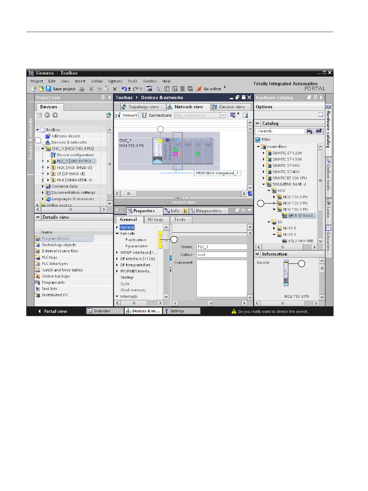
Marking failsafe components in the TIA Portal
2
1
①
The project tree shows which components of your project are F-components.
②
In the network view, device view or topology view, the Safety Integrated marking is on the NCU, representative for the
integrated components. External devices, e.g. NX, may have their own Safety Integrated marking.
③
Safety-related settings are marked in the "Properties" inspector window.
④
Folders and the devices themselves are marked in the hardware catalog. You can therefore see whether SINUMERIK
Safety Integrated is supported before inserting the device.
⑤
Failsafe devices are also marked in the information area of the hardware catalog.
Figure 3-3
Marking failsafe components in the TIA Portal
Safety Integrated plus
42
Commissioning Manual, 10/2020, 6FC5397-1FP40-6BA4
Fundamentals
3.7 Components and basic configuration in the TIA Portal
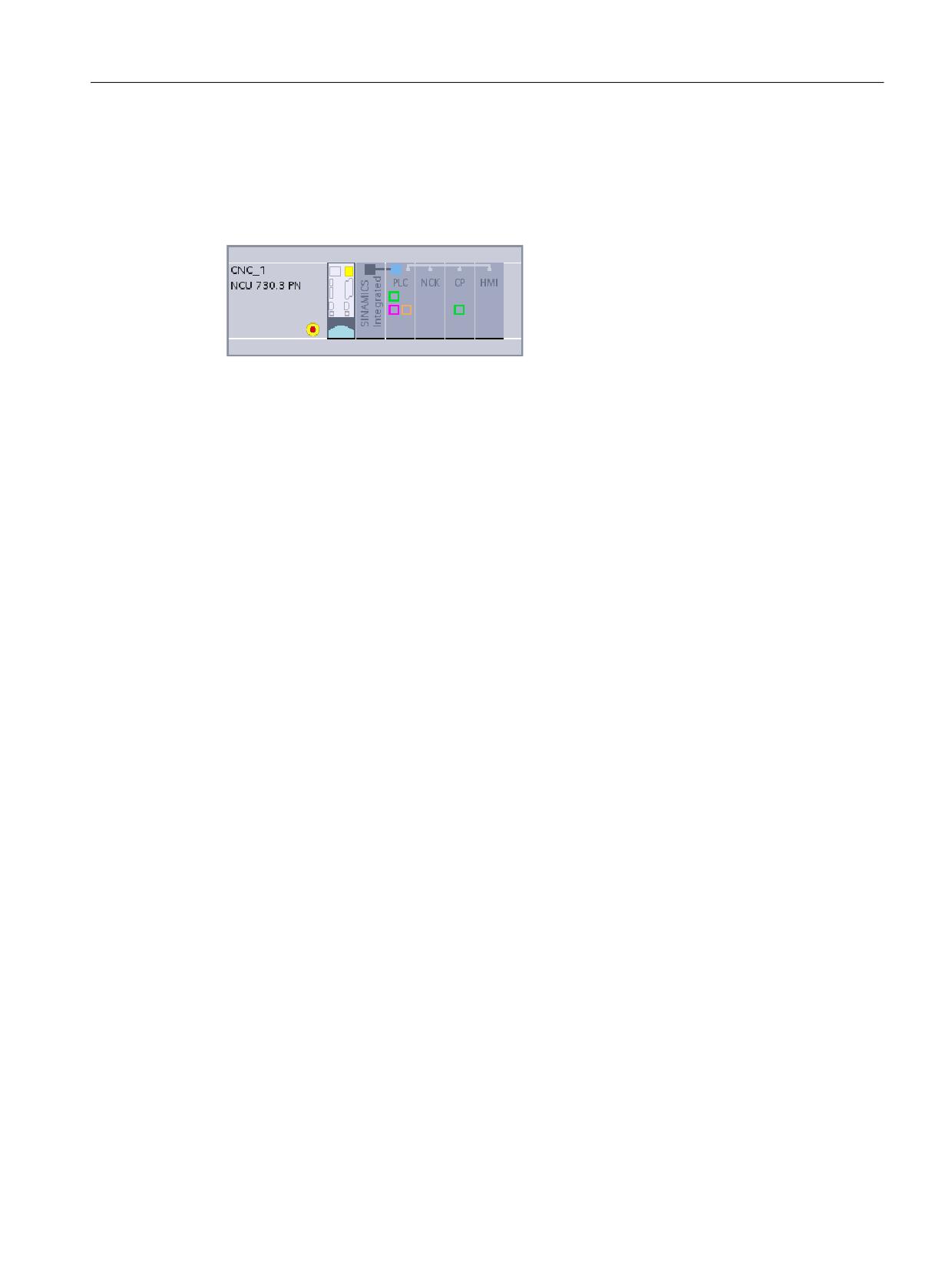
EMERGENCY STOP button symbol when using Safety Integrated plus (F-PLC)
If you activate the "Safety Integrated plus (F-PLC)" mode and therefore use PROFIsafe telegrams,
all devices with failsafe modules (PROFIsafe telegrams) have an EMERGENCY STOP button
symbol in the network and topology view:
Figure 3-4
NCU with EMERGENCY STOP button symbol
Safety Integrated plus
Commissioning Manual, 10/2020, 6FC5397-1FP40-6BA4
43
Fundamentals
3.7 Components and basic configuration in the TIA Portal
Safety Integrated plus
44
Commissioning Manual, 10/2020, 6FC5397-1FP40-6BA4
Safety program of the F-PLC
4
Information about F-PLC, F-I/O, the safety program and/or SIMATIC Safety in this manual serves
as entry-level information only - and describes the special features relating to SINUMERIK.
Note
Important additional information
For space reasons, the information described in this manual cannot replace a complete SIMATIC
Safety Manual. Therefore, when configuring these safety programs, it is crucial that you carefully
follow the information provided in the TIA Portal help on SIMATIC Safety or in the "SIMATIC Safety
- Configuring and Programming (https://support.industry.siemens.com/cs/ww/en/view/
54110126)" Manual.
Principle of operation of the F-PLC safety functions
The safety functions of the F-PLC are mainly implemented in the software. The safety functions
are executed by the F-system to bring the system into a safe state if a hazardous event takes place
- and maintain it in this safe state. Safety functions are contained mainly in the following
components:
• in the safety-related user program (safety program) in the PLC with active F-capability (F-PLC)
• in the failsafe inputs and outputs (F-I/O)
• in the safety functions integrated in the drive (drive components)
The F-I/O guarantees the safety-related processing of information from the field (sensors: e.g.
EMERGENCY STOP pushbuttons, light barriers; actuators, e.g. motor controls). They have all of
the required hardware and software components for safe processing, in accordance with the
required Safety Integrity Level. The user only has to program the user safety function. The safety
function for the process itself can be implemented using a user safety function - or a fault
response function. In the event of an error, if the F-system can no longer execute its actual user
safety function, it executes the fault reaction function; for example, the associated outputs are
shut down, and the F-PLC goes into the STOP mode, if necessary.
Example of user safety function and fault reaction function
In the event of overpressure, the F-system will open a valve (user safety function). For a
hazardous F-PLC fault, all outputs are shutdown (fault response function); the overpressure
valve opens, and also the other actuators go into a safe state. For a non-faulty F-system, only the
valve would be opened.
Safety program
If you activate Safety Integrated in the properties of the NCU, then the F-capability of the PLC is
activated and an F-runtime group is created. The F-runtime group, together with the associated
F-blocks, is known as the safety program.
Safety Integrated plus
Commissioning Manual, 10/2020, 6FC5397-1FP40-6BA4
45
Safety program of the F-PLC
You generate a safety program in the program editor. You program failsafe FBs and FCs in the
FBD and LAD programming languages with operations from the option package - creating
failsafe DBs.
Safety checks are automatically performed when compiling the safety program, and additional
failsafe blocks are integrated for fault detection and fault response. This ensures that failures
and faults are detected, and the appropriate responses triggered to keep the safety system in a
safe state - or to transition it into a safe state.
In addition to the safety program, a standard user program can also be executed in the F-PLC.
Standard and safety programs can coexist in an F-PLC. This is because the safety-related data of
the safety program are protected against being inadvertently influenced by data of the standard
user program.
Data can be exchanged between the safety and standard user program in the F-PLC using bit
memories, data of a standard DB - and by accessing the process image of inputs and outputs.
Safety Integrated plus
46
Commissioning Manual, 10/2020, 6FC5397-1FP40-6BA4
Safety program of the F-PLC
4.1 Structure of the safety program
4.1
Structure of the safety program
Representation of program structure
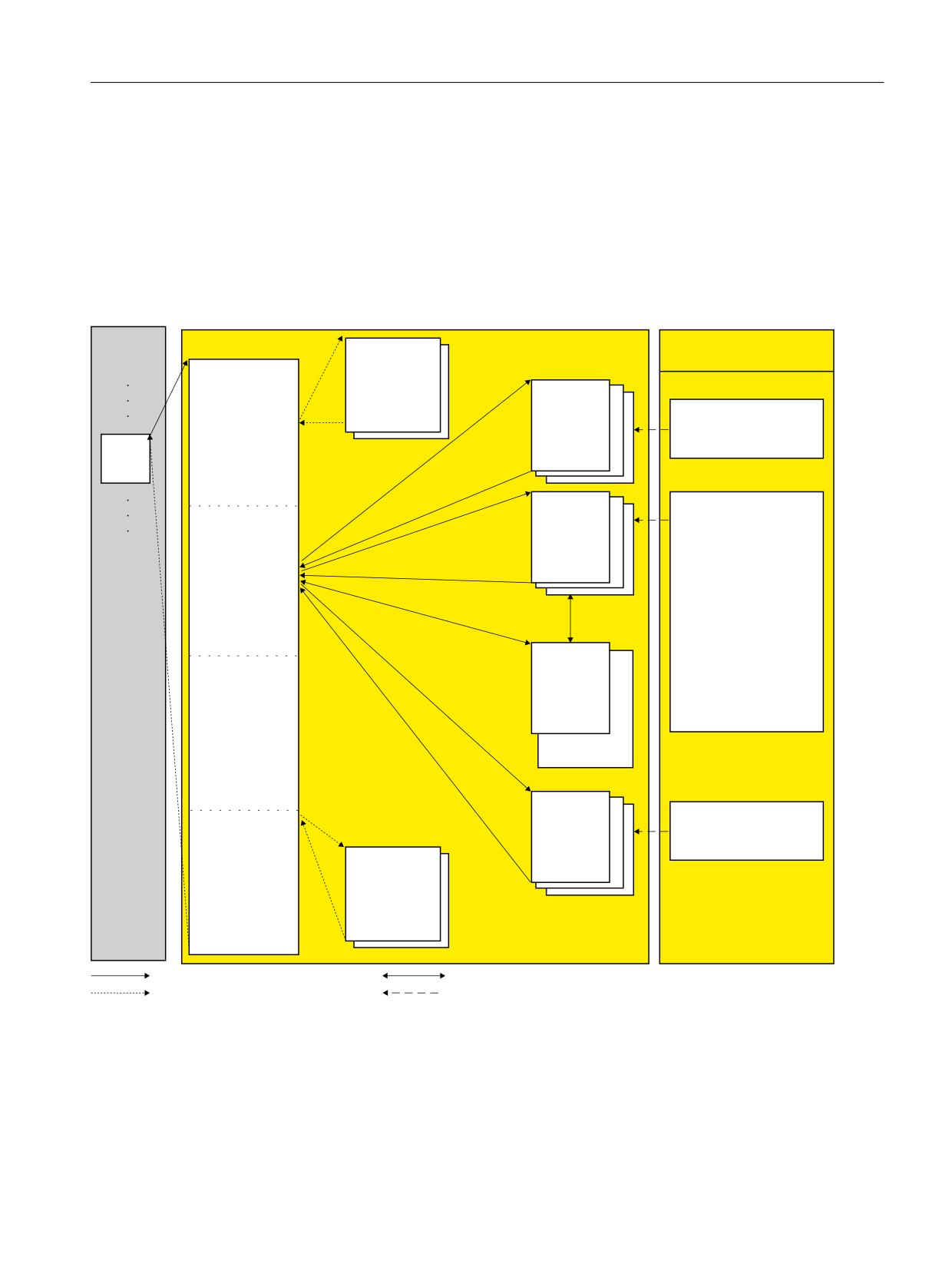
The structure of a safety program (or an F-runtime group) of the PLC of a SINUMERIK 840D sl
(F-PLC S7-300) is schematically shown in the following diagram.
6WDQGDUG XVHU SURJUDP
) UXQWLPH JURXS LQ WKH VDIHW\ SURJUDP
,QVWUXFWLRQV WDVN FDUG
0DLQ VDIHW\ EORFN
) 6%V
,QVWUXFWLRQV
$XWRPDWLF
,QSXWV RI WKH
JHQHUDWHG
5&9'3
) , 2 DUH UHDG
) EORFNV
5&96
LQWR WKH SURFHVV
RSWLRQDO
&RPPXQLFDWLRQ
LPDJH RI WKH
HJ
LQSXWV
2%
) )%
) )& [\
*HQHUDO
(GLWLQJ RI WKH
%LW ORJLF RSHUDWLRQV
) EORFNV FUHDWHG
6DIHW\ IXQFWLRQV
RU DGGHG E\ WKH
7LPHUV
XVHU
&RXQWHUV
&RPSDUDWRU RSHUDWLRQV
0DWK IXQFWLRQV
0RYH
&RQYHUVLRQ RSHUDWLRQV
) '% [\
3URJUDP FRQWURO
:RUG ORJLF RSHUDWLRQ
(GLWLQJ RI
6KLIW DQG URWDWH
DXWRPDWLFDOO\
2SHUDWH
DGGHG ) EORFNV
IDXOW FRQWURO
) ,2
PHDVXUH
'% [\
6(1''3
6(1'6
&RPPXQLFDWLRQ
3URFHVV LPDJH
RSWLRQDO
RI RXWSXWV LV
) 6%V
ZULWWHQ WR
RXWSXWV RI ) , 2
$XWRPDWLF
JHQHUDWHG
) EORFNV
FDOOHG E\ XVHU
ZULWH UHDG
FDOOHG DXWRPDWLFDOO\
IURP ,QVWUXFWLRQV WDVN FDUG
Figure 4-1
Schematic structure of a safety program
Main safety block
The main safety block is the first F-block of the safety program that you program yourself. During
compiling, it is supplemented by additional invisible calls of F-system blocks.
Safety Integrated plus
Commissioning Manual, 10/2020, 6FC5397-1FP40-6BA4
47

Safety program of the F-PLC
4.1 Structure of the safety program
You must assign the main safety block to an F-runtime group (Page 60).
The main safety block is called in an F-CPU S7-300 from any block belonging to the standard user
program. We recommend a call from an OB 3x.
) )% _ ) )&
2%
)% _ )&
) )% _ ) )&
0DLQ VDIHW\ EORFN
Figure 4-2
Calling the main safety block
F-runtime group
To improve handling, a safety program comprises one F-runtime group. An F-runtime group is
a logical arrangement comprising several contiguous F-blocks, which are internally formed by
the F-system.
An F-runtime group is made up of the following components:
• Main safety block (F-FB/F-FC, which you assign to the calling OB)
• F-blocks that you generated yourself - or that you inserted:
- F-blocks from the project library or from global libraries
- Possibly other F-FBs/F-FCs, which you program with FBD/LAD - and that you call from the
main safety block
- Possibly one or several F-DBs
• Automatically added F-blocks:
- F-I/O DBs
- F-system blocks (F-SB)
- Automatically generated F-blocks
Block types and number ranges of the safety program
An F-runtime group together with the associated blocks is automatically created when you
activate the "SINUMERIK Safety Integrated plus (F-PLC)" mode:
• Calling block: CYC_INT5_RTG1 [OB35]
• Main safety block: Main_Safety_RTG1 [FB1010]
• I-DB for the main safety block: Main_safety_RTG1_DB [DB1010]
Number range reserved for SINUMERIK
In order to avoid assigning block addresses or numbers twice, the F-blocks are automatically
assigned a free number within a certain number range reserved for SINUMERIK. You can also
Safety Integrated plus
48
Commissioning Manual, 10/2020, 6FC5397-1FP40-6BA4
Safety program of the F-PLC
4.1 Structure of the safety program
subsequently change the numbers of F-blocks in the block properties. However, only use the
number range that has been reserved:
• Number range reserved for F-FB, F-FC and F-DB of F execution groups
- F-FB 1010..1019
- F-FC 1010..1019
- F-DB 1010..1019
• Additional number range for F-blocks (e.g. generated F-system blocks)
- F-FB 3999..7999
- F-FC 3999..7999
- F-DB 8000..16000
If you configure F I/O, then automatically an F I/O DB is created within this number range. You can
change the number of an F I/O DB in the properties of the associated F I/O.
Safety Integrated plus
Commissioning Manual, 10/2020, 6FC5397-1FP40-6BA4
49

Safety program of the F-PLC
4.2 Fail-Safe Blocks
4.2
Fail-Safe Blocks
F-blocks of an F-runtime group
The following table shows the F-blocks that you use in an F-runtime group:
F-block
Function
Main safety block
For the integrated PLC of the SINUMERIK 840D sl (PLC 317F-3 PN/DP or PLC 319F-3 PN/DP), the main
safety block is a F-FC or F-FB (with instance DB), which is called by a standard block (recommendation:
OB 35) from the standard user program.
F-FB/F-FC
Both in the main safety block as well as additional F-FBs and F-FCs, you can perform the following:
• Program the safety program with the instructions available for F-blocks in FBD or LAD
• Call other created F-FBs/F-FCs for structuring the safety program
• Insert F-blocks from the project library or global libraries
F-DB
Optional failsafe data blocks that can be read- and write-accessed within the entire safety program.
F-I/O DB
An F-I/O DB is automatically generated for each F-I/O when it is configured. You can or you must access
the variables of the F-I/O DB in conjunction with F-I/O accesses.
F-global-DB
The F-shared DB is a failsafe data block that contains all of the shared data of the safety program and
additional information needed by the F-system.
Note
It is not permissible that you add, change or delete blocks in folder "System blocks". If this is not
complied with, then this can result in compilation errors or the F-PLC stopping.
Note
You are not permitted to insert F-system blocks from the "System blocks" folder in a main safety
block/F-FB/F-FC.
Additional information
Detailed information about the safety program blocks can be found at Procedure when defining
an F-runtime group (Page 60).
Safety Integrated plus
50
Commissioning Manual, 10/2020, 6FC5397-1FP40-6BA4
Safety program of the F-PLC
4.3 Safety Administration Editor
4.3
Safety Administration Editor
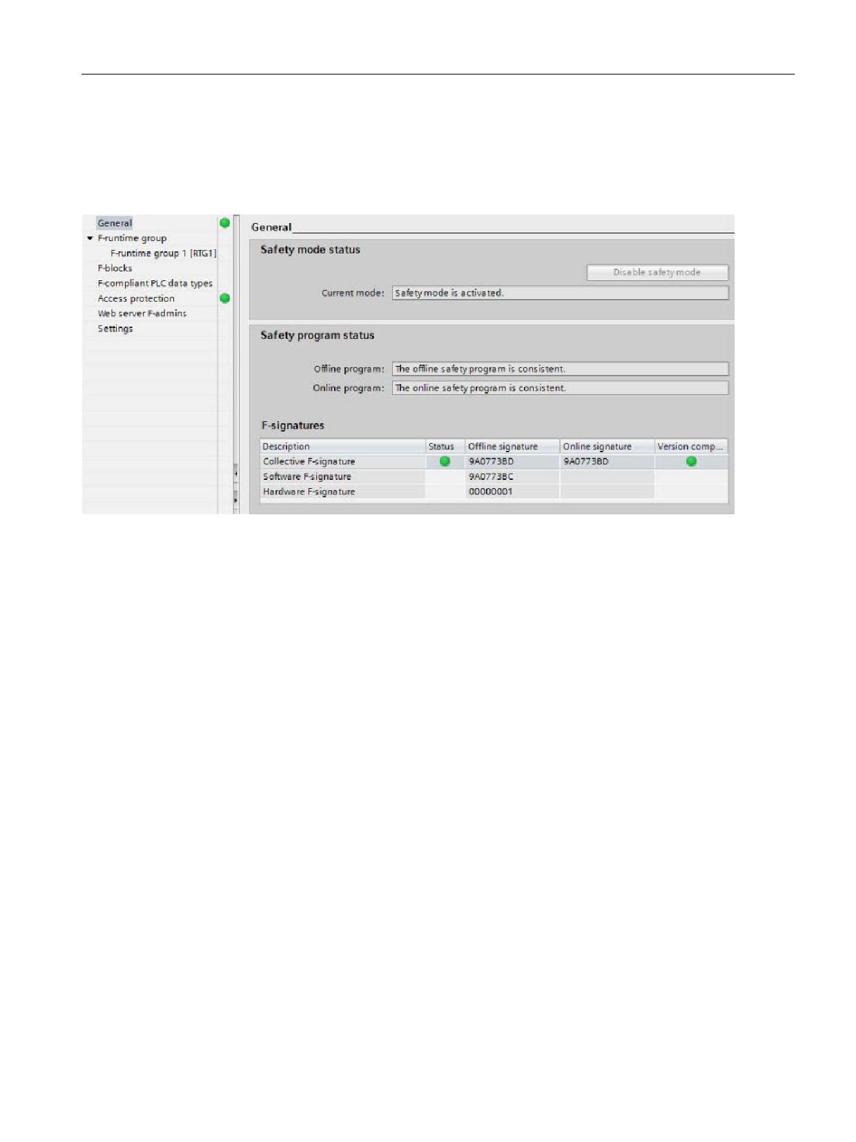
In mode "SINUMERIK Safety Integrated plus (F-PLC)", the "Safety Administration Editor" is
available in the project navigation.
Figure 4-3
Safety Administration Editor
The Safety Administration Editor supports you when carrying out the following tasks:
• Display of the safety program status
• Display of the collective signature
• Display of the safety mode status
• Creation/organization of F-runtime groups
• Display of information on the F-blocks
• Definition/change of the access protection
• Definition/change of the general settings for the safety program
The Safety Administration Editor is divided into the following sections:
• General
• F-runtime groups (Page 60)
• F-blocks
• Access protection
• Settings
Additional information
Additional information is provided in the help for SIMATIC STEP 7 Safety Advanced in Chapter
"Safety Administration Editor".
Safety Integrated plus
Commissioning Manual, 10/2020, 6FC5397-1FP40-6BA4
51

Safety program of the F-PLC
4.4 Restrictions in the programming languages FBD/LAD
4.4
Restrictions in the programming languages FBD/LAD
LAD and FBD programming languages
Generally, the user program in the F-PLC comprises a standard application program and a safety
program.
The standard user program is created using standard programming languages such as SCL, STL,
LAD, or FBD.
For the safety program, LAD or FBD may be used with certain restrictions in the instructions and
the applicable data types and operand areas.
Supported instructions
The instructions available depend on the F-PLC being used. SINUMERIK 840D sl supports all
F-CPU S7-300 instructions.
Note
Preconnection of enable input EN or evaluation of enable output ENO is not possible.
Supported data types and parameter types
Only the following data types are supported:
• BOOL
• INT
• WORD
• DINT
• DWORD
• TIME
Note
If the result of an operation lies outside the range permissible for the specific data type, then the
F-PLC can go into STOP. The cause of the diagnostic result is entered in the diagnostics buffer of
the F-PLC.
Additional information regarding the cause is available in the online help for the diagnostics
message. You must therefore ensure that the permitted range for the data type is observed
when creating the program or select a matching data type.
Safety Integrated plus
52
Commissioning Manual, 10/2020, 6FC5397-1FP40-6BA4

Safety program of the F-PLC
4.4 Restrictions in the programming languages FBD/LAD
Non-permitted data and parameter types
The following types are not permitted:
• All types not listed in the section "Supported data types and parameters types" (e.g. BYTE,
REAL)
• structured data types (e.g. STRING, ARRAY, STRUCT, PLC data type)
• Parameter types (e.g., BLOCK_FB, BLOCK_DB, ANY)
Supported operand areas
The system memory of an F-PLC is structured in the same operand area as that of a standard PLC.
You can access the operand areas listed in the table below from within the safety program.
Note that you can access data in the safety program only via the declared data type for the tag/
element of an F-compliant PLC data type:
• For the BOOL data type only bit by bit
• For the INT data type only word by word
• For the WORD data type only word by word
• For the DINT data type only double word by double word
• For the DWORD data type, only double word by double word
• For the TIME data type only double word by double word
Example: You can only access input channels, data type BOOL in the process image of the inputs
of F I/O via unit "Input (bit)".
Byte access to eight consecutive input channels of the BOOL data type is not allowed.
For reasons of clarity, you should always access operand areas in a safety program using
symbolic names.
Table 4-1
Supported operand areas
Operand area
Access via units of the fol-
S7 Nota-
Description
lowing size:
tion
Process image of the inputs
• Of F-I/O
Input (bit)
I
Only read-only access to input channels of F-I/O
is possible.
Input word
IW
Transfer to IN_OUT parameters of an F-FB or F-
Input double-word
ID
FC is therefore not valid either.
The process image of the inputs of F-I/O is up-
dated before the start of the main safety block.
• Of standard I/O
Input (bit)
I
Input channels of standard I/O can only be ac-
cessed read-only.
Input word
IW
Transfer to IN_OUT parameters of an F-FB or F-
Input double-word
ID
FC is therefore not valid either.
In addition, a process-specific validity check is
required.
See the STEP 7 help for the update times of the
process image of the inputs of standard I/O.
Safety Integrated plus
Commissioning Manual, 10/2020, 6FC5397-1FP40-6BA4
53

Safety program of the F-PLC
4.4 Restrictions in the programming languages FBD/LAD
Operand area
Access via units of the fol-
S7 Nota-
Description
lowing size:
tion
Process image of the outputs
• Of F-I/O
Output (bit)
Q
Only write-only access to output channels of F-I/
O is possible.
Output word
QW
Transfer to IN_OUT parameters of an F-FB or F-
Output double-word
QD
FC is therefore not valid either.
In the safety program, the values for the outputs
of the F-I/O are calculated and stored in the
process image of the outputs.
The process image of the outputs for F-I/O is
updated after the end of the main safety block.
• Of standard I/O
Output (bit)
Q
Output channels of standard I/O are write-only
channels.
Output word
QW
Transfer to IN_OUT parameters of an F-FB or F-
Output double-word
QD
FC is therefore not valid either.
In the safety program, the values for the outputs
of the standard I/O are also calculated and stor-
ed in the process image of the outputs, if nee-
ded.
See the STEP 7 help for the update times of the
process image of the outputs of standard I/O.
Bit memory
Bit memory (bit)
M
This area is used for data exchange with the
standard user program.
Memory word
MW
In addition, read access requires a process-spe-
Memory double word
MD
cific validity check.
A particular element of the bit memory can be
either read- or write-accessed in the safety pro-
gram.
Transfer to IN_OUT parameters of an F-FB or F-
FC is therefore not valid either.
Note that it is only permitted to use bit memory
for connecting the standard user program and
the safety program; it must not be used as a
buffer for F-data.
Data blocks
Safety Integrated plus
54
Commissioning Manual, 10/2020, 6FC5397-1FP40-6BA4

Safety program of the F-PLC
4.4 Restrictions in the programming languages FBD/LAD
Operand area
Access via units of the fol-
S7 Nota-
Description
lowing size:
tion
• F-DB
Data bit
DBX
Data blocks store information for the program.
They can either be defined as global data blocks
Data word
DBW
such that all F-FBs, F-FCs, or main safety blocks
Data double word
DBD
can access them or assigned to a particular F-FB
or main safety block (instance DB). A tag of a
shared DB can only be accessed from one F-run-
time group, and an instance DB only from the F-
runtime group in which the corresponding F-FB/
instruction is called.
• DB
Data bit
DBX
This area is used for data exchange with the
standard user program.
Data word
DBW
In addition, read access requires a process-spe-
Data double word
DBD
cific validity check.
For a tag of a DB, either read access or write
access is possible in the safety program.
Transfer to IN_OUT parameters of an F-FB or F-
FC is therefore not valid either.
Please note that the tags of a DB can only be
used for transferring data between the standard
user program and the safety program; DBs must
not be used as a buffer for F-data.
Non-permitted operand areas
Access via units other than those listed in the table above is not permitted. The same applies to
access to operand areas not listed, in particular:
• Data blocks that were automatically added
Exception: certain tags in the F I/O DB (Page 50) and in the F global DB (Page 64).
• I/O area: Inputs
• I/O area: Outputs
Boolean constants "0" or "FALSE" and "1" or "TRUE" (S7-300, S7-400)
If you require Boolean constants "0" or "FALSE" and "1" or "TRUE" in your safety program to assign
parameters during block calls, you can access the tags "VKE0" and "VKE1" in the F-shared DB
using fully qualified DB access ("F_GLOBDB".VKE0 or "F_GLOBDB".VKE1).
Safety Integrated plus
Commissioning Manual, 10/2020, 6FC5397-1FP40-6BA4
55

Safety program of the F-PLC
4.4 Restrictions in the programming languages FBD/LAD
Operand area of temporary local data: Particularities
Note
Note when using the operand area of temporary local data that the first access of a local data
element in a main safety block/F-FB/F-FC must always be a write access. This initializes the local
data element.
Make sure that the initialization of the local data element is not skipped over by JMP, JMPN. or
RET instructions (branching).
The "local data bit" should be initialized with the Assign ("=") (FBD) or ("--( )") (LAD) instruction.
Assign the local data bit a signal state of "0" or "1" as a Boolean constant.
Local data bits cannot be initialized with the Flip Flop (SR, RS), Set Output (S) or Reset Output (R)
instructions.
If this is not complied with, then the F-PLC can go into STOP. The cause of the diagnostic result
is entered in the diagnostics buffer of the F-PLC. You can find additional information on the cause
in the online help for diagnostic messages.
"Fully qualified DB access"
Access to tags of a data block in an F-FB/F-FC is "fully qualified DB access". This also applies to
initial access to tags of a data block after a jump label.
For F-PLCs S7-300/400, only the first access must be realized as "fully qualified DB access"
Alternatively, you can use the instruction "OPN".
Example of "fully qualified DB access":
Assign a name for the F-DB, e.g. "F_Data_1". Use the names assigned in the declaration of the
F-DB instead of the absolute addresses.
,17
)B'$7$B
9$/8(B$
)B'$7$B
5(68/7
,1
)B'$7$B
9$/8(B%
,1
Figure 4-4
Example with fully qualified access and symbolic names
Safety Integrated plus
56
Commissioning Manual, 10/2020, 6FC5397-1FP40-6BA4
Safety program of the F-PLC
4.4 Restrictions in the programming languages FBD/LAD
Example of "not fully qualified DB access":
1HWZRUN
'%
231
1HWZRUN
,17
'%:
'%;
,1
'%:
,1
Figure 4-5
Example without fully qualified access and symbolic names
Access to instance DBs
Please note that when accessing instance DBs of F-FBs, which are not called in the safety
program, can result in the F-PLC going into STOP.
Additional information is provided in the SIMATIC Safety Programming and Operating Manual.
Safety Integrated plus
Commissioning Manual, 10/2020, 6FC5397-1FP40-6BA4
57
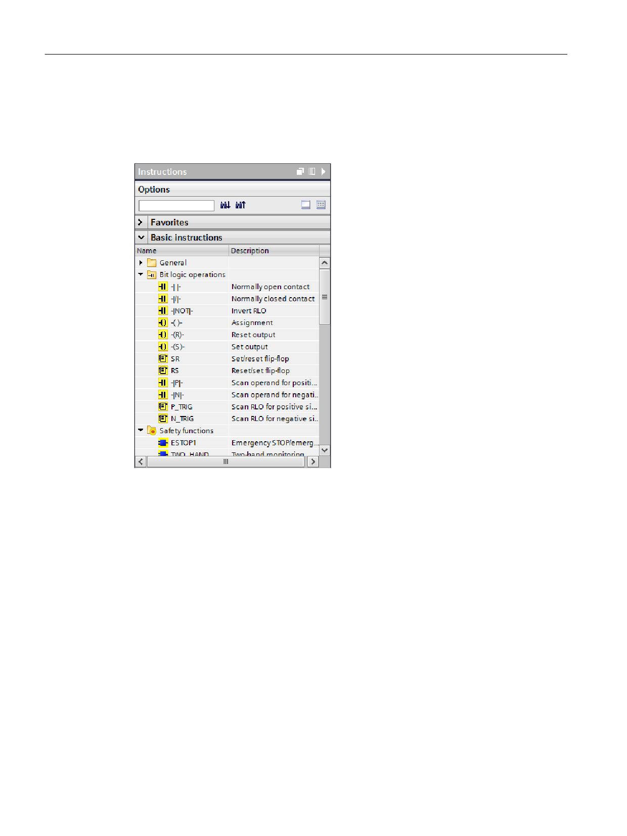
Safety program of the F-PLC
4.5 Instructions for the safety program
4.5
Instructions for the safety program
When programming an F block, in task card "Operations" you can find all the operations that you
can use when programming an F block in LAD or FBD with the configured F-PLC. These
operations have a yellow backg12round, as is already the case for as a safety-relevant functions.
Figure 4-6
Task Card "Instructions"
In addition to the known operations, there are special safety functions, e.g. for two-hand
monitoring, discrepancy analysis, muting, E STOP, protective door monitoring and feedback
circuit monitoring.
Additional information
A detailed description of the instructions for the safety program provided in the Programming
and Operating Manual SIMATIC Safety - Configuring and Programming (https://
support.industry.siemens.com/cs/ww/en/view/54110126).
Alternatively, you can call up these descriptions directly in the TIA Portal by moving the tooltip
over a specific operation.
Safety Integrated plus
58
Commissioning Manual, 10/2020, 6FC5397-1FP40-6BA4
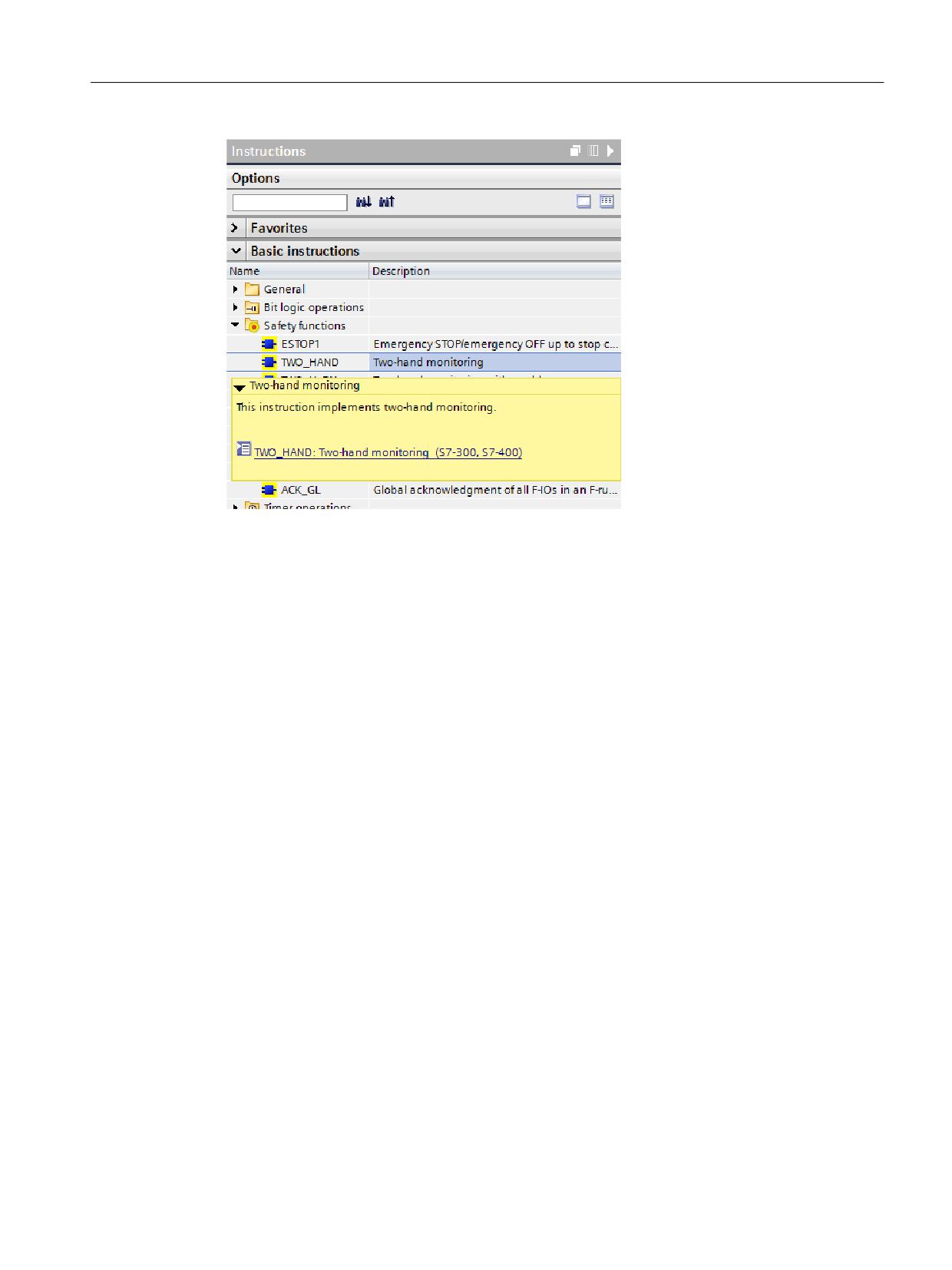
Safety program of the F-PLC
4.5 Instructions for the safety program
Figure 4-7
Tooltip of an instruction
Safety Integrated plus
Commissioning Manual, 10/2020, 6FC5397-1FP40-6BA4
59
Safety program of the F-PLC
4.6 F-runtime groups
4.6
F-runtime groups
4.6.1
Rules for F-Runtime Groups of the Safety Program
Rules
Carefully comply with the following general rules when programming with F-blocks and F-
runtime groups:
• The channels (channel values and value status) of an F-I/O can only be accessed from a single
F-runtime group.
• Variables of the F-I/O DB of an F-I/O can only be accessed from one F-runtime group and only
from that F-runtime group from which the channels or value status of this F-I/O are also
accessed (if access is made).
• Individual variables of F-DBs (except the F-shared DB) can only be used in one F-runtime
group (however, an F-DB can be used in more than one F-runtime group).
• The process image of inputs and outputs of standard I/O, bit memories and variables of the
DB of the standard user program may be accessed, either reading or writing, from several F-
runtime groups. (see also Data exchange between the standard user program and safety
program (Page 74))
You can find additional specific rules at Procedure when defining an F-runtime group (Page 60).
Note
You can improve performance by writing sections of the program that are not required for the
safety function in the standard user program.
When distributing your program between a standard user program and safety program, you
should note that you can change the standard user program more simply and load to the F-PLC.
In general, changes in the standard user program do not require an acceptance.
4.6.2
Procedure when defining an F-runtime group
An F-runtime group comprises a block (cyclic interrupt (OB3x), FB or FC), which calls the main
safety block (FB or FC).
Automatically creating the safety program
An F-runtime group is automatically created when you activate Safety Integrated plus (F-PLC)
mode.
You can adapt this response in the menu under "Options > Settings > STEP 7 Safety".
Safety Integrated plus
60
Commissioning Manual, 10/2020, 6FC5397-1FP40-6BA4
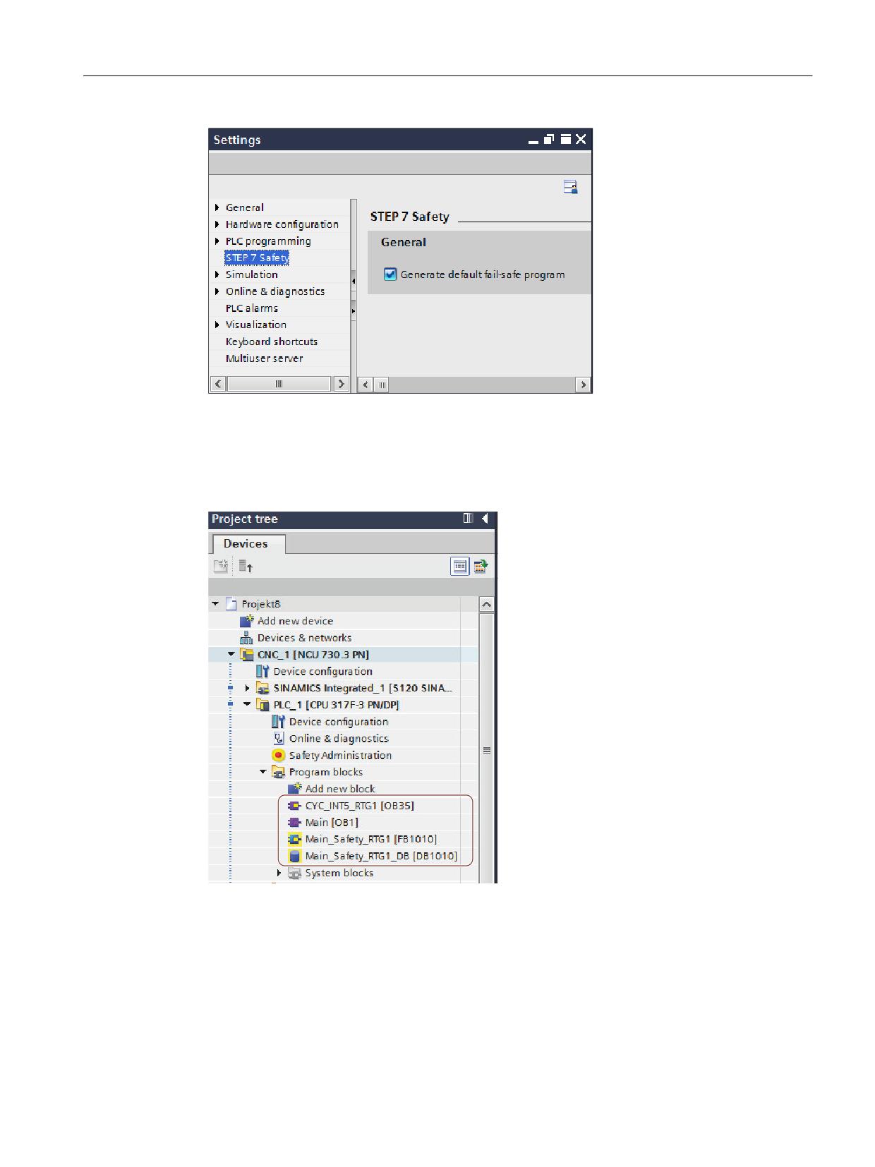
Safety program of the F-PLC
4.6 F-runtime groups
Figure 4-8
Settings for STEP 7 Safety
Archiving the F-blocks
The automatically created F-blocks of the F-runtime group are in folder "Program blocks":
CYC_INT5_RTG1 [OB35], Main-Safety_RTG1 [FB1010] and Main-Safety_RTG1_DB [DB1010].
Figure 4-9
F runtime group blocks in the project navigator
Open the "F runtime group" work cell
If you wish to adapt the automatically created F runtime group or configure F runtime groups,
in the Safety Administration Editor, open the "F runtime group" work cell.
Safety Integrated plus
Commissioning Manual, 10/2020, 6FC5397-1FP40-6BA4
61
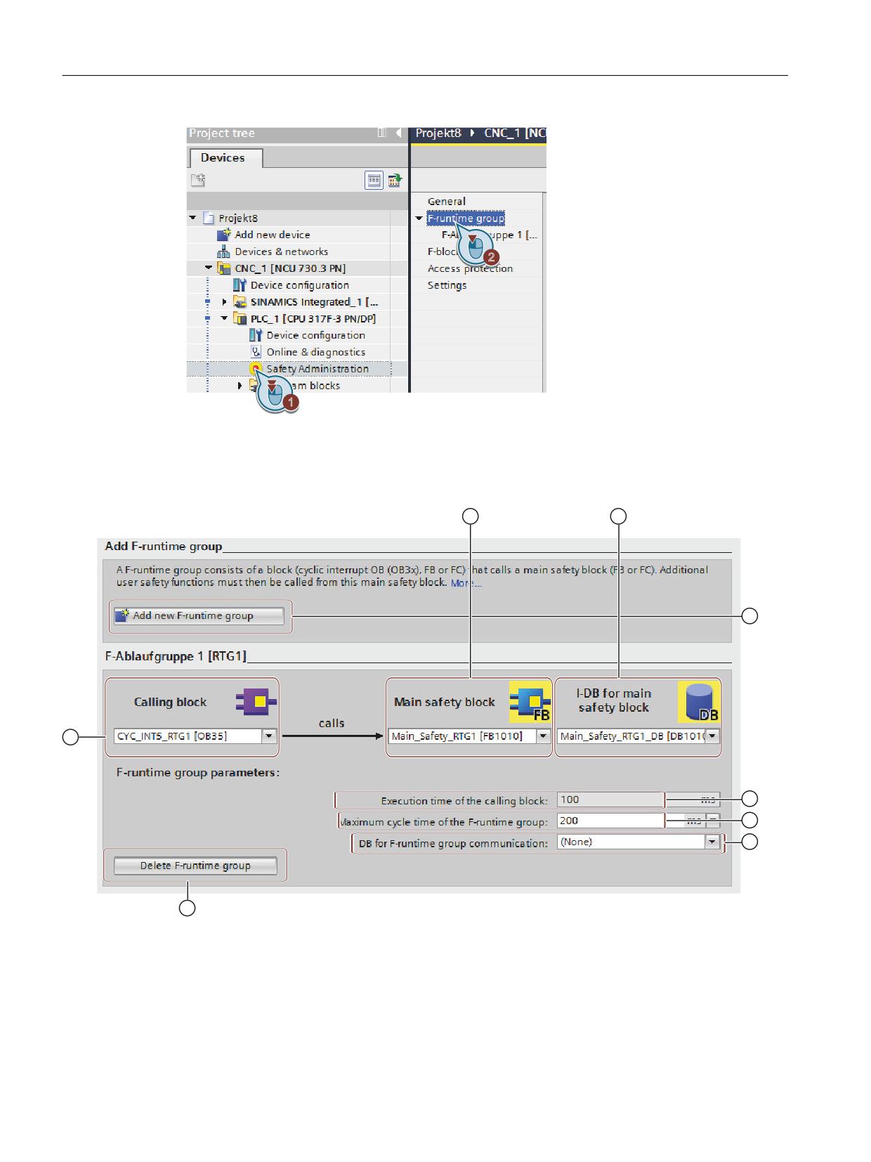
Safety program of the F-PLC
4.6 F-runtime groups
Figure 4-10
Displaying the "F runtime group" work cell
"F runtime group" work cell
Figure 4-11
Safety Administration Editor, "F runtime group" work cell
① Calling block
The default value is "CYC_INT5_RTG1 [OB35]", a cyclic interrupt OB.
Safety Integrated plus
62
Commissioning Manual, 10/2020, 6FC5397-1FP40-6BA4
Safety program of the F-PLC
4.6 F-runtime groups
The advanvariablee of using cyclic interrupt OBs is that they interrupt the cyclic program
execution in OB 1 of the standard user program at fixed time intervals; that is, the safety program
is called and executed at fixed time intervals in a cyclic interrupt OB.
Programming language
In the drop-down list "Calling block", you can only select blocks that were generated in the
programming languages LAD, FBD or STL.
If you want to call the main safety block in a block that was created in another programming
language, you must program this call itself. The text box is then inactive (grayed out), and you
cannot change the call in the Safety Administration Editor, but only in the calling block.
Rules:
• The main safety block may only be called once from a standard block. Calling the block a
multiple number of times can result in the F-PLC going into a STOP.
• To optimally utilize the temporary local data, you must call the F runtime group (the main
safety block) directly in an OB (if at all possible, a cyclic interrupt OB); in this cyclic interrupt
OB you should not declare any additional temporary local data.
• Within a cyclic interrupt OB, the F runtime group should be executed before the standard
user program, i.e. should be located right at the beginning of the OB so that the F runtime
group is always called at fixed intervals in time, independent of how long it takes to process
the standard user program.
This is also the reason that the cyclic interrupt OB should not be interrupted by higher-priority
alarms.
② Main safety block
In the "Number" text field, enter a free block number reserved for SINUMERIK Safety Integrated
plus: 1010..1019.
Rules:
• F-FBs can be used in several F-runtime groups; however, they must be called with different
instance DBs.
• F-FCs can always be called in several F-runtime groups.
③ I-DB for the main safety block
In the "Number" text field, enter a free block number reserved for SINUMERIK Safety Integrated
plus: 1010..1019.
Rules:
• Instance DBs may only be accessed from the F-runtime group in which the associated F-FB is
called
④ Create a new F-runtime group
Using this command, you can create a second F-runtime group; for example, to organize safety-
related program sections that are executed quickly, in their own dedicated F-runtime group.
⑤ Execution time of the calling block
You can adapt the cyclic execution time of the calling block under "Alarms > Cyclic interrupts" in
the PLC properties.
Safety Integrated plus
Commissioning Manual, 10/2020, 6FC5397-1FP40-6BA4
63
Safety program of the F-PLC
4.6 F-runtime groups
⑥ Maximum cycle time of the F-runtime group
In the the F-runtime group, the F-PLC monitors the F-cycle time For "Maximum cycle time of the
F-runtime group", select the maximum time that may elapse between two calls of this F-runtime
group.
The F-runtime group call interval is monitored for the maximum value; i.e. monitoring is
performed to determine whether the call is executed often enough, but not whether it is
executed too often. Therefore, failsafe times must be implemented using instructions TP, TON
or TOF from the task card "Instructions" and not using a counter (OB calls). (S007)
⑦ DB for F-runtime group communication
If one F-runtime group is to provide variables for evaluation to another F-runtime group of the
safety program, assign a DB for F-runtime group communication. Select an F-DB for "DB for F-
runtime group communication".
Rules:
• It is only permissible to access an F-communication DB from an F-runtime group.
• A DB for F-runtime group communication may read and write to the F-runtime group, for
which you set up a DB; the "receiving" F-runtime group may only read this F-DB.
• Individual variables of the F-runtime group DB may only be used in their own F-runtime
group.
⑧ Delete F-runtime group
This command deletes the assignment of the F blocks to an F-runtime group. You may have to
carry out additional steps if you wish to delete your safety program.
4.6.3
F-global DB
Function
The F-shared DB is a fail-safe data block that contains all of the shared data of the safety program
and additional information needed by the F-system. The F-shared DB is automatically inserted
when the hardware configuration is compiled.
Using its name F_GLOBDB, you can evaluate certain data elements of the safety program in the
standard user program.
Reading an F-shared DB in the standard user program
You can read out the following information in the F-shared DB in the standard user program or
on an operator control and monitoring system:
• Operating mode: safety mode or disabled safety mode ("MODE" tag)
• Error information "Error occurred when executing safety program" ("ERROR" tag)
• Collective F-signature ("F_PROG_SIG" tag)
• Compilation date of the safety program ("F_PROG_DAT" tag, DATE_AND_TIME data type)
Safety Integrated plus
64
Commissioning Manual, 10/2020, 6FC5397-1FP40-6BA4
Safety program of the F-PLC
4.6 F-runtime groups
You use fully qualified access to access these tags (e.g. ""F_GLOBDB".MODE").
Safety Integrated plus
Commissioning Manual, 10/2020, 6FC5397-1FP40-6BA4
65

Safety program of the F-PLC
4.7 Creating F-blocks
4.7
Creating F-blocks
Introduction
In order to create F-FBs, F-FCs, and F-DBs for the safety program, you should follow the same
basic procedure as for standard blocks. In the following, only the deviations from the procedure
for standard blocks are presented.
Creating F-FBs, F-FCs, and F-DBs
You create F-blocks in the same way as for standard blocks. Proceed as follows:
1. Double-click on "Add new block" under "Program blocks" in the project tree.
2. In the dialog that appears, specify the type, name, and language and select the "Create F-
block" check box. (If you do not select the check box, a standard block is created.)
3. After the dialog is confirmed, the F-block is opened in the Program editor.
Note the following
Note the following important instructions:
Note
The main safety block must not contain any parameters, as they cannot be provided with actual
values when the block is called.
Note
It is not permissible to edit the start values in instance DBs of F-FBs online and offline - and this
can result in the F-PLC going into STOP mode.
Note
It is not permitted to access static local data in single instances or multi-instances of other F-FBs.
Note
Outputs of F-FCs must always be initialized.
If this is not complied with, then the F-PLC can go into STOP. The cause of the diagnostic result
is entered in the diagnostics buffer of the F-PLC. You can find additional information on the cause
in the online help for diagnostic messages.
Note
If you wish to assign an operand from the data area (data block) to a formal parameter of an F-
FC as an actual parameter, you must use fully qualified DB access.
Safety Integrated plus
66
Commissioning Manual, 10/2020, 6FC5397-1FP40-6BA4

Safety program of the F-PLC
4.7 Creating F-blocks
Note
Note that access to the inputs in an F-FB/F-FC is read-only, while access to the outputs is write-
only.
Use an in/out if you wish to have both read and write access.
Note
For greater clarity, assign unique symbolic names to the F-blocks you have created. These
symbolic names appear in the project tree and in the block interface. Symbolic names are
assigned in the same way as for standard blocks.
Copying/pasting F-blocks
You can copy F-FBs, F-FCs, and F-DBs in exactly the same was as blocks of the standard user
program.
Exception:
You must not copy blocks from the folder "Program blocks > System blocks".
Nesting depth for F-FBs and F-FCs
We recommend that you do not exceed a nesting depth of 8 levels.
Safety Integrated plus
Commissioning Manual, 10/2020, 6FC5397-1FP40-6BA4
67
Safety program of the F-PLC
4.8 Using libraries
4.8
Using libraries
Introduction
As with standard blocks, you have the option of storing F-blocks which you wish to reuse as
master copy or types in global libraries or in the project library.
Additional information can be found in the help for STEP 7 under "Using libraries".
Reusing F-blocks which have already been tested and accepted
Please note the following when reusing F-blocks which have already been tested and if
applicable also accepted:
• Document the signature and start value signature of the F-block after you have compiled,
tested and possibly accepted the F-block.
• Document the version set for "Instructions (without their own version)" in the Safety
Administration Editor under "Settings"/"System library elements used in safety program".
For documentation purposes, you can create a safety summary of the safety program you
used to create the F-block.
• When re-using the F-block, carefully ensure that the signature and start value signature of
the F-block have not been changed.
For F-blocks with instructions for which a version is indicated in the "Version" column of the
"Instructions" task card, you must also note the following:
• Document the versions of these instructions that were set at the time the F-block was
compiled and on the basis of which the F-block was tested and, if applicable, approved.
You can use the safety summary for documentation purposes.
• When using the F-block again make sure that the documented versions are set for these
instructions in the "Instructions" task card.
• If versions other than the documented versions are set for these instructions, you must check
yourself whether the F-block still works with these versions as intended.
To do so, identify any differences between the versions based on the online help on the
instructions.
You need to have the F-block retested and accepted. Additional information on the
instruction versions can be found in the help for STEP 7 under "Fundamentals for instruction
versions".
To help you manage F-blocks that you wish to reuse and that have already been tested and if
applicable accepted, we recommend that you save these blocks as types in a global library.
Safety Integrated plus
68
Commissioning Manual, 10/2020, 6FC5397-1FP40-6BA4

Safety program of the F-PLC
4.9 Safety-relevant communication
4.9
Safety-relevant communication
Options for safety-related communication
Safety-related communication
On subnet
Additional hardware
required
I-slave-slave communication
PROFIBUS DP
-
Safety-related CPU-CPU communication:
IO controller-IO controller communica-
PROFINET IO
PN/PN coupler
tion
Master-master communication
PROFIBUS DP
DP/DP coupler
IO controller-I-device communication
PROFINET IO
-
Master-I-slave communication
PROFIBUS DP
-
I-slave-I-slave communication
PROFIBUS DP
-
IO controller-I-slave communication
PROFINET IO and PROFIBUS DP
IE/PB link
Safety-related communication via S7
Industrial Ethernet
-
connections
IO controller-IO controller communica-
PROFINET IO
PN/PN coupler
tion for S7 Distributed Safety
Master-master communication for S7 Dis-
PROFIBUS DP
DP/DP coupler
tributed Safety
Safety-related communication to S7 Dis-
Industrial Ethernet
-
tributed Safety or S7 F Systems via S7
connections
Additional information
Additional information and configuration graphics are provided in the help for SIMATIC STEP 7
Safety Advanced in Chapter "Safety-relevant communication".
Safety Integrated plus
Commissioning Manual, 10/2020, 6FC5397-1FP40-6BA4
69
Safety program of the F-PLC
4.10 Access to SI-drives and F-I/O
4.10
Access to SI-drives and F-I/O
Overview
A description is subsequently provided as to how you can access the F-I/O and the safety-relevant
drive telegrams; certain issues are also explained, that you must take into account when
programming this access.
Access via the process image
You access F-I/O and drive telegrams (just the same as standard I/O and standard drive
telegrams) via the process image (PAE and PAA).
Access is only permissible via the data type specified for the particular channel.
Example: You can only access input channels, data type BOOL in the process image of the inputs
of F I/O via unit "Input (bit)" (E x.y). It is not possible to access 16 consecutive input channels, data
type BOOL via unit "Input word" (EW x).
It is not permissible to directly access drive telegrams or F-I/O. Inputs or outputs of the F-I/O or
drive telegrams, which you wish to access, must be activated in the hardware configuration. The
channel value of an F-I/O or a drive telegram may only be accessed from a joint F-runtime group.
The process image of the inputs is updated at the start of the F-runtime group. The process
image of the outputs is updated at the end of the F-runtime group (see Structure of the safety
program (Page 47)).
The actual communication between F-PLC (process image) and the F-I/O or drive telegram to
update the process image is realized in the backg12round using a special security protocol
according to PROFIsafe.
If, between the F-PLC (S7-300) and the F-I/O, you insert an additional component, which copies
the safety telegram according to PROFIsafe between the F-PLC (S7-300) and the F-I/O using the
user program, then for each change to the user-programmed copy function, you must carefully
test all of the safety functions involved with the copy function. (S049)
Note
As a result of the special safety protocol, F-I/O and drive telegrams occupy a larger area of the
process image than is required by real channels available on the F-I/O or the drive telegram
(channel values and value status).
To find the area of the process image where the channels are stored, refer to the
relevant manuals for the F-I/O. When the process image is accessed in the safety program, only
the channels that are actually present may be accessed.
Note that for certain F-I/O (such as ET 200SP failsafe modules or ET 200MP fail-safe modules),
a "1oo2 evaluation of the sensors" can be specified. To find out which of the channels combined
by the "1oo2 evaluation of the sensors" you can access in the safety program, refer to the
relevant manuals for the F-I/O.
Safety Integrated plus
70
Commissioning Manual, 10/2020, 6FC5397-1FP40-6BA4
Safety program of the F-PLC
4.10 Access to SI-drives and F-I/O
Additional information
Additional information is provided in the help for SIMATIC STEP 7 Safety Advanced in the
following chapters:
• Data transfer from the safety to the standard user program
(Information on updating the process image)
• Safety-relevant I-slave-slave communication - F-I/O access
Also observe the documentation on the relevant F-I/O - as well as on the safety-relevant drive
telegrams.
Safety Integrated plus
Commissioning Manual, 10/2020, 6FC5397-1FP40-6BA4
71
Safety program of the F-PLC
4.11 Programming startup protection
4.11
Programming startup protection
Introduction
Initiating a STOP state, e.g. using PG/PC operator action, mode switch, communication function
or "STP" instruction - as well as maintaining a STOP state - are not safety relevant. This STOP state
can be very simply (also inadvertently) withdrawn, e.g. with an appropriate operator action at
the PG/PC.
When an F-CPU is switched from STOP to RUN mode, the standard user program starts up in the
usual way. When the safety program is started up, all F-DBs are initialized with the values from
the load memory - as is the case with a cold restart. This means that saved error information is
lost. The F-system automatically reintegrates the F-I/O. If your process does not allow such a
startup, you must program a restart/startup protection in the safety program: The output of
process data must be blocked until manually enabled. It is only permissible to issue the enable
after process values can be output without incurring any risk, and faults have been removed.
Example of restart/startup prevention
In order to implement a restart/startup prevention, it must be possible to detect a startup. To
detect a startup, in an F-DB declare a variable, data type BOOL with start value "TRUE".
Block the output of the process values if this variable has the value "1", e.g. by passivating F-I/O
using variable PRESS_ON in the F-I/O DB.
To manually enable the output of process data, you reset this tag by means of a user
acknowledgment.
Additional information
Additional information is provided in the help for SIMATIC STEP 7 Safety Advanced in the
following chapters:
• F-I/O DB
• Implementing a user acknowledgment
Safety Integrated plus
72
Commissioning Manual, 10/2020, 6FC5397-1FP40-6BA4
Safety program of the F-PLC
4.12 Implementing a user acknowledgment
4.12
Implementing a user acknowledgment
Send data must be reintegrated after communication, channel and F-I/O faults.
The existing operations provide the following options:
• Parameter "ACK_REI":
Special acknowledgment for the reintegration for each F-I/O
• Safety function "ACK_GL":
Acknowledgment to simultaneously reintegrate all F-I/O of an F-runtime group
In your safety program, you must always provide the possibility of acknowledging the
reintegration of F-I/O. You can implement the user acknowledgment as follows:
• User acknowledgment using an operating control and monitoring system
• User acknowledgment using an acknowledgment button at one of the F-I/O
- Assigning the inputs to the F-CPU of the I-slave/I-device
- Assigning the inputs to the F-CPU of the DP master/IO controller
Additional information
• Implementing user acknowledgment for global reintegration (Page 228)
• You can find additional information and examples in the help for SIMATIC STEP 7 Safety
Advanced under keywords "ACK_REI", "ACK_GL" as well as in Chapter "Implementing a user
acknowledgment".
Safety Integrated plus
Commissioning Manual, 10/2020, 6FC5397-1FP40-6BA4
73

Safety program of the F-PLC
4.13 Data exchange between the standard user program and safety program
4.13
Data exchange between the standard user program and safety
program
You have the option of transferring data between the safety program and the standard user
program. Tags can be transferred using DBs, F-DBs and bit memory:
From the standard user program
From the safety program
Read access
Write access
Read access
Write access
Tag from DB
Permitted
Permitted
A tag from the DB can be read-accessed or write-
accessed
Tag from F-DB
Permitted
Not permitted
Permitted
Permitted
Bit memory
Permitted
Permitted
Bit memory can be read-accessed or write-ac-
cessed
You can also access the process image of the standard I/O and F-I/O:
From the standard user program
From the safety program
Read access
Write access
Read access
Write access
Process image
PII
Permitted
Permitted
Permitted
Not permitted
standard I/O
PIQ
Permitted
Permitted
Not permitted
Permitted
Process image
PII
Permitted
Not permitted
Permitted
Not permitted
F-I/O
PIQ
Permitted
Not permitted
Not permitted
Permitted
Decoupling of the safety program from the standard program in case of data transfer
For data exchange between standard user program and safety program, we recommend that
you define special data blocks (transfer blocks) in which the data to be exchanged is stored. This
action allows you to decouple the blocks of the standard and the safety program. The changes
in the standard program do not affect the safety program (and vice versa) provided these data
blocks are not modified.
Safety Integrated plus
74
Commissioning Manual, 10/2020, 6FC5397-1FP40-6BA4
Safety program of the F-PLC
4.13 Data exchange between the standard user program and safety program
4.13.1
Data Transfer from the Safety Program to the Standard User Program
Overview
The standard user program can read out all data of the safety program, e.g. using symbolic (fully
qualified) access operations to:
• The instance DBs of the F-FBs ("Name of instance DB".Signal_x)
• F-DBs (for example "Name of F_DB".Signal_1)
• The process image of the inputs and process image of the outputs of F-I/O (for example
"Emergency_Stop_Button_1" (I 5.0))
Note
Process image of the inputs and outputs: Access and update
The process image of the inputs of F-I/O is updated not only at the start of the main safety
block, but also by the standard operating system.
To find the standard operating system update times, refer to the Help on STEP 7 under
"Process image of the inputs and output". For F-CPUs that support process image partitions,
also bear in mind the update times when process image partitions are used. For this reason,
when the process image of the inputs of F-I/O is accessed in the standard user program, it is
possible to obtain different values than in the safety program. The differing values can occur
due to:
• Different update times
• Use of failsafe values in the safety program
To obtain the same values in the standard user program as in the safety program, you must
not access the process image of the inputs in the standard program until after execution of
an F-runtime group. In this case, you can also evaluate the QBAD or QBAD_I_xx variable in the
associated F-I/O DB in the standard user program, in order to find out whether the process
image of the inputs is receiving failsafe values (0) or process data. When using process image
partitions, also make sure that the process image is not updated by the standard operating
system or by the UPDAT_PI instruction between execution of an F-runtime group and
evaluation of the process image of the inputs in the standard user program.
Further, you have the option of directly writing safety program data to the standard user
program (see also table of the supported operand areas in: Restrictions in the programming
languages FBD/LAD (Page 52)):
Data block/bit memory
In order to write safety program data directly to the standard user program (e.g. DIAG output of
the SENDDP instruction), you can write to data blocks of the standard user program from the
safety program. However, a written variable must not be read in the safety program itself.
You can also write to bit memory in the safety program. However, written bit memory must not
be read in the safety program itself.
Safety Integrated plus
Commissioning Manual, 10/2020, 6FC5397-1FP40-6BA4
75

Safety program of the F-PLC
4.13 Data exchange between the standard user program and safety program
Process image of the outputs
You can write to the process image of the outputs (PIQ) of standard I/O in the safety program,
for example for display purposes. The PIQ must not be read in the safety program.
4.13.2
Data Transfer from Standard User Program to Safety Program
Overview
It is only permissible that failsafe data or failsafe signals from the F-I/O and other safety programs
(in other F-CPUs) are processed in the safety program, as all variables from the standard program
are not secured.
If you have to process variables from a standard user program in the safety program, then you
can either evaluate bit memories from the standard user program, variables from a standard DB
or the process image of the inputs (PII) from the standard I/O in the safety program (see also the
table of the supported operand areas in: Restrictions in the programming languages FBD/LAD
(Page 52)).
However, note that structural changes to standard DBs, which are used in the safety program,
can result in inconsistencies of the safety program so that the password is possibly queried as a
consequence. In this case, the F-collective signature after compilation corresponds to the
original one. To avoid this effect, use "Coupling data blocks" between the standard user program
and the safety program.
WARNING
Unexpected machine motion when using non-failsafe data
Bit memories from the standard user program, variables of a standard DB or the process image
of inputs (PAE) of the standard I/O are not failsafe data. Hazardous states can occur in the
machine if you evaluate non-failsafe data in the safety program. This can put people in
dangerous situations or cause material damage.
• Check the standard data in the safety program for plausibility.
• If you use standard data in both F-runtime groups, then separately check the plausibility in
both F-runtime groups.
To make checking easier, when printing out the safety program, all PLC variables from the
standard user program, which are evaluated in the safety program, are printed out.
Bit memory
In order to process variables of the standard user program in the safety program, you can also
read bit memory in the safety program. However, read bit memory must not be written in the
safety program itself.
Safety Integrated plus
76
Commissioning Manual, 10/2020, 6FC5397-1FP40-6BA4