SINUMERIK 840D sl. Service - Safety Integrated. Manual (2020) - page 13
Safety program of the F-PLC
4.13 Data exchange between the standard user program and safety program
Data block
In order to process variables of the standard user program in the safety program, you can read
variables from data blocks of the standard user program in the safety program. However, a read
variable must not be written in the safety program itself.
Process image of the inputs
You can read the process image of the inputs (PII) of standard I/O in the safety program. The PII
must not be written in the safety program.
Examples: Programming validity checks
• Check non-safety relevant variables from the standard user program using operations to
compare whether a permissible upper/lower limit is violated (exceeded/fallen below). You
can then influence your safety function with the result of the comparison.
• With non-safety-related variables from the standard user program, for example, using
operations "S: set output", "R: reset output" or "SR: set/reset flip-flop" only allow the motor to
be switched off, but do NOT allow it to be switched on.
• For switch-on sequences, use the AND logic operation instruction, for example, to logically
combine unsafe variables from the standard user program with switch-on conditions that
you derive from failsafe variables.
If you want to process standard variables in the safety program, please bear in mind that there
is not a sufficiently simple method of checking validity for all unsafe variables.
Reading out variables that can be changed from the standard user program
If, in the safety program, you wish to read variables from the standard user program (bit
memories, variables of a standard DB or PII of the standard I/O), which - during the runtime of
the F-runtime group in which they are being read - can be changed by the standard user program
or an HMI system - for example, because your standard user program is processed by a higher
priority cyclic interrupt - then you must use separate bit memories or variables of a standard DB.
We recommend that you select the phase offset so that the standard OB is processed
immediately before the F-OB.
You must write variables from the standard user program to these bit memories or variables of
a standard DB before calling the F-runtime group.
You are then permitted to access only this bit memory or these variables of a standard DB in the
safety program.
Also note that the clock memory, which you defined under tab "Properties" when configuring the
F-CPU, can change during the runtime of the F-runtime group. This is because the clock memory
runs asynchronously to the F-CPU cycle.
Note
If this is not complied with, then the F-PLC can go into STOP. The cause of the diagnostic result
is entered in the diagnostics buffer of the F-PLC. You can find additional information on the cause
in the online help for diagnostic messages.
Safety Integrated plus
Commissioning Manual, 10/2020, 6FC5397-1FP40-6BA4
77
Safety functions integrated in the drive
5
5.1
Introduction to Safety Integrated Functions
This chapter provides the following information on the individual safety functions integrated in
the drive:
• Basic principle of operation
• Example of how they are used
• Details and parameterization required, for example when commissioning using the
parameter list/parameter view.
A shorter description on how to commission the safety functions using SINUMERIK Operate
screen forms is available at Configuring safety functions integrated in the drive (Page 256).
Note
Difference between Basic Functions and Extended Functions
Basic Functions are designated as such in the chapter headings. Chapters that are not designated
as Basic Functions, refer to Extended Functions.
Note
Term "Control Unit" in this documentation
In the Safety Integrated environment and in this documentation the term "Control Unit"
designates the SINUMERIK NCU.
Safety Integrated plus
Commissioning Manual, 10/2020, 6FC5397-1FP40-6BA4
79
Safety functions integrated in the drive
5.2 SS1 Basic:
5.2
SS1 Basic:
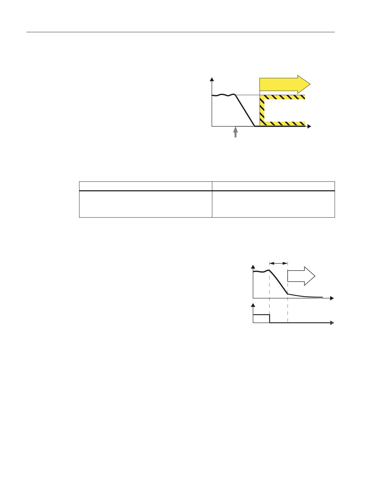
Definition according to EN 61800-5-2:
Y
"The SS1 function brakes the motor and ini-
STO
tiates the STO function after a delay time."
W
Select SS1
Example of how the function can be used
Example
Possible solution
A central Emergency Stop button ensures that several
• Evaluating an Emergency Stop pushbutton in
drives are braked as quickly as possible and brought
an F-PLC
into the STO state.
• Select SS1 via PROFIsafe.
How does SS1 function in detail?
Overview
6DIH 6WRS GHOD\
WLPH
The drive decelerates once "Safe Stop 1" has
6SHHG
been selected, and goes into the "Safe Torque
Off" state once the delay time has expired.
672
W
'HVHOHFW 66
7HUPLQDOV RU
352),VDIH
FRQWURO ZRUG
W
Select SS1
As soon as the converter identifies that SS1 has been selected via a terminal or via PROFIsafe safe
communication, the following happens:
• If, when selecting SS1, the motor is already switched off, then until the SS1 delay time
expires, there is no response. STO becomes active after the time expires.
• If the motor is switched on when SS1 is selected, the converter brakes the motor with the
OFF3 ramp-down time. STO is automatically initiated after the delay time has expired.
Safety Integrated plus
80
Commissioning Manual, 10/2020, 6FC5397-1FP40-6BA4
Safety functions integrated in the drive
5.2 SS1 Basic:
5.2.1
Details and parameterization
5.2.1.1
SS1 with OFF3
The "Safe Stop 1" (SS1) function allows the drive to be stopped in accordance with EN 60204-1,
Stop Category 1. The drive decelerates with the OFF3 ramp (p1135) once "Safe Stop 1" is
selected and switches to "Safe Torque Off" once the delay time set in p9652 has elapsed.
Note
Selection via terminals
The selection of the "Safe Stop 1" (time-controlled) function via terminals is parameterized by
setting a delay > 0 in p9652. In this case, the STO function can no longer be selected directly via
terminals, i.e. either STO or SS1 can be selected via terminals.
If the "Safe Stop 1" (time-controlled) function has been selected by parameterizing a delay time
in p9652, STO can no longer be selected directly via terminals.
Functional features of Safe Stop 1
SS1 is enabled by p9652 (delay time) ≠ 0.
• Setting parameter p9652 has the following effect:
- p9652 = 0
SS1 is not enabled. Only STO can be selected via the onboard terminals and PROFIsafe.
- p9652 > 0
SS1 is enabled. Only SS1 can be selected via the onboard terminals; with PROFIsafe, a
selection of SS1 and STO is possible.
• When SS1 is selected, the drive is braked along the OFF3 ramp (p1135) and STO/SBC is
automatically initiated after the delay time has expired (p9652).
After the function has been selected, the delay timer runs down - even if the function is
deselected during this time. In this case, after the delay time has expired, the STO/SBC
function is selected and then again deselected immediately.
Note
Setting the delay time
So that the drive is able to travel down the OFF3 ramp completely and any motor holding
brake present can be applied, before the pulses have been safely deleted, the delay time
should be set as follows:
• Motor holding brake parameterized: Delay time p9652 ≥ p1135 + p1228 + p1217
• Motor holding brake not parameterized: Delay time p9652 ≥ p1135 + p1228
• The setting of parameter p1135 must be oriented towards the actual braking capability
of the drive.
Safety Integrated plus
Commissioning Manual, 10/2020, 6FC5397-1FP40-6BA4
81

Safety functions integrated in the drive
5.2 SS1 Basic:
• The timer (p9652) after whose expiration STO is activated, is implemented with two
channels, although deceleration along the OFF3 ramp is only one channel.
• Effect on "Setpoint speed limit effective" (r9733[0...2]):
For SS1 (≙ STOP B), setpoint 0 is specified in r9733[0...2].
Requirement
• The Basic Functions are enabled via terminals and/or PROFIsafe:
- p9601 = 1, 8 or 9 (hex).
• In order that the drive can brake down to a standstill even when selected through one
channel, the time in p9652 must be shorter than the sum of the parameters for the crosswise
data comparison (p9650 and p9658). Otherwise the drive will coast down after the time
p9650 + p9658 has elapsed.
Status of Safe Stop 1
You can check the status in the SI diagnostics screens via "MENU SELECT > Diagnostics > Menu
forward key > Safety".
5.2.1.2
SS1 with external stop (SS1E)
In drive line-ups (e.g. drives that are mechanically connected via the material), the drive-
independent braking on the respective OFF3 ramp can cause problems. If the SS1E function is
used, the safe delay time (p9652) is started when the function is selected, but no OFF3 is
triggered. The higher-level controller still enters the setpoint.
Note
The function is configurable - however, the braking behavior using SS1E is not supported by the
NC (path stop).
WARNING
Axis motion that is not monitored
During the unmonitored delay time, for "Safe Stop 1 (time-controlled) with external stop", axis
motion is possible that is not monitored. This motion can result in death or severe injury.
• If there is a hazard due to undesirable motion in your application, take measures to counter
it, for example, by using a brake with safe monitoring. For additional information, see
Chapter "SBC (Basic/Extended) (Page 97)".
Safety Integrated plus
82
Commissioning Manual, 10/2020, 6FC5397-1FP40-6BA4
Safety functions integrated in the drive
5.2 SS1 Basic:
Differences between "SS1 with OFF3" and "SS1 with external stop"
"SS1 with OFF3" and "SS1 with external stop" have the following differences:
• In order to activate "Safe Stop 1 with external stop", additionally set p9653 to 1.
• When SS1E is selected, the drive is not braked along the OFF3 ramp, but after the delay time
has expired (p9652), only STO/SBC is automatically initiated.
5.2.1.3
Function diagrams and parameters
Function diagrams (see SINAMICS S120/S150 List Manual)
•
2810
SI Basic Functions - STO (Safe Torque Off), SS1 (Safe Stop 1)
•
2811
SI Basic Functions - STO (Safe Torque Off), safe pulse cancellation
Overview of important parameters (see SINAMICS S120/S150 List Manual)
• p1135[0...n]
OFF3 ramp-down time
• p1217
Motor holding brake closing time
• p1228
Pulse cancellation delay time
• p9601
SI enable functions integrated in the drive (Control Unit)
• p9652
SI Safe Stop 1 delay time (Control Unit)
• r9772.0...23
CO/BO: SI Status (Control Unit)
• r9773.0...23
CO/BO: SI Status (Control Unit + Motor Module)
• r9774.0...23
CO/BO: SI Status (group STO)
Only for "Safe Stop 1 (time-controlled) with external stop"
• p9653
SI Safe Stop 1 drive-based braking response
Safety Integrated plus
Commissioning Manual, 10/2020, 6FC5397-1FP40-6BA4
83
Safety functions integrated in the drive
5.3 SS1
5.3
SS1
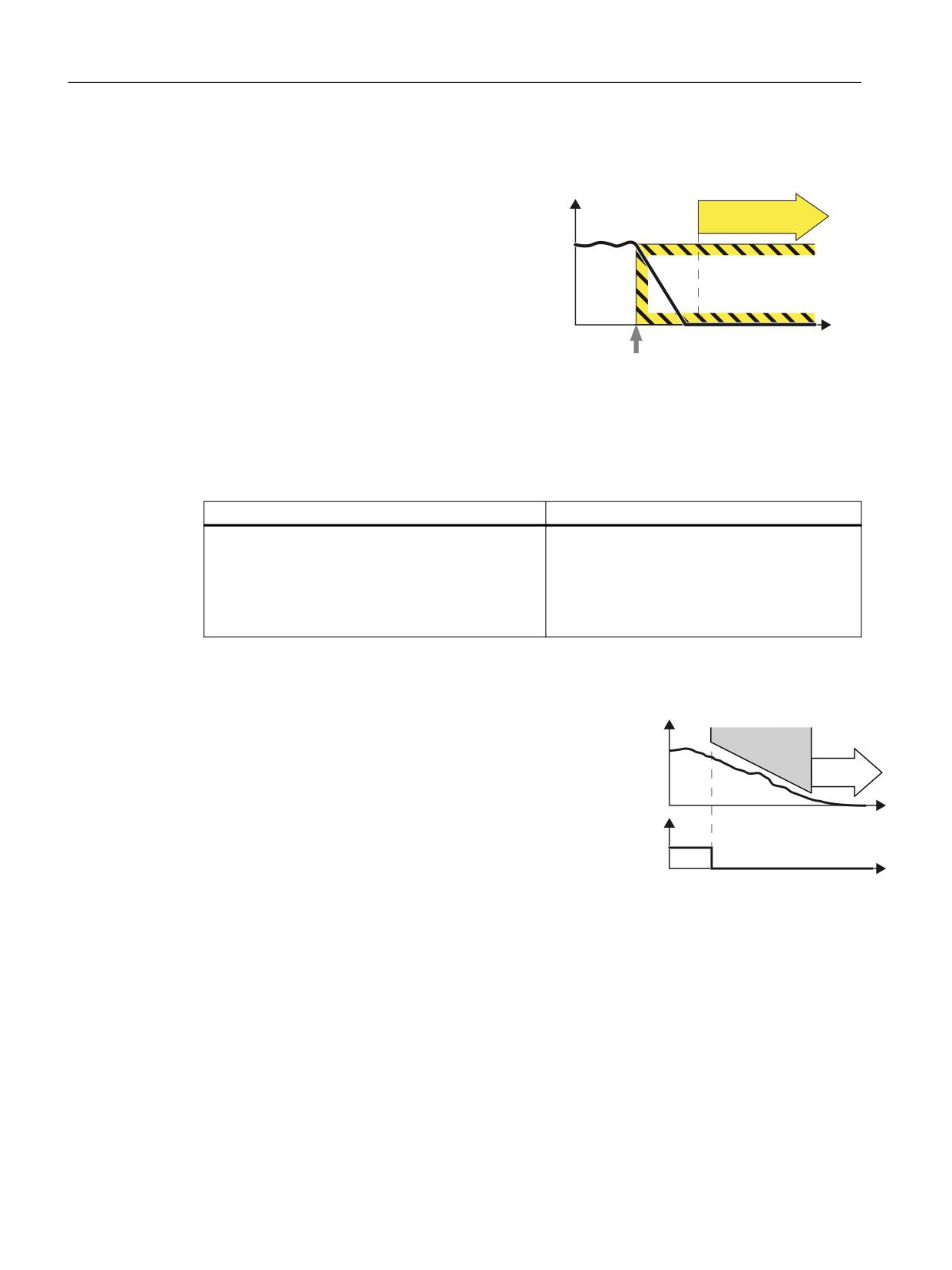
Definition according to EN 61800-5-2:
Y
The "SS1" function causes the motor to brake
STO
(this function is integrated in the drive) and ini-
tiates the "Safe Torque Off" (STO) function after a
predefined time interval has elapsed. The follow-
ing variants are possible:
• SS1-a with acceleration monitoring (SAM)
W
• SS1-r with braking ramp monitoring (SBR)
• Manually set delay time until STO is activated.
Select SS1
This function corresponds to stop category 1 to
EN 60204-1.
Example of how the function can be used
Example
Possible solution
A central Emergency Stop button ensures that several
• Evaluating an Emergency Stop pushbutton in
drives are braked as quickly as possible and brought
an F-PLC
into the STO state.
• Select SS1 via PROFIsafe.
• SS1 brakes the drives and then brings them
into the STO state.
How does SS1 function in detail?
Overview
6SHHG
0RQLWRULQJ
Using the SS1 function, the converter brakes the
motor and monitors the absolute speed.
672
If the motor speed is low enough or the delay
time has expired, the converter safely switches
W
66
GHVHOHFWLRQ
off the motor torque using STO.
352),VDIH
FRQWURO ZRUG
W
Select SS1
As soon as the converter identifies that SS1 has been selected via the PROFIsafe safe
communication, the following happens:
• If the motor has already been switched off when selecting SS1 then the converter safely
switches off the motor torque (STO).
• If the motor is switched on when SS1 is selected, the converter brakes the motor with the
AUS3 ramp-down time.
Safety Integrated plus
84
Commissioning Manual, 10/2020, 6FC5397-1FP40-6BA4
Safety functions integrated in the drive
5.3 SS1
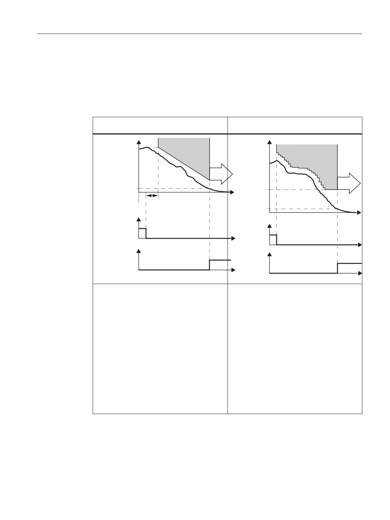
Monitoring modes
• For the Extended Functions with or without encoder, you can choose between 2 different
monitoring modes of the function SS1:
- Safe Brake Ramp (SBR)
- Safe Acceleration Monitor (SAM)
Brake ramp monitoring
Acceleration monitoring
(with or without encoder)
(with or without encoder)
6SHHG
6SHHG
6%5
6$0
6WDQGVWLOO
672
PRQLWRULQJ
6KXWGRZQ
672
YHORFLW\
W
'HOD\ WLPH IRU EUDNH UDPS
6KXWGRZQ
VSHHG 66
66
GHVHOHFWLRQ
W
352),VDIH
66
GHVHOHFWLRQ
FRQWURO ZRUG
352),VDIH
FRQWURO ZRUG
W
672
W
DFWLYH
672 DFWLYH
) '2 RU
) '2 RU
352),VDIH
352),VDIH
VWDWXV ZRUG
VWDWXV ZRUG
W
W
• Using the SBR (Safe Brake Ramp) function, the
•
The converter monitors the speed of the motor
converter monitors whether the motor speed
with the SAM function.
decreases.
•
The converter prevents the motor from acceler-
• The gradient of the SBR function can be set via
ating again by having the monitoring function
the reference velocity and the ramp-down time.
continuously track the speed as it decreases.
The SBR function only starts after the "Delay for
•
The converter reduces the monitoring thresh-
braking ramp".
old until the "Shutdown speed" has been
• The SBR function starts with the speed setpoint,
reached.
which was present at the instant in time that
•
The converter safely switches off the motor tor-
SS1 was selected.
que (STO), if one of the following conditions is
• If the converter detects that the speed has fall-
fulfilled:
en below the speed threshold (standstill moni-
- The speed has fallen below the shutdown
toring), it safely switches off the motor torque
speed SS1.
(STO).
- The maximum time until the torque is
switched off has expired.
Safety Integrated plus
Commissioning Manual, 10/2020, 6FC5397-1FP40-6BA4
85
Safety functions integrated in the drive
5.3 SS1
Note
SS1 with external stop (SS1E)
If you use "SS1 with external stop", neither of the two monitoring functions (SBR, SAM) is active.
For SS1E, the drive must be stopped within the delay time, for example via the PLC program. STO
becomes active after the delay time expires.
5.3.1
Details and parameterization
5.3.1.1
Safe Stop 1 (SS1, time and acceleration controlled)
For function SS1 of the Extended Safety Functions, braking monitoring is included.
• For p9506 = 0, the following applies:
Braking is monitored with the "Safe Acceleration Monitor" function (see Chapter "SAM
(Page 137)").
In this case, we also talk about "SS1 (time and acceleration controlled)".
• For p9506 = 2, the following applies:
Braking is monitored using the "Safe Brake Ramp" function (see Chapter "SBR (Page 139)").
In this case, we also talk about "SS1 (speed controlled)".
The "Safe Stop 1" (SS1) function allows the drive to be stopped according to EN 60204-1, Stop
Category 1. The drive brakes with the OFF3 ramp (p1135) once "Safe Stop 1" is selected and
switches to "Safe Torque Off" (STO) once the delay time has elapsed (p9556) or when the
shutdown speed is fallen below (p9560).
Functional features of Safe Stop 1 with encoder
• The delay time starts after the function has been selected. If SS1 is deselected again within
this time, the STO function is selected and deselected immediately again after the delay time
has expired or if the speed drops below the shutdown speed; i.e. the SS1 function is
terminated normally. It cannot be interrupted.
• Selection and monitoring of the acceleration (SAM) or the monitoring function "Safe Brake
Ramp" are implemented in two channels, but braking along the OFF3 ramp is only
implemented in one channel.
• Effect on "Setpoint speed limit effective" (r9733[0...2]):
For SS1 (≙ STOP B), setpoint 0 is specified in r9733[0...2].
Commissioning
The delay time (SS1 time) is set by entering parameter p9556. The wait time until safe pulse
cancellation (STO) can be shortened by defining a shutdown speed in p9560.
Safety Integrated plus
86
Commissioning Manual, 10/2020, 6FC5397-1FP40-6BA4
Safety functions integrated in the drive
5.3 SS1
To enable the drive to brake to standstill after selection, the time in p9556 must be selected to
be long enough for the drive to be able to brake along the OFF3 ramp (p1135) from any speed
of the underlying process to below the shutdown speed (p9560).
Note
Setting the delay time
So that the drive is able to travel down the OFF3 ramp completely and any motor holding brake
present can be applied, the delay time should be set as follows:
• Motor holding brake parameterized: Delay time ≥ p1135 + p1228 + p1217
• Motor holding brake not parameterized: Delay time ≥ p1135 + p1228
The shutdown speed defined in p9560 must be set in such a way that coasting down (due to the
subsequent STO function) does not represent any risk for man and machine.
Responses
System fault:
1. STOP F with subsequent STOP B, followed by STOP A
2. Safety message C01711
Status of Safe Stop 1
You can check the status in the SI diagnostics screens via "MENU SELECT > Diagnostics > Menu
forward key > Safety".
5.3.1.2
Safe Stop 1 without encoder
Two encoderless Safe Stop 1 (SS1) monitoring functions can be set with parameter p9506:
• p9506 = 3: Safe monitoring of acceleration (SAM) / delay time
The function is identical to "Safe Stop 1" with encoder (Page 86).
In this case, we also talk about "SS1 (time and acceleration controlled)".
• p9506 = 1: Safe brake ramp monitoring (SBR)
In this case, there is no SS1 delay time active. The transition from SS1 to STO depends entirely
on the speed falling below the shutdown speed (p9560). You will find more information on
the function "Safe Brake Ramp (SBR)" in Chapter "SBR (Page 139)." In this case, we also talk
about "SS1 (speed controlled)".
Safety Integrated plus
Commissioning Manual, 10/2020, 6FC5397-1FP40-6BA4
87
Safety functions integrated in the drive
5.3 SS1
6HOHFWLQJ WKH 66 UDPS
$FWLYDWLRQ RI 672
6WDUW GULYH
8VHU DFWLRQ
8VHU DFWLRQ
8VHU DFWLRQ
6HW 66
VLJQDO
1RQH
6HW 2))
21 VLJQDO
5HIHUHQFH
YHORFLW\
'HVHOHFWLQJ WKH 66 UDPS
8VHU DFWLRQ
8VHU DFWLRQ
1RQH
5HVHW 66
VLJQDO
(QYHORSH
PRQLWRULQJ UDPS
6WDWRU
VSHHG
2)) UDPS
5RWRU
=HUR VSHHG
672
VSHHG
GHWHFWLRQ
6HWSRLQW
VSHHG
W
6%5 GHOD\ WLPH S
'LDJQRVWLFV
0RQLWRULQJ UDPS 'URSRXW WLPH
672 VHOHFWHG
672 DFWLYH
66 VHOHFWHG
66 DFWLYH
352),VDIH
66 DFWLYH
3RZHU UHPRYHG
W
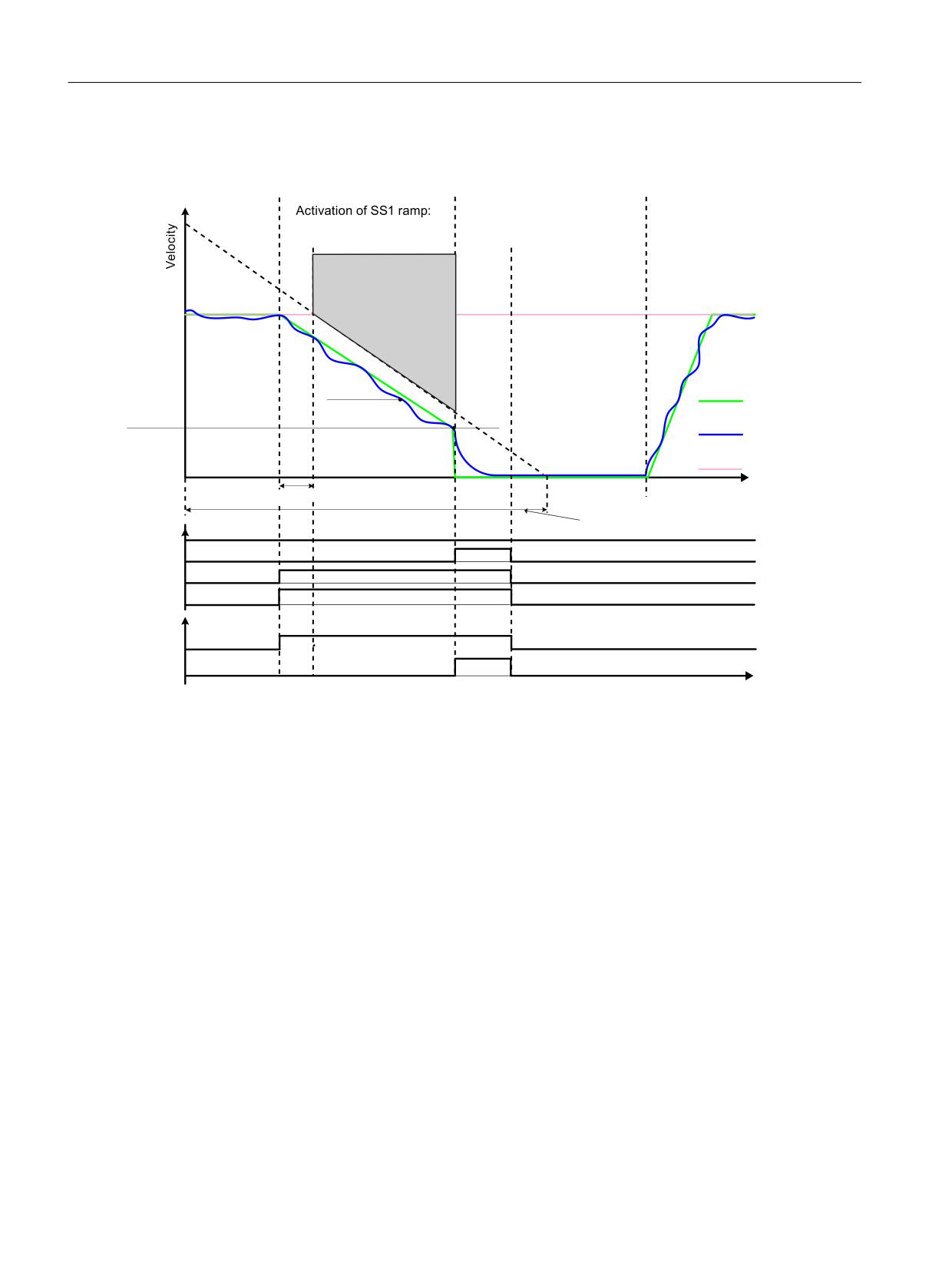
Figure 5-1
Sequence for "Safe Stop 1" without encoder with SBR monitoring (p9506 = 1)
Functional feature of Safe Stop 1 without encoder
• Selection and monitoring of the brake ramp (SBR) or the acceleration (SAM) are
implemented in two channels, however braking at the OFF3 ramp is only through one
channel.
Safety Integrated plus
88
Commissioning Manual, 10/2020, 6FC5397-1FP40-6BA4

Safety functions integrated in the drive
5.3 SS1
5.3.1.3
SS1 (Extended Functions) with external stop
General description
WARNING
Unexpected axis motion when the SS1E function is active
When the SS1E function is active, during the monitored delay time, axis motion that is not
monitored can occur. This can result in death or severe injury.
• Prevent persons from entering the hazardous area around the axis, e.g. by providing
protective doors or other suitable protective equipment.
With external stop, "Safe Stop 1" basically works exactly as described in the previous Chapters
"Safe Stop 1 with encoder (time and acceleration controlled)" and "Safe Stop 1 without encoder
(speed controlled)." Note, however, the following differences:
Differences between "Safe Stop 1 with OFF3" and "SS1 with external stop"
• In order to activate "Safe Stop 1 with external stop", additionally set p9507.3 = 1.
• When SS1 with external stop is selected, the drive is not braked along the OFF3 ramp: You
are responsible in applying suitable measures to brake the drive. After the delay time has
expired (p9556), only STO/SBC are automatically initiated. After the function has been
selected, the delay timer runs down - even if the function is deselected during this time. In
this case, after the delay time has expired, the STO/SBC function is selected and then again
deselected immediately.
• The brake ramp (SBR) and the acceleration (SAM) are not monitored and there is no standstill
detection.
• With this configuration, STO becomes active after the SS1 timer p9556 has expired; this also
applies if SBR has been configured.
• Further information can be found in Section Extended Functions (Page 323).
Constraint
Note
The function is configurable - however, the braking behavior using SS1E is not supported by the
NC (path stop).
Safety Integrated plus
Commissioning Manual, 10/2020, 6FC5397-1FP40-6BA4
89
Safety functions integrated in the drive
5.3 SS1
5.3.1.4
Function diagrams and parameters
Function diagrams (see SINAMICS S120/S150 List Manual)
•
2819
SI Extended Functions - SS1, SS2, SOS, internal STOP B, C, D, F
Overview of important parameters (see SINAMICS S120/S150 List Manual)
• p1135[0...n]
OFF3 ramp-down time
• p9501
SI Motion enable safety functions (Control Unit)
• p9506
SI Motion function specification (Control Unit)
• p9556
SI Motion STOP A delay time (Control Unit)
• p9560
SI Motion STO shutdown speed (Control Unit)
• r9722.0...15
CO/BO: SI Motion drive-integrated status signals
Only for SS1 (Extended Functions) with external stop
• p9507
SI Motion function configuration (Control Unit)
Safety Integrated plus
90
Commissioning Manual, 10/2020, 6FC5397-1FP40-6BA4
Safety functions integrated in the drive
5.4 STO (Basic/Extended)
5.4
STO (Basic/Extended)
Definition according to EN 61800-5-2:
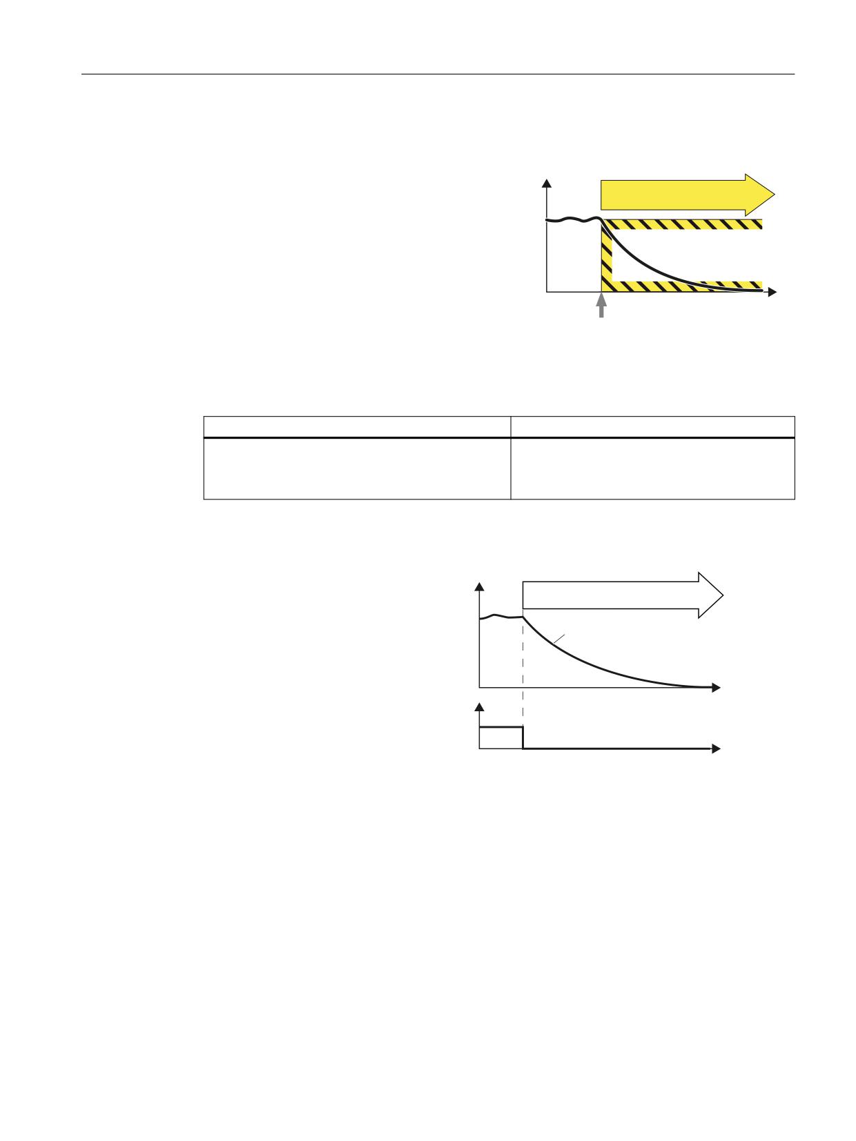
Y
"The STO function prevents energy from being
STO
supplied to the motor, which can generate a tor-
que."
W
Select STO
Examples of how the function can be used
Example
Possible solution
It is only permissible to open a protective door if the
• Select STO in the converter.
motor torque has been switched off.
• The pulses are suppressed and the motor
coasts to a standstill.
How does STO function in detail?
The converter recogni-
6SHHG
zes the selection of STO
672
via a failsafe input or via
the safe communication
7KH PRWRU WRUTXH LV
VZLWFKHG RII
PROFIsafe.
The converter then safe-
ly switches off the tor-
W
que of the connected
672 GHVHOHFWLRQ
motor.
352),VDIH FRQWURO
ZRUG
W
5.4.1
Details and parameterization
In conjunction with a machine function or in the event of a fault, the "Safe Torque Off" (STO)
function is used to safely disconnect the torque-generating energy supply to the motor.
A restart is prevented by the two-channel pulse suppression. The switching on inhibited
prevents an automatic restart after deselection of STO.
The two-channel pulse suppression function integrated in the Motor Modules / Power Modules
is the basis for this function.
Safety Integrated plus
Commissioning Manual, 10/2020, 6FC5397-1FP40-6BA4
91

Safety functions integrated in the drive
5.4 STO (Basic/Extended)
Functional features of "Safe Torque Off"
• The function is completely integrated in the drive. It can be selected via terminals or
PROFIsafe from an external source.
• The function is drive-specific, i.e. it is available for each drive and must be individually
commissioned.
• The function must be enabled via parameter.
• When the "Safe Torque Off" function is selected, the following applies:
- The motor cannot be started accidentally.
- The pulse suppression safely disconnects the torque-generating energy supply to the
motor.
- The power unit and motor are not electrically isolated.
• The selection/deselection of the STO function also acknowledges the safety faults when the
Basic Functions are used. The standard acknowledgment mechanism must also be
performed.
• Extended acknowledgment:
The selection/deselection of STO can also acknowledge the safety messages of the extended
safety functions. This means that you must configure the extended message
acknowledgment (p9507.0 = 1).
If in addition to the "Extended Functions", the "Basic Functions via terminals" are also
enabled, in addition to selection/deselection of STO via PROFIsafe (Page 332),
acknowledgement is also possible by selection/deselection of STO via terminals.
• The status of the "Safe Torque Off" function is displayed using parameters (r9772, r9872,
r9773 and r9774).
• Effect on "Setpoint speed limit effective" (r9733[0...2]):
For STO (≙ STOP A), a setpoint of 0 is specified in r9733[0...2].
WARNING
Unexpected machine motion when STO is active
After the energy feed has been disconnected (STO active) the motor can undesirably move (e.g.
the motor can coast down), therefore presenting risk to persons.
• Take suitable measures to prevent undesirable movement, e.g. by using a brake with safety-
relevant monitoring. You can find additional information in Chapter "SBC (Basic/Extended)
(Page 97)".
WARNING
Unexpected motor movement as a result of defective power transistors
Undesirable motor motion1) can occur if 2 power transistor simultaneously become defective
(breakdown of the depletion layer). This can result in accidents leading to death or severe
injury.
• Take suitable measures to prevent undesirable movement, e.g. by using a brake with safety-
relevant monitoring. You can find additional information in Chapter "SBC (Basic/Extended)
(Page 97)".
Safety Integrated plus
92
Commissioning Manual, 10/2020, 6FC5397-1FP40-6BA4
Safety functions integrated in the drive
5.4 STO (Basic/Extended)
1)
The maximum movement can involve:
• Synchronous rotary motors: Max. movement = 180° / no. of pole pairs
• Synchronous linear motors: Max. movement = pole width
Enabling the "Safe Torque Off" function
The "Safe Torque Off" function is enabled via parameter p9601:
• STO for the Safety Integrated Basic Functions:
- p9601 = 1 hex (Basic Functions via onboard terminals)
- p9601 = 8 hex (Basic Functions via PROFIsafe)
- p9601 = 9 hex (Basic Functions via PROFIsafe and onboard terminals)
• STO for the Safety Integrated Extended Functions:
- p9601 = C hex (Extended Functions via PROFIsafe)
- p9601 = D hex (extended functions via PROFIsafe and basic functions via onboard
terminals)
- p9601 = 25 hex (Extended Functions without selection and Basic Functions via onboard
terminals)
Selecting/deselecting "Safe Torque Off"
The following is executed when "Safe Torque Off" is selected:
• Each monitoring channel triggers safe pulse cancellation via its switch-off signal path.
• A motor holding brake is closed (if connected and configured).
Deselecting "Safe Torque Off" represents an internal safety acknowledgment. The following is
executed if the cause of the fault has been removed:
• Each monitoring channel cancels safe pulse cancellation via its switch-off signal path.
• The Safety requirement "Close motor holding brake" is canceled.
• Any pending STOP F or STOP A commands are canceled (see r9772).
• The messages in the fault memory must also be reset using the general acknowledgment
mechanism.
Note
No message for selection/deselection within the tolerance time (p9650)
If "Safe Torque Off" is selected and deselected through one channel within the tolerance time
p9650, the pulses are suppressed without a message being output.
However, if you want a message to be displayed, then you must reconfigure N01620 as an
alarm or fault using p2118 and p2119.
Restart after the "Safe Torque Off" function has been selected
1. Deselect the function.
2. Set drive enables.
Safety Integrated plus
Commissioning Manual, 10/2020, 6FC5397-1FP40-6BA4
93
Safety functions integrated in the drive
5.4 STO (Basic/Extended)
Status for "Safe Torque Off"
You can check the status in the SI diagnostics screens via "MENU SELECT > Diagnostics > Menu
forward key > Safety".
Internal armature short-circuit with the "Safe Torque Off" function
The function "internal armature short-circuit" can be configured together with the "STO"
function.
The "STO" safety function has the higher priority when simultaneously selected. If the "STO"
function is initiated, then an activated "internal armature short-circuit" is disabled.
5.4.1.1
Safe Torque Off (STO) for SINAMICS HLA
For the HLA module, Safe Torque Off (STO) corresponds to shutting off a safety-related shutoff
valve.
Special features of STO for HLA
• The shutoff valve controls the infeed to the hydraulic circuit. The shutoff valve is controlled
via an F-DO of SINAMICS HLA.
• For Safety Integrated Functions, it is absolutely necessary that a shutoff valve is connected
with the associated feedback signals.
• You configure the feedback signal contacts of the shutoff valve using parameter p9626.
• You can take into account the response times of the feedback signals using parameter p9625.
Safety Integrated plus
94
Commissioning Manual, 10/2020, 6FC5397-1FP40-6BA4
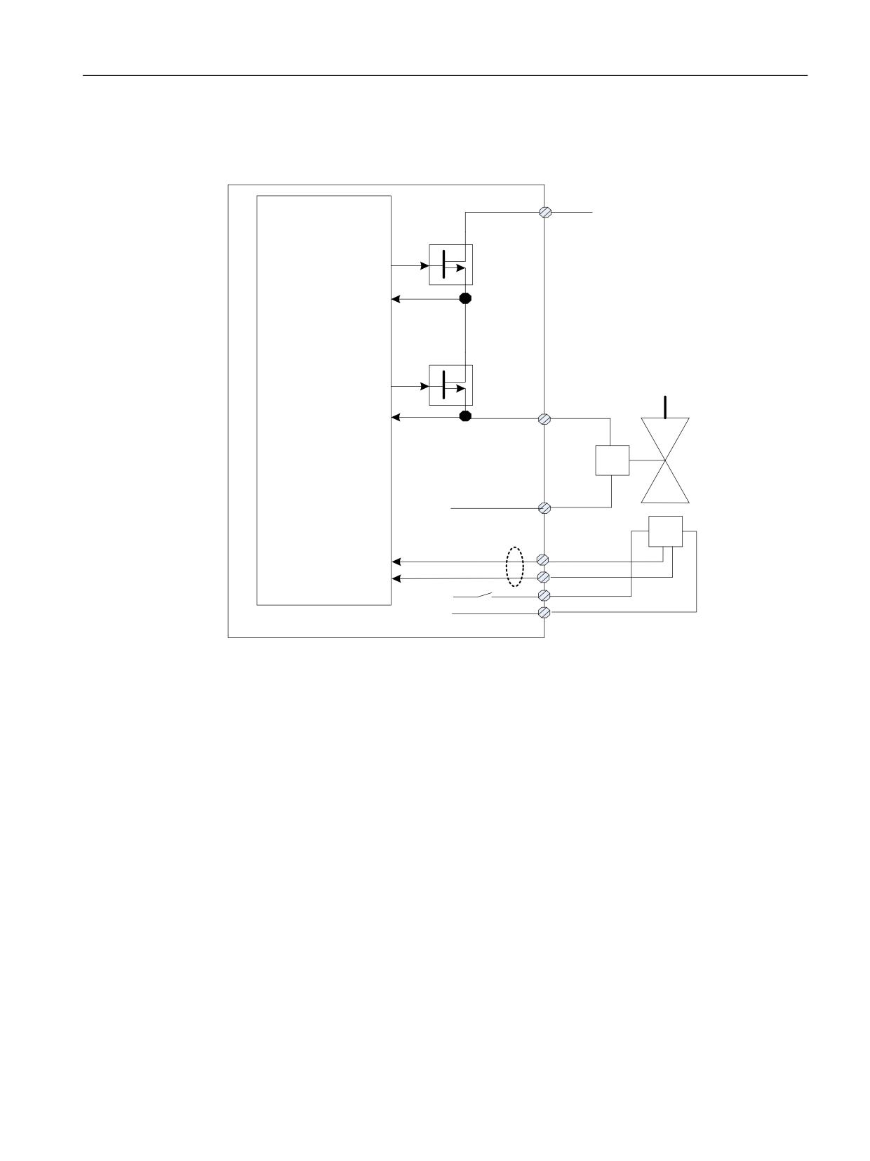
Safety functions integrated in the drive
5.4 STO (Basic/Extended)
• The shutoff valve is safely closed by selecting STO. If the shutoff valve signals a safe state via
the feedback signal(s), the "STO active/Power removed" state is displayed, and is output at the
configured safety-related output (PROFIsafe feedback signal telegram).
9 H[W
;
) '2
'LDJ '2
) '2
;
'LDJ '2
&RQ
6KXWRII YDOYH
WURO
;
0
)HHGEDFN
1& FRQWDFW 12
VLJQDOV
;
FRQWDFW
',
',
9
0
Figure 5-2
Interconnecting the shutoff valve (for an axis)
• F-DO is dynamized each time that STO is selected/deselected: "Diag DO+" and "Diag DO-" are
checked when switching F-DO+ and F-DO-.
• It is not necessary to explicitly select a test stop/forced checking procedure.
• If, for test stop/forced checking procedure, a fault occurs, then the converter outputs fault
F01632 or F30632.
Safety Integrated plus
Commissioning Manual, 10/2020, 6FC5397-1FP40-6BA4
95
Safety functions integrated in the drive
5.4 STO (Basic/Extended)
5.4.1.2
Function diagrams and parameters
Function diagrams (see SINAMICS S120/S150 List Manual)
•
2810
SI Basic Functions - STO (Safe Torque Off), SS1 (Safe Stop 1)
•
2811
SI Basic Functions - STO (Safe Torque Off), safe pulse cancellation
Overview of important parameters (see SINAMICS S120/S150 List Manual)
• p9601
SI enable functions integrated in the drive (Control Unit)
• r9720
CO/BO: SI Motion drive-integrated control signals
• r9772
CO/BO: SI Status (Control Unit)
• r9773
CO/BO: SI Status (Control Unit + Motor Module)
• r9774
CO/BO: SI Status (group STO)
HLA parameters
• p9625[0...1]
SI HLA shutoff valve wait time (CU)
• p9626
SI HLA shutoff valve feedback contacts configuration (CU)
• r9773
CO/BO: SI Status (Control Unit + Motor Module)
• r9774
CO/BO: SI Status (group STO)
• r9780
SI monitoring cycle (Control Unit)
Safety Integrated plus
96
Commissioning Manual, 10/2020, 6FC5397-1FP40-6BA4
Safety functions integrated in the drive
5.5 SBC (Basic/Extended)
5.5
SBC (Basic/Extended)
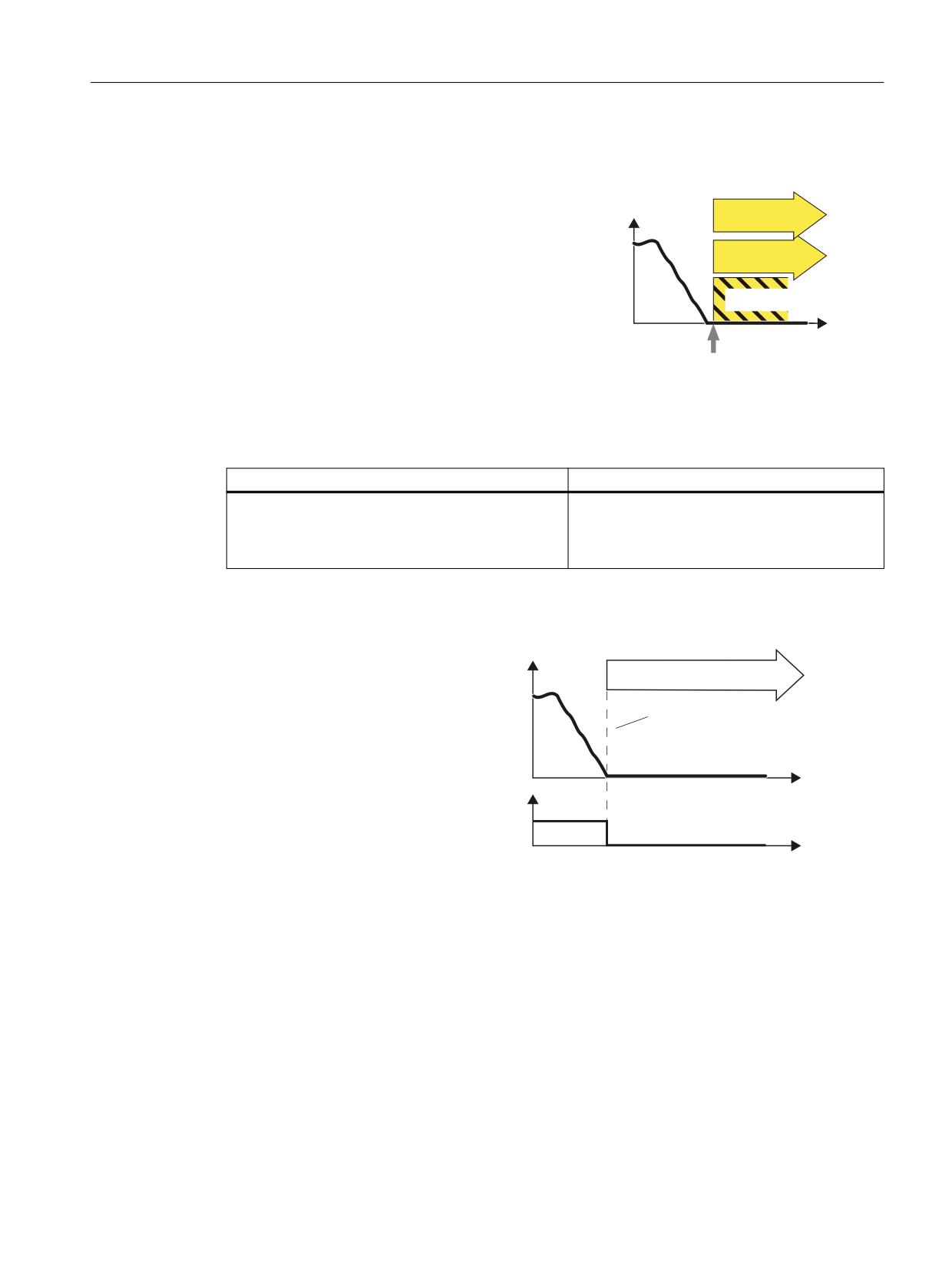
Definition according to EN 61800-5-2:
6SHHG
STO
"The SBC function supplies a safe output sig-
nal to control a holding brake."
SBC
W
6HOHFW 672
Safe Brake Control (SBC)
Example of how the function can be used
Example
Possible solution
The safe control of a motor holding brake must be
SBC is (if configured) initiated together with STO.
guaranteed in order to guarantee the motor is at a
The Motor Module / Safe Brake Relay / Safe Brake
standstill.
Adapter then carries out the action and safely
controls the outputs for the brake.
How does SBC function in detail?
The converter recogni-
6SHHG
zes the selection of STO
672 6%&
via a failsafe input or via
the safe communication
7KH PRWRU WRUTXH LV VZLWFKHG RII
PROFIsafe.
6%& FRQWUROV D EUDNH VDIHO\
The converter then safe-
ly switches off the tor-
W
que of the connected
672 GHVHOHFWLRQ
motor.
352),VDIH FRQWURO
ZRUG
SBC is (if configured) in-
W
itiated together with
STO. The Motor Mod-
ule / Safe Brake Relay /
Safe Brake Adapter then
carries out the action
and safely controls the
outputs for the brake.
Safety Integrated plus
Commissioning Manual, 10/2020, 6FC5397-1FP40-6BA4
97
Safety functions integrated in the drive
5.5 SBC (Basic/Extended)
5.5.1
Hardware required
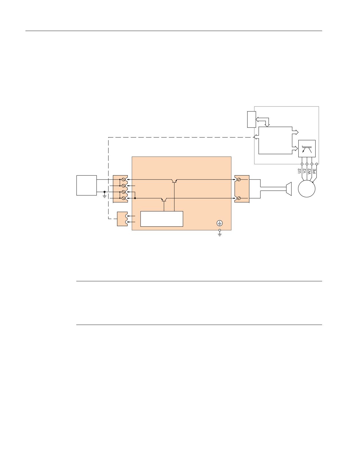
• Safe Brake Relay
The command for releasing or applying the brake is transferred to the Motor Module / Power
Module via DRIVE-CLiQ. The Motor Module / Safe Brake Relay then carries out the action and
appropriately activates the outputs for the brake.
Power Module
PM-IF interface
Prefabricated cable
Safe Brake Relay
+
+
ext.
+
BR+
24 V
M
M
M
3 ~
M
BR-
CTRL
Figure 5-3
Interconnecting the Safe Brake Relay using Blocksize as an example
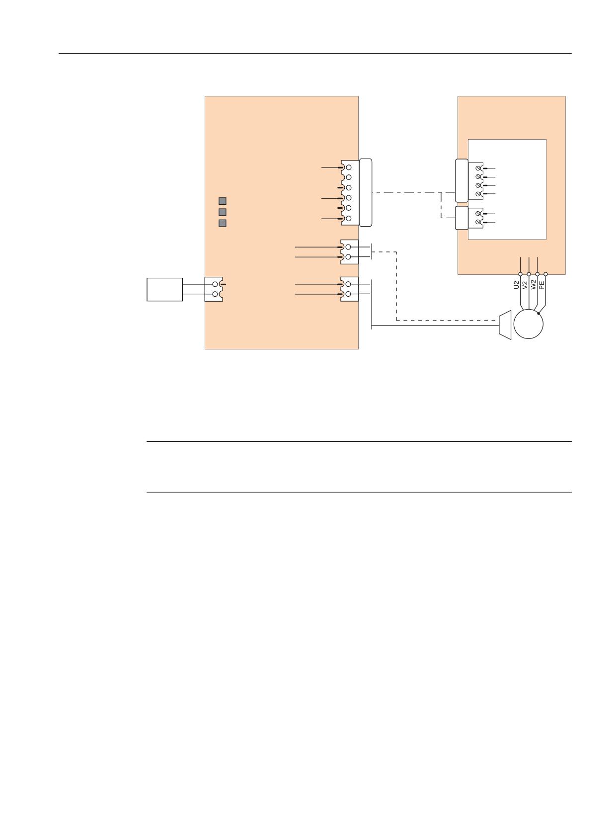
The brake cannot be directly connected to the Motor Module in the chassis format. The
connection terminals are only designed for 24 VDC with 150 mA; the Safe Brake Adapter is
required for higher currents and voltages.
Note
Additionally required hardware for other formats
A Safe Brake Relay is also required for the "Safe Brake Control" in the blocksize format. A Safe
Brake Adapter is required in the chassis format (starting with order numbers with the
ending ...xxx3). The Safe Brake Adapter is available for a 230 V AC brake control voltage.
Safety Integrated plus
98
Commissioning Manual, 10/2020, 6FC5397-1FP40-6BA4
Safety functions integrated in the drive
5.5 SBC (Basic/Extended)
Safe Brake Adapter
Motor Module/
SBA
Power Module
AC 230 V
Control Interface
-X11
Module (CIM)
-X46
BR+
1
1
BR Output+
BR- 2
Connecting cable
2
BR Output-
FB+
3
3
FB Input+
6SL3060-4DX04-0AA0
LEDs
4
FB Input-
FB-
4
230 V OK
P24
5
-X42
K1 ON
2
P24
M
6
K2 ON
3
M
-X15
External
AUX1
1
Power supply
Fast
de-energiza-
AUX2
2
tion
-X12
-X14
1
L
SBA_BR_L
1
G_D213_DE_00091b
230 V CA
2
N
SBA_BR_N
2
M
3 ~
Figure 5-4
Interconnecting the Safe Brake Adapter
5.5.2
Details and parameterization
Note
No SBC for SINAMICS HLA
SINAMICS HLA does not support Safe Brake Control.
The "Safe Brake Control" function (SBC) is used to safely control holding brakes that function
according to the closed-circuit principle (e.g. motor holding brake).
The opening and closing of the brake is controlled by the Motor Module / Power Module.
Terminals are available for this on the device in booksize format. A Safe Brake Relay is also
required for the "Safe Brake Control" in the blocksize format. With the chassis format (article
numbers ending 3 or higher), a Safe Brake Adapter is required. When the Power Module is
configured automatically, the Safe Brake Relay is detected and the motor holding brake type is
defaulted (p1278 = 0).
Safety Integrated plus
Commissioning Manual, 10/2020, 6FC5397-1FP40-6BA4
99

Safety functions integrated in the drive
5.5 SBC (Basic/Extended)
Brake activation via the brake connection on the Motor Module / Safe Brake Relay (SBR) / Safe
Brake Adapter (SBA) involves a safe, two-channel method.
Note
Controlling the brake via a relay for "Safe Brake Control":
If you use the "Safe Brake Control (SBC)" function, the use of relays/contactors can cause faults
in the brake control when brakes are switched. For this reason, this type of control is not
generally enabled.
An interrupted cable or a short-circuit in the brake winding is only detected when the state
changes, i.e. when the brake either opens or closes. For devices in the chassis format with
connected Safe Brake Adapter, the connecting cable between the Safe Brake Adapter and the
motor brake is not monitored for an interrupted cable or short-circuit.
WARNING
Undesirable motor motion due to a defective brake
The "Safe Brake Control" function does not detect mechanical defects of the brake. A defective
brake can result in unwanted motor motion, which may result in injury or death.
• Test the brake using the Safety Integrated diagnostics function "Safe Brake Test (SBT)" (for
further information, see Section "Enabling the function (Page 164)").
Functional features of "Safe Brake Control"
• SBC is executed when "Safe Torque Off" (STO) is selected.
• In contrast to conventional brake control, SBC is executed via two channels.
• SBC is executed regardless of the brake control or mode set in p1215. SBC is not
recommended, however, when 1215 = 0 or 3.
• The function must be enabled using parameters.
• When the state changes, electrical faults, such as a short-circuit in the brake winding or wire
breakage can be detected.
Enabling the "Safe Brake Control" function
The "Safe Brake Control" function is enabled via parameter p9602.
The SBC function can be used only together with STO. The selection of SBC alone is not possible.
Safety Integrated plus
100
Commissioning Manual, 10/2020, 6FC5397-1FP40-6BA4
Safety functions integrated in the drive
5.5 SBC (Basic/Extended)
Two-channel brake control
Note
Connecting the brake
The brake cannot be directly connected to the Motor Module in chassis format: A Safe Brake
Adapter is also required.
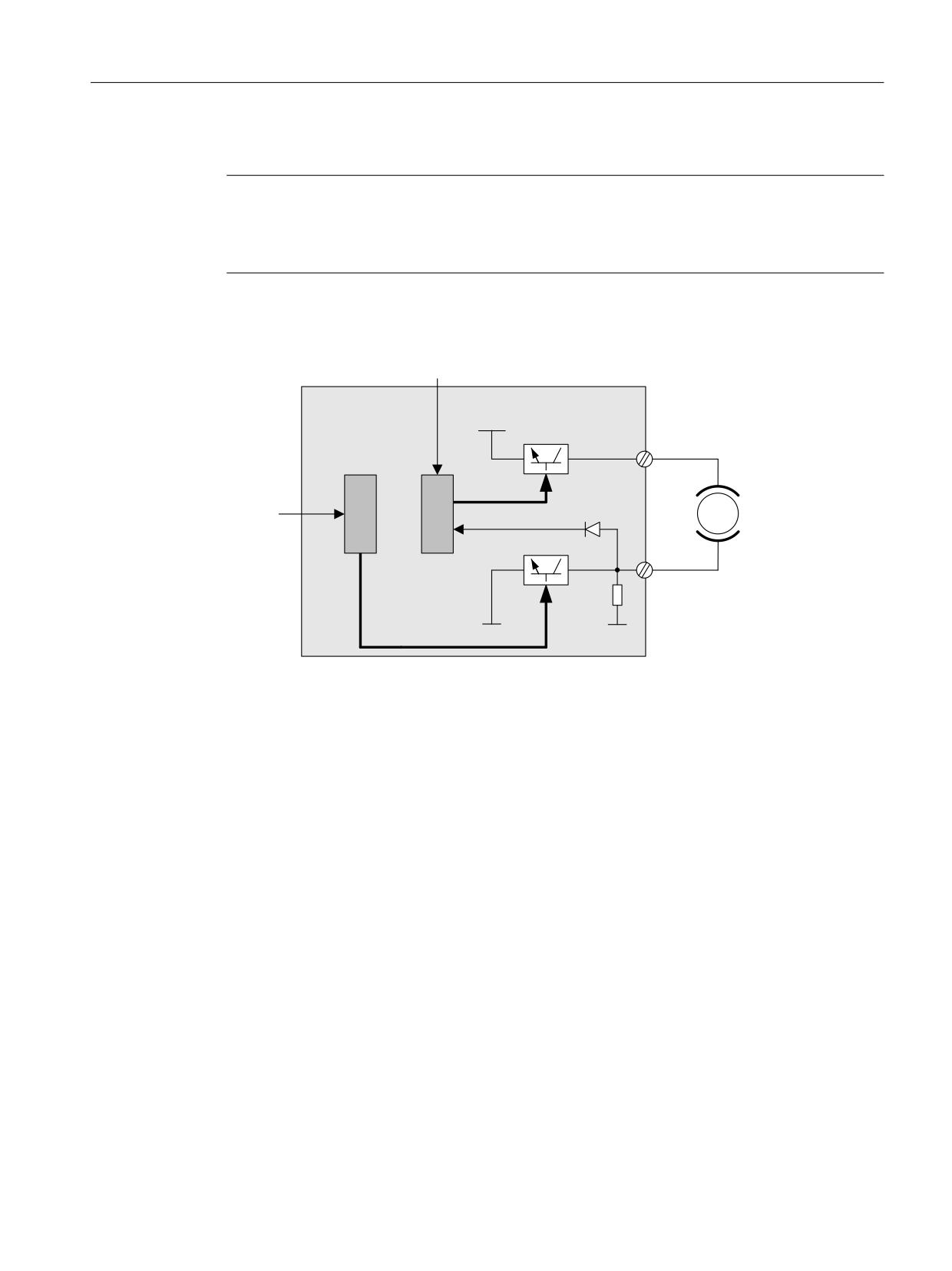
The brake is controlled from the Control Unit. Two signal paths are available for applying the
brake.
&RQWURO WHUPLQDO
&RQWURO 8QLW 0RWRU
0RGXOH 6DIH %UDNH
3
5HOD\
7%
&ORVHG FLUFXLW EUDNH
%5
&RQWURO
%5
WHUPLQDO
0RWRU
%UDNH GLDJQRVWLFV
7%
%5
0
0
%5
Figure 5-5
Two-channel brake control, blocksize (example)
For the "Safe Brake Control" function, the Motor/Power Module assumes a monitoring function
to ensure that when the Control Unit fails or malfunctions, the brake current is interrupted
therefore closing the brake.
The brake diagnosis can only reliably detect a malfunction in either of the switches (TB+, TB-)
when the status changes, i.e. when the brake is released or applied.
If the Motor Module or Control Unit detects a fault, the brake current is switched off. The brake
then closes and a safe state is reached.
5.5.2.1
SBC for Motor Modules in the chassis format
To be able to set higher power in the brakes of devices of this format, an additional Safe Brake
Adapter (SBA) module is needed. For more information about connecting and wiring the Safe
Brake Adapter, refer to the "SINAMICS G130/G150/S120 Chassis/S120 Cabinet Modules/S150
Safety Integrated" Function Manual.
Using parameter p9621, you can define via which digital input the relay (NO contacts) feedback
signal of the Safe Brake Adapter is routed to the Control Unit.
To evaluate the feedback signal contacts, you must maintain the wait times caused by the SBA.
Parameter p9622 is pre-assigned with the SBA-relay wait times:
• p9622[0] ≙ wait time, switching on
• p9622[1] ≙ wait time, switching off
Safety Integrated plus
Commissioning Manual, 10/2020, 6FC5397-1FP40-6BA4
101
Safety functions integrated in the drive
5.5 SBC (Basic/Extended)
Further functionality and the activation of the brake, i.e. reaching the safe status, are in this case
the same as the above described procedure for booksize devices.
Safe Brake Control with power units in a parallel connection
Note
SBC for parallel connection of power units
Safe Brake Control with power units in a parallel connection is available if r9771.14 = 1.
If you wish to use SBC with SBA for chassis format power units connected in parallel, then it is
only permissible that you connect precisely one SBA to a power unit in the parallel connection.
The Safe Brake Adapter and therefore the brake are controlled via this power unit.
There are two options for registering this power unit with the system:
• Automatic brake identification when commissioning the system for the first time
- Requirements:
- No Safety Integrated Functions enabled
- p1215 = 0 (no motor holding brake available)
- During the first commissioning, SINAMICS checks at which power unit an SBA is
connected. If precisely one SBA is found, the number of the power unit is entered into
parameter p7015.
If several SBAs are found at the parallel-connected power units, message "F07935 drive:
Motor holding brake configuration error" is output.
- For devices in the chassis format, if the SBA feedback signal (SBA_DIAG) is read in via an
input of the power unit, then in addition, this digital input is automatically entered into
parameter p9621.
• Manually defining the power unit
- Enter the component number of the power unit, to which the SBA is connected, into
parameter p7015. If no SBA is connected to the power unit, faults are detected when
controlling the motor holding brake and fault F01630 is output.
- In parameter p9621 (p9621 = BICO interconnection to r9872.3), enter the digital input of
the power unit to which the SBA is connected and via which the SBA feedback signal
(SBA_DIAG) is read in.
Note
Disconnecting the brake cable for service purposes
As long as the brake is permanently released and not actuated, it is possible to briefly disconnect
the brake cable, e.g. for service purposes, and not receive fault messages. In the case of a fault,
message F07935 is only output when the brake is controlled.
Safety Integrated plus
102
Commissioning Manual, 10/2020, 6FC5397-1FP40-6BA4
Safety functions integrated in the drive
5.5 SBC (Basic/Extended)
5.5.2.2
Function diagrams and parameters
Function diagrams (see SINAMICS S120/S150 List Manual)
•
2814
SI Basic Functions - SBC (Safe Brake Control), SBA (Safe Brake Adapter)
Overview of important parameters (see SINAMICS S120/S150 List Manual)
• p0799
CU inputs/outputs, sampling time
• p1215
Motor holding brake configuration
• p7015
Par_circuit holding brake power unit data set
• p9602
SI enable safe brake control (Control Unit)
• p9621
BI: SI Safe Brake Adapter signal source (Control Unit)
• p9622[0...1]
SI SBA relay wait times (Control Unit)
• r9771.14
SI common functions (Control Unit): SBC supported for parallel con-
nection
• r9780
SI monitoring cycle (Control Unit)
Safety Integrated plus
Commissioning Manual, 10/2020, 6FC5397-1FP40-6BA4
103
Safety functions integrated in the drive
5.6 SS2
5.6
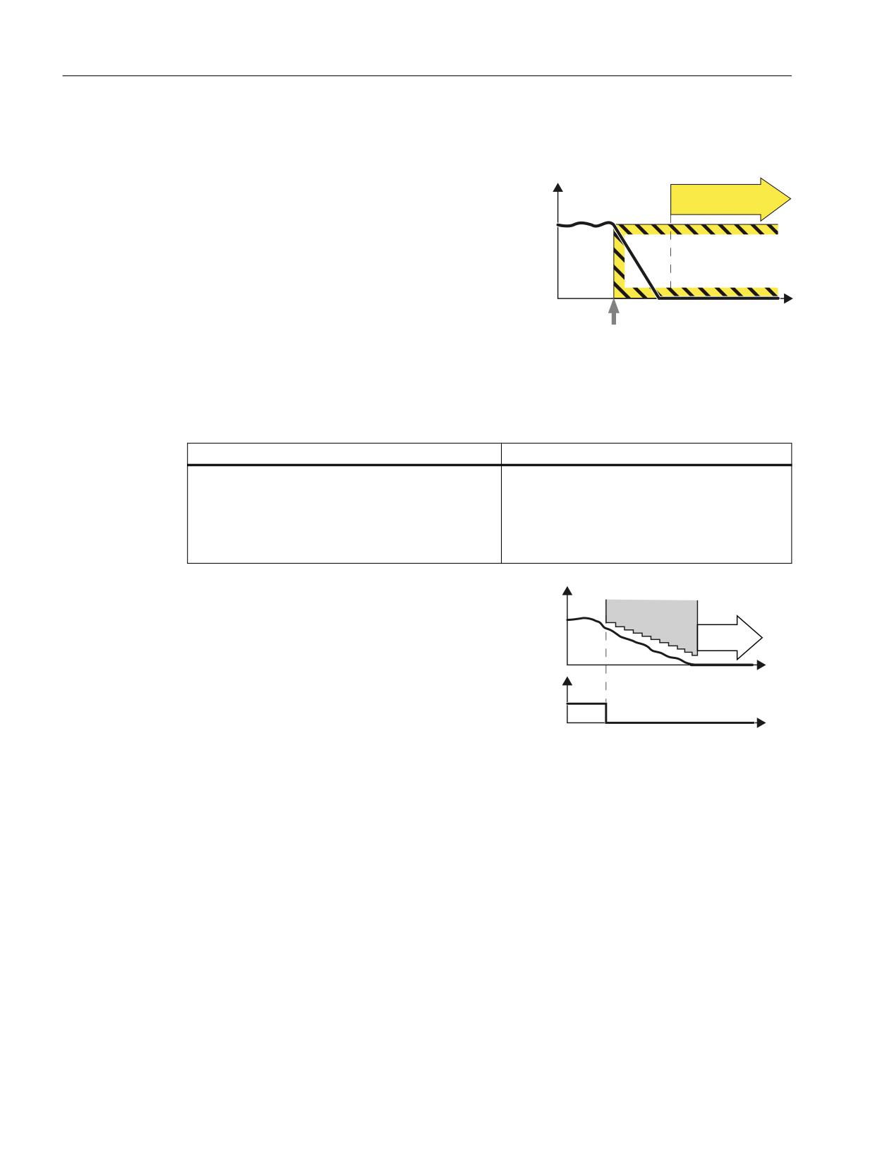
SS2
Definition according to EN 61800-5-2:
Y
The "SS2" function brings the motor to a standstill with
SOS
subsequent safe monitoring of the standstill position.
If SS2 is selected, the drive brakes the motor along a
braking ramp. The following variants are possible:
• SS2-a with acceleration monitoring (SAM)
• SS2-r with braking ramp monitoring (SBR)
W
• Manually set delay time until SOS is activated.
Select SS2
This function corresponds to stop category 2 to
EN 60204-1.
Example of how the function can be used
Example
Possible solution
A protective door must only be opened if a motor is in
• Select SS2 in the converter via a terminal or
the safe standstill state.
via PROFIsafe .
• After braking, the converter goes into the
SOS state. Only then may the protective door
be released.
The safety function SS2 monitors the load
6SHHG
speed and initiates the SOS function if the
0RQLWRULQJ
SS2 delay time has expired.
626
With SS2, braking is monitored on the
OFF3 ramp. A faulty acceleration is detec-
W
66
GHVHOHFWLRQ
ted and the drive then shuts down with
352),VDIH
STO.
FRQWURO ZRUG
W
If you are operating the motor with closed-loop torque control, the converter switches to the
closed-loop speed control mode when SS2 is selected.
Safety Integrated plus
104
Commissioning Manual, 10/2020, 6FC5397-1FP40-6BA4
Safety functions integrated in the drive
5.6 SS2
How does SS2 function in detail?
The failsafe logic (e.g. F-PLC) selects the SS2 safety function via a failsafe input or via the
PROFIsafe safe communication.
• If, when selecting SS2, the motor is already at a standstill, after a delay time, the converter
activates function "Safe Operating Stop (SOS)".
• If the drive is not at standstill when SS2 is selected, it is braked along the OFF3 ramp. Braking
is monitored with one of the following functions, depending on the setting in p9506:
- Safe Acceleration Monitor (SAM)
A faulty acceleration is therefore detected.
- Safe Brake Ramp (SBR)
In this way, a violation of the braking ramp is detected.
After a delay time, the converter activates function "Safe Operating Stop (SOS)". This function
monitors the safe standstill of the drive.
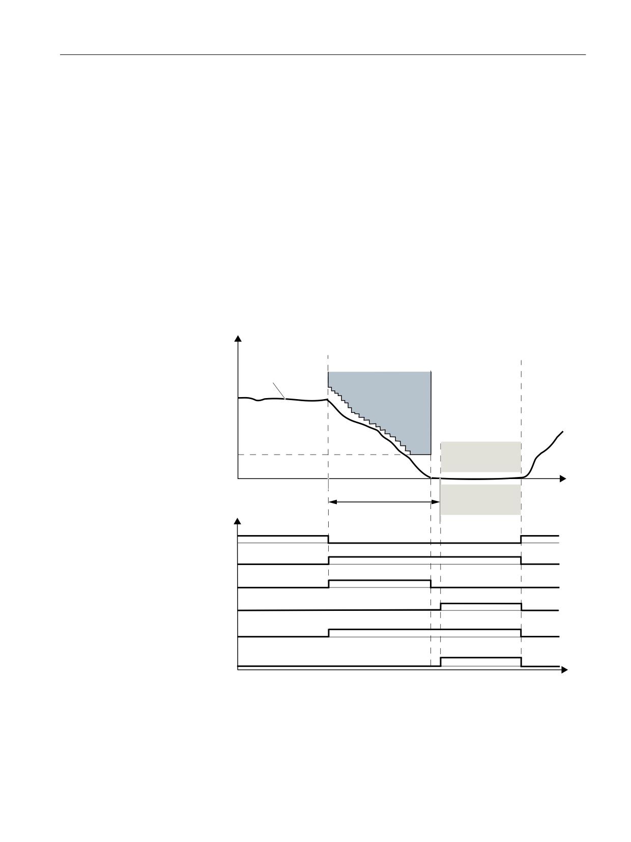
Braking behavior
/RDG VSHHG
2SHUDWRU DFWLRQV
66
VHOHFWLRQ
66
GHVHOHFWLRQ
$FWXDO YDOXH
6$0
6$0 YHORFLW\
626
OLPLW
W
626
66
GHOD\ WLPH
'LDJQRVWLFV
66
GHVHOHFWLRQ
66
DFWLYH
6$0 6%5 DFWLYH
626 DFWLYH
352),VDIH
66
DFWLYH
6WDWXV ZRUG ELW
626 DFWLYH
6WDWXV ZRUG ELW
W
Figure 5-6
Braking behavior and diagnostics (example for SS2 with SAM)
Safety Integrated plus
Commissioning Manual, 10/2020, 6FC5397-1FP40-6BA4
105
Safety functions integrated in the drive
5.6 SS2
Note
SS2 with external stop (SS2E)
If you use SS2E, neither of the two monitoring functions (SBR, SAM) is active. The drive is
decelerated by interpolation (SIC/SCC is required for this). SOS becomes active after the delay
time expires.
5.6.1
Details and parameterization
Note
SS2 only with encoder
The "Safe Stop 2" (SS2) safety function can only be used with an encoder.
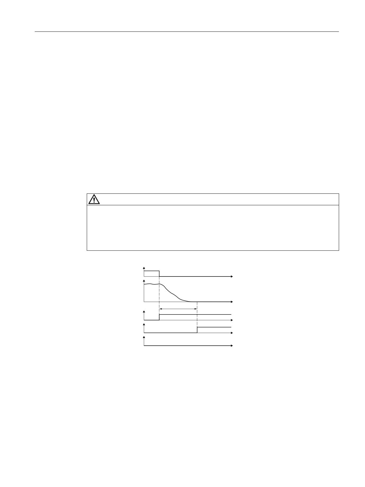
The "Safe Stop 2" (SS2) function is used to brake the motor safely along the OFF3 deceleration
ramp (p1135) with subsequent transition to the SOS state (see Chapter "Safe Operating Stop
(Page 114)") after the delay time expires (p9552). The delay time set must allow the drive to
brake to a standstill from every speed of the operating process within this time. The standstill
tolerance (p9530) may not be violated after this time.
After braking, the drives remain in speed control mode with the speed setpoint n = 0. The full
torque is available.
When braking, one of the following functions is active:
• For p9506 = 0, the following applies:
Braking is monitored with the "Safe Acceleration Monitor" function (see Chapter SAM
(Page 137)).
• For p9506 = 2, the following applies:
Braking is monitored using the "Safe Brake Ramp" function (see Chapter SBR (Page 139)).
The selection and monitoring of the acceleration (SAM) are realized through two channels -
however, braking along the OFF3 ramp, only through one channel.
• Effect on "Setpoint speed limit effective" (r9733[0...2]):
If SS2 (≙ STOP C), a setpoint of 0 is specified in r9733[0...2].
Safety Integrated plus
106
Commissioning Manual, 10/2020, 6FC5397-1FP40-6BA4
Safety functions integrated in the drive
5.6 SS2
Responses
• Speed limit violated (SAM):
- STOP A
- Safety message C01706
• Standstill tolerance violated in p9530 (SOS):
- STOP B with subsequent STOP A
- Safety message C01707
• System fault:
- STOP F with subsequent STOP A
- Safety message C01711
5.6.1.1
SS2 with external stop (SS2E)
WARNING
Unexpected axis motion when the "SS2E" function is activated
When the "SS2E" function is active, during the safety delay time, until SOS is reached, axis
motion that is not monitored can occur. This can result in death or severe injury.
• During this time, prevent persons from entering the hazardous area around the axis, e.g. by
providing protective doors or other suitable protective equipment.
66 ( GHVHOHFWLRQ
W
6SHHG
W
S
66 ( DFWLYH
W
626 DFWLYH
W
6$0 6%5 DFWLYH
W
Figure 5-7
Selecting function SS2E
With external stop, "Safe Stop 2" functions in principle exactly the same way as described in the
previous sections. Note, however, the following differences:
Differences between "Safe Stop 2 with OFF3" and "SS2 with external stop (SS2E)"
• When SS2 is selected with external stop, the drive does not automatically brake the motor,
but instead, follows the specified speed setpoint.
• During delay time p9553, the brake ramp (SBR) and the acceleration (SAM) are not
monitored and there is no standstill detection.
Safety Integrated plus
Commissioning Manual, 10/2020, 6FC5397-1FP40-6BA4
107
Safety functions integrated in the drive
5.6 SS2
• SOS becomes active after the delay time p9553 expires.
P9553 must be set in such a way that the axes are braked to a standstill with the set dynamics.
• In order to activate "Safe Stop 2 with external stop", set p9501.18 = 1.
• The PROFIsafe control word S_STW2.28 selects the SS2E function. PROFIsafe S_STW2.28 is
contained in telegrams 31, 901, 902 and 903.
• The PROFIsafe status word S_ZSW2.28 indicates whether the SS2E function is active. The
PROFIsafe status word S_ZSW2.28 is contained in telegrams 31, 901, 902 and 903. The
associated diagnostics parameter is r9722.28.
In the "Safety Info Channel", status word S_ZSW3B.11 indicates whether function SS2E is
active. The associated diagnostics parameter is r10234.11.
Diagnostic parameters p9722.28 and p10234.11 are also set during an internal STOP D.
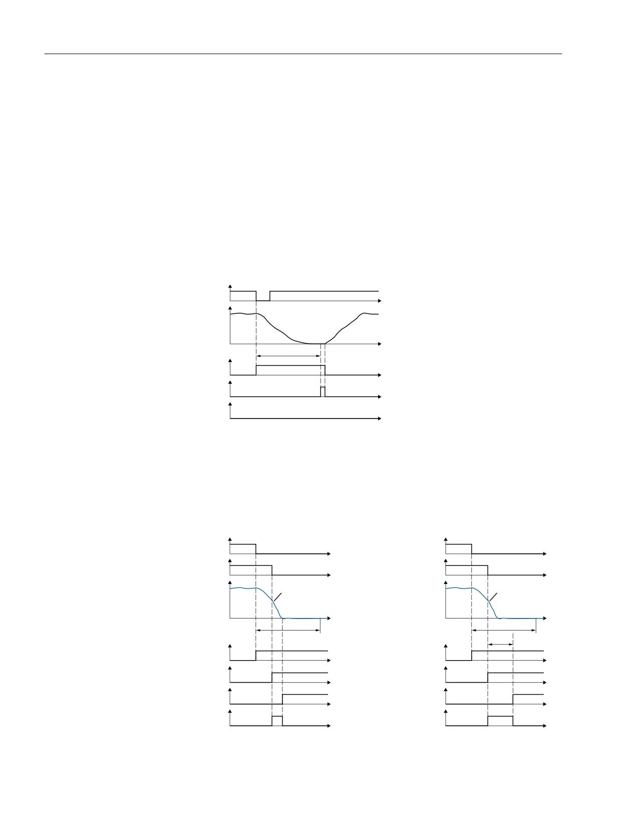
Deselecting function SS2E while SS2E is active
66 ( GHVHOHFWLRQ
W
6SHHG
S
W
66 ( DFWLYH
W
626 DFWLYH
W
6$0 6%5 DFWLYH
W
Figure 5-8
Deselecting function "SS2E" while SS2E is active
After the function has been selected, the delay time starts to elapse - even if the function is
deselected during this time. In this case, after the delay time has expired, the "SOS" function is
briefly active. Afterwards, it is permissible that the drive accelerates the motor back to the speed
setpoint.
Interruption of the active "SS2E" function by functions "SS1" and "SS2"
'HVHOHFW 66 (
'HVHOHFW 66 (
W
W
'HVHOHFW 66
'HVHOHFW 66
W
W
6SHHG
6SHHG
2)) UDPS
2)) UDPS
W
W
S
S
S
66 ( DFWLYH
66 ( DFWLYH
W
W
66 DFWLYH
66
DFWLYH
W
W
672 DFWLYH
626 DFWLYH
W
W
6$0 6%5 DFWLYH
6$0 6%5 DFWLYH
W
W
Safety Integrated plus
108
Commissioning Manual, 10/2020, 6FC5397-1FP40-6BA4
Safety functions integrated in the drive
5.6 SS2
Figure 5-9
Interruption of function "SS2E" by functions "SS1" (shown at the left) and "SS2" (shown at the
right)
When selecting SS1, the drive brakes the motor along the OFF3 ramp and monitors the speed
using the "SAM" function. Function "STO" becomes active when the motor is at a standstill.
When selecting SS2, the drive also brakes the motor along the OFF3 ramp and monitors the
speed using the "SAM" function. Function "SOS" becomes active after time p9552.
5.6.1.2
Dynamic response adaptation for SS2E
Adaptation of the dynamic response for axes
For axes, the acceleration characteristic is adapted dynamically so that the axes stop within the
time saved in p9553 "SI Motion transition time STOP D to SOS". Therefore, ensuring stopping
with low associated stress on the machine.
In order that the stop D time, parameterized in p9553, is used as basis to determine the braking
time and possibly issue an alarm, this must be enabled by setting bit 2 in MD37950
$MA_SAFE_INFO_ENABLE.
When powering up, for all axes with SIC/SCC connection - where the bit to take into account the
stop D/SS2E transition times in the braking response (MD37950.2 $MA_SAFE_INFO_ENABLE) is
set, the control system checks whether the braking time set in p9553 is sufficient for the active
acceleration characteristic of the axis. When violated, suppressible alarm 22001 "Channel %1
block %2 axis %3: braking time %6 [s] longer than the stop D time. Reason: %5" is output.
If the acceleration/deceleration behavior is changed, the axes brake for STOP D with the shortest
transition time of all path axes. It is recommended that the transition times are set the same in
p9553 for all axes of an interpolation group.
Adaptation of the dynamic response for spindles
For spindles, the actual acceleration characteristic is not adapted. The control checks whether
the braking time set in p9553 is sufficient for all spindle operating modes and configured gear
stages. When violated, suppressible alarm 22002 "Channel %1 Spindle %2: Braking time %6 [s]
longer than the stop D time gearbox stage %3. Reason: %5" is output.
If the spindle is in axis operation, then it behaves just like an axis.
Adaptation of the dynamic response for coupling
For an active axis or spindle coupling (with the exception of the synchronous spindle coupling),
the coupling is no longer taken into consideration, if synchronous stopping of the coupled group
is no longer safely possible within the time parameterized in p9553. For a coupled group, this
is the reason why a STOP D must be set for all axes of the coupled group.
For the synchronous spindle coupling, when synchronous operation is reached, the coupling is
always maintained. The coupling group is always braked via the leading spindle. If the following
spindle requires a longer braking time than the leading spindle, then p9553 must be
appropriately increased for the leading spindle.
When a synchronous spindle is active, STOP D should also be initiated for the leading and
following spindle.
Safety Integrated plus
Commissioning Manual, 10/2020, 6FC5397-1FP40-6BA4
109

Safety functions integrated in the drive
5.6 SS2
Endlessly rotating axes are braked at the acceleration limit.
The SOS function is automatically activated after the time set in p9553 expires.
Configuring support
The braking time of the active acceleration characteristic is available in the OPI variable
"diagSlopeTime".
The displayed time is the maximum expected braking time that has been determined, and is
used as diagnostic information for parameterizing the STOP D time. It is possible that it can have
a higher value than the braking time displayed in alarm A22001/A22002 (dependent on the
dynamic response settings). The determined time is displayed in commissioning screen form
SS2E.
Note
Irrespective of the reason, the longest braking time to be expected is always displayed in the OPI
variable. The OPI variable is only output when Safety Integrated is activated for the particular
axis.
Triggering alarms
The following formulas are applied to trigger alarm 22001/22002:
METRIC:
p9553 > MAX_AX_VELO * 1/60000 / MAX_AX_ACCEL
INCH/ROT/SPINDLE:
p9553 > MAX_AX_VELO * 1/60 / MAX_AX_ACCEL
For axes with jerk limitation, the minimum braking time is increased by the additional
component:
2 * MAX_AX_ACCEL / MAX_AX_JERK
The check is made for NEWCONF, RESET, unparking an axis and for programming ACC or JERKLIM.
The MD names contained in the formulas must, corresponding to the alarm situation (the alarm
occurs when parameterizing or when programming), be replaced by other values when
required.
MD
Alternative MD
Gearbox stage-specific MD spindle
Program
command
MAX_AX_VELO
min(JOG_VELO, JOG_VELO_RAPID)
$MA_GEAR_STEP_MAX_VELO_LIMIT[0…
-
max]
$MA_GEAR_STEP_PC_MAX_VELO_LIMIT[0…
max]
MAX_AX_ACCEL
MAX_AX_ACCEL
$MA_GEAR_STEP_SPEEDCTRL_ACCEL[0…
ACC
max]
$MA_GEAR_STEP_POSCTRL_ACCEL[0…max]
MAX_AX_JERK
JOG_AND_POS_MAX_JERK
JERKLIM
Safety Integrated plus
110
Commissioning Manual, 10/2020, 6FC5397-1FP40-6BA4
Safety functions integrated in the drive
5.6 SS2
Notes:
The calculated value should be rounded off to one decimal place so that for an INCH-METRIC
switchover, internal rounding effects can be compensated and no undesirable alarms are
initiated.
With the parameterization of the STOP D braking time in p9553 via the HMI IBN screen forms and
subsequent update by means of the operator panel reset, alarm 22001 or 22002 is triggered
when the specified calculation rules are violated.
The braking time of the active acceleration characteristic is available in the NC variable
"diagSlopeTime", and can be used as basis to parameterize the Stop D braking time.
Alarms 22001/22002 can be suppressed via MD 11415 bit 13. The dynamic response is adapted
as described.
When evaluating the alarm output, the conditions that are required to initiate the alarm are
checked. The first condition that is satisfied initiates the alarm; other conditions are no longer
checked. The braking time for the first condition that is satisfied is displayed in the alarm.
5.6.1.3
Safe Stop 2 Extended Stop and Retract (SS2ESR)
WARNING
Unexpected axis motion
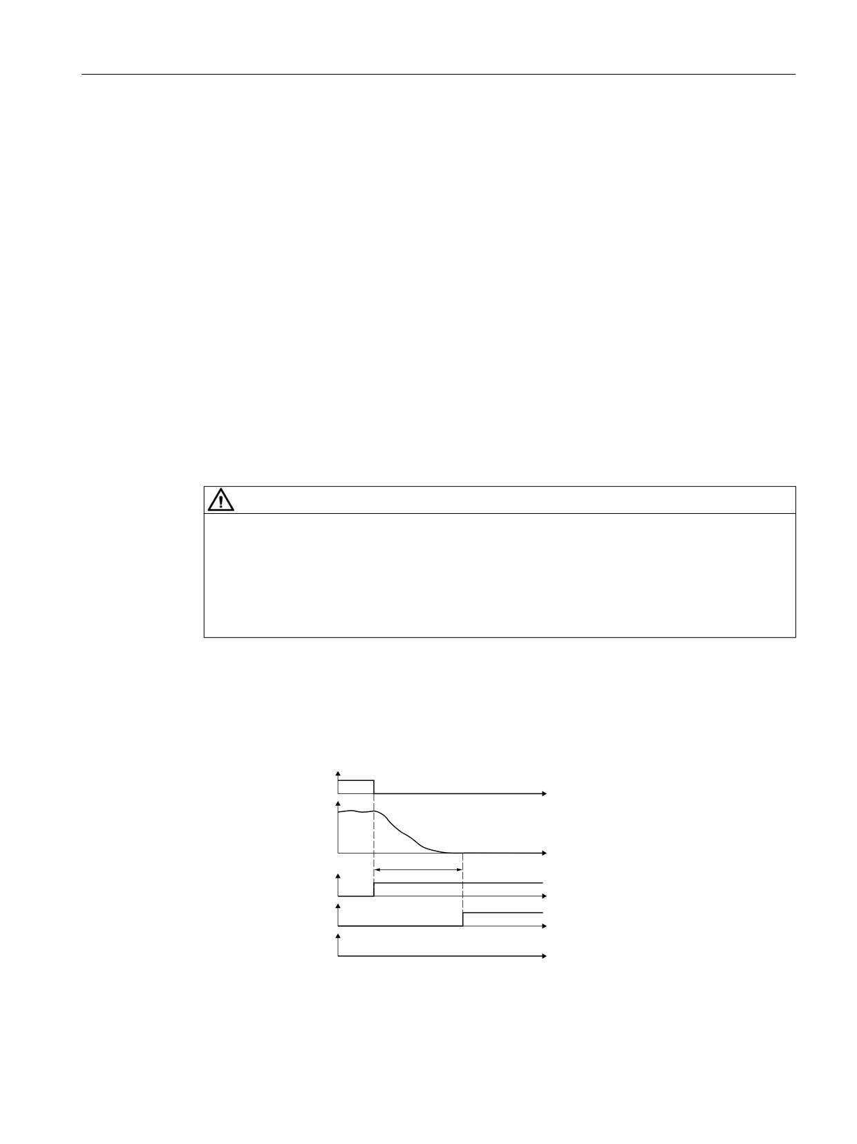
When function "SS2ESR" is active, during the delay time (p9554) the speed follows the setpoint
issued from the higher-level control system. As a consequence, unexpected axis motion is
possible, which can lead to severe injury and death.
• Prevent persons from entering the danger zone of the machine or system during the delay
time (p9554), for example, by keeping protective devices closed and interlocked.
In principle, Safe Stop 2 Extended Stop and Retract (SS2ESR) functions in exactly the same way
as SS2 described in the previous sections. Note, however, the following differences:
Select SS2ESR
'HVHOHFW 66 (65
W
6SHHG
W
S
66 (65 DFWLYH
W
626 DFWLYH
W
6$0 6%5 DFWLYH
W
Figure 5-10
Selecting function SS2ESR
Safety Integrated plus
Commissioning Manual, 10/2020, 6FC5397-1FP40-6BA4
111
Safety functions integrated in the drive
5.6 SS2
Differences between "Safe Stop 2 with OFF3" and SS2ESR
• If SS2ESR with external stop is selected, the drive does not brake the motor automatically, but
instead, follows the defined speed setpoint: This can also result in fast retraction motion.
• During the delay time p9554, the brake ramp (SBR) and the acceleration (SAM) are not
monitored, and there is no standstill detection.
• SOS becomes active after delay time p9554 has expired. If function SS2ESR is active, the
higher-level control system must define the speed setpoint such that the motor is stopped no
later than after the delay time p9554 has expired.
• To enable SS2ESR, set p9501.4 = 1.
• PROFIsafe control word S_STW2.29 selects function "SS2ESR". PROFIsafe S_STW2.29 is
contained in telegrams 31, 901, 902 and 903.
• PROFIsafe status word S_ZSW2.27 indicates whether function "SS2ESR" is active. PROFIsafe
status word S_ZSW2.27 is contained in telegrams 31, 901, 902 and 903. The associated
diagnostics parameter is r9722.27. In the "Safety Info Channel," status word S_ZSW3B.12
indicates whether the "SS2ESR" function is active. The associated diagnostics parameter is
r10234.12.
• In addition, in the "Safety Info Channel", status word S_ZSW1B.14 = 1 is set. This bit
corresponds to diagnostic parameter r9734.14.
• You can use p0890[1] to interconnect to an ESR integrated in the drive.
• SS2ESR has no effect on the "Setpoint speed limit effective" (r9733[0...2]). If SS2ESR is
enabled in p9501.4, then a STOP E also has no effect on r9733[0...2].
Deselecting SS2ESR while SS2ESR is active
'HVHOHFW 66 (65
W
6SHHG
S
W
66 (65 DFWLYH
W
626 DFWLYH
W
6$0 6%5 DFWLYH
W
Figure 5-11
Deselecting SS2ESR while SS2ESR is active
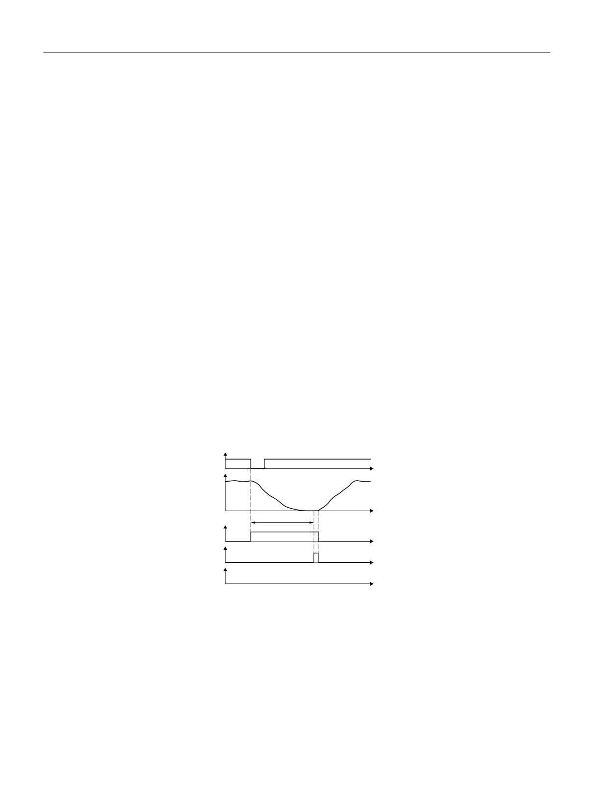
After the function has been selected, the delay time starts to elapse - even if the function is
deselected during this time. In this case, after the delay time has expired, the "SOS" function is
briefly active. Afterwards, it is permissible that the drive accelerates the motor back to the speed
setpoint.
Safety Integrated plus
112
Commissioning Manual, 10/2020, 6FC5397-1FP40-6BA4
Safety functions integrated in the drive
5.6 SS2
Interrupting active SS2ESR with SS1 and SS2
'HVHOHFW 66 (65
'HVHOHFW 66 (65
W
W
'HVHOHFW 66
'HVHOHFW 66
W
W
6SHHG
6SHHG
2)) UDPS
2)) UDPS
W
W
S
S
S
66 (65 DFWLYH
66 (65 DFWLYH
W
W
66 DFWLYH
66
DFWLYH
W
W
672 DFWLYH
626 DFWLYH
W
W
6$0 6%5 DFWLYH
6$0 6%5 DFWLYH
W
W
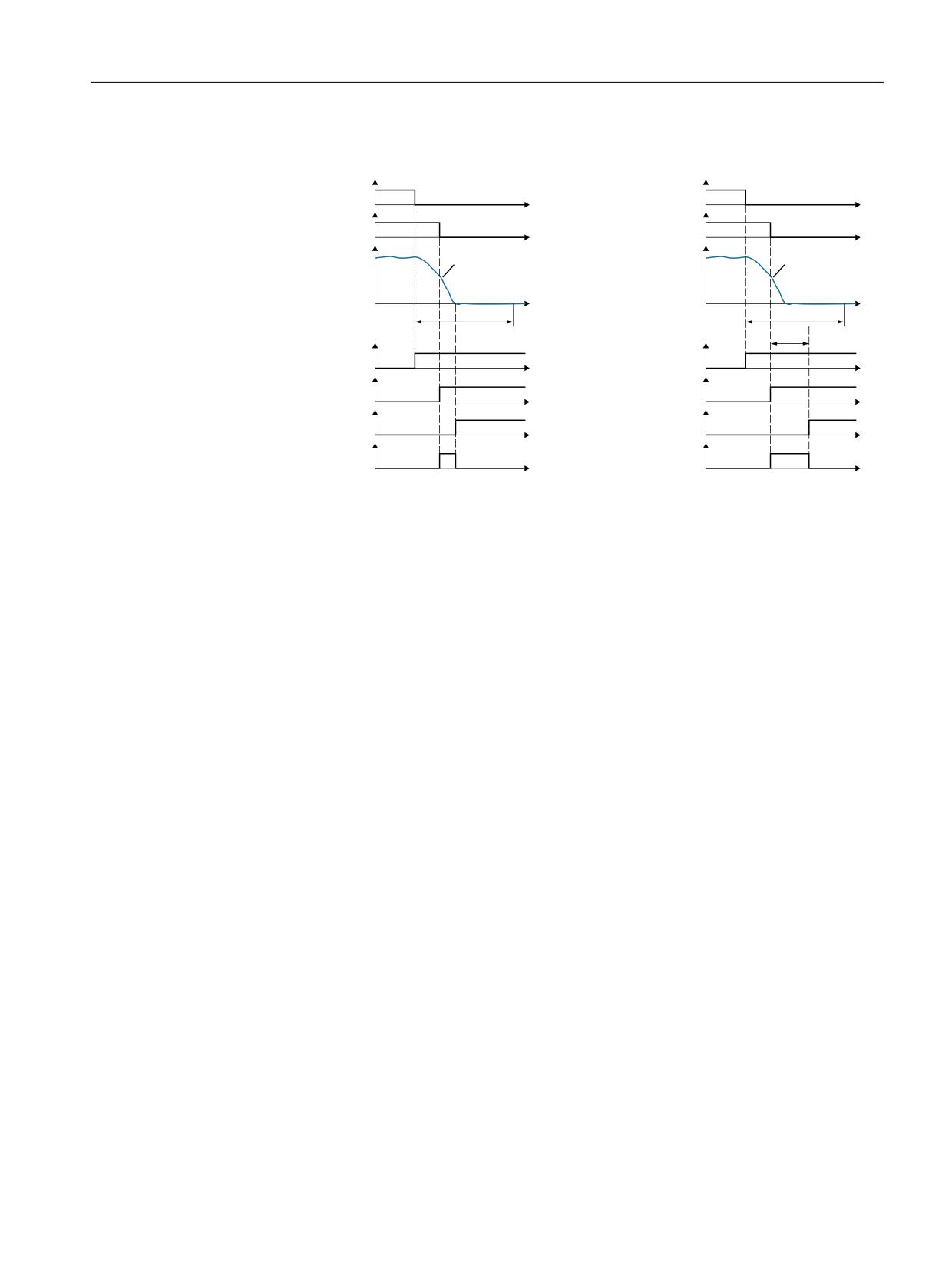
Figure 5-12
Interrupting function "SS2ESR" by functions "SS1" (shown at the left) and "SS2" (shown at
the right)
When selecting SS1, the drive brakes the motor along the OFF3 ramp and monitors the speed
using function "SAM/SBR". Function "STO" becomes active when the motor is at a standstill.
When selecting SS2, the drive also brakes the motor along the OFF3 ramp and monitors the
speed using the "SAM" function. Function "SOS" becomes active after time p9552.
5.6.1.4
Function diagrams and parameters
Function diagrams (see SINAMICS S120/S150 List Manual)
•
2819
SI Extended Functions - SS1, SS2, SOS, internal STOP B, C, D, F
Overview of important parameters (see SINAMICS S120/S150 List Manual)
• p1135[0...n]
OFF3 ramp-down time
• p9501
SI Motion enable safety functions (Control Unit)
• p9530
SI Motion standstill tolerance (Control Unit)
• p9548
SI Motion SAM actual speed tolerance (Control Unit)
• p9552
SI Motion transition time STOP C to SOS (SBH) (Control Unit)1)
• p9553
SI Motion transition time STOP D to SOS (SBH) (Control Unit)
• p9554
SI Motion transition time STOP E to SOS (SBH) (Control Unit)
• r9722.0...15
CO/BO: SI Motion drive-integrated status signals
1) STOP C corresponds to SS2.
Safety Integrated plus
Commissioning Manual, 10/2020, 6FC5397-1FP40-6BA4
113
Safety functions integrated in the drive
5.7 SOS
5.7
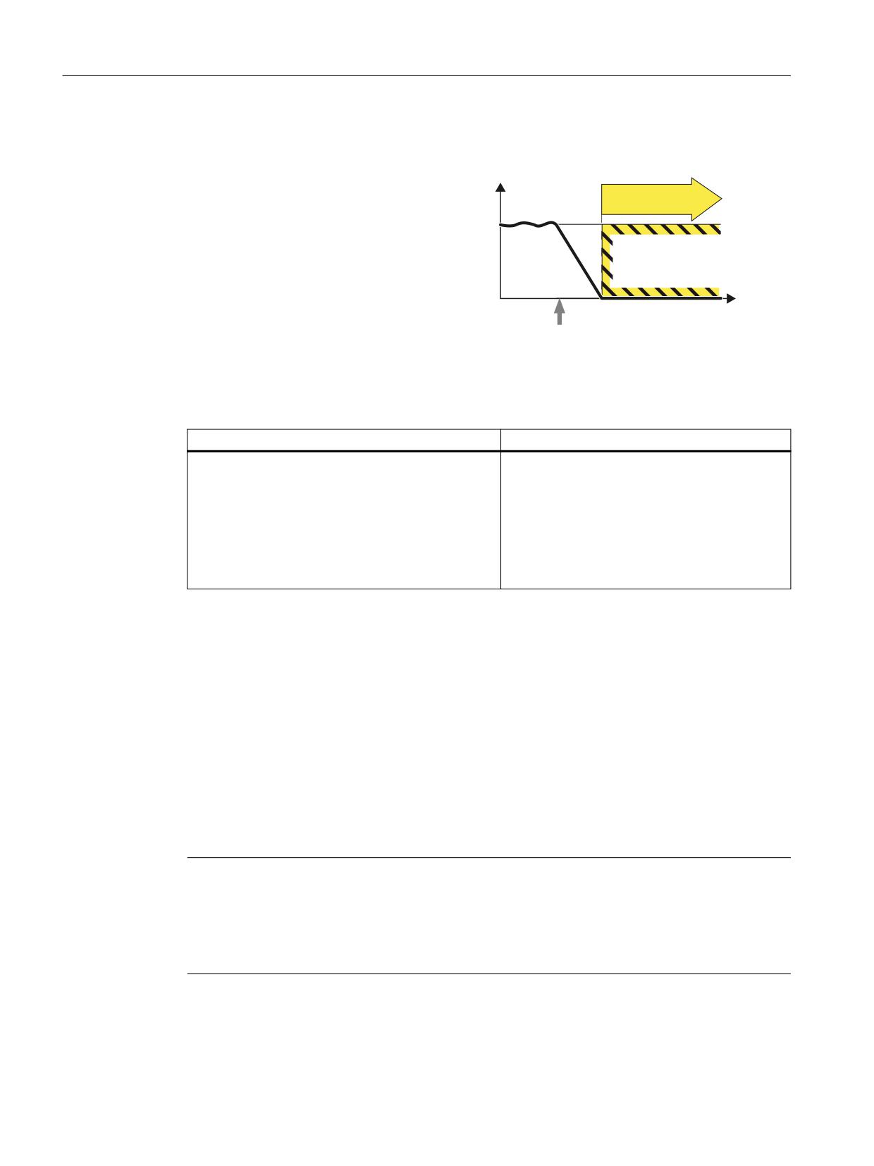
SOS
Definition according to EN 61800-5-2:
[
"The SOS function is used to safely monitor
SOS
the standstill position of a drive."
W
SOS selection
Example of how the function can be used
Example
Possible solution
A protective door must only be opened if a motor is in
• Select SOS
the safe standstill state.
• A higher-level controller brakes the axis (e.g.
position-controlled) down to standstill within
the configured time between the selection of
SOS and when it becomes active.
• Standstill is then safely monitored via the SOS
function.
5.7.1
Safe Operating Stop (SOS)
The protected machine areas can be entered without having to shut down the machine as long
as SOS is active.
After SOS has been selected it becomes active after the parameterizable delay time has expired.
The drive must be braked to standstill within this delay time (e.g. by the controller).
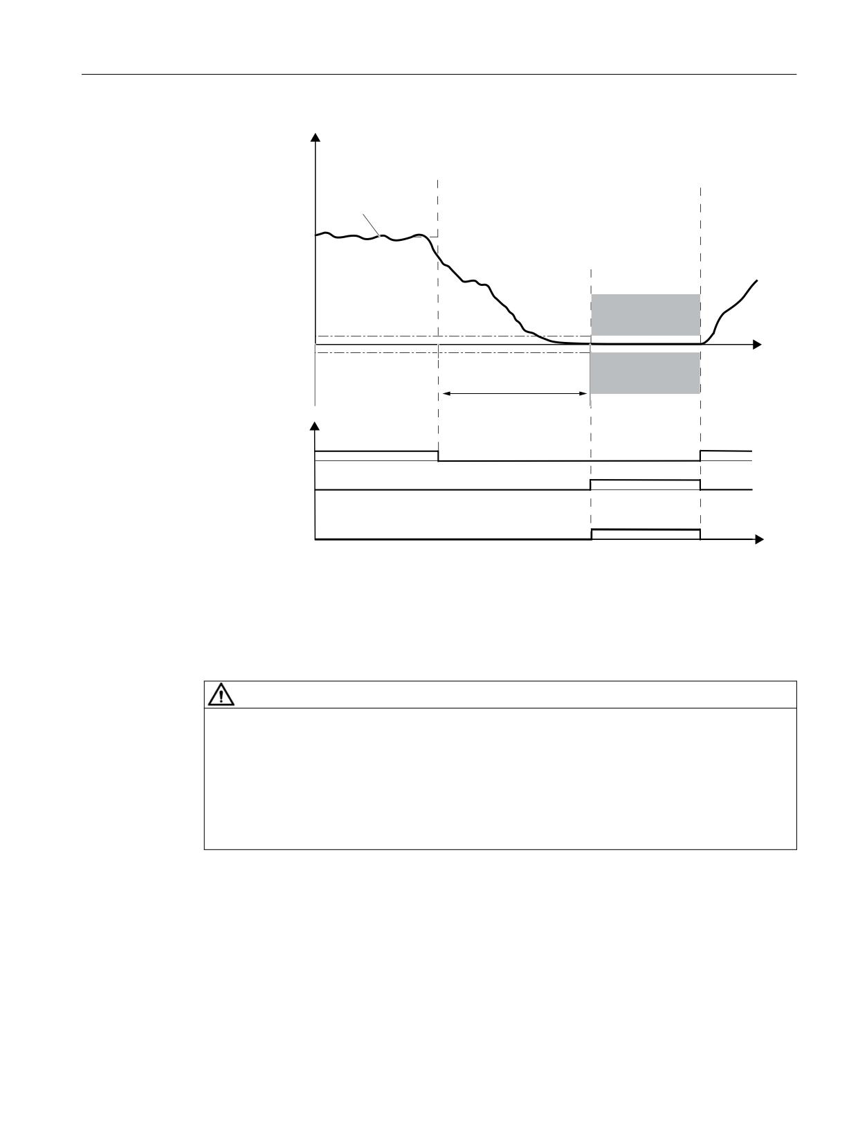
Drive stopping is monitored using an SOS tolerance window. When this function is activated, the
current actual position is saved as a comparative position, until SOS is deselected again. Any
delay time is cleared after SOS is deselected and the drive can be immediately moved.
The drive is stopped with SS1 when the standstill tolerance window is violated.
Note
Contrary to SS1 and SS2, SOS does not automatically brake the drive
The control still enters the setpoint.
This means that in the user program of the control system, the system must respond to the "SOS
selected" bit so that the control system brings the drive to a standstill within the delay time.
Safety Integrated plus
114
Commissioning Manual, 10/2020, 6FC5397-1FP40-6BA4
Safety functions integrated in the drive
5.7 SOS
;LVW
2SHUDWRU DFWLRQV
626 VHOHFWLRQ
626 GHVHOHF
WLRQ
$FWXDO SRVLWLRQ
626
6WDQGVWLOO WROHUDQFH
W
626
626 GHOD\ WLPH
'LDJQRVWLFV
626 GHVHOHFWLRQ
626 DFWLYH
352),VDIH
626 DFWLYH
6WDWXV ZRUG ELW
W
Figure 5-13
Standstill tolerance
5.7.2
Details and parameterization
WARNING
Drive can be forced out of the SOS position by mechanical forces
A drive in position control can be forced out of the Safe Operating Stop (SOS, stop Category 2
according to 60204-1) position by mechanical forces that are greater than the maximum
torque of the drive. This unexpected drive motion then initiates a Category 1 stop function
according to EN 60204-1. The alarms for SS1 and STO must be carefully observed. This
unexpected drive motion can result in death and serious injury.
• To rule out any unexpected motion, use a brake with safe monitoring (see SBC (Page 97)).
This function serves for failsafe monitoring of the standstill position of a drive.
• Drive stopping is monitored using an SOS tolerance window (p9530).
• Effect on "Setpoint speed limit effective" (r9733[0...2]):
If SOS is selected, setpoint 0 is specified in r9733[0...2].
Safety Integrated plus
Commissioning Manual, 10/2020, 6FC5397-1FP40-6BA4
115
Safety functions integrated in the drive
5.7 SOS
Note
Size of the tolerance window
The size of the tolerance window should be slightly above the standard standstill monitoring
limit, otherwise the standard monitoring functions will no longer be effective.
Parameter r9731 indicates the safe position accuracy (load side) that can be achieved as a
maximum, based on the acquisition of the actual value for the safe motion monitoring functions.
STOP B is the stop response after the standstill tolerance window has been violated.
The "SOS" function becomes active in the following cases:
• After SOS is selected and the delay time in p9551 has elapsed
The drive must be braked to standstill within this delay time (e.g. by the controller).
• As a consequence of SS2, SS2E or SS2ESR
• As a consequence of STOP C (corresponds to selection of SS2)
• As a consequence of STOP D (corresponds to selection of SOS)
• As a consequence of STOP E (corresponds to selecting SOS with additional activation of the
standard "Extended stop and retract (ESR)" function)
Responses
• Standstill tolerance violated in p9530
- STOP B with subsequent STOP A
- Safety message C01707
• System error
- STOP F
- Safety message C01711
Safety Integrated plus
116
Commissioning Manual, 10/2020, 6FC5397-1FP40-6BA4
Safety functions integrated in the drive
5.7 SOS
5.7.2.1
Function diagrams and parameters
Function diagrams (see SINAMICS S120/S150 List Manual)
•
2819
SI Extended Functions - SS1, SS2, SOS, internal STOP B, C, D, F
Overview of important parameters (see SINAMICS S120/S150 List Manual)
• p9501
SI Motion enable safety functions (Control Unit)
• p9501.23
Enable deactivation of SOS/SLS during an external STOP A
• p9530
SI Motion standstill tolerance (Control Unit)
• p9551
SI Motion SLS(SG) switchover/SOS(SBH) delay time (CU)
• p9567
Switchover speed to SOS/SLS
• p9569
Transition time to SOS after standstill
• r9722.0...31
CO/BO: SI Motion drive-integrated status signals
• r9731
SI Motion safe positioning accuracy
Safety Integrated plus
Commissioning Manual, 10/2020, 6FC5397-1FP40-6BA4
117
Safety functions integrated in the drive
5.8 SLS
5.8
SLS
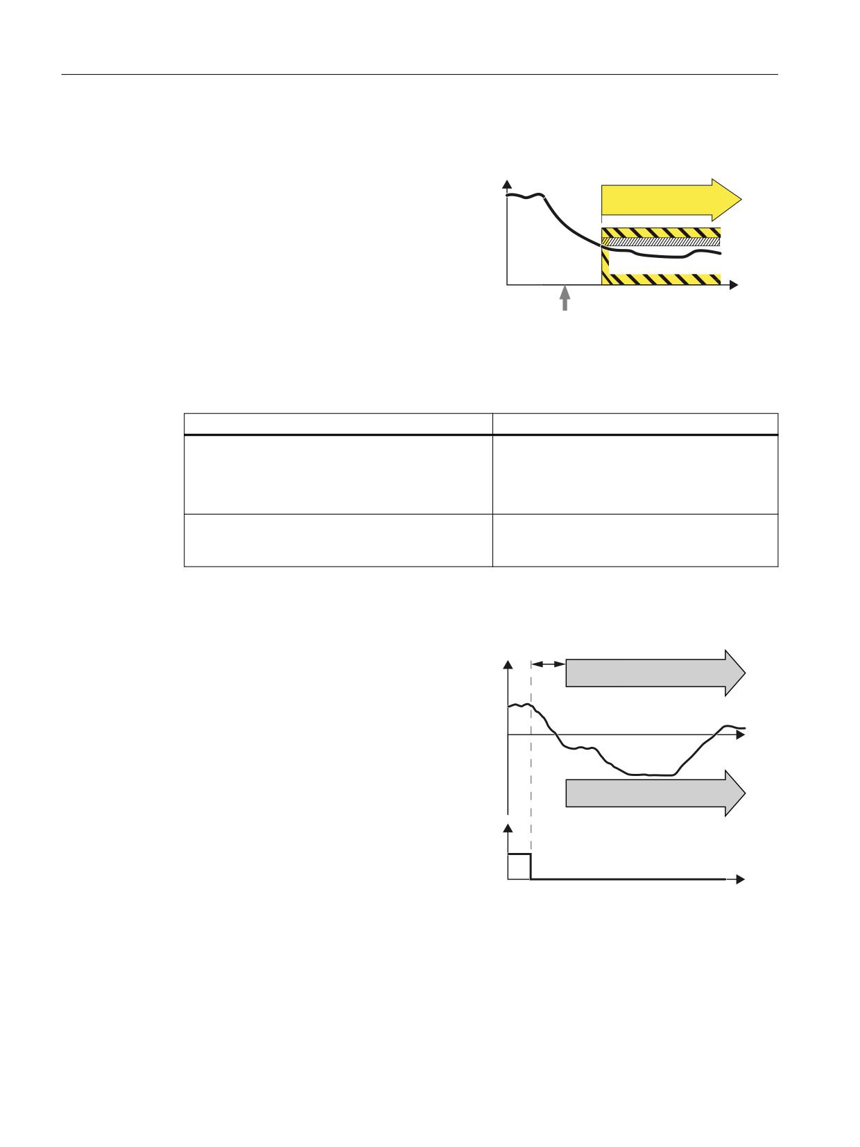
Definition according to EN 61800-5-2:
Y
"The "SLS" function prevents the motor from
SLS
exceeding the defined speed limit."
W
Select SLS
Examples of how the function can be used
Example
Possible solution
After opening a protective door, the machine opera-
• Select SLS in the converter using a failsafe
tor must enter the machine and in the hazardous
input or PROFIsafe .
zone, operate a horizontal conveyor belt running at a
• The converter limits and monitors the veloci-
slow speed using an acknowledgment button.
ty of the horizontal conveyor.
A spindle drive, depending on the selection of the
• Select SLS and the corresponding SLSlevel in
cutting tool, must not exceed a specific maximum
the converter via PROFIsafe.
velocity.
How does SLS function in detail?
Overview
'HOD\ WLPH 6/6
6SHHG
1. The inverter recognizes the
6/6
selection of SLS via a failsafe
input or via the PROFIsafe
safe communication.
2. SLS allows a motor to reduce
W
its possibly inadmissibly high
speed within a defined time.
6/6
3. SLS monitors the absolute val-
ue of the actual velocity.
6/6 GHVHOHFWLRQ
The SLS setpoint limit can be
transferred to the F-PLC,
352),VDIH
where the speed setpoint can
FRQWURO ZRUG
be limited.
W
In addition, you can configure
the setpoint limit provided by
SLS as maximum speed in the
ramp-function generator. In
this case, SLS limits the speed
setpoint.
Safety Integrated plus
118
Commissioning Manual, 10/2020, 6FC5397-1FP40-6BA4
Safety functions integrated in the drive
5.8 SLS
Note
SLS without selection
As an alternative to controlling via terminals and/or PROFIsafe, there is also the option to
parameterize the "SLS" function without selection. In this case, the "SLS" function is permanently
active after POWER ON. You can find details about this in Section "Safely-Limited Speed without
selection (Page 129)".
Selecting SLS when the motor is switched on
As soon as the converter detects the selection of SLS via a failsafe input or via PROFIsafe safe
communication, the following happens:
• To avoid a limit value being violated, the setpoint limit can be transferred to the F-PLC This
can then limit the velocity setpoint.
• If the speed setpoint limitation is interconnected to the ramp-function generator, the
converter limits the speed to a value below the SLS monitoring.
• For SLS without encoder, you can select whether or not the converter monitors motor
braking using the function "SBR (Safe Brake Ramp)" or "SAM (Safe Acceleration Monitor)" . For
SLS with encoder, function "SBR" cannot be selected.
Safety Integrated plus
Commissioning Manual, 10/2020, 6FC5397-1FP40-6BA4
119
Safety functions integrated in the drive
5.8 SLS
With braking ramp monitoring1)
Without braking ramp monitoring
(only without encoder)
(with or without encoder)
9HORFLW\
'HOD\ WLPH IRU EUDNH
9HORFLW\
'HOD\ WLPH IRU 6/6
UDPS
VZLWFKRYHU
6HWSRLQW
6HWSRLQW
6%5
6/6
6/6
/LPLWDWLRQ
/LPLWDWLRQ
W
6/6 GHVHOHFWLRQ
W
6/6 GHVHOHFWLRQ
352),VDIH FRQWURO
352),VDIH FRQWURO
ZRUG
ZRUG
W
W
6/6 DFWLYH
6/6 DFWLYH
) '2 RU
) '2 RU
352),VDIH VWDWXV
352),VDIH VWDWXV
ZRUG
ZRUG
W
W
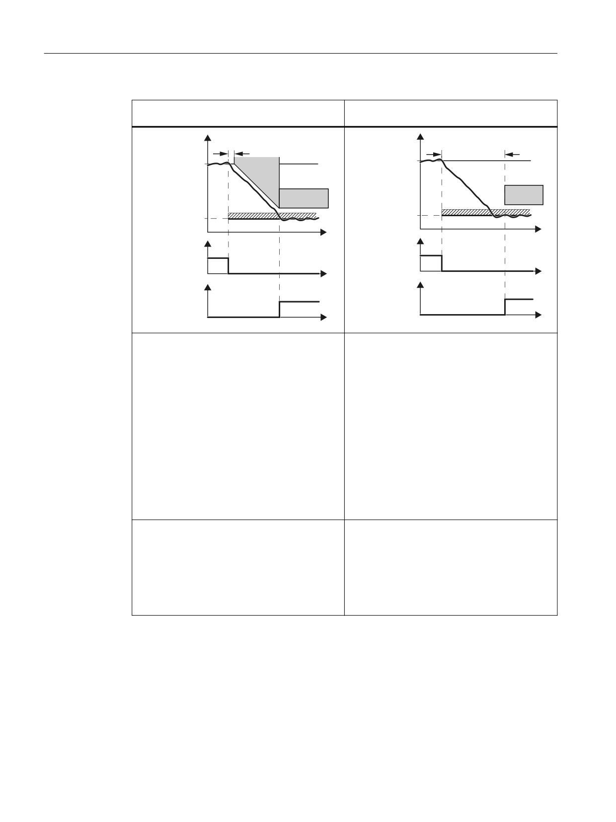
• After the adjustable "delay time for the braking
• The converter monitors the load velocity after
ramp", using the "SBR (Safe Brake Ramp)" func-
the "delay time for SLS switchover" has ex-
tion, the converter monitors whether the ve-
pired.
locity decreases.
• The converter switches from SBR to SLS as soon
as one of the following two conditions is fulfil-
led:
- The SBR monitoring ramp has reached the
value of the SLS monitoring.
This case is shown in the diagram above.
- After the actual velocity has reached the
value of the SLS monitoring threshold, the
system again waits for the "delay time for
braking ramp" until SLS becomes active.
Advantages:
Advantage:
• Already when braking, the converter detects as
• Commissioning is simplified, because instead of
to whether the load velocity decreases too
the subfunction SBR or SAM of the alternative
slowly.
brake ramp monitoring, you only have to set the
delay time.
• The feedback signal "SLS active" generally
comes earlier than without acceleration moni-
toring.
1)
The automatic reduction of the speed only takes effect when the ramp-function generator is
interconnected to the speed setpoint limitation.
Safety Integrated plus
120
Commissioning Manual, 10/2020, 6FC5397-1FP40-6BA4
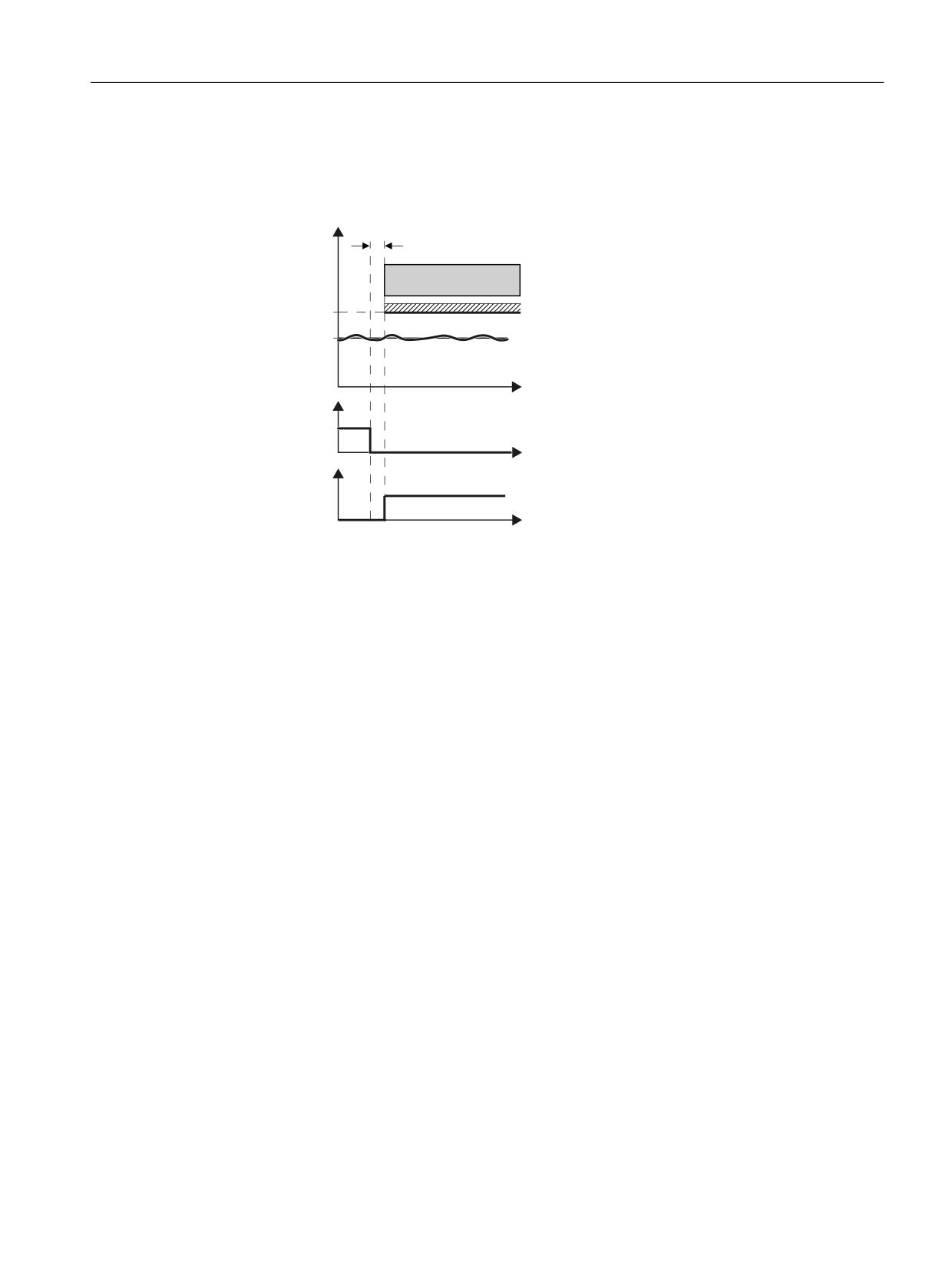
Safety functions integrated in the drive
5.8 SLS
Selecting SLS at low velocities
If the motor velocity when selecting SLS is less than the SLSlimit, then the drive responds as
follows:
9HORFLW\
'HOD\ WLPH 6/6
6/6
/LPLWDWLRQ
6HWSRLQW
W
6/6 GHVHOHFWLRQ
352),VDIH FRQWURO
ZRUG
W
6/6 DFWLYH
) '2 RU
352),VDIH VWDWXV
ZRUG
W
Figure 5-14
Selecting SLS at low velocities
Deselecting SLS
If the higher-level controller deselects SLS , then the converter deactivates limiting and
monitoring.
Switching over the monitoring limits
When SLS is active, you can switchover between 4 different speed levels. An exception is "SLS
without selection": In this case, there is only one limit.
Safety Integrated plus
Commissioning Manual, 10/2020, 6FC5397-1FP40-6BA4
121
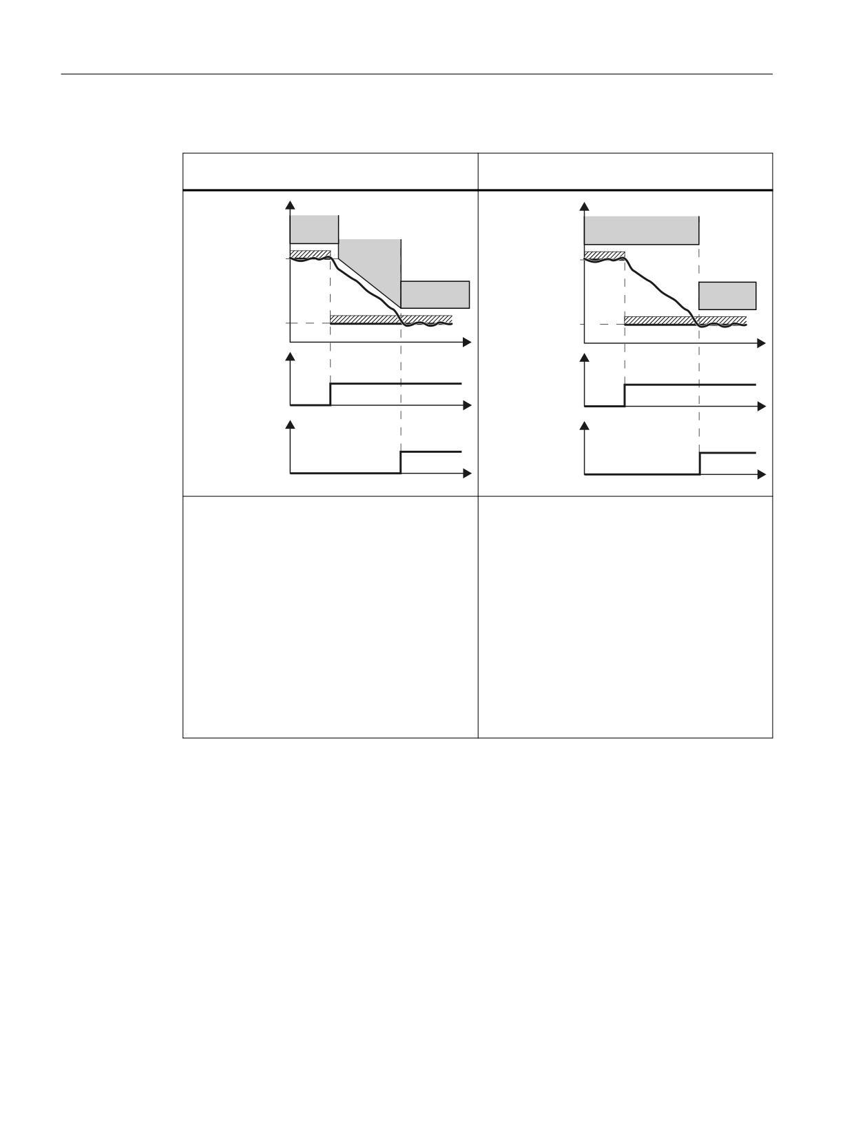
Safety functions integrated in the drive
5.8 SLS
Switching to a lower speed level
With braking ramp monitoring1)
Without braking ramp monitoring
(only without encoder)
(with or without encoder)
9HORFLW\
9HORFLW\
6/6
6/6
/LPLW OHYHO
6%5
/LPLW OHYHO
6/6
6/6
/LPLW OHYHO
/LPLW OHYHO
6HOHFW
W
6HOHFW
W
6/6 OHYHO
6/6 OHYHO
352),VDIH
/HYHO
352),VDIH
/HYHO
/HYHO
/HYHO
FRQWURO ZRUG
FRQWURO ZRUG
W
W
$FWLYH
$FWLYH
6/6 OHYHO
6/6 OHYHO
352),VDIH
352),VDIH
/HYHO
/HYHO
/HYHO
/HYHO
VWDWXV ZRUG
VWDWXV ZRUG
W
W
•
Once the "delay time for braking ramp" has
• The converter monitors the velocity with the
elapsed, the converter monitors the motor ve-
lower SLS level after the "delay time for SLS
locity using the function SBR (Safe Brake
changeover" has expired (this is the same delay
Ramp).
time that applies after selecting the function
SLS).
•
The converter switches over from SBR monitor-
ing to level 2 of SLS monitoring as soon as one
of the following conditions is fulfilled:
- The SBR monitoring ramp has reached the
value of the SLS monitoring.
This case is shown in the diagram above.
- The load velocity has decreased down to the
value SLS monitoring and the "delay time
for braking ramp" has expired.
1)
The automatic reduction of the speed only takes effect when the ramp-function generator is
interconnected to the speed setpoint limitation.
Switching to a higher speed level
If you switch over from a lower to a higher speed level, the converter immediately monitors the
actual velocity against the higher velocity.
Safety Integrated plus
122
Commissioning Manual, 10/2020, 6FC5397-1FP40-6BA4
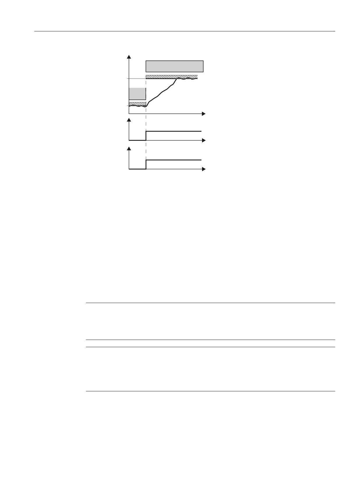
Safety functions integrated in the drive
5.8 SLS
6SHHG
6/6
/LPLW OHYHO
6/6
/LPLW OHYHO
6/6 OHYHO
W
VHOHFWLRQ
352),VDIH
/HYHO
/HYHO
FRQWURO ZRUG
W
$FWLYH
6/6 OHYHO
352),VDIH
/HYHO
/HYHO
VWDWXV ZRUG
W
Figure 5-15
Switching to a higher speed level
5.8.1
Details and parameterization
The "Safely-Limited Speed" (SLS) function is used to protect a drive against unintentionally high
speeds in both directions of rotation. This is achieved by monitoring the current drive speed up
to a speed limit.
Safely-Limited Speed prevents a parameterized speed limit from being exceeded. Limits must be
specified based on results of the risk analysis. Up to four different SLS speed limits can be
parameterized using parameter p9531[0..3]; it is possible to switch between them even if the
SLS is activated.
An override can also be added to SLS limit value 1. In operation, this override can be varied using
a PROFIsafe telegram.
Note
Deviation of the displayed speed limit
The SLS speed limit displayed in r9714[2] can deviate slightly from the specified SLS speed limit.
The reason for this is the internal resolution (r9732) of the speed values.
Note
Response in the event of a communication error
If p9580 ≠ 0 and SLS is active, in the event of communication failure, the parameterized ESR
reaction is only realized if, as SLS response, a STOP with delayed pulse cancellation when the bus
fails has been parameterized (p9563[0...3] ≥ 10).
Safety Integrated plus
Commissioning Manual, 10/2020, 6FC5397-1FP40-6BA4
123
Safety functions integrated in the drive
5.8 SLS
Note
Setpoint speed limit and SLS
• When parameterizing SLS, it also makes sense to configure the setpoint speed limiting. This
is done in a higher-level controller that evaluates the Safety Info Channel, for example, or by
wiring r9733[0/1] to the speed limits of the ramp-function generator (p1051/p1052).
• It does not make sense to use the positive and negative setpoint limiting for SLS in
conjunction with standard telegram 105 and others: With this combination, the velocity
setpoint of the standard telegram is only effective after the setpoint limiting.
5.8.1.1
Connection to the motion control in the NC
The following status bits or values from the SIC/SCC send data are linked to the NC so that for
safety functions integrated in the drive, subsequent responses or alarms do not occur in the NC:
• SI Motion Safety Info Channel status word: S_ZSW1B (Page 370)
- Bit 4 SLS_ACTIVE (SLS active)
- Bit 6 SLS_SELECTED (SLS selected)
• Speed setpoint limit in 32-bit resolution with sign bit: S_V_LIMIT_B (Page 373)
If the SLS function is selected or is active, then the corresponding bits are set in S_ZSW1B. The
currently selected velocity limit value of the SLS function integrated in the drive is then entered
in S_V_LIMIT_B.
After rescaling, S_V_LIMIT_B is multiplied with the value from MD36933
$MA_SAFE_DES_VELO_LIMIT[0...3], and is transferred to the motion control in the NC as
setpoint speed limit.
If a value of 0% or 100% is entered in MD36933, then the value from S_V_LIMIT_B is transferred
as speed setpoint limit.
When SOS or a STOP A to F is selected, then S_V_LIMIT_B contains a setpoint of 0. When the "SLS"
or "SOS" function is not selected in the drive, then the velocity/speed limit value in S_V_LIMIT_B
corresponds to the value for the maximum velocity/maximum speed (Vmax).
5.8.1.2
Safely Limited Speed (SLS)
Features
• When SLS is selected, the monitoring only takes effect after the configured delay time has
expired (p9551). Within this time, the actual speed must be below the (selected) limit. The
delay time is not effective when SLS is deselected.
• After switching to a lower limit value (p9531), the actual speed of the drive must have
dropped below the new limit within the delay time (p9551). The existing limit remains active
during the delay time. The lower limit value becomes active after the delay time expires. This
also applies to a reduction of the limit value via PROFIsafe.
• After the delay time has elapsed, if the actual speed of the drive is higher than the new Safely-
Limited Speed limit then a message is generated with the parameterized stop response.
Safety Integrated plus
124
Commissioning Manual, 10/2020, 6FC5397-1FP40-6BA4

Safety functions integrated in the drive
5.8 SLS
•
The stop response (STOP A, STOP B, STOP C, STOP D or STOP E) is parameterized with p9563.
•
During changeover to a higher limit value, the delay time is not active and the high limit value
becomes immediately active. This also applies to increasing the limit value via PROFIsafe.
•
4 parameterizable limit values p9531[0...3]
•
The first limit value can be entered via PROFIsafe telegrams 901, 902 and 903 (for
p9501.24 = 1)
•
In parameter p9533 enter the weighting factor to determine the setpoint limit from the
selected actual speed limit in percent. The active limit value is evaluated using this factor, and
is provided as setpoint limit in r9733.
- r9733[0] = p9531[x] x p9533 (converted from the load to the motor side)
- r9733[1] = - p9531[x] x p9533 (converted from the load to the motor side)
[x] = selected SLS stage
Conversion factor from the motor to the load side:
- Motor type = rotary and axis type = linear: p9522/(p9521 × p9520)
- Otherwise: p9522/p9521
•
Limit value
- r9733[0] = p9531[x] x p9533; x = selected SLS limit value
- r9733[1] = -p9531[x] x p9533; x = selected SLS limit value
r9733 is used, for example, for transferring values to a higher-level controller, which can
then, for example, adjust traversing speeds to the SLS levels or at the setpoint channel
(p1051). r9733 is a part of the Safety Info Channel (SIC).
•
The currently monitored limit value is displayed in parameter r9714[2].
Changeover of SLS limit values
The changeover is executed binary-coded via 2 F-DIs or 2 PROFIsafe control bits. The speed
selection status can be checked using parameters r9720.9/r9720.10. Parameters r9722.9 and
r9722.10 indicate the actual speed limit, bit r9722.4 must carry a "1" signal.
Table 5-1
Changeover of speed limits:
F-DI for bit 1
F-DI for bit 0
Speed limit
SLS level
(r9720.10)
(r9720.9)
0
0
p9531[0]
1
0
1
p9531[1]
2
1
0
p9531[2]
3
1
1
p9531[3]
4
Safety Integrated plus
Commissioning Manual, 10/2020, 6FC5397-1FP40-6BA4
125
Safety functions integrated in the drive
5.8 SLS
Excessively high speed during incorrect control of the Safely-Limited Speed limits via F-DI
For all control options except PROFIsafe, limit SLS1 is activated after 2 discrepancy errors that
have not been acknowledged. This means that for the 2 F-DIs for selecting the velocity levels, the
value 0 is the "safe state" (failsafe value).
• Therefore parametrize the SLS limits in ascending order, i.e. with limit SLS1 as the lowest
speed and limit SLS4 as the highest speed.
Responses
Speed limit value exceeded:
• Configured subsequent stop STOP A/B/C/D/E via p9563
• Safety message C01714
System fault:
• STOP F
• Safety message C01711
Transferring the first limit value via SIEMENS telegram 901, 902 or 903
You have the option of influencing the first SLS limit value via PROFIsafe:
• The transfer of the first SLS limit value via PROFIsafe is active if the speed level 1 in the
PROFIsafe telegram is selected and the bit "Enable transfer SLS (SG) limit via PROFIsafe"
(p9501.24) is set.
• S_SLS_LIMIT_A has the value range 1 ... 32767; the following applies:
-
32767 ≙ 100 % of the 1st SLS level
- The actually monitored limit value is calculated as follows:
SLS limit value = (S_SLS_LIMIT_A/32767) × p9531[0]
• Also in this case, speed levels 2, 3 and 4 can be parameterized and selected.
• In operation, the selected delay time cannot be changed. If you require various delay times
in your application, then you must realize this using a time-delayed transfer of the SLS limit
value using the F-PLC.
• If an incorrect SLS limit value is transferred, then the converter responds with the stop
response of speed level 1 parameterized in p9563.
Safety Integrated plus
126
Commissioning Manual, 10/2020, 6FC5397-1FP40-6BA4
Safety functions integrated in the drive
5.8 SLS
5.8.1.3
Safely Limited Speed without encoder
Functions
2 different encoderless Safely-Limited Speed monitoring functions can be set with parameter
p9506:
• p9506 = 3: Safe monitoring of acceleration (SAM) / delay time
The function is identical to "Safely-Limited Speed with encoder" which was described in the
previous section.
• p9506 = 1: Safe brake ramp monitoring (SBR)
Note
Defaults
• When commissioning, also note the description provided in the SINAMICS Safety Integrated
Function Manual, Chapter "Default settings for commissioning Safety Integrated Functions
without encoder".
• Information about setting the SBR monitoring function can be found in Chapter "SBR
(Page 139)".
Monitoring the brake ramp
• If the speed setpoint limitation (r9733) was connected to the setpoint channel (p1051/
p1052) and then SLS was selected - or if you change over to a lower SLS level - the motor
is decelerated from the actual speed to below the value defined with r9733 along the OFF3
ramp. In this case, the drive may no longer follow the setpoint of the higher-level motion
controller.
• Parameter p9582 is used to set the delay time for the braking ramp monitoring.
• Monitoring of the brake ramp is activated once the delay time in p9582 has elapsed. If the
actual speed of the drive violates the brake ramp (SBR) during braking, safety message
C01706 is output and the drive is stopped with STOP A.
• The newly selected SLS limit value is also taken over as the new limit speed, if either
- The SBR ramp has reached the new SLS limit value, or
- The actual speed of the drive was below the new SLS limit value for at least the time set
in p9582.
• The "Safely-Limited Speed without encoder" function then monitors whether the actual
speed remains below the newly selected SLS limit value.
• The parameterized stop response (p9563[x]) is initiated if the SLS limit value is exceeded.
Safety Integrated plus
Commissioning Manual, 10/2020, 6FC5397-1FP40-6BA4
127

Safety functions integrated in the drive
5.8 SLS
Configuring the limits
• The speed limits for Safely-Limited Speed without encoder are configured in exactly the same
way as described for Safely-Limited Speed with encoder.
• Only STOP A and STOP B may be configured as stop responses for "Safely-Limited Speed" (SLS)
without encoder.
Restart after OFF2/STO
If the drive has been switched off via STO, the following steps need to be carried out before a
restart can be performed:
1. Case
•
State after switching on
• SLS selected
• STO selected
• Pulse suppression active
•
Deselect STO
•
The drive enable must be issued within 5 seconds via a positive edge at OFF1, otherwise
STO is reactivated.
2. Case
•
Situation
• Traversing to standstill with SLS selected
• OFF1 is initiated, pulse cancellation becomes active (internal selection
STO)
•
Select STO
•
Deselect STO
STO activated internally via pulse suppression: This activation must be undone by selection/
deselection.
•
The drive enable must be issued within 5 seconds via a positive edge at OFF1, otherwise
STO is reactivated.
3. Case
•
Situation
• Traversing to standstill with SLS selected
• OFF1 is initiated, pulse cancellation becomes active (internal selection
STO)
•
Deselect SLS
STO activated internally via pulse suppression: This activation must be undone by selecting/
deselecting SLS.
•
Select SLS
The drive enable must be issued within 5 seconds via a positive edge at OFF1, otherwise
STO is reactivated.
4. Case
•
Situation
• All Safety Integrated functions are deselected.
•
After this the drive enable must be given by a positive edge at OFF1.
•
In this case, the motor is not started safely.
Safety Integrated plus
128
Commissioning Manual, 10/2020, 6FC5397-1FP40-6BA4
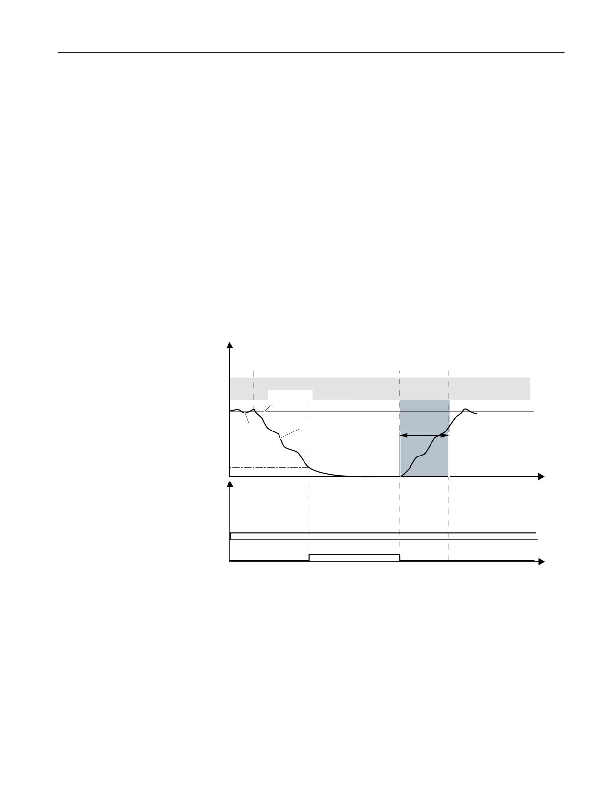
Safety functions integrated in the drive
5.8 SLS
5.8.1.4
Safely-Limited Speed without selection
Differences between Safely-Limited Speed with and without selection
• As an alternative to controlling via terminals and/or PROFIsafe, there is also the option to
parameterize the "SLS" function without selection.
• The function "SLS without selection" is selected with p9512.4 = 1.
• For "SLS without selection", only one SLS limit value can be parameterized (p9531[0]).
• The stop response is parameterized with p9563[0].
• For Safely-Limited Speed without selection there is no delay time. The function is always
active (with encoder), or it becomes active when switching on (without encoder).
Switching the motor on and off (without encoder)
The time response and diagnostic options are as follows in this SLS version:
Operator actions
/RDG VSHHG
Switch-off motor
Switch-on motor
OFF1/OFF3 command
ON command
6/6
6HWSRLQW
5DP
S GRZQ WLPH
6WDQGVWLOO
$FWXDO
VHFRQGV
2))
PRQLWRULQJ
YDOXH
S
S
S
W
'LDJQRVWLFV
6/6 DFWLYH
U
U
6DIH SXOVH FDQFHOODWLRQ
W
DFWLYH
Figure 5-16
Time response of SLS without selection (example: Switching the motor on and off (without
encoder))
"SLS without selection" behaves as follows when switching off and switching on again:
• After switch-off, the motor behaves in accordance with the canceled signal (OFF1, OFF2 or
OFF3).
• The "safe pulse cancellation" becomes active after the standstill limit is undershot. If a brake
has been parameterized, it is also closed.
Safety Integrated plus
Commissioning Manual, 10/2020, 6FC5397-1FP40-6BA4
129
Safety functions integrated in the drive
5.8 SLS
• After the ON command, the converter cancels the "safe pulse cancellation" state and the start
procedure is initiated.
• If the minimum current has not been reached after 5 s, the converter returns into the "safe
pulse suppression" state and initiates alarm C01711.
5.8.1.5
Function diagrams and parameters
Function diagrams (see SINAMICS S120/S150 List Manual)
•
2820
SI Extended Functions - SLS (Safely-Limited Speed)
Overview of important parameters (see SINAMICS S120/S150 List Manual)
• p9501.0
SI Motion enable safety functions (Control Unit)
• p9512
Select SI Motion safety functions without selection (CU)
• p9531[0...3]
SI Motion SLS (SG) limits (Control Unit)
• p9551
SI Motion SLS(SG) switchover/SOS(SBH) delay time (CU)
• p9563[0...3]
SI Motion SLS (SG)-specific stop response (Control Unit)
• p9580
SI Motion STO delay bus failure (Control Unit)
• p9581
SI Motion braking ramp reference value (Control Unit)
• p9582
SI Motion braking ramp delay time (Control Unit)
• p9583
SI Motion braking ramp monitoring time (Control Unit)
• p9601
SI enable functions integrated in the drive (Control Unit)
• r9707[0...2]
CO: SI Motion diagnostics actual position value GX_XIST1
• r9714[0...2]
CO: SI Motion diagnostics velocity
• r9720.0...27
CO/BO: SI Motion drive-integrated control signals
• r9721.0...15
CO/BO: SI Motion status signals (Control Unit)
• r9722.0...31
CO/BO: SI Motion drive-integrated status signals (Control Unit)
Safety Integrated plus
130
Commissioning Manual, 10/2020, 6FC5397-1FP40-6BA4
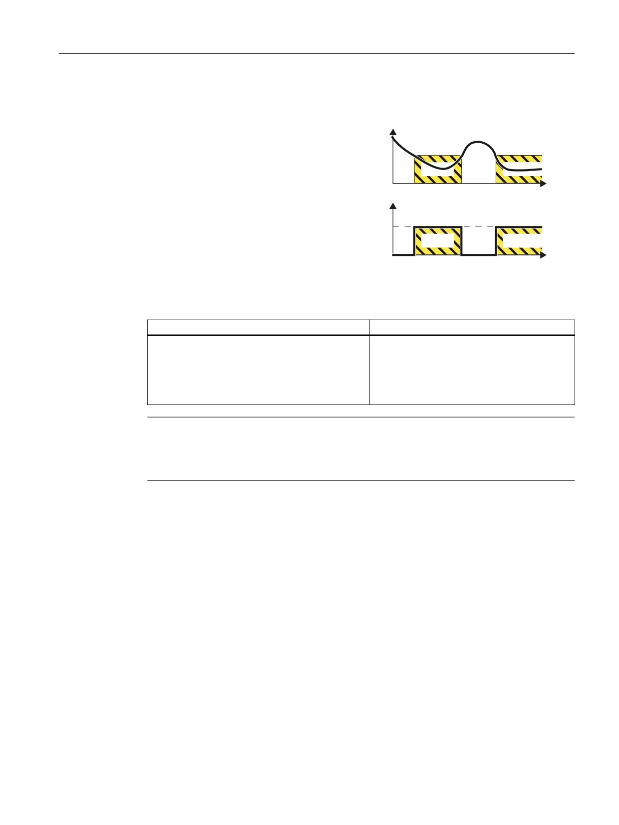
Safety functions integrated in the drive
5.9 SSM
5.9
SSM
Definition according to EN 61800-5-2:
Y
"The "SSM" function supplies a safe out-
put signal to indicate whether the mo-
tor speed is below a specified limit val-
ue."
W
660 RXWSXW VLJQDO
6SHHG
EHORZ WKH
OLPLW YDOXH
W
Example of how the function can be used
Example
Possible solution
A centrifuge may only be filled below a velocity de-
• SSM is active through the configuration of the
fined by the user.
Safety Integrated Extended Functions.
• The converter safely monitors the centrifuge
speed and enables the process to advance to
the next step using the "Status SSM" status bit.
Note
SSM is a pure signaling function
Contrary to other safety functions integrated in the drive, a violation of the SSM limit does not
result in a drive-based stop response.
5.9.1
Details and parameterization
The "Safe Speed Monitor" (SSM) function provides a reliable method for detecting when a speed
limit has been fallen below in both directions of rotation, e.g. for zero speed detection. A failsafe
output signal is available for further processing.
Features
• Safe monitoring of the specified speed limit
• Parameterizable hysteresis
• Adjustable filter time (PT1 filter)
Safety Integrated plus
Commissioning Manual, 10/2020, 6FC5397-1FP40-6BA4
131
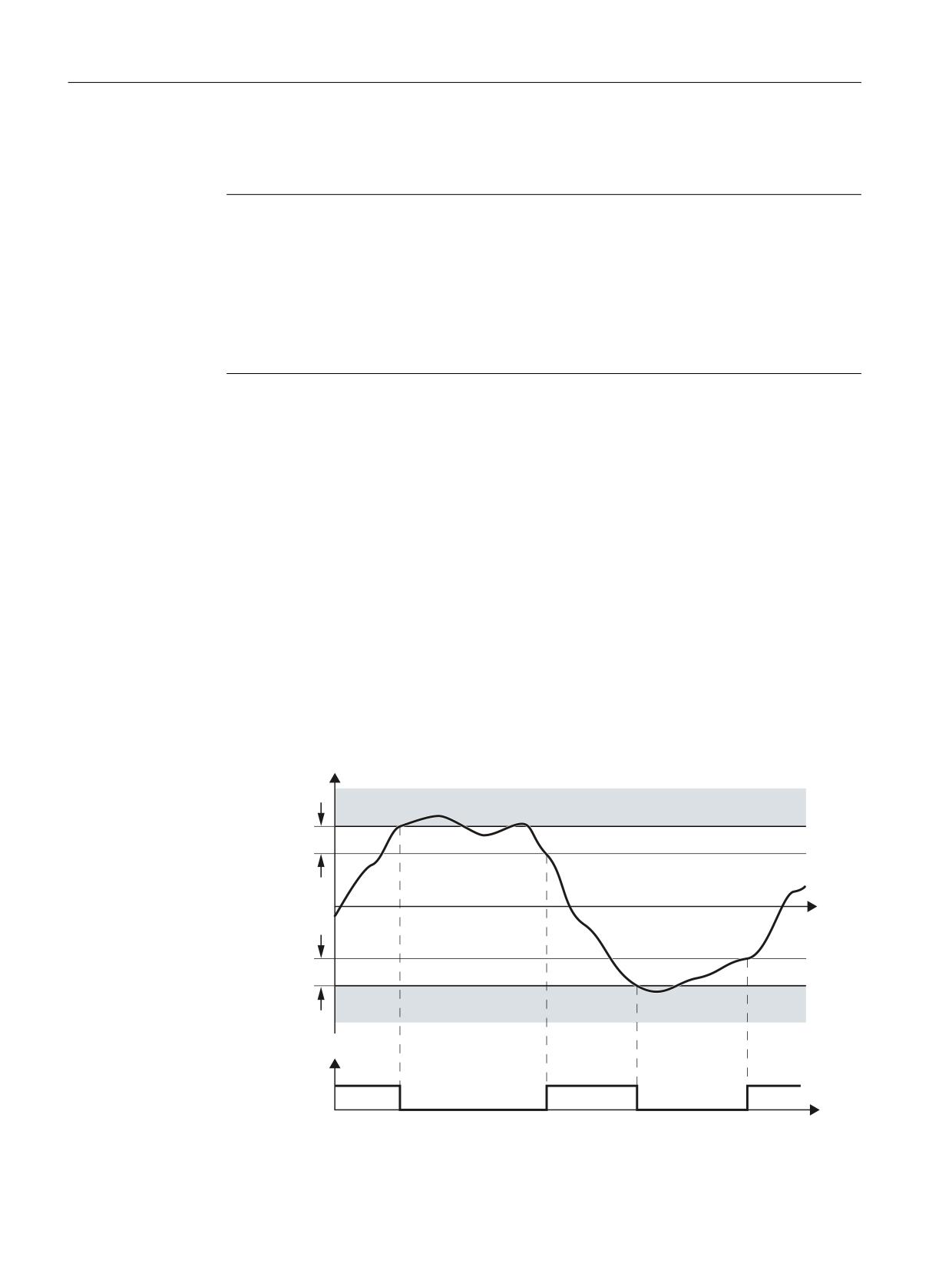
Safety functions integrated in the drive
5.9 SSM
• Safe output signal
• No stop response
Note
Unexpected response of STOP F for SSM
A STOP F is indicated by safety message C01711. STOP F only results in the subsequent
response STOP B / STOP A if one of the safety functions is active. If only the SSM function
without hysteresis (that is, p9501.16 = 0) is active, a STOP F cross-checking error does not
result in a STOP B / STOP A follow-up response.
• The monitoring function is considered to be active as soon as "SSM with hysteresis" is
activated.
How does SSM function in detail?
Requirements
The safety function "SSM" cannot be selected or deselected using external control signals. SSM
is active if, for the drive involved, the following settings have been made:
• Extended Functions are selected as safety function scope.
• The velocity limit for SSM is parameterized > 0.
Evaluating the speed
The converter compares the load speed with the speed limit and signals if the limit value is
undershot to the high-level control.
Parameterizable hysteresis
The parameterizable hysteresis ensures that the SSM output signal does not jump between the
values "0" and "1" in the limit range.
6SHHG
660
+\VWHUHVLV
W
+\VWHUHVLV
660
6SHHG EHORZ OLPLW
YDOXH
) '2 RU
352),VDIH VWDWXV ZRUG
W
Safety Integrated plus
132
Commissioning Manual, 10/2020, 6FC5397-1FP40-6BA4
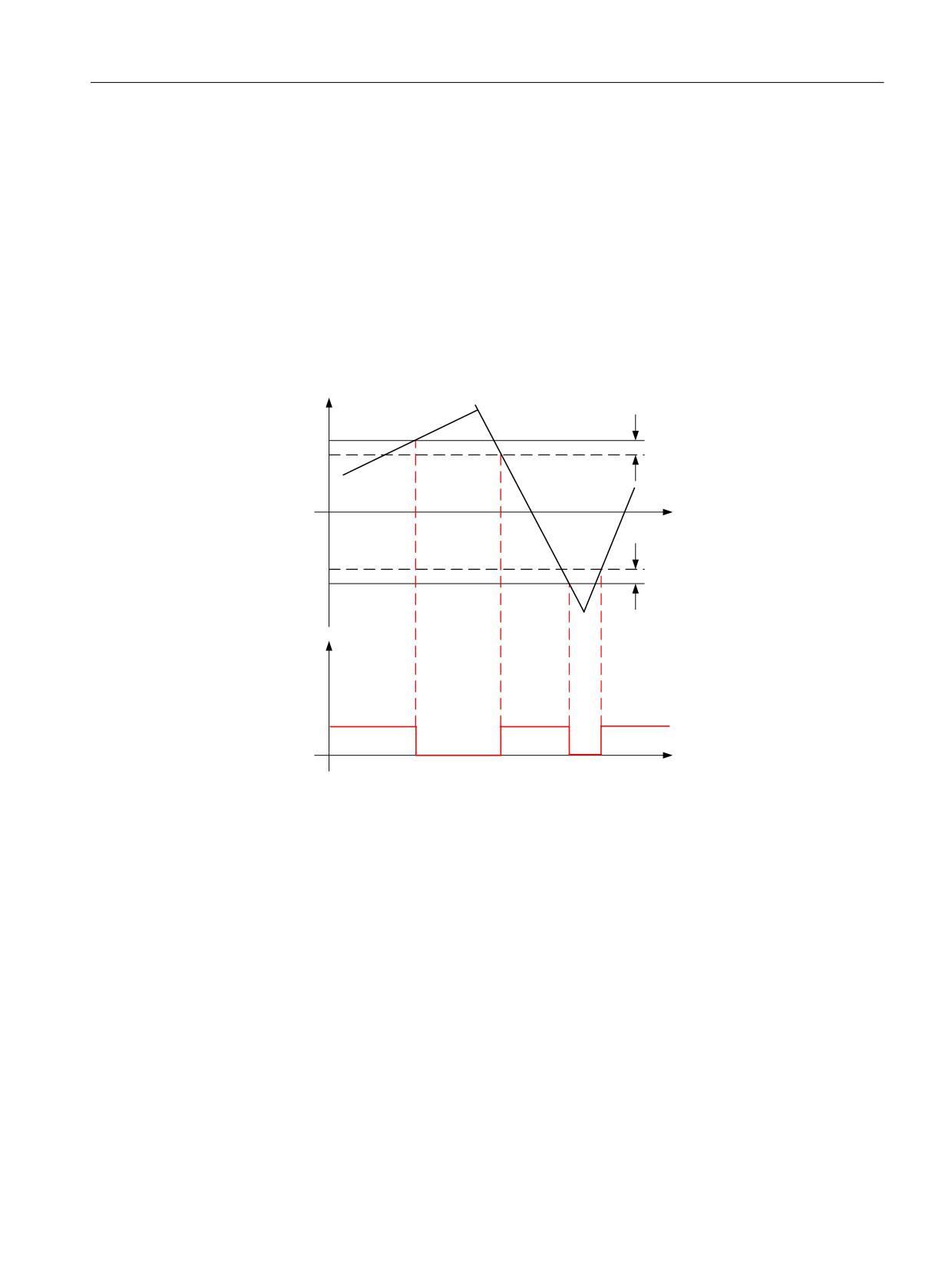
Safety functions integrated in the drive
5.9 SSM
Figure 5-17
Time response of the safety function SSM (Safe Speed Monitor)
5.9.1.1
Signal characteristic (with encoder)
Functional features of "Safe Speed Monitor" with encoder
A hysteresis can be configured for the SSM function using (p9547). In this way, a more stable
signal characteristic of SSM can be achieved at velocities close to the velocity limit (p9546).
The following diagram shows the characteristic of the safe output signal SSM when the
hysteresis is active:
Q
Q[
S
+\VWHUHVLV S
W
+\VWHUHVLV S
Q[
S
660 RXWSXW
VLJQDO
W
Figure 5-18
Safe output signal for SSM with hysteresis
5.9.1.2
Differences in operation without encoder
In operation, safety function SSM makes a distinction without encoder as a result of the
following features:
• Due to the less precise speed sensing, "Safe Speed Monitor without encoder" requires a
higher hysteresis (p9547) and, where applicable, a filter time (p9545) compared with the
function with encoder.
• For Safe Speed Monitor without encoder, after pulse suppression the drive is unable to
determine the current speed. For this operating state, the additional setting "Feedback signal
SSM for pulse inhibit" is available (see below)
Safety Integrated plus
Commissioning Manual, 10/2020, 6FC5397-1FP40-6BA4
133
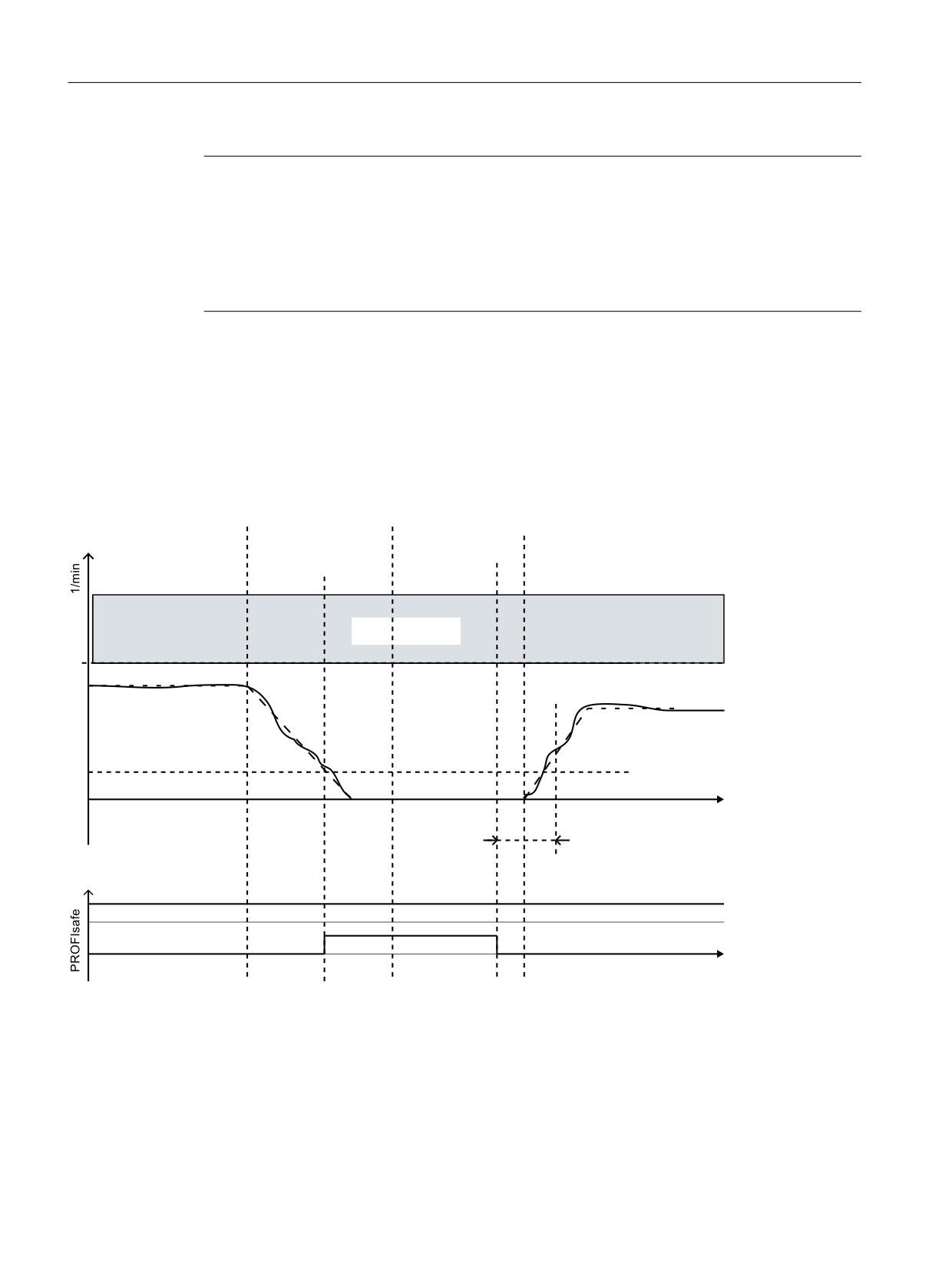
Safety functions integrated in the drive
5.9 SSM
Note
Setting of the OFF1 or OFF3 ramp-down time
If the OFF1 or OFF3 ramp-down time is too short or the difference between the SSM limit speed
and the shutdown speed is too small, the "speed below limit value" signal may not change to 1,
because no actual speed value could be determined below the SSM limit before pulse
suppression occurred. In this case, the OFF1 or OFF3 ramp-down time or the margin between
SSM speed limit and shutdown speed should be increased.
5.9.1.3
Signal characteristic (without encoder)
Procedure when the "Feedback signal SSM for pulse inhibit" setting is activated
The following diagram shows the signal characteristic if property "Feedback signal SSM for pulse
inhibit" is activated. (p9509.0 = 0)
3XOVHV
2))
6HOHFW 672
HQDEOHG
$XWRPDWLF
'HVHOHFW 672
6HOHFW 672
0R
QLWRULQJ
660 VSHHG
OLPLW
6SHHG
=HUR VSHHG GHWHFWLRQ
W
7LPHU V
660 IHHGEDFN VLJQDO
6DIH RXWSXW VLJQDO
3RZHU UHPRYHG 672
W
Figure 5-19
Flow chart: SSM without encoder with feedback signal SSM for pulse inhibit (p9509.0 = 0)
The speed remains below the speed limit throughout the entire monitoring period. This is the
reason that status signal "SSM (Speed below limit value)" goes to 1 (r9722.15 = 1). After the
command for pulse suppression, the motor speed drops. The internal STO is set when the speed
drops below the zero speed detection level.
In this case, the SSM status signal remains HIGH; it is frozen. The drive cannot accelerate again,
due to the internal STO selection.
Safety Integrated plus
134
Commissioning Manual, 10/2020, 6FC5397-1FP40-6BA4
Safety functions integrated in the drive
5.9 SSM
To restart the motor safely, the STO must be selected manually and deselected once more. After
the STO has been deselected, a 5 second time window is opened. If the pulse enable takes place
within this time window, the motor starts. If the pulse enable does not take place within this 5
second time window, the internal STO becomes active once more.
Procedure when the "Feedback signal SSM for pulse inhibit" setting is deactivated
If property "Feedback signal SSM for pulse inhibit" is deactivated (p9509.0 = 1), then SSM
monitoring is exited after pulse cancellation. Status signal "SSM (Speed below limit value)" goes
to 0 (r9722.15 = 0). The SSM monitoring is only reactivated after a new pulse enable. In this case,
STO must not be selected and deselected to start the drive.
Restart after pulse cancellation for p9509.0 = 0
If the drive pulses have been suppressed using OFF1/OFF2/STO, the following steps must be
carried out for a restart:
1. Case
• State after switching on
• SSM active
• STO selected
• Pulse suppression active
• Deselect STO
• The drive enable must be issued within 5 seconds via a positive edge at OFF1, otherwise
STO is reactivated.
2. Case
• Situation
• SSM active
• Motor turning
• OFF1 triggered, pulses are suppressed
• Select STO
• Deselect STO
STO activated internally via pulse suppression: This activation must be undone by selecting/
deselecting STO.
• The drive enable must be issued within 5 seconds via a positive edge at OFF1, otherwise
STO is reactivated.
Safety Integrated plus
Commissioning Manual, 10/2020, 6FC5397-1FP40-6BA4
135
Safety functions integrated in the drive
5.9 SSM
5.9.1.4
Function diagrams and parameters
Function diagrams
•
2823
SI Extended Functions - SSM (Safe Speed Monitor)
•
2840
SI Extended Functions - SI Motion drive-integrated control signals/status
signals
Overview of important parameters (see SINAMICS S120/S150 List Manual)
• p9501
SI Motion enable safety functions (Control Unit)
• p9501.161)
Enable SSM (n < nx) hysteresis and filtering
Screen form: "SSM with hysteresis"
• p9506
SI Motion function specification (Control Unit)
• p9509
SI Motion behavior during pulse suppression (Control Unit)
• p9509.11)
SSM during pulse cancellation and with no encoder
Screen form: "Feedback signal SSM active for pulse inhibit"
• p95451)
SI Motion SSM (SGA n < nx) filter time (Control Unit)
Screen form: "Filter time"
• p95461)
SI Motion SSM (SGA n < nx) speed limit (CU)
Screen form: "Velocity limit"
• p95471)
SI Motion SSM (SGA n < nx) speed hysteresis n_x (CU)
Screen form: "Hysteresis"
• r9722.0...14
CO/BO: SI Motion drive-integrated status signals
• r9722.151)
SSM (speed below limit value)
Screen form: "Velocity below limit value SSM"
1) You can parameterize this parameter using the additional screen form mentioned.
All other parameters that have not been specifically marked, are either part of the general NC and
drive-specific settings, or can only be configured using the parameter list. The parameter list can
be accessed in the function-specific screen forms of the safety functions by pressing softkey
"Parameter list".
Additional information
You can find a complete description of all SINAMICS parameters - as well as the associated
function diagrams - in the SINAMICS S120/S150 List Manual.
Safety Integrated plus
136
Commissioning Manual, 10/2020, 6FC5397-1FP40-6BA4
Safety functions integrated in the drive
5.10 SAM
5.10
SAM
The "Safe Acceleration Monitor" (SAM) function is used to safety monitor braking along the OFF3
ramp. The function is active for SS1, SS2 or STOP B and STOP C.
Features
As long as the speed is less, the converter continuously adds the adjustable tolerance p9548 to
the actual speed so that the monitoring tracks the speed. If the speed is temporarily higher, the
monitoring remains at the last value. The converter reduces the monitoring threshold until the
"Shutdown speed" has been reached.
SAM recognizes if the drive accelerates beyond the tolerance defined in p9548 during the ramp-
down phase, and generates a STOP A. The monitoring function is activated for SS1 (or STOP B)
and SS2 (or STOP C) and is deactivated after the speed drops below the value set in p9568.
Note
Relationship between SSM and SAM
If 0 is entered for p9568, the speed limit of the SSM function (p9546) is also used as minimum
limit value for the SAM function (Safe Acceleration Monitoring). If the speed is below this limit,
SAM no longer triggers a response from the drive.
In this case, the effects of Safe Acceleration Monitoring are therefore significantly restricted if a
relatively high SSM velocity limit is set when using the SS1 and SS2 stop functions.
Note
No direct selection of SAM
SAM is part of the Safety Integrated Extended Functions SS1 and SS2 or STOP B and STOP C. SAM
cannot be individually selected.
Calculating the SAM tolerance of the actual speed
• The following applies when parameterizing the SAM tolerance:
- The maximum speed increase after SS1 or SS2 is triggered results from the effective
acceleration (a) and the duration of the acceleration phase.
- The duration of the acceleration phase is equivalent to one monitoring cycle (MC p9500)
(delay from detecting an SS1 / SS2 until nset = 0)
• Calculating the SAM tolerance:
Actual speed for SAM = acceleration × acceleration duration
The following setup rule is derived thereof:
- For linear axes:
SAM tolerance [mm/min] = a [m/s2] x MC [s] x 1000 [mm/m] x 60 [s/min]
- For rotary axes:
SAM tolerance [rpm] = a [rev/s2] x MC [s] x 60 [s/min]
Safety Integrated plus
Commissioning Manual, 10/2020, 6FC5397-1FP40-6BA4
137
Safety functions integrated in the drive
5.10 SAM
• Recommendation
The SAM tolerance value entered should be approx. 20% higher than the calculated value.
• You set the tolerance such that the "overshoot" is tolerated that necessarily occurs when
standstill is reached after braking along the OFF3 ramp. However, it cannot be calculated as
to just how high this is.
Note
First monitoring cycle
For SAM, in the first "SI Motion monitoring cycle" (p9500) a higher SAM tolerance is taken into
account in order to compensate for possible settling operations without resulting in an incorrect
initiation. The increase factor is calculated as follows:
SI Motion monitoring cycle (p9500) / SI Motion actual value acquisition cycle (p9511)
Example:
SI Motion monitoring cycle (p9500) = 12 ms
SI Motion actual value acquisition cycle (p9511) = 1 ms
SAM tolerance (p9548) = 300 rpm
Actual speed = 250
Rotary axis
In the first cycle after activation of the monitoring, the SAM limit value is therefore:
Actual speed + SAM tolerance · (12 ms/1 ms) =
250 rpm + 300 rpm · 12 =
approx. 3850 rpm
Responses
• Speed limit violated (SAM):
- STOP A
- Safety message C01706
• System fault:
- STOP F with subsequent STOP A
- Safety message C01711
Overview of important parameters (see SINAMICS S120/S150 List Manual)
• p9546
SI Motion SSM (SGA n < nx) speed limit (CU)
• p9548
SI Motion SAM actual speed tolerance (Control Unit)
• p9568
SI Motion SAM speed limit (Control Unit)
Safety Integrated plus
138
Commissioning Manual, 10/2020, 6FC5397-1FP40-6BA4
Safety functions integrated in the drive
5.11 SBR
5.11
SBR
The "Safe Brake Ramp (SBR)" function provides a safety-related method for monitoring the brake
ramp. The "Safe Brake Ramp (SBR)" function is used to monitor braking with the functions "SS1
with/without encoder" and "SLS without encoder" as well as for STOP B / STOP C (for Safety
Integrated with encoder). For SLS, the setpoint limiting of the Safety Integrated Functions
(r9733) must be connected to the ramp-function generator (p1051/p1052).
Features
The motor is immediately braked along the OFF3 ramp as soon as SS1, SS2, or SLS is triggered.
Monitoring of the brake ramp is activated once the delay time in p9582 has elapsed. Monitoring
ensures that the motor does not exceed the set brake ramp (SBR) when braking. The safe
monitoring of the brake ramp is deactivated
• For SS1:
- As soon as the speed drops below the shutdown speed (p9560).
Or:
- As soon as the SS2 delay time (p9552) has elapsed.
• For SLS:
- As soon as the set brake ramp has reached the new SLS level
Or:
- As soon as the actual speed drops below the newly selected SLS level and has remained
there for the time parameterized in p9582.
Additional specific functions (e.g. STO, new SLS speed limit, etc.) are activated at this point,
depending on the Safety Integrated Function used.
Safety Integrated plus
Commissioning Manual, 10/2020, 6FC5397-1FP40-6BA4
139
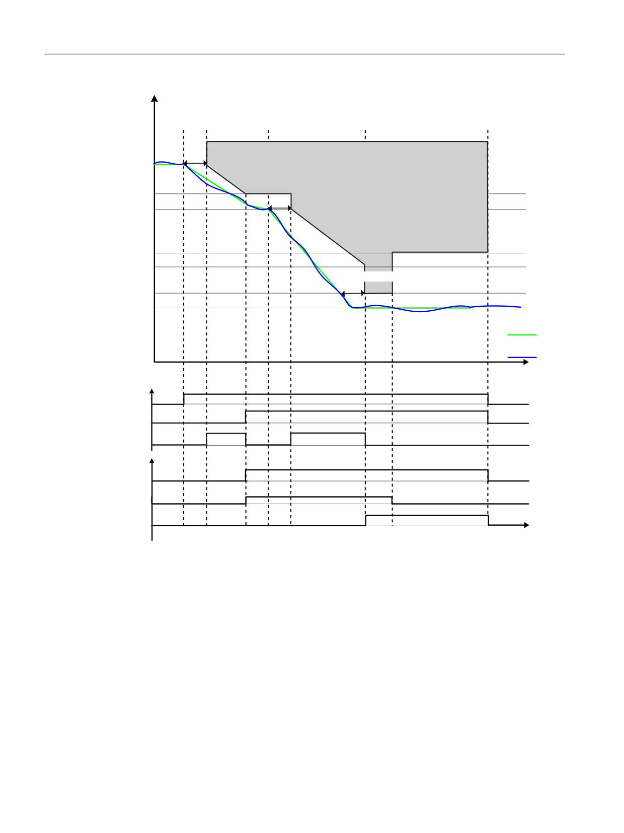
Safety functions integrated in the drive
5.11 SBR
6HOHFW 6/6
6HOHFW 6/6 OLPLW
6HOHFW 6/6 OLPLW
6HOHFW 6/6
PP
8VHU DFWLRQ
8VHU DFWLRQ
8VHU DFWLRQ
8VHU DFWLRQ
VHW 6/6
VHW 6/6 OLPLW
VHW 6/6 OLPLW
VHW 6/6 OLPLW
GHVHOHFW 6/6
!
0RQLWRULQJ UDPS DFWLYH
(QYHORSH FXUYH
6/6 OLPLW YDOXH
!
0RQLWRULQJ UDPS DFWLYH
6/6 VHWSRLQW OLPLW
(QYHORSH FXUYH
6/6 OLPLW YDOXH
6/6 VHWSRLQW OLPLW
(QYHORSH FXUYH
6/6 OLPLW YDOXH
!
6/6 VHWSRLQW OLPLW
6
SHHG VHWSRLQW
$FWXDO VSHHG YDOXH
W
'LDJQRVWLFV
6/6 VHOHFWHG
6/6 DFWLYH
6%5 0RQLWRULQJ DFWLYH
352),VDIH
6/6 DFWLYH
6/6 OLPLW
6/6 OLPLW
W
! 6%5 GHOD\ WLPH
Figure 5-20
Safe Brake Ramp without encoder (for SLS)
Safety Integrated plus
140
Commissioning Manual, 10/2020, 6FC5397-1FP40-6BA4
Safety functions integrated in the drive
5.11 SBR
Parameterization of the brake ramp
p9581 (SI Motion braking ramp reference value) and p9583 (SI Motion brake ramp monitoring
time) are used to set the gradient of the brake ramp. Parameter p9581 determine the reference
speed and parameter p9583 define the ramp-down time. Parameter p9582 is used to set the
time which passes after the triggering of SS1, selection of SLS or SLS level changeover and the
start of brake ramp monitoring.
Note
SBR and OFF3 curve
The SBR curve should be aligned to the OFF3 curve. In addition, you should check that under
every load condition, the drive can follow this OFF3 ramp.
Note
Limitation of the SBR delay time
The SBR delay time (p9582) is limited to a minimum value of 2 SI Motion monitoring cycles
(2 · p9500), i.e. even if a value less than 2 · p9500 is parameterized for the delay time (p9582),
SBR only takes effect 2 safety cycles after an active SS1.
If a value greater than 2 · p9500 is parameterized for the delay time (p9582), SBR takes effect
after active SS1 after the time p9582. Ensure that you round off the SBR delay time to an integer
multiple of the safety cycle (p9500).
Responses to brake ramp violations (SBR)
• Safety message C01706 (SI Motion: SAM/SBR limit exceeded)
• Drive is stopped with STOP A
• For an encoder fault in a 1-encoder system, the "Safe Acceleration Monitoring" function is not
active. A Category 0 or 1 stop response (EN 60204-1) can be set with parameter p9516.4.
Features
• Part of the "SS1 with/without encoder", "SS2 with encoder", "SLS without encoder" and
"STOP B/STOP C (for safety with encoder)" functions.
• Parameterizable safe brake ramp
Safety Integrated plus
Commissioning Manual, 10/2020, 6FC5397-1FP40-6BA4
141
Safety functions integrated in the drive
5.11 SBR
5.11.1
Important parameters
Overview of important parameters (see SINAMICS S120/S150 List Manual)
• p9560
SI Motion STO shutdown speed (Control Unit)
• p9581
SI Motion braking ramp reference value (Control Unit)
• p9582
SI Motion braking ramp delay time (Control Unit)
• p9583
SI Motion braking ramp monitoring time (Control Unit)
Safety Integrated plus
142
Commissioning Manual, 10/2020, 6FC5397-1FP40-6BA4
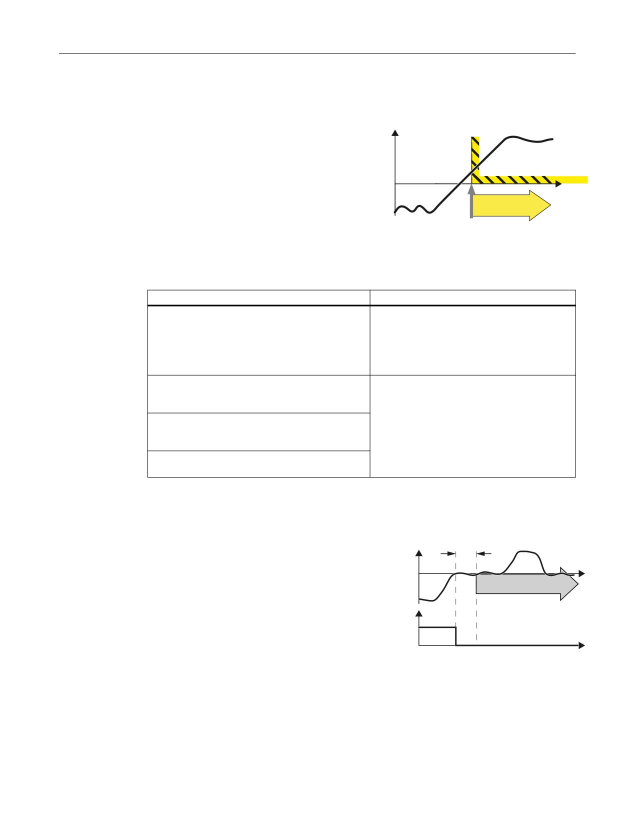
Safety functions integrated in the drive
5.12 SDI
5.12
SDI
Definition according to EN 61800-5-2:
Y
The "SDI" function prevents that the motor shaft
rotates in the unintended direction.
W
SDI
Select SDI
Examples of how the function can be used
Example
Possible solution
A protective door must only be opened if a drive
• Select SDI in the converter using a failsafe in-
moves in the safe direction (away from the operator).
put or PROFIsafe .
• Enable the locking mechanism of the protec-
tive doors via the PROFIsafe status bit of the
converter.
When replacing the pressure cylinders of the plates,
• Select SDI in the converter using a failsafe in-
the drive must only move in the safe direction of ro-
put or PROFIsafe .
tation.
• In the converter, inhibit the direction of rota-
Once the protection against jamming has been trig-
tion that is not permitted.
gered, a roller shutter gate must only be able to start
moving in one direction.
At an operational limit switch, the trolley of a crane
must only be able to start in the opposite direction.
How does SDI function in detail?
SDI (Safe Direction) monitors the actual
'HOD\ WLPH
6',
direction of rotation.
6SHHG
The SDI setpoint limit can be transmitted
to the F-PLC to enable limitation of the
6',
W
velocity setpoint.
In addition, you can configure the set-
6', GHVHOHFWLRQ
point limit provided by SDI as maximum
352),VDIH
speed in the ramp-function generator. In
FRQWURO ZRUG
this case, SDI limits the speed setpoint to
the permissible direction.
W
You can select to block either the positive or the negative direction of rotation via 2 fail-safe
signals (F-DIs or PROFIsafe).
Safety Integrated plus
Commissioning Manual, 10/2020, 6FC5397-1FP40-6BA4
143
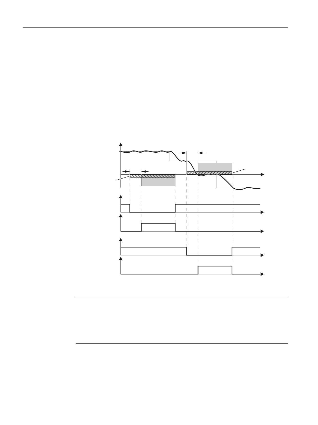
Safety functions integrated in the drive
5.12 SDI
Selecting and deselecting SDI
As soon as the converter identifies that SDIhas been selected via a failsafe input or via PROFIsafe
safe communication, the following happens:
•
You can also set a delay time, within which you can ensure that the converter moves in the
enabled (safe) direction.
•
You can also set a tolerance, within which the converter tolerates movement in the direction
that has not been enabled (unsafe). You can avoid the triggering of faults during braking
(overshoot) as well as in controlled standstill.
•
After the delay time has expired, the converter monitors the direction of rotation of the
motor.
•
If the drive now moves more than the configured tolerance in the blocked direction, a
message is output and the defined stop response is initiated.
6SHHG
'HOD\
6HWSRLQW
'HOD\
/LPLWDWLRQ WR
6',
VSHHGV
W
/LPLWDWLRQ WR VSHHGV
6',
!
6', GHVHOHFWLRQ
352),VDIH FRQWURO ZRUG
6', DFWLYH
W
) '2 RU
352),VDIH VWDWXV ZRUG
W
6', GHVHOHFWLRQ
352),VDIH FRQWURO ZRUG
6', DFWLYH
W
) '2 RU
352),VDIH VWDWXV ZRUG
W
Figure 5-21
Time response of the safety function SDI (Safe Direction)
Note
SDI without selection
As an alternative to controlling via terminals and/or PROFIsafe, there is also the option of
parameterizing SDI without selection. In this case, SDI will be permanently active after
POWER ON. You can find details about this in section "Safe Direction without selection
(Page 148)".
Safety Integrated plus
144
Commissioning Manual, 10/2020, 6FC5397-1FP40-6BA4
Safety functions integrated in the drive
5.12 SDI
5.12.1
Details and parameterization
Note
Response to bus failure
If p9580 ≠ 0 and SDI is active, in the event of communication failure, the parameterized ESR
reaction is only realized if, as SDI response, a STOP with delayed pulse cancellation when the bus
fails has been parameterized (p9566[0...3] ≥ 10).
5.12.1.1
Safe Direction with encoder
The "Safe Direction (SDI)" function allows a safe monitoring of the motion direction of the drive.
If this function is activated, the drive can only move in the enabled direction.
Principle of operation
After SDI has been selected via terminals or PROFIsafe, the delay time p9565 is started. During
this time, you have the option of ensuring that the drive is moving in the enabled direction. After
this, the "Safe Direction (SDI)" function is active and the direction of motion is monitored.
If the drive now moves more than the configured tolerance (p9564) in the disabled direction,
message C01716 is output and the stop response defined in p9566 is initiated. To acknowledge
the messages, you must first deselect SDI, correct the fault cause and then safely acknowledge
(Page 332) the messages. Only then can you reselect SDI.
Features
• Parameters r9720.12 and r9720.13 display whether the SDI function is selected.
• Parameters r9722.12 and r9722.13 display whether the SDI function is active.
• Parameter p9564 are used to set the tolerance within which a movement in a non-enabled
(non-safe) direction is tolerated.
• Parameter p9566 define the stop response in the case of a fault.
• If "SDI positive" is selected, the following value is set automatically:
- r9733[1] = 0 (setpoint limitation negative)
• If "SDI negative" is selected, the following value is set automatically:
- r9733[0] = 0 (setpoint limitation positive)
• The absolute setpoint speed limit is available in r9733[2].
Safety Integrated plus
Commissioning Manual, 10/2020, 6FC5397-1FP40-6BA4
145