SINUMERIK 840D sl. Service - Safety Integrated. Manual (2020) - page 16

Commissioning and configuring
7.6 Configuring safety functions integrated in the drive
Settings
Setting
Meaning
Modulo value SP
Sets the modulo value in degrees for rotary axes for the "Safe position" func-
tion.
p9505
This modulo value is taken into account for safe referencing and for the
transfer of the safe position via PROFIsafe when absolute position is enabled.
Enable SCA
Inhibits or enables the SCA function throughout.
Hysteresis
Specifies the hysteresis value.
<Inhibit or enable>
Inhibits/enable individual Safe Cams of the SCA function.
9503.0 ... 29
<Cam identifier>
Displays the cam identifier. Default setting, "Cam 1" … "Cam 30".
The cam identifiers are defined in the associated TS files depending on the
language, and can be freely defined by copying and adapting the files:
• Template for the TS file: /card/siemens/sinumerik/hmi/template/lng/
oem_scam_names_deu.ts
• Archive path for user-defined TS file: /card/oem/sinumerik/hmi/lng/
oem_scam_names_<Sprachkennung>.ts
Minus cam position
Sets the minus cam position in ° or mm.
p9537[0...29]
Plus cam position
Sets the plus cam position in ° or mm.
p9536[0...29]
7.6.15
SS2E
Precondition
• The Safety Integrated commissioning mode (Page 238) is active for the drive to be
configured.
• The drive is configured for operation with an encoder and Extended Functions.
Safety Integrated plus
284
Commissioning Manual, 10/2020, 6FC5397-1FP40-6BA4
Commissioning and configuring
7.6 Configuring safety functions integrated in the drive
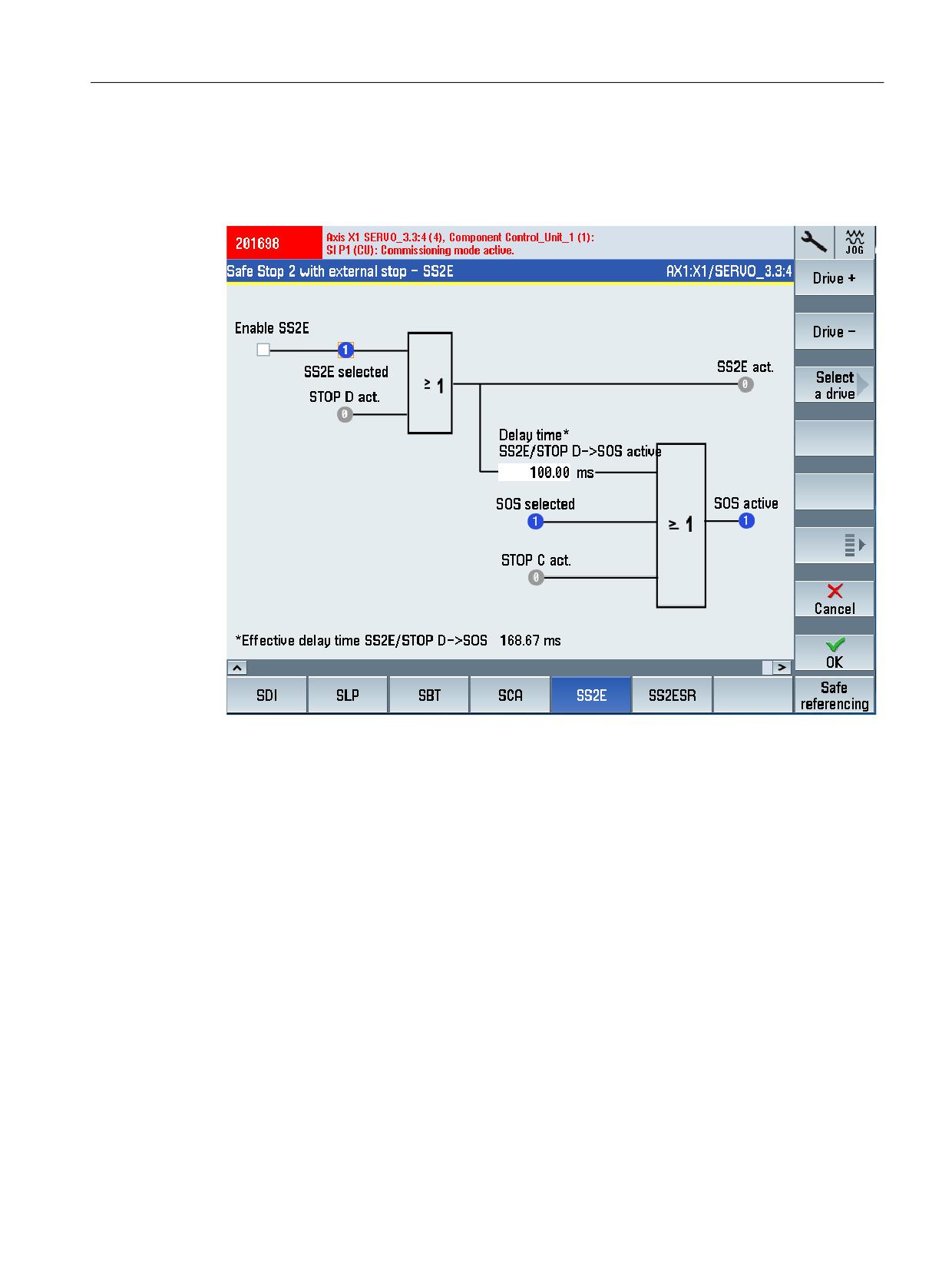
Display commissioning screen "Safe Stop 2 with external stop - SS2E"
MENU SELECT > Commissioning > Menu forward key > Safety > Functions > Menu forward key
> SS2E
Figure 7-24
Safe Stop 2 with external stop - SS2E
Safety Integrated plus
Commissioning Manual, 10/2020, 6FC5397-1FP40-6BA4
285

Commissioning and configuring
7.6 Configuring safety functions integrated in the drive
Status information
Status
Meaning
Status control signals:
Status - control and status signals for the safety motion monitoring functions
integrated in the drive on monitoring channel 1.
Select SS2E
r9720.28
Select SOS
r9720.3
Status signals:
SS2E active
r9722.28
SOS active
r9722.3
STOP C active
r9721.13
STOP D active
r9721.14
Settings
Setting
Meaning
Enable SS2E
SS2E enable is activated via the parameter.
p9501.18
Delay time, STOP D -> SOS active
Sets the transition time from STOP D to "Safe Operating Stop" (SOS) in ms.
p9553
7.6.16
SS2ESR
Precondition
• The Safety Integrated commissioning mode (Page 238) is active for the drive to be
configured.
• The drive is configured for operation with an encoder and Extended Functions.
Safety Integrated plus
286
Commissioning Manual, 10/2020, 6FC5397-1FP40-6BA4
Commissioning and configuring
7.6 Configuring safety functions integrated in the drive
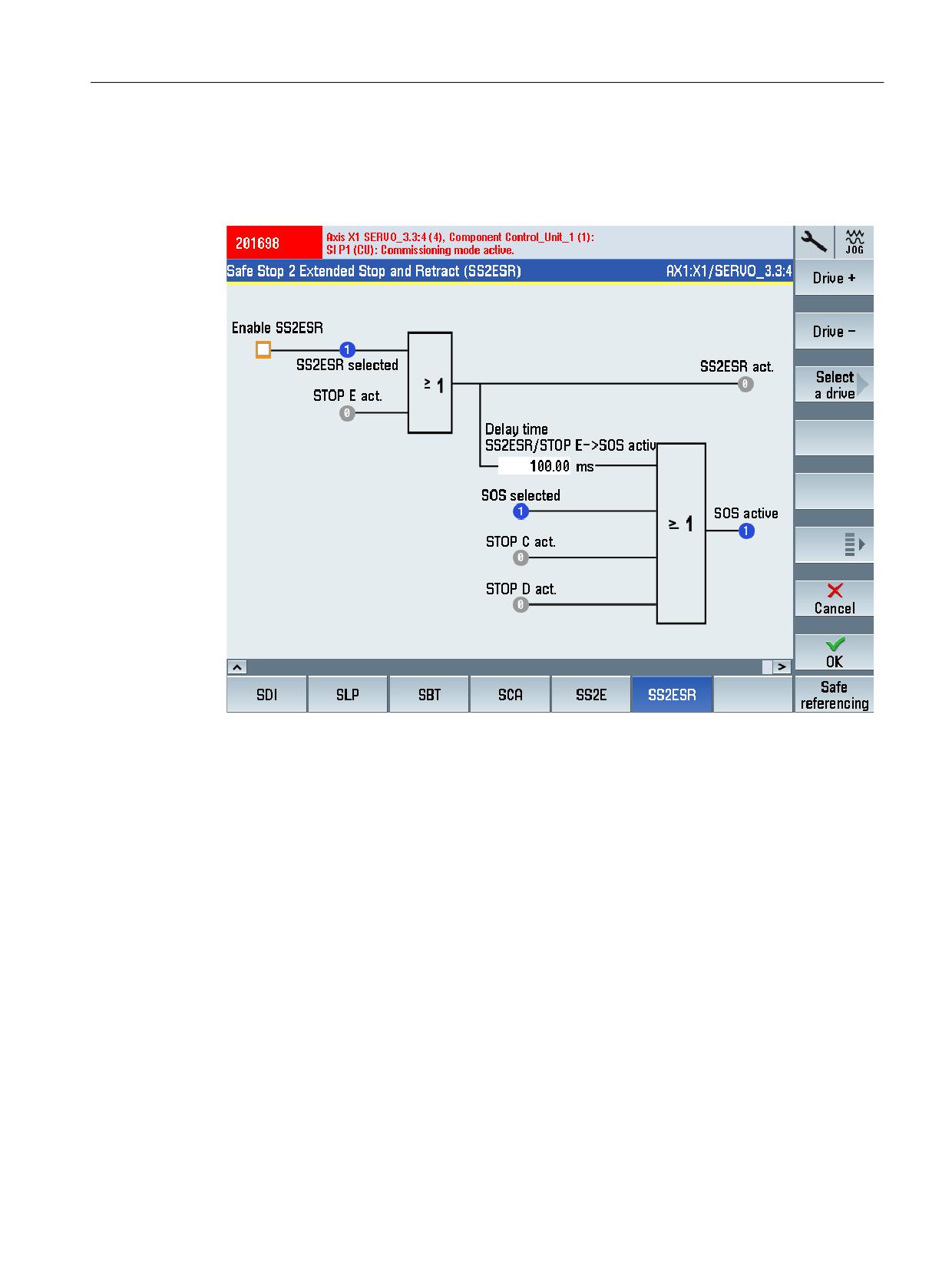
Display commissioning screen "Safe Stop 2 Extended Stop and Retract (SS2ESR)"
MENU SELECT > Commissioning > Menu forward key > Safety > Functions > Menu forward key
> SS2ESR
Figure 7-25
Safe Stop2 Extended Stop and Retract (SS2ESR)
Safety Integrated plus
Commissioning Manual, 10/2020, 6FC5397-1FP40-6BA4
287

Commissioning and configuring
7.6 Configuring safety functions integrated in the drive
Status information
Status
Meaning
Status control signals:
Status - control and status signals for the safety motion monitoring functions
integrated in the drive on monitoring channel 1.
Select SS2ESR
r9720.29
Select SOS
r9720.3
Status signals:
SS2ESR active
r9722.27
STOP E active
r9721.15
STOP C active
r9721.13
STOP D active
r9721.14
SOS active
r9722.3
Settings
Setting
Meaning
Enable SS2ESR
SS2ESR enable is activated via the parameter.
p9501.04
Delay time SS2ESR/STOP E -> SOS active
Sets the transition time from STOP D to "Safe Operating Stop" (SOS) in ms.
p9554
7.6.17
Safe referencing
Precondition
• The Safety Integrated commissioning mode (Page 238) is active for the drive to be
configured.
• Access rights of access level 2 (service) are available in SINUMERIK Commissioning.
• The drive is configured for operation with an encoder and Extended Functions.
Safety Integrated plus
288
Commissioning Manual, 10/2020, 6FC5397-1FP40-6BA4
Commissioning and configuring
7.6 Configuring safety functions integrated in the drive
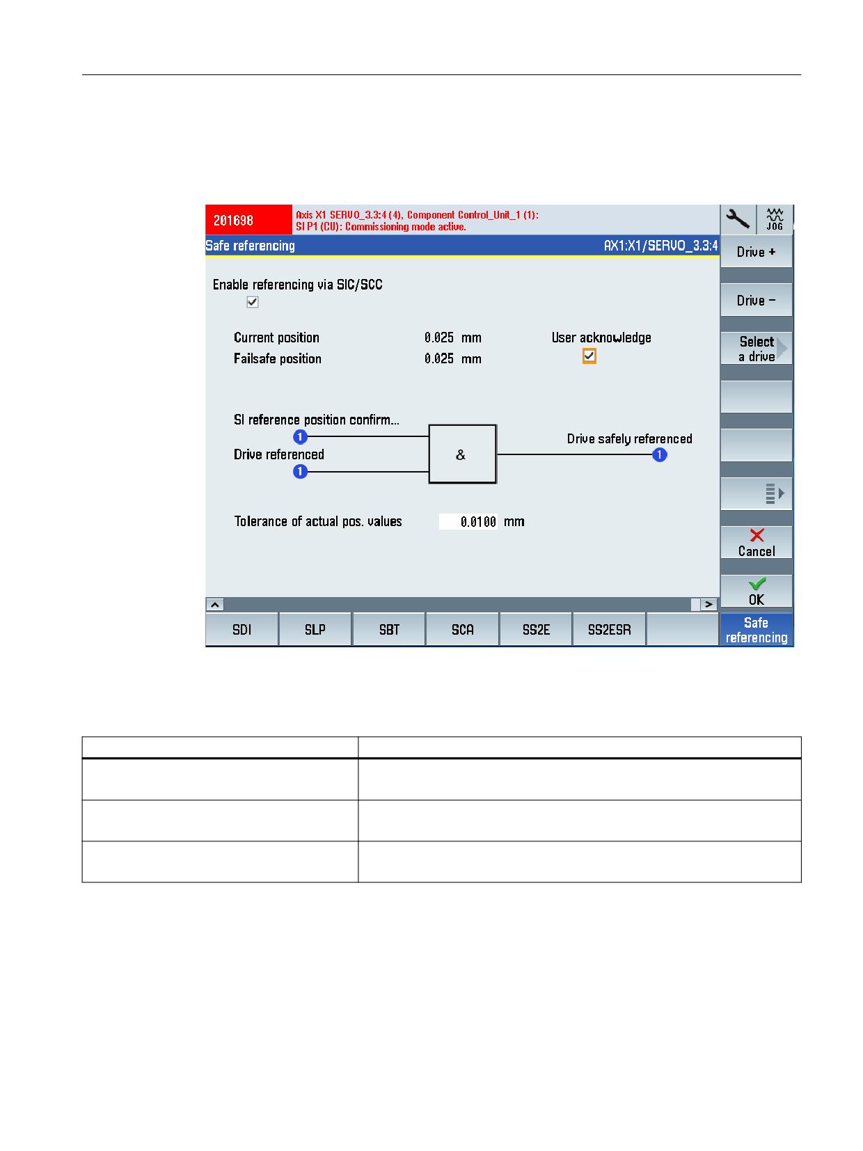
Display "Safe referencing" commissioning screen
MENU SELECT > Commissioning > Menu forward key > Safety > Functions > Menu forward key
> Safe referencing
Figure 7-26
Safe referencing
Status information
Status
Meaning
Safety reference position confirmed
Displays the internal status of the user agreement
r9727
Drive reference.
Display: Position referenced
r9723.17
Safely ref.
Display: Safely referenced
r9722.23
Safety Integrated plus
Commissioning Manual, 10/2020, 6FC5397-1FP40-6BA4
289

Commissioning and configuring
7.6 Configuring safety functions integrated in the drive
Settings
Setting
Meaning
Enable referencing via SCC
Sets the enable signals for the safety-related motion monitoring functions.
p9501.27
SI Motion, user agreement, select/deselect
User agreement Safe Position
p9726
(is only displayed if functions with Safe Position evaluation are activated)
Tolerance of the position actual values (refer-
Sets the tolerance for checking the actual values.
encing)
For an incremental encoder, the actual values are checked after referencing,
p9544
for an absolute encoder, when switching on.
7.6.18
Further safety functions
In addition to the described safety functions that are configured using commissioning screens,
the following drive-integrated safety functions can be configured in the expert list, that is, by
directly entering the parameters:
• SS2e - SS2 with external stop (Page 107)
• Homing via SIC/SCC (Page 179)
• Cancellation of the stop transition times
• Automatic SLS (Page 118)/SOS (Page 114) deselection when STO active
Safety Integrated plus
290
Commissioning Manual, 10/2020, 6FC5397-1FP40-6BA4
Commissioning and configuring
7.7 Finalizing commissioning
7.7
Finalizing commissioning
7.7.1
Confirming settings
After parameterization, the Safety Integrated commissioning mode must be deactivated and the
actual checksums must be transferred into the reference checksums.
Requirements
• The NC and drive-specific settings have been correctly configured for all safety-related drives
and for all F-I/O devices.
• The safety functions integrated in the drive are configured.
• The safety commissioning mode is activated.
Procedure
Proceed as follows to confirm the drive-specific safety settings that have been made:
1. In SINUMERIK Operate, switch to "MENU SELECT > Commissioning > Menu forward key >
Safety".
2. Using the menu forward key, switch to the 2nd Level of the vertical softkey bar.
3. Press softkey "Copy SI data" and confirm with "OK".
The safety settings are copied from the 1st into the 2nd monitoring channel.
4. Press softkey "Confirm SI data" and confirm with "OK".
5. Press softkey "Save all drive objects" and confirm with "OK".
Safety Integrated plus
Commissioning Manual, 10/2020, 6FC5397-1FP40-6BA4
291
Commissioning and configuring
7.7 Finalizing commissioning
7.7.2
Assigning a Safety Integrated password
In SINUMERIK Operate, commissioning data is generally stored in various access levels. You
protect the safety-related drive parameterization additionally with the Safety Integrated
password. This password is stored in the drive data so that it can be changed only by authorized
persons who know the password.
Note
SINAMICS Safety password must be used for SINUMERIK Safety
You can assign the SINAMICS safety password via the SINUMERIK Operate screen form (access
level "Manufacturer"). SINUMERIK Operate automatically sets the assigned SINAMICS safety
password for all axes/drives as soon as you select "Safety" in the Commissioning operating area.
The precondition to do this is an active "Service" or "Manufacturer" access level.
Alternatively, assign the password as follows via the expert list as in SINAMICS Safety:
• p0010 = 95 Commissioning mode
• p9761 = enter "Old safety password". Default setting for p9761 = 0.
• p9762 = enter "new password".
• p9763 = confirm "new password"
• p0977 = 1; "Copy from RAM to ROM"
The new and confirmed safety password is valid immediately.
Procedure
To assign the Safety Integrated password for all axes/drives, proceed as follows:
1. IN SINUMERIK Operate, go to "MENU SELECT > Commissioning > Menu forward key > Safety".
2. Select softkey "SI password".
3. Select the check box for the all "axes/drives".
4. Assign a password and confirm by clicking on "OK".
Safety Integrated plus
292
Commissioning Manual, 10/2020, 6FC5397-1FP40-6BA4
Commissioning and configuring
7.8 Series commissioning
7.8
Series commissioning
A loaded project that has been commissioned can be loaded to another SINUMERIK control
system, while still keeping the safety parameterization. However, observe the following
information:
• Different component checksums as a result of series commissioning with Safety Integrated
functionality (Page 340)
• Safety message for series commissioning with third-party motor (Page 293)
For series commissioning, you must perform an acceptance test (Page 297) for each SINUMERIK
control system.
Safety message for series commissioning with third-party motors under Safety Integrated
Extended Functions
If third-party motors with absolute encoders are being used, a situation may arise where a Safety
message prevents commissioning.
One reason for this may be that a different serial number of the absolute encoder is saved on the
memory card than that in the Control Unit which is to be commissioned. The safety message can
only be acknowledged once the serial number for the absolute encoder has first been manually
corrected. You can then proceed with the commissioning.
Safety Integrated plus
Commissioning Manual, 10/2020, 6FC5397-1FP40-6BA4
293
Commissioning and configuring
7.9 Interaction with other functions
7.9
Interaction with other functions
7.9.1
Gantry axes
Note
In a gantry group, you must configure Safety Integrated or SINUMERIK Safety Integrated plus in
the leading as well as the following axis.
Otherwise, for a gantry group it is not ensured, that a STOP at the leading axis is automatically
transferred to the following axis, for example. The gantry coupling could be opened. As a
consequence, an axis would have no monitoring.
Note
STOP A, B, C stop responses
If a stop response is only initiated on one axis in the coupled group (STOP A, B, C), then this is
taken into account on all axes of the coupled group, and an nset=0 is initiated. If this results in
different axis braking responses, then you can use drive function FASTBRK. If this results in an
offset that is not acceptable, then you should configure an SS2E stop response (STOP D).
7.9.2
Leading/following axis
For a leading/following axis group, on both axes you must configure Safety Integrated or
SINUMERIK Safety Integrated plus, assuming that there is no fixed mechanical coupling.
If a fixed mechanical coupling exists, then you must only configure SINUMERIK Safety Integrated
or SINUMERIK Safety Integrated plus in the leading axis.
Based on a risk assessment, the machine manufacturer must evaluate as to whether the fixed
mechanical coupling is sufficiently stable, so that it is adequate that Safety Integrated or
SINUMERIK Safety Integrated plus is only configured in the leading axis.
7.9.3
Brake tests for axis groups
For a gantry or leading/following axis group, the machinery manufacturer (OEM) must decide
on a case-for-case basis whether a defective brake could result in mechanical damage. The brake
test should not be performed if mechanical damage could occur.
Safety Integrated plus
294
Commissioning Manual, 10/2020, 6FC5397-1FP40-6BA4
Commissioning and configuring
7.9 Interaction with other functions
7.9.4
SERVCOUP special solution
In the SERVO control mode, SERVCOUP allows motors to be operated, which as a result of their
size and/or type of construction, cannot be operated from a single SINAMICS power unit. These
motors are subdivided into several drive objects, each of which can be operated on a Motor
Module, and can be coupled with one another. As a consequence, the individual drive objects
can be considered as partial motors with their own winding and terminals.
• When using the SERVO coupling, similar motors must be mechanically coupled very rigidly
with one another.
• OA applications (generally) have no influence on Safety Integrated or SINUMERIK Safety
Integrated plus.
• For SERVCOUP, for the leading axis, Safety Integrated Extended Functions are used to monitor
the drive. The following axes only have Safety Integrated Basic Functions.
• In the case of a leading axis fault, the following axes are stopped via STO. You must
implement this as part of your application engineering (see Function Manual SERVCOUP
Description/SINAMICS Safety Integrated/SINUMERIK Safety Integrated").
• If, for instance, the monitoring speed of the Safely-Limited Speed (SLS) is violated at the
leading drive object, then the parameterized safety STOP response is initiated at the leading
drive object. The complete drive line-up is then shut down.
7.9.5
Closing the internal motor brake using SCC
In conjunction with the safety monitoring functions and with SCC activated, you can control the
internal brake using signal SCC.CW1.CloseBrake (DB3x, ...DBX140.5) "Close internal brake".
Note
BICO interconnection
When upgrading from software release < V6.14, you might have to change the BICO
interconnection of p858 to r10251.13.
Safety Integrated plus
Commissioning Manual, 10/2020, 6FC5397-1FP40-6BA4
295
Commissioning and configuring
7.9 Interaction with other functions
Safety Integrated plus
296
Commissioning Manual, 10/2020, 6FC5397-1FP40-6BA4
Acceptance test
8
8.1
Purpose and requirements
The objective of the acceptance test is to check the correct parameterization and mode of
operation of the safety functions and to detect potential configuration errors or to document the
correctness of the configuration.
With the acceptance test, the limit values entered for all activated safety functions must be
exceeded (violated). This allows the correct execution of the function to be checked and verified.
WARNING
Unwanted motion due to incorrect parameter changes
Changes to accepted safety functions may lead to faults or to unwanted motion and thus to
serious injuries or death.
• Perform a new acceptance test as soon as changes have been made to any of the safety
functions.
• Also create an appropriate acceptance report.
Responsibility for the acceptance test
The machine manufacturer is responsible for carrying out and documenting an acceptance test.
It is not permissible to use the results of the acceptance test for other purposes!
The measured values obtained when executing the acceptance test (e.g. distance or time) and
the system response identified (e.g. initiation of a specific stop) are used to check the plausibility
of the configured safety functions. The values that are measured are typical and are not worst-
case values. They represent the behavior of the machine at the time of measurement. These
measurements cannot be used to derive real values (e.g. maximum distances for over-travel
distances).
Acceptance test in SINUMERIK Operate
A detailed description of the acceptance test in SINUMERIK Operate is provided in Function
Manual "SINUMERIK Operate Acceptance Test" (download (https://
support.industry.siemens.com/cs/ww/en/view/109761095)).
Safety Integrated plus
Commissioning Manual, 10/2020, 6FC5397-1FP40-6BA4
297
Acceptance test
8.1 Purpose and requirements
Safety Integrated plus
298
Commissioning Manual, 10/2020, 6FC5397-1FP40-6BA4

Diagnostics
9
If you are looking for a description of the diagnostic functionality, then in this Chapter you can
find a Diagnostics guide (Page 300) and descriptions relating to the safety diagnostic
functionality with SINUMERIK Operate.
These diagnostic functions are possible in the following software depending on the particular
component:
Table 9-1
Diagnostic functionality depending on the components
Component
SINUMERIK Operate
TIA Portal
F-PLC
Operating area "Diagnostics"
See the help for SIMATIC Safety
F-I/O
Operating area "Diagnostics"
See the help for SIMATIC Safety
Safety program
-
See the help for SIMATIC Safety
(F-program)
Checksums
Master checksums and SINAM-
Signatures of F-I/O, the safety
ICS checksums in operating
program and checksums of the
area "Diagnostics"
F-PLC.
See the help for SIMATIC Safety
Status of safety-relevant drives
Operating area "Diagnostics"
-
Telegram diagnostics
Operating area "Diagnostics"
-
SCA diagnostics
Operating area "Diagnostics"
-
Status and diagnostic information
Operating area "Startup"
-
about specific safety functions
(without activating the com-
missioning mode)
You will also find general descriptions and backg16round information about diagnostics using
SINUMERIK Operate in this chapter:
• Display and evaluation of diagnostic information (Page 317)
• Checksums (Page 318)
• Stop responses (Page 321)
• Using the fault buffer, message buffer and alarm buffer (Page 328)
• Acknowledgment (Page 331)
Information about replacing components (software or hardware components) is provided in a
separate chapter (Page 335).
Safety Integrated plus
Commissioning Manual, 10/2020, 6FC5397-1FP40-6BA4
299

Diagnostics
9.1 Diagnostics guide
9.1
Diagnostics guide
Table 9-2
Steps for evaluating diagnostic capabilities
Step
Procedure
Reference
1
Evaluate LEDs on the hardware (F-CPU, F-I/O):
Equipment Manual SINUMERIK
840D sl NCU 7x0.3
• SF, DP, DP/MPI and PN-LEDs of the F-CPU flash for a communication error at
the PROFIBUS DP/PROFINET IO, per channel;
Manuals for the F-I/O
SF-LED is lit, if OB 85 and OB 121 are programmed, for a programming error
(e.g. instance DB not loaded)
• STOP LED on the F-CPU: illuminates when the F-CPU is in STOP mode
• Fault LEDs on the F-I/O: e.g. SF-LED (group error LED) on if any fault occurs
in the individual F-I/O
2
Evaluate diagnostic buffer of the modules:
Help on STEP 7 and manuals for
the F-CPU and F-I/O
You read the diagnostic buffer of a module (F-CPU, F-I/O, CP) in its online and
diagnostic view in the "Diagnostic buffer" group under the "Online & Diagnos-
tics" folder.
3
Evaluate stacks of the F-CPU:
Help on STEP 7
when the F-CPU is in STOP mode, read the following successively:
• Block stack: Check whether STOP mode of the F-CPU was triggered by an
F-block of the safety program
• Interruption stack
• Local data stack
4
Evaluate diagnostic tag of the F-I/O DB using testing and commissioning
F-I/O access (Page 70) or help relat-
functions, by means of an operator control and monitoring system, or in
ing to SIMATIC Safety
the standard user program:
Evaluate the DIAG tag in the F-I/O DB
5
Evaluate diagnostic outputs of the instance DBs of instructions using
Operations (Page 58) or help relat-
testing and commissioning functions, using an operator control and mon-
ing to SIMATIC Safety
itoring system, or in the standard user program:
• For MUTING, EV1oo2DI, TWO_H_EN, MUT_P, ESTOP1, FDBBACK, SFDOOR,
evaluate in the assigned instance:
- Output DIAG
• Evaluate the following for SENDDP or RCVDP in the assigned instance DB:
- Output RET_DPRD/RET_DPWR
- Output DIAG
• Evaluate the following for SENDS7 or RCVS7 in the assigned instance DB:
- Output STAT_RCV
- Output STAT_SND
- Output DIAG
Tip on RET_DPRD/RET_DPWR
The diagnostic information of the RET_DPRD/RET_DPWR parameters correspond to the
diagnostic information of the RETVAL parameter of the "DPRD_DAT" and "DPWR_DAT"
instructions. You can find the description in the help on STEP 7 for the "DPRD_DAT" and
"DPWR_DAT" instructions.
Safety Integrated plus
300
Commissioning Manual, 10/2020, 6FC5397-1FP40-6BA4
Diagnostics
9.1 Diagnostics guide
Tip: STAT_RCV and STAT_SND
The diagnostic information of the parameter STAT_RCV corresponds to the diagnostic
information of the parameter STATUS of the instruction "URCV". The diagnostic information of
the parameter STAT_SND corresponds to the diagnostic information of the parameter STATUS of
the instruction "USEND". You can find the description in the help on STEP 7 for the instruction
"UCRV" or "USEND" .
Safety Integrated plus
Commissioning Manual, 10/2020, 6FC5397-1FP40-6BA4
301

Diagnostics
9.2 System alarms and diagnostic screens for F-PLC and F-I/O.
9.2
System alarms and diagnostic screens for F-PLC and F-I/O.
The diagnosis of faults of F-I/O or F-PLC is supported in SINUMERIK Operate via specific system
alarms (number ranges 4300XX and 43100X) as well as own diagnostics screens.
To use this functionality, the configuration must be properly completed and loaded:
• The configured NCU must have firmware version ≥V4.8 and Safety Integrated plus (F-PLC)
must be activated.
• Hardware and software must be consistently compiled and loaded.
With such a correct configuration, SI_DiagDB [DB1009] is automatically generated during the
compilation and transferred to the NCU during loading.
Details on internal processing of the F-PLC / F-I/O system alarms
The system alarms for the diagnostics of the F-PLC and F-I/O are formed based on the status
information of the safety program and collected and processed by the basic PLC program.
Information required for processing is stored in the SI_DiagDB [DB1009] (for example, design of
the safety program and assignment of the F-I/O DBs and F-global DBs). SI_DiagDB [DB1009] is
automatically generated during compilation and transferred to the NCU during loading, if Safety
Integrated plus (F-PLC) is activated and the NCU device version is correctly configured (≥V4.8).
The association between the SI_DiagDB [DB1009] and the safety program is secured by a
checksum (see also Alarm 430000).
Depending on this status information, the corresponding system alarms are triggered and
displayed in SINUMERIK Operate.
Meaning of the "F-PLC/F-I/O system alarms
Note
No simultaneous display of different system alarms with the same alarm number.
If the same error occurs for multiple modules, the respective system alarms are not displayed at
the same time but instead successively. This means that the alarm for the next module is only
displayed if the error has been corrected and/or the first module has been reintegrated.
Table 9-3
General
Meaning
Alarm No.
F-diagnostics: PLC project is inconsistent
430000
The F-diagnostics is not possible because the PLC project is inconsistent (safety program and
SI_DiagDB [DB1009] do not match) or the configured firmware version is not supported. The
configured NCU firmware version (TIA Portal) must be at least V4.8.
Compile and re-load hardware and software consistently.
Safety Integrated plus
302
Commissioning Manual, 10/2020, 6FC5397-1FP40-6BA4

Diagnostics
9.2 System alarms and diagnostic screens for F-PLC and F-I/O.
Table 9-4
F-PLC system alarms
Meaning
Alarm No.
Safety mode disabled
431001
The safety mode of the F-PLC has been disabled by the user, fault control measures are partly
deactivated.
Safety mode is reactivated at the next startup of the PLC.
Error detected by fail-safe system
431003
A serious problem was detected in safety mode (group signal); STEP 7 is required for exact
analysis.
Carrying out diagnostics on the diagnostics buffer of the CPU using STEP 7.
Table 9-5
F-I/O system alarms
Meaning
Alarm No.
F-module %1: Timeout detected by F-I/O
430001
The F-I/O has detected a timeout in the PROFIsafe communication.
Correct the displayed cause of the error and, if necessary, reintegrate the module.
F-module %1: Channel fault detected by F-I/O
430002
The F-I/O has detected a channel fault.
Correct the displayed cause of the error and, if necessary, reintegrate the module.
F-module %1: CRC error / sequence number error detected by F-I/O
430003
The F-I/O has detected a CRC error / sequence number error.
Correct the displayed cause of the error and, if necessary, reintegrate the module.
F-module %1: Timeout detected by F-system
430005
The F-system has detected a timeout.
Correct the displayed cause of the error and, if necessary, reintegrate the module.
F-module %1: Sequence number error detected by F-system
430006
The F-system has detected a sequence number error.
Correct the displayed cause of the error and, if necessary, reintegrate the module.
F-module %1: CRC error detected by F-system
430007
The F-system has detected a CRC error.
Correct the displayed cause of the error and, if necessary, reintegrate the module.
F-module %1: Reintegration necessary
430010
The F-module is passivated and has to be reintegrated for further use.
Reintegrate the F-module using the ACK_REI signal.
Safety Integrated plus
Commissioning Manual, 10/2020, 6FC5397-1FP40-6BA4
303
Diagnostics
9.3 Diagnostic functions in SINUMERIK Operate
9.3
Diagnostic functions in SINUMERIK Operate
You can find the SI-diagnostics overview and more specific diagnostic screens under "MENU
SELECT > Diagnostics > Menu forward key > Safety".
Note
A properly completed and loaded configuration is a requirement for diagnostics
functionality.
• The configured NCU must have firmware version ≥V4.8 and Safety Integrated plus (F-PLC)
must be activated.
• Hardware and software must be consistently compiled and loaded.
With such a correct configuration, SI_DiagDB [DB1009] is automatically generated during the
compilation and transferred to the NCU during loading.
9.3.1
Safety Integrated diagnostics overview
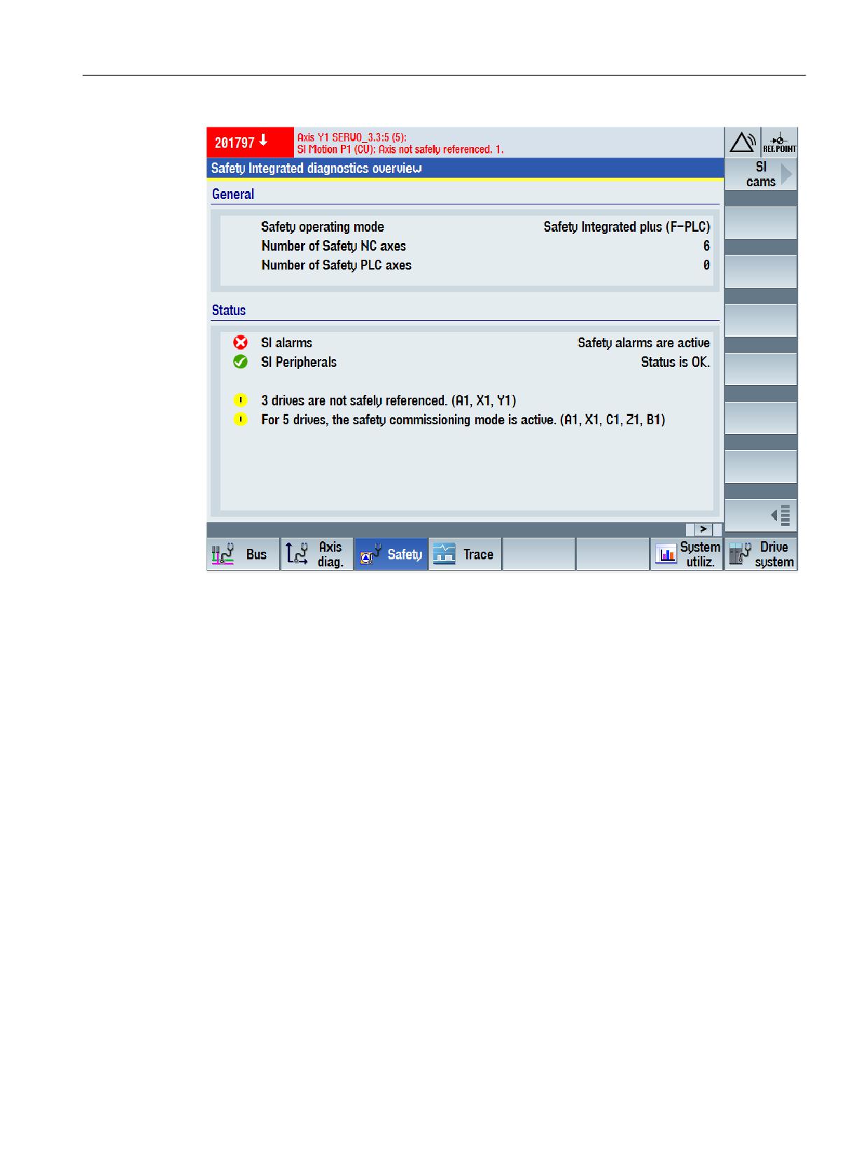
The diagnostics overview includes general information about the operating mode used, the
number and type of axes used - as well as status information about the pending alarms and safe
referencing (homing).
Call
MENU SELECT > Diagnostics > Menu forward key > Safety
Safety Integrated plus
304
Commissioning Manual, 10/2020, 6FC5397-1FP40-6BA4
Diagnostics
9.3 Diagnostic functions in SINUMERIK Operate
Figure 9-1
Safety Integrated diagnostics overview
This screen is simultaneously used as entry to the following diagnostic screens:
• SI drives (Page 305)
• SI telegrams (Page 308)
• SI checksum (Page 310)
• SI alarms (Page 312)
• SI Safe Cams (Page 313) (via menu forward key)
• SI integrated F-PLC (Page 314)
• SI I/O (Page 315)
9.3.2
SI drives status
The configured safety-relevant status and diagnostic information of the selected drive are
displayed in the "SI drive status" diagnostic screen.
Functions, which are not configured for the selected drive, are not displayed on the screen.
Call
MENU SELECT > Diagnostics > Menu forward key > Safety > SI drives
The diagnostic screen "SI drive status" is available for basic functions and for extended functions.
Safety Integrated plus
Commissioning Manual, 10/2020, 6FC5397-1FP40-6BA4
305
Diagnostics
9.3 Diagnostic functions in SINUMERIK Operate
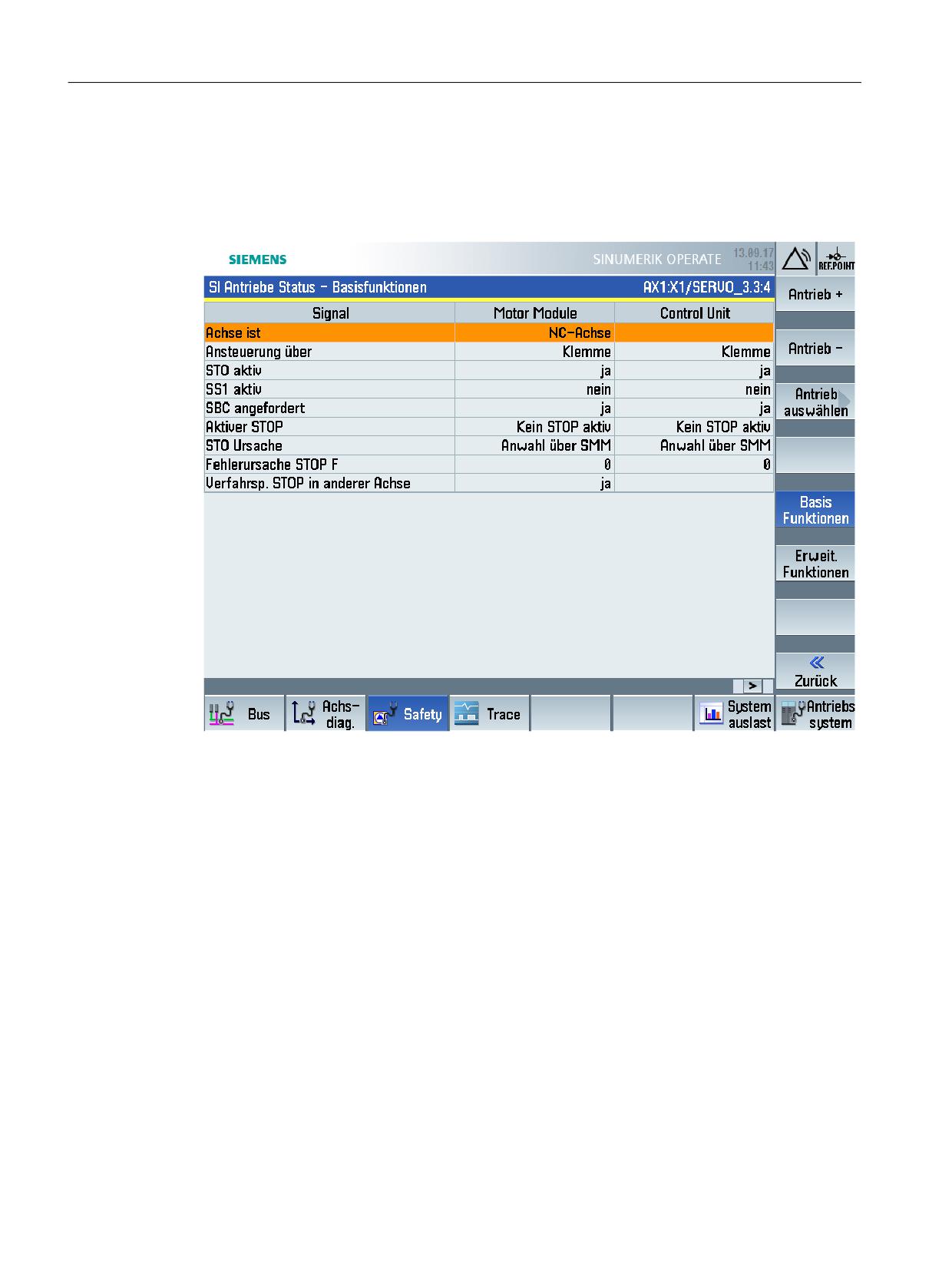
Call "SI drive status - Basic functions"
MENU SELECT > Diagnostics > Menu forward key > Safety > SI drives > Basic functions
Figure 9-2
Diagnostic screen "SI drive status - Basic functions" (sample screenshot)
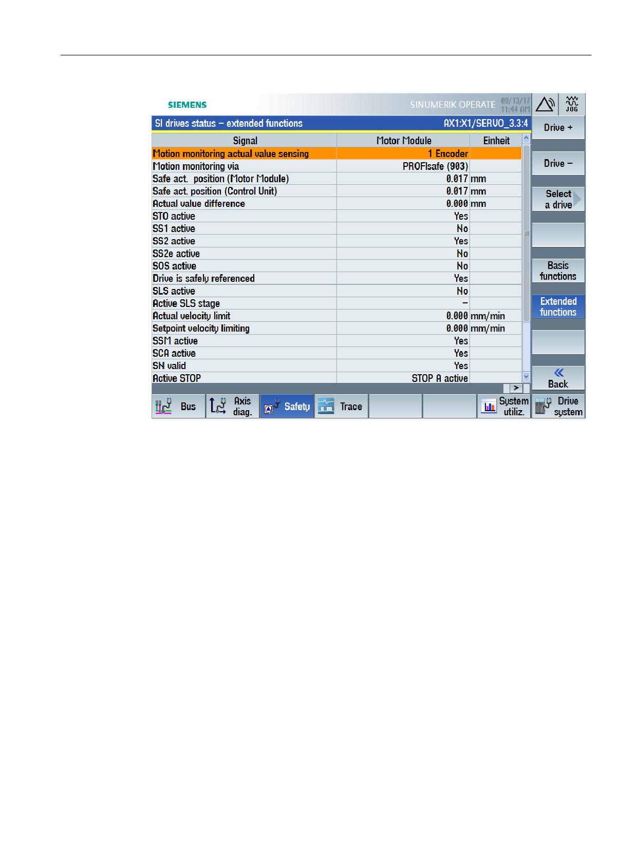
Call "SI drive status - Extended functions"
MENU SELECT > Diagnostics > Menu forward key > Safety > SI drives > Extended Functions
Safety Integrated plus
306
Commissioning Manual, 10/2020, 6FC5397-1FP40-6BA4
Diagnostics
9.3 Diagnostic functions in SINUMERIK Operate
Figure 9-3
"SI drive status - Extended functions" diagnostic screen (sample screenshot)
9.3.3
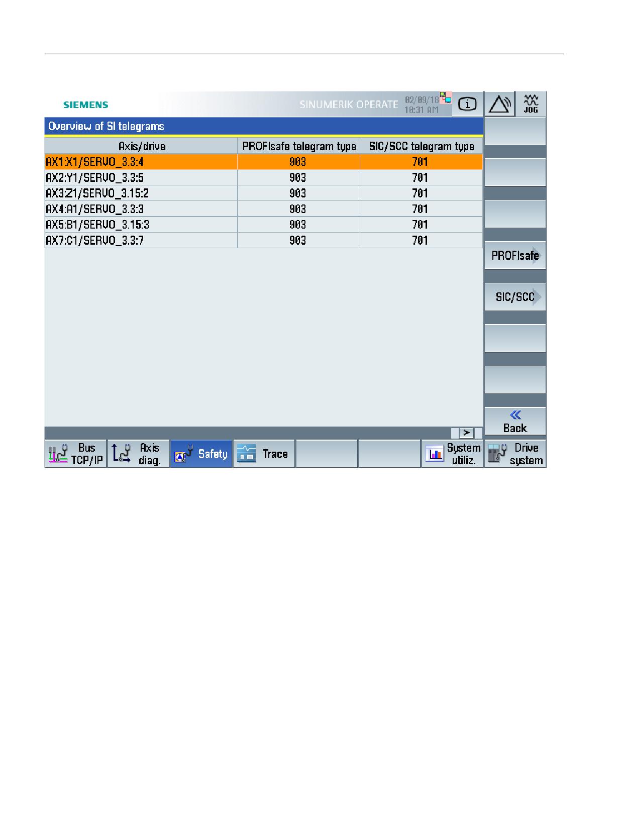
SI telegrams overview
The telegram types for PROFIsafe and SIC/SCC for the respective drives/axes are displayed in the
"SI telegrams overview" diagnostic screen.
Call
MENU SELECT > Diagnostics > Menu forward key > Safety > SI telegrams
Safety Integrated plus
Commissioning Manual, 10/2020, 6FC5397-1FP40-6BA4
307
Diagnostics
9.3 Diagnostic functions in SINUMERIK Operate
Figure 9-4
"SI telegrams overview" diagnostic screen
This screen is simultaneously used as entry to the following diagnostic screens:
• SI telegrams PROFIsafe (Page 308)
• PROFIdrive SI telegrams (Page 309)
Additional information
• You will find general information on safety-relevant telegrams in Chapter Controlling safety
functions integrated in the drive (Page 197).
9.3.4
SI telegrams PROFIsafe
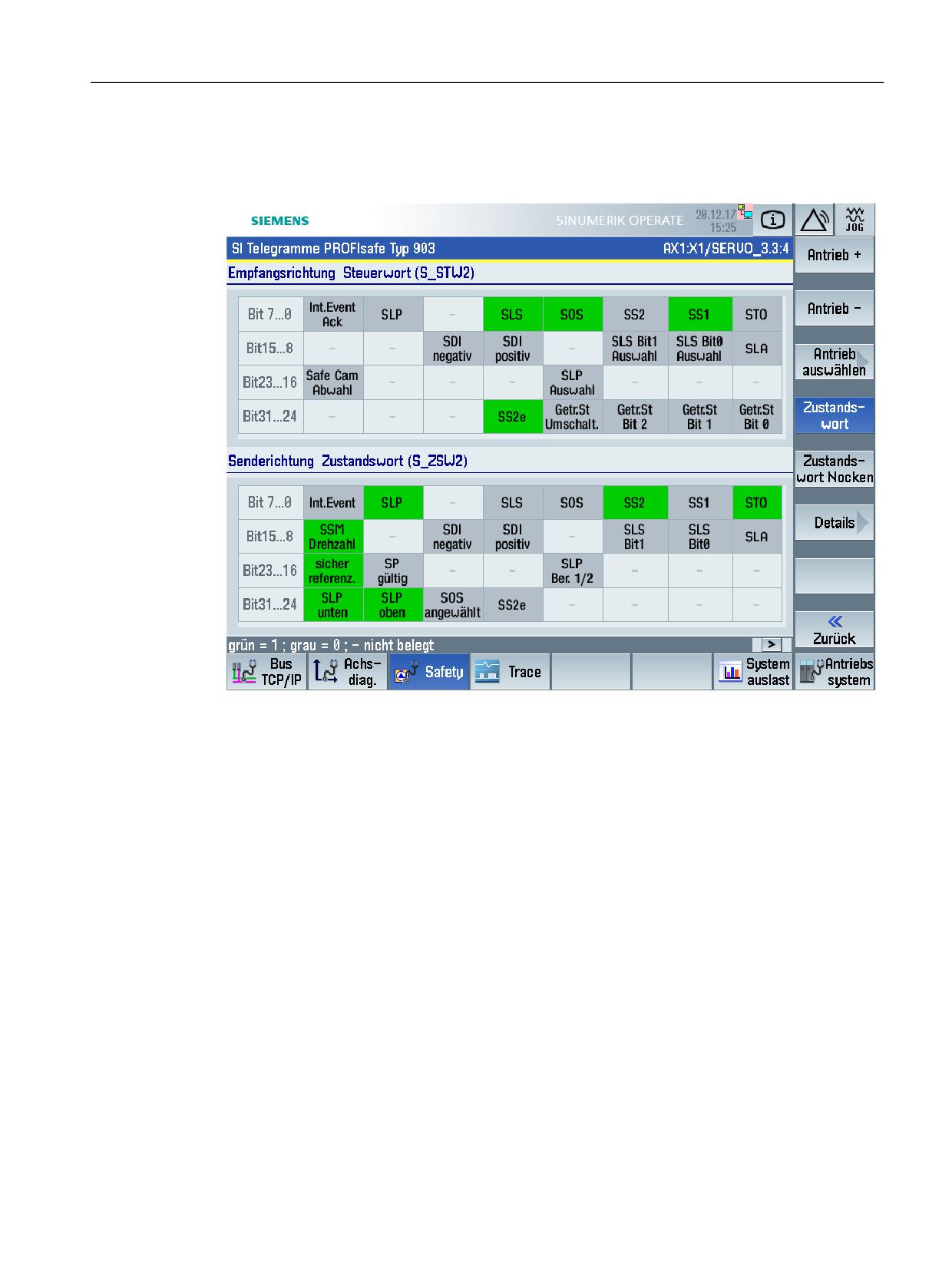
The meanings and statuses of the individual bits in the control word and status word are shown
in the "PROFIsafe SI telegrams" diagnostic screen. You can switch between the following views:
• Status word
• Status word cam (Note: only when the cam function is enabled in SINAMICS)
Safety Integrated plus
308
Commissioning Manual, 10/2020, 6FC5397-1FP40-6BA4
Diagnostics
9.3 Diagnostic functions in SINUMERIK Operate
Call
MENU SELECT > Diagnostics > Menu forward key > Safety > SI telegrams > PROFIsafe
Figure 9-5
"PROFIsafe SI telegrams" diagnostic screen
The view of all user data of the control word and status word is displayed using the "Details"
softkey.
Additional information
• You can obtain general information about PROFIsafe telegrams in Chapter Controlling via
PROFIsafe (Page 201).
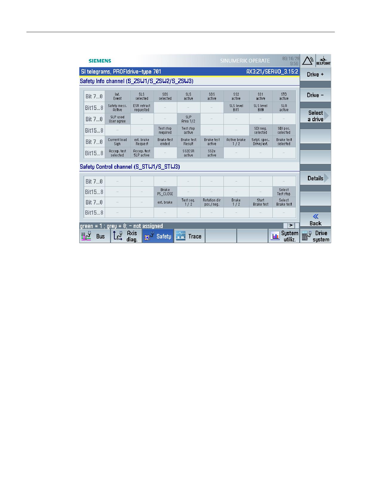
9.3.5
PROFIdrive SI telegrams
The meanings and statuses of the individual bits in the control word and status word are shown
in the "PROFIdrive SI telegrams" diagnostic screen.
Call
MENU SELECT > Diagnostics > Menu forward key > Safety > SI telegrams > SIC/SCC
Safety Integrated plus
Commissioning Manual, 10/2020, 6FC5397-1FP40-6BA4
309
Diagnostics
9.3 Diagnostic functions in SINUMERIK Operate
Figure 9-6
"SI telegrams PROFIdrive" diagnostic screen
The view of all user data of the control word and status word is displayed using the "Details"
softkey.
Additional information
• You can obtain general information about SIC/SCC telegrams in Chapter Safety Info Channel
and Safety Control Channel (SIC/SCC) (Page 205).
9.3.6
SI checksums
In the "SI checksums overview" diagnostic screen, all of the safety reference and actual
checksums are displayed for the axes and drives. Status symbols are used to flag differences
between reference and actual checksums
Calling checksums
MENU SELECT > Diagnostics > Menu forward key > Safety > SI checksum
Safety Integrated plus
310
Commissioning Manual, 10/2020, 6FC5397-1FP40-6BA4
Diagnostics
9.3 Diagnostic functions in SINUMERIK Operate
Figure 9-7
"SI checksums overview" diagnostics screen
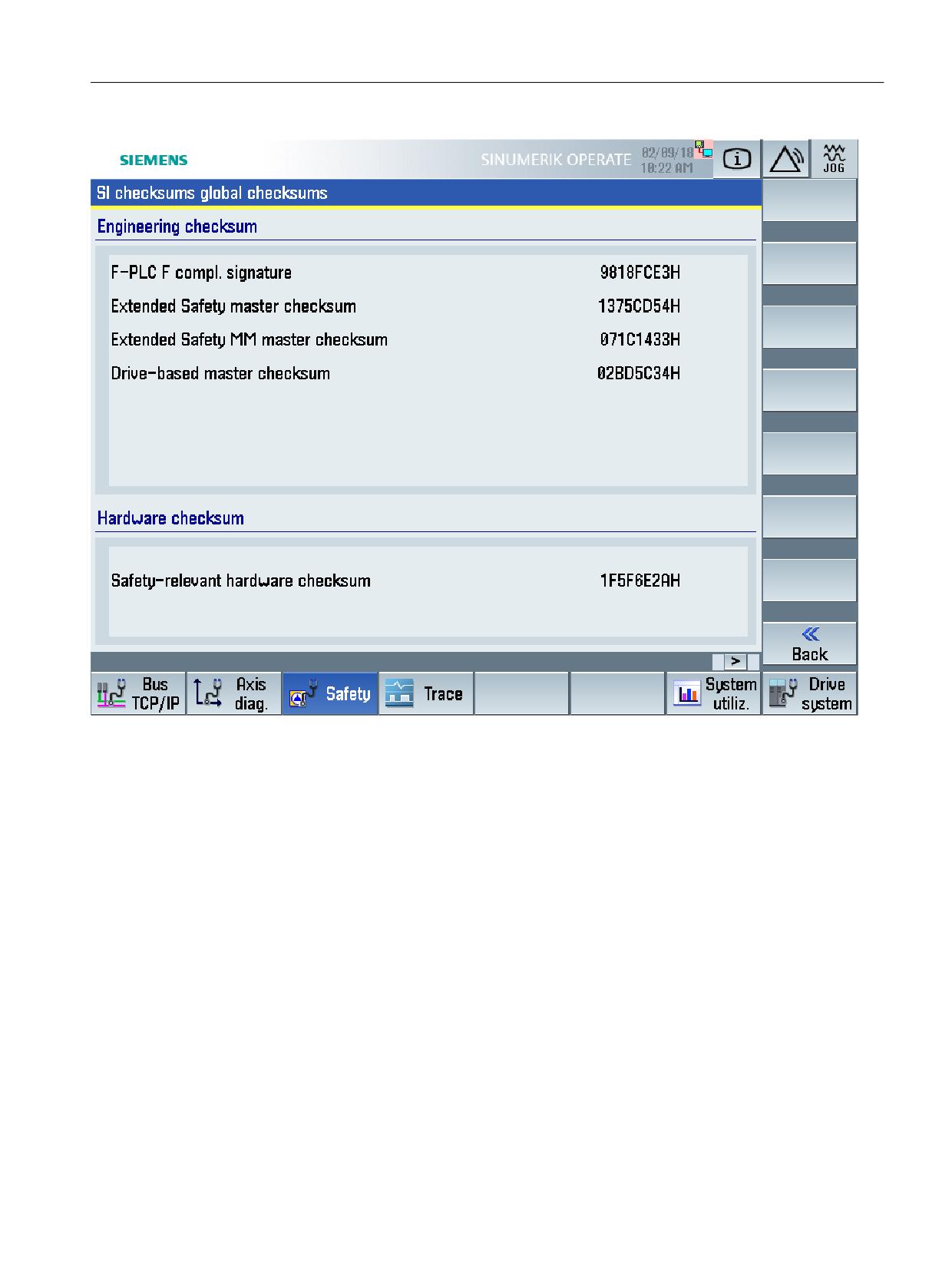
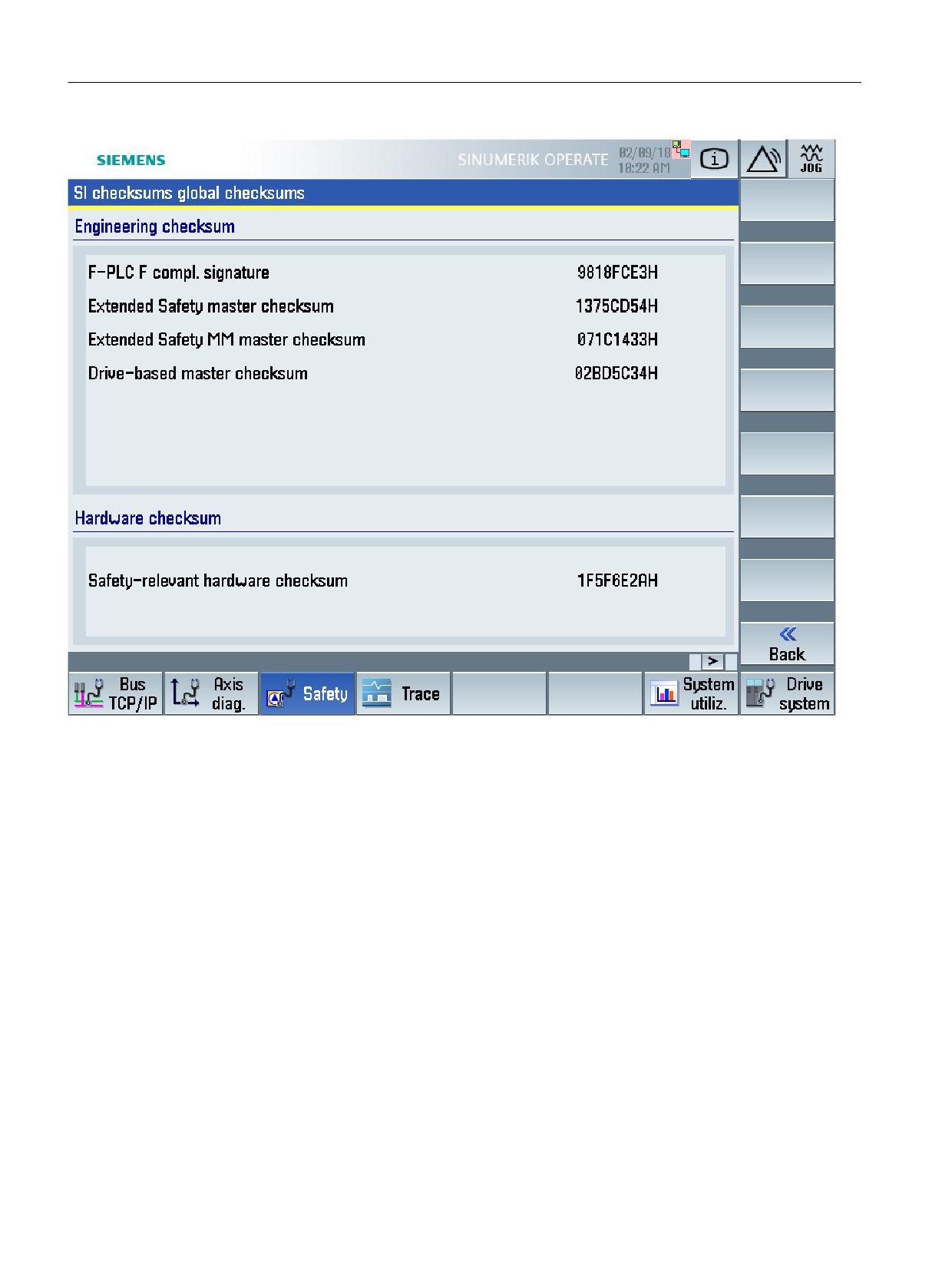
Higher-level actual checksums that are calculated from the master checksums (Page 318) are
displayed in the "SI checksums global checksums" diagnostic screen. If you call the diagnostics
screen, then the calculation of the global checksums is started - and after completion, these
actual checksums, along with the calculation date, are displayed.
Calling global checksums
MENU SELECT > Diagnostics > Menu forward key > Safety > SI checksum > Global checksums
Safety Integrated plus
Commissioning Manual, 10/2020, 6FC5397-1FP40-6BA4
311
Diagnostics
9.3 Diagnostic functions in SINUMERIK Operate
Figure 9-8
"SI checksums global checksums" diagnostic screen
If, based on these global checksums, you identify some changes in the safety configuration, then
you can switch from diagnostics screen "Global checksums" to the individual axis/drive
checksums in order to identify specific differences.
9.3.7
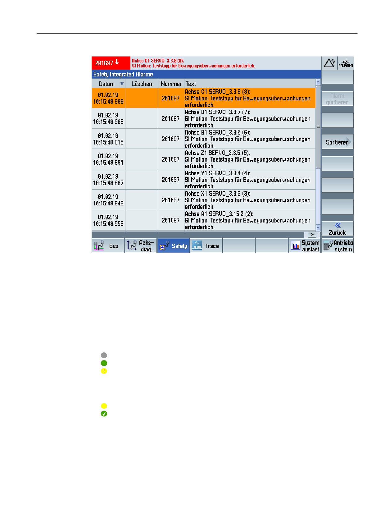
SI alarms
Active safety-relevant alarms are displayed in diagnostics screen "SI-alarms".
Call
MENU SELECT > Diagnostics > Menu forward key > Safety > SI alarms
Safety Integrated plus
312
Commissioning Manual, 10/2020, 6FC5397-1FP40-6BA4
Diagnostics
9.3 Diagnostic functions in SINUMERIK Operate
Figure 9-9
"Safety Integrated alarms" diagnostic screen
9.3.8
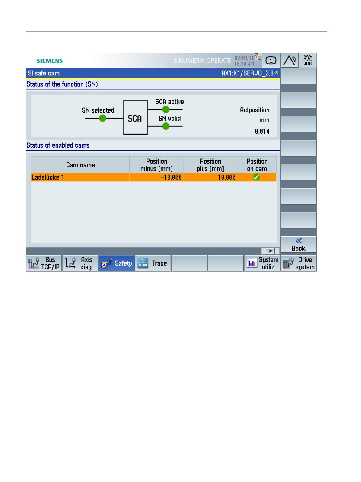
SI Safe Cams
In the "SI safe cams" diagnostic screen, the following information about the "Safe Cam (SCA)
safety function" of the selected drive is displayed:
• Status of the function (SCA)
For the selected drive, indicates whether the "Safe Cam" (SCA) safety function has been
selected, is active and is valid. The actual position is also displayed (actual value on the load
side on the CU).
Inactive
Active
Invalid. Safe referencing was not carried out.
• Status of the enabled cams
For each configured and enabled cam, displays the identifier, the minus and plus positions -
as well as the validity of the cam position.
Cam position is reached and the cam is invalid.
Cam position is reached and the cam is valid. Safe referencing was carried out.
Call
MENU SELECT > Diagnostics > Menu forward key > Safety > Menu forward key >SI cams
Safety Integrated plus
Commissioning Manual, 10/2020, 6FC5397-1FP40-6BA4
313
Diagnostics
9.3 Diagnostic functions in SINUMERIK Operate
Figure 9-10
"SI safe cams" diagnostics screen
9.3.9
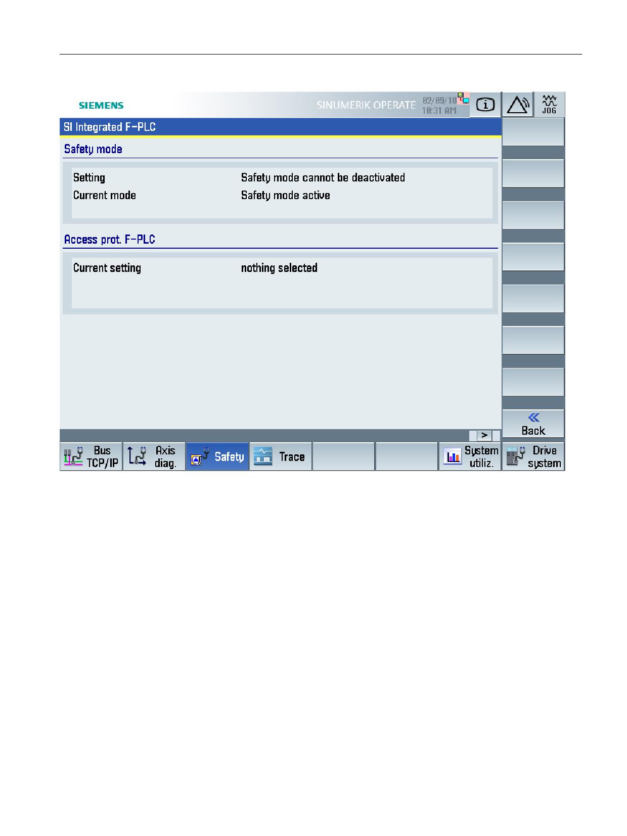
SI integrated F-PLC
The configured safety-related status and diagnostic information of the integrated F-PLC of the
SINUMERIK NCU is displayed in the "SI Integrated F-PLC" diagnostic screen.
Call
MENU SELECT > Diagnostics > Menu forward key > Safety > SI Integrated F-PLC
Safety Integrated plus
314
Commissioning Manual, 10/2020, 6FC5397-1FP40-6BA4
Diagnostics
9.3 Diagnostic functions in SINUMERIK Operate
Figure 9-11
"SI Integrated F-PLC" diagnostic screen (screenshot as example)
9.3.10
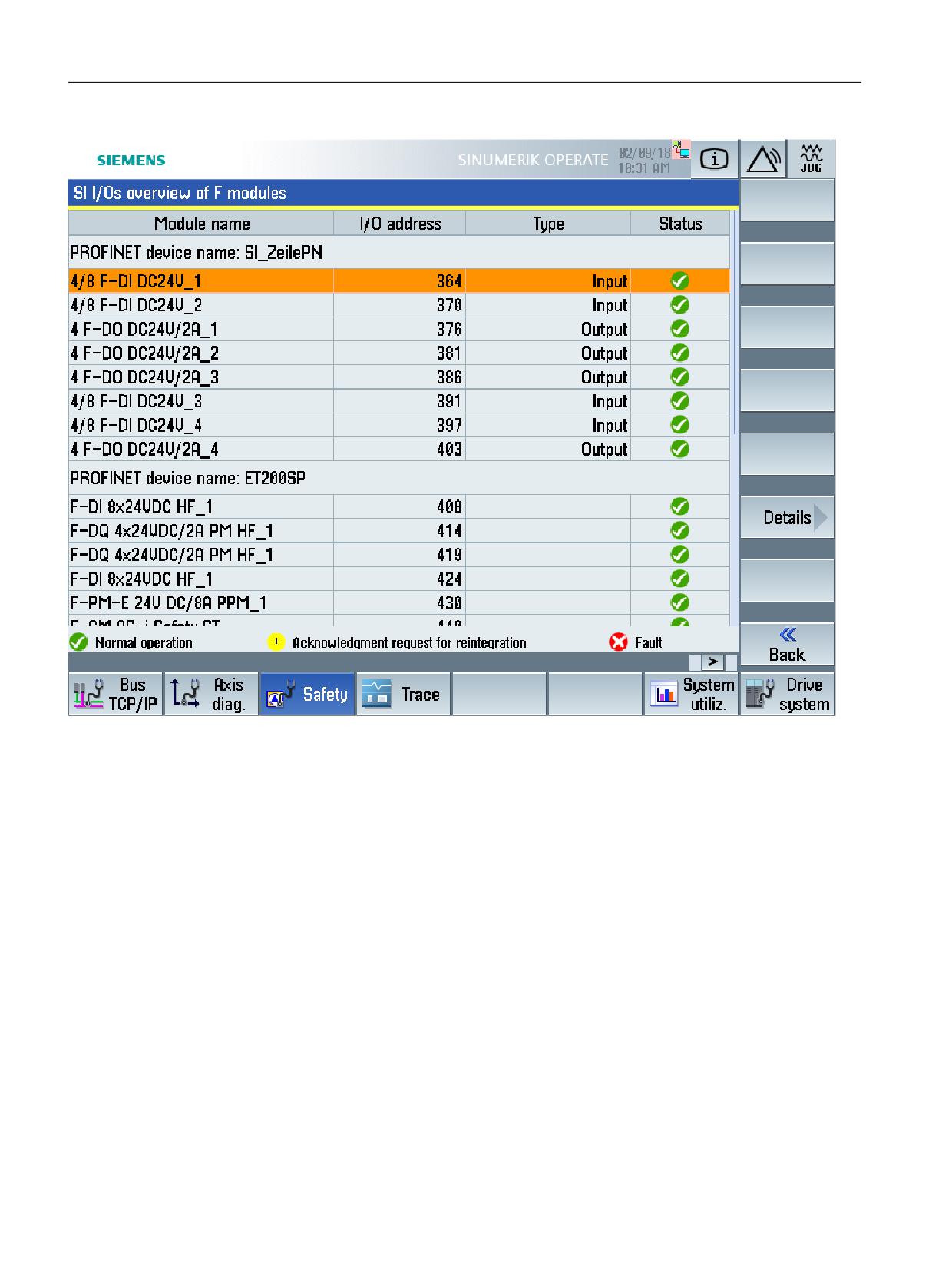
SI I/O
The configured F-I/O is displayed in the "SI I/O overview F-modules " diagnostic screen.
Call
MENU SELECT > Diagnostics > Menu forward key > Safety > SI I/O
Safety Integrated plus
Commissioning Manual, 10/2020, 6FC5397-1FP40-6BA4
315
Diagnostics
9.3 Diagnostic functions in SINUMERIK Operate
Figure 9-12
"SI I/O overview F-modules" diagnostics screen (sample screenshot).
With the "Details" softkey, you can display additional information about the selected module.
Safety Integrated plus
316
Commissioning Manual, 10/2020, 6FC5397-1FP40-6BA4
Diagnostics
9.4 Display and evaluation of diagnostic information
9.4
Display and evaluation of diagnostic information
In the "SINUMERIK Safety Integrated plus" mode, safety-related monitoring functions are
integrated and executed in the drive. Diagnostic information is communicated and evaluated as
follows:
• The status and control information (SIC/SCC) (Page 205) of the drive is communicated
between the integrated subcomponents of the NCU:
- As a consequence, the motion control in the NC is also linked (Page 326) to the safety
functions integrated in the drive, therefore avoiding unnecessary follow-on responses in
the NC.
- Some SIC status information is also saved to NC variables (OPI) (Page 345).
• SINAMICS Integrated messages and alarms can be displayed as follows:
- Safety messages of the drive are displayed in SINUMERIK Operate in the alarm lists.
Note
Information for those switching over from a different system: Evaluating alarms
using the NC
As the "SINUMERIK Safety Integrated plus" mode uses the safety functions integrated in
the drive, the NC does not suppress alarms, prioritize alarms or check alarm numbers of
drive safety messages (contrary to the "SINUMERIK Safety Integrated" mode).
- The standard alarm of a drive can also include safety-related diagnostic information. In
order that these are displayed in SINUMERIK Operate, you must activate the alarm buffer
(Page 329).
- Display and acknowledgment (Page 331) of messages depend on the scope of the Safety
Integrated Functions (Page 24) used - and the use of the safety message buffer
(Page 329).
Safety Integrated plus
Commissioning Manual, 10/2020, 6FC5397-1FP40-6BA4
317
Diagnostics
9.5 Checksums
9.5
Checksums
Based on Safety Integrated checksums and signatures, you can compare the actual state of the
machine with the original state when delivered, which is documented in the acceptance report.
The checksums are displayed in SINUMERIK Operate in the Diagnostics area (Page 310).
• The individual F-blocks have signatures, and the safety program has an F-collective
signature. These checksums for the safety program are displayed in the TIA Portal as well as
in the safety printout.
• There are SINAMICS parameters with reference checksums (defined when commissioning)
and actual checksums for the CU, MM and motion monitoring functions; these are checked
by SINAMICS Integrated when they power up. SINAMICS alarms F01650/F30650 and/or
F01680/F30680 are output if the checksums differ.
See: SINAMICS checksums (Page 320)
• In SINUMERIK Operate, additional master checksums and global checksums are displayed,
which are calculated from the actual checksums listed above. The NCU does not compare
these higher-level checksums with reference checksums - and it does not save them.
See: Calculating the global checksums/master checksums (Page 318)
The global checksums/master checksums are displayed in the diagnostics area of SINUMERIK
Operate, which means that it is easy to identify differences between the actual and reference
states.
See: SI checksums (Page 310)
9.5.1
Calculating the global checksums/master checksums
In addition to the checksums or signatures of the SINAMICS Integrated and F-PLC
subcomponents, in SINUMERIK Operate, global checksums and master checksums are
displayed, which are calculated from various actual checksums of the F-PLC and SINAMICS
Integrated. The NCU does not compare these higher-level actual checksums with reference
checksums - and it does not save them.
By displaying these higher-level actual checksums, differences between the actual and reference
states can be easily and transparently identified.
The global checksums/master checksums are calculated as follows:
• The global checksum is the sum of the associated master checksums (see table).
• The master checksums comprise the sums of the values/parameters with actual checksums
for the calculation (see table).
If SINAMICS parameters are involved for the values being used as basis, then when making
the calculation, the sum over the following drives is generated:
- Drives, which do not have an assigned NC axis, and where the safety functions are
enabled in p9601: p9601 SI enable functions integrated in the drive (Control Unit) / SI
enable fct CU ! = 0
Safety Integrated plus
318
Commissioning Manual, 10/2020, 6FC5397-1FP40-6BA4
Diagnostics
9.5 Checksums
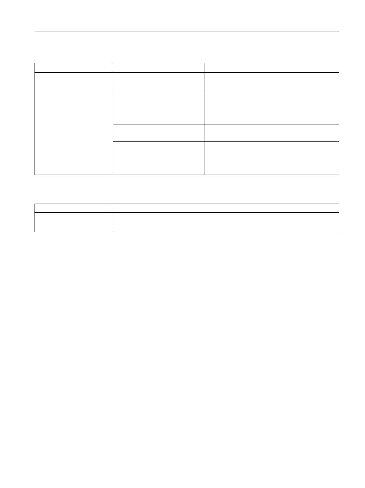
Table 9-6
Calculating the global checksum and the associated master checksums
Global checksum
Master checksum
Values/parameters used for the calculation
Global safety engineering
F-CPU master checksum
• Signature of the safety program
checksum
• Hardware checksum of the F-PLC
(sum of all master checksums)
Extended Safety master checksum
• r9728[0] SI Motion actual checksum SI parame-
ters / SI Mtn act CRC
• r9728[1] SI Motion actual checksum SI parame-
ters / SI Mtn act CRC
Extended Safety MM master check-
• r9398[0] SI Motion actual checksum SI parameters
sum
(Motor Module) / SI Mtn act CRC MM
Drive-based master checksum
• r9798 SI actual checksum SI parameters (Control
Unit) / SI act_checksum CU
• r9898 SI actual checksum SI parameters (Motor
Module) / SI act_checksum MM
Table 9-7
Calculation of the master checksum "Safety-relevant hardware checksum"
Master checksum
Parameters used for the calculation
Safety-relevant hardware
• r9728[2] SI Motion actual checksum SI parameters / SI Mtn act CRC
checksum
• r9398[1] SI Motion actual checksum SI parameters (Motor Module) / SI Mtn act CRC MM
Safety Integrated plus
Commissioning Manual, 10/2020, 6FC5397-1FP40-6BA4
319
Diagnostics
9.5 Checksums
9.5.2
SINAMICS checksums
For each monitoring channel, the safety parameters include 2 parameters for the reference and
actual checksum.
During commissioning, the actual checksum must be transferred to the corresponding
parameter for the reference checksum. This can be done for all checksums of a drive object at the
same time using parameter p9701 - or using the corresponding SINUMERIK Operate
functionality.
Table 9-8
Basic Functions
• r9798
SI actual checksum SI parameters (Control Unit)
• p9799
SI reference checksum SI parameters (Control Unit)
• r9898
SI actual checksum SI parameters (Motor Module)
• p9899
SI reference checksum SI parameters (Motor Module)
Table 9-9
Extended Functions (contain also the following checksum parameters)
• r9398[0...1]
SI Motion actual checksum SI parameters (Motor Module)
• p9399[0...1]
SI Motion reference checksum SI parameters (Motor Module)
• r9728[0...2]
SI Motion actual checksum SI parameters
• p9729[0...2]
SI Motion reference checksum SI parameters
During each ramp-up procedure, the actual checksum is calculated via the Safety parameters
and then compared with the reference checksum.
If the actual and reference checksums are different, fault F01650/F30650 or F01680/F30680 is
output.
Safety Integrated plus
320
Commissioning Manual, 10/2020, 6FC5397-1FP40-6BA4

Diagnostics
9.6 Stop responses
9.6
Stop responses
9.6.1
Overview
The stop responses that can be initiated depend on the scope of the Safety Integrated Functions
used:
• Stop responses that can be initiated for faults involving Safety Integrated Basic Functions
(Page 321)
• Stop responses that can be initiated for faults involving Safety Integrated Extended
Functions (Page 323)
Stop responses and safety functions can be dependent on a priority that has been assigned:
• No overall priority is assigned to individual safety functions.
• The various stop responses each have a certain priority (Page 326).
• For stop responses and Safety Integrated Extended Functions, there are some dependencies
regarding the priority (Page 326).
The motion control in the NC is linked (Page 326) to the Safety Integrated Functions integrated
in the drive and the associated stop responses, which means that no unnecessary follow-on
responses are initiated in the NC.
9.6.2
Basic Functions
When faults associated with Safety Integrated Basic Functions occur, the following stop
responses can be initiated:
Table 9-10
Stop responses for Safety Integrated Basic Functions
Stop response
Triggered ...
Action
Effect
STOP A cannot
For all Safety faults with pulse
Trigger safe pulse suppression
The motor coasts to a standstill or is
be acknowl-
suppression that cannot be ac-
via the switch-off signal path for
braked by the holding brake.
edged
knowledged.
the relevant monitoring chan-
nel. During operation with SBC:
STOP A
For all acknowledgeable Safety
Apply motor holding brake.
faults
As a follow-up reaction of STOP F
STOP A corresponds to Stop Category 0 in accordance with EN 60204-1.
With STOP A, the motor is switched directly to zero torque via the "Safe Torque Off (STO)" function.
A motor at standstill cannot be started again accidentally.
A moving motor coasts to standstill. This can be prevented by using external braking mechanisms, e.g.
holding or operating brake.
When STOP A is present, "Safe Torque Off" (STO) is active.
Safety Integrated plus
Commissioning Manual, 10/2020, 6FC5397-1FP40-6BA4
321

Diagnostics
9.6 Stop responses
Stop response
Triggered ...
Action
Effect
STOP F
If an error occurs in the cross-
Transition to STOP A.
Follow-up response STOP A
wise data comparison.
with adjustable delay (factory setting
without delay) if one of the safety
functions is selected
STOP F is permanently assigned to the crosswise data comparison (CDC). In this way, errors are detected in
the monitoring channels.
After STOP F, STOP A is triggered.
When STOP A is present, "Safe Torque Off" (STO) is active.
WARNING
Uncontrolled axis motion when a STOP A/F is initiated
With a vertical axis or pulling load, there is a risk of uncontrolled axis movements when STOP
A/F is triggered. If present in the hazardous area, this can result in death or severe injury.
• Use the "Safe Brake Control (SBC)" and a holding brake (not a safety-relevant brake!) with
sufficient holding force to prevent these movements.
Safety Integrated plus
322
Commissioning Manual, 10/2020, 6FC5397-1FP40-6BA4

Diagnostics
9.6 Stop responses
9.6.3
Extended Functions
Faults involving Safety Integrated Extended Functions and violation of limits can trigger the
following stop responses:
Table 9-11
Stop responses for Safety Integrated Extended Functions
Stop response
Triggered ...
Response of the initiating ax-
Response of other axes or NC re-
is or DRV response
sponse
STOP A1)
• For all acknowledgeable
Immediate pulse cancellation
All path axes: IPO rapid stop
(corresponds to
safety faults with pulse
All axes, with the exception of the
STO2))
cancellation
path axes and the initiating axis: Brak-
Effect:
ing along a ramp (acceleration limit)
• Subsequent response of
Drive coasts down
STOP B
• Configurable subsequent
stop p9563 for SLS
• Configurable subsequent
stop p9566 for SDI
• Configurable subsequent
stop p9562 for SLP
• Configurable subsequent
stop p9579 for SLA
STOP B1)
Examples:
Immediate input of speed set-
All path axes: IPO rapid stop
(corresponds to
point = 0 and start of timer tB .
• Standstill tolerance viola-
All axes, with the exception of the
SS13))
Once tB or nact < nshutdown has ex-
ted in p9530 (SOS)
path axes and the initiating axis: Brak-
pired, STOP A is triggered.
ing along a ramp (acceleration limit)
• Configurable subsequent
stop p9563 for SLS
Effect:
• Configurable subsequent
STOP B with subsequent STOP
stop p9566 for SDI
A.
• Configurable subsequent
The drive decelerates along the
stop p9562 for SLP
OFF3 ramp and then switches
• Subsequent response of
to STOP A.
STOP F
Note:
For "SS1 with external stop"
• Configurable subsequent
(SS1E), braking is not along the
stop p9579 for SLA
OFF3 ramp (see Chapter SS1
(Extended Functions) with ex-
ternal stop (Page 89))
STOP C1)
• Configurable subsequent
Immediate input of speed set-
All path axes: IPO rapid stop
(corresponds to
stop p9563 for SLS
point = 0 and start of timer tC.
All axes, with the exception of the
SS24))
• Configurable subsequent
Once tC has elapsed, SOS is se-
path axes and the initiating axis: Brak-
lected.
ing along a ramp (acceleration limit)
stop p9566 for SDI
• Configurable subsequent
stop p9562 for SLP
Effect:
Configurable subsequent
The drive decelerates along the
stop p9579 for SLA
OFF3 ramp; SOS is then selec-
ted.
Safety Integrated plus
Commissioning Manual, 10/2020, 6FC5397-1FP40-6BA4
323

Diagnostics
9.6 Stop responses
Stop response
Triggered ...
Response of the initiating ax-
Response of other axes or NC re-
is or DRV response
sponse
STOP D1), 5)
• Configurable subsequent
Timer tD is started.
Braking along the path (interpolatory
stop p9563 for SLS
braking)
No drive-integrated response,
• Configurable subsequent
but an NC response (see right).
stop p9566 for SDI
Once tD has elapsed, SOS is se-
lected.
• Configurable subsequent
stop p9562 for SLP
An automatic response is only
triggered if the standstill toler-
• Configurable subsequent
ance window is violated in SOS.
stop p9579 for SLA
STOP E1), 5)
• Configurable subsequent
SOS triggered after the expiry
Fast retraction (ESR), which allows
stop p9563 for SLS
of p9554
the controlled axes to be retracted
• Configurable subsequent
stop p9566 for SDI
Effect:
• Configurable subsequent
Controlling the drive-integra-
ted ESR functionality
stop p9562 for SLP
• Configurable subsequent
stop p9579 for SLA
STOP F1)
If an error occurs in the cross-
Timer tF1 (Basic Functions) or tF2
NC start/traversing interlock
wise data comparison.
(Extended Functions)
Follow-up response STOP B or
No drive response
STOP A
Effect:
If a safety function (SOS, SLS)
has been selected or if SSM
with hysteresis has been ena-
bled, transition to STOP A after
tF1 (Basic Functions) has
elapsed or STOP B after tF2 (Ex-
tended Functions) has elapsed.
1)
See also the following note "delayed pulse cancellation when the bus fails".
2)
The behavior of the drive after STOP A is triggered corresponds (apart from the safety messages) to the behavior after STO
is triggered. Note that the parameterization of STO applies equally for STOP A.
3)
The behavior of the drive after STOP B is triggered corresponds (apart from the safety messages) to the behavior after SS1 is
triggered. Monitoring with the aid of SAM or SBR, for example, works in exactly the same way. Note that the parameterization
of SS1 applies equally for STOP B.
4)
The behavior of the drive after STOP C is triggered corresponds (apart from the safety messages) to the behavior after SS2 is
triggered. Monitoring with the aid of SAM, for example, works in exactly the same way. Note that the parameterization of SS2
applies equally for STOP C.
5)
The behavior of the drive after STOP D (E) is initiated corresponds (apart from the safety messages) to the behavior after SS2E
(SS2ESR) is initiated.
Safety Integrated plus
324
Commissioning Manual, 10/2020, 6FC5397-1FP40-6BA4
Diagnostics
9.6 Stop responses
Note
Delayed pulse cancellation when the bus fails
For SLS, SDI, SLP and SLA, the stop responses are also available with delayed pulse cancellation
when the bus fails (to prevent the drive from immediately responding with pulse cancellation
when a communication error occurs):
• If p9580 ≠ 0 and SLS is active, in the event of communication failure, the parameterized ESR
reaction is only realized if, as SLS response, a STOP with delayed pulse cancellation when the
bus fails has been parameterized (p9563[0...3] ≥ 10).
• If p9580 ≠ 0 and SDI is active, in the event of a communication failure, the parameterized ESR
reaction only occurs if a STOP with delayed pulse cancellation when the bus fails has been
parameterized as the SDI response (p9566 ≥ 10).
• If p9580 ≠ 0 and SLP is active, the parameterized ESR reaction only takes place for a
communication failure if a STOP with delayed pulse cancellation in the event of bus failure
is parameterized as the SLP response (p9562[0...1] ≥ 10).
• If p9580 ≠ 0 and SLA is active, the parameterized ESR response is only triggered in the event
of a communication failure if a STOP with delayed pulse cancellation when the bus fails has
been parameterized as the SLA response (p9579 ≥ 10).
The delay time (p9580) must not exceed 800 ms.
Note
Delay time between STOP F and STOP B
A delay time between STOP F and STOP B should only be set if an additional response is initiated
during this time when the "Internal Event" (r9722.7) message signal is evaluated.
Further, when using the delay time, a monitoring function should always be selected (e.g. SLS
with a high limit speed) or the hysteresis of SSM should be configured.
When hysteresis is activated for SSM, then this should be considered to be an activated
monitoring function.
On delays at the transition of the stop responses
• tB: p9556
• tC: p9552
• tD: p9553
• tE: p9554
• tF1: p9658
• tF2: p9555
• nshutdown: p9560
Safety Integrated plus
Commissioning Manual, 10/2020, 6FC5397-1FP40-6BA4
325

Diagnostics
9.6 Stop responses
9.6.4
Definitions and effects in the NC
The motion control in the NC is linked to the Safety Integrated Functions in the drive via the SIC
status signals. This avoids that subsequent responses are initiated in the NC as a result of safety
stops in the drive.
Example: The motion control in the NC responds to the drive STOP responses by no longer
issuing additional setpoints for the path, for example. As a consequence, alarms to be
acknowledged are avoided, such as "Contour monitoring" or "Positioning monitoring".
The corresponding status bits from S_ZSW1 (or S_ZSW1B) are used to emulate the safety stop
responses in the NC.
9.6.5
Priorities
Table 9-12
Priorities of the stop responses
Priority classes
Stop response
Highest priority
STOP A
STOP B
STOP C
STOP D
STOP E
Lowest priority
STOP F
Priorities between stop responses and Extended Functions
The following table lists which stop response or safety function is set if a STOP is initiated when
a safety function is active.
Table 9-13
Priorities between stop responses and Extended Functions
Highest
Lowest
priority
priority
Stop response/
Extended Function
STOP A
STOP B
STOP C
STOP D
STOP E
STOP F
Highest
STO
STOP A / STO
STO
STO
STO
STO
STO
priority
SS1
STOP A
STOP B / SS1
SS1
SS1
SS1
SS1
SS2
STOP A
STOP B
STOP C / SS2
SS2
SS2
SS2 / STOP B2)
Safety Integrated plus
326
Commissioning Manual, 10/2020, 6FC5397-1FP40-6BA4

Diagnostics
9.6 Stop responses
SOS
STOP A1)
STOP B1)
SOS
SOS
STOP E/SOS
STOP B2)
Lowest
SLS
STOP A3)
STOP B3)
STOP C4)
STOP D4)
STOP E4)
STOP B2)
priority
1)
The SOS monitoring function remains active, although the fault response in the event of a fault can no longer be triggered
because it is already present.
2)
STOP B is the subsequent stop of STOP F, which is activated after a time that can be parameterized. STOP F alone does not have
any effect; the active safety function is still present.
3)
The SLS monitoring function remains active, although the fault response in the event of a fault can no longer be triggered
because it is already present.
4)
SLS remains active during the braking phase, after which the system switches to SOS.
Explanation of the table
No overall priority is assigned in the individual safety functions. SOS remains active, for example,
even if STO is requested.
• The safety functions that cause the drive to decelerate (SS1, SS2) are specified from top to
bottom in descending order of priority.
• The stop responses arranged here from left to right in descending order of priority (STOP A-
F).
If a field contains two entries, the stop responses and safety functions have the same priority.
• STOP A corresponds to selecting STO
• STOP B corresponds to selecting SS1
• STOP C corresponds to selecting SS2
• STOP D corresponds to selecting SOS
• STOP E corresponds to selecting SOS (for additional activation of the standard "Extended stop
and retract (ESR)" function)
• When the SS2 function is active, STOP F results in subsequent stop STOP B. SS2 remains active.
Examples for illustrating the information in the table:
• Safety function SS1 has just been selected. STOP A remains selected.
• By selecting a STOP with a higher priority, STOPs that are present with a lower priority will be
replaced. This means that when SS1 is selected (≙ STOP B), any STOPs C-F that are present will
be replaced.
• The SLS safety function is selected. This selection does not modify the function of STOP A-D.
A STOP F now triggers a STOP B because a safety function has been activated.
• Stop response, STOP C is selected. If the STO or SS1 safety functions are active, this does not
have any effect. If SS2 is active, this brake ramp is retained. If SOS is active, SOS remains
effective, which is also the end status of STOP C. When SLS is selected, the drive is decelerated
with STOP C.
Safety Integrated plus
Commissioning Manual, 10/2020, 6FC5397-1FP40-6BA4
327
Diagnostics
9.7 Using the fault buffer, message buffer and alarm buffer
9.7
Using the fault buffer, message buffer and alarm buffer
In addition to the standard fault buffer and the standard alarm buffer, SINAMICS Integrated has
several safety message buffers for safety-relevant messages involving Safety Integrated
Extended Functions:
• Messages for Extended Functions are displayed in the safety message buffer.
• You must enable SIC/SCC for the appropriate axes in MD39750.
• For all messages in the safety message buffer, a specific reference is made in the HMI to
the fact that safety-relevant acknowledgment (Page 331) is required.
- Reference is made to active safety-relevant alarms in SINUMERIK Operate in the
"Safety Integrated diagnostics overview "(in addition to the standard alarm list).
- Reference is made to active alarms that require a safety-relevant acknowledgment
using a safety delete symbol.
• To acknowledge messages in the safety message buffer, safety-relevant acknowledg-
ment is required - and possibly also acknowledgment with PROFIdrive RESET (Page 332).
• Messages for Basic Functions or for external drives without an NC axis assignment, cannot
be saved to the safety message buffer.
• When using external drives without NC axis assignment, then you must deactivate the
safety message buffer (Page 329).
• The response when saving safety-relevant messages relating to Basic Functions corre-
sponds to the response for a deactivated safety message buffer (see below).
• If the safety message buffer is deactivated, then safety-relevant messages are saved in the
standard fault and/or alarm buffer.
• For safety-related messages in the fault and alarm buffer, in SINUMERIK Operate, spe-
cific reference is not made to the safety-relevant acknowledgment required.
Safety-relevant alarms are displayed in SINUMERIK Operate in the standard alarm list
("MENU SELECT > Diagnostics > Alarms"); however, they require safety-relevant ac-
knowledgment.
• The messages require additional acknowledgment: For an entry in the fault buffer, in
addition alarm 25201 ("Drive fault") is output, and the drive message requires a safety-
relevant acknowledgment as well as also the acknowledgment via PROFIdrive
(Page 333).
Safety Integrated plus
328
Commissioning Manual, 10/2020, 6FC5397-1FP40-6BA4
Diagnostics
9.7 Using the fault buffer, message buffer and alarm buffer
9.7.1
Configuring the standard alarm buffer
The standard alarm buffer is automatically activated when you configure the safety mode.
This alarm buffer is required for safety-related standard warnings (Axxxx).
The display of safety-related standard warnings cannot be activated independently of the
display of other standard warnings.
The activation is entered in the following machine data:
• MD13150 $MN_SINAMICS_ALARM_MASK
- "bit 2: output faults of the drive controls"
- "bit 10: output alarms of the drive controls"
Alarms/warnings have to be evaluated.
Optionally, you can set additional bits in order to output faults or alarms of other DO groups.
9.7.2
Configuring the safety message buffer
The safety message buffer is activated in the factory setting, and is used for safety-related
messages from Extended Functions.
Under certain circumstances it can also make sense to deactivate the safety message buffer for
Extended Functions so that the messages of Basic Functions as well as those of Extended
Functions are saved to the fault and/or alarm buffer (for example, if you are predominantly using
Basic Functions).
The setting to activate/deactivate the safety message buffer is a CU parameter (p3117). It cannot
be set on a drive-specific or axes-specific basis, but is always applicable for all drives and/or axes
of this CU.
The following drive parameter is relevant:
• p3117 change safety message type/ Ch. SI mess type
Setting to re-parameterize all safety messages to faults and alarms.
Precondition
• Settings for drive parameters are protected with access level 2 (service).
Procedure
Proceed as follows to deactivate or activate the safety message buffer:
1. In SINUMERIK Operate, call the drive parameters using "MENU SELECT > Commissioning >
Machine data > Control Unit parameters".
2. Activate the CU commissioning state "Device configuration" with "p0009 = 1".
Safety Integrated plus
Commissioning Manual, 10/2020, 6FC5397-1FP40-6BA4
329
Diagnostics
9.7 Using the fault buffer, message buffer and alarm buffer
3. Set the required value in drive parameter p3117 Change safety message type / Ch. SI mess
type:
- p3117 = 0: Safety messages of this CU are not reparameterized; this means that messages
associated with Extended Functions are entered in the safety message buffer.
- p3117 = 1: All safety messages of this CU are reparameterized, and entered in the
standard fault or alarm buffer.
4. Deactivate the CU commissioning state "Device configuration" with "p0009 = 0".
5. Confirm the setting with "Save/reset> Menu forward key> Reset (po)".
Safety Integrated plus
330
Commissioning Manual, 10/2020, 6FC5397-1FP40-6BA4

Diagnostics
9.8 Acknowledgment
9.8
Acknowledgment
9.8.1
Overview
Most safety messages require safety-related acknowledgment.
Safety-related acknowledgment involves deleting safety-related messages of the drive-
integrated monitoring functions via safety-related communication. With the safety-related
acknowledgment, the fault case in the drive is marked as having been resolved (gone).
Safety-related acknowledgment is independent of the scope of the Safety Functions used (Basic
or Extended) - and is required in addition to actually removing the cause of the fault.
Depending on the drive type, different types of acknowledgment and/or safety-related
acknowledgment are possible:
Table 9-14
Permissible acknowledgment types for various drive types
Drive type
Permissible acknowledgment
Integrated drives
• Safety-related acknowledgment using PROFIsafe signal "IEACK"
(CU_I, CU_NX)
(Page 332)
• Acknowledgment by switching-off/switching-on (Page 333)
External NC drives
• Safety-related acknowledgment using PROFIsafe signal "IEACK"
(Page 332)
• Acknowledgment by deselecting STO or SS1 (Page 333)
• Acknowledgment by switching-off/switching-on (Page 333)
External SINAMICS drives with-
The safety message buffer is not supported and must be deactivated
out any assignment to an NC
(Page 329).
axis
The acknowledgment options correspond to those of external NC drives
(see above).
Depending on what has been configured, additional acknowledgments may be necessary:
• If you are using Basic Functions, or the safety message buffer is deactivated (p3117 = 1), then
you must additionally acknowledge (Page 333) all safety messages that are saved in the
standard fault buffer using a PROFIdrive RESET.
• In addition to a safety-related acknowledgment, various fault situations also require
an acknowledgment using a PROFIdrive RESET (Page 332).
WARNING
Unexpected restart for safety-related acknowledgment without MCP reset!
If a STOP response is acknowledged in a safety-related fashion by the machine operator, but
without PROFIdrive RESET acknowledgment, then the part program is not canceled and is
continued with the acknowledgment. When the machine restarts unexpectedly, this can put
people in dangerous situations or cause material damage.
• In the safety program logically combine safe acknowledgment (PROFIsafe IEACK) with a
RESET at the machine control panel (PROFIdrive RESET).
Safety Integrated plus
Commissioning Manual, 10/2020, 6FC5397-1FP40-6BA4
331

Diagnostics
9.8 Acknowledgment
9.8.2
Acknowledgment via PROFIsafe
You program a PROFIsafe acknowledgment in the safety program of the F-PLC by setting signal
"Internal Event ACK" separately for each drive object using the PROFIsafe telegram (STW bit 7).
Faults in the drive objects (DOs) cannot be acknowledged by the F-PLC in the line-up, but must
instead be acknowledged separately for each individual drive object. A falling edge of the
"Internal Event ACK" signal resets the status "Internal Event" in the particular drive, and thus
acknowledges the fault.
9.8.3
Additional acknowledgment via PROFIdrive RESET
WARNING
Unexpected restart for safety-related acknowledgment without MCP reset!
If a STOP response is acknowledged in a safety-related fashion by the machine operator, but
without PROFIdrive RESET acknowledgment, then the part program is not canceled and is
continued with the acknowledgment. When the machine restarts unexpectedly, this can put
people in dangerous situations or cause material damage.
• In the safety program logically combine safe acknowledgment (PROFIsafe IEACK) with a
RESET at the machine control panel (PROFIdrive RESET).
In addition to a safety-relevant acknowledgment, various fault situations also require an
acknowledgment using a PROFIdrive RESET.
This applies to the following STOP responses or safety functions:
• Extended Functions:
- All fault situations - or safety functions and STOP responses
• Basic Functions or inactive safety message buffer:
- Parameterizing SLS with STOP D or STOP E
In the case of a fault, if safety-relevant acknowledgment is realized without a PROFIdrive RESET,
even though the part program remains in the stop state, the spindle starts again.
A configuration such as this is not in conformance with standard IEC 61800-5-2. According to the
standard, a restart inhibit is required for all STOP functions, and it is only permissible that the
spindle restarts after a RESET.
Therefore, in the safety program logically combine safety-relevant acknowledgment (PROFIsafe
IEACK) with a RESET at the machine control panel (PROFIdrive RESET).
This means that you should configure the machine control panel RESET (MCP reset or channel/
MODE GROUP RESET) so that when actuated, a PROFIdrive RESET as well as a safety-relevant
acknowledgment (e.g. PROFIsafe IEACK) are initiated.
Safety Integrated plus
332
Commissioning Manual, 10/2020, 6FC5397-1FP40-6BA4
Diagnostics
9.8 Acknowledgment
9.8.4
Acknowledgment using POWER ON
Safety faults can also be acknowledged (as with all other faults) by switching the drive unit off
and then on again (POWER ON).
If this action has not eliminated the fault cause, the fault is displayed again immediately after
power-up.
9.8.5
Extended acknowledgment (deselecting STO/SS1)
For external drives, the extended alarm acknowledgment can be used as alternative to safety-
relevant acknowledgment. To do this, the extended alarm acknowledgment must be activated
in the safety configuration of the drive.
Extended alarm acknowledgment is not supported for integrated drives.
Basic procedure
If STO or SS1 is selected/deselected - and if p9507.0 is set = 1 - then the safety messages are
automatically withdrawn.
• Remove the cause of the fault.
• Deselect "Safe Torque Off" (STO) or "Safe Stop 1" (SS1).
• Acknowledge the fault.
If, in addition to the "Basic Functions via terminals", the "Extended Functions" are also enabled,
then acknowledgment is also possible by selecting/deselecting STO via PROFIsafe.
If the safety commissioning mode is exited when the safety functions are switched off (p0010 ≠
95 when p9601 = 0), then all safety faults can be acknowledged.
Once safety commissioning mode has been selected again (p0010 = 95), all the faults that were
previously present reappear.
9.8.6
Additional acknowledgment when the safety message buffer is inactive
If you are using Basic Functions or the safety message buffer is deactivated (p3117 = 1), then the
safety messages are saved to the standard fault buffer or to the standard alarm buffer. These
messages require a safety-relevant acknowledgment, even when the safety message buffer is
deactivated.
In addition to safety-relevant acknowledgment, safety messages in the standard fault buffer
require acknowledgment using PROFIdrive signal "Acknowledge faults" (PROFIdrive RESET). For
NC axes, a PROFIdrive RESET corresponds to a machine control panel RESET.
The required PROFIdrive RESET is displayed in SINUMERIK Operate with NC alarm 25201.
Safety Integrated plus
Commissioning Manual, 10/2020, 6FC5397-1FP40-6BA4
333

Diagnostics
9.8 Acknowledgment
When the safety message buffer is deactivated, the following safety messages are saved in the
fault buffer, and therefore also additionally required a PROFIdrive RESET:
Table 9-15
Saving safety-relevant messages in the the fault buffer (when the safety message buffer is
deactivated)
Alarm number
Alarm text
(SINAMICS)
F01689
SI Motion: Axis re-configured
C01700
SI Motion P1 (CU): STOP A initiated
C01701
SI Motion P1 (CU): STOP B initiated
C01708
SI Motion P1 (CU): STOP C initiated
C01770
SI Motion P1 (CU): Discrepancy error of the failsafe digital inputs/outputs
When the safety message buffer is deactivated, all of the safety messages listed in the table are
saved in the standard alarm buffer.
Safety Integrated plus
334
Commissioning Manual, 10/2020, 6FC5397-1FP40-6BA4

Component replacement (software/hardware)
10
WARNING
Unsafe operating state after POWER ON
After a firmware update, the system generally requests a POWER ON. After a POWER ON, an
unsafe operating state can occur - and if persons are in the hazardous area, this can result in
death or severe injury.
• After each POWER ON, perform an acceptance test and create an acceptance report.
• Do not enter the danger zone of the motor until the acceptance test has been successfully
completed.
WARNING
Unwanted motion if components are replaced without a function test
After a component replacement, connections or functions can be defective so that death or
serious injury can result if a person enters the danger zone of the motors.
• Perform a POWER ON before resuming operation.
• After component replacement, always run a simplified function test.
More detailed information can be found in Chapter "Acceptance test (Page 297)".
Safety Integrated plus
Commissioning Manual, 10/2020, 6FC5397-1FP40-6BA4
335
Component replacement (software/hardware)
10.1 Software, F-CPU, F-I/O
10.1
Software, F-CPU, F-I/O
Replacement of software components
When replacing software components on your programming device or PC (e.g. with a new
version of STEP 7), you must adhere to the information regarding upward and downward
compatibility in the documentation and readme files for these products.
Replacement of hardware components
Hardware components for SIMATIC Safety (F-CPU, F-I/O, batteries, etc.) are replaced in the same
way as in standard automation systems.
Removing and inserting F-I/O during operation
It is possible to remove and insert F-I/O during operation, as with standard F-I/O. However, be
aware that replacing an F-I/O module during operation can cause a communication error in the
F-CPU.
You must acknowledge communication errors in your safety program at variables ACK_REI of the
F-I/O DB - or alternatively, using instruction "ACK_GL". Without an acknowledgment, the F-I/O
will remain passivated.
CPU firmware update
Check of the CPU operating system for F-approval: When using a new CPU operating system
(firmware update), you must check to see if the CPU operating system you are using is approved
for use in an F-system.
The minimum CPU operating system versions with guaranteed F-capability are specified in the
appendix of the Certificate. This information and any notes on the new CPU operating system
must be taken into account.
Firmware update for interface module
When using a new operating system for an interface module, e.g. IM 151-1 HIGH FEATURE
ET 200S (firmware update), you must observe the following:
If you have selected the "Activate firmware after update" option for the firmware update (see
Help on STEP 7, "Online & Diagnostics"), the IM will be automatically reset following a successful
download operation and will then run on the new operating system. Note that the firmware
update for interface modules during operation generates a communication error in the F-CPU.
You must acknowledge communication errors in your safety program at variables ACK_REI of the
F-I/O DBs - or alternatively, using instruction "ACK_GL". Without an acknowledgment, the F-I/O
will remain passivated.
Preventive maintenance (proof test)
The probability values for the certified F-system components guarantee a proof-test interval of
20 years for ordinary configurations.
Safety Integrated plus
336
Commissioning Manual, 10/2020, 6FC5397-1FP40-6BA4

Component replacement (software/hardware)
10.1 Software, F-CPU, F-I/O
Proof test for complex electronic components generally means replacement with unused
components.
PFD, PFH values
A complete list of the probability of failure values (PFD, PFH values) for F-CPUs is provided in the
Siemens web page Industry Online Support at the following address (https://
support.industry.siemens.com/cs/ww/en/view/109481784/80883060875):
There you can find a list for the following probability of failure values:
• PFD, PFH values for F-CPUs S7-300/400 - and the proof test intervals for components that can
be used in SIMATIC Safety
• PFD, PFH values for F-CPUs S7-1200/1500 for a usage time of 20 years and for a repair time
of 100 hours. Excerpt:
Operation in low demand mode
Operation in high demand or continuous mode
low demand mode
high demand/continuous mode
According to IEC 61508:2010:
According to IEC 61508:2010:
PFDavg = Average probability of a dangerous
PFH = Average frequency of a dangerous failure
failure on demand
[h-1]
< 2E-05
< 1E-09
• PFD, PFH values for safety-relevant communication. Excerpt:
Operation in low demand mode
Operation in high demand or continuous mode
low demand mode
high demand/continuous mode
According to IEC 61508:2010:
According to IEC 61508:2010:
PFDavg = Average probability of a dangerous
PFH = Average frequency of a dangerous failure
failure on demand
[h-1]
< 1E-05
< 1E-09*
* Note on S7-300/400 F-CPUs: The value is valid under the assumption that a maximum of 100 F-I/Os
are involved in a safety function. If more than 100 F-I/Os are used, you need to add 4E-12 for each F-I/
O for this safety function.
Safety Integrated plus
Commissioning Manual, 10/2020, 6FC5397-1FP40-6BA4
337

Component replacement (software/hardware)
10.2 SINAMICS components
10.2
SINAMICS components
Note
Note additional safety instructions
Observe the instructions with regard to changing or replacing software components in Section
"Safety instructions (Page 335)"!
Overview
The faulty component was replaced according to safety regulations. The information relevant
from the perspective of Safety Integrated is provided in the following. For information about
component replacement, see "Component replacement" in the SINAMICS S120 Function
Manual Drive Functions.
• Based on the NodeID and the saved CRC of the particular hardware component, the drive
identifies that a component has been replaced. You can take the responses of the drive and
the actions that have to be carried out from the following table:
Replaced
Control type
Drive re-
User action
Diagnostic
component
sponse
parame-
Fault ac-
Acknowledg-
Save3)
(fault)
ters
knowledg-
ment is re-
ment re-
quired that the
quired1)
component
has been re-
placed2)
Basic
Control Unit
All
F01641.0 = 1
Yes
No
Yes
r9776.2 = 1
Functions Motor Module
All
F01641.1 = 1
Yes
No
Yes
r9776.2 = 1
Power Module
All
F01641.2 = 1
Yes
No
Yes
r9776.2 = 1
Safety Integrated plus
338
Commissioning Manual, 10/2020, 6FC5397-1FP40-6BA4

Component replacement (software/hardware)
10.2 SINAMICS components
Replaced
Control type
Drive re-
User action
Diagnostic
component
sponse
parame-
Fault ac-
Acknowledg-
Save3)
(fault)
ters
knowledg-
ment is re-
ment re-
quired that the
quired1)
component
has been re-
placed2)
Extended
Control Unit
All
F01641.0 = 1
Yes
No
Yes
r9776.2 = 1
Functions Motor Module
PROFIsafe, On-
F01641.1 = 1
Yes
No
Yes
r9776.2 = 1
Board F-DI,
without selec-
tion
Power Module
All
F01641.2 = 1
Yes
No
Yes
r9776.2 = 1
Sensor
All
F01641.3 = 1
Yes
No
Yes
r9776.2 = 1
Module
(CPU 1)
Sensor
All
F01640.4 = 1
Yes
Yes
Yes
r9776.2 = 1
Module
r9776.3 = 1
(CPU 2)
Encoder4)
All
F01641.5 = 1
Yes
No
Yes
r9776.2 = 1
F01641.6 = 1
1)
The fault must be acknowledged each time a component is replaced using a standard acknowledgment (e.g. using a 0/1
signal at p2103). However, even without acknowledgment the drive can still be operated.
2)
The replacement of the components listed in the table must be acknowledged in order to ensure the new internal device
communications to be established. When replacing other components, acknowledgment is not required, as the new
communications to be established are automatically ensured.
To acknowledge a component replacement, perform the following sequence on all of the drive objects involved:
- Check whether the following preconditions are fulfilled:
- p0010 = 0
- It is not permissible for a firmware update to be active on the drive object.
- Set p9702 = 29 (= 1D hex)
3)
The modified data must be saved after a component has been replaced:
- It is not permissible for a firmware update to be active on the drive object.
- Copy from RAM to ROM.
If the data is not saved, the fault is output again after the next POWER ON.
4)
Only for encoders with serial number (e.g. EnDat)
Replacing motors for safety without encoder
When using safety functions without encoder, the motor pole pair number plays a decisive role.
If a motor is replaced, then the behavior depends on the pole pair number: If a motor with a
higher pole pair number is used (other than that configured), the mechanical speed is less than
that calculated by Safety Integrated. If a motor with a lower pole pair number is used (e.g. when
a motor is replaced), the mechanical speed is higher than that calculated by Safety Integrated.
• After a replacement such as this, perform a test by comparing the safe actual speed (r9714)
with the normal speed (r0063 or the output frequency), and if required, correct the
configured pole pair number.
Safety Integrated plus
Commissioning Manual, 10/2020, 6FC5397-1FP40-6BA4
339
Component replacement (software/hardware)
10.3 Messages when components are replaced after Safety Integrated has been commissioned
10.3
Messages when components are replaced after Safety Integrated
has been commissioned
WARNING
Unsafe states after a component has been replaced
Non-safe states are possible after a component has been replaced. If persons are in the danger
zone, accidents causing death or severe injury can occur.
• Before re-entering the danger zone - and before resuming operation - perform a simplified
function test for the drive affected by the component replacement (see Chapter
"Acceptance test (Page 297)").
Safety-related components are assigned a CRC checksum, which can be used to identify if the
hardware was changed:
• Replacing certain drive components after Safety Integrated has been commissioned.
• Different checksums as a result of series commissioning with Safety Integrated functionality
The appropriate messages are displayed, depending on the components involved and the
control type:
Control type
Alarm
Extended Functions via PROFIsafe
F01650 SI P1 (CU): Acceptance test required
Fault value 2005
Indicates that the Control Unit has been replaced.
A01695 SI Motion: Sensor Module has been replaced
Indicates that the Sensor Module has been replaced.
C30711 SI Motion P2: Defect in a monitoring channel
Fault value 1031
Stop response STOP F
As a consequence of A01695, a defect is signaled in a moni-
toring channel.
Procedure
Use the following function in SINUMERIK Operate to acknowledge a CRC checksum that differs
for one of the reasons listed above:
• Commissioning > Safety Integrated > Overview > Confirm SI hardware
Safety Integrated plus
340
Commissioning Manual, 10/2020, 6FC5397-1FP40-6BA4
Component replacement (software/hardware)
10.4 Important parameters
10.4
Important parameters
Overview of important parameters (see SINAMICS S120/S150 List Manual)
• p9670
SI module identifier Control Unit
• p9671[0...n]
SI module identifier, Motor Module
• p9672
SI module identifier, Power Module
• p9673
SI module identifier, Sensor Module channel 1
• p9674
SI module identifier, Sensor Module channel 2
• p9675
SI module identification sensor channel 1
• p9676
SI module identification sensor channel 2
• p9702
Acknowledge SI component replacement
• r9776
BO: SI diagnostics
• r9793[0...9]
SI diagnostics component replacement
Safety Integrated plus
Commissioning Manual, 10/2020, 6FC5397-1FP40-6BA4
341
Component replacement (software/hardware)
10.4 Important parameters
Safety Integrated plus
342
Commissioning Manual, 10/2020, 6FC5397-1FP40-6BA4

Data descriptions
11
11.1
Machine data
Overview
Table 11-1
Machine data with settings for the Safety Integrated plus mode
Number
Symbolic name
Purpose
MD13370
$MN_SAFE_MODE
Different safety operating modes
MD36933
$MA_SAFE_DES_VELO_LIMIT
Evaluation factors to define the setpoint limits
MD36964
$MA_SAFE_IPO_STOP_GROUP
Channel-wide IPO response distribution
MD36968.2
$MA_SAFE_BRAKETEST_CONTROL, bit 2
Positioning behavior after completion of SBT
MD37950
$MA_SAFE_INFO_ENABLE
SIC/SCC and PROFIsafe enable
MD37952
$MA_PROFISAFE_MODULE_NR
Number to select a logical basis address from
MD13372
MD37954
$MA_SAFE_INFO_MODULE_NR
Number to select a logical basis address from
MD13374
Table 11-2
Machine data with I/O addresses of safety-relevant telegrams
Number
Symbolic name
Purpose
MD13372
$MN_PS_DRIVE_LOGIC_ ADDR[0..30]
I/O start address of SIEMENS telegrams 903 and 902
(PROFIsafe) of the corresponding drive object
MD13374
$MN_SAFE_INFO_DRIVE_LOGIC_ ADDR[0..30]
I/O start address of SIEMENS telegrams 701 (SIC/SCC)
of the corresponding drive object
MD13376
$MN_SAFE_INFO_TELEGRAM_ TYPE[0..30]
Telegram type that is used for SIC/SCC communica-
tion. The default value (701) corresponds to the de-
fault in the TIA Portal configuration
MD37950
$MA_SAFE_INFO_ENABLE
Activation / deactivation of safety-related telegrams
MD37952
$MA_PROFISAFE_MODULE_NR
Number to select a logical basis address from
MD13372 $MN_SAFE_PS_DRIVE_LOGIC_ADDR.
MD37954
$MA_SAFE_INFO_MODULE_NR
Number to select a logical basis address from
MD13374
Safety Integrated plus
Commissioning Manual, 10/2020, 6FC5397-1FP40-6BA4
343

Data descriptions
11.1 Machine data
Table 11-3
Machine data with safety-relevant settings for alarms/messages
Number
Symbolic name
Purpose
MD13140
$MN_PROFIBUS_ALARM_ACCESS
Alarm response of the PROFIBUS/PROFINET drives
during run-up
MD13150
$MN_SINAMICS_ALARM_MASK
Activation/deactivation of interference and alarm
buffer output of specific DO groups (for not NC-con-
trolled axes)
Additional information
• More detailed information on parameterizing, searching and filtering machine data in
SINUMERIK Operate can be found in documents SINUMERIK 840D sl Basic Software and
Operating Software, Commissioning Manual SINUMERIK Operate (IM9), Chapter Machine
and setting data.
• General information on all of the machine data is provided in the List Manual "SINUMERIK
840D sl, SINAMICS S120 Machine Data and Parameters" - or in the online help for SINUMERIK
Operate
Safety Integrated plus
344
Commissioning Manual, 10/2020, 6FC5397-1FP40-6BA4

Data descriptions
11.2 NC variables
11.2
NC variables
Note
Information for those switching over from a different system: Different use of NC variables
(OPI)
Only variables "vaStopSi", "aStopesi" and "safeDesVeloLimit" are used in the two Safety
Integrated operating modes. All other safety-related NC variables are specific to an operating
mode - and are not supplied in the two operating modes.
Safety-related NC variables (OPI) are available in the Safety Integrated plus operating mode; to
a large extent, these are mapped using SIC signals.
Table 11-4
Safety-related NC variables available
Block
index
Name
Meaning
S
183
aStopesi
Actual Safety Integrated Stop E for any axis.
SEMA
214
vaStopSi
Safety Integrated stop.
SEMA
119
safeDesVeloLimit
Effective speed setpoint limit in the NC.
This is obtained from a speed setpoint limit in the drive
and a (possibly) active speed setpoint limit in the NC.
SEMA
277
safeAxisType
Type of axis-specific safety monitoring functions (safe-
ty axis operating mode).
SEMA
306
diagSlopeTime
Expected braking time of the axis/spindle that has
been determined
S
358
safeMode
Configured Safety Integrated operating mode.
More information
You can find additional information about SINUMERIK NC variables in the:
(840D sl) List Manual NC Variables (https://support.industry.siemens.com/cs/ww/en/view/
109769139)
Safety Integrated plus
Commissioning Manual, 10/2020, 6FC5397-1FP40-6BA4
345
Data descriptions
11.3 System variables
11.3
System variables
Note
Information for those switching over from a different system: System variables available
in the "Safety Integrated plus (F-PLC)" mode
Only variables "$VA_STOPSI" and "$A_STOPESI" listed here are used in both Safety Integrated
operating modes. All of the other system variables known from the "SINUMERIK Safety
Integrated mode (SPL)" are not supplied in the "SINUMERIK Safety Integrated plus (F-PLC)" mode.
Safety-related system variables are available in the "Safety Integrated" mode, which are mapped
using SIC signals (interface, NC/PLC-DRIVE):
• $VA_STOPSI
• $A_STOPESI
• $VA_SAFE_TYPE
$VA_STOPSI - actual STOP
Axis-specific system variable that includes the present stop. For a value of 4, a STOP E is active
for this axis.
$V_STOPESI - actual STOP E
Global system variable that with a value not equal to 0 indicates that a STOP E is active for one
particular axis.
$VA_SAFE_TYPE - axial Safety Integrated operating mode
Global system variable. It indicates whether Safety Integrated motion monitoring is active for the
active axis; if yes, whether it involves motion monitoring integrated in the NC or drive-based
motion monitoring.
Additional information
Additional information about SINUMERIK system variables is available in the:
(840D sl) List Manual System Variables (https://support.industry.siemens.com/cs/ww/en/view/
109769180)
Safety Integrated plus
346
Commissioning Manual, 10/2020, 6FC5397-1FP40-6BA4
Data descriptions
11.4 Standard telegram start addresses
11.4
Standard telegram start addresses
11.4.1
PROFIsafe/PROFIdrive telegrams for Safety Integrated plus (F-PLC)
Table 11-5
SINAMICS Integrated: I/O addresses of PROFIsafe/PROFIdrive telegrams
Drive
Telegram type
I/O start address
Machine data
Standard addressing
Optimized address-
schematic
ing schematic
DriveAxis01
SIEMENS telegram 701
5800
15756
13374[0]
SIEMENS telegram 903
1008
13372[0]
DriveAxis02
SIEMENS telegram 701
5816
15676
13374[1]
SIEMENS telegram 903
992
13372[1]
DriveAxis03
SIEMENS telegram 701
5832
15596
13374[2]
SIEMENS telegram 903
976
13372[2]
DriveAxis04
SIEMENS telegram 701
5848
15516
13374[3]
SIEMENS telegram 903
960
13372[3]
DriveAxis05
SIEMENS telegram 701
5864
15436
13374[4]
SIEMENS telegram 903
944
13372[4]
DriveAxis06
SIEMENS telegram 701
5880
15356
13374[5]
SIEMENS telegram 903
928
13372[5]
Table 11-6
NX on DRIVE-CLiQ socket X105; DP address 15: I/O addresses of PROFIsafe/PROFIdrive telegrams
Drive
Telegram type
I/O start address
Machine data
Standard addressing
Optimized address-
schematic
ing schematic
DriveAxis01
SIEMENS telegram 701
5896
15206
13374[6]
SIEMENS telegram 903
912
13372[6]
DriveAxis02
SIEMENS telegram 701
5912
15126
13374[7]
SIEMENS telegram 903
896
13372[7]
DriveAxis03
SIEMENS telegram 701
5928
15046
13374[8]
SIEMENS telegram 903
880
13372[8]
DriveAxis04
SIEMENS telegram 701
5944
14966
13374[9]
SIEMENS telegram 903
864
13372[9]
DriveAxis05
SIEMENS telegram 701
5960
14886
13374[10]
SIEMENS telegram 903
848
13372[10]
DriveAxis06
SIEMENS telegram 701
5976
14806
13374[11]
SIEMENS telegram 903
832
13372[11]
Safety Integrated plus
Commissioning Manual, 10/2020, 6FC5397-1FP40-6BA4
347
Data descriptions
11.4 Standard telegram start addresses
Table 11-7
NX on DRIVE-CLiQ socket X104; DP address 14: I/O addresses of PROFIsafe/PROFIdrive telegrams
Drive
Telegram type
I/O start address
Machine data
Standard addressing
Optimized address-
schematic
ing schematic
DriveAxis01
SIEMENS telegram 701
5992
14656
13374[12]
SIEMENS telegram 903
816
13372[12]
DriveAxis02
SIEMENS telegram 701
6008
14576
13374[13]
SIEMENS telegram 903
800
13372[13]
DriveAxis03
SIEMENS telegram 701
6024
14496
13374[14]
SIEMENS telegram 903
784
13372[14]
DriveAxis04
SIEMENS telegram 701
6040
14416
13374[15]
SIEMENS telegram 903
768
13372[15]
DriveAxis05
SIEMENS telegram 701
6056
14336
13374[16]
SIEMENS telegram 903
752
13372[16]
DriveAxis06
SIEMENS telegram 701
6072
14256
13374[17]
SIEMENS telegram 903
736
13372[17]
Table 11-8
NX on DRIVE-CLiQ socket X103; DP address 13: I/O addresses of PROFIsafe/PROFIdrive telegrams
Drive
Telegram type
I/O start address
Machine data
Standard addressing
Optimized address-
schematic
ing schematic
DriveAxis01
SIEMENS telegram 701
6088
14106
13374[18]
SIEMENS telegram 903
720
13372[18]
DriveAxis02
SIEMENS telegram 701
6104
14026
13374[19]
SIEMENS telegram 903
704
13372[19]
DriveAxis03
SIEMENS telegram 701
6120
13946
13374[20]
SIEMENS telegram 903
688
13372[20]
DriveAxis04
SIEMENS telegram 701
6136
13866
13374[21]
SIEMENS telegram 903
672
13372[21]
DriveAxis05
SIEMENS telegram 701
6152
13786
13374[22]
SIEMENS telegram 903
656
13372[22]
DriveAxis06
SIEMENS telegram 701
6168
13706
13374[23]
SIEMENS telegram 903
640
13372[23]
Table 11-9
NX on DRIVE-CLiQ socket X102; DP address 12: I/O addresses of PROFIsafe/PROFIdrive telegrams
Drive
Telegram type
I/O start address
Machine data
Standard addressing
Optimized address-
schematic
ing schematic
DriveAxis01
SIEMENS telegram 701
6184
13556
13374[24]
SIEMENS telegram 903
624
13372[24]
DriveAxis02
SIEMENS telegram 701
6200
13476
13374[25]
SIEMENS telegram 903
608
13372[25]
DriveAxis03
SIEMENS telegram 701
6216
13396
13374[26]
SIEMENS telegram 903
592
13372[26]
Safety Integrated plus
348
Commissioning Manual, 10/2020, 6FC5397-1FP40-6BA4
Data descriptions
11.4 Standard telegram start addresses
Drive
Telegram type
I/O start address
Machine data
Standard addressing
Optimized address-
schematic
ing schematic
DriveAxis04
SIEMENS telegram 701
6232
13316
13374[27]
SIEMENS telegram 903
576
13372[27]
DriveAxis05
SIEMENS telegram 701
6248
13236
13374[28]
SIEMENS telegram 903
560
13372[28]
DriveAxis06
SIEMENS telegram 701
6264
13156
13374[29]
SIEMENS telegram 903
544
13372[29]
Table 11-10 NX on DRIVE-CLiQ socket X101; DP address 11: I/O addresses of PROFIsafe/PROFIdrive telegrams
Drive
Telegram type
I/O start address
Machine data
Standard addressing
Optimized address-
schematic
ing schematic
DriveAxis01
SIEMENS telegram 701
6280
13006
13374[30]
SIEMENS telegram 903
528
13372[30]
DriveAxis02
SIEMENS telegram 701
6296
12926
13374[31]
SIEMENS telegram 903
512
13372[31]
DriveAxis03
SIEMENS telegram 701
6312
12846
13374[32]
SIEMENS telegram 903
496
13372[32]
DriveAxis04
SIEMENS telegram 701
6328
12766
13374[33]
SIEMENS telegram 903
480
13372[33]
DriveAxis05
SIEMENS telegram 701
6344
12686
13374[34]
SIEMENS telegram 903
464
13372[34]
DriveAxis06
SIEMENS telegram 701
6360
12606
13374[35]
SIEMENS telegram 903
448
13372[35]
Table 11-11 NX on DRIVE-CLiQ socket X100; DP address 10: I/O addresses of PROFIsafe/PROFIdrive telegrams
Drive
Telegram type
I/O start address
Machine data
Standard addressing
Optimized address-
schematic
ing schematic
DriveAxis01
SIEMENS telegram 701
6376
12456
13374[36]
SIEMENS telegram 903
432
13372[36]
DriveAxis02
SIEMENS telegram 701
6392
12376
13374[37]
SIEMENS telegram 903
416
13372[37]
DriveAxis03
SIEMENS telegram 701
6408
12296
13374[38]
SIEMENS telegram 903
400
13372[38]
DriveAxis04
SIEMENS telegram 701
6424
12216
13374[39]
SIEMENS telegram 903
384
13372[39]
DriveAxis05
SIEMENS telegram 701
6440
12136
13374[40]
SIEMENS telegram 903
368
13372[40]
DriveAxis06
SIEMENS telegram 701
6456
12056
13374[41]
SIEMENS telegram 903
352
13372[41]
Safety Integrated plus
Commissioning Manual, 10/2020, 6FC5397-1FP40-6BA4
349
Data descriptions
11.5 Telegram structure and data
11.5
Telegram structure and data
11.5.1
PROFIsafe telegram 30
Telegram 30 transfers as user data safety control word 1 (S_STW1) and safety status word 1
(S_ZSW1).
Table 11-12 PROFIsafe telegram 30 (telegram structure)
Output data
Input data
PZD1
S_STW1
S_ZSW1
Detailed information about the process data of these telegrams is provided in Chapter
"PROFIsafe process data (Page 354)".
11.5.2
PROFIsafe telegram 31
Telegram 31 transfers safety control word 2 (S_STW2) and safety status word 2 (S_ZSW2) as user
data. It is structured as follows:
Table 11-13 PROFIsafe telegram 31 (telegram structure)
Output data
Input data
PZD1
S_STW2
S_ZSW2
PZD2
Detailed information about the process data of these telegrams is provided in Chapter
"PROFIsafe process data (Page 354)".
11.5.3
SIEMENS telegram 701
The predefined PROFIdrive telegram 701 is available for transferring SIC and SCC:
Table 11-14 SIEMENS telegram 701 (telegram structure)
Receive data
Parameter
Send data
Parameter
PZD1
S_STW1B
p10250
S_ZSW1B
r9734
PZD2
S_STW3B
p10235
S_ZSW2B
r9743
PZD3
-
-
S_V_LIMIT_B
r9733[2]
PZD4
-
-
PZD5
-
-
S_ZSW3B
r10234
Safety Integrated plus
350
Commissioning Manual, 10/2020, 6FC5397-1FP40-6BA4

Data descriptions
11.5 Telegram structure and data
Detailed information about the process data of telegram 701 is provided in Chapter "SIC/SCC
(PROFIdrive) process data (Page 369)".
Note
Update of the send data
The send data S_ZSW1B, S_ZSW2B, S_ZSW3B and S_V_LIMIT_B is only updated if the Safety
Integrated Extended Functions are enabled.
Additional information
Additional information regarding communication via PROFIdrive is available in "Communication
according to PROFIdrive" in the
SINAMICS S120 Communication Function Manual
11.5.4
SIEMENS telegram 901
Telegram 901 transfers the S_STW2, the variable SLS limit (S_SLS_LIMIT_A), the S_ZSW2, the
active SLS value of level 1 (S_SLS_LIMIT_A_ACTIVE), a counter value (S_CYCLE_COUNT) and the
safe position value in 16-bit format (S_XIST16) as user data.
Table 11-15 SIEMENS telegram 901 (telegram structure)
Output data
Input data
PZD1
S_STW2
S_ZSW2
PZD2
PZD3
S_SLS_LIMIT_A
S_SLS_LIMIT_A_ACTIVE
PZD4
-
S_CYCLE_COUNT
PZD5
-
S_XIST16
Detailed information about the process data of these telegrams is provided in Chapter
"PROFIsafe process data (Page 354)".
Safety Integrated plus
Commissioning Manual, 10/2020, 6FC5397-1FP40-6BA4
351

Data descriptions
11.5 Telegram structure and data
11.5.5
SIEMENS telegram 902
Telegram 902 transfers as user data S_STW2, the variable SLS limit (S_SLS_LIMIT_A), the
S_ZSW2, the active SLS value of level 1 (S_SLS_LIMIT_A_ACTIVE), a counter value
(S_CYCLE_COUNT) and the safe position value in 32-bit format (S_XIST32).
Table 11-16 SIEMENS telegram 902 (telegram structure)
Output data
Input data
PZD1
S_STW2
S_ZSW2
PZD2
PZD3
S_SLS_LIMIT_A
S_SLS_LIMIT_A_ACTIVE
PZD4
-
S_CYCLE_COUNT
PZD5
-
S_XIST32
PZD6
Detailed information about the process data of these telegrams is provided in Chapter
"PROFIsafe process data (Page 354)".
11.5.6
SIEMENS telegram 903
Telegram 903 transfers the following user data: S_STW2, S_SLS_LIMIT_A, S_ZSW2,
S_ZSW_CAM1 and S_SLS_LIMIT_A_ACTIVE.
Table 11-17 SIEMENS telegram 903 (telegram structure)
Output data
Input data
PZD1
S_STW2
S_ZSW2
PZD2
PZD3
S_SLS_LIMIT_A
S_ZSW_CAM1
PZD4
-
PZD5
-
S_SLS_LIMIT_A_ACTIVE
Detailed information about the process data of these telegrams is provided in Chapter
"PROFIsafe process data (Page 354)".
Safety Integrated plus
352
Commissioning Manual, 10/2020, 6FC5397-1FP40-6BA4