SINUMERIK 840D sl. Service - Safety Integrated. Manual (2020) - page 4
Connecting sensors and actuators
8.3 Modular PROFIsafe I/O interface
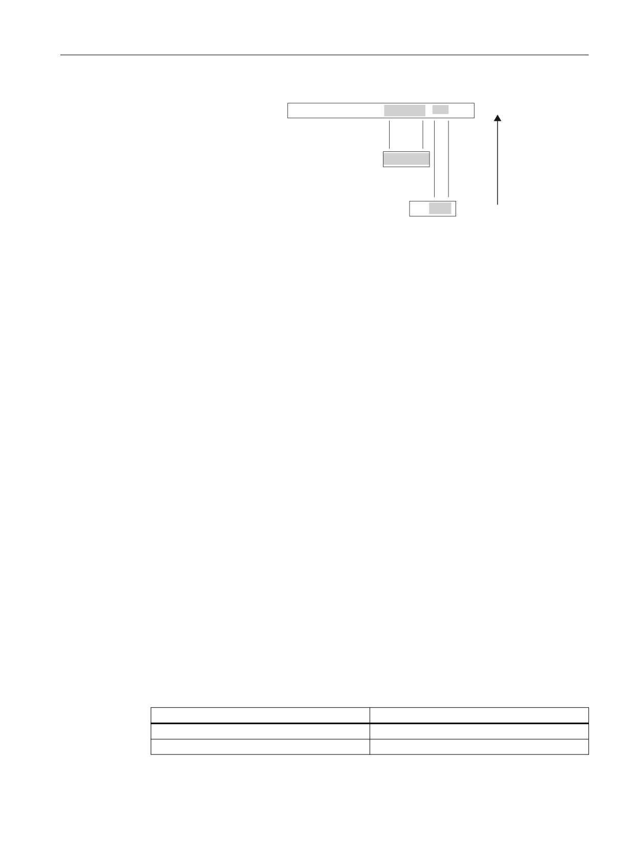
63/ LQSXWV $B,16(
6ORW ) QHW GDWD VLJQDOV
6ORW 6XEVWLWXWH YDOXHV
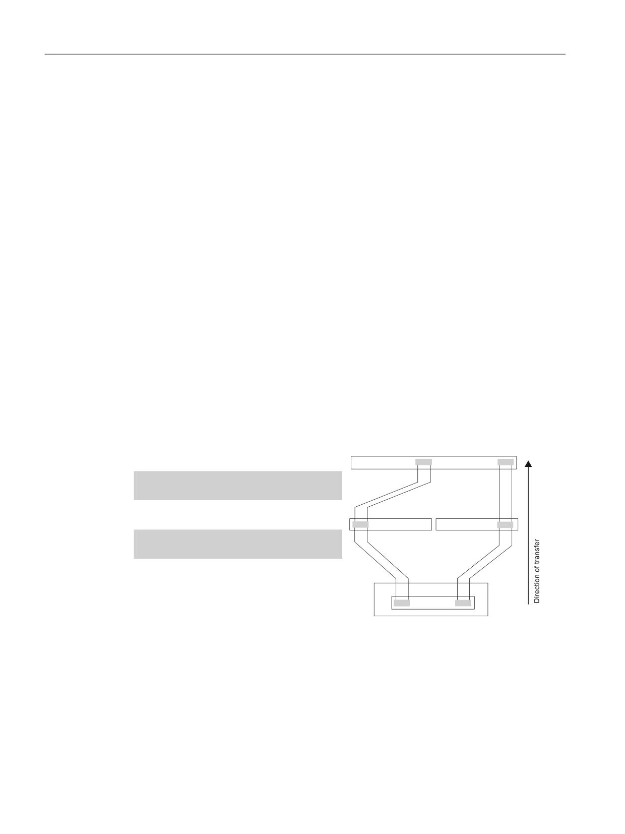
Figure 8-20
Overlap of SPL input areas of an active and passive slot
If the SPL input areas of passive slots assigned using MD10388 $MN_PROFISAFE_IN_ASSIGN
overlap, then Alarm 27204 "PROFIsafe: Dual allocation MD %1[%2] - MD %3[%4]" is displayed.
8.3.2
PROFIsafe output modules
Activating a machine data set or a slot
A machine data set or slot for PROFIsafe communication and SPL interface of a PROFIsafe output
module are activated using:
MD13303 $MN_PROFISAFE_OUT_ENABLE_MASK[m], bit x = 1
The machine data set of a slot includes machine data:
• MD $MN_PROFISAFE_OUT_ADDRESS[n]
• MD $MN_PROFISAFE_OUT_FILTER[n]
• MD $MN_PROFISAFE_OUT_ASSIGN[n]
• MD $MN_PROFISAFE_OUT_NAME[n]
Slot mode
The following slot modes are obtained as a result of the possibility of activating or deactivating
a slot:
• Active
In the control, a PROFIsafe driver is active for the slot and the SPL outputs are output as F-net
data at the associated PROFIsafe output module.
• Inactive
In the control, there is no PROFIsafe driver active for the slot; the PROFIsafe master does not
address the corresponding PROFIsafe I/O module.
The following table shows the interrelationship between the machine data and the slot mode
obtained from this:
PROFISAFE_OUT_ENABLE_MASK[m], bit n
Slot mode
1
Active
0
Inactive
Safety Integrated (system-integrated)
Function Manual, 10/2020, 6FC5397-4BP40-6BA2
211
Connecting sensors and actuators
8.4 Safety-related CPU-CPU communication (F_DP communication)
Supplementary conditions
Consistency check
In order that it is ensured that a consistent parameter assignment is also available for the
maximum expansion stage, when the control boots, the complete PROFIsafe parameter
assignments are always checked. This means a check is made as to whether each machine data
set of a parameterized slot is in itself consistent and the appropriate PROFIsafe module is
configured in the loaded S7 configuration. This especially applies to machine data sets of
inactive slots.
A slot is considered to have been parameterized as soon as one of the following data of the
machine data set is not equal to the particular default value:
• MD $MN_PROFISAFE_IN/OUT_ADDRESS
• MD $MN_PROFISAFE_IN/OUT_FILTER
• MD $MN_PROFISAFE_IN/OUT_ASSIGN
PROFIsafe input/output modules
For PROFIsafe input/output modules, the input and output direction are parameterized via
dedicated slots. These can be parameterized independently of one another for each of the
possible slot modes (active, passive or inactive).
8.4
Safety-related CPU-CPU communication (F_DP communication)
For safety-related CPU-CPU communication to the plant/system coupling, a fixed number of
failsafe data is transferred between the safety programs in the F-CPUs. Data transfer is realized
using the F_SENDDP blocks to send and F_RECVDP blocks to receive.
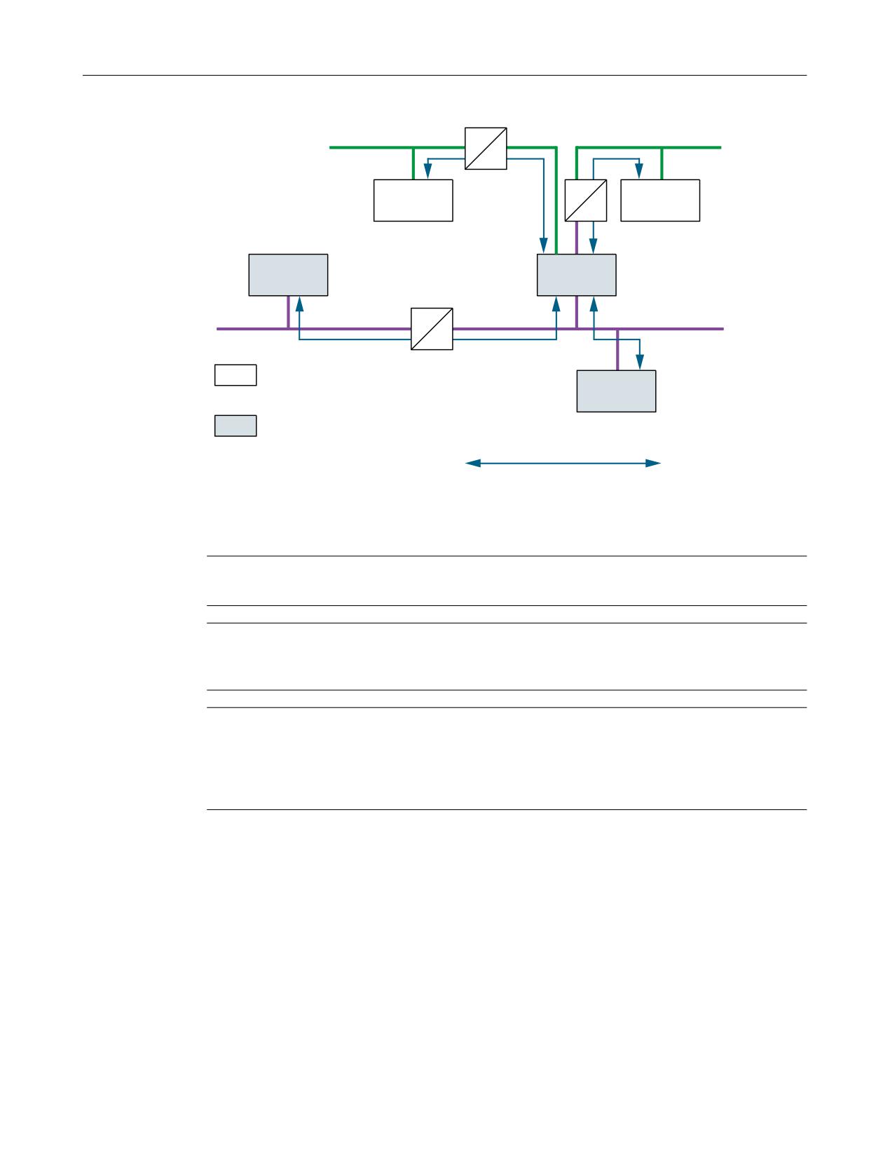
The options as to how a SINUMERIK 840D sl with F_DP communication can be integrated is
shown in the following diagram.
The F_DP communication is possible via PROFIBUS-DP (interface X126 or X136 of the NCU), as
well as via PROFINET (PROFINET interfaces of the NCU7x0PN of the PLC317F PN/DP) in the
configurations PROFIBUS-DP master, PROFIBUS-DP slave, PROFIBUS-DP slave - peer-to-peer data
transfer and PROFINET IO controller (via PN/PN coupler).
Safety Integrated (system-integrated)
212
Function Manual, 10/2020, 6FC5397-4BP40-6BA2
Connecting sensors and actuators
8.4 Safety-related CPU-CPU communication (F_DP communication)
352),1(7
31
352),1(7
31
,(
) &38
) &38
'3
) &38
) &38
352),%86 '3
'3
352),%86 '3
'3
352),1(7 FDSDEOH &38 H J
) &38
6,180(5,.
'VO
) &38
6
&38
352),%86 FDSDEOH &38
) &38
6,180(5,.
'VO
6
&38
)B'3 FRPPXQLFDWLRQ
,0
)
Figure 8-21
F_DP communication options with SINUMERIK 840D sl
With SINUMERIK 840D sl, a maximum of sixteen safety-relevant send connections and sixteen
safety-relevant receive connections can be configured for each NCU (option "SI Connect").
Note
The diagram is an example - for I Device, the PN/PN coupler can be eliminated.
Note
SIMATIC F-CPUs that support the F_SENDDP/F_RCVDP blocks are suitable as communication
partner, e.g. IM151F.
Note
The chapter only describes the SINUMERIK-specific safety-related CPU-CPU communication to
couple plants and systems corresponding to the SIMATIC F_SENDDP/F_RCVDP protocol
specifications. SINUMERIK does not support SIMATIC S7 communication with F_SENDS7/
F_RCVS7.
Description
When configuring F-DP communication between two F-CPUs, an input and output range must
be defined via SIMATIC Step 7 via which the F-telegrams are exchanged. The start address
(logical basis address) can be freely selected. However, within an F-CPU it must be the same for
the input and output ranges. However, a different start address can be used in the two F-CPUs.
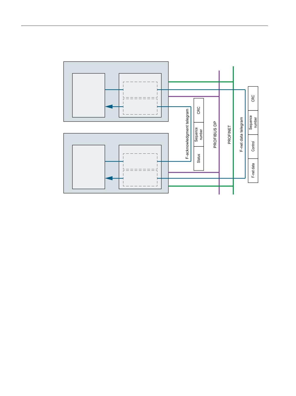
An F-DP communication always comprises a sender (F_SENDDP) and a receiver (F_RECVDP).
Only the sender (in the diagram F_SENDDP of the F-CPU1) transfers F-net data - in the F-net data
telegram - to the receiver (in the diagram F_RECVDP of F-CPU2). The receiver only acknowledges
Safety Integrated (system-integrated)
Function Manual, 10/2020, 6FC5397-4BP40-6BA2
213
Connecting sensors and actuators
8.4 Safety-related CPU-CPU communication (F_DP communication)
the receipt of the F-net data telegram using an F-acknowledgment telegram. The F-
acknowledgment telegram does not contain any F-net data.
) &38
, 2 UDQJH
2 DGGUHVV
/HQJWK
bE\WHV
)B6(1''3
VHQGHU
, DGGUHVV
/HQJWK
E\WHV
) &38
, 2 UDQJH
2 DGGUHVV
/HQJWK
E\WHV
)B5(&9'3
UHFHLYHU
, DGGUHVV
/HQJWK
bE\WHV
1RWH
7KH , DQG 2 DGGUHVVHV XVHG
DUH RQO\ H[DPSOHV RI YDOXHV
Figure 8-22
Components of an F_DP communication relationship
F-net data telegram
The F_SENDDP of the F-CPU1 (sender) cyclically generates an F-net data telegram and writes it
to the output data area of the F-CPU. The F-net data telegram has the following structure that
is compatible to SIMATIC:
•
6 bytes F-net data
2 bytes Bool
2x2 bytes for 2 INT values
(Notice: is not evaluated for SINUMERIK 840D sl)
•
2 byte status word
•
2 byte sequence number
•
2 byte CRC
As a result of the F_DP communication relationship - configured in SIMATIC Step7 - the F-net data
telegram is transferred from the output range of the F-CPU1 into the input range of the F-CPU2.
Safety Integrated (system-integrated)
214
Function Manual, 10/2020, 6FC5397-4BP40-6BA2
Connecting sensors and actuators
8.4 Safety-related CPU-CPU communication (F_DP communication)
F-acknowledgment telegram
For an F-net data telegram, which is identified as error-free, the F_RECVDP of the F-CPU2
(receiver) generates an F-acknowledgment telegram and writes this to the output data range of
the F-CPU. The F-acknowledgment telegram has the following structure:
•
2 byte status word
•
2 byte sequence number
•
2 byte CRC
Note
For the F_DP communication, F-net data is only transferred from the F_SENDDP (CPU1: Sender)
to F_RECVDP (CPU2: Receiver). If F-net data also have to be transferred in the opposite direction,
i.e. from CPU2 to CPU1, then an additional F_DP communication relationship must be
configured.
8.4.1
Configuring and parameterizing the F_DP communication
The NCK machine data to parameterize F_DP communication are entered at the HMI. The NCK-
F_DP layer transfers the machine data via the dual port RAM (DPR) to the PLC-F_DP layer. The NCK
and PLC-F_DP layers evaluate the particular NCK machine data and initialize the parameterized
F_SENDDP and F_RECVDP drivers in this machine data for cyclic F_DP communication.
The machine data listed to parameterize F_DP communication are all taken into account in
checksums (if not explicitly explained), so that if the MDs are accidentally changed, then an
appropriate alarm is output.
The start addresses (logical basis addresses) of the input and output ranges of the F_DP
communication at the I/O bus lines of a SINUMERIK 840D sl on the PLC side are defined when
configuring the hardware using SIMATIC Step7 HW Config.
The user must ensure that the starting addresses - assigned on the STEP 7 side - match the
starting addresses parameterized in the NCK machine data. A check or automatic alignment is
not made.
Parameterizing logical basis addresses in Step7
The parameterization of logical basis addresses for the F_DP communication of two NCUs via the
X136 DP interface as PROFIBUS master-slave coupling is described as an example in this section.
If a DP/DP or PN/PN coupler is used then the coupling is directly configured by configuring these
devices (see Simatic documentation).
PN/PN coupler
DP/DP coupler
Safety Integrated (system-integrated)
Function Manual, 10/2020, 6FC5397-4BP40-6BA2
215
Connecting sensors and actuators
8.4 Safety-related CPU-CPU communication (F_DP communication)
Note
In order to couple the NCUs with one another, both NCUs must be configured in a Step7 project.
Step 1: Set the interface type
The properties of the interface are accessed by double clicking on interface X136. The interface
type must be set to "PROFIBUS" under the "General" tab.
A window then opens with the PROFIBUS configuration. PROFIBUS must be configured in this
window in the usual way.
Step 2: Set the operating mode:
Under the "Mode" tab, an NCU must be set as "DP slave", the other NCU as "DP master".
The configurations can then be saved in both NCUs.
Step 3: Establish the coupling
In order that communication can be established between both NCUs, a coupling must be
established between both of them. To do this, the already configured station must be selected
from the hardware catalog in the "PROFIBUS-DP" area - for SINUMERIK, this is "CPU31..." - and
this must then be dragged to the PROFIBUS line of the PROFIBUS master NCU. The "Properties -
DP slave" window is opened.
Under the "Coupling" tab, the configured PROFIBUS master NCU must be selected and this
connected by selecting "Couple". The window must then be exited with "OK" and the project
saved.
Step 4: Set the logical basis addresses
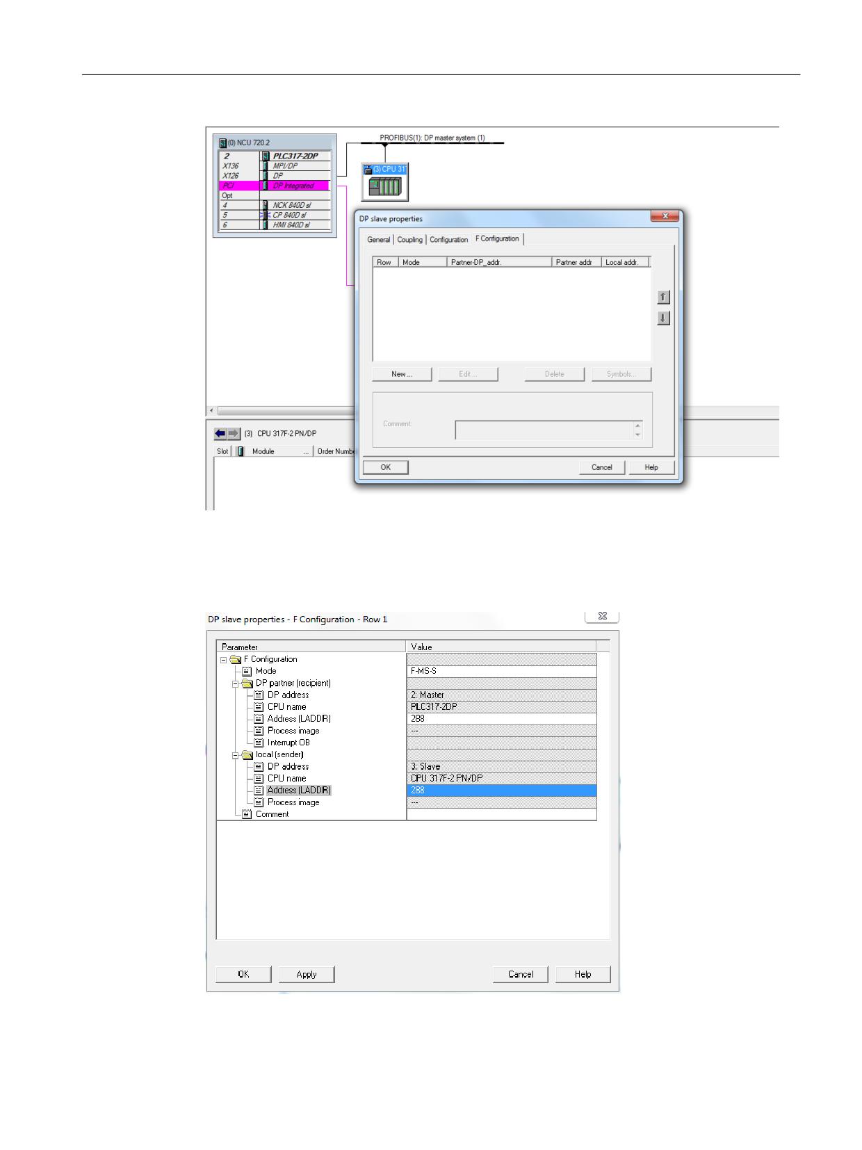
The addresses for the F_DP communication can now be set under "Properties - DP slave". Double
click on the PROFIBUS slave NCU to open the properties window in which the tab "F-
Configuration" must be selected.
Safety Integrated (system-integrated)
216
Function Manual, 10/2020, 6FC5397-4BP40-6BA2
Connecting sensors and actuators
8.4 Safety-related CPU-CPU communication (F_DP communication)
Figure 8-23
DP slave properties
The window to parameterize the logical basis addresses is opened by selecting "New ...". The
mode (F-master-slave send F-MS-S or F-master-slave receive F-MS-R) and the addresses (LADDR)
of the connection can now be set in this window.
Figure 8-24
DP slave - F-configuration properties
Safety Integrated (system-integrated)
Function Manual, 10/2020, 6FC5397-4BP40-6BA2
217
Connecting sensors and actuators
8.4 Safety-related CPU-CPU communication (F_DP communication)
By creating a new connection, the addresses for the net data and acknowledgment telegram are
automatically parameterized. The parameterized addresses should then be entered in
MD13334/13344 $MN_SAFE_SDP/RDP_LADDR.
8.4.2
Sender F_SENDDP
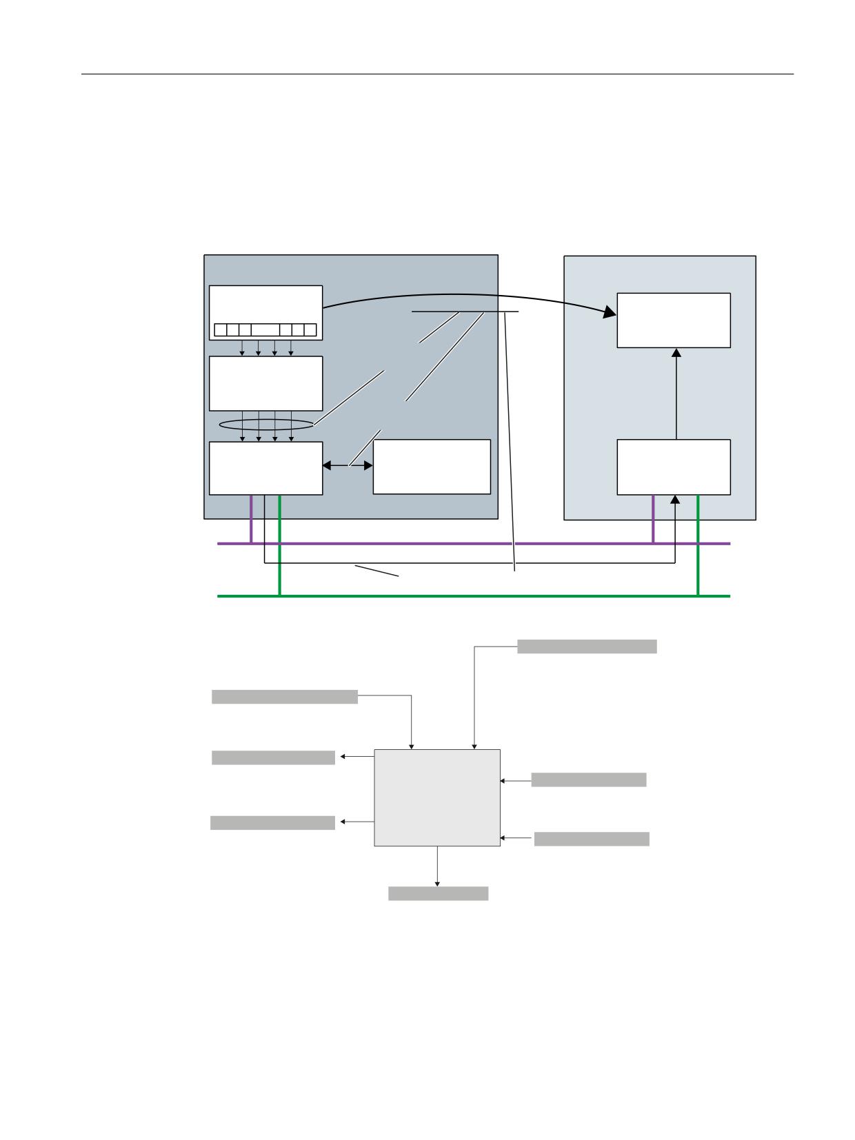
In order to send SPL output data ($A_OUTSE) from one SINUMERIK 840D sl to another F-CPU
using F_DP communication, an SPL connection must be parameterized. An SPL connection
comprises the following:
• F_DP communication relationship
The parameters of the F_DP communication are defined using the F_DP communication
relationship:
- Identifier (DP_DP_ID) and connection name
- Communication parameters:
-
- I/O start address (LADDR)
-
- Monitoring time (TIMEOUT)
- Error response (ERR_REAC)
• SPL coupling
The SPL coupling is used to define which SPL outputs ($A_OUTSE) are mapped to which net
data signals of the F-telegram.
Note:
The interpretation and processing of the F-net data signals are realized via the PLC and NCK-
SPL, and are the exclusive responsibility of the user or SPL programmer.
• Connection number
A parameterizing data set is assigned to an SPL connection using the connection number.
An SPL connection is defined in a parameterizing data set. For SINUMERIK 840D sl, 16
parameterizing data sets are available for F_SENDDP. This means that a maximum of 16 SPL
connections, identified using 16 different identifiers (DP_DP_ID) can be simultaneously active.
In case of an error, Alarm 27306 "F_DP: Max. number of active SPL connections (%1) for %2
exceeded" is output
SPL output data ($A_OUTSE) can only be assigned to an SPL connection in the parameterizing
data of the SPL coupling as contiguous area. If the SPL output data, which are required for an SPL
connection, are not contiguous, but are distributed over several areas, then several SPL
connections must be parameterized. These SPL connections are designated using identical F_DP
communication relationships and connection numbers, but different SPL couplings. The
parameterization of one SPL connection with several SPL couplings is designated as sub-slots
within the framework of PROFIsafe (see Chapter "parameterizing the SPL-SGE interface
(Page 194)").
The number of SPL couplings per SPL connection can be freely parameterized within the
framework of the number of parameterizing data sets that are available. The following options
are available to parameterize SPL connections and SPL couplings for each SPL connection:
• SPL connections: 1 up to a maximum of 16
• SPL couplings per SPL connection: 1 up to a maximum of 16, whereby the sum of all SPL
couplings of all SPL connections can be a maximum of 16
Safety Integrated (system-integrated)
218
Function Manual, 10/2020, 6FC5397-4BP40-6BA2
Connecting sensors and actuators
8.4 Safety-related CPU-CPU communication (F_DP communication)
For the case that 16 SPL connections are parameterized, for each SPL connection, there is only
one SPL coupling available.
The following value range for system variables and machine data is obtained from this:
• System variable index: 1...n with n = 16
• Machine data index: 0...m with m = 15
6,180(5,.
' VO
) &38
ORJLFDO YLHZ
63/
63/ FRQQHFWLRQ
$B2876(
63/
63/ FRXSOLQJ
) QHW GDWD
WUDQVIHU
&RQQHFWLRQ
1XPEHU
6\VWHP YDULDEOH
)B6(1''3
)B5(&9'3
LQWHUIDFH
352),%86 '3
)B'3 FRPPXQLFDWLRQ UHODWLRQVKLS
352),1(7
Figure 8-25
Example of 1 SPL connection with 4 SPL couplings
3DUDPHWHUL]LQJ GDWD 1&.
01B6$)(B6'3B,'> P@
01B6$)(B6'3B1$0(> P@
$FWLYDWLRQ GDWD 1&.
01B6$)(B6'3B&211(&7,21B15> P@
01B6$)(B6'3B/$''5> P@
01B6$)(B6'3B(1$%/(B0$6.
01B6$)(B6'3B7,0(287> P@
01B6$)(B6'3B),/7(5> P@
01B6$)(B6'3B$66,*1> P@
2XWSXW GDWD 1&.
01B6$)(B6'3B(55B5($&> P@
$B)6'3B(5525> Q@
,QSXW GDWD 1&.
$B)6'3B68%6B21> Q@
)B6(1''3
$B)6'3B(55B5($&> Q@
$B)6'3B',$*> Q@
$B2876(
2XWSXW GDWD '%
01B35(9(17B6<1$&7B/2&.
)6'3>
@ (5525
,QSXW GDWD '%
)6'3>
@ 68%6B21
)6'3>
@ (55B5($&
)6'3>
@ ',$*
63/B'$7$B2876(3>
@
)6'3>
@ 5(79$/
63/B5($'<
)6'3>
@ 5(79$/
(UURU UHVSRQVHV
$ODUP
6723 ' (
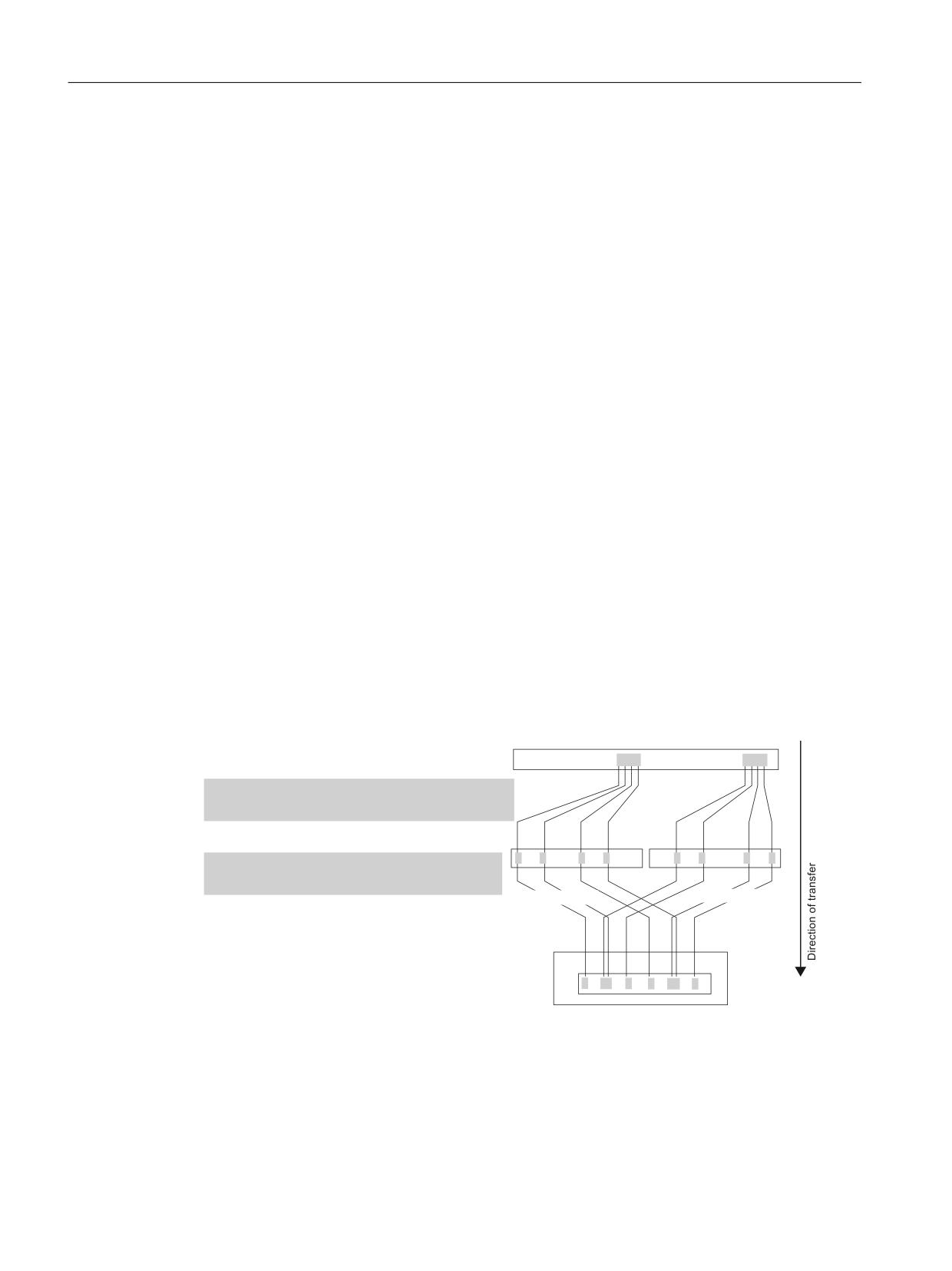
Figure 8-26
Interface overview F_SENDDP
Activation data
Every parameterizing data set can be separately activated using the enable screen form.
Safety Integrated (system-integrated)
Function Manual, 10/2020, 6FC5397-4BP40-6BA2
219
Connecting sensors and actuators
8.4 Safety-related CPU-CPU communication (F_DP communication)
Parameterizing data
The parameterizing data set of an SPL connection involves the following values:
• Identifier:
DP_DP_ID: MD13331 $MN_SAFE_SDP_ID
Name: MD13332 $MN_SAFE_SDP_NAME
• Connection number: MD13333 $MN_SAFE_SDP_CONNECTION_NR #
• Communication parameters:
I/O start address: MD13334 $MN_SAFE_SDP_LADDR #
Monitoring time: MD13335 $MN_SAFE_SDP_TIMEOUT #
• Net data parameters:
SPL assignment: MD13336 $MN_SAFE_SDP_ASSIGN
F-net data filter: MD13337 $MN_SAFE_SDP_FILTER
• Error response: MD13338 $MN_SAFE_SDP_ERR_REAC #
For SPL connections with the same ID, all of the parameters designated with # must be identical.
In case of an error, Alarm 27305 "F_DP: Parameter MD %1[%2] < > MD %3[%4]".
Input/output data
The input and output data provide the user or SPL programmer an interface compatible to the
SIMATIC F-application blocks using system variables.
Error responses
The system responses when a communication error occurs can be influenced by the user by
correspondingly setting the machine data $MN_SAFE_SDP_ERR_REAC or, at a later point in time
by programming the system variables $A_FSDP_ERR_REAC in the SPL program.
SPL couplings (sub-slots)
Just the same as for PROFIsafe, also for F_SENDDP, only contiguous areas of SPL output data
($A_OUTSE[x] to $A_OUTSE[x+y]) can be assigned to an SPL connection. Several SPL
connections must be parameterized if several non-contiguous pieces of SPL output data are to
be transferred. These are characterized due to the fact that the parameters of the SPL couplings
differ, but all other parameters of the SPL connection are identical. As part of the F_DP
communication, these SPL connections are combined to form a single SPL connection
communicating via PROFIBUS with several subordinate SPL couplings (sub-slots).
Example of an NCK parameterization
The following specifications are applied when it comes to further describing the NCK
parameterization of an F_SENDDP communication relationship.
• Identifier
DP_DP_ID: 2000D
Name: "WZM1”
• Connection number: 1
• Communication parameters
I/O start address: 288D
Monitoring time: 0.5 seconds
Safety Integrated (system-integrated)
220
Function Manual, 10/2020, 6FC5397-4BP40-6BA2
Connecting sensors and actuators
8.4 Safety-related CPU-CPU communication (F_DP communication)
• Net data parameters
SPL outputs used: $A_OUTSE[1...4]
Filter data: 1111H
SPL outputs used: $A_OUTSE[33...36]
Filter data: 8888H
• Error response: 0D
The following parameterizing data sets are obtained:
1. SPL connection (sub-slot 1)
$MN_SAFE_SDP_ID[0] = 2000D
$MN_SAFE_SDP_NAME[0] = WZM1
$MN_SAFE_SDP_CONNECTION_NR[0] = 1
$MN_SAFE_SDP_LADDR[0] = 288D
$MN_SAFE_SDP_TIMEOUT[0] = 0.5
$MN_SAFE_SDP_ASSIGN[0] = 001004D
$MN_SAFE_SDP_FILTER[0] = 1111H
$MN_SAFE_SDP_ERR_REAC[0] = 0
2. SPL connection (sub-slot 2)
$MN_SAFE_SDP_ID[1] = 2000D
$MN_SAFE_SDP_NAME[1] = WZM1
$MN_SAFE_SDP_CONNECTION_NR[1] = 1
$MN_SAFE_SDP_LADDR[1] = 288D
$MN_SAFE_SDP_TIMEOUT[1] = 0.5
$MN_SAFE_SDP_ASSIGN[1] = 033036D
$MN_SAFE_SDP_FILTER[1] = 8888H
$MN_SAFE_SDP_ERR_REAC[1] = 0
Note
All machine data of a parameterizing data set are linked with one another using the common
machine data index.
MD13331 $MN_SAFE_SDP_ID: Identifier of the SPL connection
Every SPL connection must be assigned a freely selectable, unique identifier (DP_DP_ID),
however, this must be unique across all F-CPUs that are connected using F_DP communication.
MD13332 $MN_SAFE_SDP_NAME: Connection name
An SPL connection can be given a freely selectable connection name with a maximum of 15
characters using MD $MN_SAFE_SDP_NAME. The connection name is displayed at the HMI and
in the alarm display. If a connection name has been assigned, then for alarms 2735x, the name
is displayed; if a name is not displayed, then the corresponding DP_DP_ID identifier is displayed.
The connection name does not have to be specified in all of the parameterizing data sets
associated with an SPL connection. The connection name is always used that is specified in the
first active parameterizing data set, i.e. the parameterizing data set with the lowest machine
data index. All other data sets of an SPL connection are not evaluated with reference to
connection names.
Safety Integrated (system-integrated)
Function Manual, 10/2020, 6FC5397-4BP40-6BA2
221
Connecting sensors and actuators
8.4 Safety-related CPU-CPU communication (F_DP communication)
This MD is not incorporated in the checksum calculation; i.e. it can also be changed without
aligning the checksum.
MD13334 $MN_SAFE_SDP_LADDR: I/O start address
When generating the configuration in SIMATIC STEP7 HW Config, for each SPL connection a start
address must be defined for the I/O area, which is used for the F_SENDDP to exchange data with
the associated F_RECVDP. The start address must be the same for the input and output data
areas.
The user must enter the I/O start address of the SPL connection, defined in the configuration, in
MD $MN_SAFE_SDP_LADDR[0...m].
Rules to define the start addresses and address areas of an SPL connection:
• The start address must be identical in the input and output data areas
• Slot length: Input data area = 6 bytes, output data area = 12 bytes
• Consistency of the slot in the input and output data areas in both cases over the "complete
length"
The check is made on the PLC side within the scope of the cyclic F_DP communication by
evaluating the SFC14/SFC15 return values. For an error, Alarm 27354 "F_DP: %1
communication, connection %2 signals SFC%3 error %4" is displayed.
Parameterization of the F-net data transfer
The transfer of the SPL outputs in the F-net data is parameterized using the following NCK
machine data:
• $MN_SAFE_SDP_ASSIGN[0...m]
• $MN_SAFE_SDP_FILTER[0...m]
1&. 63/ 6*$
$B2876(>
@
>
@
>
@
> @
> @
63/ DVVLJQPHQW
VW 63/ FRQQHFW 0'
01B6$)(B6'3B$66,*1> @
QG 63/ FRQQHFW 0'
01B6$)(B6'3B$66,*1> @
%LW
%LW
%LW
%LW
) QHW GDWD ILOWHU
VW 63/ FRQQHFW 0'
01B6$)(B6'3B),/7(5> @
+
QG 63/ FRQQHFW 0'
01B6$)(B6'3B),/7(5> @
+
6XE VORW
6XE VORW
) QHW GDWD VLJQDOV IURP )B6(1''3
0'
01B6$)(B6'3B,'> @
'
0'
01B6$)(B6'3B/$''5> @
'
%LW
%LW
Figure 8-27
F-net data transfer F_SENDDP
MD13336 $MN_SAFE_SDP_ASSIGN: SPL assignment
For the SPL assignment, the SPL outputs ($A_OUTSE) are selected, which are assigned to the F-
net data signals via the F-net data filter. Only a contiguous area can be selected.
Safety Integrated (system-integrated)
222
Function Manual, 10/2020, 6FC5397-4BP40-6BA2
Connecting sensors and actuators
8.4 Safety-related CPU-CPU communication (F_DP communication)
The SPL assignment is set using MD $MN_SAFE_SDP_ASSIGN[0...m].
The SPL output area data is specified in the decimal notation in the following format:
$MN_SAFE_SDP_ASSIGN[n] = aaa bbb with
aaa: Area limit 1, SPL-SGA $A_OUTSE[aaa]
bbb: Area limit 2, SPL-SGA $A_OUTSE[bbb]
The following conditions should be observed when specifying the area limits:
• all area data is valid: (aaa > bbb), (aaa < bbb), (aaa = bbb)
•
|(aaa - bbb)| ≤ 16
In case of an error, Alarm 27301 "F_DP: MD %1[%2]: SPL coupling incorrect".
•
|(aaa - bbb)| = y
With y = number of F-net data signals selected in the MD F-net data filter
$MN_SAFE_SDP_FILTER.
In case of an error, Alarm 27303 "F_DP: Number of signals in MD %1[%2] < > MD %3[%4]" is
output.
Example of an NCK parameterization (see the "Example for an NCK parameterization")
The selected SPL outputs $A_OUTSE[1...4] and $A_OUTSE[33...36] are transferred in the F-net
data corresponding to the F-net data filter of the particular SPL connection, refer to the above
diagram "F-net data transfer F_SENDDP".
MD13337 $MN_SAFE_SDP_FILTER: F-net data filter
The F-net data filter allows the SPL outputs ($A_OUTSE), which are to be transferred, to be
distributed across any F-net data signals.
The F-net data filter is set using MD $MN_SAFE_SDP_FILTER[0...m].
Example of an NCK parameterization (see the "Example for an NCK parameterization")
The parameterized SPL outputs of the F_DP communication relationship (DP_DP_ID: 2000) are
distributed via the F-net data filter to bits 0, 4, 8 and 12 (1st sub-slot) and bits 3, 7, 11 and 15
(2nd sub-slot) in the F-net data of the F-telegram, see the above diagram, "F-net data transfer
F_SENDDP".
Note
Within an SPL connection, an F-net data signal of an F-telegram may only be occupied by one
SPL coupling via the F-net data filter. When allocated a multiple number of times, Alarm 27302
"F_DP: Dual allocation MD %1[%2] - MD %3[%4]" is output.
MD13335 $MN_SAFE_SDP_TIMEOUT: Monitoring time
By specifying the monitoring time, the time is specified within which an F- telegram from
F_SENDDP must be acknowledged by F_RECVDP.
The monitoring time is set using MD $MN_SAFE_SDP_TIMEOUT[0...m].
When the monitoring time is exceeded, then depending on the system variables
$A_FSDP_ERR_REAC, the selected alarm responses are initiated:
Safety Integrated (system-integrated)
Function Manual, 10/2020, 6FC5397-4BP40-6BA2
223
Connecting sensors and actuators
8.4 Safety-related CPU-CPU communication (F_DP communication)
Alarm 27350 “F_DP: %1 communication, DP_DP_ID = 52 signals error %3" and
Alarm 27351 "F_DP: %1 communication, DP_DP_ID = 52 signals error %3".
Notes regarding commissioning
When commissioning F_DP communication for the first time, it is recommended that the
monitoring time is initially kept at the default value in order to avoid alarms caused by the
monitoring time being exceeded.
After the F_DP communication has been successfully commissioned, the monitoring time can
then be changed to the required value, e.g. monitoring time ≥ 5 * F_DP clock cycle of the slower
component of the SPL connection with F_DP clock cycle = $MA_SAFE_SRDP_IPO_TIME_RATIO *
IPO clock cycle.
For more complex PLC user programs, it is possible that the parameterized F_ DP clock cycle is
either briefly or even permanently exceeded. This is the reason that for diagnostic purposes, the
maximum value of the F_DP clock cycle since the last time the control booted (powered-up) is
displayed in machine data $MA_INFO_SAFE_SRDP_CYCLE_TIME and in the diagnostics screen "SI
communication".
Note
It can only be ensured that the level of an output signal is correctly detected on the sender side
and transferred to the receiver if it is present for at least the monitoring time that has been
parameterized (MN_SAFE_SDP_TIMEOUT).
MD13330 $MN_SAFE_SDP_ENABLE_MASK: Enable screen form
The individual parameterizing data sets are enabled using the enable screen form. The enable
screen form is bit orientated, i.e. bit 0 activates the 1st parameterizing data set with machine
data index 0.
If a parameterizing data set is not activated, then the machine data of the corresponding SPL
connection are not evaluated.
MD13333 $MN_SAFE_SDP_CONNECTION_NR: Connection number
A parameterizing data set is assigned to an SPL connection using the connection number.
Presently, a max. of max. 16 SPL connections can be parameterized for F_SENDDP. As a result,
the value range for the connection number obtained is: 1, 2, 3 ... 16.
In the default setting, a parameterizing data set is not assigned to any SPL connection
(connection number = 0). Each active parameterizing data set must be assigned to an SPL
connection. In the case of an error, Alarm 27034 "Parameterization of MD %1[%2] invalid" is
displayed.
The connection number is, at the same time, also the index to access system variables of the user
interface of the SPL connection. The user interface involves the following system variables:
Input data
• $A_FSDP_ERR_REAC[1...n]
Safety Integrated (system-integrated)
224
Function Manual, 10/2020, 6FC5397-4BP40-6BA2
Connecting sensors and actuators
8.4 Safety-related CPU-CPU communication (F_DP communication)
Output data
• $A_FSDP_ERROR[1...n]
• $A_FSDP_SUBS_ON[1...n]
• $A_FSDP_DIAG[1...n]
The connection number is set using MD $MN_SAFE_SDP_CONNECTION_NR.
Example
The parameterizing data set x set should be assigned to the 2nd SPL connection.
$MN_SAFE_SDP_CONNECTION_NR[x] = 2
This means, that as user interface, SPL connection x uses the above mentioned system variables
with index 2, e.g.: $A_FSDP_ERROR[2]
MD13338 $MN_SAFE_SDP_ERR_REAC: Error response
The default value for the system variable $A_FSDP_ERR_REAC[1...n] (alarm response) is entered
using machine data $MN_SAFE_SDP_ERR_REAC[1...n]. The alarm response can be dynamically
changed by programming the system variable in the user programming.
After programming the error response using the system variable, the value saved in the machine
data is no longer active until the control re-boots.
The significance of the values for the machine data correspond to the values for the system
variable $A_FSDP_ERR_REAC[1...n].
Input data, F_SENDDP
System variable: Error response, $A_FSDP_ERR_REAC
The response when a communication error occurs is set using the system variable
$A_FSDP_ERR_REAC[1...n]. This means, depending on the actual coupling or as a function of the
plant/system components involved in the SPL connection, the response to a communication
error, caused by an error in the communication path or by consciously switching one of the plant/
system components, can be specified. The following error responses can be set:
• Alarm 27350 and also STOP D/E
• Alarm 27350
• Alarm 27351 (display only, self-clearing)
• No alarm is displayed:
Supplementary conditions
1. For a communication error, the following system variables are always set independent of the
error response set using the system variable $A_FSDP_ERR_REAC:
$A_FSDP_ERROR = 1
$A_FSDP_SUBS_ON = 1
2. When a communication error occurs, the currently programmed error response is realized.
If the error response is changed, it only becomes effective when the next communication
error occurs.
Safety Integrated (system-integrated)
Function Manual, 10/2020, 6FC5397-4BP40-6BA2
225

Connecting sensors and actuators
8.4 Safety-related CPU-CPU communication (F_DP communication)
3. Whether STOP D or STOP E is initiated as error response can be parameterized using:
NCK: $MN_SAFE_SPL_STOP_MODE
PLC: DB18.DBX36.1
4. The system variable $A_FSDP_ERR_REAC[1...n] is a part of the crosswise data comparison
SPL-CDC.
Note
Until the system variable is programmed for the first time, after the control boots, the value set
using MD $MN_SAFE_SDP_ERR_REAC is active.
Output data, F_SENDDP
System variable: Error signal, $A_FSDP_ERROR
System variable $A_FSDP_ERROR[1...n] is used to indicate that there is a communication error.
The specific cause, determined by F_SENDDP, is communicated using the diagnostics data
(system variable $A_FSDP_DIAG).
The system variable $A_FSDP_ERROR is cyclically compared with the corresponding PLC
variables FSDP[1...3].ERROR. If unequal, there is a system error and this is displayed using Alarm
27355 "F_DP: %1 communication, connection %2 reports a system error %3 (%4)".
System variable: Substitute value signal, $A_FSDP_SUBS_ON
System variable $A_FSDP_SUBS_ON[1...n] is used to signal that F_RECVDP has output substitute
values to the application.
The system variable $A_FSDP_SUBS_ON is cyclically compared with the corresponding PLC
variables FSDP[1...3].SUBS_ON. If unequal, there is a system error and this is displayed using
Alarm 27355 "F_DP: %1 communication, connection %2 reports a system error %3 (%4)".
System variable: diagnostics data, $A_FSDP_DIAG
System variable $A_FSDP_DIAG[1...n] is used to signal the cause of the communication error
determined by F_SENDDP.
The system variable $A_FSDP_DIAG is not cyclically compared with the corresponding PLC
variables FSDP[1...16].DIAG.
Comparison, NCK system variable / PLC variable
NCK system variable
PLC variable DB18
Inputs
$A_FSDP_ERR_REAC[1...n]
FSDP[1...3].ERR_REAC or FSDP_HF[4..16].ERR_REAC
$A_OUTSE
SPL_DATA_OUTSEP[1...64] or SPL_DATA.OUTSEP_HF[65..192]
$MN_PREVENT_LOCK
SPL_READY
Outputs
$A_FSDP_ERROR[1...n]
FSDP[1...3].ERROR or FSDP_HF[4..16].ERROR
$A_FSDP_SUBS_ON[1...n]
FSDP[1...3].SUBS_ON or FSDP_HF[4..16].SUBS_ON
Safety Integrated (system-integrated)
226
Function Manual, 10/2020, 6FC5397-4BP40-6BA2

Connecting sensors and actuators
8.4 Safety-related CPU-CPU communication (F_DP communication)
NCK system variable
PLC variable DB18
$A_FSDP_DIAG[1...n]
FSDP[1...3].DIAG or FSDP_HF[4..16].DIAG
--
FSDP[1...3].RETVAL14 or FSDP_HF[4..16].RETVAL14
--
FSDP[1...3].RETVAL15 or FSDP_HF[4..16].RETVAL15
8.4.3
Receiver F_RECVDP
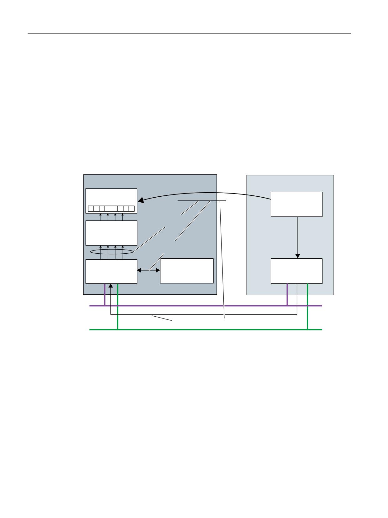
In order to transfer SPL output data from an F-CPU to a SINUMERIK 840D sl using F-DP
communication, an SPL connection must be parameterized. This connection comprises the
following:
• F_DP communication relationship
The following F_DP communication parameters are defined using the F_DP communication
relationship:
- Identifier (DP_DP_ID) and connection name
- Communication parameters:
-
- I/O start addresses (LADDR)
-
- Monitoring time (TIMEOUT)
- Error response (ERR_REAC)
- Substitute values in the case of an error (SUBS)
• SPL coupling
The SPL coupling is used to define which F-data signals of the F-telegram are to be mapped
to which SPL inputs ($A_INSE). Several SPL couplings can be parameterized for one SPL
connection.
Note:
The interpretation and processing of the F-net data signals are realized via the PLC and NCK-
SPL, and are the exclusive responsibility of the user or SPL programmer.
• Connection number
A parameterizing data set is assigned to an SPL connection using the connection number.
An SPL connection is defined in a parameterizing data set. For SINUMERIK 840D sl, 16
parameterizing data sets are available for F_RECVDP; as a consequence, 16 different SPL
connections, designated using 16 identifiers (DP_DP_ID), can be parameterized in the F-DP
communication relationships. In case of an error, Alarm 27306 "F_DP: Max. number of active SPL
connections (%1) for %2 exceeded" is output
SPL input data ($A_INSE) can only be assigned to an SPL connection in the parameterizing data
of the SPL coupling as contiguous range. If the SPL input data, which are required for an SPL
connection, are not contiguous, then several SPL connections must be parameterized in the
parameterizing sets. These SPL connections are designated using identical F_DP communication
relationships and connection numbers, but different SPL couplings. The parameterization of one
SPL connection with several SPL couplings is designated as sub-slots within the framework of
PROFIsafe (see Chapter "parameterizing the SPL-SGE interface (Page 194)").
Safety Integrated (system-integrated)
Function Manual, 10/2020, 6FC5397-4BP40-6BA2
227
Connecting sensors and actuators
8.4 Safety-related CPU-CPU communication (F_DP communication)
The number of SPL couplings per SPL connection can be freely parameterized within the
framework of the number of parameterizing data sets that are available. The following options
are available to parameterize SPL connections and SPL couplings for each SPL connection:
• SPL connections: 1 up to a maximum of 16
• SPL couplings per SPL connection: 1 up to a maximum of 16, whereby the sum of all SPL
couplings of all SPL connections can be a maximum of 16
For the case that 16 SPL connections are parameterized, for each SPL connection, there is only
one SPL coupling available.
The following value range for system variables and machine data is obtained from this:
• System variable index: 1...n with n = 16
• Machine data index: 0...m with m = 15
6,180(5,.
' VO
) &38
ORJLFDO YLHZ
63/
63/ FRQQHFWLRQ
$B,16(
63/
63/ FRXSOLQJ
) QHW GDWD
WUDQVIHU
&RQQHFWLRQ
1XPEHU
6\VWHP YDULDEOH
)B5(&9'3
)B6(1''3
LQWHUIDFH
352),%86 '3
)B'3 FRPPXQLFDWLRQ UHODWLRQVKLS
352),1(7
Figure 8-28
Example of 1 SPL connection with 4 SPL couplings
Safety Integrated (system-integrated)
228
Function Manual, 10/2020, 6FC5397-4BP40-6BA2
Connecting sensors and actuators
8.4 Safety-related CPU-CPU communication (F_DP communication)
Interface overview
3DUDPHWHUL]LQJ GDWD 1&.
$FWLYDWLRQ GDWD 1&.
01B6$)(B5'3B(1$%/(B0$6.
01B6$)(B5'3B,'> P@
01B6$)(B5'3B1$0(> P@
01B6$)(B5'3B&211(&7,21B15> P@
01B6$)(B5'3B/$''5> P@
01B6$)(B5'3B$66,*1> P@
01B6$)(B5'3B),/7(5> P@
01B6$)(B5'3B7,0(287> P@
2XWSXW GDWD 1&.
01B6$)(B5'3B(55B5($&> P@
$B)5'3B(5525> Q@
01B6$)(B5'3B68%6> P@
$B)5'3B68%6B21> Q@
$B)5'3B$&.B5(4> Q@
,QSXW GDWD 1&.
$B)5'3B',$*> Q@
)B5(&9'3
$B)5'3B(55B68%6> Q@
$B)5'3B6(1'02'(> Q@
$B,16(
$B)5'3B(55B5($&> Q@
&KDQQHOB UHVHW
2XWSXW GDWD '%
,QSXW GDWD '%
)5'3>
@ (5525
)5'3>
@ 68%6>
@
)5'3>
@ 68%6B21
)5'3>
@ (55B5($&
)5'3>
@ $6.B5(4
)5'3>
@ $&.B5(,
)5'3>
@ 6(1'02'(
6\VWHP UHVSRQVHV
)5'3>
@ ',$*
$ODUP
63/B'$7$B,16(3>
@
6723 ' (
)5'3>
@ 5(79$/
)5'3>
@ 5(79$/
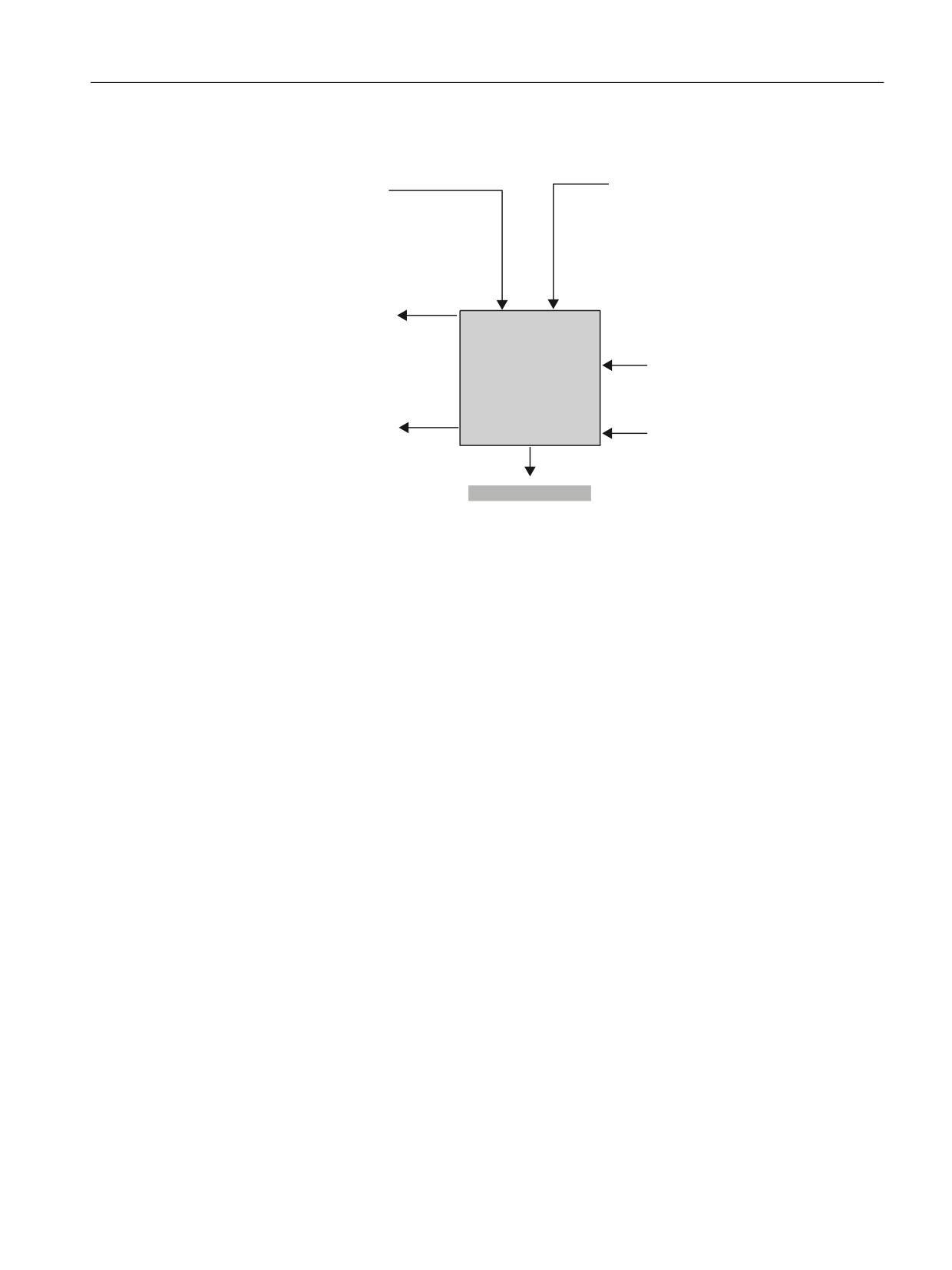
Figure 8-29
Interface overview F_RECVDP
Activation data
Every parameterizing data set can be separately activated using the activation data.
Parameterizing data
The parameterizing data set of an SPL connection involves the following data areas:
• Identifier:
DP_DP_ID: MD1334: $MN_SAFE_RDP_ID
Name: MD13342 $MN_SAFE_RDP_NAME
• Connection number: MD13343 $MN_SAFE_RDP_CONNECTION_NR #
• Communication parameters:
I/O start address: MD13344 $MN_SAFE_RDP_LADDR #
Monitoring time: MD13345 $MN_SAFE_RDP_TIMEOUT #
• Net data parameters:
SPL assignment: MD13346 $MN_SAFE_RDP_ASSIGN:
F-net data filter: MD13347 $MN_SAFE_RDP_FILTER
• Error response:
Error response: MD13348 $MN_SAFE_RDP_ERR_RE
Substitute values: MD13349 $MN_SAFE_RDP_SUBS #
For SPL connections with the same identifier, all parameters identified with # must be identical.
In case of an error, Alarm 27305 "F_DP: Parameter MD %1[%2] < > MD %3[%4]" is output.
Input/output data
The input and output data provide the user or SPL programmer an interface compatible to the
SIMATIC F-application blocks using system variables.
Safety Integrated (system-integrated)
Function Manual, 10/2020, 6FC5397-4BP40-6BA2
229
Connecting sensors and actuators
8.4 Safety-related CPU-CPU communication (F_DP communication)
Error responses
The system responses when a communication error occurs can be influenced by the user by
appropriately setting the machine data $MN_SAFE_RDP_ERR_REAC and $MN_SAFE_RDP_SUBS
- or at a later time by programming the system variables $A_FRDP_ERR_REAC, $A_FRDP_SUBS in
the SPL program.
SPL couplings (sub-slots)
Just the same as for PROFIsafe, also for F_RECVDP, only contiguous ranges of SPL input data
($A_INSE[x] up to $A_INSE[x+y]) can be assigned to an SPL connection. If the received F-net
data are to be transferred in several non-contiguous SPL input data areas, then several SPL
connections must be parameterized. These are then designated using an identical identifier,
communication parameter and connection number, but different SPL couplings. As part of the
F_DP communication, these SPL connections are combined to form a single SPL connection
communicating via PROFIBUS with several subordinate SPL couplings (sub-slots).
Example of an NCK parameterization
The following specifications are applied for the more detailed description of the NCK
parameterization.
• Identifier
DP_DP_ID: 1000D
Name: “WZM1”
• Connection number: 1
• Communication parameters
I/O start address: 298D
Monitoring time: 0.5 seconds
• Net data parameters
SPL inputs used: $A_INSE[1...4]
Filter data:
000FH
SPL inputs used: $A_INSE[33...36]
Filter data: F000H
• Error response:
Error response: 0
Substitute values: 0
Safety Integrated (system-integrated)
230
Function Manual, 10/2020, 6FC5397-4BP40-6BA2
Connecting sensors and actuators
8.4 Safety-related CPU-CPU communication (F_DP communication)
The following parameterizing data sets are obtained:
1. SPL connection (sub-slot 1)$MN_SAFE_RDP_ID[0] = 1000D
$MN_SAFE_RDP_NAME[0] = WZM1
$MN_SAFE_RDP_CONNECTION_NR[0] = 1
$MN_SAFE_RDP_LADDR[0] = 298D
$MN_SAFE_RDP_TIMEOUT[0] = 0.
MN_SAFE_RDP_ASSIGN[0] = 001 004D
$MN_SAFE_RDP_FILTER[0] = 000FH
$MN_SAFE_RDP_ERR_REAC[0] = 0
$MN_SAFE_RDP_SUBS[0] = 0
2. SPL connection (sub-slot 2)
$MN_SAFE_RDP_ID[1] = 1000D
$MN_SAFE_RDP_NAME[1] = WZM1
$MN_SAFE_RDP_CONNECTION_NR[1] = 1
$MN_SAFE_RDP_LADDR[1] = 298D
$MN_SAFE_RDP_TIMEOUT[1] = 0.5
$MN_SAFE_RDP_ASSIGN[1] = 033 036D
$MN_SAFE_RDP_FILTER[1] = F000H
$MN_SAFE_RDP_ERR_REAC[1] = 0
$MN_SAFE_RDP_SUBS[1] = 0
Note
All machine data of a parameterizing data set are linked with one another using the common
machine data index.
MD13341 $MN_SAFE_RDP_ID: Identifier of the F_DP communication relationship
The identifier must be assigned a freely selectable, unique identifier (DP_DP_ID), however, this
must be unique across all F-CPUs that are connected using F_DP communication.
MD13342 $MN_SAFE_RDP_NAME: Connection name
An SPL connection can be allocated a meaningful name using this machine data. The connection
name can be freely selected and can be a maximum of 15 characters. The connection name is
displayed at the HMI and in the alarm display. If a connection name is specified, then for Alarms
2735x, the name is displayed. If a connection name is not specified, then the corresponding
identifier is displayed (DP_DP_ID).
The connection name does not have to be specified in all of the parameterizing data sets
associated with an SPL connection. The connection name that is specified in the first active
parameterizing data set is always used, i.e. the parameterizing data set with the lowest machine
data index. All other data sets of an SPL connection are not evaluated with reference to
connection names.
This MD is not incorporated in the checksum calculation; i.e. it can also be changed without
aligning the checksum.
Safety Integrated (system-integrated)
Function Manual, 10/2020, 6FC5397-4BP40-6BA2
231
Connecting sensors and actuators
8.4 Safety-related CPU-CPU communication (F_DP communication)
MD13344 $MN_SAFE_RDP_LADDR: I/O start address
When generating the configuration in SIMATIC STEP7 HW Config, for each SPL connection a start
address must be defined for the I/O area, which is used for the F_RECVDP to exchange data with
the associated F_SENDDP. The start address must be the same for the input and output data
areas.
The user must enter the I/O start address of the SPL connection, defined in the configuration, in
the MD $MN_SAFE_RDP_LADDR[0...m].
Rules to define the start addresses and address areas of an SPL connection:
• The start address must be identical in the input and output data areas
• Slot length: Input data area = 12 bytes, output data area: 6 bytes
• Consistency of the slot in the input and output data areas in both cases over the "complete
length"
The check on the PLC side is made within the scope of the cyclic F_DP communication by
evaluating the SFC14/SFC15 return values. For an error, Alarm 27354 "F_DP: %1
communication, connection %2 signals SFC%3 error %4" is displayed.
Parameterization of the F-net data transfer
The transfer of F-net data in the SPL inputs is parameterized using the following NCK machine
data:
• $MN_SAFE_RDP_ASSIGN[0...m]
• $MN_SAFE_RDP_FILTER[0...m]
1&. 63/ 6*( $B,16( >
@
>
@
>
@
> @
> @
63/ DVVLJQPHQW
VW 63/ FRQQHFW 0'
01B6$)(B5'3B$66,*1> @
QG 63/ FRQQHFW 0'
01B6$)(B5'3B$66,*1> @
%LW
%LW
%LW
%LW
) QHW GDWD ILOWHU
6XE VORW
6XE VORW
VW 63/ FRQQHFW 0'
01B6$)(B5'3B),/7(5> @
)+
QG 63/ FRQQHFW 0'
01B6$)(B5'3B),/7(5> @
)
+
) QHW GDWD VLJQDOV IURP )B5(&9'3
0'
01B6$)(B5'3B,'> @
'
%LW
%LW
0'
01B6$)(B5'3B/$''5> @
'
Figure 8-30
F-net data transfer F_RECVDP
MD13347 $MN_SAFE_RDP_FILTER F-net data filter
If, on the receiver side, only individual F-data signals of the F-telegram - which are not located
one after the other - are required within the SPL for further processing, then these can be
selected using the F-net data filter.
The F-net data filter is set using machine data $MN_SAFE_RDP_FILTER[0...m].
Example of an NCK parameterization (see the "Example for an NCK parameterization")
Safety Integrated (system-integrated)
232
Function Manual, 10/2020, 6FC5397-4BP40-6BA2
Connecting sensors and actuators
8.4 Safety-related CPU-CPU communication (F_DP communication)
From the F-net data signals of the F-telegram, via the F-net data filter of the 1st SPL connection
(sub-slot 1), bits 0 to 3 are selected and via the F-net data filter of the 2nd SPL connection (sub-
slot 2), bits 12 to 15 are selected. The selected F-net data signals are available as seamless bit
field without any gaps (in the example, with length 4) at the output of the particular F-net data
filter.
MD13346 $MN_SAFE_RDP_ASSIGN: SPL assignment
For the SPL assignment, the F-net data signals selected using the F-net data filter are assigned
to the SPL inputs ($A_INSE) as seamless bit field (without any gaps).
The SPL assignment is set using MD $MN_SAFE_SDP_ASSIGN[0...m].
The SPL-SGE area is specified in the decimal notation in the format:
$MN_SAFE_RDP_ASSIGN[n] = aaa bbb with
aaa: Area limit 1, SPL-SGE $A_INSE[aaa]
bbb: Area limit 2, SPL-SGE $A_INSE[bbb]
The following conditions should be observed when specifying the area limit:
all area data is valid: (aaa > bbb), (aaa < bbb), (aaa = bbb)
•
|(aaa - bbb)| ≤ 16
In case of an error, Alarm 27301 "F_DP: MD %1[%2]: SPL coupling incorrect".
•
|(aaa - bbb)| = y
With y = number of F-net data signals selected in the MD F-net data filter
$MN_SAFE_RDP_FILTER.
In case of an error, Alarm 27303 "F_DP: Number of signals in MD %1[%2] < > MD %3[%4]" is
output.
Example of an NCK parameterization (see the "Example for an NCK parameterization")
The F-net data signals, selected in each of the two SPL connections using the F-net data filter, are
available at the output of the particular F-net data filter as seamless bit field (no gaps). The bit
field of the 1st SPL connection is transferred in the SPL-SGE area $A_INSE[1] to $A_INSE[4] - and
the bit field of the 2nd SPL connection in the SPL-SGE area $A_INSE[33] to $A_INSE[36], refer to
diagram "F-net data transfer F_RECVDP".
An SPL input may only be occupied by one SPL connection. When allocated a multiple number
of times, Alarm 27302 "F_DP: Dual allocation MD %1[%2] - MD %3[%4]" is output.
MD13345 $MN_SAFE_RDP_TIMEOUT: Monitoring time
By specifying the monitoring time, the time is specified, within which a new F- telegram,
designated using the incremental sequence number, must be sent from the F_SENDDP (sender)
to F_RECVDP (receiver).
The monitoring time is set using MD $MN_SAFE_RDP_TIMEOUT[0...m].
Notes regarding commissioning
When commissioning F_DP communication for the first time, it is recommended that the
monitoring time is initially kept at the default value in order to avoid alarms caused by the
monitoring time being exceeded. After the F_DP communication has been successfully
commissioned, the monitoring time can then be changed to the required value, e.g. monitoring
Safety Integrated (system-integrated)
Function Manual, 10/2020, 6FC5397-4BP40-6BA2
233
Connecting sensors and actuators
8.4 Safety-related CPU-CPU communication (F_DP communication)
time ≥ 5 * F_DP clock cycle of the slower component of the SPL connection with F_DP clock cycle
= $MA_SAFE_SRDP_IPO_TIME_RATIO * IPO clock cycle.
For more complex PLC user programs, it is possible that the parameterized F_ DP clock cycle is
either briefly or even permanently exceeded. This is the reason that for diagnostic purposes, the
maximum value of the F_DP clock cycle since the last time the control booted (powered-up) is
displayed in machine data $MA_INFO_SAFE_SRDP_CYCLE_TIME and in the diagnostics screen "SI
communication".
MD13340 $MN_SAFE_RDP_ENABLE_MASK: Enable screen form
The individual parameterizing data sets are enabled using the enable screen form. The enable
screen form is bit orientated, i.e. bit 0 activates the 1st parameterizing data set with machine
data index 0. If a parameterizing data set is not activated, then the machine data of the
corresponding SPL connection are not evaluated.
The enable screen form is set using MD13340 $MN_SAFE_RDP_ENABLE_MASK.
MD13343 $MN_SAFE_RDP_CONNECTION_NR: Connection number
A parameterizing data set is assigned to an SPL connection using the connection number. A max.
of 16 SPL connections can be parameterized for F_RECVDP. As a result, the value range for the
connection number obtained is: 1, 2, 3, ..., 16.
In the default setting, a parameterizing data set is not assigned to any SPL connection
(connection number = 0). Each active parameterizing data set must be assigned to an SPL
connection. In the case of an error, Alarm 27034 "Parameterization of MD %1[%2] invalid" is
displayed.
The connection number is, at the same time, also the index to access system variables of the user
interface of the SPL connection. The user interface involves the following system variables:
Input data
$A_FRDP_SUBS[1...n]
$A_FRDP_ERR_REAC[1...n]
Output data
$A_FRDP_ERROR[1...n]
$A_FRDP_SUBS_ON[1...n]
$A_FRDP_ACK_REQ[1...n]
$A_FRDP_DIAG[1...n]
$A_FRDP_SENDMODE[1...n]
The connection number is set using MD $MN_SAFE_RDP_CONNECTION_NR.
Example:
The 3rd SPL connection should be used.
• $MN_SAFE_RDP_CONNECTION_NR[x] = 3
Safety Integrated (system-integrated)
234
Function Manual, 10/2020, 6FC5397-4BP40-6BA2
Connecting sensors and actuators
8.4 Safety-related CPU-CPU communication (F_DP communication)
MD13348 $MN_SAFE_RDP_ERR_REAC: Error response
Machine data $MN_SAFE_RDP_ERR_REAC[1...n] is used to set the default alarm response, which
is initiated when an F_DP communication error occurs. The alarm response can be dynamically
changed by the appropriate user programming via system variable $A_FRDP_ERR_REAC[1...n].
After programming the error response using the system variable, the value saved in the machine
data is no longer active until the control re-boots.
The significance of the values for the machine data correspond to the values for the system
variable $A_FRDP_ERR_REAC[1...n].
MD13349 $MN_SAFE_RDP_SUBS: Substitute values
MD $MN_SAFE_RDP_SUBS[1...n] is used to set the default substitute values that are active after
the control boots, which are output from an F_RECVDP driver to the SPL during an F_DP
communication error.
In the SPL program, the user can dynamically enter other substitute values by writing to the
system variable $A_FRDP_SUBS[1...n]. The substitute values set in the machine data are only
active again when the control reboots the next time.
Input data F_RECVDP
System variable: Error response, $A_FRDP_ERR_REAC
The response when a communication error occurs is set using the system variable
$A_FRDP_ERR_REAC[1...n]. This means, depending on the actual coupling or as a function of the
plant/system components involved in the SPL connection, the response to a communication
error, caused by an error in the communication path or by consciously switching one of the plant/
system components, can be specified. The following error responses can be set:
• Alarm 27350 and also STOP D/E
• Alarm 27350
• Alarm 27351 (display only, self-clearing)
• No alarm is displayed.
Supplementary conditions
1. For a communication error, the following system variables are always set independent of the
error response set using the system variable $A_FRDP_ERR_REAC[1...n]:
$A_FRDP_ERROR[1...n] = 1
$A_FRDP_SUBS_ON[1...n] = 1
SPL input values $A_INSE[1...n] = $A_FRDP_SUBS[1...n]
2. When a communication error occurs, the currently programmed error response is realized.
If the error response is changed, it only becomes effective when the next communication
error occurs.
3. Whether STOP D or STOP E is initiated as error response can be parameterized using:
NCK: $MN_SAFE_SPL_STOP_MODE
PLC: DB18.DBX36.1
4. The system variable $A_FRDP_ERR_REAC[1...n] is a part of the crosswise data comparison
SPL-CDC.
Safety Integrated (system-integrated)
Function Manual, 10/2020, 6FC5397-4BP40-6BA2
235

Connecting sensors and actuators
8.4 Safety-related CPU-CPU communication (F_DP communication)
Note
Until the system variable is programmed for the first time, after the control boots, the value set
using MD $MN_SAFE_RDP_ERR_REAC is active.
System variable: Substitute values, $A_FRDP_SUBS
Using the system variable $A_FRDP_SUBS[1...n], substitute values are specified, which, in the
case of an error, are output to the SPL input data parameterized using machine data
$MN_SAFE_RDP_ASSIGN. A change to the substitute values only becomes effective in the next
F_DP clock cycle - also during an error.
The system variable $A_FRDP_SUBS[1...n] is a part of the crosswise data comparison SPL-CDC.
Note
Until the system variables are programmed for the first time, after the control boots, the values
defined using MD $MN_SAFE_RDP_SUBS[1...n] are active.
System variable: User acknowledgment, interface signal: DB18.FRDP_ACK_Rei and
channel_1 reset
A user acknowledgment is always required after a communication error detected by F_RECVDP
(system variable $A_FRDP_ERROR = 1). Once the cause of the error has been removed and
F_SENDDP and F_RECVDP are again in cyclic communication, F_RECVDP sets the request for user
acknowledgment via the system variable $A_FRDP_ACK_REI = 1.
A user acknowledgment can be realized as follows:
• PLC: Interface signal DB18.FRDP_ACK_REI
• NCK: Channel_1 reset
Driver-specific interface signal: DB18.FRDP_ACK_REI
The user acknowledgment is realized with a 0/1 change of the interface signal level. The
interface signal must either be set or reset by the PLC user program. The applies to all F_RECVDP
drivers.
The driver-specific interface signals are single-channel signals and are therefore not part of the
crosswise data comparison SPL-CDC.
Note
The user acknowledgment via the interface signal only refers to acknowledging a
communication error. If an alarm is initiated when a communication error is detected, this is not
acknowledged, and neither the alarm nor the stop responses are reset.
Channel_1 reset
The user acknowledgment is internally realized in the system by initiating the channel_1 reset
by pressing the reset key on the machine control panel
Safety Integrated (system-integrated)
236
Function Manual, 10/2020, 6FC5397-4BP40-6BA2
Connecting sensors and actuators
8.4 Safety-related CPU-CPU communication (F_DP communication)
The interface signal is a single-channel signal and is therefore not part of the crosswise data
comparison SPL-CDC.
Note
If an alarm is initiated when a communication error is detected, the alarm is acknowledged, and
the alarm and stop responses are reset.
Output data F_RECVDP
System variable: Error signal, $A_FRDP_ERROR
The system variable $A_FRDP_ERROR[1...n] is used to indicate that there is a communication
error. The specific cause, determined by F_RECVDP, is communicated using the diagnostics data
(system variable $A_FRDP_DIAG[1...n]).
System variable $A_FRDP_ERROR[1...n] is cyclically compared with the corresponding PLC
variables FRDP[1...n].ERROR. If unequal, there is a system error and Alarm 27355 "F_DP: %1
communication, connection %2 reports a system error %3 (%4)" is output.
System variable: Substitute value signal, $A_FRDP_SUBS_ON
System variable $A_FRDP_SUBS_ON[1...n] is used to signal that the substitute values, specified
using the system variable $A_FRDP_SUBS[1...n] should be output to the SPL inputs
$A_INSE[1...n].
System variable $A_FRDP_SUBS_ON[1...n] is cyclically compared with the corresponding PLC
variables FRDP[1...n].SUBS_ON. If unequal, there is a system error and this is displayed using
Alarm 27355 "F_DP: %1 communication, connection %2 reports a system error %3 (%4)".
System variable: Request signal for user acknowledgement, $A_FRDP_ACK_REQ
System variable $A_FRDP_ACK_REQ[1...n] is used to signal that after a communication error,
cyclic F-telegrams are again being exchanged, but in order to acknowledge the error and to
output the process values, a user acknowledgment is still required via the interface signal
DB18.FRDP_ACK_REI or Channel_1 reset.
System variable $A_FRDP_ACK_REQ[1...n] is cyclically compared with the corresponding PLC
variables FRDP[1...n].ACK_REQ. If unequal, there is a system error and this is displayed using
Alarm 27355 "F_DP: %1 communication, connection %2 reports a system error %3 (%4)".
System variable: Diagnostics data, $A_FRDP_DIAG
System variable $A_FRDP_DIAG[1...n] is used to signal the cause of the communication error
determined by F_RECVDP.
System variable $A_FRDP_DIAG[1...n] is not cyclically compared with the corresponding PLC
variable FRDP[1...n].DIAG.
System variable: Safety operation, $A_FRDP_SENDMODE
System variable $A_FRDP_SENDMODE[1...n] displays the actual operating mode of the F-CPU of
the sender (F_SENDDP). If the F-CPU is in the deactivated safety mode, then this is signaled to
the receiver in the F-telegram. The receiver then sets $A_FRDP_SENDMODE[1...n] = 1.
Safety Integrated (system-integrated)
Function Manual, 10/2020, 6FC5397-4BP40-6BA2
237
Connecting sensors and actuators
8.4 Safety-related CPU-CPU communication (F_DP communication)
For SINUMERIK 840D sl, the deactivated safety mode corresponds to the SPL-commissioning
mode ($MN_PREVENT_SYNACT_LOCK = 0 or DB18DBX36.0 = 0).
System variable $A_FRDP_SENDMODE[1...n] is cyclically compared with the corresponding PLC
variables FRDP[1...n].SENDMODE. If unequal, there is a system error and this is displayed using
Alarm 27355 "F_DP: %1 communication, connection %2 reports a system error %3 (%4)".
Comparison, NCK system variable / PLC variable
NCK system variable
PLC variable DB18
Inputs
$A_FRDP_SUBS[1...n]
FRDP[1...3].SUBS[0...15] or FRDP_HF[4..16].SUBS[0..15]
$A_FRDP_ERR_REAC[1...n]
FRDP[1...3].ERR_REAC or FRDP_HF[4..16].ERR_REAC
--
FRDP[1...3].ACK_REI or FRDP_HF[4..16].ACK_REI
Outputs
$A_FRDP_ERROR[1...n]
FRDP[1...3].ERROR or FRDP_HF[4..16].ERROR
$A_FRDP_SUBS_ON[1...n]
FRDP[1...3].SUBS_ON or FRDP_HF[4..16].SUBS_ON
$A_FRDP_ACK_REQ[1...n]
FRDP[1...3].ACK_REQ or FRDP_HF[4..16].ACK_REQ
$A_FRDP_SENDMODE[1...n]
FRDP[1...3].SENDMODE or FRDP_HF[4..16].SENDMODE
$A_FRDP_DIAG[1...n]
FRDP[1...3].DIAG or FRDP_HF[4..16].DIAG
$A_INSE
SPL_DATA.INSEP[1...64] or SPL_DATA.INSEP_HF[65..192]
--
FRDP[1...3].RETVAL14 or FRDP_HF[4..16].RETVAL14
--
FRDP[1...3].RETVAL15 or FRDP_HF[4..16].RETVAL15
8.4.4
Mapping the SIMATIC blocks
The parameters of the F_SENDDP and F_RCVDP blocks to be programmed in a SIMATIC-F-CPU
and their corresponding mapping for SINUMERIK 840D sl are shown in the following:
F_SENDDP
SIMATIC block parameter
SINUMERIK parameters
F_SENDDP (FB223)
Inputs
SD_BO_00
$A_OUTSE[x] 1)
SD_BO_15
$A_OUTSE[y] 1)
SD_I_00
- - - 2)
SD_I_01
- - - 2)
DP_DP_ID
$MN_SAFE_SDP_ID
TIMEOUT
$MN_SAFE_SDP_TIMEOUT
LADDR
$MN_SAFE_SDP_LADDR
Safety Integrated (system-integrated)
238
Function Manual, 10/2020, 6FC5397-4BP40-6BA2
Connecting sensors and actuators
8.4 Safety-related CPU-CPU communication (F_DP communication)
SIMATIC block parameter
SINUMERIK parameters
F_SENDDP (FB223)
Outputs
ERROR
$A_FSDP_ERROR
SUBS_ON
$A_FSDP_SUBS_ON
RETVAL 14
Alarm 27354 3)
RETAL 15
Alarm7354 3)
DIAG
$A_FSDP_DIAG
1)
Assignment of the corresponding assign and filter machine data of the SPL connection.
2
) Transfer of integer values has not been implemented. Value in the F-telegram always 0.
3)
Description of the SFC(%3) under error code (%4), see Step7, online help
F_RECVDP
SIMATIC block parameter
SINUMERIK parameters
F_RCVDP (FB224)
ACK_REI
DB18.FRDP_ACK_REI
Inputs
SUBBO_00
$MN_SAFE_RDP_SUBS/$A_FRDP_SUBS, bit 0
SUBBO_15
$MN_SAFE_RDP_SUBS/$A_FRDP_SUBS, bit 15
SUBI_00
- - - 1)
SUBI_01
- - - 1)
DP_DP_ID
$MN_SAFE_SRP_ID
TIMEOUT
$MN_SAFE_SRP_TIMEOUT
LADDR
$MN_SAFE_SRP_LADDR
Outputs
ERROR
$A_FRDP_ERROR
SUBS_ON
$A_FRDP_SUBS_ON
ACK_REQ
$A_FRDP_ACK_REQ
SENDMODE
$A_FRDP_SENDMODE
RD_BO_00
$A_INSE[x] 2)
RD_BO_15
$A_INSE[y] 2)
RD_I_00
- - - 3)
RD_I_0I
- - - 3)
RETVAL 14
Alarm27354 4)
RETVAL 15
Alarm27354 4)
DIAG
$A_FRDP_DIAG
1)
Transfer of integer values has not been implemented. Substitute values not required for integer values.
2)
Assignment of the corresponding assign and filter machine data of the SPL connection.
3)
Transfer of integer values has not been implemented. The value possibly transferred from an F-CPU in
the F-telegram is not made available to the user.
4)
Description of the SFC(%3) under error code (%4), see Step7, online help
Safety Integrated (system-integrated)
Function Manual, 10/2020, 6FC5397-4BP40-6BA2
239
Connecting sensors and actuators
8.4 Safety-related CPU-CPU communication (F_DP communication)
8.4.5
Parameterizing the PLC
Communication error when the control boots before SPL processing starts
When booting, user interface DB18 is initialized with the boot substitute values and the boot
error response from the NCK machine data. The values are valid and are effective when a
communication error occurs as long as they are not overwritten with other values from the SPL.
Initializing when booting:
FSDP[1..n].ERR_REAC = $MN_SAFE_SDP_ERR_REAC[0...n-1]
FRDP[1..n].SUBS[0..15] = $MN_SAFE_RDP_SUBS
FRDP[1..n].ERR_REAC = $MN_SAFE_RDP_ERR_REAC
8.4.6
Clock cycle setting of the F_DP communication
MD13320 $MN_SAFE_SRDP_IPO_TIME_RATIO can be used to set a reduction ratio to the IPO
clock cycle on the NCK side, this defines the time grid F_DP in which communication takes place
between the NCK and PLC (F_DP clock cycle). This means that it is indirectly possible to optimize
the utilization of the PLC using the F_DP communication.
The following supplementary conditions apply:
• The maximum value of the F_DP clock cycle exceeded
The upper value of the F_DP clock cycle is actively limited. A parameterizing error (F_DP_clock
cycle > 250 ms) results in Alarm 27300: "F_DP: Cycle time %1 [ms] is too long".
• Response when OB40 clock cycle is > F_DP clock cycle
If the F_DP clock cycle is exceeded, then Alarm 27352 "F_DP: Communication error %1, error
%2" is not immediately output, but up to a maximum limit value of 500 ms, an attempt is
made to restart the OB40 coupling. In this case, the IPO clock cycle is used as call cycle and
no longer the F_DP clock cycle.
After the 500 ms limit has been exceeded, the alarm mentioned above is output and the
configured stop response (STOP D or E) is initiated. F_DP communication processing is
stopped. The F_RECVDP drivers output failsafe values (0) as F-net data.
• Displaying the maximum F_DP clock cycle
The maximum F_DP clock cycle that has occurred is displayed in MD13322
$MN_INFO_SAFE_SRDP_CYCLE_TIME.
• Incorrect parameterization of the F_DP clock cycle
The lower value of the F_DP clock cycle is not actively limited. When setting the F_DP clock
cycle, the PLC-CPU performance should always be taken into consideration. When
parameterizing an excessively low F_DP clock cycle, Alarm 27353: “F_DP: Actual cycle time
%1 [ms] > parameterized cycle time" is output specifying the currently effective F_DP clock
cycle.
The criterion for an F_DP clock cycle that is set too low is that the parameterized F_DP clock
cycle was exceeded 100 times one after the other.
Safety Integrated (system-integrated)
240
Function Manual, 10/2020, 6FC5397-4BP40-6BA2
Connecting sensors and actuators
8.4 Safety-related CPU-CPU communication (F_DP communication)
8.4.7
Response times of the F_DP communication
The response times listed here refer exclusively to the internal processing of the signals by the
F_DP communication layer. The following apply:
• T(FRDP → DB18) or T(FRDP → SPL-INSE)
The transfer time from the input area of the F_RECVDP to the input interface of the PLC-SPL
or NCK-SPL
• T(DB18 → FSDP) or T(SPL-OUTSE → FSDP)
The transfer time from the output interface of the PLC-SPL or NCK-SPL to the output area of
the F_SENDDP.
• T(FRDP → FSDP)
Sum of the transfer times from:
- T(FRDP → DB18) or T(FRDP → SPL-INSE)
- Processing time by the user-specific SPL program.
- T(DB18 → FSDP) or T(SPL-OUTSE → FSDP)
The following applies for the subsequent tables of the PLC and NCK processing times:
• Values in italics can increase by up to 500 ms due to delays in the communication path
between the NCK and PLC.
• F_DP clock cycle: 500 ms is the permanently implemented maximum time to detect error-
free communications between the NCK and PLC. A STOP response (STOP D/E) is initiated if
this time is exceeded. The maximum F_DP clock cycle that has occurred is displayed in
MD10091 $MN_INFO_SAFE_SRDP_CYCLE_TIME.
• OB1 clock cycle: 150 ms is the maximum time set as standard in the PLC-CPU to monitor the
user level. The PLC goes into the STOP state if this time is exceeded.
• IPO: IPO clock cycle is formed from MD10050 basic system clock cycle and MD10070
interpolator clock cycle.
•
0...m * IPO clock cycle: This time component only becomes applicable if delays are incurred
on the PLC side. In this case, in each subsequent IPO clock cycle, it is determined as to whether
the PLC is ready to communicate again.
• OB40_INT is the maximum permissible time to initiate the interrupt on the NCK side up to
execution of the PROFIsafe software and a ready signal to the NCK. The time is mainly
determined by the run time (propagation time) of the F-driver implementation on the PLC
side and the PLC user program to be run-through in the OB40 context. These times typically
lie in the vicinity of a few milliseconds.
• The error response for system errors (see Alarm 27355) and F_DP communication errors:
Sequence number and CRC (see Alarms 27350 / 27351: SN and CRC) realized in the F_DP
clock cycle in which the error is identified.
• The error response for F_DP communication error TIMEOUT (see Alarms 27350 and 27351:
TO) is realized in the F_DP clock cycle in which the parameterized timeout time (FSDP:
MD13335 $MN_SAFE_SDP_TIMEOUT, FRDP: MD13345 $MN_SAFE_RDP_TIMEOUT) is
exceeded.
• The specified maximum times are theoretical values; it is extremely improbable that they
actually occur in practice.
Safety Integrated (system-integrated)
Function Manual, 10/2020, 6FC5397-4BP40-6BA2
241

Connecting sensors and actuators
8.4 Safety-related CPU-CPU communication (F_DP communication)
Reason:
• It is improbable that the run time of the PLC-F driver is delayed - in the OB40 context - by the
maximum time of 500 ms. The reason for this is that the interrupting organizational blocks
(OB8x) only have such long run times in extremely few cases.
• For the theoretical value, it would be necessary that two consecutive runs of the PLC-F_DP
layer in the OB40 context are delayed by the permitted maximum of 500 ms - this is extremely
improbable.
• The maximum time of 150 ms for the user program is not reached in any of the applications
relevant in practice.
PLC processing times
Times: T(FRDP - DB18)
Formula
2 * F_DP clock cycle + 1 * OB1
Maximum times
2 * 500 ms + 1 * 150 ms
1150 ms
Typical times 1)
2 * 80 ms + 1 * 30 ms
10 ms
Times: T(DB18 - FSDP)
Formula
2 * F_DP clock cycle + 1 * OB1
Maximum times
2 * 500 ms + 1 * 150 ms
1150 ms
Typical times 1)
2 * 80 ms + 1 * 30 ms
190 ms
Times:T(FRDP → FSDP)
Formula
4 * F_DP clock cycle + 2 * OB1
Maximum times
4 * 500 ms + 2 * 150 ms
2300 ms
Typical times 1)
4 * 80 ms + 2 * 30 ms
30 ms
F_DP clock cycle = n * IPO; with n = 1, 2, 3, ...
1)
Typical times: IPO = 8 ms; n = 10 => F_DP clock cycle = 80 ms; OB1 = 30 ms
NCK processing times (F_DP clock cycle <= 2 * IPO)
Times: T(FRDP - DB18)
Formula
2 * F_DP clock cycle + 1 * IPO
Maximum times
2 * 500 ms + 1 * 8 ms
1008 ms
Typical times 1)
2 * 16 ms + 1 * 8 ms
40 ms
Times: T(SPL-OUTSE - FSDP)
Formula
IPO + (0...m) * IPO + OB40_INT
Maximum times
8 + 500 ms + 50 ms
558 ms
Typical times 1)
8 ms + 2 ms
10 ms
Times:T(FRDP → FSDP)
Formula
2 * F_DP clock cycle + 2 * IPO + (0...m) * IPO + OB40_INT
Maximum times
2 * 500 ms + 2 * 8 ms + 500 ms + 50 ms
1566 ms
Typical times 1)
2 * 16 ms + 2 * 8 ms + 2 ms
50 ms
F_DP clock cycle = n * IPO; with n = 1, 2, 3, ...
1)
Typical times: IPO = 8 ms; n = 10 => F_DP clock cycle = 80 ms; OB40_INT = 2 ms ... 50 ms (maximum)
Safety Integrated (system-integrated)
242
Function Manual, 10/2020, 6FC5397-4BP40-6BA2

Connecting sensors and actuators
8.4 Safety-related CPU-CPU communication (F_DP communication)
NCK processing times (F_DP clock cycle > 2 * IPO)
Times: T(FRDP → SPL-INSE)
Formula
2 * F_DP clock cycle + 1 * IPO
Maximum times
2 * 500 ms + 1 * 8 ms
1008 ms
Typical times 1)
2 * 80 ms + 1 * 8 ms
168 ms
Times: T(SPL-OUTSE→ FSDP)
Formula
IPO + (n - 2) * IPO + (0...m) * IPO + OB40_INT
Maximum times
8 ms + 8 * 8 ms + 500 ms + 50 ms
622 ms
Typical times 1)
8 ms + 8 * 8 ms + 2 ms
74 ms
Times:T(FRDP → FSDP)
Formula
2 * F_DP clock cycle + F_DP clock cycle + (0...m) * IPO + OB40_INT
Maximum times
2 * 500 ms + 80 ms + 500 ms + 50 ms
1630 ms
Typical times 1)
4 * 80 ms + 80 ms + 2 ms
242 ms
F_DP clock cycle = n * IPO; with n = 1, 2, 3, ...
1)
Typical times: IPO = 8 ms; n = 10 => F_DP clock cycle = 80 ms; OB40_INT = 2 ms ... 50 ms (maximum)
8.4.8
Boot behavior of the F_DP communication
When the control boots, then the F_DP communication, i.e. the F_DP communication
relationships of all parameterized SPL connections (F_SENDDP and F_RECVDP) automatically
boot and establish cyclic F-communication with their particular communication partner.
The boot state of the F_DP communication is represented in the output data of the user interface
(DB18) as follows:
• F_SENDDP (NCK)
- $A_FSDP_ERROR[1...n] = 0
- $A_FSDP_DIAG[1...n] = 0
- $A_FSDP_SUBS_ON[1...n] = 1
• F_SENDDP (PLC)
- FSDP[1..3] or FSDP_HF[4..16]
- .ERROR = FALSE
- .SUBS_ON = TRUE
- .DIAG = 0
- .RETVAL14 = 0
- .RETVAL15 = 0
Safety Integrated (system-integrated)
Function Manual, 10/2020, 6FC5397-4BP40-6BA2
243
Connecting sensors and actuators
8.4 Safety-related CPU-CPU communication (F_DP communication)
• F_RECVDP (NCK)
- $A_FRDP_ERROR[1...n] = 0
- $A_FRDP_DIAG[1...n] = 0
- $A_FRDP_SUBS_ON[1...n] = 1
- $A_FRDP_ACK_REQ[1...n] = 0
- $A_FRDP_SENDMODE = 0
• F_RECVDP (PLC)
- FRDP[1..3] or FRDP_HF[4..16]
- .ERROR = FALSE
- .SUBS_ON = TRUE
- .ACK_REQ = FALSE
- .SENDMODE = FALSE
- .DIAG = 0
- .RETVAL14 = 0
- .RETVAL15 = 0
As long as an F_DP communication relationship is still not in cyclic F-communication, the
substitute values $MN_SAFE_RDP_SUBS[1..3] and FRDP[1..3].SUBS or FRDP_HF[4..16].SUBS
are output to the SPL inputs $A_INSE / SPL_DATA.INSEP:
• $A_INSE = $A_FRDP_SUBS / SPL_DATA.INSEP[x...y] = FRDP[1...n].SUBS[0...15]
Note
From the F_DP communication side, there is no time limit when waiting for the communication
partner. Limiting the waiting time with a response when exceeded, must be implemented in the
application itself.
After an error-free boot, the cyclic F-communication is represented in the output data of the user
interface as follows:
• F_SENDDP (NCK)
$A_FSDP_ERROR[1...n] = 0
$A_FSDP_DIAG[1...n] = 0
$A_FSDP_SUBS_ON[1...n] = 0
• F_SENDDP (PLC)
FSDP[1...3] or FSDP_HF[4..16]
.ERROR = FALSE
.SUBS_ON = FALSE
.DIAG = 0
.RETVAL14 = 0
.RETVAL15 = 0
Safety Integrated (system-integrated)
244
Function Manual, 10/2020, 6FC5397-4BP40-6BA2
Connecting sensors and actuators
8.4 Safety-related CPU-CPU communication (F_DP communication)
• F_RECVDP (NCK)
$A_FRDP_ERROR1...n] = 0
$A_FRDP_DIAG1...n] = 0
$A_FRDP_SUBS_ON1...n] = 0
$A_FRDP_ACK_REQ1...n] = 0
$A_FRDP_SENDMODE1...n] = X (value corresponding to the received F-telegram)
• F_RECVDP (PLC)
FRDP[1...3] or FRDP_HF[4..16]
.ERROR = FALSE
.SUBS_ON = FALSE
.ACK_REQ = FALSE
.SENDMODE = X (value corresponding to the received F-telegram)
.DIAG = 0
.RETVAL14 = 0
.RETVAL15 = 0
When cyclic F-communication is established, the process values received by F_SENDDP are
output at the SPL inputs $A_INSE / SPL_DATA.INSEP.
• $A_INSE / SPL_DATA.INSEP[x...y] = process values
Note
User acknowledgment is not required for the transition from booting into cyclic F-
communication.
8.4.9
Communication error after the control boots and active SPL processing
After a communication error has been detected, F_RECVDP outputs the substitute values
$A_FRDP_SUBS / FRDP[1..3].SUBS or FRDP_HF[4..16] programmed in the user program to the
SPL inputs ($A_INSE / SPL_DATA.INSEP).
F_SENDDP and F_RECVDP initiate the error response $A_FSDP/FRDP_ERR_REAC (PLC: FSDP /
FRDP[1..3].ERR_REAC or FRDP_HF[4...16]) programmed in the user program. F_SENDDP and
F_RECVDP immediately attempt to resume cyclic F_DP communication.
Note
There is no time limit when waiting for the communication partner.
Safety Integrated (system-integrated)
Function Manual, 10/2020, 6FC5397-4BP40-6BA2
245
Connecting sensors and actuators
8.4 Safety-related CPU-CPU communication (F_DP communication)
The error state of the F_DP communication is represented as follows in the output data of the
user interface:
• F_SENDDP (NCK)
- $A_FSDP_ERROR[1...n] = 1
- $A_FSDP_DIAG[1...n] = X (value corresponding to the detected communication error)
- $A_FSDP_SUBS_ON[1...n] = 1
• F_SENDDP (PLC)
- FSDP[1...3] or FSDP_HF[4..16]
- .ERROR = TRUE
- .SUBS_ON = TRUE
- .DIAG = X (value corresponding to the detected communication error)
- .RETVAL14 = X (value not equal to 0 if the error was detected by SFC)
- .RETVAL15 = X (value not equal to 0 if the error was detected by SFC)
• F_RECVDP (NCK)
- $A_FRDP_ERROR[1...n] = 1
- $A_FRDP_DIAG[1...n] = X (value corresponds to the identified communication error)
- $A_FRDP_SUBS_ON[1...n] = 1
- $A_FRDP_ACK_REQ[1...n] = 0
- $A_FRDP_SENDMODE[1...n] = X (value corresponding to the last valid F-telegram)
- $A_INSE = $A_FRDP_SUBS
• F_RECVDP (PLC)
- FRDP[1...3] or FRDP_HF[4..16]
- .ERROR = TRUE
- .SUBS_ON = TRUE
- .ACK_REQ = FALSE
- .SENDMODE = X (value corresponds to the last valid F-telegram)
- .DIAG = X (value corresponding to the detected communication error)
- .RETVAL14 = X (value not equal to 0 if the error was detected by SFC)
- .RETVAL15 = X (value not equal to 0 if the error was detected by SFC)
SPL_DATA_INSEP[x...y] = FRDP[1...3].SUBS or FRDP_HF[4...16].SUBS
If the F_DP communication relationship resumes error-free cyclic operation, then it sets the
request that the user explicitly acknowledges the communication error using
$A_FRDP_ACK_REQ = 1 (PLC: FRDP[1...3] or FRDP_HF[4..16].ACK_REQ = TRUE). Substitute
values are still output as long as the user acknowledgment has not been given. The user
acknowledges the request using DB18.FRDP_ACK_REI = 1 (PLC: FRDP[1...n].ACK_REI = TRUE) or
Channel_1 reset.
Safety Integrated (system-integrated)
246
Function Manual, 10/2020, 6FC5397-4BP40-6BA2
Connecting sensors and actuators
8.4 Safety-related CPU-CPU communication (F_DP communication)
The wait state for the user acknowledgment is represented in the output data of the user
interface as follows:
• F_SENDDP (NCK)
- $A_FSDP_ERROR[1...n] = 1
- $A_FSDP_DIAG[1...n] = X (value corresponding to the detected communication error)
- $A_FSDP_SUBS_ON[1...n] = 1
• F_SENDDP (PLC)
- FSDP[1...3] or FSDP_HF[4..16]
- .ERROR = TRUE
- .SUBS_ON = TRUE
- .DIAG = X (value corresponds to the detected communication error)
- .RETVAL14 = 0
- .RETVAL15 = 0
• F_RECVDP (NCK)
- $A_FRDP_ERROR[1...n] = 1
- $A_FRDP_DIAG[1...n] = X (value corresponds to the identified communication error)
- $A_FRDP_SUBS_ON[1...n] = 1
- $A_FRDP_ACK_REQ[1...n] = 1
- $A_FRDP_SENDMODE[1...n] = X (value corresponding to the last valid F-telegram)
- $A_INSE = $A_FRDP_SUBS
• F_RECVDP (PLC)
- FRDP[1...3] or FRDP_HF[4..16]
- .ERROR = TRUE
- .SUBS_ON = TRUE
- .ACK_REQ = TRUE
- .SENDMODE = X (value corresponding to the received F-telegram)
- .DIAG = X (value corresponding to the detected communication error)
- .RETVAL14 = 0
- .RETVAL15 = 0
SPL_DATA.INSEP[x...y] = FRDP[1...3].SUBS or FRDP_HF[4..16].SUBS
Note
After an F_DP communication error, to enable F_DP communication, a user acknowledgment
using the interface signal DB18.FRDP_ACK_REI is sufficient.
If, in addition to the F_DP communication, active alarms with NCK responses - and possibly Stop
D/E - are to be reset, then the user acknowledgment must be realized using a channel_1 reset.
Safety Integrated (system-integrated)
Function Manual, 10/2020, 6FC5397-4BP40-6BA2
247
Connecting sensors and actuators
8.4 Safety-related CPU-CPU communication (F_DP communication)
After the user acknowledgment has been given, the F_DP communication is represented in the
output data of the user interface as follows:
• F_SENDDP (NCK)
- $A_FSDP_ERROR[1...n] = 0
- $A_FSDP_DIAG[1...n] = 0
- $A_FSDP_SUBS_ON[1...n] = 0
• F_SENDDP (PLC)
- FSDP[1...3] or FSDP_HF[4..16]
- .ERROR = FALSE
- .SUBS_ON = FALSE
- .DIAG = 0
- .RETVAL14 = 0
- .RETVAL15 = 0
• F_RECVDP (NCK)
- $A_FRDP_ERROR[1...n] = 0
- $A_FRDP_DIAG[1...n] = 0
- $A_FRDP_SUBS_ON[1...n] = 0
- $A_FRDP_ACK_REQ[1...n] = 0
- $A_FRDP_SENDMODE[1...n] = X (value corresponds to the F-telegram)
- $A_INSE = process values
• F_RECVDP (PLC)
- FRDP[1...3] or FRDP_HF[4..16]
- .ERROR = FALSE
- .SUBS_ON = FALSE
- .ACK_REQ = FALSE
- .SENDMODE = X (value corresponding to the received F-telegram)
- .DIAG = 0
- .RETVAL14 = 0
- .RETVAL15 = 0
Note
If a DP slave is switched off using F_SENDDP / F_RECVDP with communication active, then among
other things, the PLC signals the Alarms 400551/400552 "MPI/DP bus error". The alarms are not
issued if, before the DP slave is switched off, this is specifically deactivated by calling SFC12
[D_ACT_DP].
8.4.10
Communication error when booting before SPL processing starts
When booting, the user interface (DB18) is initialized with the boot substitute values and the
boot error response from the NCK machine data. The values are valid and are effective for
communication error as long as they are not overwritten with values from the SPL.
Initializing when booting:
FRDP[1...3] or FSDP_HF[4..16].ERR_REAC = $MN_SAFE_SDP_ERR_REAC
FRDP[1...3] or FRDP_HF[4..16].SUBS[0..15] = $MN_SAFE_RDP_SUBS
Safety Integrated (system-integrated)
248
Function Manual, 10/2020, 6FC5397-4BP40-6BA2
Connecting sensors and actuators
8.4 Safety-related CPU-CPU communication (F_DP communication)
FRDP[1...3] or FRDP_HF[4..16].ERR_REAC = $MN_SAFE_RDP_ERR_REAC
8.4.11
Acknowledging a communication error with channel_1 reset
If, due to a communication error, an alarm with NCK responses and possibly a STOP D/E initiated,
then the user acknowledgment must be realized using a channel_1 reset in order that the alarms
are cleared and the alarm responses reset. If the channel_1 reset is initiated before setting the
request for the user acknowledgment $A_FRDP_ACK_REQ, then the NCK responses are reset
within the scope of the reset processing. As a result of the communication error that is still
present, the alarm is again initiated in the next F_DP clock cycle and the NCK responses are
reactivated.
If the error response (STOP D/E), programmed when a communication error occurs, prevents
e.g. moving plant/systems into a suitable position required to continue operation in a
production plant or system, then the error response must be re-programmed before
acknowledging the NCK responses using a channel_1 reset.
Example
1. The currently programmed error response is $A_FRDP_ERR_REAC = 0 (Alarm 27350 + STOP
D/E).
2. A communication error is identified and the responses Alarm 27350 + STOP D/E initiated.
3. In order that the plant or system can continue to produce, the component involved should
be manually moved into a suitable position. To do this, error response $A_FRDP_ERR_REAC
must be set to 3 (no Alarm) in the user program and then a channel_1 reset must be initiated.
The alarms are then cleared and the NCK responses reset.
4. The error response is initiated again as the communication error is still present after the
channel_1 reset. Due to the fact that the error response was re-programmed, an alarm is not
initiated and no NCK interlocks due to STOP D/E are effective. This means that the plant or
system components can be moved.
8.4.12
F_DP communication for a system error
There is a system error, if incorrect behavior (inappropriate response) is detected, which is not
caused by a communication error described in the F_DP protocol, but was only the result of
incorrect behavior (malfunction) of the system software or hardware.
Driver-specific system errors:
• Asynchronous fault state (StateFault)
The NCK or PLC-F_DP driver is in the fault/error state while the F_DP of the 2nd channel is not
in a fault/error state.
⇒ Alarm 27355
• Sign-of-life monitoring (LifeSign)
The NCK or PLC-F_DP driver has not updated its sign-of-life.
⇒ Alarm 27355
Safety Integrated (system-integrated)
Function Manual, 10/2020, 6FC5397-4BP40-6BA2
249
Connecting sensors and actuators
8.4 Safety-related CPU-CPU communication (F_DP communication)
• Discrepancies in the F-telegram data (TelegramDiscrepancy)
NCK and PLC-F_DP drivers cyclically generate an F-telegram with diversity through 2
channels. The two F-telegrams are compared before compiling the F-telegram to be sent. A
discrepancy in the telegram data was identified in this comparison.
⇒ Alarm 27355
• Discrepancies in the output data (OutputdataDiscrepancy)
The F_DP drivers indicate their particular state using various output data. At the end of each
F_DP clock cycle, the NCK and PLC status data are compared and they must match.
⇒ Alarm 27355
The following output data are compared:
F_SENDDP (NCK)
- $A_FSDP_ERROR
- $A_FSDP_SUBS_ON
F_SENDDP (PLC)
- FSDP[1..3] or FSDP_HF[4..16].ERROR
- FSDP[1..3] or FSDP_HF[4..16].SUBS_ON
F_RECVDP(NCK)
- $A_FRDP_ERROR
- $A_FRDP_SUBS_ON
- $A_FRDP_ACK_REQ
- $A_FRDP_SENDMODE
F_RECVDP(PLC)
- FRDP[1..3] or FRDP_HF[4..16].ERROR
- FRDP[1..3] or FRDP_HF[4..16].SUBS_ON
- FRDP[1..3] or FRDP_HF[4..16].ACK_REQ
- FRDP[1..3] or FRDP_HF[4..16].SENDMODE
F_DP communication-specific system error
• SPL input/output data (SPL I/O communication) not updated. Data exchange between the SPL
and the F_DP drivers is interrupted.
⇒ Alarm 27355
• No longer any communications between the NCK and PLC
The PLC was not able to process the OB40 request for F_DP communication within the
maximum monitoring time of 500 ms.
⇒ Alarm 27355
Depending on the particular error, the cyclic processing of the F_DP driver (driver-specific system
error) or the complete F_DP communication (F_DP communication-specific system error) is
stopped and the relevant alarm is displayed. With the alarm, the NC start is locked and STOP D/
E initiated.
Behavior regarding SPL:
Stopped F_RECVDP drivers output failsafe values (0) as F-net data towards the SPL.
Behavior regarding communication partners:
Stopped F_DP drivers no longer generate any F-telegrams. At the latest after the configured
timeout time, the communication partners detect the F_DP communication failure and go into
the safe state corresponding to the specified profile.
Safety Integrated (system-integrated)
250
Function Manual, 10/2020, 6FC5397-4BP40-6BA2
Connecting sensors and actuators
8.4 Safety-related CPU-CPU communication (F_DP communication)
8.4.13
NCK/PLC data exchange
Cyclic F_DP data transfer
After evaluating the machine data of the F_DP communication through the NCK and PLC-F_DP
layers - and initializing the parameterized F_SENDDP and F_RECVDP drivers - cyclic operation of
both F_DP layers is started.
From this instant in time, the NCK initiates an OB40 alarm on the PLC in the set F_DP clock cycle
(multiple of the interpolation clock cycle, set using MD13320
$MN_SAFE_SRDP_IPO_TIME_RATIO). The basic program software on the PLC side for F_DP
communication is then run.
If, when attempting to issue an OB40 request to the PLC, it is identified that the previous request
has still not been executed, then no new request is issued in this F_DP clock cycle. An OB40
request is only issued to the PLC, if the PLC has enabled the interface, i.e. after acknowledging
the previous request.
From the first unsuccessful attempt, attempts to issue a new OB40 request to the PLC are no
longer realized in the F_DP clock cycle but in the IPO clock cycle, so that a communication error
(timeout) does not occur as a result of the delay on the side of the external F-CPU.
If an OB40 request from the PLC is not acknowledged up to a max. limit value of 500 ms limit,
then Alarm 27352 "F_DP: Communication error %1, Error %2" is output and the configured stop
response (Stop D/E) initiated. F_DP communication processing is stopped. The F_RECVDP drivers
output failsafe values (0) as F-net data.
After the OB40 has been exited, the PLC returns to the level that was interrupted. The input
image on the PLC side is updated in DB18 after the end of the actual OB1 cycle. This therefore
ensures that the PLC-SPL always processes contiguous input information from a time
perspective.
8.4.14
Effects on the SPL
Using the F_DP communication has no impact on existing SPL programs with reference to the
interlocking logic in them. However, a conflict can occur when assigning SPL inputs, if an SPL
input is to be written to from several applications, e.g. F_RECVDP and PROFIsafe.
The multiple assignment of an SPL input is identified, when booting - across applications - and
is displayed using Alarm 27099 "Double assignment in SPL assignment MD %1[%2] - MD
%3[%4]".
Safety Integrated (system-integrated)
Function Manual, 10/2020, 6FC5397-4BP40-6BA2
251

Connecting sensors and actuators
8.4 Safety-related CPU-CPU communication (F_DP communication)
The evaluation of the status signals of the SPL connections and changing the system responses
in the case of an error must, if necessary, be additionally programmed in the SPL.
WARNING
Inverting status signals
Depending on the application, the user must invert the status signals of an F_SENDDP-/
F_RECVDP connection (e.g. $A_FSDP_ERROR[1...n], $A_FSDP_SUBS_ON[1...n],
$A_FRDP_ERROR[1...n], $A_FRDP_SUBS_ON[1...n], $A_FRDP_SENDMODE) when further
processing in the SPL. This is done in order to ensure a safe state in the case of incorrect
behavior/response of the PLC or NCK.
Example:
If $A_FRDP_SENDMODE is to be output as safety-related signal from the SPL to PROFIsafe, then
this signal must first be inverted. This is done in order that the failsafe value "0" also corresponds
to the safe state, i.e. it has the significance "deactivated safety mode".
8.4.15
Functionality of the SPL input/output data
Only the user (machinery construction OEM) defines the functionality of the SPL input/output
data within the scope of the F_DP communication.
The SPL programs of NCK-SPL and PLC-SPL are not executed synchronously (from a time
perspective). Brief differences in the output data of the two SPL programs (NCK: $A_OUTSE, PLC:
$A_OUTSEP) can occur due to the runtime differences in the SPL programs.
In order that PLC and NCK-F_SENDDP use identical F-net data when generating an F-telegram
through two channels, the SPL output data are exchanged alternating between the two
channels (PLC: $A_OUTSEP and NCK: $A_OUTSE) in each F_DP clock cycle and are then AND'ed
before the sender. For safety reasons, this is the reason that the user (machine OEM) must select
the functionality of SPL input/output data so that the value "0" corresponds to the safe state of
the functionality represented by this data. Only then can it be absolutely ensured that the
appropriate function is only activated on CPU2 (F_RECVDP) if the function is activated in both SPL
programs (PLC-SPL and NCK-SPL) of CPU1 (F_SENDDP).
WARNING
Safe state of SPL input/output data
For safety reasons, this is the reason that the functionality of an SPL input or output data is
selected so that the value "0" corresponds to the safe state of the functionality represented by
this data.
The synchronization of the SPL output data described above ensures that if it is intended to
simultaneously change several SPL output data in the SPL program, then these are also
consistently transferred (in time) in the F-net data telegram of the F_SENDDP. If, in a user
application, several SPL output data are interpreted as a contiguous bit pattern, it must therefore
be taken into account that intermediate values can briefly occur.
Example:
Safety Integrated (system-integrated)
252
Function Manual, 10/2020, 6FC5397-4BP40-6BA2

Connecting sensors and actuators
8.5 Safe programmable logic
Three SPL output data are considered to be contiguous. The value is changed from 101 to 110
in both SPL programs (NCK-SPL and PLC-SPL).
Values transferred from the F_SENDDP in the F-net data telegram:
NCK-SPL
AND
PLC-SPL
=
F-net data telegram
Output value
101
&
101
=
101
Possible inter-
110
&
101
=
100
mediate value
Final value
110
&
110
=
110
WARNING
Runtime differences
Due to runtime differences in the NCK-SPL and PLC-SPL, it cannot be guaranteed that these are
sent consistently (in time) by F_SENDDP in the F-net data telegram when several SPL output
data are simultaneously changed (NCK: $A_OUTSE, PLC: $A_OUTSEP).
8.4.16
Supplementary conditions
For SINUMERIK 840D sl, the following restrictions apply for the safety-related CPU-CPU
communication to couple plants and systems:
• The 2 integer values, defined in the F-net data area of the F-telegram, are not used or not
evaluated by the F_SENDDP and F_RECVDP realized for SINUMERIK.
• Axis specific SGE/SGA cannot be directly coupled to F_SENDDP and F_RECVDP.
• A maximum of 250 ms can be set for the F_DP clock cycle.
• The F-net data are automatically coupled to the SPL interface in DB18 by the basic PLC
program. It is not possible to couple them in a PLC user program.
8.5
Safe programmable logic
WARNING
Using safe programmable logic
Using "safe programmable logic" (outside the commissioning phase) is only possible if at least
one real axis is operated with enabled and active safety functionality.
Safety Integrated (system-integrated)
Function Manual, 10/2020, 6FC5397-4BP40-6BA2
253
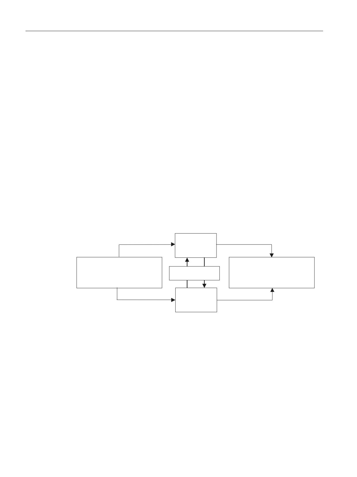
Connecting sensors and actuators
8.5 Safe programmable logic
8.5.1
Fundamentals
Fundamentals
Function
These signals must be logically combined (interlocked) in a safety-related, freely programmable
form in order to be able to flexibly process safety-related external process signals and safety-
related internal input and output signals. The "Safe Programmable Logic" (SPL) handles this task
as an integral system component.
Features:
• Logic operations implemented by the user are cyclically processed.
• Instructions are effective in all operating modes.
• The PLC program immediately starts to execute the instructions after the control has booted.
• The SGE/SGA must be supplied by the machine manufacturer - both in the drive monitoring
channel as well as in the NCK monitoring channel.
• The NCK-SPL is written as ASUB using the synchronized actions CNC function. The PLC-SPL is
written as PLC user program.
In order to check that the two SPLs (PLC and NCK) are functioning, the system program arranges
cyclic data comparison between the PLC and NCK.
6*(
6*$
1&. 63/
'LUHFW FRQQHFWLRQ RI PD[
VDIHW\
&RQQHFWLRQ RI PD[
UHODWHG VHQVRUV
VDIHW\ UHODWHG DFWXDWRUV
&URVVZLVH UHVXOW DQG GDWD
H J RSHUDWLQJ PRGH VZLWFK
FRPSDULVRQ
H J SURWHFWLYH GRRU LQWHUORFNLQJ
OLJKW EDUULHUV (PHUJHQF\ 6WRS
PRWRU EUDNHV
3/& 63/
6*(
6*$
Figure 8-31
Safe programmable logic
Safety Integrated (system-integrated)
254
Function Manual, 10/2020, 6FC5397-4BP40-6BA2
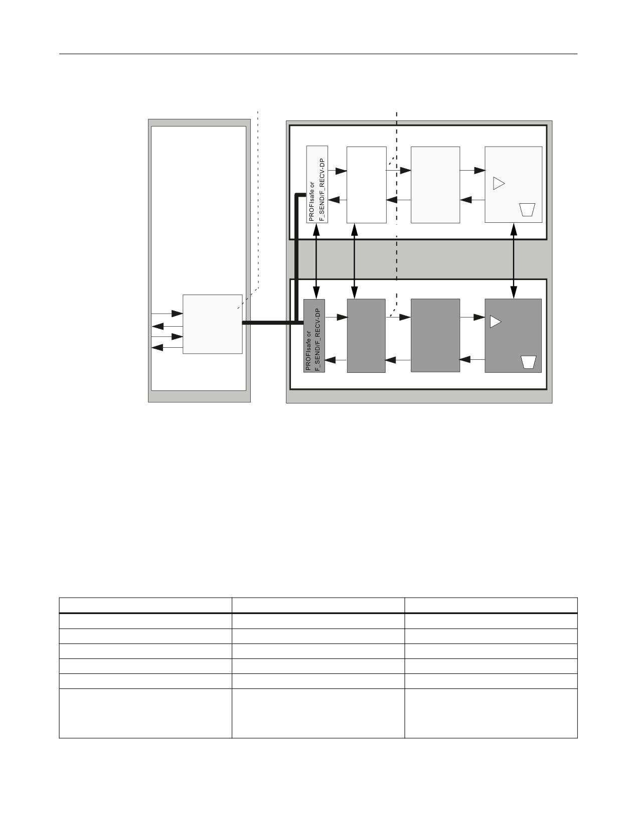
Connecting sensors and actuators
8.5 Safe programmable logic
([WHUQDO
,QWHUQDO
6*( 6*$
6*( 6*$
1&. VLJQDO SURFHVVLQJ
,QWHUIDFH
1&.
1&.
&RPSDUDWRU
63/
6*( 6*$
VLJQDOV
'DWD
0DFKLQH
1&. PRQLWRULQJ FKDQQHO
&RPP
63/
$[LV
&'&
&'&
&'&
'ULYH PRQLWRULQJ FKDQQHO
352),VDIH
&RPSDUDWRU
1& 3/&
RU
3/&
LQWHUIDFH
)B6(1''3
%XV
63/
$[LV VSLQGO
)B5(&9'3
H '%
'DWD
3/& VLJQDO SURFHVVLQJ
,QWHUIDFH
3URFHVV
6\VWHP
Figure 8-32
Integrating the SPL into the complete system
Crosswise data comparison
Data is cyclically exchanged between the PLC and NCK to check the correct functioning of the
two SPLs (PLC and NCK). Just the same as the comparison between the NCK and the drive, it
cross-checks the signals that the SPL receives, the safety-related signals generated by the SPL as
well as internal markers.
The discrepancy time for the crosswise data comparison of SPL variables is permanently set to
1 s (or 10 s $A_CMDSI).
The following signals are included in the crosswise data comparison between the NCK and the
PLC:
Table 8-2
Signals for crosswise data comparison
NCK-SPL data
Signal image of the PLC data
PLC-SPL data (DB18)
$A_INSE[1 ... 64]
$A_INSEP[1...64]
DBX38.0 ... DBX45.7
$A_OUTSE[1 ... 64]
$A_OUTSEP[1...64]
DBX46.0 ... DBX53.7
$A_INSI[1 ... 64]
$A_INSIP[1...64]
DBX54.0 ... DBX61.7
$A_OUTSI[1 ... 64]
$A_OUTSIP[1...64]
DBX62.0 ... DBX69.7
$A_MARKERSI[1 ... 64]
$A_MARKERSIP[1...64]
DBX70.0 ... DBX77.7
$A_FSDP_ERR_REAC[1...16]
--
DBW190, DBW200, DBW210
DBW448, DBW458, DBW468
-
DBW548, DBW558, DBW568
Safety Integrated (system-integrated)
Function Manual, 10/2020, 6FC5397-4BP40-6BA2
255

Connecting sensors and actuators
8.5 Safe programmable logic
NCK-SPL data
Signal image of the PLC data
PLC-SPL data (DB18)
$A_FRDP_SUBS[1...16]
--
DBW220, DBW232, DBW244
DBW578, DBW590, DBW602
--
DBW698, DBW710, DBW722
$A_FRDP_ERR_REAC[1...16]
--
DBW222, DBW234, DBW246
DBW580, DBW592, DBW604
--
DBW700, DBW712, DBW724
$A_INSE[65...192]
$A_INSEP[65...192]
DBX272.0 ...DBX287.7
$A_OUTSE[65...192]
$A_OUTSEP[65...192]
DBX288.0 ...DBX303.7
$A_INSI[65...192]
$A_INSIP[65...192]
DBX304.0 ...DBX319.7
$A_OUTSI[65...192]
$A_OUTSIP[65...192]
DBX320.0 ...DBX335.7
$A_MARKERSI[65...192]
$A_MARKERSIP[65...192]
DBX336.0 ...DBX351.7
$MN_PREVENT_SYNACT_LOCK
--
$MN_SAFE_SPL_STOP_MODE
--
$MN_SAFE_SPL_USER_DATA
--
DBD256, DBD260, DBD264,DBD268
If a difference is detected between the signals of both channels, this is indicated using Alarm
27090/27091 and the configured stop response (STOP D/E) is initiated if the SPL commissioning
phase has been defined to have been completed.
If the user attempts to acknowledge the initiated alarms and stop responses, without having
resolved the cause of the CDC error, then the stop response as well as the alarm are initiated
again.
To acknowledge a fault in the SPL-CDC, then the signal channel_1 reset (DB21.DBX7.7) must be
set for at least 100 ms. For PLC-controlled axes, the axis-specific reset must first be set up via
DB3x.DBX28.1 with a negative edge of the channel_1 reset.
The criterion "commissioning phase completed" is derived from the NCK-MD
$MN_PREVENT_SYNACT_LOCK[0,1] in the NCK. If one of the two field entries is not equal to 0,
"commissioning phase completed" is set by CDC internally. On the PLC side, this criterion is
entered using DB18.DBX36.0. If this bit is set to "1", then the commissioning phase is considered
to have been completed. An SPL-CDC error results in a stop response only after the SPL
commissioning phase has been completed.
The stop response for an SPL-CDC error is set in the NCK using NCK-MD $MN_SPL_STOP_MODE.
If the MD value is 3, for an SPL-CDC error, a STOP D is initiated - for an MD value of 4, a STOP E
is initiated. On the PLC side, this stop response is entered using DB18.DBX36.1. If this bit is set
to "1", for an SPL-CDC error, a STOP E is initiated - otherwise a STOP D.
Any changes to data on the NCK and PLC side do not take effect until after power on.
Clearing the external SPL outputs for SPL system errors
If communication between NCK and PLC is interrupted with reference to the SPL-CDC, then all
external SPL output signals ($A_OUTSE/$A_OUTSEP) are cleared with a 5 s delay.
This state occurs if data for crosswise data comparison is not exchanged between the NCK and
PLC for one second. This is due to the fact that
• the one second limit of the user cycle limit in the PLC (OB1 cycle) was exceeded.
• a system error has occurred. The NCK or PLC system software no longer runs due to a system
error - therefore interrupting communications.
Safety Integrated (system-integrated)
256
Function Manual, 10/2020, 6FC5397-4BP40-6BA2
Connecting sensors and actuators
8.5 Safe programmable logic
Behavior of the NCK
The specified timer of 5 s is started if Alarm 27092 "Communication interrupted for crosswise
Data comparison NCK-SPL, error detected by %1" is initiated. This is independent of which
component (NCK or PLC) interrupted the alarm.
The system variable $A_STATSID, bit 29 = 1 is used to indicate to the SPL user that this timer has
been started. This means that he has a possibility of initiating plant/system-specific actions
before the system deletes (clears) the output.
After this time has expired, the system deletes the external SPL outputs. The status variable
$A_STATSID, bit 29 remains set. When reading-back the external outputs in the NCK-SPL via the
system variable $A_OUTSE, "0" is read corresponding to the actual output status.
Behavior of the PLC
If, on the PLC side, it is detected that the communication timeout has been exceeded, then a
timer is started with 5 s.
After this time has expired, the PLC goes into Stop (by calling an SFC46). This state can only be
exited using a power on.
After the 5 s timer has expired, for diagnostics purposes, the PLC outputs Alarm 400253 "PLC-
STOP due to SPL system error". At the same time, an entry with the same significance is in the
diagnostics buffer.
Using the status signal DB18.DBX119.5, the SPL programmer and the NCK is provided with the
information that the timer was started. This means that he has the possibility of initiating
system-specific actions before the PLC goes into the stop condition.
Note
In order to achieve the shortest possible response time, the system variable $A_STATSID, bit 29
and the status signal DB18.DBX119.5 must be evaluated in the SPL in order to bring, as far as
possible, the SPL-SGA into a safe state (cleared SPL-SGA).
Supplementary conditions
The user must take into consideration the following points regarding the functioning of the
crosswise data comparison:
• Both channels (NCK/PLC) must execute the same logic.
• Do not implement any response sequences or sequence controllers that are externally
controlled using short input pulses. This is because short pulses of this type may only be sent
and processed in one channel because of sampling effects.
• Unused inputs/outputs/markers of the SPL must be assigned the default value = 0; single-
channel use of individual bits for non-safety relevant purposes is not permissible.
• External STOPs must be enabled (they are also used internally) and can be extracted from the
SPL if required. When using the SPL via MD $MA_SAFE_EXT_STOP_INPUT[0], for all safety
axes, the external STOP A must be parameterized at the SPL interface. If this condition is not
fulfilled, then Alarm 27033 is output.
Safety Integrated (system-integrated)
Function Manual, 10/2020, 6FC5397-4BP40-6BA2
257
Connecting sensors and actuators
8.5 Safe programmable logic
• Crosswise data comparison checks whether the "commissioning phase" has been completed.
If errors are detected in the crosswise data comparison, a "STOP D/E" is triggered on the NCK
and drive depending on this criterion. If the commissioning phase has not been completed
after booting, Alarm 27095 "SPL protection not activated" is repeatedly displayed (every 3
hours).
• In the case of a crosswise data comparison error, no system response is initiated regarding
the SGE/SGA processed by the SPL. Users must implement this themselves. The only
exception is when a system error is detected as was described above.
8.5.2
Synchronized actions for Safety Integrated
Motion-synchronizing actions (or "synchronizing actions" for short) are instructions
programmed by the user, which are evaluated in the interpolation cycle of the NCK in
synchronization with the execution of the part program. If the condition programmed in the
synchronized action is fulfilled (logical expression) or if none is specified, then actions assigned
to the instruction are activated in synchronism with the remainder of the part program run.
Description
The number of programmable synchronized action blocks depends entirely on the configurable
number of synchronized action elements. The number of storage elements for general motion-
synchronizing actions (synchronizing action elements) is defined in MD28250
$MC_MM_NUM_SYNC_ELEMENTS.
The memory management is listed separately in order to be able to independently handle
synchronized actions for SAFE.SPF. MD28251 $MC_MM_NUM_SAFE_SYNC_ELEMENTS is used
to configure the memory for the safety synchronized action elements. All modal synchronized
actions that are programmed in the sub-program /_N_CST_DIR/_N_SAFE_SPF retrieve their
elements from this memory area.
In order to determine the required for synchronized action elements, at the start and at the end
of SAFE.SPF, system variables $AC_SAFE_SYNA_MEM can be read. The difference between these
values is then the number of synchronized action elements required. This value - plus a possible
reserve - must be entered into MD28251 $MC_MM_NUM_SAFE_SYNC_ELEMENTS.
References: Function Description - Synchronized Actions
8.5.3
User configurations
In order to provide users (machinery construction OEMs, SPL programmers), the option of being
able to save various machine configurations in a protected way (e.g. regarding the I/O structure
or the number of safety-related axes), data are defined in the NCK (MD) and PLC (DB18) in which
users can save such information. This data can be interrogated in order to execute different SPL
instructions e.g. corresponding to the meaning.
This data has no function for the NCK and PLC (they are not interpreted any further by the NCK
and PLC).
For the NCK, a general machine data field MD13312 $MN_SAFE_SPL_USER_DATA[0...3] is
applicable
Safety Integrated (system-integrated)
258
Function Manual, 10/2020, 6FC5397-4BP40-6BA2
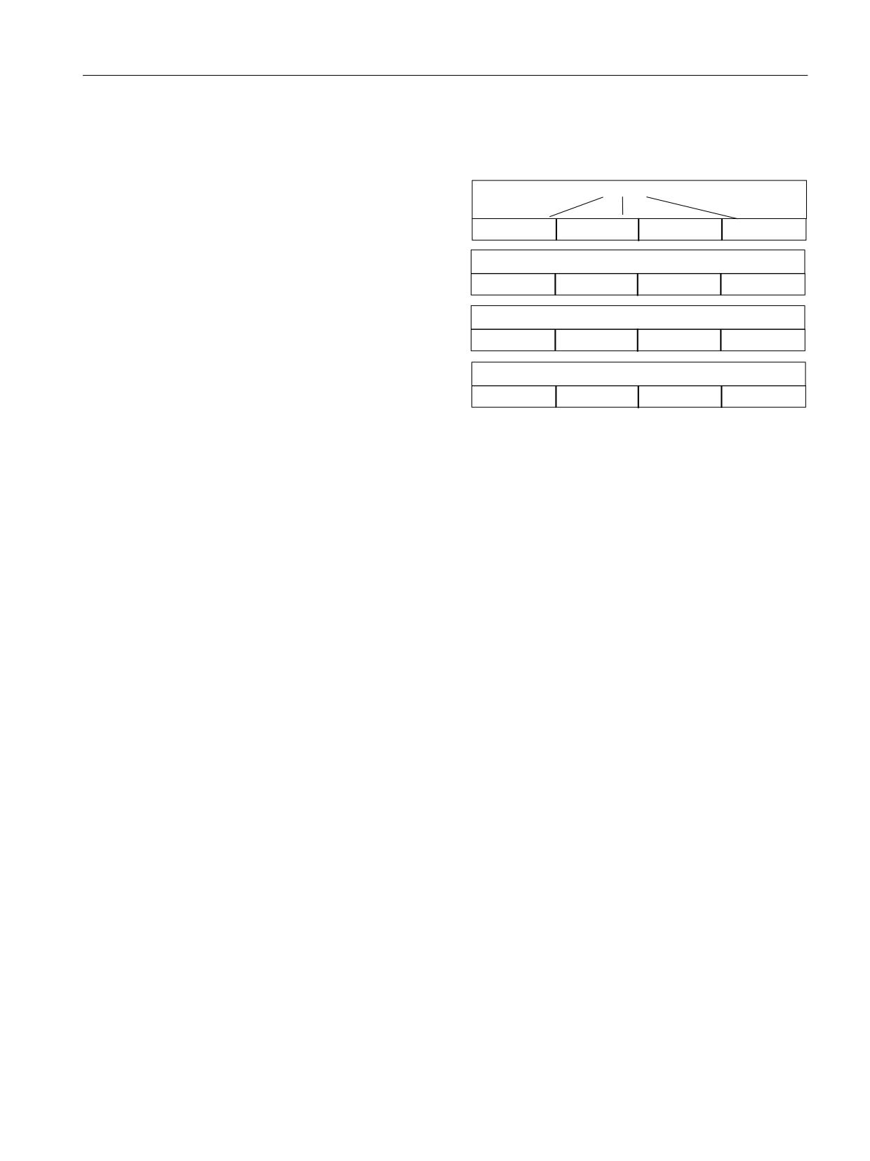
Connecting sensors and actuators
8.5 Safe programmable logic
Users can save information in this MD that must be set the same as the corresponding data in
DB18 (DBD256, 260, 264, 268), e.g.
$%
))
0'
> @
01B6$)(B63/B86(5B'$7$> @
'% '%'
63/B86(5B'$7$> @
'%%
'%%
'%%
'%%
$%
))
0'
> @
01B6$)(B63/B86(5B'$7$> @
'% '%'
63/B86(5B'$7$> @
'%%
'%%
'%%
'%%
0'
> @
01B6$)(B63/B86(5B'$7$> @
$$%%&&''
'%%
'%%
'%%
'% '%'
63/B86(5B'$7$> @
'%%
$$
%%
&&
''
0'
> @
01B6$)(B63/B86(5B'$7$> @
'%%
'%%
'%%
'%%
'% '%'
63/B86(5B'$7$> @
Figure 8-33
Assignment between MD13312 and data block DB18
Differences between the NCK and PLC data are identified using the SPL-CDC and result,
corresponding to the parameterized stop response, in a STOP D/E on all safety-related axes.
Alarm 27090 "Error for crosswise Data comparison NCK-PLC" is output with a reference to the
machine data.
Further, system variable $A_STATSID, bit 27 = 1 is used to indicate to the SPL user that there is
an SPL-CDC error.
Changes to machine data or DB18 data only become effective after power on.
Changes to data are indicated using a corresponding alarm after restart.
8.5.4
NCK-SPL program
Description
The NCK-SPL program is written as an NC program (ASUB) with synchronized actions.
Safety Integrated (system-integrated)
Function Manual, 10/2020, 6FC5397-4BP40-6BA2
259
Connecting sensors and actuators
8.5 Safe programmable logic
Features
The NCK-SPL program has the following features:
• The program can be started manually with NC START during commissioning.
• The following applies once the program has been started:
- The synchronous actions assigned an ID No. are cyclically executed in the IPO clock cycles
(modal)
- The synchronized actions assigned the keyword IDS remain active even after the
operating mode has been changed or NC-STOP/NC RESET
- In order to check the program, the status of the active synchronous actions (operating
area "Machine", soft key "Synchronized actions") can be displayed.
- The program can be modified during commissioning. It must then be re-started.
- The NCK-SPL program is saved in the NCK path_N_CST_DIR as sub-routine "_N_SAFE_SPF"
(HMI view: Standard cycles / SAFE.SPF). Other sub-routine names are not permitted.
• The images of the PLC safety variables ($A_INSIP(D), $A_OUTSIP(D), $A_INSEP(D),
$A_OUTSEP(D), $A_MARKERSIP(D)) are required for the simulation (on the NC side) of an
SPL. These can be used to develop the SPL step-by-step. They can only be read by the NCK.
Protective mechanisms
• The synchronized action IDs used for the NCK-SPL are protected from being influenced by the
PLC or other programs using MD $MN_PREVENT_SYNACT_LOCK. To activate the protection,
the number range of the synchronized action IDs used in the SPL program must be entered
into the two fields of machine data $MN_PREVENT_SYNACT_LOCK. It is then no longer
possible to change these synchronized actions (CANCEL, LOCK have no effect) once
_N_SAFE_SPF has been started.
• When changing machine data $MN_PREVENT_SYNACT_LOCK[0,1] from zero to values not
equal to zero, an option set for the SPL inputs and outputs and an SPL file under /_N_CST_DIR/
_N_SAFE_SPF, then Alarm 27098 "SPL commissioning phase complete" is initiated. This can
only be acknowledged with a power on and should be used as information for the user, that
a) the SPL protective mechanisms (see Table ) are activated
b) a restart is necessary in order to activate these protective mechanisms.
• System variables $A_OUTSI, $A_OUTSID, $A_OUTSE, $A_OUTSED, $A_MARKERSI,
$A_TIMERSI, $A_CMDSI, $A_FSDP_ERR_REAC, $A_FRDP_ERR_REAC and $A_FRDP_SUBS are
protected from being written to by programs other than the NCK-SPL (/_N_CST_DIR/
_N_SAFE_SPF). If an error occurs, Alarm 17070 "Channel %1 block %2 data item write-
protected" is output.
• A reference checksum is calculated when booting and for changes/saving the file by the NCK-
SPL (/_N_CST_DIR/_N_SAFE_SPF) - it is entered into the program as a comment:
Example: ; SAFE_CHECKSUM = 000476bbH
The checksum is then cyclically re-calculated and compared with the reference checksum. If
a deviation is detected, Alarm 27093 "Checksum error NCK-SPL, %1,%2, %3" is output.
• The system variables $A_INSIP(D), $A_OUTSIP(D), $A_INSEP(D), $A_OUTSEP(D) and
$A_MARKERSIP(D) are only accessible during the commissioning phase.
Safety Integrated (system-integrated)
260
Function Manual, 10/2020, 6FC5397-4BP40-6BA2
Connecting sensors and actuators
8.5 Safe programmable logic
If NCK-SPL execution is interrupted for any reason or the SI system variables are changed by
another program, then this is detected by the cyclic crosswise data comparison with the PLC.
Table 8-3
Response to SPL errors
Event
MD11500 $MN_PREVENT_
MD11500 $MN_PREVENT_
SYNACT_LOCK[m,n] equal to 0
SYNACT_LOCK[m,n] not equal to 0
Crosswise data comparison
Alarm 27090 is triggered
Alarm 27090 is triggered and in addition,
STOP D/E is triggered
NCK-PLC identifies an error
SPL program file is to be changed (writ-
No response
Alarm 27093 is initiated
ten, deleted, re-named, edited)
WARNING
Protective mechanisms
The protective mechanisms that prevent changes to the NCK-SPL file and the NCK-SPL
instructions (statements) are only effective if MD $MN_PREVENT_SYNACT_LOCK[0,1] is not
equal to 0.
The machine OEM must ensure that the protective mechanisms are activated no later than after
the completion of the acceptance test and the values, set in MD
$MN_PREVENT_SYNACT_LOCK[0,1] are documented in the acceptance report.
After commissioning has been completed, the access rights to the SAFE.SPF file must be set to
the correct access level for writing/reading/deleting access operations (manufacturer or
service).
As long as the protective mechanisms for the NCK-SPL have not been activated
(MN_PREVENT_SYNACT_LOCK[0.1] equal to 0), Alarm 27095 is displayed when the crosswise
data comparison between the NCK and the PLC starts. This alarm can be acknowledged with the
NCK key so that the SPL can be commissioned.
Note
The SPL program must be addressed using upper case letters. Alarm 27097 is output if this is not
observed.
8.5.5
Starting the SPL
Preconditions
The NCK-SPL is active after the control has booted, if at least
1. The functions SBH/SG and "external STOPs" have been enabled for at least one axis using
$MA_/$MD_SAFE_FUNCTION_ENABLE,
2. one of the NCK-SPL interfaces is used.
This means that an axis-specific SGE/SGA was parameterized at one of the SPL interfaces
using its assignment MD.
Safety Integrated (system-integrated)
Function Manual, 10/2020, 6FC5397-4BP40-6BA2
261
Connecting sensors and actuators
8.5 Safe programmable logic
In this case, the "external STOP A" must be parameterized at the SPL interface for all of the axes
that use Safety Integrated.
NCK-SPL (SAFE.SPF) can be started in three different ways:
• Start via safety power on
• Start via PROG_EVENT
• Start via the PLC program
Note
System utilization
Ensure that SPL is only started in one channel. Otherwise, SI synchronization routines run a
multiple number of times, which results in an excessive system utilization.
SPL start without axis-specific safety enable
When the machine is being commissioned, it may be necessary to start SPL without enabling
axis-specific safety-relevant functions.
It is therefore possible to handle general machine functions (hydraulics, Emergency Stop) before
the axis is commissioned. This is only possible in the commissioning state of the SPL
($MN_PREVENT_SYNACT_LOCK[0,1]==0 and DB18.DBX36.0==0). This state is displayed when
the SPL starts using Alarm 27095 "%1 SPL protection not activated".
If an attempt is made to start the SPL in the protective state (after commissioning has been
completed) without an axis-specific safety function having been activated, then Alarm 27096 is
output. The SPL is started if the SPL-CDC is not activated.
Further, Alarm 27096 "SPL start not permitted" is output if SPL protection is activated, however
the drive objects of all enabled SI axes in the complete system have been deactivated (drive
parameter p0105). As long as one SI axis is active, the alarm is not output.
Start via safety power on
When the "Safety power on" function is activated, SAFE.SPF is automatically started when
booting. The system starts even if alarms are present. The function is activated by setting bit 5
(safety power on) in machine data 20108 $MC_PROG_EVENT_MASK. A possible SAFE.SPF call
in the PROG_EVENT.SPF can be removed.
It is only possible to work with a restricted language scope in order that SAFE.SPF can be started
in spite of the fact that alarms are active. The PLC or drives cannot be accessed. For commands,
which are not included in the language scope, Alarm 15420 "Channel%1 %2 Instruction in the
current mode not allowed" is output.
If it is required to change over an existing SAFE.SPF to the restricted language scope, then it is
possible to proceed as follows:
• MD20108 $MC_PROG_EVENT_MASK, bit 5=0
• MD10095 $MN_SAFE_MODE_MASK, bit 2=1 (as a result, for SAFE.SPF, the reduced language
scope is activated - also as a result of the CALL call)
• Call SAFE.SPF in MDI (CALL "/_N_CST_DIR/_N_SAFE_SPF")
Safety Integrated (system-integrated)
262
Function Manual, 10/2020, 6FC5397-4BP40-6BA2

Connecting sensors and actuators
8.5 Safe programmable logic
• SAFE.SPF is edited until the program can be executed without any alarms with the restricted
language scope.
• MD $MC_PROG_EVENT_MASK, bit 5=1; SAFE.SPF is called when booting and is executed
error-free with the restricted language scope.
Starting the NCK-SPL via PROG_EVENT
Note
This function is an option, and is not included as standard in Safety Integrated.
The NCK-SPL can also be started using the PROG_EVENT mechanism.
The PROG_EVENT.SPF cycle (saved under manufacturer cycles ..\DH\CMA.DIR) is started when a
specific event occurs (event-controlled program call).
Using machine data MD 20108 $MC_PROG_EVENT_MASK, for this PROG_EVENT mechanism,
certain events are enabled on a specific channel-for-channel basis, which then start the cycle.
The start condition when booting (bit 3 ==1) must be active in order to start the NCK-SPL
(SAFE.SPL) via PROG_EVENT.SPF.
Note
When starting the NCK-SPL (SAFE.SPF), it is important that the PROG_EVENT mechanism was
started through channel 1. This must be taken into account when parameterizing the channel-
specific machine data MD20108 $MC_PROG_EVENT_MASK.
Using the system variable $P_PROG_EVENT, in PROG_EVENT.SPF it can be interrogated as to
which event activated the call:
• Part program start
$P_PROG_EVENT == 1
• Part program end
$P_PROG_EVENT == 2
• Operator panel reset
$P_PROG_EVENT == 3
• Booting
$P_PROG_EVENT == 4
For the PROG_EVENT.SPF cycle, MD11602 $MN_ASUP_START_MASK, PROG_EVENT.SPF and
the SAFE.SPF are taken into account, which can be used to set that stop reasons for the sequence
are ignored.
In order to be able to use $MC_PROG_EVENT_MASK and $MN_ASUP_START_MASK, the "Cross-
mode actions" option must be activated.
Example for PROG_EVENT.SPF
; -------------------------------------------------
; Event-controlled program call
; PROG_EVENT.SPF under \DH\CMA.DIR;
--------------------------------------------------------
; -------------------------------------------------
Safety Integrated (system-integrated)
Function Manual, 10/2020, 6FC5397-4BP40-6BA2
263
Connecting sensors and actuators
8.5 Safe programmable logic
; In machine data MD20108 PROG_EVENT_MASK, on a channel-for-channel basis, you can set;
as to which of the following events should activate the user program:
; ( ) part program start --> bit0 ==1
; ( ) part program end
--> bit1 == 1
; ( ) operator panel
--> bit2 == 1
reset
; ( x ) booting
--> bit3 = = 1
; ----------------------------------------------------------------
; Using system variable $P_PROG_EVENT, it can be interrogated as to which event activated the
call:
; ( ) part program start --> $P_PROG_EVENT == 1
; ( ) part program end
--> $P_PROG_EVENT == 2
; ( ) operator panel
--> $P_PROG_EVENT == 3
reset
; ( x ) booting
--> $P_PROG_EVENT == 4
;
;------------------------------------ Cycle definition ------------
; Suppress single block, display
; -----------------------------------------------------------------
N100 PROG_EVENT SBLOF DISPLOF
;
; Start of the NCK-SPL
;------------------------------------------------------------------
N200 IF ($P_PROG_EVENT = 4); boot query
N300 CALL "/_N_CST_DIR/_N_SAFE_SPF"
N400 ENDIF
N500 ...
N600 ...
N700 M17 ; end of cycle
The part program SAFE.SPF is called if the system variable check $P_PROG_EVENT indicated that
the part program call PROG_EVENT.SPF was called when the control system booted.
Example for SAFE.SPF
A simple example for SAFE.SPF will now be shown that is started using PROG_EVENT when the
system boots and includes static synchronized actions.
; File: SAFE.SPF
=============
Safety Integrated (system-integrated)
264
Function Manual, 10/2020, 6FC5397-4BP40-6BA2
Connecting sensors and actuators
8.5 Safe programmable logic
; Definitions
DEFINE STOP_A_DISABLE AS $A_OUTSI[1]
DEFINE STOP_C_DISABLE AS $A_OUTSI[2]
DEFINE STOP_D_DISABLE AS $A_OUTSI[3]
;
DEFINE STOP_A_EXT AS $A_INSE[6]
DEFINE STOP_C_EXT AS $A_INSE[7]
DEFINE STOP_D_EXT AS $A_INSE[8]
DEFINE STOP_A_XT AS $A_INSE[9]
;
; Program section
N10 IDS=01 DO STOP_A_DISABLE=STOP_A_EXT
N20 IDS=02 DO $A_OUTSE[1]=NOT $A_OUTSE[1]
N30 M17
Starting the NCK-SPL from the PLC user program
Program start
The NCK-SPL can also be started from the PLC user program. As soon as the NCK-SPL has been
started, the crosswise data comparison is activated in the system program (NCK and PLC basic
program).
The NCK-SPL program must be started as an ASUB. To do this, the interrupt number and channel
must first be assigned via FB4 using the ASUB (asynchronous sub-routine) function via
parameter PIService="PI.ASUP".
As soon as FB4 has been successfully run (output parameter "Done"=TRUE) the program is
executed via FC9 "ASUB" [asynchronous sub-routine].
In this case, MD11602 $MN_ASUP_START_MASK is taken into account, which can be used to
set that stop reasons for the sequence are ignored.
Deviating from the recommended setting 7H, the following settings are also possible:
• Bit 1 can be deleted if MD20700 $MN_REFP_NC_START_LOCK (in the channel in which the
SPL is started) is deleted, or, if at the instant that the ASUB starts, the axes (in the channel,
in which the SPL is started) do not have to be safely referenced, e.g. in the park state.
• Bit 2 can be deleted if no read-in disable is present when booting.
Further, MD11604 $MN_ASUP_START_PRIO_LEVEL (interrupt priority from which the MD
$MN_ASUP_START_MASK is active) must be observed.
To be able to start the NCK-SPL without any errors, according to the required SPL start type (start
via PROG_EVENT or automatic start), when booting, the following machine data must be taken
into account:
MD20106 $MC_PROG_EVENT_IGN_SINGLE_BLOCK, bit 3 or bit 5
Safety Integrated (system-integrated)
Function Manual, 10/2020, 6FC5397-4BP40-6BA2
265

Connecting sensors and actuators
8.5 Safe programmable logic
MD20107 $MC_PROG_EVENT_IGN_INHIBIT, bit 3 or bit 5
In addition, it may be necessary to not display the processing of the event-controlled programs
via MD20192 $MC_PROG_EVENT_IGN_PROG_STATE, bit 3 or bit 5 on the OPI interface. This does
not influence executing the NCK-SPL, and is only used to visualize program execution in the HMI
context
Starting the PLC-SPL
The PLC-SPL in conjunction with FB4/FC9 has started if the FC9 has signaled successful execution
and has displayed that the end of SAFE.SPF has been reached. This is displayed using a signal in
SAFE.SPF (e.g. $A_PLCSIOUT variable, M function) or SPL status bit 13 (DB18.DBX137.5). Only
then may the PLC-SPL be started to ensure that both SPLs run in synchronism, and therefore the
axis-specific monitoring channels are synchronously supplied.
Parameterizing FB4
FB4 may only be started in the cyclic mode (OB1).
Signal
Type
Value range
Meaning
Reg
PIService
ANY
PI.ASUP
Assign interrupt
Unit
INT
1 to 10 [1]
Channel
WVar1
INT
[1]
Interrupt number
WVar2
INT
[1]
Priority
WVar3
INT
0/1 [0]
LIFTFAST
WVar4
INT
0/1 [0]
BLSYNC
Addr1
STRING
’/_N_CST_DIR/’
NCK-SPL path name
Addr2
STRING
’_N_SAFE_SPF’
NCK-SPL program name
[values in brackets are standard values required for the call]
Parameterizing FC9
Signal
In-
Type
Value range
Remark
put
or
out
put
Start
E
Bool
ChanNo
E
Int
1 to 10 [1]
No. of the NC channel
IntNo
E
Int
1 - 8 [1]
Interrupt No.
Active
A
Bool
1 = active
Done
A
Bool
1 = ASUB completed
Error
A
Boo
[values in brackets are standard values required for the call]
Safety Integrated (system-integrated)
266
Function Manual, 10/2020, 6FC5397-4BP40-6BA2
Connecting sensors and actuators
8.5 Safe programmable logic
8.5.6
Language scope for SAFE.SPF
Precondition
In order that no NC alarms are output when the SINUMERIK control boots, which prevent a
started SAFE.SPF being completely executed, it is necessary to define a restricted language
scope for SAFE.SPF. It is not permissible that commands are programmed which access the PLC
or drives.
If a SAFE.SPF is tested or commissioned with a restricted language scope, then every Alarm
15189 "Channel %1 Block %2 Error when executing SAFE.SPF" requires a power on. To prevent
this, MD10095 $MN_SAFE_MODE_MASK bit 2 can be set = 1.
Now, the restricted language scope is active each time that SAFE.SPF is called using the
command CALL<path name>. For instance, the call can be made from MDI or PROG_EVENT.SPF
at reset. For commands, which are not included in the language scope, only Alarm 15420
"Channel %1 Channel %2 Instruction in current mode not allowed" is output and not Alarm
15189. Alarm 15420 can be cleared with a reset.
In order to change over an existing SAFE.SPF to a restricted language scope, it is possible to
proceed as follows for example:
• MD20108 $MC_PROG_EVENT_MASK, bit 5 = 0
• In the PROG_EVENT.SPF, remove the SAFE.SPF call from the power on section or the SAFE.SPF
call from the ASUB.
• MD10095 $MN_SAFE_MODE_MASK, bit 2 = 1
• SAFE.SPF is not called when the system boots
• SAFE.SPF is now called with CALL "_N_CMA_DIR_/_N_SAFE_SPF" e.g. from MDI or
PROG_EVENT at RESET. The restricted language scope is now active, alarms that occur can be
cleared with RESET.
• SAFE.SPF is edited until the program can be executed without any alarms with the restricted
language scope.
• MD20108 $MC_PROG_EVENT_MASK, bit 5 = 1
• MD10095 $MN_SAFE_MODE_MASK, bit 2 = 0
• SAFE.SPF is called when the system boots, and with the restricted language scope is executed
error-free.
Safety Integrated (system-integrated)
Function Manual, 10/2020, 6FC5397-4BP40-6BA2
267

Connecting sensors and actuators
8.5 Safe programmable logic
Configuration
The function is activated using machine data 20108 $MC_PROG_EVENT_MASK, bit 5 = 1. An
existing SAFE.SPF call in a PROG_EVENT.SPF power on section or in an ASUB can be removed. If
the function is active, then only the restricted language scope is possible in a SAFE.SPF. If the
function is not active, then the complete language scope is permitted in a SAFE.SPF. If MD
$MC_PROG_EVENT_MASK, bit 5 = 0, then SAFE.SPF is not executed when the system boots and
errors are active.
Table 8-4
Permissible language commands for SAFE.SPF
Block structure
Nxxx
;Block number
XYZ:
;Labels
/
;Skip, block skip
;
;Comment characters
;Empty line
Beginning of the program
SAFE PROC
;First operation in the program
Attributes, which are programmed in the PROC line
SBLOF
;Single block skip
DISPLOF
;Skip, block display
ACTBLOCNO
;For DISPLOF, for an alarm output the number of the actual block
DISPLON
;Activate block display
SBLOF is always active, even if SBLOF is not programmed
Variable definition
DEF
;Creating DUDs
DEFINE
;Creating macros
Assignments
Values are assigned to variables with an = character. The value being assigned can either be a constant
or an algorithm If the value is a constant, the binary, hexadecimal or exponential notation is possible.
’B0000001’
;Binary notation
’H3C7F’
;Hexadecimal notation
4.1EX-3
;Exponential notation
Fields can be assigned with
REP
:Initialization with the same values
SET
;Initialization with value list
SETA
;Copying fields
Writing, i.e. the lefthand part of an assignment, is possible with these variables:
LUD
GUD
R parameters
$AC_PARAM[ ]
$AC_MARKER[ ]
$AA_ESR_TRIGGER
;Single axis, trigger ESR
$AA_ESR_TRIGGER
;Trigger ESR
Safety Integrated (system-integrated)
268
Function Manual, 10/2020, 6FC5397-4BP40-6BA2

Connecting sensors and actuators
8.5 Safe programmable logic
$AN_ESR_TRIGGER
;Trigger ESR
all Synact GUDs
Safety system variables that can be written to:
$A_OUTSE[ ]
$A_OUTSED[ ]
$A_OUTSI[ ]
$A_OUTSID[ ]
$A_MARKERSI[ ]
$A_MARKERSID[ ]
$A_TIMERSI[ ]
$A_CMDSI[ ]
$A_PLCSIOUT[ ]
$A_FSDP_ERR_REAC[ ]
$A_FRDP_SUBS[ ]
$A_FRDP_ERR_REAC[ ]
Reading the righthand part of an assignment is possible with all variables - i.e. also with all safety system
variables.
Arithmetic functions
+
;Addition
-
;Subtraction
*
;Multiplication
/
;Division
DIV
;Division, for variable type INT and REAL
MOD
;Modulo division
SIN( )
;Sine
COS( )
;Cosine
Tan( )
;Tangent
ASIN ()
;Arcsine
ACOS( )
;Arccosine
ATAN2( )
;Arctangent2
SQRT( )
;Square root
ABS( )
;Absolute value
POT( )
;2nd power (square)
TRUNC( )
;Integral number
ROUND( )
;Round to integer number
ROUNDUP( )
;Round up
LN( )
;Natural logarithm
EXP( )
;Exponential function
MINVAL( )
;Lower value of two variables
MAXVAL( )
;Larger value of two variables
BOUND( )
;Variable value within the defined value range
Predefined safety functions
SIRELIN( )
;Assign input quantities
SIRELOUT( )
;Assign output quantities
Safety Integrated (system-integrated)
Function Manual, 10/2020, 6FC5397-4BP40-6BA2
269

Connecting sensors and actuators
8.5 Safe programmable logic
SIRELTIME( )
;Assign times for timer
SIRELAY
;
Predefined functions and procedures
ITOR( )
;Conversion, integer to real
ITOB( )
;Conversion, integer to bool
RTOI( )
;Conversion, real to integer
RTOB( )
;Conversion, real to bool
BTOI( )
;Conversion, bool to integer
BTOR( )
;Conversion, bool to real
SETAL( )
;Set alarm
MSG(<<)
;Output message with contents of variables
Program jumps
GOTOB
;Jump instruction with jump destination towards the beginning of pro-
gram
GOTOF( )
;Jump instruction with jump destination towards the end of program
GOTO
;Jump instruction with jump destination search. The search
;is first made towards the end of the program, then towards the begin-
ning of the program.
GOTOC
;Same effect as for GOTO, with the difference that Alarm
;14080 "Jump designation not found" is suppressed.
An IF condition can be programmed in the block in front of the jump instruction.
Program branch
CASE(<expression>)
OF <constant_1>
GOTOF <jump destination_1>
<constant_2>
GOTOF<jump destina-
tion_2...>
DEFAULT GOTOF <jump desti-
nation n>
Program repetition
REPEAT LableA P=n
;Repeat program section
REPEAT LableA LableB P=n
;Repeat program section
REPEATB LableA P=n
;Repeat block
Control structures
IF, ELSE, ENDIF
;Program loop with alternative
LOOP, ENDLOOP
;Endless program loop
FOR, TO, ENDFOR
;Count loop
WHILE; ENDWHILE
;Program loop with condition at start of loop
REPEAT, UNTIL
;Program loop with condition at end of loop
Program flow
STOPRE
;Preprocessing stop
DELAYSTON
;Start of a stop delay area
DELAYSTOF
;End of a stop delay area
Comparison operators
Safety Integrated (system-integrated)
270
Function Manual, 10/2020, 6FC5397-4BP40-6BA2

Connecting sensors and actuators
8.5 Safe programmable logic
<>, ==, >=, <, >, <=
Bit-by-bit logic operators
B_END
B_OR
B_NOT
B_XOR
Logical operators
AND
OR
NOT
XOR
For the logic operations, the following applies to the BOOL, CHAR, INT and REAL data types: 0 corresponds
to FALSE; not equal to 0, corresponds to TRUE
Synchronized action
CANCEL
;Delete synchronized actions
IDS
;Static synchronized action
;no monitoring with respect to a number range
WHENEVER
;The action is cyclically executed in each IPO clock cycle,
;as long as the condition is fulfilled.
WHEN
;As soon as the condition has been fulfilled, the
action is executed once.
EVERY
;The action is initiated once when the condition is satisfied.
;The action is executed again if the condition transitions from
;the false state into the true state.
FROM
;If the condition has been fulfilled once, the action is executed cyclically
;in every interpolation clock cycle for as long
;as the synchronized action remains active.
DO
;Start of the action section
No subprograms, i.e. technology cycles can be called in the action section.
No axes can be traversed and no auxiliary functions can be output.
Values can be assigned to the following:
- R parameters
- $AC_PARAM[ ]
- $AC_MARKER[ ]
- all Synact GUDs
- all safety system variables and G functions that can be written to
G function
G70
;Inch dimensions (group 13) G71
G71
;Metric dimensions (group 13)
G700
;Inch dimensions also F (group 13)
G710
;Metric dimensions also F (group 13)
G04 F
;Dwell time (group 2)
End of program
ENDPROC
;End line of program with start line PROC
RET
;Without output to the PLC
;The RET command without parameter can now be programmed in a
;main program.
Safety Integrated (system-integrated)
Function Manual, 10/2020, 6FC5397-4BP40-6BA2
271

Connecting sensors and actuators
8.5 Safe programmable logic
M17
;No output to the PLC
M02
;No output to the PLC
M30
;No output to the PLC
Note
All language commands, which are not listed in this table, result in NC alarms 15189 "Channel
%1 Block %2 Error when executing SAFE.SPF" and 15420 "Channel %1 Block %2 Instruction in
current mode not allowed".
Additional information on the complete NCK language scope can be found under:
References: Programming Manual Fundamentals, Chapter 16 "Tables".
8.5.7
Diagnostics/commissioning
The system variables $A_INSIP(D), $A_OUTSIP(D), $A_INSEP(D) and $A_OUTSEP(D), and
$A_MARKERSIP(D) are only used for diagnostics and commissioning the NCK-SPL. These system
variables represent the input data for crosswise data comparison on the PLC side. They are
updated every IPO cycle. They can also be used to access the CDC on the PLC side from the NC.
This helps when commissioning the SPL:
• Crosswise data comparison function can be temporarily bypassed
• NCK-SPL can be simulated to the process and to the NCK monitoring channel. To do this, the
relevant PLC images are written to the variables $A_OUTSED and $A_OUTSID as long as there
is no NCK-SPL. This means that the NCK-SPL can be commissioned step-by-step. This data may
only be accessed during the commissioning phase.
In order to allow the SPL to be commissioned without the crosswise data comparison function
constantly responding, the following "minimum NCK-SPL" can be installed in this phase:
; Simulate external SPL interface
IDS = 03 DO $A_OUTSED[1]
= $A_OUTSEPD[1]
IDS = 04 DO $AOUTSED[2]
= $A_OUTSEPD[2]
; Simulate internal SPL interface
IDS = 07 DO $A_OUTSID[1]
= $A_OUTSIPD[1]
IDS = 08 DO $A_OUTSID[2]
= $A_OUTSIPD[2]
; Emulate PLC markers (for all markers used in the PLC)
IDS = 09 DO
= $A_MARKERSIPD[1]
$A_MARKERSID[1]
IDS = 10 DO
= $A_MARKERSIPD[2]
$A_MARKERSID[2]
; End of program
M17
Safety Integrated (system-integrated)
272
Function Manual, 10/2020, 6FC5397-4BP40-6BA2
Connecting sensors and actuators
8.5 Safe programmable logic
These instructions simulate the output interfaces of the NCK-SPL and therefore "short-circuit"
the crosswise data comparison.
WARNING
Commissioning
The logic used in this phase has a single channel structure and is therefore not safe!
The described minimum NCK-SPL must be replaced by a full NCK-SPL without any access to
$A_INSIP(D), ..., $A_MARKERSIP(D) when the PLC side is completed!
Additional diagnostic support:
• $A_STATSID: A value not equal to 0 means that an error has occurred in the crosswise data
comparison.
• $A_CMDSI[n]: n=1: 10x change timer value for long forced checking procedure pulses and/
or single-channel test stop logic.
• $A_LEVELSID: Indicates how many signals have different signal levels on the NCK and PLC
sides that can be presently detected.
• In addition, other NC variables or free R parameters can be written to monitor internal states
of the SPL.
The following applies to all system variables of the NCK-SPL outputs: They can be written from
and read back to the SPL program.
See also
SPL data on the PLC side (Page 284)
Safety Integrated (system-integrated)
Function Manual, 10/2020, 6FC5397-4BP40-6BA2
273
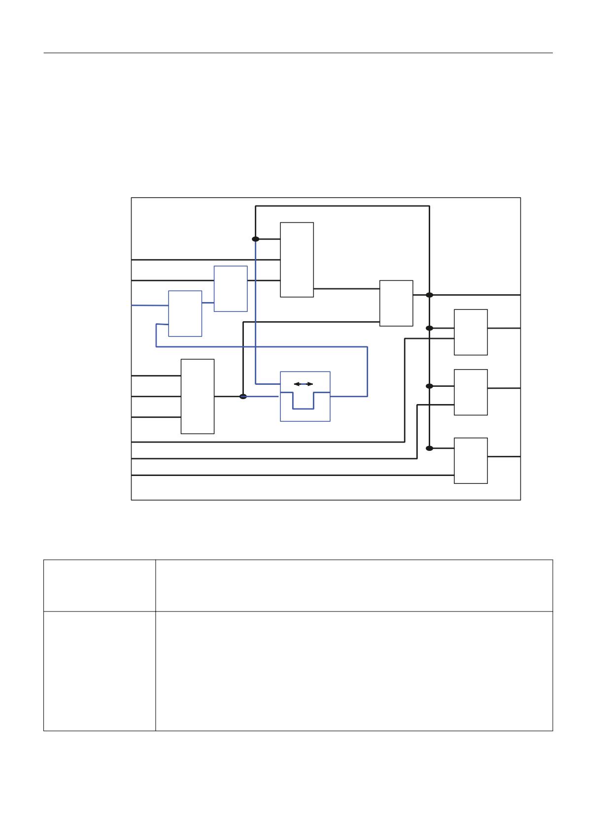
Connecting sensors and actuators
8.5 Safe programmable logic
8.5.8
Safe software relay
General
The standard SPL block "safety software relay" is designed to meet the requirements of an
Emergency Stop function with safe programmable logic. However, it can also be used to
implement other similar safety functions, e.g. to control a protective door.
25
4
4
$1'
$
$1'
70
&03
!
$
7LPHU
7LPH PHDVXUHPHQW IDOOLQJ
XS WR D ULVLQJ HGJH
(
$1'
W
$
(
W L
7LPHU
(B$1'
(
7,
$
7,
7LPHU
7,
6LJQDOV ZLWK VWDU
PHDQ ORZ DFWLYH
Figure 8-34
Function diagram of the safety relay
The description is provided in the following:
Three shutdown inputs
If one of these inputs is set to 0, then direct output A0 is set to 0. Outputs A1 to A3 switch with the
E1 to E3
delay of timer 1-3. If one of these inputs is not used, then it is internally set to "1" as static signal.
One of these inputs must also be used to initiate test operation of the safety relay (forced checking
procedure).
Two acknowledge inputs
Q1 must be supplied with the signal from the real acknowledge button.
Q1 and Q2
Q2 is only used for the forced checking procedure. The software relay itself does not have to be
subject to a forced checking procedure. However, if the Emergency Stop function is executed via
this, and if external actuators have to be subject to a forced checking procedure, if the relay drops-
out during the Emergency Stop test, then it can be acknowledged using Q2 (in a defined time
window, refer to TM1). This input must also be connected with a safety system variable (even if the
signal is not used) - preferably with a $A_MARKERSI - in order to detect that this acknowledge signal
is available as steady-state signal in the crosswise data comparison with the PLC. The associated
comparison data in the PLC must have a steady-state 0 signal level (error detection using different
states of the particular SPL marker for the PLC and NCK).
Safety Integrated (system-integrated)
274
Function Manual, 10/2020, 6FC5397-4BP40-6BA2

Connecting sensors and actuators
8.5 Safe programmable logic
Three timer initialization
The times after which outputs A1 to A3 are switched to 0 at a negative edge in output signal A0 are
values
defined here.
TI1 to TI3
One timer limit value TM1
Defines the maximum time that the shutdown inputs E1 to E3 may have been at a 0 signal level so
that they can still be acknowledged using Q2. Q2 should only be used for the internal safety relay
test. It is not permissible that Q2 is used to acknowledge a "real" shutdown.
Four output values A0 to
A0 supplies the result of ANDing E1 to E3 without any delay. Outputs A1 to A3 supply the same
A3
result for positive edges of A0; for negative edges, the results are delayed by the timer initialization
TI1 to TI3 (switch-out delay).
A0 to A3 do not produce a result after booting until an acknowledgment has been received via Q1.
Initialization in the part program
The connections for the function block are defined when initialized. The input and output
quantities of the function block are assigned to the required system variables ($A_MARKERSI,
$A_INSE, $A_OUTSE,...). The following functions must be called:
SIRELIN: This language command assigns the input quantities Q1, Q2, E1, E2 and E3 to the
safety relay x (x = 1...4). The return value contains the number of the first incorrect parameter;
a value of 0 indicates that the parameter assignment is correct.
Syntax: SIRELIN (x,status,”Q1”,”Q2”,”E1”,”E2”,”E3”)
The transfer parameters Q1 to E3 are strings and must therefore be entered in quotation marks
(" "). The following system variables are permissible as input quantities:
$A_MARKERSI[ ]
$A_INSE[ ]
$A_INSI[ ]
$A_OUTSE[
]$A_OUTSI[ ]
E2 and E3 are optional. If these parameters are not entered, the relevant inputs are set to "1"
(static signal).
SIRELOUT: This language command assigns the input quantities A0, A1, A2 and A3 to the safety
relay x (x = 1...4). The return value "status" contains the number of the first incorrect parameter;
a value of 0 indicates that the parameter assignment is correct.
Syntax: SIRELOUT (x,status,”A0”,”A1”,”A2”,A3”)
The transfer parameters A0 to A3 are strings and must therefore be entered in quotation marks
(" "). The following system variables are permissible as output quantities:
$A_MARKERSI[ ]
$A_OUTSE[ ]
$A_OUTSI[ ]
$A_PLCSIOUT[ ]
A1 to A3 are optional. If these parameters are not specified, then the corresponding outputs are
not supplied. However, if A1 is specified, the initialization value for timer 1 (TI1) must also be
parameterized via SIRELTIME. The same applies for A2 and timer 2 (TI2) and A3 and timer 3 (T!
3).
Safety Integrated (system-integrated)
Function Manual, 10/2020, 6FC5397-4BP40-6BA2
275

Connecting sensors and actuators
8.5 Safe programmable logic
SIRELTIME: This language command assigns the times - for the timers required - to safety relay
x (x=1..4). These include the timer limit value TM1 and the timer initialization values TI1, TI2 and
TI3. The return value contains the number of the first incorrect parameter; a value of 0 indicates
that the parameter assignment is correct.
Syntax: SIRELTIME (x,status,TM1,TI1,TI2,TI3)
Transfer parameters TM1 to TI3 are REAL numbers (times in seconds). TI1 to TI3 are optional. If
these parameters are not specified, the corresponding outputs A1 to A3 are not supplied.
However, if TI1 is specified, output A1 must also be parameterized via SIRELOUT. The same
applies for TI2 and A2 and TI3 and A3.
Note
• The initialization language commands must be directly included in the part program (e.g.
SAFE.SPF); they may not be used in synchronized actions! If this condition is violated, Alarm
12571, "Channel 1 Block %2 %3 not permitted in motion synchronizing action" is triggered.
• As described above, there is an interdependency between the number of the optional
parameters for the language commands SIRELTIME and SIRELOUT. This interdependency is
checked in the language command that comes later in the part program sequence. If, for
example, A2 is no longer parameterized in SIRELOUT, but TI2 is specified in SIRELTIME, then
this parameter is identified as being incorrect!
Cyclic sequence
The correctly timed call in the SPL is made using the language command SIRELAY. A calling
parameter is not required in the cyclic section except to select the required relay x (x = 1...4).
Initialization must be carried out beforehand. If this is not correctly done, then this is indicated
in the return value of the language command SIRELAY. The cyclic section must be integrated in
the synchronized actions of the SPL.
Syntax: status = SIRELAY(x)
The "status" variable must be defined as integer to correctly map the possible return values of the
function block. The following values are possible for status:
Return value
Meaning
status
1
The input quantity of the safety relay is either not parameterized or not correctly parameterized.
Remedy: Call SIRELIN with the correct parameterization
2
The output quantities of the safety relay are either not parameterized or not correctly parameter-
ized.
Remedy: Call SIRELOUT with the correct parameterization
3
The input and output quantities of the safety relay are either not parameterized or not correctly
parameterized.
Remedy: Call SIRELIN and SIRELOUT with the correct parameterization
4
The timers of the safety relay are either not parameterized or not correctly parameterized.
Remedy: Call SIRELTIME with the correct parameterization
5
The input quantities and timers of the safety relay are either not parameterized or not correctly
parameterized.
Remedy: Call SIRELIN and SIRELTIME with the correct parameterization
Safety Integrated (system-integrated)
276
Function Manual, 10/2020, 6FC5397-4BP40-6BA2

Connecting sensors and actuators
8.5 Safe programmable logic
Return value
Meaning
status
6
The output quantities of the safety relay are either not parameterized or not correctly parameter-
ized.
Remedy: Call SIRELOUT and SIRELTIME with the correct parameterization
7
The initialization of the safety relay was either not carried out or not correctly carried out.
Remedy: Call SIRELIN, SIRELOUT and SIRELTIME with the correct parameterization
Note
1. The SIRELAY call must be made in the NCK-SPL (program SAFE.SPF), since the allocation of
the output quantities corresponds to the write access operations to safety system variables.
If the call comes from a different program, Alarm 17070 "Channel %1 Block %2 Data write-
protected" is output.
2. The SIRELAY call must be included in a synchronized action. If this condition is violated, Alarm
14091, "Channel %1 Block %2 function not permitted, Index: 6" is output.
3. If parameter x contains a value that lies outside the range 1 - 4, Alarm 20149 "Channel %1
Block %2 Motion synchronous action: Invalid index" is output.
Forced checking procedure
When the safety relay is tested, acknowledge input Q2 and one of the three disable inputs (E1,
E2 or E3) must be used. Q2 must be connected to a safety marker ($A_MARKERSI[ ]), and may
only be briefly set (< 1s) to 1.
One of the three inputs E1 to E3 can be used (e.g. from the PLC) with a short falling edge to check
that the safety relay has dropped out. The 0 signal level may not be present for longer than the
time parameterized in TM1. The maximum value for TM1 is 1s, as otherwise the crosswise data
comparison between NCK and PLC-SPL would detect an error.
Acknowledge input Q2 can only be used if the measured time t4 is shorter than TM1. This
prevents a queued shutdown operation being acknowledged externally via the test
acknowledge input. If A0 is 1 at the time of the falling edge of E_AND (= ANDing of E1, E2 and
E3), then time t4i is allocated the measured time t4. For additional measurements, while A0
remains at 0, t4i is only re-saved if the measured time t4 is greater than the old value of t4i.
Supplementary conditions
The language commands SIRELIN, SIRELOUT and SIRELTIME may not be used in synchronized
actions.
The language command SIRELAY may only be used in synchronized actions of the SPL
(SAFE.SPF). The connection must be specified beforehand using the language commands
SIRELIN, SIRELOUT and SIRELTIME.
Safety Integrated (system-integrated)
Function Manual, 10/2020, 6FC5397-4BP40-6BA2
277
Connecting sensors and actuators
8.5 Safe programmable logic
Example
Example of an Emergency Stop implemented using NCK-SPL in SAFE.SPF:
DEF
INT RESULT_IN, RESULT_OUT, RESULT_TIME
N10 DEFINE IE_NH_E
AS $A_INSE[1]
N20 DEFINE IE_NH_Q
AS $A_INSE[2]
N30 DEFINE MI_NH_Q
AS $A_MARKERSI[1]
N40 DEFINE MI_C_ABW
AS $A_MARKERSI[2]
N50 DEFINE MI_A_ABW_A
AS $A_MARKERSI[3]
N60 DEFINE MI_A_ABW_S
AS $A_MARKERSI[4]
N70 DEFINE M_STATUS_1
AS $AC_MARKER[1]
;------------------------------------------------------------------
N200 SIRELIN(1,RESULT_IN,”IE_NH_Q”,”MI_NH_Q”,”IE_NH_E”)
N210 SIRELOUT(1,RESULT_OUT,”MI_C_ABW”,”MI_A_ABW_A”,”MI_A_ABW_S”)
N220 SIRELTIME(1,RESULT_TIME,0.4, 2.2, 3.5)
;------------------------------------------------------------------
N300 IDS=10 DO M_STATUS_1 = SIRELAY(1)
-------------------- Error handling -------------------------------------------------------------------------
N310 IDS=11 EVERY M_STATUS_1 < > DO
Function_Block FB10
Declaration of the function
VAR_INPUT
In1 : BOOL:= True;
//
Input 1
In2 : BOOL := True ;
//
Input 2
In3 : BOOL := True ;
//
Input 3
Ackn1 : BOOL;
//
Ackn1 signal
Ackn2 : BOOL;
//
Ackn2 signal
TimeValue1 : TIME := T#0ms ;
//
TimeValue for output 1
TimeValue2 : TIME := T#0ms ;
//
TimeValue for output 2
TimeValue3 : TIME := T#0ms ;
//
TimeValue for output 3
END_VAR
VAR_OUTPUT
Out0 : BOOL;
//
Output without delay
Out1 : BOOL;
//
Delayed output to false by timer 1
Out2 : BOOL;
//
Delayed output to false by timer 2
Out3 : BOOL;
//
Delayed output to false by timer 3
END_VAR
VAR_INOUT
Safety Integrated (system-integrated)
278
Function Manual, 10/2020, 6FC5397-4BP40-6BA2
Connecting sensors and actuators
8.5 Safe programmable logic
FirstRun: BOOL;
//
True by user after 1st start of SPL
END_VAR
The following table shows all formal parameters of the SI relay function:
Signal
Input or output
Type
Remark
In1
E
BOOL
Input 1
In2
E
BOOL
Input 2
In3
E
BOOL
Input 3
Ackn1
E
BOOL
Acknowledgment input 1
Ackn2
E
BOOL
Acknowledgment input 2
TimeValue1
E
TIME
Time value 1 for switch-off delay
TimeValue2
E
TIME
Time value 2 for switch-off delay
TimeValue3
E
TIME
Time value 3 for switch-off delay
Out0
A
BOOL
Output, instantaneous (no delay)
Out1
A
BOOL
Output, delayed by TimeValue1
Out2
A
BOOL
Output, delayed by TimeValue2
Out3
A
BOOL
Output, delayed by TimeValue3
FirstRun
E/A
BOOL
Activation of basic setting
The parameter FirstRun must be switched to the value TRUE using a retentive data (memory bit,
bit in data block) on the first run after the control has booted. This data can be preset, e.g. in
OB100. The parameter is reset to FALSE when FB10 is executed for the first time. Separate data
must be used for parameter FirstRun for each call with separate instance.
Note
The block must be called once by the user program (per SI relay) cyclically in the OB1 cycle from
when the SPL program starts. The user must provide an instance DB with any number for this
purpose. The call is multi-instance-capable.
8.5.9
System variables for SINUMERIK 840D sl
The following system variables can only be used in combination with SINUMERIK Safety
Integrated. They are used when programming the safe programmable logic (SPL).
For a detailed description of the system variables, also see Chapter "Description of the system
variables (Page 504)".
Table 8-5
Overview of system variables
System variable
Meaning
Value range
Data type
Possible access for
Part program
Synchronized action
r
w
r
w
Actual position
$VA_IS[axis]
Safe actual position NCK
DOUBLE
x
x
monitoring channel
Safety Integrated (system-integrated)
Function Manual, 10/2020, 6FC5397-4BP40-6BA2
279