SINUMERIK 840D sl. Service - Safety Integrated. Manual (2020) - page 3

Safety functions integrated in the system/drive
7.5 Safely reduced speed (SG)
Table 7-6
Explanation of the diagram
Time
Explanation
t1
The position control clock cycle, defined by the following MDs:
MD10050 $MN_SYSCLOCK_CYCLE_TIME
MD10060 $MN_POSCTRL_SYSCLOCK_TIME_RATIO
t2
Monitoring clock cycle, defined by the following MD:
for 840D sl
MD10090 $MN_SAFETY_SYSCLOCK_TIME_RATIO
for SINAMICS S120:
r9500 SI Motion monitoring clock cycle (Control Unit)
t3
Time between an error occurring and a limit value being reached
t4
Time until a limit value violation is detected
(typical 1 monitoring clock cycle, maximum 1.5 monitoring clock cycles + 1 position controller clock cycle)
t5
Response time required to initiate the configured stop response
(typical 2 monitoring clock cycles, maximum 2.5 monitoring clock cycles + 1 position controller clock cycle)
t6
Time until the stop response that was initiated starts
(STOP A: typical 2 ms, maximum 3 position controller clock cycles + 8 ms)
(STOP B/C: typical 2 position controller clock cycles, maximum 2 position controller clock cycles)
(STOP D/E: typical 2 interpolation clock cycles, maximum 2 interpolation clock cycles + 2 monitoring clock cycles
t7
Time required to bring the axis to a standstill.
This time and thus the residual distance traveled by the axis is determined by the axis design (motor, mass, friction, ...)
and the configured stop response (STOP C is faster than STOP D).
Note
Each axis must be measured during commissioning (start-up) to determine the distance that it travels between the limit switch
being violated and it coming to a standstill.
Configurable SG-specific stop responses
Using the configurable SG-specific stop response, a suitable braking behavior can be set for every
SG stage in-line with the application when the particular speed limit value is exceeded.
For example, when:
SETTING-UP, the SG stage SG2 can be active with the configured stop response STOP C and
in the AUTOMATIC mode, the SG stage SG4 with the configured stop response STOP D.
Activation
The function is active, if MD / parameter 36961/p9561 $MA_SAFE_VELO_STOP_MODE = 5 / SI
Motion SLS (SG) stop response (Control Unit) = 5.
Setting the configurable SG-specific stop responses
The SG-specific stop responses can be set using the following machine data:
For 840D sl:
MD36963 $MA_SAFE_VELO_STOP_REACTION[n]
Safety Integrated (system-integrated)
142
Function Manual, 10/2020, 6FC5397-4BP40-6BA2
Safety functions integrated in the system/drive
7.5 Safely reduced speed (SG)
For SINAMICS S120:
p9563[0...3] SI Motion SLS(SG)-specific stop response (Control Unit)
7.5.4
Override for safely reduced speed
General
16 SG override stages for the limit values of safely reduced speeds 2 and 4 can be entered using
SGEs. This means that the limit values for SG2 and SG4 can be more finely graduated.
Using the following machine data, an override stage can be assigned factors of between 1 and
100%:
for 840D sl:
MD36932 $MA_SAFE_VELO_OVR_FACTOR[n]
for SINAMICS S120:
p9532[0...15] SI Motion SLS (SG) override factor (Control Unit)
Application example
For grinding applications, the limit value for the safely reduced speed can be adjusted to the
variations in the grinding wheel peripheral speed using the SG override.
Activation
The following prerequisites must be fulfilled before the function can be used:
• The function must be enabled using MD36901 / parameter p9501
$MA_SAFE_FUNCTION_ENABLE, Bit 5 / SI Motion enable safety functions, bit 5
• Function SBH/SG is enabled via MD36901 / parameter p9501
$MA_SAFE_FUNCTION_ENABLE, Bit 0 / SI Motion enable safety functions (Control Unit), bit
0
• The required SGEs "SG override selection bits 3, 2, 1, 0" have either been completely or
partially configured
• The SG override factors in the corresponding MD36932 / parameter p9532 have been
entered: $MA_SAFE_VELO_OVR_FACTOR[n] / p9532[0...15] SI Motion SLS (SG) override
factor (Control Unit)
• Safely reduced speed 2 or 4 has been activated
Safety Integrated (system-integrated)
Function Manual, 10/2020, 6FC5397-4BP40-6BA2
143
Safety functions integrated in the system/drive
7.5 Safely reduced speed (SG)
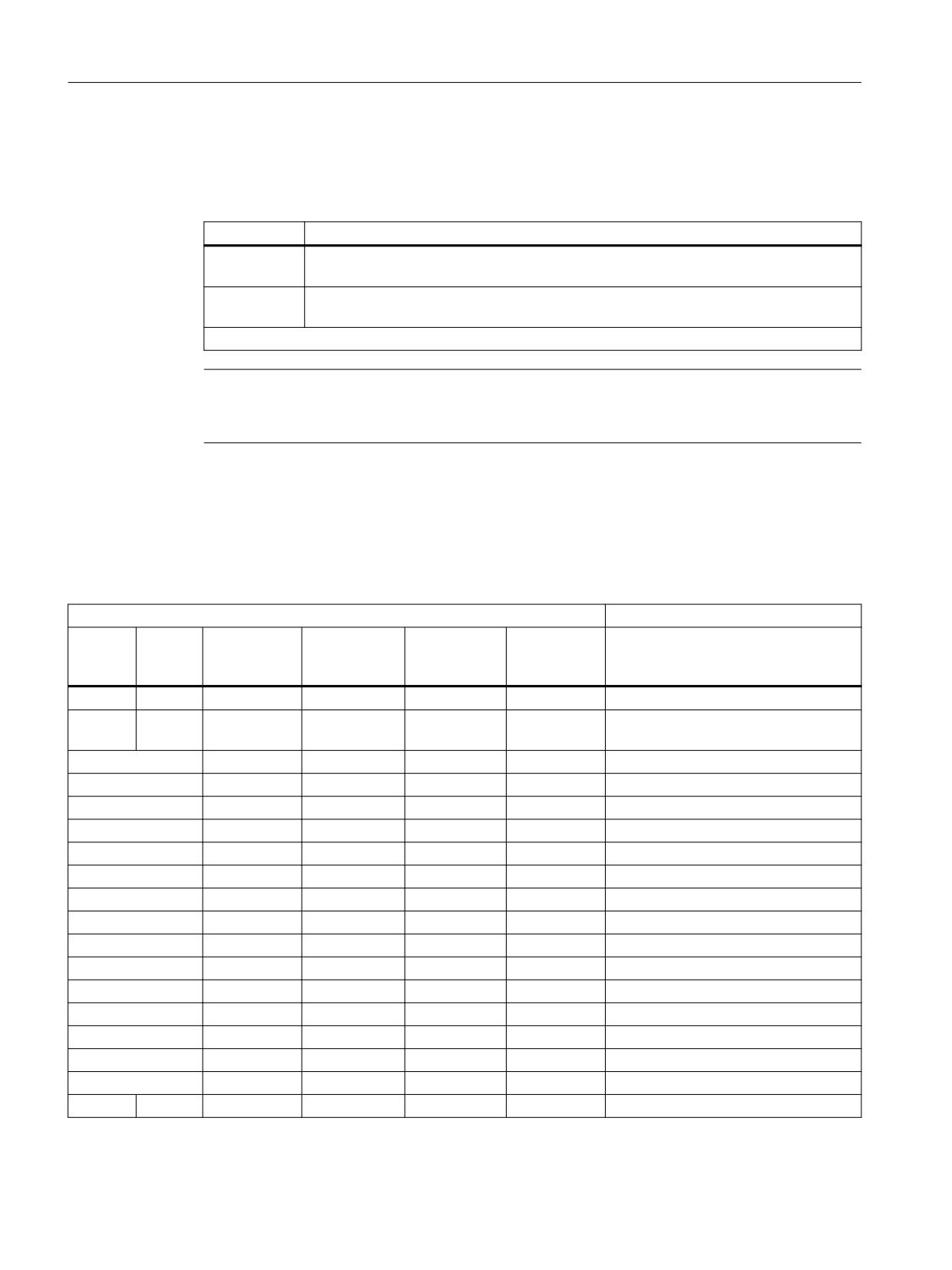
Changing over an SG override
SG override values are changed over subject to the same conditions as those that apply to speed
limit values.
Changeover
Description
From lower to
Instantaneous
higher
From higher
The time parameterized using MD36951/p9551 is started. The axis/spindle must be
to lower
braked within this delay time.
Note: See Chapter "Selecting/deselecting safely reduced speed (Page 138)"
Note
Changing between SGEs "SG override selection, bits 3, 2, 1, 0" continuously and quickly may
initiate a STOP F.
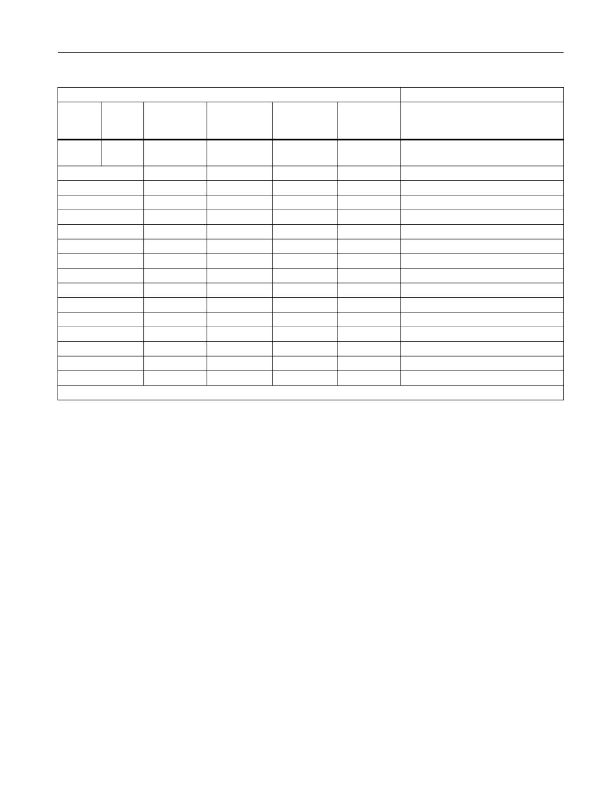
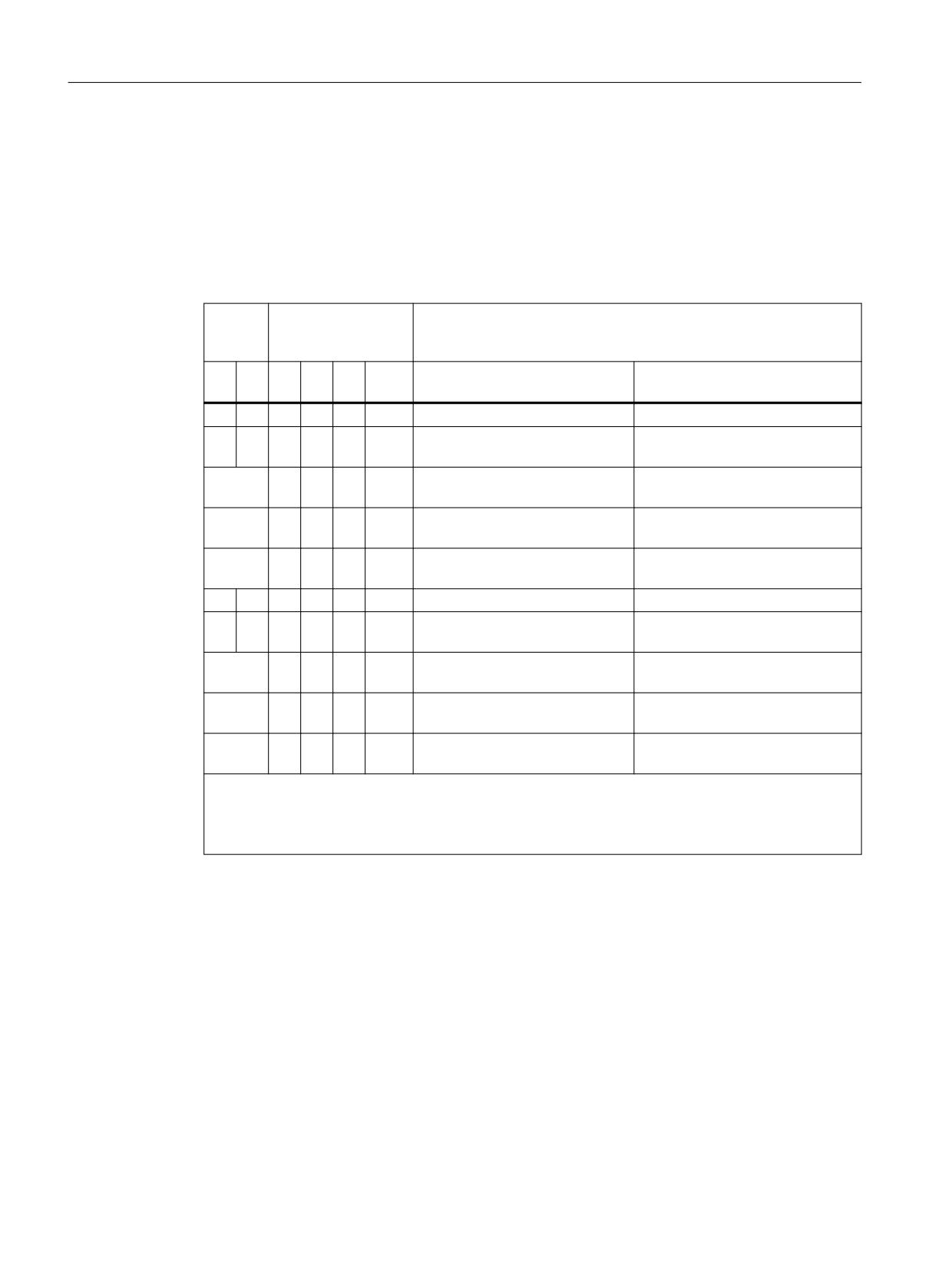
Selecting an SG override
The active speed limit value (SG 1, 2, 3 or 4) is selected using SGEs "SG selection bits 1 and 0".
The desired override is selected by combining SGEs "SG override selection bits 3, 2, 1 and 0". The
override is only effective for the speed limit value for SG2 and SG4.
SGE
SG se-
SG se-
SG override
SG override
SG override
SG override
Meaning
lection,
lection,
selection, bit
selection,
selection, bit
selection, bit
bit 1
bit 0
3
bit 2
1
0
= 0
= 0
x
x
x
x
Speed limit value for SG1 active
= 0
= 1
= 0
= 0
= 0
= 0
Speed limit value for SG2 active with
override stage 0
As above
= 0
= 0
= 0
= 1
... with override stage 1
As above
= 0
= 0
= 1
= 0
... with override stage 2
As above
= 0
= 0
= 1
= 1
... with override stage 3
As above
= 0
= 1
= 0
= 0
... with override stage 4
As above
= 0
= 1
= 0
= 1
... with override stage 5
As above
= 0
= 1
= 1
= 0
... with override stage 6
As above
= 0
= 1
= 1
= 1
... with override stage 7
As above
= 1
= 0
= 0
= 0
... with override stage 8
As above
= 1
= 0
= 0
= 1
... with override stage 9
As above
= 1
= 0
= 1
= 0
... with override stage 10
As above
= 1
= 0
= 1
= 1
... with override stage 11
As above
= 1
= 1
= 0
= 0
... with override stage 12
As above
= 1
= 1
= 0
= 1
... with override stage 13
As above
= 1
= 1
= 1
= 0
... with override stage 14
As above
= 1
= 1
= 1
= 1
... with override stage 15
= 1
= 0
x
x
x
x
Speed limit value for SG3 active
Safety Integrated (system-integrated)
144
Function Manual, 10/2020, 6FC5397-4BP40-6BA2
Safety functions integrated in the system/drive
7.5 Safely reduced speed (SG)
SGE
SG se-
SG se-
SG override
SG override
SG override
SG override
Meaning
lection,
lection,
selection, bit
selection,
selection, bit
selection, bit
bit 1
bit 0
3
bit 2
1
0
= 1
= 1
= 0
= 0
= 0
= 0
Speed limit value for SG4 active with
override stage 0
As above
= 0
= 0
= 0
= 1
... with override stage 1
As above
= 0
= 0
= 1
= 0
... with override stage 2
As above
= 0
= 0
= 1
= 1
... with override stage 3
As above
= 0
= 1
= 0
= 0
... with override stage 4
As above
= 0
= 1
= 0
= 1
... with override stage 5
As above
= 0
= 1
= 1
= 0
... with override stage 6
As above
= 0
= 1
= 1
= 1
... with override stage 7
As above
= 1
= 0
= 0
= 0
... with override stage 8
As above
= 1
= 0
= 0
= 1
... with override stage 9
As above
= 1
= 0
= 1
= 0
... with override stage 10
As above
= 1
= 0
= 1
= 1
... with override stage 11
As above
= 1
= 1
= 0
= 0
... with override stage 12
As above
= 1
= 1
= 0
= 1
... with override stage 13
As above
= 1
= 1
= 1
= 0
... with override stage 14
As above
= 1
= 1
= 1
= 1
... with override stage 15
x: Signal status is optional since override values are not effective for SG1 and SG3
Configuring NCK-SGE
NCK-SGEs (override selection bits 3, 2, 1, 0) are configured using the following machine data:
for 840D sl:
MD36978 $MA_SAFE_OVR_INPUT[n] (input assignment for override selection)
Defining SG override factors
The following machine data are used to define the SG override factors themselves (percentage
values):
for 840D sl:
MD36932 $MA_SAFE_VELO_OVR_FACTOR[n]
for SINAMICS S120:
p9532[n] SI Motion SLS (SG) override factor (Control Unit)
Safety Integrated (system-integrated)
Function Manual, 10/2020, 6FC5397-4BP40-6BA2
145
Safety functions integrated in the system/drive
7.5 Safely reduced speed (SG)
7.5.5
Example: Override for safely reduced speed
Task
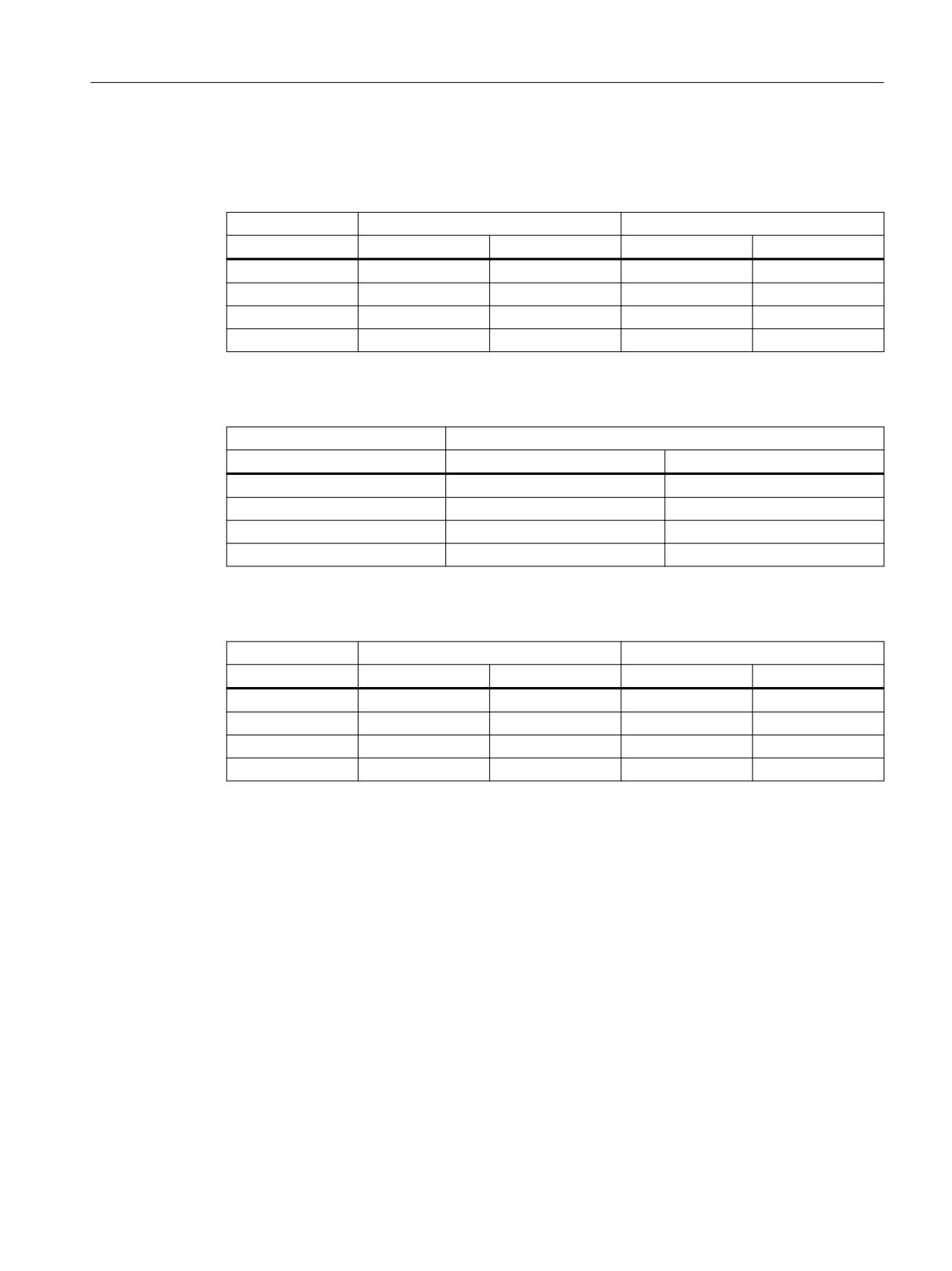
When safely reduced speeds are selected, the speed limit values must be set as follows.
Table 7-7
Application example of how override is used for safely reduced speed
SGE SG
SGE override selec-
Effective speed limit value
selec-
tion
tion
Bit
Bit
Bit
Bit
Bit
Bit 0
Assumptions for the example
1
0
3
2
1
0
0
x
x
x
x
Limit value 1
1000 mm/min
0
1
0
0
0
0
Limit value 2 with override stage
100% = 2000 mm/min
0
As
0
0
0
1
Limit value 2 with override stage
80% = 1600 mm/min
above
1
As
0
0
1
0
Limit value 2 with override stage
50% = 1000 mm/min
above
2
As
0
0
1
1
Limit value 2 with override stage
30% = 600 mm/min
above
3
1
0
x
x
x
x
Limit value 3
4000 mm/min
1
1
0
0
0
0
Limit value 4 with override stage
100% = 5000 mm/min
0
As
0
0
0
1
Limit value 4 with override stage
80% = 4000 mm/min
above
1
As
0
0
1
0
Limit value 4 with override stage
50% = 2500 mm/min
above
2
As
0
0
1
1
Limit value 4 with override stage
30% = 1500 mm/min
above
3
Note:
x: Signal status is optional since override values are not effective for SG1 and SG3
SGEs "SG override selection bit 3 and bit 2" are not required to select an SG override - i.e. they do not need
to be configured (they are internally set to "0").
Assumptions for the example
Defining the SGEs in the NCK monitoring channel
I/O number for signal SG selection, bit 1:
→ OUTSI[13]
I/O number for signal SG selection, bit 0:
→ OUTSI[14]
I/O number for signal override, bit 1:
→ OUTSI[17]
I/O number for signal override, bit 0:
→ OUTSI[18]
Safety Integrated (system-integrated)
146
Function Manual, 10/2020, 6FC5397-4BP40-6BA2
Safety functions integrated in the system/drive
7.6 Safe speed range detection "n<nx"
Defining machine data
Table 7-8
Supplying the machine data for the velocity limit values
For 840D sl
For SINAMICS S120
Limit value
MD number
Value
Parameter No.
Value
SG1
36931[0]
1000
p9531[0]
1000
SG2
36931[1]
2000
p9531[1]
2000
SG3
36931[2]
4000
p9531[2]
4000
SG4
36931[3]
5000
p9531[3]
5000
Table 7-9
Supplying the machine data for the SGE
Signal
Assignment
SGE
MD number
Value
SG selection bit 1
36972[1]
0401010D
SG selection bit 0
36972[0]
0401010E
SG override selection bit 1
36978[1]
04010111
SG override selection bit 0
36978[0]
04010112
Table 7-10
Supplying the machine data for the override factors
Override
For 840D sl
For SINAMICS S120
MD No.
Value
Parameter No.
Value
0
36932[0]
100
p9532[0]
100
1
36932[1]
80
p9532[1]
80
2
36932[2]
50
p9532[2]
50
3
36932[3]
30
p9532[3]
30
7.6
Safe speed range detection "n<nx"
The safe speed range detection function "n<nx" (SGA "n<nx") is used to safely detect the speed
range of a drive. The speed range detection is evaluated on a user-for-user basis, e.g. in so much
that a protective door can only be re-enabled if a spindle that is coasting down has fallen below
a certain speed.
The status signal "n<nx" is generated through two channels. For this purpose, each monitoring
channel compares the actual velocity with a velocity limit that can be adjusted via machine data
(MD36946 $MA_SAFE_VELO_X) - and resulting from this, the SGA "n<nx" is set or deleted.
The result of this monitoring function is exchanged between the NCK and drive monitoring
channels and compared crosswise. In order that brief dynamic deviations of the actual velocity
between the monitoring channels does not result in an error being initiated in the crosswise data
comparison, a tolerance band is defined in which the crosswise data comparison does not
immediately result in the above mentioned alarm. Alarm 27001 or 27106 is only output and the
appropriate stop response initiated when the velocity deviation between the two monitoring
Safety Integrated (system-integrated)
Function Manual, 10/2020, 6FC5397-4BP40-6BA2
147
Safety functions integrated in the system/drive
7.6 Safe speed range detection "n<nx"
channels is so large that this tolerance is exceeded (this corresponds to the behavior for the
crosswise monitoring of the results to compare the actual position with the output cam
positions).
The machine data $MA_SAFE_VELO_X is subject to a crosswise data comparison.
The function can be deactivated by writing the value of 0.0 to MD $MA_SAFE_VELO_X.
7.6.1
Basic function "n<nx"
If a value greater than 0.0 is parameterized in machine data $MA_SAFE_VELO_X, then safe
speed range detection "n<nx" is generally enabled.
An extension of the basic functionality "n< nx" is possible by setting bit 16 in MD36901
$MA_SAFE_FUNCTION_ENABLE “Synchronization, filtering and hysteresis “n<nx".
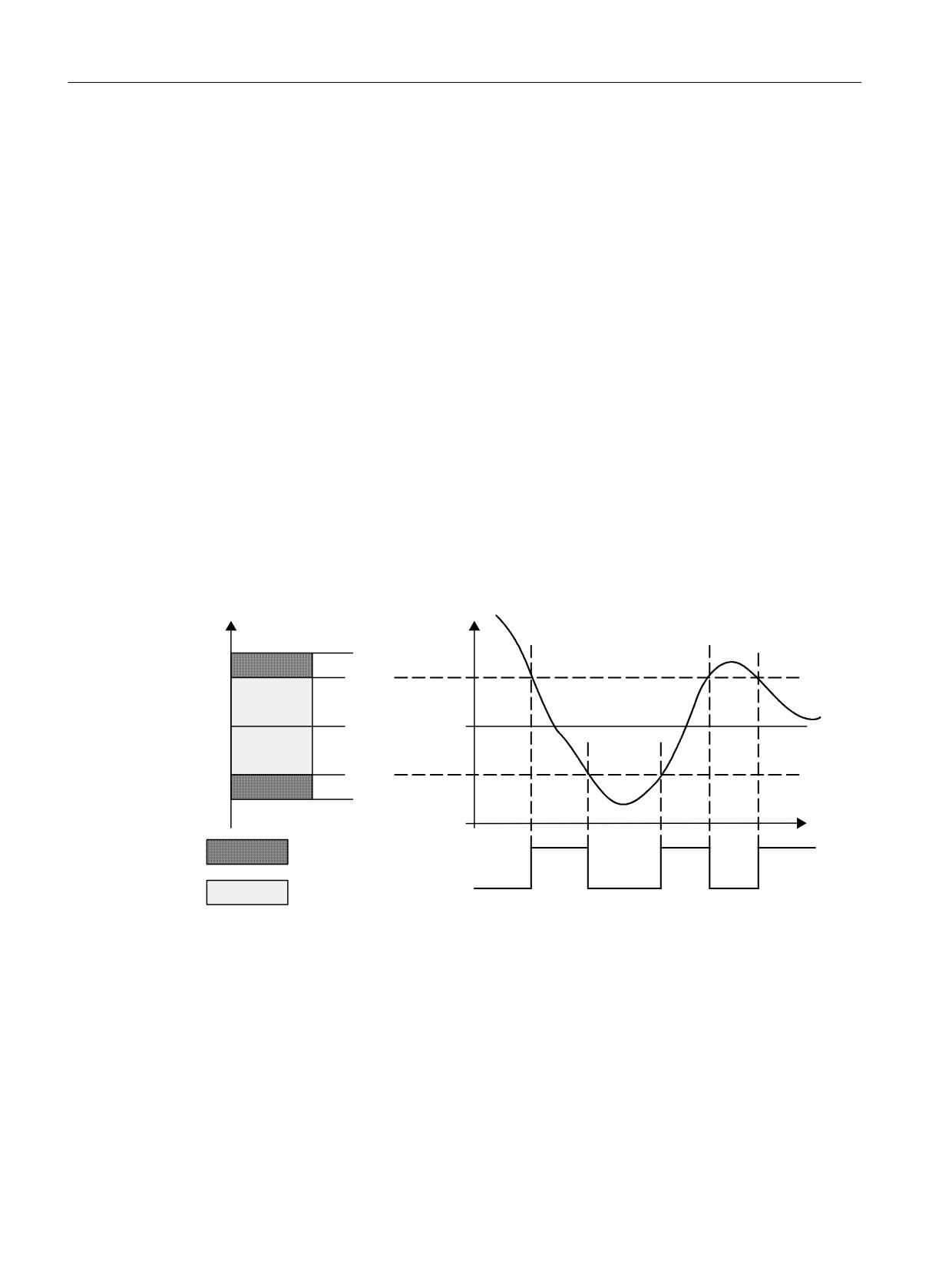
For the basic function "n<nx", the speed is monitored in the following way:
If the absolute actual velocity exceeds the limit value set in machine data $MA_SAFE_VELO_X,
then the SGA "n<nx" is deleted. If the absolute actual velocity drops below the set limit value,
then SGA "n<nx" is set again.
MD36942 $MA_SAFE_POS_TOL is used as tolerance for the crosswise comparison. Alarm 27001
or 27106 is only output and the appropriate stop response initiated when the velocity deviation
between the two monitoring channels is so large that this tolerance is exceeded.
Q
Q
Q SRV7RO[
Q[
Q[
Q
SRV7RO
[
W
7ROHUDQFH UDQJH
$FWXDO VSHHG I &'&
6*$ Q Q[
6*$ Q Q[
Figure 7-15
n<nx value range
Defining nx
The speed limit nx is defined using the following MD / following parameters:
for 840D sl:
MD36946 $MA_SAFE_VELO_X
For SINAMICS S120:
p9546 SI Motion SSM (SGA n < nx) speed limit (CU)
Safety Integrated (system-integrated)
148
Function Manual, 10/2020, 6FC5397-4BP40-6BA2

Safety functions integrated in the system/drive
7.6 Safe speed range detection "n<nx"
Response time and error responses
Typical response time for n<nx:
1 interpolation clock cycle + 2 monitoring clock cycles
Maximum response times: 1 position controller clock cycle + 5.5 monitoring clock cycles + 2
interpolation clock cycles + 3 PLC cycles
WARNING
n<nx as safety function
A STOP F (displayed using Alarms 27001, 27101 and onwards or F01711) only results in a
subsequent STOP B/A response, if at least one of the safety-related functions SBH, SG, SE, SN
or n<nx synchronization is active or selected. If only function "n<nx" is active, then a STOP F does
not result in a subsequent STOP B/A response.
This means that if "n<nx" is used as a safety function, then at least one of the SBH, SG, SE or SN
functions must be active or selected (e.g. by selecting a high SG level).
Note
If the axis/spindle runs at a speed nx, then as a result of actual differences in the two monitoring
channels, the SGA "n<nx" can have a different state.
This must be taken into account in the safe processing of the SGA.
7.6.2
Function "Synchronization, hysteresis and filtering n<nx"
As a result of actual value differences (2-encoder system) in the two monitoring channels, static
or dynamic differences can occur at the SGA "n<nx", which makes it very difficult to externally
further process the signals. This is the reason that the "n<nx" signals of the two monitoring
channels associated with the NCK and the drive are synchronized before further processing.
In addition, a hysteresis is implemented to prevent the SGA "n<nx" from continually switching as
a result of slight speed fluctuations around the threshold "nx". For actual value fluctuations, for
example caused by mechanical vibration at the machine, SGA "n<nx" is kept stable by filtering the
speed actual value.
In order to be able to use the "Synchronization, hysteresis and filtering" function, bit 16 must be
set in machine data $MA_SAFE_FUNCTION_ENABLE. The specified three functions can only be
enabled together. Further, the speed monitoring function n<nx must always be activated by a
value greater than 0.0
For 840 D sl:
MD36946 $MA_SAFE_VELO_X
For SINAMICS S120:
p9546 SI Motion SSM (SGA n < nx) speed limit (CU)
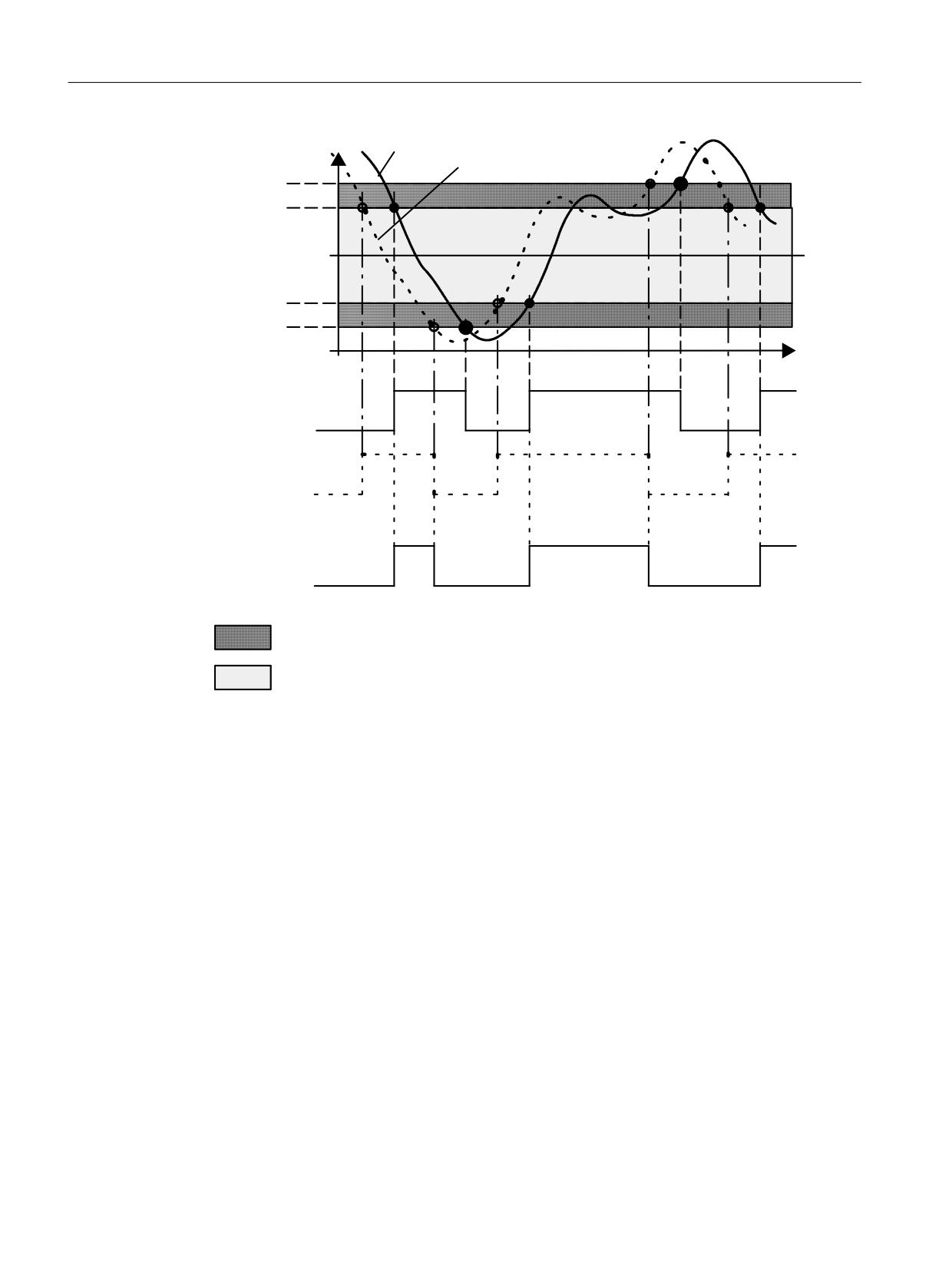
The following diagram shows possible different speed characteristics in the NCK and drive, and
the effect of synchronization and hysteresis on the SGA "n<nx".
Safety Integrated (system-integrated)
Function Manual, 10/2020, 6FC5397-4BP40-6BA2
149
Safety functions integrated in the system/drive
7.6 Safe speed range detection "n<nx"
6SHHG FKDUDFWHULVWLF 1&.
Q
6SHHG FKDUDFWHULVWLF GULYH
Q[
[ 7RO
Q
Q
[ 7RO
Q[
W
6*$ Q Q[
1&.
ZLWK K\VWHUHVLV
6*$ Q Q[ 'ULYH
ZLWK K\VWHUHVLV
6*$ Q Q[
ZLWK K\VWHUHVLV
V\QFKURQL]HG
7ROHUDQFH UDQJH 6*$ Q Q[ OHYHO GHSHQGV RQ WKH 6*$ LQ WKH ODVW PRQLWRULQJ F\FOH
6*$ Q Q[
Figure 7-16
n<nx value range with synchronization and hysteresis
CDC tolerance
As tolerance in the crosswise data comparison for the extended nx functionality, machine data
$MA_SAFE_POS_TOL is not used, but instead
for 840D sl:
MD36947 $MA_SAFE_VELO_X_HYSTERESIS
for SINAMICS S120:
p9547 SI Motion SSM (SGA n<nx) velocity hysteresis (CU)
This MD defines the maximum permissible velocity tolerance between the two monitoring
channels, and during ramp-up, a plausibility check is made to the speed limit set in
$MA_SAFE_VELO_X. In this case, the following must apply:
$MA_SAFE_VELO_X_HYSTERESIS ≤ 3/4 $MA_SAFE_VELO_X,
otherwise, Alarm 27033 "Axis %1 parameterization of MD $MA_SAFE_VELO_X_HYSTERESIS
invalid, error code %4" is issued. A crosswise data comparison error is only detected when the
velocity deviation between the two monitoring channels is greater than the tolerance in
$MA_SAFE_VELO_X_HYSTERESIS; Alarm 27001 or 27106 is then output and the corresponding
stop response is started.
The machine data $MA_SAFE_VELO_X_HYSTERESIS is subject to a crosswise data comparison.
Safety Integrated (system-integrated)
150
Function Manual, 10/2020, 6FC5397-4BP40-6BA2
Safety functions integrated in the system/drive
7.6 Safe speed range detection "n<nx"
Hysteresis
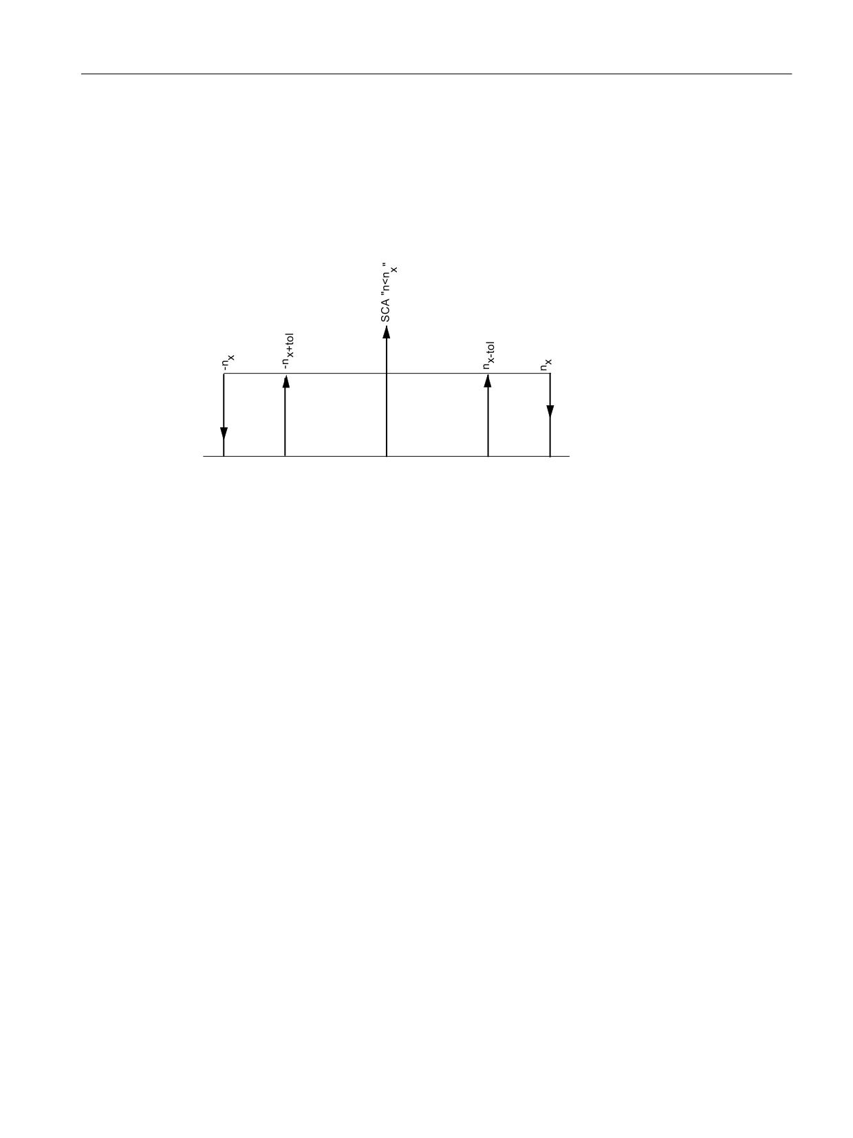
Similarly, the new MD36947 $MA_SAFE_VELO_X_HYSTERESIS is used to determine the
magnitude of the hysteresis. As a result of the hysteresis, the switching point of the SGA "n<nx"
changes as a function of the speed. As a consequence, the SGA "n<nx" no longer precisely
switches at the speed limit "nx", but instead, either at the nx threshold or at the nx threshold
tolerance depending on the SGA stage in the last monitoring cycle.
7RO
0$B6$)(B9(/2B;B+<67(5(6,6
Figure 7-17
Hysteresis SGA "n<nx"
The SGA "n<nx" can therefore never have the value 1 at a speed greater than "nx"!
Filtering
Filtering is realized using a PT1 filter with the filter time from
for 840D sl:
MD36945 $MA_SAFE_VELO_X_FILTER_TIME
for SINAMICS S120:
p9545 SI Motion SSM (SGA n < nx) filter time (Control Unit)
and is also performed in the two monitoring channels, NCK and drive.
If filtering is not necessary due to low system vibration levels or is impractical, it can be
deactivated by setting MD $MA_SAFE_VELO_X_FILTER_TIME to the value 0.
MD $MA_SAFE_VELO_X_FILTER_TIME and the smoothed actual velocity value with the
tolerance from MD $MA_SAFE_VELO_X_HYSTERESIS are subject to crosswise data comparison.
Safety Integrated (system-integrated)
Function Manual, 10/2020, 6FC5397-4BP40-6BA2
151

Safety functions integrated in the system/drive
7.6 Safe speed range detection "n<nx"
The smoothed, safe actual value of the NCK is also available in the servo trace.
Note
By parameterizing a filter time not equal to 0, the reaction time of the SGA "n<nx" increases
according to the behavior of a PT1 filter.
The maximum time delay of the SGA "n<nx" for a linear velocity increase/decrease corresponds
to the filter time parameterized in MD36945.
Example:
Filter time = 20 ms ⇒ the parameterized nx limit is reached with a max. delay of 20 ms.
Accordingly, SGA n<nx is also set with a delay.
The maximum time delay of the SGA "n<nx" for a sudden speed increase/decrease corresponds
to 3 times the filter time parameterized in MD36945.
Example:
Filter time = 20 ms ⇒ the parameterized nx limit is reached with a max. delay of 60 ms.
Accordingly, SGA "n<nx" is also set with a delay.
Synchronization
The synchronization of the SGA "n<nx", just like cam synchronization, is not performed between
the NCK and drive due to possible telegram failures (see Chapter "Safe software cams (4 cam
pairs) (Page 158)"), but instead, between the NCK and PLC by AND'ing the SGA "n<nx".
In order to ensure that a monitoring channel does not continuously return a 0 - and hence the
SGA "n<nx" would permanently remain at 0 - SGA "n<nx" is subject to a crosswise data
comparison between the NCK and drive and checked for plausibility.
For the display of the SGA "n<nx" in the service screen and servo trace, the following applies:
The value displayed in the SGA word contains the information from the relevant monitoring
channel including the hysteresis that is applied, but without synchronization.
If the actual value synchronization function in $MA_SAFE_FUNCTION_ENABLE, bit 3 is enabled,
then the velocity tolerance slip with velocity tolerance "n<nx" must be checked for plausibility. If
the velocity tolerance "n<nx" is less than the slip tolerance, then Alarm 27033 "Axis %1
parameterization of MD $MA_SAFE_VELO_X_HYSTERESIS invalid, error code %4" is issued.
WARNING
"n<nx" as safety function
A STOP F (displayed using Alarms 27001, 27101 and onwards or F01711) only results in a
subsequent STOP B/A response, if at least one of the safety-related functions SBH, SG, SE, SN
or synchronization, hysteresis and filtering "n<nx" is active or has been selected. If only function
"n<nx" is active, then a STOP F does not result in a subsequent STOP B/A response.
This means that if "n<nx" is used as a safety function, then at least one of the SBH, SG, SE or SN
functions must be active or selected (e.g. by selecting a high SG level).
Safety Integrated (system-integrated)
152
Function Manual, 10/2020, 6FC5397-4BP40-6BA2

Safety functions integrated in the system/drive
7.7 Safe software limit switches (SE)
7.7
Safe software limit switches (SE)
Note
The function "safe software limit switches" (SE) is also known as "safe limit positions".
Description
The "safe software limit switches" function (SE) can be used to implement protective functions
for operating personnel and machinery or working zone/protection zone delimination on an
axis-for-axis basis. For example, this function can replace hardware limit switches.
Two "safe software limit switches" (SE1 and SE2) are available for each axis. If the SE function is
active, software limit switch position pair SE1 or SE2 can be selected as a function of SGE "SE
selection".
Defining the upper and lower limit values
The position limit values for the software limit switch position pairs 1 and 2 are defined in the
following machine data:
for 840D sl:
MD36934 $MA_SAFE_POS_LIMIT_PLUS[n]
MD36935 $MA_SAFE_POS_LIMIT_MINUS[n]
for SINAMICS S120:
p9534[n] SI Motion SLP (SE) upper limit values (Control Unit)
p9535[n] SI Motion SLP (SE) lower limit values (Control Unit)
Note
The upper and lower position limit values must be selected so that when the axis is traversing
in this direction, the software limit switches - that are used as standard - are first reached.
Functional features
The most important functional features include:
• Software limit switches are safely defined and evaluated as a software function
• Configurable stop response when software limit switches are passed
• The stop response is implemented internally in the software (and is therefore faster than a
hardware limit switch response) when software limit switches are passed (i.e. actuated)
Safety Integrated (system-integrated)
Function Manual, 10/2020, 6FC5397-4BP40-6BA2
153

Safety functions integrated in the system/drive
7.7 Safe software limit switches (SE)
Preconditions
The following prerequisites must be fulfilled for the "safe software limit switches" function:
• The "safe software limit switches" function must be enabled
• The axis/axes must have been safely referenced (user agreement)
• SGE "SE selection" must be supplied (configured) in both channels
WARNING
Effectiveness of safe software limit switches
"Safe software limit switches" are only effective if the user agreement has been given.
During the time in which the measuring system of the machine axis is switched off, it is not
permissible that the axis is mechanically moved. Otherwise this results in an offset between the
last buffered actual position and the real actual position of the machine axis. This would lead
to an incorrect synchronization of the measuring system resulting in danger to personnel and
the machine.
If axis motion cannot be prevented mechanically in the shutdown state, either an absolute
encoder must be used or the axis must be referenced again with reference point approach after
switching on.
7.7.1
Effects when an SE responds
WARNING
Monitoring software limit switches
The SE function does not predictively monitor the SW (software) limit switches. This means that
the axis stops after passing the limit position. The distance traveled after the SE is dependent
on:
• How the function was parameterized (monitoring clock cycle, stop response, ...)
• The actual speed
• The design of the axis
Configurable stop responses
When a "safe software limit switch" is passed, then a stop response, which can be configured
using the following machine data, is generated:
for 840D sl:
MD3696: $MA_SAFE_POS_STOP_MODE
for SINAMICS S120:
p9562 SI Motion SLP (SE) stop response (Control Unit)
The user can select either STOP C, D or STOP E.
Safety Integrated (system-integrated)
154
Function Manual, 10/2020, 6FC5397-4BP40-6BA2
Safety functions integrated in the system/drive
7.7 Safe software limit switches (SE)
Effect
• The configured stop response is initiated
• The relevant alarm is displayed
Acknowledging and retracting
1. Withdraw the user agreement (SE is no longer active) or changeover to another SE.
2. Acknowledge the stop and alarm response.
3. Bring the axis into a range in which the monitoring no longer responds.
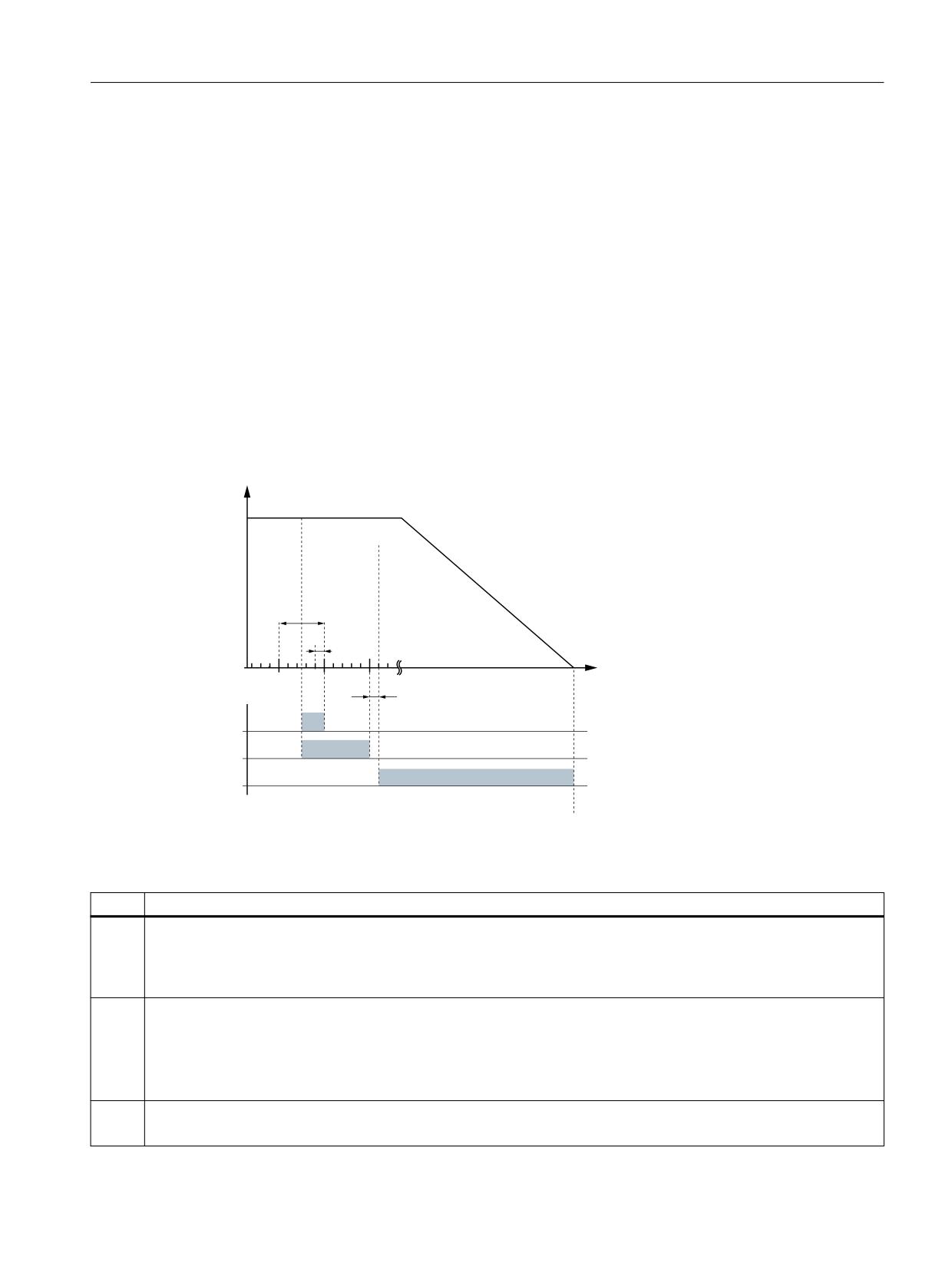
Timing when the safe software limit switches are actuated
If the "safe software limit switches" function is active, the system timing is as follows when the
software limit switches are actuated (passed):
Q
D 7KH HQG SRVLWLRQ LV SDVVHG
Q
DF
W
W
W
W
W
QRW WR VFDOH
W
W
W
Figure 7-18
Timing when a software limit switch is actuated
Table 7-11
Explanation of the diagram
Time
Explanation
t1
The position control clock cycle, defined by the following MDs:
for 840D sl:
MD10050 $MN_SYSCLOCK_CYCLE_TIME
MD10060 $MN_POSCTRL_SYSCLOCK_TIME_RATIO
t2
Monitoring clock cycle, defined by the following MD:
for 840D sl:
MD10090: $MN_SAFETY_SYSCLOCK_TIME_RATIO
For SINAMICS S120:
p9500 SI Motion monitoring clock cycle (Control Unit)
t3
Delay until the configured stop response is output
(typical 0.5 monitoring clock cycles, maximum 1 monitoring clock cycle + 1 position controller clock cycle)
Safety Integrated (system-integrated)
Function Manual, 10/2020, 6FC5397-4BP40-6BA2
155

Safety functions integrated in the system/drive
7.8 Safety software cams and safety cam track (SN)
Time
Explanation
t4
Time until the configured stop response becomes effective
(typical 1.5 monitoring clock cycles, maximum 2 monitoring clock cycles + 1 position controller clock cycle)
t5
Time until the stop response that was initiated actually starts
STOP C: typical 2 position controller clock cycles, maximum 2 position controller clock cycles
STOP D/E: typical 2 interpolation clock cycles, maximum 2 interpolation clock cycles + 2 monitoring clock cycles
t6
Time required to bring the axis to a standstill.
This time and thus the residual distance traveled by the axis is determined by the axis design (motor, mass, friction, ...)
and the configured stop response (STOP C is faster than STOP D).
Note:
Each axis must be measured during commissioning (start-up) to determine the distance that it travels between the limit switch
being violated and it coming to a standstill.
7.8
Safety software cams and safety cam track (SN)
Description
The "safe software cams" function (SN) can be used to implement safe electronic cams, safe
range detection or working zone/protection zone delimination for specific axes, thereby
replacing a hardware solution.
WARNING
Safe referencing
The enabled cam signals are immediately output when the control system is powered-up, this
output is however only safe after safe referencing (this is signaled using the SGA "Axis safely
referenced").
The cams are only considered to be safe if the axis was safely referenced. This is the reason that
the user must interlock this SGA with the cam SGA.
During the time in which the measuring system of the machine axis is switched off, it is not
permissible that the axis is mechanically moved. Otherwise this results in an offset between the
last buffered actual position and the real actual position of the machine axis. This would lead
to an incorrect synchronization of the measuring system resulting in danger to personnel and
the machine.
If axis motion cannot be prevented mechanically in the shutdown state, either an absolute
encoder must be used or the axis must be referenced again with reference point approach after
switching on.
Functional features
The most important functional features include:
• Cam positions are safely defined and evaluated as a software function
• Working ranges/zones are defined
Safety Integrated (system-integrated)
156
Function Manual, 10/2020, 6FC5397-4BP40-6BA2

Safety functions integrated in the system/drive
7.8 Safety software cams and safety cam track (SN)
Tolerance for SN
Owing to variations in the clock cycle and signal run times (signal propagation times), the cam
signals of the two monitoring channels do not switch simultaneously and not precisely at the
same position. A tolerance bandwidth can therefore be specified for all cams using the following
machine data/parameters. Within this bandwidth, the signal states for the same cam may be
different in the two monitoring channels.
For 840D sl:
MD36940 $MA_SAFE_CAM_TOL
for SINAMICS S120:
p9540 SI Motion SCA (SN) tolerance (Control Unit)
Note
The lowest possible tolerance bandwidth (less than 5-10 mm) should be selected for the "safe
software cams" function. It makes sense to parameterize the cam tolerance greater than or equal
to the actual value tolerance.
Effect when SN responds
WARNING
Safe referencing
When defining cam positions, please note that the function only monitors the actual position
thus making (predictive) sensing of cam signals impossible.
The cams are only considered as being safe if they were safely referenced. This is the reason
that the user must interlock this SGA in the SPL with the cam SGAs.
Response times
Response times without cam synchronization
typical 1 interpolation clock cycle + 1.5 monitoring clock cycles
maximum 1 position controller clock cycle + 4 monitoring clock cycles + 2 interpolation clock
cycles + 3 PLC cycles
Response times with cam synchronization
typical 1 interpolation clock cycle + 2.5 monitoring clock cycles
maximum 1 position controller clock cycle + 5 monitoring clock cycles + 2 interpolation clock
cycles + 3 PLC cycles
Safety Integrated (system-integrated)
Function Manual, 10/2020, 6FC5397-4BP40-6BA2
157
Safety functions integrated in the system/drive
7.8 Safety software cams and safety cam track (SN)
7.8.1
Safe software cams (4 cam pairs)
Note
For more than four cam pairs, then the "Safe Cam Track" function must be used (see Chapter
"Safe Cam Track (Page 161)").
Description
There are 4 pairs of cams (SN1, SN2, SN3, SN4) available for each axis. Each cam pair consists
of a plus cam (SN1+, SN2+, SN3+, SN4+) and a minus cam (SN1-, SN2-, SN3-, SN4-). Each cam
signal can be individually enabled and configured via machine data. The cam signals are output
via SGAs.
Preconditions
The following prerequisites must be fulfilled for the "safe software cams" function:
• The axis/axes must have been safely referenced (user agreement)
• The Safe Cams must be configured:
The required cams are enabled using machine data
For 840D sl:
MD36901 $MA_SAFE_FUNCTION_ENABLE, bits 8...15 and parameters
For SINAMICS S120:
p9501 SI Motion enable safety functions, bits 8...15
SGA assignment is defined using machine data
For 840D sl:
MD36988 $MA_SAFE_CAM_PLUS_OUTPUT[n] and
MD36989 $MA_SAFE_CAM_MINUS_OUTPUT[n]
Defining the cam positions
The cam positions are defined in the following machine data/parameters:
For 840D sl:
MD36936 $MA_SAFE_CAM_POS_PLUS[0...3]
MD36937 $MA_SAFE_CAM_POS_MINUS[0...3]
For SINAMICS S120:
p9536[n] SI Motion SCA (SN) plus cam position (Control Unit)
p9537[n] SI Motion SCA (SN) minus cam position (Control Unit)
Special case for SN
If the axis is positioned precisely at the parameterized cam position, the cam signals may have
different states owing to system-related variations in the actual values between the two
monitoring channels. This must be taken into account when safely processing the cam signals,
e.g. by filtering the different signal states by means of a logic circuit (see "Synchronizing cam
signals").
Safety Integrated (system-integrated)
158
Function Manual, 10/2020, 6FC5397-4BP40-6BA2
Safety functions integrated in the system/drive
7.8 Safety software cams and safety cam track (SN)
Synchronizing cam signals
As a result of system-related actual value differences, the cam signals of the monitoring channels
can have different states. In order to prevent this, the cam synchronization can be activated. This
AND's the results of both channels.
The cam SGAs at the input position of the SPL are synchronized if the user has parameterized this
using the function enable.
Cam signal synchronization is enabled using the following machine data / parameters:
for 840D sl:
MD36901 $MA_SAFE_FUNCTION_ENABLE, bit 7
for SINAMICS S120:
p9501 SI Motion enable safe functions (Control Unit), bit 7
The cam SGAs including the hysteresis, but without synchronization are displayed in the service
screen and servo trace.
Hysteresis of the two cam SGAs
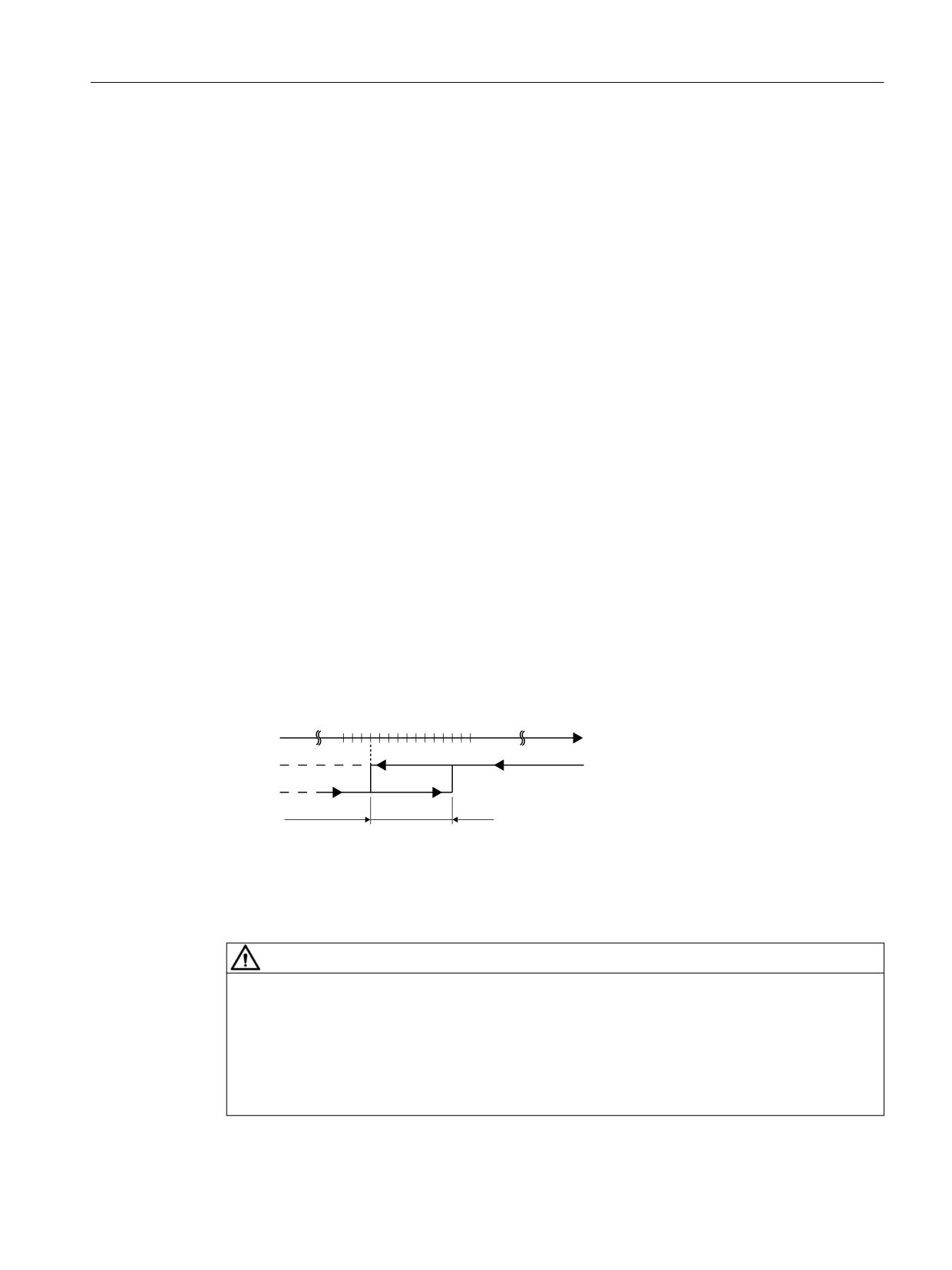
When cam synchronization is activated, cam signals are output with a hysteresis that takes into
account the approach direction (see Fig. , "Hysteresis of the cam SGAs"). This helps to prevent
the SGAs from "flickering" if the axis is positioned exactly on the cam.
The magnitude of the hysteresis is determined by the following data:
for 840D sl:
MD36940 $MA_SAFE_CAM_TOL (tolerance for safety software cams)
for SINAMICS S120:
p9540 SI Motion SCA (SN) tolerance (Control Unit)
&DP SRVLWLRQ
V
6*$
6*$
7ROHUDQFH IRU
VDIH FDPV
Figure 7-19
Hysteresis of the cam SGAs
If the cam is incorrectly/inadmissibly parameterized, then this is indicated by Alarm 27033.
WARNING
Configured cam hysteresis
As a result of the cam hysteresis, for increasing actual values, the cam SGAs do not switch at the
configured cam position (SN) but at the position increased by the cam tolerance (hysteresis) (SN
+TOL).
Users must carefully take this into consideration when configuring the cam positions and cam
tolerance.
Safety Integrated (system-integrated)
Function Manual, 10/2020, 6FC5397-4BP40-6BA2
159
Safety functions integrated in the system/drive
7.8 Safety software cams and safety cam track (SN)
Safe software cams for endlessly turning rotary axes
For rotary axes with cams, the modulo range (cam actual value range) can be set using the
following machine data/parameters:
for 840D sl:
MD36902 $MA_SAFE_IS_ROT_AX
for SINAMICS S120:
p9502 SI Motion axis type (Control Unit)
for 840D sl:
MD36905 $MA_SAFE_MODULO_RANGE
for SINAMICS S120:
p9505 SI Motion SCA (SN) modulo value (Control Unit)
The cam actual value range should be selected as wide as the modulo display of the safe actual
value.
For rotary axes, the modulo display of safe actual values is selected and parameterized using the
following machine data:
for 840D sl:
MD30300 $MA_IS_ROT_AX
MD30320 $MA_DISPLAY_IS_MODULO
MD30330 $MA_MODULO_RANGE
Limiting the cam positions
When parameterizing the cam positions, the following conditions close to the modulo limits
must be maintained.
When cam synchronization is not active:
•
- Mod_Pos + Pos_Tol < SN_Pos < Mod_Pos - Pos_Tol
When cam synchronization is active:
•
- Mod_Pos + Pos_Tol + Cam_Tol < SN_Pos < Mod_Pos - Pos_Tol - Cam_Tol
Meanings:
Pos_Tol: Actual value tolerance
MD36942 $MA_SAFE_POS_TOL for 840D sl
p9542 SI Motion actual value comparison tolerance (crosswise) (Control Unit) for SINAMICS
S120
Cam_Tol: Cam tolerance
MD36940 $MA_SAFE_CAM_TOL for 840D sl
p9540 SI Motion SCA (SN) tolerance (Control Unit) for SINAMICS S120
Mod_Pos: lower/upper modulo value:
MD36905 $MA_SAFE_MODULO_RANGE for 840D sl
p9505 SI Motion SCA (SN) modulo value (Control Unit) for SINAMICS S120
SN_Pos: Cam position:
Safety Integrated (system-integrated)
160
Function Manual, 10/2020, 6FC5397-4BP40-6BA2
Safety functions integrated in the system/drive
7.8 Safety software cams and safety cam track (SN)
MD36936 $MA_SAFE_CAM_POS_PLUS[n] for 840D sl
p9536 SI Motion SCA (SN) plus cam position (Control Unit) for SINAMICS S120
MD36937 $MA_SAFE_CAM_POS_MINUS[n] for 840D sl
p9537 SI Motion SCA (SN) minus cam position (Control Unit) for SINAMICS S120
When booting, the parameterization (parameter assignments) are checked in each monitoring
channel. In the case of parameterization errors (a condition is not fulfilled), Alarm 27033 or
F01687 is output after the control has been booted.
7.8.2
Safe Cam Track
Description
The "Safe Cam Track" function is used as an alternative to Safe Cams (refer to Chapter "Safe
software cams (4 cam pairs) (Page 158)"). The user has 4 cam tracks at his disposal. Up to 15
cams can be evaluated on a cam track. A total of 30 cams are available. The information as to
which cam of a cam track is presently active is saved in the SGA "cam range" (4 bits for each cam
track) and can together with the SGA "cam track" be evaluated in the safe programmable logic
(SPL).
Further, the cams are available as SGA "Safe Cam range bits".
Preconditions
The following prerequisites apply to the "Safe Cam Track" function:
• The axis/axes must have been safely referenced (user agreement)
• Either the "Safe Cams" function or the "Safe Cam Track" function may only be used
alternatively, i.e. simultaneous enable in the machine data or parameters
MD36903 $MA_SAFE_CAM_ENABLE / p9503 SI Motion SCA (SN) enable (Control Unit) and
MD36901 $MA_SAFE_FUNCTION_ENABLE / p9501 SI Motion enable safety functions
(Control Unit)
is not permissible, and results in Alarm 27033 / C01681 "Invalid parameterization".
Safety Integrated (system-integrated)
Function Manual, 10/2020, 6FC5397-4BP40-6BA2
161
Safety functions integrated in the system/drive
7.8 Safety software cams and safety cam track (SN)
• The modulo function is not supported. If the "Safe Cam Track" function is enabled and a value
> 0 entered in the MD36905 $MA_SAFE_MODULO_RANGE / p9505 SI Motion SCA (SN)
modulo value (Control Unit), then Alarm 27033 "Axis %1 parameterization of the MD
$MA_SAFE_REFP_STATUS_OUTPUT[0] invalid" is output with a reference to
$MA_SAFE_MODULO_RANGE.
• The Safe Cams must be configured:
The required cams are enabled using machine data
For 840D sl:
MD36903 $MA_SAFE_CAM_ENABLE, bits 0...29 and parameters
For SINAMICS S120:
p9503 SI Motion SCA (SN) enable (Control Unit), bits 0...29
SGA assignment is defined using machine data
For 840D sl:
MD36988 $MA_SAFE_CAM_PLUS_OUTPUT[n] and
MD36989 $MA_SAFE_CAM_MINUS_OUTPUT[n]
Defining the cam positions
The cam positions are defined in the following machine data/parameters:
For 840D sl:
MD36936 $MA_SAFE_CAM_POS_PLUS[0...29]
MD36937 $MA_SAFE_CAM_POS_MINUS[0...29]
For SINAMICS S120:
p9536[0...29] SI Motion SCA (SN) plus cam position (Control Unit)
p9537[0...29] SI Motion SCA (SN) plus cam position (Control Unit)
Note
The minus position of cam x must be less than the plus position of cam x, otherwise Alarm 27033
"Invalid parameterization" is output. For an incorrect parameterization, also message F01686 "SI
Motion: Cam position parameterization not permissible" of the drive is also output.
Assignment, cam to cam track
The cams defined in $MA_SAFE_CAM_POS_PLUS[0...29] and
$MA_SAFE_CAM_POS_MINUS[0...29] are assigned to a cam track as follows:
for 840D sl:
MD36938 $MA_SAFE_CAM_TRACK_ASSIGN[0...29]
for SINAMICS S120:
p9538[0...29] SI Motion cam track assignment (Control Unit)
Value range:
100...114 = cam range 0...14 at cam track 1
200...214 = cam range 0...14 at cam track 2
300...314 = cam range 0...14 at cam track 3
400...414 = cam range 0...14 at cam track 4
Safety Integrated (system-integrated)
162
Function Manual, 10/2020, 6FC5397-4BP40-6BA2
Safety functions integrated in the system/drive
7.8 Safety software cams and safety cam track (SN)
The "hundreds" position defines which cam track is assigned to the cams.
The "tens" and "ones" positions contain the numerical value that is signaled to the SPL as SGA
"cam range".
Please note:
• It is not possible to assign a cam a multiple number of times to several tracks. A multiple
assignment only functions if an additional cam is parameterized with the same cam position
and assigned to another cam track.
• Cam positions can be freely assigned to a cam range.
• Cams that have not been assigned do not appear on the cam track.
• It is not permissible that the cams on a cam track overlap.
• The cams on a cam track must have a certain minimum distance between them.
• The cams on a cam track must have a certain minimum length.
Evaluation of the parameterization
For the evaluation, the following checks are made (for the NCK and drive):
• If $MA_SAFE_CAM_ENABLE > 0, then $MA_SAFE_FUNCTION_ENABLE, bit 8-15 must be = 0.
• If $MA_SAFE_CAM_ENABLE > 0, then it is not permissible that the enable bit for cam
synchronization is set ($MA_SAFE_FUNCTION_ENABLE, bit 7 = 0)
• Modulo cams are not permissible ($MA_SAFE_MODULO_RANGE must be 0 if
$MA_SAFE_CAM_ENABLE > 0).
• Checking the CAM length: $MA_SAFE_CAM_POS_PLUS[0...29] -
$MA_SAFE_CAM_POS_MINUS[0...29] ≥ $MA_SAFE_CAM_TOL + $MA_SAFE_POS_TOL
• Checking the distance between 2 cams on a cam track $MA_SAFE_CAM_POS_MINUS[y] -
$MA_SAFE_CAM_POS_PLUS[x
≥ $MA_SAFE_CAM_TOL + $MA_SAFE_POS_TOL
• It is not permissible to parameterize two cams on the same track and range:
Example:
$MA_SAFE_CAM_TRACK_ASSIGN[2] = 205;
$MA_SAFE_CAM_TRACK_ASSIGN[5] = 205;
As a consequence, it is not possible to assign more than 15 cams to a cam track.
• If a cam is enabled in $MA_SAFE_CAM_ENABLE, then it must also be assigned.
If a violation is determined when making these checks, then alarm 27033 "Parameterization
invalid" / F01686 "SI Motion: Cam position parameterization not permissible" is output.
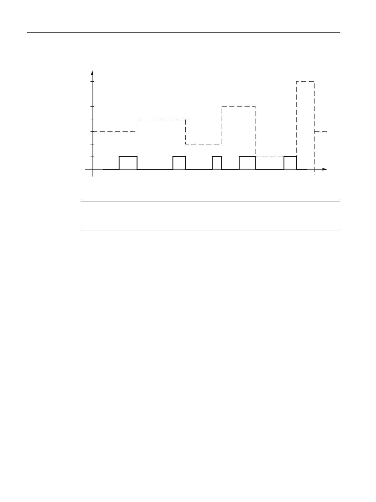
The generation of the new cam SGA is shown in the following diagram:
Safety Integrated (system-integrated)
Function Manual, 10/2020, 6FC5397-4BP40-6BA2
163
Safety functions integrated in the system/drive
7.8 Safety software cams and safety cam track (SN)
Parameterization example for SGA "cam track" and "cam range"
6*$ FDP WUDFN
6*$ FDP UDQJH
6*$ FDP UDQJH IRU
FDP WUDFN
6*$ FDP WUDFN
61
61
61
61
61
61
61
61
61
61
3RVLWLRQ
Figure 7-20
SGA "cam track" and "cam range"
Note
The traversing range for rotary axes must lie within ± 2048 revolutions. This corresponds to the
value range of the safety-related actual value.
Parameterization example for the diagram:
Enabling the cams SN1, SN2, SN3, SN6, SN8:
$MA_SAFE_CAM_ENABLE = 0xA7 (0000 0000 0000 0000 0000 0000 1010 0111);
Parameterizing the cam positions for the cams that have been enabled:
• SN1
$MA_SAFE_CAM_POS_PLUS[0] = 480
$MA_SAFE_CAM_POS_MINUS[0] = 455
• SN2
$MA_SAFE_CAM_POS_PLUS[1] = 120
$MA_SAFE_CAM_POS_MINUS[1] = 80
• SN3
$MA_SAFE_CAM_POS_PLUS[2] = 320
$MA_SAFE_CAM_POS_MINUS[2] = 300
• SN6
$MA_SAFE_CAM_POS_PLUS[5] = 200
$MA_SAFE_CAM_POS_MINUS[5] = 170
• SN8
$MA_SAFE_CAM_POS_PLUS[7] = 380
$MA_SAFE_CAM_POS_MINUS[7] = 350
Safety Integrated (system-integrated)
164
Function Manual, 10/2020, 6FC5397-4BP40-6BA2
Safety functions integrated in the system/drive
7.8 Safety software cams and safety cam track (SN)
Parameterizing the cam range assignment (all cams that have been enabled are assigned to cam
track 2)
• $MA_SAFE_CAM_TRACK_ASSIGN[0] = 201
(cam SN1 is assigned cam range 1)
• $MA_SAFE_CAM_TRACK_ASSIGN[1] = 203
(cam SN2 is assigned cam range 3)
• $MA_SAFE_CAM_TRACK_ASSIGN[2] = 202
(cam SN3 is assigned cam range 2)
• $MA_SAFE_CAM_TRACK_ASSIGN[5] = 204
(cam SN6 is assigned cam range 4)
• $MA_SAFE_CAM_TRACK_ASSIGN[7] = 205
(cam SN8 is assigned cam range 5)
Response of the SGA
The SGA "cam track" is the OR logic operation of all individual cams on a cam track. If an axis is
at a cam on a cam track, then the SGA of this cam track is set to 1. Together with the SGA "cam
range", information is available as to which cam is presently active.
The SGA "cam range" starts at the lower end of the traversing range with the range of the 1st cam
- assigned in $MA_SAFE_CAM_TRACK_ASSIGN[n] - on this cam track, i.e. in this case "3". At the
upper end after the last cam on this cam track, the range SGA is set to "15". The transition of the
range to the next value is realized when moving in the positive direction always at the falling
edge of an individual cam.
The enable machine data as well as all cam limit values and range assignments are compared
crosswise between the NCK and drive.
The user can use the following to connect to the SPL interface ($A_INSI / $A_OUTSI)
• SGA "cam track", MD37900
$MA_SAFE_CAM_TRACK_OUTPUT[0...3] and for the
• SGA "cam range", MD37901-37904:
$MA_SAFE_CAM_RANGE_OUTPUT_1/2/3/4[0...3] and for the
• SGA "cam range bits", machine data 37906-37909
$MA_SAFE_CAM_RANGE_BIN_OUTPUT_1/2/3/4[0...14].
Safety Integrated (system-integrated)
Function Manual, 10/2020, 6FC5397-4BP40-6BA2
165
Safety functions integrated in the system/drive
7.8 Safety software cams and safety cam track (SN)
The specified machine data follow the generally valid rules when assigning the safety-related
inputs/outputs.
WARNING
Cam range as supplementary information for the cam track
In the case of a fault, SGAs can assume a value of "0" (e.g. as a result of the cam synchronization
between monitoring channels, loss of the safety-related referencing etc.). The user must take
this into account so that when the SGAs are processed further, in a fault condition, no unsafe
(hazardous) machine states can occur (that means, for example, a protective door is only
enabled for a value of "1").
Further, the SGAs "cam range" may only be evaluated as supplementary information to SGA
"cam track". It is not permissible to evaluate the SGA "cam range" alone without evaluating the
SGA "cam track".
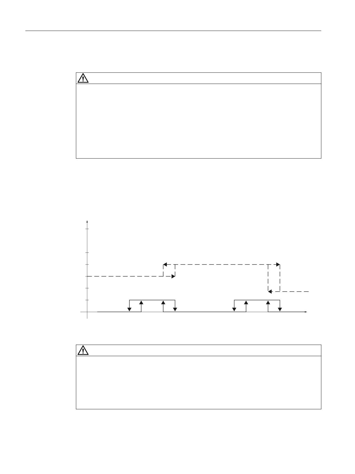
Hysteresis of cam SGAs
The hysteresis is applied both to the SGA "cam track" as well as to SGA "cam range" to prevent
signal flutter. This means the SGAs are therefore generated as follows in the two monitoring
channels, NCK and drive:
6*$ FDP WUDFN
6*$ FDP UDQJH
6*$ FDP UDQJH
6*$ FDP WUDFN
61
61
61
61
61
61
61
61
3RVLWLRQ
WRO
WRO
WRO
WRO
Figure 7-21
SGA "cam track" and "cam range" with hysteresis
WARNING
SN+TOL
As a result of the cam hysteresis, for increasing actual values, the cam SGAs do not switch at the
configured cam position (SN) but at the position increased by the cam tolerance (hysteresis) (SN
+TOL).
Users must carefully take this into consideration when configuring the cam positions and cam
tolerance.
Safety Integrated (system-integrated)
166
Function Manual, 10/2020, 6FC5397-4BP40-6BA2
Safety functions integrated in the system/drive
7.8 Safety software cams and safety cam track (SN)
Synchronization
The synchronization of the cam SGA is carried out between the NCK and PLC. Both the SGA "cam
track" as well as the SGA "cam range" must be synchronized.
The SGA "cam track" is synchronized by AND'ing the two signals from the NCK and drive
monitoring channels. The logic operation is carried out for all 4 cam positions.
The 4-bit SGA "cam range" (value range 0...15) is synchronized according to the following rule:
If the SGA "cam range" as well as the SGA "cam track" is different in both monitoring channels and
the SGA "cam track" of its own channel has a value of "1", then the SGA "cam range" of the other
channel must be used.
Alternative evaluation of the cam signals
In order to simplify the evaluation of cam signals, the cam signals "cam track" and "cam range",
generated from the axis monitoring channels NCK and drive, can be mapped to 15 "cam range
bits" for each cam track (for the cam ranges 0 ... 14).
The "cam range bits" are generated by logically combining the "cam track" and "cam range"
signals in the NCK and in the PLC. If the axis is positioned at a cam, then the cam range bit of the
cam range assigned to this cam is set to 1.
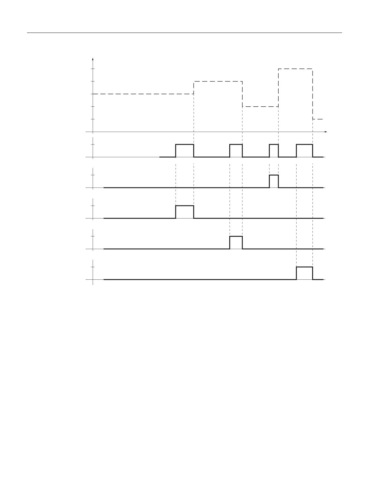
The SGA "cam track", "cam range" and "cam range bit" are shown in the following diagram using
an example:
Safety Integrated (system-integrated)
Function Manual, 10/2020, 6FC5397-4BP40-6BA2
167
Safety functions integrated in the system/drive
7.8 Safety software cams and safety cam track (SN)
6*$ FDP WUDFN
6*$ FDP UDQJH
3RVLWLRQ
6*$ ಯ&DP WUDFN
61
61
61
61
61
61
61
61
6*$ ಯ2XWSXW FDP ELW > @
IRU FDP WUDFN
6*$ ಯ2XWSXW FDP ELW > @
IRU FDP WUDFN
6*$ ಯ2XWSXW FDP ELW > @
IRU FDP WUDFN
6*$ ಯ2XWSXW FDP ELW > @
IRU FDP WUDFN
Figure 7-22
SGA "cam track" and "cam range"
Explanation
• Cam SN2 is assigned to track 2 by parameterizing cam range 3:
($MA_SAFE_CAM_TRACK_ASSIGN[1] = 203). If the axis is at cam SN2, SGA "cam range bit
[3]" (index 3 stands for cam range 3) is set to 1.
• Cam SN6 is assigned to track 2 by parameterizing cam range 4:
($MA_SAFE_CAM_TRACK_ASSIGN[5] = 204). If the axis is at cam SN6, SGA "cam range bit
[4]" (index 4 stands for cam range 4) is set to 1.
• ...
Safety Integrated (system-integrated)
168
Function Manual, 10/2020, 6FC5397-4BP40-6BA2
Connecting sensors and actuators
8
8.1
Safety-related input/output signals
8.1.1
Overview of the SGEs/SGAs and their structure
Description
The safety-related input and output signals (SGEs and SGAs) are the interface of the internal
Safety Integrated functionality to the process.
SGE signals (safety-related input signals) control the active monitoring by deselecting or
selecting the safety functions. This is also realized, depending on the status (switching status)
of sensors.
SGA signals (safety-related output signals) are feedback signals from safety functions. They can
also be used to control actuators in a safety-related fashion.
Safety Integrated (system-integrated)
Function Manual, 10/2020, 6FC5397-4BP40-6BA2
169
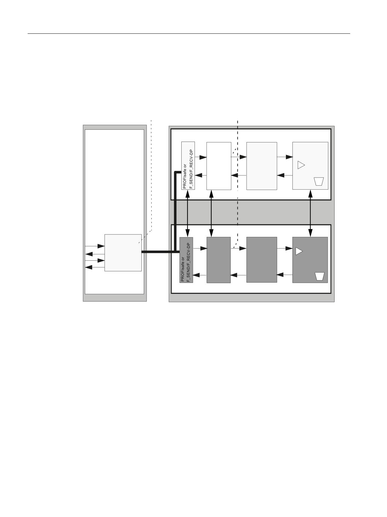
Connecting sensors and actuators
8.1 Safety-related input/output signals
Processing I/O signals for the NC and drive through two channels
A dual-channel structure is available for input/output and for processing safety-related input/
output signals (see the following diagram). All of the requests and feedback signals for safety-
related functions should be entered or retrieved through both monitoring channels (two-
channel structure).
([WHUQDO
,QWHUQDO
6*( 6*$
6*( 6*$
1&. VLJQDO SURFHVVLQJ
,QWHUIDFH
1&.
1&.
&RPSDUDWRU
63/
6*( 6*$
VLJQDOV
'DWD
0DFKLQH
1&. PRQLWRULQJ FKDQQHO
&RPP
63/
$[LV
&'&
&'&
&'&
'ULYH PRQLWRULQJ FKDQQHO
352),VDIH
&RPSDUDWRU
1& 3/&
RU
3/&
LQWHUIDFH
)B6(1''3
%XV
63/
$[LV VSLQGO
)B5(&9'3
H '%
'DWD
3/& VLJQDO SURFHVVLQJ
,QWHUIDFH
3URFHVV
6\VWHP
Figure 8-1
NCK and drive monitoring channel
For the NCK monitoring channel, signals are input/output via the SPL - possibly preprocessed by
the NCK (see Chapter "Multiple distribution and multiple interlocking (Page 181)") and emulated
(mapped) in the NCK-SGE/SGA interface.
The signals from the drive monitoring channel are input/output via the SPL and sent to the drive
via the interface axis/spindle DB.
Internal SGE/SGA (interface to the various axis-specific safety functions) are, e.g. selecting and
deselecting safety functions, changing-over limit values, output of status signals. They are
defined for the particular Safety Integrated Functions.
Sensors - e.g. switches, pushbuttons, protective door contacts, emergency stop buttons, light
curtains, laser scanners - are connected to the external SGE (interface to the process, i.e. to the
machine). Actuators - e.g. load contactors, valves, interlocking solenoids - are connected to the
external SGA. The connection is established through the PROFIsafe I/O, see also Chapter
"Connecting I/O via PROFIsafe (Page 182)" Generally, a brake is directly connected at the Motor
Modules via terminals.
The external and internal SGE/SGA are freely interlocked (logically combined) by the user using
the safe programmable logic (SPL), see also Chapter "Safe programmable logic (Page 253)".
Safety Integrated (system-integrated)
170
Function Manual, 10/2020, 6FC5397-4BP40-6BA2

Connecting sensors and actuators
8.1 Safety-related input/output signals
Crosswise data comparison is implemented between the monitoring channels that operate
independently of one another. If there is inequality, then a STOP F is initiated (CDC between the
drive and NCK).
A STOP D/E is triggered for an SPL-CDC error. SGE/SGA are set into the safe state if an error is
detected by the communication CDC.
Note
As a result of the two-channel structure of Safety Integrated, the machine manufacturer must
supply the SGE and SGA in both the NCK monitoring channel and the drive monitoring channel.
The actual signal state of the SGE/SGA is displayed using the "Service display" menu. Information
regarding Safety Integrated data with the associated axis names and the axis number are
displayed in the "Service SI" window.
For Safety Integrated, SGEs/SGAs are coupled via the PROFIsafe profile using standard PROFIBUS
and PROFINET buses based on standard network components. Internal SGE/SGA signals are
accessed via the SPL (see Chapter "Safe programmable logic (Page 253)").
For instance, the following can be requested or signaled in each monitoring channel and for
each/spindle with safety technology using SGE/SGA signals:
• Safety functions can be selected and deselected
• Limit values can be selected and changed-over
• States relating to safety operation can be fed back
Functional features
• SGE and SGA signals are processed through two channels
• Processed in the NCK monitoring channel
• Processed in the drive monitoring channel
• Safety functions are selected/deselected independent of the NC mode
• Differences in the active SGE/SGA in the monitoring channels are detected in the crosswise
data/result comparison
Access to SGE/SGA signals is explained in Chapter "Connecting I/O via PROFIsafe (Page 182)",
Chapter "Safety-related CPU-CPU communication (F_DP communication) (Page 212)" and in
Chapter "Safe programmable logic (Page 253)".
WARNING
Failsafe state
The state of a deleted SGE/SGA (logical "0") that can be achieved both by the user as well as also
using fault responses of the "SINUMERIK Safety Integrated" system, are defined as failsafe state
of an SGE/SGA. This is the reason that the system is only suitable for applications where this
state corresponds to the failsafe state of the process controlled by "SINUMERIK Safety
Integrated".
Safety Integrated (system-integrated)
Function Manual, 10/2020, 6FC5397-4BP40-6BA2
171
Connecting sensors and actuators
8.1 Safety-related input/output signals
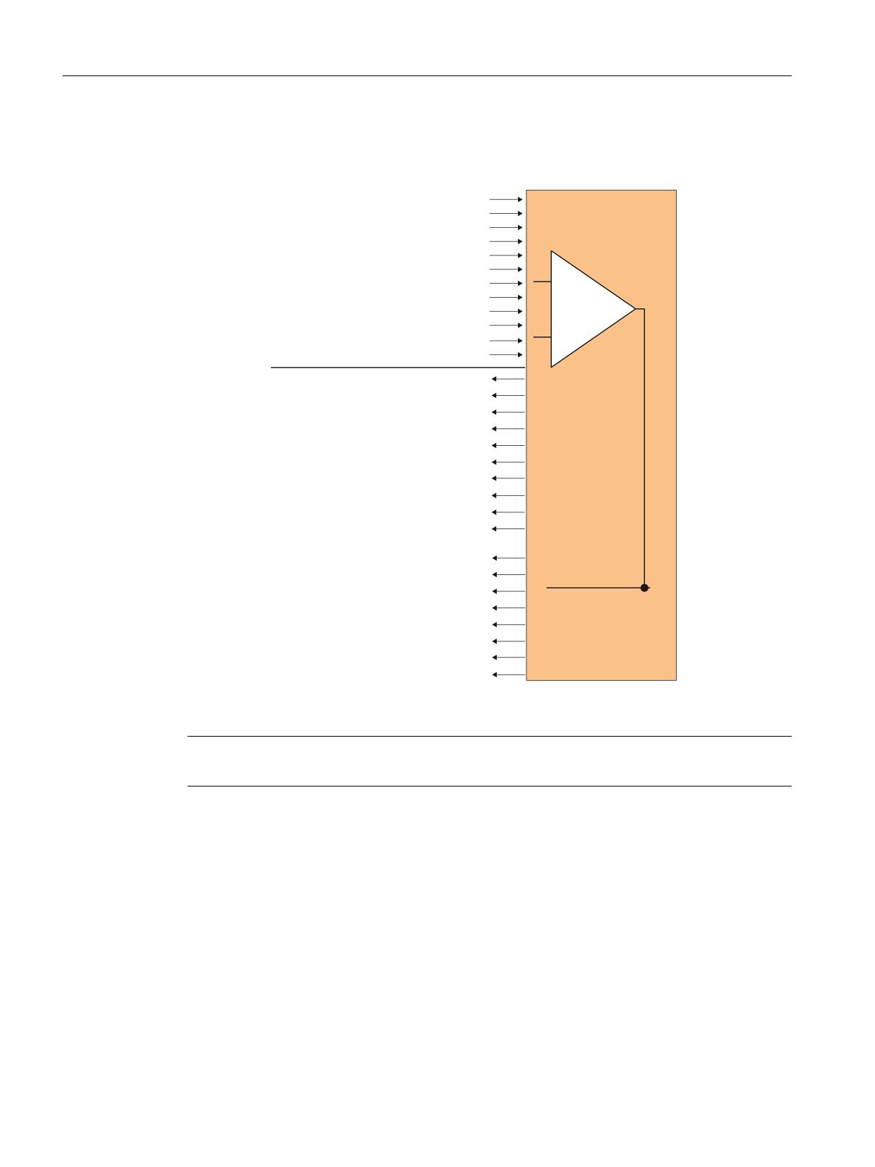
What SGE/SGA are there?
For each axis/spindle, the following SGE and SGA are in each monitoring channel:
6%+ 6* GHVHOHFWLRQ
6%+ GHVHOHFWLRQ
6* VHOHFWLRQ ELW
6( VHOHFWLRQ
5DWLR VHOHFWLRQ ELWV
6*(
7HVW VWRS VHOHFWLRQ GULYH
&ORVH EUDNH GULYH
6* FRUUHFWLRQ VHOHFWLRQ ELWV
6%+ 6*
H[W 6723 $ GHVHOHFWLRQ
6(
H[W 6723 & GHVHOHFWLRQ
61
H[W 6723 ' GHVHOHFWLRQ
H[W 6723 ( GHVHOHFWLRQ
6%+ 6* DFWLYH
$[LV VDIHO\ UHIHUHQFHG
6*$
61
61
61
61
61
61
61
61
6DIH &DP 7UDFNV
6DIH &DP UDQJH IRU FDP WUDFN ELWV
6DIH &DP UDQJH IRU FDP WUDFN ELWV
6DIH &DP UDQJH IRU FDP WUDFN ELWV
6DIH &DP UDQJH IRU FDP WUDFN ELWV
&DP UDQJH ELWV SHU ELW
IRU FDP WUDFNV
Q Q[
6* DFWLYH ELWV
6%+ DFWLYH
6WDWXV SXOVHV FDQFHOOHG GULYH
6723 $ % DFWLYH
6723 & DFWLYH
6723 ' DFWLYH
6723 ( DFWLYH
Figure 8-2
SGE and SGA in every monitoring channel for each axis/spindle
Note
The SGE/SGA signals are described in Chapter "Description of the interface signal (Page 471)".
Safety Integrated (system-integrated)
172
Function Manual, 10/2020, 6FC5397-4BP40-6BA2
Connecting sensors and actuators
8.1 Safety-related input/output signals
NCK-SGE/SGA
The signals are assigned to the NCK-SPL inputs/outputs using machine data.
Note
Only the NCK-SGE are assigned to an NCK-SPL output that are also required for the particular
application. For axes, where for example, the gear ratio does not change, the NCK-SGE "ratio
selection bit 2 to 0" do not have to be assigned to SPL inputs. A value of 0 should be entered into
the associated MD (i.e. the NCK-SGE does not have an SPL assignment and is set to 0). This does
not apply to external STOPs that are not used.
See Chapter "Forced checking procedure of the external STOPs (Page 130)" for information
about SGE/SGA for the test stop for external stops.
PLC-SGE/SGA
For the drive monitoring channel, the NC/PLC interface (axis/spindle DB) represents the SGE/SGA
interface between the PLC and the drive. The PLC user program must supply this interface.
Note
Only the PLC-SGE should be processed in the PLC user program, which are also required for the
particular application. SGE that are not used must be set to the value 0 - i.e. to a defined state.
This does not apply to external STOPs that are not used.
See Chapter "Forced checking procedure of the external STOPs (Page 130)" for information
about SGE/SGA for the test stop for external stops.
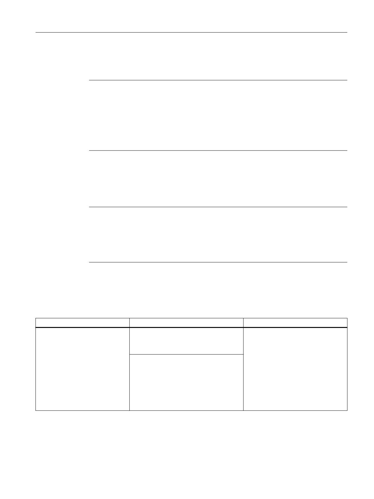
How many SGE/SGA are required as a minimum?
Depending on the particular application, only some of the maximum number of SGE/SGA
available are required.
Function
Minimum SGEs required
Minimum SGAs required
Safe Operating Stop (SBH)
SBH/SG deselection
SBH/SG active
Test stop selection (drive)
Status, pulses cancelled (drive)
External stops
STOP A/B, C, D, E active (only if required)
if gearbox stages are being used
Gear ratio selection, bit 2 (only if it is neces-
sary to select the ratio)
Gear ratio selection, bit 1 (only if it is neces-
sary to select the ratio)
Gear ratio selection, bit 0 (only if it is neces-
sary to select the ratio)
Safety Integrated (system-integrated)
Function Manual, 10/2020, 6FC5397-4BP40-6BA2
173

Connecting sensors and actuators
8.1 Safety-related input/output signals
Function
Minimum SGEs required
Minimum SGAs required
Safely reduced speed (SG)
SBH/SG deselection
SBH/SG active
SBH deselection
Status, pulses cancelled (drive)
SG selection, bit 1 (only for SG changeover)
STOP A/B, C, D, E active (only if required)
SG selection, bit 0 (only for SG changeover)
active SG stage, bits 0, 1 (only if required)
Test stop selection (drive)
External stops
if gearbox stages are being used
Gear ratio selection, bit 2 (only if it is neces-
sary to select the ratio)
Gear ratio selection, bit 1 (only if it is neces-
sary to select the ratio)
Gear ratio selection, bit 0 (only if it is neces-
sary to select the ratio)
Safe software limit switches (SE)
SE selection (only for SE changeover)
SBH/SG active
Axis safely referenced
Test stop selection (drive)
Status, pulses canceled (drive)
SBH/SG deselection (at least for test during
STOP A/B, C, D, E active (only if required)
commissioning [start-up])
External stops
Safe software cams (SN)
Test stop selection (drive)
SBH/SG active
SBH/SG deselection (at least for test during
STOP A/B, C, D, E active (only if required)
commissioning [start-up])
Axis safely referenced
External stops
SN1-, SN2-, ..., SN30 (only where re-
quired)
SN1+, SN2+, ..., SN30+ (only if required)
Status, pulses cancelled (drive)
Different signal run times in the channels
The signal timing in the two monitoring channels varies (the PLC cycle time takes up most of the
available time in the drive monitoring channel). To prevent the crosswise data comparison
function from being immediately activated after a signal change, a tolerance time is defined
using the following machine data.
For 840D sl:
MD36950 $MA_SAFE_MODE_SWITCH_TIME
For SINAMICS S120:
p9550 SI Motion SGE changeover tolerance time (Control Unit)
This data specifies the time period for which different signal states may be tolerated after the
SGEs have been changed-over before an error message is output.
Note
System-related minimum tolerance time:
2 x PLC cycle time (maximum cycle) + 1 x IPO cycle time
Safety Integrated (system-integrated)
174
Function Manual, 10/2020, 6FC5397-4BP40-6BA2
Connecting sensors and actuators
8.1 Safety-related input/output signals
8.1.2
Forced checking procedure of SPL signals
Fundamentals
Safety-related input/output signals including the connecting cables to the I/O (peripherals) and
the sensors and actuators connected to them must always be subject to a forced-checking
procedure (see Chapter "Forced checking procedure (Page 82)").
The scope of the forced checking procedure should be implemented corresponding to the
subsequent conditions.
This means that the selection of a suitable forced checking procedure concept depends on the
specific application and the specific sensor and/or actuator; this decision must be made by the
user. In this scope, the user must configure the forced checking procedure.
SPL signals
The forced checking procedure of SPL signals is a part of the SPL functionality (see Chapter "Safe
programmable logic (Page 253)").
Once the external safety circuit has been wired, a two-channel SPL has been created and the
relevant safety functions configured and checked with an acceptance test, the long-term
reliability of this function, verified using an acceptance test, can be ensured:
• External inputs/outputs
The external inputs/outputs of the SPL ($A_INSE or $A_OUTSE) must be subject to a forced
checking procedure to ensure that faults do not accumulate over a period of time which
would mean that both monitoring channels could fail.
• Internal inputs/outputs
Internal inputs/outputs ($A_INSI, $A_OUTSI), markers ($A_MARKERSI) etc. ($A_TIMERSI) do
not have to be subject to a forced checking procedure.
It will always be possible to detect an error at these locations due to the differing two-channel
responses of the external inputs/outputs or the NCK/drive monitoring channels; crosswise
data comparison is carried out at both ends of the response chain to detect any errors.
Test signals
"3-terminal concept"
• If an input signal ($A_INSE) is, for example, evaluated through two channels, then the
associated test output signal can be implemented using one channel. It is extremely
important that the input signal can be forced/changed and checked in both channels.
• In the same way, the assigned test input signal for two-channel output signals ($A_OUTSE)
can be implemented in one channel if it is connected according to the following rule:
The test input signal may only return an "OK" status ("1" signal level) if both output signals
function (i.e. both monitoring channels have output a "0"). A simultaneous test in both
channels allows the correct functioning in both channels to be checked using one feedback
signal.
Safety Integrated (system-integrated)
Function Manual, 10/2020, 6FC5397-4BP40-6BA2
175
Connecting sensors and actuators
8.1 Safety-related input/output signals
Trigger/test
The timer or event controlled triggering of the forced checking procedure is activated in one
channel by the PLC.
If errors are detected, the PLC user program should respond by initiating an external "STOP D/E"
and switching the external SGAs into a safe state.
Notes to avoid errors
1.
A "2-terminal concept" in which a single-channel user (net) signal is to be subject to a
forced checking procedure using a single-channel test signal is not permitted. In this case,
the two-channel SPL structure would be worthless and crosswise data comparison would
have no effect.
The following are permissible:
- A "full 4-terminal concept for sensors" (two-channel test signal for a two-channel user
(net) signal),
- the "3 terminal concept for sensors/actuators" recommended above
a "2-terminal concept for sensors without test signals", if the two-channel user (net)
signal to be tested automatically changes its level dynamically as a result of the process.
For example, for the input signals of a protective door,
- a "2-terminal concept for sensors without test signals", if the sensor is a safety-related
component, e.g. light curtains,
- a "2-terminal concept for actuators without test signals", if the actuator is a safety-related
component, e.g. safety valves,
- a "2-terminal concept for actuators without test signals" if the feedback signal can be
checked using other user (net) signals. For example, for a valve that indirectly switches a
BERO via the process and this is available for evaluation,
- a "2-terminal concept for actuators without test signals" if the function of the mechanical
system can be checked using other user (net) signals. For example, for a brake that is
checked using a separate brake test.
2.
The signals "external STOPs" are processed internally in a special way:
- In order to increase the level of reliability that a requested "external STOP" actually takes
effect, the STOPs are internally exchanged between the two channels. Failure of the stop
control function in one channel does not cause an error for these signals (in contrast to
the mode changeover signals, e.g. "SG/SBH active") in the crosswise data comparison.
While other signals can be subject to a forced checking procedure in parallel and in both
channels (in order to avoid errors being triggered by the crosswise data comparison), the
"external STOPs" must be subject to a forced checking procedure one after the other in
both channels.
Safety Integrated (system-integrated)
176
Function Manual, 10/2020, 6FC5397-4BP40-6BA2
Connecting sensors and actuators
8.1 Safety-related input/output signals
8.1.3
Connecting sensors - actuators using the 3-terminal concept
Basic principle for safety-related signal processing
With the 3-terminal concept, three terminals (signals) are required to connect a sensor or
actuator. Faults in the sensors and actuators can be detected in conjunction with the SPL-CDC
and forced checking procedure - or the forced checking as a result of the process itself. The
connecting cables are generally monitored autonomously by the failsafe I/O.
The following applies to the safety-related sensor connection
2 safety-related inputs + 1 standard test output.
The following applies to the safety-related actuator connection
2 safety-related outputs + 1 standard test input.
Example of an actuator connection
2 outputs (to control through 2 channels via SGA) and 1 standard test input (for the forced
checking procedure) are required to connect an actuator in a safety-related fashion. The test
input is the feedback signal from the load circuit and is fed from the power supply voltage of a
standard input module. The user should derive this as directly as possible from the process
quantity.
Actuator control, P/M switching:
The actuator is directly controlled using a plus potential (P-switching) and minus potential (M-
switching). If the actuator is not a qualified component (safety component or component where
faults can be excluded), then in the case that the actuator fails, the user must apply additional
cascaded measures in order to bring the process into a safe condition.
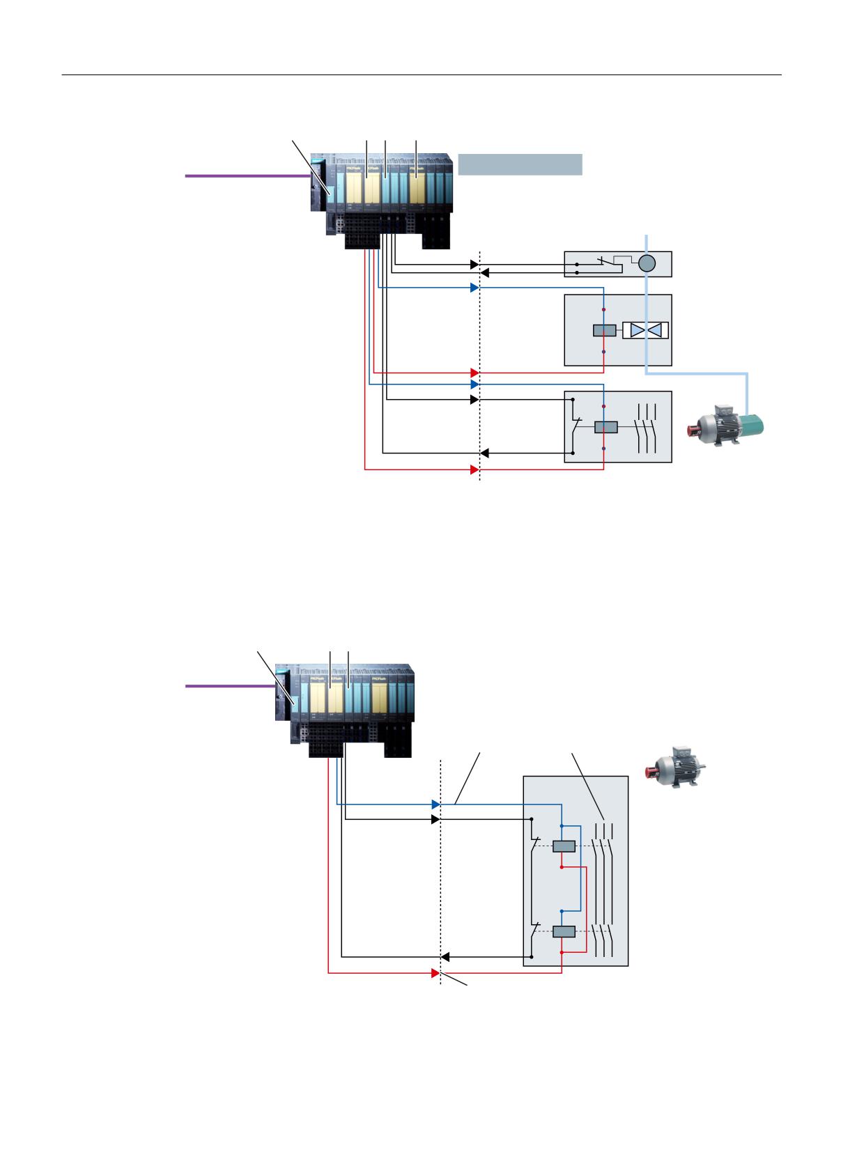
Example:
The process quantity, e.g. hydraulic pressure, is switched using a standard valve that is
controlled in a safety-related fashion. A pressure sensor signals the status of the process
quantity. If the valve can no longer switch due to a fault condition, then using a safely controlled
standard contactor, the motor that is generating the pressure, is shutdown. The advantage of
this particular version is that components can be used that are already available as standard. As
to whether this solution can be used, must be confirmed as a result of the risk assessment (see
the following diagram).
Safety Integrated (system-integrated)
Function Manual, 10/2020, 6FC5397-4BP40-6BA2
177
Connecting sensors and actuators
8.1 Safety-related input/output signals
,0
+LJK
) '2 ',
30 ( )
)HDWXUH
(7
6 352),VDIH
352),%86 ZLWK
352),VDIH
)HHGEDFN VLJQDO
3
3UHVVXUH VHQVRU
:KHQ 2. RQO\ WKH YDOYH LV
VZLWFKHG 7KH SXPS UHPDLQV
6KXWGRZQ
9 ORDG
VZLWFKHG RQ
FKDQQHO
FLUFXLW YDOYH
,Q WKH FDVH RI D IDXOW LI WKH
IHHGEDFN VLJQDO IURP WKH
6KXWGRZQ
9 ORDG
SUHVVXUH VHQVRU LV QRW UHFHLYHG
FKDQQHO
FLUFXLW PRWRU
WKHQ WKH SXPS PRWRU LV DOVR
VZLWFKHG RQ
)HHGEDFN VLJQDO
Figure 8-3
Cascaded shutdown using failsafe outputs
In other cases a second actuator must be connected in series in the load circuit (see the following
diagram).
In conjunction with the safety-related control of a brake, no feedback signal is available. The
brake test will identify as to whether the actuator is correctly functioning from a mechanical
perspective.
,0
+LJK
) '2 ',
)HDWXUH
(7
6 352),VDIH
352),%86 ZLWK
352),VDIH
(OHFWURQLFV RXWSXW
0
9 ORDG
,QGLUHFWO\ SRVLWLRQ
FLUFXLW
PRQLWRULQJ RI WKH ORDG
,QGLUHFW
9
XVLQJ SRVLWLYHO\ GULYHQ
FRQWDFWV
)HHGEDFN VLJQD
O
(OHFWURQLFV RXWSXW
3
Figure 8-4
Actuator connection via failsafe outputs, e.g. 400 V load circuit - P/M-switching
Safety Integrated (system-integrated)
178
Function Manual, 10/2020, 6FC5397-4BP40-6BA2
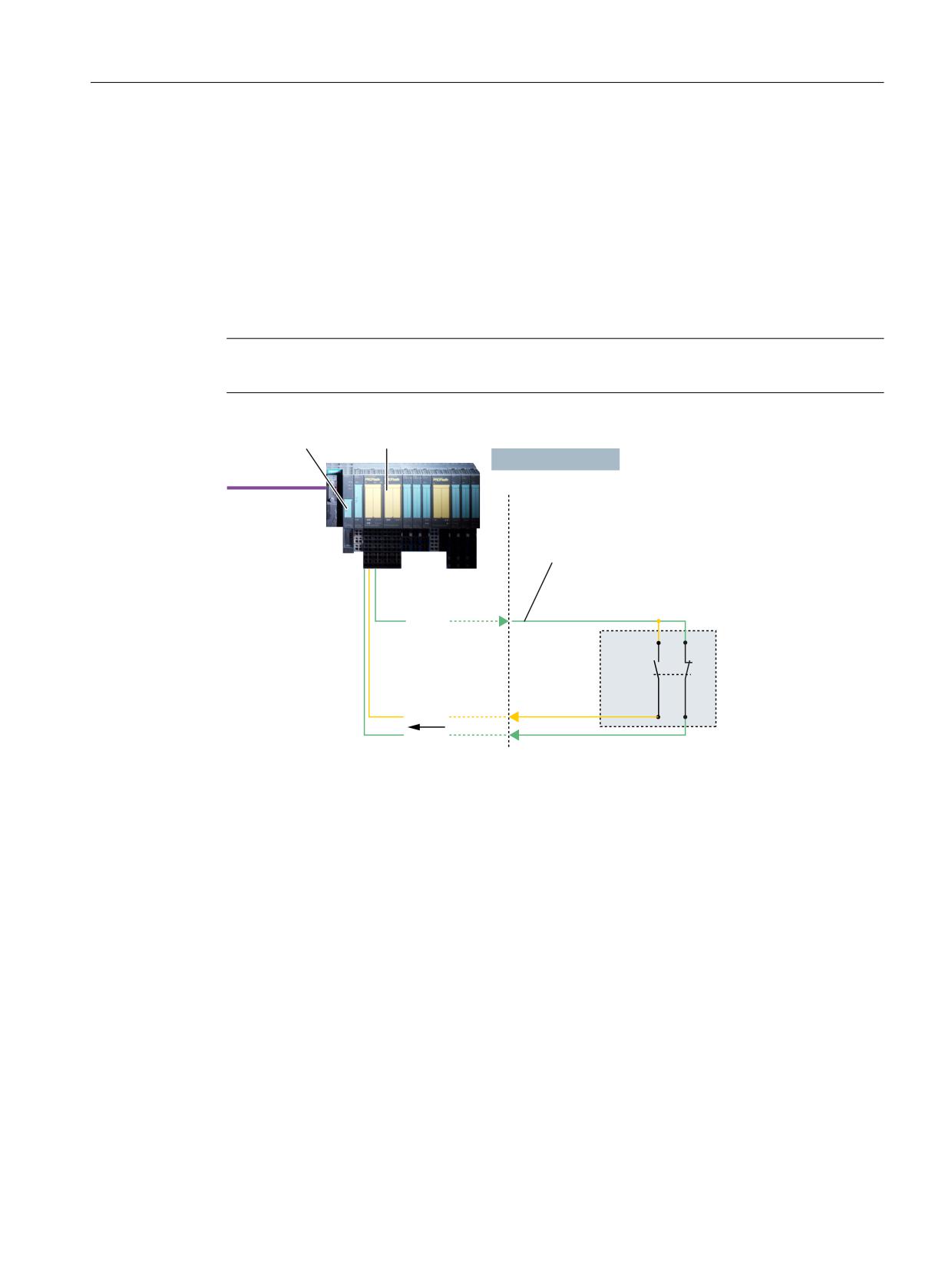
Connecting sensors and actuators
8.1 Safety-related input/output signals
Example of connecting a sensor
2 safety-related inputs (to read-in through 2 channels via SGE) and 1 standard test output (for
the forced checking procedure) are required to connect a sensor in a failsafe fashion. The test
output is fed from the power supply voltage of the safety input module. For sensors with a self-
test routine, the test output on the input module is not required. For the 3-terminal connection
concept we recommend that sensors with non-equivalence contacts are used (NC contact/NO
contact). If both signal cables have a P or M short-circuit - or are both interrupted - then a signal
state is obtained that is not logically permissible. This means, that a cross-circuit fault can be
detected by the non-equivalence concept without having to carry out any test.
Note
Cross-circuit fault detection in the input module is not required.
,0
+LJK
) ',
)HDWXUH
(7
6 352),VDIH
352),%86 ZLWK
352),VDIH
7HVW RXWSXW
96
7R DFWLYDWH DQG
HJ
GH DFWLYDWH
(PHUJHQF\
1RQ HTXLYDOHQFH
6WRS RU XVHU
FRQWDFWV 1& FRQWDFW
DJUHHPHQW
12 FRQWDFW ZLWK WKH
WHUPLQDO FRQFHSW
)HHGEDFN VLJQ
DO
&RPPHQW
,Q WKLV FDVH LW LV QRW SRVVLEOH WR FRQQHFW WKH EXWWRQV LQ
VHULHV
Figure 8-5
Sensor connection using failsafe inputs according to the 3-terminal concept
8.1.4
Sensor connection using the 4-terminal concept
With the 4-terminal concept, four terminals are required at the failsafe input module to connect
a sensor that utilizes a contact (e.g. Emergency Stop pushbutton). Faults/errors in the sensors
and actuators can be detected in conjunction with the SPL-CDC and forced checking procedure
or the forced checking as a result of the process itself. The connecting cables are generally
monitored autonomously by the failsafe input module.
The following applies to the safety-related sensor connection
2 safety-related inputs + 2 standard test outputs.
Safety Integrated (system-integrated)
Function Manual, 10/2020, 6FC5397-4BP40-6BA2
179
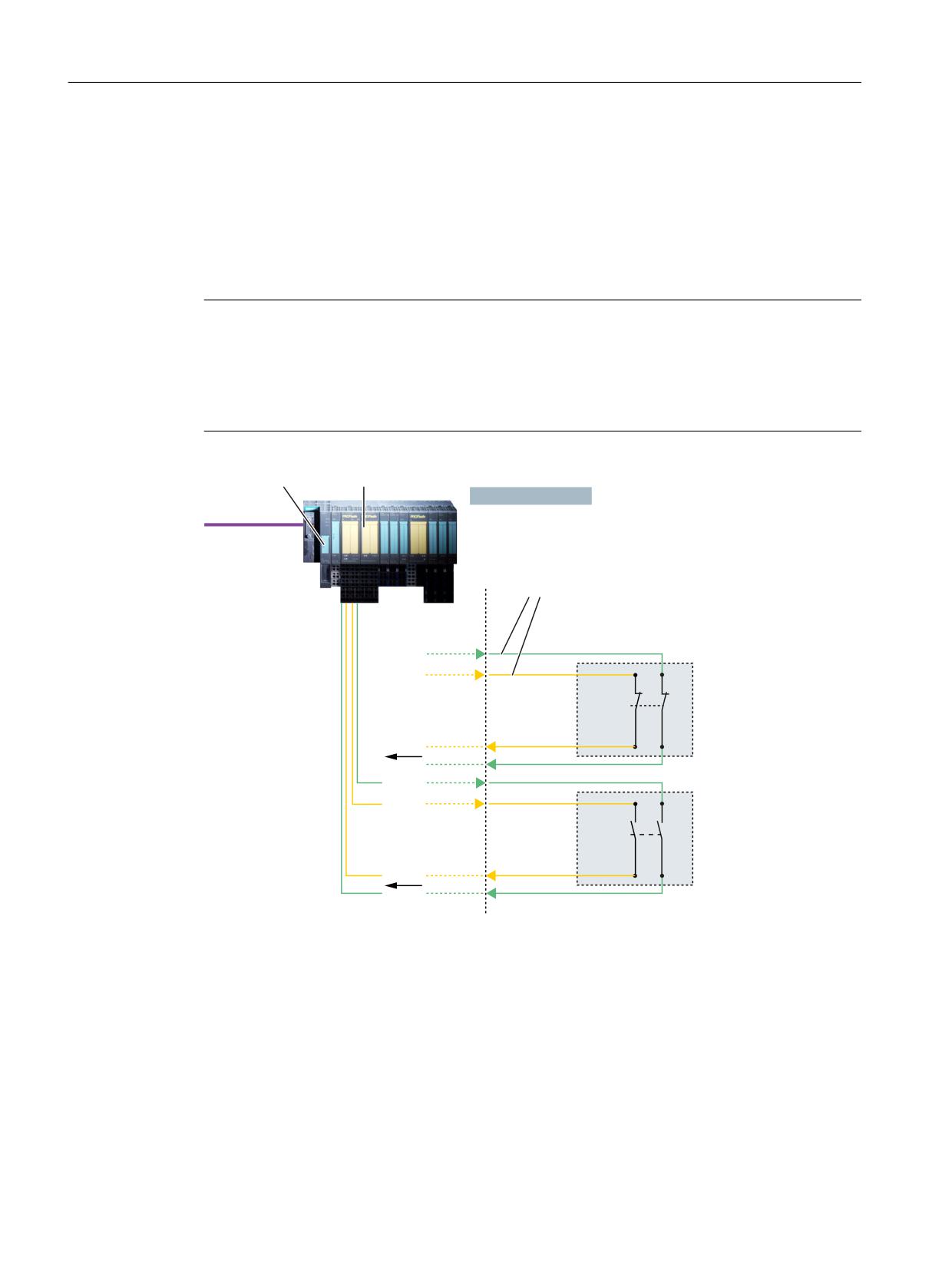
Connecting sensors and actuators
8.1 Safety-related input/output signals
Example
2 inputs (to read-in the 2-channel sensor signals via SGE) and 2 standard test outputs (for the
forced checking procedure) are required for connecting a sensor in a failsafe fashion. The test
outputs are supplied from the two power supply voltages (VS1, VS2) of the safety input module.
For the connection concept with 4 terminals, both equivalence (NC contact/NC contact, NO
contact/NO contact) as well as non-equivalence (NC contact/NO contact) contact versions are
possible.
Note
Cross-circuit fault detection in the input module is not required. Measures against cross-circuit
faults are required only for equivalence contacts (NC contact/NC contact, NO contact/NO
contact) if the cable has been routed so that it is very exposed, e.g. for cables connecting
handheld terminals. This can be mechanically implemented in the cable, e.g. using the
appropriate shielding.
,0
+LJK
) ',
)HDWXUH
(7
6 352),VDIH
352),%86 ZLWK
352),VDIH
7HVW RXWSXWV
96
96
'XDO FLUFXLW FORVH
(TXLYDOHQFH FRQWDFWV
FLUFXLW SULQFLSOH
H J (PHUJHQF\
1& FRQWDFW 1&
6WRS
FRQWDFW ZLWK WKH
GHDFWLYDWLRQ
WHUPLQDO FRQFHSW
96
96
(TXLYDOHQFH FRQWDFWV
'XDO RSHQ FRQGXFWRU
12 FRQWDFW 12
HJ
ORRSV
$JUHHPHQW
FRQWDFW ZLWK WKH
DFWLYDWLRQ
WHUPLQDO FRQFHSW
Figure 8-6
Sensor connection using the 4-terminal concept
Safety Integrated (system-integrated)
180
Function Manual, 10/2020, 6FC5397-4BP40-6BA2
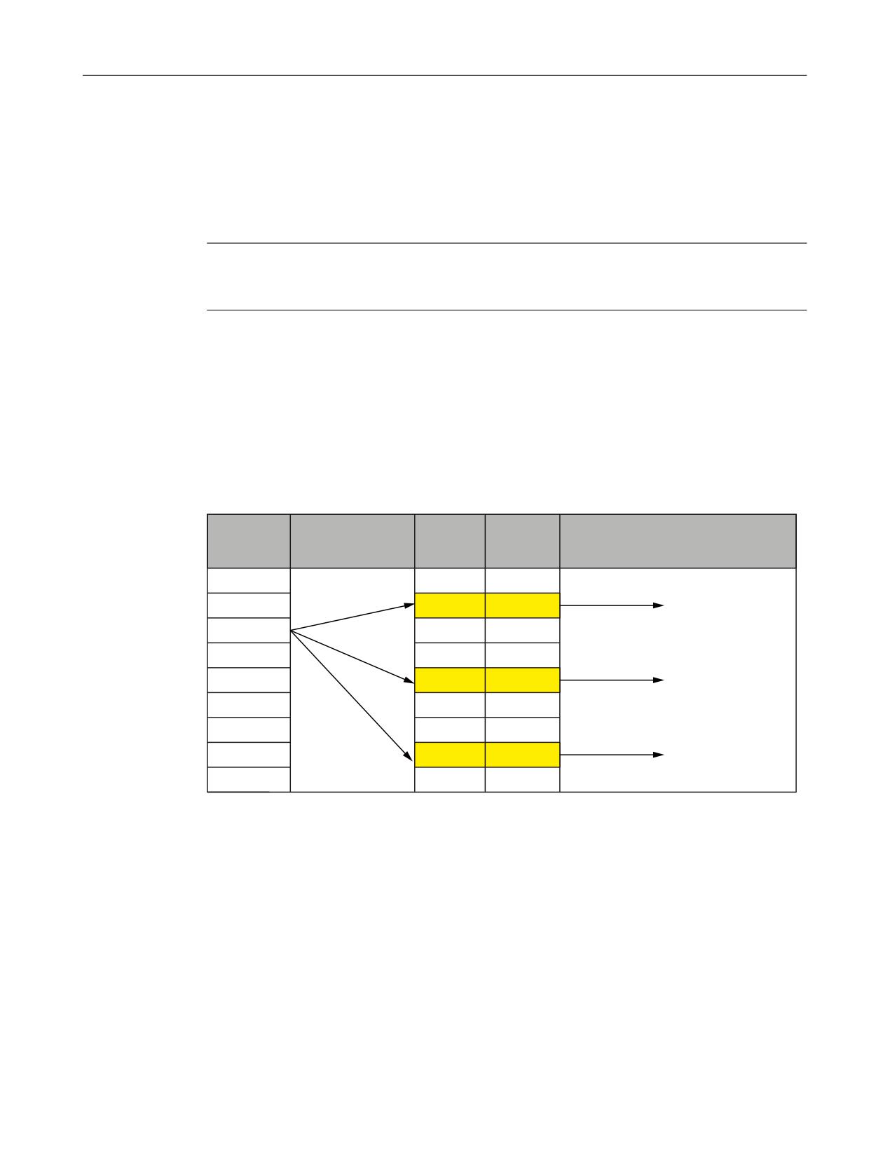
Connecting sensors and actuators
8.1 Safety-related input/output signals
8.1.5
Multiple distribution and multiple interlocking
Interlocking functions between the SGE/SGA are implemented in the NCK channel in the NCK-
SPL. However, in order to relieve the NCK-SPL, it is also possible to pre-process signals between
the NCK-SPL and NCK monitoring channel using the "multiple distribution" and "multiple
interlocking" functions.
Note
The multiple distribution/interlocking that can be parameterized in the NCK machine data must
be programmed by the user on the PLC side.
Processing the NCK-SGE for 840D sl (multiple distribution)
Axis-specific/spindle-specific machine data is used to define which internal SPL output is to be
used for which function and which axis/spindle. Under the condition that certain axes/spindles
belong to the same safety group, it is possible to implement multiple distribution (1 NCK-SPL
output is assigned, for example, to 3 axes with the same function). In addition, when an internal
NCK-SPL output is selected via MD, it is also possible to define whether the inverted signal is also
to be processed.
1&.
1&. 63/
0RQLWRULQJ
0XOWLSOH GLVWULEXWLRQ
6*( 6*$
,QYHUVLRQ
2876,
FRPSDUDWRUV
LQWHUIDFH
2XWSXW
2XWSXW
6*(
<HV QR
IRU D[LV
2XWSXW [
6*(
<HV QR
IRU D[LV
6*(
<HV QR
IRU D[LV
2XWSXW Q
Figure 8-7
Multiple distribution for NCK-SGE
Example:
It must be possible to change over between the "safe software limit switches" 1 or 2 for axes 1,
2 and 3 as a group using an internal NCK-SPL output (OUTSI x).
The machine data must be parameterized as follows:
Axis 1: MD36973 $MA_SAFE_POS_SELECT_INPUT = OUTSI x
Axis 2: MD36973 $MA_SAFE_POS_SELECT_INPUT = OUTSI x
Axis 3: MD36973 $MA_SAFE_POS_SELECT_INPUT = OUTSI x
Safety Integrated (system-integrated)
Function Manual, 10/2020, 6FC5397-4BP40-6BA2
181
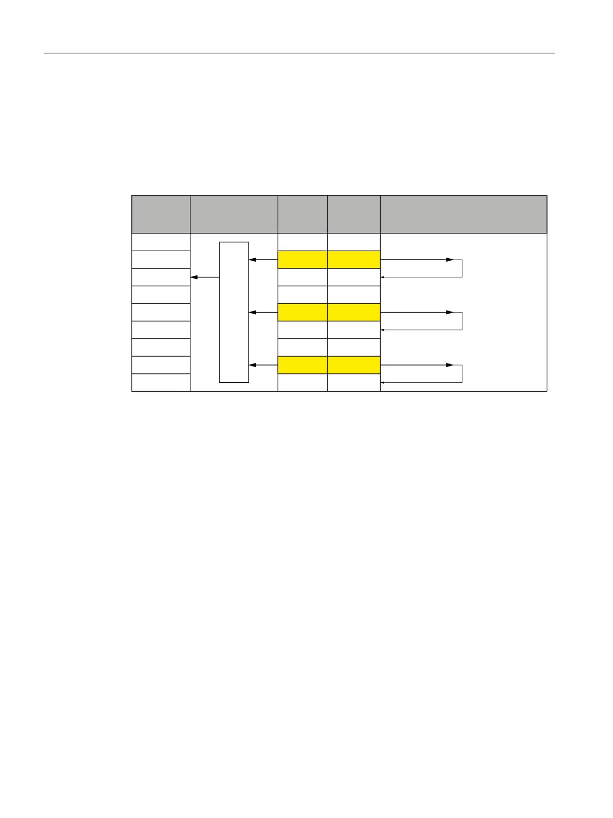
Connecting sensors and actuators
8.2 Connecting I/O via PROFIsafe
Processing the NCK-SGA for 840D sl (multiple assignment)
Axis-specific/spindle-specific machine data is used to define which SGA from which axis/spindle
must be assigned to which NCK-SPL input. It is possible to implement a multiple assignment
(SGA from several axes are assigned to 1 input) provided that certain axes/spindles belong to the
same safety group. The SGAs are then ANDed and the result output at the NCK-SPL input. In
addition, when an NCK output is selected via an MD, it is also possible to define whether the
signal is to be output in an inverted form before it is ANDed.
1&. 6*(
0XOWLSOH
0RQLWRULQJ
1&. 63/
,QYHUVLRQ
6*$
DVVLJQPHQW
FRPSDUDWRUV
,16,
,QWHUIDFH
,QSXW
,QSXW
<HV QR
6*(
IRU D[LV
,QSXW [
<HV QR
6*(
IRU D[LV
<HV QR
6*(
IRU D[LV
,QSXW Q
Figure 8-8
Multiple assignment for NCK-SGA
Axes 1, 2 and 3 belong to one safety area. For these axes, the message "axis safely referenced"
should be output at one NCK-SPL input (INSI) (this means that the message is output at the input
if the message (signal) is present for all 3 axes).
The machine data must be parameterized as follows:
Axis 1: MD36987 $MA_SAFE_REFP_STATUS_OUTPUT = INSI x
Axis 2: MD36987 $MA_SAFE_REFP_STATUS_OUTPUT = INSI x
Axis 3: MD36987 $MA_SAFE_REFP_STATUS_OUTPUT = INSI x
8.2
Connecting I/O via PROFIsafe
8.2.1
Function description
The failsafe master (F-master) integrated in SINUMERIK 840D sl in conjunction with failsafe I/O
modules (F-modules), permits failsafe communication as specified according to the PROFIsafe
profile both on PROFIBUS DP as well as on PROFINET IO (PROFIsafe communication).
This means that the safety-related input/output signals of the process (machine) are coupled to
the Safety Integrated function "safe programmable logic" (SPL) in the same way for both the PLC
and NCK-SPL via the particular I/O bus . Failsafe I/O devices can be connected via all I/O
connections.
Safety Integrated (system-integrated)
182
Function Manual, 10/2020, 6FC5397-4BP40-6BA2
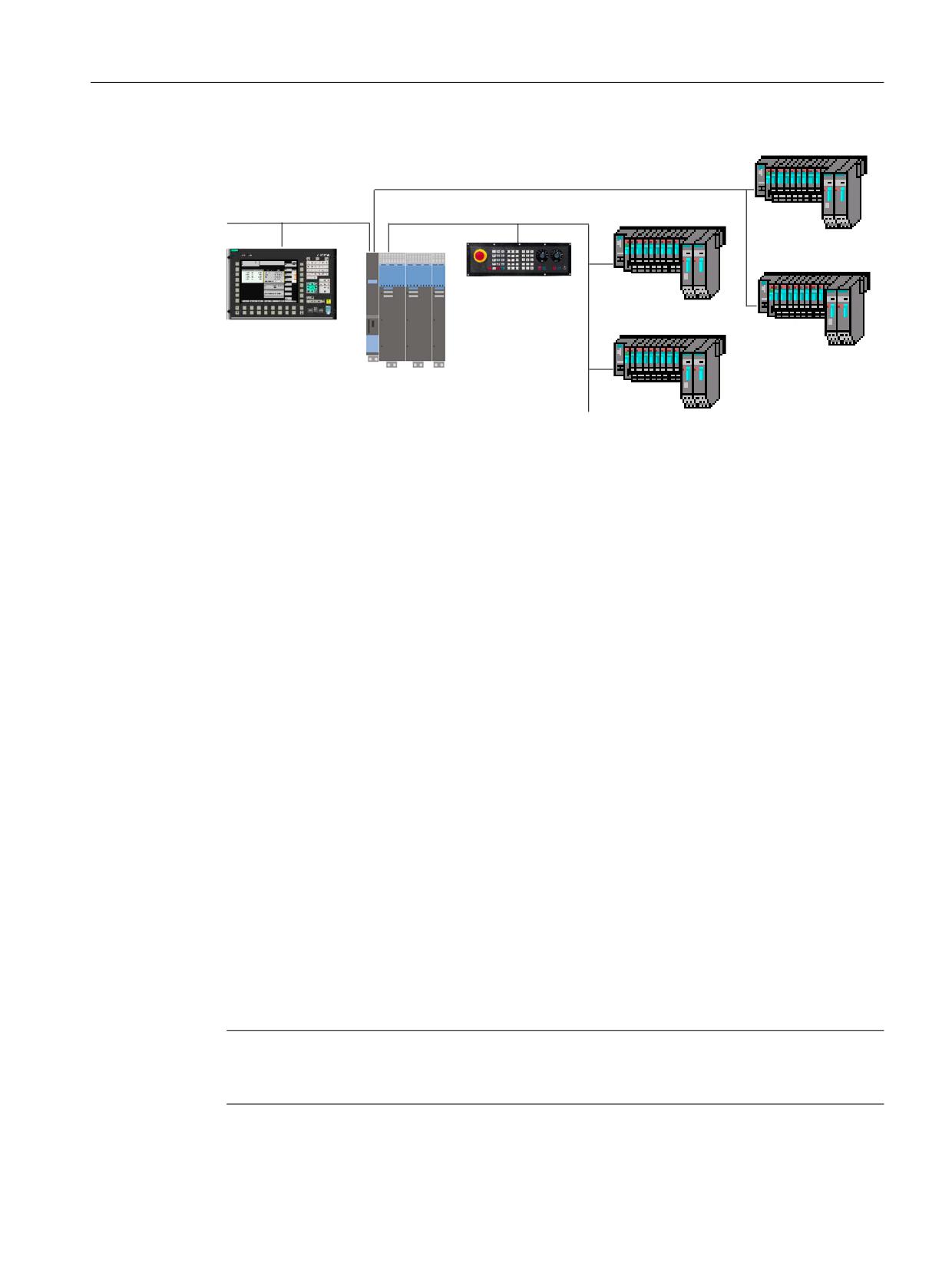
Connecting sensors and actuators
8.2 Connecting I/O via PROFIsafe
31 GHYLFH (7
6
352),1(7 ,2
(WKHUQHW
352),%86 '3
'3 VODYH (7
6
31 GHYLFH (7
6
0DFKLQH FRQWURO SDQHO
'3 VODYH (7
6
2SHUDWH
6,180(5,.
' VO
Figure 8-9
SI I/O using failsafe modules connected to PROFIBUS DP
PROFIsafe
PROFIsafe is a communication profile for failsafe data transfer between failsafe components
based on the field buses PROFIBUS and PROFINET. This represents an extension to the standard
communication. This allows both standard components and failsafe components to be
simultaneously operated on a PROFIBUS/PROFINET system.
The PROFIsafe profile is characterized by the fact that communication between the safe terminal
nodes, i.e. the F-CPUs, the distributed slaves and the actuators/sensors/field devices, uses
standard PROFIBUS functions.
The useful (net) data of the safety function plus the safety measures are sent in a standard data
telegram. This does not require any additional hardware components, since the protocol chips,
drivers, repeaters, cables can still be used as they are.
SINUMERIK Safety Integrated supports PROFIsafe V1 and PROFIsafe V2.
Communication profiles in accordance with IEC 61784
CP 3/1: PROFIBUS
CP 3/4: PROFINET CLASS A
CP 3/5: PROFINET CLASS B
CP 3/6: PROFINET CLASS C (IRT)
• V1 mode
This mode is designed for pure CP 3/1 networks (PROFIBUS DP).
• V2 mode
This mode has been designed for pure CP 3/4 - CP 3/6 networks (Ethernet, PROFINET), but can
also be used for CP 3/1 networks (PROFIBUS DP).
Note
The designations F-master and F-slave for PROFIBUS DP are in this documentation - also for the
designations F-host and the F-device for PROFINET.
Safety Integrated (system-integrated)
Function Manual, 10/2020, 6FC5397-4BP40-6BA2
183
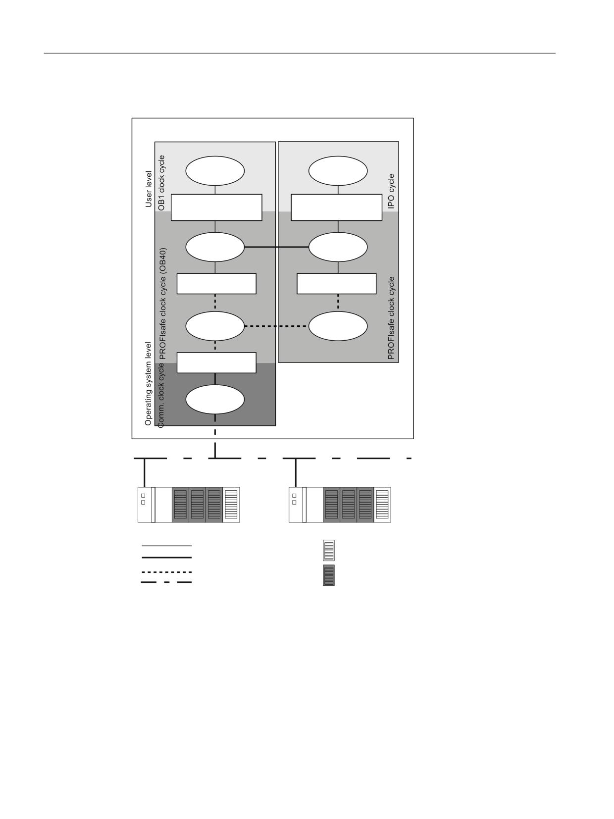
Connecting sensors and actuators
8.2 Connecting I/O via PROFIsafe
8.2.2
System structure
6,180(5,.
' VO
3/&
1&.
3/& 63/
1&. 63/
63/ 6*( 6*$
63/ 6*( 6*$
'%
,16(3 2876(3
$B,16( 2876(
6DIHW\ ,QWHJU
6DIHW\ ,QWHJU
OD\HU
OD\HU
6, GDWD
6, GDWD
352),VDIH
352),VDIH
/D\HU
/D\HU
%XV LQWHUIDFH
&RPPXQL
FDWLRQ OD\HU
352),%86 352),1(7
'3 31 , 2 (7
6
'3 31 , 2 (7
6
8VHU FRPPXQLFDWLRQ
6WDQGDUG '3 PRGXOH
6DIHW\ ,QWHJUDWHG FRPP
352),VDIH FRPP
) PRGXOH
352),%86 352),1(7 FRPP
Figure 8-10
System structure of the SI I/O using F-modules connected to PROFIBUS DP
Just like Safety Integrated, the PROFIsafe system structure also has a 2-channel diverse system
design based on the PLC and NCK-PROFIsafe layer.
PROFIsafe communication
The principle of PROFIsafe communications between SINUMERIK 840D and the F-modules is
explained in detail below. This is based on the transfer of the SPL output data $A_OUTSE/
$A_OUTSEP to the F-DO modules:
Safety Integrated (system-integrated)
184
Function Manual, 10/2020, 6FC5397-4BP40-6BA2
Connecting sensors and actuators
8.2 Connecting I/O via PROFIsafe
The PROFIsafe layer creates a PROFIsafe telegram (F-telegram) in each PROFIsafe cycle with the
ANDed SPL output data as F-net data
F-net data = (OUTSEP AND $A_OUTSE)
and the backup data (CRC and the consecutive number) and transfers it to the communication
layer via the bus interface.
In each communication cycle independent of the PROFIsafe cycle, the PROFIBUS layer transfers
a telegram with a PROFIsafe telegram generated from the F-layer as user data to the slave
devices.
WARNING
Bit pattern
It is not guaranteed that simultaneous changes to individual bits in the SPL (NCK and PLC
OUTSE), which are interpreted as a contiguous associated bit pattern, are transferred together.
It is possible that the receiver briefly receives an inconsistent bit pattern.
Configuring/parameterizing
The configuration and parameterization needed to connect the F-modules to the external NCK/
PLC-SPL interfaces entails the following steps:
1. Generating the configuration using SIMATIC STEP7.
2. Performing a standard SINUMERIK 840D sl commissioning (minimum requirement).
3. Loading the configuration and the PLC basic and user program modules into the SINUMERIK
840D sl PLC.
4. Parameterizing the PROFIsafe-relevant SINUMERIK 840D sl machine data. See Chapter
"Parameterizing the F-master (NCK) (Page 191)".
8.2.3
Configuring and parameterizing the PROFIsafe I/O
The configuration of the PROFIBUS/PROFINET I/O connections on the PLC side of a SINUMERIK
840D sl is defined using the Step7 component HW Config. There are two options:
• Integrating Siemens failsafe devices via the hardware catalog
• Integrating third-party failsafe devices by importing the corresponding generic station
description files.
This configuration is loaded into the PLC, the PLC evaluates this data and makes the information
required for PROFIsafe communication with an F-device, available to the NCK and PLC-side
Safety system SW for further evaluation of the F-device configuration.
In addition, the NCK machine data for PROFIsafe parameterization is transferred from the NCK
to PLC. Both components evaluate this machine data and compare the F-devices, which are
parameterized in this data, with the F-device configuration provided from the PLC.
The information on configuring and parameterizing the PROFIsafe I/O provided in this chapter
essentially refers to the specific requirements of SIMATIC. Complete information on configuring
and parameterizing PROFIsafe components from Siemens is provided in the SIMATIC Manuals:
Safety Integrated (system-integrated)
Function Manual, 10/2020, 6FC5397-4BP40-6BA2
185
Connecting sensors and actuators
8.2 Connecting I/O via PROFIsafe
References:
• ET 200S Distributed I/O System, Operating Instructions
• ET 200S Distributed I/O System Failsafe Modules, Installation and Operation Manual
• ET 200pro Distributed I/O System, Fail-Safe Modules, Operating Instructions
• Distributed I/O device ET 200eco, Fail-Safe I/O Modules, Operating Instructions
• ET 200M Distributed I/O device Failsafe Modules, Signal Modules Installation and Operation
Manual
• SIMATIC ET 200SP Distributed I/O System ET 200SP System Manual
• SIMATIC ET 200SP Distributed I/O System ET 200SP Equipment Manual
• SIMATIC Safety - Configuring and Programming, Programming and Operating Manual
Configuration
The F-I/O are configured while configuring the standard I/O bus configuration using STEP 7.
Parameterization
Both the standard and F-parameterization of the F-modules is carried out using the relevant
properties dialog box of the module. Select the appropriate I/O device (e.g. IM 151-1) in the
station window and then open the properties dialog box of the relevant F-module in the detailed
view.
Note
The parameter assignments specified in this chapter only refer to the ET 200 modules.
Parameters: Input/output address
The following conditions apply to the input/output addresses of an F-module:
• Input address for PLC317 PN PLC 317F
• Output address = input address
F-parameterization
F-parameterization is realized in the properties dialog box under:
Dialog: Properties
Safety Integrated (system-integrated)
186
Function Manual, 10/2020, 6FC5397-4BP40-6BA2
Connecting sensors and actuators
8.2 Connecting I/O via PROFIsafe
Tab: Parameter
Parameters > F-parameters
The F-parameters of the PROFIsafe components are automatically set to the F-monitoring time
of the HW Config and cannot be changed. The displayed values of the F-parameters
• F_source_address
• F_target_address
must be entered into the machine data to parameterize the NCK in a subsequent parameterizing
step.
The value of the F-target addresses should be set at the I/O module (F-module) using the DIL
switches provided.
Note
Failsafe modules for ET 200SP do not have DIL switches that you can use to assign a unique F-
target address for each module. Instead, the F-addresses are permanently saved using the
coding elements of the failsafe modules. For these modules, the PROFIsafe addresses (F-target
addresses) can be assigned from Step 7.
S7 Distributed Safety - Configuring and Programming, Product Information
WARNING
PROFIBUS DP subnet
The PROFIsafe addresses are for unique identification of source and target of safety-related
communications.
The following applies to pure PROFIBUS-DP subnets:
The PROFIsafe target address must be unique network-wide* and station-wide** (system-
wide).
For ET 200S, ET 200pro, ET 200M and ET 200eco, a maximum of 1022 different PROFIsafe
target addresses can be assigned.
For ET 200SP, 65534 PROFIsafe target addresses can be assigned.
* A network comprises one or several subnets. "Throughout the network" means beyond
subnet limits.
** "Station-wide" means for a station with HW configuration (e.g. a Sinumerik 840D sl).
Safety Integrated (system-integrated)
Function Manual, 10/2020, 6FC5397-4BP40-6BA2
187
Connecting sensors and actuators
8.2 Connecting I/O via PROFIsafe
F-parameters: F_source/target_address
F_source_address
The F_source_address is the decimal PROFIsafe address of the F- master allocated automatically
by HW Config. The F_source_address is formed from the "basis for PROFIsafe addresses" plus the
PROFIBUS address of the PROFIBUS DP interface.
Note
To clearly define the PROFIsafe communication, the PROFIsafe address of the F-master -
assigned by the HW Config - must be saved in the F-master. To do this, the PROFIsafe address of
the F-master must be converted from decimal into hexadecimal and entered into the machine
data of SINUMERIK 840D sl (see Chapter "Parameterizing the F-master (PLC) (Page 202)").
F_target_address
The F_target_address is the decimal PROFIsafe address of the F- module automatically allocated
by HW Config (the user can change this).
Note
In order to parameterize the PROFIsafe communication relationships, the F- master is informed,
via the PROFIsafe address of the PROFIsafe component that this PROFIsafe component is
assigned to it. To do this, the PROFIsafe address must be converted from decimal into
hexadecimal and entered into the machine data of SINUMERIK 840D sl.
The DIL switch setting shown corresponds to the PROFIsafe address to be set at the DIL switch
of the F-module.
F-parameters: F_source/target_address (PROFINET IO)
F-device
The F-addresses of the F-device are assigned by the user when configuring. They must be unique
within a sub-network.
Note
Sub-networks are connected through 2-port routers, which therefore also represent the natural
limits of the sub-networks.
F-host
The F-addresses of the F-host is the "Basis for PROFIsafe addresses" entered as default from STEP
7 under the "F-parameter" tab. The user can subsequently change the F-address in steps of 1000.
Valid F-address range: 1 - FFFEH (1 - 65534D)
Safety Integrated (system-integrated)
188
Function Manual, 10/2020, 6FC5397-4BP40-6BA2
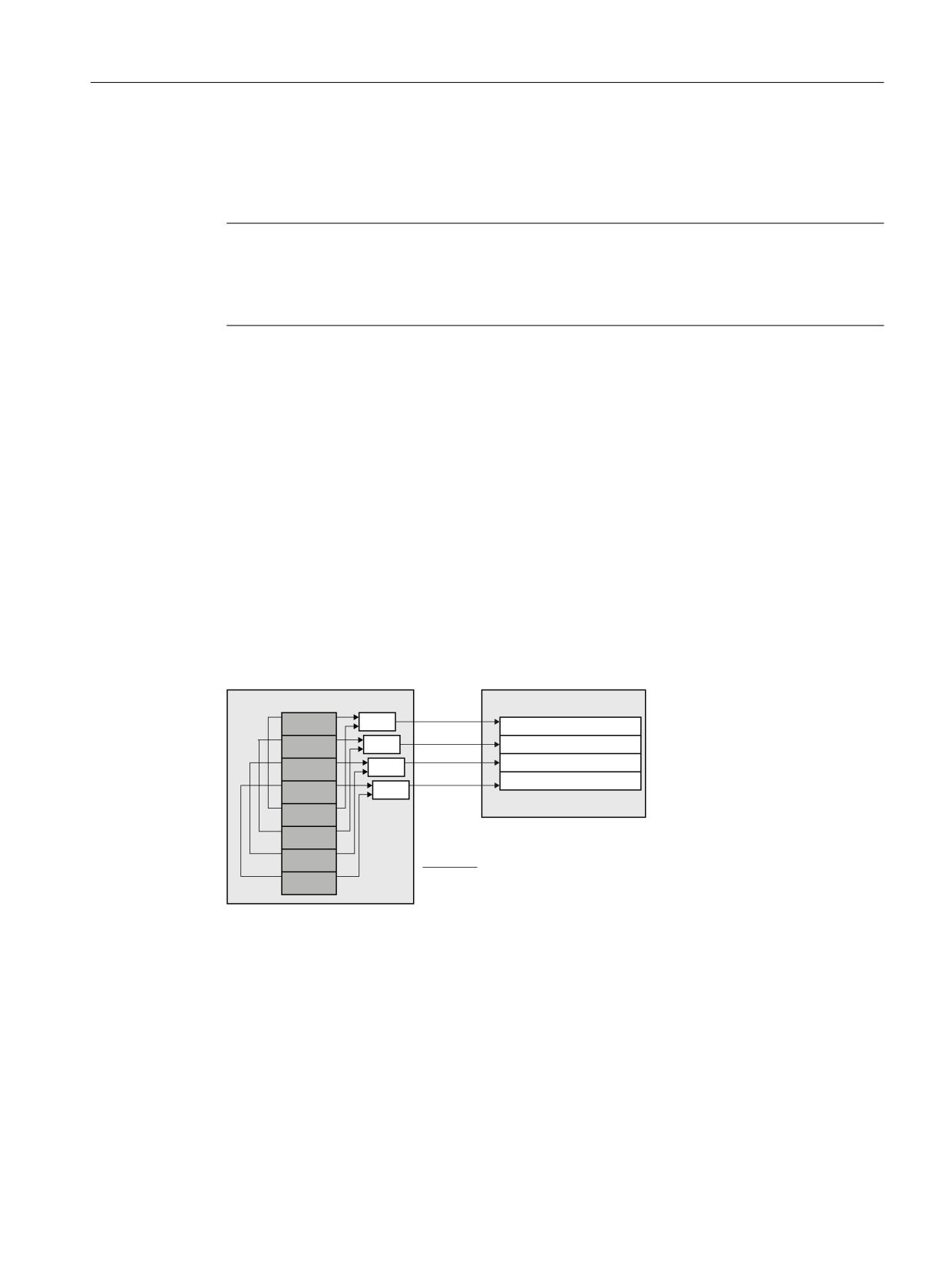
Connecting sensors and actuators
8.2 Connecting I/O via PROFIsafe
F-parameters: F-monitoring time
The F-monitoring time defines the maximum time that is tolerated when a PROFIsafe
component is waiting for a new F-telegram from its communication partner.
Note
If the F-monitoring time is configured to be shorter than the PROFIsafe monitoring clock cycle set
using the appropriate machine data, when the control runs-up an alarm is displayed:
Alarm 27242 ”PROFIsafe: F-module %1, %2 faulty
Parameters: DO/DI channel x
The channels of an F-module are parameterized in the properties dialog box under:
Dialog: Properties
Tab: Parameter
Parameter > module parameter > DO or DI channel x
F-DI module
Depending on the selected parameterization, the channels of the F-DI module are mapped
differently to the NCK/PLC-SPL inputs $A_INSE/INSEP.
• 2f2 parameterization
For 2f2 parameterization, the process signals of both channels in the F-DI module are
combined to form one F-useful (net) data signal and thus supply data for an SPL input.
(7
6 ) ', PRGXOH
6,180(5,.
' VO
&KDQQHO
$1'
$B,16( ,16(3>Q@
&KDQQHO
$1'
$B,16( ,16(3>Q
@
$B,16( ,16(3>Q
@
&KDQQHO
$1'
$B,16( ,16(3>Q
@
&KDQQHO
$1'
&KDQQHO
&KDQQHO
&KDQQHO
&RQILJXUDWLRQ &KDQQHO [ \
IURP
&KDQQHO
Figure 8-11
2f2 mapping of the F-DI channels to SPL input data for ET 200S
• 1f1 parameterization
For 1from1 parameterization, the process signals of both channels are transferred from the
F-DI module and can thus supply 2 different SPL input data.
Safety Integrated (system-integrated)
Function Manual, 10/2020, 6FC5397-4BP40-6BA2
189
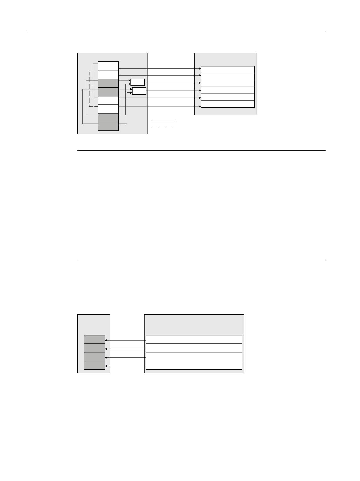
Connecting sensors and actuators
8.2 Connecting I/O via PROFIsafe
(7
6 ) ', PRGXOH
6,180(5,.
' VO
&KDQQHO
$B,16( ,16(3>Q@
&KDQQHO
$B,16( ,16(3>Q
@
&KDQQHO
$1'
$B,16( ,16(3>Q
@
$1'
$B,16( ,16(3>Q
@
&KDQQHO
$B,16( ,16(3>Q
@
&KDQQHO
$B,16( ,16(3>Q
@
&KDQQHO
&KDQQHO
&RQILJXUDWLRQ &KDQQHO [ \
IURP
&KDQQHO
&RQILJXUDWLRQ &KDQQHO [ \
IURP
Figure 8-12
2f2/1f1 mapping of the F-DI channels to SPL input data
Note
If mixed 2f2 and 1f1 parameterization is used in an F-DI module, this can reduce the number of
SPL input data $A_INSE/INSEP that can be used. This is the reason that we recommend that 1f1 is
first parameterized followed by 2f2.
If more pieces of F-net data of an F-DI module are used then the number of relevant bits that can
be transferred by parameterizing the channels of the F-DI module, then this is not recognized by
the control.
Example:
For a 2f2 parameterization of all of the channels of the F-DI module:
• ET 200S F-DI module: 4/8 F-DI 24 V DC
The 8 transferred F-net data bits contain 4 relevant (bit 0 - bit 3) and 4 non-relevant bits (bit 4
- bit 7).
F-DO module
The NCK/PLC-SPL outputs $A_OUTSE/OUTSEP are logically combined in the F-driver to produce
an F-net data signal (implicit 2f2 parameterization) and mapped to the channels of the relevant
F-DO module.
(7
6
6,180(5,.
' VO
) '2
PRGXOH
&KDQQHO
$B2876(>Q@
$1'
2876(3>Q@
&KDQQHO
$B2876(>Q
@
$1'
2876(3>Q
@
&KDQQHO
$B2876(>Q
@
$1'
2876(3>Q
@
&KDQQHO
$B2876(>Q
@
$1'
2876(3>Q
@
Figure 8-13
Mapping the SPL output data to F-DI channels
PROFIsafe clock cycle and communication cycle time
When parameterizing the PROFIsafe clock cycle to ensure a correct PROFIsafe communication,
the cyclic bus communication time must be observed. For the PROFIBUS bus system, this time
can be determined as follows:
Safety Integrated (system-integrated)
190
Function Manual, 10/2020, 6FC5397-4BP40-6BA2
Connecting sensors and actuators
8.2 Connecting I/O via PROFIsafe
DP cycle time
After the station has been fully configured, the DP cycle time can be determined by activating the
equidistant (isochronous) bus cycle:
Open the properties dialog box of PROFIBUS DP master of the configured station in HW Config:
Dialog: Properties - DP master system
Tab: General
Subnetwork, button: Properties
Dialog: Properties - PROFIBUS
Tab: Network settings
Button: Options
Dialog: Options
Tab: Equidistance
Option button: Activate the equidistant bus cycle/
Recalculate equidistant time
(Note: Activate the equidistant bus cycle using the option button: "Activate equidistant bus
cycle/recalculate equidistant time". This can be used to determine the DP cycle time. The
equidistant bus cycle should then be deactivated again.)
Display field: Equidistant bus cycle
(Note: The value calculated by HW Config, and shown in display field "Equidistant bus cycle" is
the same as the DP cycle time)
Cancel
Cancel
Cancel
A corresponding value should be determined for the PROFINET communication coupling.
Note
The communication cycle time is required as guideline when parameterizing the PROFIsafe clock
cycle (refer to Chapter "Parameterizing the PROFIsafe communication (NCK) (Page 192)").
The information and instructions in the online documentation should be carefully observed
before changing the communication cycle time (button: "Help" of the corresponding dialog).
8.2.4
Parameterizing the F-master (NCK)
The F-master is parameterized in the machine data of the NCK and comprises the following sub
areas:
• PROFIsafe communication
- PROFIsafe address of the F-master
- PROFIsafe clock cycle
Safety Integrated (system-integrated)
Function Manual, 10/2020, 6FC5397-4BP40-6BA2
191
Connecting sensors and actuators
8.2 Connecting I/O via PROFIsafe
See Chapter "Parameterizing the PROFIsafe communication (NCK) (Page 192)"
• SPL-SGE/SGA interface
- PROFIsafe address of the PROFIsafe component
- F-net data filter
- SGE/SGA assignment
SPL-SGE interface: see “parameterizing the SPL-SGE interface (Page 194)”
SPL-SGA interface: see “Parameterizing the SPL-SGA interface (Page 199)”
8.2.5
Parameterizing the PROFIsafe communication (NCK)
F-master address
In order to define a unique and clear communication relationship between F-slave and F-master,
in addition to the target address (PROFIsafe address of the F-slave), the source address
(PROFIsafe address of the F-master) must be defined.
The PROFIsafe address of the F-master is entered into the following machine data:
• MD10385 $MN_PROFISAFE_MASTER_ADDRESS[ ]
(PROFIsafe address of the F-master)
Input format: 0s 00 aaaa
s: Bus segment information
Value range: 5 = PLC-side I/O connections
aaaa: Hexadecimal PROFIsafe address
F-parameters F_source_address (range of values: 1...64125)
In order to be able to handle different PROFIsafe master addresses at different bus connections
(e.g. PROFIBUS, PROFINET), this MD is created as MD field so that it is possible to parameterize
several PROFIsafe master addresses.
If the same PROFIsafe master address is configured for various I/O connections, then only this
one PROFIsafe master address must be saved in the MD.
Note
The PROFIsafe address of the F-master is provided under:
• HW Config > Properties dialog box of the F-module > F-parameters:
F_source_address
PROFIsafe clock cycle
The PROFIsafe clock cycle defines the time grid in which new F-telegrams are generated by the
F-master for transfer to the F-modules. By default, the PROFIsafe cycle time is derived from the
interpolation cycle with the ratio 1:1.
As part of the PROFIsafe communications, a cyclic interrupt of the PLC user program (OB1) is
made. This is realized in the PROFIsafe clock cycle via OB40.
Safety Integrated (system-integrated)
192
Function Manual, 10/2020, 6FC5397-4BP40-6BA2
Connecting sensors and actuators
8.2 Connecting I/O via PROFIsafe
In order to reduce the possible resulting computational load, machine data
• MD10098 $MN_PROFISAFE_IPO_TIME_RATIO
(factor, PROFIsafe communications clock cycle)
can be used to modify the ratio between the PROFIsafe and interpolation clock cycle.
To achieve a sufficiently fast response time for PROFIsafe communication, the PROFIsafe cycle
time must not be set to longer than 25 ms. The selected PROFIsafe clock cycle is displayed in the
machine data:
• MD10099 $MN_INFO_PROFISAFE_CYCLE_TIME
(PROFIsafe communication clock cycle)
If the PROFIsafe cycle time is longer than 25 ms, an alarm will be displayed the next time the
control runs up:
• Alarm: 27200 "PROFIsafe cycle time %1 [ms] is too long"
PROFIsafe clock cycle and DP cycle time
The PROFIsafe clock cycle should be parameterized longer than the DP clock cycle time displayed
by STEP7: HW Config. Otherwise, the load (time) on the PLC user program is increased as a result
of unnecessary OB40 interrupts.
Note
The PROFIsafe clock cycle must be parameterized, so that the following applies:
12 ms < PROFIsafe cycle < 25 ms.
PROFIsafe clock cycle overruns
Even if the parameterized software operates error-free in normal operation, run time
fluctuations in the PLC operating system (e.g. processing diagnostic alarms) can mean that the
processing of the OB40 interrupt was not able to be completed before the start of the next
PROFIsafe clock cycle.
In this particular case, the NCK attempts, up to a limit of 50 ms after the last correctly processed
PROFIsafe clock cycle, to initiate an OB40 interrupt. The repeated attempts to initiate the OB40
interrupt are no longer executed in the PROFIsafe clock cycle but in the IPO clock cycle.
After the 50 ms limit value is exceeded, Alarm 27253 "PROFIsafe communication error F-master
component %1, error %2" is output and the configured stop response (Stop D or E) is initiated.
PROFIsafe communication processing is stopped. This means that the communication to F-
modules, type F-DO or F-DI/DO is interrupted. PROFIsafe drivers of type F-DI or F-DI/DO F-
modules that have been stopped, output failsafe values (0) as F-net data towards the SPL.
Further, an attempt is still made to initiate the OB40 interrupt and to maintain PROFIsafe
communications.
The time up to initiating the next OB40 interrupt is displayed in the following NCK machine data:
• MD10099 $MN_INFO_PROFISAFE_CYCLE_TIME
(PROFIsafe communication clock cycle)
If the PROFIsafe clock cycle is continuously exceeded and just not sporadically, then the
following alarm is displayed:
• Alarm: 27256 "PROFIsafe actual cycle time %1 [ms] > parameterized cycle time"
Safety Integrated (system-integrated)
Function Manual, 10/2020, 6FC5397-4BP40-6BA2
193
Connecting sensors and actuators
8.2 Connecting I/O via PROFIsafe
Distribution of the computational load on the NCK side
MD10095 $MN_ SAFE_MODE_MASK, bit 3 lists an operating mode with which the
computational load can be distributed using the PROFIsafe driver to the IPO clock cycles, the lie
in a PROFIsafe clock cycle.
If this operating mode is activated, with MD13307 $MN_PROFISAFE_IPO_RESERVE (default
value = 0), users have the option of reserving part of the IPO clock cycles so that in these clock
cycles no PROFIsafe driver is computed.
This can make sense, especially for many active PROFIsafe devices, as the PROFIsafe processing
on the PLC side makes this time necessary.
Example:
MD PROFISAFE_IPO_TIME_RATIO = 8
MD PROFISAFE_IPO_RESERVE = 3
⇒ in 5 of the 8 IPO cycles per PROFIsafe cycle, PROFIsafe drivers are computed; in the remaining
3 IPO clock cycles, no PROFIsafe calculations are made on the NCK side.
Parameterization:
Machine data $MN_PROFISAFE_IPO_RESERVE becomes effective at power on. If the value in
$MN_PROFISAFE_IPO_RESERVE exceeds the value set in $MN_PROFISAFE_IPO_TIME_RATIO,
then Alarm 27034 "Parameterization of MD %1[%2] invalid" is output with the note relating to
machine data $MN_PROFISAFE_IPO_RESERVE.
Machine data bit $MN_SAFE_MODE_MASK, bit 3, to activate the modified PROFIsafe driver
sequence in the NCK, is incorporated in checksum $MN_SAFE_GLOB_ACT_CHECKSUM[0].
Machine data $MN_PROFISAFE_IPO_RESERVE is also incorporated in checksum
$MN_SAFE_GLOB_ACT_CHECKSUM[0].
8.2.6
parameterizing the SPL-SGE interface
A bitwise assignment can be made using machine data to better link the SPL interfaces to the
user data of the F-modules.
Symbolic name
In order to be able to display the various PROFIsafe modules in accordance with symbols that can
be specified by a machine manufacturer, using the MD fields
• $MN_PROFISAFE_IN/OUT_NAME[0...47]
Safety Integrated (system-integrated)
194
Function Manual, 10/2020, 6FC5397-4BP40-6BA2
Connecting sensors and actuators
8.2 Connecting I/O via PROFIsafe
it is possible to save symbolic names such as these. This name is used in the following situations:
• Alarms: If a symbolic name for a PROFIsafe connection has been saved in the MD mentioned,
then this is displayed instead of the PROFIsafe address.
This applies to the following alarms:
27251 PROFIsafe: F-module %1, %2 signals error %3%1 = name
27254 PROFIsafe: F-module %1, error on channel %2; %3<ALSI> %1 = name
27255 PROFIsafe: F-module %1, general error%1 = name
27257 PROFIsafe: %1 %2 signals system error %3 (%4)%2 = name - only if %1 = "F-module"
• Diagnostic screens: In addition to the PROFIsafe address, the symbolic name is also displayed
in the diagnostic screens.
For PROFIsafe modules that are addressed in several MD blocks (several subslots or several SPL
couplings), then the symbolic name, which is saved in the MD set with the lowest array index,
is applicable. All other connection names are ignored.
The symbolic names can be freely selected and can be a maximum of 15 characters.
Machine data that contain symbolic names are not included in any checksum calculation. The
name can therefore be changed without aligning the checksum. The value of the machine data
becomes active after a control hot restart.
Note
The examples, now listed, to parameterize the SPL-SGE interface are based on the following
specifications:
F-DI module
- F-address: 114 = 90H
- F-net data length: 8 bytes
Machine data
MD10386 $MN_PROFISAFE_IN_ADDRESS[5] = 05 00 0090
MD13300 $MN_PROFISAFE_IN_FILTER[5] = 000F 000F
MD10388 $MN_PROFISAFE_IN_ASSIGN[5] = 008 001
MD13308 $MN_PROFISAFE_IN_NAME[5] = PS_IN_5
Assignment: PROFIsafe component to the F-master
F-net data of an F-DI module is sub-divided into units each 32 bits. Each of these 32-bit units are
known as sub-slots. This sub-division, for assigning the F-DI module to the F-master is expressed
in the sub-slot address.
Safety Integrated (system-integrated)
Function Manual, 10/2020, 6FC5397-4BP40-6BA2
195
Connecting sensors and actuators
8.2 Connecting I/O via PROFIsafe
The machine data is used to assign the F-DI module to the F-master:
• MD10386 $MN_PROFISAFE_IN_ADDRESS[0...47]
(PROFIsafe address of the F-DI module)
Input format: 0s 0x aaaa
s: Bus segment
Value range: 5 = I/O connection on the PLC side
x: Sub-slot address
Value range: 0...2
x = 0 addresses the F-net data signals 1...32
x = 1 addresses the F-net data signals 33...64
x = 2 addresses the F-net data signals 65...96
in the PROFIsafe telegram from the F-slave
aaaa: Hexadecimal PROFIsafe address of the F-master
Value range: 1...FFFFH
Note
The PROFIsafe address of an F-module is provided in STEP7 HW Config under:
Properties dialog box of the F-module > F-parameters: F_target_address
The PROFIsafe address of the F-module is displayed in the decimal format in HW Config, but must
be entered into the machine data in the hexadecimal format.
Example:
User data of the 1st sub-slot is used to supply the SPL-SGE of the F-DI module with the PROFIsafe
address: 90H.
) QHW GDWD VLJQDOV
QG VXE VORW > @
VW VXE VORW > @
) ', PRGXOH
352),VDIH DGGUHVV
+
$VVLJQPHQW RI WKH VW VXE VORWV YLD 0'
352),6$)(B,1B$''5(66> @
+
Figure 8-14
F-DI addressing with the sub-slot
As a result of the possibility of flexibly assigning the F-net data of an F-DI module to the SPL-SGE
by combining the machine data now described (...IN_FILTER[n] and ...IN_ASSIGN[n]), the use of
the same PROFIsafe and sub-slot address a multiple number of times within the machine data:
• $MN_PROFISAFE_IN_ADDRESS[0...max. Index]
Safety Integrated (system-integrated)
196
Function Manual, 10/2020, 6FC5397-4BP40-6BA2
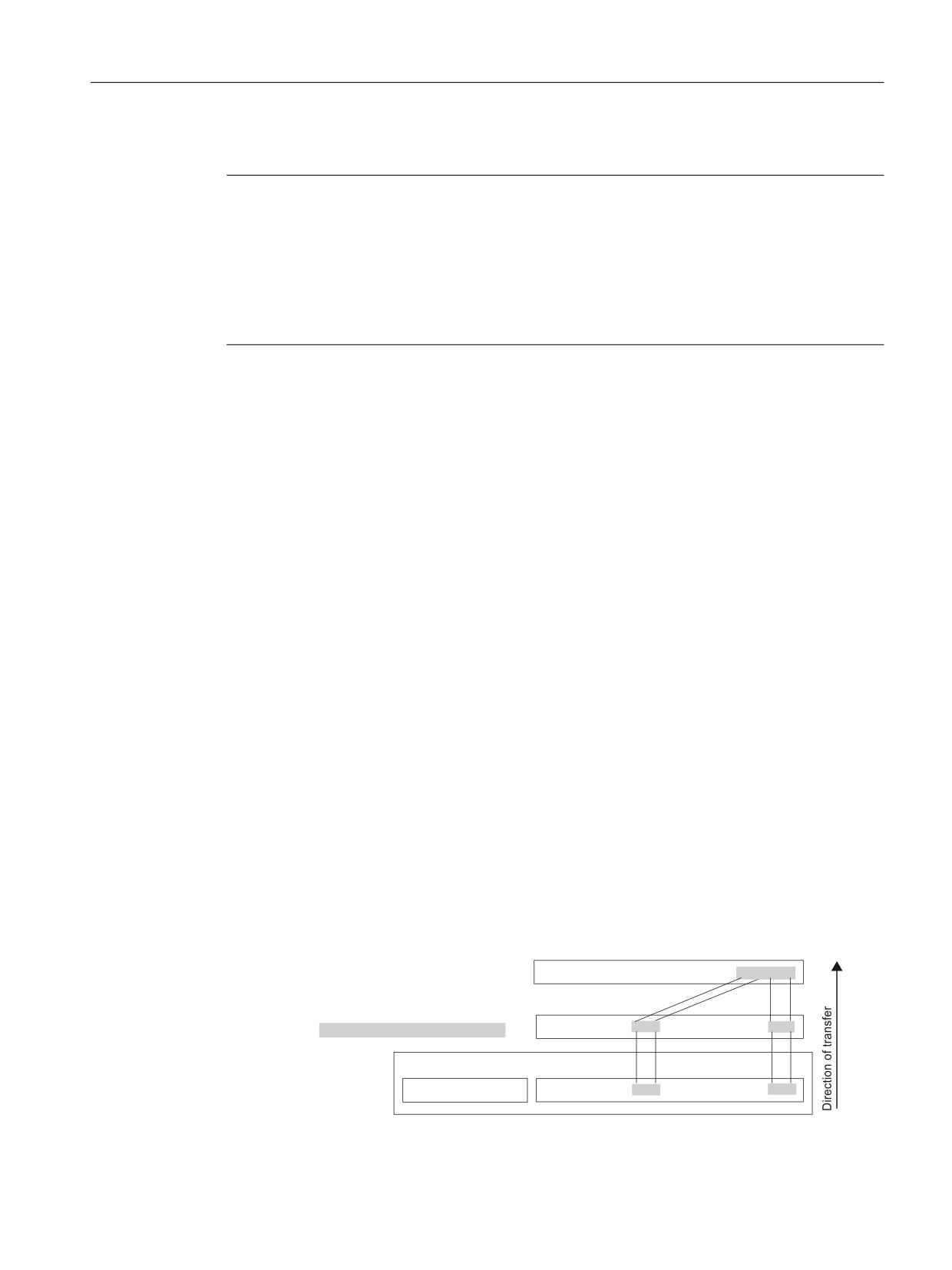
Connecting sensors and actuators
8.2 Connecting I/O via PROFIsafe
is possible and also makes sense.
Note
All machine data to connect an F-DI module to the SPL-SGE are associated with one another
through the common index of the machine data:
• $MN_PROFISAFE_IN_ADDRESS[Index]
• $MN_PROFISAFE_IN_FILTER[Index]
• $MN_PROFISAFE_IN_ASSIGN[Index]
• $MN_PROFISAFE_IN_NAME[Index]
F-net data filter
If not all of the F-net data signals of the sub-slots of an F-DI module are required for further
processing within the SPL, then the relevant F-net data signal signals can be selected using the
F-net data filter. Only these are then transferred to the SPL-SGE.
In the output direction, the F-net data filter allows the SPL-SGA ($A_OUTSE), selected using
$MN_PROFISAFE_OUT_ASSIGN[Index], to be distributed to any F-net data signals within the sub-
slot.
The F-net data filter is parameterized in the machine data:
• MD13300 $MN_PROFISAFE_IN_FILTER[0...47] (F-net data filter IN)
Each F-net data signal of the sub-slot is assigned to a filter bit. The filter bits of the F-net data
signals, that are to be transferred to SPL-SGE, should be set to 1. The filter bits of the F-net data
signals, that are not to be transferred, should be set to 0. The selected F-net data signals are
always transferred to the SPL-SGE as a consecutive bit field (i.e. a bit field without any gaps).
FFFF FFFFH is the default setting of the filter. This means that all F-net data signals are
transferred.
Example
8 F-net data signals (bits 0...3 and bits 16...19) of the 1st sub slot are filtered from the F-net data
of the F-DI module - and transferred into the SPL-SGE.
• MD10386 $MN_PROFISAFE_IN_ADDRESS[5] = 05 00 0090
• MD13300 $MN_PROFISAFE_IN_FILTER[5] = 000F 000F
• MD10388 $MN_PROFISAFE_IN_ASSIGN[5] = 008 001
63/ 6*( $B,16( ,16(3
0'
,1B$66,*1> @
%LW
%
LW
)LOWHU VHWWLQJ IRU WKH VW VXE VORW
0' 352),6$)(B,1B),/7(5> @
%LW
6XEVORW> @
%
LW
) QHW GDWD VLJQDOV
6XEVORW> @
RI WKH ) ', PRGXOH
0' 352),6$)(B,1B$''5(66> @
Safety Integrated (system-integrated)
Function Manual, 10/2020, 6FC5397-4BP40-6BA2
197
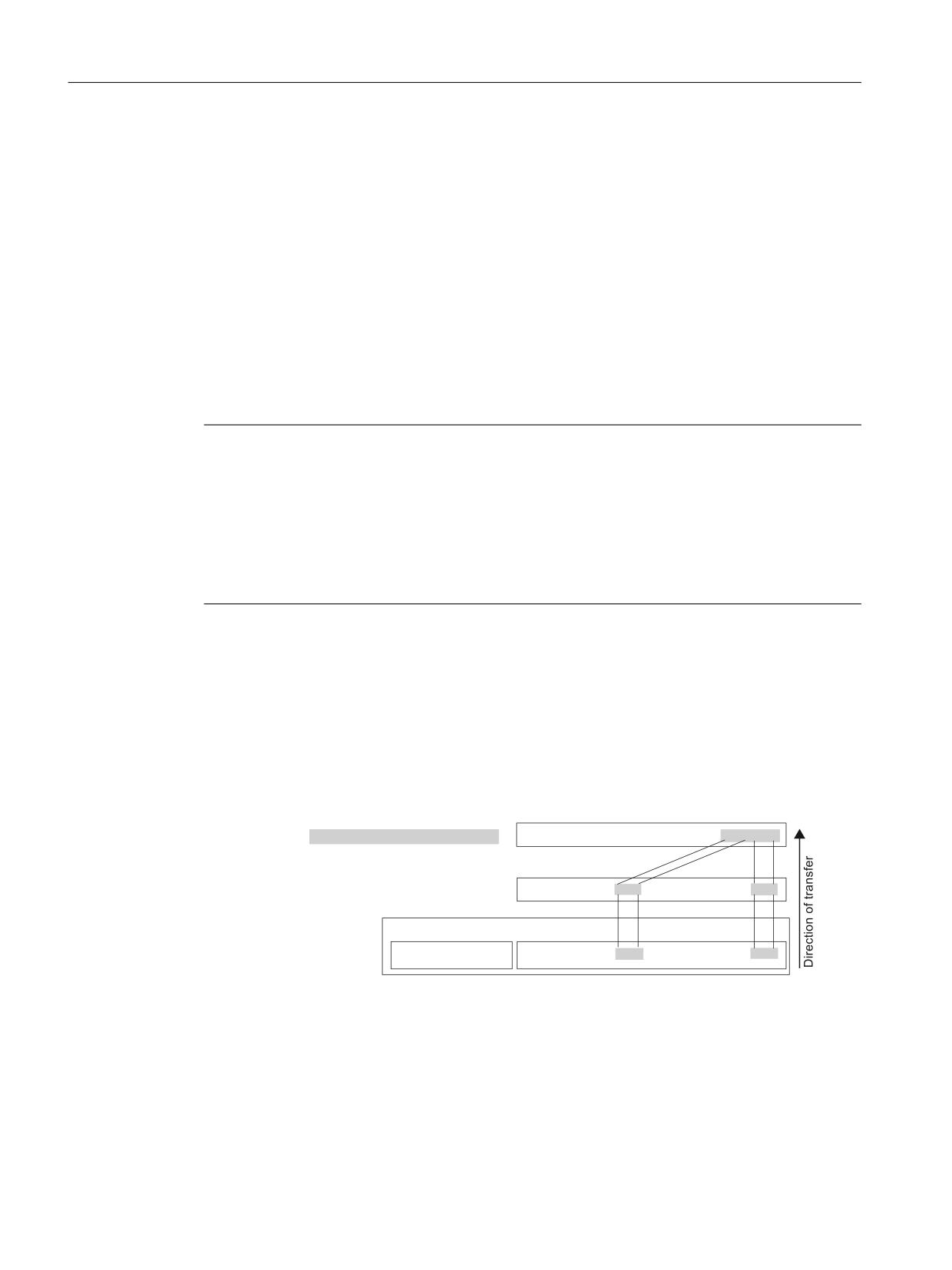
Connecting sensors and actuators
8.2 Connecting I/O via PROFIsafe
Figure 8-15
Filtering the F-net data signals in the input direction
SPL-SGE assignment
With this assignment, it is defined in which SPL-SGE ($A_INSE/$A_INSEP) the seamless (without
gaps) F-net data selected using the F-net data filter are transferred.
The assignment is made using machine data:
• MD10388 $MN_PROFISAFE_IN_ASSIGN[0...47],
(input assignment: F-net data signals to $A_INSE)
Input format: aaa bbb
aaa: Area limit 1, SPL-SGE $A_INSE/INSEP[aaa]
bbb: Area limit 2, SPL-SGE $A_INSE/INSEP[bbb]
Note
Area limits 1 and 2 are used to specify the area of the SPL input/output data to be written to/read
from via the PROFIsafe connection. The sequence in which the upper and lower limit values are
specified can be freely selected.
Example: The following data have the same significance
$MN_PROFISAFE_IN_ASSIGN[3] = 008 005
$MN_PROFISAFE_IN_ASSIGN[3] = 005 008
Example
8 F-net data signals of the 1st sub-slot filtered from the F-net data of the F-DI module are
transferred in the SPL-SGE from $A_INSE[1]/INSEP[1]).
• MD10386 $MN_PROFISAFE_IN_ADDRESS[5] = 05 00 0090
• MD13300 $MN_PROFISAFE_IN_FILTER[5] = 000F 000F
• MD10388 $MN_PROFISAFE_IN_ASSIGN[5] = 008 001
1&. 63/ 6*( $B,16(
0' 352),6$)(B,1B$66,*1> @
)LOWHU VHWWLQJ IRU WKH VW VXE VORW
%LW
%LW
0' 352),6$)(B,1B),/7(5> @
%LW
6XEVORW> @
%LW
) QHW GDWD VLJQDOV
6XEVORW> @
RI WKH ) ', PRGXOH
0' 352),6$)(B,1B$''5(66> @
Figure 8-16
Transfer: filtered F-net data signals in SPL-SGE
Safety Integrated (system-integrated)
198
Function Manual, 10/2020, 6FC5397-4BP40-6BA2
Connecting sensors and actuators
8.2 Connecting I/O via PROFIsafe
8.2.7
Parameterizing the SPL-SGA interface
Note
The following examples show the parameterization of the SPL-SGA interface based on the
following specifications:
F-DO module
F-address: 256 = 100H
F-net data length: 6 bytes
Machine data
MD10387 $MN_PROFISAFE_OUT_ADDRESS[3] = 05 00 0100
MD13301 $MN_PROFISAFE_OUT_FILTER[3] = 0000 1031
MD10389 $MN_PROFISAFE_OUT_ASSIGN[3] = 008 005
MD13309 $MN_PROFISAFE_OUT_NAME[3] = PS_OUT_3
Assignment: PROFIsafe component to the F-master
The F-net data of an F-DO module are sub-divided into 32-bit units. Each of these 32-bit units are
known as sub-slots. This sub-division, for assigning the F-DO module to the F-master is
expressed in the sub-slot address.
The machine data is used to assign the F-DO module to the F-master:
• MD10387: $MN_PROFISAFE_OUT_ADDRESS[0...47]
(PROFIsafe address of the F-DI module)
Input format: 0s 0x aaaa
s: Bus segment
Value range: 5 = PLC-side I/O connection
x: Sub-slot address
Value range: 0...2
x = 0 addresses the F-net data signals 1...32
x = 1 addresses the F-net data signals 33...64
x = 2 addresses the F-net data signals 65...96
in the PROFIsafe telegram to the F-slave
aaaa: hexadecimal PROFIsafe address of the F-module
Value range: 1...FFFFH
Note
The PROFIsafe address of an F-module is provided in STEP7 HW Config under:
Properties dialog box of the F-module > F-parameters: F_target_address
The PROFIsafe address of the F-module is displayed in the decimal format in HW Config, but must
be entered into the machine data in the hexadecimal format.
Example
Safety Integrated (system-integrated)
Function Manual, 10/2020, 6FC5397-4BP40-6BA2
199
Connecting sensors and actuators
8.2 Connecting I/O via PROFIsafe
SPL-SGA are written - as F-net data - into the 1st sub-slot of the F-DO module with PROFIsafe
address: 100H.
) QHW GDWD VLJQDOV
QG VXE VORW > @
VW VXE VORW > @
) '2 PRGXOH
352),VDIH DGGUHVV
+
$VVLJQPHQW RI WKH VW VXE VORW
B287B$''5(66> @
+
Figure 8-17
F-DO addressing with sub-slot
As a result of the possibility of flexibly assigning the F-net data of an F-DO module to the SPL-SGA
by combining the machine data now described (...OUT_FILTER[n] and ...OUT_ASSIGN[n]), the
use of the same PROFIsafe and sub-slot address a multiple number of times within the machine
data:
• $MN_PROFISAFE_OUT_ADDRESS[0...max. Index]
is possible and also makes sense.
Note
All machine data to connect an F-DO module to the SPL-SGA are associated with one another
through the common index of the machine data:
• $MN_PROFISAFE_OUT_ADDRESS[Index]
• $MN_PROFISAFE_OUT_FILTER[Index]
• $MN_PROFISAFE_OUT_ASSIGN[Index]
• $MN_PROFISAFE_OUT_NAME[Index]
F-net data filter
The F-net data filter allows the selected SPL-SGA - without any gaps - to be distributed across any
F-net data signals within the sub-slot.
The F-net data filter is parameterized in the machine data:
• MD13301 $MN_PROFISAFE_OUT_FILTER[0...47] (F-net data filter OUT)
Every selected SPL-SGA is assigned a filter bit in an increasing sequence. The filter bits, which are
used to transfer the SPL-SGA to the F-net data signals, should be set to 1. The filter bits of the SPL-
SGA that are not to be transferred, should be set to 0.
FFFF FFFFH is the default setting of the F-net data filter; this means that all of the selected SPL-
SGA, are transferred from F-net data signal 1 onwards (bit 0) into the F-net data of the F-DO
module.
Example
Safety Integrated (system-integrated)
200
Function Manual, 10/2020, 6FC5397-4BP40-6BA2
Connecting sensors and actuators
8.2 Connecting I/O via PROFIsafe
4 SPL-SGA are transferred into the F-net data of the 1st sub-slot of the F-DO module
corresponding to the set filter bits:
• MD10386 $MN_PROFISAFE_OUT_ADDRESS[3] = 05 01 0100
• MD13301 $MN_PROFISAFE_OUT_FILTER[3] = 0000 00F0
• MD10389 $MN_PROFISAFE_OUT_ASSIGN[3] = 008 005
1&. 63/ 6*$ $B2876(
0' 352),6$)(B287B$66,*1> @
)LOWHU VHWWLQJ IRU WKH QG VXE VORW
%LW
%LW
0' 352),6$)(B287B),/7(5> @
%LW
6XEVORW> @
%LW
6XE 6ORW> @
) QHW GDWD VLJQDOV RI WKH
) '2 PRGXOH
0' 352),6$)(B287B$''5(66> @
Figure 8-18
Filtering the SPL-SGA in the output direction
SPL-SGA assignment
The assignment defines which SPL-SGA ($A_OUTSE/$A_OUTSEP) are transferred in the F-net
data of the F-DO module. The SPL-SGA can only be specified as a field of output signals without
any gaps (consecutive field of output signals).
The assignment is made using machine data:
• MD10389: $MN_PROFISAFE_OUT_ASSIGN[0...47],
(Output assignment: SPL-SGA to F-net data signals)
Input format: aaa bbb
aaa: Area limit 1 SPL-SGA $A_OUTSE/OUTSEP[aaa]
bbb: Area limit 2 SPL-SGA $A_OUTSE/OUTSEP[bbb]
Note
Area limits 1 and 2 are used to specify the area of the SPL input/output data to be written to/read
from via the PROFIsafe connection. The sequence in which the upper and lower limit values are
specified can be freely selected.
Example: The following data have the same significance
$MN_PROFISAFE_OUT_ASSIGN[3] = 008 005
$MN_PROFISAFE_OUT_ASSIGN[3] = 005 008
Example
Safety Integrated (system-integrated)
Function Manual, 10/2020, 6FC5397-4BP40-6BA2
201
Connecting sensors and actuators
8.2 Connecting I/O via PROFIsafe
From the SPL-SGA, 4 output signals $A_OUTSE/OUTSEP[5] to $A_OUTSE/OUTSEP[8] are selected
for transfer in the F-net data of the F-DO module:
• MD10386 $MN_PROFISAFE_OUT_ADDRESS[3] = 05 00 0100
• MD13301 $MN_PROFISAFE_OUT_FILTER[3] = 0000 1031
• MD10389 $MN_PROFISAFE_OUT_ASSIGN[3] = 008 005
63/ 6*$ $B2876( 2876(3
0' 352),6$)(B287B$66,*1> @
)LOWHU VHWWLQJ
%LW
%LW
0' 352),6$)(B287B),/7(5> @
%LW
6XEVORW> @
%LW
) QHW GDWD RI WKH
6XEVORW> @
) '2 PRGXOH
0' 352),6$)(B287B$''5(66> @
Figure 8-19
Selecting the SPL-SGA for filtering
8.2.8
Module type (NCK)
The type of PROFIsafe component cannot be explicitly specified. The F-master determines the
type depending on the machine data in which a PROFIsafe address has been entered:
• $MN_PROFISAFE_IN_ADDRESS
• $MN_PROFISAFE_OUT_ADDRESS
Dependent on this, the PROFIsafe component is identified as either input, output or bidirectional
I/O module.
Table 8-1
PROFIsafe component module types
..._IN_ADDRESS
..._OUT_ADDRESS
Type
F-address
-
Input module
-
F-address
Output module
F-address
F-address
Input/output module
8.2.9
Parameterizing the F-master (PLC)
In the PLC, the F-master does not have to be explicitly parameterized regarding the connection
of F-modules.
The PLC is parameterized explicitly as follows:
• Parameterizing the NCK
• Generating and downloading the configuration
Safety Integrated (system-integrated)
202
Function Manual, 10/2020, 6FC5397-4BP40-6BA2
Connecting sensors and actuators
8.2 Connecting I/O via PROFIsafe
Data block DB18
Two bit arrays in data block DB18 are used to display which INSEP/OUTSEP bytes are only
assigned to F-modules as a result of the parameterization in the NCK machine data:
• MD10388 $MN_PROFISAFE_IN_ASSIGN
• MD10389 $MN_PROFISAFE_OUT_ASSIGN
Data block DB18 (excerpt):
STRUCT
:
SPL_DATA:S
TRUCT
INSEP:
ARRAY[1...64] OF
BOOL;
OUTSEP:
ARRAY[1...64] OF
BOOL;
:
//external SPL input bytes (HW) with PROFIsafe
slaves
INSEP_PROFISAFE: ARRAY[1...] of
bool;
//external SPL output bytes (HW) with
PROFIsafe slaves
OUTSEP_PROFISAFE: ARRAY[1...] of
bool;
END_STRUCT;
8.2.10
Response times
The response times listed here refer exclusively to the internal processing of the signals by the
F-master. The following apply:
• T(FDI → DB18) or T(FDI→ SPL-INSE)
The transfer time from the input area of the F-DI module to the input interface of the PLC-SPL
or NCK-SPL
• T(DB18 → FDO) or T(SPL-OUTSE → FDO)
The transfer time from the output interface of the PLC-SPL or NCK-SPL to the output area of
the F-DO module.
• T(FDI → FDO)
Sum of the transfer times from:
T(FDI → DB18) or T(FDI → SPL-INSE)
Processing time by the user-specific SPL program.
T(DB18 → FDO) or T(SPL-OUTSE → FDO)
Safety Integrated (system-integrated)
Function Manual, 10/2020, 6FC5397-4BP40-6BA2
203

Connecting sensors and actuators
8.2 Connecting I/O via PROFIsafe
The following applies for the subsequent tables of the PLC and NCK processing times:
• Values in italics can increase by up to 50 ms due to delays in the communication path
between the NCK and PLC.
• PST = 50 ms (PST = PROFIsafe clock cycle) is the permanently implemented maximum time
to detect error-free communications between the NCK and PLC. A STOP response (STOP D/E)
is initiated if this time is exceeded.
• OB1 = 150 ms is the maximum time set as standard in the PLC-CPU to monitor the user level.
The PLC goes into the STOP state if this time is exceeded.
•
0...m * IPO: This time component only becomes applicable if delays are incurred on the PLC
side. In this case, in each subsequent IPO clock cycle, it is determined as to whether the PLC
is ready to communicate again.
• OB40_INT is the maximum permissible time to initiate the interrupt on the NCK side up to
execution of the PROFIsafe software and a ready signal to the NCK. The time is mainly
determined by the run time (propagation time) of the F-driver implementation on the PLC
side and the PLC user program to be run-through in the OB40 context. These times typically
lie in the vicinity of a few milliseconds.
• The specified maximum times are theoretical values; it is extremely improbable that they
actually occur in practice.
Reason:
It is improbable that the run time of the PLC-F driver is delayed - in the OB40 context - by the
maximum time of 50 ms. The reason for this is that the interrupting organizational blocks
(OB8x) only have such long run times in extremely few cases.
For the theoretical value, it would be necessary that two consecutive runs of the PLC-
PROFIsafe master driver in the OB40 context are delayed by the permitted maximum of 50 ms
- this is extremely improbable.
The maximum time of 150 ms for the user program is not reached in any of the applications
relevant in practice.
PLC processing times
Time: T(FDI → DB18)
Formula
2 * PST + 1 * OB1
Maximum times
2 * 50 ms + 1 * 150 ms
250 ms
Typical times 1)
2 * 16 ms + 1 * 30 ms
62 ms
Time: T(DB18 → FDO)
Formula
2 * PST + 1 * OB1
Maximum times
2 * 50 ms + 1 * 150 ms
250 ms
Typical times 1)
2 * 16 ms + 1 * 30 ms
2 ms
Time: T(FDI → FDO)
Formula
4 * PST + 2 * OB1
Maximum times
4 * 50 ms + 2 * 150 ms
500 ms
Typical times 1)
4 * 16 ms + 2 * 30 ms
124 ms
1) Typical times: PST = 16 ms; OB1 = 30 ms
Safety Integrated (system-integrated)
204
Function Manual, 10/2020, 6FC5397-4BP40-6BA2

Connecting sensors and actuators
8.2 Connecting I/O via PROFIsafe
NCK processing times: PST ≤ 2*IPO
Time: T(FDI → SPL-INSE)
Formula
2 * PST + 1 * IPO
Maximum times
2 * 50 ms + 25 ms
125 ms
Typical times 1)
2 * 16 ms + 8 ms
40 ms
Time: T(SPL-OUTSE → FDO)
Formula
IPO + 0...m * IPO + OB40_INT
Maximum times
25 ms + 50 ms
125 ms
Typical times 1)
8 ms +2 ms
10 ms
Time: T(FDI → FDO)
Formula
2 * PST + 2 * IPO + 0...m * IPO + OB40_INT
Maximum times
100 ms +50 ms + 50 ms + 50 ms
250 ms
Typical times 1)
2 * 16 ms + 2 * 8 ms + 2 ms
50 ms
1) Typical times: PST = 16ms; IPO = 8ms; OB40_INT = 2ms
NCK processing times: PST > 2 * IPO
Time: T(FDI → SPL-INSE)
Formula
2 * PST + 1 * IPO
Maximum times
2 * 48 ms + 8 ms
104 ms 2)
Typical times 1)
2 * 16 ms + 6 ms
42 ms
Time: T(SPL-OUTSE → FDO)
Formula
IPO + (n-2) * IPO + 0...m * IPO + OB40_INT
Maximum times
16 ms + 48 ms + 48 ms
112 ms 2)
Typical times 1)
6 ms + 6 ms +2 ms
14 ms
Time: T(FDI → FDO)
Formula
2 * PST + PST + 0...m * IPO + OB40_INT
Maximum times
100 ms +25 ms + 50 ms + 50 ms
225 ms 3)
Typical times 1)
2 * 18 ms + 18 ms + 2 ms
56 ms
with: PST: PROFIsafe clock cycle
PST = n * IPO; with n = 1, 2, 3, ...
1)
Typical times: PST = 18 ms; IPO = 6 ms; OB40_INT = 2 ms
2)
This time is valid for the case: IPO = 8 ms, n=3 ⇒ PST = 24 ms; (maximum times for values n > 2)
3)
This time is valid for the case: PST = n * IPO = 25 ms
This information always applies for communication via PROFINET. The special features of the
various bus systems do not need to be taken into account, except for the time, determined by the
set baud rate and the bus expansion level.
8.2.11
Functionality of the SPL input/output data
The functionality of the SPL input/output data is exclusively defined by the user (machinery
construction OEM) within the scope of the PROFIsafe communication
Safety Integrated (system-integrated)
Function Manual, 10/2020, 6FC5397-4BP40-6BA2
205
Connecting sensors and actuators
8.2 Connecting I/O via PROFIsafe
The SPL programs of NCK-SPL and PLC-SPL are not executed synchronously (from a time
perspective). Brief differences in the output data of the two SPL programs (NCK: $A_OUTSE, PLC:
$A_OUTSEP) can occur due to the runtime differences in the SPL programs.
In order that the PLC and NCK use identical F-net data for the two-channel generation of a
PROFIsafe telegram, the SPL output data are interchanged alternating, between the two
channels (PLC: $A_OUTSEP and NCK: $A_OUTSE) in each PROFIsafe clock cycle - and before
sending, are AND'ed with one another. For safety reasons, this is the reason that the user must
select the functionality of SPL input/output data so that the value "0" corresponds to the safe
state of the functionality represented by this data. Only then can it be ensured that the
corresponding function is only activated at the F-slave output if the function has actually been
activated in both SPL programs (PLC-SPL and NCK-SPL).
WARNING
SPL input/output data
For safety reasons, this is the reason that the functionality of an SPL input or output data is
selected so that the value "0" corresponds to the safe state of the functionality represented by
this data.
As a result of the synchronization of the SPL output data described above, it cannot be ensured
that when several SPL output data are changed simultaneously - taking into account in the SPL
program - that these are also transferred consistently (in time) in the PROFIsafe telegram. If, in
a user application, several SPL output data are interpreted as a contiguous bit pattern, it must
therefore be taken into account that intermediate values can briefly occur.
Example:
Three SPL output data are considered to be contiguous. The value is changed from 101 to 110
in both SPL programs (NCK-SPL and PLC-SPL). Values transferred in the PROFIsafe telegram:
NCK-SPL
AND
PLC-SPL
=
PROFIsafe telegram
Output value
101
&
101
=
101
Possible intermedi-
110
&
101
=
100
ate value
Final value
110
&
110
=
110
WARNING
Runtime differences
Due to runtime differences in the NCK-SPL and PLC-SPL, it cannot be guaranteed that when
several SPL output data are simultaneously changed that these are then consistently
transferred in the PROFIsafe telegram.
Safety Integrated (system-integrated)
206
Function Manual, 10/2020, 6FC5397-4BP40-6BA2
Connecting sensors and actuators
8.2 Connecting I/O via PROFIsafe
8.2.12
Functional secondary conditions
When connecting via SPL I/O using one safety-related bus (PROFIsafe), several secondary
conditions and constraints must be taken into consideration when configuring and
programming:
• Faults/errors in the PROFIsafe input devices (e.g. input signals that differ from one another)
cause the associated SPL input signals ($A_INSE(P)) to be deleted (cleared). This initiates a
STOP D/E.
• The transfer of the external SPL input signals in the DB18 interface for the $A_INSEP variables
is realized inside the system. Only one signal state for both SPL channels is transferred to the
master from the PROFIsafe input peripherals.
• The external SPL output signals of the DB18 interface ($A_OUTSEP variables) are transferred
within the system to the relevant PROFIsafe output modules. A signal state is transferred to
the output modules via PROFIsafe.
• It may be necessary to use single-channel signals (signals that are present only in the PLC or
only in the NCK) to change over external SPL outputs (e.g. brake control). These single-
channel signals must also be made available to the other program channel to align the logic
and program synchronously. Direct communications between the NCK and PLC-SPL via DB18
is a good way to achieve this.
• In each PROFIsafe cycle, the PROFIsafe layer generates a PROFIsafe telegram with the
logically AND'ed SPL output data as F-net (useful) data.
PROFIsafe components
As far as the PROFIsafe components that can be operated with a SINUMERIK 840D sl, the
following limitations apply:
• PROFIsafe components with dynamic i parameters are not supported.
• The maximum possible F-net data width for each PROFIsafe component is 96 bits.
• The value range for the F-address of PROFIsafe component is as follows: 1 - 65535D or 1 -
FFFFH
Axis-specific SGE/SGA
I/O (F-net data) of an F-module cannot be directly connected to axis-specific SGE/SGA. They can
only be connected in the context of the SPL that must be installed for the purpose.
PLC SPL SGE/SGA
The basic PLC program automatically connects the I/O (F-net data) of an F-module to the SPL
interface in data block DB18.
It is not possible to connect them in a PLC user program.
Safety Integrated (system-integrated)
Function Manual, 10/2020, 6FC5397-4BP40-6BA2
207
Connecting sensors and actuators
8.3 Modular PROFIsafe I/O interface
8.2.13
PROFIsafe communication response when system errors occur
A system error relating to PROFIsafe communication exists, if the PROFIsafe layer identifies
erroneous behavior that is not as a result of a communication error defined in the PROFIsafe
protocol, but which can only be caused by incorrect behavior of the system software or
hardware.
Driver-specific system errors:
• Asynchronous fault state (StateFault)
The NCK or PLC-PROFIsafe driver is in the fault state while the associated PROFIsafe driver of
the 2nd channel is not in a fault state.
⇒ Alarm 27257
PROFIsafe communication-specific system fault
• The SPL input/output data are not updated (SPL I/O-communication)
Data exchange between the SPL and the PROFIsafe drivers is interrupted.
⇒ Alarm 27257
• No longer any communications between the NCK and PLC
The PLC was not able to execute the OB40 request for PROFIsafe communication within the
maximum monitoring time of 50 ms.
⇒ Alarm 27253
Depending on the particular error, the cyclic processing of the PROFIsafe driver (driver-specific
error) - or the complete PROFIsafe communication (PROFIsafe communication-specific system
error) is stopped - and Alarm 27257 "PROFIsafe: %1 %2 signals system error %3 (%4)" is
displayed. With the alarm, the NC start is locked and STOP D/E initiated.
Behavior regarding SPL:
PROFIsafe drivers of type F-DI or F-DI/DO F-modules that have stopped output failsafe values (0)
as F-net data in the direction of SPL.
Behavior regarding PROFIsafe slave:
Stopped PROFIsafe drivers no longer generate F-telegrams. At the latest after the configured
timeout time, the F-modules (PROFIsafe slaves) identify the failure of the PROFIsafe
communication and go into the safe state corresponding to the specifications of the PROFIsafe
profile.
8.3
Modular PROFIsafe I/O interface
Using this function, it is easier for machinery manufacturers to connect PROFIsafe input and
output modules for machine series with a modular design.
Example
The S7 configuration required for PROFIsafe communication, the appropriate NCK machine data
parameterization as well as the SPL programs for NCK and PLC are in the control for the
maximum expansion stage. Depending on the functionality available in a real machine, then
either the maximum number of PROFIsafe modules are connected - or just a subset of the
possible PROFIsafe modules
The PROFIsafe connection and the SPL connection for the particular PROFIsafe module are then
activated while the machine is being commissioned by activating the associated machine data
Safety Integrated (system-integrated)
208
Function Manual, 10/2020, 6FC5397-4BP40-6BA2
Connecting sensors and actuators
8.3 Modular PROFIsafe I/O interface
set or slots. Activation is realized by setting one of the activation bits assigned to the particular
machine data set.
Activation
The "modular PROFIsafe I/O interface" function is activated using machine data 10095
$MN_SAFE_MODE_MASK, bit 1 = 1.
The Step7 hardware configuration in the PLC must be available in the full scope.
8.3.1
PROFIsafe input modules
Activating a machine data set or slot
The activation of a machine data set for the PROFIsafe communication and SPL coupling of an
PROFIsafe input module is realized via:
MD13302 $MN_PROFISAFE_IN_ENABLE_MASK[m]. Bit x = 1
The machine data set of a slot includes the machine data:
• $MN_PROFISAFE_IN_ADDRESS[n]
• $MN_PROFISAFE_IN_FILTER[n]
• $MN_PROFISAFE_IN_ASSIGN[n]
• $MN_PROFISAFE_IN_SUBS_ENAB_MASK[n] (see substitute values)
• $MN_PROFISAFE_IN_SUBS[n] (see substitute values)
• $MN_PROFISAFE_IN_NAME[n]
Substitute values
If, within the scope of a specific machine configuration, the corresponding PROFIsafe module for
a slot is not connected, static substitute values can be parameterized to supply the associated
SPL inputs ($A_INSE).
Parameterization
The substitute values are parameterized using machine data
13305:$MN_PROFISAFE_IN_SUBS[n].
The substitute value for SPL input defined as lower range limit in MD10388:
$MN_PROFISAFE_IN_ASSIGN, is parameterized in MD $MN_PROFISAFE_IN_SUBS, bit 0. In bit 1,
the substitute value for the SPL input "lower area limit + 1" etc.
Thus, substitute values are input into MD $MN_PROFISAFE_IN_SUBS referred to the SPL input
area defined in MD $MN_PROFISAFE_IN_ASSIGN. If substitute values outside this SPL input area
are set to a value of 1 in MD $MN_PROFISAFE_IN_SUBS, then Alarm 27205 "PROFIsafe: Number
of signals in MD %1[%2] < > MD %3[%4] is displayed.
Activation
In order to provide machinery manufacturers with the option of defining different substitute
values for various machine constellations for the SPL input area belonging to a PROFIsafe input
Safety Integrated (system-integrated)
Function Manual, 10/2020, 6FC5397-4BP40-6BA2
209

Connecting sensors and actuators
8.3 Modular PROFIsafe I/O interface
module, the output of parameterized substitute values is explicitly activated in a machine data
set using:
MD13304 $MN_PROFISAFE_IN_SUBS_ENAB_MASK[m], bit x = 1
Slot mode
As a result of the possibility of being able to activate or deactivate a slot as well as to activate
substitute values, the following slot modes are obtained:
• Active
In the control, a PROFIsafe driver is active for the slot - and the F-net data transferred from the
associated PROFIsafe input module is output to the SPL inputs.
• Passive
In the control, there is no PROFIsafe driver active for the slot, and the parameterized
substitute values are output at the SPL inputs.
• Inactive
In the control, there is no PROFIsafe driver active for the slot, and no data is output at the SPL
inputs. The inputs assigned using MD10388 $MN_PROFISAFE_IN_ASSIGN remain in the
default state 0.
The following table shows the interrelationship between the machine data and the slot mode
obtained from this.
PROFISAFE_IN_ENABLE_MASK[m],
PROFISAFE_IN_SUBS_ENAB_MASK[m],
Slot mode
Bit n
Bit n
1
0
Active
1
1
Passive
0
x
Inactive
SPL assignment for passive slots
For active slots, where the F-net data of the associated PROFIsafe input module is transferred
into the SPL inputs, the SPL input areas assigned via MD $MN_PROFISAFE_IN_ASSIGN must not
overlap. If this rule is violated, Alarm 27204 "PROFIsafe: Dual allocation MD %1[%2] - MD
%3[%4]" is displayed.
To simplify parameter assignment, this rule does not apply to passive slots, whose SPL input area
overlaps with one or several active slots. In this case, without any feedback to the user, the
substitute values of the passive slot are automatically only transferred to the SPL inputs that are
not allocated active slots.
Example:
Active slot 1, corresponding to machine data set 5, is assigned SPL input area 9 - 16.
$MN_PROFISAFE_IN_ASSIGN[5] = 009 016
Passive slot 2, corresponding to machine data set 7, is assigned SPL input area 5 - 12.
$MN_PROFISAFE_IN_ASSIGN[7] = 005 012
$MN_PROFISAFE_IN_SUBS[7] = 0000 00FF
Safety Integrated (system-integrated)
210
Function Manual, 10/2020, 6FC5397-4BP40-6BA2