SINUMERIK 840D sl. Service - Safety Integrated. Manual (2020) - page 2

Safety Functions integrated in the drive
5.7 Commissioning the STO, SBC and SS1 functions
No.
Parameter
Description and comments
5
Enable Safe Stop 1 function
p9652 > 0
Enables SS1 on the Control Unit
p9852 > 0
Enables SS1 on the Motor Module
• The parameters are not changed until the safety commissioning mode has been exited (i.e. when
p0010 is set ≠ 95).
• Both parameters are included in the crosswise data comparison and must therefore be set to
identical values.
• The Safe Stop 1 function only becomes active if at least one safety monitoring function is enabled
(i.e. p9601 = p9801 ≠ 0).
6
Set terminals for Safe Torque Off (STO)
p9620 = "Val-
Set the signal source for STO on the Control Unit
ue"
Connect terminal "EP" (enable pulses) on the Motor Module
Terminal "EP"
• Control Unit monitoring channel:
By appropriately interconnecting BI: p9620 for the individual drives, the following is possible:
- Select/deselect STO
- Grouping the terminals for STO
- Digital input DI 0 ... DI 7 on the Control Unit can be used as a signal source (NCU). DI 0 ... DI
3 (NX).
• Motor Module monitoring channel:
By appropriately connecting the "EP" terminal on the individual Motor Modules, the following is
possible:
- Select/deselect STO
- Grouping the terminals for STO
Note:
The STO terminals must be grouped identically in both monitoring channels.
7
Set F-DI changeover tolerance time
p9650 = "Val-
F-DI changeover tolerance time on Control Unit
ue"
F-DI changeover tolerance time on Motor Module
p9850 = "Val-
• The parameters are not changed until the safety commissioning mode has been exited (i.e. when
ue"
p0010 is set ≠ 95).
• Due to the different runtimes in the two monitoring channels, an F-DI changeover (e.g. selection/
deselection of STO) does not take place simultaneously. After an F-DI changeover, dynamic data
is not subject to a crosswise data comparison during this tolerance time.
• Both parameters are included in the crosswise data comparison and must therefore be set to
identical values. A difference of one safety monitoring clock cycle is tolerated for the values.
Safety Integrated (system-integrated)
Function Manual, 10/2020, 6FC5397-4BP40-6BA2
73

Safety Functions integrated in the drive
5.7 Commissioning the STO, SBC and SS1 functions
No.
Parameter
Description and comments
8
Sets the transition time from STOP F to STOP A
p9658 = "Val-
Transition time from STOP F to STOP A on the Control Unit
ue"
Transition time from STOP F to STOP A on the Motor Module
p9858 = "Val-
• The parameters are not changed until the safety commissioning mode has been exited (i.e. when
ue"
p0010 is set ≠ 95).
• STOP F is the stop response initiated by fault F01611 or F30611 (SI defect in a monitoring
channel) when the crosswise data comparison is violated. STOP F initiates "No stop reaction" as
default setting.
• Once the parameterized time has elapsed, STOP A (immediate safety pulse cancellation) is initi-
ated by fault F01600 or F30600 (SI STOP A initiated). The default setting for p9658 and p9858
is 0, i.e. STOP F immediately results in STOP A.
• Both parameters are included in the crosswise data comparison and must therefore be set to
identical values. A difference of one safety monitoring clock cycle is tolerated for the values.
9
Sets the time to carry out the forced checking procedure and test the safety switch-off signal
paths
p9659 = "Val-
ue"
• After this time has expired, using alarm A01699 (SI CU: Switch-off signal paths must be tested),
the user is requested to test the switch-off signal paths (i.e. select/deselect STO).
• The commissioning engineer can change the time required for carrying out the forced checking
procedure and testing the safety switch-off paths.
10
Adapt the specified reference checksums
p9799 =
Reference checksum on the Control Unit
“r9798”
Specified checksum on the Motor Module
p9899 =
The current checksums for the Safety parameters that have undergone a checksum check are dis-
“r9898”
played as follows:
• Actual checksum on the Control Unit: r9798
• Actual checksum on the Motor Module: r9898
By setting the actual checksum in the parameter for the specified checksum, the commissioning
engineer confirms the Safety parameters in each monitoring channel.
11
Set the new Safety password
p9762 = "Val-
Enter a new password
ue"
Confirm new password
p9763 = "Val-
In the SINUMERIK environment we recommend that an axis-specific password is not used. The com-
ue"
missioning area is sufficiently protected using the password protection at the HMI, and an axis-spe-
cific password makes further commissioning steps more difficult.
• The new password is not valid until it has been entered in p9762 and confirmed in p9763.
• As of now, you must enter the new password in p9761 so that you can change Safety parameters.
• Changing the Safety password does not mean that you have to change the checksums in p9799
and p9899.
Safety Integrated (system-integrated)
74
Function Manual, 10/2020, 6FC5397-4BP40-6BA2

Safety Functions integrated in the drive
5.7 Commissioning the STO, SBC and SS1 functions
No.
Parameter
Description and comments
12
p0010 = value
Exits the Safety Integrated commissioning mode
not equal to 95
• If at least one safety monitoring function is enabled (p9601 =p9801 ≠ 0), the checksums are
checked:
If the reference checksum on the Control Unit has not been correctly adapted, then fault F01650
(SI CU: Acceptance test required) is output with fault code 2000 and it is not possible to exit the
safety commissioning mode.
If the reference checksum on the Motor Module has not been correctly adapted, then fault
F01650 (SI CU: Acceptance test required) is output with fault code 2001 and it is not possible to
exit the safety commissioning mode.
• If a safety monitoring function has not been enabled (p9601 = p9801 = 0), safety commissioning
mode is exited without the checksums being checked.
When safety commissioning mode is exited, the following is carried out:
• The new Safety parameters are active on the Control Unit and Motor Module.
13
All drive parameters (entire drive group or only single axis) must be manually saved from RAM to
ROM. This data is not saved automatically!
14
Carry out a power on
After commissioning, a POWER ON reset must be carried out.
15
Carry out an acceptance test and prepare an acceptance report
Once safety commissioning is complete, the commissioning engineer must carry out an acceptance
test for the enabled safety monitoring functions.
The results of the acceptance test must be documented in an acceptance certificate.
5.7.3
Safety faults
The fault messages of the Safety Basic Functions are saved in the standard message buffer and
can be read out from there.
Stop response
When faults associated with Safety Integrated Basic Functions occur, the following stop
responses can be initiated:
Stop re-
Action
Effect
Triggered ...
sponse
STOP A can-
Trigger safe pulse suppression via the
For all non-acknowledgeable
not be ac-
switch-off signal path for the relevant
safety faults with pulse sup-
The motor coasts to a standstill or is
knowl-
monitoring channel.
pression.
braked by the holding brake.
edged
For operation with SBC: The brake is
STOP A
closed.
For all acknowledgeable safe-
ty faults with pulse disable. As
a subsequent response to
STOP F.
Safety Integrated (system-integrated)
Function Manual, 10/2020, 6FC5397-4BP40-6BA2
75

Safety Functions integrated in the drive
5.7 Commissioning the STO, SBC and SS1 functions
Stop re-
Action
Effect
Triggered ...
sponse
STOP A corresponds to stop Category 0 to EN 60204-1.
With STOP A, the motor is switched directly to zero torque via the Safe Torque Off (STO) function.
A motor at standstill cannot be started again accidentally.
A moving motor coasts to standstill. This can be prevented by using external braking mechanisms, e.g. holding
or operational brake.
When STOP A is present, Safe Torque Off (STO) is active.
STOP F
Transition into STOP A (after a delay time
Follow-up response STOP A with ad-
If a fault occurs in the cross-
that can be parameterized)
justable delay (default setting with-
wise data comparison.
out delay) if one of the selected Safety
functions is selected
STOP F is permanently assigned to the crosswise data comparison (CDC). In this way, errors are detected in the
monitoring channels.
After STOP F, STOP A is initiated.
When STOP A is present, Safe Torque Off (STO) is active.
WARNING
Uncontrolled axis movement
With a vertical axis or a pulling load, there is a danger of uncontrolled movement of the axis
when STOP A/F if triggered. This can be prevented by using Safe Brake Control (SBC) and a brake
with sufficient holding force (not safety relevant).
For mechanically coupled axes, there is a risk of uncontrolled motion if a STOP A/F is not
initiated for all axes of the group.
Acknowledging Safety faults
Faults associated with Safety Integrated Basic Functions must be acknowledged as follows:
1. Remove the cause of the fault.
2. Select/deselect Safe Torque Off (STO).
3. Acknowledge fault.
If the safety commissioning mode is exited when the safety functions are switched off
(p0010 = value not equal to 95 when p9601 = p9801 = 0), all the safety faults can be
acknowledged. Once safety commissioning mode has been selected again (p0010 = 95), all
the faults that were previously present reappear.
Note
Safety faults can also be acknowledged (as with all other faults) by switching the drive unit off
and then on again (power on).
If the fault cause has still not been resolved, then the fault is immediately displayed again after
booting.
Safety Integrated (system-integrated)
76
Function Manual, 10/2020, 6FC5397-4BP40-6BA2

Safety Functions integrated in the drive
5.9 Overview of parameters and function diagrams
Description of faults and alarms
See also "Safety messages for SINAMICS S120 (Page 685)".
Note
The faults and alarms for SINAMICS Safety Integrated are described in the following
documentation:
Reference: /LH1/SINAMICS S120/S150 List Manual
5.8
Acceptance test and acceptance report
See Chapter "Acceptance test (Page 537)".
5.9
Overview of parameters and function diagrams
Parameter overview
No.
No.
Name
Can be changed to
Control
Motor Module
Unit (CU)
(MM)
p9601
p9801
Enable software functions
p9602
p9802
Enables Safe Brake Control
Safety Integrated commis-
sioning (p0010 = 95)
p9620
-
Signal source for Safe Torque Off
Safety Integrated commis-
sioning (p0010 = 95)
p9621
p9821
Safe Brake Adapter signal source
p9622[0...
p9822[0...1]
SBA relay wait times
1]
p9625
p9825
SI HLA shutoff valve wait time (CU)
p9626
p9826
SI HLA shutoff valve feedback contacts configuration (CU)
p9650
p9850
Tolerance time SGE changeover
Safety Integrated commis-
sioning (p0010 = 95)
p9651
p9851
STO/SBC/SS1 debounce time
p9652
p9852
Safe Stop 1 delay time
Safety Integrated commis-
sioning (p0010 = 95)
p9653
-
SI Safe Stop 1 drive-based braking response
p9658
p9858
Transition time STOP F to STOP A
p9659
-
Timer for forced checking procedure
Safety Integrated commis-
sioning (p0010 = 95)
p9660
-
SI forced checking procedure remaining time
p9761
-
Password input
In every operating mode
Safety Integrated (system-integrated)
Function Manual, 10/2020, 6FC5397-4BP40-6BA2
77

Safety Functions integrated in the drive
5.10 Connecting external SINAMICS drives as PLC/NC axes
No.
No.
Name
Can be changed to
Control
Motor Module
Unit (CU)
(MM)
p9762
-
New password
p9763
-
Confirm password
Safety Integrated commis-
sioning (p0010 = 95)
p9697
p9897
Pulse cancellation failsafe delay time
r9770[0...3
r9870[0...3]
Version, safety function integrated in the drive
]
r9771
r9871
Shared functions
r9772
r9872
Status
r9773
-
Status (Control Unit + Motor Module)
r9774
-
Status (Safe Torque Off group)
r9776
SI diagnostics
r9780
r9880
Monitoring cycle
r9794
r9894
Cross comparison list
r9795
r9895
Diagnostics for STOP F
r9798
r9898
Actual checksum SI parameters
p9799
p9899
Reference checksum SI parameters
Safety Integrated commis-
sioning (p0010 = 95)
Description of parameters
Note
The SINAMICS Safety Integrated parameters are described in the following reference:
Reference: /LH1/ SINAMICS S List Manual
Function diagram overview
•
2800 Parameter manager
•
2802 Monitoring and faults/alarms
•
2804 Status words
•
2810 Safe Torque Off (STO)
•
2814 Safe Brake Control (SBC)
5.10
Connecting external SINAMICS drives as PLC/NC axes
SINUMERIK 840D sl allows both NC controlled as well as PLC controlled axes to be operated. The
PLC controlled axes are addressed exclusively via the PLC user program.
For implementing the safety functions, for the PLC axes, the Safety Integrated Basic and
Extended Functions of the SINAMICS drive family are available.
Safety Integrated (system-integrated)
78
Function Manual, 10/2020, 6FC5397-4BP40-6BA2
Safety Functions integrated in the drive
5.10 Connecting external SINAMICS drives as PLC/NC axes
For further information on PLC-controlled axes, refer to the Commissioning Guide of SINUMERIK
840D sl. The Safety Integrated Basic and Extended Functions are described in the Function
Manual "SINAMICS S120 Safety Integrated" or in the respective function manuals.
Further information can be found in the SINAMICS S120 Safety Integrated Function Manual
(FSH).
Application examples for SINUMERIK Safety Integrated are available at Link (https://
support.industry.siemens.com/cs/ww/en/view/109475885).
Safety Integrated (system-integrated)
Function Manual, 10/2020, 6FC5397-4BP40-6BA2
79
Safety Functions integrated in the drive
5.10 Connecting external SINAMICS drives as PLC/NC axes
Safety Integrated (system-integrated)
80
Function Manual, 10/2020, 6FC5397-4BP40-6BA2
Basics regarding the safety functions integrated in
the system/drive
6
Motion monitoring functions with a higher-level control
The motion monitoring functions are carried out using a higher-level control. The higher-level
control and the drive are the two monitoring channels. Just like the monitoring functions
integrated in the drive, also here, each channel must be assigned a switch-off signal path so that
when a fault develops, the pulses can be cancelled independently of the other channel.
• The switch-off signal path of the Control Unit is assigned to the drive monitoring channel.
• The switch-off signal path of the Motor Module is assigned the control monitoring channel.
6.1
Monitoring cycle
Setting the monitoring clock cycle time
The axis-specific safety-related functions are monitored cyclically in the monitoring clock cycle
that can be set jointly for all axes/spindles using the following machine data:
for 840D sl
MD10090 $MN_SAFETY_SYSCLOCK_TIME_RATIO
The specified clock cycle is checked and rounded-off to the next possible value when the control
boots and every time the machine data changes.
The resulting monitoring clock cycle is displayed using MD10091
$MN_INFO_SAFETY_CYCLE_TIME .
for SINAMICS S 120
p9500 SI Motion monitoring clock cycle (Control Unit)
WARNING
Monitoring cycle
The monitoring clock cycle determines the response time of the safety-related functions. It
must therefore be selected to be <= 25 ms. The higher the monitoring cycle setting, the greater
the amount by which the monitored limit value is violated in the event of an error and the more
that the drive(s) overshoots.
6.2
Crosswise data comparison (CDC)
The continuous comparison of the safety-related data in the monitoring channels carried out in
the SI monitoring clock cycle is known as "crosswise data comparison" (CDC).
Safety Integrated (system-integrated)
Function Manual, 10/2020, 6FC5397-4BP40-6BA2
81
Basics regarding the safety functions integrated in the system/drive
6.3 Forced checking procedure
The following apply for the axis-specific monitoring functions: In the case of "non-steady-state"
data, tolerance values defined using machine data are used by which amount the results of the
two channels may deviate from one another without initiating a response (e.g. tolerance for
crosswise data comparison of actual positions).
A distinction is made between:
• The drive CDC between the drive and Motor Module
• Axis CDC between the NCK and drive (refer to Chapter "Safety functions integrated in the
system/drive (Page 101)").
• Communication CDC between NCK and PLC (see Chapter "Connecting I/O via PROFIsafe
(Page 182)" and Chapter "Safety-related CPU-CPU communication (F_DP communication)
(Page 212)").
• SPL-CDC between the NCK and PLC (refer to Chapter "Safe programmable logic (Page 253)").
Error response
If the crosswise data comparison identifies an error, then this results in a stop response (refer to
Chapter "Safe Stops A-F (Page 112)").
In addition, safety alarms are output.
Note
If SGEs are quickly switched over several times, then this can initiate a STOP F.
Displaying the crosswise data comparison clock cycle
To display the actual crosswise data comparison cycle time between the NCK and drive, the axis-
specific MD36992 $MA_SAFE_CROSSCHECK_CYCLE and general MD10092
$MN_INFO_CROSSCHECK_CYCLE_TIME are used: If the monitoring clock cycle is modified, then
the crosswise comparison clock cycle is also changed.
The length of the crosswise comparison list depends on whether certain functions have been
enabled.
The CDC cycle active on an axis is displayed in the axis-specific MD36992
$MA_SAFE_CROSSCHECK_CYCLE.
The maximum CDC cycle time active on the axes is displayed in the NCK-specific MD
$MN_INFO_CROSSCHECK_CYCLE_TIME.
6.3
Forced checking procedure
Forced checking procedure, general (extract from /6/)
"...A forced checking procedure must be carried-out for all static (steady-stage) signals and data.
Within the required time (8 h), the state must change from a logical 1 to a logical 0 - or vice versa.
If the state remains static in a fault situation, then this is detected at the latest as a result of this
forced checking procedure and the subsequent comparison.
Safety Integrated (system-integrated)
82
Function Manual, 10/2020, 6FC5397-4BP40-6BA2
Basics regarding the safety functions integrated in the system/drive
6.3 Forced checking procedure
A forced checking procedure must be used, e.g. for components that are required to stop a
process (e.g. contactors and power semiconductors) - the so-called switch-off signal path and for
the shutdown condition. Generally, it is not possible to test a shutdown condition, e.g. violation
of a limit value criterion, using other methods such as e.g. crosswise data comparison, when the
machine is in an acceptable (good) condition. This also applies to errors along the entire switch-
off signal path including associated hardware and software and circuit-breakers. By integrating
a test stop every eight hours with a comparison and expected status, faults can also be detected
when the machine is in an acceptable (good) condition
"
Comment: Acceptable (good) condition means that there are no machine faults that are
apparent to the operator
Comment: For Safety Integrated, a forced checking procedure interval of one year is permissible
Forced checking procedure with Safety Integrated
The forced checking procedure is used to detect faults/errors in the software and hardware of the
two monitoring channels. In order to do this, the safety-related parts in both channels must be
processed at least once during a defined period in all safety-related branches. Any faults/errors
in the monitoring channel would cause deviations and will be detected by the cross-wise data
comparison.
For Safety Integrated, the forced checking procedure interval is max. 1 year. This involves
components from the SINUMERIK 840D sl / SINAMICS S120 system. Possible requirements
relating to shorter forced checking procedure intervals of safety-related components (e.g.
PROFIsafe I/O modules, sensors such as e.g. Emergency Stop buttons, actuators such as e.g.
brakes, etc.) are not influenced.
The forced checking procedure must be initiated by the user or integrated in the process as an
automatic procedure, e.g.:
• When the axes are stationary after the system has been powered-up
• When the protective door is opened
• In defined cycles (e.g. every 8 hours. The maximum permissible is once per year)
• In the automatic mode, dependent on the time and event
The forced checking procedure also includes testing the safety-related sensors and actuators at
the safety-related inputs/outputs. In this case, the entire circuit including the Safe
Safety Integrated (system-integrated)
Function Manual, 10/2020, 6FC5397-4BP40-6BA2
83

Basics regarding the safety functions integrated in the system/drive
6.4 Actual value conditioning
Programmable Logic (SPL) is tested to ensure that it is correctly functioning (refer to Chapter
"Forced checking procedure of SPL signals (Page 175)").
WARNING
Duration of the interval
The test interval duration of max. 1 year may only be extended under the following conditions:
• In the time after the test interval has expired, no hazards for personnel may be allowed to
occur - they must be completely excluded (e.g. the protective door is closed and is also
interlocked)
• After the test interval has expired, before a possible hazard to personnel (e.g. for a request
to open a protective door), a test stop or a forced checking procedure must be carried out
to absolutely ensure the availability of the switch-off signal paths and the safety-related
inputs/outputs.
This means that for the duration of the automatic mode (with the protective door closed and
interlocked), a fixed cycle is not strictly specified. After expiry of the time, the forced checking
procedure can be carried out before the protective door is opened the next time.
Note
If the crosswise data comparison identifies an error, then this results in a STOP response (see
Chapter "Safe Stops A-F (Page 112)").
6.4
Actual value conditioning
6.4.1
Encoder types
Basic types
The following basic encoder types can be used with a drive module to implement safety-related
operation:
1. Incremental encoder via Sensor Module and DRIVE-CLiQ with sinusoidal voltage signals A
and B (signal A is shifted with respect to B through 90°) and a reference signal R, e.g. ERN
1387, LS 186, SIZAG2:
2. Absolute encoder via Sensor Module and DRIVE-CLiQ with EnDat interface and incremental
sinusoidal voltage signals A and B (signal A is shifted with respect to B through 90°), e.g.: EQN
1325, LC 181
3. Motor encoder (IMS) with integrated DRIVE-CLiQ interface, with the properties
corresponding to the 1. or 2.
4. Direct encoder (DMS, e.g. linear scale) with integrated DRIVE-CLiQ interface, with the
properties corresponding to 1. or 2.
Safety Integrated (system-integrated)
84
Function Manual, 10/2020, 6FC5397-4BP40-6BA2

Basics regarding the safety functions integrated in the system/drive
6.4 Actual value conditioning
Combining encoder types
Various combinations can be derived from the basic types.
Incremental encoder
Absolute encoder
Remarks
at the motor
at the load
at the motor
at the load
x
---
---
---
1-encoder system*
---
---
x
---
1-encoder system*
---
x
x
---
2-encoder system*
x
x
---
---
2-encoder system*
x
---
---
x
2-encoder system*
---
---
x
x
2-encoder system*
Note: x → encoder connection
* A list of the Siemens encoders and motors permissible for Safety Integrated Functions can be obtained
from your local SIEMENS contact partner.
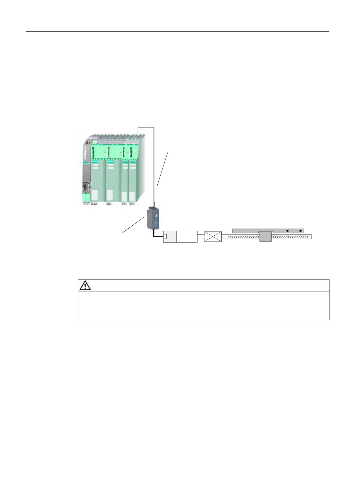
1-encoder system
For a 1-encoder system, the motor encoder is used for the safety-related actual values of the NC
and drive.
If an encoder fault develops, and a safety-related function is active, then STOP B is initiated,
followed by a STOP A.
It is possible to parameterize the response for an encoder error for 1-encoder safety systems
using encoder parameter p9516 (SI Motion encoder configuration safe functions (CU)).
p9516; bit 4 = 0 immediate STOP A for encoder errors
p9516; bit 4 = 1 → the drive is braked with STOP F → B → A.
The precondition that the axis is braked with a STOP F → B → A, is that the SINAMICS parameter
p9560 and MD36960 are set to "0".
Otherwise the actual value frozen by the encoder error can simulate downtime and therefore
cause a premature switch from STOP B to STOP A.
Braking during an encoder fault takes place via the automatic switchover to encoderless
operation. Requirement here is that encoderless operation is commissioned for the
corresponding drive. The default setting of p9516, bit 4 is "0".
As a result of the encoder fault, and the fact that internally the speed is set to a value of 0 (a valid
actual value is no longer available), i.e. no SBR monitoring is possible while STOP B is active.
The actual values are generated in a safety-related fashion either directly in the encoder or in the
Sensor Module and are provided - with no-reaction - to the NCK and the drive using safety-
related communications via DRIVE-CLiQ.
Special feature regarding linear motors:
The motor encoder (linear scale) of linear motors also acts as load measuring system. IMS and
DMS are one measuring system. The connection is made at the IMS input of the Sensor Module
or directly via DRIVE-CLiQ.
Significance of the coarse encoder position:
Safety Integrated (system-integrated)
Function Manual, 10/2020, 6FC5397-4BP40-6BA2
85
Basics regarding the safety functions integrated in the system/drive
6.4 Actual value conditioning
For a 1-encoder system, for all position monitoring functions, the accuracy of the redundant
actual value must be assumed to apply. This accuracy depends on the encoder evaluation. For
all encoder evaluation functions that can be used with Safety Integrated (SMI, SME, SMC, motor/
encoder with DRIVE-CLiQ), a redundant position value is generated and the closed-loop control
is made available. The machine manufacturer must select the appropriate encoder with the
necessary encoder pulse number for his particular requirements. To do this, the encoder
resolution must be converted to the accuracy on the load side. This conversion is dependent on
the type of encoder mounting and the type of axis. Further, gearbox factors, the spindle pitch
for linear axes and the radius of the rotary table for rotary axes must also be taken into account.
'5,9( &/L4
(QFRGHU
*HDUER[
0DFKLQH WDEOH
0RWRU
%DFN
6HQVRU 0RGXOH FDELQHW PRXQWHG
)'
ODVK
QRW XVHG IRU HQFRGHUV ZLWK
'5,9( &/L4 LQWHUIDFH
Figure 6-1
1-encoder system for a feed drive (FD)
WARNING
Residual risks
The specific residual risks for 1-encoder systems should be carefully considered (see Chapter
"Safety information & instructions and residual risks (Page 44)").
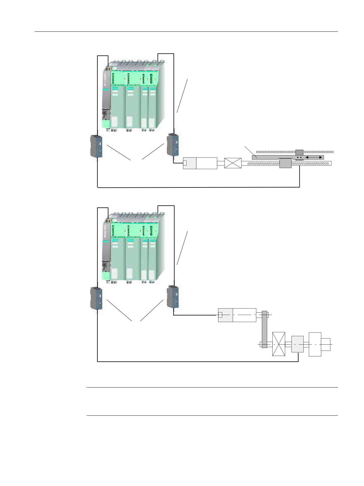
2-encoder system
In this case, the safety-related actual values for an axis are supplied from 2 separate encoders.
In standard applications, the drive evaluates the motor encoder (IMS) and the NC, the measuring
system (DMS). The actual values are generated in a safety-related fashion either directly in the
encoder or in the Sensor Module and are provided - with no-reaction - to the NCK and the drive
using safety-related communications via DRIVE-CLiQ. Each measuring system requires a
separate connection or a separate Sensor Module.
For a 2-encoder system, an encoder fault can result in a STOP F followed by STOP B and followed
by STOP A - as well as an immediate STOP A response.
Safety Integrated (system-integrated)
86
Function Manual, 10/2020, 6FC5397-4BP40-6BA2
Basics regarding the safety functions integrated in the system/drive
6.4 Actual value conditioning
'5,9( &/L4
0DFKLQH WDEOH
/LQHDU VFDOH
(QFRGHU
*HDUER[
0RWRU
%DFN
6HQVRU 0RGXOH FDELQHW PRXQWHG
)'
ODVK
QRW XVHG IRU HQFRGHUV ZLWK
'5,9( &/L4 LQWHUIDFH
Figure 6-2
2-encoder system for a feed drive (FD) with connection via 2 Sensor Modules
'5,9( &/L4
,QFUHPHQWDO HQFRGHU
0RWRU
06'
6HOHFWRU
6HQVRU 0RGXOH FDELQHW PRXQWHG QRW XVHG
JHDUER[
6SLQGOH
IRU HQFRGHUV ZLWK '5,9( &/L4 LQWHUIDFH
,QFUHPHQWDO HQFRGHU
Figure 6-3
2-encoder system for the main spindle, connected via 2 Sensor Modules
Note
For systems with slip, see Chapter "Actual value synchronization (slip for 2-encoder systems)
(Page 96)".
Safety Integrated (system-integrated)
Function Manual, 10/2020, 6FC5397-4BP40-6BA2
87

Basics regarding the safety functions integrated in the system/drive
6.4 Actual value conditioning
DRIVE-CLiQ encoder
If a DRIVE-CLiQ encoder is connected for the NCK monitoring channel (drive parameter r9527 =
2 or 3), in addition to the parameter field r0979, additional drive parameters that define the
redundant coarse position value in more detail must be read-out. When booting, these
parameters are directly read-out of the encoder and saved in the NCK machine data.
The additional parameters for DRIVE-CLiQ encoders are listed in the following table:
Drive parameters
Meaning
NCK machine data
r0469
Resolution measuring steps for linear absolute encoders
$MA_SAFE_ENC_MEAS_STEPS_RESOL
(DRIVE-CLiQ linear encoder)
r0470
Valid bits for the redundant coarse position value (DRIVE-
$MA_SAFE_ENC_NUM_BITS[0]
CLiQ encoder, binary)
r0471
Fine resolution of the redundant coarse position value
$MA_SAFE_ENC_NUM_BITS[1]
(DRIVE-CLiQ encoder, binary)
r0472
Relevant bits of the redundant coarse position value
$MA_SAFE_ENC_NUM_BITS[2]
(DRIVE-CLiQ encoder, binary)
r0473
Non-safety-related measuring steps position value POS2
$MA_SAFE_ENC_MEAS_STEPS_POS1
(DRIVE-CLiQ linear encoder)
r0474
Configuration of the redundant coarse position value
$MA_SAFE_ENC_CONF
Bit 0: Count direction, up/down
Bit 1: CRC 16: LSB/MSB first
Bit 2: MSB/LSB - justified
Bit 4: Binary comparison not possible
r0475 =
Safety MSB of the redundant coarse position value
$MA_SAFE_ENC_NUM_BITS[3]
r0470 - r0471
(DRIVE-CLiQ encoder, binary)
The difference between DRIVE-CLiQ encoder, binary or linear, is derived from drive parameter
r0474, bit 4:
• r0474.4 = 0: DRIVE-CLiQ encoder, binary
• r0474.4 = 1: DRIVE-CLiQ encoder, linear or not binary
The relevant drive parameters are evaluated, depending on the DRIVE-CLiQ prototype (binary or
linear). Different algorithms are used to compare the redundant coarse position value with the
actual value. All of the NCK machine data listed in the table above are incorporated in the
checksum via the axis-specific NCK machine data in order to identify any inadvertent changes.
In so doing, machine data:
• $MA_SAFE_ENC_NUM_BITS[0,1]
• $MA_SAFE_ENC_CONF
are incorporated in the hardware-related checksum check $MA_SAFE_ACT_CHECKSUM[1]. If
one of these NCK machine data do not match the associated drive parameter, then Alarm 27035
"Axis %1 new HW component, acknowledgment and function test required" is output. The
following machine data
• $MA_SAFE_ENC_NUM_BITS[2,3]
• $MA_SAFE_ENC_MEAS_STEPS_RESOL
• $MA_SAFE_ENC_MEAS_STEPS_POS1
Safety Integrated (system-integrated)
88
Function Manual, 10/2020, 6FC5397-4BP40-6BA2
Basics regarding the safety functions integrated in the system/drive
6.4 Actual value conditioning
have a direct impact on the accuracy of the safe position monitoring, and are therefore factored
into the functional checksum scope $MA_SAFE_ACT_CHECKSUM[0]. Further, if they do not
match the associated drive parameters, Alarm 27036 "Axis %1 encoder parameterization MD
%2[%3] was adapted" is output.
Just the same as for all encoder data, the NCK machine data for the DRIVE-CLiQ encoder are not
incorporated directly in the crosswise data comparison with the drive. However, they are
indirectly secured through the crosswise actual value comparison.
EnDatV2.2 converter
When using the EnDatV2.2 protocol, a delay is incurred when providing the actual value
information as a result of its serial data transfer.
If an EnDatV2.2 converter is used in a 2-encoder system, then as a consequence, a velocity-
dependent position difference is obtained. This must be taken into consideration in the
parameterization. In the SI service screen, using entry "Maximum position tolerance NCK/drive"
users can determine the position differences that occur, and make the appropriate position
tolerance setting in $MA_SAFE_POS_TOL.
This value includes the deviation as a result of the mechanical system, as well as also the
maximum difference resulting from the EnDatV2.2 delay.
6.4.2
Encoder adjustment, calibrating the axes
Adjusting the motor encoder
Generally, for 1-encoder systems, the integrated encoder is an integral component of the motor
(the encoder is adjusted to match the motor). Data relating to distance, speed and rotor position
(for synchronous drives) is obtained from one encoder. It is no longer possible to adjust the
encoders in motor measuring systems in the conventional sense.
Machine calibration
The machine zero and encoder zero are calibrated purely on the basis of the offset value (the
machine must be calibrated). This procedure must be carried out for both absolute and
incremental encoders.
$EVROXWH HQFRGHU DFWXDO YDOXH
2IIVHW YDOXH
3RVLWLRQ DFWXDO YDOXH
(QFRGHU
0DFKLQH
6ZLWFK RQ
]HUR
]HUR
SRVLWLRQ VWRS SRVLWLRQ
Figure 6-4
Positions and actual values
When calibrating the machine, a known or operated position is approached using a dial gauge,
fixed stop, etc. and the offset determined. This offset is then entered into the appropriate
Safety Integrated (system-integrated)
Function Manual, 10/2020, 6FC5397-4BP40-6BA2
89
Basics regarding the safety functions integrated in the system/drive
6.4 Actual value conditioning
machine data. Calibration must always be carried out for position-controlled (closed-loop) axes/
spindles.
References: Commissioning Manual, SINUMERIK 840D sl Commissioning CNC: NC, PLC, drive
SINUMERIK 840D sl, "Referencing Axis"
6.4.3
Axis states
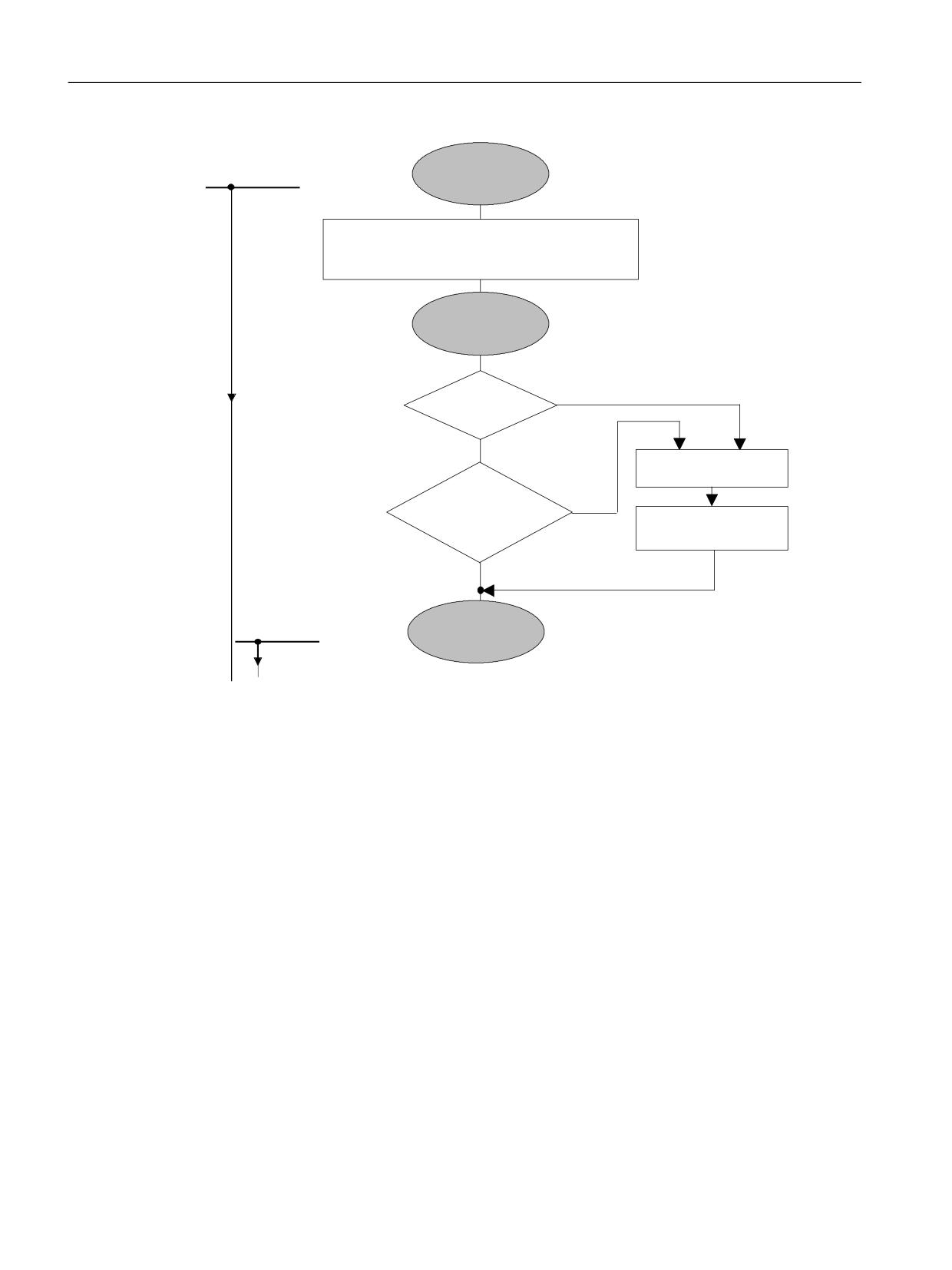
"Axis not referenced" state
The axis state "axis not referenced" is reached after the power supply has been powered-up and
the drive and control system have completely booted. This state is indicated using the axis-
specific interface signal "reference point reached" as follows:
Interface signal
"Reference point reached" = "1" axis state "Axis referenced"
"Reference point reached" = "0" axis state "Axis not referenced"
for 840D sl DB31-61, DBX60.4 / DBX60.5
(refer to Fig. "Axis states when referencing")
"Axis referenced" state
For incremental encoders, the position actual value is lost when the NC is switched off. When
the NC is switched on, a reference point approach must be carried out. If the reference point
approach is correctly executed, then the axis is referenced and goes into the "axis referenced"
state.
Contrary to incremental encoders, absolute encoders do not require a reference point approach
after the NC has been switched on. These encoders track the absolute position, e.g. using a
mechanical gear, both when switched on and switched off. The absolute position is transferred
implicitly via a serial interface when the NC is switched on. After the position data has been
transferred and the offset value has been taken into account, the axis also goes in the axis state
"axis referenced".
This axis state "axis referenced" is indicated using the axis-specific interface signal "reference
point reached" as follows:
Interface signal
"Reference point reached" = "1" axis state "Axis referenced"
"Reference point reached" = "0" axis state "Axis not referenced"
for 840D sl DB31-61, DBX60.4 / DBX60.5
Safety Integrated (system-integrated)
90
Function Manual, 10/2020, 6FC5397-4BP40-6BA2
Basics regarding the safety functions integrated in the system/drive
6.4 Actual value conditioning
"Axis safely referenced" state
In order to reach the axis state "axis safely referenced", the axis state "axis referenced" must have
been reached, and either
• the user must acknowledge the actual position using the user agreement (see Chapter "User
agreement (Page 92)")
or
• a saved and set user agreement and saved stop position when the system was switched off
must exist. The position associated with the saved data must match the current position
within a tolerance window. This is checked both in the drive and in the NC.
The axis state "axis safely referenced" is displayed using the SGA "axis safely referenced". A safety-
related position evaluation can only be carried out for the SE and SN functions after this state has
been reached.
Saved user agreement
The state of the user agreement function is saved in non-volatile memories. This saved user
agreement forms, together with the stop position, also saved in a non-volatile fashion, the
prerequisite for the axis state "axis safely referenced".
Saved stop position
The saved stop position data is combined with the permanently saved user agreement to form
the previous history.
The following must be noted when the stop position is saved:
The following applies when SE/SN is active:
• The stop position is cyclically saved.
• If the axis is moved with the system switched off, then the saved stop position no longer
matches the current position.
As described under "axis safely referenced" the "axis safely referenced" state can also be achieved
using a saved and set user agreement and a saved stop position. The following conditions must
be met:
• The saved user agreement must be available.
• The difference between the "reference position" (power-on position with absolute measuring
systems or reference position for incremental measuring systems) and the saved stop
position (including the traversing distance to the reference point with ERN) must be within
a tolerance window specified using the appropriate machine data.
Safety Integrated (system-integrated)
Function Manual, 10/2020, 6FC5397-4BP40-6BA2
91
Basics regarding the safety functions integrated in the system/drive
6.4 Actual value conditioning
6%+ 6* LV VDIH
$[LV VWDWXV LV GLVSOD\HG E\ WKH
IURP WKLV D[LV
LQWHUIDFH VLJQDO
$[LV QRW
VWDWXV RQZDUG
5HIHUHQFH SRLQW UHDFKHG
$[LV VWDWXV
UHIHUHQFHG
(41 5HDG WKH DEVROXWH YDOXH IURP WKH HQFRGHU
(51 5HIHUHQFH SRLQW DSSURDFK
,QWHUIDFH VLJQDO
$[LV UHIHUHQFHG
5HIHUHQFH SRLQW UHDFKHG
$[LV VWDWXV
8VHU
1R
DJUHHPHQW
<HV
8VHU FKHFNV WKH SRVLWLRQ
&KHFN QRW
&KHFN DFWXDO
2.
SRVLWLRQ
8VHU DJUHHPHQW
VDYHG VWDQGVWLOO
6RIWNH\
SRVLWLRQ
&KHFN 2.
6( 61 LV VDIH
IURP WKLV D[LV
$[LV VDIHO\
VWDWXV
UHIHUHQFHG
6*$
$[LV VWDWXV
$[LV VDIHO\ UHIHUHQFHG
Figure 6-5
Axis states when referencing
6.4.4
User agreement
Description
With a user agreement, an appropriately authorized person confirms that the currently displayed
SI actual position of an axis corresponds to the actual position at the machine.
This can be checked by traversing the axis to a known position (e.g. a visual mark) or the axis is
adjusted/calibrated, and the SI actual position is therefore compared in the "user agreement"
screen.
An axis/spindle with integrated safety functions can have the following status:
User agreement = yes, or
User agreement = no
Safety Integrated (system-integrated)
92
Function Manual, 10/2020, 6FC5397-4BP40-6BA2

Basics regarding the safety functions integrated in the system/drive
6.4 Actual value conditioning
All safety axes are listed in the HMI display "user agreement" for which safe limit positions and/
or safety cams have been activated. The following data are displayed:
• Machine axis name
• SI position
• User agreement
When does a user agreement have to be given?
A user agreement is always required if an axis/spindle is to be monitored for SE, SN.
A user agreement is only required:
• When the axis/spindle is commissioned for the first time.
• When the user intends or needs to again manually and safely reference the axis/spindle.
• If, after power on, the standstill position did not correspond with the actual position and the
control withdrew the user agreement.
• After parking an axis/spindle
(only if the change in position is greater than that defined using MD36944
$MA_SAFE_REFP_POS_TOL tolerance actual value comparison (referencing)).
Note
An axis/spindle must have the status user agreement = yes before the SN and SE functions can
be used.
For axes/spindles without the safety SE and SN functions, the saved stop position position is not
evaluated.
WARNING
User agreement is not available
If the drive has not been safely referenced and a user agreement has not been given, then the
following applies:
The "Safe software cams" and/or "Safe Cam Track" are active, but are not safety-relevant.
The "Safe software limit switches" are not active
The user agreement can only be set by an authorized user.
The user agreement can be cancelled by the user or as a result of a function being selected (e.g.
new gear stage) - or also an incorrect state (e.g. inconsistency in the user agreement between
the NC and drive). When the user agreement is cancelled, the axis state "axis safely referenced"
is always reset
Safety Integrated (system-integrated)
Function Manual, 10/2020, 6FC5397-4BP40-6BA2
93
Basics regarding the safety functions integrated in the system/drive
6.4 Actual value conditioning
Interlocking the user agreement
Before a user agreement can be issued, the interlock must be cancelled:
• Key-operated switch
in setting 3 → the user agreement can be issued
After the user agreement has been issued, the interlocking must be again set (e.g. key switch
position 3 must be left and the key withdrawn).
6.4.5
Selector gearboxes
6.4.5.1
Taking into account selector gearboxes
The possible gearbox ratios must be known in order that the NC and drive can evaluate the
position actual values referred to the load.
For this purposes, various gearbox ratios can be selected on an axis-for-axis basis in the machine
data and selected using the "Safety-related inputs/outputs" (SGEs/SGAs).
The following points must be carefully observed for drives with selector gearboxes (these are
generally used with spindles).
• If the drive is operated with an (indirect) encoder (motor measuring system), i.e. the safety-
related actual value for the NCK and drive are derived from the same measuring system, then
the gearbox ratios (gearbox stage selection for Safety Integrated) must also be selected for
both monitoring channels. The state of the SGE signals ratio selection (bits 0..2) is not subject
to a crosswise data comparison; however, the safety-related actual values from the NCK and
drive are compared to evaluate if there is any deviation (< 36942 $MA_SAFE_POS_TOL or
parameter p9542 SI Motion, actual value comparison tolerance (crosswise) (Control Unit)).
• If the drive is operated with an (indirect) motor encoder and a (direct) spindle encoder, the
safety-related actual values are derived from the direct encoder and those of the drive from
the indirect encoder. For the direct encoder, the gearbox changeover is not relevant and the
gearbox stage changeover only has to be configured/engineered for the drive.
• Using the two machine data fields
MD36921[0..7] $MA_SAFE_ENC_GEAR_DENOM[n] denominator, gearbox encoder/load and
MD36922[0..7] $MA_SAFE_ENC_GEAR_NUMERA[n] numerator gearbox ratio encoder/load
or
p9521[0..7] SI Motion gearbox encoder/load denominator (Control Unit) and
p9522[0..7] SI Motion gearbox encoder/load numerator (Control Unit)
8 different gearbox stage pairs for NCK/drive can be defined. For this definition, there is no
special function for an index value - e.g. interdependency on the operating mode of the
spindle. These 8 pairs must be parameterized and selected depending on the encoder
configuration.
• As a result of the gearbox stage changeover, the encoder evaluation for the safety-related
actual values change. Ideally, the gearbox stage for Safety Integrated is changed-over at
standstill. However, this is generally not in-line with what is required in practice. This means
that the actual value offset when changing-over the gearbox stage (e.g. using oscillation)
may not be greater than the already mentioned actual value tolerance window (MD36942 /
p9542).
Safety Integrated (system-integrated)
94
Function Manual, 10/2020, 6FC5397-4BP40-6BA2

Basics regarding the safety functions integrated in the system/drive
6.4 Actual value conditioning
• If, for the axis with selector gearbox, position-dependent monitoring functions are activated
- such as SE or SN - the user agreement (assuming that it was previously set) is withdrawn
when changing-over the gearbox ratio and the SGA "axis safely referenced" is set to 0. When
the gearbox stage is changed from the PLC and/or by selecting a new ratio, a new gearbox
ratio is detected using the appropriate SGEs.
• After the gearbox stage has been selected, the spindle must be resynchronized. When
resynchronizing the spindle, the two safety-related actual values (NCK and drive) are
reinitialized with the newly synchronized actual value. A possible difference that was
previously present between the two safety-related actual values is therefore corrected.
• In order to be able to re-use the SN or SE function after the gearbox ratio has been selected
(changed), the user must bring the spindle into the state "axis safely referenced" - the user
agreement must be re-issued.
• For 2-encoder systems, the gearbox ratio does not have to be selected in a safety-related
fashion and can be implemented through one channel. On the other hand, for a 1-encoder
system, the ratio selection must implemented using safety-related technology - i.e. using
two channels.
WARNING
Decoupling
When a new stage is selected for a selector gearbox (the ratio changed), an axis is parked or the
mounting situation is modified (encoder and motor replaced), then this means that the load
and encoder have been decoupled. The NC and drive cannot detect this. The state "axis safety
referenced" is no longer applicable.
The user is responsible in bringing the axis back into the "axis safely referenced" state if the
functions "safe software limit switch" or "Safe Cams" are used.
6.4.5.2
Gearbox with direction of rotation reversal
Support for mechanical gearboxes with gearbox stage-specific direction of rotation reversal
To ensure that the speed and position actual values on the load side are evaluated correctly by
the safe monitoring functions, gearbox stages with direction of rotation reversal are taken into
account. To realize this, all gearbox stages - both on the NC side as well as on the drive side
(p9539) - can be parameterized with direction of rotation reversal.
The direction of rotation reversal of the individual gearbox stages is taken into account for axes
and spindles, as well as for 1-encoder and for 2-encoder systems.
To take into account the direction of rotation reversal, analogous to drive parameter p9539 "SI
Motion gearbox direction of rotation reversal", axis-specific safety machine data
$MA_SAFE_ENC_IS_GEAR_REVERSAL (gearbox direction of rotation reversal) is available on the
NC side for all gearbox stages.
If, a value of 1 (TRUE) is entered in MD SAFE_ENC_IS_GEAR_REVERSAL for a gearbox stage, then
this results in a direction of rotation reversal of the safety-relevant actual value, and
compensates the direction of rotation reversal of the mechanical gearbox.
Safety Integrated (system-integrated)
Function Manual, 10/2020, 6FC5397-4BP40-6BA2
95
Basics regarding the safety functions integrated in the system/drive
6.4 Actual value conditioning
The default value 0 (FALSE) of MD SAFE_ENC_IS_GEAR_REVERSAL for a gearbox stage
corresponds to the previous response, i.e. the safety-relevant actual value direction of rotation
is not reversed.
When parameterizing the system, ensure that the load-side actual value has the same sense in
the safety-relevant actual value systems (NCK and DRV). Otherwise, incorrect parameterization
of the direction of rotation reversal in one or in both actual value sensing channels (NCK, DRV)
results in an error in the crosswise data comparison (CDC).
Referencing:
When referencing, the positions of the NC and SI actual value systems are set to the same value
at a defined transfer time.
If, during referencing - after this transfer time - motion still occurs, e.g. until standstill is reached
- and the NCK and Safety Integrated (SI) actual value systems have a different direction of
rotation - from this transfer time on, these count in opposing directions, and result in an offset
between the actual values the NC and SI actual value system.
This must be taken into consideration for monitoring functions with absolute reference (SE, SN)!
6.4.6
Actual value synchronization (slip for 2-encoder systems)
Description of function
When a 2-encoder system is used, SI actual values from the NC and the drive drift apart for
systems that have inherent slip. The reason for this is that the drive evaluates the motor
measuring system and the NC evaluates the direct measuring system after the gearbox.
There are the following two alternatives in order to avoid this:
•
1-encoder system without actual value synchronization
•
2-encoder system with actual value synchronization and therefore additional monitoring of
the load side
Slip tolerance
The actual value is synchronized through two channels. In both channels, machine data 36949
$MA_SAFE_SLIP_VELO_TOL / parameter p9549 "SI Motion slip velocity tolerance" is used in
which the maximum offset between the NCK and drive actual value is entered as velocity. The
tolerance value entered in MD36942 $MA_SAFE_POS_TOL is not relevant.
For the actual value synchronization, both channels correct their SI actual position to half the
determined actual value difference. Please note that the two SI actual positions no longer display
the correct absolute position. The NC actual position and the two SI actual positions are different.
The actual values are synchronized in the crosswise data comparison clock cycle. Actual value
synchronization is also performed when a crosswise data comparison of the SI actual position
outputs an error.
Actual values are also synchronized after "referencing" and for "parking axis".
The currently determined and the maximum SI speed difference since the last reset are displayed
in the axis-specific service screen for diagnostic purposes.
Safety Integrated (system-integrated)
96
Function Manual, 10/2020, 6FC5397-4BP40-6BA2

Basics regarding the safety functions integrated in the system/drive
6.4 Actual value conditioning
To define the slip tolerance, the maximum differential speed is set in MD36949
$MA_SAFE_SLIP_VELO_TOL. As a result of an action, such as e.g. maximum acceleration when
starting, gearbox stage changes with oscillation, a situation is created where the actual values
drift apart. This value can be taken as nominal value from the diagnostics screen "Maximum
velocity difference", multiplied by a factor of 1.5 and then entered into MD36949.
Note
Actual values are only synchronized when there is an actual value difference between the two
channels of 2 mm or 2 m degrees in each SI monitoring clock cycle.
Supplementary conditions
The two SI actual positions no longer display the correct absolute machine position. The correct
position can now only be read out via the NC actual position.
The safety monitoring functions SG, SBH, SBR and "n<nx" still only respond to actual value
changes from the particular actual value acquisition channel - not to changes in the actual value
resulting from the actual value synchronization. A single-channel SG violation only initiates an
alarm in the channel in which this speed violation was detected. The associated stop response
is therefore still initiated through two channels.
SGA "n<nx" can also assume different static states in the two monitoring channels.
Note
It is not possible to activate the safe SE and SN functions for an axis/spindle where slip can occur
between the motor and the load.
Activation
The actual value synchronization is selected by setting bit 3 in machine data 36901
$MA_SAFE_FUNCTION_ENABLE or parameter p9501 "SI Motion enable safety functions". In
addition, SI function "SBH/SG monitoring" must also be enabled.
Actual value synchronization is only permissible if a monitoring function with absolute reference
has not been simultaneously enabled. If SE and/or SN are also selected, power on Alarms 27033
and F01688 are also output when booting.
The actual value synchronization is only permissible for 2-encoder systems. If this function is
enabled for a single-encoder system, Alarm 27033/F01688 is output.
6.4.7
Encoder limit frequency
The encoder limit frequency is fixed at 500 kHz. This value is secured through the crosswise data
comparison between the NCK and drive.
Monitoring the speed to ensure that it does not exceed the encoder limit frequency is carried out
using the SMI, SMC and SME Sensor Modules (see Chapter "Safely reduced speed (SG)
(Page 136)").
Safety Integrated (system-integrated)
Function Manual, 10/2020, 6FC5397-4BP40-6BA2
97
Basics regarding the safety functions integrated in the system/drive
6.5 Enabling the safety-related functions
Encoders with DRIVE-CLiQ interface are not monitored with respect to an encoder limit
frequency.
6.5
Enabling the safety-related functions
Global enable
SINUMERIK Safety Integrated (SI) with the safety-related functions is enabled using options.
The enable signal determines the number of axes/spindles for which SI can be activated. Using
an additional options, in addition, the number of possible SPL-SGEs/SGAs is defined.
The SH/SBC/SS1 function is completely implemented in SINAMICS S120 and is, as a function
integrated in the drive, included in the basic drive scope.
Enabling safety-related functions
Which safety functions are to be effective can be individually selected for each axis using the
following machine data:
For 840D sl
MD36901 $MA_SAFE_FUNCTION_ENABLE
(See Chapter "Machine data for SINUMERIK 840D sl (Page 307)").
For S120
p9501 SI Motion enable safety functions (Control Unit)
(See Chapter "Parameters for SINAMICS S120 (Page 389)").
The following functions can also be individually enabled:
• SBH/SG
• SE
• SN
• SG override
• Actual value synchronization
• External STOPs
• Cam synchronization
• STOP E
• Extension n<nx
Safety Integrated (system-integrated)
98
Function Manual, 10/2020, 6FC5397-4BP40-6BA2

Basics regarding the safety functions integrated in the system/drive
6.6 Switching the system on/off
Note
• To ensure that SBH can always be selected in the event of an error, the function SBH/SG must
be activated and appropriately parameterized when the function SE and/or SN are (is)
enabled.
• The axis-specific enable data in the NCK must match those in the drive, otherwise, the
crosswise data comparison signals an error.
• An SI axis is treated as an axis in terms of the global option if at least one safety-related
function is activated via the axis-specific enable data.
• The maximum number of axes that may operate with SI and SPL SGE/SGAs is the number that
was enabled using the options.
6.6
Switching the system on/off
WARNING
Firmware version / CF card version
In a system configuration, the firmware versions of the DRIVE-CLiQ components can only differ
from the versions on the CF card, if either
a) The automatic upgrade/downgrade (parameter p7826) is deactivated, or
b) Components with a new firmware version can no longer be downgraded to the status of the
version available on the CF card.
Case a) is not permitted when Safety Integrated is used. The automatic upgrade/downgrade
must never be deactivated when Safety Integrated is used. (automatic firmware update
(p7826) must be equal to 1)
Case b) is only permissible if this combination has been explicitly approved by the
manufacturer.
WARNING
Changes or replacement of hardware and/or software components
After hardware and/or software components have been changed or replaced, it is only
permissible to run up the system and activate the drives when the protective devices are closed.
It is not permissible that personnel are present within the danger zone.
Depending on the change made - or what has been replaced - it may be necessary to carry-out
a partial or complete acceptance test (see Chapter "Acceptance test (Page 537)").
Before personnel may re-enter the hazardous area, the drives should be tested to ensure that
they exhibit stable control behavior by briefly moving them in both the plus and minus
directions (+/-).
This is especially important specifically for high-speed linear or torque motors.
Safety Integrated (system-integrated)
Function Manual, 10/2020, 6FC5397-4BP40-6BA2
99

Basics regarding the safety functions integrated in the system/drive
6.6 Switching the system on/off
What has to be observed when switching on?
The safety-related functions are only available and can only be activated after the system has
completely run up.
We recommend that the Safe Operating Stop (SBH) function is selected.
For axes with SE/SN, the stop position is used to internally check the position when switching on.
WARNING
System runup
System runup is a critical operating state with increased risk. In this phase, especially when
activating drives, it is not permissible that personnel are close to the hazardous area.
Further, for vertical axes, it is very important to ensure that the drives are in a state with the
pulses cancelled.
A complete forced checking procedure is necessary after switching on (refer to Chapter "Forced
checking procedure (Page 82)").
What has to be observed when switching off?
• When SE/SN is activated, the following applies:
The stop position is cyclically saved.
For this reason, the user should only switch-off the control when the axes/spindles with
safety functions have stopped moving.
Note
If the axis is moved with the system switched off, then the saved stop position no longer matches
the current position. For axes with safety-related functions SE and SN, when switching-on, a
user agreement is again required after the position has been checked.
Safety Integrated (system-integrated)
100
Function Manual, 10/2020, 6FC5397-4BP40-6BA2
Safety functions integrated in the system/drive
7
7.1
Safe standstill (SH)
Note
This chapter describes the safety function safe standstill (SH), controlled from the safety-related
motion monitoring functions. The function is based on the safety functions STO/SBC of the drive.
The safety functions STO, SBC and SS1, integrated in the drive and controlled via the drive
terminals, are described in Chapter "Safe Torque Off (STO) (Page 58)". Control via terminals and
from the motion monitoring functions is in parallel and can be used independently of one
another.
A STOP A/STO initiated in the drive (i.e. a system error in the drive or STO/SBC/SS1 selection via
terminal) is however not available as two-channel SGA "STOP A/B active" for the safety-related
motion monitoring functions. There is only a single-channel signal "pulses cancelled" present.
Description
The safe standstill function is based on the pulse cancellation function integrated in the Motor
Modules of the SINAMICS S120 (start inhibit).
There are two switch-off signal paths that are independent of one another, which ensure that
when a component fails, the drive is always brought into a safe condition.
The safe standstill function safely disconnects the energy feed to the motor in the event of a fault
or in conjunction with a machine function.
The following must be carefully observed when controlling/energizing SH from the motion
monitoring functions.
• The safety functions STO/SBC/SS1 integrated in the drive are, corresponding to the
description in Chapter "Safety Functions integrated in the drive (Page 51)", fully effective
(parameters, alarms etc.). The standard pre-assignment (default setting) of the associated
parameters is generally sufficient in the context of the motion monitoring functions.
• The safety function STO integrated in the drive does not have to be explicitly enabled; this is
implicitly enabled by enabling the motion monitoring functions (p9501 < > 0). However, if
the safety function SBC integrated in the drive is to be additionally activated when selecting
STO, then this must be explicitly enabled.
• The PROFIsafe drive address must be set.
Safety Integrated (system-integrated)
Function Manual, 10/2020, 6FC5397-4BP40-6BA2
101

Safety functions integrated in the system/drive
7.1 Safe standstill (SH)
WARNING
Potentially hazardous motion
If the safe standstill function or "STOP A" is activated, then the motor can no longer generate
any torque. This is the reason that potentially hazardous motion can occur, e.g. for the
following:
• When an external force acts on the drive axes
• Vertical and inclined axes without weight equalization
• Axes that are moving (coasting down)
• Direct drives with low friction and low self-locking
• Cogging torques (depending on the motor type, bearing design and friction characteristics,
up to half a pole pitch in a direction that cannot be predicted)
Possible hazards must be clearly identified using a risk analysis that must be carried out by the
manufacturer. With an assessment, based on this risk analysis, it should be defined as to which
additional measures are required, e.g. external brakes.
Functional features
The main features of the safe standstill function are as follows:
• The motor cannot be started unintentionally or accidentally
• The energy feed to the motor is safely disconnected
• The Motor Module and motor are not electrically isolated from one another
Selecting/deselecting SH
The safe standstill function corresponds to an external STOP A. This makes it possible to explicitly
select SH, not only using internal events (STOP A when a limit value is violated), but also via SGE.
• Safe standstill is activated after a STOP A.
• Safe standstill is automatically activated from every monitoring channel when testing the
switch-off signal paths.
Note
When selecting/deselecting SH, motion monitoring functions such as SBH, SG, n<nx, SE, SN are
not influenced. For instance, when manually turning a spindle in the SH state, with SBH
simultaneously selected, then this results in Alarm 27010. When required, users must take this
into account in the safe programmable logic (SPL).
WARNING
Testing the safe standstill function
After the machine has been switched on, the safe standstill function must always be tested for
all of the axes/spindles by testing the switch-off signal path using Safety Integrated.
Safety Integrated (system-integrated)
102
Function Manual, 10/2020, 6FC5397-4BP40-6BA2
Safety functions integrated in the system/drive
7.1 Safe standstill (SH)
7.1.1
Switch-off signal paths
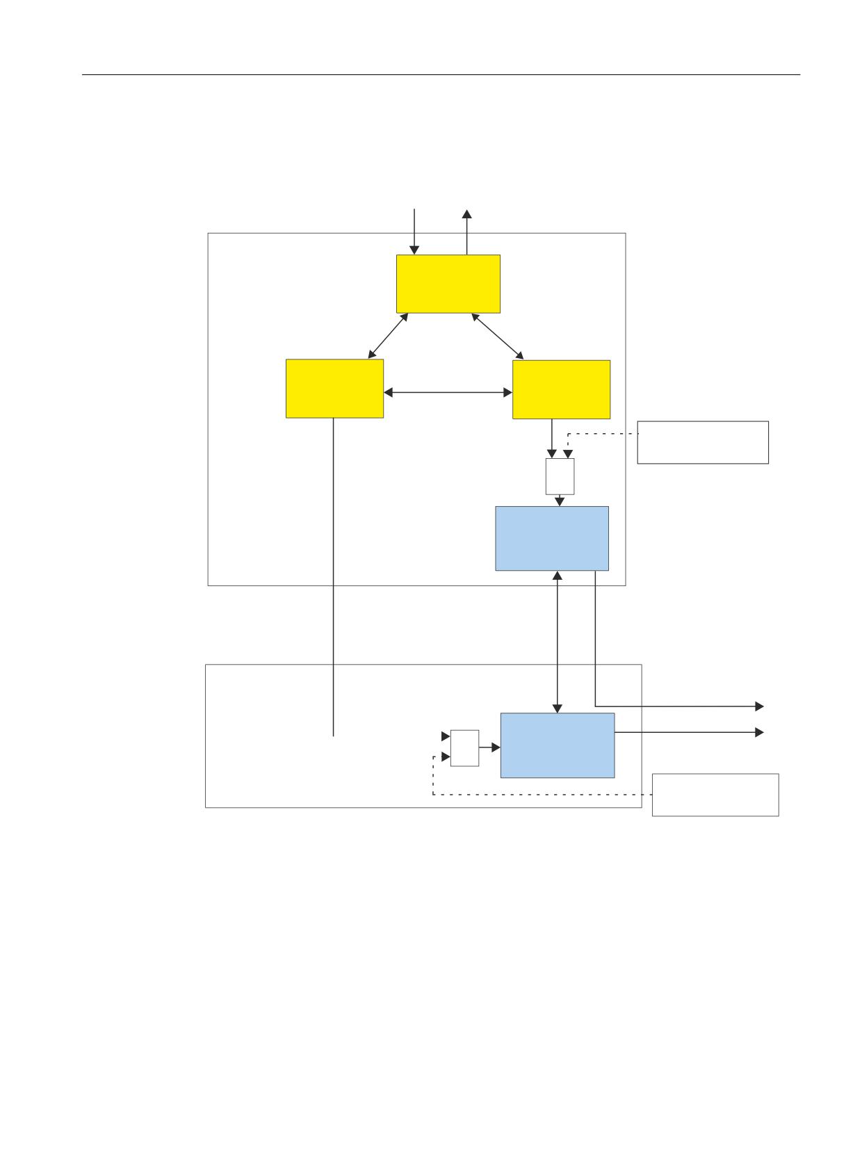
The interaction of the safety functions integrated in the drive and the motion monitoring
functions (Motion Monitor) are shown in in the following diagram.
H[W 6*(
H[W
6*(
1&8
6DIH
3URJUDPPDEOH
/RJLF 63/
6*( 6*$
6*( 6*$
6DIH
3URJUDPPDEOH
1&.
'ULYH
/RJLF 63/
0RWLRQ PRQLWRU
0RWLRQ PRQLWRU
3XOVH
2SWLRQDO
VXSSUHVVLR
Q
672 6%& 66
VHOHFWLRQ YLD WHUPLQDO
B
6ZLWFK RII VLJQDO SDWK
'ULYH &8
1&.
6, LQWHJUDWHG LQ WKH
GULYH
F\FOLF 'DWD IRU 6,
LQWHJUDWHG LQ WKH GULYH
&'&
00
6ZL
WFK RII VLJQDO SDWK &8
0RWRU 0RGXOH
3XOVH FDQFHOODWLRQ
3XOVH FDQFHOODWLRQ
'ULYH00
6ZLWFK RII VLJQDO SDWK 00
6, LQWHJUDWHG LQ WKH
3XOVH FDQFHOODWLRQ
GULYH
2SWLRQDO
672 6%& 66
VHOHFWLRQ YLD WHUPLQDO
Figure 7-1
Overview of the switch-off signal paths
Safety Integrated (system-integrated)
Function Manual, 10/2020, 6FC5397-4BP40-6BA2
103
Safety functions integrated in the system/drive
7.1 Safe standstill (SH)
Switch-off signal path of the monitoring channel, drive
The motion monitoring function in the CU signals the monitoring function integrated in the
drive in the CU that the pulses must be cancelled in the SI monitoring channel integrated in the
drive.
• Drive (CU) SI, integrated in the drive
- The requirement to cancel the pulses is detected. Mechanisms then start that are also
executed when STO is selected for the safety functions integrated in the drive:
- Initiating the pulse cancellation
- The timer routine is started to check the feedback. After the timer has expired (in the next
monitoring clock cycle integrated in the drive), using the feedback signal, it is checked as
to whether the pulses have been cancelled via this switch-off signal path.
- If p9602=1, then Safe Brake Control is executed.
Switch-off signal path of the monitoring channel, control
If the higher-level control with its motion monitoring identifies that it is necessary to cancel the
pulses, then the following sequence applies:
• NCK Motion Monitor
The control communicates to the Motor Modules the requirements to cancel the pulses.
• Drive (MM) SI, integrated in the drive
- If the drive-integrated monitoring function in the Motor Module identifies the
requirement to cancel the pulses, then the same mechanisms are started that are carried
out for an STO selection of the safety functions integrated in the drive and an STO is
initiated:
- Initiating the pulse cancellation
- The timer routine is started to check the feedback. After the timer has expired (in the next
monitoring clock cycle integrated in the drive), using the feedback signal, it is checked as
to whether the pulses have been cancelled via this switch-off signal path.
- If p9802=1, then Safe Brake Control is executed.
- If the Motor Module detects that communications to the NCK have failed, then this is
identified by the safety functions integrated in the drive and an STO is initiated.
Switch-off signal path via terminals
If the "STO/SS1/SBC selection via terminal" function is configured, then it must be taken into
account that when selecting functions STO/SS1 the higher-level motion control must respond to
this operating situation. It is especially important to observe the timing of the interaction
between the closed-loop operating control and the open-loop motion control.
Safety Integrated (system-integrated)
104
Function Manual, 10/2020, 6FC5397-4BP40-6BA2

Safety functions integrated in the system/drive
7.1 Safe standstill (SH)
If problems are manifested in the form of an unexpected alarm occurrence on the side of the
motion control (Alarm 21612 "Enable reset, cause 3 or 4"), then the following measures can be
applied in order to improve the response:
• For axes, for which motion monitoring functions have been parameterized (Safety Integrated
SPL) - or also Safety Integrated Plus) - using parameters p1226, p1227 and p1228, the pulse
inhibit (SH) can be influenced, so that no monitoring function responds on the open-loop
control side.
• For axes, which are operated without any motion monitoring functions (see Chapter "Safe
Brake Test (SBT) (Page 286)"), in order to identify early on the switching states on the NC side.
In addition, the specified parameters p1226, p1227 and p1228 can be used for optimization.
7.1.2
Testing the switch-off signal paths
Description
The test stop is used to check the switch-off signal paths of both monitoring channels. There is
a test stop input (drive SGE). The acknowledgment is realized via the drive SGA "status pulses
cancelled".
The pulse cancellation must be simultaneously initiated through both switch-off signal paths
due to the fact that the Motor Modules and drive closed-loop control are cross-checked.
The user (machine manufacturer) must configure the execution of the test stop phase.
Note
A test stop can be simultaneously made for all axes of a drive unit.
Instant in time of the test stop
The switch-off signal paths must be tested (forced checking procedure) at a suitable instant in
time (see Chapter "Forced checking procedure (Page 82)").
Note
The machine manufacturer should define the "test switch-off signal paths" time in an
appropriate "test block".
Note
If the brake control is enabled, then when the test stop is initiated, the brake is also controlled.
Safety Integrated (system-integrated)
Function Manual, 10/2020, 6FC5397-4BP40-6BA2
105
Safety functions integrated in the system/drive
7.2 Safe Operating Stop (SBH)
Prerequisites for the test stop
• At the start, the pulses must still be enabled; further, it is not permissible that SH is selected
at the start.
• For vertical (suspended) axes, the manufacturer must ensure that these are locked (to stop
them falling).
Note
The test stop can be carried out independently of the status of the standard pulse cancellation.
Message
The "test stop running" message is displayed during the "test stop".
7.2
Safe Operating Stop (SBH)
Description
The SBH function safely monitors the stop position (zero speed) of an axis/spindle in closed-loop
position or speed control.
When SBH is active (SGA "SBH active" = 1), operating personnel can, for example, enter protected
machine areas in the setting-up mode without first having to shut down the machine.
An incremental encoder is sufficient to implement this function. The actual position value is
monitored for a change.
In this case, the encoder coarse position must be taken into account for a 1-encoder system (see
Chapter "Actual value conditioning (Page 84)").
Functional features
The features of the SBH function are as follows:
• The axis remains in closed-loop control
• Parameterizable SBH tolerance window
• STOP B is the stop response after SBH has responded
Standstill tolerance
The standstill of the axis/spindle is monitored using an SBH tolerance window that is
parameterized using the following machine data:
For 840D sl:
MD36930 $MA_SAFE_STANDSTILL_TOL
For SINAMICS S120:
Safety Integrated (system-integrated)
106
Function Manual, 10/2020, 6FC5397-4BP40-6BA2
Safety functions integrated in the system/drive
7.2 Safe Operating Stop (SBH)
p9530 SI Motion standstill tolerance (Control Unit)
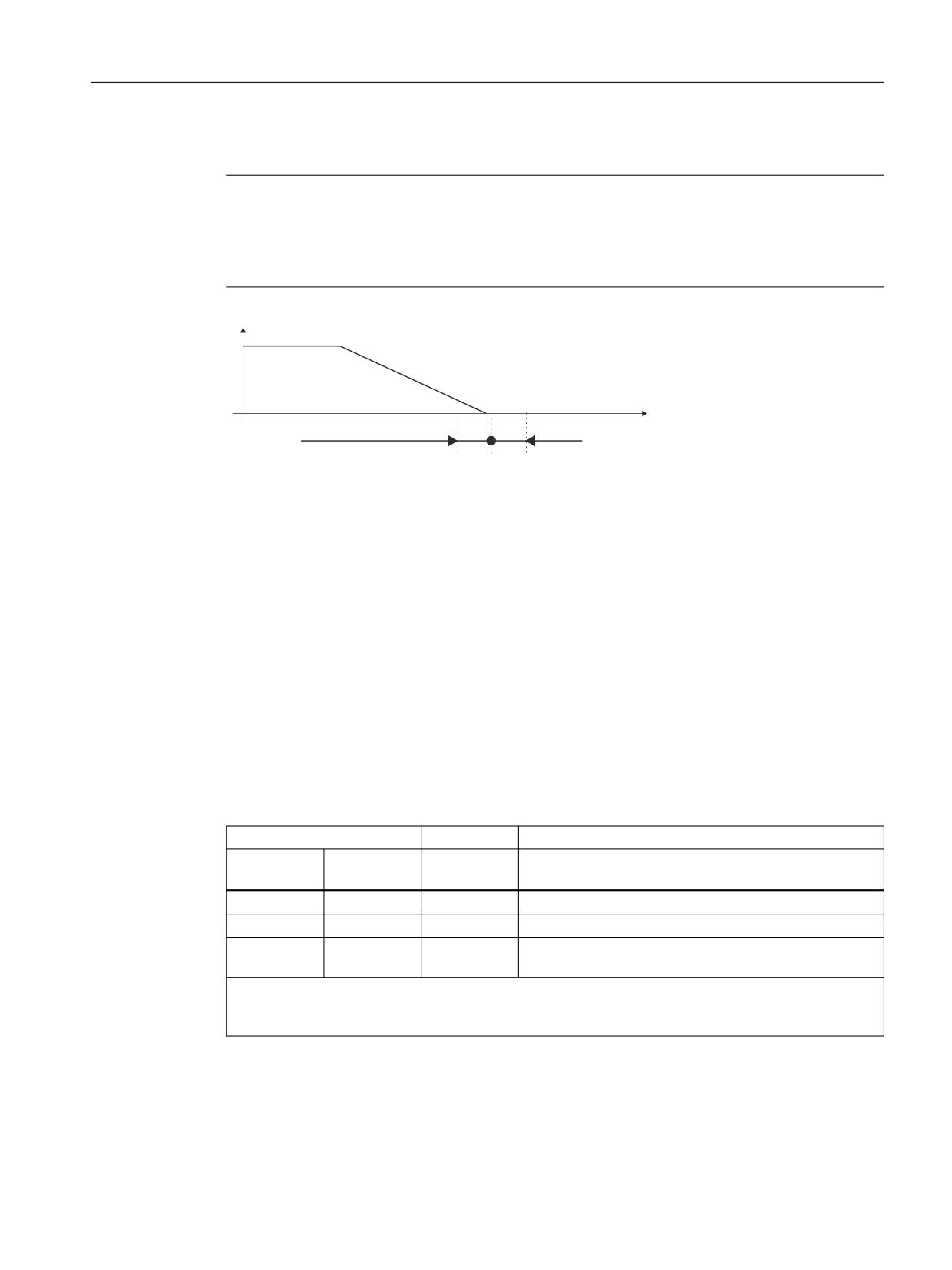
Note
The width of the SBH tolerance window should be based on the standstill (zero speed)
monitoring limit - and should lie slightly above it. Otherwise, the standard monitoring functions
of the control could be ineffective. In this case, the encoder coarse position must be taken into
account for a 1-encoder system.
9
6
6WDQGVWLOO WROHUDQFH
DFWXDO YDOXH
Figure 7-2
Standstill tolerance
Preconditions
The following preconditions must be satisfied (see Chapter "System requirements (Page 41)"):
• The option and functions must be enabled in the axis-specific machine data
• SGEs "SBH/SG deselection" and "SBH deselection" must be supplied in the NCK and drive
monitoring channel
7.2.1
Selecting/deselecting the Safe Operating Stop
Selecting SBH
The Safe Operating Stop function is selected using the following SGEs:
SGE
SGA
Meaning
SBH/SG se-
SBH deselec-
SBH active
lection
tion
= 1
x
0
SBH and SG are deselected
= 0
= 0
1
SBH is selected
= 0
= 1
0
SG is selected (see Chapter "Safely reduced speed (SG)
(Page 136)"). 1)
Note:
x → signal state is arbitrary
1) The active SG stage is displayed using SGA "SGA active bit 0" and "SG active bit 1".
Safety Integrated (system-integrated)
Function Manual, 10/2020, 6FC5397-4BP40-6BA2
107
Safety functions integrated in the system/drive
7.2 Safe Operating Stop (SBH)
Note
If safely reduced speed was not active prior to the selection of SBH, any moving axis/spindle is
stopped with STOP B/A.
The actual status of the function is displayed using the SGA "SBH active".
The SGEs and SGAs are described in Chapter "Safety-related input/output signals (Page 169)"
Internal control request for SBH
When the SG or SE responds (STOP C, D, E) the drive is internally switched to the Safe Operating
Stop state in the control. In such cases, the external circuit of the SGEs (SBH/SG deselection and
SBH deselection) is ignored and both are internally set to "0".
Selecting SBH from SG
The changeover from safely reduced speed to Safe Operating Stop is initiated using the SGE "SBH
deselection". A delay time that is parameterized in the following machine data is simultaneously
started with the changeover to SBH (signal "SBH deselection"=0):
For 840D sl
MD36951 $MA_SAFE_VELO_SWITCH_DELAY
For SINAMICS S120
p9551 SI Motion SLS(SG) changeover delay time (Control Unit)
SBH is activated as soon as the delay time expires.
Note
If the SBH function is selected while an axis/spindle is moving, the machine manufacturer must
initiate the braking process such that the axis/spindle is in position - i.e. stationary - after the
delay time has expired. This can be performed automatically using the "setpoint speed limiting"
function. If the axis moves out of the standstill tolerance window after the delay has expired, an
alarm is generated (for 840D sl: 27010, for SINAMICS S120: F01707) and STOP B/A initiated.
Safety Integrated (system-integrated)
108
Function Manual, 10/2020, 6FC5397-4BP40-6BA2
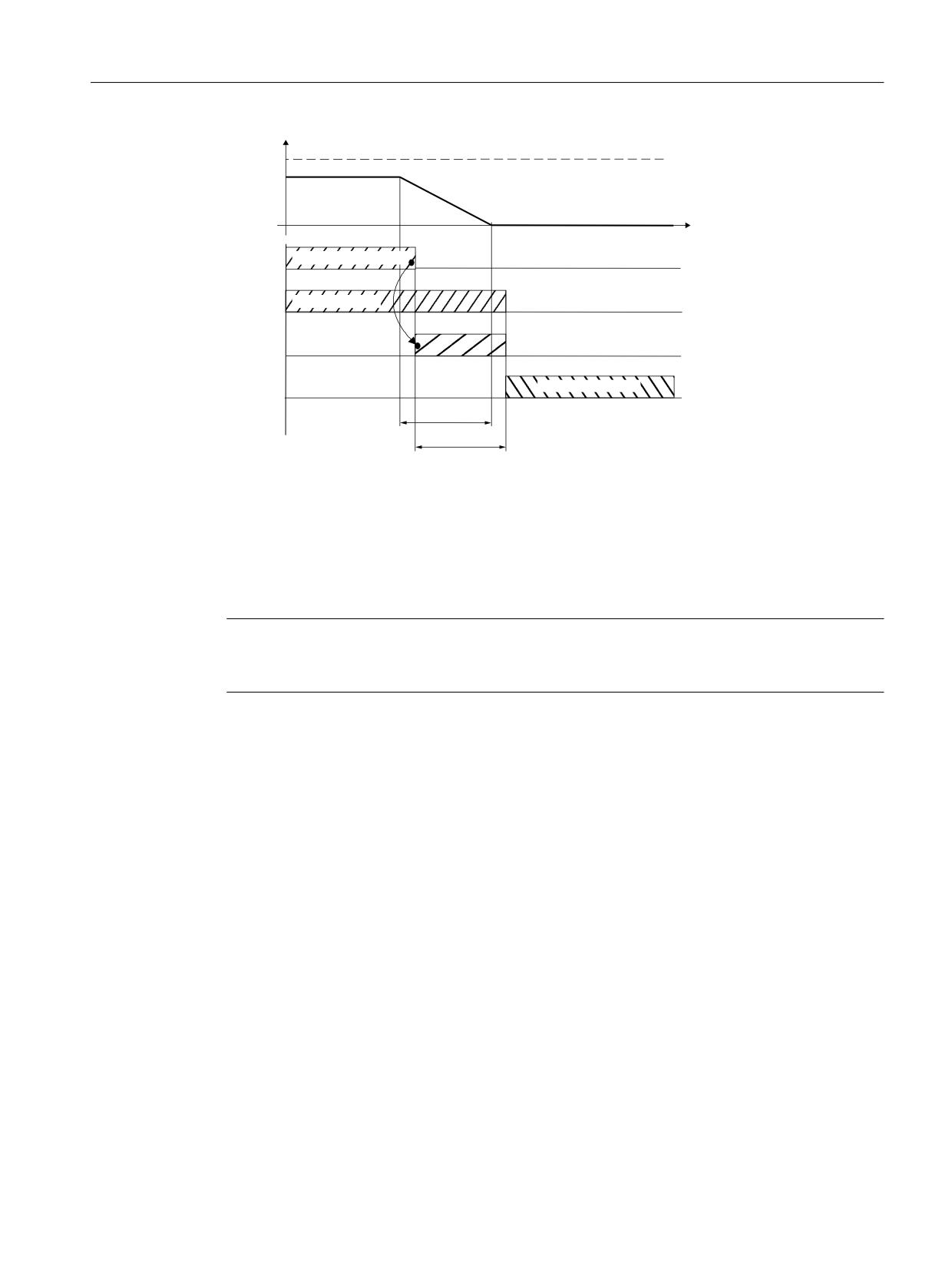
Safety functions integrated in the system/drive
7.2 Safe Operating Stop (SBH)
9
6*Q
D %UDNLQJ LV LQLWLDWHG
YDFW
6*( 6%+ GHVHOHFWLRQ
6*Q LV DFWLYH
'HOD\ WLPH
9HORFLW\ FKDQJHRYHU
6%+ LV DFWLYH
%UDNLQJ WLPH
7LPHU UXQQLQJ
Figure 7-3
Timing when SBH is selected from SG
Deselecting SBH
Safe Operating Stop can be deselected using SGE "SBH/SG deselection" (= "1" signal); this results
in a general deactivation of SBH and SG. The SBH function is also deselected when the SG
function is selected using the SGE "SBH deselection".
Note
The delay time must be selected as a function of the distance to the hazardous location. The
speeds to be taken into account in this respect are specified in Standard DIN EN ISO 13855.
Configuring NCK-SGAs
The NCK-SGA "SBH active" is configured using the following machine data:
For 840D sl
MD36981 $MA_SAFE_SS_STATUS_OUTPUT
Configuring NCK-SGEs
For 840D sl
MD36971 $MA_SAFE_SS_DISABLE_INPUT
SGA "SBH active"
If this SGA is set, then Safe Operating Stop (SBH) is active. This means that the axis is safely
monitored for zero speed. This SGA can be used, for example, to implement protective door
interlocking functions.
Safety Integrated (system-integrated)
Function Manual, 10/2020, 6FC5397-4BP40-6BA2
109
Safety functions integrated in the system/drive
7.2 Safe Operating Stop (SBH)
7.2.2
Effects when the limit is exceeded for SBH
WARNING
Fault situation for SBH
If the Safe Operating Stop function is activated, when a fault situation occurs, the axis
mechanical system can exhibit jerky, uneven motion. The magnitude of this movement
depends on the following parameters:
• Design of the mechanical system and gear ratio between the motor and mechanical system
• Speed and acceleration capability of the motor
• Magnitude of the selected monitoring clock cycle
• Magnitude of the selected SBH tolerance window
If the axis/spindle is being monitored (SGA "SBH active"=1) and leaves, for example, the standstill
tolerance window as the result of an external influence or an undefined setpoint input, then the
effects are as follows:
Effects
• The axis switches to STOP A/B configured using the following MD:
For 840D sl:
MD36956 $MA_SAFE_PULSE_DISABLE_DELAY
For S120:
p9556 SI Motion pulse cancelation delay time (Control Unit)
and
For 840D sl:
MD36960 $MA_SAFE_STANDSTILL_VELO_TOL
For S120:
p9560 SI Motion pulse cancelation shutdown speed (Control Unit)
• An alarm is generated (for 840D sl: 27010, for S120: F01707)
Safety Integrated (system-integrated)
110
Function Manual, 10/2020, 6FC5397-4BP40-6BA2
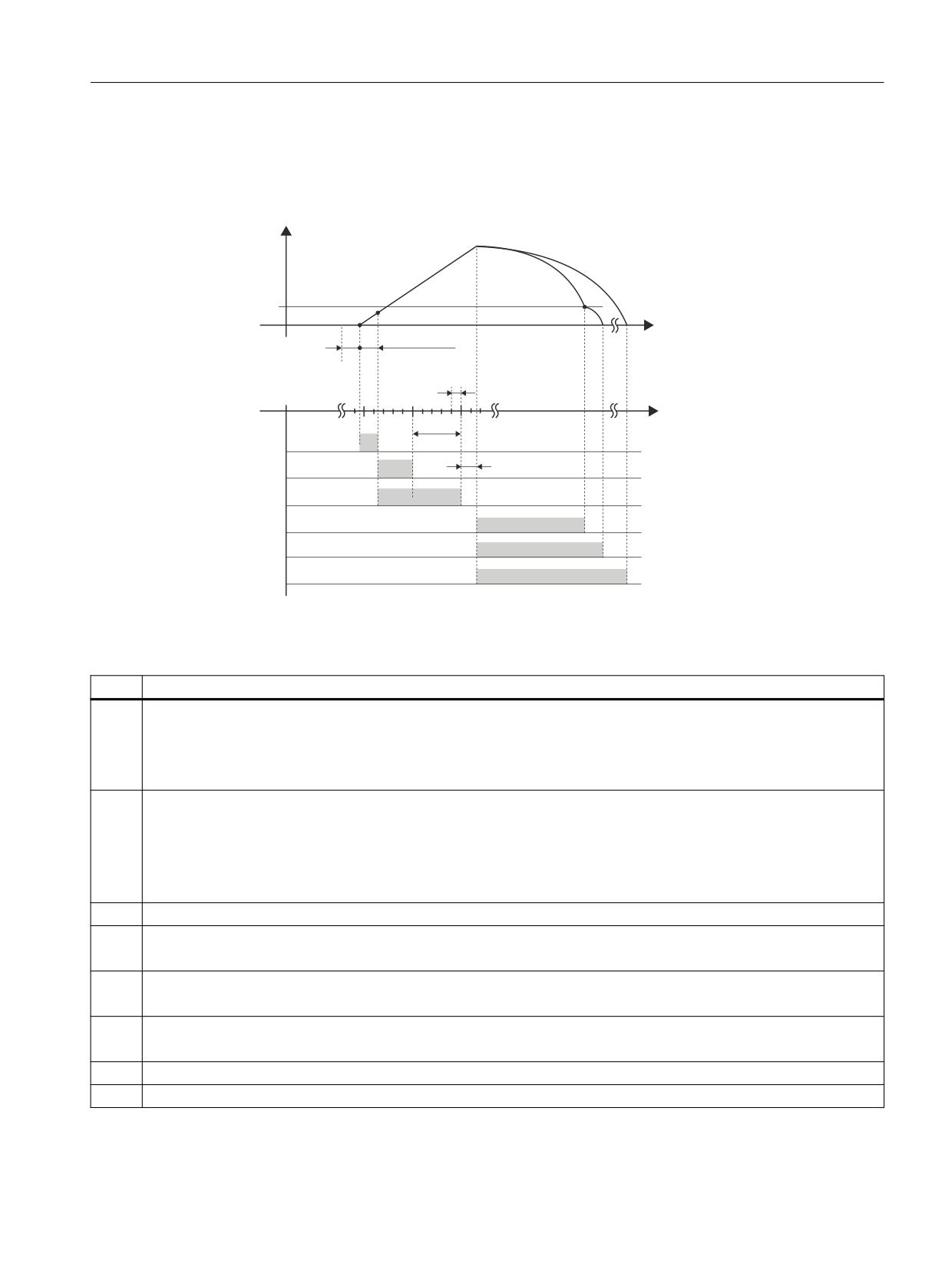
Safety functions integrated in the system/drive
7.2 Safe Operating Stop (SBH)
Timing when the limit value is exceeded
If the Safe Operating Stop function is active, the timing response when the limit value is
exceeded is as follows:
Q
G 7UDQVLWLRQ IURP 6723 % WR
F 6WDUW RI WKH VWRS UHVSRQVH
6723 $ SXOVH FDQFHOODWLRQ
6723
$
6723 %
7ROHUDQFH
H[FHHGHG E
G
6KXWGRZQ
)DXOW D
VSHHG
V
6WDQGVWLOO
WROHUDQFH
QRW
WR VFDOH
W
W
W
W
W
W
W
W
W
W
Figure 7-4
Timing when the limit value is exceeded for SBH
Table 7-1
Explanation of the diagram
Time
Explanation
t1
The position control clock cycle, defined by the following MDs:
For 840D sl:
MD10050 $MN_SYSCLOCK_CYCLE_TIME
MD10060 $MN_POSCTRL_SYSCLOCK_TIME_RATIO
t2
Monitoring clock cycle, defined by the following MD:
For 840D sl:
MD10090 $MN_SAFETY_SYSCLOCK_TIME_RATIO
For SINAMICS S120:
r9500 SI Motion monitoring clock cycle (Control Unit)
t3
Time until the standstill tolerance value is exceeded
t4
Time until it has been detected that the standstill tolerance value has been exceeded
(typical 0.5 monitoring clock cycles, maximum 1 monitoring clock cycle + 1 position controller clock cycle)
t5
Response time required to initiate the configured stop response
(typical 1.5 monitoring clock cycles, maximum 2 monitoring clock cycles + 1 position controller clock cycle)
t6
Time until the stop response that was initiated starts
(typical 2 position controller clock cycles, maximum 2 position controller clock cycles)
t7
Time required to reach the shutdown speed for STOP B.
t8
Time required to stop the axis for a STOP B.
Safety Integrated (system-integrated)
Function Manual, 10/2020, 6FC5397-4BP40-6BA2
111
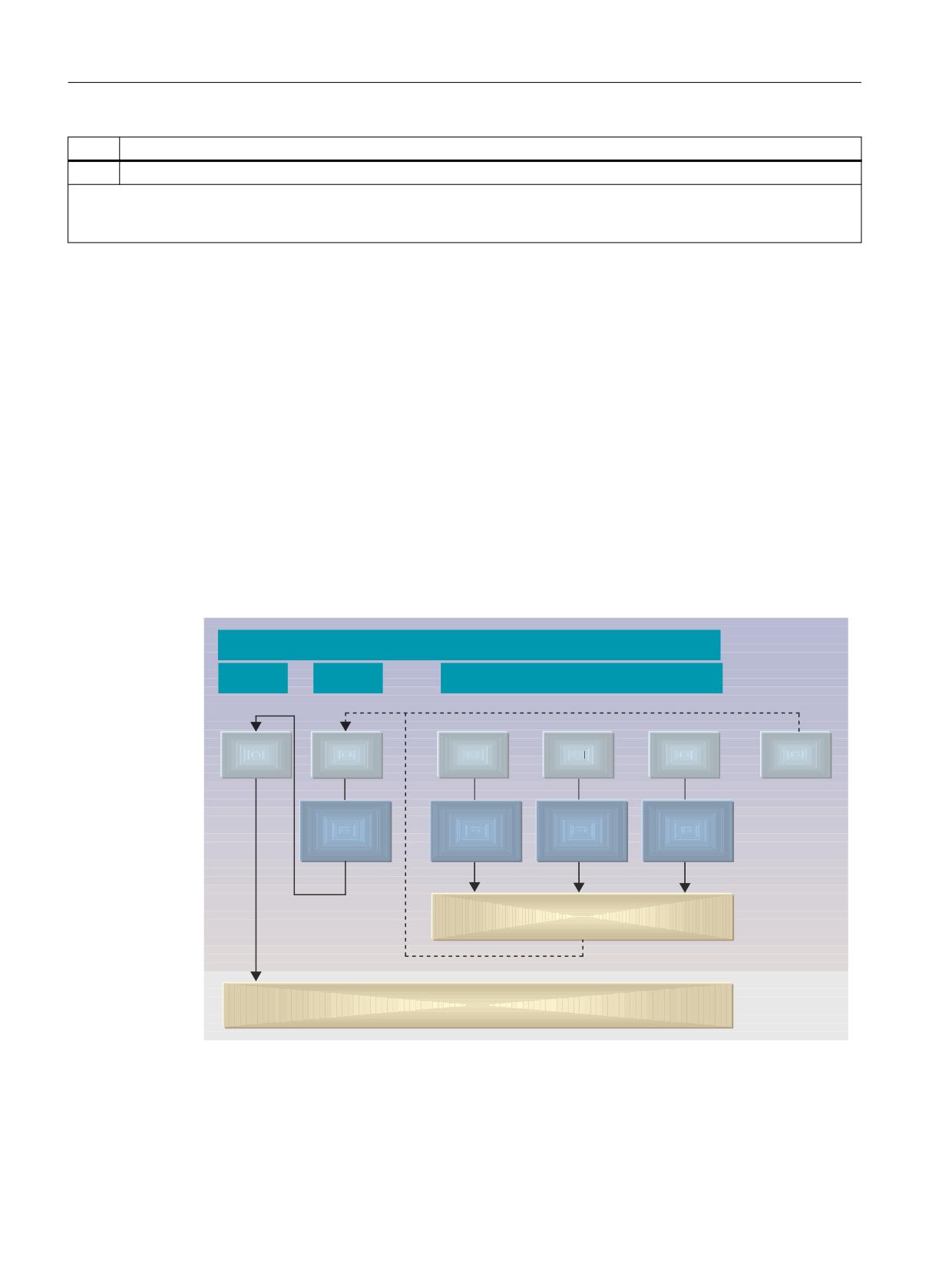
Safety functions integrated in the system/drive
7.3 Safe Stops A-F
Time
Explanation
t9
Time required to stop the axis for a STOP A.
Note:
Each axis must be measured during commissioning (start-up) to determine the distance that it travels between the limit value
being violated and it coming to a standstill.
7.3
Safe Stops A-F
7.3.1
General
Safe Stops are used to stop drive motion and bring it to a standstill. A distinction is made between
internal and external Stops. The internal stop responses, initiated by safety-related functions
when limit values are violated, initiate an alarm. The external stop responses selected by SGEs
do not issue an alarm and are acknowledged when the SGEs are deselected.
Stop responses SBH and SH
The following diagram shows the relationship between the stop responses and the Safe
Operating Stop (SBH) or the safe standstill (SH).
6WRS &DWHJRU\ DFFRUGLQJ WR (1
3DUW
2QO\ IRU DFWLYH D[LV VSHFLILF VDIHW\ IXQFWLRQ
6WRS
6WRS
6WRS
6WRS
6WRS
6WRS
$
%
&
'
(
)
3D
WK
5HWUDFWLRQ
6HW
SRLQW
6H
WSRLQW
UHO
D
WHG
F
RQGLW
LQS
XW
Q
S
XW
Q
D JURXS
LRQV
6%+
VWD
Q
G
V
W
LOO LQ FORVHG ORRS FRQWURO
2QO\ XQGHU IDXOW FRQGLWLRQV
6+
SXOVH FDQFHOODWLRQ
Figure 7-5
Stop responses, Safe Operating Stop (SBH), safe standstill (SH)
A high degree of security against faults/errors is afforded by the two-channel system structure
with its permanent, crosswise data comparison. Alarms and stop responses are initiated when
differences are detected between the two channels. The purpose of the stop responses is to
Safety Integrated (system-integrated)
112
Function Manual, 10/2020, 6FC5397-4BP40-6BA2

Safety functions integrated in the system/drive
7.3 Safe Stops A-F
safely stop the drives in a controlled fashion according to the actual machine requirements. A
differentiation is made between the stop responses STOP A, B, C, D, E, F and the test stop. The
type of stop response that occurs in the event of a fault/error can either be pre-determined by the
system or configured by the machine manufacturer. Stops A, C, D and E can also be externally
selected as a function of an event via safety-related inputs (SGE).
WARNING
Protection of persons
Protection of personnel must be given top priority when stop responses are configured. The
objective is to stop the drives in a way that best suits the situation. The time stages of the stops
must be configured with the smallest possible value corresponding to the application.
Table 7-2
Overview of the stop responses
STOP
Action
Effect
Initiated in re-
Transitioned into
Acknowledgment
sponse to
A
Pulses are immediate-
Drive coasts down
SBR/SG exceeded
SH
POWER ON
ly cancelled
B
Speed setpoint of 0 is
Drive is braked at the cur-
SBH/SG exceeded
SH
POWER ON
immediately entered
rent limit/along the OFF3
+ timer tB starts
ramp
tB =0 or nact < nshutdown:
Transition to STOP A
STOP A
C
Speed setpoint of 0 is
Drive is braked at the cur-
SG/SE exceeded
SBH
RESET
immediately entered
rent limit/along the OFF3
+ timer tC starts
ramp
tC =0: SBH is activated
D
Brake at the accelera-
Drive is braked as part of a
SG/SE exceeded
SBH
RESET
tion limit + timer tD
group along the path
starts
tD =0: SBH is activated
E
Results in stopping
Drive is braked along the
SG/SE exceeded
SBH
RESET
and retraction + timer
programmed retraction and
tE starts
stopping motion (ESR).
tE =0: SBH is activated
Safety Integrated (system-integrated)
Function Manual, 10/2020, 6FC5397-4BP40-6BA2
113

Safety functions integrated in the system/drive
7.3 Safe Stops A-F
STOP
Action
Effect
Initiated in re-
Transitioned into
Acknowledgment
sponse to
F
Distinction between
cases:
a) NC start and traverse in-
a) --
a) RESET
a) Safety function in-
terlocking
active (no SBH, SG, SE
and SN active):
Crosswise data
comparison
latched (stored) sig-
b) SH
b) POWER ON
nal to the operator
b) Transition to STOP B/A
b) Safety function ac-
tive (SBH, SG. SE or SN
c) --
c) RESET
active)
c) NC start and traverse in-
STOP B/A is initiated
terlocking
(can be configured)
c) Safety function ac-
tive and STOP C, D or E
initiated:
latched (stored) sig-
nal to the operator
Note:
The timers can be set using the appropriate machine data.
Configurable stop responses
The stop responses that occur when limit values are violated can be selected by the machine
manufacturer using the appropriate machine data. These limit values are defined using the
corresponding machine data:
Table 7-3
Configurable stop responses
Safety-related func-
Configurable stop responses
tion
SBH
STOP B* (cannot be configured)
SG
STOP A, B*, C, D, E
SE
STOP C, D, E
SN
No internal stop response.
When required, the user can configure the appropriate safe stop responses
using the SGAs SN1, SN2,
SBR
STOP A (cannot be configured)
CDC: STOP F cannot be configured
Note:
* There is an immediate transition from STOP B to A if tB = 0 or the parameterized speed threshold is
exceeded.
Safety Integrated (system-integrated)
114
Function Manual, 10/2020, 6FC5397-4BP40-6BA2

Safety functions integrated in the system/drive
7.3 Safe Stops A-F
Assignment table for stop responses
Table 7-4
Stop responses for SI acc. to E 60204-1
Stop response for SINUMERIK Safety Integrated
Stop function acc. to EN 60204-1
STOP A
Category 0
STOP B, STOP F 1)
Category 1
STOP C, STOP D, STOP E
Category 2
Note:
1): STOP F initiates STOP B if at least one safety-related function is active (SBH, SG, SE, SN and "Synchro-
nization, hysteresis, filtering n<nx").
Priority of the stop responses
Priority level
Stop response
Highest priority
STOP A
STOP B
SGE test stop selection
STOP C
STOP D
STOP E
Lowest priority
STOP F
Note
A stop response listed in Table "Priorities for stop responses" can only be initiated if at least one
safety-related function is active (except for STOP F).
Once a stop response has occurred, the sequence of operations it involves will be completed
even if the cause of the stop no longer exists.
It is possible to advance to stop responses that have a higher priority. It is not possible to advance
to stop responses that have a lower priority.
When the external stops are selected, there is still the exception that the actual low-priority STOP
F can be initiated in spite of this.
Stop response sequence
If a stop response is initiated in the drive, a signal is sent to the NC that responds by initiating the
same stop response (two-channel safety). Likewise, if a stop response is initiated in the NC, the
drive is automatically signaled and responds by requesting the same stop response.
This mechanism ensures that stop responses are managed with a high degree of safety.
External stops
Using this function, the user can stop the drive using SGEs.
Safety Integrated (system-integrated)
Function Manual, 10/2020, 6FC5397-4BP40-6BA2
115

Safety functions integrated in the system/drive
7.3 Safe Stops A-F
The drives can be brought to a standstill in the following ways:
• through pulse cancellation
SGE "Deselect ext. STOP A"
• Braking with nset = 0 / OFF3 ramp
SGE "Deselect ext. STOP C"
• Braking along a path
SGE "Deselect ext. STOP D"
• Brake with ESR motion
SGE "Deselect ext. STOP E"
Enabling and activating the function
The function "external STOPs" is enabled and activated using the following machine data:
• Enabling the function
MD36901 / parameter p9501 $MA_SAFE_FUNCTION_ENABLE / “SI Motion enable safety
functions”
Bit 0: Enable SBH/SG (see note)
Bit 6: Enable external STOPs
Bit 4: Enable external STOP E
Note
In addition to enabling the function "external STOPs", function SBH/SG must also be enabled as
a minimum requirement.
The external STOP E must be enabled with bit 4 = 1 in addition to bit 6 "enable external STOPs".
Configuring NCK-SGE
For 840D sl:
MD36977 $MA_SAFE_EXT_STOP_INPUT[n]:
(input assignment, external stop request) with n = 0, 1, 2, 3.
Note
• For stopping types that are not used, the assignment must be inverted by appropriately
parameterizing MD36977[n]. This means that they are set to a "1" signal and are
permanently "inactive".
Exception:
• STOP E is interlocked by its own enable signal.
An external Stop E can also be initiated as an error response to a crosswise data comparison of
NCK and PLC-SPL - or for PROFIsafe errors, instead of a STOP D. On the NCK side, parameterization
is realized using MD10097 $MN_SAFE_SPL_STOP_MODE = 4 - and on the PLC side, using
DB18.DBX36.1=1.
This parameterization is checked in the crosswise data comparison between PLC-SPL and NCK-
SPL (see Chapter "Safe programmable logic (Page 253)").
If the value 4 is parameterized in MD10097, without enabling the external STOP E in all axes with
SI function enable, then Alarm 27033 is output for all of these axes.
Safety Integrated (system-integrated)
116
Function Manual, 10/2020, 6FC5397-4BP40-6BA2

Safety functions integrated in the system/drive
7.3 Safe Stops A-F
SGE to stop the drive
The following SGE are available to stop the drive:
SGE
Stopping type
Priority
Deselect ext STOP A (= SH deselection)
Pulse suppression
High
Deselect ext. STOP C
Braking with nset = 0 / OFF3 ramp
Deselect ext. STOP D
Braking along a path
Deselect ext. STOP E
ESR is initiated
Low
Notes:
SGE " ... " = 1 stopping is not initiated (it is deselected)
SGE " ... " = 0 stopping is initiated (it is selected)
If a stop request is selected simultaneously using several SGEs, then that with the highest priority is
executed.
If one of these SGEs changes, the "tolerance time for SGE changeover" is activated (36950/p9550).
Feedback signals:
for SGE "Deselect ext. STOP A": via SGA "status pulses cancelled" and SGA "STOP A/B active"
for SGE "Deselect ext. STOP C": via SGA "STOP C active"
for SGE "Deselect ext. STOP D": via SGA "STOP D active"
for SGE "Deselect ext. STOP E": via SGA "STOP E active"
Note
• For external STOPs, alarms are not displayed. This means that the user himself must
configure the required message/signal.
Combinations for external STOPs
The following input bit combinations are obtained for the SGEs "Deselect ext. STOP A", "Deselect
ext. STOP C", "Deselect ext. STOP D" and "Deselect ext. STOP E":
SGE
Deselect ex-
Deselect ex-
Deselect ex-
Deselect ex-
Description
ternal STOP E
ternal STOP D
ternal STOP C
ternal STOP A
x
x
x
0
"Pulse cancellation" is initiated
x
x
0
1
”Braking is initiated with nset=0 /
AUS3”
x
0
1
1
"Braking along a path" is initiated
0
1
1
1
"ESR" is initiated
1
1
1
1
External STOPs are not selected
Safety Integrated (system-integrated)
Function Manual, 10/2020, 6FC5397-4BP40-6BA2
117

Safety functions integrated in the system/drive
7.3 Safe Stops A-F
Acknowledging a stop request
After requesting a specific stop type via SGE, this sequence can be cancelled by one of the
following events:
• Deselecting the stop request
• Selecting a stop request using an SGE with a higher priority
• A higher stop request (STOP A; B; C or D) with a higher priority is received from an internal
monitoring function
Effects of the stop responses on other axes/spindles
If a stop response is initiated, then this has the following effects on all of the other axes in the
same channel:
STOP E: Extended stop and retract initiated
STOP D: Braking along a path
STOP C: NCK: IPO fast stop (braking at the current limit/OFF3 ramp)
STOP A: IPO fast stop (braking at the current limit)
The effect on the other axes in the channel can be influenced using MD36964
$MA_SAFE_IPO_STOP_GROUP. This allows, for example, the pulses of the spindle to be safely
cancelled (with an external STOP A). This means that the spindle can be manually rotated and
the axes can still be safely monitored while it is moving.
STOP
$MA_SAFE_IPO_STOP_GROUP = 0
$MA_SAFE_IPO_STOP_GROUP = 1
C
Axes that interpolate with the involved axis
Axes that interpolate with the involved axis brake
brake at the current limit / OFF3 ramp. All
at the current limit / OFF3 ramp. All other axes do
other axes brake along the parameterized
not brake.
braking ramp.
D
Axes/spindles brake along the path or
Axes that interpolate with the involved axis brake
along the parameterized braking ramp.
along the parameterized braking ramp. All other
axes do not brake.
E
ESR enabled and active:
ESR is initiated
ESR neither active nor enabled:
After a delay time of max. 2 IPO clock cycles, the behavior as described for STOP D is initiated.
7.3.2
Description of STOP A
When STOP A is activated, safe standstill (SH) is active (see Chapter "Switch-off signal paths
(Page 103)").
Action in the drive monitoring channel:
Pulses are immediately cancelled using the internal signal "cancel pulses". In addition, the pulses
in the gating unit are cancelled by a software function.
Action in the NCK monitoring channel:
Safety Integrated (system-integrated)
118
Function Manual, 10/2020, 6FC5397-4BP40-6BA2

Safety functions integrated in the system/drive
7.3 Safe Stops A-F
the pulses are cancelled via the internal switch-off signal path of the NCK monitoring channel
• Effect:
The drive coasts to a standstill if no external braking mechanism such as an armature short-
circuit and/or holding brake is used. The axis-specific alarm results in a mode group stop, i.e.
as the result of the error in one axis, all axes and spindles in a mode group are stopped. Safe
standstill becomes effective at the end of STOP A.
• Alarm message for an internally initiated STOP A:
The alarm message "STOP A initiated" is displayed.
• Acknowledgment for an internally initiated STOP A:
An unintentional restart is prevented with a STOP A. The error can only be acknowledged
from the drive and control using a power on.
SGA "STOP A/B active"
This signal indicates that STOP A/B is active.
0 signal:
STOP A/B is not active
1 signal:
STOP A/B is active.
WARNING
Potentially hazardous motion
If the safe standstill function or "STOP A" is activated, then the motor can no longer generate
any torque. This is the reason that potentially hazardous motion can occur, e.g. for the
following:
• When an external force acts on the drive axes
• Vertical and inclined axes without weight equalization
• Axes that are moving (coasting down)
• Direct drives with low friction and low self-locking
• Cogging torques (depending on the motor type, bearing design and friction characteristics,
up to half a pole pitch in a direction that cannot be predicted)
Possible hazards must be clearly identified using a risk analysis that must be carried out by the
manufacturer. With an assessment, based on this risk analysis, it should be defined as to which
additional measures are required, e.g. external brakes.
SGE deselect external STOP A
"Pulse cancellation" can be requested and executed using this SGE.
The safety functions currently active (SG/SBH/SN/SE) are not influenced by this SGE, unless
function "Deactivate SBH/SG monitoring during an external STOP A" is enabled.
If one of the currently active limits is violated, an appropriate alarm is initiated. The associated
shutdown response cannot be activated because the pulses have already been cancelled. As
soon as the stop request is cancelled via the SGE "deselect ext. STOP A" any pending shutdown
responses become active.
If a stop request is active, SGA "STOP A/B active" is set in the same way as it would be for an
internally initiated STOP A.
Safety Integrated (system-integrated)
Function Manual, 10/2020, 6FC5397-4BP40-6BA2
119
Safety functions integrated in the system/drive
7.3 Safe Stops A-F
MD36977 $MA_SAFE_EXT_STOP_INPUT[0] is used to define the selection/deselection of the
external brake request, in this case, "deselect external STOP A" (SH, pulse cancellation).
An external STOP A is also activated if the "Parking axis" function is selected.
Deactivating SBH/SG monitoring during external STOP A
In order to avoid that an axis, whose the pulses have been canceled, violates a limit value as a
result of SBH or SG monitoring, users can use the "Deactivate SBH/SG monitoring during an
external STOP A" function.
If this function is enabled using bit 23 in MD36901 $MA_SAFE_FUNCTION_ENABLE, then during
an external STOP A, the SBH/SG monitoring is internally deactivated, independent of how the
external stop was requested.
This can be done as follows:
• Selection via SGE "Deselect ext. STOP A"
• "Parking axis" requested or active
• External STOP A from another monitoring channel
SBH/SG monitoring is also deactivated, if, during an external STOP A, an internal STOP A is active
- or becomes active.
Immediately after deselecting the external STOP A, the velocity or standstill monitoring available
at the SGE becomes immediately active.
7.3.3
Description of STOP B
Action in the drive monitoring channel:
The drive is braked along the OFF3 ramp by entering a speed setpoint = 0. If the speed actual
value falls below the value entered in p9560 "SI Motion pulse cancellation shutdown speed", or
timer p9556 "SI Motion delay time expired", then a transition is automatically made into STOP
A.
Action in the NCK monitoring channel:
Analogous to the drive, the control system enters speed setpoint = 0 and when the value in
MD36960 $MA_SAFE_STANDSTILL_VELO_TOL is fallen below, or after timer MD36956
$MA_SAFE_PULSE_DISABLE_DELAY expires, then a transition is automatically made into STOP A.
Alternatively, braking can be realized drive-based along the OFF3 ramp (see Chapter "Braking
response for STOP B/C (Page 123)").
If the timer in MD36956 $MA_SAFE_PULSE_DISABLE_DELAY or P9556 "SI Motion pulse
cancellation delay time" is set to zero, then for a STOP B an immediate transition is made into a
STOP A.
Safety Integrated (system-integrated)
120
Function Manual, 10/2020, 6FC5397-4BP40-6BA2
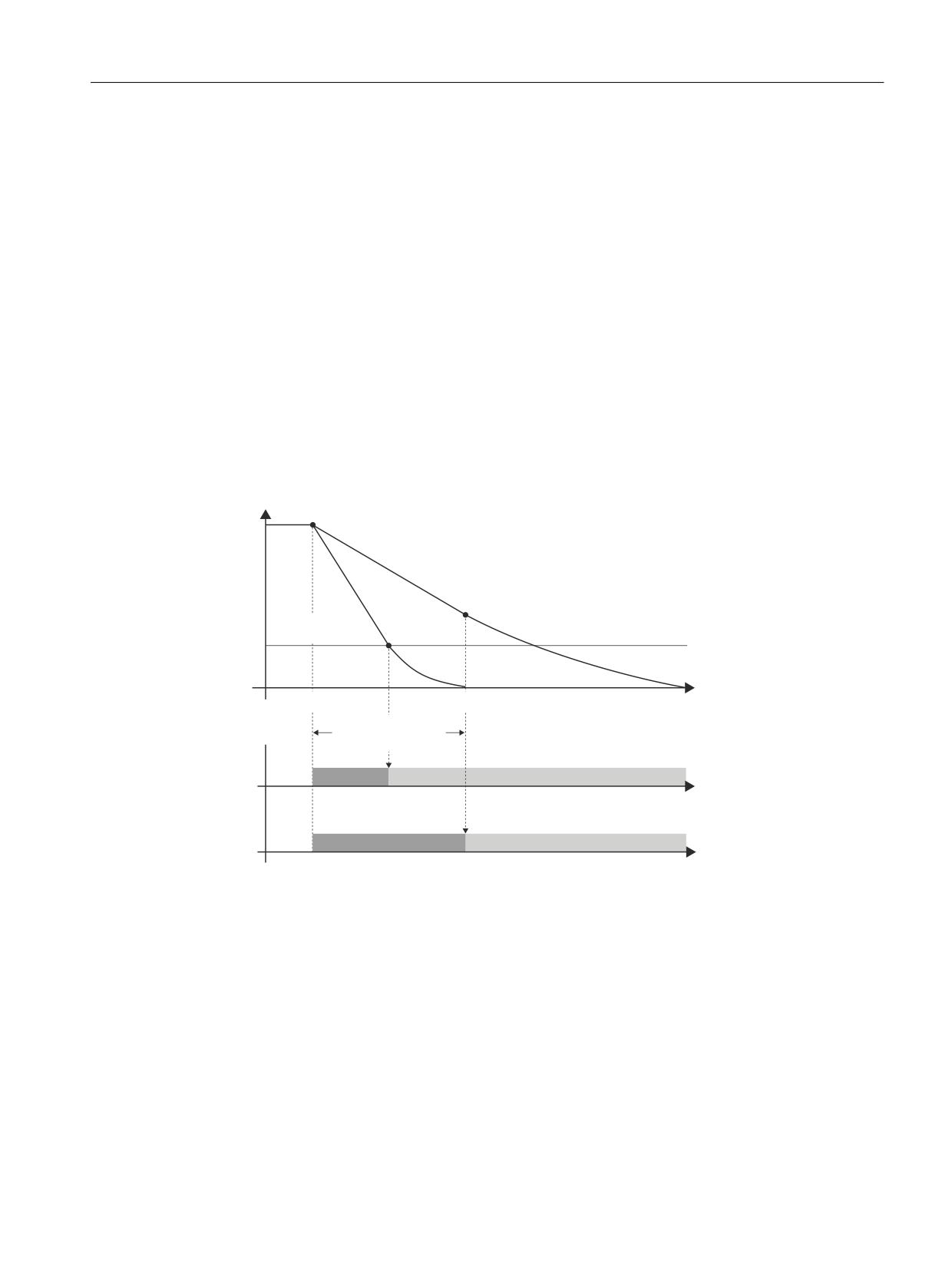
Safety functions integrated in the system/drive
7.3 Safe Stops A-F
The shutdown speed for the pulse cancellation is generally reached faster than the delay time
for the pulse cancellation.
• Effect:
The drive is braked along the OFF3 ramp under closed-loop speed control and brought to a
safe standstill.
• Alarm message for an internally initiated STOP B:
The alarm message "STOP B initiated" is displayed.
• Alarm message for an internally initiated STOP B:
An unintentional restart is prevented using a STOP B. The error can only be acknowledged
from the drive and control using a power on.
SGA "STOP A/B is active"
This signal indicates that STOP A/B is active.
0 signal: STOP A/B is not active
1 signal: STOP A/B is active
8 PLQ
D 6KXWGRZQ WLPH LV UHDFKHG EHIRUH
QLVW
WKH SXOVH FDQFHOODWLRQ GHOD\ WLPH
H[SLUHV
E 6KXWGRZQ WLPH LV UHDFKHG DIWHU
E
WKH SXOVH FDQFHOODWLRQ GHOD\ WLPH
D
H[SLUHV
6KXWGRZQ VSHHG
3XOVH FDQFHOODWLRQ
6723 %
6723
$
W
'HOD\ WLPH
3XOVH FDQFHOODWLRQ
6723 %
6723
$
D
6723 %
6723
$
E
Figure 7-6
Transition from STOP B to STOP A
It is possible that the stop for the NCK becomes effective one safety monitoring clock cycle earlier
than for the drive. This means that braking along the current limit can become effective before
the OFF3 ramp of the drive becomes effective.
In order to reduce the level of stress of the mechanical system of the machine (if required) the
braking torque can be reduced. To realize this, bit 4 "Torque limiting active in motoring/
regenerating mode" can be set in parameter p1400 and parameter p1521 "Torque limit lower/
regenerative" can be set to the required lower torque. In this case, it should be noted that the
braking distance (stopping distance) of the axis is extended, and that the torque limiting is not
only effective for STOP B, but that generally, the dynamic response of the axis changes.
Safety Integrated (system-integrated)
Function Manual, 10/2020, 6FC5397-4BP40-6BA2
121
Safety functions integrated in the system/drive
7.3 Safe Stops A-F
7.3.4
Description of STOP C
Action in the drive monitoring channel:
The drive is braked along the OFF3 ramp corresponding to the speed setpoint; in parallel, the
timer is started via parameter p9552 "Transition time from STOP C to SBH". The SBH function is
automatically activated after the timer expires.
Action in the NCK monitoring channel:
Essentially the same as the drive, the speed setpoint = 0 is specified by the control, and the
interface signal "Position controller active" (DB31, ... DBX61.5) of the drive involved is set to zero.
In parallel, the timer is started using MD36952 $MA_SAFE_STOP_SWITCH_TIME_C.
The SBH function is automatically activated after the timer expires.
• Effect:
The drive is braked along the OFF3 ramp under closed-loop speed control and brought into
SBH.
• Alarm message for an internally initiated STOP C:
The alarm message "STOP C triggered" is output (refer to Chapter "NCK safety alarms for
SINUMERIK 840D sl (Page 589)").
• Acknowledgment for an internally initiated STOP C:
An unintentional restart is prevented for a STOP C. The error can be acknowledged using the
NC-RESET key.
SGA "STOP C is active"
This signal indicates that STOP C is active.
0 signal:
STOP C is not active.
1 signal:
STOP C is active.
It is possible that the stop for the NCK becomes effective one safety monitoring clock cycle earlier
than for the drive. This means that braking along the current limit can become effective before
the OFF3 ramp of the drive becomes effective.
In order to reduce the level of stress of the mechanical system of the machine (if required) the
braking torque can be reduced. To realize this, bit 4 "Torque limiting active in motoring/
regenerating mode" can be set in parameter p1400 and parameter p1521 "Torque limit lower/
regenerative" can be set to the required lower torque. In this case, it should be noted that the
braking distance (stopping distance) of the axis is extended, and that the torque limiting is not
only effective for Stop C, but that generally, the dynamic response of the axis changes.
Alternatively, braking can be realized drive-based along the OFF3 ramp (see Chapter "Braking
response for STOP B/C (Page 123)").
Note
Tracking operation becomes active when a STOP C is initiated.
SGE deselect external STOP C
If a stop request is active, SGA "STOP C is active" is set in the same way as it would be for an
internally initiated STOP C.
Safety Integrated (system-integrated)
122
Function Manual, 10/2020, 6FC5397-4BP40-6BA2
Safety functions integrated in the system/drive
7.3 Safe Stops A-F
MD36977 $MA_SAFE_EXT_STOP_INPUT[1] is used to define the selection/deselection of the
external braking request; in this case "deselect external STOP C" (braking along the current limit
or braking along the OFF3 ramp).
7.3.5
Braking response for STOP B/C
To support gentle braking behavior for STOP B/C, the braking operation can be initiated
completely in the drive (drive-based). The speed is ramped-down to zero along a ramp defined
by parameter p1135 (OFF3 ramp). On the NCK side, the speed setpoint is no longer influenced.
This behavior can be selected using machine data 36904 $MA_SAFE_ADD_FUNCTION_MASK,
Bit 0 = 1.
The OFF3 ramp is activated via the drive monitoring channel. When STOP B/C becomes active in
this monitoring channel, then the OFF3 functionality is also activated. If there is a time offset
between activation of the STOP B/C in the NCK and drive monitoring channel, the velocity
setpoint for this time difference remains unchanged. By interchanging the stop responses
between NCK and drive monitoring channel, this time is a maximum of one monitoring clock
cycle.
Machine data M$MA_SAFE_ADD_FUNCTION_MASK, bit 0 is taken into account in the axis-
specific checksum $MA_SAFE_ACT_CHECKSUM[0].
A change to this MD becomes active after power on.
7.3.6
Description of STOP D
Action in the drive monitoring channel:
The drive monitoring channel requests a path stop or braking along the actual acceleration
characteristic. In parallel, the timer is started via parameter p9553 “Transition from STOP D to
SBH". The SBH function is automatically activated after the timer expires.
Action in the NCK monitoring channel:
Essentially the same as the drive, the NC monitoring channel requests a path stop or braking
along the acceleration characteristic. In parallel, the timer is started using MD36953
Safety Integrated (system-integrated)
Function Manual, 10/2020, 6FC5397-4BP40-6BA2
123

Safety functions integrated in the system/drive
7.3 Safe Stops A-F
$MA_SAFE_STOP_SWITCH_TIME_D. The SBH function is automatically activated after the timer
expires.
• Effect:
The drive is braked in a group - including simultaneous axes - along the set traversing path.
For axes, the acceleration characteristic is defined so that the axes stop within the time saved
in MD36953 $MA_SAFE_STOP_SWITCH_TIME_D. Therefore, ensuring stopping with low
associated stress on the machine.
If the accelerating/braking behavior is now changed in the NC program, for a STOP D, the axes
brake with the shortest transition time of all path axes, i.e. the transition times MD36953
must be set the same for all axes.
When running up, for all of the axes, the control checks whether the braking time set in
MD36953 is sufficient for the active acceleration characteristic of the axis. When violated, the
suppressible alarm 22001 "Channel %1 Block%2 Axis %3: Braking ramp longer than STOP D
time. Reason: %4" is output.
For spindles, the actual acceleration characteristic is not adapted. The control checks
whether the braking time, set in MD36953 $MA_SAFE_STOP_SWITCH_TIME_D, is sufficient
for all spindle operating modes and configured gear stages. When violated, suppressible
alarm 22002 "Channel %1 Spindle%2: Braking ramp longer than STOP D time. Gearbox stage
%3. Reason: %4" is output. If the spindle is in axis operation, then it behaves just like an axis.
For an active axis or spindle coupling (with the exception of the synchronous spindle
coupling), the coupling is no longer taken into consideration, if synchronous stopping of the
coupled group is no longer safely possible within the time parameterized in MD
$MA_SAFE_STOP_SWITCH_TIME_D. For a coupled group, this is the reason that for all axes of
the coupled group, a STOP D must be set.
For the synchronous spindle coupling, when synchronous operation is reached, the coupling
is always maintained. The coupling group is always braked via the leading spindle. If the
following spindle requires a longer braking time than the leading spindle, then MD
$MA_SAFE_STOP_SWITCH_TIME_D must be appropriately increased for the leading spindle.
When a synchronous spindle is active, STOP D should also be initiated for the leading and
following spindle.
Endlessly rotating axes are braked at the acceleration limit. The SBH function is automatically
activated after the timer expires.
When Alarm 22001/22002 is output, the following formulas are applied:
METRIC:
SAFE_STOP_SWITCH_TIME_D > MAX_AX_VELO * 1/60000 / MAX_AX_AC-
CEL
INCH/ROT/SPINDLE:
SAFE_STOP_SWITCH_TIME_D > MAX_AX_VELO * 1/60 / MAX_AX_ACCEL
For axes with jerk limitation, the minimum braking time is increased by the additional
component:
2 * MAX_ACCEL / MAX_AX_JERK
The check is made for NECONF, RESET, unparking an axis and for programming ACC or
JERKLIM.
The MD names contained in the formulas must, corresponding to the alarm situation (the
alarm occurs when parameterizing or when programming) may have to be replaced by other
values.
MD
Alternative MD
Program command
MAX_AX_ACCEL
MAX_AX_ACCEL
ACC
MAX_AX_JERK
JOG_AND_POS_MAX_JERK
JERKLIM
Comment regarding INCH-METRIC switchover:
Safety Integrated (system-integrated)
124
Function Manual, 10/2020, 6FC5397-4BP40-6BA2
Safety functions integrated in the system/drive
7.3 Safe Stops A-F
The calculated value should be rounded off to one decimal place so that for an INCH-METRIC
switchover, internal rounding effects can be compensated and no undesirable alarms are
initiated.
• Alarm message for an internally initiated STOP D:
The alarm message "STOP D initiated" is output.
• Acknowledgment for an internally initiated STOP D:
An unintentional restart is prevented for STOP D. The error can be acknowledged using the
NC-RESET key.
SGA "STOP D is active"
This signal indicates that STOP D is active.
0 signal: STOP D is not active
1 signal: STOP D is active.
SGE deselect external STOP D
If a stop request is active, SGA "STOP D is active" is set in the same way as it would be for an
internally triggered STOP D.
MD36977 $MA_SAFE_EXT_STOP_INPUT[2] is used to define the selection/deselection of the
external braking request, in this case "deselect external STOP D" (path braking).
An external STOP D can also be initiated in the drive monitoring channel from the PLC-SPL CDC
- or the PROFIsafe/FSEND-FRECV communication interface on the PLC side.
7.3.7
Description of STOP E
Action in the drive monitoring channel:
The drive monitoring channel requests an extended stop and retract (ESR), controlled from the
NC. In parallel, the timer in parameter p9554 "SI Motion transition time from STOP E to SBH" is
started. The SBH function is automatically activated after the timer expires.
Action in the NCK monitoring channel:
An ESR is requested by the control monitoring channel. In parallel, the timer in MD36954
$MA_SAFE_STOP_SWITCH_TIME_E is started. The SBH function is automatically activated after
the timer expires.
• Effect:
The extended stop and retract that has been configured is also started.
• Alarm message:
The alarm message "STOP E initiated" is displayed.
• Acknowledgment:
For STOP E, an unintentional restart is prevented. The error can be acknowledged using the
NC-RESET key.
SGA "STOP E is active"
This signal indicates that STOP E is active.
Safety Integrated (system-integrated)
Function Manual, 10/2020, 6FC5397-4BP40-6BA2
125
Safety functions integrated in the system/drive
7.3 Safe Stops A-F
0 signal: STOP E is not active
1 signal: STOP E is active.
The NC-controlled ESR is initiated by writing to the system variable $AC_ESR_TRIGGER=1 (also
see /FB3/, M3 "Axis coupling and ESR"). To obtain the criteria for initiating, the following SI
system variables are used:
$VA_STOPSI:
Axis-specific system variable that contains the present stop. For a value of 4, a STOP E is active
for this axis.
$A_STOPESI:
Global system variable that with a value not equal to 0 indicates that a STOP E is active for one
particular axis. This variable saves the user having to search through all of the axes.
SGE deselect external STOP E
When a stop request is active, the SGA "STOP E is active" is set.
MD36977 $MA_SAFE_EXT_STOP_INPUT[3] defines the selection/deselection of the external
braking request, in this case "deselect external STOP E" (extended stopping and retraction plus
path braking).
An external STOP E can also be initiated in the drive monitoring channel from the PLC-SPL CDC
- or the PROFIsafe/FSEND-FRECV communication interface on the PLC side.
Note
STOP E only produces a different response than STOP D if the user has configured the ESR
function - extended stop and retract - and initiation of the ESR is programmed depending on
$VA_STOPSI or $A_STOPESI.
If ESR is not active, the STOP E behaves like a STOP D. However, if the ESR configuration is
incorrect, there is a delay of up to 2 IPO cycles compared to STOP D until the braking operation
is initiated. Possible causes:
• The initiation of the ESR as static synchronous action does not take into account the system
variables $VA_STOPSI or $A_STOPESI.
• ESR is neither parameterized nor enabled.
• For individual PLC controlled axes, only the axis-specific ESR is used via $AA_ESR_TRIGGER.
This trigger may be used in addition to the channel-specific trigger.
For other incorrect ESR programming, a delay by the time entered in $MC_ESR_DELAY_TIME1
and $MC_ESR_DELAY_TIME2 is possible. After these times have expired, braking is initiated at
the current limit. Possible cause:
• The retraction position cannot be reached within the specified time.
Safety Integrated (system-integrated)
126
Function Manual, 10/2020, 6FC5397-4BP40-6BA2
Safety functions integrated in the system/drive
7.3 Safe Stops A-F
Note
The drive-based ESR can be initiated by writing to system variable $AN_ESR_TRGGER. The STOP
E delay time in MD36954 $MA_SAFE_SWITCH_TIME_E or drive parameter in p9554 should be
selected, so that it covers the timers for ESR (these are defined in parameter p0892 of the
SINAMICS basis system).
See also Chapter "Delayed pulse cancellation in the event of communication failure (Page 750)"):
7.3.8
Description of STOP F
The STOP F response is permanently assigned to the error handling (e.g. the crosswise result and
data comparison, detecting communication and encoder faults).
If such as fault/error state is detected, then the following responses are triggered.
Response if no safety-related functions are active:
Faults/errors are also detected if none of the safety-related functions are active (safety functions
are SBH, SG, SE, SN, n<nxsynchronization). The saved message "defect in a monitoring channel"
is output on both the drive and control sides and can only be acknowledged using the NC-RESET
key. The message does not interrupt machining. A system restart is prevented by an internal NC
start/traversing inhibit function. Dormant faults/errors are detected on the drive and control
sides.
Response if one safety-related function is active:
Faults/errors are detected and a STOP B/A response is initiated in the drive and control system
(see description of STOP B). The error can only be acknowledged from the drive and control using
a power on.
Exception: If an internal STOP C/D/E is already active, because STOP F has a lower priority (see
Chapter "General (Page 112)", Section "Priority of the stop responses").
• Alarm message:
Alarms 27001 "Defect in a monitoring channel" and/or 2710x "Difference in function..." and
C01711 "SI Motion error in a monitoring channel" are displayed.
For further diagnostics, for Alarm 27001, a fine error coding is displayed in the alarm line. The
fine coding for the drive alarm can be found in r9725 "SI Motion diagnostics for STOP F" or in
the SI status display under STOP F.
The significance of the error code is provided in Chapter "NCK safety alarms for SINUMERIK
840D sl (Page 589)" under Alarm 27001 "Defect in a monitoring channel".
A delay time before STOP B is initiated can be parameterized using MD36955
$MA_SAFE_STOP_SWITCH_TIME_F. During this time, the machine manufacturer can initiate an
NC controlled response, e.g. ESR. After this time has expired, the involved axis is braked with
STOP B. This is also true if, in the meantime, a stop with a higher priority than STOP F (STOP E,
D, C) is present. The system variables $VA_XFAULTSI and $A_XFAULTSI, bit 1 can be used to
detect whether a STOP F was initiated that is then followed by a STOP B. In the delay time up to
the STOP B, an ESR or braking along the programmed path can be initiated (e.g. by writing to
$AC_ESR_TRIGGER or initiating an external STOP D).
During the delay time up to initiating STOP B, additional, non-safety-related monitoring
functions can already result in other braking responses. A STOP D or the initiation of ESR can be
Safety Integrated (system-integrated)
Function Manual, 10/2020, 6FC5397-4BP40-6BA2
127

Safety functions integrated in the system/drive
7.3 Safe Stops A-F
influenced due to harder braking responses of the drive (the same as e.g. the configured braking
response when an encoder fails).
Note
For STOP F, when monitoring functions are active (SBH, SG, SE, not "n<nx", however,
"Synchronization, hysteresis and filtering "n<nx"), STOP B (braking at the current limit with speed
setpoint = 0) is defined as the following stop.
WARNING
Delay time
If an internal or external fault occurs, as a result of the fault, during the STOP F response the
parameterized safety functions are either no longer available or only with restrictions. This
must be carefully taken into account when parameterizing the delay time between STOP F and
STOP B (MD3695/p9555) - and must be taken into account in the risk analysis performed by the
machine manufacturer. This applies in particular to vertical axes.
Note
A delay time between STOP F and STOP B should only be set, if, during this time, an alternative
response is initiated by evaluating the system variables $VA_XFAULTSI and $A_XFAULTSI.
Further, when using the delay time, a monitoring function should always be active - also in the
automatic mode (e.g. SE, SN, SG with high limit switch). For example, if the SBH monitoring
function is only active on the drive side, for example because of the (single-channel) failure of
a door switch, then although this results in a STOP F, the STOP F - STOP B delay time on the NCK
side is not started if previously no monitoring function was active. This means that in this case,
the drive responds with a STOP B (however this is also initiated in the NCK due to the interchange
of the stop responses), but this is not displayed in the NCK variables $VA_XFAULTSI and
$A_XFAULTSI.
The appropriate monitoring functions of the drive (e.g. when SBH is selected) are also executed
instantaneously without any delay.
Note
The drive-based ESR can be initiated by writing to system variable $AN_ESR_TRIGGER. The STOP
F delay time in MD36955 $MA_SAFE_STOP_SWITCH_TIME_F or drive parameter p9555 should
be selected, so that the timer for ESR in p0892 is covered by the SINAMICS basic system.
See also Chapter "Delayed pulse cancellation in the event of communication failure (Page 750)".
Comment:
When combined with "ESR managed from the control", theoretically the following error is
possible: Both monitoring channels (NCK and drive) trigger a STOP F; however, a safety function
is only active on the drive side (errors in the two SPL channels, which are then most probably
responsible for the STOP F). In this case, the NCK does not trigger an ESR, because for the NCK
no subsequent STOP B can be identified. Conversely, this statement is also valid for the
combination with "ESR integrated in the drive" and a safety function is only active in the NCK. The
ESR integrated in the drive is then not started.
Example 1 - delaying the transition from STOP F to STOP B
Safety Integrated (system-integrated)
128
Function Manual, 10/2020, 6FC5397-4BP40-6BA2
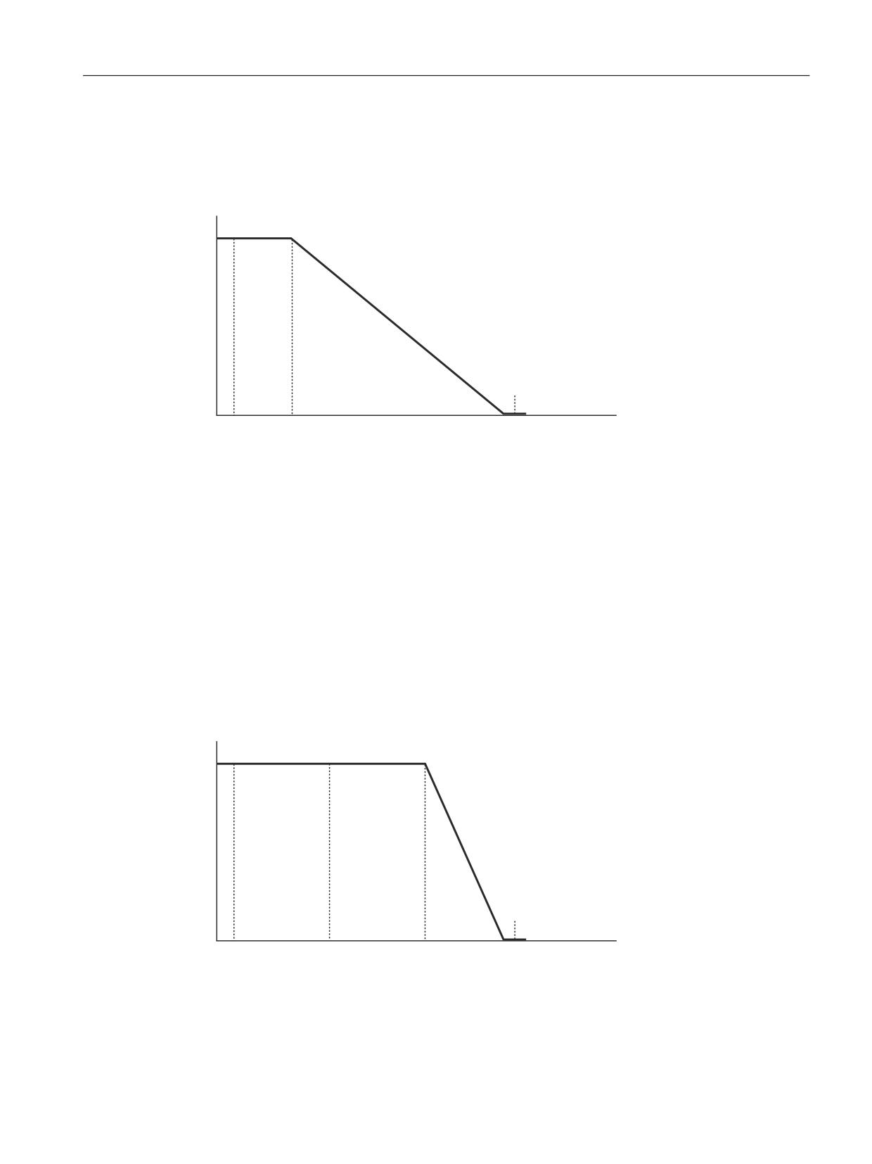
Safety functions integrated in the system/drive
7.3 Safe Stops A-F
The speed characteristic of an axis for parameterized stopping is shown in the following
diagram. In this case, the axis should continue 500 ms and then brake along the parameterized
ramp. A delay time of 2.5 s is selected until STOP B is initiated
($MA_SAFE_STOP_SWITCH_TIME_F).
&RQWLQXH WR WUDYHUVH
(65
Y
%UDNH DORQJ WKH UDPS
VWRSSLQJ
(65
W
W
W
W
Figure 7-7
Velocity characteristic of an SI axis when stopping with STOP F
The following actions take place at the following instants in time:
t1:
STOP F occurs, ESR is started
t2:
500 ms after t1, braking starts along the parameterized ramp
t3:
STOP B is initiated 2.5 s after t1. The axis is already stationary at this time, which means that the
pulses can be immediately cancelled.
Example 2 - delaying the transition from STOP F to STOP B
The same parameterization as in example 1 is shown in the following diagram. However, when
a STOP F occurs, no monitoring function is active. At instant in time t2, a monitoring function is
activated. ESR is only started if there is a STOP F with active monitoring function.
&RQWLQXH WR WUDYHUVH
(65
Y
%UDNH DORQJ WKH UDPS
VWRSSLQJ
(65
W
W
W
W
W
Figure 7-8
Velocity characteristic of an SI axis when stopping with STOP F
The following actions take place at the following instants in time:
t1:
STOP F occurs, no response
Safety Integrated (system-integrated)
Function Manual, 10/2020, 6FC5397-4BP40-6BA2
129
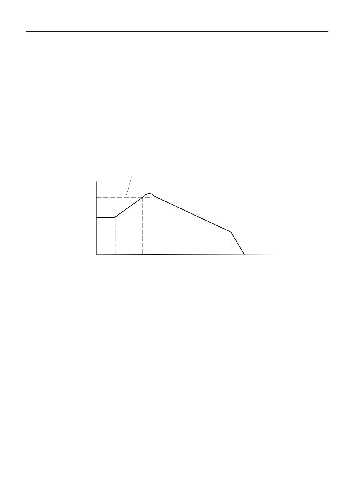
Safety functions integrated in the system/drive
7.3 Safe Stops A-F
t2:
at any time after t1, a monitoring function is activated. At this instant in time, the transition to
a STOP B is started and bits 1 in $A_XFAULTSI and $VA_XFAULTSI of this axis are set.
t3:
500 ms after t2, braking starts along the parameterized ramp
t4:
STOP B is initiated 2.5 s after t2. The axis is already stationary at this time, which means that the
pulses can be immediately cancelled.
Example 3 for STOP F with interruption by STOP D
A retraction axis is shown in the following diagram. As a result of the high velocity of the
retraction motion, the SG monitoring for this axis initiates a STOP D. After the transition time
from STOP F to STOP B expires, this braking ramp has still not been completed, so that now the
axis continues to brake with the STOP B response (nset=0 or OFF3).
6WDUW RI UHWUDFWLRQ
6*
%UDNH DORQJ WKH UDPS
OLPLW
6723 '
%UDNH DW WKH FXUUHQW OLPLW
6723 %
W
W
W
W
W
Figure 7-9
Speed characteristic for retraction with SG violation
The following actions take place at the following instants in time:
t1:
STOP F occurs, ESR starts
t2:
the set SG limit is exceeded, STOP D is initiated
t3:
after t1 + $MA_SAFE_STOP_SWITCH_TIME_F, STOP B is initiated, and the axis starts to brake at
the current limit / OFF3 ramp
t4:
STOP A is initiated after the axis comes to a standstill
7.3.9
Forced checking procedure of the external STOPs
The following applies for the test stop of external STOPs:
Safety Integrated (system-integrated)
130
Function Manual, 10/2020, 6FC5397-4BP40-6BA2
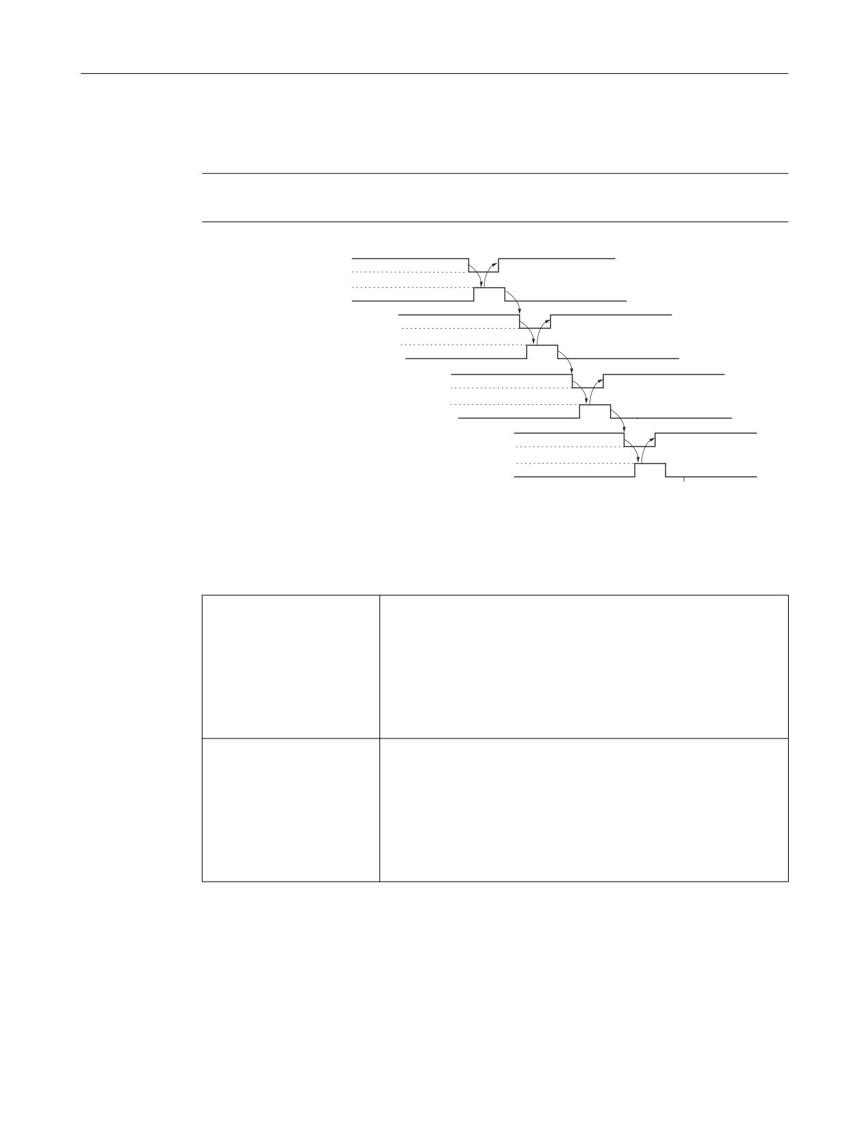
Safety functions integrated in the system/drive
7.3 Safe Stops A-F
All stop SGEs that are used are switched one after the other in each channel and the positive
response evaluated using the associated SGA "STOP x is active".
Note
Only the enabled and activated external standstill functions have to be tested.
6*( 'HVHOHFW H[W 6723 (
6*$ 6723 ( LV DFWLYH
6*( GHVHOHFW H[W 6723 '
6*$ 6723 ' LV DFWLYH
6*( GHVHOHFW H[W 6723 &
6*$ 6723 & LV DFWLYH
6*( GHVHOHFW H[W 6723 $
6*$ 6723 $ LV DFWLYH
Figure 7-10
Sequence of the test stop for external STOPs. Example: External STOPs A, B, C, D, E are used
Which SGE/SGA are required for the test stop of external STOPs?
The following SGE/SGA can be used to perform the test stop for external STOPs:
NCK monitoring channel
NCK-SGE ”Deselect ext. STOP A
NCK-SGA ”STOP A/B is active
NCK-SGE ”Deselect ext. STOP C
NCK-SGA ”STOP C is active
NCK-SGE ”Deselect ext. STOP D
NCK-SGA ”STOP D is active
NCK-SGE ”Deselect ext. STOP E
NCK-SGA ”STOP E is active”
Drive monitoring channel
PLC-SGE ”Deselect ext. STOP A
PLC-SGA ”STOP A/B is active”
PLC-SGE ”Deselect ext. STOP C”
PLC-SGA ”STOP C is active”
PLC-SGE ”Deselect ext. STOP D”
PLC-SGA ”STOP D is active”
PLC-SGE ”Deselect ext. STOP E”
PLC-SGA ”STOP E is active”
Safety Integrated (system-integrated)
Function Manual, 10/2020, 6FC5397-4BP40-6BA2
131
Safety functions integrated in the system/drive
7.3 Safe Stops A-F
7.3.10
Canceling stopping delay times
The specified transition times
SG → SBH
$MA_SAFE_VELO_SWITCH_DELAY
STOP C → SBH
$MA_SAFE_STOP_SWITCH_TIME C
STOP D → SBH
$MA_SAFE_STOP_SWITCH_TIME D
STOP E → SBH
$MA_SAFE_STOP_SWITCH_TIME E
define the time period from requesting a stop until switchover to a Safe Operating Stop. These
stopping delay times should be parameterized so that for the worst case scenario (maximum
velocity, low acceleration capability), the axis or spindle involved can stop within this time
range. Otherwise, for the subsequent switchover to a Safe Operating Stop, the SBH limits could
be exceeded, which in turn would initiate a STOP B/A response. This situation can then only by
acknowledged by a restarting again.
A setting corresponding to the worst case scenario means that for a stopping operation, e.g.
from a lower velocity to reach standstill, a wait time is incurred until a Safe Operating Stop is
assumed.
In many cases, protective doors can only be opened after the system has switched over to a Safe
Operating Stop; this means wait times for users. Wait times can be reduced by making the
appropriate parameter assignment:
In this case, a switchover is not made to the Safe Operating Stop after the actual transition time,
but as soon as standstill is identified, and a short transition time has elapsed.
The following machine data are used:
• $MA_SAFE_STANDSTILL_VELO_LIMIT
Switchover speed SBH/SG
Velocity limit with which the axis monitoring channel identifies standstill. A delay time is
started, if this velocity limit is fallen below for a stop request or an SG stage switchover.
• $MA_SAFE_STANDSTILL_DELAY
Delay time, switchover to SBH/SG
After this time, for a stop request, a Safe Operating Stop or an SG stage switchover is
activated. This time is used to bridge the time from identifying the standstill velocity down
to actual standstill.
It should be noted that time $MA_SAFE_STANDSTILL_DELAY only becomes active at the instant
that standstill is actually identified (v < $MA_SAFE_STANDSTILL_VELO_LIMIT) the remaining
time from starting the stop request up to switching over to SBH or the lower SG stage (stopping
delay time) is greater than the value in this machine data (delay time, switchover to SBH/SG).
If the stop request sequence (with respect to time) has progressed so that the originally started
stopping delay time already expires before $MA_SAFE_STANDSTILL_DELAY expires, then the
originally initiated operation is exited unchanged. This therefore ensures that the switchover to
SBH occurs at the latest after the stopping delay time.
Activation:
The function is active if a value > 0.0 is entered in MD37920
$MA_SAFE_STANDSTILL_VELO_LIMIT.
Supplementary conditions:
Safety Integrated (system-integrated)
132
Function Manual, 10/2020, 6FC5397-4BP40-6BA2
Safety functions integrated in the system/drive
7.4 Safe Acceleration Monitor
When switching over from SG to SBH using SGE "deselect Safe Operating Stop", the function can
only operate if a setpoint velocity limit is activated using MD36933
$MA_SAFE_DES_VELO_LIMIT.
Even when switching over from "non-safety operation" (neither SG nor SBH active) to SBH, the
function cannot be used because a delay time has not been defined for this switchover operation
- and the switchover to SBH is realized without delay.
7.4
Safe Acceleration Monitor
Description
Using this function, the effectiveness of braking, initiated using stop responses B and C, along
the current limit/OFF3 ramp is checked through two channels.
Functional features
The most important functional features include:
• Fastest possible detection if the axis starts to re-accelerate when braking
• SBR is automatically activated, when a STOP B or C has been initiated
• When SBR responds, a STOP A is initiated and Alarm 27013 "Axis %1 safe monitoring for
acceleration exceeded" and the drive messages C01706/C30706 "Acceleration monitoring
limit exceeded" initiated.
• For an encoder fault in a 1-safety encoder system, the "Safe Acceleration Monitor" function
is not active as a result of the defective encoder. Depending on how parameter p9516 has
been parameterized, a Category 0 or 1 (EN 60204-1) stop response is realized (see also the
warning notes in Chapter "Safety information & instructions and residual risks (Page 44)").
In case of a Category 1 stop response, the standard system brakes the defective drive at with
the current limit. The pulses are canceled after the speed parameterized in MD36960
$MA_SAFE_STANDSTILL_VELO_TOL - or the time parameterized in MD36956
$MA_SAFE_PULSE_DISABLE_DELAY.
Activating SBR
When a STOP B or C is initiated, the actual speed plus the speed tolerance, defined in the machine
data/parameter, is activated as the speed limit. When the actual speed decreases, then this
speed limit is correspondingly corrected; however, for an increased speed, it is not changed. If
the drive speed exceeds the actual speed limit then a STOP A is initiated. If the axis starts to re-
accelerate while braking, this is detected as quickly as possible and prevented.
Machine data/parameters for the SBR speed tolerance:
For 840D sl:
MD36948 $MA_SAFE_STOP_VELO_TOL
For SINAMICS S120:
p9548 SI Motion SBR actual speed tolerance (Control Unit)
Safety Integrated (system-integrated)
Function Manual, 10/2020, 6FC5397-4BP40-6BA2
133
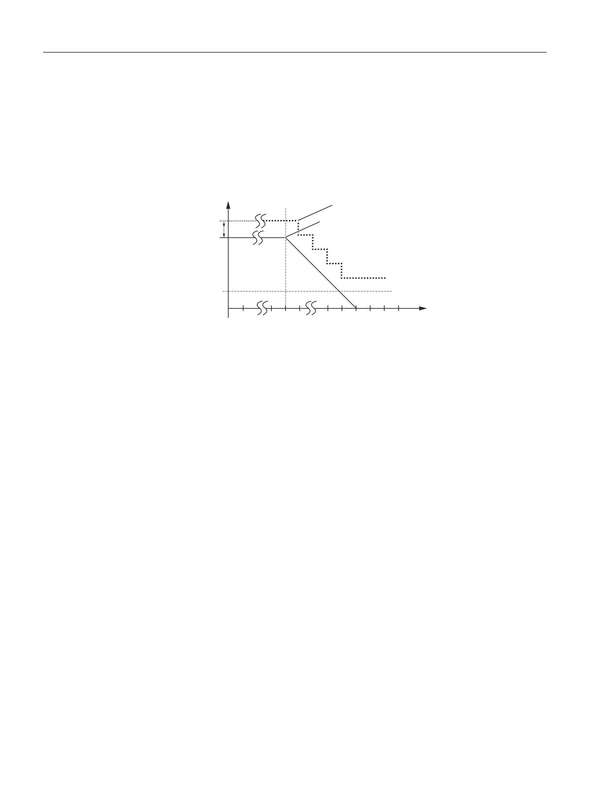
Safety functions integrated in the system/drive
7.4 Safe Acceleration Monitor
The speed limit is corrected until the speed, defined in the following machine data, is undershot
(fallen below). After that, the limit value of the SBR monitoring is frozen to the value in MD/
parameter 36946/p9546 plus the value in MD/parameter 36948/p9548.
For 840D sl:
MD36946 $MA_SAFE_VELO_X (speed limit n<nx)
For SINAMICS S120:
p9546 SI Motion SSM (SGA n < nx) speed limit (CU)
Q
6WRSSLQJ OLPLW YDOXH
6723 % & LQLWLDWHG
6SHHG
WROHUDQFH
QDFW
Q[
W
Figure 7-11
Characteristic of the SBR tolerance of the actual speed
Calculating the SBR tolerance of the actual speed
The following applies when parameterizing the SBR tolerance:
The possible speed increase after initiating a STOP B/C is obtained from the effective acceleration
a and the duration of the acceleration phase. The acceleration phase lasts from one monitoring
clock cycle MC (delay from detecting a STOP B/C until nset = 0 / activation OFF3 ramp):
SBR tolerance
Actual speed SBR = acceleration * acceleration duration
The following setup rule is derived:
For a linear axis:
SBR tolerance [mm/min] = a [m/s2] * MC [s] * 1000 [mm/m] * 60 [s/min]
For a rotary axis/spindle:
SBR tolerance [rev/min] = a [rev/s2] * MC [s] * 60 [s/min]
The following machine data should be taken into account when determining the acceleration:
MD32300 $MA_MAX_AX_ACCEL
MD35200 $MA_GEAR_STEP_SPEEDCTRL_ACCEL
MD35210 $MA_GEAR_STEP_POSCTRL_ACCEL
MD35410 $MA_SPIND_OSCILL_ACCEL
Recommendation:
The value entered for the SBR tolerance should be approx. 20% higher than the calculated value.
A velocity overshoot must be taken into account when braking with nset=0. The overshoot must
be less than the sum of $MA_SAFE_STOP_VELO_TOL and nx velocity limit or $MA_SAFE_VELO_X
Safety Integrated (system-integrated)
134
Function Manual, 10/2020, 6FC5397-4BP40-6BA2
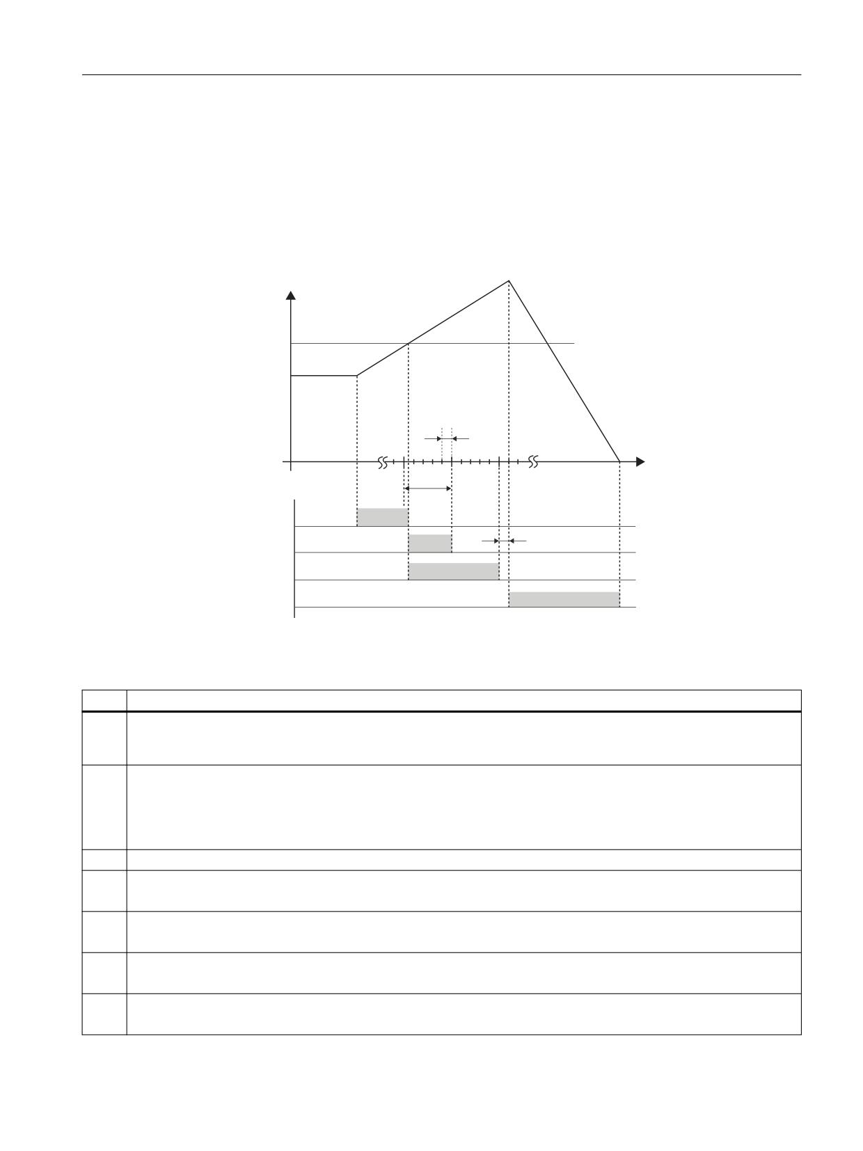
Safety functions integrated in the system/drive
7.4 Safe Acceleration Monitor
- $MA_SAFE_VELO_X_HYSTERESIS (if synchronization, hysteresis and filtering n<n
x
active). This
must be checked by taking the appropriate measurements, as otherwise the SBR function could
be inadvertently initiated, therefore resulting in a STOP A.
Timing when the actual stop limit value is exceeded
If the Safe Acceleration Monitor function is active, then the following timing is obtained when
the actual stop limit value is exceeded:
F 6WDUW RI WKH VWRS
UHVSRQVH
Q
/LPLW
YDOXH H[FHHGHG
$FWXDO VWRS
E
OLPLW YDOXH
(UURU FDVH
D
QLVW
W
W
W
QRW
W
WR VFDOH
W
W
W
W
Figure 7-12
Timing when the actual stop limit value for SBR is exceeded
Table 7-5
Explanation of the diagram
Time
Explanation
t1
Position control clock cycle, defined by the following MD:
MD10050 $MN_SYSCLOCK_CYCLE_TIME
MD10060 $MN_POSCTRL_SYSCLOCK_TIME_RATIO
t2
Monitoring clock cycle, defined by the following MD:
for 840D sl:
MD10090 $MN_SAFETY_SYSCLOCK_TIME_RATIO
for SINAMICS S120:
r9500 SI Motion monitoring clock cycle (Control Unit)
t3
Time between an error occurring and a limit value being reached
t4
Time until a limit value violation is detected
(typical 1 monitoring clock cycle, maximum 1.5 monitoring clock cycles + 1 position controller clock cycle)
t5
Response time that is required to introduce the stop response
(typical 2 monitoring clock cycles, maximum 2.5 monitoring clock cycles + 1 position controller clock cycle)
t6
Time until the stop response that was initiated starts
(typical 2 ms, maximum 3 position controller clock cycles + 8 ms)
t7
Time required to bring the axis to a standstill.
This time and thus the residual distance traveled by the axis is determined by the axis design (motor, mass, friction, ...).
Safety Integrated (system-integrated)
Function Manual, 10/2020, 6FC5397-4BP40-6BA2
135

Safety functions integrated in the system/drive
7.5 Safely reduced speed (SG)
Note
During "normal" operation, speed overshoot should not unintentionally initiate the SBR. Speed
overshoot should therefore be checked by making the appropriate measurements.
WARNING
Potentially hazardous motion
If the safe standstill function or "STOP A" is activated, then the motor can no longer generate
any torque. This is the reason that potentially hazardous motion can occur, e.g. for the
following:
• When an external force acts on the drive axes
• Vertical and inclined axes without weight equalization
• Axes that are moving (coasting down)
• Direct drives with low friction and low self-locking
• Cogging torques (depending on the motor type, bearing design and friction characteristics,
up to half a pole pitch in a direction that cannot be predicted)
Possible hazards must be clearly identified using a risk analysis that must be carried out by the
manufacturer. With an assessment, based on this risk analysis, it should be defined as to which
additional measures are required, e.g. external brakes.
7.5
Safely reduced speed (SG)
Description
The purpose of the SG (safely reduced speed) function is to safely monitor the load-side speed
of an axis/spindle.
The actual speed of the axis/spindle is cyclically compared in the monitoring clock cycle with the
speed limit value selected using SGEs. The speed limit values are defined in the following
machine data/parameters:
For 840D sl:
MD36931 $MA_SAFE_VELO_LIMIT[n]
For SINAMICS S120:
p9531 SI Motion SLS (SG) limit values (Control Unit)
The speed limit values for SG1, SG2, SG3 or SG4 allow various applications/operating states on
the machine to be monitored. The safely reduced speed function can therefore be used to
Safety Integrated (system-integrated)
136
Function Manual, 10/2020, 6FC5397-4BP40-6BA2
Safety functions integrated in the system/drive
7.5 Safely reduced speed (SG)
implement protective measures for the operating personnel and machine in the setting-up
mode or also in automatic operation.
WARNING
Selector gearboxes
For selector gears, it is important to select the correct gear ratio.
Functional features
The features of the SG function are as follows:
• Load-side speed limit values are safely monitored
• Monitoring limit values are adapted to various operating states (e.g. test, setting-up,
automatic modes)
• Configurable stop response when the SG responds
Preconditions
The following preconditions must be fulfilled:
• The option and functions must be enabled in the axis-specific machine data
• The SGEs "SBH/SG deselection" and "SBH deselection" must be configured
Specifying velocities and speeds
The requirements regarding speeds and velocities that are stipulated for individual processes
(milling, turning, grinding, etc.) vary depending on the different C Standards. For example, the
following could be specified for the setting-up mode:
Safely reduced velocity with 2 m/min for feed drives - or 50 rpm for spindle drives or standstill
within 2 revolutions.
The machine manufacturer must parameterize SI in such a way as to ensure full compliance with
the EC Machinery Directive. The relevant standards provide the necessary guidelines and
support.
Quantities that influence the parameterization include, e.g. the drive dynamic response, the set
parameters with their delay times, electrical and mechanical gear ratios and all of the
mechanical properties and characteristics. The interrelationships between the drive dynamic
Safety Integrated (system-integrated)
Function Manual, 10/2020, 6FC5397-4BP40-6BA2
137

Safety functions integrated in the system/drive
7.5 Safely reduced speed (SG)
response and internal delay times of SI are shown in the diagram "Timing when exceeding the
limit value for SG".
Note
Deviation of the speed limit
The safety-related actual speed limit can deviate slightly from the limit value set in MD36391[…]
for the safely reduced speed. The reason for this is the internal resolution of the speed values.
The safety-related actual speed limit is displayed in the diagnostics screen form Safety Safety
Integrated status.
7.5.1
Speed monitoring, encoder limit frequency
When SBH/SG is active in a configuration with a 1-encoder system, the speed is monitored to
ensure that it does not exceed a maximum encoder limit frequency. An appropriate alarm is
output if this limit is exceeded.
Encoder frequency limit
The encoder limit frequency is 500 kHz. When the encoder limit frequency in SG is exceeded, the
SG-specific parameterized stop is initiated.
Note
Monitoring against a limit frequency of 500 kHz is not performed for DRIVE-CLiQ encoders.
7.5.2
Selecting/deselecting safely reduced speed
Selecting SG
The following SGEs are used to select SG:
SGE
SBH/SG deselec-
SBH deselection
Meaning
tion
= 1
x
SBH and SG are deselected
= 0
= 0
SBH is selected
(see Chapter "Safe Operating Stop (SBH) (Page 106)")
= 0
= 1
SG is selected
Note: x → any signal state
Safety Integrated (system-integrated)
138
Function Manual, 10/2020, 6FC5397-4BP40-6BA2

Safety functions integrated in the system/drive
7.5 Safely reduced speed (SG)
Note
The actual status of the function is displayed using the SGA "SBH/SG active" and SGA "SBH active".
Before activating the SG function it must be ensured that the speed of the axis/spindle is lower
than the selected speed limit value. If it is higher, an alarm is generated that causes the drive to
be shut down.
The SGEs and SGAs are described in Chapter "Safety-related input/output signals (Page 169)"
Selecting speed limit values
The maximum permissible speed of an axis/spindle in the setting-up mode is defined for
individual machine types in the C Standards (product standards). The machine manufacturer is
responsible for ensuring that the correct speed limit value is selected depending on the
operating mode and the application.
The required speed limit is selected as follows by combining the following SGEs:
SGE
SG selection
SG selection
Meaning
bit 1
bit 0
= 0
= 0
Speed limit value for SG1 active
= 0
= 1
Speed limit value active for SG2 1)
= 1
= 0
Speed limit value for SG3 active
= 1
= 1
Speed limit value active for SG4 1)
Note:
1) SG limit values SG2 and SG4 can be more finely graduated using the SG override (see Chapter "Override
for safely reduced speed (Page 143)"). The active SG stage is displayed using SGA "SGA active bit 0" and
"SGA active bit 1".
Changing over speed limits
A changeover from a lower to a higher speed limit value takes effect instantaneously without any
delay.
When changing-over from a higher to a lower limit value, then a delay time is started that is
parameterized using the machine data (see diagram "Timing when changing-over from a higher
to a lower speed limit value").
For 840D sl
MD36951 $MA_SAFE_VELO_SWITCH_DELAY
For SINAMICS S120
p9551 SI Motion SLS(SG) changeover delay time (Control Unit)
The axis/spindle must be braked sufficiently during the delay time so that it has reached the
reduced speed that is below the new limit value when the delay time expires. However, if the
actual speed is higher than the new limit value when the time has expired, an appropriate alarm
is output with the configurable stop response.
Safety Integrated (system-integrated)
Function Manual, 10/2020, 6FC5397-4BP40-6BA2
139
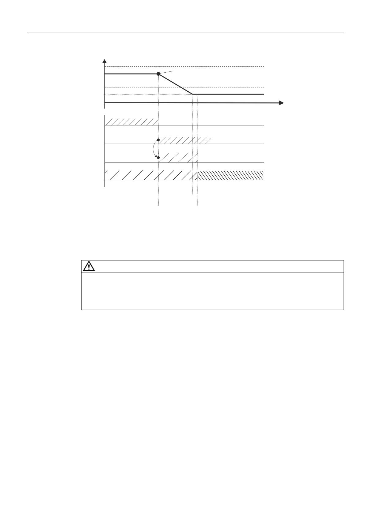
Safety functions integrated in the system/drive
7.5 Safely reduced speed (SG)
Y
6*
D %UDNLQJ LV VWDUWHG
9
6*
9
W
6*(
IRU 6*
6*(
IRU 6*
'HOD\ WLPH
9HORFLW\ FKDQJHRYHU
6* LV DFWLYH
6* LV DFWLYH
%UDNLQJ WLPH
7LPHU UXQQLQJ
Figure 7-13
Timing when changing-over from a higher to a lower speed limit.
Deselecting SG
The SG function can be deselected at any speed by activating the SGE "SBH/SG deselection".
WARNING
Delay time
The delay time must be selected as a function of the distance to the hazardous location. The
speeds to be taken into account (speed at which hands/arms are moved to appropriately
arrange protective devices/guards) are specified in Standard DIN EN ISO 13855.
7.5.3
Effects when the limit value is exceeded for SG
Configurable stop responses
When the selected speed limit value is violated, a stop response configured in the following
machine data/parameters is generated:
For 840D sl:
MD36961 $MA_SAFE_VELO_STOP_MODE
MD36963 $MA_SAFE_VELO_STOP_REACTION[n]
Safety Integrated (system-integrated)
140
Function Manual, 10/2020, 6FC5397-4BP40-6BA2
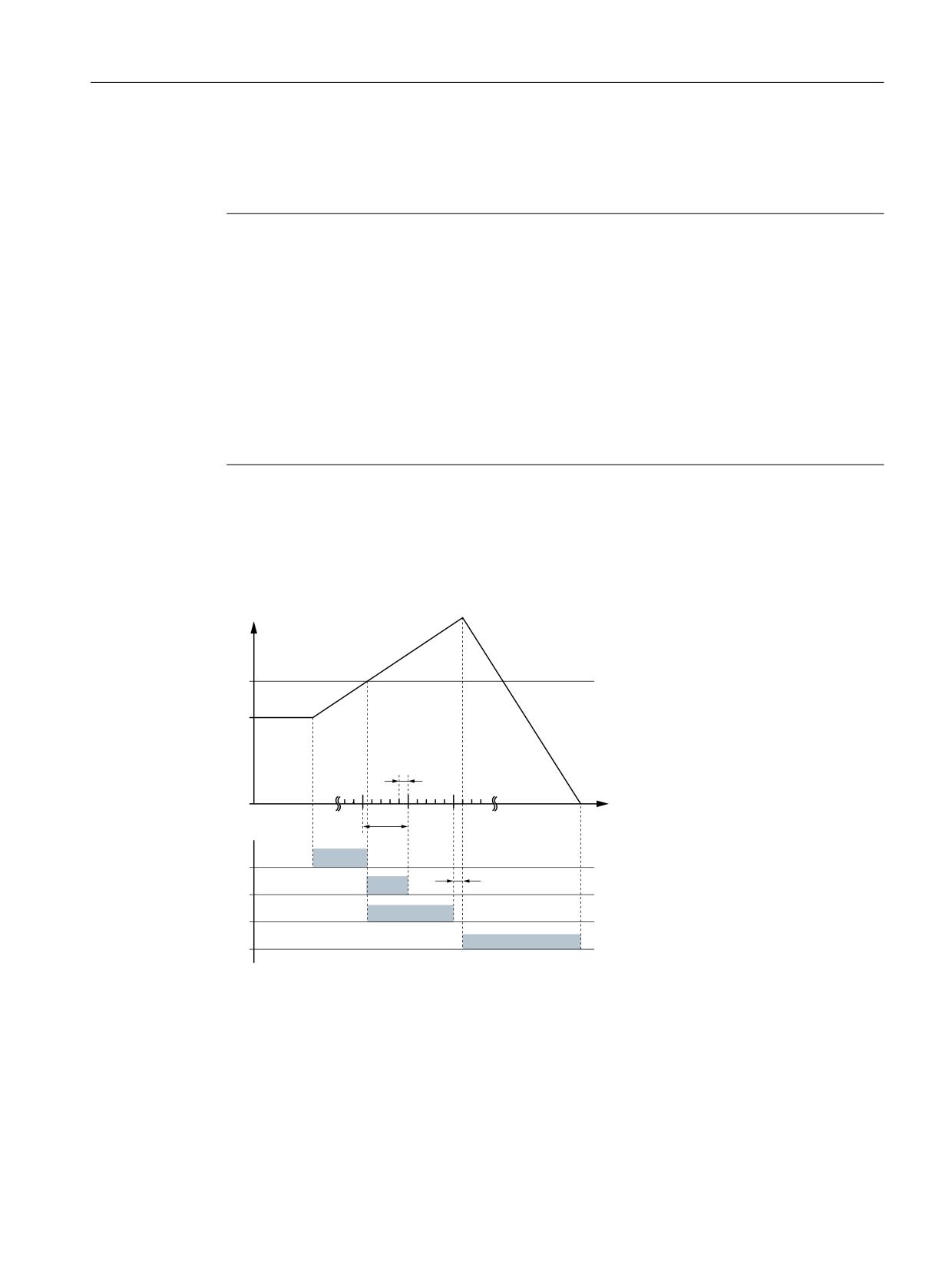
Safety functions integrated in the system/drive
7.5 Safely reduced speed (SG)
For SINAMICS S120:
p9561 SI Motion SLS (SG) stop response (Control Unit)
p9563[0...3] SI Motion SLS (SG)-specific stop response (Control Unit)
Note
• An alarm is displayed (for 840D sl: 27011, for SINAMICS S120: F01714). After the cause of
the fault has been removed, the alarm can be acknowledged with RESET. The monitoring
function is then again active.
• Depending on the selected monitoring clock cycle, the dynamic drives may cause a brief
increase in speed on the monitored axis/spindle before the stop response sequence starts.
• For traversing modes which use a transformation with singularity points (e.g. 5-axis
transformation and TRANSMIT), relatively high axis-specific speeds occur at these points.
These speeds can initiate stop responses even though the Cartesian motion of the tool center
point (TCP) is below the selected speed limit value.
The monitoring functions provided by SI are basically axis-specific. This means that it is not
possible to directly monitor the TCP.
Timing when the limit value is exceeded
When the safely reduced speed function is active, then the timing is as follows when the limit
value is violated:
F 6WDUW RI WKH VWRS UHVSRQVH
Q
/LPLW YDOXH
H[FHHGHG
E
6*
(UURU FDVH
D
Q
DFW
W
W
W
QRW WR VFDOH
W
W
W
W
W
Figure 7-14
Timing when the limit value is exceeded for SG
Safety Integrated (system-integrated)
Function Manual, 10/2020, 6FC5397-4BP40-6BA2
141