SINUMERIK 840D sl. Service - Safety Integrated. Manual (2020) - page 1
Preface
Fundamental safety
1
instructions
2
Regulations and standards
SINUMERIK
3
Brief description
SINUMERIK 840D sl
Safety Integrated (system-
4
System features
integrated)
Safety Functions integrated
5
in the drive
Function Manual
Basics regarding the safety
functions integrated in the
6
system/drive
Safety functions integrated
7
in the system/drive
Connecting sensors and
8
actuators
9
Data descriptions
10
Commissioning
11
Diagnostics
Interaction with other
12
functions
13
Appendix
Valid for
Control system
SINUMERIK 840D sl / 840DE sl
Software
version
NCU system software for 840D sl/840DE sl
4.94
10/2020
6FC5397-4BP40-6BA2
Table of contents
Preface
3
1
Fundamental safety instructions
11
1.1
General safety instructions
11
1.2
Equipment damage due to electric fields or electrostatic discharge
15
1.3
Warranty and liability for application examples
15
1.4
Security information
15
1.5
Residual risks of power drive systems
17
2
Regulations and standards
19
2.1
General
19
2.1.1
Objective
19
2.1.2
Functional safety
19
2.2
Machine safety in Europe
20
2.2.1
Machinery directive (2006/42/EC)
20
2.2.2
Harmonized European standards
21
2.2.3
Standards for implementing safety-related controls
22
2.2.4
EN ISO 13849-1
23
2.2.5
EN 62061
23
2.2.6
Series of standards EN 61508 (VDE 0803)
25
2.2.7
EN 60204-1
25
2.2.8
EN 61800-5-2
26
2.2.9
Risk analysis/assessment
26
2.2.10
Risk reduction
28
2.2.11
Residual risk
28
2.3
Machine safety in the USA
28
2.3.1
Minimum requirements of the OSHA
28
2.3.2
NRTL listing
29
2.3.3
NFPA 79
29
2.3.4
ANSI B11
30
2.4
Machine safety in Japan
30
2.5
Equipment regulations
31
2.6
Other safety-related issues
31
2.6.1
Information sheets from the various regulatory bodies
31
2.6.2
Additional references
32
2.6.3
Additional information
32
3
Brief description
33
3.1
Control/drive systems
33
3.2
Safety technology integrated in the system
34
3.2.1
Overview of the safety functions integrated in the system
35
Safety Integrated (system-integrated)
Function Manual, 10/2020, 6FC5397-4BP40-6BA2
5
Table of contents
3.3
Safety technology integrated in the drive
36
3.3.1
Overview of the safety functions integrated in the drive
38
3.4
Comparison of the function names
38
4
System features
41
4.1
System requirements
41
4.2
Current information
43
4.3
Certifications
44
4.4
Probability of failure
44
4.5
Safety information & instructions and residual risks
44
4.5.1
General residual risks for PDS (Power Drive Systems)
44
4.5.2
Additional safety information & instructions and residual risks for Safety Integrated
46
5
Safety Functions integrated in the drive
51
5.1
General information about SINAMICS Safety Integrated
51
5.1.1
Explanations and terminology
51
5.1.2
Supported functions
52
5.1.3
Supported functions: HLA module
53
5.1.4
Parameter, checksum, version, password
54
5.1.5
Forced checking procedure
56
5.2
Safety instructions
57
5.3
Safe Torque Off (STO)
58
5.4
Safe Stop 1 (SS1, time-controlled)
61
5.4.1
SS1 (time-controlled) with OFF3
61
5.4.2
SS1 (time-controlled) with external stop
63
5.4.3
Overview of important parameters
63
5.5
Safe Brake Control (SBC)
64
5.6
Control via terminals on the Control Unit and the power unit
66
5.6.1
Features
66
5.6.2
Simultaneity and tolerance time of the two monitoring channels
68
5.6.3
Bit pattern test
69
5.7
Commissioning the STO, SBC and SS1 functions
70
5.7.1
General information about commissioning safety functions
70
5.7.2
Sequence when commissioning STO, SBC and SS1
71
5.7.3
Safety faults
75
5.8
Acceptance test and acceptance report
77
5.9
Overview of parameters and function diagrams
77
5.10
Connecting external SINAMICS drives as PLC/NC axes
78
6
Basics regarding the safety functions integrated in the system/drive
81
6.1
Monitoring cycle
81
6.2
Crosswise data comparison (CDC)
81
6.3
Forced checking procedure
82
Safety Integrated (system-integrated)
6
Function Manual, 10/2020, 6FC5397-4BP40-6BA2
Table of contents
6.4
Actual value conditioning
84
6.4.1
Encoder types
84
6.4.2
Encoder adjustment, calibrating the axes
89
6.4.3
Axis states
90
6.4.4
User agreement
92
6.4.5
Selector gearboxes
94
6.4.5.1
Taking into account selector gearboxes
94
6.4.5.2
Gearbox with direction of rotation reversal
95
6.4.6
Actual value synchronization (slip for 2-encoder systems)
96
6.4.7
Encoder limit frequency
97
6.5
Enabling the safety-related functions
98
6.6
Switching the system on/off
99
7
Safety functions integrated in the system/drive
101
7.1
Safe standstill (SH)
101
7.1.1
Switch-off signal paths
103
7.1.2
Testing the switch-off signal paths
105
7.2
Safe Operating Stop (SBH)
106
7.2.1
Selecting/deselecting the Safe Operating Stop
107
7.2.2
Effects when the limit is exceeded for SBH
110
7.3
Safe Stops A-F
112
7.3.1
General
112
7.3.2
Description of STOP A
118
7.3.3
Description of STOP B
120
7.3.4
Description of STOP C
122
7.3.5
Braking response for STOP B/C
123
7.3.6
Description of STOP D
123
7.3.7
Description of STOP E
125
7.3.8
Description of STOP F
127
7.3.9
Forced checking procedure of the external STOPs
130
7.3.10
Canceling stopping delay times
132
7.4
Safe Acceleration Monitor
133
7.5
Safely reduced speed (SG)
136
7.5.1
Speed monitoring, encoder limit frequency
138
7.5.2
Selecting/deselecting safely reduced speed
138
7.5.3
Effects when the limit value is exceeded for SG
140
7.5.4
Override for safely reduced speed
143
7.5.5
Example: Override for safely reduced speed
146
7.6
Safe speed range detection "n<nx"
147
7.6.1
Basic function "n<nx"
148
7.6.2
Function "Synchronization, hysteresis and filtering n<nx"
149
7.7
Safe software limit switches (SE)
153
7.7.1
Effects when an SE responds
154
7.8
Safety software cams and safety cam track (SN)
156
7.8.1
Safe software cams (4 cam pairs)
158
7.8.2
Safe Cam Track
161
Safety Integrated (system-integrated)
Function Manual, 10/2020, 6FC5397-4BP40-6BA2
7
Table of contents
8
Connecting sensors and actuators
169
8.1
Safety-related input/output signals
169
8.1.1
Overview of the SGEs/SGAs and their structure
169
8.1.2
Forced checking procedure of SPL signals
175
8.1.3
Connecting sensors - actuators using the 3-terminal concept
177
8.1.4
Sensor connection using the 4-terminal concept
179
8.1.5
Multiple distribution and multiple interlocking
181
8.2
Connecting I/O via PROFIsafe
182
8.2.1
Function description
182
8.2.2
System structure
184
8.2.3
Configuring and parameterizing the PROFIsafe I/O
185
8.2.4
Parameterizing the F-master (NCK)
191
8.2.5
Parameterizing the PROFIsafe communication (NCK)
192
8.2.6
parameterizing the SPL-SGE interface
194
8.2.7
Parameterizing the SPL-SGA interface
199
8.2.8
Module type (NCK)
202
8.2.9
Parameterizing the F-master (PLC)
202
8.2.10
Response times
203
8.2.11
Functionality of the SPL input/output data
205
8.2.12
Functional secondary conditions
207
8.2.13
PROFIsafe communication response when system errors occur
208
8.3
Modular PROFIsafe I/O interface
208
8.3.1
PROFIsafe input modules
209
8.3.2
PROFIsafe output modules
211
8.4
Safety-related CPU-CPU communication (F_DP communication)
212
8.4.1
Configuring and parameterizing the F_DP communication
215
8.4.2
Sender F_SENDDP
218
8.4.3
Receiver F_RECVDP
227
8.4.4
Mapping the SIMATIC blocks
238
8.4.5
Parameterizing the PLC
240
8.4.6
Clock cycle setting of the F_DP communication
240
8.4.7
Response times of the F_DP communication
241
8.4.8
Boot behavior of the F_DP communication
243
8.4.9
Communication error after the control boots and active SPL processing
245
8.4.10
Communication error when booting before SPL processing starts
248
8.4.11
Acknowledging a communication error with channel_1 reset
249
8.4.12
F_DP communication for a system error
249
8.4.13
NCK/PLC data exchange
251
8.4.14
Effects on the SPL
251
8.4.15
Functionality of the SPL input/output data
252
8.4.16
Supplementary conditions
253
8.5
Safe programmable logic
253
8.5.1
Fundamentals
254
8.5.2
Synchronized actions for Safety Integrated
258
8.5.3
User configurations
258
8.5.4
NCK-SPL program
259
8.5.5
Starting the SPL
261
8.5.6
Language scope for SAFE.SPF
267
8.5.7
Diagnostics/commissioning
272
Safety Integrated (system-integrated)
8
Function Manual, 10/2020, 6FC5397-4BP40-6BA2
Table of contents
8.5.8
Safe software relay
274
8.5.9
System variables for SINUMERIK 840D sl
279
8.5.10
Behavior after power on/mode change/reset
284
8.5.11
SPL data on the PLC side
284
8.5.12
Direct communications between NCK and PLC-SPL
285
8.6
Safe Brake Test (SBT)
286
8.6.1
Applications
286
8.6.2
Parameterization
287
8.6.3
Torque limits
291
8.6.4
Traversing direction for the brake test
292
8.6.5
Brake control for SINUMERIK 840D sl
293
8.6.6
Sequence
293
8.6.7
Description of FB11
296
8.6.8
Application example
298
8.6.9
Supplementary conditions
304
8.7
Safety Information Channel and Safety Control Channel
305
9
Data descriptions
307
9.1
Machine data for SINUMERIK 840D sl
307
9.1.1
Overview of the machine data
307
9.1.2
Description of machine data
313
9.2
Parameters for SINAMICS S120
389
9.2.1
Parameters for SINAMICS S120
389
9.2.2
Parameter overview
390
9.2.3
Description of parameters
396
9.3
NCK-MD that are read from Safety Integrated
467
9.4
Drive parameters that are read from the NCK-SI
467
9.5
Protecting checksum
468
9.6
Interface signals
469
9.6.1
Interface signals for SINUMERIK 840D sl
470
9.6.2
Description of the interface signal
471
9.6.3
PLC data block (DB18)
480
9.6.4
Axis signals: Safety Control Channel (SCC) / Safety Information Channel (SIC)
496
9.7
System variable
498
9.7.1
System variable for SINUMERIK 840D sl
498
9.7.2
Description of the system variables
504
10
Commissioning
517
10.1
Alarms
517
10.2
Images of the user interface and softkeys
518
10.3
Procedure when commissioning the drive for the first time
529
10.4
Series commissioning
534
10.5
Changing machine data
535
10.6
Acceptance test
537
10.6.1
General
537
10.6.2
Conventional acceptance test
544
Safety Integrated (system-integrated)
Function Manual, 10/2020, 6FC5397-4BP40-6BA2
9
Table of contents
10.6.3
Acceptance test support
547
10.7
Replacing a motor or encoder
551
10.7.1
Replacing a hardware component
558
11
Diagnostics
559
11.1
Troubleshooting procedure
559
11.1.1
Service displays
560
11.1.2
Safety Integrated global checksums
574
11.1.3
Integrating safety SPL user alarms
578
11.1.4
Trace bit graphics for Safety Integrated
583
11.2
NCK safety alarms for SINUMERIK 840D sl
589
11.3
Safety messages for SINAMICS S120
685
11.3.1
General
685
11.3.2
List of faults and alarms
688
11.4
Safety PLC alarms
737
11.5
Reducing the number of alarms
738
11.5.1
Alarm suppression
738
11.5.2
Assigning priorities to alarms
740
12
Interaction with other functions
743
12.1
Limiting the speed setpoint
743
12.2
Setpoint switchover
744
12.3
Measuring system switchover
746
12.4
Gantry axes
746
12.5
Parking axis
747
12.6
Incremental encoder functionality
748
12.7
OEM applications
748
12.8
NCU-Link
749
12.9
Response of the Sim-NCK systems
749
12.10
Response of Safety Integrated when the communication fails
750
12.10.1
Delayed pulse cancellation in the event of communication failure
750
13
Appendix
755
13.1
Customer support
755
13.2
References
756
13.3
Abbreviations
757
13.4
List of links for SINUMERIK Safety Integrated application examples
761
Glossary
763
Index
765
Safety Integrated (system-integrated)
10
Function Manual, 10/2020, 6FC5397-4BP40-6BA2
Fundamental safety instructions
1
1.1
General safety instructions
WARNING
Electric shock and danger to life due to other energy sources
Touching live components can result in death or severe injury.
• Only work on electrical devices when you are qualified for this job.
• Always observe the country-specific safety rules.
Generally, the following steps apply when establishing safety:
1. Prepare for disconnection. Notify all those who will be affected by the procedure.
2. Isolate the drive system from the power supply and take measures to prevent it being
switched back on again.
3. Wait until the discharge time specified on the warning labels has elapsed.
4. Check that there is no voltage between any of the power connections, and between any of
the power connections and the protective conductor connection.
5. Check whether the existing auxiliary supply circuits are de-energized.
6. Ensure that the motors cannot move.
7. Identify all other dangerous energy sources, e.g. compressed air, hydraulic systems, or
water. Switch the energy sources to a safe state.
8. Check that the correct drive system is completely locked.
After you have completed the work, restore the operational readiness in the inverse sequence.
WARNING
Electric shock due to connection to an unsuitable power supply
When equipment is connected to an unsuitable power supply, exposed components may carry
a hazardous voltage. Contact with hazardous voltage can result in severe injury or death.
• Only use power supplies that provide SELV (Safety Extra Low Voltage) or PELV- (Protective
Extra Low Voltage) output voltages for all connections and terminals of the electronics
modules.
Safety Integrated (system-integrated)
Function Manual, 10/2020, 6FC5397-4BP40-6BA2
11
Fundamental safety instructions
1.1 General safety instructions
WARNING
Electric shock due to equipment damage
Improper handling may cause damage to equipment. For damaged devices, hazardous
voltages can be present at the enclosure or at exposed components; if touched, this can result
in death or severe injury.
• Ensure compliance with the limit values specified in the technical data during transport,
storage and operation.
• Do not use any damaged devices.
WARNING
Electric shock due to unconnected cable shields
Hazardous touch voltages can occur through capacitive cross-coupling due to unconnected
cable shields.
• As a minimum, connect cable shields and the cores of cables that are not used at one end
at the grounded housing potential.
WARNING
Electric shock if there is no ground connection
For missing or incorrectly implemented protective conductor connection for devices with
protection class I, high voltages can be present at open, exposed parts, which when touched,
can result in death or severe injury.
• Ground the device in compliance with the applicable regulations.
NOTICE
Damage to equipment due to unsuitable tightening tools.
Unsuitable tightening tools or fastening methods can damage the screws of the equipment.
• Be sure to only use screwdrivers which exactly match the heads of the screws.
• Tighten the screws with the torque specified in the technical documentation.
• Use a torque wrench or a mechanical precision nut runner with a dynamic torque sensor and
speed limitation system.
Safety Integrated (system-integrated)
12
Function Manual, 10/2020, 6FC5397-4BP40-6BA2
Fundamental safety instructions
1.1 General safety instructions
WARNING
Spread of fire from built-in devices
In the event of fire outbreak, the enclosures of built-in devices cannot prevent the escape of
fire and smoke. This can result in serious personal injury or property damage.
• Install built-in units in a suitable metal cabinet in such a way that personnel are protected
against fire and smoke, or take other appropriate measures to protect personnel.
• Ensure that smoke can only escape via controlled and monitored paths.
WARNING
Unexpected movement of machines caused by radio devices or mobile phones
Using radio devices or mobile telephones in the immediate vicinity of the components can
result in equipment malfunction. Malfunctions may impair the functional safety of machines
and can therefore put people in danger or lead to property damage.
• Therefore, if you move closer than 20 cm to the components, be sure to switch off radio
devices or mobile telephones.
• Use the "SIEMENS Industry Online Support app" only on equipment that has already been
switched off.
WARNING
Fire due to inadequate ventilation clearances
Inadequate ventilation clearances can cause overheating of components with subsequent fire
and smoke. This can cause severe injury or even death. This can also result in increased
downtime and reduced service lives for devices/systems.
• Ensure compliance with the specified minimum clearance as ventilation clearance for the
respective component.
NOTICE
Overheating due to inadmissible mounting position
The device may overheat and therefore be damaged if mounted in an inadmissible position.
• Only operate the device in admissible mounting positions.
Safety Integrated (system-integrated)
Function Manual, 10/2020, 6FC5397-4BP40-6BA2
13
Fundamental safety instructions
1.1 General safety instructions
WARNING
Unexpected movement of machines caused by inactive safety functions
Inactive or non-adapted safety functions can trigger unexpected machine movements that
may result in serious injury or death.
• Observe the information in the appropriate product documentation before commissioning.
• Carry out a safety inspection for functions relevant to safety on the entire system, including
all safety-related components.
• Ensure that the safety functions used in your drives and automation tasks are adjusted and
activated through appropriate parameterizing.
• Perform a function test.
• Only put your plant into live operation once you have guaranteed that the functions
relevant to safety are running correctly.
Note
Important safety notices for Safety Integrated functions
If you want to use Safety Integrated functions, you must observe the safety notices in the Safety
Integrated manuals.
WARNING
Malfunctions of the machine as a result of incorrect or changed parameter settings
As a result of incorrect or changed parameterization, machines can malfunction, which in turn
can lead to injuries or death.
• Protect the parameterization against unauthorized access.
• Handle possible malfunctions by taking suitable measures, e.g. emergency stop or
emergency off.
Safety Integrated (system-integrated)
14
Function Manual, 10/2020, 6FC5397-4BP40-6BA2
Fundamental safety instructions
1.4 Security information
1.2
Equipment damage due to electric fields or electrostatic discharge
Electrostatic sensitive devices (ESD) are individual components, integrated circuits, modules or
devices that may be damaged by either electric fields or electrostatic discharge.
NOTICE
Equipment damage due to electric fields or electrostatic discharge
Electric fields or electrostatic discharge can cause malfunctions through damaged individual
components, integrated circuits, modules or devices.
• Only pack, store, transport and send electronic components, modules or devices in their
original packaging or in other suitable materials, e.g conductive foam rubber of aluminum
foil.
• Only touch components, modules and devices when you are grounded by one of the
following methods:
- Wearing an ESD wrist strap
- Wearing ESD shoes or ESD grounding straps in ESD areas with conductive flooring
• Only place electronic components, modules or devices on conductive surfaces (table with
ESD surface, conductive ESD foam, ESD packaging, ESD transport container).
1.3
Warranty and liability for application examples
Application examples are not binding and do not claim to be complete regarding configuration,
equipment or any eventuality which may arise. Application examples do not represent specific
customer solutions, but are only intended to provide support for typical tasks.
As the user you yourself are responsible for ensuring that the products described are operated
correctly. Application examples do not relieve you of your responsibility for safe handling when
using, installing, operating and maintaining the equipment.
1.4
Security information
Siemens provides products and solutions with industrial security functions that support the
secure operation of plants, systems, machines and networks.
In order to protect plants, systems, machines and networks against cyber threats, it is necessary
to implement - and continuously maintain - a holistic, state-of-the-art industrial security
concept. Siemens’ products and solutions constitute one element of such a concept.
Customers are responsible for preventing unauthorized access to their plants, systems,
machines and networks. Such systems, machines and components should only be connected to
an enterprise network or the internet if and to the extent such a connection is necessary and only
when appropriate security measures (e.g. firewalls and/or network segmentation) are in place.
For additional information on industrial security measures that may be implemented, please
visit
Safety Integrated (system-integrated)
Function Manual, 10/2020, 6FC5397-4BP40-6BA2
15
Fundamental safety instructions
1.4 Security information
Siemens’ products and solutions undergo continuous development to make them more secure.
Siemens strongly recommends that product updates are applied as soon as they are available
and that the latest product versions are used. Use of product versions that are no longer
supported, and failure to apply the latest updates may increase customer’s exposure to cyber
threats.
To stay informed about product updates, subscribe to the Siemens Industrial Security RSS Feed
under
services/cert.html#Subscriptions).
Further information is provided on the Internet:
Industrial Security Configuration Manual (https://support.industry.siemens.com/cs/ww/en/
view/108862708)
WARNING
Unsafe operating states resulting from software manipulation
Software manipulations, e.g. viruses, Trojans, or worms, can cause unsafe operating states in
your system that may lead to death, serious injury, and property damage.
• Keep the software up to date.
• Incorporate the automation and drive components into a holistic, state-of-the-art industrial
security concept for the installation or machine.
• Make sure that you include all installed products into the holistic industrial security concept.
• Protect files stored on exchangeable storage media from malicious software by with suitable
protection measures, e.g. virus scanners.
• On completion of commissioning, check all security-related settings.
Safety Integrated (system-integrated)
16
Function Manual, 10/2020, 6FC5397-4BP40-6BA2
Fundamental safety instructions
1.5 Residual risks of power drive systems
1.5
Residual risks of power drive systems
When assessing the machine- or system-related risk in accordance with the respective local
regulations (e.g., EC Machinery Directive), the machine manufacturer or system installer must
take into account the following residual risks emanating from the control and drive components
of a drive system:
1.
Unintentional movements of driven machine or system components during commissioning,
operation, maintenance, and repairs caused by, for example,
- Hardware and/or software errors in the sensors, control system, actuators, and cables and
connections
- Response times of the control system and of the drive
- Operation and/or environmental conditions outside the specification
- Condensation/conductive contamination
- Parameterization, programming, cabling, and installation errors
- Use of wireless devices/mobile phones in the immediate vicinity of electronic components
- External influences/damage
- X-ray, ionizing radiation and cosmic radiation
2.
Unusually high temperatures, including open flames, as well as emissions of light, noise,
particles, gases, etc., can occur inside and outside the components under fault conditions
caused by, for example:
- Component failure
- Software errors
- Operation and/or environmental conditions outside the specification
- External influences/damage
3.
Hazardous shock voltages caused by, for example:
- Component failure
- Influence during electrostatic charging
- Induction of voltages in moving motors
- Operation and/or environmental conditions outside the specification
- Condensation/conductive contamination
- External influences/damage
4.
Electrical, magnetic and electromagnetic fields generated in operation that can pose a risk to
people with a pacemaker, implants or metal replacement joints, etc., if they are too close
5.
Release of environmental pollutants or emissions as a result of improper operation of the
system and/or failure to dispose of components safely and correctly
6.
Influence of network-connected communication systems, e.g. ripple-control transmitters or
data communication via the network
For more information about the residual risks of the drive system components, see the relevant
sections in the technical user documentation.
Safety Integrated (system-integrated)
Function Manual, 10/2020, 6FC5397-4BP40-6BA2
17
Fundamental safety instructions
1.5 Residual risks of power drive systems
Safety Integrated (system-integrated)
18
Function Manual, 10/2020, 6FC5397-4BP40-6BA2
Regulations and standards
2
2.1
General
2.1.1
Objective
Manufacturers and operators of technical equipment and products are responsible in
minimizing the risk from plants, machines and other technical equipment corresponding to
state-of-the-art technology. Regulations and standards are essential documents that define the
minimum requirements to minimize risks. By maintaining these minimum requirements, the
company erecting a plant or a manufacturer of a machine or a piece of equipment can prove that
they have fulfilled their obligation to exercise care and diligence.
Safety systems are designed to minimize potential hazards for both people and the environment
by means of suitable technical equipment, without restricting industrial production and the use
of machines more than necessary. Protection of man and the environment is to be standardized
using internationally harmonized safety standards. Further, unfair competition due to different
local requirements is to be avoided.
There are different concepts and requirements in the various regions and countries of the world
when it comes to ensuring the appropriate degree of safety. The legislation and the
requirements of how and when proof is to be given and whether there is an adequate level of
safety are just as different as the assignment of responsibilities.
For manufacturers of machines and companies that erect plants and systems it is important that
the local legislation and regulations always apply for that country where the machine or plant
is being operated. For example, the control system for a machine that is to be used in the US
must fulfill local US requirements even if the machinery construction company (OEM) is based
in the European Economic Area (EEA).
2.1.2
Functional safety
From the perspective of the object to be protected, safety is indivisible. The causes of hazards
and therefore also the technical measures to avoid them can vary significantly. This is the reason
that a differentiation is made between different types of safety - e.g. by specifying the cause of
possible hazards. "Functional safety" is involved if safety depends on the correct function.
To ensure the functional safety of a machine or plant, the safety-related parts of the protection
and control devices must function correctly. In addition, the systems must behave in such a way
that either the plant remains in a safe state or it is brought into a safe state if a fault occurs.
Safety Integrated (system-integrated)
Function Manual, 10/2020, 6FC5397-4BP40-6BA2
19
Regulations and standards
2.2 Machine safety in Europe
In this case, it is necessary to use specially qualified technology that fulfills the requirements
described in the relevant standards. The requirements to achieve functional safety are based on
the following basic goals:
• Avoiding systematic faults,
• Controlling systematic faults,
• Controlling random faults or failures.
The level of the functional safety achieved is expressed using different terms in the standards.
In EN 61508, EN 62061, EN 61800-5-2: "Safety Integrity Level" (SIL) and EN ISO 13849-1
"Performance Level" (PL).
2.2
Machine safety in Europe
The EU Directives that apply to the implementation of products are based on Article 95 of the EU
contract, which regulates the free exchange of goods. This is based on a new global concept
("new approach", "global approach"):
• EC directives only specify general protection goals and define basic safety requirements.
• Technical details can be defined by means of standards by Standards Associations that have
the appropriate mandate from the Commission of the European Parliament and Council
(CEN, CENELEC). These standards are harmonized in line with a specific directive and listed
in the official journal of the commission of the European Parliament and Council. Legislation
does not specify that certain standards have to be complied with. When the harmonized
Standards are observed, it can be assumed that the safety requirements and specifications of
the Directives involved have been fulfilled.
In order to market or sell a product in the European Economic Area (EEA), this product must
fulfill the protective goals and requirements of all of the applicable EC directives. For machines,
in addition to the machinery directive, these can also include e.g. the EMC directive, the noise
protection directive, the guideline for explosion protection, the low-voltage directive.
2.2.1
Machinery directive (2006/42/EC)
When the European common market was launched, a decision was made that the domestic
standards and regulations of all of the EU Member States relating to the technical
implementation of machines would be harmonized. The consequence of this was that the
contents of the machinery directive had to be implemented in national law as an internal market
directive by the individual member states. For the Machinery Directive, this was realized with the
aim of achieving standard safety objectives and, in turn, removing technical trade barriers. The
area of application of the machinery directive corresponding to its definition "Machinery means
an assembly of linked parts or components, at least one of which moves" is extremely
comprehensive. With the revised Edition from 2006, the range of applications has been
expanded to include, among other things, "Logic units for safety functions".
The machinery directive involves the implementation of machines. The basic safety and health
requirements specified in Annex I of the Directive must be fulfilled for the safety of machines.
The protective goals must be responsibly implemented in order to fulfill the requirement relating
to conformity with the directive.
Safety Integrated (system-integrated)
20
Function Manual, 10/2020, 6FC5397-4BP40-6BA2
Regulations and standards
2.2 Machine safety in Europe
Manufacturers of a machine must verify that their machine complies with the basic
requirements. This verification is facilitated by means of harmonized standards.
2.2.2
Harmonized European standards
The two Standards Organizations CEN (Comité Européen de Normalisation) and CENELEC
(Comité Européen de Normalisation Électrotechnique), mandated by the EU Commission, drew-
up harmonized European standards in order to precisely specify the requirements of the EC
directives for a specific product. These standards (EN standards) are published in the Official
Journal of the commission of the European Parliament and Council and must be included
without revision in domestic standards. They are designed to fulfill basic health and safety
requirements as well as the protective goals specified in Annex I of the Machinery Directive.
When the harmonized standards are complied with, then there is an "automatic assumption"
that the directive is fulfilled. This means that the manufacturer may then assume that he has
complied with the safety aspects of the directive under the assumption that they are also
handled in that particular standard. However, not every European Standard is harmonized in this
sense. Key here is the listing in the official journal of the commission of the European Parliament
and Council.
European standards relating to the safety of machines are structured in a hierarchical manner as
follows:
A standards (basic standards)
B standards (group standards)
C standards (product standards)
Type A standards/basic standards
A standards include basic terminology and definitions relating to all types of machine. A
standards are aimed primarily at the bodies responsible for setting the B and C standards. The
measures specified here for minimizing risk, however, may also be useful for manufacturers if no
applicable C standards have been defined.
Type B standards/group standards
B standards cover all safety-related standards for various different machine types. B standards
are aimed primarily at the bodies responsible for setting C standards. They can also be useful for
manufacturers during the machine design and construction phases, however, if no applicable C
standards have been defined. A further sub-division has been made for B standards, and more
precisely in:
• Type B1 standards for higher-level safety aspects, e.g. basic ergonomic principles, safety
clearances from hazards, minimum clearances to avoid crushing parts of the body.
• Type B2 standards for protective safety devices are defined for various machine types - e.g.
Emergency Stop devices, two-hand operating circuits, interlocking elements, contactless
protective devices, safety-related parts of controls.
Type C standards/product standards
C standards are standards for specific products - for instance, machine tools, woodworking
machines, elevators, packaging machines, printing machines etc. Product standards list
requirements for specific machines. The requirements can, under certain circumstances, deviate
Safety Integrated (system-integrated)
Function Manual, 10/2020, 6FC5397-4BP40-6BA2
21
Regulations and standards
2.2 Machine safety in Europe
from the basic and group standards. Type C/product standards have the highest priority for
machine manufacturers who can assume that it fulfills the basic requirements of Annex I of the
Machinery Directive (automatic presumption of compliance). If no product standard has been
defined for a particular machine, type B standards can be applied when the machine is being
constructed.
A complete list of the standards and the mandated draft standards are available on the Internet
at the following address:
Recommendation: Due to the rapid pace of technical development and the associated changes
in machine concepts, the standards (and C standards in particular) should be checked to ensure
that they are up to date. Where appropriate, note that the application of a particular standard
may not be mandatory provided that all the safety requirements of the applicable EU directive
are fulfilled.
2.2.3
Standards for implementing safety-related controls
If the functional safety of a machine depends on various control functions, the controller must
be implemented in such a way that the probability of the safety functions failing is sufficiently
minimized. The standards EN ISO 13849-1 and EN 62061 define guidelines for implementing
safety-related machine controls which, when properly applied, ensure that all the safety
requirements of the EC Machinery Directive are fulfilled. These standards ensure that the
relevant safety requirements of the Machinery Directive are fulfilled.
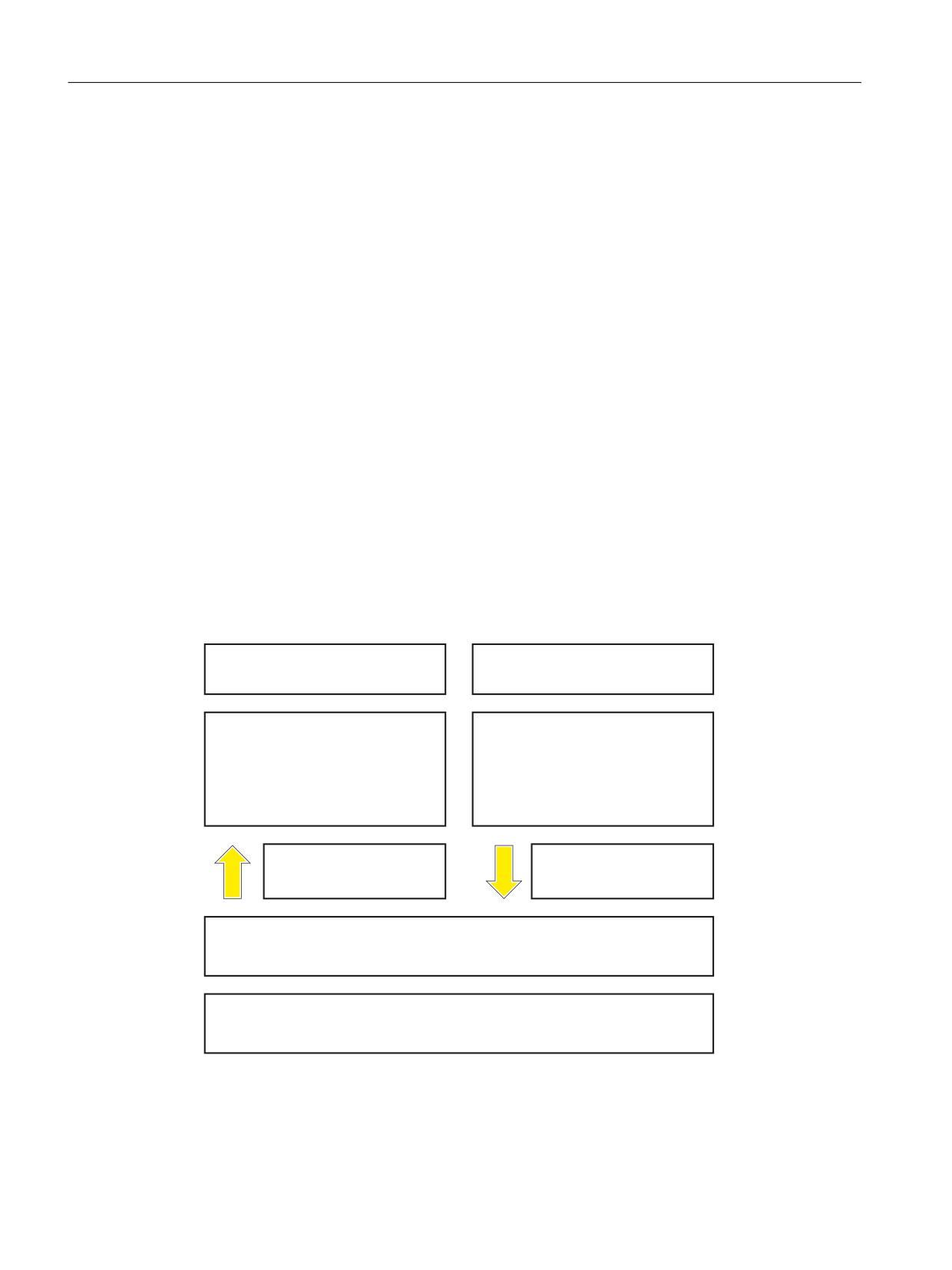
$Q\ DUFKLWHFWXUHV
'HILQHG DUFKLWHFWXUHV UHVWULFWHG
DOO 6,/
IURP 3/ E
PD[LPXP 3/ IRU HOHFWURQLFV
(1b
(1 ,62
6DIHW\ RI PDFKLQHU\
6DIHW\ RI PDFKLQHU\
)XQFWLRQDO VDIHW\ VDIHW\ UHODWHG
6DIHW\ UHODWHG SDUWV RI FRQWURO V\VWHPV
HOHFWULFDO HOHFWURQLF DQG SURJUDPPDEOH
HOHFWURQLF FRQWURO V\VWHPV
6HFWRU VWDQGDUG (1
IRU
)RU GHYLDWLRQV IURP WKH GHILQHG
WKH DUHD RI PDFKLQHV EHORZ
DUFKLWHFWXUHV UHIHUHQFH WR
(1
(1
8QLYHUVDO DSSURDFK IRU HOHFWULFDO HOHFWURQLF DQG SURJUDPPDEOH HOHFWURQLF V\VWHPV WKDW
H[HFXWH VDIHW\ IXQFWLRQV RU WKDW JXDUDQWHH IXQFWLRQDO VDIHW\
(1b
)XQFWLRQDO VDIHW\ VDIHW\ UHODWHG HOHFWULFDO HOHFWURQLF SURJUDPPDEOH HOHFWURQLF FRQWURO
V\VWHPV 3DUW WR
Safety Integrated (system-integrated)
22
Function Manual, 10/2020, 6FC5397-4BP40-6BA2
Regulations and standards
2.2 Machine safety in Europe
2.2.4
EN ISO 13849-1
EN ISO 13849-1 is based on previous standard EN 954-1, and additionally requires a quantitative
consideration of the safety functions. The following safety-related parameters are required for
components/devices:
• Category (structural requirement)
• PL:
Performance Level
• MTTFd:
Mean Time To dangerous Failure
mean time to dangerous failure
• DC:
Diagnostics coverage
Diagnostic coverage
• CCF:
Common Cause Fault
Common Cause Failure
The standard describes how the Performance Level (PL) is calculated for safety-related
components of the controller on the basis of designated architectures. In the event of any
deviations from this, EN ISO 13849-1 refers to EN 61508.
When combining several safety-related parts to form a complete system, the standard explains
how to determine the resulting PL.
2.2.5
EN 62061
EN 62061 (this is identical to IEC 62061) is a sector-specific standard below EN 61508. It
describes the implementation of safety-related electrical control systems of machines and takes
into account the complete lifecycle - from the conceptual phase to de-commissioning. The
standard is based on the quantitative and qualitative analyses of safety functions.
The standard systematically applies a top-down approach to implementing complex control
systems (known as "functional decomposition"). The safety functions derived from the risk
analysis are sub-divided into sub-safety functions, which are then assigned to real devices, sub-
systems, and sub-system elements. Both the hardware and software are covered. EN 62061 also
describes the requirements placed on implementing application programs.
A safety-related control systems comprises different subsystems. From a safety perspective, the
sub-systems are described by means of the characteristic quantities (SIL claim limit and PFHD).
Programmable electronic devices, e.g. PLCs or variable-speed drives must comply with EN
61508. They can then be integrated into the control system as subsystems. The following safety-
related characteristic quantities must be specified by the manufacturers of these devices.
Safety-related characteristic quantities for subsystems:
• SIL CL: SIL suitablility
SIL claim limit
• PFHD:
Probability of hazardous failures per hour
Probability of dangerous failure per hour
• T1:
Service life
Lifetime
Safety Integrated (system-integrated)
Function Manual, 10/2020, 6FC5397-4BP40-6BA2
23
Regulations and standards
2.2 Machine safety in Europe
Basic subsystems, e.g. sensors and actuators comprising electromechanical components, can,
in turn, comprise different interconnected subsystem elements (devices) with the characteristic
quantities to determine the corresponding PFHD value of the subsystem.
Safety-related characteristic quantities for subsystem elements (devices):
• λ:
Failure rate
Failure rate
• B10 value:
for elements that are subject to wear
• T1:
Service life
Lifetime
For electromechanical devices, a manufacturer specifies a failure rate λ with reference to the
number of operating cycles. The failure rate per unit time and the lifetime must be determined
using the switching frequency for the particular application.
Parameters for the subsystem, which comprises subsystem elements, that must be defined
during the design phase:
• T2:
Diagnostic test interval
Diagnostic test interval
• β:
Sensitivity for common cause faults
susceptibility to common cause failure
• DC:
Diagnostics coverage
Diagnostic coverage
The PFHD value of the safety-related control system is determined by adding the individual PFHD
values for subsystems.
The user has the following options when setting up a safety-related control system:
• Using devices and subsystems that already comply with EN ISO13849-1 or EN 61508 and/or
EN 62061. The standard provides information specifying how qualified devices can be
integrated when safety functions are implemented.
• Develop own subsystems.
- Programmable, electronic systems and complex systems: Application of EN 61508 or EN
61800-5-2.
- Simple devices and subsystems: Application of EN 62061.
Data on non-electrical systems is not included in EN 62061. The standard provides detailed
information on implementing safety-related electrical, electronic, and programmable electronic
control systems. EN ISO 13849-1 must be applied for non-electric systems.
Note
Details of basic subsystems that have been implemented and integrated are available as
"function examples".
Safety Integrated (system-integrated)
24
Function Manual, 10/2020, 6FC5397-4BP40-6BA2
Regulations and standards
2.2 Machine safety in Europe
Note
IEC 62061 has been ratified as EN 62061 in Europe and harmonized as part of the Machinery
Directive.
2.2.6
Series of standards EN 61508 (VDE 0803)
The series of standards describe state-of-the-art technology.
EN 61508 is not harmonized in line with any EU directives, which means that an automatic
presumption of conformity for fulfilling the protective requirements of a directive is not implied.
However, the manufacturer of a safety-related product can use EN 61508 to fulfill basic
requirements from the European directives according to the new concept. For instance in the
following cases:
• If no harmonized standard exists for the application in question. In this case, the
manufacturer can use EN 61508, although no presumption of conformity applies here.
• A harmonized European standard (e.g. EN 62061, EN ISO 13849, EN 60204-1) makes
reference to EN 61508. This ensures that the appropriate requirements of the directives are
fulfilled ("standard that is also applicable"). When manufacturers apply EN 61508 correctly
and responsibly in accordance with this reference, they can use the presumption of
conformity of the referencing standard.
EN 61508 covers all the aspects that must be taken into account when E/E/PES systems
(Electrical, Electronic, and Programmable Electronic System) are used in order to execute safety
functions and/or to ensure the appropriate level of functional safety. Other hazards, e.g. hazards
as a result of electric shock are not included in the standard.
A new aspect of EN 61508 is its positioning as "International Basic Safety Publication", which
makes it a framework for other sector-specific standards (e.g. EN 62061). As a result, this
standard is now accepted worldwide, particularly in North America and in the automotive
industry. Today, many regulatory bodies already specify it, e.g. as basis for NRTL listing.
A new aspect of EN 61508 is also its system approach. This extends the technical requirements
to the complete safety installation - from the sensor to the actuator - the quantification of the
probability of dangerous failure due to random hardware failures and the generation of
documentation associated with every phase of the complete safety-related lifecycle of the E/E/
PES.
2.2.7
EN 60204-1
European standard EN 60204-1 is based on the modified ISO edition of IEC 60204-1. It includes
general requirements and recommendations for the electrical, electronic and programmable
electronic equipment of machines with rated voltages up to and including 1000 V AC/ 1500 V DC
at rated frequencies up to and including 200 Hz, in order to:
- promote the safety of persons and assets
- maintain the functionality
- help simplify maintenance.
Safety Integrated (system-integrated)
Function Manual, 10/2020, 6FC5397-4BP40-6BA2
25
Regulations and standards
2.2 Machine safety in Europe
The equipment, which is covered by EN 60204-1, starts at the point of connection to the line
supply of the electrical equipment of the machine and ends at the motor shaft.
2.2.8
EN 61800-5-2
The European product standard EN 61800-5-2 has taken over the international standard IEC
61800-5-2 without any changes.
It defines requirements and gives recommendations for designing and developing, integrating
and validating safety-relevant power drive systems with adjustable speed (PDS(SR)) regarding
their functional safety.
This standard is only applicable if the functional safety of a PDS(SR) is used and the PDS(SR) is
operated in a mode with a high number or continuous demand (demand mode). The EN 61508
series of standards should be used for operating modes with a low demand (low demand mode).
This part of EN 61800 discusses the safety-related evaluation of a PDS(SR) within the framework
of the EN 61508 series of standards and introduces requirements placed on a PDS(SR) as
subsystems of a safety-relevant system. This therefore permits the implementation of the
electrical/electronic/programmable electronic (E/E/PE) elements of a PDS(SR) taking into
account the safety-relevant performance of the safety function(s) of a PDS.
Manufacturers and suppliers of PDS(SR) can prove to users (i.e. integrators of control systems,
developers of machines and plants etc.) the safety-relevant performance of their equipment by
implementing the specifications laid down in EN 61800-5-2. When this part of EN 61800 is
complied with, all of the requirements of the EN 61508 series of standards, which are specified
for a PDS(SR), are fulfilled.
This part of EN 61800 is only valid for PDS(SR), which implement safety functions up to SIL 3.
The following basic requirements of the EC machinery directive are covered in EN 61800-5-2:
• Safety and reliability of controls
• Faults in control circuits.
2.2.9
Risk analysis/assessment
Systems and machines represent risks due to their design and functionality. For this reason, the
Machinery Directive requires that a risk assessment be performed for each machine and, if
necessary, the level of risk reduced until the residual risk is less than the tolerable risk. To assess
these risks, the following standard must be applied:
• DIN EN ISO 12100 "Safety of machinery - General principles for design - Risk assessment and
risk reduction"
• DIN EN ISO 13849-1 "Safe control of machinery - Safety-related parts of control systems"
EN ISO 12100 mainly describes the risks to be considered and the design principles to minimize
risks - as well as the iterative process when assessing and reducing risks to achieve the
appropriate degree of safety.
Risk assessment is a procedure that allows hazards resulting from machines to be systematically
investigated. Where necessary, the risk assessment is followed by a risk reduction procedure.
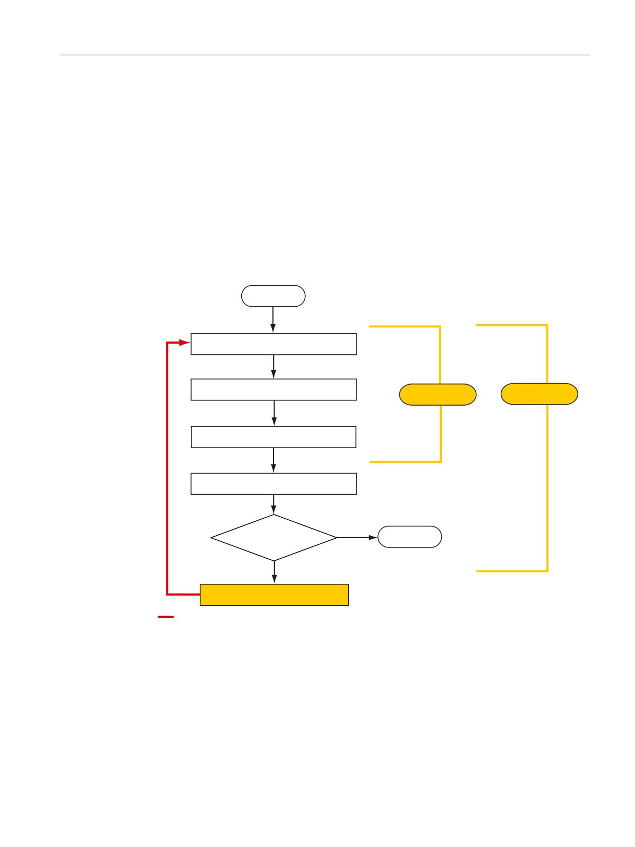
When this procedure is repeated, an iterative process is obtained (see Fig. ), which can then be
Safety Integrated (system-integrated)
26
Function Manual, 10/2020, 6FC5397-4BP40-6BA2
Regulations and standards
2.2 Machine safety in Europe
used to eliminate hazards as far as possible and so that the appropriate protective measures can
be taken.
Risk assessment encompasses the following
• Risk analysis
a) Determining the machine limits
b) Identifying hazards
c) Techniques to estimate risk
• Risk evaluation
As part of the iterative process to achieve the appropriate degree of safety, after the risk has been
analyzed the risk is assessed. A decision must then be made as to whether the residual risk needs
to be reduced. If the risk is to be further reduced, suitable protective measures must be selected
and applied. The risk assessment must then be repeated.
67
$57
'HWHUPLQLQJ WKH PDFKLQH OLPLWV
,GHQWLI\LQJ WKH SRWHQWLDO KD]DUG
5LVN DQDO\VLV
5LVN DVVHVVPHQW
5LVN HVWLPDWLRQ
5LVN HYDOXDWLRQ
<HV
,V WKH PDFKLQH VDIH
(1'
1R
5LVN PLQLPL]DWLRQ
0LQLPL]LQJ ULVNV DQG VHOHFWLQJ VXLWDEOH SURWHFWLYH PHDVXUHV DUH QRW SDUW RI WKH ULVN DVVHVVPHQW
Figure 2-1
Iterative process to achieve the required level of safety according to DIN ISO 12100
Risks must be reduced by suitably designing and implementing the machine - for instance a
control system or protective measures suitable for the safety-related functions.
If the protective measures involve the use of interlocking or control functions, these must be
designed in accordance with EN ISO 13849-1. For electrical and electronic controls, EN 62061
can be used as an alternative to EN ISO 13849-1. Electronic controls and bus systems must also
comply with EN 61508.
Safety Integrated (system-integrated)
Function Manual, 10/2020, 6FC5397-4BP40-6BA2
27
Regulations and standards
2.3 Machine safety in the USA
2.2.10
Risk reduction
Risk reduction measures for a machine can be implemented by means of safety-related control
functions in addition to structural measures. To implement these control functions, special
requirements must be taken into account, graded according to the magnitude of the risk. These
are described in EN ISO 13849-1 or, in the case of electrical controllers (particularly
programmable electronics), in EN 61508 or EN 62061. The requirements regarding safety-
related controller components are graded according to the magnitude of the risk and the level
to which the risk needs to be reduced.
EN ISO 13849-1 defines a risk flow chart that instead of categories results in hierarchically
graduated Performance Levels (PL).
IEC/EN 62061 uses "Safety Integrity Level" (SIL) for classification purposes. This is a quantified
measure of the safety-related performance of a controller. The required SIL is also determined
in accordance with the risk assessment principle according to ISO 12100 (EN 1050). Annex A of
the standard describes a method for determining the required Safety Integrity Level (SIL).
Regardless of which standard is applied, steps must be taken to ensure that all the machine
controller components required for executing the safety-related functions fulfill these
requirements.
2.2.11
Residual risk
In today's technologically advanced world, the concept of safety is relative. The ability to ensure
safety to the extent that risk is ruled out in all circumstances - "zero-risk guarantee" - is
practically impossible. The residual risk is the risk that remains once all the relevant protective
measures have been implemented in accordance with the latest state of the art.
Residual risks must be clearly referred to in the machine/plant documentation (user information
according to EN ISO 12100).
2.3
Machine safety in the USA
A key difference in the legal requirements regarding safety at work between the USA and Europe
is that, in the USA, no legislation exists regarding machinery safety that is applicable in all of the
states and that defines the responsibility of the manufacturers/supplier. Rather, there is a general
requirement that employers must ensure safety at work.
2.3.1
Minimum requirements of the OSHA
The Occupational Safety and Health Act (OSHA) from 1970 regulates the requirement that
employers must offer a safe place of work. The core requirements of OSHA are specified in
Section 5 "Duties".
The requirements of the OSH Act are managed by the "Occupational Safety and Health
Administration" (also known as OSHA). OSHA employs regional inspectors who check whether
or not workplaces comply with the applicable regulations.
Safety Integrated (system-integrated)
28
Function Manual, 10/2020, 6FC5397-4BP40-6BA2
Regulations and standards
2.3 Machine safety in the USA
The OSHA regulations are described in OSHA 29 CFR 1910.xxx ("OSHA Regulations (29 CFR)
PART 1910 Occupational Safety and Health"). (CFR: Code of Federal Regulations.)
OSHA
The application of standards is regulated in 29 CFR 1910.5 "Applicability of standards". The
concept is similar to that used in Europe. Product-specific standards have priority over general
standards insofar as they cover the relevant aspects. Once the standards are fulfilled, employers
can assume that they have fulfilled the core requirements of the OSH Act with respect to the
aspects covered by the standards.
In conjunction with certain applications, OSHA requires that all electrical equipment and devices
that are used to protect workers be authorized by an OSHA-certified, "Nationally Recognized
Testing Laboratory" (NRTL) for the specific application.
In addition to the OSHA regulations, the current standards defined by organizations such as
NFPA and ANSI must be carefully observed and the extensive product liability legislation that
exists in the US taken into account. Due to the product liability legislation, it is in the interests of
manufacturing and operating companies that they carefully maintain the applicable regulations
and are "forced" to fulfill the requirement to use state-of-the-art technology.
Third-party insurance companies generally demand that their customers fulfill the applicable
standards of the standards organizations. Self-insured companies are not initially subject to this
requirement but, in the event of an accident, they must provide verification that they have
applied generally-recognized safety principles.
See also
2.3.2
NRTL listing
To protect employees, all electrical equipment used in the USA must be certified for the planned
application by a "Nationally Recognized Testing Laboratory" (NRTL) certified by the OSHA. NRTLs
are authorized to certify equipment and material by means of listing, labeling, or similar.
Domestic standards (e.g. NFPA 79) and international standards (e.g. IEC/EN 61508 for E/E/PES
systems) are the basis for testing.
2.3.3
NFPA 79
Standard NFPA 79 (Electrical Standard for Industrial Machinery) applies to electrical equipment
on industrial machines with rated voltages of less than 600 V. A group of machines that operate
together in a coordinated fashion is also considered to be one machine.
For programmable electronics and communication buses, NFPA 79 states as a basic requirement
that these must be listed if they are to be used to implement and execute safety-related
functions. If this requirement is fulfilled, then electronic controls and communication buses can
also be used for Emergency Stop functions, Stop Categories 0 and 1 (refer to
NFPA 79 9.2.5.4.1.4). Just the same as EN 60204-1, NFPA 79 no longer specifies that the
electrical energy must be disconnected by electromechanical means for emergency stop
functions.
Safety Integrated (system-integrated)
Function Manual, 10/2020, 6FC5397-4BP40-6BA2
29
Regulations and standards
2.4 Machine safety in Japan
The core requirements regarding programmable electronics and communication buses in
accordance with NFPA 79 9.4.3:
1. Control systems that contain software-based controllers must:
- In the event of a single fault
(a) Initiate that the system switches to a safe shutdown mode
(b) Prevent the system from restarting until the fault has been rectified
(c) Prevent an unexpected restart
- Offer the same level of protection as hard-wired controllers
- Be implemented in accordance with a recognized standard that defines the requirements
for such systems.
2. IEC 61508, IEC 62061, ISO 13849-1, ISO 13849-2 and IEC 61800-5-2 are specified as suitable
standards in a note.
Underwriter Laboratories Inc. (UL) has defined a special category for "Programmable Safety
Controllers" for implementing this requirement (code NRGF). This category covers control
devices that contain software and are designed for use in safety-related functions.
A precise description of the category and a list of devices that fulfill this requirement can be
found on the Internet at the following address:
NRGF → Online Certifications Directory → UL Category code/Guide information → search for
category "NRGF"
TUV Rheinland of North America, Inc. is also an NRTL for these applications.
See also
2.3.4
ANSI B11
ANSI B11 standards are joint standards developed by associations such as the Association for
Manufacturing Technology (AMT) and the Robotic Industries Association (RIA).
The hazards of a machine are evaluated by means of a risk analysis/assessment. The risk analysis
is an important requirement in accordance with NFPA 79, ANSI/RIA 15.06, ANSI B11.TR-3 and
SEMI S10 (semiconductors). The documented results of a risk analysis can be used to select a
suitable safety system based on the safety class of the application in question.
2.4
Machine safety in Japan
The situation in Japan is different from that in Europe and the US. Legislation such as that
prescribed in Europe does not exist. Similarly, product liability does not play such an important
role as it does in the US.
Safety Integrated (system-integrated)
30
Function Manual, 10/2020, 6FC5397-4BP40-6BA2

Regulations and standards
2.6 Other safety-related issues
Instead of legal requirements to apply standards have been defined, an administrative
recommendation to apply JIS (Japanese Industrial Standard) is in place. Japan bases its approach
on the European concept and uses basic standards as national standards:
Table 2-1
Japanese standards
ISO/IEC number
JIS number
Comment
ISO12100 (EN 1050)
JIS B 9700, JIS B 9702
Earlier designation TR B 0008 and TR B 0009
ISO13849-1
JIS B 9705-1
-
ISO13849-2
JIS B 9705-1
-
IEC 60204-1
JIS B 9960-1
Without annex F or route map of the European
foreword
IEC 61508-0 to -7
JIS C 0508
-
IEC 62061
-
JIS number not yet assigned
2.5
Equipment regulations
In addition to the requirements of the guidelines and standards, company-specific requirements
must be taken into account. Large corporations in particular (e.g. automobile manufacturers)
make stringent demands regarding automation components, which are often listed in their own
equipment specifications.
Safety-related issues (e.g. operating modes, operator actions with access to hazardous areas,
EMERGENCY STOP concepts, etc.) should be clarified with customers early on so that they can be
integrated in the risk assessment/risk reduction process.
2.6
Other safety-related issues
2.6.1
Information sheets from the various regulatory bodies
Safety-related measures to be implemented cannot always be derived from directives, standards
or regulations. In this case, supplementary information and explanations are required.
Some regulatory bodies issue publications on a wide range of subjects and topics. Information
sheets covering the following areas are available, for example:
• Process monitoring in production environments
• Axes subject to gravitational force
• Roller pressing machines
• Lathes and turning centers - purchasing/selling
These information sheets handling specific subjects and issues can be ordered from all parties
interested - e.g. for providing support in plants and factories, when drawing-up regulations or
for implementing safety-related measures at machines, plants and systems. These information
sheets provide support in machinery construction, production systems, steel construction.
Safety Integrated (system-integrated)
Function Manual, 10/2020, 6FC5397-4BP40-6BA2
31
Regulations and standards
2.6 Other safety-related issues
At the following Internet address, under "Service and Contact" - "Downloads" → "Information
sheets FA MFS", you can download fact sheets (not only for axes that can fall due to gravity, but
also regarding process monitoring):
2.6.2
Additional references
• Safety Integrated, The Safety Program for Industries of the World (5th Edition and
Supplement), Article No. 6ZB5 000-0AA01-0BA1
• Safety Integrated - Terms and Standards - Machine Safety Terminology (Edition 04/2007),
Article No. E86060-T1813-A101-A1
2.6.3
Additional information
A list of links on the topic of "SINUMERIK Safety Integrated" is provided in this Product
The following topics are also included there:
• Calculation of the safety functions with SET and SISTEMA
• Application examples for:
- the calculation of safety functions for SINUMERIK
- Acceptance test
- Configuration example
• Safety Integrated function descriptions
Safety Integrated (system-integrated)
32
Function Manual, 10/2020, 6FC5397-4BP40-6BA2
Brief description
3
3.1
Control/drive systems
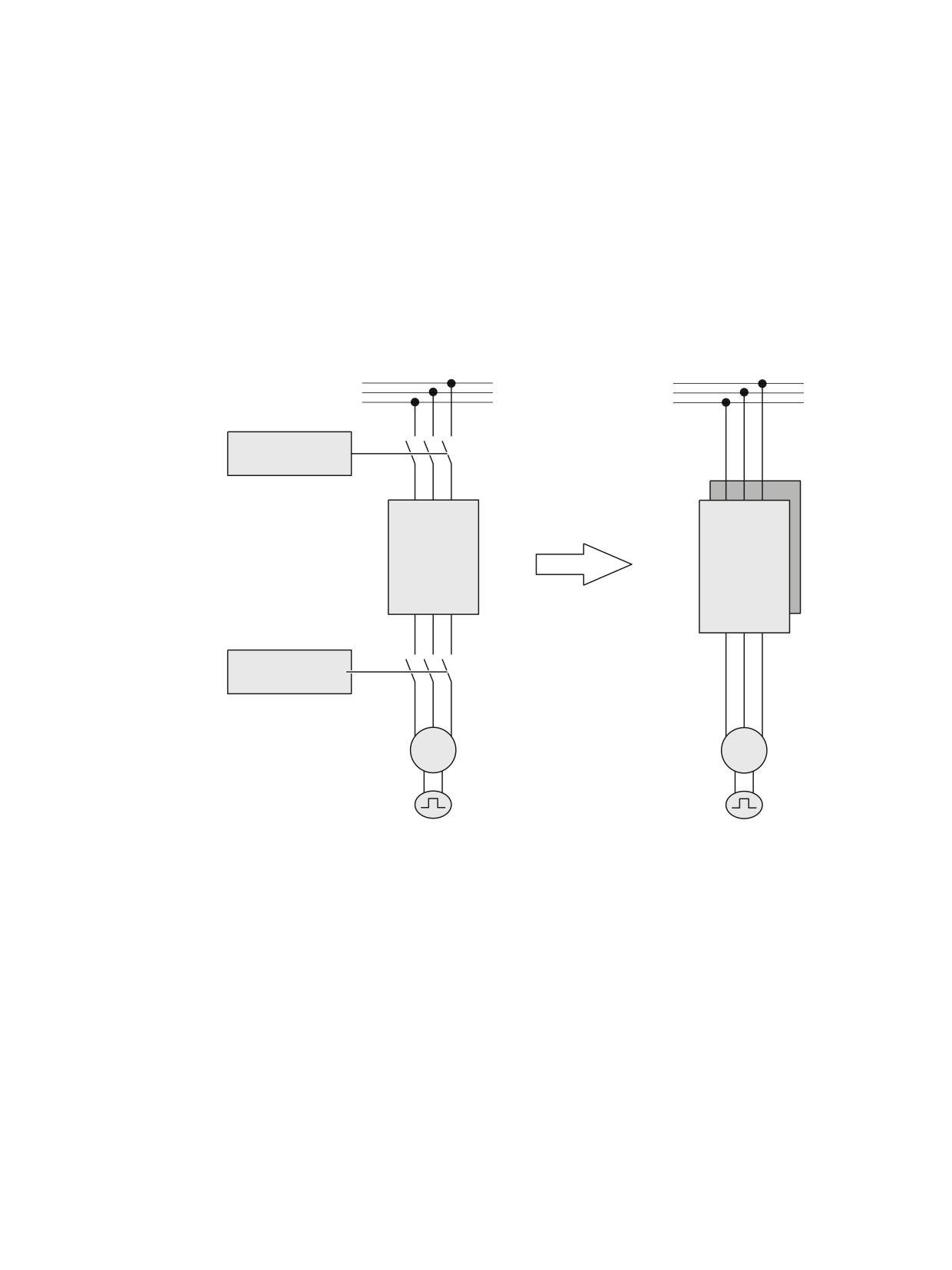
In order to implement safety-related measures, up until now, external equipment and devices
were used - e.g. contactors, switches, cams and monitoring devices. If a hazardous situation is
detected, these devices generally interrupt the power circuit using contacts, thus stopping
motion.
([WHUQDO
6DIHW\ WHFKQRORJ\
&1&
'ULYH
UHJXODWRU
'ULYH
UHJXODWRU
,QWHJUDWHG
VDIHW\
WHFKQRORJ\
([WHUQDO
6DIHW\ WHFKQRORJ\
0
0
Figure 3-1
Safety technology: External -> integrated
With the integration of safety functions, drive systems and CNC controls perform safety
functions in addition to their functional tasks. Very short response times can be achieved
because of the short data paths from acquisition of the safety-related information - e.g. speed
or position - up to evaluation.
The systems with integrated safety technology generally respond very quickly when the
permissible limit values are violated, e.g. position and velocity limit values. They can be of
decisive importance for the required monitoring result. The integrated safety technology can
directly access the power semiconductors in the drive controller without using
electromechanical switching devices in the power circuit. This helps reduce the susceptibility to
faults - and the integration also reduces the amount of cabling.
A combination of safety technology integrated in the system and drive can be used for each axis
at a machine tool (SINAMICS Basic Safety functions).
Safety Integrated (system-integrated)
Function Manual, 10/2020, 6FC5397-4BP40-6BA2
33
Brief description
3.2 Safety technology integrated in the system
3.2
Safety technology integrated in the system
SINUMERIK Safety Integrated
Using the SINUMERIK Safety Integrated function, for SINUMERIK 840D sl, for all power/
performance classes, integrated safety functions are available in conjunction with the SINAMICS
S120 drive system; these are used to monitor standstill (zero speed), velocity and position.
SINAMICS S120 is used in conjunction with 1FT6/1FK6/1FK7 three-phase servomotors and 1FN
linear motors for feed drives as well as 1FE and 1PH motors for main spindle drives.
The safety-related sensors and actuators are connected through distributed I/O via PROFIBUS DP,
PROFINET with the PROFIsafe profile, e.g. ET 200S, ET 200pro, ET 200eco, DP/AS-i F-Link.
This means that a complete digital system is available that is suitable for complex machining
tasks.
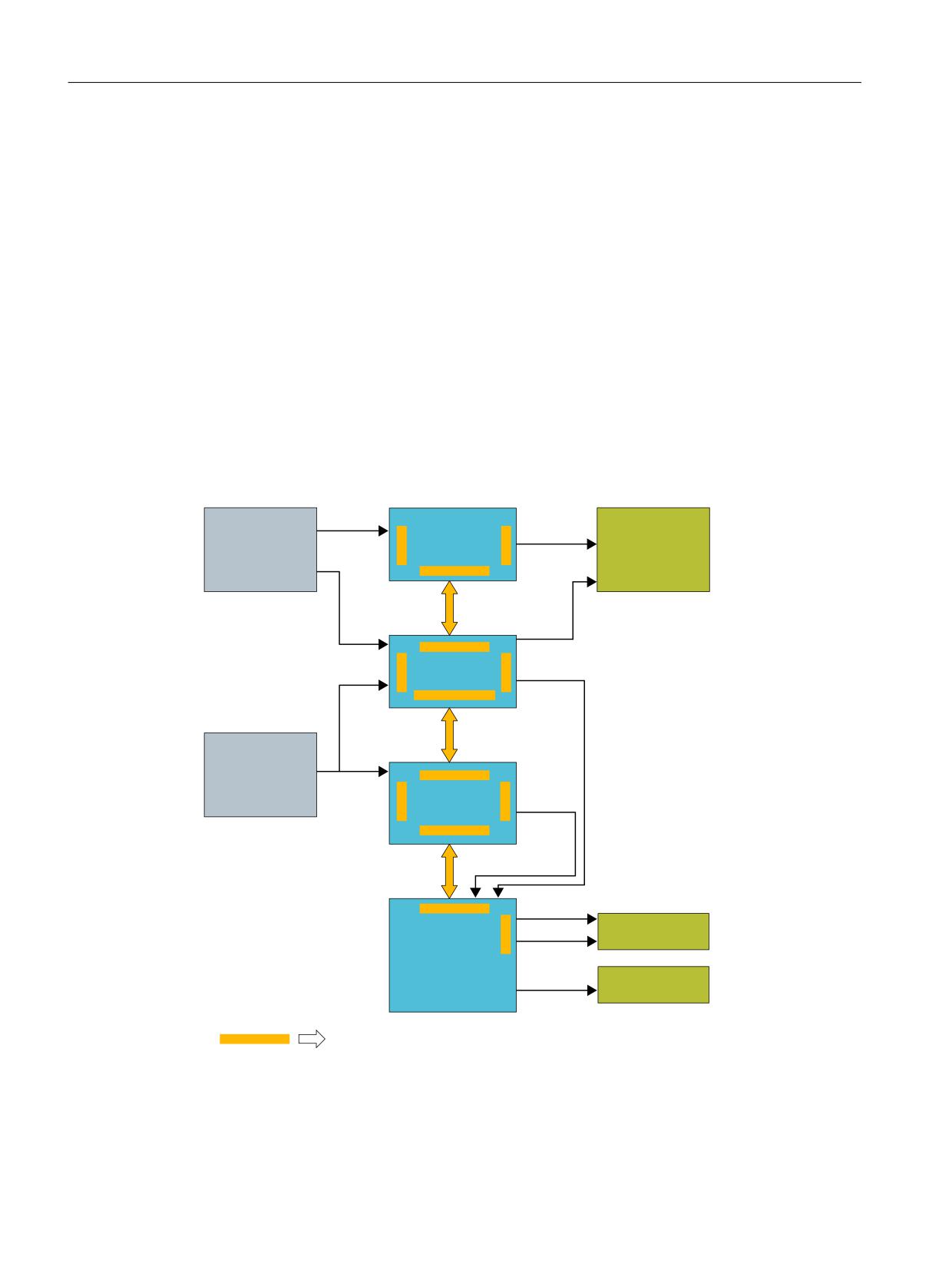
A two-channel, diverse system structure is formed on the basis of an existing multi-processor
structure.
VDIH
3/&
VDIH
VHQVRUV
DFWXDWRUV
63/ &'&
&URVVZLVH
&RPP &'&
'DWD FRPSDULVRQ
1&.
&URVVZLVH
$[LV &'&
'DWD FRPSDULVRQ
0HDVXUHG YDOXH
V\VWHP
'ULYH FRQWURO
6ZLWFK RII VLJQDO SDWKV
&URVVZLVH
'ULYH &'&
'DWD FRPSDULVRQ
%UDNH
0RWRU 0RGXOH
FRQWURO
0RWRU
6DIHW\ UHOHYDQW PRQLWRULQJ IXQFWLRQV
Figure 3-2
Evaluation/logic with monitoring functions
Safety Integrated (system-integrated)
34
Function Manual, 10/2020, 6FC5397-4BP40-6BA2
Brief description
3.2 Safety technology integrated in the system
Features of the two-channel, diverse structure
A two-channel, diverse structure is characterized by the following features:
• Two-channel structure with at least 2 independent computers (i.e. computers with different
hardware and software).
• Crosswise result and data comparison with forced checking procedure for the purpose of
detecting internal errors even in functions that are not often used (dormant errors).
• The computers can access data, reaction-free and decoupled at the shared (common)
interfaces (e.g. actual value input).
Detecting
The actual values of the individual axes are sensed by the sensor modules through two channels
and are provided to the drive and control.
In order to connect sensors and actuators in a safety-related fashion, their process signals must
be connected for further processing.
Evaluating
The safety-related functions are executed independently of one another by the NCK-CPU, PLC-
CPU and the drive CPUs. The CPUs cyclically and mutually compare their safety-related data and
results (crosswise data comparison). A test can be carried out - initiated by the CPUs - to check the
switch-off signal paths and actuators (forced checking procedure).
Reacting
When the integrated safety-related functions respond, the drive processors, the PLC processor
and/or the NCK processor can act on the connected actuators in a safety-related fashion in-line
with the actual situation. For example, the appropriate stop responses for the drives can be
initiated and the actuators shutdown via the switch-off signal paths.
3.2.1
Overview of the safety functions integrated in the system
The safety functions are available in all modes and can communicate with the process using
safety-related input/output signals. They can be implemented for each individual axis and
spindle.
• Safe shutdown (stops)
When a monitoring function or a sensor responds (e.g. a light grid), the drives are safely
controlled down to standstill, optimally adapted to the actual operating state of the machine.
• Safe monitoring of the acceleration (SBR)
Monitors the speed characteristic. The speed must decrease after a stop request.
• Safe standstill (SH)
The drive pulses are suppressed, allowing the energy feed to be safely and electronically
disconnected.
Safety Integrated (system-integrated)
Function Manual, 10/2020, 6FC5397-4BP40-6BA2
35
Brief description
3.3 Safety technology integrated in the drive
•
Safe Operating Stop (SBH)
Monitors the drives during standstill (to ensure that they remain stationary). The drives
remain fully functional in closed-loop control.
•
Safely reduced speed (SG) including override
Configured speed limits are monitored, e.g. when setting-up without using an agreement
button.
•
Safe speed range detection "n<nx"
This is used to detect the velocity range of a drive in a safety-related fashion.
•
Safe software limit switches (SE)
Variable traversing range limits
•
Safe software cams and Safe Cam Track (SN)
Range detection
•
Safety-relevant input/output signals (SGE/SGA)
Interface to the process
•
Safety-related communication via standard bus
Distributed I/O for process and safety signals are connected via PROFIBUS and PROFINET
using the PROFIsafe profile.
•
Safety-related CPU-CPU communication
Safety-relevant communication between safety-relevant controls to implement hierarchic
systems, e.g. transfer lines.
•
Safe programmable logic (SPL)
Direct connection of all safety-related signals and their internal logical interconnection.
•
Safe brake management (SBM)
Safety-related two-channel brake control (SBC) and cyclic brake test (SBT).
•
Integrated acceptance test
Partially automated acceptance test for all safety-related functions. Simple operation of the
test process, automatic configuration of trace functions and automatic generation of an
acceptance record.
3.3
Safety technology integrated in the drive
SINAMICS Safety Integrated
The SINAMICS S120 drive system provides the Safety Integrated Basic Functions and the Safety
Integrated Extended Functions.
Under certain limitations and constraints (refer to the system prerequisites), the Safety
Integrated Basic Functions can be used together with SINUMERIK 840D sl.
They can be activated via terminals at the power unit and at the NCU or at the NX module.
Safety Integrated (system-integrated)
36
Function Manual, 10/2020, 6FC5397-4BP40-6BA2
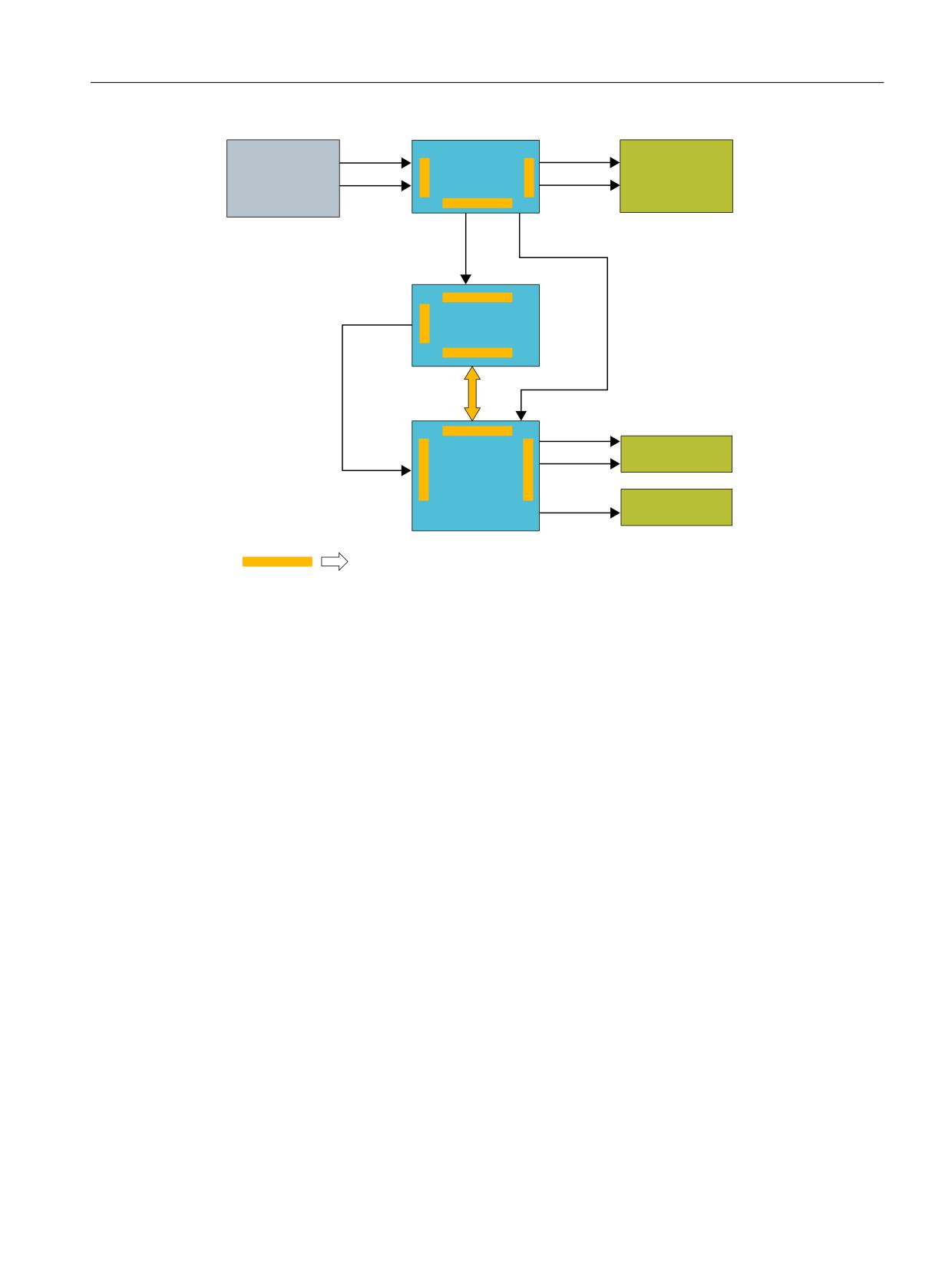
Brief description
3.3 Safety technology integrated in the drive
([WHUQDO
VDIH
VDIH
VDIH
VHQVRUV
ORJLF
DFWXDWRUV
'ULYH FRQWURO
6ZLWFK RII VLJQDO
'ULYH &'&
SDWK
%UDNH
0RWRU 0RGXOH
FRQWURO
0RWRU
6DIHW\ UHOHYDQW PRQLWRULQJ IXQFWLRQV
Figure 3-3
Safety functions integrated in the drive in conjunction with SINUMERIK
Features of the two-channel, diverse structure
A two-channel, diverse structure is characterized by the following features:
• Two-channel structure with at least 2 independent computers (i.e. computers with different
hardware and software).
• Crosswise result and data comparison with forced checking procedure for the purpose of
detecting internal errors even in functions that are not often used (dormant errors).
Detecting
In order to connect sensors and actuators in a safety-related fashion, their process signals must
be connected for further processing.
Evaluating
The two drive CPUs independently execute the safety-related functions. The CPUs cyclically and
mutually compare their safety-related data and results (crosswise data comparison). A test can
be carried out - initiated by the CPUs - to check the switch-off signal paths and actuators (forced
checking procedure).
Safety Integrated (system-integrated)
Function Manual, 10/2020, 6FC5397-4BP40-6BA2
37

Brief description
3.4 Comparison of the function names
Reacting
When the integrated safety-related functions respond, the drive processors can act on the
connected actuators in a safety-related fashion in-line with the actual situation. For example,
the appropriate stop responses for the drives can be initiated and/or the brakes activated.
3.3.1
Overview of the safety functions integrated in the drive
The safety functions are available in all modes and can communicate with the process using
safety-oriented input/output signals. They can be implemented for each individual axis and
spindle.
• Safe Torque Off (STO)
Drive pulses are canceled, resulting in safe electronic interruption of the energy supply
• Safe Brake Control (SBC)
The brake is directly controlled at the Motor Module ⇒ through two channels, and is
monitored
• Safe Stop 1 (SS1)
Braking along the OFF3 ramp, monitoring the stopping time and transition into STO
3.4
Comparison of the function names
SINUMERIK Safety Integrated functional name
Function name according to EN 61800-5-2
German
English
Abbr.
German
English
Abbr.
Safe standstill
Safe standstill
SH
Safe Torque Off
Safe Torque Off
STO
(STOP A)
(STOP A)
STOP B
STOP B
-
Safe Stop 1
Safe Stop 1
SS1
STOP C
STOP C
-
Safe Stop 2
Safe Stop 2
SS2
STOP D
STOP D
-
Safe Stop 2 1)
Safe Stop 2
SS2
STOP E
STOP E
-
Safe Stop 2 2)
Safe Stop 2
SS2
Safe Acceleration
Safe Acceleration Moni-
SBR
-
-
-
Monitor
tor
Safe Operating Stop
Safe Operating Stop
SBH
Safe Operating Stop
Safe Operating Stop
SOS
Safely reduced speed
Safely reduced speed
SG
Safely-Limited Speed
Safely-Limited Speed
SLS
SG-specific setpoint
Safely reduced speed -
-
-
-
-
limiting
specific setpoint limit-
ing
Safe software limit
Safe software limit
SE
Safely Limited Position
Safely-Limited Position
SLP
switch
switch
Safe Brake Manage-
Safe Brake Manage-
SBM
-
-
-
ment
ment
Safe Brake Control
Safe Brake Control
SBC
Safe Brake Control
Safe Brake Control
SBC
Safe brake test
Safe Brake Test
SBT
-
-
-
Safe software cam or
Safe software cam, Safe
SN
Safe Cams
Safe Cams
SCA
cam track
Cam Track
Safety Integrated (system-integrated)
38
Function Manual, 10/2020, 6FC5397-4BP40-6BA2

Brief description
3.4 Comparison of the function names
SINUMERIK Safety Integrated functional name
Function name according to EN 61800-5-2
German
English
Abbr.
German
English
Abbr.
n < nx
n < nx
-
Safe Speed Monitor
Safe Speed Monitor
SSM
Safety-relevant input/
Safety-related I/O
SGE/SGA
-
-
-
output signals
F-DI/F-DO
Safe Programmable
Safe Programmable
SPL
-
-
-
Logic
Logic
Safe software relay
Safe software relay
-
-
-
-
1) For the drive-based safety functions of SINAMICS, this involves a delayed SOS
2) For the drive-based safety functions of SINAMICS, this involves a delayed SOS with previous initiation of ESR (extended
stopping and retraction)
Safety Integrated (system-integrated)
Function Manual, 10/2020, 6FC5397-4BP40-6BA2
39
Brief description
3.4 Comparison of the function names
Safety Integrated (system-integrated)
40
Function Manual, 10/2020, 6FC5397-4BP40-6BA2

System features
4
4.1
System requirements
• Software option "SINUMERIK Safety Integrated"
SI-Basic (including 1 axis/spindle, up to 4 SPL I/Os)
6FC5800-0AM63-0YB0
SI-Comfort (including 1 axis/spindle, up to 64 SPL I/Os)
6FC5800-0AM64-0YB0
SI-axis/spindle (in addition for each axis /spindle)
6FC5800-0AC70-0YB0
SI axis/spindle package (in addition, 15 axes/spindles)
6FC5800-0AC60-0YB0
SI-High Feature (including 1 axis/spindle to 192 SPL I/O)
6FC5800-0AS68-0YB0*
SI Connect (16 safe connections)
6FC5800-0AS67-0YB0
* only for NCU 720.x and NCU 730.x
• SINUMERIK 840D sl; software release:
From 1.3.1 for safety functions integrated in the drive (SH/SBC via terminals, Chapter 4)
From 1.3.2 for safety functions integrated in the system (Chapters 5 to 7)
• Step7, V5.5
WARNING
Firmware versions
In a system configuration, the firmware versions of the DRIVE-CLiQ components can only differ
from the versions on the CF card, if either
a) The automatic upgrade/downgrade (parameter p7826) is deactivated, or
b) components with a new firmware version can no longer be downgraded to the status of the
version available on the CF card.
Case a) is not permitted when Safety Integrated is used. The automatic upgrade/downgrade
must never be disabled when Safety Integrated is used. (automatic firmware update (p7826)
must be equal to 1)
Case b) is only permissible if this combination has been explicitly approved by the
manufacturer.
• SINUMERIK 840D sl; all NCU types can be used
• The measuring circuit cables must comply with the specifications of the SINAMICS S120.
• Safety-related devices/modules, that correspond to open-type devices according to UL 50,
may only be operated in enclosure-type housings/cabinets that have as a minimum degree
of protection IP54 in accordance with EN 60529. Further, chassis units with degree of
protection IP20 and IPXXB should be operated corresponding to EN 60529 in higher-level
enclosures.
Safety Integrated (system-integrated)
Function Manual, 10/2020, 6FC5397-4BP40-6BA2
41
System features
4.1 System requirements
• The state of a deleted/clear safety-related input or output (i.e. the state logical "0" of an SGE/
SGA and electrical "low" of an associated I/O terminal) or the state of a drive where the pulses
are cancelled that can be achieved by the user as well by the fault response of the "SINUMERIK
Safety Integrated" system, is defined in what is called the "failsafe state". This is the reason
that the system is only suitable for applications where this state corresponds to the safe state
of the process controlled by SINUMERIK Safety Integrated.
• Drives with slip cannot be used for SE and SN.
• The SINUMERIK Safety Integrated Functions can be used in conjunction with the SINAMICS
booksize and chassis units.
• For the Safety Integrated function, only the explicitly released encoder systems may be used.
A list of the Siemens encoders and motors permissible for Safety Integrated Functions can be
obtained from your local Siemens contact partner.
The following applies specifically for safety functions integrated in the drive:
• A software option is not required when using the SINAMICS Safety Integrated Basic Functions.
The following specifically applies for failsafe SIMATIC modules:
• STEP7 F-configuration tool (F-Configuration Pack) as supplement to STEP7
This F-configuration tool is required so that ET 200 F-modules or the DP/AS-i F-Link can be
integrated into the HW configuration.
The F-configuration tool can be downloaded from the A&D Service&Support pages under
the topic F-Configuration Pack. Which F-configuration tool can be used for which STEP7
version is also specified there.
When using ET 200 F-modules or DP/AS-i F-Link it should be noted that a version of the F-
configuration tool should be used that the module already supports.
Which modules can be configured with which versions that can be downloaded are also
specified in the download area.
Note
Only the F-Configuration Pack is necessary to connect failsafe SIMATIC modules to SINUMERIK.
Neither SIMATIC S7 Distributed Safety nor SIMATIC S7 F-systems are required.
The following specifically applies for coupled axes:
• In a gantry group, the leading as well as the following axes must be enabled in SINUMERIK
Safety Integrated.
• Also for a master/slave group, SINUMERIK Safety Integrated must be configured on both axes,
assuming that there is no fixed mechanical coupling.
If there is a fixed mechanical coupling, then SINUMERIK Safety Integrated must only be
configured in the master axis.
Based on a risk assessment, the machine manufacturer must evaluate as to whether the
fixed mechanical coupling is adequately stable; if this is the case, then SINUMERIK Safety
Integrated only has to be configured in the master axis.
Safety Integrated (system-integrated)
42
Function Manual, 10/2020, 6FC5397-4BP40-6BA2

System features
4.2 Current information
4.2
Current information
Important note for maintaining the operational safety of your system.
WARNING
Plants and systems with the safety-relevant characteristics
Systems with safety-related characteristics are subject to special operational safety
requirements on the part of the operating company. The supplier is also obliged to maintain
certain measures regarding his product. For this reason, we publish a special newsletter
containing information on product developments and features that are (or could be) relevant
when operating safety-related systems. You should subscribe to the corresponding newsletter
in order to obtain the latest information and to allow you to modify your equipment
accordingly.
Go into the Internet at:
Note
You have to register and log in if you want to subscribe to the newsletter. You will be led
automatically through the registration process.
To subscribe to the newsletter, please proceed as follows:
1. Select the desired language for the web page.
2. Click on the menu item "Support".
3. Click on the menu item "Newsletter".
4. Click on "Login" and log in with your access data. If you do not yet have a login and password,
select "Yes, I would like to register now".
You can subscribe to the individual newsletters in the following window.
5. Select the document type you wish to be informed about under "Select document type for
topic and product newsletters".
6. Under the "Product Support" heading on this page, you can see which newsletter is currently
available.
7. Open the subject area "Safety Engineering - Safety Integrated". You will now be shown which
newsletter is available for this particular subject area or topic. You can subscribe to the
appropriate newsletter by clicking on the box. If you require more detailed information on the
newsletters then please click on these. A small supplementary window is opened from where
you can take the appropriate information.
Your subscription should cover the following product areas:
• SINUMERIK Safety Integrated
• SINAMICS Safety Integrated
• SIMOTION Safety Integrated
• SIMATIC S7-300
Safety Integrated (system-integrated)
Function Manual, 10/2020, 6FC5397-4BP40-6BA2
43
System features
4.5 Safety information & instructions and residual risks
• Distributed I/O
• SIMATIC software
4.3
Certifications
The safety functions fulfill the requirements according to EN 61508 for use up to and including
SIL2 in an operating mode with a high demand rate and Category 3 as well as PL d acc. to EN ISO
13849-1. The average time up to a hazardous failure MTTFd and the probability of hazardous
failures per hour PFHd depend on the degree of expansion of the system.
Using the safe brake test function, a brake can comply with Category 2 acc. to EN ISO 13849-1.
4.4
Probability of failure
We can provide you with a Safety Evaluation Tool (SET) - certified by the TÜV (German Technical
Inspectorate) - to evaluate the safety function (PFH value); this tool is available at no charge.
With the help of this tool, safety functions according to IEC 62061 or ISO 13849 can be
calculated. As result you will receive a standards-compliant report that can be integrated in the
machine documentation as proof of safety.
For additional information, please contact your local Siemens office.
4.5
Safety information & instructions and residual risks
4.5.1
General residual risks for PDS (Power Drive Systems)
Note
There are additional safety information & instructions and residual risks in other chapters, which
are listed in the relevant locations in this documentation.
Safety Integrated (system-integrated)
44
Function Manual, 10/2020, 6FC5397-4BP40-6BA2

System features
4.5 Safety information & instructions and residual risks
DANGER
Power Drive Systems
The control and drive components of a power drive system (PDS) are approved for industrial
and commercial use in industrial line supplies. Their use in public line supplies (public grids)
requires a different configuration and/or additional measures.
These components may only be operated in closed housings or in higher-level control cabinets
and when all of the protective devices and protective covers are used.
These components may only be handled by qualified and trained technical personnel who are
knowledgeable and observe all of the safety information and instructions on the components
and in the associated technical user documentation.
When carrying out a risk assessment of the machine in accordance with the EC Machinery
Directive, the machine manufacturer must consider the following residual risks associated with
the control and drive components of a Power Drive System.
1. Unintentional movements of driven machine components during commissioning,
operation, maintenance, and repairs caused by, for example:
- Hardware and/or software errors in the sensors, control system, actuators and
connection systems
- Response times of the control system and drive
- Operation and/or environmental conditions outside the specification
- Parameterization, programming, cabling, and installation errors
- Use of radio devices / cellular phones in the immediate vicinity of the control system
- External influences / damage
2. Exceptional temperatures as well as emissions of light, noise, particles, or gas caused by, for
example:
- Component malfunctions
- Software errors
- Operation and/or environmental conditions outside the specification
- External influences / damage
3. Hazardous touch voltages, e.g. as a result of:
- Component malfunctions
- Influence of electrostatic charges
- Induction of voltages in moving motors
- Operation and/or environmental conditions outside the specification
- Condensation/conductive contamination
- External influences / damage
4. Electrical, magnetic, and electromagnetic fields that can pose a risk to people with a
pacemaker and/or implants if they are too close.
5. Emission of pollutants if components or packaging are not disposed of properly.
For more information about residual risks, refer to the relevant chapters in the technical user
documentation.
Safety Integrated (system-integrated)
Function Manual, 10/2020, 6FC5397-4BP40-6BA2
45

System features
4.5 Safety information & instructions and residual risks
4.5.2
Additional safety information & instructions and residual risks for Safety
Integrated
DANGER
Risk reduction for plants and machines
Safety Integrated can be used to minimize the level of risk associated with machines and plants.
Safe operation of the machine or plant with Safety Integrated is however only possible if the
machine manufacturer
• is familiar with and observes every aspect of this technical user documentation, including
the documented general conditions, safety information, and residual risks.
• Carefully constructs and configures the machine/plant. A careful and thorough acceptance
test must then be performed by qualified personnel and the results documented.
• Implements and validates all the measures required in accordance with the machine/plant
risk analysis by means of the programmed and configured Safety Integrated Functions or by
other means.
Depending on the risk assessment of the machine or plant, the safety information &
instructions and residual risks listed in this documentation must also be assigned, when
required, to a hazardous level other than that specified in this documentation.
The use of Safety Integrated does not replace the risk assessment of the machine or plant
to be performed by the machine manufacturer as specified in the EC machinery directive!
In addition to Safety Integrated, further risk reduction measures must be implemented.
Safety Integrated (system-integrated)
46
Function Manual, 10/2020, 6FC5397-4BP40-6BA2

System features
4.5 Safety information & instructions and residual risks
As a result of the fault analysis, the machine manufacturer is in a position to define the residual
risk at his machine regarding Safety Integrated. The following residual risks are known.
WARNING
Additional residual risks
•
Safety Integrated is only activated if all of the system components are powered-up and have
been booted.
•
Faults in the absolute track (C-D track), cyclically interchanged phases of motor connections
(V-W-U instead of U-V-W) and a reversal in the control direction can cause an increase in the
spindle speed or axis motion. Category 1 and 2 Stop functions according to EN 60204-1
(defined as Stop B to E in Safety Integrated) that are provided, are however not effective due
to the fault.
Category 0 stop function according to EN 60204-1 (defined as STOP A in Safety Integrated)
is not activated until the transition or delay time set via machine data has expired. When SBR
is active, these errors are detected (STOP B/C) and the Category 0 stop function according
to EN 60204-1 (STOP A in Safety Integrated) is activated as early as possible irrespective of
this delay (see Chapter "Safe Acceleration Monitor (Page 133)"). Electrical faults (defective
components etc.) can also result in the response described above.
•
When incremental encoders are used, the functions "Safe software limit switches" (SE) and
"Safe software cams or cam tracks" (SN) can only be used after referencing has been
successfully completed.
•
When no user agreement has been given (see Chapter "User agreement (Page 92)", "User
agreement"), the safe software limit switches (SE) are not active; the safe software cams or
cam tracks (SN) are active, but are not safe in the sense of Safety Integrated.
•
The simultaneous failure of two power transistors (one in the upper and the other offset in
the lower inverter bridge) in the inverter may cause the axis to move briefly.
The maximum movement can be:
Synchronous rotary motors: Max. movement = 360° / no. of pole pairs
Synchronous linear motors: Max. movement = pole width
Example: Synchronous motor:
For a 6-pole synchronous motor, the axis can move by a maximum of 60 degrees. With a
ballscrew that is directly driven by, e.g. 20 mm per revolution, this corresponds to a
maximum linear motion of approximately 3.33 mm.
Example, synchronous linear motor:
For a synchronous linear motor, the movement can be a maximum of one pole width. This
corresponds to the following distances:
1FN1-07: 27 mm
1FN1-12/-18/-24: 36 mm
1FN3: 20 mm
Safety Integrated (system-integrated)
Function Manual, 10/2020, 6FC5397-4BP40-6BA2
47

System features
4.5 Safety information & instructions and residual risks
WARNING
Additional residual risks
•
The "Automatic restart" function of SINAMICS S120 must not be used in conjunction with
safety functions since this is prohibited in EN 60204-1, Chapter 9.2.5.4.2. (Deselecting a
safety shutdown function alone must not result in the machine restarting.)
•
Encoder faults are detected using various hardware and software monitoring functions. It
is not allowed to disable these monitoring functions and they must be parameterized
carefully. Depending on the fault type and which monitor responds, a Category 0 or
Category 1 stop function according to EN 60204-1 (defined as STOP A or B in SINUMERIK
Safety Integrated) is activated.
•
The Category 0 stop function according to EN 60204-1 (defined as STOP A in Safety
Integrated) means that the spindles/axes are not braked to zero speed, but coast to a stop
(this may take an appropriately long time depending on the level of kinetic energy involved)
or can even be accelerated by drawing/pulling loads. This must be integrated in the
protective door interlocking logic e.g. using logic operation n<nx.
•
When a limit value is violated, the speed may exceed the set value briefly or the axis/spindle
may overshoot the setpoint position to a greater or lesser degree during the period between
error detection and system response. This depends on the dynamic response of the drive
and the parameters/machine data settings that have been entered (see Chapter, "System/
drive integrated safety functions").
•
A position-controlled axis may be forced out of the Safe Operating Stop state (SBH) by
mechanical forces that are greater than the maximum torque of the drive motor. In such
cases, a stop function, Category 1 according to EN 60204-1 (STOP B) is activated.
•
Safety Integrated is not capable of detecting parameterization and programming errors
made by the machine manufacturer. The required level of safety can only be assured by
careful acceptance testing.
•
Safety Integrated is not capable of detecting parameterization and programming errors
made by the machine manufacturer. The required level of safety can only be assured by
careful acceptance testing.
•
Motor modules and motors must always be replaced with the same equipment type. If this
is not the case, the parameters will no longer match the actual configuration - causing
Safety Integrated to respond incorrectly. When an encoder is replaced, the axis involved
must be re-calibrated.
•
If an internal or external fault occurs, none or only some of the parameterized safety
functions are available during the STOP-F response as a result of the fault. This must be
taken into account when a delay time between STOP F and STOP B is parameterized. This
applies in particular to vertical axes.
•
An additional residual risk is obtained as a result of the possible random hardware faults for
electronic systems, arising from their very principle, which is expressed using this PFH value.
Safety Integrated (system-integrated)
48
Function Manual, 10/2020, 6FC5397-4BP40-6BA2

System features
4.5 Safety information & instructions and residual risks
WARNING
Additional residual risks
• If, for a 1-encoder system,
a) A single electrical fault in the encoder or
b) A broken encoder shaft (or loose encoder shaft coupling) - or a loose encoder housing will
cause a static state of the encoder signals (that is, they no longer follow a movement while
still returning a correct level), and prevent fault detection while the axis is in a stop state
(e.g. in SBH). Generally, the axis is held by the active closed-loop control. Especially for
vertical (suspended) axes, from a closed-loop control-related perspective, it is conceivable
that such an axis could move downwards without this being detected. The risk of an
electrical fault in the encoder as described under a) is only present for few encoder types
employing a specific principle of operation (for example, encoders with microprocessor-
controlled signal generation such as the Heidenhain EC/EQI series, Hübner HEAG 159/160,
AMO measuring systems with sin/cos output).
All of the faults described above must be included in the risk analysis of the machine
manufacturer. Additional safety measures have to be taken at suspended/vertical axes or for
handling pulling loads in order to exclude faults as described in a) for example:
- Use an encoder with analog signal generation or
- Use a 2-encoder system, and to rule-out the fault under b):
- Carry out an FMEA regarding encoder shaft breakage (or the encoder shaft coupling
slips) or if the encoder housing becomes loose and apply a fault exclusion process
according to e.g. EN 61800-5-2 or
- Use a 2-encoder system (in this case it is not permissible that the encoders are mounted
on same shaft).
A list of the Siemens encoders and motors permissible for Safety Integrated Functions can
be obtained from your local SIEMENS contact partner.
Safety Integrated (system-integrated)
Function Manual, 10/2020, 6FC5397-4BP40-6BA2
49
System features
4.5 Safety information & instructions and residual risks
Safety Integrated (system-integrated)
50
Function Manual, 10/2020, 6FC5397-4BP40-6BA2
Safety Functions integrated in the drive
5
Note
This Chapter describes the safety functions that are integrated in the drive - "Safe Torque Off"
(STO), "Safe Brake Control" (SBC) and "Safe Stop 1" (SS1), which are controlled via the drive
terminals.
Safety functions SH and SBC from the context of the safety-related motion monitoring functions
are described in Chapter "Basics regarding the safety functions integrated in the system/drive
(Page 81)". The "SS1" safety function essentially corresponds there to STOP B. Control via
terminals and from the motion monitoring functions is in parallel and can be used
independently of one another.
5.1
General information about SINAMICS Safety Integrated
5.1.1
Explanations and terminology
Note
The Control Unit is part of the NCU in general.
Two-channel monitoring structure
All the main hardware and software functions for Safety Integrated are implemented in two
independent monitoring channels (e.g. shutdown signal paths, data management, data
comparison).
The two drive monitoring channels are implemented using the following components:
• via the Control Unit
• via the Motor Module/Power Module belonging to a drive
The monitoring functions in each monitoring channel work on the principle that a defined state
must prevail before each action is carried out and a specific acknowledgement must be made
after each action.
If this expected response in a monitoring channel is not fulfilled, the drive coasts to a standstill
(two channel) and an appropriate message is output.
Safety Integrated (system-integrated)
Function Manual, 10/2020, 6FC5397-4BP40-6BA2
51

Safety Functions integrated in the drive
5.1 General information about SINAMICS Safety Integrated
Switch-off signal paths
Two independent switch-off signal paths are available. All switch-off signal paths are low active.
This ensures that the system is always switched to a safe state if a component fails or in the event
of cable breakage.
If a fault is discovered in the switch-off signal paths, the "Safe Torque Off" function is activated
and a system restart inhibited.
Monitoring cycle
The safety-relevant drive functions are executed cyclically in the monitoring cycle.
The safety monitoring clock cycle is a minimum of 4 ms. Increasing the current controller cycle
(p0110[0]) also increases the safety monitoring clock cycle.
Crosswise data comparison
The safety-relevant data in the two monitoring channels are cyclically subject to a crosswise
comparison.
If any data is inconsistent, a stop response is triggered with any Safety function.
Overview of parameters (see SINAMICS S120/S150 List Manual)
• r9780 SI monitoring clock cycle (Control Unit)
• r9880 SI monitoring clock cycle (Motor Module)
Juxtaposition of function names
SINUMERIK
SINAMICS (acc. to EN 61800-5-2)
Abbreviation
Name
New abbrevi-
New name
ation
SH
Safe standstill
STO
Safe Torque Off
SGA
Safety-related output
F-DO
Failsafe Digital Output
SGE
Safety-related input
F-DI
Failsafe Digital Input
5.1.2
Supported functions
The functions listed here are in conformance with the IEC 61508, SIL2 standard, in the operating
mode with a high demand, Category 3 and Performance Level d acc. to ISO 13849-1 (2006) as
well as IEC 61800-5-2.
Safety Integrated (system-integrated)
52
Function Manual, 10/2020, 6FC5397-4BP40-6BA2
Safety Functions integrated in the drive
5.1 General information about SINAMICS Safety Integrated
The following Safety Integrated Functions are available (SI functions):
• Safety Integrated Basic Functions
These functions are part of the standard scope of the drive and can be used without any
additional license:
- Safe Torque Off (STO)
- STO is a safety function that prevents the drive from starting unexpectedly, in accordance
with EN 60204-1, Section 5.4.
Safe Stop 1 (SS1, time-controlled)
The SS1 function is based on the "Safe Torque Off" function. This means that a Category
1 stop in accordance with EN 60204-1 can be implemented.
- Safe Brake Control (SBC)
The SBC function permits the safe control of a holding brake. SBC is supported by Power/
Motor Modules in a chassis format only with Order No
3 or higher Blocksize Power
Modules also require a Safe Brake Relay for this function.
5.1.3
Supported functions: HLA module
SINAMICS HLA and Safety Integrated
SINAMICS HLA supports the following Safety Integrated Functions of the CU320-2:
• Basic Functions
These functions are part of the standard scope of the drive and can be used without requiring
an additional license. Are always available. These functions do not require an encoder and/or
do not place any special requirements on the encoder used.
• Safe Torque Off (STO)
Safe Torque Off is a safety function in accordance with EN 60204-1 that prevents the drive
from restarting unexpectedly. STO prevents the supply of power to the valve, which can
produce a force. It is equivalent to stop Category 0.
• Safe Stop 1 (SS1, time-controlled)
Safe Stop 1 is based on the "Safe Torque Off" function. This means that a Category 1 stop in
accordance with EN 60204-1 can be implemented.
The Safety Integrated Functions of SINAMICS HLA can be commissioned using the expert list.
You can find a detailed description in
References: SINAMICS S120 Safety Integrated Function Manual (FSH)
Safety Integrated (system-integrated)
Function Manual, 10/2020, 6FC5397-4BP40-6BA2
53
Safety Functions integrated in the drive
5.1 General information about SINAMICS Safety Integrated
5.1.4
Parameter, checksum, version, password
Properties of Safety Integrated parameters
The following applies to Safety Integrated parameters:
• They are kept separate for each monitoring channel.
• At power up, a checksum (Cyclic Redundancy Check, CRC) over the Safety parameters is
generated and checked. The display parameters are not contained in the CRC.
• Data management: The parameters are stored on the non-volatile CompactFlash card.
• Factory settings for safety parameters
- You can only reset the safety parameters to the factory setting on a drive-specific basis
using p0970 or p3900 when the safety functions are not enabled (p9601 = p9801 = 0).
- All the factory settings can be restored (p0976 = 1 and p0009 = 30 on the Control Unit)
even when the safety functions are enabled (p9601 = p9801 ≠ 0).
• They are password-protected against accidental or unauthorized changes.
Note
The following safety parameters are not protected by the safety password:
• p9370 SI Motion acceptance test mode (Motor Module)
• p9570 SI Motion acceptance test mode (Control Unit)
Checking the checksum
For each monitoring channel, the safety parameters include one parameter for the actual
checksum for the safety parameters that have undergone a checksum check.
During commissioning, the actual checksum must be transferred to the corresponding
parameter for the reference checksum. This can be done for all checksums of a drive object at the
same time with parameter p9701.
Basic Functions
• r9798 SI actual checksum SI parameters (Control Unit)
• p9799 SI reference checksum SI parameters (Control Unit)
• r9898 SI actual checksum SI parameters (Motor Module)
• p9899 SI reference checksum SI parameters (Motor Module)
Each time the system boots (powers up), the actual checksum is calculated using the safety
parameters and then compared with the reference checksum. If the actual and specified
reference checksums are different, fault F01650 or F30650 is output and an acceptance test
requested.
Safety Integrated (system-integrated)
54
Function Manual, 10/2020, 6FC5397-4BP40-6BA2
Safety Functions integrated in the drive
5.1 General information about SINAMICS Safety Integrated
Safety Integrated versions
The safety software versions on the Control Units and on the Motor Modules have their own
version ID.
For the Basic Functions:
• r9770 SI version, safety functions integrated in the drive (Control Unit)
• r9870 SI version (Motor Module)
Password
Note
Allocating a password is not relevant in the SINUMERIK environment. It is only used in
conjunction with Starter (commissioning tool used for SINAMICS).
The safety password protects the safety parameters against unauthorized write access.
In the commissioning mode for Safety Integrated (p0010 = 95), you cannot change Safety
parameters until you have entered the valid Safety password in p9761 for the drives.
• When Safety Integrated is commissioned for the first time, the following applies:
Safety password = 0
Default setting for p9761 = 0
This means:
The Safety password does not need to be set during first commissioning.
• In the case of a series commissioning of safety or when replacing a part, the following
applies:
The Safety password remains on the memory card
A Safety password is not required if a part is replaced.
• Change password for the drives
- p0010 = 95 commissioning mode (see Chapter "Commissioning the STO, SBC and SS1
functions (Page 70)")
- p9761 = enter "old safety password"
- p9762 = enter "new password".
- p9763 = confirm "new password"
The new and confirmed safety password is valid immediately.
If you need to change Safety parameters but you do not know the Safety password, proceed as
follows:
1. Restore the factory setting of the complete drive unit (Control Unit with all connected drives/
components).
2. Recommission the drive unit and drives
3. Recommission Safety Integrated
Or contact your regional Siemens office and ask for the password to be deleted (complete drive
project must be made available).
Safety Integrated (system-integrated)
Function Manual, 10/2020, 6FC5397-4BP40-6BA2
55
Safety Functions integrated in the drive
5.1 General information about SINAMICS Safety Integrated
Parameter overview
• p9761 SI password input
• p9762 SI new password
• p9763 SI password acknowledgment
5.1.5
Forced checking procedure
Forced checking procedure and test of the switch-off signal paths
The forced checking procedure of the switch-off signal paths is used to detect software/hardware
faults at both monitoring channels in time and is automated by selecting/deselecting the "Safe
Torque Off" function.
To fulfill the requirements of ISO 13849-1:2006 regarding timely error detection, the two switch-
off signal paths must be tested at least once within a defined time to ensure that they are
functioning properly. This functionality must be implemented by means of forced checking
procedure, triggered either in manual mode or automated in the process.
A timer ensures that the forced checking procedure is carried out in a timely fashion.
• p9659 SI timer for the forced checking procedure
A forced checking procedure must be performed on the switch-off signal paths at least once
during the time set in this parameter.
Once this time has elapsed, an alarm is output and remains active until the forced checking
procedure is carried out.
The timer returns to the set value each time the STO function is deactivated.
When the appropriate safety devices are implemented (e.g. protective doors), it can be assumed
that machinery when operational will not pose any risk to personnel. As a consequence, the user
is only made aware of the forced checking procedure that is required using an alarm, and is
requested to perform the forced checking procedure at the next possible opportunity. This alarm
does not affect machine operation.
The user must set the time interval for carrying out the forced checking procedure to between
0.00 and 9000.00 hours depending on the components used and the application (factory
setting: 8.00 hours).
The 9000 hours are only applicable for STO, SBC, SS1 functions that are integrated in the drive
and controlled via local terminals.
When using the safety-related motion monitoring functions, the value should be set to 9000
hours so that the alarm to carry out the forced checking procedure is no longer output. After
carrying out the forced checking procedure of STO, the forced checking procedure timer is also
re-started by the motion monitoring functions.
Examples for performing the forced checking procedure:
• when the drives are at a standstill after the system has been switched on.
• When the protective door is opened.
Safety Integrated (system-integrated)
56
Function Manual, 10/2020, 6FC5397-4BP40-6BA2

Safety Functions integrated in the drive
5.2 Safety instructions
• In defined cycles (e.g. every 8 hours).
• In the automatic mode, dependent on time or a specific event
5.2
Safety instructions
Safety notices
WARNING
System power-up and drive activation after changing or replacing hardware and/or
software
After hardware and/or software components have been modified or replaced, it is only
permissible for the system to run up and the drives to be activated with the protective devices
closed. It is not permissible that personnel are present within the danger zone.
Depending on the change made or what has been replaced, it may be necessary to carry-out
a partial or complete acceptance test.
Before personnel may re-enter the hazardous area, the drives should be tested to ensure that
they exhibit stable control behavior by briefly moving them in both the plus and minus
directions (+/-).
Please note the following when switching on:
The safety functions are only available and can only be activated after the system has
completely booted (powered-up).
WARNING
Drive coasts down with STO or STOP A
The Category 0 stop function according to EN 60204-1 (defined as STO in Safety Integrated)
means that the drives are not braked to zero speed, but coast to a stop (this may take some time
depending on the level of kinetic energy involved). This must be included in the protective door
interlocking logic, e.g. with the logic operation n < nx.
WARNING
No detection of parameter assignment errors by Safety Integrated Functions
Safety Integrated is not capable of detecting parameterization errors made by the machine
manufacturer. The required level of safety can only be assured by thorough and careful
acceptance testing.
WARNING
Firmware update via p7826 = 1
The automatic firmware update via p7826 = 1 (upgrade and downgrade) must never be
deactivated under any circumstances when using Safety Integrated.
Safety Integrated (system-integrated)
Function Manual, 10/2020, 6FC5397-4BP40-6BA2
57

Safety Functions integrated in the drive
5.3 Safe Torque Off (STO)
WARNING
Limited motion
If two power transistors in the power unit fail at the same time (one in the upper bridge and one
in the lower bridge of the inverter), this can cause brief, limited movement. The maximum
movement can be:
• Synchronous rotary motors: Max. movement = 180° / pole pair number
• Synchronous linear motors: Max. movement = pole width
CAUTION
"Automatic restart" function
The "automatic restart" function may not be used together with the safety functions STO/SBC
and SS1. The reason for this is that EN 60204-1 Chapter 9.2.5.4.2 does not permit this (merely
de-selecting a safety shutdown function must not cause the machine to restart).
Note
Deactivating all components, e.g. using p0105, with activated Safety functions is not permitted.
5.3
Safe Torque Off (STO)
In conjunction with a machine function or in the event of a fault, the "Safe Torque Off (STO)"
function is used to safely disconnect the torque-generating power feed to the motor.
After selecting the function, the drive device is in a "Safe state". The switching on inhibited
function prevents the drive unit from being restarted.
The two-channel pulse suppression function integrated in the Motor Modules / Power Modules
is the basis for this function.
Functional features of Safe Torque Off
• This function is integrated in the drive, i.e. a higher-level control is not required.
• The function is drive specific. This means that each drive has the function and it must be
individually commissioned.
• The function must be enabled using a parameter.
• When the Safe Torque Off function is selected, the following applies:
- The motor cannot be started accidentally.
- The safety-related pulse suppression safely disconnects the torque-generating energy
supply to the motor.
- the power unit and motor are not electrically isolated.
Safety Integrated (system-integrated)
58
Function Manual, 10/2020, 6FC5397-4BP40-6BA2

Safety Functions integrated in the drive
5.3 Safe Torque Off (STO)
• The selection/deselection of the STO function also acknowledges the safety faults when the
Basic Functions are used. The standard acknowledgment mechanism must also be
performed.
• The signals of the components connected at the terminals (e.g. pushbuttons, switches, ...)
can be debounced in order to prevent false tripping due to signal disturbances. The filter
times are set using parameters p9651 and p9851.
WARNING
Undesirable motor motion
Appropriate measures must be taken to ensure that the motor does not move once the motor
power supply has been disconnected ("coast down") (e.g. enable the "Safe Brake Control"
function for a vertical axis).
WARNING
Danger as a result of brief, limited motion
If two power transistors in the Motor Module fail at the same time (one in the upper and one
in the lower bridge of the inverter), this can cause brief, limited movement. The maximum
movement can be:
• Synchronous rotary motors: Max. movement = 180° / pole pair number
• Synchronous linear motors: Max. movement = pole width
• The status of the Safe Torque Off function is displayed using parameters.
Enabling the Safe Torque Off function
The Safe Torque Off function is enabled via the following parameters:
• STO via terminals:
- (p9601.0 = 1, p9801.0 = 1)
Selecting/deselecting Safe Torque Off
Safe Torque Off is selected as follows:
• Each monitoring channel triggers safe pulse suppression via its switch-off signal path.
• A motor holding brake is closed (if connected and configured).
Deselecting Safe Torque Off represents an internal safe acknowledgment. The following is
executed if the cause of the fault has been removed:
• Each monitoring channel cancels safe pulse suppression via its switch-off signal path.
• The safety prompt "Close motor holding brake" is canceled.
• Any active STOP F or STOP A commands are canceled (see r9772 / r9872).
• The messages in the fault memory must also be reset using the general acknowledgment
mechanism.
Safety Integrated (system-integrated)
Function Manual, 10/2020, 6FC5397-4BP40-6BA2
59
Safety Functions integrated in the drive
5.3 Safe Torque Off (STO)
Note
If Safe Torque Off is selected and deselected again through one channel within the time in
p9650, the pulses are canceled but a signal is not output.
However, if you want a message to be displayed, then you must reconfigure N01620 as an alarm
or fault using p2118 and p2119.
Restart after the Safe Torque Off function has been selected
1. Deselect the function in each monitoring channel via the input terminals.
2. Issue drive enable signals.
3. Cancel the power-on inhibit and power-up again.
1/0 edge at input signal "ON/OFF1" (cancel "switching on inhibited")
0/1 edge at input signal "ON/OFF1" (switch on drive)
Status for Safe Torque Off
The status of the Safe Torque Off (STO) function is displayed using the parameters r9772, r9872,
r9773 and r9774:
As an alternative, the status of the function can be displayed using the configurable message
N01620 (configured using p2118 and p2119).
Response times for the Safe Torque Off function
The following values can be specified for the response times when the function is selected/
deselected via the input terminals:
• Typical response time
2 x safety monitoring clock cycle CU (r9780) + input/output time sampling time (p0799)
• Maximum response time that can occur when a fault develops:
4 x safety monitoring clock cycle CU (r9780) + input/output time sampling time (p0799)
Examples, booksize
Assumption
Safety monitoring clock cycle CU (r9780) = 4 ms and
Inputs/outputs sampling time (r0799) = 4 ms
tR_type = 2x r9780 (4 ms) + r0799 (4 ms) = 12 ms
tR_max = 4x r9780 (4 ms) + r0799 (4 ms) = 20 ms
Safety Integrated (system-integrated)
60
Function Manual, 10/2020, 6FC5397-4BP40-6BA2
Safety Functions integrated in the drive
5.4 Safe Stop 1 (SS1, time-controlled)
Parameter overview (see Chapter “Parameter overview (Page 390)”)
• p0799 "CU inputs/outputs, sampling time"
• r9780 "SI monitoring clock cycle (Control Unit)"
• r9880 "SI monitoring clock cycle (Motor Module)"
Internal armature short-circuit with the "Safe Torque Off" function
The function "internal armature short-circuit" can be configured together with the "STO"
function.
When simultaneously selected, the STO safety function has priority. If the STO function is
initiated, then an activated internal armature short-circuit is deactivated.
5.4
Safe Stop 1 (SS1, time-controlled)
5.4.1
SS1 (time-controlled) with OFF3
General description
The "Safe Stop 1" (SS1) function allows the drive to be stopped according to EN 60204-1, Stop
Category 1. The drive decelerates with the OFF3 ramp (p1135) once "Safe Stop 1" is selected and
switches to "Safe Torque Off" (STO) once the delay time set in p9652 has elapsed.
Note
Once the SS1 (time-controlled) function has been selected by parameterizing a delay in p9652,
STO can no longer be selected directly via the terminals.
Functional features of Safe Stop 1
SS1 is enabled by p9652 (delay time) not equal to "0".
• The function can be selected only in conjunction with Safe Torque Off.
• When SS1 is selected, the drive is braked along the OFF3 ramp (p1135) and STO/SBC are
automatically initiated after the delay time (p9652) has expired.
After the function has been selected, the delay timer runs down - even if the function is
deselected during this time. In this case, after the delay time has expired, the STO/SBC
function is selected and then again deselected immediately.
Safety Integrated (system-integrated)
Function Manual, 10/2020, 6FC5397-4BP40-6BA2
61
Safety Functions integrated in the drive
5.4 Safe Stop 1 (SS1, time-controlled)
Note
So that the drive is able to travel down the OFF3 ramp completely and any motor holding brake
present can be applied before the pulse is switched off, the delay time can be set as follows:
• Motor holding brake parameterized: Delay time p9652 ≥ p1135 + p1228 + p1217
• Motor holding brake not parameterized: Delay time p9652 ≥ p1135 + p1228
• The selection is realized through two channels - however braking along the OFF3 ramp, only
through one channel.
• The signals of the components connected at the terminals (e.g. pushbuttons, switches, ...)
can be debounced in order to prevent false tripping due to signal disturbances. The filter
times are set using parameters p9651 and p9851.
Enabling the SS1 function
The function is enabled using the following parameters:
• SS1 via terminals: By entering the delay time in p9652 and p9852,
Precondition
The "Safe Torque Off" function must be enabled.
To enable the drive to brake to standstill even when selected through one channel, the time in
p9652 must be shorter than the sum of the parameters for the data cross-check (p9650 and
p9658).
The time in p9652 must be dimensioned so that after selection, the drive brakes to a standstill.
Status for Safe Stop 1
The status of the Safe Stop 1 function is displayed using parameters r9772, r9872, r9773 and
r9774.
As an alternative, the status of the function can be displayed using the configurable message
N01621 (configured using p2118 and p2119).
Response time for the Safe Stop 1 function (SS1)
The following values can be specified for the selection (up until braking is initiated):
• Typical response time
2x safety monitoring clock cycle CU (r9780) + inputs/outputs, sampling time (p0799) + 2 ms
• Maximum response time that can occur when a fault develops
4x safety monitoring clock cycle CU (r9780) + inputs/outputs, sampling time (p0799) + 2 ms
Safety Integrated (system-integrated)
62
Function Manual, 10/2020, 6FC5397-4BP40-6BA2

Safety Functions integrated in the drive
5.4 Safe Stop 1 (SS1, time-controlled)
5.4.2
SS1 (time-controlled) with external stop
CAUTION
SS1 and controlled shutdown
In order to achieve stop Category 1 according to EN 60204-1 using function "SS1 (time-
controlled) with external stop (SS1E)", the higher-level control must facilitate a controlled
shutdown at the same time.
CAUTION
Any axis motion is possible
During the delay time (p9652), for "SS1 (time-controlled) with external stop", arbitrary axis
motion caused by the position controller is possible.
Differences between "Safe Stop 1 with OFF3 and with external stop"
"SS1 with OFF3" and "SS1 with external stop" have the following differences:
• In order to activate "SS1 with external stop", parameter p9653 must also be set = 1.
• When SS1 is selected, the drive is not braked along the OFF3 ramp, but after the delay time
has expired (p9652), only STO/SBC is automatically initiated.
5.4.3
Overview of important parameters
• p1135[0...n]
OFF3 ramp-down time
• p9652
SI Safe Stop 1 delay time (Control Unit)
• p9852
SI Safe Stop 1 delay time (Motor Module)
• r9772
SI status (Control Unit)
• r9773
SI status (Control Unit + Motor Module)
• r9774
SI status (group STO) / SI stat group STO
• r9872
SI status (Motor Module)
• p9653
SI Safe Stop 1 braking response integrated in the drive (only for "SS1
(time controlled) without OFF3"
Safety Integrated (system-integrated)
Function Manual, 10/2020, 6FC5397-4BP40-6BA2
63

Safety Functions integrated in the drive
5.5 Safe Brake Control (SBC)
5.5
Safe Brake Control (SBC)
Description
Safe Brake Control is used to control actuators that function according to the closed-circuit
principle (e.g. brake).
The command for releasing or applying the brake is transmitted to the Motor Module/Power
Module via DRIVE-CLiQ. The Motor Module then carries out the action and activates the outputs
for the brake.
Controlling the brake via the brake connection on the Motor Module is realized using a safety-
relevant, two-channel method.
Note
This function is only supported by chassis components that can be identified by the MLFB
ending ...xxx3. For this design, a Safe Brake Adapter is also needed.
To ensure that this function can be used for Blocksize Power Modules, a Safe Brake Relay must
be used. When the Power Module is configured automatically, the Safe Brake Relay is detected
and the motor holding brake type is preassigned (p1278 = 0).
WARNING
A brake fault was not detected
The Safe Brake Control function does not detect faults in the brake itself - such as e.g. brake
winding short-circuit, worn brakes and similar.
If a cable breaks, this is only recognized by the Safe Brake Control function when the status
changes, i.e. when the brake is closed/opened. An interrupted cable is not detected when using
SBA.
Functional features of Safe Brake Control (SBC)
• When Safe Torque Off is selected or when safety monitoring functions respond, SBC is
performed with safe pulse cancelation.
• Unlike conventional brake control, SBC is executed via p1215 through two channels.
• SBC is executed regardless of the brake control or mode set in p1215. However, SBC is not
recommended for p1215 = 0 or 3.
• The function must be enabled via parameter.
• When the state changes, electrical faults, such as e.g. a short-circuit in the brake winding or
wire breakage can be detected.
Safety Integrated (system-integrated)
64
Function Manual, 10/2020, 6FC5397-4BP40-6BA2
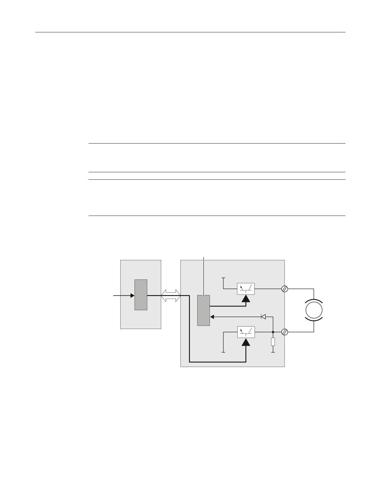
Safety Functions integrated in the drive
5.5 Safe Brake Control (SBC)
Enabling the Safe Brake Control (SBC) function
The Safe Brake Control function is enabled using the following parameters:
• p9602 "SI enable Safe Brake Control (Control Unit)"
• p9802 "SI enable Safe Brake Control (Motor Module)"
The Safe Brake Control function is only selected if at least one safety monitoring function is
enabled (i.e. p9601 = p9801 ≠ 0).
Two-channel brake control
Note
When the "Safe Brake Control" function is used, then it is not permissible that the brake is
controlled through a relay, as this can result in faults being triggered in the brake control.
Note
The brake cannot be directly connected to the Motor Module in the chassis format. The
connection terminals are only designed for 24 VDC with 150 mA; the Safe Brake Adapter is
required for higher currents and voltages.
The brake is controlled from the Control Unit. Two signal paths are available for applying the
brake.
&RQWURO WHUPLQDO
1&8 [
0RWRU 0RGXOH
3
'5,9(
7%
&ORVHG FLUFXLW EUDNH
&/L4
&RQWURO
%5
WHUPLQDO
%5
0RWRU
%UDNH GLDJQRVWLFV
7%
%5
0
0
%5
Figure 5-1
Two-channel brake control, booksize (example)
The Motor Module carries out a check to ensure that the "Safe Brake Control" function is working
properly and ensures that, if the Control Unit fails or is faulty, the brake current is interrupted,
therefore closing the brake.
The brake diagnostics can only reliably detect a malfunction in either of the switches (TB+, TB-)
when the status changes (when the brake is opened or closed).
If the Motor Module or Control Unit detects a fault, the brake current is switched off and the safe
status is reached.
Safety Integrated (system-integrated)
Function Manual, 10/2020, 6FC5397-4BP40-6BA2
65
Safety Functions integrated in the drive
5.6 Control via terminals on the Control Unit and the power unit
Safe Brake Control for Motor Modules in the chassis format
To be able to control the high rating brakes used with devices of this format, an additional Safe
Brake Adapter (SBA) module is needed. You can obtain more information on the connection and
wiring of the Safe Brake Adapter in the Equipment Manual "SINAMICS G130/G150/S120 Chassis/
S120 Cabinet Modules/S150 Safety Integrated".
Parameter p9621 is used to define via which digital input the feedback signal (brake open or
closed) of the Safe Brake Adapter is sent to the Control Unit.
The additional functionality and the control of the brake, in other words, reaching a safe state,
are in this case essentially the same as the sequence for booksize units.
Response time with the Safe Brake Control function
The following values can be specified for the response times when the function is selected/
deselected via input terminals:
• Typical response time
4x safety monitoring clock cycle CU (r9780) + inputs/outputs, sampling time (p0799)
• Maximum response time that can occur when a fault develops
8x safety monitoring clock cycle CU (r9780) + inputs/outputs, sampling time (p0799)
Example:
Assumption, monitoring clock cycle CU (r9780) = 4 ms and
Inputs/outputs sampling time (r0799) = 4 ms
tR_type = 4x r9780 (4 ms) + r0799 (4 ms) = 20 ms
tR_max = 8x r9780 (4 ms) + r0799 (4 ms) = 36 ms
Parameter overview (see Chapter “Parameter overview (Page 390)”)
• p0799
CU inputs/outputs, sampling time
• p9621
BI: SI signal source for SBA (Control Unit)
• r9780
SI monitoring cycle (Control Unit)
• p9821
BI: SI signal source for SBA (Motor Module)
• r9880
SI monitoring cycle (Motor Module)
5.6
Control via terminals on the Control Unit and the power unit
5.6.1
Features
• Only for the STO, SS1 (time-controlled) and SBC functions
• Dual-channel structure via two digital inputs (Control Unit / power unit).
• The signals of the components connected at the terminals (pushbuttons, switches, ...) can
be debounced in order to prevent false tripping due to signal disturbances or non-
symmetrical test signals. The filter times are set using parameters p9651 and p9851.
Safety Integrated (system-integrated)
66
Function Manual, 10/2020, 6FC5397-4BP40-6BA2
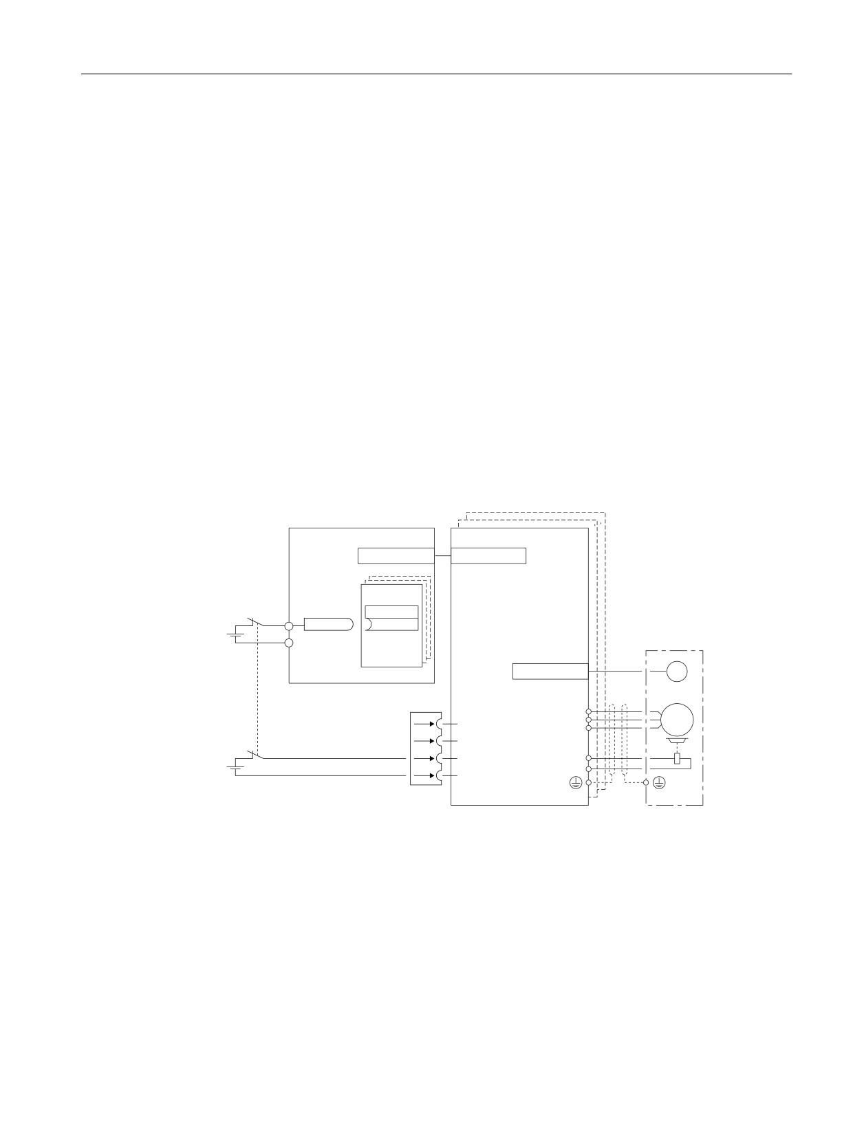
Safety Functions integrated in the drive
5.6 Control via terminals on the Control Unit and the power unit
• Different terminal strips depending on design
• Automatic ANDing of up to 8 digital inputs (p9620[0...]) on the Control Unit with parallel
configuration of power units in chassis format is not possible.
Terminals for STO, SS1 (time-controlled), SBC
The functions are separately selected/deselected for each drive using two terminals.
•
1. Control Unit switch-off signal path
The required input terminal for Safe Torque Off (STO) is selected via the BICO interconnection
(BI: p9620[0]).
Digital input DI 0 ... DI 7 on the Control Unit can be used as a signal source (NCU). NX modules
have DI 0 to DI 3.
•
2. Motor Module switch-off signal path
The input terminal is the "EP" ("Enable Pulses") terminal.
The EP terminal is periodically interrogated with a sampling time, which is rounded off to an
integer multiple of the current controller cycle; however, it is a minimum of 1 ms.
(Example: ti = 400 µs, tEP => 3 x ti = 1.2 ms)
Both terminals must be energized simultaneously within the discrepancy time p9650/p9850,
otherwise a fault will be issued.
1&8 [
0RWRU 0RGXOH
'5,9( &/L4
'5,9( &/L4
%O
1&8 [
', [
S
U
[
0
'5,9( &/L4
*
0RQLWRULQJ FKDQQHO
&RQWURO 8QLW
[
[
8
0
9
7HPS
a
:
0RQLWRULQJ FKDQQHO
7HPS
0RWRU 0RGXOH
(3
9
%5
(3 0
%5
Figure 5-2
Terminals for "Safe Torque Off" - example for Motor Modules Booksize and NCU7x0
Grouping drives
To ensure that the function works for more than one drive at the same time, the terminals for the
corresponding drives must be grouped together as follows:
•
1. Control Unit switch-off signal path
By connecting the binector input to the joint input terminal on the drives in one group.
•
2. Motor Module switch-off signal path
By appropriately connecting the "EP" terminal for the individual Motor Modules belonging to
a group.
Safety Integrated (system-integrated)
Function Manual, 10/2020, 6FC5397-4BP40-6BA2
67
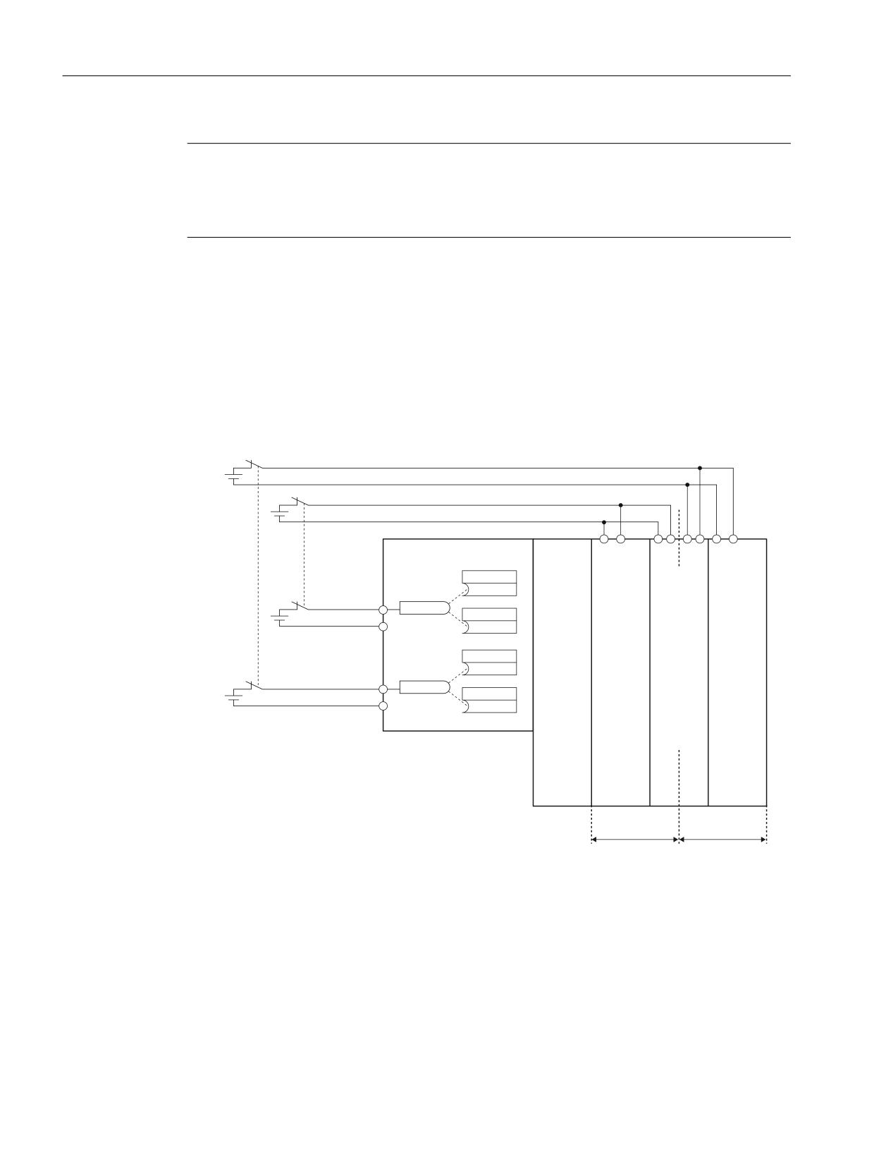
Safety Functions integrated in the drive
5.6 Control via terminals on the Control Unit and the power unit
Note
The same grouping must be set in both monitoring channels.
If a fault in a drive results in a Safe Torque Off (STO), this does not automatically mean that the
other drives in the same group also switch to Safe Torque Off (STO).
The assignment is checked during the test for the switch-off signal paths. The operator selects
Safe Torque Off for each group. The check is drive-specific.
Example: Terminal groups
It must be possible to select/deselect the Safe Torque Off function separately for group 1 (drives
1 and 2) and group 2 (drives 3 and 4).
For this purpose, the same grouping for Safe Torque Off must be performed on both the Control
Unit and the Motor Modules.
6H
OHFWLQJ GHVHOHFWLQJ
*URXS
1&8 [
0
(3
0
0
0 (3
6HOHFWLQJ
'ULYH
(3
(3
GHVHOHFWLQJ
S
*URXS
'O
'ULYH
/LQH
6LQJOH
'RXEOH
6LQJOH
U
S
0RGXOHV
0RWRU
0RWRU
0RWRU
0
0RGXOHV
0RGXOHV
0RGXOHV
'ULYH
S
'O
;
'ULYH
U
S
0
'ULYH
'ULYH
'ULYH
*URXS
*URXS
Figure 5-3
Example: Grouping the terminals for Motor Modules, booksize format
5.6.2
Simultaneity and tolerance time of the two monitoring channels
The Safe Torque Off function must be selected and deselected simultaneously in both
monitoring channels using the input terminals and is only effective for the associated drive.
1 signal: Deselects the function
0 signal: Selects the function
Safety Integrated (system-integrated)
68
Function Manual, 10/2020, 6FC5397-4BP40-6BA2
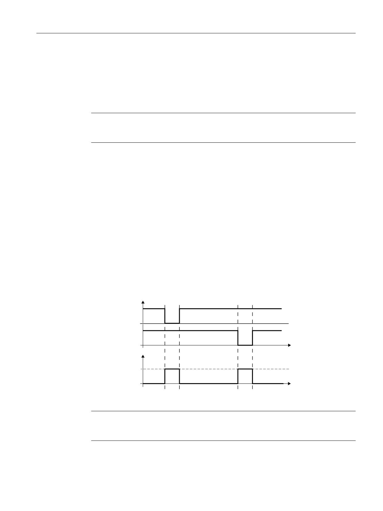
Safety Functions integrated in the drive
5.6 Control via terminals on the Control Unit and the power unit
"Simultaneously" means:
The changeover must have been completed in both monitoring channels within the
parameterized tolerance time.
• p9650 SI SGE changeover tolerance time (Control Unit)
• p9850 SI SGE changeover tolerance time (Motor Module)
Note
To avoid incorrect triggering of fault messages, at these outputs the tolerance time must always
be set to be shorter than the shortest time between two switching events (ON/OFF, OFF/ON).
If the Safe Torque Off function is not selected/deselected within the tolerance time, this is
detected by the crosswise data comparison, and fault F01611 or F30611 (STOP F) is output. In
this case, the pulses have already been canceled as a result of the selection of Safe Torque Off in
one channel.
5.6.3
Bit pattern test
Bit pattern test of failsafe outputs
The converter normally responds immediately to signal changes in its failsafe inputs. This is not
desirable in the following case: Several control modules test their failsafe outputs using bit
pattern tests (on/off tests), in order to identify faults due to either short-circuit or cross-circuit
faults. If a failsafe input of the converter is interconnected with a failsafe output of a control
module, then the converter responds to these test signals.
,QSXW VLJQDOV
) ',
W
6DIHW\ IXQFWLRQ
$FWLYH
,QDFWLYH
W
Figure 5-4
Converter response to a bit pattern test
Note
If the test pulses lead to unintended triggering of the Safety Integrated Functions, a filtering
(p9651/p9851 SI STO/SBC/SS1 debounce time) of the terminal inputs must be parameterized.
Safety Integrated (system-integrated)
Function Manual, 10/2020, 6FC5397-4BP40-6BA2
69
Safety Functions integrated in the drive
5.7 Commissioning the STO, SBC and SS1 functions
Overview of important parameters (see SINAMICS S120/S150 List Manual)
• p9651 SI STO/SBC/SS1 debounce time (Control Unit)
• p9851 SI STO/SBC/SS1 debounce time (Motor Module)
5.7
Commissioning the STO, SBC and SS1 functions
5.7.1
General information about commissioning safety functions
Note
• The "STO", "SBC" and "SS1" functions are drive specific, which means that the functions must
be commissioned individually for each drive.
• To support the "STO" and "SBC" functions, the following (minimum) safety versions are
required:
Control Unit: V02.01.01 (r9770[0...2])
Motor Module: V02.01.01 (r9870[0...2])
• To support the SS1 function, the following (minimum) safety version is required:
Control Unit: V02.04.01 (r9770[0...2])
Motor Module: V02.04.01 (r9870[0...2])
• If the version in the Motor Module is incompatible, the Control Unit responds as follows
during the switchover to safety commissioning mode (p0010 = 95):
- Fault F01655 (SI CU: Align the monitoring functions) is output. The fault initiates stop
response OFF2. The fault cannot be acknowledged until the safety commissioning mode
(p0010 ≠ 95) is exited.
- The Control Unit triggers a safe pulse suppression via its own safety switch-off signal path.
- If parameterized (p1215), the brake is closed.
- The safety functions cannot be enabled (p9601/p9801 and p9602/p9802).
Requirements for commissioning the safety functions
1. The drives must have been completely commissioned.
2. The non-safety-relevant pulse cancellation must be active, e.g. via OFF1 = “0” or OFF2 = “0”
If a brake is connected and has been parameterized, then the brake is closed.
3. The terminals for "Safe Torque Off" must be wired.
- Control Unit: Digital input DI 0 ... DI 7 (NCU)
- Control Unit: Digital input DI 0 ... DI 3 (NX)
- Motor Module: Terminal "EP"
4. For operation with SBC, the following applies:
- A brake must be connected to the appropriate Motor Module connector.
Safety Integrated (system-integrated)
70
Function Manual, 10/2020, 6FC5397-4BP40-6BA2

Safety Functions integrated in the drive
5.7 Commissioning the STO, SBC and SS1 functions
Series commissioning of the safety functions
1. A drive archive can be transferred to another drive unit, keeping the safety parameterization.
2. If the source and target devices have different firmware versions, it may be necessary to adapt
the reference checksums (p9799, p9899). This is indicated by the faults F01650 (fault value:
1000) and F30650 (fault value: 1000).
3. Once the project has been downloaded to the target device, an acceptance must be carried
out. This is indicated by fault F01650 (fault value: 2005).
Note
Once a project has been downloaded, it must be saved to the non-volatile memory card (copy
from RAM to ROM).
Replacement of Motor Modules with later firmware version
1. After a Motor Module fails, a more recent firmware version can be installed on the new Motor
Module.
2. If the old and new devices have different firmware versions, it may be necessary to adapt the
reference checksums (p9899). This is indicated by fault F30650 (fault value: 1000).
For 840D sl, checksums can be confirmed at the HMI in the "Commissioning" operating area
using the softkey "Confirm SI data" followed by power on. The data must be saved before power
on.
N
Parameter
Description and comments
o.
1
p0010 = 95
Sets the Safety Integrated commissioning mode
2
p9899 = “r9898”
Adapt the reference checksum on the Motor Module
3
p0010 = value not
Exit Safety Integrated commissioning mode
equal to 95
4
POWER ON
Carry out a power on
5.7.2
Sequence when commissioning STO, SBC and SS1
In the SINUMERIK environment, commissioning can be simplified by using the softkeys "Activate
drive commissioning" and "Deactivate drive commissioning".
With "Activate drive commissioning", p0010 is set to 95; the required functions can then be
enabled and the settings entered (see also following Table, Steps 3 to 9).
With "Deactivate drive commissioning" the checksums (p9799 = r9798, p9899 = r9898) are set
to the same value and p0010 is set to 0.
Safety Integrated (system-integrated)
Function Manual, 10/2020, 6FC5397-4BP40-6BA2
71

Safety Functions integrated in the drive
5.7 Commissioning the STO, SBC and SS1 functions
Carry out the following steps to commission the STO, SBC and SS1 functions:
No.
Parameter
Description and comments
1
p0010 = 95
Sets the Safety Integrated commissioning mode
• The following alarms and faults are output:
A01698 (SI CU: Commissioning mode active)
• During first commissioning only:
F01650 (SI CU: Acceptance test required) with fault value = 130 (no Safety parameters exist for
the Motor Module).
F30650 (SI MM: Acceptance test required) with fault value = 130 (no Safety parameters exist for
the Motor Module).
For information on the acceptance test and certificate, see Step 15.
• The pulses are safely canceled and monitored by the Control Unit and Motor Module.
• The safety sign of life is monitored by the Control Unit and Motor Module.
• The function for exchanging stop responses between the Control Unit and Motor Module is
active.
• An existing and parameterized brake has already been closed.
• In this mode, fault F01650 or F30650 with fault value = 2003 is output after a Safety parameter
is changed for the first time.
This behavior applies for the entire duration of safety commissioning, which means that the STO
function cannot be selected/deselected while safety commissioning mode is active because this
would constantly force safe pulse cancellation.
2
p9761 = "Val-
Sets the safety password
ue"
When Safety Integrated is commissioned for the first time, the following applies:
• Safety password = 0
• Default setting for p9761 = 0
This means that the safety password does not need to be set during initial commissioning.
3
Enable Safe Torque Off function
p9601.0
STO via Control Unit terminals
p9801.0
STO via Motor Module terminals
• The parameters are not changed until the safety commissioning mode has been exited (i.e. when
p0010 is set ≠ 95).
• Both parameters are included in the crosswise data comparison and must therefore be set to
identical values.
4
Enables the Safe Brake Control function
p9602 = 1
Enables SBC on the Control Unit
p9802 = 1
Enables SBC on the Motor Module
• The parameters are not changed until the safety commissioning mode has been exited (i.e. when
p0010 is set ≠ 95).
• Both parameters are included in the crosswise data comparison and must therefore be set to
identical values.
• The Safe Brake Control function only becomes active if at least one safety monitoring function is
enabled (i.e. p9601 = p9801 ≠ 0).
Safety Integrated (system-integrated)
72
Function Manual, 10/2020, 6FC5397-4BP40-6BA2