SINUMERIK 840D sl. Service - Safety Integrated. Manual (2020) - page 5

Connecting sensors and actuators
8.5 Safe programmable logic
System variable
Meaning
Value range
Data type
Possible access for
$AA_IM[axis]
Actual MCS setpoint of
DOUBLE
x
x
an axis
$VA_IM[axis]
Encoder actual value in
DOUBLE
x
x
the machine coordinate
system
Error status
$A_XFAULTSI
In the crosswise data
INT
x
x
comparison between
NCK and drive of any ax-
is, an actual-value error
has been detected
$VA_XFAULTSI[axis
The crosswise data com-
INT
x
x
name]
parison for this axis be-
tween NCK and drive has
detected an actual value
error
$VA_STOPSI
Actual Safety Integrated
INT
x
x
STOP of the particular ax-
is
$A_STOPESI
Actual Safety Integrated
INT
x
x
STOP E for any axis
Internal SPL inputs/outputs
$A_INSI[n]
NCK input
n = 1, 2, ... 192
BOOL
x
x
stands for the
number of the in-
put
$A_INSID[n]
NCK inputs
n = 1, 2, ... 6 stands
INT
x
x
for the number of
the double word
(32 bit)
$A_INSIP[n]
Image, PLC input
n = 1,2, ... 192
BOOL
x
x
stand for the No.
of the input
$A_INSIPD[n]
Image of the PLC inputs
n = 1, 2, ... 6 stands
INT
x
x
for the number of
the double word
(32 bit)
$A_OUTSI[n]
NCK output
n = 1, 2, ... 192
BOOL
x
x
x
x
stands for the
number of the out-
put
$A_OUTSID[n]
NCK outputs
n = 1, 2, ... 6 stands
INT
x
x
x
x
for the number of
the double word
(32 bit)
$A_OUTSIP[n]
Image, PLC output
n = 1, 2, ... 192
BOOL
x
x
stands for the
number of the out-
put
Safety Integrated (system-integrated)
280
Function Manual, 10/2020, 6FC5397-4BP40-6BA2

Connecting sensors and actuators
8.5 Safe programmable logic
System variable
Meaning
Value range
Data type
Possible access for
$A_OUTSIPD[n]
Image of the PLC outputs
n = 1, 2, ... 6 stands
INT
x
x
for the number of
the double word
(32 bit)
External SPL inputs/outputs
$A_INSE[n]
NCK input
n = 1, 2, ... 192
BOOL
x
x
stands for the
number of the in-
put
$A_INSED[n]
NCK inputs
n = 1, 2, ... 6 stands
INT
x
for the number of
the double word
(32 bit)
$A_INSEP[n]
Image of PLC input
n = 1, 2, ... 192
BOOL
x
x
stands for the
number of the in-
put
$A_INSEPD[n]
Image of the PLC inputs
n = 1, 2, ... 6 stands
INT
x
x
for the number of
the double word
(32 bit)
$A_OUTSE[n]
NCK output
n = 1, 2, ... 192
BOOL
x
x
x
x
stands for the
number of the out-
put
$A_OUTSED[n]
NCK outputs
n = 1, 2, ... 6 stands
INT
x
x
x
x
for the number of
the double word
(32 bit)
$A_OUTSEP[n]
Image of a PLC output
n = 1, 2, ... 192
BOOL
x
x
stands for the
number of the out-
put
$A_OUTSEPD[n]
Image of the PLC outputs
n = 1, 2, ... 6 stands
INT
x
x
for the number of
the double word
(32 bit)
SPL markers and timers
$A_MARKERSI[n]
Marker
n = 1, 2, ... 192
BOOL
x
x
x
x
stands for the
number of the
marker
$A_MARKERSID[n]
Marker
n = 1, 2, ... 6 stands
INT
x
x
x
x
for the number of
the double word
(32 bit)
$A_MARKERSIP[n]
Image of the PLC-SPL
n = 1, 2, ...192
BOOL
x
x
markers
stands for the
number of the PLC
marker
Safety Integrated (system-integrated)
Function Manual, 10/2020, 6FC5397-4BP40-6BA2
281

Connecting sensors and actuators
8.5 Safe programmable logic
System variable
Meaning
Value range
Data type
Possible access for
$A_MARKERSIPD[n]
Image of the PLC markers
n = 1, 2, ... 6 stands
INT
x
x
for the number of
the double word
(32 bit)
$A_TIMERSI[n]
Timer
n = 1, 2...16 stands
REAL
x
x
x
x
for the number of
the timer
F_SENDDP
$A_FSDP_ERR_RE-
Response when a com-
n = 1, ..., 16 stands
INT
x
x
x
x
AC[n]
munication error occurs
for the number of
the F-SENDDP rela-
tionship, is also
valid for
$A_FSDP_ERROR,
$A_FSDP_SUBS_O
N, $A_FSDP_DIAG
$A_FSDP_ERROR[n]
There is a communica-
n = 1, ..., 16
BOOL
x
x
tion error
$A_FSDP_SUBS_ON[
Substitute values are out-
n = 1, ..., 16
BOOL
x
x
n]
put to the application at
the F_RECVDP (receiver)
$A_FSDP_DIAG[n]
The cause of the commu-
n = 1, ..., 16
INT
x
x
nication error deter-
mined by F_SENDDP is
communicated
F_RECVDP
$A_FRDP_SUBS[n]
Those substitute values
n = 1, ..., 16 stands
INT
x
x
x
x
are specified, which are
for the number of
output to the SPL in cer-
the F-RECVDP con-
tain states
nection, is also val-
id for
$A_FRDP_ERR_RE-
AC,
$A_FRDP_ACK_REI
, $A_FRDP_ERROR,
$A_FRDP_SUBS_O
N,
$A_FRDP_ACK_RE
Q,
$A_FRDP_SEND-
MODE,
$A_FRDP_DIAG
$A_FRDP_ERR_RE-
Response when a com-
n = 1, ..., 16
INT
x
x
x
x
AC[n]
munication error occurs
$A_FRDP_ERROR[n]
There is a communica-
n = 1, ..., 16
BOOL
x
x
tion error
$A_FRDP_SUBS_ON[
Substitute values are out-
n = 1, ..., 16
BOOL
x
x
n]
put to the application
$A_FRDP_ACK_REQ[
Error-free F-telegrams
n = 1, ..., 16
BOOL
x
x
n]
are again cyclically ex-
changed after a commu-
nication error
Safety Integrated (system-integrated)
282
Function Manual, 10/2020, 6FC5397-4BP40-6BA2

Connecting sensors and actuators
8.5 Safe programmable logic
System variable
Meaning
Value range
Data type
Possible access for
$A_FRDP_DIAG[n
The cause of the commu-
n = 1, ..., 16
INT
x
x
nication error deter-
mined by F_RECVDP is
communicated
$A_FRDP_SEND-
Actual operating mode
n = 1, ..., 16
BOOL
x
x
MODE[n]
of the F-CPU of the
F_SENDDP communica-
tion partner
Miscellaneous
$A_STATSID
A value not equal to 0
Bit 0...5=1: CDC er-
INT
x
x
means that an error has
ror in I/O signals,
occurred in the cross-
markers or dynam-
wise data comparison.
ic data of the
FSENDDP/
FRECVDP commu-
nication
Bit 26=1: Error has
occurred in PROFI-
safe communica-
tion
Bit 27=1: CDC er-
ror in static data
Bit 28=1: CDC er-
ror "SPL protection
status"
Bit 29=1: Time er-
ror in the commu-
nication between
NCK and SPL
Bit 30=1: PLC sig-
nals a stop to the
NCK
$A_CMDSI
Control word for cross-
n = 1: Increase the
BOOL
x
x
x
x
wise data comparison
time for the signal
between the NCK and
change monitor-
PLC (SPL-CDC)
ing to 10 s
$A_LEVELSID
CDC level display:
0...320
INT
x
x
Number of signals for
which NCK and PLC de-
tect different signal levels
$A_PLCSIIN[n]
Single-channel commu-
1, 2, ... 96
BOOL
x
x
nication between NCK
and PLC SPL
$A_PLCSIOUT[n]
Single-channel commu-
1, 2, ... 96
BOOL
x
x
x
x
nication between NCK
and PLC SPL
$AC_SAFE_SYNA_M
Free safety synchroniz-
[0, MAX_INT]
x
x
EM
ing elements
$VA_SAFE_TYPE[ax-
Information about the
[0,2]
INT
x
x
is]
active safety operating
mode of this axis
Note: r = read, w = write
Safety Integrated (system-integrated)
Function Manual, 10/2020, 6FC5397-4BP40-6BA2
283
Connecting sensors and actuators
8.5 Safe programmable logic
8.5.10
Behavior after power on/mode change/reset
1. After the system has booted, the following Safety Integrated system variables are assigned
the value zero:
$A_INSE(D), not for F_DP communication,
$A_OUTSE(D),
$A_OUTSI(D),
$A_MARKERSI(D),
,$A_INSEP(D), not for F_DP communication,
$A_OUTSEP(D),
$A_OUTSIP(D),
$A_MARKERSIP(D),
$A_INSI(D).
2. Preassignment of other variables before cyclic processing of the NCK-SPL starts can be
programmed in the same part program as the NCK-SPL itself. To ensure that the pre-
assignment instructions are only performed once, they must use the following syntax:
IDS=<nr> WHEN TRUE DO<boot instructions>
As a result of the identifier IDS, the events "operating mode change" and "reset" have no
effect on the processing of the NCK-SPL.
3. Several boot instructions can be programmed in one block.
4. For the relevant FDP system variables, see Chapter "Boot behavior of the F_DP
communication (Page 243)" - and the following.
8.5.11
SPL data on the PLC side
The safe programmable logic of the PLC (PLC-SPL) is a sub-function of the safety functions
integrated in the SINUMERIK.
Signals
The PLC-SPL signals are in DB18 and are sub-divided into
1. Parameterization part, and
2. Data area/status
Parameterization part
SPL_READY:
The SPL_READY = TRUE signal indicates that the commissioning phase has been completed, i.e.
if a CDC error has occurred, the basic program sends a "STOP D/E" to all the axes.
STOP_MODE:
For crosswise comparison error:
0 = external STOP D
1 = external STOP E
to the drive
Safety Integrated (system-integrated)
284
Function Manual, 10/2020, 6FC5397-4BP40-6BA2
Connecting sensors and actuators
8.5 Safe programmable logic
Data area/status
SPL_DATA
The useful (net) data for the PLC-SPL is contained in the SPL_DATA structure. The net data area
is sub-divided into internal inputs/outputs and marker areas and external inputs/outputs that
correspond to the hardware I/O.
With the appropriate parameterization for external inputs/outputs, the basic program transfers
the input image of the I/Os to the external inputs in DB18 and from the external outputs in DB18
to the output.
SPL_DELTA
The SPL_DELTA area is used for diagnostics. A signal with the status TRUE in this area means that
the signal is different in the NCK and PLC at this bit position.
CMDSI
Signal CMDSI can be used to extend the timeout value in the crosswise SPL data comparison by
a factor of 10. This extension is used for long forced checking procedure pulses or single-channel
test stop logic functions.
STATSI
A value not equal to 0 means that an error has occurred in the crosswise data comparison.
LEVELSI
The LEVELSI signal is used for diagnostics, and provides information as to how many signals are
presently active with different signal levels.
COMM_TO
If communication between NCK and PLC regarding the SPL-CDC is interrupted, then the PLC is
switched into the STOP state with a delay of 5 s. Status signal DB18.DBB119, bit 5 is used to
inform the SPL programmer that the 5 s timer was started. This means that it is possible to initiate
system-specific actions before the PLC goes into the stop condition.
SPL status signals for SPL_STATUS (DB18.DBB136)
For a detailed description, refer to Chapter "PLC data block (DB18) (Page 480)"
8.5.12
Direct communications between NCK and PLC-SPL
In SPL applications, a certain degree of single-channel communications between the two SPLs
(NCK and PLC) is always required in addition to safety-related switching elements being
connected through two channels. Testing external stops and the Emergency Stop
acknowledgment are typical applications.
Safety Integrated (system-integrated)
Function Manual, 10/2020, 6FC5397-4BP40-6BA2
285

Connecting sensors and actuators
8.6 Safe Brake Test (SBT)
In order to be able to exchange single-channel SI-specific signals between the NCK and PLC in a
dedicated data area, a corresponding communication interface exists between these
components. The meaning of the individual bits in this interface are defined by the user.
NCK
PLC
$A_PLCSIOUT[1...96]
DB18.DBB128-131,
96 bits from the NCK to PLC
DB18.DBB432-439
$A_PLCSIIN[1...96]
DB18.DBB132-135,
96 bits from the PLC to NCK
DB18.DBB440-447
Supplementary conditions
System variables $A_PLCSIOUT[1...96] and $A_PLCSIIN[1...96] are protected so that they
cannot be accessed from other programs, except the NCK-SPL program (SAFE.SPF). A
corresponding programming command is rejected with Alarm 17070 "Channel %1 block %2
Data write-protected".
8.6
Safe Brake Test (SBT)
8.6.1
Applications
Axes and mechanical systems can drop due to gravity when the drives are switched off. The
function test of the brake mechanical system should be used for all axes that must be prevented
from moving in an uncontrolled manner by a holding brake. This test function is primarily
intended for vertical axes.
The functionality is based on "travel to fixed stop" (FXS). Travel to fixed stop can be individually
parameterized to test the function of the mechanical braking system. It is activated and
deselected from the PLC. For further details on travel to fixed stop, see /FB1/, F1.
The machine manufacturer can use his PLC user program to close the brake at a suitable instant
in time (guide value, every 8 h, see Chapter "Information sheets from the various regulatory
bodies (Page 31)") and to initiate that the drive produces an additional force in addition to the
weight of the axis. As long as no fault has occurred, the brake can exert the necessary braking
torque / the necessary braking force and the axis will hardly move.
When an error occurs, the actual position value exits the parameterizable monitoring window.
This prevents an axis from sagging. The function test of the brake mechanical system is
negatively acknowledged.
The brake test must always be started when the axis is at a standstill. The direction in which the
drive exerts its torque / its force is defined by the PLC using a "traversing motion" via FC18. The
direction of travel should be selected so that the motor applies force in the direction of the
already force already exerted due to the weight of the load. It must be possible to reach the
target of this motion without any danger (no collision, sufficient distance to the end stops) if the
brake cannot provide the necessary torque / force.
Note
When the brake test is active, no temperature compensation may be carried out.
Safety Integrated (system-integrated)
286
Function Manual, 10/2020, 6FC5397-4BP40-6BA2

Connecting sensors and actuators
8.6 Safe Brake Test (SBT)
Note
From software release 4.7 SP2, the brake test integrated in the drive can also be used in
conjunction with SINUMERIK Safety Integrated. You can find an application example on the
Internet at our "Industry Online Support":
8.6.2
Parameterization
The user can use the following axis-specific NCK machine data to parameterize the function test
of the mechanical braking system:
Machine data
Description
MD37000 $MA_FIXED_STOP_MODE
Enable brake test
MD37030 $MA_FIXED_STOP_THRESHOLD
Threshold for fixed stop detection
MD37050
Alarm screen form fixed stop
$MA_FIXED_STOP_ALARM_MASK
MD36966 $MA_SAFE_BRAKETEST_TORQUE
Enters the test torque
MD36967 $MA_SAFE_BRAKETEST_POS_TOL
Position tolerance, brake test
MD36968 $MA_SAFE_BRAKETEST_CONTROL
Bit 0 = 0: Drive MD1192/p1532 is used as the average
value of the torque limit.
Bit 0 = 1: The measured torque at the instant in time that
the brake test is selected is used as the average value of
the torque limit.
Bit 1 = 0: The torque limit value must be reached during
the programed travel distance.
Bit 1 = 1: The torque limit value must be reached during
the programed time (TV_FXSreached parameterization
FB11).
The function test of the mechanical braking system is enabled by setting bit 1 in MD37000
$MA_FIXED_STOP_MODE. If the user needs to travel to a fixed stop with this axis from the part
program, then bit 0 can also be set. It is internally monitored to check that only one type of travel
to fixed stop is active at a time. In the case of an error, Alarm 20092, "Axis % Travel to fixed stop
still active" is issued.
MD37000 $MA_FIXED_STOP_MODE: Travel to fixed stop mode
The function test of the mechanical braking system is enabled by setting bit 1 in MD37000
$MA_FIXED_STOP_MODE. If the user needs to travel to a fixed stop with this axis from the part
program, then bit 0 can also be set. It is internally monitored to check that only one type of travel
to fixed stop is active at a time. In the case of an error, Alarm 20092, "Axis % Travel to fixed stop
still active" is issued.
Safety Integrated (system-integrated)
Function Manual, 10/2020, 6FC5397-4BP40-6BA2
287
Connecting sensors and actuators
8.6 Safe Brake Test (SBT)
MD37030 $MA_FIXED_STOP_THRESHOLD: Threshold for fixed stop reached
The contour deviation that is determined is always used in the brake test to detect that the fixed
stop has been reached. The parameterization in MD37040 $MA_FIXED_STOP_BY_SENSOR is
therefore irrelevant. The required threshold value must be set in MD37030
$MA_FIXED_STOP_THRESHOLD. This means that the traversing distance from the PLC via FC18
must be greater than this threshold value.
If the travel distance that is entered is too short, after the end position is reached on the setpoint
side, Alarm 20096 "Axis %1 brake test aborted, additional information %2" is output. The
supplementary info contains the value 2 "End position reached, motion ended".
MD36966 $MA_SAFE_BRAKETEST_TORQUE: Holding torque, brake test
The machine manufacturer must parameterize the required brake test torque as percentage in
the axis-specific MD36966 $MA_SAFE_BRAKETEST_TORQUE. The magnitude of the torque to be
configured is orientated to the maximum holding force of the brake, according to the data sheet,
that should be checked. Internally, this is used to calculate the drive torque that is required in
addition to the weight of the axis to load the brake. The drive torque to load the holding brake
is limited to the maximum motor torque if the desired test torque would demand a higher drive
torque. Value for MD36966 = (test torque of the brake / p2003) * 100.
The value from $MA_SAFE_BRAKETEST_TORQUE refers to the reference torque or the reference
force from drive parameter p2003, whose image is saved in
$MA_SAFE_BRAKETEST_TORQUE_NORM.
The magnitude of the torque to be configured is orientated to the maximum holding force of the
brake to be tested.
Incorrect parameterization in MD $MA_SAFE_BRAKETEST_TORQUE could mean that the drive
with reduced torque cannot even apply the required holding torque. These parameter
assignments are detected when the brake test is selected and results in Alarm 20095 "Axis %1
inadmissible holding torque %2".
MD36967 $MA_SAFE_BRAKETEST_POS_TOL: Position tolerance, brake test
The monitoring window for the maximum permissible movement during the brake test is
defined in the axis-specific MD36967 $MA_SAFE_BRAKETEST_POS_TOL. The PLC actively
monitors this position window - from the start of the brake test and not only when it has been
detected that the fixed stop has been reached. This is a difference when compared to activating
FXS from the part program.
Safety Integrated (system-integrated)
288
Function Manual, 10/2020, 6FC5397-4BP40-6BA2
Connecting sensors and actuators
8.6 Safe Brake Test (SBT)
MD36968 $MA_SAFE_BRAKETEST_CONTROL, bit 0: Sequence check for the brake test
Principally, the automatic determination of the load torque available using MD36968
$MA_SAFE_BRAKETEST_CONTROL, bit 0 = 1 is preferred. This is because over the complete
traversing path of a suspended axis the torque situation continually changes to some extent or
the other. The torque situation is, e.g. dependent on the different tools/workpieces being used,
and can vary significantly. Using the automatic torque determination function, the
instantaneous holding torque available at standstill is automatically determined (mAct) and is
temporarily used as average value for the torque limiting in the drive. In this case, it must be
ensured that at the start of the test, the brake is open, otherwise an incorrect reference value will
be determined. With the automatic torque determination function, the plausibility of the load
torque is not checked. The currently available holding torque is displayed in r1509 "Force
setpoint before force limiting".
If the automatic torque determination function is not used (MD36968
$MA_SAFE_BRAKETEST_CONTROL, bit 0 = 0), then p1532 "Torque limit offset" should be
parameterized. Also in this case, when selecting the brake test, the holding torque required for
the force due to the weight is internally measured and the effective brake test torque adapted.
Contrary to the automatic torque determination function, the plausibility of the load torque is
checked.
MD36968 $MA_SAFE_BRAKETEST_CONTROL, bit 1: Criterion for reaching the torque limit
The brake test sequence requires that during the programmed traversing distance, the torque
limit is reliably reached (MD36968 $MA_SAFE_BRAKETEST_CONTROL, bit 1 = 0).
If the programmed traversing distance is very short, e.g. as a result of restricted space for the axis
to move, then it can occur that the required limit value is not reached in the short time that the
axis moves (Alarm 20096 "Axis %1 Brake test aborted, additional information %2").
Using MD36968 $MA_SAFE_BRAKETEST_CONTROL, bit 1 = 1, reaching the programmed end
position is no longer used as criterion for aborting the test. This means that using its monitoring
timer, the PLC itself can decide the wait time until the torque limit is reached. The test can be
continued if, during this time, DB31-61.DBX62.5 is set = 1. If the torque limit is not reached, the
PLC exits the brake test with DB31-61.DBX11.0 = 0.
MD36968 $MA_SAFE_BRAKETEST_CONTROL, Bit 2: Positioning response at the end of the
SINAMICS brake test
The positioning behavior at the end of the SINAMICS brake test must be set so that the brake is
subject to a minimum load. By pressing against the brake, the axis moves away from the last
programmable position. To conclude the brake test, the actual axis position for the next path
motion is used. (MD36968 $MA_SAFE_BRAKETEST_CONTROL bit 2 = 0). This results in motion
to the last programmed axis position on the path.
By setting MD36968 $MA_SAFE_BRAKETEST_CONTROL bit 2 = 1, the actual axis position is not
accepted. After the axis has been pressed against the brake, the closed-loop position controller
withdraws the axis to the last programmed position.
Vertical axes can be prevented from sagging as a result of a repeated brake test by setting
$MA_SAFE_BRAKETEST_CONTROL bit 2 = 1. It is also possible to briefly exceed the software limit
switch while pressing against the brake without initiating an alarm.
Safety Integrated (system-integrated)
Function Manual, 10/2020, 6FC5397-4BP40-6BA2
289
Connecting sensors and actuators
8.6 Safe Brake Test (SBT)
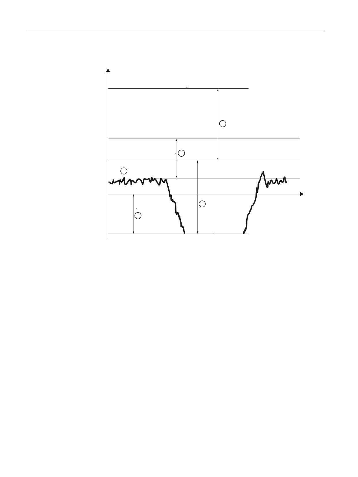
Effectiveness of the torque limiting
P
7RUTXH
XSSHU WRUTXH OLPLWLQJ P);6
OLPLWDWLRQ
P);6
P);6
0'
7RUTXH
P'ULYH
OLPLWDWLRQ
S
P$FW
W
P);6
P'ULYH
7RUTXH
OLPLWDWLRQ
ORZHU WRUTXH OLPLWLQJ P
P);6
);6
Figure 8-35
Torque limiting for SINAMICS S120
①
When selecting the brake test, the holding torque required for the force due to the weight of the
axis is internally measured (mAct).
②
The drive must only additionally provide the difference between this torque and the braking
torque from MD36966 $MA_SAFE_BRAKETEST_TORQUE. In the diagram, this torque is
designated mDrive.
③
For the non-automatic torque determination function, the following applies: The SINAMICS
drive sets its torque limits symmetrically around the torque from drive parameter p1532.
However, in the diagram the measured torque mAct is less than p1532.
This is the reason that mFXS from the diagram above is entered as torque limiting.
mFXS is the sum from mDrive and drive parameter p1532. If the measured torque mAct matches that
parameterized in drive parameter p1532, mFXS becomes the value from the MD
$MA_SAFE_BRAKETEST_TORQUE.
Safety Integrated (system-integrated)
290
Function Manual, 10/2020, 6FC5397-4BP40-6BA2
Connecting sensors and actuators
8.6 Safe Brake Test (SBT)
8.6.3
Torque limits
The torque limits p1520[0] and p1521[0] and the reference torque p2003 are pre-assigned
when commissioning the motor. The torque limits and the reference torque are pre-assigned
differently depending on the technological application p0500, and dependent on the hardware
components being used.
p500 and the resulting pre-assignment of p0640 , p2003 , p1520 , p1521:
1. p500 100 (default) - and as a result:
- p2003 = r0333 rated motor torque
- p1520 = r0333 rated motor torque
- p1521 = - r0333 rated motor torque
- p0640 = minimum (p304, r209)
2. p500 101 (feed drive) - and as a result:
- p2003 p338 * p316
- p1520 p323 * p316
- p1521 -(p323 * p316)
- p0640 minimum (p338, r209)
3. p500 102 (spindle drive) - and as a result:
- p2003 = r0333 rated motor torque
- p1520 = r0333 rated motor torque
- p1521 = - r0333 rated motor torque
- p0640 = minimum (p304*1.5, r209)
The currently active torques can be read in parameters:
• r1538 display of the currently active upper torque limit
• r1539 display of the currently active lower torque limit
Further, the torque limits p1522[0] and p1523[0] are pre-assigned as follows:
• p1522[0] 63:2902:5 reference to +100% referred to p2003 in the same Motor Module
• p1523[0] 63:2902:12 reference to -100% referred to p2003 in the same Motor Module
When using the Safe Brake Test, these pre-assignments for p1522[0] / p1523[0] may not be
changed.
However, when upgrading the software, the following setting, which is also permissible, can be
present:
• p1522[0] 0:1.0 100% of p2003
• p1523[0] 63:2900.0 reference to p2900 in the same Motor Module
• p2900[0] -100% -100% from p2003
Safety Integrated (system-integrated)
Function Manual, 10/2020, 6FC5397-4BP40-6BA2
291
Connecting sensors and actuators
8.6 Safe Brake Test (SBT)
To ensure that the brake test functions without any errors, it should be checked as to whether
the required test torque in MD36966 $MA_SAFE_BRAKETEST_TORQUE is not prevented from
being generated due to the fact that torque limits are effective in the drive. For details on this,
please see SINAMICS List Manual, e.g. function charts 5610 and 5620.
For instance, the selectable torque limits from p1520/p1521 and p1522/p1523 may not be set
so low that the required torque cannot be established for the brake test. When required, p1520/
p1521 or p2003 should be adapted. When making a change to p2003, machine data 36966
should be re-determined.
Further, e.g. the following parameters can also have a limiting effect:
• p1530/p1531 (power limit, motoring/regenerating)
• p0640 (current limit)
• p0326 (motor stall torque correction factor)
The following points should be taken into consideration when calculating the test torque:
• The matching torque corresponding to the current limit of the power unit (p0640) is:
p1520 = p640 * p316
p1521 = -(p640 * p316)
p2003= p640*p316
• The content of parameter p1520/1521 is greater than or equal to the content of parameter
p2003.
• Brake test torque calculation:
Brake test torque = value from r1509 * 1.3, or
Brake test torque = input from the mechanical system * 1.3
8.6.4
Traversing direction for the brake test
The brake test must always be started when the axis is at a standstill. The direction in which the
drive produces its force is specified by the PLC using the direction specified by the traversing
motion of FC18. For a brake test, the motor should apply a force to the brake that is applied in
addition to the force due to weight. The target of this traversing motion must be able to be
reached without incurring any potential hazard (sufficient clearance to end stops) for the case
that the brake cannot provide the necessary force. As part of the application, the position can be
interrogated using conventional cams (not safety cams, as this is not a safety-related function)
that then define the traversing direction of the axis via FC18 during the braking test. If a brake
test is executed against the force due to weight, in spite of the closed brake, the motor must
generate a torque corresponding to the force due to weight and the test torque.
Note when using MD36968 $MA_SAFE_BRAKETEST_CONTROL, bit 0 = 0:
If a traversing direction is selected that opposes the force due to the weight, Alarm "20097 axis
%1 incorrect direction braking test" is initiated if the actual torque, when selecting the brake test,
deviates by more than 7.5% of MD36966 $$MA_SAFE_BRAKETEST_TORQUE from drive
parameter p1532. This alarm indicates that the brake test was executed with a torque that was
incorrect by more than 15%. In principle, automatically determining the available load torque
using MD36968 $MA_SAFE_BRAKETEST_CONTROL, bit 0 = 1 is the preferred solution, see
Safety Integrated (system-integrated)
292
Function Manual, 10/2020, 6FC5397-4BP40-6BA2

Connecting sensors and actuators
8.6 Safe Brake Test (SBT)
Chapter "Parameterization (Page 287)", Section MD36968 $MA_SAFE_BRAKETEST_CONTROL:
Sequence check for the brake test.
8.6.5
Brake control for SINUMERIK 840D sl
If Safety Integrated is activated for an axis, then the brake can be closed using the interface
signal "Close brake", DB31-61, DBX23.5. The feedback signal is realized using the interface bit
"Motor holding brake open", DB31-61, DBX92.5. This involves a single-channel control
configuration. If the brake is to be safely controlled, then the SBC function integrated in the drive
must also be activated. The interface bits for the brake, only activated in conjunction with Safety
Integrated, have a higher priority than the standard interface signal DB31-61, DBX20.5 "Open
motor holding brake". The "Extended brake control" function of the S120 is used independently
of SBT.
8.6.6
Sequence
WARNING
Configuring the brake test
The brake test must be carried out before carrying out the test stop.
If the brake test was not successful (i.e. the brake cannot hold the axis), then it is not
permissible that the test stop is carried out. Users must carefully take this into consideration
when configuring the brake test and test stop. The brake may only be tested when the axis is
in an absolutely safe position.
The brake test must always be started when the axis is at a standstill. For the entire duration of
the brake test, the enable signals of the parameterized axis must be set to enable (e.g. the
controller inhibit, feed enable signals). It must be ensured that a feed override of 100% is
effective.
Monitoring limits of the PLC sequence signals
Step
Status/expected feedback signal
Activate brake test
DBX11.0 = 1
TV_BTactiv
Brake test active
DBX71.0 = 1
TV_BTactiv
Close brake
DBX23.5 = 1
TV_Bclose
Brake closed
DBX92.5 = 0
TV_Bclose
Output traversing command
DBX64.6 or DBX64.7
TV_FeedCommand
Check, output traversing command
DBX62.5 = 1
TV_FXSreached
Wait for the holding time
DBX62.5 = 1
TV_FXShold
Deselect brake test / open brake
DBX71.0 = 0
TV_BTactiv
The PLC signals described here are used in or as parameters in the basic program blocks FB11 and
FC18.
Safety Integrated (system-integrated)
Function Manual, 10/2020, 6FC5397-4BP40-6BA2
293
Connecting sensors and actuators
8.6 Safe Brake Test (SBT)
For a PLC-controlled axis, also see:
Reference: /FB2/, P2 "Autonomous single-axis processes"
Note
The signals shown here are only intended for diagnostics and providing an understanding. The
signals should not be influenced by the user program elsewhere.
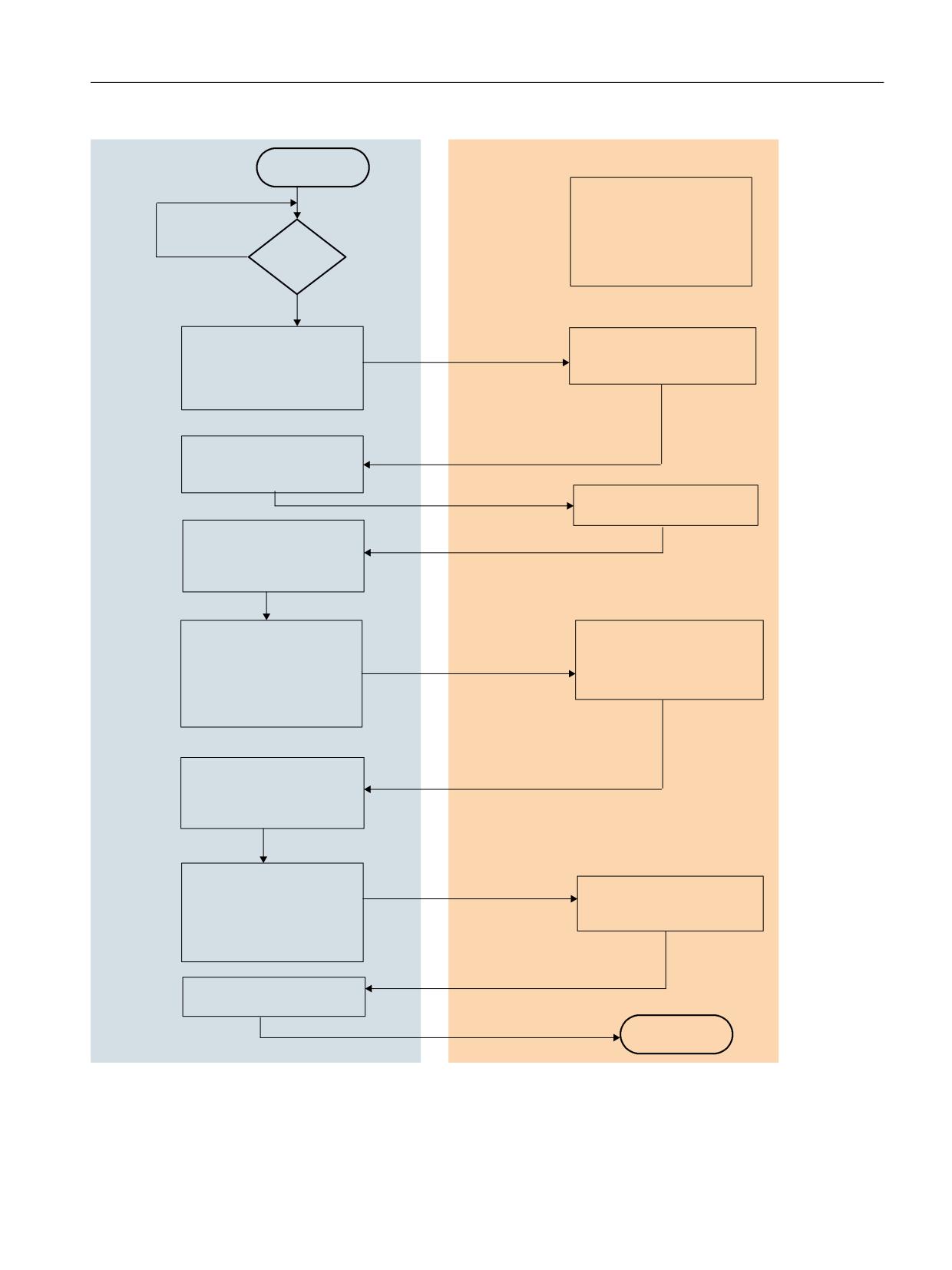
Sequence to test the mechanical braking
Before the brake test can be started via FB 11 (from the basic program), the NC axis to be tested
must be transferred to the PLC as "PLC-controlled axis". During the complete test, the axis must
remain a PLC-controlled axis. Start via FB11 can be made after the transfer to the PLC.
The start parameter of FB11 must be continuously 1 during the complete test. With MD36968
$MA_SAFE_BRAKETEST_CONTROL bit 0 =1, shortly before the brake is closed, the actual holding
torque is determined and is temporarily used in the drive as average value for the torque limiting.
After the brake is closed, the PLC-controlled axis is traversed in the specified direction against the
brake using FC18. If the fixed stop is detected ("Fixed stop reached" DB31-DB61, DBX62.5), the
PLC interrupts the traversing motion (FC18 is exited with error 30). The reduced torque limits are
withdrawn and the brake is re-opened.
Safety Integrated (system-integrated)
294
Function Manual, 10/2020, 6FC5397-4BP40-6BA2
Connecting sensors and actuators
8.6 Safe Brake Test (SBT)
3/&
1&.
67$57
7UDQVIHU D[HV WR 3/&
'%
'%;
0RWRU EUDNH FRQQHFWHG WR
6
)RU DQ H[WHUQDO
DGGLWLRQDO EUDNH WKH FRQWURO
3/&
DQG IHHGEDFN VLJQDO PXVW EH
1R
D[LV
DGDSWHG
<HV
6WDUW )%
6WDUW EUDNH WHVW
'HWHUPLQH KROGLQJ WRUTXH
'%
'%;
5HGXFH WRUTXH OLPLW
6WDUW 79B%7DFWLY
WLPH XQWLO IHHGEDFN VLJQDO
WKDW 6%7 LV DFWLYH
%UDNH WHVW DFWLYH
6WDUW WLPHU 79B%FORVH
'%
'%;
WLPH XQWLO WKH IHHGEDFN
VLJQDO EUDNH FORVHG
&ORVH EUDNH
'%
'%;
%UDNH FORVHG IHHGEDFN
VLJQDO
%UDNH FORVHG
)% RXWSXWV WUDYHO FRPPDQG
'%
'%;
6WDUW WLPHU
79B)HHG&RPPDQG WLPH XS
WR WKH WUDYHUVLQJ FRPPDQG
RXWSXW
0RYH D[LV
VWDUW WLPH 79B);6UHDFKHG
2XWSXW WUDYHUVLQJ FRPPDQG
'HWHFW IL[HG HQG VWRS DV D
WLPH XQWLO WKH IL[HG VWRS LV
'%
'%;
RU
UHVXOW RI &RQWRXU GHYLDWLRQ
UHDFKHG
'%
'%;
5HDFKLQJ WKH WRUTXH OLPLW
7UDYHUVH D[LV DJDLQVW
FORVHG EUDNH DW VWDQGVWLOO
VWDUW )&
6WDUW WLPHU 79B);6KROG
)L[HG VWRS UHDFKHG
WLPH IRU KRZ ORQJ WKH PRWRU
'%
'%;
RSHUDWHV DJDLQVW WKH EUDNH
%UDNH WHVW FRPSOHWHG
'%
'%;
FDQFHO WUDYHUVLQJ FRPPDQG
'%
'%;
RU
0RQLWRULQJ WLPH H[SLUHG
'%
'%;
'HOHWH WUDYHUVLQJ FRPPDQG
:LWKGUDZ UHGXFHG
([LW EUDNH WHVW LQ WKH 1&.
WRUTXH OLPLW
6WDUW 79B%7DFWLY
%UDNH WHVW QR ORQJHU DFWLYH
'%
'%;
'HOHWH IL[HG VWRS UHDFKHG
'%
'%;
2SHQ EUDNH
2XWSXW )% GRQH
2SHQ EUDNH
'%
'%;
(1'
Figure 8-36
Sequence, function test of the mechanical brake system
Safety Integrated (system-integrated)
Function Manual, 10/2020, 6FC5397-4BP40-6BA2
295

Connecting sensors and actuators
8.6 Safe Brake Test (SBT)
8.6.7
Description of FB11
Declaration of the function
VAR_INPUT
Start : BOOL;
//Start of brake test
Ackn : BOOL;
//Acknowledge error
Bclosed : BOOL;
//Brake closed input (single channel - PLC)
Axis : INT ;
//Testing axis no.
TimerNo : TIMER ;
//Timer from user
TV_BTactive : S5TIME ;
//TimeValue -> brake test active
TV_Bclose : S5TIME ;
//TimeValue -> close brake
TV_FeedCommand : S5TIME ;
//TimeValue -> force FeedCommand
TV_FXSreached : S5TIME ;
//TimeValue -> fixed stop reached
TV_FX
//TimeValue -> test brake
Shold :
S5TIM
E ;
END_VAR
VAR_OUTPUT
CloseBrake : BOOL;
//Signal close brake
MoveAxis : BOOL;
//Do move axis
Done: BOOL;
Error : BOOL;
State : BYTE ;
//Error byte
END_VAR
The following table lists all of the formal parameters of the brake test function:
Signal
Cate-
Type
Remark
gory
Start
I
BOOL
Start brake test
Ackn
I
BOOL
Acknowledge fault
Bclosed
I
BOOL
Feedback signal input as to whether the brake has
been closed (single-channel - PLC)
Axis
I
INT
Axis number of axis to be tested
TimerNo
I
TIMER
Timer from user program
TV_Btactive
I
S5TIME
Monitoring time value → brake test active. Axis
signal check DBX71.0
TV_Bclose
I
S5TIME
Monitoring time value → close brake. Input signal
Bclosed check after CloseBrake output set.
Safety Integrated (system-integrated)
296
Function Manual, 10/2020, 6FC5397-4BP40-6BA2

Connecting sensors and actuators
8.6 Safe Brake Test (SBT)
Signal
Cate-
Type
Remark
gory
TV_FeedCommand
I
S5TIME
Monitoring time → output drive command.
Check drive commands after MoveAxis output
has been set.
TV_FXSreached
I
S5TIME
Monitoring time → fixed stop reached
TV_FXShold
I
S5TIME
Monitoring time → test brake
CloseBrake
A
BOOL
Request, close brake
MoveAxis
A
BOOL
Request, initiate traversing motion
Done
A
BOOL
Test successfully completed
Error
A
BOOL
An error occurred
State
A
BYTE
Error status
FB11 error identifiers
State
Meaning
0
No error
1
Starting conditions not fulfilled, e.g. axis not in closed-loop control/brake closed/axis disabled
2
When selecting the brake test, there is no feedback from the NC in the "Brake test active" signal
3
No "Brake closed" feedback using input signal B closed
4
No drive command output (e.g. axis motion has not been started)
5
Fixed stop is not reached → axis RESET was initiated
6
Traversing inhibit/approach too slow → fixed stop cannot be reached. Monitoring time
TV_FXSreached has expired.
7
Programmed end position reached. Possible causes: Brake not holding, approach velocity too
high, traversing distance to small
8
Brake opens during the holding time
9
Error when deselecting the brake test
10
Internal error
11
"PLC-controlled axis" signal not enabled in the user program
Note
The block must be called by the user program. The user must provide an instance DB with any
number for this purpose. The call is multi-instance-capable.
Additional alarm support
To support the brake test commissioning, Alarm 20096, "Axis %1 brake test aborted, additional
information %2" can be enabled with MD11411 $MN_ENABLE_ALARM_MASK, bit 5 = 1. This
alarm supplies more detailed information if the brake test is interrupted.
Safety Integrated (system-integrated)
Function Manual, 10/2020, 6FC5397-4BP40-6BA2
297

Connecting sensors and actuators
8.6 Safe Brake Test (SBT)
8.6.8
Application example
Information and notes for typical applications are provided as example in the following
description.
Parameterization of the machine data
Machine data
Value
Description
MD37000 $MA_FIXED_STOP_MODE
2
Enable brake test
MD37030 $MA_FIXED_STOP_THRESH-
2 mm
Threshold for fixed stop detection. The value must be
OLD
less than the traversing distance of FC18.
MD37050
Content
Only initiate alarm 20095, if the brake test torque is
$MA_FIXED_STOP_ALARM_MASK
+ 16
less than the holding torque.
MD36966 $MA_SAFE_BRAKET-
%
Enter test torque referred to p2003
EST_TORQUE
MD36967 $MA_SAFE_BRAKET-
1 mm
Position tolerance, brake test
EST_POS_TOL
MD36968 $MA_SAFE_BRAKET-
1
Bit 0 = 1: The measured torque at the instant in time
EST_CONTROL
that the brake test is selected is used as the average
value of the reduced torque limit.
MD37000 $MA_FIXED_STOP_MODE, bit1 = 1 is the prerequisite for the SBT; only then does the
NCK evaluate the PLC signal "start brake test". If this is not the case, a timeout after the brake test
has started ensures that the SBT (FB11) is canceled (see Fig. "Sequence function test of the
mechanical braking system").
If, when starting the brake test using axis DB DBX11.0 = 1, it is identified that for this axis
MD36901 $MA_SAFE_FUNCTION_ENABLE = 0, then Alarm 27033 "Axis %1 parameterization of
the MD %2[%3] invalid, error code %4" is output.
If the "travel to fixed stop" function is used elsewhere, then the parameterization of the fixed stop
alarms should be adapted. The fixed stop alarms should be parameterized as follows for the
brake test:
MD37050
2H
Enable fixed stop alarms
$MA_FIXED_STOP_ALARM_MASK
MD37052 $MA_FIXED_STOP_ALARM_RE-
Bit 0-4 = 1
Response, fixed stop alarms
ACTION
Example of calling FB11
OPEN DB37
//Brake test, Z axis
UN
DBX
92.5
//Feedback signal, brake open
=
M
111.5
//Z axis brake is closed
O
E
7.5.
//Initiation for the brake test, Z axis
O
M
110.7
//Brake test already started
FP
M
110.0
//Edge marker
UN
M
111.4
//Error has occurred
S
M
110.7
//Brake test running
Safety Integrated (system-integrated)
298
Function Manual, 10/2020, 6FC5397-4BP40-6BA2
Connecting sensors and actuators
8.6 Safe Brake Test (SBT)
S
M
110.6
//Start
SPBN m001
//Conditional jump
L
DBB 68
//Load channel status
UW
W#16#F
//Select bits
T
MB
115
//Load channel status
L
B#16#10
//Load fixed value
T
DBB8
//Request neutral axis
m001: NOP 0
//Jump marker
U
DBX 68.6
//Checkback signal, axis is neutral
U
M
110.6
//Start
FP
M
110.1
//Edge marker
R
M
110.6
//Start
S
M
110.5
//Step 1
S
DBX 28.7
//Request PLC-monitored axes
U
DBX 63.1
//Checkback signal, axis controlled by PLC
U
M
110.5
//Step 1
FP
M
110.2
//Edge marker
R
M
110.5
//Step 1
S
M
111.0
//Start FB11
CALL FB 11, DB211
//Brake test block
Start
:=M1
//Start brake test
11.0
Ackn
:=E3.
//Acknowledge error with reset button
7
Bclos
::=M1
//Feedback signal, brake not open
ed
11.5
Axis
:=7
//Axis number of axis to be tested axis Z axis
TimerNo :=T 110
//Timer number
TV_BTactiv :=S5T#200MS
//Monitoring time value: Brake test active
DBX71.0
TV_Bclosed :=S5T#1S,
//Monitoring time value: Brake closed
TV_FeedCommand :=S5T#1S
//Monitoring time value: Traversing command
issued
TV_FXSreached := S5T#1S
//Monitoring time value: Fixed stop reached
TV_FXShold := S5T#2S,
//Monitoring time value: Brake test time
CloseBrake := DB37.DBX23.5
//Request to close brake
MoveAxis := M111.2
//Request to initiate traversing motion
Done
:= M111.3,
//Test successfully completed
Error
:= M111.4,
//Error has occurred
State
:= MB112
//Brake test, Z axis
OPEN DB37
//Brake test, Z axis
Safety Integrated (system-integrated)
Function Manual, 10/2020, 6FC5397-4BP40-6BA2
299
Connecting sensors and actuators
8.6 Safe Brake Test (SBT)
U
M
111.2
//Moveaxis
FP
M
111.5
//FC18 start
S
M
111.7
//Start FC18
O
M
111.3
//Test successfully completed
O
M
111.4
//Error has occurred
FP
M
110.3
//Edge marker
R
DBX 28.7
//Request, PLC-controlled axis
UN
DBX6
//Checkback signal, axis controlled by PLC
3.1
U
M
111.0
//Start brake test for FB
U
M
110.7
//Brake test running
SPBN m002
//Conditional jump
L
MB
115
//Load marked channel status
OW
W#16#10
//Select bits
T
DBB8
//Request channel axis
m00: NOP 0;
CALL FC18
//Traverse Z axis
Start
:=M
111.7
//Start of traversing motion
Stop
:= FALSE
//Not used
Funct
:= B#16#5
//Mode: Axis mode
Mode := B#16#1
//Traversing: Incremental
AxisNo
:= 7
//Axis number of axis to be traversed, Z axis
Pos
:= -5.000000e+000,
//Traversing distance: Minus 5 mm
FRate := 1.000000e+003,
//Feedrate: 1000 mm/min
InPos
:= M
113.0,
//Position reached
Error
:= M
113.1
//Error has occurred
State
:= MB 114
//Error status
AUF DB37
//Open axis DB
U
M
113.0
//Position reached
O
M
113.1
//Error has occurred
FP
M
113.2
//Edge marker
R
M
111.7
//Start FC18
U
E
3.7
//Reset MCP
SPBN end
//Conditional jump
U
M
111.4
//Error has occurred
= DBX28.1
//Acknowledge error with axis reset
R
M
111.0
//Start FB11
R
M
110.7
//Brake test running
end: NOP 0
Safety Integrated (system-integrated)
300
Function Manual, 10/2020, 6FC5397-4BP40-6BA2

Connecting sensors and actuators
8.6 Safe Brake Test (SBT)
Determining the test torque, MD36966 $MA_SAFE_BRAKETEST_TORQUE
When determining the test torque MD36966 $MA_SAFE_BRAKETEST_TORQUE, the maximum
holding torque that occurs must first be determined. The maximum occurring holding torque
can be determined in parameter r1509 by traversing the axis to various positions with different
forces / torques due to weight (tools or workpieces).
Examples to determine MD36966 $MA_SAFE_BRAKETEST_TORQUE, p2003=100Nm:
Max. holding torque
Test torque
Actual torque limit before SBT
M0max r1509
MT=M0max + 30%
MT*0.85
20Nm = 20%
26 %
22.1%
30Nm = 30%
39 %
33.15%
40Nm = 40%
52 %
44.2%
50Nm = 50%
65 %
55.3%
60Nm = 60%
78 %
66.3%
70Nm = 70%
91 %
77.4%
The "limit value of the actual torque before SBT" shown here, indicates that the actual torque,
automatically determined before the SBT, must not be lower, as otherwise Alarm 20095 "Axis %1
inadmissible holding torque" is output.
Evaluating the test results
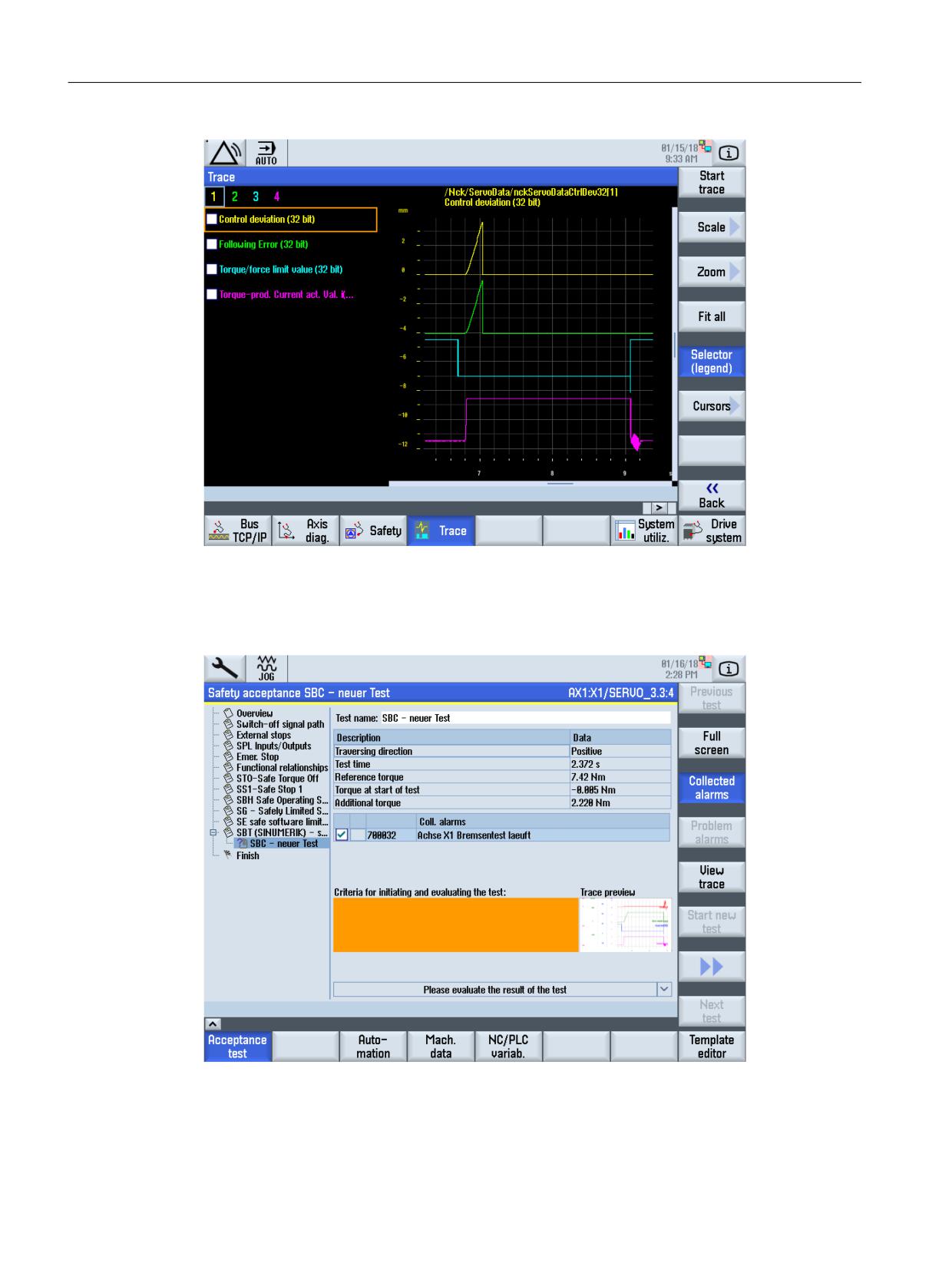
Analysis using servo trace
The signal characteristics must be viewed in order to evaluate the brake test. The behavior
during the brake test can be recorded using the trace and the following settings:
Signal selection
System deviation
Following error
Torque limit
Torque-generating actual current value i(q)
Measurement parameters
Measurement duration: 10 s
Trigger: No trigger
Safety Integrated (system-integrated)
Function Manual, 10/2020, 6FC5397-4BP40-6BA2
301
Connecting sensors and actuators
8.6 Safe Brake Test (SBT)
Figure 8-37
Servo trace brake test
SBC acceptance test
The safe brake test can be carried out under the acceptance test.
Figure 8-38
Acceptance test - safe brake test
An overview of the recording can be obtained via the "Show trace" softkey.
Safety Integrated (system-integrated)
302
Function Manual, 10/2020, 6FC5397-4BP40-6BA2
Connecting sensors and actuators
8.6 Safe Brake Test (SBT)
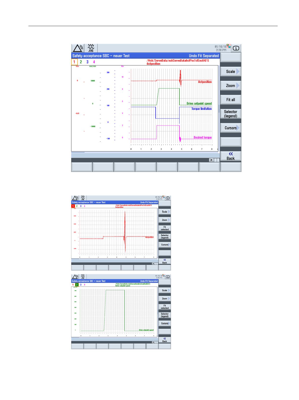
Figure 8-39
Acceptance test - trace brake test
Actual position when testing the SBT
Axis motion is minimal if the brake was suc-
cessfully tested. The holding current re-estab-
lishes itself at the end of the SBT and after
opening the brake. Here, a slight sag can be
seen.
Setpoint of the axis-specific feed
Setpoint is output and a following error built
up.
Safety Integrated (system-integrated)
Function Manual, 10/2020, 6FC5397-4BP40-6BA2
303
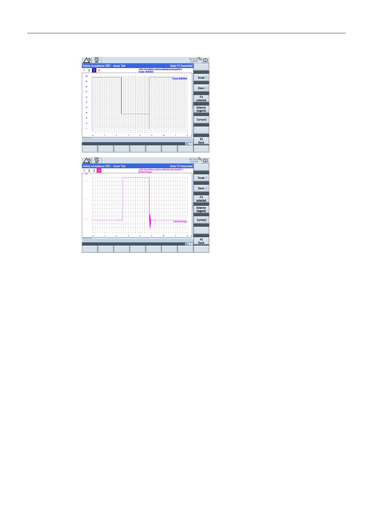
Connecting sensors and actuators
8.6 Safe Brake Test (SBT)
Torque limit when testing the SBT
Reduction of the torque limit - at the end of the
test, the limit is set to 0 in order to decrease the
additionally generated torque to zero.
Required torque when testing the SBT
During the test, an additional torque is built up
and reduced again at the end.
8.6.9
Supplementary conditions
• When testing the mechanical braking system, it is not permissible that traverse to fixed stop
(FXS) and traversing with a limited torque, FOC are simultaneously active. In this case, Alarm
20092, "Axis %1 travel to fixed stop still active" is triggered.
• During the brake test, contour monitoring is not active. After the PLC has started traversing
motion then there is also no standstill monitoring.
• For a gantry or master/slave group, the machinery manufacturer (OEM) must decide on a
case-for-case basis whether a defective brake could result in mechanical damage. The brake
test should not be performed if mechanical damage could occur.
• For other "travel to fixed stop" applications, machine data MD37050
$MA_FIXED_STOP_ALARM_MASK and MD37052 $MA_FIXED_STOP_ALARM_REACTION
should be adapted.
• If FC18 is called for the same axis in the remainder of the user program, the calls must be
mutually interlocked. For example, this can be achieved via a common call of this function
with an interlocked common data interface for the FC18 parameters. An additional option is
to call the FC18 a multiple number of times, in which case the inactive FC18 must be skipped.
An interlock against being used a multiple number of times must be provided.
Safety Integrated (system-integrated)
304
Function Manual, 10/2020, 6FC5397-4BP40-6BA2
Connecting sensors and actuators
8.7 Safety Information Channel and Safety Control Channel
• The feed override should be set to 100% so that the required velocity can be reached during
the test. If this is realized via the interface, then it should be carefully noted that if the brake
test is not successful, then the override does not statically remain at 100%. As an alternative
to directly writing to the interface, a message can be generated.
• The torque limits change when a parameter set is changed over.
• Changing the reference torque p2003 means that the use of a referred torque quantity
results in a different dynamic behavior. If p2003 is changed then this alters the system
behavior when the brake test is performed. In order to avoid this, when booting, the NCK
system software reads out the value from p2003 and saves it in MD
$MA_SAFE_BRAKETEST_TORQUE_NORM. For each additional control boot, MD36969
$MA_SAFE_BRAKETEST_TORQUE_NORM is checked for changes and where relevant, Alarm
27039 "Axis %1 parameterization MD %2[%3] changed, confirmation and functional test
required!" is displayed. MD36969 $MA_SAFE_BRAKETEST_ TORQUE_NORM, is included in
the axis-specific checksum $MA_SAFE_ACT_CHECKSUM[0].
• With simultaneous use of the extended brake control (r0108.14=1) and dynamic stiffness
control (MD32640 $MA_STIFFNESS_CONTROL_ENABLE=1), the factory setting
p1152=r0899.15 must be changed ("disconnected"), and p1152 must be set to 1.
• Transformations: Active transformations must be deactivated for the duration of the brake
test, as otherwise unexpected axis motion can occur.
8.7
Safety Information Channel and Safety Control Channel
Safety Information Channel
The Safety Information Channel (SIC) enables Safety Integrated functionality status information
of the drive to be transmitted to the higher-level motion control system. As a consequence, for
safety STOP responses of the drive (e.g. for STO) the motion control is informed, which allows
it to respond in the best possible way. This means that in situations such as these e.g. no
additional setpoints are issued for the path, which means that no follow-on/subsequent alarms
occur that have to be acknowledged. Any types of setpoint inputs, e.g. override, F or S program
blocks, are blocked by the setpoint speed limiting transferred in the SIC.
Further, the status information is made available in the PLC user interface. This gives users the
option of initiating the appropriate responses in the PLC user program to the safety functions of
the drive.
Safety Control Channel
With the Safety Control Channel (SCC), control information is sent to the safety functions of the
drive via the higher-level control. This means that functions, such as a brake test or a test stop,
can be selected in the drive.
Safety Integrated (system-integrated)
Function Manual, 10/2020, 6FC5397-4BP40-6BA2
305
Connecting sensors and actuators
8.7 Safety Information Channel and Safety Control Channel
Use in the "SINUMERK Safety Integrated" operating mode
This functionality is used in the following cases in the "SINUMERIK Safety Integrated" operating
mode:
• Connecting external SINAMICS drives with safety functionality integrated in the drive, which
are assigned to an NC axis, to the motion control.
• Using the brake test functionality integrated in the drive for the NC axes with SINUMERIK
Safety Integrated monitoring enabled.
Note
The hardware configuration for both cases are described in an application example, which you
can find on the Internet in our "Industry Online Support".
Safety Integrated (system-integrated)
306
Function Manual, 10/2020, 6FC5397-4BP40-6BA2

Data descriptions
9
9.1
Machine data for SINUMERIK 840D sl
9.1.1
Overview of the machine data
The checksum data have the following meanings:
Axis-specific checksums
CRC
Functionality
Change results in an alarm
AX[0]
Monitoring functionality
27032 "Axis %1 checksum error safe monitoring. Confirmation
and acceptance test required!"
AX[1]
SINAMICS HW-dependent
27035 "Axis %1 new HW component, acknowledgment and
data
function test required"
AX[2]
SINAMICS coupling
27060 "Axis %1 checksum error of drive assignment. Confir-
mation and acceptance test required"
NCK checksums
CRC
Functionality
Change results in an alarm
NCK[0]
Safe communication; SPL
27070 "Checksum error, SPL parameter assignment, and SPL
I/O connection; SPL func-
interfaces. Confirmation and acceptance test required!"
tionality
NCK[1]
User SPL configuration
27071 "Checksum error, safe SPL parameterization. Confirma-
tion and acceptance test required!"
NCK[2]
Enable I/O connection
27072 "Checksum error, enabling safe communication. Con-
firmation and acceptance test required"
NCK[3]
PROFIsafe-CRC1
27073 "Checksum error, S7 PROFIsafe configuration. Confir-
mation and acceptance test required.
-- means: This data is not calculated into any checksum.
Table 9-1
Overview of machine data for SINUMERIK 840D sl
Number
Identifier
Name
Checksums MD
General ($MN_ ...)
10050
SYSCLOCK_CYCLE_TIME
Basic system clock cycle, see /FB1/, G2
--
10060
POSCTRL_SYSCLOCK_TIME_RATIO
Factor, position controller clock cycle, see /
--
FB1/, G2
10070
IPO_SYSCLOCK_CYCLE_TIME_RATIO
Factor, interpolator clock cycle
--
10071
IPO_CYCLE_TIME
Interpolator clock cycle
NCK[0]
10089
SAFE_PULSE_DIS_TIME_BUSFAIL
Wait time pulse cancellation when the bus fails
AX[0]
10090
SAFETY_SYSCLOCK_TIME_RATIO
Factor for monitoring clock cycle
--
10091
INFO_SAFETY_CYCLE_TIME
Display, monitoring clock cycle time
AX[0]
Safety Integrated (system-integrated)
Function Manual, 10/2020, 6FC5397-4BP40-6BA2
307

Data descriptions
9.1 Machine data for SINUMERIK 840D sl
Number
Identifier
Name
Checksums MD
10092
INFO_CROSSCHECK_CYCLE_TIME
Displays the clock cycle time for a crosswise
--
data comparison
10093
INFO_NUM_SAFE_FILE_ACCESS
Number of SPL file access operations
--
10094
SAFE_ALARM_SUPPRESS_LEVEL
Alarm suppression level
--
10095
SAFE_MODE_MASK, bit 1
Safety Integrated operating modes
NCK[2], NCK[0]
10096
SAFE_DIAGNOSIS_MASK
Safety Integrated diagnostic functions
--
10097
SAFE_SPL_STOP_MODE
Stop response for SPL errors
NCK[0]
10098
PROFISAFE_IPO_TIME_RATIO
Factor PROFIsafe communications clock cycle
NCK[0]
time
10099
INFO_PROFISAFE_CYCLE_TIME
PROFIsafe communications clock cycle time
--
10200
INT_INCR_PER_MM
Computational resolution for linear positions
--
see /FB1/, G2
10210
INT_INCR_PER_DEG
Computational resolution for angular posi-
--
tions see /FB1/, G2
10385
PROFISAFE_MASTER_ADRESS
PROFIsafe address of the PROFIsafe master
NCK[0]
module
10386
PROFISAFE_IN_ADRESS
PROFIsafe address of an input module
NCK[0]
10387
PROFISAFE_OUT_ADRESS
PROFIsafe address of a PROFIsafe output mod-
NCK[0]
ule
10388
PROFISAFE_IN_ASSIGN
Input assignment, $A_INSE to PROFIsafe input
NCK[0]
module
10389
PROFISAFE_OUT_ASSIGN
Output assignment, $A_OUTSE to PROFIsafe
NCK[0]
module
10393
SAFE_DRIVE_LOGIC_ADDRESS
Logical drive addresses, SI
AX[2]
11411
ENABLE_ALARM_MASK
Activation of alarms
--
11415
SUPPRESS_ALARM_MASK_2
Suppress alarm outputs
--
11500
PREVENT_SYNACT_LOCK
Protected synchronized actions
--
11602
ASUP_START_MASK
Ignore stop conditions for ASUB
--
11604
ASUB_START_PRIO_LEVEL
Priorities as of which ASUP_START_MASK takes
--
effect
13300
PROFISAFE_IN_FILTER
F-net data filter IN
NCK[0]
13301
PROFISAFE_OUT_FILTER
F-net data filter OUT
NCK[0]
13302
PROFISAFE_IN_ENABLE_MASK
Enable screen of the connections to PROFIsafe
NCK[2]
input modules
13303
PROFISAFE_OUT_ENABLE_MASK
Enable screen form of the connections to PRO-
NCK[2]
FIsafe output modules
13304
PROFISAFE_IN_SUBS_ENAB_MASK
Activation of the substitute value output for
NCK[2]
PROFIsafe input modules
13305
PROFISAFE_IN_SUBS
Substitute values for passive connections to
NCK[0]
PROFIsafe input modules
13307
PROFISAFE_IPO_RESERVE
Number of IPO clock cycles without PROFIsafe
--
calculations
13308
PROFISAFE_IN_NAME
Name of the PROFIsafe input module
--
13309
PROFISAFE_OUT_NAME
Name of the PROFIsafe output module
--
13310
SAFE_SPL_START_TIMEOUT
Delay, display Alarm 27097
--
13312
SAFE_SPL_USER_DATA
User SPL data is changed
NCK[1]
Safety Integrated (system-integrated)
308
Function Manual, 10/2020, 6FC5397-4BP40-6BA2

Data descriptions
9.1 Machine data for SINUMERIK 840D sl
Number
Identifier
Name
Checksums MD
13316
SAFE_GLOB_CONFIG_CHANGE_DATA
Date/time of the last change SI-NCK-MD
--
13317
SAFE_GLOB_PREV_CONFIG
Data, previous safety configuration
--
13318
SAFE_GLOB_ACT_CHECKSUM
Actual checksum NCK
--
13319
SAFE_GLOB_DES_CHECKSUM
Reference checksum
--
13320
SAFE_SRDP_IPO_TIME_RATIO
Factor F_DP communication clock cycle
NCK[0]
13322
INFO_SAFE_SRDP_CYCLE_TIME
Maximum F_DP communication clock cycle
--
13330
SAFE_SDP_ENABLE_MASK
Enable screen form F_SENDDP communication
NCK[2]
relationships
13331
SAFE_SDP_ID
Identifier of the F_SENDDP communication re-
NCK[0]
lationship
13332
SAFE_SDP_NAME
Name of the SPL connection
--
13333
SAFE_SDP_CONNECTION_NR
Number of the SPL connection
NCK[0]
13334
SAFE_SDP_LADDR
Basis address of the input/output data area
NCK[0]
F_SENDDP
13335
SAFE_SDP_TIMEOUT
Monitoring time for F_SENDDP
NCK[0]
13336
SAFE_SDP_ASSIGN
Output assignment.$A_OUTSE to F_SENDDP
NCK[0]
net data
13337
SAFE_SDP_FILTER
F-net data filter between $A_OUTSE and
NCK[0]
F_SENDDP
13338
SAFE_SDP_ERR_REAC
Error response
NCK[0]
13340
SAFE_RDP_ENABLE_MASK
Enable screen form F_RECVDP communication
NCK[2]
relationship
13341
SAFE_RDP_ID
Identifier of the F_RECVDP communication re-
NCK[0]
lationship
13342
SAFE_RDP_NAME
Name of the SPL connection
--
13343
SAFE_RDP_CONNECTION_NR
Assignment, SPL connection to system varia-
NCK[0]
bles
13344
SAFE_RDP_LADDR
Basis address of the input/output data area,
NCK[0]
F_RECVDP
13345
SAFE_RDP_TIMEOUT
Monitoring time for F_RECVDP
NCK[0]
13346
SAFE_RDP_ASSIGN
Input assignment F_RECVDP net data to
NCK[0]
$A_INSE
13347
SAFE_RDP_FILTER
F-net data filter between F_RECVDP and
NCK[0]
$A_INSE
13348
SAFE_RDP_ERR_REAC
Error response
NCK[0]
13349
SAFE_RDP_SUBS
Substitute values in the case of an error
NCK[0]
13370
SAFE_MODE
Safety operating mode
--
13374
SAFE_INFO_DRIVE_ADDR
Logical basis addresses for the SIC/SCC com-
--
munication between NCK and drive
13376
SAFE_INFO_TELEGRAM_TYPE
SIC/SCC telegram number
--
Channel-specific ($MC_ ... )
20106
PROG_EVENT_IGN_SINGLEBLOCK
PROG_EVENTs ignore the single block
--
20107
PROG_EVENT_IGN_INHIBIT
PROG_EVENTs ignore read-in inhibit
--
20108
PROG_EVENT_MASK
Event-controlled program call
--
20192
PROG_EVENT_IGN_PROG_STATE
Do not display the execution of the prog events
--
on the OPI
Safety Integrated (system-integrated)
Function Manual, 10/2020, 6FC5397-4BP40-6BA2
309

Data descriptions
9.1 Machine data for SINUMERIK 840D sl
Number
Identifier
Name
Checksums MD
20700
REFP_NC_START_LOCK
NC-Start disable without reference point
--
28251
MM_NUM_SAFE_SYNC_ELEMENTS
Number of elements for expressions in safety
--
synchronized actions
Axis/spindle-specific ($MA_ ...)
30130
CTRLOUT_TYPE
Setpoint output type
--
30240
ENC_TYPE
Encoder type of the actual value sensing (po-
--
sition actual value) see /FB1/, G2
30300
IS_ROT_AX
Rotary axis/spindle see /FB1/, R2
--
30320
DISPLAY_IS_MODULO
Modulo 360 degrees display for rotary axis or
--
spindle see /FB1/, R2
30330
MODULO_RANGE
Size of the modulo range see /FB1/, R2
--
32300
MA_AX_ACCEL
Axis acceleration see /FB1/, B2
--
35200
GEAR_STEP_SPEEDCTRL_ACCEL
Acceleration in the open-loop speed control-
--
led mode see /FB1/, S1
35210
GEAR_STEP_POSCTRL_ACCEL
Acceleration in the closed-loop position con-
--
trolled mode see /FB1/, S1
35410
SPIND_OSCILL_ACCEL
Acceleration when oscillating see /FB1/, S1
--
36060
STANDSTILL_VELO_TOL
Threshold velocity/speed "axis/spindle station-
--
ary" see /FB1/, A2
36620
SERVO_DISABLE_DELAY_TIME
Shutdown delay controller enable see /FB1/, A2
--
36901
SAFE_FUNCTION_ENABLE
Enables safety-related functions
AX[0]
36902
SAFE_IS_ROT_AX
Rotary axis
AX[0]
36903
SAFE_CAM_ENABLE
enable Safe Cam Track
AX[0]
36904
SAFE_ADD_FUNCTION_MASK
Enables additional functions for Safety Integra-
AX[0]
ted
36905
SAFE_MODULO_RANGE
Modulo value Safe Cams
AX[0]
36906
SAFE_CTRLOUT_MODULE_NR
SI drive assignment
AX[2]
36907
SAFE_DRIVE_PS_ADDRESS
PROFIsafe address of the drive
AX[2]
36909
SAFE_ENC_MEAS_STEPS_RESOL
Resolution measuring steps for linear absolute
AX[0]
encoders
36912
SAFE_ENC_INPUT_NR
Actual value assignment: Drive encoder num-
AX[2]
ber
36913
SAFE_ENC_MEAS_STEPS_POS1
Non-safety-related measuring increments
AX[0]
POS1
36914
SAFE_SINGLE_ENC
SI single-encoder system
AX[0]
36916
SAFE_ENC_IS_LINEAR
Linear scale
AX[0]
36917
SAFE_ENC_GRID_POINT_DIST
Grid spacing, linear scale
AX[0]
36918
SAFE_ENC_RESOL
Encoder pulses per revolution
AX[0]
36919
SAFE_ENC_PULSE_SHIFT
Shift factor of the encoder multiplication
AX[0]
36920
SAFE_ENC_GEAR_PITCH
Leadscrew pitch
AX[0]
36921
SAFE_ENC_GEAR_DENOM[n]
Denominator, gearbox ratio encoder/load
AX[0]
36922
SAFE_ENC_GEAR_NUMERA[n]
Numerator, gearbox ratio encoder/load
AX[0]
36923
SAFE_INFO_ENC_RESOL
Safety-relevant encoder resolution
--
Safety Integrated (system-integrated)
310
Function Manual, 10/2020, 6FC5397-4BP40-6BA2

Data descriptions
9.1 Machine data for SINUMERIK 840D sl
Number
Identifier
Name
Checksums MD
36924
SAFE_ENC_NUM_BITS[0]
Bit information of the redundant actual value
AX[1]
SAFE_ENC_NUM_BITS[1]
AX[1]
SAFE_ENC_NUM_BITS[2]
AX[0]
SAFE_ENC_NUM_BITS[3]
AX[0]
36925
SAFE_ENC_POLARITY
Direction reversal actual value
AX[0]
36927
SAFE_ENC_MOD_TYPE
Encoder evaluation type
AX[1]
36928
SAFE_ENC_IDENT
Encoder identification
AX[1]
36929
SAFE_ENC_CONF
Configuration of the redundant actual value
AX[1]
36930
SAFE_STANDSTILL_TOL
Standstill tolerance
AX[0]
36931
SAFE_VELO_LIMIT[n]
Limit value for safely reduced speed
AX[0]
36932
SAFE_VELO_OVR_FACTOR[n]
SG correction values
AX[0]
36933
SAFE_DES_VELO_LIMIT
SG setpoint speed limiting
--
36934
SAFE_POS_LIMIT_PLUS[n]
Upper limit value for safe limit position
AX[0]
36935
SAFE_POS_LIMIT_MINUS[n]
Lower limit value for safe limit position
AX[0]
36936
SAFE_CAM_POS_PLUS[n]
Plus cams position for Safe Cams
AX[0]
36937
SAFE_CAM_POS_MINUS[n]
Minus cams position for Safe Cams
AX[0]
36938
SAFE_CAM_TRACK_ASSIGN[n]
Cam track assignment
AX[0]
36940
SAFE_CAM_TOL
Tolerance for Safe Cams
AX[0]
36942
SAFE_POS_TOL
Tolerance, actual value comparison (cross-
AX[0]
wise)
36944
SAFE_REFP_POS_TOL
Tolerance, actual value comparison (referenc-
AX[0]
ing)
36945
SAFE_VELO_X_FILTER_TIME
Filter time n< nx
AX[0]
36946
SAFE_VELO_X
Speed limit nx
AX[0]
36947
SAFE_VELO_X_HYSTERESIS
Speed limit n<nx
AX[0]
36948
SAFE_STOP_VELO_TOL
Speed tolerance for Safe Acceleration Monitor
AX[0]
36949
SAFE_SLIP_VELO_TOL
Speed tolerance, slip
AX[0]
36950
SAFE_MODE_SWITCH_TIME
Tolerance time for SGE changeover
AX[0]
36951
SAFE_VELO_SWITCH_DELAY
Delay time, speed changeover
AX[0]
36952
SAFE_STOP_SWITCH_TIME_C
Transition time, STOP C to safe standstill
AX[0]
36953
SAFE_STOP_SWITCH_TIME_D
Transition time, STOP D to safe standstill
AX[0]
36954
SAFE_STOP_SWITCH_TIME_E
Transition time, STOP E to safe standstill
AX[0]
36955
SAFE_STOP_SWITCH_TIME_F
Transition time STOP F to STOP B
AX[0]
36956
SAFE_PULSE_DISABLE_DELAY
Delay time, pulse cancellation
AX[0]
36957
SAFE_PULSE_DIS_CHECK_TIME
Time to check pulse cancellation
AX[0]
36958
SAFE_ACCEPTANCE_TST_TIMEOUT
Time limit for the acceptance test duration
AX[0]
36960
SAFE_STANDSTILL_VELO_TOL
Shutdown speed, pulse cancellation
AX[0]
36961
SAFE_VELO_STOP_MODE
Stop response, safely reduced speed
AX[0]
36962
SAFE_POS_STOP_MODE
Stop response, safe limit position
AX[0]
36963
SAFE_VELO_STOP_REACTION[n]
Stop response, safely reduced speed
AX[0]
36964
SAFE_IPO_STOP_GROUP
Grouping, safety IPO response
--
36965
SAFE_PARK_ALARM_SUPPRESS
Alarm suppression for parking axes
AX[0]
36966
SAFE_BRAKETEST_TORQUE
Holding torque, brake test
AX[0]
36967
SAFE_BRAKETEST_POS_TOL
Position tolerance, brake test
AX[0]
Safety Integrated (system-integrated)
Function Manual, 10/2020, 6FC5397-4BP40-6BA2
311

Data descriptions
9.1 Machine data for SINUMERIK 840D sl
Number
Identifier
Name
Checksums MD
36968
SAFE_BRAKETEST_CONTROL
Extended settings for the brake test
AX[0]
36969
SAFE_BRAKETEST_TORQUE_NORM
Reference quantity for the holding torque,
AX[0]
brake test
36970
SAFE_SVSS_DISABLE_INPUT
Input assignment, SBH/SG deselection
AX[0]
36971
SAFE_SS_DISABLE_INPUT
Input assignment, SBH deselection
AX[0]
36972
SAFE_VELO_SELECT_INPUT[n]
Input assignment, SG selection
AX[0]
36973
SAFE_POS_SELECT_INPUT
Input assignment, SE selection
AX[0]
36974
SAFE_GEAR_SELECT_INPUT[n]
Input assignment, gearbox ratio selection
AX[0]
36977
SAFE_EXT_STOP_INPUT[n]
Input assignment, external brake request
AX[0]
36978
SAFE_OVR_INPUT[n]
Input assignment, SG override
AX[0]
36980
SAFE_SVSS_STATUS_OUTPUT
Output assignment, SBH/SG active
AX[0]
36981
SAFE_SS_STATUS_OUTPUT
Output assignment for SBH active
AX[0]
36982
SAFE_VELO_STATUS_OUTPUT[n]
Output assignment active SG selection
AX[0]
36985
SAFE_VELO_X_STATUS_OUTPUT
Output assignment for n < nx
AX[0]
36987
SAFE_REFP_STATUS_OUTPUT
Output assignment, axis safely referenced
AX[0]
36988
SAFE_CAM_PLUS_OUTPUT[n]
Output assignment, SN1+ to SN4+
AX[0]
36989
SAFE_CAM_MINUS_OUTPUT[n]
Output assignment, SN1- to SN4-
AX[0]
36990
SAFE_ACT_STOP_OUTPUT[n]
Output assignment, active STOP
AX[0]
36992
SAFE_CROSSCHECK_CYCLE
Displays axis-specific crosswise comparison
--
clock cycle
36993
SAFE_CONFIG_CHANGE_DATE[n]
Date/time of the last change SI-NCK-MD
--
36994
SAFE_PREV_CONFIG[n]
Data, previous safety function
--
36995
SAFE_STANDSTILL_POS
Standstill position
--
36997
SAFE_ACKN
User agreement
--
36998
SAFE_ACT_CHECKSUM
Actual checksum
--
36999
SAFE_DES_CHECKSUM
Reference checksum
--
37000
FIXED_STOP_MODE
Travel to fixed stop mode
--
37900
SAFE_CAM_TRACK_OUTPUT
Output assignment cam tracks 1 to 4
AX[0]
37901
SAFE_CAM_RANGE_OUTPUT_1
Output assignment, cam range for cam track 1
AX[0]
37902
SAFE_CAM_RANGE_OUTPUT_2
Output assignment, cam range for cam track 2
AX[0]
37903
SAFE_CAM_RANGE_OUTPUT_3
Output assignment, cam range for cam track 3
AX[0]
37904
SAFE_CAM_RANGE_OUTPUT_4
Output assignment, cam range for cam track 4
AX[0]
37906
SAFE_CAM_RANGE_BIN_OUTPUT_1
Output assignment, cam range bit for cam
AX[0]
track 1
37907
SAFE_CAM_RANGE_BIN_OUTPUT_2
Output assignment, cam range bit for cam
AX[0]
track 2
37908
SAFE_CAM_RANGE_BIN_OUTPUT_3
Output assignment, cam range bit for cam
AX[0]
track 3
37909
SAFE_CAM_RANGE_BIN_OUTPUT_4
Output assignment, cam range bit for cam
AX[0]
track 4
37920
SAFE_STANDSTILL_VELO_LIMIT
Switchover speed, Safe Operating Stop
AX[0]
37922
SAFE_STANDSTILL_DELAY
Delay time switching over to Safe Operating
AX[0]
Stop
Safety Integrated (system-integrated)
312
Function Manual, 10/2020, 6FC5397-4BP40-6BA2

Data descriptions
9.1 Machine data for SINUMERIK 840D sl
Number
Identifier
Name
Checksums MD
37950
SAFE_INFO_ENABLE
SIC/SCC and PROFIsafe enable
--
37954
SAFE_INFO_MODULE_NR
SIC/SCC module number
--
9.1.2
Description of machine data
General
General information about machine data and an explanation of their contents such as units,
data type, protective stage, effectiveness, etc. can be found in the following references:
Reference: /LIS1/, List Manual Machine Data SINUMERIK 840D sl
10050
$MN_SYSCLOCK_CYCLE_TIME
MD number
Basic system cycle clock
Default value: 0.004
Min. input limit: 0.000125
Max. input limit: 0.031
Change becomes effective after: POWER ON
Protection level: 7/2
Unit: s
Data type: DOUBLE
Meaning:
Basic clock cycle time of the system software
The clock cycle times of cyclic tasks (position controller/IPO) are set in a multiple of this basic
clock cycle. Apart from special applications in which POSCTRL_SYSCLOCK_TIME_RATIO is set to
a value greater than 1, the basic clock cycle corresponds to the position controller clock cycle.
For systems with PROFIBUS-DP connection, this MD corresponds to the PROFIBUS-DP cycle time.
When booting, this time is read out of the configuring file (SDP type 2000) and written into the
MD.
This MD can only be changed using the configuring file.
Note:
If this MD is reduced, then this can result in an automatic correction of POSCTRL_CYCLE_DELAY,
that cannot be undone at the next increase!
Details:
The basic clock cycle is an integer multiple (SYSCLOCK_SAMPL_TIME_RATIO) of units of the
clock cycle of the measured value sampling. When the system boots, the entered value is
automatically rounded to an integer multiple.
Note:
After a power off/on, discrete timer division ratios may produce a value that is not an integer of
the input value, e.g.
Entry =0.005s
after power off/on =0.00499840
or
Entry =0.006s
after power off/on =0.0060032
Special cases, errors,...
corresponds with..
Safety Integrated (system-integrated)
Function Manual, 10/2020, 6FC5397-4BP40-6BA2
313

Data descriptions
9.1 Machine data for SINUMERIK 840D sl
10060
$MN_POSCTRL_SYSCLOCK_TIME_RATIO
MD number
Factor for position-control cycle
Default value:1
Min. input limit: 1
Max. input limit: 31
Change becomes effective after: POWER ON
Protection level: 7/2
Unit: -
Data type: DWORD
Meaning:
The position control clock cycle is entered as a multiple of the time units of the basic system
clock cycle SYSCLOCK_CYCLE_TIME.
The default setting is "1". This means that the position control clock cycle corresponds to the
basic system clock cycle SYSCLOCK_CYCLE_TIME.
Setting values > 1 involves computation time for processing the additional timer interrupts by
the operating system, and should only be used in cases where a task exists in the system that
should run faster than the position controller clock cycle.
For systems with PROFIBUS DP connection, this MD represents ratio between the PROFIBUS DP
clock cycle and position controller clock cycle.
Special cases, errors,...
corresponds with..
10070
$MN_IPO_SYSCLOCK_TIME_RATIO
MD number
Factor for interpolator clock cycle
Default value: 4
Min. input limit: 1
Max. input limit: 100
Change becomes effective after: POWER ON
Protection level: 7/2
Unit: -
Data type: DWORD
Meaning:
The interpolator clock cycle is entered as a multiple of the time units of the basic system clock
cycle SYSCLOCK_CYCLE_TIME.
It is only permissible to set integer multiples of the position controller clock cycle (set using
POSCTRL_SYSCLOCK_TIME_RATIO). Values, that do not represent an integer multiple of the
position controller clock cycle, are automatically increased to the next integer multiple of the
position controller clock cycle before they become effective (at the next boot).
In this case, Alarm 4102 "IPO cycle increase to [ ] ms" is output.
Special cases, errors,...
corresponds with..
MD10060 POSCTRL_SYSCLOCK_TIME_RATIO
10071
$MN_IPO_CYCLE_TIME
MD number
Interpolator clock cycle
Default value: 0.0
Min. input limit: -
Max. input limit: -
Change becomes effective after: POWER ON
Protection level: 7/2
Unit: -
Data type: DWORD
Meaning:
Interpolation time
Displays the interpolator clock cycle time (this cannot be modified !).
Internally, this is formed from the machine data SYSCLOCK_CYCLE_TIME and IPO_SYS-
CLOCK_TIME_RATIO.
Special cases, errors,...
corresponds with..
MD10050 SYSCLOCK_CYCLE_TIME
MD10070 IPOL_SYSCLOCK_TIME_RATIO
Safety Integrated (system-integrated)
314
Function Manual, 10/2020, 6FC5397-4BP40-6BA2

Data descriptions
9.1 Machine data for SINUMERIK 840D sl
10089
$MN_SAFE_PULSE_DIS_TIME_BUSFALL
MD number
Wait time pulse cancellation when the bus fails
Default value: 0.0
Min. input limit: 0.0
Max. input limit: 0.8
Change becomes effective after: POWER ON
Protection level: 7/2
Unit: s
Data type: DOUBLE
Meaning:
Time after which a communication failure to the drive occurs the pulses are safely canceled.
During this time it is still possible to implement a response that is executed independently in the
drive (refer to extended stop and retract).
In the following cases, the system does not wait for this time up to pulse cancellation to expire:
• When selecting an external STOP A, a test stop
• When SBH is active or SBH is selected
• For an active SG stage or when selecting an SG stage for which immediate pulse cancellation
is parameterized in MD36961 $MA_SAFE_VELO_STOP_MODE or MD36963 $MA_SAFE_VE-
LO_STOP_REACTION.
Note:
This value is is transferred to drive parameter p9580 using the copy function of SI-MD and
compared in a crosswise data comparison.
This general machine data is included in the axis-specific checksum calculation of the safety-
related machine data (MD36998 $MA_SAFE_ACT_CHECKSUM, MD36999
$MA_SAFE_DES_CHECKSUM).
Special cases, errors,...
corresponds with..
10090
$MN_SAFETY_SYSCLOCK_TIME_RATIO
MD number
Factor for monitoring clock cycle
Default value: 3
Min. input limit: 1
Max. input limit: 50
Change becomes effective after: POWER ON
Protection level: 7/1
Unit: -
Data type: DWORD
Meaning:
Ratio between the monitoring and system basic clock cycle. The monitoring clock cycle is the
product of this data and MD10050 $MN_SYSCLOCK_CYCLE_TIME.
Special cases, errors,...
The monitoring clock cycle is checked when powering up:
• It must be an integer multiple of the position control clock cycle
• It must be < 25 ms
If these conditions are not fulfilled, the factor is rounded-off to the next possible value. The
monitoring cycle that is actually set is displayed using MD10091 $MN_INFO_SAFETY_CY-
CLE_TIME.
Further, the value for the crosswise data comparison clock cycle that is displayed using
MD10092 $MN_INFO_CROSSCHECK_CYCLE_TIME also changes.
Note:
The monitoring clock cycle defines the response time of the monitoring functions. It should be
noted that a short monitoring clock cycle time increases the load on the CPU.
corresponds with..
MD10050 $MN_SYSCLOCK_CYCLE_TIME
MD10091 $MN_INFO_SAFETY_CYCLE_TIME
MD10092 $MN_INFO_CROSSCHECK_CYCLE_TIME
Safety Integrated (system-integrated)
Function Manual, 10/2020, 6FC5397-4BP40-6BA2
315

Data descriptions
9.1 Machine data for SINUMERIK 840D sl
10091
$MN_INFO_SAFETY_CYCLE_TIME
MD number
Display, monitoring clock cycle time
Default value: 0.0
Min. input limit: 0.0
Max. input limit:-
Change becomes effective after: POWER ON
Protection level: 7/0
Unit: s
Data type: DOUBLE
Meaning:
Display data:
Set monitoring clock cycle in seconds. Is obtained from MD10050 $MN_SYSCLOCK_CY-
CLE_TIME and MD10090 $MN_SAFETY_SYSCLOCK_TIME_RATIO.
The data value is always re-calculated as soon as one of the following data is changed:
MD10090 $MN_SAFETY_SYSCLOCK_TIME_RATIO
MD10060 $MN_POSCTRL_SYSCLOCK_TIME_RATIO
MD10050 $MN_SYSCLOCK_CYCLE_TIME
The new value only becomes effective after POWER ON.
corresponds with:
MD10090 $MN_SAFETY_SYSCLOCK_TIME_RATIO
Additional reference
/FBSIsl/ see Chapter "Monitoring cycle (Page 81)", Chapter "Crosswise data comparison (CDC)
(Page 81)"
10092
$MN_INFO_CROSSCHECK_CYCLE_TIME
MD number
Displays the clock cycle time for a crosswise data comparison
Default value: 0.0
Min. input limit: -
Max. input limit:-
Change becomes effective after: POWER ON
Protection level: 7/-
Unit: s
Data type: DOUBLE
Meaning:
Display data:
Maximum crosswise data comparison in seconds.
This is obtained from the MD10091 $MN_INFO_SAFETY_CYCLE_TIME and the number of data
to be compared crosswise (depending on the functionality that has been enabled, this can
differ for the individual axes).
The data value is always re-calculated as soon as one of the following data is changed:
MD10090 $MN_SAFETY_SYSCLOCK_TIME_RATIO
MD10060 $MN_POSCTRL_SYSCLOCK_TIME_RATIO
MD10050 $MN_SYSCLOCK_CYCLE_TIME
The new value only becomes effective after POWER ON.
corresponds with ...
MD10090 $MN_SAFETY_SYSCLOCK_TIME_RATIO
MD36992 $MA_SAFE_CROSSCHECK_CYCLE
Additional reference
/FBSIsl/ see Chapter "Monitoring cycle (Page 81)", Chapter "Crosswise data comparison (CDC)
(Page 81)"
10093
$MN_INFO_NUM_SAFE_FILE_ACCESS
MD number
Number of SPL file access operations
Default value: 0
Min. input limit: 0
Max. input limit: -
Change becomes effective after: POWER ON
Protection level: 0/0
Unit: -
Data type: DWORD
Safety Integrated (system-integrated)
316
Function Manual, 10/2020, 6FC5397-4BP40-6BA2

Data descriptions
9.1 Machine data for SINUMERIK 840D sl
10093
$MN_INFO_NUM_SAFE_FILE_ACCESS
Meaning:
Display data: SPL file /_N_CST_DIR/_N_SAFE_SPF has been accessed n-times in the protected
state. This MD is only used for service purposes. The value of the MD can only be 0 or 1. The value
cannot be changed.
Special cases, errors,...
10094
$MN_SAFE_ALARM_SUPPRESS_LEVEL
MD number
Alarm suppression level
Default value: 2
Min. input limit: 0
Max. input limit: 113
Change becomes effective after: POWER ON
Protection level: 7/2
Unit: -
Data type: BYTE
Safety Integrated (system-integrated)
Function Manual, 10/2020, 6FC5397-4BP40-6BA2
317

Data descriptions
9.1 Machine data for SINUMERIK 840D sl
10094
$MN_SAFE_ALARM_SUPPRESS_LEVEL
Meaning:
Influences the display of safety alarms.
The monitoring channels NCK and drive display alarms with the same significance in several
situations.
In order to reduce the size of the alarm screen, this MD is used to specify whether safety alarms
with the same significance are to be suppressed. The two-channel stop response is not influ-
enced by the setting.
0 = alarms triggered in two channels are displayed to the full extent
• two-channel display of all axis-specific safety alarms
• Alarm 27001, fault code 0 is displayed
• Alarms 27090, 27091, 27092, 27093 and 27095 are displayed through two channels and
a multiple number of times.
1 = alarms with the same meaning are only displayed once.
This involves the following alarms and messages:
27010 = C01707
27011 = C01714
27012 = C01715
27013 = C01706
27020 = C01710
27021 = C01709
27022 = C01708
27023 = C01701
27024 = C01700
For these alarms, only one of the specified alarms (270xx or C01xxx) is initiated. The alarm of
the monitoring channel that then subsequently initiates the alarm with the same significance,
is no longer displayed.
Furthermore, Alarm 27001 with fault code 0 is suppressed. This alarm occurs as a result of drive
Alarm C01711. In this particular case, drive parameters r9710[0,1], r9711[0,1], r9735[0,1],
r9736[0,1], r9737[0,1], r9738[0,1], r9739[0,1] provide information regarding the cause of the
error.
2 = default setting
Going beyond the functionality with MD value=1, the alarms from the SPL
processing (27090, 27091, 27092, 27093 and 27095) are only displayed
through one channel and only once. This also applies to alarms of the PROFIsafe communica-
tions (27250 and following).
3 = axis-specific alarms 27000 and A01797 are replaced by Alarm message 27100 for all axes/
drives. Alarm 27040 is replaced by Alarm 27140 for all axes/drives.
12 = going beyond the functionality with MD value = 2, the alarms are prioritized. What appears
to be apparent follow-on alarms are no longer displayed or are automatically cleared from the
display.
The following alarms may be involved:
27001, 27004, 27020, 27021, 27022, 27023, 27024, 27091, 27101, 27102, 27103, 27104,
27105, 27106, 27107
13 = going beyond the functionality with MD value = 3, the alarms are assigned priorities as for
MD value 12.
1xx (100 position set) = axis-specific checksum alarms of the NCK (27032, 27035, 27060) are
replaced in the SPL commissioning mode (MD11500 $MN_PREVENT_SYNACT_LOCK[0,1] = 0)
by alarm 27135 for all axes.
Safety Integrated (system-integrated)
318
Function Manual, 10/2020, 6FC5397-4BP40-6BA2

Data descriptions
9.1 Machine data for SINUMERIK 840D sl
10094
$MN_SAFE_ALARM_SUPPRESS_LEVEL
This machine data must be set to 0 to generate an acceptance report. This allows the system to
document all of the alarms that have been initiated.
Special cases, errors,...
10095
$MN_SAFE_MODE_MASK
MD number
Safety Integrated operating modes
Default value: 0
Min. input limit: 0
Max. input limit: 0x001E
Change becomes effective after: POWER ON
Protection level: 7/2
Unit: -
Data type: DWORD
Meaning:
Bit 1=0: The "Modular PROFIsafe I/O interface" function is not active.
Bit 1=1: The "Modular PROFIsafe I/O interface" function is active.
Bit 2=0: The reduced language scope for SAFE.SPF is only activated for an automatic start when
booting (MD20108 $MC_PROG_EVENT_MASK bit 5)
Bit 2=1: The reduced language scope for SAFE.SPF is also activated if SAFE.SPF is called using the
CALL command
Bit 3=0: all PROFIsafe drivers in one IPO clock cycle
Bit 3=1: PROFIsafe driver distributed over several IPO clock cycles
Bit 4=0: in safety operating mode "SINUMERIK Safety Integrated (SPL)", it is not possible to
couple NC axes to the drive monitoring functions via SIC/SCC
Bit 4=1: in safety operating mode "SINUMERIK Safety Integrated (SPL)", it is permissible to
couple NC axes to the drive monitoring functions via SIC/SCC
Special cases, errors,...
corresponds with:
Bit 1:
MD13302 $MN_PROFISAFE_IN_ENABLE_MASK
MD13303 $MN_PROFISAFE_OUT_ENABLE_MASK
Bit 2:
MD20108 $MC_PROG_EVENT_MASK, bit 5
10096
$MN_SAFE_DIAGNOSIS_MASK
MD number
Safety Integrated diagnostic functions
Default value: 1
Min. input limit: 0
Max. input limit: 0x000F
Change becomes effective after: NewConf
Protection level: 7/2
Unit: -
Data type: DWORD
Safety Integrated (system-integrated)
Function Manual, 10/2020, 6FC5397-4BP40-6BA2
319

Data descriptions
9.1 Machine data for SINUMERIK 840D sl
10096
$MN_SAFE_DIAGNOSIS_MASK
Meaning:
Bit 0=0
SGE differences between NCK and the drive monitoring channels are not displayed
Bit 0=1
Default setting: SGE differences between NCK and the drive monitoring channels are displayed
Differences between the following SGEs are detected (the listed bit numbers refer to the axis-
specific mapping of the SGEs - these correspond to the assignment of the axis-specific VDI
interface):
Bit 0: SBH/SG deselection = DB3<x>.DBX22.0
Bit 1: SBH deselection = DB3<x>.DBX22.1
Bit 3: SG selection, bit 0 = DB3<x>.DBX22.3
Bit 4: SG selection, bit 1 = DB3<x>.DBX22.4
Bit 12: SE selection = DB3<x>.DBX23.4
Bit 28: SG correction, bit 0 = DB3<x>.DBX33.4
Bit 29: SG correction, bit 1 = DB3<x>.DBX33.5
Bit 30: SG correction, bit 2 = DB3<x>.DBX33.6
Bit 31: SG correction, bit 3 = DB3<x>.DBX33.7
The differences are indicated using message Alarm 27004.
Bit 1 = 0:
Default setting: Displays an unsuccessful SPL start after the timer defined in MD13310
SAFE_SPL_START_TIMEOUT has expired with Alarm 27097
Bit 1 = 1:
Display of Alarm 27097 is suppressed.
Alarm 27097 indicates, that in spite of the SPL configuration, SPL was not started after the time
set in MD13310 MD SAFE_SPL_START_TIMEOUT expired. For the cause, refer to the description
of Alarm 27097.
Bit 2 = 0: Default setting: Communication errors with SFC error codes are displayed using Alarm
27354
Bit 2 = 1: Display of Alarm 27354 is suppressed
Bit 3 = 0: Default setting: Display of Alarm 27038, if, in drive parameter r0474 an unknown bit
is set.
Bit 3 = 1: Display of Alarm 27038 is suppressed.
Special cases, errors,...
10097
$MN_SAFE_SPL_STOP_MODE
MD number
Stop response for SPL errors
Default value: 3
Min. input limit: 3
Max. input limit: 4
Change becomes effective after: POWER ON
Protection level: 7/2
Unit: -
Data type: BYTE
Safety Integrated (system-integrated)
320
Function Manual, 10/2020, 6FC5397-4BP40-6BA2

Data descriptions
9.1 Machine data for SINUMERIK 840D sl
10097
$MN_SAFE_SPL_STOP_MODE
Meaning:
Selects the stop response when errors are detected in the crosswise data comparison of NCK and
PLC-SPL
3: Stop D
4 Stop E
When the value 4 is entered in this MD (Stop E) without enabling the external Stop E in all axes
with SI function enable signals (MD36901 $MA_SAFE_FUNCTION_ENABLE not equal to 0) re-
sults in Alarm 27033 with reference to this MD.
To remedy this, either parameterize STOP D or set bit 4 and bit 6 in MD36901 $MA_SAFE_FUNC-
TION_ENABLE for all of the axes involved.
If this MD is set to 4, then DB18.DBX36.1 (STOP E) must also be set to 1 in order to communicate
this parameterization to the PLC. For a different parameterization, Alarm 27090 is output.
Special cases, errors,...
10098
$MN_PROFISAFE_IPO_TIME_RATIO
MD number
Factor PROFIsafe communications clock cycle time
Default value: 1
Min. input limit: 1
Max. input limit: 25
Change becomes effective after: POWER ON
Protection level: 7/1
Unit: -
Data type: DWORD
Meaning:
Ratio between PROFIsafe communication and interpolation clock cycle. The actual PROFIsafe
communication clock cycle is the product from this data and MD10071 $MN_IPO_CYCLE_TIME
and is displayed in MD10099 $MN_INFO_PROFISAFE_CYCLE_TIME. In this clock cycle, OB40 on
the PLC side is initiated from the NCK to enable communication between the F-master and F-
slaves.
The PROFIsafe communications clock cycle may not be greater than 25 ms.
Special cases, errors,...
10099
$MN_INFO_PROFISAFE_CYCLE_TIME
MD number
PROFIsafe communications clock cycle time
Default value: 0.0
Min. input limit: -
Max. input limit: -
Change becomes effective after: POWER ON
Protection level: 7/0
Unit: s
Data type: DOUBLE
Meaning:
Display data:
Displays the maximum time grid for communications between an F-master and F-slave. PRO-
FIsafe communication via the OB40 in the PLC uses this time grid.
The value is obtained from the interpolator clock cycle and MD10098 $MN_PROFI-
SAFE_IPO_TIME_RATIO.
When the set communication clock cycle is exceeded, this is also displayed here.
In the case of an incorrect parameterization (communication clock cycle exceeds the maximum
value of 25.0 ms) then the maximum value that can be set is displayed.
Special cases, errors,...
10385
$MN_PROFISAFE_MASTER_ADDRESS[0...2]
MD number
PROFIsafe address of the master module
Default value: 0
Min. input limit: 0
Max. input limit: 0x0500FA7DH
Safety Integrated (system-integrated)
Function Manual, 10/2020, 6FC5397-4BP40-6BA2
321

Data descriptions
9.1 Machine data for SINUMERIK 840D sl
10385
$MN_PROFISAFE_MASTER_ADDRESS[0...2]
Change becomes effective after: power on
Protection level: 7/2
Unit: -
Data type: DWORD
Meaning:
Defines the PROFIsafe address for the F-master NCK/PLC. This is used to uniquely assign an F-
master to an F-slave. This parameter must be entered in accordance with the "F_source_ad-
dress" parameter set in S7-ES for the F-slaves. An attempt to establish communications is only
made for F-slaves that have entered this address.
Format: 0s 00 aaaa
s: Bus segment (5 = I/O connection on the PLC side)
aaaa: Hexadecimal PROFIsafe address of the F-master
Special cases, errors,...
10386
$MN_PROFISAFE_IN_ADDRESS[0...47]
MD number
PROFIsafe address of an input module
Default value: 0
Min. input limit: 0
Max. input limit: 0x0502FFFF
Change becomes effective after: POWER ON
Protection level: 7/2
Unit: -
Data type: DWORD
Meaning:
Definition of the PROFIsafe target address of an input module
Format: 0s 0x aaaa
s: Bus segment (5 = I/O connection on the PLC side)
x: Sub-slot address
Value range: 0...2
x = 0 addresses the F-net data signals 1 ...32
x = 1 addresses the F-net data signals 33 ...64
x = 2 addresses the F-net data signals 65...96
aaaa: Hexadecimal PROFIsafe address of the F-module
Special cases, errors,...
10387
$MN_PROFISAFE_OUT_ADDRESS[0...47]
MD number
PROFIsafe address of an output module
Default value: 0
Min. input limit: 0
Max. input limit: 0x0502FFFFH
Change becomes effective after: POWER ON
Protection level: 7/2
Unit: -
Data type: DWORD
Meaning:
PROFIsafe target address of an output module
Format: 0s 0x aaaa
s: Bus segment (5 = I/O connection on the PLC side)
x: Sub-slot address
Value range: 0...2
x = 0 addresses the F-net data signals 1 ...32
x = 1 addresses the F-net data signals 33 ...64
x = 2 addresses the F-net data signals 65...96
aaaa: Hexadecimal PROFIsafe address of the F-module
Special cases, errors,...
Safety Integrated (system-integrated)
322
Function Manual, 10/2020, 6FC5397-4BP40-6BA2

Data descriptions
9.1 Machine data for SINUMERIK 840D sl
10388
$MN_PROFISAFE_IN_ASSIGN[0...47]
MD number
Input assignment $A_INSE to PROFIsafe module
Default value: 0
Min. input limit: 0
Max. input limit: 192192
Change becomes effective after: POWER ON
Protection level: 7/2
Unit: -
Data type: DWORD
Meaning:
Assignment between an ext. SPL interface $A_INSE and a PROFIsafe input module
The SPL area data is specified in the decimal notation in the following format: aaa bbb
with aaa = area limit 1, SPL signal $A_INSE[aaa]
bbb = area limit 2, SPL signal $A_INSE[bbb]
Example:
$MN_PROFISAFE_IN_ASSIGN[0] = 001 004 or alternatively 004 001:
System variables $A_INSE[1...4] are supplied with the state of the input terminals of the PRO-
FIsafe module, which was parameterized using MD10386 $MN_PROFISAFE_IN_ADDRESS[0]
and selected using MD13300 $MN_PROFISAFE_IN_FILTER[0].
Special cases, errors,...
10389
$MN_PROFISAFE_OUT_ASSIGN[0...47]
MD number
Output assignment, $A_OUTSE to PROFIsafe module
Default value: 0
Min. input limit: 0
Max. input limit:192192
Change becomes effective after: POWER ON
Protection level: 7/2
Unit: -
Data type: DWORD
Meaning:
Assignment between an ext. SPL interface $A_OUTSE and a PROFIsafe output module
The SPL area data is specified in the decimal notation in the following format: aaa bbb
with aaa = area limit 1, SPL signal $A_OUTSE[aaa]
bbb = area limit 2, SPL signal $A_OUTSE[bbb]
Example:
$MN_PROFISAFE_OUT_ASSIGN[0] = 064 061 or alternatively 061 064:
The output terminals selected in MD13301 $MN_PROFISAFE_IN_FILTER[0] of the PROFIsafe
module parameterized using MD10387 $MN_PROFISAFE_OUT_ADDRESS[0] are supplied with
the states of system variables $A_OUTSE[61...64].
Special cases, errors,...
10393
$MN_SAFE_DRIVE_LOGIC_ADDRESS[0...30]
MD number
Logical drive addresses, SI
Default value: 6700, 6724, 6748, 6772, ...
Min. input limit: 258
Max. input limit:16383
Change becomes effective after: POWER ON
Protection level: 7/2
Unit: -
Data type: DWORD
Meaning:
Logical I/O addresses of the SI telegram of drives connected to PROFIBUS. An address is assigned
to a drive.
Special cases, errors,...
Note:
The value of the MD field entry, which is effective for an axis via MD36906
$MA_SAFE_CTRLOUT_MODULE_NR is incorporated in the calculation of MD36998
$MA_SAFE_ACT_CHECKSUM[2].
Safety Integrated (system-integrated)
Function Manual, 10/2020, 6FC5397-4BP40-6BA2
323

Data descriptions
9.1 Machine data for SINUMERIK 840D sl
The parameterization in MD10393 $MN_SAFE_DRIVE_LOGIC_ADDRESS correlates with the
logical I/O addresses that were defined when configuring the telegram.
$MN_SAFE_DRIVE_LOGIC_ADDRESS[$MA_SAFE_CTRLOUT_MODULE_NR[axis number]] must
contain the configured I/O address.
11411
$MN_ENABLE_ALARM_MASK
MD number
Activation of alarms
Default value: 0
Min. input limit: -
Max. input limit:-
Change becomes effective after: RESET
Protection level: 7/2
Unit: -
Data type: DWORD
Meaning:
Screen form to generate alarms, which are normally suppressed.
Bit set: Alarms of this alarm group are output.
Bit not set: Alarms of this alarm group are not output.
Bit hex. Value, significance
=====================================================================
0: 0x1 Alarms are output, which have as alarm response SHOWALARMAUTO.
1: 0x2 Alarms are output, which have as alarm response SHOWWARNING.
2: 0x4 Alarm 22280 "Thread power-up path too short" is output.
3: 0x8 Alarms, which are triggered by the NCU LINK MODULE, are switched-in.
4: 0x10 Alarm 10883 "Chamfer or rounding must be shortened" permitted.
5: 0x20 Alarm 20096 "Brake test interrupted" is output.
6: 0x40 Alarm 16956 "Program cannot be started because of global start inhibit" is output.
Alarm 14005 ”Program cannot be started because of program-specific start inhibit" is output.
Alarm can only be switched-in in the RESET channel state, in all other channel states, it is output
without any associated conditions.
7: 0x80 Alarm 16957 "Stop-delay range is suppressed" is output.
8: 0x100 Alarm 1011 Fine coding 150019 or 150020 "Incorrect axis number in the LINK"
9: 0x200 Alarm 22033 Diagnostics 1 to 6 for "Track synchronous operation" (couplings)
10: 0x400 alarm 15122 "PowerOn after power fail: %1 data were restored, of which %2 machine
data, %3 error" is output.
11: 0x800 Alarms 10722, 10723, 10732 or 10733 are output instead of alarms 10720, 10721,
10730 or 10731.
12: 0x1000 Alarm 22033 Diagnostics greater than or equal to 7 for "Track synchronous opera-
tion" (couplings)
Special cases, errors,...
11415
$MN_SUPPRESS_ALARM_MASK_2
MD number
Suppress alarm outputs
Default value: 0x8
Min. input limit: -
Max. input limit:-
Change becomes effective after: POWER ON
Protection level: 7/2
Unit: -
Data type: DWORD
Safety Integrated (system-integrated)
324
Function Manual, 10/2020, 6FC5397-4BP40-6BA2

Data descriptions
9.1 Machine data for SINUMERIK 840D sl
11415
$MN_SUPPRESS_ALARM_MASK_2
Meaning:
Screen form for suppressing special alarm outputs.
Bit set: The corresponding alarm (warning) is not triggered.
Bit hex. Meaning
Value
=====================================================================
0: 0x1 16773 "Channel %1 Axis %3 is following axis. The axis/spindle inhibits of the leading axes
are different"
1: 0x2 2100 "NCK battery warning level reached"
2101 ”NCK battery alarm”
2102 ”NCK battery alarm”
2: 0x4 2120 "NCK fan alarm" (ineffective on modules that are designed not to require a fan)
3: 0x8 15120 ”PowerFail: Show buffer overflow"
4: 0x10 15187 "Error during execution of PROGEVENT file"
5: 0x20 15188 "Error when executing ASUB file"
6: 0x40 26120 ”$AA_ESR_ENABLE = 1 and axis should become neutral“
26121 ”Axis is neutral and $AA_ESR_ENABLE should be set =1”
26123 ”$AA_ESR_ENABLE = 1 should be set, however $MA_ESR_REACTION is not set”
26124 ”$AC_TRIGGER initiated, however axis is neutral, ESR ignores this axis"
7: 0x80 10724 ”Software limit at the start of the block violated”
10734 ”Working area limitation violated at the start of the block ”
10737 ”WCS working area limitation violated at the start of the block”
8: 0x100 14008 ”WRITE command in /_N_EXT_DIR”
10734 ”Working area limitation violated at the start of the block ”
10737 ”WCS working area limitation violated at the start of the block”
9: 0x200 14006 "Invalid program name"
10: 0x400 4006 "Maximum number of axes that can be activated exceeded"
11: 0x800 16017 "LIFTFAST ignores this axis, as it cannot be used for the current axis type"
12: 0x1000 22025 "Channel %1 Block %2 Following axis/spindle %3 Synchronism (2): Fine
tolerance exceeded"
- exception: The alarm is generated if for the following axis/spindle involved, CPMALARM[FAx]
Bit 8 = 0 is programmed.
22026 "Channel %1 Block %2 Following axis/spindle %3 Synchronous operation (2): Coarse
tolerance exceeded"
- exception: The alarm is generated if for the following axis/spindle involved, CPMALARM[FAx]
bit 9 = 0 is programmed.
13: 0x2000 22001 ”Braking ramp longer than Stop D time.”
22002 "Braking ramp longer than Stop D time for gear stage %3 Reason %4."
14: 0x4000 16963 "ASUB start refused."
15: 0x8000 21751,” Limit velocity %2 degrees/min at the modulo axis %1 exceeded (incorrect
cam output)”
21752,” Axis %1 Minimum cam width cams %3 fallen below for active velocity %2”
16: 0x10000 17212 "Channel %1 tool management: Load manual tool %3, Duplo no. %2 to
spindle/toolholder"
17214 "Channel %1 Tool management: Unload manual tool %3 from spindle/toolholder %2"
17215 "Channel %1 tool management: Unload manual tool %3 from the buffer magazine lo-
cation %2"
17216 "Channel %1 unload manual tool from toolholder %4 and load manual tool %3 %2"
17: 0x20000 16771 "Channel %1 Block %3 Following axis %2 Overlaid movement not enabled"
Special cases, errors,...
Safety Integrated (system-integrated)
Function Manual, 10/2020, 6FC5397-4BP40-6BA2
325

Data descriptions
9.1 Machine data for SINUMERIK 840D sl
11500
$MN_PREVENT_SYNACT_LOCK
MD number
Protected synchronized actions
Default value: 0.0
Min. input limit: 0
Max. input limit:255
Change becomes effective after: POWER ON
Protection level: 7/2
Unit: -
Data type: DWORD
Meaning:
Fist and last ID of a protected synchronized action area.
Synchronized actions with ID numbers that are located in the protected range, can no longer be:
• overwritten
• deleted (CANCEL)
• disabled (lock)
once they have been defined. Protected synchronized actions cannot be disabled via the PLC
either. They are indicated to the PLC as non-lockable in the interface.
Note:
Protection for synchronized actions must be cancelled while generating the synchronized ac-
tions as otherwise, at each change, a power on would be necessary in order to re-define the
logic. With 0.0, there is no area of protected synchronized actions. The function is switched-out.
The values are read as absolute values and the upper and lower values can be specified in any
sequence.
Special cases, errors,...
11602
$MN_ASUP_START_MASK
MD number
Ignore stop conditions for ASUB
Default value: 0
Min. input limit: 0
Max. input limit:0xf
Change becomes effective after: POWER ON
Protection level: 7/2
Unit: -
Data type: DWORD
Safety Integrated (system-integrated)
326
Function Manual, 10/2020, 6FC5397-4BP40-6BA2

Data descriptions
9.1 Machine data for SINUMERIK 840D sl
11602
$MN_ASUP_START_MASK
Meaning:
The machine data specifies which stop reasons are to be ignored for an ASUB start. The ASUB is
started or the following stop reasons are ignored:
Bit 0:
Reason for the stop: Stop key, M0 or M01
If the NCK is in the reset state (or JOG mode), an ASUB is immediately started (without this bit,
an ASUB cannot be started in RESET/JOG).
NOTICE
This bit is implicitly set if, in $MN_PROG_EVENT_MASK if there is a deviation from zero in one
channel!
This bit is implicitly set, if bit 1 is set in $MN_SEARCH_RUN_MODE!
Bit 1:
Starting also permitted even if not all of the axes are referenced.
Bit 2:
Starting permitted even if a read-in inhibit is active, i.e. the blocks of the ASUB program are
immediately loaded and executed. This means that the machine data IGNORE_INHIBIT_ASUP
becomes ineffective. The NCK behavior corresponds to that of the machine data allocation
IGNORE_INHIBIT_ASUP= FFFFFFFF.
When the bit is not set:
The ASUB is selected internally, but processed only when the read-in disable is canceled.
The assignment of machine data IGNORE_INHIBIT_ASUP is evaluated.
If the following also applies: IGNORE_INHIBIT_ASUP = 0, then although an ASUB is internally
initiated, the blocks of the ASUB program are only loaded when the read-in inhibit is withdrawn.
When the ASUB is triggered, the path is immediately braked (except with the BLSYNC option).
The read-in inhibit is set again in the ASUB program.
Bit 3:
Caution:
The following function can always be activated in single-channel systems.
Multi-channel systems required, in addition, bit 1 in machine data $MN_BAG_MASK. The func-
tion is only effective for ASUBs, that were activated from the interrupted program state (channel
status reset). The function does not work in multi-channel systems without $MN_BAG_MASK
bit 1.
If an ASUB is automatically started from the JOG mode, then the user may stop in the middle of
the ASUB program. The JOG operating mode is continuously displayed to the user.
In this situation, the user can jog as BIT 3 is set. Without bit 3, this is not possible. In this situation,
the mode change is interlocked with Alarm 16927.
The user can continue the ASUB program using the "start" key.
It goes without saying that the user cannot jog as long as the ASUB program is running. The user
may jog again once the ASUB program has ended.
Bit 4...15: reserved
corresponds with ...
MD11604 $MN_ASUP_START_PRIO_LEVEL
Special cases, errors,...
11604
$MN_ASUP_START_PRIO_LEVEL
MD number
Priorities as of which ASUP_START_MASK takes effect
Default value: 0
Min. input limit: 0
Max. input limit:128
Change becomes effective after: power on
Protection level: 7/2
Unit: -
Safety Integrated (system-integrated)
Function Manual, 10/2020, 6FC5397-4BP40-6BA2
327

Data descriptions
9.1 Machine data for SINUMERIK 840D sl
11604
$MN_ASUP_START_PRIO_LEVEL
Data type: DWORD
Meaning:
This machine data specifies from which ASUB priority the machine data $MN_AS-
UP_START_MASK is to be applied. MD ASUP_START_MASK is applied from the level specified
here up to the highest ASUB priority level 1.
corresponds with ...
MD11602 $MN_ASUP_START_MASK
Special cases, errors,...
13300
$MN_PROFISAFE_IN_FILTER[0...47]
MD number
F-net data filter IN
Default value: 0xFFFFFFFF
Min. input limit: -
Max. input limit: -
Change becomes effective after: POWER ON
Protection level: 7/2
Unit: -
Data type: DWORD
Meaning:
Filter between F-net data and $A_INSE variables
This machine data is used to define which bits are transferred from the F-net data interface of
the PROFIsafe module into the NCK for further processing.
The filtered F-net data bits are pushed together inside the NCK to form a bit array without any
gaps (consecutive bit array).
Using machine data MD10388 $MN_PROFISAFE_IN_ASSIGN[n] it is then defined in which
$A_INSE variables the filtered F-net data bits should be transferred.
Example:
Note: For reasons of simplicity, only 16 bits are taken into consideration.
Parameterization:
$MN_PROFISAFE_IN_FILTER = 1010100101000100
$MN_PROFISAFE_IN_ASSIGN = 011006
n = 16
11
6
1
|x|x|x|x|x|1|1|1|0|0|1|x|x|x|x|x|
$A_INSE[n], x = not relevant
|0|0|0|0|0|0|0|0|0|0|1|1|1|0|0|1|
NCK-internal F-net data image
|1|0|1|0|1|0|0|1|0|1|0|0|0|1|0|0|
$MN_PROFISAFE_IN_FILTER
|1|0|1|0|1|0|0|0|0|0|0|0|0|1|0|0|
example of a value available at the F-net data interface of the PROFIsafe module
corresponds with ...
Additional reference
13301
$MN_PROFISAFE_OUT_FILTER[0...47]
MD number
F-net data filter OUT
Default value: FFFFFFFFH
Min. input limit: 0
Max. input limit: FFFFFFFFH
Change becomes effective after: POWER ON
Protection level: 7/2
Unit: -
Data type: DWORD
Safety Integrated (system-integrated)
328
Function Manual, 10/2020, 6FC5397-4BP40-6BA2

Data descriptions
9.1 Machine data for SINUMERIK 840D sl
13301
$MN_PROFISAFE_OUT_FILTER[0...47]
Meaning:
Filter between $A_OUTSE variables and F-net data
The machine data is used to define in which F-net data bits the relevant $A_OUTSE[n] variables
are transferred.
Machine data MD10389 $MN_PROFISAFE_OUT_ASSIGN is used to define which $A_OUTSE[n]
variables are transferred into the F-net data bits of the PROFIsafe module.
Example:
Note: For reasons of simplicity, only 16 bits are taken into consideration.
Parameterization:
$MN_PROFISAFE_OUT_FILTER = 1010100101000100
$MN_PROFISAFE_OUT_ASSIGN = 011006
n = 16 11 6 1
|x|x|x|x|x|1|1|1|1|1|1|x|x|x|x|x|
example of a value in the $A_OUTSE variables, x = not relevant
|0|0|0|0|0|0|0|0|0|0|1|1|1|1|1|1|
NCK-internal F-net data image
|1|0|1|0|1|0|0|1|0|1|0|0|0|1|0|0|
$MN_PROFISAFE_OUT_FILTER
|1|0|1|0|1|0|0|1|0|1|0|0|0|1|0|0|
F-net data of the PROFIsafe module
corresponds with ...
Additional reference
13302
$MN_PROFISAFE_IN_ENABLE_MASK[0...1]
MD number
Enable screen form of the connections to PROFIsafe input modules
Field index 0: Default value 0
Min. input limit: 0
Max. input limit: FFFFFFFFH
Field index 1: Default value 0
min. Input limit: 0
max. Input limit: 0000FFFFH
Change becomes effective after: POWER ON
Protection level: 7/2
Unit: -
Data type: DWORD
Meaning:
The machine data sets of the PROFIsafe connections to PROFIsafe input modules are enabled
using the enable screen forms.
A machine data set includes the following data:
MD10386 $MN_PROFISAFE_IN_ADDRESS[n]
MD10388$MN_PROFISAFE_IN_ASSIGN[n]
MD13300 $MN_PROFISAFE_IN_FILTER[n]
MD13305 $MN_PROFISAFE_IN_SUBS[n]
Bit n = 0
Machine data set [n] is checked for consistency, however it is not active.
The PROFIsafe connection [n] or the slot [n] is inactive.
Bit n = 1
The machine data set [n] is active.
The PROFIsafe connection [n] or the slot [n] is active.
corresponds with ...
MD10095 $MN_SAFE_MODE_MASK, bit 1
MD13304 $MN_PROFISAFE_IN_SUBS_ENAB_MASK
Additional reference
Safety Integrated (system-integrated)
Function Manual, 10/2020, 6FC5397-4BP40-6BA2
329

Data descriptions
9.1 Machine data for SINUMERIK 840D sl
13303
$MN_PROFISAFE_OUT_ENABLE_MASK[0...1]
MD number
Enable screen form of the connections to PROFIsafe outputs modules
Field index 0: Default value 0
Min. input limit: 0
Max. input limit: FFFFFFFFH
Field index 1: Default value 0
min. Input limit: 0
max. Input limit: 0000FFFFH
Change becomes effective after: POWER ON
Protection level: 7/2
Unit: -
Data type: DWORD
Meaning:
The machine data sets of the PROFIsafe connections to PROFIsafe output modules are enabled
using the enable screen forms.
A machine data set includes the following data:
MD10387 $MN_PROFISAFE_OUT_ADDRESS[n]
MD10389 $MN_PROFISAFE_OUT_ASSIGN[n]
MD13301 $MN_PROFISAFE_OUT_FILTER[n]
Bit n = 0
The machine data set [n] is checked for consistency, but is however not active.
The PROFIsafe connection [n] or the slot [n] is inactive.
Bit n = 1
The machine data set [n] is active.
The PROFIsafe connection [n] or the slot [n] is active.
corresponds with ...
MD10095 $MN_SAFE_MODE_MASK, bit 1
Additional reference
13304
$MN_PROFISAFE_IN_SUBS_ENAB_MASK[0...1]
MD number
Activation of the substitute value output for PROFIsafe input modules
Field index 0: Default value 0
Min. input limit: 0
Max. input limit: FFFFFFFFH
Field index 1: Default value 0
min. Input limit: 0
max. Input limit: 0000FFFFH
Change becomes effective after: POWER ON
Protection level: 7/2
Unit: -
Data type: DWORD
Meaning:
The substitute value output for connections to PROFIsafe input modules is enabled using the
enable screen form.
Bit n = 0
For the connection parameterized in machine data set [n], the process data of the PROFIsafe
input module are transferred to the SPL input data.
The PROFIsafe connection [n] or the slot [n] is active.
Bit n = 1
For the connection parameterized in machine data set [n], the substitute values from $MN_PRO-
FISAFE_IN_SUBS[n] are transferred into the SPL input data.
The PROFIsafe connection [n] or the slot [n] is passive.
corresponds with ...
MD10095 $MN_SAFE_MODE_MASK, bit 1
MD13305 $MN_PROFISAFE_IN_SUBS
Additional reference
13305
$MN_PROFISAFE_IN_SUBS[0...47]
MD number
Substitute values for passive connections to PROFIsafe input modules
Default value 0
Min. input limit: 0
Max. input limit: FFFFFFFFH
Safety Integrated (system-integrated)
330
Function Manual, 10/2020, 6FC5397-4BP40-6BA2

Data descriptions
9.1 Machine data for SINUMERIK 840D sl
13305
$MN_PROFISAFE_IN_SUBS[0...47]
Change becomes effective after: POWER ON
Protection level: 7/2
Unit: -
Data type: DWORD
Meaning:
For passive connections to PROFIsafe input modules, substitute values parameterized in the
machine data are transferred to SPL inputs ($A_INSE) parameterized using MD10388
$MN_PROFISAFE_IN_ASSIGN[n].
If the SPL inputs parameterized using MD10388 $MN_PROFISAFE_IN_ASSIGN[n] overlap with
the SPL inputs of an active slot, then the substitute values of the passive slot are adapted by the
control so that SPL inputs are not allocated twice. The states of the signals from the active slots
have priority.
corresponds with ...
MD10095 $MN_SAFE_MODE_MASK, bit 1
MD13304 $MN_PROFISAFE_IN_SUBS_ENAB_MASK
Additional reference
13307
$MN_PROFISAFE_IPO_RESERVE
MD number
Number of IPO clock cycles without PROFIsafe calculations
Default value 0
Min. input limit: 0
Max. input limit: 50
Change becomes effective after: POWER ON
Protection level: 7/2
Unit: -
Data type: DWORD
Meaning:
The value specifies the number of IPO clock cycles per PROFIsafe clock cycles, in which no
PROFIsafe calculations should be made.
This machine data is only active if machine data MD10095 $MN_SAFE_MODE_MASK, bit 3 is set.
The number of IPO clock cycles must be selected lower than the value in machine data
MD10098 $MN_PROFISAFE_IPO_TIME_RATIO.
corresponds with ...
Additional reference
13308
$MN_PROFISAFE_IN_NAME[0...47]
MD number
Name of the PROFIsafe input module
Default value -
Min. input limit: -
Max. input limit: -
Change becomes effective after: POWER ON
Protection level: 7/2
Unit: -
Data type: STRING
Meaning:
Every PROFIsafe input module can be assigned a symbolic name. If a name is assigned, this is
displayed in the alarm text instead of the PROFIsafe address.
corresponds with ...
Additional reference
13309
$MN_PROFISAFE_OUT_NAME[0...47]
MD number
Name of the PROFIsafe output module
Default value -
Min. input limit: -
Max. input limit:-
Change becomes effective after: POWER ON
Protection level: 7/2
Unit: -
Data type: STRING
Meaning:
Every PROFIsafe output module can be assigned a symbolic name. If a name is assigned, this is
displayed in the alarm text instead of the PROFIsafe address.
Safety Integrated (system-integrated)
Function Manual, 10/2020, 6FC5397-4BP40-6BA2
331

Data descriptions
9.1 Machine data for SINUMERIK 840D sl
13309
$MN_PROFISAFE_OUT_NAME[0...47]
corresponds with ...
Additional reference
13310
$MN_SAFE_SPL_START_TIMEOUT
MD number
Delay, display Alarm 27097
Default value 20.
Min. input limit: 1.
Max. input limit: 60.
Change becomes effective after: POWER ON
Protection level: 7/2
Unit: s
Data type: DOUBLE
Meaning:
After the control has booted, after the time has expired, Alarm 27097 is displayed if there was
no SPL start.
corresponds with ...
Additional reference
13312
$MN_SAFE_SPL_USER_DATA[0...3]
MD number
User data
Default value 0
Min. input limit: 0x0
Max. input limit: 0xFFFFFFFF
Change becomes effective after: POWER ON
Protection level: 7/2
Unit: -
Data type: DWORD
Meaning:
User data is used to save user-specific information.
Using crosswise data comparison between the NCK and PLC, this data is monitored for changes.
Changes to this data are identified by the checksum calculation and signaled with alarm 27071.
The data must match the corresponding PLC data (DB18.DBD 256 - 268). Discrepancies be-
tween the NCK and PLC lead to the parameterized Stops (STOP D or STOP E) being initiated and
are displayed using Alarm 27090.
corresponds with ...
Additional reference
13316
$MN_SAFE_GLOB_CFIG_CHANGE_DATA[0...6]
MD number
Date/time of the last change SI-NCK-MD
Default value -
Min. input limit: -
Max. input limit: -
Change becomes effective after: POWER ON
Protection level: 7/-
Unit: -
Data type: DWORD
Meaning:
Display data:
Date and time of the last configuration change of safety-related NCK machine data.
Changes made to the machine data that are calculated into the checksums MD13318
$MN_SAFE_GLOB_ACT_CHECKSUM are recorded.
corresponds with ...
Additional reference
Safety Integrated (system-integrated)
332
Function Manual, 10/2020, 6FC5397-4BP40-6BA2

Data descriptions
9.1 Machine data for SINUMERIK 840D sl
13317
$MN_SAFE_GLOB_PREV_CONFIG[0...10]
MD number
Data of the previous safety configuration
Default value 0H
Min. input limit: 0H
Max. input limit: FFFFFFFFH
Change becomes effective after: POWER ON
Protection level: 7/2
Unit: -
Data type: DWORD
Meaning:
Buffer memory to save previous safety configuration data
Index 0: Status flag bit of the change history
Index 1: Previous value, option data
Index 2: previous value reference checksum MD13319 $MN_SAFE_GLOB_DES_CHECKSUM[0]
Index 3: Last value, option data before loading default data
Index 4: last value reference checksum MD13319 $MN_SAFE_GLOB_DES_CHECKSUM[0] be-
fore loading standard data
Index 5: previous value reference checksum MD13319 $MN_SAFE_GLOB_DES_CHECKSUM[1]
Index 6: last value reference checksum MD13319 $MN_SAFE_GLOB_DES_CHECKSUM[1] be-
fore loading standard data
Index 7: previous value reference checksum MD13319 $MN_SAFE_GLOB_DES_CHECKSUM[2]
Index 8: last value reference checksum MD13319 $MN_SAFE_GLOB_DES_CHECKSUM[2] be-
fore loading standard data
Index 9: previous value reference checksum MD13319 $MN_SAFE_GLOB_DES_CHECKSUM[3]
Index 10: last value reference checksum MD13319 $MN_SAFE_GLOB_DES_CHECKSUM[3] be-
fore loading standard data
corresponds with ...
Additional reference
13318
$MN_SAFE_GLOB_ACT_CHECKSUM[0...3]
MD number
Actual checksum NCK
Default value 0H
Min. input limit: 0H
Max. input limit: FFFFFFFFH
Change becomes effective after: POWER ON
Protection level: 7/-
Unit: -
Data type: DWORD
Meaning:
Display data:
The actual checksum - calculated after POWER ON or a RESET - over the actual values of safety-
related machine data is entered here.
Assignment of the field indices:
Index 0: General safety parameterization, parameterization of the SPL I/O coupling
Index 1: SPL user data
Index 2: Enable I/O connection (PROFIsafe and F_SEND/F_RECV)
Index 3: PROFIsafe parameters from the S7 configuring
corresponds with ...
Additional reference
13319
$MN_SAFE_GLOB_DES_CHECKSUM[0...3]
MD number
Reference checksum
Default value 0H
Min. input limit: 0H
Max. input limit: FFFFFFFFH
Safety Integrated (system-integrated)
Function Manual, 10/2020, 6FC5397-4BP40-6BA2
333

Data descriptions
9.1 Machine data for SINUMERIK 840D sl
13319
$MN_SAFE_GLOB_DES_CHECKSUM[0...3]
Change becomes effective after: POWER ON
Protection level: 7/1
Unit: -
Data type: DWORD
Meaning:
This machine data contains the reference checksum over the actual values of safety-related
machine data that was saved during the last machine acceptance test.
Assignment of the field indices:
Index 0: General safety parameterization, parameterization of the SPL I/O coupling
Index 1: SPL user data
Index 2: Enable I/O connection (PROFIsafe and F_SEND/F_RECV)
Index 3: PROFIsafe parameters from the S7 configuring
corresponds with ...
Additional reference
13320
$MN_SAFE_SRDP_IPO_TIME_RATIO
MD number
Factor F_DP communication clock cycle
Default value 10
Min. input limit: 1
Max. input limit: 65535
Change becomes effective after: POWER ON
Protection level: 7/2
Unit: -
Data type: DWORD
Meaning:
Ratio between the interpolator clock cycle and the F_DP clock cycle in which F_DP communi-
cation takes place. In the resulting time grid, OB40 on the PLC side is initiated from the NCK to
enable F_DP communication.
The value obtained for the communication clock cycle from this MD and the set IPO clock cycle
may not be greater than 250 ms.
corresponds with ...
Additional reference
13322
$MN_INFO_SAFE_SRDP_CYCLE_TIME
MD number
Maximum F_DP communication clock cycle
Default value 0.0
Min. input limit: -
Max. input limit: -
Change becomes effective after: POWER ON
Protection level: 7/0
Unit: s
Data type: DOUBLE
Meaning:
Display data:
Displays the maximum time grid in which F_DP communication takes place for plant/system
coupling, which is operated via the OB40 on the PLC.
The value is obtained from the interpolator clock cycle and MD13320
$MN_SAFE_SRDP_IPO_TIME_RATIO.
When the set communication clock cycle is exceeded, this is also displayed here.
In the case of an incorrect parameterization (communication clock cycle exceeds the maximum
value of 250.0 ms) then the maximum value that can be set is displayed.
corresponds with ...
Additional reference
Safety Integrated (system-integrated)
334
Function Manual, 10/2020, 6FC5397-4BP40-6BA2

Data descriptions
9.1 Machine data for SINUMERIK 840D sl
13330
$MN_SAFE_SDP_ENABLE_MASK
MD number
Enable screen form F_SENDDP communication relationships
Default value 0
Min. input limit: 0
Max. input limit: 0xFFFF
Change becomes effective after: POWER ON
Protection level: 7/2
Unit: -
Data type: DWORD
Meaning:
Enable screen form for the individual F_SENDDP communication relationships and their SPL
couplings.
corresponds with ...
Additional reference
13331
$MN_SAFE_SDP_ID[0...15]
MD number
Identifier of the F_SENDDP communication relationship
Default value 0
Min. input limit: -32768
max. input limit: +32767
Change becomes effective after: POWER ON
Protection level: 7/2
Unit: -
Data type: DWORD
Meaning:
Any value that is unique throughout the network as identifier of the F_SENDDP communication
relationship.
SIMATIC block parameters: DP_DP_ID
corresponds with ...
Additional reference
13332
$MN_SAFE_SDP_NAME[0...15]
MD number
Name of the F_SENDDP communication relationship
Default value -
Min. input limit: -
Max. input limit: -
Change becomes effective after: POWER ON
Protection level: 7/2
Unit: -
Data type:STRING
Meaning:
A name can be assigned to each F_SENDDP communication relationship.
If a name is assigned, this is displayed in the alarm text instead of DP_DP_ID.
corresponds with ...
Additional reference
13333
$MN_SAFE_SDP_CONNECTION_NR[0...15]
MD number
Number of the F_SENDDP-SPL connection
Default value 0
Min. input limit: 0
Max. input limit: 16
Change becomes effective after: POWER ON
Protection level: 7/2
Unit: -
Data type: BYTE
Safety Integrated (system-integrated)
Function Manual, 10/2020, 6FC5397-4BP40-6BA2
335

Data descriptions
9.1 Machine data for SINUMERIK 840D sl
13333
$MN_SAFE_SDP_CONNECTION_NR[0...15]
Meaning:
This machine data is used to set the number of the F_SENDDP-SPL connection which is para-
meterized with this data set. The F_SENDDP-SPL connection number is, at the same time, also
the index to access the system variables of the user interface of this F_SENDDP-SPL connection.
This applies to the following system variables:
$A_FSDP_ERR_REAC
$A_FSDP_ERROR
$A_FSDP_SUBS_ON
$A_FSDP_DIAG
Example:
MD13333 $MN_SAFE_SDP_CONNECTION_NR[2] = 3 means that the control and status infor-
mation of the F_SENDDP-SPL connection, which is parameterized via data set 2, can be found
in the system variables with the field index 3.
corresponds with ...
Additional reference
13334
$MN_SAFE_SDP_LADDR[0...15]
MD number
log. basis address of the input/output data area F_SENDDP
Default value 288
Min. input limit: 288
Max. input limit: 32767
Change becomes effective after: POWER ON
Protection level: 7/2
Unit: -
Data type: DWORD
Meaning:
The start address of the input and output data area, parameterized in SIMATIC STEP 7, via which
the F_SENDDP of this SPL connection communicates.
SIMATIC block parameters: LADDR
corresponds with ...
Additional reference
13335
$MN_SAFE_SDP_TIMEOUT[0...15]
MD number
Monitoring time for F_SENDDP
Default value 0.5
Min. input limit: 0.0
Max. input limit: 60
Change becomes effective after: POWER ON
Protection level: 7/2
Unit: s
Data type: DOUBLE
Meaning:
The monitoring time is the time within which the F_SENDDP sends a new F-telegram to
F_RECVDP or F_RECVDP must have acknowledged a new F-telegram. When the monitoring time
is exceeded, F_RECVDP outputs substitute values to the SPL.
SIMATIC block parameters: TIMEOUT
corresponds with ...
Additional reference
13336
$MN_SAFE_SDP_ASSIGN[0...15]
MD number
Output assignment $A_OUTSE to F_SENDDP net data
Default value 0
Min. input limit: 0
Max. input limit: 192192
Change becomes effective after: POWER ON
Protection level: 7/2
Unit: -
Safety Integrated (system-integrated)
336
Function Manual, 10/2020, 6FC5397-4BP40-6BA2

Data descriptions
9.1 Machine data for SINUMERIK 840D sl
13336
$MN_SAFE_SDP_ASSIGN[0...15]
Data type: DWORD
Meaning:
The selection of the SPL signals $A_OUTSE in the F_SENDDP net data to be transferred can only
be done area for area.
The SPL area is specified in the decimal notation in the format aaa bbb
with aaa = area limit 1, SPL signal $A_OUTSE[aaa]
bbb = area limit 2, SPL signal $A_OUTSE[bbb]
Example:
$MN_SAFE_SDP_ASSIGN[0] = 001 004 or alternatively 004 001. The SPL signals $A_OUTSE[1]
to $A_OUTSE[4] are transferred in the F_SENDDP net data, selected using MD13337
$MN_SAFE_SDP_FILTER[0].
corresponds with ...
Additional reference
13337
$MN_SAFE_SDP_FILTER[0...15]
MD number
F-net data filter between $A_OUTSE and F_SENDDP
Default value 0xFFFF
Min. input limit: 0
Max. input limit: 0xFFFF
Change becomes effective after: POWER ON
Protection level: 7/2
Unit: -
Data type: DWORD
Meaning:
This MD is used to create an assignment between OUTSE signals and F_SENDDP net data signals .
The SPL signals selected via MD13336 $MN_SAFE_SDP_ASSIGN are transferred in the
F_SENDDP net data signals, for which a 1 is set in this MD.
Bit x = 1
An SPL signal is transferred at the bit position x of the F_SENDDP net data.
Bit x = 0
No SPL signal is transferred at the bit position x of the F_SENDDP net data.
corresponds with ...
Additional reference
13338
$MN_SAFE_SDP_ERR_REAC[0...15]
MD number
Error response F_SENDDP
Default value 0
Min. input limit: 0
Max. input limit: 3
Change becomes effective after: POWER ON
Protection level: 7/2
Unit: -
Data type: DWORD
Meaning:
The error response defined here is initiated in the case of a communication error. This value is
valid as long as no other value is entered from the SPL via the system variable $A_FSDP_ERR_RE-
AC.
Meaning of values:
0 = Alarm 27350 + Stop D/E
1 = Alarm 27350
2 = Alarm 27351 (only display, self-clearing)
3 = no system response
corresponds with ...
Additional reference
Safety Integrated (system-integrated)
Function Manual, 10/2020, 6FC5397-4BP40-6BA2
337

Data descriptions
9.1 Machine data for SINUMERIK 840D sl
13340
$MN_SAFE_RDP_ENABLE_MASK
MD number
Enable screen form F_RECVDP communication relationships
Default value 0
Min. input limit: 0
Max. input limit: 0xFFFF
Change becomes effective after: POWER ON
Protection level: 7/2
Unit: -
Data type: DWORD
Meaning:
Enable screen form for the individual F_RECVDP communication relationships and their SPL
couplings.
corresponds with ...
Additional reference
13341
$MN_SAFE_RDP_ID[0...15]
MD number
Identifier of the F_RECVDP communication relationship
Default value 0
Min. input limit: -32768
max. input limit: +32767
Change becomes effective after: POWER ON
Protection level: 7/2
Unit: -
Data type: DWORD
Meaning:
Any value that is unique throughout the network as identifier of the F_RECVDP communication
relationship.
SIMATIC block parameters: DP_DP_ID
corresponds with ...
Additional reference
13342
$MN_SAFE_RDP_NAME[0...15]
MD number
Name of the F_RECVDP communication relationship
Default value -
Min. input limit: -
Max. input limit: -
Change becomes effective after: POWER ON
Protection level: 7/2
Unit: -
Data type: STRING
Meaning:
A name can be assigned to each F_RECVDP communication relationship. If a name is assigned,
this is displayed in the alarm text instead of DP_DP_ID.
corresponds with ...
Additional reference
13343
$MN_SAFE_RDP_CONNECTION_NR[0...15]
MD number
Number of the F_RECVDP-SPL connection
Default value 0
Min. input limit: 0
Max. input limit: 16
Change becomes effective after: POWER ON
Protection level: 7/2
Unit: -
Data type: BYTE
Safety Integrated (system-integrated)
338
Function Manual, 10/2020, 6FC5397-4BP40-6BA2

Data descriptions
9.1 Machine data for SINUMERIK 840D sl
13343
$MN_SAFE_RDP_CONNECTION_NR[0...15]
Meaning:
The number of the F_RECVDP-SPL connection, which is parameterized with this data set, is set
using the machine data. The F_RECVDP-SPL connection number is, at the same time, also the
index to access the system variables of the user interface of this F_RECVDP-SPL connection.
This applies to the following system variables:
$A_FRDP_SUBS
$A_FRDP_ERR_REAC
$A_FRDP_ERROR
$A_FRDP_SUBS_ON
$A_FRDP_ACK_REQ
$A_FRDP_DIAG
$A_FRDP_SENDMODE
Example:
MD13343 $MN_SAFE_SDP_CONNECTION_NR[2] = 3 means that the control and status infor-
mation of the F_RECVDP-SPL connection, which is parameterized via data set 2, can be found in
the system variables with the field index 3.
corresponds with ...
Additional reference
13344
$MN_SAFE_RDP_LADDR[0..15]
MD number
log. basis address of the input/output data area, F_RECVDP
Default value 288
Min. input limit: 288
Max. input limit: 32767
Change becomes effective after: POWER ON
Protection level: 7/2
Unit: -
Data type: DWORD
Meaning:
The logical basis address of the input and output data area parameterized in SIMATIC STEP7 via
which this F_RECVDP connection communicates.
SIMATIC block parameters: LADDR
corresponds with ...
Additional reference
13345
$MN_SAFE_RDP_TIMEOUT[0...15]
MD number
Monitoring time for F_RECVDP
Default value 0.5
Min. input limit: 0.0
Max. input limit: 60
Change becomes effective after: POWER ON
Protection level: 7/2
Unit: s
Data type: DOUBLE
Meaning:
The monitoring time is the time within which the F_SENDDP sends a new F-telegram to
F_RECVDP or F_RECVDP must have acknowledged a new F-telegram. When the monitoring time
is exceeded, F_RECVDP outputs substitute values to the SPL.
SIMATIC block parameters: TIMEOUT
corresponds with ...
Additional reference
Safety Integrated (system-integrated)
Function Manual, 10/2020, 6FC5397-4BP40-6BA2
339

Data descriptions
9.1 Machine data for SINUMERIK 840D sl
13346
$MN_SAFE_RDP_ASSIGN[0...15]
MD number
Input assignment F_RECVDP net data to $A_INSE
Default value 0
Min. input limit: 0
Max. input limit: 192192
Change becomes effective after: POWER ON
Protection level: 7/2
Unit: -
Data type: DWORD
Meaning:
The selection of the SPL signals $A_INSE to be supplied from the F_RECVDP net data can only be
done area for area.
The SPL area is specified in the decimal notation in the format aaa bbb
with aaa = area limit 1, SPL signal $A_INSE[aaa]
bbb = area limit 2, SPL signal $A_INSE[bbb]
Example:
$MN_SAFE_RDP_ASSIGN[0] = 001 004 or alternatively 004 001:
The F_RECVDP net data, selected using MD13347 F_RDP_FILTER[0] are transferred in the SPL
signals $A_INSE[1] to $A_INSE[4].
corresponds with ...
Additional reference
13347
$MN_SAFE_RDP_FILTER[0...15]
MD number
F-net data filter between F_RECVDP and $A_INSE
Default value 0xFFFF
Min. input limit: 0x0
Max. input limit: 0xFFFF
Change becomes effective after: POWER ON
Protection level: 7/2
Unit: -
Data type: DWORD
Meaning:
This MD is used to create an assignment between F_RECVDP net data signals and INSE signals.
The F_RECVDP net data signals, for which a 1 is set in this MD, are transferred in the SPL signals
selected using MD13346 $MN_SAFE_RDP_ASSIGN.
Bit x = 1
The F_RECVDP net data signal of bit position x is transferred as SPL signal.
Bit x = 0
The F_RECVDP net data signal of bit position x is not transferred as SPL signal.
corresponds with ...
Additional reference
13348
$MN_SAFE_RDP_ERR_REAC[0...15]
MD number
Error response F_RECVDP
Default value 0
Min. input limit: 0
Max. input limit: 3
Change becomes effective after: POWER ON
Protection level: 7/2
Unit: -
Data type: DWORD
Safety Integrated (system-integrated)
340
Function Manual, 10/2020, 6FC5397-4BP40-6BA2

Data descriptions
9.1 Machine data for SINUMERIK 840D sl
13348
$MN_SAFE_RDP_ERR_REAC[0...15]
Meaning:
The error response defined here is initiated in the case of a communication error. This value is
valid as long as no other value is entered from the SPL via the system variable $A_FRDP_ERR_RE-
AC.
Meaning of values:
- 0 = Alarm 27350 + Stop D/E
- 1 = Alarm 27350
- 2 = Alarm 27351 (display only, self clearing)
- 3 = No system response
corresponds with ...
Additional reference
13349
$MN_SAFE_RDP_SUBS[0...15]
MD number
Substitute values in the case of an error
Default value 0
Min. input limit: 0
Max. input limit: 0xFFFF
Change becomes effective after: POWER ON
Protection level: 7/2
Unit: -
Data type: DWORD
Meaning:
In the case of a communication error, the substitute values defined here are activated in the
system variables $A_INSE assigned in this F_RECVDP-SPL connection. This value is valid as long
as no other value is entered from the SPL via the system variable $A_FRDP_SUBS.
corresponds with ...
Additional reference
13370
$MN_SAFE_MODE
MD number
Safety operating mode
Default value 0
Min. input limit: 0
Max. input limit: 3
Change becomes effective after: POWER ON
Protection level: 7/2
Unit: -
Data type: DWORD
Meaning:
MD to distinguish between the safety operating modes:
0 = safety operating mode "SINUMERIK Safety Integrated (SPL)"
1 = safety operating mode "SINUMERIK Safety Integrated (drive-based)"
2 = safety operating mode "SINUMERIK Safety Integrated (F_PLC) (without drive-based)"
3 = safety operating mode "SINUMERIK Safety Integrated plus (F-PLC)"
corresponds with ...
Additional reference
Safety Integrated (system-integrated)
Function Manual, 10/2020, 6FC5397-4BP40-6BA2
341

Data descriptions
9.1 Machine data for SINUMERIK 840D sl
Only MD13370 $MN_SAFE_MODE_MASK = 0 is relevant for this documentation. Please do not
change this value.
13372
$MN_SAFE_PS_DRIVE_LOGIC_ADDR[0...30]
MD number
Logical PROFIsafe drive address SI
Default value 1008, 992, 976, 960, 944,
Min. input limit: 0
Max. input limit: 16383
928, 912, 896, 880, 864, 848, 832,816,
800, 784, 768, 752, 736, 720, 704, 688,
672, 656, 640, 624, 608, 592, 576, 560,
544, 528, 512, 496, 480, 464, 448, 432,
416, 400, 384, 368, 352
Change becomes effective after: POWER ON
Protection level: 7/2
Unit: -
Data type: DWORD
Meaning:
The default values of the logical basis addresses correspond to the values from the S7 default
configuration.
corresponds with ...
Additional reference
MD13372 $MN_PS_DRIVE_LOGIC_ADDR is not relevant for this documentation.
13374
$MN_SAFE_INFO_DRIVE_LOGIC_ADDR[0...30]
MD number
Logical SIC/SCC drive address SI
Default value 5800, 5816, 5832, 5848,
Min. input limit: 0
Max. input limit: 16383
5864, 5880, 5896, 5912, 5928, 5944,
5960, 5976, 5992, 6008, 6024, 6040,
6056, 6072, 6088, 6104, 6120, 6136,
6152, 6168, 6184, 6200, 6216, 6232,
6248, 6264, 6280
Change becomes effective after: POWER ON
Protection level: 7/2
Unit: -
Data type: DWORD
Meaning:
Logical basis addresses for the SIC/SCC communication between NCK and drive. The default
values of the logical basis addresses correspond to the values from the S7 default configuration.
corresponds with ...
Additional reference
13376
$MC_SAFE_INFO_TELEGRAM_TYPE[0...30]
MD number
SIC/SCC telegram number
Default value 701
Min. input limit: 0
Max. input limit: 999
Change becomes effective after: POWER ON
Protection level: 7/2
Unit: -
Data type: DWORD
Meaning:
Number of the SIC/SCC telegram type
corresponds with ...
Additional reference
Safety Integrated (system-integrated)
342
Function Manual, 10/2020, 6FC5397-4BP40-6BA2

Data descriptions
9.1 Machine data for SINUMERIK 840D sl
20106
$MC_PROG_EVENT_IGN_SINGLEBLOCK
MD number
Prog events ignore the single block
Default value (0x0, 0x0,...)
Min. input limit: 0
Max. input limit: 0x3F
Change becomes effective after: POWER ON
Protection level: 7/2
Unit: -
Data type: DWORD
Meaning:
Event-controlled program calls (prog events) can be set regarding their behavior for a read-in
disable
Bit 0 = 1:
Prog event after a part program start makes a block change without another start
Bit 1 = 1:
Prog event after a part program end makes a block change without another start
Bit 2 = 1:
Prog event after a control panel reset makes a block change without another start
Bit 3 = 1:
Prog event after power up makes a block change without another start
Bit 4 = 1:
Prog event after 1st start after block search makes a block change without another start
Bit 5 = 1:
Safety prog event when booting makes a block change without another start.
corresponds with ...
Additional reference
20107
$MC_PROG_EVENT_IGN_INHIBIT
MD number
Prog events ignore the read-in disable
Default value (0x0, 0x0,...)
Min. input limit: 0
Max. input limit: 0x3F
Change becomes effective after: POWER ON
Protection level: 7/2
Unit: -
Data type: DWORD
Meaning:
Event-controlled program calls (prog events) can be set regarding their behavior for a read-in
disable
Bit 0 = 1:
Prog event after a part program start makes a block change despite the read-in inhibit
Bit 1 = 1:
Prog event after a part program end makes a block change despite the read-in inhibit
Bit 2 = 1:
Prog event after a control panel reset makes a block change despite the read-in inhibit
Bit 3 = 1:
Prog event after booting makes a block change despite the read-in inhibit
Bit 4 = 1:
Prog event after 1st start after block search makes block change despite the read-in inhibit
Bit 5 = 1:
Safety prog event when booting makes a block change despite the read-in inhibit
corresponds with ...
Additional reference
Safety Integrated (system-integrated)
Function Manual, 10/2020, 6FC5397-4BP40-6BA2
343

Data descriptions
9.1 Machine data for SINUMERIK 840D sl
20108
$MC_PROG_EVENT_MASK
MD number
Event-controlled program call
Default value (0x0, 0x0,...)
Min. input limit: 0
Max. input limit: 0x3F
Change becomes effective after: POWER ON
Protection level: 7/2
Unit: -
Data type: DWORD
Meaning:
Parameterizes the event where the user program set with MD11620 $MN_PROG_EVENT_NAME
(default setting: _N_PROG_EVENT_SPF) is implicitly called:
Bit 0 = 1: Part program start
Bit 1 = 1: Part program end
Bit 2 = 1: Operator panel reset
Bit 3 = 1: Booting
Bit 4 = 1: Reserved
Bit 5 = 1: Safety program during power-up
The user program is called using the following search path:
1. /_N_CUS_DIR/_NPROG_EVENT_SPF
2. /_N_CMA_DIR/_NPROG_EVENT_SPF
3. /_N_CST_DIR/_NPROG_EVENT_SPF
The safety program must be available at the following location:
1. _N_CST_DIR/_N_SAFE_SPF
In addition, after the action blocks, the user program set using MD11620
$MN_PROG_EVENT_NAME is automatically started via MD11450 $MN_SEARCH_RUN_MODE
bit 1, independent of the settings in this machine data.
corresponds with ...
Additional reference
20192
$MC_PROG_EVENT_IGN_PROG_STATE
MD number
Do not display the execution of the prog events on the OPI
Default value (0x0, 0x0,...)
Min. input limit: 0
Max. input limit: 0x3F
Change becomes effective after: POWER ON
Protection level: 7/2
Unit: -
Data type: DWORD
Meaning:
Event-controlled program calls (prog events) can be influenced regarding their behavior at the
OPI interface. The variables progStatus and chanStatus remain uninfluenced in spite of the
active prog event processing - and stay at the old value. As a consequence, the prog event
processing can be hidden from the HMI.
Bit 0 = 1: Reserved bit with effect
Bit 1 = 1: Prog event after part program end does not change progStatus and chanStatus
Bit 2 = 1: Prog event after operator panel reset does not change progStatus and chanStatus
Bit 3 = 1: Prog event after booting does not change progStatus and chanStatus
Bit 4 = 1: Reserved
Bit 5 = 1: Safety prog event when booting does not change progStatus and chanStatus
corresponds with ...
Additional reference
Safety Integrated (system-integrated)
344
Function Manual, 10/2020, 6FC5397-4BP40-6BA2

Data descriptions
9.1 Machine data for SINUMERIK 840D sl
20700
$MC_REFP_NC_START_LOCK
MD number
NC start inhibit without reference point
Default value TRUE
Min. input limit: -
Max. input limit: -
Change becomes effective after: RESET
Protection level: 7/2
Unit: -
Data type: BOOLEAN
Meaning:
0:
The NC/PLC interface signal (NC start) to start part programs or part program blocks (MDA and
save/overwrite) is effective, even if one or all axes of the channel has/have still not been refer-
enced. In order that the axes still reach the correct position after the NC start, the workpiece
coordinate system (WCS) must be set to a correct value using other methods (scratching, au-
tomatic work offset determination, etc.).
1:
Those axes, that were specified (in the application) as requiring to be referenced in the axis-
specific MD20700 $MA_REFP_CYCLE_NR (value > -1), must be referenced before an NC start is
permitted.
corresponds with ...
Additional reference
28251
$MC_MM_NUM_SAFE_SYNC_ELEMENTS
MD number
Number of elements for expressions in safety synchronized actions
Default value: 0
Min. input limit: 0
Max. input limit: 32000
Change becomes effective after: POWER ON
Protection level: 7/2
Unit: -
Data type: DWORD
Meaning:
The expressions of motion synchronized actions are saved in storage elements in the control
system. A motion synchronizing action requires a minimum of 4 elements.
The assignments are as follows:
each operand in the condition: 1 element
each action: >= 1 element
each assignment: 2 elements
each additional operand in complex expressions: 1 element
See also: MD28250 $MC_MM_NUM_SYNC_ELEMENTS
corresponds with ...
Additional reference
36901
$MA_SAFE_FUNCTION_ENABLE
MD number
Enables safety-related functions
Default value: 0H
Min. input limit: 0H
Max. input limit: 0x81FFFB
Change becomes effective after: POWER ON
Protection level: 7/2
Unit: -
Data type: DWORD
Safety Integrated (system-integrated)
Function Manual, 10/2020, 6FC5397-4BP40-6BA2
345

Data descriptions
9.1 Machine data for SINUMERIK 840D sl
36901
$MA_SAFE_FUNCTION_ENABLE
Meaning:
The functions for safe operation can be enabled for one axis/spindle using this machine data.
It is only possible to enable - on an axis-specific basis - as many axes/spindles for safe oper-
ation as have been enabled by the global option.
The more partial functions that are set then the more computing time the safe functions
require.
Bit 0: enable safely reduced speed, Safe Operating Stop
Bit 1: enable safe limit switch
Bit 2: reserved for functions with absolute reference (such as SE/SN)
Bit 3: enable actual value synchronization, 2-encoder system
Bit 4: enable external ESR activation (STOP E)
Bit 5: enable SG correction
Bit 6: enable the external stop requests / external STOPs
Bit 7: enable cam synchronization
Bit 8: enable Safe Cams, pair 1, cam+
Bit 9: enable Safe Cams, pair 1, cam-
Bit 10: enable Safe Cams, pair 2, cam+
Bit 11: enable Safe Cams, pair 2, cam-
Bit 12: enable Safe Cams, pair 3, cam+
Bit 13: enable Safe Cams, pair 3, cam-
Bit 14: enable Safe Cams, pair 4, cam+
Bit 15: enable Safe Cams, pair 4, cam-
Bit 16: enable synchronization, hysteresis and filtering "n<nx"
Bit 23: enable deactivation of the SBH/SG monitoring during an external STOP A
Special cases, errors,...
• If bit 1 or a higher bit is set, then bit 0 must also be set since the control system switches
to a Safe Operating Stop in response to STOP C, D or E (a parameterizing alarm 27033 is
displayed if an error is detected).
• If an insufficient number of axes/spindles have been enabled for safe operation using the
global option, then this data may be overwritten with the value 0000 when booting.
corresponds with ...
Global option
Additional reference
/FBSIsl/ see Chapter "Enabling the safety-related functions (Page 98)"
36902
$MA_SAFE_IS_ROT_AX
MD number
Rotary axis
Default value: FALSE
Min. input limit: -
Max. input limit: -
Change becomes effective after: POWER ON
Protection level: 7/2
Unit: -
Data type: BOOLEAN
Meaning:
This data specifies whether the axis for safe operation is a rotary axis/spindle or linear axis.
= 0: Linear axis
= 1: Rotary axis/spindle
The value in this MD must be the same as in MD30300 $MA_IS_ROT_AX. If they are not identical
a parameterizing error is displayed.
corresponds with ...
Safety Integrated (system-integrated)
346
Function Manual, 10/2020, 6FC5397-4BP40-6BA2

Data descriptions
9.1 Machine data for SINUMERIK 840D sl
36903
$MA_SAFE_CAM_ENABLE
MD number
Function enable Safe Cam Track
Default value: 0H
Min. input limit: 0H
Max. input limit:3FFF FFFFH
Change becomes effective after: POWER ON
Protection level: 7/2
Unit: -
Data type: DWORD
Meaning:
30 Safe Cams can be enabled for one axis/spindle for the "Safe Cam Track" function using this
machine data.
The enable signals may only be issued if the cam enable is not used in MD36901
$MA_SAFE_FUNCTION_ENABLE.
The cam synchronization is automatically activated if the "Safe Cam Track" function is enabled.
Bit 0: enable Safe Cam Track, cam 1
Bit 1: enable Safe Cam Track, cam 2
Bit 2: enable Safe Cam Track, cam 3
Bit 3: enable Safe Cam Track, cam 4
Bit 4: enable Safe Cam Track, cam 5
Bit 5: enable Safe Cam Track, cam 6
Bit 6: enable Safe Cam Track, cam 7
Bit 7: enable Safe Cam Track, cam 8
Bit 8: enable Safe Cam Track, cam 9
Bit 9: enable Safe Cam Track, cam 10
Bit 10: enable Safe Cam Track, cam 11
Bit 11: enable Safe Cam Track, cam 12
Bit 12: enable Safe Cam Track, cam 13
Bit 13: enable Safe Cam Track, cam 14
Bit 14: enable Safe Cam Track, cam 15
Bit 15: enable Safe Cam Track, cam 16
Bit 16: enable Safe Cam Track, cam 17
Bit 17: enable Safe Cam Track, cam 18
Bit 18: enable Safe Cam Track, cam 19
Bit 19: enable Safe Cam Track, cam 20
Bit 20: enable Safe Cam Track, cam 21
Bit 21: enable Safe Cam Track, cam 22
Bit 22: enable Safe Cam Track, cam 23
Bit 23: enable Safe Cam Track, cam 24
Bit 24: enable Safe Cam Track, cam 25
Bit 25: enable Safe Cam Track, cam 26
Bit 26: enable Safe Cam Track, cam 27
Bit 27: enable Safe Cam Track, cam 28
Bit 28: enable Safe Cam Track, cam 29
Bit 29: enable Safe Cam Track, cam 30
Corresponds with ...
MD36901 $MA_SAFE_FUNCTION_ENABLE
Additional reference
/FBSIsl/ see Chapter "Safety software cams and safety cam track (SN) (Page 156)"
Safety Integrated (system-integrated)
Function Manual, 10/2020, 6FC5397-4BP40-6BA2
347

Data descriptions
9.1 Machine data for SINUMERIK 840D sl
36904
$MA_SAFE_ADD_FUNCTION_MASK
MD number
Enables additional functions for Safety Integrated
Default value: 0H
Min. input limit: 0H
Max. input limit:1H
Change becomes effective after: POWER ON
Protection level: 7/2
Unit: -
Data type: DWORD
Meaning:
Bit 0:
On the NCK side, for STOP B and C, braking is not initiated by entering "Speed setpoint 0".
Braking is realized on the drive side, based on the OFF3 ramp.
Special cases, errors,...
corresponds with ...
Additional reference
36905
$MA_SAFE_MODULO_RANGE
MD number
Modulo value Safe Cams
Default value: 0.0
Min. input limit: 0.0
Max. input limit:737280.0
Change becomes effective after: POWER ON
Protection level: 7/2
Unit: Degrees
Data type: DOUBLE
Meaning:
Actual value range within which Safe Cams for rotary axes are calculated. The axis must be a
rotary axis (MD36902 $MA_SAFE_IS_ROT_AX = 1).
0: Modulo correction after +/- 2048 revolutions (i.e. after 737 280 degrees)
> 0 and multiples of 360 degrees:
Modulo correction after this value e.g. value = 360 degrees --> the actual value range is between
0 and 359.999 degrees, i.e. a modulo correction is carried out after every revolution.
Special cases, errors,...
• If the value set in this data is not 0 or a multiple of 360 degrees, then an appropriate alarm
is output when the system boots.
• The cam positions are also checked with respect to the parameterized actual value when the
system boots. An appropriate alarm is output if parameterization errors are detected.
• Actual value ranges set in MD36905 $MA_SAFE_MODULO_RANGE and MD30330
$MA_MODULO_RANGE must be multiple integers.
corresponds with ...
MD30330 $MA_MODULO_RANGE
MD36935 $MA_SAFE_CAM_POS_PLUS[n]
MD36937 $MA_SAFE_CAM_POS_MINUS[n]
Additional reference
/FBSIsl/ see Chapter "Safety software cams and safety cam track (SN) (Page 156)"
36906
$MA_SAFE_CTRLOUT_MODULE_NR
MD number
SI drive assignment
Default value: 1, 2, 3..
Min. input limit: 0
Max. input limit: 31
Change becomes effective after: POWER ON
Protection level: 7/2
Unit: -
Data type: BYTE
Meaning:
Assignment of the drive for SI Motion monitoring functions
The entry refers to data array MD10393 $MN_SAFE_DRIVE_LOGIC_ADDRESS.
The same drive must be assigned, that was also selected using MD30110 $MA_CTRLOUT_MOD-
ULE_NR and MD13050 $MN_DRIVE_LOGIC_ADDRESS.
Safety Integrated (system-integrated)
348
Function Manual, 10/2020, 6FC5397-4BP40-6BA2