SINUMERIK 840D sl. Service - Functions. Manual (2018-2020) - page 97

Transformation definitions with kinematic chains
4.2 Commissioning
Example
For the first transformation, the name of the element of the kinematic chain, at the end of which
the part chain for the tool reference point is closed, is: "T_Offset_3"
Program code
Comment
N100 $NT_CLOSE_CHAIN_T[1] = "T_Off-
; 1st transformation,
set_3"
; element for closing the subchain
; to the tool reference point
4.2.4.17
$NT_TRAFO_INCLUDES_TOOL
Function
Information about whether the tool length is to be handled within the transformation or outside
of the transformation must be entered in the system variable.
Syntax
$NT_TRAFO_INCLUDES_TOOL[<n>] = "<>"
Meaning
$NT_TRAFO_INCLUDES_TOOL:
Defines whether the tool length is handled within or outside of the
transformation.
Data type:
BOOL
•
0: Tool length is handled outside of the transfor-
mation.
•
1: Tool length is handled within the transforma-
tion.
Default val-
0
ue:
<n>:
System variable or transformation index
Data type:
INT
Range of val-
1, 2, ... (MD18866 $MN_MM_NUM_KIN_TRAFOS - 1)
ues:
Example
The 2nd transformation is assigned the name "B axis":
Program code
Comment
N100 $NT_TRAFO_INCLUDE_TOOL[1] =
; 1st transformation,
"1"
; tool length is processed within the
transformation.
Transformations
44
Function Manual, 10/2020, 6FC5397-5GP40-0BA1

Transformation definitions with kinematic chains
4.2 Commissioning
4.2.4.18
$NT_AUX_POS
Function
A position vector, e.g. for use in user-specific cycles, can be entered in the system variable. The
system variable is not evaluated in the NC. The values are, however, automatically recalculated
for an inch/metric switchover.
Syntax
$NT_AUX_POS[<n>,<k>] = <Value>
Meaning
$NT_AUX_POS:
User-specific position vector
Data type:
REAL
Default value:
(0.0, 0.0, 0.0)
<n>:
System variable or transformation index
Data type:
INT
Value range:
1, 2, ... (MD18866 $MN_MM_NUM_KIN_TRAFOS - 1)
<k>:
Index of the vector coordinates
Data type:
INT
Range of values:
0: X coordinate (abscissa)
1: Y coordinate (ordinate)
2: Z coordinate (applicate)
<Value>:
Coordinate value
Data type:
REAL
Example
A position vector (1.0, 1.0, 1.0) is entered for the first transformation:
Program code
Comment
; 1st transformation,
; position vector:
N100 $NT_AUX_POS[1,0] = 1.0
; X coordinate (abscissa)
N110 $NT_AUX_POS[1,1] = 1.0
; Y coordinate (ordinate)
N120 $NT_AUX_POS[1,2] = 1.0
; Z coordinate (applicate)
Transformations
Function Manual, 10/2020, 6FC5397-5GP40-0BA1
45

Transformation definitions with kinematic chains
4.2 Commissioning
4.2.4.19
$NT_IDENT
Function
Up to three user-specific numeric values, analogous to the system variable $TC_CARR37, can be
entered in the system variable as an identifier for the tool carrier or the current transformation
for program management. The system variable is not evaluated in the NC.
Syntax
$NT_IDENT[<n>,<k>] = <Value>
Meaning
$NT_IDENT:
User-specific administration data
Data type:
INT
Default value:
(0, 0, 0)
<n>:
System variable or transformation index
Data type:
INT
Value range:
1, 2, ... (MD18866 $MN_MM_NUM_KIN_TRAFOS - 1)
<k>:
Index of the administration data
Data type:
INT
Range of values:
0, 1, 2
<Value>:
User-specific value
Data type:
INT
Example
The following administration data is entered for the first transformation: (1000, 100, 0)
Program code
Comment
; 1st transformation,
; position vector:
N100 $NT_AUX_POS[1,0] = 1000
; identifier: Toolholder
N110 $NT_AUX_POS[1,1] = 100
; identifier: Transformation
N120 $NT_AUX_POS[1,2] = 0
; -
Transformations
46
Function Manual, 10/2020, 6FC5397-5GP40-0BA1

Transformation definitions with kinematic chains
4.2 Commissioning
4.2.4.20
$NT_CNTRL
Function
With this system variable, the behavior of the transformation in specific situations can be
influenced using bit code.
Bit
Value
Meaning
0
---
Not assigned
1 - 3
Orientation axes as speed-controlled spindles
Bit 1: 1st orientation axis
Bit 2: 2nd orientation axis
Bit 3: 3rd orientation axis
0
The orientation axis is operated as a speed-controlled axis.
1
The orientation axis is operated as a speed-controlled spindle.
Note
The following scenarios are currently supported:
• Only the 1st orientation axis (Bit 1 = 1) is operated as a speed-controlled spindle
• Only the 3rd orientation axis (Bit 3 = 1) is operated as a speed-controlled spindle
Some examples are the applications "Turning on milling machines" or "5-axis mill-
ing", in which the third orientation axis is not operated with position control.
4 - 6
Orientation axes with Hirth joint
Bit 4: 1st orientation axis
Bit 5: 2nd orientation axis
Bit 6: 3rd orientation axis
0
The orientation axis is not Hirth-coupled.
1
The orientation axis is Hirth-coupled.
Note
• Parameters of the Hirth joint
The following machine data is evaluated for the parameters of the Hirth joint:
- MD30501 $MA_INDEX_AX_NUMERATOR
- MD30502 $MA_INDEX_AX_DENOMINATOR
- MD30503 $MA_INDEX_AX_OFFSET
MD30505 $MA_HIRTH_IS_ACTIVE is not evaluated. I.e. the axis does not have to
be parameterized as a genuine Hirth axis.
• Modulo rotary axes
For modulo rotary axes (MD30310 $MA_ROT_IS_MODULO==TRUE), MD30330
$MA_MODULO_RANGE is evaluated instead of MD30501 $MA_INDEX_AX_NU-
MERATOR. The distances of the permitted axis positions are then calculated for:
Distance = $MA_MODULO_RANGE / $MA_INDEX_AX_DENOMINATOR
MD30503 $MA_INDEX_AX_OFFSET is also evaluated for modulo rotary axes
7
An additional constant element of the type "OFFSET" is automatically NC-internally inserted
into the subchain for the workpiece reference point in such a way that the chain is closed.
0
The element connects the workpiece reference point to the machine zero point.
1
The element connects the end point of the element that is referenced
by $NT_CLOSE_CHAIN_P (Page 42) to the machine zero point.
Transformations
Function Manual, 10/2020, 6FC5397-5GP40-0BA1
47

Transformation definitions with kinematic chains
4.2 Commissioning
Bit
Value
Meaning
8
An additional constant element of the type "OFFSET" is automatically NC-internally inserted
into the subchain for the tool reference point in such a way that the chain is closed.
0
The element connects the tool reference point to the machine zero point.
1
The element connects the end point of the element that is referenced
by $NT_CLOSE_CHAIN_T (Page 43) to the machine zero point.
9
The scope of functions of TRANSMIT or TRACYL transformations is specified more precisely. If
a center offset axis has been specified via $NT_ROT_AX_NAME, the behavior can be set.
0
The center offset axis can be interpolated in any way and has no influence on the
transformation.
1
The center offset axis compensates the tool offset in the Y direction. Processing up
to the center of rotation is possible.
10
0
Parameterizes TRACYL without slot side offset.
1
Parameterizes TRACYL with slot side offset.
In connection with bit 9 = 1, you can set whether TRACYL is operated with or
without slot side offset upon activation of the transformation via TRAFOON. The
default setting is slot side offset active
If you are working with slot side offset, $NT_GEO_AX_NAME must contain a refer-
ence to a linear axis (slot side offset axis).
11
0
The direction of rotation of the pole axis remains unchanged.
1
The direction of rotation of the pole axis is inverted.
12 ... 15
Reserved for OEM transformations.
16 ... 18
Binary coding using bits 16, 17 and 18 (bits H10000 - H40000) defines how the
channel axes, which are entered in $NT_GEO_AX_NAME [n,1],
$NT_GEO_AX_NAME [n,2] and $NT_GEO_AX_NAME [n,3], are assigned to the ge-
ometry axes. The geometry axis identifiers are assigned in the order (X, Y, Z).
Decimal
Order of the geometry axes
0
X
Y
Z
1
Z
X
Y
2
Y
Z
X
3
Z
Y
X
4
X
Z
Y
5
Y
X
Z
19
0
1
The last kinematic chain element, which defines the tool reference point, must be
a rotary axis. The rotation vector of the rotary axis then defines the Z direction of the
tool coordinate system. The rotation about the tool Z axis that is defined in this way
results from the corresponding definition for the local coordinate system of an axis
in kinematic chains.
If the system variable $NK_A_OFF of this chain element contains a value not equal
to zero, the tool coordinate system is also rotated about the coordinate axis with this
angle.
20
0
The sign of the axis for determining the tool coordinate system in the Z direction is
retained.
1
The sign of the axis for determining the tool coordinate system in the Z direction is
inverted if also bit 19 is set.
Transformations
48
Function Manual, 10/2020, 6FC5397-5GP40-0BA1

Transformation definitions with kinematic chains
4.2 Commissioning
Syntax
$NT_CNTRL[<n>] = "<Value>"
Meaning
$NT_CNTRL:
Bit-coded control variable of the transformation ('Bdcbbbaaa0')
Data type:
INT
Default value:
0
<n>:
System variable or transformation index
Data type:
INT
Value range:
1, 2, ... (MD18866 $MN_MM_NUM_KIN_TRAFOS - 1)
<Value>:
Bit-coded control value
Data type:
INT
Example
The third orientation axis of the first transformation is Hirth-coupled.
Program code
Comment
N100 $NT_CNTRL[1] = 'B001000000'
; 1st transformation,
4.2.4.21
$NT_BASE_TOOL_COMP
Function
Using bit-coded system variable $NT_BASE_TOOL_COMP, for each of the geometry axes you
can separately set whether for the base tool an offset is entered in transformation frame
$P_TRAFRAME. This means that when the transformation is selected, no change is made in the
WCS component.
This function is only available if system frame $P_TRAFRAME was configured using MD28082
$MC_MM_SYSTEM_FRAME_MASK bit6.
The system variable is only relevant for TRANSMIT and TRACYL.
Syntax
$NT_BASE_TOOL_COMP[<n>, <m>]
Meaning
$NT_BASE_TOOL_
Bit-coded system variable
COMP:
Data type:
INT
Default value:
Transformations
Function Manual, 10/2020, 6FC5397-5GP40-0BA1
49

Transformation definitions with kinematic chains
4.2 Commissioning
<n>:
System variable or transformation index
Data type:
INT
Value range:
1, 2, ... (MD18866 $MN_MM_NUM_KIN_TRAFOS - 1)
<m>:
Bits for coding the offset:
• Bit 0 acts in the direction of the X axis (geometry axis 1)
• Bit 1 acts in the direction of the Y axis (geometry axis 2)
• Bit 2 acts in the direction of the Z axis (geometry axis 3)
Data type:
INT
Example
The 2nd transformation is assigned the name "B axis":
Program code
Comment
N100 $NT_BASE_TOOL_COMP[n,0];
; Transformation "n" is compensated for
in the X-axis direction.
4.2.4.22
$NT_HIRTH_INC
Function
The increment steps of the Hirth gearing should be entered into system variable.
Hirth gearing is active for a rotary axis if this system data has a value not equal to 0. For a
specified setpoint position φset of a rotary axis, the actual angle set is obtained as follows:
φact = $NT_HIRTH_OFF[n, i] + k * $NT_HIRTH_INC[n, i]
Where k is an integer number, and is selected so that the difference between φact and φset is
minimal.
Syntax
$NT_HIRTH_INC[<n>,<k>] = "<HirthAxInc>"
Meaning
$NT_HIRTH_INC:
Increment step of the Hirth gearing
Data type:
DOUBLE
Default value:
Value range:
-
<n>:
System variable or transformation index
Data type:
INT
Value range:
1, 2, ... (MD18866 $MN_MM_NUM_KIN_TRAFOS - 1)
Transformations
50
Function Manual, 10/2020, 6FC5397-5GP40-0BA1

Transformation definitions with kinematic chains
4.2 Commissioning
<k>
Index for the elements that define the rotary axes
Data type:
INT
Value range:
0: 1st rotary axis in the definition sequence
1: 2nd rotary axis in the definition sequence
2: 3rd rotary axis in the definition sequence
4.2.4.23
$NT_HIRTH_OFF
Function
The offset for the Hirth gearing should be entered into the system variable.
Hirth gearing for a rotary axis is active if the associated system data $NT_HIRTH_INC[n, i] has a
value not equal to 0.
For a specified setpoint position PHIset of a rotary axis, the actual angle that is set is obtained as
follows φact = $NT_HIRTH_OFF[n, i] + k * $NT_HIRTH_INC[n, i]; where k is an integer number and
selected so that the difference between φact and φset is minimal.
Syntax
$NT_HIRTH_OFF[<n>,<k>] = "<HirthOff>"
Meaning
$NT_HIRTH_OFF
Offset for the Hirth gearing
Data type:
DOUBLE
Default value:
-
Value range:
-
<n>:
System variable or transformation index
Data type:
INT
Value range:
1, 2, ... (MD18866 $MN_MM_NUM_KIN_TRAFOS - 1)
<k>:
Index for the elements that define the rotary axes
Data type:
INT
Value range:
0: 1st rotary axis in the definition sequence
1: 2nd rotary axis in the definition sequence
2: 3rd rotary axis in the definition sequence
Transformations
Function Manual, 10/2020, 6FC5397-5GP40-0BA1
51

Transformation definitions with kinematic chains
4.3 Programming
4.3
Programming
4.3.1
Activating transformation (TRAFOON)
A transformation defined with kinematic chains is activated with the predefined TRAFOON
procedure. The call must be alone in a block.
Note
Alternatively, a transformation defined with kinematic chains can also be activated via
conventional NC commands, such as TRAORI or TRANSMIT. For this purpose, an appropriate
value, not equal to zero, must be entered in the $NT_TRAFO_INDEX system variable.
For further information on $NT_TRAFO_INDEX see "System Variables List Manual".
Syntax
TRAFOON(<Trafoname>,<Diameter>,<k>)
Meaning
TRAFOON:
Procedure for activating a transformation defined with kinematic chains
<Trafoname>:
Name of the transformation data set
Data type:
STRING
Range of values:
All names of transformation data sets defined via $NK_NAME
(Page 28)
Note:
The name of the transformation data set must be unique. It must only occur once
in $NT_NAME.
<Diameter>:
Reference or working diameter (TRACYL only)
Data type:
REAL
The value must be > 1.
<k>:
Defines the use of the groove side offset (TRACYL only).
Data type:
BOOL
Value:
FALSE
Without groove side offset
TRUE
With groove side offset
Corresponds to the TRACYL transformation type 514 (groove side offset can be
programmed). If <k> is not specified, the parameterized setting of bit 10 in
$NT_CNTRL[<n>] applies.
Example
Program code
Comment
TRAFOON["Trans_1"]
Activates the transformation with the name Trans_1.
Transformations
52
Function Manual, 10/2020, 6FC5397-5GP40-0BA1

Transformation definitions with kinematic chains
4.3 Programming
4.3.2
Deactivate transformation (TRAFOOF)
The predefined TRAFOOF procedure deactivates all active transformations and frames.
Note
For deselecting the transformation, the same secondary conditions apply as for selecting.
Frames required after this must be activated by renewed programming.
Syntax
TRAFOOF
Meaning
TRAFOOF:
Deactivating all active transformations/frames
4.3.3
Constraints for TRAFOON and TRAFOOF
TRAFOON
• The transformation is created when TRAFOON is called if it does not already exist.
• With TRAFOON/TRAFOOF, the machine must not move, neither axes nor spindle.
• The rotation must be activated by an S and an M command.
• The starting position of the spindle and the starting positions of the linear axes must "match"
each other.
TRAFOOF
• When TRAFOOF is called, the transformation is not deleted, so that it does not have to be
generated again when reactivating.
• With TRAFOOF, the spindle must no longer rotate (SPOS=0).
Transformations
Function Manual, 10/2020, 6FC5397-5GP40-0BA1
53
Transformation definitions with kinematic chains
4.3 Programming
Transformations
54
Function Manual, 10/2020, 6FC5397-5GP40-0BA1
Kinematic transformations
5
5.1
End face transformation TRANSMIT_K (option)
5.1.1
Function
5.1.1.1
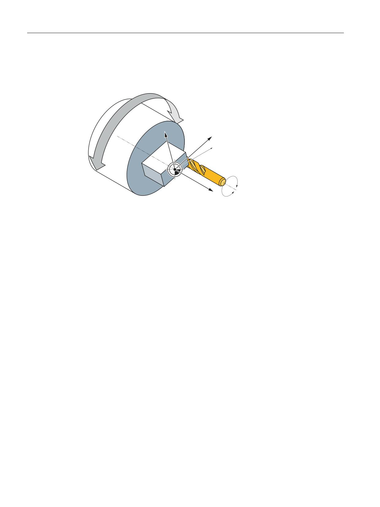
Face end transformation TRANSMIT
Note
The "TRANSMIT and peripheral surface transformation" option, which requires a license, is
needed for the function "End face transformation (TRANSMIT)".
This section describes how an end face transformation is mapped and parameterized in the
control system via system variables. The transformation and the machine kinematics can be
defined in two ways:
• Definition of TRANSMIT via kinematic chains. The machine kinematics are defined using two
kinematic chains, see Defining machine kinematics (Page 18). The system variables are
retentively saved in the NC and can be archived and/or read as "NC data" via SINUMERIK
Operate using the commissioning archive.
• Definition of TRANSMIT via machine data (Page 68)
The TRANSMIT transformation permits end face machining (drill holes, contours) on turning
machines.
Standard case:
• Rotary axis
• Infeed axis, perpendicular to rotary axis
• Longitudinal axis, parallel to rotary axis
• The linear axes are perpendicular to one another.
Transformations
Function Manual, 10/2020, 6FC5397-5GP40-0BA1
55
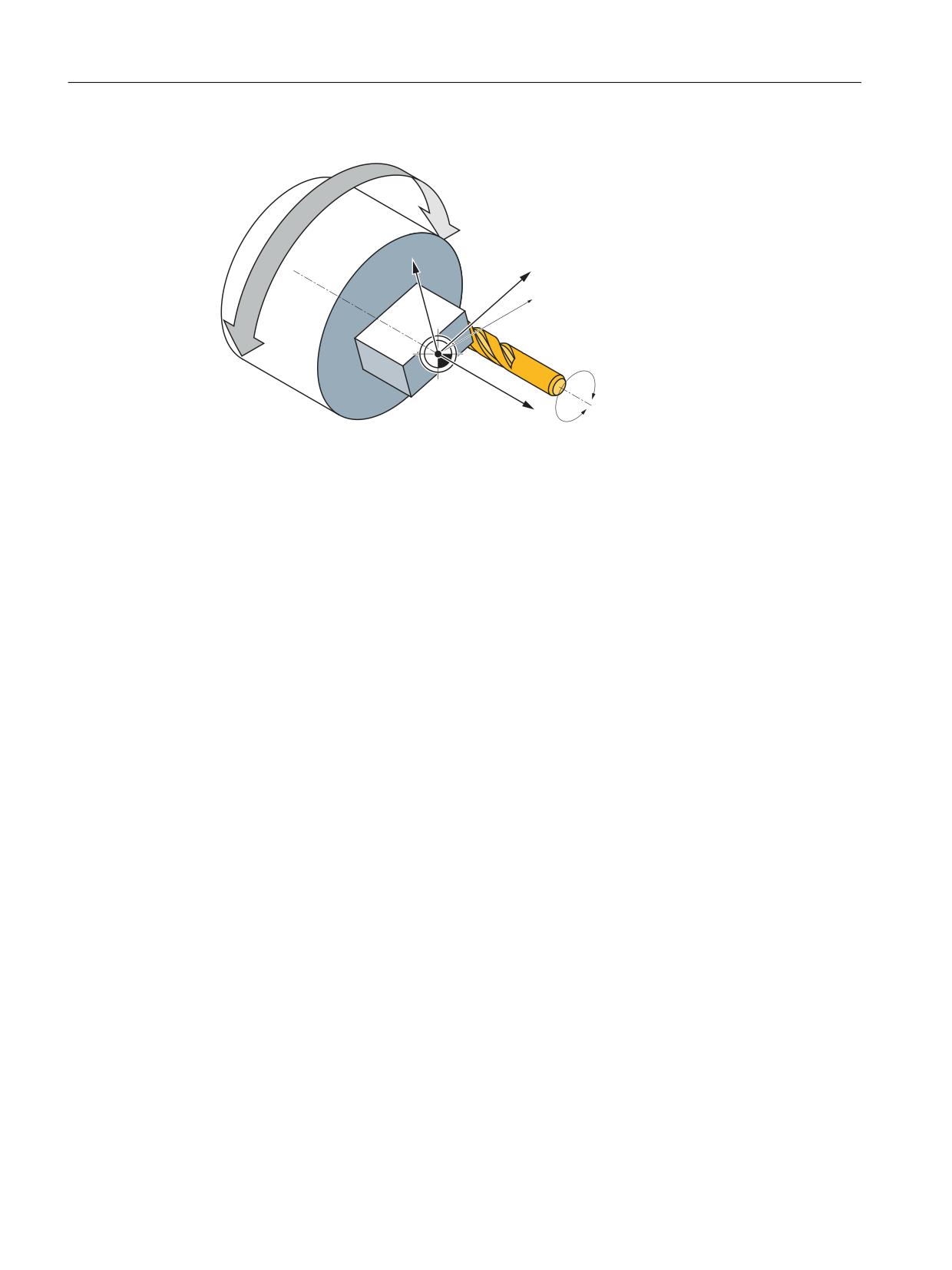
Kinematic transformations
5.1 End face transformation TRANSMIT_K (option)
&0
<
;
;0
$60
=
=0
X, Y, Z
Geometry axes
CM
Machine axis: Rotary axis
XM
Machine axis: Linear axis, perpendicular to rotary axis
ZM
Machine axis: Linear axis, parallel to rotary axis
ASM
Machine axis: Main spindle
See also
$NT_CNTRL (Page 47)
$NT_BASE_TOOL_COMP (Page 49)
$NT_ROT_OFFSET_FROM_FRAME (Page 40)
"Kinematic chain" part program for TRANSMIT (Page 77)
$NT_TRAFO_TYPE (Page 30)
Specific settings (Page 72)
5.1.1.2
Machining options
The TRANSMIT transformation has a pole at the zero point of the TRANSMIT plane. The pole is
at the intersection of the radial linear axis and the rotary axis. In the vicinity of the pole, small
positional changes in the geometry axes generally result in large changes in position in the
machine rotary axis. The only exceptions are linear motions into or through the pole.
A tool center point path through the pole does not cause the parts program to be aborted. There
are no restrictions with respect to programmable traversing commands or active tool radius
compensations. Nevertheless, workpiece processing operations close to the pole are not
recommended since these may require sharp feedrate reductions to prevent overloading of the
rotary axis.
Transformations
56
Function Manual, 10/2020, 6FC5397-5GP40-0BA1
Kinematic transformations
5.1 End face transformation TRANSMIT_K (option)
New features
A pole is said to exist if the line described by the tool center point intersects the center of rotation
of the rotary axis.
The following cases are covered:
• Under what conditions and by what methods the pole can be traversed
• The response in pole vicinity
• The response with respect to working area limitations
• Monitoring of rotary axis rotations over 360°.
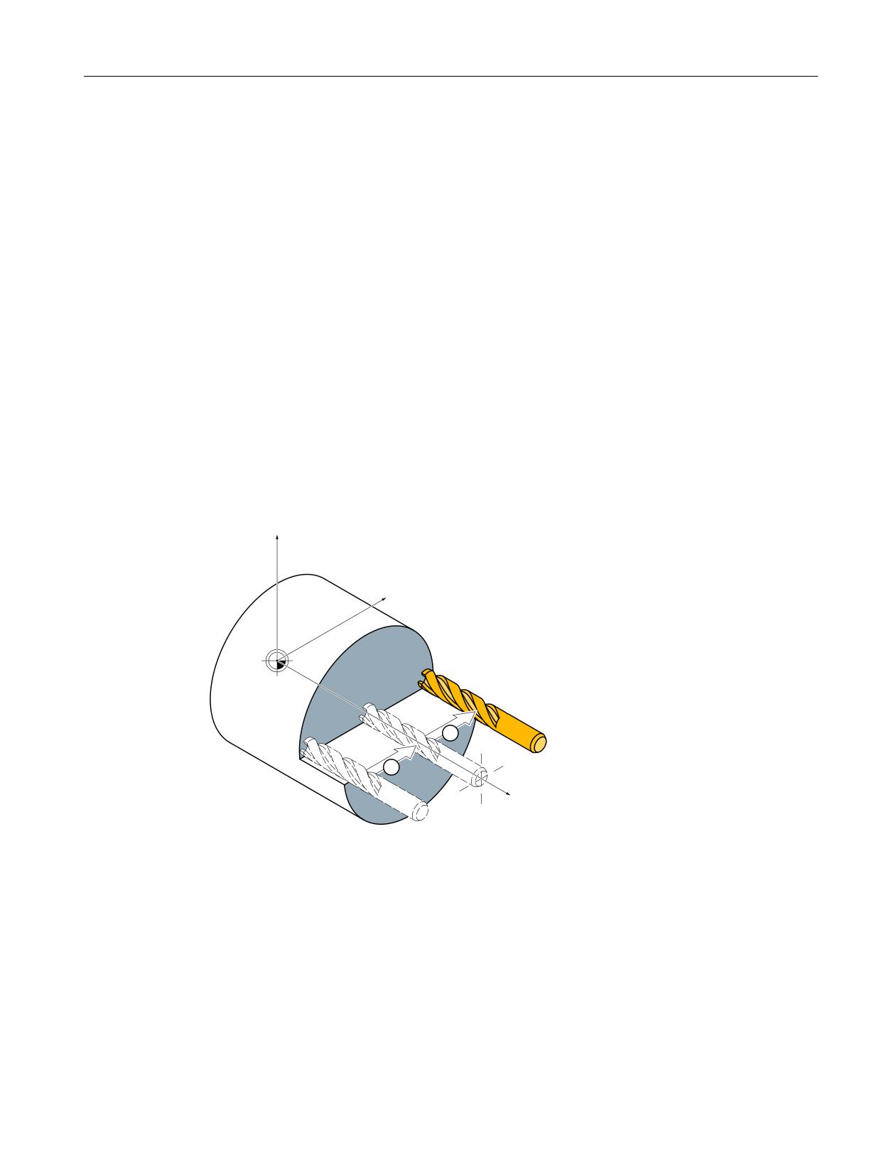
Pole crossing
The pole can be traversed by two methods:
• Traversal along linear axis
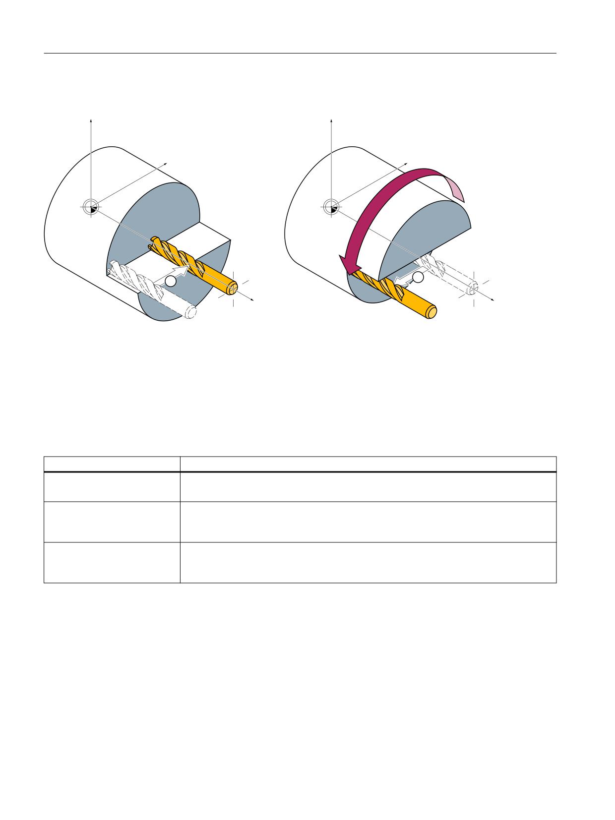
• Traversal into pole with rotation of rotary axis in pole
Traversal along linear axis
=
<
;
① Travel into the pole
② Travel out of the pole
Figure 5-1
Traversal of x axis through pole
Transformations
Function Manual, 10/2020, 6FC5397-5GP40-0BA1
57
Kinematic transformations
5.1 End face transformation TRANSMIT_K (option)
Rotation in pole
=
=
<
<
;
;
①
Travel into the pole
②
Travel out of the pole
Figure 5-2
Traversal of x axis into pole (a), rotation (b), exit from pole (c)
Behavior when passing through the pole
The behavior when passing through the pole is defined via the system variable
$NT_POLE_SIDE_FIX.
VALUE
Meaning
0
Pole crossing
The tool center point path (linear axis) must cross the pole on a continuous path.
1
Rotation around the pole.
The tool center point path must be restricted to a positive traversing range of the linear axis
(in front of center of rotation).
2
Rotation around the pole.
The tool center point path must be restricted to a negative traversing range of the linear axis.
(behind center of rotation).
In case of parameterization with machine data it is MD24911
$MC_TRANSMIT_POLE_SIDE_FIX_1 and MD24951 $MC_TRANSMIT_POLE_SIDE_FIX_2. The first
MD applies to the first TRANSMIT transformation in the channel and the second MD
correspondingly to the second TRANSMIT transformation.
Special features relating to pole traversal
The method of pole traversal along the linear axis may be applied in the AUTOMATIC and JOG
modes.
Transformations
58
Function Manual, 10/2020, 6FC5397-5GP40-0BA1

Kinematic transformations
5.1 End face transformation TRANSMIT_K (option)
Behavior:
Table 5-1
Traversal of pole along the linear axis
Mode
Status
Response
AUTOMATIC
All axes involved in the transforma-
High-speed pole traversal
tion are moved synchronously.
TRANSMIT active.
Not all of the axes participating in
Traversal of pole at creep speed
the transformation are moved syn-
chronously (e.g. positioning axis).
TRANSMIT not active.
An applied DRF (external work off-
Abortion of processing, alarm
set) does not interfere with the op-
eration. Servo errors may occur
close to the pole during application
of a DRF.
JOG
-
Traversal of pole at creep speed
Special features relating to rotation in pole
Precondition: This method is only effective in the AUTOMATIC mode.
$NT_POLE_SIDE_FIX = 1 or 2
Value: 1 Linear axis remains within positive traversing range
Value: 2 Linear axis remains within negative traversing range
In the case of a contour that would require the pole to be traversed along the tool center point
path, the following three steps are taken to prevent the linear axis from traversing in ranges
beyond the center of rotation:
Step
Action
1
Linear axis traverses into pole
2
Rotary axis turns through 180°, the other axes involved in the transformation
remain stationary.
3
Execution of remaining block. The linear axis now exits from the pole again.
In JOG mode, the motion stops in the pole. In this mode, the axis may exit from the pole only
along the path tangent on which it approached the pole. All other motion instructions would
require a step change in the rotary axis position or a large machine motion in the cases of
minimum motion instructions. They are rejected with alarm 21619.
For parameterization with machine data it is MD24911 $MC_TRANSMIT_POLE_SIDE_FIX_1 = 1
or 2 or
MD24951 $MC_TRANSMIT_POLE_SIDE_FIX_2 = 1 or 2.
Transformations
Function Manual, 10/2020, 6FC5397-5GP40-0BA1
59
Kinematic transformations
5.1 End face transformation TRANSMIT_K (option)
Traversal close to pole
If a tool center point traverses past the pole, the control system automatically reduces the
feedrate and path acceleration rate such that the settings of the machine axes (MD32000
$MA_MAX_AX_VELO[AX*] and MD32300 $MA_ MAX_AX_ACCEL[AX*]) are not exceeded. The
closer the path is to the pole, the greater the reduction in the feedrate.
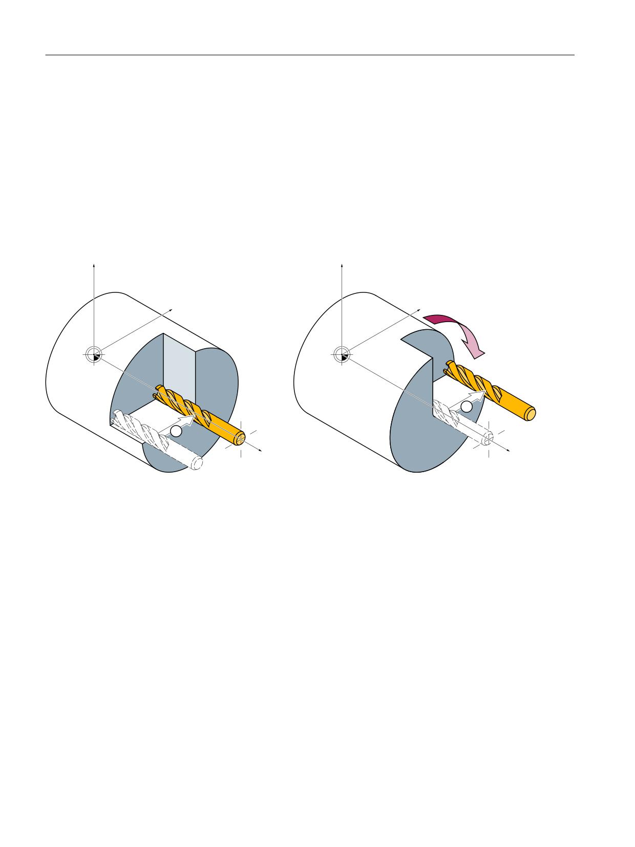
Tool center point path with corner in pole
A tool center point path which includes a corner in the pole will not only cause a step change in
axis velocities, but also a step change in the rotary axis position. These cannot be reduced by
decelerating.
=
=
<
<
;
;
①
Travel into the pole
②
Travel out of the pole
Figure 5-3
Pole traversal
Requirements:
AUTOMATIC mode,
$NT_POLE_SIDE_FIX = 0
The control system inserts a traversing block at the step change point. This block generates the
smallest possible rotation to allow processing of the contour to continue.
For parameterization with machine data it is MD24911 $MC_TRANSMIT_POLE_SIDE_FIX_1 = 0
or MD24951 $MC_TRANSMIT_POLE_SIDE_FIX_2 = 0.
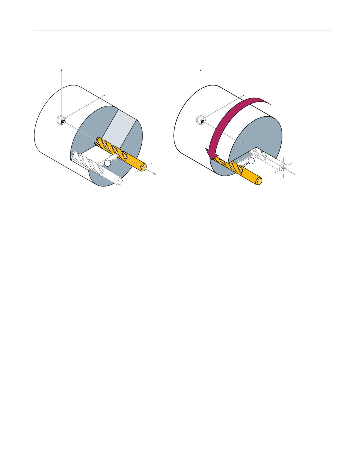
Transformations
60
Function Manual, 10/2020, 6FC5397-5GP40-0BA1
Kinematic transformations
5.1 End face transformation TRANSMIT_K (option)
Corner without pole traversal
=
=
<
<
;
;
①
Travel into the pole
②
Travel out of the pole
Figure 5-4
Processing on one pole side
Requirements:
AUTOMATIC mode,
$NT_POLE_SIDE_FIX = 1 or 2
The control system inserts a traversing block at the step change point. This block generates the
necessary rotation so that processing of the contour can continue on the same side of the pole.
For parameterization with machine data it is MD24911 $MC_TRANSMIT_POLE_SIDE_FIX_1 = 1
or 2 or MD24951 $MC_TRANSMIT_POLE_SIDE_FIX_2 = 1 or 2.
Transformations
Function Manual, 10/2020, 6FC5397-5GP40-0BA1
61
Kinematic transformations
5.1 End face transformation TRANSMIT_K (option)
Transformation selection in pole
If the processing operation must continue from a position on the tool center path which
corresponds to the pole of the activated transformation, then an exit from the pole is specified
for the new transformation.
• If $NT_POLE_SIDE_FIX = 0 is set (pole traversal), the smallest possible rotation is generated
at the beginning of the block leading out of the pole. Depending on this rotation, the axis
then traverses either in front of or behind the center of rotation.
For machine data parameterization MD24911 $MC_TRANSMIT_POLE_SIDE_FIX_1= 0 or
MD24951 $MC_TRANSMIT_POLE_SIDE_FIX_2= 0 applies
• If $NT_POLE_SIDE_FIX = 1, work is carried out before the center of rotation (linear axis in
positive travel range).
For machine data parameterization MD24911 $MC_TRANSMIT_POLE_SIDE_FIX_1= 1 or
MD24951 $MC_TRANSMIT_POLE_SIDE_FIX_2= 1 applies
• If $NT_POLE_SIDE_FIX = 2, work is carried out behind the center of rotation (linear axis in
negative travel range).
For machine data parameterization MD24911 $MC_TRANSMIT_POLE_SIDE_FIX_1= 2 or
MD24951 $MC_TRANSMIT_POLE_SIDE_FIX_2= 2 applies
Transformation selection outside pole
The controller traverses the axes participating in the transformation without evaluating the
machine data MD24911 $MC_TRANSMIT_POLE_SIDE_FIX_<t>. <t> = 1 marks the first TRANSMIT
transformation and <t> = 2 marks the second TRANSMIT transformation in the channel.
5.1.1.3
Working area limitations
Starting point
When TRANSMIT is active, the pole is replaced by a working area limitation if the tool center point
cannot be positioned at the turning center of the rotary axis involved in the transformation. This
is the case when the axis perpendicular to the rotary axis (allowing for tool offset) is not
positioned on the same radial plane as the rotary axis or if both axes are positioned mutually at
an oblique angle. The distance between the two axes defines a cylindrical space in the BCS in
which the tool cannot be positioned.
The illegal range cannot be protected by the software limit switch monitoring function since the
traversing range of the machine axes is not affected.
Transformations
62
Function Manual, 10/2020, 6FC5397-5GP40-0BA1
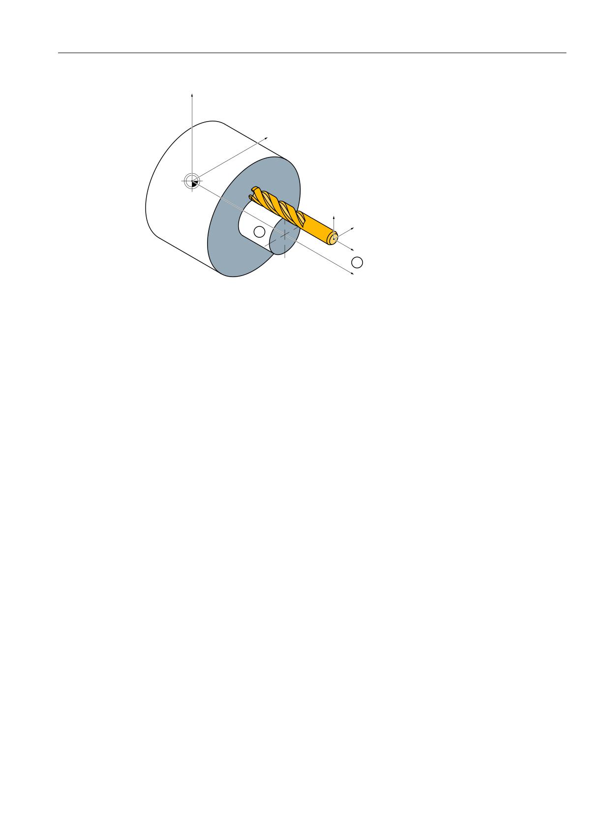
Kinematic transformations
5.1 End face transformation TRANSMIT_K (option)
=
<
=
<
;
;
① Unmachinable cylinder - working area limitation
② Axis distance
Figure 5-5
Working area limitation based on offset linear axis
Traverse into working area limitation
Any motion that leads into the working area limitation is rejected with alarm 21619. Any
corresponding parts program block is not processed. The control system stops processing at the
end of the preceding block.
If the motion cannot be foreseen promptly enough (JOG modes, positioning axes), then the
control stops at the edge of the working area limitation.
Response close to working area limitation
If a tool center point traverses past the prohibited range, the control system automatically
reduces the feedrate and path acceleration rate such that the settings in the machine axes
(MD32000 $MA_MAX_AX_VELO[AX*] and MD32300 $MA_ MAX_AX_ACCEL[AX*]) are not
exceeded. The closer the path is to the working area limitation, the greater the reduction in the
feedrate may be.
5.1.1.4
Overlaid motions with TRANSMIT
The control system cannot predict overlaid motions. However, these do not interfere with the
function provided that they are very small (e.g. fine tool offset) in relation to the current distance
from the pole (or from working area limitation). With respect to axes that are relevant for the
transformation, the transformation monitors the overlaid motion and signals any critical
quantity by alarm 21618. This alarm indicates that the block-related velocity planning function
no longer adequately corresponds to the actual conditions on the machine. When the alarm is
output, the conventional, non-optimized online velocity monitor is therefore activated. The
preprocessing routine is re-synchronized with the main run by a REORG generated internally in
the control.
Alarm 21618 should be avoided whenever possible since it indicates a state that can lead to axis
overload and thus abortion of parts program processing.
Transformations
Function Manual, 10/2020, 6FC5397-5GP40-0BA1
63
Kinematic transformations
5.1 End face transformation TRANSMIT_K (option)
5.1.1.5
Monitoring of rotary axis rotations over 360º
The positions of the rotary axis are ambiguous with respect to the number of rotations. The
control breaks down blocks containing several rotations around the pole into sub-blocks.
This subdivision must be noted with respect to parallel actions (e.g. output of auxiliary
functions, block-synchronized positioning axis motions) since the programmed block end is no
longer relevant for synchronization, but the end of the first sub-block.
Further information
Function Manual Basic Functions
Function Manual Synchronized Actions
In single block operation the control system machines individual blocks explicitly. Otherwise the
sub-blocks are traversed with Look Ahead just like a single block. A limitation of the rotary axis
setting range is monitored by the software limit switch monitoring function.
5.1.2
Parameterization of the kinematic chain and transformation
5.1.2.1
Parameterization of kinematics and transformation (TRANSMIT_K)
Setting a transformation type
For TRANSMIT with kinematic chains, the transformation type is set via the system
variable $NT_TRAFO_TYPE (Page 30):
$NT_TRAFO_TYPE[<n>] = TRANSMIT_K
For configuration via machine data, the type is set via the machine data $MC_TRAFO_TYPE_<n>
(Page 72).
Constraints for kinematic chains
• There must be exactly one rotary axis (the polar axis), with its name in
$NT_ROT_AX_NAME[n,1].
• One to three entries for linear axes are possible in the system parameters
$NT_GEO_AX_NAME[n,i].
Coordinate systems for end face transformations
The workpiece coordinate system and the basic coordinate system are independent of the world
coordinate system in which the kinematic chains are defined.
• The Z axis is parallel to the polar axis (axis CM - see above) and parallel to the longitudinal
axis, if it is defined.
• The geometry axes X, Y and Z are vertical to one another and form a perpendicular coordinate
system in the order 1st, 2nd and 3rd geometry axis.
• If the longitudinal axis ($NT_GEO_AX_NAME[n, 2]) exists, it must always be parallel to the
rotary axis ($NT_ROT_AX_NAME[n, 1]).
Transformations
64
Function Manual, 10/2020, 6FC5397-5GP40-0BA1

Kinematic transformations
5.1 End face transformation TRANSMIT_K (option)
• If there are two linear axes, they do not have to be orthogonal to one another.
• If there are three linear axes, two axes must be orthogonal to one another. A third axis can
be at an oblique angle to one of the other two axes. There can only be one axis pair in which
the angle of the two axes is not equal to 90°. An inclined axis cannot be positioned
perpendicularly on another axis.
Kinematic chains for end face transformations
Definition of the linear axes
• The X-axis is defined via the system variable $NT_GEO_AX_NAME[n,0]. This is the linear axis
of the actual TRANSMIT transformation. In the standard scenario, this axis is vertical on the
polar axis (see above).
• An entry in $NT_GEO_AX_NAME[n, 2] is optional. This axis (typically the Z-axis) is the
longitudinal axis. It must be defined parallel to the rotary axis ($NT_ROT_AX_NAME[n, 1]).
• An entry in $NT_GEO_AX_NAME[n, 1] is optional. This axis (typically the Y-axis) stands
vertically on the radial axis ($NT_GEO_AX_NAME[n, 0]) and the polar axis
($NT_ROT_AX_NAME[n, 1]) in the standard scenario.
This axis (the center offset axis) is generally used to compensate a tool offset in the Y direction
so that machining is possible up to the center of rotation.
Definition of a rotary axis
• The rotary axis is defined via the system variable $NT_ROT_AX_NAME[n,1]. This axis must
always be available. The direction of rotation of the rotary axis is defined via $NT_CNTRL Bit
11.
• An offset can be defined via system variable $NT_ROT_AX_OFFSET[n, 0] for the active
TRANSMIT transformation.
Defining the order of the axes
Various settings for the transformation are defined using system variable $NT_CNTRL[n]
(Page 47). With the bits 16-18, it is binary coded how the channel axes that are entered in
$NT_ROT_AX_NAME[n, 1], in $NT_GEO_AX_NAME[n. 0] and in $NT_GEO_AX_NAME[n. 2] are
assigned to the geometry axes. The three binary numbers must correspond to the following
decimal numbers:
Decimal
Order of the geometry axes
0
X
Y
Z
1
Z
X
Y
2
Y
Z
X
3
Z
Y
X
4
X
Z
Y
5
Y
X
Z
Transformations
Function Manual, 10/2020, 6FC5397-5GP40-0BA1
65
Kinematic transformations
5.1 End face transformation TRANSMIT_K (option)
Offset for the base tool
The system variable $NT_BASE_TOOL_COMP (Page 49) can be used to set whether an offset is
entered for the base tool in the transformation frame ($P_TRAFRAME) upon activation of the
transformation for each separate geometry axis. With the offset, the components of the base
tool are compensated in such as way that no change occurs in the component of the WCS. For
this function, $P_TRAFRAME must be configured via the machine data
$MC_MM_SYSTEM_FRAME_MASK bit 6.
The compensation can, for example, be used for a tool carrier, where the dimensions of the head
part of the tool carrier are not part of the tool length.
The separating point between the base tool and the tool can be defined via the system variable
$NT_T_REF_ELEM. If the system variable is blank, then the separating point is defined at the end
point of the tool chain.
Work offset of the rotary axis
In system variable $NT_ROT_OFFSET_FROM_FRAME (Page 40), you set whether the offset for
orientation axes is to be automatically applied. If a value is defined in the system variable, then
the programmed offset is automatically imported upon switch-on from the work offset that is
active for orientation axes:
Importing the rotary axis offset from the work offset upon selection of the transformation:
•
0 = Axial offset of the rotary axis is not taken into account.
•
1 = axial offset of the rotary axis is taken into account.
•
2 = Axial offset of the rotary axis is taken into account up to the SZS. SZS is the settable zero
system. The SZS frames contain transformed rotations around the rotary axis.
Definition of the last element in the kinematic chain
$NT_CNTRL Bit 19 is used to define that the last element of the kinematic chain is a rotary axis
or a constant rotation. The direction vector of the rotary axis defines the Z direction of the tool
coordinate system. If the system variable $NK_A_OFF of this chain element contains a value not
equal to zero, the tool coordinate system is also rotated about the coordinate axis with this
angle.
If $NT_CNTRL Bit 20 is also defined, the sign of the Z direction of the axis for the determination
of the WCS is inverted.
Example program for TRANSMIT
You will find a simple part program using TRANSMIT under "Kinematic chain" part program for
TRANSMIT (Page 77).
See also
$NT_TRAFO_INDEX (Page 28)
Transformations
66
Function Manual, 10/2020, 6FC5397-5GP40-0BA1

Kinematic transformations
5.1 End face transformation TRANSMIT_K (option)
5.1.2.2
Special system variables for TRANSMIT_K
System variables are available for defining the kinematic chain and the transformation. System
variables that are available for all kinematic transformations can be found at Commissioning
(Page 22).
Specific system variables are described below.
System variable
Meaning
$NT_POLE_SIDE_FIX
Limitation of the working area before and after the pole
Note
Establish a defined initial state
It is recommended that a defined initial state be generated before parameterizing the kinematic
chain. For this purpose, the system variables of the kinematic chain and the transformation with
the function DELOBJ() must be set to their default values.
Change system variable values
• Modified data (e.g. $NT_xxx or $NK_yyy) become effective after NEWCONF if the data does
not concern an active transformation (attention: persistent transformations or
transformations that remain active via reset/end of part program). If the data to be activated
with NEWCONF concern an active transformation, an alarm is output.
• Modified data (e.g. $NT_xxx or $NK_yyy) only become effective after a TRAFOOF and a
subsequent NC reset or NEWCONF or program end (M30).
• Changed data (e.g. $NT_xxx or $NK_yyy) become effective after NCK-PowerOn.
5.1.2.3
$NT_POLE_SIDE_FIX
Function
Using the system variable, the limitation of the work area must be set before and after the pole.
Syntax
$NT_POLE_SIDE_FIX[<n>] = <POLESIDEFIX>
Meaning
$NT_POLE_SIDE_FIX:
Names of the elements of the kinematic chain currently in effect, which
define the rotary axes
Data type:
INT
Default value:
""
Value range:
Element names of the currently active kinematic
chain
Transformations
Function Manual, 10/2020, 6FC5397-5GP40-0BA1
67

Kinematic transformations
5.1 End face transformation TRANSMIT_K (option)
<n>:
System variable or transformation index
Data type:
INT
Range of values:
1, 2, ... (MD18866 $MN_MM_NUM_KIN_TRAFOS - 1)
<PoleSIDEFIX>:
Limiting the work area:
•
0 = no limitation; traversing through the pole is allowed.
•
1 = work area of the linear axis for positions ≥ 0 (if tool length offset
is parallel to linear axis = 0).
•
2 = work area of the linear axis for positions ≤ 0 (if tool length offset
is parallel to linear axis = 0).
Data type:
STRING
Example
For the first transformation, the names of the elements of the kinematic chain currently in
effect, which define the rotary axes, are "ROT_AXIS_1", ROT_AXIS_2" and "ROT_AXIS_3".
Program code
Comment
; 1st transformation,
; elements of the rotary axes:
N100 $NT_ROT_AX_NAME[1,0] = "ROT_AXIS_1"
; 1st rotary axis
N110 $NT_ROT_AX_NAME[1,1] = "ROT_AXIS_2"
; 2nd rotary axis
N120 $NT_ROT_AX_NAME[1,2] = "ROT_AXIS_3"
; 3rd rotary axis
5.1.3
Parameterization with machine data (conventional)
5.1.3.1
Overview
Machine data: Transformation data in general
The following machine data is used to define transformation data sets in a channel:
• MD2xxxx $MC_TRAFO_TYPE_<n> (definition of the <n>th transformation in the channel)
• MD2xxxx $MC_TRAFO_AXES_IN_<n> (axis assignment for the <n>th transformation in the
channel)
• MD2xxxx $MC_TRAFO_GEOAX_ASSIGN_TAB_<n> (assignment of geometry axes to channel
axes for transformation <n>)
• MD2xxxx $MC_TRAFO_INCLUDES_TOOL_<n> (tool handling with active nth transformation)
where <n> = 1, 2, 3, ... max. number of transformation data sets
For TRANSMIT (type 256 or 257), no more than two transformation data sets may be
parameterized in a channel:
• MD2xxxx $MC_TRAFO_TYPE_<x> = <TRANSMIT type>
• MD2xxxx $MC_TRAFO_TYPE_<y> = <TRANSMIT type>
Transformations
68
Function Manual, 10/2020, 6FC5397-5GP40-0BA1
Kinematic transformations
5.1 End face transformation TRANSMIT_K (option)
Machine data: TRANSMIT transformation
A TRANSMIT transformation is parameterized using the following machine data:
• MD2xxxx $MC_TRANSMIT_ROT_AX_OFFSET_<n> (offset of the rotary axis)
• MD2xxxx $MC_TRANSMIT_ROT_AX_FRAME_<n> (rotary axis offset)
• MD2xxxx $MC_TRANSMIT_ROT_SIGN_IS_PLUS_<n> (sign of the rotary axis)
• MD2xxxx $MC_TRANSMIT_BASE_TOOL_<n> (vector of the base tool)
• MD2xxxx $MC_TRANSMIT_POLE_SIDE_FIX_<n> (restriction of the working area before/
behind the pole) with <n> = 1, 2 (TRANSMIT data record number)
Transformations
Function Manual, 10/2020, 6FC5397-5GP40-0BA1
69
Kinematic transformations
5.1 End face transformation TRANSMIT_K (option)
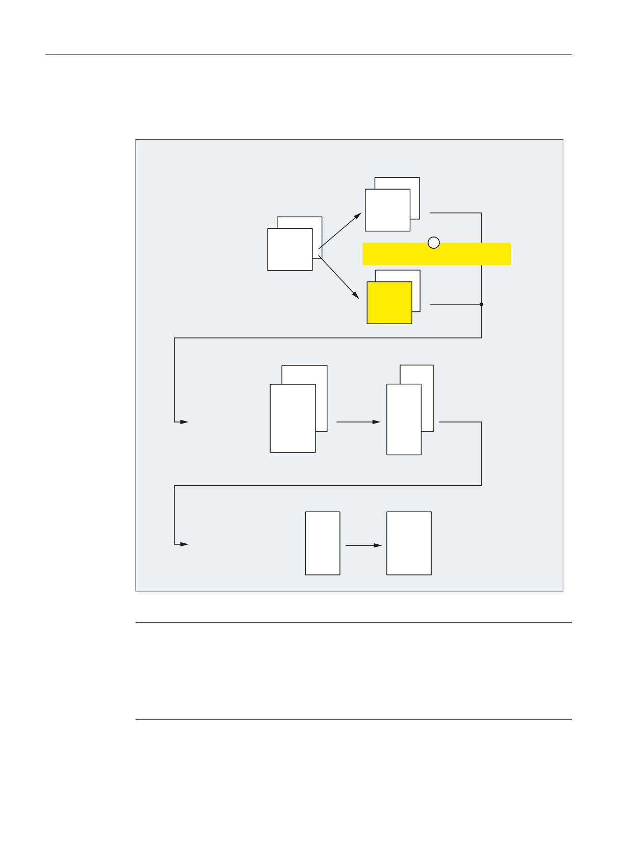
5.1.3.2
Axis configuration
The following shows an axis configuration that is typical of TRANSMIT.
0'
0&B$;&21)B*(2$;B$66,*1B7$%
&KDQQHO
0'
&KDQQHO
0&B $;&21)B*(2$;B1$0(B7$%
&KDQQHO
&KDQQHO
VW JHRPHWU\ D[LV > @
;
0'
QG JHRPHWU\ D[LV > @
<
0&B75$)2B*(2$;B$66,*1B7$%
UG JHRPHWU\ D[LV > @
=
&KDQQHO
&KDQQHO
0'
0'
0&B $;&21)B&+$1$;B1$0(B7$%
0&B$;&21)B0$&+$;B86('
&KDQQHO
&KDQQHO
&KDQQHO
&KDQQHO
VW FKDQQHO D[LV > @
;&
QG FKDQQHO D[LV > @
=&
UG FKDQQHO D[LV > @
&&
WK FKDQQHO D[LV > @
$6&
0'
0'
0$B63,1'B$66,*1B72B0$&+$;
0$B$;&21)B0$&+$;B1$0(B7$%
VW PDFKLQH D[LV >$; @
&0
QG PDFKLQH D[LV >$; @
;0
UG PDFKLQH D[LV >$; @
=0
WK PDFKLQH D[LV >$; @
$60
① Effective if TRANSMIT is active.
Note
For active transformation, the names of the machine, channel and geometry axes involved must
be different:
• MD10000 $MN_AXCONF_MACHAX_NAME_TAB (machine axis name)
• MD20080 $MC_AXCONF_CHANAX_NAME_TAB (channel axis name)
• MD20060 $MC_AXCONF_GEOAX_NAME_TAB (geometry axis name)
Transformations
70
Function Manual, 10/2020, 6FC5397-5GP40-0BA1
Kinematic transformations
5.1 End face transformation TRANSMIT_K (option)
Machine axis name
• MD10000 $MN_AXCONF_MACHAX_NAME_TAB[ 0 ] = "CM"
• MD10000 $MN_AXCONF_MACHAX_NAME_TAB[ 1 ] = "XM"
• MD10000 $MN_AXCONF_MACHAX_NAME_TAB[ 2 ] = "ZM"
• MD10000 $MN_AXCONF_MACHAX_NAME_TAB[ 3 ] = "ASM"
Geometry axis names
• MD20060 $MC_AXCONF_GEOAX_NAME_TAB[ 0 ] = "X" (name of the 1st geometry axis)
• MD20060 $MC_AXCONF_GEOAX_NAME_TAB[ 1 ] = "Y" (name of the 2nd geometry axis)
• MD20060 $MC_AXCONF_GEOAX_NAME_TAB[ 2 ] = "Z" (name of the 3rd geometry axis)
Channel axis names
• MD20080 $MC_AXCONF_CHANAX_NAME_TAB[ 0 ] = "XC"
• MD20080 $MC_AXCONF_CHANAX_NAME_TAB[ 1 ] = "ZC"
• MD20080 $MC_AXCONF_CHANAX_NAME_TAB[ 2 ] = "CC"
• MD20080 $MC_AXCONF_CHANAX_NAME_TAB[ 3 ] = "ASC"
Assignment of geometry axes to channel axes
TRANSMIT not active
• MD20050 $MC_AXCONF_GEOAX_ASSIGN_TAB[ 0 ] = 1 (1st GeoAxis → 1st channel axis XC)
• MD20050 $MC_AXCONF_GEOAX_ASSIGN_TAB[ 1 ] = 0 ( - )
• MD20050 $MC_AXCONF_GEOAX_ASSIGN_TAB[ 2 ] = 2 (3rd GeoAxis → 2nd channel axis ZC)
TRANSMIT active
• MD24120 $MC_TRAFO_GEOAX_ASSIGN_TAB_1[ 0 ] = 1 (1st TrafoGeoAxis → 1st channel axis
XC)
• MD24120 $MC_TRAFO_GEOAX_ASSIGN_TAB_1[ 1 ] = 3 (2nd TrafoGeoAxis → 3rd channel
axis CC)
• MD24120 $MC_TRAFO_GEOAX_ASSIGN_TAB_1[ 2 ] = 2 (3rd TrafoGeoAxis → 2nd channel
axis ZC)
Assignment of channel axes to machine axes
• MD20070 $MC_AXCONF_MACHAX_USED[ 0 ] = 2 (1st channel axis → 2nd machine axis XM)
• MD20070 $MC_AXCONF_MACHAX_USED[ 1 ] = 3 (2nd channel axis → 3rd machine axis ZM)
• MD20070 $MC_AXCONF_MACHAX_USED[ 2 ] = 1 (3rd channel axis → 1st machine axis CM)
• MD20070 $MC_AXCONF_MACHAX_USED[ 3 ] = 4 (4th channel axis → 4th machine axis ASM)
Identification of spindles
• MD35000 $MA_SPIND_ASSIGN_TO_MACHAX[ 0 ] = 1 (spindle)
• MD35000 $MA_SPIND_ASSIGN_TO_MACHAX[ 1 ] = 0 (axis)
Transformations
Function Manual, 10/2020, 6FC5397-5GP40-0BA1
71

Kinematic transformations
5.1 End face transformation TRANSMIT_K (option)
• MD35000 $MA_SPIND_ASSIGN_TO_MACHAX[ 2 ] = 0 (axis)
• MD35000 $MA_SPIND_ASSIGN_TO_MACHAX[ 3 ] = 2 (spindle)
5.1.3.3
Specific settings
One rotary and one linear axis: TRAFO_TYPE = 256
The transformation type 256 must be set for TRANSMIT with a rotary and a linear axis:
$MC_TRAFO_TYPE_<n> = 256
where <n> = 1, 2, ... max. number of transformations
Input axes of the transformation: $MC_TRAFO_AXES_IN_<n>
Those channel axes are specified in the machine data on which the axes of the transformation
Cartesian coordinate system are to be mapped:
$MC_TRAFO_AXES_IN_<n>[ <index> ] = <channel axis number>
where <n> = 1, 2, ... max. number of transformations
<Index>
Meaning
0
Linear axis, perpendicular to rotary axis
1
Rotary axis
2
Linear axis, parallel to rotary axis
The channel axis numbers must relate to the axis sequence defined with
$MC_TRAFO_GEOAX_ASSIGN_TAB_<n>.
One rotary and two linear axes: TRAFO_TYPE = 257
The transformation type 257 must be set for TRANSMIT with a rotary and two linear axes:
$MC_TRAFO_TYPE_<n> = 257
where <n> = 1, 2, ... max. number of transformations
The second linear axis must be oriented perpendicular to the plane clamped by the rotary and
the linear axis. The second linear axis for TRANSMIT is used exclusively for tool correction.
Input axes of the transformation: $MC_TRAFO_AXES_IN_<n>
Those channel axes are specified in the machine data on which the axes of the transformation
Cartesian coordinate system are to be mapped:
$MC_TRAFO_AXES_IN_<n>[ <index> ] = <channel axis number>
where <n> = 1, 2, ... max. number of transformations
<Index>
Meaning
0
Linear axis, perpendicular to rotary axis
1
Rotary axis
2
Linear axis, parallel to rotary axis
3
Linear axis perpendicular to the axes from index 0 and 1
Transformations
72
Function Manual, 10/2020, 6FC5397-5GP40-0BA1
Kinematic transformations
5.1 End face transformation TRANSMIT_K (option)
The channel axis numbers must relate to the axis sequence defined with
$MC_TRAFO_GEOAX_ASSIGN_TAB_<n>.
Rotary axis offset: TRANSMIT_ROT_AX_OFFSET
If the rotary axis zero point does not match the rotary axis zero position when the TRANSMIT
transformation is active, the angular difference must be entered as an offset in the machine data:
$MC_TRANSMIT_ROT_AX_OFFSET_<t> = <angular difference>
where <t> = 1, 2
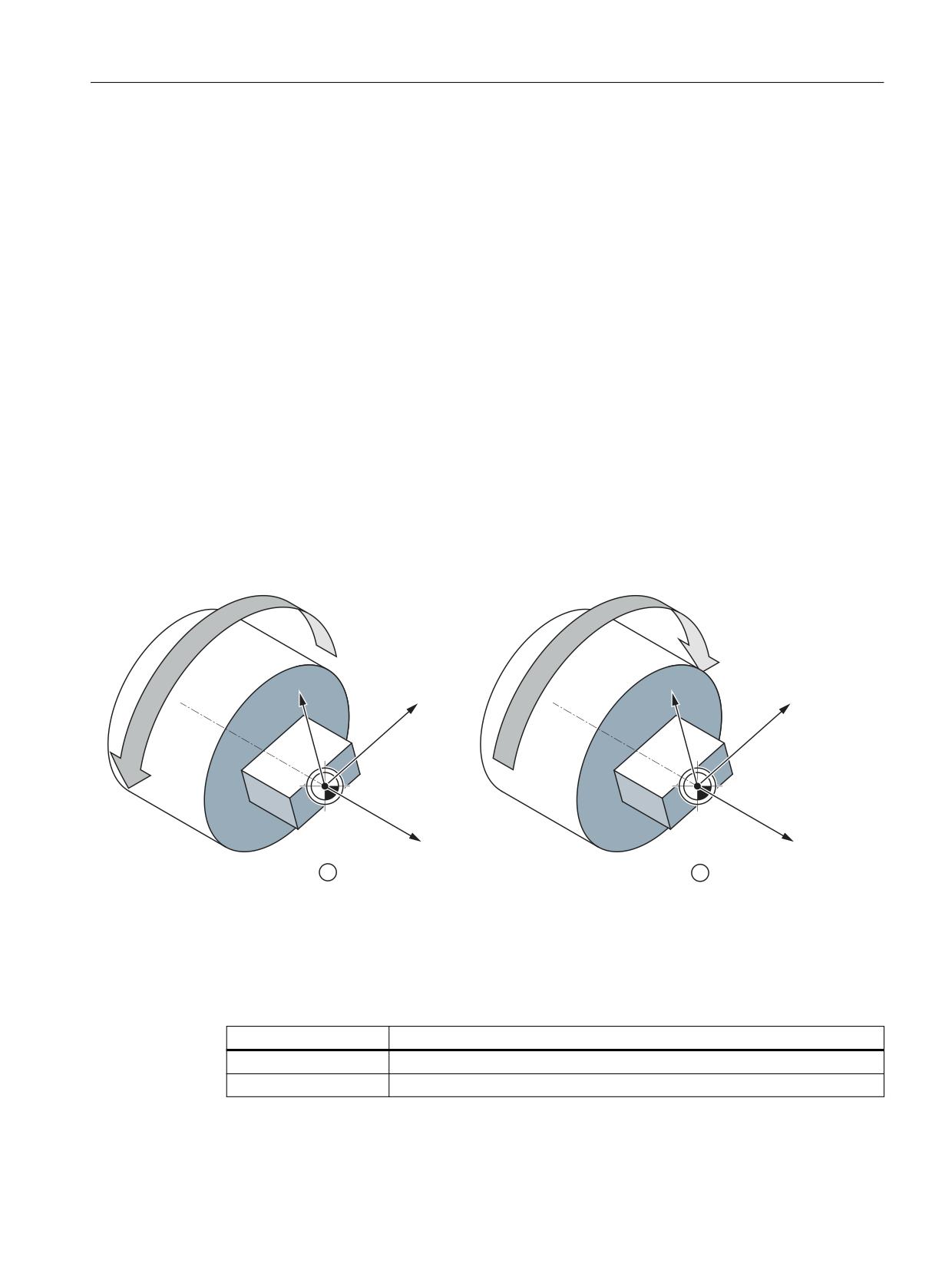
Direction of rotation: TRANSMIT_ROT_SIGN_IS_PLUS
TRANSMIT must be informed of the rotary axis direction of rotation with the following machine
data:
• The direction of rotation of the rotary axis is positive with regard to TRANSMIT if the rotary
axis rotates counterclockwise (in relation to the X/Y plane looking at the Z axis), when
traversing in the positive direction.
• The rotary axis direction of rotation with regard to TRANSMIT is negative if it rotates clockwise
when traversing in the positive direction
&0
&0
<
;
<
;
=
=
① Positive direction of rotation
② Negative direction of rotation
Figure 5-6
Rotary axis direction of rotation
$MC_TRANSMIT_ROT_SIGN_IS_PLUS_<t> = <direction of rotation>
where <t> = 1, 2
<Direction of rotation>
Meaning
0
Negative rotary axis direction of rotation ⇒ internal sign reversal
1
Positive rotary axis direction of rotation ⇒ no internal sign reversal
Transformations
Function Manual, 10/2020, 6FC5397-5GP40-0BA1
73
Kinematic transformations
5.1 End face transformation TRANSMIT_K (option)
Position of the tool zero: TRANSMIT_BASE_TOOL
The position of the tool zero is specified in relation to the origin of the effective Cartesian
coordinate system for TRANSMIT:
• MD24920 $MC_TRANSMIT_BASE_TOOL_<t>[ 0 ] = <Offset in X>
• MD24920 $MC_TRANSMIT_BASE_TOOL_<t>[ 1 ] = <Offset in Y>
• MD24920 $MC_TRANSMIT_BASE_TOOL_<t>[ 2 ] = <Offset in Z>
with <t> = 1, 2
Switchable geometry axes
When the GEOAX() geometry axes are switched, the parameterized M function is output to the
NC/PLC interface:
• MD22534 $MC_TRAFO_CHANGE_M_CODE = <M function>
Note
The values 0 to 6, 17 and 30 are not output.
Further information:
Function Manual Basic Functions; Coordinate systems, axis types, axis configurations,
workpiece-related actual-value system, external zero offset
5.1.4
Programming
5.1.4.1
Activating TRANSMIT with TRAFOON
The end face transformation (TRANSMIT) is activated in the part program or synchronized action
by means of the TRAFOON or TRANSMIT instructions. To be able to activate a transformation
parameterized with a kinematic chain with TRANSMIT, this must be parameterized in the system
variable $NT_TRAFO_INDEX (Page 28).
Additional information is provided at:
TRAFOON (Page 52)
TRANSMIT (Page 74)
The front face transformation (TRANSMIT) is activated in the part program or synchronized
action using the TRANSMIT statement.
Syntax
TRANSMIT
TRANSMIT(<n>)
Transformations
74
Function Manual, 10/2020, 6FC5397-5GP40-0BA1

Kinematic transformations
5.1 End face transformation TRANSMIT_K (option)
Meaning
TRANSMIT:
Activate TRANSMIT with the first TRANSMIT data set
TRANSMIT(n):
Activate TRANSMIT with the nth TRANSMIT data set
Note
A TRANSMIT transformation active in the channel is activated with:
• Deactivate transformation: TRAFOOF
• Activation of another transformation: E.g. TRACYL, TRAANG, TRAORI
5.1.5
Constraints
Look Ahead
All functions requiring Look Ahead (traversal through pole, Look Ahead) work satisfactorily only
if the relevant axis motions can be calculated exactly in advance. With TRANSMIT, this applies
to the rotary axis and the linear axis perpendicular to it. If one of these axes is the positioning
axis, then the Look Ahead function is deactivated by alarm 10912 and the conventional online
velocity check activated instead.
Selection of method
The user is responsible for making the optimum choice of "Traversal through pole" or "Rotation
around pole".
Several pole traversals
A block can traverse the pole any number of times (e.g. programming of a helix with several
turns). The part program block is subdivided into a corresponding number of sub-blocks.
Analogously, blocks which rotate several times around the pole are likewise divided into sub-
blocks.
Rotary axis as modulo axis
The rotary axis can be a modulo rotary axis. However, this is not a mandatory requirement as was
the case in SW 2 and 3. The relevant restrictions applying in SW 2 and 3 have been eliminated.
Rotary axis as spindle
If the rotary axis without transformation is used as a spindle, it must be switched to position-
controlled mode with SPOS before the transformation is selected.
Transformations
Function Manual, 10/2020, 6FC5397-5GP40-0BA1
75
Kinematic transformations
5.1 End face transformation TRANSMIT_K (option)
TRANSMIT with supplementary linear axis
With active TRANSMIT, the channel name of posBCS[ax[3]] must have another name in the part
program, like the geometry axes. If posBCS[ax[3]] is written only outside the TRANSMIT
transformation, this restriction does not apply if the axis has been assigned to a geometry axis.
With active TRANSMIT, no contour information is processed via ax[3].
REPOS
It is possible to reposition on the sub-blocks produced as a result of the extended TRANSMIT
function in SW 4. In this case, the control uses the first sub-block that is closest to the
repositioning point in the BCS.
Block search
In the case of block search with calculation, the block end point (of the last sub-block) is
approached in cases where intermediate blocks have been generated as the result of the
extended functionality in SW 4.
Transformations
76
Function Manual, 10/2020, 6FC5397-5GP40-0BA1
Kinematic transformations
5.1 End face transformation TRANSMIT_K (option)
5.1.6
Examples
5.1.6.1
"Kinematic chain" part program for TRANSMIT
Example program "5-axis transformation C-B"
Transformations
Function Manual, 10/2020, 6FC5397-5GP40-0BA1
77
Kinematic transformations
5.1 End face transformation TRANSMIT_K (option)
Program code
;===========================================================
; Simple example of TRANSMIT with kinematic chain:
;******************************************************
N10
DEF INT _KIE_CNTR
N20
DEF INT _TRA_CNTR
N30
R2 = DELOBJ("TRAFO_DATA")
N40
R2 = DELOBJ("KIN_CHAIN_ELEM")
N50
_KIE_CNTR
= 0
N60
_TRA_CNTR
= 1
; Definition of the kinematic chain
;******************************************************
N70
$NK_NAME[_KIE_CNTR]
= "ROOT"
N80
$NK_TYPE[_KIE_CNTR]
= "OFFSET"
N90
$NK_NEXT[_KIE_CNTR]
= "X-Axis"
N100
$NK_PARALLEL[_KIE_CNTR]
= "C-Axis"
N110
_KIE_CNTR = _KIE_CNTR + 1
N120
$NK_NAME[_KIE_CNTR]
= "X-Axis"
N130
$NK_TYPE[_KIE_CNTR]
= "AXIS_LIN"
N140
$NK_NEXT[_KIE_CNTR]
= "Z-Axis"
N150
$NK_AXIS[_KIE_CNTR]
= "X1"
N160
$NK_OFF_DIR[_KIE_CNTR,0]
= 1.0
N170
_KIE_CNTR = _KIE_CNTR + 1
N180
$NK_NAME[_KIE_CNTR]
= "Z-Axis"
N190
$NK_TYPE[_KIE_CNTR]
= "AXIS_LIN"
N200
$NK_NEXT[_KIE_CNTR]
= "Y-Axis"
N210
$NK_AXIS[_KIE_CNTR]
= "Z1"
N220
$NK_OFF_DIR[_KIE_CNTR,2]
= 1.0
N230
_KIE_CNTR = _KIE_CNTR + 1
N240
$NK_NAME[_KIE_CNTR]
= "Y-Axis"
N250
$NK_TYPE[_KIE_CNTR]
= "AXIS_LIN"
N260
$NK_NEXT[_KIE_CNTR]
= ""
N270
$NK_AXIS[_KIE_CNTR]
= "Y1"
N280
$NK_OFF_DIR[_KIE_CNTR,1]
= 1.0
N290
_KIE_CNTR = _KIE_CNTR + 1
N300
$NK_NAME[_KIE_CNTR]
= "C-Axis"
N310
$NK_TYPE[_KIE_CNTR]
= "AXIS_ROT"
N320
$NK_NEXT[_KIE_CNTR]
= ""
N330
$NK_AXIS[_KIE_CNTR]
= "C1"
N340
$NK_OFF_DIR[_KIE_CNTR,2]
= -1.0
N350
_KIE_CNTR = _KIE_CNTR + 1
; Definition of the kinematic transformation:
;******************************************************
; 1. TRANSMIT 256
;******************************************************
N360
$NT_NAME[_TRA_CNTR]
= "Trafo Transmit_1"
N370
$NT_TRAFO_TYPE[_TRA_CNTR]
= "TRANSMIT_K"
N380
$NT_P_CHAIN_LAST_ELEM[_TRA_CNTR]
= "C-Axis"
N390
$NT_T_CHAIN_LAST_ELEM[_TRA_CNTR]
= "Z-Axis"
N400
$NT_GEO_AX_NAME[_TRA_CNTR,0]
= "X-Axis"
N410
$NT_GEO_AX_NAME[_TRA_CNTR,1]
= ""
N420
$NT_GEO_AX_NAME[_TRA_CNTR,2]
= "Z-Axis"
N430
$NT_ROT_AX_NAME[_TRA_CNTR,0]
= ""
N440
$NT_ROT_AX_NAME[_TRA_CNTR,1]
= "C-Axis"
Transformations
78
Function Manual, 10/2020, 6FC5397-5GP40-0BA1
Kinematic transformations
5.1 End face transformation TRANSMIT_K (option)
Program code
N450
$NT_ROT_AX_NAME[_TRA_CNTR,2]
= ""
N460
$NT_ROT_OFFSET_FROM_FRAME[_TRA_CNTR] = 1
N470
$NT_CNTRL[_TRA_CNTR]
= 'H0'
N480
_TRA_CNTR = _TRA_CNTR + 1
; 2nd TRANSMIT 257
;******************************************************
N490
$NT_NAME[_TRA_CNTR]
= "Trafo Transmit_2"
N500
$NT_TRAFO_TYPE[_TRA_CNTR]
= "TRANSMIT_K"
N510
$NT_P_CHAIN_LAST_ELEM[_TRA_CNTR]
= "C-Axis"
N520
$NT_T_CHAIN_LAST_ELEM[_TRA_CNTR]
= "Y-Axis"
N530
$NT_GEO_AX_NAME[_TRA_CNTR,0]
= "X-Axis"
N540
$NT_GEO_AX_NAME[_TRA_CNTR,1]
= "Y-Axis"
N550
$NT_GEO_AX_NAME[_TRA_CNTR,2]
= "Z-Axis"
N560
$NT_ROT_AX_NAME[_TRA_CNTR,0]
= ""
N570
$NT_ROT_AX_NAME[_TRA_CNTR,1]
= "C-Axis"
N580
$NT_ROT_AX_NAME[_TRA_CNTR,2]
= ""
N590
$NT_ROT_OFFSET_FROM_FRAME[_TRA_CNTR] = 1
N600
$NT_CNTRL[_TRA_CNTR]
= 'H200'
; TRANSMIT 257
N610
_TRA_CNTR = _TRA_CNTR + 1
;******************************************************
; Activate kinematic chain and transformation:
;******************************************************
N620
NEWCONF
N630
STOPRE
;*************************************************************************
*************************
End
Transformations
Function Manual, 10/2020, 6FC5397-5GP40-0BA1
79
Kinematic transformations
5.1 End face transformation TRANSMIT_K (option)
5.1.6.2
Example with machine data parameterization
The example refers to the axis configuration shown in the following figure.
&0
<
;
;0
$60
=
=0
X, Y, Z
Geometry axes
CM
1st machine axis: Rotary axis
XM
2nd machine axis: Linear axis, perpendicular to rotary axis
ZM
3rd machine axis: Linear axis, parallel to rotary axis
ASM
4th machine axis: Main spindle
Parameter assignment
Machine axis name
• MD10000 $MN_AXCONF_MACHAX_NAME_TAB[ 0 ] = "CM" (1st machine axis: spindle/rotary
axis)
• MD10000 $MN_AXCONF_MACHAX_NAME_TAB[ 1 ] = "XM" (2nd machine axis: linear axis)
• MD10000 $MN_AXCONF_MACHAX_NAME_TAB[ 2 ] = "ZM" (3rd machine axis: linear axis)
• MD10000 $MN_AXCONF_MACHAX_NAME_TAB[ 3 ] = "ASM" (4th machine axis: spindle)
Geometry axis names
• MD20060 $MC_AXCONF_GEOAX_NAME_TAB[ 0 ] = "X" (name of the 1st geometry axis)
• MD20060 $MC_AXCONF_GEOAX_NAME_TAB[ 1 ] = "Y" (name of the 2nd geometry axis)
• MD20060 $MC_AXCONF_GEOAX_NAME_TAB[ 2 ] = "Z" (name of the 3rd geometry axis)
Channel axis names
• MD20080 $MC_AXCONF_CHANAX_NAME_TAB[ 0 ] = "XC" (linear axis)
• MD20080 $MC_AXCONF_CHANAX_NAME_TAB[ 1 ] = "ZC" (linear axis)
Transformations
80
Function Manual, 10/2020, 6FC5397-5GP40-0BA1
Kinematic transformations
5.1 End face transformation TRANSMIT_K (option)
• MD20080 $MC_AXCONF_CHANAX_NAME_TAB[ 2 ] = "CC" (spindle/rotary axis)
• MD20080 $MC_AXCONF_CHANAX_NAME_TAB[ 3 ] = "ASC" (spindle)
Assignment of geometry axes to channel axes
TRANSMIT not active:
• MD20050 $MC_AXCONF_GEOAX_ASSIGN_TAB[ 0 ] = 1 (1st geo. axis → 1st channel axis XC)
• MD20050 $MC_AXCONF_GEOAX_ASSIGN_TAB[ 1 ] = 0 ( - )
• MD20050 $MC_AXCONF_GEOAX_ASSIGN_TAB[ 2 ] = 2 (3rd geo. axis → 2nd channel axis ZC)
TRANSMIT active:
• MD24120 $MC_TRAFO_GEOAX_ASSIGN_TAB_1[ 0 ] = 1 (1st TrafoGeoAxis → 1st channel axis
XC)
• MD24120 $MC_TRAFO_GEOAX_ASSIGN_TAB_1[ 1 ] = 3 (2nd TrafoGeoAcxis → 3rd channel
axis CC)
• MD24120 $MC_TRAFO_GEOAX_ASSIGN_TAB_1[ 2 ] = 2 (3rd TrafoGeoAxis → 2nd channel
axis ZC)
Assignment of channel axes to machine axes
• MD20070 $MC_AXCONF_MACHAX_USED[ 0 ] = 2 (1st channel axis → 2nd machine axis XM)
• MD20070 $MC_AXCONF_MACHAX_USED[ 1 ] = 3 (2nd channel axis → 3rd machine axis ZM)
• MD20070 $MC_AXCONF_MACHAX_USED[ 2 ] = 1 (3rd channel axis → 1st machine axis CM)
• MD20070 $MC_AXCONF_MACHAX_USED[ 3 ] = 4 (4th channel axis → 4th machine axis ASM)
Identification of spindles
• MD35000 $MA_SPIND_ASSIGN_TO_MACHAX[ 0 ] = 1 (1st machine axis: spindle)
• MD35000 $MA_SPIND_ASSIGN_TO_MACHAX[ 1 ] = 0 (2nd machine axis: axis)
• MD35000 $MA_SPIND_ASSIGN_TO_MACHAX[ 2 ] = 0 (3rd machine axis: axis)
• MD35000 $MA_SPIND_ASSIGN_TO_MACHAX[ 3 ] = 2 (4th machine axis: spindle)
Transformation type
• MD24100 $MC_TRAFO_TYPE_1 = 256 (transformation TRANSMIT with a rotary or linear axis)
Offset relative to the zero position of the rotary axis
• MD24900 $MC_TRANSMIT_ROT_AX_OFFSET_1 = 0
Sign of rotary axis
• MD24910 $MC_TRANSMIT_ROT_SIGN_IS_PLUS_1 = 0
Basic offset of the tool zero relative to the geometry axes while TRANSMIT is active
• MD24920 $MC_TRANSMIT_BASE_TOOL_1 [ 0 ] = 0.0 (offset relative to 1st TrafoGeoAxis)
• MD24920 $MC_TRANSMIT_BASE_TOOL_1 [ 1 ] = 0.0 (offset relative to 2nd TrafoGeoAxis)
• MD24920 $MC_TRANSMIT_BASE_TOOL_1 [ 2 ] = 0.0 (offset relative to 3rd TrafoGeoAxis)
Transformations
Function Manual, 10/2020, 6FC5397-5GP40-0BA1
81
Kinematic transformations
5.1 End face transformation TRANSMIT_K (option)
TRANSMIT input axes
• MD24110 $MC_TRAFO_AXES_IN_1[ 0 ] = 1 (1st channel axis XC, perpendicular to the rotary
axis)
• MD24110 $MC_TRAFO_AXES_IN_1[ 1 ] = 3 (3rd channel axis CC, rotary axis)
• MD24110 $MC_TRAFO_AXES_IN_1[ 2 ] = 2 (2nd channel axis ZC, parallel to the rotary axis)
Modulo conversion for rotary axis
• MD30300 $MA_ROT_IS_MODULO[ 0 ] = 0 (1st machine axis: spindle/rotary axis)
• MD30300 $MA_ROT_IS_MODULO[ 1 ] = 0 (2nd machine axis: linear axis)
• MD30300 $MA_ROT_IS_MODULO[ 2 ] = 0 (3rd machine axis: linear axis)
• MD30300 $MA_ROT_IS_MODULO[ 3 ] = 1 (4th machine axis: spindle)
Programming example
Program code
Comment
N10 T1 D1 G54 G17 G90 F5000 G94
;
tool selection
;
1st Settable work offset
;
XY plane
;
absolute dimensions
;
linear feedrate F in mm/min
N20 G0 X20 Z10 SPOS=45
;
approach the start position
;
spindle positioning 45
N30 TRANSMIT
;
TRANSMIT with first
;
data record from MD24100 ON
N40 ROT RPL=-45
;
frame: Rotation in XY plane by Z
N50 ATRANS X-2 Y10
;
frame: Additive offset
N60 G1 X10 Y-10 G41 OFFN=1
;
square roughing; 1 mm tolerance (OFFN)
N70 X-10
N80 Y10
N90 X10
N100 Y-10
N110 G0 Z20 G40 OFFN=0
;
tool radius compensation OFF,
;
0 mm tolerance
N120 T2 D1 X15 Y-15
;
tool change
N130 Z10 G41
;
tool radius compensation left of contour
N140 G1 X10 Y-10
;
square part finishing
N150 X-10
N160 Y10
N170 X10
N180 Y-10
N190 Z20 G40
N200 TRANS
;
deselect frame
N210 TRAFOOF
;
TRANSMIT OFF
Transformations
82
Function Manual, 10/2020, 6FC5397-5GP40-0BA1
Kinematic transformations
5.2 Cylinder surface transformation TRACYL_K (option)
Program code
Comment
N220 G0 X20 Z10 SPOS=45
; approach the start position
N230 M30
5.2
Cylinder surface transformation TRACYL_K (option)
5.2.1
Cylinder surface transformation TRACYL
Note
The function "Cylinder surface transformation (TRACYL)" requires the option "TRANSMIT and
peripheral surface transformation", which is subject to license.
In this chapter, a description is provided as to how cylinder surface transformations (TRACYL) are
mapped using a kinematic chain and parameterized in the control system using system
variables.
• The machine kinematics are defined using two kinematic chains, see Specific settings
(Page 96). The system variables are retentively saved in the NC and can be archived and/or
read as "NC data" via SINUMERIK Operate using the commissioning archive.
• Definition of TRACYL via machine data (Page 92)
The TRACYL transformation permits the machining of cylinder surface curves (grooves) on
turning machines.
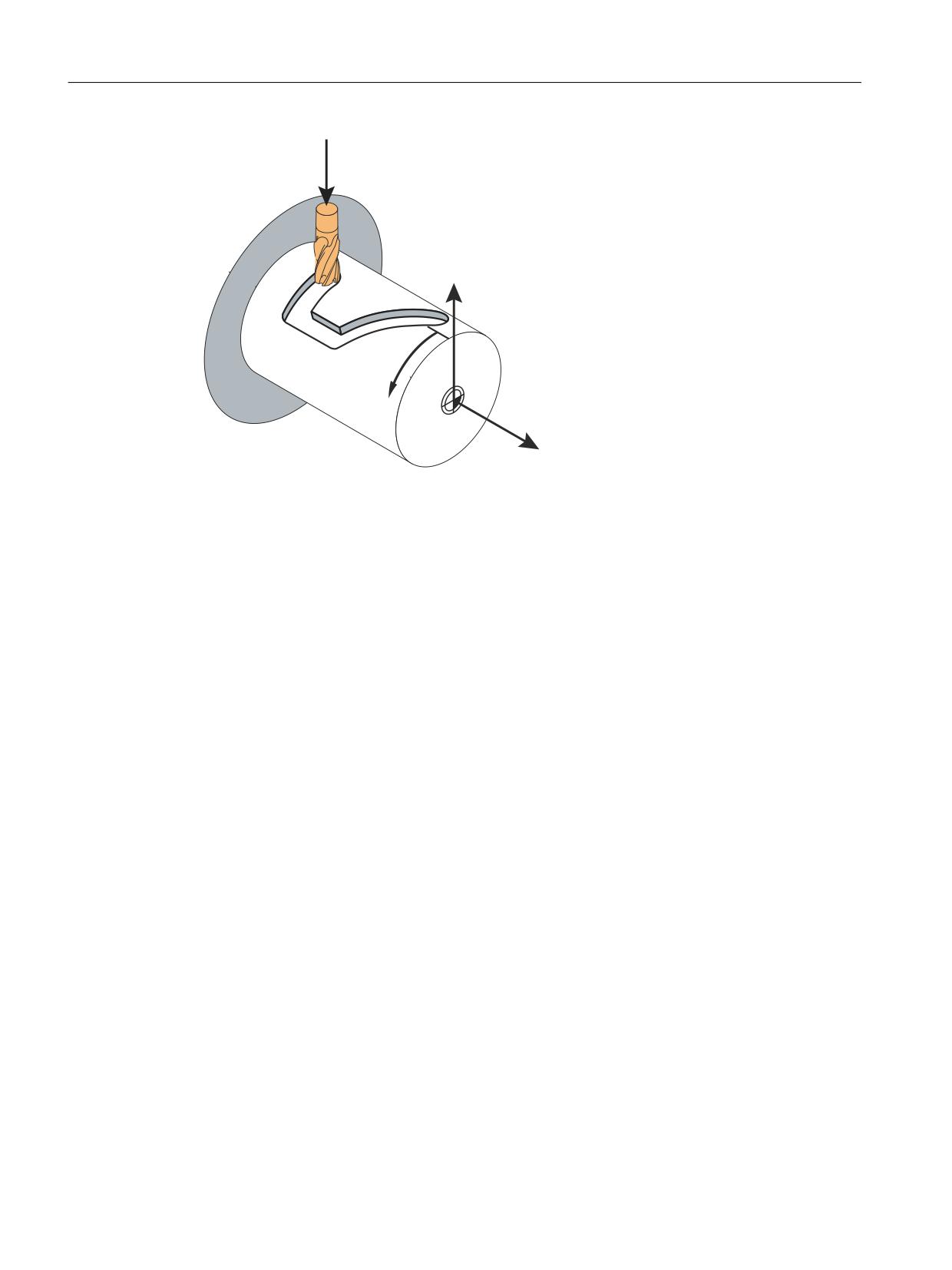
The path of the grooves is programmed with reference to the unwrapped, level surface of the
cylinder. The control system transforms the programmed traversing movements of the cylinder
coordinate system to the traversing movements of the real machine axes.
The following graphic shows an example of a cylinder surface transformation:
Transformations
Function Manual, 10/2020, 6FC5397-5GP40-0BA1
83
Kinematic transformations
5.2 Cylinder surface transformation TRACYL_K (option)
&
;
%
=
Figure 5-7
Cylinder surface transformation (TRACYL)
The machine kinematics must correspond to the cylinder coordinate system:
• One, two or three linear axes and one rotary axis
• The linear axes must be oriented perpendicular to each other
• The rotary axis must be oriented parallel to one of the linear axes
See also
$NT_ROT_OFFSET_FROM_FRAME (Page 40)
$NT_IDENT (Page 46)
Activating transformation (TRAFOON) (Page 52)
Defining machine kinematics (Page 18)
"Kinematic chain" part program for TRACYL (Page 108)
$NT_TRAFO_TYPE (Page 30)
5.2.2
Transformation types for TRACYL
Transformation types
The transformation type is set for TRACYL using kinematic chains via $NT_TRAFO_TYPE:
$NT_TRAFO_TYPE[n] = TRACYL_K
Transformations
84
Function Manual, 10/2020, 6FC5397-5GP40-0BA1

Kinematic transformations
5.2 Cylinder surface transformation TRACYL_K (option)
TRACYL is available in different variants:
• Without groove side offset
• With groove side offset
• Programmable with or without slit side offset
If parameterization is done via machine data, the transformation type is set via
$MC_TRAFO_TYPE_<n> = <Transformation type>, see Specific settings (Page 96).
Slot side offset
In connection with $NT_CNTRL bit 9 = 1, you can set whether TRACYL is operated with or without
slot side offset upon activation of the transformation via TRAFOON. "Slot side active"
corresponds to transformation type 514.
If you are working with slot side offset, $NT_GEO_AX_NAME[n,1] must contain a reference to a
linear axis (slot side offset axis).
The following settings via $NT_CNTRL are possible with bit 9 and bit 10:
Bit 10
Bit 9
Description
0
0
TRACYL without slot side offset
0
1
TRACYL with slot side offset
1
0
TRACYL with the capability of switching between the functions with and without slot side
offset via a transformation parameter upon activation of the transformation (TRAFOON). The
slot side offset is inactive by default.
1
1
TRACYL with the capability of switching between the functions with and without slot side
offset via a transformation parameter upon activation of the transformation (TRAFOON). The
slot side offset is active by default.
TRACYL without slot side offset
The cylinder surface transformation without groove side offset is used in machine kinematics
with one or two linear axes (axis configuration 1).
One linear axis
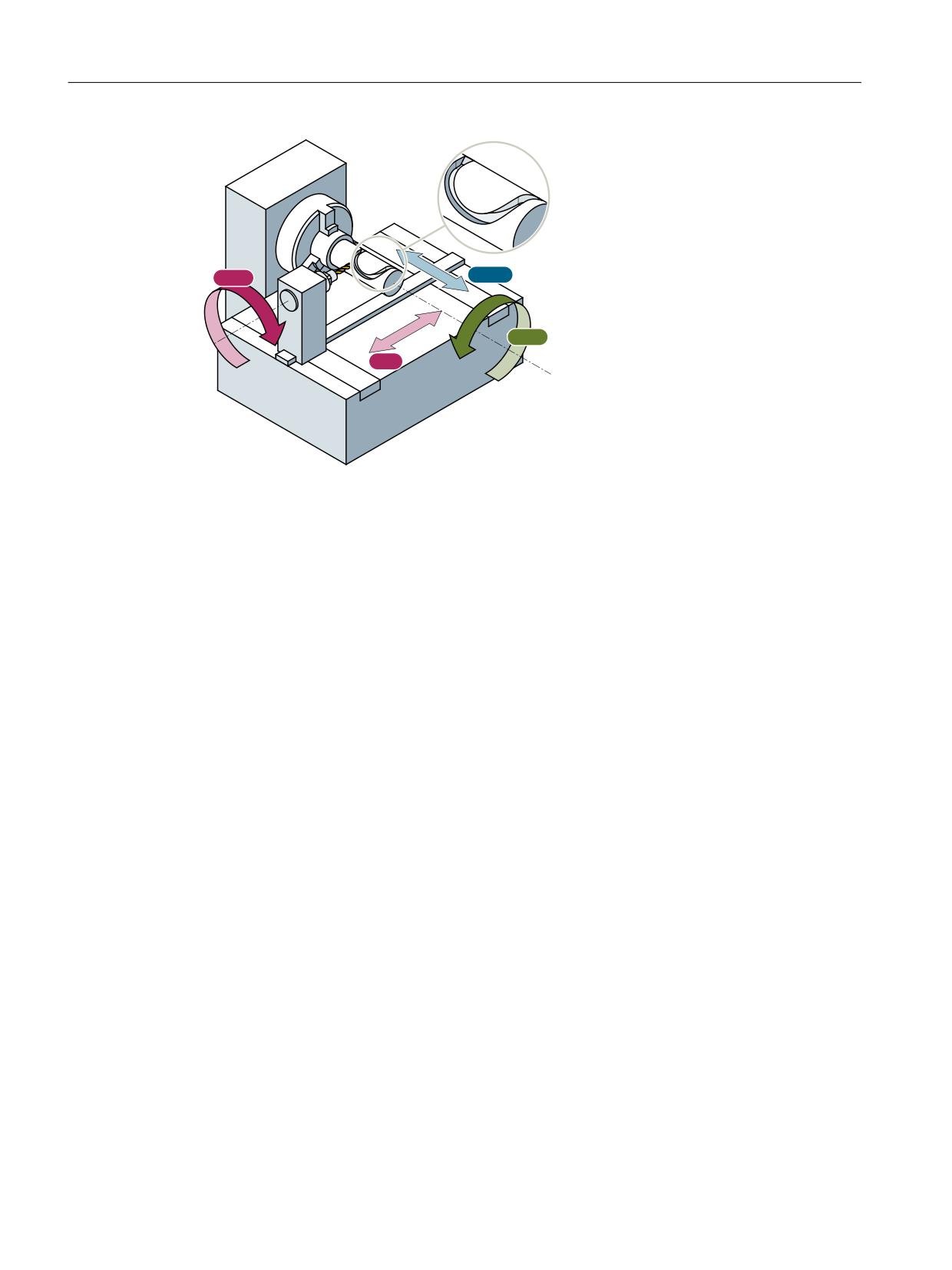
For a machine kinematic with only one linear axis (X), only grooves parallel to the periphery of
the cylinder can be generated (transverse grooves).
Two linear axes
For a machine kinematic with two linear axes (X and Z), grooves of any form can be generated
on the cylinder.
Transformations
Function Manual, 10/2020, 6FC5397-5GP40-0BA1
85
Kinematic transformations
5.2 Cylinder surface transformation TRACYL_K (option)
$60
= =0
< &0
;0
XM
Infeed axis perpendicular to the center of rotation
ZM
Linear axis parallel to the center of rotation
Y / CM
Transformatory Y axis / rotary axis
ASM
Main spindle
Figure 5-8
Machine kinematics with two linear axes
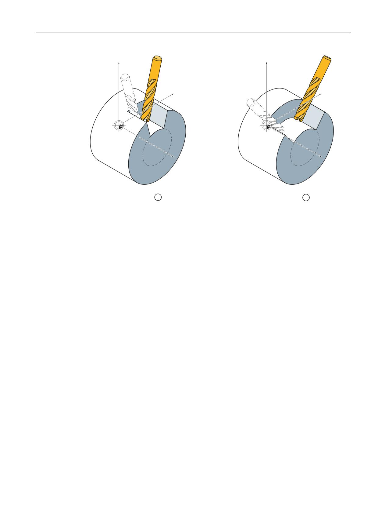
Groove edges
For a cylinder surface transformation without groove wall correction, the edges of the groove
longitudinal to the rotary axis (longitudinal grooves) are only parallel if the groove width
corresponds to the tool diameter. For groove widths greater than the tool diameter, the groove
edges are at an angle to each other (see ①).
The groove edges of grooves that extend parallel to the circumference (transverse grooves) are
not parallel to each other (see ②). Only the start and the end of the groove edges are not
parallel.
Transformations
86
Function Manual, 10/2020, 6FC5397-5GP40-0BA1
Kinematic transformations
5.2 Cylinder surface transformation TRACYL_K (option)
=
=
<
<
;
;
① Longitudinal groove
② Transverse groove
Figure 5-9
Groove edges with TRACYL without groove side offset
Transformations
Function Manual, 10/2020, 6FC5397-5GP40-0BA1
87
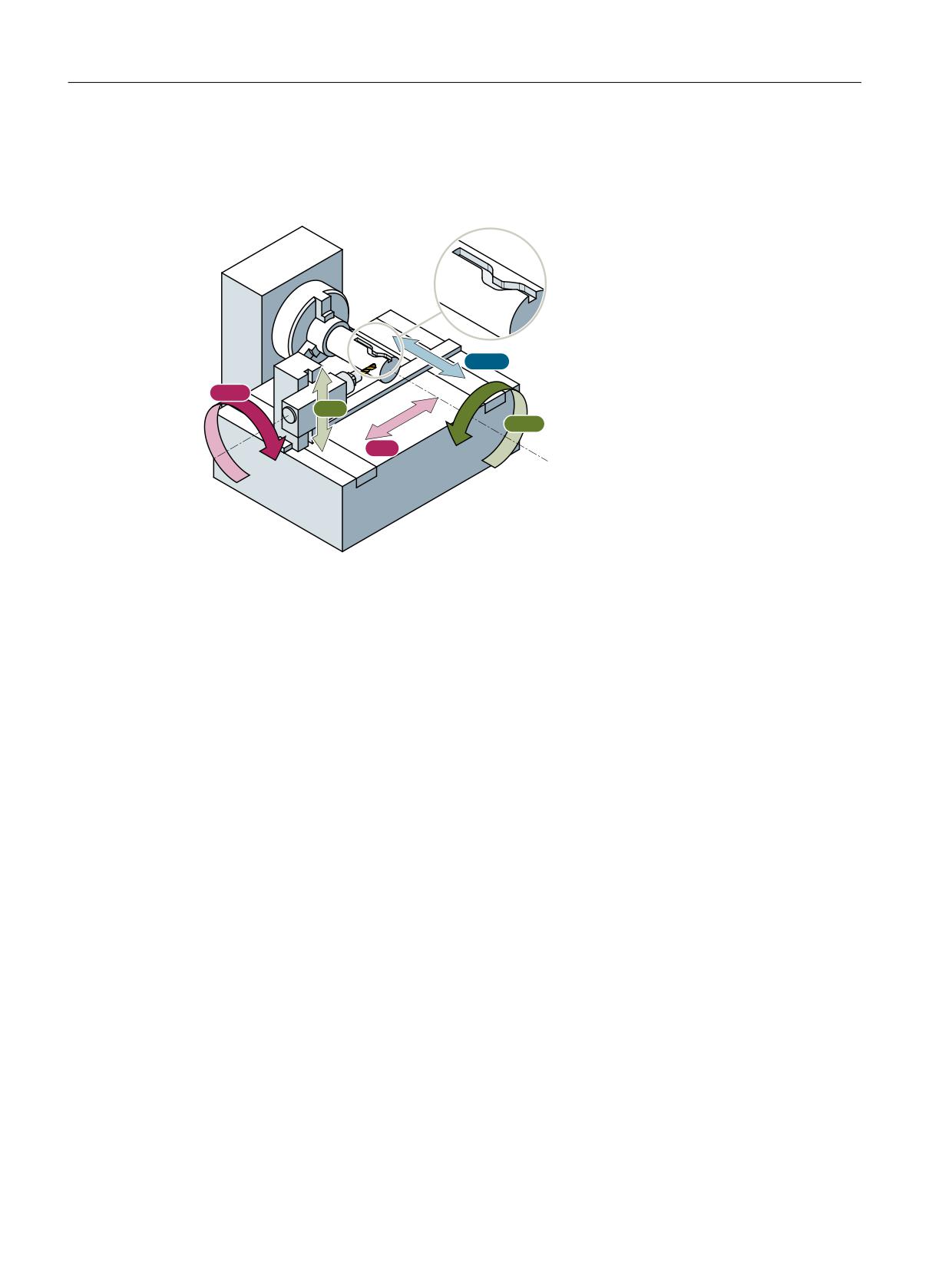
Kinematic transformations
5.2 Cylinder surface transformation TRACYL_K (option)
TRACYL with slot side offset
The cylinder surface transformation with groove wall offset is used for machine kinematics with
three linear axes (X, Y, and Z) (axis configuration 2).
= =0
$60
<0
< &0
;0
XM
Infeed axis perpendicular to the center of rotation
YM
Supplementary axis perpendicular to the X-Z plane
ZM
Linear axis parallel to the center of rotation
Y / CM
Transformatory Y axis / rotary axis
ASM
Main spindle
Figure 5-10
Machine kinematics with three linear axes
For a machine kinematic with three linear axes (X, Y and Z), grooves of any form can be
generated on the cylinder.
Groove edges
Because the Y axis is oriented perpendicular to the center of rotation, almost parallel groove
edges can be generated even for groove widths larger than the tool diameter.
Transformations
88
Function Manual, 10/2020, 6FC5397-5GP40-0BA1
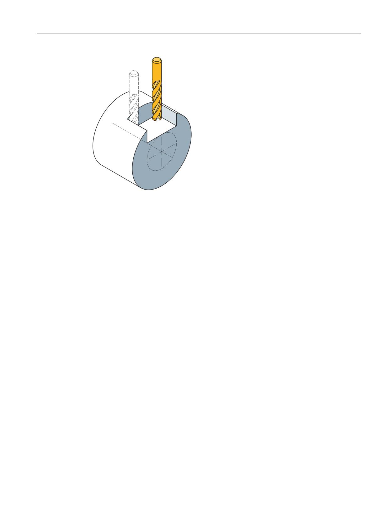
Kinematic transformations
5.2 Cylinder surface transformation TRACYL_K (option)
Figure 5-11
Parallel limited longitudinal groove with TRACYL with groove side offset
5.2.3
Parameterization of the kinematic chain and transformation
5.2.3.1
Parameterization of kinematics and transformation (TRACYL_K)
Setting a transformation type
The cylinder surface transformation with kinematic chains is set via the system
variable $NT_TRAFO_TYPE (Page 30).
$NT_TRAFO_TYPE[<n>] = "TRACYL_K"
For configuration via machine data, the type is set via the machine data $MC_TRAFO_TYPE_<n>
(Page 96).
Supplementary conditions
• There must be exactly one rotary axis (the polar axis), with its name in
$NT_ROT_AX_NAME[n,1].
• There can be 1 to 3 entries for linear axes in the system parameters $NT_GEO_AX_NAME[n,i].
Coordinate systems for cylinder surface transformations
The workpiece coordinate system and the basic coordinate system are independent of the world
coordinate system in which the kinematic chains are defined.
• The Z axis is parallel to the polar axis (axis B - see above) and parallel to the longitudinal axis,
if it is defined.
• The geometry axes X, Y and Z are vertical to one another and form a perpendicular coordinate
system in the order 1st, 2nd and 3rd geometry axis.
Transformations
Function Manual, 10/2020, 6FC5397-5GP40-0BA1
89

Kinematic transformations
5.2 Cylinder surface transformation TRACYL_K (option)
• If the longitudinal axis ($NT_GEO_AX_NAME[n, 2]) exists, it must always be parallel to the
rotary axis ($NT_ROT_AX_NAME[n, 1]).
• If there are two linear axes, they do not have to be orthogonal to one another.
• If there are three linear axes, two axes must be orthogonal to one another. A third axis can
be at an oblique angle to one of the other two axes. There can only be one axis pair in which
the angle of the two axes is not equal to 90°. An inclined axis cannot be positioned
perpendicularly on another axis.
Kinematic chains for cylinder surface transformations
Definition of the linear axes
• The X-axis is defined via the system variable $NT_GEO_AX_NAME[n,0]. This is the linear axis
of the actual TRACYL transformation. In the standard scenario, this axis is vertical on the
rotary axis (see above). The slot depth is set at this axis.
• An entry in $NT_GEO_AX_NAME[n, 1] is optional. This axis (typically the Y-axis) stands
vertically on the radial axis ($NT_GEO_AX_NAME[n, 0]) and the polar axis
($NT_ROT_AX_NAME[n, 1]) in the standard scenario.
This axis is the slot side offset axis. With this axis, the offset at the extent of the machining
cylinder is compensated when the tool radius compensation is active, so that the slot sides
remain perpendicular to the slot base.
• An entry in $NT_GEO_AX_NAME[n, 2] is optional. This axis (typically the Z-axis) is the
longitudinal axis. It must be defined parallel to the rotary axis ($NT_ROT_AX_NAME[n, 1]).
Definition of a rotary axis
• The rotary axis is defined via the system variable $NT_ROT_AX_NAME[n,1]. This axis must
always be available. The direction of rotation of the rotary axis is defined via $NT_CNTRL Bit
11.
• An offset can be defined via system variable $NT_ROT_AX_OFFSET[n, 0] for the active TRACYL
transformation.
Defining the order of the axes
Various settings for the transformation are defined using system variable $NT_CNTRL[n]
(Page 47). With the bits 16-18 it is binary coded how the channel axes that are entered in
$NT_ROT_AX_NAME[n, 1], $NT_GEO_AX_NAME[n. 0] and $NT_GEO_AX_NAME[n. 2] are
assigned to the geometry axes. The three binary numbers must correspond to the following
decimal numbers:
Decimal
Order of the geometry axes
0
X
Y
Z
1
Z
X
Y
2
Y
Z
X
3
Z
Y
X
4
X
Z
Y
5
Y
X
Z
Transformations
90
Function Manual, 10/2020, 6FC5397-5GP40-0BA1
Kinematic transformations
5.2 Cylinder surface transformation TRACYL_K (option)
Work offset of the rotary axis
Setting is done via the system variable $NT_ROT_OFFSET_FROM_FRAME (Page 40). If a value is
defined in the system variable, then the programmed offset is automatically imported upon
switch-on from the work offset that is active for orientation axes:
Importing the rotary axis offset from the work offset upon selection of the transformation:
•
0 = Axial offset of the rotary axis is not taken into account.
•
1 = axial offset of the rotary axis is taken into account.
•
2 = Axial offset of the rotary axis is taken into account up to the SZS. SZS is the settable zero
system. The SZS frames contain transformed rotations around the rotary axis.
Definition of the last element in the kinematic chain
$NT_CNTRL Bit 19 is used to define that the last element of the kinematic chain is a rotary axis
or a constant rotation. The direction vector of the rotary axis defines the Z direction of the tool
coordinate system. If the system variable $NK_A_OFF of this chain element contains a value not
equal to zero, the tool coordinate system is also rotated about the coordinate axis with this
angle.
If $NT_CNTRL Bit 20 is also defined, the sign of the Z direction of the axis for the determination
of the WCS is inverted.
Example program for TRACYL
You will find a simple part program using TRACYL under "Kinematic chain" part program for
TRACYL (Page 108).
See also
Activating transformation (TRAFOON) (Page 52)
$NT_TRAFO_INDEX (Page 28)
5.2.3.2
System variables for TRACYL_K
System variables are available for defining the kinematic chain and the transformation. System
variables that are available for all kinematic transformations can be found at Commissioning
(Page 22).
Transformations
Function Manual, 10/2020, 6FC5397-5GP40-0BA1
91
Kinematic transformations
5.2 Cylinder surface transformation TRACYL_K (option)
Note
Establish a defined initial state
It is recommended that a defined initial state be generated before parameterizing the kinematic
chain. For this purpose, the system variables of the kinematic chain and the transformation with
the function DELOBJ() must be set to their default values.
Change system variable values
• Modified data (e.g. $NT_xxx or $NK_yyy) become effective after NEWCONF if the data does
not concern an active transformation (attention: persistent transformations or
transformations that remain active via reset/end of part program). If the data to be activated
with NEWCONF concern an active transformation, an alarm is output.
• Modified data (e.g. $NT_xxx or $NK_yyy) only become effective after a TRAFOOF and a
subsequent NC reset or NEWCONF or program end (M30).
• Changed data (e.g. $NT_xxx or $NK_yyy) become effective after NCK-PowerOn.
5.2.4
Parameterization with machine data (conventional)
5.2.4.1
Overview
Machine data: Transformation data in general
The following machine data is used to define transformation data sets in a channel:
• MD2xxxx $MC_TRAFO_TYPE_<n> (definition of the <n>th transformation in the channel)
• MD2xxxx $MC_TRAFO_AXES_IN_<n> (axis assignment for the <n>th transformation in the
channel)
• MD2xxxx $MC_TRAFO_GEOAX_ASSIGN_TAB_<n> (assignment of geometry axes to channel
axes for transformation <n>)
• MD2xxxx $MC_TRAFO_INCLUDES_TOOL_<n> (tool handling with active <n>th
transformation)
where <n> = 1, 2, 3, ... max. number of transformation data sets
For TRACYL (type 512, 513, or 514), no more than two transformation data sets may be
parameterized in a channel:
• MD2xxxx $MC_TRAFO_TYPE_<x> = <TRACYL type>
• MD2xxxx $MC_TRAFO_TYPE_<y> = <TRACYL type>
Transformations
92
Function Manual, 10/2020, 6FC5397-5GP40-0BA1
Kinematic transformations
5.2 Cylinder surface transformation TRACYL_K (option)
Machine data: TRACYL transformation
A TRACYL transformation is parameterized in the following machine data:
• MD2xxxx $MC_TRACYL_ROT_AX_OFFSET_<n> (offset of the rotary axis)
• MD2xxxx $MC_TRACYL_ROT_AX_FRAME_<n> (rotary axis offset)
• MD2xxxx $MC_TRACYL_DEFAULT_MODE_<n> (selection of TRACYL mode)
• MD2xxxx $MC_TRACYL_ROT_SIGN_IS_PLUS_<n> (sign of the rotary axis)
• MD2xxxx $MC_TRACYL_BASE_TOOL_<n> (vector of the base tool)
where <n> = 1, 2 (TRACYL data set number)
Transformations
Function Manual, 10/2020, 6FC5397-5GP40-0BA1
93
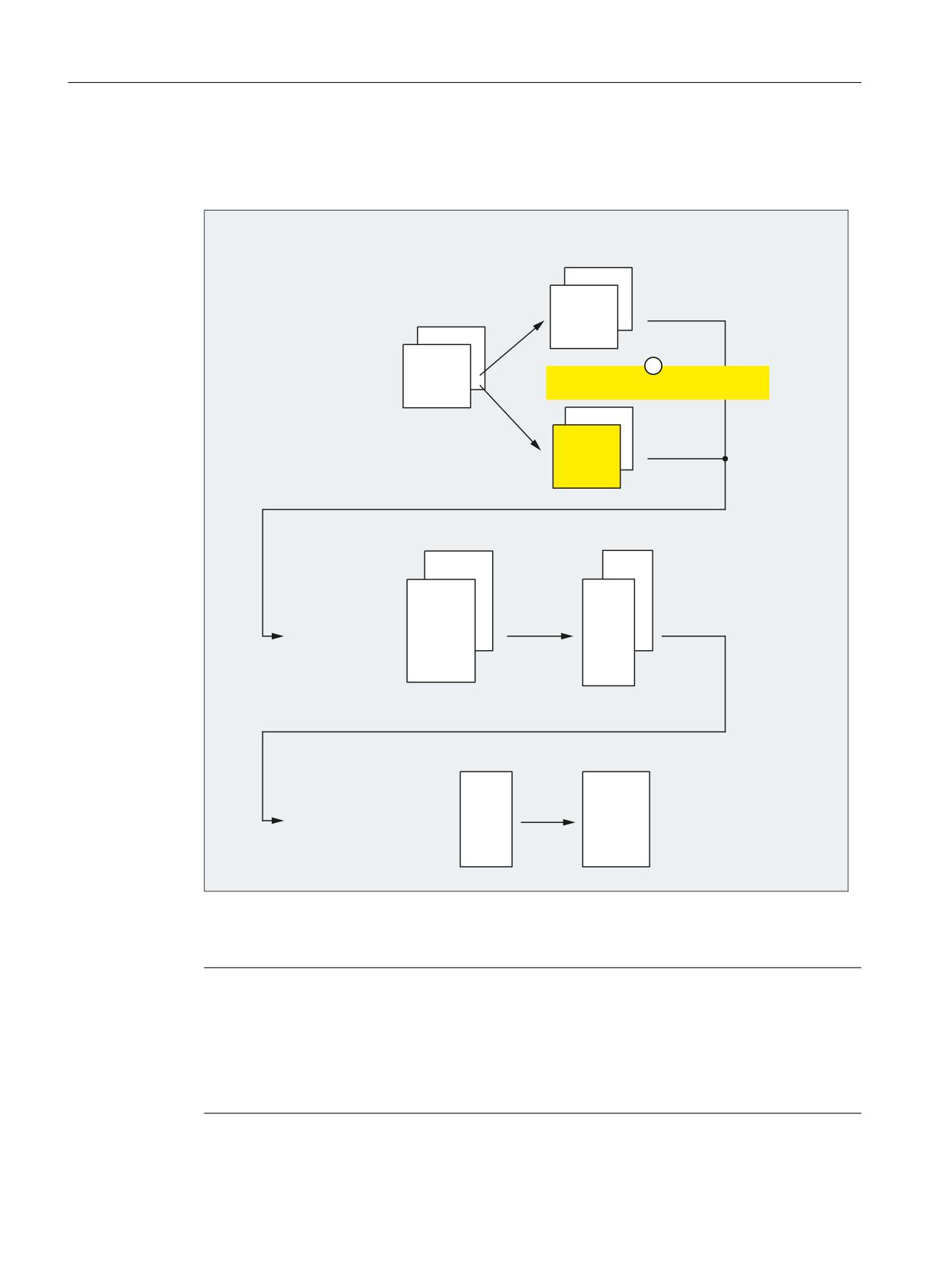
Kinematic transformations
5.2 Cylinder surface transformation TRACYL_K (option)
5.2.4.2
Axis configuration
The following shows an axis configuration that is typical of TRACYL.
0'
0&B$;&21)B*(2$;B$66,*1B7$%
&KDQQHO
0'
&KDQQHO
0&B $;&21)B*(2$;B1$0(B7$%
&KDQQHO
&KDQQHO
VW JHRPHWU\ D[LV > @
;
0'
QG JHRPHWU\ D[LV > @
<
0&B75$)2B*(2$;B$66,*1B7$%
UG JHRPHWU\ D[LV > @
=
&KDQQHO
&KDQQHO
0'
0'
0&B $;&21)B&+$1$;B1$0(B7$%
0&B$;&21)B0$&+$;B86('
&KDQQHO
&KDQQHO
&KDQQHO
&KDQQHO
VW FKDQQHO D[LV > @
;&
QG FKDQQHO D[LV > @
<&
UG FKDQQHO D[LV > @
=&
WK FKDQQHO D[LV > @
&&
WK FKDQQHO D[LV > @
$6&
0'
0'
0$B63,1'B$66,*1B72B0$&+$;
0$B$;&21)B0$&+$;B1$0(B7$%
VW PDFKLQH D[LV >$; @
&0
QG PDFKLQH D[LV >$; @
;0
UG PDFKLQH D[LV >$; @
<0
WK PDFKLQH D[LV >$; @
=0
WK PDFKLQH D[LV >$; @
$60
① Effective if TRACYL is active.
Note
For active transformation, the names of the machine, channel and geometry axes involved must
be different:
• MD10000 $MN_AXCONF_MACHAX_NAME_TAB (machine axis name)
• MD20080 $MC_AXCONF_CHANAX_NAME_TAB (channel axis name)
• MD20060 $MC_AXCONF_GEOAX_NAME_TAB (geometry axis name)
Transformations
94
Function Manual, 10/2020, 6FC5397-5GP40-0BA1
Kinematic transformations
5.2 Cylinder surface transformation TRACYL_K (option)
Machine axis name
• MD10000 $MN_AXCONF_MACHAX_NAME_TAB[ 0 ] = "CM"
• MD10000 $MN_AXCONF_MACHAX_NAME_TAB[ 1 ] = "XM"
• MD10000 $MN_AXCONF_MACHAX_NAME_TAB[ 2 ] = "YM"
• MD10000 $MN_AXCONF_MACHAX_NAME_TAB[ 3 ] = "ZM"
• MD10000 $MN_AXCONF_MACHAX_NAME_TAB[ 4 ] = "ASM"
Geometry axis names
• MD20060 $MC_AXCONF_GEOAX_NAME_TAB[ 0 ] = "X" (name of the 1st geometry axis)
• MD20060 $MC_AXCONF_GEOAX_NAME_TAB[ 1 ] = "Y" (name of the 2nd geometry axis)
• MD20060 $MC_AXCONF_GEOAX_NAME_TAB[ 2 ] = "Z" (name of the 3rd geometry axis)
Channel axis names
• MD20080 $MC_AXCONF_CHANAX_NAME_TAB[ 0 ] = "XC"
• MD20080 $MC_AXCONF_CHANAX_NAME_TAB[ 1 ] = "YC"
• MD20080 $MC_AXCONF_CHANAX_NAME_TAB[ 2 ] = "ZC"
• MD20080 $MC_AXCONF_CHANAX_NAME_TAB[ 3 ] = "CC"
• MD20080 $MC_AXCONF_CHANAX_NAME_TAB[ 4 ] = "ASC"
Assignment of geometry axes to channel axes
TRACYL not active:
• MD20050 $MC_AXCONF_GEOAX_ASSIGN_TAB[ 0 ] = 1 (1st GeoAxis → 1st channel axis XC)
• MD20050 $MC_AXCONF_GEOAX_ASSIGN_TAB[ 1 ] = 2 (2nd GeoAxis → 2nd channel axis YC)
• MD20050 $MC_AXCONF_GEOAX_ASSIGN_TAB[ 2 ] = 3 (3rd GeoAxis → 3rd channel axis ZC)
TRACYL active:
• MD24120 $MC_TRAFO_GEOAX_ASSIGN_TAB_1[ 0 ] = 1 (1st TrafoGeoAxis → 1st channel axis
XC)
• MD24120 $MC_TRAFO_GEOAX_ASSIGN_TAB_1[ 1 ] = 4 (2nd TrafoGeoAxis → 4th channel
axis CC)
• MD24120 $MC_TRAFO_GEOAX_ASSIGN_TAB_1[ 2 ] = 3 (3rd TrafoGeoAxis → 3rd channel
axis ZC)
Assignment of channel axes to machine axes
• MD20070 $MC_AXCONF_MACHAX_USED[ 0 ] = 2 (1st channel axis → 2nd machine axis XM)
• MD20070 $MC_AXCONF_MACHAX_USED[ 1 ] = 3 (2nd channel axis → 3rd machine axis YM)
• MD20070 $MC_AXCONF_MACHAX_USED[ 2 ] = 4 (3rd channel axis → 4th machine axis ZM)
• MD20070 $MC_AXCONF_MACHAX_USED[ 3 ] = 1 (4th channel axis → 1st machine axis CM)
• MD20070 $MC_AXCONF_MACHAX_USED[ 4 ] = 5 (5th channel axis → 5th machine axis ASM)
Transformations
Function Manual, 10/2020, 6FC5397-5GP40-0BA1
95

Kinematic transformations
5.2 Cylinder surface transformation TRACYL_K (option)
Identification of spindles
• MD35000 $MA_SPIND_ASSIGN_TO_MACHAX[ 0 ] = 1 (spindle)
• MD35000 $MA_SPIND_ASSIGN_TO_MACHAX[ 1 ] = 0 (axis)
• MD35000 $MA_SPIND_ASSIGN_TO_MACHAX[ 2 ] = 0 (axis)
• MD35000 $MA_SPIND_ASSIGN_TO_MACHAX[ 3 ] = 0 (axis)
• MD35000 $MA_SPIND_ASSIGN_TO_MACHAX[ 4 ] = 2 (spindle)
5.2.4.3
Specific settings
Setting the transformation type
The transformation type is set specifically for the transformation data set in:
$MC_TRAFO_TYPE_<n> = <transformation type>
with <n> = 1, 2, ... max. number of transformations
Axis configuration
<Transformation type>
1
512
2
513 or 514
The TRACYL transformation with programmed groove side offset (type 514) can be activated
with or without groove side offset (see "Programming (Page 101)").
Transformation type 514 without groove wall offset
If the machine has another linear axis which is perpendicular to both the rotary axis and the first
linear axis, transformation type 514 can be used to apply tool offsets with the real Y axis. In this
case, it is assumed that the working area of the second linear axis is small and will not be used
to execute the part program.
The previous settings apply for MD10000 $MC_TRAFO_GEOAX_ASSSIGN_TAB_<n>.
Slots with slot side offset
The required inclusion of the tool offset has already been taken into account for the TRACYL
transformation with groove side offset.
Axis image
The following paragraph describes how the transformation axis image is specified.
Transformations
96
Function Manual, 10/2020, 6FC5397-5GP40-0BA1
Kinematic transformations
5.2 Cylinder surface transformation TRACYL_K (option)
Transformation geometry axes
For the transformation dataset <n>, three (or four) channel axis numbers must be specified for
TRACYL:
• MD24110 $MC_TRAFO_AXES_IN_1[0]=channel axis number of the axis radial to the rotary
axis.
• MD24110 $MC_TRAFO_AXES_IN_1[1]=channel axis number of the rotary axis.
• MD24110 $MC_TRAFO_AXES_IN_1[2]=channel axis number of the axis parallel to the rotary
axis.
• MD24110 $MC_TRAFO_AXES_IN_1[3]=channel axis number of the supplementary axis
parallel to the cylinder surface and perpendicular to the rotary axis (provided axis
configuration 2 is present).
The axis numbers must refer to the channel axis sequences defined by the following machine
data:
MD24120 $MC_TRAFO_GEOAX_ASSIGN_TAB_<n>
Slots without slot side offset
For transformation type 514 the following indices apply to MD24110
$MC_TRAFO_AXES_IN_<n>[ ].
Meaning of indices in relation to base coordinate system (BCS):
•
[0]: Cartesian axis radial to rotary axis (if configured)
•
[1]: Axis in generated cylinder surface perpendicular to rotary axis
•
[2]: Cartesian axis parallel to rotary axis
•
[3]: Linear axis parallel to index 2 in initial position of machine
Meaning of indices in relation to machine coordinate system (MCS):
•
[0]: Linear axis radial to rotary axis (if configured)
•
[1]: Rotary axis
•
[2]: Linear axis, parallel to rotary axis
•
[3]: Linear axis, perpendicular to the axes of indices [0] and [1]
Transformations
Function Manual, 10/2020, 6FC5397-5GP40-0BA1
97
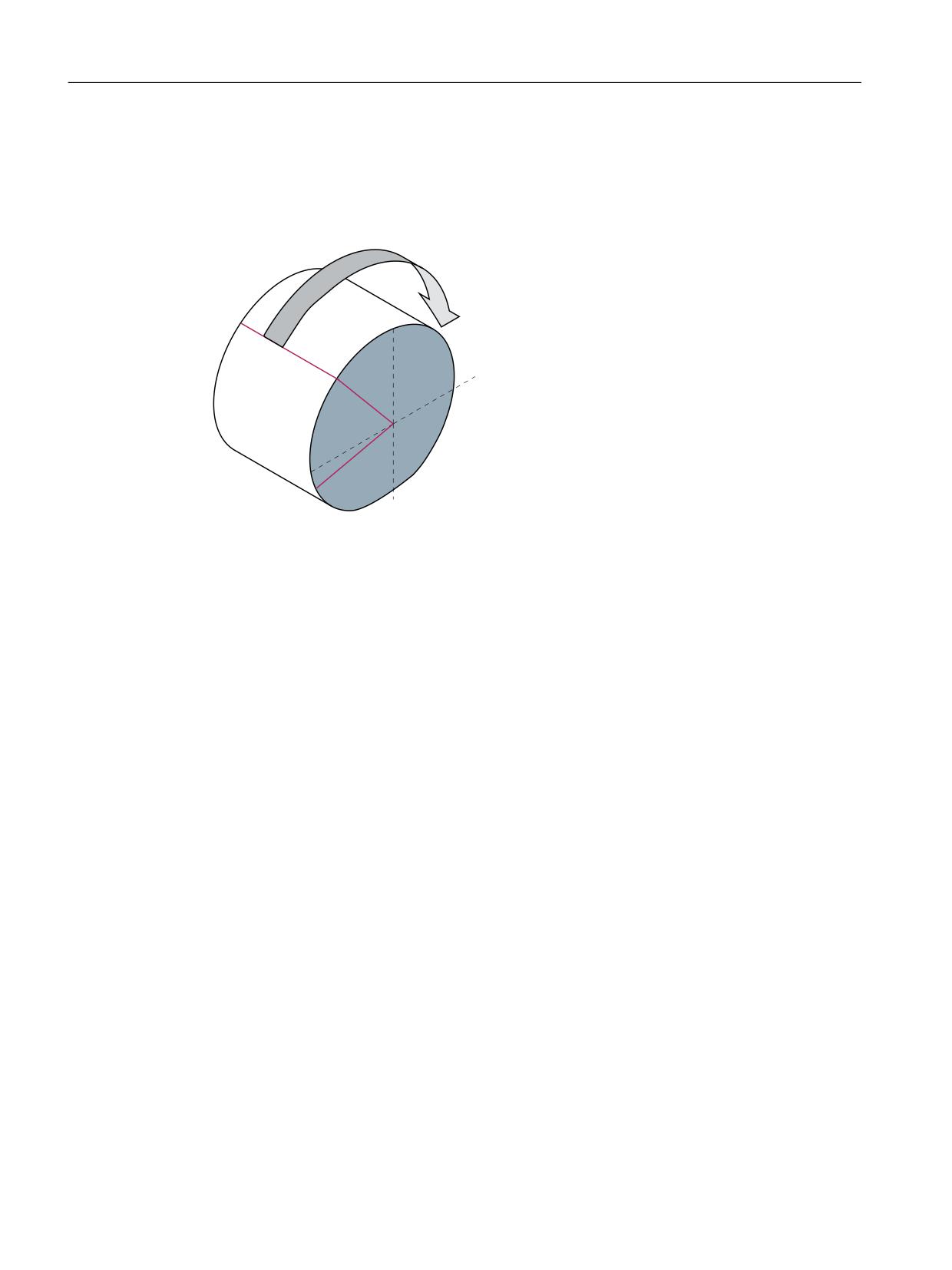
Kinematic transformations
5.2 Cylinder surface transformation TRACYL_K (option)
Rotational position
The rotational position of the axis on the cylinder peripheral surface perpendicular to the rotary
axis must be defined as follows:
<
˟
˞
˟ >r@
˞
α
Rotational position of the rotary axis for C=0
β
Position of Y = 0
Figure 5-12
Center of axis rotation in the peripheral cylinder surface
MD24800 TRACYL_ROT_AX_OFFSET_<t>
The rotational position of the peripheral surface in relation to the defined zero position of the
rotary axis is specified with:
MD24800 $MC_TRACYL_ROT_AX_OFFSET_<t> = ...°
During this, <t> is replaced by the number of TRACYL transformations (<t> can be a maximum
of 2) agreed upon in the transformation datasets.
Direction of rotation
The direction of rotation of the rotary axis is specified by machine data as described in the
following paragraph.
Transformations
98
Function Manual, 10/2020, 6FC5397-5GP40-0BA1
Kinematic transformations
5.2 Cylinder surface transformation TRACYL_K (option)
TRACYL_ROT_SIGN_IS_PLUS_<t>
If the direction of rotation of the rotary axis on the x-y plane is counterclockwise when viewed
against the z axis, then the machine data must be set to TRUE, otherwise to FALSE.
\
758(
[
MD24810 $MC_TRACYL_ROT_SIGN_IS_PLUS_<t>=TRUE
In this case, "t" is substituted by the number of TRACYL transformations declared in the
transformation data blocks (t may not be greater than 2).
Switchable geometry axes
The PLC is informed when a geometry axis has been replaced using GEOAX( ) through the
optional output of an M code that can be set in machine data.
• MD22534 $MC_TRAFO_CHANGE_M_CODE
Number of the M code that is output at the VDI interface in the case of transformation
changeover.
Note
If this machine data is set to one of the values 0 to 6, 17, 30, then no M code is output.
Further information
Function Manual Basic Functions; Coordinate systems, axis types, axis configurations,
workpiece-related actual-value system, external zero offset
Position of tool zero
The position of the tool zero point in relation to the origin of the Cartesian coordinate system is
specified by machine data as described in the following paragraph.
Transformations
Function Manual, 10/2020, 6FC5397-5GP40-0BA1
99
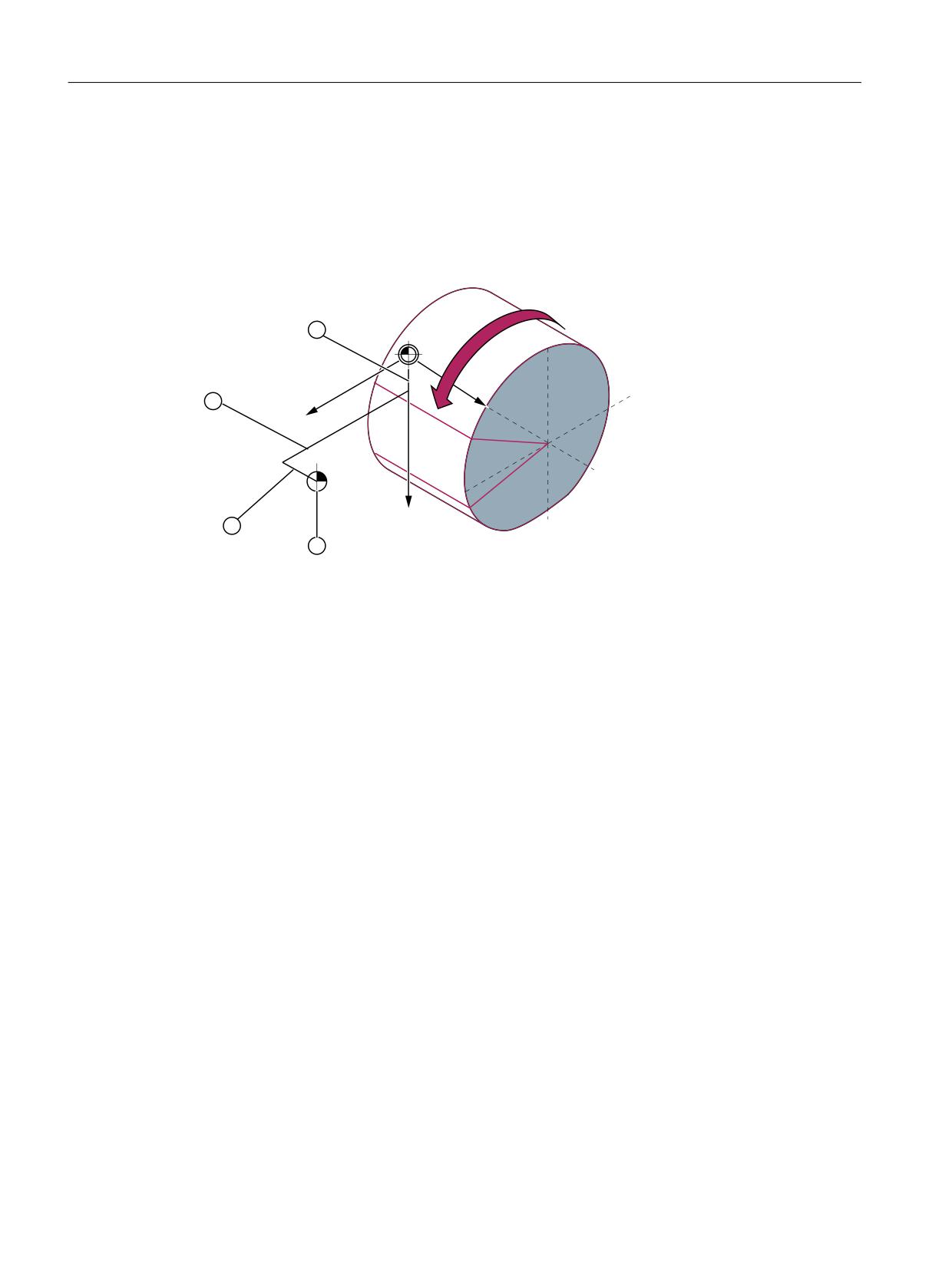
Kinematic transformations
5.2 Cylinder surface transformation TRACYL_K (option)
MD24820 TRACYL_BASE_TOOL_<t>
This machine data is used to inform the control of the tool zero point position in relation to the
origin of the cylinder coordinate system declared for TRACYL. The machine data has three
components for the axes X, Y, Z of the machine coordinate system.
=
;
<&
① ty
② tx
③ tz
④ Tool zero
Figure 5-13
Position of tool zero in relation to machine zero
Example
MD24820 $MC_TRACYL_BASE_TOOL_<t>[ 0 ] = tx
MD24820 $MC_TRACYL_BASE_TOOL_<t>[ 1 ] = ty
MD24820 $MC_TRACYL_BASE_TOOL_<t>[ 2 ] = tz
with <t> = the number of TRACYL transformations agreed upon in the transformation datasets
Transformations
100
Function Manual, 10/2020, 6FC5397-5GP40-0BA1
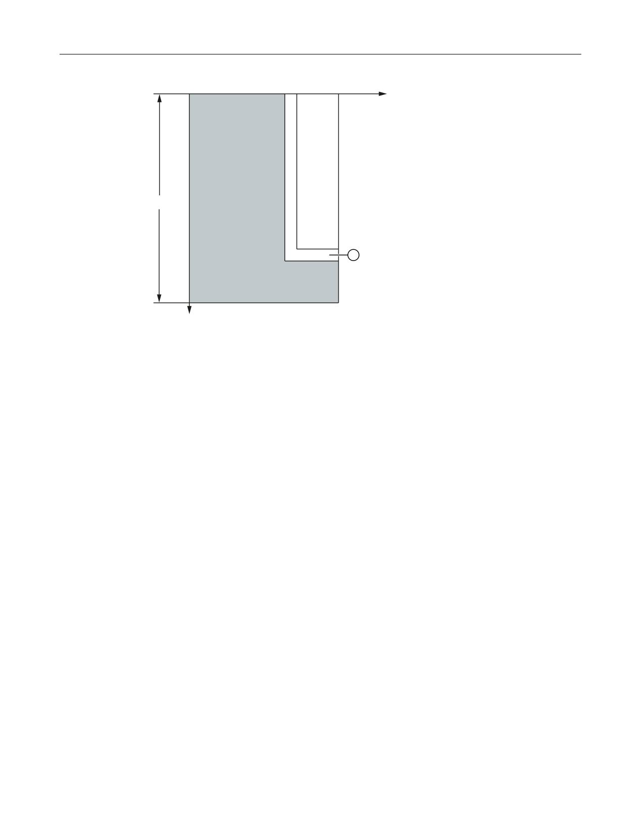
Kinematic transformations
5.2 Cylinder surface transformation TRACYL_K (option)
=
G
˭
<
① Slot (example)
Figure 5-14
Cylinder coordinate system
5.2.5
Programming
5.2.5.1
Activating TRACYL with TRAFOON
The end face transformation (TRACYL) is activated in the part program or synchronized action by
means of the TRAFOON or TRANSMIT instructions. The slot wall correction can be activated via
a parameter of the TRAFOON/TRACYL function.
Activating a transformation with TRAFOON
In addition to the name of the transformation, the reference diameter can also be specified for
TRACYL and a setting as to whether the "Slot side offset" function is active is also possible:
TRAFOON (<transformation name>, <diameter>, <k>)
With k = 1, the slot side offset is carried out, see Activating transformation (TRAFOON) (Page 52).
Activating a transformation with type
The TRACYL transformation can also be activated with the TRACYL command. To be able to
activate a transformation parameterized with a kinematic chain with TRACYL, this must be
parameterized in the system variable $NT_TRAFO_INDEX (Page 28).
TRACYL (Page 102)
Transformations
Function Manual, 10/2020, 6FC5397-5GP40-0BA1
101

Kinematic transformations
5.2 Cylinder surface transformation TRACYL_K (option)
5.2.5.2
Activate cylinder surface transformation (TRACYL)
The cylinder surface transformation (TRACYL) is activated in the part program or synchronized
action using the TRACYL statement.
Syntax
TRACYL(<d>)
TRACYL(<d>,<n>)
TRACYL(<d>,<n>,<k>)
Meaning
TRACYL(<d>):
Activate TRACYL with the first TRACYL data set and working diameter <d>
TRACYL (<d>,<n>):
Activate TRACYL with the <n>th TRACYL data set and working diameter
<d>
<d>:
Reference or working diameter
The value must be greater than 1.
<n>:
TRACYL data set number (optional)
Range of values:
1, 2
<k>:
The parameter <k> is only relevant for transformation type 514
k = 0:
without groove side correction
k = 1:
with groove side correction
If the parameter is not specified, then the parameterized basic position
applies:
$MC_TRACYL_DEFAULT_MODE_<n>
With <n> = TRACYL data set number
Note
A TRACYL transformation active in the channel is switched-off with:
• Deactivate transformation: TRAFOOF
• Activation of another transformation: E.g. TRAANG, TRANSMIT, TRAORI
Example
Program code
Comment
N40 TRACYL(40.)
; Activate TRACYL with the first TRACYL data set
and working diameter 40 mm.
Transformations
102
Function Manual, 10/2020, 6FC5397-5GP40-0BA1
Kinematic transformations
5.2 Cylinder surface transformation TRACYL_K (option)
5.2.5.3
Activate cylinder surface transformation (TRACYL): Further information
Further information
Program structure
A part program for milling a groove with TRACYL transformation 513 (TRACYL with groove side
offset) generally comprises the following steps:
1. Select tool.
2. Select TRACYL.
3. Select suitable coordinate offset (frame).
4. Positioning.
5. Program OFFN.
6. Select TRC.
7. Approach block (position TRC and approach groove side).
8. Groove center line contour.
9. Deselect TRC.
10.Retraction block (retract TRC and move away from groove side).
11.Positioning.
12.TRAFOOF.
13.Reselect original coordinate shift (frame).
Contour offset (OFFN)
In order to mill grooves using TRACYL transformation 513, the center line of the groove and half
of the groove width via the OFFN address are programmed in the part program.
To avoid damage to the groove side, OFFN acts only when the tool radius compensation is active.
It is possible to change OFFN within a part program. This allows the groove center line to be
offset from the center:
Transformations
Function Manual, 10/2020, 6FC5397-5GP40-0BA1
103

Kinematic transformations
5.2 Cylinder surface transformation TRACYL_K (option)
① OFFN
② Programmed path
Note
OFFN should be at least as large as the tool radius to avoid damage occurring to the opposite side
of the groove wall.
Note
OFFN acts differently with TRACYL than it does without TRACYL. Since, even without TRACYL,
OFFN is included when TRC is active, OFFN should be reset to zero after TRAFOOF.
NOTICE
Effect of OFFN depends on the transformation type
For TRACYL transformation 513 (TRACYL with groove side offset), half the groove width is
programmed for OFFN.
For TRACYL transformation 512 (TRACYL with groove side offset), the value of OFFN acts as an
allowance for the TRC.
Tool radius compensation (TRC)
For TRACYL transformation 513, the TRC is not taken into account relative to the groove side, but
to the programmed center of the groove. In order that the tool travels to the left of the groove
side, statement G42 must be programmed instead of G41 or the value of OFFN specified with a
negative sign.
Tool diameter
With TRACYL and a tool whose diameter is less than the groove width, the same groove side
geometry is not generated as with a tool whose diameter is the same as the groove width. To
improve the precision, it is recommended that the tool diameter is selected to be only slightly
less than the groove width.
Transformations
104
Function Manual, 10/2020, 6FC5397-5GP40-0BA1
Kinematic transformations
5.2 Cylinder surface transformation TRACYL_K (option)
Axis utilization
Note
The following axes cannot be used as a positioning axis or a reciprocating axis:
• The geometry axis in the peripheral direction of the cylinder peripheral surface (Y axis).
• The additional linear axis for groove side compensation (Z axis).
5.2.6
Boundary conditions
Selection/deselection
• An intermediate motion block is not inserted (phases/radii).
• A series of spline blocks must be concluded.
• Tool radius compensation must be deselected.
• The frame which was active prior to TRACYL is deselected by the control system
(analog G500).
• An active working area limit is deselected for axes affected by the transformation
(analog WALIMOF).
• Continuous path control and rounding are interrupted.
• DRF offsets must have been deleted by the operator.
• The Y axis used for the compensation should be set to zero for selection and active groove
side compensation.
Tool change
Tools can be changed only when the tool radius compensation function is deselected.
Frame
A frame change with G91 (incremental dimension) is not specially treated for active
transformation. The path to be traversed is evaluated in the workpiece coordinate system of the
new frame - regardless of which frame was active in the previous block.
A rotary axis offset can, for example, be entered by compensating the inclined position of a
workpiece can be considered using a frame or as offset of the rotary axis.
The following setting is required for the axial complete frame of the rotary axis to act in the
transformation:
Transformations
Function Manual, 10/2020, 6FC5397-5GP40-0BA1
105
Kinematic transformations
5.2 Cylinder surface transformation TRACYL_K (option)
$MC_TRACYL_ROT_AX_FRAME_<t> = 1
Note
Changes in the axis assignments are converted every time the transformation is selected or
deselected.
Further information
Function Manual Basic Functions; Coordinate systems, frames
Function restriction for transformation axes
The axes involved on the cylinder surface transformation must not be used for the following
functions:
• Positioning axis
• Oscillating axis
• Preset axis
• Fixed point approach G75
• Reference point approach G74
Manual traversal in JOG
When generated cylinder surface transformation with groove side compensation
($MC_TRAFO_TYPE = 513) is active in JOG mode, it must be noted that the axes are traversed
depending on the preceding status in AUTOMATIC. For active slide side compensation, the axes
so move differently than for deselected compensation. The part program can therefore be
continued (REPOS) after a part program interruption.
Transformations
106
Function Manual, 10/2020, 6FC5397-5GP40-0BA1

Kinematic transformations
5.2 Cylinder surface transformation TRACYL_K (option)
Interrupt part program
• Mode change from AUTOMATIC to JOG
If a part program processing is interrupted for active transformation and traversed manually
in the JOG operating mode, ensure for continuation of the part program in the AUTOMATIC
operating mode that the transformation is already active in the restart block from the current
position to the interruption location.
WARNING
Risk of collision
No monitoring for collisions takes place.
The operator is responsible for ensuring that the tool can be re-positioned without any
difficulties.
• START after RESET
If a part program processing is interrupted with RESET and restarted with START, ensure
that at part program begin all axes travel with a linear block (G0 or G1) to a defined position,
and the remaining part program is traversed reproducably. A tool which was active on RESET
may no longer be taken into account by the control (settable via machine data).
Transformations
Function Manual, 10/2020, 6FC5397-5GP40-0BA1
107
Kinematic transformations
5.2 Cylinder surface transformation TRACYL_K (option)
5.2.7
Examples
5.2.7.1
"Kinematic chain" part program for TRACYL
Example program "TRACYL"
Transformations
108
Function Manual, 10/2020, 6FC5397-5GP40-0BA1
Kinematic transformations
5.2 Cylinder surface transformation TRACYL_K (option)
Program code
;===========================================================
; Simple example of TRACYL with kinematic chain:
;******************************************************
N640
$NK_NAME[_KIE_CNTR]
= "ROOT"
N650
$NK_TYPE[_KIE_CNTR]
= "OFFSET"
N660
$NK_NEXT[_KIE_CNTR]
= "Z-Axis"
N670
$NK_PARALLEL[_KIE_CNTR]
= "C-Axis"
N680
_KIE_CNTR = _KIE_CNTR + 1
N690
$NK_NAME[_KIE_CNTR]
= "Z-Axis"
N700
$NK_TYPE[_KIE_CNTR]
= "AXIS_LIN"
N710
$NK_NEXT[_KIE_CNTR]
= "X-Axis"
N720
$NK_AXIS[_KIE_CNTR]
= "Z1"
N730
$NK_OFF_DIR[_KIE_CNTR,2]
= 1.0
N740
_KIE_CNTR = _KIE_CNTR + 1
N750
$NK_NAME[_KIE_CNTR]
= "X-Axis"
N760
$NK_TYPE[_KIE_CNTR]
= "AXIS_LIN"
N770
$NK_NEXT[_KIE_CNTR]
= "Y-Axis"
N780
$NK_AXIS[_KIE_CNTR]
= "X1"
N790
$NK_OFF_DIR[_KIE_CNTR,0]
= 1.0
N800
_KIE_CNTR = _KIE_CNTR + 1
N810
$NK_NAME[_KIE_CNTR]
= "Y-Axis"
N820
$NK_TYPE[_KIE_CNTR]
= "AXIS_LIN"
N830
$NK_NEXT[_KIE_CNTR]
= ""
N840
$NK_AXIS[_KIE_CNTR]
= "Y1"
N850
$NK_OFF_DIR[_KIE_CNTR,1]
= 1.0
N860
_KIE_CNTR = _KIE_CNTR + 1
N870
$NK_NAME[_KIE_CNTR]
= "C-Axis"
N880
$NK_TYPE[_KIE_CNTR]
= "AXIS_ROT"
N890
$NK_NEXT[_KIE_CNTR]
= ""
N900
$NK_AXIS[_KIE_CNTR]
= "C1"
N910
$NK_OFF_DIR[_KIE_CNTR,2]
= -1.0
; Definition of the kinematic transformation:
;******************************************************
; 1. TRACYL 512
;******************************************************
N920
$NT_NAME[_TRA_CNTR]
= "Trafo Tracyl 512"
N930
$NT_TRAFO_TYPE[_TRA_CNTR]
= "TRACYL_K"
N940
$NT_T_CHAIN_LAST_ELEM[_TRA_CNTR]
= "X-Axis"
N950
$NT_P_CHAIN_LAST_ELEM[_TRA_CNTR]
= "C-Axis"
N960
$NT_GEO_AX_NAME[_TRA_CNTR,0]
= "X-Axis"
N970
$NT_GEO_AX_NAME[_TRA_CNTR,1]
= ""
N980
$NT_GEO_AX_NAME[_TRA_CNTR,2]
= "Z-Axis"
N990
$NT_ROT_AX_NAME[_TRA_CNTR,0]
= ""
N1000
$NT_ROT_AX_NAME[_TRA_CNTR,1]
= "C-Axis"
N1010
$NT_ROT_AX_NAME[_TRA_CNTR,2]
= ""
N1020
$NT_ROT_OFFSET_FROM_FRAME[_TRA_CNTR] = 1
N1030
$NT_CNTRL[_TRA_CNTR]
= 'H0'
N1040
_TRA_CNTR = _TRA_CNTR + 1
; 2nd TRACYL 513
;******************************************************
N1050
$NT_NAME[_TRA_CNTR]
= "Trafo Tracyl 513"
N1060
$NT_TRAFO_TYPE[_TRA_CNTR]
= "TRACYL_K"
N1070
$NT_T_CHAIN_LAST_ELEM[_TRA_CNTR]
= "Y-Axis"
Transformations
Function Manual, 10/2020, 6FC5397-5GP40-0BA1
109
Kinematic transformations
5.2 Cylinder surface transformation TRACYL_K (option)
Program code
N1080
$NT_P_CHAIN_LAST_ELEM[_TRA_CNTR]
= "C-Axis"
N1090
$NT_GEO_AX_NAME[_TRA_CNTR,0]
= "X-Axis"
N1100
$NT_GEO_AX_NAME[_TRA_CNTR,1]
= "Y-Axis"
N1110
$NT_GEO_AX_NAME[_TRA_CNTR,2]
= "Z-Axis"
N1120
$NT_ROT_AX_NAME[_TRA_CNTR,0]
= ""
N1130
$NT_ROT_AX_NAME[_TRA_CNTR,1]
= "C-Axis"
N1140
$NT_ROT_AX_NAME[_TRA_CNTR,2]
= ""
N1150
$NT_ROT_OFFSET_FROM_FRAME[_TRA_CNTR] = 1
N1160
$NT_CNTRL[_TRA_CNTR]
= 'H200'
; TRACYL 513
N1170
_TRA_CNTR = _TRA_CNTR + 1
; 3rd TRACYL 514
;******************************************************
N1180
$NT_NAME[_TRA_CNTR]
= "Trafo Tracyl 514"
N1190
$NT_TRAFO_TYPE[_TRA_CNTR]
= "TRACYL_K"
N1200
$NT_T_CHAIN_LAST_ELEM[_TRA_CNTR]
= "Y-Axis"
N1210
$NT_P_CHAIN_LAST_ELEM[_TRA_CNTR]
= "C-Axis"
N1220
$NT_GEO_AX_NAME[_TRA_CNTR,0]
= "X-Axis"
N1230
$NT_GEO_AX_NAME[_TRA_CNTR,1]
= "Y-Axis"
N1240
$NT_GEO_AX_NAME[_TRA_CNTR,2]
= "Z-Axis"
N1250
$NT_ROT_AX_NAME[_TRA_CNTR,0]
= ""
N1260
$NT_ROT_AX_NAME[_TRA_CNTR,1]
= "C-Axis"
N1270
$NT_ROT_AX_NAME[_TRA_CNTR,2]
= ""
N1280
$NT_ROT_OFFSET_FROM_FRAME[_TRA_CNTR] = 1
N1290
$NT_CNTRL[_TRA_CNTR]
= 'H400'
; TRACYL 514
N1300
_TRA_CNTR = _TRA_CNTR + 1
;******************************************************
;Activate kinematic chain and transformation:
;******************************************************
N1310
NEWCONF
N1320
STOPRE
;*************************************************************************
*************************
End
Transformations
110
Function Manual, 10/2020, 6FC5397-5GP40-0BA1
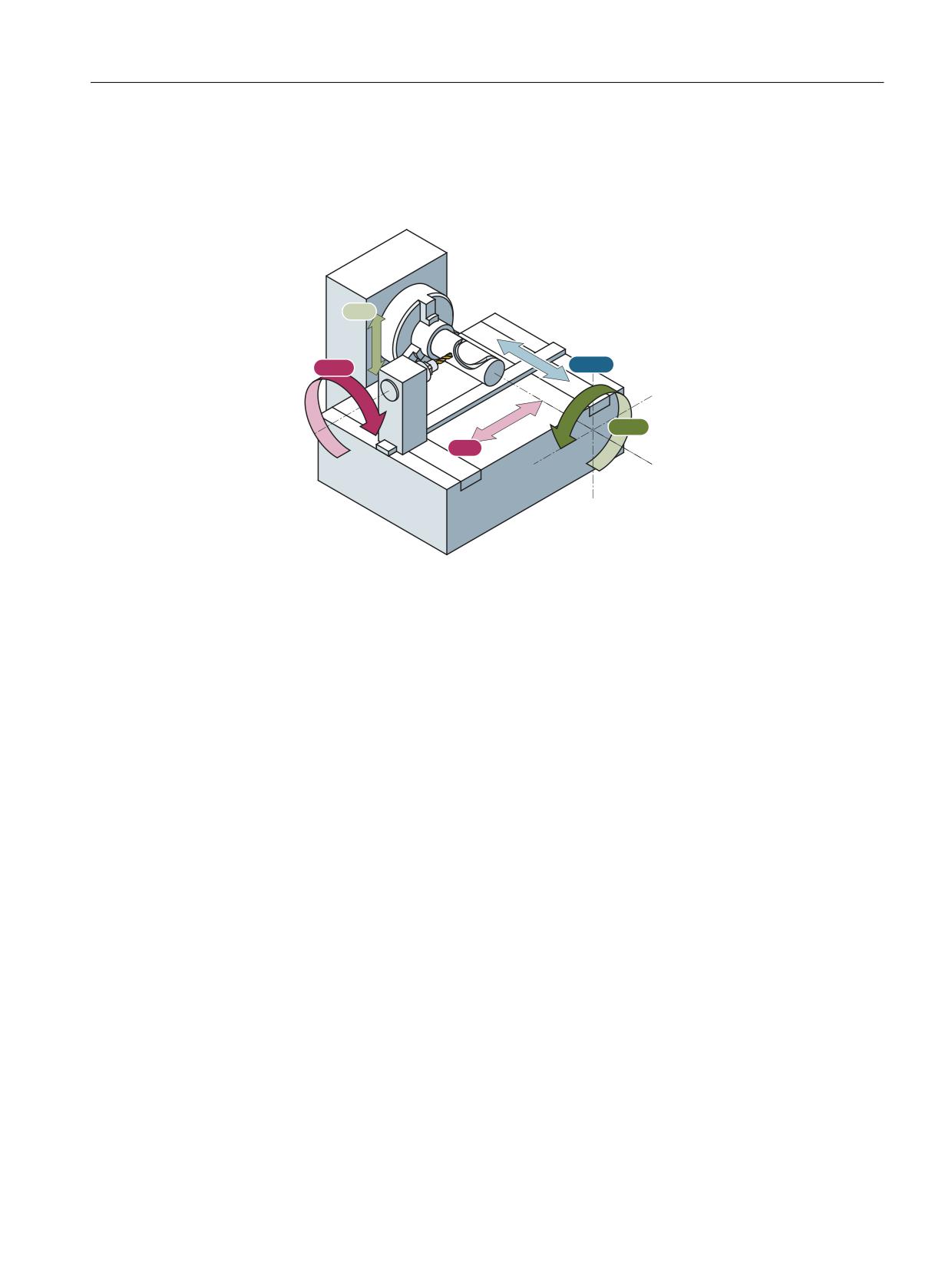
Kinematic transformations
5.2 Cylinder surface transformation TRACYL_K (option)
5.2.7.2
Machining grooves on a cylinder surface with X-Y-Z-C kinematics
The example refers to the turning machine with an additional Y axis drawn in the following
figure.
<0
$60
=0
&0
;0
XM
Infeed axis, perpendicular to rotary axis
YM
Additional axis
ZM
Axis is parallel to rotary axis
CM
Rotary axis
ASM Main spindle
Parameter assignment
Machine axis name
• MD10000 $MN_AXCONF_MACHAX_NAME_TAB[ 0 ] = "CM"
• MD10000 $MN_AXCONF_MACHAX_NAME_TAB[ 1 ] = "XM"
• MD10000 $MN_AXCONF_MACHAX_NAME_TAB[ 2 ] = "YM"
• MD10000 $MN_AXCONF_MACHAX_NAME_TAB[ 3 ] = "ZM"
• MD10000 $MN_AXCONF_MACHAX_NAME_TAB[ 4 ] = "ASM"
Geometry axis names
• MD20060 $MC_AXCONF_GEOAX_NAME_TAB[ 0 ] = "X" (name of the 1st geometry axis)
• MD20060 $MC_AXCONF_GEOAX_NAME_TAB[ 1 ] = "Y" (name of the 2nd geometry axis)
• MD20060 $MC_AXCONF_GEOAX_NAME_TAB[ 2 ] = "Z" (name of the 3rd geometry axis)
Channel axis names
• MD20080 $MC_AXCONF_CHANAX_NAME_TAB[ 0 ] = "XC"
• MD20080 $MC_AXCONF_CHANAX_NAME_TAB[ 1 ] = "YC"
Transformations
Function Manual, 10/2020, 6FC5397-5GP40-0BA1
111