SINUMERIK 840D sl. Service - Functions. Manual (2018-2020) - page 98
Kinematic transformations
5.2 Cylinder surface transformation TRACYL_K (option)
• MD20080 $MC_AXCONF_CHANAX_NAME_TAB[ 2 ] = "ZC"
• MD20080 $MC_AXCONF_CHANAX_NAME_TAB[ 3 ] = "CC"
• MD20080 $MC_AXCONF_CHANAX_NAME_TAB[ 4 ] = "ASC"
Assignment of geometry axes to channel axes
TRACYL not active:
• MD20050 $MC_AXCONF_GEOAX_ASSIGN_TAB[ 0 ] = 1 (1st geometry axis → 1st channel axis
XC)
• MD20050 $MC_AXCONF_GEOAX_ASSIGN_TAB[ 1 ] = 2 (2nd geometry axis → 2nd channel
axis YC)
• MD20050 $MC_AXCONF_GEOAX_ASSIGN_TAB[ 2 ] = 3 (3rd geometry axis → 3rd channel
axis ZC)
TRACYL active:
• MD24120 $MC_TRAFO_GEOAX_ASSIGN_TAB_1[ 0 ] = 1 (1st transformation geometry axis →
1st channel axis XC)
• MD24120 $MC_TRAFO_GEOAX_ASSIGN_TAB_1[ 1 ] = 4 (2nd transformation geometry axis
→ 4th channel axis CC)
• MD24120 $MC_TRAFO_GEOAX_ASSIGN_TAB_1[ 2 ] = 3 (3rd transformation geometry axis
→ 3rd channel axis ZC)
Assignment of channel axes to machine axes
• MD20070 $MC_AXCONF_MACHAX_USED[ 0 ] = 2 (1st channel axis → 2nd machine axis XM)
• MD20070 $MC_AXCONF_MACHAX_USED[ 1 ] = 3 (2nd channel axis → 3rd machine axis YM)
• MD20070 $MC_AXCONF_MACHAX_USED[ 2 ] = 4 (3rd channel axis → 4th machine axis ZM)
• MD20070 $MC_AXCONF_MACHAX_USED[ 3 ] = 1 (4th channel axis → 1st machine axis CM)
• MD20070 $MC_AXCONF_MACHAX_USED[ 4 ] = 5 (5th channel axis → 5th machine axis ASM)
Identification of spindles
• MD35000 $MA_SPIND_ASSIGN_TO_MACHAX[ 0 ] = 1 (spindle)
• MD35000 $MA_SPIND_ASSIGN_TO_MACHAX[ 1 ] = 0 (axis)
• MD35000 $MA_SPIND_ASSIGN_TO_MACHAX[ 2 ] = 0 (axis)
• MD35000 $MA_SPIND_ASSIGN_TO_MACHAX[ 3 ] = 0 (axis)
• MD35000 $MA_SPIND_ASSIGN_TO_MACHAX[ 4 ] = 2 (spindle)
Transformation type
• MD24100 $MC_TRAFO_TYPE_1 = 513 (TRACYL with groove side offset)
Offset relative to the zero position of the rotary axis
• MD24800 $MC_TRACYL_ROT_AX_OFFSET_1 = 0
Sign of rotary axis
• MD24810 $MC_TRACYL_ROT_SIGN_IS_PLUS_1 = FALSE
Transformations
112
Function Manual, 10/2020, 6FC5397-5GP40-0BA1
Kinematic transformations
5.2 Cylinder surface transformation TRACYL_K (option)
Basic offset of the tool zero relative to the geometry axes while TRACYL is active
• MD24820 $MC_TRACYL_BASE_TOOL_1 [ 0 ] = 0.0 (offset relative to 1st transformation
geometry axis)
• MD24820 $MC_TRACYL_BASE_TOOL_1 [ 1 ] = 0.0 (offset relative to 2nd transformation
geometry axis)
• MD24820 $MC_TRACYL_BASE_TOOL_1 [ 2 ] = 0.0 (offset relative to 3rd transformation
geometry axis)
TRACYL input axes
• MD24110 $MC_TRAFO_AXES_IN_1[ 0 ] = 1 (1st channel axis XC, perpendicular to the rotary
axis)
• MD24110 $MC_TRAFO_AXES_IN_1[ 1 ] = 4 (4th channel axis CC, rotary axis)
• MD24110 $MC_TRAFO_AXES_IN_1[ 2 ] = 3 (3rd channel axis ZC, parallel to the rotary axis)
• MD24110 $MC_TRAFO_AXES_IN_1[ 3 ] = 2 (2nd channel axis YC, special axis)
Transformations
Function Manual, 10/2020, 6FC5397-5GP40-0BA1
113
Kinematic transformations
5.2 Cylinder surface transformation TRACYL_K (option)
Programming
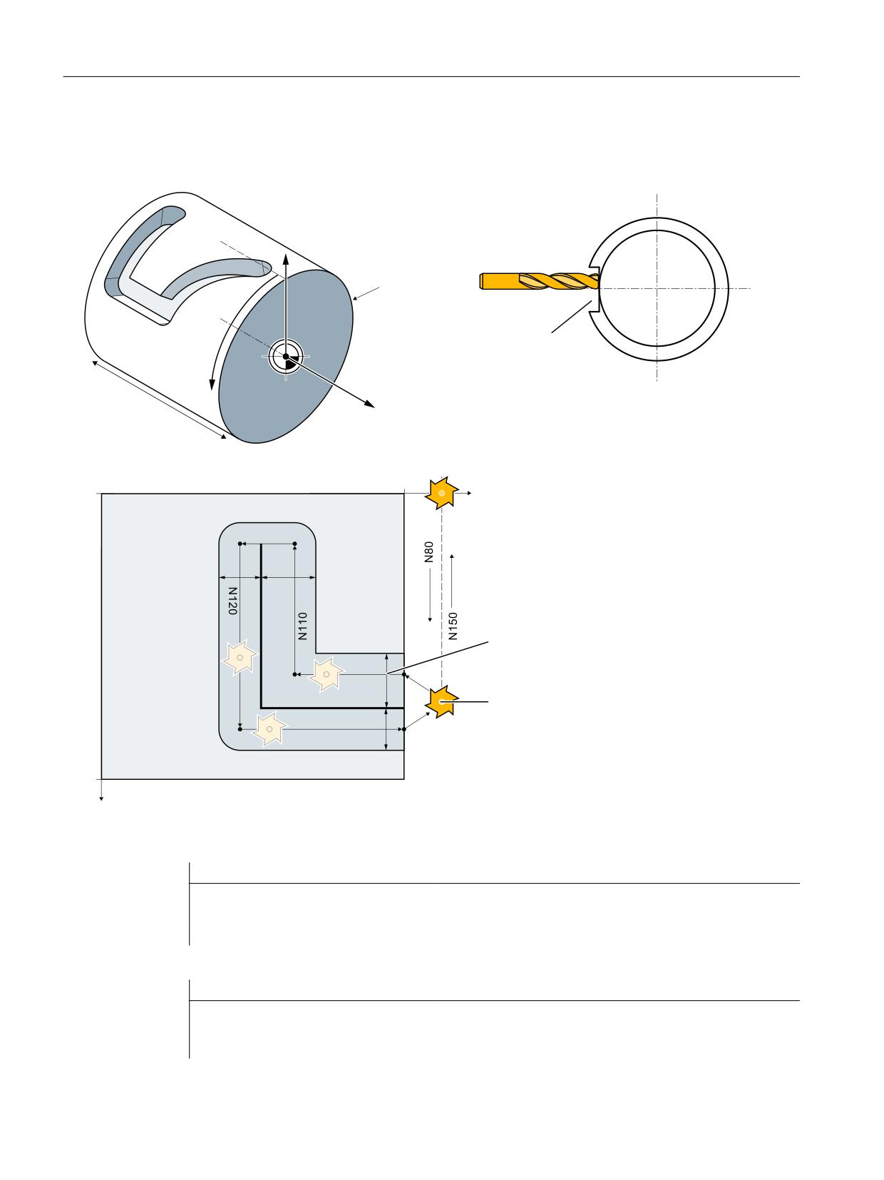
Producing a hook-shaped groove with groove side offset (TRACYL transformation type 513)
;
6ORW ZLWK VORW VLGH
RIIVHW
<
=
=
,QLWLDO SRVLWLRQ
2))1 KDOI
VORW ZLGWK
1
1
3RVLWLRQLQJ
RYHU WKH FHQWHU
RI WKH VORW
1
1
x
+DQGOLQJ RI WKH F\OLQGHU VXUIDFH
<
Tool definition
Program code
Comment
; Tool parameters
$TC_DP1[1,1]=120
; Tool type: Milling tool
$TC_DP2[1,1] = 0
; Cutting edge position: For turning tools only
Program code
Comment
; Geometry: Length compensation
$TC_DP3[1,1]=8.
; Length compensation vector: Calculation acc. to
type
Transformations
114
Function Manual, 10/2020, 6FC5397-5GP40-0BA1

Kinematic transformations
5.2 Cylinder surface transformation TRACYL_K (option)
Program code
Comment
$TC_DP4[1,1]=9.
; Length compensation vector: Calculation accord-
ing to plane
$TC_DP5[1,1]=7.
Program code
Comment
; Geometry: Radius
$TC_DP6[1,1]=6.
; Radius
$TC_DP7[1,1]=0
; Groove width b for slotting saw, rounding radi-
us for milling tools
$TC_DP8[1,1]=0
; Projection k: For slotting saw only
$TC_DP9[1,1]=0
$TC_DP10[1,1]=0
$TC_DP11[1,1]=0
; Angle for tapered milling tools
Program code
Comment
; Wear: Length and radius compensation
$TC_DP12[1,1] =0
; Remaining parameters to $TC_DP24=0 (basis di-
mension/adapter)
Groove machining on the cylinder surface
Program code
Comment
N10 T1 D1 G54 G90 F5000 G94
; Tool selection, clamping compensation
N20 SPOS=0
; Switchover of the spindle to rotary axis opera-
tion, positioning at 0 degrees
N30 G0 X25 Z110
; Approach the start position
N40 TRACYL(40.)
; Activating TRACYL with the first TRACYL data set
and working diameter 40 mm
N50 G19
; Machining plane Y/Z (cylinder surface)
N60 Y70
; Positioning over the groove center
N70 G1 X15
; Infeed tool to groove base
N80 OFFN=10
; Define 10 mm groove side spacing relative to
groove center line
N90 Z100 G42
; TRC selection and approach to right groove wall
; G42: TRC right of the progr. contour (≙ groove
center)
N100 Z50
; Path I: Producing the groove section parallel
with the cylinder axis
N110 Y10
; Path I: Producing the groove section parallel
with the circumference
N120 Y70
; Path II: Producing the groove section parallel
with the circumference
N130 Z100
; Path II: Producing the groove section parallel
with the cylinder axis
Transformations
Function Manual, 10/2020, 6FC5397-5GP40-0BA1
115
Kinematic transformations
5.2 Cylinder surface transformation TRACYL_K (option)
Program code
Comment
N140 Z110 G40
; Travel away from the groove wall and TRC dese-
lection
N150 G0 X25 Y0
; Return to the initial position
N170 TRAFOOF
; Deactivate transformation
N180 M30
; End of program
5.2.7.3
Machining grooves on a cylinder surface with X-Y-Z-A-C kinematics
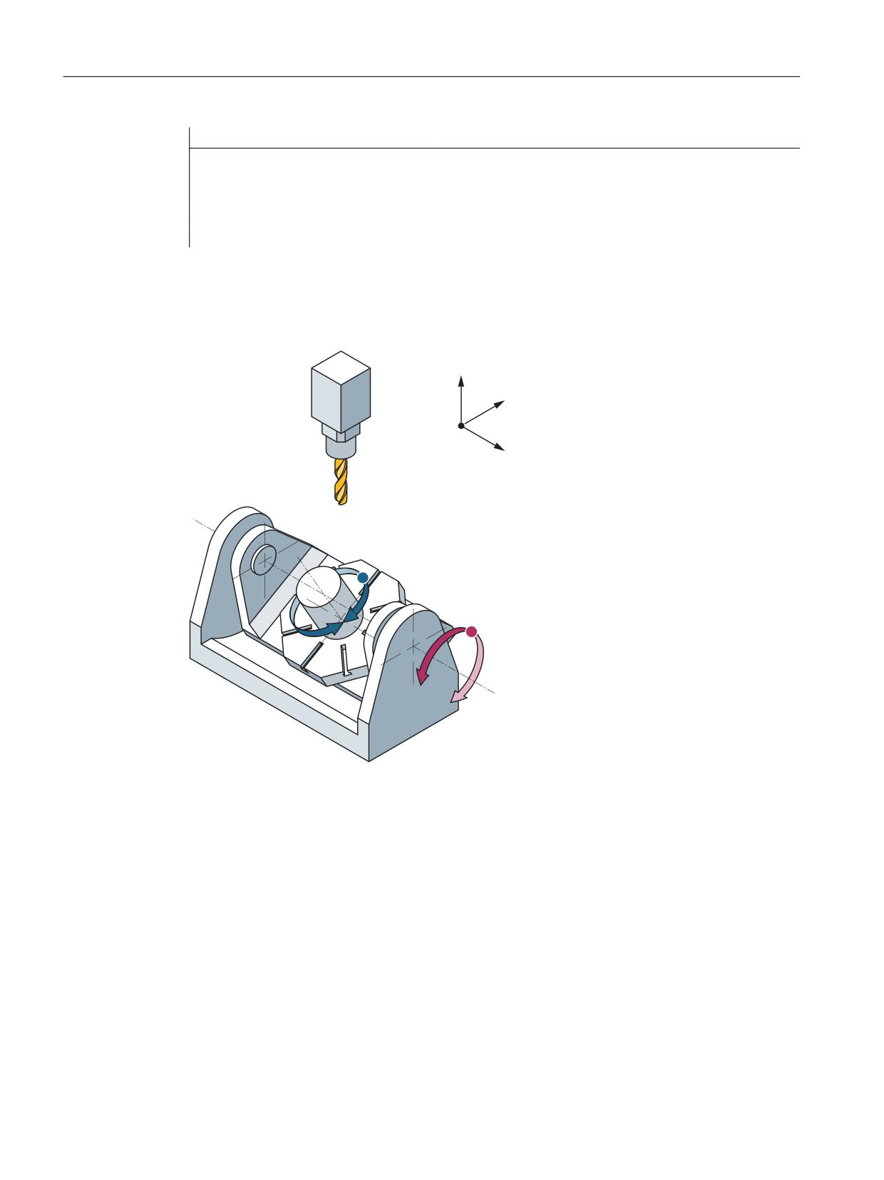
The example refers to the 5-axis milling machine with an A- and a C-axis in the following figure.
=0
<0
630
;0
&0
&
$
$0
XM
1. axis of the machining plane
YM
2. axis of the machining plane
ZM
Infeed axis
AM
Rotary axis
CM
Rotary axis
SPM Main spindle
Parameter assignment
Machine axis name
• MD10000 $MN_AXCONF_MACHAX_NAME_TAB[ 0 ] = "XM"
• MD10000 $MN_AXCONF_MACHAX_NAME_TAB[ 1 ] = "YM"
• MD10000 $MN_AXCONF_MACHAX_NAME_TAB[ 2 ] = "ZM"
Transformations
116
Function Manual, 10/2020, 6FC5397-5GP40-0BA1
Kinematic transformations
5.2 Cylinder surface transformation TRACYL_K (option)
• MD10000 $MN_AXCONF_MACHAX_NAME_TAB[ 3 ] = "SPM"
• MD10000 $MN_AXCONF_MACHAX_NAME_TAB[ 4 ] = "AM"
• MD10000 $MN_AXCONF_MACHAX_NAME_TAB[ 5 ] = "CM"
Geometry axis names
• MD20060 $MC_AXCONF_GEOAX_NAME_TAB[ 0 ] = "X" (name of the 1st geometry axis)
• MD20060 $MC_AXCONF_GEOAX_NAME_TAB[ 1 ] = "Y" (name of the 2nd geometry axis)
• MD20060 $MC_AXCONF_GEOAX_NAME_TAB[ 2 ] = "Z" (name of the 3rd geometry axis)
Channel axis names
• MD20080 $MC_AXCONF_CHANAX_NAME_TAB[ 0 ] = "XC"
• MD20080 $MC_AXCONF_CHANAX_NAME_TAB[ 1 ] = "YC"
• MD20080 $MC_AXCONF_CHANAX_NAME_TAB[ 2 ] = "ZC"
• MD20080 $MC_AXCONF_CHANAX_NAME_TAB[ 3 ] = "SPC"
• MD20080 $MC_AXCONF_CHANAX_NAME_TAB[ 4 ] = "AC"
• MD20080 $MC_AXCONF_CHANAX_NAME_TAB[ 5 ] = "CC"
Assignment of geometry axes to channel axes
TRACYL not active:
• MD20050 $MC_AXCONF_GEOAX_ASSIGN_TAB[ 0 ] = 1 (1st geometry axis → 1st channel axis
XC)
• MD20050 $MC_AXCONF_GEOAX_ASSIGN_TAB[ 1 ] = 2 (2nd geometry axis → 2nd channel
axis YC)
• MD20050 $MC_AXCONF_GEOAX_ASSIGN_TAB[ 2 ] = 3 (3rd geometry axis → 3rd channel
axis ZC)
TRACYL active:
• MD24220 $MC_TRAFO_GEOAX_ASSIGN_TAB_2[ 0 ] = 6 (1st transformation geometry axis →
6th channel axis CC)
• MD24220 $MC_TRAFO_GEOAX_ASSIGN_TAB_2[ 1 ] = 2 (2nd transformation geometry axis
→ 2nd channel axis YC)
• MD24220 $MC_TRAFO_GEOAX_ASSIGN_TAB_2[ 2 ] = 3 (3rd transformation geometry axis
→ 3rd channel axis ZC)
Assignment of channel axes to machine axes
• MD20070 $MC_AXCONF_MACHAX_USED[ 0 ] = 1 (1st channel axis → 1st machine axis XM)
• MD20070 $MC_AXCONF_MACHAX_USED[ 1 ] = 2 (2nd channel axis → 2nd machine axis YM)
• MD20070 $MC_AXCONF_MACHAX_USED[ 2 ] = 3 (3rd channel axis → 3rd machine axis ZM)
• MD20070 $MC_AXCONF_MACHAX_USED[ 3 ] = 4 (4th channel axis → 4th machine axis SPM)
• MD20070 $MC_AXCONF_MACHAX_USED[ 4 ] = 5 (5th channel axis → 5th machine axis AM)
• MD20070 $MC_AXCONF_MACHAX_USED[ 5 ] = 6 (6th channel axis → 6th machine axis CM)
Transformations
Function Manual, 10/2020, 6FC5397-5GP40-0BA1
117
Kinematic transformations
5.2 Cylinder surface transformation TRACYL_K (option)
Identification of spindles
• MD35000 $MA_SPIND_ASSIGN_TO_MACHAX[ 0 ] = 0 (axis)
• MD35000 $MA_SPIND_ASSIGN_TO_MACHAX[ 1 ] = 0 (axis)
• MD35000 $MA_SPIND_ASSIGN_TO_MACHAX[ 2 ] = 0 (axis)
• MD35000 $MA_SPIND_ASSIGN_TO_MACHAX[ 3 ] = 1 (spindle)
• MD35000 $MA_SPIND_ASSIGN_TO_MACHAX[ 4 ] = 0 (axis)
• MD35000 $MA_SPIND_ASSIGN_TO_MACHAX[ 4 ] = 0 (axis)
Transformation type
• MD24200 $MC_TRAFO_TYPE_2 = 513 (TRACYL with groove side offset)
Offset relative to the zero position of the rotary axis
• MD24850 $MC_TRACYL_ROT_AX_OFFSET_2 = 0
Sign of rotary axis
• MD24860 $MC_TRACYL_ROT_SIGN_IS_PLUS_2 = FALSE
Basic offset of the tool zero relative to the geometry axes while TRACYL is active
• MD24870 $MC_TRACYL_BASE_TOOL_2 [ 0 ] = 0.0 (offset relative to 1st transformation
geometry axis)
• MD24870 $MC_TRACYL_BASE_TOOL_2 [ 1 ] = 0.0 (offset relative to 2nd transformation
geometry axis)
• MD24870 $MC_TRACYL_BASE_TOOL_2 [ 2 ] = 0.0 (offset relative to 3rd transformation
geometry axis)
TRACYL input axes
• MD24210 $MC_TRAFO_AXES_IN_2[ 0 ] = 3 (3rd channel axis ZC, perpendicular to the rotary
axis)
• MD24210 $MC_TRAFO_AXES_IN_2[ 1 ] = 6 (6th channel axis CC, rotary axis)
• MD24210 $MC_TRAFO_AXES_IN_2[ 2 ] = 2 (2nd channel axis YC, parallel with the rotary axis)
• MD24210 $MC_TRAFO_AXES_IN_2[ 3 ] = 1 (1st channel axis XC, special axis)
Programming
Program code
Comment
N10 WORKPIECE(,"",,"CYLINDER",0,0,-180,-80,179)
; Blank definition
N20 M3 S2000
; Setting spindle speed
N30 T="NUTFRAESER" M6 D1
; Tool selection
N40 G0 G54 X0 Y-20 Z105
; Positioning
N50 CYCLE800(0,"TABLE",100000,57,0,0,0,-90,0,0,0,0,0,-1,100,1)
; Rotate A-axis with swivel cycle
N60 G17 G90
; Setting the machining plane
N70 G0 Y-10 Z100 G40
; Positioning
Transformations
118
Function Manual, 10/2020, 6FC5397-5GP40-0BA1

Kinematic transformations
5.3 Oblique angle transformation (inclined axis) TRAANG_K (option)
Program code
Comment
N80 TRACYL(179, 2)
; Selecting the Tracyl data set
2 with groove wall offset
N90 OFFN=20
; Setting the offset (half
groove width)
N100 G1 F500 X0 Z75 G42
; Setting the starting point and
selecting the TRC
N110 Y30
; Groove center path
N120 X-60
; Groove center path
N130 X0
; Groove center path
N140 Y-10
; Groove center path
N150 Z105 G40
; Retraction and deselection of
the TRC
N160 TRAFOOF
; Deselection of the transforma-
tion
N170 G0 X0 Y-20 Z115
; Positioning retract movement
N180 M5
; Spindle stop
N190 CYCLE800(0,"TABLE",100000,57,0,0,0,0,0,0,0,0,0,-1,100,1)
; Turn back A axis
N200 M30
; End of program
5.3
Oblique angle transformation (inclined axis) TRAANG_K (option)
5.3.1
Oblique angle transformation (inclined axis) TRAANG_K
Note
Option
For function "Oblique angle transformation (TRAANG) with programmable angle", option
"6FC5800-0AM28-0YB0" is necessary which requires a license.
For function "Oblique angle transformation (TRAANG) with fixed angle", option
"6FC5800-0AS54-0YB0" is necessary which requires a license.
The oblique angle transformation permits programming in the Cartesian workpiece coordinate
system (WCS) on machines with obliquely arranged machine axes, which is a typical axis
arrangement on grinding machines.
The control system transforms the programmed traversing movements of the Cartesian
coordinate system to the traversing movements of the real machine axes. This section describes
Transformations
Function Manual, 10/2020, 6FC5397-5GP40-0BA1
119
Kinematic transformations
5.3 Oblique angle transformation (inclined axis) TRAANG_K (option)
how an oblique angle transformation (TRAANG_K) is mapped by means of a kinematic chain and
parameterized in the control via system variables.
• Definition of TRAANG_K via kinematic chains. The machine kinematics are defined using two
kinematic chains, see Defining machine kinematics (Page 18). The system variables are
retentively saved in the NC and can be archived and/or read as "NC data" via SINUMERIK
Operate using the commissioning archive.
• Definition of TRAANG via machine data (Page 123).
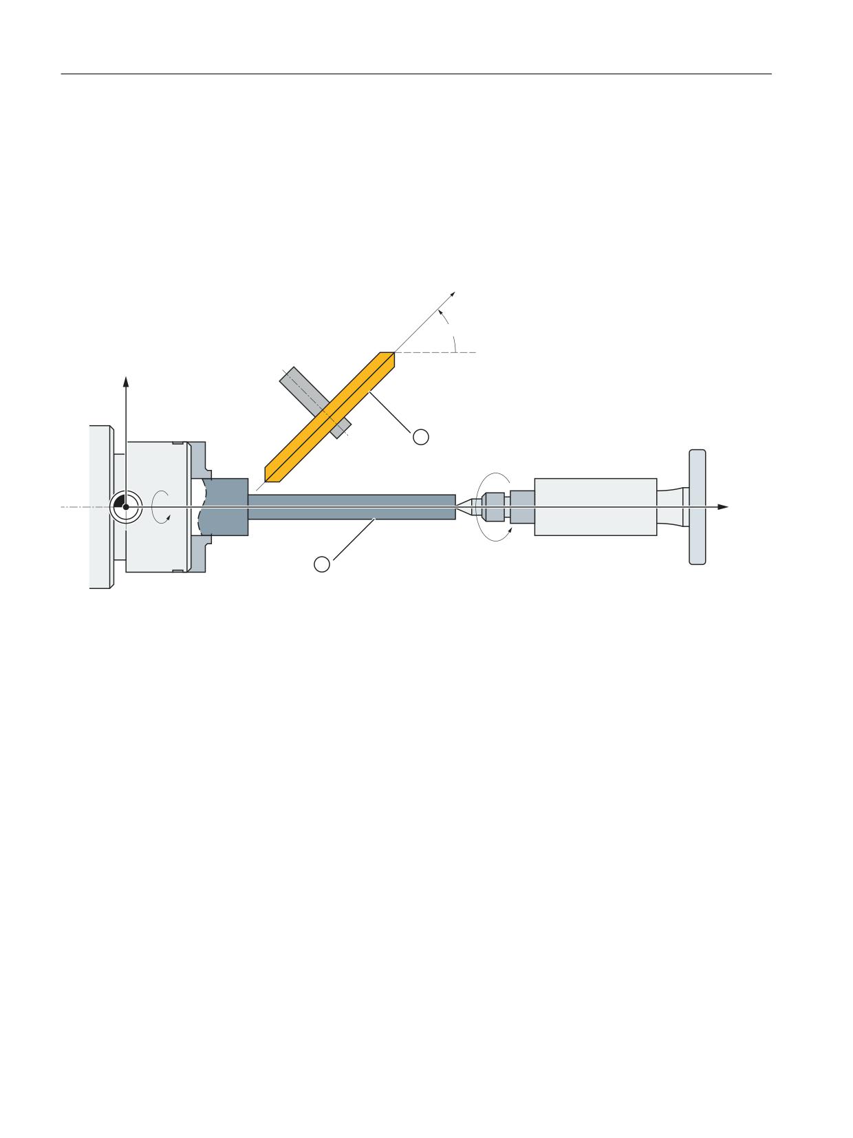
80
˞
;
= =0
0
&0
$60
①
Grinding disk
②
Workpiece
X
Geometry axis
Z
Geometry axis
ZM
Machine axis
UM
Machine axis
α
Angle of inclined axis
CM
Machine axis (spindle)
ASM
Machine axis (tailstock)
Figure 5-15
Inclined axis
The oblique angle transformation is a special case of orientation transformation.
Transformations
120
Function Manual, 10/2020, 6FC5397-5GP40-0BA1
Kinematic transformations
5.3 Oblique angle transformation (inclined axis) TRAANG_K (option)
Versions
• Oblique angle transformation (TRAANG) with programmable angle
For oblique angle transformation (TRAANG) with programmable angle, when activating the
transformation, the angle can be specified.
See Chapter "Activating an oblique angle transformation with programmable angle
(TRAANG) (Page 129)"
• Oblique angle transformation (TRAANG) with fixed angle
For oblique angle transformation (TRAANG) with fixed angle, when activating the
transformation, an angle cannot be specified.
See Chapter "Activate oblique angle transformation with fixed angle (TRAANG) (Page 130)"
See also
"Kinematic chain" part program for TRAANG (Page 135)
$NT_TRAFO_TYPE (Page 30)
Parameterization with machine data (Page 123)
5.3.2
Parameterization of kinematic chain and transformation
5.3.2.1
Parameterization and kinematics and transformation (TRAANG_K)
Setting a transformation type
For TRAANG with kinematic chains, the transformation type is set via the system
variable $NT_TRAFO_TYPE (Page 30).
$NT_TRAFO_TYPE[<n>] = TRAANG_K
For configuration via machine data, the type is set via the machine data $MC_TRAFO_TYPE_<n>
(Page 127).
Linear axes
First, linear axes are defined via the system variables of the kinematic chain. These elements
must be of the type AXIS_LIN.
Example:
$NK_NAME<name> = "AXIS_LIN"
Transformations
Function Manual, 10/2020, 6FC5397-5GP40-0BA1
121

Kinematic transformations
5.3 Oblique angle transformation (inclined axis) TRAANG_K (option)
The inclined axis is generated via an offset of the linear axis:
System variable
Offset vector (X; Y; Z)
$NK_OFF_DIR[<n>,<k>] =
k
Coordinate index
<value>
0: X coordinate (abscissa)
1: Y coordinate (ordinate)
2: Z coordinate (applicate)
n
System variable or element index
<value>
Coordinate value (offset value)
Example:
$NK_OFF_DIR[<name>,0] = COS(20)
$NK_OFF_DIR[<name>,2] = SIN(20)
The axis with the name <name> is rotated with the values COS(20) (X coordinate) and SIN(20)
(Z coordinate) and remains at this value during the transformation.
Geometry axes
Then the linear axes must be assigned to the geometry axes of the transformation:
Example:
$NT_GEO_AX_NAME["name",0]
= "X axis"
$NT_GEO_AX_NAME["name",2]
= "Y axis"
$NT_GEO_AX_NAME["name",1]
= "Z axis"
Example program for TRAANG_K
You will find a simple part program using TRAANG under "Kinematic chain" part program for
TRAANG (Page 135).
See also
$NT_TRAFO_INDEX (Page 28)
5.3.2.2
System variables for TRAANG_K
System variables are available for defining the kinematic chain and the transformation. System
variables that are available for all kinematic transformations can be found at Commissioning
(Page 22).
Transformations
122
Function Manual, 10/2020, 6FC5397-5GP40-0BA1
Kinematic transformations
5.3 Oblique angle transformation (inclined axis) TRAANG_K (option)
Note
Establish a defined initial state
It is recommended that a defined initial state be generated before parameterizing the kinematic
chain. For this purpose, the system variables of the kinematic chain and the transformation with
the function DELOBJ() must be set to their default values.
Change system variable values
• Modified data (e.g. $NT_xxx or $NK_yyy) become effective after NEWCONF if the data does
not concern an active transformation (attention: persistent transformations or
transformations that remain active via reset/end of part program). If the data to be activated
with NEWCONF concern an active transformation, an alarm is output.
• Modified data (e.g. $NT_xxx or $NK_yyy) only become effective after a TRAFOOF and a
subsequent NC reset or NEWCONF or program end (M30).
• Changed data (e.g. $NT_xxx or $NK_yyy) become effective after NCK-PowerOn.
5.3.3
Parameterization with machine data
5.3.3.1
Overview
Machine data: Transformation data in general
The following machine data is used to define transformation data sets in a channel:
• MD2xxxx $MC_TRAFO_TYPE_<n> (definition of the <n>th transformation in the channel)
• MD2xxxx $MC_TRAFO_AXES_IN_<n> (axis assignment for the <n>th transformation in the
channel)
• MD2xxxx $MC_TRAFO_GEOAX_ASSIGN_TAB_<n> (assignment of geometry axes to channel
axes for transformation <n>)
• MD2xxxx $MC_TRAFO_INCLUDES_TOOL_<n> (tool handling with active <n>th
transformation)
where <n> = 1, 2, 3, ... max. number of transformation data sets
For TRAANG (type 1024), no more than two transformation data sets may be parameterized in
a channel:
• MD2xxxx $MC_TRAFO_TYPE_<x> = <TRAANG type>
• MD2xxxx $MC_TRAFO_TYPE_<y> = <TRAANG type>
Transformations
Function Manual, 10/2020, 6FC5397-5GP40-0BA1
123
Kinematic transformations
5.3 Oblique angle transformation (inclined axis) TRAANG_K (option)
Machine data: Transformation TRAANG
A TRAANG transformation is parameterized using the following machine data:
• MD2xxxx $MC_TRAANG_ANGLE_<n> (angle between longitudinal axis and inclined axis)
• MD2xxxx $MC_TRAANG_BASE_TOOL_<n> (basic offset of the tool zero)
• MD2xxxx $MC_TRAANG_PARALLEL_VELO_RES_<n> (velocity margin for the compensation
movements
of the longitudinal axis)
• MD2xxxx $MC_TRAANG_PARALLEL_ACCEL_RES_<n> (acceleration margin for the
compensation movements
of the longitudinal axis)
where <n> = 1, 2 (TRAANG data set number)
Transformations
124
Function Manual, 10/2020, 6FC5397-5GP40-0BA1
Kinematic transformations
5.3 Oblique angle transformation (inclined axis) TRAANG_K (option)
5.3.3.2
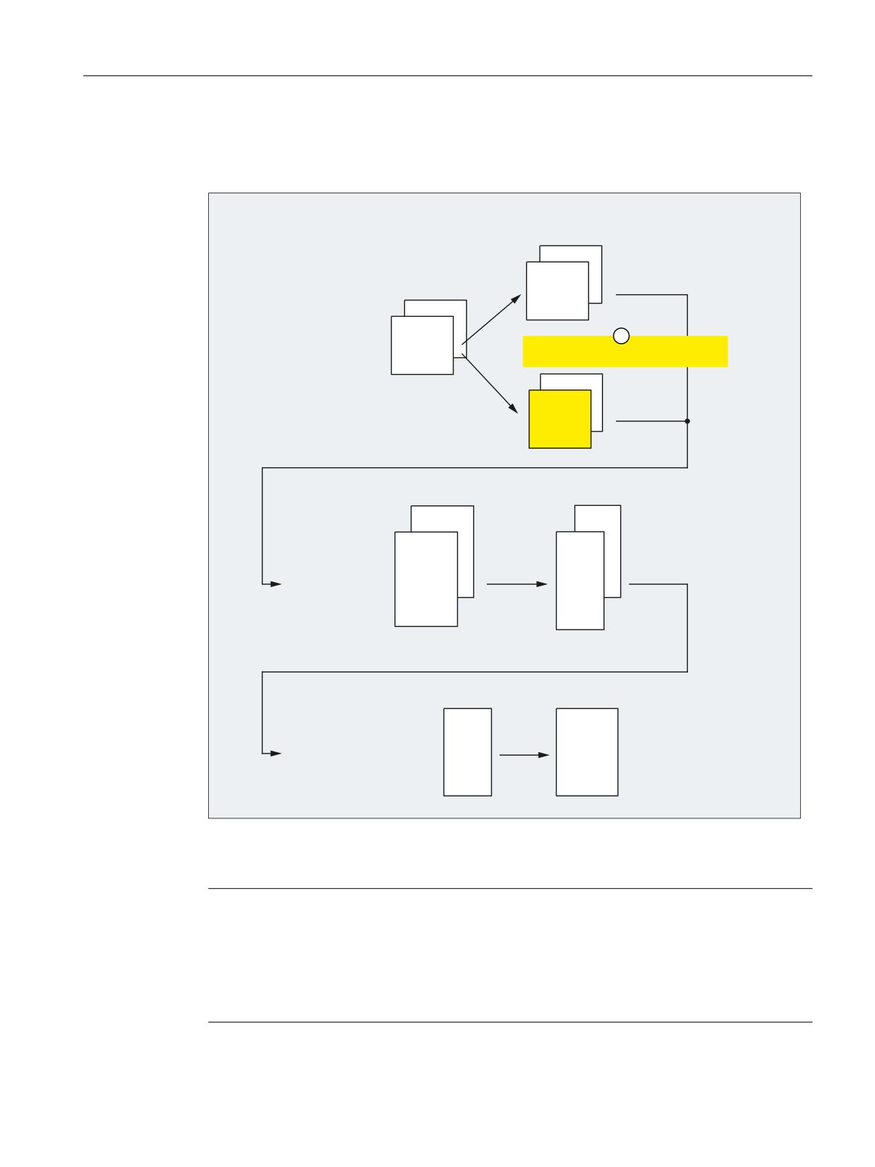
Axis configuration
The following shows an axis configuration that is typical of TRAANG.
0'
0&B$;&21)B*(2$;B$66,*1B7$%
&KDQQHO
0'
&KDQQHO
0&B $;&21)B*(2$;B1$0(B7$%
&KDQQHO
&KDQQHO
VW JHRPHWU\ D[LV > @
;
0'
QG JHRPHWU\ D[LV > @
<
0&B75$)2B*(2$;B$66,*1B7$%
UG JHRPHWU\ D[LV > @
=
&KDQQHO
&KDQQHO
0'
0'
0&B $;&21)B&+$1$;B1$0(B7$%
0&B$;&21)B0$&+$;B86('
&KDQQHO
&KDQQHO
&KDQQHO
&KDQQHO
VW FKDQQHO D[LV > @
=&
QG FKDQQHO D[LV > @
&&
UG FKDQQHO D[LV > @
$6&
WK FKDQQHO D[LV > @
8&
0'
0'
0$B63,1'B$66,*1B72B0$&+$;
0$B$;&21)B0$&+$;B1$0(B7$%
VW PDFKLQH D[LV >$; @
&0
QG PDFKLQH D[LV >$; @
80
UG PDFKLQH D[LV >$; @
=0
WK PDFKLQH D[LV >$; @
$60
① Effective if TRAANG is active.
Note
For active transformation, the names of the machine, channel and geometry axes involved must
be different:
• MD10000 $MN_AXCONF_MACHAX_NAME_TAB (machine axis name)
• MD20080 $MC_AXCONF_CHANAX_NAME_TAB (channel axis name)
• MD20060 $MC_AXCONF_GEOAX_NAME_TAB (geometry axis name)
Transformations
Function Manual, 10/2020, 6FC5397-5GP40-0BA1
125
Kinematic transformations
5.3 Oblique angle transformation (inclined axis) TRAANG_K (option)
Machine axis name
• MD10000 $MN_AXCONF_MACHAX_NAME_TAB[ 0 ] = "CM"
• MD10000 $MN_AXCONF_MACHAX_NAME_TAB[ 1 ] = "UM"
• MD10000 $MN_AXCONF_MACHAX_NAME_TAB[ 2 ] = "ZM"
• MD10000 $MN_AXCONF_MACHAX_NAME_TAB[ 3 ] = "ASM"
Geometry axis names
• MD20060 $MC_AXCONF_GEOAX_NAME_TAB[ 0 ] = "X" (name of the 1st geometry axis)
• MD20060 $MC_AXCONF_GEOAX_NAME_TAB[ 1 ] = "Y" (name of the 2nd geometry axis)
• MD20060 $MC_AXCONF_GEOAX_NAME_TAB[ 2 ] = "Z" (name of the 3rd geometry axis)
Channel axis names
• MD20080 $MC_AXCONF_CHANAX_NAME_TAB[ 0 ] = "ZC"
• MD20080 $MC_AXCONF_CHANAX_NAME_TAB[ 1 ] = "CC"
• MD20080 $MC_AXCONF_CHANAX_NAME_TAB[ 2 ] = "ASC"
• MD20080 $MC_AXCONF_CHANAX_NAME_TAB[ 3 ] = "UC"
Assignment of geometry axes to channel axes
TRAANG not active:
• MD20050 $MC_AXCONF_GEOAX_ASSIGN_TAB[ 0 ] = 0 ( - )
• MD20050 $MC_AXCONF_GEOAX_ASSIGN_TAB[ 1 ] = 0 ( - )
• MD20050 $MC_AXCONF_GEOAX_ASSIGN_TAB[ 2 ] = 1 (3rd GeoAxis → 1st channel axis ZC)
TRAANG active:
• MD24120 $MC_TRAFO_GEOAX_ASSIGN_TAB_1[ 0 ] = 4 (1st TrafoGeoAxis → 4th channel
axis UC)
• MD24120 $MC_TRAFO_GEOAX_ASSIGN_TAB_1[ 1 ] = 0 ( - )
• MD24120 $MC_TRAFO_GEOAX_ASSIGN_TAB_1[ 2 ] = 1 (3. TrafoGeoAxis → 1st channel axis
ZC)
Assignment of channel axes to machine axes
• MD20070 $MC_AXCONF_MACHAX_USED[ 0 ] = 3 (1st channel axis → 3rd machine axis ZM)
• MD20070 $MC_AXCONF_MACHAX_USED[ 1 ] = 1 (2nd channel axis → 1st machine axis CM)
• MD20070 $MC_AXCONF_MACHAX_USED[ 2 ] = 4 (3rd channel axis → 4th machine axis ASM)
• MD20070 $MC_AXCONF_MACHAX_USED[ 3 ] = 2 (4th channel axis → 2nd Machine axis UM)
Identification of spindles
• MD35000 $MA_SPIND_ASSIGN_TO_MACHAX[ 0 ] = 1 (spindle)
• MD35000 $MA_SPIND_ASSIGN_TO_MACHAX[ 1 ] = 0 (axis)
• MD35000 $MA_SPIND_ASSIGN_TO_MACHAX[ 2 ] = 0 (axis)
• MD35000 $MA_SPIND_ASSIGN_TO_MACHAX[ 3 ] = 2 (spindle)
Transformations
126
Function Manual, 10/2020, 6FC5397-5GP40-0BA1

Kinematic transformations
5.3 Oblique angle transformation (inclined axis) TRAANG_K (option)
5.3.3.3
Specific settings
Setting the transformation type
The transformation type is set specifically for the transformation data set in:
$MC_TRAFO_TYPE_<n> = <transformation type>
with <n> = 1, 2, ... max. number of transformations
Transformation type for TRAANG: "1024"
Angle between longitudinal axis and inclined axis
• MD24700 $MC_TRAANG_ANGLE_<n> = <angle>
with -90° < angle < 90° , without 0°
The angle is counted positively in the clockwise direction starting at X (see Section "Oblique
angle transformation (inclined axis) TRAANG_K (Page 119)": Angle α).
Base offset of the tool zero
The base offset of the tool zero is specified for the valid geometry axes for the active
transformation. The base offset is included with and without selection of the tool length
compensation. Programmed tool length compensations are added to the base tool.
• $MC_TRAANG_BASE_TOOL_<n>[ k ] = <base offset>
with k = 0, 1, 2 (1st - 3rd geometry axis)
Note
The tool zero is not converted when the angle is changed.
Optimization of velocity control
The machine data used to optimize the velocity control in jog mode and in positioning and
oscillation modes:
Speed margin
The machine data sets the speed margin for the compensation movements of the longitudinal
axis:
MD24720 $MC_TRAANG_PARALLEL_VELO_RES_<n> = <value>
<value>
Meaning
0.0
The speed margin is determined by the NC depending on the angle of the inclined axis
and the speed capability of the inclined and the longitudinal axis so that the same
speed limitation results in the direction of the longitudinal axis and of the associated
perpendicular (virtual) axis.
> 0.0
Speed margin = <value> * (MD32000 $MA_MAX_AX_VELO of the longitudinal axis)
Transformations
Function Manual, 10/2020, 6FC5397-5GP40-0BA1
127

Kinematic transformations
5.3 Oblique angle transformation (inclined axis) TRAANG_K (option)
Acceleration margin
The machine data sets the acceleration margin for the compensation movements of the
longitudinal axis:
$MC_TRAANG_PARALLEL_ACCEL_RES_<n> = <value>
<value>
Meaning
0.0
The acceleration margin is determined by the NC depending on the angle of the in-
clined axis and the acceleration capability of the inclined and the longitudinal axis so
that the same acceleration limitation results in the direction of the longitudinal axis
and of the associated perpendicular (virtual) axis.
> 0.0
Acceleration margin = <value> * (MD32300 $MA_MAX_AX_ACCEL of the longitudinal
axis)
M code for transformation change
The specified M code is output for switching the transformation:
• MD22534 $MC_TRAFO_CHANGE_M_CODE = <value>
WARNING
No M code is output.
The values 0 to 6, 17 and 30 are not output to the PLC.
5.3.4
Programming
5.3.4.1
Activating TRAANG with TRAFOON
The oblique angle transformation (TRAANG) is activated in the part program or synchronized
action by means of the TRAFOON or TRAANG instructions.
Activating a transformation with TRAFOON
The TRAANG transformation is activated via the name of the transformation:
TRAFOON (<transformation name>)
See Activating transformation (TRAFOON) (Page 52).
Activating a transformation with type
The TRAANG transformation can also be activated using the following commands. To be able to
activate a transformation parameterized with a kinematic chain with TRAANG, this must be
parameterized in the system variable $NT_TRAFO_INDEX (Page 28).
Activating an oblique angle transformation with programmable angle (TRAANG) (Page 129) or
Activate oblique angle transformation with fixed angle (TRAANG) (Page 130)
Transformations
128
Function Manual, 10/2020, 6FC5397-5GP40-0BA1

Kinematic transformations
5.3 Oblique angle transformation (inclined axis) TRAANG_K (option)
5.3.4.2
Activating an oblique angle transformation with programmable angle (TRAANG)
The oblique angle transformation with programmable angle is activated in the part program or
synchronized action using the TRAANG statement.
Restriction for kinematic chains
For a parameterization with machine data, the angle α of the inclined axis with respect to the
corresponding coordinate axis is defined in a rectangular coordinate system via machine data.
The angle α can be changed when called via TRAANG(<α>). A changed angle results in a change
to the kinematic model, so other applications may also be affected by this. A specification of the
angle is therefore only permissible if the angle is identical with the angle resulting from the
kinematic chain.
Note
Angle definition
The angle is only defined if the inclined axis results from the rotation around a coordinate axis.
There is therefore only one geometry axis, which is not parallel to one of the coordinate axes and
lies in the main plane.
Syntax
TRAANG
TRAANG()
TRAANG(, <n>)
TRAANG(<α>)
TRAANG(<α>,<n>)
Meaning
TRAANG:
Activate TRAANG with the first TRAANG data set and last valid angle <α>
TRAANG():
TRAANG(, <n>):
Activate TRAANG with the <n>th TRAANG data set and last valid angle
<α>
TRAANG(<α>):
Activate TRAANG with the first TRAANG data set and angle <α>
TRAANG(<α>,<n>):
Activate TRAANG with the <n>th TRAANG data set and angle <α>
<α>:
Angle of the inclined axis (optional)
Value range:
-90° < α < + 90°
The initial state parameterized in the machine data is effective if an angle
is not specified:
MD2xxxx $MC_TRAANG_ANGLE_<n>
<n>:
TRAANG data set number (optional)
Value range:
1, 2
Transformations
Function Manual, 10/2020, 6FC5397-5GP40-0BA1
129

Kinematic transformations
5.3 Oblique angle transformation (inclined axis) TRAANG_K (option)
Note
Oblique angle transformation TRAANG active in the channel is deactivated using:
• Deactivate transformation: TRAFOOF
• Activation of another transformation: E.g. TRACYL, TRANSMIT, TRAORI
Example
Program code
Comment
N20 TRAANG(45)
; Activate TRAANG with the first TRAANG data set and angle 45°
5.3.4.3
Activate oblique angle transformation with fixed angle (TRAANG)
The oblique angle transformation (TRAANG) with a fixed angle (TRAANG) is activated in the part
program or synchronized action using the TRAANG statement. When activated, it is not
permissible that an angle is specified.
The angle parameterized in the machine data of the particular TRAANG data set is active.
For a kinematic chain it is the angle resulting from the definition of the kinematic chain.
Syntax
TRAANG
TRAANG()
TRAANG(, <n>)
Meaning
TRAANG:
Activate TRAANG with the first TRAANG data set and angle <α> from
machine data MD24700 $MC_TRAANG_ANGLE_1
TRAANG():
TRAANG(, <n>):
Activate TRAANG with <n>th TRAANG data set and angle <α> from ma-
chine data MD2xxxx $MC_TRAANG_ANGLE_<n>
<n>:
TRAANG data set number (optional)
Value range:
1, 2
Note
Oblique angle transformation TRAANG active in the channel is deactivated using:
• Deactivate transformation: TRAFOOF
• Activation of another transformation: E.g. TRACYL, TRANSMIT, TRAORI
Transformations
130
Function Manual, 10/2020, 6FC5397-5GP40-0BA1

Kinematic transformations
5.3 Oblique angle transformation (inclined axis) TRAANG_K (option)
Example
Program code
Comment
N20 TRAANG(,2)
; Activate TRAANG with second TRAANG data set and the angle
; from MD24750 $MC_TRAANG_ANGLE_2.
5.3.4.4
Oblique plunge-cutting on grinding machines (G5, G7)
The G commands G7 and G5 are used to simplify programming of oblique plunge-cutting on
grinding machines with "inclined axis (TRAANG)", so that when plunge cutting, only the inclined
axis is traversed.
Only the required end position of the plunge-cutting motion has to be programmed in X and Z.
For G7, starting from the actual position of the X axis, the NC calculates and approaches the
programmed end position and angle α of the inclined axis.
The starting position is calculated from the point where the two straight lines intersect:
• Straight line parallel to the Z axis, at a distance from the actual position of the X axis
• Straight line parallel to the inclined axis through the programmed end position
With the subsequent G5, the inclined axis is traversed to the programmed end position.
Syntax
G7 <Endpos_X> <Endpos_Z>
G5 <Endpos_X>
Meaning
G7:
Calculate the starting position for the oblique plunge-cutting and approach.
G5:
Traverse the inclined axis to the programmed end position
<Endpos_X>:
X axis end position
<Endpos_Z>:
End position of the Z axis
Transformations
Function Manual, 10/2020, 6FC5397-5GP40-0BA1
131
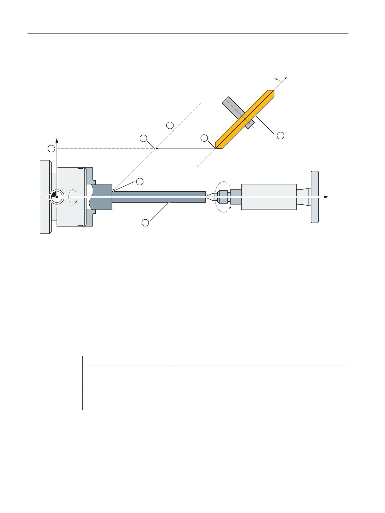
Kinematic transformations
5.3 Oblique angle transformation (inclined axis) TRAANG_K (option)
Example
˞
80
;
1
1
= =0
0
&0
$60
①
Grinding wheel
②
Workpiece
③
Parallel to the inclined axis through the programmed end position
④
Starting position
⑤
Plunge-cutting: Starting position
⑥
Plunge-cutting: End position
⑦
Parallel to the Z axis, at a distance from the actual position of the X axis
X
Geometry axis
Z
Geometry axis
ZM
Machine axis
UM
Machine axis
Figure 5-16
Programming an inclined axis
Program code
Comment
N... G18
; Select XZ plane.
N40 TRAANG (45.0)
; Activate TRAANG transformation, angle = 45°
N50 G7 X40 Z70 F4000
; Calculate the starting position and approach
N60 G5 X40 F100
; Traverse inclined axis to the end position.
N70 ...
5.3.5
Boundary conditions
The transformation can be selected and deselected via part program or MDA.
Transformations
132
Function Manual, 10/2020, 6FC5397-5GP40-0BA1
Kinematic transformations
5.3 Oblique angle transformation (inclined axis) TRAANG_K (option)
Selection and deselection
• An intermediate motion block is not inserted (phases/radii).
• A spline block sequence must be terminated.
• Tool radius compensation must be deselected.
• The current frame is deselected by the control system. Corresponds to programmed G500.
• An active working area limitation is deselected by the control for the axes affected by the
transformation (corresponds to programmed WALIMOF).
• An activated tool length compensation is included in the transformation by the control.
• Continuous path control and rounding are interrupted.
• DRF offsets must have been deleted by the operator.
• All axes specified in machine data MD24110 $MC_TRAFO_AXES_IN_n must be synchronized
on a block-related basis (e.g. no traversing instruction with POSA...).
Tool change
Tools may only be changed when the tool radius compensation function is deselected.
Frames
All instructions which refer to the workpiece coordinate system are permissible (FRAME, tool
radius compensation). Unlike the procedure for inactive transformation, however, a frame
change with G91 (incremental dimension) is not specially treated. The increment to be traversed
is evaluated in the workpiece coordinate system of the new frame - regardless of which frame
was effective in the previous block.
Extensions
When the oblique angle transformation (TRAANG) is selected and deselected, the assignment
between geometry axes and channel axes can change. The user can apply these geometric
contour sections to the axial frame as a translation, rotation, scaling and mirroring in relation to
the x and z planes with respect to the inclined infeed axis.
Further information
Further detailed information on the frame corrections for transformations can be found in:
Function Manual Basic Functions; Axes, coordinate systems, frames
Unusable functions
The following functions cannot be used in channel axes involved in the transformation:
• Set actual value (PRESETON)
• Travel to fixed stop (FXS)
• Reference point approach (G74 or manual reference point approach)
Transformations
Function Manual, 10/2020, 6FC5397-5GP40-0BA1
133
Kinematic transformations
5.3 Oblique angle transformation (inclined axis) TRAANG_K (option)
Velocity control
The velocity monitoring function for oblique angle transformation (TRAANG) is implemented by
default during preprocessing. The velocity monitoring function and limitation in the main run
takes place in the following operating states:
• AUTOMATIC mode: Programming of a positioning or oscillating axis that is involved in the
transformation
• JOG mode: After a change of operating mode to JOG mode
After resynchronization of the preprocessing to the main run, e.g. after a change of operating
mode from JOG to AUTOMATIC mode, velocity monitoring and limitation takes place in the
preprocessing again.
Note
Program operation: Behavior with axis-specific feedrate stop
• Velocity monitoring in main run
Program execution is stopped with active velocity monitoring in the main run for one of the
axes involved in the transformation of the axis-specific feedrate stop at (DBX31, ... DBX4.3 ==
1).
• Velocity monitoring in the preprocessing
The NC program execution continues with active velocity monitoring in the preprocessing for
one of the axes involved in the transformation of the axis-specific feedrate stop at
(DBX31, ... DBX4.3 == 1). The precondition for this is that no traversing motions are
programmed for the relevant axis.
Transformations
134
Function Manual, 10/2020, 6FC5397-5GP40-0BA1
Kinematic transformations
5.3 Oblique angle transformation (inclined axis) TRAANG_K (option)
5.3.6
Example
5.3.6.1
"Kinematic chain" part program for TRAANG
Example program "TRAANG"
Transformations
Function Manual, 10/2020, 6FC5397-5GP40-0BA1
135
Kinematic transformations
5.3 Oblique angle transformation (inclined axis) TRAANG_K (option)
Program code
;===========================================================
; Simple example of TRAANG with kinematic chain
;******************************************************
N2000
$NK_NAME[_KIE_CNTR]
= "ROOT"
N2010
$NK_TYPE[_KIE_CNTR]
= "OFFSET"
N2020
$NK_NEXT[_KIE_CNTR]
= "X-Axis"
N2030
$NK_PARALLEL[_KIE_CNTR]
= ""
N2040
_KIE_CNTR = _KIE_CNTR + 1
N2050
$NK_NAME[_KIE_CNTR]
= "X-Axis"
N2060
$NK_TYPE[_KIE_CNTR]
= "AXIS_LIN"
N2070
$NK_NEXT[_KIE_CNTR]
= "Z-Axis"
N2080
$NK_AXIS[_KIE_CNTR]
= "X1"
N2090
$NK_OFF_DIR[_KIE_CNTR,0]
= COS(20)
N2100
$NK_OFF_DIR[_KIE_CNTR,2]
= SIN(20)
N2110
_KIE_CNTR = _KIE_CNTR + 1
N2120
$NK_NAME[_KIE_CNTR]
= "Z-Axis"
N2130
$NK_TYPE[_KIE_CNTR]
= "AXIS_LIN"
N2140
$NK_NEXT[_KIE_CNTR]
= "Y-Axis"
N2150
$NK_AXIS[_KIE_CNTR]
= "Z1"
N2160
$NK_OFF_DIR[_KIE_CNTR,2]
= 1.0
N2170
_KIE_CNTR = _KIE_CNTR + 1
N2180
$NK_NAME[_KIE_CNTR]
= "Y-Axis"
N2190
$NK_TYPE[_KIE_CNTR]
= "AXIS_LIN"
N2200
$NK_NEXT[_KIE_CNTR]
= ""
N2210
$NK_AXIS[_KIE_CNTR]
= "Y1"
N2220
$NK_OFF_DIR[_KIE_CNTR,1]
= 1.0
N2230
_KIE_CNTR = _KIE_CNTR + 1
; Definition of the kinematic transformation:
;******************************************************
; TRRANG
;******************************************************
N2240
$NT_NAME[_TRA_CNTR]
= "Trafo Traang"
N2250
$NT_TRAFO_TYPE[_TRA_CNTR]
= "TRAANG_K"
N2260
$NT_T_CHAIN_LAST_ELEM[_TRA_CNTR]
= "Y-Axis"
N2270
$NT_P_CHAIN_LAST_ELEM[_TRA_CNTR]
= ""
N2280
$NT_GEO_AX_NAME[_TRA_CNTR,0]
= "X-Axis"
"N2290
$NT_GEO_AX_NAME[_TRA_CNTR,2]
= "Y-Axis
N2300
$NT_GEO_AX_NAME[_TRA_CNTR,1]
= "Z-Axis"
N2310
$NT_ROT_OFFSET_FROM_FRAME[_TRA_CNTR] = 1
N2320
_TRA_CNTR = _TRA_CNTR + 1
;******************************************************
; Activation of the kinematic chain and transformation:
;******************************************************
N2330
NEWCONF
N2340
STOPRE
;**********************************************************
;========================= END ===========================
Transformations
136
Function Manual, 10/2020, 6FC5397-5GP40-0BA1
Kinematic transformations
5.3 Oblique angle transformation (inclined axis) TRAANG_K (option)
5.3.6.2
Example
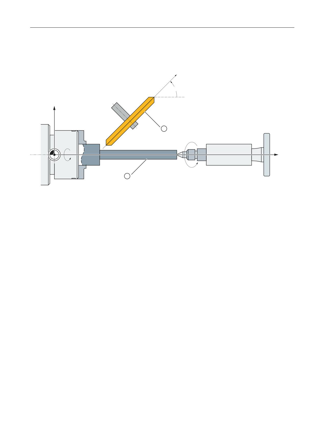
The example refers to the axis configuration shown in the following figure.
80
˞
;
= =0
0
&0
$60
①
Grinding disk
②
Workpiece
X
Geometry axis
Z
Geometry axis
ZM
Machine axis
UM
Machine axis
α
Angle of inclined axis
CM
Machine axis (spindle)
ASM
Machine axis (tailstock)
Figure 5-17
Inclined axis
Parameterization
Machine axis name
• MD10000 $MN_AXCONF_MACHAX_NAME_TAB[ 0 ] = "CM"
• MD10000 $MN_AXCONF_MACHAX_NAME_TAB[ 1 ] = "UM"
• MD10000 $MN_AXCONF_MACHAX_NAME_TAB[ 2 ] = "ZM"
• MD10000 $MN_AXCONF_MACHAX_NAME_TAB[ 3 ] = "ASM"
Geometry axis names
• MD20060 $MC_AXCONF_GEOAX_NAME_TAB[ 0 ] = "X" (name of the 1st geometry axis)
• MD20060 $MC_AXCONF_GEOAX_NAME_TAB[ 1 ] = "Y" (name of the 2nd geometry axis)
• MD20060 $MC_AXCONF_GEOAX_NAME_TAB[ 2 ] = "Z" (name of the 3rd geometry axis)
Transformations
Function Manual, 10/2020, 6FC5397-5GP40-0BA1
137
Kinematic transformations
5.3 Oblique angle transformation (inclined axis) TRAANG_K (option)
Channel axis names
• MD20080 $MC_AXCONF_CHANAX_NAME_TAB[ 0 ] = "ZC"
• MD20080 $MC_AXCONF_CHANAX_NAME_TAB[ 1 ] = "CC"
• MD20080 $MC_AXCONF_CHANAX_NAME_TAB[ 2 ] = "ASC"
• MD20080 $MC_AXCONF_CHANAX_NAME_TAB[ 3 ] = "UC"
Assignment of geometry axes to channel axes
TRAANG not active:
• MD20050 $MC_AXCONF_GEOAX_ASSIGN_TAB[ 0 ] = 0 ( - )
• MD20050 $MC_AXCONF_GEOAX_ASSIGN_TAB[ 1 ] = 0 ( - )
• MD20050 $MC_AXCONF_GEOAX_ASSIGN_TAB[ 2 ] = 1 (3rd GeoAxis → 1st channel axis ZC)
TRAANG active:
• MD24120 $MC_TRAFO_GEOAX_ASSIGN_TAB_1[ 0 ] = 4 (1st TrafoGeoAxis → 4th channel
axis UC)
• MD24120 $MC_TRAFO_GEOAX_ASSIGN_TAB_1[ 1 ] = 0 ( - )
• MD24120 $MC_TRAFO_GEOAX_ASSIGN_TAB_1[ 2 ] = 1 (3. TrafoGeoAxis → 1st channel axis
ZC)
Assignment of channel axes to machine axes
• MD20070 $MC_AXCONF_MACHAX_USED[ 0 ] = 3 (1st channel axis → 3rd machine axis ZM)
• MD20070 $MC_AXCONF_MACHAX_USED[ 1 ] = 1 (2nd channel axis → 1st machine axis CM)
• MD20070 $MC_AXCONF_MACHAX_USED[ 2 ] = 4 (3rd channel axis → 4th machine axis ASM)
• MD20070 $MC_AXCONF_MACHAX_USED[ 3 ] = 2 (4th channel axis → 2nd Machine axis UM)
Identification of spindles
• MD35000 $MA_SPIND_ASSIGN_TO_MACHAX[ 0 ] = 1 (spindle)
• MD35000 $MA_SPIND_ASSIGN_TO_MACHAX[ 1 ] = 0 (axis)
• MD35000 $MA_SPIND_ASSIGN_TO_MACHAX[ 2 ] = 0 (axis)
• MD35000 $MA_SPIND_ASSIGN_TO_MACHAX[ 3 ] = 2 (spindle)
Transformation type
• MD24100 $MC_TRAFO_TYPE_1 = 1024 (TRAANG)
Angle between Cartesian axis and real (oblique) axis
• MD24700 $MC_TRAANG_ANGLE_1 = 45.
Basic offset of the tool zero relative to the geometry axes while TRAANG is active
• MD24710 $MC_TRAANG_BASE_TOOL_1 [0] = 0.0 (offset relative to 1st TrafoGeoAxis)
• MD24710 $MC_TRAANG_BASE_TOOL_1 [1] = 0.0 (offset relative to 2nd TrafoGeoAxis)
• MD24710 $MC_TRAANG_BASE_TOOL_1 [2] = 0.0 (offset relative to 3rd TrafoGeoAxis)
Transformations
138
Function Manual, 10/2020, 6FC5397-5GP40-0BA1
Kinematic transformations
5.3 Oblique angle transformation (inclined axis) TRAANG_K (option)
TRAANG input axes
• MD24110 $MC_TRAFO_AXES_IN_1[ 0 ] = 4 (4th channel axis UC, inclined axis)
• MD24110 $MC_TRAFO_AXES_IN_1[ 1 ] = 1 (1st channel axis ZC, parallel with the Z axis)
• MD24110 $MC_TRAFO_AXES_IN_1[ 2 ] = 0 ( - )
Programming example
Program code
Comment
N10 G0 G90 Z0 UM=10 G54 F5000 G18 G64 T1 D1
; XZ planes, tool selection, clamping compensation
N20 TRAANG(45)
; Activate TRAANG with the first TRAANG data set
and angle 45°
N30 G0 Z10 X5
; Approach the start position
N40 WAITP(Z)
; Wait for end of travel of the Z axis
N50 OSP1[Z]=10 OSP2[Z]=5 OST1[Z]=-2 OST2[Z]=-2
; Oscillating motion
FA[Z]=5000
; OSP1/OSP2: Left/right reversal point
; OST1/OST2: Stopping point at the left/right re-
versal point
N60 OS[Z]=1
; Activate oscillation
N70 POS[X]=4.5 FA[X]=50
; Position X axis in parallel
N80 OS[Z]=0
; Deactivate oscillation
N90 WAITP(Z)
; Wait for end of travel of the Z axis
N100 TRAFOOF
; Deactivate transformation
N110 G0 Z10 UM=10
; Retract
N120 M30
Transformations
Function Manual, 10/2020, 6FC5397-5GP40-0BA1
139
Kinematic transformations
5.4 Rotary interpolation transformation TRAINT (option)
5.4
Rotary interpolation transformation TRAINT (option)
5.4.1
Function
5.4.1.1
Interpolation turning (TRAINT)
Interpolation turning (turning on a milling machine)
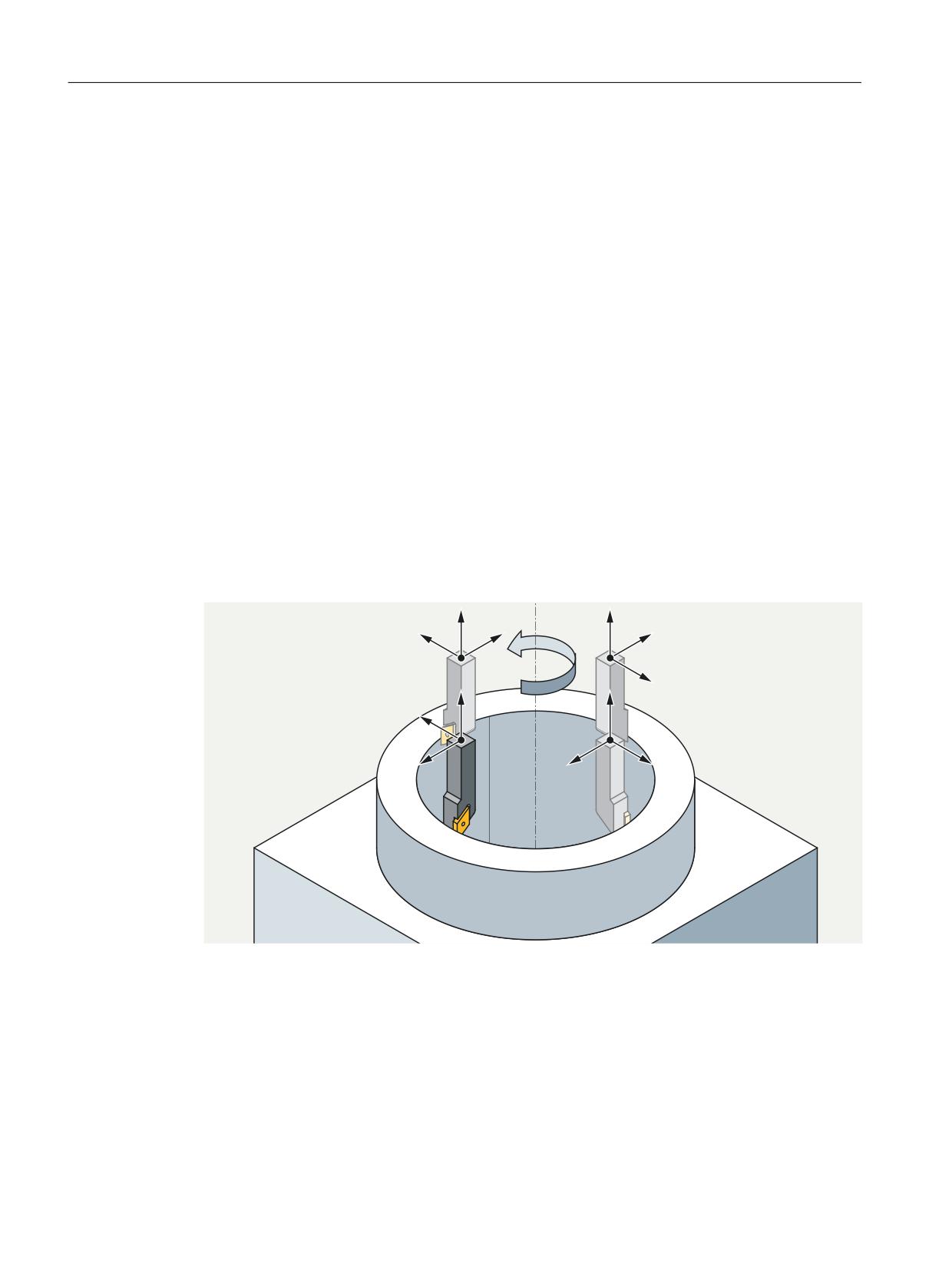
The "interpolation turning" function is intended to provide the user on a suitable machine tool
(e.g. milling machine, turning machine with three linear axes) with the environment of a simple
turning machine so that the NC commands and cycles function as on a turning machine. For this
purpose, the rotary motion is converted within the control into a circular motion of the linear
axes by means of a transformation and accordingly, the cutting edge of the tool is always aligned
with the center of rotation during the motion. The rotation does not take place through an axis
of rotation of the machine, but through a traversing movement of linear axes x, y and z, from
which a circular movement results. This distinguishes the "interpolation turning" function from
the "turning on milling machine" functionality. The axis of rotation can be selected as the center
of the turning operations and of the spindle at any mechanically accessible workpiece position
and can be freely oriented in space for 4 or 5-axis machines.
Figure 5
-18
Interpolation turning
Transformations
140
Function Manual, 10/2020, 6FC5397-5GP40-0BA1
Kinematic transformations
5.4 Rotary interpolation transformation TRAINT (option)
NOTICE
Linear axes are coupled to tool spindle
The linear axes are coupled to the tool spindle during interpolation turning. A rotation of the
spindle automatically results in motions of the linear axes. This is especially true if there is no
path motion, the path motion is stopped due to G4, or the path override is set to 0.
In contrast to a turning machine, an NC stop also stops the spindle motion.
Machine kinematics as a kinematic chain
"Interpolation turning" is only implemented as transformation based on a kinematic chain.
The axis of rotation is always parallel to the direction of the tool spindle (z axis when turning).
The axis of rotation can be freely oriented in space, for example with CYCLE800 or frames, but
must remain fixed during the rotation.
The center of the axis of rotation (spindle) must coincide with the center of the workpiece and
lies in the current zero point of the workpiece coordinate system (WCS).
The rotation is translated into movements of the linear axes through the transformation.
Accordingly, the tool cutting edge is always aligned with the center of rotation during the
motion.
Cycle 806 (option subject to license)
Cycle 806 can also be used to program interpolation turning.
Order number: 6FC5800-0BS37-0YB0
A detailed description can be found in the Programming Manual NC Programming.
Activating/deactivating transformation
A detailed description of this can be found under Activating TRAINT with TRAFOON (Page 144).
Tool length compensation
Directly after activating the transformation, the WCS position y must be equal to 0. Here it should
be noted that without transformation the tool lengths in the BCS are used without taking the
spindle position (i.e. the actual orientation of the tool) into account.
Without transformation, a difference between the tool tip and the WCS position therefore occurs
when the tool is rotated (SPOS unequal to 0 or unequal to clamping angle). This must be
corrected accordingly before TRAFOON (usually y is then not equal to 0 in the WCS, so that after
TRAFOON and taking into account the rotation of the tool y is equal to 0).
Transformations
Function Manual, 10/2020, 6FC5397-5GP40-0BA1
141
Kinematic transformations
5.4 Rotary interpolation transformation TRAINT (option)
The variables $P_TRAINT_ROT_ANGLE and $P_TRAINT_SPOS_ANGLE support the user in setting
the WCS position y equal to 0.
• $P_TRAINT_ROT_ANGLE:
The $P_TRAINT_ROT_ANGLE variable reads the correct frame rotation for selection of the
transformation TRAINT.
• $P_TRAINT_SPOS_ANGLE:
The $P_TRAINT_SPOS_ANGLE variable reads the correct position of the spindle for selection
of the transformation TRAINT.
In addition, the spindle is to be aligned via SPOS so that the tool is oriented toward the center of
rotation.
Velocity control
On a turning machine, the total motion is the result of the rotary motion by the turning spindle
and the path motion by the geometry axes X and Z. An axis of the path motion has no influence
on the rotary motion and vice versa. This independence does not exist with interpolation
turning. The machine axes X, Y and Z provide both rotational and path motion.
You can set the weighting of the shares via machine data (value range 0.001 to 0.999):
• $MC_IPT_AXIS_DYNAMIC_FACTORS[0]; Proportion of the axis acceleration limit
$MA_MAX_AX_ACCEL for the speed and acceleration of the rotary motion.
• $MC_IPT_AXIS_DYNAMIC_FACTORS[1] Influence of the axis acceleration
$MA_MAX_AX_ACCEL on the speed of the rotary motion.
- Larger value = faster rotation
• $MC_IPT_AXIS_DYNAMIC_FACTORS[2] Influence of the axis acceleration
$MA_MAX_AX_ACCEL on the acceleration of the rotary motion.
- Larger value = faster rotation
• $MC_IPT_AXIS_DYNAMIC_FACTORS[3] Proportion of the axis velocity limit for the velocity of
the rotary motion. The axis velocity limit is always $MA_MAX_AX_VELO, but a lower value
may be relevant, e.g. when SLS is activated.
• $MC_IPT_AXIS_DYNAMIC_FACTORS[4] Percentage of the axis jerk limit $MA_MAX_AX_JERK
for the rotary motion at constant speed.
For the rotary motion there is a maximum speed and a maximum rotational acceleration, which
depends on the radius. The setpoint speed of the spindle is specified continuously in the main
run and according to the current radius.
There is a warning if the speed (resulting from the TRAINT consideration) is less than
$SA_SPIND_MIN_VELO_G25.
The spindle override refers to the programmed spindle speed and not to the maximum possible
speed with the current radius (which may be lower than the programmed speed)
Transformations
142
Function Manual, 10/2020, 6FC5397-5GP40-0BA1
Kinematic transformations
5.4 Rotary interpolation transformation TRAINT (option)
Example of kinematics
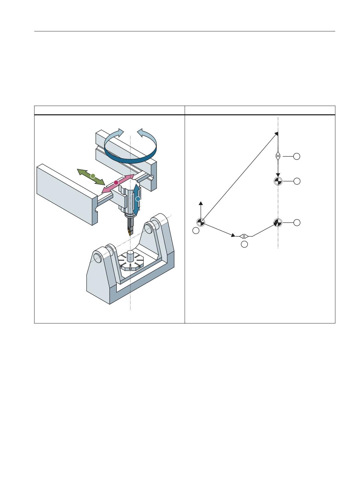
The example shows a 5-axis milling machine in AC kinematics. In the code example you will find
the definition of the kinematic chain with the corresponding definition of the TRAINT
transformation.
Table 5-2
5-axis milling machine in AC table kinematics
<
;
=
=
Kinematic chain
① World coordinate system
② Rotary axis 2 (A axis)
③ Tool reference point (end of the part chain)
④ Tool reference point (end of the tool chain)
⑤ Rotary axis 1 (C axis = spindle) parallel to the z axis
5-axis machine
Transformations
Function Manual, 10/2020, 6FC5397-5GP40-0BA1
143
Kinematic transformations
5.4 Rotary interpolation transformation TRAINT (option)
5.4.2
Parameterization of the kinematic chain and transformation
5.4.2.1
Parameterization of kinematics and transformation (TRAINT)
Specifications for the configuration of the kinematic chain
• $NT_P_CHAIN_LAST_ELEM (Page 34)
The element to be entered here must be the last element in the table chain that is not a rotary
axis.
• $NT_CNTRL (Page 47)
The chain should be closed (value 'H180').
5.4.2.2
System variables for TRAINT
System variables are available for defining the kinematic chain and the transformation. System
variables that are available for all kinematic transformations can be found at Commissioning
(Page 22).
Note
Establish a defined initial state
It is recommended that a defined initial state be generated before parameterizing the kinematic
chain. For this purpose, the system variables of the kinematic chain and the transformation with
the function DELOBJ() must be set to their default values.
Change system variable values
• Modified data (e.g. $NT_xxx or $NK_yyy) become effective after NEWCONF if the data does
not concern an active transformation (attention: persistent transformations or
transformations that remain active via reset/end of part program). If the data to be activated
with NEWCONF concern an active transformation, an alarm is output.
• Modified data (e.g. $NT_xxx or $NK_yyy) only become effective after a TRAFOOF and a
subsequent NC reset or NEWCONF or program end (M30).
• Changed data (e.g. $NT_xxx or $NK_yyy) become effective after NCK-PowerOn.
5.4.3
Programming
5.4.3.1
Activating TRAINT with TRAFOON
Activating TRAINT
The "interpolation turning" transformation TRAINT is activated in the part program with the
TRAFOON instruction and deactivated with the TRAFOOF instruction.
Transformations
144
Function Manual, 10/2020, 6FC5397-5GP40-0BA1
Kinematic transformations
5.4 Rotary interpolation transformation TRAINT (option)
Certain conditions must be fulfilled in order to activate and deactivate the transformation,
otherwise this is rejected by an alarm.
Activating transformation with TRAFOON
The "TRAINT" transformation is activated by the following command:
TRAFOON(<"transformation name", "γ">)
• The name of the transformation must be defined via the system variable $NT_NAME[n].
• The type of the transformation is specified via the system variable $NT_TRAFO_TYPE[n]
= "TRAINT".
• Angle "γ"; the gamma angle is used for the relative orientation of the cutting edge to the
tangent of the circle.
- At γ = 0 the cutting edge is perpendicular to the tangent of the circle and is outside the
circle (external machining).
- Correspondingly, at γ = 180° the cutting edge is also perpendicular to the tangent of the
circle, but within the circle (internal machining).
Both system variables are part of the transformation based on the kinematic chain.
Requirements for activation (must be fulfilled before TRAFOON)
• The center of rotation is defined as the zero point of the current frame, i.e. the WCS zero
point, and the direction of the axis of rotation corresponds to the Z axis in the WCS.
• To enable and disable the "interpolation turning" function, the machine must not move,
neither axes are traversing nor the spindle is rotating. (After switching on, the circular
movement must be activated by an S and M command)
• The direction of the tool spindle is antiparallel to the z direction of the WCS.
• The axes are positioned in such a way that after TRAFOON (and taking account of the tool
lengths), the y value in the WCS is 0. For details on tool length compensation, see
alsoInterpolation turning (TRAINT) (Page 140).
• The spindle is turned so that the desired position of the tool cutting edge to the workpiece
is achieved. There is currently no check (e.g. that the cutting edge of the tool is pointing
toward the center of rotation).
Note: Since the spindle points anti-parallelly to the Z axis, the negative angle must be
approached.
• The gamma angle is used to correct the cutting parameters, the actual adjustment of the tool
cutting edge must be done by positioning the spindle accordingly.
• The angle "γ" must be equal to 0° or 180°.
Deactivating transformation with TRAFOOF
Requirements for deactivating (TRAFOOF):
• Deactivating the transformation (TRAFOOF) is only possible when the spindle is stopped.
Transformations
Function Manual, 10/2020, 6FC5397-5GP40-0BA1
145
Kinematic transformations
5.4 Rotary interpolation transformation TRAINT (option)
5.4.4
Supplementary conditions and recommendations for TRAINT
Constraints
The following constraints must be taken into account for TRAINT:
• A kinematic chain suitable for the machine is defined. TRAINT is defined on the basis of the
kinematic chain.
• The angle "γ" is only released for values without deviation, i.e. only exactly for 0° (+/-0°) or
180° (+/-0°).
• A clamping angle unequal to 0° is not released.
• TRAINT is incompatible with the extended look-ahead MD20443
$MC_LOOKAH_FFORM[n]=1.
• TRAINT cannot be linked to another transformation.
• The orientation of the tool to the axis of rotation (spindle) is constant.
• It is not possible to engage the tool while turning. Static engaging via tool carriers is possible.
• Programmable couplings, e.g. synchronous spindle coupling, are incompatible with TRAINT.
• TRAINT must not be a persistent transformation.
• TRAINT is incompatible with Collision Avoidance.
• TRAINT is incompatible with angle head adapters or type 2 tool adapters. The angle head
adapter (adapter type 2) is only approved for tools that in the tool type range are outside of
tool type <500 or tool type >599. Thus, the combination of angle head adapter and
interpolation turning is impossible.
• NC stop stops the complete movement (including the spindle).
• TRAINT is incompatible with Advanced Surface and Top Surface.
• TRAINT in combination with conditional stops or configured stop is not released.
• There is no gear shifting (especially no automatic shifting with M40) when TRAINT is active.
• TRAINT cannot be effective as a POWER ON, reset or program end TRAFO.
Transformations
146
Function Manual, 10/2020, 6FC5397-5GP40-0BA1

Kinematic transformations
5.4 Rotary interpolation transformation TRAINT (option)
•
TRAINT is incompatible with the following function calls:
- CUT3DF, CUT3DFS, CUT3DFF, CUT3DFD, CUT3DC, CUT3DCD, CUT3DCCD
- PTP, PTPG0, PTPWOC
- G17, G19
- G331, G332, G335, G336, G33, G34, G35
- TOFFON
- TOWWCS, TOWMCS, TOWBCS, TOWTCS, TOWKCS
- DIAMONA, DIACYCOFA, DIAM90A, DIAMCHANA, DIAMOFA
- G63
- G961, G962, G97, G971, G972
- LFON
- DRIVE, BRISK
- SPCOF
- A call of the G code or function generates an alarm.
•
A frame change is not possible during an active TRAINT because the current frame is the
center of the transformation.
•
Calling the following G codes or functions generates an alarm:
- G5x (G500, G54…-G599) TRANS, ROT, MIRROR, SCALE, ATRANS AROT, AMIRROR, ASCALE
- SUPA, G153, SUPD, G53
Recommendations
It is recommended to set the following setting data as follows so that the assignment of the tool
length components (length, wear and basic dimension) and the tool orientation components of
turning and grinding tools (tool types 400 to 599) to the geometry axes is not changed when the
machining plane (G17 - G19) is changed.
SD
Identifier
Recommenda-
Description
tion
42940
$SC_TOOL_LENGTH_CONST
17
L1=Z, L2=Y, L3=X
42942
$SC_TOOL_LENGTH_CONST_T
19
L1=Z, L2=Y, L3=X
42950
$SC_TOOL_LENGTH_TYPE
3
Evaluation of SD 42942
42954
$SC_TOOL_ORI_CONST_M
0
Orientation depending on G17,18,19
42956
$SC_TOOL_ORI_CONST_T
18
Orientation vector (0,1,0)
It is recommended that the following machine data be set as follows to ensure that the dynamic
distribution between path motion (x-z motion) and circular motion is optimal.
MD
Identifier
Recommendation
Description
25500
$MC_IPT_AXIS_DYNAMIC_FACTORS [0]
0.1
default
25500
$MC_IPT_AXIS_DYNAMIC_FACTORS [1]
0.5
default
25500
$MC_IPT_AXIS_DYNAMIC_FACTORS [2]
0.5
default
Transformations
Function Manual, 10/2020, 6FC5397-5GP40-0BA1
147

Kinematic transformations
5.4 Rotary interpolation transformation TRAINT (option)
MD
Identifier
Recommendation
Description
25500
$MC_IPT_AXIS_DYNAMIC_FACTORS [3]
0.8
default
25500
$MC_IPT_AXIS_DYNAMIC_FACTORS [4]
0.8
default
It is recommended that the machine data MD35030 $MA_SPIND_DEFAULT_ACT_MASK is set as
follows: Thus, the spindle goes again into speed control mode upon reset.
MD
Identifier
Recommenda-
Description
tion
35030
$MA_SPIND_DE-
2
Default = 0
FAULT_ACT_MASK[<Spindle>]
It is recommended to set the following setting data as follows so that the position display of the
axes always takes place in the WCS to clearly indicate that Y position = 0.
MD
Identifier
Recommendation
Description
51037
$MNS_ENABLE_COORDINATE_ACS
0
Y position = 0
Transformations
148
Function Manual, 10/2020, 6FC5397-5GP40-0BA1
Kinematic transformations
5.4 Rotary interpolation transformation TRAINT (option)
5.4.5
Examples
5.4.5.1
Example of kinematic chain
Example program kinematic chain
The example shows the schematic structure of a program for the kinematic chain of a 5-axis
machine, see also Table 5-2 5-axis milling machine in AC table kinematics (Page 143).
Transformations
Function Manual, 10/2020, 6FC5397-5GP40-0BA1
149
Kinematic transformations
5.4 Rotary interpolation transformation TRAINT (option)
;######################################
; Prepare kinematic chain
;######################################
DEF INT COUNT1 = 0 COUNT2 = 0; counter for elements of the kin. chains and transformer
IF (DELOBJ("TRAFO_DATA") < 0)
SETAL(61000) ENDIF
IF (DELOBJ("KIN_CHAIN_ELEM") < 0)
SETAL(61001)
ENDIF
;########################################
; Define root element
;########################################
$NK_NAME[COUNT1]="ROOT" ;Index=0
$NK_NEXT[COUNT1]="Y1_AXIS_LIN"
$NK_PARALLEL[COUNT1]="A1_OFFSET"
$NK_TYPE[COUNT1]="OFFSET"
$NK_OFF_DIR[COUNT1,0]=0
$NK_OFF_DIR[COUNT1,1]=0
$NK_OFF_DIR[COUNT1,2]=0
$NK_AXIS[COUNT1]=""
$NK_A_OFF[COUNT1]=0
$NK_SWITCH_INDEX[COUNT1]=-1
$NK_SWITCH_POS[COUNT1]=0
COUNT1=COUNT1+1
;########################################
; Definition of the Y1 linear axis
;########################################
$NK_NAME[COUNT1]="Y1_AXIS_LIN" ;Index=1
$NK_NEXT[COUNT1]="X1_AXIS_LIN"
$NK_PARALLEL[COUNT1]=""
$NK_TYPE[COUNT1]="AXIS_LIN"
$NK_OFF_DIR[COUNT1,0]=0
$NK_OFF_DIR[COUNT1,1]=1
$NK_OFF_DIR[COUNT1,2]=0
$NK_AXIS[COUNT1]="Y1"
$NK_A_OFF[COUNT1]=0
COUNT1=COUNT1+1
;########################################
; Definition of the X1 linear axis
;########################################
$NK_NAME[COUNT1]="X1_AXIS_LIN" ;Index=2
$NK_NEXT[COUNT1]="Z1_AXIS_LIN"
$NK_PARALLEL[COUNT1]=""
$NK_TYPE[COUNT1]="AXIS_LIN"
$NK_OFF_DIR[COUNT1,0]=1
$NK_OFF_DIR[COUNT1,1]=0
$NK_OFF_DIR[COUNT1,2]=0
$NK_AXIS[COUNT1]="X1"
$NK_A_OFF[COUNT1]=0
$NK_SWITCH_INDEX[COUNT1]=-1
$NK_SWITCH_POS[COUNT1]=0
COUNT1=COUNT1+1
;########################################
Transformations
150
Function Manual, 10/2020, 6FC5397-5GP40-0BA1
Kinematic transformations
5.4 Rotary interpolation transformation TRAINT (option)
; Definition of the Z1 linear axis
;########################################
$NK_NAME[COUNT1]="Z1_AXIS_LIN" ;Index=3
$NK_NEXT[COUNT1]="SP1_AXIS_ROT"
$NK_PARALLEL[COUNT1]=""
$NK_TYPE[COUNT1]="AXIS_LIN"
$NK_OFF_DIR[COUNT1,0]=0
$NK_OFF_DIR[COUNT1,1]=0
$NK_OFF_DIR[COUNT1,2]=1
$NK_AXIS[COUNT1]="Z1"
$NK_A_OFF[COUNT1]=0
$NK_SWITCH_INDEX[COUNT1]=-1
$NK_SWITCH_POS[COUNT1]=0
COUNT1=COUNT1+1
;########################################
; Definition of the rotary axis (spindle)
;########################################
$NK_NAME[COUNT1]="SP1_AXIS_ROT" ;Index=4
$NK_NEXT[COUNT1]="END_TOOL_CHAIN"
$NK_PARALLEL[COUNT1]=""
$NK_TYPE[COUNT1]="AXIS_ROT"
$NK_OFF_DIR[COUNT1,0]=0
$NK_OFF_DIR[COUNT1,1]=0
$NK_OFF_DIR[COUNT1,2]=-1
$NK_AXIS[COUNT1]="SP1"
$NK_A_OFF[COUNT1]=0
$NK_SWITCH_INDEX[COUNT1]=-1
$NK_SWITCH_POS[COUNT1]=0
COUNT1=COUNT1+1
;########################################
; End of the tool chain of the kinematic chain
;########################################
$NK_NAME[COUNT1]="END_TOOL_CHAIN" ;Index=5
$NK_NEXT[COUNT1]=""
$NK_PARALLEL[COUNT1]=""
$NK_TYPE[COUNT1]="OFFSET"
$NK_OFF_DIR[COUNT1,0]=0
$NK_OFF_DIR[COUNT1,1]=0
$NK_OFF_DIR[COUNT1,2]=0
$NK_AXIS[COUNT1]=""
$NK_A_OFF[COUNT1]=0
$NK_SWITCH_INDEX[COUNT1]=-1
$NK_SWITCH_POS[COUNT1]=0
COUNT1=COUNT1+1
;########################################
; Definition of the A1 offsets
;########################################
$NK_NAME[COUNT1]="A1_OFFSET" ;Index=6
$NK_NEXT[COUNT1]="A1_AXIS_ROT"
$NK_PARALLEL[COUNT1]=""
$NK_TYPE[COUNT1]="OFFSET"
$NK_OFF_DIR[COUNT1,0]=0
$NK_OFF_DIR[COUNT1,1]=0
$NK_OFF_DIR[COUNT1,2]=100
$NK_AXIS[COUNT1]=""
$NK_A_OFF[COUNT1]=0
Transformations
Function Manual, 10/2020, 6FC5397-5GP40-0BA1
151
Kinematic transformations
5.4 Rotary interpolation transformation TRAINT (option)
$NK_SWITCH_INDEX[COUNT1]=-1
$NK_SWITCH_POS[COUNT1]=0
COUNT1=COUNT1+1
;########################################
; Definition of the A1 offsets of the rotary axis
;########################################
$NK_NAME[COUNT1]="A1_AXIS_ROT" ;Index=7
$NK_NEXT[COUNT1]="JOINT_OFFSET"
$NK_PARALLEL[COUNT1]=""
$NK_TYPE[COUNT1]="AXIS_ROT"
$NK_OFF_DIR[COUNT1,0]=-1
$NK_OFF_DIR[COUNT1,1]=0
$NK_OFF_DIR[COUNT1,2]=0
$NK_AXIS[COUNT1]="A1"
$NK_A_OFF[COUNT1]=0
$NK_SWITCH_INDEX[COUNT1]=-1
$NK_SWITCH_POS[COUNT1]=0
COUNT1=COUNT1+1
;########################################
; Definition of the offset of rotary axis C1
;########################################
$NK_NAME[COUNT1]="JOINT_OFFSET" ;Index=8
$NK_NEXT[COUNT1]="C1_AXIS_ROT"
$NK_PARALLEL[COUNT1]=""
$NK_TYPE[COUNT1]="OFFSET"
$NK_OFF_DIR[COUNT1,0]=0
$NK_OFF_DIR[COUNT1,1]=0
$NK_OFF_DIR[COUNT1,2]=-100
$NK_AXIS[COUNT1]=""
$NK_A_OFF[COUNT1]=0
$NK_SWITCH_INDEX[COUNT1]=-1
$NK_SWITCH_POS[COUNT1]=0
COUNT1=COUNT1+1
;########################################
; Definition of the C1 rotary axis
;########################################
$NK_NAME[COUNT1]="C1_AXIS_ROT" ;Index=9
$NK_NEXT[COUNT1]="END_PART_CHAIN"
$NK_PARALLEL[COUNT1]=""
$NK_TYPE[COUNT1]="AXIS_ROT"
$NK_OFF_DIR[COUNT1,0]=0
$NK_OFF_DIR[COUNT1,1]=0
$NK_OFF_DIR[COUNT1,2]=-1
$NK_AXIS[COUNT1]="C1"
$NK_A_OFF[COUNT1]=0
$NK_SWITCH_INDEX[COUNT1]=-1
$NK_SWITCH_POS[COUNT1]=0
COUNT1=COUNT1+1
;########################################
; End of the part chain of the kinematic chain
;########################################
$NK_NAME[COUNT1]="END_PART_CHAIN" ;Index=10
$NK_NEXT[COUNT1]=""$NK_PARALLEL[COUNT1]=""
$NK_TYPE[COUNT1]="OFFSET"
$NK_OFF_DIR[COUNT1,0]=0
$NK_OFF_DIR[COUNT1,1]=0
Transformations
152
Function Manual, 10/2020, 6FC5397-5GP40-0BA1
Kinematic transformations
5.4 Rotary interpolation transformation TRAINT (option)
$NK_OFF_DIR[COUNT1,2]=0
$NK_AXIS[COUNT1]=""
$NK_A_OFF[COUNT1]=0
$NK_SWITCH_INDEX[COUNT1]=-1
$NK_SWITCH_POS[COUNT1]=0
;########################################
; Definition of the transformation elements
;########################################
$NT_NAME[COUNT2]="TRAIPD" ;Index COUNT2=5
$NT_TRAFO_TYPE[COUNT2]="TRAINT”
$NT_T_CHAIN_FIRST_ELEM[COUNT2]=""
$NT_P_CHAIN_FIRST_ELEM[COUNT2]=""
$NT_T_CHAIN_LAST_ELEM[COUNT2]="END_TOOL_CHAIN"
$NT_P_CHAIN_LAST_ELEM[COUNT2]="ROOT"
$NT_T_REF_ELEM[COUNT2]=""
$NT_GEO_AX_NAME[COUNT2,0]="X1_AXIS_LIN"
$NT_GEO_AX_NAME[COUNT2,1]="Y1_AXIS_LIN"
$NT_GEO_AX_NAME[COUNT2,2]="Z1_AXIS_LIN"
$NT_ROT_AX_NAME[COUNT2,0]="SP1_AXIS_ROT"
$NT_CNTRL[COUNT2]='H180'
; Close chain
;########################################
;Swivel data set
;########################################
$TC_CARR7[COUNT6]=-1
$TC_CARR8[COUNT6]=0
$TC_CARR9[COUNT6]=0
$TC_CARR10[COUNT6]=0
$TC_CARR11[COUNT6]=0
$TC_CARR12[COUNT6]=-1
$TC_CARR21[COUNT6]=X ;Index COUNT6=1
$TC_CARR22[COUNT6]=X
$TC_CARR23[COUNT6]="P"
$TC_CARR30[COUNT6]=-110
$TC_CARR31[COUNT6]=-360
$TC_CARR32[COUNT6]=110
$TC_CARR33[COUNT6]=360
$TC_CARR34[COUNT6]="TC_1"
$TC_CARR35[COUNT6]="A"
$TC_CARR36[COUNT6]="C"
$TC_CARR37[COUNT6]=400009000
$TC_CARR_KIN_TOOL_START[COUNT6]=""
$TC_CARR_KIN_TOOL_END[COUNT6]=""
$TC_CARR_KIN_PART_START[COUNT6]="ROOT"
$TC_CARR_KIN_PART_END[COUNT6]="END_PART_CHAIN"
$TC_CARR_KIN_CNTRL[COUNT6]='H7'
$TC_CARR_KIN_ROTAX_NAME[COUNT6,0]="A1_AXIS_ROT"
$TC_CARR_KIN_ROTAX_NAME[COUNT6,1]="C1_AXIS_ROT"
See also
Interpolation turning (TRAINT) (Page 140)
Transformations
Function Manual, 10/2020, 6FC5397-5GP40-0BA1
153
Kinematic transformations
5.4 Rotary interpolation transformation TRAINT (option)
5.4.5.2
Example without tool rotation
Simple example without tool rotation
The configuration from Example of kinematic chain (Page 149) is used. The recommendations
from Supplementary conditions and recommendations for TRAINT (Page 146) were used.
Transformations
154
Function Manual, 10/2020, 6FC5397-5GP40-0BA1
Kinematic transformations
5.4 Rotary interpolation transformation TRAINT (option)
;######################################
;Tool
;######################################
$TC_TP2[1]="FINISHING TOOL"
$TC_DP1[1,1]=510$TC_DP2[1,1]=3
$TC_DP3[1,1]=100
$TC_DP4[1,1]=20
$TC_DP5[1,1]=30
$TC_DP6[1,1]=0.1;
;######################################
Recommendations
;######################################
$SC_TOOL_LENGTH_CONST=17 ; L1=Z, L2=Y, L3=X
$SC_TOOL_LENGTH_CONST_T=19 ; L1=Z, L2=Y, L3=X
$SC_TOOL_LENGTH_TYPE=3
; Evaluation from SD 42942
$SC_TOOL_ORI_CONST_M=0
; Orientation depends on G17,18,19
$SC_TOOL_ORI_CONST_T=18
; Orientation vector (0,1,0)
NEWCONF; Establish initial setting of milling machine
G54 G17
G0 X0 Y0 Z10
;######################################
; Any preparatory work
; e.g. milling with or without TRAORI.
; ...
; Select turning tool
;######################################
T="FINISHING TOOL"
G18
G0 X0 Y0 Z10
;######################################
; The tool is positioned in this example such that
; - L2 along WCS Y direction
; - L3 along WCS Z direction
; It should be rotated around the BCS Z axis.
; The machine is positioned such that the WCS Y position
; is equal to 0; frame shifting/rotating is therefore no longer necessary.
;######################################
$P_PFRAME=CROT(Z,ATAN2($AA_IW[Y],%AA_IW[X]))
$P_PFRAME=$P_PFRAME:CROT(Z, $P_TRAINT_SPOS_ANGLE)
G0 X0 Y0 Z10
;######################################
; Align spindle if necessary and bring it into continuous position control
;######################################
SPOS=$P_TRAINT_ROT_ANGLE+$P_TRAINT_SPOS_ANGLE SPCON
;######################################
; Activate interpolation turning
;######################################
TRAFOON("TRAIPD")
;######################################
; Now the machine is in turning machine mode
; Turning
;######################################
M3 S10 G95 G18
G4 F1
Transformations
Function Manual, 10/2020, 6FC5397-5GP40-0BA1
155
Kinematic transformations
5.4 Rotary interpolation transformation TRAINT (option)
G0 X0 Z10
G1 F1 Z5 G42
G1 X0
G0 Z2
G0 X60
G1 Z-20
G2 Z-30 CR=5
G1 Z-40
G0 X62 G40
G0 Z2
SPOS=0
M5
;######################################
; Deactivate interpolation turning
;######################################
TRAFOOF
SPCOF
M30
Transformations
156
Function Manual, 10/2020, 6FC5397-5GP40-0BA1
Kinematic transformations
5.4 Rotary interpolation transformation TRAINT (option)
5.4.5.3
Example for TRAINT
Example program
The example schematically shows the structure of a program with TRAINT. The kinematics of the
sample program Example of kinematic chain (Page 149) is used. A tool carrier "TC_1" is defined.
Transformations
Function Manual, 10/2020, 6FC5397-5GP40-0BA1
157
Kinematic transformations
5.4 Rotary interpolation transformation TRAINT (option)
;######################################
; Tool
;######################################
$TC_TP2[1]="FINISHING TOOL"
$TC_DP1[1,1]=510
$TC_DP2[1,1]=3
$TC_DP3[1,1]=100
$TC_DP4[1,1]=0
$TC_DP5[1,1]=0
$TC_DP6[1,1]=0.1
;########################################
; Recommendation
;########################################
$SC_TOOL_LENGTH_CONST=17 ; L1=Z, L2=Y, L3=X
$SC_TOOL_LENGTH_CONST_T=19 ; L1=Z, L2=Y, L3=X
$SC_TOOL_LENGTH_TYPE=3
; Evaluation of SD 42942$
SC_TOOL_ORI_CONST_M=0
; Orientation dep. on G17,18,19
$SC_TOOL_ORI_CONST_T=18
; Orientation vector (0,1,0)
NEWCONF
;########################################
; Establish initial setting of milling machine
;########################################
G54 G17
G0 X0 Y0 Z10
;########################################
; Any preparatory work
; e.g. milling with or without TRAORI.
; ...
; Select turning tool
;########################################
T="FINISHING TOOL"
G0 X0 Y0 Z10
;########################################
; The tool is anywhere in space
; Swivel cycle:
; - Frame is moved to the desired machining location:
X=20, Y=30, Z=40, swiveled -20° about x axis
; - Rotary axes are moved so that the tool spindle is parallel
;
to the y axis of the WCS: A axis at -20°
;########################################
CYCLE800(0,"TC_1",200000,57,20,30,40,-20,0,0,0,0,0,1,,2)
G0 X0 Y0 Z10
;########################################
; Interpolation turning cycle
; - Rotating the frame so that after switching on the WCS-Y position
Transformations
158
Function Manual, 10/2020, 6FC5397-5GP40-0BA1
Kinematic transformations
5.5 Chained transformations
;
of the transformation is 0
; - Switching on the transformation
;########################################
CYCLE806(1,0,0,0,0,)
;########################################
; Turning
;########################################
M3 S10
G4 F1
G0 X0 Y0 Z10
G1 F1 Z5 G42
G1 X0G0 Z2
G0 X60
G1 Z-20
G2 Z-30 CR=5
G1 Z-40
G0 X62 G40
G0 Z2
;########################################
; Interpolation turning cycle
; - Deactivate interpolation turning
;########################################
CYCLE806()
M30
5.5
Chained transformations
5.5.1
Concatenating transformations (TRACON_K)
In transformations with kinematic chains, non-orthogonal axes can be defined via the kinematic
chain. This means that transformations no longer have to be concatenated with TRACON to map
non-orthogonal axes.
Transformation type "TRACON_K" (Page 30) is used in combination with kinematic chains in
order to chain an "Open Architecture (OA)" transformation with one of the standard
transformations. More detailed information is provided in the "Open Architecture (OA)"
documentation.
More information
A detailed description of the concatenation of transformations without kinematic chains can be
found in Concatenated transformations (Page 161).
Transformations
Function Manual, 10/2020, 6FC5397-5GP40-0BA1
159

Kinematic transformations
5.5 Chained transformations
See also
$NT_TRACON_CHAIN (Page 160)
$NT_TRAFO_INDEX (Page 28)
5.5.2
Additive system variables for transformation chains (TRACON_K)
5.5.2.1
$NT_TRACON_CHAIN
Function
For chained transformations ($NT_TRAFO_TYPE[...] = "TRACON_K") with this system variable,
the names of the part transformations are specified in the order in which the transformation of
the BKS to the MKS is to be carried out.
Syntax
$NT_TRACON_CHAIN[<n>,<m>] = "<Name>"
Meaning
$NT_TRACON_CHAIN:
System variable for specifying the partial transformations for
chained transformations
<n>:
System variable or transformation index
Data type:
INT
Range of values:
1, 2, ... (MD18866 $MN_MM_NUM_KIN_TRA-
FOS - 1)
<m>:
Position of the partial transformation in the transformation chain
Data type:
INT
Range of values:
0, 1
<name>:
Name of the partial transformation
Data type:
STRING
Example
Program code
Comment
N2502 $NT_TRACON_CHAIN[2,0] = "Open Architecture Transformation"
; Partial transformation 1
N2503 $NT_TRACON_CHAIN[2,1] = "Inclined axis"
; Partial transformation 2
Transformations
160
Function Manual, 10/2020, 6FC5397-5GP40-0BA1
Kinematic transformations
5.5 Chained transformations
5.5.3
Concatenation for machine data parameterization
5.5.3.1
Introduction
For a concatenated transformation, two transformations can be connected one after the other
(chained). As a consequence, motion components of the axes can be taken from the first
transformation and used as input data for the second transformation. The motion components
of the axes from the second transformation then act on the machine axes.
• The following are possible as first transformation:
- TRAORI orientation transformations, including universal milling head
Further information
Orientation transformations (Page 217)
- Face end transformation TRANSMIT
- Cylinder surface transformation TRACYL
• Only the following is possible as second transformation:
- Inclined axis TRAANG
Note
Exception, when commissioning
A concatenated transformation normally comprises two transformations chained one after the
other. For test purposes, e.g. during commissioning, it is also permissible to enter just one
transformation in the chaining list.
Note
Different axis identifiers
For active transformation, the names of the machine, channel and geometry axes involved must
be different:
• MD10000 $MN_AXCONF_MACHAX_NAME_TAB (machine axis name)
• MD20080 $MC_AXCONF_CHANAX_NAME_TAB (channel axis name)
• MD20060 $MC_AXCONF_GEOAX_NAME_TAB (geometry axis name)
Application examples
• Grinding contours that are programmed as a side line of a cylinder (TRACYL) using an inclined
grinding wheel, e.g. tool grinding.
• Finish cutting of a contour that is not round and was generated with TRANSMIT using an
inclined grinding wheel.
Axis configuration
The following configuration measures are necessary for a chained transformation:
• Assignment of names to geometry axes
• Assignment of names to channel axes
Transformations
Function Manual, 10/2020, 6FC5397-5GP40-0BA1
161
Kinematic transformations
5.5 Chained transformations
• Assignment of geometry axes to channel axes
- General situation (no transformation active)
• Assignment of channel axes to machine axis numbers
• Identification of spindle, rotation, modulo for axes
• Allocation of machine axis names
• Transformation-specific settings (for individual transformations and for chained
transformations)
- Transformation type
- Axes going into the transformation
- Assignment of geometry axes to channel axes during active transformation
- Depending on transformation, rotational position of the coordinate system, direction of
rotation, tool zero point in relation to the original coordinate system, angle of the inclined
axis, etc.
Note
Supplementary conditions and special cases
The supplementary conditions and special cases specified in the individual transformation
descriptions must also be observed when used within a chained transformation.
Boundary conditions
Transformation data blocks for each channel
Several transformation data blocks can be defined for each channel. The names of the
corresponding machine data of the transformations begin with $MC_TRAFO... and end
with..._n, where n = 1, 2, 3, ...
Number of chained transformations
Within the transformations of a channel, a maximum of two chained transformations may be
defined.
Chaining direction
The first transformation of the chained transformations has the basic coordinate system (BCS)
as input.
The second transformation of the chained transformations has the machine coordinate system
(MCS) as output.
Tool data
A tool is always assigned the first transformation of chained transformations. The subsequent
transformation then behaves as if the active tool length were zero.
Only the basic tool lengths set in the machine data (_BASE_TOOL_) are valid for the first
transformation in the chain.
Transformations
162
Function Manual, 10/2020, 6FC5397-5GP40-0BA1
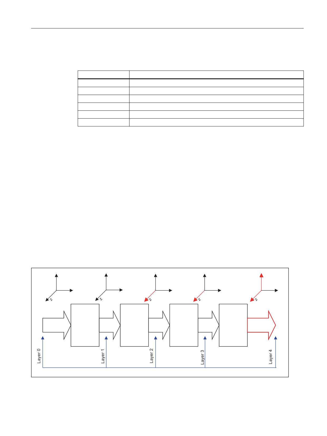
Kinematic transformations
5.5 Chained transformations
5.5.3.2
System variables
The following transformation-specific system variables are available:
System variable
Meaning
$AA_ITR
Current setpoint value at output of the nth transformation
$AA_IBC
Current setpoint value of a cartesian axis
$VA_ITR
Current actual value at output of the nth transformation
$VA_IBC
Current cartesian BCS encoder position of an axis
$VA_IW
Current WCS actual value of an axis
$VA_IB
Current BCS encoder position of an axis
Boundary conditions
• Warm restart
The encoder position has the value 0 for non-referenced axes. For the $VA variables, the
encoder actual values are appropriately inverse-transformed.
• Channel reset
The active transformation can change after a channel reset. This can have a direct influence
on the system variable values.
An active transformation, which is active again after a channel reset, is briefly deactivated
and then reactivated. This influences the position variables. The values of variables can
change.
Via the variable:
$AC_STAT == 0
this status can be queried in synchronous actions.
$AA_ITR: Actual setpoint value at output of the nth transformation
System variable $AA_ITR[ <axis>, <transformation layer> ] determines the setpoint position of
an axis at the output of the n th cascaded transformation.
\
\
\
\
\
[
[
[
[
[
%&6
7UDQVI
7UDQVI
0&6
7UDQVI
7UDQVI
Figure 5-19
Transformer layer
Transformations
Function Manual, 10/2020, 6FC5397-5GP40-0BA1
163
Kinematic transformations
5.5 Chained transformations
Axis
As 1st index of the system variable, either a geometry, a channel or a machine axis name is
permissible. When programming geometry axis names, in each transformer layer, the
assignment of the channel axes to the geometry axes corresponding to transform layer 0 is
effective. This means that the geometry axis assignment on the BCS side is active in all planes.
Using geometry axis names is meaningful only if the geometry axes are not switched over.
Otherwise, it is always better to use channel axis names.
Transformer layer
The 2nd index of the system variable corresponds to the transformation layer from which the
positions are taken:
• Transformer layer 0: The positions correspond to BCS positions, $AA_ITR[x,0] == $AA_IB[x]
• Transformer layer 1: Setpoint positions at the output of the 1st transformation
• Transformer layer 2: Setpoint positions at the output of the 2nd transformation
• Transformer layer 3: Setpoint positions at the output of the 3rd transformation
• Transformer layer 4: Setpoint positions at the output of the 4th transformation, $AA_ITR[x,4]
== $AA_IM[x]
If one or more transformations of the transformation chain are missing, the highest layers
continue to deliver the same values. If, for example, transformation 3 and transformation 4 are
missing, then the following applies:
$AA_ITR[x,2] = $AA_ITR[x,3] = $AA_ITR[x,4] = $AA_IM[x]
If the transformations are deactivated using TRAFOOF - or for a channel reset - then layers 0 to
4 merge. The system variable then supplies the BCS value (layer 0).
$AA_IBC: Actual setpoint of a cartesian axis
System variable $AA_IBC[ <axis>] determines the setpoint position of a cartesian axis lying
between BCS and MCS. If an axis is cartesian at the output of the nth transformation, then this
output value is delivered. If the corresponding axis at the output of all transformations is not
cartesian, then the BCS value including all BCS offsets of the axis are determined.
If TRACON responds to an axis as cartesian, then its MCS value is delivered. The used axis name
can be a geometry, channel or a machine axis name.
$VA_ITR: Actual value at the output of the nth transformation
System variable $VA_ITR[ <axis>, <transformation layer> ] determines the setpoint position of
an axis at the output of the n th chained transformation.
$VA_IBC: Actual cartesian BCS encoder position of an axis
System variable $VA_IBC[ <axis> ] determines the encoder position of a cartesian axis lying
between BCS and MCS. The used axis name can be a geometry, channel or a machine axis name.
If an axis at the output of the nth transformation is cartesian, then this output value is delivered.
If the corresponding axis at the output of all transformations is not cartesian, then the BCS value
of the axis is determined.
Transformations
164
Function Manual, 10/2020, 6FC5397-5GP40-0BA1
Kinematic transformations
5.5 Chained transformations
$VA_IW: Current WCS actual value of an axis
System variable $VA_IW[ <axis> ] determines the encoder position of an inverse-transformed
axis in WCS. The WCS value contains all axis-related superimposition portions (DRF, AA_OFF, ext.
zero offset etc.) and offset values (CEC, etc.).
$VA_IB: Actual BCS encoder position of an axis
System variable $VA_IB[ <axis> ] determines the inverse-transformed encoder position of an
axis in BCS. The BCS value contains all axis-related superimposition portions (DRF, AA_OFF, ext.
zero offset etc.) and offset values (CEC, etc.).
Note
$VA_ITR$, VA_IBC, $VA_IW, $VA_IB
The value of the variable does not change while reading the variable within an IPO cycle,
although the actual value could have changed.
In active transformations, one must consider that the transformation of the actual values into
BCS in the IPO cycle can be very time-consuming. In this case one must set an adequate IPO cycle.
5.5.4
Programming
A configured concatenated transformation is activated in the part program or synchronized
action via the TRAFOON (Page 52) or TRACON operation.
To be able to activate a transformation parameterized with a kinematic chain with TRACON, this
must be parameterized in the system variable $NT_TRACON_CHAIN.
Syntax
TRACON(<Trafo_No>,<Par_1>,...,<Par_n>,<Par_n+1>)
TRAFOOF
Transformations
Function Manual, 10/2020, 6FC5397-5GP40-0BA1
165

Kinematic transformations
5.5 Chained transformations
Meaning
TRACON:
Activate concatenated transformation
If another transformation was previously activated, it is implicitly
disabled by means of TRACON().
<Trafo_No>:
Number of the concatenated transformation
Type:
INT
Value range:
0 ... 2
Value:
0, 1
First/only concatenated transformation
2
Second concatenated transformation
Not
Same meaning as with 0 or 1
speci-
fied
Note:
Values not equal to 0, 1, 2 generate an error alarm.
<Par_1>, ..., <Par_n>,
Parameters for the concatenated transformations
<Par_n+1>:
<Par_1>, ..., <Par_n>
Parameters of the first transforma-
tion in the chain
The actual number depends on the
transformation type:
• TRAORI: 2 parameters
• TRACYL: 1 to 2 parameters
<Par_n+1>
Parameters of the second transfor-
mation in the chain (TRAANG)
≙ angle of the inclined axis
If parameters are not set, the defaults or the parameters last used
take effect. Commas must be used to ensure that the specified pa-
rameters are evaluated in the sequence in which they are expected,
if default settings are to be effective for previous parameters. In par-
ticular, a comma is required before at least one parameter, even
though it is not necessary to specify <Trafo_No> - for example TRA-
CON( , 3.7).
TRAFOOF:
Deactivate the last activated (concatenated) transformation
Example
Program code
Comment
N230 TRACON(1,45.)
; Activate first concatenated transformation.
; The previously active transformation is automatically de-
selected.
; The angle for the inclined axis is 45°.
N330 TRACON(2,40.)
; Activate second concatenated transformation.
; The angle for the inclined axis is 40°.
N380 TRAFOOF
; Deactivate second concatenated transformation.
Transformations
166
Function Manual, 10/2020, 6FC5397-5GP40-0BA1

Kinematic transformations
5.5 Chained transformations
Program code
Comment
See also
$NT_TRAFO_INDEX (Page 28)
5.5.5
Examples
5.5.5.1
Application example of chained transformations
The following transformations are to be defined in the channel:
Data set
Transformation
1
TRAORI
5-axis transformation with rotatable tool and axis sequence AB (trafo type 16)
2
TRANSMIT
Face end transformation (trafo type 256)
3
TRAANG
Oblique angle transformation (trafo type 1024)
4
TRAORI + TRAANG
First chained transformation (trafo type 8192)
5
TRANSMIT + TRAANG
Second chained transformation (trafo type 8192)
Parameter assignment
General channel configuration
CHANDATA(1)
; Channel data in channel 1
MD20070 $MC_AXCONF_MACHAX_USED[0]=1
MD20070 $MC_AXCONF_MACHAX_USED[1]=2
MD20070 $MC_AXCONF_MACHAX_USED[2] = 3
MD20070 $MC_AXCONF_MACHAX_USED[3] = 4
MD20070 $MC_AXCONF_MACHAX_USED[4]=5
MD20070 $MC_AXCONF_MACHAX_USED[5]=6
MD20070 $MC_AXCONF_MACHAX_USED[6]=7
MD20070 $MC_AXCONF_MACHAX_USED[7] = 0
MD20080 $MC_AXCONF_CHANAX_NAME_TAB[3]="A"
MD20080 $MC_AXCONF_CHANAX_NAME_TAB[4]="B"
MD20080 $MC_AXCONF_CHANAX_NAME_TAB[5]="C"
MD36902 $MA_IS_ROT_AX[ AX4 ] = TRUE
MD36902 $MA_IS_ROT_AX[ AX5 ] = TRUE
Transformations
Function Manual, 10/2020, 6FC5397-5GP40-0BA1
167
Kinematic transformations
5.5 Chained transformations
MD36902 $MA_IS_ROT_AX[ AX6 ] = TRUE
MD36902 $MA_IS_ROT_AX[ AX7 ] = TRUE
MD35000 $MA_SPIND_ASSIGN_TO_MACHAX[AX5]= 0
MD35000 $MA_SPIND_ASSIGN_TO_MACHAX[AX7] = 1
MD35000 $MA_ROT_IS_MODULO[AX7] = TRUE
Single transformations
; 1. TRAORI
MD24470 $MC_TRAFO_TYPE_1= 16
; TRAORI: A-B kinematics
MD24410 $MC_TRAFO_AXES_IN_1[0]=1
MD24410 $MC_TRAFO_AXES_IN_1[1]=2
MD24410 $MC_TRAFO_AXES_IN_1[2]=3
MD24410 $MC_TRAFO_AXES_IN_1[3]=4
MD24410 $MC_TRAFO_AXES_IN_1[4]=5
MD24410 $MC_TRAFO_AXES_IN_1[5]=0
MD24120$MC_TRAFO_GEOAX_ASSIGN_TAB_1[0]=1
MD24120$MC_TRAFO_GEOAX_ASSIGN_TAB_1[1]=2
MD24120$MC_TRAFO_GEOAX_ASSIGN_TAB_1[2]=3
MD24550$MC_TRAFO5_BASE_TOOL_1[0]=0
MD24550$MC_TRAFO5_BASE_TOOL_1[1]=0
MD24550$MC_TRAFO5_BASE_TOOL_1[2]=0
; 2. TRANSMIT
MD24200 $MC_TRAFO_TYPE_2 = 256
; TRANSMIT
MD24210 $MC_TRAFO_AXES_IN_2[0] = 1
MD24210 $MC_TRAFO_AXES_IN_2[1] = 6
MD24210 $MC_TRAFO_AXES_IN_2[2]=3
MD24210 $MC_TRAFO_AXES_IN_2[3]=0
MD24210 $MC_TRAFO_AXES_IN_2[4] = 0
MD24210 $MC_TRAFO_AXES_IN_2[5] = 0
MD24210 $MC_TRAFO_AXES_IN_2[6]=0
MD24220 $MC_TRAFO_GEOAX_ASSIGN_TAB_2[0] =1
MD24220 $MC_TRAFO_GEOAX_ASSIGN_TAB_2[1] =6
MD24220 $MC_TRAFO_GEOAX_ASSIGN_TAB_2[2] =3
; 3. TRAANG
MD24300 $MC_TRAFO_TYPE_3 = 1024
; TRAANG
MD24310 $MC_TRAFO_AXES_IN_3[0] = 1
MD24310 $MC_TRAFO_AXES_IN_3[1] = 3
MD24310 $MC_TRAFO_AXES_IN_3[2] = 2
MD24310 $MC_TRAFO_AXES_IN_3[3] = 0
MD24310 $MC_TRAFO_AXES_IN_3[4] = 0
MD24320 $MC_TRAFO_GEOAX_ASSIGN_TAB_3[0] =1
MD24320 $MC_TRAFO_GEOAX_ASSIGN_TAB_3[1] =3
Transformations
168
Function Manual, 10/2020, 6FC5397-5GP40-0BA1
Kinematic transformations
5.5 Chained transformations
MD24320 $MC_TRAFO_GEOAX_ASSIGN_TAB_3[2] =2
MD24700 $MC_TRAANG_ANGLE_1 = 45.
MD24720 $MC_TRAANG_PARALLEL_VELO_RES_1 = 0.2
MD24721 $MC_TRAANG_PARALLEL_ACCEL_RES_1 = 0.2
MD24710 $MC_TRAANG_BASE_TOOL_1 [0] = 0.0
MD24710 $MC_TRAANG_BASE_TOOL_1 [1] = 0.0
MD24710 $MC_TRAANG_BASE_TOOL_1 [2] = 0.0
Chained transformations
; 4. TRACON (TRAORI + TRAANG chaining)
MD24400 $MC_TRAFO_TYPE_4 = 8192
MD24420 $MC_TRAFO_GEOAX_ASSIGN_TAB_4[0] =2
MD24420 $MC_TRAFO_GEOAX_ASSIGN_TAB_4[1] =1
MD24420 $MC_TRAFO_GEOAX_ASSIGN_TAB_4[2] =3
MD24995 $MC_TRACON_CHAIN_1[0] = 1
MD24995 $MC_TRACON_CHAIN_1[1] = 3
MD24995 $MC_TRACON_CHAIN_1[2] = 0
; 5. TRACON (TRANSMIT + TRAANG chaining)
MD24430 $MC_TRAFO_TYPE_5 = 8192
MD24434 $MC_TRAFO_GEOAX_ASSIGN_TAB_5[0] =1
MD24434 $MC_TRAFO_GEOAX_ASSIGN_TAB_5[1] =6
MD24434 $MC_TRAFO_GEOAX_ASSIGN_TAB_5[2] =3
MD24996 $MC_TRACON_CHAIN_2[0] = 2
MD24996 $MC_TRACON_CHAIN_2[1] = 3
MD24996 $MC_TRACON_CHAIN_2[2] = 0
Programming example
The following programming example assumes that the angle of the "inclined axis" can be set on
the machine and is set to 0° when the single transformations are activated.
Program code
Comment
; Tool specification
$TC_DP1[1,1]=120
;Tool type
$TC_DP3[1,1]=10
; Tool length
N2 X0 Y0 Z0 A0 B0 F20000 T1 D1
N4 X20
; Call single transformations
N30 TRANSMIT
; Activate TRANSMIT
N40 X0 Y20
N50 X-20 Y0
N60 X0 Y-20
N70 X20 Y0
N80 TRAFOOF
; Deactivate TRANSMIT
Transformations
Function Manual, 10/2020, 6FC5397-5GP40-0BA1
169
Kinematic transformations
5.5 Chained transformations
Program code
Comment
N130 TRAANG(45.)
;
Activate inclined axis transformation
;
Parameter: Angle 45°
N140 X0 Y0 Z20
N150 X-20 Z0
N160 X0 Z-20
N170 X20 Z0
; Activate chained transformations
N230 TRACON(1,45.)
;
First concatenated transformation
;
Activate (TRAORI + TRAANG).
;
The previously active transformation
;
is automatically deselected.
;
The parameter for the inclined axis is 45°.
N240 X10 Y0 Z0 A3=-1 C3=1 ORIWKS
N250 X10 Y20 B3=1 C3=1
N330 TRACON(2,40.)
;
Activate second concatenated
;
transformation (TRANSMIT + TRAANG).
;
The parameter for the inclined axis
;
is 40°.
N335 X20 Y0 Z0
N340 X0 Y20 Z10
N350 X-20 Y0 Z0
N360 X0 Y-20 Z0
N370 X20 Y0 Z0
N380 TRAFOOF
;
Deactivate second concatenated
;
transformation.
N1000 M30
Transformations
170
Function Manual, 10/2020, 6FC5397-5GP40-0BA1
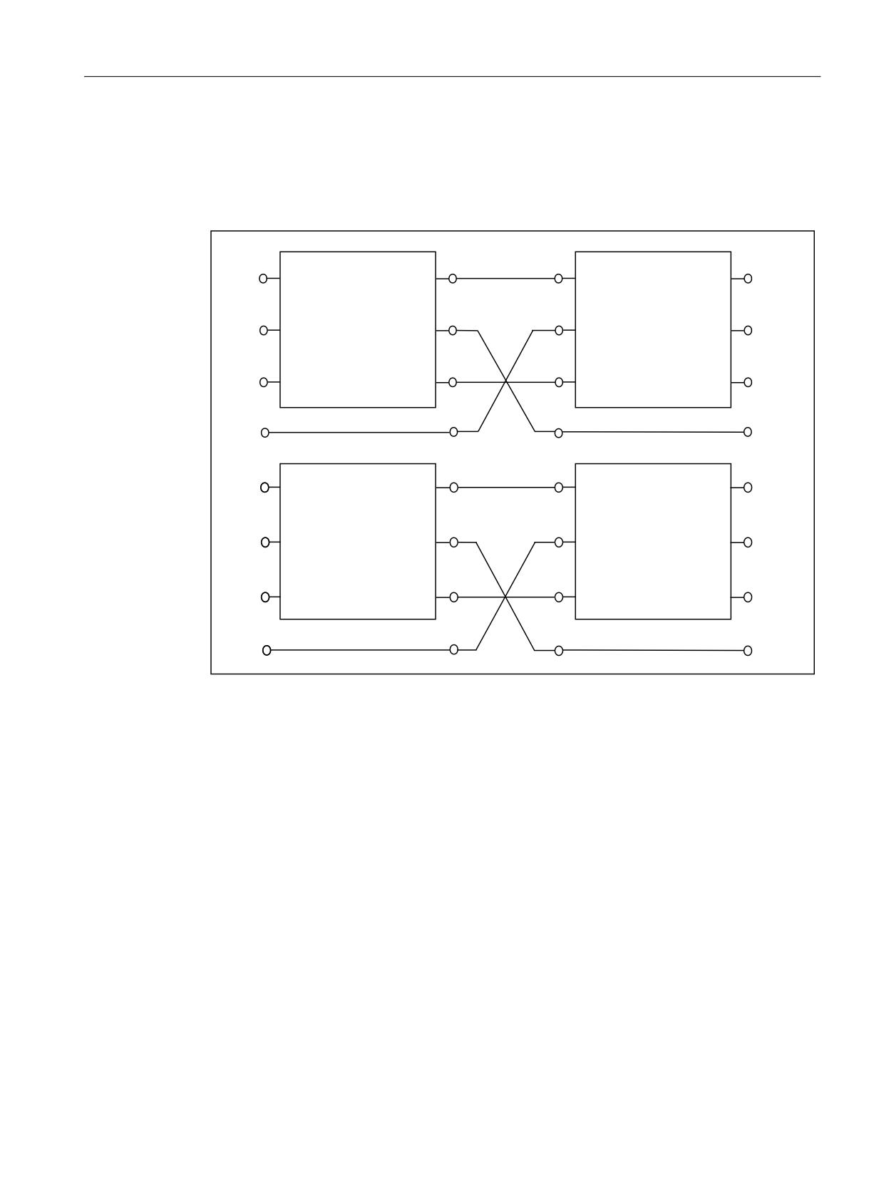
Kinematic transformations
5.5 Chained transformations
5.5.5.2
Determining the axis positions in the transformation chain
Two chained transformations are configured in the following example, and the system variables
for determining the axis positions in the synchronous action are read cyclically in the part
program.
[
;0
\
75$160,7
75$$1*
<0
]
=0
\
&
[
\
75$&</
75$$1*
]
\
Parameter assignment
CHANDATA(1)
; TRANSMIT
MD24100 $MC_TRAFO_TYPE_1=256
MD24110 $MC_TRAFO_AXES_IN_1[0] = 2
MD24110 $MC_TRAFO_AXES_IN_1[1] = 1
MD24110 $MC_TRAFO_AXES_IN_1[2] = 3
MD24120 $MC_TRAFO_GEOAX_ASSIGN_TAB_1 [0] = 2
MD24120 $MC_TRAFO_GEOAX_ASSIGN_TAB_1 [1] = 1
MD24120 $MC_TRAFO_GEOAX_ASSIGN_TAB_1 [2] = 3
; TRACYL
MD24200 $MC_TRAFO_TYPE_2=512
MD24210 $MC_TRAFO_AXES_IN_2[0]=2
MD24210 $MC_TRAFO_AXES_IN_2[1]=1
MD24210 $MC_TRAFO_AXES_IN_2[2]=3
MD24220 $MC_TRAFO_GEOAX_ASSIGN_TAB_2[0] =2
MD24220 $MC_TRAFO_GEOAX_ASSIGN_TAB_2[1] =1
MD24220 $MC_TRAFO_GEOAX_ASSIGN_TAB_2[2] =3
Transformations
Function Manual, 10/2020, 6FC5397-5GP40-0BA1
171
Kinematic transformations
5.5 Chained transformations
; TRAANG
MD24300 $MC_TRAFO_TYPE_3=1024
MD24310 $MC_TRAFO_AXES_IN_3[0] = 2
MD24310 $MC_TRAFO_AXES_IN_3[1]=4
MD24310 $MC_TRAFO_AXES_IN_3[2] = 3
MD24320 $MC_TRAFO_GEOAX_ASSIGN_TAB_3[0] =2
MD24320 $MC_TRAFO_GEOAX_ASSIGN_TAB_3[1] =4
MD24320 $MC_TRAFO_GEOAX_ASSIGN_TAB_3[2] =3
MD24700 $MC_TRAANG_ANGLE_1 = 45.
MD24720 $MC_TRAANG_PARALLEL_VELO_RES_1 = 0.2
MD24721 $MC_TRAANG_PARALLEL_ACCEL_RES_1 = 0.2
MD24710 $MC_TRAANG_BASE_TOOL_1 [0] = 0.0
MD24710 $MC_TRAANG_BASE_TOOL_1 [1] = 0.0
MD24710 $MC_TRAANG_BASE_TOOL_1 [2] = 0.0
; 1. TRANSMIT/TRAANG chaining
MD24400 $MC_TRAFO_TYPE_4=8192
; TRACON (1)
MD24995 $MC_TRACON_CHAIN_1[0] = 1
MD24995 $MC_TRACON_CHAIN_1[1] = 3
MD24995 $MC_TRACON_CHAIN_1[2] = 0
MD24995 $MC_TRACON_CHAIN_1[3] = 0
MD24410 $MC_TRAFO_AXES_IN_4[0]=1
MD24410 $MC_TRAFO_AXES_IN_4[1]=2
MD24410 $MC_TRAFO_AXES_IN_4[2]=3
MD24420 $MC_TRAFO_GEOAX_ASSIGN_TAB_4[0] =2
MD24420 $MC_TRAFO_GEOAX_ASSIGN_TAB_4[1] =1
MD24420 $MC_TRAFO_GEOAX_ASSIGN_TAB_4[2] =3
; 2. TRACYL/TRAANG chaining
MD24430 $MC_TRAFO_TYPE_5=8192
; TRACON (2)
MD24996 $MC_TRACON_CHAIN_2[0] = 2
MD24996 $MC_TRACON_CHAIN_2[1] = 3
MD24996 $MC_TRACON_CHAIN_2[2]=0
MD24996 $MC_TRACON_CHAIN_2[3]=0
MD24432 $MC_TRAFO_AXES_IN_5[0]=1
MD24432 $MC_TRAFO_AXES_IN_5[1]=2
MD24432 $MC_TRAFO_AXES_IN_5[2]=3
MD24434 $MC_TRAFO_GEOAX_ASSIGN_TAB_5[0] =2
MD24434 $MC_TRAFO_GEOAX_ASSIGN_TAB_5[1] =1
MD24434 $MC_TRAFO_GEOAX_ASSIGN_TAB_5[2] =3
M17
Programming example
Program code
Comment
N10 $TC_DP1[1,1]=120
N20 $TC_DP3[1,1]=20
N30 $TC_DP4[1,1]=0
N40 $TC_DP5[1,1]=0
N50
N60 X0 Y0 Z0 F20000 T1 D1
N70
N80
; Cyclic reading in the synchronized actions
N90 ID=1 WHENEVER TRUE DO $R0=$AA_ITR[X,0] $R1=$AA_ITR[X,1] $R2=$AA_ITR[X,2]
Transformations
172
Function Manual, 10/2020, 6FC5397-5GP40-0BA1
Kinematic transformations
5.6 Persistent transformations
Program code
Comment
N100 ID=2 WHENEVER TRUE DO $R3=$AA_IBC[X] $R4=$AA_IBC[Y] $R5=$AA_IBC[Z]
N110 ID=3 WHENEVER TRUE DO $R6=$VA_IW[X]-$AA_IW[X]
N120 ID=4 WHENEVER TRUE DO $R7=$VA_IB[X]-$AA_IB[X]
N130 ID=5 WHENEVER TRUE DO $R8=$VA_IBC[X]-$AA_IBC[X]
N140 ID=6 WHENEVER TRUE DO $R9=$VA_ITR[X,1]-$AA_ITR[X,1]
N150
N160
N170 TRACON(1,)
; 1. TRANSMIT/TRAANG chaining
N180 X20 Y0 Z0
N190 X0 Y20 Z10
N200 X-20 Y0 Z0
N210 X0 Y-20 Z0
N220 X20 Y0 Z0
N230 TRAFOOF
N240
N250
N260 TRACON(2, 40.)
; 2. TRACYL/TRAANG chaining
N270 X20 Y0 Z0
N280 X0 Y20 Z10
N290 X-20 Y0 Z0
N300 X0 Y-20 Z0
N310 X20 Y0 Z0
N320 TRAFOOF
N330
N340 M30
5.6
Persistent transformations
5.6.1
Persistent transformations in kinematic chains
Persistent transformation
A persistent transformation is a transformation which is retained even when another (different)
transformation is switched off with TRAFOOF. This transformation is identical to the
transformation that is in effect during the reset (Page 19).
If a different transformation is selected, the persistent transformation is replaced by the newly
selected transformation. The newly selected transformation is NOT concatenated with the
persistent transformation.
Transformations
Function Manual, 10/2020, 6FC5397-5GP40-0BA1
173
Kinematic transformations
5.6 Persistent transformations
5.6.2
Persistent transformation
Function
A persistent transformation is always active and has a relative effect to the other explicitly
selected transformations.
Selected transformations are computed as the first chained transformation in relation to the
persistent transformation.
Transformations such as e.g. TRANSMIT, which are selected relative to the persistent
transformation, are chained in the NC program with persistent transformation using TRACON.
The chained transformation, e.g. TRANSMIT, is then programmed in the NC program.
Further information
"NC Programming" Programming Manual
Selection and deselection
Persistent transformation is selected via the following machine data:
• MD20144 $MC_TRAFO_MODE_MASK, bit 0 = 1
• MD20144 $MC_TRAFO_RESET_VALUE defines persistent transformation.
• MD20140 $MC_TRAFO_RESET_VALUE=Number of the transformation data set of the
persistent transformation
Other machine data
• MD20110 $MC_RESET_MODE_MASK
- Bit 0 = 1 (Bit 7 is evaluated)
- Bit 7 =0 (MD20140 $MC_TRAFO_RESET_VALUE determines the transformation data set)
• MD20112 $MC_START_MODE_MASK (MD20140 $MC_TRAFO_RESET_VALUE)
• MD20118 $MC_GEOAX_CHANGE_RESET= TRUE (i.e. geometry axes are reset).
With TRAFOOF the active, chained transformation TRACON is deselected and the persistent
transformation is automatically selected.
Effects on HMI operation
As a transformation is always active with the persistent transformation, the HMI user interface
is adapted accordingly for the selection and deselection of transformations:
Chained transformation TRACON
The HMI operator interface does not display TRACON, but the 1st chain transformation of
TRACON, e.g. TRANSMIT. Accordingly, the transformation type of the 1st chained
transformation is returned by the system variable, i.e. $P_TRAFO or $AC_TRAFO. Cycles that
TRANSMIT uses can then be directly used.
Transformations
174
Function Manual, 10/2020, 6FC5397-5GP40-0BA1
Kinematic transformations
5.6 Persistent transformations
Deactivating the TRAFOOF transformation
In accordance with the TRAFOOF programming instruction no transformation is displayed in
the G command list at the user interface. System variable $P_TRAFO as well as $AC_TRAFO then
supply a value of 0. The persistent transformation is active and the BCS and MCS coordinate
systems differ. The displayed MCS position always refers to the actual machine axes.
System variables
System variable to read transformation types of the active or chained transformations.
• $AC_TRAFO (active transformation)
• $AC_TRAFO_CHAIN[0] (active chained transformation)
• $P_TRAFO (programmed transformation)
• $P_TRAFO_CHAIN[0] (programmed chained transformation)
Frames
Frame adjustments for selection and deselection of the TRACON are carried out as if there was
only the first chained transformation. Transformations on the virtual axis cease to be effective
when TRAANG is selected.
JOG
The persistent transformation remains in effect when traversing with JOG.
General conditions
The persistent transformation does not change the principle operating sequences in the NC. All
restrictions applying to an active transformation also continue to apply:
• For RESET, an existing transformation is completely deselected - and the persistent
transformation is selected again.
• When referencing, the transformation is deselected and then requires a channel reset or NC
start in order to again select the persistent transformation.
Example
For a lathe with an inclined additional Y axis, the transformation of the inclined axis should be
part of the machine configuration. As a consequence, it does not have to be taken into
consideration by the programmer. With TRACYL or TRANSMIT, the transformations are
selected, which must then include TRAANG.
When deactivating the programmed transformations, TRAANG is automatically reactivated.
TRACYL or TRANSMIT are correspondingly displayed on the user interface.
Machine constellation: Lathe with a Y1 axis, inclined to X1 and perpendicular to Z1
Transformations
Function Manual, 10/2020, 6FC5397-5GP40-0BA1
175
Kinematic transformations
5.6 Persistent transformations
Machine data parameterization
Program code
CANDATA (1)
; Kinematic without transformations
MD20080 $MC_AXCONF_CHANAX_NAME_TAB[1] = "Y2"
MD20050 $MC_AXCONF_GEOAX_ASSIGN_TAB[0] = 1
MD20050 $MC_AXCONF_GEOAX_ASSIGN_TAB[1] = 0
MD20050 $MC_AXCONF_GEOAX_ASSIGN_TAB[2] = 3
; Data for TRAANG
MD24100 $MC_TRAFO_TYP_1 = 1024 ; TRAANG, Y1 axis inclined to X1,
perpendicular to Z1
MD24110 $MC_TRAFO_AXES_IN_1[0]=2
MD24110 $MC_TRAFO_AXES_IN_1[1]=1
MD24110 $MC_TRAFO_AXES_IN_1[2] = 3
MD24110 $MC_TRAFO_AXES_IN_1[3] = 0
MD24110 $MC_TRAFO_AXES_IN_1[4] = 0
MD24120 $MC_TRAFO_GEOAX_ASSIGN_TAB_1[0] = 1
; Definition of persistent transformation
MD20144 $MC_TRAFO_MODE_MASK = 1
MD20140 $MC_TRAFO_RESET_VALVUE= 1
MD20110 $MC_RESET_MODE_MASK = 'H01'
MD20112 $MC_START_MODE_MASK = 'H80'
MD20140 $MC_TRAFO_RESET_VALUE
MD20118 $MC_GEOAX_CHANGE_RESET= TRUE
; Data for TRANSMIT, TRACYL
MD24911 $MC_TRANSMIT_POLE_SIDE_FIX_1 = 1 ; also 2, causes alarm 21617
MD24200 $MC_TRAFO_TYP_2 = 257 ; TRANSMIT
MD24210 $MC_TRAFO_AXES_IN_2[0] = 1
MD24210 $MC_TRAFO_AXES_IN_2[1] = 4
MD24210 $MC_TRAFO_AXES_IN_2[2] = 3
MD24210 $MC_TRAFO_AXES_IN_2[3] = 0
MD24210 $MC_TRAFO_AXES_IN_2[4] = 0
MD24220 $MC_TRAFO_GEOAX_ASSIGN_TAB_2[0] =1
MD24220 $MC_TRAFO_GEOAX_ASSIGN_TAB_2[1] =4
MD24220 $MC_TRAFO_GEOAX_ASSIGN_TAB_2[2] =3
MD24300 $MC_TRAFO_TYP_3 = 514 ; TRACYL
MD24310 $MC_TRAFO_AXES_IN_3[0] = 1
MD24310 $MC_TRAFO_AXES_IN_3[1] = 4
MD24310 $MC_TRAFO_AXES_IN_3[2] = 3
MD24310 $MC_TRAFO_AXES_IN_3[3] = 0
MD24310 $MC_TRAFO_AXES_IN_3[4] = 0
MD24320 $MC_TRAFO_GEOAX_ASSIGN_TAB_3[0] =1
MD24320 $MC_TRAFO_GEOAX_ASSIGN_TAB_3[1] =4
MD24320 $MC_TRAFO_GEOAX_ASSIGN_TAB_3[2] =3
; Data for TRACON
; TRACON chaining TRANSMIT 257/TRAANG (Y1 axis inclined in relation to X1)
MD24400 $MC_TRAFO_TYP_4 = 8192 ; TRACON
MD24995 $MC_TRACON_CHAIN_1[0] = 3
MD24995 $MC_TRACON_CHAIN_1[1] = 1
MD24995 $MC_TRACON_CHAIN_1[2] = 0
MD24420 $MC_TRAFO_GEOAX_ASSIGN_TAB_4[0] =1
MD24420 $MC_TRAFO_GEOAX_ASSIGN_TAB_4[1] =4
MD24420 $MC_TRAFO_GEOAX_ASSIGN_TAB_4[2] =3
Transformations
176
Function Manual, 10/2020, 6FC5397-5GP40-0BA1
Kinematic transformations
5.7 Cartesian PTP travel
Program code
; TRACON chaining TRANSMIT 257/TRAANG (Y1 axis inclined in relation to X1)
MD24430 $MC_TRAFO_TYP_5 = 8192 ; TRACON
MD24996 $MC-TRACON_CHAIN_2[0] = 2
MD24996 $MC-TRACON_CHAIN_2[1] = 1
MD24996 $MC_TRACON_CHAIN_2[2] = 0
MD24434 $MC_TRAFO_GEOAX_ASSIGN_TAB_5[0] =1
MD24434 $MC_TRAFO_GEOAX_ASSIGN_TAB_5[1] =4
MD24434 $MC_TRAFO_GEOAX_ASSIGN_TAB_5[2] =3
M17
NC program
Program code
$TC_DP1[1,1]=120 ; tool type
$TC_DP2[1,1] = 0
$TC_DP3[1,1]=3 ; length compensation vector
$TC_DP4[1,1]=25
$TC_DP5[1.1] =5
$TC_DP6[1,1]= 2; Radius; tool radius
; Transformation changeover
N1000 G0 X0 Y=0 Z0 A80 G603 SOFT G64
N1010 X10 Y20 Z30 ; TRAANG(,1) not required, as automatically selected
N1110 TRANSMIT(1)
N1120 X10 Y20 Z30
N1130 Y2=0
; TRACON(2) not required, as automatically converted
N1210 TRAFOOF
; TRAANG(,1) not required, as automatically converted
N1220 X10 Y20 Z30
M30
5.7
Cartesian PTP travel
5.7.1
Function
Requirement
Cartesian point-to-point or PTP travel can only be activated if one of the following
transformations is active:
• TRAORI_DYN, TRAORI_STAT (orientation transformation) (conventional TRAORI)
• TRANSMIT_K (end face transformation) (conventional TRANSMIT)
• TRACON_K (concatenated transformation) (conventional TRACON)
Precondition: The first chained transformation supports PTP travel!
Transformations
Function Manual, 10/2020, 6FC5397-5GP40-0BA1
177
Kinematic transformations
5.7 Cartesian PTP travel
• RCTRA (transformation for 2 to 4-axis handling/robot kinematics); not for kinematic chains,
only conventional
Precondition: Compile cycle "RMCC/RCTRA Transformation Handling" is loaded and active!
• ROBX (transformation for 4 to 6-axis robot kinematics); not for kinematic chains, only
conventional
Precondition: Compile cycle "RMCC/ROBX Transformation Extended Robotics" is loaded and
active!
Without active transformation, alarm 14146 "CP or PTP motion without transformation not
permitted" is output.
Note
The axes of the transformation must not simultaneously be positioning axes.
Function
With the Cartesian PTP travel, in G0 and G1 sets it is possible to approach a point programmed
as a Cartesian destination point with a synchronous axis movement.
Regarding the traversing movement, the Cartesian PTP travel acts as though no transformation
is active. The position data in the part program continue to be in the Cartesian workpiece
coordinate system. Programmed frames (coordinate movements and rotations) remain valid.
The display is also in the Cartesian workpiece coordinate system.
The movement in the Cartesian PTP travel is described by a starting and end position of the axes.
The path of the movement described by the individual axes from the starting to the end position
is not specified by the controller by means of path interpolation points and can therefore not be
predicted. The axes only have to reach their specified target position. Interaction between the
axis movements only exists in regard to time, i.e. all axis start simultaneously and are stopped
at the same time when the target position has been reached. The slowest axis determines the
total traverse time.
One sensible usage option is to travel by a singularity. If Cartesian positions are available, which
are provided by a CAD/CAM system for example, this has the benefit of not having to convert
them into machine axis values. Furthermore, direct traversing of the machine axes is time-
optimized compared to Cartesian traversing with active transformation and programmed feed.
The result of this would either be a corresponding reduction of the feedrate when traversing
through the singularity (speed planning in preprocessing) or an overload of the axis if no speed
planning is carried out in preprocessing.
Note
Cartesian PTP travel is only permissible in conjunction with the interpolation types G0 and G1.
Transformations
178
Function Manual, 10/2020, 6FC5397-5GP40-0BA1

Kinematic transformations
5.7 Cartesian PTP travel
Versions
Three versions are available for Cartesian PTP travel:
• PTP
The programmed Cartesian position in G0 and G1 blocks is approached with synchronous
axis motion.
• PTPG0
Only in G0 blocks is the programmed Cartesian position approached with synchronous axis
motion. In G1 blocks, it is switched to the type of motion CP (CP = Continuous Path) and the
position is approached with a Cartesian path motion.
• PTPWOC (only for orientation transformation)
Just the same as PTP, however, without any compensatory motion, which is caused by
motion of rotary axes and orientation axes.
Since the transformation, which compensates the movement of the tool tip (TCP) during
orientation changes, is not active, the position of the TCP in the workpiece coordinate system
must generally also be changed if no linear axes involved in the transformation are
programmed.
Programmed linear axis movements are carried out in the workpiece coordinate system that
applies at the beginning of the block and overlays the simultaneously programmed rotary
axis movements if applicable. The block end point that is reached in the workpiece
coordinate system is therefore generally not the same as the programmed end point.
The following table lists which version can be practically used for which transformation:
Transformation
PTP
PTPG0
PTPWOC
CP
TRAORI_DYN, TRAORI_STAT
+/-
+/-
+/-
+/-
TRANSMIT
+/-
+/-
-
+/-
RCTRA1
+/-
+/-
-
+/-
ROBX1
+/-
+/-
-
+/-
1) not for kinematic chains
NOTICE
Risk of collision
For PTP travel it must be observed that in part there are significantly different tool movements
than with CP!
This must especially be considered for PTPG0, because subprograms can be created with it
independently of the active transformation. With an active end face transformation
(TRANSMIT_K), however, completely different collision risks may occur than with an
orientation transformation (TRAORI_DYN, TRAORI_STAT).
For PTP travel with active end face transformation (TRANSMIT_K), machine axes generally
travel along the shortest path. Minor displacements of the block end point can cause the rotary
axis to rotate by +179.99° instead of + -179.99°. This results in a completely different motion,
even though the block end point has hardly changed.
Transformations
Function Manual, 10/2020, 6FC5397-5GP40-0BA1
179

Kinematic transformations
5.7 Cartesian PTP travel
PTP/CP switchover in the NC program
The switchover between the Cartesian path motion (CP) and the Cartesian PTP travel in the NC
program is done via the commands of the G group 49 (see "Activating/deactivating Cartesian PTP
travel (PTP, PTPG0, PTPWOC, CP) (Page 182)").
PTP/CP switchover in JOG mode
You can also switch between the Cartesian path motion (CP) and the Cartesian PTP travel in JOG
mode.
Switchover is carried out using the NC/PLC interface signal:
DB21, ... DBX29.4 (activate PTP travel)
Note
DB21, ... DBX29.4 is only effective in JOG mode when the transformation is active.
The active type of motion is reported via the following NC/PLC interface signal:
DB21, ... DBX317.6 (PTP travel active)
5.7.2
Commissioning
5.7.2.1
Response after POWER ON
After Power On, traversing mode CP is automatically effective for axis traversal with
transformation.
The default can be switched over to Cartesian PTP travel via the following machine data:
MD20150 $MC_GCODE_RESET_VALUES[48] (initial setting of G group 49)
Value
Meaning
1
CP (default setting)
2
PTP
3
PTPG0
4
PTPWOC
5.7.2.2
Response after reset/part program end
Which command from G group 49 takes effect after a reset/part program end depends on the
setting in the machine data:
Transformations
180
Function Manual, 10/2020, 6FC5397-5GP40-0BA1

Kinematic transformations
5.7 Cartesian PTP travel
MD20152 $MC_GCODE_RESET_MODE[48] (reset behavior of G group 49)
Value
Meaning
0
The default command in MD20150 $MC_GCODE_RESET_VALUES[48] becomes effective
(default setting).
1
The command that was active before the reset/part program end remains effective.
5.7.2.3
Consideration of the SW limits during PTP travel
Function
With Cartesian PTP travel, a rotary axis is normally traversed according to the strategy "shortest
path" if no position information has been programmed via the operation TU (Page 188). To
prevent a software limit switch being overtraveled when the target position is behind the
software limit switch, the user can use the "Consideration of the SW limits during PTP travel"
function. The rotary axis is then traversed with the strategy "long path" instead of "shortest path"
if overtravel of the software limit switch would happen, i.e. the opposite traversing direction as
with the "shortest path" strategy.
Requirement
The function can only be used when the relevant axis has been referenced.
Activation
The "Consideration of the SW limits during PTP travel" function can be activated separately for
each axis.
This setting is made via bit 14 in the axial machine data:
MD30455 $MA_MISC_FUNCTION_MASK
Bit 14
= 0
With Cartesian PTP travel, the strategy "shortest path" is retained for software limit
switch overtravel of a rotary axis (basic setting).
= 1
The strategy "long path" is used when during Cartesian PTP travel a rotary axis with
the strategy "shortest path" would overtravel the software limit switch.
Supplementary conditions
Modulo rotary axes
With modulo rotary axes, the strategy "long path" can only be used when the software limit
switch monitoring has been selected for the relevant axis:
DB31, ... DBX12.4 (modulo rotary axis: Activate traversing range limits) = 1
Example
Axis 6 is to traverse from +150° t +240°. The software limit switch is at +200°.
Transformations
Function Manual, 10/2020, 6FC5397-5GP40-0BA1
181