SINUMERIK 840D sl. Service - Functions. Manual (2018-2020) - page 96
Grinding-specific tool offset and tool monitoring
5
5.1
Grinding-specific tool data
5.1.1
Structure of tool data
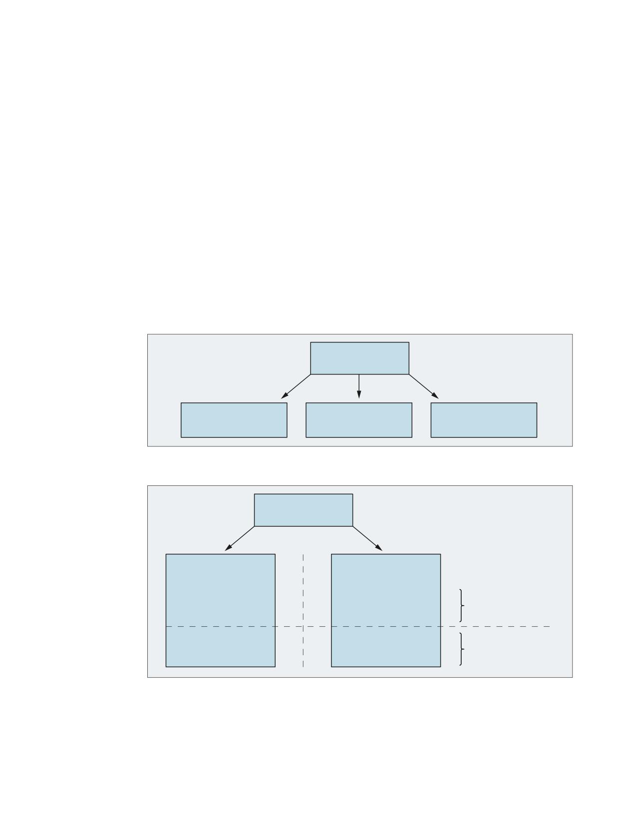
Grinding tools (tool type: 400 to 499) normally have specific tool and dresser data in addition to
cutting edge data.
The grinding wheel-specific data for the left and right wheel geometry can be stored under a T
number in the tool cutting edges D1 and D2.
If data is needed for the dresser geometry, it can be stored as follows:
• In the tool cutting edges from D3 of a T number
7 QXPEHU
*ULQGLQJ GLVN
'
'
DE '
/HIW GLVN JHRPHWU\
5LJKW GLVN JHRPHWU\
$GGLWLRQDO GDWD
• In additional cutting edge-specific parameters (see MD18096
$MN_MM_NUM_CC_TOA_PARAM)
7 QXPEHU
*ULQGLQJ GLVN
'
'
/HIW GLVN JHRPHWU\
5LJKW GLVN JHRPHWU\
7&B'3 > W! G!@
7&B'3 > W! G!@
&XWWLQJ HGJH VSHFLILF
SDUDPHWHUV
7&B'3
> W! G!@
7&B'3
> W! G!@
7&B'3& > W! G!@
7&B'3& > W! G!@
$GGLWLRQDO
SDUDPHWHUV
7&B'3& > W! G!@
7&B'3& > W! G!@
ᇆ 0'
<t>: T number
<d>: D number
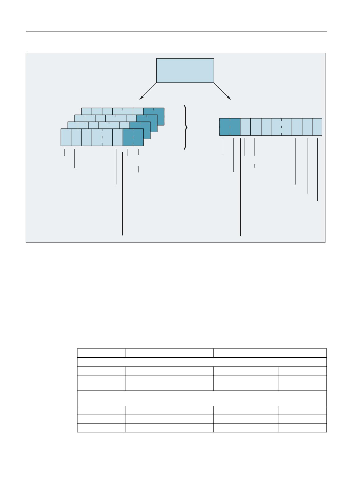
The following figure provides an overview of the (possible) storage structure of the tool data for
grinding tools:
Tools
Function Manual, 10/2020, 6FC5397-6GP40-0BA1
275
Grinding-specific tool offset and tool monitoring
5.1 Grinding-specific tool data
7 QXPEHU
*ULQGLQJ ZKHHO
'
'
'
'
7&B'3 > W! G!@
7&B'3& > W! G!@
7&B73& > W!@
7&B73* > W!@
7&B'3 > W! G!@
7&B73* > W!@
7&B'3& > W! G!@
7&B73& > W!@
7&B'3
> W! G!@
7&B73* > W!@
7&B73*B'563$7+> W!@
7&B73*B'56352*> W!@
&XWWLQJ HGJH VSHFLILF
$GGLWLRQDO
$GGLWLRQDO
7RRO VSHFLILF SDUDPHWHUV
SDUDPHWHUV
SDUDPHWHUV
SDUDPHWHUV
ᇆ 0'
ᇆ 0'
<t>:
T number
<d>:
D number
Figure 5-1
Structure of the tool data for grinding tools
5.1.2
Cutting edge-specific parameters
5.1.2.1
List of cutting edge-specific parameters
The cutting edge-specific tool parameters for grinding tools have the same meaning as those for
turning and milling tools.
Tool parameter
Meaning
Comment
$TC_DP1
Tool type
$TC_DP2
Cutting edge position
For turning and grinding
tools only
Geometry - tool length compensation
$TC_DP3
Length 1
$TC_DP4
Length 2
$TC_DP5
Length 3
Tools
276
Function Manual, 10/2020, 6FC5397-6GP40-0BA1

Grinding-specific tool offset and tool monitoring
5.1 Grinding-specific tool data
Tool parameter
Meaning
Comment
Geometry - tool radius compensation
$TC_DP6
Radius 1
$TC_DP7
Reserved
$TC_DP8
Reserved
$TC_DP9
Reserved
$TC_DP10
Reserved
$TC_DP11
Reserved
Wear - tool length compensation
$TC_DP12
Length 1
$TC_DP13
Length 2
$TC_DP14
Length 3
Wear - tool radius compensation
$TC_DP15
Radius 1
$TC_DP16
Reserved
$TC_DP17
Reserved
$TC_DP18
Reserved
$TC_DP19
Reserved
$TC_DP20
Reserved
Base dimension/adapter dimension - tool length compensation
$TC_DP21
Basic length 1
$TC_DP22
Basic length 2
$TC_DP23
Basic length 3
Technology
$TC_DP24
Undercut angle
For turning tools only
$TC_DP25
Reserved
Note
The cutting edge data for D1 and D2 of a selected grinding tool can be chained, i.e. if a parameter
in D1 or D2 is modified, then the same parameter in D1 or D2 is automatically overwritten with
the new value (see $TC_TPG2 (Page 280)).
Tools
Function Manual, 10/2020, 6FC5397-6GP40-0BA1
277

Grinding-specific tool offset and tool monitoring
5.1 Grinding-specific tool data
5.1.2.2
$TC_DP1
The parameter $TC_DP1 contains the 3-digit number of the grinding tool type:
7RRO W\SH
;
<
:LWKRXW PRQLWRULQJ ZLWK EDVH GLPHQVLRQ IRU *:36
:LWK PRQLWRULQJ ZLWK EDVH GLPHQVLRQ IRU *:36
:LWKRXW PRQLWRULQJ ZLWKRXW EDVH GLPHQVLRQ IRU *:36
:LWK PRQLWRULQJ ZLWKRXW EDVH GLPHQVLRQ IRU *:36
6XUIDFH JULQGLQJ ZKHHO
)DFLQJ ZKHHO
'UHVVHU
Number
Grinding tool type
400
Surface grinding wheel
401
Surface grinding wheel with monitoring with tool base dimension for GWPS
402
Surface grinding wheel without monitoring without tool base dimension for GWPS
403
Surface grinding wheel with monitoring without tool base dimension for GWPS
410
Facing wheel
411
Facing wheel with monitoring with tool base dimension for GWPS
412
Facing grinding wheel without monitoring without tool base dimension for GWPS
413
Facing wheel with monitoring without tool base dimension for GWPS
490
Dresser
5.1.2.3
Definition of additional parameters $TC_DPC1 ... 10
For user-specific cutting edge data, the additional parameters $TC_DPC1 to $TC_DPC10 can be
set up independent of the tool type via the following memory-configuring machine data:
MD18096 $MN_MM_NUM_CC_TOA_PARAM
NOTICE
Loss of data due to reconfiguration
Reconfiguration of the local static NC memory results in a loss of data on the active and passive
file system. We therefore urgently recommend archiving or backing up all relevant data by
creating a commissioning archive before activating a modified memory configuration.
Tools
278
Function Manual, 10/2020, 6FC5397-6GP40-0BA1

Grinding-specific tool offset and tool monitoring
5.1 Grinding-specific tool data
5.1.3
Tool-specific parameters
5.1.3.1
List of tool-specific parameters
The tool-specific parameters are automatically set up with every new grinding tool (tool type:
400 to 499).
Note
Tool-specific parameters have the same characteristics as a cutting edge.
This is to be taken into account when the number of cutting edges is specified:
MD18100 $MN_MM_NUM_CUTTING_EDGES_IN_TOA
When all the cutting edges of a tool are deleted, the associated tool-specific parameters are
deleted at the same time.
Parameters
The parameters are assigned as follows:
Parameter
Meaning
Data type
$TC_TPG1 (Page 280)
Spindle number
INT
$TC_TPG2 (Page 280)
Chaining rule
INT
$TC_TPG3 (Page 281)
Minimum wheel radius
REAL
$TC_TPG4 (Page 281)
Minimum wheel width
REAL
$TC_TPG5 (Page 281)
Current wheel width
REAL
$TC_TPG6 (Page 282)
Maximum speed
REAL
$TC_TPG7 (Page 282)
Maximum peripheral speed
REAL
$TC_TPG8 (Page 282)
Angle of inclined wheel
REAL
$TC_TPG9 (Page 283)
Parameter number for radius calculation
INT
$TC_TPG_DRSPATH (Page 283)
Directory path to the dressing program
STRING
$TC_TPG_DRSPROG (Page 283)
Dressing program name
STRING
Note
The monitoring data applies to both the left-hand and the right-hand cutting edge of the
grinding wheel.
The tool-specific parameters take effect:
• when switching on the grinding-specific tool monitoring (Page 298)
• when switching on the constant grinding wheel peripheral speed (GWPS) (Page 301)
If a changed date is to take effect, these functions must be switched on again.
The length compensations always specify the distances between the tool carrier reference point
and the tool tip in the Cartesian coordinates (must be noted for inclined grinding wheel).
Tools
Function Manual, 10/2020, 6FC5397-6GP40-0BA1
279

Grinding-specific tool offset and tool monitoring
5.1 Grinding-specific tool data
5.1.3.2
$TC_TPG1
The spindle number is entered in parameter $TC_TPG1. The grinding wheel circumferential
velocity is then monitored for this spindle.
5.1.3.3
$TC_TPG2
The tool parameters of the two cutting edges D1 and D2 are entered in parameter $TC_TPG2,
their values must always be the same. If, for a cutting edge, the value of one of these parameters
is changed, then the corresponding parameter of the other cutting edge is automatically set to
the same value.
The tool parameters are coded in parameter $TC_TPG2:
Tool parameter
Meaning
Coding
Bit
Hex
Dec
$TC_DP1
Tool type
0
0001
1
$TC_DP2
Length of cutting
1
0002
2
edge
Geometry - tool length compensation
$TC_DP3
Length 1
2
0004
4
$TC_DP4
Length 2
3
0008
8
$TC_DP5
Length 3
4
0010
16
$TC_DP6
Radius
5
0020
32
$TC_DP7
Reserved
6
0040
64
$TC_DP8
Length 4
7
0080
128
$TC_DP9
Length 5
8
0100
256
$TC_DP10
Angle 1 etc.
9
0200
512
$TC_DP11
Reserved
10
0400
1 024
Wear - tool length compensation
$TC_DP12
Length 1
11
0800
2 048
$TC_DP13
Length 2
12
1000
4 096
$TC_DP14
Length 3
13
2000
8 192
$TC_DP15
Radius
14
4000
16 384
$TC_DP16
Reserved
15
8000
32 768
$TC_DP17
Wear length 4
16
1 0000
65 536
$TC_DP18
Wear length 5
17
2 0000
131 072
$TC_DP19
Wear angle 1 etc.
18
4 0000
262 144
$TC_DP20
Reserved
19
8 0000
524 288
Base dimension/adapter dimension - tool length compensation
$TC_DP21
Basic length 1
20
10 0000
1 048 576
$TC_DP22
Basic length 2
21
20 0000
2 097 152
$TC_DP23
Basic length 3
22
40 0000
4 194 304
Technology
$TC_DP24
Reserved
23
80 0000
8 388 608
$TC_DP25
Reserved
24
100 0000
16 777 216
Tools
280
Function Manual, 10/2020, 6FC5397-6GP40-0BA1

Grinding-specific tool offset and tool monitoring
5.1 Grinding-specific tool data
Change becomes effective
If parameter $TC_TPG2 becomes effective at a later point in time, the values of the tool
parameters of the cutting edges are not automatically aligned immediately. The alignment is
only made the next time that a tool parameter of both cutting edges is changed.
Example
For a grinding tool (T1), the following parameters should be kept the same for cutting edges D1
and D2:
Tool parameter
Meaning
Coding: Hex
Coding: Decimal
$TC_DP1
Tool type
0001
1
Geometry - tool length compensation
$TC_DP3
Length 1
0004
4
$TC_DP4
Length 2
0008
8
$TC_DP5
Length 3
0010
16
Wear - tool length compensation
$TC_DP12
Length 1
0800
2 048
$TC_DP13
Length 2
1000
4 096
$TC_DP14
Length 3
2000
8 192
Base dimension/adapter dimension - tool length compensation
$TC_DP21
Basic length 1
10 0000
1 048 576
$TC_DP22
Basic length 2
20 0000
2 097 152
$TC_DP23
Basic length 3
40 0000
4 194 304
The sum of all parameter codings is entered in parameter $TC_TPG2:
$TC_TPG2 =
'H70381D'
'D7354397'
5.1.3.4
$TC_TPG3, $TC_TPG4
For grinding-specific tool monitoring (Page 298), thelower limit values of the grinding wheel are
entered in the parameters:
• Parameter $TC_TPG3: Radius [mm] or [inch]
• Parameter $TC_TPG4: Width [mm] or [inch]
Note
For inclined grinding wheels, the minimum radius must be entered in Cartesian coordinates.
5.1.3.5
$TC_TPG5
The actual width of the grinding wheel - e.g. after dressing - is entered in parameter $TC_TPG5.
Tools
Function Manual, 10/2020, 6FC5397-6GP40-0BA1
281
Grinding-specific tool offset and tool monitoring
5.1 Grinding-specific tool data
5.1.3.6
$TC_TPG6 and $TC_TPG7
For grinding-specific tool monitoring (Page 298), theupper limit values of the grinding wheel
are entered in the parameters:
• Parameter $TC_TPG6: Speed [rpm]
• Parameter $TC_TPG7: Circumferential/peripheral speed [m*s-1] or [inch*s-1]
5.1.3.7
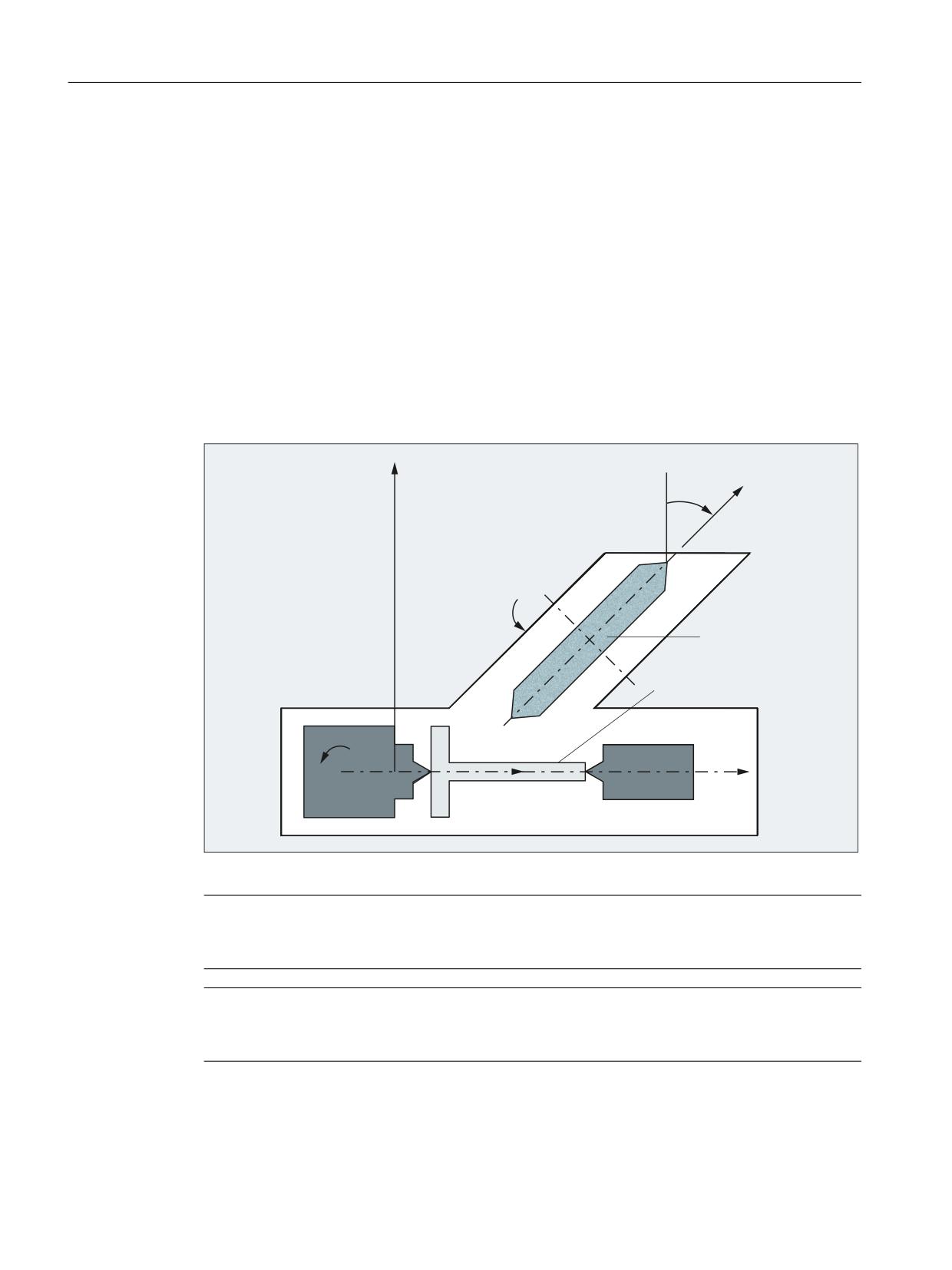
$TC_TPG8
For function "Constant grinding wheel peripheral speed (GWPS) (Page 301)", for an inclined
grinding wheel, the inclination angle α referred to the actual active plane (work plane G17, G18,
G19) is entered in parameter $TC_TPG8.
The permissible range of inclination angle α is: -90° ≤ α < +90°
;
08
˞
$6
*ULQGLQJ GLVN
:RUNSLHFH
&
=
0=
Figure 5-2
Inclined grinding wheel
Note
The tool length is not automatically compensated when the angle in parameter $TC_TPG8 is
changed.
Note
For machines with inclined axis, the same angle must be entered for the inclined axis as for the
inclined grinding wheel.
Tools
282
Function Manual, 10/2020, 6FC5397-6GP40-0BA1

Grinding-specific tool offset and tool monitoring
5.1 Grinding-specific tool data
5.1.3.8
$TC_TPG9
Parameter $TC_TPG9 is used to define to which tool parameters the following functions should
refer:
• Grinding-specific tool monitoring (Page 298)
• Constant grinding wheel peripheral speed (GWPS) (Page 301)
Examples:
$TC_TPG9 = <value>
<Value>
Reference variable
3
Length 1 (geometry + wear + base, depending on tool type)
4
Length 2 (geometry + wear + base, depending on tool type)
5
Length 3 (geometry + wear + base, depending on tool type)
6
Radius
5.1.3.9
$TC_TPG_DRSPATH and $TC_TPG_DRSPROG
Parameter $TC_TPG_DRSPATH (directory path to the dressing program) and $TC_TPG_DRSPROG
(dressing program) allow a dressing program to be assigned to a grinding wheel. In turn, this
allows a generally valid dressing procedure to be created, in which the dressing program is
executed using an indirect program call.
Example:
Program code
Comment
; Enter absolute dressing amount in $TC_DP12:
$TC_DP12[GETT("GRINDING_WHEEL",0),1]= $TC_DP12[GETT("GRINDING_WHEEL",0),1] - 0.01
G500
CYCLE435("GRINDING_WHEEL",1,"DRESSER",1)
; Calculate dressing tool position
T="DRESSER" D1
; Activate dressing tool.
; Indirectly call dressing program:
CALL "/"<<$TC_TPG_DRSPATH[GETT("GRINDING_WHEEL",0)]<<"/"<<$ TC_TPG_DRSPROG[GETT("GRINDING_WHEEL",0)]
M17
5.1.3.10
Definition of additional parameters $TC_TPC1 ... 10
For user-specific tool data, the additional parameters $TC_TPC1 to $TC_TPC10 can be set up
independent of the tool type via the following memory-configuring machine data:
Tools
Function Manual, 10/2020, 6FC5397-6GP40-0BA1
283

Grinding-specific tool offset and tool monitoring
5.1 Grinding-specific tool data
MD18096 $MN_MM_NUM_CC_TDA_PARAM
NOTICE
Loss of data due to reconfiguration
Reconfiguration of the local static NC memory results in a loss of data on the active and passive
file system. We therefore urgently recommend archiving or backing up all relevant data by
creating a commissioning archive before activating a modified memory configuration.
5.1.3.11
Access to tool-specific parameters
Tool-specific parameters can be read and written from the part program.
Examples:
Program code
Comment
R10=$TC_TPG5[2]
; read the current width of tool 2 and store in R10
$TC_TPG6[3]=2000
; write value 2000 to the maximum speed of tool 3.
The following system variable allows the tool-specific parameters for the current tool to be
accessed:
$P_ATPG[<m>]
<m> = parameter numbewr (data type: REAL)
Example:
Parameter 3 ($TPG3[<t>])
Program code
Comment
$P_ATPG[3]=R10
; read the minimum wheel radius of the current tool and store
in R10.
5.1.4
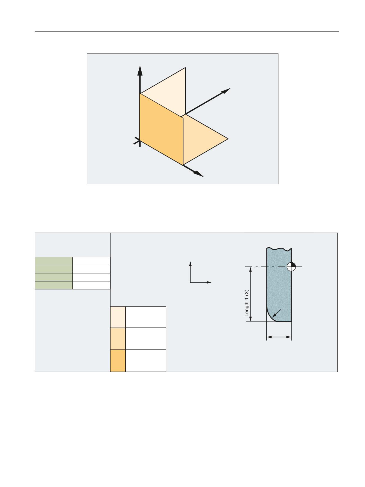
Planes and axis assignments
Tool length compensations for the geometry axes or radius compensation in the plane are
assigned on the basis of the current machining plane.
The following planes and axis assignments are possible (abscissa, ordinate, applicate for 1st,
2nd and 3rd geometry axis):
Command
Plane
Axis perpendicular to plane
(abscissa/ordinate)
(applicate)
G17
X / Y
Z
G18
Z / X
Y
G19
Y / Z
X
Tools
284
Function Manual, 10/2020, 6FC5397-6GP40-0BA1
Grinding-specific tool offset and tool monitoring
5.1 Grinding-specific tool data
<
*HRPHWULHDFKVH
;
*
*HRPHWULHDFKVH
*
*
*HRPHWULHDFKVH
=
5.1.5
Examples
(QWULHV LQ
)RU H[DPSOH
WRRO SDUDPHWHUV
*
= ; SODQH
7&B'3
;
)
7&B'3
/HQJWK
7&B'3
/HQJWK
7&B'3
5DGLXV
=
(IIHFW
5DGLXV
/HQJWK LQ <
*
/HQJWK LQ ;
5DGLXV LQ ;
<
/HQJWK LQ ;
*
/HQJWK LQ =
7KH SDUDPHWHUV WKDW
5DGLXV LQ =
;
/HQJWK
=
DUH QRW XVHG PXVW EH
VHW WR
/HQJWK LQ =
*
/HQJWK LQ <
) 7RROKROGHU UHIHUHQFH SRLQW
5DGLXV LQ <
=
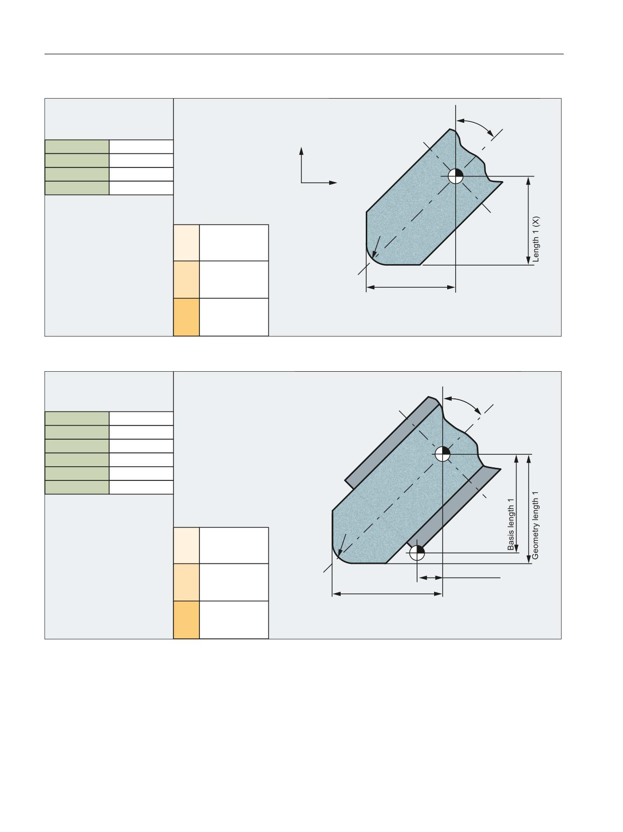
Figure 5-3
Required offset data of a surface grinding wheel
Tools
Function Manual, 10/2020, 6FC5397-6GP40-0BA1
285
Grinding-specific tool offset and tool monitoring
5.1 Grinding-specific tool data
(QWULHV LQ
)RU H[DPSOH
WRRO SDUDPHWHUV
*
= ; SODQH
˞
7&B'3
;
7&B'3
/HQJWK
7&B'3
/HQJWK
)
7&B'3
5DGLXV
=
(IIHFW
5DGLXV
/HQJWK LQ <
*
/HQJWK LQ ;
5DGLXV LQ ;
<
/HQJWK LQ ;
*
/HQJWK LQ =
/HQJWK
=
7KH SDUDPHWHUV WKDW
5DGLXV LQ =
;
DUH QRW XVHG PXVW EH
VHW WR
/HQJWK LQ =
*
/HQJWK LQ <
) 7RROKROGHU UHIHUHQFH SRLQW
5DGLXV LQ <
=
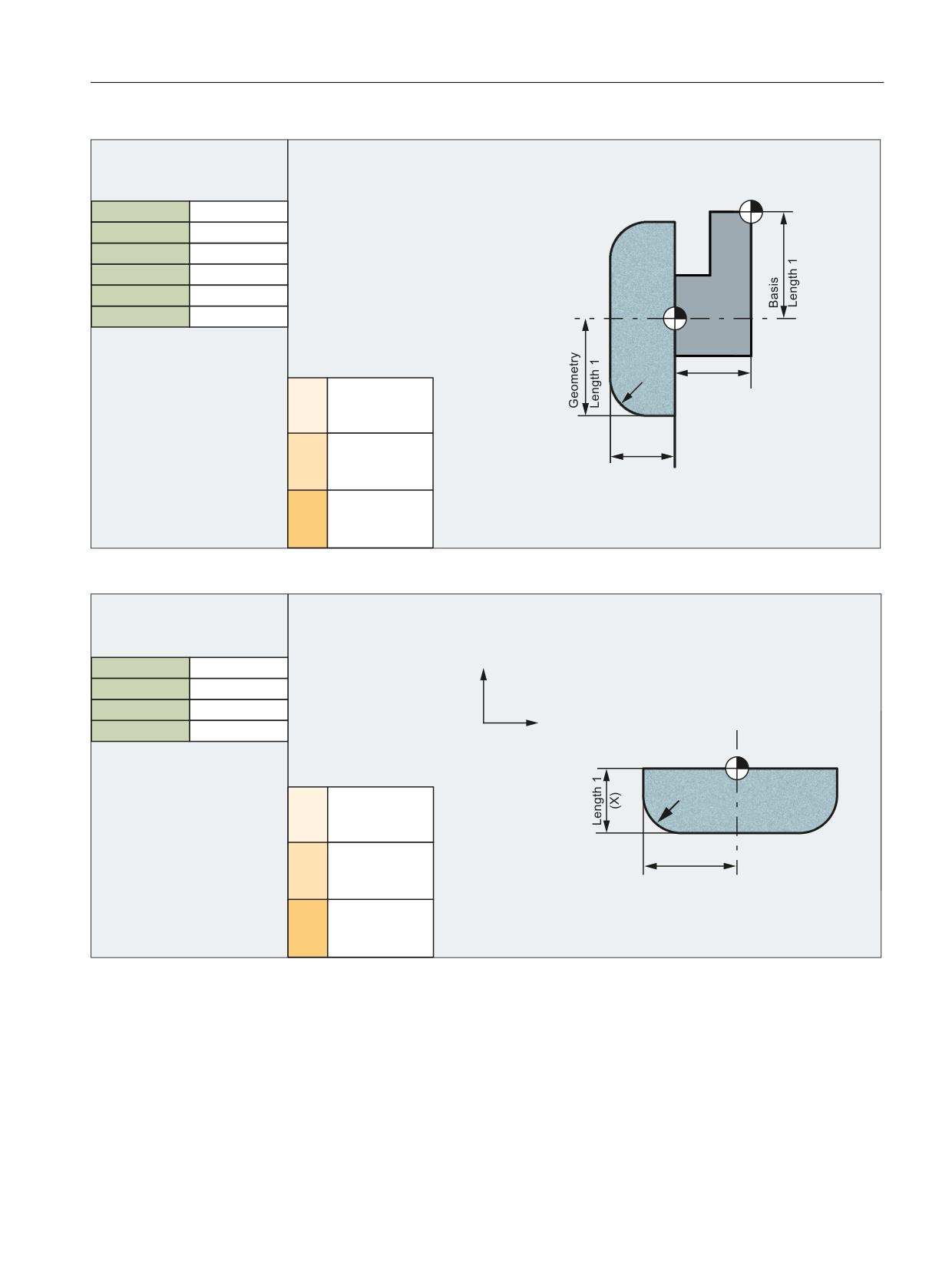
Figure 5-4
Required offset data for inclined wheel with implicit monitoring selection and without base dimension for GWPS
(QWULHV LQ
WRRO SDUDPHWHUV
˞
7&B'3
7&B'3
/HQJWK
)
7&B'3
/HQJWK
7&B'3
5DGLXV
7&B'3
/ EDVLV
7&B'3
/ EDVLV
(IIHFW
5DGLXV
$EUDVLRQ YDOXHV DV
/HQJWK LQ <
UHTXLUHG
*
/HQJWK LQ ;
5DGLXV LQ ;
<
)
/HQJWK LQ ;
%DVLV OHQJWK
7KH SDUDPHWHUV WKDW
*
/HQJWK LQ =
*HRPHWU\ OHQJWK
DUH QRW XVHG PXVW EH
5DGLXV LQ =
;
VHW WR
/HQJWK LQ =
*
/HQJWK LQ <
) 7RROKROGHU UHIHUHQFH SRLQW
5DGLXV LQ <
=
Figure 5-5
Required offset data for inclined wheel with implicit monitoring selection and with base dimension for GWPS
Tools
286
Function Manual, 10/2020, 6FC5397-6GP40-0BA1
Grinding-specific tool offset and tool monitoring
5.1 Grinding-specific tool data
(QWULHV LQ
WRRO SDUDPHWHUV
)
7&B'3
7&B'3
/HQJWK
7&B'3
/HQJWK
7&B'3
5DGLXV
7&B'3
/ EDVLV
)
7&B'3
/ EDVLV
%DVLV
(IIHFW
5DGLXV
/HQJWK
$EUDVLRQ YDOXHV DV
/HQJWK LQ <
UHTXLUHG
*
/HQJWK LQ ;
5DGLXV LQ ;
<
*HRPHWU\
/HQJWK LQ ;
7KH SDUDPHWHUV WKDW
*
/HQJWK LQ =
/HQJWK
DUH QRW XVHG PXVW EH
5DGLXV LQ =
;
VHW WR
/HQJWK LQ =
*
/HQJWK LQ <
) 7RROKROGHU UHIHUHQFH SRLQW
5DGLXV LQ <
=
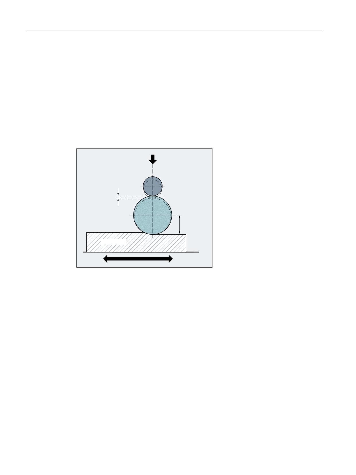
Figure 5-6
Required offset data of a surface grinding wheel without base dimension for GWPS
(QWULHV LQ
)RU H[DPSOH
WRRO SDUDPHWHUV
*
= ; SODQH
7&B'3
;
7&B'3
/HQJWK
7&B'3
/HQJWK
7&B'3
5DGLXV
=
)
(IIHFW
5DGLXV
/HQJWK LQ <
$EUDVLRQ YDOXHV DV
*
/HQJWK LQ ;
UHTXLUHG
5DGLXV LQ ;
<
/HQJWK LQ ;
/HQJWK
*
/HQJWK LQ =
=
7KH SDUDPHWHUV WKDW
5DGLXV LQ =
;
DUH QRW XVHG PXVW EH
VHW WR
/HQJWK LQ =
*
/HQJWK LQ <
) 7RROKROGHU UHIHUHQFH SRLQW
5DGLXV LQ <
=
Figure 5-7
Required offset data of a facing wheel with monitoring parameters
Tools
Function Manual, 10/2020, 6FC5397-6GP40-0BA1
287
Grinding-specific tool offset and tool monitoring
5.2 Online tool offset
5.2
Online tool offset
5.2.1
Function
A grinding operation involves both machining of a workpiece and dressing of the grinding
wheel. These processes can take place in the same channel or in separate channels.
To allow machining to continue while the grinding wheel is being dressed, the reduction in the
size of the grinding wheel caused by dressing must be transferred to the current tool in the
machining channel as a tool offset that is applied immediately. This can be implemented by
means of the "Online tool offset" function.
'UHVVLQJ UROO
'UHVVLQJ DPRXQW
*ULQGLQJ GLVN
/HQJWK WR
EH FRUUHFWHG
:RUNSLHFH
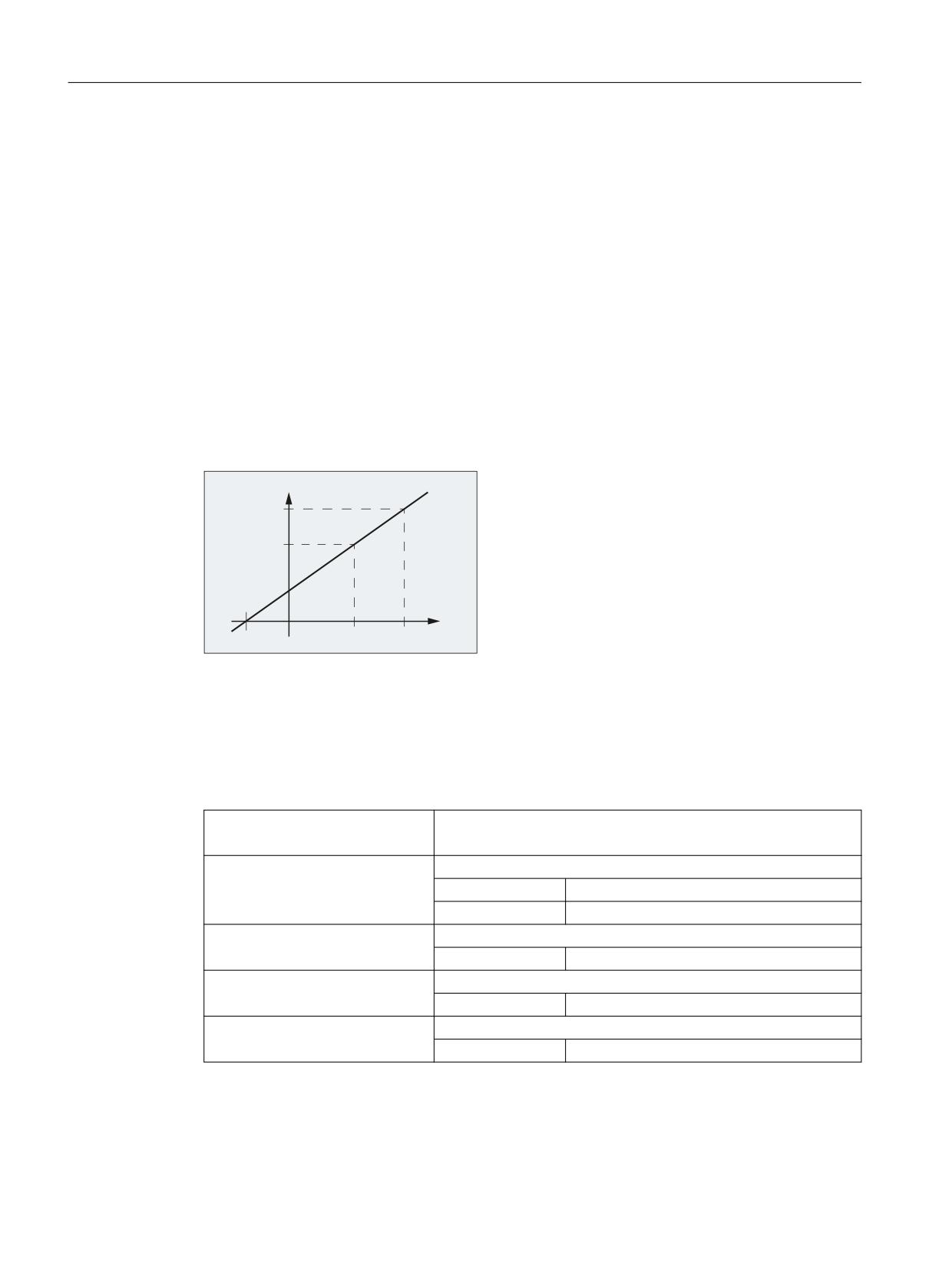
Figure 5-8
Dressing during machining using a dressing roller
The function supports the following methods of writing the tool offset:
• Continuous write, non-modal (PUTFTOCF (Page 291))
With PUTFTOCF, dressing is carried out at the same time as machining.
The tool offset is changed continuously in the machining channel according to a polynomial
function of the first, second or third order, which must have been defined previously
with FCTDEF (Page 290).
PUTFTOCF is always non-modal; in other words, it takes effect in the subsequent traversing
block.
• Continuous write, modal: ID=1 DO FTOC (for further information, see Function Manual
Synchronized Actions)
• Discrete write (PUTFTOC (Page 292))
With PUTFTOC, dressing is not carried out at the same time as machining from a parallel
channel. The correction value specified with PUTFTOC takes effect immediately in the
destination channel.
Activation / deactivation
The online tool offset in the part program is activated/deactivated by means of the G command
FTOCON/FTOCOF (Page 293).
Tools
288
Function Manual, 10/2020, 6FC5397-6GP40-0BA1
Grinding-specific tool offset and tool monitoring
5.2 Online tool offset
Additional properties
• An online tool offset can be activated for every grinding tool (tool type: 400 to 499) in each
channel.
• The online tool offset is generally applied as a length compensation. Like geometry and wear
data, lengths are assigned to geometry axes on the basis of the current plane as a function
of the tool type.
• The grinding spindle monitoring function remains active when an online tool offset is
selected.
Note
The online tool offset may only be used for grinding tools.
The offset always corrects the wear parameters of the selected length. If the length
compensation is identical for several cutting edges, then a chaining specification must be used
to ensure that the values for the 2nd cutting edge are automatically corrected as well.
If online tool offset is active in the machining channel, then the wear values for the active tool
in this channel may not be changed from the machining program or via operator inputs.
Modifications to the radius wear (P15) are not taken into account until the tool is reselected.
The online tool offset is also applied to the constant grinding wheel peripheral speed (GWPS), i.e.
the spindle speed is corrected by the corresponding value.
5.2.2
Commissioning
Number of tool holders that can be defined
Function "Online tool offset" cannot be simultaneously used with the function “Orientable
toolholder".
When using the "Online tool offset" function, the maximum number of tool holders that can be
defined in the TO area should be set to "0":
MD18075 $MN_MM_NUM_TOOLHOLDERS = 0
Note
For SINUMERIK 828D, the value of MD18075 can only be set in "Grinding" technology.
Enable online tool radius compensation
Online tool radius compensation (Page 297) must also be additionally enabled using machine
data:
MD20254 $MC_ONLINE_CUTCOM_ENABLE = 1
Tools
Function Manual, 10/2020, 6FC5397-6GP40-0BA1
289
Grinding-specific tool offset and tool monitoring
5.2 Online tool offset
5.2.3
Programming
5.2.3.1
Defining a polynomial function (FCTDEF)
Certain dressing strategies (e.g. dressing roller) are characterized by the fact that the grinding
wheel radius is continuously (linearly) reduced as the dressing roller is fed in. This strategy
requires a linear function between infeed of the dressing roller and writing the wear value of
each length. The linear function is defined using the predefined procedure FCTDEF(...) for up to
third order polynomial functions.
Straight line equation
y = f(x) = a0 + a1*x1
a1: Gradient of the straight line, with a1= Δx / Δy
a0: Shift of the straight line along the X axis with a0 = -a1 * XV
<
˂\
˂[
;
;9
Syntax
FCTDEF(<Func>,<LLimit>,<ULimit>,<a0>,<a1>,<a2>,<a3>)
Meaning
FCTDEF(...):
Defining a polynomial function for PUTFTOCF(...):
y = f(x) = a0 + a1*x + a2*x2 + a3*x3
<Func>:
Function number
Data type:
INT
Range of values:
1, 2, 3
<LLimit>:
Lower limit value
Data type:
REAL
<ULimit>:
Upper limit value
Data type:
REAL
<a0>,<a1>,<a2>,<a3>:
Coefficients of polynomial function
Data type:
REAL
Tools
290
Function Manual, 10/2020, 6FC5397-6GP40-0BA1

Grinding-specific tool offset and tool monitoring
5.2 Online tool offset
Example
Definitions
• Function number: 1
• Lower and upper limit value: -100, 100
• Gradient of the characteristic: a1 = 1
• The operating point should be located at the center of the characteristic. Based on the
setpoint position of axis XA in the WCS at the instant that the function is defined in the NC
program, the characteristic must be shifted in the negative Y direction: a0 = -a1 * XAD = -1 *
$AA_IW
• a2 = a3 = 0
Characteristic
<
8/
;$'
;$
//
UL
Upper limit value
LL
Lower limit value
XAD
Setpoint of axis XA at the time that the function is defined in the NC program
Programming
Program code
Comment
FCTDEF(1,-100,100,-$AA_IW[XA],1)
; Function definition
5.2.3.2
Write online tool offset continuously (PUTFTOCF)
Using the predefined procedure PUTFTOCF(...), an online tool offset is executed based on a
polynomial function previously defined with FCTDEF(...) (Page 290).
Note
The online tool offset can also be realized using a synchronized action.
For further information, see Function Manual Synchronized Actions.
Tools
Function Manual, 10/2020, 6FC5397-6GP40-0BA1
291

Grinding-specific tool offset and tool monitoring
5.2 Online tool offset
Syntax
PUTFTOCF(<Func>,<RefVal>,<ToolPar>,<Chan>,<Sp>)
Meaning
PUTFTOCF(...):
Write online tool offset, continuously block-by-block using the polynomial function
defined with FCTDEF(...)
<Func>:
Function number, defined in the function definition with FCTDEF(...)
Data type:
INT
Range of val-
1, 2, 3
ues:
<RefVal>:
Reference value, from which the offset is to be derived (e.g. setpoint of an axis).
Data type:
VAR REAL
<ToolPar>:
Number of the wear parameter (length 1, 2 or 3) in which the offset value is to be
included.
Data type:
INT
<Chan>:
Number of the channel in which the online tool offset is to take effect.
Note:
Only required if the offset is not to take effect in the active channel.
Data type:
INT
<Sp>:
Number of the spindle for which the online tool offset is to take effect.
Note:
Only required if the offset is to be applied to a non-active grinding wheel rather than
the active tool that is currently in use.
Data type:
INT
5.2.3.3
Write online tool offset, discrete (PUTFTOC)
Function
Using the predefined procedurePUTFTOC(...), an online tool offset is executed based on a fixed
offset value.
Syntax
PUTFTOC(<CorrVal>,<ToolPar>,<Chan>,<Sp>)
Meaning
PUTFTOC(...):
Write online tool offset
<CorrVal>:
Offset value, which is added to the wear parameter.
Data type:
REAL
<ToolPar>:
Number of the wear parameter (length 1, 2 or 3) in which the offset value is to be
included.
Data type:
INT
Tools
292
Function Manual, 10/2020, 6FC5397-6GP40-0BA1

Grinding-specific tool offset and tool monitoring
5.2 Online tool offset
<Chan>:
Number of the channel in which the online tool offset is to take effect.
Note:
Only required if the offset is not to take effect in the active channel.
Data type:
INT
<Sp>:
Number of the spindle for which the online tool offset is to take effect.
Note:
Only required if the offset is to be applied to a non-active grinding wheel rather than
the active tool that is currently in use.
Data type:
INT
5.2.3.4
Activate/deactivate online tool offset (FTOCON/FTOCOF)
The online tool offset is activated or deactivated using the G commands FTOCON and FTOCOF.
Syntax
FTOCON
FTOCOF
Meaning
FTOCON:
Activate online tool offset
The command must be programmed in the channel in which the online tool offset
is to be activated.
FTOCOF:
Deactivate online tool offset
The command must be programmed in the channel in which the online tool offset
is to be deactivated.
Note:
On FTOCOF, the axis does not move further out for the tool offset. However, the
value calculated with PUTFTOC/PUTFTOCF remains in the cutting-specific offset da-
ta.
To finally deactivate the online tool offset, the tool (T...) must again be selected/
deselected after FTOCOF.
5.2.4
Supplementary conditions
DRF offset
The online tool offset is superimposed on the programmed axis motion, allowing for the defined
limit values (e.g. velocity).
If a DRF offset and online offset are active simultaneously for an axis, the DRF offset is considered
first.
Tools
Function Manual, 10/2020, 6FC5397-6GP40-0BA1
293
Grinding-specific tool offset and tool monitoring
5.2 Online tool offset
Acceleration margin
The active online tool offset is traversed through at JOG velocity, allowing for the maximum
acceleration.
In case of FTOCON the following channel-specific machine data is taken into account:
MD20610 $MC_ADD_MOVE_ACCEL_RESERVE
An acceleration margin can thus be reserved for the movement which means that the overlaid
movement can be executed immediately.
Reference point approach
The valid online offset is deleted on reference point approach with G74.
Tool change
In cases where FTOCON has been active since the last tool or cutting edge change, preprocessing
stop with resynchronization is initiated in the control when a tool is changed.
Cutting edge changes can be implemented without preprocessing stop.
Note
Tool changes can be executed in conjunction with the online tool offset through the selection of
T numbers.
Tool changes with M6 cannot be executed in conjunction with the online tool offset function.
Machining plane and transformation
• FTOCON can be used only in conjunction with the "Inclined axis" transformation.
• It is not possible to change transformations or planes (e.g. G17 to G18) when FTOCON is
active, except in the FTOCOF state.
Resets and operating mode changes
• When online offset is active, NC-Stop and program end with M2/M30 are delayed until the
amount of compensation has been traversed.
• The online tool offset is immediately deselected in response to NC-Reset.
• Online tool offsets can be activated in AUTOMATIC mode and when the program is active.
Tools
294
Function Manual, 10/2020, 6FC5397-6GP40-0BA1
Grinding-specific tool offset and tool monitoring
5.2 Online tool offset
5.2.5
Examples
5.2.5.1
Example: Write online tool offset continuously
<
9
=
;
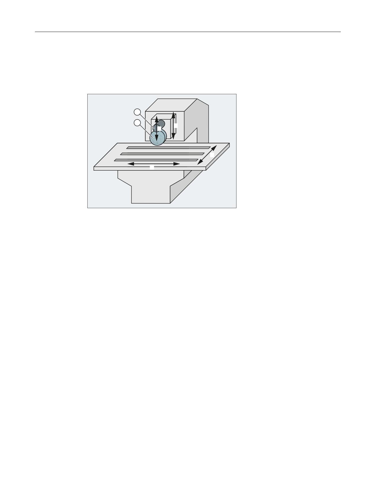
① Grinding disk
② Dressing roller
X:
Oscillating axis
Y:
Infeed axis: Grinding disk
Z:
Table axis
V:
Infeed axis: Dressing roller
Figure 5-9
Surface grinding machine
Specifications
• Tool offset
- Machining plane: Y/Z plane (G19)
- Tool type: 401 (length 1 acts in Z, length 2 acts in Y)
• Channel 1: Machining channel, axes X, Y, Z
• Channel 2: Dressing channel, axis V
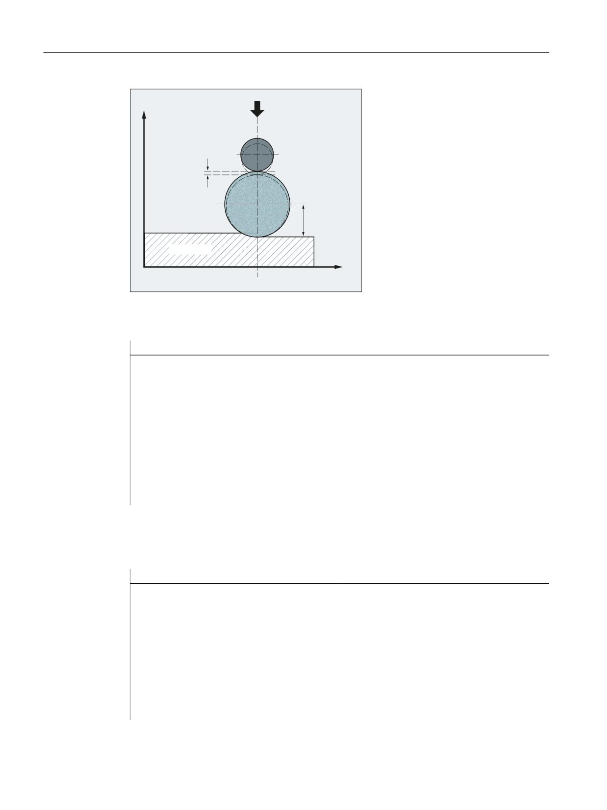
After the grinding operation has started at Y100, the grinding wheel must be dressed by 0.05
(in V direction). The dressing amount must be compensated continuously by means of an online
offset.
Tools
Function Manual, 10/2020, 6FC5397-6GP40-0BA1
295
Grinding-specific tool offset and tool monitoring
5.2 Online tool offset
<
'UHVVLQJ UROOHU
'UHVVLQJ
DPRXQW
*ULQGLQJ GLVN
/HQJWK
WR EH
FRPSHQVDWHG
:RUNSLHFH
;
Figure 5-10
Tool offset
Program (section) for channel 1: Machining channel
Program code
Comment
G1 G18 F10 G90
; initial setting
T1 D1
; select actual tool
S100 M3 X100
; switch-on spindle, X axis to initial po-
sition
INIT (2, "/_N_MPF_DIR/_N_ABRICHT_MPF",
; select: program "DRESS" in channel 2:
"S")
START (2)
; start: Channel 2
X200
; X axis at target position
FTOCON
; activate online offset
Program for channel 2: Dressing channel
The V axis traverses parallel to the Y axis, i.e. length 3 of the tool offset acts in the direction of
the Y axis, and must therefore be compensated..
Program code
Comment
PROC ABRICHT
FCTDEF(1, -1000, 1000, -$AA_IW[V], 1)
; function definition
PUTFTOCF(1, $AA_IW[V], 3, 1)
; continuously write online tool offset:
;
- Function number: 1
;
- Reference value: Setpoint position
in the WCS of the V axis
;
- Tool parameters: Length 3 of the
grinding disk
;
- Channel: 1
;
- Spindle: active grinding disk
Tools
296
Function Manual, 10/2020, 6FC5397-6GP40-0BA1
Grinding-specific tool offset and tool monitoring
5.3 Online tool radius compensation
Program code
Comment
V-0.05 G1 F0.01 G91
; infeed motion of the V axis for dressing
M30
5.3
Online tool radius compensation
Function
When the longitudinal axis of the tool and the contour are perpendicular to each other, the
offset can be applied as a length compensation to one of the three geometry axes (online tool
length compensation).
If this condition is not fulfilled, then the offset quantity can be entered as a real radius
compensation value (online tool radius compensation).
Enable
Online tool radius compensation must be enabled using machine data:
MD20254 $MC_ONLINE_CUTCOM_ENABLE = 1
Activation / deactivation
An online tool radius compensation is activated and deactivated using G commands FTOCON
and FTOCOF (Page 293) (in the same way as an online tool length compensation).
Parameter assignment
Online tool offset is parameterized using PUTFTOCF (Page 291) or PUTFTOC (Page 292).
The parameter <ToolPar> (wear parameter in which the correction value is to be calculated)
must be set for the online tool radius compensation as follows:
<ToolPar> = 4
Tools
Function Manual, 10/2020, 6FC5397-6GP40-0BA1
297

Grinding-specific tool offset and tool monitoring
5.4 Grinding-specific tool monitoring
Boundary conditions
• A tool radius compensation, and thus also an online tool radius compensation, can be
activated only when the selected tool has a radius other than "0". This means that machining
operations cannot be implemented solely with a tool radius compensation.
• The online correction values should be low in comparison to the original radius to prevent the
permitted dynamic tolerance range from being exceeded when the offset is overlaid on the
axis movement.
• For grinding and turning tools (types 400 - 599), the correction value is applied as a function
of the cutting edge position, i.e. it acts as a radius compensation when tool radius
compensation is active and as a length compensation when tool radius compensation is
deactivated in the axes specified by the cutting edge position.
On all other tool types, the correction value is applied only when tool radius compensation
has been activated with G41 or G42. The correction value is canceled when tool radius
compensation is deactivated with G40.
5.4
Grinding-specific tool monitoring
5.4.1
Function
Grinding-specific tool monitoring is a combination of geometry and speed monitoring. It can be
activated for every grinding tool (tool type: 400 to 499).
Note
Monitoring of one tool is not deselected if the monitoring function is selected for another tool
provided the two tools are referred to different spindles.
One tool and thus also one tool monitor can be active for every spindle at any point in time.
Activated monitors remain active after a reset.
Geometry monitoring
The actual wheel radius and the actual wheel width are monitored.
The compensation value of the first cutting edge (D1) of a grinding tool which is referenced in
the parameter $TC_TPG9 is used as the current wheel radius. If monitoring is active, this value
is compared to the value in parameter $TC_TPG3 (minimum wheel radius).
Note
The monitoring function for the wheel radius remains active if an online tool offset is selected:
• when the monitoring function is activated
• when the current radius (online tool offset, wear parameter) or the current width ($TC_TPG5)
is altered
Tools
298
Function Manual, 10/2020, 6FC5397-6GP40-0BA1

Grinding-specific tool offset and tool monitoring
5.4 Grinding-specific tool monitoring
The current wheel width is usually determined through the dressing cycle and can be entered in
parameter $TC_TPG5 of a grinding tool. If monitoring is active, this entered value is compared
to the value in parameter $TC_TPG4 (minimum wheel width).
If the current wheel radius falls below the value specified in the parameter $TC_TPG3 or the
current wheel width ($TC_TPG5) falls below the value defined in the parameter $TC_TPG4, the
control sets the following NC/PLC interface signal to "1":
DB31, ... DBX83.3 (geometry monitoring) == 1
Note
There is no controller-internal error response.
Speed monitoring
The speed monitor checks the grinding wheel peripheral speed in m/s (parameter $TC_TPG7) as
well as the maximum spindle speed in rpm (parameter $TC_TPG6).
The speed setpoint is monitored against the speed limitation cyclically with allowance for the
spindle override.
The speed limit is the smaller value resulting from the comparison of the maximum spindle
speed with the speed calculated from the maximum wheel peripheral speed and the current
wheel radius.
The speed limit value is recalculated:
• if monitoring is switched on
• if online correction values (wear parameters) are changed
When the speed limit value is reached, it is restricted to the speed limit value and the following
NC/PLC interface signal is set to "1":
DB31, ... DBX83.6 (speed monitoring) == 1
Note
There is no controller-internal error response.
Activation / deactivation
Activation/deactivation of grinding-specific tool monitoring is done by programming
of TMON(...)/TMOF(...) (Page 300) in the part program.
Tools
Function Manual, 10/2020, 6FC5397-6GP40-0BA1
299

Grinding-specific tool offset and tool monitoring
5.4 Grinding-specific tool monitoring
5.4.2
Commissioning
Automatic activation
If, when selecting the tool length compensation of a grinding tool with an odd tool type number,
the grinding-specific tool monitoring is to be automatically activated, the following machine
data must be set to "1":
MD20350 $MC_TOOL_GRIND_AUTO_TMON (activation of tool monitoring) = 1
5.4.3
Programming
5.4.3.1
Activate/deactivate grinding-specific tool monitoring (TMON, TMOF)
With the predefined procedures TMON(...) and TMOF(...), the grinding-specific tool monitoring
is activated or deactivated (geometry and speed monitoring).
Requirement
The tool-specific parameters $TC_TPG1 to $TC_TPG9 must be set.
Syntax
TMON(<TNo>)
TMOF(<TNo>)
Meaning
TMON(...):
Activate grinding-specific tool monitoring
The command must be programmed in the channel in which the grinding-specific tool
monitoring is to be activated.
TMOF(...):
Deactivate grinding-specific tool monitoring
The command must be programmed in the channel in which the grinding-specific tool
monitoring is to be deactivated.
<TNo>:
T number
Note:
Only required if the monitoring is to be switched on or off for an inactive grinding wheel
rather than the active grinding wheel that is currently in use.
TMOF(0):
Deactivate monitoring for all tools
Tools
300
Function Manual, 10/2020, 6FC5397-6GP40-0BA1
Grinding-specific tool offset and tool monitoring
5.5 Constant grinding wheel peripheral speed (GWPS)
5.5
Constant grinding wheel peripheral speed (GWPS)
5.5.1
Function
For grinding wheels, generally the wheel peripheral speed is used instead of the spindle speed.
The value to be set is determined by technological process parameters (e.g. grinding wheel
characteristic, material combination).
To be able to specify the wheel peripheral speed in the part program, the tool-specific
parameters $TC_TPG1 (Page 280), $TC_TPG8 (Page 282) and $TC_TPG9 (Page 283) must be set
and the function "Constant grinding wheel peripheral speed (GWPS)" must be activated.
Note
Activation of GWPS does not cause the automatic activation of tool length compensation or
grinding-specific tool monitoring!
As soon as the function is active, any subsequent S value for the spindle that is assigned to the
grinding wheel via $TC_TPG1 will be interpreted as grinding wheel peripheral speed. The
grinding wheel speed is set such that, taking account of the current wheel radius, the grinding
wheel peripheral speed remains constant.
The formula for calculating the speed is as follows:
68* >P V @
Q>PLQ @
˭
5>P@
The correction value to be used for calculation is defined in the tool-specific parameter
$TC_TPG9. The associated wear and the base dimension as a function of the tool type are added
to this correction value. The sum total is divided by "cos" ($TC_TPG8) when the value of
parameter $TC_TPG8 (angle of inclined wheel) is positive, and is divided by "sin" ($TC_TPG8)
when the value is negative.
The speed is recalculated in response to the following events:
• Specification a new grinding wheel peripheral speed, e.g. by:
- programming in the part program/overstoring
- assignment to the address "S" in MDI
- spindle speed control via PLC (FC18).
• Changing the online correction values (wear parameters)
Activation / deactivation
Activation/deactivation of GWPS is implemented by programming GWPSON(...)/GWPSOF(...) in
the part program (see "Programming (Page 303)").
Tools
Function Manual, 10/2020, 6FC5397-6GP40-0BA1
301
Grinding-specific tool offset and tool monitoring
5.5 Constant grinding wheel peripheral speed (GWPS)
Status
The following interface signal can be used to determine whether or not the GWPS is active:
DB31, ... DBX84.1 (GWPS active)
New tool
If GWPS is to be selected with a new tool for a spindle for which GWPS is already active, the active
GWPS must first be deselected (otherwise an alarm is output).
Response to reset/part program end
In the basic setting, GWPS is deactivated for a reset or end of part program and the spindle is
stopped. The machine data settings behind this behavior can be changed as needed (see
"Commissioning (Page 302)").
Additional properties
• GWPS can be activated for every grinding tool (tool type: 400 to 499) in each channel.
• GWPS can be active simultaneously for several spindles, each with a different grinding tool,
in the same channel.
5.5.2
Commissioning
Automatic activation
If the constant grinding wheel peripheral speed (GWPS) is to be automatically selected for a
spindle after Power On, and remain selected during mode switch, reset or end of the part
program, the following machine data bit must be set to "1":
MD35032 $MA_SPIND_FUNC_RESET_MODE Bit 0 = 1
Note
The prerequisite is that the tool be a grinding tool (tool type 400 to 499), the tool-specific
parameters $TC_TPG1, $TC_TPG8 and $TC_TPG9 are set, and $TC_TPG1 refers to a valid spindle.
Behavior of spindle after reset/part program end
If the spindle is not to stop after a reset or end of part program, but is to continue rotating at the
current speed, the following machine data must be set to "1":
Tools
302
Function Manual, 10/2020, 6FC5397-6GP40-0BA1

Grinding-specific tool offset and tool monitoring
5.5 Constant grinding wheel peripheral speed (GWPS)
MD35040 $MA_SPIND_ACTIVE_AFTER_RESET = 1
Note
MD35040 only takes effect in the spindle mode open-loop control operation.
5.5.3
Programming
5.5.3.1
Switching constant grinding wheel peripheral speed (GWPSON, GWPSOF) on/off:
With the predefined procedures GWPSON(...) and GWPSOF(...), the constant grinding wheel
peripheral speed (GWPS) for grinding tools (tool type: 400 to 499) is switched on and off.
Syntax
GWPSON(<TNo>)
S<n>=... :
GWPSOF(<TNo>)
Meaning
GWPSON(...):
Switch on the constant grinding wheel peripheral speed
GWPSOF(...):
Switch off the constant grinding wheel peripheral speed
<TNo>:
T number
Note:
Only required if the constant grinding wheel peripheral speed is to be switch-
ed on or off for an inactive grinding wheel rather than the active grinding
wheel that is currently in use.
S<n>=…:
Grinding wheel peripheral speed in m/s or ft/s for spindle <n>
S0=... or S... :
Grinding wheel peripheral speed for the master spindle
Query status
The following system variable can be used to query from the part program whether the constant
grinding wheel peripheral speed is active for a specific spindle.
$P_GWPS[<n>] ; where <n> = spindle number
Value
Meaning
0 (= FALSE)
GWPS is inactive.
1 (= TRUE)
GWPS is active.
Tools
Function Manual, 10/2020, 6FC5397-6GP40-0BA1
303
Grinding-specific tool offset and tool monitoring
5.5 Constant grinding wheel peripheral speed (GWPS)
5.5.4
Example
A constant grinding wheel peripheral speed is to be used for grinding tools T1 and T5. T1 is the
active tool.
Data of tool T1 (peripheral grinding wheel)
$TC_DP1[1,1] = 403
;tool type
$TC_DP3[1,1] = 300
;length1
$TC_DP4[1,1] = 50
;length2
$TC_DP12[1,1] = 0
;wear length 1
$TC_DP13[1.1] =0
;wear length 2
$TC_DP21[1.1] =300
;base length 1
$TC_DP22[1.1] =400
;base length 2
$TC_TPG1[1] = 1
;spindle number
$TC_TPG8[1] = 0
;angle of inclined wheel
$TC_TPG9[1] = 3
;parameter no. for radius calculation
Data of tool T5 (inclined grinding wheel)
$TC_DP1[5,1] = 401
;tool type
$TC_DP3[5,1] = 120
;length1
$TC_DP4[5,1] = 30
;length2
$TC_DP12[5,1] = 0
;wear length 1
$TC_DP13[5,1] =0
;wear length 2
$TC_DP21[5,1] =100
;base length 1
$TC_DP22[5,1] =150
;base length 2
$TC_TPG1[5] = 2
;spindle number
$TC_TPG8[5] = 45
;angle of inclined wheel
$TC_TPG9[5] = 3
;parameter no. for radius calculation
Programming
Program code
Comment
N20 T1 D1
; select T1 and D1
N25 S1=1000 M1=3
; 1000 rpm for spindle 1
N30 S2=1500 M2=3
; 1500 rpm for spindle 2
N40 GWPSON
; activate GWPS for active tool T1
N45 S[$P_ATPG[1]]=60
; set GWPS for active tool to 60 m/s
→ n=1909.85 rpm
N50 GWPSON(5)
; activate GWPS for tool 5 (spindle 2)
N55 S[$TC_TPG1[5]]=40
; set GWPS for spindle 2 to 40 m/s
→ n=1909.85 rpm
N60 GWPSOF
; deactivate GWPS for active tool
Tools
304
Function Manual, 10/2020, 6FC5397-6GP40-0BA1

Grinding-specific tool offset and tool monitoring
5.6 Data lists
Program code
Comment
N65 GWPSOF(5)
; deactivate GWPS for tool 5 (spindle 2)
5.6
Data lists
5.6.1
Machine data
5.6.1.1
General machine data
Number
Identifier: $MN_
Description
18075
MM_NUM_TOOLHOLDERS
Maximum number of tool holders that can be defined
18094
MM_NUM_CC_TDA_PARAM
Number of TDA
18096
MM_NUM_CC_TOA_PARAM
Number of TOA
18100
MM_NUM_CUTTING_EDGES_IN_TOA
Tool offsets per TOA
5.6.1.2
Channelspecific machine data
Number
Identifier: $MC_
Description
20254
ONLINE_CUTCOM_ENABLE
Enable online tool radius compensation
20350
TOOL_GRIND_AUTO_TMON
Automatic tool monitoring
20610
ADD_MOVE_ACCEL_RESERVE
Acceleration reserve for overlaid movements
5.6.1.3
Axis/spindlespecific machine data
Number
Identifier: $MA_
Description
32020
JOG_VELO
Jog axis velocity
35032
SPIND_FUNC_RESET_MODE
Reset behavior of individual spindle functions
35040
SPIND_ACTIVE_AFTER_RESET
Independent spindle reset
Tools
Function Manual, 10/2020, 6FC5397-6GP40-0BA1
305

Preface
1
Introduction
Fundamental safety
2
instructions
SINUMERIK
3
Overview
SINUMERIK 840D sl
Transformations
Transformation definitions
4
with kinematic chains
5
Kinematic transformations
Function Manual
Orientation
6
transformations
A
Appendix
Valid for
control system
SINUMERIK 840D sl / 840DE sl
CNC software Version 4.94
10/2020
6FC5397-5GP40-0BA1
Table of contents
Preface
3
1
Introduction
11
1.1
About this documentation
11
2
Fundamental safety instructions
13
2.1
General safety instructions
13
2.2
Warranty and liability for application examples
13
2.3
Security information
13
3
Overview
15
4
Transformation definitions with kinematic chains
17
4.1
Function description
17
4.1.1
Characteristics
17
4.1.2
Defining machine kinematics
18
4.1.3
Effective transformations upon reset
19
4.1.4
Simulation/simultaneous recording with kinematic chains
20
4.1.5
Migration of kinematic transformations
20
4.1.6
Frames for kinematic transformations
21
4.1.7
Tool lengths
22
4.2
Commissioning
22
4.2.1
General
22
4.2.1.1
Overview
22
4.2.1.2
Structure of the system variables
22
4.2.2
Machine data
24
4.2.2.1
Maximum number of transformations with kinematic chains
24
4.2.2.2
Name of the reset transformation
24
4.2.2.3
Activation limit of the real-time dynamic monitoring (linear axes)
24
4.2.2.4
Activation limit of real-time dynamic monitoring (rotary axes)
24
4.2.2.5
Correction value for offset vectors for CORRTRAFO
24
4.2.2.6
Angular deviation for rotation vectors for CORRTRAFO
24
4.2.3
Use of system variables for kinematic transformations
25
4.2.4
General system variables for transformations
26
4.2.4.1
Overview
26
4.2.4.2
$NT_NAME
28
4.2.4.3
$NT_TRAFO_INDEX
28
4.2.4.4
$NT_TRAFO_TYPE
30
4.2.4.5
$NT_T_CHAIN_FIRST_ELEM
31
4.2.4.6
$NT_P_CHAIN_FIRST_ELEM
32
4.2.4.7
$NT_T_CHAIN_LAST_ELEM
33
4.2.4.8
$NT_P_CHAIN_LAST_ELEM
34
4.2.4.9
$NT_T_REF_ELEM
36
4.2.4.10
$NT_GEO_AX_NAME
37
4.2.4.11
$NT_ROT_AX_NAME
38
Transformations
Function Manual, 10/2020, 6FC5397-5GP40-0BA1
5
Table of contents
4.2.4.12
$NT_ROT_AX_OFFSET
39
4.2.4.13
$NT_ROT_OFFSET_FROM_FRAME
40
4.2.4.14
$NT_ROT_AX_CNT
41
4.2.4.15
$NT_CLOSE_CHAIN_P
42
4.2.4.16
$NT_CLOSE_CHAIN_T
43
4.2.4.17
$NT_TRAFO_INCLUDES_TOOL
44
4.2.4.18
$NT_AUX_POS
45
4.2.4.19
$NT_IDENT
46
4.2.4.20
$NT_CNTRL
47
4.2.4.21
$NT_BASE_TOOL_COMP
49
4.2.4.22
$NT_HIRTH_INC
50
4.2.4.23
$NT_HIRTH_OFF
51
4.3
Programming
52
4.3.1
Activating transformation (TRAFOON)
52
4.3.2
Deactivate transformation (TRAFOOF)
53
4.3.3
Constraints for TRAFOON and TRAFOOF
53
5
Kinematic transformations
55
5.1
End face transformation TRANSMIT_K (option)
55
5.1.1
Function
55
5.1.1.1
Face end transformation TRANSMIT
55
5.1.1.2
Machining options
56
5.1.1.3
Working area limitations
62
5.1.1.4
Overlaid motions with TRANSMIT
63
5.1.1.5
Monitoring of rotary axis rotations over 360º
64
5.1.2
Parameterization of the kinematic chain and transformation
64
5.1.2.1
Parameterization of kinematics and transformation (TRANSMIT_K)
64
5.1.2.2
Special system variables for TRANSMIT_K
67
5.1.2.3
$NT_POLE_SIDE_FIX
67
5.1.3
Parameterization with machine data (conventional)
68
5.1.3.1
Overview
68
5.1.3.2
Axis configuration
70
5.1.3.3
Specific settings
72
5.1.4
Programming
74
5.1.4.1
Activating TRANSMIT with TRAFOON
74
5.1.5
Constraints
75
5.1.6
Examples
77
5.1.6.1
"Kinematic chain" part program for TRANSMIT
77
5.1.6.2
Example with machine data parameterization
80
5.2
Cylinder surface transformation TRACYL_K (option)
83
5.2.1
Cylinder surface transformation TRACYL
83
5.2.2
Transformation types for TRACYL
84
5.2.3
Parameterization of the kinematic chain and transformation
89
5.2.3.1
Parameterization of kinematics and transformation (TRACYL_K)
89
5.2.3.2
System variables for TRACYL_K
91
5.2.4
Parameterization with machine data (conventional)
92
5.2.4.1
Overview
92
5.2.4.2
Axis configuration
94
5.2.4.3
Specific settings
96
5.2.5
Programming
101
5.2.5.1
Activating TRACYL with TRAFOON
101
Transformations
6
Function Manual, 10/2020, 6FC5397-5GP40-0BA1
Table of contents
5.2.5.2
Activate cylinder surface transformation (TRACYL)
102
5.2.5.3
Activate cylinder surface transformation (TRACYL): Further information
103
5.2.6
Boundary conditions
105
5.2.7
Examples
108
5.2.7.1
"Kinematic chain" part program for TRACYL
108
5.2.7.2
Machining grooves on a cylinder surface with X-Y-Z-C kinematics
111
5.2.7.3
Machining grooves on a cylinder surface with X-Y-Z-A-C kinematics
116
5.3
Oblique angle transformation (inclined axis) TRAANG_K (option)
119
5.3.1
Oblique angle transformation (inclined axis) TRAANG_K
119
5.3.2
Parameterization of kinematic chain and transformation
121
5.3.2.1
Parameterization and kinematics and transformation (TRAANG_K)
121
5.3.2.2
System variables for TRAANG_K
122
5.3.3
Parameterization with machine data
123
5.3.3.1
Overview
123
5.3.3.2
Axis configuration
125
5.3.3.3
Specific settings
127
5.3.4
Programming
128
5.3.4.1
Activating TRAANG with TRAFOON
128
5.3.4.2
Activating an oblique angle transformation with programmable angle (TRAANG)
129
5.3.4.3
Activate oblique angle transformation with fixed angle (TRAANG)
130
5.3.4.4
Oblique plunge-cutting on grinding machines (G5, G7)
131
5.3.5
Boundary conditions
132
5.3.6
Example
135
5.3.6.1
"Kinematic chain" part program for TRAANG
135
5.3.6.2
Example
137
5.4
Rotary interpolation transformation TRAINT (option)
140
5.4.1
Function
140
5.4.1.1
Interpolation turning (TRAINT)
140
5.4.2
Parameterization of the kinematic chain and transformation
144
5.4.2.1
Parameterization of kinematics and transformation (TRAINT)
144
5.4.2.2
System variables for TRAINT
144
5.4.3
Programming
144
5.4.3.1
Activating TRAINT with TRAFOON
144
5.4.4
Supplementary conditions and recommendations for TRAINT
146
5.4.5
Examples
149
5.4.5.1
Example of kinematic chain
149
5.4.5.2
Example without tool rotation
154
5.4.5.3
Example for TRAINT
157
5.5
Chained transformations
159
5.5.1
Concatenating transformations (TRACON_K)
159
5.5.2
Additive system variables for transformation chains (TRACON_K)
160
5.5.2.1
$NT_TRACON_CHAIN
160
5.5.3
Concatenation for machine data parameterization
161
5.5.3.1
Introduction
161
5.5.3.2
System variables
163
5.5.4
Programming
165
5.5.5
Examples
167
5.5.5.1
Application example of chained transformations
167
5.5.5.2
Determining the axis positions in the transformation chain
171
5.6
Persistent transformations
173
Transformations
Function Manual, 10/2020, 6FC5397-5GP40-0BA1
7
Table of contents
5.6.1
Persistent transformations in kinematic chains
173
5.6.2
Persistent transformation
174
5.7
Cartesian PTP travel
177
5.7.1
Function
177
5.7.2
Commissioning
180
5.7.2.1
Response after POWER ON
180
5.7.2.2
Response after reset/part program end
180
5.7.2.3
Consideration of the SW limits during PTP travel
181
5.7.2.4
Displaying STAT and TU
182
5.7.3
Programming
182
5.7.3.1
Activating/deactivating Cartesian PTP travel (PTP, PTPG0, PTPWOC, CP)
182
5.7.3.2
Specify the position of the joints (STAT)
183
5.7.3.3
Specify the sign of the axis angle (TU)
188
5.7.3.4
Example 1: PTP travel of a 6-axis robot with ROBX transformation
190
5.7.3.5
Example 2: PTP travel for generic 5-axis transformation
192
5.7.3.6
Example 3: PTPG0 and TRANSMIT
192
5.7.4
Supplementary conditions
194
5.8
Cartesian manual traversing (option)
195
5.9
Activating transformation machine data via part program/softkey
206
5.9.1
Function
206
5.9.2
Constraints
206
5.9.3
Control response to power ON, mode change, RESET, block search, REPOS
208
5.9.4
List of machine data affected
209
5.9.5
Example
211
5.10
Data lists
212
5.10.1
Machine data
212
5.10.1.1
TRANSMIT
212
5.10.1.2
TRACYL
213
5.10.1.3
TRAANG
215
5.10.1.4
Chained transformations
216
5.10.1.5
Non transformation-specific machine data
216
6
Orientation transformations
217
6.1
Orientation transformations via kinematic chains
217
6.1.1
Dynamic orientation transformation TRAORI_DYN
217
6.1.2
Static orientation transformation TRAORI_STAT
219
6.2
3 to 5-axis transformation
220
6.2.1
5-axis Transformation
220
6.2.2
Machine types for 5-axis transformation
223
6.2.3
Singular positions and handling
224
6.3
Comparison of system variables and machine data
227
6.4
Parameterization via kinematic chains
228
6.4.1
3 to 5-axis transformation via kinematic chains
228
6.4.1.1
Definition of the machine kinematics
228
6.4.1.2
Definition of the transformation
231
6.4.2
Additive system variable for orientation transformation
233
6.4.2.1
Overview
233
6.4.2.2
$NT_BASE_ORIENT
233
6.4.2.3
$NT_BASE_ORIENT_NORMAL
234
Transformations
8
Function Manual, 10/2020, 6FC5397-5GP40-0BA1
Table of contents
6.4.2.4
$NT_POLE_LIMIT
235
6.4.2.5
$NT_POLE_LIMIT
237
6.4.2.6
$NT_POLE_TOL
239
6.4.2.7
$NT_IGNORE_TOOL_ORIENT
240
6.4.2.8
$NT_CORR_ELEM_T
241
6.4.2.9
$NT_CORR_ELEM_P
242
6.4.2.10
$NT_ROT_AX_POS
243
6.4.2.11
$NT_ROT_AX_MIN
244
6.4.2.12
$NT_ROT_AX_MAX
245
6.5
Parameterization with machine data (conventional)
245
6.5.1
Conventional 3 to 5-axis transformations
245
6.5.1.1
General specifications
245
6.5.1.2
Configuration of a machine for 5-axis transformation
246
6.5.1.3
Activation via parts/program/softkey
252
6.5.1.4
3-axis and 4-axis transformations
252
6.5.1.5
Transformation with swiveled linear axis
254
6.6
Restrictions for kinematics and interpolation
260
6.6.1
Restrictions for kinematics and interpolation
260
6.6.2
Singularities of orientation
260
6.7
Orientation
262
6.7.1
Definition of orientation vectors
262
6.7.2
Programming the tool orientation
264
6.7.3
Basic orientation with kinematic chain
270
6.7.4
Basic orientation for conventional transformations
270
6.7.5
Orientation movements with axis limits
272
6.7.6
Orientation compression
274
6.7.7
Smoothing of the orientation characteristic
279
6.7.7.1
Function
279
6.7.7.2
Commissioning
279
6.7.7.3
Activating/deactivating the orientation characteristic (ORISON, ORISOF)
280
6.7.8
Path-relative orientation (ORIPATH, ORIPATHS, ORIROTC)
281
6.7.9
Programming of orientation polynominals
287
6.7.10
System variable for tool orientation
290
6.8
Orientation axes
292
6.8.1
Orientation axes - overview
292
6.8.2
Configuration of orientation axes
293
6.8.3
Interpolation of orientation axes
295
6.8.4
JOG mode
297
6.8.5
Programming for orientation transformation
298
6.8.6
Programmable offset for kinematic chains
300
6.8.7
Programmable offset for orientation axes (conventional)
301
6.8.8
Orientation transformation and orientable tool holders
302
6.8.9
Modulo display of orientation axes
302
6.9
Orientation vectors
303
6.9.1
Polynomial interpolation of orientation vectors
303
6.9.2
Rotations of orientation vector
307
6.9.3
Extended interpolation of orientation axes
311
6.10
Online tool length offset
315
6.11
Cardan milling head
320
Transformations
Function Manual, 10/2020, 6FC5397-5GP40-0BA1
9
Table of contents
6.11.1
Universal milling head
320
6.11.2
Fundamentals of cardan milling head
321
6.11.3
Parameterization
323
6.11.4
Traverse of the cardan milling head in JOG mode
324
6.12
Generic 5-axis transformation and variants
325
6.12.1
Functionality
325
6.12.2
Description of machine kinematics
326
6.12.3
Generic orientation transformation variants
327
6.12.4
Parameterization of orientable toolholder data
329
6.12.5
Extension of the generic transformation to 6 axes
332
6.12.6
Extension of the generic transformation to 7 axes
335
6.12.7
Cartesian manual travel with generic transformation
340
6.13
Programming
341
6.13.1
Activating TRAORI_DYN and TRAORI_STAT with TRAFOON
341
6.13.2
Modifying the orientation transformation after the machine measurement (CORRTRAFO)...
341
6.13.3
Conventional transformations
349
6.13.3.1
Three, four and five axis transformation (TRAORI)
349
6.13.3.2
Programming of the 3- to 5-axis transformation
351
6.14
Examples
352
6.14.1
Examples TRAORI_DYN
352
6.14.1.1
Settings for TRAORI_DYN
352
6.14.1.2
Part program for TRAORI_DYN
355
6.14.2
Example of a 5-axis transformation
357
6.14.3
Example of a 3-axis and 4-axis transformation
359
6.14.3.1
Example of a 3-axis transformation
359
6.14.3.2
Example of a 4-axis transformation
360
6.14.4
Example of a universal milling head
360
6.14.5
Example for orientation axes
361
6.14.6
Examples for orientation vectors
364
6.14.6.1
Example for polynomial interpretation of orientation vectors
364
6.14.6.2
Example of rotations of orientation vector
365
6.14.7
Examples for generic axis transformations
365
6.14.7.1
Example of generic 5-axis transformation
365
6.14.7.2
Example of a generic 6-axis transformation
367
6.14.7.3
Example of a generic 7-axis transformation
368
6.14.7.4
Example for the modification of rotary axis motion
369
6.15
Data lists
369
6.15.1
Machine data
369
6.15.1.1
General machine data
369
6.15.1.2
Channelspecific machine data
370
6.15.1.3
Channelspecific machine data
373
6.15.2
Setting data
376
6.15.2.1
General setting data
376
6.15.2.2
Channelspecific setting data
376
A
Appendix
377
A.1
List of abbreviations
377
A.2
Documentation overview
382
Index
383
Transformations
10
Function Manual, 10/2020, 6FC5397-5GP40-0BA1

Introduction
1
1.1
About this documentation
This documentation is part of the documentation category of SINUMERIK Function Manuals.
SINUMERIK Function Manuals
The SINUMERIK Function Manuals describe the NC functions of a SINUMERIK control.
The target group are configuring engineers, technologists, commissioning engineers and
programmers.
Each Function Manual covers a specific topic and contains all the function descriptions for this
topic.
The following table shows which Function Manuals are available for your SINUMERIK control and
which topics a Function Manual covers:
Function Manual
Topic
Basic functions
Basic functions of a CNC control
Axes and spindles
Axis and spindle functions, axis couplings
Transformations
Transformation functions
Monitoring and compensating
Axis monitoring and compensation functions, collision avoid-
ance
Tools
Functions for selection, correction and monitoring of tools
Synchronized actions
Functionality of synchronized actions
PLC
Structure and functions of the PLC
Tool management
Function, commissioning and programming of tool manage-
ment
Technologies (for SINUMERIK ONE
Extended technological functionalities
and SINUMERIK 840D sl only)
Overview of contents
You will find an overview of the main chapters of the descriptions of functions that are contained
in a Function Manual on the title page.
Validity
The title page also contains all data about the validity of a document, i.e. for which SINUMERIK
control and for which software version this edition of the Function Manual is valid.
Transformations
Function Manual, 10/2020, 6FC5397-5GP40-0BA1
11

Introduction
1.1 About this documentation
System data
In the descriptions of functions, the system data relevant for a function (machine data, setting
data, system variables, interface signals and alarms) are only described with the level of detail
that is strictly necessary to understand the function. You will find detailed information on this
data in the relevant List Manuals and for alarms in the Diagnostics Manual.
PLC blocks
The descriptions of functions often refer to the PLC function blocks (FB) and functions (FC). The
descriptions of these blocks apply to the SINUMERIK 840D sl and can only be applied in part to
other SINUMERIK controls.
Interface signals
In this document, only the absolute address valid for the SINUMERIK 840D sl is used to address
interface signals.
General graphical conventions
Examples
<signal address> (<signal name>)
DB31, ... DBX16.0-2 (actual gear stage A to C)
DB31, ... DBX16.3 (gear is changed)
Note
Quantity structure
Explanations concerning the NC/PLC interface are based on the absolute maximum number of
the following components:
• Mode groups (DB11)
• Channels (DB21, etc.)
• Axes/spindles (DB31, etc.)
Transformations
12
Function Manual, 10/2020, 6FC5397-5GP40-0BA1

Fundamental safety instructions
2
2.1
General safety instructions
WARNING
Danger to life if the safety instructions and residual risks are not observed
If the safety instructions and residual risks in the associated hardware documentation are not
observed, accidents involving severe injuries or death can occur.
• Observe the safety instructions given in the hardware documentation.
• Consider the residual risks for the risk evaluation.
WARNING
Malfunctions of the machine as a result of incorrect or changed parameter settings
As a result of incorrect or changed parameterization, machines can malfunction, which in turn
can lead to injuries or death.
• Protect the parameterization against unauthorized access.
• Handle possible malfunctions by taking suitable measures, e.g. emergency stop or
emergency off.
2.2
Warranty and liability for application examples
Application examples are not binding and do not claim to be complete regarding configuration,
equipment or any eventuality which may arise. Application examples do not represent specific
customer solutions, but are only intended to provide support for typical tasks.
As the user you yourself are responsible for ensuring that the products described are operated
correctly. Application examples do not relieve you of your responsibility for safe handling when
using, installing, operating and maintaining the equipment.
2.3
Security information
Siemens provides products and solutions with industrial security functions that support the
secure operation of plants, systems, machines and networks.
In order to protect plants, systems, machines and networks against cyber threats, it is necessary
to implement - and continuously maintain - a holistic, state-of-the-art industrial security
concept. Siemens’ products and solutions constitute one element of such a concept.
Customers are responsible for preventing unauthorized access to their plants, systems,
machines and networks. Such systems, machines and components should only be connected to
Transformations
Function Manual, 10/2020, 6FC5397-5GP40-0BA1
13
Fundamental safety instructions
2.3 Security information
an enterprise network or the internet if and to the extent such a connection is necessary and only
when appropriate security measures (e.g. firewalls and/or network segmentation) are in place.
For additional information on industrial security measures that may be implemented, please
visit
Siemens’ products and solutions undergo continuous development to make them more secure.
Siemens strongly recommends that product updates are applied as soon as they are available
and that the latest product versions are used. Use of product versions that are no longer
supported, and failure to apply the latest updates may increase customer’s exposure to cyber
threats.
To stay informed about product updates, subscribe to the Siemens Industrial Security RSS Feed
under
services/cert.html#Subscriptions).
Further information is provided on the Internet:
Industrial Security Configuration Manual (https://support.industry.siemens.com/cs/ww/en/
view/108862708)
WARNING
Unsafe operating states resulting from software manipulation
Software manipulations, e.g. viruses, Trojans, or worms, can cause unsafe operating states in
your system that may lead to death, serious injury, and property damage.
• Keep the software up to date.
• Incorporate the automation and drive components into a holistic, state-of-the-art industrial
security concept for the installation or machine.
• Make sure that you include all installed products into the holistic industrial security concept.
• Protect files stored on exchangeable storage media from malicious software by with suitable
protection measures, e.g. virus scanners.
• On completion of commissioning, check all security-related settings.
Transformations
14
Function Manual, 10/2020, 6FC5397-5GP40-0BA1
Overview
3
Overview
The parameterization of kinematic transformations depends on the machine kinematics. The
transformation used must therefore be adapted to each machine kinematics.
Definition of the machine kinematics via a kinematic chain
The machine kinematics is defined as a kinematic chain. You can find detailed information about
kinematic chains in the Function Manual "Basic functions".
Note
Using kinematic chains in new projects
The machine geometry parameterized via kinematic chains can be used for further applications
such as collision avoidance. This type of configuration is recommended for the creation of new
projects.
There is a set of system variables each for the geometry and the transformation.
• The geometry is defined as a kinematic chain.
• The number of geometry, rotary and orientation axes is defined by system variables.
• The transformation is specified via the transformation type, e.g. TRANSMIT_K as end face
transformation.
Definition of the machine kinematics via machine data
This variant, which has already been introduced for some time, works with machine data and
transformation types:
• The transformation type is specified with number codes, e.g. transformation type 512
corresponds to TRACYL with slot side offset.
• Machine data is used to define the individual axes and their position relative to each other.
Available transformations
• End face transformation TRANSMIT_K (option) (Page 55)
• Cylinder surface transformation TRACYL_K (option) (Page 83)
• Oblique angle transformation (inclined axis) TRAANG_K (option) (Page 119)
• Rotary interpolation transformation TRAINT (option) (Page 140)
• Orientation transformations (Page 217)
Transformations
Function Manual, 10/2020, 6FC5397-5GP40-0BA1
15
Transformation definitions with kinematic chains
4
4.1
Function description
4.1.1
Characteristics
In this chapter, a description is provided as to how transformations are mapped using a
kinematic chain and parameterized in the control system using system variables. The system
variables are retentively saved in the NC and can be archived and/or read as "NC data" via
SINUMERIK Operate using the commissioning archive.
Transformations via kinematic chains
The machine kinematics relevant to kinematic transformations is described by two kinematic
chains:
• One chain points from the machine zero point (zero point of the world coordinate system) to
the workpiece reference point (part segment).
• The other chain points from the machine zero point to the tool reference point (tool
segment).
One of the two chains can also be empty (for pure table or tool kinematics).
=HUR SRLQW RI WKH WRRO
FRRUGLQDWH V\VWHP
7RRO FKDLQ
=HUR SRLQW RI WKH
ZRUNSLHFH FRRUGLQDWH
V\VWHP
:RUNSLHFH FKDLQ
=HUR SRLQW RI WKH ZRUOG
FRRUGLQDWH V\VWHP
Figure 4-1
Definition of a transformation via kinematic chains
Both kinematic chains are merged internally into a single kinematic chain, which, by definition,
begins at the workpiece reference point and ends at the tool reference point.
Transformations
Function Manual, 10/2020, 6FC5397-5GP40-0BA1
17

Transformation definitions with kinematic chains
4.1 Function description
Definition of the kinematic transformation
The definition of kinematic transformations via kinematic chains is used to standardize the
definition of the previous transformation types. If you have already defined the machine
kinematics for another application, e.g. collision avoidance, you can continue to use it for the
transformations.
The following transformations are taken into consideration:
• TRAORI
- TRAORI_DYN; dynamic orientation transformation
- TRAORI_STAT; static orientation transformation
• TRANSMIT_K; end face transformation
• TRACYL_K; peripheral surface transformation
• TRAANG_K; oblique angle transformation
• TRAINT; rotary interpolation transformation
4.1.2
Defining machine kinematics
Transformations with kinematic chains are defined in two steps:
• Definition of the machine kinematics
• Definition of the transformation
Defining machine kinematics
The machine kinematics (geometry of the machine) is described via kinematic chains.
The function and the relevant system variables are described in the Function Manual "Basic
Functions", Section "Kinematic chains". These system variables are structured according to the
scheme $NK_... Important system variables include:
System variable
$NK_NAME
Name of the current element
$NK_NEXT
Name of the next element
$NK_PARALLEL
Defines a parallel kinematic chain. As a result, the second chain can be defined parallel to the
first chain.
$NK_TYPE
Defines the type of the element, e.g. AXIS_LIN, AXIS_ROT, OFFSET, ROT_CONST, SWITCH
$NK_OFF_DIR
Defines the rotation vector relative to the machine axis
$NK_AXIS
Name of the machine axis
$NK_A_OFF
Defines the work offset of the assigned machine axis.
Transformations
18
Function Manual, 10/2020, 6FC5397-5GP40-0BA1

Transformation definitions with kinematic chains
4.1 Function description
See also
General system variables for transformations (Page 26)
Examples TRAORI_DYN (Page 352)
Defining transformation
The description of the machine kinematics with kinematic chains is not sufficient to completely
specify a kinematic transformation. The transformations can be completely defined via system
variables with the $NT_... prefix. The system variables available for the transformation are
divided into the following parts:
• System variables that are relevant for all transformations.
• System variables that are only relevant for specific transformations.
You can find a complete list under General system variables for transformations (Page 22).
Among other things, the following general system variables are available:
System variable
Description
$NT_NAME
Name of the transformation dataset.
$NT_TRAFO_INDEX
Identifier for alternative transformation activation; a transformation defined with kinematic
chains can also be activated using the conventional language commands (e.g. TRAORI)
instead of the TRAFOON method.
$NT_TRAFO_TYPE
Type of transformation (TRAORI_DYN, TRAORI_STAT, TRAANG_K, TRANSMIT_K, TRACYL_K,
TRAINT)
$NT_T_CHAIN_LAST_ELEM
Name of the last element of the kinematic chain to the tool.
$NT_P_CHAIN_LAST_ELEM
Name of the last element of the kinematic chain to the workpiece.
$NT_T_CHAIN_FIRST_ELEM
Name of the first element in the tool chain
$NT_P_CHAIN_FIRST_ELEM
Name of the first element of the workpiece chain
$NT_GEO_AX_NAME
Names of the elements of the geometry axes. With $NT_GEO_AX_NAME, a maximum of 3
linear axes are referenced. The linear axes carry out the compensating movements which
result from the kinematic transformation.
$NT_ROT_AX_NAME
Names of the elements of the orientation axes. With $NT_ROT_AX_NAME, a maximum of 3
linear axes are referenced.
$NT_CLOSE_CHAIN_T
Reference element for closing the kinematic chain to the workpiece.
$NT_ROT_AX_OFFSET
Position offset of a/the rotary axis for the active transformation.
$NT_CNTRL
Control word
4.1.3
Effective transformations upon reset
Active transformation upon reset
The kinematic transformation that is in effect during a reset is defined via the machine data
$MC_TRAFO_RESET_NAME.
If no name has been defined for $MC_TRAFO_RESET_NAME, $MC_TRAFO_RESET_VALUE is
active or no transformation is active upon reset. The contents of this machine data specifies the
Transformations
Function Manual, 10/2020, 6FC5397-5GP40-0BA1
19
Transformation definitions with kinematic chains
4.1 Function description
number of the conventional transformation to be activated. Conventional transformations are
not defined via kinematic chains, but via machine data.
Furthermore, the machine data $MC_RESET_MODE_MASK Bit 7 acts as it does for conventional
transformations. If bit 7 is set, the active transformation is retained after the reset or the end of
the part program.
4.1.4
Simulation/simultaneous recording with kinematic chains
Machine data $MNS_FUNCTION_MASK_SIM
To correctly carry out the simulation and simultaneous recording, the machine data MD 51226
$MNS_FUNCTION_MASK_SIM Bit 22 must be set.
The transformations TRAORI_DYN, TRANSMIT_K, TRACYL_K and TRAANG_K are affected by this.
4.1.5
Migration of kinematic transformations
Conventional transformations
Conventional transformations are understood to mean transformations that are defined via
machine data. These transformation definitions remain valid and can be used without
restrictions.
The variant available as of V4.8. SP2 also allows kinematic transformations to be defined via
kinematic chains and system variables.
Managing data only once
For the parallel use of conventional transformations and transformations via kinematic chains,
the problem occurs in which identical machine kinematics may be parameterized with different
NC data, namely, once with machine data and once with data from the system variables of the
kinematic chains and the transformations. As a result, inconsistencies in the data management
can occur.
Activating a transformation
The following functions are available for the activation of kinematic transformations:
• Syntax for transformations via kinematic chains: TRAFOON (Page 52) (<name>)
• Syntax for conventional transformations: TRAORI(...), TRANSMIT(...), TRACYL(...),
TRAANG(...), TRAINT(...)
Transformations which have been defined via kinematic chains can be called via the syntax for
conventional transformations.
To this end, the transformation that is to be called must be defined via the system variable
$NT_TRAFO_INDEX (Page 28).
Transformations
20
Function Manual, 10/2020, 6FC5397-5GP40-0BA1
Transformation definitions with kinematic chains
4.1 Function description
The following also applies:
• If a transformation has been defined conventionally and with a kinematic chain, the
transformation is called via a kinematic chain.
• No check is made to determine whether the called transformation is of a type that is
compatible with the transformation type of the original call.
• Call parameters of a conventional transformation call are forwarded to the transformation
defined with kinematic chains.
Restrictions for TRAANG_K
For a conventional TRAANG transformation (transformation of "inclined axis"), the angle of the
inclined axis is defined opposing the corresponding coordinate axis in a perpendicular
coordinate system by means of machine data (24700 $MC_TRAANG_ANGLE_x).
However, this angle can be changed during a transformation call, e.g. TRAANG(<α>), in a
parameter.
Therefore, specifying the angle parameter is only permitted when this angle is identical to the
angle that results from the definition of the kinematic chain.
Orientation transformations
For orientation transformations, which are parameterized with kinematic chains, the content of
the system variable $P_TRAFO is defined for compatibility reasons.
With an active orientation transformation, $P_TRAFO provides the values that would be
contained in the machine data $MC_TRAFO_TYPE_x for the conventional parameterization of a
corresponding transformation, i.e. the value 24 for "tool" kinematics, the value 40 for
"workpiece" kinematics, and either the value 56 or 57 for mixed kinematics.
The value 57 can only occur with 6-axis transformations if the tool chain contains one
orientation axis and the workpiece chain contains two orientation axes.
4.1.6
Frames for kinematic transformations
Frames for the description of kinematic chains
With the system variables $P_TRAFRAME_T or $P_TRAFRAME_P, frames can be read out which
describe the offset and the rotation of a coordinate system secured at the tool reference point
or at the workpiece reference point, compared to the zero point of the world coordinate system.
The contents of these frame variables can also be read via the BTSS interface.
The zero point of the world coordinate system is the point from which the kinematic chains
(Page 17) are defined for describing the machine kinematics.
Transformations
Function Manual, 10/2020, 6FC5397-5GP40-0BA1
21
Transformation definitions with kinematic chains
4.2 Commissioning
4.1.7
Tool lengths
Tool lengths
If the portion of the kinematic chain that leads to the tool is part of the tool, then the tool
reference point and the tool reference position that was set via $NT_T_REF_ELEM are no longer
identical.
The following applies to the NC functions, GETTCORR, SETTCORR and LENTOAX, for which the
tool reference point is important:
The portion of the kinematic chain that lies between the tool reference position and the tool
reference point is handled like an orientable tool carrier, which has been defined via machine
data.
4.2
Commissioning
4.2.1
General
4.2.1.1
Overview
The startup of the function "Transformations via kinematic chains" is done by means of:
• Machine data
- Specification of the quantity structure
- Specification of the first element in the kinematic chain
• System variables
- Definition of the transformation type
- Specification of the kinematic properties of an element
- Connection of the element to the kinematic chain
4.2.1.2
Structure of the system variables
The system variables are structured according to the following scheme:
• $NT_<Name>[<Index_1>]
• $NT_<Name>[<Index_1>, <Index_2>]
Transformations
22
Function Manual, 10/2020, 6FC5397-5GP40-0BA1
Transformation definitions with kinematic chains
4.2 Commissioning
General
The system variables to describe the elements of kinematic chains have the following properties:
• The prefix for all of the system variables of the kinematic chain is $NT_, (N for NC, K for
transformation).
• The system variables can be read and written via NC programs.
• The system variables can be stored in archives and loaded to the NC again.
Data type
STRING
All system variables of the STRING data type have the following properties:
• Maximum string length: 31 characters
• No distinction is made between upper and lower case
Example: "Axis1" is identical to "AXIS1"
• Spaces and special characters are permitted
Example: "Axis1" is not identical to "Axis 1"
• Names that start with two underscores "__" are reserved for system purposes and must not
be used for user-defined names.
Note
Leading space
Since spaces are valid and distinct characters, names that start with a space followed by two
underscores "__" can, in principle, be used for user-defined names. However, because they
can be easily mistaken for system names, this procedure is not recommended.
Index_1
The individual elements are addressed via index_1. Index 0 is reversed, index 1 → 1. Element,
index 2 → 2. Element, ... (n+1) → (n+1) element, with n = ($MN_MM_NUM_KIN_TRAFOS - 1)
All system variables of an element have the same index.
Index_2
For system variables that contain a vector, the coordinates of the vector are addressed via
index_2.
•
0 → X axis
•
1 → Y axis
•
2 → Z axis
Transformations
Function Manual, 10/2020, 6FC5397-5GP40-0BA1
23
Transformation definitions with kinematic chains
4.2 Commissioning
4.2.2
Machine data
4.2.2.1
Maximum number of transformations with kinematic chains
The maximum number of transformations that can be defined with kinematic chains is set using
the machine data
MD18866 $MN_MM_NUM_KIN_TRAFOS = <number>
4.2.2.2
Name of the reset transformation
The name of a transformation is specified with the machine data that is selected during run-up/
reset or at the end of the part program.
MD20142 $MC_TRAFO_RESET_NAME = <name>
4.2.2.3
Activation limit of the real-time dynamic monitoring (linear axes)
The activation limit of the real-time dynamic monitoring for linear axes is specified with the
machine data. Real-time dynamic limiting is activated when the deviation at a linear axis
participating in the transformation or the effective tool length for an orientation transformation
deviates by more than the defined limit.
MD21198 $MC_ORI_TRAFO_ONLINE_- CHECK_LIM = <value>
4.2.2.4
Activation limit of real-time dynamic monitoring (rotary axes)
The activation limit of real-time dynamic monitoring for rotary axes is specified with the machine
data. Real-time dynamic limiting is activated when the deviation at a linear axis participating in
the transformation or the effective tool length for an orientation transformation deviates by
more than the defined limit.
MD21198 $MC_ORI_TRAFO_ONLINE_- CHECK_LIMR = <value>
4.2.2.5
Correction value for offset vectors for CORRTRAFO
The maximum permitted correction value for offset vectors for CORRTRAFO is parameterized
with the setting data.
SD41610 $SN_CORR_TRAFO_LIN_MAX = <value>
4.2.2.6
Angular deviation for rotation vectors for CORRTRAFO
The maximum permitted angular deviations for rotation vectors for CORRTRAFO is
parameterized with the setting data.
SD41611 $SN_CORR_TRAFO_DIR_MAX = <name>
Transformations
24
Function Manual, 10/2020, 6FC5397-5GP40-0BA1

Transformation definitions with kinematic chains
4.2 Commissioning
4.2.3
Use of system variables for kinematic transformations
Usage table
The following table shows which $NT data is relevant for the individual types of transformations.
Note
Changed data
Modified data (e.g. $NT_xxx or $NK_yyy) become effective after NEWCONF if the data does not
concern an active transformation (attention if there are persistent transformations or
transformations which remain active via reset/end of part program). If the data to be activated
with NEWCONF concern an active transformation, an alarm is output.
Modified data (e.g. $NT_xxx or $NK_yyy) only become effective after a TRAFOOF and a
subsequent NC reset or NEWCONF or program end (M30).
Changed data (e.g. $NT_xxx or $NK_yyy) become effective after NCK-PowerOn.
Variable
OPI (col-
TRAORI_ST
TRAORI_D
TRANS-
TRAC-
TRAANG_K
TRAINT
umn ind.)
AT
YN
MIT_K
YL_K
$NT_NAME[n]
1200
x
x
x
x
x
x
$NT_TRAFO_INDEX[n]
1295
x
x
x
x
x
-
$NT_TRAFO_TYPE[n]
1201-1203
x
x
x
x
x
x
$NT_T_CHAIN_LAST_EL-
1204
x
x
x
x
x
x
EM[n]
$NT_P_CHAIN_LAST_EL-
1207
x
x
x
x
x
x
EM[n]
$NT_T_CHAIN_FIRST_EL-
1203
x
x
x
x
x
x
EM[n]
$NT_P_CHAIN_FIRST_EL-
1206
x
x
x
x
x
x
EM[n]
$NT_T_REF_ELEM[n]
1208
x
x
x
x
x
x
$NT_GEO_AX_NAME[n,0.
1210-1222
0,1,2
0,1,2
0,1,2
0,1,2
0,1,2
0,1,2
.2]
$NT_ROT_AX_NAME[n,0..
1220-1222
0,1,2
0,1,2
1
1
-
0
2]
$NT_CLOSE_CHAIN_T[n]
1226
x
x
x
x
x
-
$NT_BASE_ORI-
1280-1285
x
x
-
-
-
-
ENT[n,0..2]
$NT_BASE_ORIENT_NOR-
1283-1285
x
x
-
-
-
-
MAL[n,0..2]
$NT_ROT_OFF-
1288
x
x
x
x
-
-
SET_FROM_FRAME[n]
$NT_POLE_LIMIT[n]
1286
-
x
-
-
-
-
$NT_POLE_TOL[n]
1287
x
x
-
-
-
-
Transformations
Function Manual, 10/2020, 6FC5397-5GP40-0BA1
25

Transformation definitions with kinematic chains
4.2 Commissioning
Variable
OPI (col-
TRAORI_ST
TRAORI_D
TRANS-
TRAC-
TRAANG_K
TRAINT
umn ind.)
AT
YN
MIT_K
YL_K
$NT_IGNORE_TOOL_ORI-
1289
x
x
-
-
-
-
ENT[n]
$NT_ROT_AX_POS[n]
1230-1232
x
x
-
-
-
-
$NT_CORR_ELEM_T[n,
1235-1238
x
x
-
-
-
-
0..3]
$NT_CORR_ELEM_P[n,
1320-1323
x
x
-
-
-
-
0..3]
$NT_TRAFO_IN-
1290
-
-
-
-
x
-
CLUDES_TOOL[n]
$NT_POLE_SIDE_FIX[n]
1291
-
-
x
-
-
-
$NT_CNTRL[n]
1294
x
x
x
x
x
x
$NT_AUX_POS[n,0..2]
1300-1302
~
~
~
~
~
-
$NT_IDENT[n, 0..2]
1310-1312
~
~
~
~
~
-
$NT_ROT_AX_CNT[n,
1316-1317
x
x
x
x
x
x
0..1]
$NT_BASE_TOOL_COMP
1396
-
-
x
x
-
-
$NT_ROT_AX_OFFSET[n,
1324-1326
x
x
x
x
-
-
0
2]
$NT_ROT_AX_POS[n,
1230-1232
x
x
-
-
-
-
0..2]
$NT_ROT_AX_MIN[n,
1260-1262
x
x
-
-
-
-
0..2]
$NT_ROT_AX_MAX[n,
1270-1272
x
x
-
-
-
-
0..2]
$NT_HIRTH_OFF[n, 0..2]
1240-1242
x
x
-
-
-
-
$NT_HIRTH_INC[n, 0..2]
1250-1252
x
x
-
-
-
-
"x" affects the transformation.
"-" has no effect on the transformation
"~" has no effect on the transformation in the numerical control, but can be properly used for purposes outside of NC.
"Numbers" permitted axis indices (0 to 2)
"Column index"; column index of the variables in the operator panel interface in block N_PA (0x35).
4.2.4
General system variables for transformations
4.2.4.1
Overview
System variable
Meaning
$NT_NAME
Name of the transformation dataset
$NT_TRAFO_INDEX
Identifier for alternative transformation activation
Transformations
26
Function Manual, 10/2020, 6FC5397-5GP40-0BA1

Transformation definitions with kinematic chains
4.2 Commissioning
System variable
Meaning
$NT_TRAFO_TYPE
Transformation type
$NT_T_CHAIN_LAST_ELEM
Name of the last element of the tool chain
$NT_P_CHAIN_LAST_ELEM
Name of the last element of the workpiece chain
$NT_T_CHAIN_FIRST_ELEM
Name of the first element in the tool chain
$NT_P_CHAIN_FIRST_ELEM
Name of the first element of the workpiece chain
$NT_T_REF_ELEM
Name of the reference element for tool length
$NT_GEO_AX_NAME
Names of the elements of the geometry axes
$NT_ROT_AX_NAME
Names of the elements of the orientation axes
$NT_CLOSE_CHAIN_P
Reference element for closing the kinematic chain to the tool
$NT_CLOSE_CHAIN_T
Reference element for closing the kinematic chain to the work-
piece
$NT_ROT_OFFSET_FROM_FRAME
Importing the rotary axis offset from the work offset upon selection
of the transformation:
$NT_TRAFO_INCLUDES_TOOL
Defines whether the tool length is handled in the transformation or
- if the transformation permits it - outside of the transformation.
$NT_AUX_POS
Auxiliary position for cycles, e.g. retraction position
Note Has no meaning for the transformation
$NT_IDENT
Identification number for user-specific program management
Note Has no meaning for the transformation
$NT_CORR_ELEM_T
Names of a maximum of four correction elements in the kinematic
chain for the tool
$NT_CORR_ELEM_P
Names of a maximum of four correction elements in the kinematic
chain for the workpiece
$NT_CNTRL
Control word
The system variables are described in detail in the following sections.
Note
Establish a defined initial state
It is recommended that a defined initial state be generated before parameterizing the kinematic
chain. For this purpose, the system variables of the kinematic chain and the transformation with
the function DELOBJ() must be set to their default values.
Change system variable values
• Modified data (e.g. $NT_xxx or $NK_yyy) become effective after NEWCONF if the data does
not concern an active transformation (attention: persistent transformations or
transformations that remain active via reset/end of part program). If the data to be activated
with NEWCONF concern an active transformation, an alarm is output.
• Modified data (e.g. $NT_xxx or $NK_yyy) only become effective after a TRAFOOF and a
subsequent NC reset or NEWCONF or program end (M30).
• Changed data (e.g. $NT_xxx or $NK_yyy) become effective after NCK-PowerOn.
Transformations
Function Manual, 10/2020, 6FC5397-5GP40-0BA1
27

Transformation definitions with kinematic chains
4.2 Commissioning
4.2.4.2
$NT_NAME
Function
The NC-wide unique name of the transformation dataset or transformation must be entered in
the system variable. The transformation is referenced via this name, e.g. upon activation with
TRAFOON. If the zero string ("") is entered as the name, the transformation is considered to be
undefined.
Syntax
$NT_NAME[<n>] = "<Name>"
Meaning
$NT_NAME:
Name of the transformation
Data type:
STRING
Default value:
"" (empty string)
<n>:
System variable or transformation index
Data type:
INT
Range of values:
1, 2, ... (MD18866 $MN_MM_NUM_KIN_TRAFOS - 1)
<name>:
Transformation name, max. string length: 31 characters
Data type:
STRING
Example
The name "5-axis transformation C-B" is assigned to the first transformation with kinematic
chains:
Program code
Comment
N100 $NT_NAME[1] = "5-axis transformation
; 1st transformation,
C-B"
; name = "5-axis transformation C-B"
4.2.4.3
$NT_TRAFO_INDEX
Function
To ensure that a transformation can also be called via the corresponding conventional
command, e.g. the orientation transformation via TRAORI, an NC-wide, unique identifier must
be entered in the system variable. The identifier identifies a transformation with kinematic
chains by means of the transformation type, transformation number and channel number to
which a transformation that is called conventionally with this identifier is diverted
(TRAORI(<identifier>, ...)). The identifier is decimally coded.
Transformations
28
Function Manual, 10/2020, 6FC5397-5GP40-0BA1

Transformation definitions with kinematic chains
4.2 Commissioning
Syntax
$NT_TRAFO_INDEX[<n>] = <Id>
Meaning
$NT_TRAFO_INDEX:
Identifier, decimally coded (CCBBA)
Data type:
INT
Default value:
0
Decimal place
Meaning
Ones digit (xxxxA)
Transformation type
The type of the transformation that is parameterized in this dataset:
Value
Meaning
1
TRAORI
2
TRANSMIT
3
TRACYL
4
TRAANG
5
TRACON
Value range:
1, 2, 3, 4, 5
$NT_TRAFO_INDEX:
Tens and hundreds
Transformation number
digits (xxBBx)
(continued)
The number <n>, which references the nth channel-specific machine dataset
of this type (MD24100ff or MD25100ff) for a conventional call of a transfor-
mation type, e.g. orientation transformation TRAORI(<n>). The number can
be specified for a conventional call of the first transformation of a type
(e.g. TRAORI, TRAORI(), TRAORI(0), TRAORI(1)). All of the calls refer-
ence the 1st dataset of the transformation type in the channel. The
number must be specified after the call of the second transformation of a type
(e.g. TRAORI(2)).
Value range:
1, 2, 3, ... max. dataset number of the transformation
type
$NT_TRAFO_INDEX:
Thousands and ten-
Channel number
thousands digit
(continued)
The channel number defines which channel the current dataset is valid for. If
(CCxxx)
the conventional transformation call of an orientation
transformation TRAORI takes place, for example, in the second channel, a
transformation with kinematic chains must be parameterized with a channel
number equal to 2.
Value range:
0, 1, 2, 3, ... max. number of channels, 99
•
0 and 1: valid for channel 1
•
2, 3, ...: valid for channel 2, 3, ...
•
99: valid for all channels
<n>:
System variable or transformation index
Data type:
INT
Value range:
1, 2, ... (MD18866 $MN_MM_NUM_KIN_TRAFOS - 1)
<Id>:
Identifier
Data type:
INT
Transformations
Function Manual, 10/2020, 6FC5397-5GP40-0BA1
29

Transformation definitions with kinematic chains
4.2 Commissioning
Example
The call of the first orientation transformation TRAORI(2) in the third channel should be
diverted to the second transformation with kinematic chains.
Program code
Comment
N100 $NT_TRAFO_INDEX[1] = 03021
; 1st transformation with kin. chains,
; 1st orientation transformation for chan-
nel 3
4.2.4.4
$NT_TRAFO_TYPE
Function
The designation of the transformation type must be entered in the system variable.
Syntax
$NT_TRAFO_TYPE[<n>] = "<TrafoType>"
Meaning
$NT_TRAFO_TYPE:
Transformation type
Data type:
STRING
Default value:
""
Value range:
Value
Meaning
"TRAORI_DYN"
Dynamic orientation transformation
with orientation axes
"TRAORI_STAT"
Static orientation transformation with-
out orientation axes
"TRAANG"
Inclined angle transformation without
orientation axes
"TRAANG_K"
Oblique angle transformation
(The extension "_K" distinguishes it
from a conventionally defined TRAANG
transformation)
"TRANSMIT_K"
Face end transformation TRANSMIT
"TRACYL_K"
Cylinder surface transformation TRAC-
YL
"TRACON_K"
Concatenating transformations
"TRAINT"
Interpolation turning
<n>:
System variable or transformation index
Data type:
INT
Value range:
1, 2, ... (MD18866 $MN_MM_NUM_KIN_TRAFOS - 1)
<TrafoType>:
Transformation type
Data type:
STRING
Transformations
30
Function Manual, 10/2020, 6FC5397-5GP40-0BA1

Transformation definitions with kinematic chains
4.2 Commissioning
Example
The first transformation with kinematic chains describes a dynamic orientation transformation
with orientation axes:
Program code
Comment
N100 $NT_TRAFO_TYPE[1] =
; 1st transformation,
"TRAORI_DYN"
; transformation type = "TRAORI_DYN"
4.2.4.5
$NT_T_CHAIN_FIRST_ELEM
Function
The kinematics of a transformation is described by a maximum of two kinematic subchains,
which begin in the respective root element, i.e. the first element of the kinematic chain that is in
effect. One subchain leads from the root element to the workpiece reference point
(see Defining machine kinematics (Page 18)). The other subchain leads to the tool reference
point. If the subchain does not start, as is usual, in the root element, the first element of the
active kinematic subchain can be defined for the tool chain and for the workpiece chain using
the system variables
The name ($NT_NAME (Page 28)) of the element of the kinematic subchain that is currently
active, which defines the starting point of the subchain for the tool reference point, must be
entered in the system variable $NT_T_CHAIN_FIRST_ELEM.
Note
Pure tool kinematics
The first element only has to be defined in $NT_P_CHAIN_FIRST_ELEM in special circumstances;
otherwise the system variable can remain empty. In this case, the ROOT element is used as the
first element.
Syntax
$NT_T_CHAIN_FIRST_ELEM[<n>] = "<ElementName>"
Meaning
$NT_T_CHAIN_FIRST_ELE
Name of the element that defines the starting point of the currently
M:
active kinematic chain for the tool reference point.
Data type:
STRING
Default value:
""
Range of val-
Element names of the currently active kinematic chain
ues:
<n>:
System variable or transformation index
Data type:
INT
Range of val-
1, 2, ... (MD18866 $MN_MM_NUM_KIN_TRAFOS - 1)
ues:
Transformations
Function Manual, 10/2020, 6FC5397-5GP40-0BA1
31

Transformation definitions with kinematic chains
4.2 Commissioning
<ElementName>:
Name of an element of the currently active kinematic chain
Data type:
STRING
Example
For the first transformation, the name of the element of the kinematic subchain that defines the
starting point of the subchain for the workpiece reference point is "Baseoffset_2":
Program code
Comment
N100 $NT_T_CHAIN_FIRST_ELEM[1] = "Base-
; 1st transformation,
offset_2"
; first element for the tool reference
point
4.2.4.6
$NT_P_CHAIN_FIRST_ELEM
Function
The kinematics of a transformation is described by a maximum of two kinematic subchains,
which begin in the respective root element, i.e. the first element of the kinematic chain that is in
effect. One subchain leads from the root element to the tool reference point (see Defining
machine kinematics (Page 18)). The other subchain, which is described here, leads to
the workpiece reference point. If the subchain does not start, as is usual, in the root element,
the first element of the active kinematic subchain can be defined for the tool and workpiece
chain using the system variables.
The name ($NT_NAME (Page 28)) of the element of the kinematic chain that is currently in
effect, which defines the starting point of the subchain for the workpiece reference point, must
be entered in the system variable $NT_P_CHAIN_FIRST_ELEM.
Note
Pure workpiece kinematics
The first element only has to be defined in $NT_T_CHAIN_FIRST_ELEM in special circumstances;
otherwise the system variable can remain empty. In this case, the ROOT element is used as the
first element.
Syntax
$NT_P_CHAIN_FIRST_ELEM[<n>] = "<ElementName>"
Transformations
32
Function Manual, 10/2020, 6FC5397-5GP40-0BA1

Transformation definitions with kinematic chains
4.2 Commissioning
Meaning
$NT_P_CHAIN_FIRST_ELE
Name of the first element of the kinematic subchain that is currently
M:
active defined at the endpoint of the tool reference point.
Data type:
STRING
Default value:
""
Range of val-
Element names of the currently active kinematic chain
ues:
<n>:
System variable or transformation index
Data type:
INT
Range of val-
1, 2, ... (MD18866 $MN_MM_NUM_KIN_TRAFOS - 1)
ues:
<ElementName>:
Name of an element of the currently active kinematic chain
Data type:
STRING
Example
For the first transformation, the name of the element of the kinematic chain that defines the end
point of the subchain for the workpiece reference point is "TableOffset":
Program code
Comment
N100 $NT_P_CHAIN_FIRST_ELEM[1] = "Base-
; 2nd transformation,
offset"
; element for the workpiece reference
point
4.2.4.7
$NT_T_CHAIN_LAST_ELEM
Function
The kinematics of a transformation is described by a maximum of two kinematic subchains,
which begin in the respective root element, i.e. the first element of the kinematic chain that is in
effect. One subchain leads from the root element to the workpiece reference point
(see Defining machine kinematics (Page 18)). The other subchain, which is described here, leads
to the tool reference point.
The name ($NT_NAME (Page 28)) of the element of the kinematic chain that is currently in
effect, which defines the end point of the subchains for the tool reference point, must be entered
in the system variable $NT_T_CHAIN_LAST_ELEM.
Note
Pure tool kinematics
If, for pure tool kinematics, the kinematics of the transformation is completely described by the
subchain for the tool reference point, the parameterization of the system variable
$NT_T_CHAIN_LAST_ELEM is sufficient. The system variable for describing the subchain for the
workpiece reference point ($NT_P_CHAIN_LAST_ELEM) can remain blank.
Transformations
Function Manual, 10/2020, 6FC5397-5GP40-0BA1
33

Transformation definitions with kinematic chains
4.2 Commissioning
Syntax
$NT_T_CHAIN_LAST_ELEM[<n>] = "<ElementName>"
Meaning
$NT_T_CHAIN_LAST_ELEM
Name of the element of the kinematic chain currently in effect, which
:
defines the end point for the tool reference point, starting from the root
element.
Data type:
STRING
Default value:
""
Range of val-
Element names of the currently active kinematic chain
ues:
<n>:
System variable or transformation index
Data type:
INT
Range of val-
1, 2, ... (MD18866 $MN_MM_NUM_KIN_TRAFOS - 1)
ues:
<ElementName>:
Name of an element of the currently active kinematic chain
Data type:
STRING
Example
For the first transformation, the name of the element of the kinematic chain that defines the end
point of the subchain for the tool reference point is "Basetool":
Program code
Comment
N100 $NT_T_CHAIN_LAST_ELEM[1] = "base
; 1st transformation,
tool"
; element for the tool reference point
4.2.4.8
$NT_P_CHAIN_LAST_ELEM
Function
The kinematics of a transformation is described by a maximum of two kinematic subchains,
which begin in the respective root element, i.e. the first element of the kinematic chain that is in
effect. One subchain leads from the root element to the tool reference point (see Defining
machine kinematics (Page 18)). The other subchain, which is described here, leads to
the workpiece reference point.
Transformations
34
Function Manual, 10/2020, 6FC5397-5GP40-0BA1

Transformation definitions with kinematic chains
4.2 Commissioning
The name ($NT_NAME (Page 28)) of the element of the kinematic chain that is currently in
effect, which defines the end point of the subchains for the workpiece reference point, must be
entered in the system variable $NT_P_CHAIN_LAST_ELEM.
Note
Pure workpiece kinematics
If, for pure workpiece kinematics, the kinematics of the transformation is completely described
by the subchain for the workpiece reference point, the parameterization of the system variable
$NT_P_CHAIN_LAST_ELEM is sufficient. The system variable for describing the subchain for the
tool reference point ($NT_T_CHAIN_LAST_ELEM) can remain blank.
Syntax
$NT_P_CHAIN_LAST_ELEM[<n>] = "<ElementName>"
Meaning
$NT_P_CHAIN_LAST_ELEM
Name of the element of the kinematic chain currently in effect, which
:
defines the end point for the workpiece reference point, starting from
the root element.
Data type:
STRING
Default value:
""
Range of val-
Element names of the currently active kinematic chain
ues:
<n>:
System variable or transformation index
Data type:
INT
Range of val-
1, 2, ... (MD18866 $MN_MM_NUM_KIN_TRAFOS - 1)
ues:
<ElementName>:
Name of an element of the currently active kinematic chain
Data type:
STRING
Example
For the first transformation, the name of the element of the kinematic chain that defines the end
point of the subchain for the workpiece reference point is "TableOffset":
Program code
Comment
N100 $NT_P_CHAIN_LAST_ELEM[1] = "Ta-
; 2nd transformation,
bleOffset"
; element for the workpiece reference
point
Transformations
Function Manual, 10/2020, 6FC5397-5GP40-0BA1
35

Transformation definitions with kinematic chains
4.2 Commissioning
4.2.4.9
$NT_T_REF_ELEM
Function
The name ($NT_NAME (Page 28)) of the element of the kinematic chain that is currently in
effect, which defines the tool reference position, i.e. the reference point for the tool length
calculation, must be entered in the system variable. The tool reference position is located at
the starting point of the kinematic element.
If no name of an element is entered in the system variable, the tool reference position is identical
to the tool reference point.
Syntax
$NT_T_REF_ELEM[<n>] = "<RefElementName>"
Meaning
$NT_T_REF_ELEM:
Name of the element of the kinematic chain that is currently in effect,
which defines the tool reference position.
Data type:
STRING
Default value:
"" (tool reference position = tool reference point)
Value range:
Element names of the currently active kinematic chain
<n>:
System variable or transformation index
Data type:
INT
Range of val-
1, 2, ... (MD18866 $MN_MM_NUM_KIN_TRAFOS - 1)
ues:
<RefElementName>:
Name of an element of the currently active kinematic chain
Data type:
STRING
Example
For the first transformation, the name of the element of the kinematic chain that is currently in
effect, which defines the tool reference position, is "ToolRefPoint":
Program code
Comment
N100 $NT_T_REF_ELEM[1] = "ToolRef-
; 1st transformation,
Point"
; element for the tool reference position
Transformations
36
Function Manual, 10/2020, 6FC5397-5GP40-0BA1

Transformation definitions with kinematic chains
4.2 Commissioning
4.2.4.10
$NT_GEO_AX_NAME
Function
A maximum of three names ($NT_NAME (Page 28)) of the elements of the kinematic chain that
is currently in effect, which define the geometry axes (linear axes) of the transformation type
(Page 18) to be parameterized, must be entered in the system variable. The geometry axes carry
out the linear compensating movements, which result from the kinematic transformation.
Syntax
$NT_GEO_AX_NAME[<n>,<k>] = "<GeoAxElementName>"
Meaning
$NT_GEO_AX_NAME:
Names of the elements of the kinematic chain currently in effect, which
define the geometry axes
Data type:
STRING
Default value:
("", "", "")
Value range:
Element names of the currently active kinematic chain
<n>:
System variable or transformation index
Data type:
INT
Value range:
1, 2, ... (MD18866 $MN_MM_NUM_KIN_TRAFOS - 1)
<k>:
Index for the elements that define the geometry axes
Data type:
INT
Value range:
0: X coordinate (abscissa)
1: Y coordinate (ordinate)
2: Z coordinate (applicate)
<GeoAxElementName>:
Name of an element of the kinematic chain that is currently in effect,
which defines a geometry axis
Data type:
STRING
Example
For the first transformation, the names of the elements of the kinematic chain currently in
effect, which define the geometry axes, are "X_AXIS", Y_AXIS" and "Z_AXIS", must be entered.
Program code
Comment
; 1st transformation,
; elements of the geometry axes:
N100 $NT_GEO_AX_NAME[1,0] = "X_AXIS"
; X coordinate (abscissa)
N110 $NT_GEO_AX_NAME[1,1] = "Y_AXIS"
; Y coordinate (ordinate)
N120 $NT_GEO_AX_NAME[1,2] = "Z_AXIS"
; Z coordinate (applicate)
Transformations
Function Manual, 10/2020, 6FC5397-5GP40-0BA1
37

Transformation definitions with kinematic chains
4.2 Commissioning
4.2.4.11
$NT_ROT_AX_NAME
Function
A maximum of three names ($NT_NAME (Page 28)) of the elements of the kinematic chain that
is currently in effect, which define the rotary axes of the transformation type (Page 18) to be
parameterized, must be entered in the system variable.
• Orientation transformation: The orientation axes A, B, C
• Face end (TRANSMIT) and cylinder surface transformation (TRACYL): The rotary axis, which
rotates the workpiece and, together with a linear axis, defines the polar coordinate system.
Order of definitions
The maximum three rotary axes, beginning at Index 0, must be entered in the system variables
in the order in which they are defined in the kinematic chain that is currently in effect.
The kinematic chain must be run through as follows:
1. Starting point: Workpiece reference point
2. Elements of the chain
3. End point: Tool reference point
The elements that define the rotary axes must be seamlessly entered in the system variable with
their names, starting at Index 0.
Syntax
$NT_ROT_AX_NAME[<n>,<k>] = "<RotAxElementName>"
Meaning
$NT_ROT_AX_NAME:
Names of the elements of the kinematic chain currently in effect, which
define the rotary axes
Data type:
STRING
Default value:
("", "", "")
Value range:
Element names of the currently active kinematic chain
<n>:
System variable or transformation index
Data type:
INT
Value range:
1, 2, ... (MD18866 $MN_MM_NUM_KIN_TRAFOS - 1)
<k>:
Index for the elements that define the rotary axes
Data type:
INT
Range of val-
0: 1st rotary axis in the definition sequence
ues:
1: 2nd rotary axis in the definition sequence
2: 3rd rotary axis in the definition sequence
<RotAxElementName>:
Name of an element of the kinematic chain that is currently in effect,
which defines a rotary axis.
Data type:
STRING
Transformations
38
Function Manual, 10/2020, 6FC5397-5GP40-0BA1

Transformation definitions with kinematic chains
4.2 Commissioning
Example
For the first transformation, the names of the elements of the kinematic chain currently in
effect, which define the rotary axes, are "ROT_AXIS_1", ROT_AXIS_2" and "ROT_AXIS_3" must be
entered.
Program code
Comment
; 1st transformation,
; elements of the rotary axes:
N100 $NT_ROT_AX_NAME[1,0] = "ROT_AXIS_1"
; 1st rotary axis
N110 $NT_ROT_AX_NAME[1,1] = "ROT_AXIS_2"
; 2nd rotary axis
N120 $NT_ROT_AX_NAME[1,2] = "ROT_AXIS_3"
; 3rd rotary axis
4.2.4.12
$NT_ROT_AX_OFFSET
Function
The system variable $NT_ROT_AX_OFFSET allows you to enter an angle offset for the rotary
axes of the active transformation.
• For TRAORI_DYN, these are the rotary axes 1, 2, and 3.
• For TRANSMIT_K and TRACYL_K it is rotary axis 1.
Supplementary conditions
• System variable $NT_ROT_AX_OFFSET for Transmit or Tracyl transformations without a
kinematic chain corresponds to machine data $MC_TRANSMIT_ROT_AX_OFFSET_n or
$MC_TRACYL_ROT_AX_OFFSET_n.
• System variable $NT_ROT_AX_OFFSET for orientation transformations without a kinematic
chain corresponds to machine data $MC_TRAFO5_ROT_AX_OFFSET_n.
Syntax
$NT_ROT_AX_OFFSET[<n,m>] = <offset_angle>
Meaning
$NT_ROT_AX_OFFSET
Angle offset for rotary axes
Data type:
REAL
Default value:
-1; content is not evaluated
<n>:
System variable or transformation index
Data type:
INT
Value range:
1, 2, ... (MD18866 $MN_MM_NUM_KIN_TRAFOS - 1)
Transformations
Function Manual, 10/2020, 6FC5397-5GP40-0BA1
39

Transformation definitions with kinematic chains
4.2 Commissioning
<m>:
Index of the variable $NT_ROT_AX_CNT; specifies for which rotary axis the
offset is set.
Data type:
INT
Value range
•
0 ... 2; for orientation transformation
•
1; for TRANSMIT_K and TRACYL_K
Example
Provides the number of rotary axes for the part chain:
Program code
Comment
N100 $NT_ROT_AX_CNT[1,0] = 180
; assigns offset "180 °" to rotary axis
"0" of transformation "1".
4.2.4.13
$NT_ROT_OFFSET_FROM_FRAME
Function
In the system variable $NT_ROT_OFFSET_FROM_FRAME it must be entered whether the
programmable offset for orientation axes will be automatically imported from the zero point
offset for the orientation axes, which becomes active upon switch-on of an orientation
transformation.
• TRAORI or TRAORY_DYN:
- If $NT_ROT_OFFSET_FROM_FRAME=1 the following applies:
The offsets for the orientation axes of the 5/6 axis transformation of the rotary axes, for
which the tool orientation is in the basic setting, are automatically defined. Thus, the
offset from an active work offset of the rotary axes, which is active as soon as the
transformation is switched on, is applied.
- If $NT_ROT_OFFSET_FROM_FRAME=0, then the following applies:
The offset of the orientation axes is only applied if the work offsets when switching on the
transformation are kept, i.e. MD10602 $MN_FRAME_GEOAX_CHANGE_MODE is > 0.
• TRACYL and/or TRANSMIT
- If $NT_ROT_OFFSET_FROM_FRAME=2, the following applies:
Axial offset of the rotary axis is taken into account up to the SZS. SZS is the settable zero
system. The SZS frames contain transformed rotations around the rotary axis.
Note
Automatic application of work offsets
Automatic application of the active work offsets to the offset is mainly only practical for the polar
axis in table kinematics. i.e. for example, in AC kinematics for the C axis. If the offset is changed
for another orientation axis, in particular, the non-polar axis, this changes the kinematic
behavior of the transformation. The can result in the compensatory movement of the linear axes
no longer being correct.
Transformations
40
Function Manual, 10/2020, 6FC5397-5GP40-0BA1

Transformation definitions with kinematic chains
4.2 Commissioning
Syntax
$NT_ROT_OFFSET_FROM_FRAME[<n>] = "<ROTOffset>"
Meaning
$NT_ROT_OFFSET_FROM_FRAME:
Importing the rotary axis offset from the work offset upon se-
lection of the transformation:
•
0 = Axial offset of the rotary axis is not taken into account.
•
1 = axial offset of the rotary axis is taken into account.
•
2 = Axial offset of the rotary axis is taken into account up to
the SZS or is automatically applied (see above).
Data type:
INT
Default value:
0
<n>:
System variable or transformation index
Data type:
INT
Value range:
0, 1, 2
ROTOffset
Rotary axis offset
Example
The 2nd transformation is assigned the name "B axis":
Program code
Comment
N100 $NT_ROT_OFFSET_FROM_FRAME[1] =
; axial offset of the rotary axis is taken
1
into account.
4.2.4.14
$NT_ROT_AX_CNT
Function
The system variable $NT_ROT_AX_CNT provides the number of the relevant rotary axes in the
workpiece or in the tool chain. The relevant rotary axes in this sense are the rotary axes that are
defined in the system variable $NT_ROT_AX_Name.
Syntax
$NT_ROT_AX_CNT[<n,m>] = <NumberRotAxes>
Meaning
$NT_ROT_AX_CN
Number of relevant rotary axes of a transformation in the workpiece chain or tool
T:
chain
Data type:
INT
Default value:
-1; content is not evaluated
Transformations
Function Manual, 10/2020, 6FC5397-5GP40-0BA1
41

Transformation definitions with kinematic chains
4.2 Commissioning
<n>:
System variable or transformation index
Data type:
INT
Value range:
1, 2, ... (MD18866 $MN_MM_NUM_KIN_TRAFOS - 1)
<m>:
Index of the variable $NT_ROT_AX_CNT; specifies which kinematic chain will be
selected.
Data type:
INT
Value range
•
0; selects the workpiece chain
•
1; selects the tool chain
Example
Provides the number of rotary axes for the subchain:
Program code
Comment
N100 $NT_ROT_AX_CNT[1,0] = 2
; Transformation 1 has two rotary axes.
4.2.4.15
$NT_CLOSE_CHAIN_P
Function
The name ($NT_NAME (Page 28)) of the element of the currently active kinematic chain, at the
end of which the subchain for the workpiece reference point is closed if $NT_CNTRL, Bit 7 == 1,
can be entered in the system variable.
If no name is entered in the system variable, the subchain is closed independently of
$NT_CNTRL, Bit 7, at the end of the last element (workpiece reference point).
Syntax
$NT_CLOSE_CHAIN_P[<n>] = "<ElementName>"
Meaning
$NT_CLOSE_CHAIN_P:
Name of the element of the kinematic chain currently in effect, at the end
of which the subchain for the workpiece reference point is closed
Data type:
STRING
Default value:
""
Value range:
Element names of the currently active kinematic chain
<n>:
System variable or transformation index
Data type:
INT
Range of val-
1, 2, ... (MD18866 $MN_MM_NUM_KIN_TRAFOS - 1)
ues:
<ElementName>:
Name of an element of the currently active kinematic chain
Data type:
STRING
Transformations
42
Function Manual, 10/2020, 6FC5397-5GP40-0BA1

Transformation definitions with kinematic chains
4.2 Commissioning
Example
For the first transformation, the name of the element of the kinematic chain, at the end of which
the part chain for the workpiece reference point is closed, is: "P_Offset_3"
Program code
Comment
N100 $NT_CLOSE_CHAIN_P[1] = "P_Off-
; 1st transformation,
set_3"
; element for closing the subchain
; to the workpiece reference point
See also
$NT_CNTRL (Page 47)
4.2.4.16
$NT_CLOSE_CHAIN_T
Function
The name ($NT_NAME (Page 28)) of the element of the currently active kinematic chain, at the
end of which the subchain for the tool reference point is closed if $NT_CNTRL, Bit 8 == 1
($NT_CNTRL (Page 47)), can be entered in the system variable.
If no name is entered in the system variable, the subchain is closed independently of
$NT_CNTRL, Bit 8, at the end of the last element (tool reference point).
Syntax
$NT_CLOSE_CHAIN_T[<n>] = "<ElementName>"
Meaning
$NT_CLOSE_CHAIN_T:
Name of the element of the kinematic chain currently in effect, at the end
of which the subchain for the tool reference point is closed
Data type:
STRING
Default value:
""
Value range:
Element names of the currently active kinematic chain
<n>:
System variable or transformation index
Data type:
INT
Range of val-
1, 2, ... (MD18866 $MN_MM_NUM_KIN_TRAFOS - 1)
ues:
<ElementName>:
Name of an element of the currently active kinematic chain
Data type:
STRING
Transformations
Function Manual, 10/2020, 6FC5397-5GP40-0BA1
43