SINUMERIK 840D sl. Service - Functions. Manual (2018-2020) - page 95
Tool offset
3.16 Working with tool environments
3.16.1
Save tool environment (TOOLENV)
The TOOLENV function is used to save any current states needed for the evaluation of tool data
stored in the memory.
The individual data are as follows:
•
The active G command of group:
-
6 (G17, G18, G19)
–
56 (TOWSTD, TOWMCS, TOWWCS, TOWBCS, TOWTCS, TOWKCS)
•
The active transverse axis
•
Machine data:
- MD18112 $MN_MM_KIND_OF_SUMCORR (properties of the summed offsets in the TO
area)
- MD20360 $MC_TOOL_PARAMETER_DEF_MASK (definition of tool parameters).
•
Setting data:
- SD42900 $SC_MIRROR_TOOL_LENGTH (sign change tool length when mirroring)
- SD42910 $SC_MIRROR_TOOL_WEAR (sign change tool wear when mirroring)
- SD42920 $SC_WEAR_SIGN_CUTPOS (sign of the tool wear with cutting edge systems)
- SD42930 $SC_WEAR_SIGN (sign of wear)
- SD42935 $SC_WEAR_TRANSFORM (transformations for tool components)
- SD42940 $SC_LENGTH_CONST (change of the tool length components for a plane
change)
- SD42942 $SC_TOOL_LENGTH_CONST_T (change of tool length components for turning
tools at change of plane)
- SD42950 $SC_TOOL_LENGTH_TYPE (allocation of the tool length components
independent of tool type)
- SD42954 $SC_TOOL_ORI_CONST_M (change of tool orientation components for milling
tools at change of plane)
- SD42956 $SC_TOOL_ORI_CONST_T (change of tool orientation components for turning
tools at change of plane)
•
The orientation component of the current complete frame (rotation and mirroring, no work
offsets or scaling)
•
The orientation component and the resulting length of the active toolholder with orientation
capability
•
The orientation component and the resulting length of an active transformation
In addition to the data describing the environment of the tool, the T number, D number and DL
number of the active tool are also stored, so that the tool can be accessed later in the same
environment as the TOOLENV call, without having to name the tool again.
Syntax
<Status> = TOOLENV(<name>)
Tools
Function Manual, 10/2020, 6FC5397-6GP40-0BA1
207
Tool offset
3.16 Working with tool environments
Meaning
TOOLENV(...):
Predefined function to save a tool environment
Alone in the
Yes
block:
<Status>:
Function return value. Negative values indicate error states.
Data type:
INT
Value:
0
Function OK
-1
No memory reserved for tool environments:
MD18116 $MN_MM_NUM_TOOL_ENV = 0
This means that the "tool environments" functionality is not
available.
-2
No more free memory locations for tool environments available.
-3
Null string illegal as name of a tool environment.
-4
No parameter (<name>) specified.
Parameters
1
<name>:
Name, under which the current data set should be saved.
If a data set of the same name already exists, then it is overwritten. In this case, the
status is "0".
Data type:
STRING
Further information
Base dimension/adapter dimension - tool length compensation
When the tool magazine management is active (only available with the "Tool management"
option!), the value of the following machine data defines whether the adapter length or the tool
base dimension (cutting edge-specific parameters $TC_DP21, $TC_DP22 and $TC_DP23) is
incorporated in the calculation of the tool length:
MD18104 $MN_MM_NUM_TOOL_ADAPTER (tool adapter in TO area).
Since a change to this machine data only takes effect after the control system has powered up,
it is not saved in the tool environment.
Resulting length of toolholders with orientation capability and transformations:
Note
Both toolholders with orientation capability and transformations can use system variables or
machine data, which act as additional tool length components, and which can be subjected
partially or completely to the rotations performed. The resulting additional tool length
components must also be saved when TOOLENV is called, because they represent part of the
environment, in which the tool is used.
Adapter transformation
The adapter transformation is a property of the tool adapter and thus of the complete tool. It is,
therefore, not part of a tool environment, which can be applied to another tool.
Tools
208
Function Manual, 10/2020, 6FC5397-6GP40-0BA1
Tool offset
3.16 Working with tool environments
By saving the complete data necessary to determine the overall tool length, it is possible to
calculate the effective length of the tool at a later point in time, even if the tool is no longer active
or if the conditions of the environment (e.g. G codes or setting data) have changed. Similarly, the
effective length of a different tool can be calculated assuming that it would be used under the
same conditions as the tool, for which the status was saved.
Maximum number of data sets for tool environments
Machine data MD18116 $MN_MM_NUM_TOOL_ENV is used to define the maximum number of
data sets that can be saved to describe the tool environments. The data are in the TOA area. They
are kept even when the control system is switched off.
Data cannot be backed up. This means that this data cannot be transferred between the
different control systems.
3.16.2
Delete tool environment (DELTOOLENV)
The DELTOOLENV function is used to delete the data sets that are used to describe tool
environments. Deletion means that the set of data stored under a particular name can no longer
be accessed (an access attempt triggers an alarm).
Note
Data sets can only be deleted using the DELTOOLENV function, by an INITIAL.INI download or by
a cold start (NC power up with default machine data). There are no additional automatic
deletion operations.
Syntax
<Status> = DELTOOLENV(<name>)
<Status> = DELTOOLENV()
Meaning
DELTOOLENV(...):
Predefined function to delete a tool environment
Alone in the
Yes
block:
<Status>:
Function return value. Negative values indicate error states.
Data type:
INT
Value:
0
Function OK
-1
No memory reserved for tool environments:
MD18116 $MN_MM_NUM_TOOL_ENV = 0
This means that the "tool environments" functionality is not
available.
-2
A tool environment with the specified name does not exist.
Parameters
1
<name>:
Name of data set to be deleted
Data type:
STRING
Tools
Function Manual, 10/2020, 6FC5397-6GP40-0BA1
209
Tool offset
3.16 Working with tool environments
DELTOOLENV():
DELTOOLENV() deletes data sets describing tool environments without speci-
fying a name
3.16.3
Read T, D and DL number (GETTENV)
The GETTENV function is used to read the T, D and DL numbers stored in a tool environment.
Syntax
<Status> = GETTENV(<name>, <TDDL>)
Meaning
GETTENV(...):
Predefined function to read T, D and DL numbers in a data set to describe a tool
environment
Alone in the
Yes
block:
<Status>:
Function return value. Negative values indicate error states.
Data type:
INT
Value:
0
Function OK
-1
No memory reserved for tool environments:
MD18116 $MN_MM_NUM_TOOL_ENV = 0
This means that the "tool environments" functionality is not
available.
-2
A tool environment with the specified name does not exist.
Parameters
1
<name>:
Name of the data set from which the T, D and DL numbers are to be read
Data type:
STRING
2
<TDDL>:
The field of this result parameter contains the T, D and DL numbers of the tool,
whose tool environment is saved in the specified data set:
• <TDDL> [0]: T number
• <TDDL> [1]: D number
• <TDDL> [2]: DL number
Data type:
INT[3]
GETTENV(,<TDDL>),
When calling function GETTENV, it is permissible to omit the first param-
GETTENV("",<TDDL>):
eter - or to transfer the null string as first parameter. In these two special
cases, in <TDDL>, the T, D and DL numbers of theactive tool are returned.
Tools
210
Function Manual, 10/2020, 6FC5397-6GP40-0BA1
Tool offset
3.16 Working with tool environments
3.16.4
Read information about the saved tool environments ($P_TOOLENVN,
($P_TOOLENV)
Information regarding the saved tool environments can be read using the following system
variables:
$P_TOOLENVN:
Supplies the number of data sets (which have still not been deleted) - defined using
TOOLENV - to describe tool environments
Syntax:
<n> = $P_TOOLENVN
Meaning:
<n>:
Number of defined data sets
Data type:
INT
Value range:
0 ... MD18116
$MN_MM_NUM_TOOL_ENV
This system variable can be accessed even if no tool environments are possible
(MD18116 = 0). In this case, the return value is "0".
$P_TOOLENV:
Supplies the name of the <i>th data set to describe a tool environment
Syntax:
<Name> = $P_TOOLENV[<i>]
Meaning:
<name>:
Name of the data set with number <i>
Data type:
STRING
<i>:
Number of the data set
Data type:
INT
Value range:
1 ... $P_TOOLENVN
The assignment of numbers to data sets is not fixed, but can be changed as a result
of deleting or creating data sets. The data sets are numbered internally.
If <i> refers to a data set that has not been defined, then the null string is returned.
If index <i> is not valid, i.e. <i> is less than 1 or higher than that the maximum
number of data sets for tool environments (MD18116 $MN_MM_NUM_TOOLENV),
then the following alarm is output:
Alarm 17020 "inadmissible array index 1"
3.16.5
Read tool lengths and/or tool length components (GETTCOR)
The GETTCOR function is used to read out tool lengths or tool length components.
The parameters can be used to specify which components are considered and the conditions
under which the tool is used.
Syntax
<Status> = GETTCOR(<Len>[, <Comp>, <Stat>, <T>, <D>, <DL>])
Meaning
GETTCOR(...):
Predefined function to read tool lengths or to read tool length components
Alone in the
Yes
block:
Tools
Function Manual, 10/2020, 6FC5397-6GP40-0BA1
211
Tool offset
3.16 Working with tool environments
<Status>:
Function return value. Negative values indicate error states.
Data type:
INT
Value:
0
Function OK
-1
No memory reserved for tool environments:
MD18116 $MN_MM_NUM_TOOL_ENV = 0
This means that the "tool environments" functionality is not
available.
-2
A tool environment with the name specified under <Stat> does
not exist.
-3
Invalid string in parameter <Comp>.
Causes of this error can be invalid characters or characters pro-
grammed twice.
-4
Invalid T number
-5
Invalid D number
-6
Invalid DL number
-7
Attempt to access a non-existent memory module.
-8
Attempt to access a non-existent option (programmable tool ori-
entation, tool management).
-9
The <Comp> string contains a colon (identifier for the specifica-
tion of a coordinate system), but it is not followed by a valid
character denoting the coordinate system.
Parameters
1
<Len>:
Result vector
Data type:
REAL[11]
The vector components are arranged in the following order:
• <Len> [0]: Tool type
• <Len> [1]: Cutting edge position
• <Len> [2]: Abscissa
• <Len> [3]: Ordinate
• <Len> [4]: Applicate
• <Len> [5]: Tool radius
The coordinate system defined in <Comp> and <Stat> is used as the reference
coordinate system for the length components. If a coordinate system is not defined
in <Comp>, then tool lengths are displayed in the machine coordinate system.
The assignment of the abscissa, ordinate and applicate to the geometry axes de-
pends on the active plane used in the tool environment. This means, for G17, the
abscissa is parallel to X, with G18 it is parallel to Z, etc.
Components <Len>[6] to <Len>[10] contain the additional parameters, which can
be used to specify the geometry description of a tool (e.g. $TC_DP7 to $TC_DP11 for
the geometry and the corresponding components for wear or sum and setup off-
sets).
These 5 additional elements and the tool radius are only defined for components E,
G, S, and W. Their evaluation does not depend on <Stat>. The corresponding values
in <Len>[6] to <Len>[10] can thus only be not equal to zero if at least one of the four
specified components is involved in the tool length calculation. The remaining
components do not influence the result. The dimensions refer to the control's basic
system (inch or metric).
Tools
212
Function Manual, 10/2020, 6FC5397-6GP40-0BA1
Tool offset
3.16 Working with tool environments
2
<Comp>:
Tool length components (optional)
Data type:
STRING
The character string consists of two substrings, which are separated from one an-
other by a colon.
General form: "<SubStr_1> [: <SubStr_2]"
<SubStr_1>:
The first substring designates the tool length components to be
taken into account when calculating the tool length.
The order of the characters in the substrings, and their notation
(upper or lower case), is arbitrary. Any number of blanks or white
spaces can be inserted between the characters.
Note:
It is not permissible that the characters in the substring are
programmed twice.
Charac-
-
Minus symbol (only allowed as first character)
ters:
The complete tool length is calculated, minus
the components specified in the next string.
C
Adapter or tool base dimension (whichever of
the two alternative components is active for the
tool in use)
E
Setup offsets
G
Geometry
K
Kinematic transformation (is only evaluated for
generic 3, 4 and 5-axis transformation)
S
Summed offsets
T
Toolholder with orientation capability
W
Wear
If the first substring is empty (except for white spaces), the com-
plete tool length is calculated allowing for all components. This
applies even if the <Comp> parameter is not specified.
<Substr_2>:
The optional second substring identifies the coordinate system,
in which the tool length is to be output.
The second substring only comprises one single relevant char-
acter.
Charac-
A
Adjustable coordinate system (ACS)
ters:
B
Basic coordinate system (BCS)
K
Tool coordinate system of kinematic transfor-
mation (KCS)
M
Machine coordinate system (MCS)
T
Tool coordinate system (TCS)
W
Workpiece coordinate system (WCS)
If no coordinate system is specified, the evaluation is performed
in the MCS (machine coordinate system). If any rotations are to
be taken into account, they are specified in the tool environment
defined in <Stat>.
3
<_Stat>:
Name of the data set for describing a tool environment (optional)
Data type:
STRING
If the value of this parameter is the null string (""), or is not specified, then the
current status is used. The current tool is used if a tool is not specified.
Tools
Function Manual, 10/2020, 6FC5397-6GP40-0BA1
213
Tool offset
3.16 Working with tool environments
4
<T>:
Internal T number of the tool (optional).
Data type:
INT
If this parameter is not specified or if its value is "0", then the tool stored in <Stat>
is used.
If the value of this parameter is "-1", then the T number of the active tool is used. It
is also possible to explicitly specify the number of the active tool.
Note:
If <Stat> is not specified, the actual status is used as the tool environment. Since <T>
= 0 refers to the T number saved in the tool environment, the active tool is used in
this environment, i.e. parameters <T> = 0 and <T> = -1 have the same meaning in
this special case.
5
<D>:
Cutting edge of the tool (optional).
Data type:
INT
If this parameter is not specified, or if its value is "0", then the D number used is
based on the source of the T number. If the T number from the tool environment is
used, then the D number of the tool environment is also read, otherwise the D
number of the currently active tool is read.
6
<DL>:
Number of the offset dependent on the location (optional).
Data type:
INT
If this parameter is not specified, then the DL number used is based on the source
of the T number. If the T number from the tool environment is used, then the D
number of the tool environment is also read, otherwise the D number of the cur-
rently active tool is read.
Examples
GETTCOR(_LEN)
Calculates the tool length of the currently active
tool in the machine coordinate system allowing for
all components.
GETTCOR(_LEN,"CGW:W")
Calculates the tool length for the active tool, con-
sisting of the adapter or tool base dimension, ge-
ometry and wear. Further components, such as
toolholder with orientation capability or kinematic
transformation, are not considered. Output in the
workpiece coordinate system.
GETTCOR (_LEN,"-K:B")
Calculates the complete tool length of the active
tool without allowing for the length components of
a possibly active kinematic transformation. Output
in the basic coordinate system.
GETTCOR (_LEN,":M","Testenv1",,3)
Calculates the complete tool length in the machine
coordinate system for the tool stored in the tool
environment named "Testenv1". However, the cal-
culation is performed for cutting edge number D3,
regardless of the cutting edge number stored.
Tools
214
Function Manual, 10/2020, 6FC5397-6GP40-0BA1

Tool offset
3.16 Working with tool environments
Additional information
Adapter transformation/toolholder with orientation capability/kinematic transformation
Any rotations and component exchanges initiated by the adapter transformation, toolholder
with orientation capability and kinematic transformation, are part of the tool environment. They
are thus always performed, even if the corresponding length component is not supposed to be
included. If this is undesirable, tool environments must be defined, in which the corresponding
transformations are not active. In many cases (i.e. any time a transformation or toolholder with
orientation capability is not used on a machine), the data sets stored for the tool environments
automatically fulfill these conditions, with the result that the user does not need to make special
provision.
Turning and grinding tools: Calculating the tool length depending on MD20360
$MC_TOOL_PARAMETER_DEF_MASK
The following machine data defines how the wear and tool length are to be evaluated if a
diameter axis is used for turning and grinding tools.
MD20360 $MC_TOOL_PARAMETER_DEF_MASK (definition of tool parameters).
Bit
Value
0
For turning and grinding tools, the wear parameter of the transverse axis is taken into account
as the diameter value:
= 0 (default)
No
= 1
Yes
1
For turning and grinding tools, the tool length component of the transverse axis is taken into
account as the diameter value:
= 0 (default)
No
= 1
Yes
If the bits involved are set, the associated entry is weighted with a factor of 0.5. This weighting is
reflected in the tool length returned by GETTCOR.
Example:
MD20360 $MC_TOOL_PARAMETER_DEF_MASK = 3
MD20100 $MC_DIAMETER_AX_DEF (geometry axis with transverse axis function) = "X"
X is diameter axis (standard turning machine configuration)
Program code
Comment
N30 $TC_DP1[1,1]=500
N40 $TC_DP2[1,1]=2
N50 $TC_DP3[1,1]=3.0
; geometry L1
N60 $TC_DP4[1,1]=4.0
N70 $TC_DP5[1,1]=5.0
N80 $TC_DP12[1,1]=12.0
; wear L1
N90 $TC_DP13[1,1]=13.0
N100 $TC_DP14[1,1]=14.0
N110 T1 D1 G18
N120 R1=GETTCOR(_LEN,"GW")
N130 R3=_LEN[2]
; 17.0 (= 4.0 + 13.0)
Tools
Function Manual, 10/2020, 6FC5397-6GP40-0BA1
215
Tool offset
3.16 Working with tool environments
Program code
Comment
N140 R4=_LEN[3]
; 7.5 (= 0.5 * 3.0 + 0.5 * 12.0)
N150 R5=_LEN[4]
; 19.0 (= 5.0 + 14.0)
N160 M30
Length components of the kinematic transformation and toolholder with orientation
capability
If a toolholder with orientation capability is taken account of during the tool length
calculation, the following vectors are included in that calculation:
Type
Vectors
M
l1 and l2
T
l1, l2 and l3
P
The tool length is not influenced by the toolholder with orientation capability.
In generic 5-axis transformation, the following machine data are included in the tool length
calculation for transformer types 24 and 56:
Transforma-
Machine data
tion type
24
MD24550/24650 $MC_TRAFO5_BASE_TOOL_1/2
MD24560/24660 $MC_TRAFO5_JOINT_OFFSET_1/2
MD24558/24658 $MC_TRAFO5_PART_OFFSET_1/2
56
MD24550/24650 $MC_TRAFO5_BASE_TOOL_1/2
MD24560/24660 $MC_TRAFO5_JOINT_OFFSET_1/2
Transformation type 56 (moving tool and moving workpiece) corresponds to type M for
toolholders with orientation capability.
For this 5-axis transformation, in the previous software releases, vector MD24560/24660
$MC_TRAFO5_JOINT_OFFSET_1/2 (vector of kinematic offset of the 1st/2nd 5-axis
transformation in the channel) corresponds to the sum of the two vectors l1 and l3 for a type M
tool carrier with orientation capability.
Only the sum is relevant for the transformation in both cases. The way, in which the two
individual components are composed, is insignificant. However, when calculating the tool
length, it is relevant which component is assigned to the tool and which is assigned to the tool
table. This is the reason that machine data MD24558/24658
$MC_TRAFO5_JOINT_OFFSET_PART_1/2 (vector kinematic offset in table) was introduced. It
corresponds to vector l3. Machine data:MD24560/24660 $MC_TRAFO5_JOINT_OFFSET_1/2 no
longer corresponds to the sum of l1 and l3, but only to vector l1. If machine data
MD24558/24658 $MC_TRAFO5_JOINT_OFFSET_PART_1/2 is equal to zero, the behavior is the
same as before.
Compatibility
The GETTCOR function is used in conjunction with the TOOLENV and SETTCOR functions to
replace parts of the functionality, which were previously implemented externally in the
measuring cycles.
Only some of the parameters, which actually determine the effective tool length, were
implemented in the measuring cycles. The functions mentioned above can be configured to
reproduce the behavior of the measuring cycles in relation to the tool length calculation.
Tools
216
Function Manual, 10/2020, 6FC5397-6GP40-0BA1

Tool offset
3.16 Working with tool environments
3.16.6
Change tool components (SETTCOR)
The SETTCOR function is used to change tool components taking into account all general
conditions that can be involved when evaluating the individual components.
Note
Regarding the terminology: If in the following, in conjunction with the tool length, tool
components are involved, then the components considered from a vectorial perspective are
meant, which make up the complete tool length (e.g. geometry or wear). Such a component
comprises three individual values (L1, L2, L3), which are called coordinate values in the
following.
The tool component "geometry" therefore comprises three coordinate values $TC_DP3 to
$TC_DP5.
Syntax
<Status> = SETTCOR(<CorVal>, <Comp>, [<CorComp>, <CorMode>, <GeoAx>,
<Stat>, <T>, <D>, <DL>])
Meaning
SETTCOR(...):
Predefined function to change tool components
Alone in the
Yes
block:
Tools
Function Manual, 10/2020, 6FC5397-6GP40-0BA1
217
Tool offset
3.16 Working with tool environments
<Status>:
Function return value. Negative values indicate error states.
Data type:
INT
Value:
0
Function OK
-1
No memory reserved for tool environments:
MD18116 $MN_MM_NUM_TOOL_ENV = 0
This means that the "tool environments" functionality is not
available.
-2
A tool environment with the name specified under <Stat> does
not exist.
-3
Invalid string in parameter <Comp>.
Causes of this error can be invalid characters or characters pro-
grammed twice.
-4
Invalid T number.
-5
Invalid D number.
-6
Invalid DL number.
-7
Attempt to access a non-existent memory module.
-8
Attempt to access a non-existent option (programmable tool ori-
entation, tool management).
-9
Illegal numerical value for parameter <CorComp>.
-10
Illegal numerical value for parameter <CorMode>.
-11
The contents of parameters <Comp> and <CorComp> are con-
tradictory.
-12
The contents of parameters <Comp> and <CorMode> are con-
tradictory.
-13
The content of the <GeoAx parameter does not designate a ge-
ometry axis.
-14
Write attempt to a non-existent setup offset.
Parameters
1
<CorVal>:
Correction vector
In the workpiece coordinate system (WCS) defined by <Stat>, the following assign-
ment applies:
• <CorVal> [0]: Abscissa
• <CorVal> [1]: Ordinate
• <CorVal> [2]: Applicate
If only one tool component is to be corrected (i.e. no vectorial correction, see pa-
rameter <CorMode>), the correction value is always in <CorVal>[0], independent of
the axis on which it acts. The contents of the other two components are then not
evaluated.
If <CorVal> or a component of <CorVal> refers to the transverse axis, then the data
is evaluated as radius dimension. This means that a tool is, for example, "longer"
by the specified dimension; this correspondingly results in a change to the work-
piece diameter that is twice as large.
The dimensions refer to the basic system (inch or metric) of the control system.
Data type:
REAL[3]
Tools
218
Function Manual, 10/2020, 6FC5397-6GP40-0BA1
Tool offset
3.16 Working with tool environments
2
<Comp>:
Tool component(s)
Data type:
STRING
The character string consists of two substrings, which are separated from one an-
other by a colon.
General form: "<SubStr_1> [: <SubStr_2]"
<SubStr_1>:
The first substring must always be available, and can either
comprise one or two characters. The first or only character for the
1st component (Val1) and the second character for the 2nd com-
ponent (Val2), which are processed according to the subsequent
parameters <CorComp> and <CorMode>.
Charac-
C
Adapter or tool base dimension (whichever
ters:
of the two alternative components is active
for the tool in use)
E
Setup offsets
G
Geometry
S
Sum offsets
W
Wear
<Substr_2>:
The second substring is optional. Alternatively, it can comprise
(individual) letters "W" or "T".
Charac-
W
If the second substring is empty or contains
ters:
the letter "W", then the offset values are tak-
en into account as if they had been meas-
ured in the workpiececoordinate system
(WCS).
T
If the second substring contains the letter
"T", then the offset values are taken into ac-
count as if they had been measured in
the toolcoordinate system (Tool Coordinate
System, TCS).
The notation of the characters in the string (upper or lower case) is arbitrary. Any
number of spaces or tabs (white spaces) can be inserted.
Tools
Function Manual, 10/2020, 6FC5397-6GP40-0BA1
219

Tool offset
3.16 Working with tool environments
3
<CorComp>:
Specifies the component(s) of the tool data sets that are to be described (optional).
Data type:
INT
Value:
0
Offset value <CorVal>[0] refers to the geometry axis transferred
in parameter <GeoAx> in the workpiece coordinate system - or
in the tool coordinate system (also see a description of parame-
ter <Comp>). This means that the offset value must be calculated
in the designated tool components so that, taking account all the
parameters that can influence the tool length calculation, a
change of the total tool length by the specified value in the
specified axis direction is obtained.
This change should be achieved by correcting the component
specified in <Comp> and the symbolic algorithm specified in
<CorMode> (see the following parameters). The resulting cor-
rection can therefore have an effect on all three axis components.
1
Like "0", however, vectorial. The content of vector <CorVal> re-
fers to abscissa, ordinate and applicate in the workpiece coordi-
nate system or tool coordinate system (see the description of
parameter <Comp>).
Subsequent parameter <GeoAx> is not evaluated.
2
Vectorial offset, i.e. L1, L2 and L3 can change simultaneously.
In contrast to the versions from "0 and "1", the offset values con-
tained in <CorVal> refer to the coordinates of Val1 components
(see following parameter <CorMode>) of the tool.
Any possible inclination of an existing tool compared with the
workpiece coordinate system has no influence on the offset.
3 - 5
Correction of tool lengths L1 to L3 ($TC_DP3 to $TC_DP5) or the
corresponding values for wear, setting up or additive offsets.
The offset value is contained in <CorVal>[0]. It is measured in the
coordinates of the Val1 component (see following parameter
<CorMode>) of the tool. Any possible inclination of an existing
tool compared with the workpiece coordinate system has no
influence on the offset.
6
Correction of the tool radius ($TC_DP6) or the corresponding
values for wear, setting up or additive offsets. Bits 10 and 11
(evaluation of the diameter and/or diameter wear data, either
specified as a radius or diameter) in machine data
MD20360 $MC_TOOL_PARAMETER_DEF_MASK are taken into
account.
7
Correction of $TC_DP7 to $TC_DP11 or the corresponding values
– 11
for wear, setting up or additive offsets. These parameters are
treated just like the tool radius.
If this parameter is not specified then its value is "0".
Tools
220
Function Manual, 10/2020, 6FC5397-6GP40-0BA1
Tool offset
3.16 Working with tool environments
4
<CorMode>:
Specifies the type of write operation to be executed (optional).
Data type:
INT
Value:
0
Val1new = <CorVal>
1
Val1new = Val1old + <CorVal>
2
Val1new = <CorVal>
Val2new = 0
3
Val1new = Val1old + Val2old + <CorVal>
Val2new = 0
The notation Val1old + Val2old is symbolic. If the two components (due to the status of
<_Stat>) are evaluated in different ways, i.e. if a rotation is effective between the
two components, then Val2old is transformed prior to addition so that the resulting
tool length after deleting Val2new and prior to the addition of <CorVal> remains
unchanged.
<CorVal> always refers to Val1. <CorVal> is a value, which dependent on the second
part of parameter <Comp>, is measured in the workpiece coordinate system (WCS)
or in the tool coordinate system (TCS). It is therefore already transformed with
respect to the tool components, in which it should be calculated. Therefore, it
cannot be directly calculated together with the saved value, but must be trans-
formed back prior to adding to Val1 or Val2. This can mean that the offset acts on an
axis different than the one defined by <CorComp> - or that it acts on several axes.
For the case <CorComp> = 0, i.e. when <CorVal> does not contain a vector, but only
an individual value, then the described operations are executed in the coordinates
in which <CorVal> was measured (WCS/TCS). In particular, this also applies to set-
ting Val2new to zero in variants 2 and 3. This result is then transformed back into the
coordinates of the tool. This can mean that none of the coordinate values to be set
to zero (L1, L2, L3) become zero, or coordinate values, that were previously zero, are
now not equal to zero. However, if the corresponding operations are successively
executed for all three geometry axes, then it is guaranteed that all three coordinate
values of the components to be deleted are zero. If the tool is not rotated with
respect to the workpiece coordinate system or is rotated so that all tool components
remain parallel to the coordinate axes (axis exchange operations), then this also
ensures that only one tool coordinate changes.
The successive execution of the same operation (<CorMode>) with <CorComp> = 0
for all three coordinate axes in any sequence is identical with the single execution
of the same operation with <CorComp>=1.
For parameter values "0" and "1", parameter <Comp> must contain one character,
and for parameter values "2" and "3", two characters.
Example:
<Comp> contains string "ES", <CorMode> the value "2"
⇒ Setup offsetnew = <CorVal>, summed offsetnew = 0
If parameter <CorMode> is not specified, then its value is "0".
5
<GeoAx>:
Specifies the index of the geometry axis in which the offset value <CorVal>[0] was
read (optional)
Data type:
INT
Value range:
0 ... 2
Indices 0 to 2 refer to abscissa, ordinate and applicate in the active plane (G17/G18/
G19) of the current tool environment.
The content of this parameter is only evaluated if parameter <CorComp> has a value
of "0".
Tools
Function Manual, 10/2020, 6FC5397-6GP40-0BA1
221
Tool offset
3.16 Working with tool environments
6
<Stat>:
Name of the data set for describing a tool environment (optional)
Data type:
STRING
If the value of this parameter is the null string (""), or is not specified, then the
current status is used. The current tool is used if a tool is not specified.
7
<T>:
Internal T number of the tool (optional).
Data type:
INT
If this parameter is not specified or if its value is "0", then the tool stored in <Stat>
is used.
If the value of this parameter is "-1", then the T number of the active tool is used. It
is also possible to explicitly specify the number of the active tool.
Note:
If <Stat> is not specified, the actual status is used as the tool environment. Since <T>
= 0 refers to the T number saved in the tool environment, the active tool is used in
this environment, i.e. parameters <T> = 0 and <T> = -1 have the same meaning in
this special case.
8
<D>:
Cutting edge of the tool (optional).
Data type:
INT
If this parameter is not specified, or if its value is "0", then the D number used is
based on the source of the T number. If the T number from the tool environment is
used, the D number of the tool environment is also read, otherwise the D number
of the currently active tool is read.
9
<TL>:
Number of the offset dependent on the location (optional).
Data type:
INT
If this parameter is not specified, then the DL number used is based on the source
of the T number. If the T number from the tool environment is used, the D number
of the tool environment is also read, otherwise the D number of the currently active
tool is read. If T, D and DL specify a tool without location-dependent offsets, no
summed or setup offsets may be specified in parameter <Comp> (error code in
<Status>).
Note
Not all possible combinations of the three parameters <Comp>, <CorComp> and <CorMode>
make sense. For example, algorithm 3 in <CorComp> requires that two characters are specified
in <Comp>. If an invalid parameter combination is specified, then a corresponding error code is
returned in the <Status>.
Examples
Example 1
Program code
Comment
N10 DEF REAL _CORVAL[3]
N20 $TC_DP1[1,1]=120
; Milling tool
N30 $TC_DP3[1,1]=10.0
; Geometry L1
N40 $TC_DP12[1,1]=1.0
; wear L1
N50 _CORVAL[0]=0.333
N60 T1 D1 G17 G0
Tools
222
Function Manual, 10/2020, 6FC5397-6GP40-0BA1

Tool offset
3.16 Working with tool environments
Program code
Comment
N70 R1=SETTCOR(_CORVAL,"G",0,0,2)
N80 T1 D1 X0 Y0 Z0
; ==> MCS position X0.000 Y0.000 Z1.333
N90 M30
<CorComp> is "0", therefore, the coordinate value of the geometry component acting in the Z
direction must be replaced by the offset value 0.333.
The resulting total tool length is thus: L1 = 0.333 + 1.000 = 1.333
Example 2
Program code
Comment
N10 DEF REAL _CORVAL[3]
N20 $TC_DP1[1,1]=120
; milling tool
N30 $TC_DP3[1,1]=10.0
; geometry L1
N40 $TC_DP12[1,1]=1.0
; wear L1
N50 _CORVAL[0]=0.333
N60 T1 D1 G17 G0
N70 R1=SETTCOR(_CORVAL,"W",0,1,2)
N80 T1 D1 X0 Y0 Z0
; ==> MCS position X0.000 Y0.000 Z11.333
N90 M30
<CorComp> is "1", this means that the offset value of 0.333 - acting in the Z axis - is added to
the wear value of 1.0.
The resulting total tool length is thus: L1 = 10.0 + 1.333 = 11.333
Example 3
Program code
Comment
N10 DEF REAL _CORVAL[3]
N20 $TC_DP1[1,1]=120
; Milling tool
N30 $TC_DP3[1,1]=10.0
; Geometry L1
N40 $TC_DP12[1,1]=1.0
; Wear L1
N50 _CORVAL[0]=0.333
N60 T1 D1 G17 G0
N70 R1=SETTCOR(_CORVAL,"GW",0,2,2)
N80 T1 D1 X0 Y0 Z0
; ==> MCS position X0.000 Y0.000 Z0.333
N90 M30
<CorComp> is "2", therefore, the offset effective in the Z axis is entered in the geometry
component (the old value is overwritten) and the wear value is deleted.
The resulting total tool length is thus: L1 = 0.333 + 0.0 = 0.333
Example 4
Program code
Comment
N10 DEF REAL _CORVAL[3]
N20 $TC_DP1[1,1]=120
; Milling tool
N30 $TC_DP3[1,1]=10.0
; Geometry L1
Tools
Function Manual, 10/2020, 6FC5397-6GP40-0BA1
223

Tool offset
3.16 Working with tool environments
Program code
Comment
N40 $TC_DP12[1,1]=1.0
; wear L1
N50 _CORVAL[0]=0.333
N60 T1 D1 G17 G0
N70 R1=SETTCOR(_CORVAL,"GW",0,3,2)
N80 T1 D1 X0 Y0 Z0
; ==> MCS position X0.000 Y0.000 Z11.333
N90 M30
<CorComp> is "3", therefore, the wear value and compensation value are added to the geometry
component and the wear component is deleted.
The resulting total tool length is thus: L1 = 11.333 + 0.0 = 11.333
Example 5
Program code
Comment
N10 DEF REAL _CORVAL[3]
N20 $TC_DP1[1,1]=120
; Milling tool
N30 $TC_DP3[1,1]=10.0
; Geometry L1
N40 $TC_DP12[1,1]=1.0
; Wear L1
N50 _CORVAL[0]=0.333
N60 T1 D1 G17 G0
N70 R1=SETTCOR(_CORVAL,"GW",0,3,0)
N80 T1 D1 X0 Y0 Z0
; ==> MCS position X0.333 Y0.000 Z11.000
N90 M30
<CorComp> is "3", as in the previous example, but the compensation is now effective on the
geometry axis with index "0" (X axis), which for a milling tool, is assigned to tool component L3
due to G17. As a consequence, when calling SETTCOR, tool parameters $TC_DP3 and $TC_DP12
are not influenced. Instead, the compensation value is entered in $TC_DP5.
Example 6
Program code
Comment
N10 DEF REAL _CORVAL[3]
N20 $TC_DP1[1,1]=500
; turning tool
N30 $TC_DP3[1,1]=10.0
; geometry L1
N40 $TC_DP4[1,1]=15.0
; geometry L2
N50 $TC_DP12[1,1]=10.0
; wear L1
N60 $TC_DP13[1,1]=0.0
; wear L2
N70 _CORVAL[0]=5.0
N80 ROT Y-30
N90 T1 D1 G18 G0
N100 R1=SETTCOR(_CORVAL,"GW",0,3,1)
N110 T1 D1 X0 Y0 Z0
; ==> MCS position X24.330 Y0.000 Z17.500
N120 M30
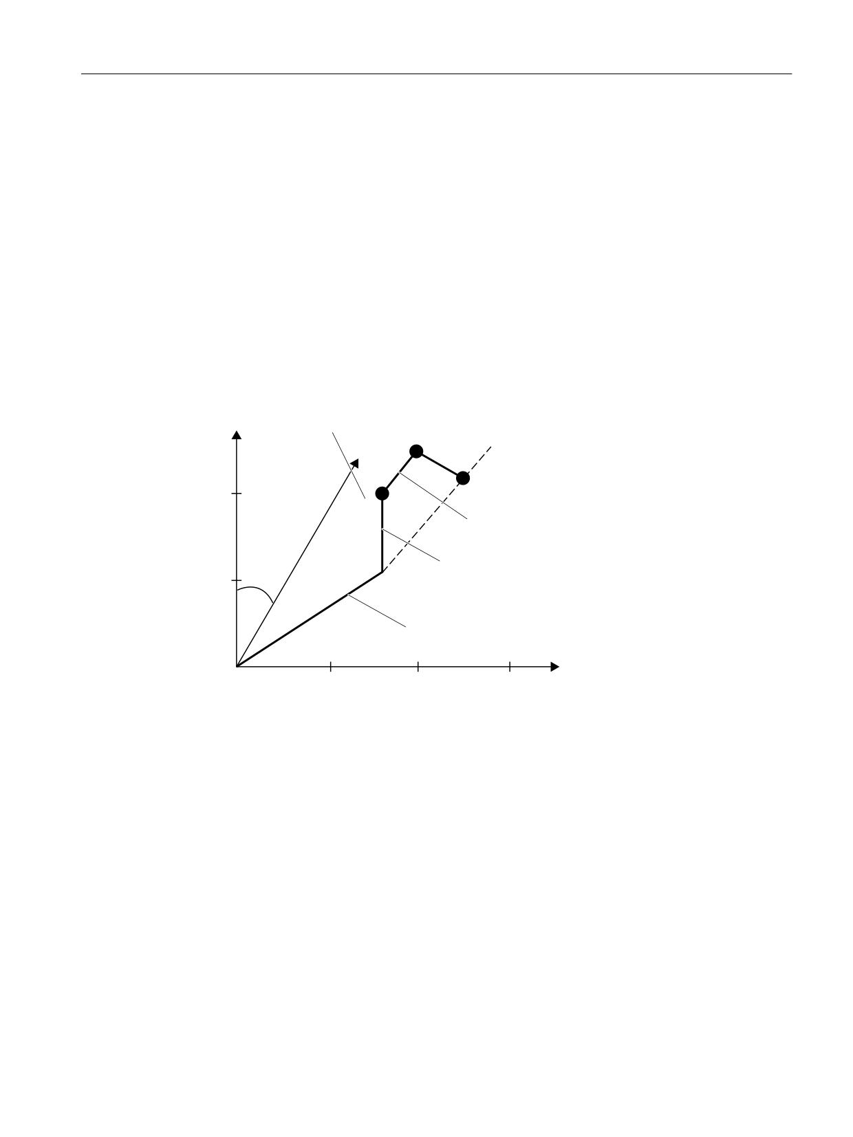
The tool is a turning tool. A frame rotation is activated in N80, causing the basic coordinate
system (BCS) to be rotated in relation to the workpiece coordinate system (WCS). In the WCS, the
compensation value (N70) acts on the geometry axis with index 1, i.e. on the X axis because G18
Tools
224
Function Manual, 10/2020, 6FC5397-6GP40-0BA1
Tool offset
3.16 Working with tool environments
is active. Since <CorMode> = 3, the tool wear in the direction of the X axis of the WCS must
become zero once N100 has been executed.
The contents of the relevant tool parameters at the end of the program are thus:
$TC_DP3[1,1]: 21.830 ; geometry L1
$TC_DP4[1,1] : 21.830 ; geometry L2
$TC_DP12[1,1] : 2.500 ; wear L1
$TC_DP13[1,1] : -4.330 ; wear L2
The geometrical relationships are shown in the figure below: The total wear including _CORVAL
is mapped onto the X' direction in the WCS. This produces point P2. The coordinates of this point
(measured in X/Y coordinates) are entered in the geometry component of the tool. The
difference vector P2 - P1 remains in the wear. The wear thus no longer has a component in the
direction of _CORVAL.
2ULJLQDO WRRO OHQJWK
[
[
3
B&259$/ DFWLYH LQ WKH ; GLUHFWLRQ
:HDU /
/
*HRPHWU\ /
/
]
If the program example is continued after N110 with the following instructions, then the
remaining wear is included completely in the geometry because the compensation is now
effective in the Z' axis (parameter <GeoAx> = 0):
N120 _CORVAL[0]=0.0
N130 R1=SETTCOR(_CORVAL,"GW",0,3,0)
N140 T1 D1 X0 Y0 Z0 ; ==> MCS position X24.330 Y0.000 Z17.500
Since the new compensation value is "0", the total tool length and thus the position approached
in N140 may not change. If _CORVAL were not equal to "0" in N120, a new total tool length and
thus a new position in N140 would result, however, the wear component of the tool length
would always be zero, i.e. the total tool length is subsequently always contained in the geometry
component of the tool.
Tools
Function Manual, 10/2020, 6FC5397-6GP40-0BA1
225
Tool offset
3.16 Working with tool environments
The same result as that achieved by calling the SETTCOR function with the <CorComp> = 0
parameter twice can also be reached by calling <CorComp> = 1 (vectorial compensation) just
once:
Program code
Comment
N10 DEF REAL _CORVAL[3]
N20 $TC_DP1[1,1]=500
; turning tool
N30 $TC_DP3[1,1]=10.0
; geometry L1
N40 $TC_DP4[1,1]=15.0
; geometry L2
N50 $TC_DP12[1,1]=10.0
; wear L1
N60 $TC_DP13[1,1]=0.0
; wear L2
N70 _CORVAL[0]=0.0
N71 _CORVAL[1]=5.0
N72 _CORVAL[2]=0.0
N80 ROT Y-30
N90 T1 D1 G18 G0
N100 R1=SETTCOR(_CORVAL,"GW",1,3,1)
N110 T1 D1 X0 Y0 Z0
; ==> MCS position X24.330 Y0.000 Z17.500
N120 M30
In this case, all wear components of the tool are set to zero immediately after the first call of
SETTCOR in N100.
Example 7
Program code
Comment
N10 DEF REAL _CORVAL[3]
N20 $TC_DP1[1,1]=500
; turning tool
N30 $TC_DP3[1,1]=10.0
; geometry L1
N40 $TC_DP4[1,1]=15.0
; geometry L2
N50 $TC_DP12[1,1]=10.0
; wear L1
N60 $TC_DP13[1,1]=0.0
; wear L2
N70 _CORVAL[0]=5.0
N80 ROT Y-30
N90 T1 D1 G18 G0
N100 R1=SETTCOR(_CORVAL,"GW",3,3)
N110 T1 D1 X0 Y0 Z0
; ==> MCS position X25.000 Y0.000 Z15.000
N120 M30
When compared to example 6, parameter <CorComp> = 3, and so the <GeoAx> parameter can
be omitted. The value contained in _CORVAL[0] now acts immediately on the tool length
component L1, the rotation in N80 has no effect on the result, the wear components in
$TC_DP12 are included in the geometry component together with _CORVAL[0], with the result
that the total tool length is stored in the geometry component of the tool, due to $TC_DP13,
after the first SETTCOR call in N100.
Tools
226
Function Manual, 10/2020, 6FC5397-6GP40-0BA1
Tool offset
3.16 Working with tool environments
Example 8
Program code
Comment
N10 DEF REAL _CORVAL[3]
N20 $TC_DP1[1,1]=500
; turning tool
N30 $TC_DP3[1,1]=10.0
; geometry L1
N40 $TC_DP4[1,1]=15.0
; geometry L2
N50 $TC_DP5[1,1]=20.0
; geometry L3
N60 $TC_DP12[1,1]=10.0
; wear L1
N70 $TC_DP13[1,1]=0.0
; wear L2
N80 $TC_DP14[1,1]=0.0
; wear L3
N90 $SC_WEAR_SIGN=TRUE
N100 _CORVAL[0]=10.0
N110 _CORVAL[1]=15.0
N120 _CORVAL[2]=5.0
N130 ROT Y-30
N140 T1 D1 G18 G0
N150 R1=SETTCOR(_CORVAL,"W",1,1)
N160 T1 D1 X0 Y0 Z0
; ==> MCS position X7.990 Y25.000 Z31.160
N170 M30
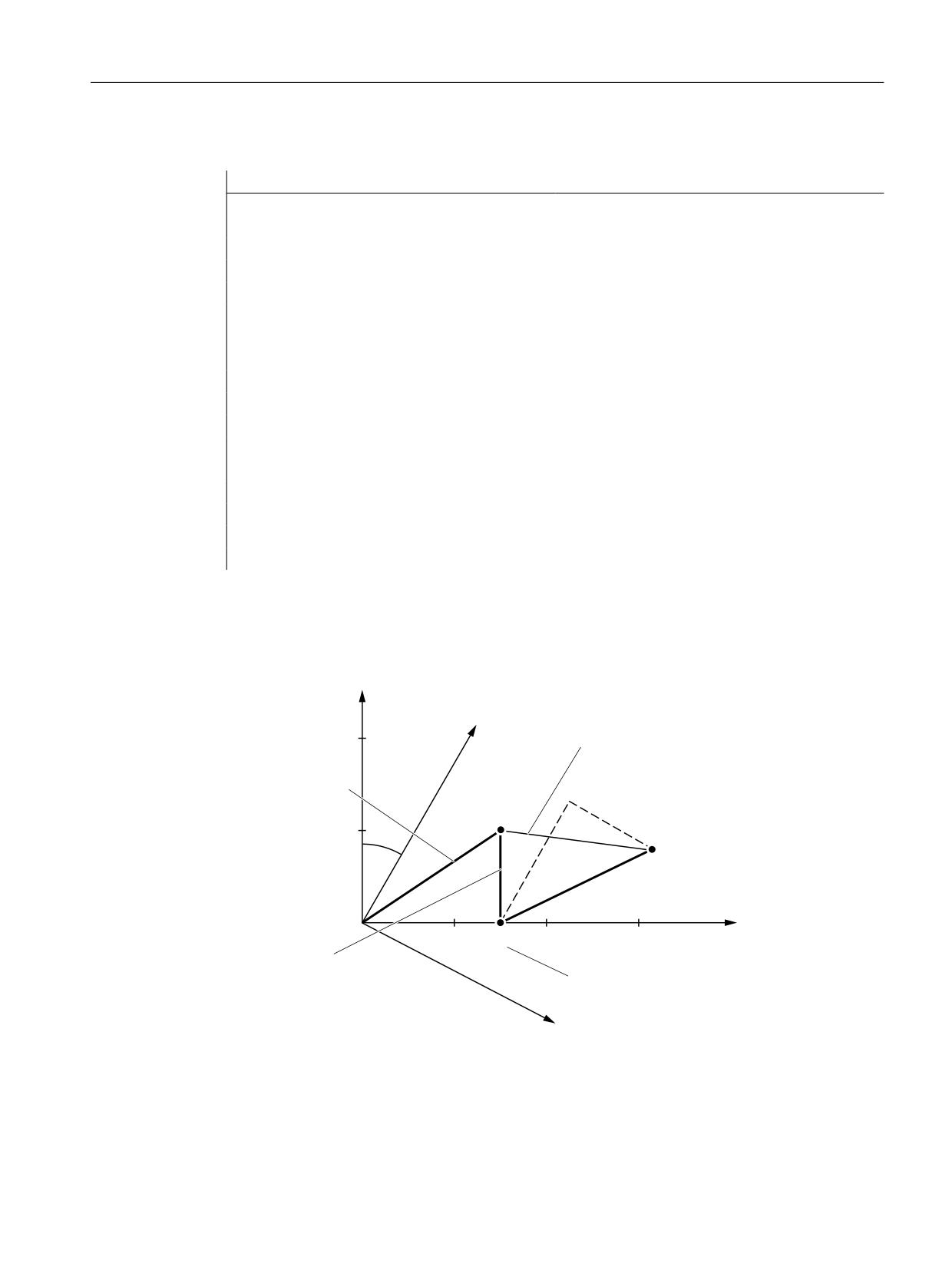
Setting data:SD42930 $SC_WEAR_SIGN is enabled in N90, i.e. the wear must be evaluated with
a negative sign. The compensation is vectorial (<CorComp> = 1), and the compensation vector
must be added to the wear (<CorMode> = 1). The geometrical relationships in the Z/X plane are
shown in the diagram below:
;
;
5HVXOWLQJ ZHDU FRPSRQHQW
*HRPHWU\
/
/
3
3
B&259$/ <
;
=
3
=
:HDU /
/
2ULJLQDO WRRO OHQJWK
QHJDWLYH HYDOXDWLRQ
=
The geometry component of the tool remains unchanged due to <CorMode> = 1. The
compensation vector defined in the WCS (rotation around the y axis) must be included in the
wear component such that the total tool length in Fig. 3 refers to point P2. Therefore, the
resulting wear component of the tool is given by the distance of the two points P1 and P2.
Tools
Function Manual, 10/2020, 6FC5397-6GP40-0BA1
227

Tool offset
3.16 Working with tool environments
However, since the wear is evaluated negatively, due to setting data SD42930 $SC_WEAR_SIGN,
the compensation determined in this way has to be entered in the compensation memory with
a negative sign. The contents of the relevant tool parameters at the end of the program are thus:
$TC_DP3[1,1]: 10.000 ; geometry L1 (unchanged)
$TC_DP4[1,1] : 15.000 ; geometry L2 (unchanged)
$TC_DP5[1,1]: 10.000 ; geometry L3 (unchanged)
$TC_DP12[1,1] : 2.010 ; wear L1 (= 10 - 15 * cos(30) + 10 * sin(30))
$TC_DP13[1,1] : -16.160 ; wear L2 (= -15 * sin(30) - 10 * cos(30))
$TC_DP14[1,1] : -5.000 ; wear L3
The effect of setting data SD42930 $SC_WEAR_SIGN on the L3 component in the Y direction can
be recognized without the additional complication caused by the frame rotation.
Additional information
Turning/grinding tools: Calculating the tool length depending on MD20360
$MC_TOOL_PARAMETER_DEF_MASK
The following machine data defines how the wear and tool length are to be evaluated if a
diameter axis is used for turning/grinding tools:
MD20360 $MC_TOOL_PARAMETER_DEF_MASK.<Bit> = <Value>
<Bit>
<Val-
Meaning
ue>
0
0
For turning/grinding tools, the wear parameter of the transverse axis is taken into
account in the radius value:
1
For turning/grinding tools, the wear parameter of the transverse axis is taken into
account as the diameter value:
1
0
For turning/grinding tools, the tool length component of the transverse axis is
taken into account as the radius value:
1
For turning/grinding tools, the tool length component of the transverse axis is
taken into account as the diameter value:
If the bits involved are set, the associated entry is weighted with a factor of 0.5. The correction
using SETTCOR is executed so that the total effective tool length change is equal to the value
transferred in <CorVal>. If, when calculating the length, a length is evaluated with a factor of 0.5
as a result of machine data MD20360 $MC_TOOL_PARAMETER_DEF_MASK, then the
compensation of this component must be realized with twice the value transferred.
Example
MD20360 $MC_TOOL_PARAMETER_DEF_MASK = 2 (tool length must be evaluated in the
diameter axis using a factor of 0.5)
Axis X is the diameter axis.
Program code
Comment
N10 DEF REAL _LEN[11]
N20 DEF REAL _CORVAL[3]
N30 $TC_DP1[1,1]=500
; Tool type
Tools
228
Function Manual, 10/2020, 6FC5397-6GP40-0BA1

Tool offset
3.17 Read the assignment of the tool lengths L1, L2, L3 to the coordinate axes (LENTOAX)
Program code
Comment
N40 $TC_DP2[1,1]=2
; Cutting edge position
N50 $TC_DP3[1,1]=3.
; Geometry - length 1
N60 $TC_DP4[1,1]=4.
; Geometry - length 2
N70 $TC_DP5[1,1]=5.
; Geometry - length 3
N80 _CORVAL[0]=1.
N90 _CORVAL[1]=1.
N100 _CORVAL[2]=1.
N110 T1 D1 G18 G0 X0 Y0 Z0
; ==> MCS position X1.5 Y5 Z4
N120 R1=SETTCOR(_CORVAL,"G",1,1)
N130 T1 D1 X0 Y0 Z0
; ==> MCS position X2.5 Y6 Z5
N140 R3=$TC_DP3[1,1]
; = 5. = (3.000 + 2.*1.000)
N150 R4=$TC_DP4[1,1]
; = 5. = (4.000 + 1.000)
N160 R5=$TC_DP5[1,1]
; = 6. = (5.000 + 1.000)
N170 M30
In each axis, the tool length compensation should be 1 mm (N80 to N100). 1 mm is thus added
to the original length in lengths L2 and L3. Twice the compensation value (2 mm) is added to the
original tool length in L1, in order to change the total length by 1 mm as required. If the positions
approached in blocks N110 and N130 are compared, it can be seen that each axis position has
changed by 1 mm.
3.17
Read the assignment of the tool lengths L1, L2, L3 to the
coordinate axes (LENTOAX)
The LENTOAX function provides information about the assignment of tool lengths L1, L2 and L3
of the active tool to the abscissa, ordinate and applicate. The assignment of abscissa, ordinate
and applicate to the geometry axes is affected by frames and the active plane (G17 - G19).
Only the geometry component of a tool ($TC_DP3[<t>,<d>] to $TC_DP5[<t>,<d>]) is
considered, i.e. a different axis assignment for other components (e.g. wear) has no effect on the
result.
Syntax
<Status> = LENTOAX(<AxInd>, <Matrix>[, <Coord>])
Principle
LENTOAX(...):
Predefined function to read the assignment of tool lengths L1, L2 and L3 of the
active tool to the coordinate axes
Alone in the block:
Yes
Tools
Function Manual, 10/2020, 6FC5397-6GP40-0BA1
229
Tool offset
3.17 Read the assignment of the tool lengths L1, L2, L3 to the coordinate axes (LENTOAX)
<Status>:
Function return value. Negative values indicate error states.
Data type:
INT
Value:
0
Function OK
Information provided in <AxInd> is sufficient for the descrip-
tion (all tool length components are in parallel to the geom-
etry axes).
1
Function is OK, however, the content of <Matrix> must be
evaluated for a correct description (the tool length compo-
nents are not parallel to the geometry axes).
-1
Invalid string in parameter <Coord>.
-2
No tool active.
Parameters
1
<AxInd>:
If the tool length components are parallel to the geometry axes, the axis indices
assigned to length components L1 to L3 are returned in the <AxInd> array.
• <AxInd> [0]: Abscissa
• <AxInd> [1]: Ordinate
• <AxInd> [2]: Applicate
Data type:
INT[3]
Value:
0
No assignment exists (axis does not exist)
1 ... 3
Number of the length effective in the corresponding coordi-
nate axis.
or
The sign is negative if the tool length component is pointing
-1 ... -3
in the negative coordinate direction.
If not all length components are parallel or antiparallel to the geometry axes, the
index of the axis, which contains the largest part of a tool length component, is
returned in <AxInd>. In this case (if the function does not return an error for a
different reason), then the return value is <Status> = 1. The mapping of tool length
components L1 to L3 to geometry axes 1 to 3 is then described completely by the
content of the 2nd parameter <Matrix>.
2
<Matrix>:
Matrix which represents the vector of the tool lengths (L1=1, L2=1, L3=1) to the
vector of the coordinate axes (abscissa, ordinate, applicate), i.e. the tool length
components are assigned to the columns in the order L1, L2, L3 and the axes are
assigned to the lines in the order abscissa, ordinate, applicate.
Data type:
REAL
All elements are always valid in the matrix, even if the geometry axis belonging to
the coordinate axis is not available, i.e. if the corresponding entry in <AxInd> is 0.
Tools
230
Function Manual, 10/2020, 6FC5397-6GP40-0BA1

Tool offset
3.17 Read the assignment of the tool lengths L1, L2, L3 to the coordinate axes (LENTOAX)
3
<Coord>:
coordinate system applicable for the assignment (optional)
Data type:
STRING
Charac-
MCS
The tool length is represented in the machine coordinate sys-
ters:
tem.
M
BCS
The tool length is represented in the basic coordinate system.
B
WCS
The tool length is represented in the workpiece coordinate
system (default setting).
W
KCS
The tool length is represented in the tool coordinate system
of the kinematic transformation.
K
TCS
The tool length is represented in the tool coordinate system.
T
The notation of the characters in the string (upper or lower case) is arbitrary.
If the parameter <Coord> is not specified, then WCS is used (default setting).
Note
In the TCS, all tool length components are always parallel or antiparallel to the axes.
The components can only be antiparallel when mirroring is active and the following setting data
is activated:
SD42900 $SC_MIRROR_TOOL_LENGTH (sign change tool length when mirroring)
Example
Standard application, milling tool for G17.
L1 applies in Z (applicate), L2 applies in Y (ordinate), L3 applies in X (abscissa).
Function call in the form:
<Status>=LENTOAX(<AxInd>,<Matrix>,"WCS")
The result parameter <AxInd> then contains the values:
<AxInd>[0] = 3
<AxInd>[1] = 2
<AxInd>[2] = 1
Or, in short: (3, 2, 1)
In this case, the associated matrix (<Matrix>) is:
0DWUL[!
A change from G17 to G18 or G19 does not alter the result, because the assignment of the length
components to the geometry axes changes in the same way as the assignment of the abscissa,
ordinate and applicate.
A frame rotation of Z through 60 degrees is now programmed with G17 active, e.g.
Tools
Function Manual, 10/2020, 6FC5397-6GP40-0BA1
231
Tool offset
3.18 Boundary conditions
ROT Z60
The direction of the applicate (Z direction) remains unchanged; the main component of L2 now
lies in the direction of the new X axis; the main component of L1 now lies in the direction of the
negative Y axis. As a consequence, the return value (<Status>) is "1", <AxInd> contains the
values (2, -3, 1).
In this case, the associated matrix (<Matrix>) is:
VLQ r FRV r
0DWUL[!
FRV r
VLQ r
3.18
Boundary conditions
3.18.1
SD42935 expansions
Transformation of wear values
Which wear components in conjunction with the instructions TOWMCS (wear values in the
machine coordinate system) and TOWWCS (wear values in the workpiece coordinate system) are
transformed or not transformed can be defined using:
SD42935 $SC_WEAR_TRANSFORM (transformation of wear values)
3.18.2
Scratching
Scratching
If the "Scratch" function is used in the reset state, then regarding the initial setting value, the
following must be taken into consideration:
• The wear components are evaluated depending on the initial settings of the G groups
TOWSTD, TOWMCS and TOWWCS.
• If a value other than the initial setting is needed to ensure correct calculation, scratching may
be performed only in the STOP state.
Tools
232
Function Manual, 10/2020, 6FC5397-6GP40-0BA1

Tool offset
3.19 Data lists
3.19
Data lists
3.19.1
Machine data
3.19.1.1
NC-specific machine data
Number
Identifier: $MN_
Description
18082
MM_NUM_TOOL
Number of tools that the NC can manage (SRAM)
18088
MM_NUM_TOOL_CARRIER
Maximum number of the defined toolholders
18094
MM_NUM_CC_TDA_PARAM
Number of tool data (SRAM)
18096
MM_NUM_CC_TOA_PARAM
Number of data, per tool cutting edge for compile cycles
(SRAM)
18100
MM_NUM_CUTTING_EDGES_IN_TOA
Tool offsets in the TOA area (SRAM)
18102
MM_TYPE_OF_CUTTING_EDGE
Type of D number programming (SRAM)
18105
MM_MAX_CUTTING_EDGE_NO
Maximum value of D number
18106
MM_MAX_CUTTING_EDGE_PERTOOL
Maximum number of D numbers per tool
18108
MM_NUM_SUMCORR
Number of all sum offsets in the NC
18110
MM_MAX_SUMCORR_PER_CUTTEDGE
Number of sum offsets per cutting edge
18112
MM_KIND_OF_SUMCORR
Properties of sum offsets in the TO area (SRAM)
18114
MM_ENABLE_TOOL_ORIENT
Assign orientation to cutting edges
18116
MM_NUM_TOOL_ENV
Tool environments in the TOA area (SRAM)
3.19.1.2
Channelspecific machine data
Number
Identifier: $MC_
Description
20096
T_M_ADDRESS_EXT_IS_SPINO
Meaning of the address extension with T, M tool change
20110
RESET_MODE_MASK
Definition of initial control setting after RESET/part pro-
gram end
20120
TOOL_RESET_VALUE
Tool length compensation at power-up (Reset/TP end)
20121
TOOL_PRESEL_RESET_VALUE
Preselect tool on Reset
20125
CUTMOD_ERR
Fault handling for the function "Modification of the off-
set data for rotatable tools"
20126
TOOL_CARRIER_RESET_VALUE
Operative tool holder on Reset
20127
CUTMOD_INIT
Initialization value for CUTMOD
20130
CUTTING_EDGE_RESET_VALUE
Tool cutting edge length compensation at power-up
(Reset/TP end)
20132
SUMCORR_RESET_VALUE
Additive offset effective on reset
20140
TRAFO_RESET_VALUE
Transformation data record at power up (Reset/TP end)
20180
TOCARR_ROT_ANGLE_INCR[i]
Rotary axis increment of the tool carrier with orientation
capability
Tools
Function Manual, 10/2020, 6FC5397-6GP40-0BA1
233

Tool offset
3.19 Data lists
Number
Identifier: $MC_
Description
20182
TOCARR_ROT_ANGLE_OFFSET[i]
Rotary axis offset of tool carrier with orientation capa-
bility
20184
TOCARR_BASE_FRAME_NUMBER
Number of the basic frames to accept the table offset
20188
TOCARR_FINE_LIM_LIN
Limit linear fine offset TCARR
20190
TOCARR_FINE_LIM_ROT
Limit of the rotary fine offset TCARR
20202
WAB_MAXNUM_DUMMY_BLOCKS
Maximum number of blocks with no traversing motions
with SAR
20204
WAB_CLEARANCE_TOLERANCE
Direction reversal for WAB
20210
CUTCOM_CORNER_LIMIT
Max. angle for intersection calculation with tool radius
compensation
20220
CUTCOM_MAX_DISC
Maximum value for DISC
20230
CUTCOM_CURVE_INSERT_LIMIT
Maximum value for intersection calculation with TRC
20240
CUTCOM_MAXNUM_CHECK_BLOCKS
Blocks for predictive contour calculation with tool radius
compensation
20250
CUTCOM_MAXNUM_DUMMY_BLOCKS
Maximum number of blocks without traversing motion
for TRC
20252
CUTCOM_MAXNUM_SUPPR_BLOCKS
Maximum number of blocks with compensation sup-
pression
20256
CUTCOM_INTERS_POLY_ENABLE
Intersection process possible for polynomials
20270
CUTTING_EDGE_DEFAULT
Basic setting of tool cutting edge without programming
20272
SUMCORR_DEFAULT
Initial setting of additive offset without program
20360
TOOL_PARAMETER_DEF_MASK
Definition of tool parameters
20390
TOOL_TEMP_COMP_ON
Activation of temperature compensation for tool length
20392
TOOL_TEMP_COMP_LIMIT
Maximum temperature compensation for tool length
20610
ADD_MOVE_ACCEL_RESERVE
Acceleration reserve for overlaid movements
21080
CUTCOM_PARALLEL_ORI_LIMIT
Minimum angle (path tangent and tool orientation) for
3D tool radius compensation
22530
TOCARR_CHANGE_M_CODE
M code for change of tool carrier
22550
TOOL_CHANGE_MODE
New tool offsets with M function
22560
TOOL_CHANGE_M_CODE
M function for tool change
22562
TOOL_CHANGE_ERROR_MODE
Response when errors occur at tool change
24558
TRAFO5_JOINT_OFFSET_PART_1
Vector of kinematic offset in table, transformation 1
24658
TRAFO5_JOINT_OFFSET_PART_2
Vector of kinematic offset in table, transformation 2
28085
MM_LINK_TOA_UNIT
Assigning ´the TO unit to a channel (SRAM)
3.19.1.3
Axis/spindlespecific machine data
Number
Identifier: $MA_
Description
32750
TEMP_COMP_TYPE
Temperature compensation type
Tools
234
Function Manual, 10/2020, 6FC5397-6GP40-0BA1

Tool offset
3.19 Data lists
3.19.2
Setting data
3.19.2.1
Channelspecific setting data
Number
Identifier $SC_
Description
42442
TOOL_OFFSET_INCR_PROG
Tool length compensation
42470
CRIT_SPLINE_ANGLE
Core limit angle, for compressor
42480
STOP_CUTCOM_STOPRE
Alarm response for tool radius compensation and pre-
processing stop
42494
CUTCOM_ACT_DEACT_CTRL
Approach and retraction behavior for tool radius com-
pensation
42496
CUTCOM_CLSDT_CONT
Behavior of the tool radius compensation for closed
contour
42900
MIRROR_TOOL_LENGTH
Sign change, tool lengths when mirroring
42910
MIRROR_TOOL_WEAR
Sign change, tool wear when mirroring
42920
WEAR_SIGN_CUTPOS
Sign of wear for tools with cutting edge position
42930
WEAR_SIGN
Sign of the wear
42935
WEAR_TRANSFORM
Transformations for tool components
42940
TOOL_LENGTH_CONST
Change of tool length components for change of plane
42950
TOOL_LENGTH_TYPE
Assignment of the tool length offset independent of tool
type
42960
TOOL_TEMP_COMP
Temperature compensation value in relation to tool
42974
TCARR_FINE_CORRECTION
Fine offset TCARR on/off
42984
CUTDIRMOD
Modification of $P_AD[2] or $P_AD[11]
42998
CUTMOD_PLANE_TOL
Difference between tool tip plane and machining plane
for CUTMOD or CUTMODK
42999
ORISOLH_INCLINE_TOL
Difference between tool tip plane and machining plane
for ORISOLH
3.19.2.2
Channelspecific setting data
Number
Identifier $SC_
Description
42442
TOOL_OFFSET_INCR_PROG
Tool length compensation
42470
CRIT_SPLINE_ANGLE
Core limit angle, for compressor
42480
STOP_CUTCOM_STOPRE
Alarm response for tool radius compensation and pre-
processing stop
42494
CUTCOM_ACT_DEACT_CTRL
Approach and retraction behavior for tool radius com-
pensation
42496
CUTCOM_CLSDT_CONT
Behavior of the tool radius compensation for closed
contour
42900
MIRROR_TOOL_LENGTH
Sign change, tool lengths when mirroring
42910
MIRROR_TOOL_WEAR
Sign change, tool wear when mirroring
42920
WEAR_SIGN_CUTPOS
Sign of wear for tools with cutting edge position
Tools
Function Manual, 10/2020, 6FC5397-6GP40-0BA1
235

Tool offset
3.19 Data lists
Number
Identifier $SC_
Description
42930
WEAR_SIGN
Sign of the wear
42935
WEAR_TRANSFORM
Transformations for tool components
42940
TOOL_LENGTH_CONST
Change of tool length components for change of plane
42950
TOOL_LENGTH_TYPE
Assignment of the tool length offset independent of tool
type
42960
TOOL_TEMP_COMP
Temperature compensation value in relation to tool
42974
TCARR_FINE_CORRECTION
Fine offset TCARR on/off
42984
CUTDIRMOD
Modification of $P_AD[2] or $P_AD[11]
42998
CUTMOD_PLANE_TOL
Difference between tool tip plane and machining plane
for CUTMOD
Tools
236
Function Manual, 10/2020, 6FC5397-6GP40-0BA1
3D tool radius compensation
4
4.1
Function
4.1.1
Introduction
3D circumferential milling and 3D face milling
3D tool radius compensation (3D-TRC) is used to process contours with tools that can be
controlled in their orientation independently of the tool path and shape.
SINUMERIK provides the 3D-TRC in different variants, which are used in combination with the
following manufacturing processes:
• Circumferential milling (Page 238) for structural components
• Face milling (Page 244) for free-form surfaces
Tool orientation
For the 3D-TRC, a distinction must be made between the two scenarios of a tool with a fixed
orientation and a tool with a changeable orientation.
The tool radius compensation with a fixed tool for circumferential milling is designated as a 2½D-
TRC. This is the conventional tool radius compensation. Circumferential milling with a
functionality that goes beyond this scope of performance is not possible for the compensation
with a fixed tool. For circumferential milling, there is only a 3D-TRC if the tool orientation is
changeable. This means, in addition to the 3 degrees of freedom for positioning the tool
(generally 3 linear axes), two additional degrees of freedom (2 rotary axes) are also needed for
setting the tool orientation (5-axis machining).
During face milling, the tool orientation can remain constant or be variable. The advantages of
variable orientation are:
• better approximation of the end contour
• increased chip performance
• more freedom in selecting the shape of the tool
• a wider range of surfaces that can be processed (undercuts)
Note
5D-WRK
The 3D-TRC is also called 5D-TRC below, because 5 degrees of freedom are available in this case
for defining the position of the tool in space relative to the workpiece.
Tools
Function Manual, 10/2020, 6FC5397-6GP40-0BA1
237
3D tool radius compensation
4.1 Function
Parameterization
The machine and setting data set for the 2D-TRC are also in effect for the 3D-TRC.
Further information
Tool offset (Page 15)
In addition to this, there is special system data that is only relevant to 3D-TRC. See Chapter
"Parameter assignment (Page 252)" regarding settings of this data.
Activation/deactivation
The selection of the 3D-TRC variant is made in the NC program via G commands of Group 22 (tool
offset type). The actual activation and deactivation are done via the G commands of Group 7
(tool radius compensation).
See Section "Programming (Page 253)".
4.1.2
Circumferential milling
The 3D circumferential milling is used for machining contours with tools having an orientation
that is not constant during processing. Processing is done using the peripheral surface of the
tool. If the tool is cylindrical, ruled surfaces (e.g. cones, cylinders, etc.) are created during this
processing. Other forms of milling machines can also be used, however (e.g. form cutters). The
tool radius compensation needed for this type of processing is an extension of the conventional
2½D-TRC.
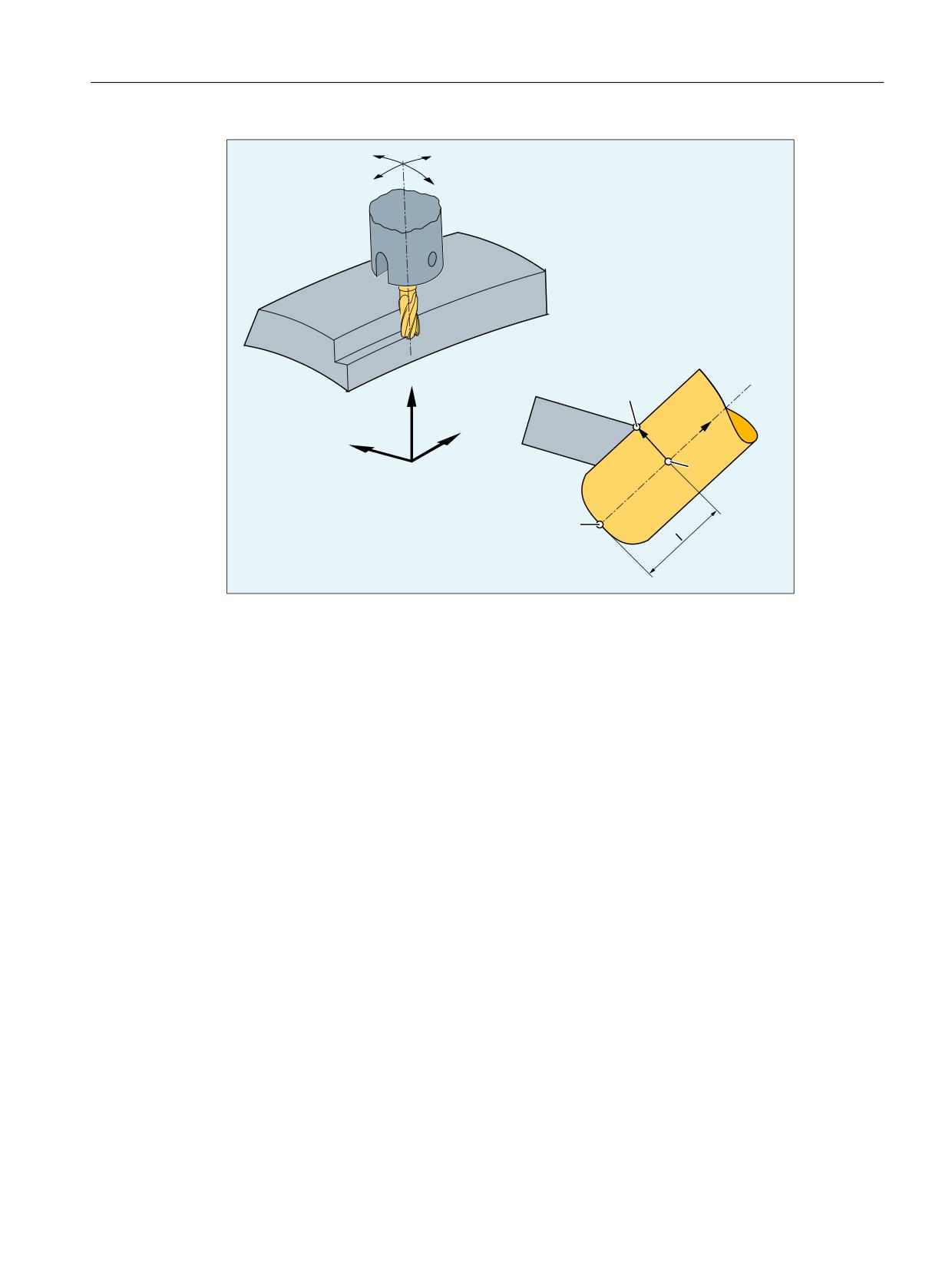
The ratios for 3D circumferential milling are shown in the following figure:
Tools
238
Function Manual, 10/2020, 6FC5397-6GP40-0BA1
3D tool radius compensation
4.1 Function
$
%
=
)(
Z
;
<
Z5
)+
)6
FE:
Milling tool machining point
FS:
Milling tool tip
FH:
Milling tool reference point
I:
Insertion depth
w:
Tool vector
wr:
Vector from the milling tool reference point to the milling tool machining point with length of
shank radius R
Figure 4-1
Circumferential milling
Insertion depth
The insertion depth of the milling tool is the distance of the milling tool reference point from the
tip of the tool.
The milling tool reference point is the vertical projection of the milling tool machining point on
the programmed path to the longitudinal axis of the tool.
The position of the machining point on the peripheral surface of the tool is set with the insertion
depth.
Via the address ISD (InSertion Depth), the insertion depth of the tool for circumferential milling
and active 3D tool radius compensation can be changed (see Chapter "Programming
(Page 253)").
Tools
Function Manual, 10/2020, 6FC5397-6GP40-0BA1
239
3D tool radius compensation
4.1 Function
4.1.2.1
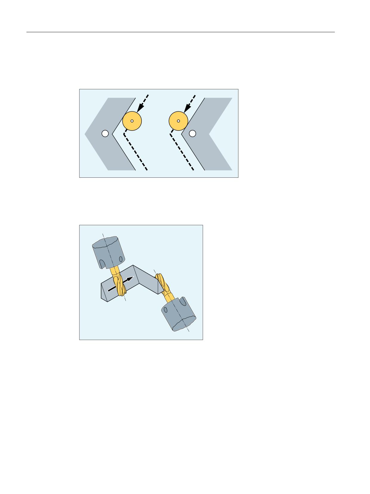
Corners in circumferential milling
Inside and outside corners are handled separately. The terms inside corner and outside corner
are dependent on the tool orientation.
*
*
① Inside corner
② Outside corner
When the orientation changes at a corner, for example, the corner type may change while
machining is in progress:
Whenever this occurs, the machining operation is aborted with alarm 10770.
Tools
240
Function Manual, 10/2020, 6FC5397-6GP40-0BA1
3D tool radius compensation
4.1 Function
4.1.2.2
Behavior at outer corners
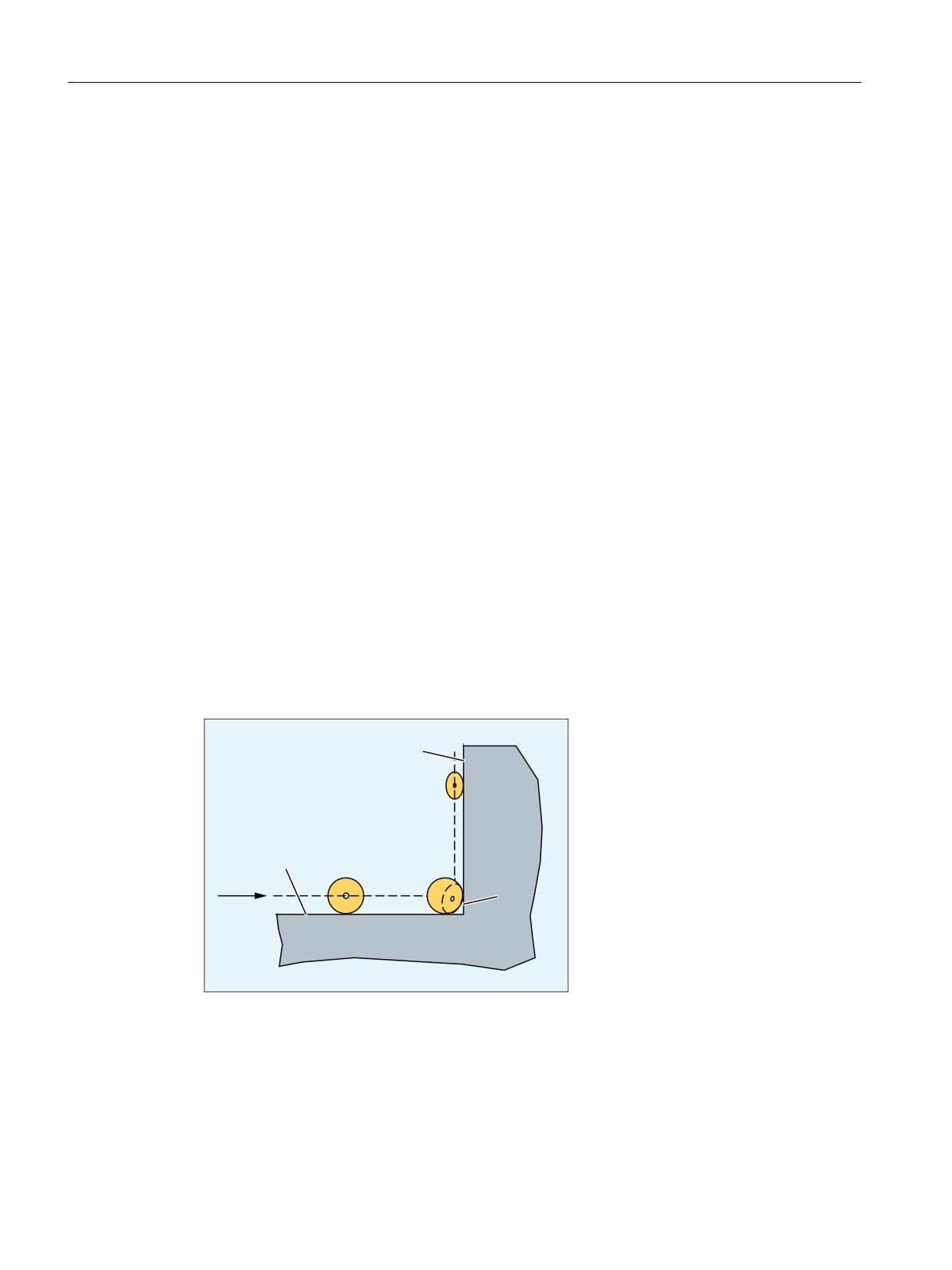
At outside corners during circumferential milling with 3D-TRC analogous to the conditions in the
2½D-TRC, the G commands of Group 18 (corner behavior tool offset) are evaluated:
• G450: Transition circle (tool travels around workpiece corners on a circular path)
Outside corners are treated like circles with a radius of 0, where the circular plane stretches
from the end tangent of the first block and the start tangent of the second block. Thus, an
orientation change during the block transition is also possible. Thus, a block is always
inserted at an outside corner.
In contrast to the solution for the 2½D-TRC, the contour element inserted at an outside
corner is always a circle with a radius of 0, which is affected by the tool radius compensation
like on any other programmed path. It is not possible to insert conical sections in place of the
circles. The address DISC therefore has no relevance in this case and is not evaluated.
• G451: Intersection of equidistant paths (tool backs off from the workpiece corner)
The intersection is determined by extending the offset curves of the two participating blocks
and defining the intersection of the two blocks at the corner in the plane perpendicular to the
tool orientation.
If an intersection is found in the plane perpendicular to the tool, this does not mean that the
curves also intersect in space. Rather the curves in the direction of the tool longitudinal axis
are considered, which are generally a certain distance apart. The positional offset is
eliminated over the entire block length in direction of the tool.
The way this offset is processed in tool direction at outside corners is the same as for inside
corners.
For nearly tangential transitions, the behavior for an active G450 is the same as for G451 (limit
angle can be set via MD20210 $MC_CUTCOM_CORNER_LIMIT). Conversely, if G451 is active, a
circle is also inserted (procedure as for G450) if there is no intersection or if the corner angle
exceeds a specific value (MD20230 $MC_CUTCOM_CURVE_INSERT_LIMIT).
Behavior during orientation changes
The intersection procedure (G451) is not used when at least one block containing a change to
the tool orientation was inserted between the traversing blocks in question. In this case a circle
is always inserted at the corner.
The G commands of Group 27 (too offset for orientation change at outside corners) can be used
to define whether orientation changes, which have been programmed between the two
traversing blocks that form the corner, are executed before the beginning of the inserted circle
set or at the same time.
• ORIC: Orientation changes at outside corners are superimposed on the circle block to be
inserted.
• ORID: Orientation changes are performed before the circle block.
If two or more blocks with orientation changes (e.g. A2=... B2=... C2=...) are programmed
between two traversing blocks and ORIC is active, then the circular block to be inserted is divided
between these intermediate blocks corresponding to the amount of the individual angle
changes. Further programmed intermediate blocks without traversing and orientation motions
are executed at the programmed positions.
If ORID is active, all inserted blocks (both those with and without orientation movement) are
executed at the end of the first of the two traversing blocks. The tangent in the end point of the
Tools
Function Manual, 10/2020, 6FC5397-6GP40-0BA1
241
3D tool radius compensation
4.1 Function
first traversing block is used for the offset calculation. The circle block with constant orientation
is inserted immediately before the second traversing block.
See also "Example 1: Orientation change at outside corner during 3D circumferential milling
(Page 268)".
Intermediate blocks without relevant traversing information
Intermediate blocks without relevant traversing information (neither tool orientation nor
position of geometry axes are changed) are permissible. The intersection procedure is applied
to the adjacent blocks as if these intermediate blocks did not exist. In the same manner, tool
direction motions in the tool direction may also be programmed in intermediate blocks.
4.1.2.3
Behavior at inside corners
For the 3D-TRC, only adjacent traversing blocks are taken into consideration for the calculation
of the intersecting point.
If the orientation is not changed at the block limit, then the contour need only be considered in
the plane vertical to the tool axis. In this case, the tool cross-section is a circle which touches the
two contours. The geometric relations in this plane are identical to those for 21/2D-TRC.
Behavior during orientation changes
If the orientation changes on a block transition, the tool moves in the inside corner so that it is
constantly in contact with the two blocks forming the corner.
Path segments must be long enough to ensure that the contact points of the tool do not cross
the block limits into other blocks when the orientation changes at an inside corner.
1
1
1
Figure 4-2
Orientation changes at inside corner
When the orientation changes in a block that is one of the two blocks forming the inside corner,
then it is no longer possible to adhere to the programmed relationship between path position
and associated orientation. This is because the orientation must reach its end value even though
the path end position is not reached. This response is identical to the response of synchronized
axes with 21/2 D tool radius compensation.
Tools
242
Function Manual, 10/2020, 6FC5397-6GP40-0BA1

3D tool radius compensation
4.1 Function
3URJUDPPHG
SRVLWLRQ
Figure 4-3
Path end position and change in orientation at inside corners
See also "Example 2: Orientation change at inside corner during 3D circumferential milling
(Page 271)".
Change in insertion depth
Generally speaking, the contour elements that form an inside corner are not positioned on the
plane perpendicular to the tool. This means that the contact points between the two blocks and
the tool are at different distances from the tool tip.
This means: The insertion depth (ISD) changes abruptly from the 1st to the 2nd block at an inside
corner.
To ensure that this difference in depth is not an abrupt step change, it is distributed continuously
among the blocks involved during interpolation. The depth-compensating motion is executed in
the current tool direction.
This solution prevents the contour from being violated by cylindrical tools if the length of the tool
prevents the cutter contact point on the lateral surface of the cutter leaving the range in which
machining is possible.
Tools
Function Manual, 10/2020, 6FC5397-6GP40-0BA1
243
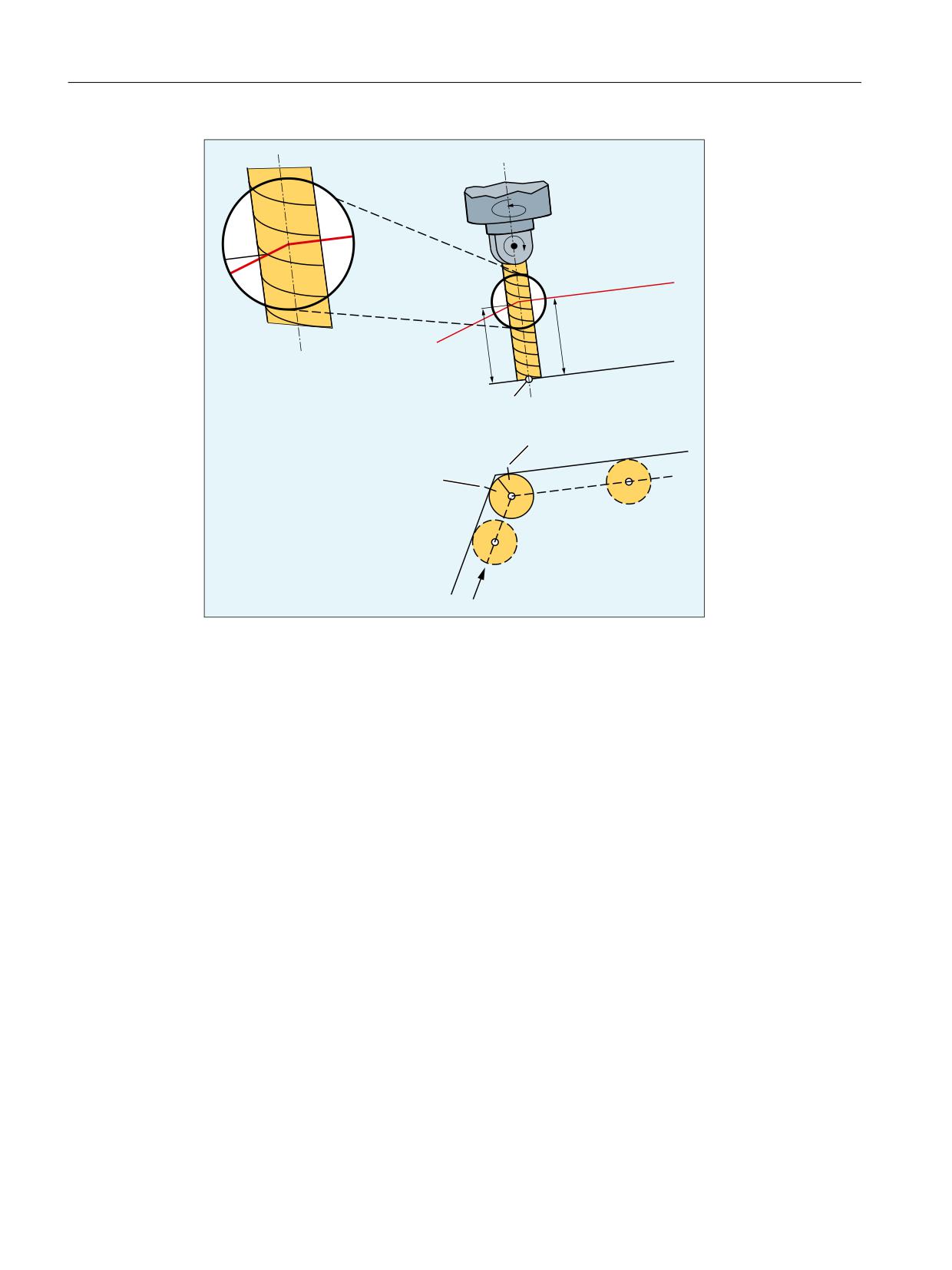
3D tool radius compensation
4.1 Function
,6' QHZ
,6' ROG
)6
QG EORFN
VW EORFN
Figure 4-4
Change in insertion depth
4.1.2.4
Monitoring of path curvature
The path curvature is monitored for an unchangeable orientation in the following way:
1. The contour in each block is projected on the plane that is orthogonal to the tool orientation.
2. Then the curvature of the projection is analyzed. Areas with too much curvature (tool does
not fit in the curve) are cut out.
3. The remaining offset contours overlap each other and thus form the global offset contour.
4.1.3
Face milling
Face milling is used to process curved surfaces of any kind. In this case, the longitudinal axis of
the tool and the surface normal vector are more or less parallel. In contrast, the longitudinal axis
of the tool and the surface normal vector of the surface to be machined in a 3D circumferential
milling operation are at right angles to one another.
Information about the surface to be machined is absolutely essential for face milling operations,
i.e. a description of the linear path in space is not sufficient. The tool shape must also be known
in order to implement the tool offset (the term "Tool radius compensation" is not appropriate in
this case).
The conditions for face milling are shown in the following figure:
Tools
244
Function Manual, 10/2020, 6FC5397-6GP40-0BA1
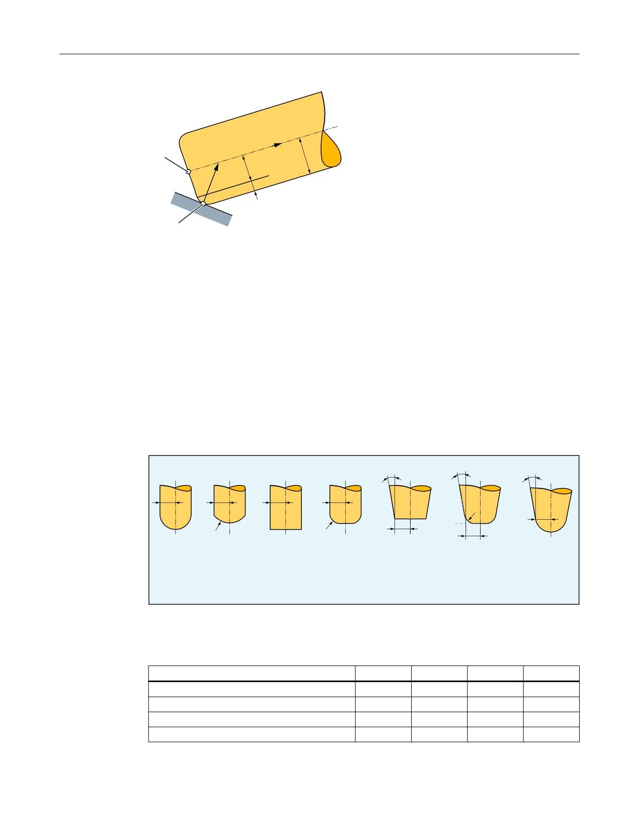
3D tool radius compensation
4.1 Function
Z
)6
5
H
Q)
U
)(
FE:
Milling tool machining point
FS:
Milling tool tip
nF:
Surface normal vector
w:
Tool vector
R:
Shaft radius
r:
Corner radius
e:
Difference between the shank radius R and corner radius r
Figure 4-5
Face milling with a torus cutter
4.1.3.1
Tool shapes and tool data for face milling
An overview of the tool shapes, which may be used for face milling operations and relevant tool
data are listed in the following. The shape of the tool shaft is not taken into account. Therefore,
the tool types 120 and 155, for example, have an identical effect.
D
D
D
5
5
5
5
U
5
U
U
5
5
%DOO HQG PLOO
&\OLQGULFDO
(QG PLOO
(QG PLOO ZLWK
%HYHO FXWWHU
%HYHO FXWWHU
7DSHUHG
GLH VLQNLQJ
FRUQHU URXQGLQJ
ZLWK FRUQHU URXQGLQJ
GLH VLQNLQJ
PLOOLQJ FXWWHU
FXWWHU
W\SH
W\SH
W\SH
W\SH
W\SH
W\SH
W\SH
R
= shank radius (tool radius)
r
= corner radius
a
= angle between the tool longitudinal axis and upper end of the torus surface
Cutter type
Type No.
R
r
a
Ball end mill
110
> 0
-
-
Cylindrical die-sinking milling cutter
111
> 0
> R
-
End mill, angle head cutter
120, 130
> 0
-
-
End mill, angle head cutter with corner rounding
121, 131
> r
> 0
-
Tools
Function Manual, 10/2020, 6FC5397-6GP40-0BA1
245

3D tool radius compensation
4.1 Function
Cutter type
Type No.
R
r
a
Bevel cutter
155
> 0
-
> 0
Bevel cutter with corner rounding
156
> 0
> 0
> 0
Tapered die-sinking cutter
157
> 0
-
> 0
- : is not evaluated.
Tool data
Tool parameters
Tool dimensions
Geometry
Wear
R
$TC_DP6
$TC_DP15
r
$TC_DP7
$TC_DP16
a
$TC_DP11
$TC_DP20
Note
If, in the NC program, a type number is specified that differs from that in the diagram, then the
system automatically uses tool type 110 (ball end mill).
Note
An alarm is output if the tool data limit values are violated.
Geometry and wear values of tool data have an additive effect, i.e. the tool form that is actually
used for the offset calculation is always described by the sum values.
In the CUT3DFD function (differential tool), only the wear value is considered as an offset value.
The geometry values are only necessary in this case for describing the tool form.
Tool length offset
The tool tip (intersecting point between the tool longitudinal axis and the workpiece surface) is
considered the reference point for the length offset.
Tool change
A new tool with changed dimensions (R, r, a) or other form can only be specified during the first
activation of the tool offset (i.e. during the transition from G40 to G41 or G42) or for an already
active offset only for new programming of G41 or G42. This rule does not apply to any other tool
data, e.g. tool lengths, so that tools can be loaded without reprogramming G41 or G42.
4.1.3.2
Face milling with a specified surface normal vector
Expanded options for orientation programming are provided for 3D face milling.
The tool offset for face milling cannot be calculated simply by specifying the path (e.g. of a line
in space). The surface to be machined must also be known. The necessary information about the
surface is provided to the controller with the surface normal vector.
The surface normal vector at the block beginning is programmed with A4, B4, C4, and the vector
at the block end with A5, B5, C5. Components of the surface normal vectors which are not
programmed are set to zero. The length of a vector programmed in this way is irrelevant. A vector
Tools
246
Function Manual, 10/2020, 6FC5397-6GP40-0BA1
3D tool radius compensation
4.1 Function
of zero length (all three components are zero) is ignored, i.e. the direction programmed
beforehand remains valid, no alarm is generated.
If only the start vector is programmed (A4, B4, C4) in a block, then the programmed surface
normal vector remains constant over the entire block. If only the end vector is programmed (A5,
B5, C5), then large-circle interpolation is used to interpolate between the end value of the
preceding block and the programmed end value. If both start and end vectors are programmed,
interpolation according to the large circle principle is also performed between the two
directions. The fact that the start vector may be reprogrammed in a block means that the
direction of the surface normal vector can change irregularly on a block transition. Irregular
transitions of the surface normal vector always occur in cases where there is no tangential
transition between the surfaces (planes) involved, i.e. if they form an edge.
Once a surface normal vector is programmed, it remains valid until a new vector is programmed.
In the basic position, the surface normal vector is set to equal the vector in the Z direction. This
basic setting direction is independent of the active plane (G17 - G19). If ORIWKS is active, surface
normal vectors refer to the active frame, i.e. when the frame is rotated, the vectors rotate
simultaneously. This applies both to programmed orientations and to those that have been
derived from the active plane. If ORIWKS is active, the surface normal vectors are brought along
during a frame change. An orientation modified as the result of frame rotations is not returned
to its original state on switchover from ORIWKS to ORIMKS.
It must be noted that the programmed surface normal vectors may not necessarily be the same
as those used internally. This is always the case if the programmed surface normal vector is not
vertical on the path tangent. A new surface normal vector is then formed, which lies within the
plane spanned by the path tangent and programmed surface normal vector, but which is vertical
on the path tangent vector. This orthogonality is required, because the path tangent vector and
the surface normal vectors (must) always be vertical to one another in a real surface. However,
since the two variables can be programmed independently of one another, they can contain
information that is mutually contradictory. Orthogonalization ensures that the information
contained in the path tangent vector has priority over the data in the surface normal vector. An
alarm is output if the angle between the path tangent vector and the programmed surface
normal vector undershoots the limit value, which is defined in the following machine data:
MD21084 $MC_CUTCOM_PLANE_PATH_LIMIT (minimal angle between surface normal vector
and path tangent vector)
If a block is shortened (inside corner), then the interpolation range of the surface normal vector
is reduced accordingly, i.e. the end value of the surface normal vector is not reached as it would
be with other interpolation quantities such as, for example, the position of an additional
synchronized axis.
In addition to the usual methods of programming orientation, it is also possible to refer the tool
orientation to the surface normal vector and path tangent vector using the addresses LEAD (lead
or camber angle) and TILT (side angle). Interpretation of the angle specifications is thus
dependent on the setting in MD21094 $MC_ORIPATH_MODE (see Function Manual
"Transformations", Section "Multi-axis transformations"). The specification of the angle relative
to the surface normal is only an expanded option of orientation programming at the end of the
block. It does not imply that the lead and side angles reach their programmed values before the
path end point is reached.
The resulting tool orientation is determined from the path tangent, surface normal vector, lead
angle and side angle at the end of the block. This orientation is always implemented by the end
of the block, particularly in cases where the block is shortened (at an inside corner). If the
omitted path section is not a straight line in a plane, the lead and side angles generally deviate
from their programmed values at the path end point. This is because the orientation has
Tools
Function Manual, 10/2020, 6FC5397-6GP40-0BA1
247
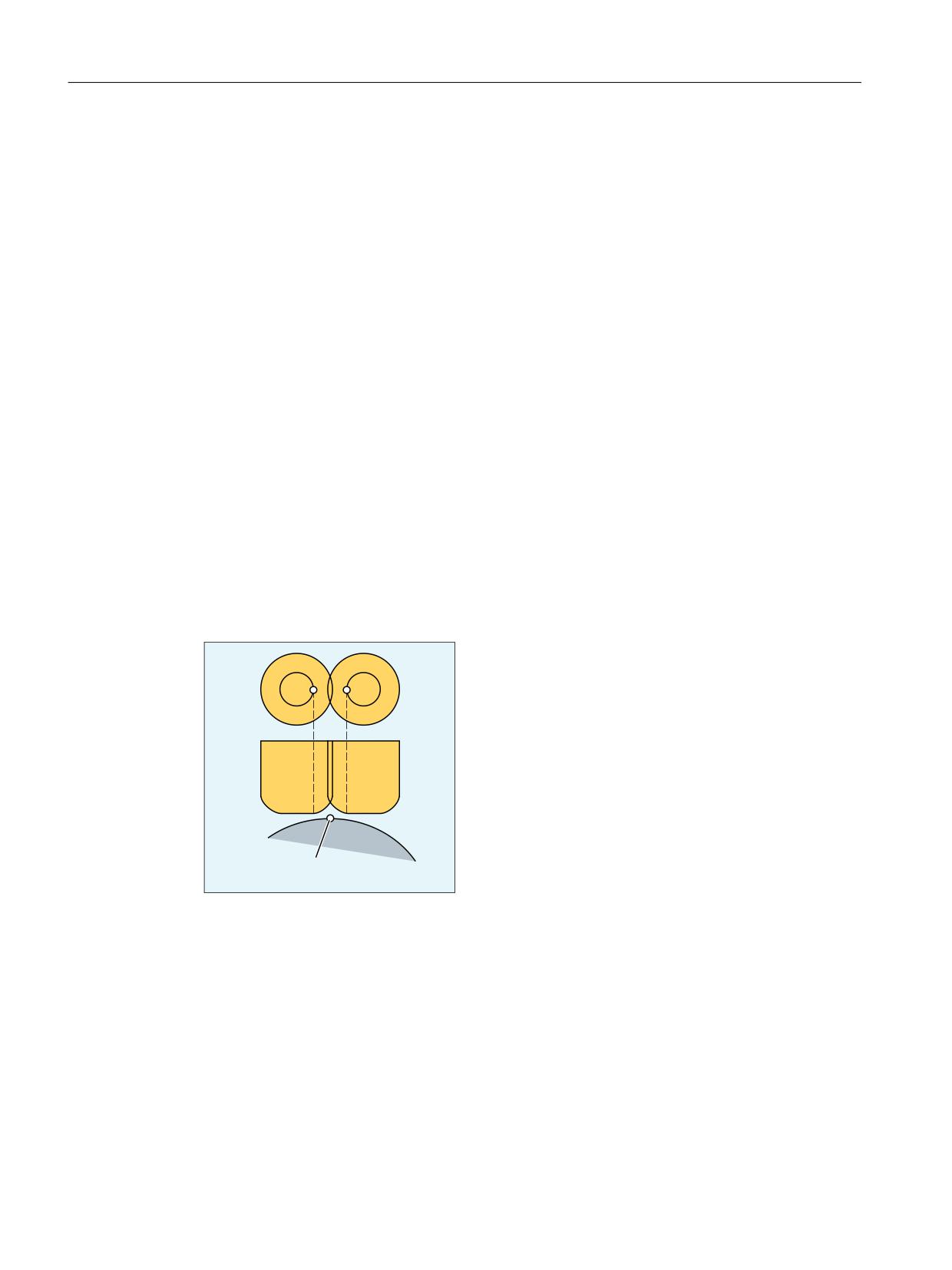
3D tool radius compensation
4.1 Function
changed relative to the surface normal vector or path tangent vector when the absolute
orientation of the tool is the same as at the original path end point.
4.1.3.3
Compensation on path
A special case must be examined with respect to face milling operations, i.e. that the machining
point on the tool surface moves around. This may be the case on a torus cutter whenever surface
normal vector nF and tool vector w become collinear (i.e. the tool is at exact right angles to the
surface) since it is not a single point on the tool that corresponds to this direction, but the entire
circular surface on the tool end face. The contact point is therefore not defined for this
orientation. A path point in which tool longitudinal axis and surface normal are parallel is
therefore referred to below as a singular point or a singularity.
The above case is also meaningful in practical terms, e.g. in cases where a convex surface, which
may have a vertical surface normal (e.g. hemisphere), must be machined with a perpendicular
tool (e.g. face milling with constant orientation). The machining point on the contour remains
fixed, but the machine must be moved to bring the machining point from one side of the tool to
the other.
The problem described is only a borderline case (lead angle β = 0 and side angle y = 0). If the lead
angle β = 0 and the side angle y has a low value, then the tool must be moved very rapidly (in
borderline case in steps) to keep the machining point resulting from the milling conditions close
to the arc-line forming the end face (see the following figure).
In principle, it is resolved by the smoothing of the surface normal and the smoothing of the
contour.
6LQJXODU SRLQW
Figure 4-6
Switching of the processing point on the tool surface in the vicinity of a point in which the
surface normal vector and the tool orientation are parallel.
Singularities do not only occur in isolated points, but can also occur over entire curves. This is the
case, for example, if the curve to be interpolated is a plane curve (i.e. a curve with a constant
osculating plane) and the tool is constantly aligned in parallel to the binormal vector
(perpendicular to the osculating plane). A simple example of this is an arc in the X-Y plane, which
is processed with a tool that is aligned parallel to the Z axis. For paths of this type, the tool offset
is reduced to a tool length compensation. I.e. the tool is positioned in such a way that its tip lies
on the programmed path.
For a jump-like transition between singular and non-singular curves, linear blocks must be
inserted, just as in the handling of individual points, so that the processing point on the tool can
Tools
248
Function Manual, 10/2020, 6FC5397-6GP40-0BA1
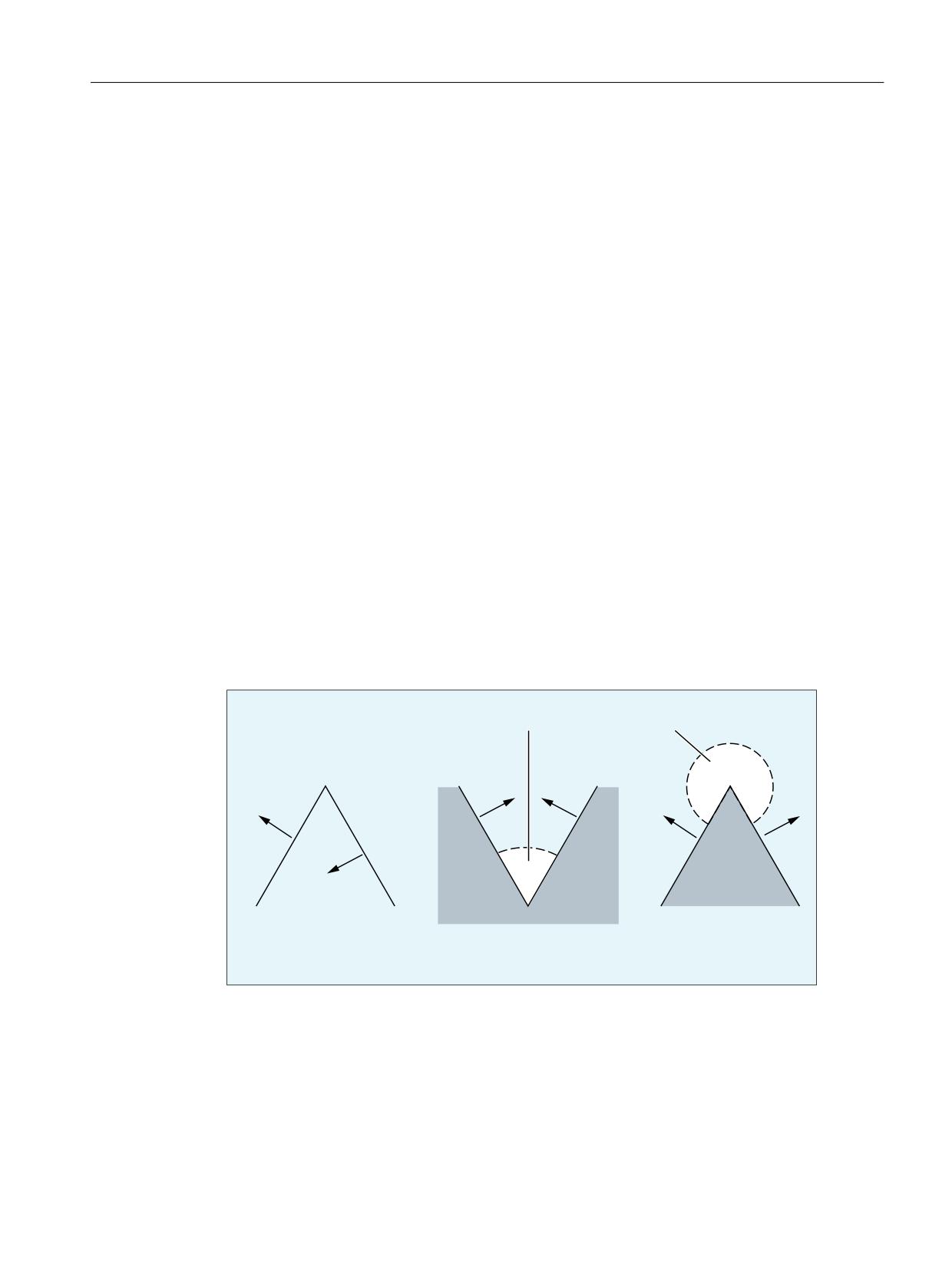
3D tool radius compensation
4.1 Function
migrate from the tool tip to the periphery (at outside corners or convex surfaces) or the paths
must be shortened to prevent contour violations (at inside corners or concave surfaces).
It is therefore necessary to activate both the smoothing of the contours ("Top Surface" function)
and the smoothing of the surface normal to ensure that the transitions run smoothly.
4.1.3.4
Corners in face milling
Two surfaces that do not tangentially transition into one another form an edge. The paths
defined on the surfaces form a corner. This corner is a point of the edge.
The type of corner (inside or outside corner) is defined by the surface normals of the
participating surfaces and the paths defined on them.
The surface normals of the two surfaces forming the edge may point in opposite directions of
the overall surface (the front edge of one surface is continued on the rear edge of the second
surface), see also the following Figure. Transitions of this type are not allowed and are rejected
with an alarm.
The scalar product of the surface normal vector and (possibly variable) tool orientation on one
corner/path must be positive at each point, i.e. it is not permissible to machine from the rear face
of the surface. If this condition is not fulfilled, an alarm is output. The permissible ranges of
validity of tool orientation for inside and outside corners are illustrated in the following Figure.
These ranges are further restricted by the condition that the angle between the surfaces to be
machined and the "steepest" surface line of the tool surface must not be lower than a particular
machine data setting. The "steepest" surface line is a line at angle a to the tool longitudinal axis
(this line is in the same direction as the tool longitudinal axis on cylindrical tools). This restriction
must be imposed to ensure that the contact point on the tool does not leave the permissible
range.
9DOLG UDQJH RI WRRO RULHQWDWLRQ
,QYDOLG VXUIDFH WUDQVLWLRQ
,QVLGH FRUQHU
2XWVLGH FRUQHU
Figure 4-7
Corners in face milling
It is possible to insert blocks that contain no motion commands (e.g. auxiliary function outputs)
and/or that include motions of geometry axes not involved in the path between two blocks
which contain a path definition. In particular, orientation changes can also be programmed in
such blocks. The only exception applies to the activation and deactivation of the 3D tool radius
compensation function: Intermediate bocks with orientation changes are not permitted
Tools
Function Manual, 10/2020, 6FC5397-6GP40-0BA1
249
3D tool radius compensation
4.1 Function
between the activation block and the first corrected block or between the last corrected block
and the deactivation block. Other intermediate block are allowed, however.
4.1.3.5
Behavior at outer corners
In face milling, outside corners are treated like circles with a radius of 0, where the circular plane
stretches from the end tangent of the first block and the start tangent of the second block. Thus,
an orientation change during the block transition is also possible. Thus, a circle is always inserted
as a contour element at an outside corner. The intersecting point process is not available for face
milling.
Behavior during orientation changes
The G commands of Group 27 (too offset for orientation change at outside corners) can be used
to define whether orientation changes, which have been programmed between the two
traversing blocks that form the corner, are executed before the beginning of the inserted circle
set or at the same time.
• ORIC: Orientation changes at outside corners are superimposed on the circle block to be
inserted.
• ORID: Orientation changes are performed before the circle block.
If two or more blocks with orientation changes (e.g. A2=... B2=... C2=...) are programmed
between two traversing blocks and ORIC is active, then the circular block to be inserted is divided
between these intermediate blocks corresponding to the amount of the individual angle
changes. Further programmed intermediate blocks without traversing and orientation motions
are executed at the programmed positions.
If ORID is active, all inserted blocks (both those with and without orientation movement) are
executed at the end of the first of the two traversing blocks. The tangent in the end point of the
first traversing block is used for the offset calculation. The circle block with constant orientation
is inserted immediately before the second traversing block.
See also "Example 1: Orientation change at outside corner during 3D circumferential milling
(Page 268)".
4.1.3.6
Behavior at inside corners
The position of the tool in which it is in contact with the two surfaces forming the corner must
be determined at an inside corner. The contact points must be on the paths defined on both
surfaces. It is not usually possible to solve this problem exactly since, when the tool is moved
along the path on the first surface, it normally touches a point on the second surface which is not
on the path.
For this reason, the tool is not moved along the path on the first surface, but deviates from the
path in such a way as to ensure that the distance between the contact points and the relevant
contours in the position in which the tool contacts both surfaces is minimal, see also the
following Figure.
Tools
250
Function Manual, 10/2020, 6FC5397-6GP40-0BA1
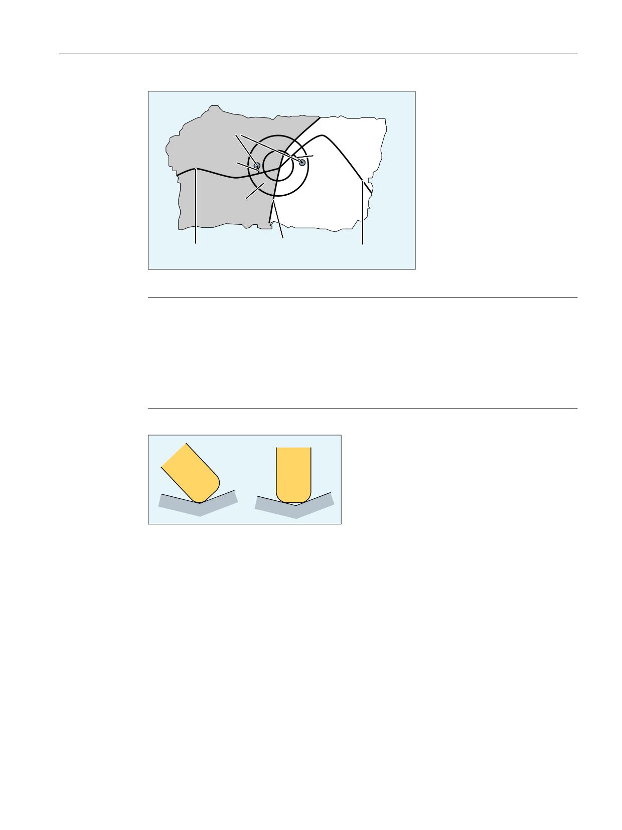
3D tool radius compensation
4.1 Function
&RQWDFW SRLQWV
7RRO VXUIDFH
3DWK
3DWK
RIIVHW S
RIIVHW S
7RRO
&XW HGJH RI
3DWK RQ VXUIDFH
3DWK RQ VXUIDFH
ERWK VXUIDFHV
Figure 4-8
Inside corner with face milling (view in direction of longitudinal axis of tool)
Note
The amount by which the contact points deviate from the programmed contour will generally
be small since the explanatory example shown in the Figure, in which the machining point
"changes" the cutter side at an inside corner (the value of the angular difference Ψ about the tool
longitudinal axis between the two contact points on the tool surface is approximately 180°) is
more likely to be the exception (see also the following Figure, on the right). The angle Ψ will
normally stay almost constant so that the distance between the contact points on the tool
surface will be relatively small (see also the following Figure, on the left).
Figure 4-9
Machining at inside corners
The difference between the programmed point on the path and the point actually to be
approached (path offset p) is eliminated linearly over the entire block length. Differences
resulting from inside corners at the block start and block end are overlaid. The current
difference in a path point is always perpendicular to the path and in the surface defined by the
surface normal vector.
If the tool orientation at an inside corner is not constant, the change in orientation is
implemented in the same way as described in Subsection "Behavior at inside corners" for 3D
circumferential milling, i.e. the tool is moved in the corner so that it contacts the two adjacent
surfaces at the block start, block end and at two points 1/3 and 2/3 of the change in orientation.
A 3rd-degree polynomial is used to interpolate between these 4 points.
A variable tool orientation in a block that is shortened owing to an inside corner is also treated
in the same way as described in Subsection "Behavior at inside corners" for 3D milling
(Page 242), i.e. the entire change in orientation is executed in the shortened block.
Consequently, the functional relationship between path tangent, surface normal and tool
orientation also changes. This results in new, previously nonexistent singularities or
Tools
Function Manual, 10/2020, 6FC5397-6GP40-0BA1
251
3D tool radius compensation
4.2 Commissioning
impermissible side angles (at points which are virtually singular) occurring in the shortened
block. If this type of situation is detected during processing of an inside corner, the machining
operation is aborted with an alarm. No block division takes place at the singular points since the
compensatory motions this would involve frequently cause contour violations and the change
in machining side on the tool is not generally intended or even foreseen by the user. The alarm
is also output during examination of an inside corner if the singularity occurs in the second of
the two blocks without the transition to the next block being considered. The system does not
therefore detect that a block of this type will form an inside corner in conjunction with the
following block and that the singularity would be eliminated again by the second block
reduction.
Remedy: Create new/different NC program, e.g. with a smaller tolerance.
The surface normal vector nF is not affected by the reduction of a block. This means that in
contrast to the tool orientation, the change in orientation that may need to be executed for this
vector will not be imaged onto the reduced traversing interval. This is necessary because a
surface other than that programmed would be machined. Unlike the tool orientation, no
problems arise as the result of an abrupt change in the surface normal vector at a block transition
since it does not reflect any axis motions.
Analogously to 3D circumferential milling, (see Section "Behavior at inside corners (Page 242)"),
the two traversing blocks that form an inside corner must contain contact points. There is no
evaluation of several traversing blocks (i.e. no bottleneck detection), CDON/CDOF are not
evaluated. If no contact point can be found, the machining operation is aborted with an alarm
(risk of collision).
4.1.3.7
Monitoring of path curvature
The path curvature is only monitored for circumferential milling. As a rule, it is therefore not
detected for CUT3DF* functions when an attempt is made to process a concave surface which
is so intensively curved that machining is not possible with the tool being used. A possible
exception are blocks that are split owing to a singularity. The transition between the two partial
blocks created after the split is then treated like an inside corner. Apart from these special cases,
it is the responsibility of the user to only use tools that make it possible to process every part of
the contour without contour violation. It could be helpful to use the CUT3DFD function for this,
where the differential tool is only minimally different from the original tool.
4.2
Commissioning
4.2.1
Parameter assignment
Minimal angle between path tangent and tool orientation
For the 3D-TRC, the angle between the path tangent and the tool orientation cannot undershoot
a specific limit angle.
This angle is defined in the machine data:
MD21080 $MC_CUTCOM_PARALLEL_ORI_LIMIT
Tools
252
Function Manual, 10/2020, 6FC5397-6GP40-0BA1
3D tool radius compensation
4.3 Programming
The lower the value of MD21080, the higher the computation effort generally is, which is
needed to check adherence to the cited conditions. Exceptions apply to linear blocks with
constant orientation.
Minimal angle between surface normal vector and tool orientation
In 3D face milling, the following machine data specifies the minimum angle which the surface
normal vector and tool orientation must form in each point of the path if you are working with
a side angle that is not equal to zero and the tool is not a cherry:
MD21082 $MC_CUTCOM_PLANE_ORI_LIMIT
If this value is undershot, processing is canceled with an alarm.
The lower the value of MD21082, the higher the computation effort generally is, which is
needed to check adherence to the cited conditions.
MD21082 has no effect in linear blocks with constant orientation. In this case, angles of any size
are permitted, even if the side angle is not equal to zero.
Minimal angle between surface normal vector and path tangent vector
During 3D face milling, the following machine data specifies the minimum angle which the
surface normal vector and path tangent vector must form in each point of the path:
MD21084 $MC_CUTCOM_PLANE_PATH_LIMIT
If this value is undershot, processing is canceled with an alarm.
The lower the value of MD21084, the higher the computation effort generally is, which is
needed to check adherence to the cited conditions.
Interpolation of the surface normals via polynomials
In order to use smoothing of the surface normal in 3D face milling, the function "Interpolation
of the surface normal via polynomials" must be enabled:
MD28291 $MC_MM_SMOOTH_SURFACE_NORMALS = TRUE
If MD28291 is not set, processing is canceled with an alarm.
4.3
Programming
4.3.1
Selecting 3D tool radius compensation for 3D circumferential milling
(CUT3DC, CUT3DCD, ISD)
The 3D tool radius compensation (3D TRC) for the 3D circumferential milling without taking
limitation surfaces into account is selected with the modally effective G command CUT3DC or
CUT3DCD.
The actual activation is performed with G41 or G42 The tool radius compensation is deactivated
with G40.
Tools
Function Manual, 10/2020, 6FC5397-6GP40-0BA1
253

3D tool radius compensation
4.3 Programming
Syntax
G41/G42 ORIC/ORID ISD=... CUT3DC/CUT3DCD CDOF2 X... Y... Z...
G40 X... Y... Z...
Meaning
CUT3DC:
3D TRC for circumferential milling (only when 5-axis transforma-
tion is active)
CUT3DCD:
3D TRC in relation to a differential tool for circumferential milling
(only when 5-axis transformation is active)
The radius difference is specified by the tool parameter $TC_DP15.
G41/G42 X... Y... Z... :
Activate tool radius compensation
G41:
Tool radius compensation left of the contour
G42:
Tool radius compensation right of the contour
Note:
The activation must be performed in a linear block (G0/G1).
CDOF2:
Deactivate collision detection for 3D circumferential milling
ORIC/ORID:
The behavior for orientation changes at outside corners is specified
via the G commands ORIC and ORID.
ORIC:
Orientation changes at outside corners are superim-
posed on the circle block to be inserted.
ORID:
Orientation changes at outside corners are executed
before the circle block to be inserted.
ISD=<Value>:
With the ISD address, the insertion depth of the tool can be
changed for circumferential milling and active 3D tool radius com-
pensation.
<Value>:
Length of the insertion depth
G40 X... Y... Z... :
Deactivate tool radius compensation
Note:
The deactivation must be performed in a linear block (G0/G1) with
geometry axis movements.
Note
The G commands for selecting the 3D TRC are evaluated in the approach block, i.e. typically in
the block that contains G41 or G42.
G41 or G42 can also be programmed in blocks without traversing movement in geometry axes
relevant for the compensation. In this case, the approach block is the first traversing block
following such a block.
A change of the 3D TRC variant with active tool radius compensation is ignored without alarm.
Tools
254
Function Manual, 10/2020, 6FC5397-6GP40-0BA1
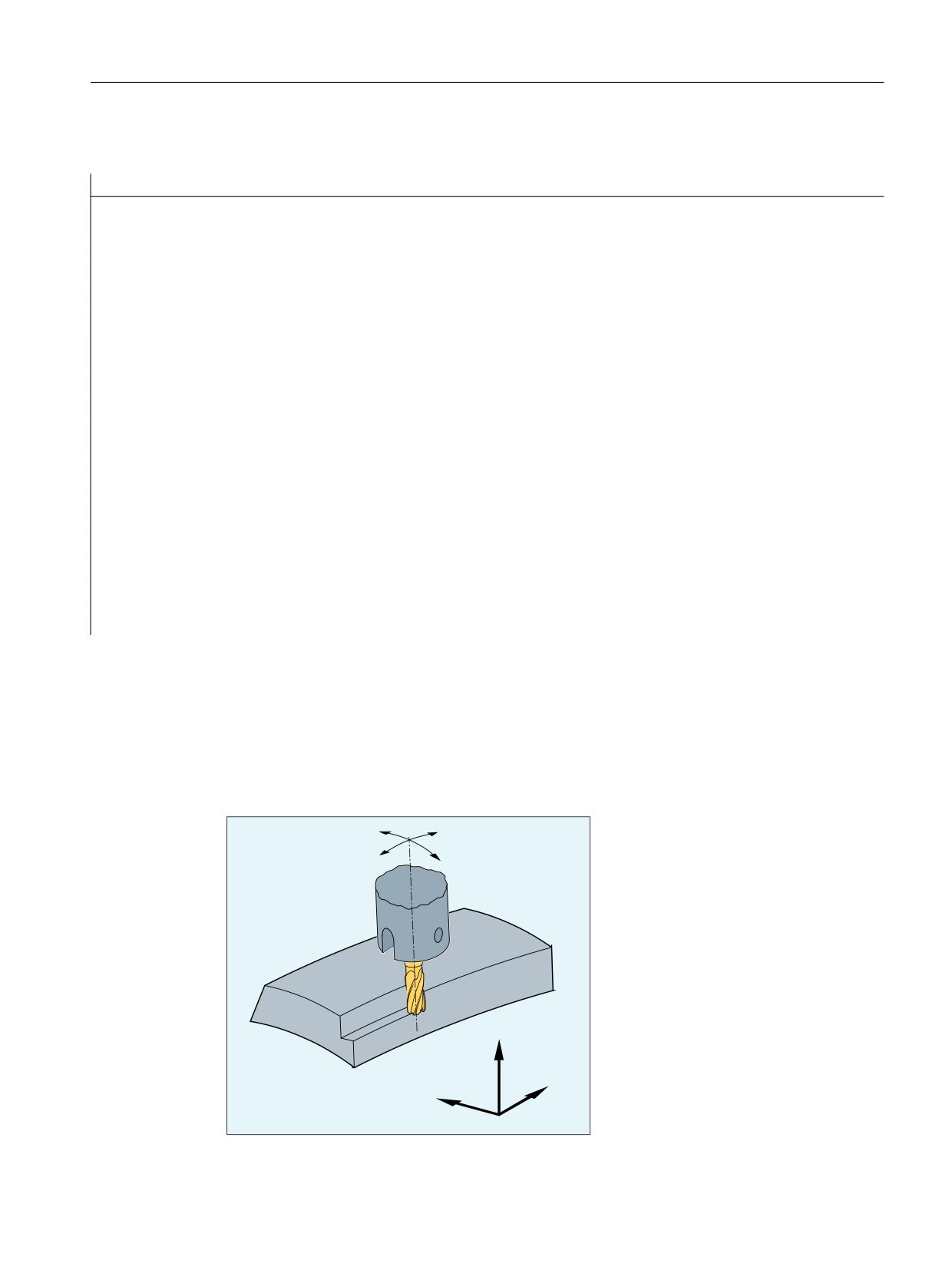
3D tool radius compensation
4.3 Programming
Example
Program code
Comment
; Definition of tool D1:
$TC_DP1[1,1]=120
; Type (end mill)
$TC_DP3[1,1]=20
; Length compensation vector
$TC_DP6[1,1]=8
; Radius
N10 X0 Y0 Z0 T1 D1 F12000
; Selection of the tool.
N20 TRAORI(1)
; Activation of the transformation.
N30 G42 ORIC ISD=10 CUT3DC G64 X30
; Activation of the 3D circumferential milling,
; continuous orientation changes at outside corners,
; insertion depth: 10 mm
N40 ORIWKS A30 B15
; Orientation change at a corner through specification of axis po-
sitions.
N50 Y20 A3=1 C3=1
; Traversing block with orientation change,
; specification of the orientation with direction vector.
N60 X50 Y30
; Traversing block with constant orientation.
N70 Y50 A3=0.5 B3=1 C3=5
; Traversing block with orientation change.
N80 M63
; Block without traversing information.
N90 X0 ISD=20
; Traversing block with change of the insertion depth.
N100 G40 Y0
; Deactivation of the tool radius compensation.
N110 M30
Further information
Path and orientation
The type of circumferential milling used here is implemented by defining a path (guide line) and
the associated orientation. In this type of machining, the shape of the tool on the path is not
relevant. Only the radius at the tool intervention point is decisive.
$
%
=
;
<
Tools
Function Manual, 10/2020, 6FC5397-6GP40-0BA1
255
3D tool radius compensation
4.3 Programming
Figure 4-10
Circumferential milling
Approach behavior
The approach behavior is always NORM for the 3D variant of the tool radius compensation.
Behavior at outside corners
The G commands of group 18 (corner behavior, tool offset) are evaluated at the outside corners
for circumferential milling with 3D TRC in the same way as for the conditions for the 2½D TRC:
• G450: Transition circle (tool travels round workpiece corners on a circular path)
In contrast to the solution for the 2½D TRC, the inserted contour element at an outside corner
is always a circle with a 0 radius, on which the tool radius compensation acts in the same way
as on any other programmed path. It is not possible to insert conics instead of circles. In this
case, the DISC address has no significance and is therefore not evaluated.
• G451: Intersection of equidistant paths (tool backs off from the workpiece corner)
The intersection is determined by extending the offset curves of the two participating blocks
and defining the intersection of the two blocks at the corner in the plane perpendicular to the
tool orientation.
The intersection procedure (G451) is not used when at least one block containing a change to
the tool orientation was inserted between the relevant traversing blocks. In this case, a circle is
always inserted at the corner.
Behavior for changes in orientation at outside corners
The ORIC and ORID G commands are used to determine whether changes in orientation
programmed between two blocks forming the corner are executed before the inserted circle
block (ORID) is processed or at the same time (ORIC).
Insertion depth
The insertion depth of the milling tool is the distance of the milling tool reference point from the
tip of the tool.
The milling tool reference point is the vertical projection of the milling tool machining point on
the programmed path to the longitudinal axis of the tool.
The position of the machining point on the peripheral surface of the tool is set with the insertion
depth.
Tools
256
Function Manual, 10/2020, 6FC5397-6GP40-0BA1
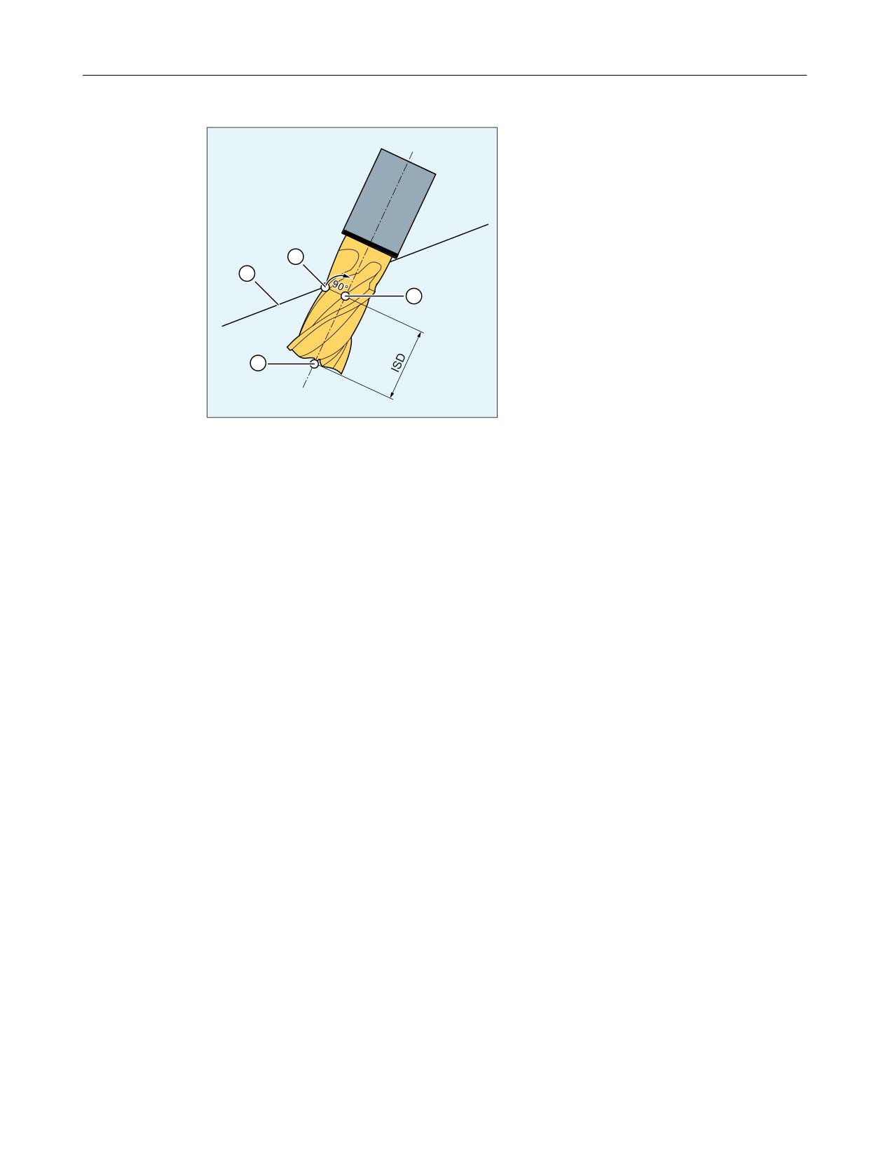
3D tool radius compensation
4.3 Programming
① Programmed path
② Milling tool machining point
③ Milling tool reference point
④ Milling tool tip
ISD
Insertion depth (InSertion Depth)
Figure 4-11
Insertion depth
Tool radius compensation referred to a differential tool
3D TRC for circumferential milling referred to a differential tool is activated via the CUT3DCD
command. It should be applied if the programmed contour refers to the center-point path of a
standard tool, and a tool other than a differential tool is used for machining. When calculating
the 3D tool radius compensation, only the wear value of the radius of the active tool ($TC_DP15)
and any programmed tool offsets OFFN and TOFFR/TOFFLR are taken into account. The basic
radius ($TC_DP6) of the active tool is not taken into account.
Pocket milling with inclined side walls for circumferential milling with CUT3DC
In this 3D tool radius compensation, a deviation of the mill radius is compensated by infeed
toward the surface normals to be machined. The plane, in which the milling tool face is located,
remains unchanged if the insertion depth ISD has remained the same. For example, a milling
tool with a smaller radius than a standard tool would not reach the pocket base, which is also the
limitation surface. For automatic tool infeed, this limitation surface must be known to the
control, see Section "3D circumferential milling taking into account a limitation surface
(CUT3DCC, CUT3DCCD) (Page 263)".
Tools
Function Manual, 10/2020, 6FC5397-6GP40-0BA1
257

3D tool radius compensation
4.3 Programming
Advanced Surface / Top Surface
Note
When applying tool radius compensation CUT3DCD in combination with the "Advanced Surface"
or "Top Surface" option (requiring a license), the setting recommendations regarding "Advanced
Surface" / "Top Surface" must be observed.
A special test program is provided in the SIOS portal for checking the set data.
→ Test program for Advanced Surface / Top Surface (https://
support.industry.siemens.com/cs/ww/en/view/109738423)
4.3.2
Selecting 3D tool radius compensation for the 3D face milling (CUT3DF,
CUT3DFS, CUT3DFF, CUT3DFD)
The 3D tool radius compensation (3D TRC) for the 3D face milling is selected with the modally
effective G command CUT3DF, CUT3DFS, CUT3DFF or CUT3DFD.
The actual activation is performed with G41 or G42
With 3D face milling, the surface normals of the plane to be machined must be defined in order
to calculate the tool radius compensation. This must be performed in the block with G41 or G42
via the A4, B4, C4 and A5, B5, C5 addresses.
The tool radius compensation is deactivated with G40.
Syntax
G41/G42 ORIC/ORID CUT3DF/CUT3DFS/CUT3DFF/CUT3DFD X... Y... Z... A4=... B4=...
C4=... A5=... B5=... C5=
G40 X... Y... Z...
Meaning
CUT3DFS:
3D TRC for face milling with constant orientation. The tool
orientation is defined by G17 - G19 and is not influenced by
frames.
CUT3DFF:
3D TRC for face milling with constant orientation. The tool
orientation is the direction defined by G17 - G19 and, in some
cases, rotated by a frame.
CUT3DF:
3D TRC for face milling with orientation change (only with
active 5-axes transformation)
Tools
258
Function Manual, 10/2020, 6FC5397-6GP40-0BA1

3D tool radius compensation
4.3 Programming
CUT3DFD:
3D TRC in relation to a differential tool for face milling with
change in orientation (only with active 5-axis transformation)
The radius difference is specified by the tool parameter
$TC_DP15.
Note:
CUT3DFD is only possible in combination with "Smoothing of
surface normals in 3D face milling". This is activated by calling
the "Top Surface" function (requires a license) via CY-
CLE832(...).
G41/G42 X... Y... Z... :
Activate tool offset
The behavior with G41 and with G42 is identical for 3D face
milling.
Note:
The activation must be performed in a linear block (G0/G1).
A4/5=... B4/5=... C4/5=...:
Definition of the surface normals of the plane to be machined
A4=... B4=... C4=...:
Definition at start of block
A5=... B5=... C5=...:
Definition at end of block
ORIC/ORID:
The behavior for orientation changes at outside corners is
specified via the G commands ORIC and ORID.
ORIC:
Orientation changes at outside corners are su-
perimposed on the circle block to be inserted.
ORID:
Orientation changes are performed before the
circle block.
G40 X... Y... Z... :
Deactivate tool radius compensation
Note:
The deactivation must be performed in a linear block (G0/G1)
with geometry axis movements.
Note
G41 or G42 can also be programmed in blocks without traversing movement in geometry axes
relevant for the compensation. In this case, the approach block is the first traversing block
following such a block.
A change of the 3D TRC variant with active tool radius compensation is ignored without alarm.
Examples
Example 1: 3D face milling with CUT3DF
Program code
Comment
N10
; Definition of tool D1:
N20 $TC_DP1[1,1]=121
; Tool type (toroidal miller)
N30 $TC_DP3[1,1]=20
; Length compensation
N40 $TC_DP6[1,1]=5
; Radius
N50 $TC_DP7[1,1]=3
; Rounding radius
N60
N70
Tools
Function Manual, 10/2020, 6FC5397-6GP40-0BA1
259

3D tool radius compensation
4.3 Programming
Program code
Comment
N80 X0 Y0 Z0 A0 B0 C0 G17 T1 D1 F12000
; Selection of the tool.
N90 TRAORI(1)
; Select orientation transformation.
N100 B4=-1 C4=1
; Definition of the plane.
N110 G41 ORID CUT3DF G64 X10 Y0 Z0
; Activate tool offset.
N120 X30
N130 Y20 A4=1 C4=1
; Outside corner, new plane definition.
N140 B3=1 C3=5
; Change in orientation with ORID.
N150 B3=1 C3=1
; Change in orientation with ORID.
N160 X-10 A5=1 C5=2 ORIC
N170 A3=-2 C3=1
; Change in orientation with ORIC.
N180 A3=-1 C3=1
; Change in orientation with ORIC.
N190 Y-10 A4=-1 C4=3
; New plane definition.
N200 X-20 Y-20 Z10
; Inside corner with previous block.
N210 X-30 Y10 A4=1 C4=1
; Inside corner, new plane definition.
N220 A3=1 B3=0.5 C3=1.7
; Change in orientation with ORIC.
N230 X-20 Y30 A4=1 B4=-2 C4=3 ORID
N240 A3 = 0.5 B3=-0.5 C3=1
; Change in orientation.
N250 X0 Y30 C4=1
; Path movement, new plane,
; orientation with relative programming.
N260 BSPLINE X20 Z15
; Spline begin, relative programming of the orien-
tation
N270 X30 Y25 Z18
; remains active during spline.
N280 X40 Y20 Z13
N290 X45 Y0 PW=2 Z8
N300 Y-20
N310 G2 ORIMKS A30 B45 I-20 X25 Y-40 Z0
; Helix, orientation with axis programming.
N320 G1 X0 A3=-0.123 B3=0.456 C3=2.789 B4=-1 C4=5
; Path movement, orientation, non-constant plane.
B5=-1 C5=2
N330 X-20 G40
; Deactivation of the tool radius compensation.
N340 M30
Example 2: NC program (section) generated from a CAD system with CUT3DFD
Program code
Comment
N01 G710
N03 T="12"
N06 S5305 M03
N07 G642
; Approaching the starting position in the MCS taking the tool length into account.
G00 G90 X-250.62787 Y-38.37944 A=DC(253.12719)
B-12.49543
G00 G90 Z251.80052
; End of positioning in the MCS.
;
Tools
260
Function Manual, 10/2020, 6FC5397-6GP40-0BA1
3D tool radius compensation
4.3 Programming
Program code
Comment
TRAORI(1)
; Select orientation transformation.
G500
D1
CYCLE832(0.01, _TOP_SURFACE_SMOOTH_ON + _ORI_FIN-
; Call CYCLE832 with:
ISH, 1)
; Contour tolerance = 0.01 mm,
; Processing type: Top Surface with smoothing,
; Finishing with input of an orientation toler-
ance,
; Orientation tolerance = 1 degree
CUT3DFD
N08 G90 G94
N09 G00 X-269.21195 Y128.32027 Z1.18577
; The blocks N09 to N10 are the fast portion of
A3=-.216361688 B3=.934284397 C3=-.283373051
the approach movement to the workpiece with con-
stant orientation.
N10 G00 X-251.90301 Y53.57752 Z23.85561
N11 G01 X-247.57578 Y34.89183 Z29.52308 F50000.00000
; In the blocks N11 to N21, the slow portion of
the approach movement is realized. The tool is
already close to the workpiece; furthermore, the
mold making settings (e.g. COMPSURF) from the CY-
CLE832 are now active (due to active G01). The
path of this so-called transient phase for the
mold-making behavior should be about 1000 times
the contour tolerance (10 mm in this example).
N12 X-247.69126 Y33.82182 Z24.78219 F1061.00000
N13 X-247.76560 Y33.13299 Z21.73022
N14 X-247.82755 Y32.55897 Z19.18691
N15 X-247.87918 Y32.08062 Z17.06748
N16 X-247.92220 Y31.68200 Z15.30129
N17 X-247.95805 Y31.34981 Z13.82947
A3=-.216361686 B3=.934284391 C3=-.283373071
N18 X-247.98792 Y31.07299 Z12.60295
A3=-.216360662 B3=.934280801 C3=-.283385691
N19 X-248.01282 Y30.84230 Z11.58085
A3=-.216336015 B3=.934194446 C3=-.283689030
N20 X-248.03357 Y30.65006 Z10.72910
A3=-.216233089 B3=.933833626 C3=-.284952647
N21 X-248.05086 Y30.48986 Z10.01931
A5=-.060687572 B5=.974940255 C5=-.214029243
A3=-.215712821 B3=.932005189 C3=-.291263295
N22 G41 X-248.06237 Y30.32400 Z9.36695
; From N22, the surface normal is completely de-
A5=-.060431854 B5=.973045457 C5=-.222554556
fined over the entire block for the first time
A3=-.214974689 B3=.929398552 C3=-.300007025
(i.e. surface normal at the end of the previous
F1061.03295
block N21 is present, thus the surface normal at
the beginning of the block N22 and the surface
normal at the end of the block N22). Thus the
prerequisite for switching on the tool offset
with G41/G42 is fulfilled.
Tools
Function Manual, 10/2020, 6FC5397-6GP40-0BA1
261
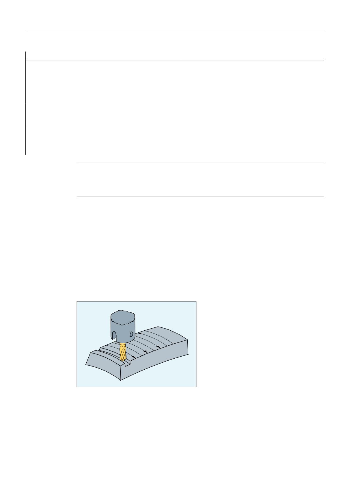
3D tool radius compensation
4.3 Programming
Program code
Comment
N23 X-248.07130 Y30.15119 Z8.71082
A5=-.060165696 B5=.971048883 C5=-.231179920
A3=-.214177198 B3=.926684940 C3=-.308841625
N24 X-248.07829 Y29.97126 Z8.05094
A5=-.059884286 B5=.968941717 C5=-.239928784
A3=-.213318480 B3=.923853466 C3=-.317789237
N25 X-248.08317 Y29.78487 Z7.38844
A5=-.059584206 B5=.966718449 C5=-.248807482
A3=-.212397895 B3=.920898045 C3=-.326854594
N26 X-248.08578 Y29.59254 Z6.72679
A5=-.059263963 B5=.964380907 C5=-.257793037
A3=-.211418355 B3=.917822366 C3=-.336012474
Note
For 3D face milling with CUT3DFD, the definition of the surface normal is required for activating
the tool offset with G41/G42. Programming of G41/G42 without definition of the surface
normals leads to the output of an alarm.
Further information
3D face milling
For this type of 3D milling, you require the line-by-line description of the 3D paths on the
workpiece surface. The tool shape and dimensions are taken into account in the calculations,
which are normally performed in CAM. The postprocessor writes to the part program - in
addition to NC blocks - the tool orientations (for active 5-axis transformation) and the G
command for the required 3D tool offset. This means that the machine operator has the
possibility of using tools that are slightly smaller - deviating from the tool used to calculate the
NC paths.
Figure 4-12
Face milling
Approach behavior
The approach behavior is always NORM for the 3D variant of the tool radius compensation.
Tools
262
Function Manual, 10/2020, 6FC5397-6GP40-0BA1
3D tool radius compensation
4.3 Programming
Behavior at outside corners
Outside corners are treated as circles with radius 0 for face milling, whereby the circle plane
extends from the end tangent of the first block to the start tangent of the second block. In this
way, the orientation can be changed during block transition. A circle is therefore always inserted
as contour element at an outside corner. The intersection procedure is not available with face
milling.
Behavior for changes in orientation at outside corners
The ORIC and ORID G commands are used to determine whether changes in orientation
programmed between two blocks forming the corner are executed before the inserted circle
block (ORID) is processed or at the same time (ORIC).
Tool radius compensation referred to a differential tool
3D tool radius compensation referring to a differential tool is selected using the CUT3DFD
command. It should be applied if the programmed contour refers to the center-point path of a
standard tool, and a tool other than a differential tool is used for machining. When calculating
the 3D tool radius compensation, only the wear value of the radius of the active tool ($TC_DP15)
and any programmed tool offsets OFFN and TOFFR/TOFFLR are taken into account. The basic
radius ($TC_DP6) of the active tool is not taken into account.
3D face milling with CUT3DFD is only possible in combination with "Smoothing of surface
normals in 3D face milling". This is activated by calling the "Top Surface" function (requires a
license) via CYCLE832(...). Activation must take place before the tool offset is activated with
G41/G42; not directly before tool intervention, but rather one path length before that, which
corresponds to approx. 1000 times the contour tolerance (e.g. 1000 x 0.01 mm = 10 mm).
Deactivation must be executed in reverse order: First switch off the tool offset with G40, then
deactivate with e.g. CUT2D (or similar) after a path length which corresponds with
approximately 1000 time the contour tolerance.
In order to be able to use the "Smoothing of surface normals in 3D face milling", the
"Interpolation of surface normals via polynomials" function must also be enabled:
MD28291 $MC_MM_SMOOTH_SURFACE_NORMALS = TRUE
Note
For 3D face milling with CUT3DFD in combination with "Top Surface", the setting
recommendations regarding "Top Surface" must be observed.
A special test program is provided in the SIOS portal for checking the set data.
→ Test program for Top Surface (https://support.industry.siemens.com/cs/ww/en/view/
109738423)
4.3.3
3D circumferential milling taking into account a limitation surface (CUT3DCC,
CUT3DCCD)
In 3D circumferential milling with a continuous or constant change in tool orientation, the tool
center-point path is frequently programmed for a defined standard tool. Because in practice
suitable standard tools are often not available, a tool that does not deviate too much from a
standard tool (≤ 5%) can be used.
Tools
Function Manual, 10/2020, 6FC5397-6GP40-0BA1
263

3D tool radius compensation
4.3 Programming
CUT3DCCD takes account of a limitation surface for a real differential tool that the programmed
standard tool would define. The NC program defines the center-point path of a standard tool.
CUT3DCC with the use of cylindrical tools takes account of a limitation surface that the
programmed standard tool would have reached. The NC program defines the contour on the
machining surface.
The surface normal vector of the limitation surface is specified with A4, B4, C4 and A5, B5, C5
for 3D face milling.
Syntax
G41/G42 CUT3DCCD/CUT3DCC CDOF2 X... Y... Z... A4=... B4=... C4=... A5=... B5=...
C5=
G40 X... Y... Z...
Meaning
CUT3DCCD:
3D TRC for circumferential milling taking into account a limitation
surface with a differential tool on the tool center-point path: Infeed to
the limitation surface
CUT3DCC:
3D TRC for circumferential milling taking into account a limitation
surface with 3D radius compensation: Contour on the machining
surface
G41/G42 X... Y... Z... :
Activate tool radius compensation
G41:
Tool radius compensation left of the contour
G42:
Tool radius compensation right of the contour
Note:
The activation must be performed in a linear block (G0/G1).
CDOF2:
Deactivate collision detection for 3D circumferential milling
A4/5=... B4/5=...
Definition of the surface normals of the limitation surface
C4/5=...:
A4=... B4=... C4=...:
Definition at start of block
A5=... B5=... C5=...:
Definition at end of block
G40 X... Y... Z... :
Deactivate tool radius compensation
Note:
The deactivation must be performed in a linear block (G0/G1) with
geometry axis movements.
Note
The G commands for selecting the 3D TRC are evaluated in the approach block, i.e. typically in
the block that contains G41 or G42.
G41 or G42 can also be programmed in blocks without traversing movement in geometry axes
relevant for the compensation. In this case, the approach block is the first traversing block
following such a block.
A change of the 3D TRC variant with active tool radius compensation is ignored without alarm.
Tools
264
Function Manual, 10/2020, 6FC5397-6GP40-0BA1
3D tool radius compensation
4.3 Programming
Example
Program code
Comment
N10 $TC_DP1[1,1]=120
; Cylindrical milling tool
N20 $TC_DP6[1,1]=10
N30 $TC_DP15[1,1]=-3
; Processing with cylindrical milling tool and CUT3DCCD
N110 TRAORI
; Activation of the transformation.
N120 A4=0 B4=0 C4=1
; Definition of the surface normal of the
limitation surface at the start of the
block.
N130 X0 Y0 Z0 A0 C0 T1 D1 F20000
N140 X10 Y0 Z0 G41 CUT3DCCD CDOF2 G64
; Activate 3D circumferential milling,
taking into account the limitation sur-
face + switching off collision detection.
N150 X20
N160 X30 A45
; Obtuse angle ==> no infeed
N170 X40 A-45
; Acute angle ==> infeed
N180 X55
N190 Y10 Z10
; Movement in the tool direction.
N200 Y20
N210 C45
; Pure change in orientation.
N220 Y30 C90
N230 A5=-1 B5=0 C5=2 Y40
; Change of the surface.
N240 Y50 G40
; Deactivation of the tool radius compen-
sation.
Further information
Tool type
The tool type (tool parameter $TC_DP1) is evaluated. Only milling tools with cylindrical shank
(cylinder or end mill, toroidal miller and, in the limit case, cylindrical die mill) are permitted. This
corresponds to the tool types 1 - 399, with the exception of the numbers 111 and 155 to 157.
Standard tools with corner rounding
Corner rounding with a standard tool is defined by the tool parameter $TC_DP7. Tool parameter
$TC_DP16 describes the deviation of the corner rounding of the real tool compared with the
standard tool.
Tools
Function Manual, 10/2020, 6FC5397-6GP40-0BA1
265
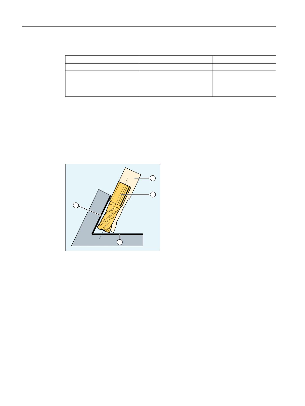
3D tool radius compensation
4.3 Programming
Example: Toroidal miller with reduced radius compared to the standard tool
Tool type
Shaft radius (R)
Corner radius (r)
Standard tool with corner rounding
R = $TC_DP6
r = $TC_DP7
Real tool with corner rounding
R' = $TC_DP6 + $TC_DP15 + OFFN
r' = $TC_DP7 + $TC_DP16
Tool types 121 and 131 toroidal
miller
(end mill with corner rounding)
In this example, both $TC_DP15 + OFFN and $TC_DP16 are negative.
3D TRC with CUT3DCCD: Tool center-point path with infeed up to the limitation surface
If a tool with a smaller radius than the appropriate standard tool is used, machining is continued
using a milling tool, which is fed in in the longitudinal direction until it reaches the bottom (base)
of the pocket. The tool removes as much material from the corner formed by the machining
surface and limitation surface. This involves a machining type combining circumferential and
face milling. Analogous to a tool with reduced radius, for a tool with increased radius, the infeed
is in the opposite direction.
① Standard tool
② Tool with smaller radius infeed up to the limitation surface
③ Limitation surface
④ Machining surface
Contrary to all other tool offsets of G group 22, tool parameter $TC_DP6 specified for CUT3DCCD
has no relevance for the tool radius and does not influence the resulting compensation. The
compensation offset results from the sum of the wear value of the tool radius (tool parameter
$TC_DP15) and a tool offset OFFN programmed to calculate the perpendicular offset to the
limitation surface.
The generated part program does not specify whether the surface to be machined is to the right
or left of the path. It is therefore assumed that the radius is a positive value and the wear value
of the original tool is a negative value. A negative wear value always describes a tool with a
reduced diameter.
Tools
266
Function Manual, 10/2020, 6FC5397-6GP40-0BA1
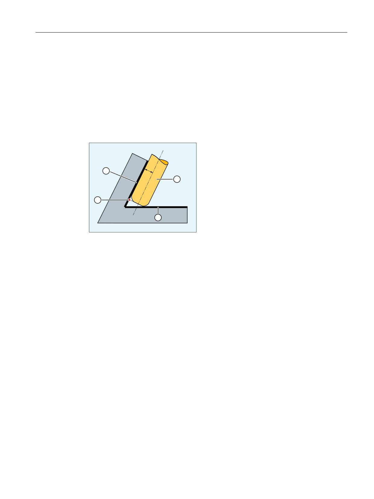
3D tool radius compensation
4.3 Programming
Using cylindrical tools
When cylindrical tools are used, infeed is only necessary if the machining surface and the surface
of limitation form an acute angle (less than 90 degrees). If a toroidal miller (end mill with corner
rounding) is used, tool infeed in the longitudinal direction is required for both acute and obtuse
angles.
3D TRC with CUT3DCC: Contour on the machining surface
If CUT3DCC is active with a toroidal miller, the programmed path refers to a fictitious cylindrical
milling tool having the same diameter. The resulting path reference point is shown in the
following diagram for a toroidal miller.
5
① Toroidal miller
② Limitation surface
③ Path reference point
④ Machining surface
R
Shaft radius (tool radius)
The angle between the machining and limitation surfaces may change from an acute to an
obtuse angle and vice versa even within the same block.
The tool actually being used may either be larger or smaller than the standard tool. However, the
resulting corner radius must not be negative and the sign of the resulting tool radius must be
kept.
For CUT3DCC, the NC part program refers to the contour on the machining surface. As for
conventional tool radius compensation, the total tool radius is used that comprises the following
components:
• Tool radius (tool parameter $TC_DP6)
• Wear value (tool parameter $TC_DP15)
• A tool offset OFFN programmed to calculate the perpendicular offset to the limitation surface
The position of the limitation surface is defined from the following difference:
Dimensions of the standard tool - tool radius (tool parameter $TC_DP6)
Tools
Function Manual, 10/2020, 6FC5397-6GP40-0BA1
267

3D tool radius compensation
4.5 Examples
Advanced Surface / Top Surface
Note
When applying tool radius compensation CUT3DCC / CUT3DCCD in combination with the
"Advanced Surface" or "Top Surface" function (requiring a license), the setting
recommendations regarding "Advanced Surface" / "Top Surface" must be observed. Special test
programs are provided in the SIOS portal for checking the set data.
→ Test program for Advanced Surface / Top Surface (https://
support.industry.siemens.com/cs/ww/en/view/109738423)
4.4
Boundary conditions
Boundary conditions for face milling
Functions with high-order geometry information
Functions with high-order geometry information (e.g. polynomials or spline interpolation)
cannot be used.
Top Surface
3D face milling with CUT3DFD is only possible in conjunction with the "Top Surface" function,
which requires a license.
Bottleneck detection
A "bottleneck detection" is not possible, and therefore the user is solely responsible.
Traversing movements in the orientation direction of the tool
For traversing motion in the orientation direction of the tool, and alarm is displayed and
machining stopped.
4.5
Examples
4.5.1
Example 1: Orientation change at outside corner during 3D circumferential
milling
Orientation change at outside corner with ORIC active
Program code
Comment
N10 A0 B0 X0 Y0 Z0 F5000
N20 T1 D1
; Selection of the tool (radius=5).
Tools
268
Function Manual, 10/2020, 6FC5397-6GP40-0BA1
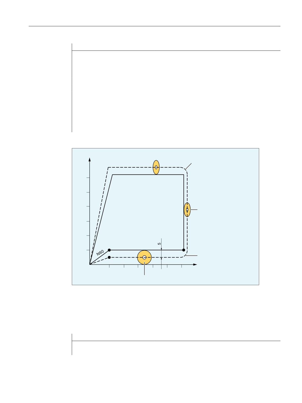
3D tool radius compensation
4.5 Examples
Program code
Comment
N30 TRAORI(1)
; Activation of transformation.
N40 CUT3DC
; Selection of 3D TRC for circumferential milling.
N50 ORIC
; Orientation changes at outside corners are super-
imposed on the circle block to be inserted.
N60 G42 X10 Y10
; Activation of TRC.
N70 X60
N80 A3=1 B3=0 C3=1
; change in orientation of external corner gener-
ated from N70 and N90
N90 Y60
N100 X10
N110 G40 X0 Y0
; Deactivation of TRC.
N120 M30
The circular motion and change in orientation are executed in parallel in block N80 (ORIC active):
<
2XWVLGH FRUQHU ZLWK FRQVWDQW
RULHQWDWLRQ LQVHUWHG EORFN QRW
SURJUDPPHG
1
1
7RRO LQFOLQHG
1
2XWVLGH FRUQHU ZLWK FRQVWDQW
1
1
RULHQWDWLRQ LQVHUWHG EORFN QRW
SURJUDPPHG
;
7RRO YHUWLFDO
Figure 4-13
ORIC: Change in orientation and path movement in parallel
Special case:
Intermediate blocks without traversing and orientation motions are executed at the
programmed positions, e.g. auxiliary functions.
Example:
Program code
Comment
N70 X60
N75 M20
; auxiliary function call
Tools
Function Manual, 10/2020, 6FC5397-6GP40-0BA1
269
3D tool radius compensation
4.5 Examples
Program code
Comment
N80 A3=1 B3=0 C3=1
; change in orientation of external corner gener-
ated from N70 and N90
N90 Y60
Blocks N75 and N80 are executed after N70. The circle block is then executed with the current
orientation.
Orientation change at outside corner with ORID active
Program code
Comment
N10 A0 B0 X0 Y0 Z0 F5000
N20 T1 D1
; Selection of the tool (radius=5).
N30 TRAORI(1)
; Activation of transformation.
N40 CUT3DC
; Selection of 3D TRC for circumferential milling.
N50 ORID
; Orientation changes at outside corners are per-
formed on the circle block to be inserted.
N60 G42 X10 Y10
; Activation of TRC.
N70 X60
N80 A3=1 B3=0 C3=1
; change in orientation of external corner gener-
ated from N70 and N90
N90 Y60
N100 X10
N110 G40 X0 Y0
; Deactivation of TRC.
N120 M30
Tools
270
Function Manual, 10/2020, 6FC5397-6GP40-0BA1
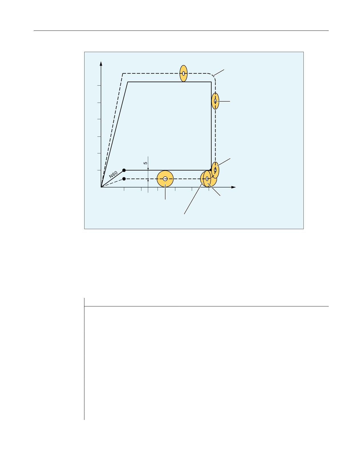
3D tool radius compensation
4.5 Examples
<
2XWVLGH FRUQHU ZLWK FRQVWDQW
RULHQWDWLRQ LQVHUWHG EORFN QRW
SURJUDPPHG
1
7RRO LQFOLQHG
1
1
7RRO DW VWDUW SRLQW RI 1
1
1
;
7RRO DW HQG RI 1
7RRO YHUWLFDO
2ULHQWDWLRQ FKDQJH LV SHUIRUPHG LQ
VXFK D ZD\ WKDW WKH WRRO DOZD\V
7RRO DW HQG RI 1
WRXFKHV WKH
HQGSRLQW RI 1
Figure 4-14
ORID: Change in orientation and path movement consecutively
4.5.2
Example 2: Orientation change at inside corner during 3D circumferential
milling
Program code
Comment
N10 A0 B0 X0 Y0 Z0 F5000
N20 T1 D1
; Selection of the tool (radius=5).
N30 TRAORI(1)
; Activation of transformation.
N40 CUT3DC
; Selection of 3D TRC for circumferential milling.
N50 ORID
N60 G42 X10 Y10 G451
; Activation of TRC.
N70 Y60
N80 A3=1 B3=0 C3=1
; change in orientation of inside corner generated
from N70 and N90.
N90 X60 Y90
N100 G40 X... Y...
N190 CDOF
N200 M30
Tools
Function Manual, 10/2020, 6FC5397-6GP40-0BA1
271
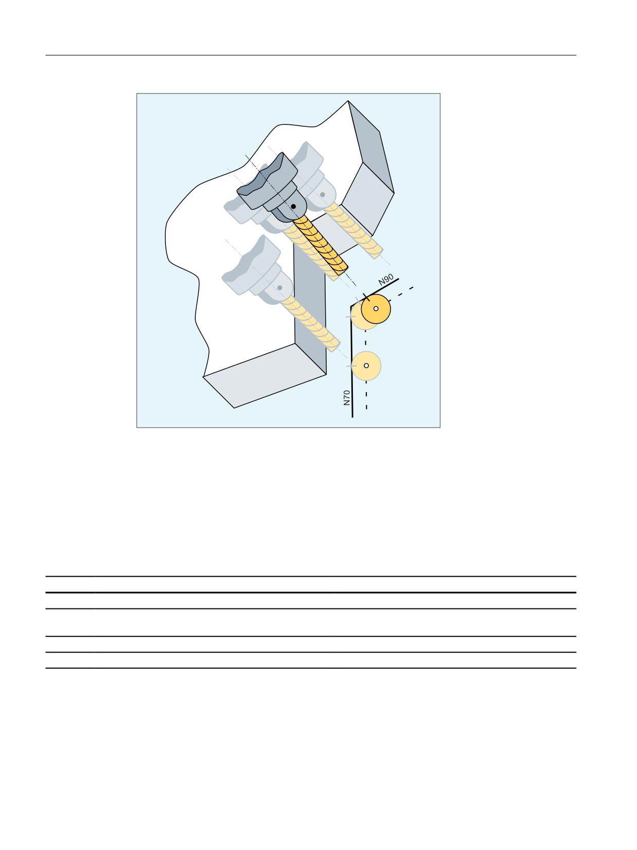
3D tool radius compensation
4.6 Data lists
4.6
Data lists
4.6.1
General machine data
Number Identifier: $MN_
Description
18094
MM_NUM_CC_TDA_PARAM
Number of TDA data
18096
MM_NUM_CC_TOA_PARAM
Number of TOA data, which can be set up per tool and
evaluated by the CC
18100
MM_NUM_CUTTING_EDGES_IN_TOA
Tool offsets per TOA module
18110
MM_NUM_TOA_MODULES
Number of TOA modules
Tools
272
Function Manual, 10/2020, 6FC5397-6GP40-0BA1

3D tool radius compensation
4.6 Data lists
4.6.2
Channelspecific machine data
Number
Identifier: $MC_
Description
20110
RESET_MODE_MASK
Definition of the control basic setting after power-up and
RESET / part program end
20120
TOOL_RESET_VALUE
Definition of the tool from which the tool length com-
pensation is selected during run-up and upon RESET or
part program end, dependent upon MD 20110.
20130
CUTTING_EDGE_RESET_VALUE
Definition of tool cutting edge for which tool length com-
pensation is selected during power-up or on reset or
parts program end as a function of MD20110
20140
TRAFO_RESET_VALUE
Definition of transformation block which is selected dur-
ing power-up and or RESET or parts program end as a
function of MD20110
20210
CUTCOM_CORNER_LIMIT
Max. angle for intersection calculation with tool radius
compensation
20220
CUTCOM_MAX_DISC
Behavior of the TRC at outside corners
20230
CUTCOM_CURVE_INSERT_LIMIT
Minimum value for intersection calculation with tool ra-
dius compensation
20240
CUTCOM_MAXNUM_CHECK_BLOCKS
Blocks for predictive contour calculation with tool radius
compensation
20250
CUTCOM_MAXNUM_DUMMY_BLOCKS
Number of blocks without traversing motion for tool ra-
dius compensation
20270
CUTTING_EDGE_DEFAULT
Selected cutting edge after tool change
20610
ADD_MOVE_ACCEL_RESERVE
Acceleration reserve for overlaid motions
21080
CUTCOM_PARALLEL_ORI_LIMIT
Minimal angle between path tangent and tool orienta-
tion for 3D-TRC
21082
CUTCOM_PLANE_ORI_LIMIT
Minimal angle between surface normal vector and tool
orientation (for 3D face milling)
21084
CUTCOM_PLANE_PATH_LIMIT
Minimal angle between surface normal vector and path
tangent vector (for 3D face milling)
22550
TOOL_CHANGE_MODE
New tool offset with M function
22560
TOOL_CHANGE_M_CODE
M function for tool change
28291
MM_SMOOTH_SURFACE_NORMALS
Interpolation of the surface normals via polynomials (for
3D face milling)
Tools
Function Manual, 10/2020, 6FC5397-6GP40-0BA1
273
3D tool radius compensation
4.6 Data lists
Tools
274
Function Manual, 10/2020, 6FC5397-6GP40-0BA1