SINUMERIK 840D sl. Service - Functions. Manual (2018-2020) - page 94
Tool offset
3.8 Tool carriers with orientation capability
Two rotary axes
Two general solutions exist for two rotary axes. The control itself chooses these two solution
pairs such that the orientation angles resulting from the frame are as close as possible to the
specified angles.
The two following options are available for specifying the angles:
1. If $TC_CARR21 or $TC_CARR22 contains a reference to a rotary axis, the position of this axis
at the start of the block in which the tool carrier is activated is used to specify the angle.
2. If $TC_CARR21 or $TC_CARR22 does not contain a reference to a rotary axis, the values
contained in $TC_CARR13 or $TC_CARR14 are used.
Example
The control first calculates an angle of 10 degrees for one axis. The specified angle is 750
degrees. 720 degrees (= 2 * 360 degrees) are then added to the initial angle, resulting in a final
angle of 730 degrees.
Rotary axis offset
Rotary axis offsets can be specified with system variables $TC_CARR24 and $TC_CARR25. A value
not equal to zero in one of these parameters means that the initial state of the associated rotary
axis is the position specified by the parameter (and not position zero). All angle specifications
then refer to the coordinate system displaced by this value.
When the machining plane is changed (G17 - G19), only the tool length components of the
active tool are interchanged. The components of the tool carrier are not interchanged. The
resulting tool length vector is then rotated in accordance with the current tool carrier and, if
necessary, modified by the offsets belonging to the tool carrier.
The two tool carrier angles α1 and α2 are determined using a frame, independent of the active
plane currently selected (G17 - G19).
Limit values
Limit angles (software limits) can be specified for each rotary axis in the system variable set
($TC_CARR30 to $TC_CARR33) used to describe the tool carrier with orientation capability.
These limits are not evaluated if both the minimum and maximum value is zero.
If at least one of the two limits is not equal to zero, the system checks whether the previously
calculated solution is within the permissible limits. If this is not the case, an initial attempt is
made to reach a valid setting by adding or subtracting multiples of 360 degrees to or from the
invalid axis position. If this is impossible and two different solutions exist, the first solution is
discarded and the second solution is used. The second solution is treated the same as the first
with reference to the axis limits.
If the first solution is discarded and the second used instead, the contents of $P_TCANG[1/2] and
$P_TCANG[3/4] are swapped, hence the solution actually used is also stored in $P_TCANG[1/2]
in this case.
The axis limits are monitored even if the axis angle is specified instead of being calculated. This
is the case if TCOABS is active when a tool carrier with orientation capability is activated.
Tools
Function Manual, 10/2020, 6FC5397-6GP40-0BA1
137
Tool offset
3.8 Tool carriers with orientation capability
3.8.9
Supplementary conditions and control system response for orientation
Full orientation
For a given data set that describes a certain kinematic, all the conceivable special orientations
can only be displayed when the following conditions are satisfied:
• The two vectors v1 and v2 that describe the axes of rotation must also be defined (i.e. both
vectors must not be equal to zero).
• The two vectors v1 and v2 must be perpendicular to each other.
• The tool orientation must be perpendicular to the second axis of rotation.
Non-defined orientation
If these conditions are not satisfied and an orientation that cannot be achieved by an active
frame is requested with TCOFR, an alarm is output.
Vector/angle of rotation dependencies
If vector v1 or v2, which describes the direction of an axis of rotation, is zero, the associated angle
of rotation α1 or α2 must also be zero. Otherwise, an alarm is output. The alarm is not output
until the tool carrier is activated, i.e. when the tool carrier is changed.
Tool fine compensation combined with orientation
Tool fine compensations and toolholders cannot be combined. The activation of tool fine
compensation when a tool carrier is active, and vice versa the activation of the tool carrier when
tool fine compensation is active, produces an alarm.
Automatic tool carrier selection, RESET
For RESET or at program start, a tool carrier can be selected automatically via the machine data:
MD20126 $MC_TOOL_CARRIER_RESET_VALUE (Active tool carrier on RESET)
It is handled similar to the controlled selection of a tool via the machine data:
MD20120 $MC_TOOL_RESET_VALUE (Tool length comp. power up (RESET/TP-End))
The behavior at RESET or at program start is controlled as in the case of tool selection via the
same bit 6 in the machine data:
MD20110 $MC_RESET_MODE_MASK (definition of initial control settings after RESET/TP-End)
Or:
MD20112 $MC_START_MODE_MASK (definition of initial control system settings at NC-START)
For further information, see Function Manual "Basic Functions", Section "Mode group, channel,
program operation, reset behavior".
As of SW 6.3
If TCOABS was active for the last selection before reset, the behavior is unchanged compared to
previous versions. A different active G code causes the tool carrier with orientation capability to
be activated with the frame that was active before the last reset. Modified tool carrier data
($TC_CARR...) are also considered. If these data are unchanged, the tool carrier is activated in
Tools
138
Function Manual, 10/2020, 6FC5397-6GP40-0BA1
Tool offset
3.8 Tool carriers with orientation capability
exactly the same state as before reset. If the tool carrier data were changed after the tool carrier
selection before reset, selection corresponding to the last frame is not always possible. In this
case, the tool carrier with orientation capability is selected according to the G code values of
group 42 valid at this time and the active frame.
MD22530 output of auxiliary functions to PLC
That, optionally, a constant or an M code is output when the tool carrier is selected, whose
number of the code is derived from the tool carrier number. Can be set with the machine data:
MD22530 $MC_TOCARR_CHANGE_M_CODE (M code at change of tool carrier)
For further information, see Function Manual "Basic Functions", Section "Mode group, channel,
program operation, reset behavior".
Tool carrier kinematics
The following constraints must be adhered to for tool carrier kinematics:
• Tool orientation in initial state, both angles α1 and α2 zero, as per default setting, even if:
- G17 parallel to Z
- G18 Parallel to Y
- G19 parallel to Z
• A permissible position in terms of the axis limits must be achievable.
• For any possible orientation to be set, the two rotary axes must be perpendicular to each
other.
For machines, on which the table is rotated by both axes, the tool orientation must also be
perpendicular to the first axis of rotation.
For machines with mixed kinematics, the tool orientation must be perpendicular to the axis
which rotates the tool, i.e. also the first axis of rotation.
The following applies to orientations specified in a frame:
• The orientation specified in a frame must be achievable with the defined tool carrier
kinematics, otherwise an alarm is output.
This situation can occur if the two axes of rotation required to define the kinematics are not
perpendicular to each other.
This applies if fewer than two axes of rotation are defined and is the case:
- With kinematic type T with rotary tool, if the tool axis, which defines the tool direction,
is not perpendicular to the second axis.
- With kinematic types M and P with rotary workpiece, if the tool axis, which defines the
tool direction, is not perpendicular to the first axis.
• Axes of rotation which require a frame with a defined tool orientation in order to reach a
specific position are only determined unambiguously in the case of one axis of rotation. Two
general solutions exist for two axes of rotation.
• In all cases where ambiguities have to be considered, it is particularly important that the
approximate angles expected from the frame are stored in the tool data and that the axes of
rotation are in the vicinity of the expected positions.
Tools
Function Manual, 10/2020, 6FC5397-6GP40-0BA1
139
Tool offset
3.9 Modification of the offset data for rotatable tools
Response with ASUB, REPOS
The tool carrier can be changed in an asynchronous subprogram (ASUB). When the interrupted
program is resumed with REPOS, the approach motion of the new tool carrier is taken into
account and the program continues with this motion. The treatment here is analogous to tool
change in an ASUB.
For further information, see Function Manual "Basic Functions", Section "Mode group, channel,
program operation, reset behavior".
3.9
Modification of the offset data for rotatable tools
3.9.1
Introduction
Function
With function "Modification of the offset data for rotatable tools", the modified geometrical
relationships that result when a tool is rotated (predominantly turning tools, but also drilling and
milling tools) relative to the workpiece being machined can be taken into account.
The actual tool rotation is always determined from a currently active tool carrier with orientation
capability (see Chapter "Tool carriers with orientation capability (Page 92)") or from an
orientation transformation defined with kinematic chains (see Transformations Function
Manual; Chapter "Transformation definition with kinematic chains").
The angle of rotation of the tool carrier with orientation capability is normally (but not
necessarily) defined with the TCOFR command from an active frame. This method can be used to
define the tool orientation independently of the actual kinematics with which the tool is rotated,
identically in each case with the help of two angles.
In an active kinematic transformation, the required angles can be determined with the function
ORISOLH (see "Calculating orientations (ORISOLH) (Page 152)").
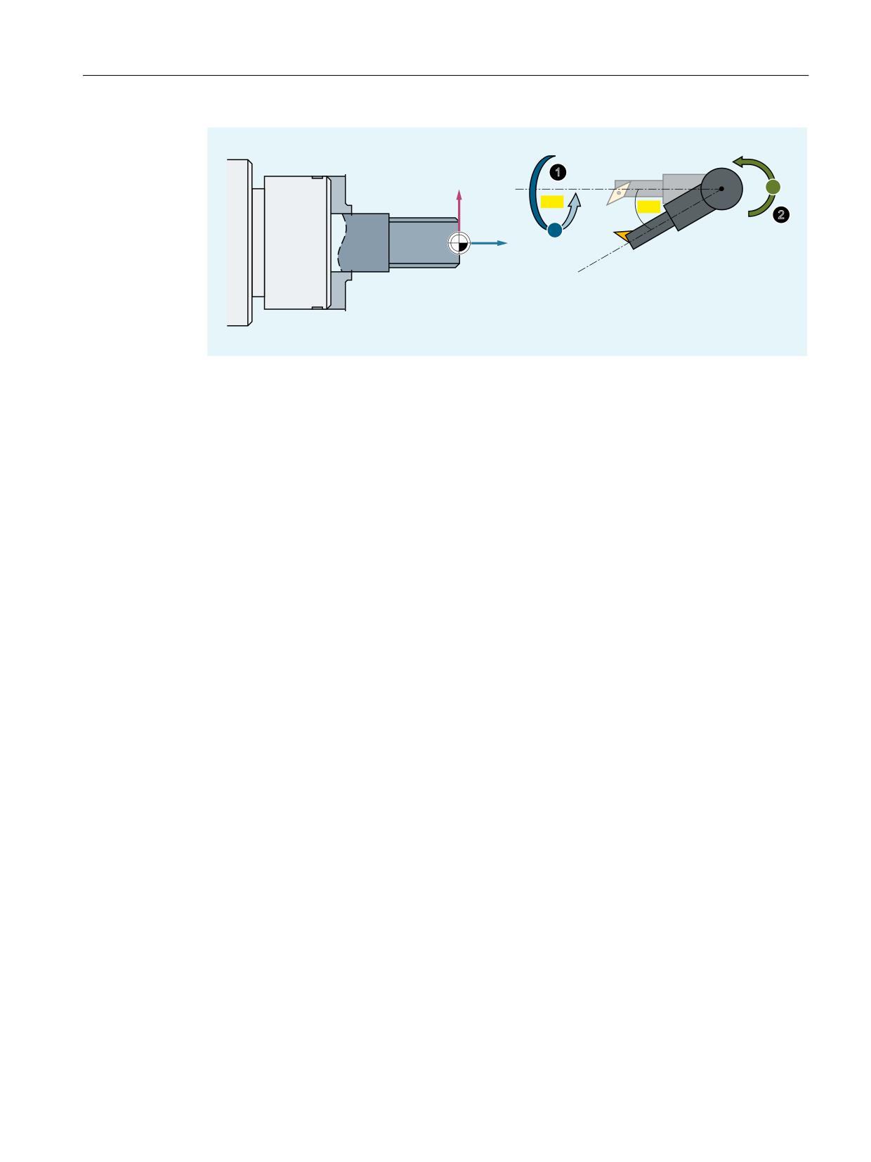
The two machine-independent orientation angles β (Beta) and γ (Gamma) are used to define the
tool rotation. β is the angle of rotation and the applicate (typically a B axis in G18) and γ a rotation
around the abscissa (Typically a C axis in G18). The rotation is first executed around Y, finally
around β. I.e., the γ axis is rotated by the β axis:
Tools
140
Function Manual, 10/2020, 6FC5397-6GP40-0BA1
Tool offset
3.9 Modification of the offset data for rotatable tools
;
%
ˠ
˟
&
=
① Rotation around the abscissa
② Rotation around the applicate
Figure 3-39
Tool rotation
Commissioning
The function is commissioned using the machine and setting data.
See Chapter "Commissioning (Page 149)".
Activation
Modification of the offset data for rotatable tools is activated in the NC program with the
language commands CUTMOD (in combination with tool carriers with orientation capability) or
CUTMODK (for orientation transformations that were defined with kinematic chains).
See Chapter "Activating the modification of the offset data for rotatable tools (CUTMOD,
CUTMODK) (Page 160)".
Results
When the function and tool rotation are active, the modified data are made available in system
variables and OPI variables.
See Chapter "Activating the modification of the offset data for rotatable tools (CUTMOD,
CUTMODK) (Page 160)".
3.9.2
Rotating turning tools
3.9.2.1
Cutting edge position, cut direction, and angle for turning tools
Turning tools
Turning tools means the following tools whose tool type ($TC_DP1) has values in the range of
500 to 599. Grinding tools (tool types 400 to 499) are equivalent to turning tools.
Tools
Function Manual, 10/2020, 6FC5397-6GP40-0BA1
141
Tool offset
3.9 Modification of the offset data for rotatable tools
Tools are treated independently of tool type such as turning tools if:
SD42950 $SC_TOOL_LENGTH_TYPE = 2
Cutting edge position and cut direction
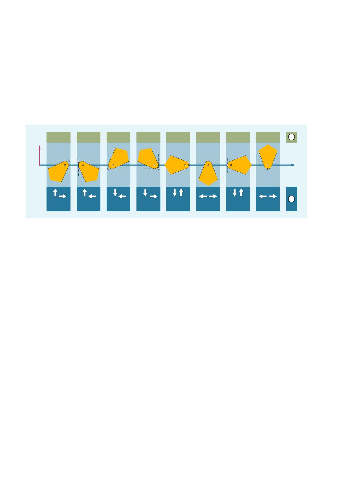
Turning tools are limited by their main and secondary cutting edges. The cutting edge position is
defined via the position of the primary and secondary cutting edges relative to the coordinate
axes. Two different cutting directions can be assigned to each cutting edge position.
;
=
①
Cutting edge position (1 - 8)
②
Cutting directions (1 - 4) assigned to the cutting edge position
Figure 3-40
Cutting edge position and cut direction
Cutting edge position
For cutting edge position 1 - 4, the primary and secondary cutting edge are in the same
quadrant.
For a cutting edge position of 5 - 8, the primary and secondary cutting edge are in adjacent
quadrants or there is a coordinate axis between the two cutting edges.
The cutting edge position is stored in the tool parameter $TC_DP2.
Cut direction
The cut directions 1 - 4 denote a positive or negative direction of the coordinate axes:
•
1: Ordinate -
•
2: Ordinate +
•
3: Abscissa -
•
4: Abscissa +
The cut direction is stored in the tool parameter $TC_DP11.
Tools
142
Function Manual, 10/2020, 6FC5397-6GP40-0BA1
Tool offset
3.9 Modification of the offset data for rotatable tools
Holder angle and clearance angle
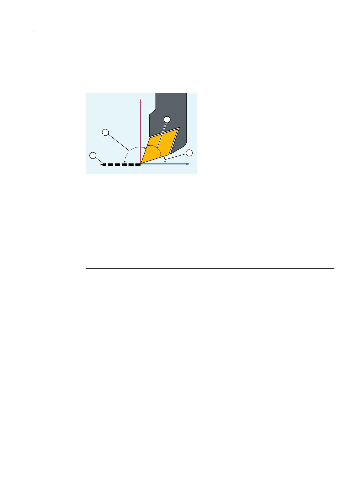
The following figure shows the holder angle and clearance angle for a rotary tool with cutting
edge position 3. The machining plane is G18 (Z/X). The cut direction is 3 (negative Z or abscissa
direction).
;
=
① Holder angle
② Wedge or plate angle = 180° - holder angle - clearance angle
③ Clearance angle
④ Cut direction
Figure 3-41
Angle and cut direction for a turning tool
Cut direction
The cut direction specifies the reference direction of the holder angle. The clearance angle is the
angle measured between the inverse cut direction and the adjacent cutting edge (positive).
Holder angle and clearance angle are stored in the tool parameters $TC_DP10 or $TC_DP24.
Note
Cut direction and tool angle are relevant only in the cutting edge positions 1 - 8.
Tools
Function Manual, 10/2020, 6FC5397-6GP40-0BA1
143
Tool offset
3.9 Modification of the offset data for rotatable tools
3.9.2.2
Modifications during the rotation of turning tools
Description of tool orientation
Unlike milling tools, turning tools are not rotation-symmetric. This means that normally 3
degrees of freedom or three rotary axes are required to describe the tool orientation. The
concrete kinematics therefore, is independent of the machine only to the extent the desired
orientation can be set. If necessary, the third degree of freedom can be substituted by a rotation
of the tool coordinate system.
Note
The division of the orientation into one component created by the tool carrier with orientation
capability and a second component achieved via a rotation of the coordinate system is the
responsibility of the application. The control does not provide any further functionality in this
regard.
If the tool is oriented using a kinematic transformation, the user can use function ORISOLH to
calculate the orientation. (see Chapter "Calculating orientations (ORISOLH) (Page 152)").
Angle between tool insert and machining plane
If a turning tool turns by an angle against the machining plane (i.e. around an axis in the
machining plane, typically a C axis) that is not a multiple of 180°, then the configuration of the
(circular) tool cutting edge in the machining plane becomes an ellipse. It is assumed that the
deviations from the circular form arising on account of such rotations is so insignificant that they
can be ignored (tilt angle < 5°). i.e. the control always ignores the tool orientation and assumes
a circular cutting edge.
This also means that with reference to the active plane, the control accepts only a rotation by
180° as a setting deviating from the initial position. This limitation is valid for the shape of
cutting edge only. The tool lengths are always considered correctly in random spatial rotations.
A rotation by 180° around an axis in the machining plane means that while using the tool at the
same position, the spindle rotation direction with reference to the use of the unturned tool must
be inverted.
A maximum value allowed for the angle between the tool insert and the machining plane can be
specified in setting data SD42998 $SC_CUTMOD_PLANE_TOL (see also Chapter "Parameter
assignment (Page 149)").
Cutting edge position, cutting direction, and tool angle
Cutting edge position and cut direction are also not modified like the cutting edge reference
point (see below) if the tool is rotated from the plane by ± 90° (with a tolerance of app. 1°)
because then the configuration of the cutting edge is not defined in the current plane.
If a transformation is active, the active complete frame is always included in the calculation of
the actual tool rotation relative to the workpiece. If a tool carrier with orientation capability is
active, the frame is only included in the calculation if bit 21 is set in machine data MD20360
$MC_TOOL_PARAMETER_DEF_MASK (Page 149). In this case, any table component of the tool
Tools
144
Function Manual, 10/2020, 6FC5397-6GP40-0BA1
Tool offset
3.9 Modification of the offset data for rotatable tools
carrier is no longer treated separately because it must be assumed that this frame component
is already included in the complete frame (system frame PAROT).
When orientation transformation is active, bit 17 of machine data MD20360
$MC_TOOL_PARAMETER_DEF_MASK can be used, should the cutting edge no longer be in the
active machining plane, either to project the cutting edge into the machine plane (bit 17 = 0) or
alternatively to rotate the cutting edge into the machining plane (bit 17 = 1) in order to calculate
the modified cutting data.
Note
MD20360, bit 17
If this bit is set, it is the responsibility of the user to ensure, using an additional frame or by
changing the orientation, to ensure that the geometric conditions during machining match
those that exist during calculation.
If bit 20 of machine data MD20360 $MC_TOOL_PARAMETER_DEF_MASK is set to value "0",
standard values that deviate from zero can be used to calculate the modified cutting edge
position and the modified cutting direction for when the cutting edge parameters for the holder
angle and cutting direction ($TC_DP10 or $TC_DP24) have value 0. The following rules apply:
• A holder angle of 0° has the same effect as an angle of 112.5° on cutting edge positions 1 to
4.
• A holder angle of 0° has the same effect as an angle of 67.5° on cutting edge positions 5 to
8.
• A clearance angle of 0° has the same effect as an angle of 22.5° on cutting edge positions 1
to 4.
• A clearance angle of 0° has the same effect as an angle of 67.5° on cutting edge positions 5
to 8.
The holder angle and clearance angle might only be temporarily mapped onto the standard
values specified above to be able to calculate the modified cutting edge position and modified
cutting direction. I.e., reading system variables $TC_DP10 or $TC_DP24 still returns value "0".
If the tool rotates in the plane (rotation around an axis vertical to the machining place or around
the Y axis for G18), the cutting edge position is determined from the resulting angle for the
clearance and holder angles. If these two angles are not specified for the tool (i.e. $TC_DP10 and
$TC_DP24 are both zero), the new cutting edge position is determined just from the turning
angle. A special feature here is that the cutting edge position only changes in steps of 90°. I.e.
the cutting edge position remains independent of the initial state either in the value range 1 to
4 or 5 to 8. The new cutting edge position is then determined exclusively from the angle of
rotation if the specified values for holder angle and clearance angle are impermissible (negative
values, resulting tool insert angle negative or greater than 90°). Impermissible angles can be set
to output an alarm (see MD20125 $MC_CUTMOD_ERR (Page 149)). Clearance angle and holder
angle are not modified in all these cases.
Depending on the rotation, the cut direction is modified in such a way that the resulting
clearance angle remains less than 90°. If the original cut direction and the original cutting edge
position do not match, then the cut direction is not modified during rotation of the tool. This
situation can be set to output an alarm (see MD20125 $MC_CUTMOD_ERR).
The angle of rotation in the plane, as it was determined from the tool carrier with orientation
capability or from the active kinematic transformation, is provided in the OPI variables
Tools
Function Manual, 10/2020, 6FC5397-6GP40-0BA1
145
Tool offset
3.9 Modification of the offset data for rotatable tools
pTCutMod or ptCut- ModS and in system variables $P_CUTMOD_ANG or $AC_CUTMOD_ANG.
This angle is the original angle without any final rounding to multiples of 45° or 90°.
Limit cases
If, for a turning tool, the cutting edge position, cut direction, clearance and holder angles have
valid values so that all cutting edge positions (1 to 8) are possible through suitable rotations in
the plane, then the cutting edge positions 1 to 4 are preferred to cutting edge positions 5 to 8
in the cases in which one of the cutting edges (main or secondary cutting edge) is away from the
coordinate axis by less than half the input increment (0.0005° for an input specification of 3
decimal digits).
The following is applicable in all other cases (milling tools or turning tools without valid cutting
edge parameters) in which rotation is possible only in 90° steps: If the amount of the rotation
angle is smaller than 45° + 0.5 input increments (corresponds to 45.0005° for an input
specification of 3 decimal places), the cutting edge position and cut direction are not changed.
I.e. these cases are treated as rotations that are smaller than 45°. Rotations, the amount of which
deviates from 180° by less than 45° + 0.5 input increments are treated identically as rotations in
the range of 135° to 225°.
Cutting edge reference point
The cutting edge center point and the cutting edge reference point are defined for turning tools.
The position of these two points relative to each other is defined by the cutting edge position.
The distance of the two points for cutting edge positions 1 to 4 is equal to √2 times the cutting
edge radius; for cutting edge positions 5 to 8 it is equal to 1 times the cutting edge radius. In the
first case, the cutting edge reference point relative to the cutting edge center point lies in the
machining plane on a bisecting line, while in the second case it lies on a coordinate axis.
If your rotate the tool by a random angle around an axis vertical to the machining plane, the the
cutting edge reference point would also rotate if it had a fixed position relative to the tool. The
above-mentioned condition (position on an axis or a bisecting axis) is not fulfilled in most cases.
This is not desirable. Instead, the cutting edge reference point should always be modified in such
a way that the distance vector between cutting edge reference point and cutting edge center
point has one of the mentioned 8 directions. The cutting edge position must be modified for this
if necessary.
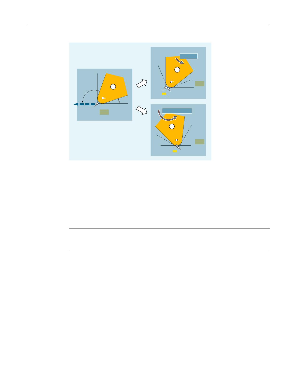
The ratios are shown with examples in the figure below:
Tools
146
Function Manual, 10/2020, 6FC5397-6GP40-0BA1
Tool offset
3.9 Modification of the offset data for rotatable tools
˟ื
r
6
6/
3
QHZ
3ROG
r
6
r
3
6/
˟ื
r
6
6/
3QHZ
3ROG
S:
Cutting edge center point
P:
Cutting edge reference point
SL:
Cutting edge position
① Tool with cutting edge position 3, clearance angle 22.5°, and holder angle 112.5°
② For rotations of the tool up to 22.5°, the cutting edge position is maintained, the position of the
cutting edge reference point relative to the tool however, is compensated in such a way that the
relative position of both points is maintained in the machining plane.
③ For bigger tool rotations (up to 67.5°), the cutting edge position changes to value 8.
Figure 3-42
Cutting edge reference point and cutting edge position for tool rotation
Note
As the cutting edge reference point is defined by the tool length vector, modifying the cutting
edge reference point changes the effective tool length.
Tool rotation
The rotation of the tool tip and the tool adapter is described by tool parameter $TC_DPROT. This
parameter (angle) is only practical for tools that do not rotate symmetrically (e.g. turning tools,
boring bars). Rotation is performed around the direction that is defined by the vector product of
tool normal vector and tool orientation vector. For an active tool, this vector can be read with
system variable $P_TOOLBIN. For standard turning tools, this vector points toward the Z axis for
G18. I.e. it turns around the axis around which angle γ also turns.
Tools
Function Manual, 10/2020, 6FC5397-6GP40-0BA1
147

Tool offset
3.9 Modification of the offset data for rotatable tools
3.9.3
Rotation of milling and drilling tools
3.9.3.1
Cutting edge position for milling and tapping tools
Milling and drilling tools
Milling and drilling tools means the following tools whose tool type ($TC_DP1) has values in the
range of 100 to 299.
Tools are treated independently of tool type such as milling and tapping tools if:
SD42950 $SC_TOOL_LENGTH_TYPE = 1
Cutting edge position
A cutting edge position which is modified accordingly has also been introduced for the milling
and tapping tools defined as specified above (see Chapter "Modifications during rotation of
milling and tapping tools (Page 149)").
Note
A cutting edge position that is declared for tools that are not milling or tapping tools, or turning
tools according to the definitions stated above, is not evaluated.
The cutting edge position of the tapping and milling tools is stored in tool parameter $TC_DP2
as in the case of turning tools. Based on the definition of the cutting edge position for turning
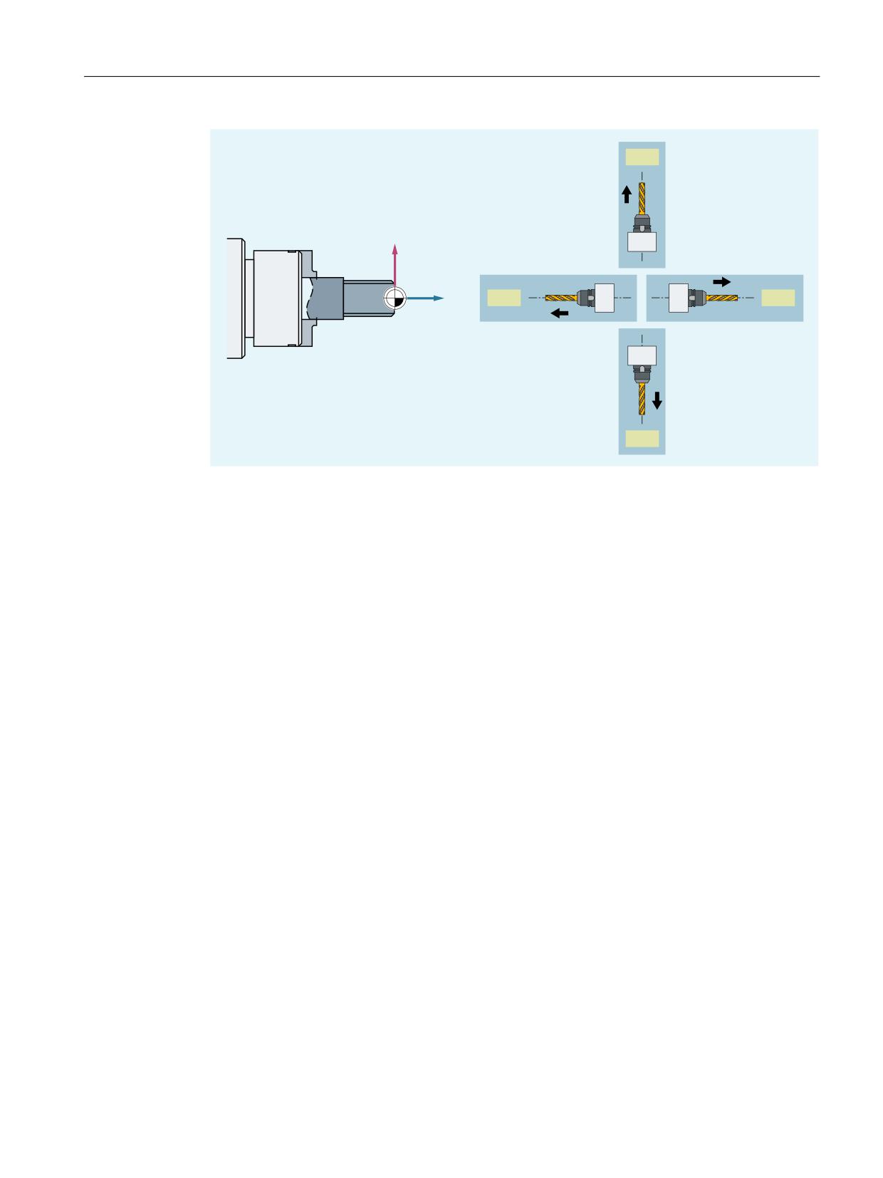
tools, this parameter can assume the values 5 to 8. Here, the cutting edge position specifies the
orientation (the direction of the rotation axis) of the tool:
Cutting edge position
Direction of rotation axis of tool
5
Abscissa +
6
Ordinate +
7
Abscissa -
8
Ordinate -
Tools
148
Function Manual, 10/2020, 6FC5397-6GP40-0BA1
Tool offset
3.9 Modification of the offset data for rotatable tools
6/
;
6/
6/
=
6/
Figure 3-43
Cutting edge position 5 - 8 of a milling tool
3.9.3.2
Modifications during rotation of milling and tapping tools
The cutting edge position is recalculated appropriately during a rotation of a milling or tapping
tool. Cut direction and tool angle (clearance angle or holder angle) are not defined for milling
and tapping tools so that the change in cutting edge position is derived exclusively from the
rotation. Thus, for milling and tapping tools, the cutting edge position always changes when the
amount of rotation with reference to the zero setting is more than 45°.
3.9.4
Commissioning
3.9.4.1
Parameter assignment
Response in the event of an error
Different fault conditions can occur during the activation of the function "Modification of the
offset data for rotatable tools" (by an explicit call in the part program or by tool selection). For
errors with error numbers < 100 (see Diagnostics Manual), it is possible to define whether the
error will trigger output of an alarm and, if so, whether such an alarm will only be displayed or
will also trigger program stop. The setting is made in the following machine data:
MD20125 $MC_CUTMOD_ERR
Tools
Function Manual, 10/2020, 6FC5397-6GP40-0BA1
149

Tool offset
3.9 Modification of the offset data for rotatable tools
Two bits of the machine data are assigned to each fault condition:
Fault status
Bit
Meaning
No valid cutting direction is defined for the active tool.
0
Alarm output
1
Program stop
The cutting edge angle (clearance angle and holder angle) of the
2
Alarm output
active tool are both zero.
3
Program stop
The clearance angle of the active tool has an impermissible value
4
Alarm output
(< 0° or > 180°).
5
Program stop
The holder angle of the active tool has an impermissible value
6
Alarm output
(< 0° or > 90°).
7
Program stop
The tool insert angle of the active tool has an impermissible value
8
Alarm output
(< 0° or > 90°).
9
Program stop
The cutting edge position - holder angle combination of the active tool
10
Alarm output
is not permitted. (The holder angle must be ≤ 90° for cutting edge
11
Program stop
position 1 to 4; for cutting edge positions 5 to 8 it must be ≥ 90°.)
The tool insert is not in the machining plane and angle γ between the
12
Alarm output
tool insert and the machining plane exceeds the upper limit specified
13
Program stop
with setting data SD42998 $SC_CUTMOD_PLANE_TOL.
The tool insert is not in the machining plane. The magnitude of an-
14
Alarm output
gle α is greater than 1°. Angle α is the angle of rotation around the
15
Program stop
coordinate axis, which is perpendicular both to the axis of rotation of
angle β and to the axis of rotation of angle γ (in the case of G18, the
X axis).
Note
The 2nd bit (program stop) is only effective if the corresponding 1st bit (alarm output) is set.
Note
Errors with error numbers ≥ 100 always result in an alarm being output and program stop.
Initialization value for CUTMOD
The function that can be programmed with NC command CUTMOD (Page 152) is automatically
initialized with the following value after a warm restart:
MD20127 $MC_CUTMOD_INIT = <initialization value for CUTMOD>
Default value: 0
If MD20127 = -2, the value from the following machine data becomes the initialization value:
MD20126 $MC_TOOL_CARRIER_RESET_VALUE (active tool carrier on reset)
Function-specific tool settings
The following machine data is a bit string with which various functions relating to tools can be
controlled:
Tools
150
Function Manual, 10/2020, 6FC5397-6GP40-0BA1

Tool offset
3.9 Modification of the offset data for rotatable tools
MD20360 $MC_TOOL_PARAMETER_DEF_MASK
The following bits are relevant for function "Modification of the offset data for rotatable tools".
Bit
Meaning
17
Bit 17 is used to set whether, on modification of the offset data for turning and grinding tools, the
cutting edge plane for calculating the offset values will be projected into the machining plane or
rotated.
= 0
The cutting edge plane is projected into the machining plane.
= 1
The cutting edge plane is rotated into the machining plane.
Note:
Bit 17 is only evaluated if the function is active in combination with a kinematic orientation
transformation.
18
Bit 18 is used to determine how the plane is defined for modification of offset data for turning and
grinding tools.
= 0
Priority is given to defining the plane with setting data SD42940
$SC_TOOL_LENGTH_CONST over defining the plane with the G commands of G Group
6 (plane selection G17 - G19).
= 1
The active plane (G17 - G19) is always used.
20
If tool parameters $TC_DP10 (holder angle) and/or $TC_DP24 (clearance angle) have the value
"0", default values deviating from "0" can be used to calculate the modified cutting edge position
and the modified cutting direction.
= 0
The following default values are used:
• Holder angle 112.5° for cutting edge positions 1 - 4
• Holder angle 67.5° for cutting edge positions 5 - 8
• Clearance angle 22.5° for cutting edge positions 1 - 4
• Clearance angle 67.5° for cutting edge positions 5 - 8
= 1
An alarm is output.
Note:
Bit 20 is used to establish compatibility with older software versions.
21
Bit 21 is used to set whether the active total frame will be taken into account in the modification
of the offset data when tool carrier with orientation capability is active.
= 0
Rotation of the table component of the tool carrier is taken into account. Frames are
ignored.
= 1
Instead of the table component of the tool carrier, the active total frame is used. The
total frame can also contain a table component of the tool carrier.
Difference between tool tip plane and machining plane for CUTMOD or CUTMODK
The maximum permissible angle through which the tool insert can be turned away from the
machining plane (standard G18) when function CUTMOD or CUTMODK (Page 160) is called (≙
maximum permissible deviation of γ from one of the two standard positions 0° or 180°) is set in
the setting data:
SD42998 $SC_CUTMOD_PLANE_TOL
Example:
Tools
Function Manual, 10/2020, 6FC5397-6GP40-0BA1
151
Tool offset
3.9 Modification of the offset data for rotatable tools
SD42998 = 5.0 ⇒ The tool insert must not be turned by more than 5° away from the machining
plane.
Note
SD42998 = 0
If SD42998 $SC_CUTMOD_PLANE_TOL is set to "0", variations of up to 89° are permissible!
Difference between tool tip plane and machining plane for ORISOLH
The maximum permissible angle through which the tool insert can be turned away from the
machining plane when function ORISOLH (Page 160) is called is set in the setting data:
SD42999 $SC_ORISOLH_INCLINE_TOL
3.9.5
Programming
3.9.5.1
Calculating orientations (ORISOLH)
The predefined ORISOLH function helps the user to set the rotary axis positions of a machine so
that a turning tool can be brought into a defined, kinematic-independent position relative to the
workpiece. Prerequisite is that a 6-axis transformation is active that has been parameterized
with kinematic chains.
Two basic functions are available:
• Tool alignment
The β and γ angles are specified. The function calculates the angles of the three orientation
axes required for this.
• Direct tool alignment
The angles of the second and third orientation axes are specified. The function calculates the
associated β and γ angles as well as that of the missing first orientation axis.
Note
Order of the orientation axes
If you run through the kinematic chain that describes the structure of the machine, from the
workpiece to the tool, then the following specifications apply for the order of the three
orientation axes of a 6-axis transformation:
• The orientation axis that is closest to the workpiece is the first orientation axis.
• The orientation axis that is closest to the tool is the third orientation axis.
Generally, the first orientation axis is a spindle and the corresponding rotation is therefore
implemented in these cases through a rotating frame.
Tools
152
Function Manual, 10/2020, 6FC5397-6GP40-0BA1

Tool offset
3.9 Modification of the offset data for rotatable tools
Syntax
<RetVal> = ORISOLH(<Cntrl>,<W1>,<W2>)
Meaning
ORISOLH:
Function call
<RetVal>:
Function return value
Data type:
INT
Range of values:
0, -2, -3, ..., -17
Values:
0
Function has ended without an error.
-2
No valid transformation (6-axis orientation transformation) is
active.
-3
The first parameter (<Cntrl>) is negative.
-4
The unit position of the first parameter (<Cntrl>) is invalid.
Only the values 0 and 1 are permissible.
-5
The tens position of the first parameter (<Cntrl>) is invalid.
Only the values 0 to 3 are permissible.
-6
The hundreds position of the first parameter (<Cntrl>) is inva-
lid.
Only the values 0 and 1 are permissible.
-7
The thousands position of the first parameter (<Cntrl>) is in-
valid.
Only the values 0 to 3 are permissible.
-8
Angle γ is too large for the "Direct tool alignment" function.
-9
At least one of the specified axis positions violates an axis limit
for the "Direct tool alignment" function.
-10
No tool is active.
-11
The requested orientation cannot be set.
-12
The adaptation of the free axis angle for the Hirth joint is not
possible for the first or only solution.
-13
The adaptation of the free axis angle for the Hirth joint is not
possible for the second solution.
-14
The adaptation of the free axis angle for the Hirth joint is not
possible for either of the two solutions.
-15
The first orientation axis is parameterized as Hirth axis.
-16
The second as well as the third rotary axis has been parame-
terized as Hirth axis. Only one of the two axes can be the Hirth
axis.
-17
At least one of the specified axis positions is not compatible
with the associated Hirth joint for the "Swivel directly" func-
tion.
Tools
Function Manual, 10/2020, 6FC5397-6GP40-0BA1
153
Tool offset
3.9 Modification of the offset data for rotatable tools
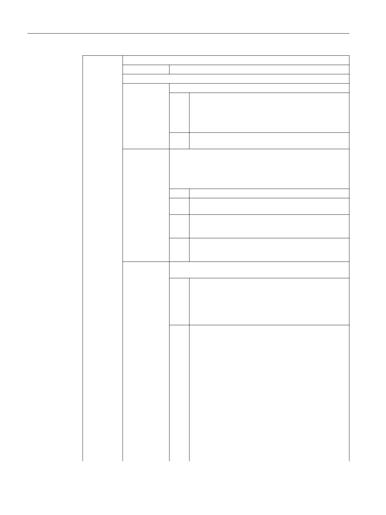
<Cntrl>:
Controls the behavior of the function
Data type:
INT
The <Cntrl> parameter is decimal coded (unit to thousands position):
Unit position:
The unit position controls the response to errors.
xxx0
In the event of an error (return value < 0), alarm 14106 is
output and program processing is aborted.
Note:
The alarm is also output irrespective of the value of the unit
position when the <Cntrl> parameter is negative.
xxx1
In the event of an error (return value < 0) no alarm is output.
The user can react suitably in the program.
Tens position:
Controls the behavior when an orientation axis with Hirth joint is
present.
Note:
This parameter is only evaluated for the "Tool alignment" function (i.e.
when the hundreds position has the value "0").
xx0x
The axis position is rounded off to the nearest position.
xx1x
The axis positions are rounded off so that the difference of
the β angle to its programmed value is minimal.
xx2x
The axis positions are rounded off so that the β angle is equal
to the highest possible value which is less than the program-
med value (β is rounded down).
xx3x
The axis positions are rounded off so that the β angle is equal
to the lowest possible value which is greater than the pro-
grammed value (β is rounded up).
Hundreds posi-
Specifies which function is to be executed or the significance of the
tion:
two following parameters <W1> and <W2>.
x0xx
"Tool alignment" function
Parameters <W1> and <W2> have the following meaning:
• <W1> = β
• <W2> = γ
The associated angles of the orientation axes are calculated.
x1xx
"Direct tool alignment" function
<W1> is the position specification for the second orientation
axis, <W2> is the position specification for the third orienta-
tion axis of a 6-axis transformation. The position of the first
orientation axis and the β and γ angles are defined which are
compatible with the two position specifications.
If no error occurs, two solutions are always output in the
$P_ORI_POS[<n>, <m>] system variables. The first index <n>
(0 or 1) refers to the solution and the second index <m>
(0 ... 2) to the orientation axis:
• $P_ORI_POS[0/1, 0]: Position of the first orientation axis
• $P_ORI_POS[0/1, 1]: Angle β
• $P_ORI_POS[0/1, 2]: Angle γ
A check is made as to whether the position specifications
<W1> and <W2> are compatible with any Hirth joints or active
software limits. If this is not the case, a corresponding error
number is returned (see <RetVal> parameter).
Tools
154
Function Manual, 10/2020, 6FC5397-6GP40-0BA1

Tool offset
3.9 Modification of the offset data for rotatable tools
If the angles <W1> and <W2> are selected arbitrarily, the cut-
ting edge of the tool is generally not in the machining plane.
The angle γ through which the cutting edge is rotated out of
the machining plane, must not be greater than the limit value
which is defined by the setting data SD42999 $SC_ORI-
SOLH_INCLINE_TOL.
Thousands posi-
Specifies which positions of the solutions may be modified when the
tion:
hundreds position has the value "0", i.e. for the "Tool alignment" func-
tion.
0xxx
The calculated axis positions should be as close as possible to
the current machine axis positions.
1xxx
The calculated axis positions for modulo axes should be as
close as possible to the middle of the modulo range, for other
axes as close as possible to 0. For non-modulo axes, this
means that the axis positions are reduced to the range
-180° … +180°.
2xxx
The calculated axis positions should be reduced to the range
-180° … +180° irrespective of the axis type.
<W1>:
First angle
The meaning results from the hundreds position of the <Cntrl> paramter.
Data type:
REAL
<W1>:
Second angle
The meaning results from the hundreds position of the <Cntrl> paramter.
Data type:
REAL
Note
Parameters that have not been programmed have the default value "0".
Tools
Function Manual, 10/2020, 6FC5397-6GP40-0BA1
155

Tool offset
3.9 Modification of the offset data for rotatable tools
Further information
The number of solutions found together with further status information when executing the
ORISOLH function, can be read via the following system variables:
System variable
Meaning
$P_ORI_POS
Returns the angles of the orientation axes that result from the orientation program-
[<n>, <m>]
ming.
<n>:
Index of the solution
Range of values:
0, 1
<m>:
Index of the orientation axis
Range of values:
0 ... 2
The order of the orientation axes (1 ... 3) refers to the
definition of the axes in $NT_ROT_AX_NAME.
When the ORISOLH function is called in the "Direct tool alignment" mode, the
$P_ORI_POS[0/1, 1] and P_ORI_POS[0/1, 2] variables contain the values of the two
angles β and γ belonging to the two solutions.
The first solution entered in $P_ORI_POS[<n>, <m>], i.e. with the index <n> = 0, is
always the solution that is selected by the control when the requested orientation is
approached directly. The second index <m> refers to the orientation axis, i.e. on
$NT_ROT_AX_NAME.
The axis positions entered in $P_ORI_POS[<n>, <m>] take into account the offsets
entered in $NK_OFF and $NK_OFF_FINE, i.e. these axis angles can be used in the
following blocks to set the required orientation without any further modification.
If a rotary axis is a Hirth axis, the solution positions are rounded off to the nearest
position of rest of the Hirth joint. For Hirth jointed rotary axes, you can read the
differences between the axis positions for the exact solutions and those of the solu-
tions adapted to the Hirth incrementing in the $P_ORI_DIFF system variable.
$P_ORI_DIFF
Returns the difference between the exact positions of the orientation axes and those
[<n>, <m>]
provided in $P_ORI_POS that result from the orientation programming.
<n>:
Index of the solution
Range of values:
0, 1
<m>:
Index of the orientation axis
Range of values:
0 ... 2
The order of the orientation axes (1 ... 3) refers to the
definition of the axes in $NT_ROT_AX_NAME.
The content can only be not equal to zero when the positions are incremented (Hirth
joint), i.e. when the system data $NT_HIRTH_INCR of the relevant axis is not equal to
zero and when this axis is a manual rotary axis.
Tools
156
Function Manual, 10/2020, 6FC5397-6GP40-0BA1
Tool offset
3.9 Modification of the offset data for rotatable tools
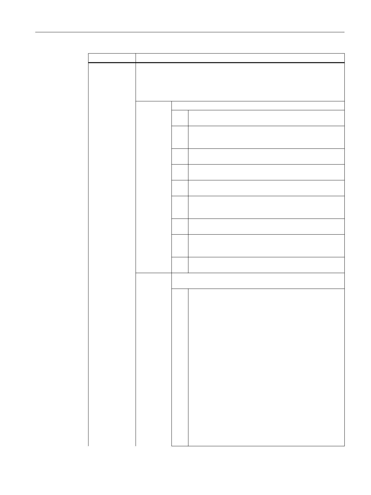
System variable
Meaning
$P_ORI_SOL
If for an orientation transformation with more than one orientation axis, the axis
angles are calculated that should result in a specified orientation, there is generally
more than one solution. The $P_ORI_SOL system variables contain the number of
valid solutions together with additional status information.
The content of $P_ORI_SOL is coded as follows:
Values < 0
General error states
-1
No solutions have been calculated yet for the active transfor-
mation (missing call of ORISOLH).
-2
A transformation is not active, or the active transformation is
not an orientation transformation (6-axis transformation) that
can provide positions for a specified orientation programming.
-4
The desired orientation cannot be set with the present kine-
matics.
-5
No solution was found when the ORISOLH function was called
in the "Direct tool alignment" mode.
-6
Angle γ is too large when the ORISOLH function was called in
the "Direct tool alignment" mode.
-7
An angle was specified when the ORISOLH function was called
in the "Direct tool alignment" mode that cannot be set because
of the Hirth joint.
-8
The first orientation axis (frame axis) must not be parameter-
ized as Hirth axis.
-9
The second as well as the third rotary axis has been parame-
terized as Hirth axis. Only one of the two axes can be the Hirth
axis.
-10
No adaptation of the solution(s) to the Hirth joint has been
found.
Values > 0
Number of mathematically possible solutions without consideration
of axis limits and any error conditions.
Unit position
0
There is no solution, i.e. the requested orientation cannot be
set.
There can be three different causes for this case:
• In principle, the requested orientation cannot be achieved
because of the machine kinematics (orientation axes not
arranged at right angles) even with an arbitrary traversing
range of the orientation axes. In this case, the tens and
hundreds positions of $P_ORI_SOL are both zero, the
$P_ORI_STAT status variables assigned to the orientation
axis have the value "-4".
• The calculated solutions cannot be achieved because they
would violate the axis limits. The positions of the orienta-
tion axes that would result without the axis limits, can be
read in $P_ORI_POS.
• Axis positions were specified when the ORISOLH function
was called in the "Direct tool alignment" mode which would
result in either the orientation vector or the orientation
normal vector of the tool being aligned parallel to the first
orientation axis, whose position is to be calculated. The
position of this axis is not defined in these cases.
Tools
Function Manual, 10/2020, 6FC5397-6GP40-0BA1
157
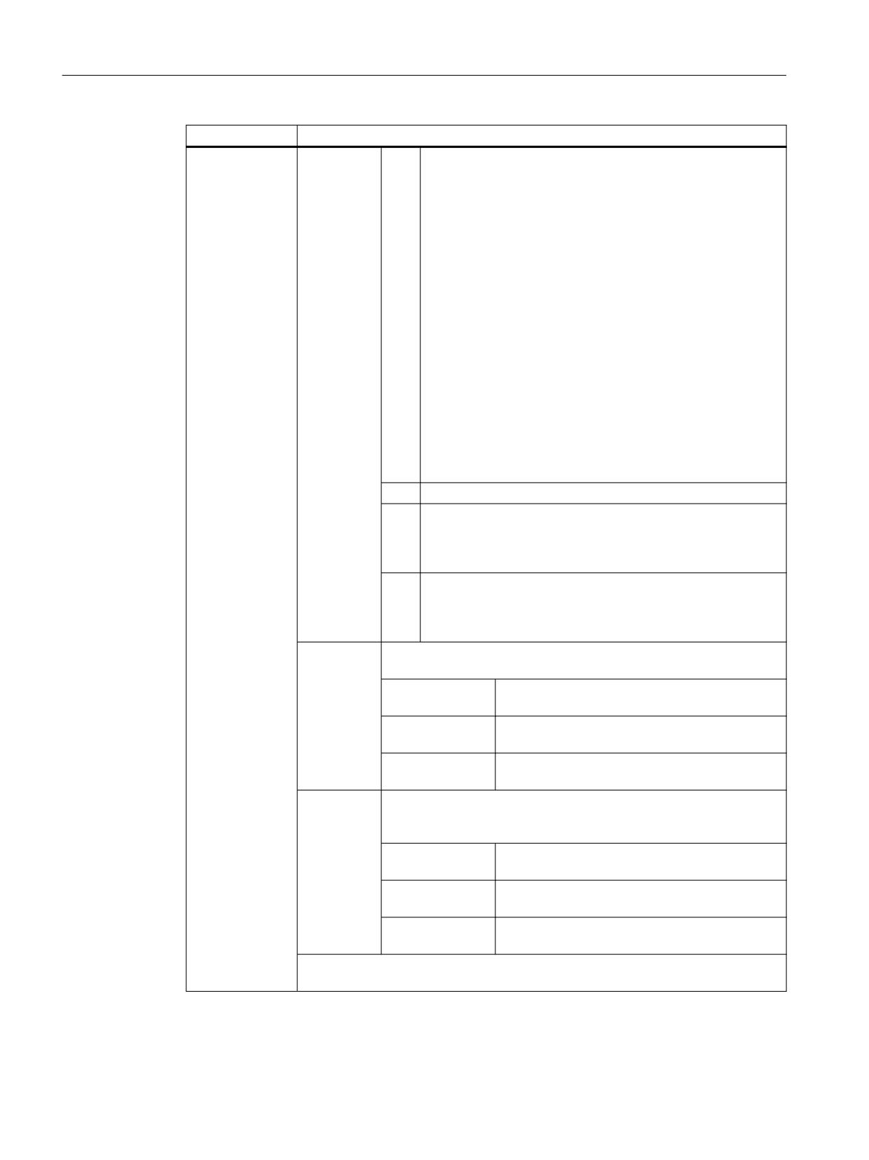
Tool offset
3.9 Modification of the offset data for rotatable tools
System variable
Meaning
1
There is a solution.
There can be three different causes for this case:
• Based on the specified orientation and the machine kine-
matics, there is only one solution (from the mathematical
point of view, two coinciding solutions) even without con-
sideration of the axis limits. This case occurs at the edge of
the orientation range for kinematics that are not at right
angles. $P_ORI_POS contains both (identical) solutions.
• There is only one solution because a second solution is in-
valid due to the violated axis limits. The valid solution is
always the first solution in $P_ORI_POS. The second solu-
tion which would result when the axis limits are not taken
into account, can also be read in $P_ORI_POS.
• This is the normal case when the ORISOLH function is called
in the "Direct tool alignment" mode. For the specified axis
positions of two orientation axes, there is generally only
one valid position for the missing orientation axis to be
calculated.
2
There are two solutions.
8
There are an infinite number of solutions, i.e. the position of an
orientation axis (the polar axis) is arbitrary. However, from the
two possible positions of the other axes, one is excludes be-
cause of the violated axis limits.
9
There are an infinite number of solutions, i.e. the position of an
orientation axis (the polar axis) is indefinite. The indefinite axis
can be determined from the hundreds position or from the
$P_ORI_STAT system variable.
Values > 0
Bit-coded display for violated axis limits. The precise cause of the error
can be determined from the $P_ORI_STAT system variable.
Tens posi-
tion
Bit 0 (value 10):
For at least one solution, at least one axis limit of
the first orientation axis is violated.
Bit 1 (value 20):
For at least one solution, at least one axis limit of
the second orientation axis is violated.
Bit 2 (value 40):
For at least one solution, at least one axis limit of
the third orientation axis is violated.
Values > 0
Bit-coded display for non-defined axis positions (can only occur when
there is an infinite number of solutions, i.e. when the unit position is
Hundreds
equal to "9").
position
Bit 0 (value 100):
The position of the first orientation axis is not de-
fined.
Bit 1 (value 200):
The position of the second orientation axis is not
defined.
Bit 2 (value 400):
The position of the third orientation axis is not
defined.
The designations first, second and third orientation axis refer to the definition of the
axes in $NT_ROT_AX_NAME.
Tools
158
Function Manual, 10/2020, 6FC5397-6GP40-0BA1
Tool offset
3.9 Modification of the offset data for rotatable tools
System variable
Meaning
$P_ORI_STAT
Returns the status for each of the maximum three orientation axes after ORISOLH has
[<n>]
been called.
<n>:
Index of the orientation axis
(correspnds to the index of the relevant orientation axis in
$NT_ROT_AX_NAME)
Range of values:
0 ... 2
The order of the orientation axes (1 ... 3) refers to the
definition of the axes in $NT_ROT_AX_NAME.
The content of $P_ORI_STAT is coded as follows:
Values < 0
General error states
-1
The status is not defined (missing call of ORISOLH).
-2
A transformation is not active, or the active transformation is
not an orientation transformation (6-axis transformation) that
can provide positions for a specified orientation programming.
-3
The axis is not included in the active transformation.
-4
The position of the axis cannot be calculated because the re-
quested orientation cannot be achieved with the present kin-
ematics even with an arbitrary assumed traversing range of the
axis.
-5
Axis positions were specified when the ORISOLH function was
called in the "Direct tool alignment" mode which would result
in either the orientation vector or the orientation normal vector
of the tool being aligned parallel to the first orientation axis,
whose position is to be calculated. The position of this axis is
not defined in these cases.
-6
Angle γ is too large when the ORISOLH function was called in
the "Direct tool alignment" mode.
-7
An angle was specified when the ORISOLH function was called
in the "Direct tool alignment" mode that cannot be set because
of the Hirth joint.
-8
The first orientation axis (frame axis) must not be parameter-
ized as Hirth axis.
-9
The second as well as the third rotary axis has been parame-
terized as Hirth axis. Only one of the two axes can be the Hirth
axis.
-10
No adaptation of the solution(s) to the Hirth joint has been
found.
Values > 0
Bit-coded display for violated axis limits of the first solution.
Unit position
Bit 0 (value 1):
The first solution violates the lower axis limit.
Bit 1 (value 2):
The first solution violates the upper axis limit.
Values > 0
Bit-coded display for violated axis limits of the second solution.
Tens posi-
Bit 0 (value 10):
The second solution violates the lower axis limit.
tion
Bit 1 (value 20):
The second solution violates the upper axis limit.
Values > 0
Display of a non-defined axis position.
Hundreds
Bit 0 (value 100):
The position of the orientation axis is not defined,
position
i.e. the requested orientation is achieved with
each arbitrary setting of the rotary axis (polar po-
Tools
Function Manual, 10/2020, 6FC5397-6GP40-0BA1
159

Tool offset
3.9 Modification of the offset data for rotatable tools
System variable
Meaning
sition). This information is also contained in the
$P_ORI_SOL system variable.
Of the error numbers that indicate a violation of the axis limits, several can occur
simultaneously. When an axis limit is violated, an attempt is made to reach a position
within the permissible axis limits by adding or subtracting multiples of 360°. If this is
not possible, it is not clearly defined whether the lower or the upper axis limit has
been violated.
If there is no solution for the requested orientation ($P_ORI_SOL = 0), the status of
the orientation axes in the transformation is "0".
Note
$NT_ROT_AX_NAME
This system variable refers to a maximum of three axes used for setting the orientation. It
contains the names of the chain elements ($NK_NAME) that define the machine axes (rotary
axes) that must perform the orientation movements resulting from a kinematic transformation.
The order in which the maximum three rotary axes are contained in this system variable is
irrelevant for the machine kinematics because this is derived from the structure of the kinematic
chains. However, as it defines the order in which other variables access the rotary axes, the order
of the orientation axes in $NT_ROT_AX_NAME must match the kinematic description.
Note
Status information
The status information that shows, for example, that an orientation cannot be achieved or can
only be achieved when relevant axis limits are violated, does not trigger an NC alarm. It is the
responsibility of the user to react suitably to the specified conditions.
3.9.5.2
Activating the modification of the offset data for rotatable tools (CUTMOD,
CUTMODK)
The modification of the offset data for rotatable tools is activated in the NC program via the
CUTMOD (in combination with orientable tool carriers) or CUTMODK language command (for
orientation transformations that were defined by means of kinematic chains).
Note
As the orientable tool carriers and orientation transformations that were defined by means of
kinematic chains cannot be active at the same time, there are no conflicts between the two
variants.
Syntax
CUTMOD = <Value>
or
Tools
160
Function Manual, 10/2020, 6FC5397-6GP40-0BA1

Tool offset
3.9 Modification of the offset data for rotatable tools
CUTMODK = <Command>
Meaning
CUTMOD:
Function call in combination with orientable tool carriers
<Value>:
Assigned value
Data type:
INT
Value:
0
The function is deactivated.
The values supplied from system variables $P_AD... are the same as
the corresponding tool parameters.
> 0
The function is activated if an orientable tool carrier with the speci-
fied number is active, i.e. the activation is linked to a specific ori-
entable tool carrier.
The values supplied from system variables $P_AD... may be modi-
fied with respect to the corresponding tool parameters depending
on the active rotation.
The deactivation of the designated orientable tool carrier tempo-
rarily deactivates the function; the activation of another orientable
tool carrier permanently deactivates it. This is the reason why in the
first case, the function is re-activated when again selecting the
same orientable tool carrier; in the second case, a new selection is
required - even if at a subsequent time, the orientable tool carrier is
re-activated with the specified number.
The function is not influenced by a reset.
-1
The function is always activated if an orientable tool carrier is active.
When changing the tool carrier or when de-selecting it and a sub-
sequent new selection, CUTMOD does not have to be set again.
-2
The function is always activated if an orientable tool carrier is active
whose number is the same as the currently active orientable tool
carrier.
If an orientable tool carrier is not active, then this has the same
significance as CUTMOD=0.
If an orientable tool carrier is active, then this has the same signif-
icance as when directly specifying the actual tool carrier number.
< -2
Values less than 2 are ignored, i.e. this case is treated as if CUTMOD
was not programmed.
Note:
This value range should not be used as it is reserved for possible
subsequent expansions.
CUTMODK:
Function call in combination with orientation transformations that have been defined by
means of kinematic chains
Tools
Function Manual, 10/2020, 6FC5397-6GP40-0BA1
161

Tool offset
3.9 Modification of the offset data for rotatable tools
<Command>:
Assigned Command
Data type:
STRING
Value:
"NEW"
The states of an active transformation defined with kinematic
chains relevant for the "Modification of the offset data", the
name of the transformation and the current contour frame
are saved.
Note:
This command is only permissible when a suitable transfor-
mation (TRAORI_DYN, TRAORI_STAT or TRAANG_K) is active.
"OFF"
Switches the active "Modification of the offset data" off. The
data previously stored with "NEW" is retained.
Note:
This command is also permissible when CUTMODK is not ac-
tive. It then remains without effect. Any data set present for
the "Modification of the offset data" is retained.
"ON"
With this command, the "Modification of the offset data" is re-
activated with a data set previously stored with the "NEW"
command.
If a transformation with the name of the stored data set is
active when this command is executed, the "Modification of
the offset data" takes effect immediately. Otherwise, the ac-
tivation is delayed until an active transformation is activated.
"CLEAR"
As with the "OFF" command, switches the "Modification of
the offset data" off and also deletes the stored data set.
Note:
This command is also permissible when CUTMODK is not ac-
tive.
Note
SD42984 $SC_CUTDIRMOD
The CUTMOD or CUTMODK command replaces the function that can be activated using the
setting data SD42984 $SC_CUTDIRMOD. However, this function remains available unchanged.
However, as it doesn't make sense to use both functions in parallel, it can only be activated if
CUTMOD is equal to zero and CUTMODK is the zero string.
Further information
Reading modified offset data
The modified offset data is provided in the following system variables and OPI variables:
Meaning
System variable
OPI variable
Cutting edge position
$P_AD[2]
cuttEdgeParam2
Holder angle
$P_AD[10]
cuttEdgeParam10
Cut direction
$P_AD[11]
cuttEdgeParam11
Clearance angle
$P_AD[24]
cuttEdgeParam24
The data is always modified with respect to the corresponding tool parameters ($TC_DP2[..., ...]
etc.) when the "Modification of the offset data for rotatable tools" function was activated with
Tools
162
Function Manual, 10/2020, 6FC5397-6GP40-0BA1

Tool offset
3.9 Modification of the offset data for rotatable tools
the CUTMOD or CUTMODK command and the tool was rotated by an orientable tool carrier or a
suitable orientation transformation.
Further function-relevant system variables
System variable
Meaning
$P_CUTMOD_ANG /
Returns the angle through which a tool was rotated in the active machining
plane and the modified cutting edge data available for the CUTMOD and CUT-
$AC_CUTMOD_ANG
MODK functions.
$P_CUTMOD /
Reads the currently valid value that was last programmed with the CUTMOD
command (number of the tool carrier for which the modification of the offset
$AC_CUTMOD
data should be activated).
If the last programmed value was CUTMOD = -2 (activation with the currently
active orientable tool carrier), then the value "-2" is not returned in the system
variable, but rather the number of the orientable tool carrier active at the time
of programming.
$P_CUTMODK /
Reads the name of the transformation under which the currently valid data set
for the "Modification of the offset data" was created.
$AC_CUTMODK
$P_CUT_INV /
Supplies the value TRUE if the tool is rotated so that the spindle direction of
rotation must be inverted. To do this, the following four conditions must be
$AC_CUT_INV
fulfilled in the block to which the read operations refer:
1. If a turning or grinding tool is active
(tool types 400 to 599 and / or SD42950 $SC_TOOL_LENGTH_TYPE = 2).
2. The modification of the offset data was activated with the CUTMOD
or CUTMODK command.
3. An orientable tool carrier or an orientation transformation defined with
kinematic chains is active, which was selected with the CUTMOD or CUT-
MODK command.
4. The tool is rotated by the orientable tool carrier or the kinematic orientation
transformation so that the resulting normal of the tool cutting edge is ro-
tated with respect to the initial position by more than 90° (typically 180°).
If at least one of the specified four conditions is not fulfilled, the variable returns
the value FALSE. For tools whose cutting edge position is not defined, the value
of the variable is always FALSE.
Tools
Function Manual, 10/2020, 6FC5397-6GP40-0BA1
163

Tool offset
3.9 Modification of the offset data for rotatable tools
System variable
Meaning
$P_CUTMOD_ERR
Error state after the last call of the CUTMOD function
The CUTMOD function can also be called implicitly for a tool change. At a reset,
the variable is reset to zero. It is reset at every tool change and, if required,
rewritten.
The variable is bit-coded. The bits have the following meanings:
Bit 0:
No valid cut direction is defined for the active tool.
Bit 1:
The cutting edge angle (clearance angle and holder angle) of the ac-
tive tool are both zero.
Bit 2:
The clearance angle of the active tool has an impermissible value (< 0°
or > 180°).
Bit 3:
The holder angle of the active tool has an impermissible value (< 0° or
> 90°).
Bit 4:
The plate angle of the active tool has an impermissible value (< 0° or >
90°).
Bit 5:
The cutting edge position - holder angle combination of the active tool
is not permitted (the holder angle must be ≤ 90° for cutting edge
position 1 to 4; for cutting edge positions 5 to 8 it must be ≥ 90°).
Bit 6:
Illegal rotation of the active tool.
The tool was rotated out of the active machining plane by ± 90° (with
a tolerance of about 1°). The cutting edge position is therefore no
longer defined in the machining plane.
Bit 7:
The cutting plate is not in the machining plane and the angle between
the cutting plate and the machining plane exceeds the upper limit
specified with the setting data SD42998 $SC_CUTMOD_PLANE_TOL.
Bit 8:
The cutting plate is not in the machining plane. Angle α is greater than
1°. Angle α is the angle of rotation around the coordinate axis which is
perpendicular to the axis of rotation of angle β as well as to the axis of
rotation of angle γ (the X axis for G18).
$P_...: Preprocessing variables
$AC_...: Main run variables
All main run variables can be read in synchronized actions. A read access operation from the
preprocessing generates a preprocessing stop.
Plane change
To determine the modified cutting edge position, cutting direction and holder or clearance
angle, the evaluation of the cutting edge in the active plane (G17 - G19) is decisive.
However, if setting data SD42940 $SC_TOOL_LENGTH_CONST (change of the tool length
component when selecting the plane) has a valid non-zero value (plus or minus 17, 18 or 19),
its contents define the plane in which the relevant quantities are evaluated.
This priority rule of the setting data over the G code can be deactivated by setting bit 18 of the
machine data $MC_TOOL_PARAMETER_DEF_MASK. This means that when this bit is set, the
plane defined with the G command of group 6 is still valid.
Effectiveness of the modified cutting data
The modified cutting edge position and the modified cutting edge reference point are
immediately effective when programming, even for a tool that is already active. A tool does not
have to be re-selected for this purpose.
Tools
164
Function Manual, 10/2020, 6FC5397-6GP40-0BA1
Tool offset
3.9 Modification of the offset data for rotatable tools
3.9.6
Example
Example
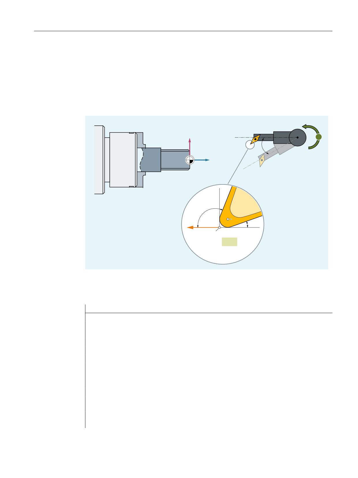
For a tool with cutting edge position 3 and an orientable tool carrier that can rotate the tool
around the B axis, the cutting edge position shall be modified after a tool rotation with the aid
of the CUTMOD command.
;
%
r
=
r
6
r
3
6/
S:
Cutting edge center point
P:
Cutting edge reference point
SL:
Cutting edge position
Program code
Comment
N10 $TC_DP1[1,1]=500
N20 $TC_DP2[1,1]=3
;Cutting edge position
N30 $TC_DP3[1,1]=12
N40 $TC_DP4[1,1]=1
N50 $TC_DP6[1,1]=6
N60 $TC_DP10[1,1]=110
; Holder angle
N70 $TC_DP11[1,1]=3
; Cut direction
N80 $TC_DP24[1,1]=25
; Clearance angle
N90 $TC_CARR7[2]=0 $TC_CARR8[2]=1 $TC_CARR9[2]=0
; B axis
N100 $TC_CARR10[2]=0 $TC_CARR11[2]=0
; C axis
$TC_CARR12[2]=1
N110 $TC_CARR13[2]=0
N120 $TC_CARR14[2]=0
Tools
Function Manual, 10/2020, 6FC5397-6GP40-0BA1
165
Tool offset
3.9 Modification of the offset data for rotatable tools
Program code
Comment
N130 $TC_CARR21[2]=X
N140 $TC_CARR22[2]=X
N150 $TC_CARR23[2]="M"
N160 TCOABS CUTMOD=0
N170 G18 T1 D1 TCARR=2
; X
Y
Z
N180 X0 Y0 Z0 F10000
; 12.000
0.000
1.000
N190 $TC_CARR13[2]=30
N200 TCARR=2
N210 X0 Y0 Z0
; 10.892
0.000
-5.134
N220 G42 Z-10
;
8.696
0.000
-17.330
N230 Z-20
;
8.696
0.000
-21.330
N240 X10
; 12.696
0.000
-21.330
N250 G40 X20 Z0
; 30.892
0.000
-5.134
N260 CUTMOD=2 X0 Y0 Z0
;
8.696
0.000
-7.330
N270 G42 Z-10
;
8.696
0.000
-17.330
N280 Z-20
;
8.696
0.000
-21.330
N290 X10
; 12.696
0.000
-21.330
N300 G40 X20 Z0
; 28.696
0.000
-7.330
N310 M30
The numerical values in the comments specify the end of block positions in the machine coordinates (MCS)
in the sequence X → Y → Z.
Explanations
In block N180, initially the tool is selected for CUTMOD=0 and non-rotated tool holders that can
be orientated. As all offset vectors of the tool holder that can be orientated are 0, the position
that corresponds to the tool lengths specified in $TC_DP3[1,1] and $TC_DP4[1,1] is
approached.
The tool holder that can be orientated with a rotation of 30° around the B axis is activated in block
N200. As the cutting edge position is not modified due to CUTMOD=0, the old cutting edge
reference point is decisive just as before. This is the reason why in block N210 the position is
approached, which keeps the old tool nose reference point at the zero (i.e. the vector (1, 12) is
rotated through 30° in the Z/X plane).
In block N260, contrary to block N200, CUTMOD=2 is effective. As a result of the tool holder
rotation that can be orientated, the modified cutting edge position becomes 8. Deviating axis
positions also result from this.
The tool radius compensation (TRC) is activated in blocks N220 and/or N270. The different
cutting edge position in both program sections has no effect on the end positions of the blocks
in which the TRC is active; the corresponding positions are therefore identical. The different
cutting edge positions only become effective again in the deselect blocks N260 and/or N300.
Tools
166
Function Manual, 10/2020, 6FC5397-6GP40-0BA1
Tool offset
3.10 Incrementally programmed compensation values
3.10
Incrementally programmed compensation values
3.10.1
G91 extension
Requirements
Incremental dimension programming with G91 is defined such that the offset value is traversed
additively to the incrementally programmed value when a tool offset is selected.
Applications
For applications such as scratching, it is necessary only to traverse the path programmed in the
incremental dimension. The activated tool offset is not traversed.
Sequence
Selection of a tool offset with incremental dimension programming
• Scratch workpiece with tool tip.
• Adopt the actual position in the basic frame (set actual value) after reducing it by the tool
offset.
• Traverse incrementally from the zero position.
Activation
It is possible to set whether a changed tool length is traversed with FRAME and incremental
dimension programming of an axis, or whether only the programmed path is traversed with the
setting data:
SD42442 $SC_TOOL_OFFSET_INCR_PROG (tool length compensations)
Work offset / frames G91
It is possible to set whether a work offset is traversed as standard with value = 1 with FRAME and
incremental dimension programming of an axis, or whether only the programmed path is
traversed with value = 0 with the setting data:
SD42440 $SC_FRAME_OFFSET_INCR_PROG (work offset in frames)
For further information, see Function Manual "Basic Functions", Chapter "Axes, coordinate
systems, frames".
Tools
Function Manual, 10/2020, 6FC5397-6GP40-0BA1
167
Tool offset
3.10 Incrementally programmed compensation values
Constraint
If the behavior is set such that the offset remains active after the end of the program and RESET
MD20110 $MC_RESET_MODE_MASK, bit6=1 (definition of basic control settings after reset/PP
end)
and if an incremental path is programmed in the first part program, the offset is always traversed
in addition to the programmed path.
Note
With this configuration, part programs should always begin with absolute programming.
3.10.2
Traversing in the direction of tool orientation (MOVT)
Typical application
On machines with toolholders with orientation capability, traversing should take place in the
tool direction (typically, when drilling) without activating a frame (e.g., using TOFRAME
or TOROT), on which one of the axes points in the direction of the tool.
This is also true of machines on which a frame defining the oblique plane is active during oblique
machining operations, but the tool cannot be set exactly perpendicular because an indexed
toolholder (Hirth tooth system) is restricting the setting of the tool orientation.
In these cases it is then necessary - contrary to the motion actually requested perpendicular to
the plane - to drill in the tool direction, as the drill would otherwise not be guided in the direction
of its longitudinal axis, which, among other things, would lead to breaking of the drill.
MOVT
The end point of such a motion is programmed with MOVT=
The programmed value is
effective incrementally in the tool direction as standard. The positive direction is defined from
the tool tip to the toolholder. The content of MOVT is thus generally negative for the infeed
motion (when drilling), and positive for the retraction motion. This corresponds to the situation
with normal paraxial machining, e.g., with G91Z
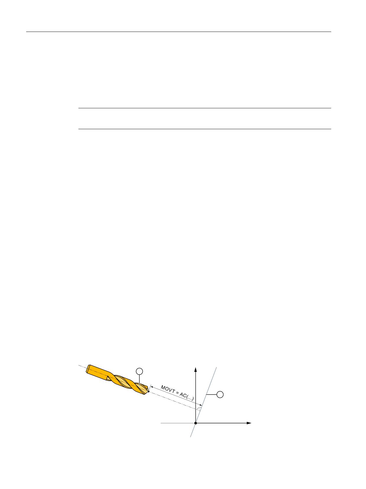
If the motion is programmed in the form MOVT=AC( ...), MOVT functions absolutely. In this
case a plane is defined, which runs through the current zero point, and whose surface normal
vector is parallel to the tool orientation. MOVT then gives the position relative to this plane:
=
;
Tools
168
Function Manual, 10/2020, 6FC5397-6GP40-0BA1

Tool offset
3.11 Assignment of tool length components to geometry axes
Figure 3-44
Definition of the position for absolute programming of a motion in tool direction
The reference to this auxiliary plane serves only to calculate the end position. Active frames are
not affected by this internal calculation.
Instead of MOVT= ... it is also possible to write MOVT=IC( ...) if it is to be plainly visible that
MOVT is to function incrementally. There is no functional difference between the two forms.
Supplementary conditions
The following supplementary conditions apply to programming with MOVT:
• It is independent of the existence of a toolholder with orientation capability. The direction of
the motion is dependent on the active plane. It runs in the direction of the vertical axes, i.e.,
with G17 in Z direction, with G18 in Y direction and with G19 in X direction. This applies both
where no toolholder with orientation capability is active and for the case of a toolholder with
orientation capability without rotary tool or with a rotary tool in its basic setting.
• MOVT acts similarly for active orientation transformation (345axis transformation).
• If in a block with MOVT the tool orientation is changed simultaneously (e.g., active 5axis
transformation by means of simultaneous interpolation of the rotary axes), the orientation
at the start of the block is decisive for the direction of movement of MOVT. The path of the tool
tip (TCP - Tool Center Point) is not affected by the change in orientation.
• Linear or spline interpolation (G0, G1, ASPLINE, BSPLINE, CSPLINE) must be active.
Otherwise, an alarm is produced. If a spline interpolation is active, the resultant path is
generally not a straight line, since the end point determined by MOVT is treated as if it had
been programmed explicitly with X, Y, Z.
• A block with MOVT must not contain any programming of geometry axes (alarm 14157).
3.11
Assignment of tool length components to geometry axes
3.11.1
Assignment according to tool type and working plane.
The values of the tool parameters length 1 ... 3 are stored in the system variables
$TC_DP3 ... $TC_DP5 (see Chapter "Tool parameters (Page 32)"). The assignment to the
geometry axes and therefore the resultant cutting direction of the tool length components
depends on the tool type ($TC_DP1) and the active machining plane (G17/G18/G19).
Table 3-1
Turning/grinding tools ($TC_DP1 = 400 … 599)
Working plane
Length 1
Length 2
Length 3
G17 (X/Y)
Y
X
Z
G18 (Z/X)
X
Z
Y
G19 (Y/Z)
Z
Y
X
Tools
Function Manual, 10/2020, 6FC5397-6GP40-0BA1
169
Tool offset
3.11 Assignment of tool length components to geometry axes
Table 3-2
Milling tools / special tools ($TC_DP1 <> 400 … 599)
Working plane
Length 1
Length 2
Length 3
G17 (X/Y)
Z
Y
X
G18 (Z/X)
Y
X
Z
G19 (Y/Z)
X
Z
Y
3.11.2
Assignment when changing plane
The assignment of tool length components (length, wear, and tool base dimension) to the
geometry axes does not change when the machining plane is changed if the following setting
data is set to not equal to zero:
SD42940 $SC_TOOL_LENGTH_CONST <> 0
The assignment of the tool length components to the geometry axes is then derived from the
ones and tens position of the setting data as shown in the following tables
Table 3-3
Turning / grinding tools ($TC_DP1 = 400 … 599)
SD42940
Assignment of tool length components to geometry axes
Length L1
Length L2
Length L3
= x17
Y
X
Z
= x18
X
Z
Y
= x19
Z
Y
X
= -x17
X
Y
Z
= -x18
Z
X
Y
= -x19
Y
Z
X
Table 3-4
Milling / special tools ($TC_DP1 <> 400 … 599)
SD42940
Assignment of tool length components to geometry axes
Length L1
Length L2
Length L3
= x17
Z
Y
X
= x18
Y
X
Z
= x19
X
Z
Y
= -x17
Z
X
Y
= -x18
Y
Z
X
= -x19
X
Y
Z
Tools
170
Function Manual, 10/2020, 6FC5397-6GP40-0BA1

Tool offset
3.11 Assignment of tool length components to geometry axes
Each value not equal to 0 and not equal to one of the six listed values is evaluated as value "17"
(for milling/special tools) or "18" (for turning/grinding tools)..
Note
Assignment of tool orientation components
The assignment of the tool orientation components is not influenced by SD42940
$SC_TOOL_LENGTH_CONST.
If necessary, the following setting data must be adapted:
• SD42954 $SC_TOOL_ORI_CONST_M
• SD42956 $SC_TOOL_ORI_CONST_T
See Chapter "Tool orientation for plane change (Page 172)".
3.11.3
Assignment independent of tool type
With the following setting data, the assignment of the tool length components (length, wear
and tool base dimension) to the geometry axes that is independent of the actual tool type
($TC_DP1) can be defined:
SD42950 $SC_TOOL_LENGTH_TYPE = <value>
<value>
Assignment of the tool length components
0 (default value)
In accordance with the specification in the system variable $TC_DP1[...].
A distinction is made between the following tool types:
• $TC_DP1[...] == 400 ... 599 ⇒ turning/grinding tools
• $TC_DP1[...] <> 400 ... 599 ⇒ milling/special tools
1
Always as for milling/special tools.
2
Always as for turning/grinding tools.
3
Activates setting data SD42942 $SC_TOOL_LENGTH_CONST_T.
With this setting, it is possible to define the assignment of the tool length compo-
nents that is effective on a machining plane change (Page 170) separately for mill-
ing/special tools and turning/grinding tools:
SD42940 $SC_TOOL_LENGTH_CONST
Assignment for milling/special tools
SD42942 $SC_TOOL_LENGTH_CONST_T
Assignment for turning/grinding tools
Example:
SD42940 $SC_TOOL_LENGTH_CONST = 17
SD42942 $SC_TOOL_LENGTH_CONST_T = 18
Tool length compensations for milling/special tools take effect in plane G17; length
compensations for turning/grinding tools take effect in plane G18.
> 3
As for SD42950 = 0.
Tools
Function Manual, 10/2020, 6FC5397-6GP40-0BA1
171
Tool offset
3.12 Paraxial tool orientation
3.12
Paraxial tool orientation
3.12.1
Basic tool orientation
The basic tool orientation results from the active machining plane:
Working plane
Tool orientation (basic setting)
G17 (X/Y)
Parallel to Z
G18 (Z/X)
Parallel to Y
G19 (Y/Z)
Parallel to X
3.12.2
Tool orientation for plane change
A setting in the setting data determines how the tool orientation changes when the machining
plane is changed.
• SD42954 $SC_TOOL_ORI_CONST_M (for milling/special tools)
• SD42956 $SC_TOOL_ORI_CONST_T (for turning/grinding tools)
Standard behavior
With the default setting (SD42954 and SD42956 = 0), the tool orientation changes with a plane
change as follows:
Plane change
Change in tool orientation
G17 → G18
1. Rotation by -90° about the Z coordinate
G18 → G19
2. Rotation by -90° about the X coordinate
G19 → G17
G18 → G17
1. Rotation by 90° about the X coordinate
G19 → G18
2. Rotation by 90° about the Z coordinate
G17 → G19
Tools
172
Function Manual, 10/2020, 6FC5397-6GP40-0BA1

Tool offset
3.12 Paraxial tool orientation
Constant tool orientation for a plane change
If SD42954 or SD42956 are not equal to zero, a right-handed orthogonal tool coordinate system
is defined, which remains unchanged if the machining plane is changed (G17-G19). The
orientation coordinate system is determined by the orientation vector and an orientation
normal vector perpendicular to it. The basic orientation is defined by the ones and tens position
of the setting data:
Table 3-5
Milling / special tools ($TC_DP1 <> 400 … 599)
SD42954
Coordinate system of the tool orientation
Orientation vector
Orientation normal vector
= xx17
(0, 0, 1)
(0, 1, 0)
= xx18
(0, 1, 0)
(1, 0, 0)
= xx19
(1, 0, 0)
(0, 0, 1)
Table 3-6
Turning / grinding tools ($TC_DP1 = 400 … 599)
SD42956
Coordinate system of the tool orientation
Orientation vector
Orientation normal vector
= xx17
(0, 0, 1)
(0, 1, 0)
= xx18
(0, 1, 0)
(1, 0, 0)
= xx19
(1, 0, 0)
(0, 0, 1)
Each value not equal to 0 and not equal to one of the three listed values is evaluated as value "17"
(for milling/special tools) or "18" (for turning/grinding tools).
Further information
A detailed description of SD42954 and SD42956 is given in the List Manual System Variables.
Note
In the case of tools whose orientation is defined by cutting edge data ($TC_DPV…), SD42954 or
SD42956 is usually ignored (see Chapter "Parameterizable basic tool orientation (Page 174)").
Tools
Function Manual, 10/2020, 6FC5397-6GP40-0BA1
173
Tool offset
3.13 Parameterizable basic tool orientation
3.13
Parameterizable basic tool orientation
3.13.1
Function
Note
Tool T and cutting edge D
In the following, the syntax [...] represents [<t>, <d>] in relation to the system variables of the
basic tool orientation. In this regard, <t> designates the number of the tool T=<t> and <d> the
number of the tool cutting edge D=<d>.
The "Parameterizable basic tool orientation" function allows each tool cutting edge to be
assigned an individual initial orientation with the following system variables:
• Selection of a predefined orientation vector
- $TC_DPV[...]: Orientation vector (values 1 ... 6)
• Definition of an orientation vector.
- $TC_DPV3[...]: L1 component of the orientation vector
- $TC_DPV4[...]: L2 component of the orientation vector
- $TC_DPV5[...]: L3 component of the orientation vector
• Definition of a normal vector for the orientation vector
- $TC_DPVN3[...]: L1 component of the normal vector
- $TC_DPVN4[...]: L2 component of the normal vector
- $TC_DPVN5[...]: L3 component of the normal vector
If the system variable $TC_DPV[...] is equal to zero, the three system variables $TC_DPV3 - 5[...]
define the direction vector of the basic tool orientation. Additionally, the three system variables
$TC_DPVN3 - 5[...] can define the orientation of the tool in the plane perpendicular to the
orientation vector. The magnitudes of the orientation vectors are immaterial.
3.13.2
Commissioning
3.13.2.1
Activation
The "Parameterizable basic tool orientation" is activated via the following machine data:
Tools
174
Function Manual, 10/2020, 6FC5397-6GP40-0BA1

Tool offset
3.13 Parameterizable basic tool orientation
MD18114 $MN_MM_ENABLE_TOOL_ORIENTATION = <value>
<value>
Meaning
0
The function "Parameterizable basic tool orientation" is not active.
1
Activation of system variables:
• Function selection: $TC_DPV[...]
With the system variable $TC_DPV[...] = 1, 2, ... 6, one of six predefined basic tool orientations
can be assigned for each tool cutting edge D=<d> of a tool T=<t>.
2
Activation of system variables:
• Function selection: $TC_DPV[...]
• Orientation vector: $TC_DPV3[...], $TC_DPV4[...] and $TC_DPV5[...]
With the system variables $TC_DPV[...] = 0 and $TC_DPV3[...], $TC_DPV4[...] and
$TC_DPV5[...], any orientation vector can be assigned for each tool cutting edge D=<d> of a
tool T=<t>.
3
Activation of system variables:
• Function selection: $TC_DPV[...]
• Orientation vector: $TC_DPV3[...], $TC_DPV4[...] and $TC_DPV5[...]
• Normal vector for the orientation vector: $TC_DPVN3[...], $TC_DPVN4[...] and
$TC_DPVN5[...]
With the setting $TC_DPV[...] = 0, any orientation vector can be assigned for each tool cutting
edge D=<d> of a tool T=<t> with the system variables $TC_DPV3[...], $TC_DPV4[...] and
$TC_DPV5[...]. Additionally, a normal vector can be defined for the orientation vector with the
system variables $TC_DPVN3[...], $TC_DPVN4[...] and $TC_DPVN5[...].
3.13.2.2
Parameterization
Assignment of the system variables $TC_DPVx[...]
A differentiation is made between the following tool types in accordance with the specification
in system variable $TC_DP1[...]:
• $TC_DP1[...] == 400 ... 599 ⇒ turning/grinding tools
• $TC_DP1[...] <> 400 ... 599 ⇒ milling/special tools
The basic tool orientation programmed in $TC_DPVx[...] is assigned to the coordinate axes
depending on the tool type.
The tool type may be changed over by the setting in setting data SD42950
$SC_TOOL_LENGTH_TYPE (as described in Chapter "Assignment independent of tool type
(Page 171)" for tool length components).
If no other orientation is defined in setting data SD42954 $SC_TOOL_ORI_CONST_M and
SD42956 $SC_TOOL_ORI_CONST_T (Page 172), the standard case (G17 for milling/special tools,
G18 for turning/grinding tools) applies for assignment of the system variables $TC_DPVx[...]:
Tool type
TC_DPV3[…]
TC_DPV4[…]
TC_DPV5[…]
Turning/grinding tools
X
Z
Y
Milling/special tools
Z
Y
X
Tools
Function Manual, 10/2020, 6FC5397-6GP40-0BA1
175
Tool offset
3.13 Parameterizable basic tool orientation
Note
SD42954 / SD42956
The assignment of the system variables $TC_DPVx[...] can only be changed with SD42954
$SC_TOOL_ORI_CONST_M and SD42956 $SC_TOOL_ORI_CONST_T if the 1000s position is
equal to "1"
Irrespective of the value of setting data SD42950 $SC_TOOL_LENGTH_TYPE, SD42954 is only
effective for a tool for which parameter $TC_DP1[...] defines a milling tool. Analogously,
SD42956 is only effective for a tool for which parameter $TC_DP1[...] defines a turning/grinding
tool.
3.13.3
Programming
The system variable $TC_DPV[...] or the system variables $TC_DPV3 - 5[...] and $TC_DPVN3 -
5[...] can be used to assign each tool cutting edge its own basic orientation.
Tools
176
Function Manual, 10/2020, 6FC5397-6GP40-0BA1

Tool offset
3.13 Parameterizable basic tool orientation
Setting options
Basically, the following setting options are available:
•
$TC_DPV[...] == 0 AND $TC_DPV3 - 5[...] == 0
The vector for the basic tool orientation results from the active machining plane:
- G17: Z coordinate
- G18: Y coordinate
- G19: X coordinate
See also "Paraxial tool orientation (Page 172)".
•
$TC_DPV[...] == 0 AND $TC_DPV3 - 5[...] <> 0
The vector for the basic tool orientation is prescribed by $TC_DPV3 - 5[...] and $TC_DPVN3 -
5[...]:
- $TC_DPV3[...] = <L1 component of the orientation vector>
- $TC_DPV4[...] = <L2 component of the orientation vector>
- $TC_DPV5[...] = <L3 component of the orientation vector>
- $TC_DPVN3[...] = <L1 component of the normal vector>
- $TC_DPVN4[...] = <L2 component of the normal vector>
- $TC_DPVN5[...] = <L3 component of the normal vector>
Example:
Basic tool orientation points in the direction of the bisectors in the L1-L3 plane, i.e. for a
milling tool and active plane G17, in the direction of the bisectors in the ZX plane.
$TC_DPV[1,1]
= 0
$TC_DPV3[1,1] = 1.0
$TC_DPV4[1,1] = 0.0
$TC_DPV5[1,1] = 1.0
Note
The system variables $TC_DPVN3-5[...] are not relevant for rotationally symmetrical tools
such as milling tools.
•
$TC_DPV[...] == 1, 2, ... 6
The vector for the basic tool orientation is prescribed by $TC_DPV[...].
The following tables show which basic tool orientations are predefined and can be selected
via $TC_DPV[...].
Selection of a predefined orientation vector
$TC_DPV[...] = <value>
Table 3-7
Turning / grinding tools ($TC_DP1 = 400 … 599)
<value>
$TC_DPV3[...] /
$TC_DPV5[...] /
$TC_DPV4[...] /
$TC_DPVN3[...]
$TC_DPVN5[...]
$TC_DPVN4[...]
1
0 / 0
1 / 0
0 / 1
2
1 / 0
0 / 1
0 / 0
Tools
Function Manual, 10/2020, 6FC5397-6GP40-0BA1
177

Tool offset
3.13 Parameterizable basic tool orientation
<value>
$TC_DPV3[...] /
$TC_DPV5[...] /
$TC_DPV4[...] /
$TC_DPVN3[...]
$TC_DPVN5[...]
$TC_DPVN4[...]
3
0 / 1
0 / 0
1 / 0
4
0 / 0
-1 / 0
0 / -1
5
-1 / 0
0 / -1
0 / 0
6
0 / -1
0 / 0
-1 / 0
Table 3-8
Milling / special tools ($TC_DP1 <> 400 … 599)
<value>
$TC_DPV5[...] /
$TC_DPV4[...] /
$TC_DPV3[...] /
$TC_DPVN5[...]
$TC_DPVN4[...]
$TC_DPVN3[...]
1
0 / 1
0 / 0
1 / 0
2
0 / 0
1 / 0
0 / 1
3
1 / 0
0 / 1
0 / 0
4
0 / -1
0 / 0
-1 / 0
5
0 / 0
-1 / 0
0 / -1
6
-1 / 0
0 / -1
0 / 0
Examples
Turning/grinding tools:
$TC_DPV[...] = 2
Corresponds $TC_DPV3[...] = 1
to
$TC_DPV4[...] = 0
$TC_DPV5[...] = 0
$TC_DPVN3[...] = 0
$TC_DPVN4[...] = 0
$TC_DPVN5[...] = 1
Milling/special tools:
$TC_DPV[...] = 3
Corresponds $TC_DPV3[...] = 0
to
$TC_DPV4[...] = 0
$TC_DPV5[...] = 1
$TC_DPVN3[...] = 0
$TC_DPVN4[...] = 1
$TC_DPVN5[...] = 0
Tools
178
Function Manual, 10/2020, 6FC5397-6GP40-0BA1
Tool offset
3.14 Special handling of tool offsets
3.13.4
Examples
A milling tool is defined with length L1=10 whose basic tool orientation is in the bisector of the
X-Z plane.
Program code
Comment
$SC_TOOL_LENGTH_TYPE=2
; assignment to the coordinate axes as for turning/
grinding tools.
$SC_TOOL_ORI_CONST_M=1019
; Working plane: G19
N10 $TC_DP1[1,1]=120
; Tool type: Milling tool
N20 $TC_DP3[1,1]=10
; Length compensation vector: L1=10
N30 $TC_DPV[1,1]=0
; Basic tool orientation via $TC_DPV3-5
N40 $TC_DPV3[1,1]=1
; Orientation vector in the Z direction
N50 $TC_DPV4[1,1]=0
; Orientation vector in the Y direction
N60 $TC_DPV5[1,1]=1
; Orientation vector in the X direction
N70 TRAFOON(...)
; Activating a transformation.
N80 G17 F1000 X0 Y0 Z0 T1 D1
; Activate tool and approach zero position.
; Due to tool length L1=10 =>
; Machine positions: X=0, Y=0, Z=10
; Plane selection G17 in block N80 is only rele-
vant for length compensations.
N90 MOVT=10
; Incr. Traversing movement in the tool direction.
; Resulting axis positions: X=7.071 Y=0 Z=17.071
N100 M30
3.14
Special handling of tool offsets
3.14.1
Relevant setting data
SD42900- 42960
Setting data SD42900 - SD42940 can be used to make the following settings with reference to
tool offset:
• Sign of the tool length
• Sign of the wear
• Behavior of the wear components when mirroring geometry axes
• Behavior of the wear components when changing the machining plane via setting data
Tools
Function Manual, 10/2020, 6FC5397-6GP40-0BA1
179
Tool offset
3.14 Special handling of tool offsets
• Allocation of the tool length components independent of actual tool type
• Transformation of wear components into a suitable coordinate system for controlling the
effective tool length
Note
In the following description, the wear includes the total values of the following components:
• Wear values: $TC_DP12 bis $TC_DP20
• Sum offset, consisting of:
- Wear values: $SCPX3 to $SCPX11
- Setup values: $ECPX3 to $ECPX11
You will find detailed information about sum and tool offsets in:
Further information
Function Manual Tool Management
Programming Manual. Fundamentals; Tool Offsets
Required setting data
• SD42900 $SC_MIRROR_TOOL_LENGTH (mirroring of tool length components and
components of the tool base dimension) (Page 180)
• SD42910 $SC_MIRROR_TOOL_WEAR (mirroring of wear values of tool length components)
(Page 180)
• SD42920 $SC_WEAR_SIGN_CUTPOS (sign evaluation of the wear components) (Page 181)
• SD42930 $SC_WEAR_SIGN (inverts the sign of the wear dimensions) (Page 181)
• SD42935 $SC_WEAR_TRANSFORM (transformation of wear values) (Page 199)
• SD42940 $SC_TOOL_LENGTH_CONST (allocation of the tool length components to the
geometry axes) (Page 170)
• SD42950 $SC_TOOL_LENGTH_TYPE (allocation of the tool length components independent
of tool type) (Page 171)
• SD42960 $SC_TOOL_TEMP_COMP (tool length offsets) (Page 183)
3.14.2
Mirroring tool lengths
Activation
Tool length mirroring is activated via the setting data:
SD42900 $SC_MIRROR_TOOL_LENGTH <> 0 (TRUE) (Sign change tool length when mirroring)
Tools
180
Function Manual, 10/2020, 6FC5397-6GP40-0BA1
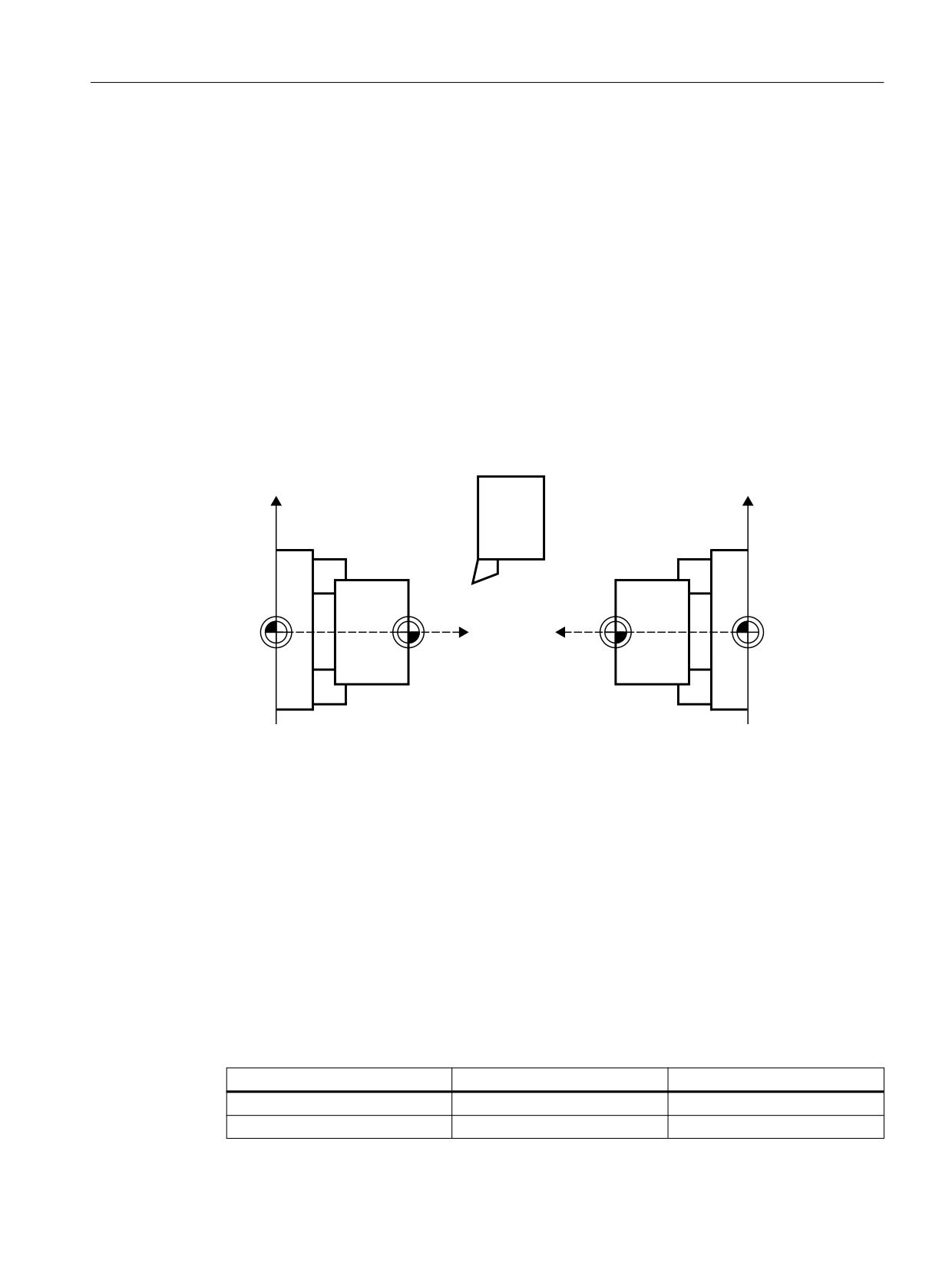
Tool offset
3.14 Special handling of tool offsets
Function
The following components are mirrored by inverting the sign:
• Tool lengths: $TC_DP3, $TC_DP4, $TC_DP5
• Tool base dimensions: $TC_DP21, $TC_DP22, $TC_DP23
Mirroring is performed for all tool base dimensions whose associated axes are mirrored. Wear
values are not mirrored.
Mirror wear values
The following setting data should be set in order to mirror the wear values:
SD42910 $SC_MIRROR_TOOL_WEAR <> 0 (Sign change tool wear when mirroring)
Inverting the sign mirrors the wear values of the tool length components whose associated axes
are mirrored.
'
;
;
:
:
0
=
=
0
0DFKLQLQJ VLWXDWLRQ
0DFKLQLQJ VLWXDWLRQ
' RSHUDWHV LQ :&6
' RSHUDWHV LQ :&6
Figure 3-45
Application example: Double-spindle turning machine
3.14.3
Mirroring wear lengths
Activation
Wear length mirroring is activated by:
SD42920 $SC_WEAR_SIGN_CUTPOS <> 0 (TRUE) (Sign of wear for tools with cutting edge
systems)
Function
Length of cutting edge
Length 1
Length 2
1
---
---
2
---
Inverted
Tools
Function Manual, 10/2020, 6FC5397-6GP40-0BA1
181

Tool offset
3.14 Special handling of tool offsets
Length of cutting edge
Length 1
Length 2
3
Inverted
Inverted
4
Inverted
---
5
---
---
6
---
---
7
---
Inverted
8
Inverted
---
9
---
---
In the case of tool types without a relevant cutting edge position, the wear length is not mirrored.
Note
The mirroring (sign inversion) in one or more components can cancel itself through a
simultaneous activation of the functions:
Tool length-mirroring (SD42900 <> 0)
And:
Tool length-mirroring (SD42920 <> 0)
SD42930 $SC_WEAR_SIGN
Setting data not equal to zero:
Inverts the sign of all wear dimensions. This affects both the tool length and other variables such
as tool radius, rounding radius, etc.
Entering a positive wear dimension makes the tool "shorter" and "thinner".
Activation of modified setting data
When the setting data described above are modified, the tool components are not reevaluated
until the next time a tool edge is selected. If a tool is already active and the data of this tool are
to be reevaluated, the tool must be selected again.
Example:
N10 $SC_WEAR_SIGN = 0
; No sign inversion of the wear values
N20 $TC_DP1[1,1] = 120
; End mill
N30 $TC_DP6[1,1] = 100
; Tool radius 100 mm
N40 $TC_DP15[1,1] = 1
; Wear dimension of tool radius 1 mm, resulting
tool radius 101 mm
N100 T1 D1 G41 X150 Y20
N150 G40 X300N10
Tools
182
Function Manual, 10/2020, 6FC5397-6GP40-0BA1
Tool offset
3.14 Special handling of tool offsets
N200 $SC_WEAR_SIGN = 1
; Sign inversion for all wear values; the new ra-
dius of 99 mm is activated on a new selection
(D1). Without D1, the radius would continue to
be 101 mm.
N300 D1 G41 X350 Y-20
N310
The same applies in the event that the resulting tool length is modified due to a change in the
mirroring status of an axis. The tool must be selected again after the mirror command, in order
to activate the modified tool-length components.
3.14.4
Tool lengths in the WCS, allowing for the orientation
Change tool or working plane
The values displayed for the tool correspond to the expansion in the WCS. If a toolholder with an
inclined clamping position is to be used, you should make sure that the transformation used
supports the toolholder. If this is not the case, incorrect tool dimensions will be displayed. When
changing the working plane from G17 to G18 or G19, you should ensure that the transformation
can also be used for these working planes. If the transformation is only available for G17
machining, the dimensions continue to be displayed for a tool in the Z direction after the plane
change.
When transformation is deactivated, the basic tool is displayed in the x, y or z direction,
according to the working plane. Allowance is made for a programmed toolholder. These tool
dimensions are not altered when traversing without a transformation.
3.14.5
Tool length offsets in tool direction
Temperature compensation in real time
On 5-axis machines with a moving tool, temperature fluctuations can occur in the machining
heads. These can result directly in expansion fluctuations which are transmitted to the tool
spindle in the form of linear expansion. A typical case on 5-axis heads, for example, is thermal
expansion in the direction of the longitudinal spindle axis.
It is possible to compensate this thermal expansion even when the tool is orientated by assigning
the temperature compensation values to the tool rather than to the machine axes. In this way,
linear expansion fluctuations can be compensated even when the tool orientation changes.
Using the orientation transformation whose direction is determined by the current tool
orientation, it is possible to overlay motions in real time and rotate them simultaneously. At the
same time, the compensation values are adjusted continuously in the tool coordinate system.
The temperature compensation only becomes effective if the axis to be compensated is really
referenced.
Tools
Function Manual, 10/2020, 6FC5397-6GP40-0BA1
183
Tool offset
3.14 Special handling of tool offsets
Activation
The temperature compensation in the tool direction is activated by setting the following
machine data to a value not equal to zero.
MD20390 $MC_TOOL_TEMP_COMP_ON (activation of temperature compensation for tool
length)
In addition, bit 2 must be set for each affected channel axis in the machine data:
MD32750 $MA_TEMP_COMP_TYPE [<axis index>] (temperature compensation type)
This can be more than three axes in cases where more than three channel axes in succession can
be temporarily assigned to geometry axes as a result of geometry axis replacement of
transformation switchover. If this bit is not set for a particular channel axis, the compensation
value cannot be applied in the axis. This does not have any effect on other axes. In this case, an
alarm is not output.
Applicability
The temperature compensation in the tool direction is only effective with generic 5-axis
transformations with:
• Transformation type 24
Two axes rotate the tool
• Transformation type 56
One axis rotates the tool, the other axis rotates the workpiece without temperature
compensation
In generic 5-axis transformation with:
• Transformation type 40
The tool orientation is constant with a rotary workpiece, which means that the motion of the
rotary axes on the machine does not affect the temperature compensation direction.
Temperature compensation in the tool direction also works in conjunction with orientation
transformations (not generic 5-axis transformations) with:
• Transformation type 64 to 69
Rotating linear axis
Note
Temperature compensation can be activated with all other types of transformation. It is not
affected by a change in tool orientation. The axes move as if no orientation transformation
with temperature compensation were active.
Limit values
The compensation values are restricted to the maximum values by the machine data:
MD20392 $MC_TOOL_TEMP_COMP_LIMIT[0...2] (maximum temperature compensation for
tool length)
The limit value default setting is 1 mm. If a temperature compensation value higher than this
limit is specified, it will be limited without an alarm.
Tools
184
Function Manual, 10/2020, 6FC5397-6GP40-0BA1
Tool offset
3.14 Special handling of tool offsets
SD42960
The three temperature compensation values together form a compensation vector and are
contained in setting data:
SD42960 $SC_TOOL_TEMP_COMP[0...2] (temperature compensation with reference to tools)
The setting data is user-defined, e.g. using synchronized actions or from the PLC. The
compensation values can, therefore, also be used for other compensation purposes.
In the initial state or when orientation transformation is deactivated, all three compensation
values apply in the direction of the three geometry axes (in the typical order X, Y, Z). The
assignment of components to geometry axes is independent of the tool type (turning, milling
or grinding tools) and the selected machining plane G17 to G19. Changes to the setting data
values take effect immediately.
Toolholder with orientation capability
If a toolholder with orientation capability is active, the temperature compensation vector is
rotated simultaneously to any change in orientation. This applies independently of any active
orientation transformation.
If a toolholder with orientation capability is active in conjunction with a generic 5-axis
transformation or a transformation with rotating linear axis, the temperature compensation
vector is subjected to both rotations.
Note
While transformations with rotating linear axes take changes in the tool vector (length) into
account, they ignore its change in orientation, which can be effected by a toolholder with
orientation capability.
Temperature compensation values immediately follow any applied change in orientation. This
applies in particular when an orientation transformation is activated or deactivated.
The same is true when the assignment between geometry axes and channel axes is changed.
The temperature compensation value for an axis is reduced to zero (interpolatory), for example,
when it ceases to be a geometry axis after a transformation change. Conversely, any
temperature compensation value for an axis which changes over to geometry axis status is
applied immediately.
Examples
Temperature compensation in tool direction
Example of a 5-axis machine with rotating tool on which the tool can be rotated around the C and
B axes.
In its initial state, the tool is parallel to the Z axis. If the B axis is rotated through 90 degrees, the
tool points in the X direction.
Therefore, a temperature compensation value in the following setting data is also effective in the
direction of the machine X axis if transformation is active:
SD42960 $SC_TOOL_TEMP_COMP[2] (temperature compensation with reference to tools)
Tools
Function Manual, 10/2020, 6FC5397-6GP40-0BA1
185

Tool offset
3.14 Special handling of tool offsets
If the transformation is deactivated with the tool in this direction, the tool orientation is, by
definition, parallel again to the Z axis and thus different to its actual orientation. The
temperature offset in the X axis direction is therefore reduced to zero and reapplied
simultaneously in the Z direction.
Example of a 5-axis machine with rotating tool (transformation type 24). The relevant machine
data is listed below:
• The first rotary axis rotates around Z, C-axis
• The second rotary axis rotates around Y, B-axis
The essential machine data is shown in the table below:
Machine data
Value
Remark
MD20390 $MC_TOOL_TEMP_COMP_ON
= TRUE
Temperature compensation active
MD32750 $MA_TEMP_COMP_TYPE[ AX1 ]
= 4
Compensation in tool direction
MD32750 $MA_TEMP_COMP_TYPE[ AX2 ]
= 4
Compensation in tool direction
MD32750 $MA_TEMP_COMP_TYPE[ AX3 ]
= 4
Compensation in tool direction
Assignment of transformation type
24
MD24100 $MC_TRAFO_TYPE_1
= 24
Transformer type 24 in first channel
MD24110 $MC_TRAFO_AXES_IN_1[0]
= 1
First axis of the transformation
MD24110 $MC_TRAFO_AXES_IN_1[1]
= 2
Second axis of the transformation
MD24110 $MC_TRAFO_AXES_IN_1[2]
= 3
Third axis of the transformation
MD24110 $MC_TRAFO_AXES_IN_1[3]
= 5
Fifth axis of the transformation
MD24110 $MC_TRAFO_AXES_IN_1[4]
= 4
Fourth axis of the transformation
MD24120 $MC_TRAFO_GEOAX_ASSIGN_TAB_1[0]
= 1
Geometry axis for channel axis 1
MD24120 $MC_TRAFO_GEOAX_ASSIGN_TAB_1[1]
= 2
Geometry axis for channel axis 2
MD24120 $MC_TRAFO_GEOAX_ASSIGN_TAB_1[2]
= 3
Geometry axis for channel axis 3
MD24570 $MC_TRAFO5_AXIS1_1[0]
= 0.0
MD24570 $MC_TRAFO5_AXIS1_1[1]
= 0.0
Direction
MD24570 $MC_TRAFO5_AXIS1_1[2]
= 1.0
First rotary axis is parallel to Z
MD24572 $MC_TRAFO5_AXIS1_2[0]
= 0.0
Direction
MD24572 $MC_TRAFO5_AXIS1_2[1]
= 1.0
Second rotary axis is parallel to Y
MD24572 $MC_TRAFO5_AXIS1_2[2]
= 0.0
MD25574 $MC_TRAFO5_BASE_ORIENT_1[0]
= 0.0
MD25574 $MC_TRAFO5_BASE_ORIENT_1[1]
= 0.0
Basic tool orientation
MD25574 $MC_TRAFO5_BASE_ORIENT_1[2]
= 1.0
In Z direction
Tools
186
Function Manual, 10/2020, 6FC5397-6GP40-0BA1

Tool offset
3.14 Special handling of tool offsets
Temperature compensation values in the NC program
The compensation values assigned to axes X and Z are not zero and are applied for temperature
compensation with respect to tool length. The machine axis positions reached in each case are
specified as comments in the program lines.
Program code
Comment
$SC_TOOL_TEMP_COMP[0] = -0.3
; Compensation value in X
$SC_TOOL_TEMP_COMP[1] = 0.0
$SC_TOOL_TEMP_COMP[2] = -1.0
; Compensation value in Z
; Position setpoints of the machine
axes
N10 G74 X0 Y0 Z0 A0 B0
; X Y Z
N20 X20 Y20 Z20 F10000
; 20.30 20.00 21.00
N30 TRAORI()
; 20.30 20.00 21.00
N40 X10 Y10 Z10 B90
; 11.00 10.00 9.70
N50 TRAFOOF
; 10.30 10.00 11.00
N60 X0 Y0 Z0 B0 C0
; 0.30 0.00 1.00
N70 M30
With the exception of block N40, temperature compensation always acts in the original
directions, as the tool is pointing in the basic orientation direction. This applies particularly in
block N50. The tool is actually still pointing in the direction of the X axis because the B axis is still
at 90 degrees. However, because the transformation is already deactivated, the applied
orientation is parallel to the Z axis again.
Machine data
Value
Remark
MD20390 $MC_TOOL_TEMP_COMP_ON
= TRUE
Temperature compensation active
MD32750 $MA_TEMP_COMP_TYPE[ AX1 ]
= 4
Compensation in tool direction
MD32750 $MA_TEMP_COMP_TYPE[ AX2 ]
= 4
Compensation in tool direction
MD32750 $MA_TEMP_COMP_TYPE[ AX3 ]
= 4
Compensation in tool direction
Further information
• For more details on "Temperature compensation" see:
Function Manual Monitoring and Compensations; Compensations
• For information on "Generic 5-axis transformations" see:
Function Manual Transformations; Multi-axis transformations
3.14.6
Special characteristics of orientable tool carriers
Setting data SD42900 - SD42950
Setting data SD42900 - SD42950 have no effect on the components of an active tool carrier with
orientation capability. The calculation with a tool carrier with orientation capability always
Tools
Function Manual, 10/2020, 6FC5397-6GP40-0BA1
187
Tool offset
3.15 Sum and setup offsets
allows for a tool with its total resulting length (tool length + wear + tool base dimension). The
calculation of the resulting total length allows for all modifications caused by the setting data.
Note
When tool carriers with orientation capability are used, it is common to define all tools for a non-
mirrored basic system, even those, which are only used for mirrored machining. When
machining with mirrored axes, the tool carrier is then rotated such that the actual position of the
tool is described correctly. All tool-length components then automatically act in the correct
direction, dispensing with the need for control of individual component evaluation via setting
data, depending on the mirroring status of individual axes.
The use of tool carriers with orientation capability is also practical if the physical characteristics
of the machine type prevents tools, which are permanently installed with different orientations,
from being rotated. Tool dimensioning can then be performed uniformly in a basic orientation,
where the dimensions relevant for machining are calculated according to the rotations of a
virtual tool carrier.
3.15
Sum and setup offsets
3.15.1
General information
Sum offsets
Sum offsets can be treated as programmable process compensations during machining and
are composed of all the error sizes (including the wear), which cause the workpiece to deviate
from the specified dimensions.
Sum offsets are a generalized type of wear. They are part of the cutting edge data. The
parameters of the sum offset refer to the geometrical data of a cutting edge.
The compensation data of a sum offset is addressed by a DL number (DL: Location-dependent;
offsets regarding the location of use).
In contrast, the wear values of a D number describe the physical wear of the cutting edge, i.e.
in special situations, the sum offset can match the wear of the cutting edge.
Summed offsets are intended for general use, i.e. with active or inactive tool management.
Machine data is used to classify the sum offsets into:
• Sum offset fine
• Sum offset coarse (setup offset)
Setup offset
The setup offset is the compensation to be entered by the setup engineer before machining.
These values are stored separately in the NC. The operator subsequently only has access to the
"sum offset fine" via HMI.
Tools
188
Function Manual, 10/2020, 6FC5397-6GP40-0BA1
Tool offset
3.15 Sum and setup offsets
The "sum offset fine" and "sum offset coarse" are added internally in the NC. This value is referred
to below as the sum offset.
Note
The function is enabled via the machine data setting:
MD18080 $MN_MM_TOOL_MANAGEMENT_MASK, Bit 8=1 (step-by-step memory reservation
for tool management).
If kinematic transformations (e.g. 5-axis transformations) are active, the tool length is calculated
first after allowing for the various wear components. The total tool length is then used in the
transformation. Unlike the case of a toolholder with orientation capability, the wear values are
thus always included in the transformation irrespective of the G command of group 56.
3.15.2
Description of function
Sum offsets
Several sum offsets (DL numbers) can be defined per D number. In this way, for
example, workpiece location-dependent offset values can be determined and assigned to a
cutting edge. Sum offsets have the same effect as wear, i.e. they are added to the offset values
of the D number. The data is permanently assigned to a D number.
Settings
You can define the following settings via machine data:
• Activate sum offset
• Define maximum number of DL data sets to be created in NC
• Define maximum number of DL numbers to be assigned to a D number
• Define whether the sum offsets (fine/coarse) are to be saved during data backup
• Define the sum offset to be activated, if:
- A new cutting edge compensation is activated
- An operator panel RESET is performed
- An operator panel START is performed
- The end of the program has been reached
The name is oriented to the logic of the corresponding machine data for tools and cutting edges.
Tools
Function Manual, 10/2020, 6FC5397-6GP40-0BA1
189

Tool offset
3.15 Sum and setup offsets
The "setup offset" and "sum offset fine" can be read and written via system variables and
corresponding OPI services.
Note
When tool management is active, a machine data item can be used to define whether the sum
offset of a tool activated during a programmed tool change remains unchanged or is set to zero.
Summary of compensation parameters $TC_DPx
The following general system variables were previously defined for describing a cutting edge:
$TC_DP1
Tool type
$TC_DP2
Cutting edge position
Parameters for geometry and wear
Tool geometry compensations are assigned to system variables $TC_DP3 to $TC_DP11. System
variables $TC_DP12 to $TC_DP20 allow you to name a wear for each of these parameters:
Geometry
Wear
Compensations
Length compensations
$TC_DP3
$TC_DP12
Length 1
$TC_DP4
$TC_DP13
Length 2
$TC_DP5
$TC_DP14
Length 3
Radius compensation
$TC_DP6
$TC_DP15
Radius 1
$TC_DP7
$TC_DP16
Radius 2
Other compensations
$TC_DP8
$TC_DP17
Length 4
$TC_DP9
$TC_DP18
Length 5
$TC_DP10
$TC_DP19
Angle 1
$TC_DP11
$TC_DP20
Angle 2
Tool base dimension or adapter dimension
$TC_DP21
Adapter length 1
$TC_DP22
Adapter length 2
$TC_DP23
Adapter length 3
Tools
190
Function Manual, 10/2020, 6FC5397-6GP40-0BA1

Tool offset
3.15 Sum and setup offsets
Technology
System variable
Clearance angle
$TC_DP24
The clearance angle is stored here for ManualTurn; tool type 5xx. Same sig-
nificance as in standard cycles for turning tools.
The tip angle of the drill is stored here for ShopMill; tool type 2xx.
Used in standard cycles for turning tools; tool type 5xx. This is the angle at the
secondary cutting edge for these tools.
$TC_DP25
The value for the cutting rate is stored here for ManualTurn.
A bit-coded value for various states of tool types 1xx and 2xx is stored here for
ShopMill.
Parameters of the sum and setup offsets ($TC_SCPxy, $TC_ECPxy)
The numbering of the parameters is oriented to the numbering of system variables $TC_DP3 to
$TC_DP11.
The effect of the parameters is similar to the wear (additive to the tool geometry). Up to six sum/
setup parameters can be defined per cutting edge parameter.
Tool geometry parame-
Sum / setup parameters
Tool wear param-
ters
eter
(to which the compen-
sation is added)
Length compensations
$TC_DP3
Length 1
$TC_DP12
$TC_SCP13, $TC_SCP23,$TC_SCP33,
$TC_SCP43,$TC_SCP53,$TC_SCP63
$TC_ECP13, $TC_ECP23,$TC_ECP33,
$TC_ECP43,$TC_ECP53,$TC_ECP63
The numbers in bold, 1, 2, ... 6, designate the parame-
ters of a maximum of six (location-dependent or similar)
compensations that can be programmed with DL =1 to
6 for the parameter specified in column one.
$TC_DP4
Length 2
$TC_DP13
$TC_SCP14, $TC_SCP24,$TC_SCP34,
$TC_SCP44,$TC_SCP54,$TC_SCP64
$TC_ECP14, $TC_ECP24,$TC_ECP34,
$TC_ECP44,$TC_ECP54,$TC_ECP64
$TC_DP5
Length 3
$TC_DP14
etc
Radius compensation
$TC_DP6
Radius
$TC_DP15
$TC_DP7
Corner radius
$TC_DP16
Other compensations
$TC_DP8
Length 4
$TC_DP17
Tools
Function Manual, 10/2020, 6FC5397-6GP40-0BA1
191

Tool offset
3.15 Sum and setup offsets
Tool geometry parame-
Sum / setup parameters
Tool wear param-
ters
eter
(to which the compen-
sation is added)
$TC_DP9
Length 5
$TC_DP18
$TC_DP10
Angle 1
$TC_DP19
...etc.
$TC_DP11
Angle 2
$TC_DP20
$TC_SCP21, $TC_SCP31,$TC_SCP41,
$TC_SCP51,$TC_SCP61,$TC_SCP71
$TC_ECP21, $TC_ECP31,$TC_ECP41,
$TC_ECP51,$TC_ECP61,$TC_ECP71
The numbers in bold, 2, 3, ... 7, designate the parame-
ters of a maximum of six (location-dependent or similar)
compensations that can be programmed with DL =1 to
6 for the parameter specified in column one.
Supplementary conditions
The maximum number of DL data sets of a cutting edge and the total number of sum offsets in
the NC are defined via machine data. The default value is zero, i.e. no sum offsets can be
programmed.
Activate the "monitoring function" to monitor a tool for wear or for "sum offset".
The additional sum/setup data sets use additional buffered memory. 8 bytes are required per
parameter.
A sum offset data set requires: 8 bytes * 9 parameters = 72 bytes
A setup data set requires an equal amount of memory. A certain number of bytes is also required
for internal management data.
3.15.3
Activation
Function
The function must be activated via the machine data:
MD18108 $MN_MM_NUM_SUMCORR (sum offsets in TO area).
System variables $TC_ECPx and $TC_SCPx and setup and sum offsets ("fine") defined via the OPI
interface can be activated in the part program.
This is done by programming the language command DL="number".
When a new D number is activated, either a new DL number is programmed, or the DL number
defined via the following machine data becomes active:
MD20272 $MC_SUMCORR_DEFAULT (basic setting of the sum offset without a program)
Tools
192
Function Manual, 10/2020, 6FC5397-6GP40-0BA1
Tool offset
3.15 Sum and setup offsets
DL programming
The sum offset is always programmed relative to the active D number with the command:
DL = "n"
The sum offset "n" is added to the wear of the active D number.
Note
If you use "setup offset" and "sum offset fine", both compensations are combined and added to
the tool wear.
The sum offset is deselected with the command:
DL = 0
Note
DL0 is not permitted. If compensation is deselected (D0 and T0), the sum offset also becomes
ineffective.
Programming a sum offset that does not exist triggers an alarm, similar to programming a D
compensation that does not exist.
Thus, only the defined wear remains part of the compensation (defined in system variables
$TC_DP12 to $TC_DP20).
Programming a sum offset when a D compensation is active (also applies to deselection) has the
same effect on the path as programming a D command. An active radius compensation will,
therefore, lose its reference to adjacent blocks.
Configuration
MD18112 $MN_MM_KIND_OF_SUMCORR, bit 4=0: (Properties of sum offset in the TO area)
default setting:
Only one set of sum offsets exists per DL number.
We refer in general to the sum offset.
This describes the data represented by $TC_SCPx.
Tools
Function Manual, 10/2020, 6FC5397-6GP40-0BA1
193
Tool offset
3.15 Sum and setup offsets
$GGLWLYH RIIVHW
7&B6&3
>W
@
7&B6&3
>W
@
' RIIVHW
$GGLWLYH RIIVHW
7&B'3 >W
@
7&B6&3
>W
@
7&B'3 >W
@
7&B6&3
>W
@
7&B'3
>W
@
7&B'3
>W
@
Figure 3-46
MD18112 $MN_MM_KIND_OF_SUMCORR, bit 4 = 0
The tool with T = t is active. With the data in the figure, the following is programmed:
D2
;
Cutting edge compensations, i.e. $TC_DP3 to $TC_DP11 + wear ($TC_DP12 to
$TC_DP20) + adapter dimension
DL=1
;
Sum offset 1 is added to the previous D2 compensations, i.e. $TC_SCP13 to
$TC_SCP21.
DL=2
;
Sum offset 2 is added to the D2 compensation instead of sum offset 1, i.e.
$TC_SCP23 to $TC_SCP31.
DL=0
;
Deselection of sum offset;
only the data of D2 remains active.
MD18112 $MN_MM_KIND_OF_SUMCORR, bit 4=1: Setup offsets are available
The sum offset is now composed of the "sum offset fine" (represented by $TC_SCPx) and the
setup offset (represented by $TC_ECPx). Two data sets therefore exist for one DL number. The
sum offset is calculated by adding the corresponding components ($TC_ECPx + $TC_SCPx).
Tools
194
Function Manual, 10/2020, 6FC5397-6GP40-0BA1
Tool offset
3.15 Sum and setup offsets
6HWXS RIIVHW
$GGLWLYH RIIVHW
ILQH
7&B(&3
>W
@
7&B6&3
>W
@
7&B(&3
>W
@
7&B6&3
>W
@
' RIIVHW
6HWXS RIIVHW
$GGLWLYH RIIVHW
7&B'3 >W
@
ILQH
7&B'3 >W
@
7&B(&3
>W
@
7&B6&3
>W
@
7&B'3
>W
@
7&B(&3
>W
@
7&B6&3
>W
@
7&B'3
>W
@
7&B'3&(>W
@
Figure 3-47
MD18112 $MN_MM_KIND_OF_SUMCORR, bit 4 = 1 "setup offsets" + "sum offsets fine"
The tool with T = t is active. With the data in the figure, the following is programmed:
D2
;
Cutting edge compensations, i.e. $TC_DP3 to $TC_DP11 + wear ($TC_DP12 to
$TC_DP20) + adapter dimension
DL=1
;
Sum offset 1 is added to the previous D2 compensations, i.e. $TC_ECP13 +
$TC_SCP13 to $TC_ECP21 + $TC_SCP21.
DL=2
;
Sum offset 2 is added to the D2 compensation instead of sum offset 1; i.e.
$TC_ECP23 + $TC_SCP23,...$TC_ECP31 + $TC_SCP31
DL=0
;
Deselection of sum offset. Only the data of D2 remains active.
Reading/writing in the part program
The individual sets of sum offset parameters are differentiated according to the number ranges
of system variable $TC_SCP.
The significance of the individual variables is similar to geometry variables $TC_DP3 to
$TC_DP11. Only length 1, length 2 and length 3 are enabled for the basic functionality (variables
$TC_SCP13 to $TC_SCP15 for the first sum offset of the cutting edge).
R5 = $TC_SCP13[ t, d ]
;
Sets the value of the R parameter to the value of the first
component of sum offset 1 for cutting edge (d)
on tool (t).
R6 = $TC_SCP21[ t, d ]
;
Sets the value of the R parameter to the value of the last
component of sum offset 1 for cutting edge (d) on tool (t).
R50 = $TC_SCP23[ t, d ]
;
Sets the value of the R parameter to the value of the first
component of sum offset 2 for cutting edge (d) on tool (t).
$TC_SCP43[ t, d ] = 1.234
;
Sets the value of the first component of sum offset 4 for
cutting edge (d) on tool (t) to the value 1.234.
Tools
Function Manual, 10/2020, 6FC5397-6GP40-0BA1
195

Tool offset
3.15 Sum and setup offsets
The above statements also apply to the setup offsets (if the NCK is configured with this option),
i.e.
R5 = $TC_ECP13[ t, d ]
;
Sets the value of the R parameter to the value of the first
component of setup offset 1 for cutting edge (d) on tool (t).
R6 = $TC_ECP21[ t, d ]
;
Sets the value of the R parameter to the value of the last
component of setup offset 1 for cutting edge (d) on tool (t).
etc.
When working with setup offsets, "sum offsets fine" are written with the $TC_SCPx system
variables.
Creating a new sum offset
If the compensation data set (x) does not yet exist, it is created on the first write operation to one
of its parameters (y).
$TC_SCPxy[ t, d ] = r.r
;
The value "r.r" is assigned to parameter y of sum offset x. The
other parameters of x have the value zero.
When working with setup offsets, "sum offsets fine" are written with the $TC_SCPx system
variables.
Note
When working with setup offsets, the data set for the setup offset is created when a data set is
created for "sum offset fine", if a data set did not already exist for [t, d].
Creating a new setup offset
If the compensation data set (x) does not yet exist, it is created on the first write operation to one
of its parameters (y).
$TC_ECPxy[ t, d ] = r.r
;
The value "r.r" is assigned to parameter y of setup offset x.
The other parameters of x have the value zero.
Note
When working with setup offsets, the data set for the "sum offset fine" is created when a data set
is created for setup offsets, if a data set did not already exist for [t, d].
Tools
196
Function Manual, 10/2020, 6FC5397-6GP40-0BA1

Tool offset
3.15 Sum and setup offsets
DELDL - Delete sum offset
Sum offsets are generally only relevant when machining with a cutting edge at a certain time at
a certain location of the workpiece. You can use the NC language command DELDL to delete
sum offsets from cutting edges (in order to release memory).
status = DELDL( t, d )
;
Deletes all sum offsets of cutting edge d on tool t.
;
t, d are optional parameters.
If d is not specified, all sum offsets of all cutting edges on tool t are deleted.
If d and t are not specified, all sum offsets for the cutting edges on all tools of the TO unit are
deleted (for the channel, in which the command is programmed).
When working with setup offsets, the DELDL command deletes both the setup offset and the
"sum offsets fine" of the specified cutting edge(s).
Note
The memory used for the data sets is released after deletion.
The deleted sum offsets can subsequently no longer be activated or programmed.
Sum offsets and setup offsets on active tools cannot be deleted (similar to the deletion of D
compensations or tool data).
The "status" return value indicates the result of the deletion command:
0:
Deletion was successful
-1:
Deletion was not (one cutting edge) or not completely (several cutting edges) successful
Data backup
The data is saved during a general tool data backup (as a component of the D number data sets).
It is advisable to save the sum offsets, in order to allow the current status to be restored in the
event of an acute problem. Machine data settings can be made to exclude sum offsets from a
data backup (settings can be made separately for "setup offsets" and "sum offsets fine").
Note
Sum offsets behave in the same way as D compensations with reference to block search and
REPOS. The behavior on Reset and Power On can be defined by machine data.
If the setting of the following machine data indicates that the last active tool compensation
number (D) is to be activated after Power On, the last active DL number is then no longer active:
MD20110 $MC_RESET_MODE_MASK (definition of control default settings after reset / part
program end)
Tools
Function Manual, 10/2020, 6FC5397-6GP40-0BA1
197
Tool offset
3.15 Sum and setup offsets
3.15.4
Examples
Example 1
That no compensation and no sum offset will come into effect must be defined during tool
change via the machine data:
• MD20270 $MC_CUTTING_EDGE_DEFAULT=0 (Basic setting of tool cutting edge without
programming)
• MD20272 $MC_SUMCORR_DEFAULT=0 (default setting sum offset without program).
T5 M06
; Tool number 5 is loaded - no compensation active.
D1 DL=3
; Compensation D1 + sum offset 3 of D1 are activated.
X10
DL=2
; Compensation D1 + sum offset 2 are activated.
X20
DL=0
; Sum offset deselection, only compensation D1 is now active.
D2
; Compensation D2 is activated - the sum offset is not included
in the compensation.
X1
DL=1
; Compensation D2 + sum offset 1 are activated.
X2
D0
; Compensation deselection
X3
DL=2
; No effect - DL2 of D0 is zero (same as programming T0 D2).
Example 2
During tool change it has to be defined that offset D2 and sum offset DL=1 are activated via the
machine data:
MD20270 $MC_CUTTING_EDGE_DEFAULT=2 (Basic setting of tool cutting edge without
programming)
MD20272 $MC_SUMCORR_DEFAULT=1 (default setting sum offset without program)
T5 M06
; Tool number 5 is loaded - D2 + DL=1 are active (= values of
machine data)
D1 DL=3
; Compensation D1 + sum offset 3 of D1 are activated.
X10
DL=2
; Compensation D1 + sum offset 2 are activated.
X20
DL=0
; Sum offset deselection, only compensation D1 is now active.
D2
; Compensation D2 is activated - sum offset DL=1 is activated.
X1
DL=2
; Compensation D2 + sum offset 2 are activated.
D1
; Compensation D1 + sum offset 1 are activated.
Tools
198
Function Manual, 10/2020, 6FC5397-6GP40-0BA1

Tool offset
3.15 Sum and setup offsets
3.15.5
Extensions for tool length determination
3.15.5.1
Calculation of compensation values on a location-specific and workpiece-specific
basis
Composition of the effective tool length
For a tool offset without active kinematic transformation, the effective tool length consists of up
to 8 vectors:
• Tool length (geometry)
($TC_DP3 - $TC_DP5)
• Wear
($TC_DP12 - $TC_DP14)
• Tool base dimension (see note)
($TC_DP21 - $TC_DP23)
• Adapter dimension (see note)
($TC_ADPT1 - $TC_ADPT3)
• Total offsets fine
($TC_SCPx3 - $TC_SCPx5)
• Sum offsets coarse or setup offsets
($TC_ECPx3 - $TC_ECPx5)
• Offset vector l1 of toolholder with orientation capability ($TC_CARR1 - $TC_CARR3)
• Offset vector l2 of toolholder with orientation capability ($TC_CARR4 - $TC_CARR6)
• Offset vector l3 of toolholder with orientation capability ($TC_CARR15 - $TC_CARR17)
Note
The tool base dimension and adapter dimension can only be applied as alternatives.
Type of action of the individual vectors
The type of action of the individual vectors or groups of vectors depends on the following further
quantities:
Influencing quantity
Operating principle
G commands
Active machining plane
Tool type
Milling tool or turning/grinding tools
Machine data
Tool management active/not active, toolholder with ori-
entation capability available/not available
Setting data
Behavior of tool length components when mirroring or
when changing the plane
Tool carriers with orientation capability
Set values of toolholder with orientation capability
Adapter transformations
Transformed tool offset values
Tools
Function Manual, 10/2020, 6FC5397-6GP40-0BA1
199

Tool offset
3.15 Sum and setup offsets
Distribution over the geometry-axis components
How the three vector components of partial totals of the vectors involved are distributed over the
three geometry-axis components is determined by the following quantities:
Influencing quantity
Dependencies
Active processing level:
Infeed plane:
G17 X/Y direction
Z
G18 Z/X direction
Y
G19 Y/Z direction
X
Tool type:
See Section "Tool parameter 1: Tool type
(Page 33)", Table "Minimum number of re-
Milling tools, drilling tools, grinding tools, turning tools
quired tool parameters"
SD42900 $SC_MIRROR_TOOL_LENGTH
See Section "Special handling of tool offsets
(Page 179)" and Section "Setting data
SD42910 $SC_MIRROR_TOOL_WEAR
(Page 235)".
SD42920 $SC_WEAR_SIGN_CUTPOS
SD42930 $SC_WEAR_SIGN
SD42940 $SC_TOOL_LENGTH_CONST
SD42950 $SC_TOOL_LENGTH_TYPE
Adapter transformations
Further information:
Function Manual Tool Management
The resulting tool orientation always remains parallel to one of the three axis directions X, Y or
Z and exclusively depends on the active machining plane G17-G19, since it has not yet been
possible to assign the tool an orientation.
Stepless variation of the tool orientation
The toolholder with orientation capability also enables the tool orientation to be varied
steplessly, in addition to providing further offsets or linear expansion fluctuations with the aid of
offset vectors l1 - l3 .
For further explanations, see Section "Tool carriers with orientation capability (Page 92)".
Minor operator compensations
Minor compensations, however, must also be modified during the normal production mode.
The reasons for this are, for example:
• Tool wear
• Clamping errors
• Temperature sensitivity of the machine:
Tools
200
Function Manual, 10/2020, 6FC5397-6GP40-0BA1

Tool offset
3.15 Sum and setup offsets
These compensations are defined as follows:
Definition
Wear components
Wear
$TC_DP12 - $TC_DP14,
Total offsets fine
$TC_SCPx3 - $TC_SCPx5,
Sum offsets coarse or setup offsets
$TC_ECPx3 - $TC_ECPx5
In particular, compensations, which affect the tool length calculation, should be entered in the
coordinates used for measurement.
These workpiece-specific compensations can be achieved more simply using the G group 56
with the three values TOWSTD, TOWMCS and TOWWCS and the setting data:
SD42935 $SC_WEAR_TRANSFORM (transformation of tool components)
SD42935
Which of the wear components:
• Wear ($TC_DP12 - $TC_DP14)
• Setup offsets or sum offsets coarse ($TC_ECPx3 - $TC_ECPx5)
• Sum offsets fine ($TC_SCPx3 - $TC_SCPx5)
are to be transformed in the transformations:
• Adapter transformation
• Toolholder with orientation capability
are to be or not to be transformed, can be defined via the setting data:
SD42935 $SC_WEAR_TRANSFORM (transformation of wear values)
With the setting data in its initial state, all wear values are transformed.
Tools
Function Manual, 10/2020, 6FC5397-6GP40-0BA1
201
Tool offset
3.15 Sum and setup offsets
The setting data is considered in the following functions:
• Wear values in the machine coordinate system
Part program instruction: TOWMCS
• Wear values in the workpiece coordinate system
Part program instruction: TOWWCS
$GDSWHU GLPHQVLRQ
7RRO OHQJWK
7RRO EDVH
GLPHQVLRQ
.LQHPDWLF
2ULHQWDEOH
$GDSWHU
WUDQVIRUPDWLRQ
WRRO FDUULHU
WUDQVIRUPDWLRQ
6XP RIIVHW ILQH
6HWXS RIIVHW RU
VXP RIIVHW FRDUVH
:HDU
6'
6&B:($5B75$162)250
%LW
758(
%LW
758(
%LW
758(
Figure 3-48
Transformation of wear data dependent on SD42935
Programming
G-code group 56 can be used to define the following values:
Syntax
Corrections
TOWSTD
Basic setting value for offsets in tool length
TOWMCS
Wear values in the machine coordinate system (MCS)
TOWWCS
Wear values in the workpiece coordinate system (WCS)
TOWBCS
Wear values in the basic coordinate system (BCS)
TOWTCS
Wear values in the TCS (Tool Coordinate System) at the toolholder (tool carrier refer-
ence point T)
TOWKCS
Wear values in tool coordinate system for kinematic transformation (KCS) of tool head
Tools
202
Function Manual, 10/2020, 6FC5397-6GP40-0BA1
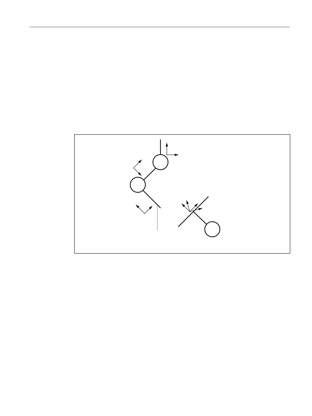
Tool offset
3.15 Sum and setup offsets
Coordinate systems for offsets in tool length
G commands TOWMCS, TOWWCS, TOWBCS, TOWTCS and TOWKCS can be used, e.g. to measure the
wear tool length component in five different coordinate systems.
1. Machine coordinate system
MCS
1. Basic coordinate system
BCS
1. Workpiece coordinate system
WCS
1. Tool coordinate system of kinematic transformation
KCS
1. Tool coordinate system
TCS
The calculated tool length or a tool length component can be represented and read out using the
predefined GETTCOR (Page 211) function in one of these coordinate systems.
=
0.6
;
=
.LQHPDWLF WUDQVIRUPDWLRQ WRRO
.&6
FRPSRQHQW
;
7RRO FDUULHU
7
WRRO FRPSRQHQW
=
;
;
=
=
;
:.6
%.6
7&6
3
7RRO
.LQHPDWLF WUDQVIRUPDWLRQ
ZRUNSLHFH WDEOH RU SDUW FRPSRQHQW
Figure 3-49
Coordinate system for the evaluation of tool lengths
3.15.5.2
Functionality of the individual wear values
TOWSTD
Basic setting (default behavior):
• The wear values are added to the other tool length components.
The resulting total tool length is then used in further calculations.
In the case of an active tool carrier with orientation capability:
• The wear values are subjected to the appropriate rotation.
TOWMCS
Wear data in the MCS (machine coordinate system):
Tools
Function Manual, 10/2020, 6FC5397-6GP40-0BA1
203
Tool offset
3.15 Sum and setup offsets
In the case of an active rotation by means of a tool carrier with orientation capability:
• The tool carrier only rotates the vector of the resultant tool length. Wear is ignored.
Then the tool length vector rotated in this way and the wear are added. The wear is not
subjected to the rotation.
If no tool carrier with orientation capability is active or this does not result in a rotation, TOWMCS
and TOWSTD are identical.
Linear transformation
The tool length can be uniquely defined in the MCS only if the MCS is generated by linear
transformation from the BCS.
This would also be the case under one of the following conditions:
• No kinematic transformation active.
• Orientation transformations (3-axis, 4-axis, and 5-axis transformations) are active.
TOWWCS
Wear values in WCS (workpiece coordinate system):
• If a tool carrier with orientation capability is active, the tool vector is calculated as for
TOWMCS, without taking the wear into account.
• The wear data is interpreted in the workpiece coordinate system.
The wear vector in the workpiece coordinate system is converted to the machine coordinate
system and added to the tool vector.
TOWBCS
Wear values in BCS (basic coordinate system):
• If a tool carrier with orientation capability is active, the tool vector is calculated as for
TOWMCS, without taking the wear into account.
• The wear data is interpreted in the workpiece coordinate system.
The wear vector in the basic coordinate system is converted to the workpiece coordinate system
and added to the tool vector.
Non-linear transformation
If a non-linear transformation is active, e.g. with TRANSMIT, and the MCS is specified as the
desired coordinate system, the BCS is automatically used instead of the MCS.
Tool carrier with orientation capability
A table component of the tool carrier with orientation capability, if available, is not applied
directly to the coordinate systems, unlike a table (or part) component of the kinematic
transformation. A rotation described by such a component is represented in a basic frame or
system frame and is thus included in the transition from WCS to BCS.
Kinematic transformation
The table (or part) component of the kinematic transformation is described by the transition
from BCS to MCS.
Tools
204
Function Manual, 10/2020, 6FC5397-6GP40-0BA1

Tool offset
3.15 Sum and setup offsets
TOWTCS
Wear values in TCS (tool coordinate system):
• If a tool carrier with orientation capability is active, the tool vector is calculated as for
TOWMCS, without taking the wear into account.
• The wear data is interpreted in the tool coordinate system.
The wear vector in the TCS (Tool Coordinate System) is converted to the machine coordinate
system by way of the tool coordinate system of the kinematic transformation (KCS) and added
to the tool vector.
TOWKCS
The wear value specifications for the kinematic transformation are interpreted in the associated
TCS (Tool Coordinate System).
The wear vector is converted to the machine coordinate system by way of the tool coordinate
system of the kinematic transformation and added to the tool vector.
G command change when a tool is active
Changing the G command in the group TOWSTD, TOWMCS, TOWWCS, TOWBCS, TOWTCS, and
TOWKCS does not affect an already active tool, and does not become effective until the next tool
is selected.
A new G command of this group will also come into effect if it is programmed in the same block,
in which a tool is selected.
Evaluation of individual wear components
Evaluation of individual wear components (assignment to geometry axes, sign evaluation) is
influenced by:
• The active plane
• The adapter transformation
• The five setting data shown in the table below
Setting data
Wear components
SD42910 $SC_MIRROR_TOOL_WEAR
TOWSTD
TOWMCS
TOWWCS
SD42920 $SC_WEAR_SIGN_CUTPOS
X
X
-
SD42930 $SC_WEAR_SIGN
X
-
-
SD42940 $SC_TOOL_LENGTH_CONST
X
X
X
SD42950 $SC_TOOL_LENGTH_TYPE
X
X
X
Note
Wear components which are subjected to an active rotation by an adapter transformation or a
tool carrier with orientation capability are referred to as non-transformed wear components.
Tools
Function Manual, 10/2020, 6FC5397-6GP40-0BA1
205
Tool offset
3.16 Working with tool environments
Special features
If TOWMCS or TOWWCS is active, the following setting data does not affect the non-transformed
wear components:
SD42920 $SC_WEAR_SIGN_CUTPOS (Sign of wear for tools with cutting edge systems)
The following setting data also does not affect the non-transformed wear components in case
of TOWWCS:
SD42910 $SC_MIRROR_TOOL_WEAR (Sign change tool wear when mirroring)
In this case, a possibly active mirroring is already contained in the frame, which is referred to for
evaluating the wear components.
On a plane change, the assignment between the non-transformed wear components and the
geometry axes is retained, i.e. these are not interchanged as with other length components. The
assignment of components depends on the active plane for tool selection.
Example
Let's assume a milling tool is used where only the wear value $TC_DP12 assigned to length L1
is not equal to zero.
If G17 is active, this length is effective in the direction of the z axis.
This measure always acts in the Z-direction also upon a plane change after the tool selection,
when TOWMCS or TOWWCS are active and the bit 1 is set in the setting data:
SD42935 $SC_WEAR_TRANSFORM (transformations for tool components)
If, for example, G18 is active on tool selection, the component is always effective in the Y
direction instead.
3.16
Working with tool environments
Overview of functions
• Save tool environment (TOOLENV) (Page 207)
• Delete tool environment (DELTOOLENV) (Page 209)
• Read T, D and DL number (GETTENV) (Page 210)
• Read tool lengths and/or tool length components (GETTCOR) (Page 211)
• Change tool components (SETTCOR) (Page 217)
System variables overview
• Read information about the saved tool environments ($P_TOOLENVN, ($P_TOOLENV)
(Page 211)
Tools
206
Function Manual, 10/2020, 6FC5397-6GP40-0BA1