SINUMERIK 840D sl. Service - Functions. Manual (2018-2020) - page 92

Alarms
11.2 Alarm description
Alarm No.
22066
Channel %1 tool management: Tool change not possible because tool %2 with duplo no. %3 is not in
magazine %4
Explanation
%1 = channel number, %2 = string (identifier), %3 = duplo number, %4 = magazine number
The desired tool change is not possible. The specified tool is not contained in the specified magazine. (NC
cannot contain tools that are not assigned to a magazine. No operations (movement, change) can be
performed with these tools).
Response
NC start disable
Alarm display
Interface signals are set
NC stop for alarm
Remedy
Please inform the authorized personnel / service department.
Ensure that the specified tool is contained in the required magazine - or program a different tool, which
should be changed.
Check whether machine data $MC_RESET_MODE_MASK, $MC_START_MODE_MASK - and in turn the cou-
pled machine data $MC_TOOL_RESET_NAME - match the actual definition data.
Continue pro-
Clear the alarm with the cancel key. No further operator action required.
gram
Alarm No.
22067
Channel %1 tool management: Tool change not possible because no tool ready for use in tool group %2
Explanation
%1 = channel number, %2 = string (identifier)
The desired tool change is not possible. The specified tool group does not contain a "ready to use" replace-
ment tool which could be loaded. The tool monitoring function may have set all potentially suitable tools to
the "disabled" status.
Response
NC start disable
Alarm display
Interface signals are set
NC stop for alarm
Remedy
At the time of the requested tool change, ensure that there is a tool that can be used in the specified tool
group.
This can be achieved, e.g. by replacing disabled tools, or by manually releasing a disabled tool.
Check whether the magazine data is correctly defined. Have all intended tools in the group been defined with
the specified identifier and loaded?
Continue pro-
Clear the alarm with the RESET key. Restart the part program.
gram
Tool management
736
Function Manual, 10/2020, 6FC5397-1HP40-0BA1

Alarms
11.2 Alarm description
Alarm No.
22068
Channel %1 tool management: No tool ready for use in tool group %3
Explanation
%1 = channel number, %2 = block number, label, %3 = string (identifier)
The specified tool group does not contain a "ready to use" replacement tool which could be loaded. The tool
monitoring function may have set all potentially suitable tools to the "disabled" status. The alarm can occur
in conjunction with alarm 14710 (error when generating the INIT block). In this special situation, for in-
stance, the NC attempts to replace the disabled tool located in the spindle by an available replacement tool
(which in this particular error case is not available).
The operator must resolve this conflict, for instance by removing the tool located in the spindle using a
movement command from the spindle (e.g. with an operator action via the HMI).
Response
NC start disable
Alarm display
Interface signals are set
Remedy
At the time of the requested tool change, ensure that there is a tool that can be used in the specified tool
group.
This can be achieved, for example, by replacing disabled tools, or by manually releasing a disabled tool.
Check whether the magazine data is correctly defined. Have all intended tools in the group been defined with
the specified identifier and loaded?
Continue pro-
Clear the alarm with NC START or the RESET key and continue the program.
gram
Alarm No.
22069
Channel %1 block %2 tool management: No tool available in tool group %3, program %4
Explanation
%1 = channel number, %2 = block number, label, %3 = string (identifier), %4 = program name
The specified tool group does not contain a "ready to use" replacement tool which could be loaded. The tool
monitoring function may have set all potentially suitable tools to the "disabled" status. Parameter %4 =
program name facilitates the identification of the program containing the programming command (tool
selection) that caused the error. This can be a subprogram or cycle, etc., which can no longer be identified
from the display. If the parameter has not bee specified, then it is the currently displayed program.
Response
Alarm display
Interface signals are set
Correction block with reorganization
Remedy
At the time of the requested tool change, ensure that there is a tool that can be used in the specified tool
group, e.g. by
replacing disabled tools, or by manually releasing a disabled tool.
Check whether the magazine data is correctly defined. Have all intended tools in the group been defined with
the specified identifier and loaded?
Continue pro-
Clear the alarm with NC START or the RESET key and continue the program.
gram
Tool management
Function Manual, 10/2020, 6FC5397-1HP40-0BA1
737

Alarms
11.2 Alarm description
Alarm No.
22070
TO unit %1 Please load tool T= %2 into magazine. Repeat data backup
Explanation
%1 = TO unit, %2 = T number of the tool
Only issued if tool management is active.
A data backup of the tool/magazine data has been started. The system has detected that the buffer magazine
still contains one or more tools. During backup, these tools lose the information assigning them to a mag-
azine and a location in the magazine. Therefore, it makes sense that all tools have been loaded the magazine
at the time the data backup is performed.
If this does not apply, when re-importing data, the magazine locations have the "reserved" status. You may
have to reset this status manually.
In the case of tools with a fixed-location coding, the loss of information about their location in the magazine
is equivalent to a general empty location search on any subsequent change back to the magazine.
Response
Interface signals are set.
Alarm display.
Remedy
Make sure that there are no tools stored in the buffer magazine before you start to back up data. Repeat the
data backup after removing the tools from the buffer magazine.
Continue pro-
Clear the alarm with the cancel key. No further operator action required.
gram
Alarm No.
22071
TO unit %1 tool %2 duplo no. %3 is active but not in the current wear group
Explanation
%1 = TO units, %2 = T number of the tool, %3 = duplo number
The "Wear group" function is active. In addition, the "Set tool to active status" setting is applied if a new wear
group is activated. This setting can also be programmed with NC command SETTA or started via similar
functions on the OPI.
It has been detected that more than one tool from the tool group has the "active" status. The tool which has
the "active" status in an "inactive" wear grouping is named in the alarm.
The alarm is for information purposes. It can be suppressed by setting bit 5 of MD 11410 SUP-
PRESS_ALARM_MASK.
Response
Alarm display
Set interface signals
Remedy
Before you start the machining operation, make sure that the "active" status is not set for any of the tools in
the magazine. You can do this by programming command SETTIA.
Continue pro-
Clear the alarm with the cancel key. No further operator action required.
gram
Alarm No.
400601
Incorrect configuration of loading points
Explanation
The PLC configuration in DB4 does not match the NC Configuration.
Response
Alarm display
Remedy
Correct tool management commissioning.
Continue pro-
Power-down the control and power-up again
gram
Tool management
738
Function Manual, 10/2020, 6FC5397-1HP40-0BA1

Alarms
11.2 Alarm description
Alarm No.
400602
Incorrect spindle configuration
Explanation
The PLC configuration in DB4 does not match the NC Configuration.
Response
Alarm display
Remedy
Correct tool management commissioning.
Continue pro-
Power-down the control and power-up again
gram
Alarm No.
400603
Incorrect turret configuration
Explanation
The PLC configuration in DB4 does not match the NC Configuration.
Response
Alarm display
Remedy
Correct tool management commissioning.
Continue pro-
Power-down the control and power-up again
gram
Alarm No.
400604
Set change with M06 in machine data
Explanation
Change is possible only with M06 for the magazine type used (box-type, chain). Check for invalid settings
when using turret magazines.
Response
Alarm display
Remedy
In the channel-specific data 22550: TOOL_CHANGE_MODE should be set to the value 1.
Continue pro-
Internal
gram
Alarm No.
410141
Number of loading points too high
Explanation
The PLC configuration in DB 4 does not match the NC configuration
Response
Alarm display
Remedy
Correct tool management commissioning.
Continue pro-
Switch control system OFF and ON again
gram
Alarm No.
410142
Number of tool holders too high
Explanation
The PLC configuration in DB 4 does not match the NC configuration
Response
Alarm display
Remedy
Correct tool management commissioning.
Continue pro-
Switch control system OFF and ON again
gram
Tool management
Function Manual, 10/2020, 6FC5397-1HP40-0BA1
739

Alarms
11.2 Alarm description
Alarm No.
410143
Number of turrets too high
Explanation
The PLC configuration in DB 4 does not match the NC configuration
Response
Alarm display
Remedy
Correct tool management commissioning.
Continue pro-
Switch control system OFF and ON again
gram
Alarm No.
410151
Magazine data for tool management missing in PLC
Explanation
No magazine data available in the PLC. Commissioning has not been completed although tool management
option has been activated.
Response
Alarm display
Remedy
Press the "Create PLC data" softkey via SINUMERIK Operate when commissioning tool management.
Continue pro-
Internal
gram
Tool management
740
Function Manual, 10/2020, 6FC5397-1HP40-0BA1

Preface
1
Introduction
Fundamental safety
2
instructions
SINUMERIK
3
Tool offset
SINUMERIK 840D sl
Tools
3D tool radius
4
compensation
Grinding-specific tool offset
5
and tool monitoring
Function Manual
A
Appendix
Valid for
control system
SINUMERIK 840D sl / 840DE sl
CNC software Version 4.94
10/2020
6FC5397-6GP40-0BA1
Table of contents
Preface
3
1
Introduction
11
1.1
About this documentation
11
2
Fundamental safety instructions
13
2.1
General safety instructions
13
2.2
Warranty and liability for application examples
13
2.3
Security information
13
3
Tool offset
15
3.1
Introduction
15
3.1.1
Programmed contour and tool path
15
3.1.2
Tool length compensation
15
3.1.3
Tool radius compensation
16
3.2
Tool change and activation of tool offset
17
3.2.1
Selection of tool and cutting edge and tool change
17
3.2.2
Activation of the tool offset
19
3.3
Tool offset memory
20
3.3.1
Compensation memory structure
20
3.3.2
Calculating the tool compensation
21
3.3.3
Address extension for NC addresses T and M
22
3.3.4
Free assignment of D numbers
23
3.3.5
Compensation block in case of error during tool change
28
3.3.6
Definition of the effect of the tool parameters
31
3.4
Tool parameters
32
3.4.1
Overview
32
3.4.2
Tool parameter 1: Tool type
33
3.4.3
Tool parameter 2: Cutting edge position
37
3.4.4
Tool parameters 3 ... 5: Geometry - tool lengths
39
3.4.5
Tool parameters 6 ... 11: Geometry - tool shape
40
3.4.6
Tool parameters 12 ... 14: Wear - tool lengths
42
3.4.7
Tool parameters 15 ... 20: Wear - tool shape
43
3.4.8
Tool parameters 21 ... 23: Base dimension / adapter dimension
43
3.4.9
Tool parameter 24: Clearance angle
46
3.5
2D tool radius compensation
47
3.5.1
General information
47
3.5.2
Selecting the TRC (G41/G42)
48
3.5.3
Approach and retraction behavior (NORM/KONT/KONTC/KONTT)
49
3.5.4
Smooth approach and retraction
54
3.5.4.1
Function
54
3.5.4.2
Parameters
54
3.5.4.3
Velocities
61
Tools
Function Manual, 10/2020, 6FC5397-6GP40-0BA1
5
Table of contents
3.5.4.4
System variables
63
3.5.4.5
Supplementary conditions
63
3.5.4.6
Examples
64
3.5.5
Deselecting the TRC (G40)
67
3.5.6
Compensation at outside corners
67
3.5.7
Compensation and inner corners
71
3.5.8
Collision monitoring ("bottleneck detection")
73
3.5.8.1
Function
73
3.5.8.2
Parameterization
74
3.5.8.3
Programming
75
3.5.8.4
Supplementary conditions
75
3.5.8.5
Example
76
3.5.9
Slot shape recognition (option)
77
3.5.10
Blocks with variable compensation value
79
3.5.11
Alarm behavior
81
3.5.12
Intersection procedure for polynomials
82
3.5.13
G461/G462 Approach/retract strategy expansion
82
3.5.14
Tools with a relevant tool point direction
86
3.6
2 1/2 D tool radius compensation
86
3.7
Keep tool radius compensation constant
89
3.8
Tool carriers with orientation capability
92
3.8.1
General information
92
3.8.2
Kinematic interaction and machine design
98
3.8.3
Tool carrier with kinematic chains
106
3.8.4
Programming
114
3.8.4.1
Tool length compensation for orientable toolholders (TCARR, TCOABS, TCOFR, TCOFRX,
TCOFRY, TCOFRZ)
114
3.8.4.2
Modifying the orientable tool carrier according to the machine measurement (CORRTC) ... 118
3.8.5
Examples
122
3.8.5.1
Example: Toolholder with orientation capability
122
3.8.5.2
Example of toolholder with orientation capability with rotary table
122
3.8.5.3
Calculation of compensation values on a location-specific and workpiece-specific basis
125
3.8.5.4
Example: Tool carrier with orientation capability via kinematic chain
127
3.8.6
Inclined surface machining with 3 + 2 axes
130
3.8.7
Machine with rotary work table
131
3.8.8
Procedure when using toolholders with orientation capability
134
3.8.9
Supplementary conditions and control system response for orientation
138
3.9
Modification of the offset data for rotatable tools
140
3.9.1
Introduction
140
3.9.2
Rotating turning tools
141
3.9.2.1
Cutting edge position, cut direction, and angle for turning tools
141
3.9.2.2
Modifications during the rotation of turning tools
144
3.9.3
Rotation of milling and drilling tools
148
3.9.3.1
Cutting edge position for milling and tapping tools
148
3.9.3.2
Modifications during rotation of milling and tapping tools
149
3.9.4
Commissioning
149
3.9.4.1
Parameter assignment
149
3.9.5
Programming
152
3.9.5.1
Calculating orientations (ORISOLH)
152
3.9.5.2
Activating the modification of the offset data for rotatable tools (CUTMOD, CUTMODK)
160
Tools
6
Function Manual, 10/2020, 6FC5397-6GP40-0BA1
Table of contents
3.9.6
Example
165
3.10
Incrementally programmed compensation values
167
3.10.1
G91 extension
167
3.10.2
Traversing in the direction of tool orientation (MOVT)
168
3.11
Assignment of tool length components to geometry axes
169
3.11.1
Assignment according to tool type and working plane
169
3.11.2
Assignment when changing plane
170
3.11.3
Assignment independent of tool type
171
3.12
Paraxial tool orientation
172
3.12.1
Basic tool orientation
172
3.12.2
Tool orientation for plane change
172
3.13
Parameterizable basic tool orientation
174
3.13.1
Function
174
3.13.2
Commissioning
174
3.13.2.1
Activation
174
3.13.2.2
Parameterization
175
3.13.3
Programming
176
3.13.4
Examples
179
3.14
Special handling of tool offsets
179
3.14.1
Relevant setting data
179
3.14.2
Mirroring tool lengths
180
3.14.3
Mirroring wear lengths
181
3.14.4
Tool lengths in the WCS, allowing for the orientation
183
3.14.5
Tool length offsets in tool direction
183
3.14.6
Special characteristics of orientable tool carriers
187
3.15
Sum and setup offsets
188
3.15.1
General information
188
3.15.2
Description of function
189
3.15.3
Activation
192
3.15.4
Examples
198
3.15.5
Extensions for tool length determination
199
3.15.5.1
Calculation of compensation values on a location-specific and workpiece-specific basis
199
3.15.5.2
Functionality of the individual wear values
203
3.16
Working with tool environments
206
3.16.1
Save tool environment (TOOLENV)
207
3.16.2
Delete tool environment (DELTOOLENV)
209
3.16.3
Read T, D and DL number (GETTENV)
210
3.16.4
Read information about the saved tool environments ($P_TOOLENVN, ($P_TOOLENV)
211
3.16.5
Read tool lengths and/or tool length components (GETTCOR)
211
3.16.6
Change tool components (SETTCOR)
217
3.17
Read the assignment of the tool lengths L1, L2, L3 to the coordinate axes (LENTOAX)
229
3.18
Boundary conditions
232
3.18.1
SD42935 expansions
232
3.18.2
Scratching
232
3.19
Data lists
233
3.19.1
Machine data
233
3.19.1.1
NC-specific machine data
233
Tools
Function Manual, 10/2020, 6FC5397-6GP40-0BA1
7
Table of contents
3.19.1.2
Channelspecific machine data
233
3.19.1.3
Axis/spindlespecific machine data
234
3.19.2
Setting data
235
3.19.2.1
Channelspecific setting data
235
3.19.2.2
Channelspecific setting data
235
4
3D tool radius compensation
237
4.1
Function
237
4.1.1
Introduction
237
4.1.2
Circumferential milling
238
4.1.2.1
Corners in circumferential milling
240
4.1.2.2
Behavior at outer corners
241
4.1.2.3
Behavior at inside corners
242
4.1.2.4
Monitoring of path curvature
244
4.1.3
Face milling
244
4.1.3.1
Tool shapes and tool data for face milling
245
4.1.3.2
Face milling with a specified surface normal vector
246
4.1.3.3
Compensation on path
248
4.1.3.4
Corners in face milling
249
4.1.3.5
Behavior at outer corners
250
4.1.3.6
Behavior at inside corners
250
4.1.3.7
Monitoring of path curvature
252
4.2
Commissioning
252
4.2.1
Parameter assignment
252
4.3
Programming
253
4.3.1
Selecting 3D tool radius compensation for 3D circumferential milling (CUT3DC,
CUT3DCD, ISD)
253
4.3.2
Selecting 3D tool radius compensation for the 3D face milling (CUT3DF, CUT3DFS,
CUT3DFF, CUT3DFD)
258
4.3.3
3D circumferential milling taking into account a limitation surface (CUT3DCC,
CUT3DCCD)
263
4.4
Boundary conditions
268
4.5
Examples
268
4.5.1
Example 1: Orientation change at outside corner during 3D circumferential milling
268
4.5.2
Example 2: Orientation change at inside corner during 3D circumferential milling
271
4.6
Data lists
272
4.6.1
General machine data
272
4.6.2
Channelspecific machine data
273
5
Grinding-specific tool offset and tool monitoring
275
5.1
Grinding-specific tool data
275
5.1.1
Structure of tool data
275
5.1.2
Cutting edge-specific parameters
276
5.1.2.1
List of cutting edge-specific parameters
276
5.1.2.2
$TC_DP1
278
5.1.2.3
Definition of additional parameters $TC_DPC1 ... 10
278
5.1.3
Tool-specific parameters
279
5.1.3.1
List of tool-specific parameters
279
5.1.3.2
$TC_TPG1
280
5.1.3.3
$TC_TPG2
280
Tools
8
Function Manual, 10/2020, 6FC5397-6GP40-0BA1
Table of contents
5.1.3.4
$TC_TPG3, $TC_TPG4
281
5.1.3.5
$TC_TPG5
281
5.1.3.6
$TC_TPG6 and $TC_TPG7
282
5.1.3.7
$TC_TPG8
282
5.1.3.8
$TC_TPG9
283
5.1.3.9
$TC_TPG_DRSPATH and $TC_TPG_DRSPROG
283
5.1.3.10
Definition of additional parameters $TC_TPC1 ... 10
283
5.1.3.11
Access to tool-specific parameters
284
5.1.4
Planes and axis assignments
284
5.1.5
Examples
285
5.2
Online tool offset
288
5.2.1
Function
288
5.2.2
Commissioning
289
5.2.3
Programming
290
5.2.3.1
Defining a polynomial function (FCTDEF)
290
5.2.3.2
Write online tool offset continuously (PUTFTOCF)
291
5.2.3.3
Write online tool offset, discrete (PUTFTOC)
292
5.2.3.4
Activate/deactivate online tool offset (FTOCON/FTOCOF)
293
5.2.4
Supplementary conditions
293
5.2.5
Examples
295
5.2.5.1
Example: Write online tool offset continuously
295
5.3
Online tool radius compensation
297
5.4
Grinding-specific tool monitoring
298
5.4.1
Function
298
5.4.2
Commissioning
300
5.4.3
Programming
300
5.4.3.1
Activate/deactivate grinding-specific tool monitoring (TMON, TMOF)
300
5.5
Constant grinding wheel peripheral speed (GWPS)
301
5.5.1
Function
301
5.5.2
Commissioning
302
5.5.3
Programming
303
5.5.3.1
Switching constant grinding wheel peripheral speed (GWPSON, GWPSOF) on/off:
303
5.5.4
Example
304
5.6
Data lists
305
5.6.1
Machine data
305
5.6.1.1
General machine data
305
5.6.1.2
Channelspecific machine data
305
5.6.1.3
Axis/spindlespecific machine data
305
A
Appendix
307
A.1
List of abbreviations
307
A.2
Documentation overview
312
Index
313
Tools
Function Manual, 10/2020, 6FC5397-6GP40-0BA1
9
Table of contents
Tools
10
Function Manual, 10/2020, 6FC5397-6GP40-0BA1

Introduction
1
1.1
About this documentation
This documentation is part of the documentation category of SINUMERIK Function Manuals.
SINUMERIK Function Manuals
The SINUMERIK Function Manuals describe the NC functions of a SINUMERIK control.
The target group are configuring engineers, technologists, commissioning engineers and
programmers.
Each Function Manual covers a specific topic and contains all the function descriptions for this
topic.
The following table shows which Function Manuals are available for your SINUMERIK control and
which topics a Function Manual covers:
Function Manual
Topic
Basic functions
Basic functions of a CNC control
Axes and spindles
Axis and spindle functions, axis couplings
Transformations
Transformation functions
Monitoring and compensating
Axis monitoring and compensation functions, collision avoid-
ance
Tools
Functions for selection, correction and monitoring of tools
Synchronized actions
Functionality of synchronized actions
PLC
Structure and functions of the PLC
Tool management
Function, commissioning and programming of tool manage-
ment
Technologies (for SINUMERIK ONE
Extended technological functionalities
and SINUMERIK 840D sl only)
Overview of contents
You will find an overview of the main chapters of the descriptions of functions that are contained
in a Function Manual on the title page.
Validity
The title page also contains all data about the validity of a document, i.e. for which SINUMERIK
control and for which software version this edition of the Function Manual is valid.
Tools
Function Manual, 10/2020, 6FC5397-6GP40-0BA1
11

Introduction
1.1 About this documentation
System data
In the descriptions of functions, the system data relevant for a function (machine data, setting
data, system variables, interface signals and alarms) are only described with the level of detail
that is strictly necessary to understand the function. You will find detailed information on this
data in the relevant List Manuals and for alarms in the Diagnostics Manual.
PLC blocks
The descriptions of functions often refer to the PLC function blocks (FB) and functions (FC). The
descriptions of these blocks apply to the SINUMERIK 840D sl and can only be applied in part to
other SINUMERIK controls.
Interface signals
In this document, only the absolute address valid for the SINUMERIK 840D sl is used to address
interface signals.
General graphical conventions
Examples
<signal address> (<signal name>)
DB31, ... DBX16.0-2 (actual gear stage A to C)
DB31, ... DBX16.3 (gear is changed)
Note
Quantity structure
Explanations concerning the NC/PLC interface are based on the absolute maximum number of
the following components:
• Mode groups (DB11)
• Channels (DB21, etc.)
• Axes/spindles (DB31, etc.)
Tools
12
Function Manual, 10/2020, 6FC5397-6GP40-0BA1

Fundamental safety instructions
2
2.1
General safety instructions
WARNING
Danger to life if the safety instructions and residual risks are not observed
If the safety instructions and residual risks in the associated hardware documentation are not
observed, accidents involving severe injuries or death can occur.
• Observe the safety instructions given in the hardware documentation.
• Consider the residual risks for the risk evaluation.
WARNING
Malfunctions of the machine as a result of incorrect or changed parameter settings
As a result of incorrect or changed parameterization, machines can malfunction, which in turn
can lead to injuries or death.
• Protect the parameterization against unauthorized access.
• Handle possible malfunctions by taking suitable measures, e.g. emergency stop or
emergency off.
2.2
Warranty and liability for application examples
Application examples are not binding and do not claim to be complete regarding configuration,
equipment or any eventuality which may arise. Application examples do not represent specific
customer solutions, but are only intended to provide support for typical tasks.
As the user you yourself are responsible for ensuring that the products described are operated
correctly. Application examples do not relieve you of your responsibility for safe handling when
using, installing, operating and maintaining the equipment.
2.3
Security information
Siemens provides products and solutions with industrial security functions that support the
secure operation of plants, systems, machines and networks.
In order to protect plants, systems, machines and networks against cyber threats, it is necessary
to implement - and continuously maintain - a holistic, state-of-the-art industrial security
concept. Siemens’ products and solutions constitute one element of such a concept.
Customers are responsible for preventing unauthorized access to their plants, systems,
machines and networks. Such systems, machines and components should only be connected to
Tools
Function Manual, 10/2020, 6FC5397-6GP40-0BA1
13
Fundamental safety instructions
2.3 Security information
an enterprise network or the internet if and to the extent such a connection is necessary and only
when appropriate security measures (e.g. firewalls and/or network segmentation) are in place.
For additional information on industrial security measures that may be implemented, please
visit
Siemens’ products and solutions undergo continuous development to make them more secure.
Siemens strongly recommends that product updates are applied as soon as they are available
and that the latest product versions are used. Use of product versions that are no longer
supported, and failure to apply the latest updates may increase customer’s exposure to cyber
threats.
To stay informed about product updates, subscribe to the Siemens Industrial Security RSS Feed
under
services/cert.html#Subscriptions).
Further information is provided on the Internet:
Industrial Security Configuration Manual (https://support.industry.siemens.com/cs/ww/en/
view/108862708)
WARNING
Unsafe operating states resulting from software manipulation
Software manipulations, e.g. viruses, Trojans, or worms, can cause unsafe operating states in
your system that may lead to death, serious injury, and property damage.
• Keep the software up to date.
• Incorporate the automation and drive components into a holistic, state-of-the-art industrial
security concept for the installation or machine.
• Make sure that you include all installed products into the holistic industrial security concept.
• Protect files stored on exchangeable storage media from malicious software by with suitable
protection measures, e.g. virus scanners.
• On completion of commissioning, check all security-related settings.
Tools
14
Function Manual, 10/2020, 6FC5397-6GP40-0BA1

Tool offset
3
3.1
Introduction
3.1.1
Programmed contour and tool path
Workpiece dimensions are programmed directly (e.g. according to the production drawing).
Therefore, tool data, such as milling tool diameter, cutting edge position of the turning tool
(counterclockwise/clockwise turning tool) and tool length, does not have to be taken into
consideration when creating the program.
The control corrects the travel path
When machining a workpiece, the tool paths are controlled according to the tool geometry so
that the programmed contour can be created with any tool.
So that the control can calculate the tool paths, the tool data must be entered in the tool
compensation memory of the control. Only the required tool (T...) and the required offset data
record (D...) are called via the NC program.
While the program is being processed, the control fetches the offset data it requires from the tool
offset memory, and corrects the tool path individually for different tools:
3URJUDPPHG FRQWRXU
:RUNSLHFH
&RUUHFWHG
7RRO SDWK
3.1.2
Tool length compensation
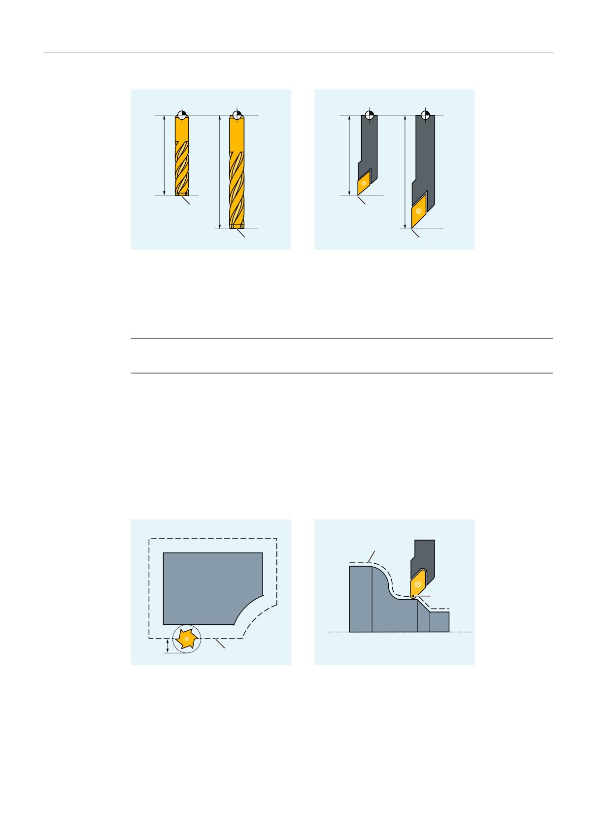
The tool length compensation compensates for the differences in length between the tools
used.
The tool length is the distance between the tool carrier reference point and the tool tip:
Tools
Function Manual, 10/2020, 6FC5397-6GP40-0BA1
15
Tool offset
3.1 Introduction
7
7
7
7
3
3
3
3
T
Tool carrier reference point
P
Tool tip
This length is measured and entered in the tool compensation memory of the control together
with definable wear values. From this data, the control calculates the traversing movements in
the infeed direction.
Note
The correction value of the tool length depends on the spatial orientation of the tool.
3.1.3
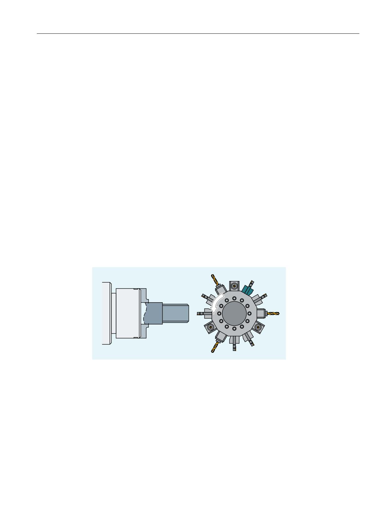
Tool radius compensation
The contour and tool path are not identical. The milling tool or cutting edge center point must
travel along a path corresponding to the tool radius that is equidistant from the contour (tool
center point path). To do this, while executing the program, the control shifts the programmed
tool center point path - based on the radius of the active tool (tool offset memory) - so that the
tool cutting edge traverses precisely along the programmed contour.
(TXLGLVWDQW
6
5
(TXLGLVWDQW
R
Tool radius
S
Cutting edge center point
The tool radius compensation is described in detail in the "2D tool radius compensation
(Page 47)" Chapter.
Tools
16
Function Manual, 10/2020, 6FC5397-6GP40-0BA1
Tool offset
3.2 Tool change and activation of tool offset
3.2
Tool change and activation of tool offset
3.2.1
Selection of tool and cutting edge and tool change
Tool selection
A tool is selected in the NC program with the T function.
The T function or the tool number can assume the following integer numbers:
• Minimum value: T0 (no tool)
• Maximum value: T32000 (tool with number 32000)
Whether the new tool will be loaded immediately by means of the T function depends on the
setting in the machine data:
MD22550 $MC_TOOL_CHANGE_MODE (new tool offset for M function)
Tool change immediate
MD22550 $MC_TOOL_CHANGE_MODE = 0
The new tool is loaded immediately with the T function.
This setting is primarily used for turning machines with turret magazines.
Tool change with M function
MD22550 $MC_TOOL_CHANGE_MODE = 1
The new tool is prepared for changing with the T function.
This setting is primarily used for milling machines with tool magazine in order to position the
new tool into the tool change position without interrupting the machining process.
The M function for tool change allows the old tool to be removed from the spindle and the new
tool to be loaded into the spindle.
The M function for tool change is defined in the machine data:
Tools
Function Manual, 10/2020, 6FC5397-6GP40-0BA1
17
Tool offset
3.2 Tool change and activation of tool offset
MD22560 $MC_TOOL_CHANGE_M_CODE (M function for tool change)
Default setting: M06 (acc. to DIN 66025)
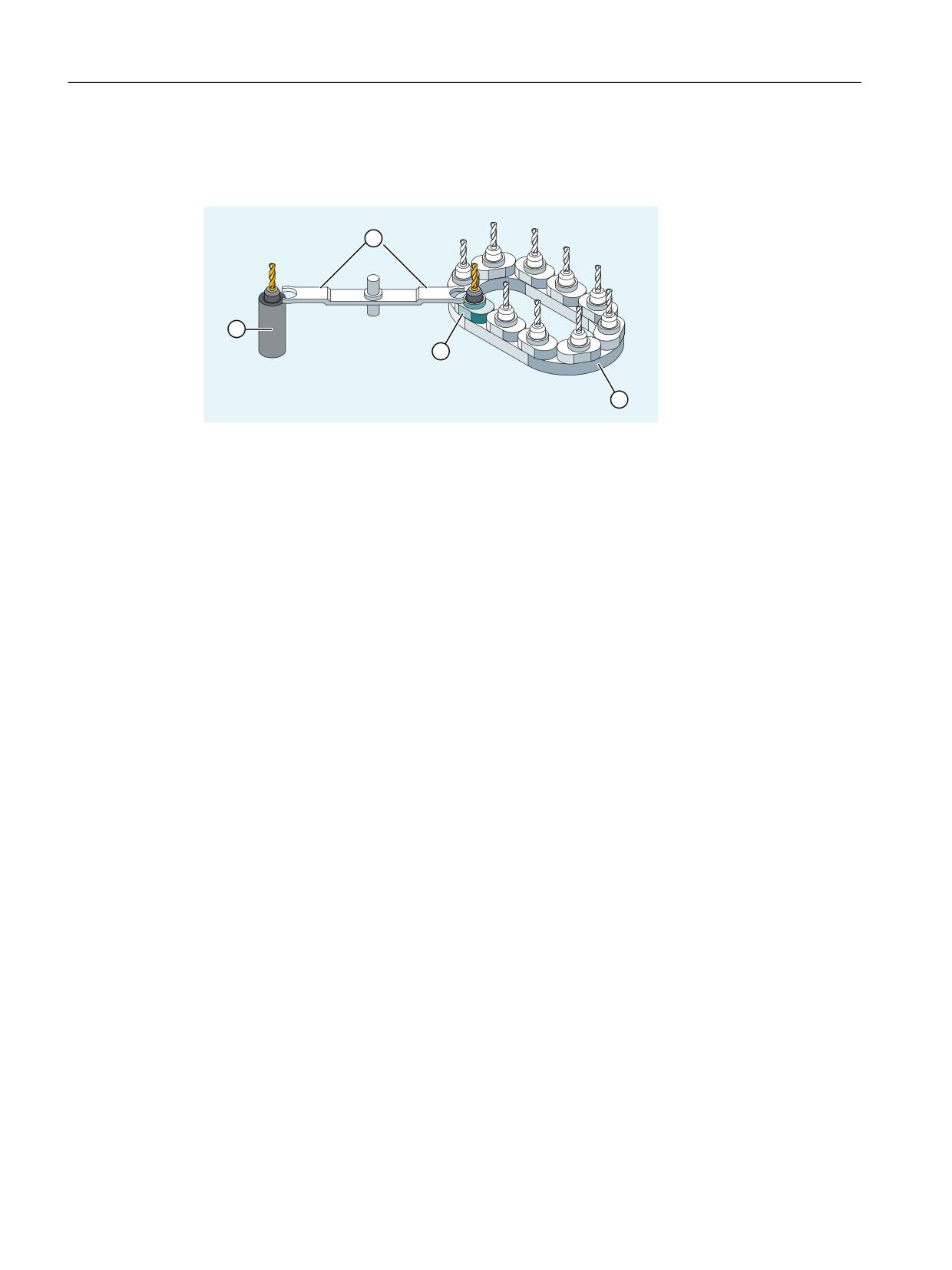
① Spindle
② Gripper
③ Magazine (here: chain magazine)
④ Tool change position
Preselected tool
The tool for which the tool length offset values are to be taken into consideration during power
up of the controller and for reset or part program end depending on MD20110
$MC_RESET_MODE_MASK and for part program start depending on MD20112
$MC_START_MODE_MASK is defined with the machine data:
MD20121 $MC_TOOL_PRESEL_RESET_VALUE
Tool cutting edge D
Several cutting edges D1 ... D<n> can be assigned to one tool T<x>.
Maximum number of tool cutting edges per tool
The maximum number of tool cutting edges (D numbers) which can be defined for each tool is
specified by the following machine data:
MD18106 $MN_MM_MAX_CUTTING_EDGE_PERTOOL
D function
Selection of the desired tool cutting edge 1 ... <n> for processing is performed in the NC program
by programming the corresponding D function D1 ... D<n>.
The selected tool cutting edge always refers to the active tool. A tool cutting edge without active
tool (actual T number is T0 ⇒ no tool selected), is not effective.
All tool compensations for the active tool T<x> are deselected with D0.
Tools
18
Function Manual, 10/2020, 6FC5397-6GP40-0BA1

Tool offset
3.2 Tool change and activation of tool offset
Selection of cutting edge for tool change
Following selection and loading of a new tool, the following options are provided for selection
of the cutting edge:
• Programming of the cutting edge number D<x>.
• The cutting edge number is defined by the machine data:
MD20270 $MC_CUTTING_EDGE_DEFAULT (basic position of the tool cutting edge without
programming)
Value
Meaning
0
No automatic cutting edge selection after M06.
≠ 0
Number of the cutting edge, which is selected in accordance with M06.
-1
The cutting edge number of the old tool is retained and is also selected for the new tool
after M06.
-2
The tool nose radius compensation of the old tool remains active until a new cutting edge
is programmed with D.
3.2.2
Activation of the tool offset
With D1 to D<n>, the tool offset for a cutting edge is activated for the active tool. Tool length
compensation and tool radius compensation become effective at different times, however:
• The tool length compensation (TLC) is performed on the first traversing motion of the axis
on which the TLC is to act.
This traversing motion must be a linear interpolation (G0, G1, POS, POSA) or polynomial
interpolation (POLY). If the POS/POSA axis is one of the active geometry axes, tool length
compensation is applied with the first axis motion, in which it is operative.
• Tool radius compensation (TRC) becomes active when G41/G42 is programmed in the
active plane (G17, G18 or G19).
In the NC block in which the tool radius compensation is activated with G41/G42, G0 (rapid
traverse) or G1 (linear interpolation) must be active and at least one geometry axis of the
active working plane must be programmed.
If only one geometry axis is specified when switching on, the last position of the second
geometry axis is automatically supplemented and then traversed in both axes.
If the axes are not geometry axes, then they must be transformed into geometry axes using
GEOAX programming.
The selection of the TRC with G41/G42 is only permitted in a program block with G0 (rapid
traverse) or G1 (linear interpolation).
Tools
Function Manual, 10/2020, 6FC5397-6GP40-0BA1
19
Tool offset
3.3 Tool offset memory
3.3
Tool offset memory
3.3.1
Compensation memory structure
Tool offset memory size
Each channel can have a dedicated tool offset memory (TO unit).
Which tool offset memory exists for the relevant channel is set with the machine data:
MD28085 $MC_MM_LINK_TOA_UNIT (assignment of TO unit to a channel)
The maximum number of tool cutting edges for all tools managed by the NC is set with the
machine data:
MD18100 $MN_MM_NUM_CUTTING_EDGES_IN_TOA (number of tool cutting edges in NC)
Tools
The tool offset memory consists of tools numbered T1 to T32000.
Each tool can be set up via TOA files or individually, using the "New tool" softkey. Offset values
not required must be assigned the value zero. This is the default setting when the offset memory
is created. The individual values in the offset memory (tool parameters) can be read and written
from the program using system variables.
Note
The tools (T1 to T32000) do not have to be stored in ascending order or contiguously in the tool
offset memory, and the first tool does not have to be assigned number T1.
Tools
20
Function Manual, 10/2020, 6FC5397-6GP40-0BA1
Tool offset
3.3 Tool offset memory
Tool cutting edges
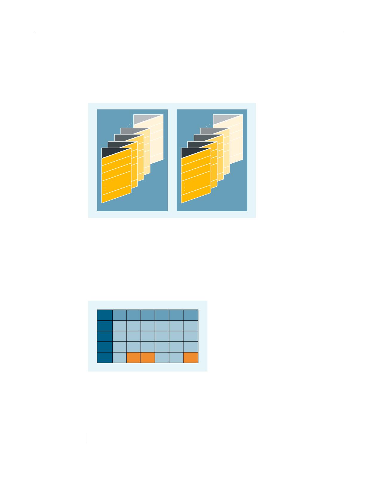
Each tool can have up to 12 cutting edges (D1 to D12). The first cutting edge (D1) is set up
automatically when a new tool is loaded to the tool offset memory. Other cutting edges (max.
11) are set up consecutively and contiguously using the "New cutting edge" softkey. A different
number of tool cutting edges can assigned to each tool in this way.
7Q
7Q
7
7
7
7
7
7
7
7
'
'
'
'
'
'
'
'
&KDQQHO
&KDQQHO
Figure 3-1
Example of a tool offset memory structure for two channels
3.3.2
Calculating the tool compensation
D No.
The D No. is sufficient for determining tool compensation values (can be set via MD).
' 1U
'3
'3
'3
'3
'
'
'Q
&9
&9
&9
CV
Total compensation value
Programming
The above compensation block is to be taken into account in the NC.
Part program call:
Tools
Function Manual, 10/2020, 6FC5397-6GP40-0BA1
21

Tool offset
3.3 Tool offset memory
Dn
3.3.3
Address extension for NC addresses T and M
MD20096
Whether the address extension of T and M is also to be interpreted as spindle number when the
tool management is not activated, can be set via the machine data:
MD20096 $MC_T_M_ADDRESS_EXT_IS_SPINO (spindle number as address extension)
The same rules then apply to the relationship between the D number and T number as when the
"Tool management" function is active.
Effect on the D number
An offset data set is determined by the D number.
The D address cannot be programmed with an address extension.
The evaluation of the D address always refers to the currently active tool.
The programmed D address refers to the active tool in relation to the master spindle (same as for
tool management function), when machine data is set:
MD20096 $MC_T_M_ADDRESS_EXT_IS_SPINO = TRUE (spindle number as address extension).
Effect on the T number
If the "Tool management" function is active, the values programmed with reference to the
master spindle (or master toolholder) are displayed as programmed/active T numbers.
If tool management is not active, all programmed T values are displayed as programmed/active,
regardless of the programmed address extension.
Only the T value programmed in relation to the master spindle is shown as programmed/active,
when:
MD20096 $MC_T_M_ADDRESS_EXT_IS_SPINO = TRUE (spindle number as address extension).
Example
The following example below shows the effect of MD20096.
Two spindles are considered. Spindle 1 is the master spindle. M6 was defined as the tool change
signal.
T1 = 5
M1 = 6
T2 = 50
M2 = 6
D4
Tools
22
Function Manual, 10/2020, 6FC5397-6GP40-0BA1
Tool offset
3.3 Tool offset memory
• If tool management is active, D4 refers to tool "5".
T2=50 defines the tool for the secondary spindle, whose tool does not influence the path
compensation. The path is determined exclusively by the tool programmed for the master
spindle.
• D4 refers to tool "50" without active tool management and with the machine data:
MD20096 $MC_T_M_ADDRESS_EXT_IS_SPINO = FALSE (significance of address extension
for T, M tool change).
The address extensions of neither T nor M are evaluated in the NC.
Each tool change command defines a new path compensation.
• D4 refers to tool "5" (as when tool management is active) without active tool management
and with the machine data:
MD20096 $MC_T_M_ADDRESS_EXT_IS_SPINO = TRUE.
Address extension 1 (T1= ..., M1= ...) addresses the master spindle.
Note
Previously, when tool management was not activated, each tool change command
(programmed with T or M) caused the tool offset to be recalculated in the path. The address
extension is not defined further by this operation. The significance of the extension is
defined by the user (in the PLC user program).
3.3.4
Free assignment of D numbers
"Relative" D numbers
In the NC it is possible to manage the D numbers as "relative" D numbers for the tool offset data
sets. The corresponding D numbers are assigned to each T number.
Functions
Expansions to functions when assigning D numbers:
• The maximum permitted D numbers are defined via the machine data:
MD18105 $MN_MM_MAX_CUTTING_EDGE_NO (max. value of the D numbers (DRAM))
The default value is 9, in order to maintain compatibility with existing applications.
• The number of cuts (or the offset data sets) for each tool can be defined via the machine data:
MD18106 $MN_MM_MAX_CUTTING_EDGE_PERTOOL (max. number of the D numbers per
tool (DRAM))
This allows you to customize the number of cutting edges to be configured for each tool to
the actual number of real cutting edges for monitoring purposes.
• It is also possible to rename D numbers in the NC and thus to allocate arbitrary D numbers to
the cutting edges.
Tools
Function Manual, 10/2020, 6FC5397-6GP40-0BA1
23
Tool offset
3.3 Tool offset memory
Cutting edge number CE
When you rename D numbers, the information in the tool Catalog detailing the numbers
defined for these cutting edges is lost. It is, therefore, impossible to determine, following
renaming, which cutting edge of the Catalog is being referenced.
Since this information is required for retooling procedures, a cutting edge number CE has been
introduced for each cutting edge. This number remains stored when the D number is renamed.
The D number identifies the cutting edge compensation in the part program. This
compensation number D is administered separately from the cutting edge number CE (the
number in the tool Catalog). Any number can be used. The number is used to identify a
compensation in the part program and on the display.
The CE number identifies the actual physical cutting edge during retooling. The cutting edge
number CE is not evaluated by the NC on compensation selection during a tool change (only
available via the OPI).
The cutting edge number CE is defined with system variable $TC_DPCE[t,d]:
• t stands for the internal T number
• d stands for the D number.
Write accesses are monitored for collisions, i.e. all cutting edge numbers of a tool must be
different. The variable $TC_DPCE is a component of the cutting edge parameter data set
$TC_DP1 to $TC_DP25.
It is only practical to parameterize $TC_DPCE if the maximum cutting edge number (MD18105)
is greater than the maximum number of cutting edges per tool (MD18106).
In this case, the default cutting edge number is the same as the classification number of the
cutting edge. Compensations of a tool are created starting at number 1 and are incremented up
to the maximum number of cutting edges per tool (MD18106).
The cutting edge number CE is the same as the D number (in compatibility with the behavior till
now) if:
MD18105 ≤ MD18106.
A read operation returns CE=D. A write operation is ignored without an alarm message.
Note
The offset values $TC_DP1 to $TC_DP25 of the active tool offset can be read with system variable
$P_AD[n], with n=1 to 25. The CE cutting edge number of the active compensation is returned
with n=26.
Commands
If the maximum cutting edge number is higher than the maximum number of cutting edges for
each tool, then the commands listed in the following table, are available
• (MD18105 $MN_MM_MAX_CUTTING_EDGE_NO) > (MD18106
$MN_MM_MAX_CUTTING_EDGE_PERTOOL)
Tools
24
Function Manual, 10/2020, 6FC5397-6GP40-0BA1

Tool offset
3.3 Tool offset memory
Command
Meaning
CHKDNO
Checks the uniqueness of the available D numbers;
The D numbers of all tools defined within a TO unit may not occur more than once. No
allowance is made for replacement tools.
GETDNO
Determines the D number for the cutting edge of a tool.
If no D number matching the input parameters exists, d=0.
If the D number is invalid, a value greater than 32000 is returned.
SETDNO
Sets or changes the D number of the CE cutting edge of tool T.
If there is no data set for the specified parameter, the value FALSE is returned. Syntax
errors generate an alarm. The D number cannot be set explicitly to 0.
GETACTTD
Determines the associated T number for an absolute D number.
There is not check for uniqueness. If several D numbers within a TO unit are the same,
the T number of the first tool found in the search is returned.
DZERO
Marks all D numbers of the TO unit as invalid;
This command is used for support during retooling.
Compensation data sets tagged with this command are no longer verified by
the CHKDNO language command. These data sets can be accessed again by setting the
D number once more with SETDNO.
Note
If the maximum cutting edge number is less than the maximum number of cutting edges for
each tool, then the commands listed in the table are ineffective. This default setting is in the
system for reasons of compatibility.
The individual commands are described in detail in:
Further information
Programming Manual Fundamentals
Activation
In order to work with unique D numbers and, therefore, with the defined language commands,
it must be possible to name D numbers freely for the tools.
To do this, the following precondition must be satisfied:
• MD18105 > MD18106
Examples
MD18105 $MN_MM_MAX_CUTTING_EDGE_NO = 1 (max. value of the D numbers)
A maximum of one compensation can be defined per tool (with D number = 1).
MD18105 $MN_MM_MAX_CUTTING_EDGE_NO = 9999
Tools can be assigned unique D numbers.
Tools
Function Manual, 10/2020, 6FC5397-6GP40-0BA1
25

Tool offset
3.3 Tool offset memory
Example: Assigning D (cutting edges) to T numbers (tools) and listing options for checking
uniqueness:
• Assignment:
- T No. 1 ⇒ assignment of D numbers 1, 2, 3
- T No. 2 ⇒ assignment of D numbers 10, 20, 30, 40, 50
- T No. 3 ⇒ assignment of D numbers 100, 200, 30 (error: 30 was entered instead of 300)
• Check for uniqueness:
The D numbers of all tools defined within a TO unit must be unique.
The check is made using the CHKDNO command. When no parameters are specified, all D
numbers of all tools are checked with respect to one another. In this particular case, the
return value == FALSE, as D30 is available in tool T2 and T3.
Command
Test
Test result
CHKDNO
All D numbers of all tools are
Return value == FALSE, as D=30 is duplica-
checked against all other tools
ted.
CHKDNO (2, 3,
D number 30 in tools 2 and 3
Return value == FALSE, as D=30 is duplica-
30)
ted.
CHKDNO (1, 3)
All D numbers of tools 1 and 3
Return value == TRUE although there is a col-
lision between the D=30 of the third tool and
D=30 of the second tool.
Note
Cutting edges per tool
If tools with n cutting edges are used, then the value of the machine data should be set to n.
This prevents inadmissible cutting edges to be defined for a tool.
MD18106 $MN_MM_MAX_CUTTING_EDGE_PERTOOL = n
Programming examples
Renaming a D number
The D number of cutting edge CE = 3 is to be renamed from 2 to 17. The following specifications
apply:
• $TC_DPx[ <tool Tn>, <cutting edge Dm> ]
• Internal T number Tn = 1
• D number Dm = 2
• Tool with one cutting edge with:
Program code
Comment
$TC_DP3[ 1, 2 ] = 120
Tool length = 120
$TC_DP6[ 1, 2 ] = 5.5
Tool radius = 5.5
$TC_DPCE[ 1, 2 ] = 3
Cutting edge number CE = 3
• MD18105 $MN_MM_MAX_CUTTING_EDGE_NO = 20 (max. value of the D numbers)
Within the part program, this compensation is programmed as standard with T1,
D2.
Tools
26
Function Manual, 10/2020, 6FC5397-6GP40-0BA1

Tool offset
3.3 Tool offset memory
You assign the current D number of cutting edge 3 to a variable (DNoOld) and define the variable
DNoNew for the new D number:
Program code
def int DNoOld, DNoNew = 17
DNoOld = GETDNO( 1, 3 )
SETDNO( 1, 3, DNoNew )
The new D value 17 is then assigned to cutting edge CE=3.
Now the data for the cutting edge are addressed via D number 17, both via the system variable
and in programming with the NC address D.
This compensation is now programmed in the part program with T1,
D17 and the data
is addressed as follows:
Program code
Comment
$TC_DP3[ 1, 17 ] = 120
$TC_DP6[ 1, 17 ] = 5.5
$TC_DPCE[ 1, 17 ] = 3
; Cutting edge number CE
Note
If the tool has defined a further cutting edge, e.g. $TC_DPCE[ 1, 2 ] = 1 ; = CE, D number 2 of
cutting edge 1 cannot have the same name as the D number of the cutting edge 3,
i.e.: SETDNO( 1, 1, 17) returns the status = FALSE as return value.
DZERO - Invalidate D numbers
The activation of this command invalidates all D numbers of the tools in the TO unit. It is no
longer possible to activate a compensation until valid D numbers are again available in the NC.
The D numbers must be reassigned using the SETDNO command.
The following tools must be defined (all with cutting edge number 1):
T1, D1
D no. of cutting edge CE=1
T2, D10
D no. of cutting edge CE=1
T3, D100
D no. of cutting edge CE=1
The following command is then programmed:
Program code
DZERO
If one of the compensations is now activated (e.g. with T3 D100), an alarm is generated,
because D100 is not currently defined.
The D numbers are redefined with:
Program code
Comment
SETDNO( 1, 1, 100 )
; T=1, cutting edge 1 is assigned the (new) D number 100
SETDNO( 2, 1, 10 )
; T=2, cutting edge 1 is assigned the (old) D number 10
SETDNO( 3, 1, 1 )
; T=3, cutting edge 1 is assigned the (new) D number 1
Tools
Function Manual, 10/2020, 6FC5397-6GP40-0BA1
27
Tool offset
3.3 Tool offset memory
Note
In the event of a power failure, the DZERO command can leave the NC in an undefined state with
reference to the D numbers. If this happens, repeat the DZERO command when the power is
restored.
Operating principle of a retooling program
Let us assume you want to ensure that the required tools and cutting edges are available. The
status of the tool-holding magazine of the NC is arbitrary. The D numbers in the part programs
for the new machining operation generally do not match the D numbers of the actual cutting
edges. The retooling program can have the following appearance:
Program code
Comment
DZERO
; All D numbers of the TO unit are tagged as invalid
; One or more loops over the locations of the magazine to check
the tools and their cutting edge numbers.
; If a tool is found, which is still enabled ($TC_TP8) and has
the required cutting edge number CE (GETDNO), the new D number is
allocated to the cutting edge (SETDNO).
; Loading and unloading operations are performed.
; It is possible to work with the tool status 'to be unloaded'
and 'to be loaded'.
CHKDNO
; Loading/unloading and the operation for renaming D numbers are
complete.
; Individual tools and/or D numbers can be checked, and colli-
sions can be handled automatically according to the return value.
3.3.5
Compensation block in case of error during tool change
MD22550
If a tool preparation has been programmed in the part program and the NC detects an error (e.g.
the data set for the programmed T number does not exist in the NC), the user can assess the error
situation and perform appropriate tasks, in order to subsequently resume machining.
The tool change may be programmed independently, depending on the machine data:
MD22550 $MC_TOOL_CHANGE_MODE (new tool offset for M function)
MD22550 $MC_TOOL_CHANGE_MODE = 0
T= 'T no.'
; Tool preparation + tool change in one NC block,
; i.e. when T is programmed a new D compensation becomes
; active in the NC. See machine data:
; MD20270 $MC_CUTTING_EDGE_DEFAULT (basic position of the tool cut-
ting edge without programming)
Tools
28
Function Manual, 10/2020, 6FC5397-6GP40-0BA1
Tool offset
3.3 Tool offset memory
MD22550 $MC_TOOL_CHANGE_MODE = 1
T= 'T no.'
; Tool preparation
M06
; Tool change
; (the number of the tool-change M code can be set),
; i.e. when M06 is programmed, a new D compensation becomes
; active in the NC (see
; machine data MD20270 $MC_CUTTING_EDGE_DEFAULT)
If the tool management is not active, the following problems can be detected:
• D compensation data set missing
• Error in the part program
Note
The "tool is not in the magazine" problem cannot be detected since the NC did not have access
to any magazine information for the tool offset.
D compensation data set missing
Program execution is interrupted at the block containing the invalid D value (regardless of the
value of machine data MD22550). The operator must either correct the program or reload the
missing data set. To do this, he requires the D and T number. These parameters are transferred
when the alarm is triggered.
Error in the part program
The options for intervention in the event of an error depend on how the tool change was
programmed, defined via the machine data:
MD22550 $MC_TOOL_CHANGE_MODE (new tool offset for M function)
Tool change with T programming (MD22550 = 0)
In this case, the "Compensation block" function available in the NC is used. The NC program stops
at the NC block in which an error was detected for the programmed T value. The "Compensation
block" is executed again when the program is resumed.
The operator can perform the following:
• Correct the part program.
• Reload the missing cutting edge compensation data from the HMI.
• Include the missing cutting edge compensation data in the NC using "Overstore".
Following operator intervention, the START key is pressed and the block, which caused the
error, is executed again. If the error was corrected, the program is resumed. Otherwise, an alarm
is output again.
Tool change with T and M06 programming (MD22550 = 1)
Tools
Function Manual, 10/2020, 6FC5397-6GP40-0BA1
29
Tool offset
3.3 Tool offset memory
In this case, an error is detected in the NC block of the tool preparation (programming of T),
which however is to be ignored at first. Execution is continued until the tool change request
(usually M06) is executed in the NC program. The program is to stop at this point.
The programmed T address can be any number of program lines before the M06 command, or
the two instructions can be in different (sub)programs. For this reason, it is not usually possible
to modify a block which has already been executed via the compensation block.
The operator has the same options for intervention as with = 0.
Reloading of missing data is possible. In this case, however, T must be programmed with
"Overstore".
If a program error has occurred, the line with the error cannot be corrected (Txx); only the line
at which the program stopped and which generated the alarm can be edited. Only when
machine data:
MD22562 $MC_TOOL_CHANGE_ERROR_MODE bit 0 = 1 (response to errors during tool change)
This results in the following sequence:
Txx
; Error! Data set with xx does not exist
; Note state; note xx;
; continue in program
M06
; Detect bit memory "xx missing" → output alarm,
; stop program
; Correct block with, e.g. Tyy M06, start,
; block Tyy M06 is interpreted and is OK.
; Execution continues.
Renewed execution of the program points results in the following:
Txx
; Error! Data set with xx does not exist,
; Note state; note xx;
; continue in program
Tyy M06
; Detect bit memory "xx missing" → reject without further response,
; as Tyy M06 is correct → program does not stop (correct).
If required, the original point of the T call can be corrected at the end of the program. If the tool
change logic on the machine cannot process this, the program must be aborted and the point
of the error corrected.
If only one data set is missing, it is transferred to the NC, Txx is programmed in "Overstore" and
the program is subsequently resumed.
Tools
30
Function Manual, 10/2020, 6FC5397-6GP40-0BA1
Tool offset
3.3 Tool offset memory
As in the case of "missing D number", the required parameter (T number) can be accessed by the
user for "missing T number" via the appropriate alarm (17191).
Note
In order to enable program correction, it stops immediately at the faulty Txx block.
The program test mode is also stopped when machine data:
MD22562 $MC_TOOL_CHANGE_ERROR_MODE bit 0=1 (response to errors during tool change).
3.3.6
Definition of the effect of the tool parameters
MD20360
The effect of the tool parameters on the transverse axis in connection with diameter
programming can be controlled selectively with the machine data:
MD20360 $MC_TOOL_PARAMETER_DEF_MASK (definition of tool parameters)
Details are described with the mentioned MD.
DRF manual handwheel traversing with half distance
During DRF handwheel traversal, it is possible to move a transverse axis through only half the
distance of the specified increment as follows:
Specify the distance with handwheel via the machine data:
MD11346 $MN_HANDWHEEL_TRUE_DISTANCE = 1 (handwheel path or speed specification)
Define the DRF offset in the transverse axis as a diameter offset with the machine data:
MD20360 $MC_TOOL_PARAMETER_DEF_MASK bit 9 = 1 (definition of tool parameters)
Deselecting an axial DRF offset (DRFOF) also deletes an existing tool offset (handwheel override
in tool direction).
Note
For further information about superimposed movements with the handwheel, please refer to:
Further information
Function Manual Axes and Spindles; Manual Traversing
Programming Manual Fundamentals
(The Programming Manual describes the complete technical program options in order to
deselect the DRF offset axis-specifically.)
Tools
Function Manual, 10/2020, 6FC5397-6GP40-0BA1
31

Tool offset
3.4 Tool parameters
3.4
Tool parameters
3.4.1
Overview
Tool parameters
A tool cutting edge is clearly defined with the following details:
• Tool type (end mill, drill, etc.)
• Geometrical description
• Technological description
The geometrical description, the technological description and the tool type are mapped to tool
parameters for each tool cutting edge.
The following tool parameters are available:
Tool parameter
Meaning
Remark
1
Tool type
2
Cutting edge position
For turning tools or for milling/grinding tools
with 2D TRC with contour tools.
Geometry - tool lengths
3
Length 1
4
Length 2
5
Length 3
Geometry - tool shape
6
Radius 1
With 2D TRC.
Turning: Rounding radius of cutting edge
3D face milling: Tool radius
Grooving saw: Diameter
7
Radius 2
3D face milling: Corner radius (for tools with
corner rounding)
Grooving saw: Slot width
8
Length 4
Grooving saw: Projection
9
Length 5
3D face milling: Upper bevel cutter diameter
(of spherical tools)
10
Angle 1
Turning: Holder angle
2D TRC with contour tools: Minimum limit
angle
11
Angle 2
Turning: Cutting direction
2D TRC with contour tools: Maximum limit
angle
3D face milling: Angle between envelope
line and tool longitudinal axis (of conical
tools)
Tools
32
Function Manual, 10/2020, 6FC5397-6GP40-0BA1

Tool offset
3.4 Tool parameters
Tool parameter
Meaning
Remark
Wear - tool lengths
12
Wear length 1
13
Wear length 2
14
Wear length 3
Wear - tool shape
15
Wear radius 1
16
Wear radius 2
17
Wear length 4
18
Wear length 5
19
Wear angle 1
20
Wear angle 2
Tool base dimension / adapter dimension
21
Basic length 1
22
Basic length 2
23
Basic length 3
Technology
24
Clearance angle
Only for turning tools.
25
Reserved*
* "Reserved" means that this tool parameter is not used and is reserved for expansions.
3.4.2
Tool parameter 1: Tool type
This tool type defines the respective tool. The selection of this tool type determines further
components such as geometry, wear and tool base dimensions in advance.
Each tool type is assigned a unique 3-digit number. The assignment of the tool to one of the
following technologies or tool groups is realized using the first digit (the hundreds position):
Tool type
Tool group
1xy
Milling tools
2xy
Drilling tools
3xy
Reserved
4xy
Grinding tools
5xy
Turning tools
6xy
Reserved
7xy
Special tools
Tools
Function Manual, 10/2020, 6FC5397-6GP40-0BA1
33
Tool offset
3.4 Tool parameters
The following is applicable to the "Tool type" parameter:
• The tool type must be specified for each tool cutting edge.
• Only the values specified can be used for the tool type.
• Tool type "0" means that no valid tool has been defined.
Relevant tool parameters
The parameter values to be entered in accordance with the tool type (tool offset data; TOA data)
are stored in system variables ($TC_DPx and $TC_TPGx).
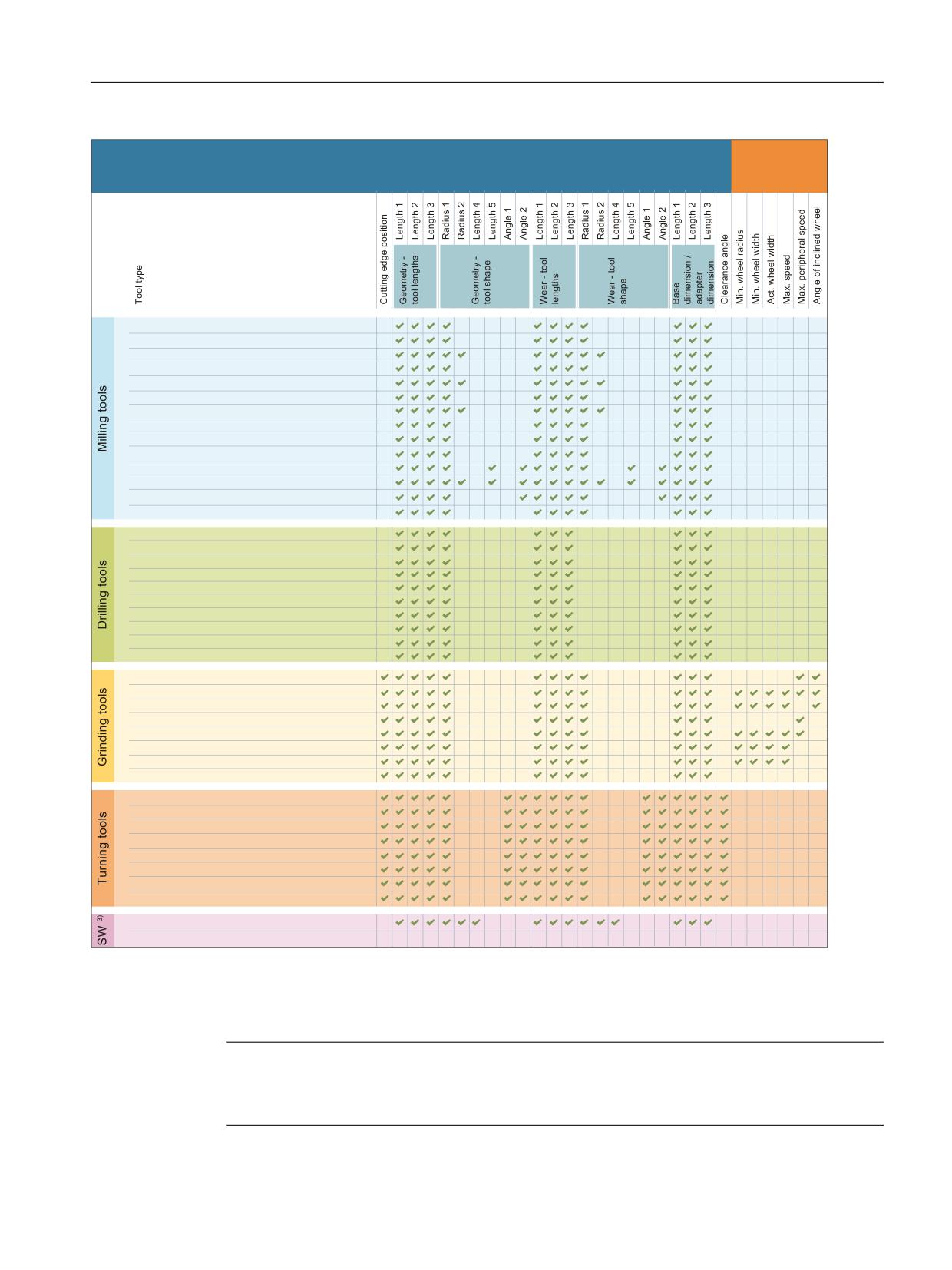
An overview of the parameter values required for the respective tool type is provided in the
following table:
Tools
34
Function Manual, 10/2020, 6FC5397-6GP40-0BA1
Tool offset
3.4 Tool parameters
&XWWLQJ HGJH SDUDPHWHU
7RRO SDUDPHWHU
7&B'3[
7&B73*[
[
0LOOLQJ WRRO DFF WR &/'$7$
%DOO HQG PLOO
&\OLQGULFDO GLH VLQNLQJ PLOOLQJ FXWWHU
(QG PLOO
(QG PLOO ZLWK FRUQHU URXQGLQJ
$QJOH KHDG FXWWHU
$QJOH KHDG PLOO ZLWK FRUQHU URXQGLQJ
)DFLQJ WRRO
7KUHDG FXWWHU
6LGH PLOO
%HYHO FXWWHU
%HYHO FXWWHU ZLWK FRUQHU URXQGLQJ
7DSHUHG GLH PLOOLQJ WRRO
'ULOO DQG WKUHDG PLOOLQJ FXWWHU
7ZLVW GULOO
'ULOO
%RULQJ EDU
&HQWHU GULOO
&RXQWHUVLQN
&RXQWHUERUH
7DS UHJXODU WKUHDG
7DS ILQH WKUHDG
7DS :KLWZRUWK WKUHDG
5HDPHU
6XUIDFH JULQGLQJ ZKHHO
6XUIDFH JULQGLQJ ZKHHO ZLWK PRQLWRULQJ
$V ZLWK
KRZHYHU ZLWKRXW EDVLF GLPHQVLRQ IRU *:36
)DFHSODWH
)DFHSODWH ZLWK PRQLWRULQJ
)DFHSODWH ZLWKRXW PRQLWRULQJ
$V ZLWK
KRZHYHU ZLWKRXW EDVLF GLPHQVLRQ IRU *:36
'UHVVHU
5RXJKLQJ WRRO
)LQLVKLQJ WRRO
3OXQJH FXWWHU
3DUWLQJ WRRO
7KUHDGLQJ WRRO
%XWWRQ WRRO 6HFWLRQDO VWHHO 722/0$1
5RWDU\ GULOO (&2&87
3UREH ZLWK FXWWLQJ HGJH SRVLWLRQ SDUDPHWHU
*URRYLQJ VDZ
1)
CLDATA = "cutter location data" (tool position data according to DIN66215)
2)
GWPS = Grinding wheel peripheral speed
3)
ST = Special tools
Note
The tool type has no significance in the turning tool groups.
Unlisted numbers are also permitted, in particular with grinding tools (400-499).
Tools
Function Manual, 10/2020, 6FC5397-6GP40-0BA1
35
Tool offset
3.4 Tool parameters
Calculating tool offset data
The CNC combines the individual components in the tool offset data to produce a value (e.g.
total length, total radius). The relevant overall dimension becomes effective when the offset
memory is activated. The use of these values in the axes is determined by the tool type and
current machining plane G17, G18 or G19.
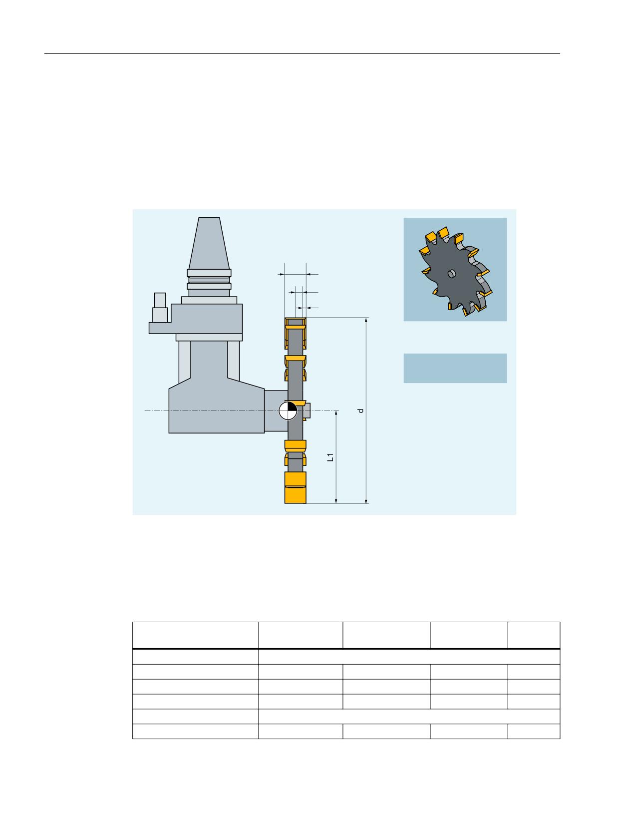
Example: Grooving saw tool type (Type 700)
E
/
N
/ G
/ E
N
7
T'
Tool carrier reference point
L1
Geometry - length 1
L2
Geometry - length 2
d
Diameter
b
Groove width
k
Projection
Geometry
Wear
Tool base di-
Unit
mension
Tool length compensation
Length 1
$TC_DP3
$TC_DP12
$TC_DP21
mm
Length 2
$TC_DP4
$TC_DP13
$TC_DP22
mm
Length 3
$TC_DP5
$TC_DP14
$TC_DP23
mm
Saw blade compensation
Diameter d
$TC_DP6
$TC_DP15
mm
Tools
36
Function Manual, 10/2020, 6FC5397-6GP40-0BA1
Tool offset
3.4 Tool parameters
Geometry
Wear
Tool base di-
Unit
mension
Groove width b
$TC_DP7
$TC_DP16
mm
Projection k
$TC_DP8
$TC_DP17
mm
The width of the saw blade is taken into account for the tool radius compensation (G40/G41/
G42) as follows:
Function
Meaning
G40
No saw blade compensation
G41
Saw blade compensation left
G42
Saw blade compensation right
3.4.3
Tool parameter 2: Cutting edge position
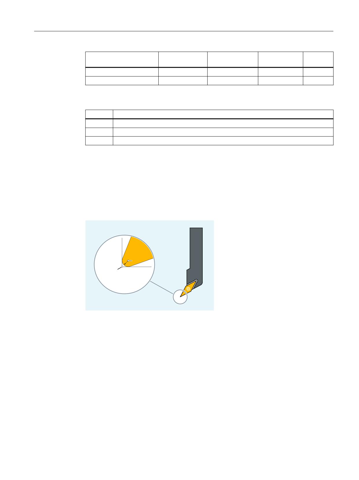
The cutting edge position describes the position of the tool tip P in relation to the cutting edge
center point S. It is entered in tool parameter 2.
The cutting edge position is required together with the cutting edge radius (tool parameter 8)
for the calculation of the tool radius compensation for turning tools (tool type 5xx).
5
6
3
P
Tool tip
S
Cutting edge center point
R
Cutting edge radius
Tools
Function Manual, 10/2020, 6FC5397-6GP40-0BA1
37
Tool offset
3.4 Tool parameters
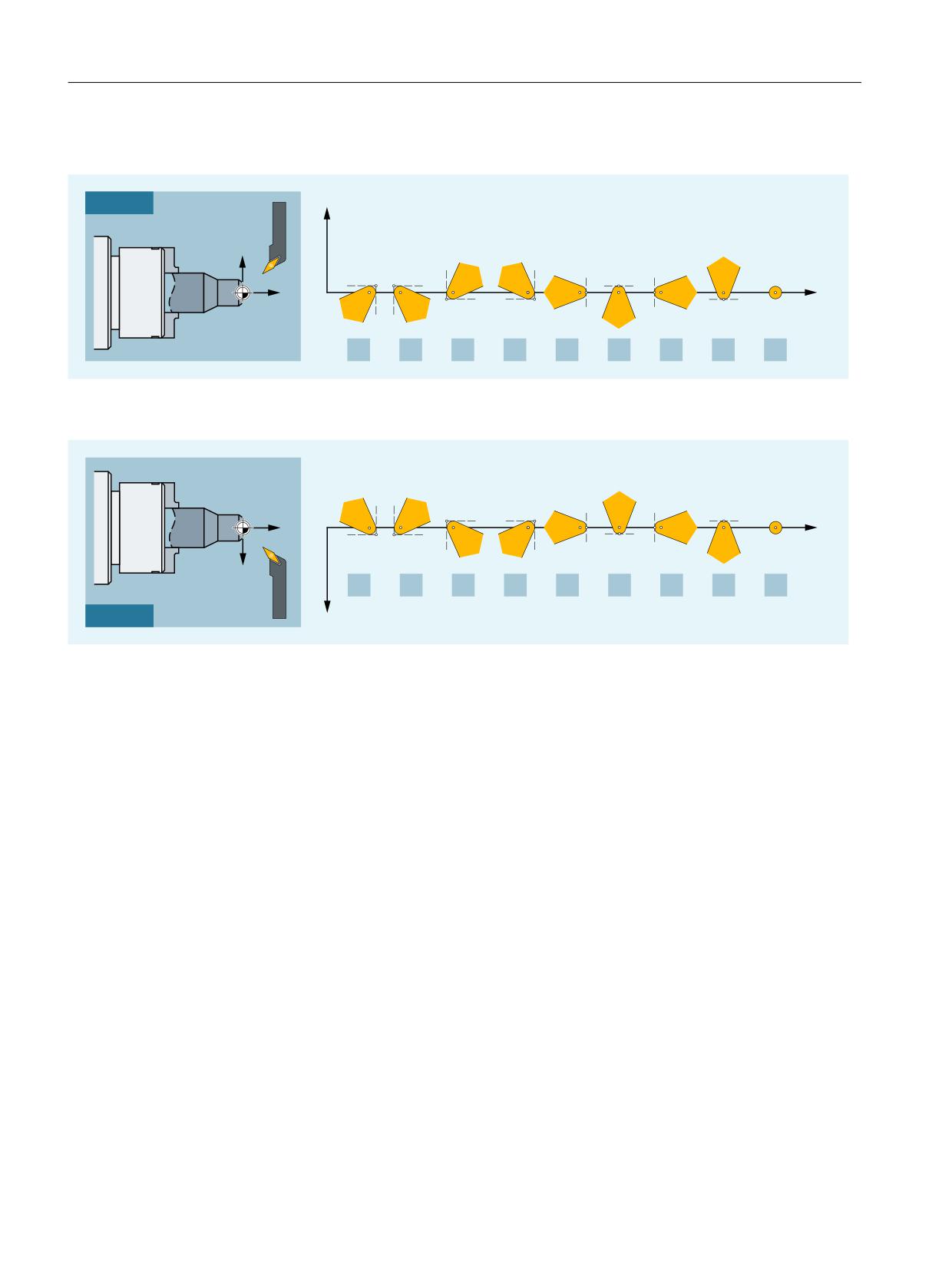
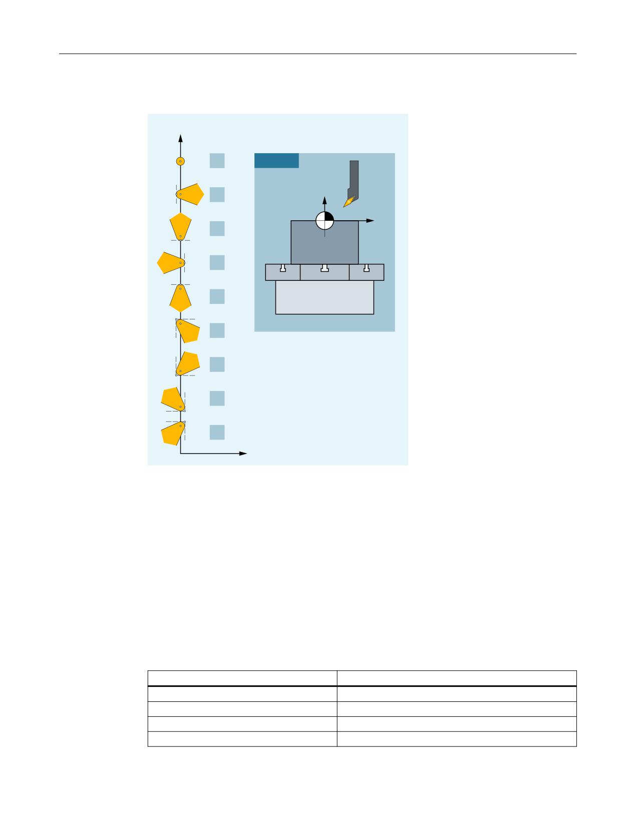
Cutting edge position (1 ... 9) for machining behind the turning center
;
*
;=
;
=
=
Cutting edge position (1 ... 9) for machining in front of the turning center
=
=
;
*
;=
;
Tools
38
Function Manual, 10/2020, 6FC5397-6GP40-0BA1
Tool offset
3.4 Tool parameters
Cutting edge position (1 ... 9) for vertical boring and turning mills
=
*
;=
=
;
;
Special aspects
• If the cutting edge center point S is used instead of point P as a reference point to calculate
the tool length compensation, the identifier 9 must be entered for the cutting edge position.
• The identifier 0 (zero) is not permitted as a cutting edge position.
3.4.4
Tool parameters 3 ... 5: Geometry - tool lengths
The lengths of the tools are required for the geometry tool length compensation. They are input
as tool lengths 1 to 3 in the tool parameters 3 to 5.
The minimum required tool length depends on the respective tool type:
Tool type
Required tool lengths
Tool type 12x, 140, 145, 150
Tool length 1
Tool type 13x
Tool length 1 ... 3 (depending on plane G17/G18/G19)
Tool type 2xx
Tool length 1
Tool type 5xx
Tool plane 1 ... 3
Tools
Function Manual, 10/2020, 6FC5397-6GP40-0BA1
39
Tool offset
3.4 Tool parameters
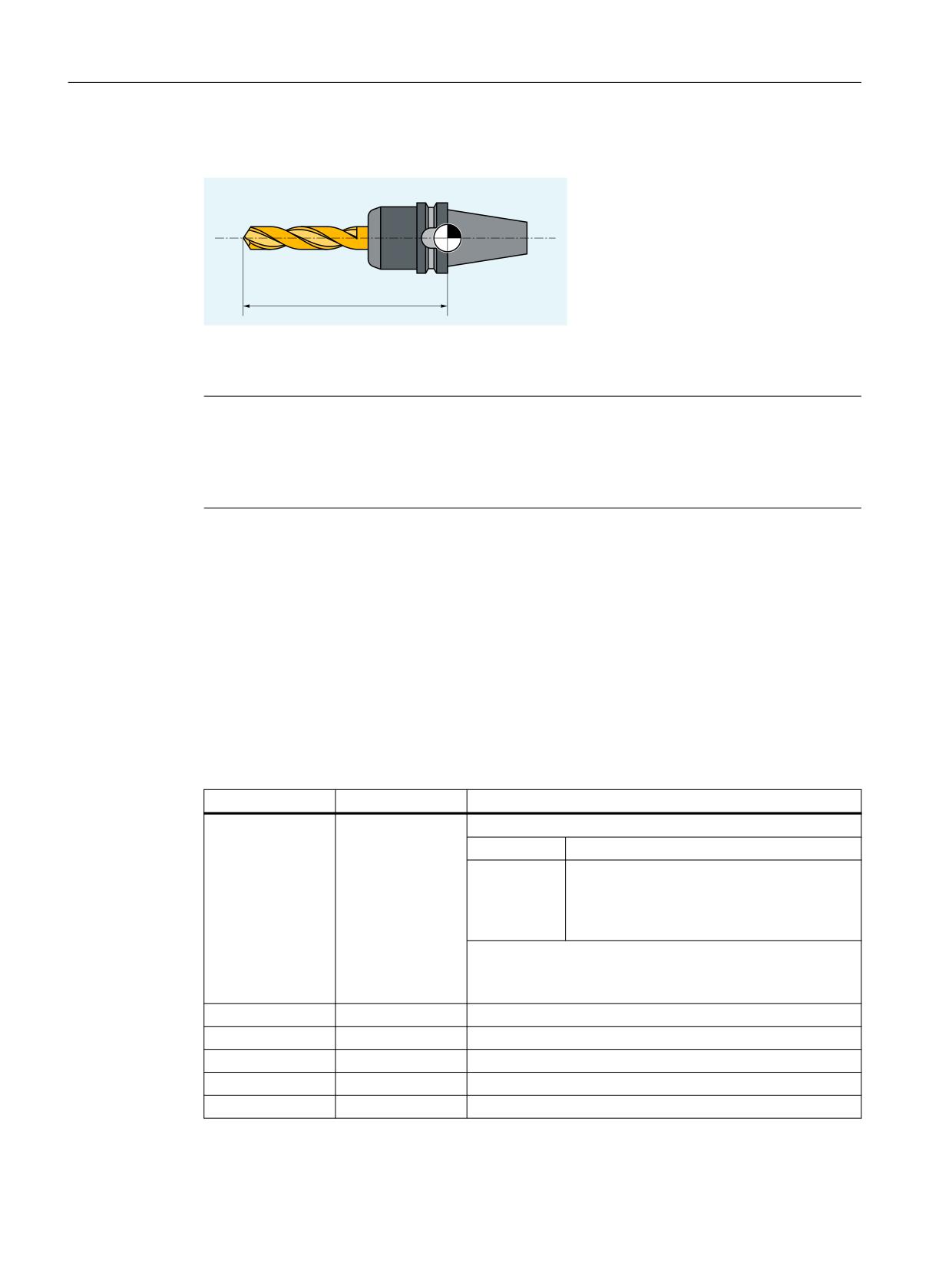
Example: Twist drill (tool type 200)
7
/
T
Tool carrier reference point
L1
Length 1 (tool parameter 3)
Note
All three tool parameters 3 to 5 (tool length 1 to 3) are always calculated in the three geometry
axes, irrespective of the tool type. If more tool lengths are input in the tool parameters 3 to 5 for
a tool type than is required as the minimum, then these extra tool lengths are settled in the
geometry axes without any alarm.
The active size of the tool is only defined when the geometry tool length compensation (tool
parameters 3 to 5) and the wear tool length compensation (tool parameters 12 to 14) are added
together. The base-dimension/adapter-dimension tool length compensation is also added in
order to calculate the total tool length compensation in the geometry axes.
3.4.5
Tool parameters 6 ... 11: Geometry - tool shape
The shape of the tool is defined using the tool parameters 6 to 11. The data is required for the
geometry tool radius compensation.
In most cases, only tool parameter 6 (tool radius 1) is used:
Tool parameter
Meaning
Use
6
Tool radius 1
The tool radius must be specified for the following tool types:
1xx
Milling tools
5xx
Turning tools
Tool parameter 2: Cutting edge position
(Page 37) must also be specified for turning
tools.
Note
Tool type 2xx: A tool radius does not have to be specified for
drilling tools.
7
Tool radius 2
Not used
8
Tool length 4
Not used
9
Tool length 5
Not used
10
Tool angle 1
Not used
11
Tool angle 2
Not used
Tools
40
Function Manual, 10/2020, 6FC5397-6GP40-0BA1
Tool offset
3.4 Tool parameters
2D TRC with contour tools
For the definition of contour tools with multiple tool cutting edges, the minimum and maximum
limit angle can be entered. Both limit angles each relate to the vector of the cutting edge center
point to the cutting edge reference point and are counted clockwise.
Tool angle 1
Minimum limit angle per tool cutting edge
Tool angle 2
Maximum limit angle per tool cutting edge
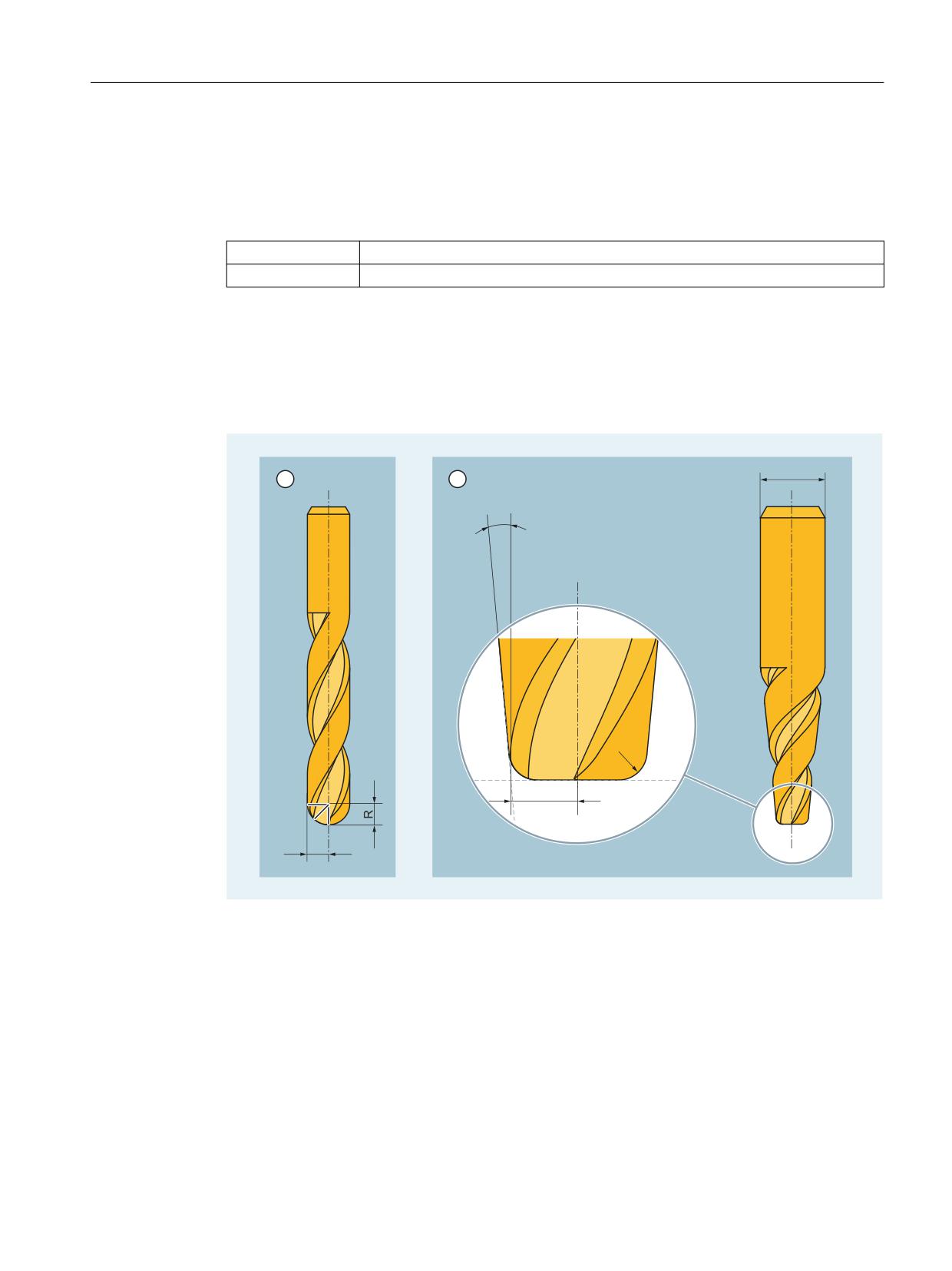
3D face milling
The tool parameters relevant to the tool description in 3D face milling are dependent on the tool
type used. Thus, for example, for a ball end mill, only tool parameter 6, for a bevel cutter with
corner rounding additionally tool parameters 7, 9 and 11, are relevant.
G
D
U
5
5
① Ball end mill
② Bevel cutter with corner rounding
R
Tool parameter 6: Tool radius
r
Tool parameter 7: Corner radius
d
Tool parameter 9: Upper bevel cutter diameter
a
Tool parameter 11: Angle between envelope line and tool longitudinal axis
Specification of tool parameter 9 (upper bevel diameter) is optional. If this tool parameter is not
specified, a conical shape stretching along the entire tool length is assumed:
Tools
Function Manual, 10/2020, 6FC5397-6GP40-0BA1
41
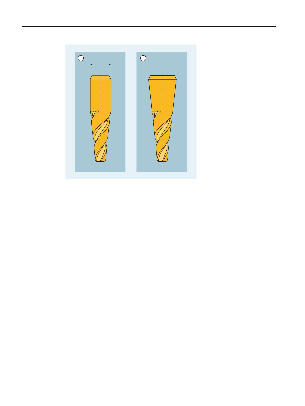
Tool offset
3.4 Tool parameters
G
① With specification of tool parameter 9
② Without specification of tool parameter 9
Further information
Please refer to the following documentation for information about entering tool shapes in tool
parameters 6 to 11 and how these are calculated by geometry tool radius compensation in the
three geometry axes:
• Programming Manual NC programming; Section "Fundamentals" > "Tool offsets" > "2½ D tool
offset"
• 3D tool radius compensation (Page 237)
For 3D face milling, refer to:
• 3D tool radius compensation (Page 237)
3.4.6
Tool parameters 12 ... 14: Wear - tool lengths
While geometry tool length compensation (tool parameters 3 to 5) is used to define the size of
the tool, wear tool length compensation can be used to correct the change in the active tool size.
The active tool variable can change as a result of the following influences:
• Differences between the tool fixture on the tool measurement machine and the tool fixture
on the machine tool
• Tool wear caused during service life by machining
• Definition of a finishing allowance
Tools
42
Function Manual, 10/2020, 6FC5397-6GP40-0BA1
Tool offset
3.4 Tool parameters
The geometry tool compensation (tool parameters 3 to 5) and the wear tool length
compensation (tool parameters 12 to 14) are added together (geometry tool length 1 is added
to wear tool length 1, ...) to arrive at the size of the active tool.
3.4.7
Tool parameters 15 ... 20: Wear - tool shape
While geometry tool radius compensation (tool parameters 6 to 11) is used to define the shape
of the tool, wear tool radius compensation can be used to correct the change in the active tool
shape.
The active tool variable can change as a result of the following influences:
• Tool wear caused during service life by machining
• Definition of a finishing allowance
The geometry tool radius compensation (tool parameters 6 to 11) and the wear tool radius
compensation (tool parameters 15 to 20) are added together (geometry tool radius 1 is added
to wear tool radius 1) to arrive at the shape of the active tool.
3.4.8
Tool parameters 21 ... 23: Base dimension / adapter dimension
Tool base dimension/adapter dimension can be used when the reference point of the toolholder
(tool size) differs from the reference point of the toolholder.
This will occur in the following situations:
• Tool and tool adapter are measured separately, however, are installed in the machine as one
unit (the tool size and adapter size are entered separately in a tool cutting edge).
→ See example 1.
• The tool is inserted in a second tool adapter which is located in a different position (e.g.
vertical and horizontal spindle).
• The tool adapters of a tool turret are in different positions.
→ See example 2.
In order that the discrepancy between the toolholder reference point F and the tool carrier
reference point T' can be corrected on the three geometry axes (3-dimensional), all 3 basic
lengths are always active irrespective of the tool type. In other words, a twist drill (tool type 200)
with a tool length compensation (length 1) can also have a base dimension/adapter dimension
in 3 axes.
Tools
Function Manual, 10/2020, 6FC5397-6GP40-0BA1
43
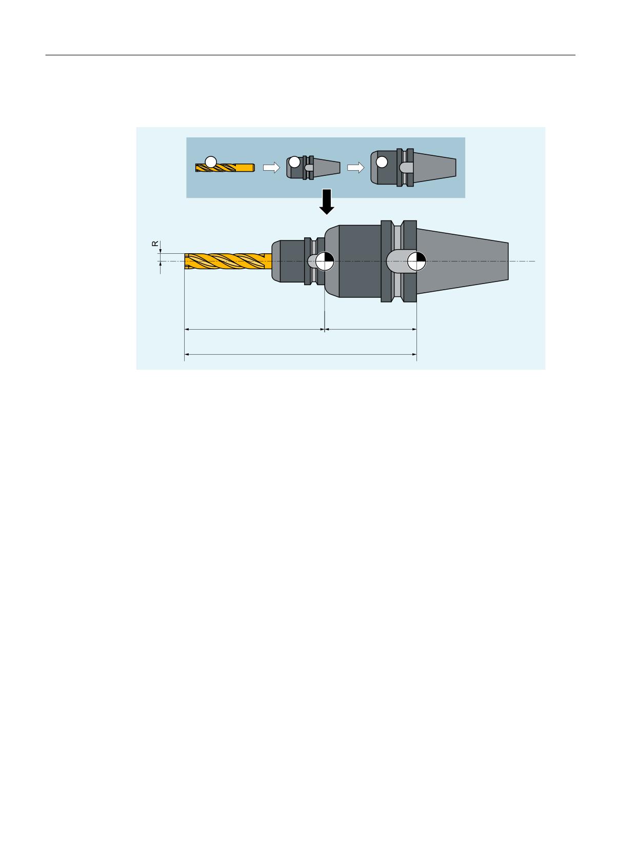
Tool offset
3.4 Tool parameters
Example 1: Tool and tool adapter are measured separately, however, are installed in the
machine as one unit
7
7
/
/
/
/
①
Tool
②
Tool holder
③
Tool adapter
T
Adapter reference point (for inserted tool = tool carrier reference point)
T'
Tool carrier reference point
L1
Geometry - length 1
L1'
Adapter dimension - length 1
L1 + L1' Total length L1
R
Radius
Tools
44
Function Manual, 10/2020, 6FC5397-6GP40-0BA1
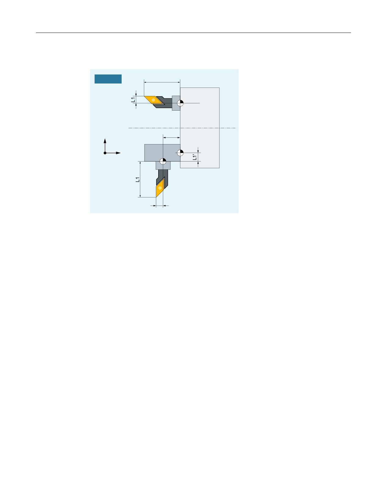
Tool offset
3.4 Tool parameters
Example 2: The tool adapters of a tool turret are in different positions
*
;=
/
7
;
/
7
=
7
/
T
Tool carrier reference point
T'
Tool carrier reference point
L1
Geometry - length 1
L2
Geometry - length 2
L1'
Base dimension - length 1
L2'
Base dimension - length 2
Tools
Function Manual, 10/2020, 6FC5397-6GP40-0BA1
45
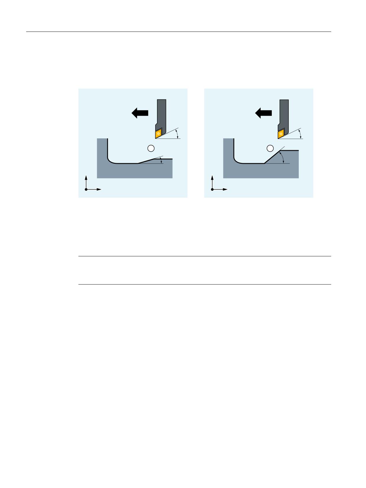
Tool offset
3.4 Tool parameters
3.4.9
Tool parameter 24: Clearance angle
Certain turning cycles, in which traversing motions with relief cuts are generated, monitor the
clearance angle of the active tool for possible contour violation.
˞
˞
;
;
=
=
α
Clearance angle
① The contour to be machined is not violated.
② The contour to be machined would be violated.
The clearance angle is entered in tool parameter 24.
Value range: 0° ... 90° (without sign)
Note
If a clearance angle of zero is entered in tool parameter 24, then relief cuts are not monitored in
the turning cycles.
Tools
46
Function Manual, 10/2020, 6FC5397-6GP40-0BA1
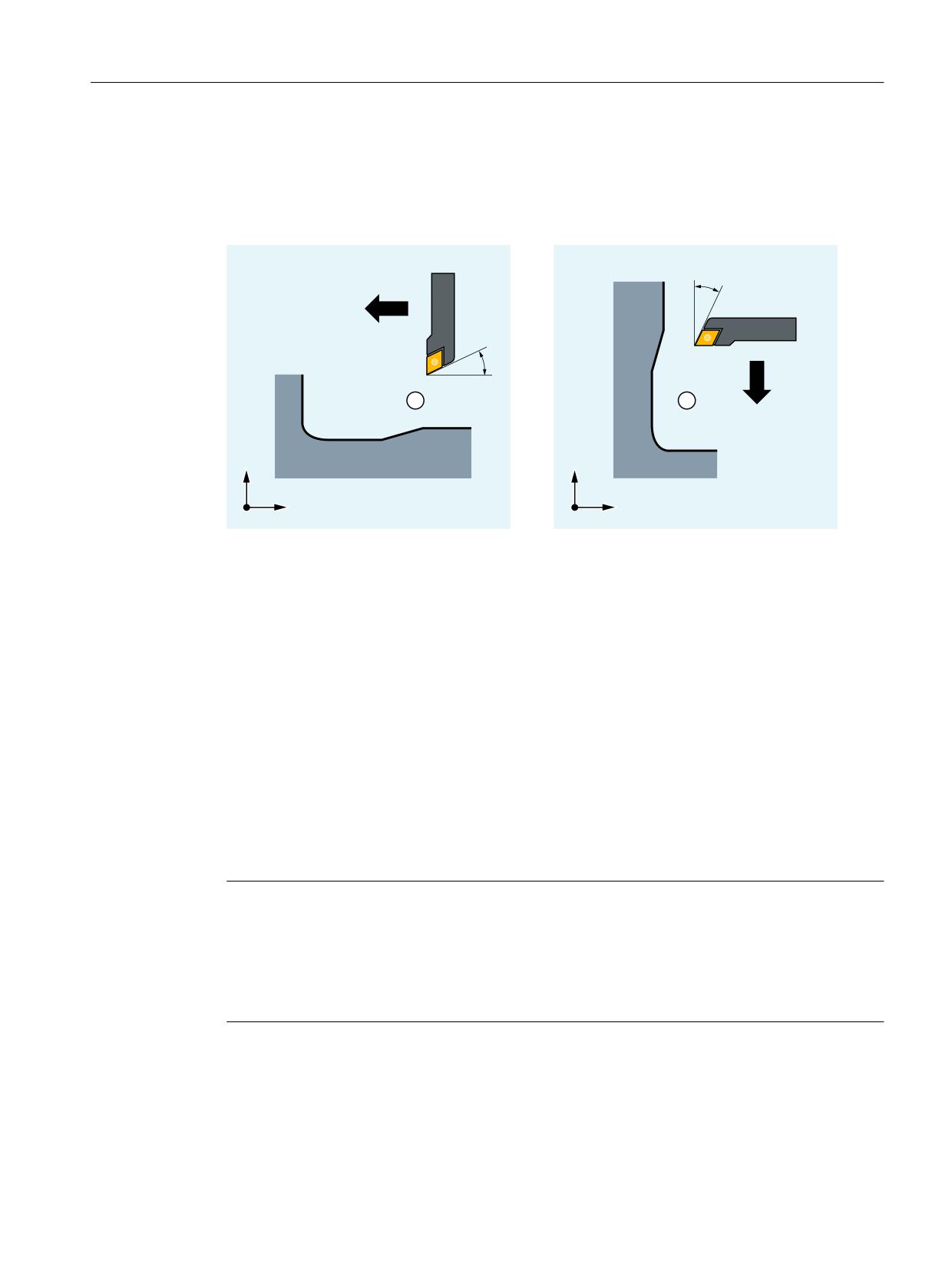
Tool offset
3.5 2D tool radius compensation
Longitudinal or face machining
The clearance angle is entered differently according to the type of processing. If a tool is to be
used for both longitudinal and face machining, two tool cutting edges must be entered for
different clearance angles.
˞
˞
;
;
=
=
α
Clearance angle
① Longitudinal machining
② Face machining
Further information
See the Programming Manual Cycles for detailed information about the clearance angle.
3.5
2D tool radius compensation
3.5.1
General information
Note
For tool radius compensation (TRC) see:
Further information:
Programming Manual Fundamentals
Only the programming guide contains a complete technical description of the tool radius
compensation (TRC) and its special aspects.
Tools
Function Manual, 10/2020, 6FC5397-6GP40-0BA1
47
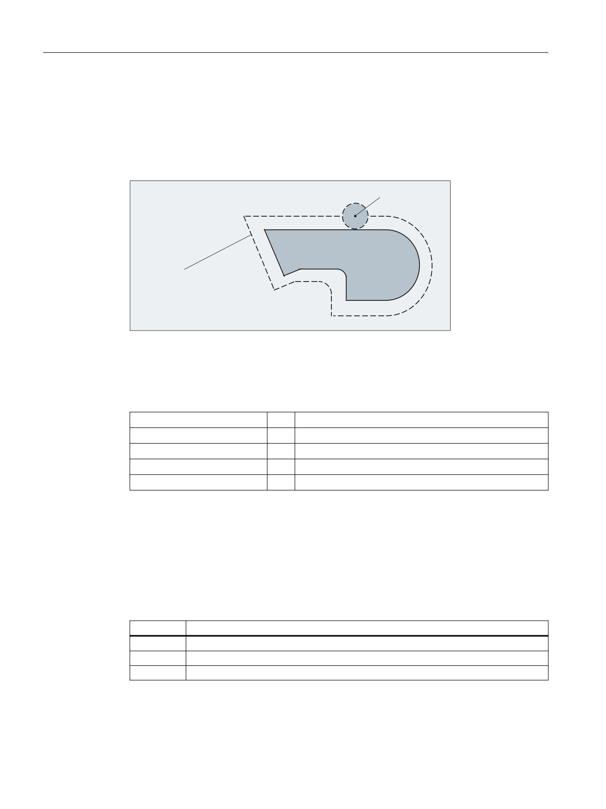
Tool offset
3.5 2D tool radius compensation
Why TRC?
The contour (geometry) of the workpiece programmed in the part program should be
independent of the tools used in production. This makes it necessary to obtain the values for the
tool length and tool radius from a current offset memory. With the current tool radius, tool radius
compensation (TRC) can be used to calculate the equidistant path to the programmed contour
in the plane.
7RROV
:RUNSLHFH
FRQWRXU
3DWK RI WKH
WRRO FHQWHU SRLQW
DW HTXDO GLVWDQFH
WR WKH FRQWRXU
HTXLGLVWDQW SDWK
Figure 3-2
Workpiece contour (geometry) with equidistant path
TRC on the plane
TRC is active on the current plane (G17 to G19) for the following types of interpolation:
• Linear interpolation
G0, G1
• Circular interpolation
G2, G3, CIP
• Helical interpolation
G2, G3
• Spline interpolation
ASPLINE, BSPLINE, CSPLINE
• Polynomial interpolation
POLY
3.5.2
Selecting the TRC (G41/G42)
Direction of compensation
TRC calculates a path, which is equidistant to the programmed contour. Compensation can be
performed on the left- or righthand side of the programmed contour in the direction of motion.
Command
Significance
G41
TRC on the lefthand side of the contour in the direction of motion
G42
TRC on the righthand side of the contour in the direction of motion
G40
Deselection of TRC
Tools
48
Function Manual, 10/2020, 6FC5397-6GP40-0BA1

Tool offset
3.5 2D tool radius compensation
Intermediate blocks
In general, only program blocks with positions on geometry axes in the current plane are
programmed when TRC is active. However, dummy blocks can still also be programmed with
active TRC. Dummy blocks are program blocks, which do not contain any positions on a
geometry axis in the current plane:
• Positions on the infeed axis
• Auxiliary functions,
• etc.
The maximum number of dummy blocks can be defined in the machine data:
MD20250 $MC_CUTCOM_MAXNUM_DUMMY_BLOCKS (Max no. of dummy blocks with no
traversing movements for TRC).
Special points to be noted
• TRC can only be selected in a program block with G0 (rapid traverse) or G1 (linear
interpolation).
• A tool must be loaded (T function) and the tool cutting edge (tool compensation) (D1 to D9)
activated no later than in the program block with the tool radius compensation selection.
• Tool radius compensation is not selected with a tool cutting edge/tool compensation of D0.
• If only one geometry axis is programmed on the plane when tool radius compensation is
selected, the second axis is automatically added on the plane (last programmed position).
• If no geometry axis is programmed for the current plane in the block with the tool radius
compensation selection, no selection takes place.
• If tool radius compensation is deselected (G40) in the block following tool radius
compensation selection, no selection takes place.
• If tool radius compensation is selected, the approach behavior is determined by the NORM/
KONT instructions.
3.5.3
Approach and retraction behavior (NORM/KONT/KONTC/KONTT)
NORM and KONT
The NORM and KONT instructions can be used to control approach behavior (selection of tool
radius compensation with G41/42) and retraction behavior (deselection of tool radius
compensation with G40):
Command
Meaning
NORM
Normal setting at start point / end point (basic setting)
KONT
Travel around contour at start point / end point
KONTC
Approach/retraction with constant curvature
KONTT
Approach/retraction with constant tangent
Tools
Function Manual, 10/2020, 6FC5397-6GP40-0BA1
49
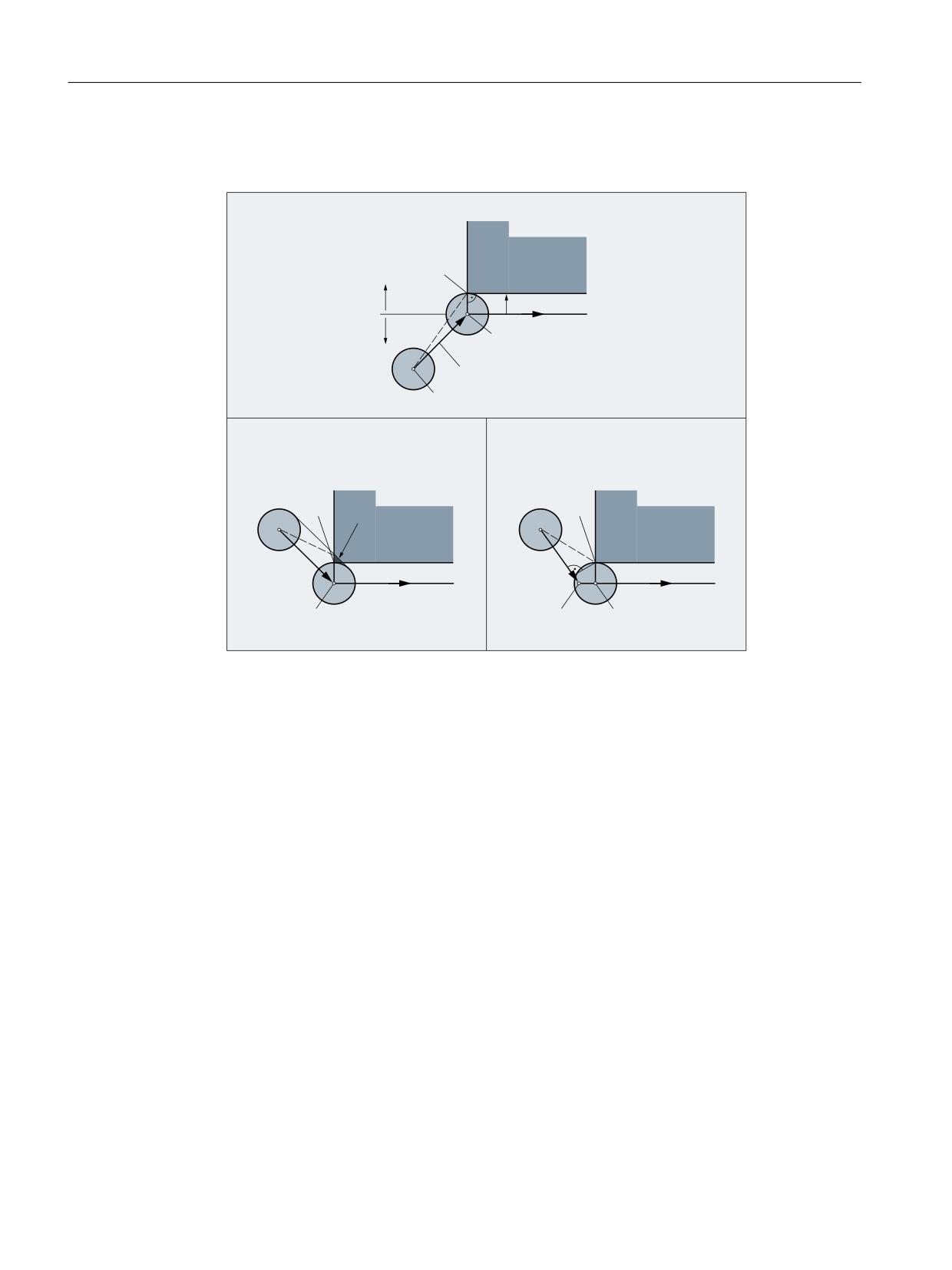
Tool offset
3.5 2D tool radius compensation
Special features
• KONT only differs from NORM when the tool start position is behind the contour.
&RQWRXU VWUDLJKW OLQH
3
%HKLQG
FRQWRXU
5 WRRO UDGLXV
,Q IURQW
RI
3
FRQWRXU
* FRUUHFWHG
3
([DPSOH RI VHOHFWLQJ 75&
([DPSOH RI VHOHFWLQJ 75&
ZLWK 1250 EHKLQG WKH
ZLWK .217 EHKLQG WKH FRQWRXU DQG
FRQWRXU
*
3
3
&RQWRXU YLRODWLRQ
&RQWRXU 2.
3
3
5
*
*
5
5
3
3
3
Figure 3-3
Example for selecting TRC with KONT or NORM in front of and behind the contour
• KONT and G450/G451 (corner behavior at outer corners) has a general effect and determines
the approach and retraction behavior with TRC.
• When tool radius compensation is deselected, the retraction behavior is determined by
the NORM/KONT instructions.
Supplementary conditions
The approach and retraction blocks are polynomials in the following two variants. Therefore,
they are only available for control variants, which support polynomial interpolation:
• KONTT
With KONTT, approach and retraction to/from the contour is with a constant tangent. The
curvature at the block transition is not usually constant.
• KONTC
With KONTC, not only the tangent but also the curvature is constant at the transition, with
the result that a jump in acceleration can no longer occur on activation/deactivation.
Although KONTC includes the KONTT property, the constant tangent version KONTT is available
on its own, because the constant curvature required by KONTC can produce undesired contours.
Tools
50
Function Manual, 10/2020, 6FC5397-6GP40-0BA1
Tool offset
3.5 2D tool radius compensation
Axes
The continuity condition is observed in all three axes. It is thus possible to program a
simultaneous path component perpendicular to the compensation plane for approach/
retraction.
Only linear blocks are permitted for the original approach and retraction blocks with KONTT/
KONTC. These programmed linear blocks are replaced in the control by the corresponding
polynomial curves.
Exception
KONTT and KONTC are not available in 3D variants of tool radius compensation (CUT3DC,
CUT3DCC, CUT3DF).
If they are programmed, the control switches internally to NORM without an error message.
Example of KONTC
The two figures below show a typical application for approach and retraction with constant
curvature:
The full circle is approached beginning at the circle center point. The direction and curvature
radius of the approach circle at the block end point are identical to the values of the next circle.
Infeed takes place in the Z direction in both approach/retraction blocks simultaneously.
The associated NC program segment is as follows:
$TC_DP1[1,1]=121
Milling tool
$TC_DP6[1,1]=10
Radius 10 mm
N10 G1 X0 Y0 Z60 G64 T1 D1 F10000
N20 G41 KONTC X70 Y0 Z0
N30 G2 I-70
Full circle
N40 G40 G1 X0 Y0 Z60
N50 M30
Explanation:
In this example, a full circle with a radius of 70 mm is machined in the X/Y plane. Since the tool
has a radius of 10 mm, the resulting tool center point path describes a circle with a radius of 60
mm. The start/end points are at X0 Y0 Z60, with the result that a movement takes place in the
Z direction at the same time as the approach/retraction movement in the compensation plane.
Tools
Function Manual, 10/2020, 6FC5397-6GP40-0BA1
51
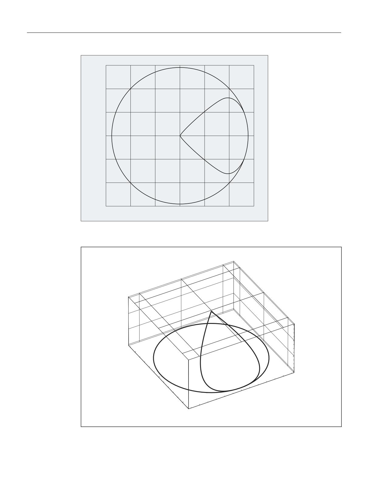
Tool offset
3.5 2D tool radius compensation
1
1
1
Figure 3-4
Approach and retraction with constant curvature during inside machining of a full circle:
Projection in the X-Y plane.
Figure 3-5
Approach and retraction with constant curvature during inside machining of a full circle: 3D
representation.
Tools
52
Function Manual, 10/2020, 6FC5397-6GP40-0BA1
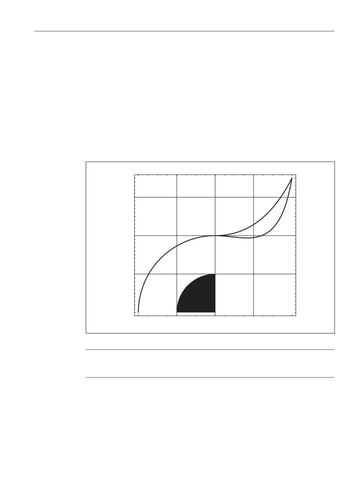
Tool offset
3.5 2D tool radius compensation
KONTT and KONTC compared
The figure below shows the differences in approach/retraction behavior between KONTT
and KONTC. A circle with a radius of 20 mm about the center point at X0 Y-40 is compensated
with a tool with an external radius of 20 mm. The tool center point therefore moves along a
circular path with radius 40 mm. The end point of the approach block is at X40 Y30. The
transition between the circular block and the retraction block is at the zero point. Due to the
extended continuity of curvature associated with KONTC, the retraction block first executes a
movement with a negative Y component. This will often be undesired. This response does not
occur with the KONTT retraction block. However, with this block, an acceleration step change
occurs at the block transition.
If the KONTT or KONTC block is the approach block rather than the retraction block, the contour
is exactly the same, but is simply machined in the opposite direction, i.e. the approach and
retraction behavior are symmetrical.
.2177
.217&
Figure 3-6
Differences between KONTT and KONTC
Note
The figure shows that a straight line bordering on the contour quadrant, e.g. to X20 Y-20, would
be violated with KONTC on retraction/approach to X0, Y0.
Tools
Function Manual, 10/2020, 6FC5397-6GP40-0BA1
53
Tool offset
3.5 2D tool radius compensation
3.5.4
Smooth approach and retraction
3.5.4.1
Function
Description
The SAR (Smooth Approach and Retraction) function is used to achieve a tangential approach to
the start point of a contour, regardless of the position of the start point.
The approach behavior can be varied and adapted to special needs using a range of additional
parameters.
The two functions, smooth approach and smooth retraction, are largely symmetrical. The
following section is, therefore, restricted to a detailed description of approach; special reference
is made to differences affecting retraction.
Sub-movements
There are maximum 4 sub-movements in case of soft retraction and approach with the following
positions:
• Start point of the movement P0
• Intermediate points P1, P2 and P3
• End point P4
Points P0, P3 and P4 are always defined. Intermediate points P1 and P2 can be omitted, according
to the parameters defined and the geometrical conditions.
On retraction, the points are traversed in the reverse direction, i.e. starting at P4 and ending at
P0.
3.5.4.2
Parameters
The response of the smooth approach and retraction function is determined by up to 9
parameters:
Non-modal G command for defining the approach and retraction contour
This G command cannot be omitted.
• G147: Approach with a straight line
• G148: Retraction with a straight line
• G247: Approach with a quadrant
• G248: Retraction with a quadrant
Tools
54
Function Manual, 10/2020, 6FC5397-6GP40-0BA1
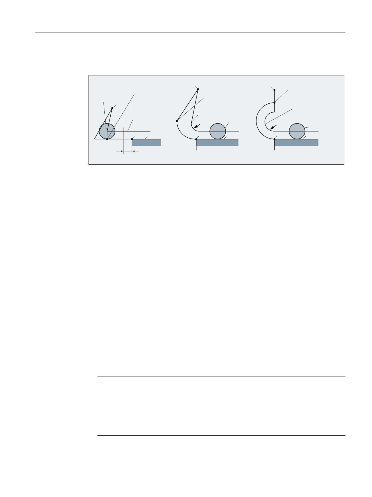
Tool offset
3.5 2D tool radius compensation
• G347: Approach with a semicircle
• G348: Retraction with a semicircle
3
3
ZKHQ DSSURDFKLQJ
3
3
ZKHQ DSSURDFKLQJ
3
ZKHQ DSSURDFKLQJ
DORQJ D VWUDLJKW OLQH
DORQJ D TXDGUDQW
DORQJ D TXDGUDQW
7RRO
*
*
*
3
7RRO FHQWHU
7RRO FHQWHU
7RRO FHQWHU
SRLQW SDWK
SRLQW SDWK
SRLQW SDWK
',65
7RRO
',65
7RRO
3
FRQWRXU
3
FRQWRXU
3
&RQWRXU
',65
Figure 3-7
Approach behavior depending on G147 to G347 and DISR (with simultaneous activation of
tool radius compensation)
Modal G command for defining the approach and retraction contour
This G command is only relevant if the approach contour is a quadrant or semicircle. The
approach and retraction direction can be determined as follows:
• G140:
Defining the approach and retraction direction using active tool radius compensation. (G140
is the basic setting value.)
With positive tool radius:
- G41 active → approach from left
- G42 active → approach from right
If no tool radius compensation is active (G40), the response is identical to G143. In this
case, an alarm is not output. If the radius of the active tool is 0, the approach and
retraction side is determined as if the tool radius were positive.
• G141:
Approach contour from left, or retract to the left.
• G142:
Approach contour from right, or retract to the right.
• G143:
Automatic determination of the approach direction, i.e. the contour is approached from the
side where the start point is located, relative to the tangent at the start point of the following
block (P4).
Note
The tangent at the end point of the preceding block is used accordingly on retraction. If the
end point is not programmed explicitly on retraction, i.e. if it is to be determined
implicitly, G143 is not permitted on retraction, since there is a mutual dependency between
the approach side and the position of the end point. If G143 is programmed in this case, an
alarm is output. The same applies if, when G140 is active, an automatic switchover to G143
takes place as a result of an inactive tool radius compensation.
Tools
Function Manual, 10/2020, 6FC5397-6GP40-0BA1
55
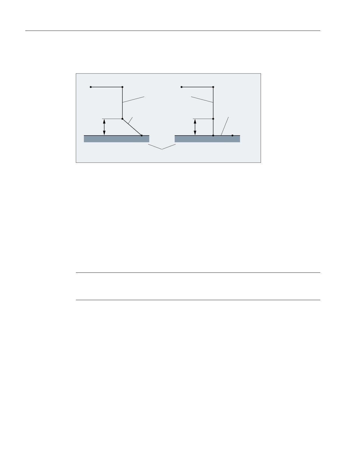
Tool offset
3.5 2D tool radius compensation
Modal G command (G340, G341), which defines the subdivision of the movement into individual
blocks from the start point to the end point
3
3
3
3
,QIHHG PRYHPHQW
6WUDLJKW OLQH
6WUDLJKW OLQH
3
3
FLUFOH RU KHOL[
3
RU FLUFOH
',6&/
',6&/
3
3
*
*
0DFKLQLQJ SODQH
G34
The approach characteristic from P0 to P4 is shown in the figure.
0:
If G247 or G347 is active (quadrant or semicircle) and start point P3 is outside the machining plane
defined by the end point P4, a helix is inserted instead of a circle. Point P2 is not defined or coincides
with P3.
The circle plane or the helix axis is determined by the plane, which is active in the SAR block (G17
- G19), i.e. the projection of the start tangent is used by the following block, instead of the tangent
itself, to define the circle.
The movement from point P0 to point P3 takes place along two straight lines at the velocity valid
before the SAR block.
G34
The approach characteristic from P0 to P4 is shown in the figure.
1:
P3 and P4 are located within the machining plane, with the result that a circle is always inserted
instead of a helix with G247 or G347.
Figure 3-8
Sequence of the approach movement depending on G340/G341
Note
Active, rotating frames are included in all cases where the position of the active plane G17 - G19
(circle plane, helix axis, infeed movements perpendicular to the active plane) is relevant.
DISR
DISRSpecifies the length of a straight approach line or the radius of an approach arc.
Retraction/approach with straight lines
On approach/retraction along a straight line, DISR specifies the distance from the cutter edge
to the start point of the contour, i.e. the length of the straight line with active TRC is calculated
as the total of the tool radius and the programmed value of DISR.
An alarm is displayed:
• If DISR is negative and the amount is greater than the tool radius (the length of the resulting
approach line is less than or equal to zero).
Retraction/approach with circles
Tools
56
Function Manual, 10/2020, 6FC5397-6GP40-0BA1
Tool offset
3.5 2D tool radius compensation
Approach/retraction with circles
DISR indicates always the radius of the tool center point path. If tool radius compensation is
activated, a circle is generated internally, the radius of which is dimensioned such that the tool
center path is derived, in this case also, from the programmed radius.
An alarm is output on approach and retraction with circles:
• If the radius of the circle generated internally is zero or negative
• If DISR is not programmed
• If the radius value ≤ 0.
DISCL
DISCLspecifies the distance from point P2 from the machining plane.
If the position of point P2 is to be specified by an absolute reference on the axis perpendicular to
the circle plane, the value must be programmed in the form DISCL = AC(
).
If DISCL is not programmed, points P1, P2 and P3 are identical with G340 and the approach
contour is mapped from P1 to P4.
The system checks that the point defined by DISCL lies between P1 and P3, i.e. in all movements,
which have a component perpendicular to the machining plane (e.g. infeed movements,
approach movements from P3 to P4), this component must have the same leading sign. It is not
permitted to change direction. An alarm is output if this condition is violated.
On detection of a direction reversal, a tolerance is permitted that is defined by the machine data:
MD20204 $MC_WAB_CLEARANCE_TOLERANCE (direction reversal on SAR).
However, if P2 is outside the range defined by P1 and P3 and the deviation is less than or equal to
this tolerance, it is assumed that P2 is in the plane defined by P1 and/or P3.
Example:
An approach is made with G17 starting at position Z=20 of point P1. The SAR plane defined by P3
is at Z=0. The point defined by DISCL must, therefore, lie between these two points.
MD20204=0.010. If P2 is between 20.000 and 20.010 or between 0 and -0.010, it is assumed
that the value 20.0 or 0.0 is programmed. The alarm is output if the Z position of P2 is greater
than 20.010 or less than -0.010.
Depending on the relative position of start point P0 and end point P4 with reference to the
machining plane, the infeed movements are performed in the negative (normal for approach)
or positive (normal for retraction) direction, i.e. with G17 it is possible for the Z component of
end point P4 to be greater than that of start point P0.
Programming the end point P4 (or P0 for retraction) generally with X... Y... Z...
Possible ways of programming the end point P4for approach
End point P4 can be programmed in the actual SAR block.
P4 can be determined by the end point of the next traversing block.
Further blocks (dummy blocks) can be inserted between the SAR block and the next traversing
block without moving the geometry axes.
Tools
Function Manual, 10/2020, 6FC5397-6GP40-0BA1
57
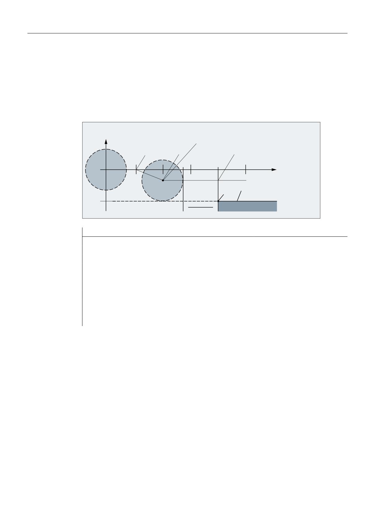
Tool offset
3.5 2D tool radius compensation
The end point is deemed to have been programmed in the actual SAR block for approach if at
least one geometry axis is programmed on the machining plane (X or Y with G17). If only the
position of the axis perpendicular to the machining plane (Z with G17) is programmed in the SAR
block, this component is taken from the SAR block, but the position in the plane is taken from the
following block. In this case, an alarm is output if the axis perpendicular to the machining plane
is also programmed in the following block.
Example:
0DFKLQLQJ XS WR WKLV
SRLQW ZLWK * WKHQ ZLWK
* )
<
=
=
=
;
&RQWRXU
3
',65
Program code
Comment
$TC_DP1[1,1]=120
; Milling tool T1/D1
$TC_DP6[1,1]=7
; Tool with 7mm radius
N10 G90 G0 X0 Y0 Z30 D1 T1
N20 X10
N30 G41 G147 DISCL=3 DISR=13 Z=0 F1000
N40 G1 X40 Y-10
N50 G1 X50
N30/N40 can be replaced by:
N30 G41 G147 DISCL=3 DISR=13 X40 Y-10 Z0 F1000
or:
N30 G41 G147 DISCL=3 DISR=13 F1000
N40 G1 X40 Y-10 Z0
Possible ways of programming the end point P0for retraction
Tools
58
Function Manual, 10/2020, 6FC5397-6GP40-0BA1
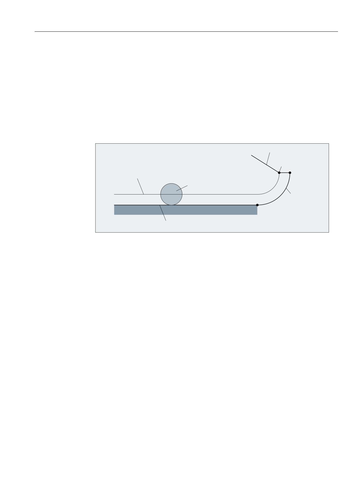
Tool offset
3.5 2D tool radius compensation
The end position is always taken from the SAR block, no matter how many axes have been
programmed. We distinguish between the following situations:
1.
No geometry axis is programmed in the SAR block.
In this case, the contour ends at point P2 (or at point P1, if P1 and P2 coincide). The position in
the axes, which describe the machining plane, is determined by the retraction contour (end
point of the straight line or arc). The axis component perpendicular to this is defined
by DISCL. If, in this case, DISCL = 0, the movement takes place completely within the
plane.
2.
Only the axis perpendicular to the machining plane is programmed in the SAR block.
In this case, the contour ends at point P1. The position of the two other axes is determined in
the same way as in 1.
)ROORZLQJ EORFN ZLWKRXW RIIVHW
3
3
7RRO FHQWHU SRLQW SDWK
7RRO
6$5 EORFN
*
*
3
&RQWRXU SUHYLRXV EORFN
Retraction with SAR with simultaneous deactivation of TRC
If the SAR retraction block is also used to deactivate tool radius compensation, in the case of
1. and 2., an additional path from P1 to P0 is inserted such that no movement is produced
when tool radius compensation is deactivated at the end of the retraction contour, i.e. this
point defines the tool center point and not a position on a contour to be corrected.
3.
At least one axis of the machining plane is programmed.
The second axis of the machining plane can be determined modally from its last position in
the preceding block. The position of the axis perpendicular to the machining plane is
generated as described in 1. or 2., depending on whether this axis is programmed or not. The
position generated in this way defines the end point P0.
No special measures are required for deselection of tool radius compensation, because the
programmed point P0 already directly defines the position of the tool center point at the end
of the complete contour.
The start and end points of the SAR contour (P0 and P4) can coincide on approach and
retraction.
Velocity of the preceding block (typically G0).
All movements from point P0 to point P2 are performed at this velocity, i.e. the movement parallel
to the machining plane and the part of the infeed movement up to the safety clearance.
Tools
Function Manual, 10/2020, 6FC5397-6GP40-0BA1
59
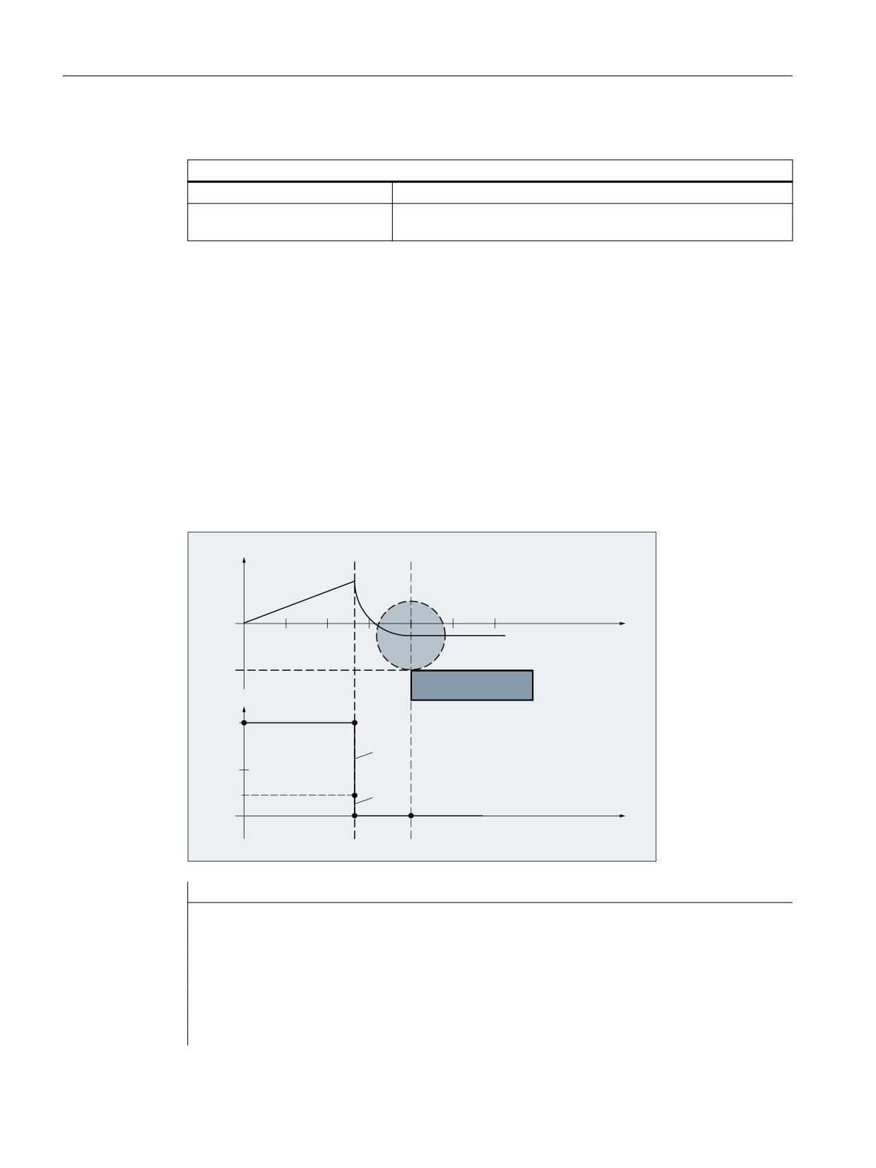
Tool offset
3.5 2D tool radius compensation
Programming the feedrate with FAD
FAD programmed with ...
G340
Feedrate from P2 or P3 to P4.
G341
Feedrate of the infeed movement perpendicular to the machining
plane from P2 to P3.
If FAD is not programmed, this part of the contour is traversed at the velocity, which is active
modally from the preceding block, in the event that no F command defining the velocity is
programmed in the SAR block.
Programmed response:
FAD=0 or negative
→ Alarm Output
FAD=...
→ Programmed value acts in accordance with the active G com-
mand of group 15 (feed type; G93, G94, etc.)
FAD=PM(...)
→ Programmed value is interpreted as linear feed (like G94), irre-
spective of the active G command of group 15
FAD=PR(...)
→ Programmed value is interpreted as revolutional feed (like G95),
irrespective of the active G command of group 15
Example:
<
;
=
*
3
3
*
3
)
3
3
)
)
;
Program code
Comment
$TC_DP1[1,1]=120
; Milling tool T1/D1
$TC_DP6[1,1]=7
; Tool with 7mm radius
N10 G90 G0 X0 Y0 Z20 D1 T1
N20 G41 G341 G247 DISCL=AC(5) DISR=13FAD 500 X40 Y-10 Z=0 F2000
N30 X50
N40 X60
Tools
60
Function Manual, 10/2020, 6FC5397-6GP40-0BA1
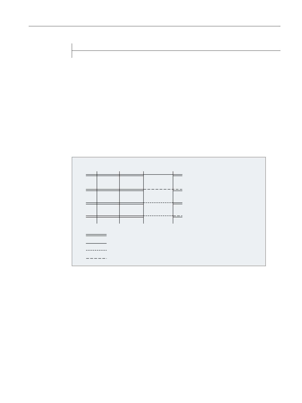
Tool offset
3.5 2D tool radius compensation
Program code
Comment
Programming feed F
This feed value is effective from point P3 (or from point P2, if FAD is not programmed). If no F
command is programmed in the SAR block, the speed of the preceding block is valid. The velocity
defined by FAD is not used for following blocks.
3.5.4.3
Velocities
Velocities at approach
In both approach diagrams below, it is assumed that no new velocity is programmed in the block
following the SAR block. If this is not the case, the new velocity comes into effect after point P4.
3
3
3
3
3
1R YHORFLW\ SURJUDPPHG
2QO\ ) SURJUDPPHG
2QO\ )$' SURJUDPPHG
) DQG )$' SURJUDPPHG
5DSLG WUDYHUVH LI * LV DFWLYH RWKHUZLVH ZLWK WKH ROG DQG QHZ ) ZRUG
9HORFLW\ RI WKH SUHGHFHVVRU EORFN ROG ) ZRUG
,QIHHG YHORFLW\ SURJUDPPHG ZLWK )$'
1HZ PRGDO YHORFLW\ SURJUDPPHG ZLWK )
Figure 3-9
Velocities in the SAR subblocks on approach with G340
Tools
Function Manual, 10/2020, 6FC5397-6GP40-0BA1
61

Tool offset
3.5 2D tool radius compensation
3
3
3
3
3
1R YHORFLW\ SURJUDPPHG
2QO\ ) SURJUDPPHG
2QO\ )$' SURJUDPPHG
) DQG )$' SURJUDPPHG
5DSLG WUDYHUVH LI * LV DFWLYH RWKHUZLVH ZLWK WKH ROG DQG QHZ ) ZRUG
9HORFLW\ RI WKH SUHGHFHVVRU EORFN ROG ) ZRUG
,QIHHG YHORFLW\ SURJUDPPHG ZLWK )$'
1HZ PRGDO YHORFLW\ SURJUDPPHG ZLWK )
Figure 3-10
Velocities in the SAR subblocks on approach with G341
Velocities at retraction
During retraction, the rolls of the modally active feedrate from the previous block and the
programmed feedrate value in the SAR block are interchanged, i.e., the actual retraction contour
(straight line, circle, helix) is traversed with the old feedrate value and a new velocity
programmed with the F word applies from point P2 up to P0.
If even retraction is active and FAD is programmed, the path from P3 to P2 is traversed with FAD,
otherwise it is traversed with the old velocity. The last F command programmed in a preceding
block always applies for the path from P4 to P2. G0 has no effect in these blocks.
Traversing from P2 to P0 takes place with the F command programmed in the SAR block or, if no
F command is programmed, with the modal F command from a preceding block. This applies on
the condition that G0 is not active.
If rapid traverse is to be used on retraction in the blocks from P2 to P0, G0 must be activated before
the SAR block or in the SAR block itself. If an additional F command is programmed in the actual
SAR blocks, it is then ineffective. However, it remains modally active for following blocks.
Tools
62
Function Manual, 10/2020, 6FC5397-6GP40-0BA1
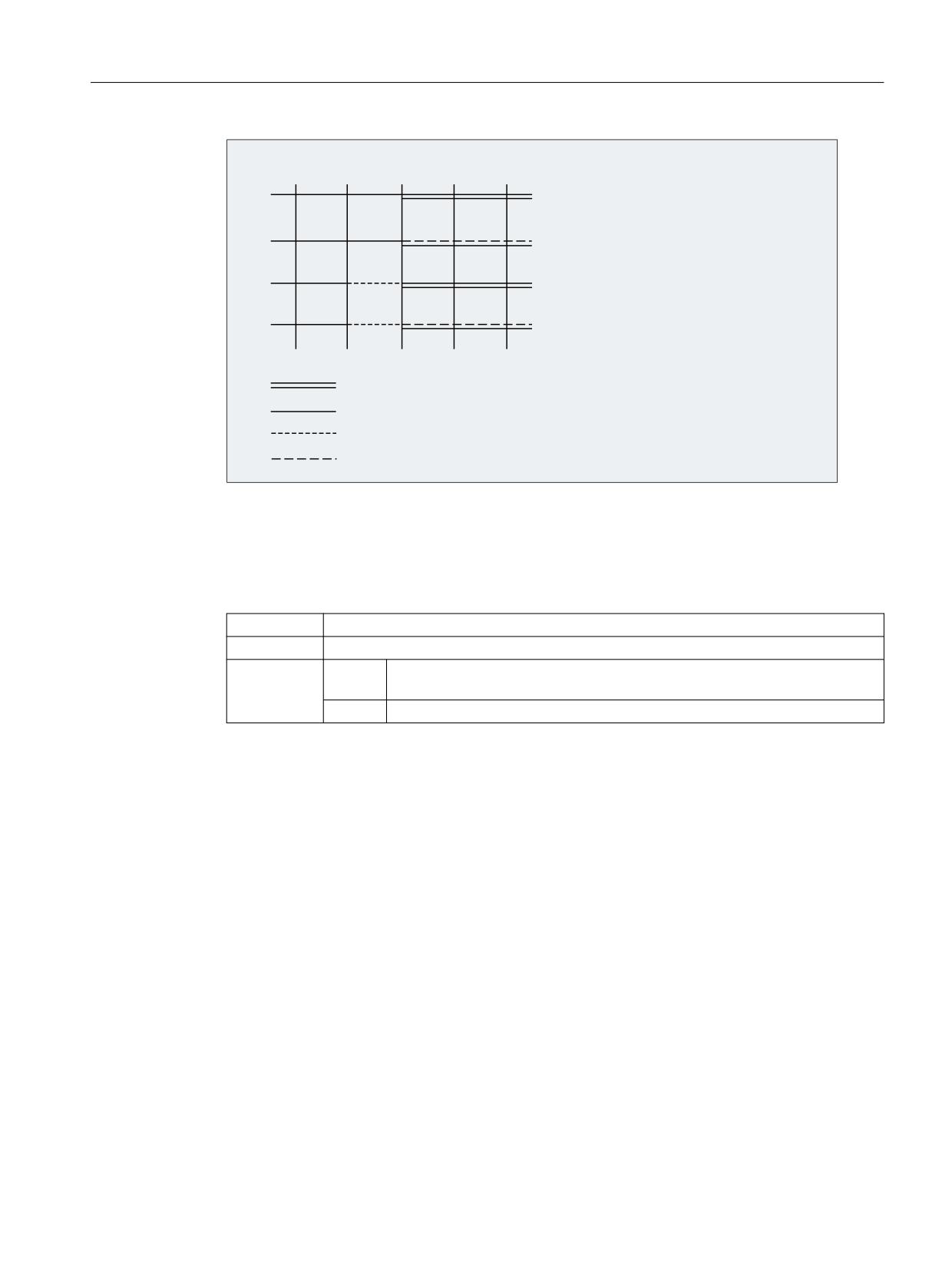
Tool offset
3.5 2D tool radius compensation
3
3
3
3
3
1R YHORFLW\ SURJUDPPHG
2QO\ ) SURJUDPPHG
2QO\ )$' SURJUDPPHG
) DQG )$' SURJUDPPHG
5DSLG WUDYHUVH LI * LV DFWLYH RWKHUZLVH ZLWK WKH ROG DQG QHZ ) ZRUG
9HORFLW\ RI WKH SUHGHFHVVRU EORFN ROG ) ZRUG
,QIHHG YHORFLW\ SURJUDPPHG ZLWK )$'
1HZ PRGDO YHORFLW\ SURJUDPPHG ZLWK )
Figure 3-11
Velocities in the SAR subblocks on retraction
3.5.4.4
System variables
Points P3 and P4 can be read in the WCS as system variables during approach.
$P_APR:
Read P3 (start point) in WCS
$P_AEP:
Read P4 (contour start point) in WCS
$P_APDV
=1
If the content of $P_APR and $P_AEP is valid, i.e., if these contain the position
values belonging to the last SAR approach block programmed.
=0
The positions of an older SAR approach block are read.
Changing the WCS between the SAR block and the read operation has no effect on the position
values.
3.5.4.5
Supplementary conditions
Supplementary conditions
• Any further NC commands (e.g. auxiliary function outputs, synchronous axis movements,
positioning axis movements, etc.) can be programmed in an SAR block.
These are executed in the first subblock on approach and in the last subblock on retraction.
• If the end point P4 is not taken from the SAR block but from a subsequent traversing block, the
actual SAR contour (straight line, quadrant or semicircle) is traversed in this block.
The last subblock of the original SAR block does not then contain traversing information for
geometry axes. It is always output, however, because further actions (e.g. single axes) may
have to be executed in this block.
Tools
Function Manual, 10/2020, 6FC5397-6GP40-0BA1
63
Tool offset
3.5 2D tool radius compensation
• At least two blocks must always be taken into consideration:
- The SAR block itself
- The block, which defines the approach or retraction direction
Further blocks can be programmed between these two blocks.
The number of possible dummy blocks is limited with the machine data:
MD20202 $MC_WAB_MAXNUM_DUMMY_BLOCKS (maximum number of blocks with no
traversing motions with SAR).
• If tool radius compensation is activated simultaneously in an approach block the first linear
block of the SAR contour is the block in which activation takes place.
The complete contour generated by the SAR function is treated by tool radius compensation
as if it has been programmed explicitly (collision detection, calculation of intersection,
approach behavior NORM/KONT).
• The direction of the infeed motion and the position of the circle plane or the helix axis are
defined exclusively by the active plane (G17 - G19) - rotated with an active frame where
appropriate.
• On approach, a preprocessor stop must not be inserted between the SAR block and the
following block which defines the direction of the tangent.
Whether programmed explicitly or inserted automatically by the control, a preprocessor stop
results, in this case, in an alarm.
Behavior with REPOS
If an SAR cycle is interrupted and repositioned, it resumes at the point of interruption on RMIBL.
With RMEBL, the contact point is the end point of the last SAR block; with RMBBL, it is the start
point of the first SAR block.
If RMIBL is programmed together with DISPR (reapproach at distance DISPR in front of
interruption point), the reapproach point can appear in a subblock of the SAR cycle before the
interruption subblock.
3.5.4.6
Examples
Example 1
The following conditions must be true:
• Smooth approach is activated in block N20
• X=40 (end point); Y=0; Z=0
• Approach movement performed with quadrant (G247)
• Approach direction not programmed, G140 is valid, i.e. because TRC is active (G42) and
compensation value is positive (10), the contour is approached from the right
• Approach circle generated internally (SAR contour) has radius 20, so that the radius of the
tool center path is equal to the programmed value DISR=10
Tools
64
Function Manual, 10/2020, 6FC5397-6GP40-0BA1
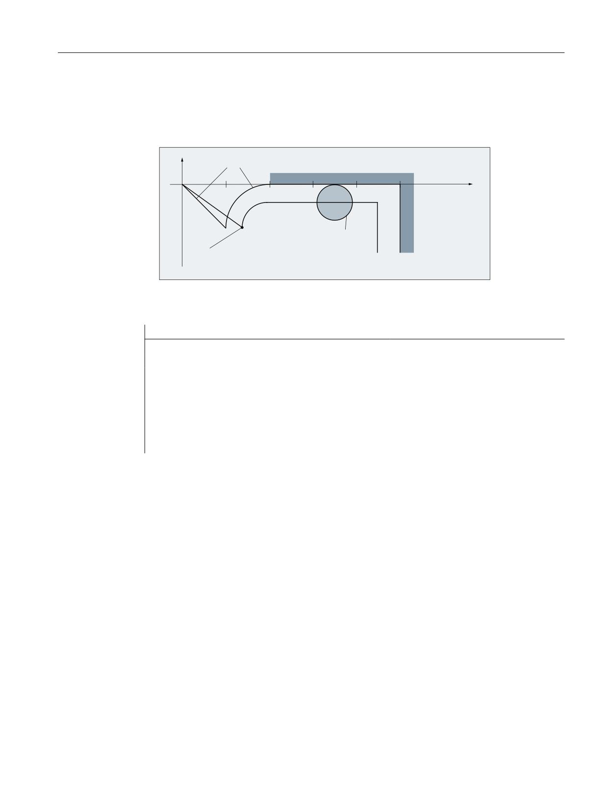
Tool offset
3.5 2D tool radius compensation
• Because of G341, the approach movement takes place with a circle in the plane, resulting in
a start point at (20, -20, 0)
• Because DISCL=5, point P2 is at position (20, -20, 5) and, because of Z30, point P1 is in N10
at (20, -20, 30)
<
6$5 FRQWRXU
;
7RRO
7RRO FHQWHU SRLQW SDWK
,QIHHG
PRYHPHQW LQ =
Figure 3-12
Contour example 1
Part program:
Program code
Comment
$TC_DP1[1,1]=120
; Tool definition T1/D1
$TC_DP6[1,1]=10
; Radius
N10 G0 X0 Y0 Z30
N20 G247 G341 G42 NORM D1 T1 Z0 FAD=1000 F=2000 DISCL=5 DISR=10
N30 X40
N40 X100
N50 Y-30
Example 2
The following conditions must be true for approach:
• Smooth approach is activated in block N20
• Approach movement performed with quadrant (G247)
• Approach direction not programmed, G140 is valid, i.e. because TRC is active (G41), the
contour is approached from the left
• Contour offset OFFN=5 (N10)
• Current tool radius=10, and so the effective compensation radius for TRC=15; the radius of
the SAR contour is thus equal to 25, with the result that the radius of the tool center path is
equal to DISR=10
Tools
Function Manual, 10/2020, 6FC5397-6GP40-0BA1
65
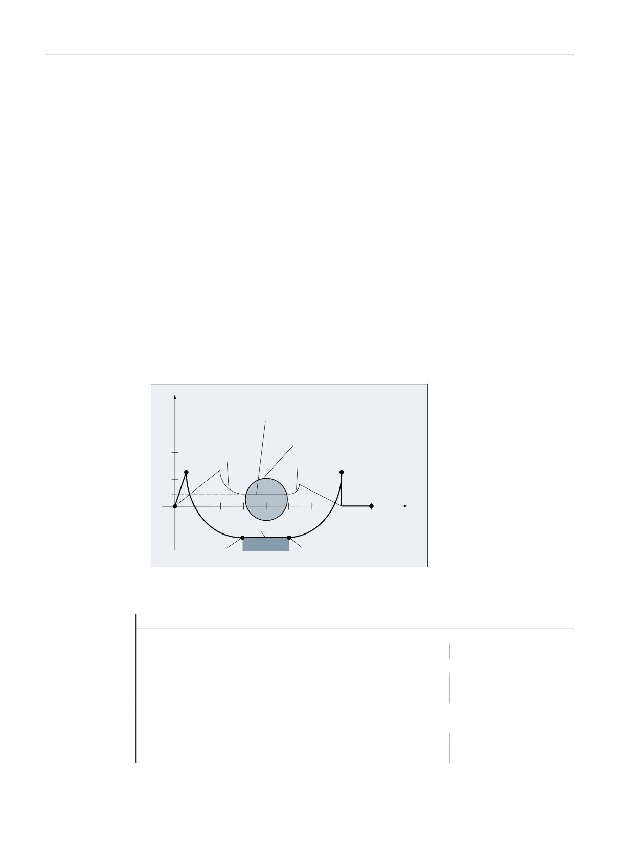
Tool offset
3.5 2D tool radius compensation
• The end point of the circle is obtained from N30, since only the Z position is programmed
in N20
• Infeed movement
- From Z20 to Z7 (DISCL=AC(7)) with rapid traverse
- Then on to Z0 with FAD=200
- Approach circle in X-Y-plane and following blocks with F1500
(In order that this velocity becomes effective in the following blocks, the active G-code G0
in N30 must be overwritten with G1. Otherwise, the contour would continue to be
machined with G0.)
The following conditions must be true for retraction:
• Smooth retraction is activated in block N60
• Retraction movement performed with quadrant (G248) and helix (G340)
• FAD not programmed, since irrelevant for G340
• Z=2 in the start point; Z=8 in the end point, since DISCL=6
• When DISR=5, the radius of SAR contour=20; that of the tool center point path=5
• After the circle block, the retraction movement leads from Z8 to Z20 and the movement is
parallel to the XY plane up to the end point at X70 Y0
<
7RRO FHQWHU SRLQW SDWK
7RRO
6HPLFLUFOH
+HOL[
3 DE
3 DQ
;
&RQWRXU
3 DE
3 DQ
3 DE
Figure 3-13
Contour example 2
Part program:
Program code
Comment
$TC_DP1[1,1]=120
; Tool definition T1/D1
$TC_DP6[1,1]=10
; Radius
N10 G0 X0 Y0 Z20 G64 D1 T1 OFFN = 5
; (P0app)
N20 G41 G247 G341 Z0 DISCL = AC(7) DISR = 10 F1500 FAD=200
; (P3app)
N30 G1 X30 Y-10
; (P4app)
N40 X40 Z2
N50 X50
; (P4ret)
N60 G248 G340 X70 Y0 Z20 DISCL = 6 DISR = 5 G40 F10000
; (P3ret)
N70 X80 Y0
; (P0ret)
Tools
66
Function Manual, 10/2020, 6FC5397-6GP40-0BA1

Tool offset
3.5 2D tool radius compensation
Program code
Comment
N80 M 30
Note
The contour generated in this way is modified by tool radius compensation, which is activated
in the SAR approach block and deactivated in the SAR retraction block.
The tool radius compensation allows for an effective radius of 15, which is the sum of the tool
radius (10) and the contour offset (5). The resulting radius of the tool center path in the
approach block is therefore 10, and 5 in the retraction block.
3.5.5
Deselecting the TRC (G40)
G40 instruction
TRC is deselected with the G40 instruction.
Special points to be noted
• TRC can only be deselected in a program block with G0 (rapid traverse) or G1 (linear
interpolation).
• If D0 is programmed when tool radius compensation is active, compensation is not
deselected and error message 10750 is output.
• If a geometry axis is programmed in the block with the tool radius compensation deselection,
then the compensation is deselected even if it is not on the current plane.
3.5.6
Compensation at outside corners
G450/G451
The G commands G450/G451 can be used to control the response for discontinuous block
transitions at outside corners:
Command
Meaning
G450
Discontinuous block transitions with transition circle
G451
Discontinuous block transitions with intersection of equidistant paths
Tools
Function Manual, 10/2020, 6FC5397-6GP40-0BA1
67
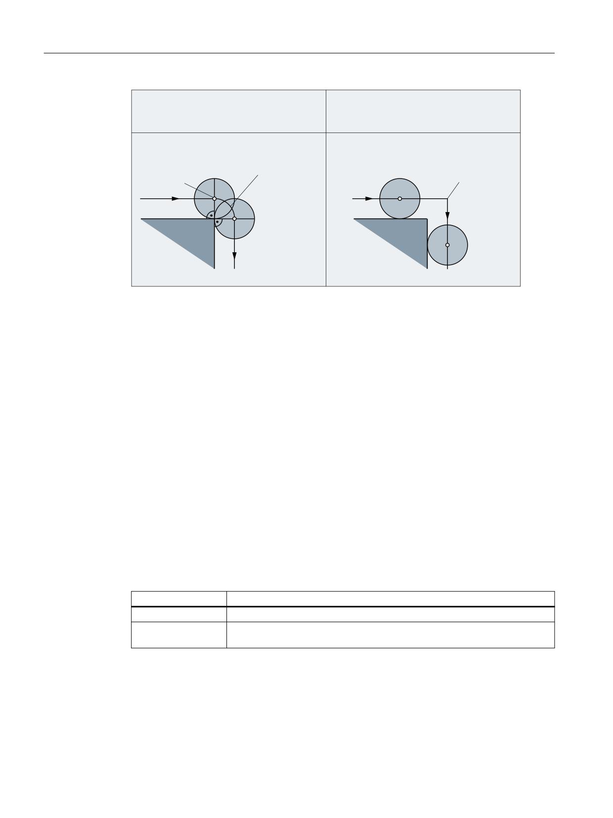
Tool offset
3.5 2D tool radius compensation
3URJUDPPLQJ *
WUDQVLWLRQ FLUFOH
3URJUDPPLQJ *
SRLQW RI LQWHUVHFWLRQ
2XWVLGH FRUQHU
2XWVLGH FRUQHU
7UDQVLWLRQ FLUFOH
5DGLXV WRRO UDGLXV
3RLQW RI LQWHUVHFWLRQ
3
Figure 3-14
Example of a 90 degree outside corner with G450 and G451
G450 (transition circle)
With the active G command G450, on outside corners, the center point of the tool travels a
circular path along the tool radius. The circular path starts with the normal position
(perpendicular to the path tangent) at the end point of the previous path section (program
block) and ends in normal position at the start point of the new path section (program block).
Where outside corners are very flat, the response with G450 (transition circle) and G451
(intersection) becomes increasingly similar (see "Very flat outside corners").
If pointed outside corners are desired, the tool must be retracted from the contour (see Section
"DISC").
DISC
The G450 transition circle does not produce sharp outside contour corners because the path of
the tool center point through the transition circle is controlled so that the cutting edge stops at
the outside corner (programmed position). When sharp outside corners are to be machined
with G450, the DISC statement can be used to program an overshoot. Thus, the transition circle
becomes a conic and the tool cutting edge retracts from the outside corner.
The range of values of the DISC statement is 0 to 100, in increments of 1.
Value
Meaning
DISC = 0
Overshoot disabled, transition circle active
DISC = 100
Overshoot large enough to theoretically produce a response similar to intersec-
tion (G451).
The programmable maximum value for DISC can be set via the machine data:
MD20220 $MC_CUTCOM_MAX_DISC (max. value for DISC).
Values greater than 50 are generally not advisable with DISC.
Tools
68
Function Manual, 10/2020, 6FC5397-6GP40-0BA1