SINUMERIK 840D sl. Service - Functions. Manual (2018-2020) - page 91
Code carrier connection - Tool Ident Connection (option)
10.2 Configuration
SampleToolSize.mcc
_VersionInfo := "SampleToolSize.mcc: Example for WKONWERT logic";
TmTool Tool = new TmTool();
// tool object
unsigned char ToolArray[0];
// data of the data carrier
void DecodeToolData()
{
Tool.TC_TP1
= readWORD( ToolArray, 0 );
// Duplo number
byte 00-01
Tool.TC_TP2
= readASCII( ToolArray, 2, 10);
// tool name byte 02-11
Tool.TC_TP7
= readINT(ToolArray, 12 );
// location type
byte 12-13
int EdgeCount = readINT(ToolArray, 14 );
// number of cutting edges byte 14-15
int EdgeIndex;
// running variable for cutting edges
int ToolSize = 1;
// tool size in half locations
for ( EdgeIndex = 1 ; EdgeIndex <= EdgeCount ; EdgeIndex++ )
{
int EdgeOffset
= 16 + (EdgeIndex-1) * 24;
// offset that the beginning of the particular cutting edge
// 24: Size of the cutting edge data
int EdgeNo
= readINT ( ToolArray, EdgeOffset + 0 );
// cutting edge number byte16-17
Tool.TC_DP1[EdgeNo]
= readINT ( ToolArray, EdgeOffset + 2 );
// tool type
byte 18-19
Tool.TC_DP2[EdgeNo]
= readREAL( ToolArray, EdgeOffset + 4 ); // cutting edge position
byte 20-23
Tool.TC_DP3[EdgeNo]
= readREAL( ToolArray, EdgeOffset + 8 ); // geometry length 1 byte 24-27
Tool.TC_DP4[EdgeNo]
= readREAL( ToolArray, EdgeOffset + 12 ); // geometry length 2 byte 28-31
Tool.TC_DP5[EdgeNo]
= readREAL( ToolArray, EdgeOffset + 16 ); // geometry length 3 byte 32-35
Tool.TC_DP6[EdgeNo]
= readREAL( ToolArray, EdgeOffset + 20 ); // geometry radius byte 36-39
double to radius = Tool.TC_DP6[EdgeNo];
if
( to radius > 30.0 && ToolSize < 4 )
ToolSize = 4;
else if ( tool radius >= 20.0 && ToolSize < 3 )
ToolSize = 3;
else if ( tool radius >= 10.0 && ToolSize < 2 )
ToolSize = 2;
}
Tool.TC_TP3
= ToolSize;
// size to the left
Tool.TC_TP4
= ToolSize;
// size to the right
Tool.TC_TP5
= ToolSize;
// size to the top
Tool.TC_TP6
= ToolSize;
// size to the bottom
}
void EncodeToolData()
{
writeWORD
( ToolArray, 0, Tool.TC_TP1 );
// Duplo number byte 00-01
writeASCII
( ToolArray, 2, 10, Tool.TC_TP2 );
// tool name
byte 02-11
writeINT
( ToolArray, 12, Tool.TC_TP7 );
// location type
Byte 12-13
int EdgeCount = Tool.EDGE_NUM;
writeINT
( ToolArray, 14, EdgeCount );
// number of cutting edges Byte 14-15
Tool management
668
Function Manual, 10/2020, 6FC5397-1HP40-0BA1
Code carrier connection - Tool Ident Connection (option)
10.2 Configuration
int EdgeIndex;
for ( EdgeIndex = 1 ; EdgeIndex <= EdgeCount ; EdgeIndex++ )
{
int EdgeNo
= Tool.EDGE_NO[EdgeIndex] ;
// cutting edge number
int EdgeOffset
= 16 + (EdgeIndex-1) * 24;
// offset at the beginning of the particular cutting edge
// 24: Size of the cutting edge data
writeINT ( ToolArray, EdgeOffset + 0, EdgeNo );
// cutting edge number byte 16-17
writeINT ( ToolArray, EdgeOffset + 2, Tool.TC_DP1[EdgeNo] );
// tool type
byte 18-19
writeREAL( ToolArray, EdgeOffset + 4, Tool.TC_DP2[EdgeNo] );
// cutting edge position
byte 20-23
writeREAL( ToolArray, EdgeOffset + 8, Tool.TC_DP3[EdgeNo] );
// geometry length 1 byte 24-27
writeREAL( ToolArray, EdgeOffset + 12, Tool.TC_DP4[EdgeNo] ); // geometry length 2 byte 28-31
writeREAL( ToolArray, EdgeOffset + 16, Tool.TC_DP5[EdgeNo] ); // geometry length 3 byte 32-35
writeREAL( ToolArray, EdgeOffset + 20, Tool.TC_DP6[EdgeNo] ); // geometry radius byte 36-39
}
}
Tool management
Function Manual, 10/2020, 6FC5397-1HP40-0BA1
669
Code carrier connection - Tool Ident Connection (option)
10.3 PLC interface in the DB19
10.3
PLC interface in the DB19
10.3.1
Structure
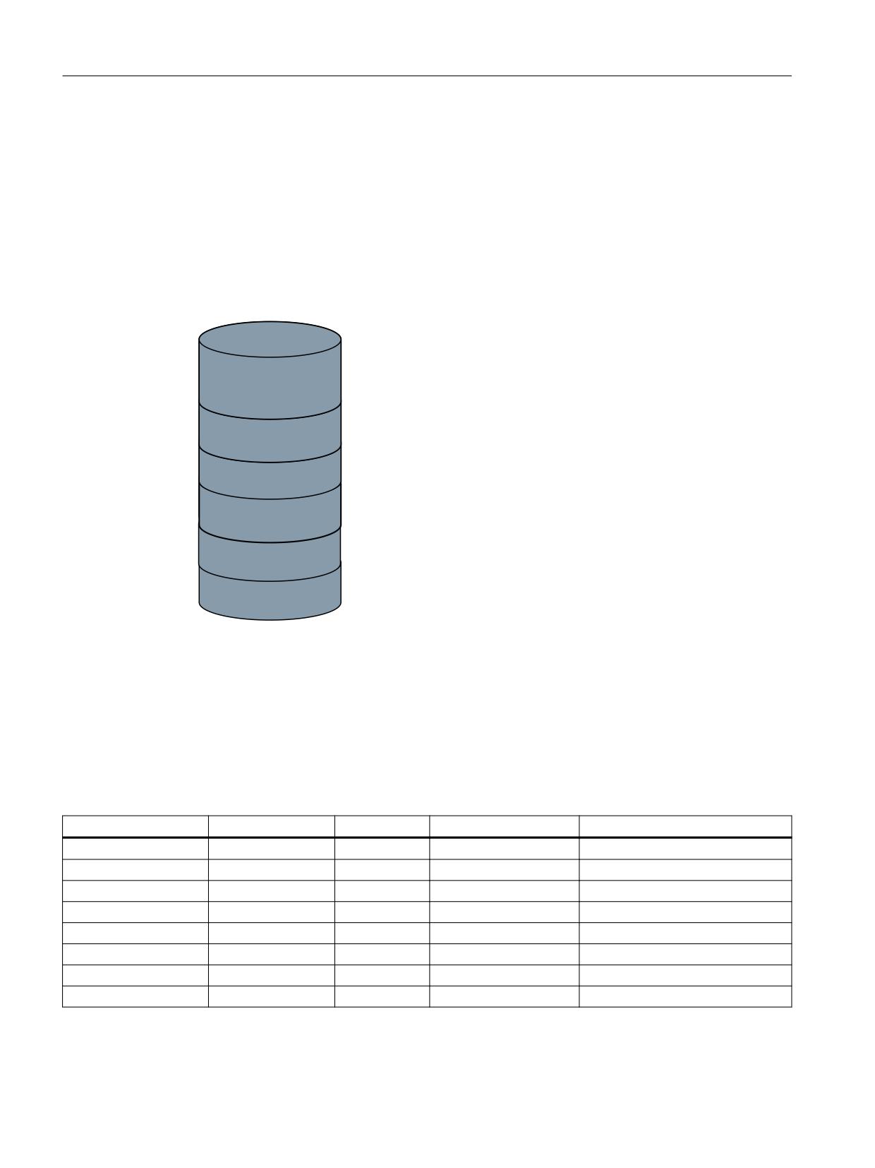
Tool Ident Connection has a parameterizable PLC interface with which defined services/
functions can be triggered or executed. Data for the services/functions is saved in a defined data
area of the PLC interface; the area for the return value of the services/functions is also provided
there.
'%
7UDQVIHU SDUDPHWHUV
5HWXUQ SDUDPHWHUV
3/& LQWHUIDFH
3DUDPHWHUV RSHUDWLQJ DUHD
Figure 10-16
Structure of the PLC interface
10.3.2
Function call of the PLC interface
The interface occupies six bytes in the PLC, has a fixed structure and the following assignment
(the table refers to the default parameterization of the interface in DB19 with offset 250):
Table 10-7
Structure of the PLC interface
PLC data
Identifier
Type
Range of values
Meaning
DB19.DBX250.0
Request
BOOL
True,False
Requesting the task
DB19.DBB251
K_Code
BYTE
0…127
Command code
DB19.DBX252.0
Done
BOOL
True,False
Task successfully completed
DB19.DBX252.1
Error
BOOL
True,False
Task ended with error
DB19.DBX252.2
Active
BOOL
True,False
Task is being processed
DB19.DBX252.7
Ident_Ready
BOOL
True,False
Status for power up
DB19.DBB253
K_CodeError
BYTE
0 ... 127
K-Code in case of an error
DB19.DBW254
Error_Code
INT
-3276 ... 32767
Error code
Tool management
670
Function Manual, 10/2020, 6FC5397-1HP40-0BA1

Code carrier connection - Tool Ident Connection (option)
10.3 PLC interface in the DB19
Note
The PLC interface can only function and accept tasks after the status bit Ident_Ready has been
set to "1".
If the request bit has already been set, it is reset and error code 0xFFFF is written into the
Error_Code word in the PLC.
10.3.3
Assignment of the PLC for transfer parameters
Various transfer parameters are required, depending on the command code, to execute certain
functions. The required transfer parameters are also stored in the PLC; this data area occupies 56
bytes and has the following fixed structure (the table refers to the default parameterization of
the interface in DB19 with offset 140):
Table 10-8
Assignment of the PLC for transfer parameters
PLC data
Identifier
Type
Range of values
Meaning
DB19.DBW140
Subtype
INT
-1…32000
Subtype of the tool
DB19.DBW142
Duplo
INT
-1…32000
Duplo number of the tool
DB19.DBB144
Ident
STRING
32 characters
Tool identifier
DB19.DBW178
T number
INT
-1…32000
T number of the tool
DB19.DBW180
Magazine location
INT
-1…32000
Magazine location number of the tool
DB19.DBW182
Magazine location type
INT
-1…32000
Magazine location type of the tool
DB19.DBB184
ToolSize_Upper
BYTE
1…127
Tool size upwards in half locations
DB19.DBB185
ToolSize_Down
BYTE
1…127
Tool size downwards in half locations
DB19.DBB186
ToolSize_Left
BYTE
1…127
Tool size to the left in half locations
DB19.DBB187
ToolSize_Right
BYTE
1…127
Tool size to the right in half locations
DB19.DBB188
Channel
BYTE
1…127
Channel number of the tool
DB19.DBB189
Loading Place
BYTE
1…127
Number of the loading/unloading loca-
tion
DB19.DBW190
Magazines
INT
0…32000
Magazine number
DB19.DBB192
Unit
BYTE
1…127
Code carrier number
DB19.DBB193
NCU_Index
BYTE
1…127
Name of the NCU
DB19.DBW194
FileIndex
INT
0…32000
File index (Import/Export)
DB19.DBX196.0
Active Enable
BOOL
True, False
Hide status bit "Tool active"
DB19.DBX196.1
Override
BOOL
True, False
Overwrite file
DB19.DBX196.2
LoadTool
BOOL
True, False
Load tool after being created
DB19.DBX196.3
DeleteTool
BOOL
True, False
Delete tool after unloading
Note
The "NCU_Index" parameter is currently not evaluated by Tool Ident Connection.
Tool management
Function Manual, 10/2020, 6FC5397-1HP40-0BA1
671

Code carrier connection - Tool Ident Connection (option)
10.3 PLC interface in the DB19
10.3.4
Assignment of the PLC for return values
To execute certain functions, various return parameters are supplied, depending on the
command code. They are also stored in the PLC; this data area occupies 50 bytes and has the
following fixed structure (the table refers to the default parameterization of the interface in
DB19 with offset 198):
Table 10-9
Assignment of the PLC for return parameters
PLC data
Identifier
Type
Range of values
Meaning
DBW 198
Subtype
INT
-1…32000
Subtype of the tool
DBW 200
Duplo
INT
-1…32000
Duplo number of the tool
DBB 202
Ident
STRING
32 characters
Tool identifier
DBW 236
T number
INT
-1…32000
T number of the tool
DBW 238
ToolState
INT
-1…32000
Tool status
DBW 240
Magazine location type
INT
-1…32000
Magazine location type of the tool
DBB 242
ToolSize_Upper
BYTE
1…127
Tool size upwards in half locations
DBB 243
ToolSize_Down
BYTE
1…127
Tool size downwards in half locations
DBB 244
ToolSize_Left
BYTE
1…127
Tool size to the left in half locations
DBB 245
ToolSize_Right
BYTE
1…127
Tool size to the right in half locations
DBW 246
Magazines
INT
0…32000
Magazine number of the tool
DBW 248
Magazine Place
INT
0…32000
Magazine location number of the tool
10.3.5
Executing functions
10.3.5.1
General sequence when executing functions
The following chronological sequence is defined (positive execution) for executing functions for
the PLC interface:
PLC interface user:
1. Transfer parameters required are written in the PLC (DB19 - offset 140)
2. Command code is defined (DB19.DBB251)
3. Request bit is set (DB19.DBX.250.0)
Tool Ident Connection:
1. Reads out the command code (DB19.DBB251)
2. Checks whether the value read-out is valid
3. Sets the active bit (DB19.DBB251.2)
4. Request is executed
5. Writes the value "0" to the error code word (DB19.DBW253)
6. Sets the done bit (DB19.DBX251.0)
Tool management
672
Function Manual, 10/2020, 6FC5397-1HP40-0BA1
Code carrier connection - Tool Ident Connection (option)
10.3 PLC interface in the DB19
PLC interface user:
1. Evaluates done bit or error bit and possibly the error code
2. Resets the request bit (DB19.DBX.250.0)
Tool Ident Connection:
1. Resets the done bit and error bit back to "0" (DB19.DBX251.0, DB19.DBX251.1)
2. Deletes the error code word (DB19.DBW253)
10.3.5.2
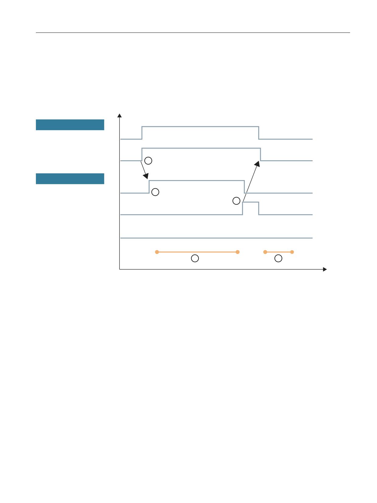
Pulse diagram for positive execution of a function
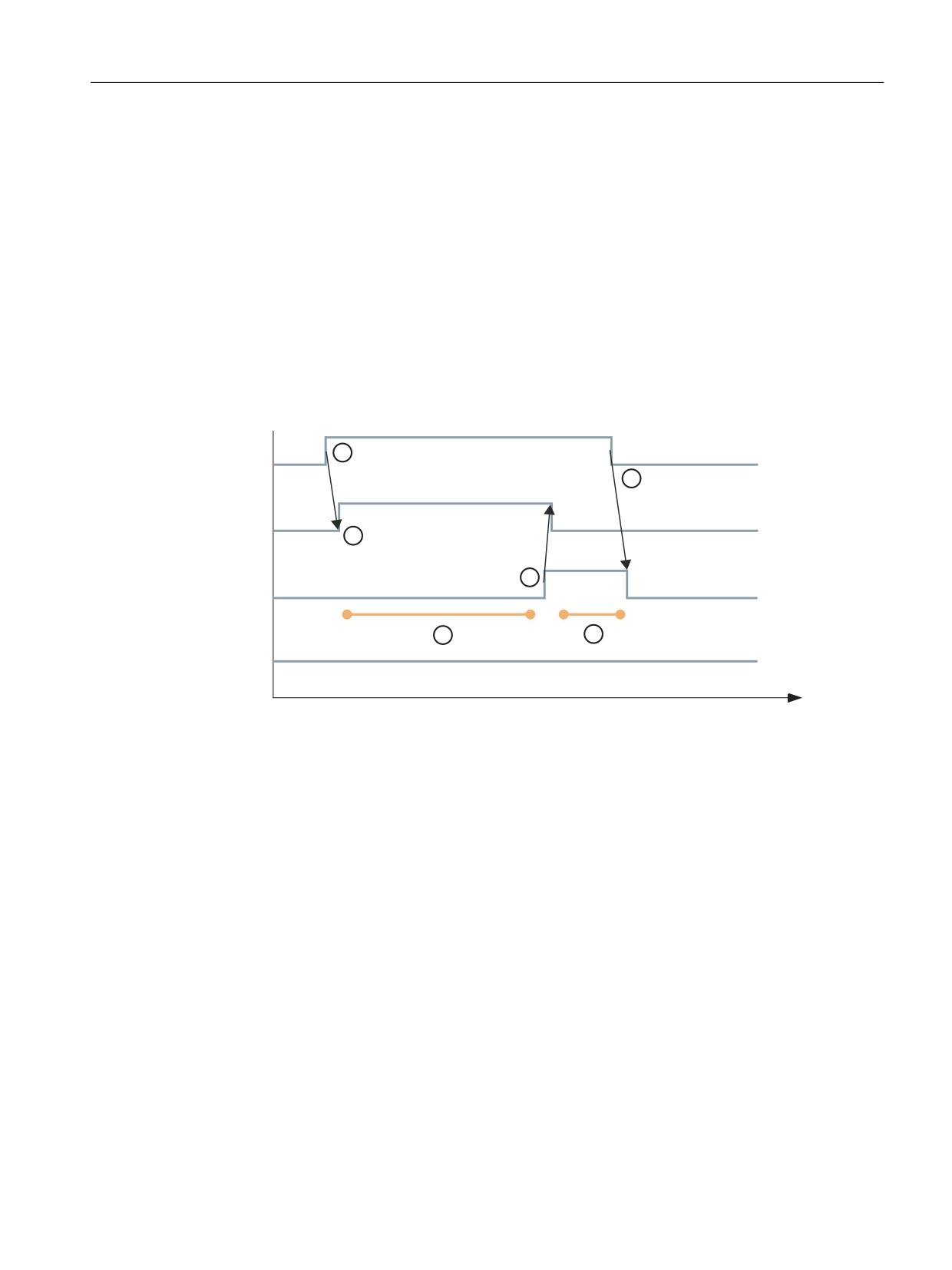
The following pulse diagram clearly shows the chronological sequence when executing a
function via the PLC interface:
5HTXHVW %LW '% '%;
$FWLYH '% '%;
'RQH '% '%;
(UURU '% '%;
W
①
Function initiated by the user
• Before initiating, the user writes the required transfer parameters and the K code into the PLC
• When triggered, Tool Ident Connection evaluates the K code
②
Feedback from Tool Ident Connection
• The active bit is set if the K code is valid
③
Processing period
• Tool Ident Connection reads the required transfer parameters and performs the desired operation / PI service
• Depending on the function, return parameters are written to the PLC
④
Feedback, processing
• After successful execution of the function, Tool Ident Connection writes "0" to the error code word and sets the
done bit
• Resets the active bit
⑤
User responds to the falling edge of the active bit
• The user evaluates the done bit or error bit and possibly the error code word, reads possible return parameters and
resets the request bit
⑥
Tool Ident Connection reacts to the falling edge of the request bit
• Sets the done bit and error bit to "0"
• Error code word is set to "0"
Tool management
Function Manual, 10/2020, 6FC5397-1HP40-0BA1
673
Code carrier connection - Tool Ident Connection (option)
10.3 PLC interface in the DB19
Figure 10-17
Pulse diagram for positive execution
10.3.5.3
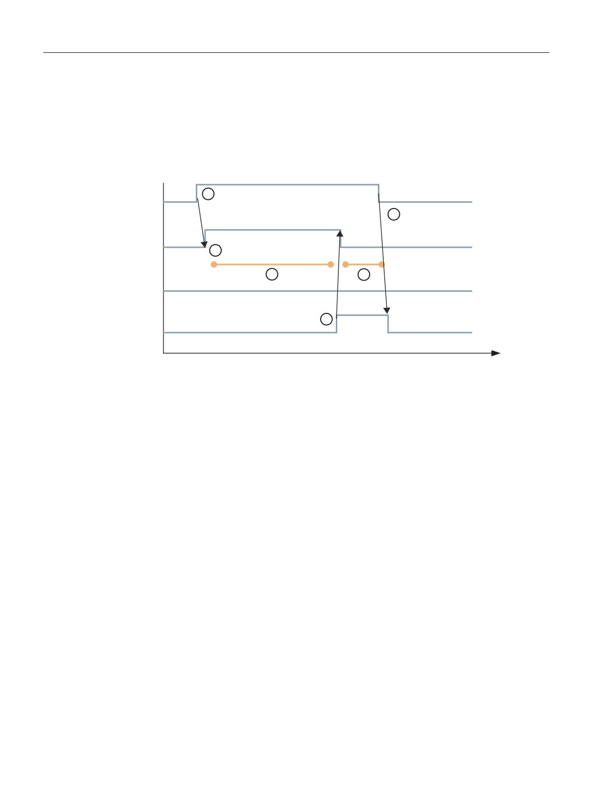
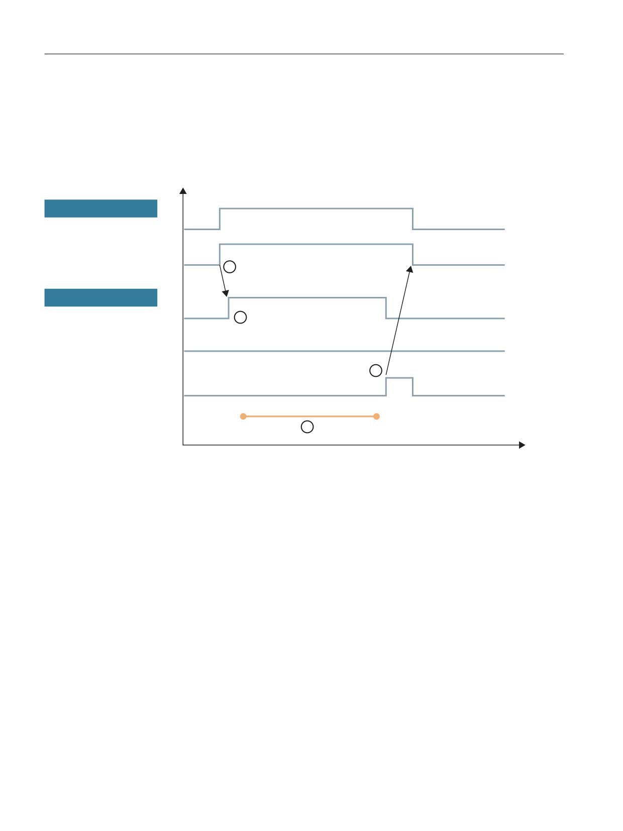
Pulse diagram when negative execution of a function
The following pulse diagram clearly shows the chronological sequence when executing a
function via the PLC interface with negative output:
5HTXHVW %LW '% '%;
$FWLYH '% '%;
'RQH '% '%;
(UURU '% '%;
W
①
Function initiated by the user
• Before initiating, the user writes the required transfer parameters and the K code into the PLC
• When triggered, Tool Ident Connection evaluates the K code
②
Feedback from Tool Ident Connection
• The active bit is set if the K code is valid
③
Processing period
• Tool Ident Connection reads the required transfer parameters and performs the desired operation / PI service
• Depending on the function, return parameters are written to the PLC
④
Feedback, processing
• After unsuccessful execution of the function, Tool Ident Connection writes the returned error code to the error code
word and sets the error bit
• Resets the active bit
⑤
User responds to the falling edge of the active bit
• The user evaluates the error bit and error code word and resets the request bit
⑥
Tool Ident Connection reacts to the falling edge of the request bit
• Sets the done bit and error bit to "0"
• Error code word is set to "0"
Figure 10-18
Pulse diagram for negative execution
10.3.5.4
Pulse diagram "Ident_Ready" signal
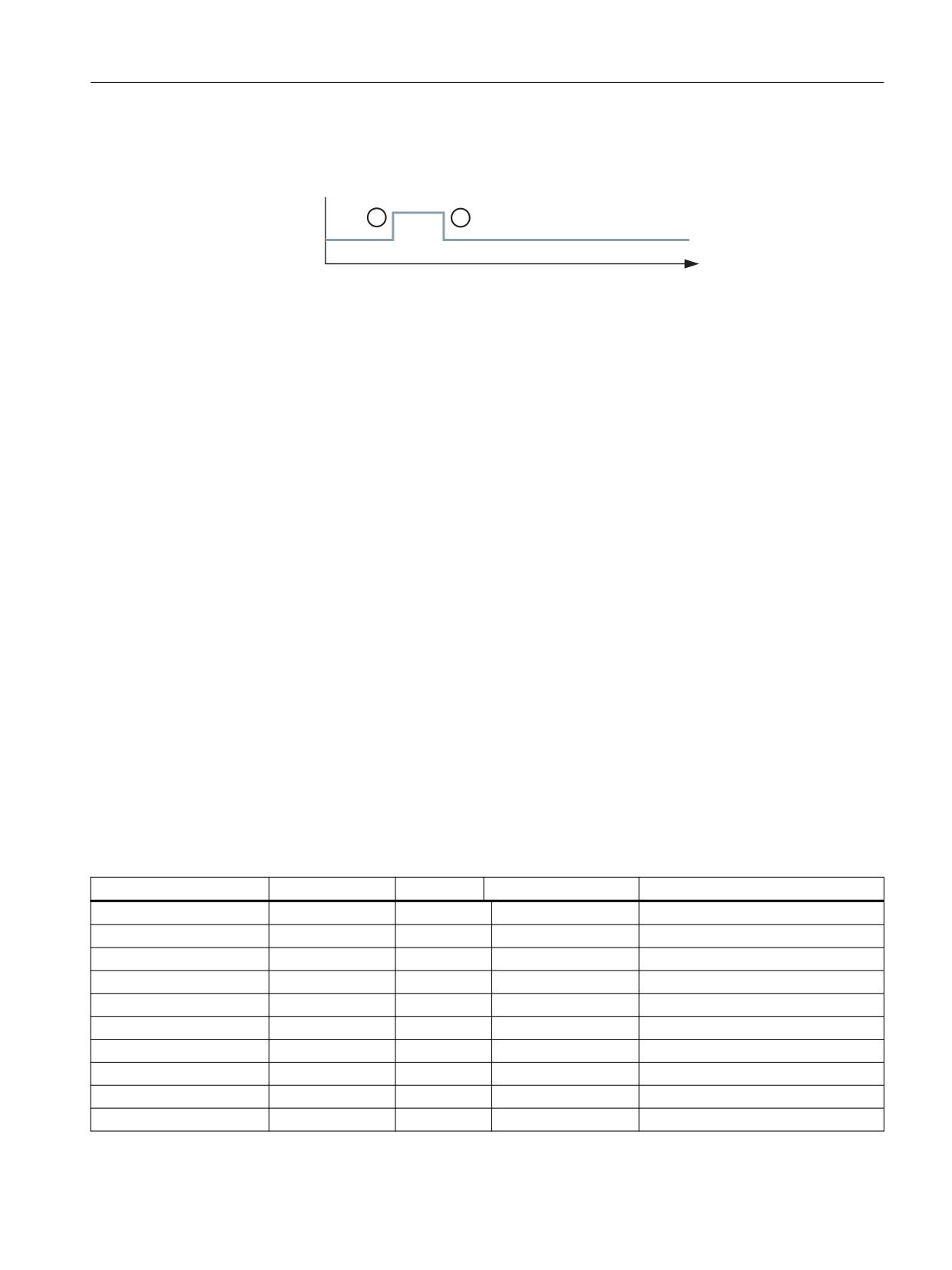
The "Ident_Ready" signal serves as the ready signal of Tool Ident Connection. The PLC user sets
the parameter "Ident_Ready" (DB19.DBX252.7) in the PLC interface to the value "1".
Tool management
674
Function Manual, 10/2020, 6FC5397-1HP40-0BA1
Code carrier connection - Tool Ident Connection (option)
10.3 PLC interface in the DB19
Tool Ident Connection reacts to the rising edge of the "Ident_Ready" signal and resets the
significance of the parameter to the value "0".
,GHQWB5HDG\
W
① Function initiated by the user
• The PLC user sets the PLC data "Ident_Ready" to a value of "1"
② Feedback from Tool Ident Connection
• Tool Ident Connection reacts to the rising edge and resets the significance of the PLC data to
"0".
Figure 10-19
Pulse diagram of the status signal Ident_Ready
10.3.6
PLC interface for the Parameter operating area
10.3.6.1
Assignment of the PLC interface for the Parameter area
ParamTM PLC interface
The "ParamTM" PLC interface is used in conjunction with the following functions:
• New tool from code carrier
• Unload tool/delete from code carrier
Configuration
In addition, this interface must be configured in the "tdidentcfg.xml" file in the
"ParamTMInterface" section.
Table 10-10 Structure of the "ParamTM-Interface" PLC interface
PLC address
Identifier
Type
Range of values
Significance
DB19.DBX256.0
Request
BOOL
True, False
Requests the task
DB19.DBB257
Reserve
BYTE
DB19.DBX258.0
Done
BOOL
True, False
Task successfully completed
DB19.DBX258.1
Error
BOOL
True, False
Task ended with error
DB19.DBX258.2
Active
BOOL
True, False
Task is being processed
DB19.DBX258.3
Reserve
BOOL
DB19.DBX258.4
Reserve
BOOL
DB19.DBX258.5
Reserve
BOOL
DB19.DBX258.6
Reserve
BOOL
DB19.DBX252.7
Reserve
BOOL
Tool management
Function Manual, 10/2020, 6FC5397-1HP40-0BA1
675

Code carrier connection - Tool Ident Connection (option)
10.3 PLC interface in the DB19
PLC address
Identifier
Type
Range of values
Significance
DB19.DBX259.0
Read
BOOL
True, False
Read tool data from CT
DB19.DBX259.1
Write
BOOL
True, False
Write tool data to CT
DB19.DBX259.2
Cancel
BOOL
True, False
Operator has canceled read/write op-
eration
DB19.DBX259.3
Write
BOOL
True, False
Selective writing of CT data
DB19.DBX259.4
Reserve
BOOL
DB19.DBX259.5
Reserve
BOOL
DB19.DBX259.6
Reserve
BOOL
DB19.DBX259.7
Reserve
BOOL
DB19.DBW260
Error_Code
INT
32768 … 32767
PLC error code
Transfer parameters
DB19.DBW262
PMagazine
INT
32768 … 32767
Magazine number
DB19.DBW264
PPlace
INT
32768 … 32767
Magazine location number
DB19.DBW266
PTnumber
INT
32768 … 32767
T number
10.3.6.2
Load the tool
"New tool from code carrier" function
The "New tool from code carrier" function is executed on the SINUMERIK Operate in the
"Parameter" area. As a consequence, the "Read" function is executed in the PLC interface.
The following pulse diagrams are shown in the following:
Sequence (Page 677)
Sequence when canceled by the PLC (Page 678)
Tool management
676
Function Manual, 10/2020, 6FC5397-1HP40-0BA1
Code carrier connection - Tool Ident Connection (option)
10.3 PLC interface in the DB19
10.3.6.3
Sequence
Sequence
The following pulse diagram clearly shows an error-free sequence of the
"New tool from code carrier" function.
6,180(5,. 2SHUDWH
5HDG '% '%;
5HTXHVW '% '%;
3/&
$FWLYH '% '%;
'RQH '% '%;
(UURU '% '%;
W
①
Function initiated by the user
With the "New tool from code carrier" function, in the PLC interface, the signals are set to Read = 1" and Request = 1.
②
Feedback from the PLC
The PLC then sets the signal to Active = 1".
③
Machining time
The PLC reads the tool data from the code carrier, and saves it in the configured data block.
④
Feedback, machining time
• If all of the tool data is in the data block, the PLC sets the following signals "Active = 0" and "Done = 1".
• SINUMERIK Operate then resets the "Read" and "Request" signals.
• The PLC also resets the "Done" signal.
⑤
Machining time
The HMI reads the tool data from the data block and the tool is loaded.
Figure 10-20
Pulse diagram for positive execution
Tool management
Function Manual, 10/2020, 6FC5397-1HP40-0BA1
677
Code carrier connection - Tool Ident Connection (option)
10.3 PLC interface in the DB19
10.3.6.4
Sequence when canceled by the PLC
Sequence
The following pulse diagram shows an incorrect sequence of the
"New tool from code carrier" function.
6,180(5,. 2SHUDWH
5HDG '% '%;
5HTXHVW '% '%;
3/&
$FWLYH '% '%;
'RQH '% '%;
(UURU '% '%;
W
① Function initiated by the user
In the PLC interface, the signals "Read = 1" and "Request = 1" are set.
② Feedback from the PLC
The PLC sets the signal "Active = 1".
③ Machining time
The PLC reads the tool data from the code carrier, and saves it in the configured data block.
④ Feedback, machining time
If the code carrier was not read, then the following happens in the PLC interface:
• The error cause is written into the "Error_Code" element.
• The PLC sets the signals "Active = 0" and "Error = 1".
• SINUMERIK Operate then resets the "Read" and "Request" signals.
• The PLC also resets the "Error" and the "Error_Code" signal.
Figure 10-21
Pulse diagram when canceled by the PLC
Tool management
678
Function Manual, 10/2020, 6FC5397-1HP40-0BA1
Code carrier connection - Tool Ident Connection (option)
10.3 PLC interface in the DB19
10.3.6.5
Unloading a tool
"Unload tool / delete on code carrier" function
The "Unload tool / delete on code carrier" function is executed on SINUMERIK Operate in the
"Parameter" area. As a consequence, the "Read" function is executed in the PLC interface, and
then the "Write" function is executed.
This sequence ensures that the content on the code carrier, which is not written to with the
current tool data as result of the conversion rule, is retained.
Please refer to the following sections for the sequence of the "Read" function.
The sequence of the "Write" function corresponds to the "Read" sequence, with the difference
that the "DB19.DBX259.1" signal is used.
Sequence (Page 677)
Sequence when canceled by the PLC (Page 678)
10.3.6.6
Diagnostics
Settings
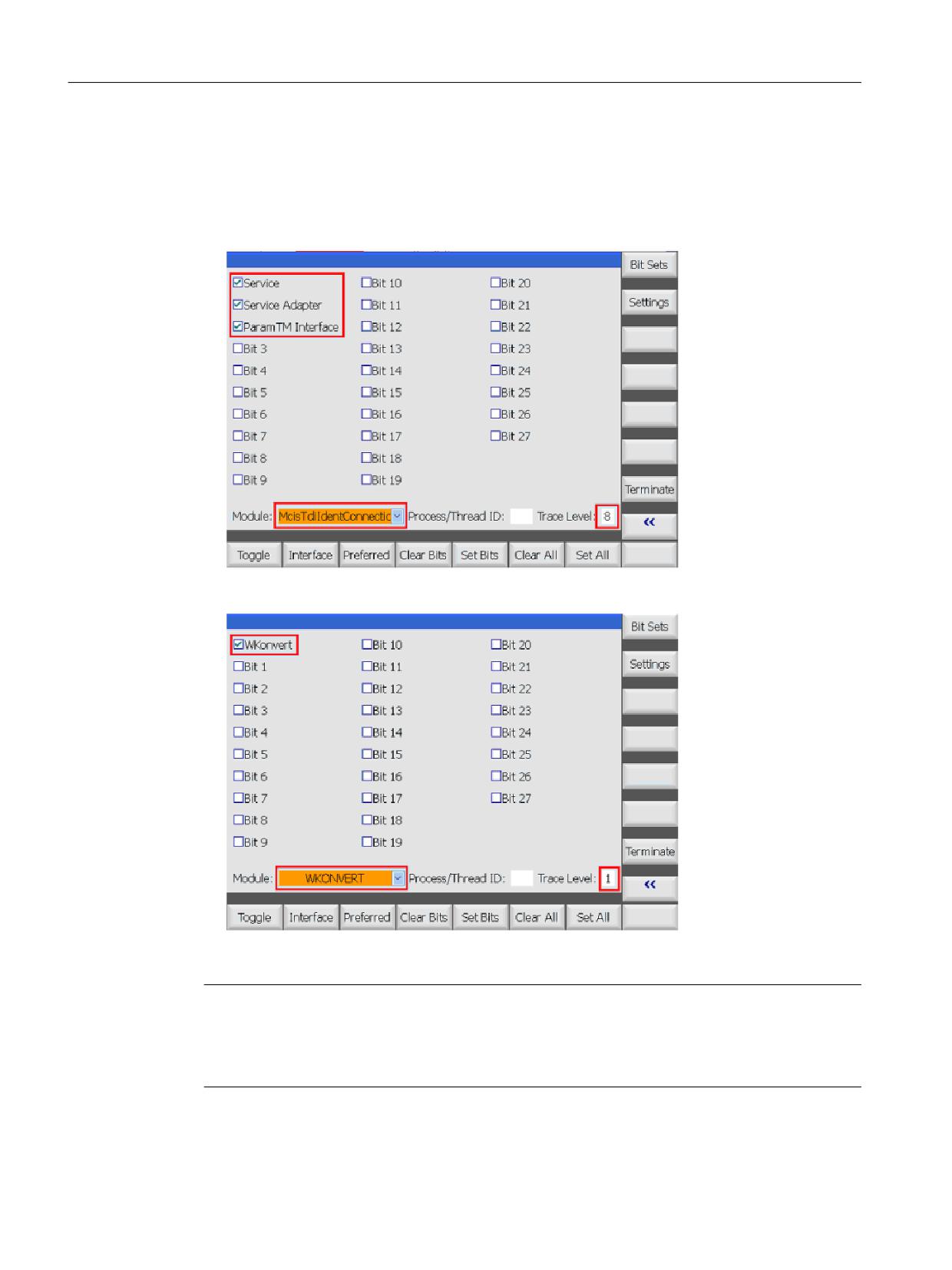
The following settings must be made in order to set the diagnostics of the described sequences.
Tool management
Function Manual, 10/2020, 6FC5397-1HP40-0BA1
679
Code carrier connection - Tool Ident Connection (option)
10.3 PLC interface in the DB19
Procedure
1. Select the "Startup" operating area.
2. Press the "SINUMERIK Operate", "Diagnostics", and "Extended" softkeys.
3. Make the following settings:
Figure 10-22
Activate trace
Figure 10-23
Activate trace
Note
Diagnostics are only available when the manufacturer's password has been entered.
Within a conversion rule, using the print() command, the user can generate an output in the
diagnostics, e.g.: print( "Radius", Tool.TC_DP6[EdgeNo], " EdgeNo:=", EdgeNo, "\r\n");
Tool management
680
Function Manual, 10/2020, 6FC5397-1HP40-0BA1

Code carrier connection - Tool Ident Connection (option)
10.3 PLC interface in the DB19
10.3.6.7
Restrictions
The following restrictions apply:
• The "Active (DB19.DBX258.2)" signal is optional. SINUMERIK Operate does not evaluate the
signal.
• The "Cancel (DB19.DBX259.2)" signal is not used. A function cannot be canceled by
SINUMERIK Operate.
• SINUMERIK Operate does not use the following transfer parameters:
- PMagazine
- PPlace
- PTnumber
• Several units can be configured in the "tdiidentcfg.xml" file. However, in the data block only
the "Unit = 1" is used.
10.3.6.8
Error messages
Error messages that are transferred in the PLC are displayed on the user interface in the form of
an error code, for example, Error_Code (DB19.DBW260)
Further, the following error codes can occur:
Error code
Description
-602
The user initiates a new function, while an active function has still not been completed.
-603
The PLC interface is not ready.
The "Done" signal is present, and prevents a new function from being initiated.
-604
Invalid reader head number
10.3.7
PLC data types
The used PLC data types and how they are interpreted by "Tool Ident Connection" is described in
the following table.
Table 10-11 PLC data used
Data type
Range of values
Note
BOOL
TRUE, FALSE
Is used if individual bits should be set in the PLC.
(TRUE: Bit = 1, FALSE: Bit = 0)
BYTE
-128...127
PLC byte
Tool management
Function Manual, 10/2020, 6FC5397-1HP40-0BA1
681

Code carrier connection - Tool Ident Connection (option)
10.3 PLC interface in the DB19
Data type
Range of values
Note
INT
-32768...32767
PLC word, whose first byte contains the high byte and the
second byte contains the low byte.
Example: PLC word 140 comprises the two PLC bytes 140 and
141 together and should be allocated the value 120.
Byte 140: 0 byte 141: 120
String
xx character
Strings occupy xx+2 bytes in the PLC as the first two bytes
contain the maximum length and the actual length of the
string. The actual string therefore does not start until the 3rd
byte. The individual characters are saved in the corresponding
bytes as ASCII code.
PLC strings do not have to end with a zero because the actual
length is always specified in the 2nd byte of the string.
Example:
"Hello" should be saved in a string, which starts at PLC byte
144 and may only have a maximum length of 32 characters.
This results in the following assignment of the bytes:
Byte 144 = 32 max. length of the string
Byte 145 = 5 actual length of the string
Byte 146 = 72 H
Byte 147 = 97 a
Byte 148 = 108 l
Byte 149 = 108 l
Byte 150 = 111 o
Tool management
682
Function Manual, 10/2020, 6FC5397-1HP40-0BA1
Code carrier connection - Tool Ident Connection (option)
10.4 Command codes
10.4
Command codes
10.4.1
Functional scope of the PLC interface (K codes)
Functional scope of the PLC interface
The PLC interface has a permanently defined range of functions. Every defined function/service
is assigned a unique command code (K code). Depending on the command to be executed,
before setting the request bit, various transfer parameters must be written to the PLC.
The following functions can be executed via Tool Ident Connection using the PLC interface:
K code
Description
0
Loading from the code carrier (K code = 0) (Page 684)
1
Unload to code carrier (K code = 1) (Page 685)
4
Loading of production host computer (K code = 4) (Page 686)
5
Unload to the production host computer (K code = 5) (Page 687)
7
Loading a tool from the tool list (K code = 7) (Page 688)
8
Unloading a tool in the tool list (K code = 8) (Page 689)
9
Empty location search (K code = 9) (Page 690)
10
Delete tool in NC (K code = 10) (Page 691)
14
Updating the code carrier (K code = 14) (Page 692)
15
Reading data from the code carrier (K code = 15) (Page 693)
The individual functions of Tool Ident Connection are described in detail in the following
sections. The optional and the mandatory transfer parameters are listed for each service.
There is also an overview of the return parameters supplied by Tool Ident Connection after the
successful execution of a command code.
10.4.2
Parameter description
Transfer parameters for the services
The terms of the transfer parameters are described in the following table:
Parameter
Description
ActiveEnable
Transfer of the tool status bit from the database in the NC (TRUE) / hiding the
status bit during the transfer (FALSE)
Channel
Channel number
DeleteTool
Delete tool after unloading (TRUE) / do not delete (FALSE)
Duplo
Duplo number
FileIndex
Index of the file from which data is to be imported or to which data is to be
exported. The file name which is extended by the index can be specified in the
INI file.
Tool management
Function Manual, 10/2020, 6FC5397-1HP40-0BA1
683

Code carrier connection - Tool Ident Connection (option)
10.4 Command codes
Parameter
Description
Ident
Tool name
LoadingPlace
Number of the loading/unloading location in the loading magazine
LoadTool
Load tool after reading (TRUE) / do not load (FALSE)
Magazines
Magazine number
MagazinePlace
Magazine location number of the tool
MagazinePlaceType
Magazine location type
NCU_Index
NCU index (parameter is presently not used)
Override
Overwrite export file (TRUE) / extend (FALSE)
Subtype
Subtype or type
TNumber
T number
ToolSize_Down
Tool size downwards in half locations
ToolSize_Left
Tool size to the left in half locations
ToolSize_Right
Tool size to the right in half locations
ToolSize_Upper
Tool size upwards in half locations
ToolState
Tool status
Unit
Code carrier unit (read/write head) from which data is read or to which data
should be written. Depending on the unit: 1...4.
10.4.3
Loading from the code carrier (K code = 0)
Reads tool data from the code carrier; whose unit is specified with "Unit". The tool is then created
if it is not already available in the NC. It is also loaded if "LoadTool" has been set. The number of
the loading location (place) in the loading magazine from "LoadingPlace" is used during this
process, if "LoadingPlace" is > 0. However, if "LoadingPlace" is set to 0, the value from
"LoadPlaceNo" node is used in the configuration file as loading location (place) number.
The channel number (channel) and the number of the read head (unit) must be specified.
If the parameter "Magazine" is assigned with ">0" and "MagazinePlace" with "0", then an attempt
is made to load the tool into an appropriate empty location in the specified magazine.
If the values for "Magazine" and "MagazinePlace" are > 0, then an attempt is made to load the tool
to this magazine location.
In all other cases, the tool is loaded into the magazine in which an empty location is found.
Table 10-12 PLC parameters for "loading from code carrier"
PLC data
Identifier
Type
Range of values
Meaning
Transfer parameters
DBW180
Magazine location
INT
-1…32000
Magazine location number of the tool
DBB188
Channel
BYTE
1…127
TO area
DBB189
Loading Place
BYTE
1…127
Number of the loading/unloading loca-
tion
DBW190
Magazines
INT
0…32000
Magazine number
DBB192
Unit
BYTE
1…127
Code carrier number
DBX196.2
LoadTool
BOOL
True, False
Load tool after being created
Tool management
684
Function Manual, 10/2020, 6FC5397-1HP40-0BA1

Code carrier connection - Tool Ident Connection (option)
10.4 Command codes
PLC data
Identifier
Type
Range of values
Meaning
Return parameters
DBW198
Subtype
INT
-1…32000
Subtype of the tool
DBW200
Duplo
INT
-1…32000
Duplo number of the tool
DBB202
Ident
STRING
32 characters
Tool identifier
DBW236
T number
INT
-1…32000
T number of the tool
DBW238
ToolState
INT
-1…32000
Tool status
DBW240
Magazine location type
INT
-1…32000
Magazine location type of the tool
DBB242
ToolSize_Upper
BYTE
1…127
Tool size upwards in half locations
DBB243
ToolSize_Down
BYTE
1…127
Tool size downwards in half locations
DBB244
ToolSize_Left
BYTE
1…127
Tool size to the left in half locations
DBB245
ToolSize_Right
BYTE
1…127
Tool size to the right in half locations
DBW246
Magazines
INT
0…32000
Magazine number of the tool
DBW248
Magazine place
INT
0…32000
Magazine location number of the tool
10.4.4
Unload to code carrier (K code = 1)
Unloads the tool that was parameterized using the transfer parameters. The channel number
and the number of the write head must be specified. If the "Magazine" and "MagazinePlace"
parameters are > 0, then an attempt is made to unload the tool, which is at this location.
Otherwise the tool is selected with the parameters "Duplo" and "Ident" or via the parameter
"TNumber".
In this case, the number of the unloading location in the loading magazine from "LoadingPlace"
is used, if "LoadingPlace" is > 0. If "LoadingPlace" is set to 0, then the value from the
"LoadPlaceNo" node is used in the configuration file as unload location number (loading point).
If "DeleteTool" is set, then the tool is also deleted from the NC after the unload operation.
Table 10-13 PLC parameters for "unload to the code carrier"
PLC data
Identifier
Type
Range of values
Meaning
Transfer parameters
DBW142
Duplo
INT
0…32000
Duplo number
DBB144
Ident
String
32 characters
Tool identifier
DBW178
TNumber
INT
0…32000
T number
DBW180
MagazinePlace
INT
0…32000
Magazine location
DBB188
Channel
BYTE
1…127
TO area
DBB189
Loading Place
BYTE
1…127
Number of the loading/unloading loca-
tion
DBW190
Magazines
INT
0…32000
Magazine number
DBB192
Unit
BYTE
1…127
Code carrier number
DBX196.3
DeleteTool
BOOL
TRUE, FALSE
Delete tool after unloading
Return parameters
None
Tool management
Function Manual, 10/2020, 6FC5397-1HP40-0BA1
685
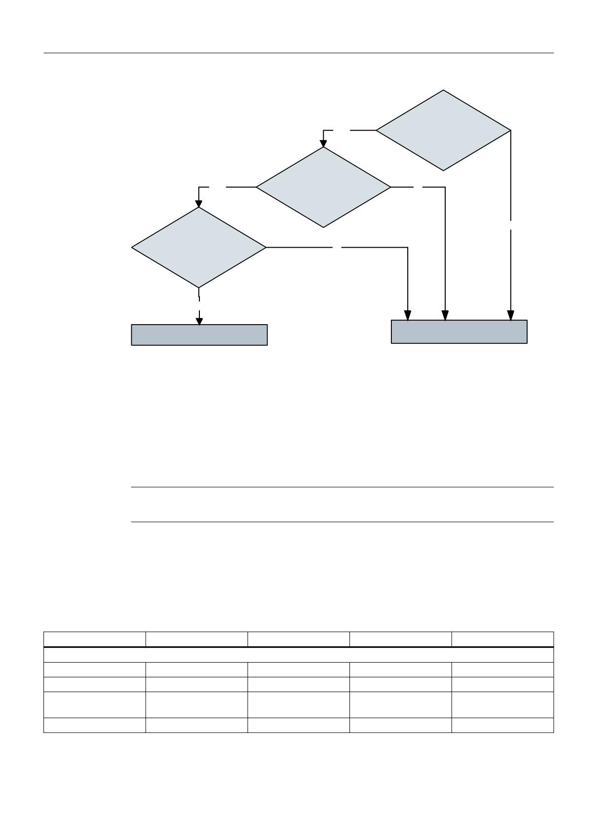
Code carrier connection - Tool Ident Connection (option)
10.4 Command codes
0DJD]LQH !
12
0DJD]LQH3ODFH !
12
71XPEHU !
<
(6
<(6
'XSOR !
<(6
,GHQW
!
12
6WDUW RI WKH RSHUDWLRQ
(UURU PHVVDJH
Figure 10-24
Flowchart to identify tools
10.4.5
Loading of production host computer (K code = 4)
Requests the data for the tool designated "Ident" from the production host computer and creates
it in the NC if it does not already exist. The NCU_Index, Channel, Ident, Duplo and Magazine
parameters must be assigned.
Note
This service can only be used in conjunction with Create MyInterface.
If the magazine number is specified as "0", the tool is loaded to the magazine that has an empty
location if LoadTool is set. The number of the loading location (place) in the loading magazine
from "LoadingPlace" is used during this process if "LoadingPlace" is > 0. However, if LoadingPlace
= 0 is set, the value of the LoadPlaceNo keyword in file TMS.INI is used as the loading place
number.
If the value for "MagazinePlace" is > 0, an attempt is made to load the tool to this magazine place.
PLC data
Identifier
Type
Value range
Meaning
Transfer parameters
DBW142
Duplo
INT
1...32000
Duplo number
DBW144
Ident
String
32 characters
Tool identifier
DBW180
Magazine-Place
INT
1...32000
Magazine location
number
DBW188
Channel
BYTE
1...127
Channel number
Tool management
686
Function Manual, 10/2020, 6FC5397-1HP40-0BA1

Code carrier connection - Tool Ident Connection (option)
10.4 Command codes
PLC data
Identifier
Type
Value range
Meaning
DBB189
Loading-Place
BYTE
1...127
Loading location num-
ber
DBW190
Magazines
INT
0...32000
Magazine number
DBB193
NCU_Index
BYTE
0...127
Index of the NCU
DBX196.2
LoadTool
BOOL
TRUE, FALSE
Load tool after creat-
ing?
Return parameters
DBW198
Subtype
INT
1...32000
Subtype
DBW200
Duplo
INT
1...32000
Duplo number
DBB202
Ident
String
32 characters
Tool identifier
DBW236
TNumber
INT
0...32000
T number
DBW238
ToolState
INT
0...32000
Status of tool
DBW240
Magazine-Place Type
INT
0...32000
Magazine location type
DBB242
ToolSize_Upper
BYTE
1...127
Tool size upwards in
half locations
DBB243
ToolSize_Down
BYTE
1...127
Tool size downwards in
half locations
DBB244
ToolSize_Left
BYTE
1...127
Tool size to the left in
half locations
DBB245
ToolSize_Right
BYTE
1...127
Tool size to the right in
half locations
DBW246
Magazines
INT
0...32000
Magazine number
DBW248
Magazine-Place
INT
0...32000
Magazine location
number
10.4.6
Unload to the production host computer (K code = 5)
Unloads the tool identified by "Ident" from the NC and transfers the data to the production host
computer. The NCU_Index, Channel, Ident, Duplo and Magazine parameters must be assigned.
Note
This service can only be used in conjunction with Create MyInterface.
If the magazine number is specified as "0", the tool is unloaded from any magazine and then
deleted, if DeleteTool is set.
If the value for "MagazinePlace" is > 0, an attempt is made to unload the tool from this magazine
place. In this case, the number of the unloading location in the loading magazine from
"loadingPlace" is used if "loadingPlace" is > 0. However, if "loadingPlace" = 0 is set, the value of
the "UnloadPlaceNo" keyword in file "TMS.INI" is used as the unloading location number.
PLC data
Identifier
Type
Value range
Meaning
Transfer parameters
DBW142
Duplo
INT
1...32000
Duplo number
DBB144
Ident
String
32 characters
Tool identifier
Tool management
Function Manual, 10/2020, 6FC5397-1HP40-0BA1
687

Code carrier connection - Tool Ident Connection (option)
10.4 Command codes
PLC data
Identifier
Type
Value range
Meaning
DBW180
Magazine-Place
INT
0...32000
Magazine location
number
DBB188
Channel
BYTE
1...127
Channel number
DBB189
Loading-Place
BYTE
1...127
Unloading location
number
DBW190
Magazines
INT
0...32000
Magazine number
DBB193
NCU_Index
BYTE
0...127
Index of the NCU
DBX196.3
DeleteTool
BOOL
TRUE, FALSE
Delete tool after un-
loading?
Return parameters
None
10.4.7
Loading a tool from the tool list (K code = 7)
Loading a tool from the tool list which was parameterized using the transfer parameters. The
tool can be selected with the parameters "Duplo" and "Ident" or via the parameter "TNumber". To
load, the number of the loading location (place) in the loading magazine from "LoadingPlace"
is used, if "LoadingPlace" is > 0. However, if "LoadingPlace" is set to 0, the value from
"LoadPlaceNo" node is used in the configuration file as loading location (place) number. The
channel number must be specified for the operation.
If the parameter "Magazine" is assigned with ">0" and "MagazinePlace" with "0", then an attempt
is made to load the tool into an appropriate empty location in the specified magazine.
If the values for "Magazine" and "MagazinePlace" are > 0, then an attempt is made to load the tool
to this magazine location. In all other cases, the tool is loaded into the magazine in which an
empty location is found.
Table 10-14 PLC parameters for "Load tool - tool list"
PLC data
Identifier
Type
Range of values
Meaning
Transfer parameters
DBW142
Duplo
INT
1…32000
Duplo number
DBB144
Ident
String
32 characters
Tool identifier
DBW178
TNumber
INT
0…32000
T number
DBW180
MagazinePlace
INT
0…32000
Magazine location number
DBB188
Channel
BYTE
1…127
TO area
DBB189
Loading Place
BYTE
1…127
Number of the loading/unloading loca-
tion
DBW190
Magazines
INT
0…32000
Magazine number
Return parameters
None
Tool management
688
Function Manual, 10/2020, 6FC5397-1HP40-0BA1
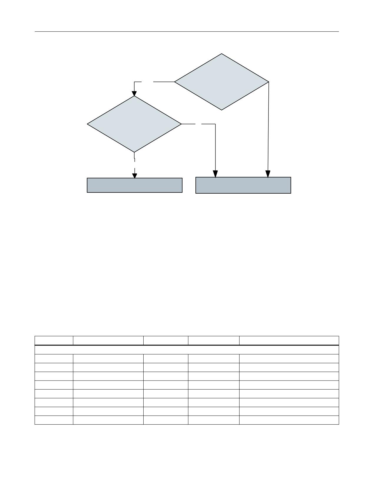
Code carrier connection - Tool Ident Connection (option)
10.4 Command codes
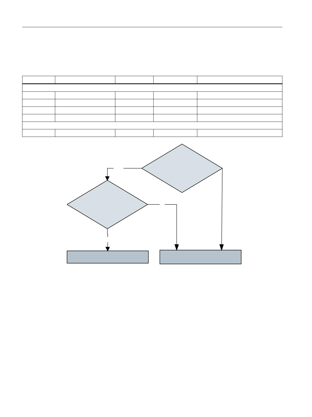
71XPEHU !
12
'XSOR !
<
(6
,GHQW
!
12
(UURU PHVVDJH
6WDUW RI WKH RSHUDWLRQ
Figure 10-25
Flowchart to identify tools
10.4.8
Unloading a tool in the tool list (K code = 8)
Unloads the tool in the tool list that was parameterized using the transfer parameters. The
channel number must be specified for this operation.
If the "Magazine" and "MagazinePlace" parameters are > 0, then an attempt is made to unload
the tool, which is at this location. Otherwise the tool is selected with the parameters "Duplo" and
"Ident" or via the parameter "TNumber".
In this case, the number of the unloading location in the loading magazine from "LoadingPlace"
is used, if "LoadingPlace" is > 0. If "LoadingPlace" is set to 0, then the value from the
"LoadPlaceNo" node is used in the configuration file as unload location number (loading point).
If "DeleteTool" is set, then the tool is also deleted from the NC after the unload operation.
Table 10-15 PLC parameters for "Unload tool - tool list"
PLC data
Identifier
Type
Range of values
Meaning
Transfer parameters
DBW142
Duplo
INT
0…32000
Duplo number
DBB144
Ident
String
32 characters
Tool identifier
DBW178
TNumber
INT
0…32000
T number
DBB188
Channel
BYTE
1…127
TO area
DBB189
LoadingPlace
BYTE
0…127
Number of loading point
DBW190
Magazines
INT
0…32000
Magazine number
DBW180
MagazinPlace
INT
0...32000
Magazine location
DBX196.3
DeleteTool
BOOL
True, False
Delete tool after unloading
Tool management
Function Manual, 10/2020, 6FC5397-1HP40-0BA1
689
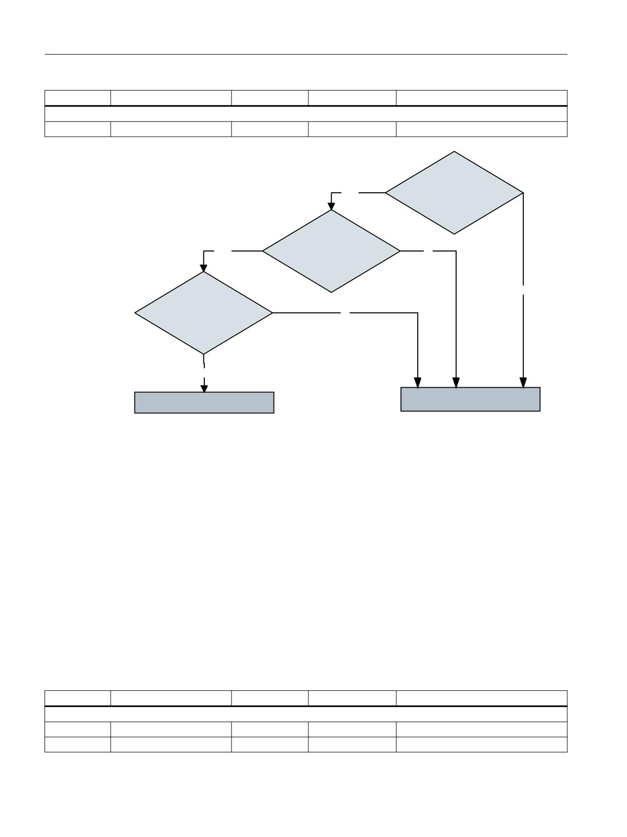
Code carrier connection - Tool Ident Connection (option)
10.4 Command codes
PLC data
Identifier
Type
Range of values
Meaning
Return parameters
None
0DJD]LQH !
12
0DJD]LQH3ODFH !
12
71XPEHU !
<
(6
<(6
'XSOR !
<(6
,GHQW
!
12
6WDUW RI WKH RSHUDWLRQ
(UURU PHVVDJH
Figure 10-26
Flowchart to identify tools
10.4.9
Empty location search (K code = 9)
For the tool specified with "TNumber" or with "Ident" and "Duplo", an empty location search or
target location check is performed. For "TNumber" = 0 an empty location is searched for the tool
specified using "Ident" and "Duplo"; for "TNumber" > 0 using the T number.
A valid value must be set for the "Channel" parameter in order to execute the function. Using the
specified loading point, an attempt is made to find an empty location in the magazines with
which the loading point is connected. To do this, the number of the loading point in the loading
magazine from "LoadingPlace" is used. However, if "LoadingPlace" is set to 0, the value from
"LoadPlaceNo" node is used in the configuration file as loading location (place) number.
If "Magazine" =0, a search is made for an empty location in any magazine; if a magazine number
is specified, then a search is made in the corresponding magazine. If, in addition, a magazine
location >0 is specified, then the function performs a target location check. This is required for
tools that are coded for specific locations.
Table 10-16 PLC parameters for "empty location search"
PLC data
Identifier
Type
Range of values
Meaning
Transfer parameters
DBW142
Duplo
INT
0…32000
Duplo number
DBB144
Ident
String
32 characters
Tool identifier
Tool management
690
Function Manual, 10/2020, 6FC5397-1HP40-0BA1
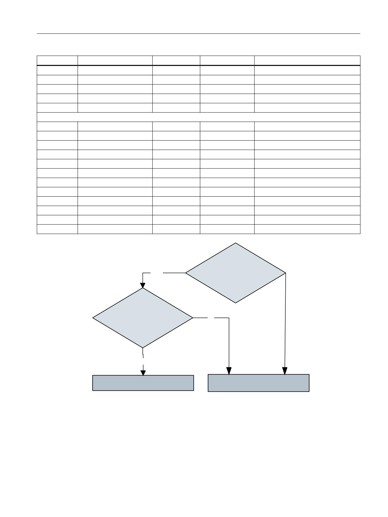
Code carrier connection - Tool Ident Connection (option)
10.4 Command codes
PLC data
Identifier
Type
Range of values
Meaning
DBW178
TNumber
INT
0…32000
T number
DBB188
Channel
BYTE
1…127
TO area
DBB189
LoadingPlace
BYTE
0…127
Number of loading point
DBW190
Magazines
INT
0…32000
Magazine number
DBW180
MagazinPlace
INT
0...32000
Magazine location
Return parameters
DBW198
Subtype
INT
-1…32000
Subtype of the tool
DBW200
Duplo
INT
-1…32000
Duplo number of the tool
DBB202
Ident
STRING
32 characters
Tool identifier
DBW236
T number
INT
-1…32000
T number of the tool
DBW238
ToolState
INT
-1…32000
Tool status
DBW240
Magazine location type
INT
-1…32000
Magazine location type of the tool
DBB242
ToolSize_Upper
BYTE
1…127
Tool size upwards in half locations
DBB243
ToolSize_Down
BYTE
1…127
Tool size downwards in half locations
DBB244
ToolSize_Left
BYTE
1…127
Tool size to the left in half locations
DBB245
ToolSize_Right
BYTE
1…127
Tool size to the right in half locations
DBW246
Magazines
INT
0…32000
Magazine number of the tool
DBW248
MagazinePlace
INT
0…32000
Magazine location number of the tool
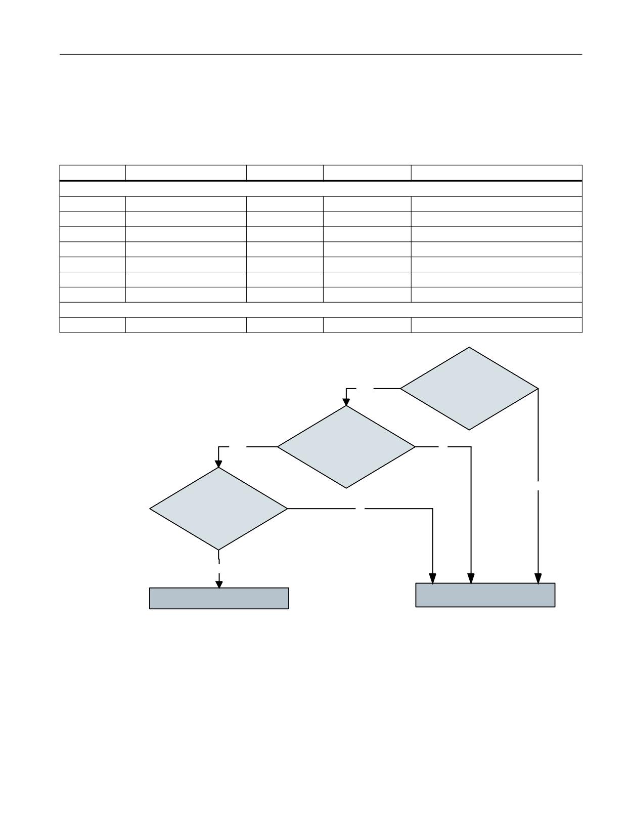
12
71XPEHU !
'XSOR !
<
(6
,GHQW
!
12
(UURU PHVVDJH
6WDUW RI WKH RSHUDWLRQ
Figure 10-27
Flowchart to identify tools
10.4.10
Delete tool in NC (K code = 10)
Deletes the tool specified with "TNumber" or with "Ident" and "Duplo" in the NC if this is not
loaded.
If a T number > "0" is specified, an attempt is made to delete the tool with this number in the NC.
Tool management
Function Manual, 10/2020, 6FC5397-1HP40-0BA1
691
Code carrier connection - Tool Ident Connection (option)
10.4 Command codes
If "TNumber = 0" is set, an attempt is made to delete the tool with the specified "Ident" and
"Duplo" in the NC.
Table 10-17 PLC parameters for "Delete tool in the NC"
PLC data
Identifier
Type
Range of values
Meaning
Transfer parameters
DBW142
Duplo
INT
0…32000
Duplo number
DBB144
Ident
String
32 characters
Tool identifier
DBW178
TNumber
INT
0…32000
T number
DBB188
Channel
BYTE
1…127
TO area
Return parameters
None
12
71XPEHU !
'XSOR !
<
(6
,GHQW
!
12
(UURU PHVVDJH
6WDUW RI WKH RSHUDWLRQ
Figure 10-28
Flowchart to identify tools
10.4.11
Updating the code carrier (K code = 14)
Updates the code carrier with the data of the tool, which was parameterized using the transfer
parameters.
The channel number and the number of the read head must be specified.
Tool management
692
Function Manual, 10/2020, 6FC5397-1HP40-0BA1
Code carrier connection - Tool Ident Connection (option)
10.4 Command codes
If the "Magazine" and "MagazinePlace" parameters are > 0, then an attempt is made to write the
data of the tool, which is at this location, to the code carrier. Otherwise the tool is selected with
the parameters "Duplo" and "Ident" or "TNumber".
Table 10-18 PLC parameters for "Update code carrier"
PLC data
Identifier
Type
Range of values
Meaning
Transfer parameters
DBW142
Duplo
INT
0…32000
Duplo number
DBB144
Ident
String
32 characters
Tool identifier
DBW178
TNumber
INT
0…32000
T number
DBB188
Channel
BYTE
1…127
TO area
DBW190
Magazines
INT
0…32000
Magazine number
DBW180
MagazinPlace
INT
0...32000
Magazine location
DBB192
Unit
BYTE
1...127
Number of the code carrier
Return parameters
None
0DJD]LQH !
12
0DJD]LQH3ODFH !
12
71XPEHU !
<
(6
<(6
'XSOR !
<(6
,GHQW
!
12
6WDUW RI WKH RSHUDWLRQ
(UURU PHVVDJH
Figure 10-29
Flowchart to identify tools
10.4.12
Reading data from the code carrier (K code = 15)
Reading tool data from the code carrier and writing return parameters into the PLC. The code
carrier is identified using "Unit".
It is then possible, for example, to read these two data from a code on which only the "Duplo"
number and the tool identifier are saved. The "Loading/unloading from the tool list" service can
then be called, for example.
Tool management
Function Manual, 10/2020, 6FC5397-1HP40-0BA1
693
Code carrier connection - Tool Ident Connection (option)
10.4 Command codes
This means that also favorably-priced "read only" code chips can be used.
Table 10-19 PLC parameters for "Reading data from the code carrier"
PLC data
Identifier
Type
Range of values
Meaning
Transfer parameters
DBB192
Unit
BYTE
1…127
Number of the read head
Return parameters
DBW198
Subtype
INT
-1…32000
Subtype of the tool
DBW200
Duplo
INT
-1…32000
Duplo number of the tool
DBB202
Ident
STRING
32 characters
Tool identifier
DBW238
ToolState
INT
-1…32000
Tool status
DBW240
Magazine location type
INT
-1…32000
Magazine location type of the tool
DBB242
ToolSize_Upper
BYTE
1…127
Tool size upwards in half locations
DBB243
ToolSize_Down
BYTE
1…127
Tool size downwards in half locations
DBB244
ToolSize_Left
BYTE
1…127
Tool size to the left in half locations
DBB245
ToolSize_Right
BYTE
1…127
Tool size to the right in half locations
10.4.13
Error codes
The error codes that are saved in the PLC byte "K_CodeError" or PLC word "Error_Code" of the PLC
interface are in the hexadecimal format and refer to the location where the task execution was
canceled with an error.
If the error code is to be shown in the decimal notation, then this must be converted into the
hexadecimal format in order to determine the error cause from tables A-1 to A-8.
The error code in "K_CodeError" identifies the command code, where the error occurred.
Table 10-20 Command codes of the task in the case of an error
K_code error
Service
00
No error
01
Load from the code carrier
02
Unload to the code carrier
03
04
05
Load from production host computer
06
Unload to the production host computer
07
08
Load tool
09
Unload tool
0A
Empty location search
0B
Delete tool in NC
0C
0D
Tool management
694
Function Manual, 10/2020, 6FC5397-1HP40-0BA1
Code carrier connection - Tool Ident Connection (option)
10.4 Command codes
K_code error
Service
0E
0F
Update code carrier
10
Read data from code carrier
11
Reserved
The error codes "Error_Code" comprise a high byte and low byte, which have a different
significance. The high byte (XX) identifies the error type group, in which the error occurred. The
low byte (YY) specifies the cause of the error, which is responsible for canceling the task.
Format of the Error_Code
;;
<<
The contents of XX = 00 and YY = 00 mean that no error has occurred.
XX = 01: General group error
Table 10-21
Low byte (YY) of the function error code
Cause of the error
01
Error when reading parameter from DB19
02
Error when calling the internal service
03
Timeout when executing the service
04
Still no data determined
05
Error when executing the internal service
Reserved
Transfer parameter error
10
Subtype
11
Duplo
12
Ident
13
TNumber
14
MagazinePlace
15
MagazinePlaceType
16
ToolSize_Upper
17
ToolSize_Down
18
ToolSize_Left
19
ToolSize_Right
1A
Channel
1B
Magazines
1C
Unit
1D
NCU_Index
1E
FileIndex
Tool management
Function Manual, 10/2020, 6FC5397-1HP40-0BA1
695

Code carrier connection - Tool Ident Connection (option)
10.4 Command codes
Cause of the error
1F
ActiveEnable
20
Override
21
LoadTool
22
DeleteTool
23
Length of Ident
Reserved
XX = 02: Code carrier error group
Table 10-22
Low byte (YY) of the function error code
Cause of the error
01
No code carrier available
02
Error when reading code carrier
03
Reading interrupted as code carrier was removed
04
Error when writing to code carrier
05
Writing interrupted as the code carrier was removed
0C
Command string unknown
0D
Number of bytes illegal
0E
Non-BCD characters found in the received write data
17
Invalid data
18
Device not available
19
Timeout
1A
Hardware faults
1B
Invalid head number
1C
Read head not connected
1E
Device is read only
1F
General read error
20
General write error
28
Unknown error
68
Data carrier not recognized (reading/writing, first page)
69
Data carrier not recognized (reading/writing, following page)
6D
Data carrier not recognized (writing, first page)
6E
Data carrier not recognized (reading before writing)
6F
Data carrier not recognized (writing the last page)
73
Non-BCD characters found in the received write data
74
Read BCD format: Non-BCD characters found on the data carrier
8D
Data carrier access error
8E
Data in the data carrier incomplete
Tool management
696
Function Manual, 10/2020, 6FC5397-1HP40-0BA1

Code carrier connection - Tool Ident Connection (option)
10.4 Command codes
XX = 05: NC error group
Table 10-23
Low byte (YY) of NC error code
Cause of the error
00
Connection not established to the requested NCU
05
Reading the NC configuration unsuccessful
0A
An invalid channel number was specified in the task
3C
An invalid magazine number was specified in the task
3E
An invalid magazine location number was specified in the task
3F
An invalid cutting edge OEM monitoring parameter number was specified in the task
41
The MMC semaphore for the search/create tool is already assigned
46
The tool specified with ident and duplo was not found in the NC
47
The tool specified with the T number was not found in the NC
48
No tool was found in the specified magazine
49
No tool is loaded at the specified magazine location
4A
The tool specified with ident and duplo was not able to be uniquely determined in the NC
4B
Number of found tools was not able to be read in the NC
50
The tool specified with ident and duplo was not created in the NC
55
The specified tool is already loaded into the magazine
5A
The tool cutting edge with the specified number has not been created in the NC
5B
The tool cutting edge with the specified number has not been deleted in the NC
5C
The specified cutting edge does not exist in the NC
5D
The specified tool cutting edge number is not valid.
5E
The specified cutting edge is already in the NC
5F
Tool state was not able to be read in the NC
64
The MMC semaphore for the empty location search is already assigned
69
An empty magazine location was not able to be found when loading into the NC
6E
Checking the specified magazine location to load negatively acknowledged
6F
Tool deletion was exited with error
70
The empty location search was exited with error
71
Creating a tool was exited with error
72
Operation to relocate tools unsuccessful
73
The MMC semaphore for tool unloading/unloading already assigned
74
Alarm extension was exited with error
78
The magazine is disabled or has not been enabled for loading
7D
Tool loading was exited with error
82
The magazine number of the tool was not able to be read in the NC
87
The specified tool is not loaded into the NC
8C
The specified tool is loaded in a different magazine
8E
The specified tool is loaded at a different magazine location
91
Magazine state not able to be read in the NC
96
Magazine not in the loading position or not enabled for unloading
9B
The tool unload operation was exited with error
Tool management
Function Manual, 10/2020, 6FC5397-1HP40-0BA1
697

Code carrier connection - Tool Ident Connection (option)
10.4 Command codes
Cause of the error
A0
The tool was not able to be deleted in the NC
A5
The tool is active in the NC! The tool was not able to be deleted in the NC
D2
The specified tool is loaded into the NC! The tool was not deleted in the DB
XX = 0B: Tool conversion error group
Table 10-24
Low byte (YY) of the function error code
Cause of the error
01
1401 Error when opening the MCX file
02
1402 Error when reading the MCX file
03
1403 Error when reading the MCX file
04
1404 Error when reading the MCX file
05
1405 Error when reading the MCX file
06
1406 Error when reading the MCX file
07
1410 Error when reading the MCX file
08
1628 System error
09
1801 System error
0A
1803 System error
0B
1804 System error
0C
1805 Incorrect version of the MCX file
0D
1806 MCX file contains functions that are not supported
0E
1807 System error
0F
1808 Error when reading the MCX file
10
1809 System error
11
1810 System error
12
2401 System error
13
2402 System error
14
2501 System error
15
2502 System error
16
2503 System error
17
2701 System error
18
2702 System error
19
2703 Index error when accessing the array
1A
2801 System error ConvertFunctions::CheckAccess()
1B
2802 System error
1C
2803 Error in conjunction with the conversion functions readXXX()/writeXXX(). Basis type of
the array parameter must be 'unsigned char'.
1D
2804 Error in the function writeBCD(). The data length (val) exceeds the size of the target
range.
1E
2805 Error in the function PlaceTypeFromString(). ToolTypeText used is not defined in the
ToolSpec.xml.
Tool management
698
Function Manual, 10/2020, 6FC5397-1HP40-0BA1

Code carrier connection - Tool Ident Connection (option)
10.4 Command codes
Cause of the error
1F
2806 Error in the function PlaceTypeToString(). ToolTypeCode used is not defined in the
ToolSpec.xml.
20
2807 Error in the function writeREAL(). Data loss due to rounding.
21
2901 System error
22
2903 System error
23
2904 System error
24
2905 System error
25
2908 System error
26
2909 System error
27
2910 System error
28
2912 System error
29
2913 Error when accessing SlTmService. setVal()
2A
2914 Error when accessing SlTmService. setVal()
2B
2915 Error when accessing SlTmService. setVal()
2C
2917 Error when accessing SlTmService. rData().val()
2D
2918 Error when accessing SlTmService. rData().val()
2E
2919 Error when accessing SlTmService. setVal()
2F
2921 Error when accessing SlTmService. val()
30
2922 System error
31
2923 Error when accessing SlTmService. val()
32
2924 System error
33
7001 System error
34
7002 The conversion rule must contain an object with the 'Tool' name.
35
7003 The 'Tool' object must be the 'TmTool' type.
36
7004 The conversion rule must contain an object with the 'ToolArray' name.
37
7005 The 'ToolArray' object must be an array.
38
7006 The 'ToolArray' object must be an array, basis type 'unsigned char'.
39
7007 The 'DecodeToolData' function was not found in the conversion rule.
3A
7008 The object 'DecodeToolData' must be a function.
3B
7009 The 'DecodeToolData' function was not found in the conversion rule.
3C
7010 The object 'EncodeToolData' must be a function.
3D
7011 System error
3E
7012 System error
3F
7013 System error
40
7014 System error
41
7015 Error when reading ToolSpec.xml'
42
7016 Error when interpreting ToolSpec.xml
43
7017 The ToolSpec.xml. The document element should have the name: "ToolSpecConver-
sion".
44
7018 Format error in the ToolSpec.xml. Attribute code="" or text="" are not included.
45
System error when converting data
80 - FF
User-defined error from conversion rule (see Error handling (Page 662))
Tool management
Function Manual, 10/2020, 6FC5397-1HP40-0BA1
699

Code carrier connection - Tool Ident Connection (option)
10.5 Examples
10.5
Examples
10.5.1
Loading the code carrier via PLC interface
In this case, the data of the imaginary tool "WZ_Test13" is read from a code carrier, the tool is
then created in the NC and loaded. The tool should be loaded into Magazine "1" of the standard
NCU in channel "1". The operation should be administered via loading location "1" of the loading
magazine.
The parameters required for this service are listed in the following table.
Before executing the service, the PLC writes a "0" into the command code byte (K_code) of the
PLC interface in data block DB19. This service is then started by setting the "Request" bit. If the
"Active" bit is reset and the "Done" bit was set, then the PLC can evaluate the "Error" byte. The
"Request" bit must then be reset again.
Table 10-25 Transfer parameters for "Loading from code carrier"
PLC data
Identifier
Value
DBW
180
MagazinePlace
0
DBB
188
Channel
1
DBB
189
LoadingPlace
1
DBW
190
Magazines
1
DBB
192
Unit
1
DBB
193
NCU_Index
0
DBX
196.2
LoadTool
TRUE
Table 10-26 Return parameters from Tool Ident Connection for "Loading from the code carrier"
PLC data
Identifier
Value
DBW
198
Subtype
120
DBW
200
Duplo
1
DBB
202
Ident
Tool_Test13
DBW
236
TNumber
289
DBW
238
ToolState
14
DBW
240
MagazinePlaceType
1
DBB
242
ToolSize_Upper
1
DBB
243
ToolSize_Down
1
DBB
244
ToolSize_Left
1
DBB
245
ToolSize_Right
1
DBW
246
Magazines
1
DBW
248
MagazinePlace
1
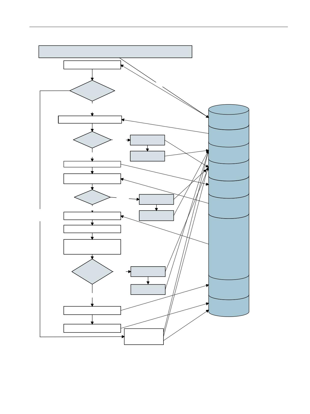
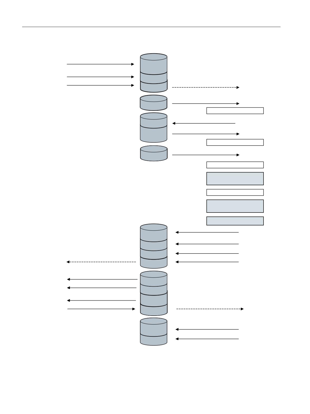
The sequence of the individual operations can be clearly seen in the following flowchart:
Tool management
700
Function Manual, 10/2020, 6FC5397-1HP40-0BA1
Code carrier connection - Tool Ident Connection (option)
10.5 Examples
7RRO ,GHQW &RQQHFWLRQ
+RWOLQNB'DWD&KDQJH
+RWOLQN
5LVLQJ IDOOLQJ
HGJH
5LVLQJ
UHTXHVW ELW
!
'%
5HDG RXW WKH . FRGH IURP WKH 3/&
'% '%;
UHTXHVW ELW
9DOLG
:ULWH
'% '%%
12
. FRGH
. FRGH"
HUURU FRGH
'% '%;
<(
6
6HW HUURU ELW
HUURU ELW
6HW DFWLYH ELW
'% '%:
HUURU FRGH
5HDG
WUDQVIHU SDUDPHWHUV IURP WKH 3/&
'% '%;
DFWLYH ELW
3DUDPHWHUV
12
:ULWH
YDOLG"
HUURU FRGH
'%
<(
6
2IIVHW
)DOOLQJ
7UDQVIHU SDUDPHWHUV
UHTXHVW ELW !
5HDG RXW FRGH FDUULHU GDWD
6HW HUURU ELW
'DWD FRQYHUVLRQ PHUJLQJ
7ULJJHU WKH UHTXLUHG 3, VHUYLFHV
YLD WKH 6,7P6HUYLFHV
'%
)HHGEDFN
:ULWH
6,7P6HUYLFHV
12
HUURU FRGH
SRVLWLYH"
'%
6HW HUURU ELW
2IIVHW
5HWXUQ SDUDPHWHUV
<(
6
'% '%;
:ULWH UHWXUQ SDUDPHWHUV
GRQH ELW
6HW GRQH ELW
5HVHW
GRQH ELW HUURU ELW
6HW HUURU FRGH
Figure 10-30
Flowchart: Loading from the code carrier via the PLC interface
Tool management
Function Manual, 10/2020, 6FC5397-1HP40-0BA1
701
Code carrier connection - Tool Ident Connection (option)
10.5 Examples
3/& XVHU
3/& LQWHUIDFH
7RRO ,GHQW &RQQHFWLRQ
:ULWHV WUDQVIHU SDUDPHWHUV
'%
2IIVHW
:ULWHV . FRGH !
FUHDWH
ORDG
'%
'%
6HWV UHTXHVW ELW WR
+RWOLQN WR UHTXHVW ELW
'%
'%;
5HDGV RXW . FRGH
'%
'%%
&KHFN YDOLG . FRGH
6HW DFWLYH ELW WR
'%
'%%
5HDGV RXW WUDQVIHU SDUDPHWHUV
'%
2IIVHW
&KHFN WUDQVIHU SDUDPHWHUV
5HDG RXW GDWD FDUULHU VWUHDP
'%
'DWD FRQYHUVLRQ RI WKH VWUHDP
&UHDWH WKH WRRO LQ WKH WRRO OLVW YLD
6,7P6HUYLFHV
5HWXUQ RI WKH 7 QXPEHUV
:ULWH WKH WRRO GDWD WR WKH 1&
(PSW\ ORFDWLRQ VHDUFK WDUJHW ORFDWLRQ
FKHFN YLD 67,P6HUYLFHV
5HWXUQ YDOXH PDJD]LQH DQG ORFDWLRQ
/RDG WKH WRRO YLD 6,7P6HUYLFHV
:ULWH WKH UHWXUQ SDUDPHWHUV
'%
2IIVHW
:ULWH HUURU FRGH ZRUG
'%
'%:
6HW GRQH ELW WR
'%
'%;
5HVHW DFWLYH ELW WR
'%
'%;
5HDG RXW GRQH ELW
'%
'%;
5HDG RXW HUURU FRGH ZRUG
'%
'%:
5HDG RXW WKH UHWXUQ SDUDPHWHUV
'%
2IIVHW
5HVHWV UHTXHVW ELW WR
+RWOLQN WR UHTXHVW ELW
'%
'%;
'%
'%;
5HVHW HUURU ELW DQG HUURU ELW WR
'%
'%;
:ULWH
WR HUURU FRGH ZRUG
'%
'%:
Tool management
702
Function Manual, 10/2020, 6FC5397-1HP40-0BA1

Code carrier connection - Tool Ident Connection (option)
10.5 Examples
10.5.2
Unloading to the code carrier via PLC interface
The tool loaded in the previous example should be unloaded and the actual data written to the
code carrier. After unloading, the tool is deleted in NC. The procedure should be managed via
unload location "2" of the loading magazine.
The transfer parameters required for this are listed in the following table. The service does not
return any parameters, and as a result, there are no new values in the return parameters of the
PLC interface.
Before executing the service, command code "1" must be written to the corresponding PLC byte
(K code). The start of the service and the further procedure are equivalent to the procedure in
Loading the code carrier via PLC interface (Page 700).
Table 10-27 Transfer parameters for "Unloading from code carrier"
PLC data
Identifier
Value
DBW
142
Duplo
1
DBB
144
Ident
Tool_Test13
DBW
180
MagazinePlace
1
DBB
188
Channel
1
DBB
189
LoadingPlace
2
DBW
190
Magazines
1
DBB
192
Unit
1
DBB
193
NCU_Index
0
DBX
196.3
DeleteTool
TRUE
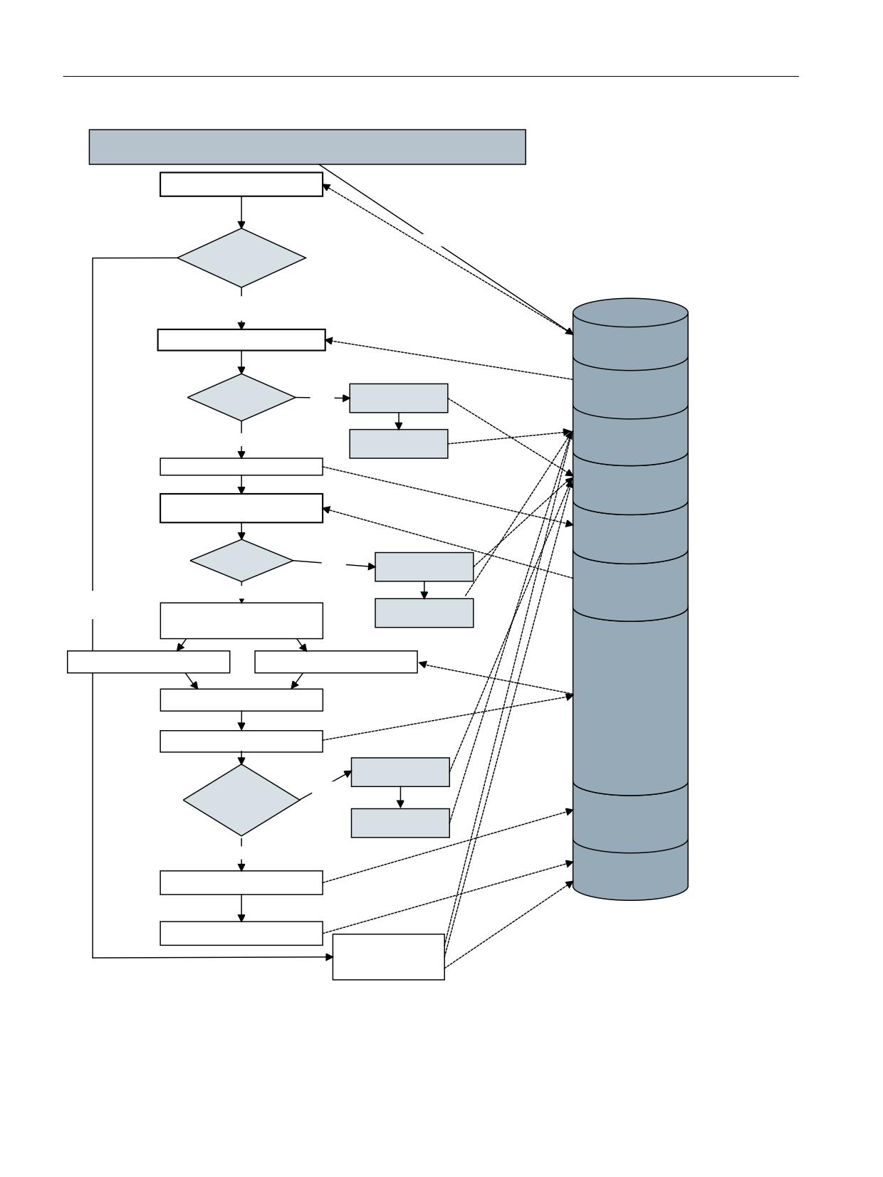
The sequence of the individual operations can be clearly seen in the following flowchart:
Tool management
Function Manual, 10/2020, 6FC5397-1HP40-0BA1
703
Code carrier connection - Tool Ident Connection (option)
10.5 Examples
7RRO ,GHQW &RQQHFWLRQ
+RWOLQNB'DWD&KDQJH
+RWOLQN
5LVLQJ IDOOLQJ
HGJH
5LVLQJ
UHTXHVW ELW
!
'%
5HDG RXW WKH . FRGH IURP WKH 3/&
'%
'%;
UHTXHVW ELW
9DOLG
'%
'%%
12
:ULWH HUURU FRGH
. FRGH
. FRGH"
'%
'%;
<(
6
6HW HUURU ELW
HUURU ELW
6HW DFWLYH ELW
'%
'%:
HUURU FRGH
5HDG
WUDQVIHU SDUDPHWHUV IURP WKH 3/&
'%
'%;
DFWLYH ELW
3DUDPHWHUV
YDOLG"
12
:ULWH HUURU FRGH
'%
<(
6
2IIVHW
)DOOLQJ
7UDQVIHU SDUDPHWHUV
UHTXHVW ELW
!
6HW HUURU ELW
7ULJJHU WKH UHTXLUHG 3, VHUYLFHV
YLD WKH 6,7P6HUYLFHV
5HDG RXW WRRO GDWD IURP 1&
5HDG RXW FRGH FDUULHU GDWD
'DWD FRQYHUVLRQ
'%
:ULWH WKH GDWD
:ULWH HUURU FRGH
12
)HHGEDFN
6,7P6HUYLFHV
SRVLWLYH"
'%
6HW HUURU ELW
2IIVHW
5HWXUQ SDUDPHWHUV
<(6
'%
'%;
:ULWH UHWXUQ SDUDPHWHUV
GRQH ELW
6HW GRQH ELW
5HVHW
GRQH ELW HUURU ELW
6HW HUURU FRGH
Figure 10-31
Flowchart: Unloading from the code carrier via the PLC interface
Tool management
704
Function Manual, 10/2020, 6FC5397-1HP40-0BA1

Alarms
11
11.1
Overview
Alarm No.
Brief description
6401
Tool change not possible, no free location in the magazine.
6402
Tool change not possible, magazine number does not exist.
6403
Tool change not possible, specified magazine location does not exist.
6404
Tool change not possible because the tool is not available or cannot be used.
6405
Command has invalid PLC acknowledgement parameter.
6406
PLC acknowledgement missing.
6407
Tool is to be set down at a location that does not meet the requirements for loading.
6410
One cutting edge of the monitored tool has reached a prewarning limit.
6411
One cutting edge of the monitored tool has reached a prewarning limit.
6412
One cutting edge of the monitored tool has reached a monitoring limit.
6413
One cutting edge of the monitored tool has reached a monitoring limit.
6421
No free location for tool in the magazine.
6422
Tool motion is not possible because the magazine has not been defined.
6423
Tool motion is not possible because no location in the magazine.
6424
Tool motion is not possible because tool not available or cannot be used.
6425
Tool motion is not possible because tool cannot be placed at the specified location in the magazine
6430
Workpiece counter: Overflow in table of monitored cutting edges.
6431
Function not permitted because TOOLMAN / TOOLMAN monitoring not activated.
6432
Function cannot be executed because there is no tool in the spindle.
6433
System variable not available for active tool management.
6436
The command cannot be programmed
6438
Inconsistent data change not permitted
6441
Writing of $P_USEKT not allowed.
6450
Tool change not possible because magazine-location number is not valid.
6451
No buffer magazine defined.
6452
Tool holder number / spindle number not defined.
6453
No relationship defined between tool holder number / spindle number and buffer magazine.
6454
Neither spindle nor buffer location has a distance relationship.
6460
Command can only be programmed for tools
6462
Command can only be programmed for magazines
6464
Command cannot be programmed for the actual multitool distance coding
6924
Tool data changed for program test.
17001
No more memory for tool magazine data.
17020
Illegal array index 1
17050
Impermissible value
17160
No tool selected.
Tool management
Function Manual, 10/2020, 6FC5397-1HP40-0BA1
705

Alarms
11.1 Overview
Alarm No.
Brief description
17180
Illegal D number.
17181
D no. not known.
17182
Illegal additive offset number.
17188
The D number specified in the channel TO unit is not unique.
17189
D number is not unique.
17191
Unknown tool identifier.
17192
No further replacement tools possible.
17193
The active tool is no longer in the tool holder
17194
No suitable tool found.
17200
Tool cannot be deleted
17202
Magazine data cannot be deleted.
17212
Manual tool must be changed.
17214
Remove manual tool from tool holder.
17215
Remove manual tool from buffer
17216
Manual tools must be changed.
17218
Tool cannot become a manual tool
17220
Tool does not exist.
17224
It is not possible on this system to select tool offsets for tools of the specified tool type.
17230
Duplo no. already assigned.
17240
Invalid tool definition.
17241
Illegal adapter definition
17242
Manual tool cannot be set, as the function is not active
17250
Invalid magazine definition.
17255
Magazine location hierarchies have been deleted
17260
Invalid magazine location definition.
17262
Incorrect tool-adapter assignment
20150
PLC terminates the interrupted command.
20160
PLC can terminate only incorrectly aborted commands.
22066
Tool motion not possible because specified tool is not in magazine.
22067
Tool change not possible because no tool ready for use in the tool group.
22068
No tool ready for use in the tool group.
22069
No tool ready for use in the tool group.
22070
Change tool into magazine. Repeat data backup.
22071
Tool has the status "active" in an "inactive" wear group.
400601
Incorrect configuration of loading points
400602
Incorrect spindle configuration
400603
Incorrect turret configuration
400604
Set change with M06 in machine data.
410141
Number of loading points too high
410142
Number of tool holders too high
410143
Number of turrets too high
410151
Magazine data for tool management missing in PLC.
Tool management
706
Function Manual, 10/2020, 6FC5397-1HP40-0BA1

Alarms
11.1 Overview
With machine dates MD11410 SUPPRESS_ALARM_MASK and MD11415
SUPPRESS_ALARM_MASK_2 it can be defined bit by bit which alarms should be suppressed.
Bit
Alarm number with description
2
16924: Program test can change the tool/magazine data.
4
17189: D number of tools defined on magazine/location %3 and %4 defined.
5
22071: TO unit, tool, duplo no. are active but are not in the active wear group.
7
22070: Load a tool into the magazine. Repeat data back-up.
8
6411, 6413: Channel - tool has reached prewarning or monitoring limit.
9
6410, 6412: TO unit - tool has reached prewarning or monitoring limit.
Tool management
Function Manual, 10/2020, 6FC5397-1HP40-0BA1
707

Alarms
11.2 Alarm description
11.2
Alarm description
Alarm No.
6401
Channel %1 tool change not possible: No free location for tool %2 in magazine %4.
Explanation
%1 = channel ID, %2 = magazine number
The tool cannot be moved into the selected tool magazine. There is no appropriate location available for this
tool. A suitable location is largely determined by the status. This must state that the location is free, not
disabled, not reserved, not occupied by an oversize tool. It is also important that the type of tool is com-
patible with the type of possibly free magazine locations (e.g. if all magazine locations are type 'B' and if
these are all free, and if the tool is type 'A', then this tool cannot be set in this magazine).
Response
Alarm display.
Interface signals are set
NC start disable
NC stop for alarm
Remedy
Check whether the magazine data is correctly defined.
Check whether the magazine simply no longer has any space to accept an additional tool due to operator
actions.
Check whether a location type hierarchy is defined and whether it, for example, does not allow insertion of
a type "A" tool in a free location with type "B".
Continue pro-
Cancel the alarm with the RESET button and start the part program again.
gram
Alarm No.
6402
Channel %1 tool change not possible because magazine no. %2 not available
Explanation
%1 = channel ID, %2 = magazine number
The desired tool change is not possible. The magazine with the specified number is not available.
Response
Alarm display.
Interface signals are set
NC start disable
NC stop for alarm
Remedy
Check whether the magazine data is correctly defined.
Check whether the magazine is connected to the required spindle via a distance relationship.
The user PLC program may have supplied incorrect data to the NC.
Continue pro-
Cancel the alarm with the RESET button and start the part program again.
gram
Alarm No.
6403
Channel %1 tool change not possible because magazine no. %2 in magazine %3 not available
Explanation
%1 = channel ID, %2 = magazine number, %3 = magazine location number
The desired tool change is not possible. The specified magazine location is not available in the specified
magazine.
Response
Alarm display
Interface signals are set
NC start disable
NC stop for alarm
Tool management
708
Function Manual, 10/2020, 6FC5397-1HP40-0BA1

Alarms
11.2 Alarm description
Alarm No.
Remedy
Check whether the magazine data is correctly defined.
The user PLC program may have supplied incorrect data to the NC.
Continue pro-
Cancel the alarm with the RESET button and start the part program again.
gram
Alarm No.
6404
Channel %1 tool change not possible. Tool %2 not available or cannot be used
Explanation
%1 = channel ID, %2 = string (identifier)
The desired tool change is not possible. The specified tool does not exist or cannot be used.
Response
Alarm display
Interface signals are set
NC start disable
NC stop for alarm
Remedy
Check whether the part program is written correctly
Check whether the magazine data is correctly defined
Check whether there is a replacement tool which can be used for the specified tool
Continue pro-
Cancel the alarm with the RESET button and start the part program again.
gram
Tool management
Function Manual, 10/2020, 6FC5397-1HP40-0BA1
709

Alarms
11.2 Alarm description
Alarm No.
6405
Channel %1 command %2 has an invalid PLC acknowledgement parameter %3 identification %4
Explanation
%1 = channel ID, %2 = command no. %3 = PLC acknowledgement parameter, %4 = error identification
The specified command has been answered by the PLC with an invalid acknowledgement in the actual
combination. The following assignments are defined for command number:
1 Move tool, load or unload magazine
2 Prepare tool change
3 Execute tool change
4 Prepare tool change and execute with T command
5 Prepare tool change and execute with M command
7 Terminate interrupted tool command
8 Check tool motion with reservation
9 Check tool motion
0 Transport acknowledgement
Parameters 2 and 3 specify the PLC command and the status number of the acknowledgement.
Example:
Parameter 4 of the alarm message is =10. It is not defined for asynchronous tool motion, to reserve a buffer
location. In the example, the NC ignores the parameter. Additional possible reasons for the alarm: The tool
change defined by the command cannot be executed. The magazine location specified in the invalid pa-
rameter does not exist in the magazine.
The error code (%4) defines the alarm in more detail:
0 Not defined
1 Status now not permitted, or non-defined status received from PLC
2 Source and/or target magazine no. / location no. not known
3 Not defined
4 Target magazine no. and/or target location no. for tool move command not final destination
5 Not defined
6 Source and/or target magazine no. / location no. not known for tool change
7 PLC command with inconsistent data: Either magazine addresses inconsistent in VDI or NC command not
the same as the PLC acknowledgement, or both
8 PLC command with inconsistent data: When lifting a tool, asynchronous tool to be rejected was unloaded.
NC cannot execute a new selection.
9 PLC command with inconsistent data: The command acknowledgements want to move a tool to a location
where another tool is already located.
10 The asynchronous tool motion with reservation is only defined for movement from a magazine to a buffer.
Response
Alarm display
Interface signals are set
NC start disable
NC stop for alarm
Remedy
Notify authorized personnel / service
Faulty PLC communication: Correct the PLC program
Continue pro-
Cancel the alarm with the RESET button and start the part program again.
gram
Tool management
710
Function Manual, 10/2020, 6FC5397-1HP40-0BA1

Alarms
11.2 Alarm description
Alarm No.
6406
Channel %1 PLC acknowledgement for command %2 is missing
Explanation
%1 = channel ID, %2 = command no.
There is still no acknowledgement from the PLC for the tool change. The NC cannot continue processing until
it receives this acknowledgement for the specified command number. Possible command no. values are
described under alarm 6405
Response
Alarm display
Interface signals are set
NC start disable
Remedy
Notify authorized personnel / service
Faulty PLC communication: Correct the PLC program.
It is possible to release NC from the wait condition with the PLC command 7. This aborts the waiting
command.
Continue pro-
Cancel the alarm with the RESET button and start the part program again.
gram
Alarm No.
6407
Channel %1 The tool %2 cannot be placed in magazine %3 on location %4. Invalid magazine definition!
Explanation
%1 = channel ID, %2 = string (identifier), %3 = magazine number, %4 = magazine location number
A tool change task or a verification task was issued to place the tool in a location whose definition does not
satisfy the prerequisites for filling.
The following causes for the error are possible:
Location is disabled or not free
Tool type does not match the location type
Tool possibly too large, adjacent locations are not free
Response
Alarm display
Interface signals are set
NC start disable
NC stop for alarm
Remedy
Check whether the magazine data is correctly defined (especially the location type)
Check whether the tool data is correctly defined (especially the location type)
Continue pro-
Cancel the alarm with the RESET button and start the part program again.
gram
Tool management
Function Manual, 10/2020, 6FC5397-1HP40-0BA1
711

Alarms
11.2 Alarm description
Alarm No.
6410
TO unit %1 tool %2 with duplo no. %3 has reached tool prewarning limit with D=%4
Explanation
%1 = TO unit, %2 = tool identifier (name), %3 = duplo number, %4 = D number
Indicates that the specified D offset of the time, workpiece quantity or wear-monitored tool has reached its
prewarning limit. If possible, specify the D number - if not, then the 4th parameter is assigned the value 0.
If the "additive offset" function is being used, then instead of the wear monitoring, an additive offset mon-
itoring can also be active. The specific type of tool monitoring is a property of the tool (see $TC_TP9). The
duplo no. specification
has no further significance if replacement tools are not being used. The alarm is triggered via the OPI
interface (HMI, PLC). The channel context is not defined. The TO unit is therefore specified (see
$MC_MM_LINK_TOA_UNIT).
Response
Alarm display
Interface signals are set
Remedy
For information only. The user must decide what to do.
Continue pro-
Clear the alarm with the cancel key. No further operator action required.
gram
Alarm No.
6411
Channel %1 Tool %2 Prewarning limit reached with D=%4
Explanation
%1 = channel number, %2 = tool identifier (Name), %4 = D number
Indicates that the specified D offset of the time, workpiece quantity or wear-monitored tool has reached its
prewarning limit. If possible, specify the D number - if not, then the 4th parameter is assigned the value 0.
If the "additive offset" function is being used, then instead of the wear monitoring, an additive offset mon-
itoring can also be active. The specific type of tool monitoring is a property of the tool (see $TC_TP9).
The duplo no. specification has no additional significance if replacement tools are not being used.
Limit is detected in the context of the channel.
The alarm is caused while the NC program is being executed.
Response
Alarm display
Interface signals are set
Remedy
For information only. The user must decide what to do.
Continue pro-
Clear the alarm with the cancel key. No further operator action required.
gram
Alarm No.
6412
TO unit %1 tool %2 with duplo no.%3 has reached tool monitoring limit with D=%4
Explanation
%1 = TO unit, %2 = tool identifier (name), %3 = duplo number, %4 = D number
Indicates that the specified D offset of the time, workpiece quantity or wear-monitored tool has reached its
monitoring limit. If possible, specify the D number - if not, then the 4th parameter is assigned the value 0.
If the "additive offset" function is being used, then instead of the wear monitoring, an additive offset mon-
itoring can also be active. The specific type of tool monitoring is a property of the tool (see $TC_TP9).
The duplo no. specification has no additional significance if replacement tools are not being used. The alarm
is triggered via the OPI interface (HMI, PLC).
The channel context is not defined. The TO unit is therefore specified (see $MC_MM_LINK_TOA_UNIT).
Response
Alarm display
Interface signals are set
Tool management
712
Function Manual, 10/2020, 6FC5397-1HP40-0BA1

Alarms
11.2 Alarm description
Alarm No.
Remedy
For information only. The user must decide what to do.
Continue pro-
Clear the alarm with the cancel key. No further operator action required.
gram
Alarm No.
6413
Channel %1 Tool %2 has reached its monitoring limit with D=%4
Explanation
%1 = channel number, %2 = tool identifier (Name), %4 = D number
Indicates that the specified D offset of the time, workpiece quantity or wear-monitored tool has reached its
monitoring limit. If possible, specify the
D number - if not, then the 4th parameter is assigned the value 0.
If the "additive offset" function is being used, then instead of the wear monitoring, an additive offset mon-
itoring can also be active. The specific type of tool monitoring is a property of the tool (see $TC_TP9).
The duplo no. specification has no additional significance if replacement tools are not being used. The alarm
originates during NC program execution.
Response
Alarm display
Interface signals are set
Remedy
For information only. The user must decide what to do.
Continue pro-
Clear the alarm with the cancel key. No further operator action required.
gram
Alarm No.
6421
Channel %1 Tool motion not possible. There is no empty location for tool %2 duplo no. %3 in magazine %4
Explanation
%1 = channel ID, %2 = string (identifier), %3 = duplo number, %4 = magazine number
The requested tool motion command - initiated from the HMI or PLC - is not possible.
The tool cannot be moved into the specified tool magazine. There is no appropriate location available for this
tool.
Response
Alarm display
Interface signals are set
NC start disable
Remedy
Check whether the magazine data is defined correctly (e.g. the magazine must not be disabled).
Check whether the tool data is correctly defined (e.g. the tool location type must match the permitted
location types in the magazine).
Check whether the magazine simply no longer has any space to accept an additional tool due to operator
actions.
Check whether a location type hierarchy is defined and whether it, for example, does not allow insertion of
a type "A" tool in a free location with type "B".
Continue pro-
Clear the alarm with the cancel key. No further operator action required.
gram
Tool management
Function Manual, 10/2020, 6FC5397-1HP40-0BA1
713

Alarms
11.2 Alarm description
Alarm No.
6422
Channel %1 Tool motion not possible because magazine no. %2 not available!
Explanation
%1 = channel ID, %2 = magazine number
The requested tool motion command - initiated from the HMI or PLC - is not possible.
The magazine with the specified number is not available.
Response
Alarm display
Interface signals are set
NC start disable
Remedy
Check whether the magazine data is correctly defined.
If the PLC issued the command for motion: check whether the PLC program is correct.
If the HMI issued the command for motion: check whether the HMI command was assigned correct param-
eters.
Continue pro-
Clear the alarm with the cancel key. No further operator action required.
gram
Alarm No.
6423
Channel %1 Tool motion not possible because magazine location no. %2 in magazine %3 not available!
Explanation
%1 = channel ID, %2 = magazine location number, %3 = magazine number
The requested tool motion command - initiated from the HMI or PLC - is not possible.
The specified magazine location is not contained in the specified magazine.
Response
Alarm display
Interface signals are set
NC start disable
Remedy
Check whether the magazine data is correctly defined.
Continue pro-
Clear the alarm with the cancel key. No further operator action required.
gram
Alarm No.
6424
Channel %1 Tool motion not possible. Tool %2 not available or cannot be used
Explanation
%1 = channel ID, %2 = string (identifier)
The requested tool motion command - initiated from the HMI or PLC - is not possible. The state of the
specified tool does not permit the tool to be moved. The specified tool is not defined or is not permitted for
the command.
Response
Alarm display
Interface signals are set
NC start disable
Remedy
Check whether the tool state "being changed" is set. If yes, then initially the corresponding tool change
command from the PLC must be terminated. The tool should then be able to be moved.
Check whether the magazine data is correctly defined.
Check whether the move command has been correctly parameterized.
Check whether the tool is already loaded (if the alarm occurs when the tool is loaded).
Continue pro-
Clear the alarm with the cancel key. No further operator action required.
gram
Tool management
714
Function Manual, 10/2020, 6FC5397-1HP40-0BA1

Alarms
11.2 Alarm description
Alarm No.
6425
Channel %1 The tool %2 cannot be placed in magazine %3 on location %4. Invalid magazine definition
Explanation
%1 = channel ID, %2 = string (identifier), %3 = magazine number, %4 = magazine location number
The requested tool motion command - initiated from the HMI or PLC - is not possible.
Using a movement task, the tool is to be placed down at a location whose definition does not fulfill the
preconditions for loading a tool. The following causes for the error are possible:
Location is disabled or not free
Tool type does not match the location type.
Tool possibly too large, adjacent locations are not free.
If loading/unloading
- the loading/unloading location must be of type "loading point".
If loading/unloading
- is the relevant magazine linked with the loading/unloading location?
See $TC_MDP1, $TC_MDP2
Response
Alarm display
Interface signals are set
NC start disable
Remedy
Check whether the magazine data is correctly defined.
Check whether the magazine simply no longer has any space to accept an additional tool due to operator
actions.
Check whether a location hierarchy is defined and whether it, for example, does not allow insertion of a type
"A" tool in a free location with type "B".
Check whether the relevant magazine is linked with the loading/unloading location or has a defined distance.
Check whether the loading/unloading location is of type "loading point".
See also $TC_MPP1
Continue pro-
Clear the alarm with the cancel key. No further operator action required.
gram
Alarm No.
6430
Workpiece counter: Overflow in table of monitored cutting edges
Explanation
No more cutting edges can be entered in the workpiece counter table. As many cutting edges can be noted
for the workpiece counter as a whole as the total number of cutting edges that are possible in the NC.
This means that if every cutting edge of each tool is precisely used for one workpiece, then the limit is
reached.
If several workpieces are machined simultaneously at several tool holders / spindles, then across all work-
pieces, 18100 MM_NUM_CUTTING_EDGES_IN_TOA cutting edges can be noted for the workpiece counter.
If the alarm is present, then this means that the cutting edges that will now be used are no longer monitored
from a workpiece number perspective; and more precisely, until the table is emptied again, e.g. using the
NC command SETPIECE or the corresponding task from the HMI, PLC (PI service).
Response
Alarm display
Interface signals are set
NC start disable
Tool management
Function Manual, 10/2020, 6FC5397-1HP40-0BA1
715

Alarms
11.2 Alarm description
Alarm No.
Remedy
Have you forgotten to decrement the workpiece counter?
Then program SETPIECE in the part program or correctly insert the corresponding command in the PLC
program.
If the part program or the PLC program is correct, then more memory should be set for tool cutting edges
using machine data $MM_NUM_CUTTING_EDGES_IN_TOA (this is only possible for those with the appro-
priate access authorization).
Continue pro-
Clear the alarm with the cancel key. No further operator action required.
gram
Alarm No.
6431
Function not allowed. Tool management/tool management monitoring not activated
Explanation
Occurs when a data management function is called which is not available because tool management is
deactivated or tool monitoring is not available. For example, the NC commands GETT, SETPIECE, GETSELT,
NEWT, DELT.
Response
Alarm display
Interface signals are set
Interpreter stop
NC start disable
Remedy
Please inform the authorized personnel / service department.
Verify how the NC control shall be configured. Is tool management or tool monitoring required, but not
activated?
Is a part program used that has been designed for NC control with tool management / tool monitoring?
Either run a part program on the suitable NC control or modify the part program.
Activate tool management / tool monitoring by setting the corresponding machine data. See
$MN_MM_TOOL_MANAGEMENT_MASK, $MC_TOOL_MANAGEMENT_MASK.
Check whether the required option is set accordingly.
Continue pro-
Clear the alarm with the cancel key. No further operator action required.
gram
Alarm No.
6432
Function cannot be executed. There is no tool on the spindle
Explanation
An attempt was made to perform an operation that requires a tool to be located on the spindle. This can be
the workpiece count monitoring function, for example.
Response
Alarm display
Interface signals are set
Remedy
Select another function, select another tool holder / spindle or locate a tool on the tool holder / spindle.
Continue pro-
Clear the alarm with the cancel key. No further operator action required.
gram
Tool management
716
Function Manual, 10/2020, 6FC5397-1HP40-0BA1

Alarms
11.2 Alarm description
Alarm No.
6433
Channel %1 block %2 variable %3 not available with tool management
Explanation
%1 = channel number, %2 = block number, Label, %3 = source symbol
The system variable specified in %3 is not available with active tool management.
The function GETSELT should be used with $P_TOOLP.
Response
Alarm display
Interface signals are set
NC start disable
Remedy
Change program
Continue pro-
Clear the alarm with the delete key.
gram
Alarm No.
6436
Channel %1 block %2 command %3 cannot be programmed. Function %4 is not activated.
Explanation
%1 = channel number, %2 = block number, %3 = command, %4 = function
The command cannot be programmed due to a missing function enable or activation.
Response
Alarm display
Interface signals are set
NC start disable
Remedy
Correct the NC program
Continue pro-
Clear the alarm with NC start or RESET key and continue the program
gram
Alarm No.
6438
Channel %1 block %2 inconsistent data modification is not permitted
Explanation
%1 = channel number, %2 = block number
For example, in a defined multitool, after creating the multitool location it is not permissible to change the
distance coding $TC_MTP_KD.
Response
Alarm display
Interface signals are set
NC start disable
Remedy
Correct the NC program
Continue pro-
Clear the alarm with NC start or RESET key and continue the program
gram
Alarm No.
6441
Writing of $P_USEKT not allowed.
Explanation
An attempt was made to write the value from $P_USEKT. This is not possible because the programming
T="location number" with automatic setting of $P_USEKT is active.
Tool management
Function Manual, 10/2020, 6FC5397-1HP40-0BA1
717

Alarms
11.2 Alarm description
Alarm No.
Response
Alarm display
Interface signals are set
Interpreter stop
NC start disable in this channel
Remedy
Verify how the NC control should be configured (bit 16 and bit 22 in $MC_TOOL_MANAGEMENT_MASK).
Is a part program used that is configured for an NC control without T="location number" with automatic
setting of $P_USEKT? It is not possible to start this program on the NC control with T="location number" with
automatic setting of $P_USEKT.
Either run a part program on the suitable NC control or modify the part program.
Continue pro-
Clear the alarm with the cancel key. No further operator action required.
gram
Alarm No.
6442
Channel %1 Function cannot be executed. No tool at the required magazine/location %2
Explanation
%1 = channel number, %2 magazine/location
It is probable that the PLC logic is incorrect. Tool change with reject tool is configured. Preparation command
present. Selected tool is unloaded from its location (e.g. from the PLC). PLC acknowledges preparation
command with "repeat tool selection" (e.g. status=7). NC does not find the tool in the magazine location
specified in the PLC command.
Or: Illegal operator intervention in a tool selection that is presently being executed (unloading the tool to be
selected) has taken place. This is the reason that the PLC acknowledgement was unsuccessful.
Response
Alarm display
Interface signals are set
Remedy
PLC programmers must observe the following:
Ensure that the tool is not removed from the specified magazine location (e.g. PLC program incorrect).
Do not withdraw (=unload) the programmed tool change before a command has been finally acknowledged.
However, it is possible to change the location of the tool to be loaded. The alarm supplements alarm 6405,
if it contains the ID 8.
Continue pro-
Clear the alarm with the cancel key. No further operator action required.
gram
Alarm No.
6450
Channel %1 Tool change not possible. Invalid magazine location number %2 in the buffer magazine
Explanation
%1 = channel number, %2 magazine location number
The desired tool change is not possible. The specified magazine location is a tool holder / spindle or is empty.
Using the NC command TCI, only the buffer numbers may be programmed which are not tool holders /
spindles; i.e. the location number of a gripper is permitted.
Response
Alarm display
Interface signals are set
Remedy
Check whether the magazine data ($TC_MPP1) is correctly defined.
Check whether the programmed command that was the cause has been correctly parameterized - e.g. TCI.
Continue pro-
Clear the alarm with NC start or RESET key and continue the program
gram
Tool management
718
Function Manual, 10/2020, 6FC5397-1HP40-0BA1

Alarms
11.2 Alarm description
Alarm No.
6451
Channel %1 Tool change not possible. No buffer magazine defined.
Explanation
%1 Channel number
The desired tool change is not possible. No buffer has been defined.
Response
Alarm display
Interface signals are set
Remedy
Check whether the magazine data is correctly defined.
Continue pro-
Clear the alarm with NC start or RESET key and continue the program
gram
Alarm No.
6452
Channel %1 block %2 tool change not possible. The tool holder no. / spindle no. = %3 is not defined.
Explanation
%1 = channel number, %2 tool holder no. / spindle no.
The desired tool change is not possible. The tool holder number / spindle number is not defined.
Response
Alarm display
Interface signals are set
Remedy
Check whether the tool holder no. / spindle no. and magazine data is correctly defined. (See also the system
variables $TC_MPP1, $TC_MPP5 of the buffer magazine).
Continue pro-
Clear the alarm with NC start or RESET key and continue the program
gram
Alarm No.
6453
Channel %1 Tool change not possible. No assignment between tool holder / spindle no. = %2 and buffer
location %3
Explanation
%1 = channel number, %2 tool holder no. / spindle no. %3 buffer location
The desired tool change is not possible. No relationship has been defined between the tool holder / spindle
number and the buffer location LocNo.
Response
Alarm display
Interface signals are set
Remedy
Check whether the magazine data ($TC_MLSR) is correctly defined.
Check whether the program command causing the error (e.g. TCI) is programmed correctly.
Continue pro-
Clear the alarm with NC start or RESET key and continue the program
gram
Alarm No.
6454
Channel %1 Tool change not possible. There is no distance relationship available.
Explanation
%1 Channel number
The desired tool change is not possible. Neither spindle nor buffer location has a distance relationship.
Response
Alarm display
Interface signals are set
Tool management
Function Manual, 10/2020, 6FC5397-1HP40-0BA1
719

Alarms
11.2 Alarm description
Alarm No.
Remedy
Check whether the magazine data ($TC_MDP2) is correctly defined.
Check whether the program command causing the error (e.g. TCI) is programmed correctly.
Continue pro-
Clear the alarm with NC start or RESET key and continue the program
gram
Alarm No.
6455
Channel %1 block %2 tool change not possible. Magazine location no. %3 not available in magazine %4
Explanation
%1 channel number %2 block number %3 magazine location number %4 magazine
The desired tool change is not possible. The specified magazine location is not available in the specified
magazine.
Response
Alarm display
Interface signals are set
Remedy
Check whether the magazine data ($TC_MAP6 and $TC_MAP7 of the buffer magazine) is correctly defined.
Check whether the program command causing the error (e.g. TCI) is programmed correctly.
Continue pro-
Clear the alarm with NC start or RESET key and continue the program
gram
Alarm No.
6460
Channel %1 block %2 command %3 can only be programmed for tools. %4 means no tool
Explanation
%1 channel number %2 block number %3 command parameter
The specified command can only be programmed for tools. The command parameter is not a T number or
not a tool name. If a multitool was programmed: The command cannot be programmed for multitools.
Response
Alarm display
Interface signals are set
Remedy
Correct the NC program
Continue pro-
Clear the alarm with NC start or RESET key and continue the program
gram
Alarm No.
6462
Channel %1 block %2 command %3 can only be programmed for magazines. %4 means no tool
Explanation
%1 channel number %2 block number %3 command parameter
The specified command can only be programmed for magazines. The command parameter is not a magazine
number or not a magazine name. If a multitool was programmed: The command cannot be programmed for
multitools.
Response
Alarm display
Interface signals are set
Remedy
Correct the NC program
Continue pro-
Clear the alarm with NC start or RESET key and continue the program
gram
Tool management
720
Function Manual, 10/2020, 6FC5397-1HP40-0BA1

Alarms
11.2 Alarm description
Alarm No.
6464
Channel %1 block %2 command %3 cannot be programmed for the actual multitool distance coding %4.
Explanation
%1 channel number %2 block number %3 command parameter
$TC_MTPPL can only be programmed, if $TC_MTP_KD has the value 2.
$TC_MTPPA can only be programmed, if $TC_MTP_KD has the value 3.
Response
Alarm display
Interface signals are set
Remedy
Correct the NC program
Continue pro-
Clear the alarm with NC start or RESET key and continue the program
gram
Alarm No.
6924
Channel %1 caution: Program test changes tool management data
Explanation
%1 = channel number
Tool data is changed during program testing. You cannot automatically correct the tool data again on
termination of program test.
This alarm prompts you to create a backup of the tool data which must be loaded again when you have
finished testing the program.
Response
Alarm display
Remedy
Please inform the authorized personnel / service department.
Save tool data on HMI and load again after "ProgtestOff".
Continue pro-
Clear the alarm with the cancel key. No further operator action required.
gram
Tool management
Function Manual, 10/2020, 6FC5397-1HP40-0BA1
721

Alarms
11.2 Alarm description
Alarm No.
17001
Channel %1 block %2 no more memory for tool / magazine data
Explanation
%1 = channel number, %2= block number, label
The number of following tool/magazine data variables in the NC is specified by machine data:
- number of tools + number of grinding data blocks: MD18082 $MN_MM_NUM_TOOL
- number of cutting edges: MD18100 $MN_MM_NUM_CUTTING_EDGES_IN_TOA
Tools, grinding data blocks, cutting edges can be used independently of the tool management.
The memory for the following data is only available if the corresponding bit has been set in MD18080
$MN_MM_TOOL_MANAGEMENT_MASK.
- Number of monitoring data blocks: MD18100 $MN_MM_NUM_CUTTING_EDGES_IN_TOA
- Number of magazines: MD18084 $MN_MM_NUM_MAGAZINE
- Number of magazine locations: MD18086 $MN_MM_NUM_MAGAZINE_LOCATION
The following variable is determined by the software configuration: Number of magazine distance data
blocks: P2 permits 32 such distance data blocks.
Definition:
- "Grinding data blocks": Grinding data can be defined for a tool of type 400 to 499. A data block of this type
occupies as much additional memory as that provided for a cutting edge.
- "Monitoring data blocks": Each cutting edge of a tool can be supplemented with monitoring data.
If the alarm occurs when writing from one of the parameters $TC_MDP1/$TC_MDP2/$TC_MLSR, check
whether the machine data MD18077 $MN_MM_NUM_DIST_REL_PER_MAGLOC / MD18076
$MN_MM_NUM_LOCS_WITH_DISTANCE has been set correctly.
MD18077 $MN_MM_NUM_DIST_REL_PER_MAGLOC defines the number of different Index1 statements that
may be made for an Index2 value.
MD18076 $MN_MM_NUM_LOCS_WITH_DISTANCE defines the number of different buffer locations that
may be named in Index2.
If a multitool is to be created - or its locations - then the alarm indicates that either more multitools are to be
created than is permitted in MD18083 $MN_MM_NUM_MULTITOOL - or if the alarm is generated when
creating the multitool locations, then the alarm indicates that more multitool locations are to be created
than permitted via MD18085 $MN_MM_NUM_MULTITOOL_LOCATIONS.
Response
Alarm display
Interface signals are set
Correction block with reorganization
Remedy
Please inform the authorized personnel / service department
Change machine data
Change NC program, i.e. reduce the number of rejected variables
Continue pro-
Clear the alarm with the RESET key. Restart the part program.
gram
Tool management
722
Function Manual, 10/2020, 6FC5397-1HP40-0BA1

Alarms
11.2 Alarm description
Alarm No.
17020
Channel %1 block %2 illegal array index 1
Explanation
%1 = channel number, %2= block number
General:
A read or write access was programmed to a field variable with invalid 1st field index. The valid field indices
must be within the defined field size and the absolute limits (0 - 32 766).
[DPA]: PROFIBUS I/O:
[DPA]: When reading/writing data, an invalid slot / I/O range index was used.
[DPA]: Cause:
[DPA]: 1.: Slot / I/O range index >= max. available number of slots / I/O ranges.
[DPA]: 2.: Slot / I/O range index references a slot / I/O range that is not configured.
[DPA]: 3.: Slot / I/O range index references a slot / I/O range that is not released for system variables.
[DPA]: The following specifically applies: If the alarm occurs when writing from one of the parameters
$TC_MDP1/$TC_MDP2/$TC_MLSR,
[DPA]: then it must be checked as to whether MD18077 $MN_MM_NUM_DIST_REL_PER_MAGLOC has been
set correctly
[DPA]: MD18077 $MN_MM_NUM_DIST_REL_PER_MAGLOC defines the number of different Index1 state-
ments that may be made for an Index2 value
If an MT number is programmed, then the value can collide with an already defined T number or an already
defined magazine number.
Response
Alarm display
Interface signals are set
NC start disable
Remedy
Correct the data relating to the field elements for the access instruction corresponding to the defined size.
When using an SPL in Safety Integrated, additional restrictions can apply to the field index via the option data.
Continue pro-
Clear the alarm with NC start or RESET key and continue the program
gram
Tool management
Function Manual, 10/2020, 6FC5397-1HP40-0BA1
723

Alarms
11.2 Alarm description
Alarm No.
17050
Channel %1 block %2 impermissible value
Explanation
%1 = channel number, %2= block number
A value has been programmed that exceeds the value range or a limit value of a variable or a machine data
item.
For example
- In a string variable (e.g. GUD or LUD), a string needs to be written that exceeds the agreed string length in
the variable definition.
- If an illegal value is to be written to a tool or magazine management variable (e.g. illegal cutting edge
number in $TC_DPCE[x,y] or illegal magazine location number in $TC_MDP2[x,y]).
- An illegal value is to be written to $P_USEKT or $A_DPB_OUT[x,y].
- An illegal value is to be written to a machine data (e.g. MD10010 $MN_AS-
SIGN_CHAN_TO_MODE_GROUP[0] = 0).
- When accessing an individual frame element, a frame component other than TRANS, ROT, SCALE or
MIRROR was addressed or the CSCALE function was assigned a negative scale factor.
A multitool number has been programmed that collides with a previously defined T number or a previously
defined magazine number.
When programming DELMLOWNER: The command cannot be programmed with the T number of a tool that
is part of a multitool.
Response
Alarm display
Interface signals are set
NC start disable
Remedy
Only address frame components with the keywords intended for the purpose; program a scale factor within
the limits 0.000 01 to 999.999 99.
Continue pro-
Clear the alarm with the RESET key. Restart the part program.
gram
Alarm No.
17160
Channel %1 block %2 no tool selected
Explanation
%1 = channel number, %2= block number, label
An attempt has been made to access the current tool offset data via the system variables:
$P_AD[n]: Contents of parameter (n: 1 - 25)
$P_TOOL: Active D number (cutting edge number)
$P_TOOLL[n]: Active tool length (n: 1 - 3)
$P_TOOLR: Active tool radius
although no tool was previously selected.
Response
Alarm display
Interface signals are set
Interpreter stop
NC start disable
Tool management
724
Function Manual, 10/2020, 6FC5397-1HP40-0BA1

Alarms
11.2 Alarm description
Alarm No.
Remedy
Program or activate a tool offset in the NC program before using the system variables.
Example:
N100 G
T5 D1 ...LF
The channel-specific machine data:
22550: TOOL_CHANGE_MODE
new tool offset for M function
22560: TOOL_CHANGE_M_MODE
M function for tool change
is set to define whether activating a tool offset in the block is carried out with the T word or whether the new
offset values are only computed with the M word for the tool change.
Continue pro-
Clear the alarm with the RESET key. Restart the part program.
gram
Alarm No.
17180
Channel %1 block %2 illegal D number
Explanation
%1 = channel number %2 = block number, label
In the displayed block, access is made to a D number (tool edge number) that is not defined and therefore
not available.
Response
Alarm display
Interface signals are set
Interpreter stop
NC start disable
Remedy
Check tool call in the NC part program:
Correct cutting edge number programmed? If a cutting edge number is not specified, then the D number D1,
set using machine data $MC_CUTTING_EDGE_DEFAULT is automatically active.
Tool parameters defined (tool type, length, …)? The dimensions of the tool cutting edge must have been
previously entered in the NC either from the operator panel or using a tool data file.
Description of the system variables $TC_DPx[t,d] as to how they are contained in a tool data file, x ...offset
parameter number P, t ... associated tool number T, d ...tool offset number D
Continue pro-
Clear the alarm with the RESET key. Restart the part program.
gram
Alarm No.
17181
Channel %1 block %2 T no.= %3, D No.= %4 does not exist
Explanation
%1 = channel number, %2 = block number, label, %3 = T number, %4 = D number
A D number has been programmed that the NC does not recognize. As standard, the D number refers to the
given T number.
Response
Alarm display
Interface signals are set
Correction block with reorganization
Tool management
Function Manual, 10/2020, 6FC5397-1HP40-0BA1
725

Alarms
11.2 Alarm description
Alarm No.
Remedy
In case of a programming error, eliminate the error with a correction block and continue the program run.
If the data record is missing, then load the NC with a data record for the specified T/D values (via HMI, with
overstore) and continue program.
Continue pro-
Cancel the alarm with NC START and continue processing.
gram
Alarm No.
17182
Channel %1 block %2 illegal additive offset number
Explanation
%1 = channel number, %2= block number, label
An attempt was made to access a non-defined additive offset of the current tool edge.
Response
Alarm display
Interface signals are set
Correction block with reorganization
Remedy
Access the additive offset memory with $TC_SCP, $TC_ECP, check the additive offset selection DLx or tool
selection Ty or offset selection Dz.
Continue pro-
Cancel the alarm with NC START and continue processing.
gram
Alarm No.
17188
Channel %1 D number %2 defined in tool T No. %3 and %4
Explanation
%1 = channel number, %2 = D number, %3 = T number for first tool, %4 = T number for second tool
The specified D number %2 in the TO unit of channel %1 is not unique. The specified T numbers %3 and %4
each have an offset with number %2. If tool management is active, the following also applies: The specified
T numbers belong to tool groups with different identifiers.
Response
Alarm display
Interface signals are set
Remedy
Ensure uniqueness of the D numbering within the TO units.
Do not use the command that caused the problem if uniqueness is not needed in the following - CHKDNO.
Continue pro-
The alarm is for information purposes. You can suppress the alarm output by setting bit 4 in MD $MN_SUP-
gram
PRESS_ALARM_MASK.
Alarm No.
17189
Channel %1 D number %2 of tools defined on magazine/location %3 and %4
Explanation
%1 = channel ID, %2 = D number, %3 = magazine no./ magazine location no. - "/" as separator, %4 = magazine
no. / magazine location no. - "/" as separator
The specified D number %2 in the TO unit of channel %1 is not unique. The tools in the specified magazine
locations %3 and %4 each have an offset with the number %2. If tool management is active, the following
also applies: The specified T numbers belong to tool groups with different identifiers.
Response
Alarm display
Set interface signals
Tool management
726
Function Manual, 10/2020, 6FC5397-1HP40-0BA1

Alarms
11.2 Alarm description
Alarm No.
Remedy
Ensure the uniqueness of the D numbering within the TO unit, e.g. by renaming the D numbers
If the uniqueness is not required, do not use the command that caused the problem.
The alarm is for information purposes. It can be suppressed by setting bit 4 of MD 11410 SUP-
PRESS_ALARM_MASK.
Continue pro-
The alarm is no longer displayed when the alarm cause has been removed. No further operator action
gram
required.
Alarm No.
17191
Channel %1 block %2 T= %3, does not exist, program %4
Explanation
A tool identifier which the NC does not recognize was programmed.
Response
Alarm display
Interface signals are set
Correction block with reorganization
Remedy
If the program pointer is at an NC block that contains the specified T identifier:
If the program is incorrect, resolve the error with a correction block and continue the program.
If the data record is missing, then create a data record. I.e. load the data record of the tool with all defined
D numbers to the NC (via HMI, with overstore), then continue the program.
If the program pointer is at an NC block that does not contain the specified T identifier:
The error already occurred earlier in the program when programming T, the alarm is however is only output
with the change command.
If the program is incorrect, e.g. T5 is programmed instead of T55, then the actual block can be corrected with
a correction block; i.e. if only M06 is there, then the block can be corrected to become T55 M06. The incorrect
T5 line remains in the program until it is terminated by a RESET or end of program.
In complex program structures with indirect programming, it may not be possible to correct the program.
Then, it is only possible to provide help locally using an overstore block - in the example with T55.
If the data record is missing, then create a data record. I.e. load the data record for the tool with all defined
D numbers to the NC (via HMI, with overstore), program T with overstore and then continue the program.
Continue pro-
Cancel the alarm with NC START and continue processing.
gram
Alarm No.
17192
TO unit %1 invalid tool name of %2, duplo no. %3. No further replacement tools in %4 possible
Explanation
%1 = TO units number, %2 = tool identifier, %3 = duplo number of the tool to be renamed, %4 = group
identifier
The tool with the specified tool identifier, duplo number cannot accept the group identifier.
Reason:
The maximum number of permitted replacement tools has already been defined.
By allocating a name for the tool, a new allocation or reallocation of the tool takes place in a tool group,
which already has the maximum permitted number of replacement tools for this machine.
Response
Alarm display
Interface signals are set
Tool management
Function Manual, 10/2020, 6FC5397-1HP40-0BA1
727

Alarms
11.2 Alarm description
Alarm No.
Remedy
Define fewer replacement tools.
Unload replacement tools that are no longer required and delete their data in the NC.
Contact the machine manufacturer and request that the maximum number should be modified.
Continue pro-
The alarm is no longer displayed when the alarm cause has been removed. No further operator action
gram
required.
Alarm No.
17193
Channel %1 block %2 the active tool is no longer on tool holder no. / spindle no. %3, program %4
Explanation
%1 = channel number, %2 = block number, label, %3 = tool holder no., spindle no., %4 = program name
The tool on the specified tool holder / spindle on which the last tool change was performed as the master tool
holder or master spindle, has been replaced.
Example:N10 SETHTH(1)
N20 T="Tool1" ;tool change to master tool holder 1
N30 SETMTH(2)
N40 T1="Tool2" ;tool holder1 is only adjacent tool holder.
;Exchanging the tool does not result in the offset being deselected.
N50 D5 ;New offset selection. There is currently no active tool to which D can refer.
Response
Alarm display
Interface signals are set
Remedy
Change program:
Set the required spindle as the main spindle or the tool holder as the master tool holder.
Then reset any possible main spindle or master tool holder.
Continue pro-
Cancel the alarm with NC START and continue processing.
gram
Alarm No.
17194
Channel %1 block %2 no suitable tool found
Explanation
%1 = channel number, %2= block number, label
An attempt was made to access a tool which has not been defined
The specified tool does not permit any access
A tool with the required properties is not available
Response
Alarm display
Interface signals are set
Correction block with reorganization
Remedy
Check access to tool:
Is the NC command parameterization correct?
Does the state of the tool prevent access?
Continue pro-
Cancel the alarm with NC START and continue processing.
gram
Tool management
728
Function Manual, 10/2020, 6FC5397-1HP40-0BA1

Alarms
11.2 Alarm description
Alarm No.
17200
Channel % 1 block % 2 tool data cannot be deleted
Explanation
%1 = channel number, %2= block number, label
An attempt has been made to delete the tool data for a tool currently being used for machining from the part
program. Tool data for tools involved in the current machining operation may not be deleted. This applies
both for the tool preselected with T or that has been changed in place of another, and also for tools for which
the constant grinding wheel peripheral speed or tool monitoring is active.
Response
Alarm display
Interface signals are set
Correction block with reorganization
Remedy
Check access to tool offset memory by means of $TC_DP1[t,d] = 0 or deselect tool.
Continue pro-
Cancel the alarm with NC START and continue processing.
gram
Alarm No.
17202
Channel %1 block %2 magazine data cannot be deleted
Explanation
%1 = channel number, %2= block number, label
You have attempted to delete magazine data that presently cannot be deleted. It is not possible to delete a
magazine that currently has the state "Tool is moving". A tool adapter currently assigned to a magazine
location cannot be deleted. A tool adapter cannot be deleted if machine data $MN_MM_NUM_TOOL_ADAPT-
ER has the value -1.
Response
Alarm display
Interface signals are set
Correction block with reorganization
Remedy
If an attempt to delete a magazine is rejected
$TC_MAP1[m]=0 ; Delete magazine with m=magazine no.
$TC_MAP1[0]=0 ; Delete all magazines
$TC_MAP6[m]=0 ; Delete magazines and the tools contained in them,
make sure that the magazine does not have the "Tool is moving" state when the magazine is called.
If an attempt to delete a tool adapter is rejected
$TC_ADPTT[a]=-1 ; Delete adapter with the number a
$TC_ADPTT[0]=-1 ; Delete all adapters,
then it has to be removed from the magazine location or the magazine locations by clearing the data.
Continue pro-
Cancel the alarm with NC START and continue processing.
gram
Alarm No.
17212
Channel %1 tool management: Load manual tool %3, duplo no. %2 onto spindle / tool holder %4
Explanation
%1 = channel number, %2 = duplo number, %3 = tool identifier, %4 = spindle / tool holder number
Indicates that the specified manual tool must be brought to the specified tool holder or spindle before the
program is continued. A manual tool is a tool whose data is registered in the NC, but which is not assigned
to a magazine location. As a result, it is not fully accessible for the purpose of automatic tool changes by the
NC and generally speaking, also the machine.
The specified manual tool can also be a tool in a multitool. Then, the MT should be loaded.
Response
Alarm display
Tool management
Function Manual, 10/2020, 6FC5397-1HP40-0BA1
729

Alarms
11.2 Alarm description
Alarm No.
Remedy
Ensure that the specified tool is placed on the tool holder. The alarm is automatically canceled once the tool
change ON command has been acknowledged by the PLC.
Continue pro-
The alarm is no longer displayed when the alarm cause has been removed. No further operator action
gram
required.
Alarm No.
17214
Channel %1 tool management: Remove manual tool %3 from spindle / tool holder %2.
Explanation
%1 = channel number, %2 = tool holder number %3 = tool identifier,
Indication that the specified manual tool must be removed from the specified tool holder or spindle before
the program is continued. A manual tool is a tool whose data is registered in the NC, but which is not assigned
to a magazine location. As a result, it is not fully accessible for the purpose of automatic tool changes by the
NC and generally speaking, also the machine.
The specified manual tool can also be in a multitool. Then, the MT should be removed.
Response
Alarm display
Remedy
Ensure that the specified tool is removed from the tool holder. The alarm is automatically canceled once the
tool change ON command has been acknowledged by the PLC. Manual tools can only be used efficiently if
appropriately supported by the PLC program.
Continue pro-
The alarm is no longer displayed when the alarm cause has been removed. No further operator action
gram
required.
Alarm No.
17215
Channel %1 tool management: Remove manual tool %3 from buffer %2.
Explanation
%1 = channel number, %2 = buffer location %3 = tool identifier,
Indication that the specified manual tool must be removed from the specified buffer before the program is
continued. A manual tool is a tool whose data is registered in the NC, but which is not assigned to a magazine
location. As a result, it is not fully accessible for the purpose of automatic tool changes by the NC and
generally speaking, also the machine.
Response
Alarm display
Remedy
Ensure that the specified tool is removed from the tool holder. The alarm is automatically canceled once the
tool change OFF command has been acknowledged by the PLC. Manual tools can only be used efficiently if
appropriately supported by the PLC program.
Continue pro-
The alarm is no longer displayed when the alarm cause has been removed. No further operator action
gram
required.
Alarm No.
17216
Channel %1 tool management: Remove manual tool from tool holder %4 and load manual tool %3, duplo no.
%2.
Explanation
%1 = channel number, %2 = duplo number, %3 = tool identifier, %4 = tool holder (spindle) number
Indicates that the specified manual tool must be loaded in the specified tool holder or spindle before the
program is continued and that the manual tool located there must be removed. A manual tool is a tool whose
data is registered in the NC, but which is not assigned to a magazine location. As a result, it is not fully
accessible for the purpose of automatic tool changes by the NC and generally speaking, also the machine.
Response
Alarm display
Tool management
730
Function Manual, 10/2020, 6FC5397-1HP40-0BA1
Alarms
11.2 Alarm description
Alarm No.
Remedy
Make sure that the manual tools are exchanged. The alarm is automatically canceled once the tool change
ON command has been acknowledged by the PLC. Manual tools can only be used efficiently if appropriately
supported by the PLC program.
Program contin-
The alarm is no longer displayed when the alarm cause has been removed. No further operator action
uation
required.
Alarm No.
17218
Channel %1 block %2 tool number %3 cannot become a manual tool.
Explanation
%1 = channel number, %2 = block number, %3 = tool number
The specified tool has an owner location or there is a location in a real magazine reserved for this tool. As a
consequence it cannot become a manual tool.
Response
Alarm display
Interface signals are set
Correction block with reorganization
Remedy
Correct the NC program
By programming "DELRMRES" ensure that there is no reference to a real magazine location
Program contin-
Clear the alarm with NC START or the RESET key and continue the program.
uation
Alarm No.
17220
Channel %1 block %2 tool does not exist
Explanation
%1 = channel number, %2= block number, label
If an attempt is made to access a tool using a T number, the tool name or the tool name and duplo no. that
has not (yet) been defined, e.g. if tools are to be placed at magazine locations by programming $TC_MPP6
= "toolNo". This is possible only when both the magazine location and the tool specified by "toolNo" have
been defined.
Response
Alarm display
Interface signals are set
NC start disable
Remedy
Correct the NC program
Continue pro-
Clear the alarm with NC start or RESET key and continue the program
gram
Alarm No.
17224
Channel %1 block %2 tool T/D=%3 - tool type %4 is not permitted
Explanation
%1 = channel number, %2 = block number, label, %3 = contested T/D number, %4 = contested tool type
It is not possible on this system to select tool offsets for tools of the specified tool type. The multitude of tool
types can be restricted by the machine manufacturer or by the individual control models.
Only use tool types permitted for this system. Check whether an error occurred when defining the tool.
Response
Alarm display
Interface signals are set
Interpreter stop
NC start disable
Tool management
Function Manual, 10/2020, 6FC5397-1HP40-0BA1
731

Alarms
11.2 Alarm description
Alarm No.
Remedy
Correct NC program or tool data
Continue pro-
Clear the alarm with NC START or the RESET key and continue the program.
gram
Alarm No.
17230
Channel %1 block %2 duplo no. already assigned
Explanation
%1 = channel number, %2= block number, label
The attempt was made to write the duplo number of a tool using a duplo number that has already been
assigned to another tool (different T number).
Response
Alarm display
Interface signals are set
Interpreter stop
NC start disable
Remedy
Correct the NC program
Continue pro-
Clear the alarm with NC START or the RESET key and continue the program.
gram
Alarm No.
17240
Channel %1 block %2 illegal tool definition
Explanation
%1 = channel number, %2= block number, label
An attempt was made to change tool data, which would subsequently destroy the data consistency or would
result in a contradictory definition.
Response
Alarm display
Interface signals are set
Interpreter stop
NC start disable
Remedy
Correct the NC program
Continue pro-
Clear the alarm with NC START or the RESET key and continue the program.
gram
Alarm No.
17241
Channel %1 block %2 illegal adapter definition
Explanation
%1 = channel number, %2= block number, label
Possible causes of the error:
• For a tool adapter of the type 1, parameters that belong to the adapter type 2 cannot be written.
• For a tool adapter of the type 2, parameters that belong to the adapter type 1 cannot be written.
Response
Alarm display
Interface signals are set
Correction block with reorganization
Tool management
732
Function Manual, 10/2020, 6FC5397-1HP40-0BA1

Alarms
11.2 Alarm description
Alarm No.
Remedy
• For a tool adapter of the type 1, only write those parameters that belong to type 1.
• For a tool adapter of the type 2, only write those parameters that belong to type 2.
Continue pro-
Clear the alarm with NC START or the RESET key and continue the program.
gram
Alarm No.
17242
Channel %1 block %2 manual tool cannot be set as the function is not active
Explanation
%1 = channel number, %2= block number, label
The manual tool function is not active. The tool cannot accept the state "manual tool" ($TC_TP8[Tool-No],
bit 15=1 or "H8000"). The "manual tool" function is activated using machine data $MC_TOOL_CHANGE_ER-
ROR_MODE, bit 1.
Response
Alarm display
Interface signals are set
Correction block with reorganization
Remedy
Correct the NC program
Continue pro-
Clear the alarm with NC START or the RESET key and continue the program.
gram
Alarm No.
17250
Channel %1 block %2 illegal magazine definition
Explanation
%1 = channel number, %2= block number, label
An attempt was made to change magazine data, which would subsequently destroy the data consistency or
would result in a contradictory definition.
Response
Alarm display
Interface signals are set
Interpreter stop
NC start disable
Remedy
Correct the NC program
Continue pro-
Clear the alarm with NC START or the RESET key and continue the program.
gram
Alarm No.
17255
%?C(channel %1) block %2 magazine location hierarchies have been deleted
Explanation
%1 = channel number, %2= block number, label
If $TC_MAMP2, bit 15 is changed, any existing hierarchies are changed because of the change in meaning.
Response
Alarm display
Remedy
Redefine magazine location hierarchies
Continue pro-
Clear the alarm with NC START or the RESET key and continue the program.
gram
Tool management
Function Manual, 10/2020, 6FC5397-1HP40-0BA1
733

Alarms
11.2 Alarm description
Alarm No.
17260
Channel %1 block %2 illegal magazine location definition
Explanation
%1 = channel number, %2 = block number
An attempt was made to change magazine location data, which would subsequently destroy the data
consistency or would result in a contradictory definition.
Example:
If parameter $TC_MPP1 (= location type) is written with "spindle / tool holder location", then a conflict is
possible with the adjacent machine data $MN_MM_NUM_TOOLHOLDERS. In this case, the remedy is either
- if the control model permits it - to increase the value of $MN_MM_NUM_TOOLHOLDERS, or to correct the
magazine definition.
A tool must not be in two different magazine locations simultaneously - and a tool must not be contained
in a multitool and a magazine location simultaneously.
Response
Alarm display
Interface signals are set
Correction block with reorganization
Remedy
Correct the NC program
Continue pro-
Clear the alarm with NC START or the RESET key and continue the program.
gram
Alarm No.
17262
Channel %1 block % illegal tool-adapter operation
Explanation
%1 = channel number, %2= block number, label
Meaning of the error causes:
1: Another adapter is already located on the magazine or multitool location provided.
Note: If MD18104 $MN_MM_NUM_TOOL_ADAPTER = -1 is set, each magazine location is assigned an
adapter of type 1 from the start.
2: A tool is already located on the magazine or multitool location provided.
3: The adapter cannot be removed from the location because a tool is still on the location.
4: An attempt is made to put a non-existent adapter on a magazine or multitool location.
5: The adapter cannot be deleted because it is still assigned to a location.
21: On a location with an adapter of the new type (type 2), grinding tools (type 4xx) and turning tools (type
5xx) are not permitted.
22: A tool adapter of the old type (type 1) cannot be assigned to a multitool location yet.
23: A tool adapter of the new type (type 2) cannot be assigned to a magazine location yet.
24: If a multitool with an adapter is placed on a magazine location with an adapter, only an adapter of type
1 with the default setting can be on the magazine location.
($TC_ADPT1[n]= 0.0, $TC_ADPT2[n]= 0.0, $TC_ADPT3[n]= 0.0, $TC_ADPTT[n]= 1)
25: An adapter of type 2 can only be on a multitool location with one location for now
Response
Alarm display
Interface signals are set
Correction block with reorganization
Tool management
734
Function Manual, 10/2020, 6FC5397-1HP40-0BA1

Alarms
11.2 Alarm description
Alarm No.
Remedy
• Assign a maximum of one adapter to a magazine location.
• For MD18104 $MN_MM_NUM_TOOL_ADAPTER = -1, only write adapter data already connected to the
magazine locations.
• There must be no tool on the magazine location when assigning an adapter to a magazine location.
• There must be no tool on the magazine location when removing an adapter from a magazine location.
• Only put existing adapters on a magazine or multitool location.
• Only place permitted types of tools on a location with an adapter of the new type (type 2).
• Only assign a tool adapter of the old type (type 1) to a magazine location.
• Only assign a tool adapter of the new type (type 2) to a multitool location.
• Do not cascade adapters on a magazine location and multitool location.
• Set up a multitool with only one magazine location for an adapter of type 2.
Continue pro-
Clear the alarm with NC START or the RESET key and continue the program.
gram
Alarm No.
20150
Channel %1 tool management: PLC terminates interrupted command
Explanation
%1 = channel number
Indication that the PLC has terminated an interrupted command (with alarm output) from the tool man-
agement - "tool change".
Response
Alarm display
Interface signals are set
Remedy
For information only
Continue pro-
Clear the alarm with the cancel key. No further operator action required.
gram
Alarm No.
20160
Channel %1 tool management: PLC can only terminate incorrectly canceled commands
Explanation
%1 = channel number
Indication that the PLC wanted to cancel an active command from the tool management (tool change); or
that there is no command active to be canceled. NC rejects because the channel status is either "active"
(cancel is then not allowed), or "reset" (then there is nothing to cancel).
Response
Alarm display
Interface signals are set
Remedy
For information only
Continue pro-
Clear the alarm with the cancel key. No further operator action required.
gram
Tool management
Function Manual, 10/2020, 6FC5397-1HP40-0BA1
735