SINUMERIK 840D sl. Service - Functions. Manual (2018-2020) - page 89

Description of functions
8.14 Tool adapter
The position of the tool to the workpiece coordinate system is defined using the cutting edge
position (values 1 ... 8). Cutting edge position 9 corresponds to S = P.
Note
The cutting edge position is only used for turning tools because their geometry is described with
reference to P and not with reference to S as is the case for milling tools.
Adapter transformation for tools with three length components
The transformations defined here constitute a subset of all conceivable transformations. Only
certain discrete values are considered here - in particular those that meet the requirements for
turning tools (2 length components only).
System variables $TC_DP21 ... 23 and $TC_ADPT
If the function "Adapter" is active, then there is no further cutting-edge specific data for the "Base
adapter dimension".
In order to keep cycles that operate with adapter data compatible, the following rules apply:
If a tool is located at a magazine location with an adapter and the adapter data is accessed via
the system variable $TC_DP21...23, then the adapter parameters of the location can be read.
' RIIVHWV
7RRO
' QR G
,QWHUQDO 7 QR W
&( QR FH
G
7&B'3
>W G @
7&B'3
>W G @
0DJD]LQH ORFDWLRQ
GQ
7&B033 >P S@ W
7&B033 >P S@ D
' RIIVHWV
$GDSWHU
' QR GQ
$GDSWHU QR D
&( QR FHQ
7&B$'37 >D@
7&B'3
>W GQ@
7&B$'37 >D@
7&B'3
>W GQ@
7&B$'37 >D@
7&B$'377>D@
Figure 8-48
Fig. 3-30 $TC_DP21, ...23 - Contents for an active "Adapter" function
Specifications:
• Tool t
• Magazine location p
• Magazine m
• Adapter a
• Tool with D offsets d1, ... dn
The adapter is assigned to the magazine location. If, for example, the system variable
$TC_DP21[t,d1] is read in the part program, through programming the system variable
Tool management
530
Function Manual, 10/2020, 6FC5397-1HP40-0BA1
Description of functions
8.14 Tool adapter
$TC_ADPT1[a] of the adapter is actually accessed, i.e. the same machine data is accessed for all
d1, ... dn.
If the assignment of the tool to the magazine location is released or the adapter is removed from
the magazine location, no more data can be assigned to the parameters. A read operation
returns the value 0, a write operation does not change the data (nor does it generate an alarm).
Transformed and non-transformed offset values
The values included in the path offset are usually the transformed working offsets.
It can generally be said that the data that describes a tool is subject to transformation. The
transformation of the adapter is communicated to the tool (orientation in which it is positioned
in the adapter). The adapter data itself is not transformed.
Data transfer to the NC
You need to declare how the data is transferred to the NC.
• You can transfer the data via the part program by programming the system variable $TC_...
The parameters are defined as non-transformed values.
• The transfer can take place via the OPI using the variable services. In this case, the data can
be transferred either as transformed or non-transformed values.
3/&
1&.
23,
00& 3/&
7 QXPEHU
'DWD SHU FXWWLQJ HGJH
' QXPEHU
*HRPHWU\ QHXWUDO GHIDXOW
*HRPHWU\
JHRPHWU\
:HDU
:HDU EDVH GLPHQVLRQ
%DVH GLPHQVLRQ
6& QXPEHU
$GDSWHU
(& QXPEHU
$GGLWLYH RIIVHW
$GGLWLYH RIIVHW ILQH
6HWXS RIIVHW
1& SURJUDP
$SSOLHG RIIVHW
7UDQVIRUPHG RIIVHW
5HSUHVHQWDWLRQ
7&B'3[
7UDQVIRUPDWLRQ RI VXP RI
WUDQVIRUPHG RU QRW
7&B$'37[
HGJH VSHFLILF RIIVHW YDOXHV
WUDQVIRUPHG
7&B6&3[
GHSHQGLQJ RQ
7&B(&3[
GHILQLWLRQ
:RUNLQJ RIIVHW
7UDQVIRUPHG RIIVHW YDOXHV
7KH V\VWHP SDUDPHWHUV
DGDSWHU GDWD RU WUDQVIRUPHG
FRQWDLQ QRQ WUDQVIRUPHG
RIIVHW DQG DGDSWHU GDWD
YDOXHV
Figure 8-49
Geometry of a tool edge and applied offsets
Constraints
When using the function (magazine-location-oriented) "adapter data" the user must ensure that
the old data records of all the data records with edge-specific adapter data are adapted to the
requirements of the new function.
However, using the described edge-specific adapter parameter definition (system variables
$TC_DP21,...23), it is possible that all old data is converted to the adapter data function by the
NC.
The function "Adapter data" excludes the existence of the cutting-edge specific data "base /
adapter dimension".
Tool management
Function Manual, 10/2020, 6FC5397-1HP40-0BA1
531

Description of functions
8.14 Tool adapter
The function "adapter data" is better suited to the applications of an adapter because it defines
the adapter as part of the magazine location and not as part of the tool or cutting edge.
Example 1
Specifications:
• MM_NUM_TOOL_ADAPTER = -1
• MM_NUM_MAGAZIN_LOCATION = 20
• One chain with 16 locations, magazine number = 1
• Two grippers
• One spindle
• One loading and unloading point
• Assignment
When creating the 20 locations in all, 20 adapters should be assigned, i.e. exactly one adapter
assigned to each location.
Note
It does not matter if the real locations are not actually fitted with an adapter. Preassigned adapter
locations have no effect on the offset. When equipping a location with a real adapter make sure
that the appropriate values are assigned to the adapter data.
The transformation number of the adapter in location 3 of the chain magazine (No. 1) is to be
changed to the new value 8:
$TC_ADPTT[$TC_MPP7[1,3]] = 8
;$TC_MPP7 contains the number of the adapter at the new mag-
azine location
Once adapter data records have been automatically generated and assigned, operations such as
undoing an assignment, renewed definition of an assignment and deletion of an adapter data
record are possible.
Example 2
Specifications:
• MM_NUM_TOOL_ADAPTER = 4
• MM_NUM_MAGAZIN_LOCATION = 20
• One chain with 16 locations
• Two grippers
• One spindle
• One loading and unloading point
Tool management
532
Function Manual, 10/2020, 6FC5397-1HP40-0BA1

Description of functions
8.14 Tool adapter
There are 4 different adapter geometries in this case. Adapters must be configured for the chain
only.
Assignment
These locations (20 in total) are initially created without adapters. Locations 1 to 4 of the chain
are equipped with adapters of the same geometry (here adapter 1). 4 chain locations are to be
equipped with adapters with the same geometry.
First, you must define the 4 adapter data records. Now you assign them:
$TC_MPP7[1,1] = 1
$TC_MPP7[1,13] = 4
$TC_MPP7[1,2] = 1
$TC_MPP7[1,14] = 4
$TC_MPP7[1,3] = 1
$TC_MPP7[1,15] = 4
$TC_MPP7[1,4] = 1
$TC_MPP7[1,16] = 4
….
In this way you can assign one adapter data record to several magazine locations.
Note
If you want to delete an adapter data record with a multiple assignment you must make sure that
you first undo all the adapter assignments.
8.14.5.4
Adapter data $TC_ADPT
$TC_ADPTx[n]
If machine data $MN_MM_NUM_TOOL_ADAPTER is set to a value = -1 or > 0, the adapter data is
defined, deleted, read and written via the following variables
x: = Parameter 1...3, T
n: = Number of the adapter
Note
OPI block AD
Calculation of line: Length 1, 2, 3 = line 1, 2, 3, transformation = line 4
Calculation of column: Adapter number
Adapter data
Name
Type
Designation
OPI VAR
Type
$TC_ADPT1
Double
Adapter geometry: Length 1
adaptData
REAL
$TC_ADPT2
Double
Adapter geometry: Length 2
adaptData
REAL
Tool management
Function Manual, 10/2020, 6FC5397-1HP40-0BA1
533

Description of functions
8.14 Tool adapter
Adapter data
Name
Type
Designation
OPI VAR
Type
$TC_ADPT3
Double
Adapter geometry: Length 3
adaptData
REAL
$TC_ADPTT[n]
Double
Adapter transformation number
adaptData
REAL
The adapter geometry values act on the geometry values of the cutting edge in the same way
as system variables $TC_DP 21, $TC_DP 22 and $TC_DP 23. The parameters are available only
when the tool management is active.
Transformation numbers 1 to 8 can be programmed for the adapter transformation function.
The parameter is available only when the tool management is active.
$TC_MPP7[m,p]: Number of the adapter assigned to magazine location
Value=0
: No adapter assigned to location
Value>0
: Number of the assigned magazine
8.14.5.5
Transformed data of the active tool $P_ADT[n]
The system variable $P_ADT reads the offset parameters $TC_DP1,... etc. of the active tool offset
transformed according to the tool adapter. See also the system variable $P_AD (Section
"Additional language commands (Page 320)") that reads the non-transformed parameters.
Without the function "Tool adapter", $P_AD and $P_ADT have the same meaning - as a
subfunction of the function "Tool management magazine" (TMMG).
When the function "Tool adapter" is active, the $P_ADT provides transformed values, when the
offset parameters are read, of those parameters that are subject to the tool-adapter
transformation if the active tool is on a tool adapter when the parameters are read. The
parameters not subjected to the transformation still provide the same values during reading as
$P_AD.
When writing, the transformed parameter values subject to the tool-adapter transformation are
accordingly transformed back by the NC and are subsequently saved in a non-transformed form
in the NC. Non-transformed values are still written with $P_AD.
8.14.6
Adapter type 2 (angle head adapter) (option)
8.14.6.1
Assigning an angle head adapter
Assigning an angle head adapter and tool to a multitool
To ensure that the angle head adapter is calculated when the tool offsets are determined, it must
be assigned to a multitool location on which the tool to be used will be located.
To this end, first a multitool (Page 450) with one location is defined. An adapter of type 2 is then
assigned to this location:
$TC_MTPP7[n,m] = <AdapterNo>
n = multitool number
Tool management
534
Function Manual, 10/2020, 6FC5397-1HP40-0BA1
Description of functions
8.14 Tool adapter
m = multitool location number (= 1) because only one location is allowed.
<AdapterNo> = number of the defined adapter of type 2
For a detailed description of the adapter data, see$TC_MTPP - Multitool location data (Page 217).
The angle head adapter is first set on a multitool location with $TC_MTPP7. Thereafter a tool is
set on the location with $TC_MTPP6.
For adapters of type 1, the system variables $TC_MPP7 and $TC_MPP6 are used.
System variables (type 1 and type 2)
The following system variables are available for processing adapters and tools:
$A_TOOLADAPT[tNo]: The variable provides the number of the adapter that is assigned to
the magazine location. If the tool is located on a multitool, the variable has the same value for
the tool ([tNo] and the multitool ([mtNo]).
$A_TOOLMTADAPT[tNo]: The variable provides the adapter number of the adapter that is
assigned to the multitool location on which the tool is currently located.
See also $A_TOOLADAPT - Assignment of tool to adapter (Page 307).
Assignment rules
• The adapter data are only taken into consideration if a tool is placed on a multitool location
with an adapter.
• The data of an adapter with an active tool can be changed.
• For a turret as the owner magazine, the calculation is done by the owner location with the
adapter.
• No adapter can be assigned to a multitool location on which a tool is already located.
• An existing adapter cannot be displaced by assigning an adapter to a magazine location. The
assignment with $TC_MPP7[magNo, locNo]=0 must first be resolved for this.
• An adapter can be used by several magazine locations/multitool locations, but each
magazine location/multitool location can only be assigned one adapter.
8.14.6.2
Angle head adapter - tool and adapter separate (type 2)
Angle head adapter - tool and adapter separate
Angle head adapter (type 2)
This function "angular head adapter type 2" is an option:
Order number: 6FC5800-0BM56-0Yx0
For angle head adapters of type 2, it is possible to describe the angle head and tool separately.
Tool management
Function Manual, 10/2020, 6FC5397-1HP40-0BA1
535
Description of functions
8.14 Tool adapter
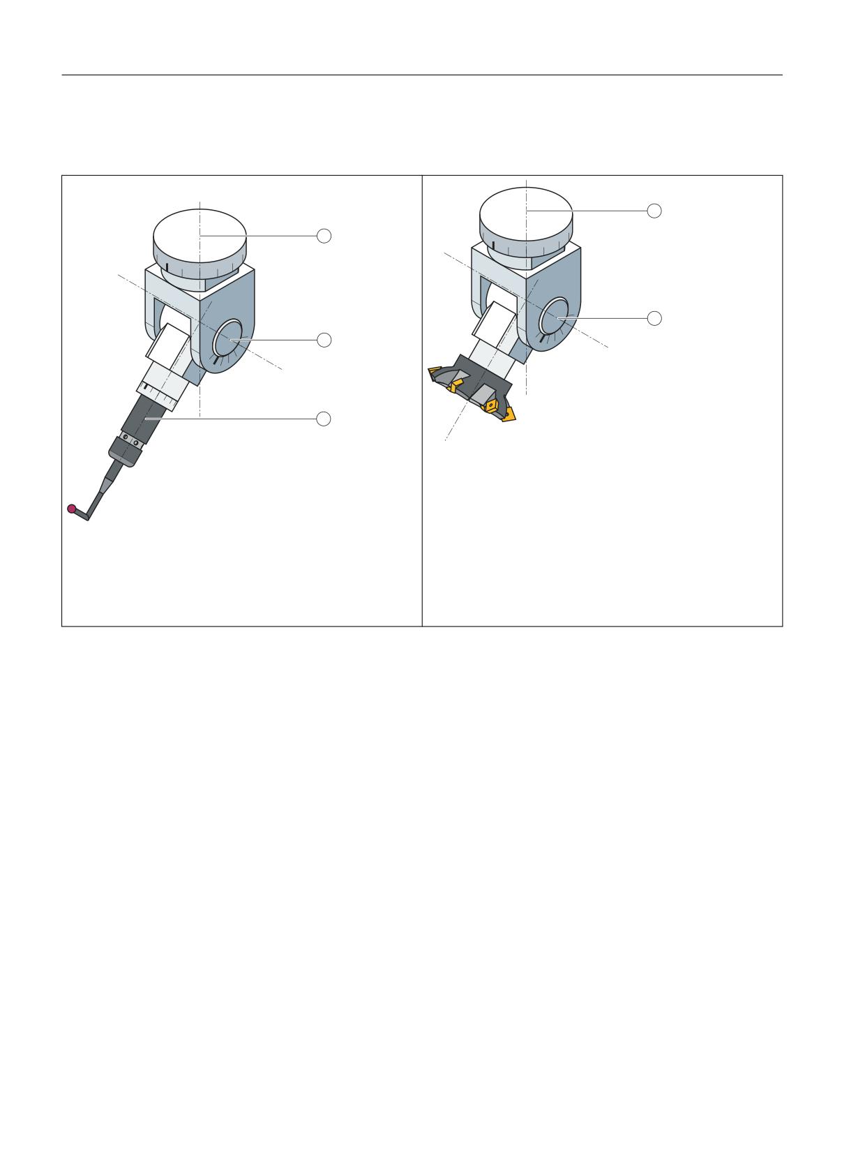
The driven part of the adapter is called the "drive end". The part into which the tools are inserted
is called the "load side".
1
1
2
2
3
Angle head with rotation-symmetrical tool
Angle head adapter with rotation-dependent tool
① C axis
② A axis
③ C1 axis
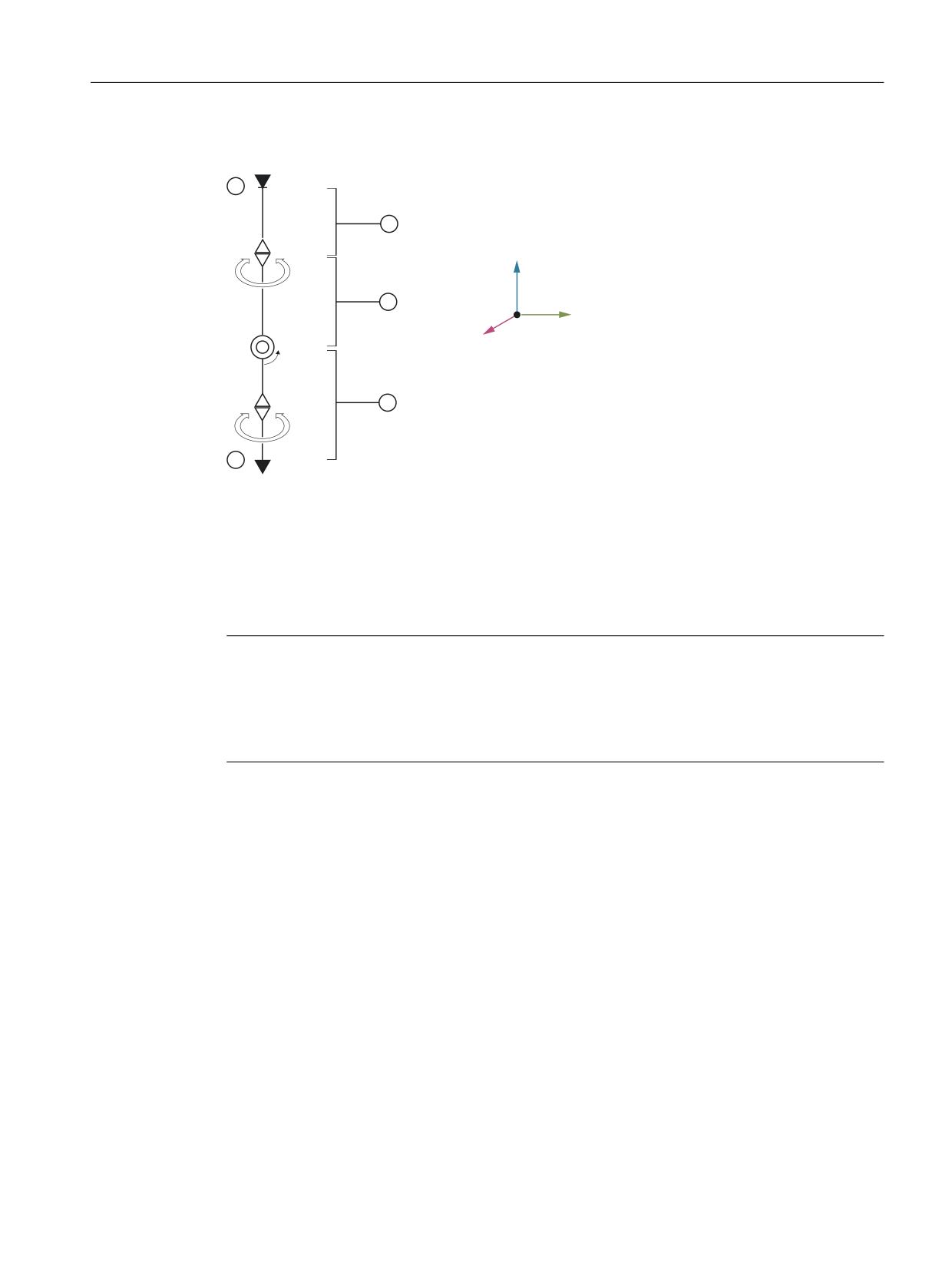
The geometry of the angle head adapter can be described via a kinematic chain. The chain is the
default and cannot be changed. Only linear offsets and angle offsets can be entered.
Basic position of the angle head in case G17 without additional machine data
• The C axis is parallel to the positive Z axis
• The position C=0 is defined in such a way that the orientation of the following rotary axis
points in the direction of the positive X axis. The 2nd rotary axis is thus an A axis.
• In position A=0, the 3rd linear element points in the direction of the positive Z axis.
• The 3rd rotary axis C1 at the end of the 3rd linear element describes the non-rotation-
symmetrical "normal orientation" of the tool. The position C1 =0 is defined in such a way that
the orientation for C=0 and A=0 points in the direction of the positive X axis. This is irrelevant
for rotation-symmetrical tools (see above).
Tool management
536
Function Manual, 10/2020, 6FC5397-1HP40-0BA1
Description of functions
8.14 Tool adapter
Kinematic chain of the angle head adapter
=
&
<
;
$
&
① Element 1 (L1): Offset of the vector 1
② Element 2 (L2): Offset of the vector 2
③ Element 3 (L3): Offset of the vector 3
④ Starting point of the kinematic chain
⑤ End point of the kinematic chain
Figure 8-50
Angle head geometry
Note
Orientation of the coordinate system
For milling tools, the orientation and order of the components are as follows: L1, L2 and L3.
The following order applies for a kinematic chain: 1st component in X direction, 2nd component
in Y direction and 3rd component in Z direction.
Tool management
Function Manual, 10/2020, 6FC5397-1HP40-0BA1
537
Description of functions
8.14 Tool adapter
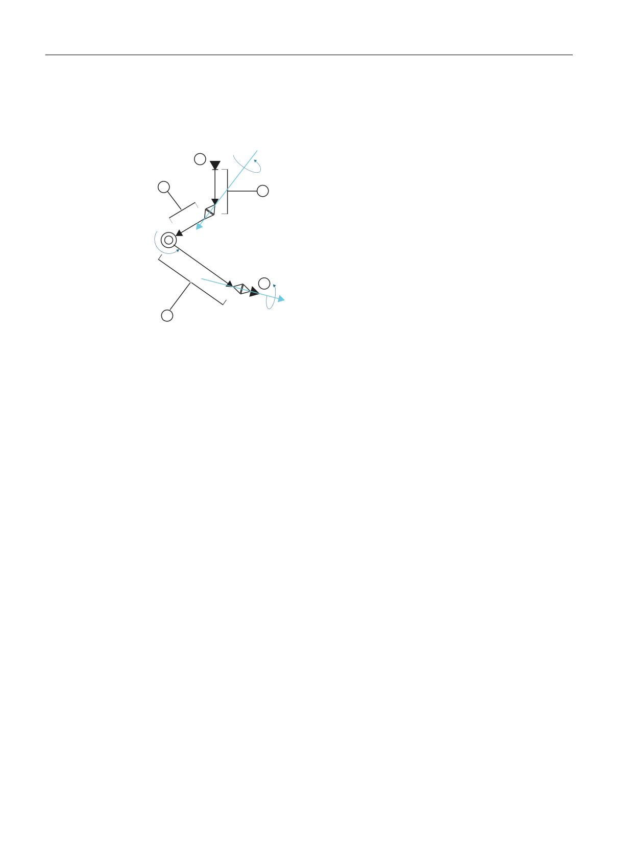
Expanded form of the angle head
In the expanded form, the direction of the rotary axes is generalized. In this way, additional
forms of tool attachments can be displayed and errors in direction axes can be compensated for.
$
$
$
①
Element 1 (L1): Offset of the vector 1
②
Element 2 (L2): Offset of the vector 2
③
Element 3 (L3): Offset of the vector 3
④
Starting point of the kinematic chain
⑤
End point of the kinematic chain
+A1, +A2, +A3
Direction of rotation and orientation of the 3 rotary axes of the angle head
The 3 rotary axes that can be respectively rotated about the center of the axis in the direction
+A1, +A2 or +A3 are located at the end of the three vectors. The direction and rotation are
illustrated by the blue arrows.
The offsets and angles are defined by system variables, see Linear offsets and direction vectors
(Page 538).
The default settings of the 3 rotary axis directions are set in such a way that they correspond to
the simpler basic form (for G17 and $SC_TOOL_LENGH_CONST=default,
$SC_TOOL_LENGH_TYP=default) text:
1. Rotary axis direction (0,0, 1)
2. Rotary axis direction (1, 0, 0)
3. Rotary axis direction (0, 0, 1)
The values for the directions are always available if the angle head adapter function is active.
Linear offsets and direction vectors
Linear offsets
The 3 linear offsets are entered via the system variables $TC_ADPT_OFF[n,3,3].
The arrays describe 3 three-dimensional vectors, which describe the direction in space. An
offset can be assigned to each vector:
Tool management
538
Function Manual, 10/2020, 6FC5397-1HP40-0BA1
Description of functions
8.14 Tool adapter
$TC_ADPT_OFF[n,m,k] = "<offset>"
$TC_ADPT_OFF[n,m
Linear offset of the element
,k]
Data type:
DOUBLE
Default value:
"" (0.0)
<n>
Number of the adapter
Data type:
INT
Range of values:
1, 2, ... (SLMAXADAPTERNUMBER)
<m>
Number of the angle head element
<k>
Coordinate index
Value range
0: L1
1: L2
2: L3
Orientations of the rotary axes
The orientations define the rotary axes for the rotation of the coordinate system about the
angles A1, A2 and A3.
The variable field $TC_ADPT_DIR[N,3,3] is available for defining the vectors.
The rules of the kinematic chain which are described in the Basic Functions Function Manual
apply for the offsets.
If the amount of a direction vector is < 10-6, it is viewed as an undefined direction vector. In this
case, the corresponding default vector from the simplified standard form is used. 1st rotary axis:
(0,0,1), 2nd rotary axis (1,0,0), 3rd rotary axis (1,0,0)
$TC_ADPT_DIR[n,m,k] = <offset>
$TC_ADPT_DIR[n,m,k]
Direction vector (X; Y; Z)
Data type:
DOUBLE
Value range
Direction vector: 0.0 < |vector| ≤ max. REAL value
Default value:
The default values are different for the three elements (1,0,0), (0,0,1) (1,0,0).
<n>:
Number of the adapter
Data type:
INT
Range of values:
1, 2, ... (SLMAXADAPTERNUMBER)
m
Number of the angle head element
Data type:
INT
k
Coordinate index
Data type:
INT
Value range
0: L1
1: L2
2: L3
Tool management
Function Manual, 10/2020, 6FC5397-1HP40-0BA1
539

Description of functions
8.14 Tool adapter
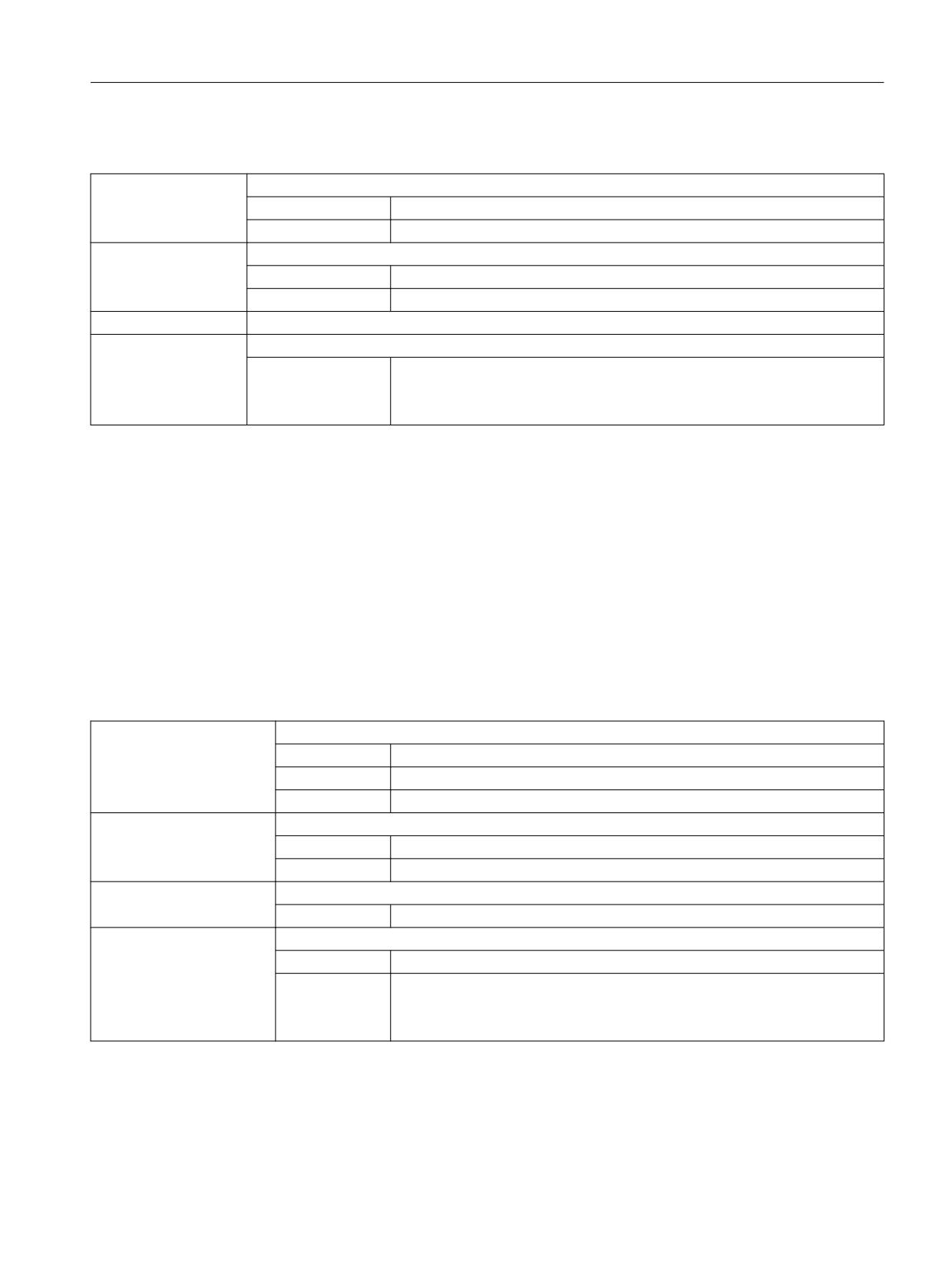
Angle offsets of rotary axes
The angles of the rotary axes are made up of the angle which can be read on the angle scale on
the angle head adapter and an offset that compensates for the difference between the 0°
position of the angle head scale and the basic position defined above. The following two-
dimensional arrays are available:
$TC_ADPT_ANG[n,m] = <value>
$TC_ADPT_ANG [n,m]
Angle of the angle head read on the scale
Data type:
Real
Default value:
0.0
<n>:
Number of the adapter
Data type:
INT
Range of val-
1, 2, ... (SLMAXADAPTERNUMBER)
ues:
m
Angle numbers (correspond to A1, A2 or A3)
Data type:
REAL
$TC_ADPT_ANG_CONST[n,m] = <offset>
$TC_ADPT_ANG_CONST[n,
Offset which compensates for the deviation of the basic setting.
m]
Data type:
Real
Default value:
0.0
<n>:
Number of the adapter
Data type:
INT
Range of val-
1, 2, ... (SLMAXADAPTERNUMBER)
ues:
m
Angle numbers (correspond to A1, A2 or A3)
Data type:
REAL
Tool management
540
Function Manual, 10/2020, 6FC5397-1HP40-0BA1
Description of functions
8.14 Tool adapter
&
$
1
2
3
4
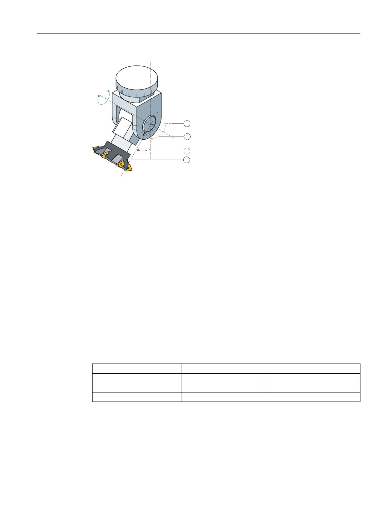
① Zero position on the scale of the angle head adapter
② Angle offset between the zero position Angle head and the zero position Kinematic chain (devi-
ation from the basic position)
③ Angle offset between the value read on angle head and the C axis
④ Angle read on angle head adapter
The actual value of the angle offset is then calculated from the sum ② + ③.
8.14.7
Offset values
8.14.7.1
Base length for the adapter
Description
The base dimension (base length) for tools without an adapter function is contained in the
system variables $TC_DP21 - $TC_DP23. When an angle head adapter is used, the tool offset gets
an offset that is displayed in the base length ($TC_DP21 - $TC_DP23).
If an adapter is active, the data of the following system variables are used:
Without adapter
Adapter type 1
Adapter type 2
$TC_DP21
$TC_ADPT1
$TC_DP21
$TC_DP22
$TC_ADPT2
$TC_DP22
$TC_DP23
$TC_ADPT3
$TC_DP23
The transformation of the basic orientation of a tool by the angle head adapter consists of the
rotations about the three adapter axes $TC_ADPT_DIR[n, 0 - 2, ] about the three angles of
rotation $TC_ADPT_ANG_CONST[n, 0 - 2] + $TC_ADPT_ANG[n, 0 - 2].
Tool management
Function Manual, 10/2020, 6FC5397-1HP40-0BA1
541

Description of functions
8.14 Tool adapter
If the variables $TC_ADPT_DIR, $TC_ADPT_ANG_CONST and $TC_ADPT_ANG are not defined,
the values of the offset vectors are set to "zero". The direction vectors of the rotary axes then have
the values that were set in advance (default values):
• Rotary axis A1 has the direction of L1
• Rotary axis A2 has the direction of L3
• Rotary axis A3 has the direction of L1
8.14.7.2
Cutter radius compensations and setup offsets for adapters
Description
For the cutting edge parameters $TC_DP3 - $TC_DP11 there are the parameter sets for sum
offsets ($TC_SCPx3 - $TC_SCPxx1) and setup offsets ($TC_ECPx3 - $TC_ECPxx1).
Assignment table without adapter:
Cut parame-
Description
Location-dependent
Location-dependent setup correction
ters
wear correction
$TC_DP3
Wear length 1
$TC_SCP13, …,
$TC_ECP13, …, $TC_ECP63
$TC_SCP63
$TC_DP4
Wear length 2
$TC_SCP14, …,
$TC_ECP14, …, $TC_ECP64
$TC_SCP64
$TC_DP11
Angle
$TC_SCP21, …,
$TC_ECP21, …, $TC_ECP71
$TC_SCP71
Assignment table when an adapter (type 1 and type 2) is used:
Cut parame-
Description
Location-dependent
Location-dependent setup correction
ters
wear correction
$TC_DP3
Wear length 1
$TC_SCP13
$TC_ECP13
$TC_DP4
Wear length 2
$TC_SCP14
$TC_ECP14
$TC_DP5
Wear length 3
$TC_SCP15
$TC_ECP15
Only the specified parameters are provided corresponding to the adapter transformation (blocks
TOST and TOET). The remaining parameters are not affected by the adapter transformation.
8.14.7.3
Cutting edge data for the orientation type 2 adapter
Cutting edge data for the orientation (TC_DPVx and TC_DPVNx)
If an angle head adapter is active for a cutting edge, the cutting edge data has no significance
for the orientation ($TC_DPV, $TC_DPV3, $TC_DPV4, $TC_DPV5, $TC_DPVN3, $TC_DPVN4,
$TC_DPVN5).
Tool management
542
Function Manual, 10/2020, 6FC5397-1HP40-0BA1

Description of functions
8.14 Tool adapter
The orientation is defined by the angle head.
Note
Value of the cutting edge data
The value of the cutting edge data in this case must be "0" ($TC_DPV = 0). If the value deviates
from "0", it is ignored. No error is output.
8.14.8
OPI block ADN
OPI block ADN
Adapter data is used to be able to describe the dimensions of an adapter per magazine location
and the direction of loaded tools. The transformation affects the processing of the tool cutting
edge data in the OPI blocks TOT, TOST and TOET if the tool is located on a magazine location to
which adapter data is assigned.
• Calculation of line: Adapter number if a field[ ] is available
• Calculation of column: Adapter parameters
The block T/ADN addresses the individual adapter via the line and the individual parameter via
the column.
Variable
Description
Adapter type
Data type
adaptType
Adapter type
Type 1 and type 2
UWORD
adapt1
Adapter geometry: Length 1
Type 1
DOUBLE
adapt2
Adapter geometry: Length 2
Type 1
DOUBLE
adapt3
Adapter geometry: Length 3
Type 1
DOUBLE
adaptt
Adapter transformation number
Type 1
UWORD
adaptOff00
Offset: 1st element, 1st component
Type 2
DOUBLE
adaptOff01
Offset: 1st element, 2nd component
Type 2
DOUBLE
adaptOff02
Offset: 1st element, 3rd component
Type 2
DOUBLE
adaptDir00
1st direction component of the 1st rotary axis
Type 2
DOUBLE
adaptDir01
2nd direction component of the 1st rotary axis
Type 2
DOUBLE
adaptDir02
3rd direction component of the 1st rotary axis
Type 2
DOUBLE
adaptAng0
Angle between 1st and 2nd element of the angle head adapt-
Type 2
DOUBLE
er
adaptAngConst0
Angle offset between 1st and 2nd element of the angle head
Type 2
DOUBLE
adapter
adaptOff10
Offset: 2nd element, 1st component
Type 2
DOUBLE
adaptOff11
Offset: 2nd element, 2nd component
Type 2
DOUBLE
adaptOff12
Offset: 2nd element, 3rd component
Type 2
DOUBLE
adaptDir10
1st direction component of the 2nd rotary axis
Type 2
DOUBLE
adaptDir11
2nd direction component of the 2nd rotary axis
Type 2
DOUBLE
adaptDir12
3rd direction component of the 2nd rotary axis
Type 2
DOUBLE
Tool management
Function Manual, 10/2020, 6FC5397-1HP40-0BA1
543

Description of functions
8.14 Tool adapter
Variable
Description
Adapter type
Data type
adaptAng1
Angle between 2nd and 3rd element of the angle head adapt-
Type 2
DOUBLE
er
adaptAngConst1
Angle offset between 2nd and 3rd element of the angle head
Type 2
DOUBLE
adapter
adaptOff20
3rd element, 1st component
Type 2
DOUBLE
adaptOff21
3rd element, 2nd component
Type 2
DOUBLE
adaptOff22
3rd element, 3rd component
Type 2
DOUBLE
adaptDir20
1st direction component of the 3rd rotary axis
Type 2
DOUBLE
adaptDir21
2nd direction component of the 3rd rotary axis
Type 2
DOUBLE
adaptDir22
3rd direction component of the 3rd rotary axis
Type 2
DOUBLE
adaptAng2
Angle after the 2nd element of the angle head adapter
Type 2
DOUBLE
adaptAngConst2
Angle offset after the 2nd element of the angle head adapter
Type 2
DOUBLE
Tool management
544
Function Manual, 10/2020, 6FC5397-1HP40-0BA1
Description of functions
8.15 Power failure while tool command is in progress
8.15
Power failure while tool command is in progress
If a power failure occurs during an action requested by tool management, defined strategies are
executed by the PLC or special part programs, in order to establish a defined and consistent
status on the machine and the tool management system. These strategies are machine-
specific. SINUMERIK control systems thereby support the following measures:
Buffered data
All tools, magazine data as well as all magazine assignments are buffered.
Data initialized for control "Power On"
The following data is set to zero:
• Tool status "Tool change in progress"
• Magazine status "Motion is active"
• Magazine location status "Reserved for tool to be loaded"
• The PI-command status with respect to magazine operations like e.g. "Motion is active"
• The tool status selected for 1:1 exchange
Task of the manufacturer's configuration
The PLC must send the last unacknowledged FC 7 or FC 8/FC 6 prior to power failure (READY did
not change to TRUE before power off) back to the NC when the power supply is restored. The
function "Asynchronous transfer" is used for tool transfer in FC 8/FC 6.
Without receiving the request from the tool management system, the PLC initiates a relocation
of tool data from one location to another. For example, relocation of tool data from gripper to
magazine if the tool needed to be returned manually to the magazine when the tool change
operation was aborted.
Changes in position of the tools involved must be communicated via FC 8. The NC then updates
the data for this tool in the tool management.
Further strategies may be necessary, e.g. if a tool change was interrupted. Tools stored in the
buffer must be returned to the magazine for this purpose.
Tool management
Function Manual, 10/2020, 6FC5397-1HP40-0BA1
545
Description of functions
8.15 Power failure while tool command is in progress
Tool management
546
Function Manual, 10/2020, 6FC5397-1HP40-0BA1
SINUMERIK Operate user interface
9
9.1
Configuring the user interface
Configurable settings
The following settings can be configured:
•
General settings
•
Configure the tool lists
•
Configure the list parameters
•
Configure the tool types
•
Configure the "Additional Data" window
•
Configure the "New Tool - Favorites" window
•
Configure the "New Tool" window
•
Configuring the "New Multitool" window
•
Configuring the "New Tool from Code Carrier" window
•
Configuring the "New Tool from File" window
•
Configure the default values for new tools
•
Configure the "Details" window
•
Assign names for magazines and magazine locations
•
Configuring the "Assign Tooltips for Multitool Locations" window
•
Assign names for magazine location types
•
Assignment of magazines and magazine locations to channels
•
Assignment of magazines to coordinate systems
•
Disabling the softkey depending on filters
•
Configuring the "Load Station Selection" window
•
Coolant and tool-specific functions
•
Reason for the tool change when reactivating
•
Configure the code carrier connection
•
Configuring store to file
The following sections explain how you configure these adaptations.
Tool management
Function Manual, 10/2020, 6FC5397-1HP40-0BA1
547

SINUMERIK Operate user interface
9.1 Configuring the user interface
Procedure
1. Open the directory: /siemens/sinumerik/hmi/template/cfg.
2. Copy the "oem_sltmlistconfig.xml" template file
3. Copy the file to the directory /oem/sinumerik/hmi/cfg
OR: /user/sinumerik/hmi/cfg.
4. Change the file name according to the set technology:
File name
MD52200 technology
MD52201 technology ex-
tension
sltmlistconfig.xml
Milling technology
sltmturninglistconfig.xml
Turning technology
sltmmillturnlistconfig.xml
Milling technology
Turning technology
sltmcirculargrindinglistconfig.xml
Cylindrical grinding technolo-
gy
sltmsurfacegrindinglistconfig.xml
Surface grinding technology
sltmplclistconfig.xml
PLC tool management
"TRANSLINE 2000"
5. Remove the comments of the example in the template to create your specific configuration.
Configuration examples
Examples for all possible configurations are provided in the template oem_sltmlistconfig.xml,
which are described individually in the following sections:
<?xml version="1.0" encoding="UTF-8" standalone="yes"?>
- <CONFIGURATION>
<!--
************************************************************-->
<!--
enter your configuration behind this comment -->
<!--
************************************************************** -->
Configuration examples
<!--
************************************************************** -->
<!--
enter your configuration ahead this comment -->
<!--
************************************************************** -->
</CONFIGURATION>
Enter your configuration using the following xml identifiers:
Identifier <tag>
for the following setting:
<SETTINGS>
General settings (Page 550)
<LISTCONFIGURATION>
Configuring tool lists (Page 555)
<PARAMETERCONFIGURATION>
Configuring list parameters (Page 569)
<TOOLTYPECONFIGURATION>
Configure tool types (Page 575)
<MOREDATACONFIGURATION>
Configuring the "Additional Data" window
(Page 577)
Tool management
548
Function Manual, 10/2020, 6FC5397-1HP40-0BA1

SINUMERIK Operate user interface
9.1 Configuring the user interface
Identifier <tag>
for the following setting:
<NEWTOOLFAVORITECONFIGURATION>
Configure the "New tool - favorites" window
(Page 579)
<NEWTOOLCONFIGURATION>
Configuring the "New Tool" window (Page 579)
<NEWMULTITOOLCONFIGURATION>
Configuring the "New Multitool" window
(Page 580)
<NEWTOOLIDENTCONNECTIONCONFIGURATION>
Configuring the "New Tool from Code Carrier"
window (Page 580)
<NEWTOOLSAVETOOLDATACONFIGURATION>
Configuring the "New Tool from File" window
(Page 581)
<NEWTOOLDEFAULTVALUECONFIGURATION>
Configuring default values for new tools
(Page 581)
<DETAILSCONFIGURATION>
Configuring the "Details" window (Page 586)
<MAGAZINEPLACENAMECONFIGURATION>
Assigning a name for magazines and magazine
locations (Page 587)
<MULTITOOLPLACETOOLTIPCONFIGURATION>
Configuring the "Assign Tooltips for Multitool Lo-
cations" window (Page 589)
<PLACETYPECONFIGURATION>
Assigning a name for magazine location types
(Page 590)
<CHANNELMAGAZINEASSIGNMENT>
Assignment of magazines and magazine loca-
tions to channels (Page 591)
<COORDSYSMAGAZINEASSIGNMENT>
Assignment between magazines and magazine
locations and coordinate systems (Page 593)
<FILTERCONFIGURATION>
Disabling the softkey depending on filters
(Page 594)
<LOADSTATIONSHANDLEALLTOOLS>
Configuring the "Load Station Selection" window
(Page 595)
<TOOLCHANGEREASON>
Reason for the tool change when reactivating
(Page 599)
<IDENTCONNECTIONCONFIGURATION>
Configure the code carrier connection
(Page 603)
<SAVETOOLDATACONFIGURATION>
Configuring Save to file (Page 606)
Tool management
Function Manual, 10/2020, 6FC5397-1HP40-0BA1
549

SINUMERIK Operate user interface
9.1 Configuring the user interface
9.1.1
General settings
<SETTINGS> tag
The general settings for the tool management user interface are stored in the <SETTINGS> tag.
Entries
Meaning
ReactivateWithMagPos
True - reactivate with positioning of the tool to the tool mag-
azine loading point.
False - default setting, reactivate without positioning the tool
magazine.
ReactivateAllMonitorModes
True - the actual values of all the monitoring types set in the
NC are reset.
False - default setting, actual value of the active monitoring
type is reset.
ReactivateEnabled
True - default setting, reactivation is enabled.
False - reactivation is disabled.
CreateNewToolDialog
True - the "New Tool" window is displayed. In this window,
you can specify the tool name and the size of the tool (over-
sized tool) before actually creating the tool. Other input op-
tions can be defined by configuring the "New tool" window.
False - default setting, the "New Tool" window is not dis-
played. Once the name has been entered, the tool will be
created directly in the tool list.
CreateNewMultiToolDialog
True - default setting, the "New Multitool" window is dis-
played. In this window, you can configure the following be-
fore actually creating the multitool:
• Multitool names
• Number of multitool locations
• Type of clearance input
• Value of the location clearance for each multitool loca-
tion
False - the "New Multitool" window is not displayed. Once the
name has been entered, the multitool will be created directly
in the tool list.
MagazineSelectionDialog
True - a dialog box displaying the buffer, tool magazine and
NC memory is displayed. A mark can be added to or removed
from each of these elements to indicate whether that ele-
ment appears in the list display. The "Go to" softkey can be
used to select an element directly in the list display.
False - no dialog box for magazine selection. The system
switches between the buffer, the tool magazines and the NC
memory.
If there is no MagazineSelectionDialog entry in the
<Settings> tag, the dialog box is automatically displayed
with more than one tool magazine (excluding the system
magazine) when magazine configuration is taking place. If
there is only one tool magazine, the switchover function is
used.
Tool management
550
Function Manual, 10/2020, 6FC5397-1HP40-0BA1

SINUMERIK Operate user interface
9.1 Configuring the user interface
Entries
Meaning
NewToolFavoritesOnly
Refers to the "New tool" function.
True - only those tool types that are configured as favorites
are listed.
False - default setting, all tool types are listed.
SortationInFirstEtcLevel
True - the "Sorting" function is placed at the first softkey level.
The "Continue" function is omitted.
False - default setting, sorting at all softkey levels.
ToolBufferOnceOnTop
True - default setting, buffer is displayed at the start of the list.
False - buffer is displayed for each magazine. Only those lo-
cations are displayed that are assigned to the magazine.
UnloadToolFromLoadPlaceEnabled
True - a tool at the load station can be removed from the load
station using the "Unload" softkey.
False - default setting. The "Unload" softkey is not displayed
for a tool at the load position.
CreateNewToolWithCuttPos9Enabled
True - cutting edge position 9 is offered in the cutting edge
position selection.
True - default setting, cutting edge position 9 is not offered in
the cutting edge position selection.
AutoHNumberDisplayEnabled
Column of the cutting edge parameter "IsoHNoDPH - ISO H
number" depending on the machine configuration.
True - default setting, the column is automatically displayed.
False - the column is not automatically displayed.
AutoUniqueDNumberDisplayEnabled
Column of the cutting edge parameter "UniqueDNo" depend-
ing on the machine configuration.
True - default setting, the column is automatically displayed.
False - the column is not automatically displayed.
AccessLevelDeleteAllDNos
The following entry specifies the access level as of which the
"Delete all D numbers delete" function is offered.
Default setting: Access level 3 (user) - relevant only when the
"Unique D number" setting has been made.
MagazineNumberOfDCheckAndActivate
Default setting: -2 - the tools of all magazines are considered
by the function "Check for unique D number and activate
tool."
>0 - The above function only considers the tools of the
named magazine.
AutoFixedPlaceDisplayEnabled
Column of the tool parameter "ToolStateFixed" - tool status -
tool is fixed-location coded and acts dependent on the mag-
azine configuration.
True - default setting, the column is automatically hidden, if
all of the configured magazines are fixed location coded.
False - the column is not automatically hidden.
MagPlaceAdapterDisplayEnabled
Columns of the magazine location adapter parameters are
displayed in the "Magazine" window.
False - default setting, parameters are not displayed.
Tool management
Function Manual, 10/2020, 6FC5397-1HP40-0BA1
551

SINUMERIK Operate user interface
9.1 Configuring the user interface
Entries
Meaning
AdaptTransDataViewEnabled
The magazine location adapter transformed display of the
cutting edge parameters is enabled. It can be switched on
and off in the settings dialog of the tool lists.
False - default setting, the magazine location adapter trans-
formed display of the cutting edge parameters is not ena-
bled.
ActiveCompensationsEnabled
The "Working offsets" function is enabled. This function de-
pends on the machine configuration. Unique D number,
magazine location adapter and magazine management
must be set.
False - default setting, the "Working offsets" function is not
enabled.
M2NLockEnabled
Locking of an M to N switchover while a function of the tool
management is being executed.
True - default setting, switchover is locked.
SDToolLengthInListEnabled
True - default setting, evaluation of SD42940, SD42942, and
SD42950 in axis name display in the tool lists.
False - the setting data are not evaluated in the axis name
display.
DisableMultiTools
True - even though the Multitools function is set in the NC,
they are not offered in the tool lists.
False - default setting, if the Multitools function is set in the
NC, they are offered in the tool lists.
CursorPositionInfoEnabled
True - information about the tool on which the cursor is posi-
tioned is written to the SlCap local variable "/Hmi/TMHMI-
CurData".
False - default setting, no information about the tool on
which the cursor is positioned is made available on an inter-
face for the OA.
EnableMonAndBasisGrindingToolTypes
True - enable switchover of grinding tool types in respect of
"with/without grinding-specific tool monitoring," "with/with-
out consideration of the base dimension when calculating
the grinding wheel radius."
False - default setting, switchover not enabled.
ErrorMessageWithoutProgressBar
True - error messages are output without a progress bar and
must be acknowledged via softkey.
False - default setting, error message is automatically closed
when the progress bar reaches the end.
ColumnZoomByResolution
True - column width is adapted to the resolution of the HMI.
False - default setting, the column width is adapted to the
font size in the HMI. With this setting, with higher resolutions
more columns can be displayed next to each other without
needing to scroll.
AccessLevelReadDetailsAllParameter
The following entry specifies the access level as of which the
"Further details" function is offered in the "Details" dialog.
Default setting: Access level 7 (keyswitch position 0) - can be
overlaid through the setting in MD51198.
FixNumberOfMultiToolPlaces
Multitools are created with a fixed number of multitool loca-
tions. There is no prompt when you create the multitool.
Tool management
552
Function Manual, 10/2020, 6FC5397-1HP40-0BA1

SINUMERIK Operate user interface
9.1 Configuring the user interface
Entries
Meaning
FixKindOfDistInMultiTools
Multitools are created with a fixed type of clearance input of
the multitool locations. There is no prompt when you create
the multitool.
Possible input value: 3 - clearance of the multitool locations
as an angle.
DlDisplayMode
• DisplayDistributed - default setting, the setup offsets EC
are displayed in the tool list and the additive offsets SC are
displayed in the tool wear list.
• EcInWearList - the setup offsets EC are displayed in the
tool wear list and the additive offsets SC are not displayed.
CombinedToolMonitoring
Specifies the combined monitoring types offered in the tog-
gle field:
• Time/Count - tool life and workpiece count
• Time/Wear - tool life and wear monitoring
• Count/Wear - workpiece count and wear monitoring
• Time/WearDlSc - tool life and wear monitoring for addi-
tive and setup offsets
• Count/WearDlSc - workpiece count and wear monitoring
for additive and setup offsets
• Time/Count/Wear - tool life, workpiece count and wear
monitoring
• Time/Count/WearDlSc - tool life, workpiece count and
wear monitoring for additive and setup offsets
FiltersCombinedWithOr
Defines the filter criteria, which are linked in the filter window
using a logical OR. The default setting for all the filter criteria
is a logical AND. The possible entries are:
• "StandBy" - for tools that are ready for use
• "Active" - for tools with active identifier
• "Locked" - for locked tools
• "Prewarn" - for the prewarning limit
• "RemainingPieces" - for the remaining unit quantity
• "RemainingTime" - for the remaining tool time
• "MarkedToUnload" - for the unload identifier
• "MarkedToLoad" - for the load identifier
AddToGrindingSpindles
Defines the spindle numbers that are to be offered in the
"GrindingSpindleNo" ($TC_TPG1) parameter when selecting
the grinding spindles. The numbers of the grinding spindles
must be separated by a space, e.g. -1 8 9.
Default display: real NC spindles and 0
HideGrindingSpindles
Defines the spindle numbers of the real NC spindles that are
not to be offered in the "GrindingSpindleNo" ($TC_TPG1) pa-
rameter when selecting the grinding spindles. The numbers
of the grinding spindles must be separated by a space,
e.g. 1 3.
Tool management
Function Manual, 10/2020, 6FC5397-1HP40-0BA1
553

SINUMERIK Operate user interface
9.1 Configuring the user interface
Entries
Meaning
MagazineMoveMessage
True - "Magazine movement running" or "Magazine move-
ment ended" message is displayed.
False - default setting, message is not displayed.
ToolLoadErrorMessage
Refers to the output of the fault message due to a negative
PLC.
True - default setting, the fault message is displayed.
False - the fault message is not displayed.
The following settings refer to markings in the lists:
True - marking is displayed.
False - marking is not displayed (default setting).
If several markings apply to one location, the most important information is displayed. For
instance, if a tool is locked, and at the same time, the "Tool position" and the "Reference direction
holder angle" for this tool do not match, then a red cross is displayed for locked. The yellow
triangle for the conflict cannot be seen.
Entries
Meaning
ShowSymbolActivePlace
Marking of the magazine location at the machining position.
True - default setting applies for the "Turret" magazine type.
False - setting for all other magazine types.
ShowSymbolActiveMultiToolPlace
Marking of the multitool location at the machining position. Is
only displayed when the multitool is located in the spindle or
the tool holder.
True - default setting.
ShowSymbolLoadPlace
Selection of the magazine location at the loading position.
True - default setting applies for all magazine types (except
Turret is true).
False - setting for the "Turret" magazine type.
ShowSymbolChangeInSpindlePlace
Marking of the magazine location at the change position.
True - default setting applies for all magazine types (except
Revolver is true).
False - setting for the "Turret" magazine type.
ShowSymbolActiveTool
Marking of the active tool.
False - default setting.
ShowSymbolProgrammedTool
Marking of the follow-on tool.
True - default setting.
ShowSymbolActiveDNo
Marking of the active cutting edge.
False - default setting.
ShowSymbolActiveDNoInTool
Marking of the active tool by marking the active cutting edge.
True - default setting for configuration without magazine
management.
False - setting for configuration with magazine management.
ShowSymbolAcitveDlNo
Marking of the active DL number.
True - default setting.
Tool management
554
Function Manual, 10/2020, 6FC5397-1HP40-0BA1

SINUMERIK Operate user interface
9.1 Configuring the user interface
Entries
Meaning
ShowConflictPositionAndDirection
Marking of a conflict; tool position and cutting direction do
not match.
True - default setting.
ShowConflictActiveToolWarning
Marking of a conflict; turret magazine type and the active tool
are not at the the machining position.
True - default setting.
Example
<SETTINGS>
<ReactivateWithMagPos value="false" type="bool" />
<MagazineMoveMessage value="false" type="bool" />
<CreateNewToolDialog value="true" type="bool" />
<MagazineSelectionDialog value="false" type="bool" />
<AccessLevelWriteDetailsAllParameter value="4" type="int" />
</SETTINGS>
9.1.2
Configuring tool lists
<LISTCONFIGURATION> tag
The entries used for configuring the following list views are located in the
<LISTCONFIGURATION> tag:
• "Tool List" window, identifier <SlTmToollistForm>, see the 1st example.
• "Tool Wear" window, <SlTmToolwearForm> identifier
• "Magazine" window, <SlTmToolmagazinForm> identifier
• "Tool Data OEM" window, <SlTmTooloemForm>identifier
This window is hidden in the default configuration. The window is only displayed when you
enable it with <Enabled>, see the 3rd example.
• "Tool Selection" window, <SlTmToolselectionForm> identifier: In order to select a tool
this window can be displayed in the program input screen.
Entry
Meaning
Enabled
True - window is displayed.
False - window is hidden.
CAPTION
Definition of the list name.
Text
Used as label/item below the "CAPTION" to define the heading text.
COLUMNX
Column selection: X stands for the column number.
TOOLTYPE_ALL
The column setting applies to all tool types.
Tool management
Function Manual, 10/2020, 6FC5397-1HP40-0BA1
555

SINUMERIK Operate user interface
9.1 Configuring the user interface
Entry
Meaning
TOOLTYPE_ALL_XXX
The column setting applies to all tool types of a group. XXX stands for the
group number of the tool types. The hundreds position is used as the
group number, for example, TOOLTYPE_ALL_100 or TOOLTYPE_ALL_200
etc.
TOOLTYPE_XXX
The column setting applies to a particular tool type. XXX stands for the
number of the tool type.
EMPTY_MAG_PLACE
The column setting applies to an empty magazine location. Empty mag-
azine locations appear in a list sorted according to magazine.
Item
Identifier of the list parameter.
See example: The column in which the magazine location type is dis-
played is created with the identifier "MagPlaceType."
Tool parameter identifiers (Page 559)
Cutting edge parameter identifiers (Page 561)
Monitoring parameter identifiers (Page 564)
Magazine location parameter identifiers (Page 566)
DELETE_COLUMN
Delete column.
INSERT_COLUMN
Insert column.
Note
Independent of their programming, the entries are effective in the following sequence:
1. COLUMNX
2. DELETE_COLUMN
3. INSERT_COLUMN
Note
The Enabled entry does not apply for the "Tool Selection" window. The other entries apply.
Example 1: Configuring the magazine list - magazine location and tool location type
Note
The columns of the list configuration cannot be taken from the display in the user interface in all
cases because some columns are automatically inserted and therefore not included in the count
of the configuration.
Variant 1
Column 10 and column 11 are overwritten. If column 10 and column 11 do not exist, the new
columns will be added to the existing columns.
<LISTCONFIGURATION>
<!-- **** Magazine list *** -->
<SlTmToolmagazinForm>
Tool management
556
Function Manual, 10/2020, 6FC5397-1HP40-0BA1
SINUMERIK Operate user interface
9.1 Configuring the user interface
<!-- **** Column 10 *** -->
<COLUMN10>
<!-- **** For all tool types *** -->
<TOOLTYPE_ALL>
<!-- **** Display magazine location type *** -->
<Item value="MagPlaceType" type="QString" />
</TOOLTYPE_ALL>
</COLUMN10>
<!-- **** Column 11 *** -->
<COLUMN11>
<!-- **** For all tool types *** -->
<TOOLTYPE_ALL>
<!-- **** Display tool location type *** -->
<Item value="ToolPlaceSpec" type="QString" />
</TOOLTYPE_ALL>
<!-- **** For all multitools *** -->
<TOOLTYPE_9997>
<!-- **** Display for all multitool location types *** -->
<Item value="MultiToolPlaceSpec" type="QString" />
</TOOLTYPE_9997>
</COLUMN11>
</SlTmToolmagazinForm>
</LISTCONFIGURATION>
Variant 2
The new columns are inserted in the standard configuration between the "Magazine location
locked" and "Oversized tool" columns.
<LISTCONFIGURATION>
<!-- **** Magazine list *** -->
<SlTmToolmagazinForm>
<!-- **** Insert column *** -->
<INSERT_COLUMN>
<!-- **** Column 7 *** -->
<COLUMN7>
<!-- **** For all tool types *** -->
<TOOLTYPE_ALL>
<!-- **** Display magazine location type *** -->
<Item value="MagPlaceType" type="QString" />
</TOOLTYPE_ALL>
</COLUMN7>
<!-- **** Column 8 *** -->
<COLUMN8>
Tool management
Function Manual, 10/2020, 6FC5397-1HP40-0BA1
557
SINUMERIK Operate user interface
9.1 Configuring the user interface
<!-- **** For all tool types *** -->
<TOOLTYPE_ALL>
<!-- **** Display tool location type *** -->
<Item value="ToolPlaceSpec" type="QString" />
</TOOLTYPE_ALL>
<!-- **** For all multitools *** -->
<TOOLTYPE_9997>
<!-- **** Display for all multitool location types *** -->
<Item value="MultiToolPlaceSpec" type="QString" />
</TOOLTYPE_9997>
</COLUMN8>
</INSERT_COLUMN>
</SlTmToolmagazinForm>
</LISTCONFIGURATION>
Example 2: Configuring the magazine list - "Oversized tool" column is deleted
Note
The columns of the list configuration cannot be taken from the display in the user interface in all
cases because some columns are automatically inserted and therefore not included in the count
of the configuration.
<LISTCONFIGURATION>
<!-- **** Magazine list *** -->
<SlTmToolmagazinForm>
<!-- **** Delete column 7 *** -->
<DELETE_COLUMN>
<COLUMN7 />
</DELETE_COLUMN>
</SlTmToolmagazinForm>
</LISTCONFIGURATION>
Example 3: Enabling the OEM tool data list
<SlTmTooloemForm>
<Enabled value="true" type="bool" />
</SlTmTooloemForm>
Tool management
558
Function Manual, 10/2020, 6FC5397-1HP40-0BA1
SINUMERIK Operate user interface
9.1 Configuring the user interface
Result
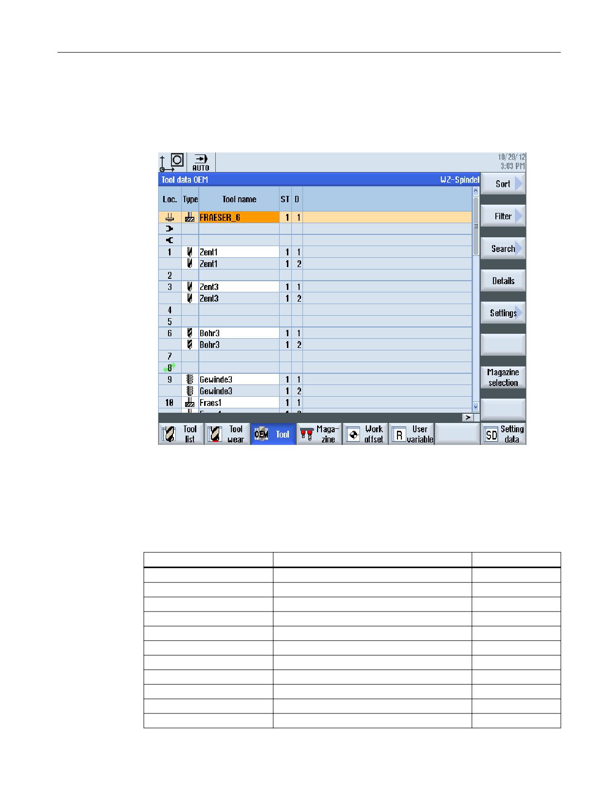
• The "OEM Tool Data" window is displayed. It automatically displays the columns shown in the
figure.
• The new "OEM tools" softkey appears and can be operated.
9.1.2.1
Tool parameter identifiers
Tool parameters
For the tool parameters, the following identifiers are used in the configuration file:
Identifier
Parameter or property
System variable *)
Empty
Empty field
-
ToolNo
Number of the tool
-
AdaptNo
Adapter number assignment
$TC_MPP8
DuploNo
Duplo number
$TC_TP1
DuploNoRW
Duplo number, read and write access
$TC_TP1
NumCuttEdges
Number of cutting edges of tool
$P_TOOLND
ToolIdent
Tool name
$TC_TP2
ToolIdentRO
Tool name, read only access
$TC_TP2
ToolInfo
Tool information
$TC_TP11
ToolInMag
Magazine in which the tool is located
$A_TOOLMN
ToolInPlace
Magazine location containing the tool
$A_TOOLMLN
Tool management
Function Manual, 10/2020, 6FC5397-1HP40-0BA1
559

SINUMERIK Operate user interface
9.1 Configuring the user interface
Identifier
Parameter or property
System variable *)
ToolInMagInPlace
Magazine number/Magazine location
$A_TOOLMN /
$A_TOOL_MLN
ToolMonTCW
Type of tool monitoring, tool life, workpiece
$TC_TP9
count and wear. If wear monitoring has not been
enabled via the machine data, this parameter is
handled like ToolMonTC.
ToolMonTC
Type of tool monitoring, tool life and workpiece
$TC_TP9
count
ToolPlaceSpec
Location type
$TC_TP7
ToolPlaceSpecIdent
Location type, if it is to be displayed as text. The
$TC_TP7
precondition is that the text for the location type
was configured.
ToolSearch
Tool search type for replacement tools
$TC_TP10
ToolMyMag
Owner magazine of the tool
$A_MYMN
ToolMyPlace
Owner magazine location of the tool
$A_MYMLN
ToolSizeLeft
Tool size left in half locations
$TC_TP3
ToolSizeRight
Tool size right in half locations
$TC_TP4
ToolSizeUpper
Tool size upper in half locations
$TC_TP5
ToolSizeDown
Tool size lower in half locations
$TC_TP6
ToolOverSize
Tool size as fixed setting - two half locations left,
$TC_TP3 - $TC_TP6
two half locations right, one half location top,
one half location bottom
ToolState
Tool status in the hexadecimal notation
$TC_TP8
ToolStateActiv
Tool status - tool active
$TC_TP8, Bit0
ToolStateEnabled
Tool status - tool released
$TC_TP8, Bit1
ToolStateLocked
Tool status - tool locked
$TC_TP8, Bit2
ToolStateLockedRO
Tool status - tool locked, only read access
$TC_TP8, Bit2
ToolStateMeasured
Tool status - tool measured
$TC_TP8, Bit3
ToolStatePrewarn
Tool status - tool has reached prewarning limit
$TC_TP8, Bit4
ToolStatePrewarnRO
Tool status - tool has reached prewarning limit,
$TC_TP8, Bit4
only read access
ToolStateInChange
Tool status - tool is being changed
$TC_TP8, Bit5
ToolStateFixed
Tool status - tool fixed place coded
$TC_TP8, Bit6
ToolStateUsed
Tool status - tool was in use
$TC_TP8, Bit7
ToolStateAutoReturn
Tool status - automatic return
$TC_TP8
ToolStateIgnoreLocked
Tool status - do not observe locked
$TC_TP8, Bit9
ToolStateMarkedToUnload
Tool status - tool is marked to unload
$TC_TP8, Bit10
ToolStateMarkedToLoad
Tool status - tool is marked to load
$TC_TP8, Bit11
ToolStatePermanent
Tool status - tool is permanent
$TC_TP8, Bit12
ToolState1To1Exchange
Tool status - one to one replacement
$TC_TP8, Bit14
ToolStateHandTool
Tool status - manual tool
$TC_TP8, Bit15
ToolProtAreaFile
File name of the tool description which is re-
$TC_TP_PROTA
quired to define the protection zone
ToolMaxVelo
Maximum speed
$TC_TP_MAX_VELO
ToolMaxAcc
Maximum acceleration
$TC_TP_MAX_ACC
Tool management
560
Function Manual, 10/2020, 6FC5397-1HP40-0BA1

SINUMERIK Operate user interface
9.1 Configuring the user interface
Identifier
Parameter or property
System variable *)
ToolInMultiTool
Multitool in which the tool is located
$A_TOOLMTN
ToolInMultiToolPlace
Multitool location containing the tool
$A_TOOLMTLN
ToolMyMultiTool
Owner multitool of the tool
$A_MYMTN
ToolMyMultiToolPlace
Owner multitool location of the tool
$A_MYMTLN
ToolAlarmIsExtended
PLC tool status - function "extended alarm" active
-
ToolAlarmLimit
PLC tool status - alarm limit reached
-
ToolExtAlarmLimit
PLC tool status - limit "extended alarm" reached
-
ToolUser_1, ... ToolUser_10
OEM tool parameters 1 to 10
$TC_TPC1, ...
$TC_TPC10
ToolAppl_1, ... ToolAppl_10
Siemens application tool parameters 1 to 10
$TC_TPCS1, ...
$TC_TPCS10
*)
Parameter corresponds to the system variable or the system variable is the basis for this parameter.
Note
Tool name "ToolIdent"
The maximum length of tool names is 31 ASCII characters.
The number of characters is reduced for Asian characters or Unicode characters.
The following special characters are not permitted: | # "
9.1.2.2
Cutting edge parameter identifiers
For the cutting edge parameters, the following identifiers are used in the configuration file:
Identifier
Parameter or property
System varia-
ble *)
EdgeNo
D number
-
EdgeNoIdx
Cutting edge number
-
ToolType
Tool type, cutting edge parameter 1
$TC_DP1
CuttEdgePos
Cutting edge position, cutting edge param-
$TC_DP2
eter 2
GeoLength1
Length 1, cutting edge parameter 3
$TC_DP3
GeoLengthGeoAx1
Length of geometry axis 1, cutting edge
$TC_DP3
parameter 3, e.g. length X
GeoLengthGeoAx1DiscDiameter
Grinding wheel diameter in geometry axis
$TC_DP3
1, cutting edge parameter 3
GeoLengthGeoAx1DresserDiameter
Dressing tool diameter in geometry axis 1,
$TC_DP3
cutting edge parameter 3
GeoLength
Length, cutting edge parameter 3
$TC_DP3
GeoLength2
Length 2, cutting edge parameter 4
$TC_DP4
GeoLengthGeoAx3
Length of geometry axis 3, cutting edge
$TC_DP4
parameter 4, e.g. length Z
GeoLengthGeoAx3DiscDiameter
Grinding wheel diameter in geometry axis
$TC_DP4
3, cutting edge parameter 4
Tool management
Function Manual, 10/2020, 6FC5397-1HP40-0BA1
561

SINUMERIK Operate user interface
9.1 Configuring the user interface
Identifier
Parameter or property
System varia-
ble *)
GeoLengthGeoAx3DresserDiameter
Dressing tool diameter in geometry axis 3,
$TC_DP4
cutting edge parameter 4
GeoLength3
Length 3, cutting edge parameter 5
$TC_DP5
GeoLengthGeoAx2
Length of geometry axis 2, cutting edge
$TC_DP5
parameter 5, e.g. length Y
GeoLengthGeoAx2DiscDiameter
Grinding wheel diameter in geometry axis
$TC_DP5
2, cutting edge parameter 5
GeoLengthGeoAx2DresserDiameter
Dressing tool diameter in geometry axis 2,
$TC_DP5
cutting edge parameter 5
GeoRadius
Radius, cutting edge parameter 6
$TC_DP6
GeoOutsideRadius714
External radius for the star probe, tool type
$TC_DP6
714, cutting edge parameter 6
GeoCuttEdgeRadius
Tool nose radius, cutting edge parameter 6
$TC_DP6
GeoCornerRadius
Corner radius, cutting edge parameter 7
$TC_DP7
GeoOutsideRadius
Outside radius, cutting edge parameter 7
$TC_DP7
GeoBoomLength
Cantilever length, cutting edge parameter
$TC_DP7
7
GeoSlotWidth
Slot width, for example, for slotting saw,
$TC_DP7
cutting edge parameter 7
GeoRadius714
Ball radius for the star probe, tool type 714,
$TC_DP7
cutting edge parameter 7
GeoLength4
Length 4, cutting edge parameter 8
$TC_DP8
PlateLength
Cutting tip length, cutting edge parameter
$TC_DP8
8
GeoProjection
Protrusion, for example, for slotting saw,
$TC_DP8
cutting edge parameter 8
GeoLength5
Length 5, cutting edge parameter 9
$TC_DP9
GeoWidth
Width, cutting edge parameter 9
$TC_DP9
PlateWidth
Cutting tip width, cutting edge parameter 9
$TC_DP9
GeoPitch
Thread pitch, cutting edge parameter 9
$TC_DP9
BoreRadius
Hole radius, cutting edge parameter 9
$TC_DP9
GeoAngle1
Angle 1, cutting edge parameter 10
$TC_DP10
HolderAngle
Holder angle, cutting edge parameter 10
$TC_DP10
CorrectionAngle
Correction angle to align the probe, cutting
$TC_DP10
edge parameter 10
GeoAngle2
Angle 2, cutting edge parameter 11
$TC_DP11
AngleConicalMillTool
Angle conical mill tools, cutting edge pa-
$TC_DP11
rameter 11
CuttDirection
Reference direction holder angle, cutting
$TC_DP11
edge parameter 11
WearLength1
Wear length 1, cutting edge parameter 12
$TC_DP12
WearLengthGeoAx1
Wear length of geometry axis 1, cutting
$TC_DP12
edge parameter 12,
e.g. Δ length X
WearLength
Wear length, cutting edge parameter 12
$TC_DP12
Tool management
562
Function Manual, 10/2020, 6FC5397-1HP40-0BA1

SINUMERIK Operate user interface
9.1 Configuring the user interface
Identifier
Parameter or property
System varia-
ble *)
WearLength2
Wear length 2, cutting edge parameter 13
$TC_DP13
WearLengthGeoAx3
Wear length of geometry axis 3, cutting
$TC_DP13
edge parameter 13,
e.g. Δ length Z
WearLength3
Wear length 3, cutting edge parameter 14
$TC_DP14
WearLengthGeoAx2
Wear length of geometry axis 2, cutting
$TC_DP14
edge parameter 14,
e.g. Δ length Y
WearRadius
Wear radius, cutting edge parameter 15
$TC_DP15
WearOutsideRadius714
Wear external radius for the star probe, tool
$TC_DP15
type 714, cutting edge parameter 15
WearCuttEdgeRadius
Wear tool nose radius, cutting edge param-
$TC_DP15
eter 15
WearCornerRadius
Wear corner radius, cutting edge parame-
$TC_DP16
ter 16
WearSlotWidth
Wear slot width, for example, for slotting
$TC_DP16
saw, cutting edge parameter 16
WearLength4
Wear length 4, cutting edge parameter 17
$TC_DP17
WearProjection
Wear protrusion, for example, for slotting
$TC_DP17
saw, cutting edge parameter 17
WearLength5
Wear length 5, cutting edge parameter 18
$TC_DP18
WearAngle1
Wear angle 1, cutting edge parameter 19
$TC_DP19
WearAngle2
Wear angle 2, cutting edge parameter 20
$TC_DP20
AdaptLength1
Adapter length 1, cutting edge parameter
$TC_DP21
21
AdaptLengthGeoAx1
Adapter length of geometry axis 1, cutting
$TC_DP21
edge parameter 21, e.g. adapter length X
AdaptLength
Adapter length, cutting edge parameter 21
$TC_DP21
AdaptLength2
Adapter length 2, cutting edge parameter
$TC_DP22
22
AdaptLengthGeoAx3
Adapter length of geometry axis 3, cutting
$TC_DP22
edge parameter 22, e.g. adapter length Z
AdaptLength3
Adapter length 3, cutting edge parameter
$TC_DP23
23
AdaptLengthGeoAx2
Adapter length of geometry axis 2, cutting
$TC_DP23
edge parameter 23, e.g. adapter length Y
ReliefAngle
Relief angle, cutting edge parameter 24
$TC_DP24
PlateAngle
Cutting tip angle, combination of cutting
$TC_DP24 and
parameter 24 and cutting edge parameter
$TC_DP10
10
NoseAngle
Nose angle, cutting edge parameter 24
$TC_DP24
CuttRate
Cutting rate, cutting edge parameter 25
$TC_DP25
SpindleDirection
For rotating tools, direction of rotation of
$TC_DP25 bit8
the tool spindle. For turning tools, direction
and bit9
of rotation of the main spindle
Coolant1
Coolant 1
$TC_DP25 Bit10
Tool management
Function Manual, 10/2020, 6FC5397-1HP40-0BA1
563
SINUMERIK Operate user interface
9.1 Configuring the user interface
Identifier
Parameter or property
System varia-
ble *)
Coolant2
Coolant 2
$TC_DP25 Bit11
MFunction1
M function 1
$TC_DP25 Bit0
MFunction2
M function 2
$TC_DP25 Bit1
MFunction3
M function 3
$TC_DP25 Bit2
MFunction4
M function 4
$TC_DP25 Bit3
IsoHNoDPH
ISO H number
$TC_DPH
OrientNo
Cutting edge orientation
$TC_DPV
OrientV1
Cutting edge orientation vector 1
$TC_DPV3
OrientV2
Cutting edge orientation vector 2
$TC_DPV4
OrientV3
Cutting edge orientation vector 3
$TC_DPV5
OrientVGeoAx1
Cutting edge orientation vector of geome-
$TC_DPV3
try axis 1, cutting edge orientation param-
eter 3, e.g. vector X
OrientVGeoAx3
Cutting edge orientation vector of geome-
$TC_DPV4
try axis 3, cutting edge orientation param-
eter 4, e.g. vector Z
OrientVGeoAx2
Cutting edge orientation vector of geome-
$TC_DPV5
try axis 2, cutting edge orientation param-
eter 5, e.g. vector Y
TeethCount
Number of teeth, cutting edge parameter
$TC_DPNT
34
BasicRotationAngle
Clamping angle of tool, cutting edge pa-
$TC_DPROT
rameter 35
UniqueDNo
Unique D number
$TC_DPCE
EdgeUser_1, ..., EdgeUser_10,
OEM cutting edge parameters 1 to 10
$TC_DPC1, ...
$TC_DPC10
EdgeAppl_1, ..., EdgeAppl_10x
Siemens application cutting edge parame-
$TC_DPCS1, ...
ters 1 to 10
$TC_DPCS10
*)
Parameter corresponds to the system variable or the system variable is the basis for this parameter.
9.1.2.3
Monitoring parameter identifiers
For the monitoring parameters, the following identifiers are used in the configuration file:
Identifier
Parameter or property
System variable *)
SupWarning
Warning limits, taking the current monitoring type
-
into consideration
SupRemaining
Actual value, taking the current monitoring type in-
-
to consideration
SupDesired
Setpoint, taking the current monitoring type into
-
consideration
SupWarningTime
Tool life warning limit
$TC_MOP1
SupRemainingTime
Tool life actual value
$TC_MOP2
SupWarningPieces
Prewarning limit for workpiece count
$TC_MOP3
SupRemainingPieces
Actual value for workpiece count
$TC_MOP4
Tool management
564
Function Manual, 10/2020, 6FC5397-1HP40-0BA1

SINUMERIK Operate user interface
9.1 Configuring the user interface
Identifier
Parameter or property
System variable *)
SupDesiredTime
Setpoint for tool life
$TC_MOP11
SupDesiredPieces
Setpoint for workpiece count
$TC_MOP13
SupWarningWear
Prewarning limit for wear
$TC_MOP5
SupRemainingWear
Actual value for wear
$TC_MOP6
SupDesiredWear
Setpoint for wear
$TC_MOP15
SupExtendedAlarm
PLC tool management: Extended alarm
-
SupWarningPiecesIncre-
PLC tool management: Prewarning limit for work-
$TC_MOP13 -
mental
piece count
$TC_MOP3
SupActualPieces
PLC tool management: Actual value for workpiece
$TC_MOP13 -
count
$TC_MOP4
EdgeSupUser_1, ...
OEM cutting edge monitoring parameters 1 to 10
$TC_MOPC1, ...
EdgeSupUser_10
$TC_MOPC10
EdgeSupAppl_1, ... Edge-
Siemens application cutting edge monitoring pa-
$TC_MOPCS1, ...
SupAppl_10
rameters 1 to 10
$TC_MOPCS10
*)
Parameter corresponds to the system variable or the system variable is the basis for this parameter.
9.1.2.4
Grinding parameter identifiers
For grinding parameters, the following identifiers are used in the configuration file:
Identifier/parameter
Meaning
System variable *)
GrindingSpindleNo
Spindle number
$TC_TPG1
GrindingConnectionRule
Chaining rule
$TC_TPG2
MinimalDiscRadius
Minimum grinding wheel radius
$TC_TPG3
ActualDiscRadius
Actual grinding wheel radius (read ac-
-
cess only)
MinimalDiscWidth
Minimum grinding wheel width
$TC_TPG4
ActualDiscWidth
Actual grinding wheel width
$TC_TPG5
MaximalDiscSpeed
Maximum grinding wheel speed
$TC_TPG6
MaximalDiscPeripheralVelocity
Maximum grinding wheel peripheral ve-
$TC_TPG7
locity
AngleBevelDisc
Angle of inclined wheel
$TC_TPG8
ParamForRadiusCalculation
Parameters to calculate the radius
$TC_TPG9
DressingPath
Directory path to the dressing program
$TC_TPG_DRSPATH
DressingProgram
Dressing program name
$TC_TPG_DRSPROG
*)
Parameter corresponds to the system variable or the system variable is the basis for this parameter.
The following parameters are assigned to the cutting edges of the grinding tool:
Identifier/parameter
Meaning
GrindingMonitoring
Grinding-specific tool monitoring
GrindingUseBaseLength
Taking into account the base dimension when calculating the
grinding wheel radius
Tool management
Function Manual, 10/2020, 6FC5397-1HP40-0BA1
565

SINUMERIK Operate user interface
9.1 Configuring the user interface
9.1.2.5
Magazine location parameter identifiers
For the magazine location parameters, the following identifiers are used in the configuration
file:
Identifier
Parameter or property
System variable *)
MagPlaceKind
Location kind
$TC_MPP1
MagPlaceType
Location type
$TC_MPP2
MagPlaceTypeIdent
Location type as text
$TC_MPP2
MagPlaceTNo
Tool number of the tool in this location
$TC_MPP6
MagPlaceWatchNeighbour
Consider adjacent location
$TC_MPP3
MagPlaceStateLocked
Magazine location locked
$TC_MPP4, Bit0
MagPlaceStateEmpty
Magazine location free
$TC_MPP4, Bit1
MagPlaceStateResInterMag
Reserved for tool in buffer
$TC_MPP4, Bit2
MagPlaceStateResLoadTool
Reserved for tool to be loaded
$TC_MPP4, Bit3
MagPlaceStateOccupiedLeft
Magazine location occupied, left half location
$TC_MPP4, Bit4
MagPlaceStateOccupiedRight
Magazine location occupied, right half loca-
$TC_MPP4, Bit5
tion
MagPlaceStateOccupiedUpper
Magazine location occupied, upper half loca-
$TC_MPP4, Bit6
tion
MagPlaceStateOccupiedDown
Magazine location occupied, lower half loca-
$TC_MPP4, Bit7
tion
MagPlaceStateReservedLeft
Magazine location reserved, left half location
$TC_MPP4, Bit8
MagPlaceStateReservedRight
Magazine location reserved, right half loca-
$TC_MPP4, Bit9
tion
MagPlaceStateReservedUpper
Magazine location reserved, upper half loca-
$TC_MPP4, Bit10
tion
MagPlaceStateReservedDown
Magazine location reserved, lower half loca-
$TC_MPP4, Bit11
tion
MagPlaceMagazineNo
Magazine number
-
MagPlaceTypeIdx
Type index
$TC_MPP5
MagPlaceWearGroup
Wear group number
$TC_MPP5
MagPlaceAdaptNo
Adapter number
$TC_MPP7
MagPlaceNo
Magazine location number
-
MagNoMagPlaceNo
Magazine number/Magazine location number
-
MagPlaceUser_1, ... MagPlaceUs-
OEM magazine location parameters 1 to 10
$TC_MPPC1, ...
er_10
$TC_MPPC10
MagPlaceAppl_1, ... MagPla-
Siemens magazine location parameters 1 to
$TC_MPPCS1, ...
ceAppl_10
10
$TC_MPPCS10
*) Parameter corresponds to the system variable or the system variable is the basis for this
parameter.
Tool management
566
Function Manual, 10/2020, 6FC5397-1HP40-0BA1

SINUMERIK Operate user interface
9.1 Configuring the user interface
9.1.2.6
Magazine location adapter parameter identifiers
The following identifiers are used in the configuration file for the magazine location adapter
parameters:
Identifier
Parameter or property
System variable *)
MagPlaceAdapterLength1
Magazine location adapter length 1
$TC_ADPT1
MagPlaceAdapterLengthGeoAx1
Magazine location adapter geometry axis 1
$TC_ADPT1
MagPlaceAdapterLength2
Magazine location adapter length 2
$TC_ADPT2
MagPlaceAdapterLengthGeoAx3
Magazine location adapter geometry axis 3
$TC_ADPT2
MagPlaceAdapterLength3
Magazine location adapter length 3
$TC_ADPT3
MagPlaceAdapterLengthGeoAx2
Magazine location adapter geometry axis 2
$TC_ADPT3
MagPlaceAdapterTrafoNo
Magazine location adapter transformation
$TC_ADPT4
number
*)
Parameter corresponds to the system variable or the system variable is the basis for this parameter.
9.1.2.7
Multitool parameter identifiers
For the multitool parameters, the following identifiers are used in the configuration file:
Identifier
Parameter or property
System variable *)
MultiToolNo
Number of the multitool
-
MultiToolNumberOfPlaces
Number of multitool locations
$TC_MTPN
MultiToolNumberOfPlacesRO
Number of multitool locations, only read
$TC_MTPN
access
MultiToolIdent
Name of the multitool
$TC_MTP2
MultiToolInMag
Magazine in which the multitool is located
$A_TOOLMN
MultiToolInPlace
Magazine location containing the multitool
$A_TOOLMLN
MultiToolInMagInPlace
Magazine number/Magazine location
$A_TOOLMN /
$A_TOOLMLN
MultiToolMyMag
Owner magazine of the multitool
$A_MYMN
MultiToolMyPlace
Owner magazine location of the multitool
$A_MYMLN
MultiToolPlaceSpec
Location type
$TC_MTP7
MultiToolPlaceSpecIdent
Location type as text
$TC_MTP7
MultiToolSizeLeft
Multitool size to the left in half locations
$TC_MTP3
MultiToolSizeRight
Multitool size to the right in half locations
$TC_MTP4
MultiToolSizeUpper
Multitool size to the top in half locations
$TC_MTP5
MultiToolSizeDown
Multitool size to the bottom in half locations
$TC_MTP6
MultiToolOverSize
Multitool size as fixed setting - two half lo-
$TC_MTP3 -
cations left, two half locations right, one
$TC_MTP6
half location top, one half location bottom
MultiToolPosition
Multitool position
$TC_MTP_POS
MultiToolProtAreaFile
File name of the multitool description
$TC_MTP_PROTA
which is required to determine the protec-
tion zone
MultiToolKindOfDist
Type of distance input of the multitool loca-
$TC_MTP_KD
tions
Tool management
Function Manual, 10/2020, 6FC5397-1HP40-0BA1
567

SINUMERIK Operate user interface
9.1 Configuring the user interface
Identifier
Parameter or property
System variable *)
MultiToolKindOfDistRO
Type of distance input of the multitool loca-
$TC_MTP_KD
tions, only read access
MultiToolDistAngle
Type of distance input of the multitool loca-
$TC_MTP_KD
tions as an angle
MultiToolDistAngleRO
Type of distance input of the multitool loca-
$TC_MTP_KD
tions as an angle, read only access
MultiToolState
Multitool status in the hexadecimal nota-
$TC_MTP8
tion
MultiToolStateEnabled
Multitool status - multitool released
$TC_MTP8, Bit1
MultiToolStateLocked
Multitool status - multitool locked
$TC_MTP8, Bit2
MultiToolStateLockedRO
Multitool status - multitool locked, only
$TC_MTP8, Bit2
read access
MultiToolStateInChange
Multitool status - multitool is being changed
$TC_MTP8, Bit5
MultiToolStateFixed
Multitool status - multitool fixed location
$TC_MTP8, Bit6
coded
MultiToolStateUsed
Multitool status - multitool was in use
$TC_MTP8, Bit7
MultiToolStateAutoReturn
Multitool status - automatic return
$TC_MTP8, Bit8
MultiToolStateIgnoreLocked
Multitool status - do not observe locked sta-
$TC_MTP8, Bit9
tus
MultiToolStateMarkedToUnload
Multitool status - multitool is selected to be
$TC_MTP8, Bit10
unloaded
MultiToolStateMarkedToLoad
Multitool status - multitool is selected to be
$TC_MTP8, Bit11
loaded
MultiToolStatePermanent
Multitool status - multitool is a master tool
$TC_MTP8, Bit12
MultiToolState1To1Exchange
Multitool status - one to one replacement
$TC_MTP8, Bit14
MultiToolStateHandTool
Multitool status - manual tool
$TC_MTP8, Bit15
MultiToolStateLockMtIfToolLock
Multitool status - multitool is locked if a tool
$TC_MTP8, Bit16
is locked in multitool
MultiToolUser_1, ... MultiToolUs-
OEM multitool parameters 1 to 10
$TC_MTPC1, ...
er_10
$TC_MTPC10
MultiToolAppl_1, ... MultiToo-
Siemens application multitool parameters 1
$TC_MTPCS1, ...
lAppl_10
to 10
$TC_MTPCS10
*) Parameter corresponds to the system variable or the system variable is the basis for this
parameter.
9.1.2.8
Multitool location parameter identifiers
For the multitool location parameters, the following identifiers are used in the configuration file:
Identifier
Parameter or property
System variable *)
MultiToolDist
Multitool location distance taking into account
-
the actual type of distance input of the multitool
MultiToolPlaceDistLength
Multitool location distance, length
$TC_MTPPL
MultiToolPlaceDistAngle
Multitool location distance angle, angle
$TC_MTPPA
MultiToolPlaceType
Location type
$TC_MTPP2
MultiToolPlaceTypeIdent
Location type as text
$TC_MTPP2
Tool management
568
Function Manual, 10/2020, 6FC5397-1HP40-0BA1

SINUMERIK Operate user interface
9.1 Configuring the user interface
Identifier
Parameter or property
System variable *)
MultiToolPlaceState
Multitool status in the hexadecimal notation
$TC_MTPP4
MultiToolPlaceStateLocked
Multitool location locked
$TC_MTPP4, Bit0
MultiToolPlaceStateEmpty
Multitool location empty
$TC_MTPP4, Bit1
MultiToolPlaceTNo
Tool number of the tool in this multitool location
$TC_MTPP6
MultiToolPlaceAdaptNo
Adapter number
$TC_MTPP7
MultiToolPlaceNo
Multitool location number
-
MultiToolPlaceUser_1, … Mul-
OEM multitool location parameters 1 to 10
$TC_MTPPC1, …
tiToolPlaceUser_10
$TC_MTPPC10
MultiToolPlaceAppl_1, … Mul-
Siemens application multitool location parame-
$TC_MTPPCS1, …
tiToolPlaceAppl_10
ters 1 to 10
$TC_MTPPCS10
*) Parameter corresponds to the system variable or the system variable is the basis for this
parameter.
9.1.3
Configuring list parameters
<PARAMETERCONFIGURATION> tag
In the <PARAMETERCONFIGURATION> tag, you have the following options:
1. Changing list parameters.
2. Creating new list parameters based on an existing parameter.
Changing list parameters
You can change all list parameters included in the system.
Tool parameter identifiers (Page 559)
Cutting edge parameter identifiers (Page 561)
Monitoring parameter identifiers (Page 564)
Grinding parameter identifiers (Page 565)
Magazine location parameter identifiers (Page 566)
Magazine location adapter parameter identifiers (Page 567)
Multitool parameter identifiers (Page 567)
Multitool location parameter identifiers (Page 568)
Entries
Meaning
HeadLine
Column header. Text entered is displayed as a header.
Example: Text "Radius" is displayed as a header (default).
Tooltip
Text that is displayed in the tooltip.
Example: Text "Geometry radius" is displayed in the tooltip (default).
ShortText
Text if the parameter is displayed in the "More Data" window.
Example: Text "Rad." is displayed in the "More Data" window (default).
Tool management
Function Manual, 10/2020, 6FC5397-1HP40-0BA1
569

SINUMERIK Operate user interface
9.1 Configuring the user interface
Entries
Meaning
DetailsText
Text, if the parameter is displayed in the "Details" window.
Example: Text "Radius" is displayed in the "Details" window (default).
Width
Column width in pixels in relation to a 640 x 480 resolution.
See example below: The default column width is changed to 53 pixels.
DisplayMode
Values that the parameter is displayed with.
See example below: The default setting is changed to "DoubleMode".
The following values can also be accepted:
AnyMode
All characters
IntegerMode
Integers
UnsignedIntegerMode
Unsigned integers
DoubleMode
Values with decimal places
The number of decimal places is specified in "Deci-
malPlaces"
UnsignedDoubleMode
Unsigned values with decimal places
The number of decimal places is specified in "Deci-
malPlaces"
Length
Specified length
Angle
Specified angle
LinearFeedPerTime
Linear feed in mm/minute
LinearFeedPerRevolution
Linear feed in mm/revolution
LinearFeedPerTooth
Linear feed in mm/tooth
RevolutionSpeed
Speed
ConstantCuttingSpeed
Constant cutting rate
DecimalPlaces
Number of decimal places if "DoubleMode" or "UnsignedDoubleMode" is selected in
the DisplayMode.
See example: Two decimal places are entered.
ItemType
Field types in which a value is displayed.
TextField
Input/output field for values and texts
TextFieldReadOnly
Output field for values and texts
CheckBox
Input/output field for states
CheckBoxReadOnly
Output field for states
BitMask
Bit mask for the display of a bit from a value. The bit mask is entered as integer value.
Bit 0 → 1, Bit 1 → 2, Bit 2 → 4
AccessLevel
Value for the access level that is used for these parameters in the user interface.
Value range 1 to 7
UpperLimit
Upper input limit for these parameters in the user interface.
Only applies for numerically entered parameters.
LowerLimit
Lower input limit for these parameters in the user interface.
Only applies for numerically entered parameters.
Example
In the following example, the <GeoRadius> parameter is used.
Tool management
570
Function Manual, 10/2020, 6FC5397-1HP40-0BA1

SINUMERIK Operate user interface
9.1 Configuring the user interface
Only enter the modified data.
<PARAMETERCONFIGURATION>
<GeoRadius>
<Width value="53" type="int" />
<DisplayMode value="DoubleMode" type="QString" />
<DecimalPlaces value="2" type="int" />
</GeoRadius>
</PARAMETERCONFIGURATION>
Configuring new list parameters based on an existing list parameter.
Assign a new parameter name and enter only the changed data:
Entries
Meaning
Assign new parameter name
See example 1: Text "NewGeoRadius"
Base
Name of the parameter on which the new parameter is based.
See example 1: "GeoRadius" parameter is used as a template.
Also enter only the changed data here. All other data is taken from the existing
parameter.
See example 1: Column width changed to 46 pixels. Number of decimal places
changed to 1.
Example 1
<PARAMETERCONFIGURATION>
<NewGeoRadius>
<Base value="GeoRadius" type="QString" />
<Width value="46" type="int" />
<DisplayMode value="DoubleMode" type="QString" />
<DecimalPlaces value="1" type="int" />
</NewGeoRadius>
</PARAMETERCONFIGURATION>
Example 2
Entries
Meaning
Assign new cutting edge parameter name
The name is "EdgeUser_1_Bit0" in the following example.
Base
Name of the parameter on which the new parameter is based.
In the following example, the "EdgeUser_1" parameter is used as template.
Tool management
Function Manual, 10/2020, 6FC5397-1HP40-0BA1
571
SINUMERIK Operate user interface
9.1 Configuring the user interface
Entries
Meaning
Also enter only the changed data here. All other data is taken from the existing
cutting edge parameter.
The following entries are changed:
Field type: Input/output field for states
Value output: All characters
Bit mask: Bit 0
Column width changed to 17 pixels.
Header changed to "TM_HL_EDGE_USER_1_Bit0"
Text in the tooltip changed to "TM_TT_EDGE_USER_1_Bit0"
<PARAMETERCONFIGURATION>
<EdgeUser_1_Bit0>
<Base value="EdgeUser_1" type="QString" />
<ItemType value="CheckBox" type="QString" />
<DisplayMode value="AnyMode" type="QString" />
<BitMask value="1" type="int" />
<Width value="17" type="int" />
<HeadLine value="TM_HL_EDGE_USER_1_Bit0" type="QString" />
<ToolTip value="TM_TT_EDGE_USER_1_Bit0" type="QString" />
</EdgeUser_1_Bit0>
</PARAMETERCONFIGURATION>
Tool management
572
Function Manual, 10/2020, 6FC5397-1HP40-0BA1

SINUMERIK Operate user interface
9.1 Configuring the user interface
9.1.4
List of tool types
Coding of tool types for milling tools
Group with type 1xy (milling tool):
100
Milling tool according to CLDATA (DIN 66215)
110
Ballhead cutter (cylindrical die milling tool)
111
Ballhead cutter (tapered die milling tool)
120
End mill (without corner rounding)
121
End mill (with corner rounding)
130
Angle head cutter (without corner rounding)
131
Angle head cutter (with corner rounding)
140
Facing cutter
145
Thread cutter
150
Side mill
151
Saw
155
Bevel cutter (without corner rounding)
156
Bevel cutter (with corner rounding)
157
Tapered die-sinking cutter
160
Drill and thread milling cutter
Coding of tool types for drills
Group type 2xy (drills):
200
Twist drill
205
Solid drill
210
Boring bar
220
Center drill
230
Countersink
231
Counterbore
240
Tap regular thread
241
Tap fine thread
242
Tap Whitworth thread
250
Reamer
Coding of tool types for grinding tools
Group type 4xy (grinding tools):
400
Grinding wheel circumference
410
Face grinding wheel
490
Dresser
494
Dressing roller for cylindrical grinding
Tool management
Function Manual, 10/2020, 6FC5397-1HP40-0BA1
573

SINUMERIK Operate user interface
9.1 Configuring the user interface
495
Dressing roller for surface grinding
496
Dressing wheel for cylindrical grinding
497
Dressing wheel for surface grinding
Grinding tool types 401, 402, 403 as well as 411, 412, 413 are not listed as tool types that can
be selected. The grinding-specific tool monitoring - taking into account the basic dimension
when calculating the grinding wheel radius - is set using dedicated parameters. These
parameters act on the tool types in the usual form.
Coding of tool types for turning tools
Group type 5xy (turning tools):
500
Roughing tool
510
Finishing tool
520
Plunge cutter
530
Parting tool
540
Threading tool
550
Steel profile
560
Rotary drill (ECOCUT)
580
Orientated probe
585
Calibration tool
Coding of tool types for special tools
Group type 7xy (special tools):
700
Slotting saw
710
3D probe
711
Edge probe
712
Mono probe
713
L probe
714
Star probe
725
Calibration tool
730
Stop
731
Spindle sleeves
732
End support
900
Auxiliary tools
Tool management
574
Function Manual, 10/2020, 6FC5397-1HP40-0BA1

SINUMERIK Operate user interface
9.1 Configuring the user interface
9.1.5
Configure tool types
<TOOLTYPECONFIGURATION> tag
The entries used for configuring the tool types are located in the <TOOLTYPECONFIGURATION>
tag:
Entries
Meaning
TOOLTYPE_XXX
XXX stands for the number of the tool type.
For the assignment of the tool type and number, please refer to Section
"List of tool types (Page 573)".
Tooltype
Number (XXX) of the tool type
Name
Text identifier of the tool name. The tool name is displayed in the following
windows:
• "New Tool - Favorites"
• "New Tool - Milling Cutter 100 - 199"
• "New Tool - Drill 200 - 299"
• "New Tool - Grinding Tool 400 - 499"
• "New Tool - Special and Auxiliary Tools 700 - 900"
See example: For the text identifier "TM_PAR_SHANK_END_CUTTER", the
name "End mill" appears on the user interface.
Shortname
Text identifier of the tool name. Tool name is displayed in the tool list.
See example: For the text identifier "TM_PPTT_SHANK_END_CUTTER",
the name "MILLING CUTTER" appears on the user interface.
Tooltip
Text identifier of the tool name. This tool name is displayed in the tooltip.
See example: For the text identifier "TM_TTTT_SHANK_END_CUTTER",
the name "End mill" appears on the user interface.
Icon9 - for milling technolo-
Icon representing the tool type.
gy
The icons are displayed in the following windows:
• "Tool List" in the "Type" column
• "New Tool - Favorites" in the "Tool position" column
• "New Tool - Milling Cutter 100 - 199" in the "Tool position" column
• "New Tool - Drill 200 - 299" in the "Tool position" column
• "New Tool - Special Tool 700 - 900 in the "Tool position" column.
The icons are in ".png" format. They are stored according to image reso-
lution in the following directories:
/oem/sinumerik/hmi/ico/ico640, oder ico800, or ico1024
/user/sinumerik/hmi/ico/ico640, oder ico800, or ico1024
IconX - for the turning and
Icon representing the tool type (see Icon9 - for milling technology)
grinding technologies
Special feature - tool positions are supported in the turning and grinding
technologies.
X is for the tool position represented by the icon. Position 9 is an unde-
fined position represented by a cross.
Icon9_2
Icon representing the tool type in cutting edge position 9. It is used when
cutting edge position 9 is to be treated as a valid cutting edge position.
(see <SETTINGS> - CreateNewToolWithCuttPos9Enabled, Chapter "Gener-
al settings (Page 550)")
Tool management
Function Manual, 10/2020, 6FC5397-1HP40-0BA1
575
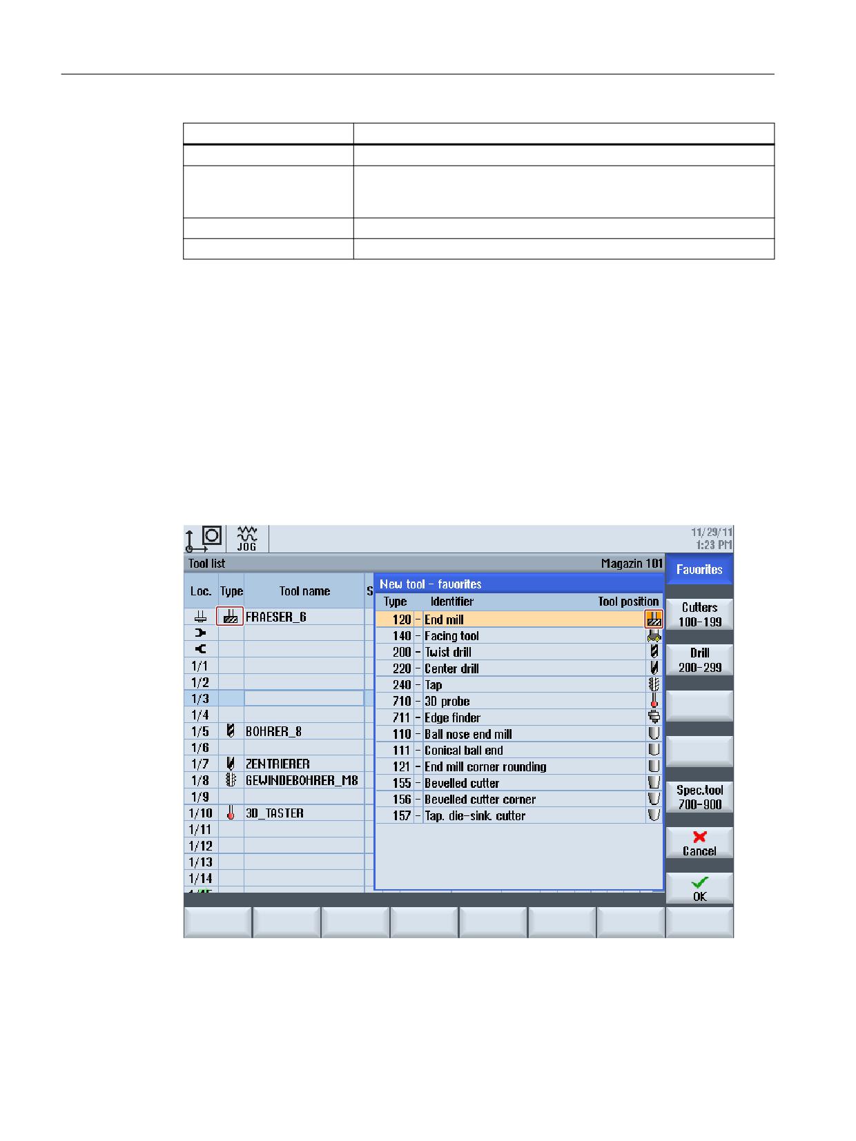
SINUMERIK Operate user interface
9.1 Configuring the user interface
Entries
Meaning
Iconorder
Order in which the tool positions, represented by icons, are switched.
DisableInNewToolDialog
With this entry, the tool type in question is not offered when new tools are
created. If the tool list finds a tool of this type that already exists, it is
correspondingly displayed.
DELETE_TOOLTYPE
All predefined tool types that are not to be supported in the tool lists.
GrindingTooltypes
All tool types that are to be used as grinding tool types.
Example 1
<TOOLTYPECONFIGURATION>
<TOOLTYPE_120>
<Tooltype value="120" type="uint" />
<Name value="TM_PAR_SHANK_END_CUTTER" type="QString" />
<Shortname value="TM_PPTT_SHANK_END_CUTTER" type="QString" />
<Tooltip value="TM_TTTT_SHANK_END_CUTTER" type="QString" />
<Icon9 value="to_poly_shank_end_cutter_down.png" type="QString" />
</TOOLTYPE_120>
</TOOLTYPECONFIGURATION>
Tool management
576
Function Manual, 10/2020, 6FC5397-1HP40-0BA1

SINUMERIK Operate user interface
9.1 Configuring the user interface
Example 2
<TOOLTYPECONFIGURATION>
<DELETE_TOOLTYPE>
<TOOLTYPE_110 />
</DELETE_TOOLTYPE>
</TOOLTYPECONFIGURATION>
9.1.6
Configuring the "Additional Data" window
<MOREDATACONFIGURATION> tag
The entries used for configuring the "Additional Data" window are located in the
<MOREDATACONFIGURATION> tag. Various data items can be displayed for each tool type in a
number of rows and columns. Each data item to be displayed is specified by entering a list
parameter:
Tool parameter identifiers (Page 559)
Cutting edge parameter identifiers (Page 561)
Monitoring parameter identifiers (Page 564)
A brief description of the parameter (ShortText) then appears in the window with the value itself
beside it. Configuring list parameters (Page 569).
If another description text is required in the "More Data" window, a text can also be entered in
a row or column. In the window, the width of the text is made to conform to that of the brief
description and value of a parameter.
Any number of rows and columns can be created. A scrollbar appears when the window reaches
a certain size.
Entries
Meaning
TOOLTYPE_XXX
Number of the tool type.
See example: Tool type 111 = Ball end mill (tapered die-sinking cutter).
ROWX_COLY
Particular rowX_columnY.
If there is no entry after rowX and columnY, this field remains blank.
See example: In the "More Data" window, the first row is blank.
Item
The following entries are possible:
• Parameter identifier
• Text
See example:
The header "Corner radius" appears in the second row of the window.
The text "Radius" and an input field for the value appear in the third row of the
window.
The fourth row is blank.
Tool management
Function Manual, 10/2020, 6FC5397-1HP40-0BA1
577

SINUMERIK Operate user interface
9.1 Configuring the user interface
Entries
Meaning
TOOLTYPE_ALL_XXX
The setting applies to all tool types of a group. XXX stands for the group
number of the tool types. The hundreds position is used as the group number,
for example, TOOLTYPE_ALL_100 or TOOLTYPE_ALL_200 etc. (see example).
WITHOUT_MORE_DATA
Tool types of a tool group for which no "further data" are to be displayed can
be excluded with this identifier (see example).
Example 1
<MOREDATACONFIGURATION>
<TOOLTYPE_111>
<ROW1_COL1>
</ROW1_COL1>
<ROW2_COL1>
<Item value="TM_DGL_CORNER_RADIUS" type="QString" />
</ROW2_COL1>
<ROW3_COL1>
<Item value="GeoCornerRadius" type="QString" />
</ROW3_COL1>
<ROW4_COL2>
</ROW4_COL2>
</TOOLTYPE_111>
</MOREDATACONFIGURATION>
Example 2
<MOREDATACONFIGURATION>
<TOOLTYPE_ALL_500>
<ROW1_COL1>
<Item value="TM_DGL_LENGTH" type="QString" />
</ROW1_COL1>
<ROW2_COL1>
<Item value="GeoLengthGeoAx3" type="QString" />
</ROW2_COL1>
</TOOLTYPE_ALL_500>
<WITHOUT_MORE_DATA>
<TOOLTYPE_580 />
</WITHOUT_MORE_DATA>
</MOREDATACONFIGURATION>
Tool management
578
Function Manual, 10/2020, 6FC5397-1HP40-0BA1

SINUMERIK Operate user interface
9.1 Configuring the user interface
9.1.7
Configure the "New tool - favorites" window
<NEWTOOLFAVORITECONFIGURATION> tag
In the tag <NEWTOOLFAVORITECONFIGURATION> you define the tool types that are most
frequently used. The specified tool types are displayed in the "New Tool - Favorites" window.
Entries
Meaning
StaticTooltypes
Numbers of tool types Enter the individual numbers, separated by blanks.
The following section describes the assignment of the tool type and num-
ber: List of tool types (Page 573)
Example
<NEWTOOLFAVORITECONFIGURATION>
<StaticTooltypes value="120 140 200 220 710 711" type="QString"/>
<AdditionalStaticTooltypes value="" type="QString"/>
</NEWTOOLFAVORITECONFIGURATION>
9.1.8
Configuring the "New Tool" window
<NEWTOOLCONFIGURATION> tag
You use the "New Tool" dialog to supply a new tool with specific tool data before creating the tool
or before loading the tool to a magazine location. These are typically the tool size and/or the tool
location type because these parameters can no longer be changed when the tool is loaded. It is
also useful to display the tool type and the tool names in this window.
Specify the parameters in the <NEWTOOLCONFIGURATION> tag that are to be displayed in the
"New Tool" dialog.
Note
The number of parameters is limited by the size of the window.
Entries
Meaning
ItemX
Entry of the identifier of the tool parameter. "X" specifies the order in which the pa-
rameters are displayed in the window.
The identifier of the tool parameter can be found in Chapter:
Tool parameter identifiers (Page 559)
Tool management
Function Manual, 10/2020, 6FC5397-1HP40-0BA1
579

SINUMERIK Operate user interface
9.1 Configuring the user interface
Example
<NEWTOOLCONFIGURATION>
<!-- The standard field "oversized tool" is removed and replaced by the fields -->
<!-- "tool location type", "tool size left" and "tool size right" -->
<!-- -->
<Item2 value="ToolPlaceSpec" type="QString"/>
<Item3 value="ToolSizeLeft" type="QString"/>
<Item4 value="ToolSizeRight" type="QString"/>
</NEWTOOLCONFIGURATION>
9.1.9
Configuring the "New Multitool" window
<NEWMULTITOOLCONFIGURATION> tag
You use the "New Multitool" dialog to supply a new multitool with specific multitool data before
creating the multitool or loading it into to a magazine location. Multitool data typically includes
the number of multitool locations and spacing between locations, as these parameters cannot
be changed once the multitool has been created. The same applies to the multitool size and/or
multitool location type as to the tool size and tool location type. These parameters, too, cannot
be changed once they have been loaded into the tool. It is also a good idea to display the
multitool name in this window.
In the <NEWMULTITOOLCONFIGURATION>tag, specify the parameters that you wish to have
displayed in the "New Multitool" dialog.
Entries
Meaning
ItemX
Entry of the identifier of the multitool parameter. "X" specifies the order in
which the parameters will be displayed in the window.
The identifier of the multitool parameter can be found in Chapter:Multitool
parameter identifiers (Page 567)
9.1.10
Configuring the "New Tool from Code Carrier" window
<NEWTOOLIDENTCONNECTIONCONFIGURATION> tag
You use the "New Tool from Code Carrier" dialog to identify a new tool before creating it. It is
therefore a good idea to display the tool type and the tool name in this window. In addition, the
same rules apply as for configuration of the window "New Tool," Section "Configuring the "New
Tool" window (Page 579)."
Tool management
580
Function Manual, 10/2020, 6FC5397-1HP40-0BA1

SINUMERIK Operate user interface
9.1 Configuring the user interface
In the <NEWTOOLIDENTCONNECTIONCONFIGURATION>tag, define the parameters that you
wish to have displayed in the "New Tool of Code Carrier" dialog.
Entries
Meaning
ItemX
Entry of the identifier of the tool parameter. "X" specifies the order in which the pa-
rameters are displayed in the window.
The identifier of the tool parameter can be found in Chapter:
Tool parameter identifiers (Page 559)
9.1.11
Configuring the "New Tool from File" window
<NEWTOOLSAVETOOLDATACONFIGURATION> tag
You use the "New Tool from File" dialog to identify a new tool before creating it. It is therefore a
good idea to display the tool type and the tool name in this window. In addition, the same rules
apply as for configuration of the window "New Tool," Section "Configuring the "New Tool"
window (Page 579)."
Specify the parameters in the <NEWTOOLSAVETOOLDATACONFIGURATION>tag that are to be
displayed in the "New Tool from Tile" dialog.
Entries
Meaning
ItemX
Entry of the identifier of the tool parameter. "X" specifies the order in which the pa-
rameters are displayed in the window.
The identifier of the tool parameter can be found in Chapter:
Tool parameter identifiers (Page 559)
9.1.12
Configuring default values for new tools
<NEWTOOLDEFAULTVALUECONFIGURATION> tag
In the <NEWTOOLDEFAULTVALUECONFIGURATION> tag, you can specify default values for tools
that you create via the user interface. These values can be configured depending on the tool type
and, if required, also depending on the cutting edge position:
Entries
Meaning
TOOLTYPE_ALL
The parameter setting applies to all tool types.
TOOLTYPE_XXX
The parameter setting applies to a specific tool type. XXX stands for the
number of the tool type.
CUTTEDGEPOS_XXX
The parameter setting applies to a specific cutting edge position. XXX stands
for the number of the cutting edge position.
Default
Default value of the parameter.
Tool management
Function Manual, 10/2020, 6FC5397-1HP40-0BA1
581
SINUMERIK Operate user interface
9.1 Configuring the user interface
Example
<NEWTOOLDEFAULTVALUECONFIGURATION>
<!-- Initialize geometry length 1 for all tool types to 70.0 -->
<TOOLTYPE_ALL>
<GeoLengthGeoAx1>
<Default value="70.0" type="double" />
</GeoLengthGeoAx1>
</TOOLTYPE_ALL>
<!-- Initialize tip angle of the twist drill to 120.0 -->
<TOOLTYPE_200>
<NoseAngle>
<Default value="120.0" type="double" />
</NoseAngle>
</TOOLTYPE_200>
<TOOLTYPE_500>
<!-- Initialize plate angle of the roughing tool to 82.0 -->
<PlateAngle>
<Default value="82.0" type="double" />
</PlateAngle>
<!-- Initialize holder angle of the roughing tool depending on the cutting edge po-
sition -->
<HolderAngle>
<CUTTEDGEPOS_1>
<Default value="93.0" type="double" />
</CUTTEDGEPOS_1>
<CUTTEDGEPOS_2>
<Default value="93.0" type="double" />
</CUTTEDGEPOS_2>
<CUTTEDGEPOS_3>
<Default value="93.0" type="double" />
</CUTTEDGEPOS_3>
<CUTTEDGEPOS_4>
<Default value="93.0" type="double" />
</CUTTEDGEPOS_4>
<CUTTEDGEPOS_5>
<Default value="49.0" type="double" />
</CUTTEDGEPOS_5>
<CUTTEDGEPOS_6>
<Default value="49.0" type="double" />
</CUTTEDGEPOS_6>
<CUTTEDGEPOS_7>
<Default value="49.0" type="double" />
</CUTTEDGEPOS_7>
<CUTTEDGEPOS_8>
Tool management
582
Function Manual, 10/2020, 6FC5397-1HP40-0BA1
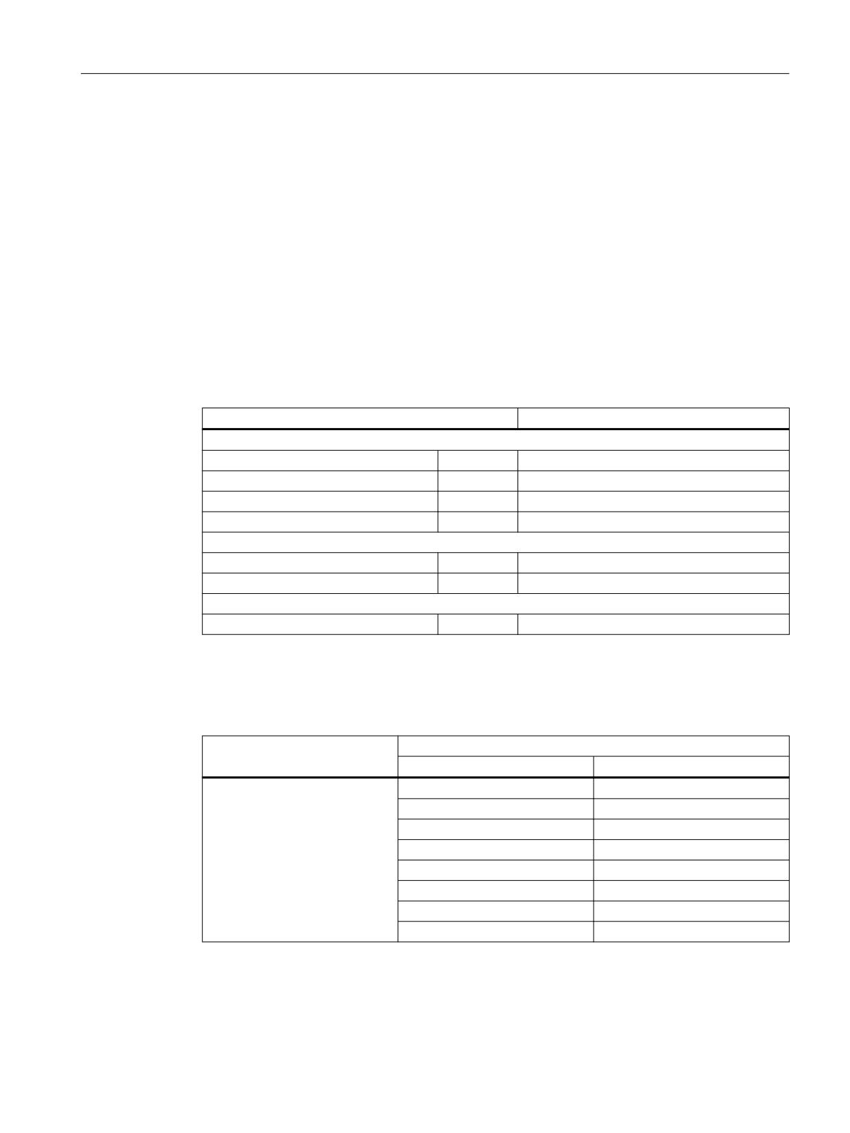
SINUMERIK Operate user interface
9.1 Configuring the user interface
<Default value="49.0" type="double" />
</CUTTEDGEPOS_8>
</HolderAngle>
</TOOLTYPE_500>
<!-- Initialize coolant 2 of the plunge cutter to switched on -->
<TOOLTYPE_520>
<Coolant2>
<Default value="true" type="bool" />
</Coolant2>
</TOOLTYPE_520>
</NEWTOOLDEFAULTVALUECONFIGURATION>
Default values when creating new tools
System variables
Default value
Tool size
Size on left
$TC_TP3
1
Size on right
$TC_TP4
1
Size above
$TC_TP5
1
Size below
$TC_TP6
1
Magazine location type of the tool
Created outside of the magazine
$TC_TP7
1
Created in a magazine location
$TC_TP7
Location type of the magazine location
Tool status
released
$TC_TP8
2
The following combinations between the cutting-edge position and the cutting direction result
dependent on the tool type. When creating the new tool, the operator selects a combination in
the "New Tool - Favorites" window.
Tool type $TC_DP1
Default values
Cutting edge $TC_DP2
Cutting direction $TC_DP11
Type 500 roughing tool
1
4
Type 510 finishing tool
2
3
Type 560 rotary drill
3
3
4
4
5
1
6
3
7
1
8
3
Tool management
Function Manual, 10/2020, 6FC5397-1HP40-0BA1
583
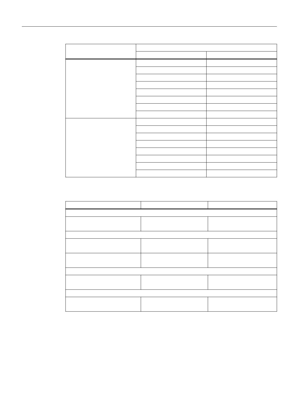
SINUMERIK Operate user interface
9.1 Configuring the user interface
Tool type $TC_DP1
Default values
Cutting edge $TC_DP2
Cutting direction $TC_DP11
Type 520 plunge cutter
1
2
Type 530 cut-off tool
1
4
Grinding tool types
4
4
3
1
4
1
2
3
3
3
2
2
Type 540 threading tool
5
2
5
1
8
3
8
4
6
3
6
4
7
2
7
1
If the ShopMill/ShopTurn option is set, the direction of spindle rotation is preassigned:
Tool type $TC_DP1
Default value $TC_DP25
Direction of spindle rotation
Measuring tools
Type 580/585/710/712/713/725
Bit 8 = 0
Spindle stop
Bit 9 = 0
Turning tools dependent on SD54215 TM_FUNCTION_MASK_SET bit 1
SD54215 bit 1 = 0
Bit 8 = 1
Spindle right
Bit 9 = 0
SD54215 bit 1 = 1
Bit 8 = 0
Spindle left
Bit 9 = 1
Special tools
Type 730/731/732
Bit 8 = 0
Spindle stop
Bit 9 = 0
All other tool types
-
Bit 8 = 1
Spindle right
Bit 9 = 0
Tool management
584
Function Manual, 10/2020, 6FC5397-1HP40-0BA1
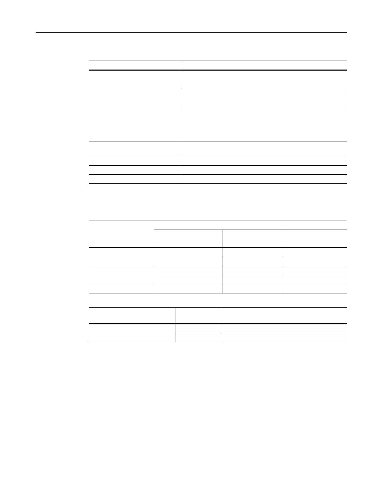
SINUMERIK Operate user interface
9.1 Configuring the user interface
Tool type $TC_DP1
Default value $TC_DP25 for switching direction
Type 712 mono probe
Bit 17 = 1
Bit 20 = 1
Type 713 L probe
Bit 17 = 1
Bit 21 = 1
Type 714 star probe
Bit 16 = 1
Bit 17 = 1
Bit 18 = 1
Bit 19 = 1
Tool type $TC_DP1
Default value $TC_DP24 for tip angle
Type 200 twist drill
118
Type 220 centering tool
90
The plate angle rather than the clearance angle is displayed on the screen:
plate angle = 180 - holder angle - clearance angle
Tool type
Default values
$TC_DP1
Cutting edge position
Holder angle
Clearance angle
$TC_DP2
$TC_DP10
$TC_DP24
Type 500 roughing tool
1 to 4
95
5
5 to 8
50
50
Type 510 finishing tool
1 to 4
93
32
5 to 8
62.5
62.5
Type 560 rotary drill
-
90
2
Tool type $TC_DP1
Unit of meas-
Default value $TC_DP8 for plate length
urement
Type 500 roughing tool
metric
11
Type 510 finishing tool
inch
0.4
For all grinding tools, the parameter for calculating the radius:
$TC_TPG9 = 3 (corresponds to length 1) applies
Tool management
Function Manual, 10/2020, 6FC5397-1HP40-0BA1
585

SINUMERIK Operate user interface
9.1 Configuring the user interface
9.1.13
Configuring the "Details" window
<DETAILSCONFIGURATION> tag
In the tag <DETAILSCONFIGURATION>, you can make the settings for the "Details" window:
Entries
Meaning
ShowToolNumber
The tool number is displayed in the upper right field of the "Details" win-
dow.
UseAxisNameInLength
The tool length is displayed with axis identifiers, for example, Length X
instead of Length 1.
If no data is specified, then the setting is taken from the tool lists.
ShowBaseLength
The basic length is displayed in the "Details" window (AdaptLength1,
AdaptLength2 and AdaptLength3).
If no data is specified, then the setting is taken from the tool lists.
ShowYAxis
The Y axis is displayed in the "Details" window.
If no data is specified, then the setting is taken from the tool lists.
AutoDisplayAxisEnabled
true
Default setting
The selection of the displayed tool lengths is based on the dis-
play of the tool lengths in the tool list.
false
Several components of the tool length are displayed, even if
only one tool length is displayed in the tool list.
OrderOfAxis
The order of display of the axes for all tool types in the window is "Details"
> "Cutting edge data".
The possible values are XYZ, XZY, YXZ, YZX, ZXY and ZYX.
Example 1
<DETAILSCONFIGURATION>
<ShowToolNumber value="true" type="bool" />
</DETAILSCONFIGURATION>
Example 2
<DETAILSCONFIGURATION>
<OrderOfAxis value="ZYX" type="QString" />
</DETAILSCONFIGURATION>
For all of the tools, the order of display in the details dialog is ZYX.
Example 3
If the entry OrderOfAxis is used as a tag, the order of display of the axes can be defined to be
tool type-specific.
<DETAILSCONFIGURATION>
<OrderOfAxis>
Tool management
586
Function Manual, 10/2020, 6FC5397-1HP40-0BA1

SINUMERIK Operate user interface
9.1 Configuring the user interface
<TOOLTYPE_130>
<Item value="ZYX" type="QString" />
</TOOLTYPE_130>
<TOOLTYPE_131>
<Item value="ZYX" type="QString" />
</TOOLTYPE_131>
</OrderOfAxis>
</DETAILSCONFIGURATION>
For angle heads (type 130 and 131), the order of display of the axes in the details dialog is ZYX.
Example 4
<DETAILSCONFIGURATION>
<OrderOfAxis>
<TOOLTYPE_130>
<Item value="ZYX" type="QString" />
</TOOLTYPE_130>
<TOOLTYPE_131>
<Item value="ZYX" type="QString" />
</TOOLTYPE_131>
<TOOLTYPE_ALL_500>
<Item value="ZXY" type="QString" />
</TOOLTYPE_ALL_500>
<TOOLTYPE_ALL>
<Item value="XYZ" type="QString" />
</TOOLTYPE_ALL>
</OrderOfAxis>
</DETAILSCONFIGURATION>
For angle heads (type 130 and 131), the order of display of the axes in the details dialog is ZYX.
For all rotary tools (type 500 and ff.), the order of display of the axes in the details dialog is ZXY.
For all remaining tools, the order of display of the axes in the details dialog is XYZ.
9.1.14
Assigning a name for magazines and magazine locations
<MAGAZINEPLACENAMECONFIGURATION> tag
The entries to assign dedicated magazine location names are located in the
<MAGAZINEPLACENAMECONFIGURATION> tag. Magazine locations can be displayed with texts.
Instead of the identifier, e.g. 1/5 for the first magazine, location five, the configured text is then
output in the tool lists.
Entries
Meaning
MAGAZINE_XXX
XXX stands for the magazine number.
PLACE_XXX
XXX stands for the location number.
Name
Text identifier of the magazine location.
Tool management
Function Manual, 10/2020, 6FC5397-1HP40-0BA1
587
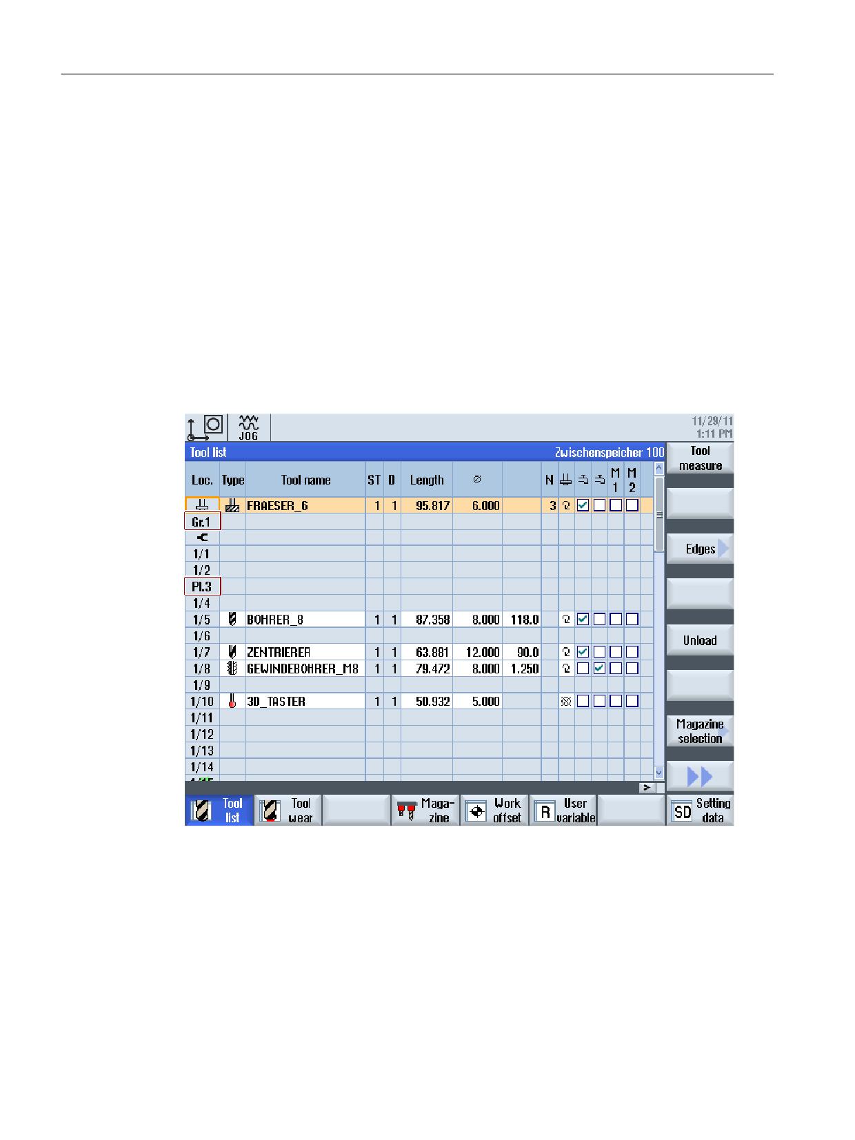
SINUMERIK Operate user interface
9.1 Configuring the user interface
Example
<MAGAZINEPLACENAMECONFIGURATION>
<MAGAZINE_9998>
<PLACE_2>
<Name value="TM_SPECIAL_MAG_PLACE_1" type="QString" />
</PLACE_2>
</MAGAZINE_9998>
<MAGAZINE_1>
<PLACE_3>
<Name value="TM_SPECIAL_MAG_PLACE_2" type="QString" />
</PLACE_3>
</MAGAZINE_1>
</MAGAZINEPLACENAMECONFIGURATION>
Name for a magazine
Dedicated texts can also be allocated for magazines. The text or the text identifier is entered into
the magazine configuration file (ini file) of the NC. The system variable for the magazine name
is $TC_MAP2[magNo]. The magazine name is displayed at the top right in the tool lists.
Example
Magazine 1 should have the name "main magazine".
Tool management
588
Function Manual, 10/2020, 6FC5397-1HP40-0BA1

SINUMERIK Operate user interface
9.1 Configuring the user interface
$TC_MAP2[1]="main magazine"
If the "main magazine" text is to be output language-dependent, then the language-dependent
texts for the text identifier "main magazine" must be created.
See also
Please refer to the following section for the procedure to create language-dependent text:
Creating OEM texts (Page 608)
9.1.15
Configuring the "Assign Tooltips for Multitool Locations" window
<MULTITOOLPLACETOOLTIPCONFIGURATION> tag
You will find the entries for assigning tooltips in the tag
<MULTITOOLPLACETOOLTIPCONFIGURATION>. This is particularly useful if all the multitools
used on a turning machine have two locations and a fixed assignment between multitool
locations and the main spindle or the counter spindle exists, for example, location 1 - main
spindle location 2 - counter spindle. In this case, the tooltip for location 1 could be "Tool Holder
for Main Spindle."
Entries
Meaning
PLACE_XXX
XXX stands for the multitool location number.
Tooltip
Text identifier of the magazine location.
Example
<MULTITOOLPLACETOOLTIPCONFIGURATION>
<PLACE_1>
<ToolTip value="TM_HOLDER_OF_MAIN_SPINDLE" type="QString" />
</PLACE_1>
<PLACE_2>
<ToolTip value="TM_HOLDER_OF_COUNTER_SPINDLE" type="QString" />
</PLACE_2>
</MULTITOOLPLACETOOLTIPCONFIGURATION>
See also
Please refer to the following section for the procedure to create language-dependent text:
Creating OEM texts (Page 608)
Tool management
Function Manual, 10/2020, 6FC5397-1HP40-0BA1
589

SINUMERIK Operate user interface
9.1 Configuring the user interface
9.1.16
Assigning a name for magazine location types
<PLACETYPECONFIGURATION> tag
You can find entries to allocate your own location type identifiers in the tag
<PLACETYPECONFIGURATION>. Magazines and magazine location types can be displayed with
texts in the tool lists. Instead of identifier 2, e.g. for location type 2, the configured text is then
output in the tool lists.
Entries
Meaning
PLACETYPEXXX
XXX stands for the number of the location type.
Text
Text identifier of the location type.
Tooltip
Tooltip text identifier of the location type.
Example
<PLACETYPECONFIGURATION>
<PLACETYPE1>
<Text value="TM_PLACETYPE_1" type="QString" />
<Tooltip value="TM_TT_PLACETYPE_1" type="QString" />
</PLACETYPE1>
<PLACETYPE2>
<Text value="TM_PLACETYPE_2" type="QString" />
<Tooltip value="TM_TT_PLACETYPE_2" type="QString" />
</PLACETYPE2>
<PLACETYPE3>
<Text value="TM_PLACETYPE_3" type="QString" />
<Tooltip value="TM_TT_PLACETYPE_3" type="QString" />
</PLACETYPE3>
</PLACETYPECONFIGURATION>
Tool management
590
Function Manual, 10/2020, 6FC5397-1HP40-0BA1
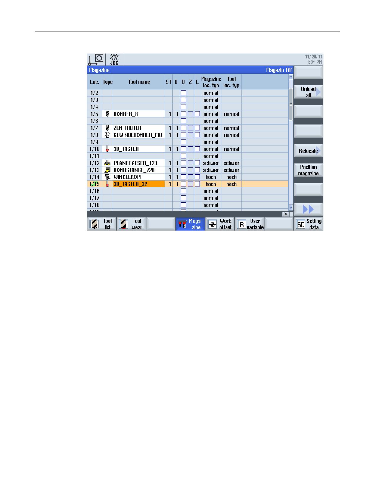
SINUMERIK Operate user interface
9.1 Configuring the user interface
See also
Please refer to the following section for the procedure to create language-dependent text:
Creating OEM texts (Page 608)
9.1.17
Assignment of magazines and magazine locations to channels
Requirement
Turning technology or milling technology and technology extension turning have been set:
Name of the associated configuration file sltmturninglistconfig.xml or
sltmmillturnlistconfig.xml.
Assignment between magazine and magazine locations and channel
With this setting, magazines and magazine locations can be assigned to channels. This makes
sense if the machine is configured so that several channels are assigned to one tool area (TOA
area). If each magazine is only used in one channel, it is possible to define this assignment
between the magazine or magazine locations and the channel here.
As a consequence of this configuration, the tool icons are output with reference to their position
depending on the channel. Every channel can be assigned a position using the channel machine
data MD52000 MCS_DISP_COORDINATE_SYSTEM. If a tool is at a magazine location which is
Tool management
Function Manual, 10/2020, 6FC5397-1HP40-0BA1
591

SINUMERIK Operate user interface
9.1 Configuring the user interface
assigned a channel via this configuration, then the tool icon is output depending on this position
that has been set.
This setting option is only available in turning technology and in milling technology with the
technology extension milling. This can be especially helpful if, on a multi-channel machine, a
magazine is used before the turning center and another magazine after the turning center. This
means that the tools can be entered into the tool list in a position visible for the operator.
The assignment between magazine locations and channels is useful when instead of two
magazines, two tool holders/tool spindles exist that fetch their tools from a magazine. One tool
holder is used in front of the turning center and one is used behind the turning center, so that
different views onto the tool result.
<CHANNELMAGAZINEASSIGNMENT> tag
In tag <CHANNELMAGAZINEASSIGNMENT> , you will find the entries for the assignment
between the magazines or magazine locations and the channels.
Entries
Meaning
CHANNELNO_XXX
XXX stands for the channel number.
Magazines
Number of magazines that are assigned to the channel.
MAGAZINE_XXX
Number of the magazine whose locations will be assigned to the channel.
Places
Number of magazine locations that will be assigned to the channel.
Example 1
The following assignment between magazine and channel should apply:
Magazine 1-3
Channel 1
Magazine 4
Channel 2
Magazine 5
Channel 3
Magazine 6
Channel 4
<CHANNELMAGAZINEASSIGNMENT>
<CHANNELNO_1>
<Magazines value="1 2 3" type="QString" />
</CHANNELNO_1>
<CHANNELNO_2>
<Magazines value="4" type="QString" />
</CHANNELNO_2>
<CHANNELNO_3>
<Magazines value="5" type="QString" />
</CHANNELNO_3>
<CHANNELNO_4>
<Magazines value="6" type="QString" />
</CHANNELNO_4>
</CHANNELMAGAZINEASSIGNMENT>
Tool management
592
Function Manual, 10/2020, 6FC5397-1HP40-0BA1
SINUMERIK Operate user interface
9.1 Configuring the user interface
Example 2
Magazine location 1 of the buffer will be assigned to channel 1.
Magazine location 2 of the buffer will be assigned to channel 2.
<CHANNELMAGAZINEASSIGNMENT>
<CHANNELNO_1>
<MAGAZINE_9998>
<Places value="1" type="QString" />
</MAGAZINE_9998>
</CHANNELNO_1>
<CHANNELNO_2>
<MAGAZINE_9998>
<Places value="2" type="QString" />
</MAGAZINE_9998>
</CHANNELNO_2>
</CHANNELMAGAZINEASSIGNMENT>
9.1.18
Assignment between magazines and magazine locations and coordinate
systems
Requirement
Turning technology or milling technology and technology extension turning have been set:
Name of the associated configuration file sltmturninglistconfig.xml or
sltmmillturnlistconfig.xml.
Assignment between the magazine or magazine locations and the coordinate system
With this setting, magazines and magazine locations can be assigned to coordinate systems.
This is useful if the machine is configured in such a way that a magazine or magazine location
does not match the position of the coordinate system set in the channel. The assignment
between magazine or magazine location and coordinate system can be defined here.
As a consequence of this configuration, the tool icons are output with reference to their position
depending on the coordinate system.
This setting option is only available in turning technology and in milling technology with the
technology extension milling.
Tool management
Function Manual, 10/2020, 6FC5397-1HP40-0BA1
593

SINUMERIK Operate user interface
9.1 Configuring the user interface
<COORDSYSMAGAZINEASSIGNMENT> tag
In tag <COORDSYSMAGAZINEASSIGNMENT>, you will find the entries for the assignment
between magazines or magazine locations and coordinate systems.
Entries
Meaning
COORDSYSNO_XXX
XXX stands for the number of the coordinate system.
Magazines
Number of the magazines that are assigned to the channel.
MAGAZINE_XXX
Number of the magazine whose locations will be assigned to the coordinate
system.
Places
Number of magazine locations that will be assigned to the coordinate system.
Example
The following assignment between magazines or magazine locations and coordinate systems is
to apply:
Magazine 1,3, and 4
Coordinate system 34
Magazine 2
Coordinate system 33
Magazine 9998 location 2
Coordinate system 33
<COORDSYSMAGAZINEASSIGNMENT>
<COORDSYSNO_34>
<Magazines value="1 3 4" type="QString" />
</COORDSYSNO_34>
<COORDSYSNO_33>
<Magazines value="2" type="QString" />
<MAGAZINE_9998>
<Places value="2" type="QString" />
</MAGAZINE_9998>
</COORDSYSNO_33>
</COORDSYSMAGAZINEASSIGNMENT>
9.1.19
Disabling the softkey depending on filters
Tag <FILTERCONFIGURATION> in combination with Tag <SOFTKEYLOCK>
Some softkeys can be hidden depending on filter settings. For example, the "New Tool" softkey
is hidden if the filter "Only disabled tools" is set. This is not a good idea because the new tool is
not created as a disabled tool and is thus directly filtered out of the display. This means that the
new tool would not be displayed after being created.
Tool management
594
Function Manual, 10/2020, 6FC5397-1HP40-0BA1

SINUMERIK Operate user interface
9.1 Configuring the user interface
Softkey identifiers of the softkey, which can be hidden:
Entries
Meaning
NewTool
New tool
Edges
Cutting edges
Entries
Meaning
FirstEdge
Filter "Only first cutting edge," default setting "Edges"
StandBy
Filter "Only tools that are ready to use," default setting "NewTool"
Active
Filter "Only tools with active code," default setting "NewTool"
Locked
Filter "Only disabled tools," default setting "NewTool"
Prewarning
Filter "Only tools that have reached the pre-alarm limit," default setting "New-
Tool"
RemainingPieces
Filter "Only tools with remaining quantity," default setting "NewTool Edges"
MarkedToUnload
Filter "Only tools with unload identifier," default setting "NewTool Edges"
MarkedToLoad
Filter "Only tools with load identifier," default setting "NewTool Edges"
Example
<FILTERCONFIGURATION>
<SOFTKEYLOCK>
<Locked value="NewTool Edges" type="QString" />
</SOFTKEYLOCK>
</FILTERCONFIGURATION>
9.1.20
Configuring the "Load Station Selection" window
<LOADSTATIONSHANDLEALLTOOLS> tag
For functions "Delete all," "Unload all," and "Load all," you must specify a load station if multiple
load stations are configured in the magazine configuration of the NC. The load station is defined
in a dialog called "Select Load Station" or via the load station configuration with tag
<LOADSTATIONSHANDLEALLTOOLS>.
Entries
Meaning
DialogEnabled
Offer window "Load Station Selection," default setting "true"
MAGAZINE_XXX
Number of the magazine to which a load station will be assigned.
LoadStation
Load station to be assigned to the magazine.
Tool management
Function Manual, 10/2020, 6FC5397-1HP40-0BA1
595
SINUMERIK Operate user interface
9.1 Configuring the user interface
Example
<LOADSTATIONSHANDLEALLTOOLS>
<DialogEnabled value="true" type="bool" />
<MAGAZINE_1>
<LoadStation value="2" type="uint" />
</MAGAZINE_1>
<MAGAZINE_2>
<LoadStation value="1" type="uint" />
</MAGAZINE_2>
</LOADSTATIONSHANDLEALLTOOLS>
9.1.21
Coolant and tool-specific functions
Assigning coolant (ShopMill/ShopTurn)
In the tool management of ShopMill/ShopTurn, you can assign coolant and tool-specific
functions to each tool. These are activated when the tool is changed. You assign the coolant to
the corresponding machine functions (M functions) using the following machine data:
MD52230 $MCS_M_CODE_ALL_COOLANTS_OFF
M code for all coolants OFF
MD52231 $MCS_M_CODE_COOLANT_1_ON
M code for coolant 1 ON
MD52232 $MCS_M_CODE_COOLANT_2_ON
M code for coolant 2 ON
MD52233 $MCS_M_CODE_COOLANT_1_AND_2_ON
M code for both coolants ON
Tool-specific functions (ShopMill)
Tool-specific functions 1 ... 4 are intended for other M functions that can be activated for a tool.
For example, third coolant, speed monitoring, tool breakage etc.
Up to eight M functions can be programmed for the activation or deactivation of the tool-
specific functions. Definition is realized using the following machine data:
MD52281 $MCS_TOOL_MCODE_FUNC_ON[0...3]
M code for tool-specific function ON
= - 1
MD52282 $MCS_TOOL_MCODE_FUNC_OFF[0...3]
M code for tool-specific function OFF
= - 1
The M functions for the tool-specific functions are executed by the ShopMill cycles at the tool
change. If the checkbox is activated, the corresponding M code is generated from MD52281. If
the checkbox is not activated, the corresponding M code is generated from MD52282.
If you do not want to automatically execute additional M commands on a tool change, set the
associated machine data to -1 for the M commands of this tool-specific function. The associated
fields are also hidden in the tool list.
Tool management
596
Function Manual, 10/2020, 6FC5397-1HP40-0BA1

SINUMERIK Operate user interface
9.1 Configuring the user interface
The default value of the machine data is -1 so that no M values are output for the corresponding
functions.
Technical procedure
The M functions for the tool-specific functions are generated by the ShopMill cycles in a set (up
to four M commands are possible).
The number and also the sequence of the M commands are dependent on the settings of the
machine data (MD52281 to MD52282) and the programming.
If M functions less than 100 are used, the number and sequence of the M commands has no
significance. They are located in the user PLC in the decoded area (DB21.DBB194 to
DB21.DBB206), independent of the number and the sequence when programming.
However, if M functions from 100 and higher are used, then you must decode these yourself in
the user PLC. In this case, you must take into consideration the number and sequence (M
function 1 to M function 4).
JOG mode
In the JOG mode, no coolant and tool-specific functions are output to the interface. For a tool
change in the JOG mode, these functions can be initiated by the operator using the keys on the
machine control panel (implementation via the PLC user program).
Example: Machine data settings
MD52281 $MCS_TOOL_MCODE_FUNC_ON[0]
= 90
MD52281 $MCS_TOOL_MCODE_FUNC_ON[1]
= 92
MD52281 $MCS_TOOL_MCODE_FUNC_ON[2]
= 94
MD52281 $MCS_TOOL_MCODE_FUNC_ON[3]
= 96
MD52282 $MCS_TOOL_MCODE_FUNC_OFF[0]
= 91
MD52282 $MCS_TOOL_MCODE_FUNC_OFF[1]
= - 1
MD52282 $MCS_TOOL_MCODE_FUNC_OFF[2]
= 95
MD52282 $MCS_TOOL_MCODE_FUNC_OFF[3]
= 97
As a result, fields 1 to 4 of the tool-specific functions are displayed in the tool list.
The following fields are activated:
Tool-specific function 1:
On
Tool-specific function 2:
Off
Tool-specific function 3:
Off
Tool-specific function 4:
Off
The M functions M90, M95 and M97 are generated by the ShopMill cycles at the tool change.
You can change the texts for "Coolant 1/2 on/off" and "Tool-spec. fct. 1, ..." (see section
Identifiers of the standard texts (Page 609)). So that the texts between the tool list and program
area machine functions match, please note the following section.
Tool management
Function Manual, 10/2020, 6FC5397-1HP40-0BA1
597