SINUMERIK 840D sl. Service - Functions. Manual (2018-2020) - page 88
Description of functions
8.6 Several tools at a magazine location (multitool)
FC6: TM_TRANS2 - transfer block for tool management and multitool (Page 153)
FC8: TM_TRANS - transfer block for tool management (Page 157)
8.6.4
Tool change and tool number for multitools
Tx - Tx programmed: Configuration of the tool selection
$MC_TOOL_MANAGEMENT_MASK, bit 11 makes it possible to adjust the behavior when
repeatedly programming Tx - Tx. The setting is valid for the tool to be selected and also for the
MT itself.
Example:
Tool selection with T, tool change with M code. The following is programmed:
T="TOOL5"
T="TOOL5"
The second tool preparation command is a "superfluous" command, which as default setting
does not result in a command being output to the PLC. If "Tool5" is a tool belonging to a multitool,
then with the command, generally
• a) a transport task of the MT "from magazine to tool holder" is generated
• b) a positioning command of the MT location with the programmed tool.
If "Tool5" is in an MT, then two basic situations can exist for the MT:
1. The MT is already located on the tool holder.
-
1.1 The programmed tool has already been positioned.
–
1.2 The programmed tool is a different tool than the tool that was positioned.
2. The MT is not yet located on the tool holder.
For case 1.1, the data is
• a) "MT from tool holder to tool holder"
• b) "Position at the location of the tool "Tool5" that has already been positioned
For case 1.2, the data is
• a) "MT from tool holder to tool holder"
• b) "Position to the location of the tool that has still not been positioned "Tool5""
For case 2, the data is
• a) "MT from magazine to tool holder"
• b) "Position to the location of the tool "Tool5""
The general criterion as to whether the second program command is a "superfluous" command
is whether the generated command data for the PLC is identical to that of the first command. The
second command is then not output to the PLC.
This command output can be forced using the bit value 1 of bit 11 from
$MC_TOOL_MANAGEMENT_MASK.
Tool management
460
Function Manual, 10/2020, 6FC5397-1HP40-0BA1
Description of functions
8.6 Several tools at a magazine location (multitool)
Tool change command canceled before the final acknowledgement
If, within the scope of a tool change, the MT has already been mechanically loaded, but the MT
has not been positioned, and the operation is interrupted in this state (fault, RESET, EMERGENCY
STOP, power off, power failure...), then before continuing, the PLC must ensure that the
previously pending MT positioning is carried out. The PLC must then make sure that the NC is
informed about the MT change (e.g. using an asynchronous transfer with acknowledgement
status 4 or 5. In so doing, the NC synchronizes the MT position with the command data from the
PLC). With an asynchronous transfer, the PLC can also communicate the MT position to the NC.
Note
Init blocks for START and/or RESET
Especially if init blocks for START and/or RESET are generated via MD settings, with the property
"activate the tool on the tool holder", and the tool on the tool holder is an MT, then the PLC must
ensure that the MT is correctly positioned on the tool holder before the NC makes the correction
selection (i.e. before the RESET command is sent to the NC, the MT must have been positioned).
T0 - tool deselection and return transport of the multitool into the magazine
T0 deselects the tool and loads the associated MT back into the magazine.
A T0 is output at the PLC user interface. The "tool carrier" must be removed from the tool holder.
It does not make any difference as to whether it involves an individual tool or a multitool.
DB72.DBB(n+1), bit 7 is not set, as there is no relevant data.
M06 ; generates the PLC command = 3.
If a tool from this multitool that has just been exchanged is again selected/loaded, then the
multitool is again loaded onto the tool holder.
It is not possible to program a T0 with the meaning to deselect the active tool, and at the same
time to keep the MT on the tool holder. T0 M06 D0 means, that after successful execution
- the correction is deselected
- there is no active tool
- there is no tool or MT on the tool holder.
Tool management
Function Manual, 10/2020, 6FC5397-1HP40-0BA1
461
Description of functions
8.6 Several tools at a magazine location (multitool)
PLC acknowledgement status 2 and 7 in the FC6
The PLC acknowledgement status numbers 2 and 7 (FC6 (Page 153) and FC8 (Page 157)) refer
to the respective tool within the multitool. This means that the tool is rejected, not the multitool.
If the newly selected tool is in another multitool, then the transport task data for the multitool
as well as for the newly selected tool contained in it, are newly determined and output to the PLC.
The following apply:
• Status=2:
The tool cannot be made available. The NC locks this tool and tries to repeat the tool
preparation with another tool. This status is permissible only in conjunction with a
preparation command.
• Status=7:
Analogous to status 2 - with the property that no tool is disabled (i.e. the same tool can be
selected again).
Tool change with "T=magazine location number" programming ("T=location")
With a multitool, there are three variants of T=location programming:
1. Specification of multitool location and magazine location, e.g. N100 MTL=2 T4
2. With MD20274 $MC_MULTITOOLLOC_DEFAULT
The magazine location is programmed, e.g. T4
The tool at the multitool location specified in the machine data is selected.
3. Via the current multitool position
The magazine location is programmed, e.g. T6
The tool at the multitool location specified in the multitool parameter $TC_MTP_POS is
selected.
In these three options, variant 1 has the highest priority and variant 3 the lowest.
The following examples illustrate this.
Example 1:
$MC_TOOL_CHANGE_MODE=0 applies (tool change only with the T command, i.e. the T
programming results in the output of command number 4 to the PLC).
Multitool with distance coding, location number, $TC_MTP_KD[500]=1, is in turret 1, location 4
and has the MT no. = 500; $TC_MPP6[1, 4] = 500. The MT position is
$TC_MTP_POS[500]=2.
The tool at magazine location 1/1 is loaded onto tool holder 9998/1. The MT on magazine
location 4 has 3 locations.
The following tools are loaded in the multitool:
"tool_1": $TC_MTPP6[500, 1] =11 MT distance $TC_MTPPA[500, 1] = 1
"tool_2": $TC_MTPP6[500, 1] =22 MT distance $TC_MTPPA[500, 2] = 2
- $TC_MTPP6[500, 1] =0 MT distance $TC_MTPPA[500, 3] = 3
There is no tool at location 3 of the multitool. $MC_MULTITOOLLOC_DEFAULT=0 applies.
Tool selection and tool change are programmed with T. The "T=magazine location number"
function is used.
Tool management
462
Function Manual, 10/2020, 6FC5397-1HP40-0BA1
Description of functions
8.6 Several tools at a magazine location (multitool)
The following command is then programmed:
;MT-Position $TC_MTP_POS[500]=2
T4
;MT position $TC_MTP_POS[500] = 2
;at magazine location 4, in the multitool loaded there, select the tool,
;which is loaded at MT location 2 of the multitool and load the MT - if it is not disabled
- and
;activate the tool.
;If the tool at MT location 2 of the multitool is disabled, then a search is made for
;another matching tool with the name "tool_2", which under certain circumstances -
;depending on the tool -;search strategy, tool equipping -is at some location ;of
another multitool ;or which is contained as individual tool on another
;turret location.
The resulting command to the PLC is as follows:
T4 programming with the result "Multitool 500 is at the programmed magazine location and at
the MT location selected (via the MT position), there is tool "tool_2" with the T no.=22" - supplies
the following (essential) data to the PLC.
No tool on MT location
For "T=magazine location" and "No tool on the magazine location", it is defined that a regular tool
change command to the PLC is output with the special property "T number of the new tool = 0".
Similarly for "T=magazine location" and
"An MT is on the magazine location" and
"No tool is on the selected MT location"
Tool management
Function Manual, 10/2020, 6FC5397-1HP40-0BA1
463
Description of functions
8.6 Several tools at a magazine location (multitool)
it is defined that a regular tool change command to the PLC is output with the special property:
• a) MT is in the magazine
T number of the tool that is to be moved on the tool holder is the MT number of the MT that
is on the magazine location and the T number of the new tool in the MT = 0.
With the information of the PLC command, the PLC can decide what is to be done in this
situation: Either position the MT on the empty MT location or issue an alarm "There is no tool
on the MT location".
- Example 2:
If $MC_MULTITOOLLOC_DEFAULT =3 applies, then the result in example 1 - the
multitool position is 2 ($TC_MTP_POS[500]=2), there is no tool on MT location 3 - is
that T0 is programmed with the programming T4 based on the effect (no new tool is
available, but the request to dispose of the old tool is issued nevertheless.
• b) MT is on the tool holder
T number of the tool that is to be moved on the tool holder is the MT number of the MT that
is already on the tool holder. The transport request "From → to" for the MT is "From tool holder
→ tool holder" and the
T number of the new tool in the MT = 0.
With the information of the PLC command, the PLC can decide what is to be done in this
situation: Either position the MT on the empty MT location or issue an alarm "There is no tool
on the MT location".
- Example 3:
The preconditions are the same as in example 2 with the condition that the MT from
location 4 is already on the tool holder. Programming T4 has the same effect as if T0 were
programmed (a new tool is not available, but the request for the offset deselection is still
issued; the old tool transport data is 0/0 → 0/0), the MT remains on the tool holder.
Tool change with "T=magazine location number MTL=MT location" programming
As an alternative to the programming described in the section above, the MT location can be
programmed with MTL=p in the multitool (p=location number).
The following applies for the programming:
• MTL is non-modal.
• MTL must be programmed in the NC block before the T command.
• The programmed value for MTL must correspond to an existing location number in the
multitool to be selected. Otherwise, an alarm is output.
MD $MC_MULTITOOLLOC_DEFAULT can be used to define the MT location number which is used
when MTL is not programmed. The MTL programming replaces the default defined with
$MC_MULTITOOLLOC_DEFAULT.
Example 4:
If $MC_MULTITOOLLOC_DEFAULT =3 applies, this results in example 2 of the section above -
the multitool position is 2 ($TC_MTP_POS[500]=2), there is no tool on MT location 3 - that, with
the following programming, the value of $MC_MULTITOOLLOC_DEFAULT=3 and the current MT
Tool management
464
Function Manual, 10/2020, 6FC5397-1HP40-0BA1
Description of functions
8.6 Several tools at a magazine location (multitool)
position 2 are ignored, because MTL is explicitly programmed. This selects "tool_1" with the tool
number 11.
MTL=1 T4
;affects precisely T4 in this block,
;which is programmed subsequently in the block.
Example 5:
If $MC_MULTITOOLLOC_DEFAULT =3 applies, this results in example 2 of the section above -
the multitool position is 2 ($TC_MTP_POS[500]=2), there is no tool on MT location 3 - that, with
the following programming, the programmed value MTL=1 remains without effect and the
value of $MC_MULTITOOLLOC_DEFAULT=3 is used. There is no tool at MT location 3 and
MTL=1
;does not affect following block T4 because this is non-modal
T4
;the setting of the MD takes effect
Example 6:
If $MC_MULTITOOLLOC_DEFAULT =0 applies, this results in example 2 of the section above -
the multitool position is 2 ($TC_MTP_POS[500]=2), there is no tool on MT location 3 - that, with
the following programming, the programmed value MTL=1 remains without effect and the
value of $MC_MULTITOOLLOC_DEFAULT=0 is used; i.e. the value of the MT position = 2. The tool
with tool number=22 is on the MT location 2.
MTL=1
;does not affect following block T4 because this is non-modal
T4
;the setting of the MD takes effect - that is now MT position=2
$C_MTL - transfer of the MTL_value to the replacement cycle
The programmed value for MTL can be read in an existing replacement cycle for T with $C_MTL.
$C_MTL_PROG - MTL is programmed
If MTL has been programmed in the NC block, then this can be determined in an existing
replacement cycle for T with $C_MTL_PROG. $C_MTL_PROG==1 means that MTL has been
programmed. The programmed value can be queried with $C_MTL.
Example:
The multitool function and the function T=location have been configured.
N10 MTL=3 T=8
Then the replacement cycle contains T code of the type for the command:
N140 IF $C_T_PROG == 1
N142
IF $C_MTL_PROG == 1
N144
MTL=$C_MTL T[$C_TE]=$C_T
N146
ELSE
N148
T[$C_TE]=$C_T
N150
ENDIF
N152 ENDIF
Tool management
Function Manual, 10/2020, 6FC5397-1HP40-0BA1
465
Description of functions
8.6 Several tools at a magazine location (multitool)
Load/move multitool on tool holder and init block
If a multitool is loaded onto a tool holder other than through a tool change (loading operation,
movement command) and for the init block handling (if it is appropriately configured), the active
tool must be subsequently determined, then the following applies:
• If necessary: After loading/moving, set the MT position so that the requested tool can be
activated - or so that the MT position matches the mechanical MT position
• Always issue a tool change command to the PLC which contains the MT position of the tool
to be activated.
• Take the MT which is located on the master tool holder.
• Take the tool which is at the MT location with MT location number = "MT position" (=
$TC_MTP_POS), and select it.
• Activate the D offset of this tool with the lowest D number.
Irrespective of the value of bit 12 (bit value==1 corresponds to ’H1000’) of the MD
$MC_TOOL_MANAGEMENT_MASK, a command is output to the PLC if the activated tool is
not on the MT location which was output last for this tool holder or was contained in the
acknowledged tool change command.
Note
The MT position of the multitool on the tool holder must be synchronized to the mechanical
position of the multitool on the machine. If the MT position when loading does not already
match the MT loading position, then under certain circumstances the PLC can initiate this
synchronization with an asynchronous transfer before the RESET command to the NC (that
generates the init block).
Example
The init block generation is activated ($MC_TOOL_MANAGEMENT_MASK, bit 14 (bit value==1
corresponds to ’H4000’)).
The part program is exited. The MT remains on the tool holder. The last tool change in the part
program was performed with regard to MT position = 3. The PLC acknowledged the MT tool
change command with MT position = 3.
The init block generated with the operator panel RESET determines the MT on the tool holder,
the tool on the MT location with the number of the MT position. The compensation of the
smallest D number is activated.
Positioning is now performed on a different location with the OPI PI _N_POSMT_. A tool
command with the number = 1 (move/position) is output to the PLC and acknowledged
accordingly. The MT now has a different position than at the time of the previous end of the
program. With the operator panel reset, the tool on this MT location is determined and the
compensation activated accordingly. There is no tool change command output to the PLC.
Only the data of the MT position is now changed (e.g. by a write command with $TC_MTP_POS).
Machine and NC data are now asynchronous. With the operator panel reset, the tool on this MT
location is determined and the compensation activated accordingly. A tool change command is
output to the PLC irrespective of the setting of bit 12 of $MC_TOOL_MANAGEMENT_MASK. After
correct positioning, the machine and the NC data are synchronous again.
Tool management
466
Function Manual, 10/2020, 6FC5397-1HP40-0BA1

Description of functions
8.6 Several tools at a magazine location (multitool)
Not possible to move the tool from or to the MT location
A tool cannot be transported to or from a multitool location. The PI service as well as the NC
command or asynchronous transfer are rejected with an error.
The multitool is considered to be an entity in its own right that is manually equipped, and which
is loaded, unloaded or transported as a whole. Movement of tools in the multitool have not been
realized.
Tool change - tool search
The tool search strategies are described in Section "Search for tool (Page 480)". They are
essentially also applied to the multitool.
NC identifier
Description
Format
Preassignment
$TC_MAMP"
Type of search strategy
INT
0
$TC_MAP10
Bit 0 - 7 tool search strategy
Regarding tools in the multitool, the individual tool search strategies behave as follows:
Bit 0 = 1: Select the "active" tool.
If there is more than one suitable tool in the multitool with the "active" state, then the first
checked tool of these tools is selected.
Bit 1 = 1: Select the tool that can be reached over the shortest distance.
Within the multitool there is no "shortest distance" search. With shortest distance, the "shortest
distance within the magazine" is always meant. It does not make any difference whether a tool
or a multitool is at the particular magazine location.
Bit 2 = 1: Select the "active" tool. If there is no active tool available, then select the replacement
tool with the lowest number contained in $TC_TP10.
If there is more than one suitable tool in the multitool with the "active" state, then the first
checked tool of these tools is selected.
Bit 3 = 1: Lowest actual value (residual value) of the monitoring functions.
If there is more than one suitable tool with "lowest actual value" in the multitool, then the first
checked tool of these tools is selected.
Bit 4 = 1: Highest actual value (residual value ) of the monitoring functions.
If there is more than one suitable tool with "highest actual value" in the multitool, then the first
checked tool of these tools is selected.
Note
Further, the tool search is tool-oriented, i.e. the tool of a tool group is checked as to whether it
can be used corresponding to the actual configuration and search strategy.
The MT with suitable tool is already on the tool holder.
If an MT with a tool suitable for the programmed tool change command is already on the
programmed tool holder, then - irrespective of the defined tool search strategy - this tool is
selected or loaded.
Tool management
Function Manual, 10/2020, 6FC5397-1HP40-0BA1
467
Description of functions
8.6 Several tools at a magazine location (multitool)
Example:
The MT with number = 22 is on the tool holder / spindle with number = 1. The tool with T no. =
7 is active and is disabled. This tool is loaded to MT location = 1. A tool with the same name
"Tool_1" and the T no. = 8 is on MT location = 2. The tool change command with the tool name
of the tool that is disabled now selects the tool with T no. = 8:
Extract from NC program:
N600 T="Tool_1" M06 ; T no. = 7 is loaded
... ; tool is disabled (e.g. because of tool monitoring)
N700 T="Tool_1" M06 ; T no. = 8 is loaded
The MT itself remains at its location (from->to addresses are 9998/1 -> 9998/1. Only a new MT
position must be assumed (MTPos value 1 -> 2)
Wear group and multitool
All tools within a multitool belong to the wear group of the multitool itself. The locations within
a multitool have the "wear group" property.
Manual tool and multitool
The "manual tool" function is also available for multitools. As far as this function is concerned,
the MT itself is the manual tool and not the programmed tool. If a tool is programmed which is
in an MT, but this MT is not loaded, then the MT is treated just like a manual tool.
Example:
The name of the multitool is "MT1", the name of the tool - programmed for tool holder 1 - is
"Tool4" with duplo number 5.
The following is programmed
T="Tool4" M06 D1.
This is then followed by the request to load with alarm 17212 "Load manual tool "Tool4", duplo
no. 5 to spindle / tool holder 1".
T0 M06 D0
then correspondingly generates alarm 17214 "Unload manual tool "Tool4" from spindle /tool
holder 1"
and correspondingly requests that the manual tool (that is an MT or is located in an MT) is again
removed from the tool holder.
Suppressing alarms 17212, 17214, 17215, 17216
The manual tool change request alarms can be suppressed using bit 16 in MD
$MN_SUPPRESS_ALARM_MASK_2. Then, using the tool change command data, the PLC must
correctly load and remove the manual tool.
Empty location search strategy - "replace old tool by new tool" and multitool
Just like tools, for an empty location search, multitools can use the search strategy - "replace old
tool by new tool" (1:1 exchange). The MT has the necessary defined data required for this
purpose - such as location type, tool size.
Tool management
468
Function Manual, 10/2020, 6FC5397-1HP40-0BA1
Description of functions
8.6 Several tools at a magazine location (multitool)
See also
Using manual tools (Page 470)
Tool management
Function Manual, 10/2020, 6FC5397-1HP40-0BA1
469
Description of functions
8.7 Using manual tools
8.7
Using manual tools
8.7.1
Manual tools (adding tools during machining)
Manual tools are tools whose data is completely available in the NC, but are not loaded into the
magazine. The function is set with MD22562 $MC_TOOL_CHANGE_ERROR_MODE, bit 1=1. The
automatically selected tool must be inserted in the machine manually and removed again
manually after machining.
Responsibility of the operator
The user must ensure that
• the data record of the tool positioned on the spindle is actually in the NC and
• that he places the tool that corresponds to the data record in the NC on the spindle.
Tools which are loaded manually during machining are referred to as "manual tools".
Note
The responsibility is on the users themselves to comply with the safety regulations via the PLC
program.
Unique identification of manual tools
Manual tools are characterized by the fact that they are not loaded in a magazine and the status
is set via $TC_TP8 Bit 15 =1.
This is then used to derive as to whether (within the scope of a change) it is loaded or removed
from the virtual magazine location 9999/1.
This also means that a tool which, for example, was loaded onto the spindle as a result of an
operator action at the HMI, is a manual tool. As a consequence, it cannot be placed in the
magazine using T0/M06.
The fact that a tool loses its owner location when being transported can be a legal state. This
means that it is no longer possible to reliably identify a manual tool.
If this state is set, a search is not made for an empty location in a magazine for the tool - and this
(old) tool is directly transported to the virtual magazine location 9999/1 when the tool is
changed. By moving this tool between the locations of the buffer magazine, independent of the
motion command that initiated this, the "manual tool" state no longer changes. (Exception: see
Section, resetting the "manual tool" state)
Note
As a consequence, a tool that was loaded onto the spindle, e.g. via SINUMERIK Operate, is now
not a manual tool. As a consequence, it is placed in the magazine using T0/M06.
Setting the "manual tool" state
Tool management
470
Function Manual, 10/2020, 6FC5397-1HP40-0BA1
Description of functions
8.7 Using manual tools
The "manual tool" state of a tool is set if the following condition are fulfilled:
• machine data $MC_TOOL_CHANGE_ERROR_MODE, bit1 is set
• as part of a tool change, an unloaded tool was selected. As a result, $TC_TP8 Bit 15 = 1 is
automatically set.
• Alternatively, the status can be explicitly set with $TC_TP8 Bit 15 = 1.
Resetting the "manual tool" state
The "manual tool" state of a tool is reset if the following occurs:
• The tool is unloaded, i.e. the tool no longer has a current magazine location.
This can especially occur as a result of:
- Unloading the old tool as part of the tool change
- Transporting a manual tool to a loading position (unloading as a result of an HMI operator
action)
- Writing $TC_MPP6[m,p]=0 to the location of the buffer magazine where the manual tool
is currently located. (m=magazine no., p=location no.)
• The command to select or load a manual tool was interrupted and the tool was still not moved
to a magazine location.
• An owner location is assigned to the tool. For example, this can be realized with the extended
NC language command "GETFREELOC" with a reservation of the location (withReserv).
• The tool was brought to a location in a real magazine or the loading magazine.
• The identification as a manual tool is reset via $TC_TP8 Bit 15 = 0.
Boundary conditions for writing the status "Manual tool"
It is not possible to set the "manual tool" tool state, if
• machine data $MC_TOOL_CHANGE_ERROR_MODE, bit1 is not set. Otherwise, Alarm 17242
( "Channel %1, block %2, manual tool cannot be set as the function is not active") is issued.
• It is not possible to set the "manual tool" tool state, if the tool is located
- in a real magazine location,
- in a loading magazine,
- in a buffer magazine location and has an owner location.
If this is set, it is rejected with Alarm 17218 ("Channel %1, block %2, tool %3 cannot become
a manual tool").
If a tool, which is located in a magazine location, is to become a manual tool, then it must be
transported into the buffer or loading magazine (using asynchronous transfer, PI service or
MVTOOL language command). Then, using the NC language command "DELMLOWNER", the
reservation and the owner location can be deleted. Only then can the "manual tool" state be
set.
If the tool state "manual tool" is explicitly reset, then initially an empty location search is not
made for the tool and no reservation is made. It is also not allocated an owner location. Only in
subsequent operations can an empty location search be made - and real magazine locations
reserved.
The state "manual tool" can also be set and reset via the OPI interface (block T/TD, column 8).
Tool management
Function Manual, 10/2020, 6FC5397-1HP40-0BA1
471

Description of functions
8.7 Using manual tools
Properties of the "manual tool" state
For a manual tool, when the tool is being changed, a search is not made for an empty location,
an owner location is not allocated and a reservation is not made. Also for other tool transport
types and search operations, for a manual tool, an empty location is not searched for - exception,
explicit reservation using the NC language command "GETFREELOC".
The command data set, which the NC sends to the PLC when a tool is being changed, always
contains as target address for a manual tool as old tool, the virtual magazine location 9999/1.
For manual tools, the empty location search strategy "1:1 replacement" is not effective, as the
"manual tool" property has priority, i.e.
• if the new tool is a manual tool and the old tool comes from a location in a real magazine, then
the transport task sent by the NC to the PLC is as follows: Old tool back into the real magazine,
new tool from virtual magazine location 9999/1.
• And vice versa: If the old tool is a manual tool and the new tool comes from a location in a real
magazine, then the transport task sent by the NC to the PLC is as follows: Old tool to virtual
magazine location 9999/1, new tool from the location of the real magazine.
The "manual tool" state is effective via a POWER ON.
When unloading a tool to the virtual magazine address 9999/1, the settings of MD
$MN_TOOL_UNLOAD_MASK are not effective, i.e. the corresponding tool states are kept.
Note
Using the NC language command "GETFREELOC" or for the PI service "_N_TMFDPL" or
"_N_TMFPBP", a check is not made as to whether a manual tool is involved. If the NC command
"GETFREELOC" is parameterized in such a way that a buffer location is also reserved, the tool
loses its "manual tool" status.
Note
At POWER ON, the "manual tool" state for tools is reset, which
• are at a real magazine location or the loading magazine, or
• are at a buffer magazine location and have an owner location, or
• are not at any magazine location.
Note
If, when writing to $TC_MPP6[m,p] a manual tool is set at a magazine location, the "manual tool"
state is deleted, if
• "m" addresses a real magazine or the loading magazine, or
• "m" addresses the buffer magazine and the tool has an owner location.
Note
If a manual tool should come to the unloading point magazine location 9999/1 for unloading
using an asynchronous transfer, the NC language command "MVTOOL" or the PI service
"_N_TMMVTL", then this location must be defined and also free. On the other hand, for
unloading operations for a manual tool, magazine location 9999/1 does not have to be defined
and does not have to be free.
Tool management
472
Function Manual, 10/2020, 6FC5397-1HP40-0BA1
Description of functions
8.7 Using manual tools
Behavior, NC language commands "TCA", "TCI" and return transport for manual tools
If the language command TCA programs a specific tool, which is not located at a magazine
location (also not at an internal magazine location), then this tool is selected and changed in as
manual tool.
If the language command TCI is applied to a buffer location where there is a manual tool, then
the target location for the movement is the virtual magazine location 9999/1 (this means that
the TCI instruction does not bring the manual tool into a real magazine corresponding to the
definition of TCI for other tools). Alarm 17215 "Channel %1 tool management: Remove manual
tool %3 from buffer %2" is issued. This alarm is acknowledged by the tool change
acknowledgement from the PLC.
Users must themselves ensure that the safety regulations are maintained through their PLC
programs, such as when loading a manual tool.
The tool state "BACKTRANSFER" for a manual tool is evaluated in the form so that the virtual
magazine location 9999/1 is specified in the PLC command for the manual tool.
Alarm 17215 "Channel %1 tool management: Unload manual tool %3 from buffer location %3."
is issued. This alarm is acknowledged by the tool change acknowledgement from the PLC.
Users must themselves ensure that the safety regulations are maintained through their PLC
programs, such as when loading a manual tool.
Suppressing alarms 17212, 17214, 17215, 17216
The manual tool change request alarms can be suppressed using bit 12 in MD
$MN_SUPPRESS_ALARM_MASK_2. Then, using the tool change command data, the PLC must
correctly load and remove the manual tool.
Example 1
(milling machine, $MC_TOOL_CHANGE_MODE=1, 1 x spindle, 1 x chain-type magazine, double
gripper)
T=MILLER_120"
Task to PLC:
new tool from 9999/1 to 9998/1
old tool from 9998/1 to 1/10
"Manual tool" identifier is set
M06
Information alarm 17212 "...manual tool "MILLER_120"
Duplo number 00001 load onto spindle / tool holder 1"
The information alarm is acknowledged with the final acknowledgment from M06
T0
Task to PLC:
new tool from 0/0 to 0/0
old tool from 9998/1 to 9999/1
M06
Information alarm 17212 "...manual tool "MILLER_120"
Duplo number 00001 take from spindle / tool holder 1"
With the final acknowledgment from M06
a. The information alarm is acknowledged
b. The identifier "manual tool" is deleted
Example 2
Tool management
Function Manual, 10/2020, 6FC5397-1HP40-0BA1
473
Description of functions
8.7 Using manual tools
(milling machine, $MC_TOOL_CHANGE_MODE=1, 1 x spindle, 1 x chain-type magazine, double
gripper)
The "FACE MILLER_120" tool is loaded directly onto the spindle (e.g. using an HMI operator
command) and is then loaded into the magazine using T0/M06.
Task to PLC:
new tool from 9999/1 to 9998/1
Identifier "manual tool" is not set, no information alarm
T0
Task to PLC:
new tool from 0/0 to 0/0
old tool from 9998/1 to 1/x
As this does not involve a manual tool, the NC performs an empty location search and
places the tool in the magazine.
M06
No information alarm, as it does not involve a manual tool.
Supplementary conditions
In conjunction with tool selection, tool change and offset selection, only problems associated
with the offset block technique can be rectified that have arisen because of programming errors
or incorrectly defined data in the NC.
8.7.2
Tool change with manual tools
Tool change sequence
If a tool change is initiated, the NC searches for the selected tool and detects that no suitable tool
is available in the magazine. After a suitable tool is not found in the magazine, then a search is
made in the other tools that are not loaded. The tool with the status "active" is selected from
these. If an active tool does not exist, a replacement tool - corresponding to the selected search
strategy - is selected.
If a suitable tool is found, then the manual tool can be loaded.
The following cases are possible during a tool change, for example:
• The manual tool is manually removed from the spindle and the new tool is manually
reinserted.
• The manual tool is manually removed from the spindle and the new tool is manually loaded
into the spindle via the magazine.
The manual tool change from the spindle to the spindle then proceeds as follows:
1. The "Perform change" request is issued.
2. The old manual tool is removed from spindle 1.
3. The new manual tool is inserted into spindle 1
4. The "Perform change" request is acknowledged.
Tool management
474
Function Manual, 10/2020, 6FC5397-1HP40-0BA1
Description of functions
8.7 Using manual tools
Note
If the manual tool is loaded, alarm 17212: "Channel %1, Manual tool %3, Duplo No. %2, load to
tool holder %4" is output. The alarm is confirmed by the tool-change acknowledgement from the
PLC.
The information alarms can be hidden ($MN_SUPPRESS_ALARM_MASK_2).
Note
It is not permissible that the PLC rejects a manual tool preselected from the NC (tool rejection,
also refer to MD20310 $TC_TOOL_MANAGEMENT_MASK).
The tool state "CHANGEACTIVE" is taken into account corresponding to the setting in
"$MC_TOOL_MANAGEMENT_MASK".
A manual tool is always inserted via the spindle change position in DB72, also for the setting
$MC_TOOL_CHANGE_MODE = 0.
Magazine location 9999/1 for manual tools
For manual tools, magazine location 1 in Magazine 9999 has a special significance.
Typically, as a result of the magazine configuration that is created on the HMI, the magazine with
number 9999 is defined as loading magazine and has at least one magazine location, which has
the number 1. As a consequence, in most cases magazine 9999 has a magazine location 1 with
the property "loading point".
For the preparation and change command from the NC or its acknowledgment, normally only
locations associated with real magazines and tool holders are involved. However, if magazine
location 1 of magazine 9999 is specified as source location of the tool to be loaded or as target
location of a tool to be changed out, then it involves a "virtual magazine location address", which
under certain circumstances, has nothing to do with the actually available magazine location 1
in magazine 9999. This can then be identified in so much that
• a tool can be loaded into the actual magazine location without an error message being
output and
• a tool at magazine location 9999/1 - assuming that magazine 9999 is defined as a loading
magazine - is not found when selecting a tool.
Block search, program test
In a block search, there is no difference to a normal tool change. However, the corresponding
alarms are not generated.
No change commands are output to the PLC during the block search. If a manual tool needs to
be loaded when the NC is first started, then this can be achieved using magazine location 1 in
magazine 9999 and output of the corresponding alarm.
The data for the tools and magazines has to remain unchanged in the NC during the program-
test mode. A manual tool that has been loaded during program-test selection is therefore
removed in terms of its data from the tool holder and saved internally. The stored manual tool
Tool management
Function Manual, 10/2020, 6FC5397-1HP40-0BA1
475
Description of functions
8.7 Using manual tools
is loaded back into the tool holder in response to PLC task "Return manual tool from magazine
9999, location 1".
Note
Several tool holders and manual tools can exist in the program test mode because of the
technology used for the internal storing.
Manual tools for circular magazines (change with T command)
Manual tools are loaded and removed via the spindle interface in the DB72 - with the exception
of a special case. The interface number is the number of the spindle / tool holder that was
assigned to the turret. The special case occurs if the tool in the spindle is a manual tool. A new
tool, which is located in the turret, is programmed. In this case, the command in DB73 is output
in the corresponding turret interface. In this case, the manual tool must first be removed. The
tool be loaded into the turret must be swiveled into the machining position. The command then
has to be acknowledged.
8.7.3
Role of the PLC for manual tools
Changing manual tools
The manual tools are identified in the interface to the PLC by the Magazine location no. 1 in
the magazine 9999. As a consequence, the basic PLC program interprets this as involving a
manual tool and sets the interface signals DB72.DBx(n) bit 5 and bit 6 "Replace or load manual
tool". The PLC user program must ensure that a safe state exists in order that the user can
perform the manual tool change.
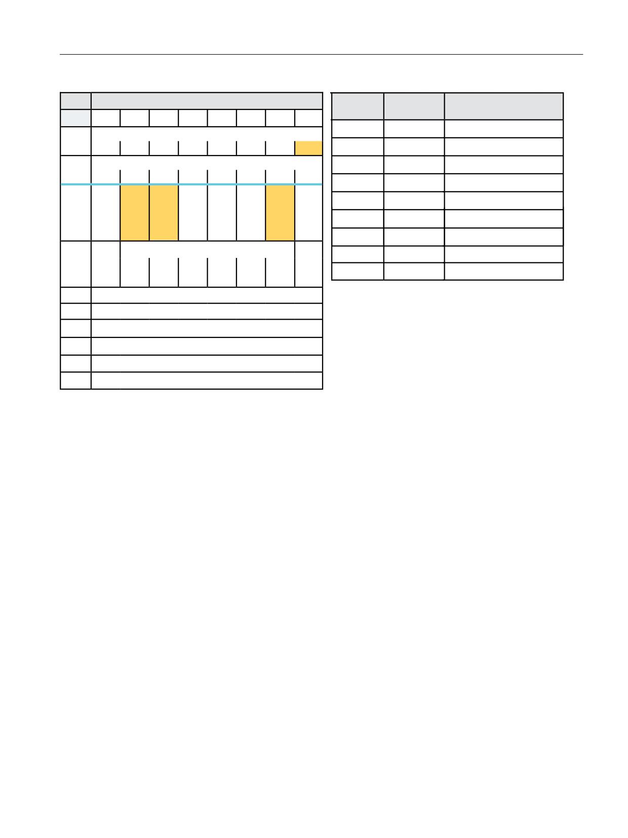
The following bytes in DB72 (Page 130) are filled during a tool change:
• DBB0.0; The interface defines the loading point. Interface 1 with loading point 1 is assigned
to the spindle.
• DBW(n+24); Number of the source magazine.
• DBW(n+26); Location number in the source magazine.
• DBW(n+28); Number of the target magazine.
• DBW(n+30); Location number
These target addresses are communicated to FC8/FC6 via the following parameters:
• "NewToolMag" contains DB72.DBW(n+20)
• "NewToolLoc" contains DB72.DBW(n+26)
• "OldToolMag" contains DB72.DBW(n+28)
• "OldToolLoc" contains DB72.DBW(n+30)
• "Status (Page 161)" conveys whether the tool change has been successfully completed.
The interface is then filled as follows (n = 4 for spindle 1)
Tool management
476
Function Manual, 10/2020, 6FC5397-1HP40-0BA1
Description of functions
8.7 Using manual tools
'%
/RDGLQJ XQORDGLQJ SRLQWV 1&. ! 3/&
)&
3DUDPHWHUV
0HDQLQJ
%\WH
%LW
%LW
%LW
%LW
%LW
%LW
%LW
%LW
6WDUW
758(
7UDQVIHU LV EHLQJ VWDUWHG
,QWHUIDFH 66 DFWLYH
'%%
7DVN,GHQW
'% LQWHUIDFH
66
66
66
66
66
66
66
66
,QWHUIDFH 66 DFWLYH
7DVN,GHQW1R
,QWHUIDFH
'%%
66
66
66
66
66
66
66
66
1HZ7RRO0DJ
'% '%:
6RXUFH PDJD]LQH RI QHZ WRRO
7RRO
5H
,QVHUW
2OG WRRO
7
3UHSDUH
([HFXWH
2EOLJD
UHPDLQV
SODFH
PDQXDO
LQ %/
FKDQJH
FKDQJH
WRU\
1HZ7RRO/RF
'% '%:
6RXUFH ORFDWLRQ RI QHZ WRRO
LQ
PDQXDO
WRRO
Q
0
FKDQJH
'%%
VSLQGOH
WRRO
2OG7RRO0DJ
'% '%:
7DUJHW PDJD]LQH IRU ROG WRRO
2OG7RRO/RF
'% '%:
7DUJHW ORFDWLRQ IRU ROG WRRO
'DWD LQ
5HVHUYHG
$FNQ
6WDWXV
2SHUDWLRQ FRPSOHWHG
'%
6WDW
'%%
0XOWLWRRO/RF
0XOWLWRRO ORFDWLRQ
'%:
%XIIHU
,' IL[HG YDOXH
'%:
/RFDWLRQ LQ EXIIHU
'%:
0DJ 1R 6RXUFH IRU QHZ WRRO
([DPSOH 5HSODFH PDQXDO WRRO
'%:
/RFDWLRQ 1R 6RXUFH IRU QHZ WRRO
'% '%:
'% '%:
'%:
0DJ 1R 7DUJHW IRU ROG WRRO
'% '%:
'%:
0DJ 1R 7DUJHW IRU ROG WRRO
'% '%:
Figure 8-39
Change manual tool DB72
Tool management
Function Manual, 10/2020, 6FC5397-1HP40-0BA1
477
Description of functions
8.7 Using manual tools
PLC sample programs
The following sample programs (description of DB150 (Page 122)) show the acknowledgement
of loading via interface 1. To this end, the network is programmed in an FC150 user block.
Sample program "Load magazine"
NETWORK TITLE =Carry out acknowledgement of change
U
E 87.7;
//Signal for the acknowledgement
U
DB72.DBX 0.0; //Interface 1 active
U
DB72.DBX 4.1; //Change active
U
DB72.DBX 4.2;
FP
M 156.1;
SPBN
M690;
L
2;
T
DB150.DBB 0; //DB72
L
1;
T
DB150.DBB 1; //Interface 1
L
DB72.DBW 24;
OW
W#16#0;
SPN
M694; //T0? No->
T
DB150.DBW 2;
T
DB150.DBW 4;
SPA
M693;
M694:
L
DB72.DBW 20;
T
DB150.DBW 2; //Source magazine of new tool
L
DB72.DBW 22;
T
DB150.DBW
4; //Source location of new tool
M693:
L
DB72.DBW 28;
T
DB150.DBW 6; //Target magazine for old tool
L
DB72.DBW 30;
T
DB150.DBW 8; //Target location for old tool
L
1;
T
DB150.DBW 10; //Status 1
U
DB72.DBX 5.7;
SPB
M692;
L -1;
T
DB150.DBW 12;
SPA
M691;
M692:
L
DB1072.DBW 10;
T
DB150.DBW 12; //Multitool location
M691:
SET ;
S
DB150.DBX 16.0; //Start FC6
M690:
NOP 0;
Tool management
478
Function Manual, 10/2020, 6FC5397-1HP40-0BA1
Description of functions
8.7 Using manual tools
Example of a transfer with FC6
NETWORK
TITLE =Tool management status transfer
CALL
FC 6 (//Tool management transfer block
Start
:= DB150.DBX 16.0,//Start
TaskID
:= DB150.DBB 0,
TaskIDNo
:= DB150.DBB 1,
NewToolMag
:= DB150.DBW 2,//Pos new tool
NewToolLoc
:= DB150.DBW 4,
OldToolMag
:= DB150.DBW 6,//Pos old tool
OldToolLoc
:= DB150.DBW 8,
Status
:= DB150.DBW 10,//Status
MultitoolLoc
:= DB150.DBW 12,
Ready
:= DB150.DBX 16.1,
Error
:= DB150.DBW 14);
U
DB150.DBX
16.1; //Prompt ready
R
DB150.DBX
16.0; //Reset start
L
DB150.DBW
14; //Error information
L
0;
<>I
;
//Evaluate error
R
DB150.DBX
16.0; //Reset start
Old tool manual tool, new tool magazine tool
The old tool can be removed from the spindle by hand and the new tool can be loaded into the
spindle from a real magazine. A tool change could go as follows:
1. "Execute change" job.
2. Remove tool from the spindle (interim acknowledgement spindle -> loading point)
3. New tool from magazine to gripper 1 (interim acknowledgement magazine -> gripper 1)
4. New tool from gripper 1 to spindle (interim acknowledgement gripper 1 -> spindle)
5. Acknowledge "Execute change" job.
In accordance with the individual steps, the DB72 and the individual interim acknowledgements
must be programmed in the user program via FC6/FC8.
See also
FC8: TM_TRANS - transfer block for tool management (Page 157)
Tool management
Function Manual, 10/2020, 6FC5397-1HP40-0BA1
479
Description of functions
8.8 Search for tool
8.8
Search for tool
8.8.1
Strategies for tool searches
The tool search is initiated by the preparation command (T selection). The search begins for a
tool to load in the spindle.
In the default setting, tool searches are always performed on a magazine-specific basis, i.e. with
this setting for the search strategy, the search is performed in the magazine from which the last
change was carried out.
Tool group
The tools with the same identifier (name or Ident) but different duplo numbers are combined to
form one tool group. The tool identifier is programmed in the part program with the NC address,
i.e. only the tool group is specified during preparation.
Tool search
In order to move a tool from a physical magazine to a spindle it must have the following
characteristics:
• Tool status must be "enabled"
• Tool status must not be "disabled" (exceptions: NC command TCA as well as PLC interface
signal "Tool disable inactive")
• Tool status may not be "currently being changed"
• Tool must not already be used by a spindle other than the requesting spindle.
• Tool must be present in the magazine location (except for manual tools)
• This magazine must be linked to the requesting spindle via a distance relationship
($TC_MDP2)
• This magazine must not have the status "disabled".
The explicit tool is requested at the time of the tool call. The request is made for a special spindle
(general tool holder); this is the number of the address extension of T. At this point in time, user
interface DB72 is written for the relevant spindle and must be evaluated by the PLC user program.
The tool search strategy is defined using the system variable $TC_MAMP2 for the TO area, with
the system variable $TC_MAP10[Mag_No] magazine-specific. With bit 0 to bit 1, a search is
made according to the criteria active tool and lowest duplo number. The "search criterion" for
tool wear uses bit 3 to bit 4. Bit 7 is used to set whether the tool search is made on a magazine-
for-magazine basis or across all linked magazines.
Setting bit 7=1 means that the search strategies defined using bits 0, 1, 2 start with the search
from the 1st magazine of the distance table. (The sequence in the distance table is defined using
the programming sequence of $TC_MDP2.) The standard setting is bit 7=0. The search starts in
the magazine from which the previous tool that was loaded was taken.
Setting bit 6 means that a search is first made in the magazine currently being considered. This
is only effective in conjunction with bit 7=1. The strategies, where the search always starts in the
Tool management
480
Function Manual, 10/2020, 6FC5397-1HP40-0BA1

Description of functions
8.8 Search for tool
first magazine of the distance table are described in Section "Magazine blocks $TC_MAMP
(Page 199)".
Note
Bit 3 = 1 and bit 4 = 1 (search criterion "tool wear") are only significant when the monitoring
function is active (defined by $TC_TP9). Otherwise they have no effect on the suitability check.
The monitoring functions are essentially cutting edge-specific. This means that the wear values
of all cutting edges of the tool are regarded. Application of this search strategy is generally not
practical for multi-edge tools.
Note
The tool search strategies apply equally for all magazine types (chain, box-type and circular) but
not for the buffer magazine.
Search strategies for tool search ($TC_MAMP2 or $TC_MAP10)
$TC_MAMP2/$TC_M
Search strategies
Meaning
AP10
Bit0=0
Search sequence
Take the first available tool found in the tool group. The search starts in
the magazine from which the last change took place (default setting).
Bit0=1
Active tool in the magazine
Select the "active" tool in the magazine of the previously changed tool,
otherwise search for replacement tool with lowest duplo number. If no
tool is found in this magazine, the search is continued in the other
associated magazines.
Bit1
Next tool
Search for the next replacement tool at the shortest possible distance
from the current magazine position.
Bit2
Active tool
Select the "active" tool, otherwise the replacement tool with the low-
est number contained in $TC_TP10 is searched for.
Bit3
Lowest actual value
Search for tool in the group with the lowest actual value for the moni-
tored quantity.
Bit4
Highest actual value
Search for tool in the group with the highest actual value for the
monitored quantity.
Bit5
Reserved
Bit6
Search current magazine
First searches in the magazine currently being considered (this is only
effective in conjunction with bit 7=1)
Bit7=0
Starting point of the tool search
The tool search starts in the magazine from which the last changed
tool came.
Bit7=1
Starting point of the tool search
The tool search always starts in the 1st magazine in the distance table.
Note
Bit7=1 + bit0=1 or bit2=1, if an "active tool" is not found in the magazine, then - if available - the
active tool is selected from another magazine linked to the tool holder.
Tool management
Function Manual, 10/2020, 6FC5397-1HP40-0BA1
481
Description of functions
8.8 Search for tool
Tool in disabled magazine location
Tools that are located in a disabled magazine location ($TC_MPP4, Bit 0=1) cannot, after a tool
change, be returned to the original magazine because that location is now disabled. With
machine data MD22562 $MC_TOOL_CHANGE_ERROR_MODE, you can set whether tools
located in disabled magazine locations will be included in the search:
• $MC_TOOL_CHANGE_ERROR_MODE Bit 8=0: Tools in disabled magazine locations are not
included in the search (factory setting).
• $MC_TOOL_CHANGE_ERROR_MODE Bit 8=1: Tools in disabled magazine locations are
included in the search. With $TC_TP8 Bit 17=1, you can mark tools so that they can also be
placed in a disabled magazine location or adjacent location with $TC_MPP6, see also Tool-
related data $TC_TP (Page 179).
Tool with the status "to be unloaded"
The machine data MD22562 $MC_TOOL_CHANGE_ERROR_MODE is used to set whether tools
with this status are to be taken into consideration during the tool search:
• $MC_TOOL_CHANGE_ERROR_MODE, Bit 9 = 0: A tool that has the status "to be unloaded"
($TC_TP8, Bit 10 = 1) continues to be considered during the tool search. That is the active
default setting.
• $MC_TOOL_CHANGE_ERROR_MODE, Bit 9 = 1: A tool that has the status "to be unloaded"
($TC_TP8, Bit 10 = 1) is treated like a disabled tool, i.e. it is no longer taken into consideration
during a tool search and can no longer be selected within the scope of T programming.
Example, tool search routine
A tool change at a spindle shall take place.
The search sequence for the correct tool is as follows:
1. The control checks whether the tool which is called is already located on the spindle.
2. If buffer locations are linked to the spindle (see $TC_MSLR), the control checks whether a
suitable tool is already located in one of these.
3. The tool search starts in the 1st magazine of the distance table ($TC_MDP2) according to the
selected search strategy.
(Applies only if bit 7 of $TC_MAMP2 = 1; otherwise, the search starts in the magazine from
which the last loaded tool was fetched.)
4. If no tool is found in the first magazine, the search is repeated in the next magazine of the
distance table.
5. If all the magazines that are linked to the spindle have been searched and no suitable tool
found, the search is terminated with an alarm (22069 or 22068).
6. If the function "manual tool" is active, after an unsuccessful search in the magazines - a search
is made in the TO unit for an unloaded tool, but a tool that can also be used. If none is found,
the search is terminated with an alarm.
Any suitable tool with the programmed identifier found (not disabled) in one of the stages
described above will be used.
Tool management
482
Function Manual, 10/2020, 6FC5397-1HP40-0BA1
Description of functions
8.9 Empty location search
8.9
Empty location search
8.9.1
Empty location search for a tool - from spindle to magazine
With the T preparation command, a matching empty location is automatically searched for the
spindle tool. The location in which the new tool is stored is still occupied at this time and cannot
therefore be identified as an empty location, the 1:1 interchange is the exception.
Note
Generally, a search is made for an empty location in that magazine from which the current tool
in the toolholder was taken.
Fixed location coding
When searching for an empty location for fixed-location coded tools its previous location in the
magazine is usually retained.
If the search for an empty location for a fixed-location-coded tool is started with a specific
magazine number, that number is ignored. The old tool location is defined as an empty location.
If this number is however an internal magazine number (for a loading or buffer magazine), then
the number is explicitly taken into consideration and the fixed location coding is ignored. This
case arises when loading/unloading tools.
If a location search for a fixed location coded tool is initiated using a specific magazine number
and magazine location number, the fixed location coding is ignored and the specified location
checked as a suitable location for the tool. This is used in the HMI function "Relocating".
Variable location coding
Initially, the procedure for an empty location search is the same as that for a fixed location-coded
tool. If this check fails, the search for a free location is continued. The search is performed
according to the selected search strategy ($TC_MAMP2 / $TC_MAP10). If the search cannot find
an available location with the specified location type in this magazine, a new search operation
based on the location type hierarchy is started in the magazine. A location is only then
considered as a suitable type of location when it applies that "Location type of the location" is
larger than "Location type of the tool", whereby the "larger than" relationship is defined by the
location-type hierarchy. If no free location is found in this magazine, the search is continued in
the next magazine (search strategy).
Tool management
Function Manual, 10/2020, 6FC5397-1HP40-0BA1
483

Description of functions
8.9 Empty location search
8.9.2
Search strategy for empty locations
Search strategy
The strategy can be defined with the magazine configuration according to which the search is
made in magazines of TO units for an empty location. If it involves a box-type magazine, then the
search is executed according to the default strategy (forwards search starting at the first location
number).
Possible strategies are listed in the table.
$TC_MAMP2
Search strategies
Meaning
Bit 8 = 1
Forwards search
The search takes place from location No. 1 in ascending
order.
256
Bit 9 = 1
Forwards search
The search takes place from the current location at the
change position in ascending order.
512
Bit 10 =1
Backwards search
The search takes place backwards starting from the last
location No.
1024
Bit 11 = 1
Backwards search
The search takes place from the current location at the
change position backwards.
2048
Bit 12 = 1
Symmetrical search
The search starts at the current location number at the
change position (1st location left, 1st location right,
4096
2nd location left, 2nd location right, etc.).
Bit 13 = 1
1:1 exchange
If the location type and size of the old and new tool are the
same, the magazine location of the "new" tool to be loa-
ded is transferred to the "old" tool to be unloaded - and
vice versa.
The 1:1 interchange acts in addition to other selected
search strategies. If possible, the 1:1 exchange is treated
as a priority.
Bit 14
Magazine search strategy
=0
First search the magazine with a search run across the
location types of the hierarchy of the tool type. If no lo-
cation is found, then a search run is performed across the
magazines.
=1
Search the location type of the tool in the magazine. If
nothing is found, search run across the magazines. If a
location is still not found, then a search run is repeated
across all magazines with the next location type from the
type hierarchy.
See also Search strategy across magazines (Page 496).
Note
The empty location search strategy is set TO-specific using $TC_MAMP2, magazine-specific using
$TC_MAP10. If the magazine-specific search is not set, when the NC boots, it copies the value
from MAMP2 to MAP10.
Tool management
484
Function Manual, 10/2020, 6FC5397-1HP40-0BA1
Description of functions
8.9 Empty location search
Definition of the current magazine position
The current magazine position at the change location is stored in magazine parameter (system
variable) $TC_MAP8. The value is automatically updated by the PLC acknowledgement of a
command, if the new tool is moved. If the magazine or tool is moved without a task from the NC,
the user must correct the actual position. An NC cycle or also the PLC can write to parameter
$TC_MAP8. Either by writing the OPI variable (selected with NCVAR selector block TM; variable
magNrPaces) or with the FC 8/FC 6 (with the parameters TaskIdent=4 TaslIdentNo=channel
number, status=5, OldToolMag=9998,OldToolLoc=1). The current position is parameterized
(referred to spindle) in NewToolMag and NewToolLocspindle.
8.9.3
Search procedure for empty locations
The following apply as criteria for the empty location search:
• Location type must coincide with location type of tool. A hierarchy is taken into account.
• Check the tool size.
• Location must have the status "free".
• Location must not be "disabled".
• Magazine must not be "disabled".
The essential search criterion for the empty location search is the magazine location type. The
magazine location type must match the magazine location type entered in the tool-specific data
($TC_TP). The magazine is searched. Each location is checked. If a suitable location is found the
search is terminated.
If a matching location is not found, then a check is made whether there is a magazine location
type hierarchy for the magazine-location type that is entered in the tool. If there is none, the next
magazine is taken if there are further magazines available. If there is a defined hierarchy, then
the search routine is repeated starting at the magazine that has just been searched. If this search
is also unsuccessful, the search moves to the next magazine, assuming another one is available.
Note
With oversized tools, the location types of the adjacent location are not considered.
8.9.4
Search strategy, 1:1 exchange (old for new)
With this search option, the magazine location of the "new" tool (tool to be loaded) is made
available as the empty location for the ’old’ tool (tool to be unloaded).
It is not assumed that the "new" tool is stored in the magazine location. It only needs to have
been loaded (it may be located on a gripper, for example). If the location in question is not
suitable for the "old" tool, then another appropriate empty location is sought.
Description of function
The new search strategy for an empty location is preset in the already existing bit-coded system
variable $TC_MAMP2 with bit 13.
Tool management
Function Manual, 10/2020, 6FC5397-1HP40-0BA1
485

Description of functions
8.9 Empty location search
If 2 tools (new and old tool) are exchanged 1:1, then the two tools are marked. For this purpose,
bit 14 = 1 is set in tool status ($TC_TP8).
Boundary conditions
With this empty-location search strategy, the NC checks a magazine location that at the point of
time of making the check is normally identified as still occupied by the "new" tool or is still
"reserved for tool from buffer location". This location is defined as an empty location for the "old"
tool if the check gives a positive result.
If the new or old tool is coded as a fixed location tool or the tool size or the location type are not
identical, then the strategy is not used.
Note
The PLC program has to execute the tool transportation operations in the correct sequence for
the tool change:
Remove "new" tool from the magazine location.
Bring the "old" tool to the magazine location.
Otherwise damage may occur to the machine or tool.
The 1:1 exchange can be set as the only search strategy for the buffer magazine (9998).
The empty location search strategy is only effective within tool changes programmed in the part
program. PI services or language commands for an empty location search cannot use this.
Example
This strategy is especially suitable for use with double grippers and tools of the same type (same
size and same location type).
The already defined system variable $TC_MAMP2 includes an additional setting option for the
new empty-location search strategy.
Bit
Value
Meaning
0
Tool search strategy
7
8
Tool management
486
Function Manual, 10/2020, 6FC5397-1HP40-0BA1

Description of functions
8.9 Empty location search
Search strategy for empty location
13
The magazine location for the "new" tool to be loaded is transferred to the "old"
tool to be replaced and vice versa.
Precondition is that the tool sizes and location types of the tools match or are
compatible in terms of location hierarchy.
The location of the "new" tool is detected as empty location for the "old" tool even
if the "new" tool is still positioned at this location at the time the check is per-
formed.
The tool transport must be designed so that the "new" tool is first removed from
the magazine location before the "old" tool is taken to it.
Otherwise, depending on the sequence of the mechanical tool transport opera-
tions, the machine could be damaged.
The type of empty location search is determined via the bits 8 through 12.
It is not possible for tool change to take place if the "old" tool does not have a
magazine location assigned to it. The tool search strategy is then determined via
bits 8 to 12.
8.9.5
Tool search in wear group
Overview
If "Wear group" function is used:
In the case of existing tool-search strategies, the search refers only to the active wear group,
i.e. only those tools are considered during a search within a tool group that are at magazine
locations of the active wear group.
Tools in magazine locations with wear group number 0 are also checked for suitability.
If there are no spare tools available, then all $TC_MPP5 parameters of the current groups are
negated and all locations are individually disabled by this. $TC_MAP9 is also negated (wear
group disabled). All active tools are reset if this response has been configured via $TC_MAMP3
(bit 1 = 1).
The next wear group is called ($TC_MAP9 is assigned the number of the next wear group that
can be activated).
If no further groups are available the search is terminated with an alarm. In such a case, the
disabled tools should be replaced, if necessary. In order to enable the wear groups again, the
wear group numbers of the magazine locations must be again set to values > 0.
Tool management
Function Manual, 10/2020, 6FC5397-1HP40-0BA1
487
Description of functions
8.9 Empty location search
Search strategies
There are two search strategies for finding the next available wear group that can be activated:
• Starting from the lowest magazine location number, the replacement tools are searched
through location by location according to the way they are sorted internally (time-optimized
search).
The wear group that is the subject of the search is found by searching for the first tool that is
assigned to a wear group that can be activated.
• A search is made for the wear group with the lowest enabled wear group number (the first
that can be activated).
Search in several magazines
The magazine definition for a machine defines whether the search is to be performed in one or
several magazines.
If the search is conducted in several magazines while several wear groups are being used, always
make sure that a wear group can only ever be assigned to one magazine.
The search is conducted according to the following priorities:
1. The search is performed in a magazine according to the configuration and strategy.
2. The search is performed in the active wear group.
3. The set tool-search strategy is taken into consideration.
Activation
In order to work with wear groups, the magazine locations must be assigned to wear groups via
system variable $TC_MPP5 and the function must be activated via the machine data.
In addition, the number of the wear group with which machining is to commence must be
assigned to system variable $TC_MAP9 of the magazine to be selected (value > 0).
For the configuration of the machine, it is defined by $TC_MAMP3 how the tool status shall
change when switching from one wear group to the next (defaulted is an unchanged tool
status).
Note
The PLC signal "tool selection from disabled tools" has no effect when resetting the tool state.
Example: Tool search in wear group
$TC_MAMP3 = 3 - change "active" status of tools
Target
• The tools must be set to "active" when a wear group is activated.
• When a wear group is disabled all the tools contained in that wear group should also be
deactivated.
Tool management
488
Function Manual, 10/2020, 6FC5397-1HP40-0BA1
Description of functions
8.9 Empty location search
Specifications
• Circular magazine number 1 (6 locations)
• The circular magazine is to be divided into two parts:
Locations 2 and 3 form wear group 1.
Locations 4, 5, 6 and 1 form wear group 2.
• $TC_MAP9 = 1 (wear group 1 is "active")
Assignment to the wear group is achieved by:
$TC_MPP5[1,2] = 1
TC_MPP5[1,3] = 1
$TC_MPP5[1,4] = 2
$TC_MPP5[1,5] = 2
$TC_MPP5[1,6] = 2
$TC_MPP5[1,1] = 2
The tools with T=10 and T=11 are assigned to wear group 1. As wear group 1 was activated, tools
T=10, 11 were therefore also set to "active" (via $TC_MAMP3, bit 0=1).
Note
NC command SETTA (see Section "SETTA - Activate tool from wear group (Page 261)") can also
be used to set these tools to active.
Tool assignment:
$TC_MPP6[1,2] = 10
;T=10 has identifier "Tool1"/duplo no.=1 tool state "ac-
tive"
$TC_MPP6[1,3] = 11
;T=11 has identifier "Tool2"/duplo no.=1 tool state "ac-
tive"
$TC_MPP6[1,4] = 12
;T=12 has identifier "Tool1"/duplo no.=2
$TC_MPP6[1,5] = 13
;T=13 has identifier "Tool2"/duplo no.=2
$TC_MPP6[1,6] = 14
;T=14 has identifier "Tool1"/duplo no.=3
$TC_MPP6[1,1] = 15
;T=15 has identifier "Tool2"/duplo no.=3
$TC_MAMP2 = 1
The active tool is to be searched for. If none is available, the next possible tool is to be located.
This tool search strategy includes a check for the number of the active wear group. That is, only
those tools are considered during the search for a tool with the status "active" that are at
magazine locations and that have the number of the currently activated wear group.
T="Tool2"
Tool group "Tool2" consists of tools
T=11, 13, 15.
T=11 is positioned in a location of the active wear group (No. 1) and is "active". The result of the
tool search is T=11.
Machining is continued. T=11 is "disabled" during machining.
Tool management
Function Manual, 10/2020, 6FC5397-1HP40-0BA1
489
Description of functions
8.9 Empty location search
T="Tool1"
Wear group 1 is still active. T=10 is identified as active and suitable for use.
T="Tool2"
The tool group of identifier "Tool2" now has no active tool (has been disabled) and a new tool has
not yet been set to "active". This step is not taken until "Tool2" is reprogrammed. The tools of the
group are examined. In the locations of wear group 1, which is still active, there is no tool with
identifier "Tool2" or any other suitable tool.
This condition causes the next wear group (2) to be activated. Wear group 1 is now no longer the
active wear group. The status of the tools in wear group 1 has been reset (not "active"), as
configured by $TC_MAMP3, bit 1=1.
The tool search is now performed exclusively in wear group 2. Its tools were set to "active" when
the wear group was activated (one tool from each tool group in the wear group because setting
of $TC_MAMP3, bit 0=1).
The turret is now assigned as follows:
$TC_MPP6[1,2]=10
T=10 has identifier "Tool1"/duplo no.=1 ;tool state "not active"
$TC_MPP6[1,3]=11
T=11 has identifier "Tool2"/duplo no.=1 ;tool state "disabled"
$TC_MPP6[1,4]=12
T=12 has identifier "Tool1"/duplo no.=2 ;tool state "active"
$TC_MPP6[1,5]=13
T=13 has identifier "Tool1"/duplo no.=2 ;tool state "active"
$TC_MPP6[1,6]=14
T=14 has identifier "Tool1"/duplo No.=3
$TC_MPP6[1,1]=15
T=15 has identifier "Tool2"/duplo No.=3
In the example T=13 is now taken as the next available tool "Tool2".
Note
The tool search only then generates an alarm when no further spare tool available in the tool
group with the given identifier is found and no further wear group can be activated.
Control system response
Control behavior at Power On, mode group change, reset, block search and Repos is described
below.
Configuration $TC_MAMP3, bit 0=1 (activate internally)
At Power On, the NC checks whether the value of $TC_MAP9 > 0, i.e. whether a wear group has
been selected. In this case the tools of that wear group are checked again and the value for
$TC_MPP5 of each location in question is set to positive. In addition, the status of the tool in the
location is set to "active".
Configuration $TC_MAMP3, bit 1=1 (disable internally)
At Power On, the NC checks whether $TC_MAP9 is negative, i.e. a wear group has been disabled.
In this case the tools of the disabled wear group are checked again and the value for $TC_MPP5
of the location in question is set to negative. The "active" status of the tool in the location is reset.
Tool management
490
Function Manual, 10/2020, 6FC5397-1HP40-0BA1

Description of functions
8.10 Location type hierarchies
8.10
Location type hierarchies
8.10.1
Hierarchies of location types in magazines
Hierarchies of location types
If a tool is to be loaded into a real magazine, the location type of the tool decides which locations
are available in the magazines. The system variables $TC_TP7 and $TC_MPP2 must be defined
and match, i.e. $TC_MPP2 is of type 'match all'. The tools of any type fit into those locations.
To optimize the assignment of locations in a magazine, hierarchies can be defined for the
magazine locations. The hierarchy level of the location type of the tool decides which locations
in a real magazine will be available for the tool.
Application example:
For example, by using location type hierarchies, you can ensure that heavy tools are stored at the
center of the magazine, but that the preferred storage location for light tools is in the outer
region of the magazine. If there are no vacant magazine locations in the outer region, magazine
locations at the center of the magazine can also be occupied by lighter tools. Several "weight
classes" can be defined, which are mapped onto the hierarchy levels.
When a tool search is started, a suitable magazine location is searched for, from the highest to
the lowest hierarchy level. The highest hierarchy level is equal to the location type of the tool
conducting the search and the lowest hierarchy level is equal to the location type "match all". The
next free location type with the highest hierarchy level is then selected.
It is possible to define several hierarchies. The valid hierarchy is then determined by the
magazine location type of the tool conducting the search.
Setting important machine data
When hierarchies are defined, the number of possible hierarchies and the number of entries in
a magazine location hierarchy must be defined.
Machine data
Description
MD18078 MM_MAX_NUM_OF_HI-
In this machine data, you define the maximum possible number of hierarchies (up to 32)
ERARCHIES
in MM_MAX_NUM_OF_HIERARCHIES. "0" means that the magazine location type hierar-
chy is not available.
MD18079 MM_MAX_HIERAR-
In this machine data, you define the maximum possible number of location types in a
CHY_ENTRIES
magazine location type hierarchy (up to 32) in MM_MAX_HIERARCHY_ENTRIES.
Tool management
Function Manual, 10/2020, 6FC5397-1HP40-0BA1
491

Description of functions
8.10 Location type hierarchies
Defining a hierarchy
The location types of a tool and magazine locations are specified by numbers. Accordingly, the
hierarchies are also specified by numbers, which are defined in system variable $TC_MPTH:
System variable $TC_MPTH
$TC_MPTH[hierarchyNo - 1, hierarchyLevel - 1]
hierarchyNo
Number of the hierarchy if several hierarchies are defined
0 < hierarchy-no ≤ $MN_MM_MAX_NUM_OF_HIERARCHIES
hierarchyLevel
Hierarchy level within a hierarchy
0 < hierarchy-level ≤ $MN_MM_MAX_HIERARCHY_ENTRIES
For examples of hierarchy definitions, see also Magazine location type hierarchy $TC_MPTH
(Page 195).
Hierarchy types
Two hierarchy types are implemented. With system variable $TC_MAMP2, you define how a
matching location type will be searched for:
• $TC_MAMP2, Bit15=0: Conventional location type hierarchy
• $TC_MAMP2, Bit15=1: Alternative location type hierarchy
Note
Hierarchy will be deleted
If you move from one location type hierarchy to the other, alarm 17255 is output warning you
that all hierarchy definitions will be deleted ($TC_MPTH[x,y]=9999).
Definitions
• $TC_MPTH = “9999” is the default setting of the system variables and designates a non-
defined location type. If this value is contained in a hierarchy, it will be interpreted as non-
existent and the search will move to the next lowest hierarchy level.
• $TC_MPTH = “0” defines the location type "match all". This value must not be included in a
hierarchy table ($TC_MPTH) because it is always placed at the end as the lowest hierarchy
level.
• Tools with location type "0" can only be loaded into magazine locations with location type
"match all".
• The location types of locations in internal magazines must also match the tool.
• Tools with a location type to which no hierarchy is assigned, are checked against a "mini
hierarchy". This mini hierarchy only consists of the highest hierarchy level (= location type of
the tool conducting the search) and the lowest hierarchy level (= location type "match all").
• The definition of the location type hierarchy always applies to one TO unit. This means that
the hierarchies and how they are selected are always defined with the cross-magazine system
variable $TC_MAMP2 and not with the magazine-specific system variable $TC_MAP10. The
relevant bits in $TC_MAP10 are defined by the corresponding bits in $TC_MAMP2.
Tool management
492
Function Manual, 10/2020, 6FC5397-1HP40-0BA1
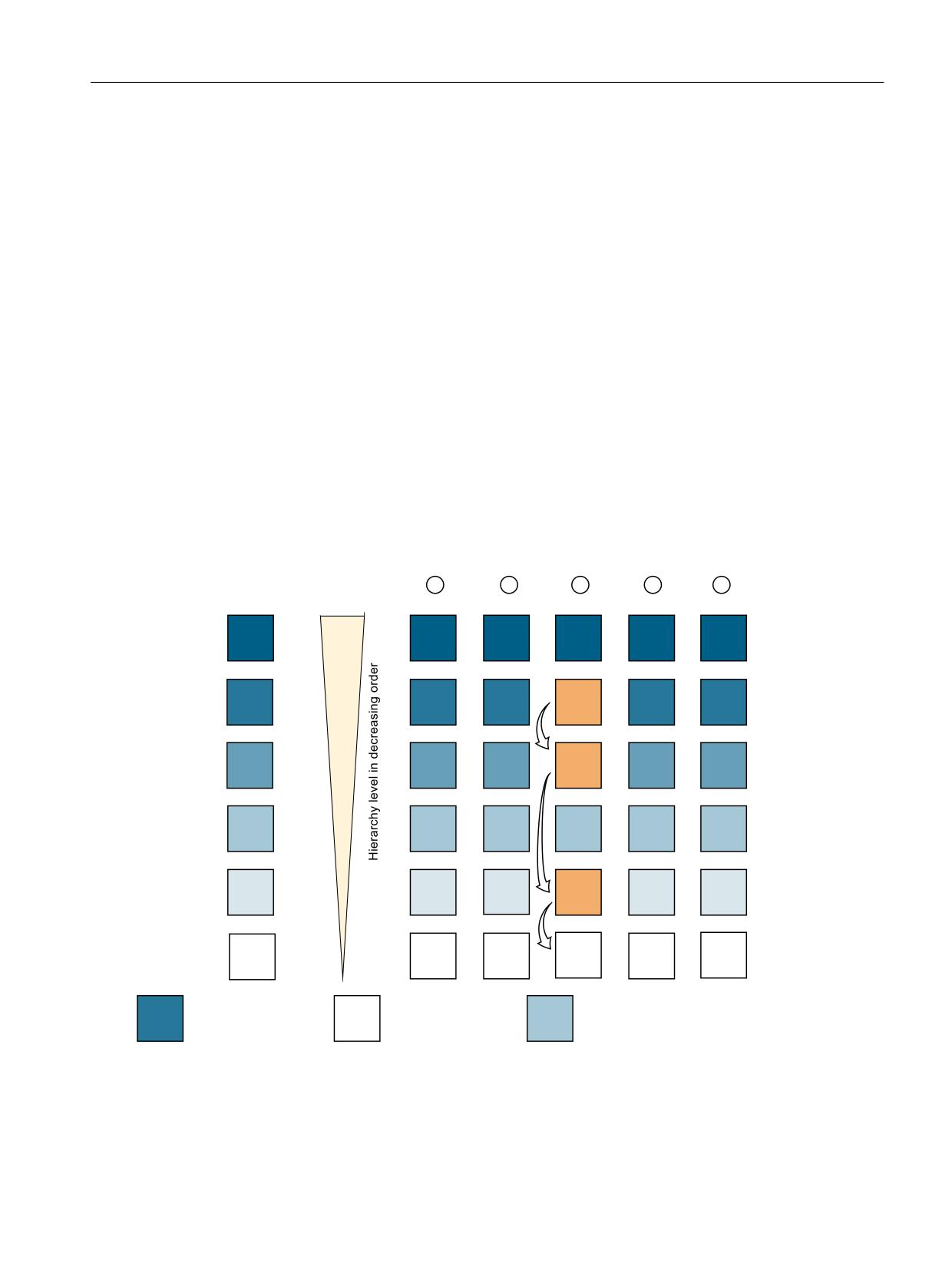
Description of functions
8.10 Location type hierarchies
System variables
You can request information about the configured magazine location type hierarchies with the
following system variables:
• $P_MAGNH / $P_MAGNHLT / $P_MAGHLT - Location type hierarchies (Page 317)
8.10.2
Conventional location type hierarchy $TC_MAMP2, Bit15=0
Conventional location type hierarchy
For this hierarchy type, the location type of the tool conducting the search is searched for in the
table of system variable $TC_MPTH[m,n]. If the location type is found, this hierarchy is used and
evaluated from this level right to the end.
Example:
Example: Search for an empty location for a tool with location type "21".
+LHUDUFK\ QXPEHU
+LHUDUFK\ RI
ORFDWLRQ W\SHV
PDWFK DOO
([DPSOH ORFDWLRQ
/RFDWLRQ W\SH
/RFDWLRQ W\SH
QRW
W\SH
PDWFK DOO
GHILQHG
Figure 8-40
Conventional location type hierarchy
Tool management
Function Manual, 10/2020, 6FC5397-1HP40-0BA1
493
Description of functions
8.10 Location type hierarchies
Location type "21" is found in hierarchy "3". The search for a free magazine location in hierarchy
"3" is performed according to the following scheme:
1. Search for location type "21", no hits?
2. Search for location type "3", no hits?
3. Search for location type "45", no hits?
4. Search for location type "match all" (="0")
The following applies to conventional location type hierarchies:
• In the system variable array $TC_MPTH, each location type must only exist once.
• The number of the hierarchy is not relevant to the hierarchy selection. This means:
hierarchies can be swapped and empty hierarchies (= all values of a hierarchy are "9999")
have no meaning.
8.10.3
Alternative location type hierarchy $TC_MAMP2, Bit15=1
Alternative location type hierarchy
In an alternative location type hierarchy, the location type of the tool for which a location is being
searched for directly determines the hierarchy in system variable $TC_MPTH[m,n].
First, a free magazine location of the relevant location type is searched for (basic level of the
hierarchy). If the search fails, the hierarchy with the number of the location type is searched.
Finally, a location of location type "match all" (= "0") is searched for.
Example:
An empty location for a tool with location type "2" is searched for.
Tool management
494
Function Manual, 10/2020, 6FC5397-1HP40-0BA1
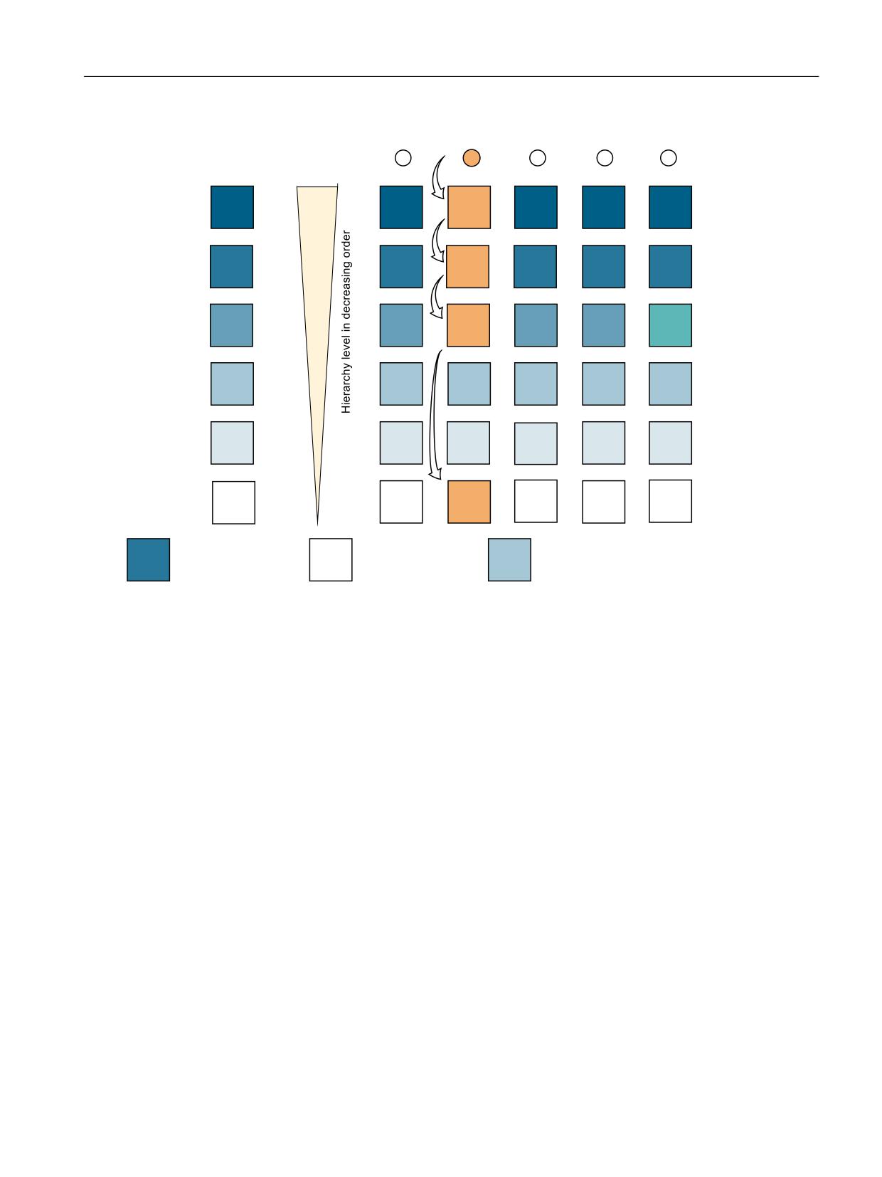
Description of functions
8.10 Location type hierarchies
+LHUDUFK\ QXPEHU
+LHUDUFK\ RI
ORFDWLRQ W\SHV
PDWFK DOO
([DPSOH ORFDWLRQ
/RFDWLRQ W\SH
/RFDWLRQ W\SH
QRW
W\SH
PDWFK DOO
GHILQHG
Figure 8-41
Alternative location type hierarchy
A free magazine location is searched for as follows:
1. Search for a free magazine location of location type "2" if the search fails:
2. Search acc. to hierarchy 2:
- Search for a free magazine location of location type "55", no match?
- Search for a free magazine location of location type "808", no match?
- Search for a free magazine location of location type "45", again no match?
3. Search for a free magazine location of location type "match all" (= "0").
It thus follows that:
• the array of system variables $TC_MPTH can contain location types more than once (see
location type "808" in the above example).
• Hierarchies must not be swapped
• For tools with location type > $MN_MM_MAX_NUM_OF_HIERARCHIES, the search is
performed with the "mini hierarchy".
Tool management
Function Manual, 10/2020, 6FC5397-1HP40-0BA1
495

Description of functions
8.10 Location type hierarchies
8.10.4
Search strategy across magazines
Search strategy
The search within a magazine or across magazine boundaries can be defined as a search
strategy. The search strategy is set with Bit14 of system variable $TC_MAMP2.
The set search strategy also applies to the "mini hierarchy", which consists only of the location
type of the tool and the general location type "match all".
Example magazines:
Hierarchy is defined as follows: 87 - 21 - 3 - 9999 - 62 - 0
Magazine 1
$TC_MPP2[1,1]=0
$TC_MPP2[1,2]=62
$TC_MPP2[1,3]=9999
$TC_MPP2[1,4]=521
$TC_MPP2[1,5]=3
$TC_MPP2[1,6]=21
$TC_MPP2[1,7]=87
$TC_MPP2[1,8]=21
$TC_MPP2[1,9]=62
$TC_MPP2[1,10]=3
$TC_MPP2[1,11]=0
Magazine 2
$TC_MPP2[2,1]=0
$TC_MPP2[2,2]=62
$TC_MPP2[2,3]=9999
$TC_MPP2[2,4]=521
$TC_MPP2[2,5]=3
$TC_MPP2[2,6]=21
$TC_MPP2[2,7]=87
Search within a magazine has priority
An empty location for a tool is first searched for within one magazine before the search is
continued in the next magazine. This search method is performed with the
setting $TC_MAMP2, Bit14=0. See also Strategies for tool searches (Page 480).
A tool of location type "21" is searched for.
∎
Magazine 1
Magazine 2
1
2
3
4
5
6
7
8
9
10
11
1
2
3
4
5
6
7
87
x
x
21
1
2
9
3
3
4
10
62
5
6
11
0
7
8
12
∎
x
x
x
x
① = hierarchy level
② = Other magazine location types (9999)
The search for an empty location is initially performed within magazine 1. If there were no empty
location in magazine 1, the search would continue in magazine 2. The numbers express the
priority of the matches.
Tool management
496
Function Manual, 10/2020, 6FC5397-1HP40-0BA1

Description of functions
8.10 Location type hierarchies
Search with priority to hierarchy
An empty location search for a tool starts with the search for a free magazine location with the
highest hierarchy level across all suitable magazines. Then the search is continued with the next
lowest hierarchy level, again across all suitable magazines.
This type of search is performed with the setting $TC_MAMP2, Bit14=1.
A tool of location type "21" is searched for.
∎
Magazine 1
Magazine 2
1
2
3
4
5
6
7
8
9
10
11
1
2
3
4
5
6
7
87
x
x
21
1
2
3
3
4
5
6
62
7
8
9
0
10
11
12
∎
x
x
x
x
① = hierarchy level
② = Other magazine location types (9999)
The empty location search starts in magazine 1 with the highest hierarchy. The search for an
empty location then continues within the hierarchy from magazine to magazine.
8.10.5
Mini hierarchies
Properties of mini hierarchies
A mini hierarchy is created for a location type that does not belong to any hierarchy. It consists
only of the location type itself and location type "match all" (="0").
The following example shows a magazine with a mini hierarchy of location types "0" and "521".
An empty location is searched for a tool with location type "521".
Hierarchy level
Magazine
1
2
3
4
5
6
7
8
9
10
11
521
1
0
2
3
Other
x
x
x
x
x
x
x
x
Search strategy "priority in magazine" in this case yields an empty location of location type "521"
at magazine location "4". In subsequent empty location searches, locations "2" and "3" are found
under location type "0".
Revoking a mini hierarchy
For compatibility reasons, it is possible to revoke a mini hierarchy with $TC_MAMP2 Bit16=1. The
empty location search then no longer differentiates between the general location type,
e.g."521", and location type "0" = match all. The search yields the next suitable location.
Tool management
Function Manual, 10/2020, 6FC5397-1HP40-0BA1
497
Description of functions
8.10 Location type hierarchies
The empty location search then follows the setting in $TC_MAMP2 Bit14, see also Search
strategy across magazines (Page 496).
Tool management
498
Function Manual, 10/2020, 6FC5397-1HP40-0BA1
Description of functions
8.11 Tool monitoring (workpiece count, tool life, wear)
8.11
Tool monitoring (workpiece count, tool life, wear)
8.11.1
Monitoring types
Quantity
The quantity monitoring, initiated by the NC command SETPIECE (Page 237), considers the
cutting edges of all of the tools that have been used. In this case, it must be observed that there
can be several spindles.
Service life
Tool life monitoring is only performed on the tool edge that is currently in use. As soon as the
path axes are moved (with the exception of G00), then monitoring time of the active cutting
edge is decremented. If the tool life for a cutting edge expires during machining, the tool is
disabled as a whole.
Wear
As is the case for the time and workpiece count (quantity) monitoring, the prerequisite for using
the wear monitoring function is that tool monitoring is enabled. In addition, wear monitoring
must be enabled using machine data (MM_TOOL_MANAGEMENT_MASK; Bit 5=1). The wear
parameters of the cutting edge correspond to the local offsets (additive offset parameters), see
Section "Location of use-dependent offsets fine (additive offsets) $TC_SCP (Page 176)".
Service life, quantity
The monitoring value runs from a value greater than 0 to 0. The monitoring setpoint has no
affect on the monitoring, this value is only evaluated when reactivating a tool.
Tool life, workpiece count and wear
The monitoring type for the tools is generally set when creating or loading. You can change the
monitoring type at any time by changing the setting for system variable MD $TC_TP9.
The tool management monitors a tool for tool life, workpiece count, tool wear state or additive
offset with prewarning limit.
The monitoring counter triggering the tool status change depends on the system variable
$TC_TP9 (= type of monitoring):
• $TC_TP9 = 0 → No monitoring
• $TC_TP9 = 1 → Time-monitored tool
• $TC_TP9 = 2 → Workpiece count-monitored tool
• $TC_TP9 = 4 → Wear-monitored tool
• $TC_TP9 = 8 → Additive offset
Tool management
Function Manual, 10/2020, 6FC5397-1HP40-0BA1
499
Description of functions
8.11 Tool monitoring (workpiece count, tool life, wear)
Several monitoring types can be activated simultaneously for one tool. Of the monitoring types,
only wear monitoring and additive offset monitoring are mutually exclusive.
If the monitoring criterion (tool life/workpiece count and wear) for a tool that is currently located
in the spindle expires, it remains in use. Machining is not automatically interrupted to replace the
tool with a replacement tool. The tool is not disabled until the next time it is selected. Since it is
no longer "available", a search is made for a replacement tool and the replacement tool is then
loaded into the spindle. The tool change has to be organized by the PLC or come from the NC
cycle.
Prewarning limit
The prewarning limits are defined via the following system variables:
• $TC_MOP1 - prewarning limit for tool life
• TC_MOP3 - prewarning limit for workpiece count
• $TC_MOP5 - prewarning limit wear
The monitoring counters count from a set setpoint > 0 down to zero. If a cutting edge has
reached its prewarning limit, then the whole tool is set to the status "Prewarning limit reached"
($TC_TP8[i]=4).
At the same time a message is output that a replacement tool may be required.
Monitoring threshold
The monitoring counters count from a set setpoint > 0 down to zero. When a tool's cutting edge
(one of up to 12 cutting edges) has reached its limit value, the whole tool is set to status
"monitoring threshold reached".
The setpoints are defined via system variables:
• $TC_MOP11 - tool life setpoint
• $TC_MOP13 - workpiece count setpoint
• $TC_MOP15 - wear setpoint
In wear or additive offset monitoring, the actual values of the monitoring counters are compared
with a maximum value. If the values of one cutting edge exceed its particular monitoring limit
values, the whole tool is set to status "disabled" = SUSPENDED.
Resetting a status
Once the prewarning limit or monitoring limit is reached, a tool is set to the status
LIMITWARNING or status SUSPENDED.
The states are reset by the following operations (manufacturer cycle, PLC, user):
• Monitoring counter is set to a value > 0.
• Monitoring counter is set to a value > prewarning limit.
• A new initial value for the monitoring counter is set.
• Reactivate the tool (HMI user interface or NC command) (RESETMON - NC command for
setpoint activation (Page 265))
Tool management
500
Function Manual, 10/2020, 6FC5397-1HP40-0BA1
Description of functions
8.11 Tool monitoring (workpiece count, tool life, wear)
The monitoring counters are the corresponding actual values:
• $TC_MOP2 - tool life - actual value
• $TC_MOP4 - workpiece count - actual value
• $TC_MOP6 - wear - actual value
The tool status changes automatically when the data changes. This means that the set status is
removed again when a limit is reached.
If the tool has several cutting edges, all of the cutting edges must be beyond the monitoring
limits.
Tool monitoring alarms
When the prewarning limit or the monitoring limit of a tool is reached, one of the alarms 6010,
6011, 6012, 6013 (cancel clear delete condition) is output for information purposes.
Note
Suppressing alarms
Alarms can be suppressed with machine data $MN_SUPPRESS_ALARM_MASK and
$MN_SUPPRESS_ALARM_MASK2.
With the NC command SETPIECE(...) or PI command _N_TMPCIT (= other workpiece counters) it
is possible for several tools to reach a limit value and therefore result in multiple alarms being
issued.
No alarm is output if a limit value is reached as the result of changing data via variable service
(OPI).
Check monitoring status
A check can be made during program execution by issuing the programmed tool change
command (e.g. "M06" for milling) without a T call to see whether a monitoring function has
responded. If it has, tool life management will search for a replacement tool and a request for
a tool change issued.
Enable memory and function
In general, in machine data
• MD18080 $MN_MM_TOOL_MANAGEMENT_MASK and
• MD20310 $MC_TOOL_MANAGEMENT_MASK
at least bits 0 and 1 must be set. This prepares the memory for the monitoring data and enables
the function.
Tool management
Function Manual, 10/2020, 6FC5397-1HP40-0BA1
501

Description of functions
8.11 Tool monitoring (workpiece count, tool life, wear)
Enabling tool life monitoring
For the tool life monitoring, in addition, in the channel-specific MD20320
$MC_TOOL_TIME_MONITOR_MASK, the spindle (the tool holder) or the spindles must be
specified, for which a tool life check should be performed. This machine data is bit-coded.
Example: MD20320 $MC_TOOL_TIME_MONITOR_MASK
• Value = 1, only spindle number 1
• Value = 2, only spindle number 2
• Value = 3, spindle numbers 1 and 2
8.11.2
Tool life monitoring
Monitoring of tool cutting edge
Tool life monitoring is only performed on the tool edge that is currently in use. The spindle (tool
holder) must have been activated beforehand (MD20320 $MC_TOOL_TIME_MONITOR_MASK =
spindle no.).
If MD20124 $MC_TOOL_MANAGEMENT_TOOLHOLDER is > 0, then for MD 20320, the tool
holder number is selected and not the spindle number.
Service life
Counting or monitoring is performed in milliseconds.
Disabled
If the remaining tool life is less than or equal to 0, the tool is set to "disabled".
After the next tool change it is no longer used.
Monitoring from the
The residual tool life is decreased whenever one of the 3 path axes is traversed
NC
at machining feedrate (e.g. G01). G00 traversing blocks are not "counted".
Monitoring from PLC
You can start and stop time monitoring with PLC signal "Time monitoring active"
DB21-DB30 (channel). Machine data 20310 is used to select whether this con-
trol type is active.
Prewarning limit
Entered during loading or via part program. When the prewarning limit has been
reached, the tool is assigned the status "Prewarning limit reached" (display in the
magazine list).
Special case, limit
The tool life of a tool expires while it is in use. A check is made as to whether this
values
disabled tool is re-programmed by a change operation (e.g. M06 without T
word), and whether the monitoring time has already elapsed. If yes, a replace-
ment tool is located.
$A-MONIFACT factor
By entering a channel-specific factor which is set before a tool is used for the first time, it is
possible to monitor the different degrees of tool wear resulting from machining different types
of workpiece material. The value by which the time value of the cutting edge is decremented is
multiplied by the current time measurement (from $A_MONIFACT). The write operation is
performed synchronously with the main run.
Tool management
502
Function Manual, 10/2020, 6FC5397-1HP40-0BA1
Description of functions
8.11 Tool monitoring (workpiece count, tool life, wear)
Start and stop the tool life decrementation
Tool life monitoring runs when geometry axes are not traversed with G00 (default setting).
The user can start and stop the time monitoring using PLC signal "Time monitoring active" (DB21
DBX1.3).
Which type of control is active is set via MD20310 $MC_TOOL_MANAGEMENT_MASK, bit 17.
The default setting (bit 17=0) is standard; i.e. traversing blocks not equal to G00 will increment
the time counter. PLC signal "Time monitoring active" is activated with bit 17 = 1.
Time monitoring hierarchy
The combination of system variable $A_MONIFACT and function "Program test active" produces
the following nested time monitoring structure:
Machine data MD20310 $MC_TOOL_MANAGEMENT_MASK defines the monitoring control via
G00 or via a PLC signal. Tools on spindles that are activated by machine data MD20320
$MC_TOOL_TIME_MONITOR_MASK, are time-monitored.
The VDI signal "Program test active" switches the momentarily valid time monitoring on or off;
i.e. "Program test active" has a higher priority than the actual time monitoring.
When time monitoring is active, the service life reduction (as defined by the internal clock) is
multiplied by the factor $A_MONIFACT and the result is subtracted from the current time count
of a tool edge mounted on the spindle.
8.11.3
Workpiece count monitoring
Changing the number of workpieces
The number of workpieces can be changed by:
• Operator action at the HMI
• With a part program command (SETPIECE)
• PI service (TMPCIT) by PLC or HMI-OEM
Workpiece counter per spindle
Every spindle has a "memory" for the cutting edges used on it. With program command SETPIECE
(1) the workpiece counter for the cutting edges that are used on the main spindle is
decremented by 1. The workpiece counter of each spindle can be addressed individually.
The workpiece counter must count all the tools that are used to produce a workpiece. Take into
account that the machine may have several spindles and that different tools can be used
simultaneously.
The cutting edge of a tool is only counted once per spindle.
The part program programmer who programmed SETPIECE can program the parameter as a
function of the material.
SETPIECE (factor * no. of workpieces)
Tool management
Function Manual, 10/2020, 6FC5397-1HP40-0BA1
503

Description of functions
8.11 Tool monitoring (workpiece count, tool life, wear)
Like the factor for time monitoring, this function allows a workpiece count that depends on the
process, the workpiece material or other factors.
Workpiece count can be deactivated via the channel DB.DBX29.5.
Monitoring from the NC
The workpiece counter is decremented each time that SETPIECE is pro-
grammed. When the prewarning limit is reached, an information alarm
is output. When the counter reaches the value=0, the tool is disabled
and an alarm is output. The next time the tool is called, the replacement
tool is loaded at change.
Set workpiece counter
Entered when creating or loading the tool or via the part program with
e.g. $TC_MOP4=500.
Decrement number of work-
The number of workpieces must be decremented at the relevant point
pieces
in the part program with the NC language command SETPIECE (x, y)
(e.g. SETPIECE(1) → workpiece counter for main spindle tools is decre-
mented by 1).
The function for decrementing the workpiece count is activated from
die PLC program using a PI command (TMPCIT).
Disabled
When the workpiece count has reached zero, the tool is disabled
Prewarning limit
Entered when creating or loading the tool or via the part program with
e.g. $TC_MOP3=50. When the prewarning limit has been reached, the
tool is assigned the status "Prewarning limit reached".
Special case, limit values
It is not possible to realize a workpiece count for any number of cutting
edges simultaneously! If the monitoring function has been enabled and
activated by machine data, then all spindles can be monitored together
at a time = "Number of cutting edges in the TO area" (= MD) for the
number of cutting edges.
An edge of a tool is only counted once per spindle.
8.11.4
Wear monitoring
The wear monitoring function is only available if the "Tool monitoring" system has been enabled
via machine data.
In addition, wear monitoring must be enabled using machine data (MD18080
$MN_MM_TOOL_MANAGEMENT_MASK, bit 5).
Definition
$TC_TP9 = 4; Wear monitoring is active for the tool.
$TC_TP9 = 8 can be set to select the "Additive offset" monitoring function if this is required.
$TC_TP9 = 4
The wear parameters for a tool edge are defined with system variables $TC_DP12, ..., $TC_DP20.
These are assigned directly to the edge geometry values TC_DP3, ...,$TC_DP11.
$TC_DP10 and $TC_DP11 describe "angles". The other parameters stand for the tool edge
lengths and radii.
Tool management
504
Function Manual, 10/2020, 6FC5397-1HP40-0BA1

Description of functions
8.11 Tool monitoring (workpiece count, tool life, wear)
Only these values are included in the monitoring, i.e. wear parameters $TC_DP19 and
$TC_DP20, which are analogous to system variables $TC_DP10 and $TC_DP11, are not taken
into account.
Note
Wear monitoring is performed automatically by the NC when the user changes the cutting edge
offsets.
Note
Wear monitoring does not monitor every single value but rather only the largest absolute value
of each of these maximum seven wear parameters ($TC_DP12, ..., $TC_DP18).
$TC_TP9 = 8
Wear parameters (system variables) of the cutting edge can be found in the additive offset
parameters.
Analog to wear, the following system variables are monitored for the additional location-specific
offsets of the cutting edge:
• $TC_SCP12, ... $TC_SCP18
First additive offset for the cutting edge (if defined)
• $TC_SCP22, ... $TC_SCP28
Second additive offset for the cutting edge (if defined) etc. for the other additive offsets for
the cutting edge
Note
Wear monitoring does not monitor every single value but rather only the high contribution
of each of these maximum seven additive offset parameters * number of defined additive
offsets for the cutting edge ($TC_SCP12, …, $TC_SCP18, $TC_SCP22, …, $TC_SCP28, …).
Most tool geometries are described by a subset of the named data records.
If a parameter is changed (written), the NC then checks whether the new value is higher than
any of the other parameters and, if necessary, this value is subtracted from the wear setpoint.
The result is the new actual value for the wear.
Analogous to other monitoring variables, the actual wear runs from the positive setpoint
towards zero.
Monitoring parameters (system variables)
$TC_MOP15
Wear setpoint or additive offset value
$TC_MOP5
Wear pre-warning limit or additive offset pre-warning limit
$TC_MOP6
Wear value or additive-offset setpoint
The physical quantity of the new monitoring parameters is "Length". The unit is the same as for
the wear values.
Wear monitoring can be deactivated via the channel DB.DBX29.6.
Tool management
Function Manual, 10/2020, 6FC5397-1HP40-0BA1
505
Description of functions
8.11 Tool monitoring (workpiece count, tool life, wear)
The signal only acts on changes in wear data that occur during execution of the NC program. The
PLC signal is suppressed if this data is changed via the OPI (e.g. during HMI operation).
Reset to setpoints
Resetting the actual values of wear and additive offset "fine" means that all the parameters for
wear offset and additive offset used for monitoring are set to zero.
Example
For the tool with T No.=3, the wear monitoring is active and it is
$TC_MOP5[3,1]=0.002
;= Wear prewarning limit
$TC_MOP6[3,1]=0.003
;= Wear actual value
$TC_MOP15[3,1]=0.007
;= Wear setpoint
It was already set.
$TC_DP12[3,1]=0.004
;= Wear component 1
$TC_DP13[3,1] =+0.00
;= Wear component 2
Wear component 3 is now set.
$TC_DP14[3,1] := -0.006.
Thus the maximum absolute value is given for the wear components = 0.006.
The resulting new actual value is
$TC_MOP15[3,1] - 0.006 = 0.001 = $TC_MOP6[3,1].
The prewarning limit has been reached.
Note: The wear components can be negative or positive - or a mixture of each.
Note
The VDI signal "Activate program test" has no effect on wear monitoring since new wear values
are only entered during machining and not during the program test (provided that wear was not
changed by the machining program itself).
8.11.5
Signals to and from the PLC
Overview
Previously, an alarm message was output as soon as the prewarning limit or limit value was
reached. Alarms 6410 and 6411 are output when the prewarning limit is reached and 6412
and 6413 when the limit value is reached. Alarms 6410 and 6412 are triggered via the OP
interface and alarms 6411 and 6413 via the NC program. The alarm texts identify the affected
tool via the tool ID, duplo number and D number.
Tool management
506
Function Manual, 10/2020, 6FC5397-1HP40-0BA1
Description of functions
8.11 Tool monitoring (workpiece count, tool life, wear)
The following information is returned to the channel interface for one OB1 cycle (internal T
numbers):
• Prewarning limit reached
• Limit reached
A strobe signal is set for one PLC cycle (DB channel.DBB344) which indicates that new data is
available.
VDI signal "Warning limit reached" channel DB.DBD348
If a tool reaches its prewarning limit with tool life, workpiece count or wear monitoring, the
internal T No. of the tool is entered here and the associated strobe signal is set.
VDI signal "Limit value reached" channel DB.DBD352
If the tool life, workpiece count or wear value has expired for a monitored tool, the internal T No.
of the tool is entered and the associated strobe signal is set.
Note
If machining is being performed with tools that are monitored for their workpiece count, it is
possible for several tools to reach their prewarning limit or limit value simultaneously (SETPIECE
is programmed at the end of program).
In this case, only the T No. of the tool that was last programmed is output.
VDI signal "T number of new replacement tool" - channel DB.DBD356
The transition to a new replacement tool is initiated by the tool status "was in use". This means
that when searching for a tool in the NC, if a (usable) tool was found that had still not been used,
then it is evaluated as being the first selection and the interface signal set.
This process state change is output to the PLC via the T number of the replacement tool.
The action of the operator changing the tool status does not cause any change to the signal.
VDI signal "Last replacement tool in the tool group" - channel DB.DBD360
If, during the tool change when searching for a tool in the NC a tool is found, and at this point
in time there are no further replacement tools available for the programmed spindle / tool
holder, then this is evaluated as the "Last replacement tool found in the tool group".
If there is only one tool (i.e. there is no replacement tool) it is also a tool group. When this tool
is programmed, the interface signal is set immediately.
This process state change is output to the PLC via the T number of the replacement tool.
Tool management
Function Manual, 10/2020, 6FC5397-1HP40-0BA1
507
Description of functions
8.11 Tool monitoring (workpiece count, tool life, wear)
The action of the operator changing the tool status does not cause any change to the signal.
Note
For tool groups containing many tools, the function increases the time required in the NC for the
main run when the tool is selected.
The function must be enabled MD20310 $MC_TOOL_MANAGEMENT_MASK, bit 18=1.
Disable monitored tools - PLC-controlled by the VDI signal
In earlier versions, a tool assumed the status "disabled" as soon as the actual value of the active
monitoring function reached the value zero. A tool being used for machining that is set to
"disabled" remains operational until the next tool change takes place. After that the tool can no
longer be used.
The PLC can also determine when a disabled tool can no longer be used, i.e. when the "disabled"
status is taken into account in the tool search.
• With the VDI signal "Tool disable not active" = 1
(channel DB.DBX29.7 = 1) the NC does not take the tool status "disabled" into account during
the tool search.
• With the VDI signal "Tool disable not active" = 0
(channel DB.DBX29.7 = 0) the NC takes the tool status "disabled" into account during the tool
search.
The bit is channel-specific.
"Search for active tool" strategy
This search strategy can ensure, for example, that a machining operation is not performed with
different tools from the same tool group.
When the tool is disabled, a monitoring function and the set VDI signal "Tool disable not active"
mean that the status "active" is not canceled.
This tool is therefore assigned the status "active" and "disabled".
If the required machining operation is terminated without a tool change, the status of all
disabled tools must be checked. A PI service (_N_TMRASS, in PLC TMRASS) is provided for this.
This service can be used to cancel the status "active" for all tools that have been disabled (e.g. by
the PLC program at the end of the program).
The other tool-search strategies
A disabled tool can still be used with the other tool-search strategies when the VDI signal "Tool
disable not active" (channel DB.DBX29.7 = 1) is set. The tool selected solely depends on the
search strategy.
The search strategy therefore takes precedence over the VDI signal "Tool disable not active".
Both the last tool to be disabled or any other disabled tool can be selected.
Another tool which is not disabled might also exist, but is not selected because of the search
strategy!
Tool management
508
Function Manual, 10/2020, 6FC5397-1HP40-0BA1
Description of functions
8.11 Tool monitoring (workpiece count, tool life, wear)
TO unit active in several channels
If a TO unit is assigned to several channels (tool and magazine data are "visible" in several
channels), then the setting of the channel-specific VDI signal "Tool disable" is effective in each
channel.
Tool management
Function Manual, 10/2020, 6FC5397-1HP40-0BA1
509
Description of functions
8.12 Tool monitoring without active tool management
8.12
Tool monitoring without active tool management
8.12.1
Tool monitoring overview
General
The tool monitoring without active tool management is activated via the following machine
data:
• MD18080 $MN_MMTOOL_MANAGEMENT_MASK, bit 1=1
• MD20310 $MC_TOOL_MANAGEMENT_MASK, bit 1=1
Note
The function "Monitoring without active tool management" (WZMO) is set by default.
The tool monitoring without active tool management function allows the following monitoring
types of the active cutting edge of the active tool:
• Monitoring the tool life
• Monitoring the workpiece count
• Monitoring the wear
• Monitoring the additive offset
The function allows tool identifiers to be used and it is also possible to use replacement tools.
Monitoring counter
Monitoring counters exist for each monitoring type. These count from a set value > 0 down to
zero. When a counter has decremented to a value of ≤0, the limit value is reached. A
corresponding alarm is issued. The same applies if a cutting edge of a tool has reached its set
prewarning limit.
State and type of tool monitoring
System parameter $TC_TP8 can be used to determine the state for the particular tool, $TC_TP9
to determine the monitoring function type.
Tool management
510
Function Manual, 10/2020, 6FC5397-1HP40-0BA1
Description of functions
8.12 Tool monitoring without active tool management
Contrary to the magazine management (see Section "Magazines (Page 345)"), in the tool
monitoring function without active tool management, only the following states are of
significance:
• $TC_TP8[t] - State of the tool with the number t
Bit 0 = 1: Tool is active
Bit 0 = 0: Tool is not active
Bit 1 = 1: Tool is enabled
Bit 0 = 0: Tool is not enabled
Bit 2 = 1 Tool is disabled
Bit 2 = 0: Tool is not disabled
Bit 3: Reserved
Bit 4 = 1: Prewarning limit reached
Bit 4 = 0: Prewarning limit not reached
• $TC_TP9[t] - Type of the monitoring function for the tool with the number t
= 0: No monitoring
= 1: Time-monitored tool
= 2: Workpiece count-monitored tool
= 4: Wear-monitored tool
= 8: Additive offset
Several monitoring types are possible for a tool. Wear and additive offset monitoring cannot be
simultaneously selected (only alternatively).
System variables for active tool
The active cutting edge of the active tool can be determined using an existing system/OPI
variable:
• $P_TOOL / actDNumber: Active tool offset D
• $P_TOOLNO / actTNumber: Active tool number T
8.12.2
Tool life monitoring
Overview
Tool life monitoring is done for the tool cutting edge that is currently in use (active cutting edge
D of the active tool T).
As soon as the path axes traverse (G1, G2, G3, ... but not for G00), the residual tool life
($TC_MOP2[t,d]) of this tool cutting edge is updated. If the remaining tool lifetime of a tool
cutting edge expires during a machining operation, an alarm is output. The tool changes to the
Tool management
Function Manual, 10/2020, 6FC5397-1HP40-0BA1
511
Description of functions
8.12 Tool monitoring without active tool management
"disabled" condition and cannot be programmed as long as the "disabled" condition is present.
The operator must intervene and ensure that an operational tool for machining is provided.
Note
As standard, the time is counted if the geometry axes are traversed - but not equal to G00. As an
alternative, using MD $MC_TOOL_MANAGEMENT_MASK, bit 17, the time monitoring can be
started and stopped from the PLC.
The channel-specific system parameter $A_MONIFACT allows the clock to be either run slower
or faster.
Time monitoring and reference to the spindle or to the tool holder
For MD $MC_T_M_ADDRESS_EXT_IS_SPINO = TRUE, only the time for the active tool is counted
whose programmed spindle number has a value that is set is by selecting the bit in MD
$MC_TOOL_TIME_MONITOR_MASK.
The value of MD $MC_TOOL_TIME_MONITOR_MASK has no significance, if MD
$MC_T_M_ADDRESS_EXT_IS_SPINO = FALSE. In this case, the time is counted and monitored for
each active cutting edge.
8.12.3
Workpiece count monitoring
General
The active cutting edge of the tool that has been loaded at change is monitored for the
workpiece count without reference to the spindle number (standard).
Monitoring the workpiece count registers all the tool edges that are used to produce a
workpiece. If the workpiece count is changed by an operator input, the monitoring data of all the
cutting edges that have become active since the last workpiece count is adjusted.
The workpiece count can be updated by the PLC, using the PI command _N_TMPCIT or from the
NC program using the language command SETPIECE.
Workpiece count monitoring and reference to the spindle or to the tool holder
If MD $MC_T_M_ADDRESS_EXT_IS_SPINO = TRUE is used, the address extension of T is
interpreted as spindle number. The workpiece counter monitoring is then realized separately for
the spindles; further, the SETPIECE command requires the "spindle number" parameter.
If MD $MC_T_M_ADDRESS_EXT_IS_SPINO = FALSE is used, the parameter "spindle number" in
SETPIECE and/or the analog PI service is ignored.
The workpiece count monitoring can be activated and deactivated by the PLC using an interface
signal.
Tool management
512
Function Manual, 10/2020, 6FC5397-1HP40-0BA1
Description of functions
8.12 Tool monitoring without active tool management
8.12.4
Wear monitoring
The wear monitoring must be enabled using MD $MN_MM_TOOL_MANAGEMENT_MASK, bit 5.
As default, the function is not activated.
The wear parameters for a cutting edge are defined with system variables $TC_DP12 ...20. The
highest value of parameter $TC_DP12 ...18 - responsible for the lengths and radii of the cutting
edge - is monitored.
The wear monitoring can be activated and deactivated by the PLC using an interface signal.
8.12.5
Monitoring the additive offset
When using the "additive offset" function, using $TC_TP9=8 for the wear monitoring, additive
offset monitoring can be selected. Instead of wear parameters $TC_DP12 ... 18, the additive
offset parameters $TC_SCP12 ...18 are monitored. This corresponds to a defined 1st additive
offset of the cutting edge. In turn, only the highest value of the additive offset parameter of all
defined additive offsets is monitored.
8.12.6
Working with replacement tools
If replacement tools are used, it is necessary to define the rules relating to the transition to the
replacement tool.
When changing a tool, only the name of the tool group is specified in the part program. This
comprises several tools, that differ by their duplo number. The NC selects, if available, the tool
with the "active" state. If there is no tool with the "active" state, the next tool that can be used
is selected whose value of the system variable $TC_TP10 regarding the other tools in the tool
group is the lowest. The user allocates the parameter values so that tools are used in the required
sequence. If values are not allocated, then the NC automatically selects some sort of suitable
tool.
8.12.7
Examples
Requirement
Specified setting:
MD18080 $MN_MM_TOOL_MANAGEMENT_MASK = 0x02
MD20310 $MC_TOOL_MANAGEMENT_MASK = 0x02
Service life monitoring for tool 2, cutting edge 1 in the NC program
$TC_TP9[2,1]=1
;Activation of the service life monitoring
$TC_MOP1[2,1]=100
;Prewarning limit in minutes
$TC_MOP2[2,1]=245
;Residual tool life in minutes
$TC_MOP11[2,1]=800
; Reference service life in minutes
Tool management
Function Manual, 10/2020, 6FC5397-1HP40-0BA1
513
Description of functions
8.12 Tool monitoring without active tool management
Service life monitoring for the active tool with active D number in the NC program
$TC_TP9[$P_TOOLNO]=1
;Activation of the service life monitoring
$TC_MOP1[$P_TOOLNO, $P_TOOL]=200
;Prewarning limit in minutes
$TC_MOP2[$P_TOOLNO, $P_TOOL]=602
;Residual tool life in minutes
$TC_MOP11[$P_TOOLNO, $P_TOOL]=700
; Reference service life in minutes
8.12.8
NC language commands
General
The NC language commands, which apply for tool monitoring without tool management, are
only listed here. A detailed description is provided in this documentation under the appropriate
index entry.
• SETPIECE
Decrement workpiece counter.
• RESETMON
Language command for setpoint activation
• $A_MONIFACT
Read factor for tool life monitoring.
• NEWT
Create new tool.
• DELT
Delete tool.
• GETT
Read T number
• GETACTT
Read the active internal T No.
The associated PI commands can also be used:
• _N_TMCRTO
• _N_TMCRTC
• _N_TMGETT
• _N_TRESMO
Tool management
514
Function Manual, 10/2020, 6FC5397-1HP40-0BA1
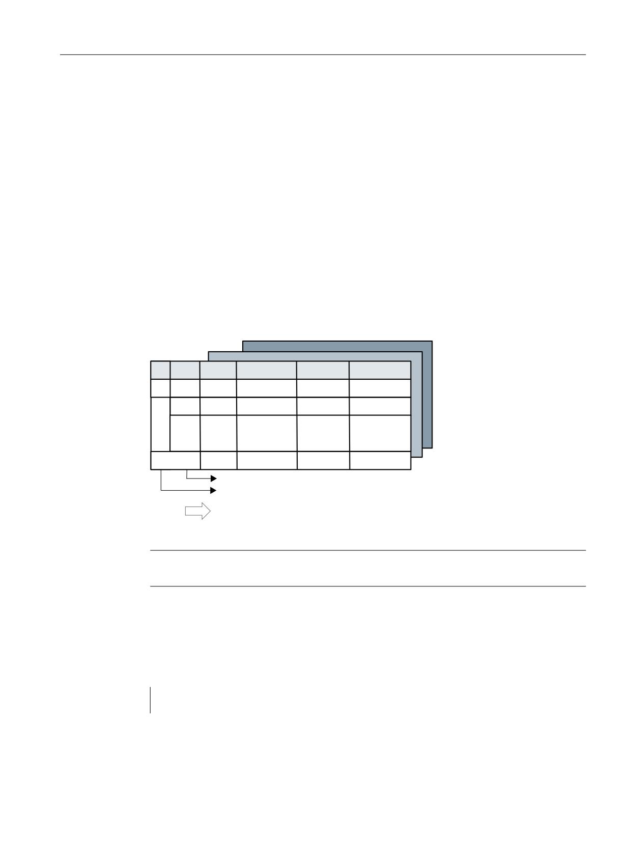
Description of functions
8.13 Variants of D-number assignments
8.13
Variants of D-number assignments
8.13.1
Free selection of D numbers for every T
D numbers can be freely assigned to tool edge numbers in systems with and without tool
management. A maximum of 12 cutting edges are possible for each tool "T". The upper limit for
the D numbers used is limited by the machine data.
This assignment option is an extension of the process to relative D numbers.
With this setting ($MN_MM_MAX_CUTTING_EDGE_NO >
$MN_MM_MAX_CUTTING_EDGE_PER_TOOL) additional program commands can be used that
make a check for unambiguous assignment of D numbers to T numbers or identifiers possible.
With this setting, the cutting edge number $TC_DPCE[T-No,D-No] is also created.
The same D numbers shall be assigned in each case for the cutting edges for duplo tools (same
identifiers).
7
7
&(
7
'[
7\SH
*HRPHWU\
:HDU
%DVLV
'\
']
'[\
8QLTXH ' QXPEHU
7RRO HGJH QXPEHU WR
2QH PHPRU\ ZLWK XS WR
FXWWLQJ HGJHV SHU WRRO
Figure 8-42
Structure of the tool offset memory
Note
Uniform system support is not available for this function.
Machine data for user (unique) assignment of D numbers
$MN_MAX_CUTTING_EDGE_NO = Maximum permissible D number
Example:
$MN_MAX_CUTTING_EDGE_NO=1
A maximum of 1 offset (D1) can be defined per
tool.
Tool management
Function Manual, 10/2020, 6FC5397-1HP40-0BA1
515
Description of functions
8.13 Variants of D-number assignments
$MN_MAX_CUTTING_EDGE_NO=9999
Tools can be assigned unique D numbers as
follows:
T1 with D1, D2, D3
T2 with D10, D20, D30
T3 with D100, D200, D300
$MN_MAX_CUTTING_EDGE_PER_TOOL =Assignment of tool edges per tool
Example:
$MN_MAX_CUTTING_EDGE_PER_TOOL=1
Only tools used with 1 cutting edge
$MN_MAX_CUTTING_EDGE_PER_TOOL=12
Up to 12 cutting edges per tool.
Check for uniqueness (CHKDNO)
The NC language command CHKDNO checks the D numbers assigned within the NC for
uniqueness. The D numbers of all tools defined within a TO unit may not occur more than once.
No allowance is made for replacement tools.
Check within the magazine (CHKDM)
Exactly like CHKNO, the NC language command CHKDM checks the D numbers assigned within
the NC for an activated tool management for uniqueness. This check function can be restricted
to individual magazines.
D number to T number (GETACTTD)
Using the NC language command GETACTTD if tool management is active, the T number in
which the D number occurs can be searched for.
Precondition for this is that the D numbers have been uniquely assigned in the TO unit being
considered.
GETDNO, SETDNO when re-equipping
The NC language commands GETDNO and SETDNO permit reading and writing the offset
number D for a specified cutting-edge number CE.
GETDNO (T, CE): Read the D number for the cutting edge CE of the tool T
SETDNO (T, CE, D): Set the D number for the cutting edge CE of the tool T
$TC_DPCE[T, D]=...: Assignment of tool edge number CE to offset number D
Tool management
516
Function Manual, 10/2020, 6FC5397-1HP40-0BA1
Description of functions
8.13 Variants of D-number assignments
Example:
Rename cutting edge CE=3 from D2 to D17
• With initial situation:
Internal T number 1
D number: 2
Tool 1 cutting edge with:
$TC_DP2[1, 2]=120 ;tool radius T1, D2: 120 mm
$TC_DP3[1, 2]=5.5 ;tool radius T1, D2: 5.5 mm
$TC_DPCE[1, 2]=3 ;cutting edge number T1, D2: 3
(programming: T1,...D2)
• Using variable definition:
DEF INT DNoOld, DNoNew=17
DnOld=GETDNO (1, 3) ;value 2 is read in DnOld
SETDNO (1, 3, DNoNew) ;the new D no. is assigned to the cutting edge
• The new D value 17 is assigned to cutting edge CE=3
$TC_DP2[1,17]=120
$TC_DP3[1, 17]=5.5
$TC_DPCE[1, 17]=3
8.13.2
Location-dependent offsets (additive offsets)
Overview
Location-dependent offsets are a generalized form of wear. They are part of the cutting edge
data. The parameters of the additive offset refer to the geometrical data of a cutting edge.
Location-dependent offset can in general be used, i.e. with active/inactive tool management;
with flat D-number function.
To meet the requirements of special machine operating modes, the location-dependent offsets
can be subdivided into the following categories by setting the appropriate machine data:
• Location-dependent offset, fine
• Location-dependent offsets, coarse = setting-up offset
The purpose of the setting-up offset is to allow the operator to set values prior to the machining
operation. These values are stored in their own memory in the NC, the operator can access the
location-dependent fine offsets via the HMI. Location-dependent offsets "fine" and location-
dependent offsets "coarse" are added NC-internally and then act like the additive offset itself.
Several location-dependent offsets can be defined per D number. Machine data define the
absolute number of location-dependent offsets, the maximum number of location-dependent
offsets per cutting edge and specify which additive offsets are active after the end of program or
when the Reset key is pressed.
Applicable only when tool management is active:
Tool management
Function Manual, 10/2020, 6FC5397-1HP40-0BA1
517

Description of functions
8.13 Variants of D-number assignments
MD18112 $MN_MM_KIND_OF_SUMCOR can be set to define which additive offset must be
operative if a tool is assigned the "active" status in the part program in the coarse of a
programmed tool change:
• Additive offset values "fine" of the tool cutting edges remain unchanged or
• Additive offset values "fine" of the tool cutting edges are set to the value 0
The function is enabled by setting bit 8 = 1 in machine data
$MN_MM_TOOL_MANAGEMENT_MASK.
DL - programming the additive/setting-up offset
Programming the additive offset is always relative to the active D number and is executed using
the command
DL ="n"
The additive offset with the relative number "n" with respect to the active D number is activated
by this. This means that the additive offset "n" is added to the wear of the active D number.
The additive offset is deselected with the command
DL = 0
Configuration of additive/setting-up offset
$MN_MM_KIND_OF_SUMCORR, bit 4=0
Corresponds to the default setting; only one data record of additive offset available per DL
number. In this case, the term "additive offset" merely refers to the data represented by
$TC_SCPx.
$GGLWLYH RIIVHW
7&B6&3
>W
@
' RIIVHW
7&B6&3
>W
@
7&B'3 >W
@
7&B'3 >W
@
7&B'3
>W
@
$GGLWLYH RIIVHW
7&B6&3
>W
@
7&B'3
>W
@
7&B'3&(>W
@
7&B6&3
>W
@
Figure 8-43
$MN_MM_KIND_OF_SUMCORR, bit 4=0
The data in the diagram is used when programming (the tool with T=t is active):
D2
;Cutting edge offsets
;i.e. $TC_DP3,...$TC_DP11 + wear ($TC_DP12,...$DP29) + adapter dimen-
sion
Tool management
518
Function Manual, 10/2020, 6FC5397-1HP40-0BA1

Description of functions
8.13 Variants of D-number assignments
DL=1
;Additive offset 1 is added to the existing offsets of D2
;i.e. $TC_SCP13,...$TC_SCP21
DL=2
;Additive offset 1 is no longer added to offset D2, but additive off-
set 2 instead
;i.e. $TC_SCP23,...$TC_SCP31
DL=0
;Deselection of additive offset; only the data of D2 is still effec-
tive
$MN_MM_KIND_OF_SUMCORR, bit 4=1
Setting-up offsets are available. The general term "additive offset" refers to a combination of the
"fine" additive offset, represented by $TC_SCPx, and the additive offset, represented by
$TC_ECPx. There are two data records for one DL number. The additive offset equals the product
of the corresponding components $TC_SCPx + $TC_ECPx.
$GGLWLYH RIIVHW ILQH
6HWXS RIIVHW
7&B(&3
>W
@
7&B6&3
>W
@
7&B(&3
>W
@
7&B6&3
>W
@
' RIIVHW
7&B'3 >W
@
7&B'3 >W
@
$GGLWLYH RIIVHW ILQH
7&B'3
>W
@
6HWXS RIIVHW
7&B(&3
>W
@
7&B'3
>W
@
7&B6&3
>W
@
7&B'3&(>W
@
7&B(&3
>W
@
7&B6&3
>W
@
Figure 8-44
$MN_MM_KIND_OF_SUMCORR, bit 4=1
The data in the diagram is used when programming (the tool with T=t is active):
D2
;Cutting edge offsets
;i.e. $TC_DP3,...$TC_DP11 + wear ($TC_DP12,...$DP29) + adapter dimen-
sion
DL=1
;Additive offset 1 is added to the existing offsets of D2
;i.e. $TC_ECP13 + $TC_SCP13 ,...$TC_ECP21 + $TC_SCP21
DL=2
;Additive offset 1 is no longer added to offset D2, but additive off-
set 2 instead
;i.e. $TC_ECP23 + $TC_SCP23,... $TC_ECP31 + $TC_SCP31
DL=0
;Deselection of additive offset; only the data of D2 is still effec-
tive
The new NC language command DELDL can be used to delete location-dependent offsets from
cutting edges.
Tool management
Function Manual, 10/2020, 6FC5397-1HP40-0BA1
519
Description of functions
8.14 Tool adapter
8.14
Tool adapter
8.14.1
Machine data for setting adapters of type 1 and type 2
Setting machine data
To use angle head adapters of types 1 and 2, the following machine data must be set:
• Tool management with magazine management (TMMG)
- $MN_MM_TOOL_MANAGEMENT_MASK, Bit0=1
- $MC_TOOL_MANAGEMENT_MASK, Bit0=1
• "Adapter" function
- $MN_MM_TOOL_MANAGEMENT_MASK, Bit7=1
• "Multitool" function (adapter type 2)
- $MN_MM_TOOL_MANAGEMENT_MASK, Bit10=1
• Number of angle head adapters specified
- $MN_MM_NUM_TOOL_ADAPTER_TYP2 >= 0
8.14.2
Creating/deleting adapters
Two types of tool adapters are supported:
• Type 1 (Page 522) defines conventional adapters. These adapters can be assigned to any
location in the magazine.
• Type 2 (Page 534) defines angle head adapters in which the tool base position is angled. This
type is assigned to a multitool location.
Create adapter
An adapter is created by using the system variable $TC_ADPT_TYPE[n] to assign an adapter type
to an adapter with the number "n".
The data is saved in system variables for the two available types of adapters. The adapter types
are defined via the system variable $TC_ADPT_TYPE[n]:
•
0: No adapter with the number "n" is defined.
•
1: An adapter with the number "n" is of type 1 (conventional adapter)
•
2: An adapter with the number "n" is of type 2 (angle head adapter)
If the data of an adapter that was not set is written, then the command is declined with an alert.
Example:
$TC_ADPT_TYPE[1] = 2 creates an adapter of type 2.
See also $TC_ADPTx - adapter description (Page 308).
Tool management
520
Function Manual, 10/2020, 6FC5397-1HP40-0BA1

Description of functions
8.14 Tool adapter
Number of possible adapters
The number of possible adapters is set via the machine
data $MN_MM_NUM_TOOL_ADAPTER_TYPE2 (Page 520).
Delete adapter
Adapters can be deleted via the system variable $TC_ADPT_TYPE[n] using the following
commands:
• $TC_ADPT_TYPE[n] = 0; the adapter with the number "n" is deleted.
• $TC_ADPT_TYPE[0] = 0; all adapters are deleted.
Note
Only adapters that are not assigned to a magazine location can be deleted.
Adapters of type "1" can be deleted using the command $TC_ADPTT[n]=-1 with n>0. This
command is not available for adapters of type "2".
With the NC language instruction "$TC_MAP1[0]=0", all of the magazine data of the TOA unit of
the channel is deleted and consequently all of the adapters as well. The exception to the rule are
adapters that are already assigned to a multitool.
8.14.3
Constraints for adapters
Constraints
Please note the following constraints:
• The option for "Angle head adapter" is set.
• The "Multitool" option is set for adapter type 2.
• The "Tool and magazine management" and "Adapters" functions are set.
• Adapter type 1 can only be assigned to a magazine location.
• Adapter type 2 (angle head) can only be assigned to a multitool location. The multitool has
only one magazine location.
• Adapters on a magazine location and multitool location cannot be cascaded.
- Exception: The adapter type 1 on the magazine location only has default values
$TC_ADPT1-3 =0 and $TC_ADPTT=1.
Note
Available tool types for adapter type 2
Only the tool types <400 and >=600 are possible, i.e. no turning or grinding tools.
Tool management
Function Manual, 10/2020, 6FC5397-1HP40-0BA1
521

Description of functions
8.14 Tool adapter
Note
Observe multitool rules for type 2 adapters
Since the adapter type 2 is only permitted on multitool locations, the rules for multitools must
be observed, e.g. handling in the PLC, determination of the T no. of the spindle tool.
8.14.4
Managing adapter data
8.14.4.1
Managing adapter data for type 1 and type 2
Number of possible adapters
The number of possible angle head adapters is set via the machine data MD
$MN_MM_NUM_TOOL_ADAPTER_TYPE2.
Managing the adapter data from the NC program
The following properties can be determined from this via system variables from the NC program.
System variable
Description
$P_MAGNA
Number of created adapters of type 1 and type 2 in total in the TO unit of the channel.
$P_MAGNA1
Number of created adapters of type 1 in the TO unit of the channel.
$P_MAGNA2
Number of created adapters of type 2 in the TO unit of the channel.
$P_MAGNA[i]
i-th adapter number that is defined. The adapter numbers are sorted in ascending order.
8.14.5
Adapter type 1
8.14.5.1
Overview
Purpose
The standard dataset for the tool offsets gives you, via the system variables $TC_DP21,
$TC_DP22 and $TC_DP23, the capability of entering the dimensions (Length1, Length2 and
Length3) of an adapter.
If tool management is active the additional adapter data can also be assigned to specific
magazine locations.
This function is used for adapters that are fixed to a magazine location for a long period and used
by different types of tool.
Tool management
522
Function Manual, 10/2020, 6FC5397-1HP40-0BA1
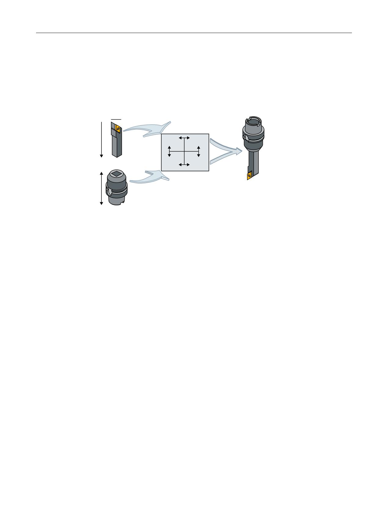
Description of functions
8.14 Tool adapter
In individual cases, it is also possible to use identical adapters on several magazine locations. To
do this it makes sense to define and store the adapter data records separately from the magazine
locations.
'HIDXOW JHRPHWU\
1HXWUDO GHIDXOW
7UDQVIRUPHG WRRO
JHRPHWU\
JHRPHWU\
4:
6/
7XUUHW ORFDWLRQ ZLWK
DGDSWHU
/:
7RRO OHQJWK
/
/
$GDSWHU
&XWWLQJ HGJH SRVLWLRQ
/$
Figure 8-45
Adapter transformation
Adapter transformation
Adapter data "adapter transformation" allows fixed orientation of the tool on the adapter or
orientation of the adapter including its tool with reference to the machine.
If adapter data are used, system variables $TC_DP21, $TC_DP22 and $TC_DP23 have a different
reference and are therefore only formally part of the cutting edge data record in the NC.
8.14.5.2
Description of function
The adapter data function must be enabled via machine data (MD18104:
$MN_MN_MM_NUM_TOOL_ADAPTER).
In order to activate the setting, bit 7 must be set in MD18080 MM_TOOL_MANAGEMENT_MASK.
Definitions
The machine data can be used to set two definition types of adapter data:
• One adapter data record is assigned to each magazine location as standard.
• Adapter data records can be defined independently of magazine locations. The magazine
locations are then assigned as an additional step.
The magazine location is the reference point for adapter and tool. Both are assigned to the
magazine location.
Tool management
Function Manual, 10/2020, 6FC5397-1HP40-0BA1
523
Description of functions
8.14 Tool adapter
The following points are realized when programming the D numbers in the part program:
• The offset is assigned to a real tool.
• The tool is assigned to a magazine location
• It is possible to assign an adapter to the magazine location, for which a transformation
(orientation) of the tool it contains can be defined.
Thus, the working offset can be clearly computed and the tool path accordingly adjusted.
If an additive offset is programmed, then its value refers to the active D offset.
8.14.5.3
Activation
Requirements
• In order to be able to use magazine location oriented adapter data, machine data MD18104
$MN_MM_NUM_TOOL_ADAPTER must have a value that is not equal to zero.
• Adapter data records must be defined.
• If the values of the machine data are > 0, the adapters must be linked to the magazine
locations or assigned to them (can be automated via the HMI or using a cycle).
As a result, the adapter data including the defined transformations are always taken into account
for the tool located on the magazine location in question. The working offset is calculated
including the transformation and the adapter data.
The offset data can then be displayed as follows:
• Geometrical data for the tool (system variable $TC_DP3,...DP11); designated as neutral
default geometry
• Non-transformed working offset (sum of the values from tool geometry, wear, additive
offset, tool base dimension or adapter)
• Non-transformed working offset (transformation of the sum of the values from tool
geometry, wear, additive offset) and tool base dimension of the adapter.
Machine data and setting data are used to define the sizes the transformation affects. The mode
of transformation of the additive offset can be set.
Magazine-location-related adapter data records
Create new
MD18104 $MN_MM_NUM_TOOL_ADAPTER = -1:
One magazine location and one adapter data record are created. Default values are stored in the
adapter data record which is automatically linked to the magazine location.
It is not possible to create a new free adapter at this point. The adapter numbers are assigned
automatically (1 ... max. number of available magazine locations).
Delete
Tool management
524
Function Manual, 10/2020, 6FC5397-1HP40-0BA1

Description of functions
8.14 Tool adapter
If an adapter data record is linked to a magazine location (MM_NUM_TOOL_ADAPTER = -1), it
cannot be deleted.
Note
Only the setting $MN_MM_NUM_TOOL_ADAPTER = -1 is currently supported by HMI Operate.
With this setting, freely creating adapter data sets and freely assigning them is not possible.
It is not permissible to change the automatic assignment and numbering of the adapter.
Free adapter data records
Create new
MD18104 $MN_MM_NUM_TOOL_ADAPTER > 0:
The adapter data can be created freely. Adapter data can be created by the user with a write
operation to a non-existent data record.
$TC_ADPTi[n] = value; i = T, 1 2, 3, ..., n (number of the adapter)
If data record n does not yet exist and the maximum number of adapter data records that have
already been defined is less than the value of MD18104 $MN_MM_NUM_TOOL_ADAPTER, a
new adapter data record is created and assigned specific values.
The value "value" is assigned to parameter i. The following applies, 0 < n ≤ 3 2000. The index
value 0 is reserved.
Note
The adapters must be assigned explicitly to the magazine locations for
MM_NUM_TOOL_ADAPTER > 0.
- OR -
An adapter is created by using the system variable $TC_ADPT_TYPE[n] to assign an adapter type
to an adapter with the number "n". Example: $TC_ADPT_TYPE[1] = 1
Deleting an adapter of type 1
If, MD18104 MM_NUM_TOOL_ADAPTER has the value > 0, then the adapter data can be deleted
as required provided it is not assigned to a magazine location.
$TC_ADPTT[n] = -1
Adapter data record n is deleted and the memory becomes free again.
- OR -
$TC_ADPT_TYPE[n] = 0; the adapter with the number "n" is deleted.
Deleting an assigned adapter data record:
The assignment to the magazine location must be undone first. You can only do this if the
magazine location is empty. An alarm is issued if deletion fails.
Tool management
Function Manual, 10/2020, 6FC5397-1HP40-0BA1
525
Description of functions
8.14 Tool adapter
Please proceed as follows:
• Remove the tool from the magazine location
(unload, relocate).
• Remove the adapter from the magazine location.
• Delete the adapter data record (with $TC_ADPTTi[n] = -1).
Adapter data record n is deleted and the memory becomes free again.
Deleting all adapter data records
For MM_NUM_TOOL_ADAPTER > 0, you can delete the adapter data if it is not assigned to a
magazine location:
$TC_ADPTT[0] = -1
All non-assigned adapter data of the TO units is deleted. If you want to delete assigned adapters,
you must first undo the assignment of those adapters to magazine locations. An alarm is issued
if deletion fails.
- OR -
$TC_ADPT_TYPE[0] = 0; all adapters are deleted.
Read/write adapter parameters
You can modify adapter data at any time even if an adapter is assigned to a magazine location
and/or a tool is located in the magazine location with the adapter.
Magazine location assignment/release
For MM_NUM_TOOL_ADAPTER > 0, an adapter record must be assigned to a magazine location
explicitly:
$TC_MPP7[m,p] = "adapter no."
Adapter number "adapter no." is assigned to magazine location p of magazine m. For "adapter
no." = 0 any previous assignment is removed.
Note
An assignment can only be established or released if no tool is assigned to the magazine location.
Determination of the adapter
When determining the relevant adapter, a distinction is made between a turret and the other
magazines.
The following applies for a turret:
The adapter is used on the owner location (i.e. the source location, whereby the tool only leaves
the magazine location in the data) of the selected tool.
Tool management
526
Function Manual, 10/2020, 6FC5397-1HP40-0BA1
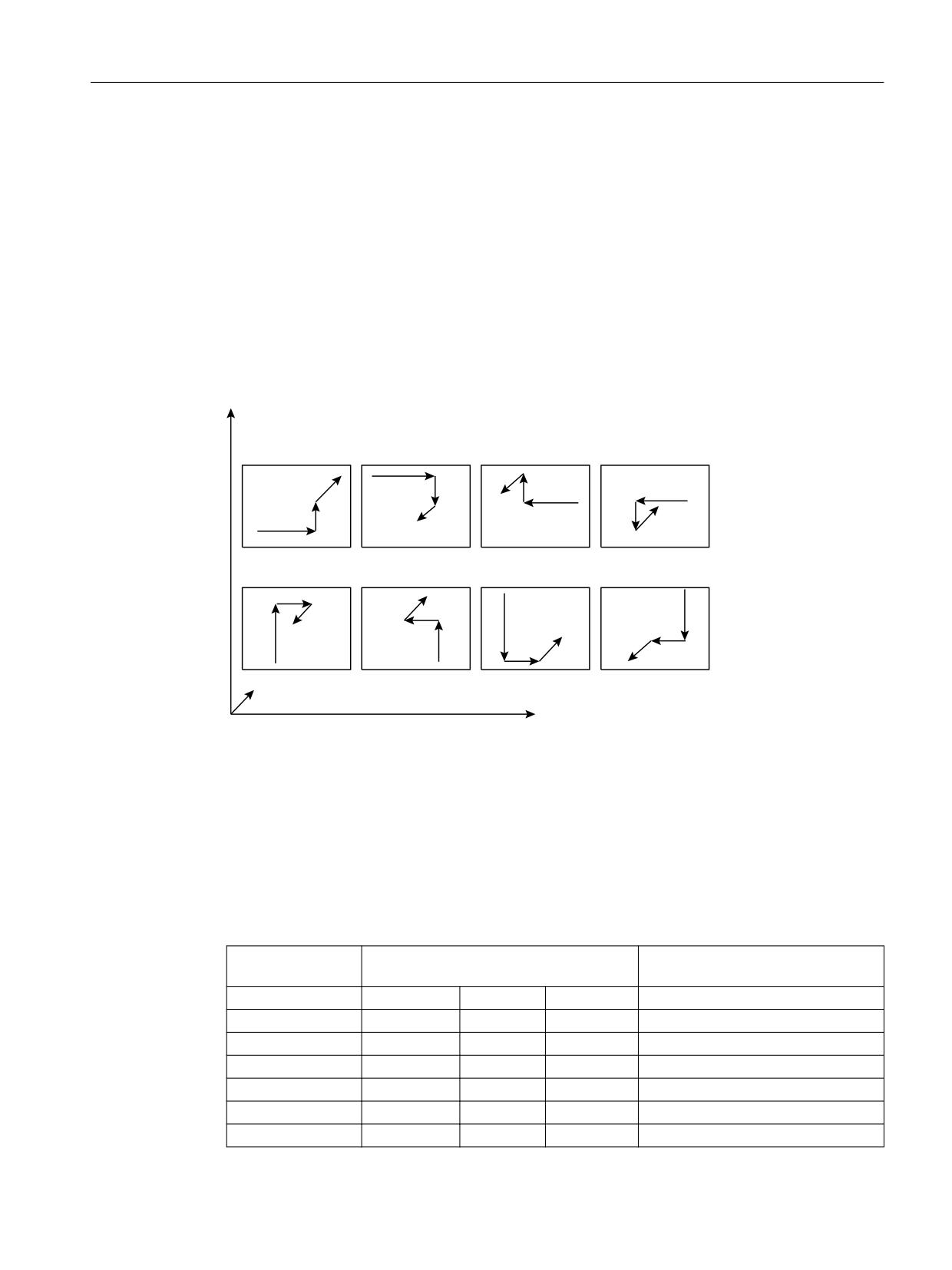
Description of functions
8.14 Tool adapter
The following applies for chain and box-type magazines:
The adapter of the current magazine location containing the tool (usually the spindle) is used.
Example:
A tool magazine is changed from Magazine_1/Location_1 into the spindle. The adapter from
Magazine_location_1 is not read now, but rather from the spindle location. This means that in
the change cycle, the adapter data from the magazine location must be copied to the spindle
location.
Example of an adapter transformation
A turning tool with lengths L and Q is described below.
]
7
LGHQWLW\
7
7
7
O
O
O
O
O
O
O
O
O
,
4
O
/
O
7
7
7
7
O
O
O
4
O
O
O
O
O
O
/
O
O
O
\
[
Figure 8-46
The 8 defined transformations (T = 1...8) for the adapter with G 18 and for a turning tool.
The assignments of tool lengths I1, I2, I3 are shown on the geometry axes x, y, z.
Transformations for numbers 1 to 8 are defined. Number 1 is the identity: no transformation of
input data.
Other transformations can be implemented. The available transformations are designed initially
for turning tools. These are typically defined by Q=I1=$TC_DP3 and L=I2=$TC_DP4.
The transformation numbers correspond to the transformations shown in the table. In general:
Length1t, length2t, length3t = f(length1, length2, length3) = f(l1,l2,l3) = f(Q,L,l3)
Transformation
GEO
number
X
Y
Z
Turning tool with G18 transformation
1
+L1
+L3
+L2
-
2
+L1
-L3
-L2
ROT X 180
3
-L1
-L3
+L2
ROT Z 180
4
-L1
+L3
-L2
ROT X 180 Z 180
5
+L2
-L3
+L1
ROT Y 90 Z 180
6
-L2
+L3
+L1
ROT Y -90
Tool management
Function Manual, 10/2020, 6FC5397-1HP40-0BA1
527

Description of functions
8.14 Tool adapter
7
+L2
+L3
-L1
ROT Y 90
8
-L2
-L3
-L1
ROT Y -90 Z 180
L1, L2 and L3 are working offsets of the tool prior to transformation with or without adapter
(depending on machine data settings). They are assigned to the geometry axes during
compensation.
Note
In turning, L and Q are also used to describe a tool. In the above table, l1 corresponds, for
example, to variable Q (or x direction) and l2 to variable L (or z direction), assuming the plane
G18 is selected (default setting for turning machines).
As standard, activation of an offset is calculated as follows:
Offset = D offset + xi(e.g. wear, additive offset)
Length1
$TC_DP3 + xi
Length2
$TC_DP4 + xi+1
Length3
$TC_DP5 + xi+2
Length4
$TC_DP6 + xi+3
The adapter transformation then acts on the transformed tool offset values and is added to the
transformed offset values.
The transformation number of the adapter causes a transformation of the tool (the cutting
edges) located in this adapter (orientation according to the transformation number).
Working offset = f(offset) + adapter dimension of the magazine location
aLength1
Length1t + $TC_ADPT1
aLength2
Length2t+ $TC_ADPT2
aLength3
Length3t + $TC_ADPT3
ARadius1
Radius1
Depending on the programmed plane selection G17, G18, G19, these values are added to the
geometry axes.
G17, G18, G19 - plane selection (declarations)
The following agreements (different for machining and milling tools) apply for assigning tool-
length parameters of the tools to the geometry axes:
Machining plane
System variables for tool length description
$TC_DP3(I1)
$TC_DP4(I2)
$TC_DP5(I3)
G17 Milling
Z
Y
X
Turning
Y
X
Z
Tool management
528
Function Manual, 10/2020, 6FC5397-1HP40-0BA1
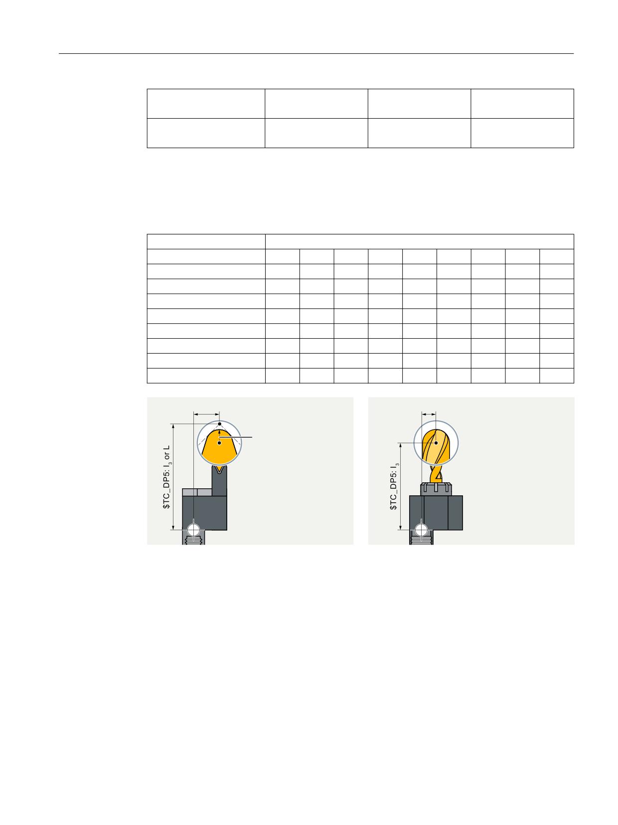
Description of functions
8.14 Tool adapter
G18 Milling
Y
X
Z
Turning
X
Z
Y
G19 Milling
X
Z
Y
Turning
Z
Y
X
Transformation of cutting edge position
The cutting edge position described by system variable $TC_DP2 is also transformed.
Transformations for the cutting edge position are performed as shown in the table below:
Transformation number
Cutting edge position
1
2
3
4
5
6
7
8
9
1
1
2
3
4
5
6
7
8
9
2
2
1
4
3
7
6
5
8
9
3
4
3
2
1
5
8
7
6
9
4
3
4
1
2
7
8
5
6
9
5
1
4
3
2
6
5
8
7
9
6
4
1
2
3
8
5
6
7
9
7
2
3
4
1
6
7
8
5
9
8
3
2
1
4
8
7
6
5
9
7&B'3
, RU 4
7&B'3
,
3
7&B'3
5DGLXV
6
6
7XUQLQJ
0LOOLQJ
Figure 8-47
Turning and milling tools - relationship between cutting edge position and radius
compensation
Turning tool geometries (I1, I3 or L, Q) are described in terms of P, the point of approach at the
workpiece. However, the center point of cutting edge S with reference to the tool nose radius
must be known for radius compensation.
This center point can only be accurately calculated if the cutting edge position is known. Point
S can then be derived from point P.
Tool management
Function Manual, 10/2020, 6FC5397-1HP40-0BA1
529