SINUMERIK 840D sl. Service - Functions. Manual (2018-2020) - page 87
Description of functions
8.4 Tool change box-type, chain, circular magazines
Select/deselect tool offset for Reset
The following machine data can be used to control the behavior for RESET:
• MD20310 TOOL_MANAGEMENT_MASK bit 14
• MD20122 TOOL_RESET_NAME
• MD20110 RESET_MODE_MASK
• MD20130 CUTTING_EDGE_RESET_VALUE
• MD20132 SUMCORR_RESET_VALUE
You can determine whether to:
• deselect the active tool
• keep the active tool selected or
• set a particular tool (according to MD20122 $MC_TOOL_RESET_NAME).
If, in terms of its data, a new tool is selected that is not yet on the master spindle or the master
tool holder (or main spindle, main tool holder), then a tool change is executed for a RESET or the
end of the program. With this type of tool change (in a similar manner to block searches), the PLC
is not capable of influencing the selection of the tool.
Select a tool at start of program
The machine data
• MD20310: TOOL_MANAGEMENT_MASK bit 14
• MD20122: TOOL_RESET_NAME
• MD20112: START_MODE_MASK
• MD20130: CUTTING_EDGE_RESET_VALUE
can be set to define whether:
• the tool on the main spindle or the main tool holder is selected again or remains selected.
• or a particular tool is selected (according to MD20122 $MC_TOOL_RESET_NAME).
If a new tool is selected which in the data is not yet specified as being on the spindle, a tool
change is performed when the program is started. For this type of tool change the PLC cannot
influence the selection of the tool, just as for block search.
Tool rejection by the PLC
With a block search, selection on reset or program start as well as the setting "Select tool in the
interpreter" ($MC_TOOL_Management_Mask bit 23=1), the tool is already selected during
preprocessing and the PLC can no longer reject the tool.
Note
If bit 4 of the machine data MD20310 $MC_TOOL_MANAGEMENT_MASK is set, then the PLC
usually has the possibility to again request preparation for a tool change, yet this time with
different parameters, i.e. to reject the tool.
Tool management
392
Function Manual, 10/2020, 6FC5397-1HP40-0BA1

Description of functions
8.4 Tool change box-type, chain, circular magazines
Communication between PLC and tool management
The communication between PLC and NC during a tool change is via the VDI interface. Tool
change is triggered by the tool management in the NC. The tool management outputs
commands to the PLC which acknowledges them either positively or negatively depending on
the situation. The PLC also has the capability of independently (asynchronously) transferring
commands to the NC, e.g. communicating the magazine position, transport of a tool, etc.
8.4.8
Predecoding (preprocessing) and block execution (main run)
Sequence
The cutting edge geometry cannot be calculated until the tool management knows the tool that
is actually to be used. Only the identifier is stated in the part program for tool change. Generally,
the tool with the status "active" is then used. But if this is disabled, then one of the other sister
tools, i.e. the replacement tool, is used instead. The precoding delays selection of the new
offsets until it is clear which tool is to be used. Only then can precalculation of the blocks be
restarted.
Tool change must have been completed before the path can be traversed with the tool offset of
the new tool.
The block is split if the preprocessing run detects that a cutting edge of a new tool has been
selected for the first time and tool preparation has been initiated, but not yet completed.
The following synchronization points exist between predecoding and block execution:
Example:
Programmed NC block:
N1 D1 M06 Txx X100 Y100
Sequential blocks:
N1 Txx M06 end of block
N2 D1 X100 Y100
1.
Interpreter detects an offset selection (D number)
2.
It determines that a tool change was previously programmed which has not yet resulted in selection
of a tool.
3.
Interpreter carries out "block splitting".
4.
Output of block N1:
Block 1 receives a request from the execution blocks to output their collective blocks, and also if
programmed, M06, T numbers, ...
5.
Output of block N2:
Block 2 receives the rest, in particular all travel information and any D numbers if programmed.
6.
Tool management stops execution of the block during preprocessing until it is clear which tool is to
be used.
7.
After receiving the tool preparation acknowledgement, execution of block 2 is continued, or first
the new T number is entered in the block and is used to calculate the contour again.
Tool management
Function Manual, 10/2020, 6FC5397-1HP40-0BA1
393
Description of functions
8.4 Tool change box-type, chain, circular magazines
Tool change at the main spindle or master tool holder
The main run waits in synchronism with tool change block for transport acknowledgement.
1. Main run waits in synchronism with tool change block for end of acknowledgement (if bit 5
or bit 6 of MD20310 $TC_TOOL_MANAGEMENT_MASK is set), or
2. After a tool change in the main run, the NC automatically synchronizes with the end of the
tool change in the block in which a cutting edge of the new tool was selected for the first time.
Note
The transport acknowledgement is an internal acknowledgement of an NC command. It
indicates to the NC that the output command was accepted. When a new command is output
to the PLC, the NC waits for the acknowledgement of the previous command.
Tool already in spindle
If the programmed tool is already in the spindle, by default no task is sent to the PLC. (The
response can be defined by the MD setting.)
Tool change at the secondary spindle or secondary tool holder
1. Main run does not wait. There is no synchronization.
2. Main run waits in synchronism with tool change block for transport acknowledgement.
3. Main run waits in synchronism with tool change block for end of acknowledgement.
Tool change preparation in a main spindle
1. In the main run, the tool management decides which tool is to be used. Until then, the
preprocessor waits at the point in the program at which the offset values of the new tool are
to be considered for the first time.
2. The PLC can also decide which tool is to be used. In this case, the PLC can reject the
recommended tool with a negative acknowledgement. If rejected by the PLC, the NC selects
a new, different tool (only if MD20300 $MC_TOOL_MANAGEMENT_MASK, bit 4 = 1, see also
FC8/FC6-description).
3. Even if the function "GETSELT(...,x)" is programmed, the preprocessor again has to wait until
a decision has been made as to which tool is to be used.
Tool management
394
Function Manual, 10/2020, 6FC5397-1HP40-0BA1
Description of functions
8.4 Tool change box-type, chain, circular magazines
Prepare to change tool in a secondary spindle
1. The main run does not wait. There is no synchronization
Note
During a synchronization operation where the new offset is used or allowed for by the
preprocessor, "block splitting" must be performed. This ensures that a preprogrammed tool
change T or M06 is actually performed and not collected in run blocks.
Unlike the STOPRE command, the preprocessor does not necessarily wait until all blocks have
been processed, but only waits if tool selection has not taken place by the appropriate time.
The appropriate time is when programming new offsets after tool change or when
programming GETSELT.
8.4.9
Traverse axes while tool is being changed
After the tool change command M06 the axes can continue travel without having to wait for the
tool change acknowledgement and, e.g., execute traversing blocks without tool offset. Travel
only stops in a block with an offset selected (D No.) until the PLC signals that a tool change has
been completed.
Precondition: MD20270 $MC_CUTTING_EDGE_DEFAULT= 0 or = -2
Example: Traversing blocks between tool change and cutting edge selection
N10 T="Drill18"
;Tool change preparation
N15 D0
;Offset deselection
N20 M06
;Tool change
N25 G00 X100 Z200
;Traverse machine axes
N30 Y150 M79
;Traverse machine axes
N35 G01 D1 X10
;Activate the tool offset.
;Check whether the tool has been changed. Preprocessing
stop until tool change preparations have been completed.
;Main run waits until tool change has been acknowledged
from PLC.
The preprocessing stop is maintained until the tool change preparations have been completed.
The main run waits at N35 (D1) until the tool change has been executed and acknowledged.
8.4.10
Special cases "T0", empty spindle, multiple T selection
T0: Empty spindle
DB72.DBX(n+0).3 indicates that T0 has been programmed. If the spindle is to be emptied using
T0, this can be identified by the fact that in DB72, DBW (n+20), DBW(n+22) data for new tool
have the value "0".
Then, values NewToolMag and NewToolLoc of FC8/FC6 must be set to "0".
Tool management
Function Manual, 10/2020, 6FC5397-1HP40-0BA1
395
Description of functions
8.4 Tool change box-type, chain, circular magazines
This applies to the preparation and to the change procedure.
Spindle is empty
A tool is to be loaded. This status is indicated by the fact that parameters OldToolMag and
OldToolLoc have the value "0".
In this case, FC8/FC6 parameters OldToolMag and NewToolLoc must be set to "0" for tool
preparation and change.
Multiple T selection
It can happen with multiple T selection that the program cannot be aborted by a RESET.
The abort response can be enhanced as follows:
• Cancel the read-in enable to prevent following blocks from being accepted in the main run.
• Then acknowledge with status 3 via FC8/FC6 (the tool command is rejected by the PLC).
8.4.11
Number of replacement tools
Machine data MD17500 MN_MAXNUM_REPLACEMENT_TOOLS can be set to select the
maximum number of replacement tools.
Once the set threshold for the number of replacement tools has been reached it is no longer
possible to:
• Create a new tool with this ID (alarm)
• Assign a tool by renaming an already fully assigned group (alarm).
Alarms
For operation via the HMI, alarm 17192 is output as an indication as soon as the defined limit is
violated.
If programming via a part program an additional interpreter alarm is triggered (e.g. 14020) if
NEWT fails.
For the setting $MN_MAXNUM_REPLACEMENT_TOOLS = 0, the data is not evaluated. This is the
factory setting.
Note
Machine data MD17500 MAXNUM_REPLACEMENT_TOOLS has a maximum input value of "32",
i.e. a tool group then contains a maximum of 32 tools.
Tool management
396
Function Manual, 10/2020, 6FC5397-1HP40-0BA1

Description of functions
8.4 Tool change box-type, chain, circular magazines
8.4.12
Tool changing errors
If an error is detected by the NC in the programmed tool preparation (e.g. no tool available, no
free position in magazine) program processing is terminated with an alarm.
The operator can assess and rectify various problems without terminating the program.
The following problems can be solved:
• The tool data record is not or not entirely in the NC.
• The part program contains a programming error.
• No more replacement tools of the tool group in question are present or available (only applies
when tool management is active).
• Alarm 22067 or 22069 is output. The tool data record has been loaded into the NC but is not
assigned to a magazine location or the magazine of the tool is not accessible to the tool
search (only applies when tool management is active). The tool must be reloaded "manually"
(e.g. directly onto the spindle).
Note
The case of illegal "D number" can occur either if there is an error in the part program or the
data record for the D number is not in the NC.
Programming example
N10 ...
N100 T="Drill"
;NC detects an error
N110 ...
N200 M06
;to the extent that the tool change is explicitly program-
med in the same program for tool preparation
N210 ...
Note
As a rule M06 is not programmed at the program level of tool preparation but rather in a
subprogram, cycle or macro.
Bit 0 of MD22562 $MC_TOOL_CHANGE_ERROR_MODE is used to set at which block a stop is to
be made.
TOOL_CHANGE_ERROR_MODE, bit 0 = 0:
N10 ...
N100 T="Drill"
;NC detects an error, program stops at this block
N110 ...
N200 M06
N210 ...
TOOL_CHANGE_ERROR_MODE, bit 0 = 1:
N10 ...
Tool management
Function Manual, 10/2020, 6FC5397-1HP40-0BA1
397
Description of functions
8.4 Tool change box-type, chain, circular magazines
N100 T="Drill"
;NC detects an error
N110 ...
N200 M06
;Program stops at this block
N210 ...
The error is detected during tool preparation, but is delayed by the NC. The program continues
and stops at M06. Tool preparation has been completed at this point in time for a regular
program run. In the event of an error, tool preparation with the correct data can be subsequently
repeated. In this situation, the language command GETSELT would supply the value "-1". With
this information, e.g. in a change cycle, a branch can be made to fault handling.
The programming error (in block 100 in this example) is corrected by adding the offset to the tool
change block:
N200 "T=Drill_1" M06
If a tool change (with M06 programming) is realized by means of a subprogram or cycle
program, then the error can be rectified by inserting an overstore block (in the example).
8.4.13
Monitoring the maximum speed of a tool
If the maximum permissible speed for a tool is exceeded, or the rotary acceleration, e.g. of large
tools, then this represents a danger for man and machine.
The appropriate limit values can be set for each tool via the following system variables:
• Speed limit value: $TC_TP_MAX_VELO[<internal T number>]
• Rotary acceleration limit value: $TC_TP_MAX_ACC[<internal T number>]
This limits the speed and/or the rotary acceleration of the spindle into which the tool is loaded.
The dynamic response limitation is active for the following spindle functions:
• Spindle control mode
• Tapping with G331/G332
• Synchronous following spindle
• Spindle positioning mode
• constant cutting rate (G96, G961, G962)
• constant peripheral grinding speed
• Manual traversing of the spindle in JOG mode
Note
The function is only available when magazine management is active.
Tool management
398
Function Manual, 10/2020, 6FC5397-1HP40-0BA1
Description of functions
8.4 Tool change box-type, chain, circular magazines
Displaying tool parameters on the user interface
In order that the tool parameters $TC_TP_MAX_VELO (speed limit value) and $TC_TP_MAX_ACC
(rotary acceleration limit value) are displayed on the user interface (read/write), they must be
configured accordingly. A detailed description can be found in:
Further information
• Configuring tool lists (Page 555)
The spindle is the tool holder
If the spindle number is also the number of the tool holder
($MC_TOOL_MANAGEMENT_TOOLHOLDER = 0) (this is typical for milling machines), then the
following applies:
The extension when programming the tool change also refers to the spindle whose dynamics
should be limited.
Example: Extension = 3
T3="Miller_10" M3=6 S3=4000
A tool with the identifier "Miller_10" is loaded onto spindle S3. The speed of spindle S3 is limited
by the tool that is located on it.
Note
If an extension has not been programmed, then the tool change - as well as the programmed
speed - refers to the actual master spindle.
The tool holder is not a spindle
If the tool holder is rigid and the tool holder number is not a spindle
($MC_TOOL_MANAGEMENT_TOOLHOLDER > 0) (this is typical for lathes), then there is no
assignment to a spindle.
However, for driven tools, it is necessary to assign the tool holder to a spindle. This is realized
using the magazine location parameter $TC_MPP_SP[buffermagazine No., location No.]. It is
only possible to change this parameter if there is no tool at this buffer magazine location.
If this assignment is not made, then the dynamics are not monitored and are not limited. As a
consequence, for example, it is not possible to limit the dynamics of the spindle of a lathe with
the fixed turning tool.
Example
Tools on tool holder 2 are driven by spindle 5:
(Buffer magazine no. = 9998, arbitrary location no. therein)
$TC_MPP5[9998,location no.]=2
$TC_MPP_SP[9998,location no.]=5
Programming:
Tool management
Function Manual, 10/2020, 6FC5397-1HP40-0BA1
399

Description of functions
8.4 Tool change box-type, chain, circular magazines
"T2="Drill_8" M2=6 S5=4000.
A tool with the identifier "Drill_8" is changed to tool holder 2. The speed of spindle S5 is now
limited by the tool in tool holder 2.
Note
If an extension has not been programmed (e.g. T="Drill" S=4000), then the tool change refers to
the actual master tool holder and the programmed speed on the actual master spindle.
Limitation becomes effective on tool change
The dynamic response limitation by the tool on the spindle is only active if the tool is on the
spindle as far as the NC data is concerned. To do this, the PLC acknowledgements are evaluated.
When the tool has been changed on the spindle or the tool holder, the NC/PLC interface signal
"Tool with dynamic response limit active" (DB31, ...DBX85.0) is set.
Note
The NC/PLC interface signal "Tool with dynamic response limit active" (DB31, ...DBX85.0)
indicates that a tool with dynamic response limitation is in the spindle. The assignment state of
the spindles can be checked, especially if all tools have a maximum tool speed, which under
certain circumstances is very high so that there is no effective limiting.
Example: Tool change:
Assumptions:
• The tool with the internal T number = 6 with parameterized dynamic response limitation is
in the spindle (old tool, AWZ).
• The tool with the internal T number = 8 with parameterized dynamic response limitation,
"Miller" tool group is loaded into the spindle (new tool, NWZ).
Step No.
NC program
NC → PLC
PLC → NC
1
N100 T1="Mill"
---
---
2
---
CMD=2 (tool preparation)
---
NWZ T-No=8: Mag./
mag.loc.1→ Sp1
AWZ T-No=6: Sp1 → Mag./
mag.loc.2
3
---
---
CMD=2, status=1
NWZ T-No=8: Mag./mag.loc.1→ Mag./
mag.loc.1
AWZ T-No=6: Sp1 → Sp1
4
N101 M1=6
---
---
Tool management
400
Function Manual, 10/2020, 6FC5397-1HP40-0BA1

Description of functions
8.4 Tool change box-type, chain, circular magazines
Step No.
NC program
NC → PLC
PLC → NC
5
---
CMD=3 (tool change)
---
NWZ T-No=8: Mag./
mag.loc.1→ Sp1
AWZ T-No=6: Sp1 → Mag./
mag.loc.2
6
---
---
CMD=3, status=105
NWZ T-No=8: Mag./mag.loc.1→ Mag./
mag.loc.1
AWZ T-No=6: Sp1 → Mag./mag.loc.2
7
---
---
CMD=3, status=105
NWZ T-No=8: Mag./mag.loc.1→ Sp1
AWZ T-No=6: Mag./mag.loc.2 → Mag./
mag.loc.2
8
---
---
CMD=3, status=1
NWZ T-No=8: Sp1→ Sp1
AWZ T-No=6: Mag./mag.loc.2 → Mag./
mag.loc.2
CMD: PLC command
NWZ: New tool
AWZ: Old tool
Mag.: Magazine
Loc.: Location
Sp: Spindle
Up to step 6, the limits of the old tool are active.
In step 6, the PLC acknowledges the NC that the old tool was taken from spindle 1; this means
that there are no limits imposed by the tool.
In step 7, the PLC acknowledges the NC that the new tool has been loaded to spindle 1, i.e. the
limits of the new tool are active.
In step 8, the tool change is formally completed; no tool is moved.
Behavior when special events occur
Warm restart or abort of tool movements
The dynamic response limitation of a spindle by a tool depends on the tool, which, from the
perspective of the NC machine data, is in the particular spindle. If required, the data in the NC
should be aligned with the actual assignment of the spindles. This should be observed for a
warm restart or if tool movements are aborted.
Channel interchange
When the channel is interchanged, the spindle keeps the dynamic limits.
Note
The channel into which the spindle is changed, must work with the same TO unit.
Tool management
Function Manual, 10/2020, 6FC5397-1HP40-0BA1
401
Description of functions
8.4 Tool change box-type, chain, circular magazines
Diagnostics
Determining the cause of the limitation
The cause of a limitation can be determined using the following system variables:
• Limitation of the spindle speed by the current tool in the spindle:
$AC_SMAXVELO_INFO[<n>] == 17, where n = spindle number
• Limitation of the spindle rotary acceleration by the current tool in the spindle:
$AC_SMAXVELO_INFO[<n>] == 12, where n = spindle number
Maximum values
The maximum values can be read via the following system variables:
• Speed: $AC_SMAXVELO[<n>]
• Rotary acceleration: $AC_SMAXACCEL_IDX[<n>]
n = spindle number
NC/PLC interface signals
The signal is set irrespective of whether the speed or the acceleration of the spindle is limited by
the current tool:
DB31, ... DBX85.0 == 1 (tool with dynamic response limitation)
Tool management
402
Function Manual, 10/2020, 6FC5397-1HP40-0BA1

Description of functions
8.4 Tool change box-type, chain, circular magazines
Commissioning
Preconditions
• The "Tool monitoring for maximum speed/acceleration" option must be set.
• The tool is loaded into the spindle after setting the speed/acceleration limitation.
Note
A change of the speed limitation in TC_TP_MAX_VELO[<T number>] is not effective if the tool
is already in the spindle / tool holder.
• One TO unit can be assigned to several channels (MD $MC_TOA_UNIT). The spindle number
must also be unique across these channels and not only in the channels in which it is
configured for axis interchange. This is realized using the magazine location data
- $TC_MPP5[<buffer magazine no>., <location no.>] if the MD
$MC_TOOL_MANAGEMENT_TOOLHOLDER = 0.
- $TC_MPP_SP[<buffer magazine no>., <location no.>] if the MD
$MC_TOOL_MANAGEMENT_TOOLHOLDER > 0.
Note
The application itself must ensure that a spindle interchange in another channel is also
correspondingly taken into account for a tool change.
The PLC can check the synchronization of the tool assignment of the spindles with the data
management of the NC. Tools with a maximum tool speed set the PLC user interface signal
"Tool with dynamic limiting active". This signal can be compared with the assignment sensors
of the spindle.
Parameterization
• Speed limit value: $TC_TP_MAX_VELO[<internal T number>] = <value>, with <value> > 0
• Rotary acceleration limit value: $TC_TP_MAX_ACC[<internal T number>] = <value>, with
<value> > 0
Note
The set values of $TC_TP_MAX_VELO and $TC_TP_MAX_ACC only take effect at the next loading
of the tool into the spindle / tool holder.
Data backup
After importing a data backup with tool data, from the data perspective, tools can be on spindles
or tool holders. The dynamic limit is correspondingly active. It is the task of the PLC user program
to adapt the actual assignment of the spindles to the NC data
Tool management
Function Manual, 10/2020, 6FC5397-1HP40-0BA1
403

Description of functions
8.4 Tool change box-type, chain, circular magazines
Interface assignment
Signals from the axis/spindle (NC-> PLC):
Syntax
Description
DB31 - DB61.DBX85.0
"Tool with dynamic response limitation active"
=1; when option "Tool monitoring for maximum speed", tool data "TC_TP_MAX_VELO" >0 or
"TC_TP_MAX_ACC">0 are set, and the affected spindle is not in axis mode.
DB31 - DB61.DBX85.1
Reserved for "Tool carrier with dynamic response limitation active"
Program example
Program code
Comment
N10 $TC_TP[10]="Miller"
;T10 = "Miller"
N20 $TC_TP_MAX_VELO[10]=3500
;Speed limitation from T10: 3500 rpm
N100 SETMS(1)
;Spindle 1 = master spindle
N110 M5
;Spindle stop
N120 T="Miller" M6
;Tool with T10 is loaded into spindle 1 ⇒
;DB31,
DBX85.0 = 1
N125 $AC_SMAXVELO[1]=3000
;Spindle speed limitation: 3000 rpm
N130 S5000 M3
;M3: 5000 rpm but limited to 3000 rpm
8.4.14
Tool changes in the NC using synchronized actions
Overview
At tool change and at loading/unloading it is often necessary to supply the NC cycles with the
data for the participating tools.
Usually this is done via the "fast data channel" (dual port RAM) using FC21.
The PLC user program checks the interface in DB71/72/73.
If a new command is pending, the data (new location, old location, T_number,...) are read, pre-
processed and supplied to the cycles via FC21. There they are (usually in synchronized actions)
read as variable $A_DBB[...] and, for example, magazine movements are derived from them.
To reduce the overhead involved and create simpler mechanisms, most of the data of the tool
management interface was mapped onto the NC variables for read access.
This means that all information about the old tool and the new tool can be read directly in the
part program or in synchronized actions; the "detour" via the PLC is no longer needed.
The following variables are used for the mapping process:
$AC_TC_FCT
Function no. (command no. of the NC)
$AC_TC_STATUS
Acknowledgement status from the PLC
$AC_TC_THNO
Tool holder or spindle no. on which the change was executed
$AC_TC_TNO
Internal T no. of the tool to be changed or prepared
Tool management
404
Function Manual, 10/2020, 6FC5397-1HP40-0BA1

Description of functions
8.4 Tool change box-type, chain, circular magazines
$AC_TC_MFN
Source new tool: Magazine number
$AC_TC_LFN
Source new tool: Location number
$AC_TC_MTN
Target new tool: Magazine number
$AC_TC_LTN
Target new tool: Location number
$AC_TC_MFO
Source old tool: Magazine number
$AC_TC_LFO
Source old tool: Location number
$AC_TC_MTO
Target old tool: Magazine number
$A_TC_LTO
Target old tool: Location number
$AC_TC_CMDT
Trigger variable to output command of the NC (is set for one IPO)
$AC_TC_ACKT
Trigger variable for acknowledgement of the PLC (is set for one IPO)
$AC_TC_CMDC
Counter for the command output
$AC_TC_ACKC
Counter for the acknowledgements
$AC_TC_MMYN
Owner magazine of the new tool
$AC_TC_LMYN
Owner location of the new tool
Supplementary variables for multitool
$AC_TC_TOOLIS
Transported tool of the type:
0 = Single tool
1 = Multitool with distance coding "location"
2 = Multitool with distance coding "distance"
3 = Multitool with distance coding "angle"
$AC_TC_MTDIST
Distance of the MT location with the new tool from the reference point. If the
multitool has "length" as distance coding, the parameter contains the length in
the unit mm or inch as specified by the set dimension system.
$AC_TC_MTNLOC
Number of locations in the MT of the new tool
$AC_TC_MTTN
MT number of the MT location with the new tool
$AC_TC_MTLTN
MT location number with the new tool
Note
The variables are read-only (exception $AC_TC_CMDC and $AC_TC_ACKC). The
acknowledgement mechanism remains unaffected (the PLC still continues to acknowledge all
commands from the NC via FC8/FC6 or FC7).
Method of operation
The variables are written:
1. With each command from the NC (CMD)
2. With each acknowledgement from the PLC (ACK)
3. With Power On all are set to value "-1"
The data is retained until it is overwritten by a new command. This means that with commands
of the same type, it is not possible to tell from the function number ($AC_TC_FCT) whether a new
task is present.
The exceptions are:
Tool management
Function Manual, 10/2020, 6FC5397-1HP40-0BA1
405
Description of functions
8.4 Tool change box-type, chain, circular magazines
$AC_TC_TNO and $AC_TC_THNO
If, for example, the NC outputs a T preparation, both of these variables are set to "-1" with the
first PLC acknowledgement via FC8/FC6 (e.g. status 105).
Note
Scanning should only take place in synchronized actions. Depending on the application, this can
then trigger the variables $AC_TC_CMDT and/or $AC_TC_ACKT.
Example 1
Positioning a tool chain onto the old location
Assumption:
The tool chain has 36 locations, is defined as rotary and indexing axis, increments are 10 degrees
therefore each graduation corresponds to one magazine location.
Tool_Change_Mode=1, Tool_Change_M-Mode=6
Ids=1 every(($AC_TC_CMDT==1)and(($AC_TC_FCT==2)or($AC_TC_FCT==5))) do
$R10=itor($AC_TC_LTO)
if ((R10>0)and($A_DBB[x]==5)) pos[U1]=cdc(R10)
endif
The trigger is sent to the command output of the NC and with command "2" (T preparation) or
command "5" (T/M06 in one block) the old location is read out and stored in R10
(itor=IntegerToReal - format conversion if the variable is stored in the R-variable in synchronized
actions).
Later in the program, when the enables from the PLC are present (for example as
$A_DBB[x]==5), the magazine axis is traversed to the saved position (old location=$AC_TC_LTO).
A magazine movement could also be started as follows (shown here in simplified form):
Ids=1 every(((($AC_TC_FCT==2)or(AC_TC_FCT==5))and
($AC_TC_STATUS==105))and(($AC_TC_LTO>0))) do pos[U1]=cdc($AC_TC_LTO)
With commands "2" and "5" (T preparation or T/M06), with old location>0 and PLC
acknowledgement status "105" (serves as enable), the magazine axis is traversed.
Old location>0: If the spindle was empty, there is no old tool and the old location is 0. Therefore,
the magazine axis does not need to move.
Example 2
Swiveling a turret
Assumption:
Turret, 6 locations, the turret is defined as an indexing axis, 60 degree increment, corresponds
to one tool location, 1xSpindle, Tool_Change_Mode=0
Tool management
406
Function Manual, 10/2020, 6FC5397-1HP40-0BA1
Description of functions
8.4 Tool change box-type, chain, circular magazines
Ids=1 every($AC_TC_CMDT==1)and($AC_TC_FCT==4)and($AC_TC_LFN>0) do
$R10=itor($AC_TC_LFN)
if ((R10>0)and($A_DBB[x]==5)) pos[B]=cac(R10)
endif
The NC is triggered with the command output and with command "4" (change with T command)
the new location is read out and saved in R10
(itor= IntegerToReal - format conversion if the variable is stored in the R-variable in synchronized
actions).
Later in the program, when the enables from the PLC are present (for example as
$A_DBB[x]==5), the turret is traversed to the saved position (new location=$AC_TC_LFN).
The logic operation $AC_TC_LFN>0 prevents a movement from taking place if, for example, T0
was programmed.
8.4.15
Replacing functions with subprograms
8.4.15.1
Function replacement
Overview
TCA, T, M, or D functions can be replaced with subprograms.
The function is available irrespective of tool management and is described in full in the "Basic
Functions" Function Manual.
The function is set using the following machine data:
$MN_M_NO_FCT_CYCLE
Enter the M function that is to be replaced, e.g. "6"
$MN_M_NO_FCT_CYCLE_NAME
Name of the cycle that should be executed instead
of the M function, e.g. "L6"
$MN_T_NO_FCT_CYCLE_NAME
Name of the cycle that should be executed instead
of the T function, e.g. "T_Cycle"
$MN_D_NO_FCT_CYCLE_NAME
Name of the cycle that should be executed instead
of the D function, e.g. "Offset"
$MN_TCA_CYCLE_NAME
Name of the cycle that should be executed instead
of the TCA command, e.g. also "T_Cycle"
The mode of operation will now be explained using a T function replacement as an example.
Example
If one of the auxiliary functions to be replaced has been programmed, e.g.
N10 G90 G00 Z-100 S3000 T="Mill_20mm" M65
Tool management
Function Manual, 10/2020, 6FC5397-1HP40-0BA1
407
Description of functions
8.4 Tool change box-type, chain, circular magazines
then the NC executes a so-called block splitting and "splits" this NC block into 2 blocks
a) G90 G00 Z-100 S3000 M65
b) T="Mill_20mm"
The information "Mill_20mm" is transferred as parameter to the cycle.
If the T call is now again programmed in the replacement cycle, then no additional replacement
is made.
Machine data $MN_T_NO_FCT_CYCLE_MODE is used to set whether the cycle is executed at the
block start or at the block end (or also at the start and end).
The offset handling type is also set: If an offset is programmed (e.g. D3) in the NC block, which
is to be split, then it can be set as to whether the offset selection is taken into account or is
transferred as parameter to the replacement cycle.
Transfer variables of the T replacement cycle
$C_T
T number of the tool (numerical)
$C_T_Prog
Bool variable that shows whether a T word is available in $C_T
$C_TS
Tool identifier (string)
$C_TS_Prog
Bool variable that shows whether an identifier is available in $C_TS
$C_TE
Address extension of the T word
$C_TCA
Bool variable that indicates whether the TCA replacement is active
$C_DUPLO_PROG
Bool variable that indicates if the Duplo number for the TCA replace-
ment has been programmed
$C_DUPLO
For $C_DUPLO_PROG == TRUE, contains the value of the programmed
duplo number
$C_THNO_PROG
Bool variable that indicates if the tool holder / spindle number for the
TCA replacement has been programmed
$C_THNO
For $C_THNO_PROG == TRUE, contains the value of the programmed
tool holder / spindle number
$C_D
Programmed D no.
$C_D_Prog
Bool variable that shows whether an offset number is available in $C_D
$C_DL
Programmed additive/setup offset
$C_DL_Prog
Bool variable that shows whether an offset number is available in $C_DL
$C_MTL_PROG
Bool variable that shows whether a multitool location is available in
$C_MTL (multitool * T=location)
$C_MTL
Programmed multitool position (for T=location)
Example of a T replacement cycle
;T replacement cycle
;
;Machine data to be set
;$MN_T_NO_FCT_CYCLE_NAME="T_cycle"
;$MN_TCA_CYCLE_NAME="T_cycle"
;
PROC T_SUB_PROG DISPLOF SBLOF
;
def string[32] Ident
Tool management
408
Function Manual, 10/2020, 6FC5397-1HP40-0BA1
Description of functions
8.4 Tool change box-type, chain, circular magazines
def int T_No,Spi_No,T_prep,T_Spi,TH_No
;
;
;---------------------------------------------------
;--- T command output ---
;---------------------------------------------------
if(($C_T_PROG==1)or($C_TS_PROG==1)or($C_TCA==1))
if $C_T_PROG==1
;T=numeric
if $C_T==0
if $C_T>=1
T[$C_TE]=0
else
T0
endif
else
if $C_TE>=1
if $C_MTL_Prog==true
;multitool T=location
MTL=$C_MTL T[$C_TE]=$C_T
else
T[$C_TE]=$C_T
endif
else
if $C_MTL_Prog==true
MTL=$C_MTL T=$C_T
else
T=$C_T
endif
endif
endif
endif
;
if $C_TS_PROG==1
;T=string
if $C_TCA==1
if $C_DUPLO_PROG==1
if $C_THNO_PROG>=1
TCA($C_TS, $C_DUPLO, $C_THNO)
else
TCA($C_TS, $C_DUPLO)
endif
else
if $C_THNO_PROG>=1
TCA($C_TS, $C_THNO)
else
TCA($C_TS)
endif
endif
else
if $C_TE>=1
T[$C_TE]=$C_TS
else
T=$C_TS
endif
Tool management
Function Manual, 10/2020, 6FC5397-1HP40-0BA1
409
Description of functions
8.4 Tool change box-type, chain, circular magazines
endif
endif
endif
;
;----------------------------------------------------
;Continuation of the T preparation (machine functions)
;----------------------------------------------------
;
;----------------------------------------------------
;----Tool offset----
;----------------------------------------------------
if (($MN_T_NO_FCT_CYCLE_MODE B_and 'B0')=='B0')
if $C_D_Prog==true
D=$C_D
endif
if $C_DL_Prog==true
DL=$C_DL
endif
endif
;
msg("")
M17
In the cycle, actions can now be easily executed to prepare the tool, scan the gripper, position
the magazine data transfer to the PLC, start auxiliary channels, etc.
Note
The TCI NC command cannot be replaced!
Transfer variables of the D replacement cycle
$C_D
Programmed D no.
$C_D_Prog
Bool variable that shows whether an offset number is available in $C_D
$C_DL
Programmed additive/setup offset
$C_DL_Prog
Bool variable that shows whether an offset number is available in $C_DL
Transfer variables of the M replacement cycle
$C_T
T number of the tool (numerical)
$C_T_Prog
Bool variable that shows whether a T word is available in $C_T
$C_TS
Tool identifier (string)
$C_TS_Prog
Bool variable that shows whether an identifier is available in $C_TS
$C_TE
Address extension of the T word
$C_D
Programmed D no.
$C_D_Prog
Bool variable that shows whether an offset number is available in $C_D
$C_DL
Programmed additive/setup offset
Tool management
410
Function Manual, 10/2020, 6FC5397-1HP40-0BA1

Description of functions
8.4 Tool change box-type, chain, circular magazines
$C_DL_Prog
Bool variable that shows whether an offset number is available in $C_DL
$C_ME
Address extension of the M word
$C_DL_Prog
Bool variable that shows whether an offset number is available in $C_DL
$C_M_PROG
TRUE if M function was programmed for tool change
$C_M
Value of substituted address M (integer)
There are two different cases:
1. The substitution subprogram for the tool change configured with
$MN_M_NO_FCT_CYCLE_PAR was called. $C_M then contains the value
$MN_M_NO_FCT_CYCLE [$MN_M_NO_FCT_CYCLE_PAR].
2. In the case of a tool change with M code, only one substitution subprogram was configured
for the T and/or D/DL addresses. If the M code for the tool change is programmed together
with one of the addresses to be substituted, the value of $MN_TOOL_CHANGE_M_MODE is
transferred to the replacement program in $C_M.
If parameters are to be transferred to the M replacement cycle, then this must be set using
$MN_M_NO_FCT_CYCLE_PAR = 1
The default setting is "0", i.e. no parameters are transferred.
The parameter transfer refers exclusively to values, which are programmed in this NC block, i.e.
in that block where block splitting is performed.
This application is of interest if Tx M06 is always programmed in an NC block. This means that
the T selection, change as well as offset selection and deselection can be included in just one
single cycle.
Note
Only one function replacement is possible for each NC block.
If, for example, ...T="Mill_20mm" and M06 are programmed in the block, and a replacement
cycle applies to both, then this is rejected with an alarm.
Note
Parameters $C_T_PROG, $C_TS_PROG, $C_D_PROG and $C_DL_PROG act as trigger. If these
parameters have the value "TRUE" - but only then - the T no. D no
is valid.
Note
More detailed information on replacing NC language commands can be found in the "Basic
Functions Function Manual".
8.4.15.2
Replacement of the TCA command
With the TCA command, it is possible to select a tool by specifying the duplo number.
Substitution of the command is possible, a description of this can be found in Section "Function
replacement (Page 407)".
Up until then, it is only possible to substitute using the procedures predefined using the general
replacement function MD10712 $MN_NC_USER_CODE_CONF_NAME_TAB.
Tool management
Function Manual, 10/2020, 6FC5397-1HP40-0BA1
411
Description of functions
8.4 Tool change box-type, chain, circular magazines
In order to use the same replacement subprogram for the TCA and T replacement, the following
replacement is inserted for the TCA command - analogous to the T function:
With MD15710 $MN_TCA_CYCLE_NAME, the replacement of the TCA command can be
activated by specifying a program name. The parameters of the TCA command are transferred
to the replacement subprogram in the following system variables:
$C_TS
Tool identifier (as in the existing T replacement)
$C_DUPLO
Duplo number
$C_THNO
Tool holder / spindle number
In addition, there are system variables, which can be used to query whether the substitution of
the TCA command is active and which parameters have actually been programmed:
$C_TCA
TRUE: Replacement of the TCA command is active
$C_TS_PROG
TRUE: $C_TS contains the programmed tool identifier
$C_DUPLO_PROG
TRUE: $C_DUPLO contains the programmed duplo number
$C_THNO_PROG
TRUE: $C_THNO contains the programmed tool holder / spindle num-
ber
Behavior regarding other replacements:
In the TCA replacement subprogram, tool programming replacement is not carried out. All other
replacements are carried out. Conversely, no TCA replacement is carried out in a replacement
subprogram for tool programming.
If the TCA command is programmed when the tool management or tool monitoring is not active,
then the part program processing is interrupted with Alarm 6431 "Tool management or tool
monitoring not active" (this is the existing behavior). If TCA replacement is configured, then in
this case, part program processing is also aborted with alarm 6431.
Note regarding MD10712 $MN_NC_USER_CODE_CONF_NAME_TAB:
If the TCA command is renamed, e.g. to "_TCA", by appropriately configuring MD10712, then the
TCA replacement is realized with the interpretation of the "_TCA" command.
Example with a common replacement cycle for T and TCA replacement:
Machine data:
$MN_T_NO_FCT_CYCLE_NAME = "T_SUB_PROG"
$MN_TCA_CYCLE_NAME = "T_SUB_PROG"
Replacement subprogram for T and TCA replacement:
N1000 PROC T_SUB_PROG DISPLOF SBLOF
;common part
;different tool selection:
N2000 IF ($C_TCA == 1)
N2010
;TCA replacement active
N2020
IF ($C_DUPLO_PROG == 1) AND ( $C_THNO_PROG == 1)
N2030
TCA( $C_TS, $C_DUPLO, $C_THNO )
N2040
ELSE
N2050
IF ( $C_DUPLO_PROG == 1) AND
( $C_THNO_PROG == 0)
N2060
TCA( $C_TS, $C_DUPLO)
Tool management
412
Function Manual, 10/2020, 6FC5397-1HP40-0BA1
Description of functions
8.4 Tool change box-type, chain, circular magazines
N2070
ELSE
N2080
IF ( $C_DUPLO_PROG == 0) AND
( $C_THNO_PROG == 1)
N2090
TCA( $C_TS, ,$C_THNO)
N2100
ELSE
N2110
TCA( $C_TS)
N2120
ENDIF
N2130
ENDIF
N2140
ENDIF
N2150 ELSE
N2160
IF ( $C_T_PROG == 1) OR ( $C_TS_PROG == 1)
N2170
;T replacement active
N2180
IF ( $C_T_PROG == 1)
N2190
T[ $C_TE ] = $C_T
N2200
ELSE
N2210
T[ $C_TE ] = $C_TS
N2220
ENDIF
N2230
ENDIF
N2240 ENDIF
M17
See also
TCA - tool selection/tool change irrespective of tool status (Page 270)
8.4.16
Block search
Block search with calculation
On a block search, selection on reset or start, the tool is selected during preprocessing. In this
case the PLC is not allowed to reject the tool (see bit 4 in MD20310). Otherwise, an alarm is
output. The block search must then be repeated. Use of the active tool can only be prevented
from an external source (HMI, PLC).
In block search with calculation the program is generally put into a state where the selected
block can be executed. With respect to the tool management function, this means that the tool
that should be located in the spindle when the machining block is reached must now be loaded
to it.
If another tool is located in the spindle a "replace" command is initiated. In such a case, the
signals "Prepare change" (DB72.DBX(n+0).2 and "Execute change" (DB72.DBX(n+0).1 are
present at the same time since the auxiliary functions are output together.
Example: $MC_TOOL_CHANGE_MODE=0
Tool "Drill1" is loaded in the spindle. The new search target has T = "Drilling machine 2" as the
momentary tool programming.
Tool management
Function Manual, 10/2020, 6FC5397-1HP40-0BA1
413

Description of functions
8.4 Tool change box-type, chain, circular magazines
NC initiates the tool change. PLC must not reject.
Note
Tool rejection by PLC: If bit 4 of MD20310 $MC_TOOL_MANAGEMENT_MASK is set, then the PLC
usually has the possibility to again request preparation for a tool change, yet this time with
different parameters, i.e. to reject the tool. This is not possible during block search. In this case,
the machine data setting is ignored.
Note
Because the tool change is frequently performed using cycles, a "replace command" generated
by the block search must be executed in an asynchronous subprogram (ASUP). Modal and static
motion-synchronization action is retained at the beginning of ASUP and is also effective in the
asynchronous subprogram. If the asynchronous subprogram is not continued with Repos, the
modified modal and static motion-synchronous actions in the main run remain operative.
Alternatively, execution of the NC part program can be stopped by halting feed and read-in, and
a fault message "Wrong tool in spindle after the block search" can be generated.
Tool cannot be used
Alarm 22068 is output if the tool to be loaded at the search target cannot be used (it is not
available, disabled, ...), the program must be canceled using a reset.
In order that the block search is not canceled if the tool involved at the search target is not the
tool to be loaded, then an attempt is made to also permit any tool (and therefore also a disabled
or an unloaded tool) - assuming that it only has the "enabled" state and therefore has a defined
geometry. This is realized before the alarm is generated.
If an additional tool change is programmed, the tool that is underway that cannot be used is not
noticed and does not stop the operation. However, if an attempt is made to precisely load this
disabled/unloaded/.. Tool at the end of the block search after the first START, then this is noticed
in the NC and acknowledged with alarm 22067; this then no longer allows the program to be
continued. The PLC can permit a disabled tool to be selected (i.e. by setting the interface signal
"Tool disabled ineffective" in the channel DB). However, in a specific case, this must be realized
during the block search, i.e. before the NC outputs Alarm 22068 or 22067. If, for a block search,
tool programming is initiated in the NC, and there is neither a tool that can be used, nor a
disabled, unloaded or soon to be unloaded tool, then alarm 22068 is output, which then
terminates the block search.
Example of a block search with block splitting effect
N100 T="Tool1" M06 D1
N110 SETMTH(1)
;Tool holder1 becomes master tool holder
N120 T="ToolZ2" M06 D2
;Target block: is not yet interpreted
N1000 IF($P_PROG_EVENT ==5)
;ASUP is started
N1020 SETMTH(2)
;Tool holder 2 becomes master tool holder
Tool management
414
Function Manual, 10/2020, 6FC5397-1HP40-0BA1
Description of functions
8.4 Tool change box-type, chain, circular magazines
N1040 ENDIF
N1099 REPOSA
N110 SETMTH(1)
;The interrupted main program is continued/started
after the last executable block before the search
target.
;Tool holder 1 becomes master tool holder again.
8.4.17
Block search (SSL) in conjunction with active tool management
The block search has already been described. Here we shall deal with the specific features in
conjunction with active tool management.
The block search establishes the start position of the target block. Auxiliary functions
programmed in the block search are collected and output in action blocks at the end of the block
search.
For now this also applies to the T command and M06. This depends on the setting in machine
data 20128 $MC_COLLECT_TOOL_CHANGE
0 = Neither T preparation nor M06 are output.
1 = T preparation and M06 are collected and output (and must be acknowledged to end the block
search). Default setting.
The following example shows how to proceed with block search.
Configuration: Milling machine, one spindle
Settings:
$MC_Tool_Change_Mode=1, i.e. change with M06
Block search
Tool change should be subsequently executed:
Situation:
T="Face_80mm" is located in the spindle
Block search to N98 (block search with contour calculation)
Target:
In order to continue in the program:
a. Tool "1537" must be loaded
b. Tool "Drill_6mm" must be prepared
N10 T="1231"
;T no. 1
N20 M06
N30 T="Face_80mm"
;T no. 2
Tool management
Function Manual, 10/2020, 6FC5397-1HP40-0BA1
415
Description of functions
8.4 Tool change box-type, chain, circular magazines
N70 M06
N80 T="1537"
;T no. 3
N90 M06
N95 T="Drill_6mm"
;T no. 4
N98
Settings:
$MC_Tool_Change_Mode=1
$MC_Collect_Tool_Change=0
$MN_Search_Run_Mode bit 1=1
$MC_Collect_Tool_Change=0 means: No output of T and M06 after block search.
Procedure:
• Negative acknowledgement is not required in the PLC.
• The program "Prog_Event.SPF" is started with the last action block.
The change and preparation must be subsequently carried out.
Note
In order to start the Prog_Event after a block search, settings are required in the machine data.
Prog_Event.SPF
…
def int T_Vor, T_Spi, T_active
…
GETEXET(T_active)
The spindle tool is read from NC view (blocks N80 and N90)
_active=3
GETSELT(T_Vor)
T preparation is read from block N95 T_Vor=4
T_Spi=$TC_MAPP6[9998,1]
The actual spindle tool is read T_Spi=2
…
;Load correct tool
if ((T_Spi< >T_active)and(T_active>0))
T=$TC_TP2[T_active]
Preparation of tool "1537"
L6 ;change cycle
Load tool "1537"
Endif
…
if T_prep< >T_active
if T_prep>0
T=$TC_TP2[T_prep]
Preparation of tool "Drill_6mm" from block N95
Endif
Tool management
416
Function Manual, 10/2020, 6FC5397-1HP40-0BA1
Description of functions
8.4 Tool change box-type, chain, circular magazines
If t_prep==0
T0
Endif
Endif
Note
If a change is output by the action blocks (in example block N80 and N90), it is always a
command "5", i.e. "Prepare change" and "Perform change" are pending in DB72 at the same time.
If the correct tool is already placed in the spindle (i.e. in the block search example at block N70
and $MC_COLLECT_TOOL_CHANGE=1 is set), the T preparation is issued (from block N30). The
setting for bit 12=0/1 in the MD $MC_TOOL_MANAGEMENT_MASK machine data is not
evaluated.
Difference between the commands GETEXET and $P_TOOLNO:
GETEXET
Reads the T no. of the spindle tool from the NC perspective.
Independent of the offset selection.
This has been specifically developed for the block search application.
$P_TOOLNO
Reads the T no. of the active tool.
This does not refer to the "active status" of the tool which is set via the T preparation, instead it
refers to the tool whose offset is being calculated. This view of the tools means that a tool doesn't
become an active tool until the offset is selected - which is what is read with $P_TOOLNO. This
means dependency on MD $MC_CUTTING_EDGE_DEFAULT,
Example:
N100 T="Countersink"
;T No. 5
N110 M06
N108 G90 G00 D1 X...
N200 T="Drill"
;T No. 32
N210 M06
N212 G90 G00 D1 X...
Block search to block N200
1. Setting $MC_Cutting_Edge_Default=-2
GETEXET = 5
$P_TOOLNO = 5
2. $MC_Cutting_Edge_Default=1
GETEXET = 5
$P_TOOLNO = 5
Tool management
Function Manual, 10/2020, 6FC5397-1HP40-0BA1
417
Description of functions
8.4 Tool change box-type, chain, circular magazines
Block search to block N212
1. Setting $MC_Cutting_Edge_Default=-2
GETEXET = 32
$P_TOOLNO = 5
2. $MC_Cutting_Edge_Default=1
GETEXET = 32
$P_TOOLNO = 32
8.4.18
System variables for state before block search
8.4.18.1
Description of the variables
The function is available with TMMO and TMMG.
To round off the "block search" function, the active tool offset must be available in an ASUP before
the block search or test mode when the target block of the block search is reached. In this ASUP,
the OEM can implement the steps necessary to place the tools in the state required in the target
block. The following system variables that describe the state in the reset state before the block
search are available for this functionality:
• $P_MTHNUM_BEFORE_SEARCH
Tool holder to which the offset refers. This is normally
the master tool holder.
• $P_D_BEFORE_SSL
Active offset in the reset state
• $P_DL_BEFORE_SSL
Active total and setup offset in the reset state
These system variables are available in the "without magazine management" and the "with
magazine management" versions.
The selected and loaded tools on the individual tool holders before the block search are available
with the extension of the NC commands GETSELT - Read the selected T number (Page 239) and
GETEXET - Reading of the loaded T number (Page 242).
In the "with magazine management" version, the essential information is already available
through the assignment of the tool holders or spindles in the buffer magazine, because the
magazine location assignment is not changed by the block search. However:
• The master tool holder
• The selected tool offset "D" and
• The selected insert offset "DL"
that were valid before the block search, are not available.
In the "without magazine management" version, there is no information about the state before
the block search. As in this case the NC does not have any data about the location of the tools,
it can only draw conclusions about the tool location from the last instructions before the block
search.
Tool management
418
Function Manual, 10/2020, 6FC5397-1HP40-0BA1

Description of functions
8.4 Tool change box-type, chain, circular magazines
The state before the block search is the reset state. This means:
• The settings made during the NC reset become the values of the system variables.
• With an NC reset, the master tool holder set during the NC reset determines the active tool
and thus the active offset.
• Therefore the settings from the init block are not included in the system variables at the start
of the block search.
After reaching the block search target, the system variables take on the values of the
corresponding system variables from the NC program, if a new value is set.
Overview of the available system variables for the reconstruction of the selected offset in a
ProgEvent program after a block search:
System variable for the state
System variable for the state
before the block search
during and after the block search
Without magazine management
With magazine management
$P_MTHNUM_BEFORE_SEARCH
$P_MTHNUM
$P_MTHNUM
GETSELT(tNo,Th,"S")
$P_TOOLP
GETSELT(tNo,Th)
GETSELT(tNo,Th)
GETEXET(tNo,Th,"S")
$P_TOOLNO
$P_TOOLNO
GETEXET(tNo,Th)
GETEXET(tNo,Th)
$P_D_BEFORE_SEARCH
$P_TOOL
$P_TOOL
$P_DL_BEFORE_SEARCH
$P_DLNO
$P_DLNO
tNo: Tool number, Th: Tool holder
8.4.18.2
Example
The following settings are active:
• The tool change is performed with M6.
• Cutting edge default=-2
In the reset state, the following state is reached for the tool offsets:
• Master tool holder = 3
• Active T number on master tool holder = 5
• Active D offset = 2
• Programmed T number on master tool holder from last NC program = 6
This results in:
$P_MTHNUM_BEFORE_SEARCH =3
GETSELT(tNo1, 3) with tNo1=6
GETEXET(tNo2, 3) with tNo2=5
$P_D_BEFORE_SEARCH = 2
$P_DL_BEFORE_SEARCH = 0 (The setup offset is not considered further and behaves in the
same way as the D offset selection.)
Tool management
Function Manual, 10/2020, 6FC5397-1HP40-0BA1
419

Description of functions
8.4 Tool change box-type, chain, circular magazines
Sequence:
• The following NC program is to be processed in the block search up to block N220
• The old D offset is selected again in a ProgEvent ASUP in order to safely remove the tool from
the tool holder taking the old D offset values into account and
• The new tool is activated with the D offset in the target block
No new tool has been loaded on tool holder 3 up to the target block.
N100 SETMTH(2)
N110 T8
N120 M6
N130 D3
N200 T9
N210 SETMTH(1)
N220 X10 G0
The meaning of the abbreviations used in the overview is as follows:
MTh: Value of master tool holder ($P_MTHNUM)
SelT(th): Return value of GETSELT for the tool holder "th"
ExeT(th): Return value of GETEXET for the tool holder "th"
DNo: Value of $P_TOOL
The ending S means the value of the corresponding variable "_BEFORE_SEARCH" or with the
optional third parameter "S".
MTh
MThS
SelT(2)
SelTS(2
ExeT(2)
Ex-
SelT(3)
SelTS(3
ExeT(3)
Ex-
DNo
DNoS
)
eTS(2)
)
eTS(3)
Before N100
*
3
*
*
*
*
*
6
*
5
*
2
After N110 T8
2
3
8
*
*
*
*
6
*
5
*
2
N120 T8
2
3
8
*
8
*
*
6
*
5
*
2
N130 D3
2
3
8
*
8
*
*
6
*
5
3
2
N200 T9
2
3
9
*
8
*
*
6
*
5
3
2
N210 SETMTH
1
3
9
*
8
*
*
6
*
5
3
2
N220 X10 G0
1
3
9
*
8
*
*
6
*
5
3
2
* Means that the value for this example is irrelevant or indeterminate.
Tool management
420
Function Manual, 10/2020, 6FC5397-1HP40-0BA1
Description of functions
8.4 Tool change box-type, chain, circular magazines
The ProgEvent program has the following rough structure:
N1000 DEF INT TNO1, TNO2
N1010 DEF INT MTH_SAVE, D_NO_SAVE, SELTNO_SAVE, EXETNO_SAVE
N1020 DEF INT SELTNO1_SAVE, EXETNO1_SAVE, TH_OF_D_SAVE
; Save the currently reached state at the end of the block search
N1100 MTH_SAVE = $P_MTHNUM D_NO_SAVE=$P_TOOL TH_OF_D_SAVE =
$P_TH_OF_D
N1110 GETSELT( SELTNO_SAVE, $P_TH_OF_D)
N1120 GETEXET( EXETNO_SAVE, $P_TH_OF_D)
; Collect data on the state before the block search
N1150 GETSELT(TNO1,$P_MTHNUM_BEFORE_SEARCH, "S")
N1160 GETEXET(TNO2,$P_MTHNUM_BEFORE_SEARCH, "S")
N1170 GETSELT(SELTNO1_SAVE,$P_MTHNUM_BEFORE_SEARCH)
N1180 GETEXET(EXETNO1_SAVE,$P_MTHNUM_BEFORE_SEARCH)
; Select old offset again.
N1200 SETMTH($P_MTHNUM_BEFORE_SEARCH)
N1210 T=TNO2
N1220 IF (EXETNO1_SAVE == TNO2)
; Old tool is still on the tool holder
N1230 M6 M=spec; additional information that M6 does not require a
tool change by PLC
N1240 D=$P_D_NO_BEFORE_SEARCH
N1250 X=x_safe Y=y_safe Z=z_safe G0 N1260 ELSE
N1300 ENDIF
; Load desired tool in accordance with target block
N1400 SETMTH(TH_OF_D_SAVE)
N1500 T=EXETNO_SAVE
N1510 M6
N1520 D=D_NO_SAVE
; Restore master tool holder in accordance with target block
N1600 SETMTH(MTH_SAVE)
Tool management
Function Manual, 10/2020, 6FC5397-1HP40-0BA1
421

Description of functions
8.4 Tool change box-type, chain, circular magazines
REPOS
MTh
MThS
SelT(2)
SelTS(2
ExeT(2)
Ex-
SelT(3)
SelTS(3
ExeT(3)
Ex-
DNo
DNoS
)
eTS(2)
)
eTS(3)
Before N1200:
1
3
9
*
8
*
*
6
*
5
3
2
After N1200:
3
3
9
*
8
*
*
6
*
5
3
2
N1210:
3
3
9
*
8
*
5
5
*
5
3
2
N1230:
3
3
9
*
8
*
5
5
5
5
3
2
N1240:
3
3
9
*
8
*
*
5
5
5
2
2
N1400:
2
2
9
*
8
*
5
5
5
5
2
2
N1500:
2
2
8
8
8
*
5
5
5
5
2
2
N1510:
2
2
9
9
8
8
5
5
5
5
2
2
N1520 D=D_NO_SAVE(=3)
2
2
9
9
8
8
5
5
5
5
3
3
N1600 SETMTH(MTH_SAVE)(=1)
1
1
9
9
8
8
5
5
5
5
3
3
* Means that the value for this example is irrelevant or indeterminate.
Note
It is the responsibility of the NC programmer to check whether the specified tool still exists.
8.4.19
Program test
Overview
The "program test" function can be used to traverse a program without axis motion.
All additional data is determined and taken into account. For tool management, this means that
the tools are searched and the appropriate values transferred to the PLC interface when the tool
is called.
The PLC must acknowledge these tasks without moving the magazine or changing a tool. Special
measures are therefore required on the PLC.
The tool management acts in exactly the same way as it would when a program is running. In
the case of tools without fixed location codes and acknowledgement, this can result in the PLC
data indicating different tool locations to the actual mechanical locations in the magazine. This
Tool management
422
Function Manual, 10/2020, 6FC5397-1HP40-0BA1

Description of functions
8.4 Tool change box-type, chain, circular magazines
can be prevented by configuring FC 8 such that a fixed location is simulated for the duration of
the program test rather than the calculated empty location applied as a parameter.
The old location of the tool is stored in the function block which handles program testing and
returned again to this location in the software (data settings). Any existing spindle tool is also
returned to the spindle in the software at the end of the program test or on a reset. This ensures
that the magazine assignments in the software match the mechanical assignments after
program testing.
For testing programs involving manual tools, see Section "Manual tools (adding tools during
machining) (Page 470)".
Example of how to adapt the PLC in test mode
The following program example can be used as a template for adapting the PLC to the program
test mode. Only the first channel and a spindle are supported as tool change locations.
The tool is always changed directly into the spindle. The spindle is used as the change position
(DB72). Access to the NC-PLC interface (DB21, DB72) is symbolic. The standard UDTs (UDT 21,
72) are included for this purpose. These are part of the basic program and must be copied to the
project and subsequently compiled.
The following must be entered in the symbol table:
Symbol
Address
Data type
Comment
Channel 1
DB21
UDT 21
SpChPos
DB72
UDT 72
TC_VAR
DB119
DB119
For testing the tool
change
All necessary variables are stored in the instance data block.
If program test mode is deselected, no action occurs. The target positions suggested by tool
management are confirmed by the PLC.
If program test mode is selected, the target positions are defined by the PLC. These correspond
to the source positions of the respective tools. The target position is only confirmed and saved
by tool management on the first tool change. It is thus possible to undo the first tool change after
program test mode is selected.
Two asynchronous transfers are required for this purpose. The first one returns any tool present
in the spindle to the magazine. The second asynchronous transfer is intended to return a tool
which was loaded in the spindle before program test mode back into the spindle.
Program test - extended
A setting can be selected with the machine data $MC_TOOL_MANAGEMENT_MASK, bit 20 such
that the NC cannot issue any tool-changing commands to the PLC in the status "Program test
active". The NC outputs its own acknowledgement so that no further data-related tool motion
exists.
The default setting is that the Tool_change command is not output.
The following applies for the tool used during program test mode:
Tool management
Function Manual, 10/2020, 6FC5397-1HP40-0BA1
423
Description of functions
8.4 Tool change box-type, chain, circular magazines
The tool status "active" can still be set and the tool status "was in use" is set. This does not have
any further detrimental effects since tool monitoring is not normally active in the test mode.
With bit 20, value 1, the generated commands are output to the PLC. Tool / magazine data can
be changed in the NC depending on the type of acknowledgement by the PLC. If the
acknowledgement parameters for the "target magazine" are set to the values of the "source
magazine", then the tool is not moved and the data therefore not altered in the NC.
Exception: The tool status of the tool activated in the test mode can take the status "active".
Note
It may not be derived - to the extent the setting "No tool change commands to PLC" is selected
- that the tool on the spindle or the tool holder during "Program test active" is the active tool.
The block search "SERUPRO" search (cross-channel block search) uses the program test.
8.4.20
Several spindles in one channel or TO unit
When using tool management and more than one spindle please note the following:
2 spindles in one channel
Only one tool offset can be active per channel. Spindle 1 defined as master spindle with
$MC_SPIND_DEF_MASTER_SPIND = 1. Spindle 2 is a secondary spindle.
The master spindle is spindle no. 1 in each case.
2 channels each of which access the same TO memory have been set in the machine data. One
spindle is assigned to each channel. Two spindles are assigned to one magazine in the magazine
configuration.
The master spindle is spindle no. 1 for both channels. To be able to change a tool in spindle No.
2 as well, before the tool change in the 2nd channel, the 2nd spindle must be defined as master
spindle. In the TM system, the spindle number is sent to the PLC. This number is determined from
the extended address of T. If this is not programmed, the NC assigns the master spindle number
of the channel in which the program is running.
Each channel has its own master spindle
2 channels each of which access the same TO memory have been set in the machine data. One
spindle is assigned to each channel.
Two spindles are assigned to one magazine in the magazine configuration.
In each channel the assigned spindle is defined as the master spindle. Tool change is possible
without making any additional definitions in the program.
Tool management
424
Function Manual, 10/2020, 6FC5397-1HP40-0BA1
Description of functions
8.4 Tool change box-type, chain, circular magazines
8.4.21
Decoupling the tool management from the spindle number
The program must specify the location (spindle number on milling machines) at which the tool
is to be changed before the tool management can insert a tool.
Machine data MD20124 $MC_TOOL_MANAGEMENT_TOOLHOLDER can be set to determine
whether a tool holder number can be assigned to define the location of the tool to be loaded
instead of a spindle number. Thus the appropriate designation (spindle number or tool holder
number) can be used in the event of use.
The following figures show which variable definitions you require for the following variants:
• Working with two spindles in one channel and one TO unit (standard functionality)
• Working with two spindles in one channel (standard functionality)
• Working with two tool holders in two channels (one TO unit)
• Working with two tool holders in one channel
Working with spindle numbers
&KDQQHO
&KDQQHO
7&B0'3 >
@
7&B0'3 >
@
0DJD]LQ
7&B0$3 > @
6SLQGOH
ORFDWLRQ
6SLQGOH
ORFDWLRQ
LQ QG LQWHUQDO PDJD]LQH
LQ QG LQWHUQDO PDJD]LQH
7&B033 >
@
VSLQGOH ORFDWLRQ
7&B033 >
@
VSLQGOH ORFDWLRQ
7&B033 >
@
VSLQGOH QXPEHU
7&B033 >
@
VSLQGOH QXPEHU
0&B63,1'B'()B0$67(5B63,1'
0&B63,1'B'()B0$67(5B63,1'
Figure 8-25
Two spindles in two channels and one TO unit
Two channels operating with the data of one TO unit (with one magazine). One spindle is
defined in each channel.
Spindle 1 in channel 1 has been declared the master spindle with MD
SPIND_DEF_MASTER_SPIND=1. Spindle 2 on channel 2 is the master spindle.
Both spindles must be assigned different numbers because the assignment of the spindle to the
second internal magazine (buffer magazine) must be unique.
This assignment is realized by $TC_MPP1 (spindle location) and by $TC_MPP5 (spindle number).
Tool management
Function Manual, 10/2020, 6FC5397-1HP40-0BA1
425
Description of functions
8.4 Tool change box-type, chain, circular magazines
6SLQGOH
ORFDWLRQ
LQ QG LQWHUQDO PDJD]LQH
7&B033 >
@
VSLQGOH ORFDWLRQ
7&B033 >
@
VSLQGOH QXPEHU
0DVWHU VSLQGOH PDFKLQH D[LV $;
7&B0'3 >
@
7&B0'3 >
@
0DJD]LQ
7&B0$3 > @
0&B63,1'B'()B0$67(5B63,1'
6SLQGOH
ORFDWLRQ
LQ QG LQWHUQDO PDJD]LQH
0$B63,1'B$66,*1B72B0$&+$;>$; @
0$B63,1'B$66,*1B72B0$&+$;>$; @
7&B033 >
@
VSLQGOH ORFDWLRQ
7&B033 >
@
VSLQGOH QXPEHU
6HFRQGDU\ VSLQGOH PDFKLQH D[LV
$;
Figure 8-26
Two spindles in one channel
Two spindles of a single channel are operating with one magazine.
Spindle 1 was defined as master spindle with SPIND_DEF_MASTER_SPIND = 1.
Spindle 2 is not a master spindle (secondary spindle).
Example of a part program (for a channel with two spindles)
(Requirement: CUTTING_EDGE_DEFAULT=1; i.e. D1 is implicitly active with the tool change
M06):
T="Miller" M06
;No address extension programmed -> the master spindle is addressed,
i.e. spindle 1 = value of machine data $MC_SPIND_DEF_MASTER_SPIND.
;The tool change takes place in spindle 1.
;The path is corrected with the offsets of the "Miller" tool.
T2="Drill" M2=6
;Address extension for the secondary spindle has been programmed.
The tool change takes place in the PLC at the tool management interface
for spindle 2.
;The path is still corrected with the offsets of the "Miller" tool
SETMS(2)
;Declares spindle no. 2 as master spindle
T="Miller_2" M06
;No address extension programmed → the master spindle is addressed
(spindle 2).
;The tool change takes place in spindle 2.
;The path is now corrected with the offsets of the "Miller_2" tool
T1="Drill_1" M1=6
;Address extension for the current secondary spindle has been program-
med.
;The tool change takes place in spindle 1.
;The path is still corrected with values from tool T="Miller_2".
Tool management
426
Function Manual, 10/2020, 6FC5397-1HP40-0BA1

Description of functions
8.4 Tool change box-type, chain, circular magazines
SETMS
;Declares the spindle defined by $MC_SPIND_DEF_MASTER_SPIND as
master spindle
T="Miller_3" M06
;No address extension programmed -> the master spindle is addressed
(spindle 1).
;Value of machine data $MC_SPIND_DEF_MASTER_SPIND). Tool change
takes place in spindle 1.
;The path is corrected with the offsets of the "Miller_3" tool.
Further example (starting conditions as above):
N10 SETMS
;Declare spindle no. 1 as master spindle
N20 T2=3
N50 M2=6
;Address extension for the secondary spindle has been programmed. Tool
change takes place on the spindle.
;The path is corrected with the offsets of "Miller_3"
N70 D3
;The path is corrected with the offsets of the active tool (that was activated
before block N10 - here in the example, "Miller_3")
N80 SETMS(2)
;Declare spindle no. 2 as master spindle
T3
M06
N90 D2
;The path is corrected with the offset of tool "T3".
Note
SETMS does not change the active tool. The new master spindle definition cannot be referenced
until the subsequently programmed tool change.
The following applies: Offset selection is active for the last tool loaded onto a master spindle.
Tool management
Function Manual, 10/2020, 6FC5397-1HP40-0BA1
427
Description of functions
8.4 Tool change box-type, chain, circular magazines
Working with tool holder numbers
&KDQQHO
&KDQQHO
7&B0'3 >
@
7&B0'3 >
@
0DJD]LQH
7&B0$3 > @
7RRO KROGHU
ORFDWLRQ
7RRO KROGHU
ORFDWLRQ
LQ WKH EXIIHU PDJD]LQH
LQ WKH EXIIHU PDJD]LQH
7&B033 >
@
VSLQGOH ORFDWLRQ
7&B033 >
@
PDFKLQLQJ ORFDWLRQ
7&B033 >
@
VSLQGOH QXPEHU
7&B033 >
@
WRRO KROGHU QXPEHU
722/B0$1$*(0(17B722/+2/'(5
722/B0$1$*(0(17B722/+2/'(5
Figure 8-27
Two channels each with one tool holder and one TO unit
(The zero position is located at the change position of the tool holder 1).
Two channels operating with the data of one TO unit (with one magazine). Tool change no
longer requires that a spindle number be specified. The address extensions of T and M now refer
to the value of machine data MD20124 $MC_TOOL_MANAGEMENT_TOOLHOLDER.
Instead of "spindle location" the general term "tool holder" (tool machining location) is used
(spindle is standard). If an address extension is not programmed, the address extension is
supplemented by the value of MD20124 TOOL_MANAGEMENT_TOOLHOLDER.
$MC_TOOL_MANAGEMENT_TOOLHOLDER = 0
The previous function remains active (default).
A value greater than zero activates the new function.
$MC_TOOL_MANAGEMENT_TOOLHOLDER > 0
If a tool change is programmed to a buffer location of the type "Tool holder" with $TC_MPP5 =
TOOL_MANAGEMENT_TOOLHOLDER, then the offset data defined for this tool corrects the path.
722/B0$1$*(0(17B722/+2/'(5
7&B0'3 >
@
7&B0'3 >
@
0DJD]LQ
7&B0$3 > @
7RRO KROGHU
ORFDWLRQ
7RRO KROGHU
ORFDWLRQ
LQ WKH EXIIHU PDJD]LQH
LQ WKH EXIIHU PDJD]LQH
7&B033 >
@
PDFKLQLQJ ORFDWLRQ
7&B033 >
@
PDFKLQLQJ ORFDWLRQ
7&B033 >
@
WRRO KROGHU QXPEHU
7&B033 >
@
WRRO KROGHU QXPEHU
PDVWHU WRRO KROGHU
VHFRQGDU\ WRRO KROGHU
Figure 8-28
One channel with two tool holders
Tool management
428
Function Manual, 10/2020, 6FC5397-1HP40-0BA1

Description of functions
8.4 Tool change box-type, chain, circular magazines
(The zero position is located at the change position of the tool holder 1).
Two tool holders in a channel are operating with one magazine. Tool holder 1 has been declared
the master using TOOL_MANAGEMENT_TOOLHOLDER = 1. Tool holder 2 is thus the secondary
tool holder.
Programming example:
The language command SETMTH (tool holder number) is used to declare one or several tool
holders as the master tool holder.
The initial state after power on is defined using machine data
$MC_TOOL_MANAGEMENT_TOOLHOLDER; the behavior at NC start and reset using the
machine data $MC_START_MODE_MASK and $MC_RESET_MODE_MASK.
SETMTH (tool holder number),
T="Miller" M06
;No address extension programmed -> the master tool holder is addressed
(tool holder 1 - value of machine data $MC_TOOL_MANAGEMENT_TOOL-
HOLDER).
;The tool change is performed at buffer location 1.
;The path is corrected with the offsets of the "Miller" tool.
T2="Drill" M2=6
;Address extension for the secondary tool holder has been programmed.
;The tool change is performed at buffer location 2.
;The path is not corrected
SETMTH(2)
;Declares tool holder 2 as the master tool holder
T="Miller_2" M06
;No address extension programmed -> the master tool holder is addressed
(tool holder 2).
;The tool change is performed at buffer location 2.
;The path is corrected with the offsets of the "Miller_3" tool.
T1="Drill_1" M1=6
;Address extension for the secondary tool holder has been programmed.
;The tool change is performed at buffer location 1.
;The path is not corrected!
SETMTH
;Declares the tool holder specified in $MC_TOOL_MANAGEMENT_TOOLHOLD-
ER as the master tool holder
T="Miller_3" M06
;No address extension programmed -> the master tool holder is addressed
(tool holder 1 - value of machine data $MC_TOOL_MANAGEMENT_TOOL-
HOLDER).
;The tool change is performed at buffer location 1.
;The path is corrected with the offsets of the "Miller_3" tool
Tool management
Function Manual, 10/2020, 6FC5397-1HP40-0BA1
429

Description of functions
8.4 Tool change box-type, chain, circular magazines
Note
SETMTH does not change the active tool. The new master tool holder definition cannot be
referenced until the subsequently programmed tool change.
The following applies: Offset selection is active for the last tool changed into the active tool
holder.
8.4.22
Several spindles/toolholders
Overview
Tool management can work in one channel with more than one tool holder. If several channels
of one TO unit are supplied with data, then make sure that the tool holder numbers have
different (= unique) numbers in the magazine configuration ($TC_MPP5 of buffer locations of
the type ($TC_MPP1) "Spindle"). The spindle numbers of the channels must then be unique as
well (if $MC_TOOL_MANAGEMENT_TOOLHOLDER=0).
Example
This example is to show how to differentiate between active tools and programmed tools.
Spindles 1...4 are defined in channel 1; analog to this, spindle locations 1...4 in magazine
configuration 4.
SETMS (2)
T12
;12 is a programmed tool
M06 D3
;12 is an active tool, 3 is an active cutting edge
SETMS (4)
T22
;12 remains an active tool, 22 becomes the programmed tool with
respect to spindle=4
T3=33 M3=6
;T33 is loaded onto the secondary tool holder 3. The tool (T33)
is not active.
SETMS (1)
;Tool holder=1 becomes master spindle, T12 remains active, T22
remains programmed
D5
;D5=active cutting edge; refers to the active tool, i.e. T12
M00
The following situation is given:
Tool holder number
T number
D number
1 master spindle
-
-
2
12 active
5 active
3
33
-
4
22 programmed
-
Tool management
430
Function Manual, 10/2020, 6FC5397-1HP40-0BA1
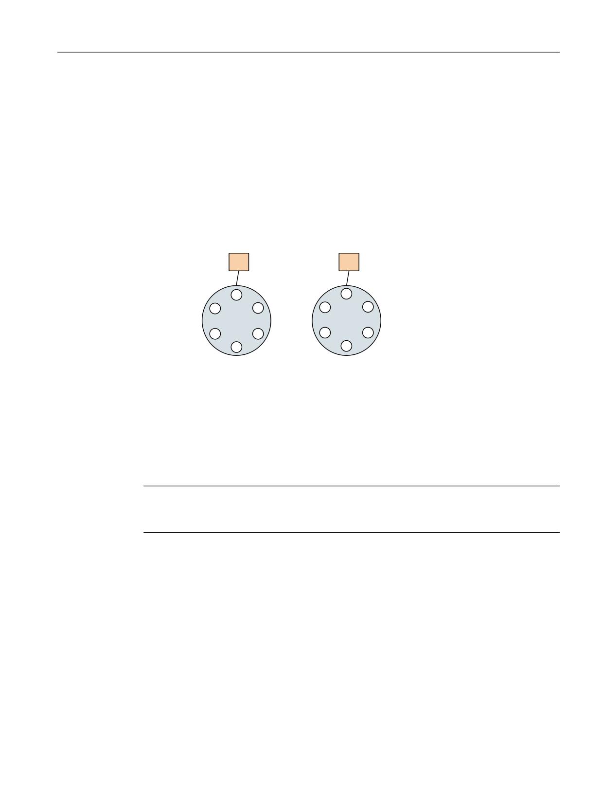
Description of functions
8.4 Tool change box-type, chain, circular magazines
8.4.23
Several magazines in one channel or one TO unit
Address extension
The NC address T can be programmed with an address extension. The tool management
function interprets the programmed address extension as a spindle number or toolholder
number. The NC address T without programmed address extension then refers to the main
spindle (master spindle).
7&B033 >
@
VSLQGOH ORFDWLRQ
7&B033 >
@
VSLQGOH ORFDWLRQ
7&B033 >
@
WRRO KROGHU QR
7&B033 >
@
WRRO KROGHU QR
7RRO KROGHU
7RRO KROGHU
'LVWDQFH UHODWLRQVKLS
'LVWDQFH UHODWLRQVKLS
0DJD]LQH
0DJD]LQH
3DUW SURJUDP
7
0DJD]LQH IRU WRRO KROGHU ORFDWLRQ
7
0DJD]LQH IRU WRRO KROGHU ORFDWLRQ
7
7
Figure 8-29
T="location" and several magazines in the same channel
The diagram shows the procedure for using more than one magazine in a channel (when
programming with T="location" this is usually a turret).
Note
The tool offset is only calculated for the toolholder that is assigned at that point in time to the
master spindle or the master toolholder.
8.4.24
Reset and start mode
Fundamentals
The tool offset selection/deselection can be set in the machine data for program end or reset as
well as for NC Start.
It is also possible to permanently preset the change for a specific tool, e.g. at NC Start.
Tool management
Function Manual, 10/2020, 6FC5397-1HP40-0BA1
431
Description of functions
8.4 Tool change box-type, chain, circular magazines
The settings are made in the following machine data:
• MD20310 $MC_TOOL_MANAGEMENT_MASK
• MD20110 $MC_RESET_MODE_MASK
• MD20112 $MC_START_MODE_MASK
• MD20122 $MC_TOOL_RESET_NAME
• MD20130 $MC_CUTTING_EDGE_RESET_VALUE
The function and interaction of the machine data are displayed in the following diagram.
&KDQQHO VSHFLILF PDFKLQH GDWD
0&B722/B0$1$*(0(17B0$6. ELW
0'
0&B5(6(7B02'(B0$6.
%LW
0'
0&B722/B5(6(7B1$0(
0'
0&B&877,1*B('*(B5(6(7B9$/8(
%LW
0'
0&B63,1'B'()B0$67(5B63,1'
%LW
0'
0&B722/B0$1$*(0(17B722/+2/'(5
0'
0&B67$57B02'(B0$6.
,I WRRO GLVDEOHG RQ
%LW
0'
0&B722/B&+$1*(B(5525B02'(
VSLQGOH
%LW
0'
0&B722/B5(6(7B1$0(
0'
0&B&877,1*B('*(B5(6(7B9$/8(
)LJ
0'
0&B63,1'B'()B0$67(5B63,1'
0'
0&B722/B0$1$*(0(17B722/+2/'(5
)LJ
Figure 8-30
Reset and start mode
Tool management
432
Function Manual, 10/2020, 6FC5397-1HP40-0BA1

Description of functions
8.4 Tool change box-type, chain, circular magazines
MD20110 $MC_RESET_MODE_MASK
Bit
Val
Meaning
ue
0
0
The offset remains unchanged, i.e. after end of part program and reset, the last programmed
offset remains active (behavior as with bit 0=1 and 6=1).
1
Reset mode, i.e. evaluation of bits 4 ... 11
2
1
Reset behavior (tool offset) with tool management not active. No effect if tool management
active
6
0
Reset behavior corresponds to MD $MC_TOOL_RESET_NAME and $MC_CUTTING_EDGE_RE-
SET_VALUE
1
Current setting for active tool length compensation is retained beyond reset/end of part pro-
gram.
For active tool management, the tool that is located in the master spindle (general: master tool
holder) is selected.
If the tool on the spindle is disabled (but released), this state is ignored, there is no selection
of a sister tool! (Replacement tool with Start_INIT only).
Activation takes place on the master spindle defined in MD $MC_SPIND_DEF_MASTER_SPIND,
or on the master tool holder defined in $TC_TOOL_MANAGEMENT_TOOLHOLDER.
The tool in the last programmed master spindle or master tool holder can also be active. Bit 16
or 17 is used for this purpose.
Reset behavior for spindles
Bit
Val
Meaning
ue
16
0
The master spindle is the spindle defined in MD $MC_SPIND_DEF_MASTER_SPIND.
The settings in the machine data below refer to this data:
• $MC_TOOL_MANAGEMENT_MASK
• $MC_RESET_MODE_MASK
• $MC_START_MODE_MASK
• $MC_TOOL_RESET_NAME
• $MC_CUTTING_EDGE_RESET_VALUE
1
The spindle last programmed with SETMS(x) remains the master spindle after end of program
and reset, regardless of the machine data setting.
This means that if bits 0/6=1, the offset remains active for the tool which is placed in the
spindle.
Power on behavior
The machine data setting is active after power on.
This means the offset for the tool which is placed in the spindles specified in MD
$TC_SPIND_DEF_MASTER_SPIND becomes active; the offset value is that of the smallest avail-
able D no. for this tool.
Tool management
Function Manual, 10/2020, 6FC5397-1HP40-0BA1
433

Description of functions
8.4 Tool change box-type, chain, circular magazines
Reset behavior for tool holder
Bit
Val
Meaning
ue
17
0
The master tool holder is the tool holder specified in MD $TC_TOOL_MANAGEMENT_TOOL-
HOLDER.
The settings in the machine data below refer to this data:
• $MC_TOOL_MANAGEMENT_MASK
• $MC_RESET_MODE_MASK
• $MC_START_MODE_MASK
• $MC_TOOL_RESET_NAME
• $MC_CUTTING_EDGE_RESET_VALUE
1
The tool holder last programmed with SETMTH(x) remains the master tool holder after end of
program and reset, regardless of the machine data setting.
This means that if bit 0=1 and bit 6=1, the offset remains active for the tool which is positioned
in this tool holder.
The machine data setting is active after power on.
This means the offset for the tool which is positioned in the tool holder specified in
$MC_TOOL_MANGEMENT_TOOLHOLDER becomes active; the offset value is that of the small-
est available D no. for this tool
MD22562 $MC_TOOL_CHANGE_ERROR_MODE
Bit
Val
Meaning
ue
3
0
Change command for a replacement tool is output.
1
The status of the disabled spindle tool is ignored. (Exception: un-released tools). The tool
becomes active with the last programmed offset.
4
0
Change command for a replacement tool is output.
1
The spindle tool is set down - "T0" is output.
MD20122 $MC_TOOL_RESET_NAME
Identifier of tool to be loaded
This tool is either loaded when end of program is reached or at reset or Power On if the associated
setting is made in MD $MC_RESET_MODE_MASK, or with NC Start if the respective setting was
made in MD $MC_START_MODE_MASK.
If there are no entries here ($MC_TOOL_RESET_NAME="") this corresponds to "T0".
MD20130 $MC_CUTTING_EDGE_RESET_VALUE
D number of tool which is to be loaded via $MC_TOOL_RESET_NAME.
This means the tool becomes active with the offset set here.
If no entries are made in this machine data, the behavior corresponds to "D0".
Tool management
434
Function Manual, 10/2020, 6FC5397-1HP40-0BA1

Description of functions
8.4 Tool change box-type, chain, circular magazines
MD20124 $MC_TOOL_MANAGEMENT_TOOLHOLDER
Specifies whether a tool holder number or spindle number is to be specified to define the location
of the tool to be loaded.
MD20090 $MC_SPIND_DEF_MASTER_SPIND
Definition of master spindle in channel. The number of the spindle is set.
MD20310 $MC_TOOL_MANAGEMENT_MASK
Bit 14 is used to activate the reset and start behavior. If bit 14 is not set, the settings in machine
data $MC_RESET_MODE_MASK and $MC_START_MODE_MASK which are specific to tool
management have no meaning.
MD20112 MC_START_MODE_MASK
Bit
Val
Meaning
ue
6
0
The last programmed offset remains active.
If the tool on the spindle is disabled, bits 3 and 4 are additionally evaluated in
MD $MC_TOOL_CHANGE_ERROR_MODE.
1
Start behavior (tool and offset selection) according to MD $MC_TOOL_RESET_NAME and
$MC_CUTTING_EDGE_RESET_VALUE
Start behavior for spindles
Bit
Val
Meaning
ue
16
0
The offset that was last selected remains active.
It does not matter whether the offset was selected in the part program or via settings in MD
$MC_RESET_MODE_MASK.
The offset for the tool placed in the master tool holder that was last programmed can also be
active (see $MC_RESET_MODE_MASK)
1
The tool holder specified in MD $MC_Tool_Management_Toolholder becomes active.
This means an offset selection refers specifically to this tool holder.
Start behavior for tool holder
Bit
Val
Meaning
ue
17
0
The offset that was last selected remains active.
It does not matter whether the offset was selected in the part program or via settings in MD
$MC_RESET_MODE_MASK.
The offset for the tool placed in the master spindle that was last programmed can also be active
(see $MC_RESET_MODE_MASK).
1
The spindle defined in MD20090 $MC_SPIND_DEF_MASTER_SPIND becomes active.
This means an offset selection refers specifically to this spindle.
Tool management
Function Manual, 10/2020, 6FC5397-1HP40-0BA1
435

Description of functions
8.4 Tool change box-type, chain, circular magazines
Note
A power on always triggers a reset ⇒ The settings in MD20110 $MC_RESET_MODE_MASK are
active after a power on.
Example 1:
In this example, the tool on the spindle is to remain active after end of program (M02/M30) and
reset.
The following applies:
• $MC_TOOL_CHANGE_MODE = 1
• $MC_CUTTING_EDGE_DEFAULT = -2
The following settings need to be made:
$MC_TOOL_MANAGEMENT_MASK
Bit 14=1
for reset and start behavior to be active
$MC_RESET_MODE_MASK
Bit 0=1,
for the tool offset to remain active
Bit 6=1
$MC_START_MODE_MASK
Bit 6=0
for the tool offset to remain active
NC program: %MPFxxx1
N110 T="MILLER_10"
N115 M06
;Tool "MILLER_10" is loaded
N120 G90 G00 D2 X...
;Offset D2 becomes active
…
N850 M30
;Offset D2 remains active
At the next program start tool "MILLER_10" is active with offset D2.
NC program: %MPFxxx2
N10 G90 G00 Z100
;This block is executed with offset D2
Example 2:
The spindle tool is to be removed at the end of program and reset ("automatic T0").
The following applies:
• $MC_TOOL_CHANGE_MODE = 1
• $MC_CUTTING_EDGE_DEFAULT = -2
• One spindle
Tool management
436
Function Manual, 10/2020, 6FC5397-1HP40-0BA1
Description of functions
8.4 Tool change box-type, chain, circular magazines
The following settings need to be made:
$MC_TOOL_MANAGEMENT_MASK.bit 14 = 1 Reset and start behavior is activated
$MC_RESET_MODE_MASK.bit 0 = 1 and bit 6 = Reset behavior:
0
• TOOL_RESET_NAME
• CUTTING_EDGE_RESET_VALUE
$MC_TOOL_RESET_NAME=""
Name of the tool that should be loaded at
change with reset. If no name is entered here,
this has the same meaning as T0
$MC_CUTTING_EDGE_RESET_VALUE = 0
The above mentioned tool becomes active
with this offset ("0" ≙ D0)
$MC_START_MODE_MASK.bit 6=0
The tool offset remains active. In the example:
D0
Example 3:
In this example, a specific tool is to be loaded at NC start, e.g. a probe.
The following applies:
• $MC_TOOL_CHANGE_MODE = 1
• $MC_CUTTING_EDGE_DEFAULT = -2
• One spindle
The following settings need to be made:
$MC_TOOL_MANAGEMENT_MASK Bit 14=1
Reset and start behavior is activated
$MC_START_MODE_MASK Bit 6=1
Start behavior
• TOOL_RESET_NAME
• CUTTING_EDGE_RESET_VALUE
$MC_TOOL_RESET_NAME="Probe_1"
Name of the tool that was loaded with reset/
start.
In the example: "Probe_1"
$MC_CUTTING_EDGE_RESET_VALUE=1
The above mentioned tool becomes active
with this offset, here D1
$MC_RESET_MODE_MASK Bit 6=0
Is not relevant for this example
Example 4:
In this example, the tool on the master spindle that was last programmed is to remain active
following end of program (M30/M02) and reset.
The following applies:
• $MC_TOOL_CHANGE_MODE = 1
• $MC_CUTTING_EDGE_DEFAULT = -2
• Two spindles
• $MC_SPIND_DEF_MASTERSPIND=1
Tool management
Function Manual, 10/2020, 6FC5397-1HP40-0BA1
437

Description of functions
8.4 Tool change box-type, chain, circular magazines
The following settings need to be made:
$MC_TOOL_MANAGEMENT_MASK.bit 14=1 Reset and start behavior is activated
$MC_RESET_MODE_MASK.bit 0=1 and bit 6=1 Leave the tool offset active
$MC_RESET_MODE_MASK.bit 16=1
The last programmed master spindle remains
active.
$MC_START_MODE_MASK.bit 6=0
The current offset remains active.
NC program
Program code
Comment
N05 SETMS(1)
;Spindle becomes master spindle (is also set via MD)
N10 T="Tool1"
N15 M06
;Change to spindle 1
N80 SETMS(2)
;Spindle 2 becomes master spindle
N85 T="Tool2"
N90 M06
;Change to spindle 2
N95 G90 G00 D2 Z...
N230 M30
;It is active: Tool2 with offset D2 on spindle 2
Note
Using MD20310, bit 12 = 1 and the described settings, for each reset a preparation and change
command is output to the PLC and must be acknowledged by the PLC. The automatic positive
acknowledgement can also be used here.
Note
If a change is triggered by reset mode at POWER ON, the NC is stationary with "No NC ready" until
an end acknowledgment has been received for this change.
8.4.25
Repeating a tool change with the same tool identifier
Overview
The behavior for repeated tool changes with identical tool identifier is set using two bits of MD
20310 $MC_TOOLMANAGEMENT_MASK.
Bit 11 = 1
The tool preparation command is also output, if it was already output for the
tool. This setting is only effective as long as the prepared tool is still not located
on the requesting spindle or tool holder.
Bit 12 = 1
The tool preparation command is also output if the tool is already located in the
spindle / tool holder, however it is only issued just one more time.
Tool management
438
Function Manual, 10/2020, 6FC5397-1HP40-0BA1
Description of functions
8.4 Tool change box-type, chain, circular magazines
The default setting (bit 11 and bit 12=0) is selected so that the preparation command is not
executed if the tool is already located in the spindle / tool holder - or the same preparation was
programmed a multiple number of times.
Exception: Block search
Here the preparation command is always issued even if the tool is already positioned in the
spindle.
Repeating the T preparation before loading
Bit 11 = 0
Bit 11 = 1
N10 T="Tool1" Tool preparation command is out- Tool preparation command is output to
put to the PLC
the PLC
N20 T="Tool1" No output to the PLC (assuming that Tool preparation command is output to
the state of the tool is unchanged) the PLC
N22 M06
Change command to the PLC
Change command to the PLC
A typical application is providing a new tool (positioning a chain) and checking before the
change using the repeated T call.
New programming for the tool that is still able to be used on the tool holder
Example 1:
Bit 12 = 0
Bit 12 = 1
N10 T="Tool1" Tool preparation command to the PLC Tool preparation command to the PLC
N12 M06
Tool change command to the PLC
Tool change command to the PLC
N20 T="Tool2" Tool preparation command to the PLC Tool preparation command to the PLC
N30 T="Tool1" No output to the PLC. This preparation
Tool preparation command to the PLC.
replaces the preparation from block
This preparation replaces (as for bit 12
N20; it is identified that a tool, which
= 0) the preceding T preparation from
can be used from group "Tool1", has
N20. The checks on the NC side are
already been loaded.
identical. However, as a result of the
machine data setting, command out-
put is forced.
N32 M06
No change command to the PLC
Tool change command to the PLC be-
cause a tool preparation command
from block N30 was output.
If bit 12 = 0, the preparation command from block N30 is deleted in NCK. In the programming,
it appears as if N10, N12 and N32 were programmed. As the state of the tool "Tool1" on the tool
holder has not changed, M06 is not output to the PLC.
For this example, bit 11 has no significance.
Tool management
Function Manual, 10/2020, 6FC5397-1HP40-0BA1
439
Description of functions
8.4 Tool change box-type, chain, circular magazines
Example 2:
Bit 12 = 0
Bit 12 = 1
N10 T="Tool1" Tool preparation command to the PLC Tool preparation command to the PLC
N12 M06
Tool change command to the PLC
Tool change command to the PLC
N20 T="Tool1" No output to the PLC
Tool preparation command to the PLC
N30 T="Tool1" No output to PLC independently of bit
Output to PLC dependent upon bit 11
11 (there is no command which could
(bit 11 is considered within bit 12 = 1).
be output again)
N32 M06
No change command to the PLC
Tool change command to the PLC be-
cause a tool preparation command
from block N20 or N30 was output.
If bit 12 = 0, the preparation command from block N20 is deleted in NCK. In the programming,
it appears as if N10, N12 and N32 were programmed. As the state of the tool "Tool1" on the tool
holder has not changed, M06 is not output to the PLC.
Bit 12 is the higher-level setting and bit 11 only takes effect if something is to be output for bit
12 = 1.
New programming for the tool that can no longer be used on the tool holder
The time monitoring has, for example, set the tool to the "disabled" state.
N10 T = "Tool1" Tool preparation command to PLC
N12 M06
Tool change command to PLC
N20 T = "Tool2"
Tool preparation command to PLC
N30 T = "Tool1"
This tool preparation replaces the tool preparation from N20; tool man-
agement detects that a tool from group "Tool1" is loaded but that the tool
can no longer be used. A replacement tool is searched for in the tool group
and the tool preparation command is output to the PLC.
N32 M06
The tool change command N32 is output to the PLC.
For this example, bit 11 and bit 12 have no significance.
Condition for processing a new tool preparation command in the NC
N10 T = "Tool1"
N20 T = "Tool2" A command is only processed in the main run if the preceding command
from the PLC was acknowledged with "End".
The does not apply if N20 is not output to the PLC. Then the "End" acknowledgement must be
present for a new tool preparation command to be output to the PLC.
Tool management
440
Function Manual, 10/2020, 6FC5397-1HP40-0BA1
Description of functions
8.4 Tool change box-type, chain, circular magazines
Condition for processing a new tool change command in the NC
N10 T = "Tool1"
N12 M06
If bit 10=0 in $MC_TOOL_MANAGEMENT_MASK:
A command is also processed in the main run if the preceding tool prep-
aration command from the PLC has not yet been acknowledged with
"End".
If bit 10=1 in $MC_TOOL_MANAGEMENT_MASK:
A command is only processed in the main run if the preceding tool prep-
aration command from the PLC has been acknowledged with "End".
Tool management
Function Manual, 10/2020, 6FC5397-1HP40-0BA1
441
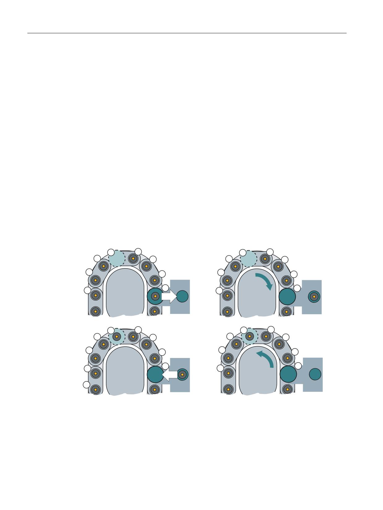
Description of functions
8.5 Relocating tools and positioning the magazine
8.5
Relocating tools and positioning the magazine
8.5.1
Relocating sequence
Basics
When it is relocated, a tool is transported from one magazine location to another. The relocation
takes place according to the following steps with DB71 (Page 125):
• The target address, the magazine, and the location for the tool to be relocated are transferred
via DB71.DBW(n+24) and DBW n+26.
• The origin of the tool is entered in DB71.DBW(n+20) and DBW(n+22).
• The target address is passed to FC8/FC6 as parameters "NewToolMag" and "NewToolLoc" and
status = 1 when relocation has been successfully completed.
• The parameters "OldToolMag" and "OldToolLoc" must be set to zero because the tool
management knows the location of the old tool.
• All relocation tasks are generally handled via the 1st interface of DB71.
The following graphic schematically shows the process of relocating via a loading magazine.
Alternatively, a buffer (spindle or gripper) can also be used:
0DJD]LQ
0DJD]LQ
0DJD]LQ
0DJD]LQ
Figure 8-31
Relocate tool
Tool management
442
Function Manual, 10/2020, 6FC5397-1HP40-0BA1
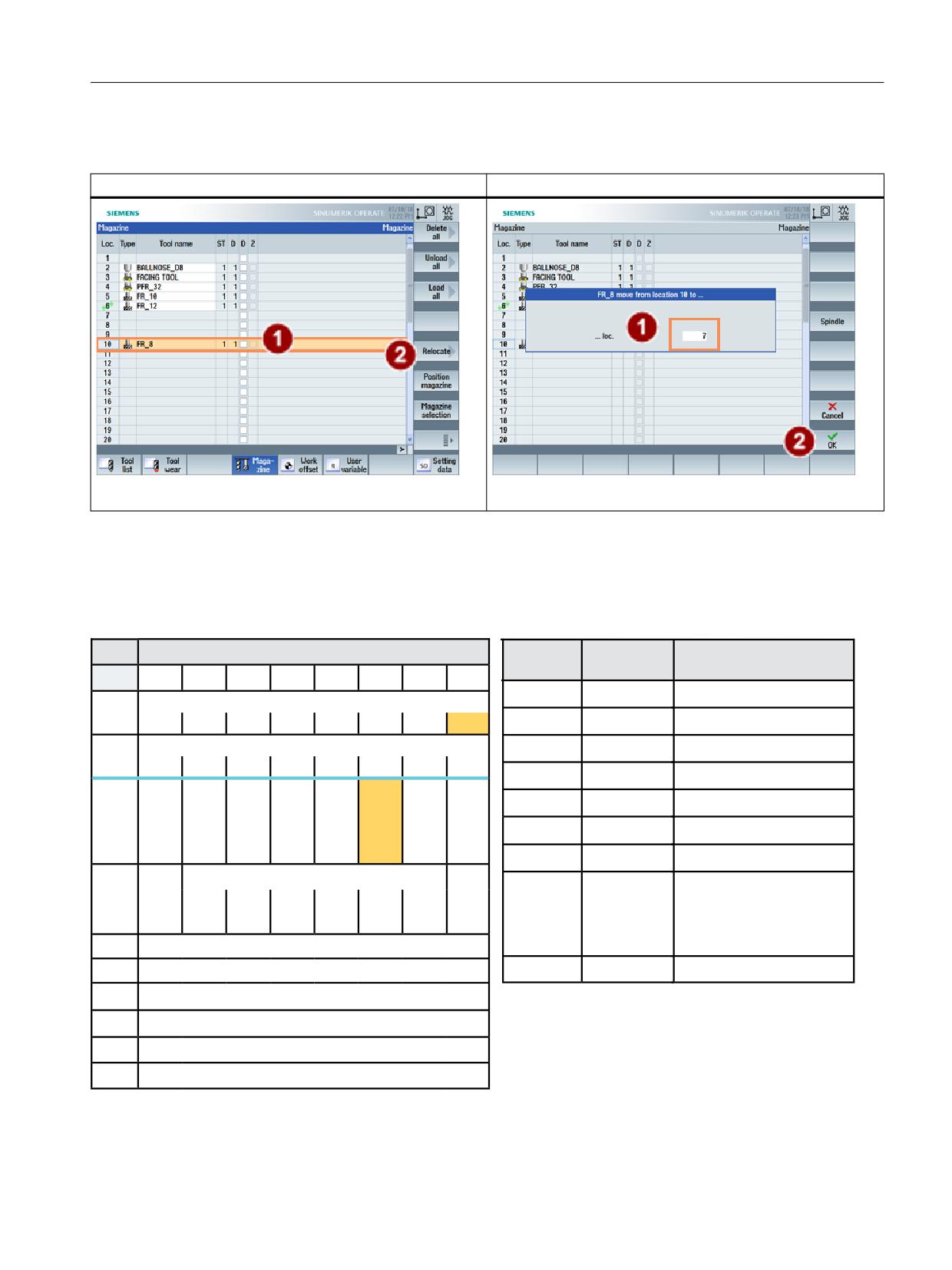
Description of functions
8.5 Relocating tools and positioning the magazine
The process is started, for example, via the "Relocate" command in SINUMERIK Operate.
Relocate - select tool
Relocate - execute
The following graphic shows an example of the parameterization of a relocation with DB71 and
FC6.
Example of relocating a tool
'%
/RDGLQJ XQORDGLQJ SRLQWV 1&. ! 3/&
)&
3DUDPHWHUV
0HDQLQJ
%\WH
%LW
%LW
%LW
%LW
%LW
%LW
%LW
%LW
6WDUW
758(
7UDQVIHU LV EHLQJ VWDUWHG
,QWHUIDFH 66 DFWLYH
'%%
7DVN,GHQW
'% LQWHUIDFH
66
66
66
66
66
66
66
66
,QWHUIDFH 66 DFWLYH
7DVN,GHQW1R
,QWHUIDFH
'%%
66
66
66
66
66
66
66
66
1HZ7RRO0DJ
'% '%:
7DUJHW PDJD]LQH IRU UHORFDWLQJ
5HV
5HV
3RV
-RE
3RV
5HOR
8QORD
/RD
1HZ7RRO/RF
'% '%:
7DUJHW ORFDWLRQ IRU UHORFDWLQJ
PXOWL
IURP
PDJD
FDWLQJ
GLQJ
GLQJ
WRRO
1&
]LQH
'%%
2OG7RRO0DJ
'% '%:
6RXUFH PDJD]LQH IRU UHORFDWLRQ
SURJ
2OG7RRO/RF
'% '%:
6RXUFH ORFDWLRQ IRU UHORFDWLRQ
'DWD LQ
$FNQ
5HVHUYHG
6WDWXV
2SHUDWLRQ WHUPLQDWHG
'%
6WDW
UHORFDWLRQ ZLWKLQ PDJD]LQH
'%%
2SHUDWLRQ WHUPLQDWHG
UHORFDWLRQ WR PDJD]LQH
ZLWK
ORFDWLRQ UHVHUYDWLRQ
'%:
,GHQWLILHU IRU ORDGLQJ XQORDGLQJ SRLQW IL[HG YDOXH
0XOWLWRRO/RF
'XULQJ UHORFDWLRQ
'%:
1R RI ORDGLQJ SRLQW
0DJ 1R 6RXUFH IRU XQORDGLQJ UHORFDWLQJ SRVLWLRQLQJ
'%:
([DPSOH 5HORFDWH WRRO IURP ORFDWLRQ WR
'%:
/RFDWLRQ 1R 6RXUFH IRU XQORDGLQJ UHORFDWLQJ SRVLWLRQLQJ
'% '%:
'% '%:
'%:
0DJ 1R 7DUJHW IRU ORDGLQJ UHORFDWLQJ SRVLWLRQLQJ
'% '%:
'%:
0DJ 1R 7DUJHW IRU ORDGLQJ UHORFDWLQJ SRVLWLRQLQJ
'% '%:
Figure 8-32
Relocate - DB71
Tool management
Function Manual, 10/2020, 6FC5397-1HP40-0BA1
443
Description of functions
8.5 Relocating tools and positioning the magazine
8.5.2
Relocation by the PLC
Task from PLC
The PLC can also issue a task to tool management to relocate a tool. This is done by notifying a
new location for the tool to the tool management. The FC8/FC6 block (TaskIdent := 4) is called
with the following parameters:
• Old magazine no. (OldToolMag)
• Old location no. (OldToolLoc)
• New magazine no. (NewToolMag)
• New location no. (NewToolLoc)
PLC sample programs
The following sample programs (definition of DB150 (Page 122)) show the acknowledgement
of loading via interface 1. To this end, the network is programmed in an FC150 user block.
Sample program "Load magazine"
NETWORK TITLE = Acknowledgement relocation interface 1
U
E 86.0; //acknowledgement is done here via the terminal E 86.0
U
DB71.DBX
0.1; //Interface 1 active
U
DB71.DBX
4.2; //Loading active
FP
M 150.4;
SPBN
M140;
L
1;
T
DB150.DBB
0; //DB71
L
2;
T
DB150.DBB
1; //Interface 1
L
DB71.DBW
28;
T
DB150.DBW
2; //Target magazine for relocation
L
DB71.DBW
30;
T
DB150.DBW
4; //Target location for relocation;
L
DB71.DBW
24;
T
DB150.DBW
6; //Source magazine for relocation
L
DB71.DBW
26;
T
DB150.DBW
8; //Source location for relocation
L
DB71.DBW
28;
L
W#16#270E;
<>I ;
SPB
M142; //Relocation in spindle? No->
L
6;
T
DB150.DBW
10; //Status 6
SPA
M141;
M142: L
1;
T
DB150.DBW
10; //Status 1
M141: L
-1;
T
DB150.DBW
12;
SET ;
S
DB150.DBX
16.0; //Start FC6
M140: NOP 0;
Tool management
444
Function Manual, 10/2020, 6FC5397-1HP40-0BA1

Description of functions
8.5 Relocating tools and positioning the magazine
Example of a transfer with FC6
NETWORK TITLE =Tool management status transfer
CALL FC 6 (//Tool management transfer block
Start
:= DB150.DBX 16.0,//Start
TaskID
:= DB150.DBB 0,
TaskIDNo
:= DB150.DBB 1,
NewToolMag
:= DB150.DBW 2,//Pos new tool
NewToolLoc
:= DB150.DBW 4,
OldToolMag
:= DB150.DBW 6,//Pos old tool
OldToolLoc
:= DB150.DBW 8,
Status
:= DB150.DBW 10,//Status
MultitoolLoc
:= DB150.DBW 12,
Ready
:= DB150.DBX 16.1,
Error
:= DB150.DBW 14);
U
DB150.DBX
16.1; //Ready prompt
R
DB150.DBX
16.0; //Reset start
L
DB150.DBW
14; //Error information
L 0;
<>I ; //Evaluate error
R
DB150.DBX 16.0; //Reset start
Example 1
The tool in magazine No. 1, location No. 5 is to be relocated to magazine No. 2, location No. 17.
The PLC takes responsibility for ensuring that the location type is correct for the transfer. This
example for calling an FC8 does not take into consideration any checkback signal to tool
management for intermediate positions of tools.
FC8 parameters
Values
Comment
Start
Starts task
TaskIdent
4
Task from PLC
TaskIdentNo
1
Channel No. for tool management
NewToolMag
2
New magazine No.
NewToolLoc
17
New location No.
OldToolMag
1
Old magazine No.
OldToolLoc
5
Old location No.
Status
1
Operation completed
Example 2
Example: The tool is to be relocated from mag. No. 1, location No. 5 via grippers 3 and 4 to mag.
No. 2, location No. 17.
FC8/FC6 must be called four times in this procedure. Only the important parameters are listed.
All other parameters are as for the example above.
The tool is transported in 4 steps:
Tool management
Function Manual, 10/2020, 6FC5397-1HP40-0BA1
445

Description of functions
8.5 Relocating tools and positioning the magazine
1. From magazine 1, location 5 to gripper 3 (location no. 4)
FC8 parameters
Values
Comment
Start
Starts task
TaskIdent
4
Task from PLC
TaskIdentNo
1
Channel No. for tool management
NewToolMag
9998
New magazine No.
NewToolLoc
4
New location No.
OldToolMag
1
Old magazine No.
OldToolLoc
5
Old location No.
Status
1
Operation completed
2. Moved from gripper 3 to transfer location 2, location no. 6.
FC8 parameters
Values
Comment
Start
Starts task
TaskIdent
4
Task from PLC
TaskIdentNo
1
Channel No. for tool management
NewToolMag
9998
New magazine No.
NewToolLoc
6
New location No.
OldToolMag
9998
Old magazine No.
OldToolLoc
4
Old location No.
Status
1
Operation completed
3. Moved from transfer location 2, location no. 6 in gripper 4, location no. 5.
FC8 parameters
Values
Comment
Start
Starts task
TaskIdent
4
Task from PLC
TaskIdentNo
1
Channel No. for tool management
NewToolMag
9998
New magazine No.
NewToolLoc
5
New location No.
OldToolMag
9998
Old magazine No.
OldToolLoc
6
Old location No.
Status
1
Operation completed
4. From gripper 4, location no. 5 to magazine 2, location 17
FC8 parameters
Values
Comment
Start
Starts task
TaskIdent
4
Task from PLC
TaskIdentNo
1
Channel No. for tool management
NewToolMag
2
New magazine No.
NewToolLoc
17
New location No.
OldToolMag
9998
Old magazine No.
OldToolLoc
5
Old location No.
Status
1
Operation completed
Tool management
446
Function Manual, 10/2020, 6FC5397-1HP40-0BA1
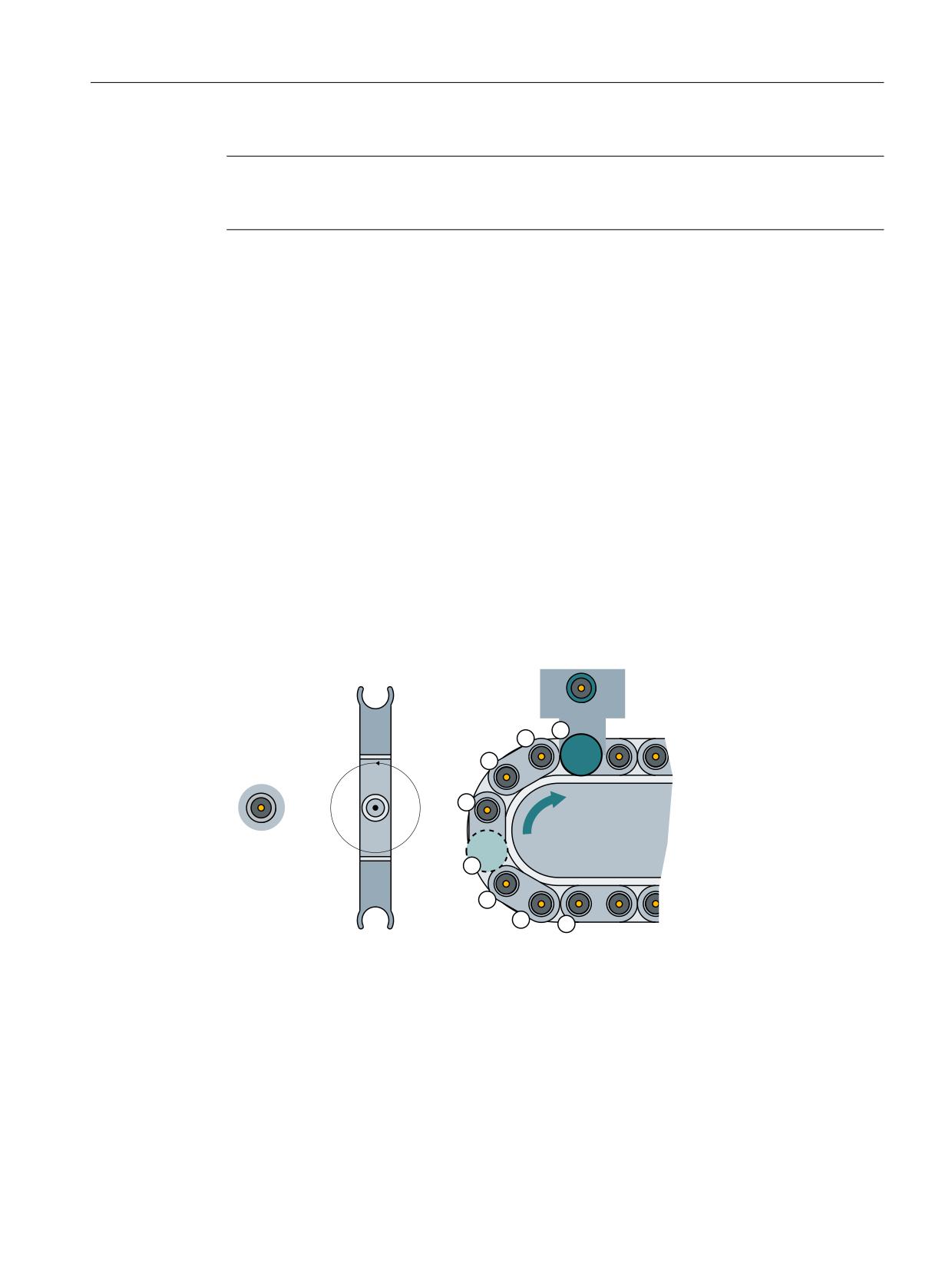
Description of functions
8.5 Relocating tools and positioning the magazine
Note
TaskIdent 5 may be programmed only for a tool transfer (magazine → buffer location).
Otherwise an error message is output, even though the tool is transferred.
The reservation is automatically reset when the tool is transferred from the buffer back into the
magazine.
8.5.3
Positioning the magazine
Overview
When positioning, a traversing task is sent to the PLC by the tool management via DB71
(Page 125).
• Bit 3 is set in DB71.DBB(n+0) "Position to the loading point".
• The magazine No. and the location No. (as target) are transferred in the parameters
DB71.DBW(n+20) and (n+22) during positioning.
The PLC then moves this location to the loading point. The number of the loading point is
entered in DB71.DBW (n+18) or determined by the number of the interface. If the PLC has moved
the magazine location to the loading point, FC8/FC6 is called and the operation is acknowledged
with status 5, position change. For loading point 2, n = 34.
%6
0,//,1*B722/B
*
%6
6S 6SLQGOH
%6
ORDGLQJ SRLQW
* *ULSSHU
* *ULSSHU
%6
ORDGLQJ SRLQW
0DJD]LQH
6S
*
Figure 8-33
Positioning a magazine location
Example:
Location 5 in magazine 1 (source) must be moved to the loading magazine 2 (target).
Tool management
Function Manual, 10/2020, 6FC5397-1HP40-0BA1
447
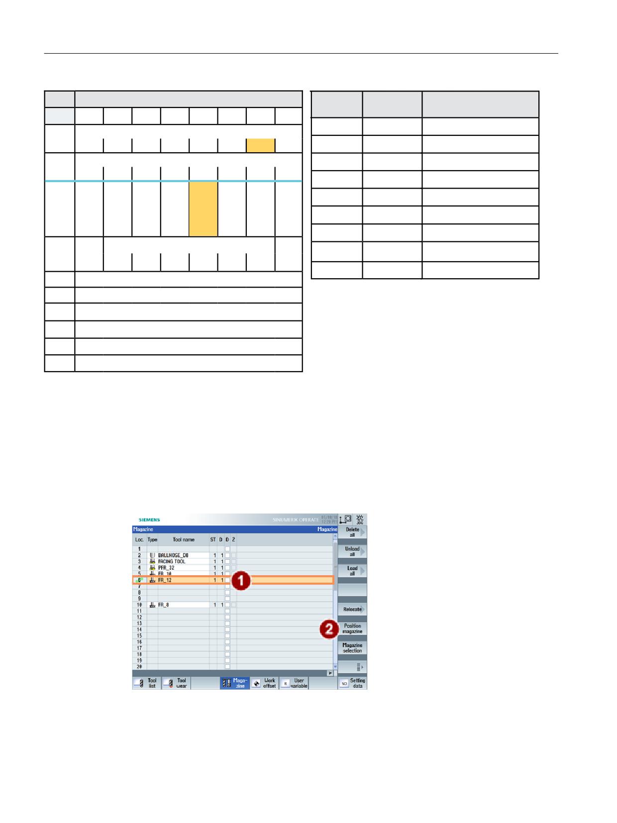
Description of functions
8.5 Relocating tools and positioning the magazine
'%
/RDGLQJ XQORDGLQJ SRLQWV 1&. ! 3/&
)&
3DUDPHWHUV
0HDQLQJ
%\WH
%LW
%LW
%LW
%LW
%LW
%LW
%LW
%LW
6WDUW
758(
7UDQVIHU LV EHLQJ VWDUWHG
,QWHUIDFH 66 DFWLYH
'%%
7DVN,GHQW
'% LQWHUIDFH
66
66
66
66
66
66
66
66
,QWHUIDFH 66 DFWLYH
7DVN,GHQW1R
,QWHUIDFH
'%%
66
66
66
66
66
66
66
66
1HZ7RRO0DJ
'% '%:
7DUJHW PDJD]LQH IRU SRVLWLRQLQJ
5HV
5HV
3RV
-RE
3RV
5HOR
8QORD
/RD
1HZ7RRO/RF
'% '%:
7DUJHW ORFDWLRQ IRU SRVLWLRQLQJ
PXOWL
IURP
PDJD
FDWLQJ
GLQJ
GLQJ
WRRO
1&
]LQH
'%%
2OG7RRO0DJ
'XULQJ SRVLWLRQLQJ
SURJ
2OG7RRO/RF
'XULQJ SRVLWLRQLQJ
'DWD LQ
5HVHUYHG
$FNQ
6WDWXV
2SHUDWLRQ FRPSOHWHG
'%
6WDW
'%%
0XOWLWRRO/RF
'XULQJ SRVLWLRQLQJ
'%:
,GHQWLILHU IRU ORDGLQJ XQORDGLQJ SRLQW IL[HG YDOXH
1R RI ORDGLQJ SRLQW
([DPSOH 0DJD]LQH ORFDWLRQ SRVLWLRQLQJ WR ORDGLQJ SRLQW
'%:
'% '%:
0DJ 1R 6RXUFH IRU XQORDGLQJ UHORFDWLQJ SRVLWLRQLQJ
'%:
'% '%:
'% '%:
'%:
/RFDWLRQ 1R 6RXUFH IRU XQORDGLQJ UHORFDWLQJ SRVLWLRQLQJ
'% '%:
'%:
0DJ 1R 7DUJHW IRU ORDGLQJ UHORFDWLQJ SRVLWLRQLQJ
'%:
0DJ 1R 7DUJHW IRU ORDGLQJ UHORFDWLQJ SRVLWLRQLQJ
Figure 8-34
Positioning DB71
Parameters "OldToolMag" and "OldToolLoc" in FC8/FC6 are not required for positioning because
only the PLC requires the information for traversing the magazine. The values for NewToolMag
and NewToolLoc are from DB71(n+24 and n+26). The PLC has to execute the positioning task
and acknowledge it with the FC8/FC6 call.
Initiate positioning via Operate
The selected magazine location is moved to the loading point via the "Positioning" softkey.
Figure 8-35
Positioning a magazine location
Tool management
448
Function Manual, 10/2020, 6FC5397-1HP40-0BA1
Description of functions
8.5 Relocating tools and positioning the magazine
PLC sample programs (user program FC150)
The following sample programs (description of DB150 (Page 122)) show the acknowledgement
of loading via interface 2. To this end, the network is programmed in an FC150 user block.
Example program "Position magazine"
NETWORK TITLE = Acknowledgement positioning interface 2
U E 86.0; //acknowledgement is done here via the terminal E 86.0
U DB71.DBX 0.1; //Interface 2 active
U DB71.DBX 34.3; //Magazine pos. active
FP M 150.5;
SPBN M150;
L 1;
T DB150.DBB 0; //DB71
L 2;
T DB150.DBB 1; //Interface 2
L DB71.DBW 58;
T DB150.DBW 2; //Target magazine for positioning
L DB71.DBW 60;
T DB150.DBW 4; //Target location for positioning
L 0;
T DB150.DBW 6;
T DB150.DBW 8;
L 1;
T DB150.DBW 10; //Status 5
L -1;
T DB150.DBW 12;
S DB150.DBX 16.0; //Start FC6
M150: NOP 0;
Example of a transfer with FC6
NETWORK TITLE =Tool management status transfer
CALL FC 6 (//Tool management transfer block
Start
:= DB150.DBX 16.0,//Start
TaskID
:= DB150.DBB 0,
TaskIDNo
:= DB150.DBB 1,
NewToolMag
:= DB150.DBW 2,//Pos new tool
NewToolLoc
:= DB150.DBW 4,
OldToolMag
:= DB150.DBW 6,//Pos old tool
OldToolLoc
:= DB150.DBW 8,
Status
:= DB150.DBW 10,//Status
MultitoolLoc
:= DB150.DBW 12,
Ready
:= DB150.DBX 16.1,
Error
:= DB150.DBW 14);
U DB150.DBX 16.1; //Prompt ready
R DB150.DBX 16.0; //Reset start
L DB150.DBW 14; //Error information
L 0;
<>I ; //Evaluate error
R DB150.DBX 16.0; //Reset start
Tool management
Function Manual, 10/2020, 6FC5397-1HP40-0BA1
449
Description of functions
8.6 Several tools at a magazine location (multitool)
8.6
Several tools at a magazine location (multitool)
8.6.1
Brief description
Overview
With the TMMG function (magazine management) and when the "Multitools" function (MT) is
also activated, so-called multitools with a number of tools can be loaded into a magazine and
unloaded from a magazine like a tool.
A multitool is a mini turret with a number of tools that is loaded to a magazine and unloaded
from a magazine as one tool in the turning technology. The T selection in the part program also
detects and checks the tools of a multitool when searching for a tool.
Note
This function is supported in SINUMERIK Operate only.
Note
The following functions are not implemented in the current version:
• Manual tool (a multitool cannot be a manual tool)
• Magazine location adapter (a multitool can be located on an adapter, but adapters are not
permitted on multitool locations)
The T selection in the part program also detects and checks the tools of a multitool when
searching for a tool.
A multitool has a definable number of MT locations, where tools can be located. The geometrical
arrangement of the MT locations can either be defined using the MT location number, an angle
or via a distance.
The commands to select a tool and to change a tool sent to the PLC have additional information
regarding the distance reference point or the machining position:
• MT location number of the tool in the multitool, or
• Angle, or
• Distance of the tool within the multitool
This type of distance coding can be defined for each MT. The PLC then initiates the corresponding
machine handling, e.g. moving a positioning axis.
The acknowledgement block FC6 is provided in the PLC basic program. The block corresponds to
FC8. It only has one additional parameter "MultitoolPosition". The FC6 includes the complete
FC8 functionality, so that the FC6 can completely replace the FC8. Analogous to DB71, DB72 and
DB73, data blocks DB1071, DB1072 and DB1073 are available as user interface. If, for example,
a multitool is changed, then the complete information of the "carrier tool" is contained in DB72,
and all the information about the individual tool in DB1072.
Tool management
450
Function Manual, 10/2020, 6FC5397-1HP40-0BA1
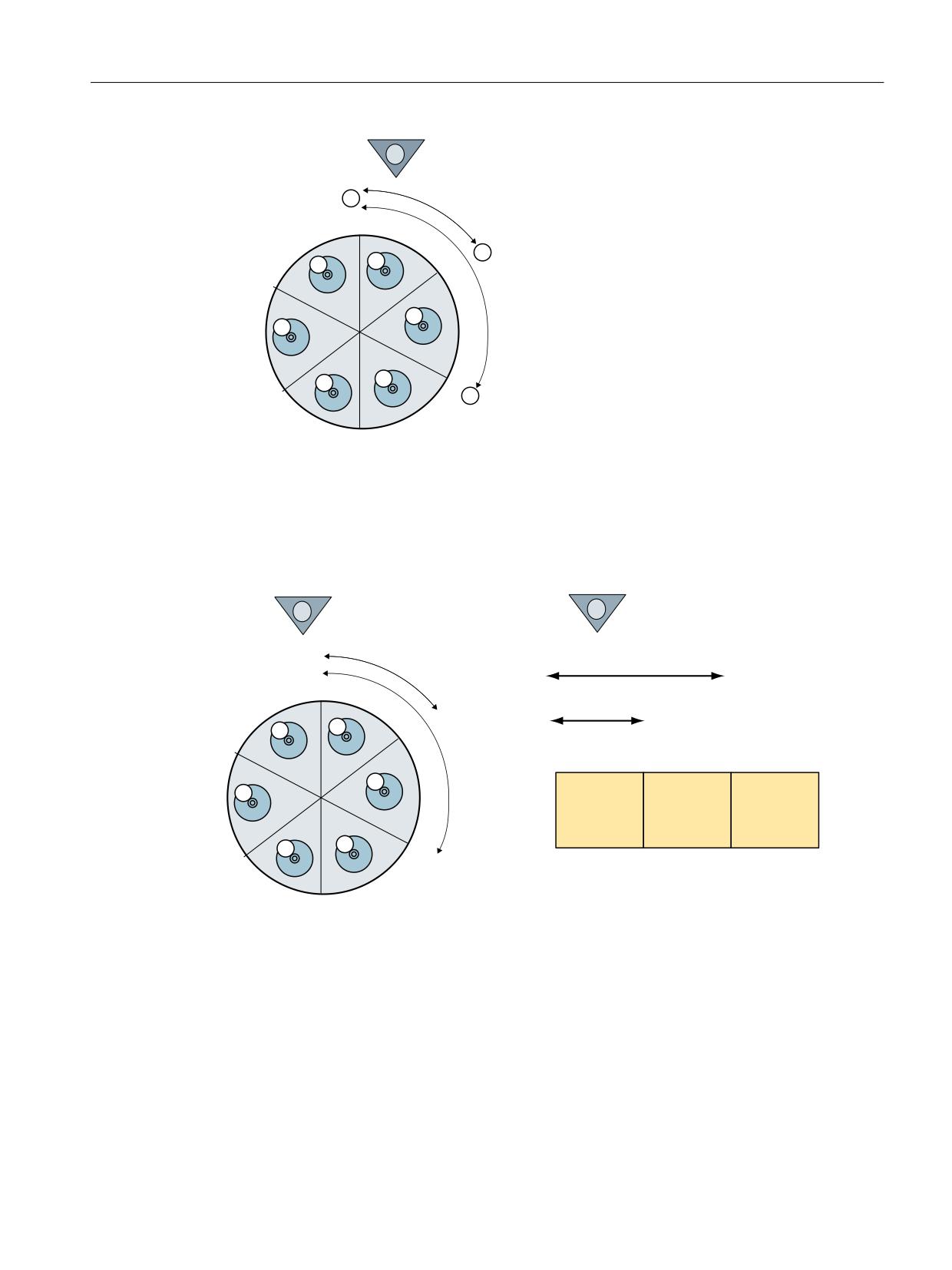
Description of functions
8.6 Several tools at a magazine location (multitool)
'LVWDQFH UHIHUHQFH SRLQW
/RFDWLRQ QXPEHU GHILQLWLRQ IRU WKH 07 ORFDWLRQ GLVWDQFH
07 ORFDWLRQ
07 ORFDWLRQ
07 ORFDWLRQ
Figure 8-36
Location number
The figure shows the distance coding of the locations in the multitool, i.e. the MT location
number of the particular MT location itself. This distance coding is especially suitable for
machines that operate with similar multitool geometries, e.g. only mini turrets.
'LVWDQFH UHIHUHQFH SRLQW
'LVWDQFH UHIHUHQFH SRLQW
˞
G
˞
G
G
7RRO $
7RRO $
7RRO %
GXSOR
GXSOR
GXSOR
˞
$QJOH GHILQLWLRQ
/HQJWK GHILQLWLRQ
IRU WKH 07 ORFDWLRQ GLVWDQFH
IRU WKH 07 ORFDWLRQ GLVWDQFH
˞
˞ $QJOH WR ORFDWLRQ
G
G DQJOH WR ORFDWLRQ
Figure 8-37
Angle and length
Typical geometries can be seen in this figure. Angle α and the lengths are output on the PLC. This
means, for example, that multitools can be used on a machine and handled by the PLC, which
have different geometries (MT locations are not symmetrically arranged: Although multitools
are inherently symmetrical, different multitools have different distances between the MT
locations).
Tool management
Function Manual, 10/2020, 6FC5397-1HP40-0BA1
451
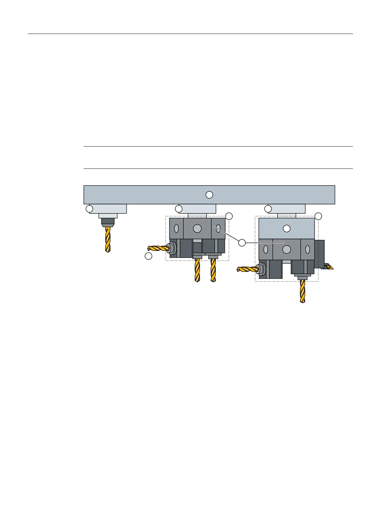
Description of functions
8.6 Several tools at a magazine location (multitool)
The distance reference point or the machining position is defined machine-specifically. The
assignment of the MT location numbers to the multitool locations must correspond to the
machine construction.
A multitool can contain tools from different tool groups, i.e. the names can be different.
Nothing changes when programming a tool change in the part program. Formally, the
commands are identical to existing commands; i.e. the tool change is programmed using T and/
or M06.
For the function T = turret location number, it is also necessary to define which tool of the turret
magazine is meant when the location contains more than one tool.
Note
Presently, SINUMERIK Operate supports the distance coding "angle" and "location number".
①
Magazine: $TC_MAP...
②
Magazine location: $TC_MAPP...
③
Multitool: $TC_MTP...
④
Magazine location adapter
⑤
Multitool location: $TC_MTPP...
⑥
Tool: $TC_TP.../$TC_DP...
Figure 8-38
Multitool shown in the magazine
The following machine data and NC commands are available for the "multitool" function:
Machine data
• $MN_MM_TOOL_MANAGEMENT_MASK, bit 10
Activation of the MT function
• $MN_MM_NUM_MULTITOOL
Number of defined MT (limit values: 0-1500; max. 600 per channel)
• $MN_MAX_TOOLS_PER_MULTITOOL
Max. number of tool locations per MT (limit values: 2-64)
Tool management
452
Function Manual, 10/2020, 6FC5397-1HP40-0BA1
Description of functions
8.6 Several tools at a magazine location (multitool)
NC commands / system parameters
• $TC_MTP, $TC_MTPP
Data definition for MT and MT location
• $TC_MTPC, $TC_MTPPC
MT OEM data for tool management
• $TC_MTPCS, $TC_MTPPCS
MT OEM data for Siemens
• NEWMT, DELMT
Creating, deleting
• POSMT
Positioning MT on tool holder MT location number
• $P_TMNOIS
What type does the number refer to: Magazine, tool or MT
• $P_MTOOLN, $P_MTOOLMT
Number of multitools, MT number of the i-th MT
• $P_MTOOLNT, $P_MTOOLT
Number of tools in the multitool, T number of the i-th tool
• $A_TOOLMTN, $A_TOOLMTLN
Location of the tool in the multitool, MT number / MT location number
• Synchronized action access in the tool management PLC command
$AC_TC_MTTN, $AC_TC_MTLTN, $AC_TC_MTNLOC, $AC_TC_TOOLIS, $AC_TC_MTDIST
NC commands
• RESETMON
Can reset the tool monitoring data of the tools in an MT to their setpoints
• GETT
Determines T no., MT no. for the name
• DELMLOWNER
Deletes the magazine owner location of the tool or MT
• MVTOOL
Moves tool or MT
• GETFREELOC
Searches for an empty location in the magazine for tool or MT, searches for an empty location
in the MT for tool
8.6.2
Programming
MT numbers
The multitool numbers originate from the same number space as the T numbers and the
magazine numbers.
Tool management
Function Manual, 10/2020, 6FC5397-1HP40-0BA1
453
Description of functions
8.6 Several tools at a magazine location (multitool)
Numbers 1-32000 are permitted for the T and magazine numbers. This allows multitools to be
handled just like simple tools (T number at the magazine location, T number as parameter in the
OPI PI service to load and unload tools, etc.). In addition, in some instances MT numbers can be
handled just like magazine numbers.
Users can explicitly enter T or MT numbers in the NC programming, if they want to create a tool
or multitool by programming $TC_TPx or $TC_MTPx. Explicitly programmed MT numbers must
not collide with already defined T numbers or magazine numbers. The programming is then
aborted with an alarm. However, if users create a new tool with the language command NEWT
- or for multitools with NEWMT - then the NC automatically allocates the T or MT numbers.
When automatically allocating an MT number, it is ensured that this is neither an already
defined tool nor an already defined magazine.
NC language commands or system parameters, which have a tool T number or magazine
number as parameter or index, and which are called using an MT number, generate an alarm if
the associated functionality for multitool is not explicitly defined.
The same number can be used for a tool and a magazine.
Example 1:
The magazine numbers 1, 2, 3, -, 5, -, -, - and the T numbers 1, -, 3, -, 5, 6, -, -, have already been
defined.
Then -, -, -, 4, -, -, 7, 8 are available for the MT numbers.
Example 2:
The magazine numbers 1, 2, 3, -, 5, -, -, - and the MT numbers -, -, -, 4, -, 6, 7, -, have already been
defined.
Then 1, 2, 3, -, 5, -, -, 8 are available for the T numbers.
MT names
Multitool names come from the same namespace as the tool names and magazine names.
Different multitools must have different names, i.e. a duplo number is not defined.
An MT name must not be the same as a tool name and not the same as a magazine name.
Hoever, a magazine name can be the same as a tool name.
8.6.3
Tool change with a tool from a multitool
Overview
A tool change for a multitool means, on the one hand, the change of the multitool itself and, on
the other hand, the change of the tool on the multitool.
The programming of a tool change for a multitool is done via the commands "T=.." and M06. The
following programming selects an appropriate tool from the tool group "Mill_150" and loads it:
T= "Miller_150"
M06
D1
Tool management
454
Function Manual, 10/2020, 6FC5397-1HP40-0BA1
Description of functions
8.6 Several tools at a magazine location (multitool)
If, corresponding to the tool search strategy, the tool found is located in a multitool, then this
does not play a role regarding activating the offset. The multitool is only involved when the data
for the tool change command is being compiled. The NC determines the distance value (->MT
location number or $TC_MTPPL/$TC_MTPPA) and adds this to the PLC command. For the tool
change itself, the multitool (with its individual tools) is moved from the magazine to the tool
holder. Using the data "Multitool location distance" that the NC sends with the tool change data
to the PLC, the PLC program must appropriately initiate the machine so that the active tool within
the multitool can machine the workpiece.
The state of tools within the multitool in question, which are not involved in an MT motion
operation, tool selection, tool change, does not change.
If programmed
T="name" M06 D1
and the name is that of a multitool, then Alarm 6404 "Tool change not possible" is generated.
Tool change from a multitool to a tool holder - PLC request
Example 1:
A multitool with four locations is in magazine 1, location 10, and has the TNo = 23. Angle
distance coding has been selected for the multitool; i. e. $TC_MTP_KD[23] = 3
The setting is $MC_TOOL_CHANGE_MODE=1, i.e. tool changed with M06.
The data of the defined and loaded multitool looks like this:
$TC_MTPN[23]=4
Number of locations
$TC_MTP2[23]="Multitool_ Identifiers
0"
$TC_MTP3[23]=2
Number of half locations (right), i.e. the multitool is over-
sized
$TC_MTP4[23]=2
Number of half locations (left)
$TC_MTP5[23]=2
Number of half locations (top)
$TC_MTP6[23]=2
Number of half locations (bottom)
$TC_MTP7[23]=1
Location type
$TC_MTP8[23]=130
Tool status (enabled, was in use)
$TC_MTP_POS[23]=2
MT position (is not evaluated, if the tool is located in the
magazine)
$TC_MTP_KD[23]=3
Distance coding (3 = angle)
$TC_MTP_PROTA[23]=""
Data for protection zone
$TC_MTPP2[23,1]=0
Location_1 - location type
$TC_MTPP4[23,1]=0
Location_1 - location state (occupied)
$TC_MTPP6[23,1]=1
Location_1 - equipped with T-No.1 ("Tool1")
$TC_MTPP7[23,1]=0
Location_1 - adapter No.
$TC_MTPPA[23,1]=0
Distance-angular value
$TC_MTPP2[23,2]=0
Location_2 ...
$TC_MTPP4[23,2]=0
$TC_MTPP6[23,2]=2
equipped with T-No.2 ("Tool2")
Tool management
Function Manual, 10/2020, 6FC5397-1HP40-0BA1
455
Description of functions
8.6 Several tools at a magazine location (multitool)
$TC_MTPP7[23,2]=0
$TC_MTPPA[23,2]=90
$TC_MTPP2[23,3]=0
Location_3 ...
$TC_MTPP4[23,3]=0
$TC_MTPP6[23,3]=3
equipped with T-No.3 ("Tool3")
$TC_MTPP7[23,3]=0
$TC_MTPPA[23,3]=180
$TC_MTPP2[23,4]=0
Location_4
$TC_MTPP4[23,4]=0
$TC_MTPP6[23,4]=4
equipped with T-No.4 ("Tool4")
$TC_MTPP7[23,4]=0
$TC_MTPPA[23,4]=270
The following is programmed:
T="Tool3";
• Change tool or multitool from location 1/10 to the tool holder 9998/1
• Tool number 23 of the multitool is output.
• The T-number 3 of the selected tool in the multitool.
Tool is contained in Multitool; distance specification has the unit angle
The tool with the tool number = 3 in the multitool no. = 23 is put into the machining position on
location 3.
The PLC user interface looks like this:
DB72
DBB0
00000001
Interface 1 active
DBB(n+4)
00000100
Prepare change
DBB(n+5)
10000000
Data available in the extended range (DB
1072)
DBW(n+20)
1
Source new tool (magazine)
DBW(n+22)
10
Source new tool (location)
DBW(n+24)
0
Target old tool (magazine)
DBW(n+26)
0
Target old tool (location)
DBW(n+28)
1
New tool: Location type
DBW(n+30)
2
New tool: Size left
DBW(n+36)
2
New tool: Size bottom
DBW(n+38)
162
New tool: Status
(enabled, was in use, being changed)
DBW(n+40)
23
New tool: T number
The "Carrier tool" in which the preselected tool is loaded is transported. That it now involves a
multitool is indicated by setting DB72.DBB(n+1), bit7 "extended data available (DB1072)".
Tool management
456
Function Manual, 10/2020, 6FC5397-1HP40-0BA1

Description of functions
8.6 Several tools at a magazine location (multitool)
The data of the specifically preselected tool ("Tool3") is now in DB1072.
DB1072
DBW(n+0)
3
Distance coding (angle)
DBW(n+2)
4
Number of locations in the multitool
DBD(n+4)
180
Location distance (3rd location, corre-
sponds to 180 degrees)
DBW(n+8)
23
New tool: Multitool number
DBW(n+10)
3
New tool: Location number in the multi-
tool → it is mandatory that the PLC ac-
knowledges this position
DBW(n+12)
0
Old tool: Multitool number
DBW(n+14)
0
Old tool: Location number in the multitool
DBW(n+16)
1
New tool: Location type
DBW(n+18)
1
New tool: Size left
DBW(n+24)
1
New tool: Size bottom
DBW(n+26)
42
New tool: Status
DBW(n+28)
3
New tool: T number
DBW(n+30)
1
New tool: Tool holder or spindle number
DBW(n+32)
1
New tool: Original magazine (is identical
with DB72.DBW(n+44))
DBW(n+34)
10
New tool: Original location (is identical
with DB72.DBW(n+46))
The FC6 can be parameterized as follows.
Assumption: the prepared tool or multitool is not moved and remains in the magazine.
FC6 parameters
Values
Comment
Start
Starts task
TaskIdent
2
DB72 interface
TaskIdentNo
1
No. of active interface
NewToolMag
1
Source for new tool: Magazine DB72.DBW(n+20) -
NewToolLoc
10
Source for new tool: Location DB72.DBW(n+22)
OldToolMag
0
Target for old tool: Magazine = "0" there is no old tool
OldToolLoc
0
Target for old tool: Location= "0" there is no old tool
Status
1
Exit operation
MultitoolLoc
xx
Multitool position - DB1072.DBW(n+10) The position, in this case (tool remains
in the magazine), has no significance. It can be acknowledged with the position
from DBW(n+10), but also with "0" or "-1".
This also applies to intermediate acknowledgements. The NC only evaluates the
multitool position with the final acknowledgement of the change.
Ready
Feedback from FC6
Error
Feedback from FC6
M06 ;
The signal DB72.DBB(n+0)Bit1 "Perform change" is set.
Tool management
Function Manual, 10/2020, 6FC5397-1HP40-0BA1
457

Description of functions
8.6 Several tools at a magazine location (multitool)
The FC6 can be parameterized as follows.
Assumption: The prepared tool or multitool was already transported and here, in the example,
only the final acknowledgement is programmed.
FC 6 parameters
Values
Comment
Start
Starts task
TaskIdent
2
DB72 interface
TaskIdentNo
1
No. of active interface
NewToolMag
9998
Target for new tool: Magazine = buffer
NewToolLoc
10
Target for new tool: Location = spindle
OldToolMag
0
Target for old tool: Magazine = "0" there is no old tool
OldToolLoc
0
Target for old tool: Location= "0" there is no old tool
Status
1
Exit operation
MultitoolLoc
3
Multitool position - DB1072.DBW(n+10) must now be forcibly acknowledged
with the correct position from DBW(n+10).
Ready
Feedback from FC6
Error
Feedback from FC6
D2 ; activate the offset of the tool with tool number = 3.
A new tool that is located in the same multitool is programmed:
T="Tool1" ;
The tool/multitool is already on the tool holder.
For the user interface this means:
• No transport task for the "carrier tool".
DB72
DBB0
00000001
Interface 1 active
DBB(n+4)
00000100
Prepare change
DBB(n+5)
10000000
Data in the extended range (DB1072)
DBW(n+20)
9998
Source new tool (magazine)
DBW(n+22)
1
Source new tool (location)
DBW(n+24)
0
Target old tool (magazine)
DBW(n+26)
0
Target old tool (location)
DBW(n+28)
1
New tool: Location type
DBW(n+30)
2
New tool: Size left
DBW(n+36)
2
New tool: Size bottom
DBW(n+38)
162
New tool: Status (enabled, was in use, be-
ing changed)
DBW(n+40)
23
New tool: T number
• The relevant data for the new tool is located in DB1072.
Tool management
458
Function Manual, 10/2020, 6FC5397-1HP40-0BA1

Description of functions
8.6 Several tools at a magazine location (multitool)
DB1072
DBW(n+0)
3
Distance coding (angle)
DBW(n+2)
4
Number of locations in the multitool
DBD(n+4)
0
Location distance (1st location, corre-
sponds to 0 degrees)
DBW(n+8)
23
New tool: Multitool number
DBW(n+10)
1
New tool: Location number in the multi-
tool → it is mandatory that the PLC ac-
knowledges this position
DBW(n+12)
23
Old tool: Multitool number
DBW(n+14)
3
Old tool: Location number in the multitool
DBW(n+16)
1
New tool: Location type
DBW(n+18)
1
New tool: Size left
DBW(n+24)
1
New tool: Size bottom
DBW(n+26)
42
New tool: Status
DBW(n+28)
1
New tool: T number
DBW(n+30)
1
New tool: Tool holder or spindle number
DBW(n+32)
1
New tool: Original magazine (is identical
with DB72.DBW(n+44))
DBW(n+34)
10
New tool: Original location (is identical
with DB72.DBW(n+46))
M06 ; generates the PLC command = 3.
The FC6 can be parameterized as follows.
FC6 parameters
Values
Comment
Start
Starts task
TaskIdent
2
DB72 interface
TaskIdentNo
1
No. of active interface
NewToolMag
9998
Target for new tool: Magazine = buffer
NewToolLoc
1
Target for new tool: Location = spindle
OldToolMag
0
Target for old tool: Magazine = "0" there is no old tool
OldToolLoc
0
Target for old tool: Location= "0" there is no old tool
Status
1
Operation completed
MultitoolLoc
1
Multitool position - DB1072.DBW(n+10) must now be forcibly acknowledged
with the correct position from DBW(n+10)
Ready
Feedback from FC6
Error
Feedback from FC6
D1 ; activate the offset of the tool with T-No. = 17
See also
Manual tools (adding tools during machining) (Page 470)
Preparing a tool change via T command (Page 378)
Tool management
Function Manual, 10/2020, 6FC5397-1HP40-0BA1
459