SINUMERIK 840D sl. Service - Functions. Manual (2018-2020) - page 86

NC programming
7.9 NC language commands
Name
$P_TC
Indices
Meaning
Value range
Access
Read in part pro-
Write in part pro-
Read in synchro-
Write in synchro-
gram
gram
nous action
nous action
X
-
-
-
Implicit prepro-
-
-
-
cessing stop
Name
$P_TCANG[n]
Meaning
Active angle of a tool holder axis; n = 1-2
Data type
REAL
Value range
Indices
Meaning
Value range
Access
Read in part pro-
Write in part pro-
Read in synchro-
Write in synchro-
gram
gram
nous action
nous action
X
-
-
-
Implicit prepro-
-
-
-
cessing stop
Name
$P_TCDIFF[n]
Meaning
Difference between calculated and used angle of a tool holder axis for grid (Hirth
tooth system) of the angle
Data type
REAL
Value range
Indices
Meaning
Value range
Access
Read in part pro-
Write in part pro-
Read in synchro-
Write in synchro-
gram
gram
nous action
nous action
X
-
-
-
Implicit prepro-
-
-
-
cessing stop
Name
$P_AD[n]
Meaning
Active tool offset; n = 1...31
n=1-25 $TC_DP1 to $TC_DP25
n=26 $TC_DPCE (optional)
n=27 $TC_DPH (optional)
n=28 $TC_DPV (optional)
n=29 $TC_DPV3 (optional)
n=30 $TC_DPV4 (optional)
n=31 $TC_DPV5 (optional)
Data type
DOUBLE
Value range
Indices
Meaning
Value range
Tool management
322
Function Manual, 10/2020, 6FC5397-1HP40-0BA1

NC programming
7.9 NC language commands
Name
$P_AD[n]
Access
Read in part pro-
Write in part pro-
Read in synchro-
Write in synchro-
gram
gram
nous action
nous action
X
X
-
-
Implicit prepro-
-
-
-
cessing stop
Name
$P_ADT[n]
Meaning
$P_ADT[n] - transformed data of the active tool
When compensation parameters are read, this parameter returns transformed val-
ues of the parameters controlled by the tool adapter transformation - if the active
tool is attached to an adapter.
n=1-25 $TC_DP1 to $TC_DP25
n=26 $TC_DPCE (optional)
n=27 $TC_DPH (optional)
n=28 $TC_DPV (optional)
n=29 $TC_DPV3 (optional)
n=30 $TC_DPV4 (optional)
n=31 $TC_DPV5 (optional)
Data type
DOUBLE
Value range
Indices
Meaning
Value range
n: Parameter numbers 1 to 31
Access
Read in part pro-
Write in part pro-
Read in synchro-
Write in synchro-
gram
gram
nous action
nous action
X
-
-
-
Implicit prepro-
-
-
-
cessing stop
Name
$AC_MSNUM
Meaning
Master spindle, return value
0: No spindle configured
1...n: Number of master spindle
Data type
Integer
Value range
Indices
Meaning
Value range
Access
Read in part pro-
Write in part pro-
Read in synchro-
Write in synchro-
gram
gram
nous action
nous action
X
-
X
-
Implicit prepro-
X
-
-
cessing stop
Tool management
Function Manual, 10/2020, 6FC5397-1HP40-0BA1
323

NC programming
7.9 NC language commands
Name
$P_MSNUM
Meaning
Master spindle
0: No spindle configured
1...n: Number of master spindle
Data type
Integer
Value range
Indices
Meaning
Value range
Access
Read in part pro-
Write in part pro-
Read in synchro-
Write in synchro-
gram
gram
nous action
nous action
X
-
-
-
Implicit prepro-
-
-
-
cessing stop
Name
$AC_MTHNUM
Meaning
Master tool holder
Value=0 no master tool holder defined
Value>0 number of the master tool holder
Data type
Integer
Value range
Indices
Meaning
Value range
Access
Read in part pro-
Write in part pro-
Read in synchro-
Write in synchro-
gram
gram
nous action
nous action
X
-
X
-
Implicit prepro-
X
-
X
-
cessing stop
Name
$P_MTHNUM
Meaning
Master tool holder
Value=0 no master tool holder defined
Value>0 number of the master tool holder
Data type
Integer
Value range
Indices
Meaning
Value range
Access
Read in part pro-
Write in part pro-
Read in synchro-
Write in synchro-
gram
gram
nous action
nous action
X
-
-
-
Implicit prepro-
-
-
cessing stop
Name
$TC_TP_MAX_VELO
Meaning
Maximum tool speed
Data type
REAL
Tool management
324
Function Manual, 10/2020, 6FC5397-1HP40-0BA1

NC programming
7.9 NC language commands
Name
$TC_TP_MAX_VELO
Value range
[0, DBL_MAX]
Indices
Internal T number
Value range
Access
Read in part pro-
Write in part pro-
Read in synchro-
Write in synchro-
gram
gram
nous action
nous action
X
X
-
-
Implicit prepro-
-
-
-
-
cessing stop
Name
$TC_TP_MAX_ACC
Meaning
Maximum rotary acceleration of the tool
Data type
REAL
Value range
[0, DBL_MAX]
Indices
Internal T number
Value range
Access
Read in part pro-
Write in part pro-
Read in synchro-
Write in synchro-
gram
gram
nous action
nous action
X
X
-
-
Implicit prepro-
-
-
-
-
cessing stop
Name
$TC_MPP_SP_MAX_ACC
Meaning
Only relevant, if $MC_TOOLHOLDER_MANAGEMENT>0: Spindle no. which is linked
to the tool holder.
Data type
Integer
Value range
[0, MAXNUM_SPIND_PER_CHAN]
Indices
Magazine no., magazine location no.
Value range
Access
Read in part pro-
Write in part pro-
Read in synchro-
Write in synchro-
gram
gram
nous action
nous action
X
X
-
-
Implicit prepro-
-
-
-
-
cessing stop
Name
$P_MTHSDC
Meaning
Master tool holder no. or master spindle no. is determined with reference to the
active tool for the next D offset selection.
> 0 Successful read access
0 No master tool holder or no master spindle available.
The next D offset works with T0.
-1 TMMG not available
Data type
Integer
Value range
[-1, MAXNUM_AXES_PER_CHAN]
Indices
Magazine no., magazine location no.
Value range
Access
Read in part pro-
Write in part pro-
Read in synchron-
Write in synchron-
gram
gram
ized action
ized action
Tool management
Function Manual, 10/2020, 6FC5397-1HP40-0BA1
325

NC programming
7.9 NC language commands
Name
$P_MTHSDC
X
-
-
-
Implicit prepro-
-
-
-
-
cessing stop
Name
$P_TH_OF_D
Meaning
Tool holder or spindle on which the active tool is located that contains the active D
offset.
> 0 Successful read access
0 No tool holder or spindle available as reference because, for example, no D offset
is active.
-1 Function is not available
If read as OPI variable, this applies for the state in the current main run block.
Data type
Integer
Value range
[-1, MAXNUM_AXES_PER_CHAN]
Indices
Value range
Access
Read in part pro-
Write in part pro-
Read in synchron-
Write in synchron-
gram
gram
ized action
ized action
X
-
-
-
Implicit prepro-
-
-
-
-
cessing stop
Name
$P_MTHNUM_BEFORE_SEARCH
Meaning
Master tool holder or master spindle before the block search or the test mode was
started.
>0: Successful read access
0: No tool holder or spindle available as reference because, for example, no D offset
is active.
-1: Function is not available
If the block search or test mode is completed, this variable contains the same value
as $P_MTHNUM, as of the next D programming.
If read as OPI variable, this applies for the state in the current main run block.
Data type
Integer
Value range
[-1, MAXNUM_AXES_PER_CHAN]
Indices
Value range
Access
Read in part pro-
Write in part pro-
Read in synchron-
Write in synchron-
gram
gram
ized action
ized action
X
-
-
-
Implicit prepro-
-
-
-
-
cessing stop
Tool management
326
Function Manual, 10/2020, 6FC5397-1HP40-0BA1

NC programming
7.9 NC language commands
Name
$P_D_BEFORE_SEARCH
Meaning
The active D offset before the block search or the test mode was started.
>0: Successful read access
0: No tool holder or spindle available as reference because, for example, no D offset
was or is active.
-1: Function is not available
If the block search or test mode is completed, this variable contains the same value
as $P_TOOL, as of the next D programming.
If read as OPI variable, this applies for the state in the current main run block.
Data type
Integer
Value range
[-1, 32000]
Indices
Value range
Access
Read in part pro-
Write in part pro-
Read in synchron-
Write in synchron-
gram
gram
ized action
ized action
X
-
-
-
Implicit prepro-
-
-
-
-
cessing stop
Name
$P_DL_BEFORE_SEARCH
Meaning
The active DL offset before the block search or the test mode was started.
>0: Successful read access
0: No tool holder or spindle available as reference because, for example, no D offset was or is active
-1: Function is not available
If the block search or test mode is completed, this variable contains the same value as $P_DLNO, as of
the next D or DL programming.
If read as OPI variable, this applies for the state in the current main run block.
Data type
Integer
Value range
[-1, 6]
Indices
Value range
Access
Read in part program
Write in part program
Read in synchronized ac-
Write in synchronized
tion
action
X
-
-
-
Implicit preprocessing
-
-
-
-
stop
7.9.64
Variables for subroutine replacement technique
Tool management NC com-
Functions
mand
$C_T
Value of the programmed address T for cycle parameterization and T
function replacement
$C_T_PROG
Address T is programmed in a block with cycle call of T function replace-
ment
Tool management
Function Manual, 10/2020, 6FC5397-1HP40-0BA1
327

NC programming
7.9 NC language commands
Tool management NC com-
Functions
mand
$C_TS
For T or TCA replacement, returns the programmed tool identifier
($C_TS_PROG == TRUE).
$C_TS_PROG
Supplies TRUE, if a tool identifier has been programmed for the T or TCA
replacement.
$C_TE
Address extension for address T for subprogram call per T function
$C_D
Value of the programmed address D in the ISO mode for cycle parame-
terization
$C_D_PROG
Address is programmed in a block with cycle call
$C_DL
Value of the programmed address DL (additive tool offset) for a subpro-
gram call per M/T function replacement
$C_DL_PROG
Queries whether, for a subprogram call per M/T function replacement,
address DL (additive tool offset) was programmed
$C_TCA
Supplies TRUE, if the TCA replacement is active
$C_DUPLO_PROG
Supplies TRUE, if the duplo number for the TCA replacement has been
programmed
$C_DUPLO
Supplies the value of the programmed duplo number for TCA replace-
ment ($C_DUPLO_PROG == TRUE)
$C_THNO_PROG
Supplies TRUE, if the tool holder / spindle number for the TCA replace-
ment has been programmed
$C_THNO
Supplies the value of the programmed tool holder / spindle number for
TCA replacement ($C_THNO_PROG == TRUE)
7.9.65
Variables for tool change in synchronized action
Tool management NC
Functions
command
$AC_TC_FCT
Command number
-1: At the instant of reading, no tool management command is active
1: Move (load, unload,...)
2: Prepare change
3: Change ON
4: Change ON (turret, without M06)
5: Prepare change and change ON (with M06)
$AC_TC_STATUS
Acknowledgement status of PLC FC8/FC6
$AC_TC_THNO
Number of the tool holder or the spindle where the new tool shall be
loaded
$AC_TC_TNO
The internal T number of the tool to be loaded at change
0: There is no new tool
$AC_TC_MFN
Source magazine number of the new tool
0: There is no new tool
$AC_TC_LFN
Source location number of the new tool
0: There is no new tool
Tool management
328
Function Manual, 10/2020, 6FC5397-1HP40-0BA1

NC programming
7.9 NC language commands
Tool management NC
Functions
command
$AC_TC_MTN
Target magazine number of new tool
0: There is no new tool
$AC_TC_LTN
Target location number of the new tool
0: There is no new tool
$AC_TC_MMYN
Owner magazine of new tool
0: There is no new tool
$AC_TC_LMYN
Owner location magazine of new tool
0: There is no new tool
$AC_TC_MFO
Source magazine number of the old tool
0: There is no old tool
$AC_TC_LFO
Source location number of the old tool
0: There is no old tool
$AC_TC_MTO
Target magazine number of old tool
0: There is no old tool
$AC_TC_LTO
Target location number of the old tool
0: There is no old tool
$AC_TC_CMDT
Trigger variable to NC command output
Set for one interpolation cycle when NC outputs a new command.
$AC_TC_CMDC
Counter for NC command output
This variable is incremented by 1 at each NC command output. Can also be
written (zero setting).
$AC_TC_ACKT
Trigger variable to PLC command
Set for one interpolation cycle when PLC outputs a command to NC. Com-
mand acknowledgement or independent message (asynchronous trans-
fer).
$AC_TC_ACKC
Counter for PLC commands
This variable is incremented by 1 at each PLC command. Can also be writ-
ten (zero setting).
Access
Read in part program
Write in part pro-
Read in synchro-
Read in synchro-
gram
nous action
nous action
X
-
X
-
Implicit prepro-
X
-
cessing stop
Tool management
Function Manual, 10/2020, 6FC5397-1HP40-0BA1
329
NC programming
7.10 Definitions when programming data
7.10
Definitions when programming data
7.10.1
Tool change
Programming the tool selection
The tool change can be divided into 2 different steps:
1. Tool change preparation
2. Tool change execution
Steps 1-2 can be programmed separately or together in the NC program (see MD22550
TOOL_CHANGE_MODE).
Examples
• Tool change in one step: (turret)
- Tx; Make new tool x available and execute tool change.
• Tool change in two steps:
- Tx; Prepare tool change (select the tool)
- M06; Execute tool change
Note
If tool management is active, a tool can only be selected with the tool identifier (name). If a T
number is now programmed, then the number is used as the identifier (name). The tool must
then receive the T number as a name during loading.
• Tool change with identifier:
- T="DRILL"; A search is performed for tool with identifier "DRILL".
• Tool change with number as identifier:
- T="123"; A search is performed for tool with identifier "123". Alternatively, T123 can also
be programmed.
Tool management
330
Function Manual, 10/2020, 6FC5397-1HP40-0BA1
NC programming
7.10 Definitions when programming data
7.10.2
Cutting edge selection
Cutting edge selection after tool change
When a tool change has been completed, the tool cutting edge can be selected in one of the
following ways:
1. The offset number D is programmed.
2. The offset number D is not programmed and is specified by MD20270
$MC_CUTTING_EDGE_DEFAULT:
= 0: No automatic cutting edge selection after M06.
> 0: Number of the cutting edge, which is selected in accordance with M06.
= -1 The cutting edge no. of the old tool remains valid and also selected for the new tool after
M06.
= -2 The offset of the old tool remains valid and also selected for the new tool after M06.
Examples:
Tool selection with the following cutting edge selection
Cutting edge selection always refers to the tool that is changed with command M06.
T1 M06
Tool change - no D programmed; therefore offset selection according to MD
20270
T5
Tool preselection
X .. Y.. Z...
Working with T1 and the offset from MD 20270
D2
Offset D2 from T1 !!!
M06
Tool change; T5 is loaded at change - offset selection according to MD 20270
T1
Tool preselection
X.., Y...
Working with T5 and the offset from MD 20270
When programming tool commands, main spindles and secondary spindles are programmed
differently. Only tool offset values of the main spindle tool are taken into account by the
geometry because only one active offset can be processed per channel. Processing of tool
commands for a secondary spindle is only relevant for signal output to the PLC and the function
GETSELT(...).
Spindle no. 2 = main spindle:
T2 = "DRILL"
M2 = 06
T1 = "MILL"
Select tool for secondary spindle
M1 = 06
Tool change: load tool in the secondary spindle
D1
Select cutting edge of "DRILL" (main spindle)
Spindle no. 2 = main spindle:
T2 = "DRILL"
Select a tool for the main spindle.
As an alternative, T= "DRILL" could also be specified.
T1 = x;
Select a tool for a secondary spindle
Tool management
Function Manual, 10/2020, 6FC5397-1HP40-0BA1
331
NC programming
7.10 Definitions when programming data
M2 = 06
Tool change
As an alternative, M06 could also be specified.
D1
Select cutting edge of a tool with identifier "DRILL"
7.10.3
Tool transfer from program test
MD20110 $MC_RESET_MODE_MASK, bit 3 can be used to define that the active tool and the tool
offset are imported as follows:
• Bit 3 = 1; from the test program which was last terminated in test mode.
or
• Bit 3 = 0; from the program which was last terminated before the program test was activated.
Precondition: Bits 0 and 6 must be set in MD20110.
$P_ISTEST
The system variable $P_ISTEST is for checking from the part program whether a program test is
active. The system variable returns the value TRUE when program testing is active.
Tool management
332
Function Manual, 10/2020, 6FC5397-1HP40-0BA1
NC programming
7.11 Programming T=location number
7.11
Programming T=location number
The function "Programming T=location number" is only available when tool management is
active. This type of programming is not only suitable for turrets, but for all other types of
magazine.
The programming type for tool selection is set using machine data MD20310
$TC_TOOL_MANAGEMENT_MASK:
• MD20310 $TC_TOOL_MANAGEMENT_MASK, Bit 16=0 (default setting) - Programming via T
= "Identifier".
- T = "x" with x as tool identifier, e.g. "drill"
• MD20310 $TC_TOOL_MANAGEMENT_MASK, Bit 16=1 - Programming via T = "Location
number".
- Tx, with x as location number of the magazine containing the tool used for machining,
e.g. location number 4
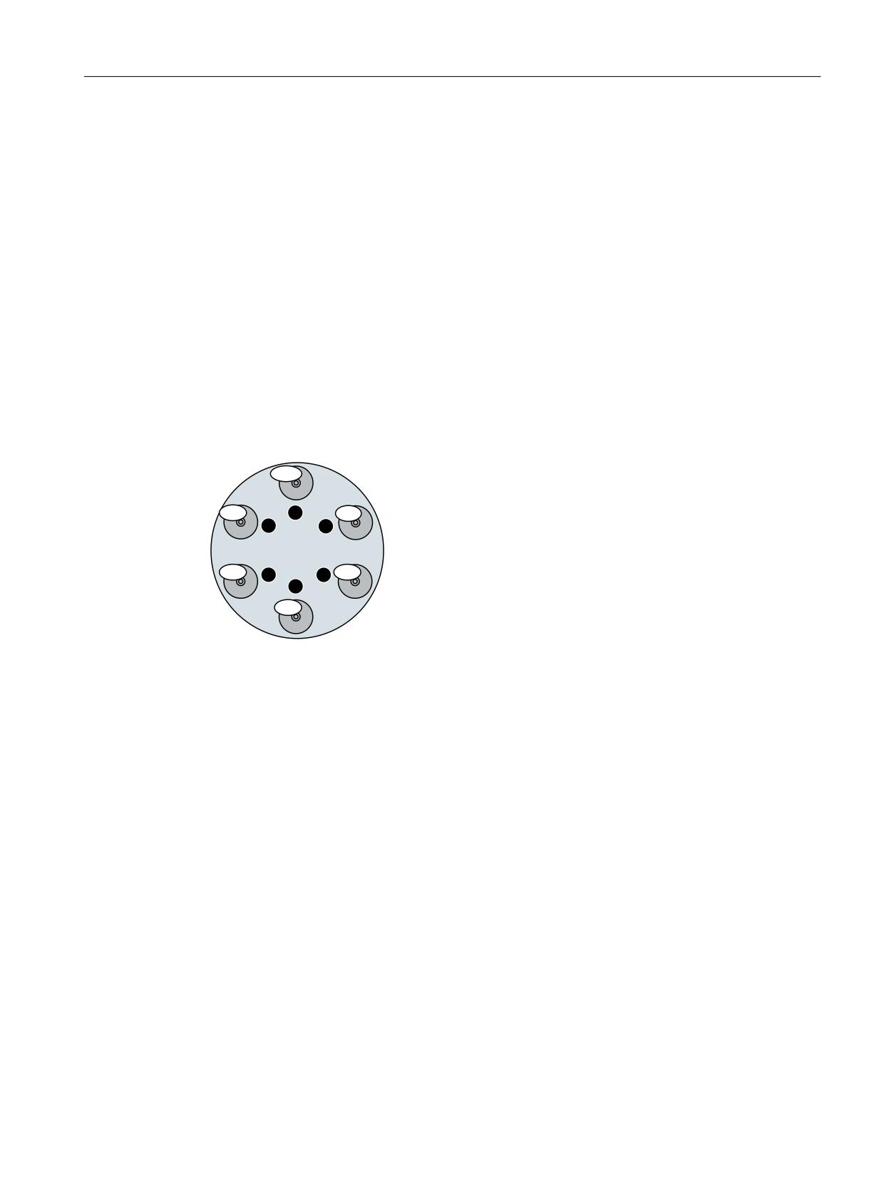
7RRO ZLWK WKH QDPH 'ULOO KDV
'ULOO GLVDEOHG
GLIIHUHQW GXSOR QR
7
1
7KHUH LV QR WRRO RQ
IXQFWLRQV
6
2
VLPLODU WR 7 LQ 1&
7XUUHW
5
3
7
4
'ULOO UHOHDVHG
7
'ULOO DFWLYH
7 LV LQWHUQDO 7 QR
Figure 7-14
Programming of T=location number
Explanation of the illustration:
When the function is active, T1 selects the tool in location number 1 instead of the tool with
identifier "1". The first magazine linked with the tool holder is accessed here. The identifier of the
tool in this location is then determined ("Drill").
The subsequent procedure is as if T="Drill" had been programmed. During the tool change
process it is determined which of the three tools from the "Drills" group shall be loaded first.
The set tool search strategy is taken into consideration:
• When the strategy "Take the first available tool from the group" is applied, T10 from location
3 is loaded ($TC_MAMP2 Bit0 = 0).
• When the strategy "Take the first tool with active status from the group" is applied, T1 is
"loaded" ($TC_MAMP2 bit0 = 1).
In so doing, it is assumed that tool T1 is also the replacement tool with the lowest duplo
number. If this is not the case, then for $TC_MAMP2 bit0 = 1, for a tool change, the tool with
the lowest duplo number is loaded.
The search strategy is set using system variables $TC_MAP10 (current search strategy of the
magazine) or $TC_MAMP2 (search strategy type). As preliminary setting, $TC_MAP10 uses the
values from $TC_MAMP2.
Tool management
Function Manual, 10/2020, 6FC5397-1HP40-0BA1
333
NC programming
7.11 Programming T=location number
T15 on location no. 1 cannot be used, because it is disabled.
No alarm is generated if the programmed location does not contain a tool. The change is output
as usual, with T no.=0. In this way, for example, the turret can be positioned to an empty location.
If more than one magazine is assigned to the tool holder, then the programmed location number
refers to the magazine that is the first magazine defined in the distance table.
If the tools of the tool group are located in different magazines of the tool holder, the search
procedure is the same as with the standard tool management.
Note
With the T=location function, alternatively T= "Drill" can also be programmed.
T=1; tool
T="Drill"; tool with identifier Drill
Tool management
334
Function Manual, 10/2020, 6FC5397-1HP40-0BA1

NC programming
7.12 Call multiple turrets with "T=location number"
7.12
Call multiple turrets with "T=location number"
7&B033 >
@
VSLQGOH ORFDWLRQ
7&B033 >
@
VSLQGOH ORFDWLRQ
7&B033 >
@
WRRO KROGHU QR
7&B033 >
@
WRRO KROGHU QR
7RRO KROGHU
7RRO KROGHU
3DUW SURJUDP
7
0DJD]LQH IRU WRRO KROGHU
ORFDWLRQ
7
0DJD]LQH IRU WRRO KROGHU
ORFDWLRQ
7
7
7XUUHW
7XUUHW
Figure 7-15
T=location number as tool management function on turning machines
The programming option "T = location number" and several magazines can be used to work in
one channel or in one TO unit.
• The NC address T can be programmed with an address expansion T1 =...
• Tool management then interprets this as the spindle number or as the toolholder number.
• T without address extension then refers to the main spindle.
Tool management
Function Manual, 10/2020, 6FC5397-1HP40-0BA1
335

NC programming
7.13 Programming examples
7.13
Programming examples
Action
Program command
Description
Create tool
DEF INT DUPLO_NO
Create new tool called Drill with duplo
no.= 7. The automatically generated T
DEF INT T_NO
no. is stored in "T_NO".
DUPLO_NO = 7
T_NO=NEWT("DRILL",DUPLO_NO)
T_NO = GETT("DRILL",
Determine the T number of tool "DRILL"
DUPLO_NO)
with duplo no. 7 that has already been
created.
or
The T No is, however, also assigned here
$TC_TP2[1] = "DRILL" ;
by the programming.
$TC_TP1[1] = DUPLO_NO
Tool data
$TC_DP1[GETT("DRILL",
Write tool type for the 2nd cutting edge
of the tool "Drill"/ DUPLO_NO
read / write
DUPLO_NO), 2] = 210
$TC_DP1[T_NO, 2] = 210
Write tool type for the 2nd cutting edge
of the tool "T number"
Tool
T="DRILL"
If there are several tools with this identi-
fier, then the T no. is returned for the
selecting
or:
first tool possible.
T=GETT("DRILL", DUPLO_NO)
Determines the T number for "DRILL"
or
with duplo number = DUPLO_NO and
Tx
selects it.
Call with T No. e.g. T1,T2,T3,
Delete tool
$TC_TP1[T_NO,0]=0
Tool with T_NO is deleted
or
Tool "DRILL"
DELT ( "DRILL", DUPLO_NO)
DUPLO_NO is deleted
$TC_TP1[GETT("DRILL"),0]=0
or alternatively:
DELT("DRILL")
Tool management
336
Function Manual, 10/2020, 6FC5397-1HP40-0BA1

NC programming
7.14 Overview of the remaining OPI blocks of tool management
7.14
Overview of the remaining OPI blocks of tool management
7.14.1
Magazine data, directory
OPI block TMV
Calculation of line: Magazine number, if a field[
] is present
Calculation of column: n.a.
NC identifier
Designation
OPI variable
Type
None
Number of magazines
numActMags
WORD
Number of the magazine
magVNo[ ]
WORD
Identifier of the magazine
magVIdent[ ]
String
Number of adapters
numActAdapter
WORD
Number of the adapter
adaptVNo
WORD
Adapter type
AdaptVType
WORD
7.14.2
Tool data, directory
OPI block TV
Calculation of line: Sequential no. of the tools, if [ ] present
Calculation of column: n.a.
NC identifier
Designation
OPI variables
Type
None
Duplo number
nrDuplo[ ]
WORD
Number of cutting edges
numCuttEdges[ ]
WORD
Number of tools in TO area
numTools
WORD
Last T number assigned for tool manage-
TnumWZV
WORD
ment
Tool identifier
toolIdent[ ]
String
Current magazine
toolInMag[ ]
WORD
Actual location
toolInPlace[ ]
WORD
T number
toolNo[ ]
WORD
Number of tool groups
numToolsGroups
WORD
Tool management
Function Manual, 10/2020, 6FC5397-1HP40-0BA1
337

NC programming
7.14 Overview of the remaining OPI blocks of tool management
7.14.3
Parameterization, return parameters _N_TMGETT, _N_TSEARC
OPI block TF
Calculation of line: Refer to table
Calculation of column: n.a.
Designation
OPI variables
Calculation of line
Type
Comparison value for PI TSEARCH of variables of the OPI
parDataTD
Parameter index of block TD
WORD
block TD
Comparison value for PI TSEARCH of variables of the OPI
parDataTO
Parameter index of block TO
DOUBLE
block TO
Comparison value for PI TSEARCH of variables of the OPI
parDataToolId
Parameter index of block TD
String
block TD
entTD
Comparison value for PI TSEARCH of variables of the OPI
parDataTS
Parameter index of block TS
DOUBLE
block TS
Comparison value for PI TSEARCH of variables of the OPI
parDataTU
Parameter index of block TU
DOUBLE
block TU
Comparison value for PI TSEARCH of variables of the OPI
parDataTUE
Parameter index of block TUE
DOUBLE
block TUE
Comparison value for PI TSEARCH of variables of the OPI
parDataTUS
Parameter index of block TUS
DOUBLE
block TUS
Mask for search criterion of PI TSEARCH (OPI block TD)
parMasksTD
Parameter index of block TD
WORD
Comparison value for PI TSEARCH of variables of the OPI
parMasksTO
Parameter index of block TO
WORD
block TO
Comparison value for PI TSEARCH of variables of the OPI
parMasksTS
Parameter index of block TS
WORD
block TS
Comparison value for PI TSEARCH of variables of the OPI
parMasksTU
Parameter index of block TU
WORD
block TU
Comparison value for PI TSEARCH of variables of the OPI
parMasksTUE
Parameter index of block TUE
WORD
block TUE
Comparison value for PI TSEARCH of variables of the OPI
parMasksTUS
Parameter index of block TUS
WORD
block TUS
D number of cutting edge used
resultCutting
Number of cutting edges of
WORD
EdgeNrUsed
tool
Number of cutting edges used
resultNrOfCut
1
WORD
EdgesUsed
Return: found tools
resultNrOfToo
1
WORD
ls
Return: T numbers of found tools
resultToolNr[
1...
WORD
]
resultNrOfTools
T number of cutting edge used
resultToolNr
Number of cutting edges of
WORD
Used
tool
Tool management
338
Function Manual, 10/2020, 6FC5397-1HP40-0BA1

NC programming
7.14 Overview of the remaining OPI blocks of tool management
7.14.4
Working offsets
OPI block AEV
Calculation of line: Cutting edge number if [ ] available
Calculation of column: n.a.
NC identifier
Designation
OPI VAR
Type
None
Number of D numbers in block
numActDEdges
WORD
D numbers
Dno[...]
WORD
Internal T number
toolNo[...]
WORD
Cutting edge number
cuttEdgeNo[...]
WORD
Tool identifier
toolIdent[...]
STRING
Duplo number
duploNo[...]
WORD
Magazine
toolInMag[...]
WORD
Location
toolInPlace[...]
WORD
7.14.5
PI services and language commands for tool management
Overview
FB4 (PI_SERV) or FB7 can be used to start program instance services (PI services) in the NC area.
A program section, which carries out a particular function (e.g. with tool management, search
for empty location in a magazine), is executed in the NC by making a request via the PI service.
PI service
Functions
NC command
MMCSEM
Semaphores for various PI services
DELETO
Delete tool
DELT("Tool", Duplo)
DELECE
Delete tool cutting edge
$TC_DP1[t,d]=0
CREATO
Generate tool
NEWT("Tool", Duplo)
CRTOCE
Create tool specifying cutting edge no.
$TC_DPx[t,D]
$TC_DPCx[t,D]
$TC_DPCSx[t,D]
$TC_MOPx[t,D]
$TC_MOPCx[t,D]
TMCRTO
Create tool
$TC_TPx[t]
TMCRTC (not available in PLC)
Create tool by specifying cutting edge no.
$TC_DPx[t,d]
CREACE
Create cutting edge
$TC_DP[t,d]=value
CRCEDN
Create new cutting edge
$TC_DPx[t,d]
TMFDPL
Empty location search for loading
GETFREELOC(magNo, locNo,
T no., refMag, refLoc,
withReserv)
TMMVTL
Prepare magazine location for loading, unload tool
Tool management
Function Manual, 10/2020, 6FC5397-1HP40-0BA1
339

NC programming
7.14 Overview of the remaining OPI blocks of tool management
PI service
Functions
NC command
TMPCIT
Set incremental value for workpiece counter, decre-
SETPIECE(SpinNo,y)
ment count by y
TMPOSM
Position magazine location or tool
POSM(p,m,ip,im)
TMFPBP
Empty location search acc. to properties
TSEARC
Complex search using search screen forms
User cycle program
TMRASS
Reset active status
TMGETT
Confirm T number for specified tool identifier with du-
GETT("Tool", Duplo)
plo number
Read the preset T number
GETSELT(SpinNo)
CHKDNO (not available in PLC)
Check the uniqueness of D numbers of the tool data of
status=CHKDNO (t1,t2,d)
the TO unit assigned to the executing channel. Param-
TMCHKD (not available in PLC)
eters t1, t2, d are optional.
DZERO (not available in PLC)
Set D numbers for all tools of the TO unit assigned to
DZERO
the channel to "invalid". On the OPI, such D numbers
are displayed with the value 0. The invalid D number is
generated NC-internally by assigning the value "old D
number" + 32000 to the D number.
For the offset number D=d, specify the associated in-
status=GETACTTD (t,d)
ternal T no. = t of the tool. The tool that has the status
"active" and "was in use" is taken from the tool group.
Specify the D no. for tool t and its cutting edge ce
d=GETDNO(t,ce)
Set the D no. of tool t and its cutting edge ce to value d
status=SETDNO (t,ce,d)
Read the active T no. and status
status=GETACTT
(Tno,"Tool")
Delete command for all location-dependent/setup off-
status=DELDL(t,d)
sets of a cutting edge or tool if d is not specified
SETTST (not available in PLC)
Set tool status to "active"
SETTA(Stat,m,vnr)
SETTST (not available in PLC)
Set tool status to "not active"
SETTIAStat,m,vnr)
CHKDM (not available in PLC)
Check uniqueness of D nos. in magazine; m=Magazine
status=CHKDM(m)
Set tool holder no. (h=holder no.)
SETMTH(h)
Set master spindle (s=spindle no.)
SETMS(s)
TRESMO
Tool life / quantity / wear setpoint activation
RESETMON
TMAWCO (not available in PLC)
Set a wear group to active
$TC_MAP9
Location-dependent offsets, coarse
$TC_EPx[t,d]
Technological grinding data
$TC_TPGx[t]
Read the loaded T number
GETEXET
NC command to move tool
MVTOOL
Delete tool holder block
DELTC
Tool deselection/tool change irrespective of tool status
TCA
Delete the location status "reserved for tool in the buf-
DELMLRES
fer"
Delete owner magazine location of the tool
DELMLOWNER
Tool management
340
Function Manual, 10/2020, 6FC5397-1HP40-0BA1

NC programming
7.14 Overview of the remaining OPI blocks of tool management
NC commands
NC states are read with the following NC commands.
Functions
NC command
Active tool no. T
$P_TOOLNO
Last programmed tool no. (without magazine management)
$P_TOOLP
Active tool cutting edge
$P_TOOL
Active total tool length; n=1-3
$P_TOOLL[n]
Active tool holder
$P_TC
Active angle of a tool holder axis; n=1-2
$P_TCANG[n]
Difference between calculated and used angle of a tool holder axis for
$P_TCDIFF[n]
Hirth gearing of the angle
Active tool radius; n=1-2
$P_TOOLR
Number of cutting edges for tool t; t=T number 1 32000
$P_TOOLND[t]
Tool with T number t exists
$P_TOOLEXIST[t]
Active tool offsets D, n=1...31
$P_AD[n]
Active tool offsets; transformed; n=1-31
$P_ADT[n]
Active additive offset number
$P_DLNO
T number of the tool (numerical)
$C_T
Tool identifier (string)
$C_TS
Bool variable that shows whether a T word is available in $C_T
$C_T_PROG
Parameter for tool name as string
$C_TS_PROG
Address extension of the T word
$C_TE
Programmed D no.
$C_D
Bool variable that shows whether an offset number is available in
$C_D_PROG
$C_D
Programmed additive/setup offset
$C_DL
Bool variable that shows whether an offset number is available in
$C_DL_PROG
$C_DL
Command number, specifies the required operation:
$AC_TC_FCT
1: Move (load/unload, relocate...);
2: Prepare change;
3: Change On;
4: Change ON (turret, without M06);
5: Prepare change and change ON (with M06); -1 At the read instant,
no tool management command is active
Acknowledgement status of PLC FC8/FC6
$AC_TC_STATUS
Tool holder or spindle number onto which the new tool should be
$AC_TC_THNO
loaded
Source magazine number of the new tool
$AC_TC_MFN
Source location number of the new tool
$AC_TC_LFN
Target magazine number of new tool
$AC_TC_MTN
Target location number of the new tool
$AC_TC_LTN
Source magazine number of the old tool (to be removed)
$AC_TC_MFO
Source location number of the old tool (to be removed)
$AC_TC_LFO
Tool management
Function Manual, 10/2020, 6FC5397-1HP40-0BA1
341

NC programming
7.14 Overview of the remaining OPI blocks of tool management
Functions
NC command
Source magazine number of the old tool (to be removed)
$AC_TC_MTO
Target location number of the old tool (to be removed)
$AC_TC_LTO
Returns the number of the actual master spindle
$AC_MSNUM
Returns the number of the master spindle
$P_MSNUM
Returns the number of the master tool holder
$AC_MTHNUM
Trigger variable to output command of the NC (is set for one IPO)
$AC_TC_CMDT
Trigger variable for acknowledgement of the PLC (is set for one IPO)
$AC_TC_ACKT
Counter for the command output
$AC_TC_CMDC
Counter for the acknowledgements
$AC_TC_ACKC
Owner magazine of the new tool
$AC_TC_MMYN
Owner location of the new tool
$AC_TC_LMYN
Returns the number of the master tool holder
$P_MTHNUM
Magazine number of tool t
$A_TOOLMN[t]
Magazine location of tool t
$A_TOOLMLN[t]
Number of the owner magazine
$A_MYMN
Number of the owner magazine location
$A_MYMLN
Number of defined magazines that are assigned to the channel
$P_MAGN
Number of defined magazines, i-th magazine number
$P_MAG[i]
Number of defined adapters that are assigned to the channel
$P_MAGNA
Number of defined adapters, i-th adapter number
$P_MAGA[i]
Number of magazines n that are linked to location n
$P_MAGNDIS[m,n]
Number of the i-th magazine that is linked with location l of the
$P_MAGNDISS[l,i]
buffer magazine
Number of the i-th magazine that is linked with location l of the
$P_MAGDISL[l,i]
loading magazine
Number of defined magazine location type hierarchies
$P_MAGNH
Number of the defined location types in the n-the defined hierarchy
$P_MAGNHLT[n]
m-th location type of hierarchy n
$P_MAGHLT[n,m]
Number of buffers assigned to the spindle numbers, tool holder
$P_MAGNREL[n]
numbers n
m-th buffer number of the n-th spindle no., tool holder no.
$P_MAGREL[n,m]
Number of spindle locations / tool holder locations in the buffer mag-
$P_MAGNS
azine that are assigned to the channel
n-th number of the spindle / tool holder in the buffer
$P_MAGS[n]
Determine the defined D numbers of a tool
$P_TOOLD
Determine existence of a tool
$P_TOOLEXIST
Number of DL offsets of the D offset given by T number T and D
$P_TOOLNDL[t,d]
number D
Number of defined tool groups that are assigned to the channel
$P_TOOLNG
Number of defined tools that are assigned to the channel
$P_TOOLNT
i-th tool number T
$P_TOOLT[i]
The following tool changes are available for all tools, whose param-
$P_USEKT, $TC_TP11
eter $TC_TP11 have set one of the bits of $P_USEKT. The value zero
has the same contents as "all bits are set"
Tool management
342
Function Manual, 10/2020, 6FC5397-1HP40-0BA1

NC programming
7.14 Overview of the remaining OPI blocks of tool management
Functions
NC command
Factor for tool search
$AC_MONMIN
Workpiece count
$A_USEDND
Workpiece count
$A_USEDT
Workpiece count
$A_USEDD
Read factor for tool life monitoring
$A_MONIFACT
Multitool and tool specifications in PI services
The following PI services refer to tools and multitools:
PI service
Meaning
TMFDPL
Empty location search for specified tool or multitool for loading or equipping. The empty location search in
the MT only makes sense for tools that have not been loaded, i.e. as part of the equipping of the MT with
tools.
TMFPBP
Empty location search for specified tool or multitool. This service searches the magazine(s) specified in the
relevant parameters for an empty location, which meets the specified criteria (tool size and location type).
TMMVTL
Load or unload tool or multitool. It is not possible to program tools of a multitool for the move command.
It is also not possible to move a tool in an MT with the command.
TMGETT
T number of the tool with the specified tool identifier / duplo number or the MT number of the multitool with
the specified identifier (multitool: the duplo number is programmed with the parameter value 00000)
TRESMO
Reset monitoring values. If an MT number is programmed, only the tools of the multitool treated.
TMPOSM
Position magazine on the specified magazine location, specified tool or multitool.
The following PI services are available functionally for tools and multitools, but with
different names:
PI service
Meaning
Create
CREATO
Create tool with specified T number
CRTOCE
Create tool with specified T number and D number
TMCRTO
Create tool with specified identifier / duplo number
TMCRTC
Create tool with specified identifier / duplo number and D number
Delete
DELETO
Delete tool with specified T number
TMDLTO
Delete tool with specified identifier / duplo number
Note
If these tool-specific PI services are called with MT-specific names or MT numbers, the respective
PI service is aborted with error status.
Tool management
Function Manual, 10/2020, 6FC5397-1HP40-0BA1
343

NC programming
7.14 Overview of the remaining OPI blocks of tool management
The following PI services are defined functionally only for tools (i.e. there are no similar PI
services for multitools):
PI service
Meaning
CHEKDM
Check the D numbers for uniqueness
CHKDNO
Check whether the tools have unique D numbers
DZERO
Set all D numbers invalid with the "Unique D number" function
CRCEDN
Create new tool cutting edge by specifying the D number
CREACE
Create tool cutting edge
DELECE
Delete tool cutting edge
SETTST
Activate tool from tool group (set tool state "active")
TMRASS
Reset active status
TMAWCO
Set active wear group in a magazine
TMPCIT
Set increment value for workpiece counter
TSEARC
Complex search using search screen forms
The following PI services are defined for adapters:
PI service
Meaning
TMCRAD
Creating adapters with a given type
TMDLAD
Deleting adapters with a given number
Note
During the search, the PI service only considers tools, also those contained in a multitool, i.e. the
PI service does not consider multitools. A "Complex multitool search" PI service is not defined.
If the tool-specific PI services are called with MT-specific names or MT numbers, the PI service is
aborted with error status.
Tool management
344
Function Manual, 10/2020, 6FC5397-1HP40-0BA1
Description of functions
8
8.1
Magazines
8.1.1
Magazine configuration
Magazine configuration
With the magazine configuration, one or more real magazines (an actual magazine) for storing
tools can be grouped together by means of Operate, an NC program or ini files.
All the magazines of one configuration can be operated simultaneously in one channel. Several
magazine configurations can be defined but only one configuration can be active in one channel
at one time.
Magazine and tool data are stored in the NC in the so-called TO area.
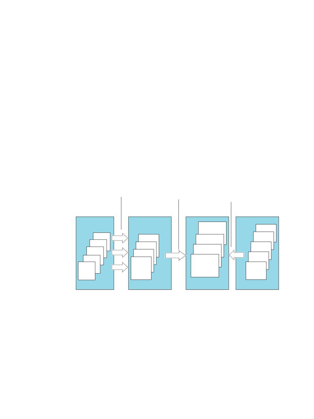
+0, FRQILJXUDWLRQ
$FWLYDWH FRQI
0DFKLQH GDWD
&RPPLVVLRQLQJ
+0,
1& 722/0$1
72BQ
&KDQQHO Q
N
P
&KDQQHO
72B
&KDQQHO
72B
0DJ
&KDQQHO
5HDO
FRQI
0DJ
5HDO PDJD]LQHV
P 72 XQLWV RQH
P PDJD]LQH
Q FKDQQHOV
N PDJD]LQHV
PDJD]LQH FRQI
FRQILJXUDWLRQV
SHU 72BXQLW
Figure 8-1
Assignment of magazines to channels
Tool management
Function Manual, 10/2020, 6FC5397-1HP40-0BA1
345
Description of functions
8.1 Magazines
Relation between TO unit and magazine configuration
The individual TO ranges are specified by machine data. A TO unit is assigned to each channel
(channel1/TOA1, channel2/TOA2,etc.) as the default setting. Which channel or channels work
on which TO units can be defined in the machine data. Only one magazine configuration can be
active at any one time per TO unit. If several channels are assigned to a TO unit, then the
magazine configuration applies for all assigned channels. A TO unit (TOA unit) is an independent
area of the tool management. It is not linked to other TO units.
Up to 10 independent TO units may be created depending on the number of channels available.
Multiple channels can be assigned to one TO unit. However, one channel cannot be assigned to
multiple TO units. A subset of magazines, buffer locations and loading magazines can be
assigned to one TO unit.
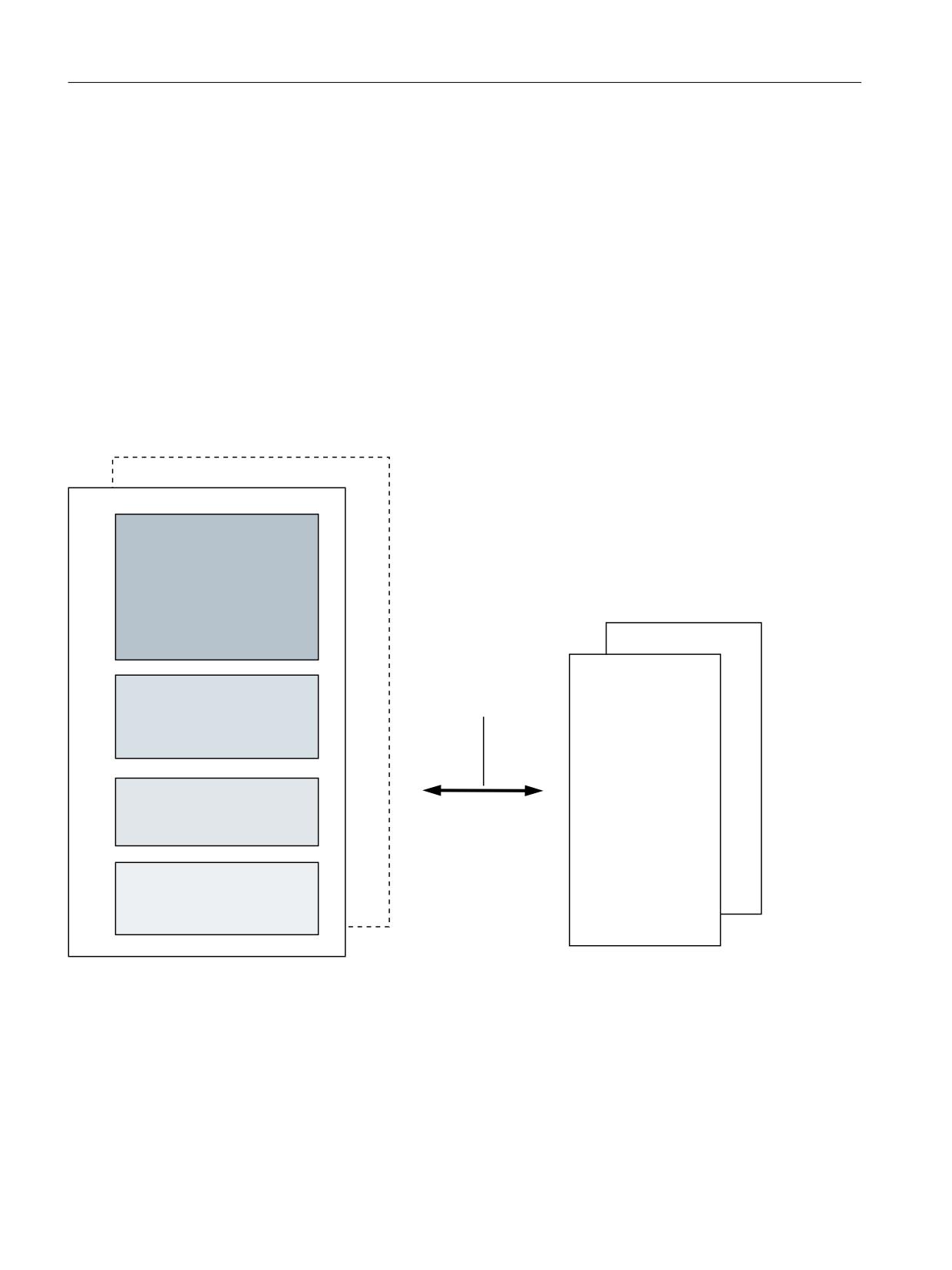
The following figure shows the relationship between TO units and the magazine configuration.
1& WRRO PDQDJHPHQW
72 XQLW
72 XQLW
0DJD]LQH GDWD
7&B0$3
1& FKDQQHOV
2QH PDJD]LQH FRQILJXUDWLRQ
IRU HDFK 72 XQLW
&KDQQHO
&KDQQHO
0XOWLWRRO GDWD
0DFKLQH GDWD
7&B073
7RRO PDQDJHPHQW
7RRO GDWD
7&B03
&XWWLQJ HGJH GDWD
7&B'3
Figure 8-2
TO units
8.1.2
Magazine types
Different magazine types are defined so that the various tasks of tool management can be
performed:
Tool management
346
Function Manual, 10/2020, 6FC5397-1HP40-0BA1
Description of functions
8.1 Magazines
Real magazines
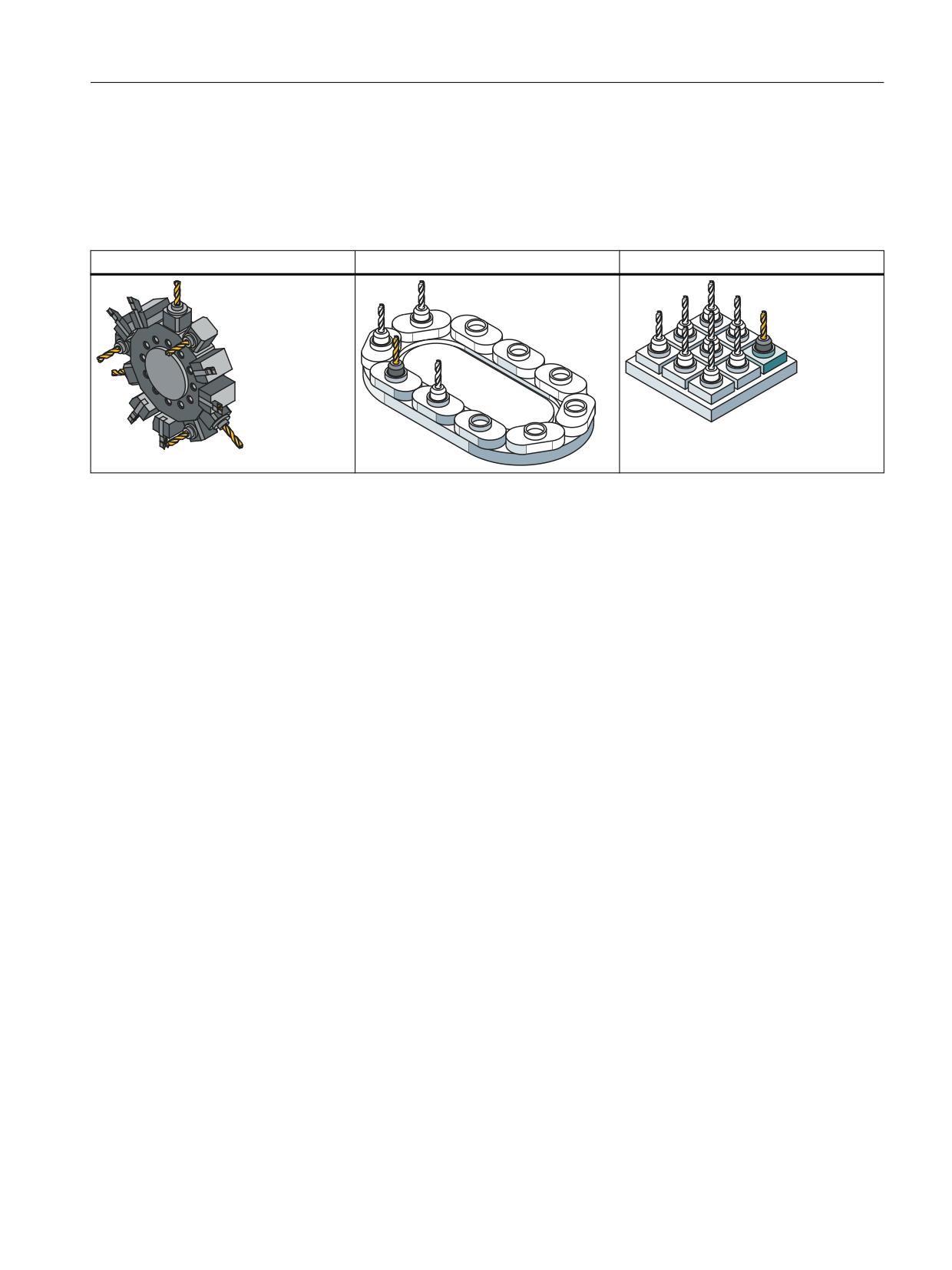
Real magazines are the magazines in which the tools are kept. Several real magazines can be
managed in the NC and grouped together into a magazine configuration.
Real magazines are, for example, turrets, chain or box magazines (magazine 1 ... n).
Turret
Chain magazine
Box-type magazine
Internal magazines
All of the positions at which a tool may be located are handled logically in the NC also as a
magazine (and magazine location). There are 2 internal magazines:
• The buffer magazine (magazine 9998)
• The loading magazine (magazine 9999)
8.1.3
Loading magazine
The loading magazine is the 1st internal tool magazine and always has magazine number 9999.
The loading magazine contains loading locations.
These are sub-divided into:
• Loading locations
• Loading stations
Loading points and stations are provided for loading and unloading tools. The allocation of
locations is fixed, all other locations can be assigned freely. Location 1 in the loading magazine
is used for the fixed assignment.
Location 1 is reserved for loading/unloading in all spindles / tool holders, as well as to load and
replace manual tools (see Manual tools (adding tools during machining) (Page 470)). A loading
point is an open entry to the magazine where tools can be manually put into and taken directly
from the magazine.
Tool management
Function Manual, 10/2020, 6FC5397-1HP40-0BA1
347
Description of functions
8.1 Magazines
/RDGLQJ SRLQW
/RFDWLRQ
*ULSSHU
0DJD]LQH
6SLQGOH
%XIIHU
*ULSSHU
Figure 8-3
Loading point
A loading station is viewed as an "external magazine location" which a gripper, for example, can
access to transport a tool to the magazine during loading.
The difference between a loading point and a loading station is as follows:
When loading a tool at a loading/unloading point, the tool is automatically removed from this
location, whereas when unloading to an unload station, it remains at the loading or unloading
location - it must then be removed from there by the application (HMI, NC cycle or PLC).
Definition of a loading magazine
A loading magazine can be defined as follows:
• In SINUMERIK Operate via the tool management (Define loading station (Page 49)).
• Via the magazine description data ($TC_MAP (Page 187)).
8.1.4
Buffer
A buffer involves the 2nd internal magazine. The magazine number is always 9998. The buffer
includes the spindle, tool holder, gripper, loader and transfer location. The locations are
numbered, just like a real magazine, ascending from 1-n. Every location has a location index.
Here, it is assigned as to which is the 1st spindle or the 1st gripper. Any numbering can be used.
However, transparency is improved if the locations of a location type (all spindles, all grippers,...)
are numbered in an ascending sequence. See also Section "Overview of magazine data
(Page 187)".
The NC only makes a differentiation between spindles or tool holders and grippers. Other
"location types" such as loaders or the transfer location are mapped on the gripper.
Tool management
348
Function Manual, 10/2020, 6FC5397-1HP40-0BA1
Description of functions
8.1 Magazines
*ULSSHU
0DJD]LQH
6SLQGOH
%XIIHU
*ULSSHU
Figure 8-4
Buffer
Example: Assigning the locations in the buffer magazine
No.
Name
Type
Index
Assignment to
Distances to
spindles
magazine
1
Spindle_1
Spindle
1
0
2
Gripper_1
Gripper
1
0
3
Gripper_2
Gripper
2
0
4
Loader_1
Loader
3
0
5
Loader_2
Loader
4
0
6
Transfer_1
Transfer location
5
0
Definition of a buffer
A buffer can be defined as follows:
• In SINUMERIK Operate via the tool management (Define buffer locations (Page 48)).
• Via the magazine description data ($TC_MAP (Page 187)).
8.1.5
Box-type and chain magazines
Fundamentals
Chain and box-type magazines do not as a rule have any additional buffer available for
transportation between magazine and spindle. These additional buffers can temporarily contain
tools.
The command is distributed in the PLC using the basic program. In this case, DB72 is used as the
user interface. There is a separate interface area for each spindle in the interface. A new
Tool management
Function Manual, 10/2020, 6FC5397-1HP40-0BA1
349
Description of functions
8.1 Magazines
command from the NC is only then entered in the interface once the previous command has
been acknowledged with status values 1 to 7 via FC8/FC6.
1. The programming function T = identifier is implemented in the PLC in DB72. Bit "Prepare tool"
is set in the associated interface.
2. Programming function M06 is also implemented in DB72. In this instance, bit "Change tool"
is set in the activated interface. The bit "Prepare tool" from an earlier T command is not reset
here. If the bit "Prepare tool" shall no longer be set for the M06, then it is the task of the user
program to reset this bit as part of acknowledging the last T command.
3. Programming functions T and M06 in the same block set the "Prepare tool" and "Change tool"
bits simultaneously in the activated DB72 interface.
Exceptional cases which are mapped in the PLC identically to case 3 above are as follows:
• Initiation of a tool change after block search (last accumulated tool change for the active tool)
• Initiation of a tool change for initialization blocks (reset and start mode), if this was set via the
machine data.
Note
Special cases, box-type and chain magazines
In these exceptional cases, the subroutine (macro, cycle) in which M06 is normally
programmed is not executed.
Definition of box-type or chain magazines
Box-type or chain magazines can be defined as follows:
• In SINUMERIK Operate via the tool management (Set up magazine configuration (Page 50)).
• Via the magazine description data ($TC_MAP (Page 187)).
Tool management
350
Function Manual, 10/2020, 6FC5397-1HP40-0BA1
Description of functions
8.1 Magazines
Example for machine tools with chain and box-type magazines
0DJD]LQH
*ULSSHU
*ULSSHU
6SLQGOH
&KDQJH SRVLWLRQ IRU
VSLQGOH
/RDGLQJ VWDWLRQ
1R
Magazine 1 = number 1
Magazine 9998 = buffer
Magazine 9999 = loading magazine
Spindle 1 = magazine 9998 location 1
Gripper 1 = magazine 9998 location 2
Gripper 2 = magazine 9998 location 3
Figure 8-5
Machine tool with chain magazine
Tool management
Function Manual, 10/2020, 6FC5397-1HP40-0BA1
351
Description of functions
8.1 Magazines
*ULSSHU
0DJD]LQH
&KDQJH SRVLWLRQ
IRU VSLQGOH
0DJD]LQH
*ULSSHU
*ULSSHU
6SLQGOH
&KDQJH SRVLWLRQ IRU
VSLQGOH
*ULSSHU
/RDGLQJ VWDWLRQ
1R
/RDGLQJ VWDWLRQ
1R
Magazine 2 = No. 2
Magazine 1 = No. 1
Magazine 9999 = all buffers
Magazine 9998 = all loading magazines
Spindle 1 = magazine 9998 location 1
Gripper 3 = magazine 9998 location 4
Gripper 1 = magazine 9998 location 2
Gripper 4 = magazine 9998 location 5
Gripper 2 = magazine 9998 location 3
Figure 8-6
Machine tool with chain and box-type magazine
The magazine zero point is defined by $TC_MDP2 (with value assignment of 0). The change
position (spindle) is normally assigned on this basis.
8.1.6
Circular magazine
Generally, turret magazines do not have any additional buffers through which tools are
transported from the magazine to the spindle. Turrets are generally used on turning machines,
on which the rotating spindle holds the workpiece and the turret holds the tools used for
machining.
So the tools are not physically carried to the spindle. They are moved into a defined position by
rotation of the turret so that machining can be performed with a further tool. The tool is only
transported to the spindle or holder in the software.
The method by which the tool is changed can be set for the turret in MD22550
$MC_TOOL_CHANGE_MODE. The setting is described in detail in Preparing a tool change via T
command (Page 378).
Tool management
352
Function Manual, 10/2020, 6FC5397-1HP40-0BA1
Description of functions
8.1 Magazines
The programming command T = identifier initiates the tool change. T = location can be
programmed as an alternative. If T = location, no tool need actually be stored in the location.
The command is distributed in the PLC using the basic program. In this case, DB73 is shown as
the interface for the user (if TOOL_CHANGE_MODE is set to 0). There is a separate interface area
for each turret. The turret numbers are assigned successively in ascending sequence according
to magazine numbers during commissioning. The permissible magazine range is 1 ... maximum
number of real magazines. A new command from the NC is only entered in the interface when
the previous command has been acknowledged via FC7 (alternatively also via FC8/FC6).
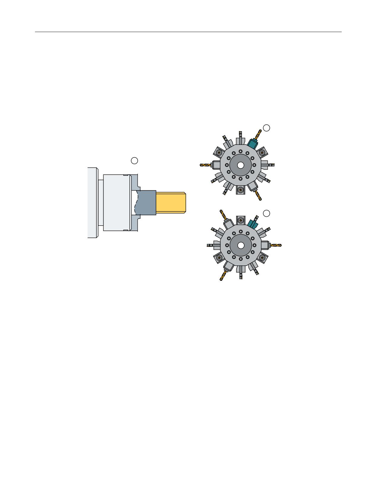
① Spindle with workpiece
② Turret 1
③ Turret 2
④ Loading/unloading location
Figure 8-7
Double-slide turning machine with direct loading/unloading point in the turret
Definition of a turret
A loading magazine can be defined as follows:
• In SINUMERIK Operate via the tool management (Set up magazine configuration (Page 50)).
• Via the magazine description data ($TC_MAP (Page 187)).
8.1.7
Other magazine types
In practice, there are other types of magazines in addition to the ones listed above. These are
e.g. disk-type, washer, pick-up, rack, cage magazines (and many more). Such types must be
mapped to the three types of magazines supported by the tool management.
Tool management
Function Manual, 10/2020, 6FC5397-1HP40-0BA1
353
Description of functions
8.1 Magazines
8.1.8
Wear group
Fundamentals
Locations in a magazine are linked to form an area referred to as the wear group. In this way,
locations of a magazine can be reserved for particular machining operations.
A wear group number is assigned to each of these locations and the magazine is thereby divided
into several different areas. Only tools from one of the areas are then used for a specific
machining operation.
The wear group number for each magazine location is defined via system variable
$TC_MPP5[m,p] (m: Magazine number, p: Location number).
Values from -32000 to +32000 are possible.
Value > 0:
The specified number is assigned to the location (e.g. $TC_MPP5[1,3] = 2 assigns the third
location of magazine 1 to wear group number 2).
Value = 0:
The location is not assigned to a wear group, threfore the magazine locations are generally
included in tool searches.
Values < 0:
The wear group whose number corresponds to the absolute value of this number is disabled
(e.g. $TC_MPP5[1,3] = - -2 disables wear group number 2 of the magazine with number 1).
This applies even if there is only one disabled location in the wear group.
Note
Wear groups are only available for real magazines. The definitions for $TC_MPP5 do not affect the
status of tools.
Up to eight wear groups per magazine are possible.
Activate wear group
System variable $TC_MAP9 defines which wear group (magazine area) is active. To change the
active wear group, the corresponding number is set in this system variable, thereby defining
which wear group will be used to start the machining operation.
The default setting is 0.
The wear group can also be set active internally by a tool change or by the user via NC commands/
OPI.
Disable wear group
If there is no longer any tool that is ready for use at the location of an active wear group, then
the system switches to the next wear group and the old wear group is disabled.
Tool management
354
Function Manual, 10/2020, 6FC5397-1HP40-0BA1
Description of functions
8.1 Magazines
Machining is continued by activating the next group and searching for a suitable replacement
tool.
The wear group is also disabled if one of the locations has been disabled via system variable
$TC_MPP5 (negative value).
Activate (internally)
Bit 0 of system variable $TC_MAMP3 can be set to determine how internal activation of a wear
group will affect the status of the associated tools.
Value 0:
The tool status is not changed (preset).
Value 1:
When activated, one tool from each included tool group is set to "active". Tools already set earlier
as active are not reset.
Disable (internally)
Bit 1 of system variable $TC_MAMP3 can be set to determine how internal deactivation of a wear
group will affect the status of the associated tools.
Value 0:
The tool status is not changed (preset).
Value 1:
When a wear group is disabled all active tools are reset.
Note
For a tool search in the wear group, see Section "Tool search in wear group (Page 487)".
Enabling or disabling tools from a wear group
Tools can be enabled or disabled in a wear group via the NC language commands SETTA and
SETTIA:
• SETTA - Activate tool from wear group (Page 261)
• SETTIA - Deactivate tool from wear group (Page 263)
8.1.9
Background magazine
Background magazines are not directly supported by the tool management. However, functions
for backg49round magazines can be activated by setting the system variable selectively. System
variable $TC_7 MAMP2, bit 7 can be used to set whether the tool search begins in the magazine
last used for tool replacement (bit 7 = 0) or whether the search is carried out in the order
defined by "Spindle to magazine" (bit 7 = 1).
Generally, this system variable is set when configuring the magazine. A change can be made at
any time via the part program or OPI.
Tool management
Function Manual, 10/2020, 6FC5397-1HP40-0BA1
355
Description of functions
8.1 Magazines
The assignment of "spindle to magazine" is set via system variable $TC_MDP2[n,m]; the order
corresponds to the order in which this variable is written. This is also pre-assigned by the
magazine configuration.
Example for four magazines and one spindle:
$TC_MAMP2=385 (bits 0, 7 and 8 set).
$TC_MDP2[1,1]=0
$TC_MDP2[2,1]=0
$TC_MDP2[3,1]=0
$TC_MDP2[4,1]=0
... this assigns the first buffer (spindle) to magazines 1 to 4; a tool search would therefore start
in magazine 1, followed by magazine 2, etc. up to magazine 4.
You can modify this search order by setting this system variable as follows:
1. Deleting the assignment
$TC_MDP2[1,0]=9999
$TC_MDP2[2,0]=9999
$TC_MDP2[3,0]=9999
$TC_MDP2[4,0]=9999
2. Re-assigning in a different order
$TC_MDP2[2,1]=0
$TC_MDP2[3,1]=0
$TC_MDP2[4,1]=0
$TC_MDP2[1,1]=0
... resulting in the search order of magazine 2, 3, 4, 1
The trigger criterion for changing the order of assignment can be the information in the change
cycle that the new tool was found in another magazine. This can be read in the program via
$A_TOOLMN[t], whereby "t" is the internal T number of the tool. The new tool is obtained via
GETSELT. You must remember the previous foreground magazine.
8.1.10
Consider adjacent location
Fundamentals
Consider adjacent location is used for oversized tools (see also Tool-related data $TC_TP
(Page 179)). When searching for empty locations (loading, relocating, changing) bits 4 to 11 are
evaluated in the magazine location parameter $TC_MPP4 (half location occupied/reserved). As
this function requires additional memory space, the default setting is 0.
To activate the function, set the following:
$MN_TOOL_MANAGEMENT_MASK, bit 3 = 1
$MC_TOOL_MANAGEMENT_MASK, bit 3 = 1
In addition, for every magazine location that is to be considered, parameter $TC_MPP3 = 1 must
be set.
Tool management
356
Function Manual, 10/2020, 6FC5397-1HP40-0BA1
Description of functions
8.1 Magazines
Two functions are available when the consider adjacent location is active.
Overlap disabled magazine locations
The function is activated by setting the magazine location parameter $TC_MPP4 bit 13 = 1. If a
location is disabled, it can now be "overlapped" by an oversized tool. This means the consider
adjacent location ignores the disabled state of this magazine location.
Example
Chain magazine, location 12 is disabled (e.g. the tool holder is defective). An oversized tool (size
2/2/1/1) is loaded or is positioned in the spindle. The tool can now be stored at location 11 or 13.
The following can be selected as default setting:
As soon as a location is disabled, "Overlapping active" is automatically set or reset as soon as the
location is enabled.
This setting is made in machine data
$MN_TOOL_DEFAULT_DATA_MASK, bit 4 = 1.
Overlapping magazine edge locations
This function is activated by setting the magazine description parameter $TC_MAP3, bits 8 to 11.
If these bits are set, the following conditions apply:
(Definition: smallest magazine location number is at the top left, the largest magazine location
number is at the bottom right).
Bit 8: Left edge location must not be covered.
Bit 9: Right edge location must not be covered.
Bit 10: Top edge location must not be covered.
Bit 11: Bottom edge location must not be covered.
The default setting for these bits is 0.
Example:
• A box-type magazine used.
• Due to the mechanical conditions, oversized tools can cover the edge at the top and on the
right.
The following must be set:
$TC_MAP3[magazine no.], bit 8 = 1
$TC_MAP3[magazine no.], bit 11 = 1
Tool management
Function Manual, 10/2020, 6FC5397-1HP40-0BA1
357

Description of functions
8.1 Magazines
Examples
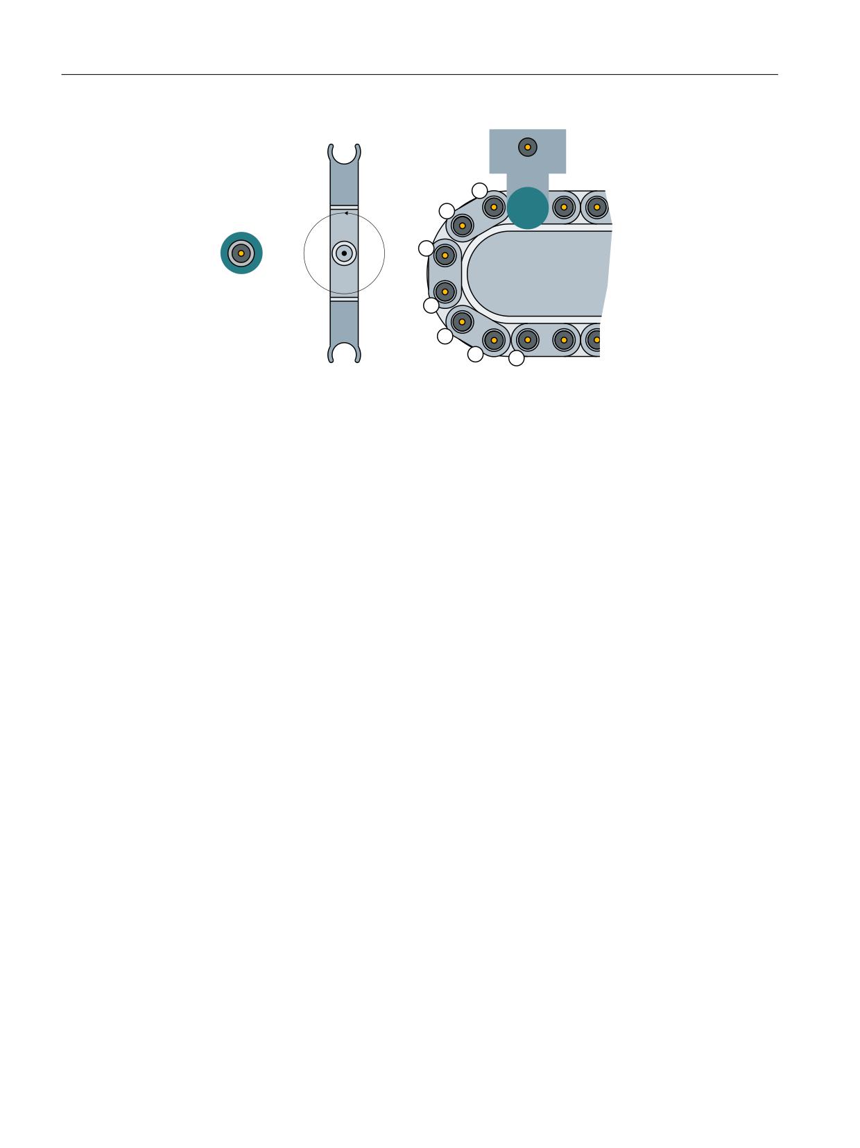
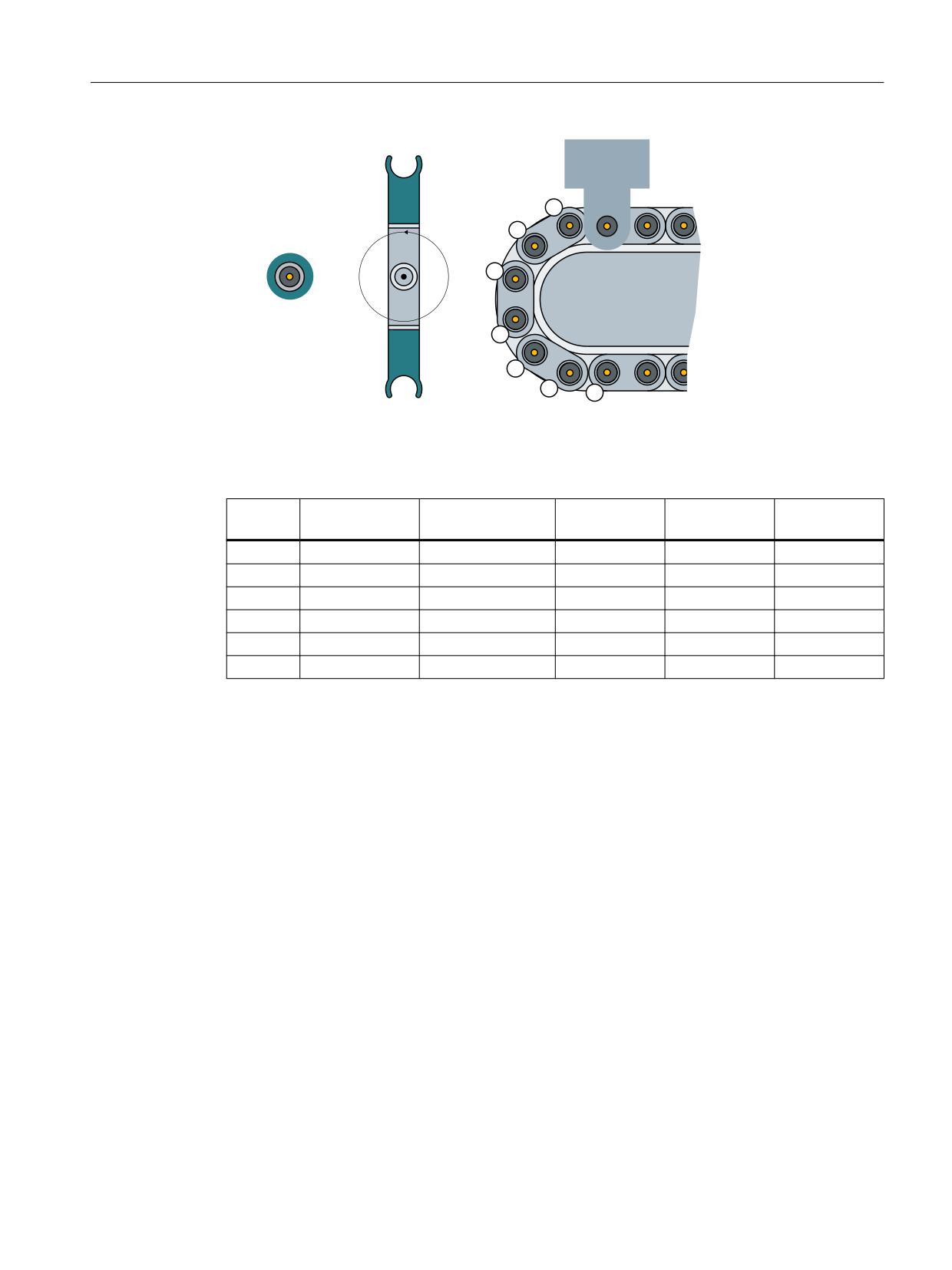
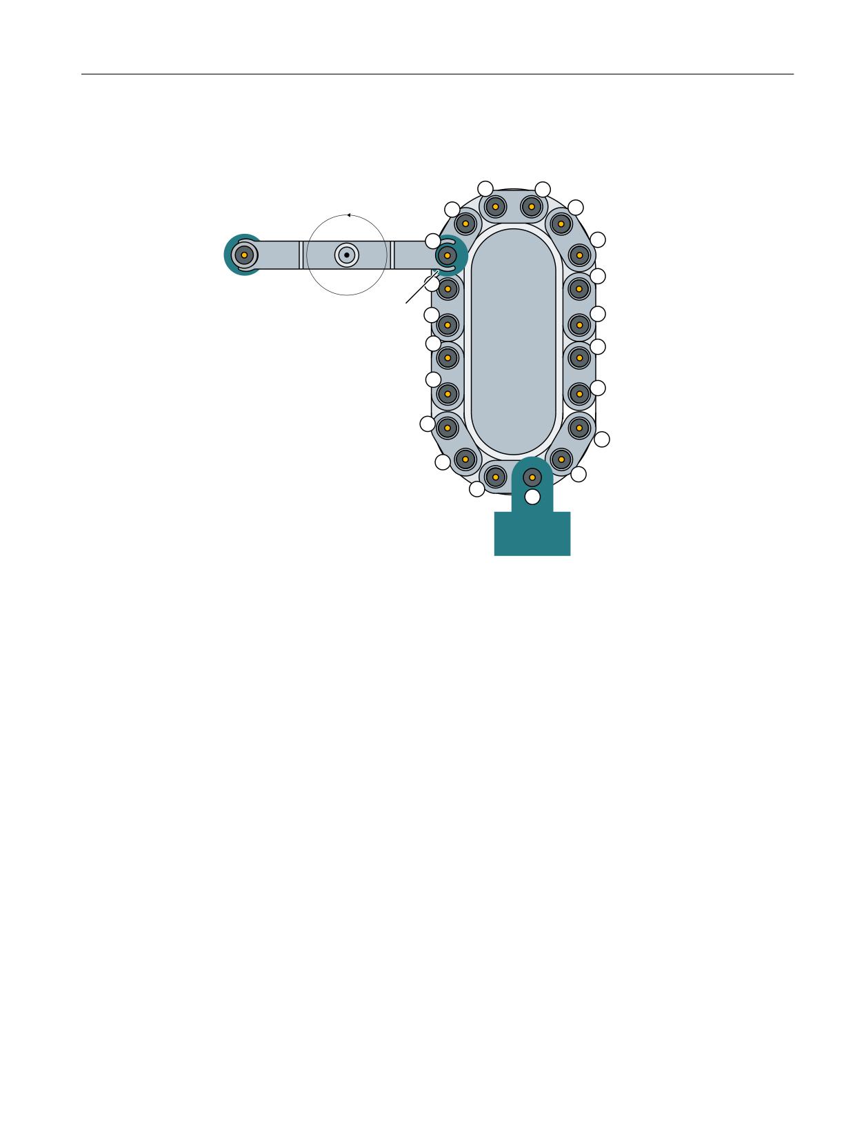
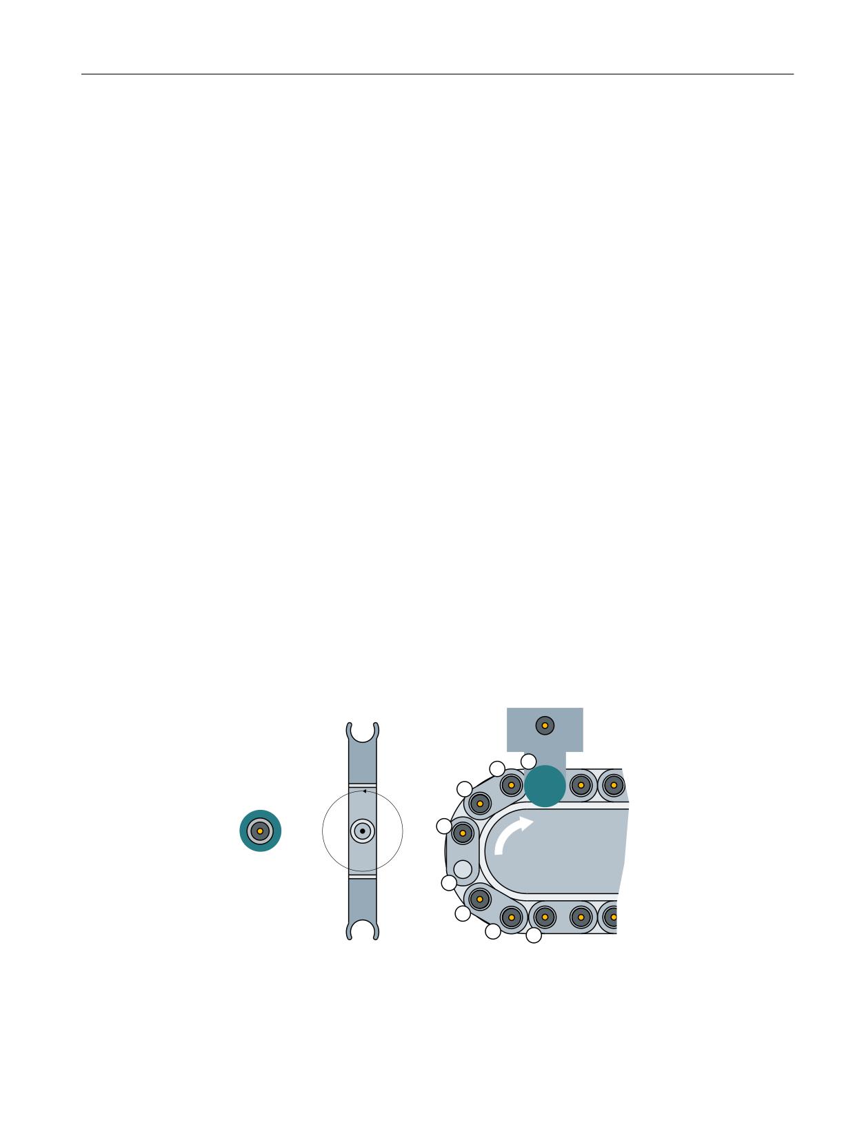
The following graphic shows a chain magazine, in which each tool occupies a half location on
the left and a half location on the right. The tool size for (1) and (2) is 2,2,1,1
Figure 8-8
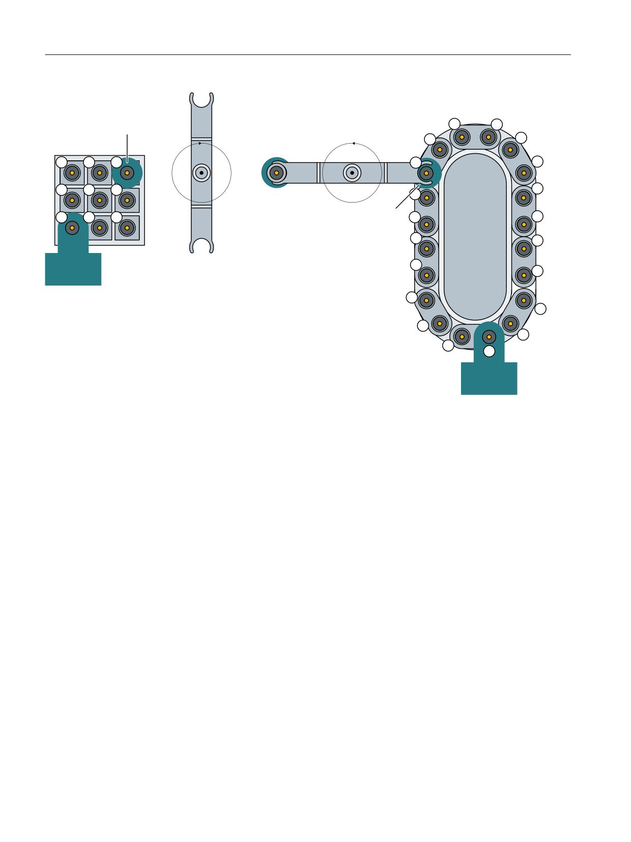
Half locations in a chain magazine
The following graphic shows half locations in a box-type magazine. The tool size is 3,3,3,3.
Figure 8-9
Half locations in a box-type magazine
Tool management
358
Function Manual, 10/2020, 6FC5397-1HP40-0BA1
Description of functions
8.2 Loading
8.2
Loading
8.2.1
Loading sequence
Overview
The "Loading" function generally involves transporting a tool from a loading point (location in
the loading magazine) into a real magazine. An owner location is assigned to the tool during
this. Only then, from the perspective of the NC, is the tool considered to have been loaded.
This means that a tool that was loaded onto the spindle - e.g. via SINUMERIK Operate - is
considered as not having been loaded.
The prerequisite is that magazines and loading points be configured in the tool management
(Page 48).
Assignment of the loading points
The loading point can be assigned via the machine data MD52274 ($MCS_TM_TOOL_LOAD_
STATION). If more than one loading point (Page 347) is defined, the following settings can be
made:
• $MCS_TM_TOOL_LOAD_ STATION = 0; a prompt window in which the loading point is
defined appears in SINUMERIK Operate.
• $MCS_TM_TOOL_LOAD_ STATION = 1; fixed loading point 1, permanently assigned as a
loading point of spindles/tool holders.
• $MCS_TM_TOOL_LOAD_ STATION = 2; fixed loading point 2
Loading points are also defined during SINUMERIK Operate configuration. More detailed
information is available at Define loading location (Page 49).
Example for loading a tool into a real magazine
/RDGLQJ SRLQW
/RFDWLRQ
*ULSSHU
6S 6SLQGOH
%6
ORDGLQJ SRLQW
* *ULSSHU
* *ULSSHU
%6
ORDGLQJ SRLQW
0DJD]LQH
6SLQGOH
%XIIHU
*ULSSHU
Figure 8-10
Load magazine
Tool management
Function Manual, 10/2020, 6FC5397-1HP40-0BA1
359
Description of functions
8.2 Loading
Loading sequence
1. The NC issues a "Load" order. The parameters are transferred to interface DB71. There is a
separate interface area in DB71 for each loading point.
2. The magazine moves the selected (empty) magazine location to the loading point
(DB71.DBW58/60).
3. The tool is loaded into the magazine (the tool is manually inserted in the example).
4. The "Load" order is acknowledged via the PLC with FC6/FC8.
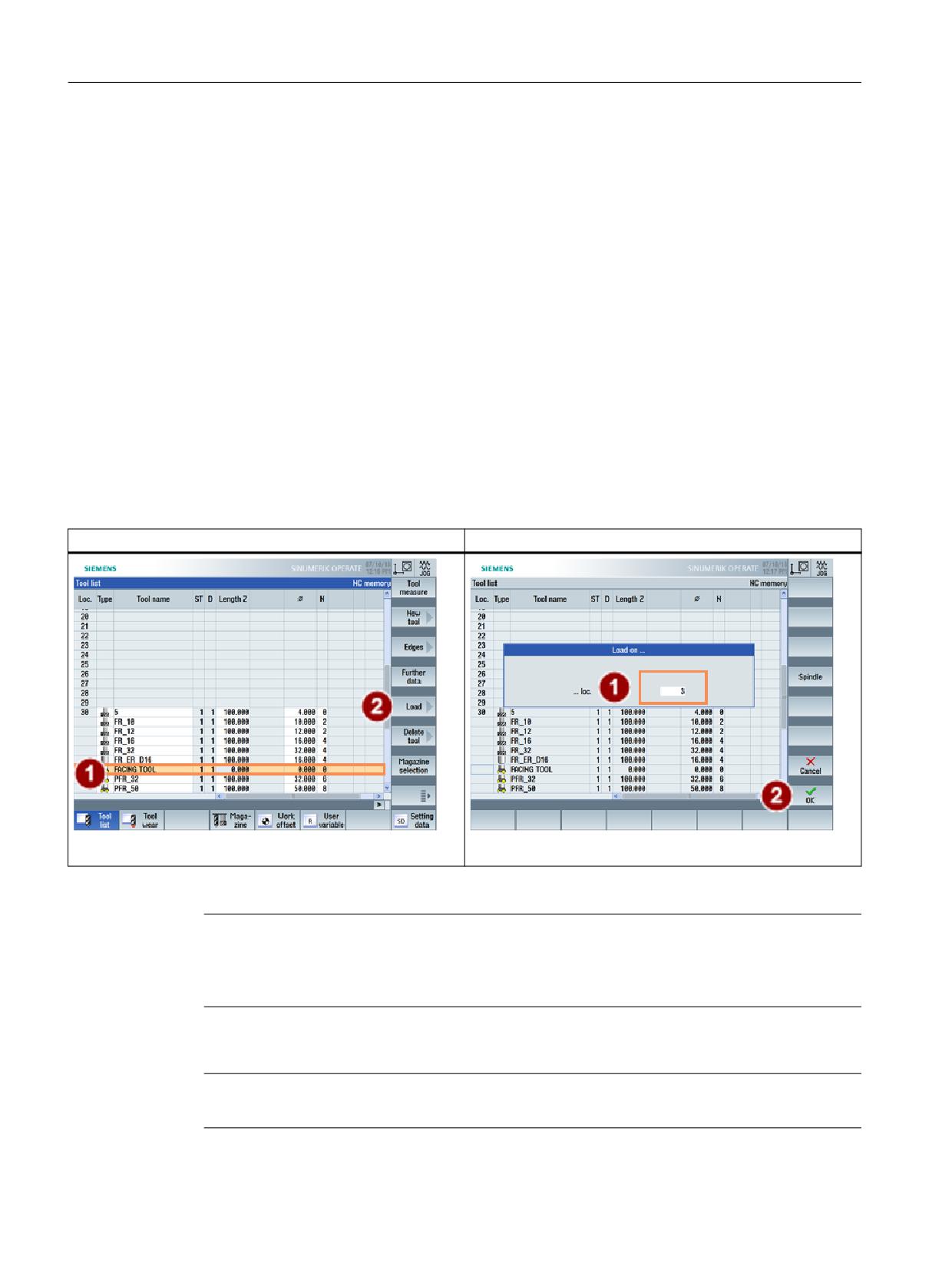
Initiate loading via SINUMERIK Operate
The magazine locations for the change point for the spindle/gripper and the loading point are
marked with arrows in the tool magazine.
Loading is initiated in SINUMERIK Operate:
1. A tool is inserted at the end of the tool list as an unloaded tool with "New tool".
2. The "loading" of the tool at the magazine location is initiated via the softkey.
Load tool
Selecting loading point
The individual steps are acknowledged via the user program in the PLC.
Note
SINUMERIK Operate automatically handles the loading. The tool data is completely generated.
The tool is placed at the loading point and tool transport initiated. This sequence does not
change, even if the tool is visually created in the magazine list via the user interface.
Note
If a tool is loaded directly onto the spindle, this does not lead to an offset selection.
Tool management
360
Function Manual, 10/2020, 6FC5397-1HP40-0BA1
Description of functions
8.2 Loading
8.2.2
Function of the PLC when loading?
Loading sequence
The PLC is notified by the NC during the loading process about the magazine and location
numbers via the "Loading/unloading (DB71)" interface.
The following bytes in DB71 (Page 125) are filled during loading:
• DBB0.1; The interface defines the loading point. Interface 2 corresponds with loading point
2. Interface 1 with loading point 1 is assigned to the spindle.
• DBB(n+0).0; the parameter "n" contains the offset for the loading point. Thus, "34" for
example, for loading point 2.
• DBW(n+24); Number of the target magazine.
• DBW(n+26); Location number of the new tool in the target magazine.
These target addresses are communicated to FC8/FC6 via the following parameters:
• "NewToolMag" contains DB71.DBW(n+24)
• "NewToolLoc" contains DB71.DBW(n+26)
• "Status (Page 161)" conveys whether the loading has been successfully completed:
- Status=10; For loading and unloading, as well as for relocating, the acknowledgement
status = 10 is available. It has the same effect as status =1 (final acknowledgement),
however it does not change the magazine position ($TC_MAP8). For every final
acknowledgement (if the tools were moved) the magazine position is always aligned.
The parameters "OldToolMag", "OldToolLoc" are preset to 0 before loading. The number of the
active interface identifies the loading location.
Example of FC8/FC6 call when loading with FC150 (user program)
The loading process in the PLC goes as follows:
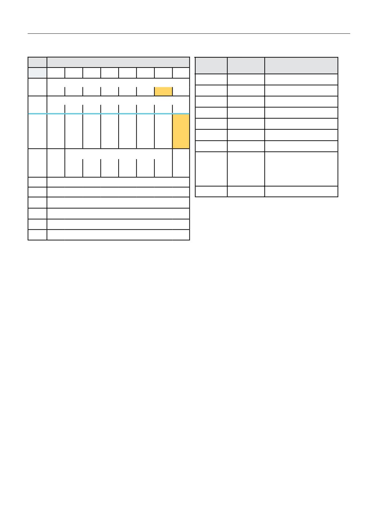
1. A request is sent to the PLC to load the tool. The information is transferred to the PLC in DB71.
Example:
Data in DB71 when loading for the 2nd interface (location 1 in magazine 1 is to be loaded
from loading location 2)
2. The PLC should now move "Location 1" from "Magazine no. 1" (into which the tool must be
loaded) to "Loading location 2" and execute the loading operation.
3. When the tool is physically present in the magazine, FC8 must be called from the user
program and the loading operation acknowledged.
Tool management
Function Manual, 10/2020, 6FC5397-1HP40-0BA1
361
Description of functions
8.2 Loading
'%
/RDGLQJ XQORDGLQJ SRLQWV 1&. ! 3/&
)&
3DUDPHWHUV
0HDQLQJ
%\WH
%LW
%LW
%LW
%LW
%LW
%LW
%LW
%LW
6WDUW
758(
7UDQVIHU LV EHLQJ VWDUWHG
,QWHUIDFH 66 DFWLYH
'%%
7DVN,GHQW
'% LQWHUIDFH
66
66
66
66
66
66
66
66
,QWHUIDFH 66 DFWLYH
7DVN,GHQW1R
,QWHUIDFH
'%%
66
66
66
66
66
66
66
66
1HZ7RRO0DJ
'% '%:
7DUJHW PDJD]LQH IRU ORDGLQJ
5HV
5HV
3RV
-RE
3RV
5HOR
8QORD
/RD
1HZ7RRO/RF
'% '%:
7DUJHW ORFDWLRQ IRU ORDGLQJ
PXOWL
IURP
PDJD
FDWLQJ
GLQJ
GLQJ
WRRO
1&
]LQH
'%%
2OG7RRO0DJ
'XULQJ ORDGLQJ
SURJ
2OG7RRO/RF
'XULQJ ORDGLQJ
'DWD LQ
5HVHUYHG
$FNQ
6WDWXV
2SHUDWLRQ FRPSOHWHG
'%
6WDW
'%%
2SHUDWLRQ WHUPLQDWHG QR
FKDQJH RI
7&B0$3
'%:
,GHQWLILHU IRU ORDGLQJ XQORDGLQJ SRLQW IL[HG YDOXH
0XOWLWRRO/RF
'XULQJ UHORFDWLRQ
'%:
1R RI ORDGLQJ SRLQW
0DJ 1R 6RXUFH IRU XQORDGLQJ UHORFDWLQJ SRVLWLRQLQJ
'%:
([DPSOH 7RRO ORDGLQJ RQ ORFDWLRQ
'%:
/RFDWLRQ 1R 6RXUFH IRU XQORDGLQJ UHORFDWLQJ SRVLWLRQLQJ
'% '%:
'% '%:
'%:
0DJ 1R 7DUJHW IRU ORDGLQJ UHORFDWLQJ SRVLWLRQLQJ
'% '%:
'%:
0DJ 1R 7DUJHW IRU ORDGLQJ UHORFDWLQJ SRVLWLRQLQJ
'% '%:
Figure 8-11
Load - DB71
In this specific case, loading from location 1 into magazine 1, with the final acknowledgement
(status_1) the magazine position is set to 1 (possibly existing offsets are not taken into
consideration). However, this is not always desirable, e.g. when equipping a turret, as HMI
Operate derives this display from the actual magazine position.
Tool management
362
Function Manual, 10/2020, 6FC5397-1HP40-0BA1
Description of functions
8.2 Loading
PLC sample programs
The following sample programs (description of DB150 (Page 122)) show the acknowledgement
of loading via interface 2. To this end, the network is programmed in an FC150 user block.
Sample program "Load magazine"
NETWORK TITLE = Acknowledgement loading interface 2
U E 86.0; //acknowledgement is done here via the terminal E 86.0
U DB71.DBX 0.1; //Interface 2 active
U DB71.DBX 34.0; //Loading active
FP M 150.0;
SPBN M100;
L 1;
T DB150.DBB 0; //DB71
L 2;
T DB150.DBB 1; //Interface 2
L 0;
L DB71.DBW 58;
T DB150.DBW 1; //Target magazine for loading
L DB71.DBW 60;
T DB150.DBW 4; //Target location for loading
L 0;
T DB150.DBW 6;
T DB150.DBW 8;
L 1;
T DB150.DBW 10; //Status 1
L -1;
T DB150.DBW 12;
S DB150.DBX 16.0; //Start FC6
M100: NOP 0;
Example of a transfer with FC6
NETWORK TITLE =Tool management status transfer
CALL FC 6 (//Tool management transfer block
Start
:= DB150.DBX 16.0,//Start
TaskID
:= DB150.DBB 0,
TaskIDNo
:= DB150.DBB 1,
NewToolMag
:= DB150.DBW 1,//Pos new tool
NewToolLoc
:= DB150.DBW 1,
OldToolMag
:= DB150.DBW 0,//Pos old tool
OldToolLoc
:= DB150.DBW 0,
Status
:= DB150.DBW 10,//Status
MultitoolLoc
:= DB150.DBW 12,
Ready
:= DB150.DBX 16.1,
Error
:= DB150.DBW 14);
U DB150.DBX 16.1; //Prompt ready
R DB150.DBX 16.0; //Reset start
L DB150.DBW 14; //Error information
L 0;
<>I ; //Evaluate error
R DB150.DBX 16.0; //Reset start
Tool management
Function Manual, 10/2020, 6FC5397-1HP40-0BA1
363
Description of functions
8.2 Loading
Problems during loading
A tool cannot be loaded. Check the following:
• Is the location type correct?
• Is a suitable empty location available?
• Has the number of tools enabled in the NC (MD18082) been reached?
Alarms on the operator panel:
• No suitable empty location available
• The "Create tools" command cannot be output to NC.
See also
FC8: TM_TRANS - transfer block for tool management (Page 157)
8.2.3
Loading by directly assigning the T number
By directly writing to parameter $TC_MPP6[magazine No.,location No.] = T, a tool can be set to
a magazine location (whether it is a real magazine, buffer or loading magazine). For example,
for oversized tools, the NC automatically reserves adjacent locations.
The NC checks whether the tool fits at this location (location type, free adjacent locations, ...),
if not, then an alarm is generated.
This does not involve an associated command output to the PLC.
8.2.4
Load tools via a part program
T number
The data required for a tool can also be loaded via a part program.
There are two possibilities to get the T number that addresses the data. You can:
• Assign the T number yourself or
• Allow the NC to assign the T number
(via the command NEWT (Page 232)).
The other data can be addressed by the T number determined in this way. Otherwise the T
number can be assigned by the user (refer to the following example):
Example
DEF INT TNo
TNo=NEWT("test",1)
$TC_TP3[TNo]=2
;Size left
Tool management
364
Function Manual, 10/2020, 6FC5397-1HP40-0BA1
Description of functions
8.2 Loading
$TC_TP4[TNo]=2
;Size right
$TC_TP5[TNo]=1
;Size top
$TC_TP6[TNo]=1
;Size bottom
$TC_TP7[TNo]=2
;Location type
$TC_TP8[TNo]=2
;Tool status
$TC_TP9[TNo]=0
;Type of monitoring
$TC_TP10[TNo]=0
;Substitute tool strategy
$TC_TP11[TNo]=0
;Tool info
$TC_DP1[TNo,DNo]=120
;Tool type: (all of the offset data is provided here)
$TC_MPP6[MagNo,LocNo]=TNo
;Tool with the determined T number is written/loaded
to the location
The tool described here also occupies adjacent locations. The tool management automatically
assigns/reserves the adjacent locations.
It is also possible to delay assignment of a tool to a location, in which case the command
$TC_MPP6 is not required. After execution of the part program the tools are contained in the tool
list and can be loaded at a later time.
8.2.5
Retroload tool data
Procedure
When tool data is "reloaded" this means that the offset data is not entered or loaded until after
the tool loading operation.
• The tools are already located in the magazine, both physically as well as their data, i.e. the
"Tool ←→ Location" assignment has taken place
• There is either no tool offset data in the NC or it is no longer up to date.
The offset data is assigned via the part program, i.e. the existing data is overwritten. If not
already known, the internal T number of the particular tool first has to be determined in the
"retroload" program to do this.
The internal T number is the tool number that the NC works with. It is unique and describes a
tool. All parameters of this tool are addressed by this T number.
The T number can be assigned either by the operator when creating a tool or by the NC.
If the operator knows the T number (e.g. specified by the entries made at the measuring station),
then this number can be retrieved in the retroload program.
If the T number is not known, then it has to be determined for each tool to be retroloaded and
be supplied from a variable. This reduces the overhead for the user and also reduces the scope
for errors.
Tool management
Function Manual, 10/2020, 6FC5397-1HP40-0BA1
365
Description of functions
8.2 Loading
Create the retroload program
The tool is measured at a measuring station and the measured data stored. For this purpose, the
tool must already be defined, i.e. by both an identifier ("Drill 12 mm" or "Miller 23" in the
following) and the relevant duplo number. (The combination of tool identifier and duplo number
uniquely defines the tool.) The internal T number of this tool is determined prior to the data
record using the command GETT("Identifier", duplo No.) and saved a variable ("T No." here). The
data required for the tool is written and then the entire program is transferred to the NC where
it is processed.
Only the variables for which data is entered have to be written. The first tool in the following
example contains all the data, the second tool only contains the relevant data.
The T number does not have to be determined in the retroload program if already specified
during loading because the data can then be assigned directly.
For example, for tool "1", writing length L1 looks like this:
$TC_DP1[1,1]=120
;Tool type
$TC_DP3[1,1]=67.032
;Length
Program for retroloading tool offset data
DEF INT Tno
;Definition of variable TNo
tl1:
TNo=GETT ("Drill 12mm",1)
if TNo==-1 goto tl2
$TC_DP1[TNo,1]=120
;Tool type
$TC_DP2[TNo,1]=0
$TC_DP3[TNo,1]=67.032
;Length1
$TC_DP4[TNo,1]=0
$TC_DP5[TNo,1]=0
$TC_DP6[TNo,1]=24
;Radius
$TC_DP7[TNo,1]=0
$TC_DP8[TNo,1]=0
$TC_DP9[TNo,1]=0
$TC_DP10[TNo,1]=0
$TC_DP11[TNo,1]=0
$TC_DP12[TNo,1]=0
$TC_DP13[TNo,1]=0
$TC_DP14[TNo,1]=0
$TC_DP15[TNo,1]=0
$TC_DP16[TNo,1]=0
$TC_DP17[TNo,1]=0
$TC_DP18[TNo,1]=0
$TC_DP19[TNo,1]=0
$TC_DP20[TNo,1]=0
$TC_DP21[TNo,1]=0
$TC_DP22[TNo,1]=0
$TC_DP23[TNo,1]=0
Tool management
366
Function Manual, 10/2020, 6FC5397-1HP40-0BA1
Description of functions
8.2 Loading
$TC_DP24[TNo,1]=0
$TC_DP25[TNo,1]=0
$TC_MOP1[TNo,1]=0
$TC_MOP2[TNo,1]=0
$TC_MOP3[TNo,1]=0
$TC_MOP4[TNo,1]=0
tl2:
;Next tool
TNo=GETT ("Miller23",2)
if TNo==-1 goto error
;Possible error routine if tool does not exist
$TC_DP1[TNo,1]=120
$TC_DP3[TNo,1]=82.51
$TC_DP6[TNo,1]=25
Fault:
;Error
:
:
M17
Tool management
Function Manual, 10/2020, 6FC5397-1HP40-0BA1
367
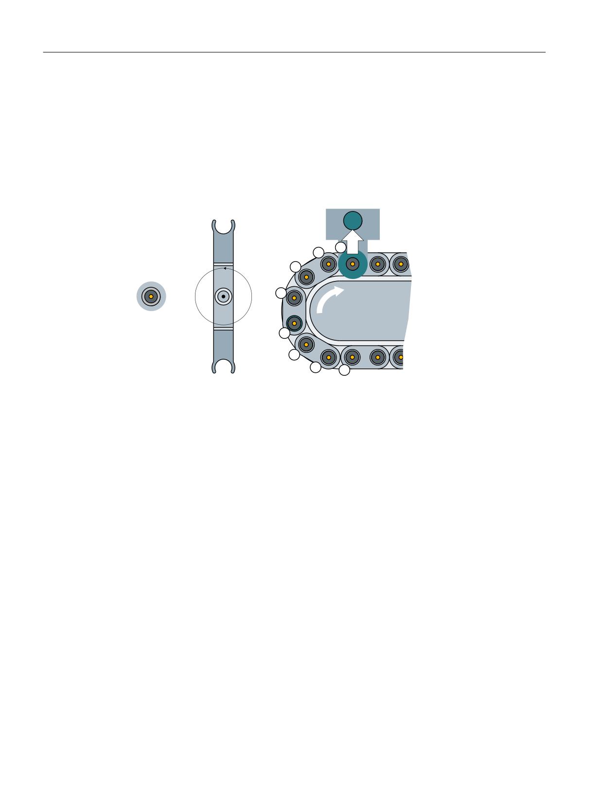
Description of functions
8.3 Unloading
8.3
Unloading
8.3.1
Unloading sequence
Unloading removes the tool from the magazine. It always involves transporting a tool from a real
magazine into the loading magazine. In so doing, the owner location of the tool as well as all
reservations made in the real magazine are deleted.
%6
)5$(6(5B
*
%6
6S 6SLQGOH
%6
ORDGLQJ SRLQW
* *ULSSHU
* *ULSSHU
0DJD]LQH
%6
ORDGLQJ SRLQW
6S
*
Figure 8-12
Unloading the magazine
Unloading sequence
1. The NC issues an "Unload" order. The parameters are transferred to interface DB71. There is
a separate interface area in DB71 for each loading point.
2. The magazine moves the selected (loaded) magazine location to the loading point
(DB71.DBW58/60).
3. The tool is unloaded from the magazine (the tool is manually removed in the example).
4. The "Unload" order is acknowledged via the PLC with FC6/FC8.
Tool management
368
Function Manual, 10/2020, 6FC5397-1HP40-0BA1
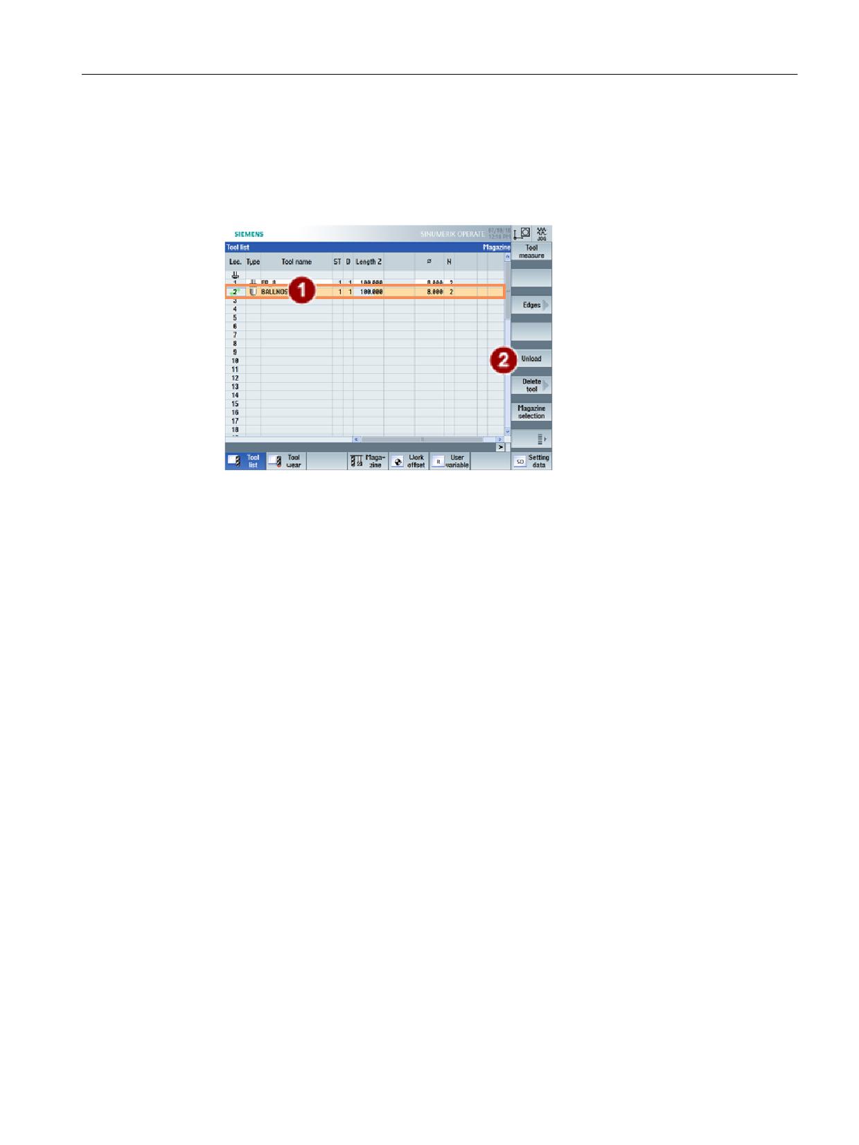
Description of functions
8.3 Unloading
Initiate loading via SINUMERIK Operate
Loading is initiated in SINUMERIK Operate:
1. The tool is selected in the magazine.
2. The "unloading" of the tool from the magazine is initiated via the softkey.
Figure 8-13
Unload tool
The individual steps are acknowledged via the user program in the PLC.
8.3.2
PLC function when unloading
Overview
The PLC is notified by the NC during the unloading process about the magazine and location
numbers via the "Loading/unloading (DB71)" interface.
The following bytes in DB71 (Page 125) are filled during unloading:
• DBB0.1; The interface defines the loading point. Interface 2 corresponds with loading point
2. Interface 1 with loading point 1 is assigned to the spindle.
• DBB(n+0).1; the parameter "n" contains the value for the loading/unloading point. Thus,
"34" for example, for loading point 2.
• DBW(n+24); Number of the source magazine.
• DBW(n+26); Location number of the tool to be unloaded.
These target addresses are communicated to FC8/FC6 via the following parameters:
• The ID of the unloading point contains DB71.DBW(n+16)
• The position number of the unloading point contains DB71.DBW(n+18)
• "Status (Page 161)" conveys whether the loading has been successfully completed:
The parameters "NewToolMag", "NewToolLoc" are preset to 0 during loading. The number of the
active interface identifies the loading location.
Tool management
Function Manual, 10/2020, 6FC5397-1HP40-0BA1
369
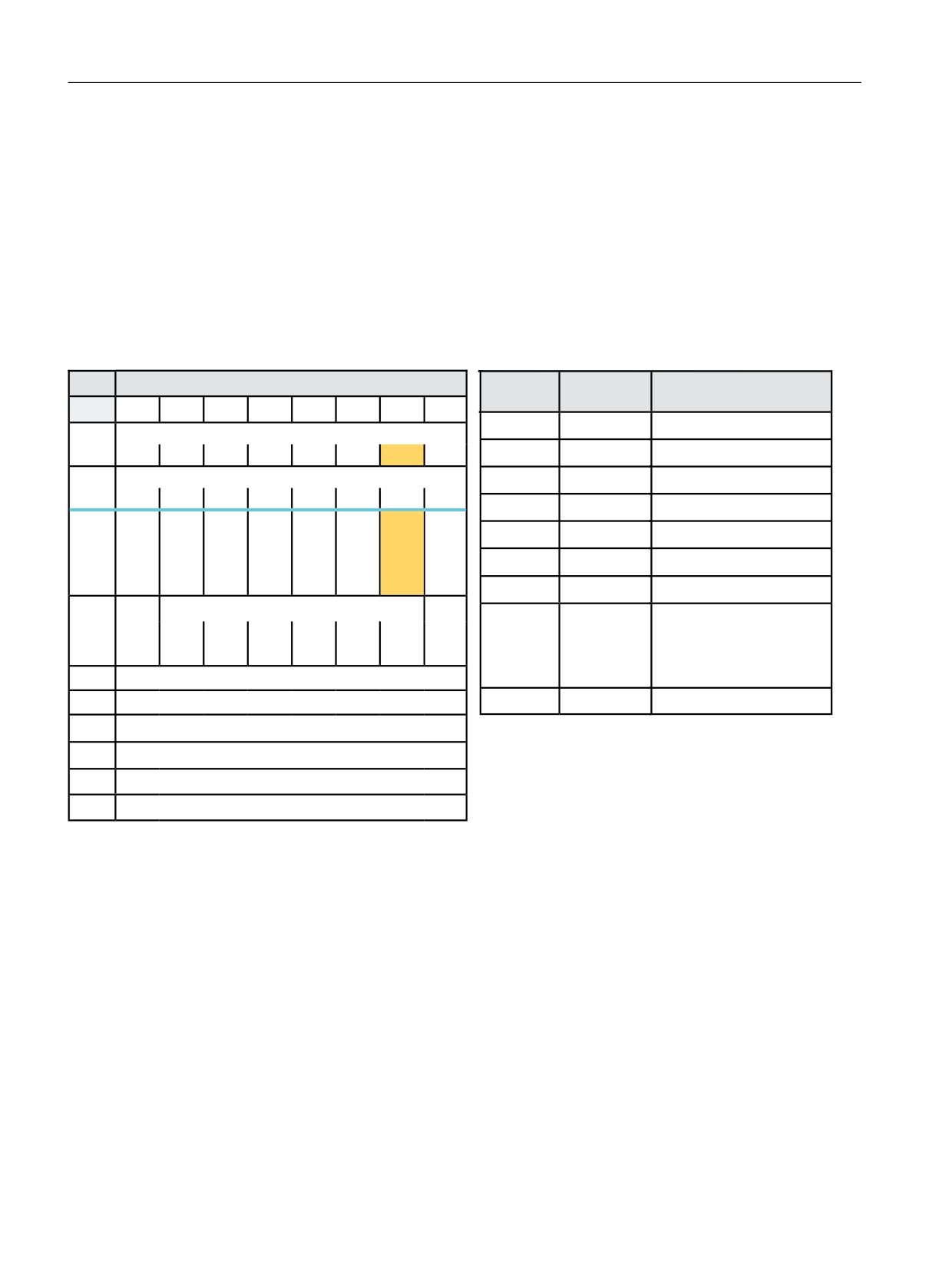
Description of functions
8.3 Unloading
Example of FC8/FC6 call when unloading with FC150 (user program)
Unloading is controlled via DB71. The unloading sequence is as follows:
1. The PLC receives the command to unload the selected tool. The information is transferred to
the PLC in DB71. Example of the data in DB71 during unloading for the 2nd interface Location
1 of magazine no. 1 must be unloaded at loading location 2.
2. The PLC positions "Location 1" from "Magazine No. 1" (from which should be unloaded) to the
"Loading/unloading point 2" and executes the unloading operation.
3. When the tool is removed from the magazine, FC8/FC6 must be called from the user program
and the unloading operation acknowledged.
'%
/RDGLQJ XQORDGLQJ SRLQWV 1&. ! 3/&
)&
3DUDPHWHUV
0HDQLQJ
%\WH
%LW
%LW
%LW
%LW
%LW
%LW
%LW
%LW
6WDUW
758(
7UDQVIHU LV EHLQJ VWDUWHG
,QWHUIDFH 66 DFWLYH
'%%
7DVN,GHQW
'% LQWHUIDFH
66
66
66
66
66
66
66
66
,QWHUIDFH 66 DFWLYH
7DVN,GHQW1R
,QWHUIDFH
'%%
66
66
66
66
66
66
66
66
1HZ7RRO0DJ
'XULQJ XQORDGLQJ
5HV
5HV
3RV
-RE
3RV
5HOR
8QORD
/RD
1HZ7RRO/RF
'XULQJ XQORDGLQJ
PXOWL
IURP
PDJD
FDWLQJ
GLQJ
GLQJ
WRRO
1&
]LQH
'%%
2OG7RRO0DJ
'% '%:
7DUJHW PDJD]LQH IRU XQORDGLQJ
SURJ
2OG7RRO/RF
'% '%:
7DUJHW ORFDWLRQ IRU XQORDGLQJ
'DWD LQ
5HVHUYHG
$FNQ
6WDWXV
2SHUDWLRQ FRPSOHWHG
'%
6WDW
'%%
2SHUDWLRQ WHUPLQDWHG QR
FKDQJH RI
7&B0$3
'%:
,GHQWLILHU IRU ORDGLQJ XQORDGLQJ SRLQW IL[HG YDOXH
0XOWLWRRO/RF
'XULQJ UHORFDWLRQ
'%:
1R RI ORDGLQJ SRLQW
'%:
0DJ 1R 6RXUFH IRU XQORDGLQJ UHORFDWLQJ SRVLWLRQLQJ
([DPSOH 7RRO XQORDGLQJ IURP ORFDWLRQ
'% '%:
'%:
/RFDWLRQ 1R 6RXUFH IRU XQORDGLQJ UHORFDWLQJ SRVLWLRQLQJ
'% '%:
'% '%:
0DJ 1R 7DUJHW IRU ORDGLQJ UHORFDWLQJ SRVLWLRQLQJ
'%:
'% '%:
'% '%:
0DJ 1R 7DUJHW IRU ORDGLQJ UHORFDWLQJ SRVLWLRQLQJ
'%:
'% '%:
Figure 8-14
Unloading DB71
Example: Call FC8/FC6 when unloading
The PLC user program moves the magazine to the unloading point and executes the unloading
operation. If the tool comes via a buffer location (gripper, loader) to the unloading point or
station, then the NC is to be notified of each position change by means of the FC8/FC6 with status
104, 105.
Status "1" is not set via FC8 until the tool is in the specified unloading point/station. This means
that the unload operation has been completed; the magazine position is also automatically
aligned.
Tool management
370
Function Manual, 10/2020, 6FC5397-1HP40-0BA1
Description of functions
8.3 Unloading
PLC sample programs
The following sample programs (definition of DB150 (Page 122)) show the acknowledgement
of loading via interface 2. To this end, the network is programmed in an FC150 user block.
Sample program "Load magazine"
NETWORK TITLE = Acknowledgement of unloading interface 2
U
E 86.0; //acknowledgement is done here via the terminal E 86.0
U
DB71.DBX
0.1; //Interface 2 active
U
DB71.DBX
34.1; //Loading active
FP
M 150.0;
SPBN
M100;
L
1;
T
DB150.DBB
0; //DB71
L
2;
T
DB150.DBB
1; //Interface 2
L
0;
T
DB150.DBW
2;
T
DB150.DBW
4;
L
DB71.DBW
50;
T
DB150.DBW
6; //Target magazine for unloading
L
DB71.DBW
52;
T
DB150.DBW
1; //Target location for unloading
L
0;
L
1;
T
DB150.DBW
10; //Status 1
L
-1;
T
DB150.DBW
12;
S
DB150.DBX
16.0; //Start FC6
M100: NOP 0;
Example of a transfer with FC6
NETWORK TITLE =Tool management status transfer
CALL FC 6 (//Tool management transfer block
Start
:= DB150.DBX 16.0,//Start
TaskID
:= DB150.DBB 0,
TaskIDNo
:= DB150.DBB 1,
NewToolMag
:= DB150.DBW 2,//Pos new tool
NewToolLoc
:= DB150.DBW 4,
OldToolMag
:= DB150.DBW 6,//Pos old tool
OldToolLoc
:= DB150.DBW 8,
Status
:= DB150.DBW 10,//Status
MultitoolLoc
:= DB150.DBW 12,
Ready
:= DB150.DBX 16.1,
Error
:= DB150.DBW 14);
U
DB150.DBX
16.1; //Ready prompt
R
DB150.DBX
16.0; //Reset start
L
DB150.DBW
14; //Error information
L 0;
<>I ; //Evaluate error
R
DB150.DBX 16.0; //Reset start
Tool management
Function Manual, 10/2020, 6FC5397-1HP40-0BA1
371

Description of functions
8.3 Unloading
Positioning for unloading (with SINUMERIK Operate)
This means that the HMI sends two tasks to the NC (and this in turn to the PLC). First positioning
(which is described in the following), then unloading.
When a magazine is being positioned at a loading magazine, the target address is stored in
DB71.DBW(n+16) and DBW(n+18). This target address is passed to FC8/FC6 as parameters
"NewToolMag" and "NewToolLoc" and "Status" = 1 once the magazine has been successfully
positioned. Parameters "OldToolMag", "OldTool-Loc" must be set to 0.
The magazine and magazine location to be positioned are stored in DB71.DBW(n+20) and
DBW(n+22). Positioning here only concerns magazine positioning a free location or a location
with a tool to a loading/unloading station. The number of the active interface identifies the
loading magazine (location No.).
Example: Positioning for unloading
FC8 parameters
Values
Comment
Start
Starts task
TaskIdent
1
DB 71 interface
TaskIdentNo
2
No. of active interface
NewToolMag
9999
MAG. No. 9999
NewToolLoc
3
Loc. No. 3
OldToolMag
0
During positioning = 0
OldToolLoc
0
During positioning = 0
Status
1
Operation completed
See also
FC8: TM_TRANS - transfer block for tool management (Page 157)
8.3.3
Unloading by deleting the T number from the magazine location
By directly writing to parameter $TC_MPP6[magazine No.,location No.] = 0, a tool can be
removed from this magazine location (whether it is a real magazine, buffer or loading
magazine). All reservations of the removed tool are automatically deleted.
This does not involve an associated command output to the PLC.
Tool management
372
Function Manual, 10/2020, 6FC5397-1HP40-0BA1
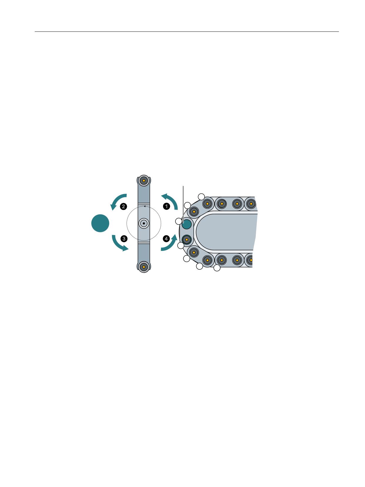
Description of functions
8.4 Tool change box-type, chain, circular magazines
8.4
Tool change box-type, chain, circular magazines
8.4.1
Overview
Tool change - Overview
During a tool change, a tool is changed from a real magazine into the spindle or the turret is
rotated to the correct position. The used tool is changed from the spindle into a real magazine.
The tool can be changed using an intermediate magazine such as a gripper. Other options are,
for example, changing the tool using turrets (rotating the turret) and a manual tool change
(manual tool).
The following example shows a tool change in a chain magazine with a double gripper.
&KDQJH SRVLWLRQ IRU
*ULSSHU
VSLQGOH
0DJD]LQH
6SLQGOH
*ULSSHU
Figure 8-15
Tool change with double gripper
All of the intermediate steps during a tool change must be programmed in the user program of
the PLC and acknowledged via the transfer blocks FC6, FC7 or FC8. In the example above, this
means:
• The tool is positioned at the change point of the magazine.
•
① The tool is loaded from the change point of magazine 1 into gripper 1.
•
① The tool is loaded from spindle 1 into gripper 2.
•
② The tool is loaded from gripper 1 into spindle 1.
•
② The tool is loaded from gripper 2 to the change point in magazine 1.
Tool management
Function Manual, 10/2020, 6FC5397-1HP40-0BA1
373
Description of functions
8.4 Tool change box-type, chain, circular magazines
8.4.2
General tool change sequence
Tool change sequence
The prompt for changing the tool is issued by the part program via T command or M command.
1. The tool-management function in NC searches in accordance with the tool search strategy
for a tool suitable for use (preparation) and, at the same time, searches for an empty location
for the tool to be exchanged.
2. The determined data is provided in DB72/73. The user program must react by making a new
tool available.
3. If machine data MD22550 $MC_TOOL_CHANGE_MODE is set to 1, with the "M06 command"
in the part program, the PLC executes the tool change and signals the end of the change
operation.
If the machine data is set to 0, then by programming T, the tool is loaded. In both cases, the
PLC has the option of applying its own tool change strategy. It can choose its own empty
location for storing the old tool.
Note
The tool change is an NC-internal operation that is executed as an interaction with the PLC.
The HMI only has the task of displaying data and facilitating data input.
Tool management
374
Function Manual, 10/2020, 6FC5397-1HP40-0BA1
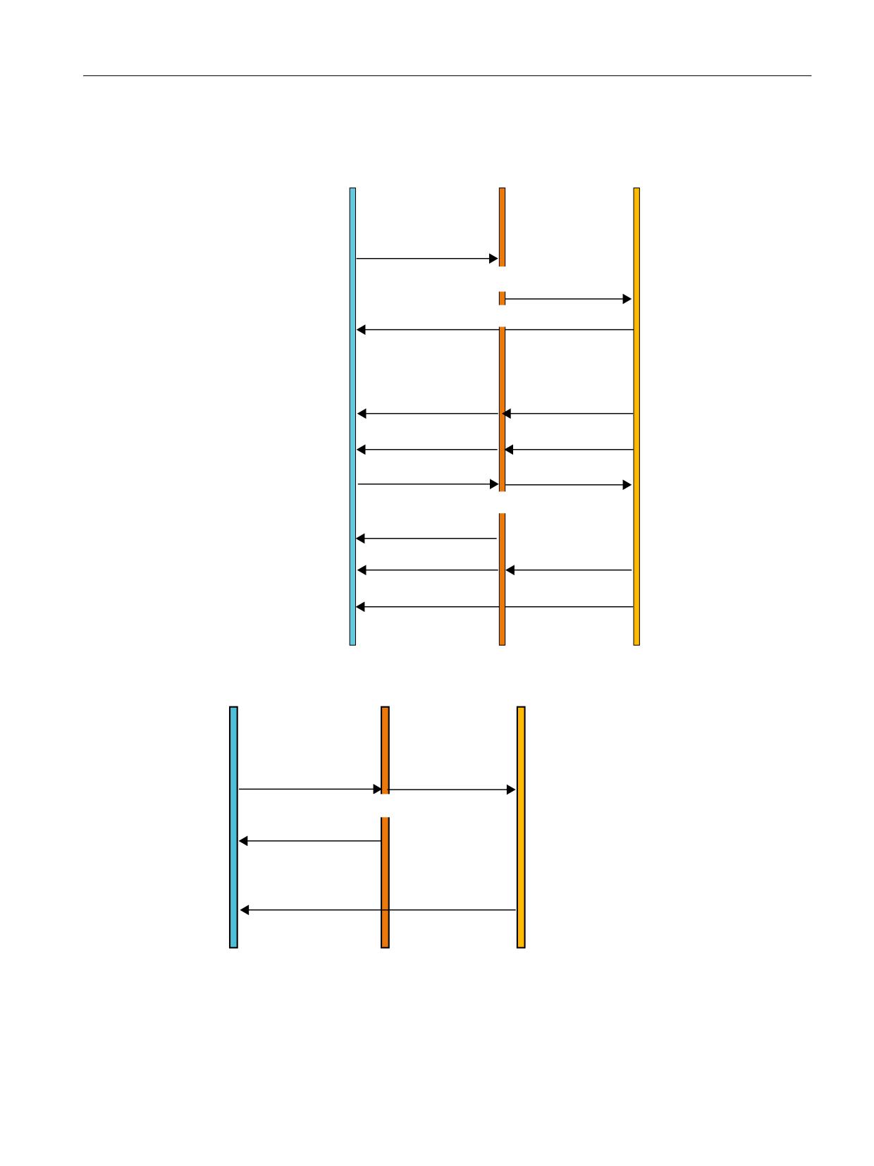
Description of functions
8.4 Tool change box-type, chain, circular magazines
Tool change sequence
1&
3/& *3
3/& XVHU
3DUW SURJUDP FRPPDQG
3URFHVV DODUP
7 ,GHQW
1&
GHWHUPLQHV ORFDWLRQV RI
'LVWULEXWLRQ LQ 2% DIWHU FKHFN
&RPPDQG LQ '%
WKH SDUWLFLSDWLQJ WRROV
ZKHWKHU WKH LQWHUIDFH LV IUHH
,QIOXHQFLQJ RI FKDQQHO
VLJQDOV H J UHDG LQ GLVDEOHG
:DLW F\FOH 2%
7UDQVIHU RI F\FOLF
$FWLRQV IRU SUHSDULQJ
VLJQDOV DQG WUDQVSRUW
H J PDJD]LQHV
DFNQRZOHGJHPHQW
IRU 7
)&
6WDWXV
)&
6WDWXV
3URFHVV DODUP
3URFHVV DODUP
,QLWLDWH DFWLRQV IRU
3URJUDP FRPPDQG 0
&KDQJH
'LVWULEXWLRQ LQ 2% LI '%
66 LV IUHH
7UDQVSRUW DFNQRZOHGJH
PHQW 0
F\FOH
)&
)URP WKLV SRLQW RQ
6WDWXV
PRWLRQ EORFNV ZLWK
)&
DFWLYH FXWWLQJ HGJH FDQ
&KDQJH H[HFXWHG
EH WUDYHUVHG
6WDWXV
Figure 8-16
Preparing and changing a tool
1&
3/& *3
3/& XVHU
&RPPDQG LQ '%
,QLWLDWLRQ RI DFWLRQV IRU
3URJUDP FRPPDQG
3URFHVV DODUP
3URFHVV DODUP
&KDQJH SRVVLEOH LQIOXHQFLQJ
7 'HV
7 /RFDWLRQ
RI FKDQQHO VLJQDOV H J UHDG LQ
'LVWULEXWLRQ LQ 2% LI '%
66 LV IUHH
GLVDEOHG
7UDQVSRUW DFNQRZOHGJHPHQW 7
F\FOH
)URP WKLV SRLQW RQ PRWLRQ
EORFNV ZLWK DFWLYH FXWWLQJ
)&
&KDQJH DFNQRZOHGJH
HGJH FDQ EH WUDYHUVHG
PHQW H[HFXWHG
Figure 8-17
Tool changing with T command
Tool management
Function Manual, 10/2020, 6FC5397-1HP40-0BA1
375

Description of functions
8.4 Tool change box-type, chain, circular magazines
Spindle and tool holder
Tool management can also be used for machines that have no spindle (e.g. punch presses or
turrets). In this case the term "spindle" is replaced by "tool holder";
This is defined in MD20124 $MC_TOOL_MANAGEMENT_TOOLHOLDER. If MD > 0, then the
spindle numbers $TC_MPP5 are interpreted as tool holder numbers.
Fixed location coding
If fixed location coding is selected for a tool, the tool will always be returned to the same location
when it is replaced.
Variable location coding
Tools defined with variable location coding can be returned to any location for the appropriate
tool size and location type in the magazine.
Automatic tool return to real magazine
1. An automatic tool return is initiated by the TM only if the tool is transported via several
stations (status 105) after a T preparation command from the PLC and the T preparation
command is finally acknowledged positively with status 1.
The return of a preselected tool from the buffer can be suppressed by setting MD20310:
TOOL_MANAGEMENT_MASK, bit 15 = 1.
2. If a tool change is interrupted because the control is switched off but the tool is already
located in a buffer location (gripper), the next tool change must either return the tool in the
buffer to the spindle or to the real magazine.
3. If several tools are located in the buffer the spindle tool is considered first. If there is no tool
on the spindle, the order for return is in accordance with system variable $TC_MLSR.
Example for the time sequence of a tool change
The following example shows a typical cut-to-cut sequence of operations for a tool change with
a tool changer and a fixed absolute tool change point on a milling machine.
Machining program
N970 G0 X = Y = Z
;Retraction from the contour
N980 T = "MILLING CUTTER"
;Tool preselection
N990 T_CHANGE
;Subprogram call without parameters
N1000 G90 G0 X= Y= Z= M3 S1000
;Continue machining
Subprogram for the tool change
PROC W_WECHSEL
N10 SPOSA= S0
;Spindle positioning
N20 G75 FP=2 X1=0 Y1=0 Z1=0;
;Approach tool change point
N30 M06
;Change tool
N40 M17
Tool management
376
Function Manual, 10/2020, 6FC5397-1HP40-0BA1
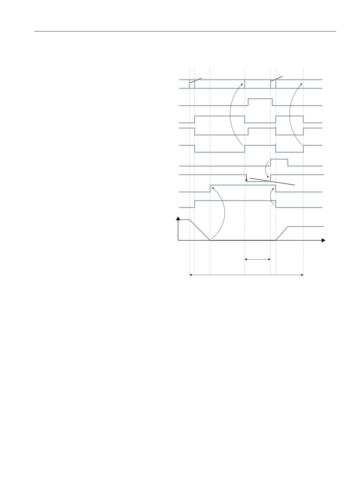
Description of functions
8.4 Tool change box-type, chain, circular magazines
1
1
&XUUHQW ORFDWLRQ QXPEHU
1
1
1
,6 )HHG GLVDEOH
,6 7UDYHUVLQJ FRPPDQG
D[LV
,6 ([DFW VWRS ILQH D[LV
,6 ([DFW VWRS FRDUVH D[LV
3/& 1HZ WRRO ORDGHG
,6 5HDG LQ HQDEOH
,6 ([DFW VWRS ILQH VSLQGOH
E\
0
3RVLWLRQLQJ PRGH DFWLYH
6SLQGOH VSHHG LQ USP
7LPH
722/ 72 722/ 7,0(
&87 72 &87 7,0
(
W
W
W
W
W
Figure 8-18
Chronological sequence of tool change
t1 axes stationary, spindle rotating, start of the tool change cycle in N10
t2 Traverse axis with G75 in N20 to tool change point.
t3 Spindle reaches programmed position from block N10.
t4 Axes reach exact stop coarse from N20; N30 now starts.
M06 removes the previous tool from the spindle and loads and clamps the new tool.
t5 Tool changer swivels back to original position.
Then, in N1000 of the calling main program,
• the new tool offset can be selected,
• the axes returned to the contour.
• spindle accelerated.
Tool management
Function Manual, 10/2020, 6FC5397-1HP40-0BA1
377
Description of functions
8.4 Tool change box-type, chain, circular magazines
8.4.3
Preparing a tool change via T command
Fundamentals
A tool change is prepared via the part program with the "T" command and then executed via the
command "M06".
The tool change type is set using machine data 22550 $MC_TOOL_CHANGE_MODE.
• $MC_TOOL_CHANGE_MODE = 0
No separate T preparation, change with the T command.
• $MC_TOOL_CHANGE_MODE = 1
Separate T preparation, the change is performed with M06 or the M function, which is set in
machine data $MC_TOOL_CHANGE_M_CODE.
This setting setting is independent of the magazine type. This means that also for a turret, T and
M06 can be programmed just the same as for a chain magazine only with a T command.
$MC_TOOL_CHANGE_MODE=0
T="Tool identifier"
;Tool preparation and tool change with an NC command (=
within an NC block)
;NC sends a command to the PLC
If an error is detected during tool preparation, then machining is stopped when the block T =
identifier is read-in.
After correction and NC Start, the block with T = identifier is interpreted again and program
processing is continued.
$MC_TOOL_CHANGE_MODE=1
• Within an NC block
T="Tool identifier" M06
;Tool preparation and tool change from this programming
results in a command to the PLC
Program tool preparation and tool change in one block (T= "Tool identifier" M06), corresponds
to setting TOOL_CHANGE_MODE = 0.
• Distributed over two NC blocks
T="Tool identifier"
;Tool preparation
;NC sends a command to the PLC
M06
;Tool change (the number of the M code can be set)
;NC sends a command to the PLC
Tool preparation and tool change are typically programmed in different blocks. Two commands
are transferred to the PLC.
Tool management
378
Function Manual, 10/2020, 6FC5397-1HP40-0BA1
Description of functions
8.4 Tool change box-type, chain, circular magazines
8.4.4
Execution of the tool change
Programming the tool change
A tool change is prepared via the part program with the "T" command and then executed via the
command "M06".
The change is initiated with M06.
Change in tool "MILLER1"
TEST_PROGRAM.MPF
N10
N20
N30 T="MILLER1"
//Prepare tool change
N40
N50
N60 M06
N70
N80
N90 M30 end of program
An alarm is triggered if an error occurs in T="tool identifier". If the MD22562
TOOL_CHANGE_ERROR_MODE is set accordingly, the alarm is delayed until the associated tool
change command M06 is interpreted in the program sequence. Only then is the alarm output.
The operator can make corrections in this block.
Note
Offset selection or deselection is automatically made with the tool change command. In so
doing, machine data MD20270 CUTTING_EDGE_DEFAULT is evaluated.
If the T/M function of the tool change is programmed with address extension, the address
extension specifies the spindle number for which the tool change is to take place:
Example: T3 = "Miller" M3 = 6
The tool with the "Miller" identifier is loaded into spindle 3.
Empty spindle
Program commands T0 and M06 remove the tool from the spindle and return it to the magazine.
The spindle is then empty.
Possible problems when programming T/M06
$MC_TOOL_CHANGE_MODE=0; tool change with T address
Tool management
Function Manual, 10/2020, 6FC5397-1HP40-0BA1
379
Description of functions
8.4 Tool change box-type, chain, circular magazines
The part program is executed through to the block T = "identifier". The following problems can
occur and are handled as follows:
• The tool data record is in the NC but not assigned to a magazine location. The tool must be
reloaded mechanically, if necessary, e.g. directly onto the spindle. The assignment of the tool
to the magazine location/the spindle takes place, e.g. with the function "Overstore";
$TC_MPP6[m,p] = T no., or by the HMI operation "Load (onto spindle)".
• The tool data record is not in the NC: Create data record, e.g. through HMI operation, in the
NC.
• Programming error in part program: Correct NC block with error in the part program.
• Alarm 22067:
The desired tool change is not possible. The specified tool group does not contain a "ready to
use" replacement tool which could be loaded. The tool monitoring function may have set all
potentially suitable tools to the "disabled" status.
The Start pushbutton is pressed once the operation has been completed. The NC block T="tool
identifier" is interpreted again and program processing is continued provided operator
intervention was correct. If not, the alarm will be generated again.
8.4.5
Tool change for chain and box-type magazines
8.4.5.1
PLC function during preparation (chain, box type)
Spindle/buffer DB72
The data block DB72 (Page 130) is responsible for changing tools in the spindle. This data block
also prepares the tool change. This data block has an interface for every spindle.
User data is available at each interface (sequence in accordance with the spindle number) as for
the loading and unloading points. Data are additionally available for the new tool to be loaded
at change. This data includes, for example, location type, sizes, tool status and the T number
internally assigned in the NC.
The buffer address of the spindle is contained in DB72.DBW(n+16) and DBW(n+18) as the target
for the new tool. This position is communicated as the target position of the new tool in
parameters "NewToolMag" and "NewToolLoc" when the tool change has been successfully
completed. The target position of the old tool (DB72.DBW(n+24) and DBW(n+26)) is transferred
to FC8/FC6 in parameters "OldToolMag, "OldToolLoc" together with parameter "Status" = 1 after
the change tool command has been executed.
Tool management
380
Function Manual, 10/2020, 6FC5397-1HP40-0BA1
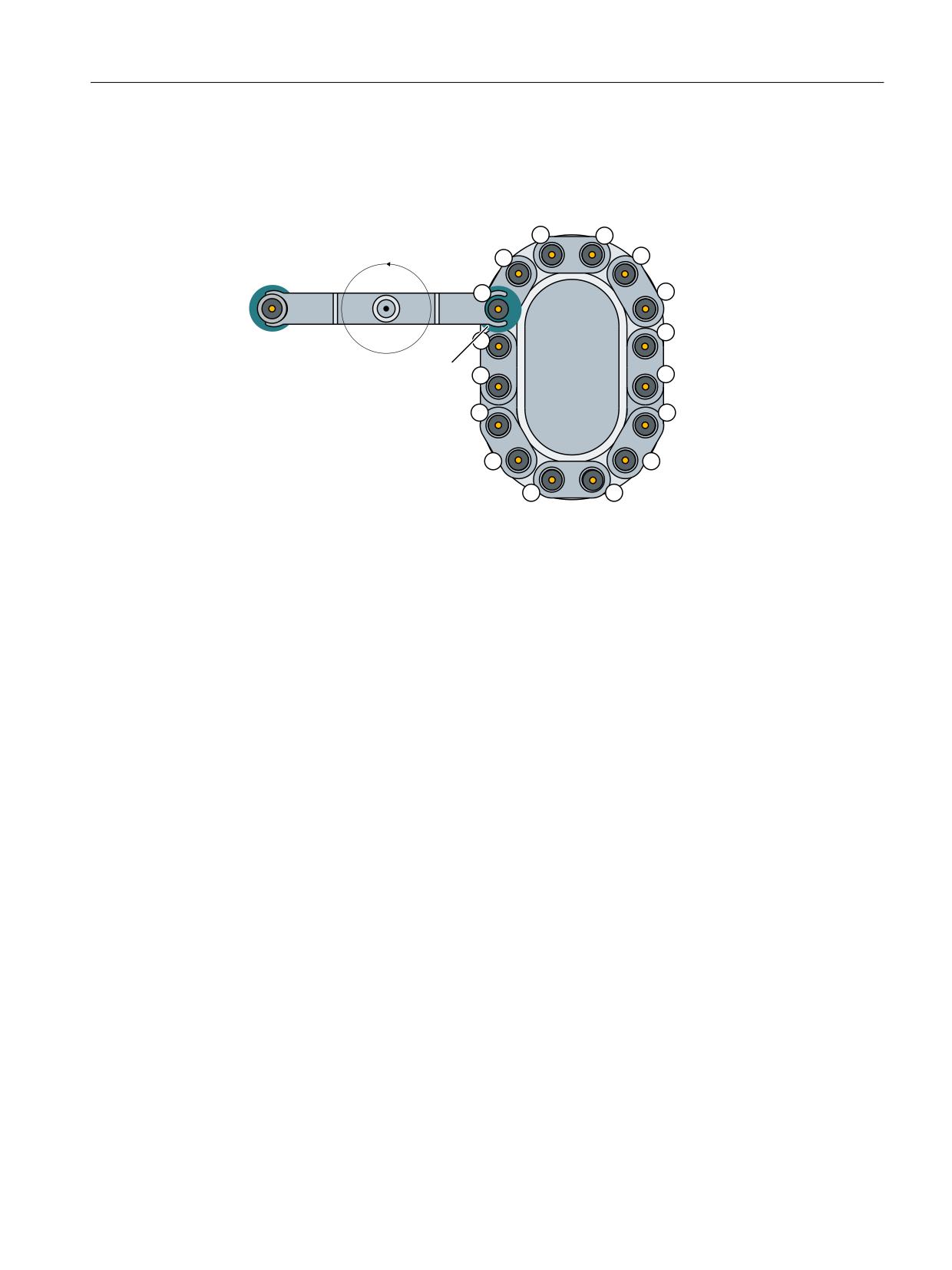
Description of functions
8.4 Tool change box-type, chain, circular magazines
Description of tool change operation in spindle
The tool in location 1, magazine 1 is to be loaded to the spindle (magazine no. 9998, location
1) and the tool in the spindle is to be returned to magazine 1 location 8.
*ULSSHU
*ULSSHU
6SLQGOH
0DJD]LQH
&KDQJH
SRVLWLRQ IRU VSLQGOH
Spindle 1 = magazine 9998 location 1
Gripper 1 = magazine 9998 location 2
Gripper 2 = magazine 9998 location 3
Figure 8-19
Tool change in the spindle
The tool change in the spindle is split into two steps (for TOOL_CHANGE_MODE=1):
1. Prepare change:
Search for new tool and move to the change position
2. Execute change:
New tool into the spindle and old tool into the magazine at the correct location
1. Prepare change
Bit 2 is set in DB72.DBB n+0. In preparing for the change, the current positions of the tools are
communicated to FC8/FC6 in the associated parameters once the preparation step has been
completed. In this case, "Status (Page 161)" = 1 is parameterized for FC8. This means that the "old
tool" is still in the spindle and that the "new tool" is either still in the source magazine at the same
location or has been placed in a buffer.
The following information is passed to FC8/FC6:
• The new tool is in the change position, but is still located in magazine (NewToolMag = 1 and
NewToolLoc = 1).
• The old tool is still in the spindle (OldToolMag = 9998 and OldToolLoc = 1).
Tool management
Function Manual, 10/2020, 6FC5397-1HP40-0BA1
381
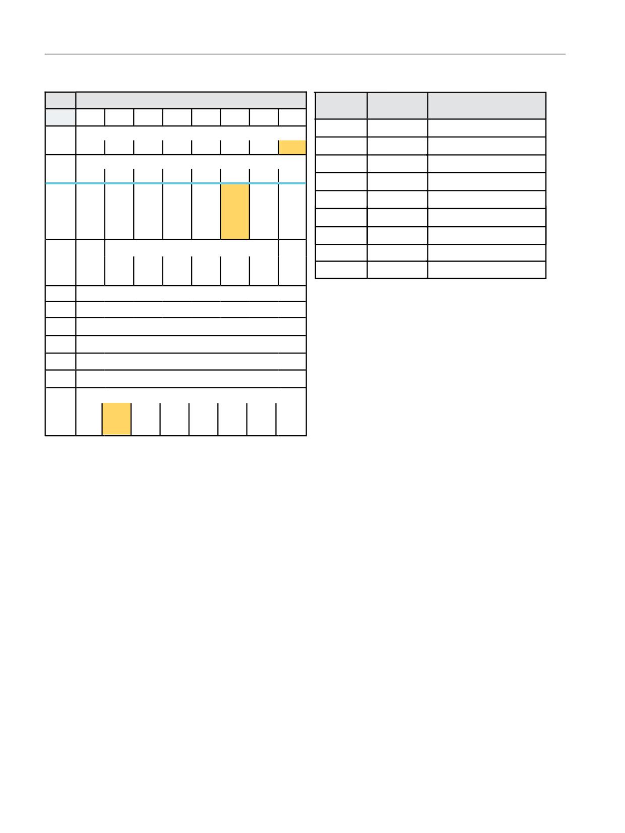
Description of functions
8.4 Tool change box-type, chain, circular magazines
'%
/RDGLQJ XQORDGLQJ SRLQWV 1&. ! 3/&
)&
3DUDPHWHUV
0HDQLQJ
%\WH
%LW
%LW
%LW
%LW
%LW
%LW
%LW
%LW
6WDUW
758(
7UDQVIHU LV EHLQJ VWDUWHG
,QWHUIDFH 66 DFWLYH
'%%
7DVN,GHQW
'% LQWHUIDFH
66
66
66
66
66
66
66
66
,QWHUIDFH 66 DFWLYH
7DVN,GHQW1R
,QWHUIDFH
'%%
66
66
66
66
66
66
66
66
1HZ7RRO0DJ
'% '%:
6RXUFH PDJD]LQH IRU SUHSDUDWLRQ
7RRO
5H
,QVHUW
2OG WRRO
7
3UHSDUH
([HFXWH
2EOLJD
UHPDLQV
SODFH
PDQXDO
LQ %/
FKDQJH
FKDQJH
WRU\
1HZ7RRO/RF
'% '%:
6RXUFH ORFDWLRQ IRU SUHSDUDWLRQ
LQ
PDQXDO
WRRO
Q
0
FKDQJH
'%%
VSLQGOH
WRRO
2OG7RRO0DJ
'% '%:
7DUJHW PDJD]LQH IRU SUHSDUDWLRQ
2OG7RRO/RF
'% '%:
7DUJHW ORFDWLRQ IRU SUHSDUDWLRQ
'DWD LQ
5HVHUYHG
$FNQ
6WDWXV
2SHUDWLRQ FRPSOHWHG
'%
6WDW
'%%
0XOWLWRRO/RF
0XOWLWRRO ORFDWLRQ
'%:
%XIIHU
,' IL[HG YDOXH
'%:
/RFDWLRQ LQ EXIIHU
'%:
0DJ 1R 6RXUFH IRU QHZ WRRO
([DPSOH
H[FKDQJH
([DPSOH QR
H[FKDQJH
'%:
/RFDWLRQ 1R 6RXUFH IRU QHZ WRRO
'% '%:
'% '%:
'% '%:
'% '%:
'%:
0DJ 1R 7DUJHW IRU ROG WRRO
'% '%:
'% '%:
'% '%:
'% '%:
'%:
0DJ 1R 7DUJHW IRU ROG WRRO
'% '%[
'% '%[
7RRO VWDWXV IRU QHZ WRRO
0DQXDO
0DVWHU
7R EH
7R EH
EORFNHG
,' IRU
'%:
WRRO
H[
WRRO
ORDGHG
XQORD
WRRO
FKDQJH
GHG
Figure 8-20
DB72 during preparation of the tool change
Tool management
382
Function Manual, 10/2020, 6FC5397-1HP40-0BA1
Description of functions
8.4 Tool change box-type, chain, circular magazines
PLC sample program
The following sample programs (description of DB150 (Page 122)) show the acknowledgement
of the preparation (positioning at the change point) via interface 1. To this end, the network is
programmed in an FC150 user block.
Sample program "Prepare magazine change"
NETWORK
TITLE =Prepare acknowledgement of change
U
E
86.0;
U
DB72.DBX
0.0; //Interface 1 active
UN
DB72.DBX
4.1;
U
DB72.DBX
4.2; //Preparation active
FP
M
151.0;
SPBN
M180;
L
2;
T
DB150.DBB 0; //DB72
L
1;
T
DB150.DBB 1; //Interface 1
L
DB72.DBW
24;
T
DB150.DBW
2; //Source magazine for preparation
L
DB72.DBW
26;
T
DB150.DBW
4; //Source location for preparation
L
DB72.DBW
28;
OW
W#16#0;
SPN
M182; //Tool in spindle? Yes->
T
DB150.DBW 6;
T
DB150.DBW 8;
SPA
M181;
M182: L
DB72.DBW 20;
T
DB150.DBW 6; //Target magazine for preparation
L
DB72.DBW 22;
T
DB150.DBW 8; //Target location for preparation
M181: L
1;
T
DB150.DBW 10; //Status 1
L
-1;
T
DB150.DBW 12;
S
DB150.DBX 16.0; //Start FC6
M180: NOP
0;
8.4.5.2
PLC function during tool change (chain, box type)
Perform change
If the preparation command has been correctly acknowledged with status = 1, the "Change" bit
DB72.DBB n+0 bit 1 is set with the M06 command from the part program. The free parameters
are also transferred again. All other values remain unaffected by the "Change tool" operation.
Two tools are involved in the tool change procedure. The old tool is in the spindle and the new
tool is in the magazine. The tool transport is executed in this example with gripper 1 and gripper
2. Any change in the positions of the tools must be communicated to the tool management with
FC8/FC6. FC8/FC6 must be called twice for this purpose.
FC8/FC6 call with status 105 change in progress
Tool management
Function Manual, 10/2020, 6FC5397-1HP40-0BA1
383
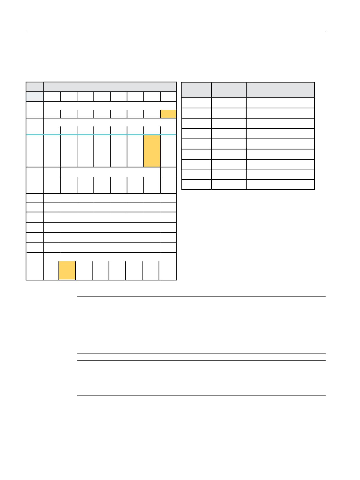
Description of functions
8.4 Tool change box-type, chain, circular magazines
The tool with the dual gripper is withdrawn from the magazine and the spindle. The old tool is
now in gripper 2 at location no. 3 and the new tool in gripper 1 in location no. 2. This results in
the following FC8/FC6 call:
'%
/RDGLQJ XQORDGLQJ SRLQWV 1&. ! 3/&
)&
3DUDPHWHUV
0HDQLQJ
%\WH
%LW
%LW
%LW
%LW
%LW
%LW
%LW
%LW
6WDUW
758(
7UDQVIHU LV EHLQJ VWDUWHG
,QWHUIDFH 66 DFWLYH
'%%
7DVN,GHQW
'% LQWHUIDFH
66
66
66
66
66
66
66
66
,QWHUIDFH 66 DFWLYH
7DVN,GHQW1R
,QWHUIDFH
'%%
66
66
66
66
66
66
66
66
1HZ7RRO0DJ
6RXUFH PDJD]LQH RI WKH QHZ WRRO
7RRO
5H
,QVHUW
2OG WRRO
7
3UHSDUH
([HFXWH
2EOLJD
UHPDLQV
SODFH
PDQXDO
LQ %/
FKDQJH
FKDQJH
WRU\
1HZ7RRO/RF
6RXUFH ORFDWLRQ RI WKH QHZ WRRO
LQ
PDQXDO
WRRO
Q
0
FKDQJH
'%%
VSLQGOH
WRRO
2OG7RRO0DJ
7DUJHW PDJD]LQH IRU QHZ WRRO
2OG7RRO/RF
7DUJHW ORFDWLRQ IRU QHZ WRRO
'DWD LQ
5HVHUYHG
$FNQ
6WDWXV
,QWHUPHGLDWH ORFDWLRQ UHDFKHG
'%
6WDW
'%%
0XOWLWRRO/RF
0XOWLWRRO ORFDWLRQ
'%:
%XIIHU
,' IL[HG YDOXH
'%:
/RFDWLRQ LQ EXIIHU
'%:
0DJ 1R 6RXUFH IRU QHZ WRRO
([DPSOH
H[FKDQJH
'%:
/RFDWLRQ 1R 6RXUFH IRU QHZ WRRO
'% '%:
'% '%:
'%:
0DJ 1R 7DUJHW IRU ROG WRRO
'% '%:
'%:
0DJ 1R 7DUJHW IRU ROG WRRO
'% '%:
'% '%[
7RRO VWDWXV IRU QHZ WRRO
0DQXDO
0DVWHU
7R EH
7R EH
EORFNHG
,' IRU
'%:
WRRO
H[
WRRO
ORDGHG
XQORD
WRRO
FKDQJH
GHG
Figure 8-21
Tool change DB72 and FC6
Note
The operator uses FC8/FC6 to notify the tool management of the new positions of the
exchanged tools.
Tool management knows which is the new (called) tool and which is the old (spindle) tool.
The current positions are also known to the tool management. If these positions change, the tool
management is only informed about this through FC8/FC6.
Note
If T preparation and change signals are simultaneously present, then the tool call and the change
command (T and M) are programmed in one block. When calling FC8/FC6, in such a case, only
the change has to be acknowledged and not the selection.
FC8/FC6 call with status 1 tool change complete
While the gripper is moving the tools, the PLC can read the magazine location for the old tool
(from the spindle) from DB72.DBW (n+24) and (n+26) and move the magazine to the change
Tool management
384
Function Manual, 10/2020, 6FC5397-1HP40-0BA1
Description of functions
8.4 Tool change box-type, chain, circular magazines
position. This position is location 8 in magazine 1 in this example. The tool change can now be
mechanically ended by "inserting" the tools. Tool management shall be informed of this change
in tool positions by a FC8/FC6 call with status = 1. The new tool is placed in the spindle of
magazine No. 9998, location No. 1 and the old tool in magazine No. 1 at location 8.
Interim acknowledgement of tool change
The following sample program (definition of DB150 (Page 122)) shows the acknowledgement
of the tool change via interface 1. To this end, the network is programmed in an FC150 user
block.
NETWORK
TITLE
=Interim acknowledgement M1 -> Gr1,Sp -> Gr2
U
E
86.2;
//Acknowledgement via terminal 86.2
U
DB72.DBX
0.0; //Interface 1 active
U
DB72.DBX
4.1; //Change active
U
DB72.DBX
4.2;
FP
M
152.0;
SPBN
M200;
L
2;
T
DB150.DBB
0; //DB72L 1;
T
DB150.DBB
1; //Interface 1
L
DB72.DBW
24;
OW
W#16#0;
SPN
M204;
//T0? No->
T
DB150.DBW
2;
T
DB150.DBW
4;
SPA
M203;
M204:
L
9998;
T
DB150.DBW
2; //Source magazine of new tool 2;
T
DB150.DBW
4; //Source location of new tool
M203:
L DB72.DBW
28;
OW
W#16#0;
SPN
M202; //Tool in spindle? Yes->
T
DB150.DBW
6;
T
DB150.DBW
8;
SPA
M201;
M202:
L
9998;
T
DB150.DBW
6; //Target magazine for old tool
L
3;
T
DB150.DBW
8; //Target location for old tool
M201:
L
105;
T
DB150.DBW
10; //Status 105
L
-1;
T
DB150.DBW
12;
SET ;
S
DB150.DBX
16.0; //Start FC6
M200:
NOP
0;
Tool management
Function Manual, 10/2020, 6FC5397-1HP40-0BA1
385

Description of functions
8.4 Tool change box-type, chain, circular magazines
8.4.5.3
PLC sample programs tool change
Tool change via intermediate memory
If the dual gripper is to place the spindle tool in the magazine location of the new tool, the user
must ensure that the magazine location is of the same size and location type as the spindle tool.
Here too, a 1:1 exchange is supported through appropriate setting of the search strategy by the
tool management; in this case, the NC checks the location type, size, adjacent location
allocation,...
If this is the case, the transfer can be performed simultaneously (on the dual gripper in the
spindle and in the magazine location at the change position).
FC8/FC6 must be parameterized as follows:
,QWHULP DFNQRZOHGJHPHQW JULSSHU ! VSLQGOH JULSSHU ! PDJ
3HUIRUP FKDQJH DFNQRZOHGJHPHQW ZLWK )&
)&
3DUDPHWHUV
0HDQLQJ
)&
3DUDPHWHUV
0HDQLQJ
6WDUW
758(
7UDQVIHU LV EHLQJ VWDUWHG
6WDUW
758(
7UDQVIHU LV EHLQJ VWDUWHG
7DVN,GHQW
'% LQWHUIDFH
7DVN,GHQW
'% LQWHUIDFH
7DVN,GHQW1R
,QWHUIDFH
7DVN,GHQW1R
,QWHUIDFH
1HZ7RRO0DJ
'% '%:
6RXUFH PDJD]LQH RI WKH QHZ WRRO
1HZ7RRO0DJ
'% '%:
6RXUFH PDJD]LQH RI WKH QHZ WRRO
1HZ7RRO/RF
'% '%:
6RXUFH ORFDWLRQ RI WKH QHZ WRRO
1HZ7RRO/RF
'% '%:
6RXUFH ORFDWLRQ RI WKH QHZ WRRO
2OG7RRO0DJ
'% '%:
7DUJHW PDJD]LQH IRU QHZ WRRO
2OG7RRO0DJ
'% '%:
7DUJHW PDJD]LQH IRU QHZ WRRO
2OG7RRO/RF
'% '%:
7DUJHW ORFDWLRQ IRU QHZ WRRO
2OG7RRO/RF
'% '%:
7DUJHW ORFDWLRQ IRU QHZ WRRO
6WDWXV
,QWHUPHGLDWH ORFDWLRQ UHDFKHG
6WDWXV
2SHUDWLRQ FRPSOHWHG
0XOWLWRRO/RF
0XOWLWRRO ORFDWLRQ
0XOWLWRRO/RF
0XOWLWRRO ORFDWLRQ
Figure 8-22
Acknowledgement tool change FC6
Tool management
386
Function Manual, 10/2020, 6FC5397-1HP40-0BA1
Description of functions
8.4 Tool change box-type, chain, circular magazines
Interim acknowledgement of tool change
The following sample programs (definition of DB150 (Page 122)) show the acknowledgement
of the tool change via interface 1. To this end, the network is programmed in an FC150 user
block.
NETWORK
TITLE
=Interim acknowledgement Gr1 -> Sp, Gr2 -> M1
U
E 86.3;
U
DB72.DBX
0.0; //Interface 1 active
U
DB72.DBX
4.1; //Change active
U
DB72.DBX
4.2;
FP
M
152.1;
SPBN
M210;
L
2;
T
DB150.DBB
0; //DB72
L
1;
T
DB150.DBB
1; //Interface 1
L
DB72.DBW
24;
OW
W#16#0;
SPN
M214; //T0? No->
T
DB150.DBW
2;
T
DB150.DBW
4;
SPA
M213;
M214:
L
DB72.DBW
20;
T
DB150.DBW
2; //Source magazine of new tool
L
DB72.DBW
22;
T
DB150.DBW
4; //Source location of new tool
M213:
L
DB72.DBW
28;
OW
W#16#0;
SPN
M212; //Tool in spindle? Yes->
T
DB150.DBW
6;
T
DB150.DBW
8;
SPA
M211;
M212:
L
DB72.DBW
28;
T
DB150.DBW
6; //Target magazine for old tool
L
DB72.DBW
30;
T
DB150.DBW
8; /Target location for old tool
M211:
L
105;
T
DB150.DBW
10; //Status 105
L
-1;
T
DB150.DBW
12;
SET ;
S
DB150.DBX
16.0; //Start FC6
M210:
NOP 0;
Tool management
Function Manual, 10/2020, 6FC5397-1HP40-0BA1
387
Description of functions
8.4 Tool change box-type, chain, circular magazines
Carry out acknowledgement of change
NETWORK
TITLE
=Carry
out acknowledgement of change
U
E
86.4;
U
DB72.DBX
0.0; //Interface 1 active
U
DB72.DBX
4.1; //Change active
U
DB72.DBX
4.2;
FP
M
151.1;
SPBN
M190;
L
2;
T
DB150.DBB
0; //DB72
L
1;
T
DB150.DBB
1; //Interface 1
L
DB72.DBW
24;
OW
W#16#0;
SPN
M194; //T0? No->
T
DB150.DBW
2;
T
DB150.DBW
4;
SPA
M193;
M194:
L
DB72.DBW
20;
T
DB150.DBW
2; //Source magazine of new tool
L
DB72.DBW
22;
T
DB150.DBW
4; //Source location of new tool
M193:
L
DB72.DBW
28;
T
DB150.DBW
6; //Target magazine for old tool
L
DB72.DBW
30;
T
DB150.DBW
8; //Target location for old tool
L
1;
T
DB150.DBW
10; //Status 1
U
DB72.DBX
5.7;
SPB
M192;
L
-1;
T
DB150.DBW
12;
SPA
M191;
M192:
L
DB1072.DBW 10;
T
DB150.DBW
12; //Multitool location
M191:
SET ;
S
DB150.DBX
16.0; //Start FC6
M190:
NOP 0;
8.4.5.4
Example structure of the PLC program for a tool change
PLC example of an acknowledgement with FC6
Individual steps for a tool change via a double gripper.
NETWORK TITLE =Interim acknowledgement M1 -> Gr1,Sp -> Gr2
Tool management
388
Function Manual, 10/2020, 6FC5397-1HP40-0BA1
Description of functions
8.4 Tool change box-type, chain, circular magazines
NETWORK TITLE =Interim acknowledgement Gr1 -> Sp,Gr2 -> Mag
NETWORK TITLE =Carry out acknowledgement of change
Programming the transfer
The following example shows the programming of the FC6 via a data block DB150 (definition
of DB150 (Page 122)). To this end, the network is programmed in an FC150 user block.
NETWORK
TITLE =Tool management status transfer
CALL FC 6 (//Tool management transfer block
Start
:= DB150.DBX 16.0,//Start
TaskID
:= DB150.DBB 0,
TaskIDNo
:= DB150.DBB 1,
NewToolMag
:= DB150.DBW 2,//Pos new tool
NewToolLoc
:= DB150.DBW 4,
OldToolMag
:= DB150.DBW 6,//Pos old tool
OldToolLoc
:= DB150.DBW 8,
Status
:= DB150.DBW 10,//Status
MultitoolLoc := DB150.DBW 12,
Ready
:= DB150.DBX 16.1,
Error
:= DB150.DBW 14);
U DB150.DBX
16.1; //Prompt ready
R DB150.DBX
16.0; //Reset start
L DB150.DBW
14; //Error information
L 0;
<>I ; //Evaluate error
R DB150.DBX
16.0; //Reset start
Tool management
Function Manual, 10/2020, 6FC5397-1HP40-0BA1
389
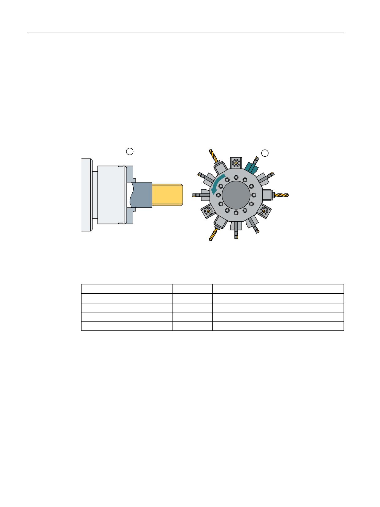
Description of functions
8.4 Tool change box-type, chain, circular magazines
8.4.6
Tool change with turret
Turret DB73
DB73 is responsible for "changing" tools in the turret. During this, the turret is rotated to the
point so that the desired tool is in the working position. This data block has an interface for every
turret. The turrets are numbered using ascending magazine numbers. User data are available at
each interface as for the loading and unloading point. Data are additionally available for the new
tool to be loaded at change. This data includes location type, sizes, tool status and the T number
internally assigned in the NC.
Figure 8-23
Tool change turret
Following completion of the tool-change operation, loading the new tool shall be
acknowledged by FC7. To this end, the parameter "ChgdRevNo" receives the turret number of
the new tool that has been inserted.
FC 7 parameters
Values
Comment
Start
Starts task
ChgdRevNo
1
1st turret
Ready
Feedback from FC8/FC6
Error
Feedback from FC8/FC6
Tool management
390
Function Manual, 10/2020, 6FC5397-1HP40-0BA1
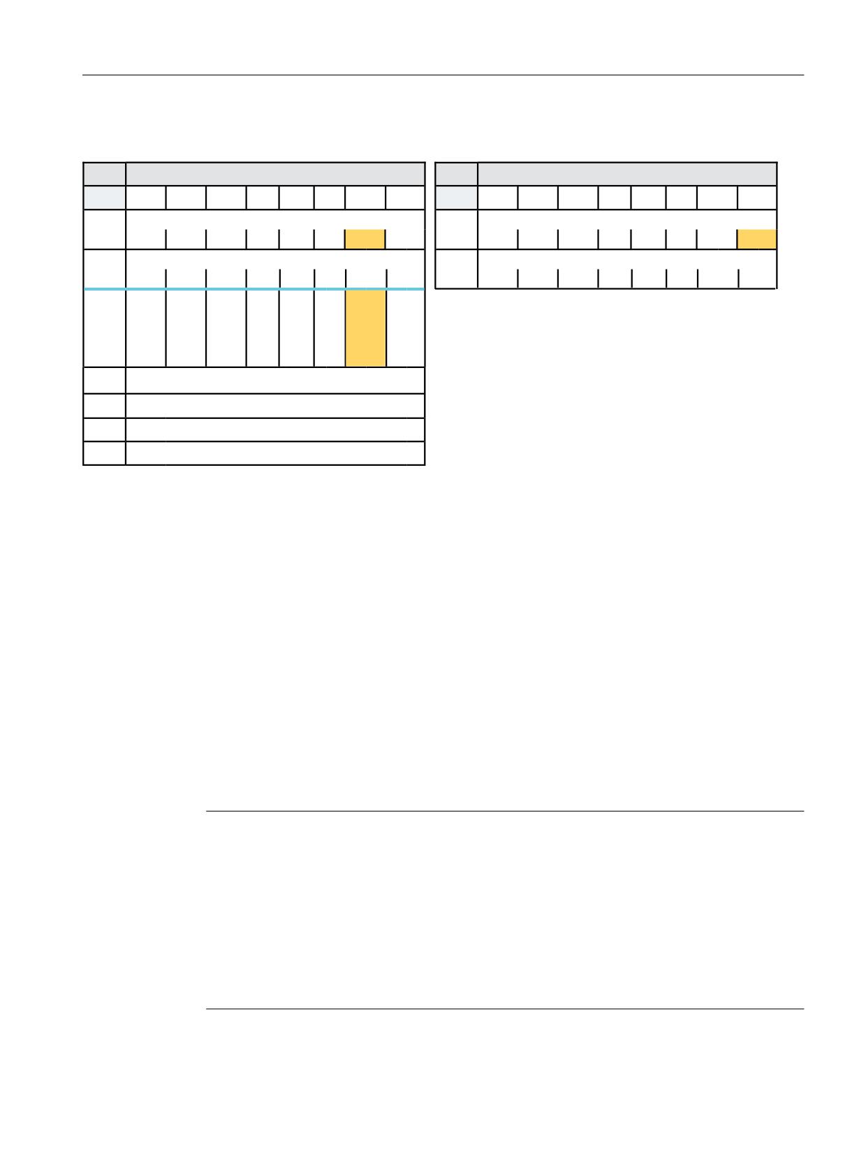
Description of functions
8.4 Tool change box-type, chain, circular magazines
DB73 for tool change with standard acknowledgement
'%
/RDGLQJ XQORDGLQJ SRLQWV 1&. ! 3/&
'%
/RDGLQJ XQORDGLQJ SRLQWV 3/& ! 1&.
%\WH
%LW
%LW
%LW
%LW
%LW
%LW
%LW
%LW
%\WH
%LW
%LW
%LW
%LW
%LW
%LW
%LW
%LW
,QWHUIDFH 66 DFWLYH
,QWHUIDFH 66 DFWLYH
'%%
'%%
66
66
66
66
66
66
66
66
66
66
66
66
66
66
66
66
,QWHUIDFH 66 DFWLYH
,QWHUIDFH 66 DFWLYH
'%%
'%%
66
66
66
66
66
66
66
66
66
66
66
66
66
66
66
66
5HV
0DQXDO
5HV
5HV
7
5HV
3HU
2EOLJD
WRRO
IRUP
WRU\
FKDQJH
FKDQJH
FKDQJH
([DPSOH &KDQJH WR WXUUHW SRVLWLRQ
'%%
WRRO
QXPEHU
'% '%:
'% '%:
'% '%:
0DJ 1R 6RXUFH IRU XQORDGLQJ UHORFDWLQJ SRVLWLRQLQJ
'%:
'% '%:
'%:
/RFDWLRQ 1R 6RXUFH IRU XQORDGLQJ UHORFDWLQJ SRVLWLRQLQJ
'%:
0DJ 1R 7DUJHW IRU ORDGLQJ UHORFDWLQJ SRVLWLRQLQJ
'%:
0DJ 1R 7DUJHW IRU ORDGLQJ UHORFDWLQJ SRVLWLRQLQJ
Figure 8-24
Tool change at a turret
Alternatively to the acknowledgement via FC7, the standard acknowledgement of DB73 can also
be used.
Sample program acknowledgment via DB73"
NETWORK TITLE =Acknowledgement of change with T no.
U
E 86.0;
U
DB73.DBX
0.0; //Interface 1 active
FP
M 150.0;
SPBN
M200.1;
S
DB73.DBX
0; //Acknowledgement Interface 1
8.4.7
Selecting a tool and a cutting edge
Precondition
Note
The T number and the M function are no longer transferred to the PLC as an auxiliary function
if tool management is activated.
Numbers are also valid tool names, e.g. "3" instead of T = "3" can be programmed more simply
than T3.
There must be a tool with the T number as the identifier available when working with the T
number.
Example: If you want to call a tool using T3, the tool must have the name "3". A tool CANNOT be
called with the internal T number managed by NC only.
Tool management
Function Manual, 10/2020, 6FC5397-1HP40-0BA1
391