SINUMERIK 840D sl. Service - Functions. Manual (2018-2020) - page 84
NC programming
7.5 Tool data
Status bit 17 (tool is at a disabled magazine location)
Tools in a subsequently disabled magazine location are assigned, with $TC_TP8 Bit 17=1, the
identifier indicating that they are located in a disabled magazine location. With instruction
$TC_MPP6, tools identified in this way can be placed in disabled magazine locations or disabled
adjacent locations. Oversize tools that project beyond the edge of the magazine are not taken
into account.
$TC_TP9
If a monitoring type is activated for the tool with $TC_DP9, the current monitoring parameters
are evaluated and, if necessary, the tool status set to "disabled" or "prewarning limit reached". An
existing tool disable is however not withdrawn. Not even then when the monitoring function for
this tool has been deactivated.
$TC_TP11
Tool subgroups
The system variable is bit-coded. Only bits 0...3 are evaluated. A tool group (the same identifier,
different duplo No.) can be split into a maximum of 4 subgroups in this way. A tool can also be
included in several subgroups.
If no bit is set, so $TC_TP11[x]=0, this means the same as "all bits set", i.e. the tool belongs to all
the defined subgroups.
Selection of the tool subgroup
1. With the NC command $P_USEKT (UseKindofTool)
(only possible when not working with the setting T=location)
During tool search, only tools that have one of these bits in system variable $TC_TP11, can
be found. This means that it is possible to form so-called "Technology Groups", to
differentiate between tools with the same identifier and specifically release them for
machining.
Example 1:
$P_USEKT=4
This means that the only tools to be taken into account are those with bit 2 in $TC_TP11 or
Example 2:
$P_USEKT=9
This means that the only tools to be taken into account are those with bit 3 or 0 in $TC_TP11
2. By programming a tool
with the function T=location $P_USEKT is set automatically at every tool change and in fact
at the $TC_TP11 value of the loaded tool.
Example: T3 M06
The bit value of $TC_TP11 of T3 is now valid (is accepted in "USEKT").
During the transition to a spare tool (and there only) the only tools to be taken into account
are those with one of these bits set in system variable $TC_TP11.
Tool management
184
Function Manual, 10/2020, 6FC5397-1HP40-0BA1

NC programming
7.5 Tool data
7.5.3
Tool-related grinding data $TC_TPG
$TC_TPGx[t]
Technology-specific grinding data
The default setting for grinding data is "0". Tools with tool type 400 to 499 are always grinding
tools, i.e. additionally have these data which take up additional memory space. If a tool of type
400-499 is set to a value outside this range, then its loses its grinding-specific data - the
associated memory is released again and can be used for other tools.
x: = parameter 1
9
t: = T number 1...32000
OPI block TG
Calculation of line: T number
Calculation of column: N/A
Tool-related grinding data
Name
Type
Designation
OPI VAR
Type
$TC_TPG 1
INT
Spindle number
spinNoDress
REAL
$TC_TPG 2
INT
Chaining rule
conntectPar
REAL
$TC_TPG 3
Double
Minimum grinding wheel radius
minToolDia
REAL
$TC_TPG 4
Double
Minimum grinding wheel width
minToolWide
REAL
$TC_TPG 5
Double
Current grinding wheel width
actToolWide
REAL
$TC_TPG 6
Double
Max. speed
maxRotSpeed
REAL
$TC_TPG 7
Double
Maximum peripheral speed
maxTipSpeed
REAL
$TC_TPG 8
Double
Inclination angle of inclined wheel
inclAngle
REAL
$TC_TPG 9
INT
Parameter number for radius calcu-
paramNrCCV
REAL
lation
7.5.4
Tool-related user data $TC_TPC
$TC_TPCx[t]
User-related tool data
An additional 64 tool-specific parameters can be set up per tool (V4.7 and higher). Setting with
MD18094 MM_CC_TDA_PARAM and enable with MD18080 MM_TOOL_MANAGEMENT_MASK
(set bit 2)
x: = Parameter 1...64
t: = T number 1...32000
Tool management
Function Manual, 10/2020, 6FC5397-1HP40-0BA1
185

NC programming
7.5 Tool data
OPI block TU/TUD
Calculation of line: T number
Calculation of column: Parameter number
Tool-related OEM user data
NC identifier
Type
Designation
OPI VAR
Type
$TC_TPC1
Double
data
REAL
Double
data
REAL
$TC_TPC64
Double
data
REAL
Note
The data is displayed in the tool management. Additional tool status information, for example,
can be stored here.
Tool management
186
Function Manual, 10/2020, 6FC5397-1HP40-0BA1
NC programming
7.6 Magazine data
7.6
Magazine data
7.6.1
Overview of magazine data
Magazine data
0$*$=,1( '$7$
0/65
0DJD]LQH ORFDWLRQ DVVLJQPHQW WR VSLQGOHV
0$03
0DJD]LQH EORFN GDWD
0'3
'LVWDQFH WR FKDQJH SRVLWLRQ
037+
0DJD]LQH ORFDWLRQ W\SH KLHUDUFK\
033&
8VHU PDJD]LQH ORFDWLRQ GDWD
033
0DJD]LQH ORFDWLRQ GDWD
0$3&
8VHU PDJD]LQH GHVFULSWLRQ GDWD
0$3
0DJD]LQH GHVFULSWLRQ GDWD
Figure 7-6
Overview of magazine data
7.6.2
Magazine description data $TC_MAP
$TC_MAPx[n]
Magazine description data
This data identifies the real magazine:
x: = Parameter 1...10
n: = Magazine number 1...3200
OPI block TM
Calculation of line: Magazine number
Calculation of column: N/A
Magazine description data, tool management
NC identifier
Type
Designation
OPI variables
Type
Default set-
ting
Magazine number
magNo
WORD
0
$TC_MAP2
String
Identifier of the magazine
magIdent
String
" "
Tool management
Function Manual, 10/2020, 6FC5397-1HP40-0BA1
187

NC programming
7.6 Magazine data
Magazine description data, tool management
NC identifier
Type
Designation
OPI variables
Type
Default set-
ting
$TC_MAP1
INT
Type of magazine
magKind
WORD
0
1 = Chain
3 = Turret
5 = Box magazine
7 = Tool buffer magazine
9 = Loading magazine
$TC_MAP3
INT
Status of magazine
magState
WORD
2
Bit 0: Active magazine
Bit 1: Disabled
Bit 2: Magazine is at load position
Bit 3: Tool motion is active
Bit 4: Magazine or tool may be moved. Enabled for
loading
Bit 6: Magazine is fixed-location-coded, i.e. tools in
this magazine are considered fixed-location-coded
tools and treated accordingly
Bit 8: Edge location must not be overlapped left
Bit 9: Edge location must not be overlapped right
Bit 10: Edge location must not be overlapped top
Bit 11: Edge location must not be overlapped bot-
tom
$TC_MAP4
INT
Reserved
-1
$TC_MAP5
INT
Reserved
-1
$TC_MAP6
INT
Number of lines (box magazines only)
magDim
WORD
1
$TC_MAP7
INT
Number of columns
-
-
-
-
Number of locations for the magazine, corre-
magNrPlaces
WORD
0
sponds to $TC_MAP6*$TC_MAP7
$TC_MAP8
INT
Current magazine position relative to change posi-
magActPlace
WORD
0
tion
-
magCmd
WORD
-
magCmdState
WORD
-
magCmdPar1
WORD
-
magCmdPar2
WORD
$TC_MAP9
INT
Current wear grouping number
magWearCom-
DINT
0
poundNo
$TC_MAP10
INT
Current tool search strategies of magazine (see
magToolSearch-
WORD
0
$TC_MAMP2)
Strat
(bit 0...7)
$TC_MAP10
INT
Current empty location search strategy of maga-
magPlace-
WORD
0
zine
SearchStrat
(bit 8...15)
Tool management
188
Function Manual, 10/2020, 6FC5397-1HP40-0BA1
NC programming
7.6 Magazine data
$TC_MAP3
The magazine status bit 3 (tool motion is active) is always reset when the software is booted with
backup.
A magazine that has the status "Tool motion is active" cannot be deleted.
Empty locations are not sought in magazines with the "disabled" status. If a disabled magazine
is explicitly defined for the empty location search, then the process is aborted with an error
message.
A tool that is in a "disabled" magazine cannot be loaded into the spindle or the tool holder.
Overlapping edge locations (bit 8...11=1)
For default setting (Bit 8 ...11 = 0), an oversized tool extends beyond the magazine edge
locations. If this has to be prevented (e.g. due to the mechanical situation at the machine), then
one or several of these bits can be set.
Example: Bits 8 and 9 are set, bits 10 and 11 are not set.
This means that an oversized tool must not overlap the magazine (typically a box-type
magazine) on its left and right sides, but an oversized tool may overlap / extend beyond the
magazine on its top and bottom sides.
The following applies:
Left and top regarding a reference location is where the magazine locations with the lower
magazine numbers are.
Right and bottom regarding a reference location is where the magazine locations with the
higher magazine numbers are.
$TC_MAP8
The current magazine position $TC_MAP8 is refreshed by the NC every time the magazine is
moved.
When the magazine configuration has been loaded, variable $TC_MAP8 is assigned the value
zero. The position value is the number of the magazine location that is located at the zero
position of the magazine. As a maximum, the magazine position can have the number of
magazine locations in the magazine. Larger or negative values are rejected.
$TC_MAP10
Magazine-specific tool search
The bit settings correspond precisely to the system variables $TC_MAMP2.
The default setting "0" always applies to buffer magazines, that is to say the search is made
forwards from the 1st magazine location.
Tool management
Function Manual, 10/2020, 6FC5397-1HP40-0BA1
189

NC programming
7.6 Magazine data
7.6.3
Magazine user data $TC_MAPC
$TC_MAPCx[n]
Magazine user data
Up to 64 user data can be additionally created for each magazine (V4.7 and higher). Setting in
the MD18090 MM_NUM_CC_MAGAZINE_PARAM and enable with MD18080
MM_TOOL_MANAGEMENT_MASK (set bit 2)
x: = Parameter 1...64
n: = Magazine number 1...32000
OPI block TUM
Calculation of line: Parameter number
Calculation of column: Magazine number
Magazine description data OEM user
Name
Type
Designation
OPI VAR
Type
$TC_MAPC1
userData
DINT
userData
DINT
$TC_MAPC64
userData
DINT
7.6.4
Magazine location data $TC_MPP
$TC_MPPx[n,m]
Magazine location data
The following data describes the magazine location
x: = Parameter 1..7
n: = Physical magazine number 1...32000
m: = Physical location number 1...1500
The maximum value of x is stored in OPI variable numMagPlaceParams in block Y.
OPI block TP
Calculation of line: (magazinLocNo-1)*numMagPlaceParams+parameterNo.
Tool management
190
Function Manual, 10/2020, 6FC5397-1HP40-0BA1

NC programming
7.6 Magazine data
Calculation of column: Magazine number
Magazine location data, tool management
NC identifier
Typ
Designation
OPI variables
Type
Default
e
setting
$TC_MPP1
INT
Location type
placeData
WORD
0
1 = Magazine location
2 = Spindle, tool holder
3 = Gripper
4 = Loader
5 = Transfer location
6 = Loading station
7 = Loading point
$TC_MPP2
INT
Location type
placeData
WORD
9999
> 0: Location type for virtual location
= 0: Every tool fits in this location
9999: Not defined
$TC_MPP3
BO
Consider adjacent location on/off
placeData
WORD
FALSE
OL
$TC_MPP4
INT
Location state
placeData
WORD
1
Bit 0: Disabled
Bit 1: Free to accept a tool (occupied)
Bit 2: Reserved for tool from buffer
Bit 3: Reserved for new tool to be loaded
Bit 4: Occupied in left half location
Bit 5: Occupied in right half location
Bit 6: Occupied in upper half location
Bit 7: Occupied in lower half location
Bit 8: Left half location reserved
Bit 9: Right half location reserved
Bit 10: Top half location reserved
Bit 11: Lower half location reserved
Bit 12: Wear group disabled
Bit 13: Overlapping permitted. Tools can
overlap disabled magazine locations. Only
possible if consider adjacent location is ac-
tive (see also MD 17520).
-
Reference of phys. magazine (r.t.)
placeData
WORD
0
$TC_MPP5
INT
Location type index (location type num-
placeData
WORD
0
bering) or wear group number
$TC_MPP6
INT
T No. of tool at this location
placeData
WORD
0
$TC_MPP7
INT
No. of adapter in mag. location
placeData
WORD
0
Tool management
Function Manual, 10/2020, 6FC5397-1HP40-0BA1
191

NC programming
7.6 Magazine data
Magazine location data, tool management
NC identifier
Typ
Designation
OPI variables
Type
Default
e
setting
$TC_MPP_SP
INT
For tool speed and acceleration monitor-
placeData
ing
Only relevant when $MC_TOOLHOLD-
ER_MANAGEMENT > 0. Spindle no. which
is linked to the tool holder.
$TC_MPP66
INT
T No. of the tool, for which the identifica-
placeData
tion "reserved for tool in buffer" is set.
If a tool is transported into the spindle
within the scope of changing from the
magazine, the magazine location is re-
served (identifier "reserved for tool in the
buffer"), the T No. of this tool is entered
into $TC_MPP6 and the tool has entered
this location in the variable $A_MYMN/
MYMLN.
Writing magazine location data
Points to be noted about writing magazine location data:
When writing to a $TC_MPP... parameter for the first time, all of the magazine locations defined
by magazine parameters are created with their default values (the memory for the locations is
therefore "used up"). I.e. the magazine must have been defined by this time ($TC_MAP...
parameter).
$TC_MPP1 (location type)
Only magazine locations of the type "Magazine location" ($TC_MPP1 = 1) may be defined at
magazines that are not of the type "internal" ($TC_MAP1 = 7 or = 9).
Location types:
•
1 = Magazine location
Only locations of type "1" can be defined on real magazines.
•
2 = Spindle / tool holder
•
3 = Gripper
•
4 = Loader
•
5 = Transfer location
The distinction gripper / loader / transfer location is intended for HMI applications. Here, NC
does not make a distinction, loader and transfer location are treated just like a gripper.
•
6 = Loading station
After the tool moves to this location, the tool stays there. It can only be removed by explicit
operation (unloading).
•
7 = Loading point
If a tool is moved from the magazine or buffer to this location, after the PLC acknowledgement
of this motion command, the tool is automatically removed from this location.
Tool management
192
Function Manual, 10/2020, 6FC5397-1HP40-0BA1
NC programming
7.6 Magazine data
Please note when writing the location status and number of the tool in this location that the
following dependencies on $TC_MPP2 to $TC_MPP4 apply; these are checked during the write
operation:
• If the location already contains a tool, the location type to be written must be checked against
the tool location type.
• The status "not occupied" may only be written when none of the "assigned" states is set and
there is no tool at the location.
• The "Disabled" state can be set irrespective of the other states.
• If there is no tool contained then the state "free" is automatically active; i.e. the state "not
free" cannot be set by the NC program or PLC, HMI.
• "Occupied" states can only be set by the NCK within the scope of the adjacent location
consideration; i.e. these states are ignored during writing by the NC program or PLC, HMI.
• The state "Reserved for tool from buffer" is set when a tool is removed by the NC from the real
magazine during a tool change. This location is then not designated as "free" for tools other
than the tool removed.
• The states "reserved for tool from buffer" and "reserved for new tool to be loaded" of a
location are automatically reset when a tool is placed in this location.
• The states "reserved for tool from buffer" and "reserved for new tool to be loaded" of a real
magazine location are automatically reset when a tool from this location is placed at a
location in the loading/unloading magazine.
• The state "reserved for tool from buffer" is reset during an empty location search if the tool
for which the empty location is being sought is assigned a magazine location other than its
previous real magazine location. The newly found empty location is assigned the state
"Reserved for tool from buffer" and becomes the new owner of the tool being sought.
The magazine location state "Reserved for tool to be loaded" is always reset when the control
system is restarted. If "Consider adjacent location" is active, reservations of adjacent locations
are also considered.
Users only have to deal with these rules if they wish to define the magazine directly at the NC
program level. Data back-up is such that the rules are observed when data is imported to the NC.
$TC_MPP5 (location type index)
This data contains the spindle number for magazine locations of type "spindle" ($TC_MPP1) and
is thus made known to the tool management.
The value cannot be changed for location type = 1 ($TC_MPP1; i.e. for all locations of internal
magazines) if there is a tool at the location.
$TC_MPP6 (T No.)
• Tools can only be placed in magazine locations when both the tool and the magazine, plus
its magazine locations, have been defined.
The tool may occupy only one magazine location!
Procedure:
Tool management
Function Manual, 10/2020, 6FC5397-1HP40-0BA1
193
NC programming
7.6 Magazine data
It first attempts to find the tool associated with the T No.
• If it is already defined, then an attempt is made - subject to appropriate check procedure - to
add it to the magazine location.
• If it is not yet defined, then an error has occurred.
Checks:
• The type of the tool to be placed must match the type of the location. If the type has not been
set explicitly at the time of writing (default = 9999 = "Not defined"), then the tool is not
placed.
• The state of the location must be "free" and must not be "disabled".
• If the value T No.=0 is programmed, then this means that the present tool will be removed
from the magazine location.
Notice: $TC_MPP6 = 0 also changes the state of the location: a tool can only be placed in a
magazine location if the location does not already contain a tool. The old tool might first have
to be removed with $TC_MPP6 = 0.
Note
Because of this dependency of the individual data, it is mandatory for the T number of the
tool to be written as the last data in a magazine configuration. If you do not adhere to this
sequence, default values might be set which may result in unwanted data.
7.6.5
Magazine location user data $TC_MPPC
$TC_MPPCx[n,m]
Magazine location user data
Up to 64 user data can be additionally created for each magazine (V4.7 and higher). Setting for
number of parameters in MD18092 $MN_MM_NUM_CC_MAGLOC_PARAM and enable with
MD18080 $MN_MM_TOOL_MANAGEMENT_MASK (set bit 2)
x: = Parameter 1...64
n: = Magazine number 1...30
m:= Magazine location number 1...32000
OPI block TUP
Calculation of line: (m-1)*numMagLocParams_u+ParameterNo.
Tool management
194
Function Manual, 10/2020, 6FC5397-1HP40-0BA1

NC programming
7.6 Magazine data
Calculation of column: Magazine number
OEM user magazine location data
NC identifier
Type
Designation
OPI variables
Type
Default
setting
$TC_MPPC1
INT
userplaceData
DINT
0
INT
userplaceData
DINT
0
$TC_MPPC64
INT
userplaceData
DINT
0
7.6.6
Magazine location type hierarchy $TC_MPTH
$TC_MPTH[n,m]
Magazine location type hierarchy
The location types can be organized in a hierarchy by programming these system variables.
n: = index of hierarchy, from 0...$MN_MM_MAX_NUM_OF_HIERARCHIES
m: = index within hierarchy n, location type 0...$MN_MM_MAX_HIERARCHY_ENTRIES
Magazine location types, refer also to $TC_TP7 and $TC_MPP2.
OPI block TT
Calculation of line: Number of location type+1
Calculation of column: Number of the location hierarchy+1
Magazine data: Magazine location type hierarchy
NC identifier
Typ
Designation
OPI variables
Type
Default set-
e
ting
$TC_MPTH[n,m]
INT
Location type hierarchy
placeType
WORD
9999
n: Hierarchy 0...$MN_MM_MAX_NUM_OF_HIERARCHIES - 1
m: Location type 0...$MN_MM_MAX_HIERARCHY_ENTRIES
- 1
If a tool is to be loaded into the magazine, then the location type determines the availability of
locations, i.e. $TC_TP7 and $TC_MPP2 must be defined.
If the location type of the tool is part of the location type hierarchy, then the location assignment
is carried out in accordance with this hierarchy.
Several such hierarchies can be set up in one TO-area unit, With a conventional hierarchy, a
location type may only be entered in one hierarchy.
Example
A chain magazine is to be split into 6 location types and the following hierarchy defined (the
magazine No. is "1", the numbers of the location types are selected at random).
Location type_124 < Location type_3 < Location type_15 < Location type_1080 < Location
type_5 <Location type_18
Tool management
Function Manual, 10/2020, 6FC5397-1HP40-0BA1
195
NC programming
7.6 Magazine data
Definitions:
Magazine:
$TC_MPP2[magazine no., location]
$TC_MPP2[1,1...6] = 124
$TC_MPP2[1,7...12] = 3
$TC_MPP2[1,13...18] = 15
$TC_MPP2[1,19...24] = 1080
$TC_MPP2[1,25...30] = 5
$TC_MPP2[1,31...36] = 18
Hierarchy:
$TC_MPTH[0,0] = 124
$TC_MPTH[0,1] = 3
$TC_MPTH[0,2] = 15
$TC_MPTH[0,3] = 1080
$TC_MPTH[0,4] = 5
$TC_MPTH[0,5] = 18
If a tool of type_15 ($TC_TP) is loaded, it is preferable for it to be stored at locations 13...18. If
none of these locations are free, the search for an empty location continues, in accordance with
the hierarchy, at locations of type_1080.
See also
Hierarchies of location types in magazines (Page 491)
7.6.7
Distance to change position $TC_MDP
$TC_MDPx[n,m]
Distance from magazine zero
$TC_MDPx[n,m]=value
x: = 1: Loading magazine: Loading points, loading station (1st int. mag.)
x: = 2: Buffer magazine: Spindle, gripper, etc. (2nd int. mag.)
n: = Magazine no. of real magazine
m: = Location no. of internal magazine (loading point,..).
Value: = Distance in number of locations
Tool management
196
Function Manual, 10/2020, 6FC5397-1HP40-0BA1

NC programming
7.6 Magazine data
OPI block TPM
Calculation of line:
(LocNo.-1)*numPlaceMulti*numPlaceMultiParams+ParameterNo.
Calculation of column: Magazine number
Magazine data: Distance to change position
NC identifier
Type
Designation
OPI VAR
Type
$TC_MDP1
INT
Distance between tool change posi-
multiPlace
WORD
tion of magazine n and location m
of 1st internal magazine (loading
magazine, 9999)
$TC_MDP2
INT
Distance between tool change posi-
multiPlace
WORD
tion of magazine n and location m
of 2nd internal magazine (buffer
storage magazine, 9998)
Description
Magazine position
The current magazine position is required for tool change, loading and unloading. This position
refers to the magazine zero point established by the machine manufacturer. This is usually at the
change position.
The number of the location at the magazine zero point has to be given during initialization.
Otherwise, it is assumed that the non-existent location 0 is at the change position.
If the magazine is moved by a task, the current position is changed accordingly. The NC does not
know how many positions the magazine has moved but knows the targets of the relevant
commands. On the basis of the defined distance between and object (e.g. spindle 2) and the
change position, the NC is able to update the current position.
Comment:
The value of the distance and the current magazine position are also evaluated for box
magazines.
For empty location searches and tool searches, search strategies based on reference to the
current magazine position convert the position contained in system variable $TC_MAP8 to the
change position, loading point in each case at which the search is started. With search tasks, the
NC always specifies internally which change position, loading point is to be used as reference for
the search.
Assignment
By defining $TC_MDPx[n,m], a connection or assignment (distance relationship) is established
between the real magazine and the buffers or the loading points. The HMI can only display
assigned buffer locations and loading points. A tool transport within the scope of a t preparation
or a change can only be realized via an assigned buffer (exception: asynchronous transfers). The
tool search, for T preparation and change is also only made in those magazines assigned to a
spindle or tool holder.
The maximum number of these distance relationships can be defined with machine data
$MN_MM_NUM_LOCS_WITH_DISTANCE.
Tool management
Function Manual, 10/2020, 6FC5397-1HP40-0BA1
197
NC programming
7.6 Magazine data
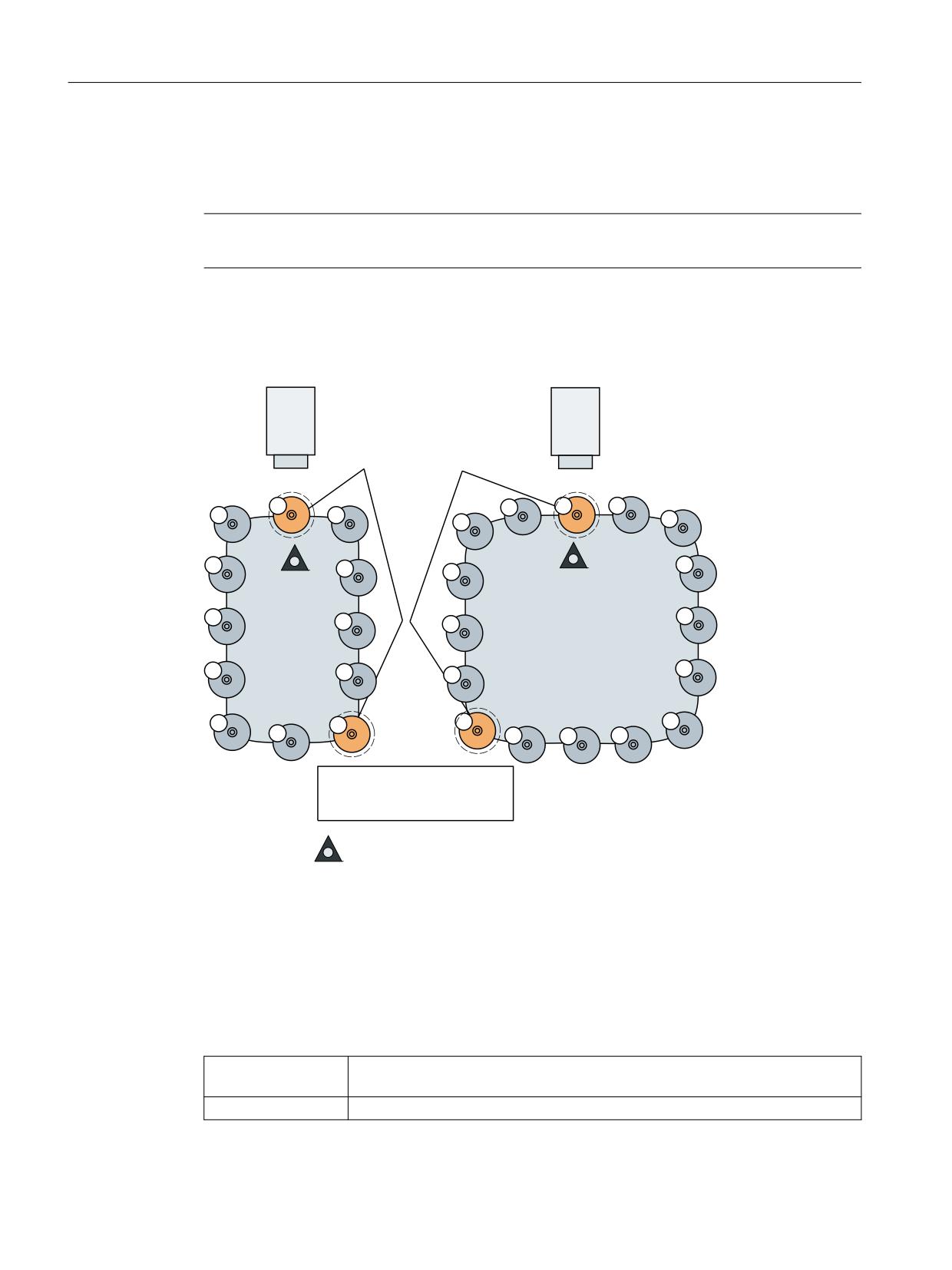
Example: 1st TO unit, 1 magazine, 1x spindle, double gripper, 2x loading point. This is a total of
5 distance relationships (3x $TC_MDP2 to assign the real magazine to the 3 buffers, 2x
$TC_MDP1 to assign the real magazine to the two loading points).
Note
Command $TC_MDP2[n,m]=9999 can be used to dissolve a distance relationship.
Example:
%XIIHU ORFDWLRQ
%XIIHU ORFDWLRQ
6SLQGOH
6SLQGOH
'
'
0DJD]LQH
0DJD]LQH
7&B0$3 > @
7&B0$3 > @
/RDGLQJ VWDWLRQ IRU PDJD]LQH DQG
PDJD]LQH
/RFDWLRQ LQ ORDGLQJ PDJD]LQH
0DJD]LQH ]HUR SRLQW
D1 = Distance from magazine zero point to loading station -> 5 locations = $TC_MDP1[1,1]
D2 = Distance from magazine zero point to loading station -> 6 locations = $TC_MDP1[2,1]
Figure 7-7
Distance to change position $TC_MDPx[y,z]=value
The magazine zero point is usually the change position of the spindle. Therefore, the following
applies:
• If location 1 is located at zero position, the current magazine position = 1 ($TC_MAP8[1]).
Examples for programming the distance to the zero position:
$TC_MDP1[1,1] = 5
Distance between location 1 of the loading station and the zero position of mag-
azine 1
$TC_MDP1[2,1] = 6
Distance between the same location and the zero position of magazine 2
Tool management
198
Function Manual, 10/2020, 6FC5397-1HP40-0BA1

NC programming
7.6 Magazine data
$TC_MDP2[1,1] = 0
Distance between location 1 of 2nd internal magazine and zero position of mag-
azine 1
$TC_MDP2[2,2] = 0
Distance between location 2 of 2nd internal magazine and zero position of mag-
azine 2
7.6.8
Magazine blocks $TC_MAMP
$TC_MAMPx
Magazine block data
x: = Parameter 1, 2, 3
OPI block TMC
Calculation of line: N/A
Calculation of column: N/A
Magazine block data, magazine control block
NC identifier
Type
Designation
OPI variables
Type
Default
setting
$TC_MAMP1
String
Identifier of the configuration
magCBIdent
String
" "
magazine
Number of the loading magazine
magBLMag
WORD
Number of the buffer magazine
magZWMag
WORD
Tool management
Function Manual, 10/2020, 6FC5397-1HP40-0BA1
199

NC programming
7.6 Magazine data
Magazine block data, magazine control block
NC identifier
Type
Designation
OPI variables
Type
Default
setting
$TC_MAMP2
INT
Type of tool search (bits 0...7)
magSearch
0
and type of empty location
search (bits 8...16)
Bit 0=0: Default strategy
Take the first available tool found
in the tool group. First search in
the magazine from which the last
change took place.
Bit 0=1: Select the "active" tool in
the magazine of the previously
changed tool; otherwise search
for replacement tool with lowest
duplo number. If no tool is found
in this magazine, the search is
continued in the other associated
magazines.
Bit 1: Search for the next replace-
ment tool at the shortest possible
distance from the current maga-
zine position.
Bit 2: Select the "active" tool, oth-
erwise the replacement tool with
the lowest number in $TC_TP10
(does not work with manual
tools).
Bit 3: Search for the tool in the
group with the lowest actual val-
ue of the monitored quantity.
Bit 4: Search for tool in the group
with the highest actual value of
the monitored quantity.
$TC_MAMP2
INT
Bit 5: Reserved
magSearch
0
Bit 6: First search in the magazine
currently being considered (this
is only effective in conjunction
with bit 7=1)
Bit 7=0: Start the tool search in
the magazine where the tool last
changed came from
Bit 7=1: Always start the search in
the 1st magazine of the distance
table
Bit 7= 1 + bit 0=1 or bit 2=1, if no
"activeTool" is found in the mag-
azine, - if available - the active
tool is selected from another
magazine linked with the tool
holder
Tool management
200
Function Manual, 10/2020, 6FC5397-1HP40-0BA1

NC programming
7.6 Magazine data
Magazine block data, magazine control block
NC identifier
Type
Designation
OPI variables
Type
Default
setting
$TC_MAMP2
Bit 8
Search forwards starting at first
location number
Bit 9
Search forwards starting at cur-
rent magazine position
Bit 10
Search backwards starting at last
location number
$TC_MAMP2
Bit 11
Search backwards starting at cur-
rent magazine position
Bit 12
Symmetrical search starting at
the current magazine position
Bit 13
(1:1 exchange) behavior
If the 1:1 exchange is not possi-
ble, the search strategy for an
empty location is considered
"symmetrical".
The 1:1 exchange acts in addition
to other set search strategies. If
possible, the 1:1 exchange is trea-
ted as a priority.
Bit 14 = 0
Search within individual maga-
zines first. If no possible location
is found, search in the next mag-
azine for a free location for the
tool.
Bit 14 = 1
Search in all magazines for the
best location according to the hi-
erarchy for the tool.
Tool management
Function Manual, 10/2020, 6FC5397-1HP40-0BA1
201

NC programming
7.6 Magazine data
Magazine block data, magazine control block
NC identifier
Type
Designation
OPI variables
Type
Default
setting
Bit 15 = 0 (conventional hierar-
chy type): For this type, the loca-
tion type of the tool conducting
the search is searched for in the
table of system variable
$TC_MPTH. If the location type is
found, this hierarchy is taken and
evaluated from this level to the
end.
Bit 15 = 1 (alternative hierarchy
type): Location type hierarchies
can be defined for the listed loca-
tion types 1, ...,
$MN_MM_MAX_NUM_OF_HIER-
ARCHIES. The hierarchy for loca-
tion type 1 is defined by
$TC_MPTH[0,n], for location
type 2 by $TC_MPTH[1,n], and so
on. (n: index within a hierarchy).
With this setting, a location type
can be defined in different hierar-
chies.
$TC_MAMP2
INT
Bit16:
The mini hierarchy, which con-
sists only of the location type it-
self and location type 0, cancels
consideration of hierarchy. In this
case, the empty location search
does not distinguish between a
suitable location type ( $TC_TP7
== $TC_MPP2) and the general
location type "0" of the magazine
location.
$TC_MAMP3
INT
Procedure for tools in a wear
mode-
WORD
0
group (bit 0...7)
WearGroup
Search strategies for wear groups
(bit 8...15)
Bit 0=0: When a wear group is ac-
tivated, the tool status remains
unchanged
Bit 0=1: When a wear group is ac-
tivated, the tool status is
changed. One tool from each tool
group becomes active
Tool management
202
Function Manual, 10/2020, 6FC5397-1HP40-0BA1

NC programming
7.6 Magazine data
Magazine block data, magazine control block
NC identifier
Type
Designation
OPI variables
Type
Default
setting
$TC_MAMP3
Bit 1=0: When a wear group is
disabled, the tool status remains
unchanged
Bit 1=1: When a wear group is
disabled, the tool status is
changed
Bit 2...7 reserved
Search strategy for next wear
group
Bit 8=0: Find the next possible
wear group
Bit 8=1: Find the wear group with
the next highest group number
that can be activated
Bit 9...11 reserved
$TC_MAMP3
Search strategy within the tool
group for the tool to be set to ac-
tive (NC command SETTA or
PI_SETTST)
Bit 12=0: Lowest possible duplo
number
Bit 12=1: Lowest possible maga-
zine location number
Bit 13=1: Lowest number con-
tained in $TC_TP10 (substitute
order)
Interaction of the bits for the tool search strategy
The following strategies always start the search in the first magazine of the distance table.
$TC_MAMP2 =
Meaning
Bit
Hex value
7 + 0
'H80'
Otherwise, the same as value 0
7 + 0
'H81'
Otherwise, the same as value 1 - however, if an "active" tool is not found in the
magazine, - if available - the "active" tool is selected from another magazine linked
with the tool holder. If no tool with the "active" state is available, a search is made
for the replacement tool with the lowest duplo number.
7 + 6 + 0
'HC1'
Otherwise, the same as value 1 - however, if an "active" tool is not found in the
magazine, a search is made in the same magazine for any tool that can be used; if
no tool is available, a search is made in another magazine linked with the tool
holder.
7 + 1
'H82'
Otherwise, the same as bit 1 =1 ('H2')
7 + 6 + 1
'HC2'
Tool management
Function Manual, 10/2020, 6FC5397-1HP40-0BA1
203
NC programming
7.6 Magazine data
$TC_MAMP2 =
Meaning
7 + 2
'H84'
Otherwise, the same as bit 2 = 1 ('H4') - however, if an "active" tool is not found in
the magazine, - if available - the "active" tool is selected from another magazine
linked with the tool holder. If no tool with the "active" state is available, a search is
made for the replacement tool with the lowest number in $TC_TP10.
7 + 6 + 2
'HC4'
Otherwise, the same as bit 2 =1 ('H4') - however if no "active" tool is found in the
magazine, a search is made in the same magazine for a tool that can be used, if
available, a search is made for the replacement tool in another magazine linked
with the tool holder with the lowest number in $TC_TP10.
7 + 3
'H88'
Otherwise, the same as bit 3 =1 ('H8')
7 + 6 + 3
'HC8'
7 + 4
'H90'
Otherwise, the same as bit 4 =1 ('H10')
7 + 6 + 4
'HD0'
Search operation for $TC_MAMP2, bit 0=1, bit 6=0, bit 7=1
A search is made for the appropriate tool in the magazine according to the tool search strategy
that has been set (defined using parameter $TC_MAMP2). The search is considered to have been
successful if a tool was found according to the search strategy.
Search operation for $TC_MAMP2, bit 0=1, bit 6=1, bit 7=1
A search is first made for the appropriate tool in the magazine according to the tool search
strategy that has been set (defined using parameter $TC_MAMP2). The search is considered to
have been successful if a tool according to the search strategy was found - or all tools of the
group were checked and no tool was found according to the search strategy - but in spite of this,
a tool that can be used was found among the tools that were searched.
If a search is made according to the strategy, bit 2=1 (sequence of use $TC_TP10) then the same
principle applies. The criterion is also "active tool" and instead of the duplo number, the number
in $TC_TP10.
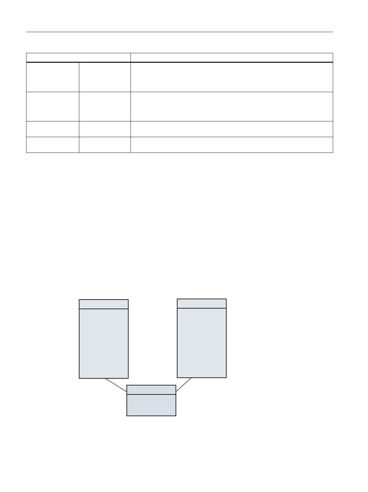
Example to clarify the principle of operation of bit 6 and bit 7
0DJD]LQH
0DJD]LQH
7RRO
7RRO
0LOOB
0LOOB
7RRO
7RRO DFWLYH
7RRO
7RRO
7RRO
7RRO
7RRO
7RRO DFWLYH
6SLQGOH
7&B0'3 >
@
7&B0'3 >
@
Tool management
204
Function Manual, 10/2020, 6FC5397-1HP40-0BA1
NC programming
7.6 Magazine data
Assumption:
• All tools can be used
• Basic setting of the search strategy is bit 0 = 1 - search for the active tool, if there is no active
tool, take the tool with the lowest duplo No.
• Spindle_1 is linked to both magazines, magazine_1 is the first in the distance table
Example_1:
Bit 6 = 0
Bit 7 = 0
T="Mill_15" M06
There is only one "Mill_15" tool, it was found in magazine_1 and was
loaded
T="Tool3"
M06
The last change was performed from magazine_1. Therefore, the
search is first made in magazine_1. There is no active "Tool3" there,
but there are two tools in this group that can be used. The tool with the
lowest duplo no. is selected. Magazine_2 is no longer considered.
Example_2:
Bit 6 = 0
Bit 7 = 1
T="Mill_20" M06
There is only one "Mill_20" tool, it was found in Magazine_2 and was
loaded
T="Tool3"
M06
The last change was performed from Magazine_2. As a result of bit 7
= 1, the tool search is however started in Magazine_1. But this setting
also means that the search strategy "active tool" has priority over a
magazine-specific approach. This means that: No active tool from the
group "Tool3" was found in Magazine_1, i.e. the search is continued
in the next magazine (corresponding to the sequence in the distance
table). An active "Tool3" is there - and this is selected.
Example_3:
Bit 6 = 1
Bit 7 = 1
T="Mill_20" M06
There is only one "Mill_20" tool, it was found in Magazine_2 and was
loaded
T="Tool3"
M06
The last change was performed from Magazine_2. As a result of bit
7 = 1, the tool search starts in Magazine_1. However, no tool of this
group is present there. As a result of bit 6 = 1 (considers the actual
magazine with priority), a search is now made for a "Tool3" that can
be used in Magazine_1 (for this search, this is also the actual mag-
azine); this tool is also found.
Tool management
Function Manual, 10/2020, 6FC5397-1HP40-0BA1
205

NC programming
7.6 Magazine data
$TC_MAMP2
For software releases less than 2.5, the tool search is always made magazine for magazine,
starting in the magazine from which the last change was made.
With bit 7 there is an additional option to select the tool search.
Bit 7 = 1
The search always starts in the 1st magazine of the distance table. If the search for the active tool
is set using either bit 0 or bit 2, a search is made for the active tool across all of the magazines
linked with the spindle. A search is only made for a replacement tool if no active tool was found
in all of these magazines.
Note
The tool sequence in a tool group is not defined (e.g. ascending duplo number). This means, if
the default strategy is used for the search (MAMP2=0), any tool that is capable of being used is
found.
7.6.9
Assignment of buffers to spindles $TC_MLSR
$TC_MLSR[x,y]
Assignment of buffer locations to spindles - $TC_MLSR[x,y]
x: = Location no. in buffer 1 ... 32000
y: = Location no. of the spindle in buffer magazine 1 ... 32000
OPI block n.a.
Calculation of line: N/A
Calculation of column: N/A
NC identifier
Type
Designation
OPI varia-
Type
Default set-
bles
ting
$TC_MLSR[x,y]
INT
System variable for assigning maga-
-
-
0
zine locations of the buffer magazine
to the spindle
Description
This assignment is important when searching for tools. The search is always made, viewed from
the requesting spindle, initially in the associated buffers, then in the assigned magazines. This
means that a tool, which is located in the buffer, can only be found if there is an assignment to
the spindle via parameter $TC_MLSR.
The number of possible links between the spindle and the buffer can be set using machine data
$MN_MM_DIST_REL_PER_MAGLOC.
Tool management
206
Function Manual, 10/2020, 6FC5397-1HP40-0BA1
NC programming
7.6 Magazine data
Example: 1st TO unit, 1 magazine, 1x spindle, double gripper, 2x loading point. The double
gripper is linked to the spindle via $TC_MLSR[2,1]=0 and $TC_MLSR[3,1]=0. The correct value
for the MD is "2".
The sequence when programming is decisive for the sequence when automatically returning
tools.
Note
The content value of the system variable is not evaluated. The assignment is defined via indices
x and y. In order to check via the part program whether a certain assignment exists, a read
operation has to return the value zero.
Note
No more than 16 magazines or buffer locations can be assigned to one spindle.
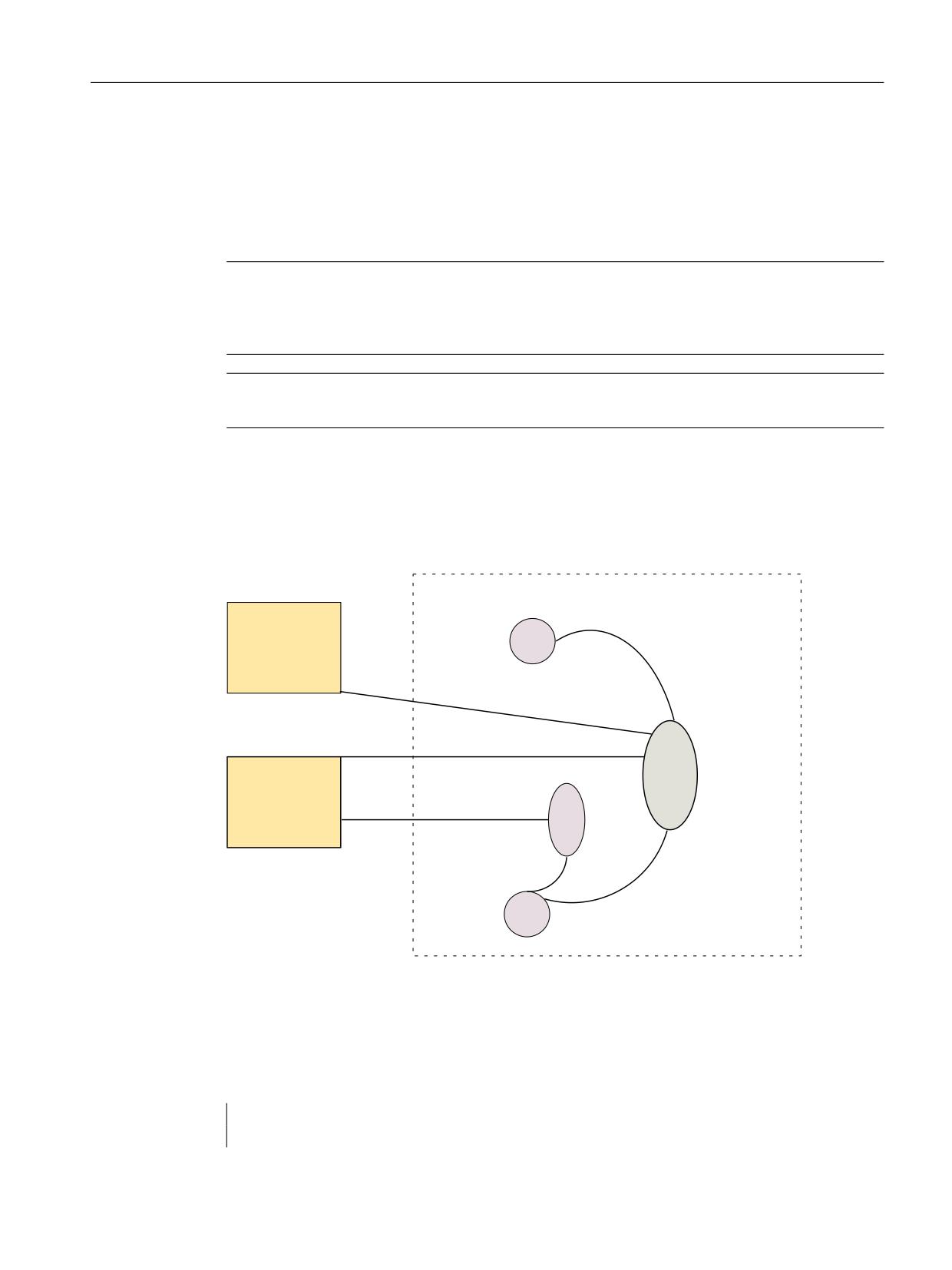
Magazine distance to buffer via tool holder / spindle
$TC_MDP2 and $TC_MLSR establish a relationship between the buffer locations and magazines.
0DJD]LQH
EXIIHU PDJD]LQH
*ULSSHU
0DJD]LQH
/RFDWLRQ
7&B0/65>
@
7&B0'3 >
@
7&B0'3 >
@
0DJD]LQH
7RRO KROGHU
7RRO KROGHU
/RFDWLRQ
/RFDWLRQ
7&B0'3 >
@
7&B0/65>
@
7&B0/65>
@
*ULSSHU
/RFDWLRQ
Figure 7-8
Magazine distance to the buffer
Configuration
Two magazines are defined with numbers 1 and 2.
Four locations 1, 2, 3 and 4 are defined in buffer 9998; two tool holders 5, 7 and two grippers
4, 5.
$TC_MPP1[9998,1] = 2
;Location type = spindle or tool holder
$TC_MPP5[9998,1] = 7
;Tool holder no. = 7
Tool management
Function Manual, 10/2020, 6FC5397-1HP40-0BA1
207
NC programming
7.6 Magazine data
$TC_MPP1[9998,2] = 3
;Location type = gripper
$TC_MPP5[9998,2] = 4
;Gripper no. = 4
$TC_MPP1[9998,3] = 3
;Location type = gripper
$TC_MPP5[9998,3] = 5
;Gripper no. = 5
$TC_MPP1[9998,4] = 2
;Location type = spindle or tool holder
$TC_MPP5[9998,4] = 5
;Tool holder no. = 5
Both grippers are linked to tool holder 5 via $TC_MLSR. They do not require their own distance
definition for the magazines. They are linked to the magazines via tool holder 5 with the distance
relations defined there. However, it is also possible to define separate distance relationships for
the grippers.
Tool holder 5 is linked with both magazines via $TC_MDP2.
Tool holder 7 is only linked with magazine 2; gripper 5 is assigned to it.
Tool management
208
Function Manual, 10/2020, 6FC5397-1HP40-0BA1

NC programming
7.7 Multitool data
7.7
Multitool data
7.7.1
$TC_MTP - multitool data
Overview
A multitool is a combination of several tools to form a unit. The following parameters allow a
multitool to be described so that it fits into the systemology of the tool magazine function.
All of the parameters in the following table have no physical units. The default access right is
"key-operated switch position 0" - for access operations from the NC program as well as for
access operations from the OPI. Access rights can be restricted using the REDEF command.
$TC_MTPx[y]
x: Parameters 1 …8, …PROTA
y: = Multitool number MT = 1 …32000
NC identifier
Description
Format
Preassignment, limit values
$TC_MTPN
The number of locations
INT
2
is defined as delete com-
2-$MN_MAX_TOOLS_PER_MULTITOOL
mand
$TC_MTP2
Identifiers
STRING
MT number
$TC_MTP3
Size to the left in half lo-
INT
1
cations (= towards a low-
1 - 11
er location number)
$TC_MTP4
Size to the right in half lo-
INT
1
cations (= towards a high-
1 - 11
er location number)
$TC_MTP5
Size upwards in half loca-
INT
1
tions (= towards a lower
1 - 11
location number)
$TC_MTP6
Size downwards in half
INT
1
locations (= towards a
1 - 11
higher location number)
$TC_MTP7
Magazine location type
INT
9999 (not defined)
0 - 32000
$TC_MTP8
State; bit-coded
INT
0 (not enabled)
0 - "0x3FFFF"
$TC_MTP_POS
MT position. The follow-
INT
0 (not defined)
ing applies: Position 1 is
0-$MN_MAX_TOOLS_PER_MULTITOOL
defined as "location 1 in
the machining position"
Tool management
Function Manual, 10/2020, 6FC5397-1HP40-0BA1
209

NC programming
7.7 Multitool data
NC identifier
Description
Format
Preassignment, limit values
$TC_MTP_KD
Type of distance coding
INT
0 (not defined)
1 (= location number)
2 (= length)
3 (= angle)
$TC_MTP_PROTA
Name of the protection
STRING
""(= not defined)
zone or name of the file,
which contains the de-
scription of the protec-
tion zone.
$TC_MTPN - number of MT locations
The multitool does not have a duplo number like the tool. The parameter $TC_MTPN contains the
number of locations, which the multitool offers to accept tools. In addition, by programming
$TC_MTPN[mtNo] = 0 the multitool is deleted. After MT locations have been generated, the
parameter can no longer be changed.
A multitool is similar to a chain magazine with regard to its locations, i.e. if there are tool search
strategies or empty location search strategies with results that depend on the type of magazine,
the property can be like that of a chain magazine.
$TC_MTP2 - MT name
Multitools can be assigned names so that a multitool can be uniquely defined by its name or by
its number. The rules that apply when assigning names are the same as those that apply to tool
names. Multitool names must be different from tool names and magazine names within a TO
unit.
$TC_MTTP3 $TC_MTP6 - MT size
The size data of a multitool is essentially the same as the size data of a tool - and is used to find
an optimally suitable magazine location for the multitool when loading into the magazine
(empty location search) when consider adjacent location is active.
The rules for changing the multitool size are the same as the rules for changing the tool size, i.e.
the MT size of a multitool can be changed so long as the MT is not assigned to an owner location.
$TC_MTP7
The magazine location type of the multitool is essentially the same as the magazine location
type of a simple tool and is required for the empty location search, empty location check (loading
operations into the magazine, tool change). The permitted values and rules to change data
correspond to those that apply for the corresponding data in the tool. The value cannot be
changed if the multitool is loaded into the magazine.
For multitools that are contained in the loading magazines or buffer magazines and still do not
have an owner location (i. e. that are logically valid as unloaded - $A_MYMN=0, $A_MYMLN=0),
the magazine location type can be changed. The magazine location type of a multitool can be
changed, as long as the multitool is still not assigned to an owner location.
Tool management
210
Function Manual, 10/2020, 6FC5397-1HP40-0BA1

NC programming
7.7 Multitool data
$TC_MTP8 - MT state
The state of a multitool corresponds to the state of an individual tool. The defined states are the
same as those of an individual tool as defined under $TC_TP.
The following additional definitions apply:
Bit
Meaning
Comment
0
Active
Reserved
Multitools do not have the "active" state defined. Only tools contained in them can
assume the state.
1
Released
Equipped multitools have this state, so that a tool in them can be selected.
2
Blocked
Multitool can be disabled. Independent of the state of the contained tools, the
selection of these tools can be prevented. The PLC signal "ignore disabled state" also
ignores the disabled state of the multitool. The tool change command TCA for a tool
ignores the disabled state of the multitool.
3
measured
Reserved
Multitools cannot be measured. Only tools contained in them can assume the state.
4
Prewarning limit reached
Reserved
Multitools cannot be monitored. Only tools contained in them can assume the
state.
5
is being changed
Protect the multitool during tool selection from competing additional tool selection/
MT motion. This means that it is not possible to select a tool within the MT, as long
as this state is set due to the selection of a tool in the MT.
If the state is set, it is permitted to select another tool from the MT, if this selection
regarding the same toolholder is realized just like the selection, that had set the
state of the MT. In this case, there is no competing tool selection, but instead a
replacing one. If the state is set, then a tool in this MT also has this state set. The
state is reset again together with that of the tool. Bit 21 from $TC_TOOL_MAN-
AGEMENT_MASK refers to the tool and the MT.
The state is reset at POWER ON.
6
fixed-location-coded
Multitools can be fixed-location-coded
7
was in use
The state of multitools is defined the same as that of the tool. After unloading a tool
from the tool holder, the MT and the old tool are assigned the state.
8
autom. return transport
Regarding the tool transport, multitools behave just the same as basic tools.
$TC_TOOL_MANAGEMENT_MASK, bit15 also refers to this state.
9
ignore locked
The state is internally set and reset. The rules are essentially the same as the rules
for the tool.
10
MT is to be unloaded
Multitools can be selected for unloading
11
MT is to be loaded
Multitool can be selected for loading
12
Reserved
Reserved
13
Reserved
Reserved
14
Selected for 1:1 exchange
Multitool is selected for the pending 1:1 exchange. The rules as for the tool apply.
Tool management
Function Manual, 10/2020, 6FC5397-1HP40-0BA1
211

NC programming
7.7 Multitool data
Bit
Meaning
Comment
15
Manual tool
The multitool is used as manual tool. The state is set and reset again for the MT as
part of the tool selection. The tool to be selected and its MT change state synchro-
nously. The tools not involved with the tool selection do not experience a state
change.
16
MT is locked if a tool in the MT is
If a tool contained in the MT has made the state transition to "disabled", then the MT
locked
also assumes this state (bit 2). After a tool has made the state transition to "not
disabled", and then there is no longer any tool in the multitool that has the "disa-
bled" state, then the MT itself also loses the "disabled" state.
Loading/removing a disabled / enabled tool to the MT or from the MT can change
the MT state "disabled/enabled".
Example: Loading to a disabled tool corresponds to an MT state transition to "dis-
abled".
Note
Reserved or non-defined MT state bits cannot be written to. Writing to such a bit results in Alarm
17050 "illegal value".
Interdependencies between the tool and multitool states
Tools, which are loaded in the multitool, can influence the state of the multitool and for MT
transport operations, the MT can influence the tool status of the loaded tool.
Bit
Meaning
Comment
1
Released
Users allocate tools and multitools a status independent of one another. (Enabled
tools can be loaded into a multitool that has not been enabled. Tools that have not
been enabled can be loaded into an enabled MT.)
2
Blocked
Changing this state is initiated from the tool as part of the tool monitoring and the
command RESETMON . Examples 1a, 1b, 2a, 2b at the end of this table show how
the state of loaded tools can influence that of the multitool.
User-specific changes to the MT state are not transferred to the loaded tools.
5
is being changed
The state is set and reset again for the MT as part of the tool selection. The tool to
be selected and its MT change the state synchronously. The tools not involved with
the tool selection do not experience a state change.
The state is always reset at POWER ON.
6
fixed-location-coded
Tools loaded in the MT are implicitly fixed-location-coded, i.e., the state has no
significance for the tool in the MT. For the MT itself, the state is defined; however,
this has no influence on the loaded tools. If the tool state changes, this has no
effect on the state of the multitool.
7
was in use
The state is automatically set as part of the tool change for the MT and the tool in
the MT involved in the change. Tools in the MT, not involved in the tool change, do
not change the state.
The user is responsible for the reset. If the last tool contained in the MT loses this
state, the MT also loses this state. If the user deletes the multitool state, then the
states of all of the tools contained in it are also deleted.
If the user sets this MT state, it has no effect on the loaded tools in the MT.
8
autom. return transport
At the tool change, the state is automatically set and reset for the MT only, however
not for the tools contained in the MT.
Tool management
212
Function Manual, 10/2020, 6FC5397-1HP40-0BA1

NC programming
7.7 Multitool data
Bit
Meaning
Comment
9
ignore locked
The state is set and reset automatically. The state is set and reset for the tool to be
loaded and for the MT in which this tool is loaded. For the other tools not involved
in the change, the state remains unchanged.
10
MT is to be unloaded
When unloading from the magazine, the MT and the its loaded tools lose this state.
If a tool that has this state set is removed from the MT, then the state in the tool that
has been removed is reset.
11
MT is to be loaded
When loaded to a magazine location, the MT and the tools loaded in it lose this
state. If a tool that has this state set is loaded into an MT, then the tool state:
- is not changed, if the MT has the state set
- is reset, if the MT does not have this state set.
12
Master tool
The user allocates the state. The tool state does not influence the MT - and vice
versa.
14
selected for 1:1 exchange
This state is not required for tools loaded in the MT. As part of the empty location
search, it is only automatically set for the MT and reset again at the end of the
command.
16
MT is locked if a tool in the
See examples 1a, 1b, 2a, 2b at the end of this table.
MT is locked
Notice
If tools are in the MT at the time of the state change, the following applies: When
the state is changed, the state of the loaded tools is checked and the MT state
"disabled" set or reset.
Notice
The loading/removing of a tool to the MT / from the MT causes the states of the tools
loaded in the MT to be checked loading/removing has been completed and the MT
state "disabled" is set accordingly. See examples 4a, 4b.
Example 1a:
Bit 2 = 0 and bit 16 = 1
The MT has three tools that are not disabled and have been enabled. The MT itself is also not
disabled and has been enabled. Bit 16 is set to 1.
If the "disabled" state of any tool in this MT is set (either manually or automatically), the
"disabled" state will also be set in the MT, although there are still two tools for which the
"disabled" state has not been set (i.e., these tools can still be used).
Example 1b:
Bit 2 = 1 and bit 16 = 1
The MT has three tools that are disabled and have been enabled. The MT itself is also disabled
and has been enabled. Bit 16 = 1 is set.
If the "disabled" state of two of the three tools is deleted in the MT, then the "disabled" state of
the multitool itself remains unchanged. If, for the last tool with the "disabled" state, the
"disabled" state is deleted (either manually or automatically), then the "disabled" state is also
deleted in the MT.
Example 2a:
Bit 2 = 0 and bit 16 = 0
The MT has three tools that are not disabled and can be used. The MT itself is also not disabled
and has been enabled. Bit 16 = 0 is set.
If the "disabled" state of two of the three tools is set in the MT (either manually or automatically),
then the status value of bits 2 in the MT remain unchanged. This means that the last "not
Tool management
Function Manual, 10/2020, 6FC5397-1HP40-0BA1
213
NC programming
7.7 Multitool data
disabled" tool of the multitool can still be loaded. The MT is only set to the "disabled" state when
this last tool also enters the "disabled" state.
Example 2b:
Bit 2 = 1 and bit 16 = 0
The MT has three tools that are disabled and can be used. The MT itself is also disabled and has
been enabled. Bit 16 = 0 is set.
If the "disabled" state of a tool in the MT is deleted (either manually or automatically), then in
addition, the "disabled" state in the MT is also deleted, independent of the state of the other tools
in the MT.
Bit 16 = 0 is advantageous, for example, if the MT only contains identical tools. All tools can then
be used until their relevant monitoring limit has been reached.
Bit 16 = 1 is advantageous, for example, if an MT is to be loaded and the tools it contains are
different and have to perform various machining operations. If one of these tools is now disabled
due to the monitoring function, then another MT must be loaded, which contains a complete set
of tools that are ready for use for this particular machining operation.
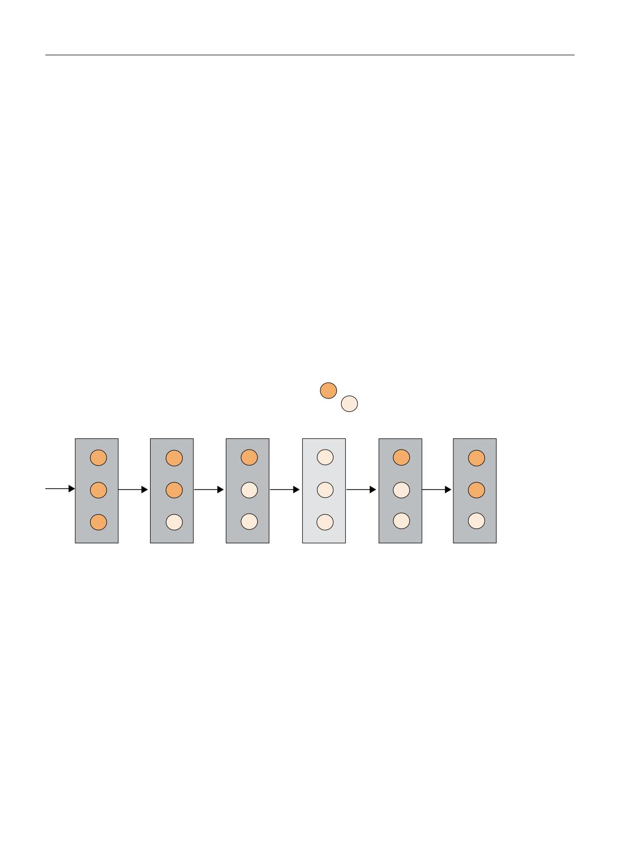
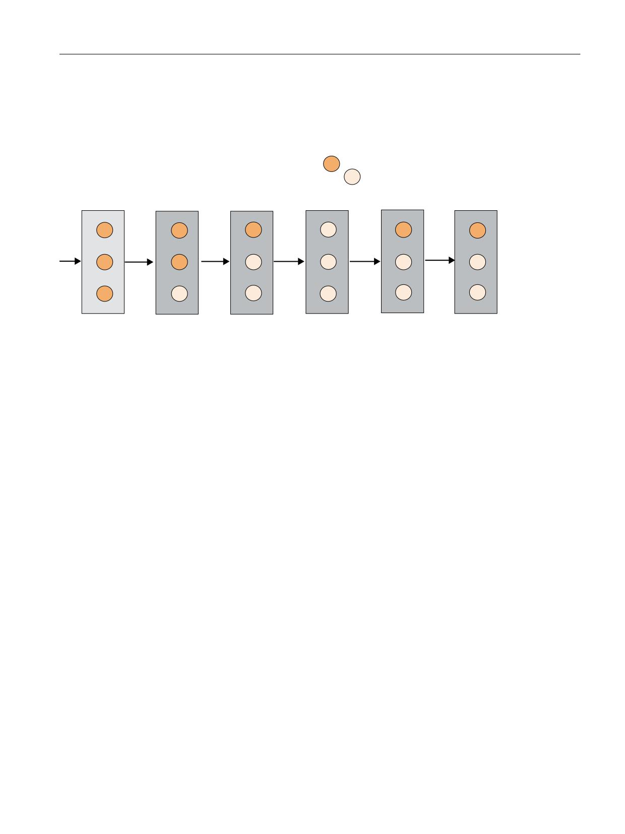
A graphic representation of the "disabled" state coupling is again shown in the following two
diagrams:
07 VWDWH
7&B073
7RRO VWDWH
7&B73
'LVDEOHG
*
'LVDEOHG
*
1RW GLVDEOHG
)
1RW GLVDEOHG
)
)
)
)
*
)
)
)
)
*
*
*
)
)
*
*
*
*
*
)
)
)
*
)
)
7&B073
ELW
6TXDUH PHDQV PXOWLWRRO FLUFOH LQ VTXDUH PHDQV WRRO
Figure 7-9
Automatic state change of the multitool depending on the state of the loaded tools and bit 16 of $TC_MTP8
Example 3a:
Bit 16 = 0:
If in the figure above bit 16 is changed from 0 to 1 at the time when the state is the same as
shown in the fifth MT state figure from the left (MT with F), then the state of the MT changes from
F to G because at least one tool with the state G has been loaded after the bit value change and
therefore the MT also assumes the state G. When the bit value changes from 0 to 1, the figure
changes to the following.
Example 4a:
Bit 16 = 0:
Tool management
214
Function Manual, 10/2020, 6FC5397-1HP40-0BA1
NC programming
7.7 Multitool data
If in the third MT state figure from the left (MT with F), the tool with F is removed from the
multitool, the state of the MT changes from F to G because only two tools with the state G are
loaded after the tool removal and therefore the MT also assumes the state G.
07 VWDWH
7&B073
7RRO VWDWH
7&B73
'LVDEOHG
*
'LVDEOHG
*
1RW GLVDEOHG
)
1RW GLVDEOHG
)
)
)
)
*
)
)
)
)
*
*
*
)
)
*
*
*
*
*
)
*
*
*
*
*
7&B073
ELW
6TXDUH PHDQV PXOWLWRRO FLUFOH LQ VTXDUH PHDQV WRRO
Figure 7-10
Automatic state change of the multitool depending on the state of the loaded tools and bit 16 of $TC_MTP8
Example 4b:
Bit 16 = 1:
If in the second MT state figure from the left (MT with G), the tool with G is removed from the
multitool, the state of the MT changes from G to F because only two tools with the state F are
loaded after the tool removal and therefore the MT also assumes the state F.
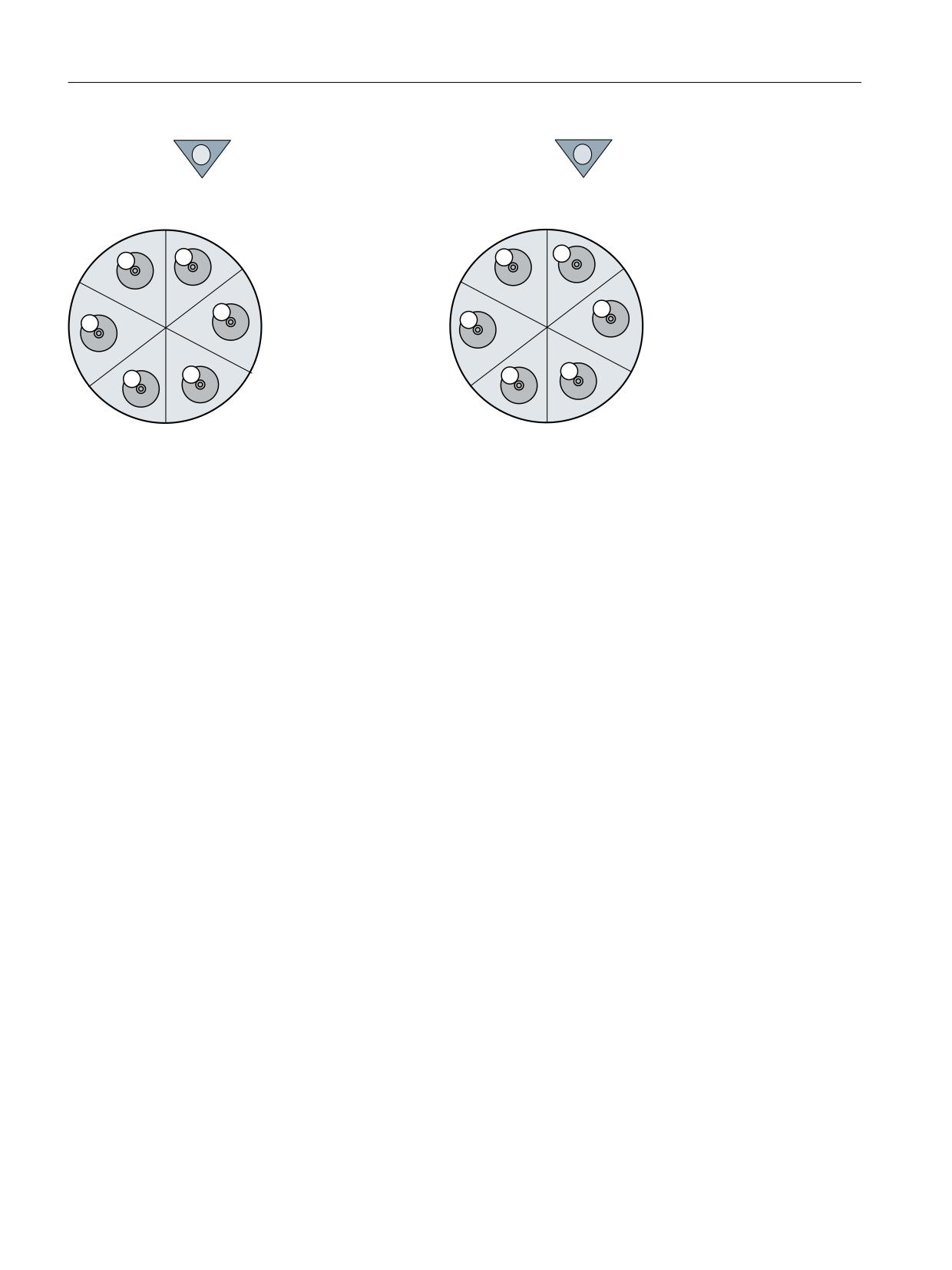
$TC_MTP_POS - MT position
The position of the multitool is the MT location number of the location, which is in the machining
position, and which typically contains the machining (active) tool; see the next figure.
With the final acknowledgement (PLC status value = 1) of a tool change command for a tool in
the MT, the MT position is set to the value of the MT location number of the MT location, which
contains the tool that was loaded. The other PLC status values (e.g. status_105) do not change
the MT position value.
With the end acknowledgement (PLC status value = 1) of an MT positioning command (POSMT,
_N_POSMT), the MT position is set to the value of the programmed MT location number. The
other PLC status values are not permitted for the MT positioning command and are rejected with
Alarm 6405 "incorrect acknowledgement data".
With an asynchronous transfer control, the PLC can position the multitool.
If a command output to the PLC is not acknowledged with "end" (e.g. cancel, status_3), then the
MT position in the NC is not updated (even if the positioning has already been mechanically
carried out).
The MT position of a multitool, which is not located in a toolholder, has no further significance.
The exception is programming T="magazine location number", which is typically used for
revolvers.
Tool management
Function Manual, 10/2020, 6FC5397-1HP40-0BA1
215
NC programming
7.7 Multitool data
'LVWDQFH UHIHUHQFH SRLQW
'LVWDQFH UHIHUHQFH SRLQW
7&B073B326>
@
7&B073B326>
@
/RFDWLRQ
07 SRVLWLRQ
Figure 7-11
The location on the machining position determines the MT position
Example 1:
An MT is moved to the tool holder with a tool motion command (e.g. MVTOOL). The parameters
are set according to the current MT position. With the final acknowledgement of the MT motion
command, the PLC can inform the NC whether and how the position of the multitool is to be
updated.
• The FC6 is parameterized with MultitoolLoc=0. NC does not perform a position
synchronization, the mechanical position can differ from the data position.
• The FC6 is parameterized with MultitoolLoc=1 (valid MT location number). This means that
the NC synchronizes the MT position with the acknowledged position.
If subsequently a tool change is programmed for a tool of this MT on the tool holder, a tool
change command is output to the PLC with which the MT positioning data is sent to the PLC. With
the final acknowledgement of the tool change, the MT position is updated to the value that
belongs to the tool that is to be loaded. The PLC must have performed the MT positioning before
the final acknowledgement is sent to the NC. The PLC must not change the MT position for the
tool selection, tool change commands specified by the NC in the acknowledgement data. The
attempt is rejected with alarm 6405 "Command has invalid PLC acknowledgement parameter".
Example 2:
An MT is moved to the tool holder with a tool motion command (e.g. MVTOOL). As in example
1, the MT positioning/synchronization depends on the PLC application.
If subsequently a RESET is executed, then - when RESET is configured with "Activate tool on the
master tool holder" - a tool change command is output to the PLC with which the data of the tool
to be activated and the MT positioning data is sent to the PLC. With RESET, the tool to be activated
is specified in the NC as the tool at the MT location displayed at the MT position output to the PLC.
This means that in this example, it depends on the PLC logic for the tool motion on the master
tool holder, which tool is activated at RESET. If a different tool is to be activated, this must be
specified in the application , for example by positioning the MT appropriately first with the NC
program command POSMT (or similar PI _N_POSMT by the HMI or PLC). It is also possible to set
the MT position in the NC directly to the desired value before the RESET (by programming
parameter $TC_MTP8 or by writing the position via the operator panel interface (by the HMI or
PLC), or the PLC positions the multitool with an asynchronous transfer).
Tool management
216
Function Manual, 10/2020, 6FC5397-1HP40-0BA1
NC programming
7.7 Multitool data
$TC_MTP_KD - type of distance coding for the MT locations
The location distances (KindOfDistance) within the multitool can be defined in a variety of ways:
$TC_MTP_KD[y] = 1
The distance coding uses the MT location number. The location num-
ber is automatically allocated when creating the MT locations.
$TC_MTPPL, $TC_MTPPA cannot be written except with the value 0.0.
$TC_MTP_KD[y] = 2
The distance coding is via length specifications. $TC_MTPPL can be
written, $TC_MTPPA cannot be written, except $TC_MTPPA[...]=0.0.
$TC_MTP_KD[y] = 3
The distance coding is via angle specifications. $TC_MTPPA can be
written, $TC_MTPPL cannot be written, except $TC_MTPPL[...]=0.0.
The type of distance coding can only be changed as long as no MT locations have been created.
Otherwise Alarm 6438 "Inconsistent data modification is not permitted" is generated.
Example:
If, for distance coding, the location number has been defined ($TC_MTP_KD[ y ] = 1), then
writing $TC_MTPPL, $TC_MTPPA with values other than 0.0 results in alarm 6464 "Command
cannot be programmed for the current multitool distance coding".
Example:
The multitool is defined. Although the number of MT locations has been defined, they have still
not been created.
$TC_MTP_KD[200] = 1
;subsequently writing to $TC_MTPPL or $TC_MTPPA results in
;Alarm "Command cannot be programmed for the defined multi-
tool distance coding"
$TC_MTP_KD[300] = 2
;subsequently writing to $TC_MTPPL is permitted.
;subsequently writing to $TC_MTPPA results in Alarm
;"Command cannot be programmed for the defined
;multitool distance coding"
The MT locations are now created, e.g. by writing to the system of parameters:
$TC_MTPPL[300, 1] = 30.0
; all MT locations are implicitly created using the command
Then an attempt is made to change the distance type (that was previously defined using
$TC_MTP_KD[300] = 2):
$TC_MTPPL[300, 1] = 3
;After the MT locations have been created, the type of
;distance coding must no longer be changed:
;Alarm "Inconsistent data change not permitted"
7.7.2
$TC_MTPP - Multitool location data
Overview
The default access right of the following parameters is "key switch position 0" (everyone has
access), for access operations from the NC program as well as for access operations from the OPI.
Access rights can be restricted using the REDEF command.
Tool management
Function Manual, 10/2020, 6FC5397-1HP40-0BA1
217

NC programming
7.7 Multitool data
$TC_MTPPx[y, z]
x:= 2, 4, 6, 7, L, A (see table)
y: = multitool numer MT=1...32000
z: = n-th location in the multitool; 1,...$MN_MAX_TOOLS_PER_MULTITOOL
The x parameter numbers are based on the values of the magazine location parameters.
The x numbers of the parameters are based on the numbers of the $TC_MPP1,... magazine
location parameters.
NC identifier
Description
Format
Physic. unit
Pre-assigned
limit values
$TC_MTPP2
Multitool location type
INT
None
0 (=every tool fits the
(corresponds to the significance of the maga-
location)
zine location type)
0 - 32000
$TC_MTPP4
MT location state
INT
None
0 (=every tool fits the
location)
0 - 3
$TC_MTPP6
T number of the tool contained
INT
None
0
0 - 32000
$TC_MTPP7
Adapter number of the tool adapter at this
INT
None
0
multitool location
0 - 32000
$TC_MTPPL
Distance to the reference location; "length"
REAL
Length
0
unit (L stands for length)
[mm/inch]
0 - 1000
$TC_MTPPA
Distance to the reference location; "angle"
REAL
Angle
0
unit (A stands for angle)
[degrees]
0 - 360
Example:Transporting a multitool (loading into the magazine or onto the spindle)
"Multitool_2" has been created (T-no. 25), with six locations and distance coding "location".
The multitool is directly loaded onto the spindle, e.g. via the user interface. This means that no
positioning is involved.
The NC generates a transport task (CMD1)
ID:00000/00000 ------ CMD:00001
NewTool: from M: 09999 P: 00001 to M: 09998 P: 00001 TNo: 00025
TMMVTL-chan: 00000
isMultitool: 00001 MTPN: 00006 MT-Dist:
00000/0.00
OldTool: from M: 00000 P: 00000 to M: 00000 P: 00000
The multitool is loaded just like an individual tool.
Additional information is contained in the command: Multitool, distance coding "location"
The user interface looks like this:
DB71
DBB0
00000001
Interface 1 active
DBBn
00000001
Loading
DBB(n+1)
10000000
Data available in the extended range, i.e. it
is a multitool
Tool management
218
Function Manual, 10/2020, 6FC5397-1HP40-0BA1

NC programming
7.7 Multitool data
DBW(n+20)
0
Magazine no. (source)
DBW(n+22)
0
Location no. (source)
DBW(n+24)
9998
Magazine no. (target)
DBW(n+26)
1
Location no. (target)
DB1071
DBW(n+0)
1
Multitool, distance coding is "location"
All other data is "0" - there is no additional information from the NC
There are now two options for acknowledging:
• The multitool position remains undetermined, i.e. the init blocks do not output a command
and no offset is selected. This option makes sense if the tool is loaded into the magazine (the
multitool position is not evaluated) or if the tool is loaded via the spindle. The multitool must
be positioned if a tool in the multitool is now to be brought into the machining position (from
a data perspective).
• The PLC specifies a position. This means that the NC synchronizes to the acknowledged
position. An init block can activate the tool that is at this location.
FC6 can be parameterized as follows:
FC6 parameters
Values
Comment
Start
Starts task
TaskIdent
1
DB71 interface
TaskIdentNo
1
No. of active interface
NewToolMag
9998
Target for the new tool: Magazine DB71.DBW(n+24) -
NewToolLoc
1
Target for the new tool: Location DB71.DBW(n+26)
OldToolMag
0
Source for the old tool: Magazine = "0" there is no old tool
OldToolLoc
0
Source for the old tool: Location= "0" there is no old tool
Status
1
Operation completed
MultitoolLoc
0/x
In case_1, "0" should be entered here. The multitool position remains undeter-
mined, alternatively "-1"
In case_2, the multitool location, which is in the machining position, is entered
here.
Ready
Feedback from FC6
Error
Feedback from FC6
Positioning a multitool
It is only possible to position a multitool, if
a) It is located on a tool holder
b) No offset is active. This means that none of the tools in this multitool may be active.
Positioning can be performed via the language command POSMT or the similar PI service
(POSMT). Positioning from the PLC via an asynchronous transfer is also possible.
Tool management
Function Manual, 10/2020, 6FC5397-1HP40-0BA1
219

NC programming
7.7 Multitool data
The multitool loaded onto the spindle in the previous example is now positioned to location_5
using a part program.
N10 POSMT(state 5,1); position the multitool on tool holder_1 at
position 5
NC generates a command 1
ID:00001/00000 ------ CMD:00001
NewTool: from M: 09998 P: 00001 to M: 09998 P: 00001 TNo: 00025
Spindle: 00001
isMultitool: 00001 MTPN: 00006 MT-Dist:
00005/5.00
OldTool: from M: 00000 P: 00000 to M: 00000 P: 00000
New tool from spindle to spindle, i.e. it is already on the spindle. T-No=25, spindle=1
Multitool with distance coding "location", number of locations of the multitool=6, target
position=5.
There is no old tool
The user interface looks like this:
DB71
DBB0
00000001
Interface 1 active
DBBn
00110000
Positioning the multitool / command
comes from the part program
DBB(n+1)
10000000
Data available in the extended range, i.e. it
is a multitool
DBW(n+20)
9998
Magazine no. (source)
DBW(n+22)
1
Location no. (source)
DBW(n+24)
9998
Magazine no. (target)
DBW(n+26)
1
Location no. (target)
DB1071
DBW(n+0)
1
Multitool, distance coding is "location"
DBW(n+2)
6
Number of locations of the multitool
DBD(n+4)
5.0
Location distance
DBW(n+8)
25
T no. of the multitool
DBW(n+10)
5
Location no. in the multitool
All other data is "0"
FC6 can be parameterized as follows:
FC6 parameters
Values
Comment
Start
Starts task
TaskIdent
1
DB71 interface
TaskIdentNo
1
No. of active interface
NewToolMag
9998
Target for the new tool: Magazine DB71.DBW(n+24) -
NewToolLoc
1
Target for the new tool: Location DB71.DBW(n+26)
OldToolMag
0
Source for the old tool: Magazine = "0" there is no old tool
Tool management
220
Function Manual, 10/2020, 6FC5397-1HP40-0BA1

NC programming
7.7 Multitool data
OldToolLoc
0
Source for the old tool: Location= "0" there is no old tool
Status
1
Operation completed
MultitoolLoc
5
Multitool position - DB1071.DBW(n+10)
Ready
Feedback from FC6
Error
Feedback from FC6
$TC_MTPP2 - MT location type
The location type of a tool must match the location type of the MT location. It is checked when
the multitool is loaded by writing parameter $TC_MTPP6.
The location type may only be changed when the new value is compatible with the value of the
location type of a loaded tool.
The default value is selected (each tool fits the MT location) in such a way that, when the
"Location type check" function is not required in the specific application for the tool loading
operation, the parameter does not have to be considered, and therefore the default setting is
already suitable.
$TC_MTPP4 - MT location state
The following location states have been defined (bit numbers and definition based on the state
of the magazine location; $TC_MPP4):
0 Disabled
1 Free to accept a tool
$TC_MTPP6 - T number of the loaded tool
The locations of the multitools can be loaded with tools. The loading can only be defined with
the aid of parameter $TC_MTPP6. In particular, loading involving the PLC has not been defined.
(The OPI PI service _N_TMMVTL and the NC language command MVTOOL are exclusively for the
loading/unloading of tools and multitools to and from magazines.) With $TC_MTPP6[MT no.,
loc. no.] = T number, loading is performed. With $TC_MTPP6[MT no., loc. no.] = 0, a tool is
removed from the multitool.
The multitool can contain tools with the same or different names. Each tool fits into each location
of a multitool with the default value of $TC_MTPP2. Generally, it is assumed that a multitool is
a mechanical entity whose correct loading is the sole responsibility of the user.
If $TC_MTP8, bit 16 = 1 has been set for the MT state, the following must be considered:
When loading a tool to an MT or removing a tool from an MT, the MT state "disabled"/"not
disabled" can change. The following applies:
• After loading, the states of the tools in the MT determine whether and how the state of the
multitool is changed automatically.
When removing a tool from an MT, the following applies:
• After removing the tool, the states of the remaining tools in the MT determine whether and
how the state of the MT is changed automatically.
Tool management
Function Manual, 10/2020, 6FC5397-1HP40-0BA1
221
NC programming
7.7 Multitool data
Formally, a tool can be loaded to an MT or removed from an MT at any time. It is the responsibility
of the user to ensure compliance with the application. For example, the user must know what
it means to remove an MT loaded on a tool holder from the tool holder, or to remove and active
tool from an MT.
A tool can be assigned either to a magazine or to an MT, but not to both at the same time. Such
an attempt is rejected with alarm 17260 "Illegal magazine location definition".
When loading a tool to an MT, the magazine location type of the tool and the MT location are
checked for compatibility if the MT location type does not have the value "Every tool fits the
location" (this is the default value). A tool can only be loaded to an MT location when the state
of the MT location is "Free".
Note
Multitools do not have a "Consider adjacent location" function for oversized tools. This means
that the tool size is not evaluated when loading a tool to an MT location.
$TC_MTPPL, $TC_MTPPA - Location distance
The distance between the tools in the multitool is defined alternatively with one of these
parameters. Which parameter is to be defined for the specific multitool is determined via the MT
parameter $TC_MTP_KD. The change rules for the date are those that have also been defined for
the multitool sizes. System parameters are not required for the distance coding "MT location
number". When creating the locations for an MT, the locations are automatically assigned the
numbers 1, 2, ...
7.7.3
Multitool-related user data
$TC_MTPCx[t]
User-related multitool tool data
An additional 64 multitool-specific parameters can be set up per multitool. Set with MD18192
MM_NUM_CC_MULTITOOL_PARAM and enable with MD18080
MM_TOOL_MANAGEMENT_MASK (set bit 2)
x: = Parameter 1...64
t: = T number 1...32000
OPI block MTUD
Calculation of line: T number
Tool management
222
Function Manual, 10/2020, 6FC5397-1HP40-0BA1

NC programming
7.7 Multitool data
Calculation of column: Parameter number
Tool-related OEM user data
NC identifier
Type
Designation
OPI VAR
Type
$ TC_MTPC1
Double
data
REAL
Double
data
REAL
$TC_MTPC64
Double
data
REAL
Note
The data is displayed in the tool management. Additional tool status information, for example,
can be stored here.
7.7.4
Multitool-location-related user data
$TC_MTPPCx[t]
User-related multitool tool data
An additional 64 multitool-location-specific parameters can be set up per multitool. Set with
MD18194 $MN_MM_NUM_CC_MTLOC_PARAM and enable with MD18080
MM_TOOL_MANAGEMENT_MASK (set bit 2)
x: = Parameter 1...64
t: = T number 1...32000
OPI block MTUP
Calculation of line: T number
Calculation of column: Parameter number
Tool-related OEM user data
NC identifier
Type
Designation
OPI VAR
Type
$ TC_MTPPC1
Double
data
REAL
Double
data
REAL
$TC_MTPPC64
Double
data
REAL
Note
The data is displayed in the tool management. Additional tool status information, for example,
can be stored here.
Tool management
Function Manual, 10/2020, 6FC5397-1HP40-0BA1
223

NC programming
7.8 User-definable variables
7.8
User-definable variables
User-definable parameters
These programmable variables provide the user with three user-definable parameters. These
system variables are transferred via the user interface with the T selection signal and the change
command to the PLC. They allow the user to send additional tool management information to
the PLC. The parameters can be read and written by the NC program. They are not buffered and
are set to "0" on Reset or end of program.
$P_VDITCP[x]
x: = Parameter 0, 1, 2
NC identifier
Description
Format
$TC_VDITCP[0]
Tool management VDI user-definable parameter 0
int
$TC_VDITCP[1]
Tool management VDI user-definable parameter 1
int
$TC_VDITCP[2]
Tool management VDI user-definable parameter 2
int
Interface DB72, DB73
The user parameters are output in DB72 and DB73 on the tool management interface. They are
only valid when the status of the interface is active. The format is DINT.
Example
$P_VDITCP[0]=12; DB72.DBD(n+4) =12 or
$P_VDITCP[1]=33; DB72.DBD(n+8) =33 or
$P_VDITCP[2]=2000; DB72.DBD(n+12) =2000
T="Tool"
The variables must be set in the part program before the T call or M06 if these shall be transferred
for a tool to the PLC as well.
Programming
The parameters can be programmed as required in the NC program. The output to the PLC is
however always realized in conjunction with the tool preparation or change command
programmed in the following.
Example:
T= "Tool1"
$P_VDITCP[0] = 1
M06
$P_VDITCP[0] = 2
T= "Tool2"
Tool management
224
Function Manual, 10/2020, 6FC5397-1HP40-0BA1
NC programming
7.8 User-definable variables
Exactly the value = 2 is also given to the PLC with the command output of T = "Tool2" to the PLC
and not the value 1 when the M06 command is output to the PLC.
The output of the programmed value also takes place when M6 is programmed, i.e. the output
can now also be realized with the command number 3 provided $MC_CHANGE_MODE=1 has
been set.
Tool management
Function Manual, 10/2020, 6FC5397-1HP40-0BA1
225

NC programming
7.9 NC language commands
7.9
NC language commands
7.9.1
CHKDNO - Uniqueness check for D number
If tool management is active, the function CHKDNO checks the uniqueness of the D number.
Uniqueness of the D number here (no replacement tools) means that the D numbers of all tools
defined in the TO unit can occur only once. D numbers in the TO unit are unique and absolute.
Syntax
State = CHKDNO(T1, T2,D)
Meaning
CHKDNO
The function returns the value of state as the return value.
Data
Bool
type:
T1
T number of tool 1 (optional)
Data
INT
type:
T2
T number of tool 2 (optional)
Data
INT
type:
D
D number (optional); without parameter D, all D numbers of the named tools
are checked.
Data
INT
type:
Return value
state
state shows whether a D number collision occurs
Data
BOOL
type:
FALSE = D number collision
TRUE = D numbers are unique
D numbers of replacement tools
Replacement tools can be defined and used when tool management is active. The machining
part program does not generally indicate whether any replacement tools are available. As a rule,
the machining program addresses tools with T="Identifier". (Programming T="location number"
is referred back to T="identifier" internally). The program otherwise only contains the actual
programming of the offset (the D number). Therefore, the D number for the tool and
replacement tool must be identical.
Tool management
226
Function Manual, 10/2020, 6FC5397-1HP40-0BA1

NC programming
7.9 NC language commands
Example
Active tool and replacement tools for T="drill_5mm"
• T No. = 10 with D numbers 1, 2, 3 (active)
• T No. = 11 with D numbers 1, 2, 3 (replacement)
• T No. = 12 with D numbers 1, 2, 3 (replacement)
Active tool and replacement tools for T="drill_3mm"
• T No. = 20 with D numbers 1, 2, 3 (active)
• T No. = 21 with D numbers 1, 2, 3 (replacement)
• T No. = 22 with D numbers 1, 2, 3 (replacement)
CHKDNO - without parameters specified - detects a collision of D numbers 1, 2 and 3 for
"drill_5mm" with D numbers 1, 2 and 3 for "drill_3mm", but not between the D numbers of the
active and replacement tools.
The collisions are displayed as individual alarms, e.g.:
• "Channel 1 D number 1 defined for tool T no. 10 and 20"
• "Channel 1 D number 1 defined for tool T no. 10 and 21"
The state = FALSE is also returned in the event that the parameterization is invalid. (The T or D
number called is not defined in the channel.)
If the following applies: MAX_CUTTING_EDGE_NO ≤ MAX_CUTTING_EDGE_PER_TOOL ,
CHKDNO always returns the TRUE state, irrespective of the parameter settings.
7.9.2
CHKDM - Uniqueness check within a magazine
With active tool management, the command CHKDM checks the data in NC for D number
uniqueness within one or more magazines. The functionality corresponds to CHKDNO. The
parameters are optional.
Syntax
state = CHKDM (magazine no., D no., tool holder no.)
Meaning
CHKDM
Checks the uniqueness of a D number within a magazine
Data type:
Bool
MagNo
Magazine number of magazine to be checked
Data type:
INT
Omitting the parameter or programming with a value=0 means that the tools
of all the connected magazines of the spindle numbers or tool holder numbers
specified in Tool holder no. are checked.
Tool management
Function Manual, 10/2020, 6FC5397-1HP40-0BA1
227
NC programming
7.9 NC language commands
Dno
D number against which the check will be made.
Data type:
INT
Omitting the parameter or programming with a value=0 means that all D
numbers of the specified magazine are checked for uniqueness.
Tool holder no.
Specifies the spindle number or tool holder number for which the magazines
are checked
Unit
INT
Omission of the parameter means that the magazines are obtained for the
check from the distance table of the spindle location for the master spindle or
the master tool holder.
Return value
state
Result of the check:
Data type
Bool
TRUE
Checked D numbers are unique
FALSE
Check not OK
7.9.3
GETACTTD - Determining the tool number of a unique D No.
If tool management is active (e.g. in measuring cycle programs), command GETACTTD provides
the associated T number of the active tool in the tool group based on a D number.
Syntax
status = GETACTTD (Tno, Dno)
Meaning
GETACTTD
returns the T number of the active tool in the tool group
Data type:
INT
Dno
D number for which the T number shall be searched. The D numbers are not
checked for uniqueness.
Data type:
INT
If the same D numbers are defined in different tool groups of the same TO unit,
then the T number of the first tool group that is found determines the tools that
have the specified number.
Tno
T number found
Data type:
INT
Return value
Tool management
228
Function Manual, 10/2020, 6FC5397-1HP40-0BA1
NC programming
7.9 NC language commands
status
Result of search
Data type:
INT
0
T number found, Tno is assigned the value
-1
No T number exists for the specified D number, Tno as-
signed the value 0.
-2
D number is not unique; Tno is assigned the value of the
D number that was first determined.
-3
The tool group does not contain any tools that have the
desired status and the specified D number, Tno is as-
signed the value 0.
-4
The tool group contains several tools that have the de-
sired status and the D number that has been sought; Tno
contains the value of the first tool found with the desired
D number.
-5
Function could not be executed for other reasons.
7.9.4
GETDNO - Read out D numbers
Function GETDNO reads out the offset number d of a tool with T number t and cutting
edge ce.
Syntax
d = GETDNO(t, ce)
Meaning
GETDNO
Reads out offset number d
Data type:
INT
t
T number of the tool
Data type:
INT
ce
Cutting edge ce of the tools
Data type:
INT
Return value
d
Return value offset number d
Data type:
INT
If t or ce are parameters which have no data record, d=0 is returned. Any
parameters violating the syntax rules will generate an alarm.
Dependencies
• The command is only available if $MN_MAX_CUTTING_EDGE_NO >
$MN_MAX_CUTTING_EDGE_PER_TOOL.
• $MN_MAX_CUTTING_EDGE_NO ≤ $MN_MAX_CUTTING_EDGE_PER_TOOL returns GETDNO
d=ce as D number.
Tool management
Function Manual, 10/2020, 6FC5397-1HP40-0BA1
229

NC programming
7.9 NC language commands
7.9.5
SETDNO - Set or change D number
With function SETDNO, offset number d of cutting edge ce of tool t can be set or changed.
Syntax
state = SETDNO(t, ce, d)
Meaning
SETDNO
Function for editing offset number d of cutting edge ce of tool t
Data type:
INT
t
T number of the tool
Data type:
INT
ce
Cutting edge ce of the tools
Data type:
INT
d
Offset number d
Data type:
INT
If t or ce are parameters that have no data record, state = FALSE is re-
turned. Any parameters violating the syntax rules will generate an alarm.
Return value
state
Status of the function
Data type:
INT
FALSE (0)
Machining was not successful
TRUE (1)
Machining was successful
Dependencies
t, ce, d must be specified as > 0; d=0 cannot be set.
See also
DZERO - Invalidate D numbers (Page 230)
7.9.6
DZERO - Invalidate D numbers
Function DZERO identifies all D numbers of the TO unit as invalid. This command is used for
support during setup. Offset data sets tagged with this command are no longer checked by
the CHKDNO NC command. The D numbers have to be set with SETDNO to make these accessible
again, see also SETDNO - Set or change D number (Page 230).
Syntax
DZERO
Tool management
230
Function Manual, 10/2020, 6FC5397-1HP40-0BA1

NC programming
7.9 NC language commands
7.9.7
DELDL - Delete additive offsets
Function DELDL deletes the additive offsets for the cutting edge of a tool (to release memory
space). Both the defined wear values and the setup values are deleted.
Syntax
status = DELDL(t, d)
Meaning
DELDL
Deletes all sum offsets of cutting edge d of tool t
Data type:
INT
t
Number of the tool (optional); if t and d are not specified, all sum offsets of all
cutting edges of all tools of the TO unit are deleted.
Data type:
INT
d
Number of the cutting edge (optional); if d is not specified, all sum offsets of all
cutting edges on tool t are deleted.
Data type:
INT
Return value
status
Delete result
Data type:
INT
0
Offsets have been successfully deleted
-1
Offsets have not been deleted (if the parameter settings
specify exactly one cutting edge), or not deleted com-
pletely (if the parameter settings specify multiple cutting
edges)
7.9.8
NEWT - Create new tool
With function NEWT, you can create a new tool without specifying a T number.
The function returns the automatically generated tool number, with which the tool can
subsequently be addressed. The new tool is automatically given a cutting edge with CE number
= 1 and D number = 1. All offsets are set to 0 by default. You can change the CE number with
function SETDNO, see SETDNO - Set or change D number (Page 230).
An alarm is output if the attempt to create a new tool fails.
Syntax
tno = NEWT ("TO", Duplono.)
Meaning
NEWT
Creates a new tool with name "TO" and duplo no. Duplono. and returns the
T number of the new tool as the return value.
Data type:
INT
Tool management
Function Manual, 10/2020, 6FC5397-1HP40-0BA1
231

NC programming
7.9 NC language commands
Tool
Tool label
Data type:
STRING
Duplo no.
Duplo number of tool (optional); if not otherwise specified, duplo number no.
= old duplo no. +1 is used.
Data type:
INT
Return value
tno
T number of new tool
Data type:
INT
Examples
Example 1: Create new tool with the function NEWT and CE/D numbers = 2, 47
Program code
Comment
def int tno
tno = NEWT("tool", 111)
;Tool with Ident/DuploNo.="Steel"/111, T
no.=tno=1 in the example and a cutting
edge CE=1, D=1 is created
;the cutting edge is to be changed to
CE=2, D=47
$TC_DPCE[tno, 1]=2
;Rename the CE number
SETDNO(tno,2,47)
;Rename the D number
;Assign the remaining data of the tool /
cutting edge
Example 2: Create tool "Steel"/111, T No.=tno=1 with $TC... and CE numbers = 2 4 (let us assume
that T No.=1 does not yet exist)
Program code
Comment
$TC_TP1[1] = 111
;Create new tool with T no.=1, duplo
no.=111
$TC_TP2[1] = "Steel"
;Assign tool identifier="Steel"
$TC_TPCE[1,47] = 2
;Create new offset, D=47, assign CE no.=2
;Assign the remaining data of the tool /
cutting edge
The function is used for creating tools in a loading program (load cycle).
7.9.9
NEWMT Create new multitool
Function NEWMT is available with TMMG.
With function NEWMT, a new multitool with the specified name "name" and the MT number of
locations = "number of locations" is created.
An implicit STOPRE is initiated at the end of the block.
Tool management
232
Function Manual, 10/2020, 6FC5397-1HP40-0BA1

NC programming
7.9 NC language commands
Messages:
• If the "Several tools at magazine location" function is not activated, Alarm 6436 "Command
cannot be programmed. Function is not activated" is generated.
• If parameter name is already in use, alarm 14020 "Illegal parameter value" is output.
• If parameter Number of locations is outside the permissible range, alarm 14020 "Illegal
parameter value" is output.
• If the function NEWMT is interrupted with an alarm, the value "0" is returned for mtNo.
Syntax
mtNo = NEWMT(name, location number)
Meaning
NEWMT
Creates a new multitool of name "name" and number of locations Number
of locations.
Data type:
INT
name
Multitool label
Data type:
STRING
Number of
Number of multitool locations
locations
Data type:
INT
Return value
mtNo
MT number of the multitool; the number is created automatically and returned
as the result value.
Data type:
INT
Examples
A tool with the name "A" and the T number 1 and a magazine with the name "B" and the number
2 already exist. The following is now programmed:
Program code
Comment
def int mtNo
;
mtNo = NEWMT("C", 2)
;
The command is executed successfully, mtNo has the value 3. The multitool has been created for
2 locations. However, the locations have not been created yet. A call with the name "A" or "B"
would have resulted in an alarm, as the names have already been allocated to a tool and a
magazine.
After creating using NEWMT additional parameters of the multitool can be defined, e.g.
Program code
Comment
$TC_MTP7[ 3 ] = 12
; Multitool can be loaded to magazine lo-
cation with this location type number
$TC_MTP_POS[ 3 ] = 2
; Position value = location 2
$TC_MTP_KD[ 3 ] = 3
; Angle-coded distance
Tool management
Function Manual, 10/2020, 6FC5397-1HP40-0BA1
233

NC programming
7.9 NC language commands
Program code
Comment
$TC_MTPPA[ 3, 1 ] = 0.0
; The two locations are created with this
write operation
$TC_MTPPA[ 3, 2 ] = 180.0
;
$TC_MTP8[ 3 ] = 2
; Released (multitool definition has been
completed)
The two parameters $TC_MTPN and $TC_MTP2 were already defined using the NEWMT
command. Parameters $TC_MTP3,..., 6 were not programmed. The default values are effective.
7.9.10
DELT Delete tool
With function DELT, a tool can be deleted by specifying the tool identifier and the duplo
number. Only tools that have been unloaded can be deleted.
All tool-related data is set to 0 (user data, hierarchy data, ...).
Syntax
DELT("TL",DUPLO_NO)
Meaning
DELT
Deletes the specified tool.
Data type:
-
Tool
Tool label
Data type:
STRING
DUPLO_NO
Duplo number of the tool
Data type:
INT
Return value
-
Examples
The function is used for deleting tools in the part program.
Program code
Comment
T=GETT("DRILL", DUPLO_NR)
;
;
7.9.11
DELMT - Delete multitool
Function DELMT is available with TMMG.
A multitool is deleted with function DELMT.
A multitool can only be deleted if it is not contained in a magazine (is unloaded) and none of the
tools contained in the multitool are the active tool for offset selection. If there are still tools in the
Tool management
234
Function Manual, 10/2020, 6FC5397-1HP40-0BA1

NC programming
7.9 NC language commands
multitool at the time of deletion, they are automatically removed from the multitool before the
delete operation. The following tools are not deleted:
If a name is specified for which a multitool has not been defined, the command is rejected with
Alarm 17220 "Tool does not exist".
Note
After the multitool was unloaded, the tools contained in it are also unloaded. After the multitool
has been deleted, the tools contained in it are again available for loading into a magazine - or
into another multitool.
Syntax
DELMT (name)
Meaning
DELMT
Deletes the multitool of name name
name
Multitool label
Data type:
STRING
7.9.12
$TC_MTPN - Delete one or all multitools
It is possible to delete one or several multitools with $TC_MTPN analogously to $TC_TP1[TNo] =
0 The delete command is defined as follows:
• $TC_MTPN[MTNo.] = 0 ; Delete multitool with the number MTNo > 0
• $TC_MTPN[0] = 0 ; Delete all multitools
For MTNo > 0, the multitool with the number MTNo is deleted. For MTNo = 0, all multitools are
deleted. The same rules apply as defined for the DELMT command, see also DELMT - Delete
multitool (Page 234).
Syntax
$TC_MTPN[MTNo]
Meaning
$TC_MTPN[MTNo]
Returns the multitool number or deletes a multitool.
Data type:
INT
MTNo
Number of the multitool
Data type:
INT
Value range:
0 < x < SLMAXTOOLNUMBER
Tool management
Function Manual, 10/2020, 6FC5397-1HP40-0BA1
235

NC programming
7.9 NC language commands
Note
The delete commands to delete all tools ($TC_TP1[0] = 0 and $TC_DP1[0,0] = 0) also delete all
multitools.
Only with the deletion of the multitool, are the MT locations also deleted.
7.9.13
Reading the GETT - T no.
The GETT function returns the T number associated with the tool identifier and its duplo number
as a return value.
The command can be used for tools as well as for multitools. A duplo number cannot be
programmed for multitools.
If the tool identifier or duplo number cannot be assigned to a tool, value -1 is returned.
This function is used, for example, to retroload tools via the part program.
Syntax
tNo = GETT("TL", DUPLO_NO)
Meaning
GETT
Returns the T number of a tool or multitool
Data type:
INT
Tool
Tool label
Data type:
STRING
DUPLO_NO
Duplo No. of the tool (optional)
Data type:
INT
If a duplo number has not been specified, the T number of any tool from the
group of tools with the specified identifier or the number of a multitool is
returned. (The sequence is not defined within a tool group.)
Return value
tNo
T number of the tool
Data type:
INT
> 0
Tool or multitool number associated with the program-
med name
-1
The name is neither a tool nor a multitool name
-2
A multitool name was programmed with duplo number
Tool management
236
Function Manual, 10/2020, 6FC5397-1HP40-0BA1

NC programming
7.9 NC language commands
Examples
Determine the T number for drill with duplo number.
Program code
Comment
R10=GETT("DRILL", DUPLO_NO)
;The T number is in R10
$TC_TPx,[GETT("DRILL",DUPLO_NO)]=value
;Write tool-related data
7.9.14
SETPIECE - decrementing the workpiece counter
With the SETPIECE function, the user can update the count monitoring data of the tools
associated with the machining process. Each tool that has been loaded since the last activation
of SETPIECE is acquired. The function serves as a rule for programming at the end of the NC
part program to decrement the count from all the tools associated with count monitoring.
Note
The command is not active in the block search (with/without calculation). If the value for the
count = 0, the internal table for flagged tools/cutting edges is deleted.
Note
SETPIECE works through the table "blindly". This means that every cutting edge entered in the
table is recorded. It is irrelevant where the tool is located at the time of the SETPIECE
programming, whether it is stored in the magazine, remains on the spindle, or has been
unloaded.
If it is set that the tool remains active after a reset and there is a tool in the spindle at the start
of the program, this tool is selected internally and an entry is made in the Setpiece table.
Syntax
SETPIECE(x,y)
Meaning
SETPIECE
Updates the workpiece count monitoring data
Data type:
-
x := 0 ... 32000
Value used when decrementing
Data type:
INT
y := 0...8
Spindle index, value 0 means index of main spindle (does not have to be
programmed)
Data type:
INT
Tool management
Function Manual, 10/2020, 6FC5397-1HP40-0BA1
237

NC programming
7.9 NC language commands
Examples
Program code
Comment
SETPIECE(1);
Workpiece counter of main spindle is decremented by 1
SETPIECE(1,1);
Workpiece counter of spindle no. or tool holder no. 1 is
decremented by 1
SETPIECE(4,2);
Workpiece counter of spindle no. or tool holder no. 2 is
decremented by 4
Example of SETPIECE with M06 tool change command:
The tools involved in a workpiece (program) should be decremented by a value of 1.
Program code
Comment
T1
;T1 is preselected (with regard to main spindle)
M06
;T1 is changed
D1
;D1 becomes active
T2
;T2 is preselected
:
;Machining program
:
M06
;T2 is changed
D1
;D1 from T2 is activated
T3
;T3 is preselected
:
;Machining program
:
:
M06
T0
;Preparation for clearing the spindle
:
M06
;Clearing the spindle
SETPIECE(1)
;SETPIECE on all tools
M30
The counter is to be decremented for each tool
In this example, tools T1, T2 and T3 are to machine a program. All three tools are monitored for
workpiece count. The aim is to decrement tool T1 by the value 1, T2 by the value 2 and not to
decrement T3.
The following programming is required:
Program code
Comment
N500 T1
N600 M06
N700 D1
;With the offset selection, the tool that was loaded is
stored in the SETPIECE memory
N900 T2
;Prepare next tool
;Machining command
Tool management
238
Function Manual, 10/2020, 6FC5397-1HP40-0BA1

NC programming
7.9 NC language commands
Program code
Comment
:
N1000 setpiece(1)
;SETPIECE acts on T1, SETPIECE memory is cleared
N1100 M06
N1200 D1
N1400 T3
:
;Machining commands
:
N1500 setpiece(2)
;Only acts on T2
N1600 M06
N1700 D1
:
;Machining commands
:
N1800 setpiece(0)
;Only acts on T3, not decremented
N1900 T0
N2000 M06
N2100 D0
N2300 M30
7.9.15
GETSELT - Read the selected T number
The function GETSELT is available with TMMO and TMMG.
The GETSELT function returns the T number of the selected tool with regard to the individual
tool holders or spindles from the NC program viewpoint and is used to access the offset data of
the selected tool during T programming and cutting edge selection.
During preprocessing or while the NC program is running, the selected T number is not available
until after the next cutting edge selection. The task of the function GETSELT is to establish
synchronization with the main run earlier.
NOTICE
Alarm delay
If an alarm delay is active ($MC_TOOL_CHANGE_ERROR_MODE, bit 0 = 1) and an alarm occurs
during the tool preparation, which is to be delayed until after M06 and programmed before the
programming of M06 GETSELT, the T number found by GETSELT has the value = -1.
Syntax
GETSELT (Tno, th, ssl)
Meaning
GETSELT
Reads out the selected T number
Data type:
-
Tool management
Function Manual, 10/2020, 6FC5397-1HP40-0BA1
239

NC programming
7.9 NC language commands
Tno
T number of the tool
Data type:
INT
= 0
There is no selected T number or the tool has been de-
leted in the meantime (occurs only with ssl="S").
= -1
If the alarm delay is active and GETSELT is called between
the T and the M06 programming.
th= 0,1, ..., ≤ 20
Number of spindle or of the tool holder (optional). If th is not specified,
this acts as th=0.
Data type:
INT
• If ssl="" or is not set, the command refers to the currently active main
spindle / active main tool holder
• If ssl="S", during the block search and test mode, the command refers
to the tool holder that determined the D offset before the block search
ssl
Block search (optional)
Data type
CHAR
= ""
Function as previously, i.e. the current state after the NC
program
= "S"
Block search: Returns the tool selected before block
search or test mode
If "ssl" is set (="S" for "searchrun"), during the block search or test mode, the GETSELT NC
command returns the tool number of the selected tool on the specified tool holder before the
block search or before the test mode. At the end of the block search or test mode, the GETSELT
NC command returns the value irrespective of ssl after the first T programming for the specified
tool holder.
After program end / abort, the T numbers of all the tool holders that were returned with GETSELT
are set to the value = 0. For the master tool holder, the value is then set to the corresponding
setting in $MC_RESET_MODE_MASK, or after a program restart to the corresponding setting in
$MC_START_MODE_MASK.
If required, the function makes an implicit preprocessing stop if the main run has not received
the tool preparation command.
OPI variable
The values supplied by the "GETSELT" function are available in the OPI variable "toolHolderData"
of the C/S block.
Parameter no. 2 returns the value of GETSELT(tNo, Th).
Parameter no. 4 returns the value of GETSELT(tNo, Th, "S").
The OPI variable is available in all versions of the tool management.
Example (1)
There is no tool holder location in the magazine management for the programmed value of tool
holder no. = 3.
Program code
Comment
N110 GETSELT ( tNo, 3 )
; tNo = 0 is the result.
Tool management
240
Function Manual, 10/2020, 6FC5397-1HP40-0BA1

NC programming
7.9 NC language commands
Example (2)
Tool preparation has not been programmed for the programmed tool holder number = 4, and no
tool has been loaded.
Program code
Comment
N110 GETSELT ( tNo, 4 )
; tNo = 0 is the result.
Example (3)
There is a tool with the name "disabled" and the T number = 5.
Program code
Comment
def int tNo
N100 T=”disabled”
; Alarm 'No tool ready for use' is
; delayed until the associated M06 is programmed
; or until T is programmed again.
N110 GETSELT ( tNo )
; tNo = -1 is the result
N120 M06
; The delayed alarm from N100 is output
OPI:
In this case, the OPI variable "progTNumber" in the C/S variable block displays the previously
programmed T number or the value = 0 if no other T selection has been programmed before the
faulty T selection.
Example (4)
In the reset state, the tool with the T number = 5 is loaded into the main spindle. A block search
is started on block "N100" in the following NC program.
Program code
Comment
def int tNo, tNo1
N70 T7
N80 GETSELT( tNo )
; tNo = 7
N90 GETSELT(tNo1,,"S")
; tNo1=5
N100 X1 G0
; Target block
N110 GETSELT( tNo )
; tNo = 7
N120 GETSELT(tNo1,,"S")
; tNo1=5, because no new T has been programmed
; after the target block
N130 T8
N140 GETSELT( tNo )
; tNo = 8
N150 GETSELT(tNo1,,"S")
; tNo1=8, because a new T has been programmed
OPI:
In this case, the OPI variable "progTNumberSSL" in the C/S variable block displays the previously
programmed T number or the value = 0 if no other T selection has been programmed before the
faulty T selection.
See also chapter Block search (SSL) in conjunction with active tool management
Tool management
Function Manual, 10/2020, 6FC5397-1HP40-0BA1
241

NC programming
7.9 NC language commands
See also
Block search (SSL) in conjunction with active tool management (Page 415)
7.9.16
GETEXET - Reading of the loaded T number
The function GETEXET is available with TMMO and TMMG.
The function GETEXET is specifically designed for block search. Its parameters are set in the same
way as for GETSELT. It returns the T number of the tool that is active from the point of view of the
NC program.
Syntax
GETEXET(Tno, th, ssl)
Meaning
GETEXET
Reads out the selected T number
Data type:
-
Tno
T number of the tool
Data type:
INT
= 0
There is no loaded T number or the tool has been deleted in the
meantime (occurs only with ssl="S").
th= 0,1, ..., ≤ 20
Number of spindle or of the tool holder (optional). If th is not specified, GETEXET refers to the
current master spindle.
Data type:
INT
= 0:
If ssl="" or is not set, the command refers to the currently active main
spindle / tool holder.
If ssl="S", the command refers to the tool holder that determined the
D offset before the block search.
ssl
Block search (optional)
Data type
CHAR
= "":
Function as previously, i.e. the current state after the NC program
= "S":
Block search function: Returns the tool loaded before the block
search or test mode.
If "ssl" is set (="S" for "searchrun"), during the block search or test mode, the GETEXET NC
command returns the T number of the loaded tool on the specified tool holder before the block
search or before the test mode. At the end of the block search or test mode, the GETEXET NC
command returns the value independent of ssl after the first programming of a tool change for
the specified tool holder.
If required, the function makes an implicit preprocessing stop if the main run has not received
the tool change command.
After the program end / abort, the "getexet" T numbers of all tool holders are set to the value =
0. For the master tool holder, the value is then set to the corresponding setting in
Tool management
242
Function Manual, 10/2020, 6FC5397-1HP40-0BA1
NC programming
7.9 NC language commands
$MC_RESET_MODE_MASK, or after a program restart to the corresponding setting in
$MC_START_MODE_MASK.
Note
If the tool change is only programmed with T ($MC_TOOL_CHANGE_MODE), GETSELT and
GETEXET return the same T number.
If the tool change is programmed with T (selection) and M06 (change), the two commands have
different contents.
OPI variable
The values supplied by the "GETEXET" function are available in the OPI variable "toolHolderData"
of the C/S block.
Parameter no. 3 returns the value of GETEXET(tNo, Th).
Parameter no. 5 returns the value of GETEXET(tNo, Th, "S").
The OPI variable is available in all versions of the tool management.
Example (1)
Three tools are defined with Tno. = 5 / Name = "Tool5" , Tno. = 7 / Name = "Tool7" and Tno. = 9 /
Name = "Tool9".
The tool change is programmed with T + M6.
Two tool holders have been defined. Tool holder 2 is the master tool holder.
At the start, there is neither a tool on the tool holder nor a tool active or programmed:
Program code
Comment
def int tNo1, tNo2
T="Tool5"
; tool selection for master
too holder
getselt ( tNo2, 2 )
;tNo2 = 5 preselected tool for master
tool holder
getselt ( tNo1, 1 )
;tNo1 = 0
getexet ( tNo2, 2 )
;tNo2 = 0 no active tool for master tool
holder
getexet ( tNo1, 1 )
;tNo1 = 0
M6
; tool change for master tool holder
getselt ( tNo2, 2 )
;tNo2 = 5
getexet ( tNo2, 2 )
;tNo2 = 5
T="Tool9"
; tool selection for master
tool holder
getselt ( tNo2, 2 )
;tNo2 = 9
getexet ( tNo2, 2 )
;tNo2 = 5
Tool management
Function Manual, 10/2020, 6FC5397-1HP40-0BA1
243

NC programming
7.9 NC language commands
Program code
Comment
T1="Tool7"
; tool selection for secon-
dary tool holder
getselt ( tNo2, 2 )
;tNo2 = 9 preselected tool for master
tool holder
getselt ( tNo1, 1 )
;tNo1 = 7 preselected tool for secondary
tool holder
M1=6
; tool change for secondary tool
holder
getexet ( tNo1, 1 )
;tNo1 = 7 active tool for secondary tool
holder
Example (2)
In the reset state, the tool with the T number = 5 is loaded into the main spindle. A block search
is started on block "N100" in the following NC program.
Program code
Comment
def int tNo, tNo1
N70 T7 M6
N75 T8
N80 GETEXET(tNo)
;tNo =7
N90 GETSELT(tNo1,,"S")
;tNo1=5
N100 X1
G0
;target block
N110 GETEXET(tNo)
;tNo =7
N120 GETEXET(tNo1,,"S")
;tNo1=5, because no new tool has been programmed
;after the target block
N130 M6
N140 GETEXET(tNo)
;tNo=8
N150 GETEXET(tNo1,,”S”)
;tNo1=8, because a new tool has been loaded
OPI:
In this case, the OPI variable "progTNumberSSL" in the C/S variable block displays the previously
programmed T number or the value = 0 if no other T selection has been programmed before the
faulty T selection.
Use of $P_TOOLNO - GETEXET
With active tool management, GETEXET should generally be used.
If the following specification are complied with, $P_TOOLNO can also be used:
After programming D, $P_TOOLNO always returns the correct value of the active T number.
Program code
Comment
T2 M6 D1
;Tool group "2" has precisely one tool with Tno. = 2
r1 = $P_TOOLNO
;r1 = 2
Tool management
244
Function Manual, 10/2020, 6FC5397-1HP40-0BA1
NC programming
7.9 NC language commands
For $MC_CUTTING_EDGE_DEFAULT=-1, >0, $P_TOOLNO always returns the correct value of the
active T number.
Program code
Comment
T2 M6
;Tool group "2" has precisely one tool with Tno. = 2
r1 = $P_TOOLNO
;r1 = 2
There are exceptions for $MC_CUTTING_EDGE_DEFAULT=-2 and 0.
a) $MC_CUTTING_EDGE_DEFAULT = 0
Program code
Comment
T2 M6
;Tool group "2" has precisely one tool with Tno. = 2
r1 = $P_TOOLNO
;!!!r1 = ? - the T no. is not defined until the main run.
;!!!This means that it is generally not available here.
def int tNo
T2 M6
;Tool group "2" has precisely one tool with Tno. = 2
GETEXET(tNo, $PMTHSDC)
;Safe determination of the active Tno. tNo = 2
b) $MC_CUTTING_EDGE_DEFAULT = -2
Program code
Comment
N10 T2 M6
;Tool group "2" has precisely one tool with Tno. = 2
r1 = $P_TOOLNO
;!!!r1 = 22 - if T no.=22 was the active tool before
N10
def int tNo
N10 T2 M6
;Tool group "2" has precisely one tool with Tno. = 2
GETEXET(tNo, $P_MTHSDC)
;Safe determination of the active Tno. to be loaded
;tNo =2 - the Tno. becomes the active Tno. at the
;next programming of D>0.
This means that for $MC_CUTTING_EDGE_DEFAULT=-2, $P_TOOLNO and also GETEXET can be
used, and with a different meaning.
See also chapter Block search (SSL) in conjunction with active tool management.
See also
Block search (SSL) in conjunction with active tool management (Page 415)
7.9.17
$P_MTHSDC - master tool holder with regard to the D offset selection
System variable $P_MTHSDC is provided with TMMG.
The system variable $P_MTHSDC (Master tool holder regarding selected D correction) returns
the number of the tool holder/spindle on which the last tool change was performed on a master
tool holder/spindle. This means that this is the tool holder on which the tool is located that
Tool management
Function Manual, 10/2020, 6FC5397-1HP40-0BA1
245

NC programming
7.9 NC language commands
determines the next D offset and therefore becomes the active tool (if this tool was not already
active).
Syntax
$P_MTHSDC
Meaning
$P_MTHSDC
Supplies the number of the tool holder/spindle.
Data type:
INT
Return value
> 0
Successful read access
= 0
No tool holder or spindle available
-1
TMMG not available
Examples
Settings:
$MC_CUTTING_EDGE_DEFAULT = -2,
i.e. the old tool offset remains active with M06 if D has not been explicitly programmed.
$MN_TOOL_CHANGE_MODE = 0
$MC_TOOL_MANAGEMENT_TOOLHOLDER = 2
Program code
Comment
N10 SETMTH ( 1)
N20 T="Tool5"
;T no. = 5 is the only tool in the tool group
;tool change to the current master tool holder (tool hold-
er 1)
N30 D5
;Offset of the tool last changed on a master tool holder
;(T no. 5 in this case)
N100 SETMTH ( 2)
;Change master tool holder
N110 T="Tool7"
;T no. = 7 is the only tool in the tool group
;tool change to the current master tool holder (tool hold-
er 2)
N120 SETMTH ( 1)
;Change master tool holder
;Further blocks without T, M6, D
N130 D5
;Offset with D5 of the tool that was loaded last on to a
;master tool holder (T=7 on tool holder 2
;in this case). Only now is a new active tool defined
To ensure that after a block search on a block between N120 and N130 the D selection in N130
refers to the correct tool ("Tool7" here), the tool change for "Tool7" on tool holder 2 must be
performed as master tool holder and must be performed as the last tool change. This may have
to be ensured via ASUBs. This information cannot be determined with the previously available
Tool management
246
Function Manual, 10/2020, 6FC5397-1HP40-0BA1

NC programming
7.9 NC language commands
NC commands and variables. The variable contains the information on which tool holder the last
tool change was performed as this was master tool holder.
In the above case, the variable $P_MTHSDC has the value 2, because on this tool holder the last
tool change was performed on a master tool holder. With the aid of GETEXET(TNo,2) or if
($P_MTHSDC > 0) GETEXET(TNo,$P_MTHSDC), the tool can be determined that belongs on this
tool holder so that the program can be continued correctly.
$P_MTHSDC = 0 means that currently no tool holder has been defined that has the active tool
after D programming.
7.9.18
$P_TH_OF_D - master tool holder to which the current D offset refers
System variable $P_TH_OF_D is available with TMMO and TMMG.
The system variable $P_TH_OF_D (Tool holder of active D correction) returns the number of the
tool holder / spindle on which the tool is or was located that determines the active D offset.
Syntax
$P_TH_OF_D
Meaning
$P_TH_OF_D
Supplies the number of the tool holder/spindle
Data type:
INT
> 0
successful read access
0
No tool holder available
-1
Function not available
Examples
Settings:
$MC_CUTTINGEDGE_DEFAULT = -2, i.e. the old tool offset remains active with M06 if D has not
been explicitly programmed.
$MN_TOOLCHANGE_MODE = 0
$MC_TOOL_MANAGEMENT_TOOLHOLDER = 2
Program code
Comment
N00
;No tool active → $P_TH_OF_D =
N10 SETMTH(1)
N20 T="Tool5"
;T no. = 5 is the only tool in the tool group;tool
change to the current master tool holder (tool holder
1)
N30 D5
;Offset is of the tool that is located on tool holder
1;→ $P_TH_OF_D = 1
N100 SETMTH(2)
;Change master tool holder
Tool management
Function Manual, 10/2020, 6FC5397-1HP40-0BA1
247

NC programming
7.9 NC language commands
Program code
Comment
N110 T="Tool7"
;T no. = 7 is the only tool in the tool group
;tool change to the current master tool holder (tool
holder 2)
N120 SETMTH(1)
;Change master tool holder
;Further blocks without T, M6, D
N130 D5
;Offset with D5 of the tool that was loaded last on to
a;master tool holder (here T=7 on tool;holder 2) →
$P_TH_OF_D = 2
In a ProgEvent program, after a block search, the situation is to be established with regard to
tools and tool offset that would have existed without a block search.
After a block search on a block between N100 and N130, it is determined how the currently
active "D5" from block N30 is established. For this purpose, it must be recognized that "D5"
comes from the tool on tool holder 1. The last tool change on a main tool holder was performed
on block N20 on tool holder 1. This information is provided by system variable $P_TH_OF_D.
The variable $P_TH_OF_D specifies on which tool holder the tool is located that determines the
currently active D offset.
The variable $P_MTHSDC specifies on which tool holder the tool is located that determines the
offset at the next D programming.
$P_TH_OF_D = 0 means that currently no tool holder is defined to which the current tool offset
"D" refers. The active tool is then also T=0 and the active D no. =0.
7.9.19
GETACTT - Read the active internal T number
Function GETACTT returns the T number of the tool with status "active" and "was in use" via
parameter "TNo" from a tool group "name" (a tool becomes "active" immediately before it is
loaded into the tool holder)
Note
GETACCT cannot detect a tool that is positioned in the spindle for its first use.
The tool sequence in a group is not defined. GETACCT will read any random tool in the group
where the status bits "active" and "was in use" are set.
Syntax
status=GETACTT(Tno,name)
Meaning
GETACTT
Returns the T number of the active tool
Data type:
INT
Tno
T number of the active tool
Data type:
INT
Tool management
248
Function Manual, 10/2020, 6FC5397-1HP40-0BA1

NC programming
7.9 NC language commands
name
Name of the tool group
Data type:
STRING
Return value
status
Shows readout status
Data type:
INT
0
Function successful; T No. contains the desired value
-1
No tool matching the specified identifier exists; T No.
contains value = 0
-2
The tool group does not contain a tool with the desired
status; T no. contains value = 0
-3
There are several tools with the desired status in the tool
group; T No. contains the value of the first tool with the
desired status
GETACTT can have several meanings! It is always conceivable that there may be several tools
in the tool group that have the same status. The command will only then meaningfully function
if the user ensures there is exactly one tool with the desired status in the tool group.
The command does not initiate a main run synchronization. It may be necessary to enter STOPRE
before the call.
Example
Tool group "Drills" contains three tools with the duplo numbers 1, 2, 3, and the T numbers 1, 2,
3:
Program code
Comment
def int tNo, status
;Initially, there is no active tool in the
tool group "Drill"
status=GETACTT(Tno, "Drill")
;status=-2, Tno=0
T="Drill"
;Preparation sets tool status to "active"
status=GETACTT(Tno, "Drill")
;status=0, Tno=0
;the tool is active, but the identifier "was
in use" is not yet applied
M06
;Change
T="Hugo"
;Preparation
status=GETACTT(Tno, "Drill")
;status=-2, Tno=0
;the tool is active, but the identifier "was
in use" is still not yet applied
M06
;Change
status=GETACTT(Tno, "Drill")
;status=0, Tno=1
;Read job is performed
;Tool "Drill" is now assigned the status "was
in use" as it was removed and the "active" sta-
tus remains unchanged
Tool management
Function Manual, 10/2020, 6FC5397-1HP40-0BA1
249

NC programming
7.9 NC language commands
7.9.20
SETMS - Set master spindle
Available with TMMO and TMMG.
Function SETMS declares the spindle specified in n to be the master spindle. A spindle can also
be defined as the master via a machine data.
When SETMS is programmed without a spindle name, the spindle programmed in the machine
data used instead.
Syntax
SETMS(n)
Meaning
SETMS
Declares the spindle specified in n as the master spindle
Data type:
-
n
Number of spindle
Data type:
INT
Reset behavior
The programmed values from SETMS can remain active beyond program end/RESET/START.
7.9.21
SETMTH - Set master toolholder number
The function SETMTH is made available with TMMG.
With function SETMTH, tool holder number n is declared the master tool holder.
Machine data MD20124 TOOL_MANAGEMENT_TOOLHOLDER can be set to determine
whether a tool holder number can be assigned to define the location of the tool to be loaded
instead of a spindle number. It only makes sense to use this NC command if MD is > 0.
Note
SETMTH does not change the active tool. The new master tool holder definition cannot be taken
into account until the tool change is programmed.
Syntax
SETMTH(n)
Tool management
250
Function Manual, 10/2020, 6FC5397-1HP40-0BA1

NC programming
7.9 NC language commands
Meaning
SETMSH
Declares the tool holder in n as the master tool holder
Data type:
-
n
Number of the toolholder
Data type:
INT
Example (1)
Programming example
Program code
Comment
T="Mill" M06
;No address extension programmed → this refers to the mas-
ter tool holder; i.e. tool holder 1 (value of machine data
TOOL_MANAGEMENT_TOOLHOLDER).
The tool change is performed at the buffer location with
$TC_MPP5=1.
The path is corrected with the tool offsets.
T2="Drill" ..M2=6
;Address extension for the secondary tool holder has been
programmed.
The tool change is performed at buffer location 2. The path
is not corrected.
SETMTH (2)
;Declare tool holder 2 as the master tool holder
T="Mill_2""M06
;No address extension programmed → this refers to the mas-
ter tool holder; i.e. tool holder 2.
The tool change is performed at buffer location 2.
The path is corrected with the tool offset.
T1="Drill_1" M1=6
;Address extension for the secondary tool holder has been
programmed.
The tool change is performed at the buffer location with
$TC_MPP5=1.
The path is not corrected.
SETMTH
;Declare the tool holder specified in TOOL_MANAGEMENT_TOOL-
HOLDER as the master tool holder
T="Mill_3" M06
;No address extension programmed → this refers to the mas-
ter tool holder; i.e. tool holder 1 (value of the
MD TOOL_MANAGEMENT_TOOLHOLDER).
Tool change is performed at buffer location 1.
The path is corrected with the tool offset.
Example (1)
The following applies:
$MC_RESET_MODE_MASK = "H18041"
Tool management
Function Manual, 10/2020, 6FC5397-1HP40-0BA1
251
NC programming
7.9 NC language commands
$MC_SPIND_DEF_MASTER_SPIND = 1
$MC_TOOL_MANAGEMENT_TOOLHOLDER = 2
After the end of program/RESET both the active tool offset and the programmed values for
SETMTH and SETMS remain active. The tool change still does not take place at the spindle, but
rather at the tool holder instead.
Program code
Comment
T="Drill" M06 D2
;Tool change change on master tool holder=2
SETMS(3)
;New master spindle=3
SETMTH(1)
;New master tool holder=1
T="Mill" M06 D1
;Tool change on master tool holder=1
M17
After end of program or RESET, the following applies:
• Spindle no. = 3 is the master spindle
• Tool holder no. = is 1 the master tool holder
• Tool = "Mill" with offset D1 determines the path correction.
After Power On, the settings for the machine data take effect:
• Spindle no. = 1 is the master spindle
• Tool holder no = 2 is the master toolholder
The tool offset is derived from the lowest D number of the tool that is located in the master tool
holder; i.e. which is T="Drill" with D1
(Assuming that the tool has two D offsets D1, D2).
Example (2)
The following applies:
$MC_RESET_MODE_MASK = "H41"
$MC_SPIND_DEF_MASTER_SPIND = 1
$MC_TOOL_MANAGEMENT_TOOLHOLDER = 0
After the end of program/RESET both the active tool offset and the programmed value for SETMS
remain active. The tool change takes place at the spindle which now becomes the tool holder.
Program code
Comment
T="Drill" M06 D2
;Tool change on master tool holder = 1
SETMS(3)
;New master spindle = master tool holder = 3
T="Mill" M06 D1
;Tool change on master tool holder = 3
M17
After end of program or RESET, the following applies:
• Spindle no. = 1 is the master spindle
• Tool = "Mill" with offset D1 (on spindle with no. = 3) determines the path correction.
Tool management
252
Function Manual, 10/2020, 6FC5397-1HP40-0BA1

NC programming
7.9 NC language commands
After Power On, the settings for the machine data take effect:
• Spindle no. = 1 is the master spindle / the master tool holder.
• The tool offset is derived from the lowest D number of the tool that is located in the master
tool holder; i.e. which is T="Drill" with D1 (assuming that the tool has two D offsets D1, D2).
Reset behavior
The programmed values from SETMTH can remain active beyond program end/RESET/START.
7.9.22
POSM - Positioning the magazine
Function POSM positions a magazine to a particular location in an internal magazine (e.g.
spindle, tool holder, loading magazine), irrespective of the current assignment of the location
or the status of the tool it contains. The NC command includes parts of the OPI PI service
_N_TMPOSM.
Note
The NC command POSM(...) is terminated without waiting for acknowledgement from the PLC.
Syntax
POSM (p, m, ip, im)
Meaning
POSM
Positions a magazine at a particular location
Data type:
-
p
Location number to which the magazine is to be positioned
Data type:
INT
m
Magazine number of the magazine to be moved (optional).
If m is not set, the location number refers to the magazine contained in the
distance table as the first magazine for the specified internal location.
The magazine (number m) must be linked by a distance relationship with the
selected loading or buffer-magazine location. Alarms are generated when in-
correct parameters are specified (e.g. undefined location numbers).
Data type:
INT
ip
Location number for the specified internal magazine (spindle location, loading
magazine, etc.)
This parameter is optional.
If ip is not specified, the positioning operation refers to the main spindle lo-
cation or the main tool holder location.
Data type:
INT
Tool management
Function Manual, 10/2020, 6FC5397-1HP40-0BA1
253