SINUMERIK 840D sl. Service - Functions. Manual (2018-2020) - page 83
PLC programming
6.2 PLC description
• If this data does not match, then after the acknowledgement data of the PLC has been
checked, it is accepted in the NC data management.
• Acknowledgement of the command in the NC is continued.
Note
If the tool to be loaded at change is transported from the magazine to the tool holder in
multiple individual steps, the PLC acknowledgement number 105 applies.
With the PI command _N_TMMVTL or the analog NC command "MVTOOL", a tool in status
"being changed" cannot be moved.
The following applies for loading, relocating, reloading and positioning: The PLC must not
change the target positions specified by the NC for the NewTool as they have to be identical
with those in the NC.
Example 1
A tool is being prepared and already with the preparation is to be brought into gripper_1
(preparation). The change moves the new tool from gripper_1 to the spindle and moves the old
tool into gripper_2. This completes the change.
The NC command looks like this:
Bring the new tool (T No.6) from magazine_3, location_6 to the spindle and the old tool from the
spindle (9998/1) into magazine_3, location_11.
ID:00000/00000-------- CMD:00002
NewTool:
from M: 00003 P: 00006 to M: 09998 P: 00001 TNo: 00006 Spindle: 00001
OldTool:
from M: 09998 P: 00001 to M: 00003 P: 00011
As a result of this change sequence, this task is not executed like this. When acknowledging, the
PLC program must change the data shown in bold.
There are two options to do this:
Case_1
The PLC synchronously acknowledges the preparation command
ID:00000/00001-------- ACK:00002 St: 00001
NewTool:
from M: 00003 P: 00006 to M: 09998 P: 00002
OldTool:
from M: 09998 P: 00001 to M: 09998 P: 00001
Case_2
The PLC asynchronously transports the prepared tool to the gripper and now synchronously
acknowledges the preparation command to the end.
ID:00000/00001-------- ACK:00008 St: 00001
NewTool:
from M: 00003 P: 00006 to M: 09998 P: 00002
Tool management
116
Function Manual, 10/2020, 6FC5397-1HP40-0BA1

PLC programming
6.2 PLC description
OldTool:
from M: 00000 P: 00000 to M: 00000 P: 00000
ID:00000/00002-------- ACK:00002 St: 00001
NewTool:
from M: 09998 P: 00002 to M: 09998 P: 00002
OldTool:
from M: 09998 P: 00001 to M: 09998 P: 00001
In both cases, using the end acknowledgement, the NC checks the tool data acknowledged by
the PLC against the data in the command - and after an internal command assignment, corrects
the command data, in order that additional acknowledgements are made with valid data (new
tool located on 9998/2). The source file ("from") for the old tool and the new tool are managed
by the basic program, a change is not possible.
See also
PLC function when unloading (Page 369)
6.2.5
Simplified acknowledgement of tool management commands
Overview
It is possible to acknowledge tool management commands via the user program with FC8/FC6
or FC7. For the standard acknowledgement with the end status per interface, there is a bit
available within DB71, DB72, DB73 which can be used to acknowledge the command using the
cyclic basic program. For this purpose, acknowledgement bits are defined in DB71, DB72, DB73
in DBW2, which the user program must set to acknowledge an active command for one PLC
cycle. When the acknowledgement bit is set for the pending task, then end acknowledgements
are generated.
The acknowledgement parameters used are described in the following table:
Function
New tool
Old tool
Status
Loading
Target position (n+24, n+26)
0
1
Unloading
0
Specified loading point
1
Relocating
Target position (n+24, n+26)
0
1 or 6
Positioning
Target position (n+24, n+26)
0
5
Prepare change
Actual position or 0
Actual position or 0
1
Change
Target position (n+16, n+18) or 0 (for T0)
Target position (n+24, n+26)
1
Change with preparation
Target position (n+16, n+18) or 0 (for T0)
Target position (n+24, n+26)
1
Change with turret
Target position (n+16, n+18) or 0 (for T0)
Target position (n+24, n+26)
1
If active commands with fault are to be acknowledged, this can also be realized using the
acknowledgement bit in DBW2. In addition, for the particular task, in DBX(n+1.0) the value 1
must be connected in parallel to set the acknowledgement bit. The acknowledgement
parameters are listed in the following table.
Tool management
Function Manual, 10/2020, 6FC5397-1HP40-0BA1
117

PLC programming
6.2 PLC description
For DBX(n+1.0), n is the start address of the interface in the particular data block.
Function
New tool
Old tool
Status
Loading
Current position
0
3
Unloading
0
Current position
3
Relocating
Current position
0
3
Positioning
Current position
0
3
Prepare change
Actual position or 0 (for T0)
Actual position or 0
3
Change
Actual position or 0 (for T0)
Actual position or 0
3
Change with preparation
Actual position or 0 (for T0)
Actual position or 0
3
Change with turret
Actual position or 0 (for T0)
Actual position or 0
3
When processing an acknowledgement using the acknowledgement bits, the
acknowledgement bit and also DBX(n+1.0) are automatically reset by the basic program.
Note
Before setting the acknowledgement bit, additional intermediate acknowledgements (with the
status > 100), are realized from the user program via the FC8/FC6 (e.g. re-storing in the gripper).
Relocating
If a tool is relocated from the real magazine into the spindle or to a buffer location,
acknowledgement is with Status_6, i.e. the source location in the real magazine is reserved for
the tool. No tool or offset selection is connected to this.
6.2.6
Diagnostics for communication between NC and PLC
General
Communication between the NC and the PLC can be logged in a file as part of the tool change
procedure.
Note
The diagnostics data is saved with the reset or cancel key.
Tool management
118
Function Manual, 10/2020, 6FC5397-1HP40-0BA1
PLC programming
6.2 PLC description
Precondition
• Bit 13 of MD20310 $MC_TOOL_MANAGEMENT_MASK must be set.
• The trace is a ring buffer (_NTCTRA'xx'MPF, with 'xx' = channel number 01, 02, ...). Free
memory space must be available on the NC for saving the data. The number of files in the file
system must be below the maximum number of files.
• The trace size can be set using the machine data
$MN_TOOL_MANAGEMENT_TRACE_BUFFER_SZ[Index] = number of commands
- Index 0 = buffer size of the IPO trace (prepare, change commands and
acknowledgements, asynchronous transfers).
- Index 1 = buffer size of the preparatory trace (commands and acknowledgements due to
PI services).
The Trace representation with index 0 also assumes the commands and acknowledgements
due to PI services. The trace file with index 1 is then irrelevant.
Example
Milling machine with a chain magazine, a spindle and double gripper (any tool is located on the
spindle)
T="Miller_30mm"
- The tool remains at its location, after positioning the mag-
azine, the preparation is acknowledged with "end"
M06
Step 1 (is acknowledged with Status_105)
- Old tool comes from the spindle into Gripper_1
- New tool comes from the magazine into Gripper_2
Step 2 (is acknowledged with Status_1 (end))
- New tool comes from the Gripper_2 into the spindle
- Old tool comes from the Gripper_1 into the magazine
The recorded trace (TCTRA'xx'_MPF), looks like this:
ID:00002/00002 ------------ CMD:00002
NewTool: from M: 00003 P: 00006 to M: 09998 P: 00001 TNo: 00006 Spindle: 00001
OldTool: from M: 09998 P: 00001 to M: 00003 P: 00002
ID:00002/00003 ------------ ACK:00002 St: 00001
NewTool: from M: 00003 P: 00006 to M: 00003 P: 00006
OldTool: from M: 09998 P: 00001 to M: 09998 P: 00001
ID:00003/00003 ------------ CMD:00003
NewTool: from M: 00003 P: 00006 to M: 09998 P: 00001 TNo: 00006 Spindle: 00001
OldTool: from M: 09998 P: 00001 to M: 00003 P: 00002
ID:00003/00004 ------------ ACK:00003 St: 00105
NewTool: from: M: 00003 P: 00006 to M: 09998 P: 00003
OldTool: from M: 09998 P: 00001 to M: 09998 P: 00002
ID:00003/00005 ------------ ACK:00003 St: 00001
NewTool: from: M: 09998 P: 00003 to M: 09998 P: 00001
OldTool: from M: 09998 P: 00002 to M: 00003 P: 00002
Explanation
Tool management
Function Manual, 10/2020, 6FC5397-1HP40-0BA1
119

PLC programming
6.2 PLC description
The ID number is used by the NC to assign acknowledgements. The first number specifies the
command ID of the output command. The second number specifies the command identification
with which the PLC had acknowledged the command.
Definition of command identification: Every command via the tool management interface from
the NC to the PLC is allocated a unique identification number. PLC (the basic program, not the
user program) acknowledges a command with this command number. This means that it is
possible to assign the acknowledged command to the command that was output.
Every NC command (CMD) has the following structure:
1. The command ID (this is incremented at each command output)
2. The command no. (CMD preparation, change, ...)
3. The transport for the tool to be loaded at change (from - to)
4. The internal T No. of the tool to be loaded at change
5. The number of the requesting spindle or tool holder
6. The transport for the tool to be replaced (from - to)
Every PLC acknowledgement (ACK) has the following structure:
1. From the ID No. The ID of the NC is returned + a PLC ID
2. The command no. (NC sends a CMD:00002, PLC responds with an ACK:00002)
3. The acknowledgement status (see FC8/FC6 description)
4. The transport for the tool to be loaded at change (from - to)
5. The transport for the tool to be replaced (from - to)
List of values and meanings for CMD and ACK
CMD
Explanation
1
A tool is transported from ... to
Loading, unloading, relocating, positioning.
2
Tool change is to be prepared (setting MD22550 = 1)
3
Tool change is to be executed (setting MD22550 = 1)
4
Tool change is to be prepared and carried out (setting MD 22550 = 0)
5
Tool change is to be prepared and carried out (setting MD 22550 = 1)
ACK
Explanation
1
Tool is/was transported. Loading, unloading, relocating, positioning.
FC8/FC6 - parameter TaskIdent = 1
2
Tool is/was prepared (setting MD22550 = 1)
FC8/FC6 - parameter TaskIdent = 2
3
Tool is/was executed (setting MD22550 = 1)
FC8/FC6 - parameter TaskIdent = 2
4
Tool change is/was prepared (setting MD22550 = 0)
FC8/FC6 - parameter TaskIdent = 3
Tool management
120
Function Manual, 10/2020, 6FC5397-1HP40-0BA1

PLC programming
6.2 PLC description
ACK
Explanation
5
Tool change is/was prepared (setting MD22550 = 1)
FC8/FC6 - parameter TaskIdent = 2
7
Terminate canceled tool command
DB10.DBX105.0=1
8
Tool was transported. If a tool is present at the source address, its data is transported to the target address. Otherwise,
only the current magazine position is changed. If the tool transport is from a real magazine, the location to which the
source address points is reserved.
FC8/FC6 - parameter TaskIdent = 5
9
Tool was transported. If a tool is present at the source address, its data is transported to the target address. Otherwise,
only the current magazine position is changed.
FC8/FC6 - parameter TaskIdent = 4
6.2.7
Function blocks
Overview
Block number
Meaning
FC6 (Page 153)
Transfer blocks for the tool management, call at position and status changes FC
6 is required for the "multitool" function. The block corresponds to the FC8. It has
FC8 (Page 157)
an additional parameter "MultitoolPosition". The FC6 includes the complete FC8
functionality, so that the FC6 can completely replace the FC8.
FC7 (Page 154)
Transfer block for tool change with turret
All function blocks are described in: /FB1/ P3, Basic PLC Program
Additional PLC services
In addition to the function blocks given above, there are further PLC services available for more
complex requirements on the part of the PLC user program to influence tool management.
These services are possible using FB2, FB3, FB4 and FB7 (read and write variables or PI services).
A description of these function blocks is part of the basic PLC program description. The PI services
(program instances) of the tool management are also described in the basic PLC program
description regarding FB4 and FB7. The tool management variables are described in the lists in
the section on variables.
Tool management
Function Manual, 10/2020, 6FC5397-1HP40-0BA1
121

PLC programming
6.2 PLC description
6.2.8
Sample programs
Overview
The following example shows the various blocks that are helpful for acknowledging with basic
tool management functions.
• User block FC150
• Data block DB150
• OB1
User block FC150 must be cyclically called via a call command from the organization block. The
function block contains the various networks that are necessary to acknowledge the functions
Load, Unload, Relocate or Position.
Data block DB150 contains the structure that is used to reference the various variables of the
interface (e.g. DB71).
Example user data block DB150
Example: Definition of a data block DB150
Address
Name
Type
Initial value
Comment
+0.0
task
BYTE
B#16#0
TaskIdent
+1.0
no
BYTE
B#16#0
TaskID-No
+2.0
magnew
INT
0
New tool, current magazine
+4.0
locnew
INT
0
New tool, current location
+6.0
magold
INT
0
Old tool, current magazine
+8.0
locold
INT
0
Old tool, current location
+10.0
stat
INT
0
Status information
+12.0
multitool
INT
0
Multitool location
+14.0
error
INT
0
Error information
+16.0
start
BOOL
FALSE
Start
+16.1
ready
BOOL
FALSE
FC6 ready
+18.0
rec_magnew
INT
0
New tool, saved magazine
+20.0
rec_locnew
INT
0
New tool, saved Location
+22.0
rec_magold
INT
0
Old tool, saved magazine
+24.0
rec_locold
INT
0
Old tool, saved Location
=26.0
END_STRUCT
Tool management
122
Function Manual, 10/2020, 6FC5397-1HP40-0BA1
PLC programming
6.2 PLC description
Example user function FC150
The following example shows an excerpt from a user function (STL). The data is buffered in
DB150.
Sample program "Load magazine"
NETWORK TITLE = Acknowledgement loading interface 2
U E 86.0; //acknowledgement is done here via the terminal E 86.0
U DB71.DBX 0.1; //Interface 2 active
U DB71.DBX 34.0; //Loading active
FP M 150.0;
SPBN M100;
L 1;
T DB150.DBB 0; //DB71
L 2;
T DB150.DBB 1; //Interface 2
L DB71.DBW 58;
T DB150.DBW 1; //Target magazine for loading
L DB71.DBW 60;
T DB150.DBW 4; //Target location for loading
L 0;
T DB150.DBW 6;
T DB150.DBW 8;
L 1;
T DB150.DBW 10; //Status 1
L -1;
T DB150.DBW 12;
S DB150.DBX 16.0; //Start FC6
M100: NOP 0;
//Definition of the transfer via FC6
NETWORK TITLE =Tool management status transfer
CALL FC 6 (//Tool management transfer block
Start
:= DB150.DBX 16.0,//Start
TaskID
:= DB150.DBB 0,
See also
Function of the PLC when loading? (Page 361)
PLC function when unloading (Page 369)
Tool management
Function Manual, 10/2020, 6FC5397-1HP40-0BA1
123

PLC programming
6.3 Signal description of the PLC interface and transfer blocks
6.3
Signal description of the PLC interface and transfer blocks
6.3.1
Overview of the blocks
Overview of data blocks
The table below shows an overview of the data blocks used for data management.
DB71
For loading/unloading points
DB1071
Extended data for multitools
DB72
For spindle as change position
DB1072
Extended data for multitools
DB73
For turret as change position
DB1073
Extended data for multitools
DB74
Internal data block of basic program for tool management.
1. There is a separate interface area in DB71 for each loading point configured in the magazine
configuration. The interface area for loading point 1 generally has the task of loading into the
spindle.
Relocation- and positioning tasks are always handled via loading point_1 (spindle loading
point).
2. DB72 contains a separate interface area for every spindle defined in the tool management
function.
3. A separate interface area is provided in DB73 for each turret of the magazine configuration.
The turret numbers are numbered without any gaps from the lowest up to the highest
magazine number.
4. Data for multitools is available in data blocks DB1071, DB1072 and DB1073 (analog to DB71,
DB72 and DB73 loading and unloading, spindle change positions, turret).
All interfaces are designed for receiving tool-management commands (load, tool change, ...).
Basic program blocks FC6 (multitool), FC7 and FC 8 are used to communicate the current
positions of tools.
One of the interfaces is updated by the NC via the basic program after a command (e.g. by
operating the function "Load" or by part program function "Tool change").
Note
If the configuration is changed (number of spindles, loading/unloading points, number of
magazines and numbers, ...), the PLC must also be adapted.
This happens automatically on the next Power On or when DB4 is changed. On the next restart,
the basic PLC program automatically clears DB71 ... DB73, DB1071 ... 1073, DB74 and creates
the blocks again.
Tool management
124
Function Manual, 10/2020, 6FC5397-1HP40-0BA1
PLC programming
6.3 Signal description of the PLC interface and transfer blocks
Overview of the transfer blocks
FC6
Block FC6 "TM_TRANS2" is used for position changes of the tools, status changes, and multitool.
FC7
Block FC7 "TM_REV" is used for tool changing on a turret.
FC8
Block FC8 "TM_TRANS" is used for position changes of the tools and status changes.
6.3.2
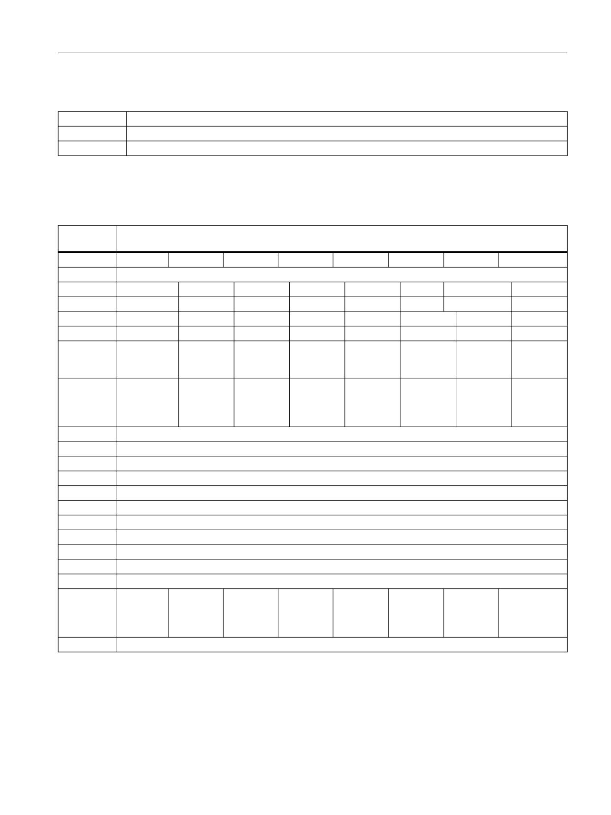
Interface for loading/unloading magazine
DB71
Signals of loading/unloading points
Data block
NC -> PLC interface
BYTE
Bit7
Bit6
Bit5
Bit4
Bit3
Bit2
Bit1
Bit0
Interfaces
DBB0
INT 8
INT 7
INT 6
INT 5
INT 4
INT 3
INT 2
INT 1
DBB1
INT 16
INT 15
INT 14
INT 13
INT 12
INT 11
INT 10
INT 9
DBB2
Ackn INT 8
Ackn INT 7
Ackn INT 6
Ackn INT 5
Ackn INT 4
Ackn INT 3
Ackn INT 2
Ackn INT 1
DBB3
Ackn INT 16
Ackn INT 15
Ackn INT 14
Ackn INT 13
Ackn INT 12
Ackn INT 11
Ackn INT 10
Ackn INT 9
DBB(n+0)
Res.
Position a
Position
Position a
Relocating
Unloading
Loading
multitool
with an NC
magazine
program
DBB(n+1)
Data in the
Res.
Res.
Res.
Res.
Res.
Res.
Acknowl-
extended
edgement
range
status = 3
(DB 1071)
DBB(n+2)
Assigned channel (8bit-Int)
DBB(n+3)
Tool management number (8bit-Int)
DBB(n+4)
Reserved
DBD(n+8)
Reserved
DBD(n+12)
Reserved
DBW(n+16)
Identifier for loading/unloading point (Int), (fixed value 9999)
DBW(n+18)
Location no. of loading/unloading point (Int)
DBW(n+20)
Magazine no. (Source) for unloading/relocating/positioning (Int)
DBW(n+22)
Location no. (Source) for unloading/relocating/positioning (Int)
DBW(n+24)
Magazine no. (Target) for unloading/relocating/positioning (Int)
DBW(n+26)
Location no. (Target) for unloading/relocating/positioning (Int)
DBW(n+28)
Loading/
unloading
without mov-
ing magazine
DBW(n+29)
Spare
Starting addresses of loading/unloading points:
Loading/unloading point 1: n = 4
Loading/unloading point 2: n = 34
Loading/unloading point 3: n = 64
Tool management
Function Manual, 10/2020, 6FC5397-1HP40-0BA1
125

PLC programming
6.3 Signal description of the PLC interface and transfer blocks
Loading/unloading point 4: n = 94
Loading/unloading point 16:...
Example of calculating address DBWn+24 (magazine no. target)
n=(m-1)*len+4 m = location no. of loading station/point
len = 30 (length of loading point)
m = 2; len = 30 n= (2-1)*30+4 --> n = 34
DBW (34+24) = DBW 58
Address for magazine no. Target of 2nd loading point is DBW 58.
Loading point 1 is intended for loading/unloading in all spindles. Loading point is also used to
relocate/position tools in any location (e.g. buffer location).
DB71.DBX0.0 - 1.7
Active status of interface 1 - 16
Edge evaluation
Signal(s) updated: job-controlled
Signal state 1
The active interface has a valid data record. A task bit has been set in
DBB(n+0). There are 16 interfaces. Address "n" must always be cal-
culated for the active interface.
Signal state 0
Operation for this interface has ended. Is reset by FC8 or FC6.
DB71.DBX2.0 - 3.7
"auto" acknowledgement of interface 1 - 16
Edge evaluation
Signal(s) updated: job-controlled
Signal state 1
When setting (edge) the bit, the pending command is acknowledged
with status_1. Unless it is a relocation operation from a real maga-
zine to a buffer. Then acknowledgement is with status_6. This re-
serves the source location.
For example
U DB71.DBX0.0
U DB71.DBX4.1 (unloading)
S DB71.DBX2.0
Signal state 0
Operation for this interface has ended. Is reset by the basic program.
DB71.DBX(n+0).0
Command: Loading
Edge evaluation
Signal(s) updated: job-controlled
Meaning
Loading operation for a tool is initiated. The magazine location into
which the tool is to be loaded is defined in DBW(n+26). The loading
point in question is the location number of the loading point. It is also
located in DBW(n+18)
Corresponding to...
DB71.DBX(n+16) and (n+18) and (n+26)
Tool management
126
Function Manual, 10/2020, 6FC5397-1HP40-0BA1

PLC programming
6.3 Signal description of the PLC interface and transfer blocks
DB71.DBX(n+0).1
Command: Unloading
Edge evaluation
Signal(s) updated: job-controlled
Meaning
Unloading operation is initiated for a tool; the magazine location
from which it is to be unloaded is in DBW (n+20) and DBW (n+22).
The number of the unloading point is in DBW(n+18).
Corresponding to...
DB71.DBX(n+16) and (n+18) or (n+20) and (n+22)
DB71.DBX(n+0).2
Command: Relocating
Edge evaluation
Signal(s) updated: job-controlled
Meaning
Relocate operation for a tool is initiated. From magazine/location (n
+20, n+22=source) to magazine/location (n+24, n+26=target)
Note
The bits in DBB(n+0) (loading, unloading,
) are not updated by the basic program until a new
task exists for this interface. They are current only if the corresponding interface bit in DBB0 is
set to "1''. If required, the user can reset bits DBB(n+0).
DB71.DBX(n+0).3
Command: Positioning to the loading point
Edge evaluation
Signal(s) updated: job-controlled
Meaning
A magazine location is to be positioned at the loading point (maga-
zine no. 9999). The magazine location that is to be moved to the
loading point is in DB71.DBW(n+20) and (n+22). The loading point is
in DB71.DBWn+18.
DB71.DBX(n+0).4
Command: Task comes from the NC program
Edge evaluation
Signal(s) updated: job-controlled
Meaning
The signal is set if the task is received from the part program or via a
cycle.
1. Positioning task with the language command POSM
2. A relocation task or tool transport using the language command
MVTOOL
3. Positioning a multitool using the language command POSMT
DB71.DBX(n+0).5
Command: Position a multitool
Edge evaluation
Signal(s) updated: job-controlled
Meaning
Positioning a multitool has been initiated.
This can be realized using a language command, PI service or the HMI
user interface.
Tool management
Function Manual, 10/2020, 6FC5397-1HP40-0BA1
127

PLC programming
6.3 Signal description of the PLC interface and transfer blocks
DB71.DBX(n+1).0
"auto" ackn negative
Edge evaluation
Signal(s) updated: job-controlled
Meaning
The bit is only evaluated in conjunction with "auto" ackn. If it is set,
then the auto acknowledge is negative, i.e. with status_3.
DB71.DBX(n+1).7
Command: Data in the extended range
Edge evaluation
Signal(s) updated: job-controlled
Meaning
The signal is set if a multitool is loaded, unloaded or positioned. The
multitool data are then available in DB1071.
DB71.DBB(n+2)
Assigned channel
Edge evaluation
Signal(s) updated: job-controlled
Meaning
Number of the channel for which the active interface is valid.
DB71.DBB(n+3)
Tool management no.
Edge evaluation
Signal(s) updated: job-controlled
Meaning
Associated tool management number; corresponds to the number of
the TO area.
DB71.DBW(n+16)
Identifier for loading/unloading point (fixed value 9999)
Edge evaluation
Signal(s) updated: job-controlled
Meaning
The identifier for the loading/unloading point is fixed to the value
9999.
DB71.DBW(n+18)
Location no. of the loading/unloading point
Edge evaluation
Signal(s) updated: job-controlled
Meaning
The location no. of the loading/unloading point is displayed.
DB71.DBW(n+20)
Magazine no. (Source) for unloading/relocating/positioning
Edge evaluation
Signal(s) updated: job-controlled
Meaning
Unloading: Magazine from which the tool is to be unloaded
Relocating: Magazine from which the tool comes
Positioning: Magazine that is to be positioned
Corresponding to...
DBW(n+22)
Tool management
128
Function Manual, 10/2020, 6FC5397-1HP40-0BA1

PLC programming
6.3 Signal description of the PLC interface and transfer blocks
DB71.DBW(n+22)
Location no. (Source) for unloading/relocating/positioning
Edge evaluation
Signal(s) updated: job-controlled
Meaning
Unloading: Location from which the tool is to be unloaded
Relocating: Location from where the tool comes
Positioning: Location that should be positioned
Corresponding to...
DBW(n+20)
DB71.DBW(n+24)
Magazine no. (Target) for unloading/relocating/positioning
Edge evaluation
Signal(s) updated: job-controlled
Meaning
Loading: Magazine into which the tool is to be loaded
Relocating: Magazine into which the tool comes
Positioning: Magazine to be positioned to
Tool remains in the original magazine
Only meaningful for interface 1. If values other than 0 are entered
here, the data define the magazine or location for positioning (lan-
guage command POSM).
Corresponding to...
DBW(n+26)
DB71.DBW(n+26)
Location no. (Target) for unloading/relocating/positioning
Edge evaluation
Signal(s) updated: job-controlled
Meaning
Loading: Location into which the tool is to be loaded
Relocating: Location into which the tool comes
Positioning: Location to be positioned to
Tool remains at the original location
Only meaningful for interface 1. If values other than 0 are entered
here, the data define the magazine or location for positioning (lan-
guage command POSM).
Corresponding to...
DBW(n+24)
DB71.DBX(n+28) Bit0
Loading/unloading without moving magazine
Edge evaluation
Signal(s) updated: job-controlled
Meaning
HMI / Jobshop sets/deletes this signal when requested by the opera-
tor. If the bit is active, there must be no traversing motion of the
magazine, only a mechanical unlocking/locking of the location. The
loading/unloading command must be acknowledged after the ac-
tion. For a positioning and relocating request, this signal is not valid
for a traversing movement.
See also
Interfaces (Page 108)
PLC function when unloading (Page 369)
Tool management
Function Manual, 10/2020, 6FC5397-1HP40-0BA1
129

PLC programming
6.3 Signal description of the PLC interface and transfer blocks
6.3.3
Interface for spindle as change position
DB72
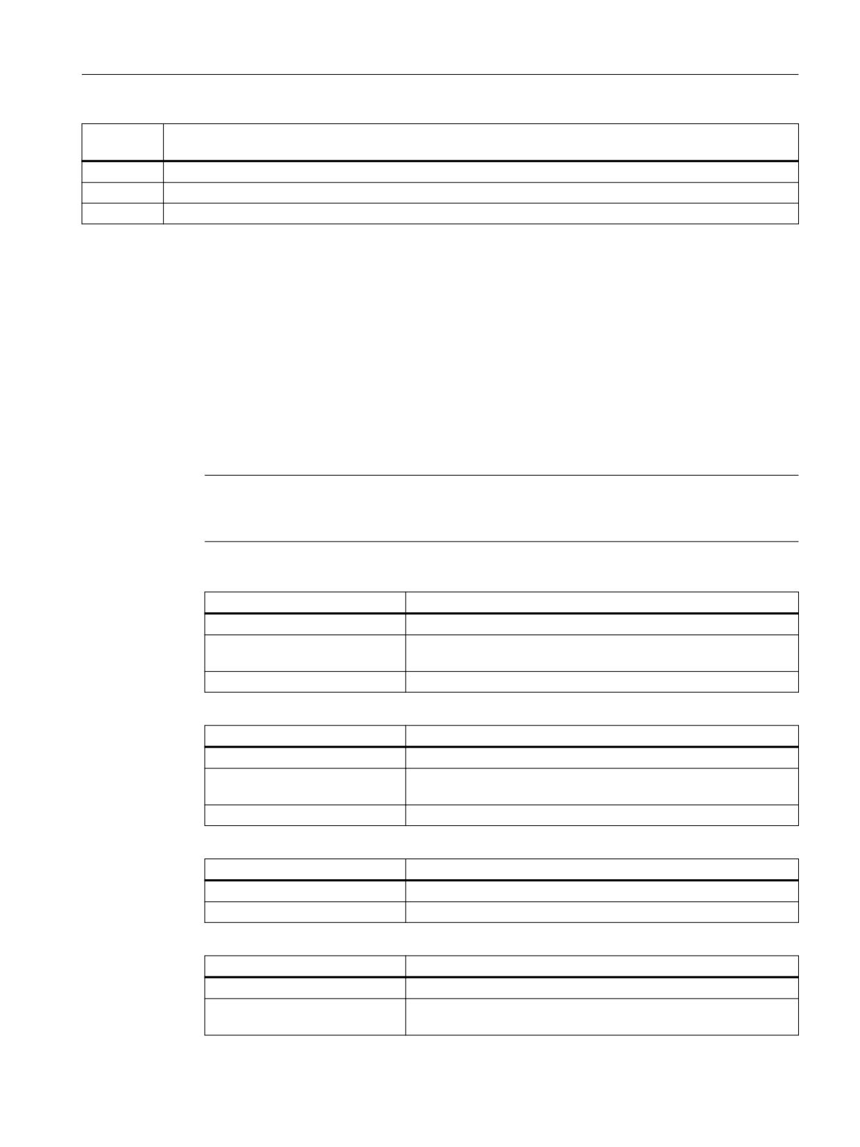
Spindle as change position
data block
Interface NC -> PLC
Byte
Bit7
Bit6
Bit5
Bit4
Bit3
Bit2
Bit1
Bit0
Interfaces
DBB0
INT 8
INT 7
INT 6
INT 5
INT 4
INT 3
INT 2
INT 1
DBB1
INT 16
INT 15
INT 14
INT 13
INT 12
INT 11
INT 10
INT 9
DBB2
Ackn INT 8
Ackn INT 7
Ackn INT 6
Ackn INT 5
Ackn INT 4
Ackn INT 3
Ackn INT 2
Ackn INT 1
DBB3
Ackn INT 16
Ackn INT 15
Ackn INT 14
Ackn INT 13
Ackn INT 12
Ackn INT 11
Ackn INT 10
Ackn INT 9
DBB(n+0)
Tool remains
Unload
Load man-
OldTool in
T0
Prepare
Change
Obligatory
in spindle
manual tool
ual tool
BL no. (n
change
tool (initi-
change
+42)
ated by
M06)
DBB(n+1)
Data in the
Res.
Res.
Res.
Res.
Res.
Res.
Acknowl-
extended
edgement
range (DB
status = 3
1072)
DBB(n+2)
Assigned channel (8bit-Int)
DBB(n+3)
Tool management number (8bit-Int)
DBD(n+4)
$P_VDITCP[0]
User-definable parameter 0 (DWord)
DBD(n+8)
$P_VDITCP[1]
User-definable parameter 1 (DWord)
DBD(n+12)
$P_VDITCP[2]
User-definable parameter 2 (DWord)
DBW(n+16)
Buffer identifier (Int), (fixed value 9998)
corresponds to "Target position for new tool"
DBW(n+18)
Relative location (target) in buffer magazine (Int)
DBW(n+20)
Magazine no. (Source) for new tool (Int)
DBW(n+22)
Location no. (Source) for new tool (Int)
DBW(n+24)
Magazine no. (Target) for old tool (Int)
DBW(n+26)
Location no. (Target) for old tool (Int)
DBW(n+28)
New tool: Location type (Int)
DBW(n+30)
New tool: Size on left (Int)
DBW(n+32)
New tool: Size on right (Int)
DBW(n+34)
New tool: Size at top (Int)
DBW(n+36)
New tool: Size at bottom (Int)
DBB(n+38)
Tool status for new tool
Tool was in
Tool fixed-
Tool is be-
Prewarning
Measure
Tool disa-
Tool ena-
Active tool
use
location-
ing
limit
tool
bled
bled
coded
changed
reached
DBB(n+39)
Tool status for new tool
Manual
1:1 ex-
Master tool
Tool to be
Tool to be
Disabled,
Identifier for
tool
change
loaded
unloaded
but ignore
tools in the
buffer
DBW(n+40)
New tool: Internal T number
Tool management
130
Function Manual, 10/2020, 6FC5397-1HP40-0BA1
PLC programming
6.3 Signal description of the PLC interface and transfer blocks
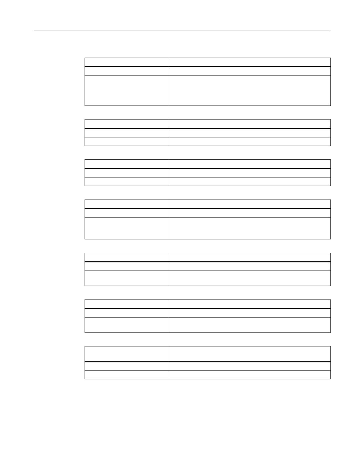
DB72
Spindle as change position
data block
Interface NC -> PLC
DBW(n+42)
If DBX (n+0.4) = 1, then the buffer location of the old tool must be entered here
DBW(n+44)
Original magazine of new tool
DBW(n+46)
Original location of the new tool
Start address of the spindle:
Spindle 1: n = 4
Spindle 2: n = 52
Spindle 3: n = 100
Spindle 16:...
n = (m-1)*len + 4
m = location number of the change position
len = 48
Note
If only M06 is programmed, only free parameters, channel, tool management number and the
bit for "Perform change" are updated.
DB72.DBX0.0 - 1.7
Active status of interface 1 - 16
Edge evaluation
Signal(s) updated: job-controlled
Signal state 1
Associated interface has a valid data record, a tool change request of
tool preparation has been initiated.
Signal state 0
Operation for this interface has ended. Is reset by FC 8/FC 6.
DB72.DBX2.0-3.7
"auto" acknowledgement of interface 1-16
Edge evaluation
Signal(s) updated: job-controlled
Signal state 1
When setting (edge) the bit, the pending command is acknowledged
with status_1.
Signal state 0
Operation for this interface has ended. Is reset by the basic program.
DB72.DBX(n+0).0
Command code: Obligatory change
Edge evaluation
Signal(s) updated: job-controlled
Meaning
The new tool is fixed-location-coded.
DB72.DBX(n+0).1
Command code: Perform change with M06
Edge evaluation
Signal(s) updated: job-controlled
Meaning
M06 command was programmed for tool change, the tool change
can now take place
Tool management
Function Manual, 10/2020, 6FC5397-1HP40-0BA1
131

PLC programming
6.3 Signal description of the PLC interface and transfer blocks
DB72.DBX(n+0).2
Command code: Prepare change
Edge evaluation
Signal(s) updated: job-controlled
Meaning
Prepare new tool for change. If necessary, move location for old tool
to spindle.
DB72.DBX(n+0).3
Command code: T0
Edge evaluation
Signal(s) updated: job-controlled
Meaning
Indicates that T0 has been programmed (no-load traversing of spin-
dle).
DB72.DBX(n+0).4
Command code: Old tool in buffer
Edge evaluation
Signal(s) updated: job-controlled
Meaning
The buffer number of the tool to be changed is written in DB72.DBW
(n+42)
DB72.DBX(n+0).5
Command code: Load manual tool
Edge evaluation
Signal(s) updated: job-controlled
Meaning
A manual tool is to be loaded. The HMI displays the tool which is to
be loaded.
DB72.DBX(n+0).6
Command code: Unload manual tool
Edge evaluation
Signal(s) updated: job-controlled
Meaning
The tool is to be changed via manual operation.
DB72.DBX(n+0).7
Command code: Tool remains in spindle
Edge evaluation
Signal(s) updated: job-controlled
Meaning
The bit is set at change from spindle to spindle. Initiated, e.g. by reset
and start mode or block search.
Note
The bit in DBB (n+0).2 (prepare change) is not reset by the system with a change command. The
bits in DBB(n+0) ... are current only if the corresponding interface bit in DBB0 is set to "1''.
However, the user can reset the bits when required.
If DBX(n+0).1 and DBX(n+0).2 are present at the same time, it means that T and M06 were
programmed in one block.
DB72.DBX(n+1).0
"auto" ackn negative
Edge evaluation
Signal(s) updated: job-controlled
Meaning
The bit is only evaluated in conjunction with "auto" ackn. If it is set,
the AUTO acknowledge is negative, i.e. with status_3.
Tool management
132
Function Manual, 10/2020, 6FC5397-1HP40-0BA1
PLC programming
6.3 Signal description of the PLC interface and transfer blocks
DB72.DBX(n+1).7
Command: Data in the extended range
Edge evaluation
Signal(s) updated: job-controlled
Meaning
The signal is set if a tool is prepared in a multitool or is loaded into a
multitool. DB 72 contains the data of the multitool, the data of the
selected tool is available in DB 1072.
For T0 the signal is not set.
DB72.DBB(n+2)
Assigned channel
Edge evaluation
Signal(s) updated: job-controlled
Meaning
Number of channel for which active interface applies.
DB72.DBB(n+3)
Tool management no.
Edge evaluation
Signal(s) updated: job-controlled
Meaning
Associated tool management no. (TO area).
DB72.DBD(n+4)
User-definable parameter 0 (DInt)
Edge evaluation
Signal(s) updated: job-controlled
Meaning
If you need to send a value to the PLC via the part program, the
transfer can be programmed with $P_VDITCP[0];. Values are trans-
ferred at T call.
DB72.DBD(n+8)
User-definable parameter 1 (DInt)
Edge evaluation
Signal(s) updated: job-controlled
Meaning
If you need to send a value to the PLC via the part program, the
transfer can be programmed with $P_VDITCP[1];.
DB72.DBD(n+12)
User-definable parameter 2 (DInt)
Edge evaluation
Signal(s) updated: job-controlled
Meaning
If you need to send a value to the PLC via the part program, the
transfer can be programmed with $P_VDITCP[2]
DB72.DBW(n+16)
Buffer magazine no. (fixed value 9998)
Target position for new tool
Edge evaluation
Signal(s) updated: job-controlled
Meaning
Magazine no. 9998 (buffer magazine); target magazine for new tool.
Tool management
Function Manual, 10/2020, 6FC5397-1HP40-0BA1
133

PLC programming
6.3 Signal description of the PLC interface and transfer blocks
DB72.DBW(n+18)
Location in buffer magazine (spindle)
Edge evaluation
Signal(s) updated: job-controlled
Meaning
Location no. of buffer magazine to which the new tool must be loa-
ded. This is normally the spindle. The location number defined for
this particular buffer during commissioning is output.
DB72.DBW(n+20)
Magazine no. (source) for new tool to be loaded
Edge evaluation
Signal(s) updated: job-controlled
Meaning
No. of magazine from which the new spindle tool comes.
Corresponding to ...
DBW(n+22)
DB72.DBW(n+22)
Location no. (source) for new tool
Edge evaluation
Signal(s) updated: job-controlled
Meaning
Location no. of the magazine from which the new spindle tool
comes.
Corresponding to ...
DBW(n+20)
DB7.2DBW(n+24)
Magazine no. (target) for old tool to be removed
Edge evaluation
Signal(s) updated: job-controlled
Meaning
Number of magazine in which the tool to be removed at change will
be placed.
Corresponding to ...
DBW(n+26)
DB72.DBW(n+26)
Location no. (target) for new tool
Edge evaluation
Signal(s) updated: job-controlled
Meaning
Magazine location for tool that is unloaded at change.
DB72.DBW(n+28)
New tool: Location type
Edge evaluation
Signal(s) updated: job-controlled
Meaning
The location type of the new spindle tool is entered here.
Corresponding to ...
Tool size: Left, right, top, bottom.
DB72.DBW(n+30)
New tool: Size left
Edge evaluation
Signal(s) updated: job-controlled
Meaning
Specification of the tool size left in half locations for the new spindle
tool.
Tool management
134
Function Manual, 10/2020, 6FC5397-1HP40-0BA1

PLC programming
6.3 Signal description of the PLC interface and transfer blocks
DB72.DBW(n+32)
New tool: Size right
Edge evaluation
Signal(s) updated: job-controlled
Meaning
Specification of the tool size right in half locations for the new spin-
dle tool.
DB72.DBW(n+34)
New tool: Size top
Edge evaluation
Signal(s) updated: job-controlled
Meaning
Specification of the tool size top in half locations for the new spindle
tool.
DB72.DBW(n+36)
New tool: Size bottom
Edge evaluation
Signal(s) updated: job-controlled
Meaning
Specification of the tool size bottom in half locations for the new
spindle tool.
DB72.DBW(n+38)
Tool status for new tool
Edge evaluation
Signal(s) updated: job-controlled
Meaning
Bit 0: Active tool
Bit 1: Enable tool
Bit 2: Tool disabled
Bit 3: Measure tool
Bit 4: Prewarning limit reached
Bit 5: Tool is being changed
Bit 6: Tool is fixed-location-coded
Bit 7: Tool was in use
Bit 8: Tool in the buffer
Bit 9: Ignore disabled
Bit 10: To be unloaded
Bit 11: To be loaded
Bit 12: Master tool
Bit 13: Reserved
Bit 14: 1:1 exchange
Bit 15: Manual tool
DB72.DBW(n+40)
New tool: internal T number of NC
Edge evaluation
Signal(s) updated: job-controlled
Meaning
Display of internal T number of NC for the new spindle tool.
Tool management
Function Manual, 10/2020, 6FC5397-1HP40-0BA1
135
PLC programming
6.3 Signal description of the PLC interface and transfer blocks
DB72.DBW(n+42)
Buffer location of old tool
Edge evaluation
Signal(s) updated: job-controlled
Meaning
If DB72.(n+0.4) = 1, the buffer location of the old tool must be en-
tered here. This can be any buffer (also a gripper).
DB72.DBW(n+44)
Original magazine of new tool
Edge evaluation
Signal(s) updated: job-controlled
Meaning
Owner magazine of the new tool
Corresponds to NC variables $A_MYMN[T no.]
If the new tool is located in the magazine, then this value is identical
with DB72.DBW(n+20).
If the new tool is in the buffer magazine (e.g. gripper) then the mag-
azine no. is entered here from where the tool originally came.
DB72.DBW(n+46)
Original location of new tool
Edge evaluation
Signal(s) updated: job-controlled
Meaning
Owner location of the new tool
Corresponds to NC variables $A_MYMLN[T no.]
6.3.4
Interface for turrets as change position
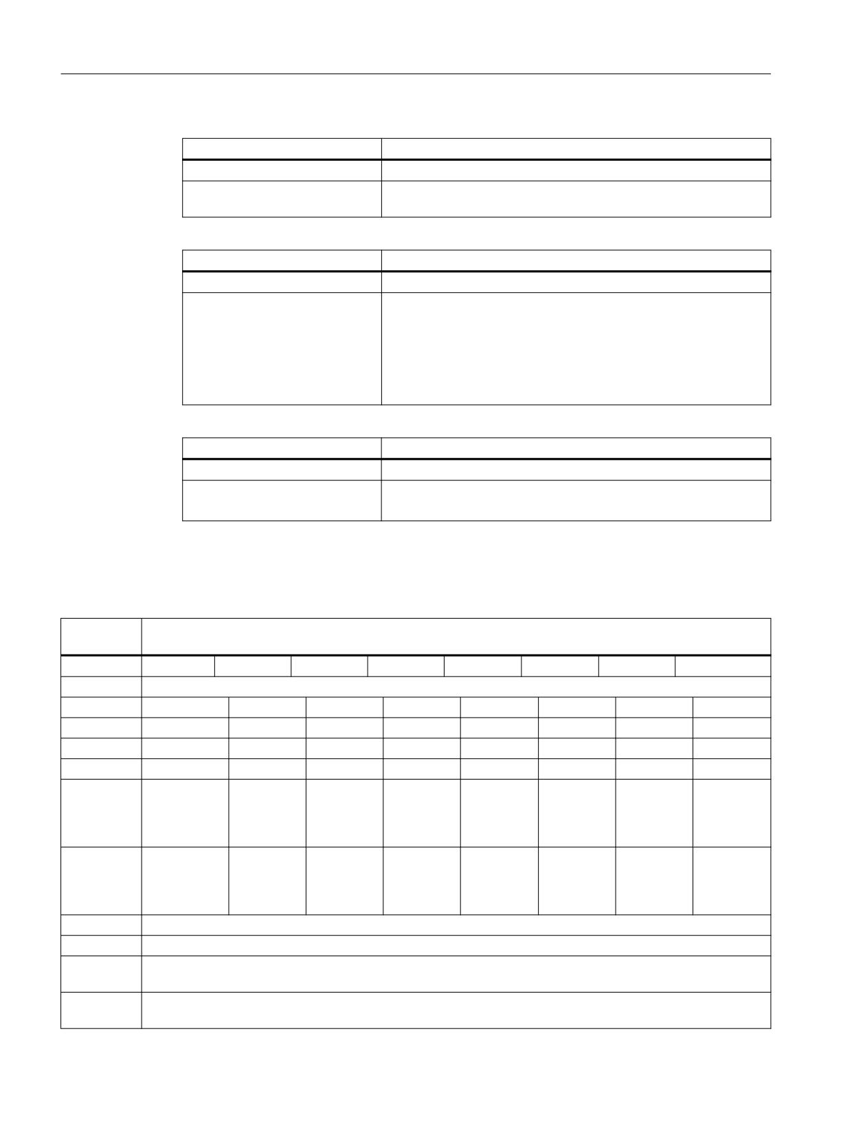
DB73
Turret as change position
data block
Interface NC -> PLC
Byte
Bit7
Bit6
Bit5
Bit4
Bit3
Bit2
Bit1
Bit0
Interfaces
DBB0
INT 8
INT 7
INT 6
INT 5
INT 4
INT 3
INT 2
INT 1
DBB1
INT 16
INT 15
INT 14
INT 13
INT 12
INT 11
INT 10
INT 9
DBB2
Ackn INT 8
Ackn INT 7
Ackn INT 6
Ackn INT 5
Ackn INT 4
Ackn INT 3
Ackn INT 2
Ackn INT 1
DBB3
Ackn INT 16
Ackn INT 15
Ackn INT 14
Ackn INT 13
Ackn INT 12
Ackn INT 11
Ackn INT 10
Ackn INT 9
DBB(n+0)
Res.
Unload
Res.
Res.
T0
Res.
Perform
Obligatory
manual tool
change, ini-
change
tiation: T
no.
DBB(n+1)
Data in the
Res.
Res.
Res.
Res.
Res.
Res.
Acknowl-
extended
edgement
range
status = 3
(DB1073)
DBB(n+2)
Assigned channel (8bit-Int)
DBB(n+3)
Tool management number (8bit-Int)
DBD(n+4)
$P_VDITCP[0]
User-definable parameter 0 (DWord)
DBD(n+8)
$P_VDITCP[1]
User-definable parameter 1 (DWord)
Tool management
136
Function Manual, 10/2020, 6FC5397-1HP40-0BA1

PLC programming
6.3 Signal description of the PLC interface and transfer blocks
DB73
Turret as change position
data block
Interface NC -> PLC
DBW(n+12)
$P_VDITCP[2]
User-definable parameter 2 (DWord)
DBW(n+16)
Reserved
DBW(n+18)
Reserved
DBW(n+20)
Magazine no. of turret (Int)
DBW(n+22)
Location no. of new tool (Int)
DBW(n+24)
Reserved
DBW(n+26)
Location no. of old tool (Int)
DBW(n+28)
New tool: Location type (Int)
DBW(n+30)
New tool: Size on left (Int)
DBW(n+32)
New tool: Size on right (Int)
DBW(n+34)
New tool: Size at top (Int)
DBW(n+36)
New tool: Size at bottom (Int)
DBB(n+38)
Tool status for new tool
Tool was in
Tool, fixed-
Tool being
Prewarning
Measure
Tool disa-
Tool ena-
Active tool
use
location-
changed
limit
tool
bled
bled
coded
reached
DBB(n+39)
Tool status for new tool
Manual
1:1 ex-
Master tool
Tool to be
Tool to be
Disabled,
Identifier for
tool
change
loaded
unloaded
but ignore
tools in the
buffer
DBW(n+40)
New tool: Internal T no. of NC (Int)
DBW(n+42)
Original location of new tool in this circular magazine
Start address of the turret:
Turret, 1: n = 4
Turret 2: n = 48
Turret 3: n = 92
Turret 16:...
n = (m-1)*len + 4
m = location no. of the change position
len = 44
Example for change position 3: n = (3-1)*44 + 4 = 2*44 + 4= 88 + 4 = 92
DB73.DBX0.0 - 1.7
Active status of interfaces 1-16
Edge evaluation
Signal(s) updated: job-controlled
Signal state 1
Associated interface has a valid data record.
Signal state 0
Operation for this interface has ended. Is reset by FC7.
Tool management
Function Manual, 10/2020, 6FC5397-1HP40-0BA1
137

PLC programming
6.3 Signal description of the PLC interface and transfer blocks
DB73.DBX2.0 - 3.7
"auto" acknowledgement of interface 1-16
Edge evaluation
Signal(s) updated: job-controlled
Signal state 1
When setting (edge) the bit, the pending command is acknowledged
with status_1.
Signal state 0
Operation for this interface has ended. Is reset by the basic program.
DB73.DBX (n+0).0
Command: Obligatory change
Edge evaluation
Signal(s) updated: job-controlled
Signal state 1
Signal state 0
Corresponding to ...
Position of participating tools
DB73.DBX(n+0).1
Command: Perform change
Edge evaluation
Signal(s) updated: job-controlled
Meaning
Execute tool change
DB73.DBX(n+0).3
T0
Edge evaluation
Signal(s) updated: job-controlled
Meaning
Indicates that T0 has been programmed
DB73.DBX(n+1).0
"auto" ackn negative
Edge evaluation
Signal(s) updated: job-controlled
Meaning
The bit is only evaluated in conjunction with "auto" ackn. If it is set,
the AUTO acknowledge is negative, i.e. with status_3.
DB73.DBX(n+1).7
Command: Data in the extended range
Edge evaluation
Signal(s) updated: job-controlled
Meaning
The signal is set if a tool is loaded into a multitool. DB 73 contains the
data of the multitool, the data of the selected tool is available in DB
1073.
For T0 the signal is not set.
DB73.DBB(n+2)
Assigned channel
Edge evaluation
Signal(s) updated: job-controlled
Meaning
Number of channel from which the T word was programmed.
DB73.DBB(n+3)
Tool management number
Edge evaluation
Signal(s) updated: job-controlled
Meaning
Associated tool management number (TO area) of channel.
Tool management
138
Function Manual, 10/2020, 6FC5397-1HP40-0BA1

PLC programming
6.3 Signal description of the PLC interface and transfer blocks
Note
The bits in DBB(n+0) (obligatory change, execute change, ...) are not reset by the system. They
are current only if the corresponding interface bit in DBB0 is set to "1''. However, the bits can be
reset by the user if necessary.
DB73.DBD(n+4)
User-definable parameter 0 (DInt)
Edge evaluation
Signal(s) updated: job-controlled
Meaning
If you need to send a value to the PLC via the part program, the
transfer can be programmed with $P_VDITCP[0] = value. Parameters
0-2 are transferred with the T command.
DB73.DBD(n+8)
User-definable parameter 1 (DInt)
Edge evaluation
Signal(s) updated: job-controlled
Meaning
If you need to send a value to the PLC via the part program, the
transfer can be programmed with $P_VDITCP[1] = value.
DB73.DBD(n+12)
User-definable parameter 2 (DInt)
Edge evaluation
Signal(s) updated: job-controlled
Meaning
If you need to send a value to the PLC via the part program, the
transfer can be programmed with $P_VDITCP[2] = value.
DB73.DBW(n+20)
Magazine no. of new tool
Edge evaluation
Signal(s) updated: job-controlled
Meaning
Magazine no. of the new tool, which should be processed.
Corresponding to ...
DBW(n+22)
DB73.DBW(n+22)
Location no. of new tool to be loaded at change
Edge evaluation
Signal(s) updated: job-controlled
Meaning
Location no. of the new tool, which should be processed.
Corresponding to ...
DBW(n+20)
DB73.DBW(n+26)
Location no. of old tool to be unloaded
Edge evaluation
Signal(s) updated: job-controlled
Meaning
Location no. of the old tool (used up to now for machining).
Tool management
Function Manual, 10/2020, 6FC5397-1HP40-0BA1
139
PLC programming
6.3 Signal description of the PLC interface and transfer blocks
DB73.DBW(n+28)
New tool: Location type
Edge evaluation
Signal(s) updated: job-controlled
Meaning
The location type of the new tool is entered here.
Corresponding to ...
Tool size: Left, right, top, bottom
DB73.DBW(n+30)
New tool: Size left
Edge evaluation
Signal(s) updated: job-controlled
Meaning
Specification of the tool size left in half locations for the new tool.
DB73.DBW(n+32)
New tool: Size right
Edge evaluation
Signal(s) updated: job-controlled
Meaning
Specification of the tool size right in half locations for the new tool
DB73.DBW(n+34)
New tool: Size top
Edge evaluation
Signal(s) updated: job-controlled
Meaning
Specification of the tool size top in half locations for the new tool
DB73.DBW(n+36)
New tool: Size bottom
Edge evaluation
Signal(s) updated: job-controlled
Meaning
Specification of the tool size bottom in half locations for the new tool
DB73.DBW(n+38)
Tool status for new tool
Edge evaluation
Signal(s) updated: job-controlled
Meaning
Bit 0: Active tool
Bit 1: Enable tool
Bit 2: Disabled
Bit 3: Measure tool
Bit 4: Prewarning limit reached
Bit 5: Tool being changed
Bit 6: Tool is fixed-location-coded
Bit 7: Tool was in use
Bit 8: Tool in the buffer
Bit 9: Ignore disabled
Bit 10: To be unloaded
Bit 11: To be loaded
Bit 12: Master tool
Bit 13: Reserved
Bit 14: 1:1 exchange
Bit 15: Manual tool
Tool management
140
Function Manual, 10/2020, 6FC5397-1HP40-0BA1

PLC programming
6.3 Signal description of the PLC interface and transfer blocks
DB73.DBW(n+40)
New tool: Internal T no. of NC
Edge evaluation
Signal(s) updated: job-controlled
Meaning
Display of internal T no. of NC for the new tool. Tool management
variables can be read/written via FB2/FB3 using this T no.
DB73.DBW(n+42)
Original location of new tool in this circular magazine
Edge evaluation
Signal(s) updated: job-controlled
Meaning
Location that owns the new tool. Corresponds to NC variables
$A_MYMLN[T no.]
6.3.5
Interface for loading/unloading magazine (multitool) (DB1071)
DB1071
Magazine, loading/unloading (multitool)
Data block
NC -> PLC interface
Byte
Bit7
Bit6
Bit5
Bit4
Bit3
Bit2
Bit1
Bit0
DBW(n+0)
Distance coding
DBW(n+2)
Multitool location number
DBD(n+4)
Multitool distance
DBW(n+8)
Multitool number
DBW(n+10)
Multitool location number
DBW(n+12)
Tool holder
DBW(n+14)
Reserved
DBW(n+16)
Reserved
DBW(n+18)
Reserved
Starting address of loading/unloading points:
Loading/unloading point 1: n = 0
Loading/unloading point 2: n = 20
Loading/unloading point 3: n = 40
Loading/unloading point 4: n = 60
Loading/unloading point 16:...
DB1071.DBW(n+0)
Distance coding
Edge evaluation
Signal(s) updated: job-controlled
Meaning
Type of distance coding of the multitool (corresponds to
$TC_MTP_KD)
1 = location number
2 = distance
3 = angle
Tool management
Function Manual, 10/2020, 6FC5397-1HP40-0BA1
141
PLC programming
6.3 Signal description of the PLC interface and transfer blocks
DB1071.DBW(n+2)
Multitool location number
Edge evaluation
Signal(s) updated: job-controlled
Meaning
Number of locations of the multitool
DB1071.DBD(n+4)
Multitool location distance
Edge evaluation
Signal(s) updated: job-controlled
Meaning
Distance of the MT location to be positioned from the reference
location (real value). In accordance with the distance coding
DB1071.DBW(n+8)
Multitool number
Edge evaluation
Signal(s) updated: job-controlled
Meaning
Internal T number of the multitool
DB1071.DBW(n+10)
Multitool location number
Edge evaluation
Signal(s) updated: job-controlled
Meaning
Location number within the multitool (which the system positions
to)
DB1071.DBW(n+12)
Tool holder
Edge evaluation
Signal(s) updated: job-controlled
Meaning
Spindle or tool holder number
6.3.6
Interface for spindle (multitool) (DB1072)
DB1072
Spindle (multitool)
Data block
Interface NC -> PLC
Byte
Bit7
Bit6
Bit5
Bit4
Bit3
Bit2
Bit1
Bit0
DBW(n+0)
Distance coding
DBW(n+2)
Multitool location number
DBD(n+4)
Multitool distance
DBW(n+8)
Multitool number (new tool)
DBW(n+10)
Multitool location number (new tool)
DBW(n+12)
Multitool number (old tool)
DBW(n+14)
Multitool location number (old tool)
DBW(n+16)
Location type
DBW(n+18)
Tool size, left
DBW(n+20)
Tool size, right
DBW(n+22)
Tool size, top
DBW(n+24)
Tools size, bottom
Tool management
142
Function Manual, 10/2020, 6FC5397-1HP40-0BA1
PLC programming
6.3 Signal description of the PLC interface and transfer blocks
DB1072
Spindle (multitool)
Data block
Interface NC -> PLC
DBW(n+26)
Tool status
DBW(n+28)
T number of the tool
DBW(n+30)
Tool holder
DBW(n+32)
Original magazine of new tool
DBW(n+34)
Original location of new tool
DBW(n+36)
Reserved
to
DBW(n+48)
Start addresses of the spindles:
Spindle 1: n = 0
Spindle 2: n = 50
Spindle 3: n = 100
Spindle 16: ...
DB1072.DBW(n+0)
Distance coding
Edge evaluation
Signal(s) updated: job-controlled
Meaning
Type of distance coding of the multitool (corresponds to
$TC_MTP_KD)
1 = location number
2 = distance
3 = angle
DB1072.DBW(n+2)
Multitool location number
Edge evaluation
Signal(s) updated: job-controlled
Meaning
Number of locations of the multitool.
DB1072.DBD(n+4)
Multitool location distance
Edge evaluation
Signal(s) updated: job-controlled
Meaning
Distance of the MT location to be positioned from the reference
location (real value). In accordance with the distance coding.
DB1072.DBW(n+8)
Multitool number (new tool)
Edge evaluation
Signal(s) updated: job-controlled
Meaning
Internal T number of the (new) multitool.
DB1072.DBW(n+10)
Multitool location number (new tool)
Edge evaluation
Signal(s) updated: job-controlled
Meaning
Location number within the multitool where the new tool is located.
Tool management
Function Manual, 10/2020, 6FC5397-1HP40-0BA1
143
PLC programming
6.3 Signal description of the PLC interface and transfer blocks
DB1072.DBW(n+12)
Multitool number (old tool)
Edge evaluation
Signal(s) updated: job-controlled
Meaning
Internal T number of the (old) multitool.
The T number is entered here if the preparation or the change to a
tool is realized within the same multitool (which, due to a previous
change, is located on the tool holder). It is identical with
DB1072.DBW(n+8).
DB1072.DBW(n+14)
Multitool location number (old tool)
Edge evaluation
Signal(s) updated: job-controlled
Meaning
Location number within the multitool where the old tool is located.
The location number - where the old tool is located - is entered here
if the preparation or the change to a tool is realized within the same
multitool (which, due to a previous change, is located on the tool
holder).
DB1072.DBW(n+16)
New tool: Location type
Edge evaluation
Signal(s) updated: job-controlled
Meaning
Location type of the new tool (of the programmed tool in the mul-
titool).
Corresponding to ...
Tool size: Left, right, top, bottom
DB1072.DBW(n+18)
New tool: Size left
Edge evaluation
Signal(s) updated: job-controlled
Meaning
Specification of the tool size to the left in half locations of the new
tool (of the programmed tool in the multitool).
DB1072.DBW(n+20)
New tool: Size right
Edge evaluation
Signal(s) updated: job-controlled
Meaning
Specification of the tool size to the right in half locations of the new
tool (of the programmed tool in the multitool).
DB1072.DBW(n+22)
New tool: Size top
Edge evaluation
Signal(s) updated: job-controlled
Meaning
Specification of the tool size to the top in half locations of the new
tool (of the programmed tool in the multitool).
DB1072.DBW(n+24)
New tool: Size bottom
Edge evaluation
Signal(s) updated: job-controlled
Signal state 1
Specification of the tool size to the bottom in half locations of the
new tool (of the programmed tool in the multitool).
Tool management
144
Function Manual, 10/2020, 6FC5397-1HP40-0BA1

PLC programming
6.3 Signal description of the PLC interface and transfer blocks
DB1072.DBW(n+26)
Tool status for new tool:
Edge evaluation
Signal(s) updated: job-controlled
Meaning
Tool status of the programmed tool in the multitool.
Corresponds to parameter $TC_TP8[T_No]
Bit 0: Active tool
Bit 1: Enable tool
Bit 2: Tool disabled
Bit 3: Measure tool
Bit 4: Prewarning limit reached
Bit 5: Tool is being changed
Bit 6: Tool is fixed-location-coded
Bit 7: Tool was in use
Bit 8: Tool in the buffer
Bit 9: Ignore disabled
Bit 10: To be unloaded
Bit 11: To be loaded
Bit 12: Master tool
Bit 13: Reserved
Bit 14: 1:1 exchange
Bit 15: Manual tool
DB1072.DBW(n+28)
New tool: internal T number of NC
Edge evaluation
Signal(s) updated: job-controlled
Meaning
Display of internal T number of NC for the new spindle tool (of the
programmed tool in the multitool).
DB1072.DBW(n+30)
Tool holder
Edge evaluation
Signal(s) updated: job-controlled
Meaning
Spindle or tool holder number to which the change refers (the mul-
titool that is to be changed).
DB1072.DBW(n+32)
Original magazine of new tool
Edge evaluation
Signal(s) updated: job-controlled
Meaning
Magazine that owns the new tool.
Corresponds to NC variables $A_MYMN[T no.]
If the new tool is located in the magazine, then this value is identical
with DB72.DBW(n+20).
If the new tool is in the buffer magazine (e.g. gripper), the number of
the magazine from which the tool originally came is entered here.
The new tool has the same owner location as the multitool onto
which it is loaded.
Tool management
Function Manual, 10/2020, 6FC5397-1HP40-0BA1
145

PLC programming
6.3 Signal description of the PLC interface and transfer blocks
DB1072.DBW(n+34)
Original location of new tool
Edge evaluation
Signal(s) updated: job-controlled
Meaning
Location that owns the new tool.
Corresponds to NC variables $A_MYMLNT[T no.]
If the new tool is located in the magazine, then this value is identical
with DB72.DBW(n+20).
If the new tool is in the buffer magazine (e.g. gripper), the number of
the magazine from which the tool originally came is entered here.
The new tool has the same owner location as the multitool onto
which it is loaded.
6.3.7
Interface for turret (multitool) (DB1073)
DB1073
Turret (multitool)
Data block
Interface NC -> PLC
Byte
Bit7
Bit6
Bit5
Bit4
Bit3
Bit2
Bit1
Bit0
DBW(n+0)
Distance coding
DBW(n+2)
Multitool location number
DBD(n+4)
Multitool distance
DBW(n+8)
Multitool number (new tool)
DBW(n+10)
Multitool location number (new tool)
DBW(n+12)
Multitool number (old tool)
DBW(n+14)
Multitool location number (old tool)
DBW(n+16)
Location type
DBW(n+18)
Tool size, left
DBW(n+20)
Tool size, right
DBW(n+22)
Tool size, top
DBW(n+24)
Tools size, bottom
DBW(n+26)
Tool status
DBW(n+28)
T number of the tool
DBW(n+30)
Tool holder
DBW(n+32)
Original magazine of new tool
DBW(n+34)
Original location of new tool
DBW(n+36)
Reserved
to
DBW(n+48)
Start addresses of the turrets:
Spindle 1: n = 0
Spindle 2: n = 50
Tool management
146
Function Manual, 10/2020, 6FC5397-1HP40-0BA1
PLC programming
6.3 Signal description of the PLC interface and transfer blocks
Spindle 3: n = 100
Spindle 16:...
DB1073.DBW(n+0)
Distance coding
Edge evaluation
Signal(s) updated: job-controlled
Meaning
Type of distance coding of the multitool (corresponds to
$TC_MTP_KD)
1 = location number
2 = distance
3 = angle
DB1073.DBW(n+2)
Multitool location number
Edge evaluation
Signal(s) updated: job-controlled
Meaning
Number of locations of the multitool
DB1073.DBD(n+4)
Multitool location distance
Edge evaluation
Signal(s) updated: job-controlled
Meaning
Distance of the MT location to be positioned from the reference
location (real value). In accordance with the distance coding.
DB1073.DBW(n+8)
Multitool number (new tool)
Edge evaluation
Signal(s) updated: job-controlled
Meaning
Internal T number of the (new) multitool
DB1073.DBW(n+10)
Multitool location number (new tool)
Edge evaluation
Signal(s) updated: job-controlled
Meaning
Location number within the multitool where the new tool is located.
DB1073.DBW(n+12)
Multitool number (old tool)
Edge evaluation
Signal(s) updated: job-controlled
Meaning
Internal T number of the (old) multitool.
The T number is entered here if the preparation or the change to a
tool is realized within the same multitool (which, due to a previous
change, is located on the tool holder). It is identical with
DB1072.DBW(n+8).
Tool management
Function Manual, 10/2020, 6FC5397-1HP40-0BA1
147
PLC programming
6.3 Signal description of the PLC interface and transfer blocks
DB1073.DBW(n+14)
Multitool location number (old tool)
Edge evaluation
Signal(s) updated: job-controlled
Meaning
Location number within the multitool where the old tool is located.
The location number - where the old tool is located - is entered here
if the preparation or the change to a tool is realized within the same
multitool (which, due to a previous change, is located on the tool
holder).
DB1073.DBW(n+16)
New tool: Location type
Edge evaluation
Signal(s) updated: job-controlled
Meaning
Location type of the new tool (of the programmed tool in the mul-
titool).
Corresponding to ...
Tool size: Left, right, top, bottom
DB1073.DBW(n+18)
New tool: Size left
Edge evaluation
Signal(s) updated: job-controlled
Meaning
Specification of the tool size to the left in half locations of the new
tool (of the programmed tool in the multitool).
DB1073.DBW(n+20)
New tool: Size right
Edge evaluation
Signal(s) updated: job-controlled
Meaning
Specification of the tool size to the right in half locations of the new
tool (of the programmed tool in the multitool).
DB1073.DBW(n+22)
New tool: Size top
Edge evaluation
Signal(s) updated: job-controlled
Meaning
Specification of the tool size to the top in half locations of the new
tool (of the programmed tool in the multitool).
DB1073.DBW(n+24)
New tool: Size bottom
Edge evaluation
Signal(s) updated: job-controlled
Meaning
Specification of the tool size to the bottom in half locations of the
new tool (of the programmed tool in the multitool).
Tool management
148
Function Manual, 10/2020, 6FC5397-1HP40-0BA1

PLC programming
6.3 Signal description of the PLC interface and transfer blocks
DB1073.DBW(n+26)
Tool status for new tool:
Edge evaluation
Signal(s) updated: job-controlled
Meaning
Tool status of the programmed tool in the multitool
Corresponds to parameter $TC_TP8[T_No]
Bit 0: Active tool
Bit 1: Enable tool
Bit 2: Tool disabled
Bit 3: Measure tool
Bit 4: Prewarning limit reached
Bit 5: Tool is being changed
Bit 6: Tool is fixed-location-coded
Bit 7: Tool was in use
Bit 8: Tool in the buffer
Bit 9: Ignore disabled
Bit 10: To be unloaded
Bit 11: To be loaded
Bit 12: Master tool
Bit 13: Reserved
Bit 14: 1:1 exchange
Bit 15: Manual tool
DB1073.DBW(n+28)
New tool: internal T number of NC
Edge evaluation
Signal(s) updated: job-controlled
Meaning
Display of internal T number of NC for the new spindle tool (of the
programmed tool in the multitool).
DB1073.DBW(n+30)
Tool holder
Edge evaluation
Signal(s) updated: job-controlled
Meaning
Spindle or tool holder number to which the change refers (the mul-
titool that is to be changed).
DB1073.DBW(n+32)
Original magazine of new tool
Edge evaluation
Signal(s) updated: job-controlled
Meaning
Magazine that owns the new tool.
Corresponds to NC variables $A_MYMN[T no.]
If the new tool is located in the magazine, then this value is identical
with DB72.DBW(n+20).
If the new tool is in the buffer magazine (e.g. gripper), the number of
the magazine from which the tool originally came is entered here.
The new tool has the same owner location as the multitool onto
which it is loaded.
Tool management
Function Manual, 10/2020, 6FC5397-1HP40-0BA1
149
PLC programming
6.3 Signal description of the PLC interface and transfer blocks
DB1073.DBW(n+34)
Original location of new tool
Edge evaluation
Signal(s) updated: job-controlled
Meaning
Location that owns the new tool.
Corresponds to NC variables $A_MYMLNT[T no.]
If the new tool is located in the magazine, then this value is identical
with DB72.DBW(n+20).
If the new tool is in the buffer magazine (e.g. gripper), the number of
the magazine from which the tool originally came is entered here.
The new tool has the same owner location as the multitool onto
which it is loaded.
6.3.8
Interface NC channels
Signals are also contained in the channel data blocks for tool management functions. The data
relevant for tool management is in bold formatting.
DB21-30
Signals to/from NC channel
Data block
Interface PLC -> NC
Byte
Bit7
Bit6
Bit5
Bit4
Bit3
Bit2
Bit1
Bit0
DBB1
Activate
PLC action
CLC over-
CLC stop
Time moni-
Synchron-
Release pro-
Activate ref-
program
completed
ride
toring ac-
ized action
tection
erencing
test
tive
off
areas
DBB29
Tool disa-
Disable
Deactivate
Activate
Activate
Activate
Activate
Activate
ble not ef-
wear moni-
workpiece
PTP traver-
fixed feed 4
fixed feed 3
fixed feed 2
fixed feed 1
fective
toring
counter
sal
Cyclic signals from NC channel
DBB317
Tool miss-
PTP traver-
External
ing
sal active
language
mode active
Change signals TM functions
DBB344
Last re-
Transition
Tool pre-
Tool pre-
placement
to new re-
warning
warning
tool of the
placement
limit
limit
tool group
tool
reached
reached
Transferred tool management functions
DBD348
T number for tool management prewarning limit (DInt)
DBD352
T number for tool limit value (DInt)
DBD356
T number of new replacement tool (DInt)
DBD360
T number of last replacement tool (DInt)
DB21.DBX1.3
The user can start and stop tool life monitoring time using PLC signal "Time monitor active". The effec-
tiveness of this control is set via MD20310 $MC_TOOL_MANAGEMENT_MASK, bit 17.
Tool management
150
Function Manual, 10/2020, 6FC5397-1HP40-0BA1
PLC programming
6.3 Signal description of the PLC interface and transfer blocks
DB21.DBX29.5
Switches workpiece count monitoring on/off.
DB21.DBX29.6
Switches wear monitoring on/off.
DB21.DBX29.7
VDI signal "Tool disable ineffective" (bit value=1) means that the NC does not process the tool status
"Disabled" during tool search.
The signal is not effective, if the tool selection is realized using the Init blocks (Reset- and
Start_Mode_Mask). If, for instance, it is to be possible to select a disabled spindle tool, then this must be
set in machine data $MC_TOOL_CHANGE_ERROR_MODE.
DB21.DBX317.7
Display in PLC that the programmed tool is missing. (Tool is either not available or cannot be used.)
DB21.DBX 344.0 - 344.3
Modification signals of the tool management functions
Edge evaluation
Signal(s) updated: job-controlled
Meaning
A T number for tool prewarning limit, limit value, new replacement
tool, last replacement tool has been output with a value at the in-
terface at the beginning of an OB1 cycle together with the associated
modification signal. In this case, the change signal indicates that the
appropriate value is valid.
6.3.9
Interface magazine configuration
DB4
Interface HMI -> PLC
Address
Meaning
Data type
DBB64
Number of magazines including buffer magazines
BYTE
and loading magazines
<
Beginning of rerun loop; number of reruns from
DB4.DBB64
DBW65 (70, 75, ...)
Magazine number
INT
DBB67 (...)
Magazine type
BYTE
DBW68 (...)
Number of locations
INT
>
Return loop end
Address =
Number of spindles
BYTE
(contents DBB64*5) +65
Checks during run-up
During run-up, the NC checks the magazine configuration in all channels and transfers the
magazine description via the VDI interface directly to the basic PLC program.
Tool management
Function Manual, 10/2020, 6FC5397-1HP40-0BA1
151

PLC programming
6.3 Signal description of the PLC interface and transfer blocks
The following sequence is defined:
• Is the magazine description from the NC available (and no entry in DB4)?
This is used and set up accordingly; the magazine description is NOT copied to DB4.
• Is a magazine description available in DB4?
- This is used and the user interface set up accordingly.
This means that the entry in DB4 has priority. This ensures full compatibility.
• If there is neither a magazine description from the NC nor one in DB4, the user interface is set-
up with the maximum configuration (16 interfaces each).
6.3.10
Delete pending tasks
General
The communication initiated by the NC yet interrupted by the PLC task "Delete pending task"
(DB10.DBX105.0) can be terminated by the PLC during commissioning.
DB10
General signals
Data block
Byte
Bit7
Bit6
Bit5
Bit4
Bit3
Bit2
Bit1
Bit0
DBB105
Cancel TM
command
GP -> PLC
The function cancels all pending tool management tasks from the NC (compare NC switch-on).
The NC tool management is reset in a defined manner. This is intended to be a pure
commissioning function. If a command must be cancelled in regular operation, then this is done
using FC8/FC6 and acknowledgement status "3" (negative acknowledgement).
This function enables direct intervention by the operator to, for example, take a tool out of the
gripper where a change is just about to take place, or if there is no acknowledgement from the
PLC program.
Note
Please ensure that the data consistency in the NC is maintained.
Boundary condition
The "Delete pending task" function can be activated only if the NC is in the "Channel not active"
state.
Tool management
152
Function Manual, 10/2020, 6FC5397-1HP40-0BA1

PLC programming
6.3 Signal description of the PLC interface and transfer blocks
6.3.11
FC6: TM_TRANS2 - transfer block for tool management and multitool
Function
The block FC6 "TM_TRANS2" is used for position changes of the tools, state changes, and
multitool.
The FC6 block has the same functionality as the FC8 block, plus the multitool functionality.
The description of FC6 only contains the multitool functionality.
The functionality of FC8 is described in "FC8: TM_TRANS - transfer block for tool management
(Page 157)".
Declaration of the function
FUNCTION FC6: VOID
VAR_INPUT
Start:
BOOL;
TaskIdent:
BYTE ;
TaskIdentNo:
BYTE ;
NewToolMag:
INT;
NewToolLoc:
INT;
OldToolMag:
INT;
OldToolLoc:
INT;
Status:
INT;
MtoolPlaceNum:
INT;
END_VAR
VAR_OUTPUT
Ready:
BOOL;
Error:
INT;
END_VAR
BEGIN
END_FUNCTION
Description of formal parameters
Signal
Type
Type
Value range
Description
Start:
I
BOOL
0 (FALSE), 1
See block description FC8
(TRUE)
TaskIdent:
I
BYTE
See block description FC8
TaskIdentNo:
I
BYTE
See block description FC8
NewToolMag:
I
INT
See block description FC8
NewToolLoc:
I
INT
See block description FC8
OldToolMag:
I
INT
See block description FC8
OldToolLoc:
I
INT
See block description FC8
Status:
I
INT
See block description FC8
Tool management
Function Manual, 10/2020, 6FC5397-1HP40-0BA1
153

PLC programming
6.3 Signal description of the PLC interface and transfer blocks
Signal
Type
Type
Value range
Description
MtoolPlaceNum:
I
INT
Multitool location No.
Ready:
O
BOOL
0 (FALSE), 1
See block description FC8
(TRUE)
Error:
O
INT
See block description FC8
See also
FC7: TM_REV - transfer block for tool change with revolver (Page 154)
Function blocks (Page 121)
6.3.12
FC7: TM_REV - transfer block for tool change with revolver
Function
After a revolver has been changed, the user calls block FC7 "TM_REV". The revolver number
corresponding to interface number in DB73 must be specified in parameter "ChgdRevNo" for this
purpose. As this block is called, the associated "Interface active" bit in data block DB73.DBW0 of
FC7 is reset after parameter "Ready" == TRUE is returned.
Job executed correctly
If the job was executed correctly, "Ready" == 1. The user must then set the parameter "Start" = 0
or no longer call FC7.
Job executed with errors
If the job was executed with errors, parameter "Ready" == 0 and parameter "Error" == 1. The job
must be repeated in the next PLC cycle. Since the parameter "Start" does not need a positive edge
for a subsequent job, "Start" = 1 remains, because the job has not yet been completed. See "Call
example" and "Pulse diagram" below.
Constraints
• Block FC7 may only be started with parameter "Start" = 1 if an activation signal for the
associated interface (DB73.DBW0) for this transfer has been supplied by the tool
management function.
• A cancellation of a transfer, e.g. by a channel reset, is not permitted.
• Parameter "Start" = 1, until parameter "Ready" == 1 or "Error" == 1
Further information
• PI services for tool management, see:
- FB4: PI_SERV - request PI service, see Function Manual PLC.
- FC8: TM_TRANS - transfer block for tool management (Page 157)
Tool management
154
Function Manual, 10/2020, 6FC5397-1HP40-0BA1

PLC programming
6.3 Signal description of the PLC interface and transfer blocks
Manual turret switching
If the turret is rotated in manual operation, neither a tool change nor an offset selection is
associated with this operation. The first step is the removal of the tool from the tool carrier back
to its location in the turret. An asynchronous transfer must be performed with FC8 (alternative:
FC6). The associated parameter settings are shown below:
TaskIdent = 4
TaskIdentNo = Channel no.
NewToolMag = Magazine no. of the turret
NewToolLoc = Original location of the tool
OldToolMag = Magazine no. of the buffer storage (spindle) = 9998
OldToolLoc = Buffer storage no. of the spindle
Status = 1
If the turret is now turned to any position at which a tool is located, this tool must be activated.
This is done easiest by the new T programming in the part program. However, if this should take
place, for example, at the end of turret switching from the PLC user program, an ASUB must be
started for this purpose. The current turret position must be transferred to the ASUB. Thus the
tool is determined on this location in the ASUB and this is selected.
Declaration of the function
FUNCTION FC7:
VOID
//NAME :TM_REV
VAR_INPUT
Start :
BOOL;
ChgdRevNo :
BYTE ;
END_VAR
VAR_OUTPUT
Ready :
BOOL;
Error :
INT;
END_VAR
BEGIN
END_FUNCTION
Description of formal parameters
Signal
Typ
Type
Value range
Meaning
e
Start:
I
BOOL
0 (FALSE),
1 = start transfer
1 (TRUE)
ChgdRevNo:
I
BYTE
1, 2, 3, ...
Number of turret interface
Tool management
Function Manual, 10/2020, 6FC5397-1HP40-0BA1
155
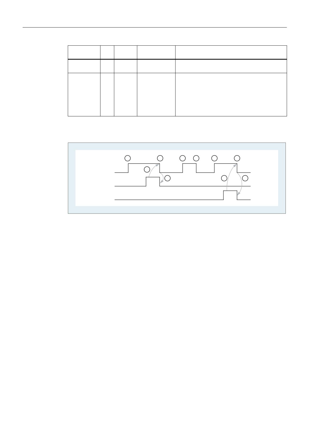
PLC programming
6.3 Signal description of the PLC interface and transfer blocks
Signal
Typ
Type
Value range
Meaning
e
Ready:
O
BOOL
0 (FALSE),
1 = Transfer complete
1 (TRUE)
Error:
O
INT
0, 1 , 2, 3
Error checkback
0: No error has occurred
1: No turret present
2: Illegal turret number in parameter "ChgdRevNo"
3: Illegal job ("interface active" signal for selected
turret = "FALSE")
Pulse diagram
6WDUW
5HDG\
(UURU
!
① User: Set request, Start = 0 → 1
② FB4: PI service successfully completed, Ready = 1
User: Reset request, IF Ready == 1 THEN Start = 0
③ User: IF Ready == 1 THEN reset request: 1 → 0
④ FB4: Reset job confirmation, Ready = 0
⑤ User: IF Ready == 0 AND Error == 0 THEN reset request Start = 1 → 0 not permissible
⑥ FB4: PI service completed with errors, Error = 1
User: Reset request, IF Ready == 1 OR Error == 1 THEN Start = 0, possible further error handling
Call example
CALL
// Tool management: Transfer block for turret
FC7(
Start :=
m 20.5,
// Start := "1 " => initiate the
transfer
ChgdRevNo :=
DB61.DBB1,
Ready :=
m 20.6,
Error :=
DB61.DBW12
};
u
m 20.6;
// Poll ready
r
m 20.5;
// Reset start
Tool management
156
Function Manual, 10/2020, 6FC5397-1HP40-0BA1
PLC programming
6.3 Signal description of the PLC interface and transfer blocks
spb
m001;
// Jump, if everything OK
l
db61.dbw 12;
// Error information
ow
w#16#0;
// Evaluate error
spn
error;
// Jump to troubleshooting, if <> 0
m001:
// Start of another program
error:
r
m 20.5;
// Start reset, if an error has
occurred
6.3.13
FC8: TM_TRANS - transfer block for tool management
Function
The user calls this block FC TM-TRANS when the position of the tool or the status of the transfer
operation changes. The parameter "TaskIdent" specifies the transfer job for the block FC8 at the
tool management interface:
• For loading/unloading positions
• For spindle change positions
• For turret change positions as transfer identifier
• Asynchronous transfer
• Asynchronous transfer with location reservation
The interface number is indicated in parameter "TaskIdentNo".
Example for loading point 5:
Parameter "TaskIdent":= 1 and "TaskIdentNo":= 5.
Furthermore, the current tool positions and status data (list of "Status" parameter in the
following text) are also transferred for this transfer function.
Note
FC8 informs the NC of the current positions of the old tool.
The NC knows where the old and the new tool were located until the position change.
In the case of a transfer without a so-called "old tool" (e.g. on loading), the value 0 is assigned
to parameters "OldToolMag", "OldToolLoc".
Block FC TM_TRANS may be started only with "Start" parameter = "TRUE" if an activation signal
for the appropriate interface (DB71, DB72, DB73 in word 0) for this transfer has been supplied
by the tool management function.
When this job is executed correctly, the output parameter "Ready" contains the value TRUE.
The user must then set the "Start" parameter to FALSE or not call the block again.
If the "Ready" parameter = FALSE, the error code in the "Error" parameter must be interpreted
(see Call example FC8 and pulse diagram).
Tool management
Function Manual, 10/2020, 6FC5397-1HP40-0BA1
157
PLC programming
6.3 Signal description of the PLC interface and transfer blocks
If the error code = 0, this job must be repeated in the next PLC cycle (e.g. "Start" remains set to
"TRUE"). This means that the transfer operation has not yet been completed.
If the user assigns a value of less than 100 to the "Status" parameter, the associated interface in
data block DB71 or DB72 or DB73, word 0 is deactivated (process completed). The appropriate
bit for the interface is set to 0 by FC8.
The "Start" parameter does not need a signal edge for a subsequent job. This means that new
parameters can be assigned with "Start = TRUE" immediately when "Ready = TRUE" is received.
Asynchronous transfer
To ensure that changes in the position of a tool are automatically signaled from the PLC to the
tool management (e.g. power failure during an active command or independent changes in the
position by the PLC), FC8 is called with "TaskIdent" = 4 or 5. This call does not require interface
activation by the tool management.
If parameter "TaskIdent" = 5, the tool management reserves the location in addition to changing
the position. The location is only reserved if the tool has been transported from a real magazine
to a buffer storage.
A relevant NC channel must be parameterized in the "TaskIdentNo" parameter.
The previous location of the tool is specified in the parameters "OldToolMag" and "OldToolLoc".
The current location of the tool is specified in the parameters "NewToolMag", "NewToolLoc".
"Status" = 1 must be specified.
With "Status" = 5, the specified tool remains at location "OldToolMag", "OldToolLoc". This location
must be a buffer (e.g. spindle). The real magazine and location must be specified in the
parameters "NewToolMag", "NewToolLoc"; the location is at the position of the buffer. This
procedure must always be used if the tool management is to be informed of the position of a
specific magazine location. This procedure is used for alignment in search strategies.
Supplementary conditions
• A cancellation of a transfer, e.g. by a channel reset, is not permitted.
• Parameter "Start" = 1, until parameter "Ready" == 1 or "Error" == 1
Further information
• PI services for tool management
- FB4: PI_SERV - request PI service, see Function Manual PLC.
- FC7: TM_REV - transfer block for tool change with revolver (Page 154)
Declaration of the function
FUNCTION FC8: VOID
//NAME :TM_TRANS
VAR_INPUT
Start :
BOOL;
TaskIdent:
BYTE ;
TaskIdentNo:
BYTE ;
NewToolMag:
INT;
Tool management
158
Function Manual, 10/2020, 6FC5397-1HP40-0BA1

PLC programming
6.3 Signal description of the PLC interface and transfer blocks
NewToolLoc:
INT;
OldToolMag:
INT;
OldToolLoc:
INT;
Status:
INT;
END_VAR
VAR_OUTPUT
Ready
BOOL;
Error :
INT;
END_VAR
BEGIN
END_FUNCTION
Description of formal parameters
Signal
Type
Type
Range of values
Meaning
Start:
I
BOOL
0 (FALSE),
1: Start transfer
1 (TRUE)
TaskIdent:
I
BYTE
1, 2, 3, 4, 5
Interface or task identifier
1: Loading/unloading location
2: Spindle change position
3: Turret change position
4: Asynchronous transfer
5: Asynchronous transfer with location reserva-
tion
TaskIdentNo:
I
BYTE
1, 2, 3 ... 10
Number of the associated interface or channel
number.
NewToolMag:
I
INT
-1, 0, 1, 2 ...
Current magazine number of tool to be replaced
-1: Tool remains at its location
NewToolLoc = any value
Only permissible if TaskIdent = 2
NewToolLoc:
I
INT
0, 1, 2 … max. lo-
Current location number of new tool
cation no.
OldToolMag:
I
INT
-1, 0 ...
Current magazine number of tool to be replaced
-1: The tool remains at its previous location. "Old-
ToolLoc" = <any value>. Only permissible if "Tas-
kIdent" = 2.
OldToolLoc:
I
INT
Max. location
Current location number of tool to be replaced
number
Status:
I
INT
1, 2, 3 ... 7, 103,
Status information about transfer operation
104, 105
Tool management
Function Manual, 10/2020, 6FC5397-1HP40-0BA1
159
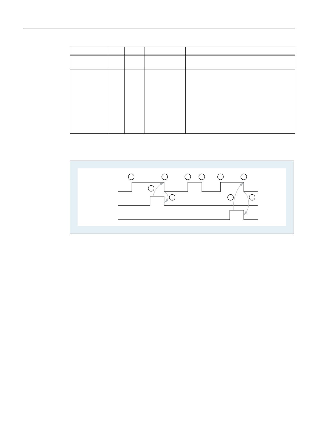
PLC programming
6.3 Signal description of the PLC interface and transfer blocks
Signal
Type
Type
Range of values
Meaning
Ready:
O
BOOL
0 (FALSE),
1: Transfer completed
1 (TRUE)
Error:
O
INT
0 ... 65535
Error checkback
0: No error has occurred
1: Unknown "TaskIdent"
2: Unknown "TaskIdentNo"
3: Impermissible job, ("Interface active" signal for
selected turret == 0)
Other value: The number corresponds to the error
message of the tool management function in the
NC caused by this transfer.
Pulse diagram
6WDUW
5HDG\
(UURU
!
① Activation of function by means of a positive edge
② Positive acknowledgement: Tool management has been transferred
③ Reset function activation after receipt of acknowledgement
④ Signal change using FC
⑤ This signal chart is not permissible. The job must generally be terminated since the new tool
positions must be conveyed to the tool management in the NC.
⑥ Negative acknowledgement: Error occurred, error code in the output parameter Error
Tool management
160
Function Manual, 10/2020, 6FC5397-1HP40-0BA1

PLC programming
6.3 Signal description of the PLC interface and transfer blocks
Status
Table 6-1
Status bits
Sta-
Description
tus
1
The tool management job has been completed.
The parameters "NewToolMag", "NewToolLoc", "OldToolMag", "OldToolLoc" of the FC8 block
should be parameterized to the actual positions of the tools involved. Except in the case of
preparing the change, they are normally the specified target positions of the tools of the asso-
ciated tool management interface, see also "Explanations of the formal parameters".
1. In the case of loading/unloading/reloading, the tool has arrived at the required target
address. If the bit in the interface in DB 71.DBX (n+0).3 "position at loading point" is enabled,
status 1 cannot be used for the function termination. Status 5 must be used for correct
termination.
2. In the case of "Prepare change", the new tool is now available. The tool may, for example,
be positioned in a buffer (gripper). In some cases, the target (magazine, location) of the old
tool has been moved to the tool change position after placement of the new tool in a buffer.
However, the old tool still remains in the spindle. The preparations for a tool change are thus
complete. After this acknowledgement, the "Change" command can be received. The posi-
tions in parameters "NewToolMag", "NewToolLoc", "OldToolMag" and "OldToolLoc" corre-
spond to the current tool positions.
3. In the case of "Change" (spindle or turret), the tools addressed in the interface have now
reached the required target addresses.
The tool change operation is thus completed.
2
The "new" tool cannot be made available
This status is only admissible in conjunction with the "Change tool" command. When this status
is applied, the PLC must be prevented from making a change with the proposed tool. The pro-
posed (new) tool is disabled by the tool management function in the NC. A new command is then
output by the tool management with a duplo tool. The positions in parameters "NewToolMag",
"NewToolLoc", "OldToolMag", and "OldToolLoc" correspond to the original tool positions.
The status is provided as first synchronous acknowledgment. This means that receipt status 2
must be implemented immediately after the tool preparation.
A previous intermediate acknowledgement, e.g. with Status_105, is not permissible.
3
An error has occurred
The tool positions must not have been changed. Any changes to the magazine positions of the
tool that have taken place in the meantime must be notified beforehand, for example, with
status = 105 via FC8 transfer block. Only then will the tool positions be taken into account by the
tool management function.
4
It would be better to position the "old" tool in the magazine position specified in parame-
ters "OldToolMag" and "OldToolLoc"
This status is permissible only in conjunction with preparation for tool change (change into
spindle). The magazine location specified for the "old" tool must be free. Once this status has
been passed to the tool management in the NC, a new preparation command is generated
(Status_4 = final acknowledgment) and output to the DB72, for which the requested magazine
position of the old tool is considered.
No new tool search is performed explicitly, the positions for "NewToolMag" and "NewToolLoc"
are taken from the original preparation command. But this is done only when this position is free.
Parameters "NewToolMag" and "NewToolLoc" are not taken into account.
Tool management
Function Manual, 10/2020, 6FC5397-1HP40-0BA1
161

PLC programming
6.3 Signal description of the PLC interface and transfer blocks
Sta-
Description
tus
5
The operation is complete
The "new" tool is in the position specified in parameters "NewToolMag", "NewToolLoc". In this
case, the specified tool is not really in this position, but is still in the same magazine location.
However, this magazine location has been moved to the position set in the parameters (e.g. tool
change position). This status may be used only for turrets, chain-type magazines and disk mag-
azines. The status enables the tool management function to adjust the current position of a
magazine and to improve the search strategy for subsequent commands. This status is permis-
sible only in conjunction with loading, unloading, and reloading operations and with prepara-
tions for a tool change. The "OldToolMag" and "OldToolLoc" parameters must be parameterized
with the data of a buffer.
• Loading, reloading:
On loading or reloading, a location for the tool is already reserved in the NC. The machine
operator must then insert the tool at the target location. Notice: The location reservation is
canceled when the control system is switched on again.
• Tool-change preparation:
Tool motions still to be executed are not carried out until after the tool has been changed.
• Positioning to the loading point:
If the bit in the interface in DB 71.DBX (n+0).3 "position at loading point" is enabled, only
status 5 be used for the function termination (not status 1).
6
The tool management job has been completed
This status has the same function as status 1, but, in addition, a reservation of the source
location is carried out. This status is only permitted when reloading. The command is ended and
the source location of the tool is reserved if the target location is in a buffer magazine.
7
Initiate repetition of the command "Prepare Tool"
This status is only admissible in conjunction with the "Change tool" command. This status is
intended for use when the "new" tool has changed its position (e.g. via an asynchronous com-
mand of the "new" tool). After "Ready = 1" has been provided by FC8, the "Prepare Change"
command is repeated automatically with the same tool. For the automatic repetition, a new tool
search is carried out. The positions in parameters "NewToolMag", "NewToolLoc", "OldToolMag",
and "OldToolLoc" correspond to the original tool positions.
The status is provided as first synchronous acknowledgment. This means that receipt status 7
must be implemented immediately after the tool preparation.
A previous intermediate acknowledgement, e.g. with Status_105, is not permissible.
103
The "new" tool can be inserted
This status is permitted only in the tool change preparation, when the PLC may reject the new
tool (e.g. in case of MD20310 $MC_TOOL_MANAGEMENT_MASK, bit 4 = 1 for the possibility,
request changed parameter from PLC once again). The tool positions have remained unchanged.
This status is therefore necessary, when the processing is to be continued in the NC without an
unnecessary stop.
Tool management
162
Function Manual, 10/2020, 6FC5397-1HP40-0BA1

PLC programming
6.3 Signal description of the PLC interface and transfer blocks
Sta-
Description
tus
104
The "new" tool is in the position specified in parameters "NewToolMag", "NewToolLoc"
This status is only permissible if the tool is still in the magazine in the same location. The "old"
tool is in the position (buffer) specified in parameters "OldToolMag", "OldToolLoc". In this case,
however, the new tool is not really in this position, but is still in the same magazine location.
However, this magazine location has been moved to the position set in the parameters (e.g. tool
change position). This status may be used only in conjunction with turrets, chaintype magazines
and disk magazines for the "Tool change preparation" phase. The status enables the tool man-
agement to adjust the current position of a magazine and to improve the search strategy for
subsequent commands.
105
The specified buffer location has been reached by all tools involved
Standard case if the operation has not yet been completed.
The tools are in the specified tool positions (parameters "NewToolMag", "NewToolLoc", "Old-
ToolMag", "OldToolLoc").
Status definition
A general rule for the acknowledgement status is that the status information 1 to 7 leads to the
termination of the command. If FC8 receives a status information, the "Interface active bit" of
the interface specified in FC8 is reset to "0" (see also interface lists DB 71 to DB 73), thus
completing the operation. The behavior is different in the case of status information 103 to 105.
When the FC8 receives a status information, the "Interface active bit" of this interface remains
at "1". Further processing is required by the user program in the PLC (e.g. continuation of
magazine positioning). This status information is generally used to transfer changes in position
of one or both tools while the operation is still in progress.
Call example
CALL FC8(
//Tool management transfer block
Start :=
m 20.5,
// Start := "1 " => initiate the transfer
TaskIdent :=
DB61.DBB0,
TaskIdentNo :=
DB61.DBB1,
NewToolMag :=
DB61.DBW2,
// Current position of new tool
NewToolLoc :=
DB61.DBW4,
OldToolMag :=
DB61.DBW6,
// Current position of old tool
OldToolLoc :=
DB61.DBW8,
Status :=
DB61.DBW10,
// Status
Ready :=
m 20.6,
Error :=
DB61.DBW12);
u m 20.6;
// Poll ready
r m 20.5;
// Reset start
spb m001;
// Jump if everything OK
l DB61.dbw12;
// Error information
ow w#16#0;
// Evaluate error
JC error;
// Jump to troubleshooting
m001:
// Normal branch
Tool management
Function Manual, 10/2020, 6FC5397-1HP40-0BA1
163
PLC programming
6.3 Signal description of the PLC interface and transfer blocks
error:
//Troubleshooting
r m 20.5:
// Reset start
Tool management
164
Function Manual, 10/2020, 6FC5397-1HP40-0BA1
NC programming
7
7.1
Overview of OPI and system variables
Fundamentals
All the data required for the purpose of tool management (e.g. to define a magazine or load a
tool...) is stored in the NC. This data can be read and written via part programs with system
variables and via the PLC with FB2 and FB3. When configuring the machine, the user (machine
manufacturer) must determine the most efficient method of reading and writing tool
management data, i.e. in the PLC, the NC or in an ASUP.
Read and write access can generally be made to system variables.
When language commands are used, it may be necessary to program the "STOPRE" command.
The $TC variables do not generate a preprocessing stop.
Tool identifiers can consist of the following characters:
a...z
A...Z
0...9
+ - _ . ,
The names are case-sensitive, i.e. uppercase and lowercase characters are considered different
characters.
Note
Additional information on OPI variables can be found in the Help file for the NC-VAR selector.
Execution of the commands
The initial writing of data for tools or magazines causes the creation of the corresponding
objects with their default data. Examples include:
• $TC_TP1 creates a tool.
• $TC_MAP1[x] creates a magazine.
Tool management
Function Manual, 10/2020, 6FC5397-1HP40-0BA1
165
NC programming
7.1 Overview of OPI and system variables
Note
Not enabled/active functions
If data of unreleased functions are written, NO alarm is output and the write command is not
executed.
The attempt to read data from inactive functions causes an alarm to be output.
Overview
The following diagram shows an overview of all cutting edge, tool and magazine data ($TC_...)
when tool management is active.
Note:
The sequence of system variables shown corresponds to the OPI numbering sequence.
&877,1* ('*( '$7$
(&3
/RFDWLRQ GHSHQGHQW RIIVHWV FRDUVH
6&3
/RFDWLRQ GHSHQGHQW RIIVHWV ILQH
023&
8VHU FXWWLQJ HGJH PRQLWRULQJ
023
&XWWLQJ HGJH PRQLWRULQJ
'3&
8VHU FXWWLQJ HGJH GDWD
'3
&XWWLQJ HGJH GDWD
722/ '$7$
73&
7RRO UHODWHG XVHU GDWD
73*
7RRO UHODWHG JULQGLQJ GDWD
73
7RRO UHODWHG GDWD
0/65
0DJD]LQH ORFDWLRQ DVVLJQPHQW WR VSLQGOHV
0$*$=,1( '$7$
0$03
0DJD]LQH EORFN GDWD
0'3
'LVWDQFH WR FKDQJH SRVLWLRQ
037+
0DJD]LQH ORFDWLRQ W\SH KLHUDUFK\
033&
8VHU PDJD]LQH ORFDWLRQ GDWD
033
0DJD]LQH ORFDWLRQ GDWD
0$3&
8VHU PDJD]LQH GHVFULSWLRQ GDWD
0$3
0DJD]LQH GHVFULSWLRQ GDWD
Figure 7-1
Overview of cutting edge, tool and magazine data
Tool management
166
Function Manual, 10/2020, 6FC5397-1HP40-0BA1
NC programming
7.1 Overview of OPI and system variables
The identifiers (DP,...TP,...MOP,...) are taken from the NC language. They are part of the names
of the system variables $TC_DP,...
Note
The gray data fields are only available if tool management is active.
Dark gray data fields are also available without tool management, but with monitoring function.
White data fields are available when the TOOLMAN function is not active.
$'$37(5 '$7$
$'37
Figure 7-2
Adapter data
722/ +2/'(5 '$7$
&$55
2IIVHW FRPSRQHQWV RI WRRO KROGHUV
Figure 7-3
Tool holder data
Tool management
Function Manual, 10/2020, 6FC5397-1HP40-0BA1
167

NC programming
7.2 Use of the magazine data
7.2
Use of the magazine data
Sequence for defining data
The "Assign tool to a magazine location" sequence creates an interdependency between the tool
data and the magazine/magazine location data.
Example:
The tool contains the magazine location type for which it is intended. The magazine type
contains its own magazine location type. If the tool is assigned to the magazine location, as a
rule the location type cannot be changed again as this can cause inconsistencies.
The resulting requirement is for tools and magazines to be loaded by a special routine into the
PLC and that the structure-determining definitions may no longer be changed during the
preparation (these are e.g. magazine dimension, magazine location type, duplo no., tool
name, ...). They do not include: Cutting edge data, magazine location status, tool status, ...
Use of the magazine data
Action
Program command
Description
Creating a new magazine
$TC_MAPx[y] = value;
Value <>0, y = magazine no. of a magazine not yet set up
Delete a magazine
$TC_MAP1[y] = 0;
The data of the magazine and its magazine locations as
well as any defined distances to change positions are de-
leted. The associated memory is released.
Delete a magazines and the
$TC_MAP6[y] = 0;
The data of the magazine and its magazine locations as
tools contained in it
well as any defined distances to change positions are de-
leted. Any tools contained in the magazine are also de-
leted.
The associated memory is released
Delete all magazines
$TC_MAP1[0] = 0;
All of the data of all magazines of the selected TO area unit
is deleted and the associated memory is released again.
The magazine data block is then empty.
Create new magazine location
$TC_MPPx[y,z] = value;
Value <>0, y = location number not yet available.
Before the data of the first location can be created, the
associated magazine must be defined.
When the first parameter of the first magazine location to
be set up is written, then all magazine locations belonging
to the magazine are set up using their default values in
accordance with the requirements for number of lines and
columns for the magazine.
Set magazine location type hier-
$TC_MPTHx[y] = value;
archy
Set magazine distances (dis-
$TC_MPTHx[y] = value;
tance to change position)
Delete magazine distances (dis-
$TC_MDPx[y,0] = 0
Delete all defined distances of the magazine with the
tance to change position)
number "y", I.e. the magazine is no longer "seen" during a
tool search and an empty location search.
$TC_MDPx[0,0] = 0;
Delete all defined distances of all magazines of the TO unit.
Tool management
168
Function Manual, 10/2020, 6FC5397-1HP40-0BA1

NC programming
7.2 Use of the magazine data
Action
Program command
Description
Delete the assignments of the
$TC_MLSR[x,0] = 0;
Delete all defined assignments of a buffer location with
buffer to the spindles
the number "x", I.e. the magazine is no longer "seen" dur-
ing the tool search.
$TC_MLSR[0,0] = 0;
Delete all defined assignments of buffer locations of the
TO unit to spindles
Set magazine block data
$TC_MAMPx = value;
Loading data
Because tools are linked to magazines via magazine location parameter $TC_MPP6, the
following rules for correct definition of tools and magazines must be adhered to:
1. Load tool data
2. Load magazine data
3. Load $TC_MPP6 parameters (⇒ places tool in magazine location)
The same sequence is used for data backup.
The grinding data of a tool cannot be written until tool type = "grinding tool" has been defined
for at least one cutting edge.
The distance parameter ($TC_MDPx) and the buffer assignment parameter ($TC_MLSR) cannot
be written until the magazines and their locations have been defined.
Delete data
A tool cannot be deleted while it is still contained in a magazine. The following sequence of
operations must be followed when deleting:
1. Delete the magazine data (this removes tools from the magazine); or remove the tool
explicitly from the magazine.
2. Delete tool data
In addition, a magazine cannot be deleted if it has the state $TC_MAP3[i]= 8 (motion is active).
The delete command is rejected for all magazines even if only one magazine is preventing the
command from being executed.
Note
If a single tool is to be deleted it must first be removed from the magazine location with an
unload operation and then it can be deleted.
Tools that are currently selected cannot be deleted! You can ensure that no tool is selected
beyond a part program by programming T0 before the end of a part program independently of
the settings in the machine data (see MD for selecting tools beyond the end of a program).
Tool management
Function Manual, 10/2020, 6FC5397-1HP40-0BA1
169

NC programming
7.3 Use of the tool and cutting edge data
7.3
Use of the tool and cutting edge data
Overview
If a parameter for a cutting edge, tool or magazine that does not exist is written, a new cutting
edge, tool or magazine is created.
Note
When a tool is created, all the cutting-edge-specific data of cutting edge D1 are created with it.
(DP, DPC, MOP, MOPC are preset to "0".) The grinding-specific tool data ($TC_TG1...) is not
created until one of the tool types ($TC_DP1) 400-499 has been programmed for one of the
cutting edges of the tool.
Use of the tool and cutting edge data with tool management
Magazine management and monitoring are active (TMMG and TMMO)
Action
Program command
Description
Create a tool
T_NO = NEWT("tool identifier",
duplo number)
or
$TC_TP1[y] = duplo number;
$TC_TP2[y] = "tool identifier"
y = tool number
Create a cutting
$TC_DPx[y,z] = value
Create cutting edge D = z if D = z does not yet exist!
edge
y = tool number
z = cutting edge number
Set tool data
$TC_TPx[y] = value;
or
y = tool number
$TC_TPx[GETT("DRILL",DUPLO NO)]
Write tool-related user data
= value;
or
Write tool-related grinding data
$TC_TPCx[y] = value;
$TC_TGx[y] = value;
Set data of a cutting
$TC_DPx[y,z] = value
Write offset data
edge
$TC_DPCx[y,z] = value
Write cutting edge-related user data
$TC_MOPx[y,z] = value
Write cutting edge-related monitoring data
$TC_MOPCx[y,z] = value
Write CC (OEM) cutting edge monitoring data
y = tool number
z = cutting edge number
Tool management
170
Function Manual, 10/2020, 6FC5397-1HP40-0BA1

NC programming
7.3 Use of the tool and cutting edge data
Action
Program command
Description
Deletion of the tool
$TC_TP1[0,0];
When deleting tools, the entries for the location data
and cutting edge da-
must also be corrected.
ta
Deletion of a tool
$TC_TP1[y] = 0;
or
All tool-related data is set to "0" (user data, hierarchy
data, ...). When deleting a tool, the entries for the loca-
$TC_TP1[GETT("tool identifier",
tion data must also be corrected.
duplo number)] = 0;
or
DELT["tool identifier", duplo
number]
Use of the tool and cutting edge data without tool management
Action
Program command
Description
Create a tool
$TC_DPx[y,z] = value;
Create tool T if T does not yet exist!
y = tool number
$TC_TP2[y] = "Number"
z = cutting edge number
Create a cutting
$TC_DPx[y,z] = value
Create cutting edge D = z if D = z does not yet exist!
edge
y = tool number
z = cutting edge number
Set data of a cutting
$TC_DPx[y,z] = value
Write offset data
edge
$TC_DPCx[y,z] = value
Write cutting edge-related user data
$TC_MOPx[y,z] = value
Write cutting edge-related monitoring data
$TC_MOPCx[y,z] = value
Write CC (OEM) cutting edge monitoring data
y = tool number
z = cutting edge number
Deletion of the tool
$TC_DP1[0,0] = 0;
All tools of the channel are deleted, the memory is re-
and cutting edge da-
leased.
ta
Deleting data
When deleting, the memory area is deleted and automatically released again.
A tool can only be deleted if it is not active (offset-determining) and is not in a magazine, i.e. it
must have been removed or unloaded.
Note
If tool management is active you must ensure that the tool being deleted is not assigned to a
magazine location ($TC_MPP6). This assignment must be removed before the tool is deleted.
The grinding-specific tool data ($TC_TG1...) is created as soon as one of the tool types ($TC_DP1)
400-499 has been programmed for any of the cutting edges of the tool.
If the tool type is set from the current value taken from the range 400-499 to a value outside this
range, the grinding data memory released again, i.e. the grinding-specific data is lost.
Tool management
Function Manual, 10/2020, 6FC5397-1HP40-0BA1
171
NC programming
7.4 Cutting edge data
7.4
Cutting edge data
7.4.1
Cutting edge data
Cutting edge data
023&
8VHU FXWWLQJ HGJH PRQLWRULQJ
023
&XWWLQJ HGJH PRQLWRULQJ
'3&
'3
8VHU FXWWLQJ HGJH GDWD
&XWWLQJ HGJH GDWD
Figure 7-4
Overview of cutting edge data
This data exists for each cutting edge that is created (D1-D12). Tool management includes the
geometry and user data as well as the optional monitoring data for the cutting edges.
If the cutting edges are created via HMI, the D number is counted up from 1. It is possible to
program the D no. with gaps, e.g. D1, D3, D6 if cutting edges are set up using an NC program.
7.4.2
Cutting edge parameter $TC_DP
$TC_DPx[t,D]
Cutting edge parameters for geometry, technology and tool type.
Parameters:
• x: Parameters 1...25
The maximum value for x is displayed in the OPI variable "numCuttEdgeParams" in block Y.
• t: T number 1...32000
• D: Cutting edge number 1...12 or D number
Depending on the tool type, up to 25 cutting edge parameters can be programmed for each tool
cutting edge.
Further information: Function Manual Tools, tool offset
OPI block TO
Address calculations:
• Line = (D - 1) * "numCuttEdgeParams" + parameter number
• Column = T number
Tool management
172
Function Manual, 10/2020, 6FC5397-1HP40-0BA1

NC programming
7.4 Cutting edge data
Tool offset parameters (system variables)
NC identifier
Type
Designation
OPI varia-
Type
De-
bles
fault2)
$TC_DP1
INT
Tool type
edgeData
REAL
9999
$TC_DP2
Double
Cutting edge position*
edgeData
REAL
0
$TC_DP3
Double
Geometry length 1
edgeData
REAL
0
$TC_DP4
Double
Geometry length 2
edgeData
REAL
0
$TC_DP5
Double
Geometry length 3
edgeData
REAL
0
$TC_DP6
Double
Radius geometry
edgeData
REAL
0
$TC_DP7
Double
Geometry - corner radius
edgeData
REAL
0
(tool type 700; slotting saw)
$TC_DP81)
Double
Geometry length 4
edgeData
REAL
0
(tool type 700; slotting saw)
$TC_DP91)
Double
Geometry length 5
edgeData
REAL
0
$TC_DP101)
Double
Geometry - angle 1
edgeData
REAL
0
$TC_DP111)
Double
Geometry - angle 2 for tapered mill-
edgeData
REAL
0
ing tools
$TC_DP12
Double
Wear - length 1
edgeData
REAL
0
$TC_DP13
Double
Wear - length 2
edgeData
REAL
0
$TC_DP14
Double
Wear - length 3
edgeData
REAL
0
$TC_DP15
Double
Wear - radius
edgeData
REAL
0
$TC_DP16
Double
Wear - slot width b/rounding radius
edgeData
REAL
0
$TC_DP17
Double
Wear - projection k
edgeData
REAL
0
$TC_DP18
Double
Wear - length 5
edgeData
REAL
0
$TC_DP19
Double
Wear - angle 1
edgeData
REAL
0
$TC_DP20
Double
Wear - angle 2 for conical milling
edgeData
REAL
0
tools
$TC_DP21
Double
Adapter length 1
edgeData
REAL
0
$TC_DP22
Double
Adapter length 2
edgeData
REAL
0
$TC_DP23
Double
Adapter length 3
edgeData
REAL
0
$TC_DP24
Double
Clearance angle
edgeData
REAL
0
$TC_DP25
Double
ManualTurn: Cutting speed
edgeData
REAL
0
ShopMill: Status value of tool of type
1xx and 2xx.
$TC_DPCE [t,d]
INT
System variable of an offset data re-
-
-
0
cord with T=t and D=d containing
cutting edge number CE. (Unique D
no. or user assignment of D no. for
cutting edge numbers)
Value range for permissible cutting
edge numbers: 1, 2, 3 ... MD18106.
$TC_DPH [t,d]
INT
H parameter (Y / extraCuttEdgePar-
-
-
0
ams), Bit0=1
$TC_DPV
Double
Tool cutting edge orientation
-
-
-
Tool management
Function Manual, 10/2020, 6FC5397-1HP40-0BA1
173

NC programming
7.4 Cutting edge data
Tool offset parameters (system variables)
NC identifier
Type
Designation
OPI varia-
Type
De-
bles
fault2)
$TC_DPV3
L1 component of the tool cutting
-
-
-
edge orientation
$TC_DPV4
L2 component of the tool cutting
-
-
-
edge orientation
$TC_DPV5
L3 component of the tool cutting
-
-
-
edge orientation
$TC_DPNT
INT
Number of teeth, cutting edge pa-
-
-
-
rameter 34
$TC_DPROT
Double
Tool clamping angle for turning tools
-
-
-
$TC_DPVNx
Double
Component of the orientation nor-
-
-
-
mals
1) The meaning of this data is different depending on the tool type.
$TC_DP11
$TC_DP11 contains the identification for the main direction of machining as is defined and
required by the Siemens Cycle950. $TC_DP11 assumes an intermediate position between tool
OEM parameter and NC system variable:
• $TC_DP11 is a tool OEM parameter in so far as NC does not evaluate the contents of the value.
• $TC_DP11 is an NC system variable in so far as when accessing via $P_ADT[ n ], with n=11,
NC is subject to the special values 1, 2, 3, 4 of the tool adapter transformation if TMMG and
the subfunction "Tool adapter" are active. This system parameter property is also used with
the analog OPI block TOT.
7.4.3
User cutting edge data $TC_DPC
$TC_DPCx[t,D]
Up to 64 additional cutting edge parameters can be programmed for each cutting edge. Setting
with MD18096 MM_NUM_CC_TOA_PARAM and enable with MD18080
MM_TOOL_MANAGEMENT_MASK (set bit 2=1)
X = Parameter 1...64
T = T number 1...32000
D = Cutting edge number 1...12
D = D number
OPI block TUE/TUO
Calculation of line:(d-1)*numCuttEdgeParams_tu+parameter no.
Tool management
174
Function Manual, 10/2020, 6FC5397-1HP40-0BA1
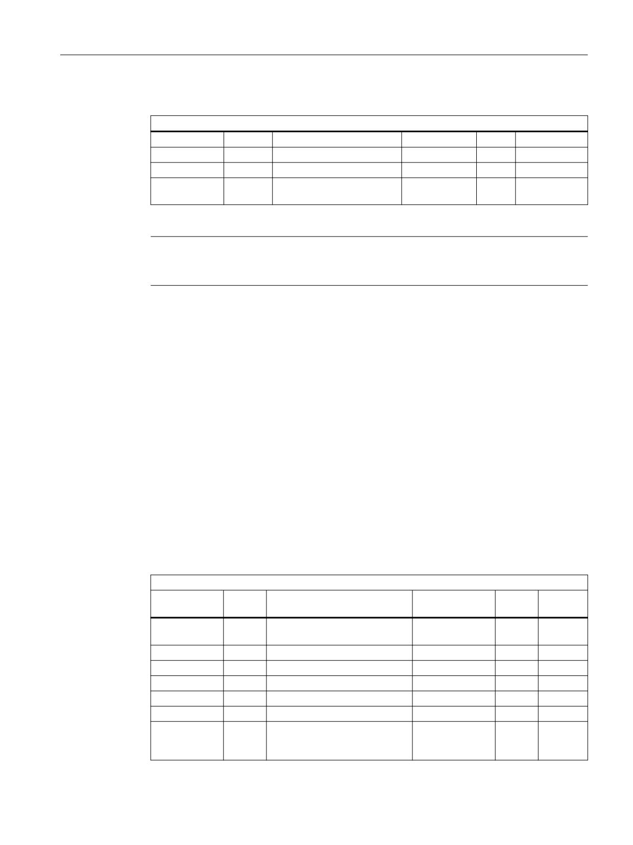
NC programming
7.4 Cutting edge data
Calculation of column: T number
User-related cutting edge data
NC identifier
Type
Designation
OPI variables
Type
Default setting
$TC_DPC1
Double
CC_Cutting edge parameter 1
edgeData
REAL
0
Double
edgeData
REAL
0
$TC_DPC64
Double
CC_Cutting edge parameter
edgeData
REAL
0
64
Note
The data is displayed in the tool management. Here you could store "Max. cutting rate",
for example, which is then evaluated in the part program.
7.4.4
Cutting edge-related tool monitoring $TC_MOP
$TC_MOPx[t,D]
Tool cutting edges are monitored according to tool life, workpiece count and/or wear.
X = Parameter 1...15
T = T_Number 1...32000
D = Cutting edge number 1...12
D = D number
OPI block TS
Calculation of line: (d-1)*numCuttEdgeParams_ts+parameter no.
Calculation of column: T number
Tool management monitoring data
NC identifier
Type
Designation
OPI variables
Type
Default
setting
$TC_MOP1
Double
Prewarning limit for tool life in
data
REAL
0
min.
$TC_MOP2
Double
Residual tool life in minutes
data
REAL
0
$TC_MOP3
INT
Prewarning limit for count
data
REAL
0
$TC_MOP4
INT
Residual unit quantity
data
REAL
0
$TC_MOP11
Double
Setpoint for tool life
data
REAL
0
$TC_MOP13
INT
Setpoint for workpiece count
data
REAL
0
$TC_MOP5
Double
Wear prewarning limit - or loca-
data
REAL
0
tion-dependent offset fine pre-
warning limit
Tool management
Function Manual, 10/2020, 6FC5397-1HP40-0BA1
175

NC programming
7.4 Cutting edge data
Tool management monitoring data
NC identifier
Type
Designation
OPI variables
Type
Default
setting
$TC_MOP6
Double
Actual wear or location-depend-
data
REAL
0
ent offset, fine actual value
$TC_MOP15
Double
Wear setpoint - or location-de-
data
REAL
0
pendent offset, fine setpoint
7.4.5
User cutting edge monitoring $TC_MOPC
$TC_MOPCx[t,D]
Tool monitoring user data (edge-specific)
Up to 64 additional tool monitoring parameters can be programmed for each cutting edge. (V4.7
and higher). Setting with MD18098 MM_NUM_CC_MON_PARAM and enable with MD18080
MM_TOOL_MANAGEMENT_MASK (set bit 2)
X = Parameter 1
64
T = T_Number 1
32000
D = Cutting edge number 1
12
D = D number
OPI block TUS
Calculation of line: (d-1)*numCuttEdgeParams_tus+parameter no.
Calculation of column: T number
Tool monitoring user data (edge-specific)
NC identifier
Type
Designation
OPI variables
Type
Default
setting
$TC_MOPC1
Int
CC monitoring parameters
userdata
REAL
0
Int
userdata
REAL
0
$TC_MOPC64
Int
CC monitoring parameters
userdata
REAL
0
7.4.6
Location of use-dependent offsets fine (additive offsets) $TC_SCP
$TC_SCPx[t,D]
Location-dependent offsets fine (the term "additive offsets" is also frequently used) comprise all
the magnitudes of error which contribute to the total deviation between the actual workpiece
and the specified dimensions. The parameters for the location-dependent offsets refer to the
geometrical data of a cutting edge. DL: Location-dependent; offsets regarding the location of
use.
Tool management
176
Function Manual, 10/2020, 6FC5397-1HP40-0BA1

NC programming
7.4 Cutting edge data
X = Parameter for DL=1...DL=6
T = T number 1...32000
D = Cutting edge number 1...12
D = D number
OPI block TOS, TOST
Calculation of line: (d-1)*(maxnumEdgeSC*numParams_SC) + ((EdgeSC_1)*numParams_SC)
+Parameter no.
Calculation of column: T number
Location-dependent offsets
Name
Type
Designation
OPI variables
Type
$TC_SCPx
x = 13-21
Double
Can be activated with DL=1
edgeSCData
REAL
x = 23-31
Double
Can be activated with DL=2
edgeSCData
REAL
x = 33-41
Double
Can be activated with DL=3
edgeSCData
REAL
x = 43-51
Double
Can be activated with DL=4
edgeSCData
REAL
x = 53-61
Double
Can be activated with DL=5
edgeSCData
REAL
x = 63-71
Double
Can be activated with DL=6
edgeSCData
REAL
Transformed location-dependent
edgeSCData
REAL
offsets fine, block TOST
7.4.7
Location-dependent offsets coarse (setting-up offsets) $TC_ECP
$TC_ECPx[t,D]
The location-dependent offsets, coarse (also setting-up offsets) can be set by the machine setter
before the machining operation (see also $TC_SCP (Page 176)).
X = Parameter for DL=1...DL=6
T = T number 1...32000
D = Cutting edge number 1...12
D = D number
OPI block TOE, TOET
Calculation of line: (d-1)*(maxnumEdge_SC*numParams_SC)+((EdgeSC-1)*numParams_SC)
+Parameter no.
Tool management
Function Manual, 10/2020, 6FC5397-1HP40-0BA1
177

NC programming
7.4 Cutting edge data
Calculation of column: T number
Setting-up offsets
Name
Type
Designation
OPI variables
Type
$TC_ECPx
edgeECData
REAL
x = 13-21
Double
Can be activated with DL=1
edgeECData
REAL
x = 23-31
Double
Can be activated with DL=2
edgeECData
REAL
x = 33-41
Double
Can be activated with DL=3
edgeECData
REAL
x = 43-51
Double
Can be activated with DL=4
edgeECData
REAL
x = 53-61
Double
Can be activated with DL=5
edgeECData
REAL
x = 63-71
Double
Can be activated with DL=6
edgeECData
REAL
Transformed setting-up offsets,
edgeECData
REAL
block TOET
Tool management
178
Function Manual, 10/2020, 6FC5397-1HP40-0BA1
NC programming
7.5 Tool data
7.5
Tool data
7.5.1
Overview
73&
7RRO UHODWHG XVHU GDWD
73*
7RRO UHODWHG JULQGLQJ GDWD
73
7RRO UHODWHG GDWD
Figure 7-5
Overview of tool data
7.5.2
Tool-related data $TC_TP
$TC_TPx[t]
General tool data
This data describes the tool in the magazine.
Programming of general tool data with tool management
x: = Parameter 1...11
t: = T number 1...32000
OPI block TD
Calculation of line: T number
Calculation of column: n.a.
Tool-related data, tool management
NC identifier
Type
Designation
OPI variables
Type
Default
setting
$TC_TP2
String
Tool identifier
toolldent
String
"T No."
$TC_TP1
INT
Duplo number
duploNo
WORD
T No.
$TC_TP3
INT
Size on left
toolsize_left
WORD
1
$TC_TP4
INT
Size on right
toolsize_right
WORD
1
$TC_TP5
INT
Size above
toolsize_upper
WORD
1
$TC_TP6
INT
Size below
toolsize_down
WORD
1
$TC_TP7
INT
Magazine location type
toolplace_spec
WORD
9999
Tool management
Function Manual, 10/2020, 6FC5397-1HP40-0BA1
179

NC programming
7.5 Tool data
Tool-related data, tool management
NC identifier
Type
Designation
OPI variables
Type
Default
setting
$TC_TP8
INT
Status
toolState
WORD
0=not
enabled
Value 0 not enabled
Bit 0 active tool
Bit 1 enabled
Bit 2 disabled
Bit 3 measure
Bit 4 prewarning limit reached
Bit 5 tool being changed
Bit 6 fixed-location coded
Bit 7 tool was in use
Bit 8 identifier for tools in buffer
Bit 9=1 ignore disabled state
Bit 9=0 do not ignore
Bit 10 to be unloaded
Bit 11 to be loaded
Bit 12 reserved
Bit 13 reserved
Bit 14 1:1 exchange
Bit 15, manual tool
Bit 17 tool is at a disabled magazine loca-
tion
$TC_TP9
INT
Tool monitoring method
toolMon
WORD
0
Value 0 no tool monitoring
Bit 0 tool life
Bit 1 workpiece count
Bit 2 wear monitoring active
Bit 3 wear monitoring, location-dependent
offset fine active
$TC_TP10
INT
Number for a replacement tool.
toolSearch
WORD
0
$TC_TP11
INT
Tool information:
toolInfo
Integer
0
Allows tool groups to be divided into sub-
groups. Tool selection, only with tools of
the lower group
$A_TOOLMN
INT
Magazine assignment tool
toolInMag
WORD
$A_TOOLMLN
INT
Location assignment tool
toolInPlace
WORD
$P_TOOLND
INT
Number of cutting edges
numCuttEdges
WORD
-
Adapter No. Assignment
adaptNo
WORD
$A_MYMN
INT
Owner magazine for tool
toolMyMag
WORD
$A_MYMLN
INT
Owner magazine location for tool
toolMyPlace
WORD
$TC_TP_PROTA
string
Name of the three-dimensional protection
area for the tool or name of the file that
contains the description of the protection
area for the tool.
Tool management
180
Function Manual, 10/2020, 6FC5397-1HP40-0BA1

NC programming
7.5 Tool data
Tool-related data, tool management
NC identifier
Type
Designation
OPI variables
Type
Default
setting
$TC_TP_MAX_VELO
real
Maximum speed of the tool, if the value is
toolMaxVelo
> 0. If a speed limit is not defined (=0), then
no monitoring is performed
$TC_TP_MAX_ACC
real
Maximum acceleration of the tool, if the
toolMaxAcc
value is > 0. If an acceleration speed limit
has not been defined (=0), then no moni-
toring is performed
$TC_TP1 and $TC_TP2
Like the T No. is sufficient to identify a tool, a tool is equally unique in terms of its duplo number
and its tool name (identifier).
TO units may therefore only contain names that have different duplo numbers. The write
operations of $TC_TP1 and $TC_TP2 are checked for the above and rejected if collisions are
found.
$TC_TP3 to TP6
Size in terms of half locations:
Size 1 means that the tool exactly completely occupies its own magazine location. If the size
increases in one direction by 1, half an adjacent location is reserved in this direction for the tool.
The maximum programmable size is 11. This means that no more than five whole adjacent
locations can be reserved by the tool in one direction.
The tool size (half locations) can only be written or changed if the tool does not have an owner
location. This applies to the following situations:
• The tool has yet not been loaded
• During loading, as long as the tool is not at its target location in a real magazine
• If the tool is at a location of the buffer or loading magazine and beforehand, the owner
location as well as the reservation in the magazine was deleted (exclusively using the NC
commands DELMRES and DELMOWNER).
$TC_TP7
The magazine location type can only be written or changed if the tool does not have an owner
location. This applies to the following situations:
• The tool has yet not been loaded
• During loading, as long as the tool is not at its target location in a real magazine
• If the tool is at a location of the buffer or loading magazine and beforehand, the owner
location as well as the reservation in the magazine was deleted (exclusively using the NC
commands DELMRES and DELMOWNER).
Tool management
Function Manual, 10/2020, 6FC5397-1HP40-0BA1
181
NC programming
7.5 Tool data
$TC_TP8
The tool status is described with system variable $TC_TP8. The system variable is bit-coded. In
other words, a particular state of the tool is assigned to each bit of this data.
The status of a tool must be bit 1=1 ("enabled") so that it can be loaded within the scope of a
programmed tool change for machining in the toolholder.
During tool selection, the status of a tool that is loaded onto the toolholder (spindle, ...) is set by
the NC to bit 0 ("active").
A tool cannot be loaded if its status is bit 2=1 ("disabled"). The status is set automatically by the
tool monitoring function, when the monitoring value of at least one cutting edge reaches the
limit value. The status bit 2=4 of the tool on the toolholder can or will be ignored when
generating the INIT blocks (see MD 20110 and 20112). The PLC also has the option to make NC
ignore the status during tool selection.
The status bit 4=1 ("prewarning") is mainly for information purposes. With this status the tool
can still be loaded.
The status bit 7=1 ("was in use") is set by the NC if the tool is removed from a magazine location
of the type spindle or toolholder.
The tool status bit 5=1 (="W"= is being change) is always reset by the software during buffered
booting. A tool receives/loses this status within the scope of a programmed tool change.
The following applies: All tools (new and old) involved in the tool change are given the status bit
5=1 by the tool selection. The status is reset again by the end acknowledgement for each tool
command.
The following applies in particular:
The end acknowledgement of the PLC command 2 (programming the T address with
$MC_TOOL_CHANGE_MODE=1), resets the status "W" of the old tool.
With the end acknowledgement of the PLC command 3, 4, 5
(programming M06 in a block with $MC_TOOL_CHANGE_MODE=1, T, M06 in a block with
$MC_TOOL_CHANGE_MODE=1
T address with $MC_TOOL_CHANGE_MODE=0)
the status bit 5=1 of the old and the new tool is reset.
Tools that are in the buffer can also be used for a new programmed tool command if they have
the status bit 5=1 (alternating).
Tools that are in the real magazine and have this status can be used depending on bit 21 of the
MD 20310 or cannot be used for a competing tool-change command for another spindle.
The status bit 5=1 is generally not taken into consideration for a tool selection within the scope
of a block search or for init block generation.
For a RESET, the status is reset for those tools that are involved in a tool change at that point in
time.
The status bit 5=1 is not evaluated when a manual tool is selected.
The tool status bit 8=1 ("return transport") ensures that during the next tool change, a tool that
is at a buffer location and not intended for the next job in machining is returned to the real
magazine.
Bit 9 ignores disabled state.
Tool management
182
Function Manual, 10/2020, 6FC5397-1HP40-0BA1

NC programming
7.5 Tool data
If this bit is set, the disabled state of this tool is ignored. This means the disabled tool can be used
(depending on the search strategy).
This state acts independently of the PLC interface signal:
"Tool disable not effective" (DB21.DBx29.7).
Status bit 11 (to be loaded)
Bit 11 is set for tools that are not in a magazine and are to be loaded. The following definitions
apply:
• The state remains for Power On.
• It is included in the data back-up and rewritten when transferred back to the NC.
• When assigning a tool to a real magazine the tool status is reset by the NC (applies to locations
of location type 1, i.e. not to internal magazines such as the loading magazine, buffer
magazine, etc).
Bit
Value
Meaning
11
0
"Not to be loaded"
1
"To be loaded"
Status bit 10 (to be unloaded)
Bit 10 is set for tools that are located in a magazine and are to be unloaded. The following
definitions apply:
• The state remains for Power On.
• It is included in the data back-up and rewritten when transferred back to the NC.
• Unloading a tool via an unloading location causes the NC to reset the tool status.
Bit
Value
Meaning
10
0
"Not to be unloaded"
1
"To be unloaded"
For $MC_TOOL_CHANGE_ERROR_MODE, Bit 9 = 1:
A tool that has the status "to be unloaded" ($TC_TP8, Bit 10 = 1) is treated like a disabled tool,
i.e. it is no longer taken into consideration during a tool search and can no longer be selected
within the scope of T programming.
Status bit 12 (reserved)
Bit 12 is reserved.
State bit 14 (tool marked for 1:1 exchange)
NC-internal state, that indicates (for a selected search strategy, 1:1 interchange), that the new
and old tool should be interchanged 1:1.
Note
Take care when "manually" changing the tool status via the OPI during machining. This could
undo internal state changes by the NC and result in incorrect machining.
Tool management
Function Manual, 10/2020, 6FC5397-1HP40-0BA1
183