SINUMERIK 840D sl. Service - Functions. Manual (2018-2020) - page 81
Punching and nibbling
12.3 Activation and deactivation
The delay time for stroke initiation can be adjusted in machine data:
MD26018 $MC_NIBBLE_PRE_START_TIME
Example:
With an IPO cycle of 5 ms, a stroke shall be released two cycles after reaching the interpolation
end:
⇒ MD26018 $MC_NIBBLE_PRE_START_TIME = 0.01 [s]
A pre-initiation time can also be programmed in setting data:
SD42402 $SC_NIBPUNCH_PRE_START_TIME
This setting takes effective only if MD26018 = 0 has been set.
Monitoring of the input signal
If the "stroke active" signal is fluctuating between strokes due to plunger overshoots, for
example, the message "undefined punching signal" can be also be output when interpolation is
stopped.
The message output is dependent on the setting in machine data:
MD26020 $MC_NIBBLE_SIGNAL_CHECK
MD26020 = 0
No alarm
MD26020 = 1
Alarm
Minimum period between two strokes
A minimum time interval between two consecutive strokes can be programmed in setting data:
SD42404 $SC_MINTIME_BETWEEN_STROKES
Example:
There must be a minimum delay of at least 1.3 seconds between two stroke initiations
irrespective of physical distance:
⇒ SD42404 $SC_MINTIME_BETWEEN_STROKES = 1.3 [s]
If a punching dwell time (PDELAYON) is also programmed, then the two times are applied
additively.
If a pre-initiation time at G603 is programmed, it will be effective only if the end of interpolation
is reached before the time set in SD42404.
The programmed time becomes operative immediately. Depending on the size of the block
buffer, strokes that have already been programmed can be executed with this minimum interval.
The following programming measures (example) can be taken to prevent this:
Program code
N...
N100 STOPRE
N110 $SC_ MINTIME_BETWEEN_STROKES = 1.3
Technologies
Function Manual, 10/2020, 6FC5397-8GP40-0BA1
253
Punching and nibbling
12.3 Activation and deactivation
The function is not active when SD42404 = 0.
Path-dependent acceleration
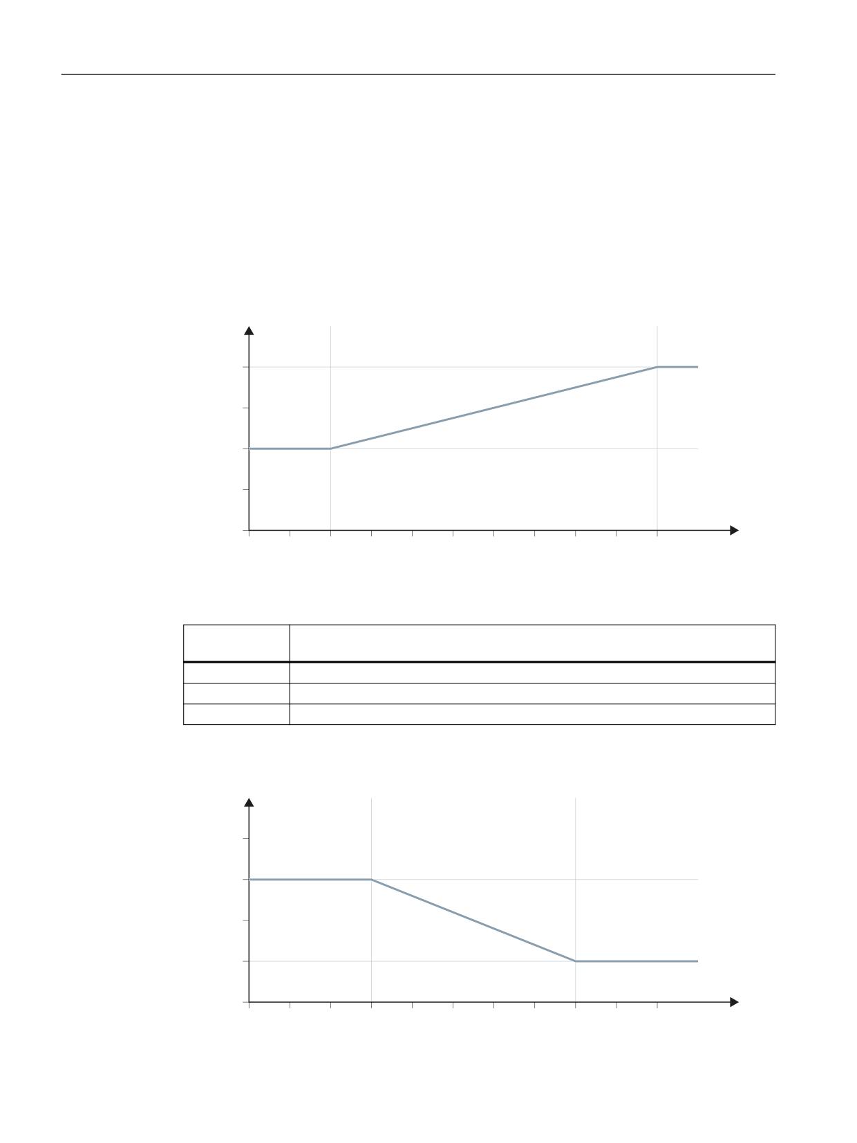
An acceleration characteristic can be defined using the PUNCHACC (Smin, Amin, Smax,
Amax) language command. This command can be used to define different acceleration rates
depending on the distance between holes.
Example 1:
$>
@
381&+$&&
6 >PP@
The characteristic defines the following acceleration rates:
Distance be-
Acceleration
tween holes
< 2 mm
The axis accelerates at a rate corresponding to 50% of maximum acceleration.
2 - 10 mm
Acceleration is increased to 100%, proportional to the spacing.
> 10 mm
The axis accelerates at the maximum rate (100%).
Example 2:
$>
@
381&+$&&
6 >PP@
Technologies
254
Function Manual, 10/2020, 6FC5397-8GP40-0BA1

Punching and nibbling
12.3 Activation and deactivation
The characteristic defines the following acceleration rates:
Distance be-
Acceleration
tween holes
< 3 mm
The axis accelerates at a rate corresponding to 75% of maximum acceleration.
3 - 8 mm
Acceleration is reduced to 25%, proportional to the spacing.
> 10 mm
The axis accelerates at a rate of 25%.
If a reduced acceleration rate has already been programmed via ACC, then the acceleration
limits defined with PUNCHACC refer to the reduced acceleration rate.
The function is deselected with:
Smin = Smax = 0
The acceleration rate programmed beforehand with ACC remains operative.
Block search
In the case of a search for a block containing a nibbling function, it is possible to program
whether the punch stroke is executed at the block beginning or suppressed.
The setting is programmed in machine data:
MD11450 $MN_SEARCH_RUN_MODE
Bit
Value
Meaning
5
0
Punch stroke at beginning of block is suppressed.
1
Punch stroke at beginning of block is executed.
Further information:
Function Manual Basic Functions; Mode Group, Channel, Program Operation, Reset Response,
Block Search
12.3.3
Compatibility with earlier systems
Use of M functions
As in earlier versions, macro technology allows special M functions to be used instead of
language commands (compatibility).
The M functions and equivalent language commands as used in earlier systems are as follows:
M20, M23
≙ SPOF
M22
≙ SON
M25
≙ PON
M26
≙ PDELAYON
Technologies
Function Manual, 10/2020, 6FC5397-8GP40-0BA1
255
Punching and nibbling
12.3 Activation and deactivation
Note
M functions can be configured in machine data.
When M functions are assigned to language commands, it must be noted that M functions are
organized in auxiliary function groups.
Examples
DEFINE M20 AS SPOF
Punching/nibbling OFF
or
DEFINE M20 AS SPOF M=20
Punching with auxiliary function output
DEFINE M20 AS SPOF PDELAYOF Punching/nibbling OFF and punching with delay OFF
DEFINE M22 AS SON
Nibbling ON
or
DEFINE M22 AS SON M=22
Nibbling ON with auxiliary function output
DEFINE M25 AS PON
Punching ON
or
DEFINE M25 AS PON M=25
Punching ON with auxiliary function output
DEFINE M26 AS PDELAYON
Punching with delay ON
or
DEFINE M26 AS PDELAYON M=26 Punching and auxiliary function output
Programming example:
Program code
Comment
:
:
N100 X100 M20
; position without punch initiation
N110 X120 M22
; Activate nibbling, before and after motion
; stroke initiation
:
N120 X150 Y150 M25
; Activate punching, initiate stroke at end
; of the motion
:
:
Technologies
256
Function Manual, 10/2020, 6FC5397-8GP40-0BA1
Punching and nibbling
12.4 Automatic path segmentation
12.4
Automatic path segmentation
12.4.1
General information
Function
One of the following two methods can be applied to automatically segment a programmed
traversing path:
• Path segmentation with maximum path segment programmed via language command SPP
• Path segmentation with a number of segments programmed via language command SPN
Both functions generate sub-blocks independently.
In earlier systems
• SPP<number> corresponds to E<number>
• SPN<number> corresponds to H<number>
Since addresses E and H now represent auxiliary functions, language commands SPP and SPN
are used to avoid conflicts. The new procedure is therefore not compatible with those
implemented in earlier systems. Both language commands (SPP and SPN) can be configured.
Note
The values programmed with SPP are either mm or inch settings depending on the initial setting
(analogous to axes).
The automatic path segmentation function ensures that the path is divided into equidistant
sections with linear and circle interpolation.
When the program is interrupted and automatic path segmentation is active (SPP/SPN), the
contour can be reentered only at the beginning of the segmented block. The first punch stroke
is executed at the end of this sub-block.
SPP and SPN can be activated only if geometry axes are configured.
SPP
The automatic path segmentation function SPP divides the programmed traversing path into
sections of equal size according to the segment specification.
The following conditions apply:
• Path segmentation is active only when SON or PON is active.
(Exception: MD26014 $MC_PUNCH_PATH_SPLITTING = 1)
• SPP is modally active, i.e. the programmed segment remains valid until it is programmed
again, but it can be suppressed on a block-by-block (non-modal) basis by means of SPN.
• The path segments are rounded off by the control system if required so that a total
programmed distance can be divided into an integral number of path sections.
• The path segment unit is either mm/stroke or inch/stroke (depending on axis settings).
Technologies
Function Manual, 10/2020, 6FC5397-8GP40-0BA1
257
Punching and nibbling
12.4 Automatic path segmentation
• If the programmed SPP value is greater than the traversing distance, then the axis is
positioned on the programmed end position without path segmentation.
• SPP = 0, reset or program end delete the programmed SPP value. The SPP value is not
deleted when punching/nibbling is deactivated.
SPN
The automatic path segmentation function SPN divides the traversing path into the
programmed number of path segments.
The following conditions apply:
• Path segmentation is active only when SON or PON is active.
(Exception: MD26014 $MC_PUNCH_PATH_SPLITTING = 1)
• SPN has a non-modal action.
• Any previously programmed SPP value is suppressed for the block containing SPN, but is re-
activated again in the following blocks.
Supplementary conditions
• The path segmentation function is operative with linear and circular interpolation.
The interpolation mode remains unchanged, i.e. circles are traversed when circular
interpolation is selected.
• If a block contains both SPN (number of strokes) and SPP (stroke path), then the number of
blocks is activated in the current block while the stroke path is activated in all blocks that
follow.
• Path segmentation is active only in conjunction with punching or nibbling functions.
(Exception: MD26014 $MC_PUNCH_PATH_SPLITTING = 1).
• Any programmed auxiliary functions are output before, during the first or after the last sub-
block.
• In the case of blocks without traversing information, the rules which govern the
programming of SON and PON also apply to SPP and SPN. In other words, a stroke is initiated
only if an axis motion has been programmed.
12.4.2
Operating characteristics with path axes
MD26010
All axes defined and programmed via machine data:
MD26010 $MC_PUNCHNIB_AXIS_MASK
are traversed along path sections of identical size with SPP and SPN until the programmed end
point is reached. This also applies to rotatable tool axes if programmed. The response can be
adjusted for single axes.
Technologies
258
Function Manual, 10/2020, 6FC5397-8GP40-0BA1
Punching and nibbling
12.4 Automatic path segmentation
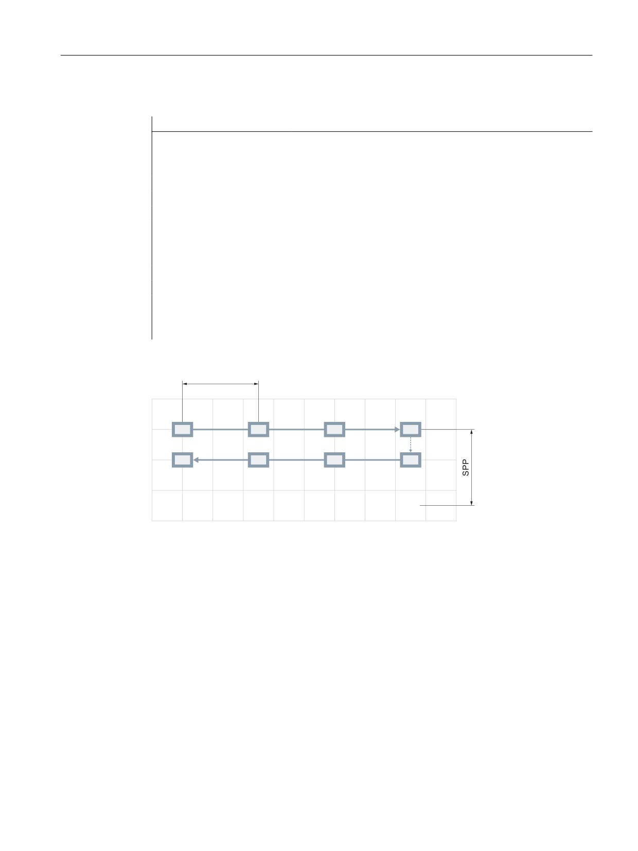
Example of SPP
Program code
Comment
N1 G01 X0 Y0 SPOF
; positioning without punch initiation
N2 X75 SPP=25 SON
; nibbling with feedrate value 25 mm; initiate punch
; before the first movement and after each
; path segment.
:
:
N3 Y10
; positioning with reduced SPP value, because
:
; traversing distance < SPP value, and initiate punch
; after the movement.
:
:
N4 X0
Reposition with punch initiation
after each path section.
:
633
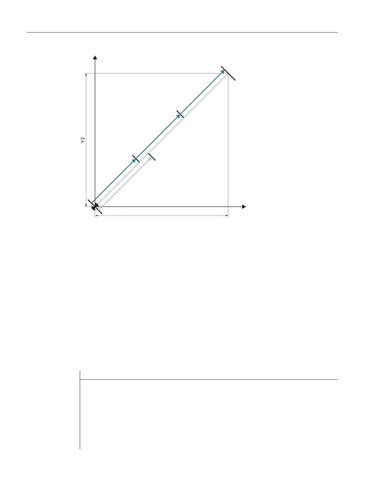
If the programmed path segmentation is not an integral multiple of the total path, then the feed
path is reduced.
Technologies
Function Manual, 10/2020, 6FC5397-8GP40-0BA1
259
Punching and nibbling
12.4 Automatic path segmentation
\
633ಿ
633
;
[
X2/Y2:
Programmed traversing distance
SPP:
Programmed SPP value
SPP':
Automatically rounded-off offset distance
Figure 12-4
Path segmentation
Example of SPN
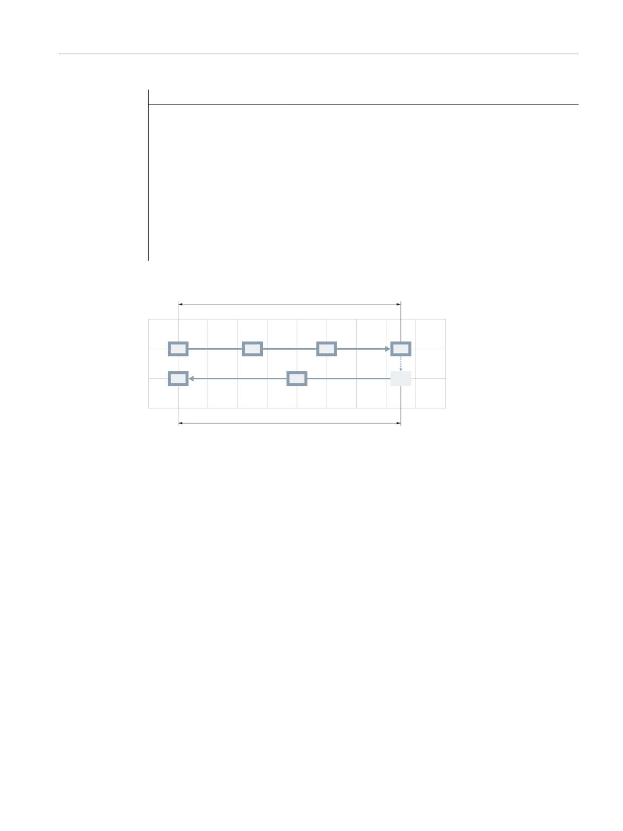
The number of path segments per block is programmed via SPN.
A value programmed via SPN takes effect on a non-modal basis for both punching and nibbling
applications. The only difference between the two modes is with respect to the first stroke. This
is normally executed at the beginning of the first segment with nibbling operations and at its end
with punching operations. This means that when n segments are programmed, n strokes are
executed with punching operations but n+1 with nibbling. Furthermore, where no travel
information is available, only a single stroke is executed, even if several are programmed. Should
it be necessary to generate several strokes at one position, then the corresponding number of
blocks without traversing information must be programmed.
Program code
Comment
N1 G01 X0 Y0 SPOF
; positioning without punch initiation
N2 X75 SPN=3 SON
; activate nibbling. The total path is
; divided into 3 path segments. Before the first
; movement and at the end of each path segment, a
; stroke is initiated.
:
:
:
Technologies
260
Function Manual, 10/2020, 6FC5397-8GP40-0BA1
Punching and nibbling
12.4 Automatic path segmentation
Program code
Comment
:
N3 Y10 SPOF
; positioning without punch initiation
N4 X0 SPN=2 PON
; activate punching. The total path is divided into 2
; path segments. Because punching has been activated,
; the first stroke is initiated at the end of the first
path
; segment.
:
:
:
:
631
631
Technologies
Function Manual, 10/2020, 6FC5397-8GP40-0BA1
261
Punching and nibbling
12.4 Automatic path segmentation
Example
;
<
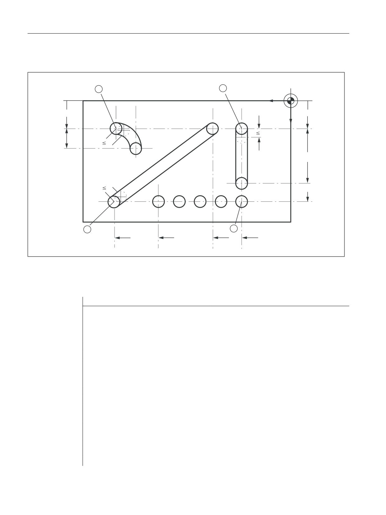
Figure 12-5
Workpiece
Extract from program
Program code
Comment
N100 G90 X130 Y75 F60 SPOF
; positioning to starting point (1) of the
; vertical nibbling path segments
N110 G91 Y125 SPP=4 SON
; end point coordinates (incremental)
; path segment: 4 mm, activate nibbling
N120 G90 Y250 SPOF
; absolute dimensioning, positioning at
; the start point (2) of the horizontal
; nibbling path segment
N130 X365 SPN=4 SON
; end point coordinates, 4 path segments,
; activate nibbling
N140 X525 SPOF
; positioning to starting point (3) of the
; inclined nibbling path
N150 X210 Y75 SPP=3 SON
; end point coordinates, path segment: 3
mm,
; activate nibbling
N160 X525 SPOF
; positioning to starting point (4) of the
; nibbling path on pitch circle path
N170 G02 G91 X-62.5 Y62.5 I0 J62.5 SON
; incremental circular interpolation with
; activate parameters,
Technologies
262
Function Manual, 10/2020, 6FC5397-8GP40-0BA1
Punching and nibbling
12.4 Automatic path segmentation
Program code
Comment
; nibbling
N180 G00 G90 Y300 SPOF
; positioning
12.4.3
Response in connection with single axes
MD26016
The path of single axes programmed in addition to path axes is distributed evenly among the
generated intermediate blocks as standard.
In the following example, the additional rotary axis C is defined as a synchronous axis.
If this axis is programmed additionally as a "Punch-nibble axis":
MD26010 $MC_PUNCHNIB_AXIS_MASK = 1,
, then the behavior of the synchronous axis can be varied as a function of machine data:
MD26016 $MC_PUNCH_PARTITION_TYPE
Programming example:
Program code
N10 G90 G1 PON X10 Y10 C0 F10000
N20 SPP=5 X25 C45
N30 G3 SPN=3 X35 Y20 I0 J10 C90
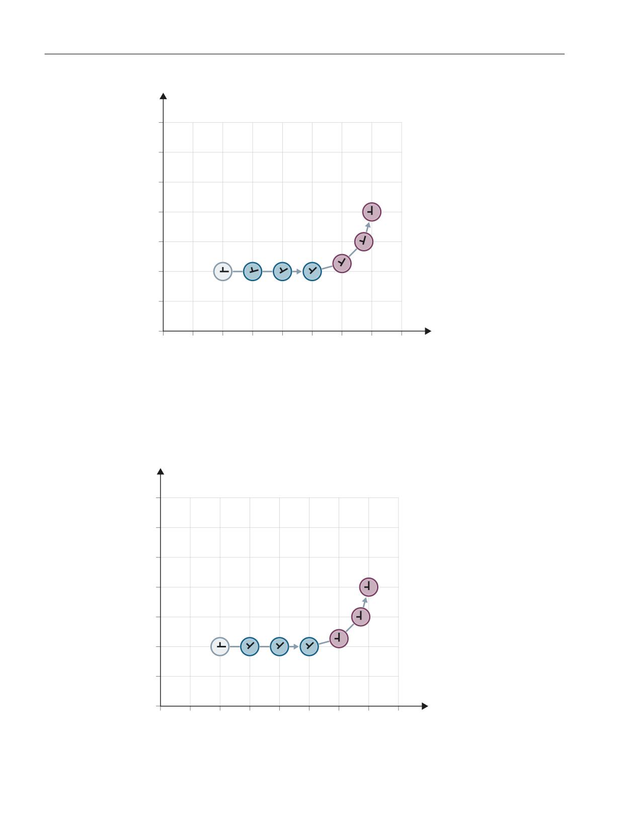
MD26016 $MC_PUNCH_PARTITION_TYPE=0 (default setting)
With this setting, the axes behave as standard, i.e. the programmed special axis motions are
distributed among the generated intermediate blocks of the active path segmentation function
in all interpolation modes.
In block N20, the C axis is rotated through 15° in each of the three intermediate blocks. The axis
response is the same in block N30, in the case of circular interpolation (three sub-blocks, each
with 15° axis rotation).
Technologies
Function Manual, 10/2020, 6FC5397-8GP40-0BA1
263
Punching and nibbling
12.4 Automatic path segmentation
\
r
1
1
r
r
& r
r
r
r
[
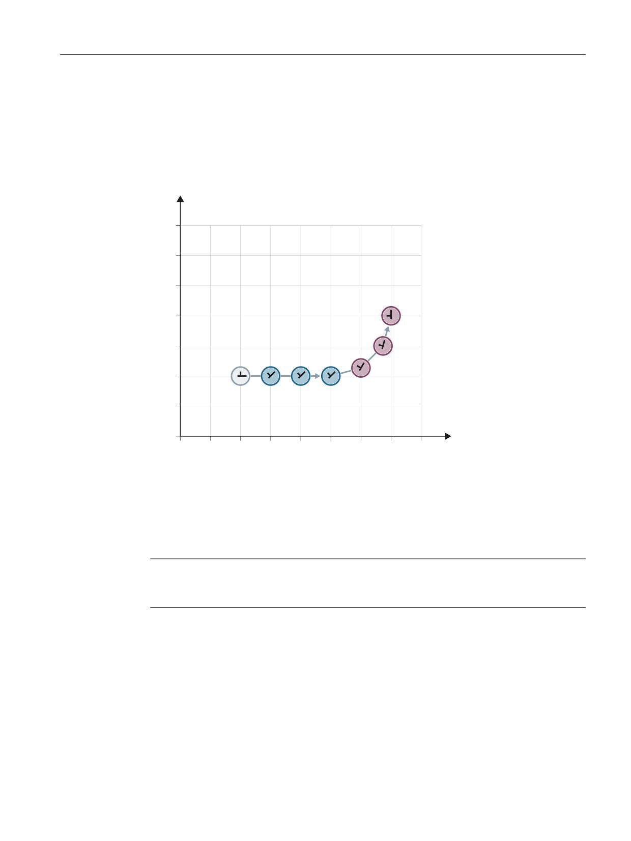
MD26016 $MC_PUNCH_PARTITION_TYPE=1
In contrast to the behavior described above, here the synchronous axis travels the entire
programmed rotation path in the first sub-block of the selected path segmentation function.
Applied to the example, the C axis already reaches the programmed end position C=45 when it
reaches X position X=15. It behaves in the same way in the circular interpolation block below.
\
r
1
1
r
r
& r
r
r
r
1
[
Technologies
264
Function Manual, 10/2020, 6FC5397-8GP40-0BA1
Punching and nibbling
12.4 Automatic path segmentation
MD26016 $MC_PUNCH_PARTITION_TYPE=2
MD26016=2 is set in cases where the axis must behave as described above in linear interpolation
mode, but according to the default setting in circular interpolation mode (see 1st case).
The axis behavior for the example is then as follows: In block N20, the C axis is rotated to C=45°
in the first sub-block. The following circular interpolation block rotates the C axis through 15° in
every sub-block.
\
r
1
1
r
r
& r
r
r
r
1
[
The axis response illustrated in the diagram above can be particularly useful when applied to the
axis of a rotatable tool in cases where it is used to place the tool in a defined direction (e.g.
tangential) in relation to the contour, but where the tangential control function must not be
applied. However, it is not a substitute for the tangential control function since the start and end
positions of the rotary axis must always be programmed.
Note
Additional offset motions of special axes (in this case, rotary axis C) are implemented via a zero
offset.
Technologies
Function Manual, 10/2020, 6FC5397-8GP40-0BA1
265
Punching and nibbling
12.4 Automatic path segmentation
Supplementary conditions
• If the C axis is not defined as a "Punch-nibble axis", then the C axis motion path is not
segmented in block N30 in the above example nor is a stroke initiated at the block end.
• If the functionality described above is to be implemented in a variant not specific to nibbling
applications, but with alignment of the special axis, then stroke initiation can be suppressed
by the following PLC interface signal:
DB 21, 22 DBX3.2 (stroke suppression)
(Application: e.g. alignment of electron beam during welding)
A similar response can be programmed with the following machine data setting:
MD26014 $MC_PUNCH_PATH_SPLITTING=1
In this case, the path is segmented irrespective of punching or nibbling functions.
Technologies
266
Function Manual, 10/2020, 6FC5397-8GP40-0BA1
Punching and nibbling
12.5 Rotatable tool
12.5
Rotatable tool
12.5.1
General information
Function overview
The following two functions are provided for nibbling/punching machines with rotatable punch
and lower die:
• Coupled motion
for synchronous rotation of punch and die
• Tangential control
for normal alignment of rotary axes for punches in relation to workpiece
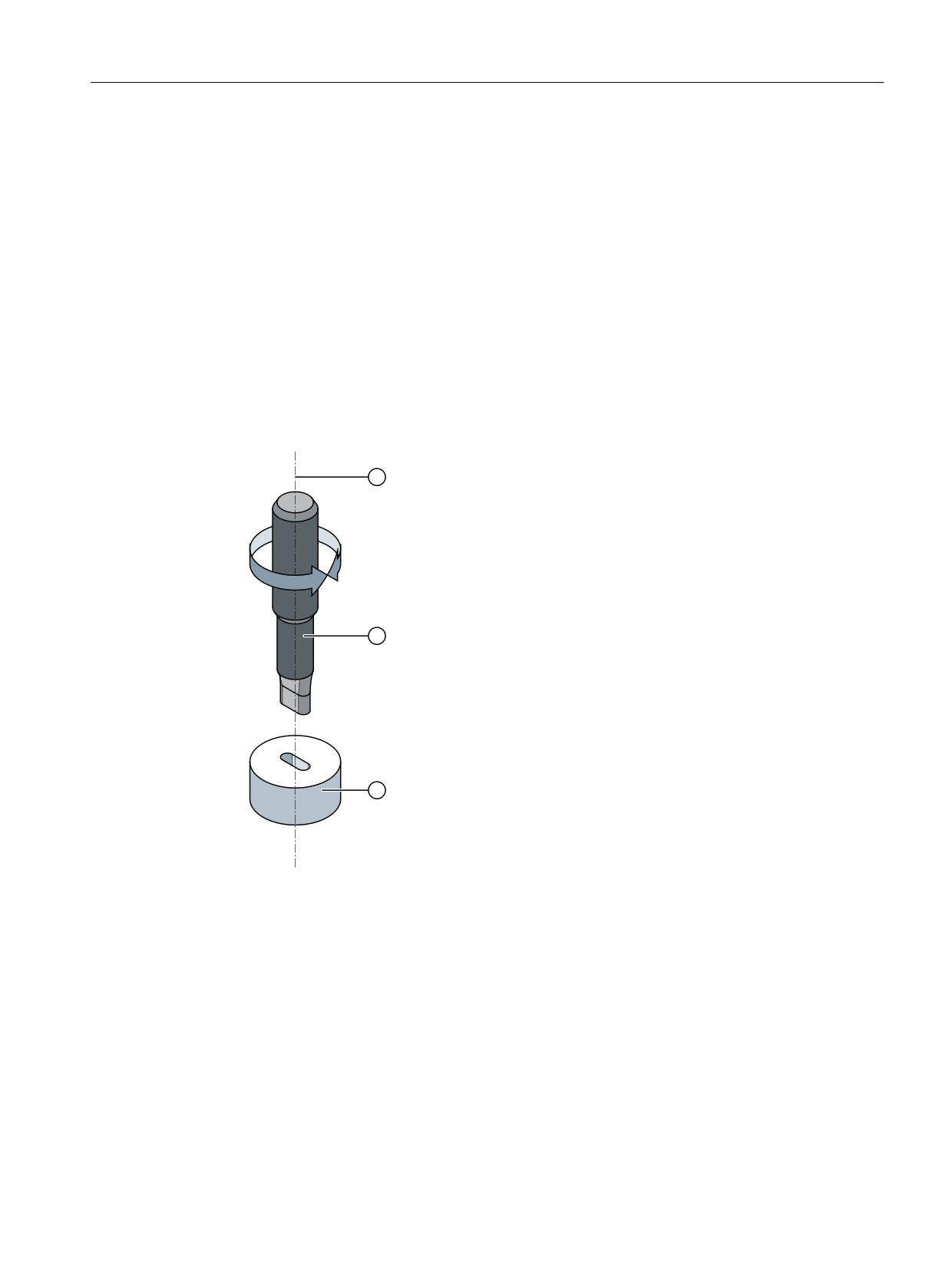
1
Tool axis
2
Stamp
3
Die
Figure 12-6
Representation of a rotatable tool axis
Technologies
Function Manual, 10/2020, 6FC5397-8GP40-0BA1
267
Punching and nibbling
12.5 Rotatable tool
12.5.2
Coupled motion of punch and die
Function
Using the standard function "Coupled motion", it is possible to assign the axis of the die as a
coupled motion axis to the rotary axis of the punch.
Activation
The "Coupled motion" function is activated or deactivated with language commands TRAILON
and TRAILOF respectively.
Further information
Function Manual Axes and Spindles; Axis Couplings
Example
Example of a typical nibbling machine with rotatable punches where C is the punch axis and C1
the die axis:
Program code
Comment
:
:
TRAILON (C1, C, 1)
;Enabling the coupled-motion grouping
G01 X100 Y100 C0 PON
;Initiate stroke with C axis /
;C1 axis position C=0=C1
X150 C45
;Initiate stroke with C axis /
;C1 axis position C=45=C1
:
:
M30
Basic position
No coupled-motion groupings are active after power up. Once the two tool axes have
approached the reference point, the coupled-motion grouping is not generally separated again.
This can be achieved by:
• Program single activation of the coupled-motion grouping (see example above)
• Program MD setting:
MD20110 $MC_RESET_MODE_MASK, bit 8=1
In this way, the coupled-motion grouping remains active after RESET/part program start or end.
Technologies
268
Function Manual, 10/2020, 6FC5397-8GP40-0BA1
Punching and nibbling
12.5 Rotatable tool
12.5.3
Tangential control
Function
The "tangential control" function aligns the rotary axis used for positioning the punching/
nibbling tool so that it is tangential to the programmed path. In connection with tangential
control, this axis is called the tangential axis. The linear axes of the machining plane are the
leading axes of the tangential coupling. The tangential axis is the following axis that is aligned
to the path tangent of the lead axes. An additive offset angle for the tangent angle can also be
programmed for the tangential axis.
If the punching/nibbling tool (die and die plate) is moved via two separate rotary axes, the
second rotary axes can be coupled to the tangential axis via "coupled motion".
Note
Switch-on sequence
In the NC program, the tangential control must first be defined and then the coupled motion
must be activated.
Further information
A detailed description of the tangential control can be found in the Axis and Spindles Function
Manual.
Example: Linear interpolation
Assumptions
• The punching/nibbling tool is subdivided into bottom and top tool
• The bottom tool and top tool are moved by different rotary axes (C/C1).
• The linear axes X and Y are the leading axes (machining plane G17)
Program code
Comment
N2 TANG (C, X, Y, 1, "B")
; definition tangential control
; leading axes: X, Y
; following axis: C
; coupling factor: 1
; basic coordinate system
N5 G0 X10 Y5
; starting position
N8 TRAILON (C1, C, 1)
; coupled motion ON
N10 Y10 C225 PON F60
; C/C1 axis → 225°
; nibbling initiation ON, → stroke
N15 X20 Y20 C45
; C/C1 axis → 45° → stroke
N20 X50 Y20 C90 SPOF
; C/C1 axis → 90°
; stroke initiation: OFF
Technologies
Function Manual, 10/2020, 6FC5397-8GP40-0BA1
269
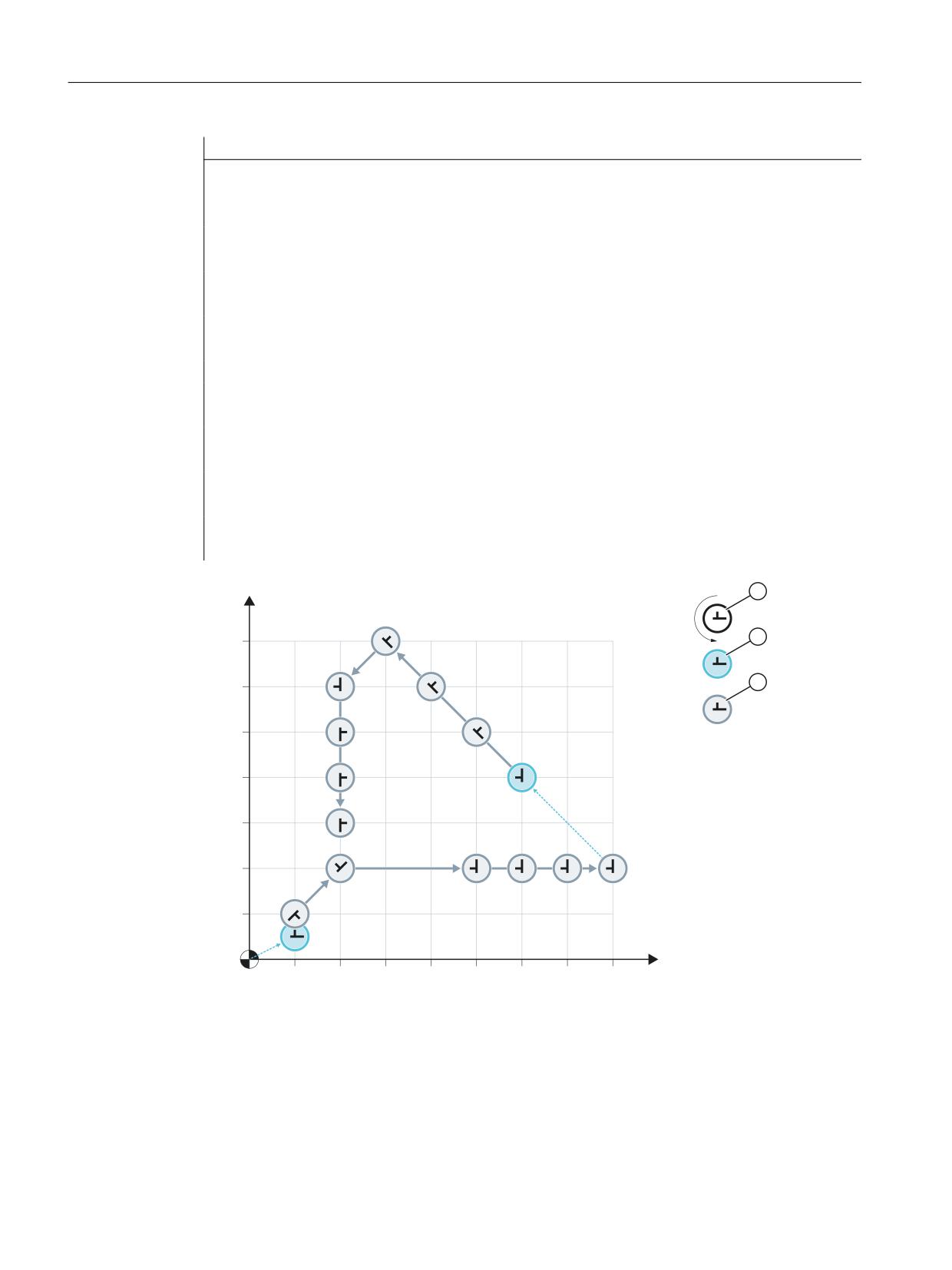
Punching and nibbling
12.5 Rotatable tool
Program code
Comment
N25 X80 Y20 SPP=10 SON
; path segmentation: ON
; path segment: 10 mm → 4 lifts
; punch initiation: ON
N30 X60 Y40 SPOF
; positioning
; stroke initiation: OFF
N32 TANGON (C, 180)
; tangential control: ON
; offset angle: 180°
N35 X30 Y70 SPN=3 PON
; path segmentation: 3 path segments → lift
; nibbling initiation: ON
N40 G91 C45 X-10 Y-10
; C/C1: 90° (-135°+180°+45°) → lift
N42 TANGON (C, 0)
; tangential control: ON
; offset angle: 0°
N45 G90 Y30 SPN=3 SON
; path segmentation → 3 lifts
; punch initiation: ON
N50 SPOF TANGOF
; stroke initiation: OFF
; tangential control: OFF
N55 TRAILOF (C1, C)
; coupled motion: OFF
N60 M2
\
1
&
r
1
1
1
1
1
1
1
[
① Mounting position 0°
② Positioning
③ Stroke
Technologies
270
Function Manual, 10/2020, 6FC5397-8GP40-0BA1
Punching and nibbling
12.5 Rotatable tool
Example: Circular interpolation
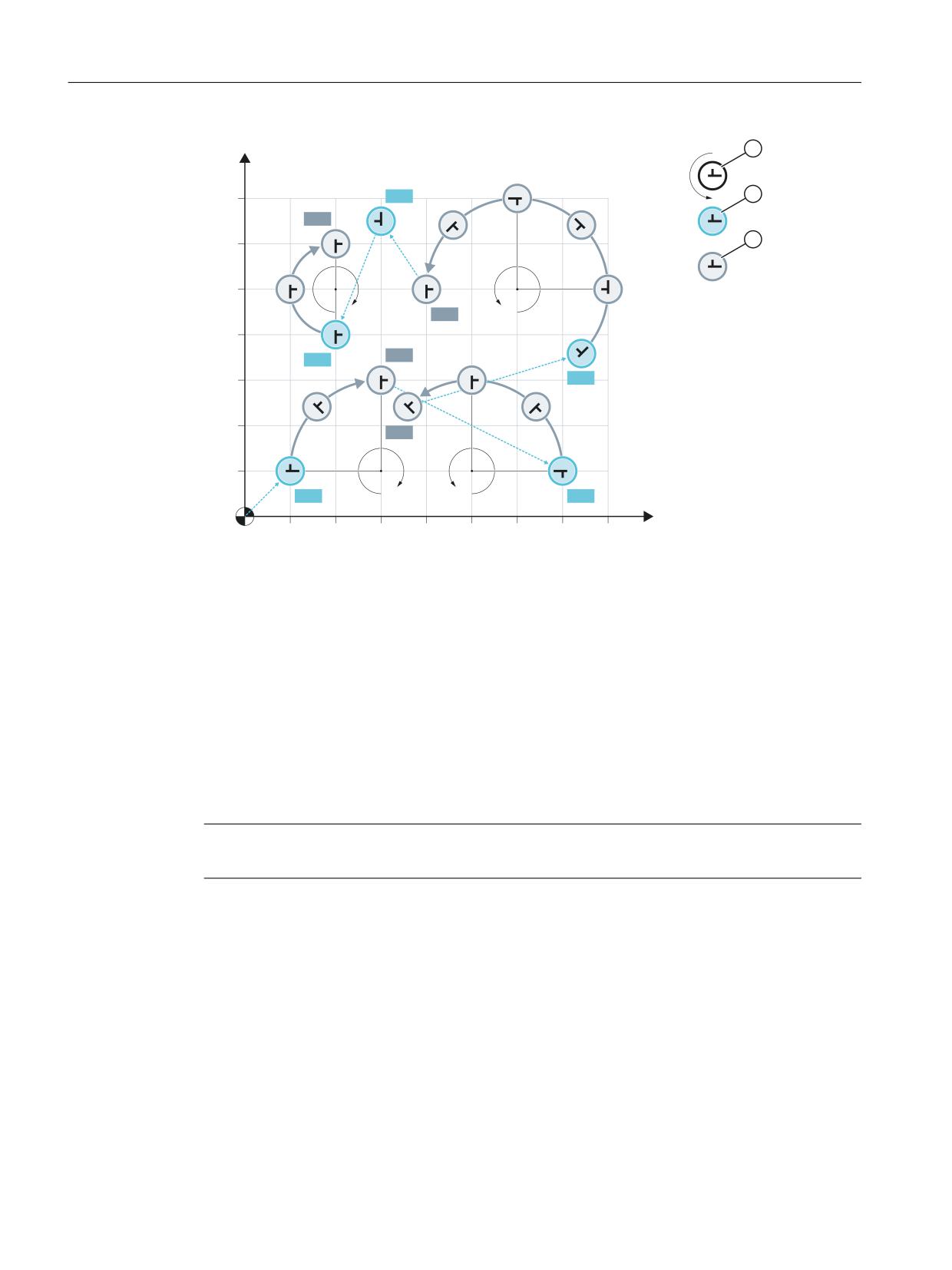
In circular interpolation mode, particularly when path segmentation is active, the tool axes
rotate along a path tangentially aligned to the programmed path axes in each sub-block.
Program code
Comment
N2 TANG (C, X, Y, 1, "B")
;
definition tangential control
;
leading axes: X, Y
;
following axis: C
;
coupling factor: 1
;
basic coordinate system
N5 G0 F60 X10 Y10
;
starting position
N8 TRAILON (C1, C, 1)
;
coupled motion: ON
N9 TANGON (C, -90)
;
tangential control: ON
;
offset angle: -90° or 270°
N10
G02 X30 Y30 I20 J0 SPN=2 PON
;
circular interpolation
;
path segmentation → 2 lifts
N15
G0 X70 Y10 SPOF
;
positioning
;
stroke initiation: OFF
N17
TANGON (C, 90)
;
tangential control: ON
;
offset angle: 90°
N20
G03 X35,86 Y24,14 CR=20 SPP=16 SON
;
circular interpolation
;
path segmentation → 4 lifts
;
punch initiation: ON
N25
G0 X74,14 Y35,86 C0 PON
;
positioning
;
C/C1 axis: 0°
;
nibbling initiation: ON
N27
TANGON (C, 0)
;
tangential control: ON
;
offset angle: 0°
N30
G03 X40 Y50 I-14,14 J14,14 SPN=5 SON
;
circular interpolation
;
path segmentation → 5 lifts
;
punch initiation: ON
N35
G0 X30 Y65 C90 SPOF
;
positioning
;
stroke initiation: OFF
N40
G91 X-10 Y-25 C180
;
positioning, incremental
;
C/C1 axis: +180°
;
⇒ 270° absolute
N43
TANGOF
;
tangential control: OFF
N45
G90 G02 Y60 I0 J10 SPP=2 PON
;
circular interpolation
;
path segmentation → 2 lifts
N50
SPOF
;
stroke initiation: OFF
N55
TRAILOF (C1, C)
;
coupled motion: OFF
N60
M2
Technologies
Function Manual, 10/2020, 6FC5397-8GP40-0BA1
271
Punching and nibbling
12.7 Supplementary conditions
\
&
r
1
1
1
1
1
1
1
1
1
[
① Mounting position 0°
② Positioning
③ Stroke
12.6
Protection zones
Clamping protection zone
The "clamping protection zone" function is contained as a subset in the "Protection zones"
function. Its purpose is to simply monitor whether clamps and tool could represent a mutual risk.
Note
No by-pass strategies are implemented for cases where the clamp protection is violated.
Further information
Function Manual Monitoring and Compensating; Axis Monitoring, Protection Zones
12.7
Supplementary conditions
Availability of function "Punching and nibbling"
The function is an option ("Punching and nibbling functions"), which must be assigned to the
hardware through the license management.
Technologies
272
Function Manual, 10/2020, 6FC5397-8GP40-0BA1
Punching and nibbling
12.8 Examples
12.8
Examples
12.8.1
Examples of defined start of nibbling operation
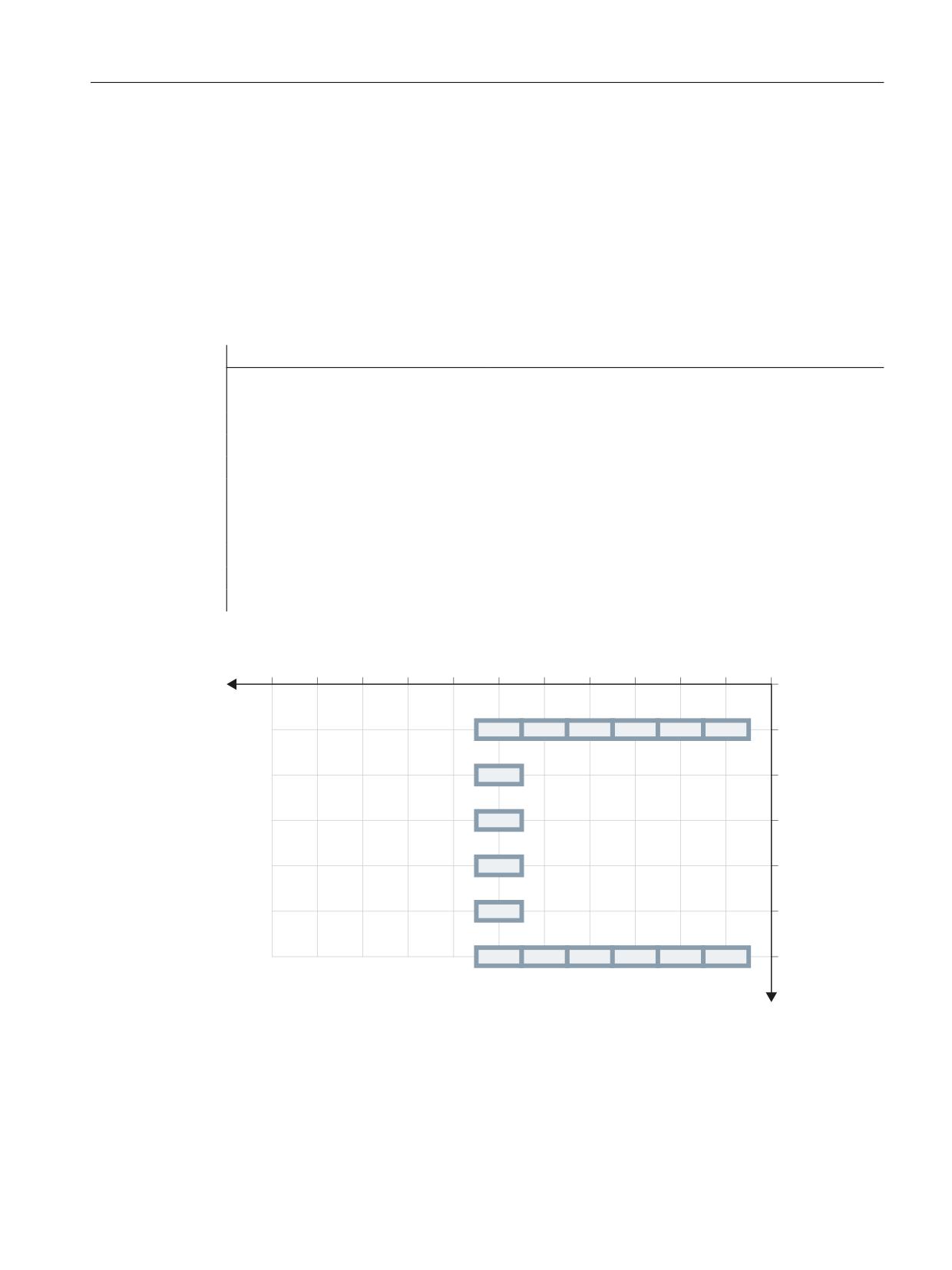
Example 1
Example of defined start of nibbling operation
Program code
Comment
:
:
N10 G0 X20 Y120 SPP= 20
; Position 1 is approached
N20 X120 SON
; Defined start of nibbling, first stroke at
; "1", last stroke at "2"
N30 Y20
; Defined start of nibbling, first stroke at
; "3", last stroke at "4"
N40 X20
; Defined start of nibbling, first stroke at
; "5", last stroke at "6"
N50 SPOF
N60 M2
[
\
Technologies
Function Manual, 10/2020, 6FC5397-8GP40-0BA1
273
Punching and nibbling
12.8 Examples
Example 2
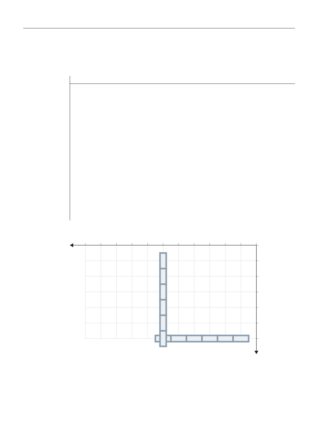
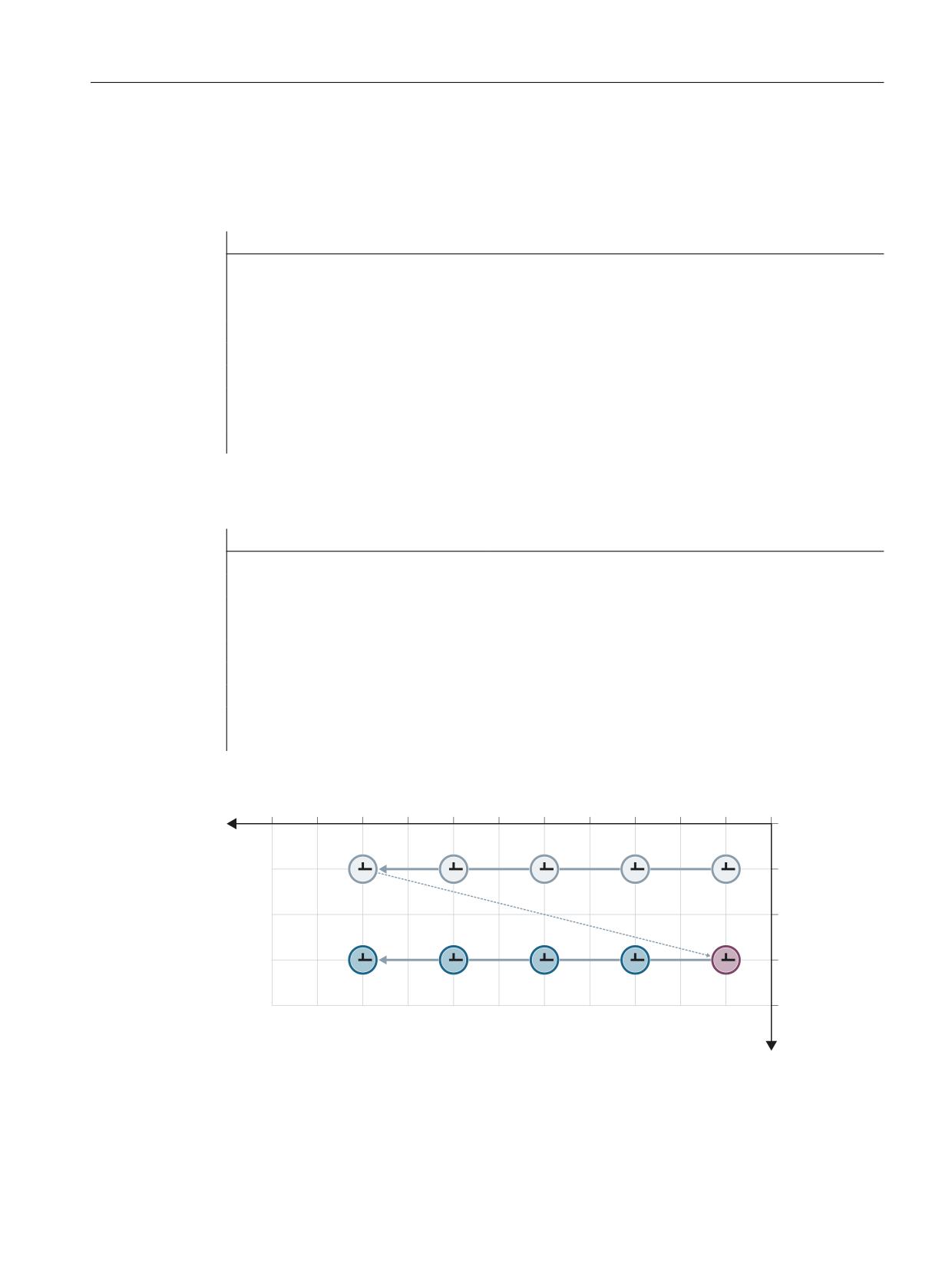
This example utilizes the "Tangential control" function. Z has been selected as the name of the
tangential axis.
Program code
Comment
:
:
N5 TANG (Z, X, Y, 1, "B")
; Define tangential axis
N8 TANGON (Z, 0)
; Select tangential control
N10 G0 X20 Y120
; Position 1 is approached
N20 X120 SPP=20 SON
; Defined start of nibbling,
; tangential control selected,
; first stroke at "1", last stroke at "2"
N30 SPOF TANGOF
; Deselect nibbling mode and deselect
; tangential control
N38 TANGON (Z, 90)
; Select tangential control
N40 Y20 SON
; Defined start of nibbling,
; tangential control selected,
; first stroke at "2" rotated 90 degrees to
; block N20, last stroke at "3"
N50 SPOF TANGOF
; Deselect nibbling mode and deselect
; tangential control
N60 M2
[
\
Technologies
274
Function Manual, 10/2020, 6FC5397-8GP40-0BA1
Punching and nibbling
12.8 Examples
Examples 3 and 4 for defined start of nibbling
Example 3: Programming of SPP
Program code
Comment
:
:
N5 G0 X10 Y10
; Positioning
N10 X90 SPP=20 SON
; Defined start of nibbling,
; 5 punches initiated
N20 X10 Y30 SPP=0
; One punch is initiated at the end of the path
N30 X90 SPP=20
; 4 punches initiated at intervals of 20 mm
N40 SPOF
N50 M2
Example 4 Programming of SPN
Program code
Comment
:
:
N5 G0 X10 Y10
; Positioning
N10 X90 SPN=4 SON
; Defined start of nibbling, 5
; 5 punches initiated
N20 X10 Y30 PON
; One punch is initiated at the end of the path
N30 X90 SPN=4
; 4 punches initiated
N40 SPOF
N50 M2
[
1
1
1
\
Figure 12-7
Examples 3 and 4 for defined start of nibbling
Technologies
Function Manual, 10/2020, 6FC5397-8GP40-0BA1
275
Punching and nibbling
12.8 Examples
Examples 5 and 6 without defined start of nibbling
Example 5 Programming of SPP
Program code
Comment
:
:
N5 G0 X10 Y30
; Positioning
N10 X90 SPP=20 PON
; No defined start of nibbling,
; 4 punches initiated
N15 Y10
; One punch is initiated at the end of the path
N20 X10 SPP=20
; 4 punches initiated at intervals of 20 mm
N25 SPOF
N30 M2
Example 6 Programming of SPN
Program code
Comment
:
:
N5 G0 X10 Y30
; Positioning
N10 X90 SPN=4 PON
; No defined start of nibbling,
; 4 punches initiated
N15 Y10
; One punch is initiated at the end of the path
N20 X10 SPN=4
; 4 punches initiated
N25 SPOF
N30 M2
Technologies
276
Function Manual, 10/2020, 6FC5397-8GP40-0BA1
Punching and nibbling
12.8 Examples
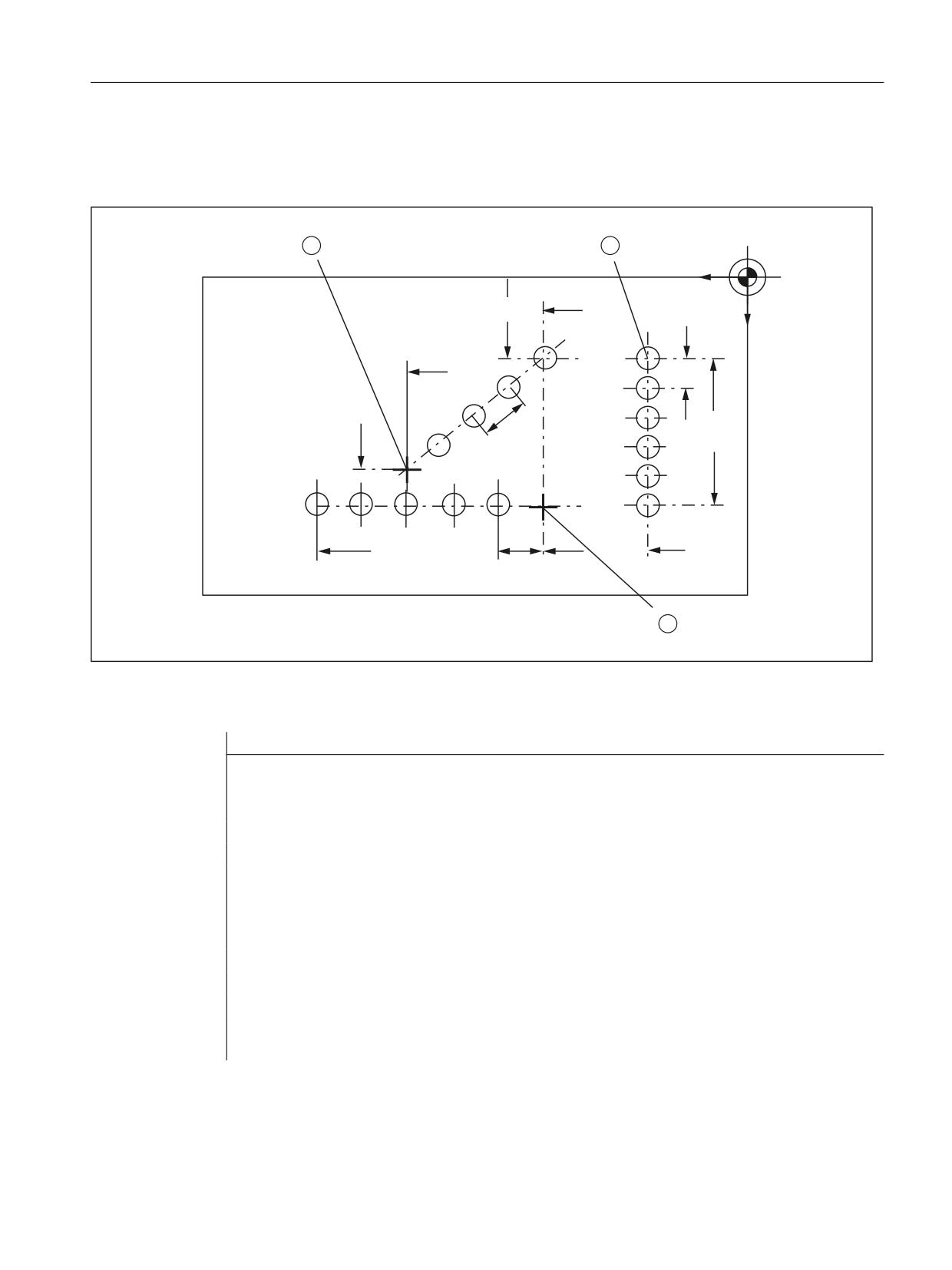
Example 7 Application example of SPP programming
;
<
Figure 12-8
Workpiece
Extract from program:
Program code
Comment
N100 G90 X75 Y75 F60 PON
; Positioning to starting point (1) of the
; vertical line of holes, punch single hole
N110 G91 Y125 SPP=25 PON
; End point coordinates (incremental),
; path segment: 25 mm, activate punching
N120 G90 X150 SPOF
; Absolute dimensioning, position at
; the start point (2) of the horizontal line of
holes
N130 X375 SPP=45 PON
; End point coordinates, path segment: 45 mm
N140 X275 Y160 SPOF
; Positioning to starting point (3) of the
; oblique line of holes
N150 X150 Y75 SPP=40 PON
; End point coordinates, programmed
; path segment: 40 mm, calculated
; path segment: 37.39 mm
N160 G00 Y300 SPOF
; Positioning
Technologies
Function Manual, 10/2020, 6FC5397-8GP40-0BA1
277

Punching and nibbling
12.9 Data lists
12.9
Data lists
12.9.1
Machine data
12.9.1.1
General machine data
Number
Identifier: $MN_
Description
11450
SEARCH_RUN_MODE
Block search parameter settings
12.9.1.2
Channelspecific machine data
Number
Identifier: $MC_
Description
20150
GCODE_RESET_VALUES[n]
Reset G groups
26000
PUNCHNIB_ASSIGN_FASTIN
Hardware assignment for input-byte with stroke control
26002
PUNCHNIB_ASSIGN_FASTOUT
Hardware assignment for output-byte with stroke con-
trol
26004
NIBBLE_PUNCH_OUTMASK[n])
Mask for quick output bits
26006
NIBBLE_PUNCH_INMASK[n]
Mask for quick input bits
26008
NIBBLE_PUNCH_CODE[n]
Determination of the M functions
26010
PUNCHNIB_AXIS_MASK
Definition of punching and nibbling axes
26012
PUNCHNIB_ACTIVATION
Activation of punching and nibbling functions
26014
PUNCH_PATH_SPLITTING
Activation of automatic path segmentation
26016
PUNCH_PARTITION_TYPE
Behavior of single axes with active automatic path seg-
mentation
26018
NIBBLE_PRE_START_TIME
Automatically activated pre-initiation time
26020
NIBBLE_SIGNAL_CHECK
Monitoring of the input signal
12.9.2
Setting data
12.9.2.1
Channelspecific setting data
Number
Identifier: $SC_
Description
42400
PUNCH_DWELL_TIME
Dwell time
42402
NIBPUNCH_PRE_START_TIME
Pre-start time
42404
MINTIME_BETWEEN_STROKES
Minimum time interval between two consecutive
strokes
Technologies
278
Function Manual, 10/2020, 6FC5397-8GP40-0BA1

Punching and nibbling
12.9 Data lists
12.9.3
Language commands
G group
Language com-
Meaning
mand
35
SPOF
Stroke / Punch OFF
Punching and nibbling OFF
35
SON
Stroke ON
Nibbling ON
35
SONS
Stroke ON
Nibbling ON (position controller)
35
PON
Punch ON
Punching ON
35
PONS
Punch ON
Punching ON (position controller)
36
PDELAYON
Punch with Delay ON
Punching with delay ON
36
PDELAYOF
Punch with Delay OFF
Punching with delay OFF
Path segmentation
SPP
Path per stroke, modal action
SPN
Number of strokes per block, non-modal action
Technologies
Function Manual, 10/2020, 6FC5397-8GP40-0BA1
279
Preface
1
Introduction
Fundamental safety
2
instructions
SINUMERIK
3
Functional scope
SINUMERIK 840D sl
Tool management
Basic commissioning and
4
configuration
5
Machine data
Function Manual
6
PLC programming
7
NC programming
8
Description of functions
SINUMERIK Operate user
9
interface
Code carrier connection -
Tool Ident Connection
10
(option)
11
Alarms
A
Appendix
Valid for
Control system
SINUMERIK 840D sl / 840DE sl
CNC software Version 4.94
10/2020
6FC5397-1HP40-0BA1
Table of contents
Preface
3
1
Introduction
15
1.1
About this documentation
15
2
Fundamental safety instructions
17
2.1
General safety instructions
17
2.2
Warranty and liability for application examples
18
2.3
Security information
19
3
Functional scope
21
3.1
Introduction
21
3.2
System overview
23
3.3
Function structure of tool management
27
3.4
Magazine management
28
3.5
Data structure HMI/PLC - NC (OPI)
29
3.6
PLC - NC interfaces
31
3.7
Access protection, protection levels
33
4
Basic commissioning and configuration
35
4.1
Input of the machine data
35
4.1.1
Settings with/without magazine management
35
4.1.2
Configuration via machine data
36
4.1.3
Additional settings
40
4.2
Configuration in SINUMERIK Operate
44
4.2.1
Function overview of the tool management editor
44
4.2.2
Editing the tool management
45
4.2.3
Parameterizing the tool management
48
4.2.3.1
Create tool unit
48
4.2.3.2
Define buffer locations
48
4.2.3.3
Define loading location
49
4.2.3.4
Create magazine configuration
50
4.2.3.5
Link assignments
51
5
Machine data
55
5.1
NC-specific machine data
55
5.2
Channel-specific machine data
79
5.3
Machine data for function replacement
100
5.4
Machine data for the Siemens user data
105
Tool management
Function Manual, 10/2020, 6FC5397-1HP40-0BA1
5
Table of contents
6
PLC programming
107
6.1
Overview
107
6.2
PLC description
108
6.2.1
Interfaces
108
6.2.2
Jobs from the NC tool management
111
6.2.3
Asynchronous transfer
113
6.2.4
Definitions of the acknowledgement status
113
6.2.5
Simplified acknowledgement of tool management commands
117
6.2.6
Diagnostics for communication between NC and PLC
118
6.2.7
Function blocks
121
6.2.8
Sample programs
122
6.3
Signal description of the PLC interface and transfer blocks
124
6.3.1
Overview of the blocks
124
6.3.2
Interface for loading/unloading magazine
125
6.3.3
Interface for spindle as change position
130
6.3.4
Interface for turrets as change position
136
6.3.5
Interface for loading/unloading magazine (multitool) (DB1071)
141
6.3.6
Interface for spindle (multitool) (DB1072)
142
6.3.7
Interface for turret (multitool) (DB1073)
146
6.3.8
Interface NC channels
150
6.3.9
Interface magazine configuration
151
6.3.10
Delete pending tasks
152
6.3.11
FC6: TM_TRANS2 - transfer block for tool management and multitool
153
6.3.12
FC7: TM_REV - transfer block for tool change with revolver
154
6.3.13
FC8: TM_TRANS - transfer block for tool management
157
7
NC programming
165
7.1
Overview of OPI and system variables
165
7.2
Use of the magazine data
168
7.3
Use of the tool and cutting edge data
170
7.4
Cutting edge data
172
7.4.1
Cutting edge data
172
7.4.2
Cutting edge parameter $TC_DP
172
7.4.3
User cutting edge data $TC_DPC
174
7.4.4
Cutting edge-related tool monitoring $TC_MOP
175
7.4.5
User cutting edge monitoring $TC_MOPC
176
7.4.6
Location of use-dependent offsets fine (additive offsets) $TC_SCP
176
7.4.7
Location-dependent offsets coarse (setting-up offsets) $TC_ECP
177
7.5
Tool data
179
7.5.1
Overview
179
7.5.2
Tool-related data $TC_TP
179
7.5.3
Tool-related grinding data $TC_TPG
185
7.5.4
Tool-related user data $TC_TPC
185
7.6
Magazine data
187
7.6.1
Overview of magazine data
187
7.6.2
Magazine description data $TC_MAP
187
7.6.3
Magazine user data $TC_MAPC
190
7.6.4
Magazine location data $TC_MPP
190
Tool management
6
Function Manual, 10/2020, 6FC5397-1HP40-0BA1
Table of contents
7.6.5
Magazine location user data $TC_MPPC
194
7.6.6
Magazine location type hierarchy $TC_MPTH
195
7.6.7
Distance to change position $TC_MDP
196
7.6.8
Magazine blocks $TC_MAMP
199
7.6.9
Assignment of buffers to spindles $TC_MLSR
206
7.7
Multitool data
209
7.7.1
$TC_MTP - multitool data
209
7.7.2
$TC_MTPP - Multitool location data
217
7.7.3
Multitool-related user data
222
7.7.4
Multitool-location-related user data
223
7.8
User-definable variables
224
7.9
NC language commands
226
7.9.1
CHKDNO - Uniqueness check for D number
226
7.9.2
CHKDM - Uniqueness check within a magazine
227
7.9.3
GETACTTD - Determining the tool number of a unique D No
228
7.9.4
GETDNO - Read out D numbers
229
7.9.5
SETDNO - Set or change D number
230
7.9.6
DZERO - Invalidate D numbers
230
7.9.7
DELDL - Delete additive offsets
231
7.9.8
NEWT - Create new tool
231
7.9.9
NEWMT Create new multitool
232
7.9.10
DELT Delete tool
234
7.9.11
DELMT - Delete multitool
234
7.9.12
$TC_MTPN - Delete one or all multitools
235
7.9.13
Reading the GETT - T no
236
7.9.14
SETPIECE - decrementing the workpiece counter
237
7.9.15
GETSELT - Read the selected T number
239
7.9.16
GETEXET - Reading of the loaded T number
242
7.9.17
$P_MTHSDC - master tool holder with regard to the D offset selection
245
7.9.18
$P_TH_OF_D - master tool holder to which the current D offset refers
247
7.9.19
GETACTT - Read the active internal T number
248
7.9.20
SETMS - Set master spindle
250
7.9.21
SETMTH - Set master toolholder number
250
7.9.22
POSM - Positioning the magazine
253
7.9.23
POSMT - position multitool on toolholder to location number
255
7.9.24
MVTOOL - NC command to move tool
258
7.9.25
SETTA - Activate tool from wear group
261
7.9.26
SETTIA - Deactivate tool from wear group
263
7.9.27
RESETMON - NC command for setpoint activation
265
7.9.28
DELTC - Delete toolholder data record
269
7.9.29
TCA - tool selection/tool change irrespective of tool status
270
7.9.30
TCI - Load tool from buffer into magazine
273
7.9.31
GETFREELOC - Search for empty location
275
7.9.32
DELMLRES - Delete location status "reserved for tool in the buffer"
281
7.9.33
DELMLOWNER - Delete owner magazine location of the tool
282
7.9.34
$P_USEKT - Tool change only with tools of subgroup
284
7.9.35
TOOLGNT/TOOLGT - Tool groups
287
7.9.36
$P_TMNOIS - is number, T number, magazine number, or MT number
288
7.9.37
$P_TOOLEXIST - Determine existence of a tool
289
7.9.38
$A_TOOLMN - read magazine no. from tool
290
7.9.39
$P_MTOOLN / $P_MTOOLMT- determine number of multitools / MT number
291
Tool management
Function Manual, 10/2020, 6FC5397-1HP40-0BA1
7
Table of contents
7.9.40
$P_MTOOLNT / $P_MTOOLT - Number of tools in the multitool
292
7.9.41
$A_TOOLMLN - Read magazine location No. of tool
293
7.9.42
$P_TOOLND - Read number of cutting edges for tool
294
7.9.43
$A_MONIFACT - factor for tool life monitoring
294
7.9.44
$AC_MONMIN - Factor for tool search
296
7.9.45
$P_TOOLNG - Number of tool groups
299
7.9.46
$A_MYMN / $A_MYMLN - Owner magazine/location of the tool
299
7.9.47
$A_MYMTN / $A_MYMTLN - $A_TOOLMTN / $A_TOOLMTLN - tools in multitool
300
7.9.48
$P_TOOLNT / $P_TOOLT - T numbers
302
7.9.49
$P_TOOLD - D numbers
302
7.9.50
$P_TOOLNDL - Number of defined DL offsets
303
7.9.51
$A_USEDND - Workpiece counting
304
7.9.52
$A_USEDT - Workpiece counting
305
7.9.53
$A_USEDD - Workpiece count
306
7.9.54
$A_TOOLADAPT - Assignment of tool to adapter
307
7.9.55
$TC_ADPTx - adapter description
308
7.9.56
$P_MAGNA / $P_MAGA - Tool adapter
310
7.9.57
$P_MAGN / $P_MAG - Magazine
311
7.9.58
$P_MAGNDIS / $P_MAGDISS / $P_MAGDISL - magazine distance tables
312
7.9.59
$P_MAGNS / $P_MAGS - Toolholder
313
7.9.60
$P_MAGNREL / $P_MAGREL - Assigned buffer
314
7.9.61
Example of magazine configuration system variables
315
7.9.62
$P_MAGNH / $P_MAGNHLT / $P_MAGHLT - Location type hierarchies
317
7.9.63
Additional language commands
320
7.9.64
Variables for subroutine replacement technique
327
7.9.65
Variables for tool change in synchronized action
328
7.10
Definitions when programming data
330
7.10.1
Tool change
330
7.10.2
Cutting edge selection
331
7.10.3
Tool transfer from program test
332
7.11
Programming T=location number
333
7.12
Call multiple turrets with "T=location number"
335
7.13
Programming examples
336
7.14
Overview of the remaining OPI blocks of tool management
337
7.14.1
Magazine data, directory
337
7.14.2
Tool data, directory
337
7.14.3
Parameterization, return parameters _N_TMGETT, _N_TSEARC
338
7.14.4
Working offsets
339
7.14.5
PI services and language commands for tool management
339
8
Description of functions
345
8.1
Magazines
345
8.1.1
Magazine configuration
345
8.1.2
Magazine types
346
8.1.3
Loading magazine
347
8.1.4
Buffer
348
8.1.5
Box-type and chain magazines
349
8.1.6
Circular magazine
352
8.1.7
Other magazine types
353
8.1.8
Wear group
354
Tool management
8
Function Manual, 10/2020, 6FC5397-1HP40-0BA1
Table of contents
8.1.9
Background magazine
355
8.1.10
Consider adjacent location
356
8.2
Loading
359
8.2.1
Loading sequence
359
8.2.2
Function of the PLC when loading?
361
8.2.3
Loading by directly assigning the T number
364
8.2.4
Load tools via a part program
364
8.2.5
Retroload tool data
365
8.3
Unloading
368
8.3.1
Unloading sequence
368
8.3.2
PLC function when unloading
369
8.3.3
Unloading by deleting the T number from the magazine location
372
8.4
Tool change box-type, chain, circular magazines
373
8.4.1
Overview
373
8.4.2
General tool change sequence
374
8.4.3
Preparing a tool change via T command
378
8.4.4
Execution of the tool change
379
8.4.5
Tool change for chain and box-type magazines
380
8.4.5.1
PLC function during preparation (chain, box type)
380
8.4.5.2
PLC function during tool change (chain, box type)
383
8.4.5.3
PLC sample programs tool change
386
8.4.5.4
Example structure of the PLC program for a tool change
388
8.4.6
Tool change with turret
390
8.4.7
Selecting a tool and a cutting edge
391
8.4.8
Predecoding (preprocessing) and block execution (main run)
393
8.4.9
Traverse axes while tool is being changed
395
8.4.10
Special cases "T0", empty spindle, multiple T selection
395
8.4.11
Number of replacement tools
396
8.4.12
Tool changing errors
397
8.4.13
Monitoring the maximum speed of a tool
398
8.4.14
Tool changes in the NC using synchronized actions
404
8.4.15
Replacing functions with subprograms
407
8.4.15.1
Function replacement
407
8.4.15.2
Replacement of the TCA command
411
8.4.16
Block search
413
8.4.17
Block search (SSL) in conjunction with active tool management
415
8.4.18
System variables for state before block search
418
8.4.18.1
Description of the variables
418
8.4.18.2
Example
419
8.4.19
Program test
422
8.4.20
Several spindles in one channel or TO unit
424
8.4.21
Decoupling the tool management from the spindle number
425
8.4.22
Several spindles/toolholders
430
8.4.23
Several magazines in one channel or one TO unit
431
8.4.24
Reset and start mode
431
8.4.25
Repeating a tool change with the same tool identifier
438
8.5
Relocating tools and positioning the magazine
442
8.5.1
Relocating sequence
442
8.5.2
Relocation by the PLC
444
8.5.3
Positioning the magazine
447
Tool management
Function Manual, 10/2020, 6FC5397-1HP40-0BA1
9
Table of contents
8.6
Several tools at a magazine location (multitool)
450
8.6.1
Brief description
450
8.6.2
Programming
453
8.6.3
Tool change with a tool from a multitool
454
8.6.4
Tool change and tool number for multitools
460
8.7
Using manual tools
470
8.7.1
Manual tools (adding tools during machining)
470
8.7.2
Tool change with manual tools
474
8.7.3
Role of the PLC for manual tools
476
8.8
Search for tool
480
8.8.1
Strategies for tool searches
480
8.9
Empty location search
483
8.9.1
Empty location search for a tool - from spindle to magazine
483
8.9.2
Search strategy for empty locations
484
8.9.3
Search procedure for empty locations
485
8.9.4
Search strategy, 1:1 exchange (old for new)
485
8.9.5
Tool search in wear group
487
8.10
Location type hierarchies
491
8.10.1
Hierarchies of location types in magazines
491
8.10.2
Conventional location type hierarchy $TC_MAMP2, Bit15=0
493
8.10.3
Alternative location type hierarchy $TC_MAMP2, Bit15=1
494
8.10.4
Search strategy across magazines
496
8.10.5
Mini hierarchies
497
8.11
Tool monitoring (workpiece count, tool life, wear)
499
8.11.1
Monitoring types
499
8.11.2
Tool life monitoring
502
8.11.3
Workpiece count monitoring
503
8.11.4
Wear monitoring
504
8.11.5
Signals to and from the PLC
506
8.12
Tool monitoring without active tool management
510
8.12.1
Tool monitoring overview
510
8.12.2
Tool life monitoring
511
8.12.3
Workpiece count monitoring
512
8.12.4
Wear monitoring
513
8.12.5
Monitoring the additive offset
513
8.12.6
Working with replacement tools
513
8.12.7
Examples
513
8.12.8
NC language commands
514
8.13
Variants of D-number assignments
515
8.13.1
Free selection of D numbers for every T
515
8.13.2
Location-dependent offsets (additive offsets)
517
8.14
Tool adapter
520
8.14.1
Machine data for setting adapters of type 1 and type 2
520
8.14.2
Creating/deleting adapters
520
8.14.3
Constraints for adapters
521
8.14.4
Managing adapter data
522
8.14.4.1
Managing adapter data for type 1 and type 2
522
8.14.5
Adapter type 1
522
Tool management
10
Function Manual, 10/2020, 6FC5397-1HP40-0BA1
Table of contents
8.14.5.1
Overview
522
8.14.5.2
Description of function
523
8.14.5.3
Activation
524
8.14.5.4
Adapter data $TC_ADPT
533
8.14.5.5
Transformed data of the active tool $P_ADT[n]
534
8.14.6
Adapter type 2 (angle head adapter) (option)
534
8.14.6.1
Assigning an angle head adapter
534
8.14.6.2
Angle head adapter - tool and adapter separate (type 2)
535
8.14.7
Offset values
541
8.14.7.1
Base length for the adapter
541
8.14.7.2
Cutter radius compensations and setup offsets for adapters
542
8.14.7.3
Cutting edge data for the orientation type 2 adapter
542
8.14.8
OPI block ADN
543
8.15
Power failure while tool command is in progress
545
9
SINUMERIK Operate user interface
547
9.1
Configuring the user interface
547
9.1.1
General settings
550
9.1.2
Configuring tool lists
555
9.1.2.1
Tool parameter identifiers
559
9.1.2.2
Cutting edge parameter identifiers
561
9.1.2.3
Monitoring parameter identifiers
564
9.1.2.4
Grinding parameter identifiers
565
9.1.2.5
Magazine location parameter identifiers
566
9.1.2.6
Magazine location adapter parameter identifiers
567
9.1.2.7
Multitool parameter identifiers
567
9.1.2.8
Multitool location parameter identifiers
568
9.1.3
Configuring list parameters
569
9.1.4
List of tool types
573
9.1.5
Configure tool types
575
9.1.6
Configuring the "Additional Data" window
577
9.1.7
Configure the "New tool - favorites" window
579
9.1.8
Configuring the "New Tool" window
579
9.1.9
Configuring the "New Multitool" window
580
9.1.10
Configuring the "New Tool from Code Carrier" window
580
9.1.11
Configuring the "New Tool from File" window
581
9.1.12
Configuring default values for new tools
581
9.1.13
Configuring the "Details" window
586
9.1.14
Assigning a name for magazines and magazine locations
587
9.1.15
Configuring the "Assign Tooltips for Multitool Locations" window
589
9.1.16
Assigning a name for magazine location types
590
9.1.17
Assignment of magazines and magazine locations to channels
591
9.1.18
Assignment between magazines and magazine locations and coordinate systems
593
9.1.19
Disabling the softkey depending on filters
594
9.1.20
Configuring the "Load Station Selection" window
595
9.1.21
Coolant and tool-specific functions
596
9.1.22
Reason for the tool change when reactivating
599
9.1.23
Configure the code carrier connection
603
9.1.24
Configuring Save to file
606
9.2
Creating OEM texts
608
9.2.1
Identifiers of the standard texts
609
Tool management
Function Manual, 10/2020, 6FC5397-1HP40-0BA1
11
Table of contents
9.2.2
Examples of OEM texts
611
9.3
Examples
614
9.3.1
Example: Configuring an OEM tool list
614
9.3.1.1
Adapting the configuration file
614
9.3.1.2
Adaptation of the customer text file
616
9.3.2
Example: Configuring magazine location types with names
618
9.3.2.1
Adapting the configuration file
618
9.3.2.2
Adaptation of the customer text file
619
9.4
Working with two tool holders
622
10
Code carrier connection - Tool Ident Connection (option)
625
10.1
Installation
625
10.1.1
System requirements
625
10.1.2
Installation of Tool Ident Connection
626
10.1.2.1
Activation of Tool Ident Connection
626
10.1.2.2
Installation of Wkonvert wizard
627
10.2
Configuration
633
10.2.1
Configuration schematic
633
10.2.2
Configuration of the tool lists
633
10.2.3
TDIIdentCfg.xml
633
10.2.4
Read/write device at the PLC
636
10.2.5
Data conversion
637
10.2.5.1
Using the Wkonvert wizard
639
10.2.5.2
Messages of the Wkonvert wizard
640
10.2.6
Conversion files wkonvert.txt and DefToolDat.txt
641
10.2.6.1
Structure of the description file wkonvert.txt
641
10.2.6.2
Examples for the description files wkonvert.txt
646
10.2.6.3
Tool data initialization file DefToolDat.txt
649
10.2.7
Conversion rule based on the MCIS-C script language
651
10.2.7.1
Structure of the conversion rule
651
10.2.7.2
Access to tool data
653
10.2.7.3
Auxiliary functions for numerical coding
655
10.2.7.4
Configuration of ToolSpec.xml
661
10.2.7.5
Error handling
662
10.2.7.6
Description of the MCIS-C script language
663
10.2.7.7
Help functions in conversion specifications
664
10.2.8
Examples
665
10.3
PLC interface in the DB19
670
10.3.1
Structure
670
10.3.2
Function call of the PLC interface
670
10.3.3
Assignment of the PLC for transfer parameters
671
10.3.4
Assignment of the PLC for return values
672
10.3.5
Executing functions
672
10.3.5.1
General sequence when executing functions
672
10.3.5.2
Pulse diagram for positive execution of a function
673
10.3.5.3
Pulse diagram when negative execution of a function
674
10.3.5.4
Pulse diagram "Ident_Ready" signal
674
10.3.6
PLC interface for the Parameter operating area
675
10.3.6.1
Assignment of the PLC interface for the Parameter area
675
10.3.6.2
Load the tool
676
Tool management
12
Function Manual, 10/2020, 6FC5397-1HP40-0BA1
Table of contents
10.3.6.3
Sequence
677
10.3.6.4
Sequence when canceled by the PLC
678
10.3.6.5
Unloading a tool
679
10.3.6.6
Diagnostics
679
10.3.6.7
Restrictions
681
10.3.6.8
Error messages
681
10.3.7
PLC data types
681
10.4
Command codes
683
10.4.1
Functional scope of the PLC interface (K codes)
683
10.4.2
Parameter description
683
10.4.3
Loading from the code carrier (K code = 0)
684
10.4.4
Unload to code carrier (K code = 1)
685
10.4.5
Loading of production host computer (K code = 4)
686
10.4.6
Unload to the production host computer (K code = 5)
687
10.4.7
Loading a tool from the tool list (K code = 7)
688
10.4.8
Unloading a tool in the tool list (K code = 8)
689
10.4.9
Empty location search (K code = 9)
690
10.4.10
Delete tool in NC (K code = 10)
691
10.4.11
Updating the code carrier (K code = 14)
692
10.4.12
Reading data from the code carrier (K code = 15)
693
10.4.13
Error codes
694
10.5
Examples
700
10.5.1
Loading the code carrier via PLC interface
700
10.5.2
Unloading to the code carrier via PLC interface
703
11
Alarms
705
11.1
Overview
705
11.2
Alarm description
708
A
Appendix
741
A.1
List of abbreviations
741
A.2
Documentation overview
743
A.3
Available IPCs
744
Index
745
Tool management
Function Manual, 10/2020, 6FC5397-1HP40-0BA1
13

Introduction
1
1.1
About this documentation
This documentation is part of the documentation category of SINUMERIK Function Manuals.
SINUMERIK Function Manuals
The SINUMERIK Function Manuals describe the NC functions of a SINUMERIK control.
The target group are configuring engineers, technologists, commissioning engineers and
programmers.
Each Function Manual covers a specific topic and contains all the function descriptions for this
topic.
The following table shows which Function Manuals are available for your SINUMERIK control and
which topics a Function Manual covers:
Function Manual
Topic
Basic functions
Basic functions of a CNC control
Axes and spindles
Axis and spindle functions, axis couplings
Transformations
Transformation functions
Monitoring and compensating
Axis monitoring and compensation functions, collision avoid-
ance
Tools
Functions for selection, correction and monitoring of tools
Synchronized actions
Functionality of synchronized actions
PLC
Structure and functions of the PLC
Tool management
Function, commissioning and programming of tool manage-
ment
Technologies (for SINUMERIK ONE
Extended technological functionalities
and SINUMERIK 840D sl only)
Overview of contents
You will find an overview of the main chapters of the descriptions of functions that are contained
in a Function Manual on the title page.
Validity
The title page also contains all data about the validity of a document, i.e. for which SINUMERIK
control and for which software version this edition of the Function Manual is valid.
Tool management
Function Manual, 10/2020, 6FC5397-1HP40-0BA1
15

Introduction
1.1 About this documentation
System data
In the descriptions of functions, the system data relevant for a function (machine data, setting
data, system variables, interface signals and alarms) are only described with the level of detail
that is strictly necessary to understand the function. You will find detailed information on this
data in the relevant List Manuals and for alarms in the Diagnostics Manual.
PLC blocks
The descriptions of functions often refer to the PLC function blocks (FB) and functions (FC). The
descriptions of these blocks apply to the SINUMERIK 840D sl and can only be applied in part to
other SINUMERIK controls.
Interface signals
In this document, only the absolute address valid for the SINUMERIK 840D sl is used to address
interface signals.
General graphical conventions
Examples
<signal address> (<signal name>)
DB31, ... DBX16.0-2 (actual gear stage A to C)
DB31, ... DBX16.3 (gear is changed)
Note
Quantity structure
Explanations concerning the NC/PLC interface are based on the absolute maximum number of
the following components:
• Mode groups (DB11)
• Channels (DB21, etc.)
• Axes/spindles (DB31, etc.)
Tool management
16
Function Manual, 10/2020, 6FC5397-1HP40-0BA1

Fundamental safety instructions
2
2.1
General safety instructions
WARNING
Danger to life if the safety instructions and residual risks are not observed
If the safety instructions and residual risks in the associated hardware documentation are not
observed, accidents involving severe injuries or death can occur.
• Observe the safety instructions given in the hardware documentation.
• Consider the residual risks for the risk evaluation.
WARNING
Malfunctions of the machine as a result of incorrect or changed parameter settings
As a result of incorrect or changed parameterization, machines can malfunction, which in turn
can lead to injuries or death.
• Protect the parameterization against unauthorized access.
• Handle possible malfunctions by taking suitable measures, e.g. emergency stop or
emergency off.
Tool management
Function Manual, 10/2020, 6FC5397-1HP40-0BA1
17
Fundamental safety instructions
2.2 Warranty and liability for application examples
2.2
Warranty and liability for application examples
Application examples are not binding and do not claim to be complete regarding configuration,
equipment or any eventuality which may arise. Application examples do not represent specific
customer solutions, but are only intended to provide support for typical tasks.
As the user you yourself are responsible for ensuring that the products described are operated
correctly. Application examples do not relieve you of your responsibility for safe handling when
using, installing, operating and maintaining the equipment.
Tool management
18
Function Manual, 10/2020, 6FC5397-1HP40-0BA1
Fundamental safety instructions
2.3 Security information
2.3
Security information
Siemens provides products and solutions with industrial security functions that support the
secure operation of plants, systems, machines and networks.
In order to protect plants, systems, machines and networks against cyber threats, it is necessary
to implement - and continuously maintain - a holistic, state-of-the-art industrial security
concept. Siemens’ products and solutions constitute one element of such a concept.
Customers are responsible for preventing unauthorized access to their plants, systems,
machines and networks. Such systems, machines and components should only be connected to
an enterprise network or the internet if and to the extent such a connection is necessary and only
when appropriate security measures (e.g. firewalls and/or network segmentation) are in place.
For additional information on industrial security measures that may be implemented, please
visit
Siemens’ products and solutions undergo continuous development to make them more secure.
Siemens strongly recommends that product updates are applied as soon as they are available
and that the latest product versions are used. Use of product versions that are no longer
supported, and failure to apply the latest updates may increase customer’s exposure to cyber
threats.
To stay informed about product updates, subscribe to the Siemens Industrial Security RSS Feed
under
services/cert.html#Subscriptions).
Further information is provided on the Internet:
Industrial Security Configuration Manual (https://support.industry.siemens.com/cs/ww/en/
view/108862708)
WARNING
Unsafe operating states resulting from software manipulation
Software manipulations, e.g. viruses, Trojans, or worms, can cause unsafe operating states in
your system that may lead to death, serious injury, and property damage.
• Keep the software up to date.
• Incorporate the automation and drive components into a holistic, state-of-the-art industrial
security concept for the installation or machine.
• Make sure that you include all installed products into the holistic industrial security concept.
• Protect files stored on exchangeable storage media from malicious software by with suitable
protection measures, e.g. virus scanners.
• On completion of commissioning, check all security-related settings.
Tool management
Function Manual, 10/2020, 6FC5397-1HP40-0BA1
19
Fundamental safety instructions
2.3 Security information
Tool management
20
Function Manual, 10/2020, 6FC5397-1HP40-0BA1

Functional scope
3
3.1
Introduction
Overview
The "Tool management" (TOOLMAN) function ensures that at any given time the correct tool is
selected and that the data assigned to the tool is up to date. The function is used on machine
tools with circular magazines, chain magazines or box magazines. Tool management also
enables the following functions:
• Optimum tool staging for tool change.
• Avoidance of waste by monitoring tool operation (function "Tool monitoring function").
• Avoidance of machine downtimes by using replacement tools.
• Search for a suitable magazine location for the tool being replaced (with function Magazine
management).
Note
If only "TMMO" is active, magazine management must be implemented by the machine
manufacturer in the PLC user program.
Function versions of tool management
There are 3 different function versions when handling tools:
• TMMO: ToolManagement Tool (Monitoring)
(English: TMMO = Tool Management Tool Monitoring)
• TMMG: ToolManagementMagazines (only available with active tool management)
(English: TMMG = Tool Management Magazines)
• TMMO and TMMG
Combination of the two function types
Quantity structure
Quantity structure
NCU 730
NCU 720
NCU 710
Number of magazines
64
32
32
Number of cutting edges
3000
1500
1500
Number of tools per multitool
64
32
32
Tool management
Function Manual, 10/2020, 6FC5397-1HP40-0BA1
21
Functional scope
3.1 Introduction
Option
Tool management with more than 4 real magazines is an OPTION.
Tool management
22
Function Manual, 10/2020, 6FC5397-1HP40-0BA1
Functional scope
3.2 System overview
3.2
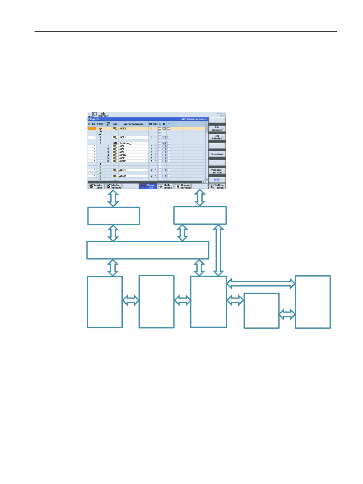
System overview
System overview
The following diagram shows an overview of tool management.
6\VWHP VWUXFWXUH
+0,
7',
70 6HUYLFH
&RGH FDUULHU
23, LQWHUIDFH
1&
,QWHUIDFH
3/&
3/&
/DQJXDJH
%DVLF SURJUDP
8VHU SURJUDP
GDWD PDQDJH
)%
3/&
PHQW
8VHU LQWHUIDFH
VHTXHQWLDO
'%
FRQWURO V\VWHP
ORJLF
Figure 3-1
System overview diagram Tool management
Magazine management
Special functions of the tool management include magazine management, tool and empty
location search. These additional functions are only available when tool management is active.
Without active tool management, the magazine management must be implemented by the
machine manufacturer in the PLC user program.
Tool monitoring
The tool monitoring function is used to monitor tool lifetime, unit quantity or wear values.
Tool management
Function Manual, 10/2020, 6FC5397-1HP40-0BA1
23
Functional scope
3.2 System overview
OPI variables
Additional functions are available using OPI variables on the PLC or HMI side. You can use OPI
variables (NC variables) by choosing them with the NC-VAR selector.
Further information
• SINUMERIK 840D sl: Function Manual PLC
System variables
NC programs (e.g. cycle, ASUB) provide corresponding NC commands to achieve optimum
adaptation of the tool management to the machine environment. You can obtain a clear
overview about the data structures that form the basis of the tool management. They are
represented in the form of NC data blocks.
Operator panels
The following operator panels can be used for tool management:
• OP177, e.g. for loading magazines
• OP8T, e.g. for box-type magazines
Data
Data storage and management is carried out in the NC and SINUMERIK Operate. All data can be
read and written manually via the NC program or by data transfer.
Operation via system screens
Operation is mainly performed via system screens. There are system screens for commissioning
and for tool management operation (magazine lists, tool lists, loading/unloading).
Configuration of user-specific screens
Tool-specific data that is not displayed via SINUMERIK Operate system screens can be displayed
and changed in configurable user-specific screens.
The configuration of user-specific screens is described in:
Further information
• SINUMERIK 840D sl: Commissioning Manual, Base Software and Operating Software;
SINUMERIK Integrate Run MyScreens (BE2)
Programming in the NC part program
The tool management function makes it possible to call a tool in the part program using a name
(identifier), e.g. T = "end mill 120 mm".
Tool call is still possible via the T no. (tool number). The T no. is then the name of the tool
(e.g. T=T12345678).
Tool management
24
Function Manual, 10/2020, 6FC5397-1HP40-0BA1
Functional scope
3.2 System overview
A tool is uniquely defined by its internal T number or identifier and its duplo number.
Furthermore, each tool can be uniquely identified by its name. The internal T number
is generally assigned by the NC, and is not used for programming a tool change in the part
program.
Using a machine data, it can be set as to whether the change is realized using the T command
(typical for lathes) or whether the tool is prepared using T programming and only changed with
M06. This machine data setting is independent of the magazine type.
The following characters are permitted for the identifier:
[ _ ] [ a...z ] [ A...Z ] [ 0...9 ] ; [ + - . , ]
Identifiers are case-sensitive, i.e. differentiate between upper-case and lower-case characters.
PLC
There are data blocks (DB71-73) as well as DB1071-1073 for receiving tool management
commands and function blocks (FC6, FC7, FC8) for acknowledging the tool management
commands. A "fast acknowledgement" is implemented for simple applications in data blocks
DB71...73.
Another block, FC22, is used as a direction selection for magazines.
Tool management data can also be read and written via FB2 and FB3. Complex tool management
services can be initiated via FB4.
Location coding
Fixed location coding as well as variable location coding are supported for the tools.
Location type
The location type defines the type and shape of the location. By assigning location types to
magazine locations it is possible to subdivide a magazine into areas. This means that different
types of special tools, e.g. "especially_large", "especially_heavy" can be assigned to specific
locations.
The location types can be placed in ascending order - a so called hierarchy. This order determines
that a tool that is supposed to be inserted in a "small" location type can also be placed in a "larger"
location type if no "smaller" location type is vacant.
Monitoring functions
In tool management, it is possible to select either workpiece counts or tool life monitoring (with
reference to the cutting edges). Further, a wear monitoring function is available. Replacement
tools (duplo tools) are differentiated by means of a duplo number.
Search strategy
Various strategies are possible for tool search and to search for the empty location of the "old
tool". The "old tool" is the tool to be replaced.
The empty location search strategy is used for loading tools.
Tool management
Function Manual, 10/2020, 6FC5397-1HP40-0BA1
25

Functional scope
3.2 System overview
Tool groups
Tools with the same identifier are combined in tool groups. Using duplo numbers, a distinction
can be made between tools - and used as replacement tools ("sister tool") within the framework
of the tool management.
Excerpt from TOOLMAN basic data
Term
Data/Range
Magazine configuration per channel
1
Total number of magazines
Max. 64
Total number of magazine locations
Max. 1500
Total number of tools
Across all TO units max. 1500
Programming tools (names) in the NC program us-
e.g. T="angled mill_32"
ing 32 alphanumeric characters
Duplo number 1)
1 - 32000
Total number of cutting edges
Max. 3000
Location type definition
Assigning location types to magazine locations
Viewing adjacent locations in half locations
2dimensional
Location coding
Fixed or variable
Strategy for tool search
can be set (programmable) via system variables
Strategy for empty location search
can be set (programmable) via system variables
M06 command for tool change
M code, settable via MD, channel-specific
Tool change with M06 or T command
settable via MD, channel-specific
Wear monitoring
For every cutting edge
Wear monitoring according to tool life
Resolution in ms
Wear monitoring according to number of workpie-
Counter
ces
Access to tool management data via NC program
System variables
Automatic decoding stop until tool is selected
Yes
T=Location No.
settable via MD
1) The duplo number or the duplo tool is called "sistertool" in SINUMERIK Operate.
Tool management
26
Function Manual, 10/2020, 6FC5397-1HP40-0BA1
Functional scope
3.3 Function structure of tool management
3.3
Function structure of tool management
HMI
• Tool list
• Tool wear list
• OEM tool list
• Magazine list
NC
• Tool data management
- State
- Monitoring
- Corrections
• Magazine data management
- Magazines
- Magazine locations
• Tool management
- Search for tool
- Find empty location
- Change tool
- Load, unload
PLC
• Magazine control
• Gripper control
• Spindle control
• Safety interlocks
• Execute tool change
• Calculation of position, if necessary
• Own change strategy, if applicable
Tool management
Function Manual, 10/2020, 6FC5397-1HP40-0BA1
27
Functional scope
3.4 Magazine management
3.4
Magazine management
Tool magazine management - TMMG
Magazine management administers the magazine locations. The locations have the following
properties:
• The locations are free.
• The locations are occupied with tools.
• These locations are occupied by oversized tools in adjacent locations.
• The locations are reserved for a tool in a buffer or loading magazine.
The tool magazine management offers the following functions:
• Magazine management provides extended functions such as load, unload, position tools or
position magazines.
• It also includes search functions for tools, magazine locations, and search strategies for
replacement tools.
• For the tool monitoring functions, while the activated monitoring is running, tools are
disabled and no longer used.
• For further machining, if a similar tool (replacement tool) is present which is not disabled,
then this tool is used automatically.
• When tool management is active, you define the configuration of magazines, loading
magazines, spindles, grippers, etc. The NC defines the interfaces (DB 71 to DB 73) in the PLC
via the configuration data.
Task-related tool motions (e.g. position chain, swivel gripper) are derived from the interface
processing. After tool movements, the positions and task status should be acknowledged via
basic program blocks (FC6, FC7 and FC8). The acknowledgement procedure is described in
detail in Definitions of the acknowledgement status (Page 113) and Simplified
acknowledgement of tool management commands (Page 117).
If necessary, create another cycle (or ASUP) for the NC program where tool changing is
programmed with the required travel motions. An identifier is programmed for the tool change
or tool preselection when the TOOLMAN system is active. A duplo number is also available to
support unique identification of replacement tools. Tool identifier and duplo numbers are always
mapped on an internally assigned T number. This internally assigned T number is used for
addressing the variables described in the following.
Magazine types in the magazine management
Magazine management manages the following real magazines.
• Circular magazine (Page 352)
• Box-type and chain magazines (Page 349)
Other magazine types, e.g. pick-up magazines, are mapped onto these.
Real magazines can be defined as a circular, chain or box-type. Loading points or loading stations
shall be used as the magazine type for loading and unloading.
A magazine buffer combines all other locations in which tools can be placed (spindle, gripper, ...).
Tool management
28
Function Manual, 10/2020, 6FC5397-1HP40-0BA1
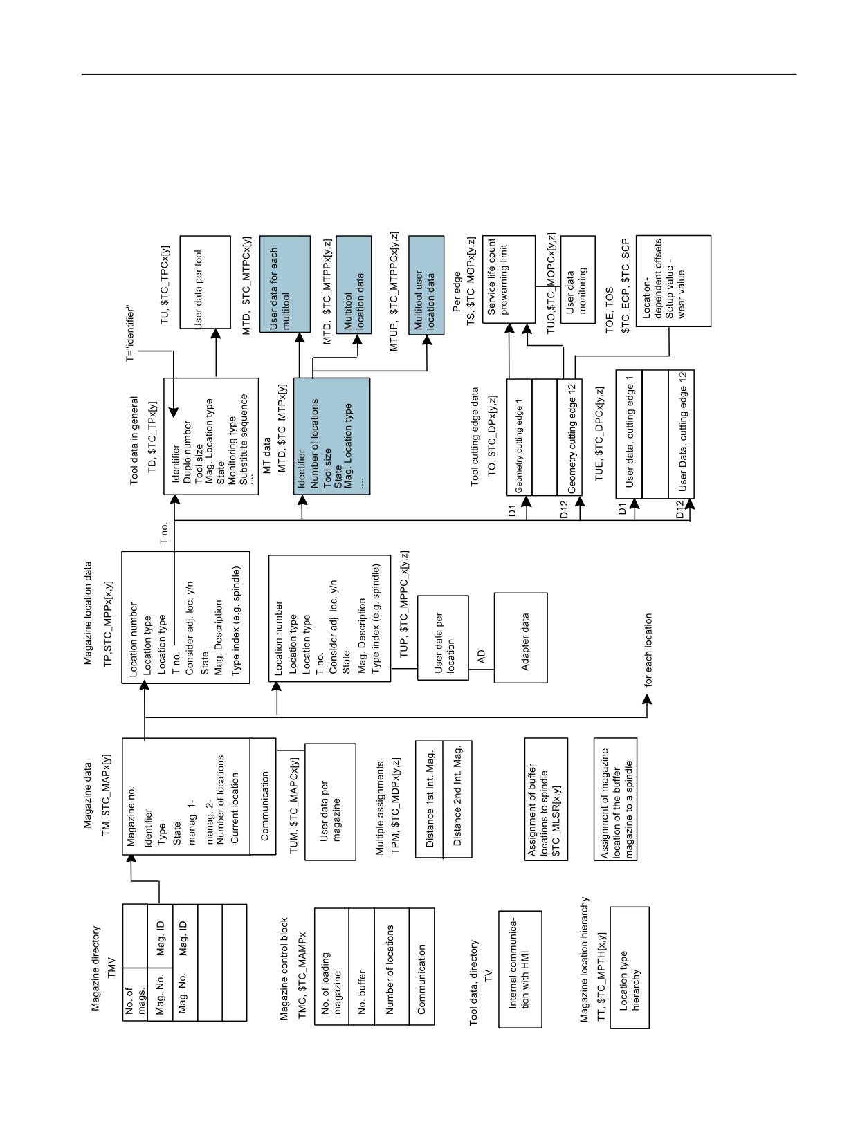
Functional scope
3.5 Data structure HMI/PLC - NC (OPI)
3.5
Data structure HMI/PLC - NC (OPI)
Data structure (structure of magazine data and tool data)
Tool management
Function Manual, 10/2020, 6FC5397-1HP40-0BA1
29
Functional scope
3.5 Data structure HMI/PLC - NC (OPI)
Blue fields
Blue fields describe the data of multitools
Tool management
30
Function Manual, 10/2020, 6FC5397-1HP40-0BA1
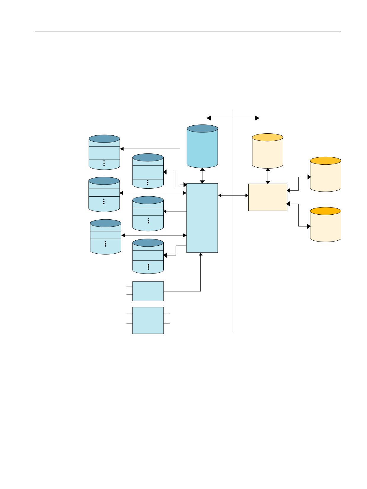
Functional scope
3.6 PLC - NC interfaces
3.6
PLC - NC interfaces
Overview
The core of the tool management is located on the NC. The PLC merely contains the interfaces
for the machine-specific part.
3/&
1&
'%
'%
3DUDPH
WHUV
/RDGLQJ
DVVLJQPHQW
0DFKLQH
XQORDGLQJ VW
'%
EXIIHU HWF
GDWD
/RDGLQJ XQO
RDGLQJ VW
72 GDWD
'%
6SLQGOH
7RRO PDQDJH
%DVLF
'%
PHQW
SURJUDP
6SLQGOH
)%
'%
0DJD]LQH
GDWD
7XUUHW
'%
7XUUHW
)&
/RF WRRO ROG
70B75$16
/RF WRRO QHZ
)&
70B',5
6HWSRLQW SRV
'LUHFWLRQ
6HOHFWLRQ RI
$FWXDO SRV
'LVWDQFH WR JR
GLUHFWLRQ
Figure 3-2
Data structure and PLC - NC interface
Tool management
Function Manual, 10/2020, 6FC5397-1HP40-0BA1
31
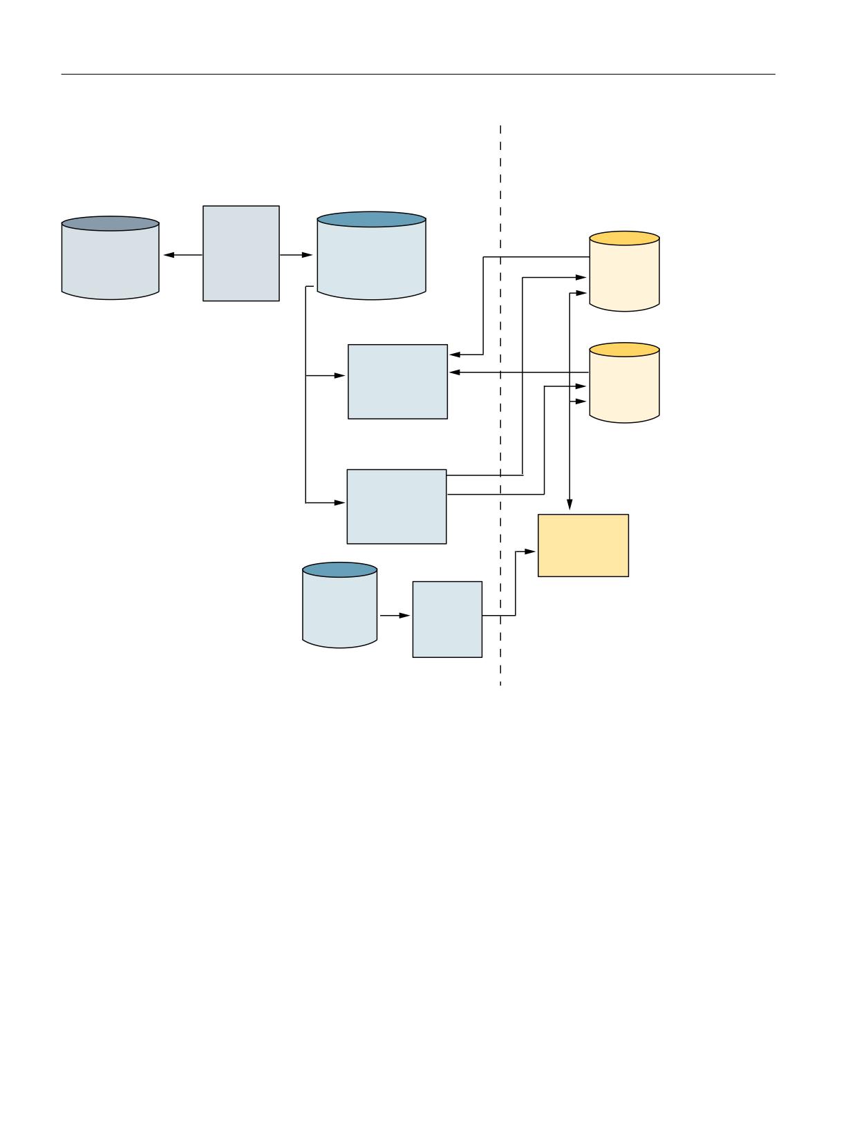
Functional scope
3.6 PLC - NC interfaces
3&
3/&
1&
1&9$5[\ PGE
8VHU '%
$GGUHVVHV RI 1&
1& 9$5
7RRO PDQDJH
YDULDEOHV
VHOHFWRU
PHQW YDULDEOHV
7RRO PDQDJHPHQW
72 GDWD
YDULDEOHV
)%
5HDG *(7
0DJD]LQH
1& YDULDEOH
GDWD
)%
:ULWH 387
1& YDULDEOH
7RRO PDQDJH
PHQW
'%
)%
)%
7RRO
PDQDJH
PHQW 3,
VHUYLFHV
Figure 3-3
Extended interface for tool management between PLC and NC
Tool management
32
Function Manual, 10/2020, 6FC5397-1HP40-0BA1

Functional scope
3.7 Access protection, protection levels
3.7
Access protection, protection levels
The access to programs, data and functions is protected via 8 hierarchical levels according to
customer requirements. These are subdivided into
• Four password levels for Siemens, machine manufacturers and end users
• Four keyswitch positions for end users
Protec-
Locked by:
User
tion level
0
Password
Siemens
1
Password
Machine manufacturer: Development
2
Password
Machine manufacturer: Commissioning engineer
3
Password
End user: Service
4
Keyswitch, position 3
End user: Programmer, machine setter
5
Keyswitch, position 2
End user: Qualified operator, who does not program
6
Keyswitch, position 1
End user: Selected operator, who does not program
7
Keyswitch, position 0
End user: Semi-skilled operator
Examples of functions that can be disabled with SINUMERIK Operate:
• Loading
• Unloading
• Magazine list, tool list display
• Tool cabinet, tool catalog
• Loading the magazine configuration
Tool management
Function Manual, 10/2020, 6FC5397-1HP40-0BA1
33
Functional scope
3.7 Access protection, protection levels
Tool management
34
Function Manual, 10/2020, 6FC5397-1HP40-0BA1

Basic commissioning and configuration
4
4.1
Input of the machine data
4.1.1
Settings with/without magazine management
Setting without magazine management
Make the following settings if you are commissioning the tool management without NC
magazine management:
MD18080 $MN_MM_TOOL_MANAGEMENT_MASK
Memory for the tool management is re-
(Page 63)
served step by step (SRAM).
= 02H
Bit 1
Provide monitoring data.
MD20310 $MC_TOOL_MANAGEMENT_MASK (Page 91)
Activating the tool management func-
tions.
= 02H
Bit 1
Monitoring functions of tool management active.
MD17530 $MN_TOOL_DATA_CHANGE_COUNTER
Marking the changed tool data for HMI.
(Page 58)
= 1FH
Bit 0
Tool status change.
Bit 1
Tool remaining unit quantity change.
Bit 2
Tool data change service.
Bit 3
Magazine data in the change service.
Bit 4
ISO data in the change service.
MD28450 $MC_MM_TOOL_DATA_CHG_BUFF_SIZE
Buffer for changing tool data (DRAM).
= 400
Number of entries in the buffer for the OPI change service for tool data. Dynamic memory is
used. This buffer is only created if either bit 2 or bit 3 is set in MD17530 $MN_TOOL_DA-
TA_CHANGE_COUNTER (default setting).
Tool management
Function Manual, 10/2020, 6FC5397-1HP40-0BA1
35

Basic commissioning and configuration
4.1 Input of the machine data
Setting with magazine management
Make the following settings if you are commissioning the tool management with NC magazine
management:
MD18080 $MN_MM_TOOL_MANAGEMENT_MASK
Memory for the tool management is re-
(Page 63)
served step by step (SRAM).
= 03H
Bit 0
Provide tool management data.
Bit 1
Provide monitoring data.
MD20310 $MC_MM_TOOL_MANAGEMENT_MASK
Activating the tool management func-
(Page 91)
tions.
= 03H
Bit 0
Magazine management active.
Bit 1
Monitoring functions of tool management active.
MD17530 $MN_TOOL_DATA_CHANGE_COUNTER
Marking the changed tool data for HMI.
(Page 58)
= 1FH
Bit 0
Tool status change.
Bit 1
Tool remaining unit quantity change.
Bit 2
Tool data change service.
Bit 3
Magazine data in the change service.
Bit 4
ISO data in the change service.
MD28450 $MC_MM_TOOL_DATA_CHG_BUFF_SIZE
Buffer for changing tool data (DRAM).
= 400
Number of entries in the buffer for the OPI change service for tool data. Dynamic memory is
used. This buffer is only created if either bit 2 or bit 3 is set in MD17530 $MN_TOOL_DA-
TA_CHANGE_COUNTER (default setting).
See also
NC-specific machine data (Page 55)
Channel-specific machine data (Page 79)
4.1.2
Configuration via machine data
General machine data
Machine data for memory partitions, assignment of channels to TO units have to be set for tool
management. Also, memory will be needed in the battery-buffered RAM.
Tool management
36
Function Manual, 10/2020, 6FC5397-1HP40-0BA1
Basic commissioning and configuration
4.1 Input of the machine data
Configuration via machine data
Option: More than four magazines (if required)
MD18080
MM_TOOL_MANAGEMENT_MASK
Activate the memory for tool management
MD17500
MAXNUM_REPLACEMENT_TOOLS
Maximum number of replacement tools
MD17510
TOOL_UNLOAD_MASK
Behavior of tool data at unloading
MD17515
TOOL_RESETMON_MASK
Behavior of tool data at RESETMON
MD17520
TOOL_DEFAULT_DATA_MASK
Create new tool: Data default setting
MD17530
TOOL_DATA_CHANGE_COUNTER
Identifying tool data change for HMI
MD17540
TOOLTYPES_ALLOWED
Permitted tool types
MD18074
MM_TOOL_MANAGEMENT_TRACE_SZ
Maximum size of the tool management diagnostics ring buffer
MD18075
MM_NUM_TOOLHOLDERS
Max. number of tool holders
MD18076
MM_NUM_LOCS_WITH_DISTANCE
Max. number of magazine locations per TOA with distance connections
MD18077
MM_NUM_DIST_REL_PER_MAGLOC
Max. number of magazines in the distance table of a magazine location
MD18078
MM_MAX_NUM_OF_HIERARCHIES
Maximum number of definable hierarchies for magazine location types
MD18079
MM_MAX_HIERARCHY_ENTRIES
Maximum permissible number of entries in a magazine-location-type hierarchy.
Definition of number of magazines and magazine locations
MD18084
MM_NUM_MAGAZINE
Maximum number of magazines that NC can manage (minimum of 3 maga-
zines). Buffer and loading magazines must be added (i.e. for 2 real magazines,
"4" must be specified)!
MD18086
MM_NUM_MAGAZINE_LOCATION
Number of magazine locations the NC can manage. Buffer and loading locations
must be added!
Tool management
Function Manual, 10/2020, 6FC5397-1HP40-0BA1
37
Basic commissioning and configuration
4.1 Input of the machine data
Definition of tools and tool cutting edges
MD18082
MM_NUM_TOOL
Number of tools to be managed by the NC
MD18100
MM_NUM_CUTTING_EDGES_IN_TOA
Number of cutting edges in NC, tool offsets per TOA block
MD18106:
MM_MAX_CUTTING_EDGE_PER_TOOL
Maximum number of cutting edges (D offset) per tool (per T number)
Options for providing additional user data for magazines, magazine locations, tools and tool
edges
MD18090
MM_NUM_CC_MAGAZINE_PARAM
Number of additional magazine data $TC_MAPCx[n]
MD18091
MM_TYPE_CC_MAGAZINE_PARAM
Type definition for magazine-oriented user data
MD18092
MM_NUM_CC_MAGLOC_PARAM
Number of additional magazine location data $TC_MPPCx[n,m] generated
MD18093
MM_TYPE_CC_MAGLOC_PARAM
Type definition for magazine location-oriented user data
MD18094
MM_NUM_CC_TDA_PARAM
Number of additional tool-specific data per tool $TC_TPPCx[t] generated
MD18095
MM_TYPE_CC_TDA_PARAM
Type definition for tool-oriented user data
MD18096
MM_NUM_CC_TOA_PARAM
Number of additional data per tool edge $TC_DPCx[t,d] generated
MD18097
MM_TYPE_CC_TOA_PARAM
Type definition for cutting edge-oriented user data
MD18098
MM_NUM_CC_MON_PARAM
Number of additional monitoring data per tool edge $TC_MOPCx[t,d] generated
MD18099
MM_TYPE_CC_MON_PARAM
Type definition for monitoring-related user data
Channel-specific machine data
Enabling of channel-specific functions for tool management.
MD20310
TOOL_MANAGEMENT_MASK
Channel-specific activation of tool management
Specification of spindle number for tool life monitoring.
MD20320
TOOL_TIME_MONITOR_MASK
Activation of tool life monitoring for the spindle specified here (tool holder
number)
Tool management
38
Function Manual, 10/2020, 6FC5397-1HP40-0BA1
Basic commissioning and configuration
4.1 Input of the machine data
Tool change turret or spindle.
MD22550
TOOL_CHANGE_MODE
Change with M06 or with T selection
MD22560
TOOL_CHANGE_M_MODE
M function for tool change
Cutting edge selection after tool change.
MD20270
CUTTING_EDGE_DEFAULT
Offset selection or deselection at tool change
Definition of tool with which tool offset is to be selected as a function of MD20110 and MD20112
during power-up and reset.
MD20122
TOOL_RESET_NAME
Definition for selection of tool length compensation
Definition of the active tool holder number.
MD20124
TOOL_MANAGEMENT_TOOLHOLDER
Definition of the active tool holder number
Assignment of TO units to channels.
MD28085
MM_LINK_TOA_UNIT
Allocation of a TOA range to a channel
Definition of initial setting for control after boot, reset, end of part program in relation to G
commands, tool length offsets, and transformation.
MD20110
RESET_MODE_MASK
Definition of the control basic setting. Relevant bit = 0: The actual value remains
valid.
Note
For machine data 20310 TOOL_MANAGEMENT_MASK and 18080
MM_TOOL_MANAGEMENT_MASK, bits 0-3 must always be set the same.
Tool management
Function Manual, 10/2020, 6FC5397-1HP40-0BA1
39

Basic commissioning and configuration
4.1 Input of the machine data
4.1.3
Additional settings
Additional settings
You can enable further functions on the user interface via the following machine data / setting
data:
MD52270 $MCS_TM_FUNCTION_MASK
Bit 0
Creating a tool at the magazine location is not permitted.
Bit 1
Load/unload lock if the machine is not in the reset state.
Bit 2
Load/unload lock for emergency stop.
Bit 3
Loading/unloading or relocating tool in/out of buffer.
Bit 4
Tool loaded directly into spindle.
Bit 5
Using the grinding configuration file.
Bit 6
Relocating a tool in/out of buffer is permitted despite lock (see bit 3).
Bit 7
Tool is created using the number.
Bit 8
Hide tool relocation.
Bit 9
Hide magazine positioning.
Bit 10
Reactivate tool with magazine positioning.
Bit 11
Reactivate tool in all monitoring types.
Bit 12
Hide reactivating tool.
SD54215 $SNS_TM_FUNCTION_MASK_SET
Bit 0
Diameter display for rotating tools.
Cutting edge parameters 6 (tool nose radius) and 15 (wear radius) are not displayed as a
radius value, but as a diameter value for the following tool types: Types 100 to 299, 580, 710,
711, 712, 713, 714 and 725.
Cutting edge parameter 7 (outside radius) is not displayed as a radius value, but as a diameter
value for the following tool types: Types 140 and 714.
Bit 1
M4 is the standard direction of rotation for all turning tools. When creating turning tools, the
direction of rotation is pre-assigned with M4.
Bit 2
A name is not suggested when creating a tool.
Bit 3
Input lock, tool name and tool type for loaded tools. For loaded tools, the tool name and the
tool type can no longer be changed.
Bit 4
Input lock for loaded tools if the channel is not in the reset state.
Bit 5
Tool wear entries are added: Wear data is entered in addition to the already existing wear
value.
Bit 6
Only numerical entries are permitted in the "Tool identifier".
Bit 7
Hide tool monitoring parameters. The tool monitoring parameters are hidden in the user
interface.
Bit 8
Diameter display for face axis - geometry. The geometry value of the transverse axis is dis-
played as a diameter value, if a transverse axis is defined in MD20100 $DIAMETER_AX_DEF
and SD42940 $TOOL_LENGTH_CONST is set to 18 and SD42950 $TOOL_LENGTH_TYPE is set
to 2.
Bit 9
Diameter display for face axis - wear. The wear value of the transverse axis is displayed as a
diameter value, if a transverse axis is defined in MD20100 $DIAMETER_AX_DEF and SD42940
$TOOL_LENGTH_CONST is set to 18 and SD42950 $TOOL_LENGTH_TYPE is set to 2.
Tool management
40
Function Manual, 10/2020, 6FC5397-1HP40-0BA1

Basic commissioning and configuration
4.1 Input of the machine data
Bit 10
Enable tool load/relocate to buffer storage locations. The magazine number can be entered
into the load dialog box. It is therefore possible to access the buffer storage via magazine
number 9998.
Bit 11
Creating new tools at gripper locations is blocked.
Bit 12
Measuring tools are not unloaded with the "Unload all" function.
Bit 13
The wear value is not deleted when a tool geometry value is entered.
Bit 14
Load or relocate tool. Empty location search performed without default value with the tool
magazine last used.
= 0 Empty location always starts with the tool magazine last used.
= 1: Empty location search follows the set search strategy.
Dependencies
The setting data SD54215 $TM_FUNCTION_MASK_SET and the machine data MD20360
$TOOL_PARAMETER_DEF_MASK have the following dependencies:
Dependency
Description
Recommendation
SD54215
⇔
MD20360
Bit 9
⇔
Bit 0
If bit 0 is set in MD20360, then SD54215 bit
It is recommended that the setting MD20360
9 has no effect because the NC already re-
bit 0 and bit 1 not be used.
turns the linear wear value of the trans-
Instead, use SD4215 bit 9 and bit 8.
verse axis as a diameter value.
MD20360 bit 0 and bit 1 are effective only for
turning and grinding tools. This setting there-
Bit 8
⇔
Bit 1
If bit 1 is set in MD20360, then SD54215 bit
fore cannot be used on a turning/milling ma-
8 has no effect because the NC already re-
chine because the linear component of the
turns the linear geometry value of the trans-
transverse axis applies for turning tools in the
verse axis as a diameter value.
diameter and for milling tools in the radius.
When the setting data is used, only the display
goes to diameter, the internal value in the NC
remains at radius.
Bit 0
⇔
Bit 11
If bit 11 is set in MD20360, then SD54215
It is recommended that the setting MD20360
bit 0 has no effect with regard to cutting
bit 11 and bit 12 not be used.
edge parameter 6 (tool nose radius) be-
Instead, set bit 0 in SD54215.
cause the NC already returns the tool nose
MD20360 bit 11 and bit 12 apply to all tool
radius as a diameter value.
types, i.e. also to turning tools. This setting
therefore cannot be used on a turning/milling
Bit 0
⇔
Bit 12
If bit 12 is set in MD20360, then SD54215
machine because the tool nose radius of a turn-
bit 0 has no effect with regard to cutting
ing tool should never be specified in the diam-
edge parameter 15 (wear radius) because
eter.
the NC already returns the wear radius as a
When the setting data is used, only the display
diameter value.
goes to diameter, the internal value in the NC
remains at radius.
Tool management
Function Manual, 10/2020, 6FC5397-1HP40-0BA1
41

Basic commissioning and configuration
4.1 Input of the machine data
Enabling the graphic tool and magazine display function
Make the following settings when the tools and the magazine should be represented graphically:
MD52271 $MCS_TM_MAG_PLACE_DISTANCE
Distance between individual magazine lo-
cations in the unit of measurement of the
basic NC system.
> 0
The tools and magazine locations are displayed graphically.
= 0
The tools and magazine locations are not displayed graphically.
You must make the following settings on the user interface:
1. Press the "Settings" softkey in the "Tool list" window.
The "Settings" window opens.
2. Activate the "Switch on graphical magazine display" checkbox.
This checkbox is offered only when the MD52271 $MCS_TM_MAG_PLACE_DISTANCE
machine data has a value > 0.
Supplementary conditions:
• MD52200 $MCS_TECHNOLOGY = 2 (milling)
• MD52201 $MCS_TECHNOLOGY_EXTENSION = 0
Default settings for unloading/loading and relocating
MD52272 $MCS_TM_TOOL_LOAD_DEFAULT_MAG
Default magazine for loading tools.
= 0
No default magazine, default value
MD52273 $MCS_TM_TOOL_MOVE_DEFAULT_MAG
Default magazine for relocating tools.
= 0
No default magazine, default value
MD52274 $MCS_TM_TOOL_LOAD_STATION
Number of loading station.
= 0
All configured stations are considered, default value
Input limits for wear input
MD51212 $MNS_TM_WRITE_WEAR_ABS_LIMIT
Maximum value of the tool wear.
MD51213 $MNS_TM_WRITE_WEAR_DELTA_LIMIT
Maximum differential value of restricted tool
wear input.
MD51214 $MNS_TM_WRITE_LIMIT_MASK
Range of validity of the restricted tool wear
input.
Tool management
42
Function Manual, 10/2020, 6FC5397-1HP40-0BA1

Basic commissioning and configuration
4.1 Input of the machine data
Setting the manual tool function
MD22562 $MC_TOOL_CHANGE_ERROR_MODE
Response when errors occur at tool
change.
Bit 1 = 1
Manual tools can be loaded.
Bit 2 = 1
Active D No. > 0 and active T No. = 0 generate an alarm message.
Active D No. > 0 and active D No. = 0 generate an alarm message.
Note
If, in machine data MD22562 $MC_TOOL_CHANGE_ERROR_MODE bit 2 = 1, then you have the
option, using a correction selection (D No.) in the program, to stop the machine until the PLC
signals that the tool change has been completed. To do this, machine data MD20270
$MC_CUTTING_EDGE_DEFAULT must be set to = 0.
Tool management
Function Manual, 10/2020, 6FC5397-1HP40-0BA1
43
Basic commissioning and configuration
4.2 Configuration in SINUMERIK Operate
4.2
Configuration in SINUMERIK Operate
4.2.1
Function overview of the tool management editor
The tool management allows you to define all real tool magazines and internal magazines with
the appropriate properties through the operating software and to link them channel-specifically
to the tool unit. You can configure the relationships between tool magazine, griper and spindle
via a tree view.
Calling the tool management
You open the tool management window as follows:
1.
Select the "Start-up" operating area.
2.
Press the "NC" and "Tool management" softkeys.
The "Tool management" window opens.
General sequence
The following steps are required to create a tool management:
• Create tool unit
• Define buffer locations
• Define loading location
• Create magazine configuration
• Link assignments
Note
When you create a new tool unit, a buffer location with a spindle location, a loading magazine
with a loading location and a real magazine with five locations are created by default.
Meaning of the symbols
Symbol
Description
Folder for the actively used tool units
Folder with access to templates
Tool management
44
Function Manual, 10/2020, 6FC5397-1HP40-0BA1
Basic commissioning and configuration
4.2 Configuration in SINUMERIK Operate
Symbol
Description
Tool spindle / tool holder
Tool gripper 1
Tool gripper 2
Shows the changes in the the "Active data" folder that has not been activated yet
Meaning of the tree view
The following folders are available in the tree view:
• Active data: Configure and activate the magazine management.
• Examples: Copy templates into the "Active data" folder.
• Network/USB: Copy the new magazine managements into the "Active data" folder or use
existing ones for other systems.
See also
Loading sequence (Page 359)
4.2.2
Editing the tool management
For the tree view of the tool management, functions are available with which you can
parameterize magazine data items and link them with each other.
Note
If you position the cursor on an element, only those functions possible for this element are
active. All other functions are inactive which is indicated with grayed-out softkeys.
Procedure
The "Tool management" window is open.
Adding a new tool unit
1.
Position the cursor on the "Active data" folder element.
2.
Press the "New element" softkey.
A folder element with the standard designation <tool unit> is inserted and
the "TO unit" input window opens.
Tool management
Function Manual, 10/2020, 6FC5397-1HP40-0BA1
45