SINUMERIK 840D sl. Service - Functions. Manual (2018-2020) - page 79
Transformation package handling
7.3 Definition of terms
7.3.2
Definition of positions and orientations using frames
In order to make a clear distinction from the term "frame" as it is used in the NC language, the
following description explains the meaning of the term "frame" in relation to the handling
transformation package.
Frame
A frame can be used to translate one coordinate system into another. In this respect, a distinction
must be made between translation and rotation. Translation results in an offset; a rotation, a
rotation of the coordinate system with respect to the initial system. Coordinates X, Y and Z are
used as designator for a translation. They are defined so as to result in a legal coordinate system.
Translation
A translation is always specified in relation to the coordinate directions of the initial system.
These directions are assigned to machine data as follows:
• X direction: ..._POS[ 0 ]
• Y direction: ..._POS[ 1 ]
• Z direction: ..._POS[ 2 ]
Rotation
A rotation is specified in RPY angles A, B and C (R=roll, P=pitch, Y=yaw). The positive direction of
rotation is defined by the right hand rule, i.e. if the thumb on the right hand is pointing in the
direction of the axis of rotation, then the fingers are pointing in the positive angular direction.
Angles A and C are defined in the interval [ -180; +180 ], and B in the interval [ -90; +90 ].
The definitions of the RPY angles are as follows:
• Angle A: 1. rotation about the Z axis of the initial system
• B angle: 2. Rotation through the rotated Y axis
• C angle: 3. rotation about the twice rotated X axis
The RPY angles are assigned to machine data as follows:
• Angle A: ..._RPY[ 0 ]
• B angle: ..._RPY[ 1 ]
• C angle: ..._RPY[ 2 ]
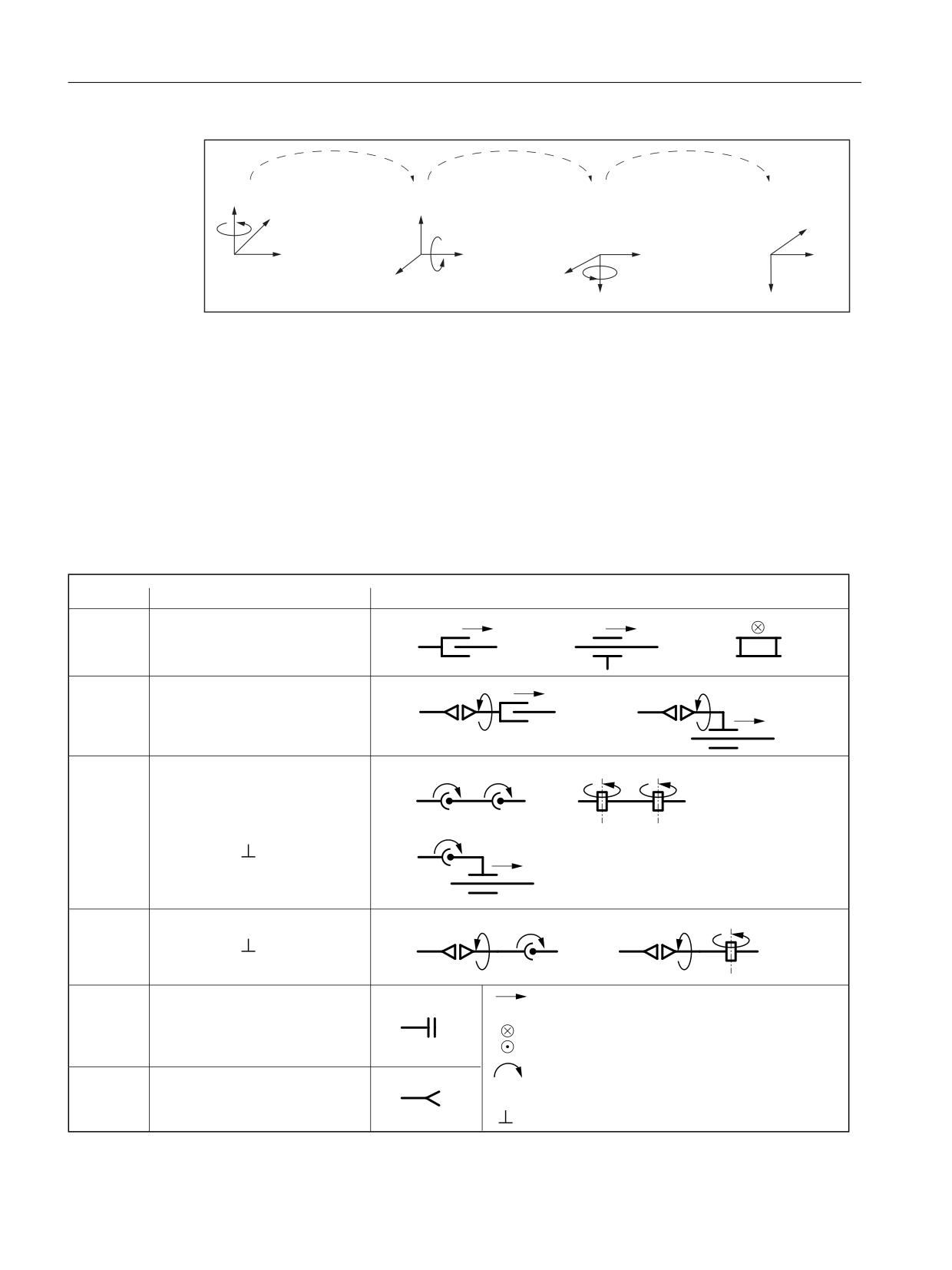
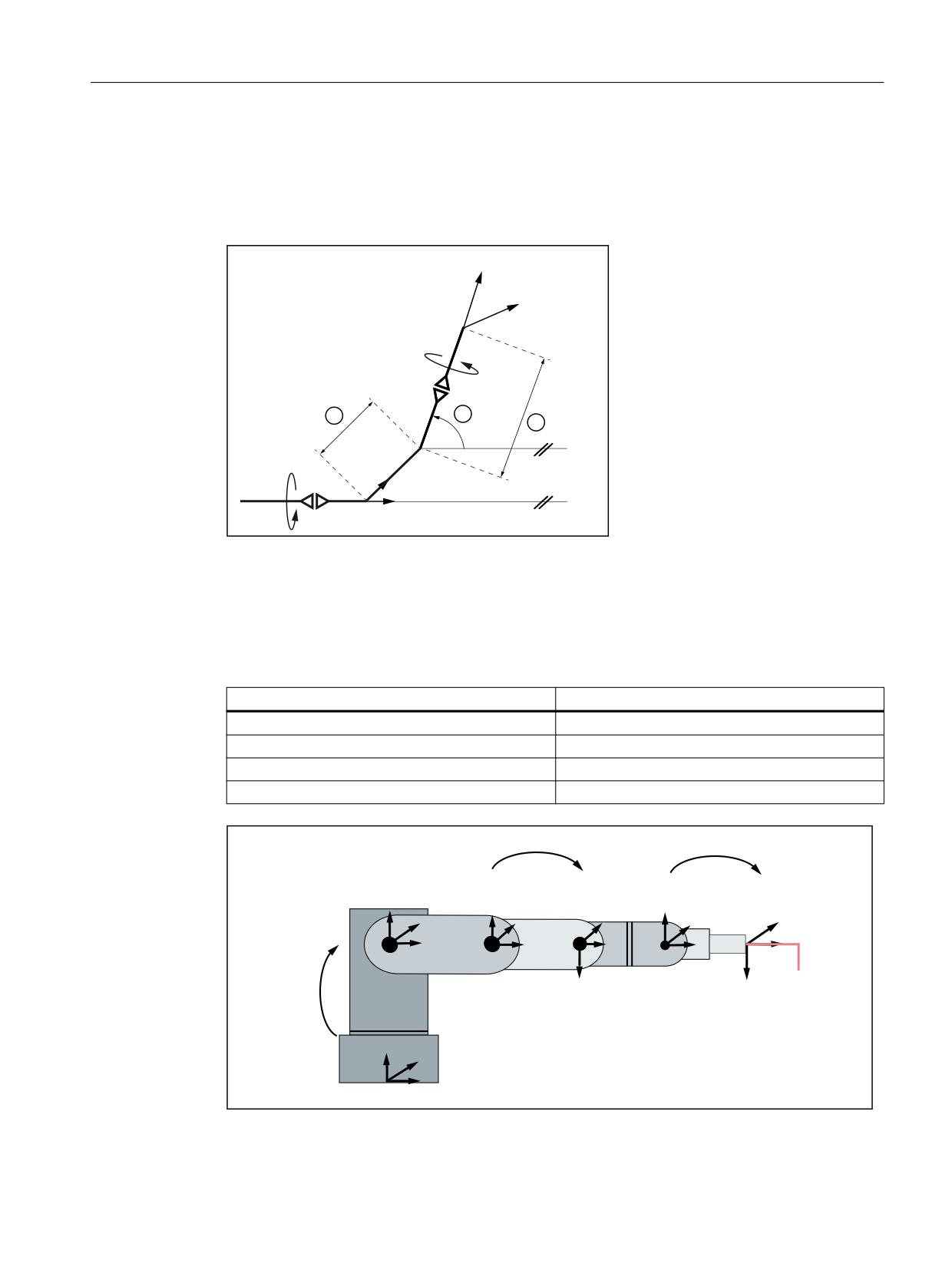
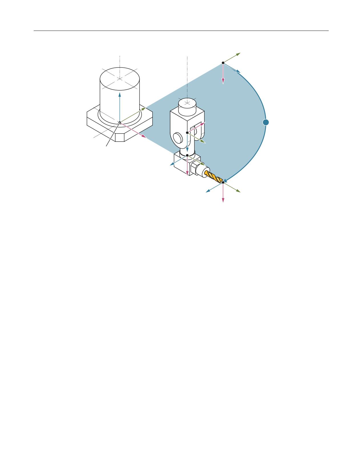
The following diagram shows an example for a rotation through the RPY angle. The initial
coordinate system X1, Y1, Z1 is transitioned into the coordinate system X4, Y4, Z4
1. Rotation through angle A around the Z1 axis
2. Rotation through angle B around the Y2 axis
3. Rotation through angle C around the X3 axis.
Technologies
Function Manual, 10/2020, 6FC5397-8GP40-0BA1
115
Transformation package handling
7.3 Definition of terms
$
r
% r
&
r
=
=
<
<
;
<
<
=
;
=
;
;
Figure 7-1
Example of rotation through RPY angles
7.3.3
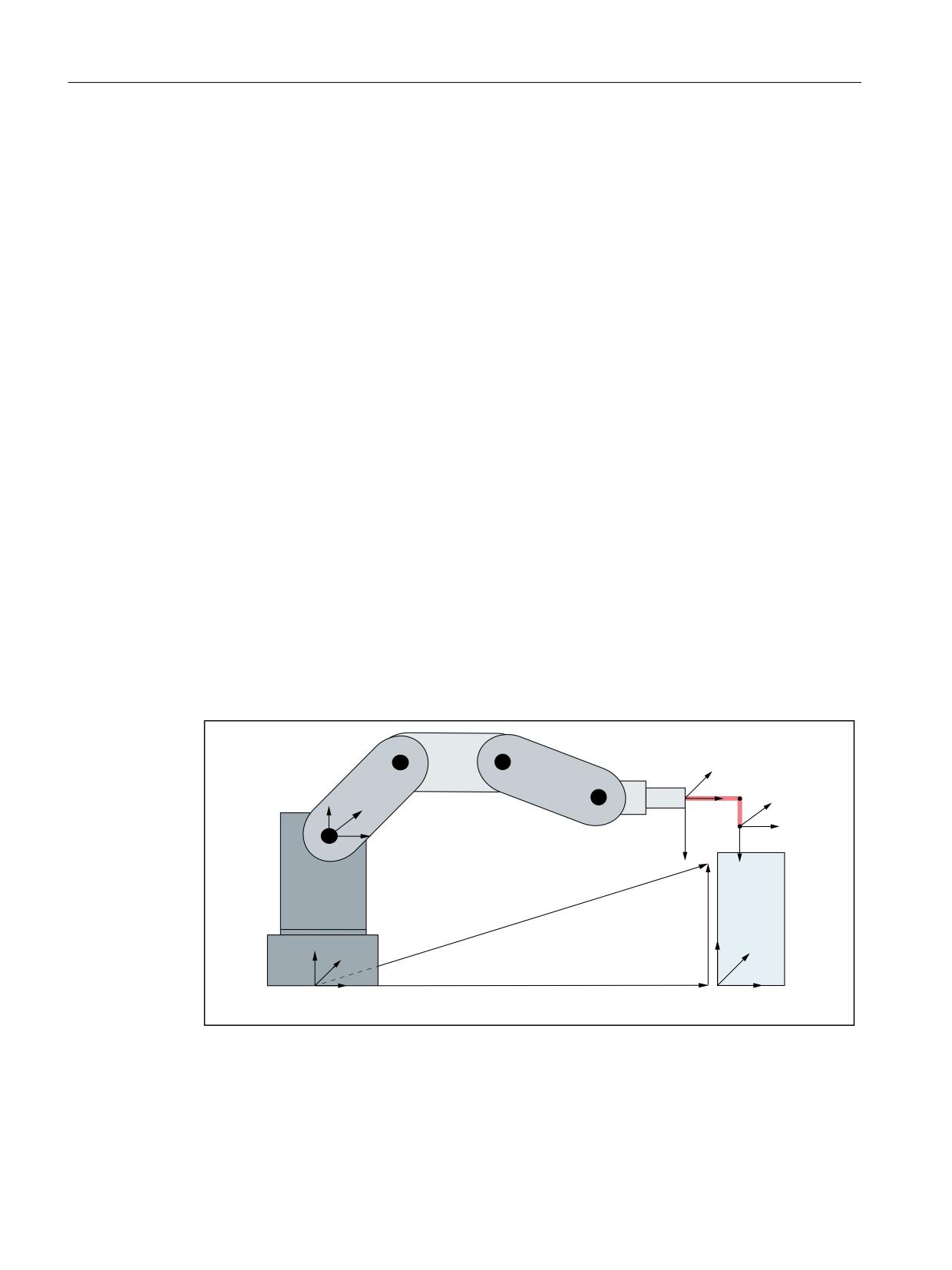
Definition of a joint
Meaning
A sliding joint is implemented using a translatory axis, and a swivel joint, using a rotary axis.
The basic axis identifiers result from the arrangement and sequence of the individual joints.
These are specified using letter codes (S, C, R, N).
,GHQWLILHU
'HVLJQDWLRQ
,FRQV
6
6OLGLQJ MRLQW
&
6OLGLQJ MRLQW __ VZLYHO MRLQW
6ZLYHO MRLQW __ VZLYHO MRLQW
5
6ZLYHO MRLQW
6OLGLQJ MRLQW
1
6ZLYHO MRLQW
VZLYHO MRLQW
3RVLWLYH D[LV GLUHFWLRQ
)ODQJH IRU DWWDFKLQJ
3RVLWLYH D[LV GLUHFWLRQ
)/
WKH WRRO
IORZLQJ WRZDUG WKH GUDZLQJ SODQH
IORZLQJ DZD\ IURP WKH GUDZLQJ SODQH
3RVLWLYH GLUHFWLRQ RI URWDWLRQ
__
$[LV GLUHFWLRQV SDUDOOHO WR RQH DQRWKHU
7
7RRO
$[LV GLUHFWLRQV SHUSHQGLFXODU WR RQH DQRWKHU
Technologies
116
Function Manual, 10/2020, 6FC5397-8GP40-0BA1
Transformation package handling
7.4 Configuration of a kinematic transformation
Figure 7-2
Joint identifying letters
7.4
Configuration of a kinematic transformation
Meaning
In order to ensure that the kinematic transformation can convert the programmed values into
axis motions, it must have access to some information about the mechanical construction of the
machine. This information is stored in machine data:
• Axis assignments
• Geometry information
7.4.1
General machine data
MD24100 $MC_TRAFO_TYPE_1 (definition of transformation 1 in the channel)
The value 4100 must be entered in this data for the handling transformation package.
MD24110 $MC_TRAFO_AXES_IN_1 (axis assignment for transformation)
The axis assignment at the transformation input defines which transformation axis is mapped
internally onto a channel axis. It is specified in machine data:
MD24110 $MC_TRAFO_AXES_IN_1
There is a predetermined axis sequence for the handling transformation package, The basic axes
are entered in the first three components (index 0…2). The upper three components (index 3…
5) are assigned to the manual axes.
• MD24110 $MC_TRAFO_AXES_IN_1[0] = 1 ; 1. Basic axis
• MD24110 $MC_TRAFO_AXES_IN_1[1] = 2 ; 2. Basic axis
• MD24110 $MC_TRAFO_AXES_IN_1[2] = 3 ; 3. Basic axis
• MD24110 $MC_TRAFO_AXES_IN_1[3] = 4 ; 1. Manual axis
• MD24110 $MC_TRAFO_AXES_IN_1[4] = 5 ; 2. Manual axis
• MD24110 $MC_TRAFO_AXES_IN_1[5] = 6 ; 3. Manual axis
MD24120 $MC_TRAFO_GEOAX_ASSIGN_TAB_1 (assignment between geometry axis and channel
axis for transformation 1)
The translational degrees of freedom that are available for the transformation are entered via
machine data:
MD24120 $MC_TRAFO_GEOAX_ASSIGN_TAB_1
Technologies
Function Manual, 10/2020, 6FC5397-8GP40-0BA1
117
Transformation package handling
7.4 Configuration of a kinematic transformation
The 3 geometry axes normally correspond to Cartesian axis directions X, Y and Z.
In this case, the first three channel axis numbers must be transferred from MD24110
$MC_TRAFO_AXES_IN_1 to MD24120 $MC_TRAFO_GEO_AX_ASSIGN_TAB_1.
• MD24120 $MC_TRAFO_GEO_AX_ASSIGN_TAB_1[0] = 1
• MD24120 $MC_TRAFO_GEO_AX_ASSIGN_TAB_1[1] = 2
• MD24120 $MC_TRAFO_GEO_AX_ASSIGN_TAB_1[2] = 3
7.4.2
Parameterization using geometry data
Modular principle
The machine geometry is parameterized according to a type of modular principle. With this
method, the machine is successively configured in geometry parameters from its base center
point to the tool tip, thereby producing a closed kinematic loop. In this case, frames are used to
describe the geometry. While the control is powering up, the configuration machine data is
checked and alarms displayed when relevant. All axes of the mode group are tracked as alarm
response. The alarms can be deleted using POWER ON.
As shown in the following diagram "Closed kinematic loop illustrated by the example of a robot",
the kinematic transformation converts the tool operating point (tool coordinate system: XTO,
YTO, ZTO), specified relative to the base coordinate system (BCS = robot coordinate system: XRO,
YRO, ZRO), in machine axis values (MCS positions: A1, A2, A3, ...). The operating point (XWZ, YWZ,
ZWZ) is specified in the part program in relation to the workpiece to be machined (workpiece
coordinate system WCS: XWS, YWS, ZWS). The programmable frames make it possible to create an
offset between the workpiece coordinate system (WCS) and the base coordinate system (BCS).
$
;
)/
=,52
;:=
<,52
<)/
$
$
<:=
$
;,52
$
=)/
=:=
.LQHPDWLF
WUDQVIRUPDWLRQ
3URJUDPPHG
SRVLWLRQ
$
=:6
=52
<:6
<52
;52
3URJUDPPDEOH )5$0(6
:.6
;:6
%.6
Figure 7-3
Closed kinematic loop illustrated by the example of a robot
Technologies
118
Function Manual, 10/2020, 6FC5397-8GP40-0BA1
Transformation package handling
7.4 Configuration of a kinematic transformation
Note
For more detailed information about coordinate systems, please see:
Further information:
Function Manual Basic Functions; Axes, Coordinate Systems, Frames" > "Coordinate Systems"
The following machine data is available for configuring kinematic transformations:
Frame between base center point and internal coordinate system
The frame T_IRO_RO links the base center point of the machine (BCS = RO) with the first internal
coordinate system (IRO) determined by the transformation.
• MD62613 $MC_TRAFO6_TIRORO_RPY (frame between base center point and internal
coordinate system (rotation component), n = 0...2)
• MD62612 $MC_TRAFO6_TIRORO_POS (frame between base center point and internal
coordinate system (position component), n = 0...2)
Basic axis arrangement
The type of basic axis arrangement is specified in machine data:
• MD62603 $MC_TRAFO6_MAIN_AXES (basic axis identifier)
The first three axes included in the transformation are generally referred to as the "basic axes".
They must always be mutually parallel or perpendicular.
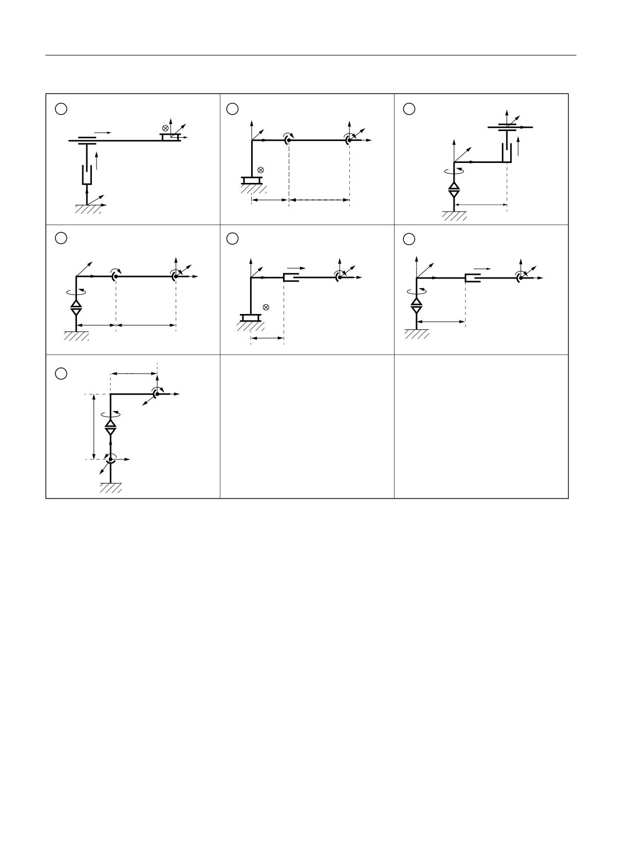
The handling transformation package contains the basic axis kinematics shown in the following
diagram. Every basic axis arrangement has its own special identifier (see Chapter "Definition of
a joint (Page 116)").
Technologies
Function Manual, 10/2020, 6FC5397-8GP40-0BA1
119
Transformation package handling
7.4 Configuration of a kinematic transformation
5
5
=,52
5
4
4
4
<,52
=,52
3
3
3
;,52
;,52
<,52
=,52
<,52
;,52
$
%
$
=,52
=,52
5
=,52
5
5
<,52
4
4
<,52
4
<,52
3
3
3
;,52
;,52
;,52
$
%
$
$
$
4
3
5
%
<,52
;,52
=,52
① SS: MD62603 = 1, gantry (3 linear axes, rectangular)
② CC: MD62603 = 2, SCARA (1 linear axis, 2 rotary axes (in parallel))
③ CS: MD62603 = 6, SCARA (2 linear axes, 1 rotary axis (spin axis))
④ NR: MD62603 = 3, articulated arm (3 rotary axes (2 axes in parallel))
⑤ SC: MD62603 = 4, SCARA (2 linear axes, 1 rotary axis (swivel axis))
⑥ RR: MD62603 = 5, articulated arm (1 linear axis, 2 rotary axes (vertical))
⑦ NN: MD62603 = 7, articulated arm (3 rotary axes)
Figure 7-4
Overview of basic axis configuration
Basic axis lengths A and B
The basic axis lengths A and B are specified with machine data:
• MD62607 $MC_TRAFO6_MAIN_LENGTH_AB (basic axis lengths A and B, n = 0...1)
As Fig. "Overview of basic axis configurations" illustrates, these are specially defined for each
type of basic axis.
Technologies
120
Function Manual, 10/2020, 6FC5397-8GP40-0BA1
Transformation package handling
7.4 Configuration of a kinematic transformation
Position of the 4th axis
Whether the 4th axis is mounted parallel, anti-parallel or perpendicular to the last rotary basic
axis is specified in machine data:
• MD62606 $MC_TRAFO6_A4PAR (axis 4 is parallel/anti-parallel to last basic axis)
Description of the wrist axis
Frame to attach the wrist axis
Frame T_X3_P3 links the last coordinate system of the basic axes with the first wrist axis
coordinate system.
• MD62608 $MC_TRAFO6_TX3P3_POS (attachment of wrist axis (position component], n =
0...2)
• MD62609 $MC_TRAFO6_TX3P3_RPY (attachment of wrist axis (rotation component), n =
0...2)
Frame between wrist point and flange coordinate system
Frame T_FL_WP links the last hand wrist axis coordinate system with the flange coordinate
system.
• MD62610 $MC_TRAFO6_TFLWP_POS (frame between wrist point and flange coordinate
system (position component), n = 0...2)
• MD62611 $MC_TRAFO6_TFLWP_RPY (frame between wrist point and flange coordinate
system (rotation component), n = 0...2)
This data is explained in more detail in the following sections.
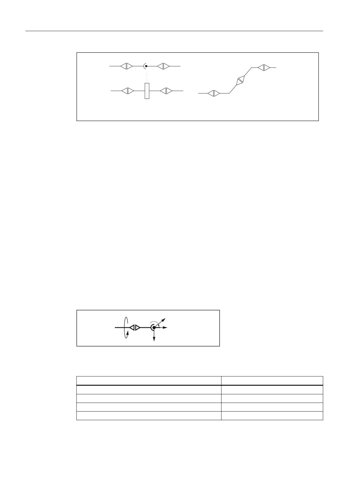
Description of the wrist axis type
These parameters describe the wrist axis type.
• MD62604 $MC_TRAFO6_WRIST_AXES (wrist axis identifier)
The term wrist axes generally refers to axes four to six.
Wrist axes included in every transformation
The fourth axis and all further axes are generally referred to as "wrist axes". The handling
transformation package can only identify wrist axes with rotary axes. The wrist axis identifier for
three-axis wrists is entered in machine data:
• MD62604 $MC_TRAFO6_WRIST_AXES (wrist axis identifier)
When there are fewer than three wrist axes, the identifier for the inclined wrist axis or a central
wrist axis is entered in the machine data:
• MD62604 $MC_TRAFO6_WRIST_AXES (wrist axis identifier)
The current software only supports the central and inclined wrist axis types.
Technologies
Function Manual, 10/2020, 6FC5397-8GP40-0BA1
121
Transformation package handling
7.4 Configuration of a kinematic transformation
&HQWUDO KDQG
%HYHOHG KDQG ZLWK HOERZ
Figure 7-5
Overview of wrist axis configuration
Parameterization of wrist axes
With the following machine data, using a special frame type, the geometry of the wrist axis and/
or the position of the coordinate system in the wrist axis with respect to one another is defined.
• MD62614 $MC_TRAFO6_DHPAR4_5A (parameter A for configuring the wrist axis, n = 0...1)
• MD62615 $MC_TRAFO6_DHPAR4_5D (parameter D for configuring the wrist axis, n = 0...1)
• MD62616 $MC_TRAFO6_DHPAR4_5ALPHA. (Parameter ALPHA for configuring the wrist axis,
n = 0...1)
For this purpose, the machine data corresponds to certain frame components (see Section
"Definition of positions and orientations using frames (Page 115)"):
• X component: MD62614 $MC_TRAFO6_DHPAR4_5A ≙ _POS[ 0 ] (x component)
• Z component: MD62615 $MC_TRAFO6_DHPAR4_5D ≙ _POS[ 2 ] (z component)
• C angle: MD62616 $MC_TRAFO6_DHPAR4_5ALPHA ≙ _RPY[ 2 ] (C angle)
The other components of the frame are zero.
Central wrist axis
On a central wrist axis, all wrist axes intersect at one point. All parameters must be set as shown
in Table "Configuring data for a central wrist axis".
]
+3
]
[
[
[+3
Figure 7-6
Central wrist axis, 5-axis machine
Table 7-1
Configuring data for a central wrist axis
Machine data
Value
MD62604 $MC_TRAFO6_WRIST_AXES
2
MD62614 $MC_TRAFO6_DHPAR4_5A
[0.0, 0.0]
MD62615 $MC_TRAFO6_DHPAR4_5D
[0.0, 0.0]
MD62616 $MC_TRAFO6_DHPAR4_5ALPHA
[-90.0, 90.0]
Technologies
122
Function Manual, 10/2020, 6FC5397-8GP40-0BA1
Transformation package handling
7.4 Configuration of a kinematic transformation
Inclined wrist axis
The inclined wrist axis differs from the central wrist axis in two respects, i.e. the axes do not
intersect nor are they mutually perpendicular. Parameters a4, d5, and a4 are available for this type
of hand, as shown in Table "Configuring data for a central wrist axis".
]
]
+3
[
[
+3
[
]
① MD62614 $MC_TRAFO6_DHPAR4_5A[ 0 ]
② MD62616 $MC_TRAFO6_DHPAR4_5ALPHA[ 0 ]
③ MD62615 $MC_TRAFO6_DHPAR4_5D[ 1 ]
Figure 7-7
Inclined wrist axis, 5-axis machine
Table 7-2
Configuring data for an inclined wrist axis (5-axis
Machine data
Value
MD62604 $MC_TRAFO6_WRIST_AXES
6
MD62614 $MC_TRAFO6_DHPAR4_5A
[a4, 0.0]
MD62615 $MC_TRAFO6_DHPAR4_5D
[0.0, d5]
MD62616 $MC_TRAFO6_DHPAR4_5ALPHA
[α4, 0.0]
7B; B3
7B)/B:3
$
$
$
$
$
]
,5
2
U
[
\
T
+3
[
,5
2
\
]
)/
+
3
[
S
[
\
,5
2
+3
\
)/
]
]
)
/
7B,5
2B52
$
]
5
2
\
5
2
[
5
2
Figure 7-8
Link frames
Technologies
Function Manual, 10/2020, 6FC5397-8GP40-0BA1
123
Transformation package handling
7.4 Configuration of a kinematic transformation
Frame: T_IRO_RO
Frame T_IRO_RO provides the link between the base center point coordinate system (RO)
defined by the user and the internal robot coordinate system (IRO). The internal robot coordinate
system is predefined in the handling transformation package for each basic axis type and
included in the kinematic diagrams for the basic axis arrangements. The base center point
system is in the Cartesian zero point of the machine, corresponding to the basic coordinate
system. If no FRAMES are programmed, the basic coordinate system equals the workpiece
coordinate system.
Note
For more detailed information about FRAMES, please see:
Further information
Programming Manual Fundamentals
Frame T_IRO_RO is not subject to any restrictions for 5-axis kinematics.
The following restrictions apply in relation to 4-axis kinematics:
• The first rotary axis must always be parallel/anti-parallel to one of the coordinate axes of the
base center point coordinate system (RO).
• No further restrictions apply to type SS basic axes.
• In the case of type CC, CS or SC basic axes, no further restrictions apply provided that the 4th
axis is parallel to the last rotary basic axis.
• With respect to all other basic axes, and basic axes of type CC, CS or SC if the 4th axis is
perpendicular to the last rotary basic axis, the Z axis of RO must be parallel to the Z axis of IRO.
Frame: T_X3_P3
Frame T_X3_P3 describes the method used to attach the wrist axis to the basic axes. Frame
T_X3_P3 is used to link the coordinate system of the last basic axis (p3_q3_r3 coordinate system)
with the coordinate system of the first wrist axis (x3_y3_z3 coordinate system). The p3_q3_r3
coordinate system is included in the kinematic diagrams for the basic axis arrangements.
The z3 axis is always on the 4th axis.
Depending on the number of axes to be included in the transformation, frame T_X3_P3 is
subject to certain restrictions relating to the wrist and basic axes:
• For 5-axis kinematics, frame T_X3_P3 can be freely selected in the following cases:
- If the basic axes are of the SS type.
- If the basic axes are type CC, CS, or SC, the transformation must either include a central
wrist axis or the 4th axis must be positioned parallel to the last rotary basic axis.
- If the basic axes are type NR or RR, the transformation must either include a central wrist
axis or the 4th axis must be positioned in parallel to the last basic rotary axis and an X
flange must intersect the 5th axis.
- If the basic axes are of the NN type, the transformation must include a central wrist axis.
• For 4-axes, ensure that the Z3 axis is always parallel/anti-parallel or perpendicular to the last
basic axis.
Technologies
124
Function Manual, 10/2020, 6FC5397-8GP40-0BA1

Transformation package handling
7.4 Configuration of a kinematic transformation
Frame: T_FL_WP
Frame T_FL_WP links the flange with the last internal coordinate system (wrist point coordinate
system) preset by the handling transformation package.
For kinematics with less than 6 axes, this frame is subject to certain restrictions. These
restrictions are explained by the relevant kinematics.
Other configuring data
Number of transformed axes
The number of axes included in the transformation is defined in machine data:
• MD62605 $MC_TRAFO6_NUM_AXES (number of transformed axes)
The number of transformed axes can currently lie between two and six axes.
Changing the axis sequence
Rearrangement of axes: MD62620
Note
With certain types of kinematics, it is possible to transpose axes without changing the behavior
of the kinematic transformation. Machine data:
MD62620 $MC_TRAFO6_AXIS_SEQ (rearrangement of axes)
The axes on the machine are numbered consecutively from 1 to 6 and must be entered in the
internal sequence in machine data:
MD62620 $MC_TRAFO6_AXIS_SEQ[0] ...[4]
All other axis-specific machine data refer to the sequence of axes on the machine.
Table 7-3
Changing the axis sequence
Basic axis kinematics
Options for changing axis sequence
SS, CC
Any
SC
1 and 2
CS
2 and 3
Example 1
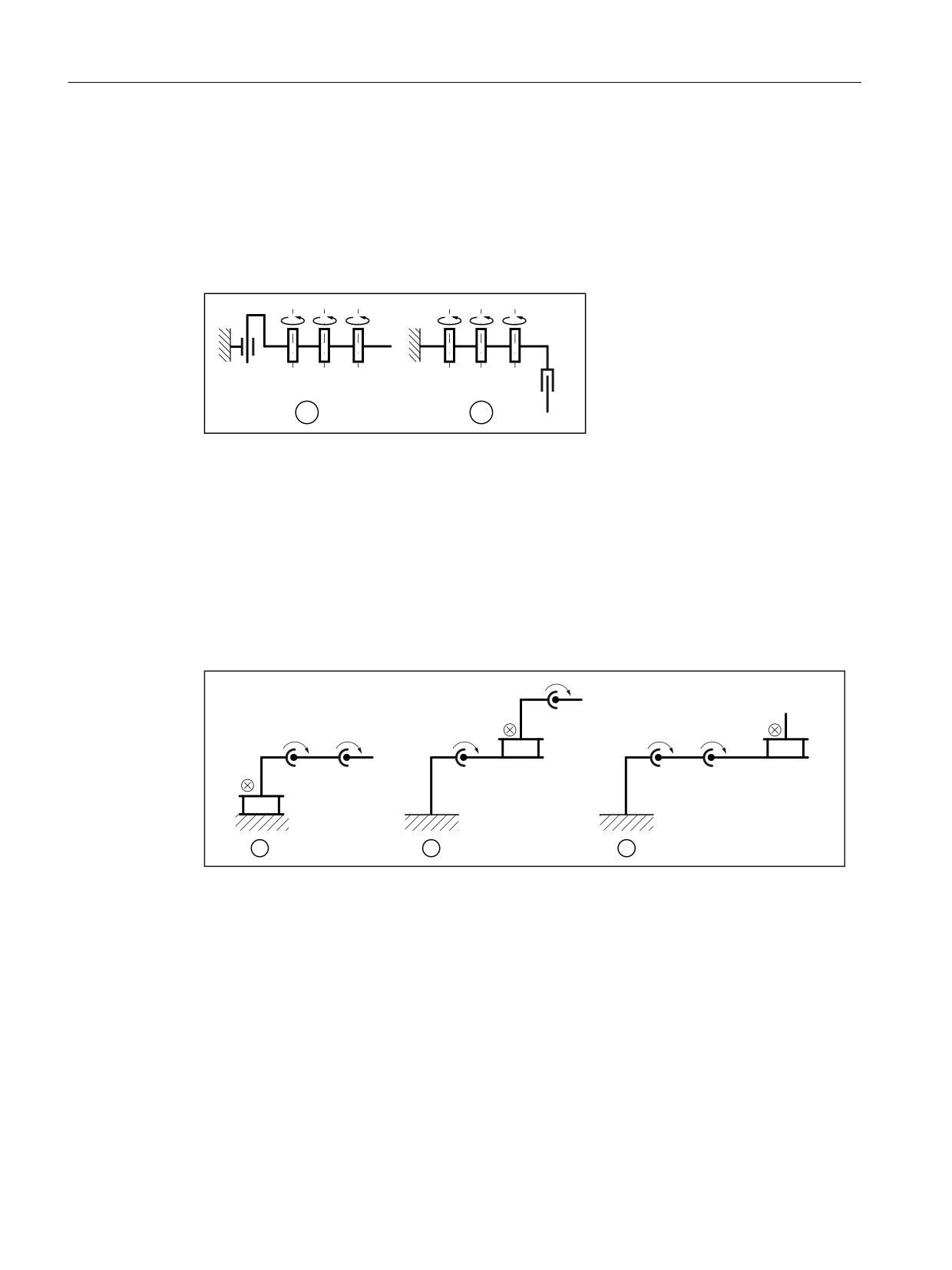
There are two kinematics, such as those shown in Fig. "Rearrangement of axes 1". Kinematic 1
is directly included in the handling transformation package. It corresponds to a CC kinematic
with a wrist axis parallel to the last basic rotary axis.
Kinematic 2 is the same as kinematic 1 inasmuch as it is irrelevant for the resulting robot
movement whether the translational axis is axis 1 or axis 4. In this instance, the data for
kinematic 2 must be entered as follows in machine data:
• MD62620 $MC_TRAFO6_AXIS_SEQ (rearrangement of axes)
Technologies
Function Manual, 10/2020, 6FC5397-8GP40-0BA1
125
Transformation package handling
7.4 Configuration of a kinematic transformation
The input is as follows:
• MD62620 $MC_TRAFO6_AXIS_SEQ[ 0 ] = 4
• MD62620 $MC_TRAFO6_AXIS_SEQ[ 1 ] = 1
• MD62620 $MC_TRAFO6_AXIS_SEQ[ 2 ] = 2
• MD62620 $MC_TRAFO6_AXIS_SEQ[ 3 ] = 3
① Kinematics 1
② Kinematics 2
Figure 7-9
Rearrangement of axes 1
Example 2
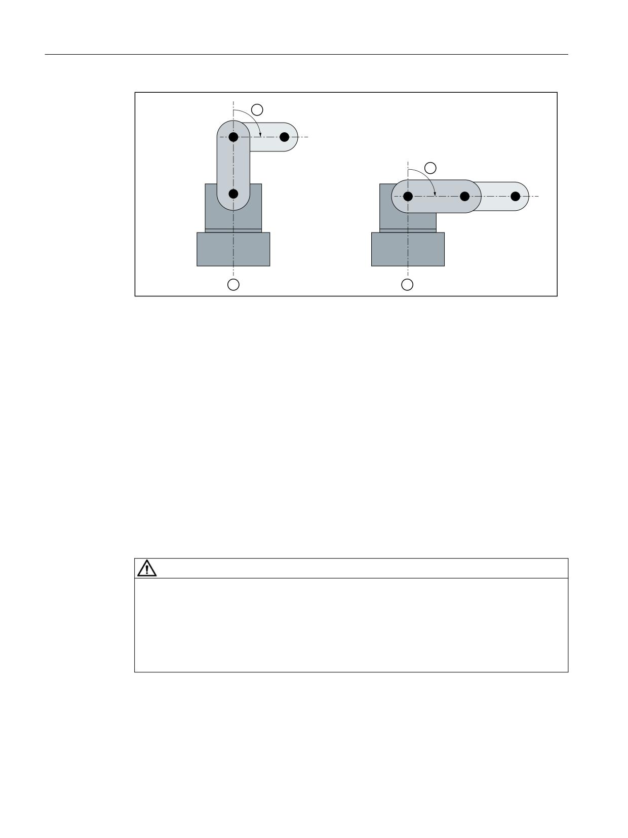
This example involves a SCARA kinematic transformation as illustrated in Fig. "Rearrangement
of axes 2", in which the axes can be freely transposed. Kinematic 1 is directly included in the
handling transformation package. It corresponds to a CC kinematic. As regards the transposition
of axes, it is irrelevant how many wrist axes are involved in the transformation.
① Kinematics 1: Axis sequence 1 2 3
② Kinematics 2: Axis sequence 2 1 3
③ Kinematics 3: Axis sequence 2 3 1
Figure 7-10
Rearrangement of axes 2
Technologies
126
Function Manual, 10/2020, 6FC5397-8GP40-0BA1
Transformation package handling
7.4 Configuration of a kinematic transformation
Changing the directions of axes
A rotational or offset direction is preset for each axis in the handling transformation package.
This direction is not necessarily the same as the corresponding direction on the machine. The
following machine data must be set to -1 for the relevant axis if the direction is to be inverted,
or otherwise to +1:
• MD62618 $MC_TRAFO6_AXES_DIR[ ] (matching of physical and mathematical directions of
rotation [axis no.]: 0...5)
Adapting the zero points of the axes
Offset between mathematical and mechanical zero points
The mathematical zero points of axes are preset in the handling transformation package.
However, the mathematical zero point does not always correspond to the mechanical zero point
(calibration point) of axes. In order for the zero point of each axis to fit one another, the
difference between the mathematical zero point and the alignment point for each axis must be
entered in the following machine data:
• MD62617 $MC_TRAFO6_MAMES[ ] (offset between mathematical and mechanical zero
points [axis no.]: 0...5)
The deviation to be entered corresponds to the difference between the mechanical zero point
and the mathematically positive direction of rotation of the axis.
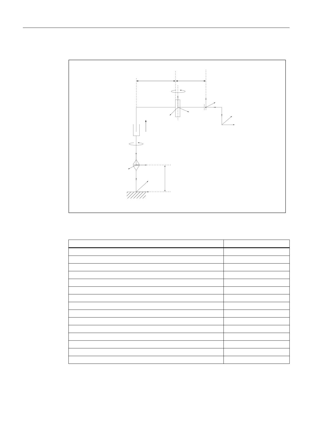
Example
Jointed arm kinematics are shown in the following diagram.
In the mathematical zero position ②, axis 2 (A2) has a value of 90º. This value should be entered
into the machine data for axis 2 (index 1):
• MD62617 $MC_TRAFO6_MAMES[ 1 ] = 90
Axis 3 (A3) is counted relative to the previous axis 2 (A2) in the kinematic chain, and in the
mechanical zero position ① has the value: -90º:
• MD62617 $MC_TRAFO6_MAMES[ 2 ] = -90
Technologies
Function Manual, 10/2020, 6FC5397-8GP40-0BA1
127
Transformation package handling
7.4 Configuration of a kinematic transformation
$
$
$
$
$
$
① mechanical zero position (adjusted position):
② MD62617 $MC_TRAFO6_MAMES[ 2 ] = -90
③ mathematical zero position
④ MD62617 $MC_ TRAFO6_MAMES[ 1 ] = 90
Figure 7-11
Matching mathematical and mechanical zero points
Axis type for transformation
Which axis type is handled is specified in machine data:
• MD62601 $MC_TRAFO6_AXES_TYPE (axis type for transformation [axis no.]: 0...5)
The transformation package distinguishes between the following axis types:
• Linear axis: MD62601 = 1
• Rotary axis: MD62601 = 3
Velocity and acceleration values for override control that limits the dynamic response
CAUTION
Unnecessarily high limiting default values
Since software release RCTRA 07.05.00, RCTRA transformation for limiting the Cartesian
velocities and acceleration levels, takes into account machine data MD62629 to MD62632.
In order to avoid unnecessarily limiting the velocities and acceleration levels, this machine data
must be adapted to the machine capabilities. Frequently, unnecessarily high limiting default
values are set here, as - up until now - this data has not been used.
For traversing axes with active RCTRA transformation and override controls that limit the
dynamic performance, dedicated substitute limit values have been introduced for velocities and
acceleration levels for Cartesian motion components.
Technologies
128
Function Manual, 10/2020, 6FC5397-8GP40-0BA1
Transformation package handling
7.4 Configuration of a kinematic transformation
The override controller within the transformation is only active if motion is interpolated, whose
dynamic limits are not secured - or not completely secured - through motion planning in the Look
Ahead function of the control.
The velocity controller is active in the following cases:
• When traversing in the JOG mode with transformation
• For overlaid motion in realtime, e.g. via system variable $AA_OFF[ X ]
• For velocity limits as a result of Safety Integrated (SG level active)
Cartesian velocity
The velocities for individual translatory motion directions when traversing with override
controller are specified using machine data:
• MD62629 $MC_TRAFO6_VELCP[ i ] (Cartesian velocity [No.]: 0...2)
- Index i = 0 : X component of basic system
- Index i = 1 : Y component of basic system
- Index i = 2 : Z component of basic system
Cartesian acceleration rates
The acceleration levels for individual translatory motion directions when traversing with
override controller are specified using machine data:
• MD62630 $MC_TRAFO6_ACCCP[i] (Cartesian acceleration levels [no.]: 0...2)
- Index i = 0 : X component of basic system
- Index i = 1 : Y component of basic system
- Index i = 2 : Z component of basic system
Orientation angle velocities
The velocities for individual orientation directions when traversing with override controller are
specified using machine data:
• MD62631 $MC_TRAFO6_VELORI[ i ] (orientation angle velocities [no.]: 0...2)
- Index i = 0 : A angle
- Index i = 1 : B angle
- Index i = 2 : C angle
Technologies
Function Manual, 10/2020, 6FC5397-8GP40-0BA1
129
Transformation package handling
7.5 Descriptions of kinematics
Orientation angle acceleration rates
The acceleration levels for individual orientation directions when traversing with override
controller are specified using machine data:
• MD62632 $MC_TRAFO6_ACCORI[ i ] (orientation angle acceleration levels [no.]: 0...2)
- Index i = 0 : A angle
- Index i = 1 : B angle
- Index i = 2 : C angle
Reduction factor for the velocity controller
A reduction factor for the velocity controller in the JOG mode can be specified with the machine
data:
• MD62633 $MC_ROBX_DYN_LIM_REDUCE (reduction factor for the velocity controller)
Time constant for the velocity controller
A time constant for the PT1 filter of the velocity controller can be specified with the machine data:
• MD62634 $MC_ROBX_VEL_FILTER_TIME (time constant for the velocity controller)
7.5
Descriptions of kinematics
The following descriptions of kinematics for transformations involving 2 to 5 axes explain the
general configuring procedure first before describing how the machine data need to be
configured, using a configuring example for each kinematic type. These examples do not include
all possible lengths and offsets. The direction data refer to the positive directions of traversal and
rotation for the transformation. The axis positions correspond to their zero position for the
relevant transformation.
7.5.1
3-axis kinematics
3-axis kinematics normally possess three translational degrees of freedom, but do not have a
rotational degree of freedom for orientation. As a consequence, 3-axis kinematics only have
basic axes.
Configuration
The procedure for configuring a 3-axis kinematic is as follows:
1. Enter "Standard" kinematic category in machine data:
MD62600 $MC_TRAFO6_KINCLASS (kinematic category)
2. Set the number of axes for transformation in machine data:
MD62605 $MC_TRAFO6_NUM_AXES = 3 (number of transformed axes)
Technologies
130
Function Manual, 10/2020, 6FC5397-8GP40-0BA1
Transformation package handling
7.5 Descriptions of kinematics
3. Compare the basic axes with the basic axes contained in the handling transformation
package. → Enter the basic axis identifier in machine data:
MD62603 $MC_TRAFO6_MAIN_AXES (basic axis identifier)
4. If the axis sequence is not the same as the normal axis sequence, it must be corrected in
machine data:
MD62620 $MC_TRAFO6_AXIS_SEQ (rearrangement of axes)
5. As identifier for the wrist axes, the following machine data must be set to 1 (no wrist axis):
MD62604 $MC_TRAFO6_WRIST_AXES = 1 (wrist axis identifier)
6. Enter the axis types for the transformation in machine data:
MD62601 $MC_TRAFO6_AXES_TYPE (axis type for transformation)
7. Compare the directions of rotation of axes with the directions defined in the handling
transformation package and correct in machine data:
MD62618 $MC_TRAFO6_AXES_DIR (matching of physical and mathematical directions of
rotation)
8. Enter the mechanical zero offset in machine data:
MD62617 $MC_TRAFO6_MAMES (offset between mathematical and mechanical zero
points)
9. Enter the basic axis lengths in machine data:
MD62607 $MC_TRAFO6_MAIN_LENGTH_AB (basic axis lengths A and B)
10.Define frame T_IRO_RO and enter the offset in machine data:
MD62612 $MC_TRAFO6_TIRORO_POS (frame between base center point and internal
system (position component))
Enter the rotation in machine data:
MD62613 $MC_TRAFO6_TIRORO_RPY (frame between base center point and internal
system (rotation component))
11.Determine the flange coordinate system. For this purpose, the p3_q3_r3 coordinate system
must be regarded as the initial system. The offset is entered in machine data:
MD62610 $MC_TRAFO6_TFLWP_POS (frame between wrist point and flange (position
component))
The rotation is entered in machine data:
MD62611 $MC_TRAFO6_TFLWP_RPY (frame between wrist point and flange (rotation
component))
SCARA kinematics
SCARA kinematics are characterized by the fact that they possess both translational and rotary
axes. The kinematics have different names depending on how the basic axes are arranged with
respect to one another, e.g.: CC, SC, CS kinematics (see Chapter "Definition of a joint
(Page 116)").
Technologies
Function Manual, 10/2020, 6FC5397-8GP40-0BA1
131
Transformation package handling
7.5 Descriptions of kinematics
3-axis CC kinematics
&&
0'
0'
75$)2 B0$,1B/(1*7+B$%>
@
75$)2 B7)
/:3B326> @
T
]
)/
\)/
S
[)/
]:=
\:=
U
[:=
\,52
[,522
],52
]
0'
52
\52
75$)2 B7,5252B326> @
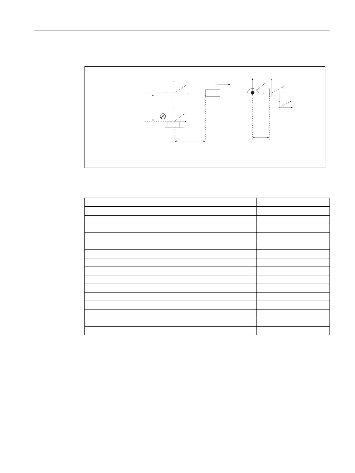
[52
Figure 7-12
3-axis CC kinematics
Table 7-4
Configuration data for 3-axis CC kinematics
Machine data
Value
MD62600 $MC_TRAFO6_KINCLASS
1
MD62605 $MC_TRAFO6_NUM_AXES
3
MD62603 $MC_TRAFO6_MAIN_AXES
2
MD62604 $MC_TRAFO6_WRIST_AXES
1
MD62601 $MC_TRAFO6_AXES_TYPE
[3, 1, 3, ...]
MD62620 $MC_TRAFO6_AXIS_SEQ
[2, 1, 3, 4, 5, 6]
MD62618 $MC_TRAFO6_AXES_DIR
[1, 1, 1, 1, 1, 1]
MD62617 $MC_TRAFO6_MAMES
[0.0, 0.0, 0.0, 0.0, 0.0, 0.0]
MD62607 $MC_TRAFO6_MAIN_LENGTH_AB
[0.0, 300.0]
MD62612 $MC_TRAFO6_TIRORO_POS
[0.0, 0.0, 500.0]
MD62613 $MC_TRAFO6_TIRORO_RPY
[0.0, 0.0, 90.0]
MD62608 $MC_TRAFO6_TX3P3_POS
[0.0, 0.0, 0.0]
MD62609 $MC_TRAFO6_TX3P3_RPY
[0.0, 0.0, 0.0]
MD62610 $MC_TRAFO6_TFLWP_POS
[200.0, 0.0, 0.0]
MD62611 $MC_TRAFO6_TFLWP_RPY
[0.0, 0.0, -90.0]
Technologies
132
Function Manual, 10/2020, 6FC5397-8GP40-0BA1
Transformation package handling
7.5 Descriptions of kinematics
3-axis SC kinematics
])/
6&
]
U
,52
T
\,52
\)/
[)/
[,52
S
]:=
\:=
0'
],52
[:=
75$)2 B7,5252B326> @
\,52
[,52
0'
0'
75$)2 B0$,1B/(1*7+B$%> @
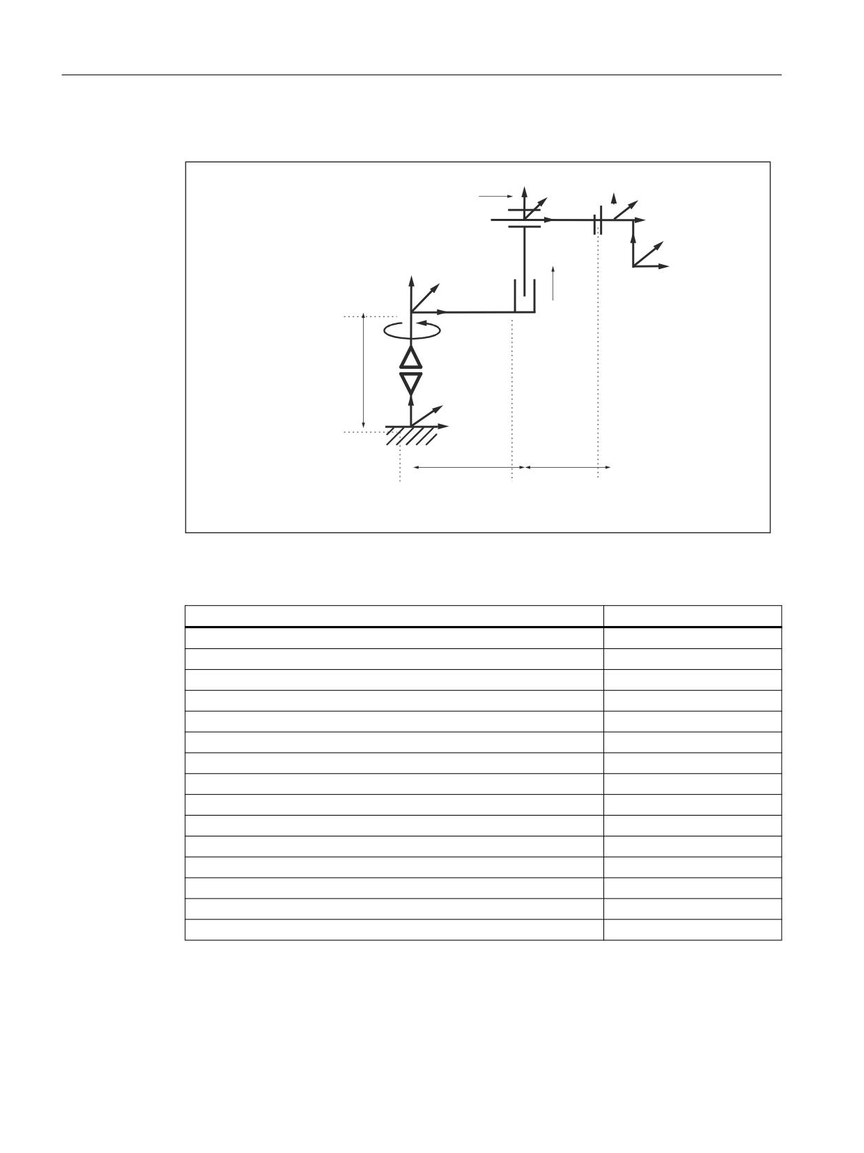
75$)2 B7)/:3B326> @
Figure 7-13
3-axis SC kinematics
Table 7-5
Configuration data for 3-axis SC kinematics
Machine data
Value
MD62600 $MC_TRAFO6_KINCLASS
1
MD62605 $MC_TRAFO6_NUM_AXES
3
MD62603 $MC_TRAFO6_MAIN_AXES
4
MD62604 $MC_TRAFO6_WRIST_AXES
1
MD62601 $MC_TRAFO6_AXES_TYPE
[1, 1, 3, ...]
MD62620 $MC_TRAFO6_AXIS_SEQ
[1, 2, 3, 4, 5, 6]
MD62618 $MC_TRAFO6_AXES_DIR
[1, 1, 1, 1, 1, 1]
MD62617 $MC_TRAFO6_MAMES
[0.0, 0.0, 0.0, 0.0, 0.0, 0.0]
MD62607 $MC_TRAFO6_MAIN_LENGTH_AB
[500.0, 0.0]
MD62612 $MC_TRAFO6_TIRORO_POS
[0.0, 0.0, 500.0]
MD62613 $MC_TRAFO6_TIRORO_RPY
[0.0, 0.0, 0.0]
MD62608 $MC_TRAFO6_TX3P3_POS
[0.0, 0.0, 0.0]
MD62609 $MC_TRAFO6_TX3P3_RPY
[0.0, 0.0, 0.0]
MD62610 $MC_TRAFO6_TFLWP_POS
[300.0, 0.0, 0.0]
MD62611 $MC_TRAFO6_TFLWP_RPY
[0.0, 0.0, 0.0]
Technologies
Function Manual, 10/2020, 6FC5397-8GP40-0BA1
133
Transformation package handling
7.5 Descriptions of kinematics
3-axis CS kinematic
r
3
CS
z
q
FL
y
3
3
FL
x
p
FL
3
y
z
WZ
WZ
z
x
IRO
WZ
y
IRO
2
x
IRO
MD 62612:
1
TRAFO6_TIRORO_POS[2]
z
RO
y
RO
x
RO
MD 62610
:
TRAFO6_TFLWP_POS[0]
MD 62607:
TRAFO6_MAIN_LENGTH_AB[0]
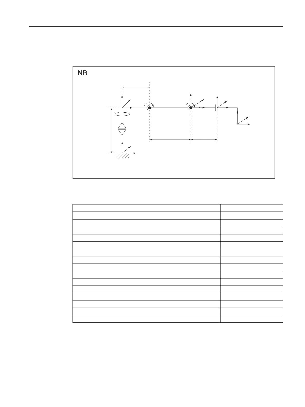
Figure 7-14
3-axis CS kinematic
Table 7-6
Configuration data for 3-axis CS kinematics
Machine data
Value
MD62600 $MC_TRAFO6_KINCLASS
1
MD62605 $MC_TRAFO6_NUM_AXES
3
MD62603 $MC_TRAFO6_MAIN_AXES
6
MD62604 $MC_TRAFO6_WRIST_AXES
1
MD62601 $MC_TRAFO6_AXES_TYPE
[3, 1, 1, ...]
MD62620 $MC_TRAFO6_AXIS_SEQ
[1, 2, 3, 4, 5, 6]
MD62618 $MC_TRAFO6_AXES_DIR
[1, 1, 1, 1, 1, 1]
MD62617 $MC_TRAFO6_MAMES
[0.0, 0.0, 0.0, 0.0, 0.0, 0.0]
MD62607 $MC_TRAFO6_MAIN_LENGTH_AB
[500.0, 0.0]
MD62612 $MC_TRAFO6_TIRORO_POS
[0.0, 0.0, 500.0]
MD62613 $MC_TRAFO6_TIRORO_RPY
[0.0, 0.0, 0.0]
MD62608 $MC_TRAFO6_TX3P3_POS
[0.0, 0.0, 0.0]
MD62609 $MC_TRAFO6_TX3P3_RPY
[0.0, 0.0, 0.0]
MD62610 $MC_TRAFO6_TFLWP_POS
[300.0, 0.0, 0.0]
MD62611 $MC_TRAFO6_TFLWP_RPY
[0.0, 0.0, 0.0]
Technologies
134
Function Manual, 10/2020, 6FC5397-8GP40-0BA1
Transformation package handling
7.5 Descriptions of kinematics
Articulated-arm kinematics
3-axis NR kinematics
0'
75$)2 B0$,1B/(1*7+B$%> @
5
=,52
=
)/
<
4
,52
<)/
;,52
3
;)/
=:=
<:=
;:=
0'
75$) B
7,5252B326> @
=52
<52
0'
75$)2 B
7)/:3B326> @
;52
0'
75$)2 B
0$,1B/(1*7+B$%> @
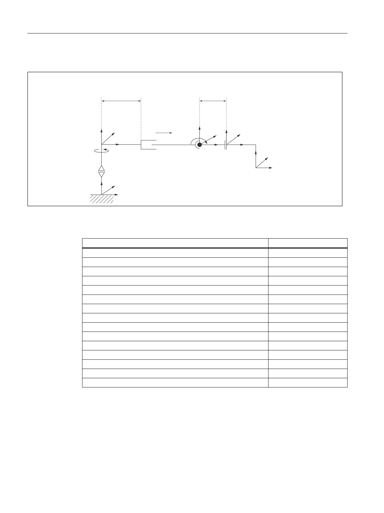
Figure 7-15
3-axis NR kinematics
Table 7-7
Configuration data 3-axis NR kinematic
Machine data
Value
MD62600 $MC_TRAFO6_KINCLASS
1
MD62605 $MC_TRAFO6_NUM_AXES
3
MD62603 $MC_TRAFO6_MAIN_AXES
3
MD62604 $MC_TRAFO6_WRIST_AXES
1
MD62601 $MC_TRAFO6_AXES_TYPE
[3, 3, 3, ...]
MD62620 $MC_TRAFO6_AXIS_SEQ
[1, 2, 3, 4, 5, 6]
MD62618 $MC_TRAFO6_AXES_DIR
[1, 1, 1, 1, 1, 1]
MD62617 $MC_TRAFO6_MAMES
[0.0, 0.0, 0.0, 0.0, 0.0, 0.0]
MD62607 $MC_TRAFO6_MAIN_LENGTH_AB
[300.0, 500.0]
MD62612 $MC_TRAFO6_TIRORO_POS
[0.0, 0.0, 500.0]
MD62613 $MC_TRAFO6_TIRORO_RPY
[0.0, 0.0, 0.0]
MD62608 $MC_TRAFO6_TX3P3_POS
[0.0, 0.0, 0.0]
MD62609 $MC_TRAFO6_TX3P3_RPY
[0.0, 0.0, 0.0]
MD62610 $MC_TRAFO6_TFLWP_POS
[300.0, 0.0, 0.0]
MD62611 $MC_TRAFO6_TFLWP_RPY
[0.0, 0.0, 0.0]
Technologies
Function Manual, 10/2020, 6FC5397-8GP40-0BA1
135
Transformation package handling
7.5 Descriptions of kinematics
3-axis RR kinematics
55
0'
0'
75$)2 B0$,1B/(1*7+B$%> @
75$)2 B7)/:3B326> @
5
=,52
=)/
<,52
4
<)/
;,52
3
;)/
=:=
<:=
;:=
=52
<52
;52
Figure 7-16
3-axis RR kinematics
Table 7-8
Configuration data for 3-axis RR kinematics
Machine data
Value
MD62600 $MC_TRAFO6_KINCLASS
1
MD62605 $MC_TRAFO6_NUM_AXES
3
MD62603 $MC_TRAFO6_MAIN_AXES
5
MD62604 $MC_TRAFO6_WRIST_AXES
1
MD62601 $MC_TRAFO6_AXES_TYPE
[3, 1, 3, ...]
MD62620 $MC_TRAFO6_AXIS_SEQ
[1, 2, 3, 4, 5, 6]
MD62618 $MC_TRAFO6_AXES_DIR
[1, 1, 1, 1, 1, 1]
MD62617 $MC_TRAFO6_MAMES
[0.0, 0.0, 0.0, 0.0, 0.0, 0.0]
MD62607 $MC_TRAFO6_MAIN_LENGTH_AB
[300.0, 0.0]
MD62612 $MC_TRAFO6_TIRORO_POS
[0.0, 0.0, 300.0]
MD62613 $MC_TRAFO6_TIRORO_RPY
[0.0, 0.0, 0.0]
MD62608 $MC_TRAFO6_TX3P3_POS
[0.0, 0.0, 0.0]
MD62609 $MC_TRAFO6_TX3P3_RPY
[0.0, 0.0, 0.0]
MD62610 $MC_TRAFO6_TFLWP_POS
[200.0, 0.0, 0.0]
MD62611 $MC_TRAFO6_TFLWP_RPY
[0.0, 0.0, 0.0]
Technologies
136
Function Manual, 10/2020, 6FC5397-8GP40-0BA1
Transformation package handling
7.5 Descriptions of kinematics
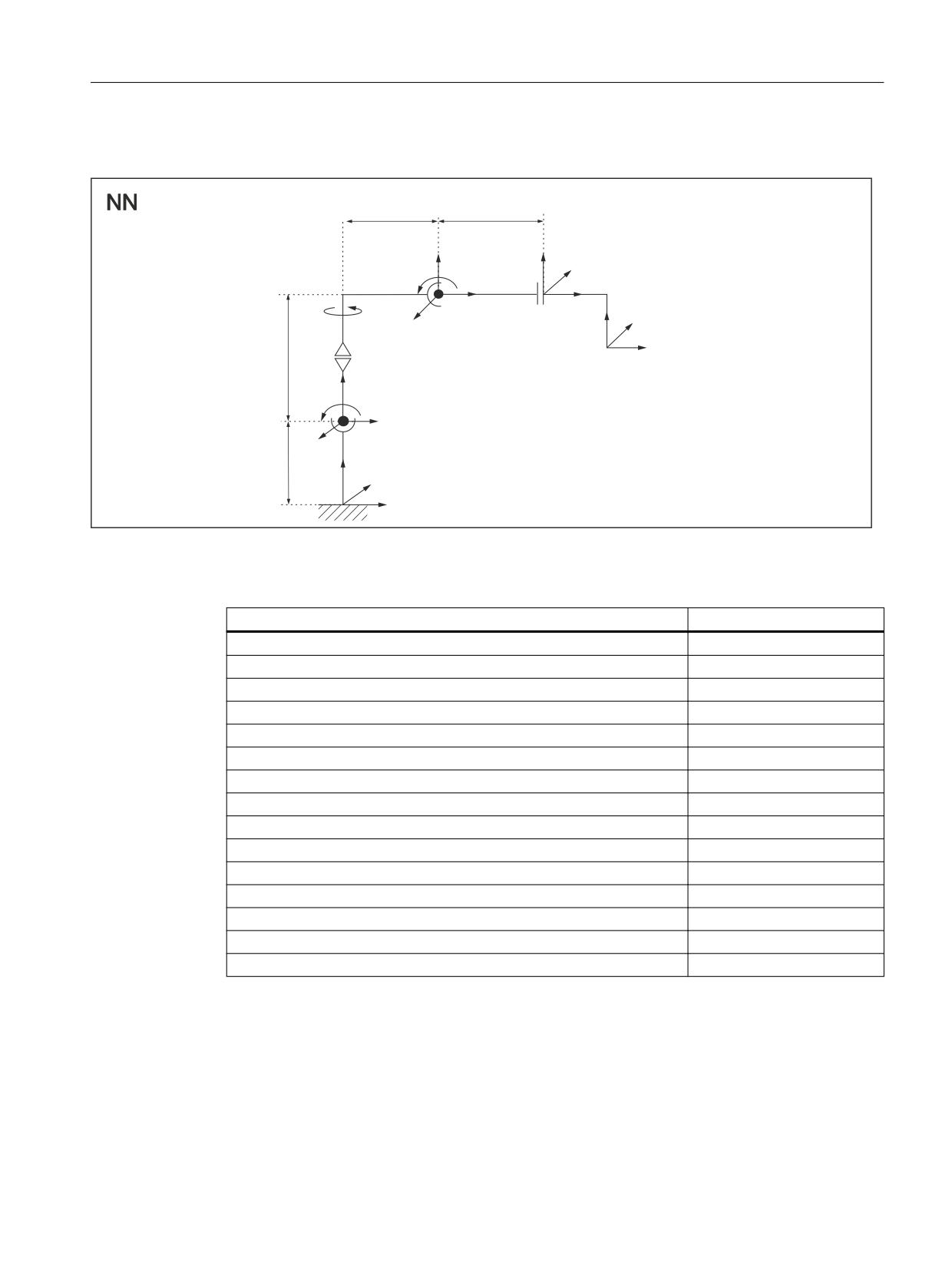
3-axis NN kinematics
0'
0'
75$)2 B0$,1B/(1*7+B$%> @
75$)2 B7)/:3B326> @
4
=)/
<)/
;)/
3
=:=
5
<:=
0'
;:=
75$)2 B0$,1
B
/(1*7+B$%> @
<,52
;,52
=,52
0'
75$)2 B7,5252B
326> @
=52
<52
;52
Figure 7-17
3-axis NN kinematics
Table 7-9
Configuration data for 3-axis NN kinematics
Machine data
Value
MD62600 $MC_TRAFO6_KINCLASS
1
MD62605 $MC_TRAFO6_NUM_AXES
3
MD62603 $MC_TRAFO6_MAIN_AXES
7
MD62604 $MC_TRAFO6_WRIST_AXES
1
MD62601 $MC_TRAFO6_AXES_TYPE
[3, 3, 3, ...]
MD62620 $MC_TRAFO6_AXIS_SEQ
[1, 2, 3, 4, 5, 6]
MD62618 $MC_TRAFO6_AXES_DIR
[1, 1, 1, 1, 1, 1]
MD62617 $MC_TRAFO6_MAMES
[0.0, 0.0, 0.0, 0.0, 0.0, 0.0]
MD62607 $MC_TRAFO6_MAIN_LENGTH_AB
[300.0, 500.0]
MD62612 $MC_TRAFO6_TIRORO_POS
[0.0, 0.0, 300.0]
MD62613 $MC_TRAFO6_TIRORO_RPY
[0.0, 0.0, 90.0]
MD62608 $MC_TRAFO6_TX3P3_POS
[0.0, 0.0, 0.0]
MD62609 $MC_TRAFO6_TX3P3_RPYFehler! Bookmark not defined.
[0.0, 0.0, 0.0]
MD62610 $MC_TRAFO6_TFLWP_POS
[400.0, 0.0, 0.0]
MD62611 $MC_TRAFO6_TFLWP_RPY
[0.0, 0.0, -90.0]
7.5.2
4-axis kinematics
4-axis kinematics normally have 3 translational degrees of freedom and one rotational degree
of freedom for orientation.
Technologies
Function Manual, 10/2020, 6FC5397-8GP40-0BA1
137
Transformation package handling
7.5 Descriptions of kinematics
Restrictions
The following restrictions apply to 4-axis kinematics:
The frame T_FL_WP is subject to the following condition:
• MD62611 $MC_TRAFO6_TFLWP_RPY = [ 0.0, 90.0, 0.0 ] (frame between wrist point and
flange (rotation component))
• X flange and X tool must be parallel to the 4th axis.
• Two successive basic axes must be parallel or orthogonal.
• The 4th axis must only be mounted in a parallel or orthogonal way to the last basic axis.
Configuration
The procedure for configuring a 4-axis kinematic is as follows:
1. Enter "Standard" kinematic category in the machine data:
MD62600 $MC_TRAFO6_KINCLASS (kinematic category)
2. Set the number of axes for transformation in the machine data:
MD62605 $MC_TRAFO6_NUM_AXES=4 (number of transformed axes)
3. Compare the basic axes with the basic axes contained in the handling transformation
package.
- Enter the basic axis identifier in machine data:
MD62603 $MC_TRAFO6_MAIN_AXES (basic axis identifier)
4. If the axis sequence is not the same as the normal axis sequence, it must be corrected in
machine data:
MD62620 $MC_TRAFO6_AXIS_SEQ (rearrangement of axes)
5. As identifier for the wrist axes, the following machine data must be set (no wrist axis):
MD62604 $MC_TRAFO6_WRIST_AXES = 1 (wrist axis identifier)
6. Whether axis 4 runs parallel/anti-parallel to the last rotary basic axis is entered into the
machine data:
MD62606 $MC_TRAFO6_A4PAR (axis 4 is parallel/anti-parallel to last basic axis)
7. Enter the axis types for the transformation in machine data:
MD62601 $MC_TRAFO6_AXES_TYPE (axis type for transformation)
8. Compare the directions of rotation of axes with the directions defined in the handling
transformation package and correct in the machine data:
MD62618 $MC_TRAFO6_AXES_DIR (matching of physical and mathematical directions of
rotation)
9. Enter the mechanical zero offset in the machine data:
MD62617 $MC_TRAFO6_MAMES (offset between mathematical and mechanical zero
points)
10.Enter the basic axis lengths in the machine data:
MD62607 $MC_TRAFO6_MAIN_LENGTH_AB (basic axis lengths A and B)
Technologies
138
Function Manual, 10/2020, 6FC5397-8GP40-0BA1
Transformation package handling
7.5 Descriptions of kinematics
11.Define frame T_IRO_RO and enter the offset in the machine data:
MD62612 $MC_TRAFO6_TIRORO_POS (frame between base center point and internal
system (position component))
Enter the rotation in the machine data:
MD62613 $MC_TRAFO6_TIRORO_RPY (frame between base center point and internal
system (rotation component))
12.Specification of frame T_X3_P3 to attach wrist axis. For this purpose, the p3_q3_r3
coordinate system must be regarded as the initial system. The offset is entered in the machine
data:
MD62608 $MC_TRAFO6_TX3P3_POS (attachment of wrist axis (position component))
The rotation is entered in the machine data:
MD62609 $MC_TRAFO6_TX3P3_RPY (attachment of wrist axis (rotation component))
is entered.
13.Determine the flange coordinate system. For this purpose, the wrist point coordinate system
must be regarded as the initial system. The offset is entered in the machine data:
MD62610 $MC_TRAFO6_TFLWP_POS (frame between wrist point and flange (position
component))
The rotation is entered in the machine data:
MD62611 $MC_TRAFO6_TFLWP_RPY (frame between wrist point and flange (rotation
component))
SCARA kinematics
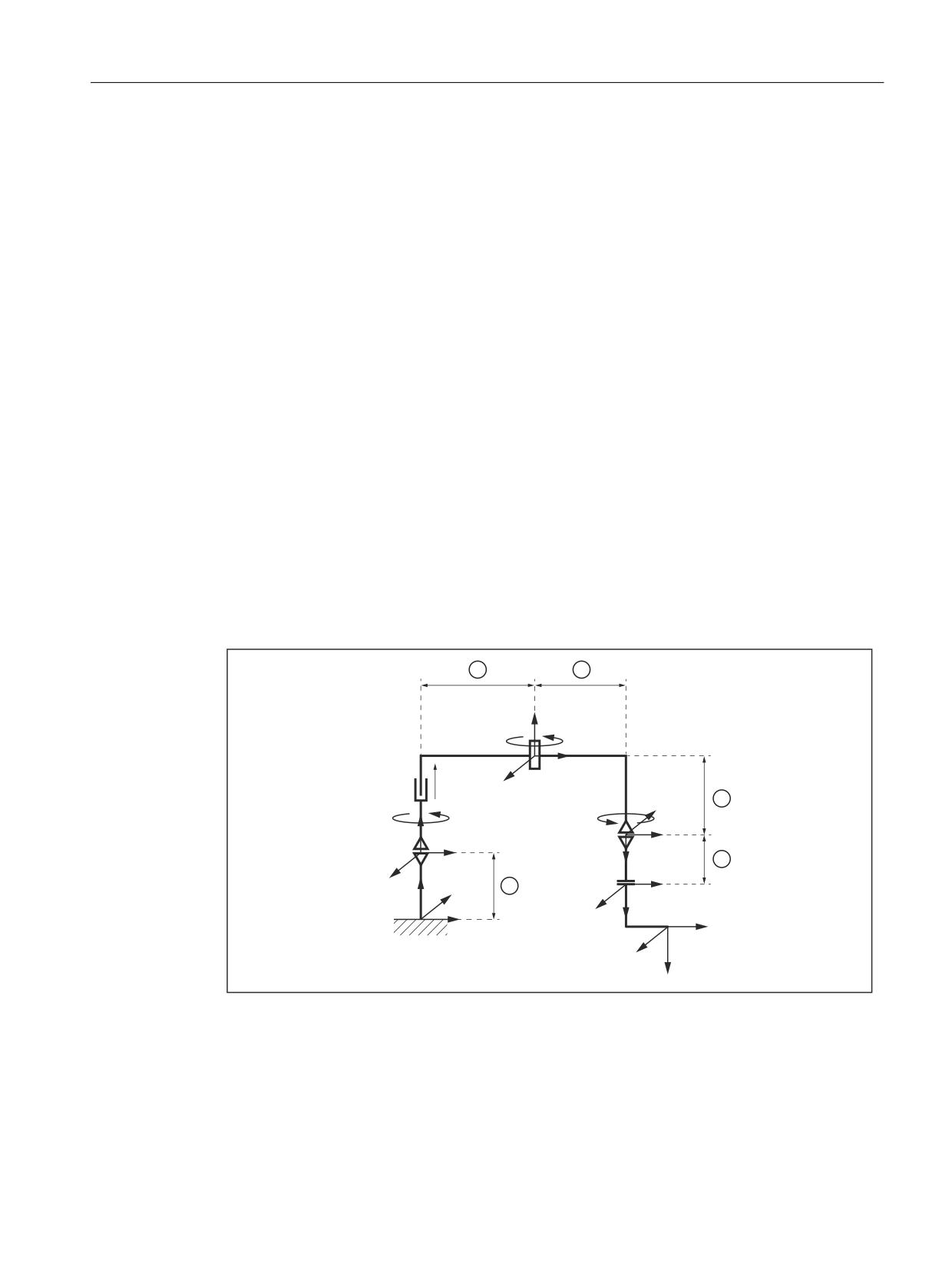
4-axis CC kinematics
T
S
U
[+3
\,52
\+3
]+3
[,52
],52
\
)/
[)/
])/
\:=
]:=
[:=
① MD62612 $MC_TRAFO6_TIRORO_POS[2]
② MD62607 $MC_TRAFO6_MAIN_LENGTH_AB[1]
③ MD62608 $MC_TRAFO6_TX3P3_POS[0]
④ MD62608 $MC_TRAFO6_TX3P3_POS[1]
⑤ MD62610 $MC_TRAFO6_TFLWP_POS[0]
Figure 7-18
4-axis CC kinematics
Technologies
Function Manual, 10/2020, 6FC5397-8GP40-0BA1
139
Transformation package handling
7.5 Descriptions of kinematics
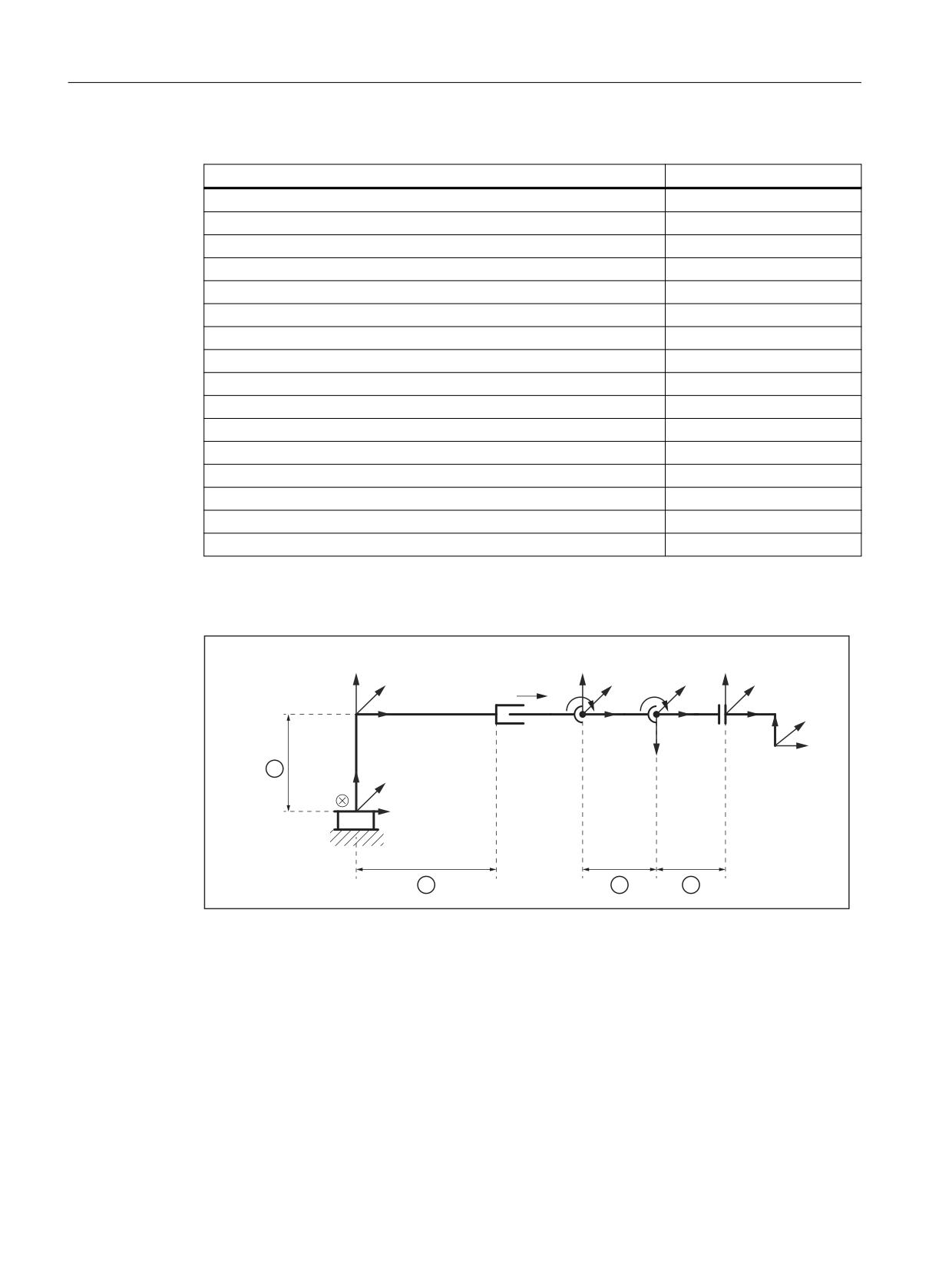
Table 7-10
Configuration data for 4-axis CC kinematics
Machine data
Value
MD62600 $MC_TRAFO6_KINCLASS
1
MD62605 $MC_TRAFO6_NUM_AXES
4
MD62603 $MC_TRAFO6_MAIN_AXES
2
MD62604 $MC_TRAFO6_WRIST_AXES
1
MD62606 $MC_TRAFO6_A4PAR
1
MD62601 $MC_TRAFO6_AXES_TYPE
[3, 1, 3, 3, ...]
MD62620 $MC_TRAFO6_AXIS_SEQ
[2, 1, 3, 4, 5, 6]
MD62618 $MC_TRAFO6_AXES_DIR)
[1, 1, 1, 1, 1, 1]
MD62617 $MC_TRAFO6_MAMES
[0.0, 0.0, 0.0, 0.0, 0.0, 0.0]
MD62607 $MC_TRAFO6_MAIN_LENGTH_AB
[0.0, 300.0]
MD62612 $MC_TRAFO6_TIRORO_POS
[0.0, 0.0, 500.0]
MD62613 $MC_TRAFO6_TIRORO_RPY
[0.0, 0.0, 90.0]
MD62608 $MC_TRAFO6_TX3P3_POS
[300.0, 0.0, -200.0]
MD62609 $MC_TRAFO6_TX3P3_RPY
[-90.0, 90.0, 0.0]
MD62610 $MC_TRAFO6_TFLWP_POS
[0.0, 0.0, 200.0]
MD62611 $MC_TRAFO6_TFLWP_RPY
[0.0, -90.0, 0.0]
4-axis SC kinematics
],52
U
\)/
\,52
T
]
[)/
\:=
[,52
S
[
])/
[:=
\
]:=
]52
\52
[52
① MD62612 $MC_TRAFO6_TIRORO_POS[2]
② MD62607 $MC_TRAFO6_MAIN_LENGTH_AB[0]
③ MD62608 $MC_TRAFO6_TX3P3_POS[0]
④ MD62610 $MC_TRAFO6_TFLWP_POS[0]
Figure 7-19
4-axis SC kinematics
Technologies
140
Function Manual, 10/2020, 6FC5397-8GP40-0BA1
Transformation package handling
7.5 Descriptions of kinematics
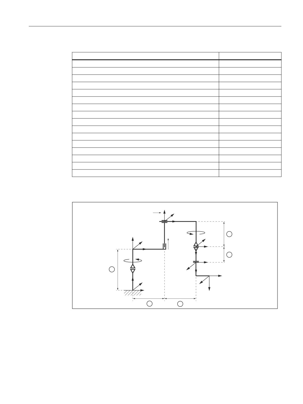
Table 7-11
Configuration data for 4-axis SC kinematics
Machine data
Value
MD62600 $MC_TRAFO6_KINCLASS
1
MD62605 $MC_TRAFO6_NUM_AXES
4
MD62603 $MC_TRAFO6_MAIN_AXES
4
MD62604 $MC_TRAFO6_WRIST_AXES
1
MD62606 $MC_TRAFO6_A4PAR
1
MD62601 $MC_TRAFO6_AXES_TYPE
[1, 1, 3, 3, ...]
MD62620 $MC_TRAFO6_AXIS_SEQ
[1, 2, 3, 4, 5, 6]
MD62618 $MC_TRAFO6_AXES_DIR
[1, 1, 1, 1, 1, 1]
MD62617 $MC_TRAFO6_MAMES
[0.0, 0.0, 0.0, 0.0, 0.0, 0.0]
MD62607 $MC_TRAFO6_MAIN_LENGTH_AB
[300.0, 0.0]
MD62612 $MC_TRAFO6_TIRORO_POS
[0.0, 0.0, 300.0]
MD62613 $MC_TRAFO6_TIRORO_RPY
[0.0, 0.0, 0.0]
MD62608 $MC_TRAFO6_TX3P3_POS
[200.0, 0.0, 0.0]
MD62609 $MC_TRAFO6_TX3P3_RPY
[0.0, 0.0, -90.0]
MD62610 $MC_TRAFO6_TFLWP_POS
[200.0, 0.0, 0.0]
MD62611 $MC_TRAFO6_TFLWP_RPY
[0.0, -90.0, 180.0]
4-axis CS kinematic
U
T
S
],52
[+3
\,52
\+3
[,52
]+3
\)/
])/
[)/
]52
\:=
\52
]:=
[:=
[52
① MD62612 $MC_TRAFO6_TIRORO_POS[2]
② MD62607 $MC_TRAFO6_MAIN_LENGTH_AB[0]
③ MD62608 $MC_TRAFO6_TX3P3_POS[0]
④ MD62608 $MC_TRAFO6_TX3P3_POS[2]
⑤ MD62610 $MC_TRAFO6_TFLWP_POS[2]
Figure 7-20
4-axis CS kinematic
Technologies
Function Manual, 10/2020, 6FC5397-8GP40-0BA1
141
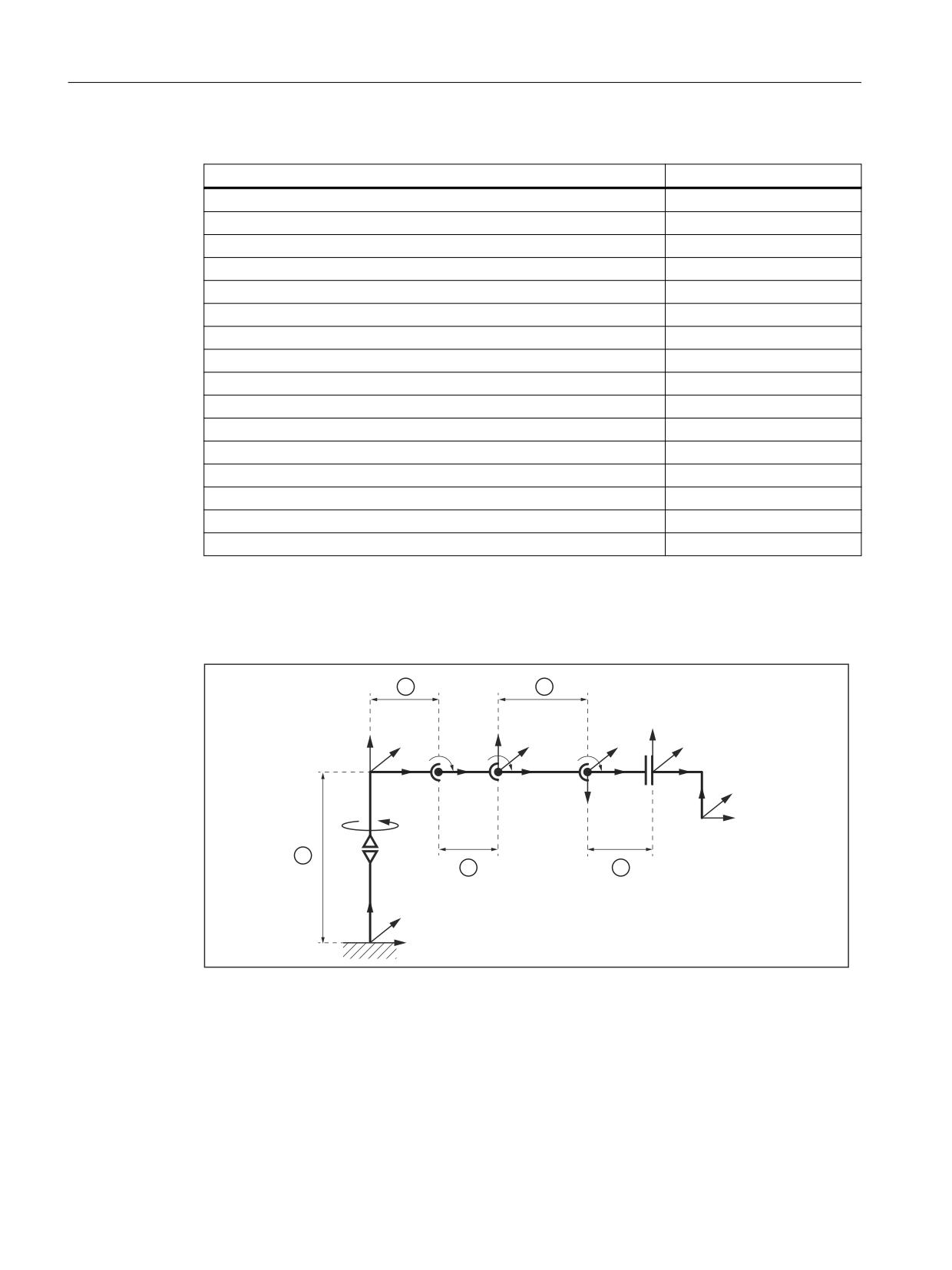
Transformation package handling
7.5 Descriptions of kinematics
Table 7-12
Configuration data for 4-axis CS kinematics
Machine data
Value
MD62600 $MC_TRAFO6_KINCLASS
1
MD62605 $MC_TRAFO6_NUM_AXES
4
MD62603 $MC_TRAFO6_MAIN_AXES
6
MD62604 $MC_TRAFO6_WRIST_AXES
1
MD62606 $MC_TRAFO6_A4PAR
1
MD62601 $MC_TRAFO6_AXES_TYPE
[3, 1, 1, 3, ...]
MD62620 $MC_TRAFO6_AXIS_SEQ
[1, 2, 3, 4, 5, 6]
MD62618 $MC_TRAFO6_AXES_DIR
[1, 1, 1, 1, 1, 1]
MD62617 $MC_TRAFO6_MAMES
[0.0, 0.0, 0.0, 0.0, 0.0, 0.0]
MD62607 $MC_TRAFO6_MAIN_LENGTH_AB
[400.0, 0.0]
MD62612 $MC_TRAFO6_TIRORO_POS
[0.0, 0.0, 400.0]
MD62613 $MC_TRAFO6_TIRORO_RPY
[0.0, 0.0, 0.0]
MD62608 $MC_TRAFO6_TX3P3_POS
[500.0, 0.0, -200.0]
MD62609 $MC_TRAFO6_TX3P3_RPY
[90.0, 0.0, 180.0]
MD62610 $MC_TRAFO6_TFLWP_POS
[0.0, 0.0, 200.0]
MD62611 $MC_TRAFO6_TFLWP_RPY
[0.0, -90.0, 0.0]
Articulated-arm kinematics
4-axis NR kinematics
U
],52
T
\)/
]+3
\,52
[)/
])/
[,52
\+3
S
[:=
[+3
\:=
]:=
]52
\52
[52
① MD62612 $MC_TRAFO6_TIRORO_POS[2]
② MD62607 $MC_TRAFO6_MAIN_LENGTH_AB[0]
③ MD62607 $MC_TRAFO6_MAIN_LENGTH_AB[1]
④ MD62608 $MC_TRAFO6_TX3P3_POS[0]
⑤ MD62610 $MC_TRAFO6_TFLWP_POS[0]
Figure 7-21
4-axis NR kinematics
Technologies
142
Function Manual, 10/2020, 6FC5397-8GP40-0BA1

Transformation package handling
7.5 Descriptions of kinematics
Table 7-13
Configuration data 4-axis NR kinematic
Machine data
Value
MD62600 $MC_TRAFO6_ KINCLASS
1
MD62605 $MC_TRAFO6_NUM_AXES
4
MD62603 $MC_TRAFO6_MAIN_AXES
3
MD62604 $MC_TRAFO6_WRIST_AXES
1
MD62606 $MC_TRAFO6_A4PAR
1
MD62601 $MC_TRAFO6_AXES_TYPE
[3, 3, 3, 3, ...]
MD62620 $MC_TRAFO6_AXIS_SEQ
[1, 2, 3, 4, 5, 6]
MD62618 $MC_TRAFO6_AXES_DIR
[1, 1, 1, 1, 1, 1]
MD62617 $MC_TRAFO6_MAMES
[0.0, 0.0, 0.0, 0.0, 0.0, 0.0]
MD62607 $MC_TRAFO6_MAIN_LENGTH_AB
[300.0, 300.0]
MD62612 $MC_TRAFO6_TIRORO_POS
[0.0, 0.0, 500.0]
MD62613 $MC_TRAFO6_TIRORO_RPY
[0.0, 0.0, 0.0]
MD62608 $MC_TRAFO6_TX3P3_POS
[300.0, 0.0, 0.0]
MD62609 $MC_TRAFO6_TX3P3_RPY
[0.0, 0.0, -90.0]
MD62610 $MC_TRAFO6_TFLWP_POS
[200.0, 0.0, 0.0]
MD62611 $MC_TRAFO6_TFLWP_RPY
[0.0, -90.0, 180.0]
See also
Definition of a joint (Page 116)
7.5.3
5-axis kinematics
5-axis kinematics usually imply 3 degrees of freedom for translation and 2 for orientation.
Restrictions
The following restrictions apply to 5-axis kinematics:
1. There are restrictions for the flange coordinate system because the X flange axis must
intersect the 5th axis, nevertheless, it must not be parallel to it.
2. The frame T_FL_WP is subject to the following condition as far as 5-axis articulated-arm
kinematics are concerned:
- MD62610 $MC_TRAFO6_TFLWP_POS = [0.0, 0.0, Z] (frame between wrist point and
flange (position component))
- MD62611 $MC_TRAFO6_TFLWP_RPY = [A, 0.0, 0.0] (frame between wrist point and
flange (rotation component))
3. There are restrictions for the tool as far as 5-axis articulated-arm kinematics are concerned:
-
4. Axis parallel to the 3rd axis: 2-dimensional tool is possible [X, 0.0, Z]
–
4. Axis perpendicular to the 3rd axis: Only 1-dimensional tool is possible [X, 0.0, 0.0]
Technologies
Function Manual, 10/2020, 6FC5397-8GP40-0BA1
143
Transformation package handling
7.5 Descriptions of kinematics
4. There are restrictions for the tool as far as 5-axis Scara kinematics are concerned:
-
4. Axis perpendicular to the 3rd axis: 1-dimensional tool is possible [X, 0.0, 0.0]
5. Two successive basic axes must be parallel or orthogonal.
6. The 4th axis must only be mounted in a parallel or orthogonal way to the last basic axis.
Configuration
The procedure for configuring a 5-axis kinematic is as follows:
1. Enter "Standard" kinematic category in machine data:
MD62600 $MC_TRAFO6_KINCLASS (kinematic category)
2. Set the number of axes for transformation in the machine data:
MD62605 $MC_TRAFO6_NUM_AXES = 5 (number of transformed axes)
3. Compare the basic axes with the basic axes contained in the handling transformation
package.
- Enter the basic axis identifier in machine data:
MD62603 $MC_TRAFO6_MAIN_AXES (basic axis identifier)
4. If the axis sequence is not the same as the normal axis sequence, it must be corrected in
machine data:
MD62620 $MC_TRAFO6_AXIS_SEQ (rearrangement of axes)
5. ID specification for the wrist axes. If axis 4 and 5 intersect, a central hand (ZEH) is present. In
all other cases, the ID for beveled hand with elbow (BHE) must be entered in the machine
data:
MD62604 $MC_TRAFO6_WRIST_AXES (wrist axis identifier)
6. Whether axis 4 runs parallel/anti-parallel to the last rotary basic axis must be entered into the
machine data:
MD62606 $MC_TRAFO6_A4PAR (axis 4 is parallel/anti-parallel to last basic axis)
7. Enter the axis types for the transformation in machine data:
MD62601 $MC_TRAFO6_AXES_TYPE (axis type for transformation)
8. Compare the directions of rotation of axes with the directions defined in the handling
transformation package and correct in machine data:
MD62618 $MC_TRAFO6_AXES_DIR (matching of physical and mathematical directions of
rotation)
9. Enter the mechanical zero offset in the machine data:
MD62617 $MC_TRAFO6_MAMES (offset between mathematical and mechanical zero
points)
10.Enter the basic axis lengths in machine data:
MD62607 $MC_TRAFO6_MAIN_LENGTH_AB (basic axis lengths A and B)
11.Define frame T_IRO_RO and enter the offset in machine data:
MD62612 $MC_TRAFO6_TIRORO_POS (frame between base center point and internal
system (position component))
Define frame T_IRO_RO and enter the rotation in machine data:
MD62613 $MC_TRAFO6_TIRORO_RPY (frame between base center point and internal
system (rotation component))
Technologies
144
Function Manual, 10/2020, 6FC5397-8GP40-0BA1
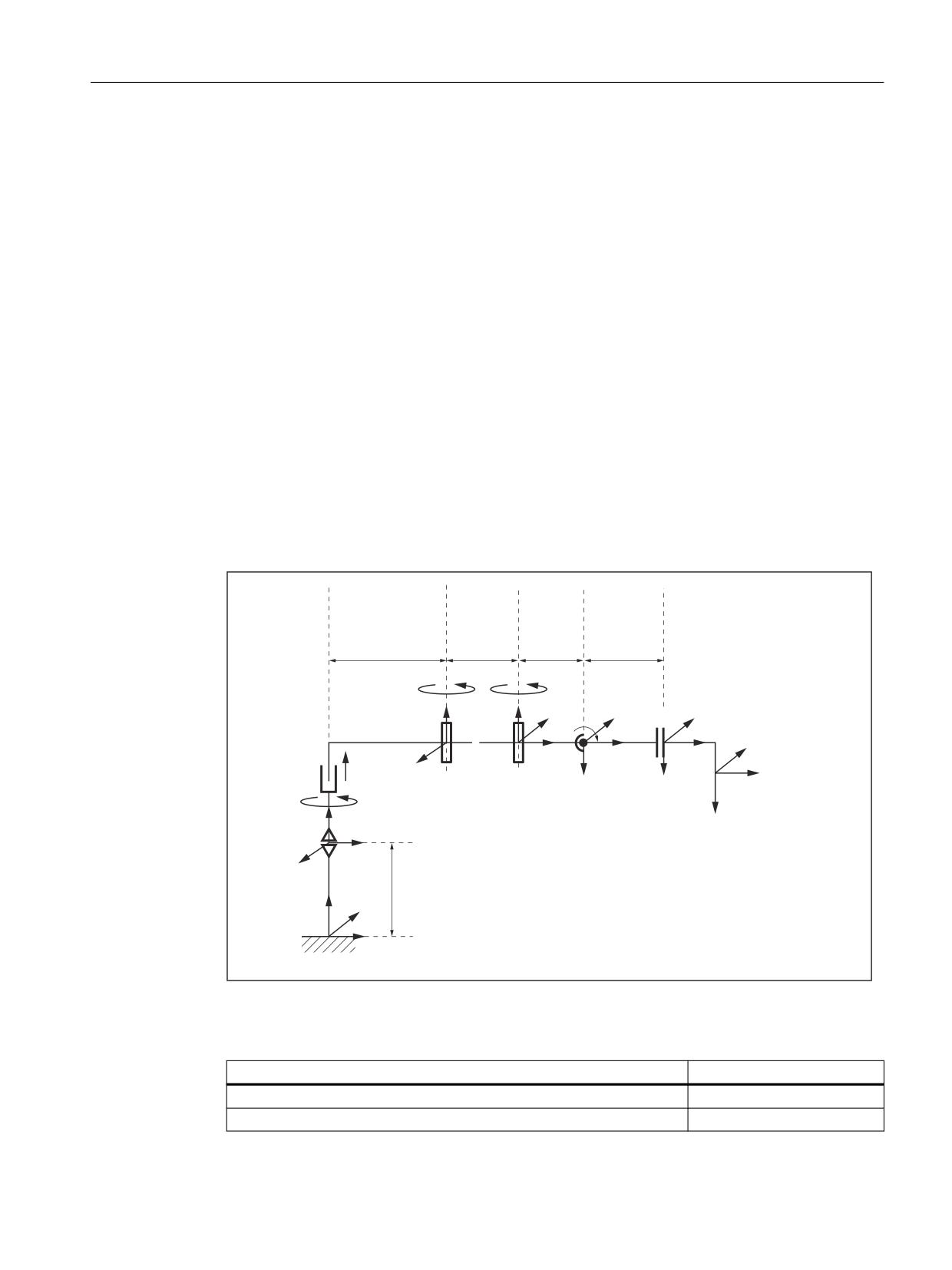
Transformation package handling
7.5 Descriptions of kinematics
12.Specification of frame T_X3_P3 to attach hand. The offset is entered in machine data:
MD62608 $MC_TRAFO6_TX3P3_POS (attachment of hand (position component))
The rotation is entered in the machine data:
MD62609 $MC_TRAFO6_TX3P3_RPY (attachment of hand (rotation component))
13.Specification of wrist axes parameters. For this purpose, only the parameters for axis 4 must
be entered in the machine data:
MD62614 $MC_TRAFO6_DHPAR4_5A[0] (parameter A for configuring the hand)
MD62616 $MC_TRAFO6_DHPAR4_5ALPHA[0] (parameter A for configuring the hand)
All other parameters must be set to 0.0.
14.Determine the flange coordinate system. For this purpose, the hand-point coordinate system
must be regard as the initial system. The offset is entered in the machine data:
MD62610 $MC_TRAFO6_TFLWP_POS (frame between wrist point and flange (position
component))
The rotation is entered in the machine data:
MD62611 $MC_TRAFO6_TFLWP_RPY (frame between wrist point and flange (rotation
component))
SCARA kinematics
5-axis CC kinematics
0'
&&
0'
0&B75$)2 B'+3$5 B $> @
0&B75$)2 B0$,
1B
0'
/(1*7+B$%> @
0'
0&B75$)2
B7)/:3B326> @
0&B75$)2 B7; 3 B
326> @
T
]
\
]
]
+3
)/
[
[+3
[)/
]:=
S
U
[:=
\+3
\)/
\,52
\:=
[,52
],52
0'
]52
0&B75$)2 B7,5252B326> @
\52
[52
Figure 7-22
5-axis CC kinematics
Table 7-14
Configuration data for 5-axis CC kinematics
Machine data
Value
MD62600 $MC_TRAFO6_KINCLASS
1
MD62605 $MC_TRAFO6_NUM_AXES
5
Technologies
Function Manual, 10/2020, 6FC5397-8GP40-0BA1
145
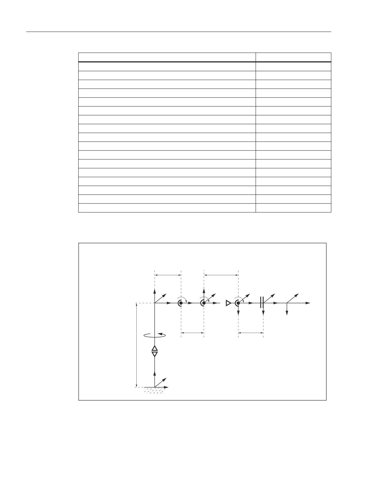
Transformation package handling
7.5 Descriptions of kinematics
Machine data
Value
MD62603 $MC_TRAFO6_MAIN_AXES
2
MD62604 $MC_TRAFO6_WRIST_AXES
5
MD62606 $MC_TRAFO6_A4PAR
1
MD62601 $MC_TRAFO6 _AXES_TYPE
[3, 1, 3, 3, 3, ...]
MD62620 $MC_TRAFO6_AXIS_SEQ
[2, 1, 3, 4, 5, 6]
MD62618 $MC_TRAFO6_AXES_DIR
[1, 1, 1, 1, 1, 1]
MD62617 $MC_TRAFO6_MAMES
[0.0, 0.0, 0.0, 0.0, 0.0, 0.0]
MD62607 $MC_TRAFO6_MAIN_LENGTH_AB
[0.0, 500.0]
MD62612 $MC_TRAFO6_TIRORO_POS
[0.0, 0.0, 500.0]
MD62613 $MC_TRAFO6_TIRORO_RPY
[0.0, 0.0, 90.0]
MD62608 $MC_TRAFO6_TX3P3_POS
[300.0, 0.0, -200.0]
MD62609 $MC_TRAFO6_TX3P3_RPY
[0.0, 0.0, -90.0]
MD62610 $MC_TRAFO6_TFLWP_POS
[200.0, 0.0, 0.0]
MD62611 $MC_TRAFO6_TFLWP_RPY
[0.0, 0.0, 0.0]
MD62614 $MC_TRAFO6_DHPAR4_5A
[200.0, 0.0]
MD62615 $MC_TRAFO6_DHPAR4_5D
[0.0, 0.0]
MD62616 $MC_TRAFO6_DHPAR4_5ALPHA
[-90.0, 0.0]
5-axis NR kinematics
15
0'
0'
0&B75$)2 B0$,1B/(1*7+B$%> @
0&B75$)2 B7; 3 B326> @
]
U
,52
T
]+3
])/
]:=
\
,52
[:=
[,52
\+3
[)/
S
[+3
\)/
\
:=
0'
0'
0'
0&B75$)2 B0$,1B
0&B75$)2 B7)/:3B326> @
0&B75$)2 B
/(1*7+B$%> @
7,5252B326> @
]52
\52
[52
Figure 7-23
5-axis NR kinematics
Technologies
146
Function Manual, 10/2020, 6FC5397-8GP40-0BA1

Transformation package handling
7.5 Descriptions of kinematics
Table 7-15
Configuration data 5-axis NR kinematic
Machine data
Value
MD62600 $MC_TRAFO6_KINCLASS
1
MD62605 $MC_TRAFO6_NUM_AXES
5
MD62603 $MC_TRAFO6_MAIN_AXES
3
MD62604 $MC_TRAFO6_WRIST_AXES
2
MD62606 $MC_TRAFO6_A4PAR
0
MD62601 $MC_TRAFO6_AXES_TYPE
[3, 3, 3, 3, 3, ...]
MD62620 $MC_TRAFO6_AXIS_SEQ
[1, 2, 3, 4, 5, 6]
MD62618 $MC_TRAFO6_AXES_DIR
[1, 1, 1, 1, 1, 1]
MD62617 $MC_TRAFO6_MAMES
[0.0, 0.0, 0.0, 0.0, 0.0, 0.0]
MD62607 $MC_TRAFO6_MAIN_LENGTH_AB
[30.0, 300.0]
MD62612 $MC_TRAFO6_TIRORO_POS
[0.0, 0.0, 500.0]
MD62613 $MC_TRAFO6_TIRORO_RPY
[0.0, 0.0, 0.0]
MD62608 $MC_TRAFO6_TX3P3_POS
[500.0, 0.0, 0.0]
MD62609 $MC_TRAFO6_TX3P3_RPY
[0.0, 90.0, 0.0]
MD62610 $MC_TRAFO6_TFLWP_POS
[0.0, -300.0, 0.0]
MD62611 $MC_TRAFO6_TFLWP_RPY
[-90.0, 0.0, 0.0]
MD62614 $MC_TRAFO6_DHPAR4_5A
[0.0, 0.0]
MD62615 $MC_TRAFO6_DHPAR4_5D
[0.0, 0.0]
MD62616 $MC_TRAFO6_DHPAR4_5ALPHA
[-90.0, 0.0]
See also
Definition of a joint (Page 116)
7.5.4
6-axis kinematics
6-axis kinematics usually imply 3 degrees of freedom for translation and 3 more for orientation.
This allows for the tool direction to be manipulated freely in space. Also, the tool can be rotated
along its own axis to the machining surface or inclined with a tilting angle.
This kinematic type is supported by the software, but only for very specific solutions as the
auxiliary method for this handling transformation package. A general, comprehensive and
universally applicable software version is still not available for 6-axis kinematics.
Technologies
Function Manual, 10/2020, 6FC5397-8GP40-0BA1
147
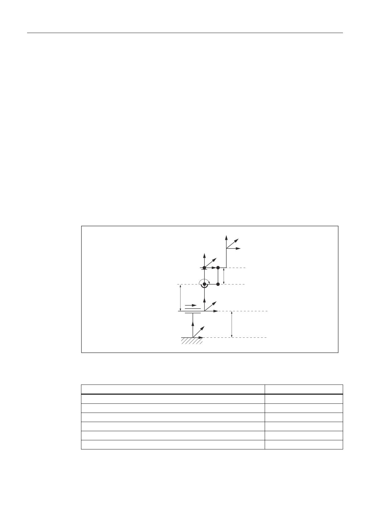
Transformation package handling
7.5 Descriptions of kinematics
7.5.5
Special kinematics
MD62602 $MC_TRAFO6_SPECIAL_KIN (special kinematic type)
Special kinematics are kinematics that are not directly included in the building block system of
the Handling transformation package. They are frequently missing a degree of freedom or are
characterized by mechanical links between the axes or with the tool. Set the following machine
data for these kinematics:
MD62600 $MC_TRAFO6_KINCLASS = 2 (kinematic category)
Which special kinematic is handled is specified in machine data:
MD62602 $MC_TRAFO6_SPECIAL_KIN (special kinematic type)
Special 2-axis SC kinematic
This special kinematic is characterized by the fact that the tool is always maintained in the same
orientation via a mechanical linkage. It implies two Cartesian degrees of protection. The
identifier for this kinematic is machine data:
MD62602 $MC_TARFO6_SPECIAL_KIN = 3 (special kinematic type)
[:=
]:=
\:=
[)/
])/
\)/
0'
0&B75$)2 B0$,1B/(1*7+B$%> @
0'
$
[
0&B75$)2 B0$,1B/(1*7+B$%> @
,52
]
,52
,52
\
$
[
52
0'
0&B75$)2 B7,5252B326> @
]52
\52
Figure 7-24
Special 2-axis SC kinematic
Table 7-16
Configuring data for a special 2-axis SC kinematic
Machine data
Value
MD62600 $MC_TRAFO6_KINCLASS
2
MD62602 $MC_TRAFO6_SPECIAL_KIN
3
MD62605 $MC_TRAFO6_NUM_AXES
2
MD62603 $MC_TRAFO6_MAIN_AXES
2
MD62604 $MC_TRAFO6_WRIST_AXES
1
MD62601 $MC_TRAFO6_AXES_TYPE
[1, 3, 3, ...]
Technologies
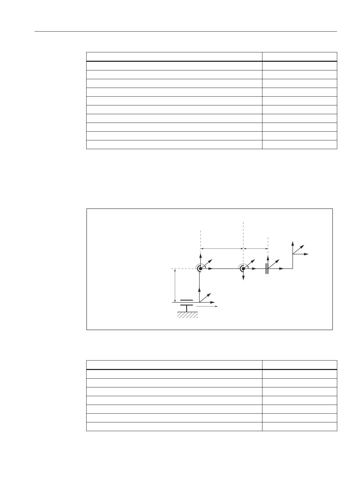
148
Function Manual, 10/2020, 6FC5397-8GP40-0BA1
Transformation package handling
7.5 Descriptions of kinematics
Machine data
Value
MD62620 $MC_TRAFO6_AXIS_SEQ
[1, 2, 3, 4, 5, 6]
MD62618 $MC_TRAFO6_AXES_DIR
[1, 1, 1, 1, 1, 1]
MD62617 $MC_TRAFO6_MAMES
[0.0, 0.0, 0.0, 0.0, 0.0, 0.0]
MD62607 $MC_TRAFO6_MAIN_LENGTH_AB
[400.0, 500.0]
MD62612 $MC_TRAFO6_TIRORO_POS
[0.0, 0.0, 300.0]
MD62613 $MC_TRAFO6_TIRORO_RPY
[0.0, 0.0, 0.0]
MD62608 $MC_TRAFO6_TX3P3_POS
[0.0, 0.0, 0.0]
MD62609 $MC_TRAFO6_TX3P3_RPY
[0.0, 0.0, 0.0]
MD62610 $MC_TRAFO6_TFLWP_POS
[0.0, 0.0, 0.0]
MD62611 $MC_TRAFO6_TFLWP_RPY
[0.0, 0.0, 0.0]
Special 3-axis SC kinematic
The special kinematic has 2 Cartesian degrees of freedom and one degree of freedom for
orientation. The identifier for this kinematic is:
MD62602 $MC_TRAFO6_SPECIAL_KIN = 4 (special kinematic type)
0'
0'
0&B75$)2 B7; 3 B326> @
0&B75$)2 B7)/:3B326> @
\:=
[:=
],52
\)/
\,52
]
[
]:=
)/
$
[
$
[
]
,52
)/
0'
0&B75$)2 B7,5252B326> @
\
]52
\52
[52
$
Figure 7-25
Special 3-axis SC kinematic
Table 7-17
Configuring data for a special 3-axis SC kinematic
Machine data
Value
MD62600 $MC_TRAFO6_KINCLASS
2
MD62602 $MC_TRAFO6_SPECIAL_KIN
4
MD62605 $MC_TRAFO6_NUM_AXES
3
MD62603 $MC_TRAFO6_MAIN_AXES
2
MD62604 $MC_TRAFO6_WRIST_AXES
1
MD62601 $MC_TRAFO6_AXES_TYPE
[1, 3, 3, ...]
MD62620 $MC_TRAFO6_AXIS_SEQ
[1, 2, 3, 4, 5, 6]
Technologies
Function Manual, 10/2020, 6FC5397-8GP40-0BA1
149
Transformation package handling
7.5 Descriptions of kinematics
Machine data
Value
MD62618 $MC_TRAFO6_AXES_DIR
[1, 1, 1, 1, 1, 1]
MD62617 $MC_TRAFO6_MAMES
[0.0, 0.0, 0.0, 0.0, 0.0, 0.0]
MD62607 $MC_TRAFO6_MAIN_LENGTH_AB
[0.0, 0.0]
MD62612 $MC_TRAFO6_TIRORO_POS
[0.0, 0.0, 400.0]
MD62613 $MC_TRAFO6_TIRORO_RPY
[0.0, 0.0, 0.0]
MD62608 $MC_TRAFO6_TX3P3_POS
[400.0, 0.0, 0.0]
MD62609 $MC_TRAFO6_TX3P3_RPY
[0.0, 0.0, -90.0]
MD62610 $MC_TRAFO6_TFLWP_POS
[200.0, 0.0, 0.0]
MD62611 $MC_TRAFO6_TFLWP_RPY
[0.0, -90.0, 180.0]
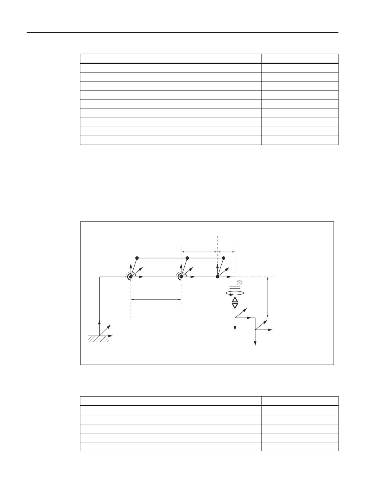
Special 4-axis SC kinematic
This special kinematic is characterized by the fact that axis 1 and axis 2 are mechanically coupled.
This coupling ensures that axis 2 is maintained at a constant angle when axis 1 is swiveled. This
kinematic also guarantees that axes 3 and 4 always remain perpendicular, irrespective of the
positions of axes 1 and 2. The identifier for this kinematic is:
MD62602 $MC_TRAFO6_SPECIAL_KIN = 7 (special kinematic type)
0'
0'
0&B75$)2 B7; 3 B326> @
0&B75$)2 B0$,1B/(1*7+B$%> @
],52
]
U
\
\
T
,52
[
S
[
,52
0'
0&B75$)2 B7)/:3B
0'
326> @
\)/
0&B75$)2 B0$,1B/(1*7+B$%> @
]52
\:=
\52
])/
]:=
[52
[)/
[:=
Figure 7-26
Special 4-axis SC kinematic
Table 7-18
Configuring data for a special 4-axis SC kinematic
Machine data
Value
MD62600 $MC_TRAFO6_KINCLASS
2
MD62602 $MC_TRAFO6_SPECIAL_KIN
7
MD62605 $MC_TRAFO6_NUM_AXES
4
MD62603 $MC_TRAFO6_MAIN_AXES
2
MD62604 $MC_TRAFO6_WRIST_AXES
1
Technologies
150
Function Manual, 10/2020, 6FC5397-8GP40-0BA1
Transformation package handling
7.5 Descriptions of kinematics
Machine data
Value
MD62601 $MC_TRAFO6_AXES_TYPE
[3, 3, 1, 3, ...]
MD62620 $MC_TRAFO6_AXIS_SEQ
[1, 2, 3, 4, 5, 6]
MD62618 $MC_TRAFO6_AXES_DIR
[1, 1, 1, 1, 1, 1]
MD62617 $MC_TRAFO6_MAMES
[0.0, 0.0, 0.0, 0.0, 0.0, 0.0]
MD62607 $MC_TRAFO6_MAIN_LENGTH_AB
[100.0, 400.0]
MD62612 $MC_TRAFO6_TIRORO_POS
[100.0, 0.0, 1000.0]
MD62613 $MC_TRAFO6_TIRORO_RPY
[0.0, 0.0, 0.0]
MD62608 $MC_TRAFO6_TX3P3_POS
[300.0, 0.0, 0.0]
MD62609 $MC_TRAFO6_TX3P3_RPY
[0.0, 0.0, 0.0]
MD62610 $MC_TRAFO6_TFLWP_POS
[0.0, 0.0, -600.0]
MD62611 $MC_TRAFO6_TFLWP_RPY
[0.0, 90.0, 0.0]
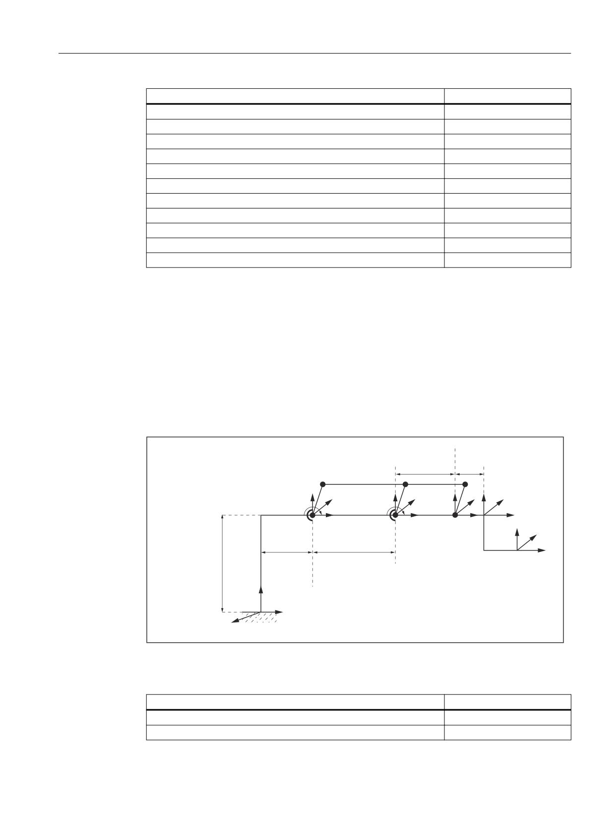
Special 2-axis NR kinematics
This special kinematic is characterized by the fact that axis 1 and axis 2 are mechanically coupled.
Another special feature is the tool. With this kinematic, it maintains its orientation in space
irrespective of the positions of the other axes.
The identifier for this kinematic is:
MD62602 $MC_TRAFO6_SPECIAL_KIN = 5 (special kinematic type)
Without a mechanical coupling between axis 1 and 2, it has the following identifier:
MD62602 $MC_TRAFO6_SPECIAL_KIN = 8 (special kinematic type)
0'
0'
0&B75$)2 B
0&B75$)2 B7; 3 B326> @
0$,1B/(1*7+B$%> @
],52
])/
U
\
]
\
\,52
T
)/
[)/
S
[
[
,52
]:=
\
:=
[:=
0'
0'
0&B75$)2 B
0&B75$)2 B0$,1B/(1*7+B$%> @
7,5252B326> @
0'
\52
0&B75$)2 B7,5252B326> @
[52
]52
Figure 7-27
Special 2-axis NR kinematics
Table 7-19
Configuration data for special 2-axis NR kinematics
Machine data
Value
MD62600 $MC_TRAFO6_KINCLASS
2
MD62602 $MC_TRAFO6_SPECIAL_KIN
5 (8)
Technologies
Function Manual, 10/2020, 6FC5397-8GP40-0BA1
151
Transformation package handling
7.6 Tool orientation
Machine data
Value
MD62605 $MC_TRAFO6_NUM_AXES
2
MD62603 $MC_TRAFO6_MAIN_AXES
3
MD62604 $MC_TRAFO6_WRIST_AXES
1
MD62601 $MC_TRAFO6_AXES_TYPE
[3, 3, ...]
MD62620 $MC_TRAFO6_AXIS_SEQ
[1, 2, 3, 4, 5, 6]
MD62618 $MC_TRAFO6_AXES_DIR
[1, 1, 1, 1, 1, 1]
MD62617 $MC_TRAFO6_MAMES
[0.0, 0.0, 0.0, 0.0, 0.0, 0.0]
MD62607 $MC_TRAFO6_MAIN_LENGTH_AB
[100.0, 400.0]
MD62612 $MC_TRAFO6_TIRORO_POS
[100.0, 500.0, 0.0]
MD62613 $MC_TRAFO6_TIRORO_RPY
[0.0, 0.0, -90.0]
MD62608 $MC_TRAFO6_TX3P3_POS
[400.0, 0.0, 0.0]
MD62609 $MC_TRAFO6_TX3P3_RPY
[0.0, 0.0, 0.0]
MD62610 $MC_TRAFO6_TFLWP_POS
[0.0, 0.0, 0.0]
MD62611 $MC_TRAFO6_TFLWP_RPY
[0.0, 0.0, 0.0]
7.6
Tool orientation
=
$
;
%
<
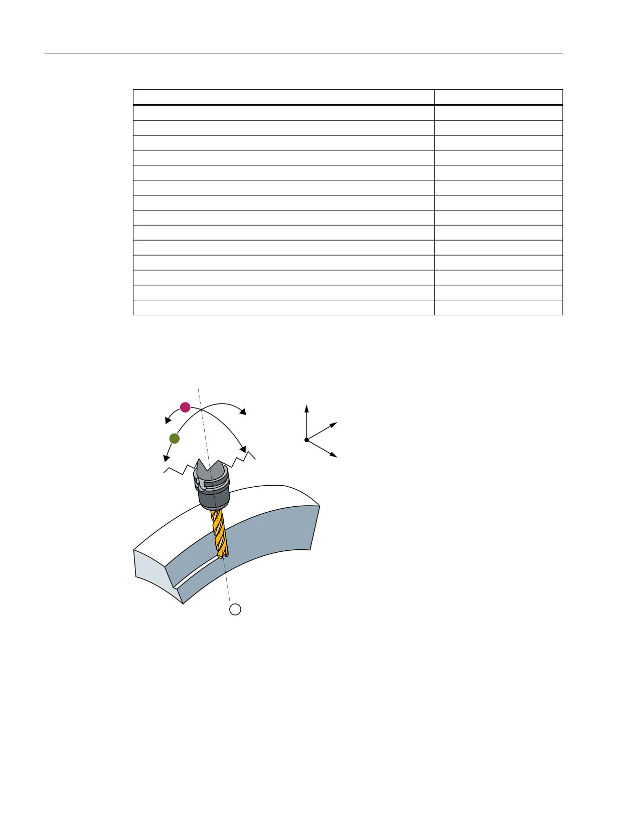
① Tool axis
Figure 7-28
Peripheral milling with 5-axis transformation
Machine data
Identifiers of the Euler angles
The identifiers with which the Euler angles are programmed in the NC program can be set using:
MD10620 $MN_EULER_ANGLE_NAME_TAB (name of Euler angles)
Technologies
152
Function Manual, 10/2020, 6FC5397-8GP40-0BA1

Transformation package handling
7.6 Tool orientation
Standard identifier: "A2", "B2", "C2"
Identifier of the direction vector components
The identifier with which the components of the direction vector are programmed in the NC
program can be set using:
MD10640 $MN_DIR_VECTOR_NAME_TAB (name of normal vectors)
The tool orientation can be located in any block. Above all, it can be programmed alone in a
block, resulting in a change of orientation in relation to the tool tip which is fixed in its
relationship to the workpiece.
Channel-specific input: Euler or RPY angle
Whether the tool orientation programming is realized in the channel with Euler angle or RPY
angle can be set using:
MD21100 $MC_ORIENTATION_IS_EULER (angle definition for orientation programming)
G command for orientation interpolation
The type of interpolation for the orientation is specified using machine data:
MD21104 $MC_ORI_IPO_WITH_G_CODE = <value>
<value>
Meaning
FALSE
G commands for orientation interpolation: ORIWKS and ORIMKS
TRUE
G commands of the 51st G group for orientation interpolation: ORIAXES, ORIVECT,
ORIPLANE, ...
Channel-specific initial setting for the tool orientation
G commands of the 25th G group: "Tool orientation reference" which takes effect after a channel
or end of program reset, can be set via:
MD20150 $MC_GCODE_RESET_VALUES[ 24 ] (25. G group: tool orientation reference)
Programming
Function
The tool orientation can be programmed via:
• Directly programming the rotary axes
• Programming the Euler or RPY angle
• Programming the direction vector
The coordinate system in which motion is executed is defined using the ORIWKS and ORIMKS
commands.
Syntax
ORIWKS
ORIMKS
Technologies
Function Manual, 10/2020, 6FC5397-8GP40-0BA1
153

Transformation package handling
7.6 Tool orientation
Meaning
ORIWKS:
Tool orientation in the workpiece coordinate system (WCS)
In the case of a change in orientation with the tool tip at a fixed point in space, the tool
moves along a large arc on the plane extending from the start vector to the end vector.
Transitioning a tool orientation at the start of a block to an orientation at the end of the
block is only possible in the WCS.
Effective:
Modal
ORIMKS:
Tool orientation in the machine coordinate system (MCS)
In the case of a change in orientation of a tool tip at a fixed point in space, linear inter-
polation takes place between the rotary axis positions.
Effective:
Modal
Note
• ORIWKS is the preferred approach for a program independent of a particular machine.
• It is not possible to program the tool orientation using Euler angles, RPY angles or direction
vectors for kinematics involving fewer than 5 axes. For 4-axis kinematics with only one rotary
axis, there is only one degree of freedom for orientation. This orientation angle can only be
programmed with orientation axis angle "A".
• Transferring an orientation using ORIMKS is not allowed in the handling transformation
package. With an active transformation, the machine axis angles are not programmed and
traversed, but rather the "orientation angles" (RPY angles according to robotics definition, see
Section "Definition of positions and orientations using frames (Page 115)").
7.6.1
Orientation programming for 4-axis kinematics
4-axis kinematics possess only one degree of freedom for orientation. When programming
orientation using RPY angle, Euler angle or direction vector, it is not always possible to approach
the specified orientation. If at all, this type of orientation programming is only practical for
certain kinematics, where there is an invariance of the orientation angle with respect to the basis
axes. This is the case for the Scara kinematics, for example.
For this reason, orientation programming is only permitted via "orientation angle" A for 4-axis
kinematics. This angle corresponds to the RPY angle C of the robot definition. This means one
rotation around the ZRO axis, as illustrated in Fig. "Orientation angle for 4-axis kinematics".
Technologies
154
Function Manual, 10/2020, 6FC5397-8GP40-0BA1
Transformation package handling
7.6 Tool orientation
$
$
=52
<52
;+3
$
;52
%.6
<+3
=+3
<)/
=)/
;)/
=:=
<:=
;:=
A
Virtual orientation angle
Figure 7-29
Orientation angle for 4-axis kinematics
Absolute calculation of the tool orientation for 4-axis kinematics
For 4-axis kinematics, the "virtual orientation angle" A is normally only defined within the range
-180° < A < = + 180°. This means that, in the transition from 180° to 181°, angle A jumps to -179°.
The following machine data must be set to avoid this step, and to ensure that angle A is
continually controlled:
MD62643 $MC_TRAFO6_SPECIAL_FEATURE_MASK, bit 0 = 1
As a consequence, for the following 4-axis kinematics, angle A is controlled in absolute terms:
• CC kinematics
• SC kinematics
• CS kinematics
This is on condition that the 4th axis is installed parallel to the last rotary basic axis (MD62606
$MC_TRAFO6_A4PAR == 1).
Angle A is calculated from the sum of the rotary axes. Machine data MD62617
$MC_TRAFO6_MAMES and MD62618 $MC_TRAFO6_AXES_DIR are taken into account.
If, as a result of the rotations via MD62612 $MC_TRAFO6_TIRORO_RPY and MD62611
$MC_TRAFO6_TFLWP_RPY, additional rotations are obtained, then these must be compensated
using MD62642 $MC_TRAFO6_C_ANGLE_OFFSET. In machine data MD62642, the angle, which
is displayed as "virtual orientation angle" A at the mathematical zero position of the axes, must
be entered with inverted sign.
Technologies
Function Manual, 10/2020, 6FC5397-8GP40-0BA1
155
Transformation package handling
7.6 Tool orientation
7.6.2
Orientation programming for 5-axis kinematics
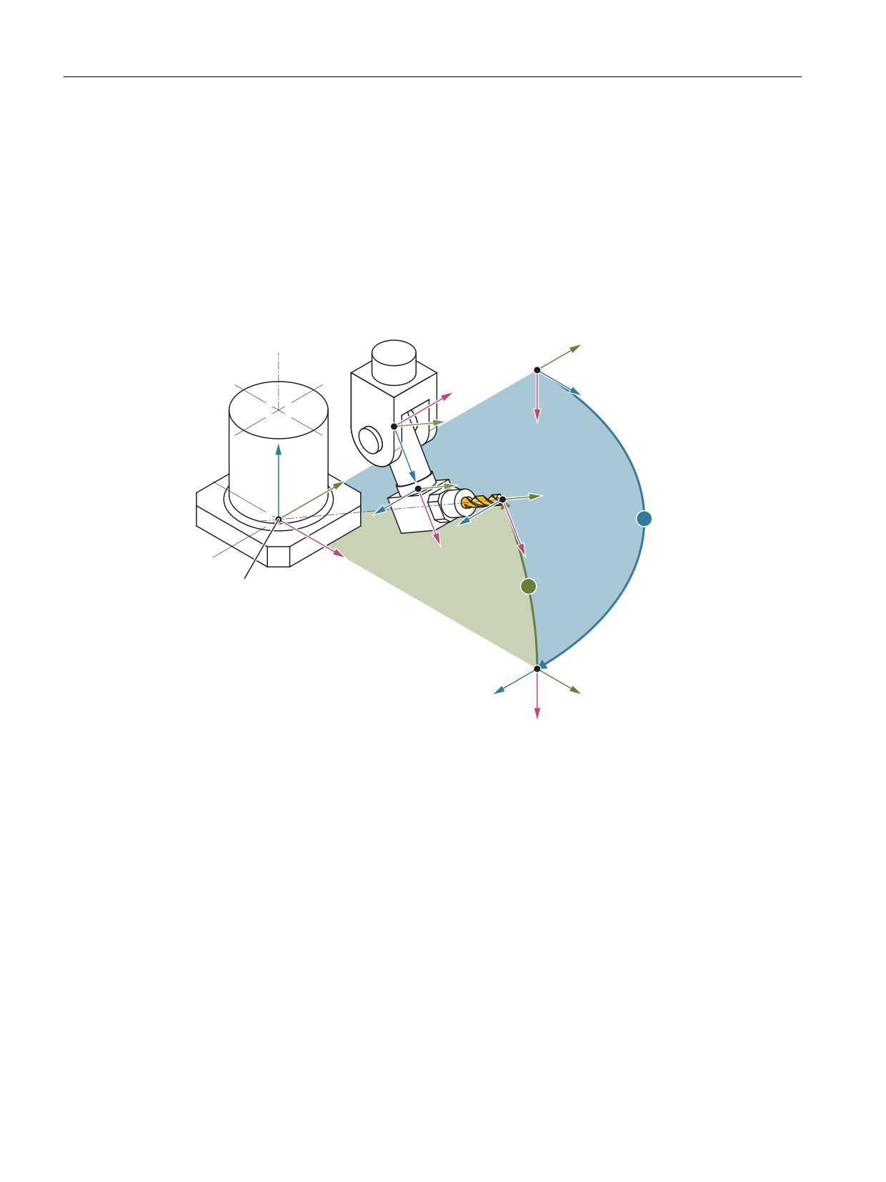
For 5-axis kinematics, when programming via orientation vector, it is assumed that the
orientation vector corresponds to the x component of the tool.
When programming via orientation angle (RPY angle according to robotics definition), the x
component of the tool is considered the initial point for rotations.
For this purpose, the vector in the x tool direction, as shown in Fig. "Orientation angle for 5-axis
kinematic", is first rotated around the Z axis by the angle A and then around the rotated Y axis by
the angle B. The rotation by the angle C is not possible for 5-axis kinematics because of the
restricted degrees of freedom for the orientation.
$
;+3
<+3
=52
<52
=+3
<
)/
<:=
=
$
)/
=:=
;
)/
;:=
;52
%.6
%
Figure 7-30
Orientation angle for 5-axis kinematic
Adaptation of the flange coordinate system
This machine data is used to set the flange coordinate system on the user side so that Z can be
set as the tool direction for 5-axis kinematics:
MD62636 $MC_TRAFO6_TFL_EXT_RPY
Definition of the tool direction
In this machine data, set whether the tool direction will be calculated according to robotics
conventions or NC conventions:
MD62637 $MC_TRAFO6_TOOL_DIR
Standard definition of the tool direction
The tool calculation normally used with machine tools can be set with machine data:
MD62637 $MC_TRAFO6_TOOL_DIR = 1
Technologies
156
Function Manual, 10/2020, 6FC5397-8GP40-0BA1
Transformation package handling
7.8 Call and application of the transformation
This machine data also has an effect on the rotation sequence of the virtual orientation axes. For
this purpose, the vector in the Z tool direction is first turned through angle A at the X axis and
then through angle B at the rotated Y axis. The rotation by the angle C is not possible for 5-axis
kinematics because of the restricted degrees of freedom for the orientation.
Note
More information can be found in:
• Function Manual, Special Functions, Section "Orientation axes"
• Programming Manual, Job Planning; Section "Orientation axes".
7.7
Singular positions and how they are handled
The calculation of the machine axes to a preset position, i.e. position with orientation, is not
always clear. Depending on the machine kinematic, there may be positions with an infinite
number of solutions. These positions are called "singular".
Singular positions
• A singular position is, for example, characterized by the fact that the fifth axis is positioned
at 0°. In this case, the singular position does not depend on a specified orientation. The fourth
axis is not specified in this position, i.e., the fourth axis does not have any influence on the
position or the orientation.
• A singular position also applies for articulated arm and SCARA kinematics if the third axis is
at 0° or 180°. These positions are called leveling/diffraction singularity.
• Another singular position exists for articulated arm kinematics if the hand point is above the
rotary axis of axis 1. This position is called overhead singularity.
Extreme velocity increase
If the path runs in close vicinity to a pole (singularity), one or several axes may traverse at a very
high velocity. Alarm 10910 "Irregular velocity run in a path axis" is then triggered.
Behavior at pole
The unwanted behavior of fast compensating movements can be improved by reducing the
velocity in the proximity of a pole. Traveling through the pole with active transformation is
usually not possible.
7.8
Call and application of the transformation
switch on
The transformation is activated by the TRAORI(1) command.
Technologies
Function Manual, 10/2020, 6FC5397-8GP40-0BA1
157

Transformation package handling
7.8 Call and application of the transformation
When the transformation is switched on, the following NC/PLC interface signals are output:
DB21, ... DBX33.6 = 1 (Transformation active)
DB21, ... DBB388 = ... (Index number of the active transformation in the channel)
Note
If the machine data have not been defined for an activated transformation grouping, the NC
program stops and the control displays the alarm 14100 "Orientation transformation does not
exist".
Switch off
The currently active transformation is deactivated by means of TRAFOOF or TRAFOOF().
Note
When the "Handling transformation package" transformation is deactivated, no preprocessing
stop and no synchronization of the preprocessing with the main run is performed.
Reset/end of program
The behavior of the controller with regard to the transformations after start-up, end of program
or reset is determined by the following machine data:
MD20110 $MC_RESET_MODE_MASK, bit 7
Bit 7
Reset behavior, "active kinematics transformation"
= 0
The initial setting for the active transformation after end of part program or
reset is defined by the following machine data:
MD20140 $MC_TRAFO_RESET_VALUE (transformation data record startup
(reset/part program end)) = <Value>
<Value>
Meaning
0
No transformation is active after reset.
1 to 8
The set transformation is active according to machine da-
ta:
MD24100 $MC_TRAFO_TYPE_1 (Definition of transforma-
tion 1 in channel)
MD24460 $MC_TRAFO_TYPE_8 (Transformation 8 in
channel)
= 1
The actual setting for the active transformation is retained after Reset or end
of part program.
Technologies
158
Function Manual, 10/2020, 6FC5397-8GP40-0BA1
Transformation package handling
7.10 Tool programming
7.9
Actual value display
MCS machine coordinate system
The machine axes are displayed in mm/inch and/or degrees in MCS display mode.
WCS workpiece coordinate system
If the transformation is active, the tool tip (TCP) is specified in mm/inch and the orientation by
the RPY angles A, B and C in WCS display mode. The tool orientation results from turning a vector
in the Z direction firstly with A around the Z axis, then with B around the new Y axis and lastly
with C around the new X axis.
If the transformation is deactivated, the axes will be displayed with the channel axis names.
Otherwise the geometry axis names will be displayed.
7.10
Tool programming
Meaning
The tool lengths are specified in relation to the flange coordinate system. Only 3-dimensional
tool compensation is possible. Depending on which kinematic is involved, additional restrictions
for the tool exist for 5- and 4-axis kinematics. For a kinematic as illustrated in Fig. "5-axis NR
kinematic", only a 1-dimensional tool with length in the x direction is permitted.
The tool direction is dependent on the machine's initial setting, as specified with G commands
G17, G18 and G19. The tool lengths refer to the zero position specified by G17. These should not
be changed in the program.
Example
An example of a 2-dimensional tool mounted on a 5-axis Scara is described below (see Fig. "5-
axis CC kinematic"). Type 100 (cutting tool) should be specified as identification for the tool. The
tool lengths result from the specifications shown in Fig. "Tool length programming". X-TOOL
must be entered as tool length x and Y-TOOL must be entered as tool length y in the tool
parameters.
$TC_DP1[1,1 ] = 100 ;
Cutting tool type
$TC_DP3[1,1 ] = 0.0 ;
(z) length compensation vector
$TC_DP4[1,1 ] = Y-TOOL ;
(y) length compensation vector
$TC_DP5[1,1 ] = X-TOOL ;
(x) length compensation vector
Technologies
Function Manual, 10/2020, 6FC5397-8GP40-0BA1
159
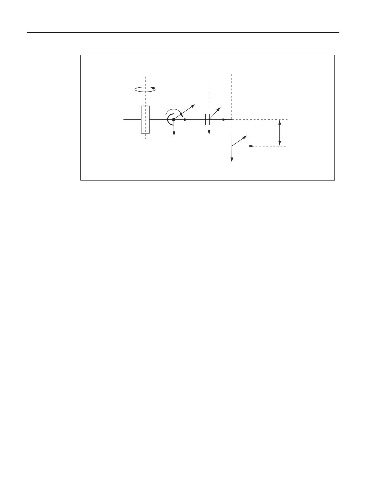
Transformation package handling
7.12 Startup
; 722/
]+3
])/
[+3
[)/
]:=
< 722/
\+3
\
)/
$
$
[:=
\:=
Figure 7-31
Tool length programming
7.11
Cartesian PTP travel with handling transformation package
It is possible to use the "Cartesian PTP travel" function with the handling transformation package
(see Function Manual "Transformations", Chapter "Cartesian PTP travel"). For this, the following
machine data must be set:
MD24100 $MC_TRAFO_TYPE_1 = 4100 (definition of transformation 1 in the channel)
7.12
Startup
7.12.1
General commissioning
The handling transformation package is a compile cycle.
The general commissioning of a compile cycle is described in Chapter "Installation and activation
of loadable compile cycles (Page 17)".
7.12.2
Function-specific commissioning
Option
The "Handling transformation package" function is an option for which a license must be
purchased:
• Transformation Handling RCTRA, Order No.: 6FC5800-0AM31-0YB0
Technologies
160
Function Manual, 10/2020, 6FC5397-8GP40-0BA1
Transformation package handling
7.12 Startup
A detailed description of licensing, for instance the assignment between a license and hardware,
is provided in:
Further information
Commissioning Manual, CNC Commissioning: NC, PLC, drive; licensing
User-specific alarm texts
To create user-specific alarm texts in conjunction with compile cycles, see Chapter "Creating
alarm texts (Page 23)"
Parameterizing transformation
1.
Enter the transformation type into the machine data:
- MD24100 $MC_TRAFO_TYPE_1 = 4100 (definition of transformation 1 in the channel)
2.
Enter the assignment of the channel axes involved in the transformation in the machine data
(axis numbers, starting at 1):
- MD24110 $MC_TRAFO_AXES_IN_1[0 ... 5] (axis assignment for transformation)
3.
Enter the geometry axes corresponding to the Cartesian degrees of freedom of the machine
in the machine data:
- MD24120 $MC_TRAFO_GEOAX_ASSIGN_TAB_1[0 ... 2] (assignment between geometry
axis and channel axis for transformation 1)
4.
Enter the kinematic identifier in the machine data:
- MD62600 $MC_TRAFO6_KINCLASS (kinematic category)
5.
Enter the identifier for special kinematics, if there are any, in machine data:
- MD62602 $MC_TRAFO6_SPECIAL_KIN (special kinematic type)
6.
Enter the number of axes in the machine data:
- MD62605 $MC_TRAFO6_NUM_AXES (number of transformed axes)
7.
If the travel direction of the involved axes is opposed to the transformation definition, then
change the factory setting in the machine data:
- MD62618 $MC_TRAFO6_AXES_DIR[ ] (matching of physical and mathematical directions
of rotation)
8.
Enter the data which define the basic axes:
- MD62603 $MC_TRAFO6_MAIN_AXES (basic axis identifier)
- MD62607 $MC_TRAFO6_MAIN_LENGTH_AB (basic axis lengths A and B)
9.
Enter any changes to the axis sequence in the machine data:
- MD62620 $MC_TRAFO6_AXIS_SEQ (rearrangement of axes)
Technologies
Function Manual, 10/2020, 6FC5397-8GP40-0BA1
161
Transformation package handling
7.13 Supplementary conditions
10.Enter the data which define the wrist axis:
- MD62604 $MC_TRAFO6_WRIST_AXES (wrist axis identifier)
- MD62614 $MC_TRAFO6_DHPAR4_5A (parameter A for configuring the wrist axis)
- MD62615 $MC_TRAFO6_DHPAR4_5D (parameter D for configuring the wrist axis)
- MD62616 $MC_TRAFO6_DHPAR4_5ALPHA (parameter ALPHA for configuring the wrist
axis)
- MD62606 $MC_TRAFO6_A4PAR (axis 4 is parallel/anti-parallel to last basic axis)
11.Enter the geometry parameters:
- Frame T_IRO_RO
- Frame T_X3_P3
- Frame T_FL_WP
12.Enter the position in relation to the calibration point in the machine data:
- MD62617 $MC_TRAFO6_MAMES (offset between mathematical and mechanical zero
points)
13.Enter the Cartesian velocities and acceleration rates.
7.13
Supplementary conditions
Clearance control
The handling transformation package cannot be used together with the technology function:
"clearance control".
Moving to fixed end stop
The handling transformation package cannotbe used in conjunction with the "Travel to fixed
stop".
Several transformations
The handling transformation package can be activated just once per channel in all channels.
Tool programming
Tools can only be parameterized by specifying tool lengths. It is not possible to program an
orientation for the tool.
Technologies
162
Function Manual, 10/2020, 6FC5397-8GP40-0BA1

Transformation package handling
7.14 Data lists
Programming of orientation
The programming possibilities of the orientation depend on the number of axes available on the
machine:
• Number < 5:
- Orientation axis angle
• Number = 5:
- Orientation axis angle
- Orientation vector
Singularities
A pole cannot be directly passed through when a transformation is active.
NOTICE
Traversing close to the pole
When traversing close to the pole, the axes involved can be overloaded. This is because the
control does not automatically reduce or limit the feedrate, acceleration or jerk. As a
consequence, the user is responsible in limiting the feedrate of the axes involved and/or the
clearance to the pole.
7.14
Data lists
7.14.1
Machine data
7.14.1.1
General machine data
Number
Identifier: $MN_
Description
10620
EULER_ANGLE_NAME_TAB[n]
Name of Euler angle
19410
TRAFO_TYPE_MASK, bit 4
Option data for OEM transformation
60943
CC_ACTIVE_IN_CHAN_RCTR
Activation of the handling transformation for the corre-
sponding channels
19610
TECHNO_EXTENSION_MASK
Option data for handling transformation
Technologies
Function Manual, 10/2020, 6FC5397-8GP40-0BA1
163

Transformation package handling
7.14 Data lists
7.14.1.2
Channelspecific machine data
Number
Identifier: $MC_
Description
21100
ORIENTATION_IS_EULER
Angle definition for orientation programming
21110
X_AXIS_IN_OLD_X_Z_PLANE
Coordinate system with automatic FRAME definition
24100
TRAFO_TYPE_1
Definition of transformation
24110
TRAFO_AXES_IN_1
Axis assignment for transformation 1
24120
TRAFO_GEOAX_ASSIGN_TAB_1
Assignment of geometry axes to channel axes
7.14.1.3
Channel-specific machine data for compile cycles
Number
Identifier: $MC_
Description
62600
TRAFO6_KINCLASS
Kinematic category
62601
TRAFO6_AXES_TYPE
Axis type for transformation
62602
TRAFO6_SPECIAL_KIN
Special kinematic type
62603
TRAFO6_MAIN_AXES
Basic axis identifier
62604
TRAFO6_WRIST_AXES
Wrist axis identifier
62605
TRAFO6_NUM_AXES
Number of transformed axes
62606
TRAFO6_A4PAR
Axis 4 is parallel/anti-parallel to last basic axis
62607
TRAFO6_MAIN_LENGTH_AB
Basic axis lengths A and B
62608
TRAFO6_TX3P3_POS
Attachment of hand (position component)
62609
TRAFO6_TX3P3_RPY
Attachment of hand (rotation component)
62610
TRAFO6_TFLWP_POS
Frame between wrist point and flange (position com-
ponent)
62611
TRAFO6_TFLWP_RPY
Frame between wrist point and flange (rotation compo-
nent)
62612
TRAFO6_TIRORO_POS
Frame between base center point and internal system
(position component)
62613
TRAFO6_TIRORO_RPY
Frame between base center point and internal system
(rotation component)
62614
TRAFO6_DHPAR4_5A
Parameter A for configuring the hand
62615
TRAFO6_DHPAR4_5D
Parameter D for configuring the hand
62616
TRAFO6_DHPAR4_5ALPHA
Parameter ALPHA for configuring the hand
62617
TRAFO6_MAMES
Offset between mathematical and mechanical zero
points
62618
TRAFO6_AXES_DIR
Matching of physical and mathematical directions of ro-
tation
62619
TRAFO6_DIS_WRP
Mean distance between wrist point and singularity (not
used)
62620
TRAFO6_AXIS_SEQ
Rearrangement of axes
62621
TRAFO6_SPIN_ON
Configuration includes triangular or trapezoidal spindles
62622
TRAFO6_SPIND_AXIS
Axis that is controlled by triangular spindle
62623
TRAFO6_SPINDLE_RAD_G
Radius G for triangular spindle
Technologies
164
Function Manual, 10/2020, 6FC5397-8GP40-0BA1

Transformation package handling
7.14 Data lists
Number
Identifier: $MC_
Description
62624
TRAFO6_SPINDLE_RAD_H
Radius H for triangular spindle
62625
TRAFO6_SPINDLE_SIGN
Sign for triangular spindle
62626
TRAFO6_SPINDLE_BETA
Angular offset for triangular spindle
62627
TRAFO6_TRP_SPIND_AXIS
Axes driven via trapezoidal connection
62628
TRAFO6_TRP_SPIND_LEN
Trapezoid lengths
62629
TRAFO6_VELCP
Cartesian velocities (substitute limit values for the ve-
locity controller)
62630
TRAFO6_ACCCP
Cartesian accelerations (substitute limit values for the
velocity controller)
62631
TRAFO6_VELORI
Orientation angle velocities (substitute limit values for
the velocity controller)
62632
TRAFO6_ACCORI
Orientation angle accelerations (substitute limit values
for the velocity controller)
62634
TRAFO6_DYN_LIM_REDUCE
Reduction factor for velocity controller during the JOG
travel
62635
TRAFO6_VEL_FILTER_TIME
Time constant for PT1 filter when the velocity controller
is active
62636
TRAFO6_TFL_EXT_RPY
Adaptation of the flange coordinate system
62637
TRAFO6_TOOL_DIR
Definition of the tool direction
62642
TRAFO6_C_ANGLE_OFFSET
Offset angle for C angle calculation in the BCS
62643
SPECIAL_FEATURE_MASK
Function mask
Technologies
Function Manual, 10/2020, 6FC5397-8GP40-0BA1
165
Transformation package handling
7.14 Data lists
Technologies
166
Function Manual, 10/2020, 6FC5397-8GP40-0BA1
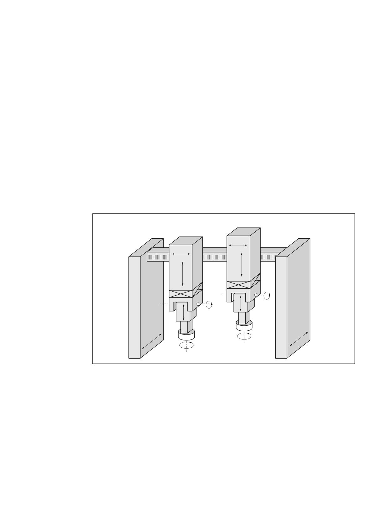
MCS coupling
8
8.1
Brief description
If there are two or more separately traversable machining heads on a machine tool and a
transformation is required for machining, the orientation axes of the machining heads cannot
be coupled via the standard coupling functions COUPON, TRAILON. The couplings are
established in the workpiece coordinate system (WCS). However, under the conditions
mentioned above the coupling of the orientation axes must be performed in the machine
coordinate system (MCS).
The compile cycle "MCS coupling" can be used to parameterize couplings in the machine
coordinate system (MCS) with coupling factors "1" and "-1" for a master axis, referred to as
CC_Master in the following, and several slave axes, referred to as CC_Slave in the following.
The couplings can be switched on and off via commands in the part program.
0DFKLQLQJ KHDG
0DFKLQLQJ KHDG
<
<
=
=
$
$
:
:
;
&
8
&
Figure 8-1
Application example: Double slide gantry-type milling machine
Master and slave axes
A CC_Master can be master for several CC_Slaves. A CC_Slave cannot be a CC_Master at the same
time.
The following functions are not possible for a CC_Slave:
• To be a PLC axis
• To be a command axis
• To be traversed separately from the CC_Master in JOG mode
Technologies
Function Manual, 10/2020, 6FC5397-8GP40-0BA1
167
MCS coupling
8.2 Description of MCS coupling functions
Tolerance window
When the coupling is active, the actual values of the CC_Master and CC_Slave are monitored for
compliance with a parameterizable tolerance window.
Programming a CC-Slave
If a CC_Slave is programmed in a channel, either an alarm is displayed or the axis is requested for
the channel via an implicitly triggered axis interchange (GET), depending on the setting in
machine data:
MD30552 $MA_AUTO_GET_TYPE = <GET type> (automatic GET for axis)
Switching the coupling on/off
A coupling is switched on and off via OEM-specific language commands and can be active in all
operating modes.
Collision protection
In order to protect the machining heads against collision in decoupled operation or in mirrored
coupling, a collision protection can be parameterized. The activation is performed via machine
data or the NC/PLC interface. The assignment of the protected pairs is not dependent on the
CC_Master and CC_Slave pairs.
8.2
Description of MCS coupling functions
8.2.1
Defining coupling pairs
A CC_SLAVE axis is matched to its CC_Master axis via the following axial machine data:
MD63540 $MA_CC_MASTER_AXIS (specifies the CC_Master axis assigned to a CC_Slave axis)
The axes involved in the coupling can only be changed when the coupling is not active (open).
A CC_Slave axis is displayed in axial VDI-Out byte:
DB31, ... DBX97.0 (MCS coupling: slave axis)
Precondition
• The CC_Master and CC_Slave axes must be either both rotary axes or both linear axes.
• Spindles cannot be coupled by this function.
• Neither CC_Master nor CC_Slave axis are permitted to be a interchanged axis
($MA_MASTER_CHAN[AXn]=0)
Technologies
168
Function Manual, 10/2020, 6FC5397-8GP40-0BA1
MCS coupling
8.2 Description of MCS coupling functions
8.2.2
Switching the coupling ON/OFF
Activating the coupling
• Activating the 1:1 coupling. Monitoring of the tolerance window is active.
CC_COPON([<axis1>][<axis2>][<axis3>][<axis4>][<axis5>])
• Activating the 1:-1 coupling (mirror). Monitoring of the tolerance window is not active.
CC_COPONM([<axis1>][<axis2>][<axis3>][<axis4>][<axis5>])
Axis name
An axis can be specified via:
• Machine axis name
• Channel axis name
• Geometry axis name
Boundary conditions
• A programmed axis must be involved in a coupling.
• CC_Master axes, CC_Slave axes or both can be programmed simultaneously. All defined
couplings are switched on with CC_COPON or CC_COPONM.
• An alarm is output if an axis not involved in a coupling is programmed.
NC/PLC interface signals
All NC/PLC interface signals of a coupling refer to the CC_Slave axes.
• DB31, … DBX97.1 (MCS coupling: coupling active)
• DB31, ... DBX97.2 (MCS coupling: mirroring active)
• DB31, …DBX24.2 (MCS coupling: deactivate or do not permit)
If the coupling is suppressed, an alarm is not output for the CC_Slave axis.
Deactivating the coupling
CC_COPOFF([<axis1>][<axis2>][<axis3>][<axis4>][<axis5>])
As for switching on the coupling with the difference that no alarm is output if an axis is
programmed that is not involved in a coupling.
An existing coupling can also be switched off by the axial NC/PLC interface signal of the CC_Slave
axis.
Boundary condition
A coupling can only be switched on or off when the axes are at standstill.
Technologies
Function Manual, 10/2020, 6FC5397-8GP40-0BA1
169
MCS coupling
8.3 Description of collision protection
8.2.3
Tolerance window
A monitoring window is specified via axial machine data:
MD63541 $MA_CC_POSITION_TOL (monitoring window)
The absolute difference between the actual values of CC_Slave axis and CC_Master axis must
never be greater than this value. Alarm 70010 is output if values are exceeded.
Monitoring is not active
• if the machine data is set to 0,
• if the coupling is switched off (open),
• if 'axis/spindle inhibit' is set for one of the axes,
• if an axis is in the 'follow-up mode',
• for the 1:-1 coupling.
If the offset stored at the instant of coupling activation changes when 1:1 coupling is active, the
change is indicated at the NC => PLC VDI-SS:
DB31, ... DBX97.3 (MCS coupling: offset change)
Note
The offset can change.
• if the SW limit monitor was active for one axis during the main run,
• if one axis has been switched to follow-up mode,
• if collision protection was active for one axis.
8.2.4
Memory configuration: Block memory
The technological function requires additional data in the NC-internal block memory. The
values must be increased for the following memory configuring channel-specific machine data:
• MD28090 $MC_MM_NUM_CC_BLOCK_ELEMENTS += 1 (number of block elements for
compile cycles)
• MD28100 $MN_MM_NUM_CC_BLOCK_USER_MEM += 1 (size of block memory for compile
cycles (DRAM) in KB)
8.3
Description of collision protection
8.3.1
Defining protection pairs
A ProtecSlave axis (PSlave) is matched to its ProtecMaster (PMaster) axis via the following axial
machine data:
MD63542 $MA_CC_PROTECT_MASTER (specifies the PMaster axis assigned to a PSlave axis)
Technologies
170
Function Manual, 10/2020, 6FC5397-8GP40-0BA1
MCS coupling
8.3 Description of collision protection
The protection pairs can thus be defined independently of the coupling pairs. A PSlave axis may
act as the PMaster axis for another axis. The axes must be either both rotary axes or both linear
axes.
8.3.2
Switching collision protection ON / OFF
The minimum clearance between PSlave and PMaster is provided in the axial machine data of
the PSlave axis:
MD63544 $MA_CC_COLLISION_WIN (collision protection window)
No collision protection is implemented if the value entered here is less than 0. The 0 position
offset between PSlave and PMaster is provided in the axial machine data (PSlave axis):
MD63545 $MA_CC_OFFSET_MASTER (zero point offset between PSlave and PMaster)
Before the collision protection is switched on, the monitoring function for each individual axis
must be enabled in the following machine data:
MD63543 $MA_CC_PROTECT_OPTIONS
In the same machine data for the PSlave axis, a setting is entered to specify whether the collision
protection must be active continuously or whether it is activated via VDI interface signal (PLC =>
NC):
DB31, … DBX24.3
If collision protection is active, the setpoint positions of the PSlave and PMaster in the next IPO
cycle are extrapolated and monitored in the IPO clock cycle using the current setpoint position
and current velocity.
If the axes violate the minimum clearance, they are braked at the configured maximum
acceleration rate:
MD32300 $MA_MAX_AX_ACCEL (Axis acceleration)
Or at a 20% faster acceleration rate, defined in machine data:
MD63543 $MA_CC_PROTECT_OPTIONS
An alarm is output as soon as the axes reach zero speed.
WARNING
Risk of collision when starting
If the axes are forced to brake, the positions displayed in the workpiece coordinate system are
incorrect!
These are not re-synchronized again until a system RESET.
If the axes are already violating the minimum clearance when collision protection is activated,
they can only be traversed in one direction (retraction direction). The retraction direction is
configured in machine data:
MD63543 $MA_CC_PROTECT_OPTIONS
The collision protection status is optionally displayed in axial VDI-Out byte of the PSlave:
Technologies
Function Manual, 10/2020, 6FC5397-8GP40-0BA1
171
MCS coupling
8.3 Description of collision protection
DB31, ... DBX66.0 (MCS coupling: collision protection active)
• DB31, … DBX66.0=1 → collision protection active
• DB31, … DBX66.0=0 → collision protection inactive
This output is activated via Bit7 in machine data of the PSlave axis:
MD63543 $MA_CC_PROTECT_OPTIONS
8.3.3
Configuring example
CC_COLLISION_WIN[PSlave]
CC_PROTECT_OPTIONS[PMaster] bit0=0
PMaster
PSlave
CC_PROTECT_OPTIONS[PSlave] bit0 = 1
CC_OFFSET_MASTER[PSlave]
Figure 8-2
Configuring example
Note
Since the collision protection function extrapolates the target positions from the "current
velocity + maximum acceleration (or +20%)", the monitoring alarm may be activated
unexpectedly at reduced acceleration rates:
Example:
PMaster = X, PSlave = X2, $MA_CC_COLLISION_WIN = 10mm
Starting point in part program: X=0.0 X2=20.0
N50 G0 X100 X2=90
; the monitoring alarm is activated because X and X2 are interpolating together: for this reason,
the acceleration rate of X2 < maximum acceleration.
Remedy:
• N50 G0 POS[X]=100 POS[X2]=90
• or switch the monitoring function off.
Technologies
172
Function Manual, 10/2020, 6FC5397-8GP40-0BA1
MCS coupling
8.5 Special operating states
8.4
User-specific configurations
Parking the machining head
In this context, "parking" means that the relevant machining head is not involved in workpiece
machining. All of the axes are in closed-loop position control and are at an exact stop.
The coupling should be active, even if only one machining head is being used for production!
This is essential primarily if only the second head (Y2
) is being for machining. "Axis/spindle
inhibit" must then be set axially (PLC -> NC) for the "parked" head.
Note
When an axis/spindle inhibit is active, a part program can be executed if this axis is not operating
under position control.
Spindle functionalities
Since an MCS coupling cannot be activated for spindles, other types of solutions should be
configured for these.
• Positioning the spindle (SPOS= ...)
Instead, a cycle is called from SPOS. SPOS is called for all active spindles in this cycle.
• Speed setpoint
Speed and direction of rotation setpoints can be detected via synchronized actions or PLC and
transferred to all other active spindles.
• Synchronous spindle function
8.5
Special operating states
Reset
The couplings can remain active after a RESET.
Reorg
No non-standard functionalities.
Block search
During a block search, the last block containing an OEM-specific language command is always
stored and then output with the last action block. This feature is illustrated in the following
examples. The output positions of the axes are always 0.
Example 1:
N01 M3 S1000
Technologies
Function Manual, 10/2020, 6FC5397-8GP40-0BA1
173
MCS coupling
8.6 Boundary conditions
N02 G01 F1000 X10 Y10
N03 CC_COPON( X, Y)
TARGET:
If this program is started normally, axes X and Z traverse to X10 Z10 in the decoupled state.
After block search to TARGET: axes X and Y traverse to this position in the coupled state!
Example 2:
N01 M3 S1000
N02 CC_COPON( X)
N03 G01 F1000 X100 Y50
N04 CC_COPOFF( X)
N05 CC_COPON( Y)
N06 Y100
N10 CC_COPOFF()
TARGET:
After block search to TARGET: the axes traverse to X100 Y100 in the decoupled state.
Example 3:
N01 CC_COPON( X, Y, Z)
N02
N10 CC_COPOFF( Z)
TARGET:
After block search to TARGET: no coupling is active!
Single block
There are no nonstandard functionalities.
8.6
Boundary conditions
Validity
The function is configured only for the first channel.
Braking behavior
Braking behavior at the SW limit with path axes
The programmable acceleration factor ACC for braking at the SW limit corresponds to the path
axes.
Technologies
174
Function Manual, 10/2020, 6FC5397-8GP40-0BA1

MCS coupling
8.7 Data lists
The axes in an MCS coupling are principal axes that are referred to as geometry axes due to their
geometric arrangement.
Braking geometry axes using synchronized actions
The faster deceleration capacity as required for path axes can be implemented for geometry axes
as follows using a synchronized action:
ACC[x2]=190
Axial acceleration limitation with G0
The following machine data is not considered by the MCS coupling:
MD32434 $MA_G00_ACCEL_FACTOR (scaling of the acceleration limitation with G0)
A value deviating from the standard value affects the braking ramp up to the software limit
switch.
8.7
Data lists
8.7.1
Machine data
8.7.1.1
Channelspecific machine data
Number Identifier: $MC_
Description
28090
NUM_CC_BLOCK_ELEMENTS
Number of block elements for compile cycles.
28100
NUM_CC_BLOCK_USER_MEM
Total size of usable block memory for compile cycles
8.7.1.2
Axis/spindlespecific machine data
Number Identifier: $MA_
Description
63540
CC_MASTER_AXIS
Specifies the CC_Master axis assigned to a CC_Slave axis.
63541
CC_POSITION_TOL
Monitoring window
63542
CC_PROTEC_MASTER
Specifies the PMaster axis assigned to a PSlave axis.
63543
CC_PROTEC_OPTIONS
63544
CC_COLLISION_WIN
Collision protection window
63545
CC_OFFSET_MASTER
Zero point offset between PSlave and PMaster
Technologies
Function Manual, 10/2020, 6FC5397-8GP40-0BA1
175
MCS coupling
8.7 Data lists
Technologies
176
Function Manual, 10/2020, 6FC5397-8GP40-0BA1
Continue machining (retrace support)
9
9.1
Brief description
Function
The "Continue machining - Retrace support (RESU)" technological function supports the
retracing of uncompleted 2-dimensional machining processes such as laser cutting, water jet
cutting, etc.
In the event of a fault during the machining process, e.g. loss of the laser, RESU can be used even
by machine operators who do not have specific knowledge of the active part program to
interrupt machining and travel back along the contour from the interruption point to a program
continuation point necessary for machining purposes.
After reaching the "continue machining" point, the machine operator triggers the re-machining.
As part of the retrace process, an implicit block search takes place along the contour with
calculation followed by repositioning on the contour and automatic retracing of the part
program machining process.
The possibility of retrace support within a machining program is realized by programming RESU
start and end points using the CC_PREPRE(...) procedure. The program continuation point can
be arbitrarily selected within a contour range defined in this way.
QG JHRPHWU\ D[LV
1
H J VSOLQH
EORFN
1
3URJUDP FRQWLQXDWLRQ
SRLQW
1
&&B35(35(
5(326 VWDUWLQJ SRLQW
1
1
VW JHRPHWU\ D[LV
① RESU start point or start of the RESU-capable contour range
② RESU end point or end of the RESU-capable contour range
③ Example of a program continuation point
Figure 9-1
Programmed contour with program continuation and interruption points
Precise retracing of contours is possible along all programmed contours comprising straight and
circular elements. During retracing, other contour elements such as splines or automatically
inserted non-linear contour elements (circle, parable, etc. e.g. through tool radius
compensation) are mapped as straight lines between the start and end points of the
corresponding contour element, thereby preventing precise retracing of contours.
Technologies
Function Manual, 10/2020, 6FC5397-8GP40-0BA1
177
Continue machining (retrace support)
9.2 Function description
Function code
The code for the "Continue Machining - Retrace support" technological function for function-
specific identifiers of program commands, machine data, etc. is:
RESU (= REtrace SUpport)
Restrictions
The use of the "Continue Machining Retrace support" technological function is subject to the
following restrictions:
• The technology function is available only in the 1st channel of NC.
• Program continuation or reverse travel is only possible for part program blocks that contain
traversing blocks in the configured RESU working plane (e.g. 1st and 2nd geometry axes of
the channel, see Section "Definition of the RESU working plane (Page 185)").
Further information
The "Continue Machining - Retrace support" technological function is a compile cycle. For the
handling of compile cycles (see Function Manual Technologies, Section Installation and
activation of loadable compile cycles).
See also
Installation and activation of loadable compile cycles (Page 17)
9.2
Function description
9.2.1
Function
Block search with calculation on contour
To be able to resume interrupted machining at a specific point in a part program, a block search
can be carried out using the "Block search with calculation on contour" standard function.
However, detailed knowledge of the part program is required to be able to enter the block
number of the part program block required for the block search (i.e. the number of the block the
search needs to locate).
Continue machining - retrace support
The "Continue machining - Retrace support" technological function supports the continuation
of the machining operation by means of an implicit block search with calculation on the contour
without the machine operator needing to know the part program block required.
Technologies
178
Function Manual, 10/2020, 6FC5397-8GP40-0BA1
Continue machining (retrace support)
9.2 Function description
Continue machining might be required for example in a laser cutting application if the laser is
lost during the machining operation and machining needs to resume at the point at which it was
interrupted.
RESU supports continue machining (retrace support) using the following automatically running
sub-functions:
• Function-specific reverse travel along the contour to the required program continuation point
• Automatic identification of the part program block associated with the program continuation
point
• Block search with calculation on the contour for the part program block identified
• Repositioning on the contour at the program continuation point
• Continuation of part program machining
To approach the required program continuation point exactly, it is possible to switch several
times between reverse and forward travel along the contour during the continue machining
process.
RESU-capable contour ranges
RESU is activated by programming the function-specific part program command CC_PREPRE
(1). Only the contour range lying between the RESU start (CC_PREPRE(1)) and the
interruption point (NC stop) is retraceable in the sense of RESU.
Once RESU has been launched, all part program blocks in which traversing movements are
programmed are logged by RESU for possible subsequent reverse travel. Contour ranges for
which continuing machining is irrelevant can be excluded from the log using RESU stop
CC_PREPRE (0).
Contour ranges, which are not logged are bridged by straight lines between the start and end
points during reverse/forward travel.
Technologies
Function Manual, 10/2020, 6FC5397-8GP40-0BA1
179
Continue machining (retrace support)
9.2 Function description
QG JHRPHWU\ D[LV
1
1
1
1
&&B35(35(
1
1
1
1
&&B35(35(
1
VW JHRPHWU\ D[LV
① RESU start point 1 or start of the RESU-capable contour range 1
② RESU end point 1 or end of the RESU-capable contour range 1
③ RESU start point 2 or start of the RESU-capable contour range 2
④ RESU end point 2 or end of the RESU-capable contour range 2
⑤ RESU straight-line as equivalent contour of the non RESU-capable contour range
Figure 9-2
RESU-capable contour ranges
9.2.2
Definition of terms
Interruption point
The interruption point is the point of the contour at which the traversing movement comes to
a standstill following an NC stop and reverse travel is activated.
Program continuation point
The program continuation point is the point of the contour at which reverse travel terminates
and program continuation is activated.
Retraceable contour range
Retraceable contour ranges consist of traversing blocks in the configured RESU working plane
(e.g. 1st and 2nd geometry axis of the channel), that are programmed in the part program
between the RESU start command CC_PREPRE(1) and the RESU stop
command CC_PREPRE(0) (see "Figure 9-2 RESU-capable contour ranges (Page 180)").
9.2.3
Functional sequence (principle)
The principle sequence of the RESU function between the interruption point, program
continuation point and continuation of part program processing is described below.
Technologies
180
Function Manual, 10/2020, 6FC5397-8GP40-0BA1
Continue machining (retrace support)
9.2 Function description
Requirements
A part program with traversing blocks in the configured RESU working plane (Page 185) as well
as the command for the RESU start has been started in the 1st channel.
Functional sequence
1. Interrupt part program processing:
The part program processing / traversing movement may be interrupted any number of
traversing blocks after RESU start by NC stop.
2. Select reverse travel:
The selection of reverse travel is realized using the NC/PLC interface signal:
DB21, … DBX0.1 = 1
3. Reverse travel:
The contour is traversed in the RESU working plane (Page 185) in the reverse direction with
NC start. Instead of the current machining program, RESU selects the automatically
generated RESU main program (Page 192).
4. End reverse travel:
Once the required program continuation point on the contour has been reached, reverse
travel is ended using NC stop.
5. Select forward travel (optional):
For forward travel, reverse travel must be deselected via NC/PLC interface signal:
DB21, … DBX0.1 = 0
6. Forward travel (optional):
The contour is traversed in the RESU working plane (Page 185) in the forward direction with
NC start.
7. End forward travel (optional):
Once the required program continuation point on the contour has been reached, forward
travel is ended using NC stop.
Technologies
Function Manual, 10/2020, 6FC5397-8GP40-0BA1
181
Continue machining (retrace support)
9.2 Function description
8. Retrace support:
Continue machining is initiated via PLC interface signal:
DB21, … DBX0.2 = 1 (start retrace support)
For retrace support, RESU automatically selects the original machining program and
launches a block search with calculation as far as the program continuation point.
9. Continuation of part program machining:
Part program processing continues at the program continuation point in accordance with the
"Block search with calculation" standard function when two NC start commands occur one
after the other.
The first NC start command processes the action blocks. Retrace support
ASUP CC_RESU_BS_ASUP.SPF (Page 195) is initiated when the last action block is reached:
DB21, … DBX32.6 == 1 (last action block active)
The second NC start command processes the approach block before part program processing
is resumed.
Note
Points 3 to 8 can be repeated as often as required.
Following retrace support, a new reverse travel is possible up to a maximum of the last
program continuation point.
Technologies
182
Function Manual, 10/2020, 6FC5397-8GP40-0BA1