SINUMERIK 840D sl. Service - Functions. Manual (2018-2020) - page 78
Clearance control (CLC/CLCX)
5.5 Startup
For sensor-controlled approximation to the sheet metal from a distance greater than the sensor's
sensing range, CLCX uses the maximum valid clearance in the table to limit the approach
velocity so that the axis can be braked to the programmed clearance setpoint.
If the evaluation electronics of the sensor already linearizes the clearance signal well, the
characteristic can consist of only two entries: the voltage at zero distance and the voltage at the
largest measurable distance. This saves computing time in the CLCX for the evaluation of
unnecessary linear intermediate points.
Improving the signal
If the input signal displayed in "CLC_RTD_SENSOR_VOLT" contains a high noise level, first try to
improve the electrical quality of the signal by better shielding and grounding of the electrical
connection. To use a more reliable sensor signal during calibration, you can temporarily increase
the time constant of the mean value filter during calibration:
62525__MC_CLC_SENSOR_FILTER_TIME[0]
Before the clearance control is switched on, the filter time must be reset. Too large a time
constant of the mean value filter causes a sensor delay (half of the mean value time constant),
which impairs the dynamic response of the control loop.
If there is a need for permanent filtering of the input signal, no more than a few milliseconds
should be entered.
If you check the variable "CLC_RTD_SENSOR_DIST" in the display, note that these are calculated
with the sensor clearance table that was last activated.
You can switch to the second sensor table, for example, by starting the following part program:
Example code
CLC_RT_TECH_CMD=120
; Block CLCX motion to CLC(1)
CLC(1)
CLC_SEL(2)
; Activate table 2
CLC(0)
; Deactivate CLC. Table 2 remains active
M30
; RESET deletes CLC_RT_TECH_CMD (see Figure 2)
5.5.4.5
Compensation of the time delay of the sensor
Time delay
The clearance information that the CLCX receives from the clearance sensor includes a time
delay in relation to the actual position of the axis read by the encoder. If this delay is constant, its
effect can be compensated.
• When using the "POS mode" (CLC_RT_CTRL_MODE=0), this compensation will significantly
improve the quality of the sensor-controlled motion - especially when the sensor approaches
the sheet metal from a greater distance.
• It is also important for the "GAIN mode" (CLC_RT_CTRL_MODE=1) to compensate for the
sensor delay: As long as the distance during the approach phase is greater than the range of
the sensor, the correct determination of the approach velocity depends on the correct
compensation of the delay.
Technologies
Function Manual, 10/2020, 6FC5397-8GP40-0BA1
45
Clearance control (CLC/CLCX)
5.5 Startup
CLCX provides a function to determine and compensate for this delay. To use this function, the
following GUD variables must be defined in one of the definition files MGUD, UGUD,
GUD4...GUD7:
DEF NCK REAL CLC_SIN_GEN_FREQ
DEF NCK REAL CLC_SIN_GEN_AMPL
DEF CHAN REAL CLC_SENSOR_MATCH[ 2 ]
Only after the next NCK restart does the CLCX gain access to these variables.
To measure the delay, place a piece of sheet metal under the sensor and position the CLCX axis
at a suitable height (approx. 1 mm) above this sheet metal. Make sure that the sheet metal does
not vibrate during the test. If necessary, you must stabilize the sheet metal with clamps or a
weight.
Using a part program
The following part program starts the integrated function generator of the CLCX. It generates a
sinusoidal movement of the CLCX axis.
• Adjust the amplitude (CLC_SIN_GEN_AMPL) so that the sinusoidal motion is completely
within the sensitive range of the sensor.
• Carefully ensure that the SynAct variable CLC_RTD_DYN_LIM remains at ZERO throughout
the evaluation of the phase. This ensures that no dynamic limitation of the axis movement
occurs during the measurement of the sensor deceleration.
• If dynamic limiting occurs, reduce the frequency or amplitude of the stimulating sinusoidal
movement. Dynamic constraints interfere with the correct determination of the delay.
• During the sine wave movement, the time delay of the sensor relative to the encoder is
calculated after each period. The evaluation can be monitored online in the GUD
CLC_SENSOR_MATCH[0]. The number of periods already evaluated is displayed in
CLC_SENSOR_MATCH[1].
Let the measurement run until the monitored value in CLC_SENSOR_MATCH[0] is sufficiently
stable.
Example program
CLC_SIN_GEN_AMPL=5.0 ; Generates a sinusoidal motion with +-5mm amplitude.
; This must lie within the sensitive range of the sensor.
CLC_SIN_GEN_FREQ=0.5 ; The frequency used is 0.5 Hz
G4 F1
; Wait until the GUD values in the CLCX have become safely effective
CLC_LIM( -30, 10 )
; Here it is assumed that a sheet of metal is located max. 50 mm
; below the position where the CLCX was switched on.
CLC_DIST=1,0
; The clearance setpoint for this sheet metal is 1 mm.
CLC(1)
; Activate CLC
G4 F1
; Wait for the axis to approach the clearance setpoint
whenever TRUE CLC_RT_TECH_CMD=99 ; Starts the sine movement
M0
; Monitor calculated delay in GUD CLC_SENSOR_MATCH[0]
; Check if the measured value is stable against small variations of
amplitude and frequency.
M30
Technologies
46
Function Manual, 10/2020, 6FC5397-8GP40-0BA1
Clearance control (CLC/CLCX)
5.5 Startup
• It is important that the stroke of the sinusoidal movement, which is twice as large as
CLC_SIN_GEN_AMPL specifies, remains completely within the sensitive range of the sensor.
• Select CLC_SIN_GEN_AMPL so that it corresponds to about one third of the largest entry of
the sensor characteristic curve.
Example:
CLC_SIN_GEN_AMPL = 0.354 * $MC_CLC_SENSOR_DIST_TABLE[ <highestIndexUsed>]
reaches 70% of the sensitive sensor range.
If CLC_RTD_PROG_DIST does not exceed the remaining 30%, the delay can be evaluated
correctly.
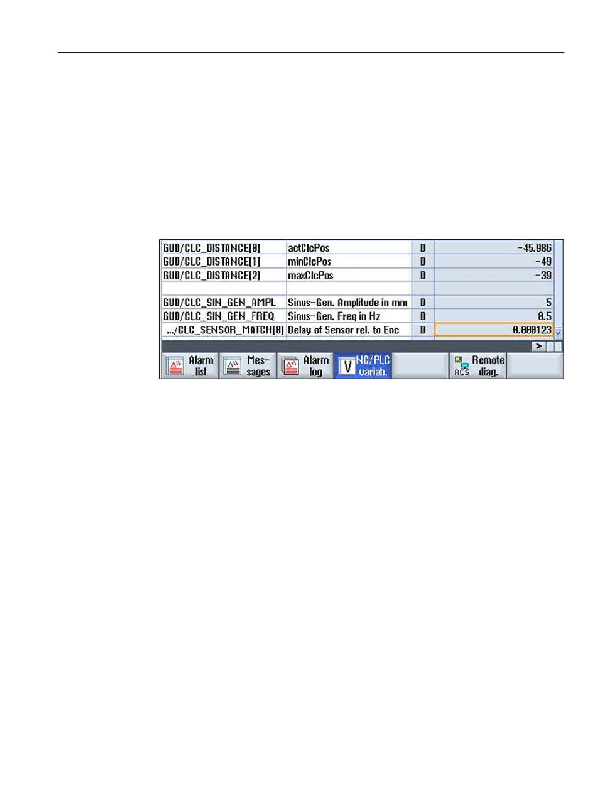
• After a few periods of sine movement executed within the M0 block, the GUD variable
CLC_SENSOR_MATCH[0] displays the evaluated delay in seconds.
Figure 5-4
Determination of the sensor delay
Determine and adjust measured data
Modern clearance sensors connected via an isochronous PROFINET IO A/D converter should
show a delay in the range of a few milliseconds or even less, largely independent of frequency.
The example above shows a time delay of 0.123 ms.
If you get a stable and positive delay during the measurement, transfer the measured sensor
delay in seconds as compensation value to the following machine data:
• MD62519 $MC_CLC_SENSOR_DELAY_COMP_TIME = CLC_SENSOR_MATCH[0]
• Execute NEWCONFIG or RESET to make the compensation value effective.
CLCX compares the position information read by the sensor with the position information of the
encoder.
This is required for the "POS mode" and usually for any sensor-controlled approach starting at a
distance outside the sensitive range of the sensor.
If you repeat the measurement with an already correctly determined entry in
$MC_CLC_SENSOR_DELAY_COMP_TIME, CLC_SENSOR_MATCH[0] will still show the delay of the
uncompensated sensor.
Technologies
Function Manual, 10/2020, 6FC5397-8GP40-0BA1
47
Clearance control (CLC/CLCX)
5.5 Startup
5.5.5
Parameter settings for clearance control
Part programs
For function-specific naming of the programmable NC address CLC_DIST, the standard name
OMA1 must be reconfigured in the following machine data:
• MD10712 $MN_NC_USER_CODE_CONF_NAME_TAB[0] = "OMA1" (list of re-configured NC
codes)
• MD10712 $MN_NC_USER_CODE_CONF_NAME_TAB[1] = "CLC_DIST"
1D/ 3D clearance control
The choice between 1D or 3D clearance control is based on the machine data:
• MD62500 $MC_CLC_AXNO = <n> (Axis assignment of clearance control)
- <n> > 0: 1D clearance control. <n> is the channel axis number of the clearance-controlled
axis
- <n> = -1: 1st 5-axis transformation configured in the channel
- <n> = -2: 2nd 5-axis transformation configured in the channel
- <n> = -3: 3rd 5-axis transformation configured in the channel
- <n> = -4: 4th 5-axis transformation configured in the channel
Input signals
The input signals of the clearance sensor parameterized above are made known to the clearance
control via the following machine data (see also Chapter "Parameterizing the input signals
(Page 42)"):
• MD62502 $MC_CLC_ANALOG_IN = <n> (Analog input for clearance control)
<n> = input number, corresponds to the addressing of the system variable $A_INA[<n>]
• MD62504 $MC_CLC_SENSOR_TOUCHED_INPUT = <m> (Input bit assignment for the "sensor
collision" signal)
<m> = input number, corresponds to the addressing of the system variable $A_IN[<m>]
Exact stop
In order to satisfy the programmed block change condition "Exact stop coarse/fine reached"
(G601/G602), the traversing velocity generated by the clearance control in the clearance-
controlled axes must be lower than the standstill velocity tolerance at least for the duration of
the standstill delay time.
In order to optimize the block change time with active clearance control, the following machine
data must be adjusted if necessary:
• MD36000 $MA_STOP_LIMIT_COARSE[<x>] (Exact stop coarse)
• MD36010 $MA_STOP_LIMIT_FINE[<x>] (Exact stop fine)
• MD36020 $MA_POSITIONING_TIME[<x>] (Delay time exact stop fine)
Technologies
48
Function Manual, 10/2020, 6FC5397-8GP40-0BA1

Clearance control (CLC/CLCX)
5.5 Startup
• MD36040 $MA_STANDSTILL_DELAY_TIME[<x>] (Delay time for standstill monitoring)
• MD36060 $MA_STANDSTILL_VELO_TOL[<x>] (Threshold velocity/speed 'Axis/spindle in
stop')
<x> = identifier of the clearance-controlled machine axis
5.5.6
Configuration of the basic MD of CLCX
Basic machine data
Table 5-2
Machine data for configuration of CLCX
Machine data
Description
MD62500 $MC_CLC_AXNO
> 0: Activates the 1D clearance control for the channel axis with the specified axis
number. This axis must not be a modulo rotary axis.
n < 0: activates the 3D clearance control.
A prerequisite for activating the 3D clearance control is that at least one of the
first four 5-axis transformations possible in the channel is configured.
-1: the first 5-axis transformation configured with $MC_TRAFO_TYPE_n in the
channel (16 <= transformer type <=149) defines the three Cartesian axes on
which clearance control acts.
-4: the fourth 5-axis transformation configured in the channel is selected.
MD 62502 $MC_CLC_ANALOG_INPUT
Number of the analog input to which the clearance sensor is connected.
MD62507
Start address of the real-time variables $A_DBR / $A_DBB (e.g. 1000)
$MC_CLC_A_DB_RT_VAR_START_INDEX
The CLCX function reads and writes to the $A_DBx variables that follow this start
address. Therefore 100 bytes from this start address should not be used for other
functions.
MD $MC_CLC_SENSOR_TOUCHED_INPUT
Number of the digital input to be used for collision monitoring (provided the
sensor outputs a tip-touch signal).
MD62528 $MC_CLC_PROG_ORI_AX_MASK
Axis mask for simulated axes when using the 3D-CLC function with freely pro-
grammed direction specification.
MD28090 $MC_MM_NUM_CC_BLOCK_ELE-
Configures the number of block elements that can be used for compile cycles.
MENTS
Each instance of the CLCX in the channel requires 4 block elements.
MD28100
Configures the size of the dynamic memory available for compile cycles in the
$MC_MM_NUM_CC_BLOCK_USER_MEM
internal block. Each instance of the CLCX in the channel requires 20 KB.
MD28150 $MC_MM_NUM_VDIVAR_ELE-
Number of block elements available for writing PLC variables. Recommended
MENTS
value for programming synchronized actions to use the CLCX function: 20
Technologies
Function Manual, 10/2020, 6FC5397-8GP40-0BA1
49

Clearance control (CLC/CLCX)
5.5 Startup
"New" machine data for CLCX
Table 5-3
Additional machine data for CLCX
Number
Identifier: $MC_
Description
62503
CLC_ANALOG_IN_HW_NORM_FACT
Normalization of the internal voltage values to the input voltage in
Volts
62507
CLC_A_DB_RT_VAR_START_INDEX
Start index of the CLCX real-time variable $A_DBx
62509
CLC_DISTANCE_SETPOINT
Defines a default distance that is used after reset as long as no
distance has been explicitly programmed.
62511
CLC_SENSOR_DIST_TABLE_1 [0... 15 ]
First clearance table for linearization of the sensor characteristic
curve
62513
CLC_SENSOR_DIST_TABLE_2 [ 0... 15 ]
Second clearance table for linearization of the sensor characteristic
curve
62514
CLC_DISTANCE_CTRL_GAIN
Defines the default value of the CLC circuit gain. This value is effec-
tive in "GAIN mode" after reset as long as no GAIN value has been
explicitly programmed.
62515
CLC_PLUS_DIR_GAIN_FACTOR
Increase the gain factor if the current distance of the sensor be-
comes smaller than the programmed distance setpoint.
62518
CLC_SENSOR_JERK_TIME
Jerk filter for smoothing the non-sensor-controlled CLCX motion.
62519
CLC_SENSOR_DELAY_COMP_TIME
Value to compensate for the delay time of the sensor used. This
adjustment is required for the sensor-guided approach from large
distances and for the POS mode.
62525
CLC_SENSOR_FILTER_TIME
• Index0: Time constant of the mean value filtering of the sensor
input signal.
• Index1: Time constant of the mean value filtering for internal
calculation of the tip-touch signal.
62526
CLC_TIP_TOUCH_DISTANCE
Threshold value for triggering internal tip-touch monitoring.
62527
CLC_MODE_SWITCH_DIST_ERROR
Threshold value for automatic switching from POS mode to GAIN
mode and vice versa.
An entry >0 activates the automatic switchover.
Table 5-4
List of redeclared machine data for CLCX
Number
Identifier:
Description
10712
$MN_NC_USER_CODE_CONF_NAME_TAB[0]
-
= "OMA1"
10712
$MN_NC_USER_CODE_CONF_NAME_TAB[1]
-
= "CLC_DIST"
Technologies
50
Function Manual, 10/2020, 6FC5397-8GP40-0BA1

Clearance control (CLC/CLCX)
5.5 Startup
"Old" machine data for CLC
This machine data is no longer provided or used by CLCX.
Table 5-5
CLC machine data that is no longer required
Number
Identifier: $MC_
Description
62511
CLC_SENSOR_VELO_TABLE_1 [0 ... 15 ]
First velocity table for linearization of the sensor characteristic curve
62513
CLC_SENSOR_VELO_TABLE_2 [ 0 ... 15 ]
Second velocity table for linearization of the sensor characteristic
curve
62522
CLC_OFFSET_ASSIGN_ANAOUT
Assignment of internal additional analog value to sensor signal
62523
CLC_LOCK_DIR_ASSIGN_DIGOUT
Assignment of digital output for interlock CLC
List of redeclared machine data for CLC.
Table 5-6
List of redeclared machine data for CLC
Number
Identifier:
Description
10712
$MN_NC_USER_CODE_CONF_NAME_TAB[0
-
] = "OMA1"
10712
$MN_NC_USER_CODE_CONF_NAME_TAB[1
-
] = "CLC_GAIN"
10712
$MN_NC_USER_CODE_CONF_NAME_TAB[2
-
] = "OMA2"
10712
$MN_NC_USER_CODE_CONF_NAME_TAB[3
-
] = "CLC_VOLT"
5.5.7
Definition of the real-time variables for synchronized actions
Real-time variables
CLCX uses the following two data types to display and operate its own real-time variables:
• "$A_DBR; variables of data type "REAL".
• "$A_DBB" variables of data type "BYTE".
The individual $A_DBx variables are located at fixed byte offsets starting with the configured
start address (via MD62507 $MC_CLC_A_DB_RT_VAR_START_INDEX). For clear use of the
variables in synchronized actions, it is recommended to assign functionally descriptive names to
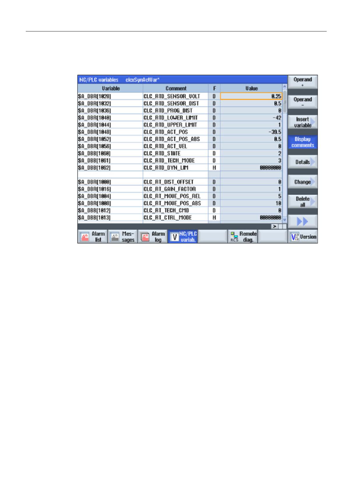
the $A_DBx variables using MACRO definitions. In the "NC/PLC variables" operating menu of the
SINUMERIK Operate, the same names can be entered manually in the "Comment" column of the
variable list. This view allows the variables to be displayed and operated during commissioning.
The name selection of this documentation uses the prefix CLC_RT* for variables that require
input and CLC_RTD* for variables that are only used to display states of the CLCX. RTD stands for
"Real-Time Display". The SINUMERIK Operate allows you to save or load a commented variable
view.
In the delivery package of the CLCX you will find the file "clcxSynActVar.xml". If you adapt this
file with regard to the variable start address you have selected and copy it to the "HMI Data/
Technologies
Function Manual, 10/2020, 6FC5397-8GP40-0BA1
51
Clearance control (CLC/CLCX)
5.5 Startup
Template/User/VariableMasks" directory, you can directly load the variable view shown in the
following figure.
Figure 5-5
Real-time variables CLCX
Technologies
52
Function Manual, 10/2020, 6FC5397-8GP40-0BA1
Clearance control (CLC/CLCX)
5.5 Startup
Defining names of the real-time variables
To have symbolic names available for programming the real-time variables in synchronized
actions, you can add the following global definitions to the definition file "MMAC.DEF" of the NC.
With the same MACRO definitions, symbolic names which are only needed in a cycle program
can also be defined locally in the header of this program.
Example program
; SPATH=/_N_DEF_DIR
; CLCX interface variables:
; ========= 76 bytes used =============
DEFINE CLC_RT_DIST_OFFSET AS $A_DBR[1000]
DEFINE CLC_RT_MOVE_POS_REL AS $A_DBR[1004]
DEFINE CLC_RT_MOVE_POS_ABS AS $A_DBR[1008]
DEFINE CLC_RT_TECH_CMD AS $A_DBB[1012]
DEFINE CLC_RT_CTRL_MODE AS $A_DBB[1013]
; Reserved byte index 1014
; Reserved byte index 1015
DEFINE CLC_RT_GAIN_FACTOR AS $A_DBR[1016]
DEFINE CLC_RT_TABLE3_PARAM AS $A_DBR[1020]
; Reserved dword index 1024
DEFINE CLC_RTD_SENSOR_VOLT AS $A_DBR[1028]
DEFINE CLC_RTD_SENSOR_DIST AS $A_DBR[1032]
DEFINE CLC_RTD_PROG_DIST AS $A_DBR[1036]
DEFINE CLC_RTD_LOWER_LIMIT AS $A_DBR[1040]
DEFINE CLC_RTD_UPPER_LIMIT AS $A_DBR[1044]
DEFINE CLC_RTD_ACT_POS AS $A_DBR[1048]
DEFINE CLC_RTD_ACT_POS_ABS AS $A_DBR[1052]
DEFINE CLC_RTD_ACT_VEL AS $A_DBR[1056]
DEFINE CLC_RTD_STATE AS $A_DBB[1060]
DEFINE CLC_RTD_TECH_MODE AS $A_DBB[1061]
DEFINE CLC_RTD_DYN_LIM AS $A_DBB[1062]
; Reserved byte index 1063
; Reserved Dword Index 1064
DEFINE CLC_RT_TRACE_FLAG AS $A_DBD[1068]
M17
For assigning values to $A_DBx variables without using a synchronized action, it is
recommended to set the following machine data:
MD28150 $MC_MM_NUM_VDIVAR_ELEMENTS = 20
This setting allows the following simple programming of the $A_DBx real-time variables:
N100 CLC_RTD_ACT_POS=5.0 ; this assignment creates an executable NC
block with an IPO cycle processing time
Alternatively, a synchronized action with a one-time fulfilled condition would be used:
N99, when TRUE do CLC_RTD_ACT_POS=5.0 ; assignment is appended to the
next executable NC block
N100...; next executable NC block>
See also
NC commands and Synact variables (Page 56)
Technologies
Function Manual, 10/2020, 6FC5397-8GP40-0BA1
53
Clearance control (CLC/CLCX)
5.6 Programming
5.6
Programming
5.6.1
Activating and deactivating clearance control (CLC)
Syntax
CLC(Mode)
Mode
• Format: integer
• Value range: -1, 0, 1, 2, 3, 4
CLC(...) is an NC procedure call and must therefore be programmed in a separate part program
block.
Functionality
The following options are available for switching clearance control on/off:
• CLC(1)
Switching on the clearance control
The evaluation of the sensor collision signal is deactivated.
• CLC(2)
Switching on the clearance control
The evaluation of the sensor collision signal is activated.
• CLC(3)
Switching on the 3D clearance control with freely programmable direction. The evaluation
of the sensor collision signal is deactivated.
• CLC(4)
Switching on the 3D clearance control with freely programmable direction. The evaluation
of the sensor collision signal is activated.
• CLC(0)
Switching off the clearance control without canceling the position offset of the axes
If the clearance-controlled axes are still moving at the switch-off time due to the sensor
signal, they are stopped first. Then the positions in the workpiece coordinate system (WCS)
are synchronized to the axis positions reached at standstill. The command causes an
implicitly triggered preprocessing stop (STOPRE).
• CLC(-1)
Switching off the clearance control with canceling the position offset of the axes.
If the clearance-controlled axes are still moving at the switch-off time due to the sensor
signal, they are stopped first. The position offset to the last programmed IPO position is then
retracted by an axis motion.
Technologies
54
Function Manual, 10/2020, 6FC5397-8GP40-0BA1
Clearance control (CLC/CLCX)
5.6 Programming
RESET behavior
CLC(0) is executed implicitly on a reset (NC RESET or end of program). The IPO positions shown
in the standard display (WCS or MCS) are synchronized to the axis positions currently reached in
the servo without any traversing motion taking place. The next programmed traversing block
starts at the position reached by sensor specification.
Constraints
Please note the following supplementary conditions:
• Continuous path mode
Switching the clearance control (CLC(Mode)) on/off during active continuous-path mode
(G64/G64x) results in a brief stop of the path motion. In cases where this path stop should be
avoided, the clearance control can already be activated before a path section with constant
path velocity. The control can then be blocked by means of appropriate real-time influencing
until a "on-the-fly release" occurs at the desired position.
• Block change with exact stop
If Exact stop at end of block (G60/G09 with G601/G602) is active, the block change may be
delayed due to small axis movements which may be caused by a noisy sensor signal. If
necessary, you may have to adapt the parameters of standstill monitoring. See above.
• Tool radius compensation
The 3D clearance control may only be deactivated if no tool radius compensation is active in
the channel at the time of deactivation (G40). The following alarm is issued when tool radius
compensation (G41/G42) is active:
- Alarm "75015 Channel number Block number CLC(0) with active TRC."
Technologies
Function Manual, 10/2020, 6FC5397-8GP40-0BA1
55

Clearance control (CLC/CLCX)
5.6 Programming
5.6.2
NC commands and Synact variables
NC variables and synchronized actions variables for operation
Table 5-7
NC variables and synchronized actions variables
Name
Type
Description
Action on reset
CLC(<intArg>)
NC procedure
Modal NC command.
CLCX is switched off
Must be programmed in a separate block
with CLC(0)
Switches CLC on and off
<intArg>: 1
Switch on without tip-touch monitoring
<intArg>: 2
Switch on with activated tip-touch monitoring
<intArg>: 3
Switch on with "3d free direction programming"
<intArg>: 4
Switch on with "3d free direction programming with
tip-touch monitoring".
<intArg>: 0
Switch off by synchronizing the servo position
<intArg>: -1
Switch off by moving back to the switch-on position
CLC_SEL(<intArg>)
NC procedure
Modal NC command
The last selected table
Selects the voltage clearance table to be used for lin-
remains active when
earizing the clearance sensor. A new setting is only
CLCX is switched off or
effective if CLC is activated.
a RESET is performed.
Table 1 is selected by
1: MD 62510 / MD 62511
default
2: MD 62512 / MD 62513
when the program is
10...20: Voltage clearance table defined by GUD vari-
started.
able
CLC_LIM( <realArg1>,
NC procedure
Modal NC command
MD 62505 [0]
<realArg2>)
Defines the limits of CLC motion relative to the switch-
and
ing-on position:
MD 62506 [0]
initialize the limit val-
<realArg1>: Lower limit
ues
<realArg2>: Upper limit
CLCX_PREP_DATA(SEN-
NC function
Non-modal NC command
Unchanged
SOR_GUD_TAB)
Checks the up to 11 additional clearance voltage ta-
bles created in GUD and makes them available for ap-
plication with the command CLC_SEL(10..20) - provi-
ded that the GUD definitions of all tables were free of
errors.
CLC_DIST=<realValue>
NC address
Modal NC command
MD 62509
<realValue> defines the clearance between the sensor
initializes the clear-
tip and the sheet metal.
ance
CLC_GAIN=<realValue>
NC address
This NC address of the old CLC is no longer supported
MD 62514
in CLCX.
initializes the GAIN
The GAIN factor set with MD 62514 can now be
changed by the synchronized action variable
CLC_RT_GAIN_FACTOR.
Technologies
56
Function Manual, 10/2020, 6FC5397-8GP40-0BA1

Clearance control (CLC/CLCX)
5.6 Programming
Name
Type
Description
Action on reset
CLC_RT_DIST_OFFSET
SynAct variable
Real-time offset in mm, which is added to the clear-
Initialized with zero
$A_DBR[x+0]
ance setpoint programmed with CLC_DIST=<>
CLC_RT_GAIN_FACTOR
SynAct variable
Real-time factor by which the CLC loop gain set by the
Is initialized with 1.0
$A_DBR[x+16]
MD $MC_CLC_DISTANCE_CTRL_GAIN is multiplied.
CLC_RT_MOVE_POS_REL
SynAct variable
Relative distance in mm to which the CLC axis jumps
Unchanged
$A_DBR[x+4]
when the command CLC_RT_TECH_CMD=10 is given
or when "tip-touch monitoring" is triggered.
CLC_RT_MOVE_POS_ABS
SynAct variable
Absolute MCS position in mm to which the CLC axis
Unchanged
$A_DBR[x+8]
jumps when the command CLC_RT_TECH_CMD=11 is
given. In the 3D case: absolute jump position within
the CLC coordinate system.
CLC_RT_TECH_CMD
SynAct variable
Real-time command that triggers the following ac-
Initialized with zero
$A_DBB[x+12]
tions:
• Jump-up of the CLC motion
• Freezing of the CLC motion
• Switch to the mode for determining the sensor de-
lay time
For a complete list of commands, see Available tech-
nology commands (Page 59).
With CLC_RT_TECH_MODE=0 the active technology
command is terminated and the sensor-controlled
mode is reactivated.
CLC_RT_CTRL_MODE
SynAct variable
Selects the control mode:
Bit_0 is initialized with
$A_DBB[x+13]
the value of Bit_12 of
• Bit 0 = 0: POS mode
MD 62508.
• Bit 0 = 1: GAIN mode
Bit_4 of $A_DBB[x
• Bit_4 = 1: causes the CLC velocity limit to use the
+13] remains un-
value set in MD $MC_CLC_SENSOR_VELO_LIM-
changed after a reset
IT[1].
CLC_RT_TRACE_FLAG
SynAct variable
Variable to start and stop the integrated CLCX trace.
Unchanged
$A_DBB[x+68]
Technologies
Function Manual, 10/2020, 6FC5397-8GP40-0BA1
57

Clearance control (CLC/CLCX)
5.6 Programming
5.6.3
Synact variables for diagnostics
Available synchronized actions variables for diagnostics
Table 5-8
Diagnostics variables
Name of the
Type and byte
Description
SynAct variable
offset
CLC_RTD_SENSOR_VOLT
$A_DBR[x+28]
Shows the currently applied input voltage in Volts. Allows you to set the
correct normalization factor and update/check the voltage clearance tables.
The sensor voltage is displayed even if CLC is not active.
CLC_RTD_SENSOR_DIST
$A_DBR[x+32]
Shows the distance that the sensor is currently measuring.
This value results from the actual sensor voltage and the currently selected
voltage clearance table.
The table is evaluated even if CLC is actually deactivated. The last selected
table number remains active after RESET.
The distance is always displayed in mm, regardless of any inch/metric set-
tings.
CLC_RTD_PROG_DIST
$A_DBR[x+36]
Displays the clearance setpoint resulting from the programmed modal NC
command CLC_DIST=<value> and the real-time offset set with the SynAct
variable CLC_RT_DIST_OFFSET.
The clearance setpoint is always displayed in mm, regardless of all inch/
metric settings.
CLC_RTD_LOWER_LIMIT
$A_DBR[x+40]
Shows the effective lower limit of the CLC motion.
The value refers to the position at which the CLC was switched on.
With 3D-CLC, the limitation can be additionally restricted if the programmed
TCP motion approaches the software limit of an axis.
This value is always displayed in mm, regardless of any inch/metric settings.
CLC_RTD_UPPER_LIMIT
$A_DBR[x+44]
Shows the effective upper limit of CLC motion.
The value refers to the position at which the CLC was switched on.
With 3D-CLC, the limitation can be additionally restricted if the programmed
TCP motion approaches the software limit of an axis.
This value is always displayed in mm, regardless of any inch/metric settings.
CLC_RTD_ACT_POS
$A_DBR[x+48]
The current set position of the CLC motion.
The zero point to which this coordinate refers is the position at which the
CLC was switched on.
The set position is always displayed in mm, regardless of any inch/metric
settings.
CLC_RTD_ACT_POS_ABS
$A_DBR[x+52]
The current set position of the CLC motion in MCS coordinates.
This position is always displayed in mm, regardless of any inch/metric set-
tings.
In the 3D case, this variable shows the same position as CLC_RTD_ACT_POS.
CLC_RTD_ACT_VEL
$A_DBR[x+56]
The current speed setpoint of the CLC motion.
This speed is always displayed in mm/min, regardless of any inch/metric
settings.
CLC_RTD_STATE
$A_DBB[x+60]
Displays the current status of the CLC motion. See Diagnosis of the CLCX
state (Page 61).
CLC_RTD_TECH_MODE
$A_DBB[x+61]
Shows the state that resulted from the last given TECH command.
Technologies
58
Function Manual, 10/2020, 6FC5397-8GP40-0BA1

Clearance control (CLC/CLCX)
5.6 Programming
Name of the
Type and byte
Description
SynAct variable
offset
CLC_RTD_DYN_LIM
$A_DBB[x+62]
The bits indicate the various dynamic limits currently acting on the input
variable of the CLC interpolator and limiter.
If all bits are zero, the sensor's motion specification is currently not limited.
CLC_RTD_FREE_DIR_ANGLE
$A_DBB[x+72]
Angle (in degrees) between the orientation generated by "free direction
programming" and the current tool orientation of the 5-axis transformation.
5.6.4
Available technology commands
Technology commands available for synchronized action
The following table lists the technology commands that can be programmed in synchronized
actions while the CLC is active. The right column shows the corresponding mode that is output
by the variable CLC_RTD_TECH_MODE.
Table 5-9
Technology commands
CLC_RT_
Description
CLC_RTD_ TECH_MODE
TECH_CMD
0
This command cancels any other currently active command and moves the
0 ... 5
CLC axis sensor-controlled up to the programmed distance
CLC_RTD_PROG_DIST above the plate.
10
jump_up_rel: Starting from the current position, the CLC axis moves with
10
the maximum permissible dynamic response by the distance specified in
the variable CLC_RT_MOVE_POS_REL.
11
jump_up_abs: The CLC axis moves with the maximum permissible dynam-
11
ic response up to the MCS position specified in the variable
CLC_RT_MOVE_POS_ABS.
Note: In the 3D case, the target position of the jump is specified absolutely
in relation to the CLC coordinate system. For the reference to the regular
MCS, the specification of three coordinates would be necessary.
20
freeze_both_dirs: Locks the CLC axis at its current position
20
21
freeze_down_pos: Prevents the CLC axis from moving lower than its cur-
21
rent position.
The axis can still be moved upward (sensor-controlled) and can also be
moved back again to the frozen position.
22
freeze_down_dir: Prevents the CLC axis from moving further down. The
22
sensor can only move the axis upwards to higher positions.
Technologies
Function Manual, 10/2020, 6FC5397-8GP40-0BA1
59

Clearance control (CLC/CLCX)
5.6 Programming
CLC_RT_
Description
CLC_RTD_ TECH_MODE
TECH_CMD
30
This number reports a "tip-touch" event if tip-touch monitoring has been
30
activated with the switch-on command CLC(2) or CLC(4):
Either the external tip-touch signal or the internal tip-touch evaluation has
triggered a motion of the CLC axis by the distance specified in the variable
CLC_RT_MOVE_POS_REL.
This state cannot be actively programmed. However, the tip-touch state
can be canceled and the sensor-controlled motion can be continued by
overwriting the pending command code 30 with 0 or another valid com-
mand code in CLC_RT_TECH_CMD.
99
Switches on the sine-wave generator to determine the sensor delay
99
The GUD CLC_SIN_GEN_AMP determines the amplitude (in mm) of the
generator and CLC_SIN_GEN_FREQ the frequency (in Hz).
Executing a technology command in the IPO task
In principle, all CLC_RT_TECH_CMD commands that are not equal to "0" must be repeated within
each IPO cycle as long as the command is to be executed. If you do not repeat the command in
an IPO cycle, CLCX receives the command "CLC_RT_TECH_CMD=0" and terminates the current
technology actions (Auto-Cancelling).
Example:
For example, if you want to cross a hole already cut in the sheet metal with the cutting head
raised by 5 mm, you can program the following instruction:
Programming example
CLC_RT_MOVE_REL_POS=5.0 ; prepares a relative jump-up of 5 mm
whenever TRUE do CLC_RT_TECH_CMD=10 ; keeps the jump_up_rel command active during the next
executable block
The Auto-Cancelling property of CLC_RT_TECH_CMD makes the programming of synchronized
actions more user-friendly in many cases because you do not need an additional command to
terminate the action.
On the other hand, this setting prevents the corresponding commands from being entered into
the $A_DBB variable by the PLC or manually via the variable view of the SINUMERIK Operate,
since with both methods the input cannot be repeated in every IPO cycle.
Executing a technology command with "AUTO-HOLD"
To nevertheless use the technology commands from the PLC or from the variable view of the
SINUMERIK Operate, you can optionally select the Auto Hold mode which can be applied for each
technology command not equal to zero. You must increase the respective command value by
100 for this purpose.
Technologies
60
Function Manual, 10/2020, 6FC5397-8GP40-0BA1

Clearance control (CLC/CLCX)
5.6 Programming
Example:
Set the technology command CLC_RT_TECH_CMD = 10 (jump_up_rel) with auto hold mode in
a synchronized action:
Programming example
When TRUE do CLC_RT_TECH_CMD=110 ; in the first cycle of the next executable block, the
jump_up_rel command becomes active in AUTO-HOLD
A technology command issued in Auto-Hold mode remains active until you explicitly cancel it by
executing CLC_RT_TECH_CMD=0 or another technology command.
As long as no technology command greater than zero is active, CLCX controls the axis in sensor-
controlled mode.
CLC_RTD_TECH_MODE
As long as no technology command is issued, the CLC moves the axes in sensor-driven control
mode. The variable CLC_RTD_TECH_MODE reports back details of the active control mode
according to the following table:
CLC_RTD_TECH_MODE
Description
0
The CLC function is switched off
1
The CLC motion is driven by the sensor. It approaches the sheet metal, but
the sensor is still outside its sensitive range.
2
The "POS mode" is active (CLC_RT_CTRL_MODE=0)
The CLC motion is driven by the sensor, which is now in its sensitive range.
3
The "GAIN mode" is active (CLC_RT_CTRL_MODE=1)
The CLC motion is driven by the sensor, which is now in its sensitive range.
4
Like mode 2, but the internal JERK filter is still activated. In sensor-driven
mode, the jerk filter is switched off as quickly as possible.
5
Like mode 3, but the internal JERK filter is still activated. In sensor-driven
mode, the jerk filter is switched off as quickly as possible.
5.6.5
Diagnosis of the CLCX state
Motion state of CLCX
The synchronized action variable CLC_RTD_STATE shows the detailed motion status of the CLCX
axis:
Table 5-10
Synchronization variable CLC_RTD_STATE
CLC_RTD_STATE
Description
0
CLC is deactivated.
1
CLC axis is moving.
2
CLC motion is at a standstill according to the period set in MD 62520 and the
position tolerance set in MD 62521 [0].
Technologies
Function Manual, 10/2020, 6FC5397-8GP40-0BA1
61

Clearance control (CLC/CLCX)
5.7 3D clearance control
CLC_RTD_STATE
Description
3
CLC stopped at lower motion limit.
4
CLC stopped at upper motion limit.
5
CLC motion is at standstill and at the same time the current sensor position is
within the tolerance window to the programmed clearance setpoint specified in
MD 62521 [1].
10
CLC stops:
Identifies the IPO cycles required by the CLC to decelerate the axis motion to a
standstill after an off command is received
11
CLC moves back:
Appears while the axis is moving back to the last IPO position if the deactivation
was programmed with CLC(-1).
12
CLC has reached the stop state:
Marks the IPO cycle in which the CLC motion is stopped after state 10.
CLCX limiter/interpolator
The synchronized action variable CLC_DIAG_RTD_DYN_LIM shows the detailed state of the CLCX
interpolator/dynamic limiter.
As long as this variable shows a value of zero, the motion specified by the sensor or internally can
be executed without being limited by the dynamic response of the CLC axis.
Table 5-11
Display CLCX interpolator with CLC_DIAG_DYN_LIM
CLC_RTD_DYN_LIM
Description
bit_0
Brakes with predictable overshoot
bit_1
Braking to a fixed target position
bit_2
Current negative acceleration limit reached
bit_3
Current positive acceleration limit reached
bit_4
Current negative velocity limit reached
bit_5
Current positive velocity limit reached
bit_6
Lower position limit reached
bit_7
Upper position limit reached
5.7
3D clearance control
5.7.1
3D clearance control - overview
4 and 5-axis transformation
A prerequisite for the application of the 3D clearance control is that a 4 or 5-axis transformation
has been defined via TRAORI.
Technologies
62
Function Manual, 10/2020, 6FC5397-8GP40-0BA1
Clearance control (CLC/CLCX)
5.7 3D clearance control
Three linear axes are used to position the tool. One or two rotary axes are used for the orientation
of the tool vector (5-axis machining). The clearance control only affects the linear axes. Two
options are available for the direction of the sensor-guided control motion in space ("the 3D
control direction"):
• in the direction of the vector of the programmed tool orientation (standard case)
• in any direction, which must be programmed by three additional vector components within
each traversing block
Note
The 3D clearance control can only be used on Cartesian machines with generic 4 or 5-axis
transformation.
The 3D CLC cannot be used on robots or other non-Cartesian kinematics. There, the TOFF
function, which operates in the IPO cycle, can be used.
5.7.2
3D control direction
Standard 3D control direction
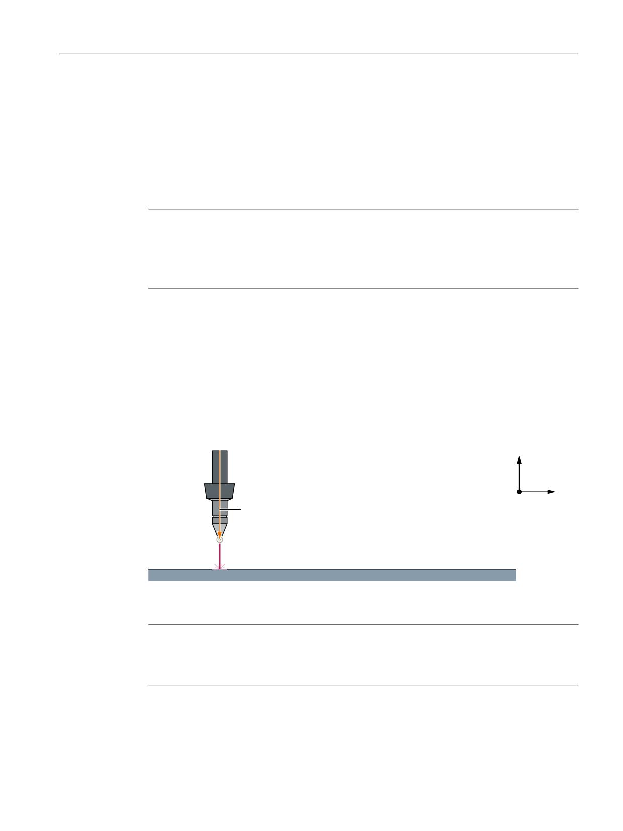
In the standard case, the control direction of the clearance control and the vector of the tool
orientation are identical. Consequently, the compensation movement of the clearance control
is normally always in the direction of the tool orientation.
=
;
ൺ
. 9HFWRU RI WKH FRQWURO GLUHFWLRQ
7&3 7RRO &HQWHU 3RLQW
% 0DFKLQLQJ SRLQW
:RUNSLHFH VXUIDFH
*)
The programmed TCP corresponds to the ideal machining point.
Figure 5-6
Clearance control with standard control direction
Note
In all the figures in this section, the traversing movement of the machining head needed in order
to machine the workpiece is in the direction of the Y coordinate, i.e. perpendicular to the
drawing plane.
As long as the tool orientation and thus also the control direction is perpendicular to the
workpiece surface, no geometric offset of the machining point on the surface of the workpiece
surface results from the correction movements of the clearance control.
Technologies
Function Manual, 10/2020, 6FC5397-8GP40-0BA1
63
Clearance control (CLC/CLCX)
5.7 3D clearance control
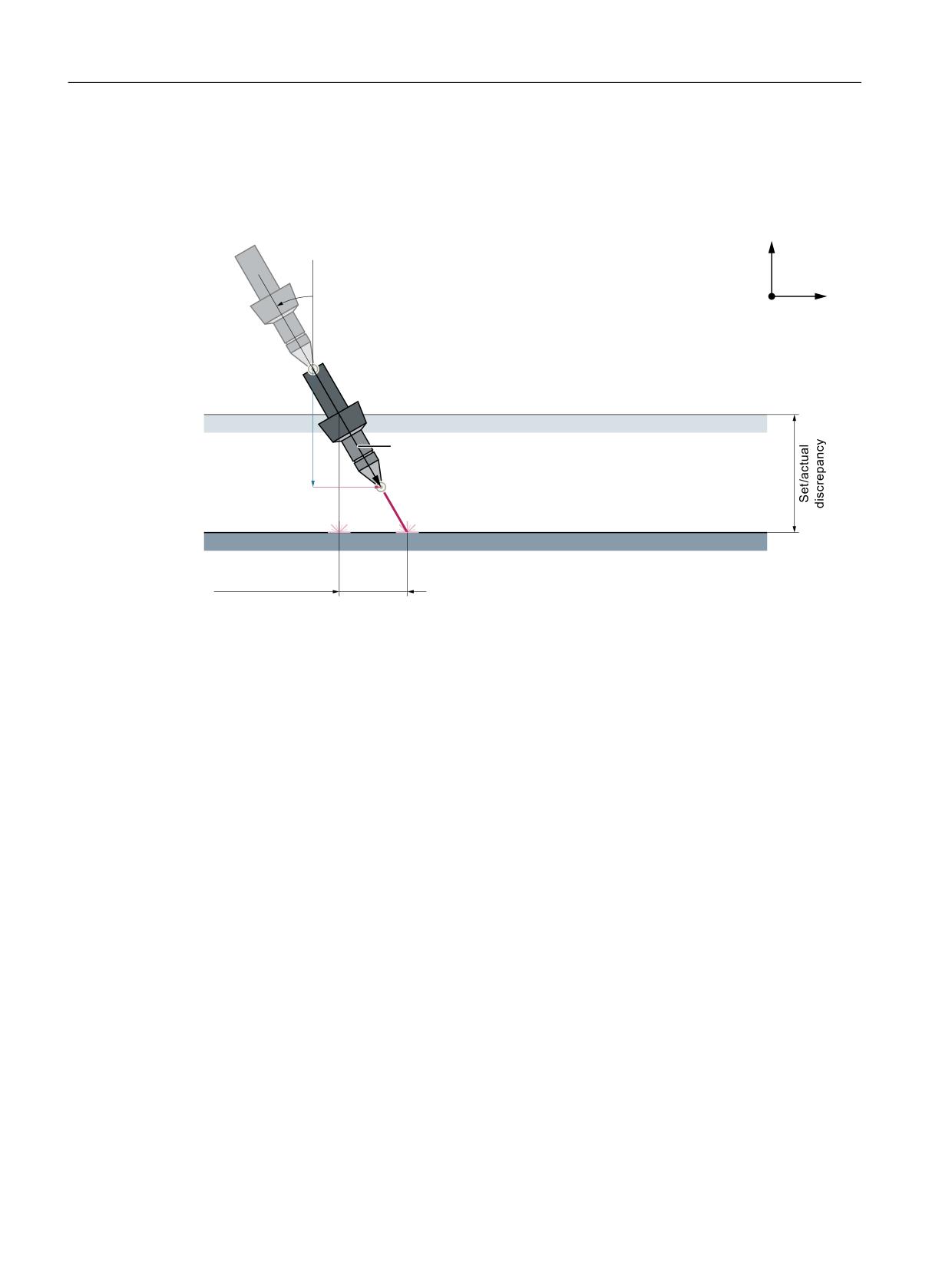
If, for technological reasons, a setting angle of the beam is required so that the tool orientation
is no longer perpendicular to the workpiece surface, correction movements of the clearance
control of the standard control direction result in a geometric offset of the machining point on
the workpiece surface.
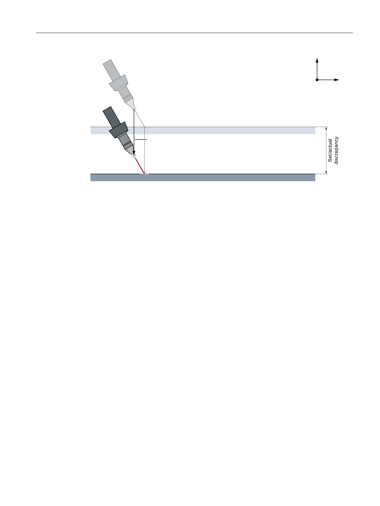
=
7RRO VHWWLQJ DQJOH
;
7&33URJ
:RUNSLHFH VXUIDFH6HWSRLQW
9HFWRU RI WKH FRQWURO GLUHFWLRQ
.=
7&3&/&
.;
%6HWSRLQW
%$FWXDO
2IIVHW RI WKH
:RUNSLHFH VXUIDFH$FWXDO
PDFKLQLQJ SRLQW
Figure 5-7
Standard 3D control direction
The reason for the offset of the machining point is the vector component (KX) of the control
direction parallel to the workpiece surface. The TCP of the tool, and thus the machining point B,
is shifted by this amount.
Programmable control direction
When using the software option "freely programmable control direction", the correction
movements of the clearance control can be made in the direction of the programmed vector, i.e.
it is no longer bound to the beam orientation (= tool orientation).
If the programmed orientation is perpendicular to the workpiece surface, a geometric offset due
to the 3D correction motion of the CLCX can be avoided.
Technologies
64
Function Manual, 10/2020, 6FC5397-8GP40-0BA1
Clearance control (CLC/CLCX)
5.7 3D clearance control
=
;
7&33URJ
:RUNSLHFH VXUIDFH6HWSRLQW
9HFWRU RI WKH FRQWURO GLUHFWLRQ
SURJUDPPHG
7&3&/&
%$FWXDO
%6HWSRLQW
:RUNSLHFH VXUIDFH$FWXDO
Figure 5-8
Programmable 3D control direction
5.7.3
Parameterization of the programmable control direction
Reference coordinate system
Three vector components to be programmed as additional axis positions are used to specify the
direction in which the sensor-guided correction movement of the clearance control takes place.
The vector components refer to the basic coordinate system. Programmed frames that act on the
contour and, if applicable, the tool orientation are not taken into account when calculating the
control direction.
Axis positions for setting the vector of the control direction
The following conditions must be met for the specification of the vector components of the
control direction via programmed axis positions:
1. The three axes used should be simulated NC axes:
- MD30240 $MA_ENC_TYPE[x]=0
- MD30130 $MA_CTRLOUT_TYPE[x]=0
2. The axes must be channel axes of the channel in which the clearance control is activated.
3. The axes must be linear axes. +-1.0mm is recommended as maximum programmed position
range of each vector component to avoid interpolation of long axis distances. The length of
the programmed vector need not be standardized to 1.0.
Technologies
Function Manual, 10/2020, 6FC5397-8GP40-0BA1
65
Clearance control (CLC/CLCX)
5.7 3D clearance control
4. The axes may not participate in an axis coupling, e.g. transformation, electronic gear, etc.
5. To ensure that the path dynamics are not limited due to insufficient axis dynamics, the
following machine data of these axes must be set about a factor 100 higher than the
corresponding values of the real geometry axes of the channel:
- MD32000 $MA_MAX_AX_VELO[x] (Maximum axis velocity)
- MD32300 $MA_MAX_AX_ACCEL[0,x
- MD32431 $MA_MAX_AX_JERK[x] (Configuration of the position controller structure)
x = name of the simulated axis
The machine data is used to determine which channel axes the vector components of the
programmable control direction specify:
• MD62528 $MC_CLC_PROG_ORI_AX_MASK (Progr. orientation vector: axis mask)
Each bit of this machine data corresponds to a channel axis according to the following scheme.
)RUPDW
%LW
%LW
&KDQQHO D[LV
&KDQQHO D[LV
The selected channel axes are used in ascending numerical order in the channel for
programming and interpolation of the three components x, y, z of the vector of the control
direction.
Current difference angle
The current difference angle between the vector of the beam orientation and the vector of the
control direction is displayed in the $A_DBR variable CLC_RTD_FREE_DIR_ANGLE.
Monitoring of the maximum difference angle
The maximum allowed difference angle between the vector of the tool orientation and that of
the control direction can be set via the following machine data:
MD65520 $MC_CLC_PROG_ORI_MAX_ANGLE ()
If a value greater than zero is entered in this machine data and the current difference angle
exceeds this value, alarm 75014 is output
Technologies
66
Function Manual, 10/2020, 6FC5397-8GP40-0BA1
Clearance control (CLC/CLCX)
5.7 3D clearance control
5.7.4
3D clearance control and 5-axis transformation
Relationship between 3D clearance control and 5-axis transformation
If 3D clearance control is activated before the 5-axis transformation required for clearance
control in the direction of the tool orientation has been activated, the clearance control function
will be dependent on the selection of the active working plane (G17/G18/G19):
• G17: Direction of clearance control = Z
• G18: Direction of clearance control = Y
• G19: Direction of clearance control = X
Activation of 5-axis transformation
When 5-axis transformation is activated, the tool orientation specified by means of the rotary
axis positions must tally with the control direction specified by the active working plane on
activation of clearance control.
If the tool orientation of the 5-axis transformation and the control direction of the clearance
control function do not tally, the following CLC alarm will appear:
• Alarm "75006 Channel number Block number CLCX: Abrupt change in orientation
Deactivation of 5-axis transformation
If the 5-axis transformation is switched off when clearance control is active, the CLC retains the
last control direction before switching off the 5-axis transformation.
Vector of the control direction
Actual position of the direction axes
If the clearance control with freely programmable direction is activated with the value 0.0 in all
three components of the direction vector, no control direction can be calculated from this. In this
case, the following alarm is displayed:
• Alarm "75014 channel number, error ID: 1, angle 0.0"
Referencing the direction axes
Before activating clearance control with freely programmable direction CLC(3)/CLC(4), the
simulated axes must be referenced for the components of the control direction.
Switching over clearance control
Direct switching over of the clearance control from CLC(1) or CLC(2) to CLC(3)/CLC(4) or vice
versa is not possible. Such switchovers are ignored without a checkback signal. If such a
switchover is necessary, the clearance control must first be switched off with CLC(0) or CLC(-1)
and then switched on again in the desired mode.
Interpolation of the control direction
If the vector of the control direction with regard to its orientation is to follow a non-linear
workpiece surface, e.g. an arc of a circle, this can be achieved by programming the direction axes
accordingly.
Example
Technologies
Function Manual, 10/2020, 6FC5397-8GP40-0BA1
67
Clearance control (CLC/CLCX)
5.7 3D clearance control
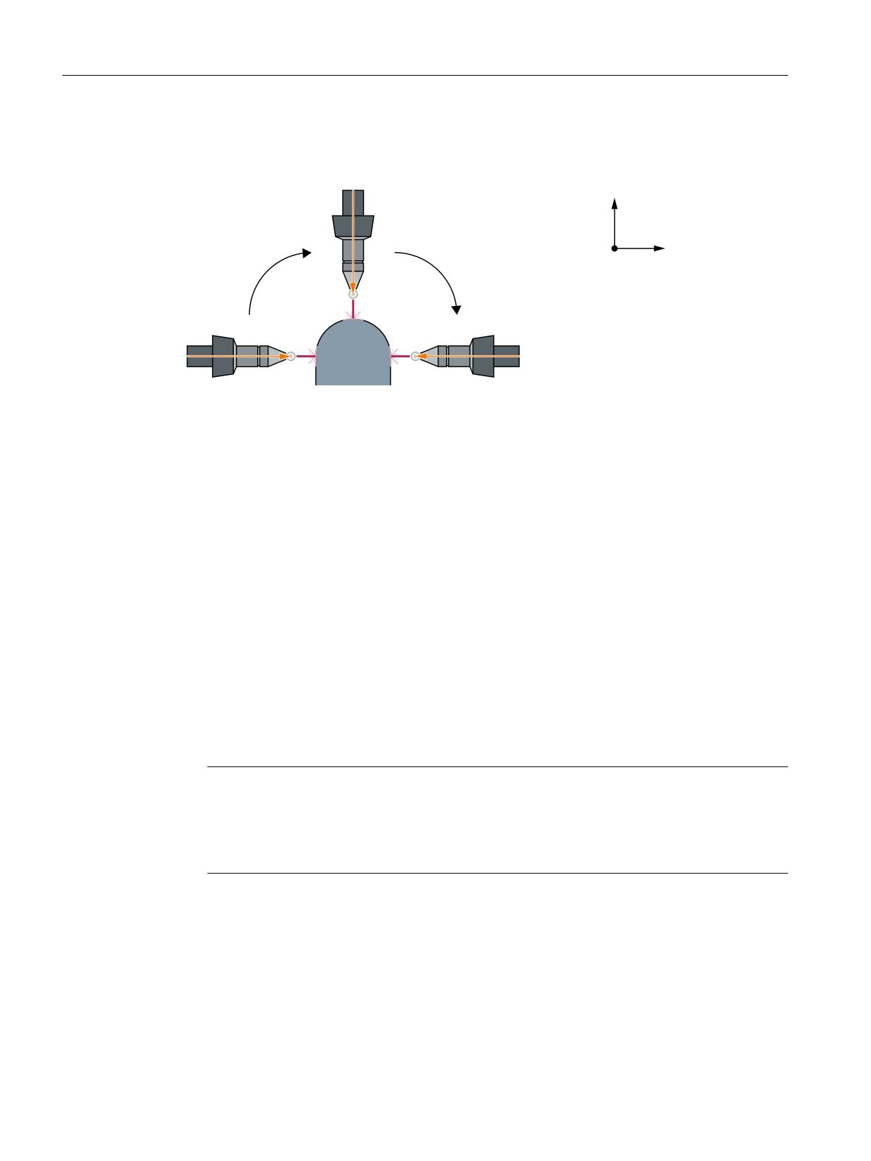
Orientation of the control direction perpendicular to a semicircular workpiece surface. The
programming of the traversing motion is not considered.
ൺ
>
@
=
;
1
1
ൺ
ൺ
>
@
>
@
Figure 5-9
Interpolation of the vector of the control direction
Before the part program block N100, the control direction vector has been oriented to [1, 0, 0]
by programming the direction axes. In part program block N100, the end position of the control
direction vector is oriented by programming the direction axes at [0, 0, -1].
The intermediate values are generated by synchronous interpolation of all axes programmed in
the part program block:
• Geometry and orientation axes for the movement of the machining head
• The three component axes for rotating the vector of the control direction.
It is necessary to break the movement down into part program blocks N100 and N200, because
an antiparallel orientation of the control direction vector of [1, 0, 0] at the start of the movement
and [-1, 0, 0] at the end of the movement (semi-circle) would otherwise result. In this case, the
interpolator would interpolate only the X coordinate of the vector, and the orientation of the
control direction vector would remain unchanged.
Antiparallel orientation of the vector of the control direction
If in a part program block an antiparallel orientation of the free control direction with respect to
the previous direction is programmed, the following alarm will be displayed:
• Alarm "75018 Channel number Block number CLC in programmable direction, error ID: 1"
Note
Interpolation of the vector
As described above, the interpolation of the vector of the control direction is not a true vector
interpolation, but is the result of the component-wise interpolation of the three simulation
axes involved.
Rotation of the workpiece coordinate system
The programming of the three vector components of the control direction always refers to the
basic coordinate system, as described above. If a rotating or mirroring frame is used for
machining the workpiece, so that the coordinate axes of the programming coordinate system
(WCS) and those of the basic coordinate system are no longer parallel and of the same
Technologies
68
Function Manual, 10/2020, 6FC5397-8GP40-0BA1

Clearance control (CLC/CLCX)
5.8 Multiple CLCX instances in different channels
orientation, a corresponding conversion must also be made for the components of the control
direction.
CAUTION
Not of the same orientation
If the workpiece coordinate system is rotated or mirrored in such a way that the coordinate axes
of the basic and workpiece coordinate systems are no longer parallel and of the same
orientation, the user is responsible for the corresponding transformation of the freely
programmed control direction.
5.8
Multiple CLCX instances in different channels
5.8.1
Multiple CLCX instances in one channel
CLCX instance
Via a CLCX instance, the functionality of clearance control is applied to an axis or (for 3D CLC) to
the Cartesian axes of a 4 or 5-axis transformation. Up to four instances can be configured within
one NCU. All four instances can be used in one channel ("multi-head machine") or freely
distributed to several channels of a control system. For example, two instances can run in the
first channel and one instance each in the second channel and fourth channel.
Since a channel represents a machining context in which only exactly one 5-axis transformation
can run, CLCX configurations with several instances per channel only make sense with the single-
axis version.
Assigning CLCX instances to channels
As with other compile cycles, the following machine data determines the channels in which the
CLCX function is to be used:
$MN_CC_ACTIVE_IN_CHAN_CLCX[0] = 'Hxxx':
• 'Hxxx' is a bit mask in hexadecimal format, which is used to select the channels in which at
least one CLCX instance should be available.
Activating an instance in a channel
$MN_CC_ACTIVE_IN_CHAN_CLCX[0] = 'H1'
With this command you activate a CLCX instance in channel 1.
Activating one instance in several channels each
$MN_CC_ACTIVE_IN_CHAN_CLCX[0] = 'H5'
With this command you activate one instance in channel 1 and one instance in channel 3 (H5 =
binary 0101).
Technologies
Function Manual, 10/2020, 6FC5397-8GP40-0BA1
69
Clearance control (CLC/CLCX)
5.8 Multiple CLCX instances in different channels
Activating multiple instances in channels
To activate more than one instance in a channel, the number of instances to be activated in the
respective channel must be specified in $MN_CC_ACTIVE_IN_CHAN_CLCX[ 0 ] in addition to the
channel selection described. This happens in the machine data $MN_CC_ACTIVE_IN_CHAN[1].
Each hexadecimal digit of this machine data determines the number of instances in the assigned
channel:
$MN_CC_ACTIVE_IN_CHAN_CLCX[1] = 'H103'
With this entry you activate three instances in channel 1 and one instance in channel 3, provided
that the channel assignment from the last command is effective simultaneously:
$MN_CC_ACTIVE_IN_CHAN_CLCX[0] = 'H5'
To activate the change from a configuration with one instance per channel to a configuration
with multiple instances, you must first upload an archive with the new setting after you have set
$MN_CC_ACTIVE_IN_CHAN_CLCX[1] accordingly, and then download the archive back to the
control system. A simple restart of the NC kernel is not enough for this.
Converting machine data to multiple instances
The archive download deletes the buffered memory of the NC kernel and thus also the CLCX
machine data. This is necessary to convert the following eight CLCX channel machine data units
from single data to array data. Then the first CLCX instance within the channel reads the value
of the first array element, the second instance reads the value of the second array element, and
so on.
The following list shows the eight machine data units that become arrays during the download
process.
The four machine data units, which must always be given an individual setting for each CLCX
instance in the channel, are marked with an exclamation mark in the list.
List of the machine data converted to an array
62500 $MC_CLC_AXNO[0]
62500 $MC_CLC_AXNO[1] ; !
62502 $MC_CLC_ANALOG_INPUT[0]
62502 $MC_CLC_ANALOG_INPUT[1] ; !
62503 $MC_CLC_ANALOG_IN_HW_NORM_FACT[0]
62503 $MC_CLC_ANALOG_IN_HW_NORM_FACT[1]
62504 $MC_CLC_SENSOR_TOUCHED_INPUT[0]
62504 $MC_CLC_SENSOR_TOUCHED_INPUT[1]
; !
62507 $MC_CLC_A_DB_RT_VAR_START_INDEX[0]
62507 $MC_CLC_A_DB_RT_VAR_START_INDEX[1] ; !!
62509 $MC_CLC_DISTANCE_SETPOINT[0]
62509 $MC_CLC_DISTANCE_SETPOINT[1]
62514 $MC_CLC_DISTANCE_CTRL_GAIN[0]
62514 $MC_CLC_DISTANCE_CTRL_GAIN[1]
62519 $MC_CLC_SENSOR_DELAY_COMP_TIME[0]
62519 $MC_CLC_SENSOR_DELAY_COMP_TIME[1]
Technologies
70
Function Manual, 10/2020, 6FC5397-8GP40-0BA1
Clearance control (CLC/CLCX)
5.8 Multiple CLCX instances in different channels
All other channel-specific machine data is shared by the CLCX instances within the same
channel. This data can therefore not be set individually for each CLCX instance.
It is recommended to increase the resources of the compile cycle block memory in the channels
accordingly where more than one CLCX instance is being executed:
28090 $MC_MM_NUM_CC_BLOCK_ELEMENTS
28100 $MC_MM_NUM_CC_BLOCK_USER_MEM
Detailed descriptions for renaming the NC addresses can be found at Programming several
instances within one channel (Page 73), 10712 $MN_NC_USER_CODE_CONF_NAME_TAB.
5.8.2
Macros for operating and monitoring multiple instances in one channel
Adjusting real-time variables
According to the setting of the instance-specific start offset in
$MC_CLC_A_DB_RT_VAR_START_INDEX[n], the macros of the real-time variables must be
adjusted for the operation of the CLX instances. Since the $A_DBx variables are global, the
names should be selected so that both the channel number and the number of the instance
using the data are evident.
Example macro
The following setting is provided:
channel_1:
62507 $MC_CLC_A_DB_RT_VAR_START_INDEX[0]=1000
62507 $MC_CLC_A_DB_RT_VAR_START_INDEX[1]=1100
channel_2:
62507 $MC_CLC_A_DB_RT_VAR_START_INDEX[0]=2000
62507 $MC_CLC_A_DB_RT_VAR_START_INDEX[1]=2100
Technologies
Function Manual, 10/2020, 6FC5397-8GP40-0BA1
71
Clearance control (CLC/CLCX)
5.8 Multiple CLCX instances in different channels
The following definitions can be used for this setting:
Example macro
MMAC. DEF:
; SPATH=/_N_DEF_DIR
; CLCX interface variables:
; === channel1_instance1 ==============
DEFINE CLC_RT_DIST_OFFSET AS $A_DBR[1000]
; or "CLC11_RT_..." (to be really consistent)
DEFINE CLC_RT_MOVE_POS_REL AS $A_DBR[1004]
DEFINE CLC_RT_MOVE_POS_ABS AS $A_DBR[1008]
; === channel1_instance2 ==============
DEFINE CLC12_RT_DIST_OFFSET AS $A_DBR[1100]
DEFINE CLC12_RT_MOVE_POS_REL AS $A_DBR[1104]
DEFINE CLC12_RT_MOVE_POS_ABS AS $A_DBR[1108]
; === channel2_instance1 ==============
DEFINE CLC21_RT_DIST_OFFSET AS $A_DBR[2000]
DEFINE CLC21_RT_MOVE_POS_REL AS $A_DBR[2004]
DEFINE CLC21_RT_MOVE_POS_ABS AS $A_DBR[2008]
; === channel2_instance2 ==============
DEFINE CLC22_RT_DIST_OFFSET AS $A_DBR[2100]
DEFINE CLC22_RT_MOVE_POS_REL AS $A_DBR[2104]
DEFINE CLC22_RT_MOVE_POS_ABS AS $A_DBR[2108]
Depending on which functions you actually want to use, you do not have to define all variables.
Note
If the real-time variables are to be used within a part program which can be called from
different channels, the channel-dependent part of the start offset used in the macro must not be
fixed, but must depend on the channel which is currently using the index ($P_CHANNO).
Example
; === instance1 ==============
DEFINE CLC_RT_DIST_OFFSET AS $A_DBR[$P_CHANNO*1000+0]
DEFINE CLC_RT_MOVE_POS_REL AS $A_DBR[$P_CHANNO*1000+4]
; === instance2 ==============
DEFINE CLC2_RT_DIST_OFFSET AS $A_DBR[$P_CHANNO*1000+100]
DEFINE CLC_RT_MOVE_POS_REL AS $A_DBR[$P_CHANNO*1000+104]
Technologies
72
Function Manual, 10/2020, 6FC5397-8GP40-0BA1
Clearance control (CLC/CLCX)
5.8 Multiple CLCX instances in different channels
5.8.3
Programming several instances within one channel
Additionally configured instances
If additional CLCX instances are configured in a channel, extended NC commands are available
for switching on and off and for parameterizing each individual instance.
Regular commands:
CLC()
CLC_SEL() ; selects the characteristic to be used. Standard:
characteristic 1
CLC_LIM()
Extended commands, e.g. for the second instance:
CLC2()
CLC2_SEL() ; selects the characteristic to be used. Standard:
characteristic 1 !!
CLC2_LIM()
If the sensor used for the second instance has an individual characteristic curve, this must be
determined and entered as Characteristic_2. At the beginning of each part program the
Characteristic_2 must then be selected with the command CLC2_SEL(2).
Programmable clearance
The effective clearance for the second instance can be programmed modally with the following
NC address:
CLC2_DIST=x.y
To do this, you must replace the default name of the OA NC address "OMA2" in the following
machine data:
10712 $MN_NC_USER_CODE_CONF_NAME_TAB[0]="OMA1" ; default name of the
1st OA NC address
10712 $MN_NC_USER_CODE_CONF_NAME_TAB[1]="CLC_DIST" ; Renaming
10712 $MN_NC_USER_CODE_CONF_NAME_TAB[2]="OMA2" ; default name of the
2nd OA NC address
10712 $MN_NC_USER_CODE_CONF_NAME_TAB[3]="CLC2_DIST"; Renaming
As long as the setpoint is not programmed, the value entered in
$MC_CLC_DISTANCE_SETPOINT[1] acts as the default distance of the second CLCX instance in
the channel.
Technologies
Function Manual, 10/2020, 6FC5397-8GP40-0BA1
73
Clearance control (CLC/CLCX)
5.8 Multiple CLCX instances in different channels
5.8.4
Additional voltage/clearance characteristics
Defining additional characteristics
The channel-specific machine data of CLCX offers two sensor characteristics per channel for
linearization and adaptation of different clearance sensors:
62510__MC_CLC_SENSOR_VOLTAGE_TABLE_1[0..15]
62511__MC_CLC_SENSOR_DIST_TABLE_1[0..15]
62512__MC_CLC_SENSOR_VOLTAGE_TABLE_2[0..15]
62513__MC_CLC_SENSOR_DIST_TABLE_2[0..15]
In cases where more than two characteristic curves are required in a channel, i.e. in particular
in applications that configure several CLCX instances within a channel to operate up to 4 CLCX
axes within this channel), up to eleven additional sensor characteristic curves can be defined
with the following global GUD:
DEF NCK REAL CLCX_TAB_D[16] ; All GUD characteristics use the same
clearances. This table applies to all voltage tables.
DEF NCK REAL CLCX_TAB_V[11, 16]; ; 11 voltage tables with 16
breakpoints each
DEF NCK INT CLCX_TAB_STATUS; ; the variable for error messages
If fewer than 11 characteristics are required or if the characteristics are defined with fewer than
16 clearance breakpoints, the dimension of the GUD arrays can be reduced. The minimum
configuration that provides only one global additional sensor characteristic curve defined by
only two voltage clearance points is as follows:
DEF NCK REAL CLCX_TAB_D[2]
DEF NCK REAL CLCX_TAB_V[2]
The following rules apply to the definition of the sensor characteristic curves defined by GUD as
for the corresponding machine data:
• The first entry in the clearance table CLCX_TAB_D[0] must be zero.
• The entries in the clearance table must increase monotonically.
• The entries in the voltage tables must either increase or decrease monotonically.
A zero entry in the clearance table indicates the end of the table. This means that a table in
particular may be shorter than specified in the GUD definition.
Typically, the sensor calibration is automated in a cycle program that moves the sensor head up
step by step from a position where the sheet metal is almost touched to the clearances defined
in CLCX_TAB_D[m] and writes the read-out voltage values to the corresponding element of
CLCX_TAB_V[n,m].
After the characteristic curves have been measured and stored in GUD, the following NC
function provided by the CLCX must be called to transfer all GUD values to the internal data
representation which can be used by the CLCX function:
CLCX_TAB_STATUS = CLCX_PREP_DATA("SENSOR_GUD_TAB")
Technologies
74
Function Manual, 10/2020, 6FC5397-8GP40-0BA1

Clearance control (CLC/CLCX)
5.8 Multiple CLCX instances in different channels
During the NC restart, the CLCX calls this function internally. In this way, the additional
characteristics can be used without having to explicitly repeat the call of this NC function at each
NCK restart.
In any case, the GUD variable CLCX_TAB_STATUS reflects the status of the last transmission and
must be checked to detect errors within the current GUD definition. Such errors do not set the
alarm 75001 with error ID: -1 or -2 as invalid characteristic curves entered via machine data do.
Display CLCX_TAB_STATUS
If CLCX_TAB_STATUS shows one of the following negative values, none of the additional
characteristics defined via GUD can be used. You must first fix the specified problem.
Table 5-12
Status displays
-1
CLCX_PREP_DATA was called while CLC is active and one of the GUD tables is in use.
-2
CLCX_PREP_DATA was called with an argument unequal to "SENSOR_GUD_TAB".
-3
CLCX_PREP_DATA internal READ_ERROR when reading the argument.
-10
Expected GUD names CLCX_TAB_V, CLCX_TAB_D not found.
-11
The GUD data definition must be global: "DEF NCK REAL ..."
-12
The GUD data definition must be of data type REAL: "DEF NCK REAL ..."
-13
CLCX_TAB_D and CLCX_TAB_V: The size of the first array dimension must be at least 2.
-14
CLCX_TAB_V: The size of the second array dimension must be at least 2.
-16
Internal READ_ERROR when reading a GUD
-20
CLCX_TAB_V: The order of the entries does not increase or decrease monotonously.
-21
CCC_TAB_D: Order of entries does not increase monotonously.
-25
CLC_TAB_D: The first entry in the clearance table is not equal to zero.
If there was no problem in any of the table definitions during the transmission of the GUD values,
the number of successfully transmitted voltage values is reported back as a positive number.
If, for example, 11 tables with 16 valid entries each have been defined, the following value is set
in the status variable:
CLCX_TAB_STATUS = 176
If CLCX_TAB_STATUS shows that the additional internal sensor characteristics have been
successfully updated from the GUD arrays, any instance of the CLCX function in any channel can
use these characteristics by programming CLC_SEL(10) through CLC_SEL(20).
• CLC_SEL(10) uses the measured voltages CLCX_TAB_V[0, 0...15]
• CLC_SEL(11) uses the measured voltages from CLCX_TAB_V [1, 0...15]
• ...
• CLC_SEL(20) uses the measured voltages from CLCX_TAB_V[10, 0 ...15]
If a characteristic is programmed in CLC_SEL() that is currently not defined, CLCX sets the
following alarm:
75002 Channel %1 NC block %2 CC_CLCX programming error, error code: 5
Error code 5: CLC_SEL(1x) programs without valid GUD characteristics set
Technologies
Function Manual, 10/2020, 6FC5397-8GP40-0BA1
75

Clearance control (CLC/CLCX)
5.9 Function-specific display data
5.9
Function-specific display data
The "Clearance control" technology function provides specific display data for supporting setup
and for service purposes.
Possible applications
Possible applications of the display data include, for example:
• Determination of the form deviations and control errors occurring for a short time via the
variables for the maximum and minimum position offset or the sensor input voltage.
• Determination of the voltage noise detected by the A/D converter using the variables for the
maximum and minimum sensor input voltage. Prerequisites are a constant distance of the
clearance sensor from the workpiece surface with blocked clearance control (e.g. with
CLC__RT_GAIN_FACTOR = 0.0).
The minimum and maximum values are acquired in the position controller cycle.
Types of variables
The current display data is available both as channel-specific GUD (Global User Data) and as
a synchronized action variable (Page 61). The min/max values are only available in the GUD.
5.9.1
Channel-specific GUD variables
The "Clearance control" technology function provides the following channel-specific GUD
variables for SINUMERIK Operate:
Table 5-13
Channel-specific GUD variables
GUD variable
Designation
Unit
Access
CLC_DISTANCE[0]
Current position offset
mm
read only
CLC_DISTANCE[1]
Absolute minimum of position off-
mm
read / write
set
CLC_DISTANCE[2]
Absolute maximum of position off-
mm
read / write
set
CLC_VOLTAGE[0]
Current sensor input voltage
V
read only
CLC_VOLTAGE[1]
Absolute minimum of sensor input
V
read / write
voltage
CLC_VOLTAGE[2]
Absolute maximum of sensor input
V
read / write
voltage
Once the technology function has been set up, the GUD variables listed are not displayed
automatically on the HMI interface.
Technologies
76
Function Manual, 10/2020, 6FC5397-8GP40-0BA1

Clearance control (CLC/CLCX)
5.10 Function-specific alarm texts
SINUMERIK Operate
Proceed as follows to create and display the GUD variables for SINUMERIK Operate.
1. Set password
Enter the password for protection level 1: (machine manufacturer).
2. If no MGUD.DEF file exists yet:
Operating area switchover > Commissioning > System data > Open NC data directory:
Move the cursor to Definitions > New...
• Name: MGUD
• Type: DEF
Confirm with OK.
This opens the file in the editor.
1. Edit the GUD variable definitions
DEF CHAN REAL CLC_DISTANCE[3] ; Array of real, 3 elements
DEF CHAN REAL CLC_VOLTAGE[3] ; Array of real, 3 elements
M30
2. Save the file and close the editor
3. Activate the file MGUD.DEF
The GUD variables for clearance control are now displayed under:
Operating area switchover >Parameters > User variables > Channel GUD
SINUMERIK NC
The newly created and already displayed GUD variables are only recognized and supplied with
current values by the clearance control after an NC POWER ON-RESET.
Note
After creating the GUD variables, an NC POWER ON-RESET must be triggered so that the
clearance control updates the GUD variables.
5.10
Function-specific alarm texts
For the procedure for creating function-specific alarm texts, see Creating alarm texts (Page 23).
The following table shows the alarm numbers of CLCX:
CLCX alarm number
CLC alarm number
75001
CLCX wrong MD configuration, error code: %2
75002
CLCX NC block %2 programming error, error code: %3
75003
CLCX NC block %2 invalid limits prog. in CLCX_LIM
75004
CLCX NC block %2 switched off with active tool radius compensation
75006
CLCX NC block %2 abrupt change of orientation
75007
CLCX NC block %2 sensor tip touched at pos. %3 mm
Technologies
Function Manual, 10/2020, 6FC5397-8GP40-0BA1
77
Clearance control (CLC/CLCX)
5.11 Supplementary conditions
CLCX alarm number
CLC alarm number
75008
CLCX NC block %2 position offset at lower limit %3
75009
CLCX NC block %2 position offset at upper limit %3
75011
CLCX NC block %2 prog. clearance exceeds %3 mm
75013
CLCX NC block %2 freely prog. direction error code %3
75014
CLCX NC block %2 freely prog. Direction real-time error code %3
5.11
Supplementary conditions
5.11.1
I/O modules
The analog output voltage of the clearance sensor for the A/D conversion must be connected to
the NC via an I/O module with an analog input.
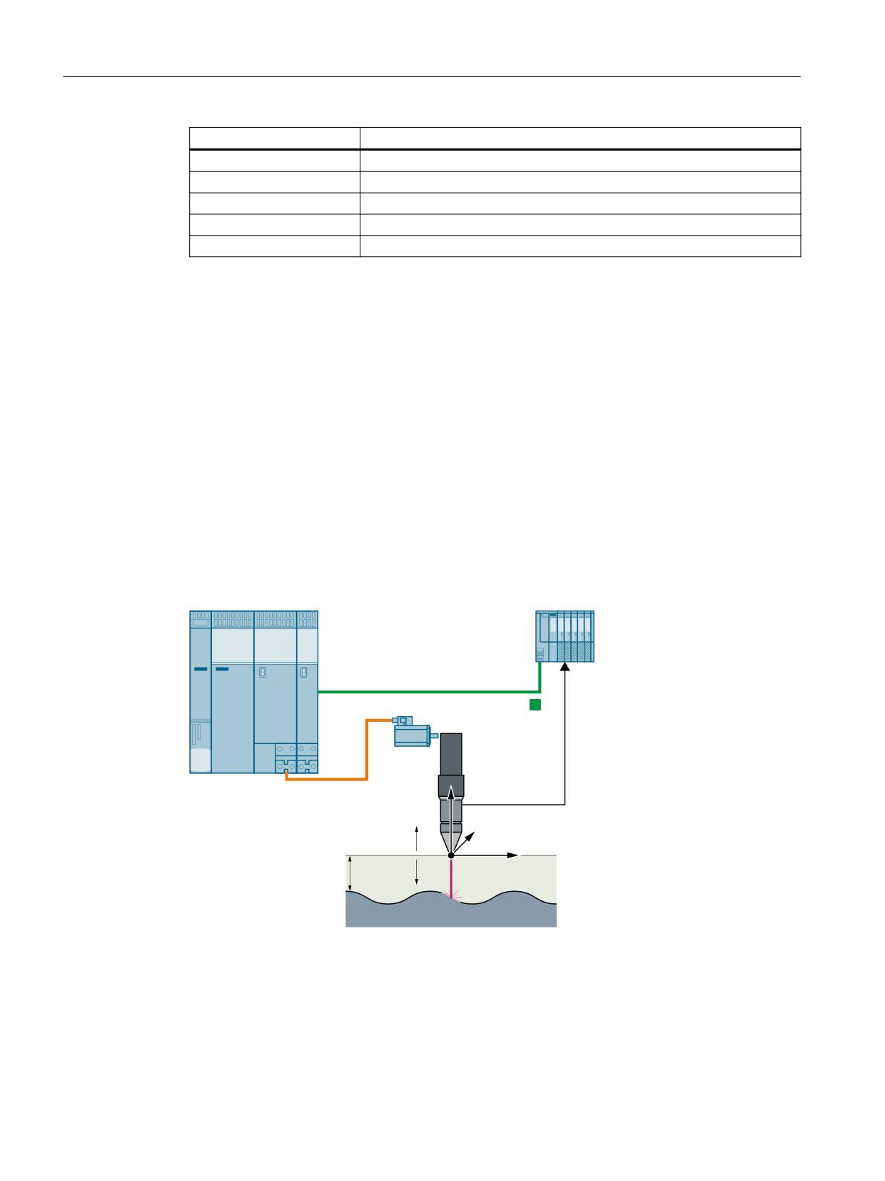
Connection options
With a SINUMERIK NCU, the SIMATIC ET 200S I/O is connected via PROFINET IO. The clearance
sensor is connected via an analog S7 I/O module.
1&8 ZLWK
6,0$7,& (7
6,2
6,1$0,&6 6
352),1(7 ,2
6HQVRU VLJQDO
/DVHU
=
0DFKLQLQJ KHDG ZLWK
FOHDUDQFH VHQVRU
<
0RWLRQ D[HV ; DQG <
=
&OHDUDQFH FRQWURO $[LV =
&OHDUDQFH WR EH
=
;
FRQWUROOHG
:RUNSLHFH VXUIDFH
Figure 5-10
I/O modules connection for SINUMERIK NCU
Suitable I/O modules
As the A/D conversion time directly affects the dead time of the clearance control loop, only one
I/O module may be used with low conversion time.
Technologies
78
Function Manual, 10/2020, 6FC5397-8GP40-0BA1
Clearance control (CLC/CLCX)
5.11 Supplementary conditions
Suitable SIMATIC S7 I/O modules for the clearance control are, for example:
Analog I/O module 2 AI, U, High Speed for ET 200S
Analog I/O module 2 AO, U, High Speed for ET 200S
Suitable modules are described under Setting up the analog sensor input (Page 41).
Connection of the I/O modules
The SIMATIC peripheral devices of the ET200 series, e.g. ET200M, are introduced and
configured in the S7 project as usual by means of hardware configuration.
Note
To check whether a module selected from the hardware catalog complies with the module in the
automation system, the following procedure is recommended:
1. Note the article numbers of all modules used in the automation system.
2. Select the corresponding module in the hardware catalog and compare the article number
of the module used in the automation system with the article number that is displayed in the
hardware catalog. Both article numbers must match one another.
5.11.1.1
External smoothing filters
If an external filter is to be interconnected to smooth the output voltage of the clearance sensor
before the A/D conversion of the output voltage by the I/O module, please ensure that the
resulting time constant is small in relation to the NC position controller cycle.
Note
It is better for the control if electromagnetic shielding is used to ensure a large signal-noise ratio
than if smoothing filters are used in the signal path.
5.11.2
Function-specific supplementary conditions
Complete NC stop
If in conjunction with an NC Stop, not only the programmed path motion but also the traversing
movement of the clearance-controlled axes should be stopped, the following NC/PLC interface
signals must be set:
• DB21, ... DBX7.3 = 1 (NC Stop)
• DB21, ... DBX7.4 = 1 (NC stop axes and spindles)
Technologies
Function Manual, 10/2020, 6FC5397-8GP40-0BA1
79
Clearance control (CLC/CLCX)
5.11 Supplementary conditions
Tracking
If a clearance-controlled axis is to be switched as an alarm response or via the corresponding NC/
PLC interface signal to "Track" mode, setpoint output will also cease for clearance control on this
axis.
Traversing without software limit switch
If the clearance-controlled axes are to be moved without reference (traversing without software
limit switch), values must nevertheless be entered in the axis-specific software limit switch
machine data for the axes moved by the CLCX which do not restrict the intended traversing
range:
• MD36100 $MA_POS_LIMIT_MINUS (1st software limit switch minus)
• MD36110 $MA_POS_LIMIT_PLUS (1st software limit switch plus)
• MD36120 $MA_POS_LIMIT_MINUS2 (2nd software limit switch minus)
• MD36130 $MA_POS_LIMIT_PLUS2 (2nd software limit switch plus)
The clearance control also considers these machine data in the non-referenced state of an axis.
No influence on the digital/analog inputs from the PLC
Both the analog input for the input voltage of the clearance sensor and the digital input used by
the clearance control for external tip-touch detection cannot be influenced by the PLC as usual
(lockable/overwritable):
DB10, DBB0 (disable digital NC inputs)
DB10, DBB146 (disable the analog NC inputs)
The CLCX reads the hardware status without PLC manipulation.
Gantry axes: Only leading axes
Only one of the clearance-controlled axes may be configured for the 3D-CLC as the leading axis
of a gantry system:
MD37100 $MA_GANTRY_AXIS_TYPE (Gantry axis definition)
The use of following axes in a gantry system is not permitted.
If one of the three geometry axes of the 3D CLC is a gantry leading axis, the CLC automatically
outputs the offset value to its first gantry following axis as well. The axial CLC does not support
gantry axes.
Technologies
80
Function Manual, 10/2020, 6FC5397-8GP40-0BA1
Clearance control (CLC/CLCX)
5.11 Supplementary conditions
Displaying the axis position
The actual, current target axis position of a clearance-controlled axis as the sum of the
programmed axis position and the current position offset of the clearance control is not
displayed in the WCS/MCS positions of the machine root screen:
• SINUMERIK HMI Advanced:
The actual current axis position is only shown in the service screen: Operating area
switchover > Diagnostics > Service displays > Axis/spindle displayed as the "Position
setpoint" and as "Actual position value".
• SINUMERIK Operate:
The actual current axis position is only shown in the service screen: Operating area
switchover > Diagnostics > Axis dialog > Service axis > displayed as position setpoints and
as the "Actual position value measuring system 1 and 2".
No virtual axes
Clearance-controlled axes must not be parameterized as virtual axes:
MD30132 $MA_IS_VIRTUAL_AX[<axis>] (Axis is virtual axis)
Computing time requirement
On controllers where the computing time load of the NCU due to the cycle times of the
interpolation and position control cycle is already extremely high compared to the
recommended setting, the additional computing time requirement of the technology function
"Clearance control" must be taken into account.
The additional required computing time results after the activation of the clearance control in
the CLC(...) part program. If the interpolation or position controller cycle is exceeded, the
following alarm appears:
• Interrupt: "4240 Computing time overflow at IPO or position controller level, IP point in part
program"
Execution of the part program is aborted.
1D clearance control function
Alarm "1016: System error, ID550010" can occur in the following situation:
• The clearance-controlled axis (e.g. Z axis) is parameterized as geometry axis
• Within a command sequence in which STOPRE is triggered implicitly or explicitly, the
clearance control is deactivated with CLC(0)
We therefore recommend that the clearance-controlled axis of a 1D clearance control function
(e.g. Z axis) is parameterized so that it is no longer the geometry axis of the channel.
Parameter assignment: Machine data
• MD20050 $MC_AXCONF_GEOAX_ASSIGN_TAB[<Z axis>] = 0
• MD20060 $MC_AXCONF_GEOAX_NAME_TAB[<Z axis>] = "NO_Z_AXIS"
Technologies
Function Manual, 10/2020, 6FC5397-8GP40-0BA1
81

Clearance control (CLC/CLCX)
5.12 Data lists
Programming: Rotations around the Z axis
Since the Z axis is no longer a geometry axis in this configuration, its name can no longer be used
for rotary frames. Therefore, for rotations around the Z axis, the predefined procedure CRPL()
must be used instead of the predefined function CROT():
CROT(Z,<angle>) → CRPL(1,<angle>)
5.12
Data lists
5.12.1
Machine data
5.12.1.1
NC-specific machine data
Number
Identifier: $MN_
Description
10362
HW_ASSIGN_ANA_FASTIN
Hardware assignment of external analog NC inputs:
0...7
10712
NC_USER_CODE_CONF_NAME_TAB
List of renamed NC identifiers
5.12.1.2
Channelspecific machine data
Number
Identifier: $MC_
Description
28090
MM_NUM_CC_BLOCK_ELEMENTS
Number of compile cycle block elements (DRAM)
28100
MM_NUM_CC_BLOCK_USER_MEM
Memory for compile cycle block elements (DRAM) in KB
Clearance control
62500
CLC_AXNO
Assignment of a channel axis or transformation number
62502
CLC_ANALOG_IN
Assignment of an analog input
62503
CLC_ANALOG_IN_HW_NORM_FACT
Normalization of the internal voltage representation to the input
voltage
62504
CLC_SENSOR_TOUCHED_INPUT
Assignment of an input for the external "tip-touch" signal
62505
CLC_SENSOR_LOWER_LIMIT
Lower motion limit of clearance control
62506
CLC_SENSOR_UPPER_LIMIT
Upper motion limit of clearance control
62507
CLC_A_DB_RT_VAR_START_INDEX
Start index of the used variable area $A_DBx
62508
CLC_SPECIAL_FEATURE_MASK
Special functions and operating modes of the clearance control
62509
CLC_DISTANCE_SETPOINT
Default clearance that is used after reset as long as no clearance has
been programmed.
62510
CLC_SENSOR_VOLTABE_TABLE_1
First voltage table for linearization of the sensor characteristic curve
62511
CLC_SENSOR_DIST_TABLE_1 [0... 15 ]
First clearance table for linearization of the sensor characteristic
curve
62512
CLC_SENSOR_VOLTABE_TABLE_2
Second voltage table for linearization of the sensor characteristic
Technologies
82
Function Manual, 10/2020, 6FC5397-8GP40-0BA1

Clearance control (CLC/CLCX)
5.12 Data lists
Number
Identifier: $MC_
Description
62513
CLC_SENSOR_DIST_TABLE_2 [ 0... 15 ]
Second clearance table for linearization of the sensor characteristic
curve
62514
CLC_DISTANCE_CTRL_GAIN
GAIN factor in "GAIN mode"
62515
CLC_PLUS_DIR_GAIN_FACTOR
Increase the gain factor if the sensor is below the clearance setpoint.
62516
CLC_SENSOR_VELO_LIMIT
Limit of the velocity of the clearance control movement
62517
CLC_SENSOR_ACCEL_LIMIT
Limit of the acceleration of the clearance control movement
62518
CLC_SENSOR_JERK_TIME
Jerk filter for smoothing the non-sensor-controlled CLCX motion.
62519
CLC_SENSOR_DELAY_COMP_TIME
Compensates the delay time of the sensor signal with respect to the
encoder position.
62520
CLC_SENSOR_STOP_POS_TOL
Position tolerance for status message "Clearance control zero speed"
62521
CLC_SENSOR_STOP_DWELL_TIME
Wait time for "CLC standstill"
62525
CLC_SENSOR_FILTER_TIME
Time constant of the mean value filter for the sensor signal and
internal tip-touch monitoring
62526
CLC_TIP_TOUCH_DISTANCE
Trigger distance of the internal tip-touch monitoring
62527
CLC_MODE_SWITCH_DIST_ERROR
Activation and threshold specification for automatic switchover
from POS mode to GAIN mode and vice versa
62528
CLC_PROG_ORI_AX_MASK
Axis mask for selecting the vector components for the freely pro-
grammable 3D control direction
62529
CLC_PROG_ORI_MAX_ANGLE
Maximum difference angle between the freely programmable con-
trol direction and the tool orientation.
5.12.1.3
Axis/spindlespecific machine data
Number
Identifier: $MA_
Description
32410
AX_JERK_TIME
Time constant for axial jerk filter. Do not use for CLCX axes if possible.
32610
VELO_FFW_WEIGHT Feedforward control factor for velocity feedforward control
36000
STOP_LIM-
Exact stop coarse
IT_COARSE
36010
STOP_LIMIT_FINE
Exact stop fine
36040
STANDSTILL_DE-
Delay time zero-speed monitoring
LAY_TIME
36060
STANDSTILL_VE-
Axis/spindle velocity stopped
LO_TOL
36100
POS_LIMIT_MINUS
1st software limit switch in minus direction. Must be set for CLC axes
36110
POS_LIMIT_PLUS
1st software limit switch in plus direction. Must be set for CLC axes
36120
POS_LIMIT_MINUS2 2nd software limit switch in minus direction. Must be set for CLC axes
36130
POS_LIMIT_PLUS2
2nd software limit switch in plus direction. Must be set for CLC axes
Technologies
Function Manual, 10/2020, 6FC5397-8GP40-0BA1
83
Clearance control (CLC/CLCX)
5.12 Data lists
Technologies
84
Function Manual, 10/2020, 6FC5397-8GP40-0BA1
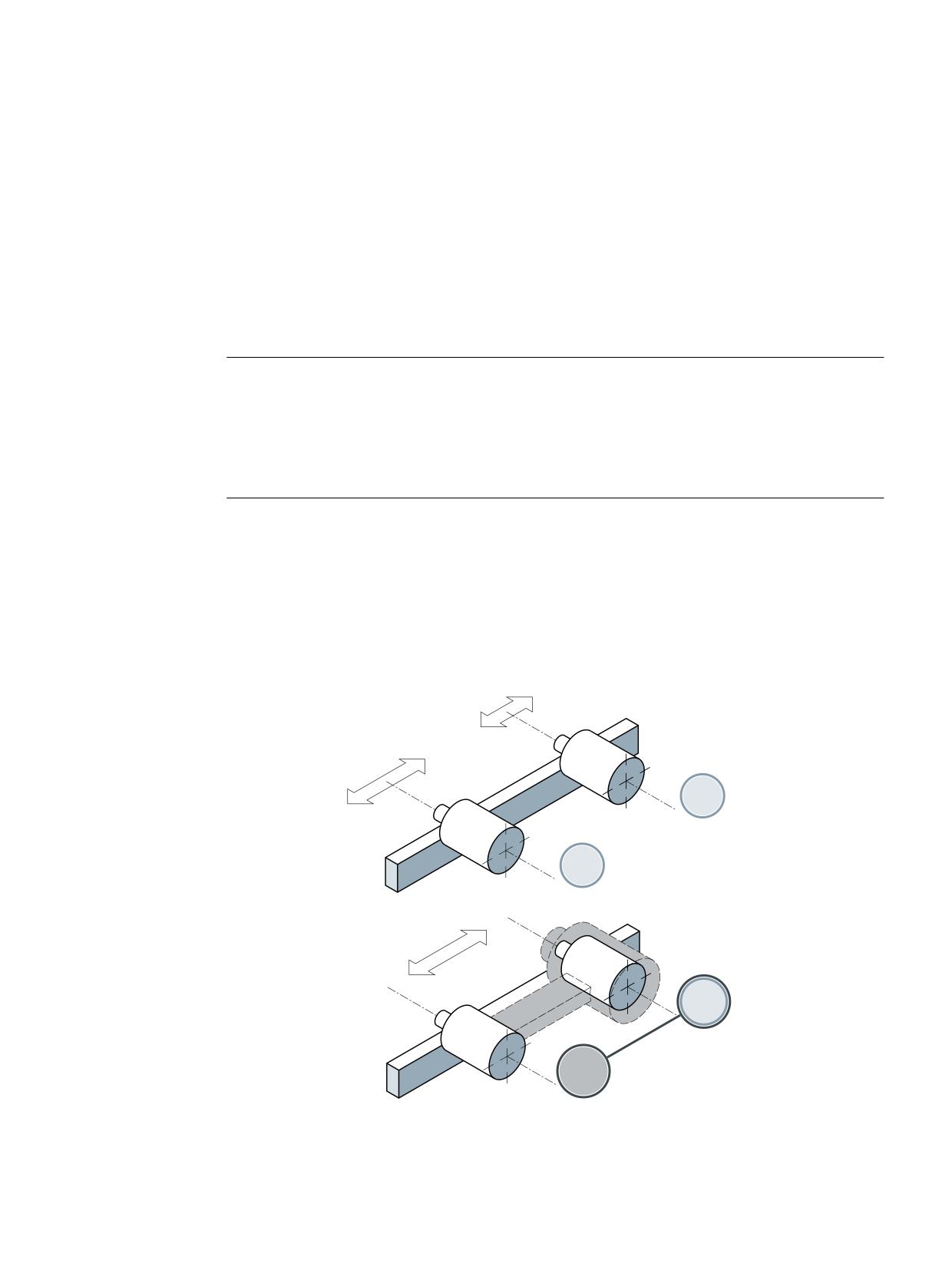
Speed/torque coupling, master-slave
6
6.1
Brief description
A master-slave coupling is a speed setpoint coupling between a master and any number of slave
axes - performed at the position controller level - with and without torque equalization control.
The coupling can be permanently switched on, dynamically switched on/off and reconfigured.
Note
The following restrictions apply for the SINUMERIK 828D with regard to the "Master-slave
coupling":
• Only one master-slave grouping is possible. (Exception: control variant "SW28x(1) CNC-SW
Milling Adv. Export (me822) with max. two master-slave groupings).
• Only one slave axis can be coupled to the master axis.
Applications
Possible applications of a master-slave coupling include:
• Increase the power for mechanically coupled drives
• Compensating gear and gear tooth flank play by entering a pre-tensioning torque
Dynamic master-slave coupling of two axes
&RXSOLQJ
0RYHPHQW
$[LV
2))
0RYHPHQW
$;
$[LV
$;
&RXSOLQJ
21
0RYHPHQW
$[LV DQG $[LV
$;
6ODYH
$;
0DVWHU
Technologies
Function Manual, 10/2020, 6FC5397-8GP40-0BA1
85
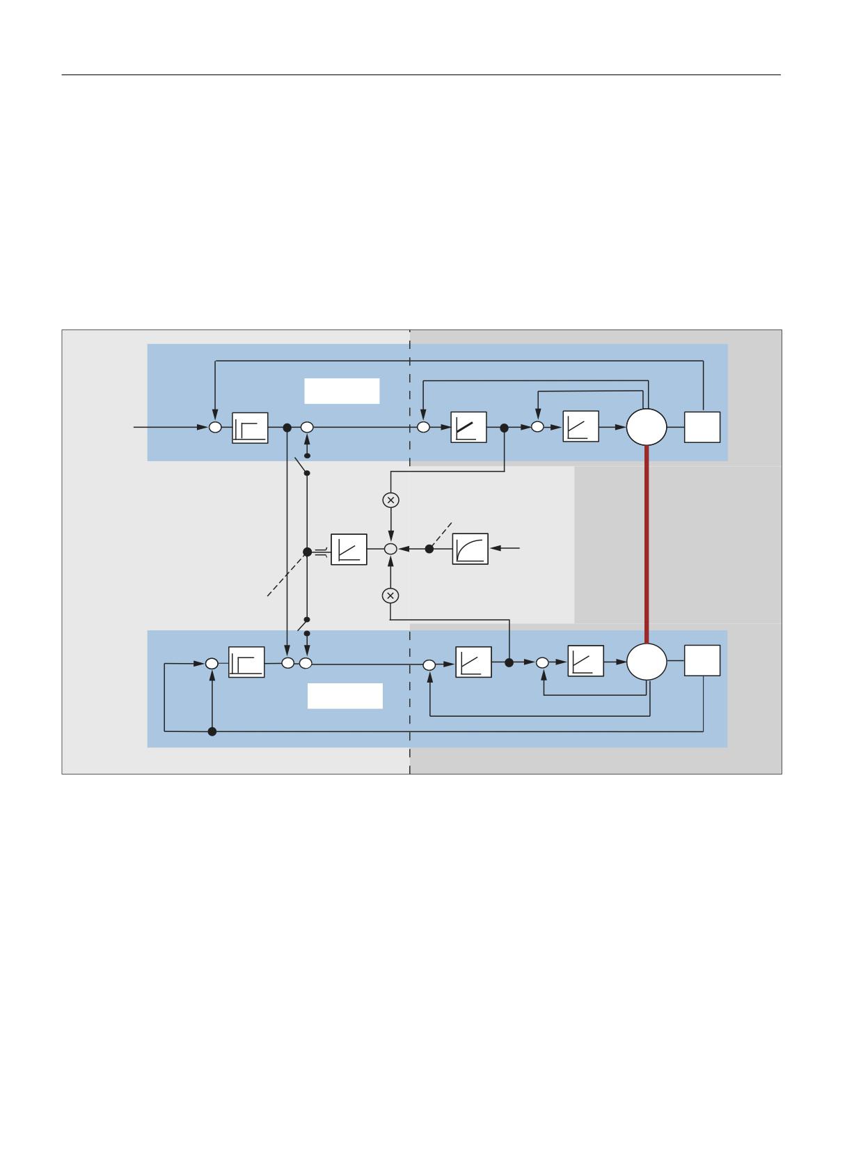
Speed/torque coupling, master-slave
6.2 Coupling diagram
6.2
Coupling diagram
If the coupling is closed, the slave axis is traversed only with the load-side setpoint speed of the
master axis. It is therefore only speed-controlled, not position-controlled. There is no
differential position control between the master and slave axis.
The torque required between the master and slave axis is distributed using the torque
equalization controller. When using different motors, this distribution can be adapted to the
specific requirements using a weighting factor.
A tension can be established between the master and slave axes by entering a supplementary
torque (tensioning torque).
3RVLWLRQDFW
0$67(5
QLVW
LLVW
3RVLWLRQVHW
QVROO
LVROO
,QWHU
0
(
SRODWRU
3RVLWLRQ FRQWUROOHU
6SHHG FRQWUROOHU
7RUTXH FRQWUROOHU
,QWHUFRQQHFWLRQ
FRQWUROOHU
RXWSXW
:HLJKWLQJ IDFWRU
6HUYR WUDFH &ODPSLQJ WRUTXH
6SHHG VHWSRLQW FRXSOLQJ
0HFKDQLFDO
&ODPSLQJ WRUTXH
FRXSOLQJ
3,
37
ILOWHU
6HUYR WUDFH
FRQWUROOHU
:HLJKWLQJ IDFWRU
7RUTXH FRPSHQVDWRU\
FRQWUROOHU
3RVLWLRQ FRQWUROOHU
6SHHG FRQWUROOHU
7RUTXH FRQWUROOHU
3RVLWLRQVHW
0
(
LVROO
Q
VROO
LLVW
QLVW
6/$9(
3RVLWLRQDFW
1&8
'ULYH
Figure 6-1
Control structure
Technologies
86
Function Manual, 10/2020, 6FC5397-8GP40-0BA1

Speed/torque coupling, master-slave
6.3 Configuring a coupling
6.3
Configuring a coupling
Static assignment
For a speed setpoint coupling and torque equalization control, the static assignment of master
and slave axis is defined separately in the following machine data:
• Speed setpoint coupling
MD37250 $MA_MS_ASSIGN_MASTER_SPEED_CMD[<slave axis>] =
<machine axis number of the master axis for the speed setpoint coupling>
• Torque equalization control
MD37252 $MA_MS_ASSIGN_MASTER_TORQUE_CTR[<slave axis>] =
<machine axis number of the master or slave axis for torque equalization control>
(see Section "Tension torque (Page 92)")
Dynamic assignment
The assignment of master and slave axes can be dynamically changed using the following
program commands.
Defining assignments
Assignment of one or several slave axes to a master axis:
MASLDEF (<slave axis_1>, <slave axis_2>, ..., <master axis>)
In principle, any number of slave axes can be assigned. The assignment is kept even after an
operating mode change, reset and end of part program.
Deleting assignments
Delete assignment of one or several slave axes to their associated master axis:
MASLDEL (<slave axis_1>, <slave axis_2>, ...)
An active coupling is first implicitly switched off before deleting the assignment.
Axis assignment for speed setpoint coupling and torque equalization control
For the speed setpoint coupling, the slave axis refers to the master axis specified when defining
the assignment (MASLDEF).
The axis to which the slave axis refers for torque equalization control is defined in the following
machine data:
MD37253 $MA_MS_FUNCTION_MASK[<slave axis>], bit 1 = <value>
<value>
Description
0
In the case of dynamic assignment (MASLDEF), the slave axis for the torque equalization
control - as well as for speed setpoint coupling - refers to the master axis of the master-slave
grouping.
1
In the case of dynamic assignment (MASLDEF), the slave axis for the torque equalization
control refers to the axis, master or slave axis of the master-slave grouping specified in ma-
chine data:
MD37252 $MA_MS_ASSIGN_MASTER_TORQUE_CTR<slave axis> = <axis>
Technologies
Function Manual, 10/2020, 6FC5397-8GP40-0BA1
87
Speed/torque coupling, master-slave
6.3 Configuring a coupling
(See Section "Tension torque (Page 92)")
Supplementary conditions
The following supplementary conditions must be observed for the dynamic assignment:
• When the coupling is switched on, a change to the assignment using MASLDEF has no
effect. The change only becomes effective the next time that the coupling is switched off.
• The same master axis is always used for the speed setpoint coupling and torque equalization
control.
• A plausibility check of the assignment is only made when the coupling is switched on.
User-specific standard assignment after reset
A user-specific standard assignment, which is always effective after a reset, can be defined in
PROG_EVENT.SPF using the program commands MASLDEF and MASLDEL.
The following machine data should be set in order that PROG_EVENT.SPF is executed for a reset:
MD20108 $MC_PROG_EVENT_MASK.Bit 2 = 1
Example: Dynamic change of the assignment
The assignment of slave axis AX3 is changed from master axis AX1 to master AX2. To do this, the
coupling must be temporarily switched off (see Section "Closing/opening a coupling
(Page 95)").
Programming
Description
①
MASLDEF (AX3, AX1)
Assignment of slave axis AX3 to master axis AX1
②
MASLON (AX3)
Switching on the coupling
③
MASLDEL (AX3)
Switch off the coupling and cancel the assignment between AX3 and AX1
④
MASLDEF (AX3, AX2)
Assignment of slave axis AX3 to master axis AX2
$;
$;
$;
$;
$;
$;
$;
$;
$;
$;
$;
$;
Figure 6-2
Alternating assignment of the slave axis
Technologies
88
Function Manual, 10/2020, 6FC5397-8GP40-0BA1

Speed/torque coupling, master-slave
6.4 Torque compensatory controller
General supplementary conditions
Please note the following general supplementary conditions:
• A slave axis can only be assigned to one master axis
• A master axis can be assigned several slave axes
• A slave axis must not be a master axis or be in another master-slave relationship.
Note
Drive optimization
At a SINAMICS S120 drive unit, a maximum of three drives can be optimized or measured at
the same time (speed controller optimization / function generator). Therefore, for a coupling
with more than three coupled drives at the same time, we recommend that these are
distributed over several drive units.
6.4
Torque compensatory controller
The torque compensatory controller (PI control) calculates a load-side initial speed setpoint. The
additional speed setpoint can be differently entered via the following machine data:
MD37254 $MA_MS_TORQUE_CTRL_MODE[<slave axis>] = <value>
<value>
Input of the additional speed setpoint at:
0
Master and slave axis (default value)
1
Slave axis
2
Master axis
3
No additional setpoint injection
Note
Several slave axes
For a master-slave grouping with one master and several slave axes, the input of the additional
speed setpoint to the master and slave axes - set as standard in MD37254 - can result in
instability. For multiple slave axes, injection of an additional speed setpoint should only be
applied in the slave axes:
MD37254 $MA_MS_TORQUE_CTRL_MODE = 1
SINAMICS S120: Current setpoint filter
Up to four current setpoint filters (p1656 - p1674, function block diagram [5710]) can be
activated in the SINAMICS S120. In a master-slave group, it is recommended that, for the master
and all of the slave axes, only filters with the same data be activated at any one time.
Technologies
Function Manual, 10/2020, 6FC5397-8GP40-0BA1
89

Speed/torque coupling, master-slave
6.4 Torque compensatory controller
Scaling
Scaling of the machine data for the gain factor (P component) (MD37256
$MA_MS_TORQUE_CTRL_P_GAIN) and the speed setpoint limiting (MD37260
$MA_MS_MAX_CTRL_VELO) is defined in the following machine data:
MD37253 $MA_MS_FUNCTION_MASK[<slave axis>], bit 0 = <value>
<value>
Description
0
MD37256 and MD37260 are internally multiplied with the following factor: 1 / interpolator
clock cycle 1)
1
MD37256 and MD37260 are accepted unchanged
1) The interpolator cycle is displayed with MD10071 $MN_IPO_CYCLE_TIME
Note
We recommend not changing MD37256 and MD37260:
MD37253 $MA_MS_FUNCTION_MASK[<slave axis>], bit 0 = 1
Gain factor (P component)
The gain factor of the torque compensatory controller is set in the following machine data as a
percentage of the ratio of the maximum load-side axis velocity of the slave axis (MD32000
$MA_MAX_AX_VELO) to its rated torque (SINAMICS S120: p2003):
MD37256 $MA_MS_TORQUE_CTRL_P_GAIN[<slave axis>]
Note: Scaling via MD37253 $MA_MS_FUNCTION_MASK[<slave axis>], bit 0
Integral time (I component)
The integral time of the torque compensatory controller is set in the following machine data:
MD37258 $MA_MS_TORQUE_CTRL_I_TIME[<slave axis>]
The I component is deactivated as standard.
Speed setpoint limiting
The speed setpoint calculated by the torque compensatory controller can be limited using the
following machine data. The input is a percentage referred to the maximum, load-side axis
velocity of the slave axis (MD32000 $MA_MAX_AX_VELO).
MD37260 $MA_MS_MAX_CTRL_VELO[<slave axis>]
Note: Scaling via MD37253 $MA_MS_FUNCTION_MASK[<slave axis>], bit 0
Technologies
90
Function Manual, 10/2020, 6FC5397-8GP40-0BA1
Speed/torque coupling, master-slave
6.4 Torque compensatory controller
Deactivating the torque compensatory controller
If the following settings are made, the torque compensatory controller will be inactive:
• MD37254 $MA_MS_TORQUE_CTRL_MODE[<slave axis>] = 3
• MD37256 $MA_MS_TORQUE_CTRL_P_GAIN[<slave axis>] = 0
Torque weighting
The percentage of the torque generated by the slave axis of the total torque can be set using the
torque weighting.
MD37268 $MA_MS_TORQUE_WEIGHT_SLAVE[<slave axis>]
Using the torque weighting, it is possible to configure a different torque distribution between the
master and slave axes for motors with different rated torques. For motors of the master and slave
axes with the same rated torques, it makes sense to have a 50 % torque distribution (default
setting).
The torque provided by the master axis is given by:
Torque provided by the master axis = 100 % - MD37268
Note
Mechanical coupling
When using the torque compensatory controller, it is absolutely necessary to have a mechanical
coupling between the master and slave axis. Otherwise, the two drives involved could accelerate
in an uncontrollable fashion.
Activation / Deactivation via the NC/PLC interface
Activation of the torque compensatory controller via the NC/PLC interface must be explicitly
enabled:
MD37255 $MA_MS_TORQUE_CTRL_ACTIVATION[<slave axis>] = 1
Activation
The torque compensatory controller can be activated axis for axis via:
DB31, ... DBX24.4
Reading the actual state
The actual activation state of the torque compensatory controller can be read via:
DB31, ... DBX96.4
Technologies
Function Manual, 10/2020, 6FC5397-8GP40-0BA1
91

Speed/torque coupling, master-slave
6.5 Tension torque
6.5
Tension torque
The tension torque is a supplementary torque which is switched to the active torque equalization
controller. This means that a mechanical tension can be established between axes within a
master-slave grouping. Establishing a tension is not only possible between the master and a
slave axis, but also between two slave axes by declaring one of the slave axes the reference axis
for the torque equalization controller.
Setting
The tension torque is entered as a percentage of the rated torque of the slave axis and is active
immediately:
MD37264 $MA_MS_TENSION_TORQUE[<slave axis>] = <tension torque>
As can be seen from the structure of the torque equalization controller (Chapter "Torque
compensatory controller (Page 89)"), the tension torque is entered via a PT1 filter. The filter time
constant is set using the following machine data:
MD37266 $MA_MS_TENSION_TORQ_FILTER_TIME[<slave axis>] = <time constant>
A value for the filter time constant greater than 0 activates the filter.
NOTICE
No axis equalization
If a tension torque is entered without a mechanical coupling between the master and slave axis
then this causes the axes to move.
Note
Minimum tension torque
A minimum tension torque must be greater than the stiction, so that the edges are applied
reliably. Otherwise an edge change will not be permitted:
• If this is the case, the acceleration (+const. forces) must be limited accordingly so that the
forces are less than the tension torque.
• If the acceleration is greater, the result is a torque difference (no longer an opposite sign).
However, this is always adhered to with a 50% division.
Reducing motor heating
The tension torque can be reduced when the motor is at a standstill to reduce the motor
temperature rise.
Example 1: Static coupling and establishing a tension in pairs
A master-slave application is parameterized so that one leading axis is assigned three slave axes
and a tension torque is entered for one axis pair. As a consequence, the leading axis alone does
not have to establish the tension torque with respect to all of the slave axes.
Assumption regarding machine axes:
• 1st to 4th machine axis: AX1, AX2, AX3, AX4
Technologies
92
Function Manual, 10/2020, 6FC5397-8GP40-0BA1
Speed/torque coupling, master-slave
6.5 Tension torque
Static coupling for all slave axes
• MD37262 $MA_MS_COUPLING_ALWAYS_ACTIVE[AX2] = 1
• MD37262 $MA_MS_COUPLING_ALWAYS_ACTIVE[AX3] = 1
• MD37262 $MA_MS_COUPLING_ALWAYS_ACTIVE[AX4] = 1
Axis
Reference axis of speed setpoint
Reference axis of the torque
Input of the torque equalization
coupling
equalization controller
contr.
MD37250 = value
MD37252 = value
MD37254 = value
Value
Description
Value
Description
Value
Description
AX1
0
No reference axis
0
No reference axis
0
Master and slave
AX2
1
Leading axis, AX1
1
Leading axis, AX1
0
Master and slave
AX3
1
Leading axis, AX1
0
No reference axis
3
No input
AX4
1
Leading axis, AX1
3
2nd slave axis, AX3
0
Master and slave
$;
$;
0DVWHU
6ODYH
$;
$;
6ODYH
6ODYH
① Jointly driven machine element
② Torque compensatory control
③ Speed coupling
Figure 6-3
Example 1: Torque equalization control in pairs
Example 2: Dynamic coupling with 1x4 and 2x2 axes grouped in pairs
Assumption regarding machine axes:
• 1st to 4th machine axis: AX1, AX2, AX3, AX4
Dynamic coupling for all slave axes:
• MD37262 $MA_MS_COUPLING_ALWAYS_ACTIVE[AX2] = 0
• MD37262 $MA_MS_COUPLING_ALWAYS_ACTIVE[AX3] = 0
• MD37262 $MA_MS_COUPLING_ALWAYS_ACTIVE[AX4] = 0
For a dynamic coupling, the leading axis specified when defining the coupling (MASLDEF) is, as
standard, the reference axis for speed setpoint coupling and torque equalization control.
Technologies
Function Manual, 10/2020, 6FC5397-8GP40-0BA1
93
Speed/torque coupling, master-slave
6.5 Tension torque
The definition of reference axis AX3 for the torque equalization control of the 3rd slave axis AX4
is required for the application "1x4 axes" where the following machine data is set: MD37253
$MA_MS_FUNCTION_MASK[AX4], Bit 1 = 1 (see part program)
Axis
Reference axis of speed setpoint
Reference axis of the torque
Input of the torque equalization
coupling
equalization controller
contr.
MD37250 = value
MD37252 = value
MD37254 = value
Value
Description
Value
Description
Value
Description
AX1
0
No reference axis
0
No reference axis
0
Master and slave
AX2
0
No reference axis
0
No reference axis
0
Master and slave
AX3
0
No reference axis
0
No reference axis
3
No input
AX4
0
No reference axis
3
Machine axis AX3
0
Master and slave
Program code
Comment
PROC MASL_SWITCH IPRTLOCK DISPLOF
IF MASL_REQUEST==4
;
Activate "1x4 axes"
MASLOF(AX2, AX4)
;
Switch off coupling
MASLDEL(AX2, AX4)
;
Delete coupling
$MA_MS_FUNCTION_MASK[AX4]=
;
MD37253, bit1 = 1:
$MA_MS_FUNCTION_MASK[AX4] B_OR 'B10'
;
Reference axis of the torque equalization controller
;
from AX4, is AX3 (MD37252)
NEWCONF
;
Activate machine data change
STOPRE
MASLDEF(AX2, AX3, AX4, AX1)
;
Define assignment for "1x4 axes"
MASLON(AX2, AX3, AX4)
;
Switch on couplings
MASL_ACTIVE=4 MASL_REQUEST=0
;
Feedback: "1x4 axes" activated
ENDIF
IF MASL_REQUEST==2
;
Activate "2x2 axes"
MASLOF(AX2, AX3, AX4)
;
Switch off coupling
MASLDEL(AX2, AX3, AX4)
;
Delete coupling
$MA_MS_FUNCTION_MASK[AX4]=
;
MD37253, Bit1 = 0:
$MA_MS_FUNCTION_MASK[AX4] B_AND
;
Reference axis of the torque equalization controller
'HFFFD'
;
from AX4, is the MASLDEF-defined
;
leading axis
NEWCONF
STOPRE
MASLDEF(AX2, AX1)
;
Define assignment for 1st "2x2 axes"
MASLDEF(AX4, AX3)
;
Define assignment for 2nd "2x2 axes"
MASLON(AX2, AX4)
;
Switch on couplings
MASL_ACTIVE=2 MASL_REQUEST=0
;
Feedback: "2x2 axes" switched on
ENDIF
RET
Technologies
94
Function Manual, 10/2020, 6FC5397-8GP40-0BA1
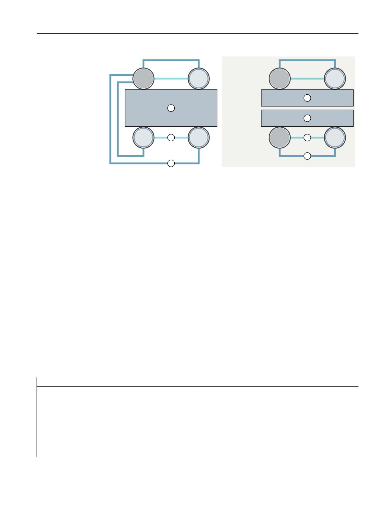
Speed/torque coupling, master-slave
6.6 Closing/opening a coupling
D[HV
D[HV
$;
$;
$;
$;
0DVWHU
6ODYH
0DVWHU
6ODYH
$;
$;
$;
$;
6ODYH
6ODYH
0DVWHU
6ODYH
① Jointly driven machine element
② Torque compensatory control
③ Speed coupling
Figure 6-4
Example 2: alternating coupling with 1x4 and 2x2 axes
6.6
Closing/opening a coupling
Default setting
After the control has booted, the following machine data defines whether the coupling is
permanently switched on (static) or can be dynamically switched on/off and reconfigured:
MD37262 $MA_MS_COUPLING_ALWAYS_ACTIVE[<slave axis>] = <switch on mode>
Statically switching on a coupling
MD37262 $MA_MS_COUPLING_ALWAYS_ACTIVE[<slave axis>] = 1
After the control boots, the coupling is statically switched on.
By writing the machine data in the part program or synchronized action with subsequent warm
restart NEWCONF, then a static coupling can also be switched off/on at a later time.
Example: Switching the static coupling for slave axis AX2 off and on
Program code
Comment
N100 $MA_MS_COUPLING_ALWAYS_ACTIVE[AX2] = 0
; Coupling type: static -> dynamic
N110 NEWCONF
; Activate machine data.
N120 MASLOF(AX2)
; Switch off coupling.
N200 PRESETON(AX2,...)
; E.g. actual value setting of the slave axis.
N300 $MA_MS_COUPLING_ALWAYS_ACTIVE[AX2] = 1
; Coupling type: dynamic -> static, switch on cou-
pling.
Technologies
Function Manual, 10/2020, 6FC5397-8GP40-0BA1
95
Speed/torque coupling, master-slave
6.6 Closing/opening a coupling
Note
A statically switched on coupling can neither be switched on/off nor reconfigured using the
master-slave-specific NC/PLC interface signals and/or program commands.
Dynamically switching a coupling on/off
MD37262 $MA_MS_COUPLING_ALWAYS_ACTIVE[<slave axis>] = 0
The coupling can be dynamically switched on and off and reconfigured.
The coupling can be switched on/off by:
• Machine data MD37262
Writing the machine data to switch on ( = 1) or switch off ( = 0) in the part program or
synchronized action. The change becomes active immediately.
• NC/PLC interface
DB31, ... DBX24.7 = 1 or 0 (master-slave on or off)
• Program commands
- Switch on: MASLON (<slave axis_1>, <slave axis_2>, ...)
- Switch off: MASLOF (<slave axis_1>, <slave axis_2>, ...)
- Switching off with braking of the slave spindles:
MASLOFS (<slave spindle_1>, <slave spindle_2>, ...)
- Switching off with deletion of the assignment:
MASLDEL (<slave axis_1>, <slave axis_2>, ...)
Note
Changing the static assignment
The setting:
MD37262 $MA_MS_COUPLING_ALWAYS_ACTIVE[<slave axis>] = 0
Permits the coupling to be dynamically changed. This means that it is possible to define
a new assignment using MASLDEF. The assignment parameterized in the machine data
(see static assignment, Section "Configuring a coupling (Page 87)") takes effect only after
the control has been powered up again (NC reset).
Coupling state
System variable
The actual coupling state of a slave axis can be read in the part program and synchronized action
using the following system variable:
Technologies
96
Function Manual, 10/2020, 6FC5397-8GP40-0BA1
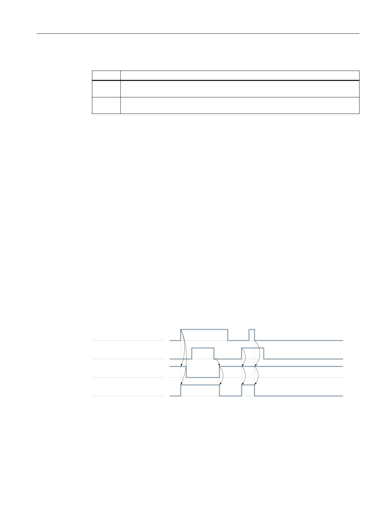
Speed/torque coupling, master-slave
6.7 Response on activation/deactivation
$AA_MASL_STAT[<slave axis>]
Value
Description
0
1) The coupling of the slave axis is not active.
2) The specific axis is not a slave axis
> 0
The coupling is active.
<value> == machine axis number of the master axis
NC/PLC interface signal
The current coupling state of a slave axis can be read using the following axis-specific NC/PLC
interface signal:
DB31, ... DBX96.7 (master/slave coupling active)
Setpoint state
Requests to switch on/off a master-slave coupling (NC/PLC interface signal and/or program
commands) that consecutively follow one another mutually overwrite one another. The
effective setpoint state results from the last chronological request (see Section "Response on
activation/deactivation (Page 97)").
6.7
Response on activation/deactivation
On/off at standstill (axis)
A request to switch on/off the coupling only becomes effective when the master and slave axis
are at a standstill (zero speed):
DB31, ... DBX61.4 == 1 (axis/spindle stationary)
In this case, the coupled axes must be in the closed-loop controlled mode.
'%
ಹ '%;
PDVWHU VODYH RQ
0$6/21
0$6/2)
'%
ಹ '%;
D[LV VSLQGOH LV VWDWLRQDU\
'%
ಹ '%;
PDVWHU VODYH DFWLYH
Figure 6-5
Activation procedure
When switching on the coupling using the program command MASLON, the system waits until
the coupling is closed before the block is changed. The "Master-slave switchover active" message
will be displayed on the user interface during this time.
Technologies
Function Manual, 10/2020, 6FC5397-8GP40-0BA1
97
Speed/torque coupling, master-slave
6.7 Response on activation/deactivation
Switching on/off during motion (spindle)
Note
Switching on/off during motion
During the motion, the coupling can be switched on/off only for spindles in speed control
mode.
Technologies
98
Function Manual, 10/2020, 6FC5397-8GP40-0BA1
Speed/torque coupling, master-slave
6.7 Response on activation/deactivation
Switching on
When switching on during the motion, the coupling operation divides itself at different speeds
in two phases.
• Phase 1
The PLC user program must request the switch on of the coupling with:
DB31, ... DBX24.7 = 1 (master/slave ON)
The slave spindle accelerates or brakes along a ramp to the setpoint speed of the master
spindle.
When the setpoint speed is reached, the coupling is switched on and the NC/PLC interface
signal is set:
DB31, ... DBX96.7 == 1 (coupling active)
If the master spindle is accelerated while the coupling is being switched on, then Phase 1 is
extended corresponding to the dynamic difference between the master and the slave spindle.
• Phase 2
The following synchronous signals are generated from the actual speed difference between
the master and slave spindle(s):
- DB31, ... DBX96.3 (speed tolerance, coarse)
- DB31, ... DBX96.2 (speed tolerance, fine)
The associated limits are set using the following machine data:
- MD37270 $MA_MS_VELO_TOL_COARSE ("Tolerance coarse")
Technologies
Function Manual, 10/2020, 6FC5397-8GP40-0BA1
99
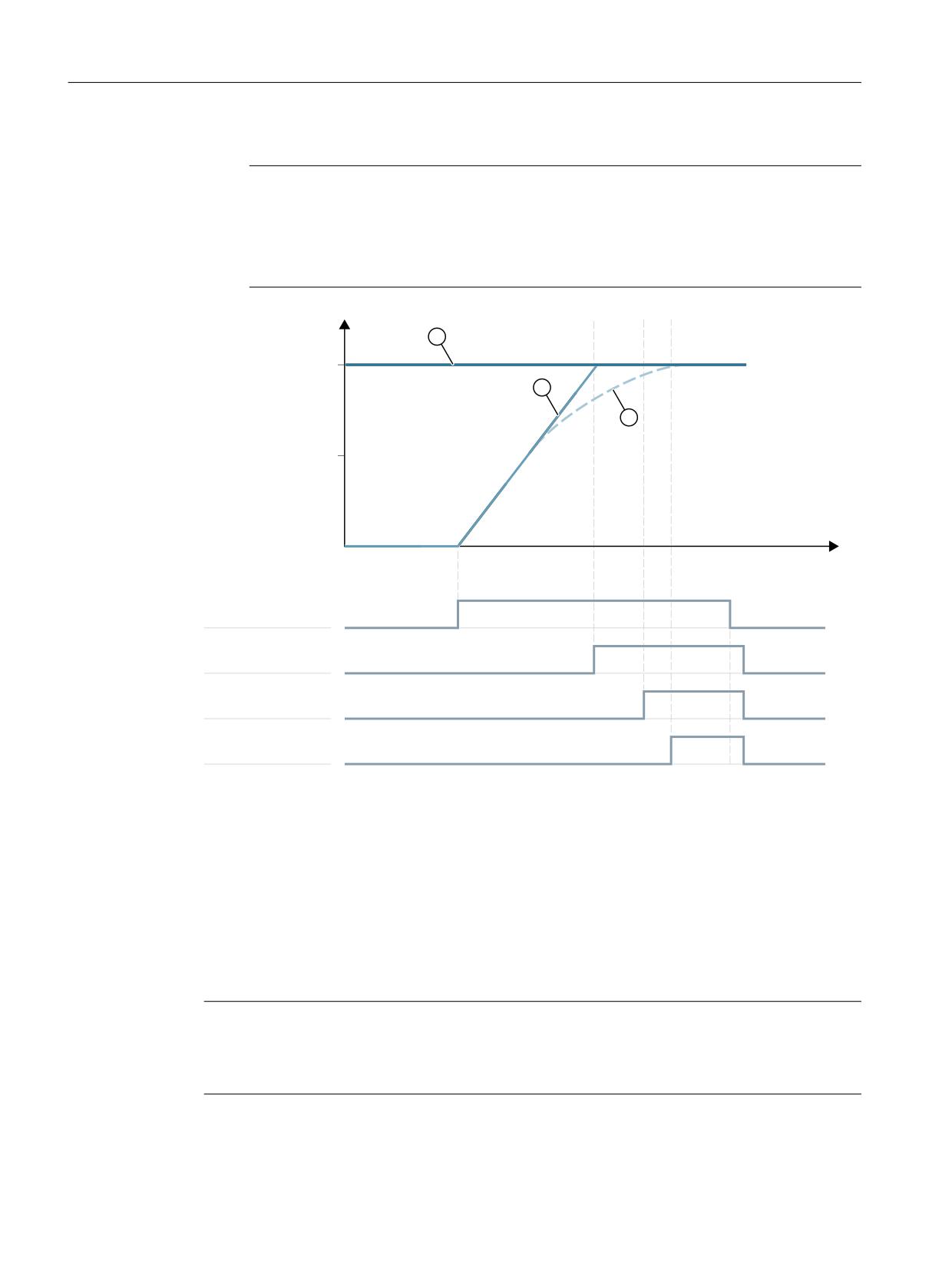
Speed/torque coupling, master-slave
6.7 Response on activation/deactivation
- MD37272 $MA_MS_VELO_TOL_FINE ("Tolerance fine").
Note
The "Speed tolerance coarse" signal can be used to implement a monitoring function on
the PLC side that checks a coupled master-slave grouping for loss of speed synchronism.
The "Speed tolerance fine" signal can be used to directly derive the time taken to close the
coupling mechanically and switch on the torque equalization controller.
W
W
W
6SHHG
W
'%
'%;
FRXSOLQJ RQ
'%
'%;
FRXSOLQJ DFWLYH
'%
'%;
VSHHG WROHUDQFH FRDUVH
'%
'%;
VSHHG WROHUDQFH ILQH
Figure 6-6
Coupling operation at different speeds
Switch off without braking
If the coupling is switched off with the MASLOF program command, the coupling will be
switched off immediately for spindles in speed control mode. The slave spindles maintain their
speeds at the time that the coupling is switched off until a new speed is programmed.
Switch off with braking
If the coupling is switched off with the MASLOFS program command, the coupling will be
switched off immediately for spindles in speed control mode and the slave spindles braked.
Note
The implicit preprocessing stop is omitted for MASLON and MASLOF. The missing preprocessing
stop means that the $P system variables of the slave spindles do not supply updated values until
reprogrammed.
Technologies
100
Function Manual, 10/2020, 6FC5397-8GP40-0BA1

Speed/torque coupling, master-slave
6.8 Supplementary conditions
Coupling characteristics
The behavior regarding the program commands MASLON, MASLOF, MASLOFS, MASLDEL and the
NC/PLC interface signal: DB31, ... DBX24.7 (master/slave on) is, for spindles in the open-loop
speed controlled mode, set using the following machine data:
MD37263 $MA_MS_SPIND_COUPLING_MODE[<slave spindle>] = <value>
<value>
Description
0
Coupling and disconnection take place only at standstill.
The current coupling state is retained until all axes involved have actually come to a standstill.
The MASLOFS and MASLOF operations are identical; the slave spindle is not decelerated
automatically.
1
Coupling and disconnection takes place immediately and therefore during motion.
During coupling, the slave spindles are accelerated automatically to the current speed of the
master spindle.
On disconnection, the slave spindles rotating at this time retain their speeds until next speed
programming. However, a slave spindle disconnected with MASLOFS decelerates automati-
cally.
6.8
Supplementary conditions
6.8.1
Functional boundary conditions
General
• Master and slave axes must be on the same NCU.
• A coupling is closed or opened independent of the channel state the next time that the axis
is at a standstill.
• Slave axes can only be traversed via the master axis when the coupling is closed.
• A coupled slave axis cannot be switched further via the axis container.
• A requested axis interchange of coupled slave axes is not executed.
• When the coupling is switched-in (closed) via the slave axis, the master axis is braked
automatically, if the channel axis is in the same channel: ⇒ asymmetrical behavior when
opening and closing the coupling:
- Activate: the leading axis is automatically braked
- Deactivating: no automatic braking of the leading axis
• The setpoint position of a coupled slave axis corresponds to its actual position.
• For axes and spindles in the positioning mode, the coupling is only switched-in (closed) and
switched-out (opened) at standstill (zero speed).
• The leading-following coupling must be deactivated prior to a gear change or a star-delta
switchover.
Technologies
Function Manual, 10/2020, 6FC5397-8GP40-0BA1
101
Speed/torque coupling, master-slave
6.8 Supplementary conditions
Axial monitoring functions
• Except monitoring the speed setpoint and actual speed, axial monitoring functions like
contour and standstill in the slave axis are inactive because of the missing position controller.
The position control circuit parameters like gain factor, precontrol, balancing can thus be set
differently for master and slave axes without the monitoring functions responding.
• In order to ensure the same braking behavior for all axes of a master-slave group, when the
coupling is active, the same alarm reaction is applied to all of the axes of the master-slave
group.
• The parameterization and evaluation of the standstill detection (e.g. braking ramp) is
realized axially for each axis in the master-slave group. This can result in an asynchronous
withdrawal of the controller enable for the coupled axes.
• When canceling error states, the slave axes do not reposition to the point of interruption.
Virtual axis
Master and/or slave axes must not be "virtual" axes:
MD30132 $MA_IS_VIRTUAL_AX (axis is virtual axis) = 0
Modulo rotary axes
• For slave axes, when the coupling is closed, the actual value displayed in the service display
is not modulo 360°. Independent of the setting in machine data:
MD30310 $MA_ROT_IS_MODULO[<slave axis>]
Spindles
• If a master-slave coupling is activated with spindles, the slave spindle is operated in the open-
loop speed controlled mode. The actual value of the slave spindle is not displayed as modulo
360° in the service display. However, in the automatic basic display the actual value is
displayed as modulo 360°.
• If the spindles are accelerated at the current limit, this may mean that no adjusting reserves
are left over in the coupled state for the torque compensatory controller to use to distribute
the torque between the master and the slave as required.
• The maximum master spindle chuck speed must be configured in the following machine data
to be lower than or equal to that of the following spindles:
MD35100 $MA_SPIND_VELO_LIMIT[<master spindle>]
• The axial velocity monitoring function should be adapted to the chuck speed:
MD36200 $MA_AX_VELO_LIMIT[<master spindle>]
Technologies
102
Function Manual, 10/2020, 6FC5397-8GP40-0BA1
Speed/torque coupling, master-slave
6.8 Supplementary conditions
6.8.2
Axial NC/PLC interface signals
•
In the brake control logic, the NC/PLC interface signal may longer be evaluated for slave axes:
DB3x.DBX61.5 (position controller active
). When the coupling is closed, the signal is no longer set. Instead, the following NC/PLC
interface signal should be used:
DB31, ... DBX96.7 (master-slave coupling active).
•
When requested, and for a closed coupling, the following NC/PLC interface signals are
directly taken from the master axis for the slave axis:
DB31, ... DBX2.1 (controller enable)
DB31, ... DBX21.7 (pulse enable)
•
When the controller enable is cancelled for the master axis:
DB31, ... DBX2.1 (controller enable) = 0
within the configured time of:
MD36610 $MA_AX_EMERGENCY_STOP_TIME
then this also results in interpolatory braking of the slave axis. The corresponding speed and
current controller enable signals are only cancelled after the configured time has expired
MD36620 $MA_SERVO_DISABLE_DELAY_TIME
•
In order to facilitate a standard braking behavior for all coupled axes, it is recommended that
the following parameters are set the same.
- MD36620 $MA_SERVO_DISABLE_DELAY_TIME
- p9560 (pulse suppression, shutdown speed)
- p1228 (pulse suppression, delay time)
•
If, for the master or slave axis, one of the following drive status signals is not set:
DB31, ... DBX61.7 (current controller active) == 0 OR
DB31, ... DBX61.6 (speed controller active) == 0
then, when the slave axis is at a standstill, the status signal is reset:
DB31, ... DBX96.7 (master/slave active) = 0
As soon as the master and slave axis are again in closed-loop control:
DB31, ... DBX61.7 (current controller active) == 1 AND
DB31, ... DBX61.6 (speed controller active) == 1
then for the slave axis, the status signal is again set:
DB31, ... DBX96.7 (master/slave active) = 1
•
The torque equalization controller can be activated via the NC/PLC interface using:
DB31, ... DBX24.4 = 1 (torque equalization controller on)
The status of the torque equalization controller is displayed in:
DB31, ... DBX96.4 (master/slave equalization controller active)
Note
The slave axis is only closed-loop speed controlled when the coupling is closed. The NC/PLC
interface signal: DB31, ... DBX61.5 (position controller active) is no longer set.
Technologies
Function Manual, 10/2020, 6FC5397-8GP40-0BA1
103
Speed/torque coupling, master-slave
6.8 Supplementary conditions
6.8.3
Interaction with other functions
Function generator
To calibrate the speed control loop with activated coupling, it is recommended that a low value
should be set for the torque weighting of the slave axis (MD37268
$MA_MS_TORQUE_WEIGHT_SLAVE). Traversing of a mechanical coupled-motion slave axis is
not prevented by the torque compensatory controller.
Reference point approach
If the coupling is switched on, only the master axis can be referenced. Referencing of slave axes
is suppressed. The referencing requirement does not have to be explicitly canceled for the slave
axis in order to do this. The referencing status of coupled slave axes remains unchanged. The
slave axis position is generally not the same as the master axis position. This difference in
position is not significant. If the coupling is separated, each axis can be referenced separately as
usual.
Position-related compensations
Position-related compensations of the slave axis, such as spindle pitch errors, backlash,
temperature and sag offsets are not active because the position controller of the slave axis is not
active.
Correct calculation of the backlash compensation requires that the backlash of the slave axis is
always overtraveled by the motion of the master axis in coupled mode. Disconnecting the
coupling during an axis reversal error will generate an incorrect actual value for the slave axis.
Dynamic stiffness control (DSC)
The "Dynamic stiffness control (DSC)" function must either be active or not active for all axes of
a master-slave grouping.
MD32640 $MA_STIFFNESS_CONTROL_ENABLE
Speed/torque feedforward control (FFW)
The "Speed/torque feedforward control (FFW)" function does not have to be activated explicitly
in the slave axis. The corresponding settings of the master axis are used. The speed feedforward
value of the master axis is already incorporated in the speed setpoint of the slave axis. For an
active torque feedforward control, the load-side torque feedforward control value of the master
axis is also active in the slave drive.
The mechanical situation changes when the coupling is switched on. Axis-specific settings must
be adapted accordingly. All coupled drives should have the same speed control dynamics.
Gantry
If one master-slave relationship is defined on each side of the gantry grouping to increase the
gain, only the leading axis or following axis may be operated as master axis.
Technologies
104
Function Manual, 10/2020, 6FC5397-8GP40-0BA1
Speed/torque coupling, master-slave
6.8 Supplementary conditions
Travel to fixed stop (FXS)
The "Travel to fixed stop (FXS)" function can be programmed only in the master axis when a
coupling is active and has a different effect on the master and slave axes:
• The programmed value is expressed as a percentage of the rated drive torque of the master
axis. The master axis detects when the fixed stop has been reached.
• The programmed value is also active on the slave axis, but refers to the drive torque of the
slave axis.
If the rated torque values of the master and slave axes are different, they can be adapted to each
other through the following slave axis machine data:
MD37014 $MA_FIXED_STOP_TORQUE_FACTOR
Specifying a factor < 1 reduces the programmed clamping torque in the slave axis.
Please note the following supplementary conditions:
• Torque distribution between the master and slave axes is not possible during clamping as the
torque compensatory controller is switched off during clamping operations.
• Status changes to the master-slave coupling have no effect during travel to fixed stop.
Specification of a new status is only accepted when the fixed stop function has been
completed.
Safety Integrated
As the slave axis is traversed via the master axis speed setpoint, the axis-specific setpoint
limitation MD36933 $MA_SAFE_DES_VELO_LIMIT is inactive in the coupled slave axes. All safety
monitoring functions remain active in the slave axes however.
Gear stage change with activated master-slave coupling
An automatic gear stage change in a coupled slave spindle is not possible and can only be
implemented indirectly using the master spindle. The point in time at which the gear stage is
changed is then derived from the master spindle. The oscillating motion of the coupled slave
spindle is generated implicitly via the oscillating motion of the master spindle.
In contrast to the master spindle, the associated parameter block must be explicitly selected in
the coupled slave spindle. To enable the parameter set specification, the following machine data
must be set:
MD35590 $MA_PARAMSET_CHANGE_ENABLE = 2
Note
For more information about gear stage change and parameter sets for changes in spindle mode,
see:
Further information
Function Manual Axis and Spindles; Spindles
Technologies
Function Manual, 10/2020, 6FC5397-8GP40-0BA1
105
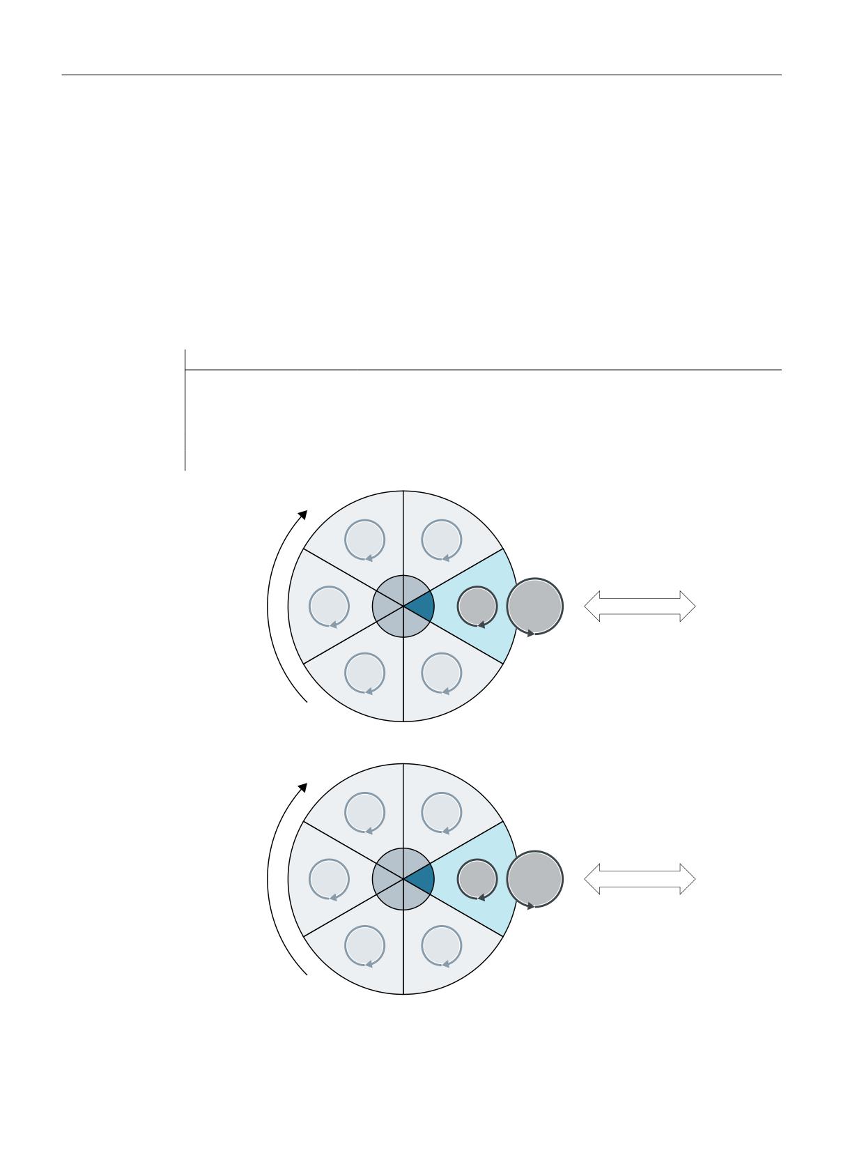
Speed/torque coupling, master-slave
6.8 Supplementary conditions
Axis container
If a coupled slave axis is configured as a container axis, alarm "4025 Switch axis container %3 not
permitted: Master-slave active channel %1 Axis %2" is displayed for an axis container rotation.
Axis containers with changing master can be used to make the relevant spindle the master
spindle following a rotation of the axis container. Both master and slave spindles can be
container spindles.
For a coupling to be closed after axis container rotation using a different spindle in each case, the
old coupling must be separated before the rotation, the configuration deleted and the new
coupling configured and closed after the rotation.
Example of a cyclic coupling sequence (position = 3 / container = CT1)
Program code
Comment
MASLDEF(AUX,SPI(3))
; S3 master for AUX
MASLON(AUX)
; Coupling in for AUX
M3=3 S3=4000
; Machining ...
MASLDEL(AUX)
; Delete configuration and release coupling
AXCTSWE(CT1)
; Axis container rotation
'LUHFWLRQ RI URWDWLRQ
&RQWDLQHU
$;
$;
6
6
$;
6
6
$;
$8;
6
6
0HFKDQLFDO LQIHHG
$;
$;
Figure 6-7
Coupling between container spindle S3 and auxiliary motor AUX (prior to rotation)
'LUHFWLRQ RI URWDWLRQ
&RQWDLQHU
$;
$;
6
6
$;
6
6
$;
$8;
6
6
0HFKDQLFDO LQIHHG
$;
$;
Figure 6-8
Coupling between container spindle S3 and auxiliary motor AUX (after to rotation)
Technologies
106
Function Manual, 10/2020, 6FC5397-8GP40-0BA1
Speed/torque coupling, master-slave
6.8 Supplementary conditions
Hardware and software limit switches
If the software or hardware limit switch is overtraveled by a slave axis, the master-slave grouping
is stopped via the master axis. The relevant slave axis is shown in the alarm. The limit switch of
the slave axis is overtraveled by the amount of the deceleration distance of the master axis.
The movement away of the slave axis from the limit switch must be performed via the traversing
of the master axis. Switching off the coupling (MASLOF) and traversing the slave axis is not
possible. The coupling cannot be switched off until the cause of the error has been removed.
NOTICE
Power off/on or warm restart (reset (po)) after the software or hardware limit switch has
been passed - and the coupling switched out with MASLOF
If the software or hardware limit switch is overtraveled by a slave axis and an attempt is made
to switch off the coupling with MASLOF while the slave axis is still behind the limit switch, the
message "Waiting for coupled slave axis" is displayed. The coupling can only be switched off by
means of a Power Off/On or warm restart (reset (po)).
Block search
Static coupling
The "Block search with calculation" function (SERUPRO) can be used without any restrictions in
conjunction with a static master-slave coupling.
Dynamic coupling
For a dynamic coupling, the following restrictions must be observed with regard to the program
commands MASLON and MASLOF:
• The coupled axes must be on the same NCU.
• The coupled axes must be in the same channel when the block search is executed.
• After the block search has been completed, the coupling state, the associated axis positions
and speeds must be subsequently influenced by the user via the system ASUB
"PROGEVENT.SPF". System variables are available for this purpose.
- $P_PROG_EVENT: This variable provides information about the event which activated the
subprogram. A value of 5 stands for block search.
- $P_SEARCH_MASLC[slave axis name]: This variable stands for alteration of the coupling
status during a block search.
- $P_SEARCH_MASLD[slave axis name]: This variable indicates the positional offset
calculated in the block search between the slave and master axes at the instant the
coupling was closed.
- $AA_MASL_STAT[slave axis name]: This variable indicates the current coupling state.
Technologies
Function Manual, 10/2020, 6FC5397-8GP40-0BA1
107
Speed/torque coupling, master-slave
6.8 Supplementary conditions
• The system ASUB "PROGEVENT.SPF" must be saved under the following path: /_N_CMA_DIR/
_N_PROG_EVENT_SPF
• The following machine data should be parameterized so that PROGEVENT.SPF is started.
NC-specific machine data:
- MD11450 $MN_SEARCH_RUN_MODE = 'H02'
- MD11602 $MN_ASUP_START_MASK = 'H01'
- MD11604 $MN_ASUP_START_PRIO_LEVEL = 100
Channel-specific machine data:
- MD20105 $MC_PROG_EVENT_IGN_REFP_LOCK = ’H3F’
Table 6-1
Example 1: PROGEVENT.SPF: Example 1
Program code
Comment
N10 IF $P_PROG_EVENT==5
; Block search active
N20
IF (($P_SEARCH_MASLC[Y]<>0) AND
; The coupling state has changed during
($AA_MASL_STAT[Y]<>0))
block search AND the current state is
"coupled"
N30
MASLOF(Y)
; Disconnect coupling
N40
SUPA Y=$AA_IM[X]-$P_SEARCH_MASLD[Y]
; Traverse through the position offset
using the slave axis
N50
MASLON(Y)
; Close coupling
N60
ENDIF
N70 ENDIF
N80 REPOSA
Table 6-2
Example 2: PROGEVENT.SPF
Program code
Comment
N10 IF $P_PROG_EVENT==5
; Block search active
N20
IF (($P_SEARCH_MASLC[SPI(2)]<>0) AND
; The state of the second spindle has
($AA_MASL_STAT[SPI(2)]==0))
changed during block search AND the cur-
rent state is "disconnected"
N30
M2=$P_SEARCH_SDIR[2]
; Update direction of rotation
N40
S2=$P_SEARCH_S[2]
, Update speed
N50
ENDIF
N60 ENDIF
N70 REPOSA
Technologies
108
Function Manual, 10/2020, 6FC5397-8GP40-0BA1
Speed/torque coupling, master-slave
6.9 Examples
For more application examples (see Chapter "Examples (Page 109)).
Note
For an activated coupling, it is recommended to only use block search type 5, "Block search via
program test" (SERUPRO) for a block search.
More information about event-driven program calls and "block search using the program test"
(SERUPRO) is included in:
Further information
Function Manual Basic Functions;
• Auxiliary function outputs to PLC
• Mode Group, Channel, Program Operation, Reset Response
Function Manual Axis and Spindles
• Spindles (S1)
6.9
Examples
6.9.1
Master-slave coupling between AX1=Master and AX2=Slave.
Configuration
Master-slave coupling between AX1=Master and AX2=Slave.
1. Machine axis number of master axis for speed setpoint coupling
MD37250 $MA_MS_ASSIGN_MASTER_SPEED_CMD[AX2] = 1
2. Master axis with torque distribution identical to master axis with speed setpoint coupling
MD37252 $MA_MS_ASSIGN_MASTER_TORQUE_CTR[AX2] = 0
3. Permanent coupling
MD37262 $MA_MS_COUPLING_ALWAYS_ACTIVE[AX2] = 1
4. Torque is injected in both the master and slave axes
MD37254 $MA_MS_TORQUE_CTRL_MODE[AX2] = 0
5. Torque distribution between the master and slave axes is 50% to 50%
MD37268 $MA_MS_TORQUE_WEIGHT_SLAVE[AX2] = 50
6. Parameters of the torque compensatory controller
MD37256 $MA_MS_TORQUE_CTRL_P_GAIN[AX2] = 0.5
MD37258 $MA_MS_TORQUE_CTRL_I_TIME[AX2] = 5.0
Technologies
Function Manual, 10/2020, 6FC5397-8GP40-0BA1
109

Speed/torque coupling, master-slave
6.9 Examples
6.9.2
Close coupling via the PLC
This application allows you to close or separate a master-slave coupling between the machine
axes AX1=Master axis and AX2=Slave axis during operation.
Preconditions
• One configured master axis
MD37250 $MA_MS_ASSIGN_MASTER_SPEED_CMD ≠ 0
• Activation of a master-slave coupling via
MD37262 $MA_MS_COUPLING_ALWAYS_ACTIVE=0
• The coupling is open.
Typical sequence of operations
Action
Effect/comment
• Approach coupling position
Each axis moves to the coupling position.
• Close coupling mechanically
Both axes are mechanically coupled to one another.
• Request to close the coupling
PLC interface signal "Master/slave on" DB32, ...
DBX24.7 is set.
• Read back coupling state
When the axis is at a standstill, the coupled slave
axis sets PLC interface signal "Master/slave active"
DB32, ... DBX96.7 and clears "Position controller
active" DB32, ... DBX61.5.
Wait for checkback signal.
• Moving the master-slave group
The master axis is moved.
6.9.3
Close/separate coupling via part program
This application allows you to close or separate a master-slave coupling between the machine
axes AX1=Master axis and AX2=Slave via the part program.
Preconditions
• A configured master axis MD37250 0 0.
• Not a static master-slave coupling:
MD37262 $MA_MS_COUPLING_ALWAYS_ACTIVE= 0
• The coupling is open.
Parts program
Program code
Comment
N10 G0 AX1=0 AX2=0
; Approach the coupling position on an axis-for-axis basis
Technologies
110
Function Manual, 10/2020, 6FC5397-8GP40-0BA1

Speed/torque coupling, master-slave
6.9 Examples
Program code
Comment
N20 MASLON (AX2)
; (mechanically connect the axes)
; Close the coupling.
N30 AX1=100
; Move the master-slave group using the master axis.
N40 MASLOF (AX2)
; Open the coupling.
; (Mechanically separate the axes)
N50 AX1=200 AX2=200
; Move the axes separately.
N60 M30
6.9.4
Release the mechanical brake
This application allows implementation of a brake control for machine axes AX1=Master axis and
AX2=Slave axis in a master-slave coupling.
Preconditions
• Master-slave coupling is configured.
• Axes are stationary.
• No servo enable signals.
Typical sequence of operations
Action
Effect/comment
• Request to close the coupling
The following PLC interface signal is set:
DB31, ... DBX24.7 (Master/Slave ON)
• Set controller enable
PLC interface signal "Servo enable" DB31, ...
DBX2.1 is set for both axes.
• Interpreting the feedback
Link PLC interface signals of the master axis using
AND:
DB31, ... DBX61.7 (current controller active)
DB31, ... DBX61.6 (speed controller active)
DB31, ... DBX61.5 (position controller active)
Link PLC interface signals of the saster axis using
AND:
DB31, ... DBX61.7 (current controller active)
DB31, ... DBX61.6 (speed controller active)
DB31, ... DBX96.7 (master/slave active)
• Release brakes
If the result of the AND operations on the master
and slave axes is ≠ 0, the brake may be released.
Technologies
Function Manual, 10/2020, 6FC5397-8GP40-0BA1
111

Speed/torque coupling, master-slave
6.10 Data lists
6.10
Data lists
6.10.1
Machine data
6.10.1.1
Axis/spindlespecific machine data
Number
Identifier: $MA_
Description
37250
MS_ASSIGN_MASTER_SPEED_CMD
Leading axis for speed setpoint coupling
37252
MS_ASSIGN_MASTER_TORQUE_CTR
Leading axis for torque distribution
37254
MS_TORQUE_CTRL_MODE
Connection of torque control output
37255
MS_TORQUE_CTRL_ACTIVATION
Activate torque compensatory control
37256
MS_TORQUE_CTRL_P_GAIN
Gain factor of torque compensatory controller
37258
MS_TORQUE_CTRL_I_TIME
Reset time for torque compensatory controller
37260
MS_MAX_CTRL_VELO
Limitation of torque compensatory control
37262
MS_COUPLING_ALWAYS_ACTIVE
Permanent master-slave coupling
37263
MS_SPIND_COUPLING_MODE
Coupling characteristics of a spindle
37264
MS_TENSION_TORQUE
Master-slave tension torque
37268
MS_TORQUE_WEIGHT_SLAVE
Torque weighting of the slave axis
37270
MS_VELO_TOL_COARSE
Master-slave velocity tolerance "coarse"
37272
MS_VELO_TOL_FINE
Master-slave velocity tolerance "fine"
37274
MS_MOTION_DIR_REVERSE
Invert master-slave direction of travel
6.10.2
System variables
After a block search, the coupling status and associated axis positions can be adjusted
subsequently by means of a system ASUB (asynchronous subroutine) "PROGEVENT.SPF". System
variables $P_SEARCH_MASL_C, $P_SEARCH_MASL_D and $AA_MASL_STAT are available for this
purpose; they can be used to alter the positional offset between the coupled axes and the
coupling status:
Identifier
Meaning
$P_SEARCH_MASLC[following axis name]
This variable registers a change in the coupling state during the
SERUPRO block search.
$P_SEARCH_MASLD[following axis name]
This variable indicates the positional offset between the slave and
master axes at the instant the coupling was closed.
$AA_MASL_STAT[following axis name]
This variable indicates the current coupling state.
Value ≠ 0: "Master-slave coupling active"
In this case, it contains the current machine number of the master
axis and, if the NCU link is active (several operating panel fronts and
NCUs), also the NCU No. at the hundreds position.
Example: 201 for Axis 1 on NCU2.
Technologies
112
Function Manual, 10/2020, 6FC5397-8GP40-0BA1
Transformation package handling
7
7.1
Brief description
The handling transformation package has been designed for use on manipulators and robots.
The package is a type of modular system, which enables the customer to configure the
transformation for his machine by setting machine data (provided that the relevant kinematics
are included in the handling transformation package).
Section structure
The "Handling transformation package" section deals with the following topics:
• The "Kinematic transformation (Page 114)" section describes the kinematic transformation
environment.
• The "Definition of terms (Page 114)" section explains some basic terms.
• The "Configuration of the kinematic transformation (Page 117)" section explains the
machine data required for the configuration.
• The "Kinematic descriptions (Page 130)" section uses configuring examples to illustrate the
most commonly used 2-axis to 5-axis kinematics that can be configured with the "Handling
transformation package".
• The "Tool orientation (Page 152)" to "Tool programming (Page 159)" sections handle the
programming. describing orientation programming, the entry of tool parameters and
transformation calls.
Abbreviations
FL
Flange coordinate system
HP
Wrist point coordinate system
IRO
Internal robot coordinate system
p3, q3, r3
Coordinates of the last basic axis
RO
Robot or base center point coordinate system (= basic coordinate system)
WS
Workpiece coordinate system
T
Tool coordinate system
x3, y3, z3
Coordinates of the first wrist axis
Technologies
Function Manual, 10/2020, 6FC5397-8GP40-0BA1
113
Transformation package handling
7.3 Definition of terms
7.2
Kinematic transformation
Task of a transformation
The purpose of a transformation is to transform movements in the tool tip, which are
programmed in a Cartesian coordinate system, into machine axis positions.
Fields of application
The handling transformation package described here has been designed to cover the largest
possible number of kinematic transformations implemented solely via parameter settings in
machine data. Currently, kinematics with two to maximum six axes to be included in the
transformation can be configured with this package, corresponding to up to five spatial degrees
of freedom. In this case, a maximum of 3 degrees are available for translation and 3 degrees for
orientation, This package thus allows a tool (milling cutter, laser beam) to be oriented by a 5-axis
machine in any desired relation to the workpiece in every point of the machining space. The
workpiece is always programmed in the rectangular workpiece coordinate system; any
programmed or set frames rotate and shift this system in relation to the basic system. The
kinematic transformation then converts this information into motion instructions for the real
machine axes. The kinematic transformation requires information about the design
(kinematics) of the machine, which are stored in machine data.
Kinematic categories
The handling transformation package is divided into two categories of kinematics, which can be
selected via machine data:
MD62600 $MC_TRAFO6_KINCLASS (kinematic category)
• STANDARD: This category includes the most commonly used kinematics.
• SPECIAL: Special kinematics
7.3
Definition of terms
7.3.1
Units and directions
Lengths and angles
In the transformation machine data, all lengths are specified in millimeters or inches and, unless
otherwise stated, all angles in degrees at intervals of [ -180°, 180° ].
Direction of rotation
In the case of angles, arrows in the drawings always indicate the mathematically positive
direction of rotation.
Technologies
114
Function Manual, 10/2020, 6FC5397-8GP40-0BA1