SINUMERIK 840D sl. Service - Functions. Manual (2018-2020) - page 76
Detailed description
4.5 Language elements for synchronized actions and technology cycles
Access rights
The access rights defined in a GUD definition file remain valid and refer only to the GUD variables
defined in this GUD definition file.
Deletion behavior
If the content of a particular GUD definition file is reactivated, the old GUD data block in the active
file system is deleted first. The configured synchronized-action GUD is also reset at this point. This
process is also possible using the HMI in the operator area "Services" > "Define and activated user
data (GUD)".
4.5
Language elements for synchronized actions and technology
cycles
The following language elements can be used in synchronized actions and technology cycles:
Fixed addresses
L
Subprogram number
F
Feed
S 1) 2)
Spindle
M 1) 2)
M function
H1)
H function
1) Chapter: "Output of M, S and H auxiliary functions to the PLC (Page 66)"
2) Chapter: "Traversing spindles (M, S, SPOS) (Page 91)"
Fixed addresses with axis extension: Miscellaneous
POS
Traversing axes to position (Page 78)
POSA
Modal positioning axis
SPOS
Spindle positioning (Page 91)
MOV 1)
Traversing axes, endless (Page 84)
FA
Axial feedrate (Page 85)
OVRA
Axial override
ACC
Axial acceleration
MEASA
Axial measurement with deletion of distance-to-go
MEAWA
Axial measurement without delete distance-to-go (Page 110)
MEAC
Cyclic measuring (Page 110)
SCPARA
Parameter set changeover
VELOLIMA
Axial velocity/speed limitation
ACCLIMA
Axial acceleration limitation
JERKLIMA
Axial jerk limitation
1) Not permitted in technology cycles
Synchronized actions
60
Function Manual, 10/2020, 6FC5397-5BP40-6BA4

Detailed description
4.5 Language elements for synchronized actions and technology cycles
Settable addresses: Travel to fixed stop 1)
FXS
Activate travel to fixed stop
FXST
Torque limit for travel to fixed stop
FXSW
Monitoring window for travel to fixed stop
FOC
Non-modal torque/force limitation
FOCON
Activate travel with limited torque/force
FOCOF
Deactivate travel with limited torque/force
1) Chapter: "Travel to fixed stop (FXS, FXST, FXSW, FOCON, FOCOF, FOC) (Page 113)"
Settable addresses: Couplings > Generic coupling 1)
CPBC
Block change criterion with active coupling
CPDEF
Create coupling module
CPDEL
Delete coupling module
CPFMOF
Behavior of the following axis when switching off the coupling
CPFMON
Behavior of the following axis when switching on the coupling
CPFMSON
Synchronization mode during coupling
CPFPOS
Synchronized position of the following axis when switching on
CPFRS
Reference system for the coupling module of the following axis
CPLA 2)
Assigning an axis as leading axis to a following axis
CPLCTID
Number of the curve table for the coupling of the following axis
CPLDEF
Definition of the reference: Leading axis to following axis
CPLDEL
Cancellation of the reference: Leading axis to following axis
CPLDEN
Coupling factor: Numerator
CPLNUM
Coupling factor: Denominator
CPLDYPRIO
Priority of the leading axis for the dynamic limitation
CPLDYVLL
Limitation of the overlaid motion of the leading axis: Lower limit
CPLDYVLU
Limitation of the overlaid motion of the leading axis: Upper limit
CPLINSC
Scaling factor for the input value of the leading axis
CPLINTR
Offset value for the input value of the leading axis
CPLOF
Coupling of leading axis to following axis: Switch off
CPLON
Coupling of leading axis to following axis: Switch on
CPLOUTSC
Scaling of the output value
CPLOUTTR
Offset of the output value
CPLPOS
Synchronized position of the leading axis when switching on
CPLSETVAL
Coupling type of the following axis to the leading axis
CPMALARM
Define alarm behavior
CPMBRAKE 2)
Defining the response to a stop signal and commands
CPMPRT
Define start behavior for program test
CPMRESET
Define reset behavior
CPMSTART
Define start behavior
CPMVDI
Define behavior regarding NC/PLC interface signals
CPOF
Deactivation of the coupling to all defined leading axes
Synchronized actions
Function Manual, 10/2020, 6FC5397-5BP40-6BA4
61

Detailed description
4.5 Language elements for synchronized actions and technology cycles
Settable addresses: Couplings > Generic coupling 1)
CPON
Activation of the coupling to all defined leading axes
CPRES 2)
Activates the coupling parameter parameterized in the machine data
CPSETTYPE
Define basic coupling properties
CPSYNCOP
Position synchronism "coarse"
CPSYNCOP2
Position synchronism 2 "coarse"
CPSYNFIP
Position synchronism "fine"
CPSYNFIP2
Position synchronism 2 "fine"
CPSYNCOV
Velocity synchronism "coarse"
CPSYNFIV
Velocity synchronism "fine"
1) Chapter: "Couplings (CP..., LEAD..., TRAIL..., CTAB...) (Page 106)"
2) Currently not available in synchronized actions
G functions: Set measuring system 1)
G70
Inch measuring system
G71
Metric measuring system
G700
Inch measuring system
G710
Metric measuring system
1) Chapter: "Setting the measuring system (G70, G71, G700, G710) (Page 82)"
Predefined subprograms: Miscellaneous
POLFA
Axial retraction position for single axis
POLFC
Axial retraction position for channel axes
STOPREOF
Revoke preprocessing stop (Page 76)
RDISABLE
Programmed read-in disable (Page 74)
DELDTG
Delete distance-to-go (Page 76)
LOCK
Lock synchronized action
UNLOCK
Unlock synchronized action
ICYCON
Technology cycle: One block per interpolator clock cycle
ICYCOF
Technology cycle: All blocks in one interpolator clock cycle
SYNFCT
Polynomial evaluation (Page 67)
FTOC
Tool fine compensation (Page 73)
SOFTENDSA
Software limit switch
PROTA
Change status of a protection zone
SETM
Set marker of the channel coordination (Page 115)
CLEARM
Delete marker of the channel coordination (Page 115)
RET
Subprogram return
GET
Request axis (Page 86)
RELEASE
Release axis (Page 86)
AXTOCHAN
Transfer axis to another channel (Page 86)
AXCTSWEC
Withdraw enable for the axis container rotation (Page 92)
SETAL
User-specific error responses (Page 116)
Synchronized actions
62
Function Manual, 10/2020, 6FC5397-5BP40-6BA4

Detailed description
4.5 Language elements for synchronized actions and technology cycles
Predefined subprograms: Miscellaneous
IPOBRKA
Block change criterion: Deceleration ramp
ADISPOSA
Tolerance window for end-of-motion criterion
Predefined subprograms: Coupling > Coupled motion 1)
TRAILON
Coupled motion on
TRAILOF
Coupled motion off
1) Section: "Couplings (CP..., LEAD..., TRAIL..., CTAB...) (Page 106)"
Predefined subprograms: Couplings > Master value coupling 1)
LEADON
Master value coupling on
LEADOF
Master value coupling off
1) Section: "Couplings (CP..., LEAD..., TRAIL..., CTAB...) (Page 106)"
Predefined subprograms: Couplings > Torque coupling (master/slave)
MASLON
Coupling on
MASLOF
Coupling off
MASLDEF
Define coupling
MASLDEL
Delete coupling
MASLOFS
Coupling with slave spindle off
Predefined functions: Coupling > Curve tables 1)
CTAB
Calculates the following axis position based on the leading axis position
using the curve table
CTABINV
Calculates the leading axis position based on the following axis position
using the curve table
CTABID
Determines the table number of the curve table
CTABLOCK
Disable curve table
CTABUNLOCK
Enable curve table
CTABISLOCK
Determines the lock status of the curve table
CTABEXISTS
Checks whether the curve table exists
CTABMEMTYP
Determines the storage location of the curve table (static/dynamic
memory)
CTABPERIOD
Determines the periodicity of the curve table
CTABNO
Determines the number of curve tables
CTABNOMEM
Determines the number of existing curve tables in a specific storage
location
CTABSEG
Determines the number of already used curve segments in a specific
storage location
CTABSEGID
Determines the number of already used curve segments in a specific
table
CTABFSEG
Determines the number of curve segments that are still possible in a
specific table
Synchronized actions
Function Manual, 10/2020, 6FC5397-5BP40-6BA4
63

Detailed description
4.5 Language elements for synchronized actions and technology cycles
Predefined functions: Coupling > Curve tables 1)
CTABMSEG
Determines the maximum possible number of curve segments in a spe-
cific storage location
CTABPOL
Determines the number of already used polynomials in a specific stor-
age location
CTABPOLID
Determines the number of already used polynomials in a specific table
CTABFPOL
Determines the number of polynomials that are still possible in a spe-
cific table
CTABMPOL
Determines the maximum possible number of polynomials in a specific
storage location
CTABTSV
Determines the following value at the start of the table
CTABTEV
Determines the following value at the end of the table
CTABTSP
Determines the leading value at the start of the table
CTABTEP
Determines the leading value at the end of the table
CTABTMIN
Determines the minimum following value of the table
CTABTMAX
Determines the minimum following value of the table
CTABFNO
Determines the number of curve tables that are still possible in a spe-
cific storage location
CTABSSV
Determines the starting value of a table segment for the following axes
CTABSEV
Determines the end value of a table segment for the following axes
1) Section: "Couplings (CP..., LEAD..., TRAIL..., CTAB...) (Page 106)"
Predefined functions: Arithmetic
SIN
Sine
ASIN
Arc sine
COS
Cosine
ACOS
Arc cosine
TAN
Tangent
ATAN2
Arc tangent 2
SQRT
Square root
POT
2nd power (square)
TRUNC
Integer component
ROUND
Round to next integer
ROUNDUP
Rounding up of an input value to the next integer
ABS
Absolute value
LN
Natural logarithm
EXP
Exponential function
MINVAL
Smaller of two values
MAXVAL
Larger of two values
BOUND
Check for defined value range
Synchronized actions
64
Function Manual, 10/2020, 6FC5397-5BP40-6BA4

Detailed description
4.6 Language elements for technology cycles only
Predefined functions: Current machine data values
GETMDACT
Determines the current value of the machine data
GETMDPEAK
Determines the maximum value that has occurred in the machine data
since the last RESETPEAK
GETMDLIM
Determines the maximum or minimum limit value of the machine data
RESETPEAK
Resets the maximum value again for GETMDPEAK
Predefined functions: Format conversions
ITOR
INT → REAL
RTOI
REAL → INT
RTOB
REAL → BOOL
BTOR
BOOL → REAL
ITOB
INT → BOOL
BTOI
BOOL → INT
Predefined functions: Safety Integrated
SIRELAY
Activation of the safety functions parameterized with SIRELIN, SIREL-
OUT and SIRELTIME
Predefined functions: Miscellaneous
POSRANGE
Position in specified reference range (Page 83)
PRESETON
Actual value setting with loss of the referencing status (Page 95)
PRESETONS
Actual value setting without loss of the referencing status (Page 100)
Predefined procedures: Miscellaneous
CANCELSUB
Cancels the current subprogram level (Page 116)
Further information
A detailed description of all NC language elements is provided in the Programming Manual NC
Programming.
4.6
Language elements for technology cycles only
The following language elements may only be used in technology cycles:
Jump statements
IF
Branch
GOTO
Jump to label, search direction forward, then backward
Synchronized actions
Function Manual, 10/2020, 6FC5397-5BP40-6BA4
65

Detailed description
4.7 Actions in synchronized actions
Jump statements
GOTOF
Jump to label, search direction forward
GOTOB
Jump to label, search direction backward
End of program
M02
End of program
M17
End of program
M30
End of program
RET
End of program
4.7
Actions in synchronized actions
4.7.1
Output of M, S and H auxiliary functions to the PLC
Output timing
Auxiliary functions of the M, S and H type can be output from synchronized actions. The output
to the PLC is immediate, i.e. directly in the interpolator clock cycle in which the action is executed.
Any output times set via the machine data for auxiliary functions have no effect when output
from synchronized actions:
• MD11110 $MN_AUXFU_GROUP_SPEC (auxiliary function group specification)
• MD22200 $MC_AUXFU_M_SYNC_TYPE (output time of M functions)
• MD22210 $MC_AUXFU_S_SYNC_TYPE (output time of the S functions)
• MD22230 $MC_AUXFU_H_SYNC_TYPE (output time of the H functions)
Maximum number
General
A maximum of 10 auxiliary functions can be output simultaneously from the part program and
the active synchronized actions of a channel, i.e. in one OB40 cycle of the PLC.
Synchronized-action-specific
The maximum permissible number of auxiliary functions in the action part of a synchronized
action is:
• M functions: 5
• S functions: 3
• H functions: 3
Synchronized actions
66
Function Manual, 10/2020, 6FC5397-5BP40-6BA4
Detailed description
4.7 Actions in synchronized actions
Non-modal synchronized actions
In non-modal synchronized actions (without specification of ID or IDS), auxiliary functions can
only be output in conjunction with the scanning frequency WHEN or EVERY.
Predefined M functions
Predefined M functions generally must not be output in synchronized actions.
Exceptions: M3, M4, M5, M40, M41, M42, M43, M44, M45, M70 and M17
See also
Frequency (WHENEVER, FROM, WHEN, EVERY) (Page 17)
4.7.2
Reading and writing of system variables
The system variables of the NC are listed in the "System Variables" Parameter Manual with their
respective properties. System variables that can be read or written in the action part of
synchronous actions are marked with an "X" in the corresponding line (Read or Write) of the "SA"
(synchronous action) column.
Note
System variables used in synchronous actions are implicitly read and written synchronous to the
main run.
Further information
List Manual System Variables
4.7.3
Polynomial evaluation (SYNFCT)
Application
A variable that is evaluated via a polynomial can be read with the SYNFCT function in the main
run and the result can be written to another variable. Application examples:
• Feedrate as a function of drive load
• Position as a function of a sensor signal
• Laser power as a function of path velocity
Syntax
SYNFCT(<Poly_No>,<SysVar_Out>,<SysVar_In>)
Synchronized actions
Function Manual, 10/2020, 6FC5397-5BP40-6BA4
67
Detailed description
4.7 Actions in synchronized actions
Meaning
Parameter
Meaning
<Poly_No>:
Number of the polynomial defined with FCTDEF:
f(x) = a0 + a1*x + a2*x2 + a3*x3
<SysVar_Out>:
System variable, output:
<SysVar_Out> = f(x)
<SysVar_In>:
System variable, input:
x = <SysVar_In>
For information on FCTDEF, see Chapter "Polynomial coefficients, parameters ($AC_FCT ...) (Page 43)"
Example: Additive override of the path feedrate
An override value is added to the programmed feedrate (F word):
Factive = Fprogrammed + FAC
<SysVar_Out>
Meaning
$AC_VC
additive path feedrate override
$AA_VC[axis]
additive axial feedrate override
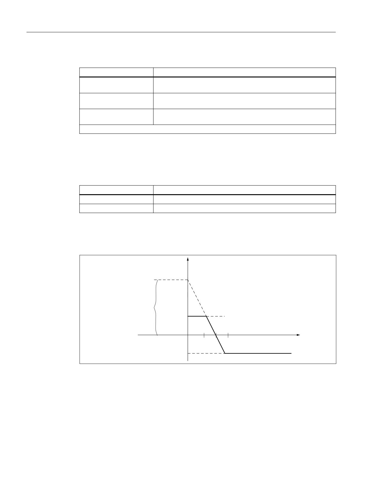
Input value is the actual current value $AA_CURR of the X axis.
The operating point is set to 5 A.
The feedrate may be altered by ±100 mm/min and the axial current deviation may be ±1 A.
)HHGUDWH >PP PLQ@
D
8SSHU OLPLW
$FWXDO FXUUHQW YDOXH >$@
$$B&855>;@
/RZHU OLPLW
Figure 4-3
Example: Additive control of path feed
Determining the parameters of the FCTDEF function:
FCTDEF(<Poly_No>,<Lo_Limit>,<Up_Limit>,a0,a1,a2,a3)
<Poly_No>:
= 1 (example)
<Lo_Limit>:
= -100
<Up_Limit>:
= 100
Polynomial: f(x) = a0 + a1x +a2x2 + a3x3
a0:
1 / 100 = 5 / a0 ⇒ a0 = 500
Synchronized actions
68
Function Manual, 10/2020, 6FC5397-5BP40-6BA4
Detailed description
4.7 Actions in synchronized actions
a1
= 100 mm/min / -1 A = -100 [mm/min / A]
a2
= 0 (not a square component)
a3
= 0 (not a cubic component)
Calculation of the override value:
SYNFCT(<Poly_No>,<SysVar_Out>,<SysVar_In>)
<Poly_No>:
= 1
<SysVar_Out>:
$AC_VC (additive path feedrate override)
<SysVar_In>:
$AA_CURR (drive actual current value)
Programming:
Program code
N100 FCTDEF(1, -100, 100, 500, -100)
N110 ID=1 DO SYNFCT(1, $AC_VC[X], $AA_CURR[X])
Example: Multiplicative override of the path feedrate
The programmed feedrate is multiplied by a percentage factor (additional override):
Factive = Fprogrammed * FactorAC
<SysVar_Out>
Meaning
$AC_OVR
Path override can be specified via synchronous action
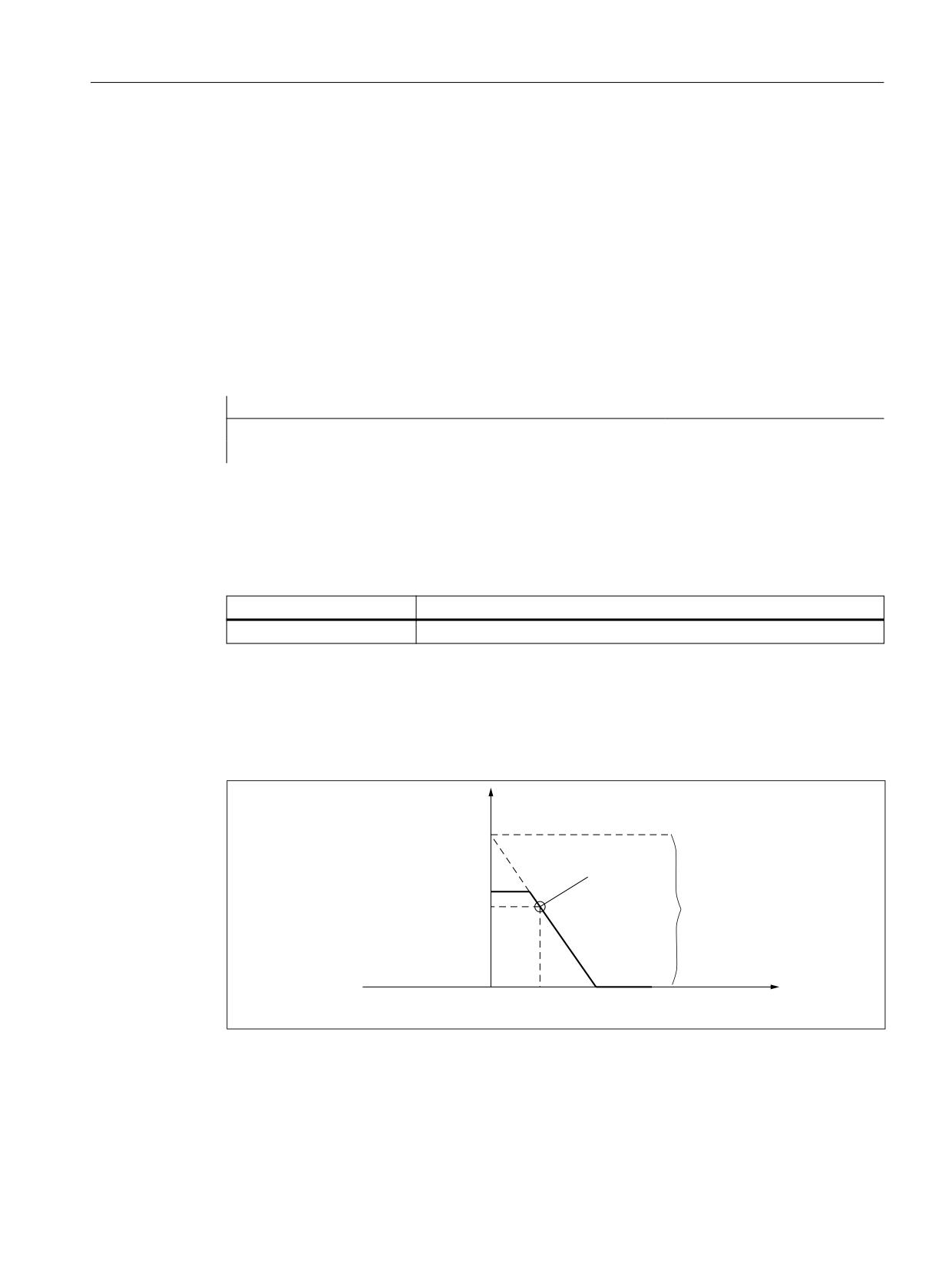
Input value is the percentage drive load $AA_LOAD of the X axis.
The operating point is set to 100% at 30% drive load.
The axis must stop at 80% load.
An excessive velocity corresponding to the programmed value +20% is permissible.
2YHUULGH >
@
2SHUDWLQJ SRLQW
8SSHU OLPLW
D
'ULYH ORDG >
@
$$B/2$'
Figure 4-4
Example: Multiplicative control
Determining the parameters of the FCTDEF function:
FCTDEF(<Poly_No>,<Lo_Limit>,<Up_Limit>,a0,a1,a2,a3)
<Poly_No>:
= 2 (example)
Synchronized actions
Function Manual, 10/2020, 6FC5397-5BP40-6BA4
69
Detailed description
4.7 Actions in synchronized actions
<Lo_Limit>:
= 0
<Up_Limit>:
= 120
Polynomial: f(x) = a0 + a1x +a2x2 + a3x3
a0:
50 / 100 = 80 / a0 ⇒ a0 = 160
a1
= 100% / -50% = -2
a2
= 0 (not a square component)
a3
= 0 (not a cubic component)
Calculation of the override value:
SYNFCT(<Poly_No>,<SysVar_Out>,<SysVar_In>)
<Poly_No>:
= 2
<SysVar_Out>:
$AC_OVR (path override can be specified via synchronous action)
<SysVar_In>:
$AA_LOAD (drive load)
Programming:
Program code
N100 FCTDEF(2, 0, 120, 160, -2)
N110 ID=1 DO SYNFCT(2, $AC_OVR[X], $AA_LOAD[X])
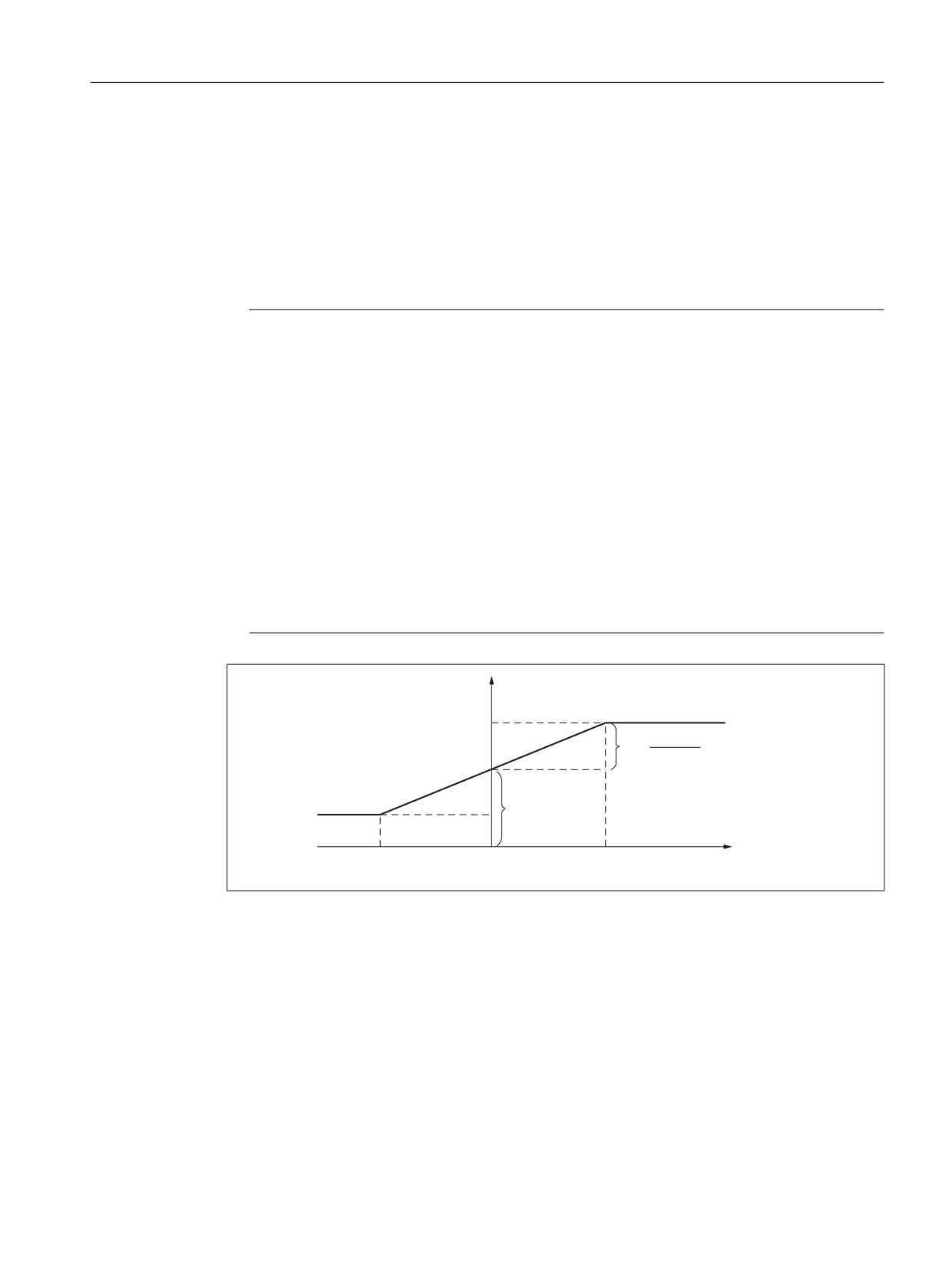
Example: Clearance control
=
&OHDUDQFH VHQVRU
>PP@
6XUIDFH
;
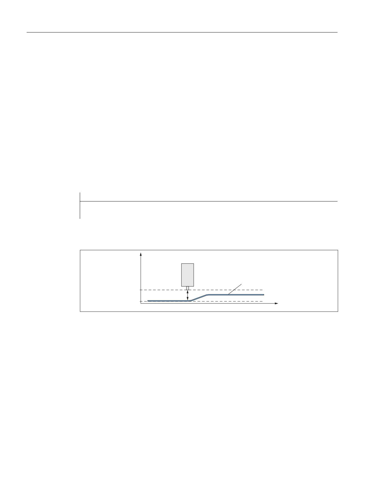
Figure 4-5
Clearance control: Principle
The clearance control of the infeed axis Z is performed via the FCTDEF and SYNFCT functions
as well as by the system variables $AA_OFF and $A_INA.
Synchronized actions
70
Function Manual, 10/2020, 6FC5397-5BP40-6BA4
Detailed description
4.7 Actions in synchronized actions
Boundary conditions:
• The analog voltage of the clearance sensor is connected via the analog input $A_INA[3].
• The position deviations are summated in $AA_OFF (integrated):
MD36750 $MA_AA_OFF_MODE, bit 0 = 1
• If the upper limit of the Z axis is exceeded by 1 mm, the X axis is stopped:
SD43350 $SA_AA_OFF_LIMIT[Z] = 1
See also Chapter "Overlaid movements ($AA_OFF) (Page 45)".
Note
$AA_OFF is effective in the basic coordinate system (BCS)
The offset is effective before the kinematic transformation in the basic coordinate system
(BCS). The example therefore cannot be used for a clearance control in the orientation
direction of the tool (workpiece coordinate system WCS).
For clearance control system with high dynamic response or 3D clearance control, see:
Further information
Function Manual Technologies
User-specific responses
When the limit value SD43350 $SA_AA_OFF_LIMIT is reached, customized responses can be
triggered, for example:
• Chapter "Override ($A...OVR) (Page 36)"
• Chapter "User-specific error reactions (SETAL) (Page 116)"
6XSHULPSRVLWLRQ
>PP@
PP
D
9
D
9
9
6HQVRU YROWDJH >9@
$$B,1$
Figure 4-6
Clearance control
Determining the parameters of the FCTDEF function:
FCTDEF(<Poly_No>,<Lo_Limit>,<Up_Limit>,a0,a1,a2,a3)
<Poly_No>:
= 1 (example)
<Lo_Limit>:
= 0.2
<Up_Limit>:
= 0.5
Polynomial: f(x) = a0 + a1x +a2x2 + a3x3
a0:
10 / x = 20 / 0.3 ⇒ a0 = x + 0.2 = 0.15 + 0.2 = 0.35
a1
= 0.15 mm / 10 V = 1.5 * 10-2 mm/V
Synchronized actions
Function Manual, 10/2020, 6FC5397-5BP40-6BA4
71
Detailed description
4.7 Actions in synchronized actions
a2
= 0 (not a square component)
a3
= 0 (not a cubic component)
Calculation of the override value:
SYNFCT(<Poly_No>,<SysVar_Out>,<SysVar_In>)
<Poly_No>:
= 1
<SysVar_Out>:
$AA_OFF (overlaid movement of an axis)
<SysVar_In>:
$A_INA (analog input)
Programming:
Program code: %_N_AON_SPF
Comment
PROC AON
; Clearance control "ON"
FCTDEF(1, 0.2, 0.5, 0.35, 1.5 EX-2)
; Polynomial definition
ID=1 DO SYNFCT(1,$AA_OFF[Z],$A_INA[3])
; Clearance control
ID=2 WHENEVER $AA_OFF_LIMIT[Z]<>0 DO $AA_OVR[X] = 0
; Limit value test
RET
ENDPROC
Program code: %_N_AOFF_SPF
Comment
PROC AOFF
; Clearance control "OFF"
CANCEL(1)
; Delete clearance control
CANCEL(2)
; Delete limit value check
RET
ENDPROC
Program code: %_N_MAIN_MPF
Comment
N100 $SA_AA_OFF_LIMIT[Z]=1
N110 AON
; Clearance control "ON"
N200 G1 X100 F1000
N210 AOFF
; Clearance control "OFF"
M30
See also
Online tool offset (FTOC) (Page 73)
Synchronized actions
72
Function Manual, 10/2020, 6FC5397-5BP40-6BA4
Detailed description
4.7 Actions in synchronized actions
4.7.4
Online tool offset (FTOC)
The FTOC function enables the overlaid movement of a geometry axis for the online tool offset,
depending on a reference value, e.g. the actual value of an arbitrary axis. The offset value is
calculated on the basis of a polynomial defined with FCTDEF (see Section "Polynomial
coefficients, parameters ($AC_FCT ...) (Page 43)"). The coefficient a0 specified in the polynomial
definition is also evaluated by FTOC.
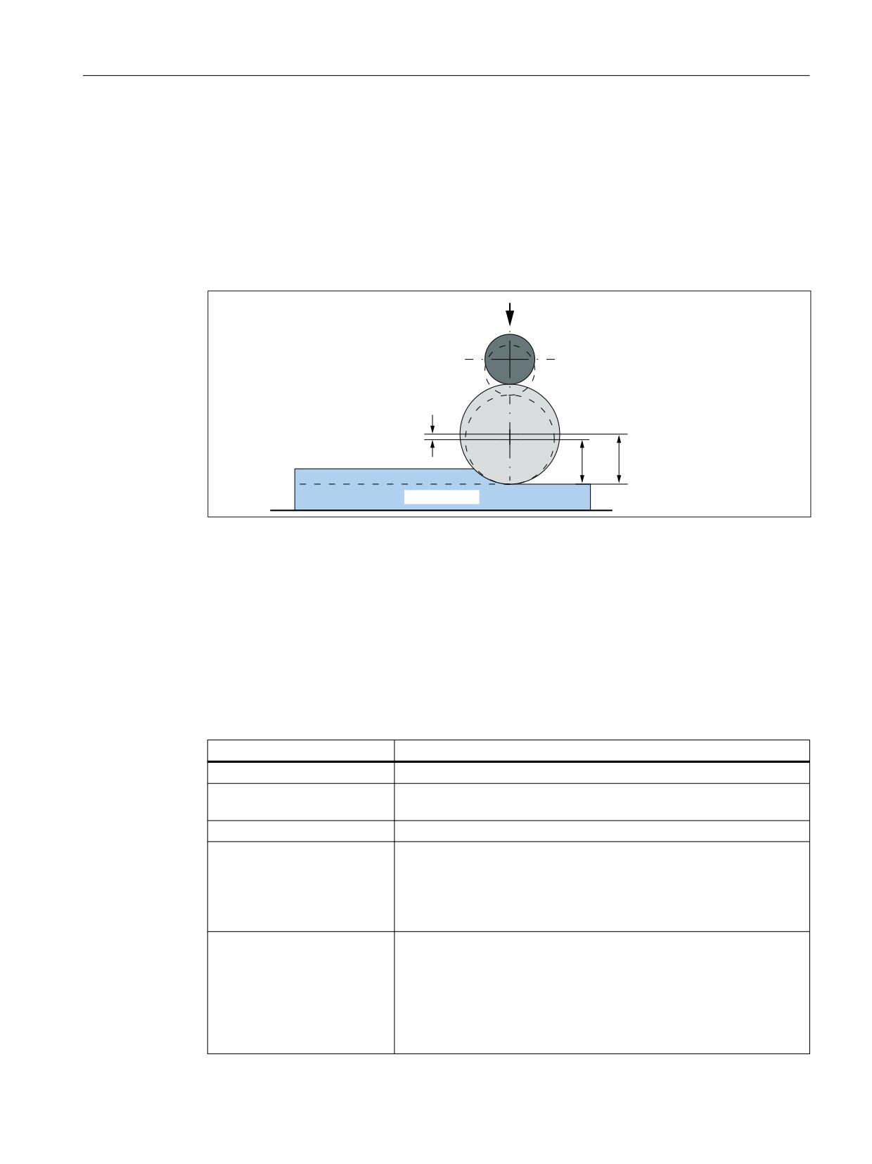
Example: Machining and dressing in the "Grinding" technology
'UHVVLQJ UROO
/HQJWK WR EH FRUUHFWHG
*ULQGLQJ ZKHHO
$ %HIRUH GUHVVLQJ
% $IWHU GUHVVLQJ
'UHVVLQJ DPRXQW
%
$
:RUNSLHFH
Figure 4-7
Dressing during machining using a dressing roll
Further information
Function Manual for tools
Syntax
FTOC(<Poly_No>,<systemvar>,<wear>[,<channel_No>,<spindle_No>])
Meaning
Parameter
Meaning
<Poly_No>:
Number of the polynomial defined with FCTDEF
<Systemvar>:
Arbitrary system variable of the REAL type that can be used in synchro-
nous actions.
<wear>:
Wear parameter (length 1, 2 or 3) in which the offset value is added.
<Channel_No>:
Target channel in which the offset must be applied. This enables simul-
taneous dressing from a parallel channel. In the target channel of the
offset, the online offset must be switched on with FTOCON.
If no channel number is programmed, the offset acts in the active chan-
nel.
<Spindle_No>:
The spindle number is programmed if a non-active grinding wheel
needs to be dressed.
Precondition: One of the following functions is active
• "Constant grinding wheel peripheral speed"
• "Tool monitoring"
If no spindle number is programmed, the active tool is compensated.
Synchronized actions
Function Manual, 10/2020, 6FC5397-5BP40-6BA4
73
Detailed description
4.7 Actions in synchronized actions
Example
Compensate length of an active grinding wheel
Program code
Comment
FCTDEF(1, -1000, 1000, -$AA_IW[V], 1)
; FTOC:
; Polynomial no.: 1
; System variable: $AA_IW[V] (axial actual value of the V axis)
; Wear parameter: Length 3
; Target channel: Channel 1
ID=1 DO FTOC(1, $AA_IW[V], 3, 1)
WAITM (1,1,2)
; Synchronization with the machining
channel
G1 V-0.05 F0.01 G91
; Traversing motion of the V axis
CANCEL(1)
; Deselect online offset
Note
Because no frequency and no condition has been specified in the synchronous action, the action
part is executed in every interpolator clock cycle.
4.7.5
Programmed read-in disable (RDISABLE)
Function
The RDISABLE command in the active section causes block processing to be stopped when the
relevant condition is fulfilled. Processing of programmed motion-synchronous actions still
continues. The read-in disable is canceled again as soon as the condition for the RDISABLE is no
longer fulfilled.
An exact stop is initiated at the end of the block containing RDISABLE irrespective of whether
or not the read-in disable is still active. The exact stop is also triggered if the control is in the
continuous-path mode (G64, G641 ... G645).
RDISABLE can be programmed with reference to the block or also modal (ID=, IDS=)!
Application
Using RDISABLE, for example, the program can be started in the interpolator clock cycle as a
function of external inputs.
Synchronized actions
74
Function Manual, 10/2020, 6FC5397-5BP40-6BA4

Detailed description
4.7 Actions in synchronized actions
Example
Program code
Comment
WHENEVER $A_INA[2]<7000
; Program processing is stopped if the voltage at input
DO RDISABLE
2 drops to below 7 V (assuming that the value 1000 cor-
responds to 1 V).
N10 G01 X10
; RDISABLE acts at the end of N10, if the condition is
fulfilled during its processing.
N20 Y20
Supplementary conditions
Read-in disable RDISABLE in conjunction with axis exchange
Acts via the synchronized actions RDISABLE read-in disable and axis exchange (e.g. path axis
→ positioning axes) together in one block, RDISABLE does not act on the action block, but the
re-approach block REPOSA implicitly generated as a result of the axis exchange:
Program code
Comment
N100 G0 G60 X300 Y300
N105 WHEN TRUE DO POS[X]=20 FA[X]=20000
; Synchronized action → REORG → REPOSA
N110 WHENEVER $AA_IM[X]<>20 DO RDISABLE
; RDISABLE acts on REPOSA
N115 G0 Y20
; 1. X-axis, 2nd Y axis
N120 Y-20
N125 M30
Path axis X becomes a positioning axis as a result of the synchronized action in the block N105.
REORG is therefore executed in the channel with REPOSA. Therefore, RDISABLE in N110 does
not act on block N115 - but instead on the internal REPOSA block. As a consequence, to start,
positioning axis X is traversed to its programmed position and then in block N115, the Y axis to
its programmed position.
An explicit release of path axis X before traversing as positioning axis (synchronized action in
N105) with RELEASE(X) avoids the REORG operation, and the X and Y axes traverse together
in block N115.
Program code
Comment
N100 G0 G60 X300 Y300
N101 RELEASE(X)
; Explicit release
N105 WHEN TRUE DO POS[X]=20 FA[X]=20000
Synchronized actions
Function Manual, 10/2020, 6FC5397-5BP40-6BA4
75
Detailed description
4.7 Actions in synchronized actions
4.7.6
Cancel preprocessing stop (STOPREOF)
With the STOPREOF command, an existing preprocessing stop can be cancelled from a
synchronized action.
Note
The STOPREOF command can only be programmed in non-modal synchronized actions
(without specification of ID or IDS) and only in conjunction with the scanning frequency WHEN.
Example
• N10: Non-modal synchronized action.
If the path distance-to-go $AC_DTEB is less than 5 mm, the existing preprocessing stop due
to the reading of the analog input $A_INA is cancelled.
• N20: Traversing block whose path distance-to-go is evaluated via $AC_DTEB.
• N30: Branch that triggers the preprocessing stop due to the reading of $A_INA.
Due to the synchronized action, input $A_INA is not evaluated at the end of the N20 block, but
already 5 mm before the end of the block. If the voltage is then greater than 5 V at input $A_INA,
there is a branch to "MARKE_1".
Program code
N10 WHEN $AC_DTEB < 5 DO STOPREOF
N20 G01 X100
N30 IF $A_INA[7] > 5000 GOTOF MARKE_1
4.7.7
Delete distance-to-go (DELDTG)
The path distance-to-go can be deleted with the DELDTG command and axial distances-to-go
can be deleted with the DELDTG (...) function in synchronized actions.
After deletion of the distance-to-go, the value of the deleted distance-to-go can be read via a
system variable:
• Path distance-to-go: $AC_DELT
• Axial distance-to-go: $AA_DELT
Syntax
DELDTG
DELDTG(<axis 1>[,<axis 2>, ... ])
Synchronized actions
76
Function Manual, 10/2020, 6FC5397-5BP40-6BA4

Detailed description
4.7 Actions in synchronized actions
Meaning
Parameter
Meaning
DELDTG
Deletion of the path distance-to-go
DELDTG(...)
Deletion of the axial distances-to-go of the specified channel axes
<Axis n>:
Channel axis
Supplementary conditions
Path-specific and axial delete distance-to-go
Path-specific and axial delete distance-to-go can only be executed in a non-modal synchronized
action (without specification of ID or IDS).
Path-specific delete distance-to-go
• The deletion of the path distance-to-go can only be executed in a non-modal synchronized
action (without specification of ID or IDS).
• The deletion of the path distance-to-go must not be used with active tool radius
compensation.
Axial delete distance-to-go
Delete distance-to-go for indexing axes:
• Without Hirth tooth system: The axis is braked immediately
• With Hirth tooth system: The axis traverses to the next indexing position
Examples
Delete path distance-to-go
If the input $A_IN is set during the traversing block N20, the path distance-to-go is deleted.
Program code
N10 WHEN $A_IN[1]==1 DO DELDTG
N20 G01 X100 Y100 F1000
Delete axial distances-to-go
N10: If input 1 is set at any time within the part program, the V axis is started as a positioning
axis in the positive traversing direction.
N100: Non-modal synchronized action to delete distance-to-go of the V axis, depending on
digital input 2.
N110: Non-modal synchronized action to delete distance-to-go of the X1 axis, depending on
digital input 3.
N120: The X1 axis is positioned modally. The Y and Z axes are traversed as path axes. The non-
modal synchronized actions from N100 and N110 are executed together with N120. The non-
modal synchronized actions are also terminated with the end of block N120.
Synchronized actions
Function Manual, 10/2020, 6FC5397-5BP40-6BA4
77
Detailed description
4.7 Actions in synchronized actions
For this reason, the distances-to-go of the X1 and V axes can only be deleted as long as N120 is
active.
Program code
N10 ID=1 WHEN $A_IN[1]==1 DO MOV[V]=1 FA[V]=700
N100 WHEN $A_IN[2]==1 DO DELDTG(V)
N110 WHEN $A_IN[3]==1 DO DELDTG(X1)
N120 POSA[X1]=100 FA[X1]=10 G1 Y100 Z100 F1000
4.7.8
Traversing axes, to position (POS)
With the POS command, an axis can be traversed using a synchronized action. The axis is then
called the command axis. It is possible to traverse the axis alternating via the part program and
the synchronized action. If a command axis traversed via synchronized actions is subsequently
traversed via the part program, a preprocessing stop with reorganization (STOPRE) is executed
in the channel of the part program.
Example 1: Alternate traversing via part program and synchronized action
Program code
Comment
N10 G01 X100 Y200 F1000
; Traversing via part program
; Traversing via static synchronized action when input 1 is set
N20 ID=1 WHEN $A_IN[1]==1 DO POS[X]=150 FA[X]=200
CANCEL(1)
; Deselect synchronized action
; Traversing again via part program => implicit preprocessing stop
; with reorganization, if the X axis in the meantime has been
; traversed via synchronized action
N100 G01 X240 Y200 F1000
Example 2: Alternate traversing of the X-axis via two synchronized actions
If the traversing motion of one synchronized action is still active when the traversing motion of
the other synchronized action is started, the second traversing motion replaces the first.
Program code
; 1st Traversing motion
ID=1 EVERY $A_IN[1]>=1 DO POS[V]=100 FA[V]=560
; 2nd Traversing motion
ID=2 EVERY $A_IN[2]>=1 DO POS[V]=$AA_IM[V] FA[V]=790
Synchronized actions
78
Function Manual, 10/2020, 6FC5397-5BP40-6BA4

Detailed description
4.7 Actions in synchronized actions
Dimensions: Absolute/incremental
The commands G90/G91 to specify the dimensions (absolute/incremental) cannot be
programmed in synchronized actions. Therefore by default, the dimensions that were active in
the part program at the time of execution of the synchronized action are also effective in the
synchronized action.
The following commands can be programmed in the action part to specify the dimensions
within a synchronized action:
Command
Meaning
IC(…)
Incremental
AC(…)
Absolute
DC(...)
Direct (position rotary axis via shortest route)
ACN(...)
Position modulo rotary axis absolutely in negative direction of motion
ACP(...)
Position modulo rotary axis absolutely in positive direction of motion
CAC(...)
Traverse axis to coded position absolutely
CIC(...)
Traverse axis to coded position incrementally
CDC(...)
Traverse rotary axis to coded position via shortest route
CACN(...)
Traverse modulo rotary axis to coded position in negative direction
CACP(...)
Traverse modulo rotary axis to coded position in positive direction
Examples:
Program code
; Incremental traversing by 10 mm
ID=1 EVERY G710 $AA_IM[B]>75 DO POS[X]=IC(10)
; Absolute traversing
ID=1 EVERY G710 $AA_IM[B]>75 DO POS[X]=AC($AA_MW[V]-$AA_IM[W]+13.5)
Behavior with active axis-specific frames
Whether programmable and settable axis-specific frames and tool length compensations are
included in synchronized actions, depends on the following MD setting:
MD32074 $MA_FRAME_OR_CORRPOS_NOTALLOWED
Bit
Value
Meaning
9
0 (default)
The active axis-specific frame and/or tool length compensation which is active in
the part program at the time of execution takes effect in the synchronized action
which is executed parallel to the part program.
1
Axis-specific frames and tool length compensation are not considered for com-
mand axes.
Example 1: Traversing with active frames / tool length compensations (bit 9 == 0):
Program code
Comment
N100 TRANS X20
; Zero offset in X: 20 mm.
; Synchronized action: The X axis traverses to position 60 mm
Synchronized actions
Function Manual, 10/2020, 6FC5397-5BP40-6BA4
79

Detailed description
4.7 Actions in synchronized actions
Program code
Comment
IDS=1 EVERY G710 $A_IN==1 DO POS[X]=40
; Zero offset in X: -10 mm. =>
; Synchronized action: The X axis now traverses to position 30 mm
N130 TRANS X-10
Example 2: Traversing with deactivated frames / tool length compensations (bit 9 == 1):
Program code
Comment
N100 TRANS X=0.001
; Zero offset in X: 0.001 degrees
N120 POS[X]=270
; X traverses to position 270.001 degrees
; With $A_IN=1, X traverses to position 180.000 degrees.
IDS=1 EVERY G710 $A_IN==1 DO POS[X]=180
; X traverses to position 90.001 degrees
N130 POS[X]=90
; Coded position 1 = 100 degrees => X traverses to 100.001 degrees
N140 POS[X]=CAC(1)
; Coded position 2 = 200 degrees => X traverses to 200.000 degrees
N150 POS[X]=CIC(1)
Note
If a command axis travels to indexing positions incrementally, the axis-specific frames have no
effect on this command axis.
Non-modal suppression of the active frame with G153
If MD32074 is set so that active axis-specific frames and tool offsets always have to be taken into
account for command axes (bit 9 == 0), the active frame can be suppressed in a non-modal
synchronized action, if necessary, with G153. For this purpose, the block must be turned into an
executable block with the G153 command via program code G4 F0.1. In this case, it must be
ensured that the dwell time is at least 0.1. This is the only way to ensure that the processing time
in the interpolator is sufficient.
Examples:
WHEN TRUE DO POS[Z]=401 FA[Z]=$MA_MAX_AX_VELO[Z]
G153 G4 F0.1
Synchronized actions
80
Function Manual, 10/2020, 6FC5397-5BP40-6BA4

Detailed description
4.7 Actions in synchronized actions
WHILE $AA_IM[Z]<400
ENDWHILE
WHEN TRUE DO POS[Z]=400
G153 G4 F0.1
Takeover of the control of a command axis by the PLC
The control of a command axis that has been started via a static synchronized action (IDS) is
taken over by the PLC irrespective of the status of the part program containing the synchronized
action:
DB31, ... DBX28.7 == 1 (request for PLC to control axis)
Additional information
Function Manual Axes and Spindles
Parameterizable axis status
The behavior with regard to the axis status after the end of the part program and NC Reset can
be parameterized via the following machine data:
MD30450 $MA_IS_CONCURRENT_POS_AX[<axis>] = <value>
<value>
Axis status before PP end / NC RESET 1)
Axis status after PP end / NC RESET 1)
0
Channel axis
Channel axis
0
Command axis
Channel axis
1
Channel axis
Command axis
1
Command axis
Command axis
1)
PP end: Part program end
See also
Technology cycles (Page 117)
Synchronized actions
Function Manual, 10/2020, 6FC5397-5BP40-6BA4
81
Detailed description
4.7 Actions in synchronized actions
4.7.9
Setting the measuring system (G70, G71, G700, G710)
If a specific measuring system (inch/metric) is not explicitly defined in a synchronized action
with G70, G71, G700, G710, the measuring system active in the part program at the time the
synchronized action is executed takes effect:
• G70/G71 active in the part program:
- All the programmed position values are interpreted in the programmed measuring
system.
- All the read position data is interpreted in the parameterized basic system.
• G700/G710 active in the part program:
- All the programmed position values are interpreted in the programmed measuring
system.
- All the read position data is interpreted in the parameterized basic system.
The following rules apply when defining the measuring system in the synchronized action:
• If a measuring system is programmed in the condition part, this also takes effect in the action
part if a measuring system has not been specifically programmed there.
• If there is only a measuring system programmed in the action part, the system which is
currently activated in the part program takes effect in the condition part.
• Different systems of units can be programmed in the condition and action parts.
• The measuring system programmed in the synchronized action has no effect on the part
program.
Example
Program code
Comment
N10 ID=1 EVERY $AA_IM[Z]>200 DO POS[Z2]=10
;
$AA_IM:
#
;
200:
#
;
10:
#
N20 ID=2 EVERY $AA_IM[Z]>200 DO G70 POS[Z2]=10
;
$AA_IM:
#
;
200:
#
;
10:
inch
N30 ID=3 EVERY G71 $AA_IM[Z]>200 DO POS[Z2]=10
;
$AA_IM:
#
;
200:
mm
;
10:
mm
N40 ID=4 EVERY G71 $AA_IM[Z]>200 DO G70 POS[Z2]=10
;
$AA_IM:
#
;
200:
mm
;
10:
inch
N50 ID=5 EVERY $AA_IM[Z]>200 DO G700 POS[Z2]=10
;
$AA_IM:
#
;
200:
#
;
10:
inch
N60 ID=6 EVERY G710 $AA_IM[Z]>200 DO POS[Z2]=10
;
$AA_IM:
mm
;
200:
mm
;
10:
mm
N70 ID=7 EVERY G710 $AA_IM[Z]>200 DO G700 POS[Z2]=10
;
$AA_IM:
mm
;
200:
mm
;
10:
inch
Synchronized actions
82
Function Manual, 10/2020, 6FC5397-5BP40-6BA4

Detailed description
4.7 Actions in synchronized actions
Program code
Comment
#: The unit depends on the parameterized basic system (MD10240 $MN_SCALING_SYS-
TEM_IS_METRIC) and the measuring system programmed in the part program
Note
Measuring system and technology cycles
If a technology cycle is being used, the measuring system can also be programmed in the
technology cycle instead of the measuring system having to be assigned in the action part of the
synchronized action.
4.7.10
Position in specified reference range (POSRANGE)
Function
The POSRANGE function can be used to determine whether the current position of an axis is
within the tolerance range around a specified reference position.
Note
With modulo axes, the modulo offset is taken into account.
Syntax
<Status> POSRANGE(<axis>, <RefPos>, <tolerance>, [<CoordSys>] )
Meaning
<status>
Function return value
Type: BOOL
TRUE: The current position of the axis is within the tolerance
range.
FALSE: The current position of the axis is not within the tolerance
range.
<axis>
Name of the channel axis
Type: AXIS
<RefPos>
Reference position
Type: REAL
<Tolerance>
Permissible tolerance around the reference position
Type: REAL
The tolerance is specified as an absolute value. The tolerance
range results from: Reference position +/- tolerance
Synchronized actions
Function Manual, 10/2020, 6FC5397-5BP40-6BA4
83
Detailed description
4.7 Actions in synchronized actions
<CoordSys>
Optional: Coordinate system
Type: INT
Range of values:
0 = MCS (machine coordinate system)
1 = BCS (basic coordinate system)
2 = SZS (settable zero system)
3 = WCS (workpiece coordinate system)
4.7.11
Traversing axes, endless (MOV)
Function
An axis can be traversed endlessly, i.e. without specifying an end position, in a specific direction
via the MOV command. The axis traverses so long in the specified direction until it is stopped or
another traversing direction is specified by a MOV command.
Application example: Endlessly rotating rotary axes
Syntax
MOV[<axis>] = <direction>
Meaning
MOV
Traversing command for a command axis
<axis>
Channel axis name
Type: AXIS
<Direction>
Traversing direction
Type: INT
Range of values:
> 0: Positive traversing direction (default: +1)
< 0: Negative traversing direction (default: -1)
= 0: Stop
Note
Indexing axis
If an indexing axis is stopped with MOV[<indexing axis>] = 0, it stops at the next indexing
position.
Technology cycle
The MOV command must not be used in technology cycles.
Synchronized actions
84
Function Manual, 10/2020, 6FC5397-5BP40-6BA4
Detailed description
4.7 Actions in synchronized actions
See also
Axial feedrate (FA) (Page 85)
4.7.12
Axial feedrate (FA)
An axial feedrate can be specified in a synchronous action via the FA command. The axial
feedrate is modal.
Examples
Constant feedrate value:
Program code
ID=1 EVERY $AA_IM[B] > 75 DO POS[U]=100 FA[U]=990
Variable feedrate value:
Program code
ID=1 EVERY $AA_IM[B] > 75 DO POS[U]=100 FA[U]=$AA_VACTM[W]+100
IDS=2 WHENEVER $A_IN[1] == 1 DO POS[X]=100 FA[X]=$R1
Remarks
• The default value for the feedrate of positioning axes is set via axial machine data:
MD32060 $MA_POS_AX_VELO (initial setting for positioning axis velocity)
• The axial feedrate can be specified as a linear or revolutional feedrate.
The feedrate type can be set via the setting data:
SD43300 $SA_ASSIGN_FEED_PER_REV_SOURCE (revolutional feedrate for positioning axes/
spindles)
• The feedrate type can be switched synchronous to the part program via the FPRAON
and FPRAOF commands. See also:
Further information
Function Manual Axes and Spindles
Note
So that technology cycles executed in parallel do not obstruct each other, the axial feedrate
from synchronous actions is not output as an auxiliary function to the NC/PLC interface.
See also
Traversing axes, endless (MOV) (Page 84)
Synchronized actions
Function Manual, 10/2020, 6FC5397-5BP40-6BA4
85
Detailed description
4.7 Actions in synchronized actions
4.7.13
Axis replacement (GET, RELEASE, AXTOCHAN)
Command axes can be interchanged between channels via the GET, RELEASE and AXTOCHAN
commands.
Requirement
The command axis that is interchanged between the channels must be known and
parameterized as command axis in the respective channel.
Programming
Syntax
GET(<axis 1> [{, <axis n>}])
RELEASE((<axis 1> [{, <axis n> }])
AXTOCHAN(<axis 1>, <channel number 1> [{, <axis n>, <channel number
n> }])
Meaning
GET:
Request to replace an axis in own channel
RELEASE:
Release of an axis for an axis replacement
AXTOCHAN:
Request for an axis for replacement in the specified channel
<axis n>:
Machine axis name
Type:
AXIS
Value range:
Machine axis names defined in the channel
<channel
Channel number
number n>:
Type:
INTEGER
Value range:
1 ... maximum channel number
Axis type and axis status regarding axis replacement
The axis type and axis status currently valid at the time of the synchronous action activation can
be queried via the $AA_AXCHANGE_TYP or $AA_AXCHANGE_STAT system variable. Depending
on the channel that has the current interpolation authorization for this axis and depending on
the status for the permissible axis replacement, a different sequence results from the
synchronous action.
An axis can be requested with GET from a synchronous action, if
• Another channel has the write or interpolation authorization for the axis
• The requested axis is already assigned to the requested channel
• The axis in the neutral axis state is controlled by the PLC
Synchronized actions
86
Function Manual, 10/2020, 6FC5397-5BP40-6BA4
Detailed description
4.7 Actions in synchronized actions
• The axis is a command axis, oscillating axis, or concurrent PLC axis
• The axis is already assigned to the NC program of the channel
Note
Boundary condition: An "axis controlled exclusively by the PLC" or a "permanently assigned
PLC axis" cannot be assigned to the NC program.
An axis can be released from a synchronous action with RELEASE, if the axis:
• Was previously assigned to the NC program of the channel
• Is already in the neutral axis state
• Already has another channel that has the interpolation authorization of this axis
Request axis from another channel
If, when the GET action is activated, another channel has the interpolation authorization for the
axis $AA_AXCHANGE_TYP[axis] == 2, axis replacement is used to fetch the axis from this channel
$AA_AXCHANGE_TYP[axis] == 6 and assign it to the requesting channel as soon as possible. The
axis then becomes the neutral axis ($AA_AXCHANGE_TYP[axis]==3).
The status change to a neutral axis does not result in reorganization in the requesting channel.
Requested axis was already requested as neutral axis:
$AA_AXCHANGE_TYP[<axis>]==6, the axis is required for the NC program
$AA_AXCHANGE_TYP[axis] == 5 and assigned as soon as possible to the NC program of the
channel $AA_AXCHANGE_TYP[axis] == 0.
Note
This assignment results in a reorganization.
Axis is already assigned to the requested channel
If the requested axis has already been assigned to this channel at the point of activation, and
its status is that of a neutral axis not controlled by the PLC $AA_AXCHANGE_TYP[axis]==3, it is
assigned to the NC program $AA_AXCHANGE_TYP[axis]==0.
This results in a reorganization procedure.
Axis in the state of the neutral axis is controlled from the PLC
If the axis is in neutral axis status controlled by the PLC $AA_AXCHANGE_TYP[axis]==4, the axis
is requested as a neutral axis $AA_AXCHANGE_TYP[axis] == 8. This disables the axis for
automatic axis replacement between channels (Bit 0 == 0) in accordance with the value of bit
0 in machine data:
MD10722 $MN_AXCHANGE_MASK (parameterization of the axis replacement behavior)
This corresponds to $AA_AXCHANGE_STAT[axis] == 1.
Synchronized actions
Function Manual, 10/2020, 6FC5397-5BP40-6BA4
87
Detailed description
4.7 Actions in synchronized actions
Axis is active as command axis / assigned to the PLC
If the axis is active as a command axis or oscillating axis or a concurrent positioning axis (PLC
axis) ($AA_AXCHANGE_TYP[<axis>] == 1), the axis is requested as a neutral axis
($AA_AXCHANGE_TYP[<axis>] == 8). Depending on the setting in the following machine data,
the axis is blocked for an automatic axis replacement between channels:
MD10722 $MN_AXCHANGE_MASK (parameterization of the axis replacement behavior)
This corresponds to $AA_AXCHANGE_STAT[<axis>] == 1.
With a further GET request, the axis is then requested for the NC program ⇒
$AA_AXCHANGE_TYP[axis] == 7.
Axis already assigned to the NC program of the channel
If the axis is already assigned to the NC program of the channel ($AA_AXCHANGE_TYP[<axis>]
== 0) or if this assignment is requested, e.g. axis replacement triggered by the NC program
($AA_AXCHANGE_TYP[<axis>] == 5 or $AA_AXCHANGE_TYP[<axis>] == 7), there is no state
change.
Release axis for axis replacement
If the axis is assigned to the NC program at the time of release ($AA_AXCHANGE_TYP[<axis>] ==
0), it is transferred to the neutral axis state ($AA_AXCHANGE_TYP[<axis>] == 3) and if required,
released for axis replacement in another channel.
This results in a reorganization procedure.
Axis to be released is already a neutral axis:
If the axis is already in the neutral axis state ($AA_AXCHANGE_TYP[<axis>] == 3) or active as
command or oscillating axis or assigned to the PLC as concurrent positioning axis
($AA_AXCHANGE_TYP[<axis>] == 1), the axis is released for an automatic axis replacement
between channels.
$AA_AXCHANGE_STAT[<axis>] is reset from 1 to 0 if there is no other reason to link the axis to
the channel. Such a link of the axis is present, for example, with:
• Active axis coupling
• Active fast retraction
• Active transformation
• JOG request
• Rotating frame with PLC, command or oscillating axis motion
Another channel already has the interpolation authorization
If another channel already has the interpolation authorization ($AA_AXCHANGE_TYP[<axis>]
== 2), there is no state change. This also means that waiting for an axis, triggered by NC program
($AA_AXCHANGE_TYP[<axis>] == 5) or a previous GET request from a synchronous action
($AA_AXCHANGE_TYP[<axis>] == 6) cannot be aborted by a RELEASE from a synchronous
action.
Synchronized actions
88
Function Manual, 10/2020, 6FC5397-5BP40-6BA4
Detailed description
4.7 Actions in synchronized actions
Boundary conditions
• If several GET requests and RELEASE enables are programmed for the same axis in the action
part of a synchronous action, they may mutually cancel each other under certain
circumstances and only the last respective task is performed.
Example:
Programming:
GET(X,Y) RELEASE(Y,Z) GET(Z)
Version:
GET(X) RELEASE(Y) GET(Z)
• If further commands are programmed in the action part of a synchronous action in addition
to GET / RELEASE, there is no waiting period until the GET / RELEASE request is completed
before these commands are executed. This can lead to an error if, for example, an axis
requested for the positioning motion with GET is not yet available:
GET[<axis>] POS[<axis>]
Example 1: GET and RELEASE as action in synchronous actions in two channels
Precondition: The Z axis must be known in the 1st and 2nd channel
1. Program sequence in the 1st channel:
Program code
Comment
WHEN TRUE DO RELEASE(Z)
; Z axis becomes neutral
; Read-in disable as long as Z axis is program axis
WHENEVER $AA_TYP[Z] == 1 DO RDISABLE
N110 G4 F0.1
; Z axis become NC program axis again
WHEN TRUE DO GET(Z)
; Read-in disable until Z axis is program axis
WHENEVER $AA_TYP[Z] <> 1 DO RDISABLE
N120 G4 F0.1
WHEN TRUE DO RELEASE(Z)
; Z axis becomes neutral
; Read-in disable as long as Z axis is program axis
WHENEVER $AA_TYP[Z] == 1 DO RDISABLE
N130 G4 F0.1
N140 START(2)
; 2. Start channel
N150 ; See below: "3. Continuation: Program sequence in the 1st channel"
2. Program sequence in the 2nd channel:
Program code
Comment
WHEN TRUE DO GET(Z)
; Move Z axis to 2nd channel (neutral)
; Read-in disable as long as Z axis is in other channel
WHENEVER $AA_TYP[Z] == 0 DO RDISABLE
N210 G4 F0.1
Synchronized actions
Function Manual, 10/2020, 6FC5397-5BP40-6BA4
89
Detailed description
4.7 Actions in synchronized actions
Program code
Comment
WHEN TRUE DO GET(Z)
; Z axis becomes NC program axis
; Read-in disable until Z axis is program axis
WHENEVER $AA_TYP[Z] <> 1 DO RDISABLE
N220 G4 F0.1
WHEN TRUE DO RELEASE(Z)
; Z axis in 2nd channel neutral
; Read-in disable as long as Z axis is program axis
WHENEVER $AA_TYP[Z] == 1 DO RDISABLE
N230 G4 F0.1
N250 WAITM(10,1,2)
; Synchronize with channel 1
N999 M30
3. Continuation: Program sequence in the 1st channel:
Program code
Comment
N150 WAITM(10,1,2)
; Synchronize with channel 2
WHEN TRUE DO GET(Z)
; Move Z axis to this channel
; Read-in disable as long as Z axis is in other channel
WHENEVER $AA_TYP[Z] == 0 DO RDISABLE
N160 G4 F0.1
N199 WAITE(2)
; Wait for end of program in Channel 2
N999 M30
Transfer axis to another channel (AXTOCHAN)
An axis can be requested for an arbitrary channel from a synchronous action with the AXTOCHAN
command.
If the axis is already assigned to the NC program of the channel ($AA_AXCHANGE_TYP[<axis>]
== 0), there is no state change.
If an axis is requested for the same channel from a synchronous action, AXTOCHAN is mapped
on the GET command.
• With the first request for the same channel, the axis becomes a neutral axis.
• With the second request, the axis is assigned to the NC program.
Boundary condition
A "PLC-controlled axis" corresponds to a "concurrent positioning axis" where special
supplementary conditions must be carefully observed. For further details, see:
Further information
Synchronized actions
90
Function Manual, 10/2020, 6FC5397-5BP40-6BA4

Detailed description
4.7 Actions in synchronized actions
Function Manual Axes and Spindles
Note
A PLC axis cannot replace the channel.
An axis controlled exclusively by the PLC cannot be assigned to the NC program.
4.7.14
Traversing spindles (M, S, SPOS)
Spindles can be started, positioned and stopped via synchronized actions. The programming is
performed in the action part of the synchronized action with the same syntax as in the part
program. Without numeric extension the commands for the master spindle apply. By specifying
a numeric extension, it is possible to program each spindle individually:
Program code
Comment
ID = 1 EVERY $A_IN[1]==1 DO M3 S1000
;Master spindle
ID = 2 EVERY $A_IN[2]==1 DO SPOS=270
;Master spindle
ID = 1 EVERY $A_IN[1]==1 DO M1=3 S1=1000 SPOS[2]=90
If concurrent commands are specified for a spindle through synchronized actions that are active
in parallel, the chronological sequence decides the activation.
User-specific spindle enable
The start of spindle motions at defined times can be achieved via synchronized actions by
blocking the motion programmed in the part program.
Example:
The spindle is programmed within a part program and should not start at the beginning of the
block, but only when input 1 is set. The synchronized action holds the spindle override at 0%
until the enable via input 1. See Chapter "Override ($A...OVR) (Page 36)".
Program code
; As long as input 1 is not set => spindle override = 0%
ID=1 WHENEVER $A_IN[1]==0 DO $AA_OVR[S1]=0
; The start of the spindle is triggered
; The spindle is enabled when input 1 is set
G01 X100 F1000 M3 S1=1000
Transition between command axis and spindle
Since several synchronized actions can be active simultaneously, the situation may arise where
a spindle motion is started when the spindle is already active. In this case, the most recently
activated motion is applicable. At a reversal in the direction of motion, the spindle is first braked
and then traversed in the opposite direction.
Direction of rotation, speed and position can also be changed during the motion.
Synchronized actions
Function Manual, 10/2020, 6FC5397-5BP40-6BA4
91
Detailed description
4.7 Actions in synchronized actions
Examples
Program code
Comment
ID=1 EVERY $AC_TIMER[1] >= 5 DO M3 S300
;Direction of rotation and speed
ID=2 EVERY $AC_TIMER[1] >= 7 DO M4 S500
;Direction of rotation and speed
ID=3 EVERY $A_IN[1]==1 DO S1000
;Speed
ID=4 EVERY ($A_IN[4]==1) AND ($A_IN[1]==0) DO SPOS=0
;Spindle positioning
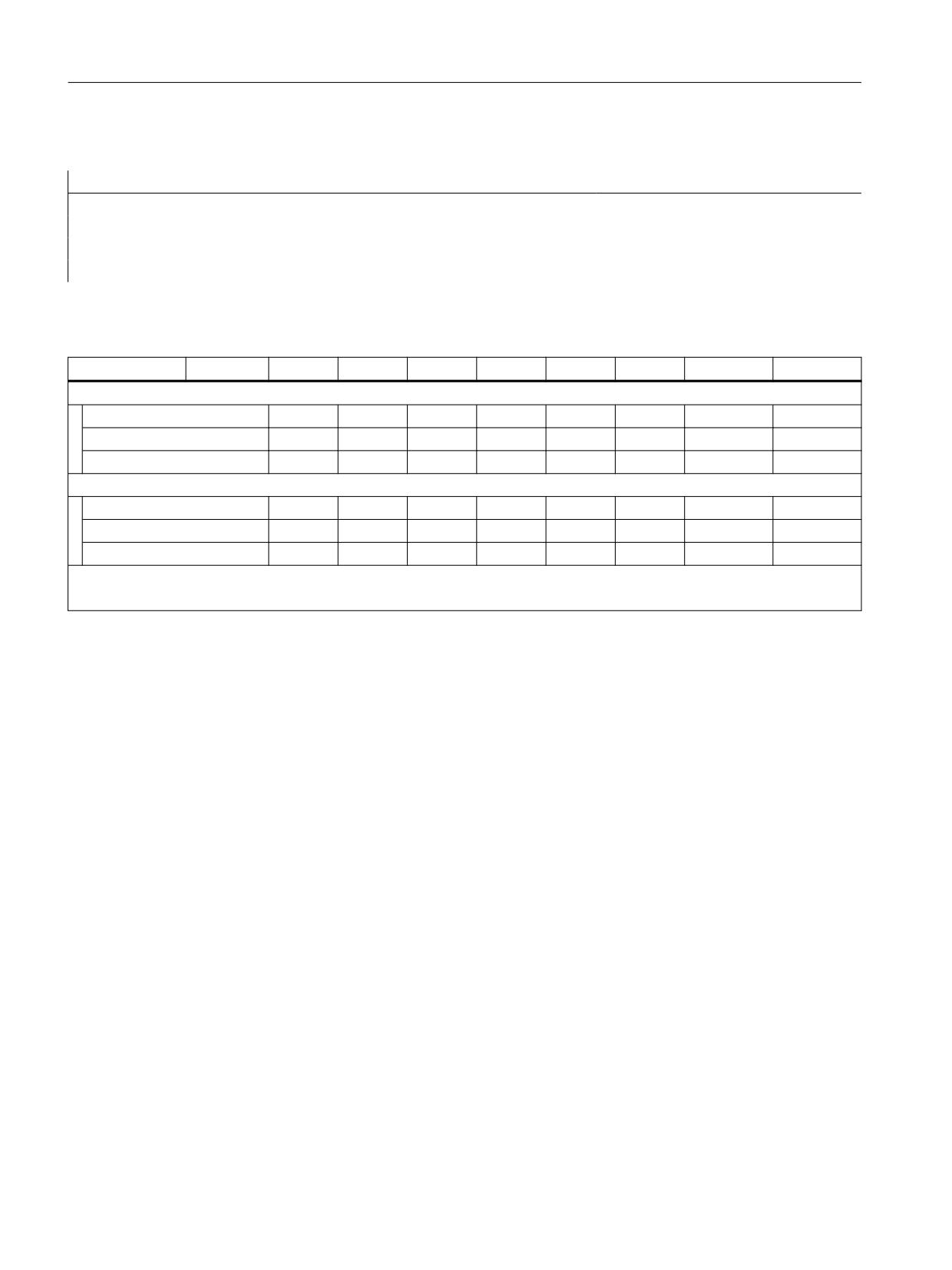
Transitions between axis and spindle
In state ↓
To →
POS
MOV<>0
MOV=0
SPOS
M3/M4
M5
LEADON
TRAIL ON
during traversing
Axis
x
x
x
x
x
x
x
x
Position-controlled spindle
x
x
x
x
x
x
-
-
Speed-controlled spindle
-
-
-
x
x
x
-
-
in motion
Axis
x
x
x
-
-
-
x
x
Position-controlled spindle
-
-
-
-
-
-
-
-
Speed-controlled spindle
-
-
-
x
x
x
-
-
Transitions marked with x are permitted:
The transitions marked with - are rejected with an alarm.
See also
Couplings (CP..., LEAD..., TRAIL..., CTAB...) (Page 106)
4.7.15
Withdrawing the enable for the axis container rotation (AXCTSWEC)
Function
Using the command AXCTSWEC an already issued enable signal to rotate the axis container can
be withdrawn again. The command triggers a preprocess stop with reorganization (STOPRE).
The following conditions must be fulfilled so that in the channel, the enable signal to rotate the
axis container is withdrawn again:
• In the channel, the axis container rotation must already have been enabled:
- AXCTSWE(<container>)
- $AC_AXCTSWA[<container>] == 1
• Axis container rotation was still not started:
- $AN_AXCTSWA[<container>] == 0
As feedback signal for the successful withdrawal of the enable signal, the following channel-
specific system variable is reset:
Synchronized actions
92
Function Manual, 10/2020, 6FC5397-5BP40-6BA4
Detailed description
4.7 Actions in synchronized actions
$AC_AXCTSWA[<container>] == 0
For a detailed description of the system variables, refer to:
Further information
List Manual System Variables
Syntax
DO AXCTSWEC(<container>)
Meaning
AXCTSWEC:
Withdrawing the enable for the axis container rotation for the channel
<Container>:
Name of axis container
Possible data include:
• CT<container number>:
The number of the axis container is attached to the CT letter combina-
tion. Example: CT3
• <container name>:
Individual name of the axis container set using
MD12750 $MN_AXCT_NAME_TAB. Example: A_CONT3
• <Axis name>:
Axis name of a container axis known in the channel.
Example
Program code
; Initialization of the global counter for the technology cycle CTSWEC
N100 $AC_MARKER[0]=0
N110 ID=1 DO CTSWEC
;For technology cycle CTSWEC, see below.
NEXT:
N200 G0 X30 Z1
N210 G95 F.5
N220 M3 S1000
N230 G0 X25
N240 G1 Z-10
N250 G0 X30
N260 M5
; Enable of the axis container rotation for container spindle S1.
N270 AXCTSWE(S1)
N200 GOTO NEXT
Synchronized actions
Function Manual, 10/2020, 6FC5397-5BP40-6BA4
93
Detailed description
4.7 Actions in synchronized actions
Program code
PROC CTSWEC( STRING _ex_CT="CT1"
INT
_ex_CTsl_BITmask=1H
INT
_ex_CT_SL_Number=1
INT
_ex_WAIT_number_of_IPOs=1000
) DISPLOF ICYCOF
DEFINE _ex_number_of_IPOs AS $AC_MARKER[0]
IF ($AC_STOP_COND[0] + $AC_STOP_COND[1] + $AC_STOP_COND[2] + $AC_STOP_COND[3] +
$AC_STOP_COND[4] + $AC_STOP_COND[5] + $AC_STOP_COND[6] + $AC_STOP_COND[7] +
$AC_STOP_COND[8] + $AC_STOP_COND[9] + $AC_STOP_COND[10]) > 0)
; Increment IPO cycle counter
_ex_number_of_IPOs = _ex_number_of_IPOs + 1
; If a stop condition for longer than "_ex_WAIT_number_of_IPOs"
; IPO cycles is present AND its own slot has not been enabled
IF ( _ex_number_of_IPOs
>= _ex_WAIT_number_of_IPOs) AND
($AN_AXCTSWEC[_ex_CT] == _ex_CTsl_BITmask )
AXCTSWEC
;Cancel the enable of the axis container rotation.
ENDIF
ELSE
; Reset IPO cycle counter
_ex_number_of_IPOs = 0
ENDIF
RET
Boundary condition
Time of execution of synchronous actions
Program code
; Enable of the axis container rotation.
N10 AXCTSWE(CT3)
; Traversing of the container axis AX_A => before the axis is traversed,
there
; is a waiting period for the end of the axis container rotation:
$AN_AXCTSWA[CT3]==0
N20 AX_A = 10
; Cancellation of the enable. No effect!
WHEN <condition> DO AXCTSWEC(AX_A)
N30 G4 F1
Because after the enable of the axis container rotation in block N10, an axis of the axis container
(AX_A) is used in block N20 and this use leads to the system waiting for the end of the axis
container rotation, the synchronous action only comes together with the program block N30 in
the main run and has therefore no effect.
Synchronized actions
94
Function Manual, 10/2020, 6FC5397-5BP40-6BA4
Detailed description
4.7 Actions in synchronized actions
Remedy:
Program code
; Enable of the axis container rotation.
N11 AXCTSWE(CT3)
; Cancellation of the enable.
WHEN <condition> DO AXCTSWEC(AX_A)
N21 ...
;Executable NC block
; Traversing of the container axis AX_A => before the axis is traversed,
there
; is a waiting period for the end of the axis container rotation:
$AN_AXCTSWA[CT3]==0
N31 AX_A = 10
Note
Without the executable block N21, the synchronous action would only be implemented after the
end of the axis container rotation with the next executable program block N31 in the main run
and would therefore have no effect, just the same as in the example above.
4.7.16
Actual value setting with loss of the referencing status (PRESETON)
Function
The PRESETON() procedure sets new actual values in the machine coordinate system (MCS)
from synchronized actions for one axis. This corresponds to work offset of the axis MCS. The axis
is not traversed.
From synchronized actions, PRESETON must only be used on command axes, i.e. on axes that
have been started from a synchronized action. The axis must also be assigned to the channel, i.e.
this channel must have the interpolation right for this axis. The axis is not requested from
another channel via axis replacement.
Referencing status
By setting a new actual value in the machine coordinate system, the referencing status of the
machine axis is reset.
DB31, ... DBX60.4/.5 = 0 (referenced/synchronized measuring system 1/2)
It is recommended that PRESETON only be used for axes that do not require a reference point.
Synchronized actions
Function Manual, 10/2020, 6FC5397-5BP40-6BA4
95
Detailed description
4.7 Actions in synchronized actions
To restore the original machine coordinate system, the measuring system of the machine axis
must be referenced again, e.g. through active referencing from the part program (G74).
CAUTION
Loss of the referencing status
By setting a new actual value in the machine coordinate system with PRESETON, the
referencing status of the machine axis is reset to "not referenced/synchronized".
Programming
Syntax
WHEN | EVERY ... DO PRESETON(<axis>,<value>)
Meaning
WHEN, EVERY:
Only WHEN and EVERY must be used as frequency (Page 17).
PRESETON:
Actual value setting with loss of the referencing status
<axis>:
Machine axis name
Type:
AXIS
Range of values:
Machine axis names defined in the channel
<value>:
New actual value of the machine axis in the machine coordinate system
(MCS)
The input is made in the current valid system of units (inch/metric)
An active diameter programming (DIAMON) is taken into account
Type:
REAL
System variable
$AC_PRESET
The axis-specific system variable $AC_PRESET provides the vector from the zero point of the
currently offset MCS' to the zero point of the original MCS0 after the referencing of the machine
axis.
$AC_PRESET<axis> = $AC_PRESET<axis> + "current actual position of the axis in the MCS" -
"PRESETON actual position"
The work offset can be undone with the system variables:
PRESETON(<axis>, $VA_IM + $AC_PRESET[<axis>]) ; "current actual
position of the axis in the MCS'" + "offsets"
Example
Program code
N10 G1 X=10 F5000
; Traverse the X axis as command axis to position 200
Synchronized actions
96
Function Manual, 10/2020, 6FC5397-5BP40-6BA4
Detailed description
4.7 Actions in synchronized actions
Program code
N20 WHEN TRUE DO G71 POS[X]=200
; IF set position of the X axis in the MCS ($AA_IM[X]) >= 80
; THEN "actual position of the X axis in the MCS" = "set position of the X
axis in the MCS" + "offset"
;
= 80 + 70 = 150
;
"progr. end position of the X axis" = "progr. end position of the X
axis" + "offset"
;
= 200 + 70 = 270
;
$AC_PRESET = $AC_PRESET - 70
N30 WHEN G71 $AA_IM[X] >= 80 DO PRESETON(X, $AA_IM[X]+70)
N40 G4 F3
Supplementary conditions
Axes for which PRESETON must not be used
• Traversing command axes in spindle mode
• Traversing concurrent positioning axes (FC18)
• Axes involved in a transformation
• Traversing path axes
• Reciprocating axes
• Axes on which one or more of the following safety functions (Safety Integrated) are active
- Enable "Safe software limit switch"
MD36901 $MA_SAFE_FUNCTION_ENABLE[<safe axis>], bit 1 = 1
- Enable "Safe software cam", pair 1 ... 4, cam +/-
MD36901 $MA_SAFE_FUNCTION_ENABLE[<safe axis>], bits 8 ... 15 = 1
or
Enable "Safe Cam Track", cam 1 ... 30
MD36903 $MA_SAFE_CAM_ENABLE[<safe axis>], bits 0 ... 29 = 1
• Hirth axes
• Synchronized axes of a gantry grouping
• Axes for which the reference point approach from the part program (G74) is active
• Slave axis of a speed/torque coupling (master-slave)
Synchronized actions
Function Manual, 10/2020, 6FC5397-5BP40-6BA4
97
Detailed description
4.7 Actions in synchronized actions
Geometry axes
• PRESETON can be used on a stationary geometry axis when a further geometry axis is not
being traversed in the channel at the same time.
• PRESETON can be used on a stationary geometry axis even when a further geometry axis is
being traversed in the channel at the same time, but this axis is in the "neutral axis" state or
traversing as a command axis.
Example: A further geometry (X) is traversing at the same time in the "neutral axis" state
Program code
Comment
N10 G0 X0 Y0
; X, Y: Geometry axes
N15 RELEASE(Y) 1)
; Neutral axis
N20 ID=1 WHEN 20.0 < $AA_IM[X] DO
; $AA_IM: Set position in the
PRESETON(Y,20)
MCS
N30 G0 X40
; Geometry axis X traverses
N40 M30
1) Note
The release of an axis in the action part of a synchronized action does not ensure that the release is
on time.
N20 ID=1 WHEN 20.0 < $AA_IM[X] DO RELEASE(Y) PRESETON(Y,20) ; NOT
recommended!
Example: A further geometry (X) is traversing at the same time as command axis
Program code
Comment
N10 G0 X0 Y0
; X, Y: Geometry axes
N20 ID=1 WHEN TRUE DO POS[X]=40
; X command axis
FA[X]=1000
N30 ID=2 WHEN 20.0 < $AA_IM[X] DO
; $AA_IM: Set position in the
PRESETON(Y,20)
MCS
N40 M30
PLC-controlled axes
• PRESETON can be used on PLC-controlled axes according to their current type.
Spindle states
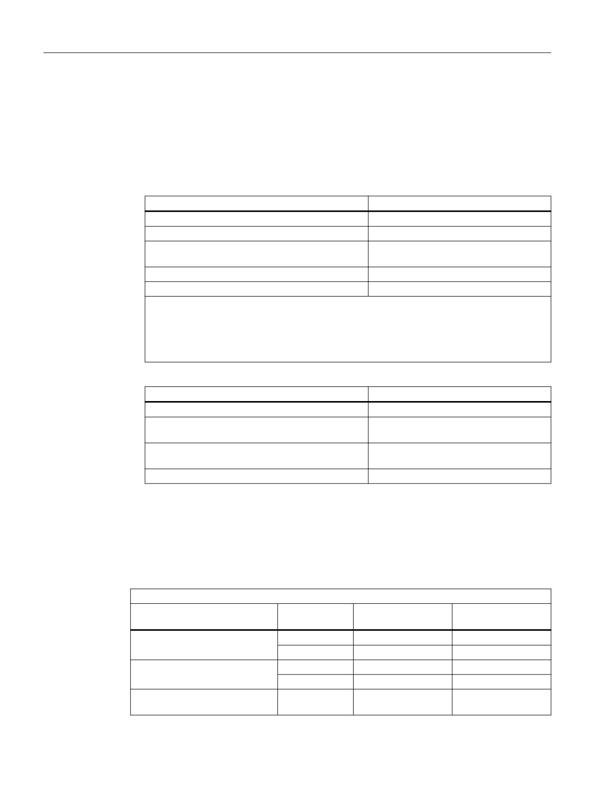
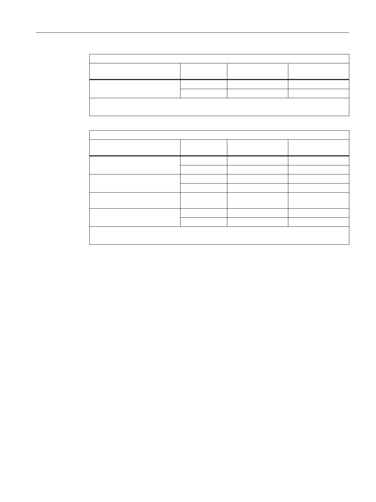
The following table shows the reactions that occur when PRESETON is used on a spindle in a
synchronized action:
PRESETON in synchronized action
Spindle mode
Traversing sta-
Assigned to the NC
Main axis
tus
program
Speed control mode
In motion
Alarm 17601
Alarm 17601
Stationary
+/-
+/-
Positioning mode SPOS
In motion
Alarm 17601
Alarm 17601
Stationary
+/-
+/-
Positioning across block bounda-
In motion
Alarm 17601
-
ries SPOSA
Synchronized actions
98
Function Manual, 10/2020, 6FC5397-5BP40-6BA4
Detailed description
4.7 Actions in synchronized actions
PRESETON in synchronized action
Spindle mode
Traversing sta-
Assigned to the NC
Main axis
tus
program
Axis mode
In motion
Alarm 17601
+/-
Stationary
+/-
+/-
+/- Possible
-: Not possible
PRESETON in the NC program
Spindle mode
Traversing sta-
Assigned to the NC
Main axis
tus
program
Speed control mode
In motion
Alarm 22324
Alarm 22324
Stationary
+/-
+/-
Positioning mode SPOS
In motion
-
+/-
Stationary
+/-
+/-
Positioning across block bounda-
In motion
Alarm 10610
-
ries SPOSA
Axis mode
In motion
-
+/-
Stationary
+/-
+/-
+/- Possible
-: Not possible
Axis couplings
• Leading axes: The sudden change of the leading axis position caused by PRESETON is not
traversed in the following axes. The coupling is not changed.
• Following axes: Only the overlaid position component of the following axis is affected
by PRESETON.
Gantry grouping
• If PRESETON is used on the guide axis of a gantry grouping, the work offset is also performed
in all synchronized axes of the gantry grouping.
Indexing axes
• PRESETON can be used on indexing axes.
Software limit switches, operating range limit, protection areas
• If the axis position is outside the specified limits after a work offset by PRESETON, an alarm
is not displayed until an attempt is made to traverse the axis.
Block search with calculation
PRESETON commands are collected during the block search and executed with the NC start to
continue the NC program.
Synchronized actions
Function Manual, 10/2020, 6FC5397-5BP40-6BA4
99
Detailed description
4.7 Actions in synchronized actions
Position-dependent NC/PLC interface signals
• The status of the position-dependent NC/PLC interface signals is redetermined based on the
new actual position.
Example: Fixed point positions
- Parameterized fixed point positions: MD30600 $MA_FIX_POINT_POS[0...3] = <fixed point
position 1...4>
- NC/PLC interface signals DB31, ... DBX75.3 ... 5 (JOG approach fixed point: reached)
If the axis is at a fixed point position with the exact stop tolerance, the associated NC/PLC
interface signal is set. The NC/PLC interface signal is reset when the actual value is set
by PRESETON to a different value outside the exact stop tolerance around the fixed point
position.
DRF offset
• A DRF offset of the axis is deleted by PRESETON.
Overlaid movement $AA_OFF
• An overlaid movement ($AA_OFF) (Page 45) is not affected by PRESETON.
Online tool offset FTOC
• An active online tool offset (FTOC) (Page 73) remains active even after PRESETON.
Axis-specific compensations
Axis-specific compensations remain active after PRESETON.
JOG mode
• PRESETON must only be used on a stationary axis.
JOG mode, REF machine function
• PRESETON must not be used.
See also
On-the-fly parting (Page 148)
4.7.17
Actual value setting without loss of the referencing status (PRESETONS)
Function
The PRESETONS() procedure sets new actual values in the machine coordinate system (MCS)
from synchronized actions for one axis. This corresponds to work offset of the axis MCS. The axis
is not traversed.
From synchronized actions, PRESETONS must only be used on command axes, i.e. on axes
that have been started from a synchronized action. The axis must also be assigned to the
channel, i.e. this channel must have the interpolation right for this axis. The axis is not requested
from another channel via axis replacement.
Synchronized actions
100
Function Manual, 10/2020, 6FC5397-5BP40-6BA4
Detailed description
4.7 Actions in synchronized actions
Referencing status
By setting a new actual value in the machine coordinate system (MCS) with PRESETONS, the
referencing status of the machine axis is not changed.
Requirements
• Encoder type
PRESETONS is only possible with the following encoder types of the active measuring
system:
- MD30240 $MA_ENC_TYPE[<measuring system>] = 0 (simulated encoder)
- MD30240 $MA_ENC_TYPE[<measuring system>] = 1 (raw signal encoder)
• Referencing mode
PRESETONS is only possible with the following referencing mode of the active measuring
system:
- MD34200 $MA_ENC_REFP_MODE[<measuring system>] = 0 (no reference point
approach possible)
- MD34200 $MA_ENC_REFP_MODE[<measuring system>] = 1 (referencing of
incremental, rotary or linear measuring systems: zero pulse on the encoder track)
Startup
Axis-specific machine data
Actual value setting without loss of the referencing status (PRESETONS) must be set axis-
specifically:
MD30460 $MA_BASE_FUNCTION_MASK, bit 9 = 1
Note
PRESETON deactivated
Activation of the "Actual value setting without loss of the referencing status PRESETONS"
function deactivates the "Actual value setting with loss of the referencing status PRESETON"
function. The options mutually exclude each other.
Programming
Syntax
<frequency> ... DO PRESETONS(<axis>, <value>)
Meaning
<frequency>: Only WHEN and EVERY must be used as frequency (Page 17).
PRESETONS:
Actual value setting with loss of the referencing status
<axis>:
Machine axis name
Type:
AXIS
Range of values:
Machine axis names defined in the channel
Synchronized actions
Function Manual, 10/2020, 6FC5397-5BP40-6BA4
101
Detailed description
4.7 Actions in synchronized actions
<value>:
New current actual value of the machine axis in the machine coordinate
system (MCS)
The input is made in the active system of units (inch/metric)
An active diameter programming (DIAMON) is taken into account
Type:
REAL
System variable
$AC_PRESET
The axis-specific system variable $AC_PRESET provides the vector from the zero point of the
currently offset MCS' to the zero point of the original MCS0 after the referencing of the machine
axis.
$AC_PRESET<axis> = $AC_PRESET<axis> + "current actual position of the axis in the MCS" -
"PRESETONS actual position"
The work offset can be undone with the system variables:
PRESETONS(<axis>, $VA_IM + $AC_PRESET[<axis>]) ; "current actual
position of the axis in the MCS'" + "offsets"
Example
Work offset of the X axis MCS by 70 units.
The programmed end position of the X axis (command axis) is transformed to the new MCS with
PRESETONS.
Program code
N10 G1 X=10 F5000
; Traverse the X axis as command axis to position 200
N20 WHEN TRUE DO G71 POS[X]=200
; IF set position of the X axis in the MCS ($AA_IM[X]) >= 80
; THEN "actual position of the X axis in the MCS" = "set position of the X
axis in the MCS" + "offset"
;
= 80 + 70 = 150
;
"progr. end position of the X axis" = "progr. end position of the X
axis" + "offset"
;
= 200 + 70 = 270
;
$AC_PRESET = $AC_PRESET - 70
N30 WHEN G71 $AA_IM[X] >= 80 DO PRESETONS(X, $AA_IM[X]+70)
N40 G4 F3
Supplementary conditions
Axes for which PRESETONS must not be used
• Traversing command axes in spindle mode
• Traversing concurrent positioning axes (FC18)
• Axes involved in a transformation
Synchronized actions
102
Function Manual, 10/2020, 6FC5397-5BP40-6BA4
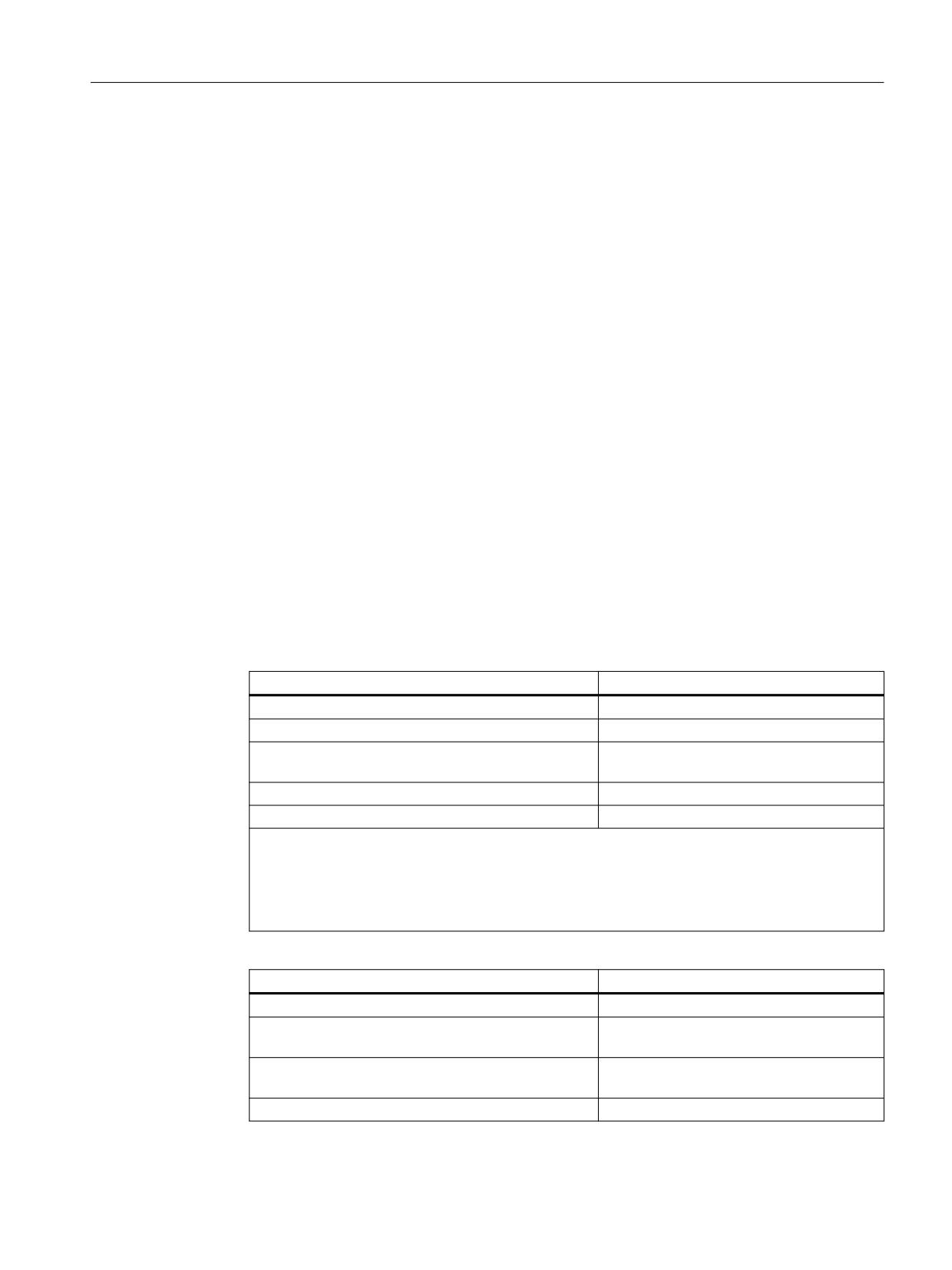
Detailed description
4.7 Actions in synchronized actions
• Traversing path axes
• Reciprocating axes
• Axes on which one or more of the following safety functions (Safety Integrated) are active
- Enable "Safe software limit switch"
MD36901 $MA_SAFE_FUNCTION_ENABLE[<safe axis>], bit 1 = 1
- Enable "Safe software cam", pair 1 ... 4, cam +/-
MD36901 $MA_SAFE_FUNCTION_ENABLE[<safe axis>], bits 8 ... 15 = 1
or
Enable "Safe Cam Track", cam 1 ... 30
MD36903 $MA_SAFE_CAM_ENABLE[<safe axis>], bits 0 ... 29 = 1
• Hirth axes
• Synchronized axes of a gantry grouping
• Axes for which the reference point approach from the part program (G74) is active
• Slave axis of a speed/torque coupling (master-slave)
Geometry axes
• PRESETONS can be used on a stationary geometry axis when a further geometry axis is not
being traversed in the channel at the same time.
• PRESETONS can be used on a stationary geometry axis even when a further geometry axis
is being traversed in the channel at the same time, but this axis is in the "neutral axis" state
or traversing as a command axis.
Example: A further geometry (X) is traversing at the same time in the "neutral axis" state
Program code
Comment
N10 G0 X0 Y0
; X, Y: Geometry axes
N15 RELEASE(Y) 1)
; Neutral axis
N20 ID=1 WHEN 20.0 < $AA_IM[X] DO
; $AA_IM: Set position in the
PRESETONS(Y,20)
MCS
N30 G0 X40
; Geometry axis X traverses
N40 M30
1) Note
The release of an axis in the action part of a synchronized action does not ensure that the release is
on time.
N20 ID=1 WHEN 20.0 < $AA_IM[X] DO RELEASE(Y) PRESETONS(Y,20) ; NOT
recommended!
Example: A further geometry (X) is traversing at the same time as command axis
Program code
Comment
N10 G0 X0 Y0
; X, Y: Geometry axes
N20 ID=1 WHEN TRUE DO POS[X]=40
; X command axis
FA[X]=1000
N30 ID=2 WHEN 20.0 < $AA_IM[X] DO
; $AA_IM: Set position in the
PRESETONS(Y,20)
MCS
N40 M30
Synchronized actions
Function Manual, 10/2020, 6FC5397-5BP40-6BA4
103
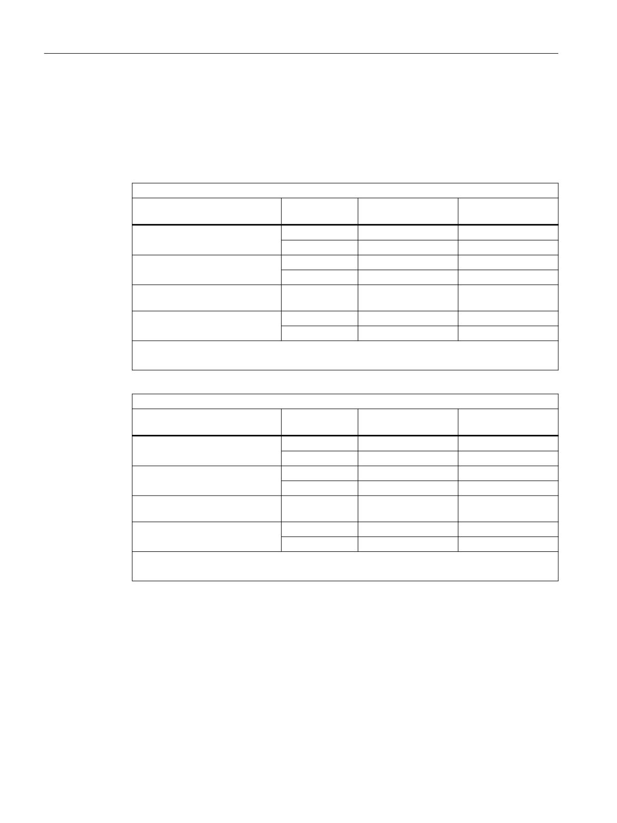
Detailed description
4.7 Actions in synchronized actions
PLC-controlled axes
• PRESETONS can be used on PLC-controlled axes according to their current type.
Spindle states
The following table shows the reactions that occur when PRESETONS is used on a spindle in a
synchronized action:
PRESETONS in synchronized action
Spindle mode
Traversing sta-
Assigned to the NC
Main axis
tus
program
Speed control mode
In motion
Alarm 17601
Alarm 17601
Stationary
+/-
+/-
Positioning mode SPOS
In motion
Alarm 17601
Alarm 17601
Stationary
+/-
+/-
Positioning across block bounda-
In motion
Alarm 17601
-
ries SPOSA
Axis mode
In motion
Alarm 17601
+/-
Stationary
+/-
+/-
+/- Possible
-: Not possible
PRESETONS in the NC program
Spindle mode
Traversing sta-
Assigned to the NC
Main axis
tus
program
Speed control mode
In motion
Alarm 22324
Alarm 22324
Stationary
+/-
+/-
Positioning mode SPOS
In motion
-
+/-
Stationary
+/-
+/-
Positioning across block bounda-
In motion
Alarm 10610
-
ries SPOSA
Axis mode
In motion
-
+/-
Stationary
+/-
+/-
+/- Possible
-: Not possible
Axis couplings
• Leading axes: The sudden change of the leading axis position caused by PRESETONS is not
traversed in the following axes. The coupling is not changed.
• Following axes: Only the overlaid position component of the following axis is affected
by PRESETONS.
Gantry grouping
• If PRESETONS is used on the guide axis of a gantry grouping, the work offset is also
performed in all synchronized axes of the gantry grouping.
Synchronized actions
104
Function Manual, 10/2020, 6FC5397-5BP40-6BA4
Detailed description
4.7 Actions in synchronized actions
Indexing axes
• PRESETONS can be used on indexing axes.
Software limit switches, operating range limit, protection areas
• If the axis position is outside the specified limits after a work offset by PRESETONS, an alarm
is not displayed until an attempt is made to traverse the axis.
Block search with calculation
PRESETONS commands are collected during the block search and executed with the NC start to
continue the NC program.
Position-dependent NC/PLC interface signals
• The status of the position-dependent NC/PLC interface signals is redetermined based on the
new actual position.
Example: Fixed point positions
- Parameterized fixed point positions: MD30600 $MA_FIX_POINT_POS[0...3] = <fixed point
position 1...4>
- NC/PLC interface signals DB31, ... DBX75.3 ... 5 (JOG approach fixed point: reached)
If the axis is at a fixed point position with the exact stop tolerance, the associated NC/PLC
interface signal is set. The NC/PLC interface signal is reset when the actual value is set
by PRESETONS to a different value outside the exact stop tolerance around the fixed point
position.
DRF offset
• A DRF offset of the axis is deleted by PRESETONS.
Overlaid movement $AA_OFF
• An overlaid movement ($AA_OFF) (Page 45) is not affected by PRESETONS.
Online tool offset FTOC
• An active online tool offset (FTOC) (Page 73) remains active even after PRESETONS.
Axis-specific compensations
Axis-specific compensations remain active after PRESETONS.
JOG mode
• PRESETONS must only be used on a stationary axis.
JOG mode, REF machine function
• PRESETONS must not be used.
Synchronized actions
Function Manual, 10/2020, 6FC5397-5BP40-6BA4
105
Detailed description
4.7 Actions in synchronized actions
4.7.18
Couplings (CP..., LEAD..., TRAIL..., CTAB...)
The commands listed in Section "Language elements for synchronized actions and technology
cycles (Page 60)" can be programmed in synchronous actions for the functions coupled motion
(TRAIL...), curve tables (CTAB...), master value coupling (LEAD...) and generic coupling
(CP...):
Note
Generic coupling
Note that the "generic coupling" CP ... commands are always executed in synchronous
actions in the sequence of the programming from left to right. This means that in contrast to the
programming in the part program, the effect of the various commands depends on the
sequence in the synchronous action.
Curve tables
The CTAB and CTABINV commands can be used in the condition and in the action.
Further information
Detailed information on coupling commands can be found in:
• Coupled motion, curve tables, master value coupling
Programming Manual NC Programming
• Generic coupling
Function Description Axes and Spindles
Coupled motion
When the coupling is activated from the synchronous action, the leading axis can be in motion.
In this case the following axis is accelerated up to the set velocity. The position of the leading axis
at the time of synchronization of the velocity is the starting position for coupled-axis motion.
Master value coupling
Syntax
... DO LEADON(<FA>, <LA>, <NO>, <OVW>)
Meaning
<FA>:
Name of the following axis
Type: AXIS
<LA>:
Name of the leading axis
Type: AXIS
Synchronized actions
106
Function Manual, 10/2020, 6FC5397-5BP40-6BA4
Detailed description
4.7 Actions in synchronized actions
<NO>:
Number of the curve table
Type: INT
<OVW>:
Status of the overwrite permission
Type: BOOL
0: Overwriting of the table is not permitted
1: Overwriting of the table is permitted
• Synchronous actions can be used to change the basic curve table without a
resynchronization even during an active master value coupling.
The following axis attempts as fast as possible to follow the position values specified by the
new curve table.
• In order to be able to program an axis to be coupled via synchronous actions, the axis must
first be released with the RELEASE command.
Example:
Program code
N60 RELEASE(X)
N50 ID=1 EVERY SR1==1 DO LEADON(C, X, 1)
Example: On-the-fly parting
An extruded material which passes continuously through the operating area of a cutting tool
must be cut into parts of equal length.
• X axis: Axis in which the extruded material moves (WCS)
• X1 axis: Machine axis of the extruded material (MCS)
• Y axis: Axis in which the cutting tool "tracks" the extruded material
It is assumed that the infeed and control of the cutting tool are controlled via the PLC user
program. The signals at the PLC interface can be evaluated to determine whether the extruded
material and cutting tool are synchronized.
Program code
N100 R3=1500
;Length of a part to be cut off
N200 R2=100000 R13=R2/300
N300 R4=100000
N400 R6=30
;Start position Y axis
N500 R1=1
;Start condition for conveyor axis
N600 LEADOF(Y,X)
;Delete coupling
N700 CTABDEF(Y,X,1,0)
;Table definition
N800 X=30 Y=30
;Value pairs
N900 X=R13 Y=R13
N1000 X=2*R13 Y=30
N1100 CTABEND
;End of table definition
N1200 PRESETON(X1,0)
;PRESET at beginning
N1300 Y=R6 G0
;Start position Y axis, axis is linear
; PRESET after length R3, new start after parting
Synchronized actions
Function Manual, 10/2020, 6FC5397-5BP40-6BA4
107

Detailed description
4.7 Actions in synchronized actions
Program code
N1400 ID=1 WHENEVER $AA_IW[X]>$R3 DO PESETON(X1,0)
N1500 RELEASE(Y)
; Couple Y to X via table 1, for X < 10
N1800 ID=6 EVERY $AA_IM[X]<10 DO LEADON(Y,X,1)
; > 30 before traversed parting distance, deactivate coupling
N1900 ID=10 EVERY $AA_IM[X]>$R3-30 DO LEADOF(Y,X)
N2000 WAITP(X)
; Set extruded material axis continuously in motion
N2100 ID=7 WHEN $R1==1 DO MOV[X]=1 FA[X]=$R4
N2200 M30
Generic coupling
• When a coupling module is activated in a synchronous action, the following axis must
already be active in the channel and be in the state "neutral axis" or "axis already assigned to
the part program of the channel". The corresponding axis state can be generated, if
necessary, in the synchronous action by programming GET[<following axis>].
• The commands of the generic coupling CP ... are processed directly in synchronous
actions by the coupling module. The command therefore takes effect immediately.
• With the programming of a coupling factor (CPLNUM, CPLDEN) or table number (CPLCTID),
a previously activated non-linear coupling relationship, e.g. a curve table, is deactivated.
Generic coupling: Using the TRAIL, LEAD, EG or COUP coupling type.
If in the framework of the generic coupling, a behavior corresponding to one of the known
coupling types "Coupled motion", "Master value coupling", "Electronic gear" or "Synchronous
spindle" is required, the command CPSETTYPE is also possible in synchronous actions when
creating or defining the coupling module:
CPSETTYPE[FAx] = <coupling type>
<Coupling type>
Meaning
CP
Freely programmable
TRAIL
"Coupled motion" coupling type
LEAD
"Master value coupling" coupling type
EG
"Electronic gearbox" coupling type
COUP
"Synchronous spindle" coupling type
Constraints
Synchronism status of a following axis
The system variable $AA_SYNC[<axis>] can be used to read the synchronism status of a
following axis in the part program or synchronous action.
Synchronized actions
108
Function Manual, 10/2020, 6FC5397-5BP40-6BA4
Detailed description
4.7 Actions in synchronized actions
Axis replacement with cross-channel coupling
For axis replacement, the following and leading axes must be known to the calling channel. Axis
replacement of leading axes can be performed independently of the state of the coupling. A
defined or active coupling does not produce any other supplementary conditions.
Note
With the activation of the coupling, the following axis becomes the main run axis and is not
available for an axis replacement. The following axis is thus logged out of the channel. With this
type of coupling, an overlaid movement is therefore not possible.
See also Section "Axis replacement (GET, RELEASE, AXTOCHAN) (Page 86)"
Conflict prevention when changing from following axis to channel axis
In order to be able to traverse a following axis traversed via synchronous actions as a channel axis
again, you must ensure that the coupling is deactivated before the channel requests the relevant
axis.
The following example shows an error case:
Program code
N50 WHEN TRUE DO TRAILOF(Y, X)
N60 Y100
The Y axis is not released early enough in N50 because TRAILOF only becomes active with N60
through the non-modal synchronous action.
Corrected example:
Program code
N50 WHEN TRUE DO TRAILOF(Y, X)
N55 WAITP(Y)
; Wait for end of travel of the positioning axis
N60 Y100
Examples
Define coupling: Y = following axis, X = leading axis
Program code
... DO CPLDEF[Y]=X CPLNUM[Y,X]=1.5
Activate coupling and define coupling relationship.
• N10 with the correct sequence: First CPLON then CPLNUM
• N20 with incorrect sequence: First CPLNUM then CPLON
Program code
N10 ... DO CPLON[Y]=X CPLNUM[X,Y]=1.5
Synchronized actions
Function Manual, 10/2020, 6FC5397-5BP40-6BA4
109
Detailed description
4.7 Actions in synchronized actions
Program code
N20 ... DO CPLNUM[X,Y]=2 CPLON[Y]=X
; Error
Activate coupling, deactivation/activation with implicit resynchronization
Program code
N10 ... DO CPLON[X]=Y CPLNUM[X,Y]=3
N20 Y100 F100
N30 ... DO CPLOF=X CPLON[X]=Y CPLNUM[X,Y]=3
Activate coupling, deactivate and traverse as a command axis
Program code
N10 ... DO CPLON[X]=Y CPLNUM[X,Y]=3
N20 Y100 F100
N30 ... DO CPLOF=X MOV[X]=10
4.7.19
Measurement (MEAWA, MEAC)
The following commands can be used in synchronous actions for measurement:
• MEAWA (measurement without delete distance-to-go)
• MEAC (continuous measurement without delete distance-to-go)
While the measuring function in the part program is limited to one motion block, the measuring
function can be switched on and off any number of times from synchronous actions.
Note
Measurement can also be performed in JOG mode via static synchronous actions IDS
Further information
Detailed information on measuring commands can be found in:
• Coupled motion, curve tables, master value coupling
Programming Manual NC Programming
• Generic coupling
Function Description Axes and Spindles
Synchronized actions
110
Function Manual, 10/2020, 6FC5397-5BP40-6BA4

Detailed description
4.7 Actions in synchronized actions
Measurement tasks and state changes
When a measurement task has been executed from a synchronous action, the control system
responds in the following way:
State
Response
Operating mode change
A measurement task activated by a modal synchronous action is not affected
by a change in operating mode. It remains active beyond block limits.
Reset
The measurement task is aborted.
Block search
Measurement tasks are collected, but not activated until the programmed
condition is fulfilled.
REPOS
Activated measurement tasks are not affected.
End of program
Measurement tasks started from static synchronous actions remain active.
Remarks
System variable
The following system variables can be used in conjunction with synchronous actions:
• $AA_MEAACT (axial measuring active)
• $A_PROBE (probe state)
• $AA_MM1 ... 4 (probe position 1st to 4th trigger (machine coordinate system))
The following system variable cannot be used in conjunction with synchronous actions:
• $AC_MEA (probe has responded)
Measurement job
Only one measurement job at a time may be active for an axis.
Priority with more than one measurement
A new measurement task for the same axis has the effect that the trigger events are reactivated
and the measurement results reset.
Measurement jobs started from the part program cannot be influenced from synchronous
actions. If a measurement task is started from a synchronous action for an axis for which a
measurement task is already active from the part program, an alarm is displayed.
If a measurement task is already active from a synchronous action, measurement can no longer
be started from the part program.
Saving measurement results
A FIFO memory is set up in the $AC_FIFO system variables to save the measurement results. See
Chapter "FIFO variables ($AC_FIFO) (Page 31)".
Synchronized actions
Function Manual, 10/2020, 6FC5397-5BP40-6BA4
111
Detailed description
4.7 Actions in synchronized actions
Examples
In the following examples, two FIFO memories are set up via machine data:
• MD28050 $MC_MM_NUM_R_PARAM = 300
• MD28258 $MC_MM_NUM_AC_TIMER = 1
• MD28260 $MC_NUM_AC_FIFO = 1 (set up FIFO memory)
• MD28262 $MC_START_AC_FIFO = 100 (FIFO memory starts from R100)
• MD28264 $MC_LEN_AC_FIFO = 28 (22 variables + 6 management data)
• MD28266 $MC_MODE_AC_FIFO = 0 (no summation)
Example 1
All rising edges of probe 1 are to be recorded between 0 and 100 mm for the X axis. It is assumed
that no more than 22 measuring edges occur.
Program code
Comment
DEF INT NUMBER
; number of current measured values
DEF INT INDEX_R
; loop index
N10 G0 X0
; approach starting point for the measure-
ment
;Measurement: Mode = 1 (simultaneously), FIFO memory = 1,
; trigger event = 1 (rising edge of probe 1)
N20 MEAC[X]=( 1, 1, 1) POS[X]=100
N30 STOPRE
; stop preprocessing
N40 MEAC[X]=(0)
; cancel measurement
N50 ANZAHL=$AC_FIFO1[4]
; number of saved measured values
N60 ANZAHL = ANZAHL - 1
N70 FOR INDEX_R=0 TO ANZAHL
N80
R[INDEX_R]=$AC_FIFO1[0]
; save measured value in R parameter
N90 ENDFOR
Example 2
All rising and falling edges of probe 1 are to be recorded between 0 and 100 mm for the X axis.
The number of measurements is not known. Therefore, the measured values must be fetched
parallel to the measurement and stored in ascending order as of $R1. The number of stored
measured values is entered in $R0.
Program code
Comment
$AC_MARKER[1]=1
; initialize index for R parameter index
N10 G0 X0
; approach starting point for the measurement
; If measured values are available in the FIFO memory, the oldest value is read and
; stored in the current R parameter[$AC_MARKER[1]].
; The R parameter index is then incremented.
N20 ID=1 WHENEVER $AC_FIFO1[4] >= 1 DO $R[$AC_MARKER[1]] = $AC_FIFO1[0]
$AC_MARKER[1] = $AC_MARKER[1] + 1
Synchronized actions
112
Function Manual, 10/2020, 6FC5397-5BP40-6BA4
Detailed description
4.7 Actions in synchronized actions
Program code
Comment
; Continuous measurement: Mode = 1 (simultaneously), FIFO memory = 1,
; trigger event 1 = 1 (rising edge of probe 1),
; trigger event 2 = -1 (falling edge of probe 1)
N30 MEAC[X]=(1, 1, 1, -1) POS[X]=100
N40 MEAC[X]=(0)
; turn off measurement
N50 STOPRE
; stop preprocessing
N60 R0 = $AC_MARKER[1]
; number of recorded measured values
Example 3
Rising and falling edges of probe 1 are to be recorded between 0 and 500 mm for the X axis. The
number of measurements is limited to 10.
The distance-to-go of the X axis is then deleted.
Program code
Comment
N10 G0 X0
; approach starting point for the measure-
ment
; Abort condition: Deselect continuous measurement after 10 or more measurements
; and perform "delete distance-to-go"
N10 WHEN $AC_FIFO1[4] >= 10 DO MEAC[X]=(0) DELDTG(X)
; Continuous measurement: Mode = 1 (simultaneously), FIFO memory = 1,
; trigger event 1 = 1 (rising edge of probe 1),
; trigger event 2 = -1 (falling edge of probe 1)
N20 MEAC[X]=(1, 1, 1, -1) G01 X100 F500
N30 MEAC [X]=(0)
; turn off measurement
N40 R0 = $AC_FIFO1[4]
; number of recorded measured values
4.7.20
Travel to fixed stop (FXS, FXST, FXSW, FOCON, FOCOF, FOC)
Function
Travel to fixed stop
The function "Travel to fixed stop" can be controlled via synchronized actions with the FXS, FXST
and FXSW commands.
The activation can also be performed without traversing motion of the relevant axis. The torque
is immediately limited. The fixed stop is monitored as soon as the axis is traversed.
Travel with limited torque/force
Travel with limited torque/force can be controlled via synchronized actions with the FOCON,
FOCOF and FOC commands.
Syntax
FXS[<axis>]=<request>
Synchronized actions
Function Manual, 10/2020, 6FC5397-5BP40-6BA4
113

Detailed description
4.7 Actions in synchronized actions
FXST[<axis>]=<clamping torque>
FXSW[<axis>] = <window width>
FOCON[<axis>]
FOCOF[<axis>]
FOC[<axis>]
Meaning
Parameter
Meaning
FXS:
Travel to fixed stop
<Request>:
Request to the "Travel to fixed stop" function:
0 = switch off
1 = switch on
FXST:
Set clamping torque
<Clamping torque>:
Clamping torque as % of the maximum drive torque
FXSW:
Set monitoring window
<Window width>:
Width of the tolerance window around the fixed stop
Unit: mm, inch or degrees
FOCON:
Switch on modal torque/force limitation
FOCOF:
Switch off modal torque/force limitation
FOC:
Non-modal torque/force limitation
<axis>:
Name of the channel axis on which the command will be applied
Remarks
Avoidance of multiple selection
The "Travel to fixed stop" function must only be switched on once per axis. In the event of an
error, alarm 20092 is displayed and the corresponding alarm response takes effect.
To avoid multiple selections, it is recommended that a selection marker be used in the
synchronized action.
Example:
Program code
Comment
N10 R1=0
; Initialize selection marker
N20 IDS=1 WHENEVER ($R1==0 AND $AA_IW[AX3] > 7) DO $R1=1 FXS[AX1]=1
Switching on during the approach motion
"Travel to fixed stop" can also be switched on during the approach motion through a non-modal
synchronized action.
Example:
Program code
Comment
N10 G0 G90 X0 Y0
;
Approach initial setting
Synchronized actions
114
Function Manual, 10/2020, 6FC5397-5BP40-6BA4

Detailed description
4.7 Actions in synchronized actions
Program code
Comment
; "Travel to fixed stop" is switched on for the X axis,
; as soon as the position setpoint in the WCS is > 20 mm
; Execution of the non-modal synchronized action: With N30
N20 WHEN G71 $AA_IW[X] > 20 DO FXS[X]=1
N30 G1 F200 X100
;
Traversing block of the X axis
Example: Travel to fixed stop completely via synchronized actions
Program code
Comment
; IF selection request $R1==1 AND state of the Y axis == "not to fixed stop"
; THEN: For the Y axis:
;
- Switch on FXS
;
- Traverse to position 150 mm
;
- Reduce drive torque to 10%
IDS=1 WHENEVER G71 (($R1==1) AND $AA_FXS[y]==0)) DO $R1=0 FXS[Y]=1 FXST[Y]=10
FA[Y]=200 POS[Y]=150
; IF state of the Y-Axis == "Fixed stop has been detected"
; THEN: Increase drive torque to 30%
IDS=2 WHENEVER ($AA_FXS[Y]==4) DO FXST[Y]=30
; IF state of the Y axis == "Successful travel to fixed stop"
; THEN: Set drive torque in accordance with setting $R0
IDS=3 WHENEVER ($AA_FXS[Y]==1) DO FXST[Y]=$R0
; Deselection depending on R3 and retract.
IDS=4 WHENEVER (($R3==1) AND $AA_FXS[Y]==1)) DO FXS[Y]=0 FA[Y]=1000 POS[Y]=0
N10 R1=0 FXS[Y]=0 G0 G90 Y0
;
Initialization
N30 RELEASE(Y)
;
Enable Y axis for traversing in synchronized actions
N50 ...
N60 GET(Y)
;
Include Y axis in the path group again
4.7.21
Channel synchronization (SETM, CLEARM)
Synchronization markers can be set and deleted in the channel in which the synchronous action
runs with the SETM and CLEARM commands.
Syntax
SETM(<No_marker 1> [,<No_marker 2> {, ... < No_marker n>} ] )
CLEARM(<No_marker 1> [,<No_marker 2> {, ... < No_marker n>} ] )
Synchronized actions
Function Manual, 10/2020, 6FC5397-5BP40-6BA4
115
Detailed description
4.7 Actions in synchronized actions
Meaning
A detailed description of the SETM and CLEARM commands can be found in:
Further information
Programming Manual NC Programming
4.7.22
User-specific error reactions (SETAL)
Synchronous actions can be used to react user-specifically to application-specific error states.
Possible reactions are:
• Axis with stop via override = 0%
• Display user-specific alarm
• Set digital output
Display alarm
Syntax
SETAL(<Alarm_no>[,"Alarm text"])
Meaning
Parameter
Meaning
<Alarm_no>:
Alarm number from the range: 65000 - 69999
A complete description of the configuration of user alarms can be found in:
Further information
Commissioning Manual Basesoftware
Examples
; If the distance between axes X1 and X2 is less than 5 mm =>
; stop axis X2
ID=1 WHENEVER G71 ($AA_IM[X1]-$AA_IM[X2])<5.0 DO $AA_OVR[X2]=0
; If the distance between axes X1 and X2 is less than 5 mm =>
; display alarm 65000
ID=1 WHENEVER G71 ($AA_IM[X1]-$AA_IM[X2])<5.0 DO SETAL(65000)
4.7.23
Cancel the actual subprogram level (CANCELSUB)
Using CANCELSUB, in the channel in which the synchronized action is executed, the NC program
active in the current subprogram level is canceled and in the calling program, the next higher
program level is selected. There, program execution is continued normally.
Synchronized actions
116
Function Manual, 10/2020, 6FC5397-5BP40-6BA4
Detailed description
4.8 Technology cycles
Properties
• For each call, only the current subprogram level is canceled.
• After a cancellation, the next higher program level can only be canceled if a return jump is
made from the canceled subprogram level.
• The main program level cannot be canceled.
Syntax
CANCELSUB
Meaning
CANCELSUB:
Cancels the current subprogram level
See also
The cancellation of the current subprogram level can be realized using the channel-specific NC/
PLC interface signal, also from the PLC user program, which is functionally identical:
DB21,
DBX6.4 (program level cancellation)
4.8
Technology cycles
4.8.1
General
Definition
A technology cycle is an NC program that is called in the action part of a synchronous action. All
language elements and system variables that are also used in the action part of a synchronous
action can be used in a technology cycle. In addition, there are also the following language
elements that may only be used within a technology cycle:
• Chapter "System variables for synchronized actions (Page 21)"
• Chapter "User-defined variables for synchronized actions (Page 58)"
• Chapter "Language elements for synchronized actions and technology cycles (Page 60)"
• Chapter "Language elements for technology cycles only (Page 65)"
• Chapter "Actions in synchronized actions (Page 66)"
End of program
The following commands are permitted as end of program: M02, M17, M30, RET
Synchronized actions
Function Manual, 10/2020, 6FC5397-5BP40-6BA4
117
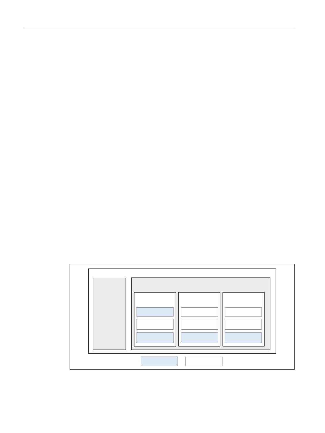
Detailed description
4.8 Technology cycles
Search path
When calling a technology cycle, the same search path is used as for subprograms and cycles.
Further information
Programming Manual NC Programming
Multiple calls
If a condition is fulfilled again while the technology cycle is being executed, the technology cycle
is not restarted.
If a technology cycle is started because of a fulfilled WHENEVER condition and the condition is
still fulfilled after completion of the technology cycle, then the technology cycle is started again.
Behavior with non-modal synchronous actions
A non-modal synchronous action is always linked to the next main run block. If the execution
time of the technology cycle is longer than the processing time of the associated main run block,
the technology cycle is aborted with the block change.
Execution sequence of technology cycles
If several technology cycles are programmed in the action part of a synchronous action, they are
executed in the programmed sequence from left to right.
Example
Calling three technology cycles in the action part of a synchronous action.
Program code
ID=1 <condition part> DO AXIS_X AXIS_Y AXIS_Z
6\QFKURQL]HG DFWLRQ
&RQGLWLRQ
$FWLRQ
7HFKQRORJ\ F\FOH
7HFKQRORJ\ F\FOH
7HFKQRORJ\ F\FOH
$[LVB;
$[LVB<
$[LVB=
1
0
1
326><@
1
326>=@
1
326>;@
1
326><@
1
326>=@
1
0
1
0
1
0
6LQJOH F\FOH
0XOWL F\FOH
Synchronized actions
118
Function Manual, 10/2020, 6FC5397-5BP40-6BA4
Detailed description
4.8 Technology cycles
Execution sequence of the technology cycle blocks: N10, N11, N12, N20, N21, N22, N30, N31,
N32
Note
Constraints
• A maximum of eight technology cycles may be called in the action part of a synchronous
action.
• Except for the call of further technology cycles, no other action may be programmed in the
action part of a synchronous action in which a technology cycle is called.
See also
Processing mode (ICYCON, ICYCOF) (Page 119)
4.8.2
Processing mode (ICYCON, ICYCOF)
Function
The ICYCOF and ICYCON commands can be used to control the processing mode of the actions
within technology cycles.
Per default, the processing mode ICYCON is active.
Processing mode: ICYCON
A non-modal technology cycle is executed in the ICYCON processing mode. The execution of all
actions programmed in a block is initiated in the same interpolator clock cycle. As soon as all
initiated actions are completed, the next block is processed in the following interpolator clock
cycle.
A distinction is made between single-cycle and multi-cycle actions. Examples are:
• Single-cycle actions: Auxiliary function output, value assignments
• Multi-cycle actions: Traversing motions of axes and spindles
Each block of a technology cycle requires at least one interpolator clock cycle.
Processing mode: ICYCOF
All actions of all blocks of a technology cycle are initiated in parallel in the ICYCOF processing
mode.
NC program as a part program
If an NC program is executed as a part program, the ICYCOF and ICYCON commands have no
effect.
Synchronized actions
Function Manual, 10/2020, 6FC5397-5BP40-6BA4
119
Detailed description
4.8 Technology cycles
Syntax
In the action part of a synchronized action
ID=1 <condition part> DO [ICYCOF] <technology cycle 1> [ICYCOF |
ICYCON] <technology cycle 2> ...
As property of an NC program
PROC <name> [ICYCOF | ICYCON]
Within an NC program
PROC <name>
N10 ...
N20 [ICYCOF | ICYCON]
N90 ...
N100 [ICYCOF | ICYCON]
N110 ...
RET
Example
Program code
Effective processing mode
Interpolator cycle
PROC TECHNOCYC
ICYCON
$R1=1
ICYCON
1
POS[X]=100
ICYCON
2 ... 25
ICYCOF
ICYCOF
26
$R1=2
ICYCOF
26
$R2=$R1+1
ICYCOF
26
POS[X]=110
ICYCOF
26
$R3=3
ICYCOF
26
RET
ICYCOF
26
4.8.3
Definitions (DEF, DEFINE)
If an NC program is used as technology cycle, that contains commands for variable (DEF) and/or
macro definition (DEFINE) then these have no effect when executing the technology cycle.
Although variables and macro definitions have no effect within a technology cycle, they must
nevertheless have the correct syntax. In the event of an error, the execution of the technology
cycle is aborted and an alarm displayed.
As the variables and macros are not available in the technology cycle, special measures may have
to be taken in the program code. See Chapter "Context variable ($P_TECCYCLE) (Page 121)".
4.8.4
Parameter transfer
Only the Call-by-Value parameter transfer is possible in a subprogram being applied as a
technology cycle.
Synchronized actions
120
Function Manual, 10/2020, 6FC5397-5BP40-6BA4
Detailed description
4.8 Technology cycles
The application of Call-by-Reference parameters is not permissible and will trigger a
corresponding alarm.
Further information
A detailed description of the parameter transfer and parameter definition in subprograms can be
found in:
Programming Manual NC Programming
4.8.5
Context variable ($P_TECCYCLE)
Function
If an NC program is used as part program as well as also technology cycle, then context-specific
program sections can be defined using system variable $P_TECCYCLE:
• $P_TECCYCLE == TRUE ⇒ The NC program is currently being executed as technology cycle
• $P_TECCYCLE == FALSE ⇒ The NC program is currently being executed as part program
Application
The (DEF) variables and (DEFINE) macro definitions have no effect in technology cycles. If an NC
program is executed as a technology cycle that contains the appropriate definitions, a context-
specific case distinction has to be made in the program code as the variables and macros are then
no longer available.
Example
Travel parameters via user variables in the part program and R parameters in the technology cycle
Program code
Comment: Use in
PROC UP_1
DEF REAL POS_X=100.0
Part program
DEF REAL F_X=250.0
Part program
IF $P_TECCYCLE==TRUE
$R1=100.0
Technology cycle
$R2=250.0
Technology cycle
ENDIF
IF $P_TECCYCLE==TRUE
N100 POS[X]=$R1 FA[X]=$R2
Technology cycle
ELSE
N200 POS[X]=POS_X FA[X]=F_X
Part program
ENDIF
RET
Synchronized actions
Function Manual, 10/2020, 6FC5397-5BP40-6BA4
121
Detailed description
4.9 Protected synchronized actions
See also
Definitions (DEF, DEFINE) (Page 120)
4.9
Protected synchronized actions
Each synchronized action is clearly identified via its ID.
The following machine data can be used to define an NC global or channel-specific range of
identification numbers with which a synchronized action can be protected against overwriting,
deletion (CANCEL(ID)) and locking (LOCK(ID)):
• NC global:
MD11500 $MN_PREVENT_SYNACT_LOCK (protected synchronized actions)
• Channel-specific:
MD21240 $MN_PREVENT_SYNACT_LOCK (protected synchronized actions)
Behavior is the same in both cases.
Protected synchronized actions cannot be locked via the NC/PLC interface or are displayed as
non-lockable:
• DB21, ... DBB300 ... 307 (lock synchronized actions)
• DB21, ... DBB308 ... 315 (synchronized actions that can be disabled locked)
Application
The synchronized actions defined by the machine manufacturer to react to certain machine
states should not be changed after commissioning.
Note
It is recommended that the protection of synchronized actions should not be activated during
the commissioning phase as otherwise a Power on reset is required at each change to the
synchronized action.
Example
In a system with two channels, the synchronized actions of the following identification number
areas should be protected:
Channel 1: 20 ... 30
Channel 2: 25 ... 35
Machine data configuration
NC-global protection area:
• MD11500 $MN_PREVENT_SYNACT_LOCK[0] = 25
• MD11500 $MN_PREVENT_SYNACT_LOCK[1] = 35
Synchronized actions
122
Function Manual, 10/2020, 6FC5397-5BP40-6BA4
Detailed description
4.11 Coordination via PLC
Channel-specific protection area for channel 1:
• MD21240 $MC_PREVENT_SYNACT_LOCK_CHAN[0] = 20
• MD21240 $MC_PREVENT_SYNACT_LOCK_CHAN1] = 30
Channel-specific protection area for channel 2:
• MD21241 $MC_PREVENT_SYNACT_LOCK_CHAN[0] = -1
• MD21241 $MC_PREVENT_SYNACT_LOCK_CHAN[1] = -1
A separate protection was not defined in channel 2 and therefore the NC-global protection area
applies.
4.10
Coordination via part program and synchronized action (LOCK,
UNLOCK, CANCEL)
Each modal and static synchronized action must be assigned a unique identification number
during the definition:
Program code
ID=<number> condition part DO action part
IDS=<number> condition part DO action part
By specifying the identification number, synchronized actions from part programs and from
synchronized actions can be coordinated via the following commands:
Keyword
Meaning
TP1)
SA2)
LOCK(<number>):
Lock synchronized action
-
x
An active positioning action is interrupted.
UNLOCK(<number>):
Continue interrupted synchronized action
-
x
An interrupted positioning operation is continued.
CANCEL(<number>):
Delete synchronized action
x
-
An active positioning action is terminated.
1) Can be programmed in the part program
2) Can be programmed in a synchronized action / technology cycle
4.11
Coordination via PLC
With regard to their execution by the NC, synchronized actions that are not protected can be
locked. Either all synchronized actions in the channel can be locked together or individually in
the ID/IDS 1 - 64 area.
All, channel-specific
Lock all synchronized actions in the channel:
DB21, … DBX1.2 = 1 (inhibit all synchronized actions)
Synchronized actions
Function Manual, 10/2020, 6FC5397-5BP40-6BA4
123

Detailed description
4.12 Configuration
Individually, channel-specific
Synchronized actions that can be locked
The synchronized actions ID/IDS that can be inhibited are displayed using:
DB21, … DBX308.0 - 315.7 == 1 (synchronized actions ID/IDS can be locked)
The update of the inhibit signals in the interface by the NC must be actively requested from the
PLC user program:
DB21, … DBX281.1 = 1 (request: Update synchronized actions that can be locked)
The NC then updates the inhibit signals in the interface, and acknowledges the update by
resetting the request:
DB21, … DBX281.1 = 0 (acknowledgement: Synchronized actions that can be locked updated)
Lock synchronized actions
For each synchronized action ID/IDS, which is to be inhibited in the channel, the PLC user
program must set the associated inhibit signal:
DB21, … DBX300.0 - 307.7 = 1 (inhibit synchronized action ID/IDS)
The acceptance of the inhibit signals from the interface in the NC must be actively requested
from the PLC user program:
DB21, … DBX280.1 = 1 (request: Accept synchronized actions to be locked)
The NC then accepts the inhibit signals from the interface in the channel and acknowledges the
acceptance by resetting the request:
DB21, … DBX280.1 = 0 (acknowledgement: Synchronized actions to be locked accepted)
4.12
Configuration
Number of synchronized action elements
The number of synchronized action elements that can be provided per channel is set via the
machine data:
MD28250 $MC_MM_NUM_SYNC_ELEMENTS (number of elements for expressions in
synchronized actions)
At least four synchronized action elements are required per synchronized action. Further
synchronized action elements are required for:
Operation
Number of required elements
Operator in the condition
1
Action
>= 1
Assignment
2
Further operands in complex expressions
1
The number of programmable synchronized actions therefore depends on the number of
available synchronized action elements and the complexity of the synchronized actions.
Synchronized actions
124
Function Manual, 10/2020, 6FC5397-5BP40-6BA4
Detailed description
4.12 Configuration
Memory utilization
The status display for synchronized actions can be used to track the memory utilization of the
synchronized action memory (see chapter "Diagnostics (Page 131)").
The number of free synchronized action elements can also be read via the system variable
$AC_SYNA_MEM.
If more synchronized action elements are required during operation than are available, alarm
"14751 Resources for motion synchronous actions not sufficient" is displayed.
Number of FCTDEF elements
The number of FCTDEF elements per channel is set via the machine data:
MD28252 $MC_MM_NUM_FCTDEF_ELEMENTS (number of FCTDEF elements)
Synchronized actions and interpolator clock cycle
If there are a large number of simultaneously active synchronized actions, the interpolator clock
cycle may have to be increased:
MD10070 $MN_IPO_SYSCLOCK_TIME_RATIO
Table 4-1
Time required by individual operations
Synchronized action commands
Time required 1)
Total
Text in bold print
Basic load for a synchronized action if condition is not fulfilled:
WHENEVER FALSE DO $AC_MARKER[0]=0
10 µs
10 µs
Read variable:
WHENEVER $AA_IM[Y]>10 DO $AC_MARKER[0]=1
11 μs
1 µs
Write variable:
DO $R2=1
11-12 μs
1-2 µs
Read/write setting data:
DO$$SN_SW_CAM_MINUS_POS_TAB_1[0]=20
24 μs
14 µs
Basic arithmetic operations, e.g. multiplication:
DO $R2=$R2*2
22 μs
12 µs
Trigonometric functions (e.g. cos):
DO $R2=COS($R2)
23 μs
13 µs
Start positioning axis:
WHEN TRUE DO POS[z]=10
83 μs
73 µs
1) Measured with SINUMERIK 840D sl with NCU 7x0.3 PN
Synchronized actions
Function Manual, 10/2020, 6FC5397-5BP40-6BA4
125

Detailed description
4.13 Control behavior in specific operating states
4.13
Control behavior in specific operating states
4.13.1
Power On
No synchronized actions are active during ramp-up of the NC (Power On).
Synchronized actions that are to be active immediately after the ramp-up of the NC (Power On),
must be event-driven as static synchronized actions within an ASUB or activated via the PLC user
program.
Further information
Detailed information on the activation of synchronized actions after ramp-up of the NC (Power
On) can be found in:
PLC user program
PLC Function Manual
Event-driven
Basic Functions Function Manual
4.13.2
NC reset
State after NC reset:
From:
Modal and non-modal synchronized action (ID)
Static synchronized action (IDS)
Synchronized action
Aborted or inactive
Active
Traversing motion
The traversing motions are aborted
Speed-controlled
MD35040 $MA_SPIND_ACTIVE_AFTER_RESET = <value>
spindle
TRUE ⇒ The spindle remains active
FALSE ⇒ The spindle is stopped
Master value coupling
MD20110 $MC_RESET_MODE_MASK, bit 13 = <value>
1 ⇒ The coupling remains active
0 ⇒ The coupling is released
Measuring
Aborted
4.13.3
NC stop
Non-modal and modal synchronized actions (ID)
Traversing motions from non-modal and modal synchronized actions are stopped by NC stop.
While the channel is in the "interrupted" state (DB21, ... DBX35.6 == 1), a non-modal or modal
synchronized action remains active. If the condition is fulfilled during this time, all actions are
executed with the exception of traversing motions.
Synchronized actions
126
Function Manual, 10/2020, 6FC5397-5BP40-6BA4
Detailed description
4.13 Control behavior in specific operating states
Stopped traversing motions are continued with NC start.
Static synchronized actions (IDS)
Whether traversing motions from static synchronized actions are stopped by NC stop depends
on which is controlling the command axis:
• NC controls axis (DB31, ... DBX28.7 == 0):
Traversing motions from static synchronized actions are stopped by NC stop.
• PLC controls axis (DB31, ... DBX28.7 == 1):
Traversing motions from static synchronized actions are not stopped by NC stop.
4.13.4
Operating mode change
Status after operating mode change:
From:
Modal and non-modal synchronized action (ID)
Static synchronized action (IDS)
Synchronized action
Aborted or inactive 1)
Active
Traversing motion
Aborted 2)
Active
Speed-controlled
Active
Active
spindle
Master value cou-
MD20110 $MC_RESET_MODE_MASK, bit 13 = <value>
Active
pling
1 ⇒ The coupling remains active
0 ⇒ The coupling is released
Measuring
Aborted
Active
1) After the change back to AUTOMATIC mode, whether the synchronized actions become active again depends on the
commands in the synchronized action (see example).
2) End of program M30 is delayed until the axis is at standstill.
Example
Case 1:
ID=1 Do POS[X]=100 FA[X]=100
G4 F999
ID=1 Do means: The synchronized action is started in every interpolation cycle of the following
block, even if it is already waiting at pos. "100".
Case 2:
Changing the synchronized action of Case 1 to:
ID=1 When true do POS[X]=100 FA[X]=100
G4 F999
ID=1 When true do means: Synact is started "once" when the block is loaded. The axis moves
with this command.
Performing an operator action
After an NC stop and override "0", in both cases the axis stops and is not in the end position.
Synchronized actions
Function Manual, 10/2020, 6FC5397-5BP40-6BA4
127

Detailed description
4.13 Control behavior in specific operating states
In case 2, the synchronized action comes to an end after the first interpolation cycle. In this case,
the axis is no longer started on NC start.
The axis is not in the end position.
4.13.5
End of program
State after end of program:
From:
Modal and non-modal synchronized action (ID)
Static synchronized action (IDS)
Synchronized action
Aborted or inactive
Active
Traversing motion
Aborted 1)
Active
Speed-controlled
MD35040 $MA_SPIND_ACTIVE_AFTER_RESET = <value>
Active
spindle
TRUE ⇒ The spindle remains active
FALSE ⇒ The spindle is stopped
Master value cou-
MD20110 $MC_RESET_MODE_MASK, bit 13 = <value>
Active
pling
1 ⇒ The coupling remains active
0 ⇒ The coupling is released
Measuring
Aborted
Active
1) End of program M30 is delayed until the axis is at standstill.
4.13.6
Block search
Synchronized actions are collected during the block search but not activated. I.e. the conditions
are not evaluated, the actions are not executed.
The synchronized actions only become active with NC start. I.e. the conditions are evaluated and
the actions executed if necessary.
Static synchronized actions (IDS)
Static synchronized actions that are already active remain effective during the block search.
However, as these are collected additionally, this may have the result that the number of
synchronized action elements required during the block search exceeds the number of elements
available for the channel according to the parameter setting in MD28250
$MC_MM_NUM_SYNC_ELEMENTS. This would lead to Alarm 14751 "Insufficient number of
resources motion-synchronous actions " (see "Configuration (Page 124)").
Synchronized actions
128
Function Manual, 10/2020, 6FC5397-5BP40-6BA4
Detailed description
4.13 Control behavior in specific operating states
To prevent a possible memory overload during the block search, we recommend that you
proceed as follows:
1. Activate automatic ASUB start after block search:
MD11450 $MN_SEARCH_RUN_MODE Bit1 = 1
⇒ Following NC Start and when the last action block is loaded, the block search. ASUP stated
in MD11620 $MN_PROG_EVENT_NAME is activated.
2. Activate static synchronized actions in the block search ASUP within the query IF
($P_PROG_EVENT==5) (ASUP has been implicitly activated after output of the last action
block following block search run) (see example).
3. In the part program, bracket static synchronized actions with IF ($P_SEARCH==0) (block
search not active), to prevent this section from being performed during block search.
Example:
Subprogram _N_PROG_EVENT_SPF (section)
DEF INT II, SIDS
IF ($P_PROG_EVENT==5)
FOR II=SIDS TO SIDS+8
CANCEL(II)
ENDFOR
STOPRE
IDS=SIDS DO G710 $AC_MARKER[SACM+2]=(($AC_MARKER[SACM+2]+1) MOD 2)*(($A_DBW[72]
B_AND 16)/16)
SIDS=SIDS+1
IDS=SIDS WHENEVER (($AC_PARAM[SACP+6])>=ZPOS_CO[1])
DO $AC_PARAM[SACP+4]=SIN((($AC_PARAM[SACP+6]-ZPOS_CO[0])/ (ZPD_CO))*90)
... ; Further synchronized actions
ENDIF
4.13.7
Program interruption by ASUB
Non-modal and modal synchronized actions (ID)
Active modal synchronized actions also remain active during the ASUB.
Traversing motions started from non-modal and modal synchronized actions are interrupted. If
at the end of the ASUB, positioning is at the interruption point of the part program (REPOS), then
the interrupted traversing motions are continued.
Static synchronized actions (IDS)
Static synchronized actions also remain active during the ASUB.
Traversing motions started from static synchronized actions are not interrupted by the ASUB.
Synchronized actions
Function Manual, 10/2020, 6FC5397-5BP40-6BA4
129