SINUMERIK 840D sl. Service - Functions. Manual (2018-2020) - page 77
Detailed description
4.13 Control behavior in specific operating states
Synchronized actions of the ASUB
If the ASUB is not continued with REPOS, the modal and static synchronized actions from the
ASUB remain effective in the part program.
4.13.8
REPOS
In the remainder of the block, the synchronized actions are treated in the same way as in an
interruption block.
Modifications to modal synchronized actions in the asynchronous subprogram are not effective
in the interrupted program.
Polynomial coefficients programmed with FCTDEF are not affected by ASUB and REPOS.
The coefficients from the calling program are applied in the asynchronous subprogram. The
coefficients from the asynchronous subprogram continue to be applied in the calling program.
If positioning motions started from synchronized actions are interrupted by the operating mode
change or start of the interrupt routine, then they are continued with REPOS.
4.13.9
Response to alarms
• If an action of a synchronized action triggers an alarm, this action will be aborted. Other
actions of the synchronized action are processed.
• If a modal synchronized action triggers an alarm, it will be inactive after the interrupt time.
• If a technology cycle generates an alarm with motion stop, it will then be aborted and no
longer processed.
• If an alarm is triggered with motion stop, all axis/spindle motions, which were started by
synchronized actions, will be stopped. Actions without traversing motion are still executed.
• If an alarm is triggered with interpreter stop, it will only have an effect on synchronized
actions after complete execution of the predecoded blocks.
Synchronized actions
130
Function Manual, 10/2020, 6FC5397-5BP40-6BA4

Detailed description
4.14 Diagnostics
4.14
Diagnostics
4.14.1
Displaying the status of synchronized actions
The following information is displayed for diagnosing synchronized actions in the "Synchronized
Actions" window of the "Machine" operating area:
• List of programmed synchronized actions
• Validity and identification number (only for modal synchronized actions)
See Section "Validity, identification number (ID, IDS) (Page 16)"
• Status of synchronized actions
Status
Meaning
Waiting
The condition is being checked in the interpolation cycle.
Active
The action part of the synchronized action is being executed. If the action con-
sists of a technology cycle, the cycle displays the current block number.
Locked
The synchronized action is locked.
See Chapter:
• Coordination via part program and synchronized action (LOCK, UNLOCK,
CANCEL) (Page 123)
• Coordination via PLC (Page 123)
Note
Non-modal synchronized actions can only be identified by their status display. They are only
displayed during execution.
Synchronized actions
Function Manual, 10/2020, 6FC5397-5BP40-6BA4
131
Detailed description
4.14 Diagnostics
Synchronized actions
132
Function Manual, 10/2020, 6FC5397-5BP40-6BA4

Examples
5
5.1
Examples of conditions in synchronized actions
Condition
Programming
Path distance-to-go ≤ 10 mm (WCS)
... WHEN $AC_DTEW <= 10 DO ...
Distance-to-go of the X axis ≤ 10 mm (WCS)
... WHEN $AA_DTEW[X]<= 10 DO ...
Path distance to start of block ≥ 20 mm (BCS)
...WHEN $AC_PLTBB >= 20 DO ...
Actual value of the Y axis (MCS) > 10 * SIN(R10)
... WHEN $AA_IM[y] > 10*SIN (R10) DO...
Input 1 changes from 0 to 1
... EVERY $A_IN[1]==1 DO ...
Input 1 == 1
... WHENEVER $A_IN[1]==0 DO ...
5.2
Reading and writing of SD/MD from synchronized actions
Infeed and oscillation for grinding operations
Setting data, whose values remain unchanged during machining, are addressed by name as in
the part program.
Example: Oscillation from synchronized actions
Program code
N610 ID=1 WHENEVER $AA_IM[Z] > $SA_OSCILL_REVERSE_POS1[Z] DO $AC_MARKER[1]=0
; ALWAYS WHEN current position of the oscillating axis in the MCS < start of reversal area 2,
; THEN override of the infeed axis = 0%
N620 ID=2 WHENEVER $AA_IM[Z] < $SA_OSCILL_REVERSE_POS2[Z] - 6 DO
$AA_OVR[X]=0 $AC_MARKER[0]=0
; ALWAYS WHEN current position of the oscillating axis in the MCS == reversal position 1,
; THEN override of the oscillation axis = 0%, override of the infeed axis = 100%
; This cancels the previous synchronized action!
N630 ID=3 WHENEVER $AA_IM[Z] == $SA_OSCILL_REVERSE_POS1[Z] DO
$AA_OVR[Z]=0 $AA_OVR[X]=100
; ALWAYS WHEN distance-to-go of the partial infeed == 0,
; THEN override of the oscillation axis = 100%
; This cancels the previous synchronized action!
N640 ID=4 WHENEVER $AA_DTEPW[X]==0 DO $AA_OVR[Z]=100 $AC_MARKER[0]=1 $AC_MARKER[1]=1
N650 ID=5 WHENEVER $AC_MARKER[0]==1 DO $AA_OVR[X]=0
N660 ID=6 WHENEVER $AC_MARKER[1]==1 DO $AA_OVR[X]=0
Synchronized actions
Function Manual, 10/2020, 6FC5397-5BP40-6BA4
133
Examples
5.2 Reading and writing of SD/MD from synchronized actions
Program code
; WHEN current position of the oscillating axis in the WCS == reversal position 1,
; THEN override of the oscillation axis = 100%, override of the infeed axis = 0%
; This cancels the second synchronized action once!
N670 ID=7 WHEN $AA_IM[Z] == $SA_OSCILL_REVERSE_POS1[Z] DO $AA_OVR[Z]=100 $AA_OVR[X]=0
; Setting data whose value changes during machining (e.g. by means of
; operator input or synchronized action) must be programmed with $$S...:
; Example: Oscillation from synchronized actions with change of the oscillation
; position via the user interface
N610 ID=1 WHENEVER $AA_IM[Z] > $$SA_OSCILL_REVERSE_POS1[Z] DO $AC_MARKER[1]=0
; ALWAYS WHEN current position of the oscillating axis in the MCS < start of reversal area 2,
; THEN override of the infeed axis = 0%
N620 ID=2 WHENEVER $AA_IM[Z] < $$SA_OSCILL_REVERSE_POS2[Z]-6 DO
$AA_OVR[X]=0 $AC_MARKER[0]=0
; ALWAYS WHEN current position of the oscillating axis in the MCS == reversal position 1,
; THEN override of the oscillation axis = 0%, override of the infeed axis = 100%
; This cancels the previous synchronized action!
N630 ID=3 WHENEVER $AA_IM[Z]==$$SA_OSCILL_REVERSE_POS1[Z] DO
$AA_OVR[Z]=0 $AA_OVR[X]=100
; ALWAYS WHEN distance-to-go of the partial infeed == 0,
; THEN override of the oscillation axis = 100%
; This cancels the previous synchronized action!
N640 ID=4 WHENEVER $AA_DTEPW[X]==0 DO $AA_OVR[Z]=100 $AC_MARKER[0]=1 $AC_MARKER[1]=1
N650 ID=5 WHENEVER $AC_MARKER[0]==1 DO $AA_OVR[X]=0
N660 ID=6 WHENEVER $AC_MARKER[1]==1 DO $AA_OVR[X]=0
; WHEN current position of the oscillating axis in the WCS == reversal position 1,
; THEN override of the oscillation axis = 100%, override of the infeed axis = 0%
; This cancels the second synchronized action once!
N670 ID=7 WHEN $AA_IM[Z]==$$SA_OSCILL_REVERSE_POS1[Z]
DO $AA_OVR[Z]=100 $AA_OVR[X]=0
Synchronized actions
134
Function Manual, 10/2020, 6FC5397-5BP40-6BA4
Examples
5.3 Examples of adaptive control
5.3
Examples of adaptive control
General procedure
The following examples use the polynomial evaluation function SYNFCT().
1. Representation of relationship between input value and output value (main run variables in
each case)
2. Definition of this relationship as polynomial with limitations
3. With position offset: Setting the MD and SD
- MD36750 $MA_AA_OFF_MODE (Effect of value assignment for axial override in case of
synchronized actions)
- SD43350 $SA_AA_OFF_LIMIT (optional) (Upper limit of the offset value $AA_OFF in case
of clearance control)
4. Activation of the control in a synchronized action
5.3.1
Clearance control with variable upper limit
Example of polynomial with dynamic upper limit
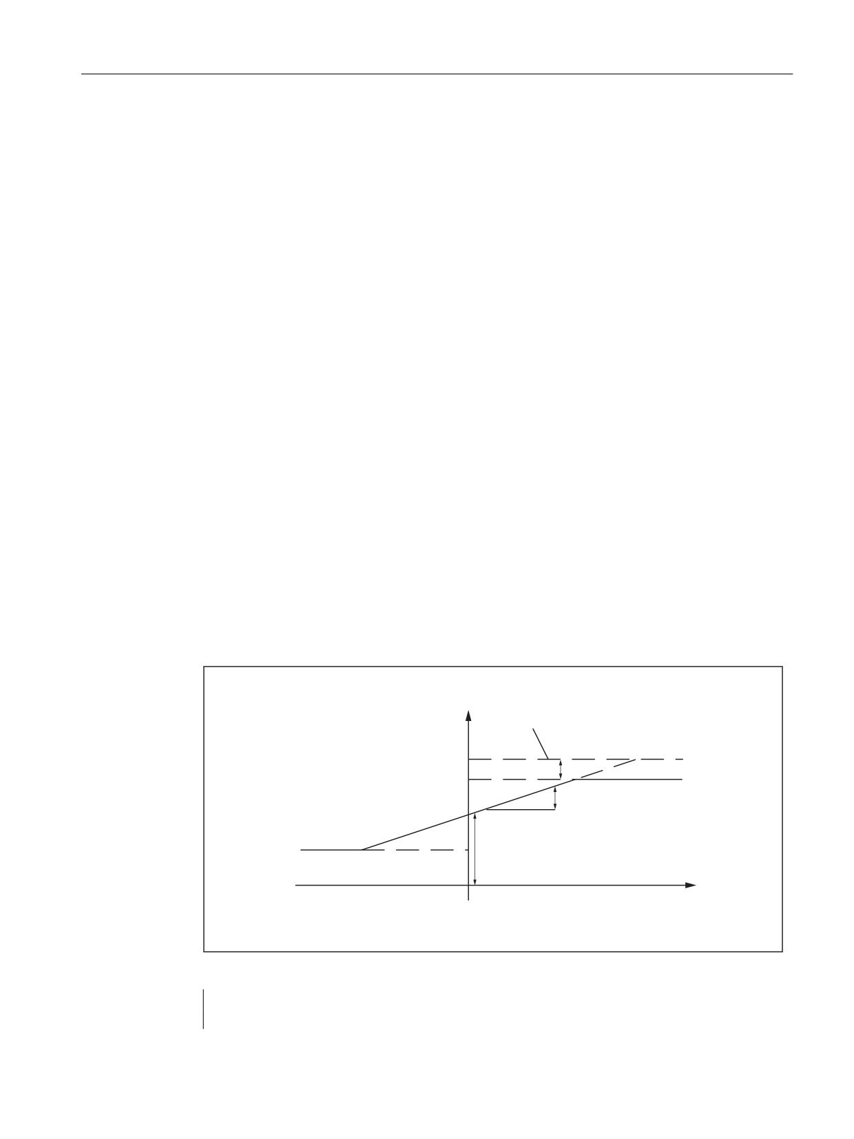
For the purpose of clearance control, the upper limit of the output ($AA_OFF, override value in
axis V) is varied as a function of the spindle override (analog input 1). The upper limit for
polynomial 1 is varied dynamically as a function of analog input 2.
Polynomial 1 is defined directly via system variables:
$$B2))>9@
$GDSWDWLRQ UDQJH RI
XSSHU OLPLW
$&B)&78/> @
$&B)&7 > @
$&B)&7 > @
$B,1$> @
Figure 5-1
Clearance control with variable upper limit
$AC_FCTLL[1]=0.2
; Lower limit
$AC_FCTUL[1]=0.5
; Request Value of upper limit
Synchronized actions
Function Manual, 10/2020, 6FC5397-5BP40-6BA4
135
Examples
5.3 Examples of adaptive control
$AC_FCT0[1]=0.35
; Zero passage a
0
$AC_FCT1[1]=1.5 EX-5
; Pitch a1
STOPRE
; see following note
STOPRE
; see following note
ID=1 DO $AC_FCTUL[1]=$A_INA[2]*0.1+0.35
;
Adjust upper limit dynamically via
analog input 2,
;
no condition
;
ID=2 DO SYNFCT(1, $AA_OFF[V], $A_INA[1])
;
Clearance control by override of no
condition
;
Note
When system variables are used in the part program, STOPRE must be programmed to ensure
block-synchronous writing. The following is an equivalent notation for polynomial definition:
FCTDEF(1,0.2, 0.5, 0.35, 1.5EX-5).
Synchronized actions
136
Function Manual, 10/2020, 6FC5397-5BP40-6BA4
Examples
5.3 Examples of adaptive control
5.3.2
Feedrate control
Example of adaptive control with an analog input voltage
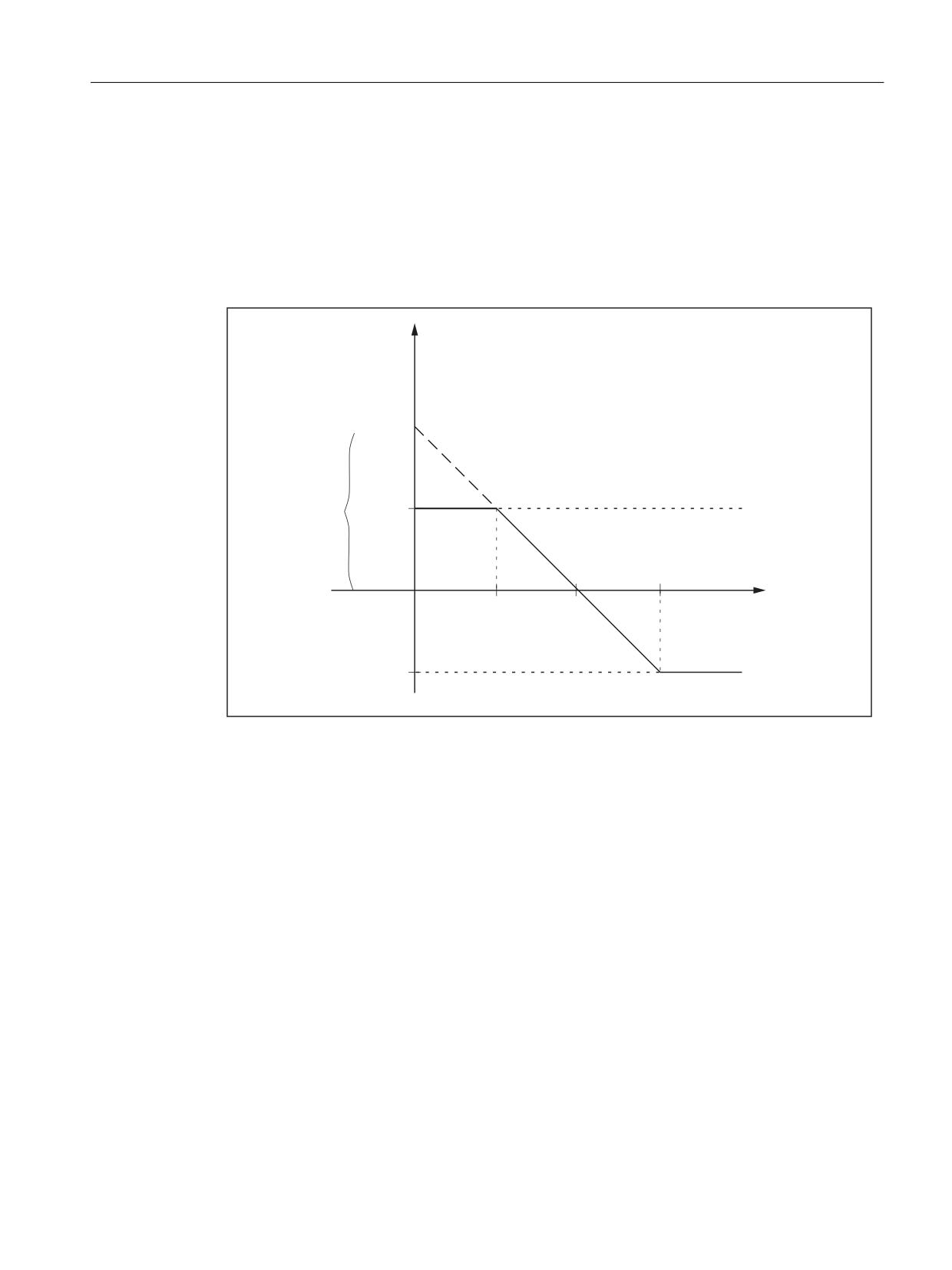
A process quantity (measured via $A_INA[1]) is to be controlled at 2 V using an additive control
factor implemented by a path (or axial) feedrate override. Feedrate override is to be performed
within the range of +100 [mm/min].
3DWK DQG D[LDO
IHHGUDWH RIIVHW
$&B9&
$$B9&>$;@
8QLW
H J PP PLQ
8/,0,7
D
9
9
9
$QDORJ LQSXW
$B,1$> @
8QLW
9
//,0,7
Figure 5-2
Diagram illustrating adaptive control
Determining the coefficients:
y = f(x) = a0 + a1x +a2x2 + a3x3
a1 = - 100mm / (1min * 1V)
a1 = - 100% control constant, gradient
a0 = - (-100) * 2 = 200
a2 = 0 (not a square component)
a3 = 0 (not a cubic component)
upper limit = 100
Lower limit = -100
FCTDEF(
Polynomial
LLIMIT,
ULIMIT,
a0,
; y for x = 0
a1,
; gradient
Synchronized actions
Function Manual, 10/2020, 6FC5397-5BP40-6BA4
137
Examples
5.3 Examples of adaptive control
a
2
,
; square component
a3 )
; cubic component
With the values determined above, the polynomial is defined as follows:
FCTDEF(1, -100, 100, 200, -100, 0, 0)
The following synchronized actions can be used to activate the adaptive control function:
for the axis feedrate:
ID = 1 DO SYNFCT (1, $AA_VC[X], $A_INA[1])
or for the path feedrate:
ID = 2 DO SYNFCT(1, $AC_VC, $A_INA[1])
5.3.3
Control velocity as a function of normalized path
Multiplicative adaptation
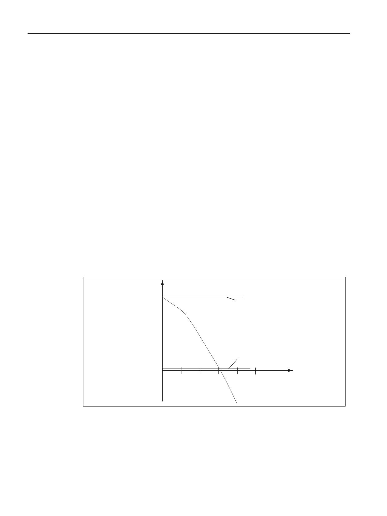
The normalized path is applied as an input quantity: $AC_PATHN.
0: At block start
1: at block end
Variation quantity $AC_OVR must be controlled as a function of $AC_PATHN according to a 3rd
order polynomial. The override must be reduced from 100 to 1% during the motion.
2YHUULGH
$&B295
8SSHU OLPLW
/RZHU OLPLW
3DWK SDUDPHWHUV
$&B3$7+1
Figure 5-3
Regulate velocity continuously
Polynomial 2:
Lower limit: 1
Hi limit: 100
a0: 100
Synchronized actions
138
Function Manual, 10/2020, 6FC5397-5BP40-6BA4
Examples
5.5 Store execution times in R parameters
a
1
: -100
a2: -100
a3: not used
With these values, the polynomial definition is as follows:
FCTDEF(2, 1, 100, 100, -100, -100)
; Activation of the variable override as a function of the path:
ID= 1 DO SYNFCT (2, $AC_OVR, $AC_PATHN)
G01 X100 Y100 F1000
5.4
Monitoring a safety clearance between two axes
Task
The axes X1 and X2 operate two independently controlled transport devices used to load and
unload workpieces.
To prevent the axes from colliding, a safety clearance must be maintained between them.
If the safety clearance is violated, then axis X2 is decelerated. This interlock is applied until axis
X1 leaves the safety clearance area again.
If axis X1 continues to move towards axis X2, thereby crossing a closer safety barrier, then it is
traversed into a safe position.
NC language
Comment
ID=1 WHENEVER $AA_IM[X2] -
; Safety barrier
$AA_IM[X1] < 30 DO $AA_OVR[X2]=0
ID=2 EVERY $AA_IM[X2] - $AA_IM[X1]
; Safe position
< 15 DO POS[X1]=0
5.5
Store execution times in R parameters
Task
Store the execution time for part program blocks starting at R parameter 10.
Program
Comment
; The example is
; as follows without symbolic programming:
IDS=1 EVERY $AC_TIMEC==0 DO
; Advance R parameter
$AC_MARKER[0] = $AC_MARKER[0] + 1
; pointer on block change
IDS=2 DO $R[10+$AC_MARKER[0]] =
; Write current time
$AC_TIME
; of block start in each case to R parameter
Synchronized actions
Function Manual, 10/2020, 6FC5397-5BP40-6BA4
139
Examples
5.6 "Centering" with continuous measurement
Program
Comment
; The example is
; as follows with symbolic programming:
DEFINE INDEX AS $AC_MARKER[0]
; Agreements for symbolic
; programming
IDS=1 EVERY $AC_TIMEC==0 DO INDEX =
; Advance R parameter
INDEX + 1
; pointer on block change
IDS=2 DO $R[10+INDEX] = $AC_TIME
; Write current time
; of block start in each case to R parameter
5.6
"Centering" with continuous measurement
Introduction
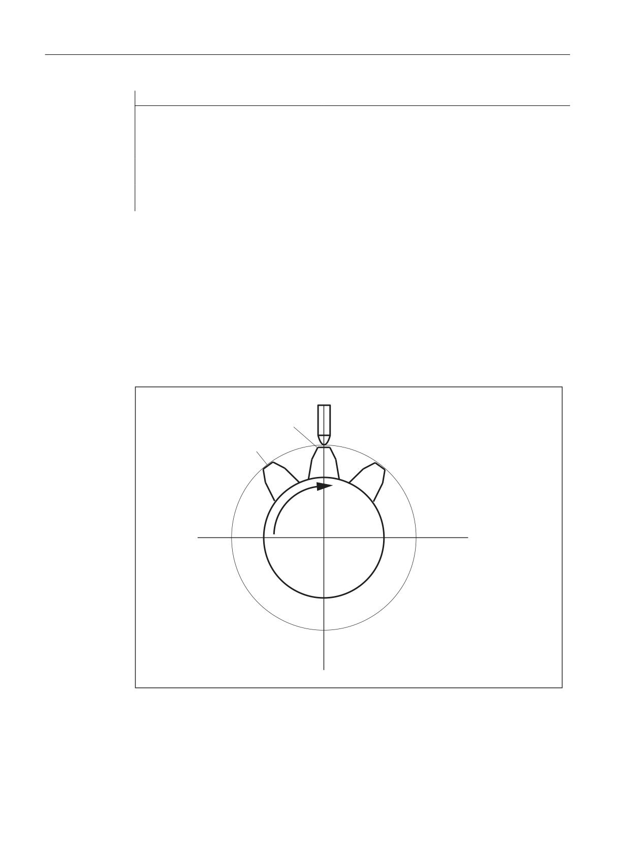
The gaps between gear teeth are measured sequentially. The gap dimension is calculated from
the sum of all gaps and the number of teeth. The center position required to continue machining
is the position of the first measuring point plus 1/2 the average gap size. When measuring, the
speed is selected so that for each interpolation clock cycle a measured value can be reliably
detected.
IDOOLQJ HGJH VWDUW RI JDS
ULVLQJ HGJH HQG RI JDS
3UREH
Figure 5-4
Diagrammatic representation showing how gaps between the gear teeth are measured
Synchronized actions
140
Function Manual, 10/2020, 6FC5397-5BP40-6BA4
Examples
5.6 "Centering" with continuous measurement
%_N_MEAC_MITTEN_MPF
; Measure using rotary axis B (BACH) where the difference is displayed
; between the measured values
;*** Define local user variables ***
N1 DEF INT ZAEHNEZAHL
; Input number of gear teeth
N5 DEF REAL HYS_POS_FLANKE
; Hysteresis positive edge probe
N6 DEF REAL HYS_NEG_FLANKE
; Hysteresis negative edge probe
;*** Define short names for synchronized action markers ***
define M_ZAEHNE as $AC_MARKER[1]
; ID marker for calculation: neg/pos edge per
tooth
define Z_MW as $AC_MARKER[2]
; Read ID counter MW FIFO
define Z_RW as $AC_MARKER[3]
; Calculate ID Counter MW tooth gaps
;*** Input values for ZAHNRADMESSEN ***
N50 ZAEHNEZAHL=26
; Enter number of gear teeth to be measured
N70 HYS_POS_FLANKE = 0.160
; Hysteresis positive edge probe
N80 HYS_NEG_FLANKE = 0.140
; Hysteresis negative edge probe
Start:
*** Assign variables ***
R1=0
; ID2 calculation result for gap dimension
R2=0
; ID2 calculation result addition of all gaps
R3=0
; Content of the first element read
R4=0
; R4 corresponds to a tooth distance
R5=0
; Gap position calculated, final result
R6=1
; Switch-on ID 3 BACH with MOV
R7=1
; Switch-on ID 5 MEAC
M_ZAEHNE=ZAEHNEZAHL*2
; Calculate ID neg./pos. edge per tooth
Z_MW=0
; Read ID counter MW FIFO till the number of
teeth
Z_RW=2
; Calculate ID counter difference of tooth gap
R13=HYS_POS_FLANKE
; Hysteresis in calculation register
R14=HYS_NEG_FLANKE
; Hysteresis in calculation register
;*** Traverse axis, measure, calculate ***
N100 MEAC[BACH]=(0)
; Reset measurement job
; Reset FIFO1[4] variables and ensure a defined measurement trace
N105 $AC_FIFO1[4]=0
; Reset FIFO1
STOPRE
;*** Read out FIFO until the number of teeth reached ***
; If FIFO1 is not empty and all teeth are still not measured, save measured value
from FIFO variable in
; synchronization parameter and increment counter of measured values
ID=1 WHENEVER ($AC_FIFO1[4]>=1) AND (Z_MW<M_ZAEHNE)
DO $AC_PARAM[0+Z_MW]=$AC_FIFO1[0]
Z_MW=Z_MW+1
Synchronized actions
Function Manual, 10/2020, 6FC5397-5BP40-6BA4
141
Examples
5.6 "Centering" with continuous measurement
; if 2 measured values are present, start calculation, calculate ONLY gap dimension
; and gap sum, increment calculation value counter by 2
ID=2 WHENEVER (Z_MW>=Z_RW) AND (Z_RW<M_ZAEHNE)
DO $R1=($AC_PARAM[-1+Z_RW]-$R13)-($AC_PARAM[-2+Z_RW]-$R14)
Z_RW=Z_RW+2 $R2=
$R2+$R1
;*** Switch-on the axis BACH as endless rotating rotary axis with MOV ***
WAITP(BACH)
; Switch on
ID=3 EVERY $R6==1 DO MOV[BACH]=1 FA[BACH]=1000
; Switch off
ID=4 EVERY $R6==0 and ($AA_STAT[BACH]==1) DO MOV[BACH]=0
; Measure sequentially, store in FIFO 1, MT2 neg, MT2 pos edge;the distance between
two teeth is measured
;falling edge-...-rising edge, probe 2
N310 ID=5 WHEN $R7==1 DO MEAC[BACH]=(2, 1, -2, 2)
; Cancel measurement
N320 ID=6 WHEN (Z_MW>=M_ZAEHNE) DO MEAC[BACH]=(0)
M00
STOPRE
;*** Fetch FIFO values and save***
; Content of the first element read
; Reset FIFO1[4] variables and ensure a
; defined measurement trace for the next measuring job
N400 R3=$AC_PARAM[0]
N500 $AC_FIFO1[4]=0
;*** Calculate difference between the individual teeth ***
; R4 corresponds to an average tooth distance
; division "/1000" removed in later SW versions
N510 R4=R2/(ZAEHNEZAHL)/1000
;*** Calculate center position ***
N520 R3=R3/1000
; First measurement position converted to de-
gree
N530 R3=R3 MOD 360
; first measurement point modulo
N540 R5=(R3-R14)+(R4/2)
; Calculate gap position
M00
STOPRE
R6=0
; Deactivate axis rotation from BACH
GOTOB START
M30
Synchronized actions
142
Function Manual, 10/2020, 6FC5397-5BP40-6BA4
Examples
5.7 Axis couplings via synchronized actions
5.7
Axis couplings via synchronized actions
5.7.1
Coupling to leading axis
Task assignment
A cyclic curve table is defined by means of polynomial segments. Controlled by means of
arithmetic variables, the movement of the master axis and the coupling process between master
and slave (following) axes is activated/deactivated.
%_N_KOP_SINUS_MPF
N5 R1=1
; ID 1, 2 activate/deactivate coupling: LEADON
(CACB, BACH)
N6 R2=1
; ID 3, 4 Move leading axis on/off: MOV BACH
N7 R5=36000
; BACH Feedrate/min
N8 STOPRE
;*** Define periodic table No. 4 through polynomial segments ***
N10 CTABDEF (YGEO,XGEO,4,1)
N16 G1 F1200 XGEO=0.000 YGEO=0.000
; Go to basic position
N17 POLY PO[XGEO]=(79,944.30.420,00.210) PO[YGEO]=(24,634.00.871,-9,670)
N18 PO[XGEO]=(116.059,0.749,-0.656) PO[YGEO]=(22.429,-5.201,0.345)
N19 PO[XGEO]=(243.941,-17.234,11.489) PO[YGEO]=(-22.429,-58.844,39.229)
N20 PO[XGEO]=(280.056,1.220,-0.656) PO[YGEO]=(-24.634,4.165,0.345)
N21 PO[XGEO]=(360.000,-4.050,0.210) PO[YGEO]=(0.000,28.139,-9.670)
N22 CTABEND
;
*** End of table definition ***
; Travel axis leading axis and coupled axis in quick motion in basic position
N80 G0 BACH=0 CACH=0
; Channel axis names
N50 LEADOF(CACH,BACH)
; existing coupling OFF
N235 ;*** Switch-on the coupling movement for the axis CACH ***
N240 WAITP(CACH)
; Synchronize axis to channel
N245 ID=1 EVERY $R1==1 DO LEA-
; Coupling via table 4
DON(CACH, BACH, 4)
N250 ID=2 EVERY $R1==0 DO LEA-
; Deactivate coupling
DOF(CACH, BACH)
N265 WAITP(BACH)
Synchronized actions
Function Manual, 10/2020, 6FC5397-5BP40-6BA4
143
Examples
5.7 Axis couplings via synchronized actions
N270 ID=3 EVERY $R2==1 DO
; Rotate leading axis with feedrate endlessly
MOV[BACH]=1 FA[BACH]=R5
in R5
N275 ID=4 EVERY $R2==0 DO
; Stop leading axis
MOV[BACH]=0
N280 M00
N285 STOPRE
N290 R1=0
; Disable coupling condition
N295 R2=0
; Disable condition for rotating leading axis
N300 R5=180
; New feedrate for BACH
N305 M30
5.7.2
Non-circular grinding via master value coupling
Task assignment
A non-circular workpiece that is rotating on axis CACH must be machined by grinding. The
distance between the grinding wheel and workpiece is controlled by axis XACH and depends on
the angle of rotation of the workpiece. The interrelationship between angles of rotation and
assigned movements is defined in curve table 2. The workpiece must move at velocities that are
determined by the workpiece contour defined in curve table 1.
Solution
CACH is designated as the leading axis in a master value coupling. It controls:
• via table 2 the compensatory movement of the axis XACH
• via table 1 the "software axis" CASW.
The axis override of axis CACH is determined by the actual values of axis CASW, thus providing
the required contour-dependent velocity of axis CACH.
Synchronized actions
144
Function Manual, 10/2020, 6FC5397-5BP40-6BA4
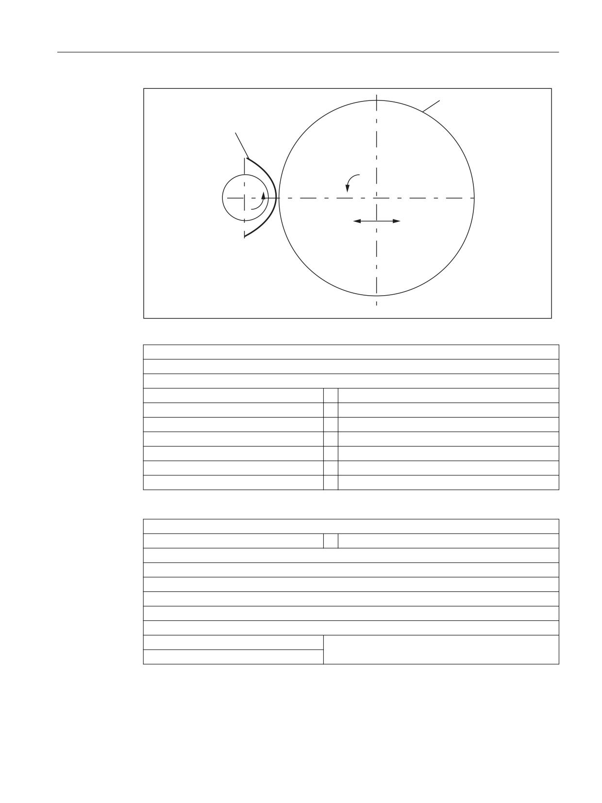
Examples
5.7 Axis couplings via synchronized actions
*ULQGLQJ GLVF
6HFWLRQ RI
:RUNSLHFH FRQWRXU
&$&
+
;$&+
Figure 5-5
Diagrammatic representation of non-circular contour grinding
%_N_CURV_TABS_SPF
PROC CURV_TABS
N160 ; *** Define table 1 override ***
N165 CTABDEF(CASW,CACH,1.1)
;
Table 1 periodic
N170 CACH=0 CASW=10
N175 CACH=90 CASW=10
N180 CACH=180 CASW=100
N185 CACH=350 CASW=10
N190 CACH=359.999 CASW=10
N195 CTABEND
N160 ; *** Define table 2 linear compensatory movement of XACH ***
CTABDEF(YGEO,XGEO,2.1)
;
Table 2 periodic
N16 XGEO=0.000 YGEO=0.000
N16 XGEO=0.001 YGEO=0.000
N17 POLY PO[XGEO]=(116.000,0.024,0.012) PO[YGEO]=(4.251,0.067,-0.828)
N18 PO[XGEO]=(244.000,0.072,-0.048) PO[YGEO]=(4.251,-2.937)
N19 PO[XGEO]=(359.999,-0.060,0.012) PO[YGEO]=(0.000,-2.415,0.828)
N16 XGEO=360.000 YGEO=0.000
N20 CTABEND
M17
%_N_UNRUND_MPF
; Coupling group for a non-circular machining
; XACH is the infeed axis of the grinding disk
Synchronized actions
Function Manual, 10/2020, 6FC5397-5BP40-6BA4
145
Examples
5.7 Axis couplings via synchronized actions
; CACH is the workpiece axis as rotary axis and master value axis
; Application: Grind non-circular contours
; Table 1 maps the override for axis CACH as function of the position of CACH
; Overlay of the XGEO axis with handwheel infeed for scratching
N100 DRFOF
;
deselect handwheel overlay
N200 MSG(Select "DRF, (Handwheel 1 active) and Select INKREMENT.== Handwheel overlay AKTIV")
N300 M00
N500 MSG()
;
Reset message
N600 R2=1
;
LEADON Table 2, Activate with ID=3/4 CACH to XACH
N700 R3=1
;
LEADON Table 1, Activate with ID=5/6 CACH to CASW,
override
N800 R4=1
;
Endless rotating axis CACH, start with ID=7/8
N900 R5=36000
;
FA[CACH] Endless rotating rotary axis speed
N1100 STOPRE
N1200
;
*** Set axis and leading axis to FA ***
;
Move Axis, master axis and following axis
;
to the initial position
N1300 G0 XGEO=0 CASW=10 CACH=0
N1400 LEADOF(XACH,CACH)
;
Coupling AUS XACH compensatory movement
N1500 LEADOF(CASW,CACH)
;
Coupling AUS CASW override table
N1600 CURV_TABS
;
Sub-program with definition of the tables
N1700
;
*** On-off switch of the LEADON compensatory move-
ment XACH ***
N1800 WAITP(XGEO)
;
Synchronize axis to channel
N1900 ID=3 EVERY $R2==1 DO LEA-
DON(XACH,CACH,2)
N2000 ID=4 EVERY $R2==0 DO LEA-
DOF(XACH,CACH)
N2100
;
*** On-off switch of the LEADON CASW
;
override table ***
N2200 WAITP(CASW)
N2300 ID=5 EVERY $R3==1 DO LEA-
;
CTAB Coupling ON leading axis CACH
DON(CASW,CACH,1)
N2400 ID=6 EVERY $R3==0 DO LEA-
;
CTAB Coupling OFF leading axis CACH
DOF(CASW,CACH)
Synchronized actions
146
Function Manual, 10/2020, 6FC5397-5BP40-6BA4

Examples
5.7 Axis couplings via synchronized actions
N2500
;
*** Control override of the CACH from position
;
CASW with ID 10 ***
N2700 ID=11 DO $$AA_OVR[CACH]=
;
Assign "axis position" CASW to OVR CACH
$AA_IM[CASW]
N2900 WAITP(CACH)
N3000 ID=7 EVERY $R4==1 DO
;
Start as endless rotating rotary axis
MOV[CACH]=1 FA[CACH]=R5
N3100 ID=8 EVERY $R4==0 DO
;
Stop as endless rotating rotary axis
MOV[CACH]=0
N3200 STOPRE
N3300 R90=$AA_COUP_ACT[CASW]
;
State of the coupling for CASW for checking
N3400 MSG("Override table CASW activated with LEADON "<<R90<<", further ENDE with NC-START")
N3500 M00
;
*** NC HALT ***
N3600 MSG()
N3700 STOPRE
;
Preprocessing stop
N3800 R1=0
;
Stop with ID=2 CASW axis as
;
endless rotating rotary axis
N3900 R2=0
;
LEADOF with ID=6 FA XACH
;
and leading axis CACH
N4000 R3=0
;
LEADOF TAB1 CASW with ID=7/8 CACH
;
to CASW override table
N4100 R4=0
;
Stop axis as endless rotating rotary axis
;
, ID=4 CACH
N4200 M30
Expansion options
The example above can be expanded by the following components:
• Introduction of a Z axis to move the grinding wheel or workpiece from one non-circular
operation to the next on the same shaft (cam shaft).
• Table switchovers, if the cams for inlet and outlet have diferent contours.
ID = ... <Condition> DO LEADOF(XACH, CACH) LEADON(XACH, CACH, <new
table number>)
• Dressing of grinding wheel by means of online tool offset acc. to Subsection "Online tool
offset FTOC".
Synchronized actions
Function Manual, 10/2020, 6FC5397-5BP40-6BA4
147
Examples
5.7 Axis couplings via synchronized actions
5.7.3
On-the-fly parting
Task assignment
An extruded material which passes continuously through the operating area of a cutting tool
must be cut into parts of equal length.
X axis: Axis in which the extruded material moves, WCS
X1 axis: Machine axis of the extruded material, MCS
Y axis: Axis in which the cutting tool "tracks" the extruded material
It is assumed that the infeed and control of the cutting tool are controlled via the PLC. The signals
at the PLC interface can be evaluated to determine whether the extruded material and cutting
tool are synchronized.
Actions
Activate coupling, LEADON
Deactivate coupling, LEADOF
Set actual values, PRESETON
Program code
Comment
%_N_SCHERE1_MPF
;$PATH=/_N_WKS_DIR/_N_DEMOFBE_WPD
N100 R3=1500
; Length of a part to be cut off
N200 R2=100000 R13=R2/300
N300 R4=100000
N400 R6=30
; Start position Y axis
N500 R1=1
; Start condition for conveyor axis
N600 LEADOF(Y,X)
; Delete any existing coupling
N700 CTABDEF(Y,X,1,0)
; Table definition
N800 X=30 Y=30
; Value pairs
N900 X=R13 Y=R13
N1000 X=2*R13 Y=30
N1100 CTABEND
; End of table definition
N1200 PRESETON(X1,0)
; Preset offset at the beginning
N1300 Y=R6 G0
; Start position Y axis
; The axis is a linear axis
N1400 ID=1 EVERY $AA_IW[X]>$R3 DO PRESETON(X1,0)
; Preset offset after length R3, PRESE-
TON must only be executed with WHEN
and EVERY
; New start after parting
N1500 WAITP(Y)
N1800 ID=6 EVERY $AA_IM[X]<10 DO LEADON(Y,X,1)
; For X < 10, couple Y to X via table 1
N1900 ID=10 EVERY $AA_IM[X]>$R3-30 DO LEADOF(Y,X)
; > 30 before traversed parting dis-
tance, deactivate coupling
N2000 WAITP(X)
Synchronized actions
148
Function Manual, 10/2020, 6FC5397-5BP40-6BA4
Examples
5.8 Technology cycles position spindle
Program code
Comment
N2100 ID=7 WHEN $R1==1 DO MOV[X]=1 FA[X]=$R4
; Set extruded material axis continuous-
ly in motion
N2200 M30
5.8
Technology cycles position spindle
Application
Interacting with the PLC program, the spindle which initiates a tool change should be:
• Traversed to an initial position,
• Positioned at a specific point at which the tool to be inserted is located.
See Section "Starting command axes" and Section "Control via PLC".
Coordination
The PLC and NCK are coordinated by means of the common data that are provided in SW version
4 and later (see Section "List of system variables relevant to synchronized actions")
• $A_DBB[0]: Go to basic position 1,
• $A_DBB[1]: Go to target position 1,
• $A_DBW[1]: Value to be positioned +/- , PLC calculates the shortest route.
Synchronized actions
%_N_MAIN_MPF
IDS=1 EVERY $A_DBB[0]==1 DO NULL_POS
; When $A_DBB[0] set by PLC, go
to basic position.
IDS=2 EVERY $A_DBB[1]==1 DO ZIEL_POS
; When $A_DBB[1] set by PLC, po-
sition spindle to the value stor-
ed in$A_DBW[1].
Technology cycle NULL_POS
%_N_NULL_POS_SPF
PROC NULL_POS
SPOS=0
; Put drive for the tool change into basic posi-
tion.
$A_DBB[0]=0
; Basic position executed in NC.
Synchronized actions
Function Manual, 10/2020, 6FC5397-5BP40-6BA4
149
Examples
5.9 Synchronized actions in the TC/MC area
Technology cycle ZIEL_POS
%_N_ZIEL_POS_SPF
PROC ZIEL_POS
SPOS=IC($A_DBW[1])
; Traverse spindle to position value that has been
stored in $A_DBW[1] by the PLC, incremental dimen-
sion
$A_DBB[1]=0
; Target positions executed in NC.
5.9
Synchronized actions in the TC/MC area
Introduction
The following figure shows the schematic structure of a tool-changing cycle.
<
<
= UHOHDVHG
0DJD]LQH 3RVLWLRQLQJ
5HWXUQ WRRO
)HWFK 722/
/HYHO WRRO SRFNHWV
:3<
:3<
:3;
:3;
= FODPSHG
,QWHUPHGLDWH SRLQW
=3 <
FDQ EH URXQGHG
=3 ;
93<
93<
93;
6WDUWLQJ SRLQW
93;
6WDUWLQJ SRLQW
= FODPSHG
= UHOHDVHG
=
=
;
Figure 5-6
Schematic sequence for tool-changing cycle
Synchronized actions
150
Function Manual, 10/2020, 6FC5397-5BP40-6BA4
Examples
5.9 Synchronized actions in the TC/MC area
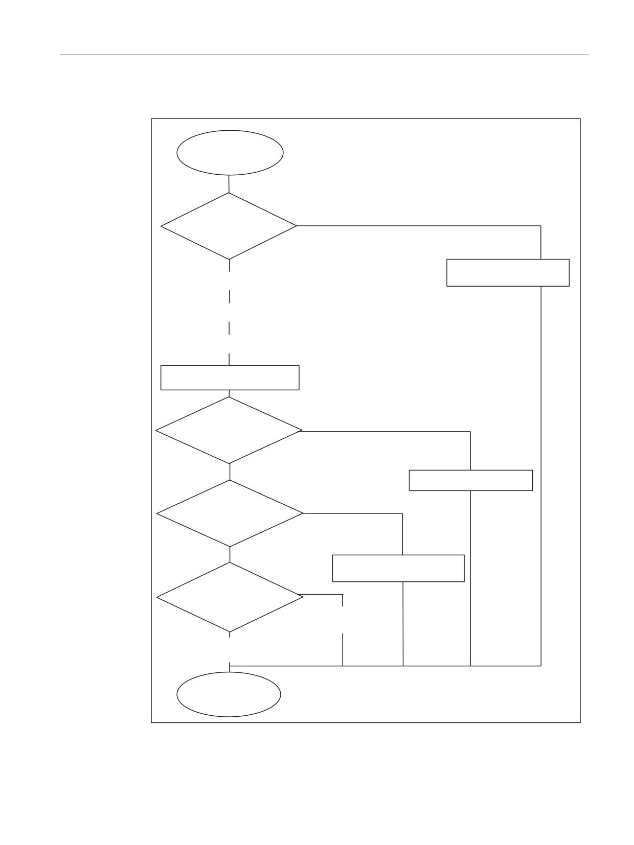
Flow diagram
6WDUW
7RRO FKDQJH F\FOH LQ
03)
<HV
%ORFN VHDUFK DFWLYH"
,I 3B6($5&+ *272)
1R
7RRO FKDQJH 0
3RVLWLRQ VSLQGOHV RYHU EORFN OLPLWV
' $FWLYDWH WRRO RIIVHW
6326$ RU 6326$>Q@
5HDG SUHVHW 7 QXPEHU
*(76(/7>@ RU *(76(/7> Q@
5HDG 7 QXPEHU IURP VSLQGOH
7RRO6SLQGOH
7&B033 >
P@
&KDQJH WRRO
0
0'
3UHVHOHFWHG WRRO LQ 63"
<HV
,I :=6SLQGOH
:=6HOHFWLRQ
*272)
1R
' $FWLYDWH WRRO RIIVHW
3UHVHOHFWHG 7 1R
"
<HV
,I 7RROFRGH
*272)
1R
5HWXUQ WRRO
' 'HDFWLYDWH WRRO RIIVHW
<HV
1R WRRO LQ VSLQGOH"
,I 7RRO6SLQGOH
*272)
)HWFK 722/
' $FWLYDWH WRRO RIIVHW
1R
VW 5HWXUQ WRRO QG )HWFK WRRO
' $FWLYDWH WRRO RIIVHW
(QG
Figure 5-7
Flow diagram for tool changing cycle
Synchronized actions
Function Manual, 10/2020, 6FC5397-5BP40-6BA4
151
Examples
5.9 Synchronized actions in the TC/MC area
NC program
Comment
%_N_WZW_SPF
;$PATH=/_N_SPF_DIR
N10 DEF INT WZVorwahl,WZSpindel
;Marker on = 1 when MagAxis traversed
N15 WHEN $AC_PATHN<10 DO $AC_MARKER[0]=0 $AC_MARKER[1]=0
$AC_MARKER[2]=0
N20 ID=3 WHENEVER $A_IN[9]==TRUE DO $AC_MARKER[1]=1
N25 ID=4 WHENEVER $A_IN[10]==TRUE DO $AC_MARKER[2]=1
;Marker on = 1 when MagAxis traversed
N30 IF $P_SEARCH GOTOF wzw_vorlauf
;Block preprocessing active ? ->
N35 SPOSA=0 D0
N40 GETSELT(WZVorwahl)
;Read preselected T no.
N45 WZSpindel=$TC_MPP6[9998,1]
;Read tool in spindle
N50 M06
N55 IF WZSpindel==WZVorwahl GOTOF wz_in_spindel IF WZVor-
wahl==0 GOTOF ablegen1 IF WZSpindel==0 GOTOF holen1
;*** Fetch and store tool***
ablegen1holen1:
N65 WHENEVER $AA_VACTM[C2]<>0 DO $AC_MARKER[1]=1
;when MagAxis travels Marker = 1
N70 G01 G40 G53 G64 G90 X=Magazin1VPX Y=Magazin1VPY Z=Maga-
zin1ZGespannt F70000 M=QU(120) M=QU(123) M=QU(9)
N75 WHENEVER $AA_STAT[S1]<>4 DO $AC_OVR=0
;Spindle in position
N80 WHENEVER $AA_VACTM[C2]<>0 DO $AC_MARKER[1]=1
;Query MagAxis travel
N85 WHENEVER $AC_MARKER[1]==0 DO $AC_OVR=0
;Override=0 when axis not traversed
N90 WHENEVER $AA_STAT[C2]<>4 DO $AC_OVR=0
;Override=0 when MagAxis
not in position fine
N95 WHENEVER $AA_DTEB[C2]>0 DO $AC_OVR=0
;Override=0 when distance-to-go MagAx-
is > 0
N100 G53 G64 X=Magazin1ZP1X Y=Magazin1ZP1Y F60000
N105 G53 G64 X=Magazin1WPX Y=Magazin1WPY F60000
N110 M20
;Release tool
N115 G53 G64 Z=MR_Magazin1ZGeloest F40000
N120 WHENEVER $AA_VACTM[C2]<>0 DO $AC_MARKER[2]=1;
N125 WHENEVER $AC_MARKER[2]==0 DO $AC_OVR=0
N130 WHENEVER $AA_STAT[C2]<>4 DO $AC_OVR=0
N135 WHENEVER $AA_DTEB[C2]>0 DO $AC_OVR=0
N140 G53 G64 Z=Magazin1ZGespannt F40000
N145 M18
;Clamp tool
N150 WHEN $AC_PATHN<10 DO M=QU(150) M=QU(121)
;Condition always fulfilled
N155 G53 G64 X=Magazin1VPX Y=Magazin1VPY F60000 D1 M17
Synchronized actions
152
Function Manual, 10/2020, 6FC5397-5BP40-6BA4
Examples
5.9 Synchronized actions in the TC/MC area
NC program
Comment
;*** Store tool***
ablegen1:
N160 WHENEVER $AA_VACTM[C2]<>0 DO $AC_MARKER[1]=1
N165 G01 G40 G53 G64 G90 X=Magazin1VPX Y=Magazin1VPY Z=Maga-
zin1ZGespannt F70000 M=QU(120) M=QU(123) M=QU(9)
N170 WHENEVER $AA_STAT[S1]<>4 DO $AC_OVR=0
N175 WHENEVER $AA_VACTM[C2]<>0 DO $AC_MARKER[1]=1
N180 WHENEVER $AC_MARKER[1]==0 DO $AC_OVR=0
N185 WHENEVER $AA_STAT[C2]<>4 DO $AC_OVR=0
N190 WHENEVER $AA_DTEB[C2]>0 DO $AC_OVR=0
N195 G53 G64 X=Magazin1ZP1X Y=Magazin1ZP1Y F60000
N200 G53 G64 X=Magazin1WPX Y=Magazin1WPY F60000
N205 M20
;Release tool
N210 G53 G64 Z=Magazin1ZGeloest F40000
N215 G53 G64 X=Magazin1VPX Y=Magazin1VPY F60000 M=QU(150)
M=QU(121) D0 M17
;*** Fetch tool***
holen1:
N220 WHENEVER $AA_VACTM[C2]<>0 DO $AC_MARKER[2]=1
N225 G01 G40 G53 G64 G90 X=Magazin1VPX Y=Magazin1VPY Z=Maga-
zin1ZGeloest F70000 M=QU(120) M=QU(123) M=QU(9)
N230 G53 G64 X=Magazin1WPX Y=Magazin1WPY F60000
N235 WHENEVER $AA_STAT[S1]<>4 DO $AC_OVR=0
N240 WHENEVER $AA_VACTM[C2]<>0 DO $AC_MARKER[2]=1
N245 WHENEVER $AC_MARKER[2]==0 DO $AC_OVR=0
N250 WHENEVER $AA_STAT[C2]<>4 DO $AC_OVR=0
N255 WHENEVER $AA_DTEB[C2]>0 DO $AC_OVR=0
N260 G53 G64 Z=Magazin1ZGespannt F40000
N265 M18
;Clamp tool
N270 G53 G64 X=Magazin1VPX Y=Magazin1VPY F60000 M=QU(150)
M=QU(121) D1 M17
;***Tool in spindle***
wz_in_spindle:
N275 M=QU(121) D1 M17
;***Block preprocessing***
wzw_feed:
N280 STOPRE
N285 D0
N290 M06
N295 D1 M17
Synchronized actions
Function Manual, 10/2020, 6FC5397-5BP40-6BA4
153
Examples
5.9 Synchronized actions in the TC/MC area
Synchronized actions
154
Function Manual, 10/2020, 6FC5397-5BP40-6BA4

Data lists
6
6.1
Machine data
6.1.1
General machine data
Number
Identifier: $MN_
Description
11110
AUXFU_GROUP_SPEC
Auxiliary function group specification
11500
PREVENT_SYNACT_LOCK
Protected synchronized actions
18860
MM_MAINTENANCE_MON
Activate recording of maintenance data
6.1.2
Channelspecific machine data
Number
Identifier: $MC_
Description
21240
PREVENT_SYNACT_LOCK_CHAN
Protected synchronized actions for channel
28250
MM_NUM_SYNC_ELEMENTS
Number of elements for expressions in synchronized
actions
28252
MM_NUM_FCTDEF_ELEMENTS
Number of FCTDEF elements
28254
MM_NUM_AC_PARAM
Number of $AC_PARAM parameters
28255
MM_BUFFERED_AC_PARAM
Memory location of $AC_PARAM
28256
MM_NUM_AC_MARKER
Number of $AC_MARKER markers
28257
MM_BUFFERED_AC_MARKER
Memory location of $AC_MARKER
28258
MM_NUM_AC_TIMER
Number of $AC_TIMER time variables
28260
NUM_AC_FIFO
Number of $AC_FIFO1, $AC_FIFO2, ... variables
28262
START_AC_FIFO
Store FIFO variables from R parameter
28264
LEN_AC_FIFO
Length of $AC_FIFO ... FIFO variables
28266
MODE_AC_FIFO
FIFO processing mode
6.1.3
Axis-specific machine data
Number
Identifier: $MA_
Description
30450
IS_CONCURRENT_POS_AX
Concurrent positioning axis
32060
POS_AX_VELO
Initial setting for positioning axis velocity
32070
CORR_VELO
Axial velocity for handwheel, ext. WO (work offset),
cont. dressing, clearance control
Synchronized actions
Function Manual, 10/2020, 6FC5397-5BP40-6BA4
155

Data lists
6.2 Setting data
Number
Identifier: $MA_
Description
32074
FRAME_OR_CORRPOS_NOTALLOWED
Effectiveness of frames and tool length offset
32920
AC_FILTER_TIME
Filter smoothing time constant for Adaptive Control
33060
MAINTENANCE_DATA
Configuration, recording maintenance data
36750
AA_OFF_MODE
Effect of value assignment for axial override with
synchronized actions
37200
COUPLE_POS_TOL_COARSE
Threshold value for "Coarse synchronism"
37210
COUPLE_POS_TOL_FINE
Threshold value for "Fine synchronism"
6.2
Setting data
6.2.1
Axis/spindle-specific setting data
Number
Identifier: $SA_
Description
43300
ASSIGN_FEED_PER_REV_SOURCE
Rotational feedrate for positioning axes/spindles
43350
AA_OFF_LIMIT
Upper limit of offset value for $AA_OFF clearance con-
trol
43400
WORKAREA_PLUS_ENABLE
Working area limitation in pos. direction
Synchronized actions
156
Function Manual, 10/2020, 6FC5397-5BP40-6BA4
Preface
1
Introduction
Fundamental safety
2
instructions
SINUMERIK
Installation and activation
3
of loadable compile cycles
SINUMERIK 840D sl
Technologies
Simulation of compile
4
cycles (only HMI Advanced)
Clearance control (CLC/
5
CLCX)
Function Manual
Speed/torque coupling,
6
master-slave
Transformation package
7
handling
8
MCS coupling
Continue machining
9
(retrace support)
Cycle-independent path-
synchronous switching
10
signal output (HSLC)
11
Axis pair collision protection
12
Punching and nibbling
A
Appendix
Valid for
control system
SINUMERIK 840D sl / 840DE sl
CNC software Version 4.94
10/2020
6FC5397-8GP40-0BA1
Table of contents
Preface
3
1
Introduction
13
1.1
About this documentation
13
2
Fundamental safety instructions
15
2.1
General safety instructions
15
2.2
Warranty and liability for application examples
15
2.3
Security information
15
3
Installation and activation of loadable compile cycles
17
3.1
Loading compile cycles
18
3.1.1
Loading a compile cycle with SINUMERIK Operate
18
3.1.2
Loading a compile cycle with HMI Advanced
19
3.1.3
Loading a compile cycle from an external computer with WinSCP
20
3.2
Interface version compatibility
20
3.3
Software version of a compile cycle
22
3.4
Activating the technological functions in the NC
22
3.5
Function-specific startup
23
3.6
Creating alarm texts
23
3.6.1
Creating alarm texts with SINUMERIK Operate
23
3.7
Upgrading a compile cycle
24
3.8
Deleting a compile cycle
25
3.9
Data lists
26
3.9.1
Machine data
26
3.9.1.1
NC-specific machine data
26
4
Simulation of compile cycles (only HMI Advanced)
27
4.1
Brief description
27
4.1.1
Function
27
4.2
OEM transformations
27
5
Clearance control (CLC/CLCX)
29
5.1
Brief description
29
5.1.1
Function description
30
5.2
Clearance control
32
5.2.1
POS mode
32
5.2.1.1
Overview
32
5.2.1.2
POS mode
33
5.2.2
GAIN mode
33
Technologies
Function Manual, 10/2020, 6FC5397-8GP40-0BA1
5
Table of contents
5.2.2.1
Control dynamics - GAIN mode
33
5.2.3
Dead times in the clearance control
35
5.2.4
Optimizing the control behavior
36
5.3
Technological features of clearance control
36
5.4
Sensor collision monitoring
37
5.5
Startup
38
5.5.1
Setup steps
39
5.5.2
Activating the technological function
40
5.5.3
Configuring the memory
41
5.5.4
Sensor input and sensor signals
41
5.5.4.1
Setting up the analog sensor input
41
5.5.4.2
Parameterizing the input signals
42
5.5.4.3
Simulation of the sensor signals
42
5.5.4.4
Linearizing the signal of the clearance sensor
44
5.5.4.5
Compensation of the time delay of the sensor
45
5.5.5
Parameter settings for clearance control
48
5.5.6
Configuration of the basic MD of CLCX
49
5.5.7
Definition of the real-time variables for synchronized actions
51
5.6
Programming
54
5.6.1
Activating and deactivating clearance control (CLC)
54
5.6.2
NC commands and Synact variables
56
5.6.3
Synact variables for diagnostics
58
5.6.4
Available technology commands
59
5.6.5
Diagnosis of the CLCX state
61
5.7
3D clearance control
62
5.7.1
3D clearance control - overview
62
5.7.2
3D control direction
63
5.7.3
Parameterization of the programmable control direction
65
5.7.4
3D clearance control and 5-axis transformation
67
5.8
Multiple CLCX instances in different channels
69
5.8.1
Multiple CLCX instances in one channel
69
5.8.2
Macros for operating and monitoring multiple instances in one channel
71
5.8.3
Programming several instances within one channel
73
5.8.4
Additional voltage/clearance characteristics
74
5.9
Function-specific display data
76
5.9.1
Channel-specific GUD variables
76
5.10
Function-specific alarm texts
77
5.11
Supplementary conditions
78
5.11.1
I/O modules
78
5.11.1.1
External smoothing filters
79
5.11.2
Function-specific supplementary conditions
79
5.12
Data lists
82
5.12.1
Machine data
82
5.12.1.1
NC-specific machine data
82
5.12.1.2
Channelspecific machine data
82
5.12.1.3
Axis/spindlespecific machine data
83
Technologies
6
Function Manual, 10/2020, 6FC5397-8GP40-0BA1
Table of contents
6
Speed/torque coupling, master-slave
85
6.1
Brief description
85
6.2
Coupling diagram
86
6.3
Configuring a coupling
87
6.4
Torque compensatory controller
89
6.5
Tension torque
92
6.6
Closing/opening a coupling
95
6.7
Response on activation/deactivation
97
6.8
Supplementary conditions
101
6.8.1
Functional boundary conditions
101
6.8.2
Axial NC/PLC interface signals
103
6.8.3
Interaction with other functions
104
6.9
Examples
109
6.9.1
Master-slave coupling between AX1=Master and AX2=Slave
109
6.9.2
Close coupling via the PLC
110
6.9.3
Close/separate coupling via part program
110
6.9.4
Release the mechanical brake
111
6.10
Data lists
112
6.10.1
Machine data
112
6.10.1.1
Axis/spindlespecific machine data
112
6.10.2
System variables
112
7
Transformation package handling
113
7.1
Brief description
113
7.2
Kinematic transformation
114
7.3
Definition of terms
114
7.3.1
Units and directions
114
7.3.2
Definition of positions and orientations using frames
115
7.3.3
Definition of a joint
116
7.4
Configuration of a kinematic transformation
117
7.4.1
General machine data
117
7.4.2
Parameterization using geometry data
118
7.5
Descriptions of kinematics
130
7.5.1
3-axis kinematics
130
7.5.2
4-axis kinematics
137
7.5.3
5-axis kinematics
143
7.5.4
6-axis kinematics
147
7.5.5
Special kinematics
148
7.6
Tool orientation
152
7.6.1
Orientation programming for 4-axis kinematics
154
7.6.2
Orientation programming for 5-axis kinematics
156
7.7
Singular positions and how they are handled
157
7.8
Call and application of the transformation
157
Technologies
Function Manual, 10/2020, 6FC5397-8GP40-0BA1
7
Table of contents
7.9
Actual value display
159
7.10
Tool programming
159
7.11
Cartesian PTP travel with handling transformation package
160
7.12
Startup
160
7.12.1
General commissioning
160
7.12.2
Function-specific commissioning
160
7.13
Supplementary conditions
162
7.14
Data lists
163
7.14.1
Machine data
163
7.14.1.1
General machine data
163
7.14.1.2
Channelspecific machine data
164
7.14.1.3
Channel-specific machine data for compile cycles
164
8
MCS coupling
167
8.1
Brief description
167
8.2
Description of MCS coupling functions
168
8.2.1
Defining coupling pairs
168
8.2.2
Switching the coupling ON/OFF
169
8.2.3
Tolerance window
170
8.2.4
Memory configuration: Block memory
170
8.3
Description of collision protection
170
8.3.1
Defining protection pairs
170
8.3.2
Switching collision protection ON / OFF
171
8.3.3
Configuring example
172
8.4
User-specific configurations
173
8.5
Special operating states
173
8.6
Boundary conditions
174
8.7
Data lists
175
8.7.1
Machine data
175
8.7.1.1
Channelspecific machine data
175
8.7.1.2
Axis/spindlespecific machine data
175
9
Continue machining (retrace support)
177
9.1
Brief description
177
9.2
Function description
178
9.2.1
Function
178
9.2.2
Definition of terms
180
9.2.3
Functional sequence (principle)
180
9.2.4
Maximum retraceable contour area
184
9.3
Startup
184
9.3.1
Activation
184
9.3.2
Definition of the RESU working plane
185
9.3.3
Memory configuration: Block memory
185
9.3.4
Memory configuration: Heap memory
186
9.3.5
RESU main program memory area
187
Technologies
8
Function Manual, 10/2020, 6FC5397-8GP40-0BA1
Table of contents
9.3.6
Storage of the RESU subroutines
188
9.3.7
ASUB enable
188
9.3.8
PLC user program
189
9.4
Programming
190
9.4.1
RESU Start/Stop/Reset (CC_PREPRE)
190
9.5
RESU-specific part programs
191
9.5.1
Overview
191
9.5.2
Main program (CC_RESU.MPF)
192
9.5.3
INI program (CC_RESU_INI.SPF)
193
9.5.4
END program (CC_RESU_END.SPF)
195
9.5.5
Retrace support ASUB (CC_RESU_BS_ASUP.SPF)
195
9.5.6
RESU ASUB (CC_RESU_ASUP.SPF)
196
9.6
Retrace support
197
9.6.1
General information
197
9.6.2
Block search with calculation on contour
197
9.6.3
Reposition
198
9.6.4
Temporal conditions concerning NC start
199
9.6.5
Block search from last main block
199
9.7
Function-specific display data
200
9.7.1
Channel-specific GUD variables
200
9.8
Function-specific alarm texts
201
9.9
Boundary conditions
202
9.9.1
Function-specific supplementary conditions
202
9.9.1.1
Continue machining within subprograms
202
9.9.1.2
Continue machining within program loops
202
9.9.1.3
Machining continuation on full circles
203
9.9.1.4
Automatically generated contour elements
203
9.9.2
Supplementary conditions for standard functions
203
9.9.2.1
Axis replacement
203
9.9.2.2
Traversing movements of the channel axes
203
9.9.2.3
Block numbers
204
9.9.2.4
Block search
204
9.9.2.5
Transformations
204
9.9.2.6
Compensations
205
9.9.2.7
Frames
205
9.9.2.8
Tool offsets
206
9.10
Data lists
206
9.10.1
Machine data
206
9.10.1.1
General machine data
206
9.10.1.2
Channelspecific machine data
206
10
Cycle-independent path-synchronous switching signal output (HSLC)
209
10.1
Brief description
209
10.2
Functional description
210
10.2.1
General information
210
10.2.2
Calculating the switching positions
210
10.2.2.1
Block-related switching signal output
210
10.2.2.2
Path length-related switching signal output
211
Technologies
Function Manual, 10/2020, 6FC5397-8GP40-0BA1
9
Table of contents
10.2.3
Calculating the switching instants
212
10.2.4
Switching frequency and switching position distance
212
10.2.5
Approaching switching position
214
10.2.6
Programmed switching position offset
214
10.2.7
Response to part program interruption
215
10.3
Startup
215
10.3.1
Activation
215
10.3.2
Memory configuration
215
10.3.3
Parameterizing the digital on-board outputs
216
10.3.4
Parameterizing the switching signal
216
10.3.5
Parameterization of the geometry axes
217
10.4
Programming
217
10.4.1
Activating the block-related switching signal output (CC_FASTON)
217
10.4.2
Activating the path length-related switching signal output (CC_FASTON_CONT)
218
10.4.3
Deactivation (CC_FASTOFF)
219
10.5
Function-specific alarm texts
220
10.6
Supplementary conditions
220
10.6.1
Block search
220
10.6.2
Transformations
221
10.6.3
Transformations
222
10.6.4
Compensations
222
10.6.5
Tool radius compensation (TRC)
222
10.6.6
Continuous-path mode
222
10.6.7
Software cams
223
10.7
Data lists
223
10.7.1
Machine data
223
10.7.1.1
General machine data
223
10.7.1.2
Channelspecific machine data
223
11
Axis pair collision protection
225
11.1
Brief description
225
11.2
Functional description
225
11.3
Commissioning
226
11.3.1
Enabling the technology function (option)
226
11.3.2
Activating the technology function
227
11.3.3
Activating the supplementary functions
227
11.3.4
Definition of an axis pair
227
11.3.5
Retraction direction
228
11.3.6
Offset for the machine coordinate systems
228
11.3.7
Protection window
229
11.3.8
Orientation
230
11.3.9
Protection window extension
230
11.3.10
Activating the protection function
231
11.3.11
Axis-specific acceleration
232
11.3.12
Monitoring status (GUD)
232
11.3.13
PLC interface: Axis-specific braking operations
233
11.3.14
PLC interface: Axis pair-specific activation of the protection function
234
11.4
Boundary conditions
234
Technologies
10
Function Manual, 10/2020, 6FC5397-8GP40-0BA1
Table of contents
11.4.1
Axes
234
11.4.2
Axis container
235
11.4.3
Link axes
236
11.4.4
Interpolatory couplings
236
11.5
Examples
237
11.5.1
Collision protection
237
11.5.2
Collision protection and distance limiter
238
11.6
Data lists
240
11.6.1
Option data
240
11.6.2
Machine data
240
11.6.2.1
NC-specific machine data
240
11.6.2.2
Axis/Spindle-specific machine data
240
11.6.3
User data
240
11.6.3.1
Global user data (GUD)
240
12
Punching and nibbling
241
12.1
Brief Description
241
12.2
Stroke control
241
12.2.1
General information
241
12.2.2
High-speed signals
242
12.2.3
Criteria for stroke initiation
243
12.2.4
Axis start after punching
245
12.2.5
PLC signals specific to punching and nibbling
246
12.2.6
Punching and nibbling-specific reactions to standard PLC signals
247
12.2.7
Signal monitoring
247
12.3
Activation and deactivation
247
12.3.1
Language commands
247
12.3.2
Functional expansions
252
12.3.3
Compatibility with earlier systems
255
12.4
Automatic path segmentation
257
12.4.1
General information
257
12.4.2
Operating characteristics with path axes
258
12.4.3
Response in connection with single axes
263
12.5
Rotatable tool
267
12.5.1
General information
267
12.5.2
Coupled motion of punch and die
268
12.5.3
Tangential control
269
12.6
Protection zones
272
12.7
Supplementary conditions
272
12.8
Examples
273
12.8.1
Examples of defined start of nibbling operation
273
12.9
Data lists
278
12.9.1
Machine data
278
12.9.1.1
General machine data
278
12.9.1.2
Channelspecific machine data
278
12.9.2
Setting data
278
12.9.2.1
Channelspecific setting data
278
Technologies
Function Manual, 10/2020, 6FC5397-8GP40-0BA1
11
Table of contents
12.9.3
Language commands
279
A
Appendix
281
A.1
List of abbreviations
281
A.2
Documentation overview
286
A.3
Available IPCs
286
Index
289
Technologies
12
Function Manual, 10/2020, 6FC5397-8GP40-0BA1

Introduction
1
1.1
About this documentation
This documentation is part of the documentation category of SINUMERIK Function Manuals.
SINUMERIK Function Manuals
The SINUMERIK Function Manuals describe the NC functions of a SINUMERIK control.
The target group are configuring engineers, technologists, commissioning engineers and
programmers.
Each Function Manual covers a specific topic and contains all the function descriptions for this
topic.
The following table shows which Function Manuals are available for your SINUMERIK control and
which topics a Function Manual covers:
Function Manual
Topic
Basic functions
Basic functions of a CNC control
Axes and spindles
Axis and spindle functions, axis couplings
Transformations
Transformation functions
Monitoring and compensating
Axis monitoring and compensation functions, collision avoid-
ance
Tools
Functions for selection, correction and monitoring of tools
Synchronized actions
Functionality of synchronized actions
PLC
Structure and functions of the PLC
Tool management
Function, commissioning and programming of tool manage-
ment
Technologies (for SINUMERIK ONE
Extended technological functionalities
and SINUMERIK 840D sl only)
Overview of contents
You will find an overview of the main chapters of the descriptions of functions that are contained
in a Function Manual on the title page.
Validity
The title page also contains all data about the validity of a document, i.e. for which SINUMERIK
control and for which software version this edition of the Function Manual is valid.
Technologies
Function Manual, 10/2020, 6FC5397-8GP40-0BA1
13

Introduction
1.1 About this documentation
System data
In the descriptions of functions, the system data relevant for a function (machine data, setting
data, system variables, interface signals and alarms) are only described with the level of detail
that is strictly necessary to understand the function. You will find detailed information on this
data in the relevant List Manuals and for alarms in the Diagnostics Manual.
PLC blocks
The descriptions of functions often refer to the PLC function blocks (FB) and functions (FC). The
descriptions of these blocks apply to the SINUMERIK 840D sl and can only be applied in part to
other SINUMERIK controls.
Interface signals
In this document, only the absolute address valid for the SINUMERIK 840D sl is used to address
interface signals.
General graphical conventions
Examples
<signal address> (<signal name>)
DB31, ... DBX16.0-2 (actual gear stage A to C)
DB31, ... DBX16.3 (gear is changed)
Note
Quantity structure
Explanations concerning the NC/PLC interface are based on the absolute maximum number of
the following components:
• Mode groups (DB11)
• Channels (DB21, etc.)
• Axes/spindles (DB31, etc.)
Technologies
14
Function Manual, 10/2020, 6FC5397-8GP40-0BA1

Fundamental safety instructions
2
2.1
General safety instructions
WARNING
Danger to life if the safety instructions and residual risks are not observed
If the safety instructions and residual risks in the associated hardware documentation are not
observed, accidents involving severe injuries or death can occur.
• Observe the safety instructions given in the hardware documentation.
• Consider the residual risks for the risk evaluation.
WARNING
Malfunctions of the machine as a result of incorrect or changed parameter settings
As a result of incorrect or changed parameterization, machines can malfunction, which in turn
can lead to injuries or death.
• Protect the parameterization against unauthorized access.
• Handle possible malfunctions by taking suitable measures, e.g. emergency stop or
emergency off.
2.2
Warranty and liability for application examples
Application examples are not binding and do not claim to be complete regarding configuration,
equipment or any eventuality which may arise. Application examples do not represent specific
customer solutions, but are only intended to provide support for typical tasks.
As the user you yourself are responsible for ensuring that the products described are operated
correctly. Application examples do not relieve you of your responsibility for safe handling when
using, installing, operating and maintaining the equipment.
2.3
Security information
Siemens provides products and solutions with industrial security functions that support the
secure operation of plants, systems, machines and networks.
In order to protect plants, systems, machines and networks against cyber threats, it is necessary
to implement - and continuously maintain - a holistic, state-of-the-art industrial security
concept. Siemens’ products and solutions constitute one element of such a concept.
Customers are responsible for preventing unauthorized access to their plants, systems,
machines and networks. Such systems, machines and components should only be connected to
Technologies
Function Manual, 10/2020, 6FC5397-8GP40-0BA1
15
Fundamental safety instructions
2.3 Security information
an enterprise network or the internet if and to the extent such a connection is necessary and only
when appropriate security measures (e.g. firewalls and/or network segmentation) are in place.
For additional information on industrial security measures that may be implemented, please
visit
Siemens’ products and solutions undergo continuous development to make them more secure.
Siemens strongly recommends that product updates are applied as soon as they are available
and that the latest product versions are used. Use of product versions that are no longer
supported, and failure to apply the latest updates may increase customer’s exposure to cyber
threats.
To stay informed about product updates, subscribe to the Siemens Industrial Security RSS Feed
under
services/cert.html#Subscriptions).
Further information is provided on the Internet:
Industrial Security Configuration Manual (https://support.industry.siemens.com/cs/ww/en/
view/108862708)
WARNING
Unsafe operating states resulting from software manipulation
Software manipulations, e.g. viruses, Trojans, or worms, can cause unsafe operating states in
your system that may lead to death, serious injury, and property damage.
• Keep the software up to date.
• Incorporate the automation and drive components into a holistic, state-of-the-art industrial
security concept for the installation or machine.
• Make sure that you include all installed products into the holistic industrial security concept.
• Protect files stored on exchangeable storage media from malicious software by with suitable
protection measures, e.g. virus scanners.
• On completion of commissioning, check all security-related settings.
Technologies
16
Function Manual, 10/2020, 6FC5397-8GP40-0BA1
Installation and activation of loadable compile
cycles
3
Contents
The following sections describe how technology and special functions in the form of individual
loadable compile cycle files (*.ELF) are installed and activated in the control.
Technology functions available from Siemens in the form of compile cycles
• 1D/3D clearance control in position control cycle
Compile cycle: CCCLC.ELF
Further information: Clearance control (CLC/CLCX) (Page 29)
• Transformation package handling
Compile cycle: CCRCTRA.ELF
Further information: Transformation package handling (Page 113)
• Setpoint exchange
Compile cycle: CCSETP.ELF
Further information: Function Manual Axes and Spindles; Setpoint Exchange (S9)
• Axial coupling in the machine coordinate system (MCS coupling)
Compile cycle: CCMCSC.ELF
Further information: MCS coupling (Page 167)
• Continue machining at the contour (retrace support)
Compile cycle: CCRESU
References: Continue machining (retrace support) (Page 177)
• Fast laser switching signal
Compile cycle: CCHSLC.ELF
Further information: Cycle-independent path-synchronous switching signal output (HSLC)
(Page 209)
• Axis pair collision protection
Compile cycle: CCPROT.ELF
Further information: Function Manual Monitoring and Compensating; Axis Pair Collision
Protection
Compile cycle files (*.ELF) and CNC software versions
Compile cycle files (*.ELF) that have been generated for CNC software versions up to SW 4.4
cannot run on systems with CNC software versions as of SW 4.5.
Technology and special functions provided by Siemens in the form of compile cycles
New compile cycle files (*.ELF) for Siemens technology and special functions for CNC software
versions as of SW 4.5 can be obtained from your regional Siemens sales partner.
Technologies
Function Manual, 10/2020, 6FC5397-8GP40-0BA1
17
Installation and activation of loadable compile cycles
3.1 Loading compile cycles
Technology and special functions provided by third parties in the form of compile cycles
Compile cycle files (*.ELF) that have been generated for CNC software versions up to SW 4.4
must be adapted and recompiled with the generation environment for CNC software versions as
of SW 4.5. Details on the adaptation of the user-specific technology and special functions can be
found in the Open Architecture (OA) documentation.
Compile cycles
Compile cycles are functional expansions of the NC system software that can be created by the
machine manufacturer and/or by Siemens and then imported in the control later.
As part of the open NC system architecture, compile cycles have comprehensive access to data
and functions of the NC system level via defined software interfaces. In this way, compile cycles
significantly extend the functionality of the NC.
Including a compile cycle in the NC system software is performed by loading the compile cycle
into the file system of the NC. The compile cycle can be loaded at any time.
Siemens compile cycles
Siemens compile cycles are the technological functions supplied by Siemens.
When you order one of these technological functions, you get only the corresponding software
license number. To obtain the compile cycle in the form of a loadable file (".ELF" extension for
"executable and linking format") please contact your regional Siemens sales partner.
Note
Compile cycles created by Siemens are options that require explicit activation and licensing.
Further information:
Ordering information in Catalog NC 60/61
3.1
Loading compile cycles
3.1.1
Loading a compile cycle with SINUMERIK Operate
Requirement
• The compile cycle to be transferred to the control must be saved on a storage medium which
can be directly connected to the control, such as a USB-FlashDrive.
• Access authorization of protection level 1 "Machine manufacturer" (default password
"SUNRISE") must be available.
• If there are no cursor keys on the operator panel, a mouse or keyboard must be connected in
order to perform the operator actions.
Technologies
18
Function Manual, 10/2020, 6FC5397-8GP40-0BA1
Installation and activation of loadable compile cycles
3.1 Loading compile cycles
Execution
Perform the following steps to load a compile cycle from a USB-FlashDrive, for example:
1. Insert the USB-FlashDrive in the USB interface on the front of the operator panel.
2. At the user interface, change into the "System data" area:
Horizontal softkey bar: "Operating area switchover" > "Commissioning" > "System data"
3. Open the USB-FlashDrive: Directory "USB" (keyboard: "Enter" key).
4. Select the compile cycle and copy it:
Vertical softkey bar: "Copy"
5. Within the "System data" area, switch into the directory "NC data" > "Compile cycles" and
insert the compile cycle there:
Vertical softkey bar: "Insert"
6. Initiate an NC reset to activate the compile cycle:
Horizontal softkey bar: "Operating area switchover" > "Commissioning" > "Machine data"
Vertical softkey bar: "Reset (po)"
3.1.2
Loading a compile cycle with HMI Advanced
Precondition
To transfer a compile cycle to the control, the following requirements must be met:
A storage medium (e.g. USB FlashDrive), which stores the compile cycle, is connected to the PCU.
Execution
Perform the following operation to load a compile cycle from a USB FlashDrive to the NC:
1. Insert the USB FlashDrive into the PCU 50/70.
2. Open the USB FlashDrive as the local drive:
Operating area switchover > Services > Data admin > Local USB
If the "Local USB" is displayed as disabled, it implies the USB FlashDrive was not detected. Wait
until HMI Advanced has detected the USB FlashDrive.
3. Select the compile cycle and copy it:
vertical "Copy" softkey
4. Go to the OEM directory of the NC card:
ETC key (">") > "NC card" > Directory: "cc" or "Loadable Compile Cycles"
5. Add the compile cycle to the NC card's OEM directory:
Vertical "Add" softkey
6. Initiate an NCK reset.
Technologies
Function Manual, 10/2020, 6FC5397-8GP40-0BA1
19
Installation and activation of loadable compile cycles
3.2 Interface version compatibility
3.1.3
Loading a compile cycle from an external computer with WinSCP
Requirement
To transfer a compile cycle to the control, the following requirements must be met:
• The external computer (programming device / PC) which the compile cycle is loaded onto is
linked to the PCU/IPC via a network (TCP / IP).
• The program "WinSCP" is installed on the external computer.
• The host name or the IP address of the PCU/IPC is known.
• The user name and the password to log onto the PCU/IPC are known.
Execution
Perform the following operation to load a compile cycle from an external computer into the NC:
1. Start the "WinSCP" program on the external computer (PG / PC).
2. Establish a connection to the PCU/IPC by selecting an appropriate profile or by entering the
host name or IP address, the user name and the password.
3. Copy the compile cycle from the external computer into the following directory on the PCU/
IPC:
/oem/sinumerik/data/cc
The file name of the compile cycle should have any capital letters in the directory of the PCU/
IPC.
4. Initiate an NC reset.
Further information
A list of the PCU-Basesoftware-compatible industrial PCs can be found under:
Commissioning Manual PCU Basic Software of the Controller
3.2
Interface version compatibility
A SINUMERIK-specific interface is used for communication between the compile cycle and NC
system software. The interface version used by the loaded compile cycle must be compatible
with the interface version of the NC system software.
Technologies
20
Function Manual, 10/2020, 6FC5397-8GP40-0BA1
Installation and activation of loadable compile cycles
3.2 Interface version compatibility
Interface versions
The relevant interface versions are displayed under:
•
Interface version of the NC system software
HMI Advanced:
Diagnosis > Service Display > Version > NCU Version
Display (excerpt)
-------------------------------------------
CC Interface Version:
@NCKOPI
@Interfaces=<1. Position>.<2. Position>
Loaded Compile Cycles:
-------------------------------------------
•
Interface version of a compile cycle that has not yet been loaded
HMI Advanced (excerpt):
Services > <Medium> > Softkey: "Properties"
Display:
-------------------------------------------
Contents: Loadable compile cycle
Interface:
@Interfaces=<1. Position>.<2. Position>
-------------------------------------------
•
Interface version of a loaded compile cycle
HMI Advanced:
Diagnosis > Service Display > Version > NCU Version
Display (excerpt)
-------------------------------------------
CC Interface Version:
@NCKOPI
Loaded Compile Cycles:
<Identifier> <Version> <Generation Data>
CC start address
_N_<Identifier><Version>IF<1st Position><2nd Position>_ELF . . .
-------------------------------------------
Example:
_N_CLC407IF003001_ELF corresponds to interface version: 3.1
Dependencies
The following dependencies exist between the interface versions of a compile cycle and the NC
system software:
•
1. Position of the interface version number
The 1st position of the interface version number of a compile cycle and the NC system
software must be the same.
•
2. Position of the interface version number
The 2nd position of the interface version number of a compile cycle must be less than or
equal to the 2nd position of the NC system software.
Note
If alarm 7200 is displayed after powering-up, this means no compile cycle has been loaded!
Technologies
Function Manual, 10/2020, 6FC5397-8GP40-0BA1
21
Installation and activation of loadable compile cycles
3.4 Activating the technological functions in the NC
3.3
Software version of a compile cycle
The SW version of a compile cycle is displayed under:
HMI Advanced:
Diagnosis > Service Display > Version > NCU Version
Display (excerpt)
-------------------------------------------
CC Interface Version:
@NCKOPI
Loaded Compile Cycles:
<Identifier> <Version> <Generation Data>
CC start address
_N_<Identifier><Version>IF<1st digit><2nd digit>_ELF . . .
Code=<Address> Data=<Address> . . .
-------------------------------------------
Example:
_N_CLC407IF003001_ELF corresponds to software version 4.7
Note
The display of code and data range start addresses of a compile cycle are provided for diagnostics
purposes only and have no significance in normal operation.
3.4
Activating the technological functions in the NC
Requirement
The corresponding option must be enabled before activating a technology function as described
below.
If the option data has not been set, the following alarm appears every time the NC boots and the
technology function will not be activated:
Alarm 7202 "XXX_ELF_option_bit_missing: <Bit number>"
Function-specific machine data
Each technology function loaded by compile cycle creates a function-specific global NC machine
data within the range of numbers from 60900 to 60999 in accordance with the following
pattern:
$MN_CC_ACTIVE_IN_CHAN_<identifier>[n], with n = 0, 1
Example:
Technologies
22
Function Manual, 10/2020, 6FC5397-8GP40-0BA1
Installation and activation of loadable compile cycles
3.6 Creating alarm texts
$MN_CC_ACTIVE_IN_CHAN_MCSC[0]
$MN_CC_ACTIVE_IN_CHAN_MCSC[1]
Activation for 1st NC channel
The technology functions are activated in the first NC channel via:
$MN_CC_ACTIVE_IN_CHAN_<identifier>[0], bit0 = 1
The meaning of machine data bits Bit1 - Bit31 is described in the relevant function description
(TE1 - TEn).
After the next NC run-up, the activated technology functions are integrated into the system
software.
CAUTION
Alarm display
The following alarm is displayed when a bit is set for the first time in the function-specific NC
machine data:
$MN_CC_ACTIVE_IN_CHAN_XXXX[0]
:
Alarm 4400 "MD modification causes reorganization of the buffered memory (data loss)"
And you are warned that all user data (part programs, tool data, etc.) will be deleted on the next
run-up. If necessary, an archive should be created after setting the date and before triggering
NC RESET.
3.5
Function-specific startup
Further function-specific installation routines are described in the corresponding function
description (TE1 - TEn).
3.6
Creating alarm texts
The alarm texts of the technology functions are stored in the system. If a new alarm is required,
then the alarm texts can be supplemented accordingly. The general process depends on the
existing interface.
3.6.1
Creating alarm texts with SINUMERIK Operate
The following alarms should be added to the alarm texts of the technology functions:
075999 0 0 "Channel %1 Sentence %2 Call parameter is invalid"
Technologies
Function Manual, 10/2020, 6FC5397-8GP40-0BA1
23
Installation and activation of loadable compile cycles
3.7 Upgrading a compile cycle
Procedure
1.
Please copy the "oem_alarms_deu.ts" file from the "/siemens/sinumerik/hmi/template/lng"
directory to the "/oem/sinumerik/hmi/lng" directory.
2.
Rename the file ("xxx_deu.ts").
3.
Open the file in the editor and add the new alarm number and the new alarm text in German:
<message>
<source>075999/NCK</source>
<translation>
Channel %1 block %2 call parameter is invalid
</translation>
</message>
Note
Each alarm starts with the <message> tag and ends with the </message> tag.
The <source> tag contains the alarm number and the source URL. The <translation>
tag contains the alarm text.
4.
To create an alarm text file in a foreign language, copy the just changed file and modify the
language code in the filename (e.g., "xxx_eng.ts for English").
5.
Open the foreign language alarm text file in the editor and record the translated alarm text
in the <translation> tag.
6.
Copy the example configuration file "oem_slaesvcadapconf.xml" from directory "/siemens/
sinumerik/hmi/template/cfg" into directory "/oem/sinumerik/hmi/cfg".
7.
Rename the file to "slaesvcadapconf.xml".
8.
Open the "slaesvcadapconf.xml" file in the editor and enter the new base name (filename of
the newly created alarm text file without language code and postfix), e.g.:
<BaseNames>
<BaseName_02 type="QString" value="xxx"/>
</BaseNames>
9.
Restart SINUMERIK Operate.
Further information about creating alarm texts with SINUMERIK Operate can be found in:
Further information:
Commissioning Manual SINUMERIK Base Software and Operating Software
Commissioning Manual SINUMERIK Operate (IM9), Configuration of Alarms/Machine Data
3.7
Upgrading a compile cycle
To upgrade a compile cycle installed in the control, under no circumstances is it sufficient to just
exchange the corresponding ELF file. If only the ELF file is replaced, then this can result in
undefined behavior of the NC software due to inconsistent data of the memory and data
management.
Technologies
24
Function Manual, 10/2020, 6FC5397-8GP40-0BA1
Installation and activation of loadable compile cycles
3.8 Deleting a compile cycle
Execution
Perform the following actions to upgrade a compile cycle:
1. Create an NC archive without compile cycles:
Operating area: "Commissioning" > "ETC" key > "Commissioning archive" > "Creating a
commissioning archive" > "OK" >
- Selection: "NC data" selected
- Selection: "with Compile cycles" not selected!
2. Delete the old compile cycle:
Operating area: "Commissioning" > "System data" in the directory: NC data > "Compile cycles"
> File: <Identifier>.ELF
3. Download the new compile cycle (see Section "Loading compile cycles (Page 18)")
4. Initiate a power on reset with an NC general reset (NC commissioning switch: position "1").
See:
Further information:
Commissioning Manual IBN CNC: NC, PLC, drive; General tips > Separate NC and PLC general
reset > NC general reset
5. Download the NC archive created under Point 1 into the NCU again.
Operating area: "Commissioning" > "ETC" key > "Commissioning archive" > "Read in
commissioning archive" > "OK"
Note
Version check
To check the version of the newly loaded compile cycle (see Section "Software version of a
compile cycle (Page 22)").
Several loaded compile cycles
If several compile cycles are loaded in the control, when upgrading a compile cycle according to
the process described above, the other compile cycles remain unchanged.
Newly created data
If the new compile cycle creates new data, which were still not available in the previous version,
then after subsequently booting the control, these are preassigned default values.
3.8
Deleting a compile cycle
If a loaded compile cycle is to be completely deleted in the control, it is not enough to only delete
the corresponding ELF file. With this procedure, the following data is kept in the retentive
memory of the control:
• Activation data: $MN_CC_ACTIVE_IN_CHAN_<identifier>[n]
• Function-specific machine data
Technologies
Function Manual, 10/2020, 6FC5397-8GP40-0BA1
25

Installation and activation of loadable compile cycles
3.9 Data lists
Execution
Perform the following actions to delete a compile cycle:
1. Create an NC archive without compile cycles:
Operating area: "Commissioning" > "ETC" key > "Commissioning archive" > "Creating a
commissioning archive" > "OK" >
- Selection: "NC data" selected
- Selection: "with Compile cycles" not selected!
2. Delete the compile cycle:
Operating area: "Commissioning" > "System data" in the directory: NC data > "Compile cycles"
> Select file: "<Designator>.ELF" > "Delete"
3. Initiate a power on reset with an NC general reset (NC commissioning switch: position "1").
See:
Further information:
Commissioning Manual IBN CNC: NC, PLC, drive; General tips > Separate NC and PLC general
reset > NC general reset
4. Download the NC archive created under Point 1 into the NCU again.
Operating area: "Commissioning" > "ETC" key > "Commissioning archive" > "Read in
commissioning archive" > "OK"
Note
Several loaded compile cycles
If several compile cycles are loaded in the control, when deleting a compile cycle according to
the process described above, the other compile cycles remain unchanged.
Efficient memory usage
To use the memory resources in the NC as efficiently as possible, you should only load the
compile cycles (ELF files) that are actually required into the machine.
3.9
Data lists
3.9.1
Machine data
3.9.1.1
NC-specific machine data
Number
Identifier: $MN_
Description
60900 ...
CC_ACTIVE_IN_CHAN_abcd[n]
• The element with index [0] always contains the channel
60999
bit mask in which the respective compile cycle is to be
with:
abcd = acronym of the respective compile cycle
activated.
function
• Each compile cycle defines the function of the elements
with the indices [1] and [2] specifically.
Technologies
26
Function Manual, 10/2020, 6FC5397-8GP40-0BA1
Simulation of compile cycles (only HMI Advanced)
4
4.1
Brief description
4.1.1
Function
If, at the SINUMERIK user interface "HMI Advanced" part programs are simulated that use
compile cycles, depending on the compile cycle being used, general specific conditions must be
established. These are described in the subsequent chapters.
4.2
OEM transformations
When using OEM transformations, the simulation runtime environment has to be set.
Proceed as follows
1. On the computer, on which HMI Advanced is installed, in addition to the directory available
as standard "<HMI Advanced installation path>/MMC2", create a new directory "<HMI
Advanced installation path>/OEM".
2. In the "OEM" directory, create the file "DPSIM.TEA" with the following content:
$MN_NC_USER_CODE_CONF_NAME_TAB[196]="TRAORI"
$MN_NC_USER_CODE_CONF_NAME_TAB[197]="_TRAORI"
$MN_NC_USER_CODE_CONF_NAME_TAB[198]="TRACON"
$MN_NC_USER_CODE_CONF_NAME_TAB[199]="_TRACON"
CHANDATA(1)
$MC_AXCONF_GEOAX_ASSIGN_TAB[0]=1
$MC_AXCONF_GEOAX_ASSIGN_TAB[1]=2
$MC_AXCONF_GEOAX_ASSIGN_TAB[2]=3
$MC_TRAFO_RESET_VALUE=0
; Make sure that transformation types 4096 - 4101 are deleted
$MC_TRAFO_TYPE_1=0
$MC_TRAFO_TYPE_2=0
$MC_TRAFO_TYPE_3=0
; Delete transformation chains with OEM transformations
$MC_TRACON_CHAIN_1[0]=0
$MC_TRACON_CHAIN_1[1]=0
; NOTICE! No spaces after M30
M30
3. In the "OEM" directory, create the file "DPSIM.INI" with the following content:
[PRELOAD]
CYCLES=1
CYCLEINTERFACE=0
4. Close the HMI application.
Technologies
Function Manual, 10/2020, 6FC5397-8GP40-0BA1
27
Simulation of compile cycles (only HMI Advanced)
4.2 OEM transformations
5. Launch the HMI application.
6. In the directory for the manufacturer cycles, create the file "TRAORI.SPF" with the following
content:
PROC TRAORI(INT II)
RET
7. In the directory for the manufacturer cycles, create the file "TRACON.SPF" with the following
content:
PROC TRACON(INT II)
RET
Note
The "TRAORI.SPF" and "TRACON.SPF" manufacturer cycles created under 6. and 7. must not
be loaded onto the NC.
8. Start the simulation.
9. Run a data comparison for the cycles after the simulation has started up:
HMI Advanced: Data comparison > Compare cycles
Note
At least the password for protection level 3 "End user: Service" is needed for the data
comparison.
Technologies
28
Function Manual, 10/2020, 6FC5397-8GP40-0BA1
Clearance control (CLC/CLCX)
5
5.1
Brief description
Function
The "Clearance control" technology function is used to maintain a one-dimensional (1D) or
three-dimensional (3D) clearance required for technological reasons with the aid of an external
sensor. The distance to be maintained is, for example, the distance between a laser machining
head and the workpiece surface to be machined. If a force transducer is used instead of a
clearance sensor, a pressing force can alternatively be maintained (e.g. for friction welding).
Function code
The code for the "Clearance control" technology function for function-specific identifiers of
program commands, machine data, etc. is:
CLC/CLCX (= clearance control)
Function extension CLCX
With the function extension CLCX, the technology function "CLC" has been fundamentally
revised.
• CLCX permits you to linearize the signal of the clearance sensor.
• The velocity voltage tables are replaced by clearance voltage tables.
• Real-time variables ($A_DBx) facilitate diagnostics and operation.
• Integration of jump-up movements between laser cuts without explicit deactivation of the
CLC avoids idle times for the synchronization of the IPO position.
• The "POS mode" is available in addition to the "GAIN mode". Especially a reapproach after a
lift-off movement is executed faster via the POS mode. When the clearance setpoint is
reached and maintained, the control behavior of the POS mode is rougher than that of the
GAIN mode.
It is therefore possible to switch automatically between POS and GAIN mode.
Versions
The clearance control is offered with the following control variants:
• POS mode (Page 32); the clearance is approached via the clearance signal of the sensor and
the evaluation of the actual positions of the axis encoders.
• GAIN mode (Page 33); the clearance is controlled via the clearance signal from the sensor
and the control loop gain.
Technologies
Function Manual, 10/2020, 6FC5397-8GP40-0BA1
29
Clearance control (CLC/CLCX)
5.1 Brief description
Multiple CLCX instances
Up to four instances of the technology function "Clearance control" can be assigned to the active
channels of a controller. It is also possible to use several CLCX instances in one channel (Multiple
CLCX instances in different channels (Page 69)).
Compile cycle
The "Clearance control" technology function is a compile cycle.
A description of the system-specific availability and handling of compile cycles can be found
under Installation and activation of loadable compile cycles (Page 17).
5.1.1
Function description
The further description of the functionality of the technology function "clearance control" is
exemplified by the technology "laser cutting".
Laser cutting
During laser cutting, an expanded, parallel laser beam is guided via several mirrors or an fiber-
optic cable to a focusing lens mounted in the laser machining head. The focusing lens focuses
the laser beam at its focal point. Typical focal lengths are from 5 to 20 cm.
The position of the focal point in the workpiece is an extremely critical process parameter in laser
cutting, which must be kept constant within a tolerance of ≤100 µm.
The distance between the focal point and the workpiece, which is also a key process variable, is
usually measured by means of a high-speed capacitive clearance sensor. The analog output
voltage of the clearance sensor contains the information about the current distance of the
sensor from the workpiece surface.
The output voltage of the clearance sensor is transferred as a digital input value via an analog
I/O module to the controller, where it is linearized and converted into a distance value if required.
Deviations from the clearance setpoint ultimately generate superimposed position and velocity
setpoints for the motion axes of the machining head.
Technologies
30
Function Manual, 10/2020, 6FC5397-8GP40-0BA1
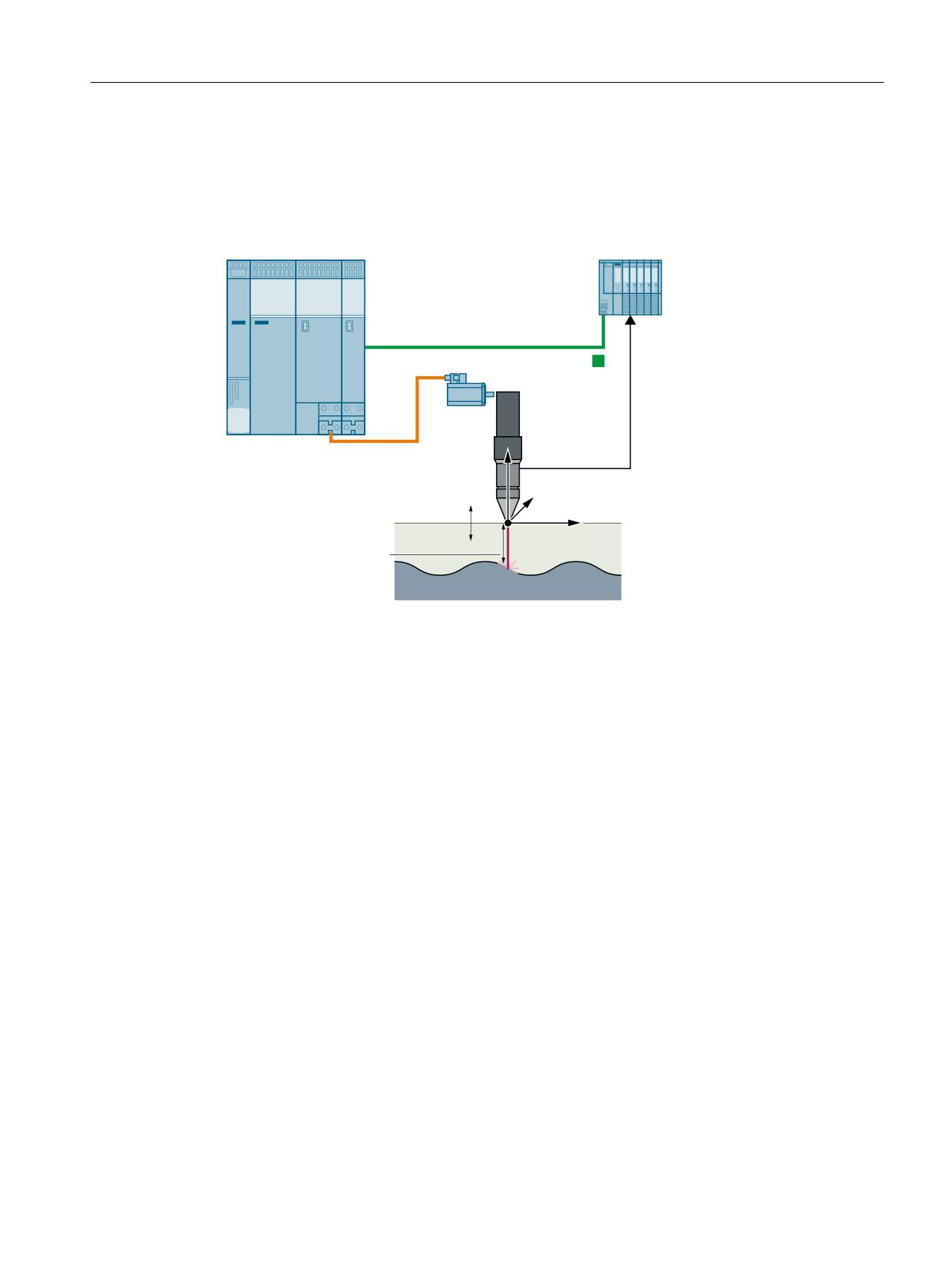
Clearance control (CLC/CLCX)
5.1 Brief description
System overview
The following figure provides an overview of the system components required for clearance
control:
1&8 ZLWK
6,0$7,& (7
6,2
6,1$0,&6 6
352),1(7 ,2
6HQVRU VLJQDO
/DVHU
=
0DFKLQLQJ KHDG ZLWK
FOHDUDQFH VHQVRU
<
0RWLRQ D[HV ; DQG <
=
&OHDUDQFH FRQWURO $[LV =
=
;
&OHDUDQFH WR EH
FRQWUROOHG
:RUNSLHFH VXUIDFH
Figure 5-1
System components for clearance control with SINUMERIK NCU
1D machining
For 1D machining, only one axis is influenced by the clearance control. For example, axis Z, as
shown in the machine configuration described in the system overview (see previous diagram).
Clearance control acts only in the direction of the Z axis.
3D machining
Three linear axes are used to position the tool. A detailed description can be found under 3D
clearance control - overview (Page 62).
Technologies
Function Manual, 10/2020, 6FC5397-8GP40-0BA1
31
Clearance control (CLC/CLCX)
5.2 Clearance control
5.2
Clearance control
5.2.1
POS mode
5.2.1.1
Overview
Properties of the POS mode
The system deviation of the clearance control is the difference between the programmed
setpoint clearance and the current actual clearance reported by the clearance sensor.
In POS mode this system deviation is calculated together with the actual position of the axis to
a target position for the clearance control axis. For this purpose, the delay time of the sensor in
relation to the actual position of the axis encoders must be compensated for in the best possible
way.
The POS mode does not cause overshooting, which depends on the size of the initial system
deviation, and is therefore more suitable for approaching from a greater distance than the GAIN
mode.
Technologies
32
Function Manual, 10/2020, 6FC5397-8GP40-0BA1
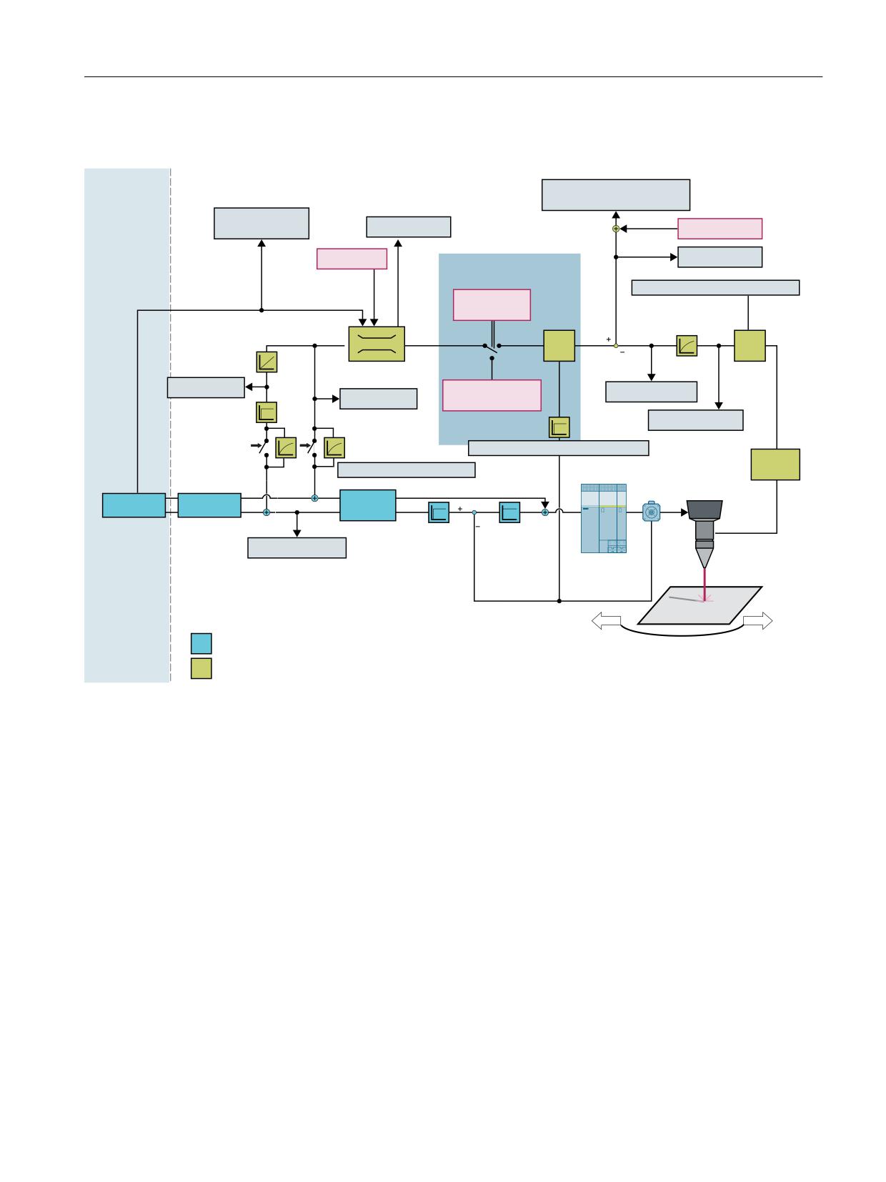
Clearance control (CLC/CLCX)
5.2 Clearance control
5.2.1.2
POS mode
,QWHUSRODWRU
3RVLWLRQ FRQWURO WDVN
%ORFN V\QF SURJ &/&B',67
[\
WDVN
0&B&/&B',67$1&(B6(732,17
57'B833(5B/,0,7
57'B/2:(5B/,0,7
57'B'<1B/,0
57B',67B2))6(7
&/& 326 6<0
57B',5B/2&.
57'B352*B',67
$MC_CLC_SENSOR_FILTER_TIME[0]
57B7(&+B&0'
ಯMXPS SRVಯ
9ROWDJH GLVWDQFH
$[LV WUDYHO UDQJH DQG G\QDPLFV
UHPDLQLQJ IURP LQWHUSRODWHG PRWLRQ
WDEOHB
WDEOHB
326
$YJ
PRGH
ILOWHU
/LPLWDWLRQ RI SRVLWLRQ
YHORFLW\ DQG DFFHOHUDWLRQ
57'B$&7B326
57B029(B326B5(/
57'B6(1625B',67
57'B$&7B9(/
57B029(B326B$%6
57'B6(1625B92/7
6ZLWFKHV ZLWK
3URIL1HW
$MC_CLC_SENSOR_DELAY_COMP_TIME
326 *$,1 PRGH
$'
$MC_CLC_SENSOR_JERK_TIME
FRQYHUWHU
'ULYHV
DQDORJ
YHO
0RWRU
/DVHU KHDG
$;B-(5.
,32
),1( ,32
$;B'(/$<
SRV
&OHDUDQFH
)): 326
.9
VHQVRU
6<0
57'B$&7B326B$%6
(QFRGHU
1&. 6\VWHP VRIWZDUH
,VRFKURQRXV
&/&; &RPSLOH &\FOH DGGRQ VRIWZDUH
Figure 5-2
POS mode
5.2.2
GAIN mode
5.2.2.1
Control dynamics - GAIN mode
Control loop gain KV
The system deviation of the clearance control is the difference between the programmed
setpoint clearance and the current actual clearance reported by the clearance sensor. In GAIN
mode, this system deviation is multiplied by the control loop gain KV: The result is the control
speed that moves the axis toward the clearance setpoint.
The control loop gain KVCLC in the superimposed sensor control loop is defined as:
Technologies
Function Manual, 10/2020, 6FC5397-8GP40-0BA1
33
Clearance control (CLC/CLCX)
5.2 Clearance control
6SHHG >PP PLQ@
.9&/&
6\VWHP GHYLDWLRQ >PP@
Especially when approaching from a great distance, i.e. with an initially large system deviation,
the GAIN mode generates high control speeds which lead to overshooting of the axis position.
The maximum adjustable control loop gain is limited by the dynamics of the closed control loop
(sensor-control-axis) and the tolerable overshoot. Small values of the control loop gain cause
time losses due to a slow approach.
Max. control loop gain
The maximum achievable control loop gain is determined by the following delay and reaction
times of the overall system:
1. Reaction time of sensor
2. Delay time of the A/D converter
3. Delay/dead times of signal processing and transmission
4. Reaction time of position controller
5. Reaction times of speed and current controllers
6. Time constants of motor and mechanical system
Points 1, 3 and 4 are relevant in practice.
In total, the influencing variables result in an effective time constant. If the control loop gain is
set too high in relation to this time constant, natural oscillations of the axis/axes to be controlled
will occur in the range of a few hertz.
The aim of setting up the clearance control in GAIN mode is to adjust the decisive time constants
in such a way that the highest possible control loop gain can be set without the occurrence of
natural oscillations and with a tolerable overshoot amplitude when approaching.
Technologies
34
Function Manual, 10/2020, 6FC5397-8GP40-0BA1
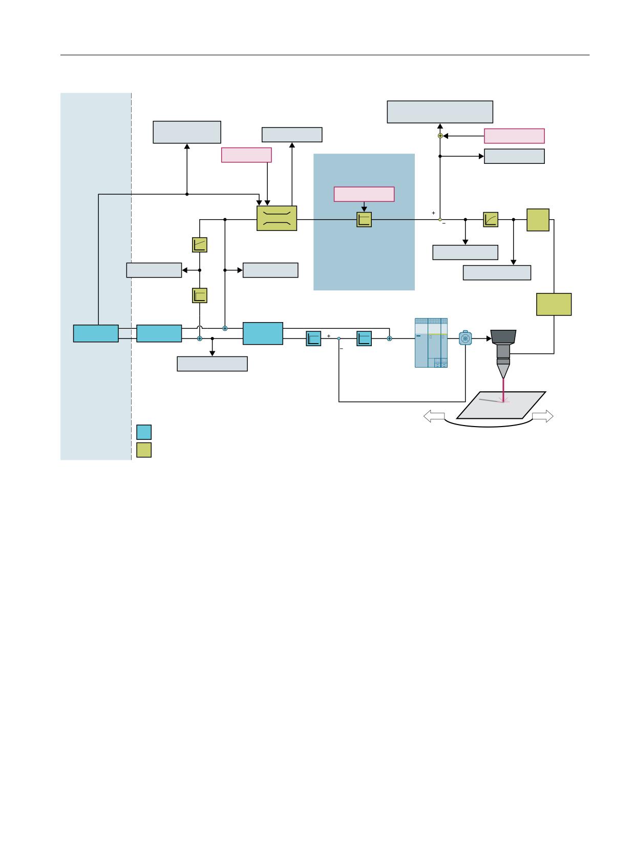
Clearance control (CLC/CLCX)
5.2 Clearance control
,QWHUSRODWRU WDVN
3RVLWLRQ FRQWURO WDVN
%ORFN V\QF SURJ &/&B',67
[\
0&B&/&B',67$1&(B6(732,17
57'B833(5B/,0,7
57'B/2:(5B/,0,7
57'B'<1B/,0
57B',67B2))6(7
57B',5B/2&.
57'B352*B',67
57B*$,1B)$&725
$[LV WUDYHO UDQJH DQG G\QDPLFV
9ROWDJH GLVWDQFH
UHPDLQLQJ IURP LQWHUSRODWHG PRWLRQ
WDEOHB
WDEOHB
$YJ
ILOWHU
/LPLWDWLRQ RI
0&B&/&B
SRVLWLRQ YHORFLW\
',67$1&(B&75/B*$,1
DQG DFFHOHUDWLRQ
57'B6(1625B',67
57'B$&7B326
57'B$&7B9(/
57'B6(1625B92/7
352),1(7
&/& 326 6<0
$'
FRQYHUWHU
'ULYHV
DQDORJ
YHO
0RWRU
/DVHU KHDG
$;B-(5.
,32
),1( ,32
$;B'(/$<
SRV
&OHDUDQFH
)): 326
.9
VHQVRU
6<0
57'B$&7B326B$%6
(QFRGHU
1&. 6\VWHP VRIWZDUH
,VRFKURQRXV
&/&; &RPSLOH &\FOH DGGRQ VRIWZDUH
Figure 5-3
GAIN mode
5.2.3
Dead times in the clearance control
Dead time
In order to achieve a highly dynamic control behavior, the clearance control is implemented in
the position controller cycle layer of the NC kernel.
For I/O modules that are connected via the isochronous fieldbus (PROFINET IRT) and when using
SINAMICS drives there is a system-dependent dead time Tdead of:
Tdead = 2 * position controller cycle + 2 * speed controller cycle + PROFINET Ti
In order to achieve an optimum dynamic response of the clearance control, the reaction time (or
dead time) of the sensor should not be significantly longer than the system-related dead time.
Technologies
Function Manual, 10/2020, 6FC5397-8GP40-0BA1
35
Clearance control (CLC/CLCX)
5.3 Technological features of clearance control
5.2.4
Optimizing the control behavior
Optimizing the control behavior
If the control behavior of the axis becomes too hard due to feedforward control, the control
behavior can be optimized. Instructions for using the jerk filter can be found under Startup
(Page 38).
The speed filters of the SINAMICS S120 drive provide additional damping capabilities:
• Parameter 1414 ff. (time constant, speed setpoint filter 1, 2)
Note
Each damping measure in the axis control loop results in an additional contribution to the
increase of the total time constant of the superimposed sensor control loop!
Further information:
A complete description of the velocity feedforward control is provided in:
Function Manual Monitoring and compensating; Compensations, dynamic feedforward control
(following error compensation)
5.3
Technological features of clearance control
Clearance control is characterized by the following technological properties:
• Sensor characteristic
The voltage/clearance characteristic of a sensor can be specified with up to 16 breakpoints.
• Sensors
Several sensors with different gain characteristics can be used. The active sensor
characteristic can be switched over block-synchronously by means of a language command
in the part program.
• Control loop gain of the clearance control (GAIN mode)
The control loop gain of the clearance control, parameterized by NC machine data, can be
changed block-synchronously by a voice command in the part program. In addition, the real-
time variable CLC_RT_GAIN_FACTOR can multiply the gain.
• Motion limitation
The lower and upper limits configured in the NC machine data for the axis movements
induced by clearance control can be changed block-synchronously by means of a language
command in the part program.
An alarm appears when a limit is reached. The alarm response can be parameterized (stop of
the traversing motions or display only). The current position offset can be frozen via the real-
time variable CLC_RT_TECH_CMD (or a PLC signal).
• Switch-off behavior
The switch-off behavior of the clearance control can be programmed either with
synchronization to the current axis positions (no compensating motion) or with
compensating motion of the axes back to the last programmed IPO positions.
• Programmable clearance setpoint
The clearance setpoint can be programmed block-synchronously. An additional offset can be
added via the real-time variable CLC_RT_DIST_OFFSET.
Technologies
36
Function Manual, 10/2020, 6FC5397-8GP40-0BA1
Clearance control (CLC/CLCX)
5.4 Sensor collision monitoring
• State data of the clearance control
The following real-time variables can be read at any time:
CLC_RTD_SENSOR_VOLT, the current sensor signal in Volt
CLC_RTD_SENSOR_DIST, the distance calculated over the selected characteristic
• Sensor signal
The sensor signal can be smoothed by a sliding average value filter with adjustable time
constant:
62525 $MC_CLC_SENSOR_FILTER_TIME[0]
• Variables for synchronized actions
Additional functions such as jump-up or blocking of sensor motion can be controlled via the
real-time variable CLC_RT_TECH_CMD without having to switch the CLC function off and on
again.
5.4
Sensor collision monitoring
Tip-touch signal from the sensor
If the clearance sensor used has an additional "tip-touch" signal for detecting a collision of the
sensor with the workpiece to be machined, this signal can be made available to the clearance
control via a digital NC peripheral input.
As a reaction to this signal, the clearance control performs a fast retraction movement in all
clearance-controlled axes. The retraction movement is executed independently of the current
value of the velocity override at traversing velocity in positive control direction by a specified
distance. At the same time, the alert 75007 is issued and a real-time variable indicates the "tip-
touch" state. Synchronized actions can be used to program the desired reaction to the path. After
the cause of the collision has been eliminated, the retracted axis can be reset to control mode
via the real-time variable CLC_RT_TECH_CMD.
Parameterization
The digital peripheral input, which the tip-touch signal is wired to, is assigned to the clearance
control via the following machine data:
MD62504 $MC_CLC_SENSOR_TOUCHED_INPUT (digital peripheral input for "sensor collision"
signal)
The digital input is specified via the same input numbering that is used to address the
corresponding system variable $A_IN[input number].
If a negative input number is specified, the CLCX evaluates the tip-touch signal internally in
inverted form (wire break protection). In this case a falling signal edge triggers the tip-touch
reaction.
Internal tip-touch detection
If tip-touch detection is programmed, the clearance signal from the sensor can be monitored to
determine whether it falls below a set distance threshold: Machine data 62526
$MC_CLC_TIP_TOUCH_DISTANCE.
Technologies
Function Manual, 10/2020, 6FC5397-8GP40-0BA1
37
Clearance control (CLC/CLCX)
5.5 Startup
To avoid false tripping, the signal should be averaged over a suitable time (e.g. 30 ms) before
comparison with the distance threshold using the mean value filter available for this purpose:
Machine data 62525 $MC_CLC_SENSOR_FILTER_TIME[ 1 ].
The response of the CLCX to the undershooting of the tip-touch distance threshold is the same
as when an external tip-touch signal is received.
5.5
Startup
Compile cycle
Before setting up the technology function, ensure that the corresponding compile cycle has
been loaded and activated (see Installation and activation of loadable compile cycles (Page 17)).
General relationships
The clearance control works within the position controller task. The WCS and MCS positions on
the standard HMI screen do not show the offset generated by the clearance control. Only if you
switch off the CLC function with the CLC(0) command will the IPO positions displayed by default
be resynchronized, and thus the axis positions actually reached will be displayed.
The clearance control generates the overlaid movement within the CLC coordinate system:
• The zero point is the position at which the CLC function was activated.
• The arguments of CLC_LIM (<lower limit>, <upper limit>) refer to this coordinate system.
CLC_RTD_ACT_POS also refers to the CLC coordinate system.
Only the real-time variable CLC_RTD_ACT_POS_ABS shows the axis position in the regular
MCS coordinates. In the 3D case, this variable shows the same position as
CLC_RTD_ACT_POS.
Assign CLCX instance to a channel
A CLCX instance must be assigned to one channel each for activation. Several CLCX instances are
described under Multiple CLCX instances in one channel (Page 69).
Activating an instance in a channel
MD60940 $MN_CC_ACTIVE_IN_CHAN_CLCX[0] = 'H1'
• Bit n = 1
• n = channel number - 1
- Bit0 = 1st channel
- Bit1 = 2nd channel, etc.
Technologies
38
Function Manual, 10/2020, 6FC5397-8GP40-0BA1
Clearance control (CLC/CLCX)
5.5 Startup
Notes
If you want CLCX to act on a single axis only (and not in a 3D application), preferably do not
configure the CLC axis as a geometry axis ($MC_AXCONF_GEOAX_ASSIGN_TAB[2]=0).
This has the advantage that the position synchronization required when CLCX is deactivated
cannot affect XY path motion functions, but requires a change in programming.
When the Z axis is no longer a geometry axis, the geometry axis name of the Z axis (typically "Z")
can no longer be used to program rotating frames within the XY plane.
Therefore, program rotations with CRPL(1, 0) instead of CROT(Z, 0).
Jerk filter
Do not apply the standard jerk filter (MD32400 $MA_AX_JERK_ENABLE=0) to limit the axis jerk
caused by the CLCX motion, as this filter will cause a delay within the sensor control loop. If you
need to limit the axis jerk when moving the axis with the regular interpolator, program SOFT
movement mode instead and limit the jerk with MD32431 $MA_MAX_AX_JERK.
CLCX provides a separate jerk filter (MD62518 $MC_CLC_SENSOR_JERK_TIME) to limit the jerk
during CLCX jerk movements. If a filter time constant greater than zero is set there, the CLCX
automatically switches the filter on and off in a sliding manner according to the current situation:
• The jerk filter is switched on when approaching the plate and in case of predefined "jumps"
of the axis; in normal sensor-controlled control operation it is switched off. Nevertheless, the
specified filter time should also be kept as short as possible for this jerk filter (in the <20 ms
range).
5.5.1
Setup steps
Setting up CLCX
To set up CLCX for optimum performance and productivity, it is recommended that the following
steps be performed:
• Optimize the axis/axes by setting up Feed-Forward, DSC and other functions that provide the
best possible precision and dynamics.
• Set up the analog input of the sensor for isochronous operation (PROFINET IRT), see Setting
up the analog sensor input (Page 41).
Technologies
Function Manual, 10/2020, 6FC5397-8GP40-0BA1
39
Clearance control (CLC/CLCX)
5.5 Startup
• Linearize the clearance sensor input using the machine data tables
62510__MC_CLC_SENSOR_VOLTAGE_TABLE_1[0... 15] and
62511__MC_CLC_SENSOR_DIST_TABLE_1[0...15], see also Linearizing the signal of the
clearance sensor (Page 44).
- To obtain optimum performance of the CLCX function, the sensitive clearance range of
the sensor should be as large as possible (preferably up to 20 mm) and linearized as well
as possible.
- The highest entry in the clearance table and the correct linearization of the distance
within the entire table range are particularly important in order to obtain the optimum
sensor-controlled approach movement from a far-away starting position to the workpiece
surface.
- The linearization of the sensor characteristic curve can be automated with an appropriate
part program. CLCX simplifies a quick sensor calibration check, since both the analog
input voltage information and the resulting clearance of the currently selected table
available are available, even when CLCX is switched off.
• When using the POS mode and the enhanced approach function, the following is
recommended:
- The time delay between the relative position measurement of the sensor and the absolute
axis position detection of the encoder must be compensated for in the best possible way,
see Compensation of the time delay of the sensor (Page 45).
• The commissioning and testing of all functions that do not directly depend on the axis
dynamics and the specific sensor characteristic can also be carried out via Create MyVirtual
Machine with simulated axes and a simulated sensor.
5.5.2
Activating the technological function
The technology function is activated via the machine data:
MD60940 $MN_CC_ACTIVE_IN_CHAN_CLCX[0], bit n = 1
n = channel number - 1; Bit0 = 1st channel, Bit1 = 2nd channel, etc.
Note
A maximum of four instances of the CLCX technology function can be activated on one NCU.
Technologies
40
Function Manual, 10/2020, 6FC5397-8GP40-0BA1

Clearance control (CLC/CLCX)
5.5 Startup
5.5.3
Configuring the memory
The CLCX technology function requires additional data in the NC-internal block memory. For
each CLCX instance that is active in the channel, the values specified must be entered in the
following memory-configuring channel-specific machine data. If the memory requirement for
other compile cycle functions is already entered in this MC, the values must be added to the
existing entries:
• MD28090 $MC_MM_NUM_CC_BLOCK_ELEMENTS: + 4 (number of block elements for
compile cycles)
• MD28100 $MC_MM_NUM_CC_BLOCK_USER_MEM: + 20 (size of block memory for compile
cycles (DRAM), in KB)
5.5.4
Sensor input and sensor signals
5.5.4.1
Setting up the analog sensor input
Recommended hardware
It is recommended to convert and read in the analog input signals of the capacitive clearance
sensor with the following hardware:
Table 5-1
Recommended SIMATIC modules
Article number
Device
Description
6ES7 151-3BA60-0AB0
SIMATIC ET200S IM151-3PN HS Firmware
Profinet Interface Module
V3.0
6ES7 138-4CA01-0AA0
SIMATIC ET200S PM-E DC24V
Power Module
6ES7 134-4FB52-0AB0
SIMATIC ET200S 2AI U HS
Module with 2 analog inputs
In order to achieve the best dynamic response of the clearance control, the analog input, which
contains the clearance information, must be isochronously transferred to the NC.
Configure the PROFINET IRT operation in the "HWConfig" area of the Simatic Manager or in the
corresponding function of the TIA Portal for:
• the bus segment
• the interface module (the head module)
• the analog input module to which the sensor is connected
• the digital input for tip-touch detection of the sensor - if available
Technologies
Function Manual, 10/2020, 6FC5397-8GP40-0BA1
41
Clearance control (CLC/CLCX)
5.5 Startup
5.5.4.2
Parameterizing the input signals
The following input signals must be parameterized in the machine data:
• Input voltage of the clearance sensor
-
1 analog input
• "Sensor-tip-touch" input signal (optional)
-
1 digital input
Analog input
The PROFINET address of the analog input module configured on the PLC side must be entered
on the NC side in the following machine data:
• MD10362 $MN_HW_ASSIGN_ANA_FASTIN (per analog input) (hardware assignment of the
fast analog NC inputs)
Digital input
Unless one of the onboard inputs of the NCU is used for this purpose, the PROFINET address of
the digital input module configured on the PLC side must be entered in the following machine
data:
• MD10366 $MN_HW_ASSIGN_DIG_FASTIN (per -bit input block) (hardware assignment of the
external digital NC inputs)
A complete description of the analog and digital inputs can be found in:
Further information
Function Manual Basic Functions; digital and analog NC I/O
5.5.4.3
Simulation of the sensor signals
Preparing a simulation
The properties of the single-axis CLCX can be tested without a real clearance sensor and, if
necessary, even without real axes. In this case, a sensor/plate simulation integrated in the CLCX
software closes the control loop.
The axes are switched to simulation mode as usual with the following machine data:
•
30240__$MA_ENC_TYPE[Z]=0
•
30130__$MA_CTRLOUT_TYPE[Z] =0
The simulation can only simulate the fundamental function of the sensor, but not the real
dynamic response of the clearance control.
To apply the simulation, the following definitions must be added to the definition file, which also
contains the other GUD definitions of the CLCX:
• DEF CHAN REAL CLC_SIM_SHEET_POS[3]
• DEF CHAN REAL CLC_SIM_SENSOR_DELAY[2]
Technologies
42
Function Manual, 10/2020, 6FC5397-8GP40-0BA1
Clearance control (CLC/CLCX)
5.5 Startup
A restart of the NC kernel is required for the new GUD definitions to take effect in the CLCX. Then
the simulation of sensor and sheet metal (workpiece) can be used.
Defining the sensor simulation
The simulation only works if a simulated sensor delay time not equal to zero is set in the
following GUD variable:
Programming example
CLC_SIM_SENSOR_DELAY[0] = 0.001234
; activates the simulation and uses a simulated
; sensor delay of 1.234 ms
Note
The content of the GUD variable CLC_SIM_SENSOR_DELAY[0] is intentionally deleted after each
NC restart to deactivate the sensor simulation by default after the restart. This is to avoid the
accidental use of the simulated sensor when a real sensor is connected.
Defining the sheet metal
To simulate the sheet metal, simply enter the desired sheet metal position in MCS coordinates
into this GUD variable:
Programming example
CLC_SIM_SHEET_POS[0] = -30 ; simulates a sheet metal in the MCS position -30 mm.
Make sure that the simulated sheet metal is positioned UNDER the axis position where you
switch on the CLC.
The other GUD elements can be applied optionally:
Programming example
CLC_SIM_SHEET_POS[2] = 0.005
;simulates white noise of the sheet metal position of 5 µm
CLC_SIM_SHEET_POS[1] = 0.1
; simulates a linear up/down movement of the sheet metal of
0.1 mm.
CLC_SIM_SENSOR_DELAY[1] = 2.0
; .. with a duration of 2 seconds
If you change the content of a GUD variable within a part program, note that it may take a short
time until the CLCX actually evaluates a changed GUD value.
In order to obtain stable test conditions, it is therefore recommended to program a dwell time
of one second (G4 F1) after a change of the GUD values or before switching on or enabling the
CLCX motion.
In order for the simulation of the closed CLC control loop to behave as realistically as possible
dynamically, you should compensate the set delay of the simulated sensor in the machine data
$MC_CLC_SENSOR_DELAY_COMP_TIME in the same way as is required for a real sensor:
$MC_CLC_SENSOR_DELAY_COMP_TIME = CLC_SIM_SENSOR_DELAY[0]
Technologies
Function Manual, 10/2020, 6FC5397-8GP40-0BA1
43
Clearance control (CLC/CLCX)
5.5 Startup
5.5.4.4
Linearizing the signal of the clearance sensor
Normalizing the analog input value
The first step in providing a linearized sensor signal is to normalize the analog input value:
• Connect a known static analog voltage to the sensor input.
• Adjust the value of MD62503 $MC_CLC_ANALOG_IN_HW_NORM_FACT until the variable
CLC_RTD_SENSOR_VOLT correctly indicates the voltage in V applied at the input.
This can also be done without the CLCX being switched on by program command, as the
variable is updated as soon as CLCX is activated via the PowerOn machine data.
• The same applies to the variable CLC_RTD_SENSOR_DIST, which displays the linearized
sensor distance resulting from the applied input voltage with the currently effective sensor
characteristic curve:
MD62510 $MC_CLC_SENSOR_VOLTAGE_TABLE_1[0... 15] MD62511
$MC_CLC_SENSOR_DIST_TABLE_1[0... 15]
or
MD62512 $MC_CLC_SENSOR_VOLTAGE_TABLE_2[0... 15] MD62513
$MC_CLC_SENSOR_DIST_TABLE_2[0... 15]
Calibration of the sensor table via "CLC_RTD_SENSOR_VOLT" and "CLC_RTD_SENSOR_DIST"
Recalibrating the sensor means storing the currently effective characteristic of the sensor in a
CLCX sensor characteristic curve. For this purpose, the distance breakpoints to be measured are
first selected by entering them in ascending order starting with zero, e.g. in the table values of
the machine data $MC_CLC_SENSOR_DISTANCE_TABLE_1. In areas where the characteristic
curve is strongly non-linear, a correspondingly higher number of breakpoints should be selected.
Starting with the zero distance, at which the sensor should almost touch the sheet metal, the
axis is moved upwards step by step by the entered distances via a part program with the CLCX
function switched off. For each distance the voltage output by the sensor is written to the
corresponding element of the voltage table $MC_CLC_SENSOR_VOLTAGE_TABLE_1.
• Start with the greatest possible approximation
Greatest possible approximation means almost contact of the sensor with the sheet metal
(zero distance).
• Gradually increase the distance and transfer the measured voltage to the element of the
voltage table corresponding to the distance.
Note
• The first entry within the clearance table must be zero. If it is not possible to measure the
sensor voltage at this (contact) position, a corresponding estimated sensor voltage should be
entered in MD62510 $MC_CLC_SENSOR_VOLTAGE_TABLE_x[0].
• All subsequent clearance and voltage entries must be monotonically increasing.
The table ends with the entry in index 15 or with a clearance entry of 0.0 under an index smaller
than 15.
Technologies
44
Function Manual, 10/2020, 6FC5397-8GP40-0BA1