SINUMERIK 840D sl. Service - Functions. Manual (2018-2020) - page 75
Glossary
Interpolatory compensation
Mechanical deviations of the machine are compensated for by means of interpolatory
compensation functions, such as → leadscrew error, sag, angularity, and temperature
compensation.
Interrupt routine
Interrupt routines are special → subprograms that can be started by events (external signals)
in the machining process. A part program block which is currently being worked through is
interrupted and the position of the axes at the point of interruption is automatically saved.
Inverse-time feedrate
The time required for the path of a block to be traversed can also be programmed for the axis
motion instead of the feed velocity (G93).
JOG
Operating mode of the control (setup mode): The machine can be set up in JOG mode.
Individual axes and spindles can be traversed in JOG mode by means of the direction keys.
Additional functions in JOG mode include: → Reference point approach, → Repos, and → Preset
(set actual value).
Key switch
The key switch on the → machine control panel has four positions that are assigned functions
by the operating system of the controller. The key switch has three different colored keys that
can be removed in the specified positions.
Keywords
Words with specified notation that have a defined meaning in the programming language for
→ part programs.
KV
Servo gain factor, a control variable in a control loop.
Leading axis
The leading axis is the → gantry axis that exists from the point of view of the operator and
programmer and, thus, can be influenced like a standard NC axis.
Leadscrew error compensation
Compensation for the mechanical inaccuracies of a leadscrew participating in the feed. The
controller uses stored deviation values for the compensation.
Special functions
Function Manual, 12/2018, A5E40874099B AB
963
Glossary
Limit speed
Maximum/minimum (spindle) speed: The maximum speed of a spindle can be limited by
specifying machine data, the → PLC or → setting data.
Linear axis
In contrast to a rotary axis, a linear axis describes a straight line.
Linear interpolation
The tool travels along a straight line to the destination point while machining the workpiece.
Load memory
The load memory is the same as the → working memory for the CPU 314 of the → PLC.
Look Ahead
The Look Ahead function is used to achieve an optimal machining speed by looking ahead
over an assignable number of traversing blocks.
Machine axes
Physically existent axes on the machine tool.
Machine control panel
An operator panel on a machine tool with operating elements such as keys, rotary switches,
etc., and simple indicators such as LEDs. It is used to directly influence the machine tool via
the PLC.
Machine coordinate system
A coordinate system, which is related to the axes of the machine tool.
Machine zero
Fixed point of the machine tool to which all (derived) measuring systems can be traced back.
Machining channel
A channel structure can be used to shorten idle times by means of parallel motion sequences,
e.g. moving a loading gantry simultaneously with machining. Here, a CNC channel must be
regarded as a separate CNC control system with decoding, block preparation and interpolation.
Special functions
964
Function Manual, 12/2018, A5E40874099B AB
Glossary
Macro techniques
Grouping of a set of statements under a single identifier. The identifier represents the set of
consolidated statements in the program.
Main block
A block preceded with ":" that contains all information to start the operating sequence in a
→ part program.
Main program
The term "main program" has its origins during the time when part programs were split strictly
into main and → subprograms. This strict division no longer exists with today's SINUMERIK
NC language. In principle, any part program in the channel can be selected and started. It then
runs through in → program level 0 (main program level). Further part programs or → cycles as
subprograms can be called up in the main program.
MDI
Operating mode of the control: Manual Data Input. In the MDI mode, individual program blocks
or block sequences with no reference to a main program or subprogram can be input and
executed immediately afterwards through actuation of the NC start key.
Messages
All messages programmed in the part program and → alarms detected by the system are
displayed on the operator panel in plain text with date and time and the corresponding symbol
for the deletion criterion. Alarms and messages are displayed separately.
Metric measuring system
Standardized system of units: For length, e.g. mm (millimeters), m (meters).
Mirroring
Mirroring reverses the signs of the coordinate values of a contour, with respect to an axis. It
is possible to mirror with respect to more than one axis at a time.
Mode
An operating concept on a SINUMERIK control The following modes are defined: → Jog, → MDI,
→ Automatic.
Mode group
Axes and spindles that are technologically related can be combined into one mode group.
Axes/spindles of a mode group can be controlled by one or more → channels. The same
→ mode type is always assigned to the channels of the mode group.
Special functions
Function Manual, 12/2018, A5E40874099B AB
965
Glossary
NC
Numerical Control component of the → CNC that executes the → part programs and coordinates
the movements of the machine tool.
Network
A network is the connection of multiple S7-300 and other end devices, e.g. a programming
device via a → connecting cable. A data exchange takes place over the network between the
connected devices.
NRK
Numeric robotic kernel (operating system of → NC)
NURBS
The motion control and path interpolation that occurs within the control is performed based on
NURBS (Non Uniform Rational B-Splines). This provides a uniform procedure for all internal
interpolations.
OEM
The scope for implementing individual solutions (OEM applications) has been provided for
machine manufacturers, who wish to create their own user interface or integrate technology-
specific functions in the control.
Offset memory
Data range in the control, in which the tool offset data is stored.
Oriented spindle stop
Stops the workpiece spindle in a specified angular position, e.g. in order to perform additional
machining at a particular location.
Overall reset
In the event of an overall reset, the following memories of the → CPU are deleted:
●
→ Working memory
● Read/write area of → load memory
●
→ System memory
●
→ Backup memory
Special functions
966
Function Manual, 12/2018, A5E40874099B AB
Glossary
Override
Manual or programmable possibility of intervention that enables the user to override
programmed feedrates or speeds in order to adapt them to a specific workpiece or material.
Part program
Series of statements to the NC that act in concert to produce a particular → workpiece. Likewise,
this term applies to execution of a particular machining operation on a given → raw part.
Part program block
Part of a → part program that is demarcated by a line feed. There are two types: → main blocks
and → subblocks.
Part program management
Part program management can be organized by → workpieces. The size of the user memory
determines the number of programs and the amount of data that can be managed. Each file
(programs and data) can be given a name consisting of a maximum of 24 alphanumeric
characters.
Path axis
Path axes include all machining axes of the → channel that are controlled by the → interpolator
in such a way that they start, accelerate, stop, and reach their end point simultaneously.
Path feedrate
Path feedrate affects → path axes. It represents the geometric sum of the feedrates of the
→ geometry axes involved.
Path velocity
The maximum programmable path velocity depends on the input resolution. For example, with
a resolution of 0.1 mm the maximum programmable path velocity is 1000 m/min.
PCIN data transfer program
PCIN is a utility program for sending and receiving CNC user data (e.g. part programs, tool
offsets) via the serial interface. The PCIN program can run under MS-DOS on standard
industrial PCs.
Peripheral module
I/O modules represent the link between the CPU and the process.
Special functions
Function Manual, 12/2018, A5E40874099B AB
967
Glossary
I/O modules are:
●
→ Digital input/output modules
●
→ Analog input/output modules
●
→ Simulator modules
PLC
Programmable Logic Controller: → Programmable logic controller. Component of → NC:
Programmable control for processing the control logic of the machine tool.
PLC program memory
SINUMERIK 840D sl: The PLC user program, the user data and the basic PLC program are
stored together in the PLC user memory.
PLC programming
The PLC is programmed using the STEP 7 software. The STEP 7 programming software is
based on the WINDOWS standard operating system and contains the STEP 5 programming
functions with innovative enhancements.
Polar coordinates
A coordinate system which defines the position of a point on a plane in terms of its distance
from the origin and the angle formed by the radius vector with a defined axis.
Polynomial interpolation
Polynomial interpolation enables a wide variety of curve characteristics to be generated, such
as straight line, parabolic, exponential functions (SINUMERIK 840D sl).
Positioning axis
Axis that performs an auxiliary motion on a machine tool (e.g. tool magazine, pallet transport).
Positioning axes are axes that do not interpolate with → path axes.
Pre-coincidence
Block change occurs already when the path distance approaches an amount equal to a
specifiable delta of the end position.
Program block
Program blocks contain the main program and subprograms of → part programs.
Special functions
968
Function Manual, 12/2018, A5E40874099B AB
Glossary
Program level
A part program started in the channel runs as a → main program on program level 0 (main
program level). Any part program called up in the main program runs as a → subprogram on
a program level 1 ... n of its own.
Programmable frames
Programmable → frames enable dynamic definition of new coordinate system output points
while the part program is being executed. A distinction is made between absolute definition
using a new frame and additive definition with reference to an existing starting point.
Programmable logic controller
Programmable logic controllers (PLCs) are electronic controllers, the function of which is stored
as a program in the control unit. This means that the layout and wiring of the device do not
depend on the function of the controller. The programmable logic control has the same
structure as a computer; it consists of a CPU (central module) with memory, input/output
modules and an internal bus system. The peripherals and the programming language are
matched to the requirements of the control technology.
Programmable working area limitation
Limitation of the motion space of the tool to a space defined by programmed limitations.
Programming key
Characters and character strings that have a defined meaning in the programming language
for → part programs.
Protection zone
Three-dimensional zone within the → working area into which the tool tip must not pass.
Quadrant error compensation
Contour errors at quadrant transitions, which arise as a result of changing friction conditions
on the guideways, can be virtually entirely eliminated with the quadrant error compensation.
Parameterization of the quadrant error compensation is performed by means of a circuit test.
R parameters
Arithmetic parameter that can be set or queried by the programmer of the → part program for
any purpose in the program.
Rapid traverse
The highest traverse velocity of an axis. It is used, for example, when the tool approaches the
→ workpiece contour from a resting position or when the tool is retracted from the workpiece
Special functions
Function Manual, 12/2018, A5E40874099B AB
969
Glossary
contour. The rapid traverse velocity is set on a machine-specific basis using a machine data
item.
Reference point
Machine tool position that the measuring system of the → machine axes references.
Rotary axis
Rotary axes apply a workpiece or tool rotation to a defined angular position.
Rotation
Component of a → frame that defines a rotation of the coordinate system around a particular
angle.
Rounding axis
Rounding axes rotate a workpiece or tool to an angular position corresponding to an indexing
grid. When a grid index is reached, the rounding axis is "in position".
RS-232-C
Serial interface for data input/output. Machining programs as well as manufacturer and user
data can be loaded and saved via this interface.
Safety functions
The controller is equipped with permanently active monitoring functions that detect faults in
the → CNC, the → PLC, and the machine in a timely manner so that damage to the workpiece,
tool, or machine is largely prevented. In the event of a fault, the machining operation is
interrupted and the drives stopped. The cause of the malfunction is logged and output as an
alarm. At the same time, the PLC is notified that a CNC alarm has been triggered.
Scaling
Component of a → frame that implements axis-specific scale modifications.
Setting data
Data which communicates the properties of the machine tool to the NC as defined by the
system software.
Softkey
A key, whose name appears on an area of the screen. The choice of softkeys displayed is
dynamically adapted to the operating situation. The freely assignable function keys (softkeys)
are assigned defined functions in the software.
Special functions
970
Function Manual, 12/2018, A5E40874099B AB
Glossary
Software limit switch
Software limit switches limit the traversing range of an axis and prevent an abrupt stop of the
slide at the hardware limit switch. Two value pairs can be specified for each axis and activated
separately by means of the → PLC.
Spline interpolation
With spline interpolation, the controller can generate a smooth curve characteristic from only
a few specified interpolation points of a set contour.
Standard cycles
Standard cycles are provided for machining operations which are frequently repeated:
● For the drilling/milling technology
● For turning technology
The available cycles are listed in the "Cycle support" menu in the "Program" operating area.
Once the desired machining cycle has been selected, the parameters required for assigning
values are displayed in plain text.
Subblock
Block preceded by "N" containing information for a sequence, e.g. positional data.
Subprogram
The term "subprogram" has its origins during the time when part programs were split strictly
into →main and subprograms. This strict division no longer exists with today's SINUMERIK NC
language. In principle, any part program or any → cycle can be called up as a subprogram
within another part program. It then runs through in the next → program level (x+1) (subprogram
level (x+1)).
Synchronization
Statements in → part programs for coordination of sequences in different → channels at certain
machining points.
Synchronized actions
1. Auxiliary function output
During workpiece machining, technological functions (→ auxiliary functions) can be output
from the CNC program to the PLC. For example, these auxiliary functions are used to
control additional equipment for the machine tool, such as quills, grabbers, clamping
chucks, etc.
2. Fast auxiliary function output
For time-critical switching functions, the acknowledgement times for the → auxiliary
functions can be minimized and unnecessary hold points in the machining process can be
avoided.
Special functions
Function Manual, 12/2018, A5E40874099B AB
971
Glossary
Synchronized axes
Synchronized axes take the same time to traverse their path as the geometry axes take for
their path.
Synchronized axis
A synchronized axis is the → gantry axis whose set position is continuously derived from the
motion of the → leading axis and is, thus, moved synchronously with the leading axis. From
the point of view of the programmer and operator, the synchronized axis "does not exist".
System memory
The system memory is a memory in the CPU in which the following data is stored:
● Data required by the operating system
● The operands timers, counters, markers
System variable
A variable that exists without any input from the programmer of a → part program. It is defined
by a data type and the variable name preceded by the character $. See → User-defined variable.
Tapping without compensating chuck
This function allows threads to be tapped without a compensating chuck. By using the
interpolating method of the spindle as a rotary axis and the drilling axis, threads can be cut to
a precise final drilling depth, e.g. for blind hole threads (requirement: spindles in axis operation).
Text editor
See → Editor
TOA area
The TOA area includes all tool and magazine data. By default, this area coincides with the
→ channel area with regard to the access of the data. However, machine data can be used to
specify that multiple channels share one → TOA unit so that common tool management data
is then available to these channels.
TOA unit
Each → TOA area can have more than one TOA unit. The number of possible TOA units is
limited by the maximum number of active → channels. A TOA unit includes exactly one tool
data block and one magazine data block. In addition, a TOA unit can also contain a toolholder
data block (optional).
Special functions
972
Function Manual, 12/2018, A5E40874099B AB
Glossary
Tool
Active part on the machine tool that implements machining (e.g. turning tool, milling tool, drill,
LASER beam, etc.).
Tool nose radius compensation
Contour programming assumes that the tool is pointed. Because this is not actually the case
in practice, the curvature radius of the tool used must be communicated to the controller which
then takes it into account. The curvature center is maintained equidistantly around the contour,
offset by the curvature radius.
Tool offset
Consideration of the tool dimensions in calculating the path.
Tool radius compensation
To directly program a desired → workpiece contour, the control must traverse an equistant path
to the programmed contour taking into account the radius of the tool that is being used (G41/
G42).
Transformation
Additive or absolute zero offset of an axis.
Travel range
The maximum permissible travel range for linear axes is ± 9 decades. The absolute value
depends on the selected input and position control resolution and the unit of measurement
(inch or metric).
User interface
The user interface (UI) is the display medium for a CNC in the form of a screen. It features
horizontal and vertical softkeys.
User memory
All programs and data, such as part programs, subprograms, comments, tool offsets, and work
offsets / frames, as well as channel and program user data, can be stored in the shared CNC
user memory.
User program
User programs for the S7-300 automation systems are created using the programming
language STEP 7. The user program has a modular layout and consists of individual blocks.
Special functions
Function Manual, 12/2018, A5E40874099B AB
973
Glossary
The basic block types are:
● Code blocks
These blocks contain the STEP 7 commands.
● Data blocks
These blocks contain constants and variables for the STEP 7 program.
User-defined variable
Users can declare their own variables for any purpose in the → part program or data block
(global user data). A definition contains a data type specification and the variable name. See
→ System variable.
Variable definition
A variable definition includes the specification of a data type and a variable name. The variable
names can be used to access the value of the variables.
Velocity control
In order to achieve an acceptable traverse rate in the case of very slight motions per block, an
anticipatory evaluation over several blocks (→ Look Ahead) can be specified.
WinSCP
WinSCP is a freely available open source program for Windows for the transfer of files.
Work offset
Specifies a new reference point for a coordinate system through reference to an existing zero
point and a → frame.
1. Settable
A configurable number of settable work offsets are available for each CNC axis. The offsets
- which are selected by means of G commands - take effect alternatively.
2. External
In addition to all the offsets which define the position of the workpiece zero, an external
work offset can be overridden by means of the handwheel (DRF offset) or from the PLC.
3. Programmable
Work offsets can be programmed for all path and positioning axes using the TRANS
statement.
Working area
Three-dimensional zone into which the tool tip can be moved on account of the physical design
of the machine tool. See → Protection zone.
Special functions
974
Function Manual, 12/2018, A5E40874099B AB
Glossary
Working area limitation
With the aid of the working area limitation, the traversing range of the axes can be further
restricted in addition to the limit switches. One value pair per axis may be used to describe the
protected working area.
Working memory
The working memory is a RAM in the → CPU that the processor accesses when processing
the application program.
Workpiece
Part to be made/machined by the machine tool.
Workpiece contour
Set contour of the → workpiece to be created or machined.
Workpiece coordinate system
The workpiece coordinate system has its starting point in the → workpiece zero-point. In
machining operations programmed in the workpiece coordinate system, the dimensions and
directions refer to this system.
Workpiece zero
The workpiece zero is the starting point for the → workpiece coordinate system. It is defined
in terms of distances to the → machine zero.
Special functions
Function Manual, 12/2018, A5E40874099B AB
975

Preface
1
Introduction
Fundamental safety
2
instructions
SINUMERIK
3
Brief description
SINUMERIK 840D sl
Synchronized actions
4
Detailed description
5
Examples
Function Manual
6
Data lists
A
Appendix
Valid for
control system
SINUMERIK 840D sl / 840DE sl
CNC software Version 4.94
10/2020
6FC5397-5BP40-6BA4
Table of contents
Preface
3
1
Introduction
9
1.1
About this documentation
9
2
Fundamental safety instructions
11
2.1
General safety instructions
11
2.2
Warranty and liability for application examples
11
2.3
Security information
11
3
Brief description
13
4
Detailed description
15
4.1
Definition of a synchronized action
15
4.2
Components of synchronized actions
16
4.2.1
Validity, identification number (ID, IDS)
16
4.2.2
Frequency (WHENEVER, FROM, WHEN, EVERY)
17
4.2.3
G command (condition)
18
4.2.4
Condition
18
4.2.5
G command (action)
19
4.2.6
Actions with condition fulfilled (DO)
20
4.2.7
Actions with condition unfulfilled (ELSE)
20
4.3
System variables for synchronized actions
21
4.3.1
Reading and writing
22
4.3.2
Operators and arithmetic functions
22
4.3.3
Type conversions
25
4.3.4
Marker/counter ($AC_MARKER)
26
4.3.5
Parameters ($AC_PARAM)
27
4.3.6
R parameters ($R)
28
4.3.7
Machine and setting data ($$M, $$S)
29
4.3.8
Timer ($AC_TIMER)
30
4.3.9
FIFO variables ($AC_FIFO)
31
4.3.10
Path tangent angle ($AC_TANEB)
36
4.3.11
Override ($A...OVR)
36
4.3.12
Capacity evaluation ($AN_IPO ... , $AN/AC_SYNC ... , $AN_SERVO)
38
4.3.13
Working-area limitation ($SA_WORKAREA_ ... )
41
4.3.14
SW cam positions and times ($$SN_SW_CAM_ ...)
41
4.3.15
Path length evaluation / machine maintenance ($AA_TRAVEL ... , $AA_JERK ... )
42
4.3.16
Polynomial coefficients, parameters ($AC_FCT ...)
43
4.3.17
Overlaid movements ($AA_OFF)
45
4.3.18
Online tool length compensation ($AA_TOFF)
48
4.3.19
Current block in the interpolator ($AC_BLOCKTYPE, $AC_BLOCKTYPEINFO,
$AC_SPLITBLOCK)
51
4.3.20
Initialization of array variables (SET, REP)
54
4.3.21
Grinding-specific system variables ($AC_IN_KEY_G...)
54
Synchronized actions
Function Manual, 10/2020, 6FC5397-5BP40-6BA4
5
Table of contents
4.3.22
Status Synchronized action disabled ($AC_SYNA_STATE)
57
4.4
User-defined variables for synchronized actions
58
4.5
Language elements for synchronized actions and technology cycles
60
4.6
Language elements for technology cycles only
65
4.7
Actions in synchronized actions
66
4.7.1
Output of M, S and H auxiliary functions to the PLC
66
4.7.2
Reading and writing of system variables
67
4.7.3
Polynomial evaluation (SYNFCT)
67
4.7.4
Online tool offset (FTOC)
73
4.7.5
Programmed read-in disable (RDISABLE)
74
4.7.6
Cancel preprocessing stop (STOPREOF)
76
4.7.7
Delete distance-to-go (DELDTG)
76
4.7.8
Traversing axes, to position (POS)
78
4.7.9
Setting the measuring system (G70, G71, G700, G710)
82
4.7.10
Position in specified reference range (POSRANGE)
83
4.7.11
Traversing axes, endless (MOV)
84
4.7.12
Axial feedrate (FA)
85
4.7.13
Axis replacement (GET, RELEASE, AXTOCHAN)
86
4.7.14
Traversing spindles (M, S, SPOS)
91
4.7.15
Withdrawing the enable for the axis container rotation (AXCTSWEC)
92
4.7.16
Actual value setting with loss of the referencing status (PRESETON)
95
4.7.17
Actual value setting without loss of the referencing status (PRESETONS)
100
4.7.18
Couplings (CP..., LEAD..., TRAIL..., CTAB...)
106
4.7.19
Measurement (MEAWA, MEAC)
110
4.7.20
Travel to fixed stop (FXS, FXST, FXSW, FOCON, FOCOF, FOC)
113
4.7.21
Channel synchronization (SETM, CLEARM)
115
4.7.22
User-specific error reactions (SETAL)
116
4.7.23
Cancel the actual subprogram level (CANCELSUB)
116
4.8
Technology cycles
117
4.8.1
General
117
4.8.2
Processing mode (ICYCON, ICYCOF)
119
4.8.3
Definitions (DEF, DEFINE)
120
4.8.4
Parameter transfer
120
4.8.5
Context variable ($P_TECCYCLE)
121
4.9
Protected synchronized actions
122
4.10
Coordination via part program and synchronized action (LOCK, UNLOCK, CANCEL)
123
4.11
Coordination via PLC
123
4.12
Configuration
124
4.13
Control behavior in specific operating states
126
4.13.1
Power On
126
4.13.2
NC reset
126
4.13.3
NC stop
126
4.13.4
Operating mode change
127
4.13.5
End of program
128
4.13.6
Block search
128
4.13.7
Program interruption by ASUB
129
4.13.8
REPOS
130
Synchronized actions
6
Function Manual, 10/2020, 6FC5397-5BP40-6BA4
Table of contents
4.13.9
Response to alarms
130
4.14
Diagnostics
131
4.14.1
Displaying the status of synchronized actions
131
5
Examples
133
5.1
Examples of conditions in synchronized actions
133
5.2
Reading and writing of SD/MD from synchronized actions
133
5.3
Examples of adaptive control
135
5.3.1
Clearance control with variable upper limit
135
5.3.2
Feedrate control
137
5.3.3
Control velocity as a function of normalized path
138
5.4
Monitoring a safety clearance between two axes
139
5.5
Store execution times in R parameters
139
5.6
"Centering" with continuous measurement
140
5.7
Axis couplings via synchronized actions
143
5.7.1
Coupling to leading axis
143
5.7.2
Non-circular grinding via master value coupling
144
5.7.3
On-the-fly parting
148
5.8
Technology cycles position spindle
149
5.9
Synchronized actions in the TC/MC area
150
6
Data lists
155
6.1
Machine data
155
6.1.1
General machine data
155
6.1.2
Channelspecific machine data
155
6.1.3
Axis-specific machine data
155
6.2
Setting data
156
6.2.1
Axis/spindle-specific setting data
156
A
Appendix
157
A.1
List of abbreviations
157
A.2
Documentation overview
162
Index
163
Synchronized actions
Function Manual, 10/2020, 6FC5397-5BP40-6BA4
7

Introduction
1
1.1
About this documentation
This documentation is part of the documentation category of SINUMERIK Function Manuals.
SINUMERIK Function Manuals
The SINUMERIK Function Manuals describe the NC functions of a SINUMERIK control.
The target group are configuring engineers, technologists, commissioning engineers and
programmers.
Each Function Manual covers a specific topic and contains all the function descriptions for this
topic.
The following table shows which Function Manuals are available for your SINUMERIK control and
which topics a Function Manual covers:
Function Manual
Topic
Basic functions
Basic functions of a CNC control
Axes and spindles
Axis and spindle functions, axis couplings
Transformations
Transformation functions
Monitoring and compensating
Axis monitoring and compensation functions, collision avoid-
ance
Tools
Functions for selection, correction and monitoring of tools
Synchronized actions
Functionality of synchronized actions
PLC
Structure and functions of the PLC
Tool management
Function, commissioning and programming of tool manage-
ment
Technologies (for SINUMERIK ONE
Extended technological functionalities
and SINUMERIK 840D sl only)
Overview of contents
You will find an overview of the main chapters of the descriptions of functions that are contained
in a Function Manual on the title page.
Validity
The title page also contains all data about the validity of a document, i.e. for which SINUMERIK
control and for which software version this edition of the Function Manual is valid.
Synchronized actions
Function Manual, 10/2020, 6FC5397-5BP40-6BA4
9

Introduction
1.1 About this documentation
System data
In the descriptions of functions, the system data relevant for a function (machine data, setting
data, system variables, interface signals and alarms) are only described with the level of detail
that is strictly necessary to understand the function. You will find detailed information on this
data in the relevant List Manuals and for alarms in the Diagnostics Manual.
PLC blocks
The descriptions of functions often refer to the PLC function blocks (FB) and functions (FC). The
descriptions of these blocks apply to the SINUMERIK 840D sl and can only be applied in part to
other SINUMERIK controls.
Interface signals
In this document, only the absolute address valid for the SINUMERIK 840D sl is used to address
interface signals.
General graphical conventions
Examples
<signal address> (<signal name>)
DB31, ... DBX16.0-2 (actual gear stage A to C)
DB31, ... DBX16.3 (gear is changed)
Note
Quantity structure
Explanations concerning the NC/PLC interface are based on the absolute maximum number of
the following components:
• Mode groups (DB11)
• Channels (DB21, etc.)
• Axes/spindles (DB31, etc.)
Synchronized actions
10
Function Manual, 10/2020, 6FC5397-5BP40-6BA4

Fundamental safety instructions
2
2.1
General safety instructions
WARNING
Danger to life if the safety instructions and residual risks are not observed
If the safety instructions and residual risks in the associated hardware documentation are not
observed, accidents involving severe injuries or death can occur.
• Observe the safety instructions given in the hardware documentation.
• Consider the residual risks for the risk evaluation.
WARNING
Malfunctions of the machine as a result of incorrect or changed parameter settings
As a result of incorrect or changed parameterization, machines can malfunction, which in turn
can lead to injuries or death.
• Protect the parameterization against unauthorized access.
• Handle possible malfunctions by taking suitable measures, e.g. emergency stop or
emergency off.
2.2
Warranty and liability for application examples
Application examples are not binding and do not claim to be complete regarding configuration,
equipment or any eventuality which may arise. Application examples do not represent specific
customer solutions, but are only intended to provide support for typical tasks.
As the user you yourself are responsible for ensuring that the products described are operated
correctly. Application examples do not relieve you of your responsibility for safe handling when
using, installing, operating and maintaining the equipment.
2.3
Security information
Siemens provides products and solutions with industrial security functions that support the
secure operation of plants, systems, machines and networks.
In order to protect plants, systems, machines and networks against cyber threats, it is necessary
to implement - and continuously maintain - a holistic, state-of-the-art industrial security
concept. Siemens’ products and solutions constitute one element of such a concept.
Customers are responsible for preventing unauthorized access to their plants, systems,
machines and networks. Such systems, machines and components should only be connected to
Synchronized actions
Function Manual, 10/2020, 6FC5397-5BP40-6BA4
11
Fundamental safety instructions
2.3 Security information
an enterprise network or the internet if and to the extent such a connection is necessary and only
when appropriate security measures (e.g. firewalls and/or network segmentation) are in place.
For additional information on industrial security measures that may be implemented, please
visit
Siemens’ products and solutions undergo continuous development to make them more secure.
Siemens strongly recommends that product updates are applied as soon as they are available
and that the latest product versions are used. Use of product versions that are no longer
supported, and failure to apply the latest updates may increase customer’s exposure to cyber
threats.
To stay informed about product updates, subscribe to the Siemens Industrial Security RSS Feed
under
services/cert.html#Subscriptions).
Further information is provided on the Internet:
Industrial Security Configuration Manual (https://support.industry.siemens.com/cs/ww/en/
view/108862708)
WARNING
Unsafe operating states resulting from software manipulation
Software manipulations, e.g. viruses, Trojans, or worms, can cause unsafe operating states in
your system that may lead to death, serious injury, and property damage.
• Keep the software up to date.
• Incorporate the automation and drive components into a holistic, state-of-the-art industrial
security concept for the installation or machine.
• Make sure that you include all installed products into the holistic industrial security concept.
• Protect files stored on exchangeable storage media from malicious software by with suitable
protection measures, e.g. virus scanners.
• On completion of commissioning, check all security-related settings.
Synchronized actions
12
Function Manual, 10/2020, 6FC5397-5BP40-6BA4
Brief description
3
General
A synchronized action consists of a series of related statements within a part program that is
called cyclically in the interpolator clock cycle synchronously to the machining blocks.
A synchronized action is essentially divided into two parts, the optional condition and the
obligatory action part. The time at which the actions are executed can be made dependent on a
specific system state using the condition part. The conditions are evaluated cyclically in the
interpolator clock cycle. The actions are then a reaction to user-definable system states. Their
execution is not bound to block limits.
Furthermore, the validity of the synchronized action (non-modal, modal or static) and the
frequency of the execution of the actions (once, repeatedly) can be defined.
Examples of permissible actions
• Output of auxiliary functions to PLC
• Writing and reading of main run variables
• Traversing of positioning axes
• Activation of synchronous procedures, such as:
- Read-in disable
- Delete distance-to-go
- End preprocessing stop
• Activation of technology cycles
• Calculation of function values
• Tool offsets
• Activating/deactivating couplings
• Measuring
• Enabling/disabling of synchronized actions
Examples of non-permissible actions
• Traversing of path axes
Synchronized actions
Function Manual, 10/2020, 6FC5397-5BP40-6BA4
13
Brief description
Schematic diagram of synchronized actions
,Q 1&. LQWHUSRODWLRQ F\FOH
5HDO WLPH HYHQWV DQG YDOXHV
,QLWLDWHG DFWLRQV
'LJLWDO LQSXWV VLJQDOV
*DWLQJ ORJLF
QRQ PRGDO
9DOXHV RI V\VWHP YDULDEOHV
(YDOXDWLRQ RI
PRGDO
0HDVXUHG YDOXHV
FRQGLWLRQV
PRGDO VWDWLF
'ULYH GDWD
DFURVV PRGHV
Synchronized actions
14
Function Manual, 10/2020, 6FC5397-5BP40-6BA4
Detailed description
4
4.1
Definition of a synchronized action
A synchronized action is defined in a block of a part program. Any further commands that are not
part of the synchronized action, must not be programmed within this block.
Components of a synchronized action
A synchronized action consists of the following components:
Validity, ID
Condition part
Action part with condition fulfil-
Action part with condition unful-
no.
led
filled
(optional)
(Page 16)
(optional)
(optional)
Frequency
G com-
Condition
Keyword
G com-
Actions
Keyword
G com-
Actions
(Page 17)
mand
(Page 18)
mand
(Page 20)
mand
(Page 20)
(Page
(Page
(Page
18)
19)
19)
(op-
(op-
(op-
tional)
tional)
tional)
--- 1)
--- 1)
G...
Logical
DO
G...
Action 1
ELSE
G...
Action 1
ID=<no.>
WHENEVER
Expressio
n
IDS=<no.
FROM
Action n
Action n
>
WHEN
EVERY
1)
Not programmed
Syntax
Examples:
• DO <Action 1...n>
• <frequency> [<G function>] <condition> DO <action 1...n>
• ID=<no.> <frequency> [<G function>] <condition> DO <action 1...n>
• IDS=<no.> <frequency> [<G function>] <condition> DO <action 1...n>
• IDS=<no.> <frequency> [<G function>] <condition> DO <action 1...n>
ELSE <action 1...n>
Synchronized actions
Function Manual, 10/2020, 6FC5397-5BP40-6BA4
15

Detailed description
4.2 Components of synchronized actions
4.2
Components of synchronized actions
4.2.1
Validity, identification number (ID, IDS)
Validity
The validity defines when and where the synchronized action will be processed:
Validity
Meaning
--- 1)
Non-modal synchronized action
A non-modal synchronized action applies:
• As long as the main run block following the synchronized action is active
• Only in the AUTOMATIC mode
Example:
The synchronized action from N10 takes effect as long as N20 is active.
N10 WHEN $A_IN[1]==TRUE DO $A_OUTA[1]=10
N20 G90 F1000 X100
ID=<ID number>
Modal synchronized action
A modal synchronized action applies:
• Until the part program has been completed
• Only in the AUTOMATIC mode
Value range: See the paragraph below "Identification number" > "Value range"
Example:
N20 ID=1 EVERY $A_IN[1]==TRUE DO $A_OUTA[1]=10
IDS=<ID number>
Static synchronized action
A static synchronized action applies:
• In all operating modes for an unlimited period of time
Value range: See the paragraph below "Identification number" > "Value range"
Example:
N30 IDS=1 EVERY $A_IN[1]==TRUE DO $A_OUTA[1]=10
1)
Not programmed
Note
Static synchronized actions
Static synchronized actions (IDS) can be defined in an ASUB and activated at any time by
activation of the ASUB via the PLC user program.
Synchronized actions
16
Function Manual, 10/2020, 6FC5397-5BP40-6BA4

Detailed description
4.2 Components of synchronized actions
Identification number ID/IDS
Range of values
The identification numbers ID/IDS lie in various number ranges. The number ranges are assigned
to different users.
ID/IDS
User
Directory
1 ... 999
"General area"
Any directory
1000 ... 1199
Machine manufacturer
/_N_CMA_DIR
1200 ... 1399
Siemens
/_N_CST_DIR
Parallelization
If several synchronized actions are to be active in parallel in a channel, then they must have
different identification numbers ID/IDS. Synchronized actions with the same identification
number replace each other within a channel.
Sequence of execution
Modal and static synchronized actions are executed in the order of their identification numbers
ID/IDS.
Non-modal synchronized actions are executed after execution of the modal synchronized
actions in the order of their programming.
Coordination via part programs and synchronized actions
Synchronized actions can be coordinated using part programs and synchronized actions
(Page 123) based on the identification numbers ID/IDS.
Coordination via PLC
Synchronized actions with identification numbers ID/IDS in the range from 1 to 64 can be
coordinated via the NC/PLC interface from the PLC user program (Page 123).
4.2.2
Frequency (WHENEVER, FROM, WHEN, EVERY)
The frequency specifies how often the condition is queried and, when the condition is fulfilled,
how often the action should be executed. The frequency is part of the condition.
Frequency
Meaning
--- 1)
If no frequency is specified, the action is executed cyclically in every interpolator clock cycle.
WHENEVER
If the condition is fulfilled, the action is executed cyclically in every interpolator clock cycle.
FROM
After the condition has been fulfilled once, the action is executed cyclically in every interpolator clock
cycle for as long as the synchronized action is active.
WHEN
If the condition is fulfilled, the action is executed once and then the condition is no longer checked.
EVERY
In the following cases, the action is executed once:
• The condition is already satisfied at the start of the synchronized action (state: TRUE)
• At every state transition of the condition from FALSE to TRUE (rising edge)
1)
Not programmed
Synchronized actions
Function Manual, 10/2020, 6FC5397-5BP40-6BA4
17
Detailed description
4.2 Components of synchronized actions
See also
Technology cycles (Page 117)
4.2.3
G command (condition)
Defined initial state
With regard to the part program sequence, synchronized actions can be executed at any time
depending on fulfillment of the condition. It is therefore recommended that the measuring
system (inch or metric) be defined in a synchronized action before the condition and/or in the
action part. This generates a defined initial position for the evaluation of the condition and the
execution of the action, irrespective of the current part program state.
G commands
The following G commands are permissible:
• G70 (Inch dimensions for geometric specifications (lengths))
• G71 (Metric dimensions for geometric specifications (lengths))
• G700 (Inch dimensions for geometric and technological specifications (lengths, feedrate))
• G710 (Metric dimensions for geometric and technological specifications (lengths, feedrate))
Note
No other G commands are permitted in synchronized actions except G70, G71, G700 and G710.
Validity
A G command programmed in the condition part also applies for the action part even if no G
command has been programmed in the action part itself.
A G command programmed in the action part only applies within the action part.
4.2.4
Condition
Execution of the action can be made dependent on the fulfillment of a condition. As long as the
synchronized action is active, the condition is checked cyclically in the interpolator clock cycle.
If no condition is specified, the action is executed cyclically in every interpolator clock cycle.
All operations that return a truth value (TRUE/FALSE) as the result can be programmed as a
condition:
• Comparisons of system variables with constants
• Comparisons of system variables with system variables
Synchronized actions
18
Function Manual, 10/2020, 6FC5397-5BP40-6BA4
Detailed description
4.2 Components of synchronized actions
• Comparisons of system variables with results of arithmetic operations
• Linking of comparisons through Boolean expressions
Examples
Comparisons
Program code
ID=1 WHENEVER $AA_IM[X] > $$AA_IM[Y] DO ...
ID=2 WHENEVER $AA_IM[X] > (10.5 * SIN(45)) DO ...
Boolean operations
Program code
ID=1 WHENEVER ($A_IN[1]==1) OR ($A_IN[3]==0) DO ...
See also
Reading and writing (Page 22)
Examples of conditions in synchronized actions (Page 133)
System variables for synchronized actions (Page 21)
4.2.5
G command (action)
Defined initial state
With regard to the part program sequence, synchronized actions can be executed at any time
depending on fulfillment of the condition. Therefore, it is advisable to define the required
measuring system (inch or metric) in the action part in a synchronized action. This generates a
defined initial position for the execution of the action, irrespective of the current part program
state.
G commands
The following G commands are permissible:
• G70 (Inch dimensions for geometric specifications (lengths))
• G71 (Metric dimensions for geometric specifications (lengths))
• G700 (Inch dimensions for geometric and technological specifications (lengths, feedrate))
• G710 (Metric dimensions for geometric and technological specifications (lengths, feedrate))
Synchronized actions
Function Manual, 10/2020, 6FC5397-5BP40-6BA4
19
Detailed description
4.2 Components of synchronized actions
Validity
A G command programmed in the condition part also applies for the action part even if no G
command has been programmed in the action part itself.
A G command programmed in the action part only applies within the action part.
4.2.6
Actions with condition fulfilled (DO)
The action part of a synchronized action is initiated with the keyword DO.
One or more actions can be programmed in the action part. These are executed when the
appropriate condition is fulfilled. If several actions are programmed in one synchronized action,
they are all executed in the same interpolator clock cycle.
Example:
If the actual value of the Y axis is greater than or equal to 35.7, the auxiliary function M135 is
output on the PLC and, at the same time, digital output 1 = 1 is set.
Program code
WHEN $AA_IM[Y] >= 35.7 DO M135 $A_OUT[1]=1
Technology cycle
A technology cycle can be called as an action (see Section "Technology cycles (Page 117)").
4.2.7
Actions with condition unfulfilled (ELSE)
With the keyword ELSE, every synchronized action can be expanded by actions which are to be
executed if the condition is not fulfilled. This allows the combination of synchronized actions
which have contrary conditions.
Example:
ID=101 WHENEVER $VA_IM[x] < 100 DO $AC_OVR=100
ID=102 WHENEVER $VA_IM[x] >= 100 DO $AC_OVR=50
The two synchronized actions can be brought together by programming ELSE:
ID=101 WHENEVER $VA_IM[x] < 100 DO $AC_OVR=100 ELSE $AC_OVR=50
Synchronized actions
20
Function Manual, 10/2020, 6FC5397-5BP40-6BA4
Detailed description
4.3 System variables for synchronized actions
Additional properties
• In the ELSE branch, the same conditions apply as for the actions with the condition fulfilled
(Page 20)
• ELSE is always possible with every condition. The practical use is the responsibility of the user.
Example:
WHEN $AA_IW[X] > 100 DO $R1=1 ELSE $R1=2
G0 X100 F10
Here, the expression $R1=2 is executed in each interpolation cycle and the R parameter is
written, even if this is not essential. This must be taken into account by the user.
• The language command ELSE can be used together with all frequency variants.
Examples:
- The ELSE branch is always executed when the condition is not fulfilled:
WHENEVER $AA_IW[X] > 100 DO $R1=1 ELSE $R1=2
EVERY $AA_IW[X] > 100 DO $R1=1 ELSE $R1=2
- As long as the condition is not fulfilled, the ELSE branch is executed, then always the
action:
FROM $AA_IW[X] > 100 DO $R1=1 ELSE $R1=2
- As long as the condition is not fulfilled, the ELSE branch is executed, then the action and
the synchronized action are ended:
WHEN $AA_IW[X] > 100 DO $R1=1 ELSE $R1=2
4.3
System variables for synchronized actions
The system variables of the NC are listed in the "System Variables" Parameter Manual with their
respective properties. System variables that can be read or written in synchronized actions, are
marked with an "X" in the corresponding line (Read or Write) of the "SA" (synchronized action)
column.
Note
System variables used in synchronized actions are implicitly read and written synchronous to the
main run.
Further information
A comprehensive description of the system variables listed in this function manual can be found
in:
• System Variables Parameter Manual
Synchronized actions
Function Manual, 10/2020, 6FC5397-5BP40-6BA4
21
Detailed description
4.3 System variables for synchronized actions
4.3.1
Reading and writing
The reading and writing of variables is performed in the main run in synchronized actions with
a few exceptions. Exceptions are:
• User-defined variables: LUD, GUD
• Machine data: $M...
• Setting data: $S...
• R parameters: R<number> or R[<index>]
These variables are already read and written during the preprocessing.
System variables
Generally, all system variables that can be used in synchronized actions are read/written in the
main run. These system variables are marked with an "X" in the "Read" and/or "Write" line of the
"SA" (synchronized action) column in the "System Variables" Parameter Manual.
Further information
List Manual System Variables
System of the identifiers
The identifiers of the system variables that are read/written in the main run have the following
system:
$A...
Current main run data
$V...
Servo data
$R...
R parameters to be read/written in the main run
$$M...
Machine data to be read/written in the main run
$$S...
Setting data to be read/written in the main run
4.3.2
Operators and arithmetic functions
Operators
Arithmetic operators
System variables of the REAL and INT type can be linked by the following operators:
Operator
Meaning
+
Addition
-
Subtraction
*
Multiplication
Synchronized actions
22
Function Manual, 10/2020, 6FC5397-5BP40-6BA4

Detailed description
4.3 System variables for synchronized actions
Operator
Meaning
/
• Division in synchronized actions: INT / INT ⇒ INT
• Division in synchronized actions with REAL result by using the function ITOR():
ITOR( INT ) / ITOR( INT ) ⇒ REAL
• Division in NC programs: INT / INT ⇒ REAL
DIV
Integer division: INT / INT ⇒ INT
MOD
Modulo division (only for type INT) supplies remainder of an INT division
Example: 3 MOD 4 = 3
Note
Only variables of the same type may be linked by these operations.
Relational operators
Operator
Meaning
==
Equal to
<>
Not equal to
<
Less than
>
Greater than
<=
Less than or equal to
>=
Greater than or equal to
Boolean operators
Operator
Meaning
NOT
NOT
AND
AND
OR
OR
XOR
Exclusive OR
Bit logic operators
Operator
Meaning
B_OR
Bit-by-bit OR
B_AND
Bit-by-bit AND
B_XOR
Bit-by-bit exclusive OR
B_NOT
Bit-by-bit negation
Synchronized actions
Function Manual, 10/2020, 6FC5397-5BP40-6BA4
23
Detailed description
4.3 System variables for synchronized actions
Priority of the operators
The operators have the following priorities for execution in the synchronized action (highest
priority: 1):
Priori-
Operators
Meaning
ty
1
NOT, B_NOT
Negation, bit-by-bit negation
2
*, /, DIV, MOD
Multiplication, division
3
+, -
Addition, subtraction
4
B_AND
Bit-by-bit AND
5
B_XOR
Bit-by-bit exclusive OR
6
B_OR
Bit-by-bit OR
7
AND
AND
8
XOR
Exclusive OR
9
OR
OR
10
<<
Concatenation of strings, result type STRING
11
==, <>, <, >, >=, <=
Relational operators
Note
It is strongly recommended that the individual operators are clearly prioritized by setting
parentheses "( … )" when several operators are used in an expression.
Example of a condition with an expression with several operators:
Program code
... WHEN ($AA_IM[X] > VALUE) AND ($AA_IM[Y] > VALUE1) DO ...
Arithmetic functions
Operator
Meaning
SIN()
Sine
COS()
Cosine
TAN()
Tangent
ASIN()
Arc sine
ACOS()
Arc cosine
ATAN2()
Arc tangent 2
SQRT()
Square root
ABS()
Absolute value
POT()
2nd power (square)
TRUNC()
Integer component
The accuracy for comparison commands can be set using TRUNC
ROUND()
Round to an integer
LN()
Natural logarithm
EXP()
Exponential function
Synchronized actions
24
Function Manual, 10/2020, 6FC5397-5BP40-6BA4

Detailed description
4.3 System variables for synchronized actions
Indexing
The index of a system variable of type "Array of …" can in turn be a system variable. The index
is also evaluated in the main run in the interpolator clock cycle.
Example
Program code
... WHEN … DO $AC_PARAM[$AC_MARKER[1]]=3
Restrictions
• It is not permissible to nest indices with further system variables.
• The index must not be formed via preprocessing variables. The following example is
therefore not permitted since $P_EP is a preprocessing variable:
$AC_PARAM[ 1 ] = $P_EP[ $AC_MARKER[ 0 ] ]
4.3.3
Type conversions
An implicit type conversion is performed between the following data types for value
assignments and parameter transfers with different data types:
• REAL
• INT
• BOOL
Note
Conversion REAL to INT
For the conversion from REAL to INT, a decimal place value ≧ 0.5 rounded up to the next
higher integer. For a decimal place value < 0.5, rounding is to the next lower integer.
Behavior in accordance with the ROUND function.
If the REAL value is outside the INT value range, an alarm is displayed and a conversion is not
performed.
Conversion from REAL or INT to BOOL
• Value <> 0 → TRUE
• Value == 0 → FALSE
Examples
Conversion: INT $AC_MARKER → REAL $AC_PARAM
Program code
$AC_MARKER[1]=561
ID=1 WHEN TRUE DO $AC_PARAM[1] = $AC_MARKER[1]
Conversion: REAL $AC_PARAM → INT $AC_MARKER
Program code
$AC_PARAM[1]=561.0
Synchronized actions
Function Manual, 10/2020, 6FC5397-5BP40-6BA4
25

Detailed description
4.3 System variables for synchronized actions
Program code
ID=1 WHEN TRUE DO $AC_MARKER[1] = $AC_PARAM[1]
Conversion: INT $AC_MARKER → BOOL $A_OUT
Program code
$AC_MARKER[1]=561
ID=1 WHEN $A_IN[1] == TRUE DO $A_OUT[0]=$AC_MARKER[1]
Conversion: REAL $R401 → BOOL $A_OUT
Program code
R401 = 100.542
WHEN $A_IN[0] == TRUE DO $A_OUT[2]=$R401
Conversion: BOOL $A_OUT → INT $AC_MARKER
Program code
ID=1 WHEN $A_IN[2] == TRUE DO $AC_MARKER[4] = $A_OUT[1]
Conversion: BOOL $A_OUT → REAL $R10
Program code
WHEN $A_IN[3] == TRUE DO $R10 = $A_OUT[3]
4.3.4
Marker/counter ($AC_MARKER)
The $AC_MARKER[<index>] variables are channel-specific arrays of system variables for use as
markers or counters.
Data type:
INT (integer)
<Index>:
Array index: 0, 1, 2, ... (max. number - 1)
Number per channel
The maximum number of $AC_MARKER variables per channel can be set via the machine data:
MD28256 $MC_MM_NUM_AC_MARKER = <maximum number>
Storage location
The storage location of the $AC_MARKER variables can be defined channel-specifically via the
machine data:
MD28257 $MC_MM_BUFFERED_AC_MARKER = <value>
Value
Storage location
0
Dynamic memory (default setting)
1
Static memory
Synchronized actions
26
Function Manual, 10/2020, 6FC5397-5BP40-6BA4

Detailed description
4.3 System variables for synchronized actions
Note
Data backup and memory space
• The $AC_MARKER variables created in the static memory can be saved channel-specifically
via the data backup. Data block: _N_CH<channel number>_ACM
• Please ensure that sufficient memory is available in the selected memory area. An array
element requires 4 bytes of memory space.
Reset behavior
The reset behavior depends on the storage location of the $AC_MARKER variables:
• Dynamic memory: Initialization with the value "0"
Static memory: Retention of the current value
4.3.5
Parameters ($AC_PARAM)
The $AC_PARAM[<index>] variables are channel-specific arrays of system variables for use as
general buffers.
Data type:
REAL
<Index>:
Array index: 0, 1, 2, ... (max. number - 1)
Number per channel
The maximum number of $AC_PARAM variables per channel can be set via the machine data:
MD28254 $MC_MM_NUM_AC_PARAM = <maximum number>
Storage location
The storage location of the $AC_PARAM variables can be defined channel-specifically via the
machine data:
MD28255 $MC_MM_BUFFERED_AC_PARAM = <value>
Value
Storage location
0
Dynamic memory (default setting)
1
Static memory
Synchronized actions
Function Manual, 10/2020, 6FC5397-5BP40-6BA4
27
Detailed description
4.3 System variables for synchronized actions
Note
Data backup and memory space
• The $AC_PARAM variables created in the static memory can be saved channel-specifically via
the data backup. Data block: _N_CH<channel number>_ACP
• Please ensure that sufficient memory is available in the selected memory area. An array
element requires 4 bytes of memory space.
Reset behavior
The reset behavior depends on the storage location of the $AC_PARAM variables:
• Dynamic memory: Initialization with the value "0"
• Static memory: Retention of the current value
4.3.6
R parameters ($R)
Whether R parameters are treated as preprocessing or main run variables depends on whether
they are written with or without $ characters. In principle, the notation is freely selectable. For
use in synchronized actions, R parameters should be used as main run variables, i.e. with $
characters:
• $R[<index>]
• $R<number>
Data type:
REAL
<Index>:
Array index: 0, 1, 2, ...
<Number>:
Number of the R parameter: 0, 1, 2, ...
The notations with index or number are equivalent.
Parameterizable number per channel
The maximum number of R parameters per channel can be set via the machine data:
MD28050 $MC_MM_NUM_R_PARAM = <maximum number>
Reset behavior
R parameters are saved persistently in the static memory of the NC. Therefore, R parameters
retain their values with all reset types:
• Power on reset
• NC reset
• End of part program reset
Synchronized actions
28
Function Manual, 10/2020, 6FC5397-5BP40-6BA4
Detailed description
4.3 System variables for synchronized actions
Example
Value assignment to R10 in the action part of the synchronized action and subsequent
evaluation in the part program
WHEN $A_IN[1]==1 DO $R[10]=$AA_IM[Y] ; assignment
G1 X100 F150
STOPRE
IF R[10] > 50 ... ; evaluation in the part program
4.3.7
Machine and setting data ($$M, $$S)
Reading and writing MD and SD
When machine and setting data is used in synchronized actions, a distinction must be made as
to whether this remains unchanged during the execution of the synchronized action, or is
changed through parallel processes.
Data that remains unchanged can already be read or written by the NC during preprocessing.
Data that is changed can only be read or written by the NC during the main run.
Data access during preprocessing
Machine and setting data that can already be read and written in synchronized actions during
preprocessing, are programmed with the same identifiers as in the part program: $M... or $S...
Program code
; The reversal position of the Z axis $SA_OSCILL_REVERSE_POS2[Z]
; remains unchanged over the entire machining period
ID=2 WHENEVER $AA_IM[z]<$SA_OSCILL_REVERSE_POS2[Z]-6 DO $AA_OVR[X]=0
Data access during the main run
An additional "$" is added as prefix for machine and setting data that may only be read or written
in synchronized actions during the main run: $$M… or $$S…
Program code
; The reversal position of the Z axis $SA_OSCILL_REVERSE_POS2[Z]
; can be changed by operator input at any time
ID=1 WHENEVER $AA_IM[z] < $$SA_OSCILL_REVERSE_POS2[Z] DO $AA_OVR[X] = 0
Writing during the main run
The following requirements must be satisfied for writing during the main run:
• The access authorization at the time of writing must be sufficient for writing.
• The machine or setting data must have the property "Effective immediately".
Synchronized actions
Function Manual, 10/2020, 6FC5397-5BP40-6BA4
29
Detailed description
4.3 System variables for synchronized actions
Program code
; The switching position of the SW cam $SN_SW_CAM_ ... must,
; depending on the current setpoint of the X axis in WCS $AA_IW[X],
; only be written during the main run
ID=2 WHEN $AA_IW[X] > 10 DO $$SN_SW_CAM_PLUS_POS_TAB_1[0] = 20
$$SN_SW_CAM_MINUS_POS_TAB_1[0]=20
A complete overview of the properties of the machine and setting data can be found in:
Further information
• List Manual System Variables
• List Manual Machine Data
4.3.8
Timer ($AC_TIMER)
The $AC_TIMER[<index>] variables are channel-specific arrays of system variables.
Data type:
REAL
<Index>:
Array index: 0, 1, 2, ... (max. number - 1)
Unit:
Seconds
Number per channel
The maximum number of $AC_TIMER variables per channel can be set via the machine data:
MD28258 $MC_MM_NUM_AC_TIMER = <maximum number>
Function
Starting
A timer is started by assigning a value ≥ 0:
$AC_TIMER[<index>] = <starting value>; with starting value ≥ 0
Incrementing
The value of the timer is incremented by the duration of the set interpolator clock cycle
(MD10071 IPO_CYCLE_TIME) for each interpolator clock cycle.
$AC_TIMER[<index>] += <interpolator clock cycle>
Stopping
A timer is stopped by assigning a value < 0:
$AC_TIMER[<index>] = <stopping value>; with stopping value < 0
Synchronized actions
30
Function Manual, 10/2020, 6FC5397-5BP40-6BA4
Detailed description
4.3 System variables for synchronized actions
When a stopping value is assigned, only the further incrementing of the timer is stopped. The
stopping value is not assigned. After the timer is stopped, the last valid value is retained and can
still be read.
Note
The current value of a timer can be be read when the timer is running or stopped.
Example
Output the actual value of the X axis as voltage value via analog output $A_OUTA[3], 500 ms
after the detection of digital input $A_IN[1]:
Program code
Comment
WHEN $A_IN[1] == 1 DO $AC_TIMER[1]=0
; Start timer, starting value 0
WHEN $AC_TIMER[1]>=0.5 DO $A_OUTA[3]=$AA_IM[X] $AC_TIMER[1]=-1
4.3.9
FIFO variables ($AC_FIFO)
A FIFO variable provides a complex data structure based on R parameters. The data structure
comprises one administration part and one user data part. The user data part is structured as a
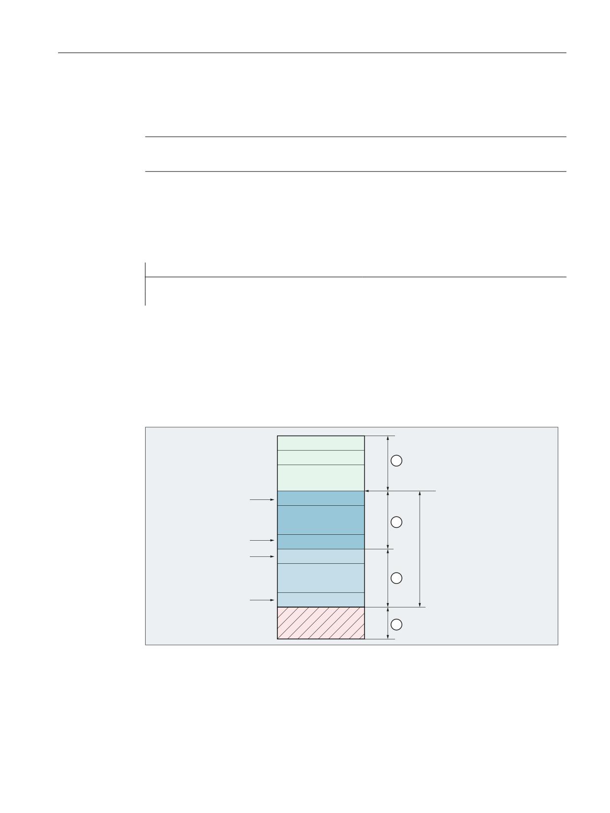
stack according to the FIFO principle (first in, first out). Using the index of the FIFO variables, the
different functions are addressed in the administration part as well as the user data.
5
5
0'
0&B67$57B$&B),)2
$&B),)2 >
@
5Q
$&B),)2 >
@
5Q
0'
$&B),)2 >
@
5Q
0&B/(1B$&B),)2
$&B),)2 > P @
5Q
0'
① Administration part
② User data part
③ R parameter range above the FIFO variables: Read and write permitted
④ R parameter range below the FIFO variables: Only read permitted
Synchronized actions
Function Manual, 10/2020, 6FC5397-5BP40-6BA4
31

Detailed description
4.3 System variables for synchronized actions
Note
The statements regarding R parameters also apply to FIFO variables. See Chapter "R parameters
($R) (Page 28)".
Syntax
Write
$AC_FIFO<n>[<i>] = <value>
$AC_FIFO[<n>, <i>] = <value>
Read
<variable> = $AC_FIFO<n>[<i>]
<variable> = $AC_FIFO[<n>, <i>]
Meaning
$AC_FIFO:
FIFO data structure in the R parameters, starting from value in MD28262
$MC_START_AC_FIFO
Data type:
REAL
<n>:
Number of FIFO variables
Data type:
INT
Value range:
1, 2, ... max. number (see additional information)
Synchronized actions
32
Function Manual, 10/2020, 6FC5397-5BP40-6BA4

Detailed description
4.3 System variables for synchronized actions
<i>:
Index of the FIFO variables with which the various functions and data within the data
structure of the FIFO variables is accessed.
Value range:
0, 1, 2, ... (MD28264 $MC_LEN_AC_FIFO - 1)
Value
Meaning
Administrative data
0
Write
A value is written to the FIFO stack by assigning a value to the FIFO stack via
index 0 ($AC_FIFO[ 0 ] = <value>). The assigned value is written to the next
free location in the FIFO stack.
If all memory locations in the FIFO stack are already occupied, an alarm is
displayed:
• When writing in an NC program: Alarm 20149
• When writing in a synchronous action: Alarm 17020
Read
A value is read from the FIFO stack by assigning the FIFO stack to a variable
with index 0 (<variable> = $AC_FIFO[ 0 ]). The oldest value is read and then
removed from the FIFO stack.
Note
• Reading in the NC program / synchronous action
If a value is read in an NC program / synchronous action with index 0, the
oldest value is read and removed from the FIFO stack as described above.
• Reading on the user interface, e.g. SINUMERIK Operate
If a value is read or displayed with index 0 on the user interface, e.g.
SINUMERIK Operate: "Diagnosis" > "NC/PLC Variables", the value is read
internally with index 1 (oldest value) without changing the FIFO stack.
1
Write / Read: The "oldest" user data is addressed; the FIFO stack is not changed
2
Write / Read: The "newest" user data is addressed; the FIFO stack is not
changed
3
Read: Returns the sum of the values of all user data
Enable via MD28266 $MC_MODE_AC_FIFO, bit 0 required. See paragraph
below "Summation across all user data"
4
Read: Supplies the number of user data currently stored in the FIFO stack.
Write: Reset to the initial state is realized by writing the value of 0 to FIFO
variable, index 4.
Example: $AC_FIFO1[4] = 0
5
Read: Returns the current write index, relative to the beginning of the FIFO
stack
User data
6
Write/read: The 1st field element of the user data range is addressed
7
Write/read: The 2nd field element of the user data range is addressed
n
Write/read: The nth field element of the user data range is addressed
Further information
List Manual System Variables
Synchronized actions
Function Manual, 10/2020, 6FC5397-5BP40-6BA4
33

Detailed description
4.3 System variables for synchronized actions
Machine data
Number of FIFO variables per channel
The number of FIFO variables per channel is set using:
MD28260 $MC_NUM_AC_FIFO = <number of FIFO variables per channel>
Beginning of the R parameter range of FIFO variables
The R parameter, from which the range of FIFO variables for the channel begins, is set using:
MD28262 $MC_START_AC_FIFO = <number of the start R parameter>
Note
Free R parameters
Only the R parameters whose numbers are below the start R parameter of the FIFO variables, can
be written to the NC program.
Number of field elements for each FIFO variable
The maximum number of field elements per FIFO variable is set using:
MD28264 $MC_LEN_AC_FIFO = <number of field elements per FIFO variable>
Total number of R parameters in the channel
The total number of R parameters, which are required in the channel, is set using:
MD28050 $MC_MM_NUM_R_PAR- MD28262 $MC_START_AC_FIFO +
AM =
MD28260 $MC_NUM_AC_FIFO *
(MD28264 $MC_LEN_AC_FIFO + 6)
Summation of all user data
The sum of the values of all user data is only provided via $AC_FIFO[ 3 ] if the function is activated
via machine data:
MD28266 $MC_MODE_AC_FIFO, bit 0 = <value>
Value
Meaning
FALSE
The sum of the values of all user data is not provided
TRUE
The sum of the values of all user data is provided
Synchronized actions
34
Function Manual, 10/2020, 6FC5397-5BP40-6BA4
Detailed description
4.3 System variables for synchronized actions
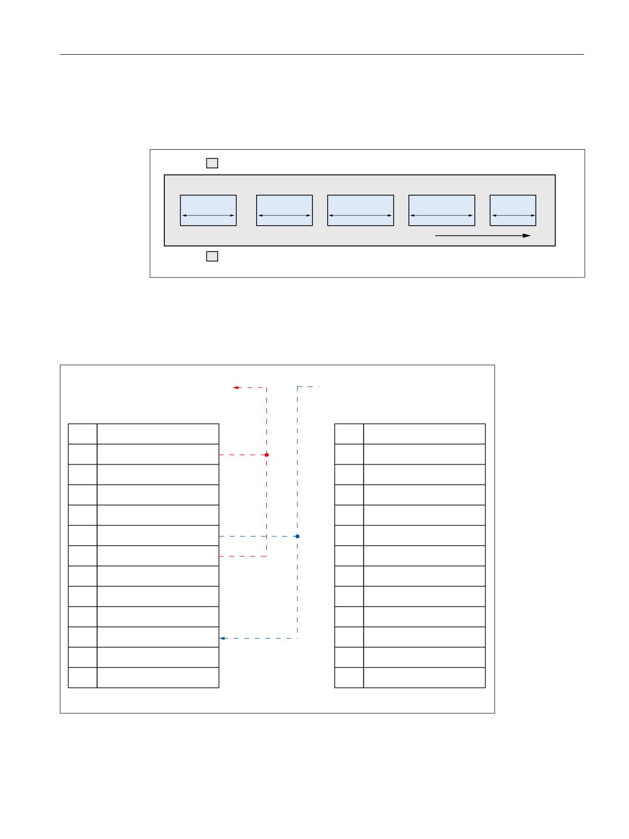
Example
Serial determination of the length of workpieces that move past an automatic measuring station
on a conveyor belt.
'LUHFWLRQ RI EHOW WUDYHO
/HQJWK PHDVXUHPHQW
The measurement results are written to or read from the $AC_FIFO1 system variable via
synchronous actions.
• Read: With index 0, the "oldest" user data element is read and deleted from the FIFO stack.
• Write: With index 0, the value is written to the next free user data element.
5HDG 2OGHVW HOHPHQW
:ULWH 1H[W HOHPHQW
1
5
$&B),)2 > @
1
$&B),)2 > @
$&B),)2 >
@
$&B),)2 >
@
>
@
8QGHILQHG
> @
8QGHILQHG
>
@
2OGHVW HOHPHQW > @
> @
2OGHVW HOHPHQW > @
>
@
0RVW UHFHQW HOHPHQW > @
> @
0RVW UHFHQW HOHPHQW >
@
>
@
6XP RI DOO YDOXHV
> @
6XP RI DOO YDOXHV
>
@
1XPEHU RI DVVLJQHG HOHPHQWV
> @
1XPEHU RI DVVLJQHG HOHPHQWV
>
@
&XUUHQW ZULWH LQGH[
> @
&XUUHQW ZULWH LQGH[
>
@
> @
8QGHILQHG
>
@
> @
>
@
> @
>
@
> @
>
@
8QGHILQHG
>
@
>
@
8QGHILQHG
>
@
8QGHILQHG
>
@
8QGHILQHG
>
@
8QGHILQHG
3UHYLRXVO\
$IWHU UHDGLQJ DQG ZULWLQJ
Synchronized actions
Function Manual, 10/2020, 6FC5397-5BP40-6BA4
35
Detailed description
4.3 System variables for synchronized actions
4.3.10
Path tangent angle ($AC_TANEB)
The angle between the tangent at the end point of the current block and the tangent at the start
point of the following block can be read via the channel-specific system variable $AC_TANEB
(Tangent ANgle at End of Block).
Data type:
REAL
The tangent angle is always specified positive in the range 0.0 to 180.0°.
If the tangent angle cannot be determined, the value -180.0° is output.
Used only with programmed blocks
It is recommended that the tangent angle only be read for programmed blocks, not for
intermediate blocks generated by the system. A distinction can be made via the system variable
$AC_BLOCKTYPE:
$AC_BLOCKTYPE == 0 (programmed block)
Example:
Program code
ID=2 EVERY $AC_BLOCKTYPE==0 DO $R1=$AC_TANEB
4.3.11
Override ($A...OVR)
Current override
Channel-specific override
The path feedrate can be changed via the channel-specific system variable $AC_OVR.
Data type:
REAL
Unit:
%
Range of val-
0.0 to machine data
ues:
• For binary-coded override switch
MD12100 $MN_OVR_FACTOR_LIMIT_BIN
• For gray-coded override switch
MD12030 $MN_OVR_FACTOR_FEEDRATE[30]
The system variable $AC_OVR must be written in every interpolator clock cycle, otherwise the
value "100%" is effective.
Channel-specific rapid traverse override
With G0 blocks (rapid traverse), the rapid traverse feedrate can also be influenced via the setting
data SD42122 $SC_OVR_RAPID_FACTOR in addition to the system variable $AC_OVR.
Requirement: Release of the rapid traverse override via the user interface.
Synchronized actions
36
Function Manual, 10/2020, 6FC5397-5BP40-6BA4
Detailed description
4.3 System variables for synchronized actions
Axis-specific override
The axial feedrate can be changed via the axis-specific system variable $AA_OVR:
Data type:
REAL
Unit:
%
Range of val-
0.0 to machine data
ues:
• For binary-coded override switch
MD12100 $MN_OVR_FACTOR_LIMIT_BIN
• For gray-coded override switch
MD12030 $MN_OVR_FACTOR_FEEDRATE[30]
The system variable $AA_OVR must be written in every interpolator clock cycle, otherwise the
value "100%" is effective.
PLC override
Channel-specific override
The channel-specific override (DB21, ... DBB4) set via the machine control panel can be read via
the channel-specific system variable $AC_PLC_OVR:
Data type:
REAL
Unit:
%
Range of val-
0.0 to maximum value
ues:
Axis-specific override
The axis-specific override (DB31, ... DBB0) set via the machine control panel can be read via the
axis-specific system variable $AA_PLC_OVR:
Data type:
REAL
Unit:
%
Range of val-
0.0 to maximum value
ues:
Effective override
Effective channel-specific override
The effective channel-specific override can be read via the channel-specific system variable
$AC_TOTAL_OVR:
Data type:
REAL
Unit:
%
Range of val-
0.0 to maximum value
ues:
Synchronized actions
Function Manual, 10/2020, 6FC5397-5BP40-6BA4
37

Detailed description
4.3 System variables for synchronized actions
Effective axis-specific override
The effective axis-specific override can be read via the axis-specific system variable
$AA_TOTAL_OVR:
Data type:
REAL
Unit:
%
Range of val-
0.0 to maximum value
ues:
4.3.12
Capacity evaluation ($AN_IPO ... , $AN/AC_SYNC ... , $AN_SERVO)
The values of the current, maximum and average system utilization due to synchronized actions
can be read via the following system variables:
NC-specific system variable
Meaning
$AN_IPO_ACT_LOAD
Current computing time of the interpolator level (incl. synchron-
ized actions of all channels)
$AN_IPO_MAX_LOAD
Longest computing time of the interpolator level (incl. synchron-
ized actions of all channels)
$AN_IPO_MIN_LOAD
Shortest computing time of the interpolator level (incl. synchron-
ized actions of all channels)
$AN_IPO_LOAD_PERCENT
Current computing time of the interpolator level in relation to the
interpolator cycle (%)
$AN_SYNC_ACT_LOAD
Current computing time for synchronized actions over all channels
$AN_SYNC_MAX_LOAD
Longest computing time for synchronized actions over all chan-
nels
$AN_SYNC_TO_IPO
Percentage share that the synchronized actions have of the total
computing time (over all channels)
$AN_SERVO_ACT_LOAD
Current computing time of the position controller
$AN_SERVO_MAX_LOAD
Longest computing time of the position controller
$AN_SERVO_MIN_LOAD
Shortest computing time of the position controller
Channel-specific system variable
Meaning
$AC_SYNC_ACT_LOAD
Current computing time for synchronized actions in the channel
$AC_SYNC_MAX_LOAD
Longest computing time for synchronized actions in the channel
$AC_SYNC_AVERAGE_LOAD
Average computing time for synchronized actions in the channel
Synchronized actions
38
Function Manual, 10/2020, 6FC5397-5BP40-6BA4
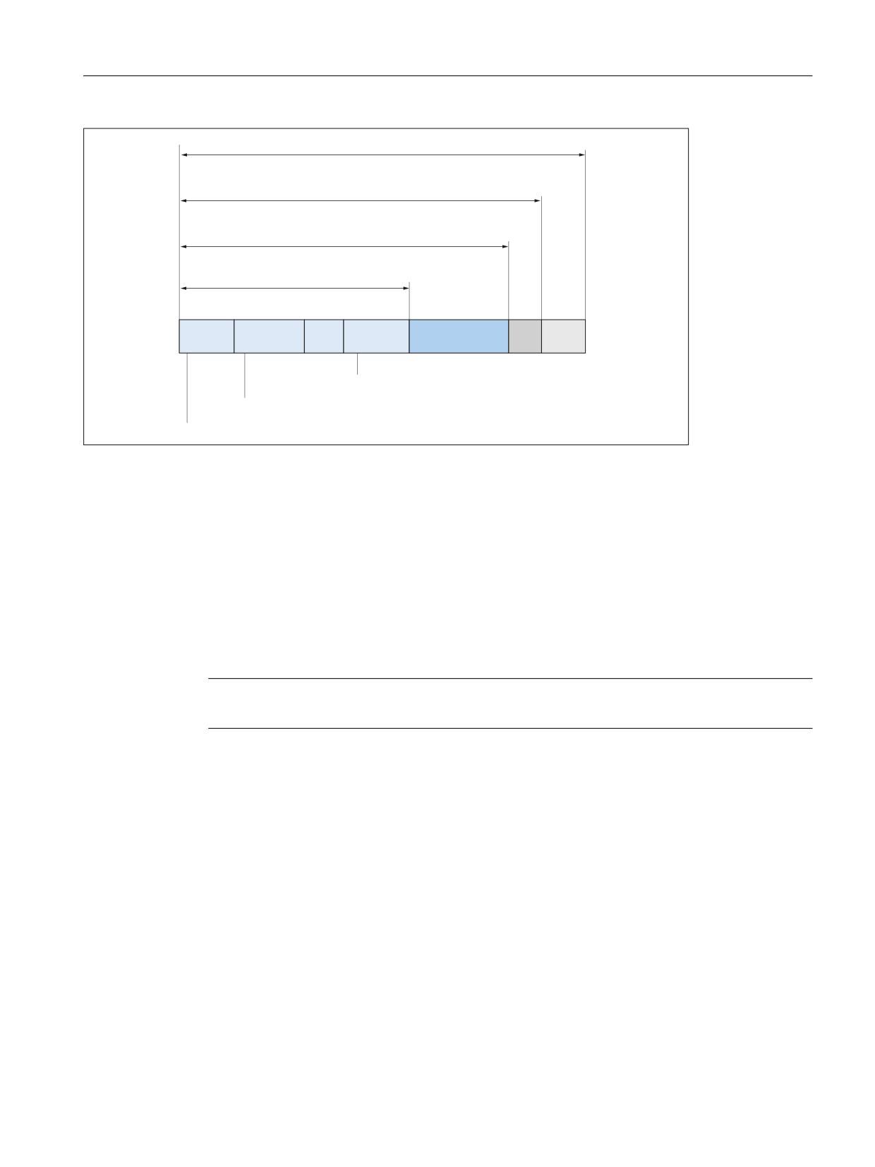
Detailed description
4.3 System variables for synchronized actions
0'
01B,32B&<&/(B7,0(
0'
01B,32B0$;B/2$'
$1B,32B$&7B/2$'
$1B6<1&B$&7B/2$'
&KDQQHO
&KDQQHO
&KDQQHO Q
$&B6<1&B$&7B/2$'> FKDQQHO Q!@
$&B6<1&B$&7B/2$'> FKDQQHO
!@
$&B6<1&B$&7B/2$'> FKDQQHO
!@
Figure 4-1
Computing time shares of the synchronized actions on the interpolator cycle
Activation
The system variables only contain valid values when the "Utilization evaluation via synchronized
actions" diagnostic function is active.
For this, the following machine data must be greater than zero:
MD11510 $MN_IPO_MAX_LOAD > 0 (maximum permissible interpolator utilization)
When the function is active, the current values are displayed in the "Time required for
synchronized actions" line in the "Diagnostics" > "System utilization" operating area.
Note
The system variables always contain the values of the previous interpolator cycle.
Overload limit
An overload limit is specified via the value set via MD11510 $MN_IPO_MAX_LOAD:
MD11510 $MN_IPO_MAX_LOAD = <maximum permissible utilization in % of the interpolator
cycle>
If the value set in the machine data is exceeded, the following system variable is set:
$AN_IPO_LOAD_LIMIT = TRUE
If the value falls below the set value again, the system variable is reset:
$AN_IPO_LOAD_LIMIT = FALSE
Application
A user-specific strategy to avoid a level overflow can be implemented via the system variable
$AN_IPO_LOAD_LIMIT.
Synchronized actions
Function Manual, 10/2020, 6FC5397-5BP40-6BA4
39

Detailed description
4.3 System variables for synchronized actions
Resetting of min./max. values
The following system variables for min./max. values are reset by writing arbitrary values:
System variable
Meaning
$AN_SERVO_MAX_LOAD
Longest computing time of the position controller
$AN_SERVO_MIN_LOAD
Shortest computing time of the position controller
$AN_IPO_MAX_LOAD
Longest computing time of the interpolator level
(incl. synchronized actions of all channels)
$AN_IPO_MIN_LOAD
Shortest computing time of the interpolator level
(incl. synchronized actions of all channels)
$AN_SYNC_MAX_LOAD
Longest computing time for synchronized actions
over all channels
$AC_SYNC_MAX_LOAD
Longest computing time for synchronized actions
in the channel
Example
Program code
Comment
$MN_IPO_MAX_LOAD=80
; Overload limit
;
; Initialization of the min./max. values
N01 $AN_SERVO_MAX_LOAD=0
N02 $AN_SERVO_MIN_LOAD=0
N03 $AN_IPO_MAX_LOAD=0
N04 $AN_IPO_MIN_LOAD=0
N05 $AN_SYNC_MAX_LOAD=0
N06 $AC_SYNC_MAX_LOAD=0
;
; Alarm 63111 when the overload limit is exceeded
N10 IDS=1 WHENEVER $AN_IPO_LOAD_LIMIT == TRUE DO M4711 SETAL(63111)
;
; Alarm 63222 when the computing time share of the
; synchronized actions over all channels exceeds 30% of the interpolator cycle
N20 IDS=2 WHENEVER $AN_SYNC_TO_IPO > 30 DO SETAL(63222)
;
N30 G0 X0 Y0 Z0
N999 M30
Synchronized actions
40
Function Manual, 10/2020, 6FC5397-5BP40-6BA4

Detailed description
4.3 System variables for synchronized actions
4.3.13
Working-area limitation ($SA_WORKAREA_ ... )
Only the activation via the setting data is effective for the traversable command axes in
synchronized actions with regard to the programmable working-area limitation G25/G26:
• $SA_WORKAREA_PLUS_ENABLE
• $SA_WORKAREA_MINUS_ENABLE
Switching the working-area limitation on and off via the commands WALIMON/WALIMOF in the
part program has no effect on the command axes traversable via synchronized actions.
4.3.14
SW cam positions and times ($$SN_SW_CAM_ ...)
The values of the SW cam positions and times can be read and written via the following setting
data:
NC-specific setting data
Meaning
$SN_SW_CAM_MINUS_POS_TAB_1[0..7]
Minus cam positions
$SN_SW_CAM_MINUS_POS_TAB_2[0..7]
Minus cam positions
$SN_SW_CAM_PLUS_POS_TAB_1[0..7]
Plus cam positions
$SN_SW_CAM_PLUS_POS_TAB_2[0..7]
Plus cam positions
$SN_SW_CAM_MINUS_TIME_TAB_1[0..7]
Minus cam lead or delay time
$SN_SW_CAM_MINUS_TIME_TAB_2[0..7]
Minus cam lead or delay time
$SN_SW_CAM_PLUS_TIME_TAB_1[0..7]
Plus cam lead or delay time
$SN_SW_CAM_PLUS_TIME_TAB_2[0..7]
Plus cam lead or delay time
Note
The setting of a software cam via synchronized actions must not be performed immediately
before the cam is reached. At least three interpolation cycles must be available before the cam
is reached.
A detailed description of the "Software cam" function can be found in:
Further information
Function Manual Axes and Spindles
Examples
Program code
; Changing a cam position:
ID=1 WHEN $AA_IW[x] > 0 DO $$SN_SW_CAM_MINUS_POS_TAB_1[0] = 50.0
; Changing a lead time
ID=1 WHEN $AA_IW[x] > 0 DO $$SN_SW_CAM_MINUS_TIME_TAB_1[0] = 1.0
Synchronized actions
Function Manual, 10/2020, 6FC5397-5BP40-6BA4
41

Detailed description
4.3 System variables for synchronized actions
See also
Machine and setting data ($$M, $$S) (Page 29)
4.3.15
Path length evaluation / machine maintenance ($AA_TRAVEL ... , $AA_JERK ... )
The data of the path length evaluation, e.g. for machine maintenance, can be read via the
system variables listed below.
Activation
The activation for the recording of the path length evaluation data is performed via:
MD18860 $MN_MM_MAINTENANCE_MON = 1
The data to be recorded for the specific axis can be selected via the following axis-specific
machine data:
MD33060 $MA_MAINTENANCE_DATA[<axis>], bit n = 1
Bit
Meaning
0
Recording of total traversing distance, total traversing time and number of traversing operations
of the axis.
1
Recording of total traversing distance, total traversing time and number of traversing operations
of the axis at high speed.
2
Recording of total number of axis jerks, the time during which the axis is traversed with jerk and
the number of traversing operations with jerk.
System variable
System variable
Meaning
n
$AA_TRAVEL_DIST
Total travel distance:
0
Sum of all set position changes in MCS in [mm] or [deg.].
$AA_TRAVEL_TIME
Total travel time:
Sum of IPO cycles of set position changes in MCS in [s] (resolution: 1 IPO cycle)
$AA_TRAVEL_COUNT
Total travel count:
A complete machine axis trip is defined by the following succession of states, as
based on set position: standstill > traversing > standstill
$AA_TRAVEL_DIST_HS
Total traversing distance at high axis velocities 1)
1
$AA_TRAVEL_TIME_HS
Total traversing time at high axis velocities 1)
$AA_TRAVEL_COUNT_HS
Total number of traversing operations at high axis velocities 3)
$AA_JERK_TOT
Total sum of axis jerks:
2
Sum of all jerk setpoints in [m/s3] or [deg./ s3].
$AA_JERK_TIME
Total travel time with jerk:
Sum of IPO cycles from jerk setpoint changes in [s] (resolution: 1 IPO cycle)
$AA_JERK_COUNT
Total number of traversing operations with jerk
1) Actual machine axis velocity ≥ 80% of the maximum parameterized axis velocity (MD32000 MAX_AX_VELO)
Synchronized actions
42
Function Manual, 10/2020, 6FC5397-5BP40-6BA4
Detailed description
4.3 System variables for synchronized actions
Further information
For a detailed description of the function, refer to:
Function Manual Axes and Spindles
4.3.16
Polynomial coefficients, parameters ($AC_FCT ...)
Function
Using the FCTDEF function, as a maximum, a 3rd degree polynomial can be defined:
f(x) = a0 + a1*x + a2*x2 + a3*x3
Note
The definition must be made in a part program.
Syntax
FCTDEF(<Poly_No>,<Lo_Limit>,<Up_Limit>,a0,a1,a2,a3)
Meaning
Parameter
Meaning
<Poly_No>:
Number of the polynomial function
<Lo_Limit>:
Lower limit of the function values
<Up_Limit>:
Upper limit of the function values
a0, a1, a2, a3:
Polynomial coefficient
Note
Polynomial coefficients (a2, a3) that are not required can be omitted when programming
the FCTDEF(...) function.
System variable
Read and write access to polynomial coefficients and parameters is also possible from
synchronized actions via the following system variables:
System variable
Meaning
$AC_FCTLL[<Poly_No>]:
Lower limit for function value
$AC_FCTUL[<Poly_No>]:
Upper limit for function value
$AC_FCT0[<Poly_No>]:
a0
$AC_FCT1[<Poly_No>]:
a1
Synchronized actions
Function Manual, 10/2020, 6FC5397-5BP40-6BA4
43
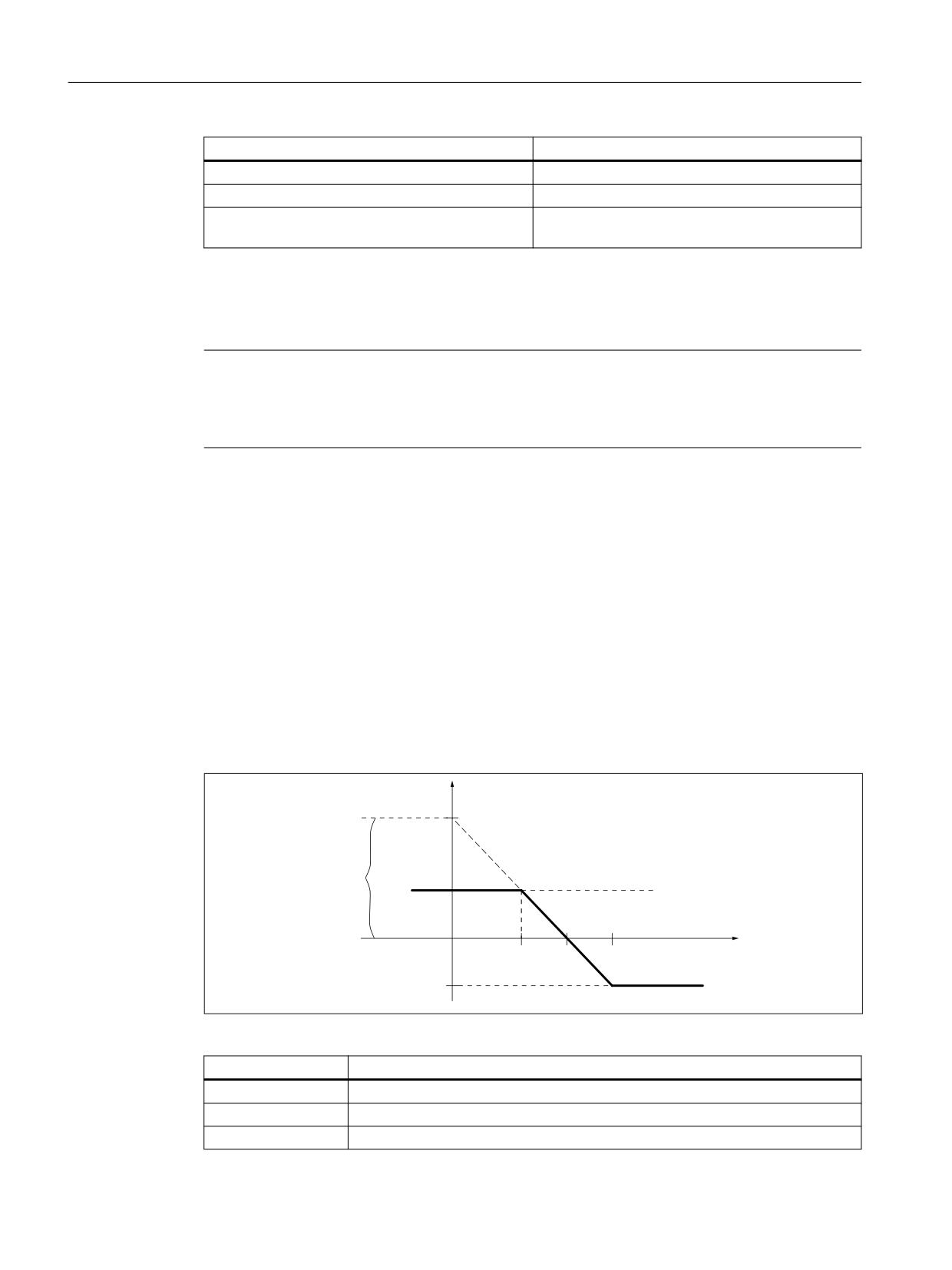
Detailed description
4.3 System variables for synchronized actions
System variable
Meaning
$AC_FCT2[<Poly_No>]:
a2
$AC_FCT3[<Poly_No>]:
a3
<Poly_No>:
The number specified during the definition of the
polynomial function (see above: Syntax)
Part program
When writing system variables in the part program, preprocessing stop STOPRE must be
programmed explicitly for block-synchronous writing.
Note
Block-synchronous writing in the part program
So that the system variables can be written block-synchronously in the part program,
the STOPRE command (preprocessing stop) must be used after writing the system variables.
Synchronized action
When writing system variables in synchronized actions, they take effect immediately.
Use
The function value f(x) of the polynomial can be used as input value in synchronized actions, e.g.
for the following functions:
• "Polynomial evaluation (SYNFCT) (Page 67)"
• "Online tool offset (FTOC) (Page 73)"
Example: Linear dependency
)HHGUDWH ) >PP PLQ@
D
8SSHU OLPLW
$FWXDO FXUUHQW YDOXH >$@
$$B&855
/RZHU OLPLW
Figure 4-2
Example of linear dependency
Parameter
Meaning
<Poly_No>:
Number of the polynomial, e.g. = 1
<Lo_Limit>:
Lower limit of the function values = -100
<Up_Limit>:
Upper limit of the function values = 100
Synchronized actions
44
Function Manual, 10/2020, 6FC5397-5BP40-6BA4

Detailed description
4.3 System variables for synchronized actions
Parameter
Meaning
a0:
Axis section on the ordinate (feedrate):
(5 - 4) / 100 = 5 / a0
a0 = 100 * 5 / (5 - 4) = 500
a1:
Gradient of the straight line:
a1 = 100 / (4 - 5) = -100
a2:
= 0 (no square component)
a3:
= 0 (no cubic component)
Program code
FCTDEF(1, -100, 100, 500, -100, 0, 0)
; Or in abbreviated notation without parameters a2 and a3
FCTDEF(1, -100, 100, 500, -100)
4.3.17
Overlaid movements ($AA_OFF)
Overlaid movements
The system variable $AA_OFF can be used to specify a position offset in a channel axis which is
traversed immediately:
$AA_OFF[<channel axis>] = <position offset>
The following machine data can be used to set whether the position offset of the system variable
is to be assigned or summed up (integrated):
MD36750 $MA_AA_OFF_MODE, bit 0 = <value>
<value>
Meaning
0
Assignment: $AA_OFF = <position offset>
1
Summing (integration): $AA_OFF += <position offset>
Limitation of the overlay velocity
The maximum permissible velocity with which the position offset can be traversed can be set via
the machine data:
MD32070 $MA_CORR_VELO (axis velocity for overlay)
Axial jerk limitation
Setting the following machine data activates an axial jerk limitation for the $AA_OFF overlaying:
MD32420 $MA_JOG_AND_POS_JERK_ENABLE (basic position of axial jerk limitation) = 1
Synchronized actions
Function Manual, 10/2020, 6FC5397-5BP40-6BA4
45

Detailed description
4.3 System variables for synchronized actions
The axial jerk is limited to the value set in MD32430 $MA_JOG_AND_POS_MAX_JERK (axial jerk).
Note
No predictive velocity control can be made for the overlaid $AA_OFF motion. This can cause a
discontinuous velocity change, in particular for clocked specification (via synchronous actions)
for $AA_OFF overlay values. In such cases, we recommend the deactivation of the jerk limitation
when possible.
Upper limit of the compensation value
The value of $AA_OFF can be limited via the following setting data:
SD43350 $SA_AA_OFF_LIMIT (upper limit of the compensation value $AA_OFF in case of
clearance control)
The status of the limitation can be read via the following system variable:
$AA_OFF_LIMIT[<axis>] == <value>
Value
Meaning
-1
Compensation value is limited in the negative direction.
1
Compensation value is limited in the positive direction.
0
No limitation of the offset value
Reset behavior
With static synchronous actions (IDS = <number> DO $AA_OFF = <value>), deselection
of the position offset effective in $AA_OFF results in an immediate new overlaid movement. The
reset behavior with regard to $AA_OFF can therefore be set via the following machine data:
MD36750 $MA_AA_OFF_MODE, bit 1 = <value>
<value>
Meaning
0
The position offset in $AA_OFF is deselected with RESET
1
The position offset in $AA_OFF is retained after RESET
JOG mode
Execution of an overlaid movement because of $AA_OFF can also be enabled for JOG mode:
MD36750 $MA_AA_OFF_MODE, bit 2 = <value>
<value>
Meaning
0
JOG mode: Overlaid movement because of $AA_OFF disabled
1
JOG mode: Overlaid movement because of $AA_OFF enabled
A mode change to JOG mode is only possible when the current position offset has been
traversed. Otherwise the following alarm is displayed:
Alarm "16907 Action ... only possible in stop state"
Synchronized actions
46
Function Manual, 10/2020, 6FC5397-5BP40-6BA4
Detailed description
4.3 System variables for synchronized actions
Boundary conditions
•
Interrupt routines and ASUB
When an interrupt routine is activated, modal motion-synchronous actions are retained and
are also effective in the ASUB. If the subprogram return is not made with REPOS, the modal
synchronous actions changed in the asynchronous subprogram continue to be effective in
the main program.
•
REPOS
In the remainder of the block, the synchronous actions are treated in the same way as in an
interruption block. Modifications to modal synchronous actions in the ASUB are not effective
in the interrupted program. Polynomial coefficients programmed with FCTDEF are not
affected by ASUB and REPOS.
The polynomial coefficients from the calling program are active in the ASUB. The polynomial
coefficients from the ASUB continue to be active in the calling program.
•
End of program
Polynomial coefficients programmed with FCTDEF remain active after the end of program.
•
Block search: Collection of the polynomial coefficients
During block search with calculation, the polynomial coefficients are collected in the system
variables.
•
Block search: Deselection of active overlaid movements
During block search, the CORROF and DRFOF commands are collected and output in an
action block. All the deselected DRF offsets are collected in the last block that
contains CORROF or DRFOF.
The commands for the deselection of overlaid movements CORROF(<axis>, "AA_OFF")
are not collected during a block search. If a user wishes to continue to use this block search,
this is possible by means of block search via "SERUPRO" program testing.
Further information
Function Manual Basic Functions
•
Deselection of the position offset in case of synchronous actions
Alarm 21660 is displayed if a synchronous action is active when the position offset is
deselected via the CORROF(<axis>,"AA_OFF") command. $AA_OFF is deselected
simultaneously and not set again. If the synchronous action becomes active later in the block
after CORROF, $AA_OFF remains set and a position offset is interpolated.
Note
The coordinate system (BCS or WCS) in which a main run variable is defined determines whether
frames will or will not be included.
Distances are always calculated in the set basic system (metric or inch). A change with G70
or G71 has no effect.
DRF offsets, zero offsets external, etc., are only taken into consideration in the case of main run
variables that are defined in the MCS.
Synchronized actions
Function Manual, 10/2020, 6FC5397-5BP40-6BA4
47
Detailed description
4.3 System variables for synchronized actions
4.3.18
Online tool length compensation ($AA_TOFF)
Function
In conjunction with an active orientation transformer or an active tool carrier, tool length
compensations can be applied during processing/machining in real time. Changing the
effective tool length using online tool length compensation produces changes in the
compensatory movements of the axes involved in the transformation in the event of changes in
orientation. The resulting velocities can be higher or lower depending on machine kinematics
and the current axis position.
Velocity and acceleration, with which specified tool length compensations can be traversed via
the system variable $AA_TOFF, can be specified via the following machine data:
• MD21194 $MC_TOFF_VELO (velocity, online offset in tool direction)
• MD21196 $MC_TOFF_ACCEL (acceleration, online offset in tool direction)
For further information regarding the activation of the function, see:
Further information
Programming Manual NC Programming
Applications in synchronous actions
In synchronous actions, tool length compensations can be applied in all three dimensions via the
system variable $AA_TOFF. The three geometry axis names X, Y, Z are used as index. All three
offset directions can be active at the same time.
For an active orientation transformation or for an active tool carrier that can be oriented, the
offsets are effective in the respective tool axes. An overlaid motion must be switched off with
TOFFOF() before switching a transformation on or off.
After deselection of the tool length compensation in one dimension, the value of the system
variable $AA_TOFF in this dimension is equal to 0.
Mode of operation of the offset in the tool direction
The tool length compensations do not change the tool parameters, but are taken into account
within the transformation or the tool carrier that can be orientated, so that offsets are obtained
in the tool coordinate system.
For each dimension, it is possible to define whether the tool length compensation specified in
$AA_TOFF should be calculated as an absolute or incremental (integrating) value via the
following machine data:
MD21190 $MC_TOFF_MODE (operation of tool offset in tool direction)
Synchronized actions
48
Function Manual, 10/2020, 6FC5397-5BP40-6BA4
Detailed description
4.3 System variables for synchronized actions
The current value of the tool length compensation can be read via the system variable
$AA_TOFF_VAL.
Note
An evaluation of the variables $AA_TOFF_VAL is only useful in conjunction with an active
orientation transformation or an active tool carrier.
Examples
Selecting the online tool length compensation
Machine data for online tool length compensation:
• MD21190 $MC_TOFF_MODE = 1
• MD21194 $MC_TOFF_VEL[0] = 10000
• MD21194 $MC_TOFF_VEL[1] = 10000
• MD21194 $MC_TOFF_VEL[2] = 10000
• MD21196 $MC_TOFF_ACC[0] = 1
• MD21196 $MC_TOFF_ACC[1] = 1
• MD21196 $MC_TOFF_ACC[2] = 1
Activate online tool length compensation in the part program:
Program code
N5 DEF REAL XOFFSET
; Activate orientation transformation
N10 TRAORI
; Activate tool length compensation in the Z direction
N20 TOFFON(Z)
; Tool length compensation in the Z direction: 10 mm
N30 WHEN TRUE DO $AA_TOFF[Z] = 10
G4 F5
; Static synchronous action: Tool length compensation in the X direction
; corresponds to the position of the X2 axis in the WCS
N50 ID=1 DO $AA_TOFF[X] = $AA_IW[X2]
G4 F5
; Note: Current total tool length compensation in the X direction
N100 XOFFSET = $AA_TOFF_VAL[X]
; Retract the tool length compensation in the X direction to 0
N120 TOFFON(X, -XOFFSET)
G4 F5
Synchronized actions
Function Manual, 10/2020, 6FC5397-5BP40-6BA4
49

Detailed description
4.3 System variables for synchronized actions
Deselecting the online tool length compensation
Program code
; Activate orientation transformation
N10 TRAORI
; Activate tool length compensation in the X direction
N20 TOFFON(X)
; Tool length compensation in the X direction: 10 mm
N30 WHEN TRUE DO $AA_TOFF[X] = 10
G4 F5
; Delete tool length compensation in the X direction
; No axis is traversed. To the current position in the WCS
; the position offset in accordance with the current orientation
; is added.
N80 TOFFOF(X)
N90 TRAFOOF
Activating and deactivating in the part program
The online tool length compensation is activated in the part program with TOFFON and
deactivated with TOFFOF. When activating for the respective offset direction, an offset value can
be specified, e.g. TOFFON(Z,25), which is then immediately traversed. The status of the online
tool length compensation is activated at the NC/PLC interface via the following signals:
• DB21, ... DBX318.2 (TOFF active)
• DB21, ... DBX318.3 (TOFF movement active)
Note
The online tool length compensation remains inactive until it is reselected using via TOFFON
in the part program.
Behavior at reset and power on
The behavior at reset can be set via the machine data:
MD21190 $MC_TOFF_MODE, bit 0 = <value> (operation of tool offset in tool direction)
Value
Meaning
0
The tool length offset $AA_TOFF is deselected at reset
1
The tool length offset $AA_TOFF is retained at reset
This is always necessary in case of synchronous actions IDS=<number> DO
$AA_TOFF[n]=<value>, as otherwise there would be an immediate tool length
compensation.
Similarly, a transformation or a tool carrier that can be oriented, can be deselected after reset
via the following machine data:
MD20110 $MC_RESET_MODE_MASK (initial setting after reset)
Synchronized actions
50
Function Manual, 10/2020, 6FC5397-5BP40-6BA4
Detailed description
4.3 System variables for synchronized actions
The tool length compensation must also be deleted in this case.
If a tool length offset is to remain active extending beyond a reset, and a transformation change
or a change of the tool carrier that can be oriented takes place, then alarm 21665 "Channel %1
$AA_TOFF[ ] reset" is output. The tool length compensation is set to 0.
After power on, all tool length offsets are set to 0.
The function is deactivated after POWER ON.
Behavior at change of operating mode
The tool length compensation remains active after a change of operating mode. The offset is
executed in all operating modes except JOG and REF.
If a tool length compensation is traversed because of $AA_TOFF[ ] at a change of operating
mode, the operating mode changeover is only carried out after the traversal of the tool length
compensation. Alarm 16907 "Channel %1 action %2 <ALNX> possible only in stop state" is
displayed.
Behavior with REPOS
The tool length compensation is active in REPOS mode.
Boundary conditions
With an existing tool length offset, the following supplementary conditions must be taken into
account:
• A transformation must be switched off with TRAFOOF.
• Before activating a transformation in the part program, an active tool length offset must be
deleted with TOFFOF.
• A transformation is switched off when changing over from CP to PTP. A tool length offset
must be deleted before the changeover. If a tool length compensation is active when you
change to axis-specific manual travel in JOG mode, the change to PTP is not performed. CP
remains active until the tool length compensation has been deleted via TOFFOF.
• Before a geometry axis interchange, an active tool length offset in the direction of the
geometry axis must be deleted via TOFFOF.
• Before a change of plane, an active tool length offset must be deleted via TOFFOF.
• The TOFFON and TOFFOF are not collected during a block search and not output in the action
block.
4.3.19
Current block in the interpolator ($AC_BLOCKTYPE, $AC_BLOCKTYPEINFO,
$AC_SPLITBLOCK)
Information on the block currently being processed in the main run can be read in synchronized
actions via the following system variables.
Synchronized actions
Function Manual, 10/2020, 6FC5397-5BP40-6BA4
51
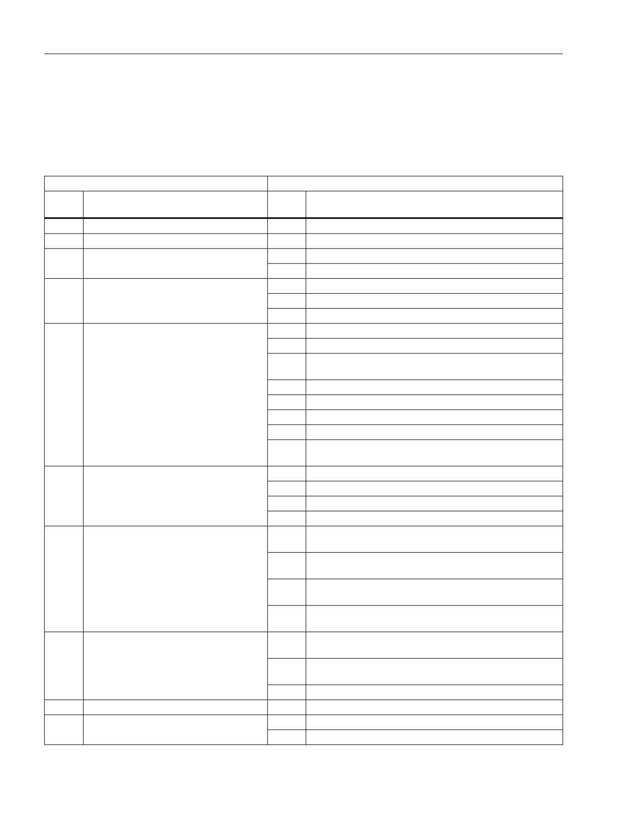
Detailed description
4.3 System variables for synchronized actions
$AC_BLOCKTYPE and $AC_BLOCKTYPEINFO
The system variable $AC_BLOCKTYPE contains the block type or the ID for the function that
generated the block.
The system variable $AC_BLOCKTYPEINFO contains, in addition to the block type (thousands
position), the function-specific cause for the generation of the intermediate block.
$AC_BLOCKTYPE
$AC_BLOCKTYPEINFO
Value
Meaning: Current block has been gener-
Value
Meaning
ated because of ...
0
Programmed block!
-
-
1
NC as intermediate block
1000
Contains no further information
2
Chamfer/rounding
2001
Straight line
2002
Circle
3
Smooth approach/retraction (SAR)
3001
Approach with straight line
3002
Approach with quadrant
3003
Approach with semicircle
4
Tool offset
4001
Approach block after STOPRE
4002
Connection blocks if intersection point not found
4003
Point-type circle on inner corners
(on TRACYL only)
4004
Bypass circle (or conical cut) at outer corners
4005
Approach blocks for offset suppression
4006
Approach blocks on repeated TRC activation
4007
Block split due to excessive curvature
4008
Compensation blocks for 3D front milling (tool vector parallel
to plane vector)
5
Corner rounding
5001
Rounding contour through G641
5002
Rounding contour through G642
5003
Rounding contour through G643
5004
Rounding contour through G644
6
Tangential tracking (TLIFT)
6001
Linear movement of the tangential axis without lift move-
ment
6002
Non-linear movement of the tangential axis (polynomial)
without lift movement
6003
Lift movement: Tangential axis and lift movement start si-
multaneously
6004
Lift movement: Tangential axis does not start until a certain
lift position is reached
7
Path segmentation
7001
Programmed path segmentation is active without punching
or nibbling
7002
Programmed path segmentation with active punching or nib-
bling
7003
Automatically, internally generated path segmentation
8
Compile cycle
x
x: ID of the compile cycle application that generated the block
9
Path-relative orientation interpolation (OR-
9000
Interpolation of the tool orientation with ORIPATH
IPATH/ORIROTC)
9001
Interpolation of the rotation of the tool with ORIROTC
Synchronized actions
52
Function Manual, 10/2020, 6FC5397-5BP40-6BA4
Detailed description
4.3 System variables for synchronized actions
$AC_BLOCKTYPE
$AC_BLOCKTYPEINFO
Value
Meaning: Current block has been gener-
Value
Meaning
ated because of ...
10
Pole handling with orientation transforma-
10000
Look-ahead positioning of the pole axis
tion
10001
Traversal of the pole taper
$AC_SPLITBLOCK
The system variable $AC_SPLITBLOCK can be used to determine whether an internally generated
block or a programmed block shortened by the NC is present.
$AC_SPLITBLOCK
Value
Meaning:
0
Programmed block. A block generated by the compressor is also treated as a programmed
block.
1
Internally generated block or a shortened original block
3
Last block in a chain of internally generated blocks or shortened original blocks
Example
Synchronized actions for counting smoothing blocks.
The query of the system variable $AC_TIMEC == 0 (interpolation cycles since start of the block)
ensures that the block type is determined only once at the start of the block.
Program code
Comment
$AC_MARKER[0]=0
; Counter for all smoothing blocks
$AC_MARKER[1]=0
; Counter for G641 smoothing blocks
$AC_MARKER[2]=0
; Counter for G642 smoothing blocks
; Synchronized action for counting all smoothing blocks
ID=1 WHENEVER ($AC_TIMEC==0) AND ($AC_BLOCKTYPE==5) DO
$AC_MARKER[0] = $AC_MARKER[0] + 1
; Synchronized action for counting the G641 smoothing blocks
ID=2 WHENEVER ($AC_TIMEC==0) AND ($AC_BLOCKTYPEINFO==5001) DO
$AC_MARKER[1] = $AC_MARKER[1]+1
; Synchronized action for counting the G642 smoothing blocks
ID=3 WHENEVER ($AC_TIMEC==0) AND ($AC_BLOCKTYPEINFO==5002) DO
$AC_MARKER[2] = $AC_MARKER[2] + 1
Synchronized actions
Function Manual, 10/2020, 6FC5397-5BP40-6BA4
53
Detailed description
4.3 System variables for synchronized actions
4.3.20
Initialization of array variables (SET, REP)
Function
Array variables can also be initialized in synchronous actions via the SET and REP commands.
For a detailed description of the commands, refer to:
Further information
Programming Manual NC Programming
Example
Program code
PROC MAIN
N10 DEF REAL SYG_IS[3,2]
WHEN TRUE DO SYG_IS[0,0]=REP(0.0,3)
WHEN TRUE DO SYG_IS[1,1]=SET(3,4,5)
Boundary conditions
• Only array variables that can be written in synchronous actions are initialized.
4.3.21
Grinding-specific system variables ($AC_IN_KEY_G...)
When grinding, input signals asynchronous with the machine operation must be identified and
the appropriate actions must be integrated in the program sequence. The following system
variables and NC/PLC interface signals are available:
System variable
NC/PLC interface DB21, ...
Description
NC-internal communication
$AC_IN_KEY_G_ENABLE[1 ... 8] 1
---
Input signal enable on the NC side
Communication NC → PLC 2)
$AC_IN_KEY_G_ISENABLE[1 ... 8] 1)
DBX390.0 ... 7
Input signal enable
$AC_IN_KEY_G_RUN_OUT[1 ... 8]
DBX391.0 ... 7
Enable request for the action on the NC side (optional)
Communication PLC → NC 3)
$AC_IN_KEY_G[1 ... 8]
DBX385.0 ... 7
Input signal
---
DBX386.0 ... 7 1)
Input signal inhibit on the PLC side
$AC_IN_KEY_G_RUN_IN[1 ... 8]
DBX387.0 ... 7
Enable request for the action on the PLC side (optional)
1) As a result of the ANDlogic operation of the NC enable signal on the NC side in $AC_IN_KEY_G_ENABLE and PLC enable
signal NOT(DBX386.0 ... 7), the enable signal is formed in $AC_IN_KEY_G_ISENABLE and DBX390.0 ... 7.
2) The content of the system variable is transferred in the NC/PLC interface
3) The content of the NC/PLC interface is transferred in the system variable
Synchronized actions
54
Function Manual, 10/2020, 6FC5397-5BP40-6BA4
Detailed description
4.3 System variables for synchronized actions
Example
Inputs
• The main program starts a cycle (ZYKLUS_1), in which grinding is executed as well as the
intermediate dressing.
• An operator can request an "intermediate dressing" action asynchronous to the machining
operation itself using an input signal of the PLC I/O.
• Identifying the input signal and requesting the action is realized in a technology cycle.
Technology cycle ("SIGNAL_IN_x") is called in the action part of the synchronized action (ID
<xy>) set up in the cycle.
The call schematic, the relevant commands and the signal flow are shown in the following
diagram.
Synchronized actions
Function Manual, 10/2020, 6FC5397-5BP40-6BA4
55
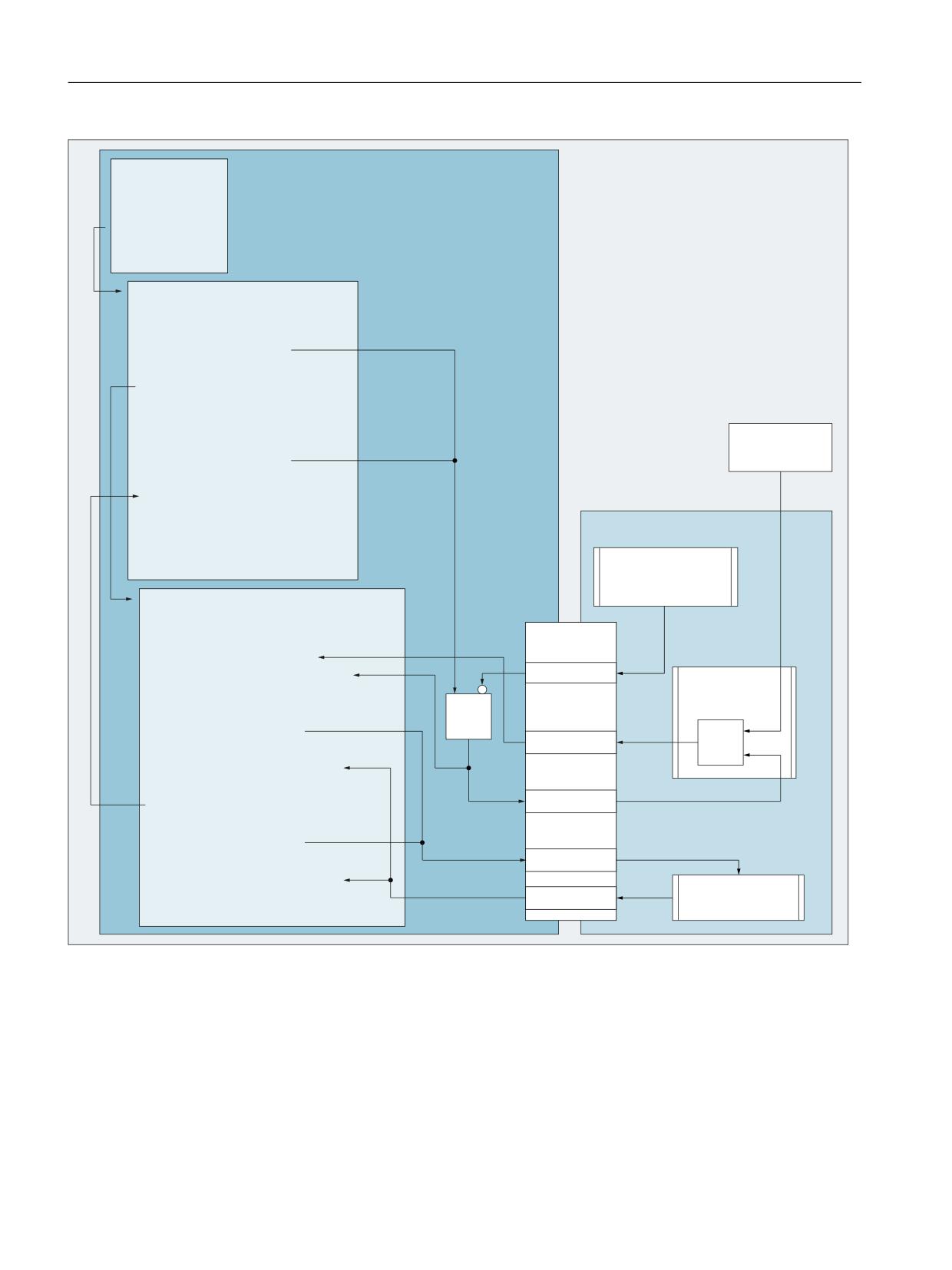
Detailed description
4.3 System variables for synchronized actions
0DLQ SURJUDP
1&
&DOOLQJ WKH F\FOH
=<./86B[
0
&\FOH
352& =<./86B
(QDEOH LQSXW VLJQDO [
$&B,1B.(<B*B(1$%/(>[@
6HWXS V\QFKURQL]HG DFWLRQ
,' [\! '2 6,*1$/B,1B[
5
!!! JULQGLQJ
5HVHW HQDEOH
$&B,1B.(<B*B(1$%/(>[@
,) DFWLRQ [ ,QWHUPHGLDWH GUHVVLQJ UHTXHVWHG
,) 5
!!! LQWHUPHGLDWH GUHVVLQJ
3/&
(1',)
)XQFWLRQ
0
(QDEOH LQSXW
VLJQDO [
7HFKQRORJ\ F\FOH
352& 6,*1$/B,1B[
'%
&KHFN IRU LQSXW VLJQDO [
:+,/( $&B,1B.(<B*>[@
25
$&B,1B.(<B*B,6(1$%/(>[@
'%;
)XQFWLRQ
(1':+,/(
,QSXW VLJQDO [
5HTXHVW VHW (QDEOH DFWLRQ [
$&B,1B.(<B*B581B287>[@
'%;
:DLW IRU WKH HQDEOH RI DFWLRQ [
:+,/( $&B,1B.(<B*B581B,1>[@
(1':+,/(
5
UHTXHVW DFWLRQ [
'%;
$FWLRQ [ FRPSOHWHG WR WKH 3/& XVHU SURJUDP
$&B,1B.(<B*B581B287>[@
:DLW IRU IHHGEDFN VLJQDO IURP 3/& XVHU SURJUDP
'%;
:+,/( $&B,1B.(<B*B581B,1>[@
)XQFWLRQ
(1':+,/(
'%;
(QDEOH DFWLRQ [
0
The PLC user program must provide the functions on the PLC side, for example "enable input
signal x".
Synchronized actions
56
Function Manual, 10/2020, 6FC5397-5BP40-6BA4

Detailed description
4.3 System variables for synchronized actions
Sequence
•
Main program
- Call cycle "ZYKLUS_1"
•
Cycle "ZYKLUS_1"
- Set the enable for input signal x ($AC_IN_KEY_G_ENABLE)
- Set up the synchronized action with technology cycle "SIGNAL_IN_x"
- Initialize the trigger for action x "intermediate dressing" (R01)
- Grind the component
•
Technology cycle "SIGNAL_IN_x" (in parallel with the cycle)
- Identify the input signal ($AC_IN_KEY_G) with the enable active
($AC_IN_KEY_G_ISENABLE)
- Request the enable of action x from the PLC ($AC_IN_KEY_G_RUN_OUT)
- Wait for the enable of action x from the PLC ($AC_IN_KEY_G_RUN_IN)
- Request action x in cycle (R01)
- Feedback signal of the request to the PLC ($AC_IN_KEY_G_RUN_OUT)
- Wait for acknowledgment from the PLC ($AC_IN_KEY_G_RUN_IN)
•
Cycle "ZYKLUS_1" (after completing grinding)
- Reset the enable for input signal x ($AC_IN_KEY_G_ENABLE)
- If action x is requested ⇒ execute intermediate dressing
- ... (possibly re-execute grinding/intermediate dressing operations etc.)
•
PLC user program
- Function "Enable input signal x":
Set interface signal DBX386.0 ... 7
- Function "Enable input signal x":
Logically combine (AND) the input signal from the PLC I/O and the enable of input signal
(DBX390.0 ... 7) - and set the result in the interface (DBX385.0 ... 7)
- Function "Enable action x":
Check/set the interface signals DBX391.0 ... 7 / DBX387.0 ... 7
4.3.22
Status Synchronized action disabled ($AC_SYNA_STATE)
System variable $AC_SYNA_STATE outputs in bit code whether a synchronized action is
disabled via the PLC (Page 123) or a synchronized action (Page 123).
These bits have the following meaning:
Bit
Value
Meaning
0
0
Not disabled
1
Disabled via PLC or synchronized action
Synchronized actions
Function Manual, 10/2020, 6FC5397-5BP40-6BA4
57
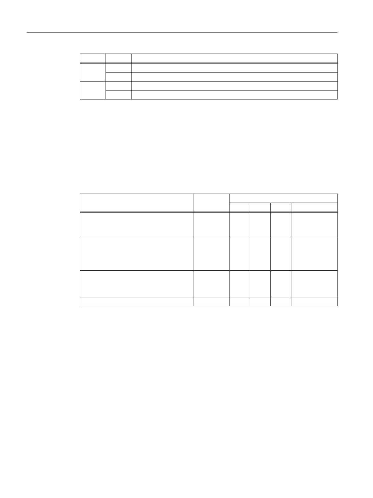
Detailed description
4.4 User-defined variables for synchronized actions
Bit
Value
Meaning
1
0
Not disabled via PLC
1
Disabled via PLC
2
0
Not disabled via synchronized action
1
Disabled via synchronized action
Disabling via PLC or synchronized action have different levels of priority. The following hierarchy
of priorities applies:
Priority 1 (highest priority):
Disabled via PLC across all channels (⇒ all synchronized ac-
tions in the channel are inhibited)
Priority 2:
Disabled via synchronized action
Priority 3:
Individual disabling via PLC (⇒ a single synchronized action in
the channel is disabled)
$AC_SYNA_STATE only outputs the value of the disable with the highest priority, even if
disabling is simultaneously active via PLC and Synchronized action:
Status
Highest
$AC_SYNA_STATE
priority
Bit 2
Bit 1
Bit 0
Bit-coded value
Channel-wide disable via PLC is active.
Channel-
0
1
1
3
wide disable
In addition, disable via synchronized action
via PLC
can be active.
Channel-wide disable via PLC is not active.
Disabled via
1
0
1
5
synchron-
Disable via synchronized action is active.
ized action
Additionally, a single disable can be active
via PLC.
Channel-wide disable via PLC is not active.
Single disa-
0
1
1
3
ble via PLC
Disable via synchronized action is not active.
Single disable via PLC is active.
No disable is active.
-
0
0
0
0
4.4
User-defined variables for synchronized actions
GUD variables capable of synchronized actions
As well as specific system variables, predefined global synchronized-action user variables
(synchronized action GUD) can also be used in synchronized actions. The number of
synchronized action GUD items available to the user is parameterized for each specific data type
and access using the following machine data:
• MD18660 $MM_NUM_SYNACT_GUD_REAL[<x>] = <number>
• MD18661 $MM_NUM_SYNACT_GUD_INT[<x>] = <number>
• MD18662 $MM_NUM_SYNACT_GUD_BOOL[<x>] = <number>
• MD18663 $MM_NUM_SYNACT_GUD_AXIS[<x>] = <number>
Synchronized actions
58
Function Manual, 10/2020, 6FC5397-5BP40-6BA4
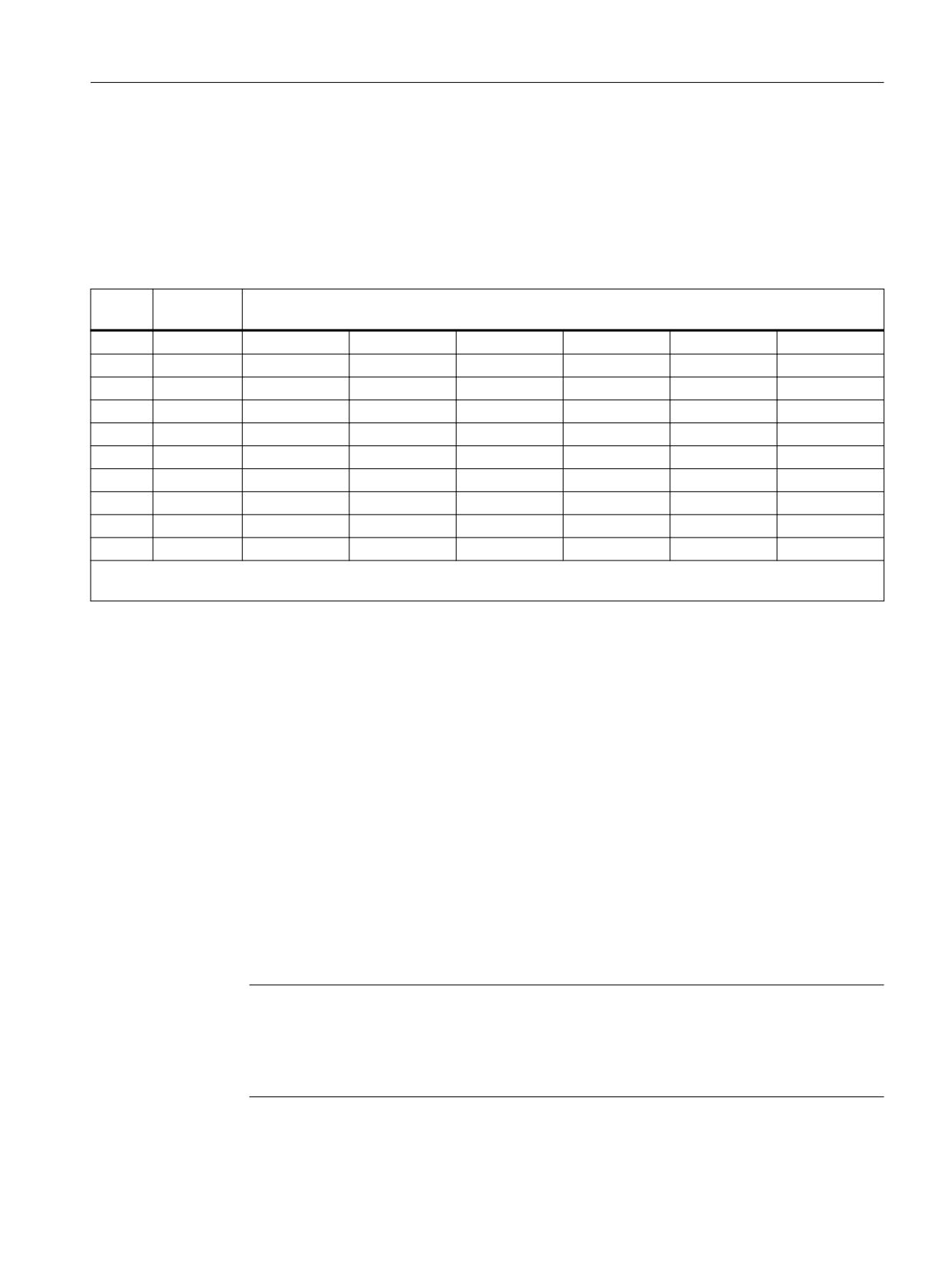
Detailed description
4.4 User-defined variables for synchronized actions
• MD18664 $MM_NUM_SYNACT_GUD_CHAR[<x>] = <number>
• MD18665 $MM_NUM_SYNACT_GUD_STRING[<x>] = <number>
The index <x> is used to specify the data block (access rights) and the value <number> to specify
the number of synchronized-action GUDs for each data type (REAL, INT, etc.). A 1-dimensional
array variable with the following naming scheme is then created in the relevant data block for
each data type.: SYG_<data type><access right>[<index>]:
Index
Data type
<x>
(MD18660 to MD18665)
Block
REAL
INT
BOOL
AXIS
CHAR
STRING
0
SGUD
SYG_RS[ i ]
SYG_IS[ i ]
SYG_BS[ i ]
SYG_AS[ i ]
SYG_CS[ i ]
SYG_SS[ i ]
1
MGUD
SYG_RM[ i ]
SYG_IM[ i ]
SYG_BM[ i ]
SYG_AM[ i ]
SYG_CM[ i ]
SYG_SM[ i ]
2
UGUD
SYG_RU[ i ]
SYG_IU[ i ]
SYG_BU[ i ]
SYG_AU[ i ]
SYG_CU[ i ]
SYG_SU[ i ]
3
GUD4
SYG_R4[ i ]
SYG_I4[ i ]
SYG_B4[ i ]
SYG_A4[ i ]
SYG_C4[ i ]
SYG_S4[ i ]
4
GUD5
SYG_R5[ i ]
SYG_I5[ i ]
SYG_B5[ i ]
SYG_A5[ i ]
SYG_C5[ i ]
SYG_S5[ i ]
5
GUD6
SYG_R6[ i ]
SYG_I6[ i ]
SYG_B6[ i ]
SYG_A6[ i ]
SYG_C6[ i ]
SYG_S6[ i ]
6
GUD7
SYG_R7[ i ]
SYG_I7[ i ]
SYG_B7[ i ]
SYG_A7[ i ]
SYG_C7[ i ]
SYG_S7[ i ]
7
GUD8
SYG_R8[ i ]
SYG_I8[ i ]
SYG_B8[ i ]
SYG_A8[ i ]
SYG_C8[ i ]
SYG_S8[ i ]
8
GUD9
SYG_R9[ i ]
SYG_I9[ i ]
SYG_B9[ i ]
SYG_A9[ i ]
SYG_C9[ i ]
SYG_S9[ i ]
Where i = 0 to (<number> - 1)
Block: _N_DEF_DIR/_N_ ... _DEF, e.g for SGUD ⇒ _N_DEF_DIR/_N_SGUD_DEF
Properties
Synchronized-action GUD have the following properties:
• Synchronized-action GUD can be read and written in synchronized actions and part
programs/cycles.
• Synchronized-action GUD can be accessed via the OPI.
• Synchronized-action GUD is displayed on the HMI user interface in the "Parameters"
operating area.
• Synchronized-action GUD can be used on the HMI in the Wizard, in the variables view and in
the variables log.
• The array size for STRING type synchronized action GUD is set to a fixed value of 32 (31
characters + \0).
• Even if no definition files have been created manually for global user data (GUD),
synchronized-action GUD defined using machine data can be read in the corresponding GUD
block from the HMI.
Note
User variables (GUD, PUD, LUD) can only be defined with the same name as synchronized-
action GUD (DEF ... SYG_xy) if no synchronized-action GUD has been parameterized
with the same name (MD18660 - MD18665). These user-defined items of GUD cannot be
used in synchronized actions.
Synchronized actions
Function Manual, 10/2020, 6FC5397-5BP40-6BA4
59