SINUMERIK 840D sl. Service - Functions. Manual (2018-2020) - page 73
TE7: Continue machining at the contour (retrace support) - 840D sl only
22.2 Function description
Continue machining might be required for example in a laser cutting application if the laser is
lost during the machining operation and machining needs to resume at the point at which it
was interrupted.
RESU supports continue machining (retrace support) using the following automatically running
sub-functions:
● Function-specific reverse travel along the contour to the required program continuation point
● Automatic identification of the part program block associated with the program continuation
point
● Block search with calculation on the contour for the part program block identified
● Repositioning on the contour at the program continuation point
● Continuation of part program machining
To approach the required program continuation point exactly, it is possible to switch several
times between reverse and forward travel along the contour during the continue machining
process.
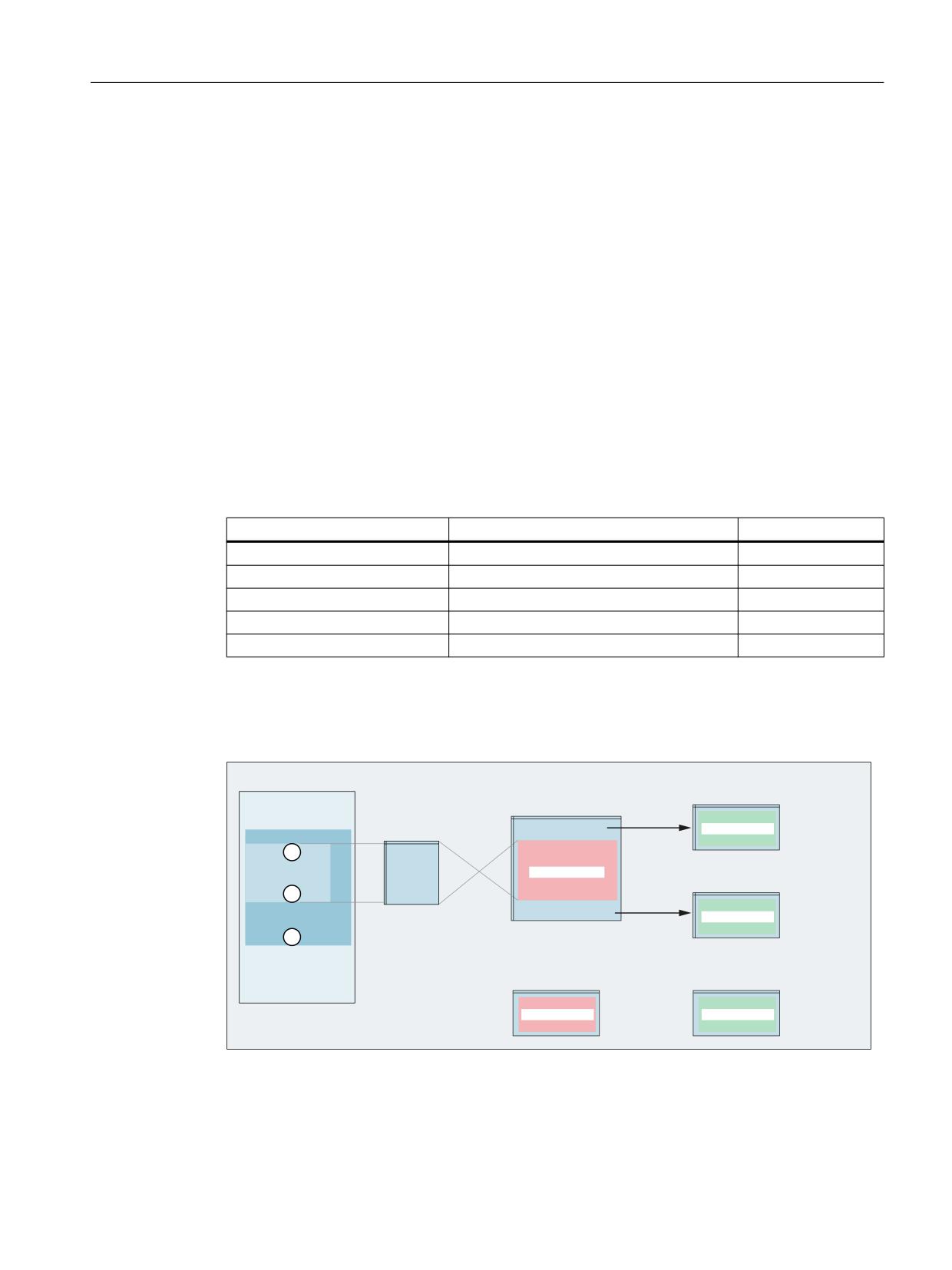
RESU-capable contour ranges
RESU is activated by programming the function-specific part program command CC_PREPRE
(1). Only the contour range lying between the RESU start (CC_PREPRE(1)) and the
interruption point (NC stop) is retraceable in the sense of RESU.
Once RESU has been launched, all part program blocks in which traversing movements are
programmed are logged by RESU for possible subsequent reverse travel. Contour ranges for
which continuing machining is irrelevant can be excluded from the log using RESU stop
CC_PREPRE (0).
Contour ranges, which are not logged are bridged by straight lines between the start and end
points during reverse/forward travel.
Special functions
Function Manual, 12/2018, A5E40874099B AB
825
TE7: Continue machining at the contour (retrace support) - 840D sl only
22.2 Function description
1
&&B35(35(
1
1
1
&&B35(35(
1
1
&&B35(35(
1
1
1
1
&&B35(35(
1
VW JHRPHWU\ D[LV
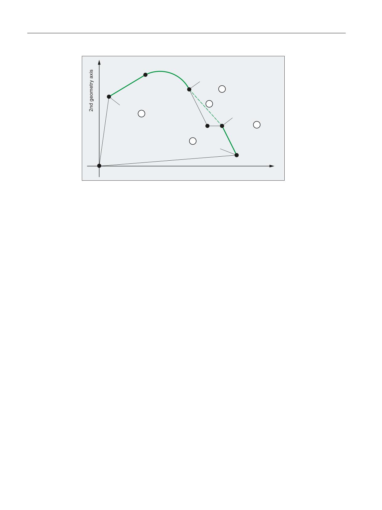
① RESU start point 1 or start of the RESU-capable contour range 1
② RESU end point 1 or end of the RESU-capable contour range 1
③ RESU start point 2 or start of the RESU-capable contour range 2
④ RESU end point 2 or end of the RESU-capable contour range 2
⑤ RESU straight-line as equivalent contour of the non RESU-capable contour range
Figure 22-2
RESU-capable contour ranges
22.2.2
Definition of terms
Interruption point
The interruption point is the point of the contour at which the traversing movement comes to
a standstill following an NC stop and reverse travel is activated.
Program continuation point
The program continuation point is the point of the contour at which reverse travel terminates
and program continuation is activated.
Retraceable contour range
Retraceable contour ranges consist of traversing blocks in the configured RESU working plane
(e.g. 1st and 2nd geometry axis of the channel), that are programmed in the part program
between the RESU start command CC_PREPRE(1) and the RESU stop command
CC_PREPRE(0) (see "Figure 22-2 RESU-capable contour ranges (Page 826)").
Special functions
826
Function Manual, 12/2018, A5E40874099B AB
TE7: Continue machining at the contour (retrace support) - 840D sl only
22.2 Function description
22.2.3
Functional sequence (principle)
The principle sequence of the RESU function between the interruption point, program
continuation point and continuation of part program processing is described below.
Requirements
A part program with traversing blocks in the configured RESU working plane (Page 831) as
well as the command for the RESU start has been started in the 1st channel.
Functional sequence
1. Interrupt part program processing:
The part program processing / traversing movement may be interrupted any number of
traversing blocks after RESU start by NC stop.
2. Select reverse travel:
The selection of reverse travel is realized using the NC/PLC interface signal:
DB21, … DBX0.1 = 1
3. Reverse travel:
The contour is traversed in the RESU working plane (Page 831) in the reverse direction
with NC start. Instead of the current machining program, RESU selects the automatically
generated RESU main program (Page 838).
4. End reverse travel:
Once the required program continuation point on the contour has been reached, reverse
travel is ended using NC stop.
5. Select forward travel (optional):
For forward travel, reverse travel must be deselected via NC/PLC interface signal:
DB21, … DBX0.1 = 0
6. Forward travel (optional):
The contour is traversed in the RESU working plane (Page 831) in the forward direction
with NC start.
7. End forward travel (optional):
Once the required program continuation point on the contour has been reached, forward
travel is ended using NC stop.
Special functions
Function Manual, 12/2018, A5E40874099B AB
827
TE7: Continue machining at the contour (retrace support) - 840D sl only
22.2 Function description
8. Retrace support:
Continue machining is initiated via PLC interface signal:
DB21, … DBX0.2 = 1 (start retrace support)
For retrace support, RESU automatically selects the original machining program and
launches a block search with calculation as far as the program continuation point.
9. Continuation of part program machining:
Part program processing continues at the program continuation point in accordance with
the "Block search with calculation" standard function when two NC start commands occur
one after the other.
The first NC start command processes the action blocks. Retrace support ASUP
CC_RESU_BS_ASUP.SPF (Page 841) is initiated when the last action block is reached:
DB21, … DBX32.6 == 1 (last action block active)
The second NC start command processes the approach block before part program
processing is resumed.
Note
Points 3 to 8 can be repeated as often as required.
Following retrace support, a new reverse travel is possible up to a maximum of the last
program continuation point.
Special functions
828
Function Manual, 12/2018, A5E40874099B AB
TE7: Continue machining at the contour (retrace support) - 840D sl only
22.2 Function description
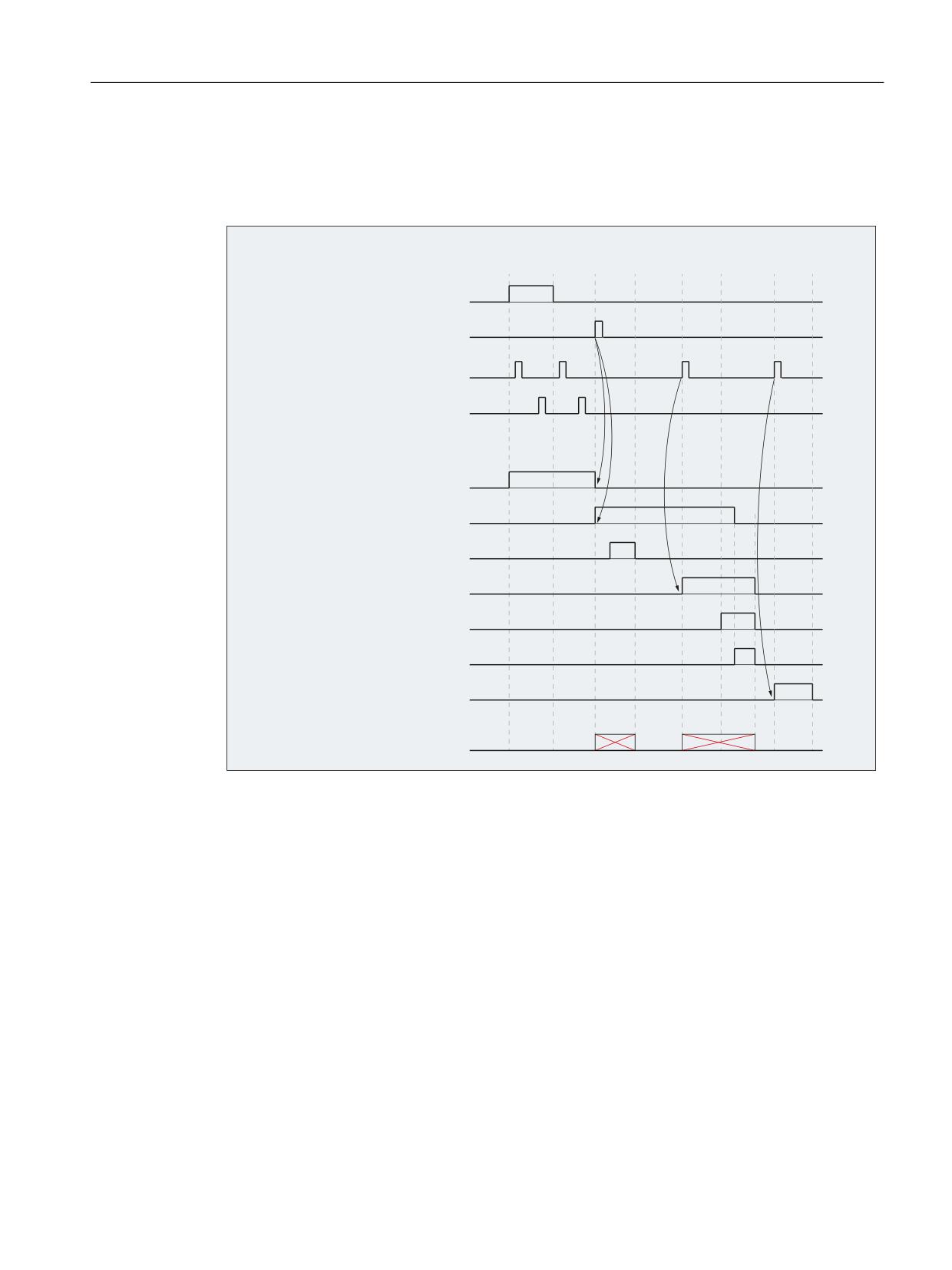
Signal characteristic of the NC/PLC interface signals
The principle sequence of the RESU function is illustrated in the following figure as a signal
characteristic of the NC/PLC interface signals involved:
,QWHUIDFH VLJQDOV
ཱ
ི
ཱི
ུ
ཱུ
ྲྀ
ཷ
WR 1& FKDQQHO 3/& ൺ 1&
'%
'%;
EDFNZDUG IRUZDUG
'%
'%;
VWDUW UHWUDFH VXSSRUW
'%
'%;
1& VWDUW
'%
'%;
1& VWRS
1& VWRS DW WKH EORFN
OLPLW
IURP 1& FKDQQHO 1& ൺ 3/&
'%
'%;
UHWUDFH PRGH DFWLYH
'%
'%;
UHWUDFH VXSSRUW DFWLYH
'%
'%;
EORFN VHDUFK DFWLYH
'%
'%;
DFWLRQ EORFN DFWLYH
'%
'%;
ODVW DFWLRQ EORFN DFWLYH
'%
'%;
$683 VWRSSHG
'%
'%;
DSSURDFK EORFN DFWLYH
1& VWDUW LV UHMHFWHG
ZLWK DODUP
①
Reverse travel is started.
②
Forward travel is started (optional).
③
Continue machining is started (block search).
④
Search destination (target block) was found.
⑤
1st NC START → Action blocks are output
⑥
Last action block is activated.
The RESU ASUP CC_RESU_BS_ASUP.SPF (Page 841) is triggered when the last action
block is activated.
⑦
2nd NC start → the approach block to the program continuation point is executed.
⑧
Part program processing (target block) resumed
Figure 22-3
Signal chart
Special functions
Function Manual, 12/2018, A5E40874099B AB
829
TE7: Continue machining at the contour (retrace support) - 840D sl only
22.2 Function description
22.2.4
Maximum retraceable contour area
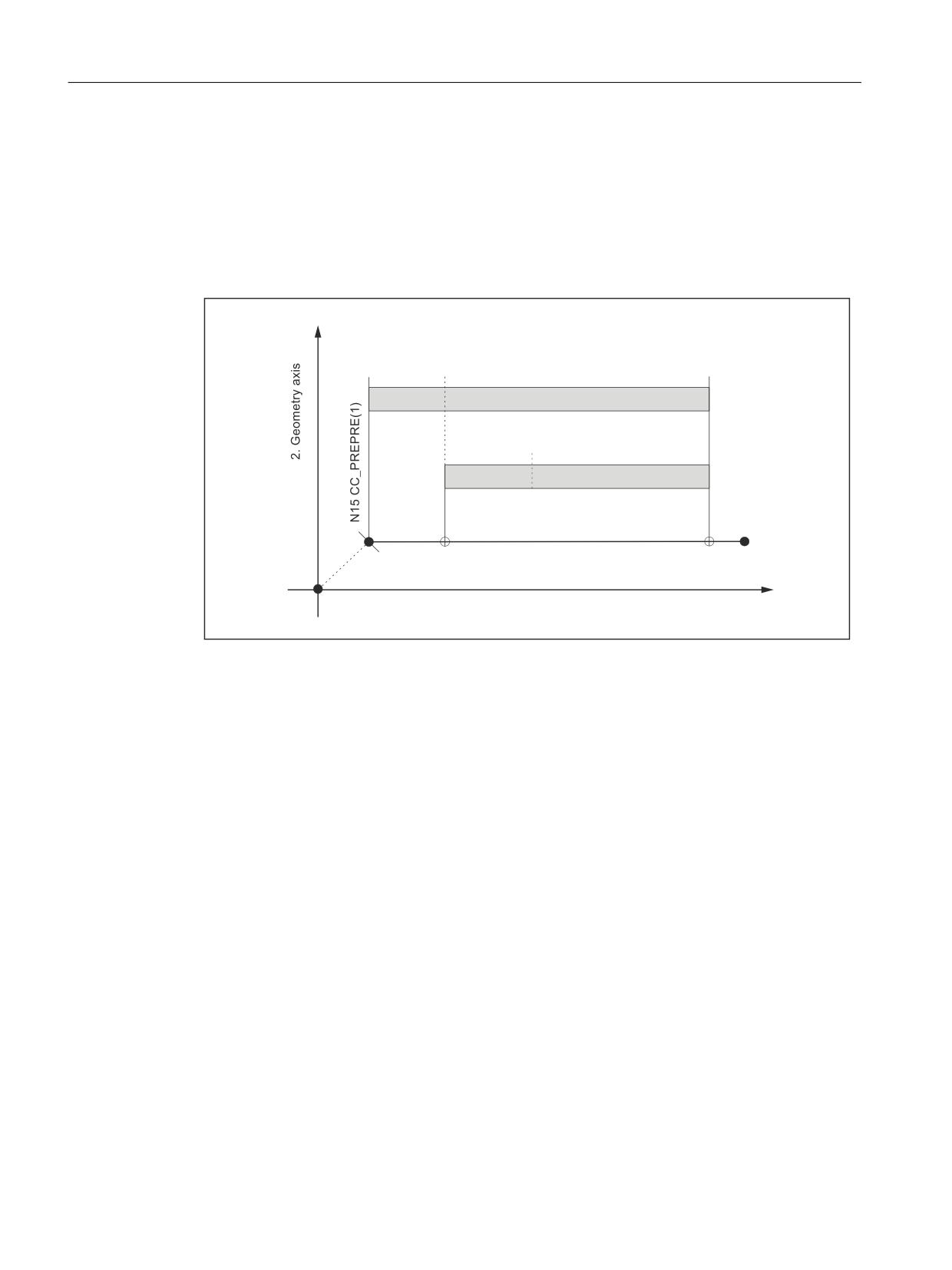
In multiple machining continuation within a contour area, the reverse travel on the contour is
always possible only up to the last machining continuation point (W). In first-time reverse travel
after RESU start, reverse travel up to the start of the contour range is possible.
This response must be illustrated via the following graph. For the sake of simplicity, the
interruption point (U) is always the same:
: SURJUDP FRQWLQXDWLRQ SRLQW
8 LQWHUUXSWLRQ SRLQW
:
8
8
: PD[
5HYHUV
H WUDYHO 0D[ 5(68 UDQJH
:
: PD[
5HYHUVH WUD
YHO 0D[ 5(68 UDQJH
1
*
;
)
1
* ;
<
*HRPHWU\ D[LV
Figure 22-4
Maximum Retraceable contour range
1st reverse travel
In first-time reverse travel, reverse travel is possible maximum up to the start of the first contour
element (N20) after RESU start (N15) (W1max).
If reverse travel takes place up to the machining continuation point W1, W1 defines the
maximum RESU range for a possible further reverse travel after machining continuation and
forward travel.
2nd reverse travel
A renewed reverse travel can now be undertaken maximum only up to the last machining
continuation point W2max = W1.
If reverse travel goes as far back as program continuation point W2, the maximum RESU range
is restricted further.
Special functions
830
Function Manual, 12/2018, A5E40874099B AB

TE7: Continue machining at the contour (retrace support) - 840D sl only
22.3 Startup
22.3
Startup
22.3.1
Activation
Before commissioning the technological function, ensure that the corresponding compile cycle
has been loaded and activated (see also Section "TE01: Installation and activation of loadable
compile cycles (Page 673)").
Activation
The "Continue machining - Retrace support" technology function is activated via the following
machine data:
MD60900+i $MN_CC_ACTIVE_IN_CHAN_RESU[0], bit 0 = 1
Note
The "Continue machining - Retrace support" technological function is available only in the
1st channel of NC.
22.3.2
Definition of the RESU working plane
Machining continuation/reverse travel is possible only for part program blocks that contain
traversing blocks in the configured RESU working plane.
The RESU working plane is defined with the following machine data:
MD62580 $MC_RESU_WORKING_PLANE
Value
Meaning
1
The RESU working plane is formed by the 1st and 2nd Geometry axes of the 1st channel (for
G17).
2
The RESU working plane is formed by the 1st and 3rd Geometry axes of the 1st channel (for
G18).
3
The RESU working plane is formed by the 2nd and 3rd Geometry axes of the 1st channel (for
G19).
22.3.3
Memory configuration: Block memory
The technological function requires additional data in the NC-internal block memory. The
values must be increased for the following memory configuring channel-specific machine data:
● MD28090 $MC_MM_NUM_CC_BLOCK_ELEMENTS += 4 (number of block elements for
compile cycles)
● MD28100 $MN_MM_NUM_CC_BLOCK_USER_MEM += 20 (size of block memory for
compile cycles (DRAM) in KB)
Special functions
Function Manual, 12/2018, A5E40874099B AB
831
TE7: Continue machining at the contour (retrace support) - 840D sl only
22.3 Startup
22.3.4
Memory configuration: Heap memory
Memory requirements
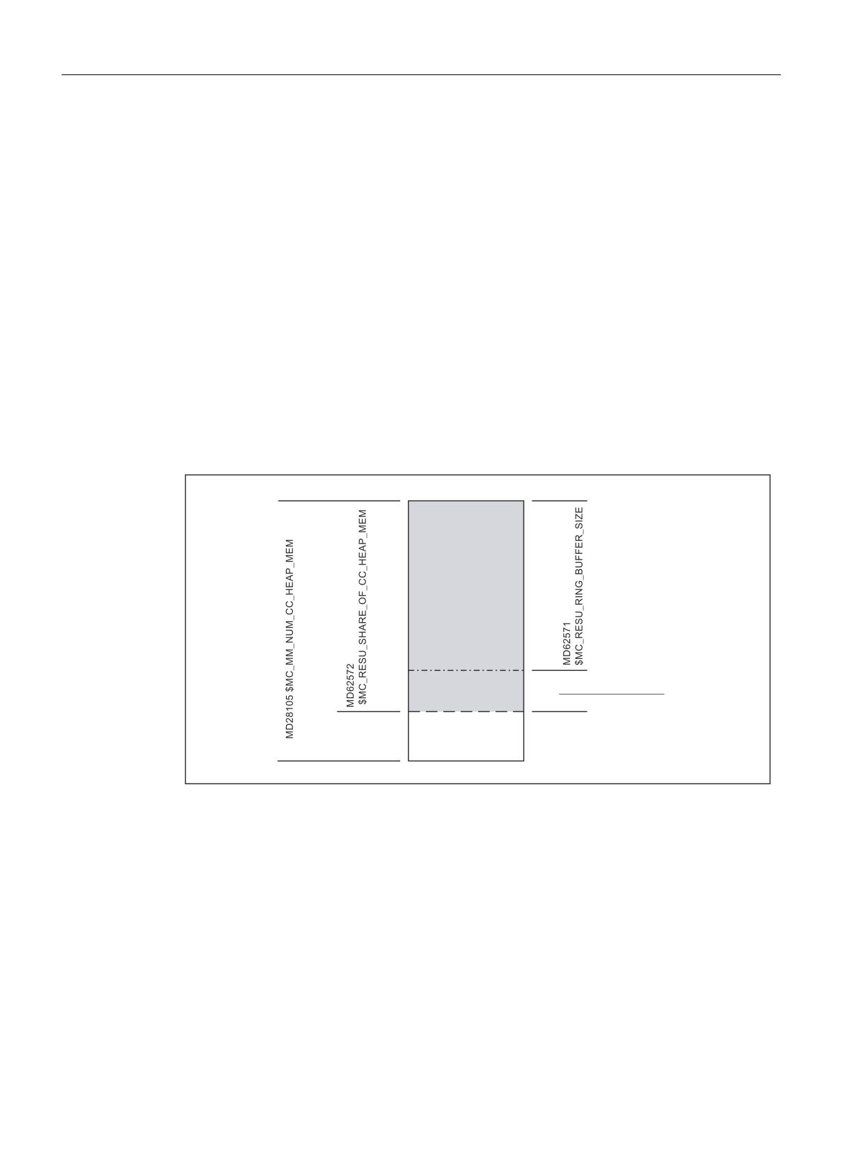
RESU requires compile cycles heap memory for the following function-specific buffers:
● Block buffer
The larger the block buffer (see "Figure 22-6 RESU-specific part programs (Page 837)"),
the larger the number of part program blocks that can be traversed backwards.
32 bytes are required per part program block.
The block buffer can be parameterized directly.
● Block search buffer
The block search buffer contains the information required for processing subprogram
searches in the context of RESU.
180 bytes are required for each subprogram. The block search buffer requires at least 2880
bytes (16 subprogram calls with 180 bytes each).
The block search buffer cannot be parameterized directly.
A function-specific GUD variable displays the size of the block search buffer (for creation
of GUD variables, see Section "Channel-specific GUD variables (Page 846)").
%ORFN EXIIHU
0'
0'
%ORFN VHDUFK EXIIHU
0'
+HDS PHPRU\ IRU
DGGLWLRQDO FRPSLOH
F\FOHV
Figure 22-5
Division of the heap memory for compile cycles
Memory configuration
Size of the compile cycle heap memory
The size of the heap memory in KB that can be used by the user for compile cycles is defined
via the memory configuring channel-specific machine data:
MD28105 $MC_MM_NUM_CC_HEAP_MEM
For RESU, the already existing machine data value (x) is adjusted as follows:
MD28105 $MC_MM_NUM_CC_HEAP_MEM = x + 50
Size of the block buffer
Special functions
832
Function Manual, 12/2018, A5E40874099B AB

TE7: Continue machining at the contour (retrace support) - 840D sl only
22.3 Startup
The size of the block buffer is adjusted via the machine data:
MD62571 $MC_RESU_RING_BUFFER_SIZE
Default setting:
MD62571 $MC_RESU_RING_BUFFER_SIZE = 1000
RESU portion of the total heap memory
The RESU portion of the total heap memory that can be used for compile cycles is set via the
machine data:
MD62572 $MC_RESU_SHARE_OF_CC_HEAP_MEM
Default setting:
MD62572 $MC_RESU_SHARE_OF_CC_HEAP_MEM = 100
Error messages
The block search buffer requires at least 2880 bytes (corresponding to 16 subprogram calls
with 180 bytes each). Otherwise, the following alarm will be generated during NC power-up:
Alarm 75600 "Channel 1 Retrace Support: Incorrect MD configuration, error no. 5"
If the block search buffer is not big enough during operation, the following alarm appears:
Alarm 75606 "Channel 1 retraceable contour shortened"
22.3.5
RESU main program memory area
Memory configuration
The storage location of the RESU main program CC_RESU.MPF can be set with the following
machine data (see Section "Main program (CC_RESU.MPF) (Page 838)"):
MD62574 $MC_RESU_SPECIAL_FEATURE_MASK (additional RESU features)
Bit
Value
Meaning
1
0
The RESU main program is stored in the dynamic NC memory (default).
1
The RESU main program is stored in the static NC memory (default).
Storage in the dynamic NC memory (default)
If the RESU main program is created in the dynamic NC memory, the memory area available
to the user for file storage must be increased as follows:
MD18351 $MN_MM_DRAM_FILE_MEM_SIZE = x1) + 100
1) already available machine data value
Special functions
Function Manual, 12/2018, A5E40874099B AB
833

TE7: Continue machining at the contour (retrace support) - 840D sl only
22.3 Startup
Storage in the static NC memory
If the RESU main program is created in the static memory area of the NC, it is retained even
after a POWER OFF. However, since RESU regenerates the RESU main program every time
the retrace support function is used, this parameter setting is not recommended.
22.3.6
Storage of the RESU subroutines
Storage as user or manufacturer cycles
The following RESU-specific subroutines can be stored as user cycles or manufacturer cycles:
● INI program: CC_RESU_INI.SPF
● END program CC_RESU_END.SPF
● Retrace support ASUB CC_RESU_BS_ASUP.SPF
● RESU ASUB CC_RESU_BS_ASUP.SPF
The setting is done using machine data:
MD62574 $MC_RESU_SPECIAL_FEATURE_MASK (additional RESU features)
Bit
Value
Meaning
2
0
The RESU-specific subroutines are stored as user cycles (default).
1
The RESU-specific subroutines are stored as manufacturer cycles.
Series commissioning
Due to the default setting of MD62574 Bit 2, the RESU-specific subroutines along with their
contents are stored as user cycles the first time the NC is powered up after the activation of
the technological function.
If the setting is then changed to specify that the RESU-specific subroutines are to be stored
as manufacturer cycles, the RESU-specific subroutines already created as user cycles are
retained even after a new power-up and must be deleted.
As support for series commissioning, the RESU-specific subroutines present as user cycles
can be deleted without prompting when the NC is powered up:
MD62574 $MC_RESU_SPECIAL_FEATURE_MASK, Bit 3 = 1
22.3.7
ASUB enable
Note
A requirement for using ASUBs is that the "Cross-mode actions" option must be available.
Special functions
834
Function Manual, 12/2018, A5E40874099B AB
TE7: Continue machining at the contour (retrace support) - 840D sl only
22.3 Startup
The following machine data must be set for the start enable for the RESU-specific ASUB
CC_RESU_ASUP.SPF while the channel is in the NC STOP state:
MD11602 $MN_ASUP_START_MASK, bit 0 = 1 (ignore stop reason for ASUB)
MD11604 $MN_ASUP_START_PRIO_LEVEL = 1 (priorities from which MD11602 is
effective)
22.3.8
PLC user program
Requirements
The following functionality is necessary for the sequential coordination of the RESU function
in the PLC user program:
IF
DB21, … DBX32.2
"Retrace support active" == 1
THEN
DB21, … DBX0.1
"Forward/Reverse" = 0
DB21, … DBX0.2
"Start retrace support" = 0
IF
DB11, … DBX0.7
"Mode group reset" == 1
OR
DB21, … DBX7.7
"Reset" == 1
THEN
DB21, … DBX0.1
"Forward/Reverse" = 0
DB21, … DBX0.2
"Start retrace support" = 0
The following signals should be reset for safety reasons:
IF
DB21, … DBX0.2
"Start retrace support" == 1
THEN
DB21, … DBX0.1
"Forward/Reverse" = 0
IF
DB21, … DBX0.1
"Forward/Reverse" == 1
THEN
DB21, … DBX0.2
"Start retrace support" = 0
Program example
The following program extract implements the changes described above:
U
DB21, … DBX32.2
// IF
"Retrace support active" == 1
R
DB21, … DBX0.1
// THEN
"Forward/Reverse" = 0
R
DB21, … DBX0.2
//
"Start retrace support" = 0
O
DB11, … DBX0.7
// IF
"Mode group reset" == 1
O
DB21, … DBX7.7
// OR
"Reset" == 1
R
DB21, … DBX0.1
// THEN
"Forward/Reverse" = 0
R
DB21, … DBX0.2
//
"Start retrace support" = 0
U
DB21, … DBX0.2
// IF
"Start retrace support" == 1
R
DB21, … DBX0.1
// THEN
"Forward/Reverse" = 0
Special functions
Function Manual, 12/2018, A5E40874099B AB
835

TE7: Continue machining at the contour (retrace support) - 840D sl only
22.4 Programming
U
DB21, … DBX0.1
// IF
"Forward/Reverse" == 1
R
DB21, … DBX0.2
// THEN
"Start retrace support" = 0
22.4
Programming
22.4.1
RESU Start/Stop/Reset (CC_PREPRE)
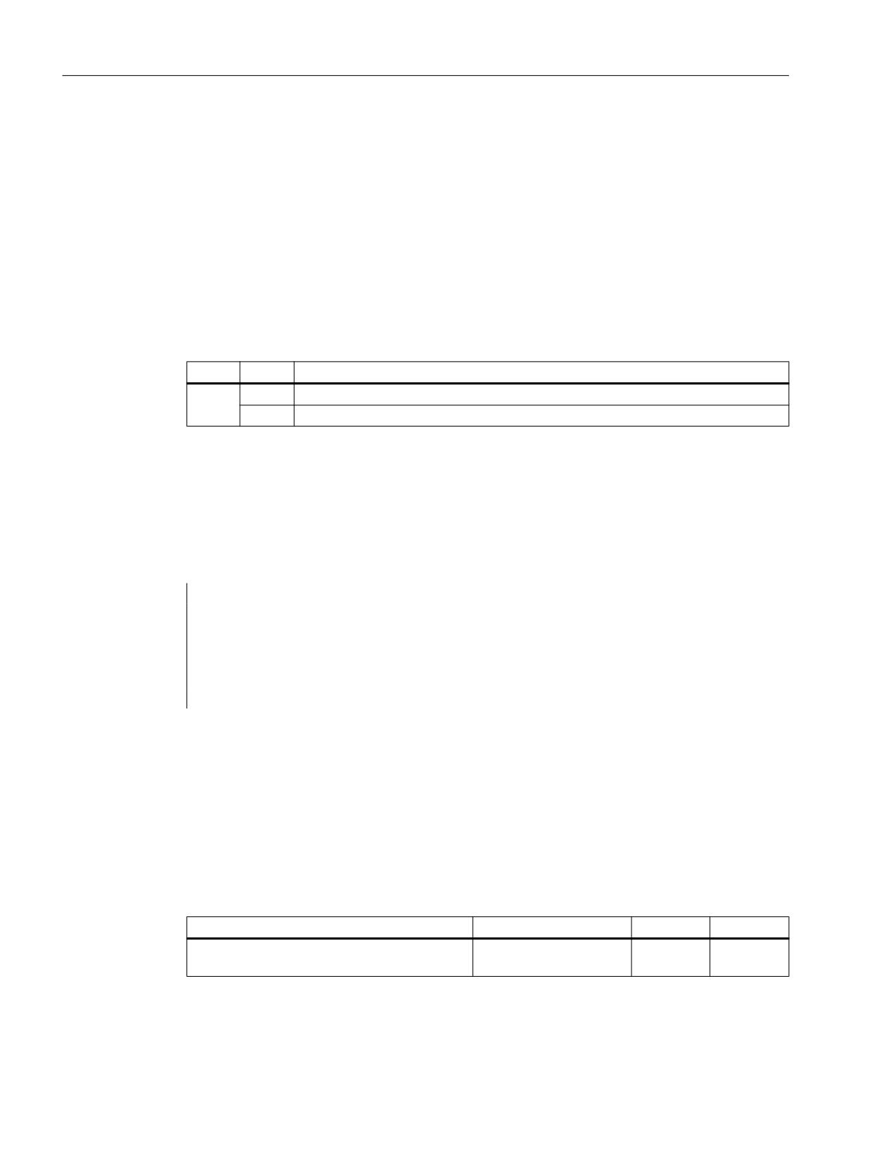
Using procedure CC_PREPRE (Prepare Retrace) the "Start", "Stop" and "Reset" modes can be
activated for retracing:
Syntax
CC_PREPRE(<mode>)
Meaning
CC_PREPRE:
Retrace mode
Alone in the block:
Yes
<mode>:
Mode
Data type:
INT
Value range:
-1, 0, 1
Value
Meaning
-1
Starts logging the traversing blocks.
The information required for traversing backward is logged on a
block-specific basis in a RESU-internal block buffer. The traversing
information is related to the two geometry axes of the RESU work-
ing plane e.g. the 1st and 2nd geometry axes of the channel:
MD20050 $MC_AXCONF_GEOAX_ASSIGN_TAB[x]; with x = 0
and 1
Or, if transformation is active:
MD24120 $MC_TRAFO_GEOAX_ASSIGN_TAB[x]; with x = 0 and
1
0
Stops logging the traversing blocks.
Thus irrelevant contour areas can be excluded from the log.
These excluded contour areas are bridged by a straight line be-
tween the starting point and end point when traversing backward.
1
Deactivates logging of the traversing blocks and deletes the func-
tion-internal block buffer. Contour areas located before the instant
of deactivation of the part program are therefore no longer availa-
ble to RESU.
Special functions
836
Function Manual, 12/2018, A5E40874099B AB
TE7: Continue machining at the contour (retrace support) - 840D sl only
22.5 RESU-specific part programs
RESET response
For the following reset events, CC_PREPRE(-1) is implicitly executed:
● Power on (warm restart)
● Channel reset
● End of program reset (M30)
22.5
RESU-specific part programs
22.5.1
Overview
The following programs are automatically generated within the scope of the retrace support
functionality (continue machining). User-specific content can be incorporated in the programs
listed.
Function
Program name
Can be changed
Main program
CC_RESU.MPF
No
INI program
CC_RESU_INI.SPF
Yes
END program
CC_RESU_END.SPF
Yes
Continue machining ASUP
CC_RESU_BS_ASUP.SPF
Yes
RESU ASUP
CC_RESU_ASUP.SPF
No
Internal structure
The following diagram provides an overview of the internal structure of the technological
function and the relationship between the various part programs.
1& SURJUDP
5(68 ,1, SURJUDP
5(68 PDLQ SURJUDP
&&B5(68B,1, 63)
&&B5(68 03)
5(68 LQWHUQDO
%ORFN EXIIHU
&&B5(68B,1, 63)
&DQ EH FKDQJHG
1
&&B35(35(
1
1
1
&DQQRW EH FKDQJHG
5(68 (1' SURJUDP
&&B5(68B(1' 63)
1
1
1
&&B5(68B(1' 63)
&DQ EH FKDQJHG
1
1
&&B35(35(
5(68 $683
5(68 UHWUDFH VXSSRUW $683
&&B5(68B$683 63)
&&B5(68B%6B$683 63)
1
0
&DQQRW EH FKDQJHG
&DQ EH FKDQJHG
Figure 22-6
RESU-specific part programs
Special functions
Function Manual, 12/2018, A5E40874099B AB
837
TE7: Continue machining at the contour (retrace support) - 840D sl only
22.5 RESU-specific part programs
22.5.2
Main program (CC_RESU.MPF)
Function
In addition to the calls for the RESU-specific subprograms, the RESU main program
"CC_RESU.MPF" contains the traversing blocks generated from the traversing blocks logged
in the block buffer for reverse/forward travel along the contour. The program is always
regenerated by the RESU function if, once the part program has been interrupted, the status
of the following interface signal changes:
DB21, … DBX0.1 (Reverse / Forward)
Note
CC_RESU.MPF must not be changed. User-specific adjustments are to be made in the
corresponding RESU-specific subprograms.
Error messages
By default, RESU generates traversing blocks for the entire retraceable contour range logged
in the block buffer. If there is not enough memory for all traversing blocks to be generated in
the parameterized memory area of the RESU main program (see Section "RESU main program
memory area (Page 833)"), RESU reduces the number of generated traversing blocks.
The lacking memory and/or reduction in the number of the generated traversing blocks is
indicated by an alarm:
RESU alarm 75608 "Channel number NC memory limit reached, RAM type type"
If the RESU main program is created in the static user memory, the following system alarm
appears at the same time as the RESU alarm:
Alarm 6500 "NC memory full"
Note
If the number of traversing blocks generated is reduced due to insufficient memory, the entire
retraceable contour can still be retraced for retrace support. To do this, proceed as follows:
● Reverse travel up to the end of the RESU main program
● Two-time change of the interface signal:
DB21, … DBX0.1 (Reverse/Forward)
Using the current position as a new interruption point enables RESU to generate a new RESU
main program.
Subsequently, travel is possible as far as the end of the retraceable contour range or, if the
limits have changed, as far as the starting point of the last traversing block that can be
generated.
The procedure described can be repeated as many times as required both for reverse and
forward travel.
Special functions
838
Function Manual, 12/2018, A5E40874099B AB
TE7: Continue machining at the contour (retrace support) - 840D sl only
22.5 RESU-specific part programs
22.5.3
INI program (CC_RESU_INI.SPF)
Function
The RESU-specific subprogram "CC_RESU_INI.SPF" contains the defaults required for the
reverse travel:
● Metric input system:
G71
● Absolute dimensions:
G90
● To switch off the adjustable zero-point offsets / frames G500
(see Chapter "Frames (Page 851)"):
● To switch off the active tool offsets (see Chapter "Tool T0
offsets (Page 851)"):
● Switching off the tool radius offset:
G40
● Traversing velocity:
F200
Program structure
CC_RESU_INI.SPF has the following content by default:
PROC CC_RESU_INI
Special functions
Function Manual, 12/2018, A5E40874099B AB
839

TE7: Continue machining at the contour (retrace support) - 840D sl only
22.5 RESU-specific part programs
G71 G90 G500 T0 G40 F200
;system frames that are present are deactivated
;actual value and scratching
if $MC_MM_SYSTEM_FRAME_MASK B_AND 'H01'
$P_SETFRAME = ctrans()
endif
;external zero point offset
if $MC_MM_SYSTEM_FRAME_MASK B_AND 'H02'
$P_EXTFRAME = ctrans()
endif
;tool carrier
if $MC_MM_SYSTEM_FRAME_MASK B_AND 'H04'
PAROTOF
endif
if $MC_MM_SYSTEM_FRAME_MASK B_AND 'H08'
TOROTOF
endif
;workpiece reference points
if $MC_MM_SYSTEM_FRAME_MASK B_AND 'H10'
$P_WPFRAME = ctrans()
endif
;cycles
if $MC_MM_SYSTEM_FRAME_MASK B_AND 'H20'
$P_CYCFRAME = ctrans()
endif
;transformations
if $MC_MM_SYSTEM_FRAME_MASK B_AND 'H40'
$P_TRAFRAME = ctrans()
endif
; bit mask for global basic frames
$P_NCBFRMASK = 0
;bit mask for channel-specific basic frames
$P_CHBFRMASK = 0
;programmable frame
$P_PFRAME = ctrans()
M17
CAUTION
Program changes
By changing the content of the RESU-specific subprogram "CC_RESU_INI.SPF", the user
(machine manufacturer) takes over the responsibility for the correct sequence of the
technological function.
Note
CC_RESU_INI.SPF may be changed.
CC_RESU_INI.SPF must not contain any RESU part program commands. CC_PREPRE(x).
Special functions
840
Function Manual, 12/2018, A5E40874099B AB

TE7: Continue machining at the contour (retrace support) - 840D sl only
22.5 RESU-specific part programs
22.5.4
END program (CC_RESU_END.SPF)
Function
The task of the RESU-specific subroutine "CC_RESU_END.SPF" is to stop reverse travel once
the end of the retraceable contour is reached. If the RESU function is parameterized
appropriately, this scenario will not arise under normal circumstances.
Program structure
CC_RESU_END.SPF has the following content by default:
PROC CC_RESU_END
M0
M17
CAUTION
Program changes
By changing the content of the RESU-specific subroutine "CC_RESU_END.SPF", the user
(machine manufacturer) takes over the responsibility for the correct sequence of the
technological function.
Note
CC_RESU_END.SPF may be changed.
CC_RESU_END.SPF must not contain any RESU part program commands. CC_PREPRE(x).
22.5.5
Retrace support ASUB (CC_RESU_BS_ASUP.SPF)
Function
The NC is forced to approach the current path point during machining continuation with the
help of the RESU-specific ASUB "CC_RESU_BS_ASUP.SPF":
● Reapproach next point on path:
RMN
● Approach along line on all axes:
REPOSA
Program structure
CC_RESU_BS_ASUP.SPF has the following content by default:
PROC CC_RESU_BS_ASUP SAVE
RMN
REPOSA
Special functions
Function Manual, 12/2018, A5E40874099B AB
841

TE7: Continue machining at the contour (retrace support) - 840D sl only
22.5 RESU-specific part programs
M17
CAUTION
Program changes
By changing the content of the RESU-specific subroutine "CC_RESU_BS_ASUP.SPF", the
user (machine manufacturer) takes over the responsibility for the correct sequence of the
technological function.
Note
CC_RESU_BS_ASUP.SPF may be changed.
User-specific modifications must be inserted before the part program block RMN.
22.5.6
RESU ASUB (CC_RESU_ASUP.SPF)
Function
The RESU-specific ASUB "CC_RESU_ASUP.SPF" is required internally for the function. The
ASUB is initiated if the following RESU interface signal is switched over in the NC stop state:
DB21, … DBX0.1 (Forward/Reverse)
Program structure
CC_RESU_ASUP.SPF has the following content:
PROC CC_RESU_ASUP
; siemens system asub - do not change
G4 F0.001
M0
REPOSA
M17
Note
CC_RESU_ASUP.SPF must not be changed.
Special functions
842
Function Manual, 12/2018, A5E40874099B AB
TE7: Continue machining at the contour (retrace support) - 840D sl only
22.6 Retrace support
22.6
Retrace support
22.6.1
General information
Retrace support refers to the entire operation from initiation of retracing through the interface
signal DB21, … DBX0.2 = 1 (start machining continuation) up to to the continuation of the part
program processing of the programmed contour.
Requirement
In order for retrace support to function, the retrace mode, launched by means of the request
for reverse travel, must be active in the channel:
DB21, … DBX32.1 = 1 (retrace mode active)
(See Section "Functional sequence (principle) (Page 827)")
Subfunctions
The two essential subfunctions of retrace support are the standard NC functions:
● Block search with calculation on contour
● Repositioning on the contour via shortest route (REPOS RMN)
22.6.2
Block search with calculation on contour
Function
The block search with calculation on the contour initiated implicitly by RESU within the
framework of the retrace support has the following tasks:
● Set the program pointer on the part program block on which repositioning was done with
the help of Reverse / Forward travel
● Calculates the axis positions on the basis of the programmed traversing blocks from the
start of the part program to the target block
● Collates the instructions programmed from the start of the part program to the target block,
which are executed in the action block. These include:
- Auxiliary functions
- Tool change
- Spindle functions
- Feedrate programming
Special functions
Function Manual, 12/2018, A5E40874099B AB
843
TE7: Continue machining at the contour (retrace support) - 840D sl only
22.6 Retrace support
All part program instructions which are not executed in the action block but are required for
retrace support in the part program must be entered manually in the RESU-specific retrace
support ASUB CC_RESU_BS_ASUP.SPF, e.g.:
● Synchronized actions
● M functions
References
The complete description of the Block search is available in:
Basic Functions Function Manual; Mode Group, Channel, Program Mode (K1), Program test
22.6.3
Reposition
Function
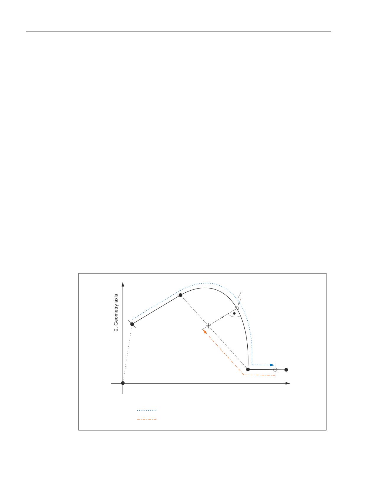
Following the end of the last action block (last traversing block before repositioning), NC Start
outputs the approach block for repositioning all channel axes programmed in the part program
as far as the target block.
Geometry axes
In the approach block, the geometry axes of the RESU working plane (e.g. 1st and 2nd
geometry axes of the channel) traverse the shortest route along the contour to the program
continuation point.
1
H J VSOLQH EORFN
3URJUDP FRQWLQXDWLRQ SRLQW
1
5(326 VWDUWLQJ
1
&&B35(35(
SRLQW
1
1
*HRPHWU\ D[LV
3DWK VHFWLRQV WUDYHUVHG
3DUW SURJUDP SURFHVVLQJ
5HYHUVH WUDYHO
Figure 22-7
Retraceable contour ranges and REPOS
Special functions
844
Function Manual, 12/2018, A5E40874099B AB
TE7: Continue machining at the contour (retrace support) - 840D sl only
22.6 Retrace support
Channel axes
All other channel axes programmed in the part program travel to the relevant position
calculated in the block search.
22.6.4
Temporal conditions concerning NC start
NC start should be initiated twice by the machine operator within the framework of continue
machining (see Section "Functional sequence (principle) (Page 827)").
The following conditions must be met:
● In NC start for outputting the action blocks:
- The block search must be completed:
DB21, … DBX33.4 = 0 (block search active)
● In NC start for outputting the approach blocks:
- The RESU ASUB "CC_RESU_BS_ASUP" must be completed:
DB21, … DBX318.0 = 1 (ASUB stopped)
22.6.5
Block search from last main block
The block search with calculation on the contour executed within the framework of the
machining continuation via the use of the most powerful NCU in very large part programs can
itself lead to computation times of several minutes up to the reaching of the target block.
A significant reduction of this waiting period is possible through the use of the "Block search
from the last main block".
Functionality
For retrace support with block search from the last main block, the search for the target block
takes place in 2 stages:
1. Block search without calculation from start of machining program to last main block before
target block. Subprograms are ignored during this search, i.e. it takes place exclusively in
the main program.
2. Block search with calculation on contour from main block to target block. This block search
does not ignore subprograms.
Requirement
To enable a search from last main block for retrace support, at least one main block must be
programmed after the RESU start CC_PREPRE(1).
Main block
All instructions required for processing the subsequent section of the part program must be
programmed in one main block.
Special functions
Function Manual, 12/2018, A5E40874099B AB
845
TE7: Continue machining at the contour (retrace support) - 840D sl only
22.7 Function-specific display data
The main blocks are to be designated with a Main Block No. consisting of the sign ":" and a
positive whole number (block number).
References:
Programming Manual, Fundamentals; Fundamentals of NC Programming, Language
Elements of the Programming Language
Activation
Activation of the block search from the last main block is performed using the RESU-specific
machine data:
MD62575 $MC_RESU_SPECIAL_FEATURE_MASK_2, bit 0 (additional RESU features)
Bit
Value
Meaning
0
0
Retrace support is performed using block search with calculation on contour.
1
Retrace support is performed using block search from the last main block.
Supplementary conditions
In order that a new retrace support operation can take place following a retrace support
operation with block search from last main block, the RESU start CC_PREPRE(1) must be
programmed in the retrace support ASUB "CC_RESU_BS_ASUP.SPF".
Programming example:
PROC CC_RESU_BS_ASUP SAVE
; (synchronized actions, M functions, etc. required for retrace support
)
CC_PREPRE(1)
RMN
REPOSA
M17
22.7
Function-specific display data
22.7.1
Channel-specific GUD variables
As display data for the size of the block search buffer, RESU provides the following channel-
specific GUD variables:
GUD variable
Meaning
Value
Access
CLC_RESU_LENGTH_BS_BUFFER
Size of block search buf-
Byte
read only
fer
After the startup of the technological function, the GUD variable is not displayed automatically
on the operator panel.
Special functions
846
Function Manual, 12/2018, A5E40874099B AB
TE7: Continue machining at the contour (retrace support) - 840D sl only
22.8 Function-specific alarm texts
Creating and displaying the GUD variable
Perform the following steps to create and display the GUD variables in the operator panel:
1. Set password:
The password of protection level 1 (machine manufacturer) is to be input.
2. Activate the "Definitions" display
3. The file is recreated if an "SGUD.DEF" file is still not available:
Name: SGUD
Type: Global data /system
Confirm entry with OK.
This opens the file in the editor.
4. Edit the GUD variable definitions:
DEF CHAN REAL CLC_RESU_LENGTH_BS_BUFFER
M30
5. Save the file and close the editor.
6. Activate the "SGUD.DEF" file.
The GUD variable is not displayed on the operator panel.
Note
The new GUD variable, which is already being displayed, will be detected by the RESU function
and supplied with an up-to-date value only following an NC POWER ON Reset. As a
consequence, an NC POWER ON must be initiated after the creation.
References
The exact procedure to be following while creating and displaying GUD variables depends on
the software version of the existing operator panel and is described in the:
● Operating Manual
22.8
Function-specific alarm texts
For details of the procedure for creating function-specific alarm texts, see Section "Creating
alarm texts (Page 679)".
Special functions
Function Manual, 12/2018, A5E40874099B AB
847

TE7: Continue machining at the contour (retrace support) - 840D sl only
22.9 Boundary conditions
22.9
Boundary conditions
22.9.1
Function-specific supplementary conditions
22.9.1.1
Continue machining within subprograms
Subprogram call outside or inside a program loop
Clear retrace support within subprograms depends on whether the subprogram call is made
outside or inside a program loop:
● Outside
Clear retrace support is possible if a subprogram is called outside a program loop.
● Inside
Clear retrace support may not be possible if a subprogram is called inside a program loop
(see Section "Continue machining within program loops (Page 848)").
Number of passes P
Subprogram repetitions using number of passes P are taken into account for retrace support.
This means that retrace support is performed in the part program with the correct reference to
the part program block and number of passes P to the program continuation point of the contour.
22.9.1.2
Continue machining within program loops
In NC high-level language, program loops can be programmed using:
● LOOP
ENDLOOP
● FOR
ENDFOR
● WHILE
ENDWHILE
● REPEAT
UNTIL
● CASE/IF-ELSE-ENDIF in conjunction with GOTOB
WARNING
Risk of collision
Significant contour deviations can occur during the machining if the programmed continuation
point at the programmed contour is the result of a loop run that is not equal to the first loop
run.
If retrace support is performed within program loops, the retrace support is always effective
in the first loop run.
Special functions
848
Function Manual, 12/2018, A5E40874099B AB
TE7: Continue machining at the contour (retrace support) - 840D sl only
22.9 Boundary conditions
22.9.1.3
Machining continuation on full circles
In full circles, the block starting and end points coincide at one contour point. As no clear
differentiation is possible in this case, one always starts from the block start point during
machining continuation on this kind of a contour point. The first part program block following
retrace support is then the circular block.
A contour point just before the block end point of the circular block must be selected to avoid
traversing the circular block after the machining continuation.
22.9.1.4
Automatically generated contour elements
The automatic generation of non-linear / non-circular contour elements by the NC takes place,
for example, when programming the following NC functions in the part program:
● RND
● G641/G642
● Tool radius compensation
For reverse / forward travel as part of RESU these contour elements can be replaced by straight
lines between the start and end of the block.
22.9.2
Supplementary conditions for standard functions
22.9.2.1
Axis replacement
As long as RESU is active, the two geometry axes of the RESU working plane (e.g. the 1st
and 2nd geometry axes of the channel) must not be transferred to another channel via axis
replacement ( RELEASE(x)/GET(x)).
The RESU activity:
● Starts:
- with the part program command CC_PREPRE(1)
● Ends with:
- the program end
or
- with the part program command CC_PREPRE(-1)
22.9.2.2
Traversing movements of the channel axes
Other channel axes, except the two geometry axes of the RESU working plane, are not
considered by RESU.
Special functions
Function Manual, 12/2018, A5E40874099B AB
849

TE7: Continue machining at the contour (retrace support) - 840D sl only
22.9 Boundary conditions
If traversing movements in other channel axes are required for machining continuation or
reverse travel, these can either be undertaken by the machined operator manually, or
programmed as travel block in the RESU-specific subroutine "CC_RESU_INI.SPF".
WARNING
Risk of collision when traversing
The machine operator must ensure that collision of the associated traversing movements
does not take place during the entire machining continuation operation within the framework
of the technological function of RESU.
22.9.2.3
Block numbers
The following RESU-specific subroutines and their subroutines must not contain block
numbers:
● CC_RESU_INI.SPF
● CC_RESU_END.SPF
The following alarm appears in the event of an error:
Alarm 75604 "Reverse travel not possible, error no. number"
22.9.2.4
Block search
Block search with calculation
RESU is subject to the following constraints in the context of the "block search with calculation
(on contour/at end of block") standard function:
● The last block of the RESU part program command CC_PREPRE(x) run during the block
search is effective in the target block.
● The retraceable contour range starts with the REPOS approach block.
Block search without calculation
RESU part program commands CC_PREPRE(x) haveno effect in the "block searches without
calculation" function.
22.9.2.5
Transformations
RESU can also be used for active kinematic transformation (e.g. 5-axis transformation) subject
to restrictions, as the traversing movements of the two geometry axes of the RESU working
plane are recorded in the basic coordinate system (BCS) and therefore before the
transformation (see also Section "TE4: Handling transformation package - 840D sl only
(Page 759)").
Special functions
850
Function Manual, 12/2018, A5E40874099B AB
TE7: Continue machining at the contour (retrace support) - 840D sl only
22.9 Boundary conditions
Transformation changeover
While RESU is active, no transformation changes are permitted to take place and
transformation must not be activated/deactivated.
The RESU activity:
● Starts:
- with the part program command CC_PREPRE(1)
● Ends with:
- the program end
or
- with the part program command CC_PREPRE(-1)
References
A full description of the transformations is available in:
Function Manual, Extended Functions; Kinematic Transformation (M1)
22.9.2.6
Compensations
RESU can be used in interaction with compensations, because the traversing movements of
the two geometry axes of the RESU working plane is recorded in the basic coordinate system
(BCS) and therefore before the compensation.
A full description of the compensations can be found in:
References:
Function Manual, Extended Functions; Compensations (K3)
22.9.2.7
Frames
RESU can be used in conjunction with frames.
However, as the traversing movements of the two geometry axes of the RESU working plane
are recorded in the basic coordinate system (BCS) and therefore after the frames have been
taken into account, the frame offsets must be deactivated during retrace support (reverse /
forward travel).
The frame offsets are deactivated during retrace support via the standard default settings of
the RESU-specific subprogram "CC_RESU_INI.SPF" (see Section: "INI program
(CC_RESU_INI.SPF) (Page 839)").
A full description of the frames can be found in:
Reference:
Function Manual, Basic Functions; Axes, Coordinate Systems, Frames (K2)
22.9.2.8
Tool offsets
RESU can be used in conjunction with tool offsets.
However, as the traversing movements of the two geometry axes of the RESU working plane
are recorded in the basic coordinate system (BCS) and therefore after the tool offsets have
Special functions
Function Manual, 12/2018, A5E40874099B AB
851

TE7: Continue machining at the contour (retrace support) - 840D sl only
22.10 Data lists
been taken into account, the tool offsets must be deactivated during retrace support (reverse /
forward travel).
The tool offsets are deactivated during retrace support via the standard default settings of the
RESU-specific subprogram "CC_RESU_INI.SPF" (see Section "INI program
(CC_RESU_INI.SPF) (Page 839)").
Specific instances of tool radius compensation, e.g. compensation on outside corners
G450 DISC=x may generate contour deviations between the contour traversed during retrace
support and the contour programmed in the machining program.
Contour deviations are always generated if tool radius compensation produces contour
elements that are non-linear or circular. For example, G450DISC=x, where x > 0 produces
parabolic or hyperbolic contour elements.
A full description of the tool radius compensation can be found in:
Reference:
Function Manual, Basic Functions; Tool Compensation (W1)
22.10
Data lists
22.10.1
Machine data
22.10.1.1
General machine data
Number
Identifier: $MN_
Meaning
11602
ASUP_START_MASK
Ignore stop reasons if an ASUB is running.
11604
ASUP_START_PRIO_LEVEL
Defines the ASUB priority from which MD11602 is effec-
tive.
18351
MM_DRAM_FILE_MEM_SIZE
Size of the part program memory in DRAM (in kByte)
22.10.1.2
Channelspecific machine data
Number
Identifier: $MC_
Description
20050
AXCONF_GEOAX_ASSIGN_TAB
Assignment 'geometry/channel axis'
24120
TRAFO_GEOAX_ASSIGN_TAB_1
Assignment of geometry - channel axes for transforma-
tion 1
28090
MM_NUM_CC_BLOCK_ELEMENTS
Number of block elements for compile cycles (CC)
28100
MM_NUM_CC_BLOCK_USER_MEM
Size of block memory for CC in KB
28105
MM_NUM_CC_HEAP_MEM
Heap memory in KB for CC applications (DRAM)
62571
RESU_RING_BUFFER_SIZE
Size of ring buffer (RESU-internal block buffer)
62572
RESU_SHARE_OF_CC_HEAP_MEM
RESU portion of the total CC heap memory
62573
RESU_INFO_SA_VAR_INDEX
Indices of the synchronized action variables
Special functions
852
Function Manual, 12/2018, A5E40874099B AB

TE7: Continue machining at the contour (retrace support) - 840D sl only
22.10 Data lists
Number
Identifier: $MC_
Description
62574
RESU_SPECIAL_FEATURE_MASK
Additional RESU features
62575
RESU_SPECIAL_FEATURE_MASK_2
Additional RESU properties
62580
RESU_WORKING_PLANE
Selection of the RESU working plane
22.10.2
Signals
22.10.2.1
Signals to channel
Signal name
SINUMERIK 840D sl
SINUMERIK 828D
RESU: Backward/forward
DB21,
DBX0.1
-
RESU: Start retrace support
DB21,
DBX0.2
-
22.10.2.2
Signals from channel
Signal name
SINUMERIK 840D sl
SINUMERIK 828D
RESU: Retrace mode active
DB21,
DBX32.1
-
RESU: Retrace support active
DB21,
DBX32.2
-
Special functions
Function Manual, 12/2018, A5E40874099B AB
853
TE7: Continue machining at the contour (retrace support) - 840D sl only
22.10 Data lists
Special functions
854
Function Manual, 12/2018, A5E40874099B AB
TE8: Cycle-independent path-synchronous switching
signal output - 840D sl only
23
23.1
Brief description
Function
The "Cycle-independent path synchronized switching signal output" technological function
serves the purpose of switching time-critical, position-based machining processes on and off
quickly, e.g. high speed laser cutting (HSLC; High Speed Laser Cutting).
The switching signal output can be block-related or path length-related:
● Block-related switching signal output
The switching signal output and therefore, the activation / deactivation of the machining is
undertaken independently of the status changes:
- Rapid travel mode G00 active / inactive
- Programmed feed threshold fell short / exceeded
● Path length-related switching signal output
The switching signal output and therefore, the activation / deactivation of the machining
takes place in a continuous change and is monitored along the traversed path.
This enables a regular machining without the individual switching positions having to be
programmed explicitly.
The activation or selection of the mentioned options leads to the monitoring of the output of
the digital signal which is programmed with a part program command.
I/Os
Only the on-board I/Os of the NC module can be used as the digital I/O via which the switching
signal is output: The switching signal can only be output via one of the 4 on-board digital outputs
on the NCU module.
Restrictions
The use of the "Cycle-independent path synchronized switching signal output" technological
function is subject to the following restriction:
● The technological function is available only in one channel of NC.
References
The "cycle-independent path-synchronous switching signal output" technological function is a
compile cycle. For the handling of compile cycles, see Section "TE01: Installation and
activation of loadable compile cycles (Page 673)".
Special functions
Function Manual, 12/2018, A5E40874099B AB
855
TE8: Cycle-independent path-synchronous switching signal output - 840D sl only
23.2 Functional description
23.2
Functional description
23.2.1
General information
Note
The functionality is described with examples, with the help of the "High speed laser cutting
technology (HSLC, High Speed Laser Cutting).
23.2.2
Calculating the switching positions
23.2.2.1
Block-related switching signal output
Switching criteria
During high-speed laser cutting, e.g. as used to manufacture perforated sheets, it is absolutely
essential to switch the laser beam on/off exactly at the programmed setpoint positions during
the machining process.
In order to minimize programming overheads, the switching positions of the technology
function are calculated using the velocity of the geometry axes programmed in the part program
block.
The following criteria define the setpoint position programmed in the part program block (end
of block position) as a switching position:
1. G0 edge change
2. Overshooting/undershooting a freely programmable velocity threshold
G0 edge change as switching criterion
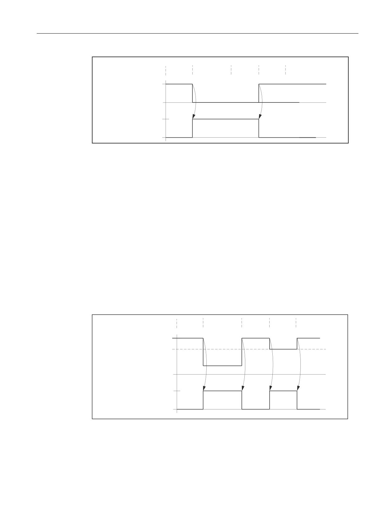
If G0 (rapid traverse) is active in a part program block (programmed or modal), the switching
signal is switched off. On the other hand: If G0 (rapid traverse) is not active in a part program
block, the switching signal is switched on. The G0 edge change marks the programmed end
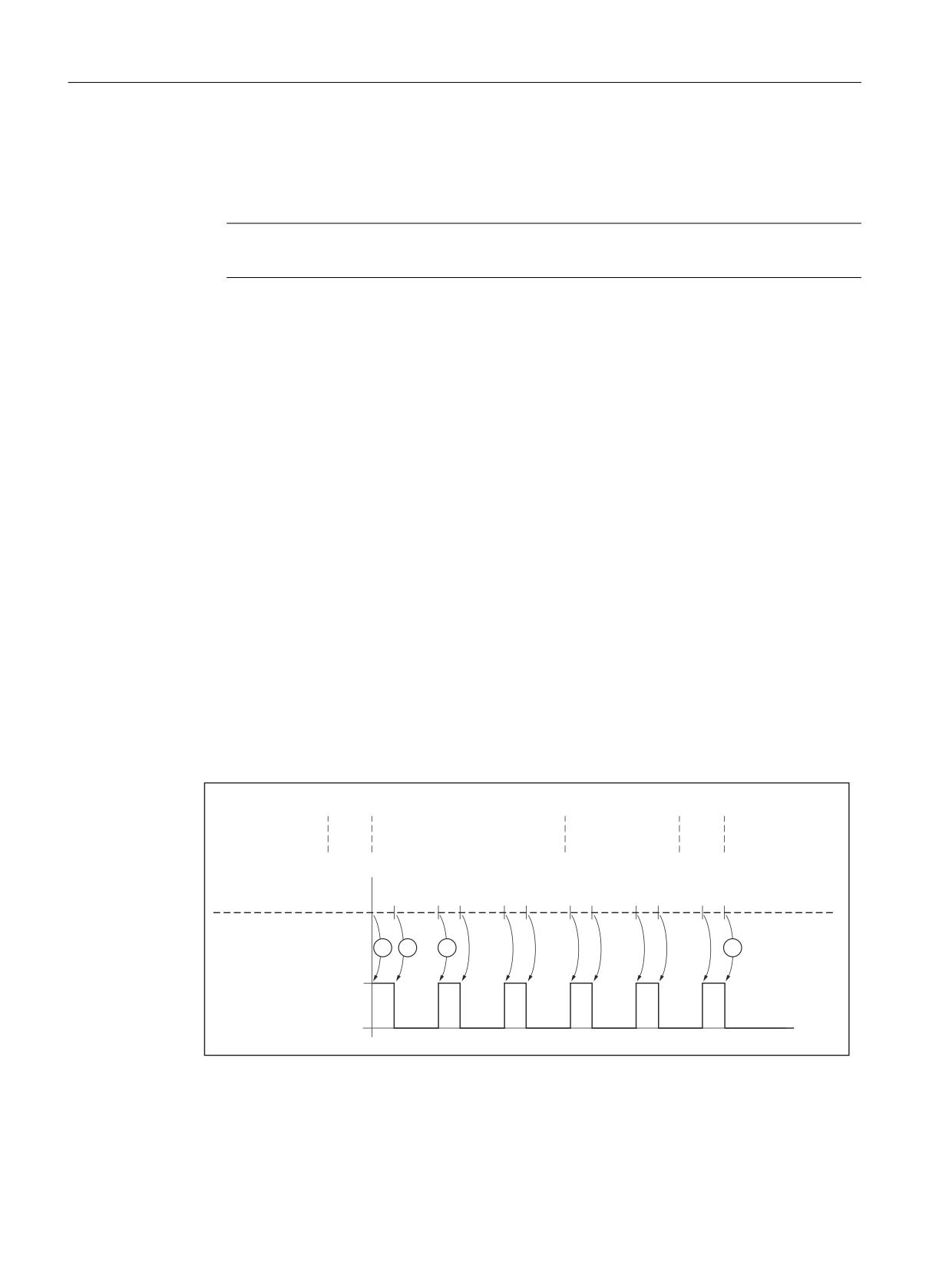
of block position of the previous block as the switching position.
Example:
Special functions
856
Function Manual, 12/2018, A5E40874099B AB
TE8: Cycle-independent path-synchronous switching signal output - 840D sl only
23.2 Functional description
3DUW SURJUDP
1
1
1
1
1
EORF
* ;
* )
;
;
* ;
;
N
2Q
*
2II
2Q
6ZLWFKLQJ
VLJQDO
2II
The following block positions function as switching positions:
● Position X30 for G0-edge change from N10 to N20
● Position X100 for G0-edge change from N30 to N40
Freely programmable velocity threshold value as switching criterion
A freely programmable velocity threshold value is used to define the setpoint velocity
programmed in the part program block at and above which the switching signal is activated/
deactivated.
● If the setpoint velocity programmed in the part program block is above the programmed
threshold, the switching signal is switched off.
● If the setpoint velocity is at or below the threshold value, the switching signal is switched
on.
The edge change marks the programmed end of block position of the previous block as the
switching position.
Example:
1
1
3DUW SURJUDP
1
1
)
)
1
EORFN
* ;
* )
;
;
;
* ;
2Q
7KUHVKROG
YDOXH
6SHHG VHWSRLQW
2II
2Q
6ZLWFKLQJ
VLJQDO
2II
Special functions
Function Manual, 12/2018, A5E40874099B AB
857
TE8: Cycle-independent path-synchronous switching signal output - 840D sl only
23.2 Functional description
The following block positions function as switching positions:
● Position X30 for edge change from N10 to N20
● Position X70 for edge change from N20 to N30
Note
G0 always deactivates the switching signal, regardless of the threshold value.
23.2.2.2
Path length-related switching signal output
Programmable paths as the switching criterion
In path-related switching signal output, the switching positions are defined with the help of the
two freely programmable paths s1 and s2.
Functional sequence
The path length-related switching signal output starts with a switch on signal at the beginning
of the first traversing block after activation with CC_FAST_CONT (refer to ① in the screen).
The processing is active till a deactivation signal is set after the traversing of a programmable
path s1 (refer to ② in screen). This way the processing is interrupted till a switch on signal is
set again after the traversing of a programmable path s2 (refer to ③ in screen).
The changeover between activation and deactivation signal, and therefore between processing
and interruption phase is path length dependent at the end of either of the stretch sections s1
and s2. This enables a continuous and regular machining without the individual switching
positions having to be programmed explicitly.
The path length-related switching signal output ends with the start of the first traversing block
(or of another executable block) after deactivation with CC_FASTOFF (refer to ④ in screen).
3DUW SURJUDP
1
*
* *
)
1
1
&&B)$6721B&217 V V
1
* ; < =
1
1
&&B)$672))
1
;
<
=
1
* ; < =
1
* ; < =
7UDYHO SDWK
V
V
V
V
V
V
V
V
V
V
V
2Q
6ZLWFKLQJ VLJQDO
2II
Figure 23-1
Path length-related switching signal output
Special functions
858
Function Manual, 12/2018, A5E40874099B AB
TE8: Cycle-independent path-synchronous switching signal output - 840D sl only
23.2 Functional description
23.2.3
Calculating the switching instants
In order for the switching to be as precise as possible at the switching positions calculated,
the control calculates the positional difference between the actual position of the geometry
axes involved and the switching difference in every position controller cycle.
If the positional difference is less than 1.5 position controller cycles, the control converts it into
a temporal difference taking into account the current path velocity and acceleration rate of the
geometry axes.
With the temporal difference specified, a hardware timer is started, which triggers the switching
signal at exactly the instant calculated in advance regardless of the position controller cycle.
23.2.4
Switching frequency and switching position distance
Maximum switching frequency
The maximum switching frequency is: 1 signal edge change per IPO cycle
Note
Special case: IPO cycle time = position controller cycle time
In this case, the maximum switching frequency is:
1 signal edge change per 2 IPO cycles
Minimum switching position clearance
The minimum possible distance between the switching positions placed one above the other
depends on:
● The duration of an IPO cycle
● The feed rate
The theoretically possible minimum distance can be determined from these dimensions as
follows:
0LQLPXP VZLWFKLQJ SRVLWLRQ FOHDUDQFH 3URJUDPPHG IHHG UDWH
,32 F\FOH WLPH
Example:
For IPO cycle times of 2 ms and position controller cycle times of 1 ms as well as a feed rate
of 20000 mm/min, the theoretically possible minimum distance between switching positions
one above the other is limited to:
20000 mm/min * 2 ms = 0.667 mm
Special functions
Function Manual, 12/2018, A5E40874099B AB
859
TE8: Cycle-independent path-synchronous switching signal output - 840D sl only
23.2 Functional description
Value below minimum switching position distance
For path length-related switching signal output, the value may fall below the minimum switching
position distance, e.g. due to:
● Increase in feed rate
● Decrease in programmable switching position distance s1 and s2
The following reactions take place if the value falls below the minimum:
● Alarm 75501 "Channel %1 HSLC: CC_FASTON_CONT speed too high" is displayed.
● The switching signal at the current switching position is omitted. To maintain the machining
rhythm, the function also suppresses the switching signal at the following switching position.
The position of all the following switching positions is not affected by this. In the further
course of the path, one can witness alternating output and suppression of two switching
signals following each other.
23.2.5
Approaching switching position
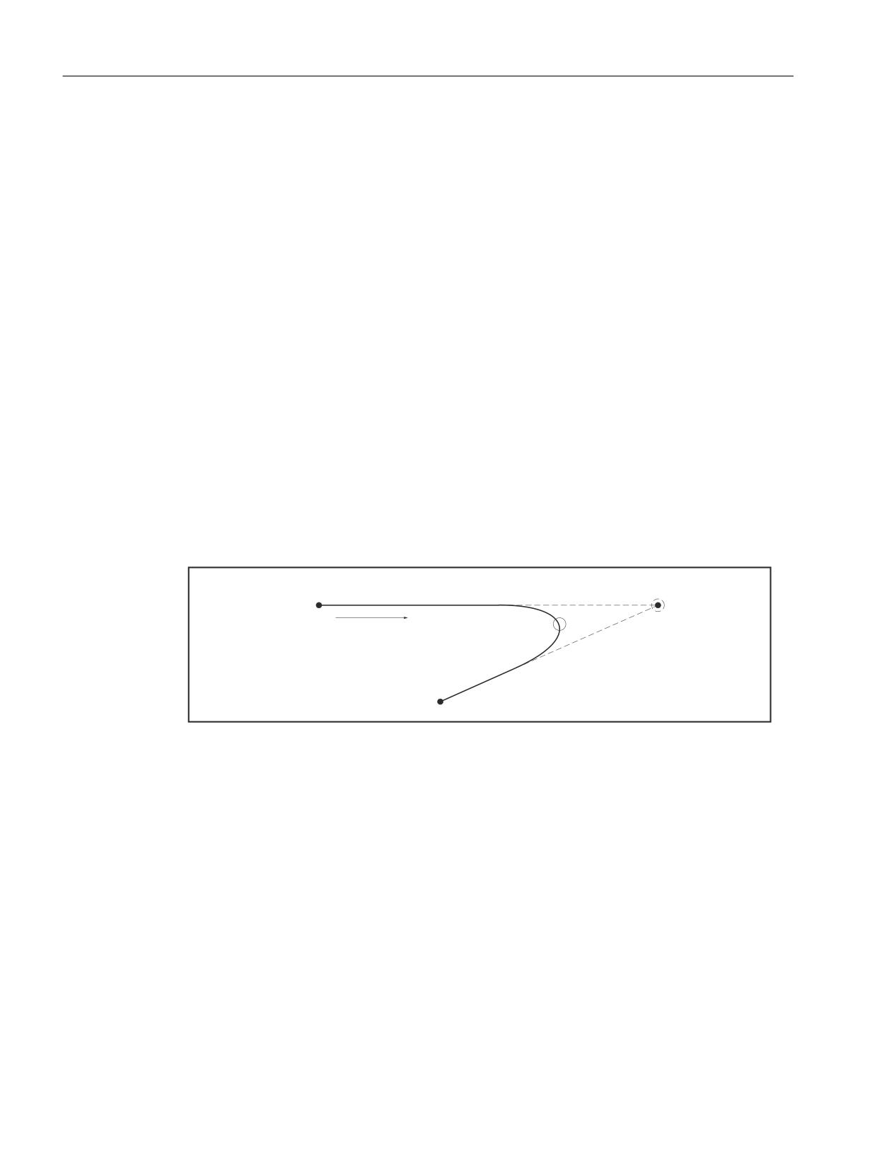
If in block-related switching signal output a switching position is not reached exactly, e.g. in
continuous-path mode and travel in more than one geometry axis, then switching takes place
at the instant at which the positional difference between the actual position of the geometry
axes involved and the programmed switching position increases again.
1
* *
)
;
7UDYHUVLQJ
$FWXDO
3URJUDPPHG
GLUHFWLRQ
6ZLWFKLQJ
6ZLWFKLQJ
SRVLWLRQ
SRVLWLRQ
Figure 23-2
Switching position offset in path control mode
Special functions
860
Function Manual, 12/2018, A5E40874099B AB
TE8: Cycle-independent path-synchronous switching signal output - 840D sl only
23.2 Functional description
23.2.6
Programmed switching position offset
Programmed switching position offset
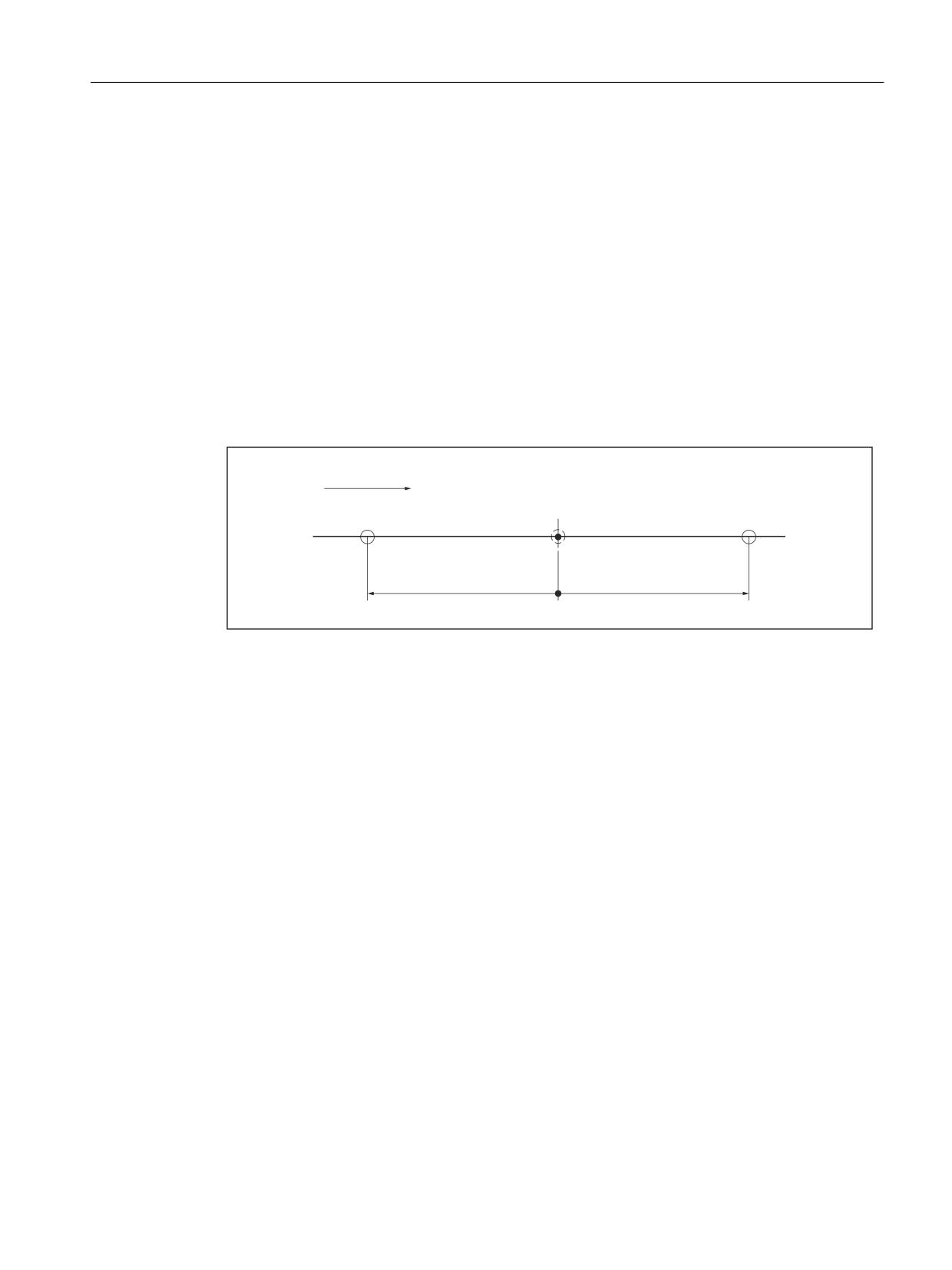
For block-related switching signal output, a positional offset of the switching position can be
programmed :
● Offset distance negative = lead
With a negative offset distance, the switching position is offset before the set point position
programmed in the part program block.
If an excessively large negative offset distance is programmed, i.e. the setpoint has already
been exceeded by the time the edge is detected, the signal is switched immediately.
● Offset distance positive = follow-up
With a positive offset distance, the switching position is offset behind the set point position
programmed in the part program block.
6ZLWFKLQJ
SRVLWLRQ ;
'LUHFWLRQ RI PRWLRQ
ZLWKRXW RIIVHW
1
* ;
1
* )
;
1HJDWLYH RIIVHW
3RVLWLYH RIIVHW
GLVWDQFH
GLVWDQFH
OHDG
IROORZ XS
Figure 23-3
Programmed switching position offset
Path reference
The offset distance is a positional specification that refers to the programmed path. This way
one can start from a simplified linear motion. Path curves are not taken into account.
Response to single block and G60
Due to the internal motion logic, negative offset distances (lead) have no effect when used
with the following standard functions:
● Single Block
● Exact stop at block end (G60)
23.2.7
Response to part program interruption
Following an interruption in the part program (NC-STOP) and subsequent change to JOG
mode, the technological function is deactivated or switching signals cease to be output.
The technology function is reactivated or switching signals are output again only after switching
to the AUTOMATIC mode and continuing the part program (NC-START).
Special functions
Function Manual, 12/2018, A5E40874099B AB
861
TE8: Cycle-independent path-synchronous switching signal output - 840D sl only
23.3 Startup
23.3
Startup
23.3.1
Activation
Before commissioning the technological function, ensure that the corresponding compile cycle
has been loaded and activated (see also Section "TE01: Installation and activation of loadable
compile cycles (Page 673)").
Activation
The "Cycle-independent path synchronized switching signal output" technology function is
activated via the following machine data:
MD60948 $MN_CC_ACTIVE_IN_CHAN_HSLC[0], Bit 0 = 1
Note
The "Cycle-independent path-synchronized switching signal output" is available only in one
channel of NC.
23.3.2
Memory configuration
The technological function requires additional data in the NC-internal block memory. The
values must be increased for the following memory configuring channel-specific machine data:
● MD28090 $MC_MM_NUM_CC_BLOCK_ELEMENTS += 1 (number of block elements for
compile cycles)
● MD28100 $MN_MM_NUM_CC_BLOCK_USER_MEM += 10 (size of block memory for
compile cycles (DRAM) in KB)
23.3.3
Parameterizing the digital on-board outputs
Parameter assignment
A digital output from the local I/O is required for the switching signal.
For this, at least 1 digital output byte must be defined through the following machine data:
MD10360 $MN_FASTIO_DIG_NUM_OUTPUTS ≥ 1 (number of active digital output bytes)
References
A full description of the parameterization of a digital output can be found in:
● Function Manual, Extended Functions, Digital and Analog NC I/O (A4)
Special functions
862
Function Manual, 12/2018, A5E40874099B AB
TE8: Cycle-independent path-synchronous switching signal output - 840D sl only
23.3 Startup
23.3.4
Parameterizing the switching signal
Output number of the switching signal
Once the compile cycle has started up, the following function-specific machine data appears
in the channel-specific machine data:
MD62560 $MC_FASTON_NUM_DIG_OUTPUT (number of the digital output of the switching
signal)
The number n of the on-board digital output through which the switching signal is to be output,
must be entered in it:
n = 1, 2, 3 or 4
Disable
Entering the number of the digital output n = 0 deactivates the function. No message or alarm
is output.
Effect on other output signals
The hardware-timer-controlled output of the switching signal at the parameterized output
delays the signal output for the other digital on-board outputs, e.g. due to synchronized actions,
by 2 IPO cycles.
23.3.5
Parameterization of the geometry axes
Default setting
Machines for high-speed laser cutting normally have two geometry axes that are configured
in the following two machine data:
MD20050_$MC_AXCONF_GEOAX_ASSIGN_TAB[0]
MD20050_$MC_AXCONF_GEOAX_ASSIGN_TAB[1]
The calculation of the switching instants is derived from these two geometry axes.
Note
The configured axis selection for calculating the switching instants can be changed by
redefining the first and second geometry axes in the part program with the help of program
instructions GEOAX(1,<axis name>) and GEOAX(2,<axis name>).
Important:
For the function change to be considered correctly, it should occur before the interpretation of
the CC_FASTON command.
Special functions
Function Manual, 12/2018, A5E40874099B AB
863

TE8: Cycle-independent path-synchronous switching signal output - 840D sl only
23.4 Programming
Changing the default setting
For a deviating machine configuration (e.g. definition of a third geometry axis), the default
setting can be adjusted via the following machine data:
MD60948 $MN_CC_ACTIVE_IN_CHAN_HSCL[1]
Value
Meaning
$MN_CC_ACTIVE_IN_CHAN_HSCL[1]='H3'
Default setting.
The calculation of the switching instants is derived
from the first and second geometry axis.
$MN_CC_ACTIVE_IN_CHAN_HSCL[1]='H7'
The calculation of the switching instants is derived
from the first, second and third geometry axis.
Any change is effective only after the NC has powered up the next time.
23.4
Programming
23.4.1
Activating the block-related switching signal output (CC_FASTON)
Syntax
CC_FASTON (DIFFON, DIFFOFF [,FEEDTOSWITCH])
CC_FASTON() is a procedure call and must therefore be programmed in a dedicated part
program block.
Parameter
The parameters for the CC_FASTON() procedure have the following meaning:
Parameter
Meaning
<DIFFON>
Length* of the offset distance for setting the switching signal.
<DIFFOFF>
Length* of the offset distance for deactivating the switching signal.
<FEEDTOSWITCH>
This parameter is optional.
If the parameter is not specified in the procedure call, the G0 edge change
is used as the switching criterion.
If the parameter is specified in the procedure call, it contains as a switching
criterion the velocity threshold value, which, when undershot or exceeded,
activates or deactivates the switching signal accordingly.
* The basic unit (inch or mm) depends on the current dimensions programming (G70 / G71 / G700 /
G710).
Special functions
864
Function Manual, 12/2018, A5E40874099B AB

TE8: Cycle-independent path-synchronous switching signal output - 840D sl only
23.4 Programming
Programming example
Programming
Comment
DEF REAL DIFFON= -0.08
; Length* of the offset distance for
activating the switching signal =
-0.08
DEF REAL DIFFOFF= 0.08
; Length* of the offset distance for
deactivating the switching signal =
0.08
DEF REAL FEEDTOSWITCH= 20000
; Speed threshold value = 20000
CC_FASTON(DIFFON,DIFFOFF,FEEDTOSWITCH)
; Activating block-related switching
signal output (with speed threshold
value as switching criterion)
Changing parameters
The parameters for the CC_FASTON() procedure can be modified at any time during the
execution of the part program. To do this, enter the procedure call again with the new parameter
values. The switching criterion (G0 edge change / velocity threshold value) may also be
changed.
Reset response
A reset (NC RESET or end of program) deactivates the function.
23.4.2
Activating the path length-related switching signal output (CC_FASTON_CONT)
Syntax
CC_FASTON_CONT (PATH_DISTANCE_ON, PATH_DISTANCE_OFF)
CC_FASTON_CONT() is a procedure call and must therefore be programmed in a dedicated
part program block.
Parameter
The parameters for the CC_FASTON_CONT() procedure have the following meaning:
Parameter
Meaning
< PATH_DISTANCE_ON >
Length* of the stretch section with machining (s1).
< PATH_DISTANCE_OFF>
Length* of the stretch section without machining (s2).
* The basic unit (inch or mm) depends on the current dimensions programming (G70 / G71 / G700 /
G710).
Special functions
Function Manual, 12/2018, A5E40874099B AB
865
TE8: Cycle-independent path-synchronous switching signal output - 840D sl only
23.5 Function-specific alarm texts
Programming example
Programming
Comment
DEF REAL PATH_DISTANCE_ON = 0.5
; Length* of the stretch section with
machining = 0.5
DEF REAL PATH_DISTANCE_OFF = 1.0
; Length* of the stretch section
without machining = 1.0
CC_FASTON_CONT (PATH_DISTANCE_ON, PATH_DISTANCE_OFF)
; Activating path
length-related
switching signal out-
put.
Changing parameters
The parameters for the CC_FASTON_CONT( ) procedure can be modified at any time during
the execution of the part program. For this, the procedure call must be specified again with the
new parameter values.
Reset response
A reset (NC RESET or end of program) deactivates the function.
23.4.3
Deactivation (CC_FASTOFF)
Syntax
CC_FASTOFF
CC_FASTOFF is a procedure call and must therefore be programmed in a dedicated part
program block.
Functionality
The CC_FASTOFF procedure call deactivates the "Cycle independent, path synchronized
switching signal output" function.
23.5
Function-specific alarm texts
For details of the procedure for creating function-specific alarm texts, see Section "Creating
alarm texts (Page 679)".
Special functions
866
Function Manual, 12/2018, A5E40874099B AB
TE8: Cycle-independent path-synchronous switching signal output - 840D sl only
23.6 Supplementary conditions
23.6
Supplementary conditions
23.6.1
Block search
Switching signal output for block search
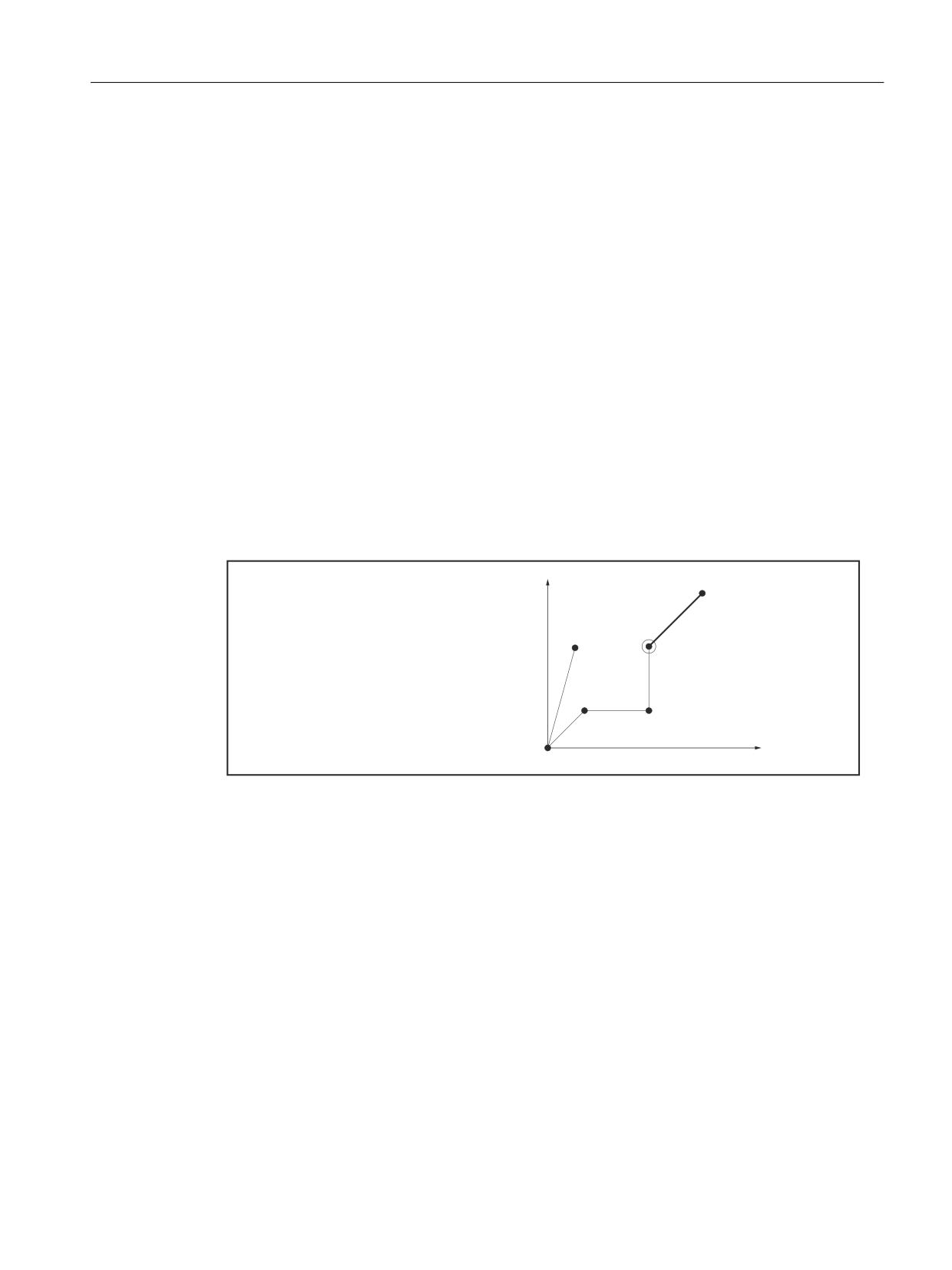
If a block search is on a part program block which lies after a CC_FASTON() procedure call
for activating the technology function, then the switching signal is activated with the next
traversing motion. One of the specific consequences of this is to initiate travel along the contour
from the start position of the geometry axes back to the program continuation point with an
activated switching signal.
Example
Normal process:
In the normal process of the part program machining, the switching signal is activated for the
first time at the beginning of part program block N60.
3DUW SURJUDP
1
* ; <
<
1
* )
;
<
1
1
* ;
6WDUW SRVLWLRQ
1
&&B)$6721
6ZLWFKLQJ
1
<
VLJQDO 2Q
1
* ;
<
1
1
1
1
1
;
Figure 23-4
Switching signal for part program machining operation
Process sequence after block search:
If a block search is executed for the block end point of part program block N60 the switching
signal is activated on reaching the start position of the geometry axes.
Special functions
Function Manual, 12/2018, A5E40874099B AB
867

TE8: Cycle-independent path-synchronous switching signal output - 840D sl only
23.6 Supplementary conditions
6WDUW SRVLWLRQ
3DUW SURJUDP
6ZLWFKLQJ VLJQDO 21
1
* ; <
<
1
* )
;
<
1
1
* ;
1
&&B)$6721
1
<
1
* ;
<
1
1
1
1
1
;
Figure 23-5
Switching signal after block search
Suppressing the switching signal output
The user (machine manufacturer) must take appropriate measures, e.g. disable the switching
signal, in order to suppress the activation of the switching signal in the REPOS block in the
constellation described above.
Note
It is the sole responsibility of the user (machine manufacturer) to suppress the output of the
switching signal during repositioning, e.g. after a block search.
References
You will find a description of the block search in:
Function Manual, Basic Functions, Mode Group, Channel, Program Operation, Reset Behavior
(K1)
23.6.2
Transformations
The function will only run correctly with deactivated transformation. There is no monitoring
function.
For a description of the transformations (see Section "TE4: Handling transformation package
- 840D sl only (Page 759)").
References:
Function Manual Extended Functions; Kinematic Transformation (M1)
Special functions
868
Function Manual, 12/2018, A5E40874099B AB
TE8: Cycle-independent path-synchronous switching signal output - 840D sl only
23.6 Supplementary conditions
23.6.3
Compensations
The following compensations are considered while calculating the switching positions:
● Temperature compensation
● Sag compensation
A description of the compensations can be found in:
Reference:
Function Manual, Extended Functions; Compensations (K3)
23.6.4
Tool radius compensation (TRC)
As part of tool radius compensation, control-internal part program blocks (compensation
blocks) are inserted into the part program. With reference to the switching signal output, a
compensation block is always added to the next programmed part program block.
A description of the tool radius compensation can be found in:
Reference:
Function Manual, Basic Functions; Tool Compensations (W1), Section: Tool radius
compensation
23.6.5
Continuous-path mode
Continuous-path mode
Although the CC_FASTON(), CC_FASTON_CONT() and CC_FASTOFF procedure calls must
be programmed in dedicated part program blocks, this will not lead to a drop in velocity while
continuous-path mode is active (G64, G641, ...).
Continuous-path mode (ADIS)
If in continuous-path mode with programmable rounding response (G641 ADIS) a part
program block is inserted in the part program, then the originally programmed switching
position is not reached and the switching signal output takes place nevertheless in the center
of the rounding block.
References
You will find a description of the continuous-path mode in:
Function Manual, Basic Functions, Continuouspath Mode, Exact Stop and Look Ahead (B1)
Special functions
Function Manual, 12/2018, A5E40874099B AB
869

TE8: Cycle-independent path-synchronous switching signal output - 840D sl only
23.7 Data lists
23.6.6
Software cams
Because the hardware timer is also used for the "software cam" function, it is not possible to
use the "clock-independent switching signal output" function with software cams at the same
time.
The following alarm appears in the event of an error:
Alarm 75500 "Channel Channel No., wrong configuration of function: clock-independent
switching signal output"
A description of the software cams can be found in:
Reference:
Function Manual, Extended Functions; Software cams, Position switching signals (N3)
23.7
Data lists
23.7.1
Machine data
23.7.1.1
General machine data
Number
Identifier: $MN_
Description
10360
FASTO_NUM_DIG_OUTPUTS
Number of digital output bytes
23.7.1.2
Channelspecific machine data
Number
Identifier: $MC_
Description
20050
AXCONF_GEOAX_ASSIGN_TAB
Assignment of geometry axis to channel axis
28090
MM_NUM_CC_BLOCK_ELEMENTS
Number of block elements for CC
28100
MM_NUM_CC_BLOCK_USER_MEM
Size of block memory for CC
62560
FASTON_NUM_DIG_OUTPUT
Number of the on-board digital output for the switching
signal
Special functions
870
Function Manual, 12/2018, A5E40874099B AB
TE9: Axis pair collision protection
24
24.1
Brief description
Note
Compile cycle
Before commissioning the function, ensure that the corresponding compile cycle has been
loaded and activated (see Chapter "TE01: Installation and activation of loadable compile
cycles (Page 673)").
Function
The "axis pair collision protection" function enables machine axes, which are arranged on the
same guide element of a machine, to be monitored in pairs to ensure that no collisions occur
and that the maximum distance between the two axes is not exceeded.
Function code
The code for function-specific identifiers of machine data, system variables etc., is:
PROTECT (axial collision PROTECTion)
Maximum number of axis pairs
A maximum of 20 axis pairs can be parameterized.
24.2
Functional description
The "axis pair collision protection" function is a protection function for machine axes which are
arranged in a machine tool in such a way (on the same guide rail, for example) that incorrect
operation or programming could cause them to collide with one another.
The machine axes are always monitored in pairs, i.e. parameters always need to be assigned
for two machine axes in each case, which are then monitored in relation to one another. The
machine axes being monitored may be located in different machine coordinate systems.
Special functions
Function Manual, 12/2018, A5E40874099B AB
871
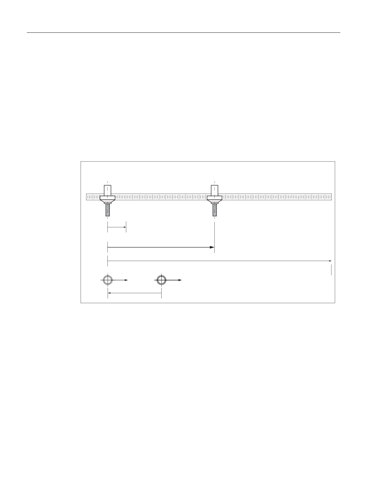
TE9: Axis pair collision protection
24.3 Startup
Collision protection
The function uses the current actual positions and actual velocities, as well as the offset for
the machine coordinate systems and the axis-specific brake acceleration values, to calculate
the distance between the standstill positions of the machine axes, on a cyclical basis. If the
resulting distance is shorter than the protection window that has been set, the machine axes
are decelerated to a standstill. This ensures that the minimum distance defined using the
protection window is not undershot.
Distance monitoring
If the offset vector is selected accordingly, the function can also be used to monitor the
maximum distance between the two machine axes (maximum distance vector).
0DFKLQH D[LV $
0DFKLQH D[LV $
0LQLPXP FOHDUDQFH YHFWRU
$FWXDO FOHDUDQFH YHFWRU
0D[LPXP FOHDUDQFH YHFWRU
0&6B$
0&6B$
0&6BRIIVHW YHFWRU
Figure 24-1
Basic design
Monitoring status
The actual status of an axis pair can be read out of _PROTECT_STATUS (Page 878),
optionally defined global user variables in the NC program (GUD).
24.3
Startup
24.3.1
Enabling the technology function (option)
The function is an option, which must be assigned to the hardware via the license management.
6FC5800-0AN06-0YB0, "RMCC/PROT axis collision avoidance"
For test purposes, the function can be enabled by setting the option data:
Special functions
872
Function Manual, 12/2018, A5E40874099B AB
TE9: Axis pair collision protection
24.3 Startup
MD19610 $ON_TECHNO_EXTENSION_MASK[ 2 ], BIT4 = 1
24.3.2
Activating the technology function
Activation rule
The function must be activated on a channel-for-channel basis for the following NC channels:
● Independent of which channels are assigned to the machine axes to be monitored, always
in the 1st channel of the NC
● In all channels that are assigned to the machine axes to be monitored (by the function) by
parameterizing the machine data
● In all channels that are assigned at a later point in time to the machine axes to be monitored
(by the function), e.g. as a result of axis replacement
Activation
The function is activated on a channel-for-channel basis using machine data:
MD60972 $MN_CC_ACTIVE_IN_CHAN_PROT[ 0 ], bit n = 1
with n = 0, 1, 2, ..., corresponding to the (n+1)th channel of the NC
See also
TE01: Installation and activation of loadable compile cycles (Page 673)
24.3.3
Activating the supplementary functions
The supplementary functions are activated for specific axis pairs using option data:
MD61535 $MN_CC_PROTECT_OPTIONS[ <a> ]
with a = 0, 1, 2, ... (maximum number of axis pairs - 1) corresponding axis pair 1, 2, 3, ...
Bit
Value
Meaning
0
1
Axis pair-specific activation/deactivation of the function "Axis pair collision protection"
via the NC/PLC interface signal (Page 879)"
Note
After activating this supplementary function, the protection function is in the monitoring
status (Page 878) == 1 (selected, but still not active)
24.3.4
Definition of an axis pair
A machine axis pair to be monitored is defined on an axis pair-specific basis in machine data:
MD61516 $MN_CC_PROTECT_PAIRS[ <a> ] = <yyxx>
Special functions
Function Manual, 12/2018, A5E40874099B AB
873

TE9: Axis pair collision protection
24.3 Startup
with a = 0, 1, 2, ... (maximum number of axis pairs - 1) corresponding axis pair 1, 2, 3, ...
<yyxx>
Meaning
xx
1st and 2nd decimal place ⇒ axis number of the 1st machine axis
yy
3rd and 4th decimal place ⇒ axis number of the 2nd machine axis
Example
Definition of the 1st axis pair:
● 1st axis: 4th machine axis
● 2nd axis: 12th machine axis
MD61516 $MN_CC_PROTECT_PAIRS[ 0 ] = 1204
24.3.5
Retraction direction
The direction of travel for retracting the corresponding machine axis is set using machine data:
MD61517 $MN_CC_PROTECT_SAFE_DIR[ <a> ] = <yyxx>
with a = 0, 1, 2, ... (maximum number of axis pairs - 1) corresponding axis pair 1, 2, 3, ...
<yyxx>
Meaning
xx
Retraction direction for the 1st axis of the axis pair
yy
Retraction direction for the 2nd axis of the axis pair
Retraction in the positive direction of travel of the machine axis: xx or yy > 0
Retraction in the negative direction of travel of the machine axis: xx or yy = 0
Note
Changing the retraction direction
Changing the retraction direction in machine data MD61517
$MN_CC_PROTECT_SAFE_DIR[<axis pair>] may only be carried out if the protection function
for the axis pair is not active (MD61516 $MN_CC_PROTECT_PAIRS[<axis pair>] == 0).
24.3.6
Offset for the machine coordinate systems
If the machine axes of the axis pair are located in different machine coordinate systems, then
the appropriate offset vector must be specified in the following machine data:
MD61518 $MN_CC_PROTECT_OFFSET[ <a> ] = <offset vector>
with a = 0, 1, 2, ... (maximum number of axis pairs - 1) corresponding axis pair 1, 2, 3, ...
The offset vector should be specified as vector from the origin of the machine coordinate
system of the 2nd axis of the axis pair to the origin of the machine coordinate system of the
1st axis, referred to the machine coordinate system of the 1st axis.
Special functions
874
Function Manual, 12/2018, A5E40874099B AB
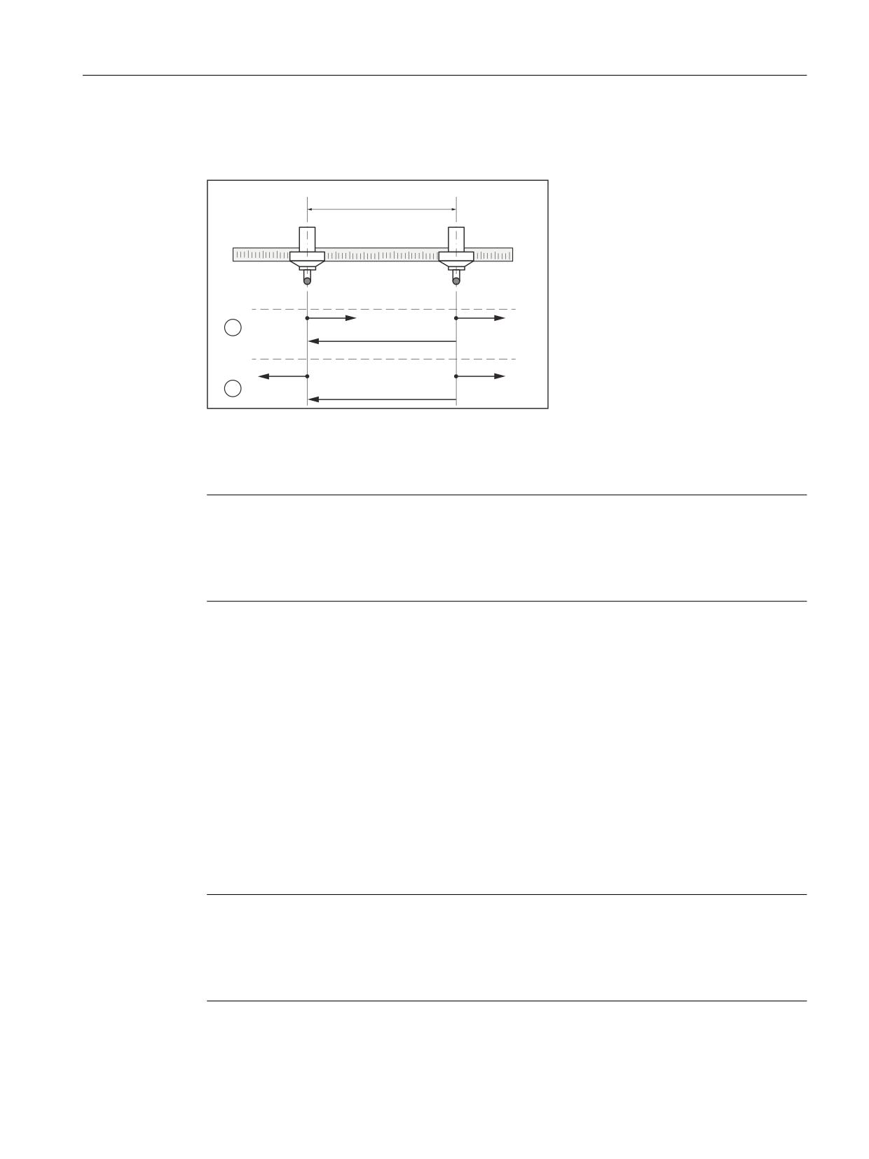
TE9: Axis pair collision protection
24.3 Startup
If both machine axes are located in the same machine coordinate system, an offset vector of
0 must be specified.
$FKVH
$FKVH
0.6
0.6
9
9
① Case 1: Equidirectional MCS orientation
② Case 2: Counterdirectional MCS orientation
V Offset vector
Note
Changing the offset vector
Changing the offset vector in machine data MD61518 $MN_CC_PROTECT_OFFSET[<axis
pair>] may only be carried out if the protection function for the axis pair is not active (MD61516
$MN_CC_PROTECT_PAIRS[<axis pair>] == 0).
24.3.7
Protection window
The protection window and/or the minimum clearance is defined which the axes of the axis
pair may not fall below using the machine data:
MD61519 $MN_CC_PROTECT_WINDOW[ <a> ] = <minimum clearance>
with a = 0, 1, 2, ... (maximum number of axis pairs - 1) corresponding axis pair 1, 2, 3, ...
When the clearance approaches the minimum clearance, the axes are braked with the function-
specific acceleration (Page 877).
The protection window can be dynamically extended, e.g. in an NC P program using
theprotection window extension (Page 876).
Note
Changing the protection window
Changing the protection window in machine data MD61519
$MN_CC_PROTECT_WINDOW[<axis pair>] may also be carried out if the protection function
for the axis pair is active (MD61516 $MN_CC_PROTECT_PAIRS[<axis pair>] ≠ 0).
Special functions
Function Manual, 12/2018, A5E40874099B AB
875

TE9: Axis pair collision protection
24.3 Startup
24.3.8
Orientation
The orientation of the axes of the axis pair to one another is specified in the following machine
data:
MD61532 $MN_CC_PROTECT_DIR_IS_REVERSE[ <a> ] = <value>
with a = 0, 1, 2, ... (maximum number of axis pairs - 1) corresponding axis pair 1, 2, 3, ...
<value>
Meaning
0
Equidirectional orientation
1
Counterdirectional orientation
Note
Changing the orientation
Changing the orientation in machine data MD61532
$MN_CC_PROTECT_DIR_IS_REVERSE[<axis pair>] may only be carried out if the protection
function for the axis pair is not active (MD61516 $MN_CC_PROTECT_PAIRS[<axis pair>] ==
0).
24.3.9
Protection window extension
The protection window (Page 875) can be dynamically extended using machine data:
MD61533 $MN_CC_PROTECT_WINDOW_EXTENSION[ <a> ] = <extension>
with a = 0, 1, 2, ... (maximum number of axis pairs - 1) corresponding axis pair 1, 2, 3, ...
The resulting effective protection window of an axis pair is as follows:
Effective protection window[<axis pair>] =
MD61519 $MN_CC_PROTECT_WINDOW[<axis pair>] +
MD61533 $MN_CC_PROTECT_WINDOW_EXTENSION[<axis pair>]
It is not possible to reduce the protection window by entering a negative value.
Note
Changing the protection window extension
Changing the protection window extension in machine data MD61533
$MN_CC_PROTECT_WINDOW_EXTENSION[<axis pair>] may also be carried out when the
protection function is active, e.g. from the NC program - and can be activated by initiating
"Activate machine data".
Special functions
876
Function Manual, 12/2018, A5E40874099B AB
TE9: Axis pair collision protection
24.3 Startup
24.3.10
Activating the protection function
Static activation using machine data
The protection function for an axis pair is statically activated as soon as the following
preconditions are fulfilled:
● Both machine axes of the axis pair have been referenced
● Valid machine axes have been parameterized for the axis pair:
MD61516 $MN_CC_PROTECT_PAIRS[<axis pair>] = <valid machine axis pair>
● The supplementary function "Axis pair-specific activation/deactivation via axis-specific NC/
PLC interface signals" is not active:
MD61535 $MN_CC_PROTECT_OPTIONS[<axis pair>], bit 0 = 0
Dynamic activation via NC/PLC interface signal
The protection function for an axis pair is dynamically activated as soon as the following
preconditions are fulfilled:
● Both machine axes of the axis pair have been referenced
● Valid machine axes have been parameterized for the axis pair:
MD61516 $MN_CC_PROTECT_PAIRS[<axis pair>] = <valid machine axis pair>
● The supplementary function "Axis pair-specific activation/deactivation via axis-specific NC/
PLC interface signals" is active:
MD61535 $MN_CC_PROTECT_OPTIONS[<axis pair>], bit 0 = 1
● The axis-specific NC/PLC interface signal to activate the protection function is set for one
of the two machine axes of the axis pair:
DB31,
DBX24.3 == 1
Clearance less than the protection window
If, at the time when the protection function is activated, the distance between the two machine
axes is less than the minimum distance of the protection window which has been
parameterized, then the machine operator must retract the machine axes. In this particular
state, the control only allows traversing motion in the parameterized retraction direction
(Page 874) of the machine axes.
Monitoring status
The actual monitoring status of an axis pair can be read using global user variable
_PROTECT_STATUS (Page 878).
24.3.11
Axis-specific acceleration
The acceleration with which the two machine axes of the axis pair are braked by the protection
function when a critical distance is approached is set using:
Special functions
Function Manual, 12/2018, A5E40874099B AB
877

TE9: Axis pair collision protection
24.3 Startup
MD63514 $MA_CC_PROTECT_ACCEL[<axis>] = <acceleration>
with <axis>: Machine axis name, e.g. AX1, AX2, ...
Note
Without jerk limitation
The braking acceleration set using MD63514 $MA_CC_PROTECT_ACCEL acts without jerk
limiting.
Priority of the function-specific acceleration
The protection function only uses the function-specific acceleration of the machine axes from
MD63514 $MA_CC_PROTECT_ACCEL to calculate the time at which the axis should be
braked. The protection function does not take the actual acceleration of the machine axis in
the channel into account.
Note
Path reference
If machine axes being monitored by the protection function are traversed by a channel with a
path reference to other axes, this path reference is lost as soon as the protection function
causes the axis grouping to decelerate. The machine axes being monitored by the protection
function are decelerated using their function-specific acceleration values from machine data
item MD63514 $MA_CC_PROTECT_ACCEL. The remaining axes in the axis grouping are
decelerated using the current path acceleration value of the channel.
24.3.12
Monitoring status (GUD)
The actual status of one axis pair is displayed using the global user variable
_PROTECT_STATUS.
The variable is not available in the default setting. When required, it must be defined in the
GUD.DEF definition window.
Definition
DEF NCK INT _PROTECT_STATUS[ <number of parameterized axis pairs> ]
with <number of parameterized axis pairs> = 1, 2, 3, ... (maximum number of axis pairs)
Range of values
Value
Meaning: The monitoring of the axis pair is ...
0
Not active
1
selected, but not yet active
2
active, the axes are currently not being braked
3
active, the axes are currently being braked
4
deselected, however still active
Special functions
878
Function Manual, 12/2018, A5E40874099B AB

TE9: Axis pair collision protection
24.3 Startup
24.3.13
PLC interface: Axis-specific braking operations
Within the general system variable field $A_DBD, a double word (four bytes) can be used to
define an axes-specific braking interface. When the axes of the axis pair critically approach
one another, the actual braking of the machine axes is displayed via the braking interface.
MD61534 $MN_CC_PROTECT_A_DBD_INDEX = <value>
<value>
Meaning
-1
Deactivation of the output.
≥ 0
Braking interface index within the system variable field:
$A_DBD[ <index> ] with index = 0, 4, 8, 12, ...
Note
Double word index
The starting index can be specified in the machine data, byte-by-byte (0, 1, 2, ...). System
variable $A_DBD is accessed from the PLC using a double word. This means that a starting
index, which is not located at a double word boundary (0, 4, 8, ...), is rounded off to the next
double word boundary (0, 4, 8, 12, ...): Index = (index DIV 4) * 4
Braking interface
Each bit of the braking interface is assigned a machine axis:
Bit n → (n+1)th machine axis, with n = 0, 1, 2, ...
Bit
31
30
29
28
3
2
1
0
MA 1)
---
31
30
29
4
3
2
1
1) Machine axis number
Bit n
Meaning
0
Machine axis (n+1) is not braked
1
Machine axis (n+1) is braked
References
Block FC21, function 3 is available to read the braking interface from the PLC user program.
Function Manual Basic Functions; Chapter "Basic PLC program for SINUMERIK 840D sl" >
"Block descriptions" > "FC21: Transfer data exchange NC/PLC" > "Function 3, 4: Fast data
exchange PLC-NC"
24.3.14
PLC interface: Axis pair-specific activation of the protection function
If the supplementary function "Activation/deactivation of function "Axis pair collision protection"
via NC/PLC interface signal (Page 873)" is active, using the axis-specific interface signal, the
protection function for the axis pair can be activated and deactivated from the PLC user
program:
Special functions
Function Manual, 12/2018, A5E40874099B AB
879
TE9: Axis pair collision protection
24.4 Limitations and constraints
DB31,
DBX24.3 (activate collision protection)
Activating
The protection function is activated if the axis-specific interface signal for one of the two
machine axes of the axis pair is set.
Deactivating
The protection function is deactivated if the axis-specific interface signal for both machine axes
of the axis pair is reset.
24.4
Limitations and constraints
24.4.1
Axes
Same axis types
Both machine axes of an axis pair must be of the same axis type:
● Linear axis:
- MD30300 $MA_IS_ROT_AX = 0
- MD30310 $MA_ROT_IS_MODULO = 0
● Rotary axis:
- MD30300 $MA_IS_ROT_AX = 1
- MD30310 $MA_ROT_IS_MODULO = 0
Modulo rotary axes
None of the machine axes of an axis pair may be a modulo rotary axis:
● MD30300 $MA_IS_ROT_AX = 1 (rotary axis)
● MD30310 $MA_ROT_IS_MODULO = 1 (error: modulo rotary axis !)
24.4.2
Axis container
If the assignment of the machine axes to be monitored changes dynamically during the course
of a machining process - for example when using axis containers - the function must be
deactivated, its parameters reassigned, and then reactivated prior to the change (e.g. axis
container rotation) being made.
Example
The protection function is to monitor logical machine axes 1 and 13. These relate to slots 1
and 2 of axis container CT1. The associated real machine axes are AX1 and AX13.
Special functions
880
Function Manual, 12/2018, A5E40874099B AB
TE9: Axis pair collision protection
24.4 Limitations and constraints
In an axis container rotation, the axis container makes a transition by one step, which causes
the real machine axes to be changed.
Machine axis AX13 is retracted in the positive direction of travel. Machine axis AX1 is retracted
in the negative direction of travel.
Assigning parameters for the NC
Logical machine axes: axis numbers 1 and 13
● MD10002 $MN_AXCONF_LOGIC_MACHAX_TAB [ 0 ] = "CT1_SL1" (log. mach. axis 1)
● MD10002 $MN_AXCONF_LOGIC_MACHAX_TAB [ 12 ] = "CT1_SL2" (log. mach. axis 13)
Axis container CT1, slot 1 and slot 2
● MD12750 $MN_AXCT_NAME_TAB[ 0 ] = "CT1"
● MD12701 $MN_AXCT_AXCONF_ASSIGN_TAB1[ 0 ] = "AX1" (slot 1)
● MD12701 $MN_AXCT_AXCONF_ASSIGN_TAB1[ 1 ] = "AX13" (slot 2)
Real machine axes: machine axis names AX1 and AX13
● MD10000 $MN_AXCONF_MACHAX_NAME_TAB[ x ] = "AX1"
● MD10000 $MN_AXCONF_MACHAX_NAME_TAB[ y ] = "AX13"
Parameterizing the "axis pair collision protection" function before axis container rotation
● MD61516 $MN_CC_PROTECT_PAIRS[0] = 01 13
● MD61517 $MN_CC_PROTECT_SAVE_DIR[0] = 01 00
Performing the axis container rotation
1. Deactivate the protection function
MD61516 $MN_CC_PROTECT_PAIRS[0] = 00 00
2. Trigger a reset in the 1st NC channel in order to adopt the change made to the machine
data
MD60972 $MN_CC_ACTIVE_IN_CHAN_PROT[0], BITx, ...
3. Execute the axis container rotation
AXCTSWED(CT1)
Re-parameterizing the "axis pair collision protection" function after axis container rotation:
● MD61516 $MN_CC_PROTECT_PAIRS[0] = 13 01
● MD61517 $MN_CC_PROTECT_SAFE_DIR[0] = 01 00
or
● MD61516 $MN_CC_PROTECT_PAIRS[0] = 01 13
● MD61517 $MN_CC_PROTECT_SAFE_DIR[0] = 00 01
Trigger a "reset" in the 1st NC channel in order to adopt the change made to the machine data.
Special functions
Function Manual, 12/2018, A5E40874099B AB
881
TE9: Axis pair collision protection
24.4 Limitations and constraints
24.4.3
Link axes
If the axes of an axis pair are link axes, i.e. the setpoints of machine axes from channels of
various NCUs are generated via the "NCU link" function, then the axes can neither be
monitored with respect to one another nor protected.
24.4.4
Interpolatory couplings
Assumption
1. A machine axis is part of an interpolatory coupling, e.g.:
- Generic coupling (CP)
- Coupled motion(TRAIL)
- Master value coupling (LEAD)
- Electronic gear (EG)
- Synchronous spindle(COUP)
2. The machine axis is not traversed in the first channel of the NC.
3. The machine axis is monitored using the "axis pair protection" function.
Effect
If the machine axis is not traversed in the first channel of the NC, then the components, created
from the interpolatory couplings for the position and velocity setpoint are only available after
a deadtime of one interpolator clock cycle of the "axis pair collision protection" function.
Therefore, the machine axes are monitored, offset by these components. The absolute value
of the components is independent of the interpolator clock cycle and the actual velocity and
acceleration of the machine axis.
Special functions
882
Function Manual, 12/2018, A5E40874099B AB
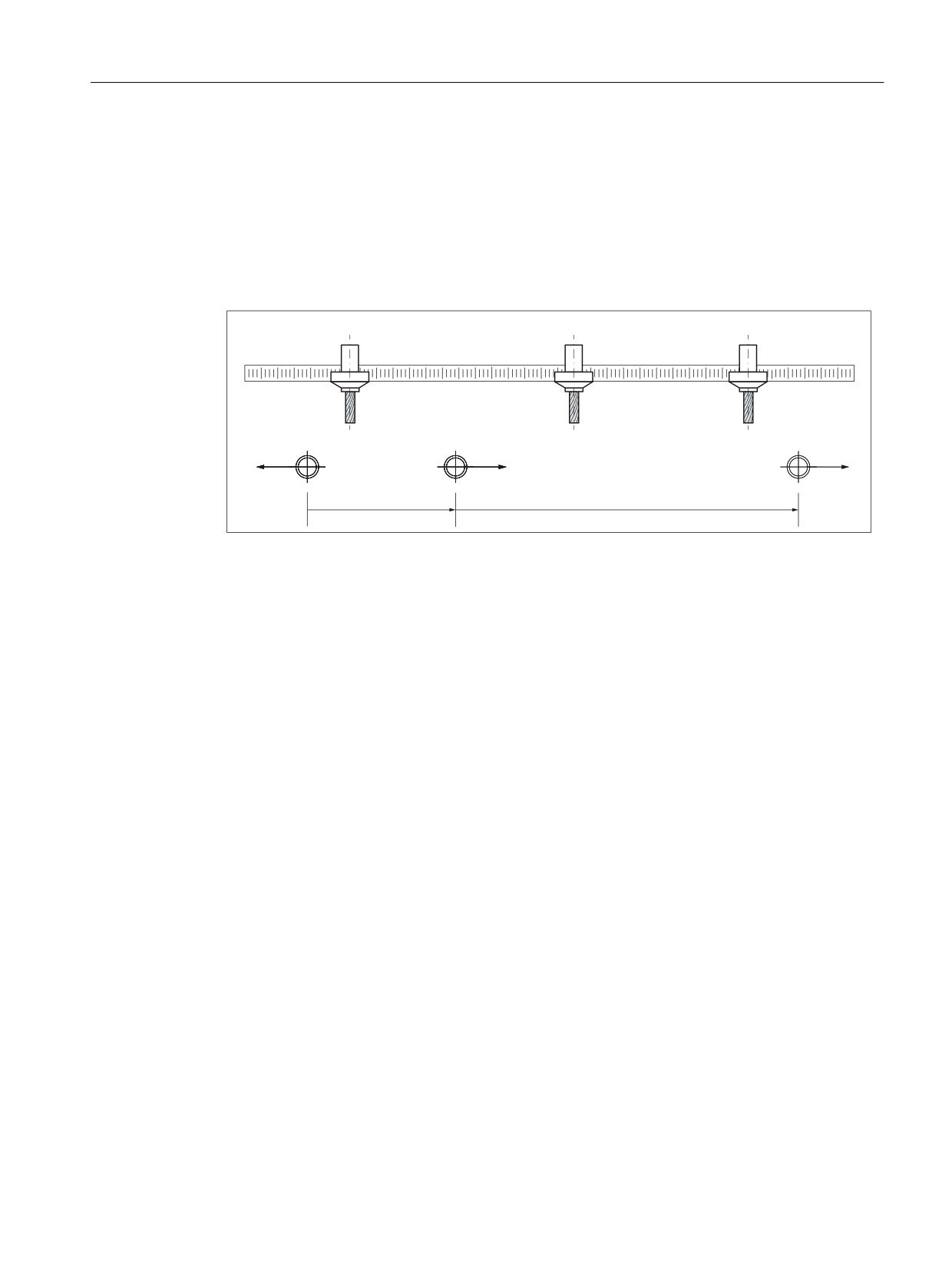
TE9: Axis pair collision protection
24.5 Examples
24.5
Examples
24.5.1
Collision protection
The figure shows the arrangement of 3 machine axes and the offset and orientation of the
machine coordinate systems (machine).
$
$
$
0&6B$
0&6B$
0&6B$
0&6BRIIVHW YHFWRU
0&6BRIIVHW YHFWRU
Figure 24-2
Collision protection for 2 axis pairs
Parameter assignment: Protection function 1
Axis pair: 1st machine axis A3, 2nd machine axis A1
● MD61516 $MN_CC_PROTECT_PAIRS[0] = 01 03
Retraction direction: A1 in negative direction, A3 in positive direction
● MD61517 $MN_CC_PROTECT_SAFE_DIR[0] = 00 01
Offset vector from machine coordinate system machine_A1 to machine_A3 with reference to
machine_A3
● MD61518 $MN_CC_PROTECT_OFFSET[0] = 70.0
Example protection window, 10.0 mm
● MD61519 $MN_CC_PROTECT_WINDOW[0] = 10.0
Orientation of the machine coordinate systems to one another: same direction
● MD61532 $MN_CC_PROTECT_DIR_IS_REVERSE[0] = 0
Protection window extension: none
● MD61533 $MN_CC_PROTECT_WINDOW_EXTENSION[0] = 0.0
Parameter assignment: Protection function 2
Axis pair: 1st machine axis A1, 2nd machine axis A12
● MD61516 $MN_CC_PROTECT_PAIRS[1] = 12 01
Special functions
Function Manual, 12/2018, A5E40874099B AB
883
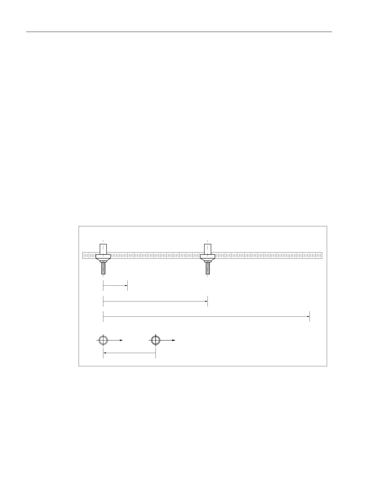
TE9: Axis pair collision protection
24.5 Examples
Retraction direction: A12 in positive direction, A1 in positive direction
● MD61517 $MN_CC_PROTECT_SAFE_DIR[1] = 01 01
Offset vector from machine coordinate system machine_A12 to machine_A1 with reference to
machine_A1
● MD61518 $MN_CC_PROTECT_OFFSET[1] = 32.0
Example protection window, 5.0 mm
● MD61519 $MN_CC_PROTECT_WINDOW[1] = 5.0
Orientation of the machine coordinate systems to one another: opposite direction
● MD61532 $MN_CC_PROTECT_DIR_IS_REVERSE[1] = 1
Protection window extension: by 5.0 mm to give a total of 10.0 mm
● MD61533 $MN_CC_PROTECT_WINDOW_EXTENSION[1] = 5.0
24.5.2
Collision protection and distance limiter
The figure shows the arrangement of two machine axes, the offset and orientation of the
machine coordinate systems (machine), and the minimum and maximum distance vectors.
$FWXDO YDOXHB$
PP
$FWXDO YDOXHB$
PP
0LQ FOHDUDQFH YHFWRU
$FWXDO FOHDUDQFH YHFWRU
0D[ FOHDUDQFH YHFWRU
0&6B$
0&6B$
0&6BRIIVHW YHFWRU
Figure 24-3
Collision protection and distance limiter for one axis pair
Parameter assignment: Protection function 1 - Collision protection
Axis pair: 1st machine axis A1, 2nd machine axis A3
● MD61516 $MN_CC_PROTECT_PAIRS[0] = 03 01
Retraction direction: A1 in negative direction, A3 in positive direction
● MD61517 $MN_CC_PROTECT_SAFE_DIR[0] = 01 00
Special functions
884
Function Manual, 12/2018, A5E40874099B AB
TE9: Axis pair collision protection
24.5 Examples
Offset vector from machine coordinate system machine_A3 to machine_A1 with reference to
machine_A1
● MD61518 $MN_CC_PROTECT_OFFSET[0] = -100.0
Example protection window, 40.0 mm
● MD61519 $MN_CC_PROTECT_WINDOW[0] = 40.0
Orientation of the machine coordinate systems to one another: same direction
● MD61532 $MN_CC_PROTECT_DIR_IS_REVERSE[0] = 0
Protection window extension: none
● MD61533 $MN_CC_PROTECT_WINDOW_EXTENSION[0] = 0.0
Parameter assignment: Protection function 2 - Distance limiter
Axis pair: 1st machine axis A1, 2nd machine axis A3
● MD61516 $MN_CC_PROTECT_PAIRS[1] = 03 01
Retraction direction: A1 in positive direction, A3 in negative direction
● MD61517 $MN_CC_PROTECT_SAFE_DIR[1] = 00 01
Offset vector = "offset vector from machine coordinate system machine_A3 to machine_A1
with reference to machine_A1" - "maximum distance vector with reference to machine_A1"
Note
Maximum distance vector
The maximum distance vector from the 1st machine axis to the 2nd machine axis is the vector
from the origin of the machine coordinate system for the 1st machine axis to the maximum
permissible position of the 2nd machine axis, with reference to the machine coordinate system
for the 1st machine axis.
● MD61518 $MN_CC_PROTECT_OFFSET[1] = -100.0 - 500.0 = 400.0
Example protection window, 20.0 mm
● MD61519 $MN_CC_PROTECT_WINDOW[1] = 20.0
Orientation of the machine coordinate systems to one another: same direction
● MD61532 $MN_CC_PROTECT_DIR_IS_REVERSE[1] = 0
Protection window extension: none
● MD61533 $MN_CC_PROTECT_WINDOW_EXTENSION[1] = 0.0
If machine axis A1 has a value of 0, the settings above will limit the traversing range of machine
axis A3 to between -60.0 and 380.0, with reference to machine_A3.
Special functions
Function Manual, 12/2018, A5E40874099B AB
885

TE9: Axis pair collision protection
24.6 Data lists
24.6
Data lists
24.6.1
Option data
Number
Identifier: $ON_
Description
19610
TECHNO_EXTENSION_MASK[6]
Enable the technology function via BIT4 = 1
24.6.2
Machine data
24.6.2.1
NC-specific machine data
Number
Identifier: $MN_
Description
60972
CC_ACTIVE_IN_CHAN_PROT[ 0 ]
Channel-specific activation of the technology function
61516
CC_PROTECT_PAIRS[ <a> ]
Axis pair-specific definition of both machine axes
61517
CC_PROTECT_SAFE_DIR[ <a> ]
Axis pair-specific definition of the retraction direction
61518
CC_PROTECT_OFFSET[ <a> ]
Axis pair-specific definition of the offset of both machine coordi-
nate systems
61519
CC_PROTECT_WINDOW[ <a> ]
Axis pair-specific definition of the protection window or minimum
clearance
61532
CC_PROTECT_DIR_IS_REVERSE[ <a> ]
Axis pair-specific definition of the orientation of the machine coor-
dinate systems of both machine axes to one another
61533
CC_PROTECT_WINDOW_EXTEN-
Axis pair-specific definition of the protection window extension
SION[ <a> ]
61534
CC_PROTECT_A_DBD_INDEX
Braking interface window within the system variable field $A_DBD
61535
CC_PROTECT_OPTIONS[ <a> ]
Axis pair-specific activation of supplementary functions
24.6.2.2
Axis/Spindle-specific machine data
Number
Identifier: $MA_
Description
61514
CC_PROTECT_ACCEL
Protection function-specific brake acceleration
24.6.3
Signals
24.6.3.1
Signals to axis/spindle
Signal name
SINUMERIK 840D sl
SINUMERIK 828D
Activate collision protection
DB31,
DBX24.3
-
Special functions
886
Function Manual, 12/2018, A5E40874099B AB
TE9: Axis pair collision protection
24.6 Data lists
24.6.4
User data
24.6.4.1
Global user data (GUD)
Identifier
Description
_PROTECT_STATUS[n]
Status of the protection function (optional)
Special functions
Function Manual, 12/2018, A5E40874099B AB
887
TE9: Axis pair collision protection
24.6 Data lists
Special functions
888
Function Manual, 12/2018, A5E40874099B AB
V2: Preprocessing
25
25.1
Brief description
Preprocessing
The programs stored in the directories for standard and user cycles can be preprocessed to
reduce runtimes.
Preprocessing is activated via machine data.
Standard and user cycles are preprocessed when the power is switched on, i.e. as an internal
control function, the part program is translated (compiled) into a binary intermediate code
optimized for processing purposes.
All program errors that can be corrected by means of a compensation block are detected during
preprocessing. In addition, when the program includes branches and check structures, a check
is made to ensure that the branch destinations are present and that structures are nested
correctly.
The full scope of control functionality is available:
● Override influence
● Reactions to data and signals that are input by the PLC or the operator
● Current block display
● The programs can be processed in single block mode (SBL1 and SBL2). Block searches
can be executed. The compilation cannot be stored; it is concealed from the user and
regenerated every time the power is switched on.
Preprocessing can be used:
● To optimize the runtimes of part programs with high-level language components (branches,
check structures, motion-synchronous actions)
● CPU time intensive part programs (e.g. stock removal cycles)
● Faster processing of time-critical sections (e.g. program continuation after preprocessing
stop during rapid deletion of distance-to-go, or return stroke, or in the tool change cycle).
General information
Preprocessing standard and user cycles is possible. The processing time of part programs
can then be reduced without restricting the control functionality.
The standard and user cycles are preprocessed when machine data is set accordingly:
MD10700 $MN_PREPROCESSING_LEVEL (program preprocessing level)
Preprocessing is carried out program-specifically. It is possible to mix preprocessed part
programs and part programs interpreted in ASCII format. Preprocessing serves to reduce
incidental times.
Special functions
Function Manual, 12/2018, A5E40874099B AB
889
V2: Preprocessing
25.1 Brief description
Memory is required for preprocessing cycles. You can optimize your memory in two ways:
● The program to be executed can be shortened with the command DISPLOF (display off).
● MD10700 $MN_PREPROCESSING_LEVEL has been expanded by bit 2 and 3. This allows
selective cycle preprocessing of the individual directories (e.g. user cycles).
MD10700 $MN_PREPROCESSING_LEVEL has been expanded by bit 4. This allows you to
select preprocessing for user cycles from the _N_CMA_DIR directory.
MD10700 $MN_PREPROCESSING_LEVEL has been expanded by bit 5. This allows selective
preprocessing of the specific individual user cycles that have the command PREPRO after the
PROC instruction.
Pretranslated cycles are stored in the dynamic NC memory by default. MD10700
$MN_PREPROCESSING_LEVEL has been expanded by bit 6. This allows specifying that the
compiled programs that are now stored in the dynamic NC memory and no longer have enough
space can be stored in static NC memory.
Functionality
The programs stored in the directories for standard and user cycles are preprocessed when
the power is switched on, i.e. the part program is translated (compiled) into an intermediate
binary code optimized for processing purposes. The compilation is processed when called.
Runtime optimization
The preprocessing function is primarily suited for optimizing the runtimes of part programs with
high-level language components (branches, check structures, motion-synchronous actions).
While branches and check structures are invalidated by a search through all blocks (block
start) when part programs are interpreted in ASCII format (active as default), a branch is made
directly to the destination block in a preprocessed part program.
The runtime differences between branches and check structures are thus eliminated.
Example of a preprocessing runtime:
Runtime reduction by 30% with active compressor
DEF INT COUNTER
Target: G1 G91 COMPON
G1 X0.001 Y0.001 Z0.001 F100000
COUNTER=COUNTER +1
COUNTER=COUNTER -1
COUNTER=COUNTER +1
IF COUNTER<= 100000 GOTOB TARGET
CPU time intensive programs and programs with symbolic names are processed faster.
Runtime-critical sections (e.g. continuation of processing after deletion of distance-to-go or
preprocessing stop in cycles) can be processed faster.
If the interrupt routine is available as a preprocessed cycle, processing can be continued more
rapidly after the program interrupt.
Special functions
890
Function Manual, 12/2018, A5E40874099B AB

V2: Preprocessing
25.2 Program handling
25.2
Program handling
Activation/Deactivation
Cycles are preprocessed on POWER ON if the following machine data is set:
MD10700 $MN_PREPROCESSING_LEVEL, bit 1 (program preprocessing level)
Bit
Value
Meaning
0
No preprocessing
0
Call description of cycles is not known by default.
Cycles, like normal subprograms, have to be stated as external before the cycle call.
This is a sensible setting when no cycles with call parameters are used.
1
During control power-up, the call description of the cycles is generated. All user cycles
(_N_CUS_DIR directory) and Siemens cycles (_N_CST_DIR directory) with transfer
parameters can be called up without external statement. Changes to the cycle-call
interface do not take effect until the next POWER ON.
The following machine data must be set:
MD18170 $MN_MM_NUM_MAX_FUNC_NAMES (number of auxiliary actions)
MD18180 $MN_MM_NUM_MAX_FUNC_PARAM (number of auxiliary parameters for
cycles)
1
1
During control power-up, all cycles are preprocessed into a compilation optimized for
processing. All user cycles (_N_CUS_DIR directory) and standard cycles
(_N_CST_DIR directory) are processed at high speed. Program changes to cycle
programs do not take effect until the next POWER ON.
2
1
During control power-up, the standard cycles in the _N_CST_DIR directory are pre-
processed in a compilation optimized for processing.
3
1
During control power-up, the user cycles in the _N_CUS_DIR directory are prepro-
cessed in a compilation optimized for processing.
4
1
Preprocessing of user cycles from the directory _N_CMA_DIR
5
1
Preprocessing the user cycles with the PREPRO command in the PROC instruction
line. Unmarked files of directories marked with bits 1-4 are not preprocessed.
If bit 0, then control of the preprocessing is carried out in accordance with the speci-
fications of bits 0-4.
6
0
The compilation is stored in the dynamic NC memory as long as free memory is still
available. If sufficient memory is not available, preprocessing is aborted.
The size of the dynamic NC memory is obtained with this machine data:
MD18351 $MN_MM_DRAM_FILE_MEM_SIZE.
The areas occupied in the dynamic NC memory by the compilation are visible to the user.
Bit combinations are permissible.
Special functions
Function Manual, 12/2018, A5E40874099B AB
891
V2: Preprocessing
25.2 Program handling
Compiling
In the directories for standard cycles: _N_CST_DIR, _N_CMA_DIR and user cycles:
Subprograms (_SPF file extension) located in _N_CUS_DIR, and, if necessary, the
subprograms marked with PREPRO are compiled. The name of the compilation corresponds
to the original cycle with extension _CYC.
Note
Program changes to precompiled programs do not take effect until the next POWER ON.
Access rights
The preprocessed program can only be executed, but not read or written. The compilation
cannot be modified or archived. The original cycles _SPF files are not deleted.
The compilation is not changed when the ASCII cycle is altered, i.e. changes do not take effect
until after the next POWER ON.
Memory requirements
The memory requirement for compiled cycles is approximately factor 2 in addition to the ASCII
part program.
The memory requirements for variables defined in the part programs are defined by the
following machine data:
MD28020 $MC_MM_NUM_LUD_NAMES_TOTAL (number of local user variables)
MD28010 $MC_MM_NUM_REORG_LUD_MODULES (number of modules for local user
variables with REORG)
MD28040 $MC_MM_LUD_VALUES_MEM (memory size for local user variables)
MD18242 $MC_MM_MAX_SIZE_OF_LUD_VALUE (memory block size for LUD/GUD
values)
References:
Function Manual, Extended Functions; Memory Configuration (S7)
While preprocessing is in progress, the amount of memory required is the same as if the
preprocessed program were called on the first subprogram level.
When programs are preprocessed after POWER ON, a name is counted for each branch
destination/label as if it were a variable. These names must be taken into account in the
following machine data:
MD28020 $MC_MM_NUM_LUD_NAMES_TOTAL (number of local user variables)
Example:
Program code
Comment
PROC NAMES
; 1 name
DEF INT VARIABLE, ARRAY[2]
; 2 names
START:
; 1 name, only for preprocessing
FOR VARIABLE = 1 TO 9
; 1 name, only for preprocessing
Special functions
892
Function Manual, 12/2018, A5E40874099B AB