SINUMERIK 840D sl. Service - Functions. Manual (2018-2020) - page 71
TE1: Clearance control - 840D sl only
18
18.1
Brief description
18.1.1
Brief description
Function
The "clearance control" technological function is used to maintain a one-dimensional (1D) or
three-dimensional (3D) clearance required for technological reasons during a defined
machining process. The clearance to be maintained may be e.g. the distance of a tool from
the workpiece surface to be machined.
Function code
The code for the "clearance control" technological function for function-specific identifiers of
program commands, machine data, etc. is:
CLC = Clearance Control
Function restriction
The "clearance control" technological function is only available in the first NC channel, even
on controls with more than one NC channel.
This means:
● Only channel axes in the first NC channel may be used as clearance-controlled axes.
● CLC part program commands for the clearance control may only be used in part programs
processed in the first NC channel.
Note
The "clearance control" technological function is only available in the first NC channel!
Availability
The "clearance control" technological function is only available for SINUMERIK 840D sl.
Compile cycle
The "clearance control" technological function is a compile cycle.
Special functions
Function Manual, 12/2018, A5E40874099B AB
687
TE1: Clearance control - 840D sl only
18.1 Brief description
For a description of the system-specific availability and use of compile cycles (see Section
"TE01: Installation and activation of loadable compile cycles (Page 673)").
18.1.2
Function description
Laser cutting technology is used as an example for the detailed description of the "clearance
control" functionality.
Laser cutting
During laser cutting, a divergent parallel laser beam is directed across a fiber-optic cable or
via a mirror to a light-collecting lens mounted on the laser machining head. The collecting lens
focuses the laser beam at its focal point. Typical focal lengths are from 5 to 20 cm.
The position of the focal point in relation to the workpiece is an extremely critical process
parameter in laser cutting operations and must be kept constant within a tolerance of ≤100 µm.
The distance between the focal point and the workpiece, which is also a key process variable,
is usually measured by means of a high-speed capacitive clearance sensor. The analog output
voltage of the clearance sensor is approximately proportional to the distance between the
sensor and the workpiece surface.
The output voltage of the clearance sensor is transmitted as a digital input value via an analog
I/O module to the control where, in the event of deviations from the setpoint clearance, it
generates an additional velocity setpoint for the machining head motion axes.
Special functions
688
Function Manual, 12/2018, A5E40874099B AB
TE1: Clearance control - 840D sl only
18.1 Brief description
System overview
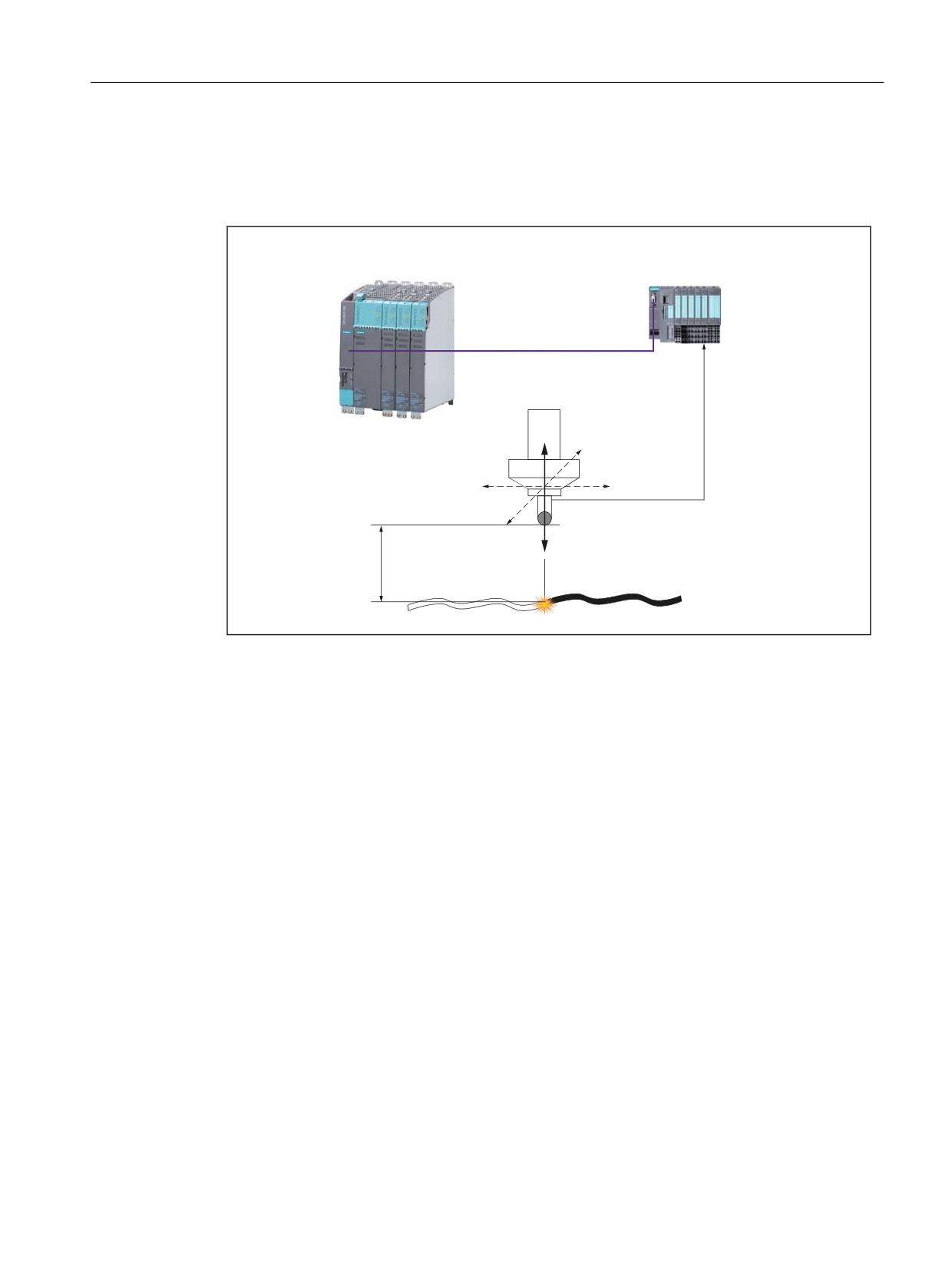
An overview of the system components required for clearance control in conjunction with
SINUMERIK 840D sl is provided in the following diagram.
6,180(5,.b
'bVO ZLWK
6,0$7,& (7
6,2
6,1$0,&6 6
352),%86 '3
1&8
/DVHU
<
0DFKLQLQJ KHDG
;
ZLWK
&OHDUDQFH VHQVRU
=
0RWLRQ D[HV ; DQG <
&OHDUDQFH FRQWURO D[LV =
&OHDUDQFH WR
EH FRQWUROOHG
:RUNSLHFH VXUIDFH
Figure 18-1
System components for clearance control with SINUMERIK 840D sl
1D- / 3D machining
Clearance control can be used for 1D and 3D machining with up to five interpolatory axes.
● 1D machining
For 1D machining, only one axis is affected by the clearance control. For example, axis Z,
as shown in the machine configuration described in the system overview (see previous
diagram). Clearance control acts only in the direction of the Z axis.
● 3D machining
Three linear axes are used to position the tool. One or two rotary axes are used for the
orientation of the tool vector (5-axis machining). Up to three linear axes are controlled by
the clearance control. Compensation motion can be specified in the directions of the
following vectors:
- Tool orientation vector (normal case)
- Any programmable vector (compensation vector)
Special functions
Function Manual, 12/2018, A5E40874099B AB
689
TE1: Clearance control - 840D sl only
18.2 Clearance control
18.2
Clearance control
18.2.1
Control dynamics
Control loop gain KV
The dynamic response of the closed control loop (sensor - open-loop control - axis) is
determined by the maximum closed-loop control gain KV.
The closed-loop control gain KV is defined as:
9HORFLW\ >P PLQ@
>P PLQ@
.9
LQ >
@
)ROORZLQJ HUURU >PP@
>PP@
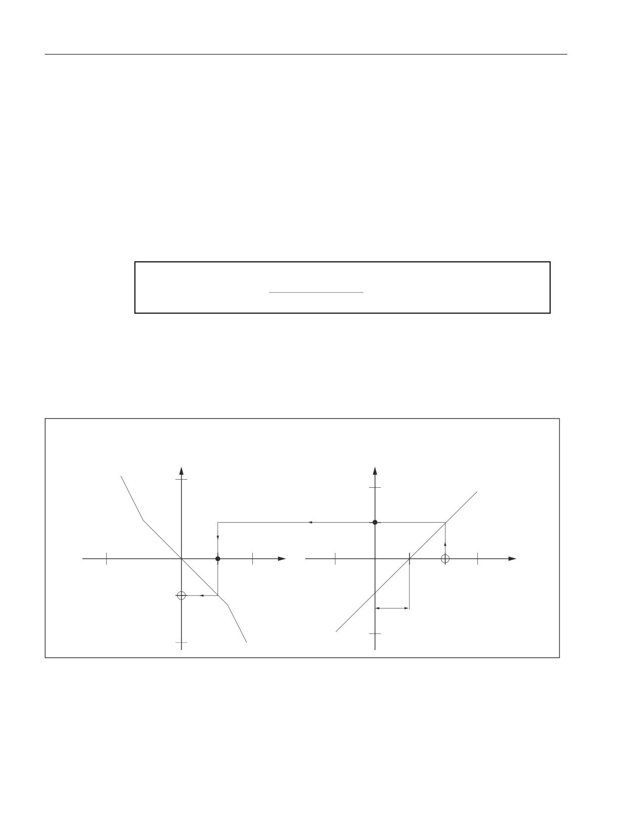
Clearance control characteristics
Clearance control is based on the two characteristics shown in the following diagram:
● Clearance sensor characteristic (sensor property)
● Clearance control characteristic (can be parameterized via machine data)
&OHDUDQFH FRQWURO FKDUDFWHULVWLF
0'
0&B&/&B6(1625B92/7$*(B7$%/(B B
&OHDUDQFH FRQWURO FKDUDFWHULVWLF
0'
0&B&/&B6(1625B9(/2B7$%/(B B
&RPSHQVDWRU\ YHORFLW\ RI
6HQVRU RXWSXW
FOHDUDQFH FRQWUROOHG D[LV
YROWDJH 8>9@
9PD[
D[HV 9>P PLQ@
8PD[
8DFW
8PD[
8PD[
6PD[
6PD[
8DFW
6HQVRU RXWSXW
6HQVRU
$FWXDO
YROWDJH 8>9@
FOHDUDQFH 6
FOHDUDQFH
>PP@
$FWXDO FRPSHQVDWRU\
YHORFLW\ RI FOHDUDQFH FRQWURO
6HWSRLQW GLVWDQFH ZRUNLQJ GLVWDQFH
DGMXVWDEOH RQ WKH FOHDUDQFH VHQVRU
8PD[
9PD[
Figure 18-2
Correlation between characteristics: Clearance sensor and clearance control
● The clearance sensor measures the actual distance from the workpiece surface and returns
as its output variable a voltage in [V], which is almost directly proportional to the distance.
● The clearance control function uses the parameterized voltage/velocity characteristic from
the voltage provided by the clearance sensor to calculate a compensatory velocity for the
clearance-controlled axes that is appropriate for the clearance.
Special functions
690
Function Manual, 12/2018, A5E40874099B AB
TE1: Clearance control - 840D sl only
18.2 Clearance control
From the point of view of the control, the unit for the closed-loop control gain is [(mm/min)/V].
In the same way as the setpoint clearance in standardized in [mm], values can only be
standardized in [(mm/min)/mm] by using the sensor electronics.
Max. closed-loop control gain
The maximum achievable closed-loop control gain is determined by the following delay and
reaction times of the overall system:
1. Reaction time of sensor
2. Delay time of A/D converter
3. Signal processing delay times/deadtimes
4. Reaction time of position controller
5. Reaction times of speed and current controllers
6. Time constants of motor and mechanical components
In practice, only items 3 and 4 are relevant.
The influencing variables together produce an effective time constant. A closed-loop control
gain set too high based on this time constant will induce natural oscillations in the range of
several hertz in the axis/axes to be controlled.
The objective when starting up the clearance control is to minimize important time constants
so that the closed-loop control gain required by the process can be set without inducing natural
oscillation of this type.
Dead time
In order to maximize the dynamics of the control response, clearance control takes place on
the highest priority position controller level of the NC.
SINUMERIK 840D sl with I/O modules and drives connected via PROFIBUS DP produces a
deadtime Tdead of:
Tdead = 2 * position controller cycle + 2 * speed controller cycle + input lead time Ti
Special functions
Function Manual, 12/2018, A5E40874099B AB
691
TE1: Clearance control - 840D sl only
18.2 Clearance control
18.2.2
Velocity feedforward control
Eliminating the delay time
The closed-loop control gain, KV, set for the position controller, corresponds to a delay time
Δt. The display time, Δt, is the time which elapses until the actual position of the axis to be
controlled reaches the set position at a prescribed velocity of v.
With a delay time:
˂W
.9
and a closed-loop control gain
P PLQ
PP
V
>
@
>
@
>
@
KV in seconds:
PP
PP
V
for an assumed
˂W
PV
loop control gain KV = 4
>
@
, the corresponding delay time Δt is:
V
Optimizing the control response
If the control response of the axis is too rigid due to the velocity feedforward control, the control
response can be optimized with the following axis-specific NC machine data:
● MD32410 $MA_AX_JERK_TIME (time constant for the axial jerk filter)
● MD32610 $MA_VELO_FFW_WEIGHT (feedforward control factor for speed)
The speed filters of the SINAMICS S120 drive provide additional damping capabilities:
● Parameter 1414 ff. (time constant, speed setpoint filter 1, 2)
Note
Every damping measure implemented contributes to increasing the overall time constant
of the control loop!
Reference:
The complete description of the velocity feedforward control is described in:
Function Manual Expansion Functions; K3: Compensation, Section "Dynamic feedforward
control (following error compensation)"
Special functions
692
Function Manual, 12/2018, A5E40874099B AB
TE1: Clearance control - 840D sl only
18.2 Clearance control
18.2.3
Control loop structure
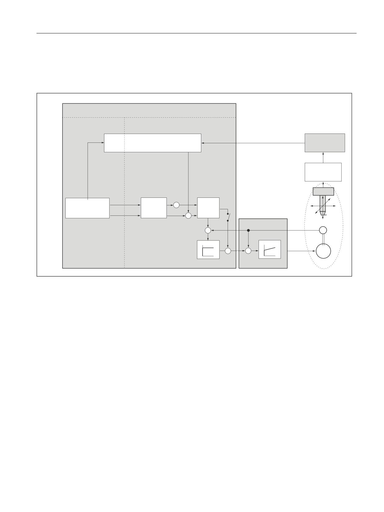
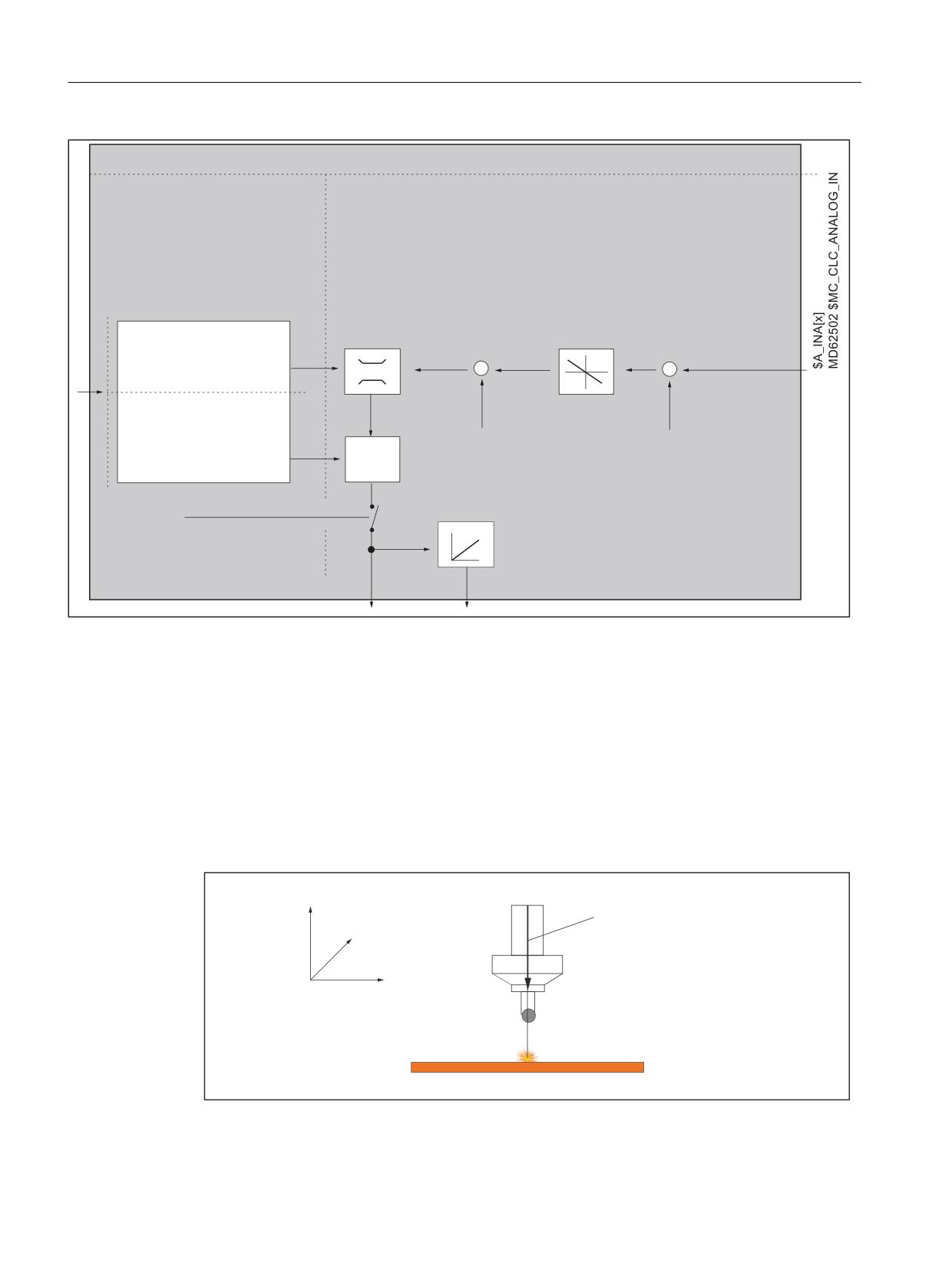
The figures below provide an overview of how the clearance control function is embedded in
the control loop structure of the NC position controller and the internal structure of the function.
6,180(5,.
1&
,QWHUSRODWRU
3RVLWLRQ FRQWUROOHU
1&. , 2V
&OHDUDQFH FRQWURO
$ ' FRQYHUVLRQ
6HQVRU
HOHFWURQLFV
9HORFLW\
3RVLWLRQ
FRPSRQHQW
FRPSRQHQW
/DVHU
9HOR
FLW\ IHHGIRU
<
,QWHUSRODWLRQ
9HORF
LW\ =
)LQH
ZDUG
FRQWURO
0DFKLQLQJ KHDG
-HUN
SDWK DQG
LQWHUSROD
ZLWK FOHDUDQFH
;
ILOWHU
RULHQWDWLRQ
WLRQ
VHQVRU
3RVLWL
RQ =
=
'ULYH =
(QFRGHU =
3
3,
0
0RWRU =
3RVLWLRQ FRQWUROOHU .Y
6SHHG FRQWUROOHU
Figure 18-3
Control structure, position controller with clearance control (principle)
Special functions
Function Manual, 12/2018, A5E40874099B AB
693
TE1: Clearance control - 840D sl only
18.2 Clearance control
&OHDUDQFH FRQWURO
,QWHUSRODWRU
3RVLWLRQ FRQWUROOHU
6HQVRU FKDUDFWHULVWLF
&/&B6(/
0'
[
0&B&/&B6(1625B92/7$*(B7$%/(B\
/LPLWDWLRQV
0'
[
0&B&/&B6(1625B9(/2B7$%/(B\
&/&B/,0
0'
0&B&/&B6(1625B/2:(5B/,0,7>[@
0'
0&B&/&B6(1625B833(5B/,0,7>[@
0'
0&B&/&B6(1625B9(/2B/,0,7
&DOFXODWLRQ RI WKH D[LDO
0'
0&B&/&B6(1625B$&&(/B/,0,7
FRPSRQHQWV EDVHG RQ WKH
FXUUHQW WRRO RULHQWDWLRQ
&DOFXODWLRQ RI WKH FRPSR
QHQWV RI
GLVWDQFH
&/&B*$,1
YHORFLW\
&RPSR
&/&B92))
DFFHOHUDWLRQ UHPDLQLQJ IRU
QHQW
RU
FOHDUDQFH FRQWURO
= D[LV
$B287>Q@
0'
0&B
$B287>Q@ DQG >P@
&/&B2))6(7B
0'
0&B&/&B/2&.B
$66,*1B$1$287
',5B$66,*1B',*287>[@
,
9HORFLW\ FRPSRQHQW
3RVLWLRQ FRPSRQHQW
SURJUDPPHG LQ V\QFKURQL]HG DFWLRQ RU SDUW SURJUDP
Figure 18-4
Control structure, clearance control (principle)
18.2.4
Compensation vector
Standard compensation vector
The compensation vector of the clearance control and the tool orientation vector are normally
identical. Consequently, the compensation movement of the clearance control is normally
always in the direction of the tool orientation.
&RPSHQVDWLRQ YHFWRU
=
<
;
7&3 7RRO &HQWHU 3RLQW
:RUNSLHFH VXUIDFH
% 0DFKLQLQJ SRLQW
Figure 18-5
Clearance control with standard compensation vector
Special functions
694
Function Manual, 12/2018, A5E40874099B AB
TE1: Clearance control - 840D sl only
18.2 Clearance control
Note
In all the figures in this section, the traversing movement of the machining head needed in
order to machine the workpiece is in the direction of the Y coordinate, i.e. perpendicular to the
drawing plane.
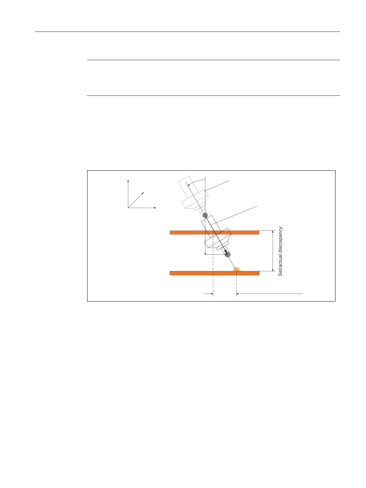
As long as the tool orientation, and hence the compensation vector, is perpendicular to the
workpiece surface, no disadvantage for the machining process results from the compensation
movements of the clearance control.
If a tool setting angle is needed for technological reasons, with the result that the tool orientation
is no longer perpendicular to the workpiece surface, the machining point on the workpiece
surface is shifted during compensation movements of the clearance control along the standard
compensation vector.
7RRO VHWWLQJ DQJOH
=
D
<
&RPSHQVDWLRQ YHFWRU
;
7&3 3URJ
:RUNSLHFH VXUIDFH VHWSRLQW
.=
7&3&/&
.;
:RUNSLHFH VXUIDFH DFWXDO
%
VHWSRLQW
% DFWXDO
0DFKLQLQJ SRLQW
VKLIW
Figure 18-6
Standard compensation vector
The reason for the shift in the machining point is the X component (KX) of the compensation
vector parallel to the workpiece surface. The TCP of the tool, and thus the machining point B,
is shifted by this amount.
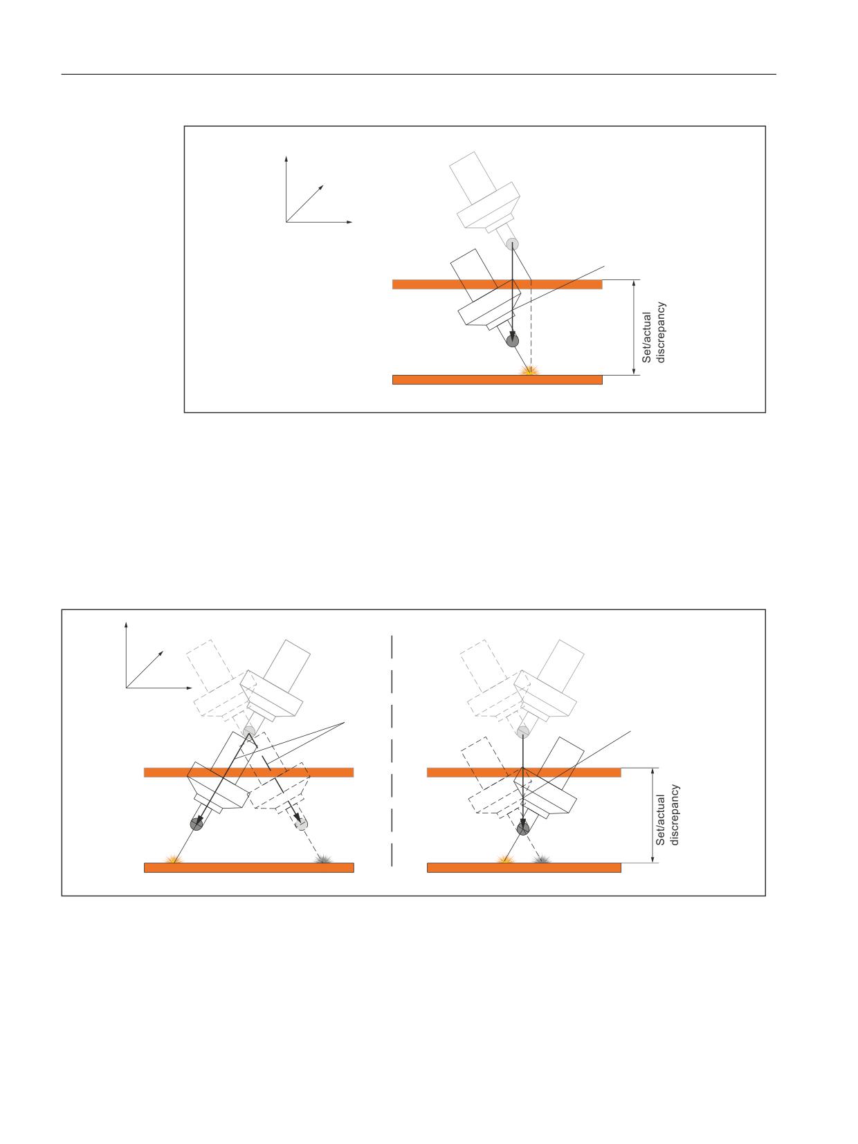
Programmable compensation vector
When using the programmable compensation vector, the compensation movements of the
clearance control are in the direction of the programmed vector, and not in the direction of the
tool orientation.
The X component specified above (KX) is omitted because the programmable compensation
vector is defined perpendicular to the workpiece surface. This does not cause the machining
point (B) to be shifted as a result of the compensation movement of the clearance control.
Special functions
Function Manual, 12/2018, A5E40874099B AB
695
TE1: Clearance control - 840D sl only
18.2 Clearance control
=
<
;
7&33URJ
&RPSHQVDWLRQ YHFWRU
SURJUDPPHG
:RUNSLHFH VXUIDFH VHWSRLQW
7
&3&/&
:RUNSLHFH VXUIDFH DFWXDO
% DFW % VHWS
Figure 18-7
Programmable compensation vector
Changes in orientation
Based on the above observations, a different behavior also results when the orientation of the
machining head is changed while the clearance control is active.
In the following diagram the normal case is shown on the left (compensation vector == tool
orientation vector); and the case with the programmed compensation vector is shown on the
right.
=
<
;
&RPSHQVDWLRQ Y
HFWRU
&RPSHQVDWLRQ YHFWRU
WRRO RULHQWDWLRQ
YHFWRU
SURJUDPPHG
7&33URJ
7&33URJ
7&3&/&
7&3&/&
7&3&/&
Figure 18-8
Change in orientation of the machining head
The meaning of the individual positions of the machining head is as follows:
1. Programmed position of the machining head
2. Actual position of the machining head with clearance control active before the orientation
change
Special functions
696
Function Manual, 12/2018, A5E40874099B AB
TE1: Clearance control - 840D sl only
18.3 Technological features of clearance control
3. Programmed position of the machining head after the change in orientation
4. Actual position of the machining head with clearance control active after the orientation
change
The machining head movement visible on the machine when the change in orientation takes
place is direct from position 2 to position 4.
18.3
Technological features of clearance control
Clearance control is characterized by the following technological features:
● Dynamic Response
The overlaid sensor motion uses the current residual dynamic response that is still in
reserve after the programmed axis motion (velocity and acceleration). The proportion of
residual acceleration that must be used can be set as a percentage in a machine data.
● Sensor characteristic
The gain characteristic of a sensor can be defined with up to 10 interpolation points.
● Sensors
Two sensors with different gain characteristics (e.g. a mechanical and a capacitive sensor)
can be used simultaneously. The active sensor characteristic can be switched over block-
synchronously by means of a language command in the part program.
● Closed-loop control gain of clearance control
The closed-loop control gain configured in the NC machine data for clearance control can
be changed block-synchronously by means of a language command in the part program.
● Motion limitation
The lower and upper limits configured in the NC machine data for the axis movements
induced by clearance control can be changed block-synchronously by means of a language
command in the part program.
An alarm appears when a limit is reached. The alarm response (stop all traversing
movements or display only) can be parameterized. The current position offset can be frozen
by means of a PLC signal.
● Response on deactivation
The deactivation response of the clearance control function can be programmed either for
synchronization with the current axis positions (no compensating movement) or for
compensating axis movements to the last programmed axis positions (axis positions
without clearance control).
● Programmable clearance setpoint
An additional voltage value can be programmed in order to alter the setpoint distance set
in the sensor electronics on a block-related basis.
Special functions
Function Manual, 12/2018, A5E40874099B AB
697
TE1: Clearance control - 840D sl only
18.4 Sensor collision monitoring
● Control options via the PLC interface
The following signals are available at the PLC interface:
Status signals:
- Closed-loop control active
- Overlaying movement at standstill
- Lower limit reached
- Upper limit reached.
Control signals:
- Path override for sensor movement active
● Status data of clearance control
Both the current values and the min/max values of the sensor signal and of the position
offset are available as GUD and/or OPI variables.
● Sensor signal
The sensor signal can be smoothed via a PT1 filter with adjustable time constant.
18.4
Sensor collision monitoring
Sensor signal
If the clearance sensor used has an additional "sensor collision" signal for detecting a collision
between the sensor and the workpiece being machined, this signal can be made available to
the clearance control function via a digital NC peripheral input.
As response to this signal, the clearance control executes retraction motion in all axes with
clearance control. The retraction motion is executed independently of the current value of the
velocity override with maximum traversing velocity in a positive control direction until the
currently valid upper limit of the control range is reached. Path motion is simultaneously
stopped.
After all traversing motion has been stopped, part program machining can be continued with
NC START.
Parameter assignment
The digital peripheral input, which the "sensor collision" signal is wired to, is assigned to the
clearance control function using the following machine data:
MD62504 $MC_CLC_SENSOR_TOUCHED_INPUT (digital peripheral input for "sensor
collision" signal)
The digital peripheral input is specified by entering the input number in the same way as $A_IN/
$A_OUT digital I/O peripheral system variables are specified ($A_IN[input number]).
If a negative input number is entered, the "sensor collision" signal will be processed with
internal inversion by the clearance control function (fail safe method).
Special functions
698
Function Manual, 12/2018, A5E40874099B AB
TE1: Clearance control - 840D sl only
18.5 Startup
18.5
Startup
Compile cycle
Before commissioning the technological function, ensure that the corresponding compile cycle
has been loaded and activated (see Section "TE01: Installation and activation of loadable
compile cycles (Page 673)").
18.5.1
Activating the technological function
The technological function is activated via the machine data:
MD60940 $MN_CC_ACTIVE_IN_CHAN_CLC[0], bit n = 1
n = channel number - 1; bit0 = channel 1, bit1 = channel 2, etc.
Note
The technological function can be activated for several channels simultaneously.
18.5.2
Configuring the memory
The technological function requires additional data in the NC-internal block memory. The
values must be increased for the following memory configuring channel-specific machine data:
● MD28090 $MC_MM_NUM_CC_BLOCK_ELEMENTS += 4 (number of block elements for
compile cycles)
● MD28100 $MN_MM_NUM_CC_BLOCK_USER_MEM += 20 (size of block memory for
compile cycles (DRAM) in KB)
18.5.3
Parameterizing the input signals
The following input signals must be parameterized in the machine data:
● Clearance sensor input voltage
-
1 analog input
● "Sensor collision" input signal (optional)
-
1 digital input
Special functions
Function Manual, 12/2018, A5E40874099B AB
699
TE1: Clearance control - 840D sl only
18.5 Startup
Analog input
The following machine data must be parameterized for the analog input:
● MD10300 $MN_FASTIO_ANA_NUM_INPUTS (number of active analog NC inputs)
● MD10362 $MN_HW_ASSIGN_ANA_FASTIN (per analog module) (hardware assignment
for the fast analog NC inputs)
Specifying the physical address activates the analog input module
Digital input
The following machine data must be parameterized for the digital input:
● MD10350 $MN_FASTIO_DIG_NUM_INPUTS (number of active digital NC input bytes)
● MD10366 $MN_HW_ASSIGN_DIG_FASTIN (per digital module) (hardware assignment for
external digital NC inputs)
Specifying the physical address activates the digital input module.
A complete description of the analog and digital inputs appears in:
References:
Function Manual, Extended Functions, Digital and Analog NC I/O (A4)
18.5.4
Parameters of the programmable compensation vector
Reference coordinate system
The programmable compensation vector specifies the direction in which the compensation
movement of the clearance control takes place. The compensation vector always refers to the
basic coordinate system (machine coordinate system).
The start coordinates [Xa, Ya, Za] of the compensation vector coincide with the origin of the
basic coordinate system and are thus always [0, 0, 0].
The end coordinates [Xe, Ye, Ze] of the compensation vector are determined by the actual
positions of 3 channel axes, known as the direction axes.
Direction axes
The direction axes must meet the following conditions:
1. The direction axes must be channel axes of the channel in which the clearance control is
activated.
2. The direction axes must be linear axes.
Note:
Since the direction axes are only used to interpolate the direction components, they do not
need mechanical axes and can therefore be configured as simulation axes.
3. [mm] or [inch] must be selected as the unit of measurement for the direction axes.
Special functions
700
Function Manual, 12/2018, A5E40874099B AB
TE1: Clearance control - 840D sl only
18.5 Startup
4. The direction axes may not participate in an axis coupling, e.g. transformation, electronic
gear, etc.
5. To ensure that the dynamic response of the path is not limited by the dynamic response of
the direction axes, the following machine data for the direction axes must be set equal to
or more than the corresponding values of the geometry axes of the channel:
- MD32000 $MA_MAX_AX_VELO[x] (maximum axle velocity)
- MD32200 $MA_POSCTRL_GAIN[x] (Kv factor)
- MD32230 $MA_MAX_AX_ACCEL[x] (position controller structure configuration)
x = axle number
The following machine data is used to specify which channel axis is the direction axis:
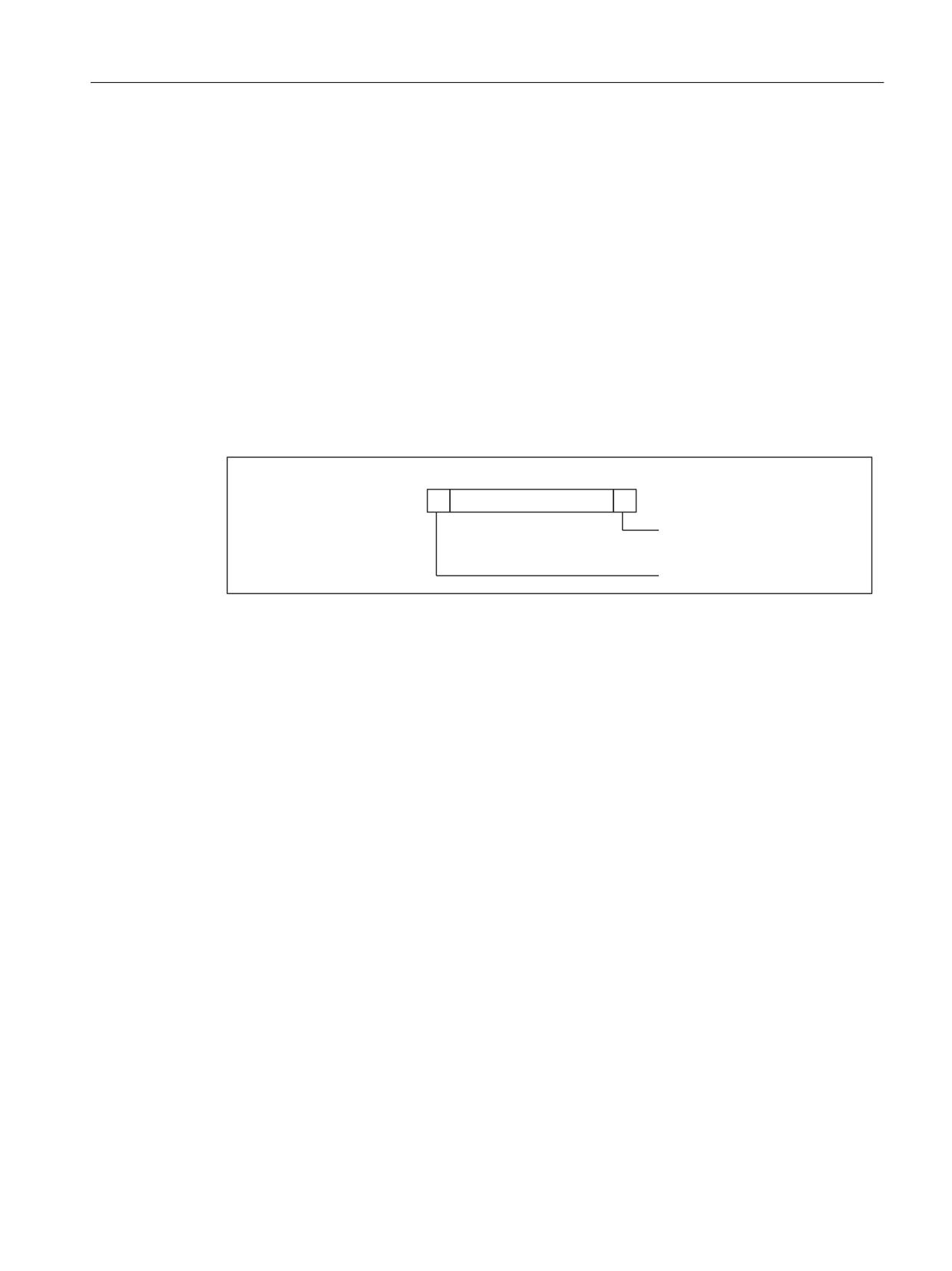
● MD62528 $MC_CLC_PROG_ORI_AX_MASK (progr. orientation vector: axis mask)
Each machine data bit corresponds to a channel axis.
)RUPDW
%LW
%LW
&KDQQHO D[LV
&KDQQHO D[LV
● Coordinate X = channel axis corresponding to bit a
● Coordinate Y = channel axis corresponding to bit b
● Coordinate Z = channel axis corresponding to bit c
with a < b < c
Current difference angle
The difference angle is the angle between the tool orientation vector and the compensation
vector. If the current difference angle of the clearance control is to be output in a system
variable $AC_PARAM[n], index n of the system variable should be entered in the following
machine data:
MD65530 $MC_CLC_PROG_ORI_ANGLE_AC_PARAM ()
Permissible limit angle
The permissible limit angle specifies the maximum difference angle allowed between the tool
orientation vector and the compensation vector. The limit angle is configured via the following
machine data:
MD65520 $MC_CLC_PROG_ORI_MAX_ANGLE ()
Special functions
Function Manual, 12/2018, A5E40874099B AB
701
TE1: Clearance control - 840D sl only
18.5 Startup
18.5.5
Parameter settings for clearance control
The part program name
The following machine data must be parameterized for the declaration of the function-specific
part program name CLC_GAIN and CLC_VOFF:
● MD10712 $MN_NC_USER_CODE_CONF_NAME_TAB[0] = "OMA1" (list of re-configured
NC codes)
● MD10712 $MN_NC_USER_CODE_CONF_NAME_TAB[1] = "CLC_GAIN"
● MD10712 $MN_NC_USER_CODE_CONF_NAME_TAB[2] = "OMA2"
● MD10712 $MN_NC_USER_CODE_CONF_NAME_TAB[3] = "CLC_VOFF"
1D/ 3D clearance control
The following machine data is used to select 1D or 3D clearance control:
● MD62500 $MC_CLC_AXNO = <n> (axis assignment for clearance control)
- <n> > 0: 1D clearance control where <n> = axis number of the clearance-controlled
channel axis
- <n> = -1: 1. 5-axis transformation configured in channel
- <n> = -2: 2. 5-axis transformation configured in channel
Input signals
The clearance sensor input signals parameterized above are made known to the clearance
control function with the following machine data (see also Section "Parameterizing the input
signals (Page 699)"):
● MD62502 $MN_CLC_ANALOG_IN = <n> (analog input for the clearance control)
<n= input number, analog to the addressing of the system variables $A_INA[<n>]
● MD62504 $MN_CLC_SENSOR_TOUCHED_INPUT = <n> (assignment of an input bit for
the "sensor collision" signal)
<n= input number, analog to the addressing of the system variables $A_IN[<n>]
Exact stop
In order to be able to meet a programmed "Exact stop coarse/fine reached" block change
condition (G601/G602), the traversing velocity induced by the clearance control function in the
clearance-controlled axes must be lower than the standstill velocity tolerance at least for the
duration of the standstill delay time.
The following machine data must be modified to optimize the block change time:
● MD36000 $MA_STOP_LIMIT_COARSE[<x>] (exact stop coarse)
● MD36010 $MA_STOP_LIMIT_FINE[<x>] (exact stop fine)
● MD36020 $MA_POSITIONING_TIME[<x>] (delay time exact stop fine)
Special functions
702
Function Manual, 12/2018, A5E40874099B AB

TE1: Clearance control - 840D sl only
18.5 Startup
● MD36040 $MA_STANDSTILL_DELAY_TIME[<x>] (standstill monitoring time delay)
● MD36060 $MA_STANDSTILL_VELO_TOL[<x>] ("axis/ spindle stopped" velocity/speed
threshold)
<x> = axis number of clearance-controlled machine axis
18.5.6
Starting up clearance control
Clearance sensor
The clearance sensor outputs should be connected to the I/O modules that were activated
using the following machine data:
● MD10362 $MN_HW_ASSIGN_ANA_FASTIN (I/O address of the I/O module) (hardware
assignment of fast analog NC inputs)
● MD10366 $MN_HW_ASSIGN_DIG_FASTIN (I/O address of the I/O module) (hardware
assignment of external digital NC inputs)
(See also Section " "Supplementary conditions > I/O modules (Page 722)").
Test control direction
Proceed as follows to test the control direction of the clearance control function:
● Activating the clearance control function using the part program with CLC(1) (see Chapter
"Activating and deactivating clearance control (CLC) (Page 705)")
● Generate an input voltage, e.g. via the following synchronized action:
Program code
N100 $AC_TIMER[1]=2.5
N110 ID = 1 EVERY $AC_TIMER[1] >= 2.5 DO $AC__TIMER[1]=0
N120 ID = 2 WHENEVER $AC_TIMER[1] < 2.0 DO $A_OUTA[6] = 100000.0 *
($AC_TIMER[1] - 1.0)
N130 ID = 3 WHENEVER $AC_TIMER[1] >= 2.0 DO $A_OUTA[6] = 0.0
2XWSXW YROWDJH >9@
7LPH >V@
Figure 18-9
Output voltage for synchronized action
The voltage specification for the analog output $A_OUTA[6] used in the synchronized action
is subtracted from the clearance sensor input voltage by the clearance control function and
therefore has the opposite polarity to the input signal.
Special functions
Function Manual, 12/2018, A5E40874099B AB
703
TE1: Clearance control - 840D sl only
18.5 Startup
Set the following machine data to induce the clearance control function to use analog output
6 ($A_OUTA[6]) as an additional input overlaid on the sensor input:
MD62522 $MN_CLC_OFFSET_ASSIGN_ANAOUT = 6 (hardware assignment of external
digital NC inputs)
Note
Before the clearance control function is activated for the first time, check that the entire working
range enabled for clearance control is collision-free:
● MD62505 $MC_CLC_SENSOR_LOWER_LIMIT (lower clearance control motion limit)
● MD62506 $MC_CLC_SENSOR_UPPER_LIMIT (upper clearance control motion limit)
An incorrect control direction can be corrected using one of the following methods:
● Reversing the polarity of the analog input
● Changing the sign of all values in the following machine data:
- MD62511 $MC_CLC_SENSOR_VELO_TABLE_1 (coordinate velocity of interpolation
points sensor characteristic 1)
- MD62513 $MC_CLC_SENSOR_VELO_TABLE_2 (coordinate velocity of interpolation
points sensor characteristic 2)
Sensor signal
Signal quality
The quality of the analog input signal can be checked using the function-specific display data
(see Chapter "Function-specific display data (Page 718)").
Input voltage range
The input voltage range for the measuring signal of the sensor can be adapted using the
machine data for the weighting factor for the analog NC inputs:
MD10320 $MN_FASTIO_ANA_INPUT_WEIGHT[<analog input>] = <weighting factor>
The following machine data must be set in order that the weighting factor from the clearance
control function is included in the calculation:
MD62508 $MC_CLC_SPECIAL_FEATURE_MASK, Bit 13 = 1
Function-specific alarm texts
To display function-specific alarm texts, these must first be incorporated in the appropriate
HMI data management (see Chapter "Creating alarm texts (Page 679)").
Completion
A data backup is recommended once the start-up procedure has been completed.
References:
Special functions
704
Function Manual, 12/2018, A5E40874099B AB
TE1: Clearance control - 840D sl only
18.6 Programming
Commissioning Manual IBN CNC: NC, PLC, Drive
Note
A data backup is recommended once the start-up procedure has been completed.
18.6
Programming
18.6.1
Activating and deactivating clearance control (CLC)
Syntax
CLC(Mode)
Mode
● Format: Integer
● Value range: -1, 0, 1, 2, 3
CLC(...) is a procedure call and must therefore be programmed in a dedicated part program
block.
Functionality
The following modes are available for activating/ deactivating clearance control:
● CLC(1)
Activation of the clearance control with compensation vector in the direction of the tool
orientation
The evaluation of the sensor collision signal is deactivated.
● CLC(2)
Activation of the clearance control with compensation vector in the direction of the tool
orientation
The evaluation of the sensor collision signal is activated.
● CLC(3)
Activation of the clearance control with programmed compensation vector
The evaluation of the sensor collision signal is deactivated.
Special functions
Function Manual, 12/2018, A5E40874099B AB
705
TE1: Clearance control - 840D sl only
18.6 Programming
● CLC(0)
Deactivation of clearance control without canceling the position offset.
If the clearance-controlled axes are still moving at the instant of deactivation due to the
sensor signal, they are stopped. The workpiece coordinate system (WCS) is then
synchronized with the corresponding standstill positions. An automatic preprocessing stop
is executed.
● CLC(-1)
Deactivation of clearance control with cancellation of the position offset
If the clearance-controlled axes are still moving at the instant of deactivation due to the
sensor signal, they are stopped. A position offset to the last programmed position is
canceled automatically with the deactivation command.
RESET behavior
CLC(0) is executed implicitly on a reset (NC RESET or end of program).
Parameterizable RESET behavior
The reset response of a 1D clearance control function can be determined via the channel-
specific NC OEM machine data:
● MD62524 $MC_CLC_ACTIVE_AFTER_RESET (reset response with active CLC)
CAUTION
Clearance control
The channel-specific NC-OEM machine data MD62524 is only effective in conjunction
with a 1D clearance control function.
For 3D clearance control, CLC(0) is always effective in the event of a RESET.
The following response can be parameterized:
● MD62524 $MC_CLC_ACTIVE_AFTER_RESET = 0
In the event of a reset, the clearance control function responds as it does to deactivation
with CLC(0) (see "Functionality" section).
● MD62524 $MC_CLC_ACTIVE_AFTER_RESET = 1
The current state of the clearance control function is retained.
Boundary conditions
Please note the following supplementary conditions:
Continuous-path mode
Activating/ deactivating clearance control (CLC(mode)) during active continuous-path mode
(G64/G64x) will induce a drop in velocity for path motions. To avoid voltage drops of this type,
clearance control must be activated before a path section with constant path velocity. During
the corresponding path section, if necessary, clearance control can be blocked and then re-
enabled via the programmed gain factor for clearance control (CLC_GAIN).
Special functions
706
Function Manual, 12/2018, A5E40874099B AB
TE1: Clearance control - 840D sl only
18.6 Programming
Block change with exact stop
If exact stop is active at the end of the block (G60/G09 with G601/G602) the block change
may be delayed due to axis movements induced by the clearance control sensor signal.
Sensor collision monitoring
A digital input for an additional collision signal can be configured by the sensor using the
following machine data:
MD62504 $MC_CLC_SENSOR_TOUCHED_INPUT (assignment of the input signal for the
"sensor collision" signal)
This collision monitor can be activated and deactivated block-synchronously through alternate
programming of CLC(1)/CLC(2).
As a reaction to the sensor collision signal, the clearance control moves, irrespective of the
feedrate override setting, at maximum velocity in the plus direction until it reaches the currently
valid upper limit. The path motion is stopped simultaneously.
NC-START can be used to resume processing.
3D clearance control and 5-axis transformation
If 3D clearance control is activated before the 5-axis transformation required for clearance
control in the direction of the tool orientation has been activated, the clearance control function
will be dependent on the active working plane (G17/G18/G19):
● G17: Direction of clearance control = Z
● G18: Direction of clearance control = Y
● G19: Direction of clearance control = X
Activation of 5-axis transformation
When 5-axis transformation is activated, the tool orientation specified by means of the rotary
axis positions must tally with the control direction specified by the active working plane on
activation of clearance control.
If the tool orientation of the 5-axis transformation and the control direction of the clearance
control function do not tally, the following CLC alarm will appear:
● Alarm "75016 Channel number Block number CLC: Orientation changed with TRAFOOF"
Deactivation of 5-axis transformation
If 5-axis transformation is deactivated when clearance control is active, the last control direction
before 5-axis transformation was deactivated is retained.
Tool radius compensation
3D clearance control can only be deactivated if no tool radius compensation is active in the
channel at the time of deactivation (G40). If tool radius compensation is active (G41/G42), the
following alarm appears:
● Alarm "75015 Channel number Block number CLC(0) with active TRC."
Special functions
Function Manual, 12/2018, A5E40874099B AB
707
TE1: Clearance control - 840D sl only
18.6 Programming
Compensation vector
Actual position of the direction axes
If the clearance control is activated with a programmable compensation vector at a position of
0 on all 3 direction axes, a compensation vector cannot be calculated from this information.
The following alarm is then displayed:
● Alarm "75019 Channel number, error ID: 1, angle 0.0"
Referencing of the direction axes
The direction axes must be referenced before clearance control is activated with
programmable compensation vector CLC(3).
Interface signals of the direction axes
The following interface signals must be set for all 3 direction axes by the PLC user program,
before clearance control is activated with programmable compensation vector CLC(3).
● DBX31, … DBX1.5 = 1 (position measuring system 1)
● DBX31, … DBX2.1 = 1 (servo enable)
● DBX31, … DBX21.7 = 1 (pulse enable)
x = axle number
Switchover of clearance control
Direct switchover of clearance control from CLC(1) or CLC(2) to CLC(3) or vice-versa is not
possible. Such switchovers are ignored without a checkback message. If a switchover is
necessary, the clearance control must first be deactivated with CLC(0) or CLC(-1) and then
activated in the desired mode.
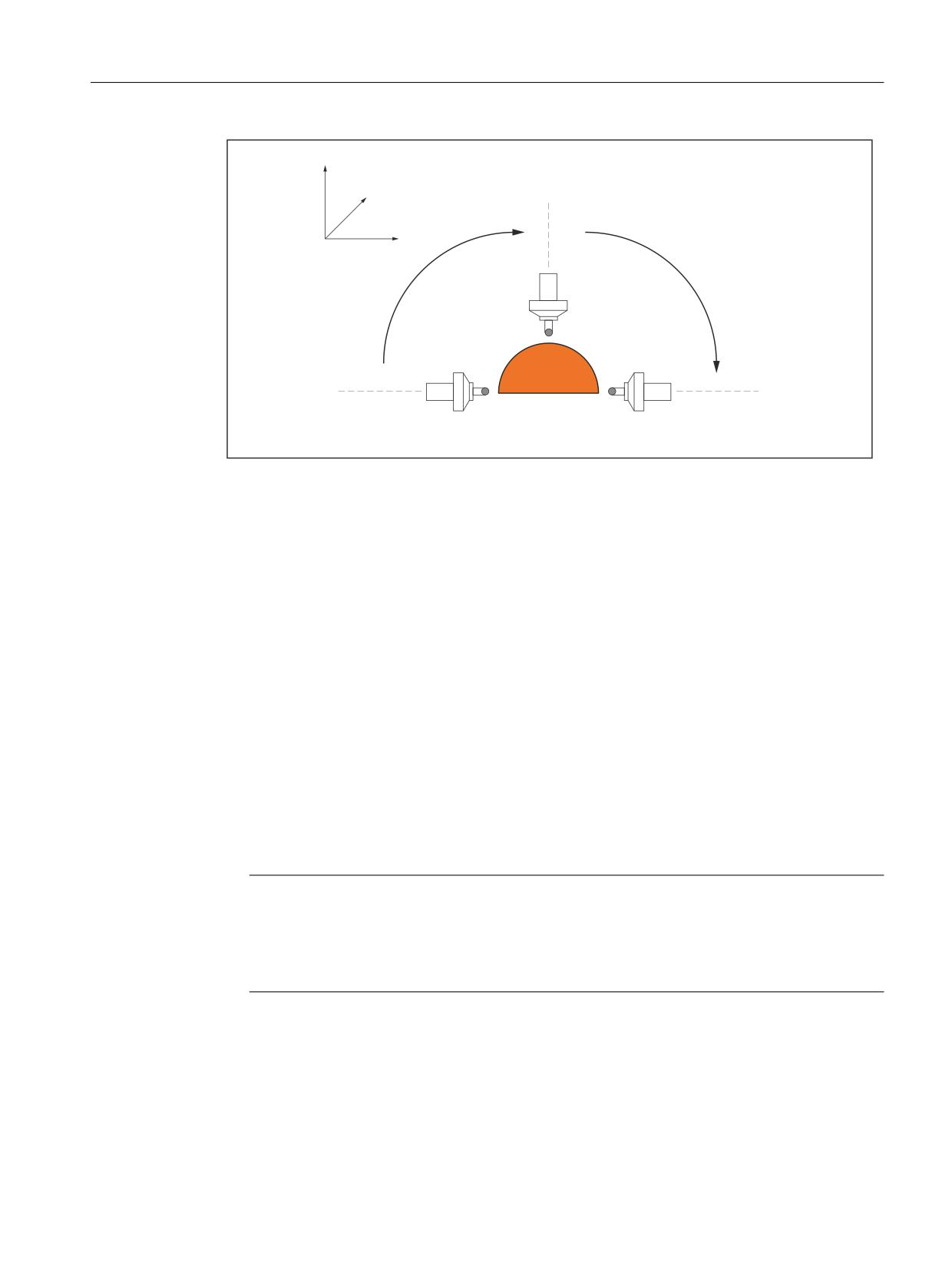
Interpolation of the compensation vector
If the compensation vector is required to follow a non-linear workpiece surface, such as an
arc, with respect to its orientation, this can be achieved by programming the direction axes.
Example
Orientation of the compensation vector perpendicular to a semi-circular workpiece surface.
The programming of the traversing movement is not considered.
Special functions
708
Function Manual, 12/2018, A5E40874099B AB
TE1: Clearance control - 840D sl only
18.6 Programming
=
<
&RPSHQVDWLRQ YHFWRU
>
@
;
1
1
&RPSHQVDWLRQ YHFWRU
>
@
&RPSHQVDWLRQ YHFWRU
>
@
Figure 18-10
Interpolation of the compensation vector
The compensation vector must be oriented by programming the direction axes at [1, 0, 0]
before part program block N100. In part program block N100, the end position of the
compensation vector is oriented by programming the direction axes at [0, 0, -1].
The intermediate values are generated by path interpolation of all axes programmed in the
part program block:
● Geometry axes for the movement of the machining head
● Direction axes of the compensation vector
It is necessary to break the movement down into part program blocks N100 and N200, because
an antiparallel orientation of the compensation vector of [1, 0, 0] at the start of the movement
and [-1, 0, 0] at the end of the movement (semi-circle) would otherwise result. In this case, the
interpolator would interpolate only the X coordinate of the compensation vector, and the
orientation of the compensation vector would remain unchanged.
Antiparallel orientation of the compensation vector
When an antiparallel orientation of the compensation vector is programmed in a part program
block, the following alarm is displayed:
● Alarm "75018 Channel number Block number CLC in programmable direction, error ID: 1"
Note
Interpolation of the compensation vector
The interpolation of the compensation vector is not a genuine vector interpolation, as
described above, but results from the interpolation of the actual positions of the direction
axes.
Consequently, if the compensation vector changes due to the workpiece contour, the
interpolation of the direction axes is included in the path interpolation of the geometry axes. In
order to minimize the impact of the direction axes on the path interpolation, it is recommended
to configure the dynamic response of the direction axes at least equal to or greater (by a factor
of approx. 10) than the dynamic response of the geometry axes.
Special functions
Function Manual, 12/2018, A5E40874099B AB
709
TE1: Clearance control - 840D sl only
18.6 Programming
In the case of a re-orientation (rotation) of the compensation vector, it is also necessary to note
the ratio between the programmed traversing path and the configured dynamic response of
the direction axes. The ratio should be chosen such that the programmed traversing path is
not traversed in one or a small number of interpolation cycles, due to the dynamic response
of the axis. This causes heavy loads on the machine and, in certain circumstances, may trigger
axial alarms and abort part program execution.
Example
Rotation of the compensation vector and thus the machining head through 90°:
● Initial orientation: Parallel to coordinate axis X
● Target orientation: Parallel to coordinate axis Y
Bad programming of re-orientation:
●
[1, 0, 0] → [0, 1, 0]
Good programming of re-orientation:
●
[100, 0, 0] → [0, 100, 0]
Rotation of the workpiece coordinate system
As described above, the compensation vector always refers to the basic coordinate system
(machine coordinate system). If the workpiece coordinate system (rotation, mirroring) is
transformed to machine a workpiece in such a way that the coordinate axes of both coordinate
systems are no longer parallel with the same orientation, a corresponding transformation must
be carried out for the compensation vector.
CAUTION
Unequal orientation
If the workpiece coordinate system is transformed such that the coordinate axes of the basic
and workpiece coordinate systems are no longer parallel with the same orientation, it is the
sole responsibility of the user to ensure that an appropriate transformation of the
compensation vector is carried out.
18.6.2
Closed-loop control gain (CLC_GAIN)
Syntax
CLC_GAIN = Factor
Factor
● Format: Real
● Range of values: y 0.0
CLC_GAIN is an NC address and can therefore be written together with other instructions in
a part program block.
When a negative factor is programmed, the absolute value is used without an alarm output.
Special functions
710
Function Manual, 12/2018, A5E40874099B AB
TE1: Clearance control - 840D sl only
18.6 Programming
Functionality
The current closed-loop control gain for clearance control is produced by the active
characteristic specified via machine data:
● MD62510 $MC_CLC_SENSOR_VOLTAGE_TABLE1 (coordinate voltage of interpolation
points sensor characteristic 1)
● MD62511 $MC_CLC_SENSOR_VELO_TABLE1 (coordinate velocity of interpolation points
sensor characteristic 1)
or
● MD62512 $MC_CLC_SENSOR_VOLTAGE_TABLE2 (coordinate voltage of interpolation
points sensor characteristic 2)
● MD62513 $MC_CLC_SENSOR_VELO_TABLE2 (coordinate velocity of interpolation points
sensor characteristic 2)
CLC_GAIN can be used to multiply the closed-loop control gain of the characteristic by a
programmable factor.
NOTICE
Imprecise characteristic
Increasing the gain (CLC_GAIN > 1.0) may lead to oscillation in the controlled axes!
Instant of activation
The modified closed-loop control gain is effective in the part program block in which CLC_GAIN
has been programmed or, if this block does not contain any executable instructions, in the next
part program block with executable instructions.
Response to characteristic changeover
The programmed factor remains active even when the gain characteristic is changed over with
CLC_SEL, i.e. it is immediately applied to the newly selected characteristic.
Response to CLC_GAIN=0.0
If the closed-loop control gain for clearance control is deactivated with CLC_GAIN=0.0, the
CLC position offset present at the time of deactivation is retained and is not changed. This can
be used for example when laser-cutting sheet steel to "skip over" sections of sheet that are
not to be machined without foundering.
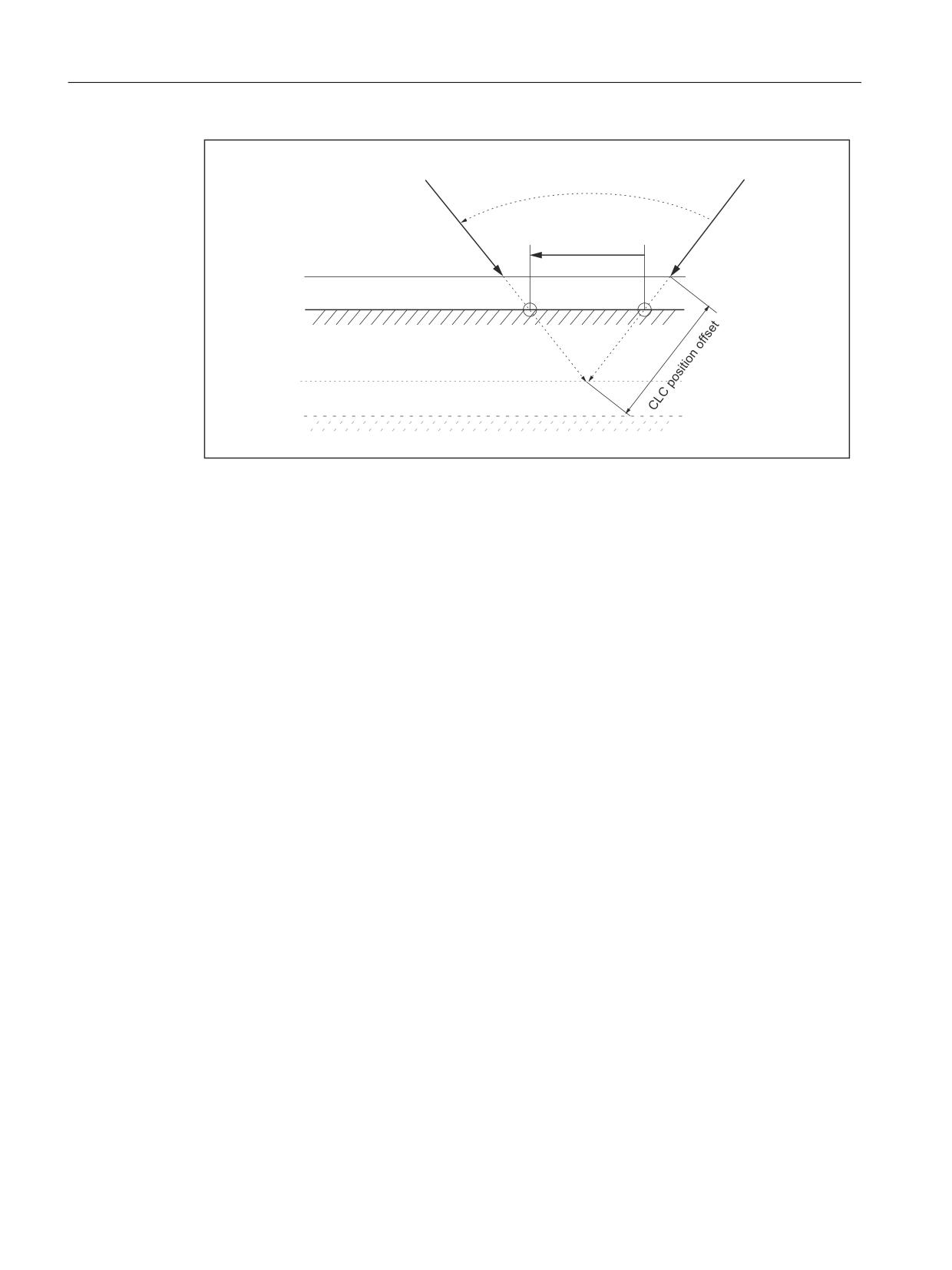
If the tool orientation is changed when 3D clearance control is active and the closed-loop
control gain has been deactivated (CLC_GAIN=0.0), the CLC offset vector is rotated
simultaneously. This generally induces an offset in the CLC operating point on the workpiece
surface (see following diagram).
Special functions
Function Manual, 12/2018, A5E40874099B AB
711
TE1: Clearance control - 840D sl only
18.6 Programming
&/&
&/& RIIVHW
RIIVHW YHFWRU
&KDQJLQJ WKH WRRO RULHQWDWLRQ
YHFWRU
ZKHQ &/&B*$,1
:RUNLQJ SRLQW VKLIW
RQ WKH ZRUNSLHFH VXUIDFH
3DWK ZLWK DFWLYH
FOHDUDQFH FRQWURO
:RUNSLHFH VXUIDFH DFW
3URJUDPPHG SDWK
:RUNSLHFH VXUIDFH VHW
Figure 18-11
Response of the CLC offset vector when CLC_GAIN=0.0
Reset
Within a part program, a modified gain factor must be reset by means of explicitly programming
CLC_GAIN=1.0.
RESET behavior
CLC_GAIN=1.0 becomes effective after a power on reset, NC RESET or end of program.
18.6.3
Limiting the control range (CLC_LIM)
Syntax
CLC_LIM(lower limit, upper limit)
Lower limit, upper limit
Format and value range as machine data:
● MD62505 $MC_CLC_SENSOR_LOWER_LIMIT[n] (lower clearance control motion limit)
● MD62506 $MC_CLC_SENSOR_UPPER_LIMIT[n] (upper clearance control motion limit)
CLC_LIM(...) is a procedure call and must therefore be programmed in a dedicated part
program block.
Special functions
712
Function Manual, 12/2018, A5E40874099B AB
TE1: Clearance control - 840D sl only
18.6 Programming
Functionality
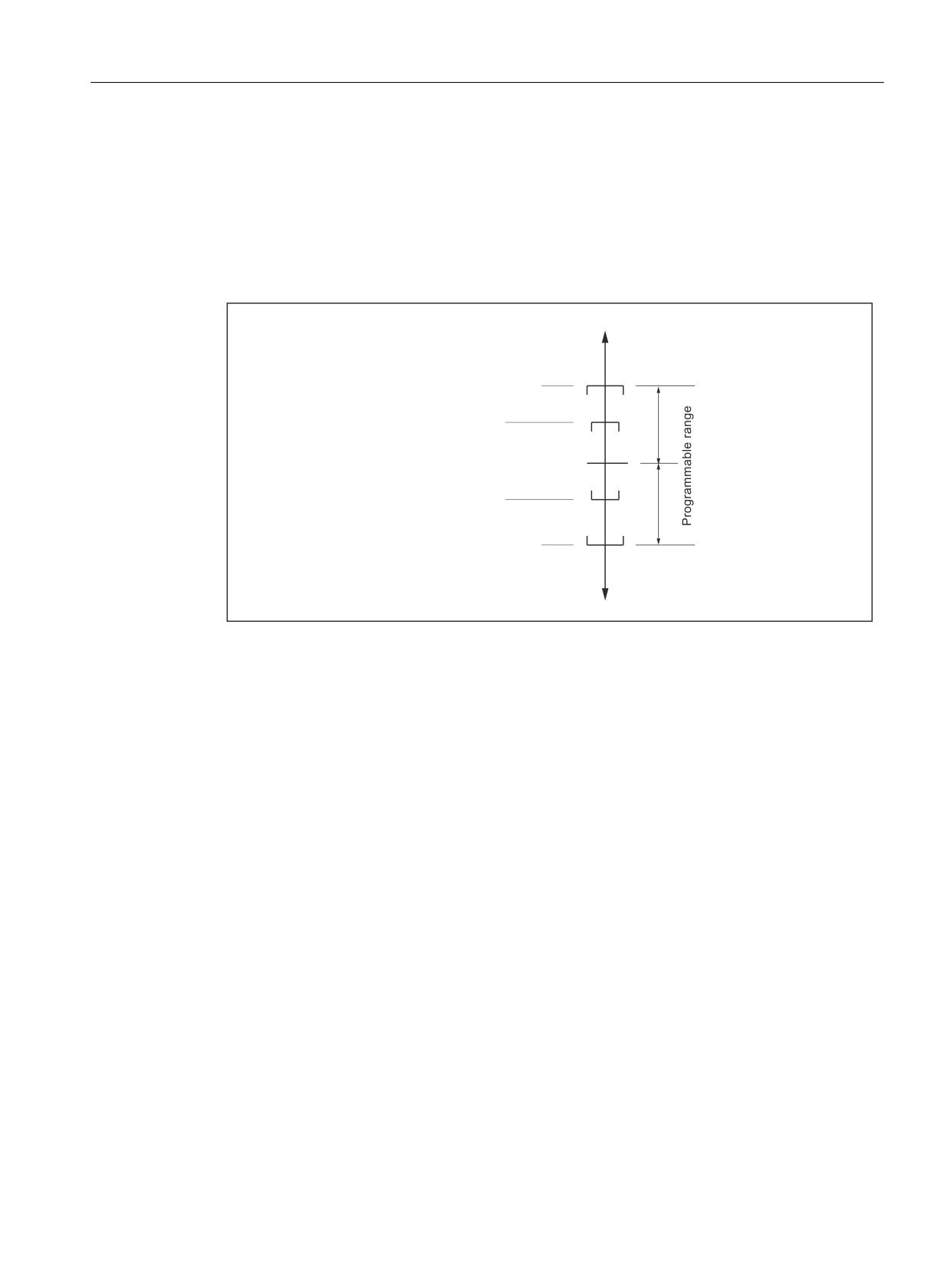
The maximum control range for clearance control can be modified on a block-specific basis
using CLC_LIM. The maximum programmable lower/upper limit is limited by the limit value
preset in the relevant machine data:
● MD62505 $MC_CLC_SENSOR_LOWER_LIMIT[1] (lower clearance control motion limit)
● MD62506 $MC_CLC_SENSOR_UPPER_LIMIT[1] (upper clearance control motion limit)
&RQWURO UDQJH
0'
> @
0D[ SURJUDPPDEOH XSSHU OLPLW
0'
> @
8SSHU EDVLF VHWWLQJ OLPLW
5HIHUHQFH
0'
> @
SRVLWLRQ
/RZHU EDVLF VHWWLQJ OLPLW
0'
> @
0D[ SURJUDPPDEOH ORZHU OLPLW
&RQWURO UDQJH
Figure 18-12
Value range limits for lower and upper limit
The control range limit is effective in relation to the current programmed setpoint position of
the axis. If the limits are changed so that the actual position is located outside the limit, the
clearance control automatically effects travel back to the limit range.
Reset
Within a part program, a modified control range limit can be reset by explicitly programming
CLC_LIM without a "CLC_LIM( )" argument. This reapplies the limits from the following
machine data:
● MD62505 $MC_CLC_SENSOR_LOWER_LIMIT[0] (lower clearance control motion limit)
● MD62506 $MC_CLC_SENSOR_UPPER_LIMIT[0] (upper clearance control motion limit)
RESET response
The default setting from the above-mentioned machine data becomes effective after power on
reset, NC RESET and end of program.
Special functions
Function Manual, 12/2018, A5E40874099B AB
713
TE1: Clearance control - 840D sl only
18.6 Programming
Error messages
The following programming errors are displayed with an alarm:
● Programming more than 2 arguments
- CLC alarm "75005 Channel number Block number CLC_LIM: general programming
error"
● Programming arguments outside the permissible limits
- CLC alarm "750010 Channel number Block number CLC_LIM Value greater than MD
limit"
18.6.4
Direction-dependent traversing motion disable
Syntax
$A_OUT[number] = enabling signal
Number
Number of the parameterized digital output (see "Parameter Assignment" section)
● Format: Integer
● Range of values: 1, 2, . . . max. number of digital outputs
Enabling signal
Invertable enable signal (see "Parameter Assignment" section)
● Format: Integer
● Range of values: 0, 1
System variable $A_OUT[n] can be set block-synchronously in the part program or
asynchronously via synchronized actions.
Functionality
Parameterizable digital outputs (system variable $A_OUT) can be used for direction-
dependent disabling of the traversing motion (manipulated variable) induced via clearance
control. As long as e.g. the negative traversing direction is disabled, the clearance-controlled
axes will only travel in a positive direction due to the sensor signal.
This can be used for example when laser-cutting sheet steel to "skip over" sections of sheet
that are not to be machined without foundering.
Special functions
714
Function Manual, 12/2018, A5E40874099B AB
TE1: Clearance control - 840D sl only
18.6 Programming
Parameterization
The following machine data is used to parameterize the digital outputs:
● MD62523 $MC_CLC_LOCK_DIR_ASSIGN_DIGOUT[n] (assignment of the digital outputs
for disabling the CLC movement)
n = 0 → Digital output for disabling the negative traversing direction
n = 1 → Digital output for disabling the positive traversing direction
Example
The following digital outputs are to be used:
● $A_OUT[3] to disable the negative traversing direction
● $A_OUT[4] to disable the positive traversing direction
Parameter settings in the machine data:
● MD62523 $MC_CLC_LOCK_DIR_ASSIGN_DIGOUT[0] = 3 (assignment of the digital
outputs for disabling the CLC movement)
● MD62523 $MC_CLC_LOCK_DIR_ASSIGN_DIGOUT[1] = 4
Effect:
● $A_OUT[3] = 0 → Negative traversing direction enabled
● $A_OUT[3] = 1 → Negative traversing direction disabled
● $A_OUT[4] = 0 → Positive traversing direction enabled
● $A_OUT[4] = 1 → Positive traversing direction disabled
Inversion of the evaluation
Enter the negative number of the digital output to evaluate the digital output signal with
inversion:
Parameter settings in the machine data:
● MD62523 $MC_CLC_LOCK_DIR_ASSIGN_DIGOUT[0] = -3 (assignment of the digital
outputs for disabling the CLC movement)
● MD62523 $MC_CLC_LOCK_DIR_ASSIGN_DIGOUT[1] = -4
Effect:
● $A_OUT[3] = 0 → Negative traversing direction disabled
● $A_OUT[3] = 1 → Negative traversing direction enabled
● $A_OUT[4] = 0 → Positive traversing direction disabled
● $A_OUT[4] = 1 → Positive traversing direction enabled
Special functions
Function Manual, 12/2018, A5E40874099B AB
715
TE1: Clearance control - 840D sl only
18.6 Programming
18.6.5
Voltage offset, can be set on a block-specific basis (CLC_VOFF)
Syntax
CLC_VOFF = Voltage offset
Voltage offset
● Format: Real
● Unit: Volts
● Range of values: No restrictions
CLC_VOFF is an NC address and can therefore be written together with other instructions in
a part program block.
Functionality
CLC_VOFF can be used to preset a constant voltage offset for clearance control, which is
subtracted from the input voltage of the clearance sensor. The programmed voltage offset
therefore changes the setpoint distance between the workpiece and the clearance sensor or
offsets the operating point for clearance control.
The quantitative effect of the voltage offset is dependent on the additional parameters for
clearance control and can therefore not be standardized in a generally valid format.
Instant of activation
The voltage offset is effective in the part program block in which CLC_VOFF has been
programmed or, if this block does not contain any executable instructions, in the next part
program block with executable instructions.
Reset
Within a part program, a voltage offset must be reset by means of explicitly programming
CLC_VOFF=0.0.
RESET response
CLC_VOFF =0.0 becomes effective after a power on reset, NC RESET or end of program.
18.6.6
Voltage offset definable by synchronized action
Syntax
$A_OUTA[number] = Voltage offset
Number
Special functions
716
Function Manual, 12/2018, A5E40874099B AB
TE1: Clearance control - 840D sl only
18.6 Programming
Number of the parameterized analog output (see "Parameter Assignment" section)
● Format: Integer
● Range of values: 1, 2, . . .max. number of analog outputs
Voltage offset
Just like the voltage offset for CLC_VOFF (see Section "Voltage offset, can be set on a block-
specific basis (CLC_VOFF) (Page 716)").
Functionality
A parameterizable output (system variable $A_OUTA) can be used to apply a voltage offset
for clearance control, which, like CLC_OFF, is subtracted from the input voltage of the
clearance sensor.
The voltage offset can be modified in the interpolator clock cycle by programming the analog
output within a synchronized action.
Parameterization
The following machine data is used to parameterize the analog output:
MD62522 $MC_CLC_OFFSET_ASSIGN_ANAOUT (modification of the setpoint distance by
means of sensor signal override)
Example
An external voltage Uext is present at analog input $A_INA[3], which is to be overlaid on the
sensor voltage as a continuously variable voltage offset e.g. for test or start-up purposes.
$A_OUTA[2] is used as an analog output for the clearance control voltage offset.
Parameter setting for the analog output for clearance control voltage offset:
MD62522 $MC_CLC_OFFSET_ASSIGN_ANAOUT = 2 (modification of the setpoint distance
by means of sensor signal override)
The analog input $A_INA[3] is assigned to the clearance control analog output $A_OUTA[2]
within a synchronized action:
ID=1 DO $A_OUTA[2] = $A_INA[3]
18.6.7
Selection of the active sensor characteristic (CLC_SEL)
Syntax
CLC_SEL(characteristic number)
Characteristic number
● Format: Integer
● Range of values: 1, 2
Special functions
Function Manual, 12/2018, A5E40874099B AB
717
TE1: Clearance control - 840D sl only
18.7 Function-specific display data
CLC_SEL(...) is a procedure call and must therefore be programmed in a dedicated part
program block.
Characteristic number = 2 selects characteristic 2. Any other value selects characteristic 1
without alarm.
Functionality
CLC_SEL can be used to switch between the sensor characteristics defined in the machine
data.
● Characteristic 1:
- MD62510 $MC_CLC_SENSOR_VOLTAGE_TABLE_1 (coordinate voltage of
interpolation points sensor characteristic 1)
- MD62511 $MC_CLC_SENSOR_VELO_TABLE_1 (coordinate velocity of interpolation
points sensor characteristic 1)
● Characteristic 2:
- MD62512 $MC_CLC_SENSOR_VOLTAGE_TABLE_2 (coordinate voltage of
interpolation points sensor characteristic 2)
- MD62513 $MC_CLC_SENSOR_VELO_TABLE_2 (coordinate velocity of interpolation
points sensor characteristic 2)
RESET response
Characteristic 1 becomes effective after a power on reset, NC RESET or end of program.
18.7
Function-specific display data
The "clearance control" technological function provides specific display data for supporting
start-up and for service purposes.
Possible applications
Application options for display data include for example:
● Determination of form variances and transient control errors via the variables for the
maximum and minimum position offset/sensor voltage.
● Determination of the voltage noise detected by the A/D converter via the variables for the
maximum and minimum sensor input voltage. This requires a constant clearance between
the clearance sensor and the workpiece surface and the deactivation of clearance control
via CLC_GAIN = 0.0.
The minimum and maximum values are detected in the position controller cycle.
Special functions
718
Function Manual, 12/2018, A5E40874099B AB

TE1: Clearance control - 840D sl only
18.7 Function-specific display data
Types of variable
The display data is available both as channel-specific GUD (Global User Data) variables and
as OPI variables.
18.7.1
Channel-specific GUD variables
The "clearance control" technological function provides the following channel-specific GUD
variables for HMI applications:
● SINUMERIK HMI Advanced
● SINUMERIK Operate
Table 18-1
Channel-specific GUD variables
GUD variables
Description
Unit
Access
CLC_DISTANCE[0]
Current position offset
mm
read only
CLC_DISTANCE[1]
Absolute minimum of position off-
mm
read/write
set
CLC_DISTANCE[2]
Absolute maximum of position off-
mm
read/write
set
CLC_VOLTAGE[0]
Current sensor input voltage
V
read only
CLC_VOLTAGE[1]
Absolute minimum of sensor input
V
read/write
voltage
CLC_VOLTAGE[2]
Absolute maximum of sensor input
V
read/write
voltage
Once the technological function has been started up successfully, the GUD variables listed
are not displayed automatically on the HMI interface.
SINUMERIK HMI Advanced
Proceed as follows to create and display the GUD variables in HMI Advanced.
1. Setting the password
Enter the password for protection level 1: (machine manufacturer).
2. Activate the "definitions" display.
Operating area switchover > Services > Data Selection
3. If no SGUD.DEF file is yet available:
Operating area switchover > Services > Data admin > New...
● Name: SGUD
● Type: Global data/system
Confirm with OK.
This opens the file in the editor.
Special functions
Function Manual, 12/2018, A5E40874099B AB
719
TE1: Clearance control - 840D sl only
18.7 Function-specific display data
1. Edit the GUD variable definitions
DEF CHAN REAL CLC_DISTANCE[3] ; Array of real, 3 elements
DEF CHAN REAL CLC_VOLTAGE[3] ; Array of real, 3 elements
M30
2. Save the file and close the editor.
3. Activate the SGUD.DEF file.
The GUD variables for clearance control are now displayed under:
Operating area switchover > Parameters > User data > Channel user data
SINUMERIK Operate
Proceed as follows to create and display the GUD variables for SINUMERIK Operate.
1. Setting the password
Enter the password for protection level 1: (machine manufacturer).
2. If no SGUD.DEF file is yet available:
Operating area switchover > Commissioning > System data > Open NC data directory: Set
cursor to definitions > New...
● Name: SGUD
● Type: DEF
Confirm with OK.
This opens the file in the editor.
1. Edit the GUD variable definitions
DEF CHAN REAL CLC_DISTANCE[3] ; Array of real, 3 elements
DEF CHAN REAL CLC_VOLTAGE[3] ; Array of real, 3 elements
M30
2. Save the file and close the editor.
3. Activate the SGUD.DEF file.
The GUD variables for clearance control are now displayed under:
Operating area switchover > Parameters > User variables > GUD channel
SINUMERIK NC
The newly created GUD variables, which are already being displayed, will only be detected by
the clearance control function and supplied with up-to-date values following an NC POWER
ON RESET.
Note
Once the GUD variables have been created, an NC POWER ON RESET must be carried out
in order for the clearance control function to update the GUD variables.
Special functions
720
Function Manual, 12/2018, A5E40874099B AB

TE1: Clearance control - 840D sl only
18.7 Function-specific display data
18.7.2
OPI variable
The technology function "Clearance control" provides the following channel-specific OPI
variables as display data for the HMI application:
OPI variable
Description
Unit
Access
CLC[0]
Current position offset
mm
read only
CLC[1]
Absolute minimum of position offset
mm
read/write
CLC[2]
Absolute maximum of position offset
mm
read/write
CLC[3]
Current sensor input voltage
V
read only
CLC[4]
Absolute minimum of sensor input
V
read/write
voltage
CLC[5]
Absolute maximum of sensor input
V
read/write
voltage
CLC[6]
1st component of the normalized
-
read only
tool orientation vector
CLC[7]
2nd component of the normalized
-
read only
tool orientation vector
CLC[8]
3rd component of the normalized
-
read only
tool orientation vector
OPI variables still have to be registered or defined in the system in order that they can be
accessed.
Defining OPI variables
The following operator actions must be carried out to define OPI variables.
1. Create the CLC-specific definition file: CLC.NSK
Note:
We recommend that you create the file in the \OEM directory rather than in the \MMC2
directory so that it is not overwritten when a new software version is installed.
2. Define the CLC-specific OPI variables.
Add the following line to the CLC.NSK file:
LINK("CLC" ,200,"2 1 1 1 1F# /NC 5 0 1",100)
3. Create/expand the user-specific definition file: USER.NSK
(See item 1: Note)
4. The call of the CLC-specific definition file CLC.NSK must be added to the USER.NSK
definition file. To do this, insert the following line:
CALL(CLC.NSK)
Using LinkItem
In order to use the OPI variables in a DDE control, the "LinkItem" property of the DDE control
must be set in accordance with the following example:
label1.LinkItem = "CLC[u1,1,9](" "!d%15.4lf" ")"
The format string can be modified if necessary.
Special functions
Function Manual, 12/2018, A5E40874099B AB
721
TE1: Clearance control - 840D sl only
18.9 Supplementary conditions
The following code lines provide an example of how the variables supplied by means of NCDDE
access can be distributed on a field of labels:
FOR i = 0 To 8
label2.Caption[i] = Trim$(Mid$(label1.Caption, 1+15*i, 15))
NEXT
18.8
Function-specific alarm texts
For details of the procedure for creating function-specific alarm texts, see Section "Creating
alarm texts (Page 679)".
18.9
Supplementary conditions
18.9.1
I/O modules
The analog output voltage of the distance sensor for the A/D conversion must be connected
to the NC using an I/O module with an analog input.
Connection options
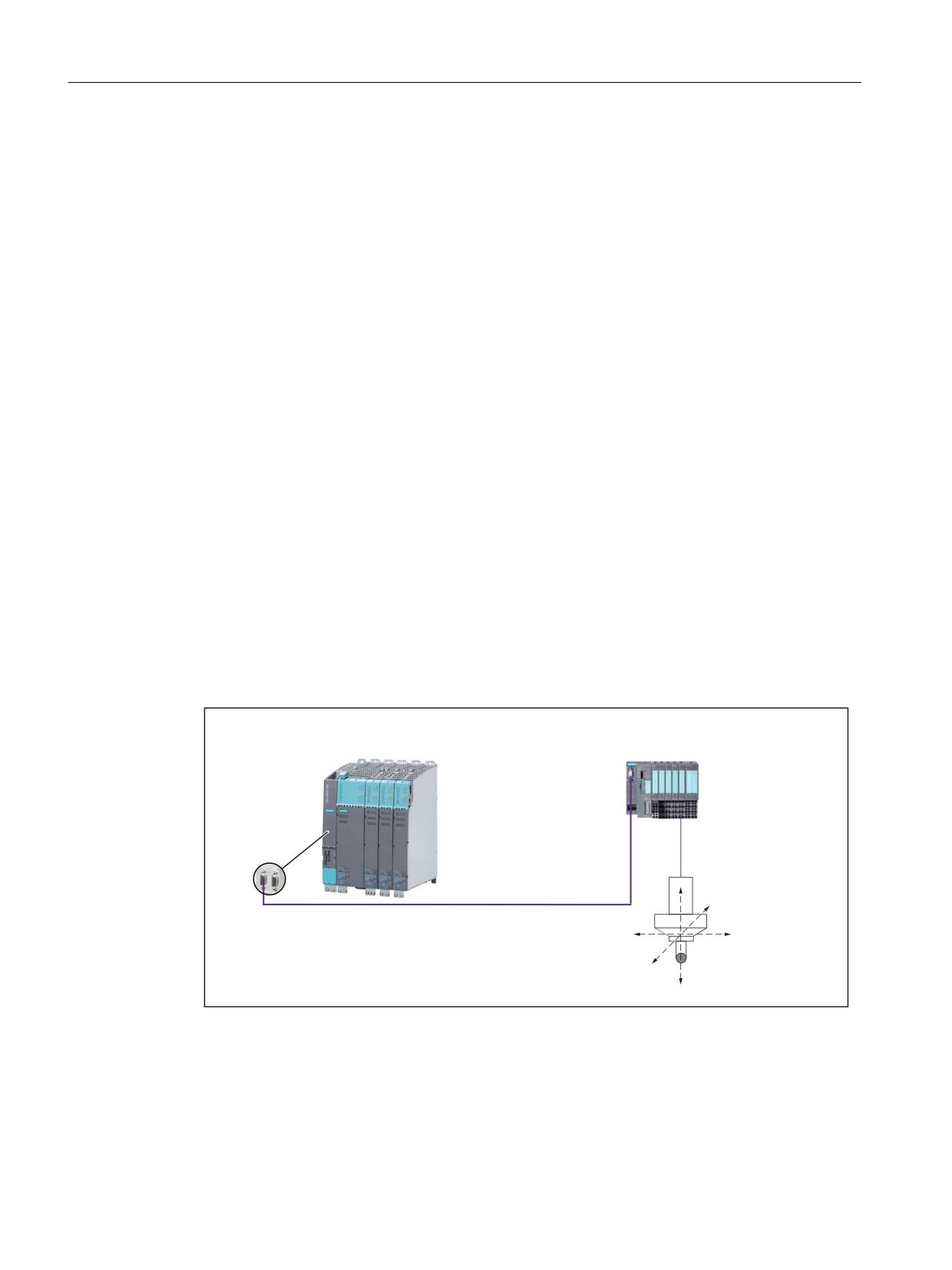
The SIMATIC ET 200S I/O for SINUMERIK 840D sl is connected via PROFIBUS DP. The
clearance sensor is connected via an analog S7 I/O module.
6,180(5,.b
'bVO ZLWK
6,0$7,& (7
6,2
6,0$7,& 6
1&8
&OHDUDQFH VHQVRU
2XWSXW YROWDJH
352),%86 '3
Figure 18-13
I/O modules connection for SINUMERIK 840D sl
Suitable I/O modules
As the A/D conversion time directly affects the deadtime of the clearance control servo loop,
only one I/O module may be used with low conversion time.
Special functions
722
Function Manual, 12/2018, A5E40874099B AB
TE1: Clearance control - 840D sl only
18.9 Supplementary conditions
Suitable SIMATIC S7 I/O modules for the clearance control are:
● Analog I/O module 2 AI, U, high-speed for ET 200S
● Analog I/O module 2 AO, U, high-speed for ET 200S
I/O module connection
The SIMATIC I/O devices of the Production Series ET200, e.g. ET200M, are brought into the
S7 project as usual, and configured.
Note
To check whether a module selected from the hardware catalog complies with the module in
the automation system, the following procedure is recommended:
1. Note the article numbers of all modules used in the automation system.
2. Select the corresponding module in the hardware catalog and compare the article number
of the module used in the automation system with the article number that is displayed in
the hardware catalog. Both article numbers must match one another.
18.9.1.1
External smoothing filters
If an external filter is to be interconnected to smooth the output voltage of the clearance sensor
before the A/D conversion of the output voltage by the I/O module, please ensure that the
resulting time constant is small in relation to the NC position controller cycle.
Note
It is better for the control if electromagnetic shielding is used to ensure a large signal-noise
ratio than if smoothing filters are used in the signal path.
18.9.2
Function-specific supplementary conditions
Complete NC Stop
If in conjunction with an NC Stop, not only the programmed path motion but also the traversing
movement of the clearance-controlled axes should be stopped, the following NC/PLC interface
signals must be set:
● DB21, ... DBX7.3 = 1 (NC Stop)
● DB21, ... DBX7.4 = 1 (NC stop axes and spindles)
Followup
If a clearance-controlled axis is to be switched as an alarm response or via the corresponding
interface signal from the NC/PLC in "follow-up" mode, setpoint output will cease for clearance
control on this axis.
Special functions
Function Manual, 12/2018, A5E40874099B AB
723
TE1: Clearance control - 840D sl only
18.9 Supplementary conditions
Travel without software limit switches
If the clearance-controlled axes are to travel without referencing (travel without software limit
switches), values outside the used traversing range must still be parameterized for the axis-
specific software limit switches:
● MD36100 $MA_POS_LIMIT_MINUS (1st software limit switch minus)
● MD36110 $MA_POS_LIMIT_PLUS (1st software limit switch plus)
● MD36120 $MA_POS_LIMIT_MINUS2 (2nd software limit switch minus)
● MD36130 $MA_POS_LIMIT_PLUS2 (2nd software limit switch plus)
Clearance control takes the machine data into account even if an axis has not been referenced.
Disabling digital/ analog inputs
Neither the analog input for the input voltage of the clearance sensor nor the digital input used
by the clearance control in the context of the "Lift fast with position controller cycle" special
function can be controlled (disabled) via the PLC:
DB10, DBB0 (inhibit digital NC inputs)
DB10, DBB146 (inhibit analog NC inputs)
See also the description of machine data:
● MD62508 $MC_CLC_SPECIAL_FEATURE_MASK, bit 4 and 5 (Special functions and
operating modes of the clearance control)
Gantry axes: Only leading axes
Only one of the clearance-controlled axes may be configured as the master axis of a gantry
grouping:
MD37100 $MA_GANTRY_AXIS_TYPE (gantry axis definition)
The use of following axes in a gantry grouping is not permitted.
Displaying the axis position
The actual current axis position of a clearance-controlled axis as the sum of an interpolatory
axis position and the current position offset of clearance control is not displayed in the main
machine screen:
● SINUMERIK HMI Advanced:
The actual current axis position is displayed in the Service screen: Operating area
switchover > Diagnosis > Service displays > Axis/spindle displayed as the "actual position
value".
● SINUMERIK Operate:
The actual current axis position is displayed in the Service screen: Operating area
switchover > Diagnosis > Axis dialog > Service axis > displayed as the "measuring system
1 and 2 actual position value".
Special functions
724
Function Manual, 12/2018, A5E40874099B AB
TE1: Clearance control - 840D sl only
18.9 Supplementary conditions
No virtual axes
Clearance-controlled axes must not be parameterized as virtual axes:
MD30132 $MA_IS_VIRTUAL_AX[<axis>] (axis is virtual axis)
Computing time requirements
The additional computing time required for the "clearance control" technological function must
be taken into account on control systems in which the cycle times set for the interpolator and
position controller cycle have been substantially optimized in comparison with the default
setting:
The additional required computing time results after the activation of the clearance control in
the CLC( ... ) part program. If the interpolation or position controller cycle is exceeded,
the following alarm appears:
● Interrupt: "4240 Computing time overflow at IPO or position controller level, IP point in part
program"
Execution of the part program is aborted.
1D clearance control function
Alarm "1016: System error, ID550010" can occur in the following situation:
● The clearance-controlled axis (e.g. Z axis) is parameterized as geometry axis
● Within any command sequence in which STOPRE is initiated implicitly or explicitly, the
clearance control with CLC(0) is switched off
This is the reason that it is recommended to parameterize the clearance-controlled axis of a
1D clearance control (e.g. Z axis) so that it is no longer the geometry axis of the channel.
Parameter assignment: Machine data
● MD20050 $MC_AXCONF_GEOAX_ASSIGN_TAB[<Z axis>] = 0
● MD20060 $MC_AXCONF_GEOAX_NAME_TAB[<Z axis>] = "NO_Z_AXIS"
Programming: Rotations around the Z axis
As the Z axis is no longer a geometry axis after reparameterization, for rotation around the Z
axis, instead of the predefined function CROT() the predefined procedureCRPL() must be
used:
CROT(Z,<angle>) → CRPL(1,<angle>)
Special functions
Function Manual, 12/2018, A5E40874099B AB
725

TE1: Clearance control - 840D sl only
18.10 Data lists
18.10
Data lists
18.10.1
Machine data
18.10.1.1
NC-specific machine data
Number
Identifier: $MN_
Description
10300
FASTIO_ANA_NUM_INPUTS
Number of active analog NC inputs
10350
FASTIO_DIG_NUM_INPUTS
Number of active digital NC input bytes
10362
HW_ASSIGN_ANA_FASTIN
Hardware assignment of external analog NC inputs
0...7
10712
NC_USER_CODE_CONF_NAME_TAB
List of renamed NC identifiers
18.10.1.2
Channelspecific machine data
Number
Identifier: $MC_
Description
28090
MM_NUM_CC_BLOCK_ELEMENTS
Number of compile cycle block elements (DRAM)
28100
MM_NUM_CC_BLOCK_USER_MEM
Memory for compile cycle block elements (DRAM) in
kB
28254
MM_NUM_AC_PARAM
Number of parameters for synchronized actions
Clearance control
62500
CLC_AXNO
Axis assignment for clearance control
62502
CLC_ANALOG_IN
Analog input for clearance control function
62504
CLC_SENSOR_TOUCHED_INPUT
Input bit assignment for the "sensor collision" signal
62505
CLC_SENSOR_LOWER_LIMIT
Lower motion limit of clearance control
62506
CLC_SENSOR_UPPER_LIMIT
Upper motion limit of clearance control
62508
CLC_SPECIAL_FEATURE_MASK
Special functions and operating modes of the clear-
ance control
62510
CLC_SENSOR_VOLTABE_TABLE_1
Coordinate voltage of interpolation points sensor char-
acteristic 1
62511
CLC_SENSOR_VELO_TABLE_1
Coordinate velocity of interpolation points sensor char-
acteristic 1
62512
CLC_SENSOR_VOLTAGE_TABLE_2
Coordinate voltage of interpolation points sensor char-
acteristic 2
62513
CLC_SENSOR_VELO_TABLE_2
Coordinate velocity of interpolation points sensor char-
acteristic 2
62516
CLC_SENSOR_VELO_LIMIT
Clearance control movement velocity
62516
CLC_SENSOR_ACCEL_LIMIT
Clearance control movement acceleration
62520
CLC_SENSOR_STOP_POS_TOL
Positional tolerance for status message "Clearance
control zero speed"
Special functions
726
Function Manual, 12/2018, A5E40874099B AB

TE1: Clearance control - 840D sl only
18.10 Data lists
Number
Identifier: $MC_
Description
62521
CLC_SENSOR_STOP_DWELL_TIME
Dwell time for status message "Clearance control zero
speed"
62522
CLC_OFFSET_ASSIGN_ANAOUT
Modification of the setpoint distance by means of sen-
sor signal override
62523
CLC_LOCK_DIR_ASSIGN_DIGOUT
Assignment of the digital outputs for disabling the CLC
movement
62524
CLC_ACTIVE_AFTER_RESET
Clearance control remains active after RESET
62525
CLC_SENSOR_FILTER_TIME
PT1 filtering time constant of sensor signal
62528
CLC_PROG_ORI_AX_MASK
Programmed orientation vector: Axis mask
62529
CLC_PROG_ORI_MAX_ANGLE
Programmed orientation vector: Maximum difference
angle
62530
CLC_PROG_ORI
Programmed orientation vector: Index of the $AC_PAR-
AM variables for the output of the current difference
angle
18.10.1.3
Axis/spindlespecific machine data
Number
Identifier: $MA_
Description
32070
CORR_VELO
Axis velocity for handwheel, external zero offsets, SA
clearance control
32410
AX_JERK_TIME
Time constant for axis jerk filter
32610
VELO_FFW_WEIGHT
Feedforward control factor for velocity feedforward con-
trol
36000
STOP_LIMIT_COARSE
Exact stop coarse
36010
STOP_LIMIT_FINE
Exact stop fine
36040
STANDSTILL_DELAY_TIME
Delay time zero speed monitoring
36060
STANDSTILL_VELO_TOL
Axis/ spindle velocity stopped
36750
AA_OFF_MODE
Value calculation mode for axial position override
18.10.2
Drive parameters (SINAMICS S120)
Number
Short name
Long name
p1414[0...n]
n_soll_filt current
Speed setpoint filter activation 1, 2
p1415[0...n]
n_soll_filt 1 type
Speed setpoint filter 1 type
p1416[0...n]
n_soll_filt 1 T
Speed setpoint filter 1 time constant
p1417[0...n]
n_soll_filt 1 fn_n
Speed setpoint filter 1 denominator natural frequency
p1418[0...n]
n_soll_filt 1 D_n
Speed setpoint filter 1 denominator damping
p1419[0...n]
n_soll_filt 1 fn_z
Speed setpoint filter 1 numerator natural frequency
p1420[0...n]
n_soll_filt 1 D_z
Speed setpoint filter 1 numerator damping
p1421[0...n]
n_soll_filt 2 type
Speed setpoint filter 2 type
p1422[0...n]
n_soll_filt 2 T
Speed setpoint filter 2 time constant
Special functions
Function Manual, 12/2018, A5E40874099B AB
727

TE1: Clearance control - 840D sl only
18.10 Data lists
Number
Short name
Long name
p1423[0...n]
n_soll_filt 2 fn_n
Speed setpoint filter 2 denominator natural frequency
p1424[0...n]
n_soll_filt 2 D_n
Speed setpoint filter 2 denominator damping
p1425[0...n]
n_soll_filt 2 fn_z
Speed setpoint filter 2 numerator natural frequency
p1426[0...n]
n_soll_filt 2 D_z
Speed setpoint filter 2 numerator damping
18.10.3
Signals
18.10.3.1
Signals to channel
DB number
Byte.bit
Description
21, ...
1.4
Stop CLC motion
21, ...
1.5
Feedrate override acts on CLC
18.10.3.2
Signals from channel
DB number
Byte.bit
Description
21, ...
37.3
CLC is active
21, ...
37.4-5
CLC motion has stopped
21, ...
37.4
CLC motion at lower motion limit
21, ...
37.5
CLC motion at upper motion limit
Special functions
728
Function Manual, 12/2018, A5E40874099B AB
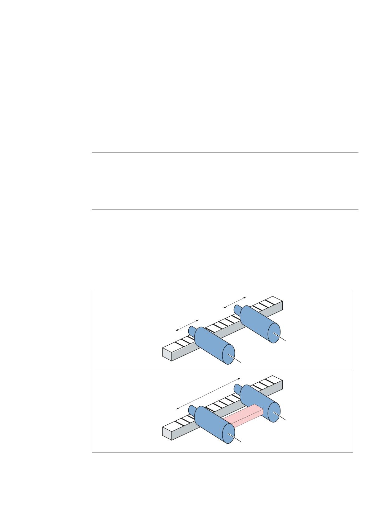
TE3: Speed/torque coupling, master-slave
19
19.1
Brief description
A master-slave coupling is a speed setpoint coupling between a master and any number of
slave axes - performed at the position controller level - with and without torque equalization
control. The coupling can be permanently switched on, dynamically switched on/off and
reconfigured.
Note
The following restrictions apply for the SINUMERIK 828D with regard to the "Master-slave
coupling":
● Only one master-slave grouping is possible. (Exception: control variant "SW28x(1) CNC-
SW Milling Adv. Export (me822) with max. two master-slave groupings).
● Only one slave axis can be coupled to the master axis.
Applications
Possible applications of a master-slave coupling include:
● Increase the power for mechanically coupled drives
● Compensating gear and gear tooth flank play by entering a pre-tensioning torque
Dynamic master-slave coupling of two axes
&RXSOLQJ
2))
0RWLRQ $[LV
0RWLRQ $[LV
$[LV
$[LV
&RXSOLQJ
21
0RWLRQ $[LV DQG D[LV
$[LV
6ODYH D[LV
$[LV
0DVWHU D[LV
Special functions
Function Manual, 12/2018, A5E40874099B AB
729
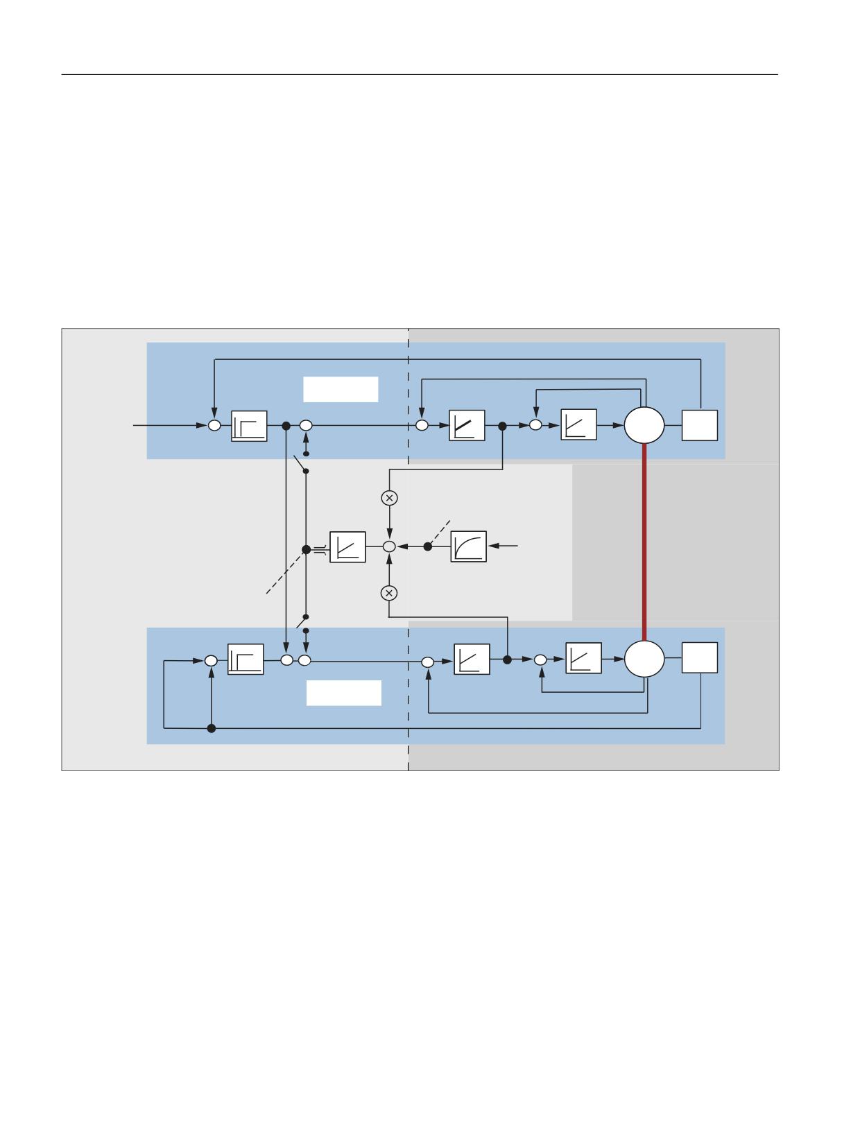
TE3: Speed/torque coupling, master-slave
19.2 Coupling diagram
19.2
Coupling diagram
If the coupling is closed, the slave axis is traversed only with the load-side setpoint speed of
the master axis. It is therefore only speed-controlled, not position-controlled. There is no
differential position control between the master and slave axis.
The torque required between the master and slave axis is distributed using the torque
equalization controller. When using different motors, this distribution can be adapted to the
specific requirements using a weighting factor.
A tension can be established between the master and slave axes by entering a supplementary
torque (tensioning torque).
3RVLWLRQDFW
0$67(5
QLVW
LLVW
3RVLWLRQVHW
QVROO
LVROO
,QWHU
0
(
SRODWRU
3RVLWLRQ FRQWUROOHU
6SHHG FRQWUROOHU
7RUTXH FRQWUROOHU
,QWHUFRQQHFWLRQ
FRQWUROOHU
RXWSXW
:HLJKWLQJ IDFWRU
6HUYR WUDFH &ODPSLQJ WRUTXH
6SHHG VHWSRLQW FRXSOLQJ
0HFKDQLFDO
&ODPSLQJ WRUTXH
FRXSOLQJ
3,
37
ILOWHU
6HUYR WUDFH
FRQWUROOHU
:HLJKWLQJ IDFWRU
7RUTXH FRPSHQVDWRU\
FRQWUROOHU
3RVLWLRQ FRQWUROOHU
6SHHG FRQWUROOHU
7RUTXH FRQWUROOHU
3RVLWLRQVHW
0
(
LVROO
Q
VROO
LLVW
QLVW
6/$9(
3RVLWLRQDFW
1&8
'ULYH
Figure 19-1
Control structure
Special functions
730
Function Manual, 12/2018, A5E40874099B AB

TE3: Speed/torque coupling, master-slave
19.3 Configuring a coupling
19.3
Configuring a coupling
Static assignment
For a speed setpoint coupling and torque equalization control, the static assignment of master
and slave axis is defined separately in the following machine data:
● Speed setpoint coupling
MD37250 $MA_MS_ASSIGN_MASTER_SPEED_CMD[<slave axis>] =
<machine axis number of the master axis for the speed setpoint coupling>
● Torque equalization control
MD37252 $MA_MS_ASSIGN_MASTER_TORQUE_CTR[<slave axis>] =
<machine axis number of the master or slave axis for torque equalization control>
(see Section "Tension torque (Page 736)")
Dynamic assignment (only 840D sl)
The assignment of master and slave axes can be dynamically changed using the following
program commands.
Defining assignments
Assignment of one or several slave axes to a master axis:
MASLDEF (<slave axis_1>, <slave axis_2>, ..., <master axis>)
In principle, any number of slave axes can be assigned. The assignment is kept even after an
operating mode change, reset and end of part program.
Deleting assignments
Delete assignment of one or several slave axes to their associated master axis:
MASLDEL (<slave axis_1>, <slave axis_2>, ...)
An active coupling is first implicitly switched off before deleting the assignment.
Axis assignment for speed setpoint coupling and torque equalization control
For the speed setpoint coupling, the slave axis refers to the master axis specified when defining
the assignment (MASLDEF).
The axis to which the slave axis refers for torque equalization control is defined in the following
machine data:
MD37253 $MA_MS_FUNCTION_MASK[<slave axis>], bit 1 = <value>
<value>
Description
0
In the case of dynamic assignment (MASLDEF), the slave axis for the torque equalization
control - as well as for speed setpoint coupling - refers to the master axis of the master-
slave grouping.
1
In the case of dynamic assignment (MASLDEF), the slave axis for the torque equalization
control refers to the axis, master or slave axis of the master-slave grouping specified in
machine data:
MD37252 $MA_MS_ASSIGN_MASTER_TORQUE_CTR<slave axis> = <axis>
Special functions
Function Manual, 12/2018, A5E40874099B AB
731
TE3: Speed/torque coupling, master-slave
19.3 Configuring a coupling
(See Section "Tension torque (Page 736)")
Supplementary conditions
The following supplementary conditions must be observed for the dynamic assignment:
● When the coupling is switched on, a change to the assignment using MASLDEF has no
effect. The change only becomes effective the next time that the coupling is switched off.
● The same master axis is always used for the speed setpoint coupling and torque
equalization control.
● A plausibility check of the assignment is only made when the coupling is switched on.
User-specific standard assignment after reset (only 840D sl)
A user-specific standard assignment, which is always effective after a reset, can be defined
in PROG_EVENT.SPF using the program commands MASLDEF and MASLDEL.
The following machine data should be set in order that PROG_EVENT.SPF is executed for a
reset: MD20108 $MC_PROG_EVENT_MASK.Bit 2 = 1
Example: Dynamic change of the assignment (only 840D sl)
The assignment of slave axis AX3 is changed from master axis AX1 to master AX2. To do this,
the coupling must be temporarily switched off (see Section "Closing/opening a coupling
(Page 739)").
Programming
Description
①
MASLDEF (AX3, AX1)
Assignment of slave axis AX3 to master axis AX1
②
MASLON (AX3)
Switching on the coupling
③
MASLDEL (AX3)
Switch off the coupling and cancel the assignment between AX3 and AX1
④
MASLDEF (AX3, AX2)
Assignment of slave axis AX3 to master axis AX2
$;
$;
$;
$;
$;
$;
$;
$;
$;
$;
$;
$;
Figure 19-2
Alternating assignment of the slave axis
Special functions
732
Function Manual, 12/2018, A5E40874099B AB

TE3: Speed/torque coupling, master-slave
19.4 Torque compensatory controller
General supplementary conditions
Please note the following general supplementary conditions:
● A slave axis can only be assigned to one master axis
● A master axis can be assigned several slave axes
● A slave axis must not be a master axis or be in another master-slave relationship.
Note
Drive optimization
At a SINAMICS S120 drive unit, a maximum of three drives can be optimized or measured
at the same time (speed controller optimization / function generator). Therefore, for a
coupling with more than three coupled drives at the same time, we recommend that these
are distributed over several drive units.
19.4
Torque compensatory controller
The torque compensatory controller (PI control) calculates a load-side initial speed setpoint.
The additional speed setpoint can be differently entered via the following machine data:
MD37254 $MA_MS_TORQUE_CTRL_MODE[<slave axis>] = <value>
<value>
Input of the additional speed setpoint at:
0
Master and slave axis (default value)
1
Slave axis
2
Master axis
3
No additional setpoint injection
Note
Several slave axes
For a master-slave grouping with one master and several slave axes, the input of the additional
speed setpoint to the master and slave axes - set as standard in MD37254 - can result in
instability. For multiple slave axes, injection of an additional speed setpoint should only be
applied in the slave axes:
MD37254 $MA_MS_TORQUE_CTRL_MODE = 1
SINAMICS S120: Current setpoint filter
Up to four current setpoint filters (p1656 - p1674, function block diagram [5710]) can be
activated in the SINAMICS S120. In a master-slave group, it is recommended that, for the
master and all of the slave axes, only filters with the same data be activated at any one time.
Special functions
Function Manual, 12/2018, A5E40874099B AB
733

TE3: Speed/torque coupling, master-slave
19.4 Torque compensatory controller
Scaling
Scaling of the machine data for the gain factor (P component) (MD37256
$MA_MS_TORQUE_CTRL_P_GAIN) and the speed setpoint limiting (MD37260
$MA_MS_MAX_CTRL_VELO) is defined in the following machine data:
MD37253 $MA_MS_FUNCTION_MASK[<slave axis>], bit 0 = <value>
<value>
Description
0
MD37256 and MD37260 are internally multiplied with the following factor: 1 / interpolator
clock cycle 1)
1
MD37256 and MD37260 are accepted unchanged
1) The interpolator cycle is displayed with MD10071 $MN_IPO_CYCLE_TIME
Note
We recommend not changing MD37256 and MD37260:
MD37253 $MA_MS_FUNCTION_MASK[<slave axis>], bit 0 = 1
Gain factor (P component)
The gain factor of the torque compensatory controller is set in the following machine data as
a percentage of the ratio of the maximum load-side axis velocity of the slave axis (MD32000
$MA_MAX_AX_VELO) to its rated torque (SINAMICS S120: p2003):
MD37256 $MA_MS_TORQUE_CTRL_P_GAIN[<slave axis>]
Note: Scaling via MD37253 $MA_MS_FUNCTION_MASK[<slave axis>], bit 0
Integral time (I component)
The integral time of the torque compensatory controller is set in the following machine data:
MD37258 $MA_MS_TORQUE_CTRL_I_TIME[<slave axis>]
The I component is deactivated as standard.
Speed setpoint limiting
The speed setpoint calculated by the torque compensatory controller can be limited using the
following machine data. The input is a percentage referred to the maximum, load-side axis
velocity of the slave axis (MD32000 $MA_MAX_AX_VELO).
MD37260 $MA_MS_MAX_CTRL_VELO[<slave axis>]
Note: Scaling via MD37253 $MA_MS_FUNCTION_MASK[<slave axis>], bit 0
Special functions
734
Function Manual, 12/2018, A5E40874099B AB
TE3: Speed/torque coupling, master-slave
19.4 Torque compensatory controller
Deactivating the torque compensatory controller
If the following settings are made, the torque compensatory controller will be inactive:
● MD37254 $MA_MS_TORQUE_CTRL_MODE[<slave axis>] = 3
● MD37256 $MA_MS_TORQUE_CTRL_P_GAIN[<slave axis>] = 0
Torque weighting
The percentage of the torque generated by the slave axis of the total torque can be set using
the torque weighting.
MD37268 $MA_MS_TORQUE_WEIGHT_SLAVE[<slave axis>]
Using the torque weighting, it is possible to configure a different torque distribution between
the master and slave axes for motors with different rated torques. For motors of the master
and slave axes with the same rated torques, it makes sense to have a 50 % torque distribution
(default setting).
The torque provided by the master axis is given by:
Torque provided by the master axis = 100 % - MD37268
Note
Mechanical coupling
When using the torque compensatory controller, it is absolutely necessary to have a
mechanical coupling between the master and slave axis. Otherwise, the two drives involved
could accelerate in an uncontrollable fashion.
Activation / Deactivation via the NC/PLC interface
Activation of the torque compensatory controller via the NC/PLC interface must be explicitly
enabled:
MD37255 $MA_MS_TORQUE_CTRL_ACTIVATION[<slave axis>] = 1
Activation
The torque compensatory controller can be activated axis for axis via:
DB31, ... DBX24.4
Reading the actual state
The actual activation state of the torque compensatory controller can be read via:
DB31, ... DBX96.4
Special functions
Function Manual, 12/2018, A5E40874099B AB
735

TE3: Speed/torque coupling, master-slave
19.5 Tension torque
19.5
Tension torque
The tension torque is a supplementary torque which is switched to the active torque
equalization controller. This means that a mechanical tension can be established between
axes within a master-slave grouping. Establishing a tension is not only possible between the
master and a slave axis, but also between two slave axes by declaring one of the slave axes
the reference axis for the torque equalization controller.
Setting
The tension torque is entered as a percentage of the rated torque of the slave axis and is active
immediately:
MD37264 $MA_MS_TENSION_TORQUE[<slave axis>] = <tension torque>
As can be seen from the structure of the torque equalization controller (Chapter "Torque
compensatory controller (Page 733)"), the tension torque is entered via a PT1 filter. The filter
time constant is set using the following machine data:
MD37266 $MA_MS_TENSION_TORQ_FILTER_TIME[<slave axis>] = <time constant>
A value for the filter time constant greater than 0 activates the filter.
NOTICE
No axis equalization
If a tension torque is entered without a mechanical coupling between the master and slave
axis then this causes the axes to move.
Note
Minimum tension torque
The tension torque chosen must be high enough to ensure that the resulting torque does not
drop below the minimum required tension even during acceleration.
Reducing the motor temperature rise
The tension torque can be reduced when the motor is at a standstill to reduce the motor
temperature rise.
Example 1 (840D sl): Static coupling and establishing a tension in pairs
A master-slave application is parameterized so that one master axis is assigned three slave
axes and a tension torque is entered for one axis pair. As a consequence, the master axis
alone does not have to establish the tension torque with respect to all of the slave axes.
Assumption regarding machine axes:
● 1st to 4th machine axis: AX1, AX2, AX3, AX4
Special functions
736
Function Manual, 12/2018, A5E40874099B AB
TE3: Speed/torque coupling, master-slave
19.5 Tension torque
Static coupling for all slave axes
● MD37262 $MA_MS_COUPLING_ALWAYS_ACTIVE[AX2] = 1
● MD37262 $MA_MS_COUPLING_ALWAYS_ACTIVE[AX3] = 1
● MD37262 $MA_MS_COUPLING_ALWAYS_ACTIVE[AX4] = 1
Axis
Reference axis of the speed set-
Reference axis of the torque equal-
Input of the torque equalization
point coupling
ization controller
contr.
MD37250 = value
MD37252 = value
MD37254 = value
Value
Description
Value
Description
Value
Description
AX1
0
No reference axis
0
No reference axis
0
Master and slave
AX2
1
Master axis, AX1
1
Master axis, AX1
0
Master and slave
AX3
1
Master axis, AX1
0
No reference axis
3
No input
AX4
1
Master axis, AX1
3
2nd slave axis, AX3
0
Master and slave
0DVWHU
6ODYH
$;
$;
-RLQWO\ GULYHQ PDFKLQH
HOHPHQW
6ODYH
6ODYH
$;
$;
'UHK]DKONRSSOXQJ
0RPHQWHQDXVJOHLFKVUHJHOXQJ
Figure 19-3
Example 1: Torque equalization control in pairs
Example 2 (840D sl): Dynamic coupling with 1x4 and 2x2 axes grouped in pairs
Assumption regarding machine axes:
● 1st to 4th machine axis: AX1, AX2, AX3, AX4
Dynamic coupling for all slave axes:
● MD37262 $MA_MS_COUPLING_ALWAYS_ACTIVE[AX2] = 0
● MD37262 $MA_MS_COUPLING_ALWAYS_ACTIVE[AX3] = 0
● MD37262 $MA_MS_COUPLING_ALWAYS_ACTIVE[AX4] = 0
For a dynamic coupling, the master axis specified when defining the coupling (MASLDEF) is,
as standard, the reference axis for speed setpoint coupling and torque equalization control.
Special functions
Function Manual, 12/2018, A5E40874099B AB
737
TE3: Speed/torque coupling, master-slave
19.5 Tension torque
The definition of reference axis AX3 for the torque equalization control of the 3rd slave axis
AX4 is required for the application "1x4 axes" where the following machine data is set:
MD37253 $MA_MS_FUNCTION_MASK[AX4], Bit 1 = 1 (see part program)
Axis
Reference axis of the speed set-
Reference axis of the torque equal-
Input of the torque equalization
point coupling
ization controller
contr.
MD37250 = value
MD37252 = value
MD37254 = value
Value
Description
Value
Description
Value
Description
AX1
0
No reference axis
0
No reference axis
0
Master and slave
AX2
0
No reference axis
0
No reference axis
0
Master and slave
AX3
0
No reference axis
0
No reference axis
3
No input
AX4
0
No reference axis
3
Machine axis AX3
0
Master and slave
Program code
Comment
PROC MASL_SWITCH IPRTLOCK DISPLOF
IF MASL_REQUEST==4
;
Activate "1x4 axes"
MASLOF(AX2, AX4)
;
Switch off coupling
MASLDEL(AX2, AX4)
;
Delete coupling
$MA_MS_FUNCTION_MASK[AX4]=
;
MD37253, bit1 = 1:
$MA_MS_FUNCTION_MASK[AX4] B_OR 'B10'
;
Reference axis of the torque equalization controller
;
from AX4, is AX3 (MD37252)
NEWCONF
;
Activate machine data change
STOPRE
MASLDEF(AX2, AX3, AX4, AX1)
;
Define assignment for "1x4 axes"
MASLON(AX2, AX3, AX4)
;
Switch on couplings
MASL_ACTIVE=4 MASL_REQUEST=0
;
Feedback signal: "1x4 axes" switched-in
ENDIF
IF MASL_REQUEST==2
;
Activate "2x2 axes"
MASLOF(AX2, AX3, AX4)
;
Switch off coupling
MASLDEL(AX2, AX3, AX4)
;
Delete coupling
$MA_MS_FUNCTION_MASK[AX4]=
;
MD37253, bit1 = 0:
$MA_MS_FUNCTION_MASK[AX4] B_AND
;
Reference axis of the torque equalization controller
'HFFFD'
;
from AX4, is the master axis defined
;
with MASLDEF
NEWCONF
STOPRE
MASLDEF(AX2, AX1)
;
Define assignment for the 1st "2x2 axes"
MASLDEF(AX4, AX3)
;
Define assignment for the 2nd "2x2 axes"
MASLON(AX2, AX4)
;
Switch on couplings
MASL_ACTIVE=2 MASL_REQUEST=0
;
Feedback signal: "2x2 axes" switched on
ENDIF
RET
Special functions
738
Function Manual, 12/2018, A5E40874099B AB
TE3: Speed/torque coupling, master-slave
19.6 Closing/opening a coupling
0DVWHU
6ODYH
0DVWHU
6ODYH
$;
$;
$;
$;
-RLQWO\ GULYHQ PDFKLQH
HOHPHQW
-RLQWO\ GULYHQ PDFKLQH
HOHPHQW
-RLQWO\ GULYHQ PDFKLQH
HOHPHQW
6ODYH
6ODYH
0DVWHU
6ODYH
$;
$;
$;
$;
6SHHG FRXSOLQJ
[ D[HV
[ D[HV
7RUTXH HTXDOL]DWLRQ FRQWURO
Figure 19-4
Example 2: Alternating coupling with 1x4 and 2x2 axes
19.6
Closing/opening a coupling
Default setting
After the control has booted, the following machine data defines whether the coupling is
permanently switched on (static) or can be dynamically switched on/off and reconfigured:
MD37262 $MA_MS_COUPLING_ALWAYS_ACTIVE[<slave axis>] = <switch on mode>
Statically switching on a coupling
MD37262 $MA_MS_COUPLING_ALWAYS_ACTIVE[<slave axis>] = 1
After the control boots, the coupling is statically switched on.
By writing the machine data in the part program or synchronized action with subsequent warm
restart NEWCONF, then a static coupling can also be switched off/on at a later time.
Example: Switching the static coupling for slave axis AX2 off and on
Program code
Comment
N100 $MA_MS_COUPLING_ALWAYS_ACTIVE[AX2] = 0
; Coupling type: static -> dynamic
N110 NEWCONF
; Activate machine data.
N120 MASLOF(AX2)
; Switch off coupling.
N200 PRESETON(AX2,...)
; E.g. actual value setting of the slave axis.
N300 $MA_MS_COUPLING_ALWAYS_ACTIVE[AX2] = 1
; Coupling type: dynamic -> static, switch on cou-
pling.
Special functions
Function Manual, 12/2018, A5E40874099B AB
739
TE3: Speed/torque coupling, master-slave
19.6 Closing/opening a coupling
Note
A statically switched on coupling can neither be switched on/off nor reconfigured using the
master-slave-specific NC/PLC interface signals and/or program commands.
Dynamically switching a coupling on/off
MD37262 $MA_MS_COUPLING_ALWAYS_ACTIVE[<slave axis>] = 0
The coupling can be dynamically switched on and off and reconfigured.
The coupling can be switched on/off by:
● Machine data MD37262
Writing the machine data to switch on ( = 1) or switch off ( = 0) in the part program or
synchronized action. The change becomes active immediately.
● NC/PLC interface
DB31, ... DBX24.7 = 1 or 0 (master-slave on or off)
● Program commands (only 840D sl)
- Switch on: MASLON (<slave axis_1>, <slave axis_2>, ...)
- Switch off: MASLOF (<slave axis_1>, <slave axis_2>, ...)
- Switching off with braking of the slave spindles:
MASLOFS (<slave spindle_1>, <slave spindle_2>, ...)
- Switching off with deletion of the assignment:
MASLDEL (<slave axis_1>, <slave axis_2>, ...)
Note
Changing the static assignment
The setting:
MD37262 $MA_MS_COUPLING_ALWAYS_ACTIVE[<slave axis>] = 0
Permits the coupling to be dynamically changed. This means that it is possible to define
a new assignment using MASLDEF. The assignment parameterized in the machine data
(see static assignment, Section "Configuring a coupling (Page 731)") takes effect only
after the control has been powered up again (NC reset).
Coupling state
System variable
The actual coupling state of a slave axis can be read in the part program and synchronized
action using the following system variable:
Special functions
740
Function Manual, 12/2018, A5E40874099B AB
TE3: Speed/torque coupling, master-slave
19.7 Response on activation/deactivation
$AA_MASL_STAT[<slave axis>]
Value
Description
0
1) The coupling of the slave axis is not active.
2) The specific axis is not a slave axis
> 0
The coupling is active.
<value> == machine axis number of the master axis
NC/PLC interface signal
The current coupling state of a slave axis can be read using the following axis-specific NC/PLC
interface signal:
DB31, ... DBX96.7 (master/slave coupling active)
Setpoint state
Requests to switch on/off a master-slave coupling (NC/PLC interface signal and/or program
commands) that consecutively follow one another mutually overwrite one another. The
effective setpoint state results from the last chronological request (see Section "Response on
activation/deactivation (Page 741)").
19.7
Response on activation/deactivation
On/off at standstill (axis)
A request to switch on/off the coupling only becomes effective when the master and slave axis
are at a standstill (zero speed):
DB31, ... DBX61.4 == 1 (axis/spindle stationary)
In this case, the coupled axes must be in the closed-loop controlled mode.
0DVWHU VODYH RQ
'%
'%;
0$6/21
0$6/2)
$[LV VSLQGOH
VWDWLRQDU\ '%
'%;
0DVWHU VODYH
DFWLYH '%
'%;
Figure 19-5
Activation procedure
Special functions
Function Manual, 12/2018, A5E40874099B AB
741
TE3: Speed/torque coupling, master-slave
19.7 Response on activation/deactivation
When switching on the coupling using the program command MASLON, the system waits until
the coupling is closed before the block is changed. The "Master-slave switchover active"
message will be displayed on the user interface during this time.
Switching on/off during motion (spindle)
Note
Switching on/off during motion
During the motion, the coupling can be switched on/off only for spindles in speed control
mode.
Special functions
742
Function Manual, 12/2018, A5E40874099B AB
TE3: Speed/torque coupling, master-slave
19.7 Response on activation/deactivation
Switching on
When switching on during the motion, the coupling operation divides itself at different speeds
in two phases.
● Phase 1
The PLC user program must request the switch on of the coupling with:
DB31, ... DBX24.7 = 1 (master/slave ON)
The slave spindle accelerates or brakes along a ramp to the setpoint speed of the master
spindle.
When the setpoint speed is reached, the coupling is switched on and the NC/PLC interface
signal is set:
DB31, ... DBX96.7 == 1 (coupling active)
If the master spindle is accelerated while the coupling is being switched on, then Phase 1
is extended corresponding to the dynamic difference between the master and the slave
spindle.
● Phase 2
The following synchronous signals are generated from the actual speed difference between
the master and slave spindle(s):
- DB31, ... DBX96.3 (speed tolerance, coarse)
- DB31, ... DBX96.2 (speed tolerance, fine)
The associated limits are set using the following machine data:
- MD37270 $MA_MS_VELO_TOL_COARSE ("Tolerance coarse")
Special functions
Function Manual, 12/2018, A5E40874099B AB
743
TE3: Speed/torque coupling, master-slave
19.7 Response on activation/deactivation
- MD37272 $MA_MS_VELO_TOL_FINE ("Tolerance fine").
Note
The "Speed tolerance coarse" signal can be used to implement a monitoring function
on the PLC side that checks a coupled master-slave grouping for loss of speed
synchronism.
The "Speed tolerance fine" signal can be used to directly derive the time taken to close
the coupling mechanically and switch on the torque equalization controller.
6HWSRLQW
0DVWHU
W
W
W
6SHHG
VSLQGOH
6HWSRLQW
$FWXDO YDOXH
6ODYH
6ODYH
VSLQGOH
VSLQGOH
W
ಯ&RXSOLQJ FORVHGರ
'%
'%;
ಯ&RXSOLQJ DFWLYHರ
'%
'%;
ಯ6SHHG WROHUDQFH FRDUVHರ
'%
'%;
ಯ6SHHG WROHUDQFH ILQHರ
'%
'%;
Figure 19-6
Coupling operation at different speeds
Switch off without braking
If the coupling is switched off with the MASLOF program command, the coupling will be switched
off immediately for spindles in speed control mode. The slave spindles maintain their speeds
at the time that the coupling is switched off until a new speed is programmed.
Special functions
744
Function Manual, 12/2018, A5E40874099B AB

TE3: Speed/torque coupling, master-slave
19.8 Supplementary conditions
Switch off with braking
If the coupling is switched off with the MASLOFS program command, the coupling will be
switched off immediately for spindles in speed control mode and the slave spindles braked.
Note
The implicit preprocessing stop is omitted for MASLON and MASLOF. The missing preprocessing
stop means that the $P system variables of the slave spindles do not supply updated values
until reprogrammed.
Coupling characteristics
The behavior regarding the program commands MASLON, MASLOF, MASLOFS, MASLDEL (only
840D sl) and the NC/PLC interface signal: DB31, ... DBX24.7 (master/slave on) is, for spindles
in the open-loop speed controlled mode, set using the following machine data:
MD37263 $MA_MS_SPIND_COUPLING_MODE[<slave spindle>] = <value>
<value>
Description
0
Coupling and disconnection take place only at standstill.
The current coupling state is retained until all axes involved have actually come to a stand-
still. The MASLOFS and MASLOF operations are identical; the slave spindle is not decelerated
automatically.
1
Coupling and disconnection takes place immediately and therefore during motion.
During coupling, the slave spindles are accelerated automatically to the current speed of
the master spindle.
On disconnection, the slave spindles rotating at this time retain their speeds until next speed
programming. However, a slave spindle disconnected with MASLOFS decelerates automat-
ically.
19.8
Supplementary conditions
19.8.1
Functional boundary conditions
General
● Master and slave axes must be on the same NCU.
● A coupling is closed or opened independent of the channel state the next time that the axis
is at a standstill.
● Slave axes can only be traversed via the master axis when the coupling is closed.
● A coupled slave axis cannot be switched further via the axis container.
● A requested axis interchange of coupled slave axes is not executed.
Special functions
Function Manual, 12/2018, A5E40874099B AB
745
TE3: Speed/torque coupling, master-slave
19.8 Supplementary conditions
● When the coupling is switched-in (closed) via the slave axis, the master axis is braked
automatically, if the channel axis is in the same channel: ⇒ asymmetrical behavior when
opening and closing the coupling:
- Activate: the leading axis is automatically braked
- Deactivating: no automatic braking of the leading axis
● The setpoint position of a coupled slave axis corresponds to its actual position.
● For axes and spindles in the positioning mode, the coupling is only switched-in (closed)
and switched-out (opened) at standstill (zero speed).
● The leading-following coupling must be deactivated prior to a gear change or a star-delta
switchover.
Axial monitoring functions
● Except monitoring the speed setpoint and actual speed, axial monitoring functions like
contour and standstill in the slave axis are inactive because of the missing position
controller. The position control circuit parameters like gain factor, precontrol, balancing can
thus be set differently for master and slave axes without the monitoring functions
responding.
● In order to ensure the same braking behavior for all axes of a master-slave group, when
the coupling is active, the same alarm reaction is applied to all of the axes of the master-
slave group.
● The parameterization and evaluation of the standstill detection (e.g. braking ramp) is
realized axially for each axis in the master-slave group. This can result in an asynchronous
withdrawal of the controller enable for the coupled axes.
● When canceling error states, the slave axes do not reposition to the point of interruption.
Virtual axis
Master and/or slave axes must not be "virtual" axes:
MD30132 $MA_IS_VIRTUAL_AX (axis is virtual axis) = 0
Modulo rotary axes
● For slave axes, when the coupling is closed, the actual value displayed in the service display
is not modulo 360°. Independent of the setting in machine data:
MD30310 $MA_ROT_IS_MODULO[<slave axis>]
Special functions
746
Function Manual, 12/2018, A5E40874099B AB
TE3: Speed/torque coupling, master-slave
19.8 Supplementary conditions
Spindles
● If a master-slave coupling is activated with spindles, the slave spindle is operated in the
open-loop speed controlled mode. The actual value of the slave spindle is not displayed
as modulo 360° in the service display. However, in the automatic basic display the actual
value is displayed as modulo 360°.
● If the spindles are accelerated at the current limit, this may mean that no adjusting reserves
are left over in the coupled state for the torque compensatory controller to use to distribute
the torque between the master and the slave as required.
● The maximum master spindle chuck speed must be configured in the following machine
data to be lower than or equal to that of the following spindles:
MD35100 $MA_SPIND_VELO_LIMIT[<master spindle>]
● The axial velocity monitoring function should be adapted to the chuck speed:
MD36200 $MA_AX_VELO_LIMIT[<master spindle>]
19.8.2
Axial NC/PLC interface signals
● In the brake control logic, the NC/PLC interface signal may longer be evaluated for slave
axes: DB3x.DBX61.5 (position controller active
). When the coupling is closed, the signal is no longer set. Instead, the following NC/PLC
interface signal should be used:
DB31, ... DBX96.7 (master-slave coupling active).
● When requested, and for a closed coupling, the following NC/PLC interface signals are
directly taken from the master axis for the slave axis:
DB31, ... DBX2.1 (controller enable)
DB31, ... DBX21.7 (pulse enable)
● When the controller enable is cancelled for the master axis:
DB31, ... DBX2.1 (controller enable) = 0
within the configured time of:
MD36610 $MA_AX_EMERGENCY_STOP_TIME
then this also results in interpolatory braking of the slave axis. The corresponding speed
and current controller enable signals are only cancelled after the configured time has expired
MD36620 $MA_SERVO_DISABLE_DELAY_TIME
● In order to facilitate a standard braking behavior for all coupled axes, it is recommended
that the following parameters are set the same.
- MD36620 $MA_SERVO_DISABLE_DELAY_TIME
- p9560 (pulse suppression, shutdown speed)
- p1228 (pulse suppression, delay time)
Special functions
Function Manual, 12/2018, A5E40874099B AB
747
TE3: Speed/torque coupling, master-slave
19.8 Supplementary conditions
● If, for the master or slave axis, one of the following drive status signals is not set:
DB31, ... DBX61.7 (current controller active) == 0 OR
DB31, ... DBX61.6 (speed controller active) == 0
then, when the slave axis is at a standstill, the status signal is reset:
DB31, ... DBX96.7 (master/slave active) = 0
As soon as the master and slave axis are again in closed-loop control:
DB31, ... DBX61.7 (current controller active) == 1 AND
DB31, ... DBX61.6 (speed controller active) == 1
then for the slave axis, the status signal is again set:
DB31, ... DBX96.7 (master/slave active) = 1
● The torque equalization controller can be activated via the NC/PLC interface using:
DB31, ... DBX24.4 = 1 (torque equalization controller on)
The status of the torque equalization controller is displayed in:
DB31, ... DBX96.4 (master/slave equalization controller active)
Note
The slave axis is only closed-loop speed controlled when the coupling is closed. The NC/
PLC interface signal: DB31, ... DBX61.5 (position controller active) is no longer set.
19.8.3
Interaction with other functions
Function generator
To calibrate the speed control loop with activated coupling, it is recommended that a low value
should be set for the torque weighting of the slave axis (MD37268
$MA_MS_TORQUE_WEIGHT_SLAVE). Traversing of a mechanical coupled-motion slave
axis is not prevented by the torque compensatory controller.
Reference point approach
If the coupling is switched on, only the master axis can be referenced. Referencing of slave
axes is suppressed. The referencing requirement does not have to be explicitly canceled for
the slave axis in order to do this. The referencing status of coupled slave axes remains
unchanged. The slave axis position is generally not the same as the master axis position. This
difference in position is not significant. If the coupling is separated, each axis can be referenced
separately as usual.
Position-related compensations
Position-related compensations of the slave axis, such as spindle pitch errors, backlash,
temperature and sag offsets are not active because the position controller of the slave axis is
not active.
Correct calculation of the backlash compensation requires that the backlash of the slave axis
is always overtraveled by the motion of the master axis in coupled mode. Disconnecting the
coupling during an axis reversal error will generate an incorrect actual value for the slave axis.
Special functions
748
Function Manual, 12/2018, A5E40874099B AB
TE3: Speed/torque coupling, master-slave
19.8 Supplementary conditions
Dynamic stiffness control (DSC)
The "Dynamic stiffness control (DSC)" function must either be active or not active for all axes
of a master-slave grouping.
MD32640 $MA_STIFFNESS_CONTROL_ENABLE
Speed/torque feedforward control (FFW)
The "Speed/torque feedforward control (FFW)" function does not have to be activated explicitly
in the slave axis. The corresponding settings of the master axis are used. The speed
feedforward value of the master axis is already incorporated in the speed setpoint of the slave
axis. For an active torque feedforward control, the load-side torque feedforward control value
of the master axis is also active in the slave drive.
The mechanical situation changes when the coupling is switched on. Axis-specific settings
must be adapted accordingly. All coupled drives should have the same speed control dynamics.
Gantry
If one master-slave relationship is defined on each side of the gantry grouping to increase the
gain, only the leading axis or following axis may be operated as master axis.
Travel to fixed stop (FXS)
The "Travel to fixed stop (FXS)" function can be programmed only in the master axis when a
coupling is active and has a different effect on the master and slave axes:
● The programmed value is expressed as a percentage of the rated drive torque of the master
axis. The master axis detects when the fixed stop has been reached.
● The programmed value is also active on the slave axis, but refers to the drive torque of the
slave axis.
If the rated torque values of the master and slave axes are different, they can be adapted to
each other through the following slave axis machine data:
MD37014 $MA_FIXED_STOP_TORQUE_FACTOR
Specifying a factor < 1 reduces the programmed clamping torque in the slave axis.
Please note the following supplementary conditions:
● Torque distribution between the master and slave axes is not possible during clamping as
the torque compensatory controller is switched off during clamping operations.
● Status changes to the master-slave coupling have no effect during travel to fixed stop.
Specification of a new status is only accepted when the fixed stop function has been
completed.
Safety Integrated (new 840D sl)
As the slave axis is traversed via the master axis speed setpoint, the axis-specific setpoint
limitation MD36933 $MA_SAFE_DES_VELO_LIMIT is inactive in the coupled slave axes. All
safety monitoring functions remain active in the slave axes however.
Special functions
Function Manual, 12/2018, A5E40874099B AB
749
TE3: Speed/torque coupling, master-slave
19.8 Supplementary conditions
Gear stage change with activated master-slave coupling
An automatic gear stage change in a coupled slave spindle is not possible and can only be
implemented indirectly using the master spindle. The point in time at which the gear stage is
changed is then derived from the master spindle. The oscillating motion of the coupled slave
spindle is generated implicitly via the oscillating motion of the master spindle.
In contrast to the master spindle, the associated parameter block must be explicitly selected
in the coupled slave spindle. To enable the parameter set specification, the following machine
data must be set:
MD35590 $MA_PARAMSET_CHANGE_ENABLE = 2
Note
For more information about gear stage change and parameter sets for changes in spindle
mode, see:
References:
Function Manual, Basic Functions; Spindles (S1)
Axis container
If a coupled slave axis is configured as a container axis, alarm "4025 Switch axis container
%3 not permitted: Master-slave active channel %1 Axis %2" is displayed for an axis container
rotation.
Axis containers with changing master can be used to make the relevant spindle the master
spindle following a rotation of the axis container. Both master and slave spindles can be
container spindles.
For a coupling to be closed after axis container rotation using a different spindle in each case,
the old coupling must be separated before the rotation, the configuration deleted and the new
coupling configured and closed after the rotation.
Example of a cyclic coupling sequence (position = 3 / container = CT1)
Program code
Comment
MASLDEF(AUX,SPI(3))
; S3 master for AUX
MASLON(AUX)
; Coupling in for AUX
M3=3 S3=4000
; Machining ...
MASLDEL(AUX)
; Delete configuration and release coupling
AXCTSWE(CT1)
; Axis container rotation
Special functions
750
Function Manual, 12/2018, A5E40874099B AB
TE3: Speed/torque coupling, master-slave
19.8 Supplementary conditions
6
6
'LUHFWLRQ RI
$;
$;
0HFKDQLFDO
URWDWLRQ
,QIHHG
&RQWDLQHU
6
$;
$;
$8;
$;
$;
6
6
Figure 19-7
Coupling between container spindle S3 and auxiliary motor AUX (prior to rotation)
6
6
'LUHFWLRQ RI
$;
$;
0HFKDQLFDO
URWDWLRQ
,QIHHG
&RQWDLQHU
6
$;
$;
$8;
$;
$;
6
6
Figure 19-8
Coupling between container spindle S3 and auxiliary motor AUX (after to rotation)
Hardware and software limit switches
If the software or hardware limit switch is overtraveled by a slave axis, the master-slave
grouping is stopped via the master axis. The relevant slave axis is shown in the alarm. The
limit switch of the slave axis is overtraveled by the amount of the deceleration distance of the
master axis.
Special functions
Function Manual, 12/2018, A5E40874099B AB
751
TE3: Speed/torque coupling, master-slave
19.8 Supplementary conditions
The movement away of the slave axis from the limit switch must be performed via the traversing
of the master axis. Switching off the coupling (MASLOF) and traversing the slave axis is not
possible. The coupling cannot be switched off until the cause of the error has been removed.
NOTICE
Power off/on or warm restart (reset (po)) after the software or hardware limit switch has been
passed - and the coupling switched out with MASLOF
If the software or hardware limit switch is overtraveled by a slave axis and an attempt is made
to switch off the coupling with MASLOF while the slave axis is still behind the limit switch, the
message "Waiting for coupled slave axis" is displayed. The coupling can only be switched off
by means of a Power Off/On or warm restart (reset (po)).
Block search
Static coupling
The "Block search with calculation" function (SERUPRO) can be used without any restrictions
in conjunction with a static master-slave coupling.
Dynamic coupling (only 840D sl)
For a dynamic coupling, the following restrictions must be observed with regard to the program
commands MASLON and MASLOF:
● The coupled axes must be on the same NCU.
● The coupled axes must be in the same channel when the block search is executed.
● After the block search has been completed, the coupling state, the associated axis positions
and speeds must be subsequently influenced by the user via the system ASUB
"PROGEVENT.SPF". System variables are available for this purpose.
- $P_PROG_EVENT: This variable provides information about the event which activated
the subprogram. A value of 5 stands for block search.
- $P_SEARCH_MASLC[slave axis name]: This variable stands for alteration of the
coupling status during a block search.
- $P_SEARCH_MASLD[slave axis name]: This variable indicates the positional offset
calculated in the block search between the slave and master axes at the instant the
coupling was closed.
- $AA_MASL_STAT[slave axis name]: This variable indicates the current coupling state.
Special functions
752
Function Manual, 12/2018, A5E40874099B AB
TE3: Speed/torque coupling, master-slave
19.8 Supplementary conditions
● The system ASUB "PROGEVENT.SPF" must be saved under the following path: /
_N_CMA_DIR/_N_PROG_EVENT_SPF
● The following machine data should be parameterized so that PROGEVENT.SPF is started.
NC-specific machine data:
- MD11450 $MN_SEARCH_RUN_MODE = 'H02'
- MD11602 $MN_ASUP_START_MASK = 'H01'
- MD11604 $MN_ASUP_START_PRIO_LEVEL = 100
Channel-specific machine data:
- MD20105 $MC_PROG_EVENT_IGN_REFP_LOCK = ’H3F’
Table 19-1
Example 1: PROGEVENT.SPF: Example 1
Program code
Comment
N10 IF $P_PROG_EVENT==5
; Block search active
N20
IF (($P_SEARCH_MASLC[Y]<>0) AND
; The coupling state has changed during
($AA_MASL_STAT[Y]<>0))
block search AND the current state is
"coupled"
N30
MASLOF(Y)
; Disconnect coupling
N40
SUPA Y=$AA_IM[X]-$P_SEARCH_MASLD[Y]
; Traverse through the position offset
using the slave axis
N50
MASLON(Y)
; Close coupling
N60
ENDIF
N70 ENDIF
N80 REPOSA
Table 19-2
Example 2: PROGEVENT.SPF
Program code
Comment
N10 IF $P_PROG_EVENT==5
; Block search active
N20
IF (($P_SEARCH_MASLC[SPI(2)]<>0) AND
; The state of the second spindle has
($AA_MASL_STAT[SPI(2)]==0))
changed during block search AND the cur-
rent state is "disconnected"
N30
M2=$P_SEARCH_SDIR[2]
; Update direction of rotation
N40
S2=$P_SEARCH_S[2]
, Update speed
N50
ENDIF
N60 ENDIF
N70 REPOSA
Special functions
Function Manual, 12/2018, A5E40874099B AB
753
TE3: Speed/torque coupling, master-slave
19.9 Examples
For more application examples (see Chapter "Examples (Page 754)).
Note
For an activated coupling, it is recommended to only use block search type 5, "Block search
via program test" (SERUPRO) for a block search.
More information about event-driven program calls and "block search using the program test"
(SERUPRO) is included in:
References:
Function Manual, Basic Functions;
● Auxiliary function outputs to PLC (H2)
● Mode group, channel, program operation, reset response (K1)
● Spindles (S1)
19.9
Examples
19.9.1
Master-slave coupling between AX1=Master and AX2=Slave.
Configuration
Master-slave coupling between AX1=Master and AX2=Slave.
1. Machine axis number of master axis for speed setpoint coupling
MD37250 $MA_MS_ASSIGN_MASTER_SPEED_CMD[AX2] = 1
2. Master axis with torque distribution identical to master axis with speed setpoint coupling
MD37252 $MA_MS_ASSIGN_MASTER_TORQUE_CTR[AX2] = 0
3. Permanent coupling
MD37262 $MA_MS_COUPLING_ALWAYS_ACTIVE[AX2] = 1
4. Torque is injected in both the master and slave axes
MD37254 $MA_MS_TORQUE_CTRL_MODE[AX2] = 0
5. Torque distribution between the master and slave axes is 50% to 50%
MD37268 $MA_MS_TORQUE_WEIGHT_SLAVE[AX2] = 50
6. Parameters of the torque compensatory controller
MD37256 $MA_MS_TORQUE_CTRL_P_GAIN[AX2] = 0.5
MD37258 $MA_MS_TORQUE_CTRL_I_TIME[AX2] = 5.0
19.9.2
Close coupling via the PLC
This application allows you to close or separate a master-slave coupling between the machine
axes AX1=Master axis and AX2=Slave axis during operation.
Special functions
754
Function Manual, 12/2018, A5E40874099B AB