SINUMERIK 840D sl. Service - Functions. Manual (2018-2020) - page 69

M3: Coupled axes
10.6 Dynamic response of following axis
Synchronization between following and leading axes
The acceleration characteristics set and the dynamics offsets set change the duration for
synchronization between following and leading axes during acceleration operations as follows:
Dynamic offset
Activation
Dynamic reduction
Prolongs the synchronism difference.
The monitoring from leading to following value may exceed the al-
lowed range for extended periods.
Dynamic increase
Shortens the synchronism difference.
The monitoring of leading and following values may exceed the
allowed range for short periods.
Note
The user must restore the technological synchronization between machining and the
synchronism difference.
Acceleration mode
Only BRISKAis available for the following axis, i.e., abrupt axis acceleration. Acceleration
modes SOFTA and DRIVEAare not available for the following axes described.
Furthermore, it is also possible to configure the positions controller as a PI controller.
CAUTION
Application faults
This option can only be used in conjunction with servo trace and with the appropriate technical
knowledge of the control.
References:
● CNC Commissioning Manual: NC, PLC, Drive
● Function Manual, Basic Functions; Velocities, Setpoint-Actual Value Systems, Closed-
Loop Control (G2)
POWER ON
During POWER ON the values of VELOLIMA and ACCLIMA are initialized to 100%.
Mode change
The dynamic offsets remain valid only on transition from AUTO → JOG mode.
RESET
The validities of the (VELOLIMA and ACCLIMA) dynamic offsets after RESET depend on the
setting in the channel-specific machine data:
Special functions
Function Manual, 12/2018, A5E40874099B AB
549

M3: Coupled axes
10.6 Dynamic response of following axis
MD22410 $MC_F_VALUES_ACTIVE_AFTER_RESET (F Function is active even after
RESET)
Value
Meaning
0
The values of VELOLIMA[FA] and ACCLIMA[FA] are set to 100% after RESET.
1
The last programmed values of VELOLIMA[FA] and ACCLIMA[FA] are also active after
RESET.
This response also applies for dynamics offsets set using static synchronized actions. If this
is not the case even when MD22410 = 0, then the IDS synchronized action should trigger a
repeat or continuous writing of the dynamic offset.
References:
Function Manual, Synchronized Actions
10.6.2.2
Examples
Electronic gearbox
Axis 4 is coupled to X via an electronic gearbox coupling. The acceleration capability of the
following axis is limited to 70% of maximum acceleration. The maximum permissible velocity
is limited to 50% of maximum velocity. After POWER ON, the maximum permissible velocity
is set to 100% again.
N120 ACCLIMA[AX4]=70
N130 VELOLIMA[AX4]=50
; reduced speed
N150 EGON(AX4,"FINE",X,1,2)
N200 VELOLIMA[AX4]=100
; full speed
Master value coupling
Axis 4 is coupled to X via a master value coupling. The acceleration capability of the following
axis is limited to 80% of maximum acceleration.
N120 ACCLIMA[AX4]=80
; 80%
N130 LEADON(AX4,X,2)
; Activate coupling
Special functions
550
Function Manual, 12/2018, A5E40874099B AB

M3: Coupled axes
10.7 General supplementary conditions
Master value coupling with synchronized action
Axis 4 is coupled to X via a master value coupling. The acceleration response is limited to
position 80% by static synchronized action 2 from position 100.
N120 IDS=2 WHENEVER $AA_IM[AX4] > 100 DO ACCLIMA[AX4]=80
N130 LEADON(AX4,X,2)
10.6.2.3
System variables
For geometry axis, channel axis, machine axis and spindle axis, the following readable system
variables are available in the part program and synchronous actions:
Identifier
Data type
Description
Unit
Preprocessing
$PA_ACCLIMA[n]
REAL
Acceleration offset set with ACCLIMA[Ax]
%
$PA_VELOLIMA[n]
REAL
Velocity offset set with VELOLIMA[Ax]
%
Main run
$AA_ACCLIMA[n]
REAL
Acceleration offset set with ACCLIMA[Ax]
%
$AA_VELOLIMA[n]
REAL
Velocity offset set with VELOLIMA[Ax]
%
Note
Reading the main run variables, implicitly triggers a preprocessing stop.
10.7
General supplementary conditions
Note
Drive optimization
At a SINAMICS S120 drive unit, a maximum of 3 drives can be optimized or measured at the
same time (speed controller optimization/function generator). Therefore, for a coupling with
more than 3 coupled drives at the same time, we recommend that these are distributed over
several drive units.
Note
Block search with active coupling
For an active coupling, it is recommended to only use block search type 5, "Block search via
program test" (SERUPRO) for a block search.
Special functions
Function Manual, 12/2018, A5E40874099B AB
551

M3: Coupled axes
10.8 Data lists
10.8
Data lists
10.8.1
Machine data
10.8.1.1
NC-specific machine data
Number
Identifier: $MN_
Description
11410
SUPPRESS_ALARM_MASK
Screen form for suppressing special alarm outputs
11415
SUPPRESS_ALARM_MASK_2
Suppress alarm outputs
11660
NUM_EG
Number of possible electronic gears
11750
NCK_LEAD_FUNCTION_MASK
Functions for master value coupling
11752
NCK_TRAIL_FUNCTION_MASK
couple motion functions
18400
MM_NUM_CURVE_TABS
Number of curve tables (SRAM)
18402
MM_NUM_CURVE_SEGMENTS
Number of curve segments (SRAM)
18403
MM_NUM_CURVE_SEG_LIN
Number of linear curve segments (SRAM)
18404
MM_NUM_CURVE_POLYNOMS
Number of curve table polynomials (SRAM)
18406
MM_NUM_CURVE_TABS_DRAM
Number of curve tables in DRAM
18408
MM_NUM_CURVE_SEGMENTS_DRAM
Number of curve segments in DRAM
18409
MM_NUM_CURVE_SEG_LIN_DRAM
Number of linear curve segments (DRAM)
18410
MM_NUM_CURVE_POLYNOMS_DRAM
Number of curve polynomials in DRAM
18450
MM_NUM_CP_MODULES
Maximum number of allowed CP coupling modules
18452
MM_NUM_CP_MODUL_LEAD
Maximum number of allowed CP master values
10.8.1.2
Channelspecific machine data
Number
Identifier: $MC_
Description
20110
RESET_MODE_MASK
Definition of control basic setting after run-up and RE-
SET/part program end
20112
START_MODE_MASK
Definition of control basic setting after run-up and RE-
SET
22620
START_MODE_MASK_PRT
Definition of the control basic settings for special start
22621
ENABLE_START_MODE_MASK_PRT
Activation of MD22620
20900
CTAB_ENABLE_NO_LEADMOTION
Curve tables with jump of following axis
20905
CTAB_DEFAULT_MEMORY_TYPE
Default memory type for curve tables
21300
COUPLE_AXIS_1
Projection synchronous spindle pair
Special functions
552
Function Manual, 12/2018, A5E40874099B AB

M3: Coupled axes
10.8 Data lists
10.8.1.3
Axis/spindlespecific machine data
Number
Identifier: $MA_
Description
30130
CTRLOUT_TYPE
Setpoint output type
30132
IS_VIRTUAL_AX
Axis is virtual axis
30455
MISC_FUNCTION_MASK
Axis functions
35040
SPIND_ACTIVE_AFTER_RESET
Own spindle RESET
37160
LEAD_FUNCTION_MASK
Functions for master value coupling
37200
COUPLE_POS_TOL_COARSE
Threshold value for "Coarse synchronous operation"
37202
COUPLE_POS_TOL_COARSE_2
Second synchronous operation monitoring: Threshold
value for "Coarse synchronous operation"
37210
COUPLE_POS_TOL_FINE
Threshold value for "Fine synchronous operation"
37212
COUPLE_POS_TOL_FINE_2
Second synchronous operation monitoring: Threshold
value for "Fine synchronous operation"
37220
COUPLE_VELO_TOL_COARSE
Velocity tolerance "coarse"
37230
COUPLE_VELO_TOL_FINE
Velocity tolerance "fine"
37500
ESR_REACTION
Reaction definition with extended stop and retract
37550
EG_VEL_WARNING,
Threshold value for speed warning threshold
37560
EG_ACC_TOL
Threshold value for the signal "Axis is accelerating"
10.8.2
Setting data
10.8.2.1
Axis/spindle-specific setting data
Number
Identifier: $SC_
Description
43100
LEAD_TYPE
Definition of master value type
43102
LEAD_OFFSET_IN_POS
Offset of master value with coupling to this axis
43104
LEAD_SCALE_IN_POS
Scaling of master value with coupling to this axis
43106
LEAD_OFFSET_OUT_POS
Offset of the function value of the curve table
43108
LEAD_SCALE_OUT_POS
Scaling of the function value of the curve table
10.8.3
System variables
Electronic gear (EG) and master value coupling
Identifier
Meaning
$AA_EG_ACTIVE
Coupling for leading axis b is active, i.e. switched on
$AA_EG_AX
Name for nth leading axis
Special functions
Function Manual, 12/2018, A5E40874099B AB
553

M3: Coupled axes
10.8 Data lists
Identifier
Meaning
$AA_EG_DENOM
Numerator of the coupling factor for leading axis b
$AA_EG_NUMERA
Numerator of the coupling factor for leading axis b
$AA_EG_NUMLA
Number of leading axes defined with EGDEF
$AA_EG_SYN
Synchronized position of leading axis b
$AA_EG_SYNFA
Synchronous position of following axis a
$AA_EG_TYPE
Type of coupling for leading axis b
$AA_IN_SYNC[FA]
Synchronization status of the following axis
$AA_LEAD_P
Current leading position value (modulo reduced).
$AA_LEAD_P_TURN
current leading value - position component lost as a result of modulo reduction.
$AA_LEAD_SP
simulated master value - position MCS
$AA_LEAD_SV
Simulated master value - velocity
$AA_LEAD_V
Current leading velocity value
$AA_SYNC
Coupling status of the following axis for leading value coupling.
$P_EG_BC
Block change criterion for EG activation calls: EGON, EGONSYN. WAITC = immediate
synchronism fine or coarse and setpoint synchronous operation.
$VA_EG_SYNCDIFF
Synchronism difference
Generic coupling
Identifier
Meaning
$AA_ACCLIMA
Acceleration correction (main run) set with ACCLIMA
$AA_COUP_ACT
Coupling type of a following axis/spindle
$AA_COUP_CORR
Following spindle - correction value for tracking the deviation in synchronism
$AA_COUP_CORR_DIST
$AA_COUP_CORR distance-to-go
$AA_COUP_OFFS
Setpoint position offset
$AA_CPACTFA
Name of active following axis
$AA_CPACTLA
Name of active leading axis
$AA_CPBC
Block change criterion
$AA_CPDEFLA
Name of defined leading axis
$AA_CPFACT
Coupling type of the following axis/spindle.
$AA_CPFCMDPT
Axis setpoint position for all coupling components
$AA_CPFCMDVT
Axis setpoint speed for all coupling components
$AA_CPFMOF
Behavior of the following axis at switch-off
$AA_CPFMON
Behavior of the following axis at switching on
$AA_CPFMSON
Synchronization mode
$AA_CPFRS
Coupling reference system
$AA_CPLCMDP
Axis setpoint component of the leading axis
$AA_CPLCMDV
Axis setpoint speed component of the leading axis
$AA_CPLCTID
Table number of the active curve table
$AA_CPLDEN
Denominator of the coupling factor
$AA_CPLNUM
Numerator of the coupling factor
Special functions
554
Function Manual, 12/2018, A5E40874099B AB

M3: Coupled axes
10.8 Data lists
Identifier
Meaning
$AA_CPLSETVAL
Coupling reference of the leading axis
$AA_CPLSTATE
State of the coupling
$AA_CPSYNCOP
Threshold value of position synchronism "Coarse" (main run)
$AA_CPSYNCOV
Threshold value of velocity synchronism "Coarse" (main run)
$AA_CPSYNFIP
Threshold value of position synchronism "Fine" (main run)
$AA_CPSYNFIV
Threshold value of velocity synchronism "Fine" (main run)
$AA_CPLINSC
Scaling factor of the input value of a leading axis (main run)
$AA_CPLINTR
Offset value of the input value of a leading axis (main run)
$AA_CPLOUTSC
Scaling factor of the output value of the coupling (main run)
$AA_CPLOUTTR
Offset value of the output value of the coupling (main run)
$AA_CPLTYPE
Type of coupling
$AA_CPMRESET
State of the coupling after RESET
$AA_CPMSTART
State of the coupling after program start
$AA_CPNACTFA
Number of active following axes
$AA_CPNACTLA
Number of active leading axes
$AA_CPNDEFLA
Number of defined leading axes
$AA_CPSETTYPE
Preset coupling type
$AA_EG_ACTIVE
Coupling for leading axis b is active
$AA_EG_AX
Name for nth leading axis
$AA_EG_BC
Block change criterion
$AA_EG_DENOM
Denominator of the coupling factor
$AA_EG_NUMERA
Numerator of the coupling factor
$AA_EG_NUM_LA
Number of leading axes defined with EGDEF
$AA_EG_SYN
Synchronized position of the leading axis
$AA_EG_SYNFA
Synchronized position of the following axis
$AA_EG_TYPE
Type of coupling
$AA_IN_SYNC[FA]
Synchronization status of the following axis
$AA_JERKLIMA
Jerk correction set with JERKLIMA (main run)
$AA_LEAD_SP
Simulated master value - position with LEAD
$AA_LEAD_SV
Simulated master value - speed with LEAD
$AA_LEAD_P_TURN
Current leading value - position component lost as a result of modulo reduction.
$AA_LEAD_P
Current leading value - position (modulo reduced)
$AA_LEAD_V
Current leading velocity value
$AA_SYNC
Coupling status of following axis
$AA_SYNCDIFF[FA]
Synchronism difference of the setpoint
$AA_SYNCDIFF_STAT[FA]
Status of the synchronism difference of the setpoint
$AA_TYP/TYPE
Axis type
$AA_VELOLIMA
Velocity correction set with VELOLIMA (main run)
$PA_ACCLIMA
Acceleration correction set with ACCLIMA (pre-processing)
$PA_CPFACT
Coupling type of the following axis/spindle.
$PA_CPFPOSSTAT
Validity of synchronous and stop position
Special functions
Function Manual, 12/2018, A5E40874099B AB
555

M3: Coupled axes
10.8 Data lists
Identifier
Meaning
$PA_CPSYNCOP
Threshold value of position synchronism "Coarse" (pre-processing)
$PA_CPSYNCOV
Threshold value of velocity synchronism "Coarse" (pre-processing)
$PA_CPSYNFIP
Threshold value of position synchronism "Fine" (pre-processing)
$PA_CPSYNFIV
Threshold value of velocity synchronism "Fine" (pre-processing)
$PA_CPLINSC
Scaling factor of the input value of a leading axis (pre-processing)
$PA_CPLINTR
Offset value of the input value of a leading axis (pre-processing)
$PA_CPLOUTSC
Scaling factor of the output value of the coupling (pre-processing)
$PA_CPLOUTTR
Offset value of the output value of the coupling (pre-processing)
$PA_CPSETTYPE
Preset coupling type
$PA_JERKLIMA
Jerk correction set with JERKLIMA (pre-processing)
$PA_VELOLIMA
Velocity correction set with VELOLIMA (pre-processing)
$VA_COUP_OFFS[S2]
Actual-value position offset of the synchronous spindle
$VA_EG_SYNCDIFF
Synchronism difference
$VA_EG_SYNCDIFF_S
Synchronism difference with sign
$VA_SYNCDIFF[FA]
Synchronism difference of the actual value
$VA_SYNCDIFF_STAT[FA]
Status of the synchronism difference
$P_COUP_OFFS[S2]
Programmed position offset of the synchronous spindle
$P_EG_BC
Block change criterion
Dynamics of following axis
Identifier
Meaning
$AA_ACCLIMA
Main run acceleration correction set with ACCLIMA
$AA_VELOLIMA
Main run speed correction set with VELOLIMA
$PA_ACCLIMA
Preprocessing acceleration correction set with ACCLIMA
$PA_VELOLIMA
Preprocessing speed correction set with VELOLIMA
10.8.4
Signals
10.8.4.1
Signals to axis/spindle
Signal name
SINUMERIK 840D sl
SINUMERIK 828D
Feedrate override
DB31, ... DBX0.0-7
DB380x.DBB0
Axis disable
DB31, ... DBX1.3
DB380x.DBX1.3
Controller enable
DB31, ... DBX2.1
DB380x.DBX2.1
Activate handwheel
DB31, ... DBX4.0-2
DB380x.DBX4.0/1
Feed stop
DB31, ... DBX4.3
DB380x.DBX4.3
Enable following axis overlay
DB31, ... DBX26.4
DB380x.DBX5002.4
Synchronize following spindle
DB31, ... DBX31.4
DB380x.DBX5007.4
Special functions
556
Function Manual, 12/2018, A5E40874099B AB

M3: Coupled axes
10.8 Data lists
Signal name
SINUMERIK 840D sl
SINUMERIK 828D
Disable synchronization
DB31, ... DBX31.5
DB380x.DBX5007.5
Track synchronism
DB31, ... DBX31.6
DB380x.DBX5007.6
Reset synchronism correction
DB31, ... DBX31.7
DB380x.DBX5007.7
10.8.4.2
Signals from axis/spindle
Signal name
SINUMERIK 840D sl
SINUMERIK 828D
Limiting of differential speed
DB31, ... DBX83.1
DB390x.DBX2001.1
Spindle in setpoint range, differential speed
DB31, ... DBX83.5
DB390x.DBX2001.5
Speed limit exceeded, total speed
DB31, ... DBX83.6
DB390x.DBX2001.6
Actual direction of rotation clockwise, total speed
DB31, ... DBX83.7
DB390x.DBX2001.7
Synchronous mode
DB31, ... DBX84.4
DB390x.DBX2002.4
Synchronism fine
DB31, ... DBX98.0
DB390x.DBX5002.0
Synchronism coarse
DB31, ... DBX98.1
DB390x.DBX5002.1
Actual value coupling
DB31, ... DBX98.2
DB390x.DBX5002.2
Overlaid movement
DB31, ... DBX98.4
DB390x.DBX5002.4
Velocity warning threshold
DB31, ... DBX98.5
DB390x.DBX5002.5
Acceleration warning threshold
DB31, ... DBX98.6
DB390x.DBX5002.6
Leading spindle active
DB31, ... DBX99.0
DB390x.DBX5003.0
Following spindle active
DB31, ... DBX99.1
DB390x.DBX5003.1
Synchronism correction implemented
DB31, ... DBX99.2
DB390x.DBX5003.2
Following axis accelerated
DB31, ... DBX99.3
DB390x.DBX5003.3
Synchronization in progress
DB31, ... DBX99.4
DB390x.DBX5003.4
Maximum velocity reached
DB31, ... DBX99.5
DB390x.DBX5003.5
Maximum acceleration reached
DB31, ... DBX99.6
DB390x.DBX5003.6
Synchronism correction is taken into account
DB31, ... DBX103.0
DB390x.DBX5007.0
Synchronism 2 fine
DB31, ... DBX103.4
DB390x.DBX5007.4
Synchronism 2 coarse
DB31, ... DBX103.5
DB390x.DBX5007.5
Special functions
Function Manual, 12/2018, A5E40874099B AB
557
M3: Coupled axes
10.8 Data lists
Special functions
558
Function Manual, 12/2018, A5E40874099B AB
R3: Extended stop and retract
11
11.1
Brief description
The extended stop and retract function - subsequently called ESR - offers the possibility of
flexibly responding when a fault situation occurs as a function of the process:
● Extended stop
Assuming that the specific fault situation permits it, all of the axes, enabled for extended
stopping, are stopped in an orderly fashion.
● Retract
The tool currently in use is retracted from the workpiece as quickly as possible.
● Generator operation (SINAMICS drive function "Vdc control")
If a parameterizable value of the DC link voltage is fallen below, e.g. because the line
voltage fails, the electrical energy required for retraction is generated by recovering the
braking energy of the drive intended for this purpose (generator operation).
ESR and active couplings
While stopping and retracting, active couplings are kept for a parameterizable time.
Retracting along a path
A straight line can be programmed as retraction path, as an alternative to purely axial retraction.
11.2
Control-managed ESR - 840D sl only
11.2.1
Extended stop and retract (ESR)
Using the Extended stop/retract (ESR)" function, axes that have been enabled for the function
are stopped and retracted in a defined, delayed fashion. This is done to quickly separate the
tool and workpiece in certain programmable system states.
In order that the energy required for the retraction motion is available in the drives involved -
even when the power fails - then one or several drives can be parameterized as "generators"
Special functions
Function Manual, 12/2018, A5E40874099B AB
559
R3: Extended stop and retract
11.2 Control-managed ESR - 840D sl only
using the SINAMICS S120 "Vdc control" drive function. Even when the power fails, their kinetic
energy is used to maintain the DC link voltage in order to permit NC controlled retraction motion.
Note
Detailed information on the SINAMICS S120 drive function "Vdc control" can be found in:
References
Function Manual SINAMICS S120 Drive Functions
NC-controlled responses
The function provides the following NC-controlled responses:
● "Extended stop"
Programmable, defined, delayed path-related stopping of traversing motion
● "Retraction"
Fastest possible retraction away from the machining plane to a safe retraction position to
separate the tool and workpiece
The responses are independent of each other. Retraction operations and temporary
continuation of axis couplings before stopping can be configured so that they are executed in
parallel from a time perspective. In this case, an axis in generator mode (Vdc control) can
maintain the DC link voltage.
Interaction of NC-controlled responses
The NC controlled responses are initiated via the channel-specific system variable
$AC_ESR_TRIGGER.
Using $AC_ESR_TRIGGER, interpolatory stopping along the path or contour is possible. The
NC-controlled retraction is performed in synchronism by the retraction axes in the channel.
For ESR-enabled axes, only precisely one channel may be assigned and it is not possible to
switch between channels.
For NC-controlled stopping, an existing traversing motion as well as an active electronic
coupling is maintained over an adjustable time (MD21380 $MC_ESR_DELAY_TIME1) even if
there is an alarm with motion stop. After the parameterized time has expired, the axis is braked
down to standstill along the programmed path.
In order to perform retraction outside the AUTOMATIC mode as well, triggering of this function
is linked to the system variable $AC_ESR_TRIGGER. Retraction initiated via
$AC_ESR_TRIGGER is locked, in order to prevent multiple retractions.
Special functions
560
Function Manual, 12/2018, A5E40874099B AB
R3: Extended stop and retract
11.2 Control-managed ESR - 840D sl only
11.2.2
Drive-independent reactions
Generator operation
Generator operation is a drive function. Using the "Vdc control" function, the SINAMICS S120
drive unit can monitor the DC link group for undervoltage. When an adjustable voltage value
is fallen below, then the drive intended for the purpose is switched into generator operation.
The kinetic energy of the drive is used to buffer the DC link voltage. This allows the axes that
are still moving to be stopped and retracted in an ordering fashion on the NC side.
Note
At the instant that it is switched into generator operation, if an axis is in closed-loop position
control, then additional alarms can occur.
References
For detailed information on the SINAMICS S120 drive function "Vdc control", see:
Function Manual SINAMICS S120 Drive Functions
11.2.3
Power failure detection and bridging
DC link voltage limit values
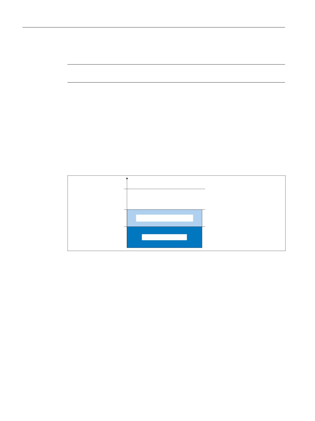
The DC link is monitored against the limit values shown in the following diagram:
'& OLQN YROWDJH
9
3XOVH FDQFHOODWLRQ '& OLQN
3XOVH FDQFHOODWLRQ GULYHV
9
9
9
9
:RUN DUHD
9
3XOVH UHVLVWRU PRGXOH
9
9
Figure 11-1
DC link voltage limit values
The drive and DC link pulses are cancelled at specific voltage levels, which means that the
drives coast-down. If this behavior is not desired, the excess energy can be discharged using
Special functions
Function Manual, 12/2018, A5E40874099B AB
561
R3: Extended stop and retract
11.2 Control-managed ESR - 840D sl only
a resistor module. The operating range of the resistor module (shown highlighted in the
diagram) lies below the critical voltage level.
Note
The pulse power of the resistor module is greater than the infeed power.
Monitoring the intermediate circuit minimum voltage limit
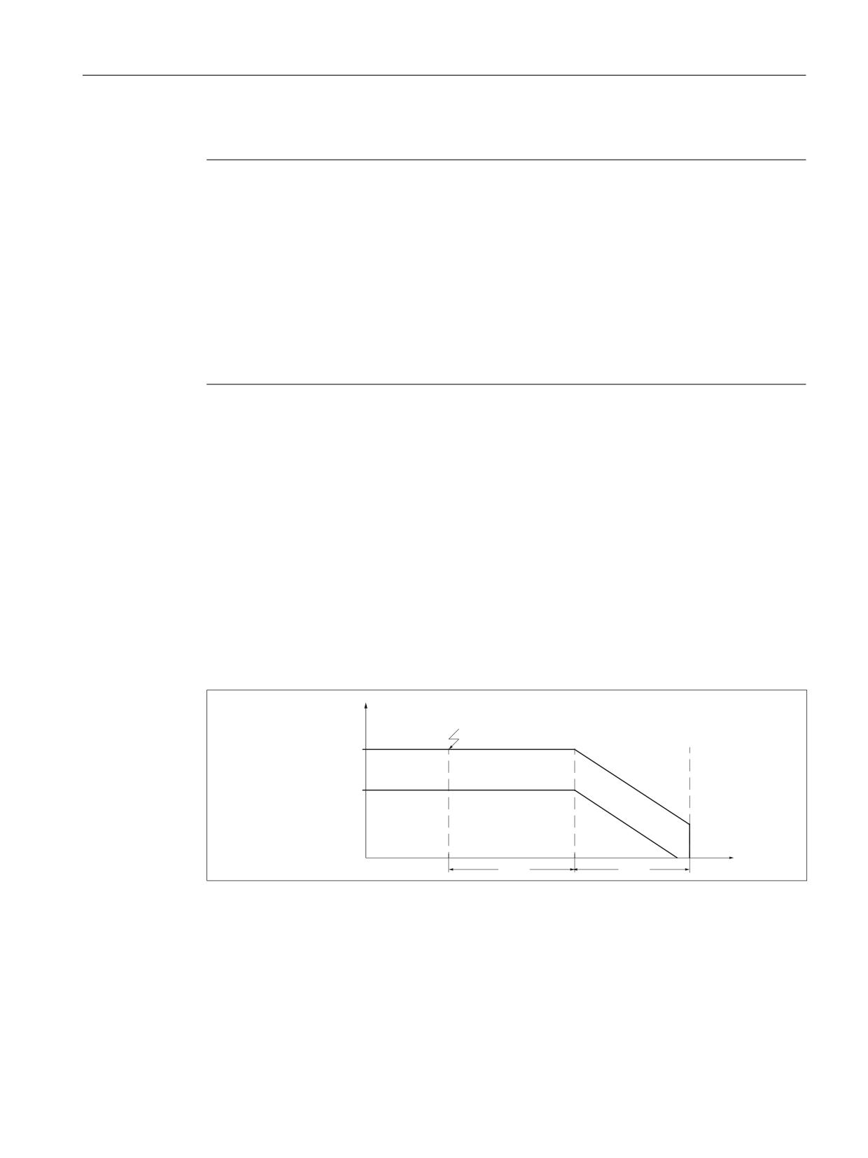
The DC link voltage can be monitored against a limit value that can be parameterized in the
drive:
● p1248 (DC link voltage - lower voltage threshold)
When the limit value is fallen below, the following signal is set in the message word (MELDW)
of the PROFIdrive telegram:
● MELDW.Bit4 = 1 (VDC_min controller is active (Vdc link < p1248))
The signal can be used in the NC to initiate ESR responses.
9
9'& OLQN UDWHG
9
9
9'& OLQN YROWDJH
8=. S
WKUHVKROGBORZHU
'& OLQN XQGHUYROWDJH
9'& OLQN RII
9
6,1$0,&6 $/0 2))
9
Figure 11-2
Monitoring the DC link voltage
11.2.4
NC-controlled extended stop
Axis-specific parameterization
The NC-controlled extended stopping for a machine axis is activated using machine data:
Special functions
562
Function Manual, 12/2018, A5E40874099B AB
R3: Extended stop and retract
11.2 Control-managed ESR - 840D sl only
MD37500 $MA_ESR_REACTION[<axis>] = 22
Note
Path axes
If NC-controlled extended stopping is parameterized for a path axis, then the corresponding
behavior is also transferred to all other path axes of the channel.
Leading and following axis
During the extended stopping, a following axis of an electronic gearbox follows the leading
axes according to the parameterized/programmed motion principle. That is why independent
braking is not possible for the following axis during the times specified in MD21380
$MC_DELAY_TIME1 and MD21381 $MC_ESR_DELAY_TIME2. MD21380
$MC_DELAY_TIME1MD21381 $MC_ESR_DELAY_TIME2 A prerequsite for correct
functioning of ESR is that all necessary enable signals must be set and remain set.
Channel-specific parameterization
The timing within a channel is parameterized using the following machine data:
● MD21380 $MC_ESR_DELAY_TIME1[<axis>] (delay time ESR axes)
● MD21381 $MC_ESR_DELAY_TIME2[<axis>] (ESR time for interpolatory braking)
Time sequence
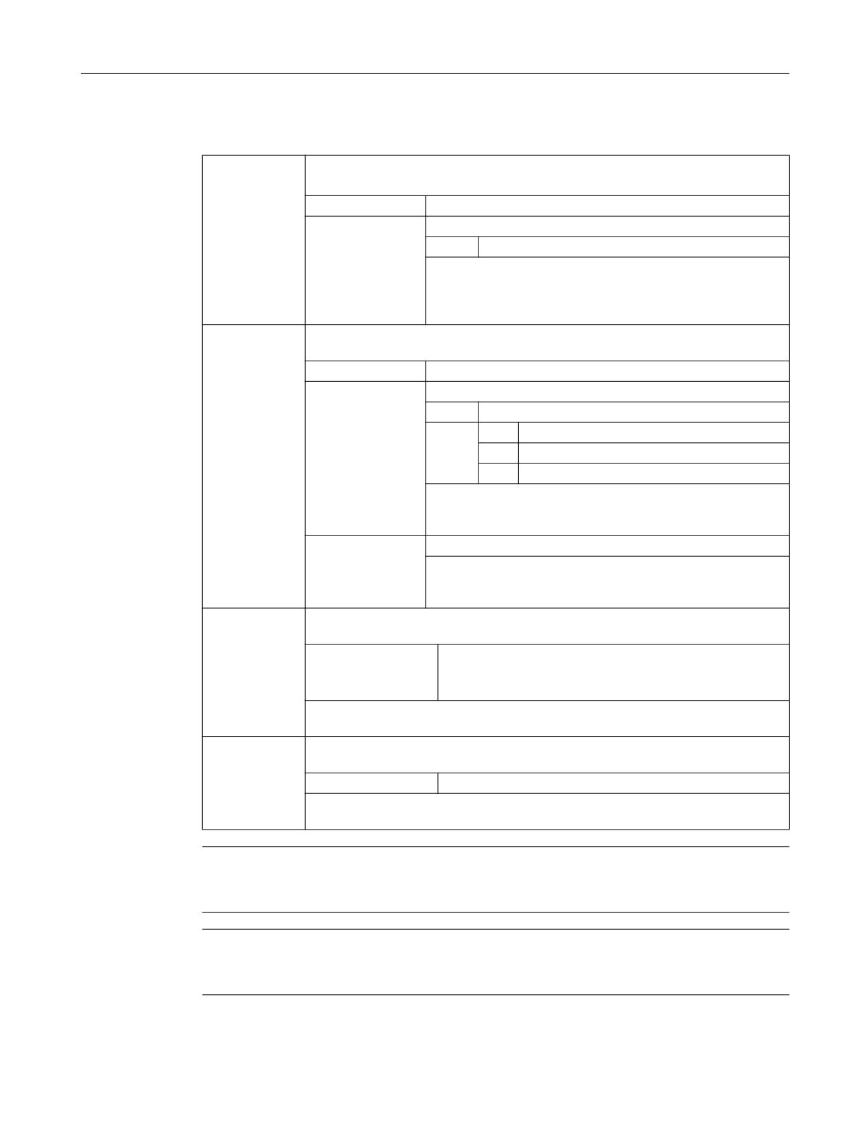
After initiating ESR, the axis continues to traverse with the actual speed. After a delay time
has expired (..._TIME1), the axis is braked, interpolating.
The set time (..._TIME 2) is the maximum time available for interpolatory braking. After this
time has expired, a setpoint of 0 is output for the axis, and the follow-up mode is activated.
6SHHG Q
(65 WULJJHUHG
2XWSXW RI VHWSRLQW
Q
Q
7
7
=HLW W
T1
MD21380 $MC_ESR_DELAY_TIME1 (delay time, ESR axes)
T2
MD21381 $MC_ESR_DELAY_TIME2 (ESR time for interpolatory braking)
n1
Actual speed, which could be braked to a standstill within T2
n2
Actual speed, which could not be braked to a standstill within T2 ⇒ fast braking
Special functions
Function Manual, 12/2018, A5E40874099B AB
563
R3: Extended stop and retract
11.2 Control-managed ESR - 840D sl only
Note
For safety reasons, the sum of T1 and T2 should not exceed a maximum value of approx. 1
second.
Precondition
To ensure that ESR is carried out, at least one of the axes involved in the movement must be
parameterized as an NC-controlled retraction or stopping axis: MD37500
$MA_ESR_REACTION > 20
For axes that are not parameterized as NC controlled retraction or stopping axis, fast braking
with subsequent tracking is realized immediately so that extended stopping starts
($AC_ESR_TRIGGER = 1).
Processing of all commands, especially those that result in an axis stop (e.g. Reset, Stop,
Stopall), as well as the standard alarm responses STOPBYALARM and NOREADY, is delayed
by the sum of the parameterized times:
Delay time = MD21380 $MC_ESR_DELAY_TIME1 + MD21381 $MC_ESR_DELAY_TIME2
An NC controlled stop is also active in conjunction with the "Electronic gearbox" function (see
Chapter "Electronic gear (EG) (Page 442)"). It contains the (selective) switchover of the
electronic gearbox to actual value coupling if there is a fault on the leading axes, and also
maintains traversing motion and the enable signals during the delay time for ESR axes:
MD21380 $MC_ESR_DELAY_TIME1
11.2.5
Retract
11.2.5.1
Function
Rapid lift to the position defined with POLF is programmed using modal command LFPOS.
Retraction motion parameterized with LFPOS or POLF for the axes programmed with
POLFMASK or POLFMLIN replaces the traversing motion programmed for these axes in the NC
program.
Regarding retraction motion, the following applies:
● The axes specified with POLFMASK independently traverse to the positions specified with
POLF.
● The axes specified with POLFMLIN traverse to the positions specified with POLF in a
linear relationship.
The extended retraction (i.e. LIFTFAST/LFPOS initiated through $AC_ESR_TRIGGER) cannot
be interrupted and can only be terminated prematurely using Emergency Off.
Velocity and acceleration limits for the axes involved in the retraction are monitored during the
retraction motion. The retracting movement takes place with BRISK, i.e. without jerk limitation.
Special functions
564
Function Manual, 12/2018, A5E40874099B AB

R3: Extended stop and retract
11.2 Control-managed ESR - 840D sl only
Initiating the retraction
Retraction motion LIFTFAST is initiated in a channel, if, in this channel there is an axis for
which retraction motion is enabled ($AA_ESR_ENABLE == 1) - and the trigger for fast
retraction ($AC_ESR_TRIGGER = 1) is set.
Requirement
● The retraction position must be programmed in the NC program.
● The enable signals must be set and remain set for retraction motion.
11.2.5.2
Parameterization: Machine data
Activation
NC-controlled retraction for an axis is activated using machine data:
MD37500 $MA_ESR_REACTION = 21
Delay times
Two different retraction times can be parameterized for the retraction:
● MD21380 $MC_ESR_DELAY_TIME1 = <delay time: Traversing motion>
● MD21381 $MC_ESR_DELAY_TIME2 = <delay time: Interpolatory braking>
To perform retraction motion, the sum of the two delay times are available. After the total delay
time has expired, fast braking is initiated for the retraction axes with a setpoint of 0 - with
subsequent switchover into follow-up (tracking) operation.
Mirroring
The machine data is used to set, whether, for active "Mirroring" function (DB31, … DBX97.2),
the retraction direction should be mirrored for "Fast retraction from the contour" (LIFTFAST):
MD21202 $MC_LIFTFAST_WITH_MIRROR = TRUE
The mirroring of the retraction direction only refers to the direction components perpendicular
to the tool direction.
Stop behavior
The stop response for lift motion is set on a channel-for-general basis using the following
machine data:
MD21204 $MC_LIFTFAST_STOP_COND, <bit> = <value>
Bit
Val-
Description
ue
0
Response to the axis-specific NC/PLC interface signal DB31 DBB4.3 (feed stop) or context-
sensitive interpolator stop.
0
Retraction motion is stopped for axis-specific feed stop or context-sensitive interpolator
stop
1
Retraction motion is not stopped for axis-specific feed stop or context-sensitive interpo-
lator stop
Special functions
Function Manual, 12/2018, A5E40874099B AB
565

R3: Extended stop and retract
11.2 Control-managed ESR - 840D sl only
Bit
Val-
Description
ue
1
Response to the channel-specific NC/PLC interface signal DB21, ... DBB6.0 (feed inhibit)
0
Retraction motion stop for feed disable in the channel
1
No retraction motion stop for feed disable in the channel
Note
Influence of the interface signals
● The axis-specific NC/PLC interface signal DB31 DBB4.3 (feed stop) influences the
complete retraction motion. All axis motion defined using POLFMASK and POLFMLIN are
stopped.
● The channel-specific NC/PLC interface signal, DB21, ... DBB7.3 (NC stop) has no effect
on the retraction movement.
See also
Lift fast with linear relation of axes (Page 597)
11.2.5.3
Parameterization: System variable
Axis-specific function enable
An axis is enabled for retraction on an axis-for-axis basis using system variable:
$AA_ESR_ENABLE[<axis>] = 1
Channel-specific initiation
Retraction motion is initiated on a channel-for-channel basis using system variable:
$AC_ESR_TRIGGER = 1
Retraction is then realized in all channel axes for which the following applies:
$AA_ESR_ENABLE[<axis>] == 1 AND MD37500 $MA_ESR_REACTION[axis] == 21 OR 22
11.2.5.4
Programming (POLF, POLFA, POLFMASK, POLFMLIN)
Syntax
POLF(<axis>)=<position>
POLFA(<axis>,<type>,<position>)
POLFA(<axis>,<type>)
POLFMASK(<axis_1>,<axis_2>,...)
POLFMLIN(<axis_1>,<axis_2>,...)
Special functions
566
Function Manual, 12/2018, A5E40874099B AB
R3: Extended stop and retract
11.2 Control-managed ESR - 840D sl only
Meaning
POLF:
Address for specifying the target position of the retraction axis
POLF is modal.
<axis>:
Channel axis name of the retraction axis
<position>:
Retraction position
Type:
REAL
The geometry axis is retracted in the WCS. For all other chan-
nel axes in the MCS.
With the same identifiers for geometry and channel/machine
axis, retraction is in the WCS.
POLFA:
Predefined subprogram call for the specification of the retraction position of single
axes
<axis>:
Channel axis name of the retraction axis
<type>:
Position specification mode
Type:
INT
Value:
0
Mark position value as invalid
1
Position value is absolute
2
Position value is incremental (distance)
Note:
If an axis is not a single axis or if the type is missing or type=0,
then a corresponding alarm is output.
<position>:
Retraction position (see above) (optional)
Note:
The position value is also accepted with type=0. Only this value
is marked as invalid and has to be reprogrammed for retraction.
POLFMASK:
Predefined subprogram call for selection of the axes that are to be retracted after
tripping of rapid lift independently of one another.
<axis_1>,…:
Names of the axes that are to be traversed to their positions
defined with POLF during rapid lift.
All the axes specified must be in the same coordinate system.
POLFMASK() without specification of an axis deactivates the rapid lift for all axes
that have been retracted independently of one another.
POLFMLIN:
Predefined subprogram call for selection of the axes that are to be retracted after
tripping of rapid lift in linear relation.
<axis_1>,…:
See above.
POLFMLIN() without specification of an axis deactivates the rapid lift for all axes
that have been retracted in linear relation.
Note
Before rapid retraction to a fixed position can be enabled via POLFMASK or POLFMLIN, a
position must have been programmed with POLF for the selected axes.
Note
If axes are enabled one after the other with POLFMASK, POLFMLIN or POLFMLIN, POLFMASK,
then the last definition always applies for the particular axis.
Special functions
Function Manual, 12/2018, A5E40874099B AB
567

R3: Extended stop and retract
11.2 Control-managed ESR - 840D sl only
Note
The positions programmed with POLF and the activation by POLFMASK or POLFMLIN are
deleted when the part program is started. This means that the user must reprogram the values
for POLF and the selected axes in POLFMASK or POLFMLIN in each part program.
Note
If, when using the abbreviated form POLFA only the type is changed, then the user must ensure
that either the retraction position or the retraction path contains a practical and sensible value.
In particular, the retraction position and the retraction path have to be set again after a warm
restart.
Example: Retracting an individual axis
Program code
Comment
MD37500 $MA_ESR_REACTION[AX1]=21
; NC-controlled retraction.
$AA_ESR_ENABLE[AX1]=1
POLFA(AX1,1,20.0)
; AX1 is assigned the axial retraction
position 20.0 (absolute).
$AA_ESR_TRIGGER[AX1]=1
; Retraction starts from here.
11.2.5.5
Boundary conditions
General supplementary conditions
Exceptions
Retraction and/or rapid lift is not executed for the following axes:
● Axes, which are not permanently assigned a channel
● Axes, which are in the open-loop speed-controlled mode (spindles)
● Axes, which are interpolated as positioning spindles (SPOS/SPOSA)
Modulo rotary axes
Modulo rotary axes respond to rapid lift as follows:
● For incremental programming of the target position, the latter is approached without modulo
offset.
● With absolute programming, the target position is approached time-optimized with the use
of modulo offsets. This is almost identical to positioning via the shortest path.
Utilizing the axis dynamics
The retraction movement is interpolated linearly, using the maximum acceleration and speed
of the axes involved in POLFLIN.
Special functions
568
Function Manual, 12/2018, A5E40874099B AB
R3: Extended stop and retract
11.2 Control-managed ESR - 840D sl only
Parallel retraction
Only one linear retraction is permitted in each channel. This means that multiple axis groups,
which approach their retraction positions linearly, cannot be created in the channel.
In parallel with linear retraction, additional axes can also use POLFMASK for independent axis-
specific retraction movement to their programmed retraction positions.
Concurrent retraction
If axes are used in both POLFMASK and in POLFMIN, it should be noted that the last state
programmed is always active for retracting movement. This means that an axis previously
activated with POLFMIN is removed from the linear relationship following programming in
POLFMASK and the retracting movement would then take place as an independent movement
(see the examples in Chapter "Lift fast with linear relation of axes (Page 597)").
Effectiveness of retraction parameters
The parameters valid at the triggering time are decisive for the retraction movement. If one of
these parameters (POLF, POLFMASK, POLFMLIN, Frame, etc.) changes during the retracting
movement (e.g. due to a block change), this change does not affect the retraction movement
that has already started.
Supplementary conditions: Path axes
Alternative extended stopping
If, for a path axis ESR_REACTION=21 (NC-controlled retraction) is configured and enabled
with $AC_ESR_ENABLE=1, then ESR_REACTION=22 (extended stopping) is active for all
path axes for which no ESR_REACTION=21 is configured or enabled.
Rapid retraction/lift without retraction motion enabled
If, for an axis, ESR_REACTION=21 is configured and enabled with $AC_ESR_ENABLE=1,
but e.g. no retraction motion is enabled with POLFMASK, then, for this axis,
ESR_REACTION=22 is active (extended stopping).
Behavior for different enable signals
"NC-controlled retraction" is configured for path axes X and Y:
● MD37500 $MA_ESR_REACTION[X] = 21
● MD37500, $MA_ESR_REACTION[Y] = 21
Special functions
Function Manual, 12/2018, A5E40874099B AB
569
R3: Extended stop and retract
11.2 Control-managed ESR - 840D sl only
1. "Extended stop and retract" and retraction motion is enabled for both path axes:
- $AA_ESR_ENABLE(X) = 1
- $AA_ESR_ENABLE(Y) = 1
- POLFMASK(X,Y)
For rapid lift, X and Y execute the programmed retraction motion.
2. "Extended stop and retract" is only enabled for one path axis, but retraction motion is
enabled for both path axes:
- $AA_ESR_ENABLE(X) = 0
- $AA_ESR_ENABLE(Y) = 1
- POLFMASK(X,Y)
For rapid lift, for axis X, due to the path interrelationship, in spite of the fact that it is not
enabled, "extended stopping" corresponding to ESR_REACTION = 22 is executed.
Axis Y executes the programmed retraction motion.
3. However, for both path axes, "Extended stop and retract" is enabled - but retraction motion
only for one path axis:
- $AA_ESR_ENABLE(X) = 1
- $AA_ESR_ENABLE(Y) = 1
- POLFMASK(Y)
For rapid lift, for axis X, due to the path interrelationship, in spite of the missing enable
signal, retraction motion "extended stopping" corresponding to ESR_REACTION = 22 is
executed.
Axis Y executes the programmed retraction motion.
11.2.6
Trigger sources
A distinction must be made between the ESR trigger sources on a user-for-user basis by
evaluating system variables. This is the reason that all system variables are available, which
can be read in synchronized actions.
General trigger sources
● Digital inputs of the NCU module or the internal control image of digital outputs that can be
read back: $A_IN, $A_OUT
● Channel status: $AC_STAT
● NC/PLC interface signals
Special functions
570
Function Manual, 12/2018, A5E40874099B AB
R3: Extended stop and retract
11.2 Control-managed ESR - 840D sl only
● System variables written from the PLC: $A_DBB, $A_DBW, $A_DBD
It is not recommended to use these system variables, written by the PLC for time-critical
signals, as in this case, the PLC cycle time is included in the total response time.
Nevertheless, it is an appropriate way for the PLC to influence the sequence or release of
the extended stop and retract function. However, linking-in PLC states in such a fashion
does make sense if these are exclusively input from the PLC (e.g. Emergency-Stop, reset
button, stop button)
● Group signals from alarms: $AC_ALARM_STAT
Axial trigger sources
● $VA_SYNCDIFF[<following axis>] (synchronism difference, on the actual value side)
● $AA_ESR_STAT (axial return signal word: ESR status)
Alarm responses
When ESR is active, the alarm responses NOREADY and STOPBYALARM are delayed by
one IPO cycle. The self-clearing alarm is displayed to indicate this delay:
Alarm 21600 "Monitoring for ESR active".
Note
The display of this alarm can be suppressed by:
MD11410 $MN_SUPPRESS_ALARM_MASK, bit16 = 1
11.2.7
Logic gating functions: Source and reaction linking
The flexible logic operation possibilities of the static synchronized actions can be used to trigger
specific reactions based on sources. Linking all relevant sources using static synchronized
actions is the responsibility of the user/machine manufacturer. They can selectively evaluate
the source system variables as a whole or by means of bit masks, and then make a logic
operation with their desired reactions. The static synchronous actions are effective in all
operating modes. A detailed description of how to use synchronous actions can be found in:
References:
● Function Manual, Synchronized Actions
● Programming Manual Work Preparation (Synchronized Actions, System Variables)
Linking of axial sources with global or channel specific sources can be configured variably with
the aid of $AA_TYP (axis type).
Special functions
Function Manual, 12/2018, A5E40874099B AB
571
R3: Extended stop and retract
11.2 Control-managed ESR - 840D sl only
11.2.8
Activation
Option
The function "Extended stop and retract" is an option.
Axis-specific function enable ($AA_ESR_ENABLE)
The axis-specific function enable is realized using the system variable:
$AA_ESR_ENABLE[<axis>] = 1
Axis-specific enable for extended stopping
An axis is enabled for extended stopping with:
MD37500 $MA_ESR_REACTION[axis] = 22
Axis-specific enable for retraction
An axis is enabled for retraction using:
MD37500 $MA_ESR_REACTION[axis] = 21
Channel-specific trigger ($AC_ESR_TRIGGER)
ESR is triggered on a channel-for-channel basis by setting the following system variable:
$AC_ESR_TRIGGER = 1
ESR is then realized in all channel axes for which the following applies:
$AA_ESR_ENABLE[<axis>] == 1 AND MD37500 $MA_ESR_REACTION[axis] == 21 OR 22
11.2.9
Configuring aids for ESR
Voltage failure
For the following modules, when the line voltage fails, the power supply must be maintained
using suitable measures at least until it is ensured that the axes have come to a stop:
● SINUMERIK 840D sl NCU 7x0
● SINUMERIK NCU I/O modules
● SIMATIC PLC I/O modules
● SINAMICS drive system S120 (booksize)
Special functions
572
Function Manual, 12/2018, A5E40874099B AB
R3: Extended stop and retract
11.2 Control-managed ESR - 840D sl only
DC link energy
The energy available in the DC link of the drive units when the line supply fails is calculated
as follows:
E = 1/2 * C * (VDC linkalarm2 - VDC linkmin2)
E:
Energy in Wattseconds [Ws]
C:
Total capacity of intermediate circuit in Farad [F]
VDClinkalarm: DC link voltage below which an undervoltage is identified.
SINAMICS Parameter: r0296 + p0279
VDClinkmin: Lower limit of the DC link voltage for safe and reliable operation, tak-
ing into account the motor-specific EMF.
Note VDC linkmin > VDC linkoff
This energy is available for a minimum time of tmin:
tP = E / Pn * η
E:
Energy in Wattseconds [Ws]
tP:
Buffer time in milliseconds [ms]
Pn:
Power in kilowatt [kW]
η:
Efficiency of the drive unit
Example
Assumptions:
● Pn = 16 kW, infeed (ALM) with 3-ph. 380 VAC
● C = Cis - 20% = 20,000 µF - 20% = 16,000 µF = 16 * 10-3 F, for safety, a 20% lower effectively
available capacity is assumed.
● VDC linkalarm = 550 V
● VDC linkmin = 350 V
E = 1/2 * 16*10-3 F * ( (550 V)2 - (350 V)2 ) = 1440 Ws
This energy is available for a time tmin, e.g. for a retraction:
● E = 1440 Ws
● Pn = 16 kW
● η = 0.9 (assumption)
tPmin = 1440 Ws / 16 kW * 0.9 = 81 ms
The following table shows a summary of the values for various SINAMICS infeeds (ALMs).
Whereby, the nominal (Cmax) and minimum (Cmin) capacitance are taken into account.
The total capacitance of the DC link available is made up, taking into account the respective
maximum capacitance Cmax (charge limit), from the capacitances of the infeed (ALM), the motor
modules as well as any capacitor modules.
Special functions
Function Manual, 12/2018, A5E40874099B AB
573

R3: Extended stop and retract
11.2 Control-managed ESR - 840D sl only
The capacitance specified in the table for the minimum energy content (E
min
for Cmin) takes into
account a component tolerance of -20% (worst case).
Note
It is recommended that the SIZER configuration tool be used to determine the total capacitance
of the DC link available.
Table 11-1
SINAMICS infeeds (ALMs): Nominal and minimum buffer times
ALM
Max. capacitance
Energy content
Energy content Emin
Backup time tPmax
Buffer time tPmin for
Cmax[μF]
Emax for Cmax [Ws]
for Cmin [Ws]
for Pmax [ms]
Pmax [ms]
Pmax[kW]
16
20000
1800
1440
101,25
81,00
36
20000
1800
1440
45,00
36,00
55
20000
1800
1440
29,46
23,56
80
20000
1800
1440
20,25
16,20
120
20000
1800
1440
13,50
10,80
Energy balance
When configuring retraction motion, it is always necessary to consider the energy flow
(balance) to find out whether an additional capacitor module or a generator axis (with
correspondingly dimensioned flywheel effect) is required - or not.
Stopping as energy supply
From approx. the third interpolator clock cycle, the speed setpoints of the configured stopping
or retraction axes change. After this time the braking phase starts (if no drive independent
shutdown is projected for this axis).
As soon as the braking process is initiated, the energy released in this manner is available for
retraction motion. An energy balance must be used to ensure that the kinetic energy of the
braking axes is sufficient for retraction.
The energy balance shows the maximum setting for the interpolator clock cycle time, which
will allow a safe emergency retraction to be executed.
Example
With a 16 kW unit under maximum load and minimum intermediate circuit capacity it should
be possible to execute an emergency retraction without generator operation. Interpolator clock
cycle time may theoretically not be more than 4.86 ms, i.e. in this case a maximum of 4 ms
could be set.
If necessary, a more powerful NCU must be chosen in order to achieve optimal conditions.
Special functions
574
Function Manual, 12/2018, A5E40874099B AB
R3: Extended stop and retract
11.2 Control-managed ESR - 840D sl only
Generator operation
For cases in which the DC link energy is not sufficient for safe and reliable retraction (minimum
3 IPO cycles), generator operation can be configured for a drive using the SINAMICS "Vdc
control" function. In this case, the mechanical energy of an axis is fed back into the DC link.
The energy stored in an axis can be calculated as follows:
E = 1/2 * Jtot * ω2
Jtot
Total moment of inertia [kg*m2]
ω
Angular velocity at the time of switchover to generator operation [s-1]
This energy is fed back into the DC link with an efficiency of approx. 90%:
When using infeeds with a high power rating (55, 80, 120 kW) for generator operation, it is
recommended to use a dedicated axis with additional flywheel effect. For this axis, after the
drive has accelerated to the rated speed, energy is only required to compensate for friction
losses.
However, in principle, any axis can be used for generator operation, if this is not directly
involved in extended stopping and retraction or in couplings that must be specifically
maintained.
In order to prevent that the DC link voltage does not become too high when using generator
operation (limit value: pulse cancelation, drive) and as a consequence that the pulses are
canceled for the axes, adequately dimensioned pulsed resistor modules must be used or the
SINAMICS function "Vdc control, overvoltage monitoring".
11.2.10
Control system response
11.2.10.1
Axis behavior depending on the enable signals
Systematic
If an axis is configured as NC-controlled retraction axis:
MD37500, $MA_ESR_REACTION[<axis>] = 21
The following enable signals must be available to execute retraction motion in the case of ESR:
● Axial ESR enable using system variable: $AA_ESR_ ENABLE[<axis>] = 1
● Axial retraction enable using a part program command: POLFMASK(<axis>)
Special functions
Function Manual, 12/2018, A5E40874099B AB
575

R3: Extended stop and retract
11.2 Control-managed ESR - 840D sl only
If one of the two enable signals is not available, then in the case of ESR, the axis responds
corresponding to the following table:
Enable signals
Response in the case of ESR
● $AA_ESR_ ENABLE[<axis>] = 1
For the axis, implicit NC-controlled stopping becomes active, corresponding
to MD37500, $MA_ESR_REACTION[<axis>] = 22.
● No enable via POLFMASK
● $AA_ESR_ ENABLE[<axis>] = 0
Axis is a path axis:
For the axis, the ESR response is implicitly changed to NC-controlled stop-
● Enable via POLFMASK(<axis>)
ping. The response corresponds then to a configuration of MD37500,
$MA_ESR_REACTION[<axis>] = 22
Axis is a special axis:
The axis is stopped with rapid stop.
Examples for axes with path relationship
For the subsequent examples, two path axes X and Y are assumed, which are configured as
NC-controlled retraction axes and are programmed for the retraction positions:
● MD37500, $MA_ESR_REACTION[X] = 21
● MD37500, $MA_ESR_REACTION[Y] = 21
● POLF[X]=<retraction position> LFPOS
● POLF[Y]=<retraction position> LFPOS
Initial situation
Response in the case of ESR
● $AA_ESR_ ENABLE[X] = 1
Retraction motion in X and Y.
● $AA_ESR_ ENABLE[Y] = 1
● POLFMASK(X,Y)
● Program traversing motion: Y
● $AA_ESR_ ENABLE[X] = 0
X does not have ESR enable. As X is a path axis, for X, the ESR response
is implicitly changed to 22 (stopping). This is the reason that X continues to
● $AA_ESR_ ENABLE[Y] = 1
traverse corresponding to the programmed traversing motion.
● POLFMASK(X,Y)
Y executes retraction motion.
● Program traversing motion: X and Y
After the delay time for ESR axes expires, MD21380, $MC_ESR_DE-
LAY_TIME1, X is stopped with the path acceleration.
● $AA_ESR_ ENABLE[X] = 1
X has no retraction enable (POLFMASK). X does not execute any retraction
motion. As X is a path axis, for X, the ESR response is implicitly changed to
● $AA_ESR_ ENABLE[Y] = 1
22 (stopping). This is the reason that X continues to traverse corresponding
● POLFMASK(Y)
to the programmed traversing motion.
● Program traversing motion: X
Y executes retraction motion.
After the delay time for ESR axes expires, MD21380, $MC_ESR_DE-
LAY_TIME1, X is stopped with the path acceleration.
● $AA_ESR_ ENABLE[X] = 1
Y has not been enabled for retraction (POLFMASK). see lines above, syntax
Y does not execute retraction motion. As Y is a path axis, for Y, the ESR
● $AA_ESR_ ENABLE[Y] = 1
response is implicitly changed to 22 (stopping). This is the reason that Y
● POLFMASK(X)
continues to traverse corresponding to the programmed traversing motion.
● Program traversing motion: X and Y
X executes retraction motion.
After the delay time for ESR axes expires, MD21380, $MC_ESR_DE-
LAY_TIME1, Y is stopped with the path acceleration.
Special functions
576
Function Manual, 12/2018, A5E40874099B AB

R3: Extended stop and retract
11.2 Control-managed ESR - 840D sl only
Examples for axes without path relationship
For the subsequent examples, path axes X and a command axis B are assumed, which are
configured as NC-controlled retraction axis:
● MD37500, $MA_ESR_REACTION[X] = 21
● MD37500, $MA_ESR_REACTION[B] = 21
Initial situation
Response in the case of ESR
● $AA_ESR_ ENABLE[X] = 1
B is not enabled for ESR. As B is not a path axis, B is immediately stopped
with a rapid stop.
● $AA_ESR_ ENABLE[B] = 0
X executes retraction motion.
● POLFMASK(X)
● Program traversing motion: X and B
● $AA_ESR_ ENABLE[X] = 1
B is not enabled for retraction (POLFMASK). However, as B is enabled for
ESR, for B, the ESR response is implicitly changed to 22 (stopping). This is
● $AA_ESR_ ENABLE[B] = 1
the reason that B continues to traverse corresponding to the programmed
● POLFMASK(X)
traversing motion.
● Program traversing motion: X and B
Y executes retraction motion.
After the delay time for ESR axes expires, MD21380, $MC_ESR_DE-
LAY_TIME1, B is stopped with axial acceleration.
11.2.10.2
POWER OFF/POWER ON
If the user-specific retraction logic is programmed within motion synchronized actions, then it
must be observed that this is still not active when the control boots (POWER ON). A retraction
logic, which should be active after POWER ON, must therefore lie in an ASUB started from
the PLC or must be called event-controlled.
References
For detailed information about event-driven program calls see:
Function Manual, Basic Functions; Mode Group, Channel, Program Operation, Reset
Response (K1), Section: Eventcontrolled program calls
11.2.10.3
Operating mode change, NC Stop, reset
Static synchronized actions (IDS keyword) can be used for user-specific retraction logic as the
following system states or state change have no influence on this:
● Operating mode change, e.g. DB11 DBX0.0 (AUTOMATIC)
● NC stop, e.g. DB21, ... DBX7.3 (NC stop)
● Reset, e.g. DB21, ... DBX7.7 (reset)
Special functions
Function Manual, 12/2018, A5E40874099B AB
577

R3: Extended stop and retract
11.2 Control-managed ESR - 840D sl only
Note
NC stop and command axes
Traversing command axes is interrupted for an NC stop.
Note
POLF/POLFMASK reset and program commands
For reset, the programmed absolute retraction positions (POLF) and the enable signals for the
retraction axes (POLFMASK) are not deleted.
11.2.10.4
Part program start, NC start
In order that a defined initial state is available when a part program starts, the programmed
absolute retraction positions and the enable signals of the retraction axes are deleted when
the part program starts.
Note
Retraction positions and enable signals
When a part program starts, the absolute retraction positions (POLF) and the enable signals
of the retraction axes (POLFMASK) must be reprogrammed corresponding to the actual
requirements.
11.2.10.5
Alarm behavior
The alarm response depends on the axis in which a fault occurs:
● Fault in an axis outside the axis grouping of an electronic gear:
This axis switches off "normally". Extended stopping and retraction continue to operate as
before - or are initiated by such a fault.
● Error in a leading axis (LA):
selective switchover to actual value linkage already during stop, otherwise as previously.
● Error in a following axis (FA):
- Carry out retract: Retraction axis may not be a following axis, that is, no conflict.
- Carry out stop: The following axis may react with uncontrollable behavior. Saving the
workpiece/tool must be left to the retraction; however, the stop should not disrupt the
process any further.
Special functions
578
Function Manual, 12/2018, A5E40874099B AB
R3: Extended stop and retract
11.3 ESR executed autonomously in the drive
● Error in the retraction axis: There is no retraction.
● Emergency Stop
An Emergency Stop is not a fault from a control system point of view, rather the response
is the same as for any other control signal. For safety reasons, Emergency Stop interrupts
the interpolation and all traversing motion, and also cancels the electronic coupling by
withdrawing the controller enable signals.
In applications where the coupling and traversing movements must remain valid after
Emergency Stop, the PLC must delay the Emergency Stop long enough for the required
NC or drive-end reactions to terminate.
The following interface signal is available as feedback signal to the PLC:
IS "ESR reaction not initiated" DB31, ... DBX98.7
If an alarm with cross-channel NOREADY reaction is issued during the active phase of the
ESR (i.e. NOREADY | NCKREACTIONVIEW | BAGREACTIONVIEW), then ESR is triggered
in all channels.
11.2.10.6
Block search, REPOS
Extended stop and retract does not affect block search or REPOS motions.
11.3
ESR executed autonomously in the drive
11.3.1
Fundamentals
Function
Drive-autonomous extended stop and retract (ESR) enables the fast separation of workpiece
and tool independent of the higher-level control (NC).
For this purpose, the following axis-specific functions can be configured in the drive:
● Generator operation
● Extended stop
● Retract
The drive-autonomous responses are automatically initiated in error situations. The triggering
of the drive-autonomous responses can also be realized user-specific via the part programs
or synchronized actions from the higher-level control system.
As the stopping and retraction motion of the drive-autonomous ESR are purely axis-specific,
in contrast to control-managed ESR, couplings are not taken into account.
Special functions
Function Manual, 12/2018, A5E40874099B AB
579

R3: Extended stop and retract
11.3 ESR executed autonomously in the drive
ESR executed autonomously in the drive can also be used in combination with control-
managed ESR. This also allows stopping and retraction motion in the drives if they are no
longer specified from the control, e.g. as a result of a communication failure.
Note
DRIVE-CLiQ
For possibly occurring DRIVE-CLiQ errors, in order to keep the reaction to the functions of the
drive-autonomous ESR as low as possible, within the scope of ESR, we recommend that the
motor modules involved are not connected through a line-type topology, but instead are directly
connected to the Control Unit (CU).
Link axes
The "Drive-autonomous extended stop and retract (ESR)" function cannot be used in
conjunction with link axes.
Requirements
The following conditions must be fulfilled:
● SINAMICS and SINUMERIK software version: ≥ V4.4
● Servo drive object, PROFIdrive telegram: 102 - 199
● Servo drive object, function module "ESR" active
The function module "Extended stop and retract (ESR)" must be activated via the drive
wizard of SINUMERIK Operate. For a description of the drive wizard, see: SINUMERIK
Operate online help.
● Servo drive object, generator operation (Vdc control) active in a drive
● Control unit drive object, PROFIdrive telegram: 390, 391
● The 24 V power supply for the modules is buffered via CSM or UPS
11.3.2
Configuring stopping in the drive
Drive integrated shutdown is configured via the following drive parameters:
Parameter
Description
p0888
ESR: Configuration
Value
Meaning
1
Extended stopping (function integrated in the drive)
Special functions
580
Function Manual, 12/2018, A5E40874099B AB
R3: Extended stop and retract
11.3 ESR executed autonomously in the drive
Parameter
Description
p0891
ESR: Off ramp
Value
Meaning
0
OFF3 (default)
The drive is braked along the OFF3 down ramp by immediately entering n_set
= 0 (p1135: OFF3 ramp-down time).
1
OFF1
By immediately entering n_set = 0, the drive is braked along the ramp gener-
ator down ramp (p1121: ramp-function generator ramp-down time).
Parameter
Description
p0892
ESR: Timer
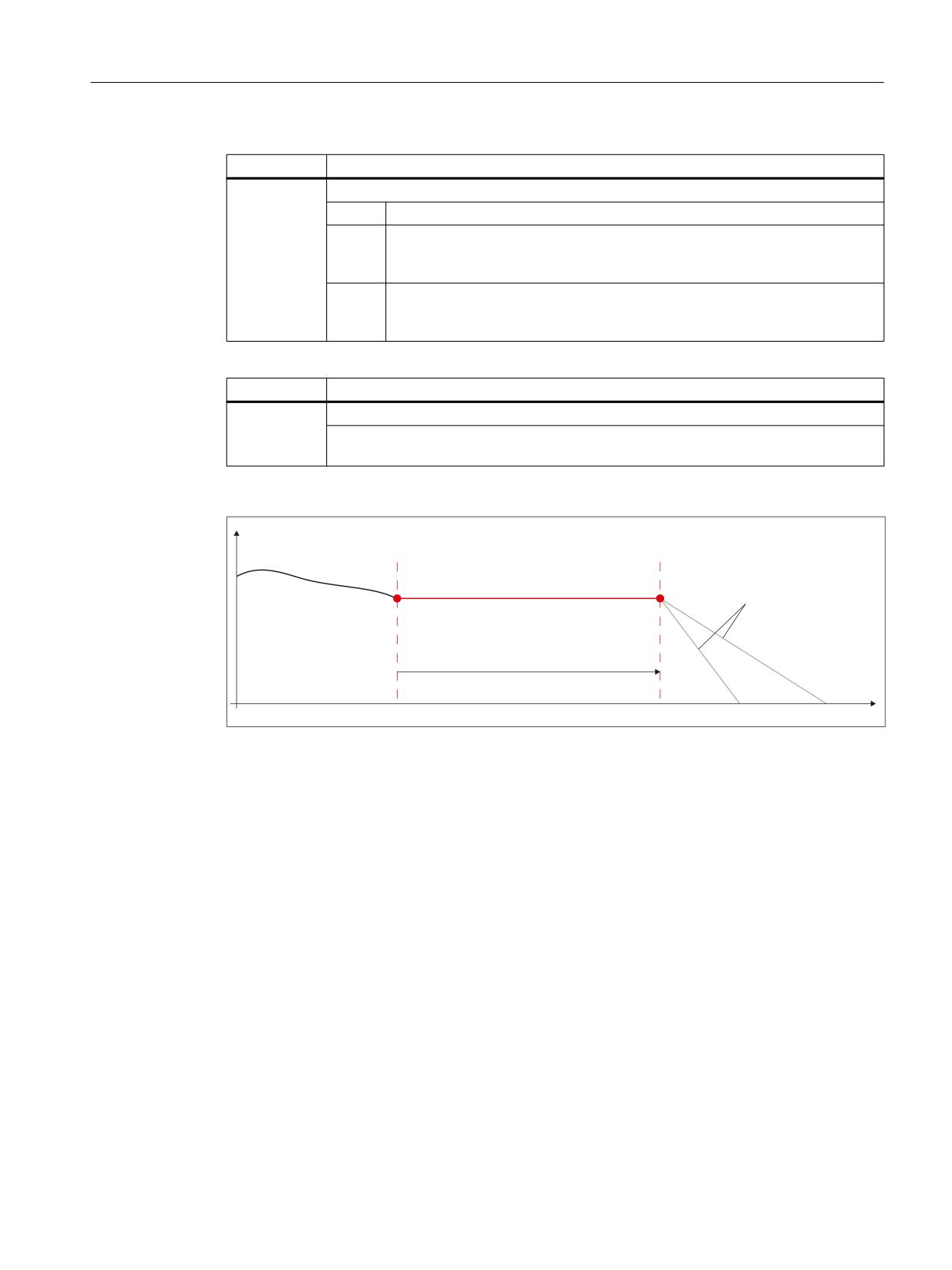
The drive travels at a constant velocity for the configured time with the speed setpoint
that was present when the fault occurred.
6SHHG Q
S
S
$86
$86
7
7
7LPH W
T1
Time at which stopping was triggered
T2
Instant in time after the time that was configured in p0892 has expired
OFF3/OFF1
Braking ramp as a function of p0891
Figure 11-3
Response to drive-integrated stopping
Feedback signal
The stop status is returned to the control (see Section "Feedback of the ESR status
(Page 585)").
References
For a detailed description of drive parameters, refer to:
SINAMICS S120/S150 Parameter Manual
Special functions
Function Manual, 12/2018, A5E40874099B AB
581

R3: Extended stop and retract
11.3 ESR executed autonomously in the drive
11.3.3
Configuring retraction in the drive
Drive integrated retraction is configured using the following drive parameters:
Parameter
Description
p0888
ESR: Configuration
Value
Meaning
2
Extended retraction (function integrated in the drive)
Parameter
Description
p0891
ESR: Off ramp
Value
Meaning
0
OFF3 (default)
The drive is braked along the OFF3 down ramp by immediately entering n_set
= 0 (p1135: OFF3 ramp-down time).
1
OFF1
By immediately entering n_set = 0, the drive is braked along the ramp gener-
ator down ramp (p1121: ramp-function generator ramp-down time).
Parameter
Description
p0892
ESR: Timer
The parameter specifies the total time that elapses to reach the speed specified in
p0893 followed by constant velocity travel.
This is followed by an OFF1 or OFF3 ramp depending on the parameterization in p0891.
Parameter
Description
p0893
ESR: Speed
The parameter specifies the speed (retraction speed) that is reached when initiating
retraction via an OFF3 ramp.
Special functions
582
Function Manual, 12/2018, A5E40874099B AB
R3: Extended stop and retract
11.3 ESR executed autonomously in the drive
6SHHG Q
S
S
$86
S
$86
$86
7
7
7
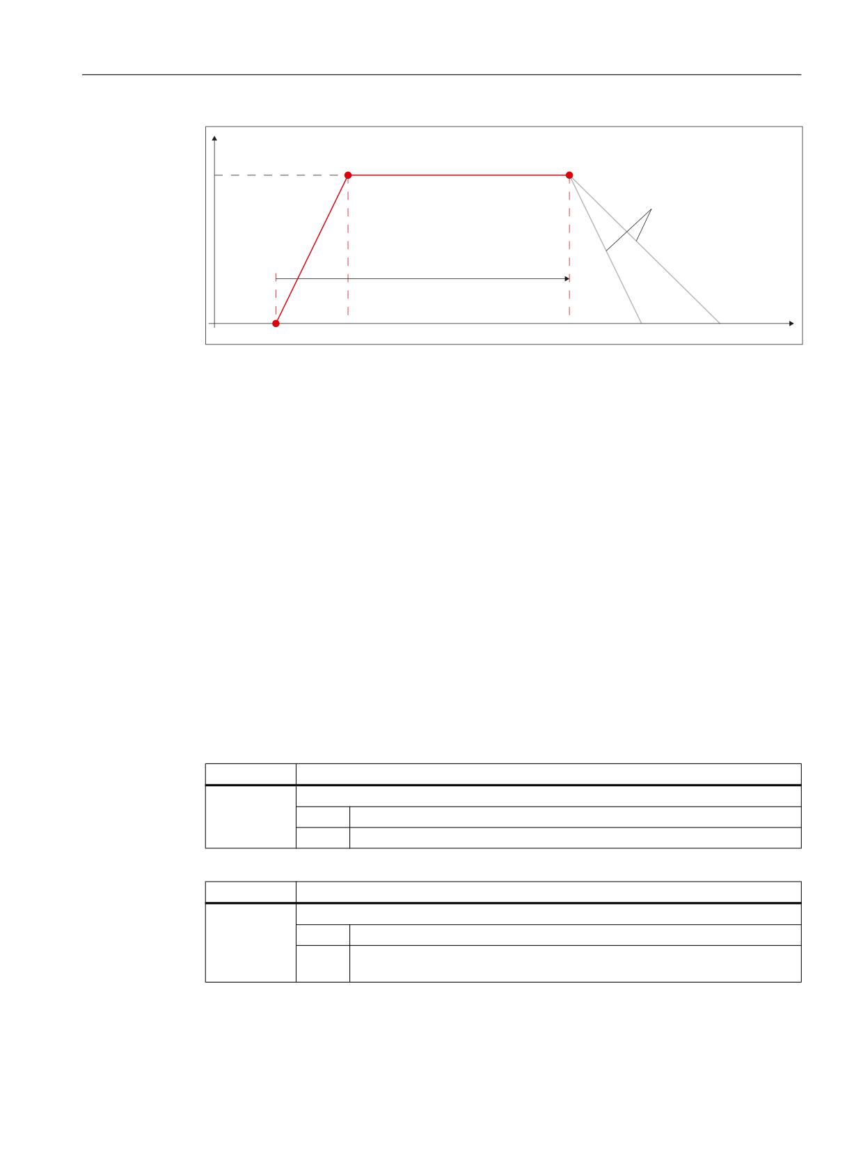
7LPH W
T1
Instant in time that retraction was initiated
T2
Instant in time when the retraction speed specified in p0893 is reached
T3
Instant in time after the time that was configured in p0892 has expired
Figure 11-4
Behavior for drive-integrated retraction
Feedback signal
The retract status is returned to the control (see Section "Feedback of the ESR status
(Page 585)").
References
For a detailed description of drive parameters, refer to:
SINAMICS S120/S150 Parameter Manual
11.3.4
Configuring generator operation in the drive
The generator mode for the drive-autonomous ESR is configured using the following drive
parameters:
Parameter
Description
p0888
ESR: Configuration
Value
Meaning
3
Generator operation (Vdc controller)
Parameter
Description
p1240
Vdc controller or Vdc monitoring configuration
Value
Meaning
2
When reaching the lower DC link voltage threshold (p1248) - for ESR - the
motor is braked in order to utilize its kinetic energy to buffer the DC link.
Special functions
Function Manual, 12/2018, A5E40874099B AB
583
R3: Extended stop and retract
11.3 ESR executed autonomously in the drive
Parameter
Description
p1248
Lower DC link voltage threshold
Setting the lower threshold for the DC link voltage. For p1240 = 2, this threshold is used
as setpoint limit for the Vdc_min controller.
'& OLQN YROWDJH 9
S
S
U
7
7
7LPH W
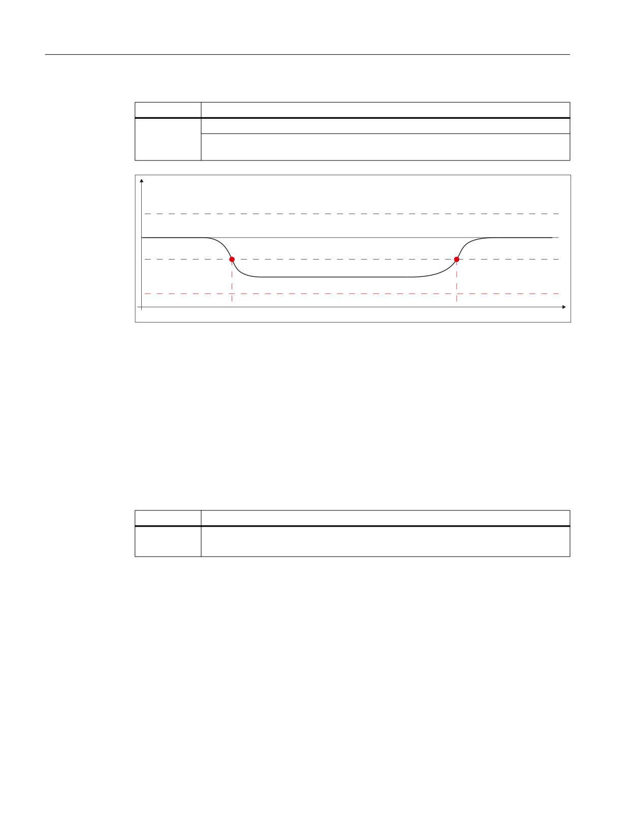
p1244
Upper DC link voltage threshold
p1248
Lower DC link voltage threshold
r0208
Rated power unit line supply voltage.
The pulses are canceled if the DC link voltage drops below 0.9*r0208
T1
Instant in time at which generator operation was triggered
T2
Instant in time at which generator operation was exited
Figure 11-5
Configuring_drive_integrated_generator_operation
Generator minimum speed
The lower limit of the motor speed of the generator axis is configured using drive parameter
p2161:
Parameter
Description
p2161
Speed threshold value 3
Speed threshold value for the message: |n_act| < speed threshold value 3
Feedback signal
The generator operation status is returned to the control (see Section "Feedback of the ESR
status (Page 585)").
References
A detailed description of drive parameters and the Vdc control can be found in:
● SINAMICS S120/S150 List Manual
● SINAMICS S120 Function Manual; Section "Servo control" > "Vdc control"
Special functions
584
Function Manual, 12/2018, A5E40874099B AB
R3: Extended stop and retract
11.3 ESR executed autonomously in the drive
11.3.5
ESR is enabled via system variable
The ESR response of an axis, configured via drive parameter, must be programmed on a user-
specific basis in a part program/synchronized action using the following axis-specific system
variable:
$AA_ESR_ENABLE[<axis>]
Value
Meaning
1
ESR responses enabled in the drive
0
ESR responses inhibited in the drive
11.3.6
Triggering ESR via system variable
Triggering ESR responses, configured via drive parameter and enabled via
$AA_ESR_ENABLE[<axis>], must be programmed on a user-specific basis in a part program/
synchronized action via the following NC-specific system variable:
$AN_ESR_TRIGGER
Value
Meaning
1
trigger drive-integrated ESR reactions that have been released
0
do not trigger drive-integrated ESR reactions that have been released
Note
The trigger signal must be active in the part program/synchronized action for at least 2 IPO
cycles to ensure that the PROFIdrive telegram is transferred to the drive.
Mapping in the drive unit
System variable $AN_ESR_TRIGGER is mapped to drive parameter p0890.0. Interconnecting
drive parameter p0890.0 with the corresponding information in telegram 390 or 391 to the
Control Unit is realized automatically when the drive unit commissions the ESR reactions.
References
For a detailed description of drive parameters, refer to:
SINAMICS S120/S150 List Manual
11.3.7
Feedback of the ESR status
The drive signals back the actual ESR status to the control using the message word (MELDW)
of the cyclic PROFIdrive telegram. In the PLC, the status can be read via system variables
and NC/PLC interface signals.
Special functions
Function Manual, 12/2018, A5E40874099B AB
585

R3: Extended stop and retract
11.3 ESR executed autonomously in the drive
System variable
The system variables can be evaluated in the part program / synchronized action, for example,
in order to trigger the drive-autonomous ESR (see Section "Triggering ESR via system
variable (Page 585)") or to acknowledge the ESR reactions triggered in the drive (see Section
"Acknowledge ESR reactions (Page 586)").
Interrelationship between signals
MELDW
System variable
NC/PLC interface signal
Meaning
MELDW.Bit 9
$AA_ESR_STAT.Bit 2
DB31, … DBX95.2
ESR: Reaction triggered or generator operation
active (r0887.12)
(r0887.12)
MELDW.Bit 4
$AA_ESR_STAT.Bit 3
DB31, … DBX95.1
ESR: DC link undervoltage (p1248)
(r0056.15)
MELDW.Bit 2
$AA_ESR_STAT.Bit 4
DB31, … DBX95.3
ESR, generator operation: Speed lower than min-
imum (p2161)
(r2199.0)
11.3.8
Acknowledge ESR reactions
Acknowledging axis-specific drive-independent ESR reactions must be programmed on a user-
specific basis in a part program/synchronized action. After the ESR reaction in the drive has
been completed, an edge change must be generated in the system variables
$AA_ESR_ENABLE: 1→0→1. In order that the drive-integrated ESR reactions can be
retriggered, the system variable $AN_ESR_TRIGGER must also be reset to a value of 0.
Special functions
586
Function Manual, 12/2018, A5E40874099B AB
R3: Extended stop and retract
11.3 ESR executed autonomously in the drive
System variable and drive parameters
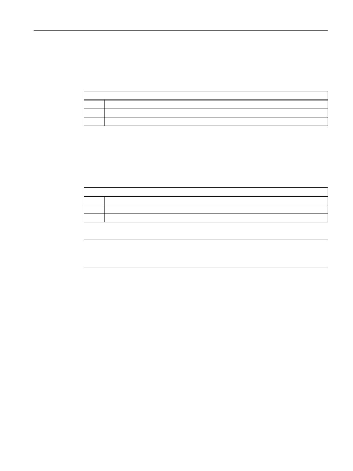
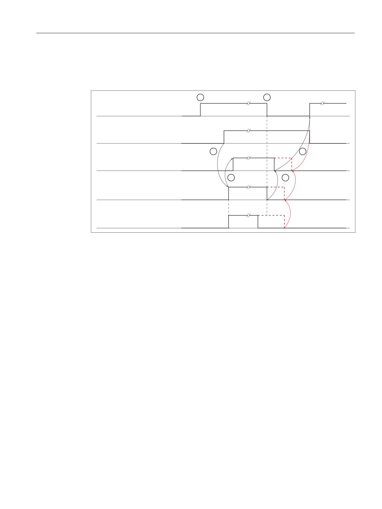
The following diagram shows the relationship between system variables and drive parameters
when triggering and acknowledging ESR reactions.
$$B(65B(1$%/(> D[LV!@
$1B(65B75,**(5
$$B(65B67$7 %,7 > D[LV!@
U
(65 WULJJHUHG
U
(65 UHDFWLRQ EHLQJ H[HFXWHG
① NC: Enabling the ESR reaction via $AA_ESR_ENABLE = 1 (axis-specific)
② NC: Triggering ESR responses via $AN_ESR_TRIGGER = 1
③ Drive: The triggering of the ESR reaction has been detected (CU_STW.2 == 1) ⇒
r0887.12 = 1 AND r0887.13 = 1
Feedback signal to the NC via $AA_ESR_STAT.BIT2 = 1 (axis-specific)
④ NC: Acknowledging the ESR reaction via $AA_ESR_ENABLE = 0 (axis-specific)
Black: At instant in time ④, the ESR reaction no longer runs (r0887.13 == 0) ⇒
⑤ Drive: Reset "ESR triggered": r0887.12 = 0
Feedback signal to the NC via $AA_ESR_STAT.BIT2 = 0 (axis-specific)
⑥ NC: The ESR reaction can be re-enabled ⇒
$AA_ESR_ENABLE = 1 AND $AN_ESR_TRIGGER = 0
Red: At instant in time ④, the ESR reaction still runs (r0887.13 == 1) ⇒
⑤ Drive: "ESR initiated" is only reset (r0887.12 = 0), if the ESR response in the drive has been
completed: r0887.13 == 0
Feedback signal to the NC via $AA_ESR_STAT.BIT2 = 0 (axis-specific)
⑥ See ⑥ above
Figure 11-6
Sequence: Trigger and acknowledge drive-integrated ESR reactions
11.3.9
Configuring ESR in the part program
Configuring drive-autonomous ESR functions "stop" and "retract" can be changed using the
commands from the part program described in the following.
Special functions
Function Manual, 12/2018, A5E40874099B AB
587
R3: Extended stop and retract
11.3 ESR executed autonomously in the drive
11.3.9.1
Stopping (ESRS)
Syntax
ESRS(<access_1>,<stopping time_1>[,...,<axis_n>,<stopping time_n>])
Meaning
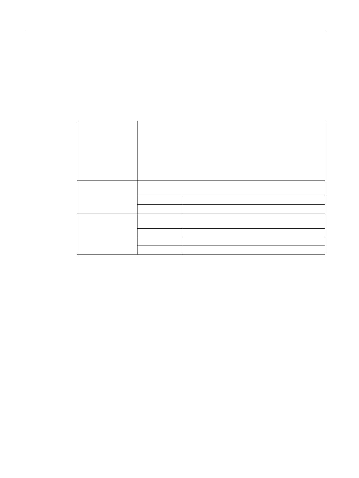
ESRS:
Using the function, drive parameters can be changed regarding the drive-au-
tonomous "stop" ESR function.
Special situations:
● Must be alone in the block
● Triggers a preprocessing stop
● Cannot be used in synchronized actions
● A maximum of five axes can be programmed per function call; n = 5
<axis_n>:
For the specified axis, writes to drive parameter p0888 (configuration): p0888
= 1
Data type:
AXIS
Range of values:
Channel axis name
<stopping
For the axis specified under <Axis_n>, writes to drive parameter p0892 (tim-
time_n>:
er): P0892 = <stopping time_n>
Unit:
s
Data type:
REAL
Range of values:
0.00 - 20.00
11.3.9.2
Retraction (ESRR)
Syntax
ESRR(<axis_1>,<retraction distance_1>,<retraction
velocity_1>[,...,<axis_n>,<retraction distance_n>,<retraction
velocity_n>])
Special functions
588
Function Manual, 12/2018, A5E40874099B AB

R3: Extended stop and retract
11.3 ESR executed autonomously in the drive
Meaning
ESRR:
Using the function, drive parameters can be changed regarding the drive-au-
tonomous "retract" ESR function.
Special situations:
● Must be alone in the block
● Triggers a preprocessing stop
● Cannot be used in synchronized actions
● A maximum of five axes can be programmed per function call; n = 5
<axis_n>:
For the specified axis, writes to drive parameter p0888 (configuration): p0888
= 2
Data type:
AXIS
Range of values:
Channel axis name
<retraction
For the axis specified under <Axis_n>, writes to drive parameter p0893 (re-
velocity_n>:
traction speed):
p0893 = (<retraction velocity> based on the currently effective total transmis-
sion ratio converted into the corresponding retraction speed)
Unit:
mm/min, inch/min, degrees/min (depending on the unit of
the axis)
Data type:
REAL
Range of values:
0.00 - MAX
<retraction
For the axis specified under <Axis_n>, writes to drive parameter p0892 (re-
distance_n>:
traction time):
p0892 = <retraction distance_n> / <retraction velocity _n>
Unit:
mm, inches, degrees (depending on the unit of the axis)
Data type:
REAL
Range of values:
MIN - MAX
Note
Retraction speed
It should be ensured that the drive can reach the programmed retraction speed (see
parameters <retraction velocity_n>) within the retraction time (see parameter <retraction
distance _n>). The settings in the following drive parameters should be checked:
● p1082[0...n] (maximum speed)
● p1135[0...n] (OFF3 ramp-down time)
Retraction path
The conversion of the retraction path into a retraction duration for drive parameter p0892 is
performed under the assumption that the retraction motion is triggered at axis standstill (see
"Figure 11-5 Configuring_drive_integrated_generator_operation (Page 584)").
If retraction motion is triggered while the axis is traversing, the actually traversed retraction
distance differs from the programmed retraction distance due to the fact that traversing motion
is superimposed on the retraction motion.
Special functions
Function Manual, 12/2018, A5E40874099B AB
589
R3: Extended stop and retract
11.3 ESR executed autonomously in the drive
Dependencies
The programmed values for the retraction path and the retraction velocity refer to the load side.
Before writing to the drive parameters these are converted over to the motor side. The
transmission ratio effective in the NC at the execution time is applicable for the conversion. If
the drive-autonomous ESR for an axis is enabled ($AA_ESR_ENABLE[<axis>] == 1), then it
is not permissible to change the axial transmission ratio.
Note
Changing the transmission ratio
If the drive-autonomous ESR is not enabled for an axis ($AA_ESR_ENABLE[<axis>] == 0),
then the axial transmission ratio can be changed. After the change, it is the sole responsibility
of the user/machine manufacturer to appropriately adapt the retraction distance and the
retraction velocity.
See also
Configuring generator operation in the drive (Page 583)
11.3.9.3
Boundary conditions
Consistent parameter change
In order that the drive parameters are consistently effective, in the part program the drive-
autonomous ESR enable signals must be withdrawn before the functions ESRS(...) and
ESRR(...).
Example:
Program code
Comment
N100 $AA_ESR_ENABLE[X1]=0
; Withdraw ESR enable signals
N110 $AA_ESR_ENABLE[Z1]=0
N120 $AA_ESR_ENABLE[Y1]=0
N130 ESRR(X1,20.0,10000.0,Z1,-15.0,20000.0)
; Change ESR parameters
N140 ESRS(Y1,0.5,B1,0.5)
N150 $AA_ESR_ENABLE[X1]=1
; Set ESR enable signals
N160 $AA_ESR_ENABLE[Z1]=1
N170 $AA_ESR_ENABLE[Y1]=1
When executing the functions ESRS(...) and ESRR(...) further execution of the part
program is stopped until writing to the drive parameters has been acknowledged. During this
time, the following message is used as feedback signal for the user: "Wait for drive parameters
from <Function>" is displayed.
Block search with calculation
During the block search with calculation, the functions ESRS(...) and ESRR( ... ) are
collected and executed in the action block.
Special functions
590
Function Manual, 12/2018, A5E40874099B AB
R3: Extended stop and retract
11.3 ESR executed autonomously in the drive
Block search with calculation in "Program test" (SERUPRO) mode
During SERUPRO, the functions ESRS(...) and ESRR( ... ) are executed immediately.
Reset behavior
The parameter values written using the functions ESRS(...) and ESRR(...) are
overwritten with the parameter values saved in the drive when the drive runs up or for a drive
warm restart.
Drive parameters can be saved from the HMI user interface or in the drive. From the HMI user
interface:
● Operating area "Commissioning" > "Machine data" > "Drive MD" > "Save/Reset" > "Save"
> "Drive object"or "drive unit" or " drive system"
Control power-up (POWER ON)
If the drive-autonomous ESR should already be active after the control has powered up
(POWER ON), then the programming and enable must be realized within one of the ASUBs
started from the PLC - or using the PROGEVENT mechanism.
References
For detailed information about event-controlled program calls, refer to:
Basic Functions Function Manual, Mode Group, Channel, Program Operation, Reset
Response (K1);
Chapter: Event-driven program calls
11.3.10
ESR and Safety Integrated (840D sl)
Delay times
In order that drive-integrated ESR reactions in conjunction with Safety Integrated are executed
before the safety reactions associated with STOP E, STOP F or communication failure, then
the corresponding delay times regarding safety reactions must be configured in the control
and in the drive.
Delay times are configured in the controller using the following machine data:
● MD36954 $MA_SAFE_STOP_SWITCH_TIME_E (transition time, STOP E to safe
standstill)
● MD36955 $MA_SAFE_STOP_SWITCH_TIME_F (transition time, STOP F to STOP B)
● MD36961 $MA_SAFE_VELO_STOP_MODE (stop response, safely-reduced speed)
● MD36963 $MA_SAFE_VELO_STOP_REACTION (stop response, safely-reduced speed)
● MD10089 $MN_SAFE_PULSE_DIS_TIME_BUSFAIL (wait time pulse cancellation when
the bus fails)
Delay times in the drive are configured using the following drive parameters:
● p9554 (transition time from STOP E to "Safe Operating Stop" (SOS))
● p9555 (transition time STOP F to STOP B)
Special functions
Function Manual, 12/2018, A5E40874099B AB
591
R3: Extended stop and retract
11.3 ESR executed autonomously in the drive
● p9561 (SG stop response)
● p9563 (SG-specific stop response)
● p9580 (wait time after which the pulses are safely cancelled after bus failure)
● p9697 (delay time for the pulse suppression after bus failure)
● p9897 (delay time for the pulse suppression after bus failure)
Note
The drive parameters are automatically aligned with the corresponding NC machine data
using the Safety Integrated commissioning function "Copy SI data".
Trigger drive-integrated ESR reactions
The feedback signal of the safety stop reaction - currently active in the drive - sent to the
control is realized using the following axis-specific system variable:
● $VA_STOPSI[<axis>] (actual stop reaction)
By evaluating the system variable in a part program/synchronized action, a user-specific
response can be realized to the particular stop reaction of the axis, e.g. by triggering the drive-
integrated and/or control-managed ESR reactions using the system variable
$AN_ESR_TRIGGER and/or $AC_ESR_TRIGGER or $AA_ESR_TRIGGER.
References
A detailed description for configuring and the interaction of drive-integrated ESR responses
and Safety Integrated functions is given in:
References
Function Manual SINUMERIK Safety Integrated
11.3.11
ESR and Safety Integrated (828D)
No feedback signal of the safety stop reaction
Within the scope of SINUMERIK 828D, the safety stop reaction currently active in the drive is
not signaled back to the control. Therefore, in conjunction with Safety Integrated, only drive-
autonomous ESR functions can be used.
The ESR reactions triggered from the drive can be determined on the control side using the
axis-specific system variable $AA_ESR_STAT (see Chapter "Feedback of the ESR status
(Page 585)") and additional ESR reactions can be triggered on a user-specific basis via
$AN_ESR_TRIGGER.
Special functions
592
Function Manual, 12/2018, A5E40874099B AB

R3: Extended stop and retract
11.4 Boundary conditions
ESR reactions that are not influenced by safety reactions
In order that drive-autonomous ESR reactions in conjunction with Safety Integrated are not
influenced by safety reactions as a result of STOP E, STOP F executed in parallel or
communication failure, then the appropriate delay times must be configured in the drive
regarding safety reactions and the corresponding safety trigger sources to trigger the drive-
autonomous ESR reactions.
Delay times
Delay times in the drive are configured using the following drive parameters:
● p9554 (transition time from STOP E to "Safe Operating Stop" (SOS))
● p9555 (transition time STOP F to STOP B)
● p9580 (wait time after which the pulses are safely cancelled after bus failure)
● p9697 (delay time for the pulse suppression after bus failure)
Safety trigger sources
Using a BICO interconnection of drive parameter p0890 (BI: ESR trigger) ESR reactions can
also be triggered with the safety reactions STOP E, STOP F and communication failure:
Parameter
BICO interconnection
Effect: Trigger ESR reactions for
with:
p0890[1]
r9721[15]
Safety STOP E
p0890[2]
r9723[1]
Safety STOP F
p0890[3]
r9723[2]
Safety communication failure
References
A detailed description of the drive parameters and the BICO technology can be found in:
● SINAMICS S120/S150 List Manual
● SINAMICS S120 Function Manual; Chapter "Fundamentals of drive technology" > "BICO
technology: Interconnecting signals"
11.4
Boundary conditions
Transformation
If NC-controlled extended stopping and retraction is activated for anaxis involved in an active
transformation, then extended stopping and retraction must also be activated for all other axes
involved in the transformation. Otherwise, when activating extended stopping and retraction,
it is possible that the transformation group will ungrouped.
Special functions
Function Manual, 12/2018, A5E40874099B AB
593
R3: Extended stop and retract
11.5 Examples
Drive components
In order that the configured stopping or retraction responses can be executed, the drive
components involved must be fully functional. Axis-specific servo or drive alarms, which
indicate the failure of one of these components, are also implicitly signaling that the configured
stopping or retraction response of the axis involved is no longer available or only partially.
Motion-synchronous actions
Motion-synchronous actions are executed in the interpolator clock cycle. Increasing the
interpolator clock cycle, e.g. due to a high number of active motion-synchronous actions,
results in a coarser time grid for evaluating trigger conditions and triggering responses for
extended stopping and retraction.
11.5
Examples
11.5.1
NC-controlled reactions
Task
The A axis is to operate as the generator drive, while the X axis should retract 10 mm at
maximum velocity in the event of a fault. The Y and Z axes should stop after a delay of 100
ms so that the X retraction axis has sufficient time to cancel the mechanical coupling.
The example is performed using NC-controlled reactions.
Only the essential parts of the entire functionality are displayed.
Requirements
The following functions must be available:
● Extended stopping and retraction (ESR)
● Static synchronized actions
● Asynchronous subprograms (ASUBs)
Settings
Machine data
Axis-specific operating mode of the ESR
● MD37500 $MA_ESR_REACTION[X] = 21 (NC-controlled retraction axis)
● MD37500 $MA_ESR_REACTION[Y] = 22 (NC-controlled stop axis)
● MD37500 $MA_ESR_REACTION[Z] = 22 (NC-controlled stop axis)
Special functions
594
Function Manual, 12/2018, A5E40874099B AB
R3: Extended stop and retract
11.5 Examples
Configuration: NC-controlled extended stop
● MD21380 $MC_ESR_DELAY_TIME1 = 0.1 (duration of the path interpolation in seconds)
● MD21381 $MC_ESR_DELAY_TIME2 = 0.04 (braking duration in seconds)
Programming
Program code
Comment
LFPOS
Axis-specific lift to a position
POLF[X]=IC(10)
Retraction position, incremental
POLFMASK(X)
Enable retraction
; Enable "Extended stop and retract"
$AA_ESR_ENABLE[X]=1
; X axis
$AA_ESR_ENABLE[Y]=1
; Y axis
$AA_ESR_ENABLE[Z]=1
; Z axis
Trigger conditions and static synchronized actions
Example 1
Trigger condition is the occurrence of alarms, which activate the follow-up (tracking) mode:
Program code
IDS=02 WHENEVER ($AC_ALARM_STAT B_AND 'H2000') > 0 DO $AC_ESR_TRIGGER=1
Example 2
Trigger condition is when the ELG synchronous monitoring responds, if, e.g. Y is defined as
ELG following axis and the max. permissible synchronism difference is 100 mm:
Program code
IDS=03 WHENEVER $VA_EG_SYNCDIFF[Y] > 0.1 DO $AC_ESR_TRIGGER=1
11.5.2
Retraction while thread cutting
During thread cutting, for a fault/interruption, axis X should be retracted to the position specified
under POLF as response. Axis Z continues to traverse until it is stopped as normal.
Program code
Comment
N10 G0 G90 X200 Z0 S200 M3
;
N20 G0 G90 X170
;
N30 POLF[X]=210
; Retraction position axis X, absolute
N40 LFPOS
; Retraction via POLF/POLFMASK ON
N50 POLFMASK(X)
; Enable retraction, axis X
N60 LFON
; Fast retraction for thread cutting ON
; Thread cutting
N70 G33 X100 I10
; Retraction response, axial: X (abs.)
N80 X130 Z-45 K10
; dto.
Special functions
Function Manual, 12/2018, A5E40874099B AB
595

R3: Extended stop and retract
11.5 Examples
Program code
Comment
N90 X155 Z-128 K10
; dto.
N100 X145 Z-168 K10
; dto.
N110 X120 I10
; dto.
N120 G0 Z0 LFOF
; Fast retraction for thread cutting OFF
N130 POLFMASK()
; Disable retraction of all axes
11.5.3
Rapid lift using ASUB and fast input
Activating ASUB using the LIFTFAST program command (rapid lift) via fast input 1:
Program code
Comment
N10 SETINT (1) PRIO=1 ABHEB_Y LIFTFAST
; ASUB activation, fast input 1
N20 LFPOS
; Retraction via POLF/POLFMASK ON
N30 POLF[X]=19.5 POLF[Y]=33.3
; Retraction positions axis X Y, absolute
N40 POLF[Z]=100
; Retraction position axis Z, absolute
N50 X0 Y0 G0
;
N60 POLFMASK(X, Y)
; Enable retraction, axis X Y
N70 Z100 G1 F1000
; Retraction response, axial: X, Y (abs.)
N80 POLFMASK(Z)
; Disable retraction, axis X Y and
; Enable retraction, axis Z
N90 Y10
; Retraction response, axial: Z (abs.)
N100 POLFMASK()
; Disable retraction of all axes
11.5.4
Rapid lift, absolute and incremental
Retraction to absolute positions and through an incremental distance:
Program code
Comment
N10 $AA_ESR_ENABLE[X]=1
; Enable retraction, axis X
N20 $AA_ESR_ENABLE[Z]=1
; Enable retraction, axis Z
N30 $AA_ESR_ENABLE[Y]=1
; Enable retraction, axis Y
N40 LFPOS
; Retraction via POLF/POLFMASK ON
N50 POLF[X]=IC(3.0) POLF[Y]=-4.0
; Retraction position axis X, incremental
; Retraction position axis Y, absolute
N60 POLF[Z]=100
; Retraction position axis Z, absolute
N70 G0 X0 Y0 Z0
;
N80 POLFMASK(X, Y)
; Enable retraction, axis X Y
N90 Z100 G1 F1000
; Retraction response, axial: X (inc.), Y (abs.)
N100 POLF[X]=10
; Retraction position axis X, absolute
N110 Y0 G1 F1000
; Retraction response, axial: X, Y (abs.)
N120 POLFMASK(Z)
; Disable retraction, axis X Y and
; Enable retraction, axis Z
N130 Y10
; Retraction response, axial: Z (abs.)
Special functions
596
Function Manual, 12/2018, A5E40874099B AB

R3: Extended stop and retract
11.6 Data lists
Program code
Comment
N140 POLFMASK()
; Disable retraction of all axes
11.5.5
Lift fast with linear relation of axes
Retracting in a linear relationship, absolute and incremental
Program code
Comment
N10 $AA_ESR_ENABLE[X]=1
; Enable retraction, axis X
N20 $AA_ESR_ENABLE[Y]=1
; Enable retraction, axis Y
N30 $AA_ESR_ENABLE[Z]=1
; Enable retraction, axis Z
N40 LFPOS
; Retraction via POLF/POLFMASK ON
N50 POLF[X]=IC(3.0) POLF[Z]=-4.0
; Retraction position axis X, incremental
; Retraction position axis Z, absolute
N60 POLF[Y]=100
; Retraction position axis Z, absolute
N70 X0 Y0 Z0 G0
; ---
N80 POLFMLIN(X, Y)
; Enable retraction, axis X Y, linear
; Relationship
N85 POLFMASK(Z)
; Enable retraction, axis Z
N90 Z100 G1 F1000
;
Retraction response:
;
- linear relation: X (inc.), Y (abs.)
;
- axial: Z (abs.)
N95 POLF[X]=10
; Retraction position axis X, absolute
N100 Y0 G1 F1000
;
Retraction response:
;
- linear relation: X (inc.), Y (abs.)
;
- axial: Z (abs.)
N110 POLFMLIN()
; Disable retraction, axis X Y
N120 Y10
; Retraction response, axial: Z (abs.)
N130 POLFMASK()
; Disable retraction of all axes
11.6
Data lists
11.6.1
Machine data
11.6.1.1
Channelspecific machine data
Number
Identifier: $MC_
Description
21204
LIFTFAST_STOP_COND
Stop characteristics for rapid lift
21380
ESR_DELAY_TIME1
Delay time (STOPBYALARM, NOREAD) for ESR axes
21381
ESR_DELAY_TIME2
Time for interpolatory braking of ESR axes
Special functions
Function Manual, 12/2018, A5E40874099B AB
597

R3: Extended stop and retract
11.6 Data lists
11.6.1.2
Axis/spindlespecific machine data
Number
Identifier: $MA_
Description
37500
ESR_REACTION
Reaction definition with extended stop and retract
11.6.2
System variables
Identifier
Meaning
$A_DBB
Read/write data byte from/to PLC
$A_IN
Digital input
$A_OUT
Digital output
$AA_ESR_ENABLE[<axis>]
Enable "Extended stop and retract"
$AA_TYP[<axis>]
Axis type
$AA_ESR_TRIGGER[<axis>]
Initiate ESR for PLC controlled axis (single axis)
$AC_ALARM_STAT
Alarm status in the channel
$AC_ESR_TRIGGER
Trigger ESR, channel-specific
$AC_STAT
Channel status
11.6.3
Signals
11.6.3.1
Signals to channel
Signal name
SINUMERIK 840D sl
SINUMERIK 828D
Feedrate disable
DB21, ... DBX6.0
11.6.3.2
Signals to axis/spindle
Signal name
SINUMERIK 840D sl
SINUMERIK 828D
Feed stop
DB31, ... DBX4.3
Special functions
598
Function Manual, 12/2018, A5E40874099B AB

R3: Extended stop and retract
11.6 Data lists
11.6.3.3
Signals from axis/spindle
Signal name
SINUMERIK 840D sl
SINUMERIK 828D
ESR: DC link undervoltage (p1248)
DB31, ... DBX95.1
DB390x.DBX4003.1
ESR: Reaction triggered / generator operation active
DB31, ... DBX95.2
DB390x.DBX4003.2
(r0887.12)
ESR, generator operation: Speed lower than minimum
DB31, ... DBX95.3
DB390x.DBX4003.3
(p2161)
Special functions
Function Manual, 12/2018, A5E40874099B AB
599
R3: Extended stop and retract
11.6 Data lists
Special functions
600
Function Manual, 12/2018, A5E40874099B AB
S9: Setpoint exchange - 840D sl only
12
12.1
Brief description
Function
The "Setpoint switchover" function is required if only one motor is to be used to drive several
axes/spindles. For example, for milling heads, where the spindle motor is to be used to drive
the tool as well as to orientate the milling head.
Requirements
The following conditions must be fulfilled so that the setpoint can be switched over:
● All of the axes involved in the setpoint switchover are at a standstill
● No sign-of-life error and no errors are active on PROFIBUS
● None of the following functions in the axis with drive control are active:
- Reference point approach
- Measuring
- Travel to fixed stop
- Function generator
- Star/delta switchover
- Parameter set switchover
Position control loop
The drive train, and therefore also the position control loop, are disconnected while the setpoint
is being switched over. In order to avoid instability, the setpoint is only switched over at standstill
- and once all controller enable signals have been cleared (deleted).
When using a single drive, only one control loop can be closed at the same instant in time.
Axes without drive control are operated with open position controller and tracked positions.
Note
Vertical axes
The controller enable signals for all of the axes involved are automatically withdrawn by the
control for the duration of the switchover. Axes without drive control are not in closed-loop
control. Therefore, a brake control must be implemented for vertical axes.
Special functions
Function Manual, 12/2018, A5E40874099B AB
601
S9: Setpoint exchange - 840D sl only
12.1 Brief description
Example
;
;
60&
;
;
;
;
'5,9( &/L4
60&
60&
1&8
$FWLYH /LQH
6LQJOH 0RWRU
'RXEOH 0RWRU
0RGXOH
0RGXOH
0RGXOH
1
a 0
0
①
Motor with encoder
②
Mechanical switchover device
③
Gearbox 1
④
Encoder 1 (e.g. for the milling head)
⑤
Gearbox 2
⑥
Encoder 2 (e.g. for the spindle)
Figure 12-1
Setpoint switchover with 2 axes
Special functions
602
Function Manual, 12/2018, A5E40874099B AB
S9: Setpoint exchange - 840D sl only
12.2 Startup
Replacing the technology function "setpoint changeover" (TE5)
The "setpoint changeover" function replaces the technology function "setpoint changeover"
(TE5). Migration of the technology function to the functionality of the "setpoint changeover"
function means that you must make changes in the machine data and in the PLC user program:
● Machine data MD63750 is no longer required.
● The meanings of various NC/PLC interface signals have changed.
● Alarms 70451 and 70452 are no longer applicable.
● A setpoint changeover with simulated axes (MD30130 = 0) is no longer supported.
● The known restrictions relating to the technology card function are no longer applicable.
12.2
Startup
Machine data
Setpoint assignment
The same setpoint channel of a drive is assigned a number of times to define the axes
participating in the setpoint switchover. For this, the following machine data must be pre-
assigned with the same logical drive number for each axis:
MD30110 $MA_CTRLOUT_MODULE_NR (setpoint assignment: module number)
Note
Alarm 26018 is output if the option is missing.
Encoder assignment
The encoder is assigned in the machine data on an axis-for-axis basis:
MD30230 $MA_ENC_INPUT_NR(actual value assignment: Input on drive module/measuring
circuit module)
NC/PLC interface signals
Note
Access rights
Despite assignment of a drive to several machine axes, the use of NC/PLC interface signals
remains unchanged. In the PLC user program this requires an explicit coordination of the
access operations to the NC/PLC interface signal of the individual machine axes involved in
the setpoint switchover.
Request for drive control
The request to assume drive control is realized via:
Special functions
Function Manual, 12/2018, A5E40874099B AB
603
S9: Setpoint exchange - 840D sl only
12.2 Startup
DB31, ... DBX24.5 (setpoint switchover: request drive control)
Status of the drive control
The current status of drive control is displayed via:
DB31, ... DBX96.5 (setpoint switchover: drive control active)
Status signals
After drive control is assumed for the first time for one of the machine axes involved in the
setpoint switchover (DB31, ... DBX24.5 = 1 (setpoint switchover: switchover)) the following
status signals are always displayed the same for all of the machine axes involved:
DB31, ... DBB92 - DBB95
Control signals
The control signals are only active in the machine axis that currently has the drive control
(DB31, ... DBX96.5 == 1 (setpoint switchover active)):
DB31, ... DBB20 to DBB21
Controller enable
The controller enable (DB31, ... DBX2.1) is only active in the machine axis that currently has
drive control (DB31, ... DBX96.5 == 1 (status setpoint switchover))
Follow-up mode
Machine axes without drive control, involved in the setpoint switchover, are always switched
into the follow-up mode in the control itself (DB31, ... DBX61.3 == 0).
Note
Only one axis with drive control
At any one point in time, only one axis must have drive control DB31, ... DBX24.5 == 1 and
DB31, ... DBX96.5 == 1.
Special cases
Several simultaneous requests to take over
No switchover takes place for several simultaneous takeover requests. The last axis used
keeps drive control. The same effect applies if there are no takeover requests.
No takeover request when powering up
If there is no takeover request when the control powers up, then the control assigns the drive
control to the first machine axis with the same logical drive number.
MD30110 $MA_CTRLOUT_MODULE_NR[0,AX1] = 1
MD30110 $MA_CTRLOUT_MODULE_NR[0,AX2] = 2
MD30110 $MA_CTRLOUT_MODULE_NR[0,AX3] = 3
Special functions
604
Function Manual, 12/2018, A5E40874099B AB
S9: Setpoint exchange - 840D sl only
12.2 Startup
MD30110 $MA_CTRLOUT_MODULE_NR[0,AX4] = 4 ; setpoint switchover: 1st
axis
MD30110 $MA_CTRLOUT_MODULE_NR[0,AX5] = 4 ; setpoint switchover: 2nd
axis
In order to be able to traverse the axis using the drive, the NC/PLC interface signal to request
drive control (DB31, ... DBX24.5) must be set.
Special functions
Function Manual, 12/2018, A5E40874099B AB
605
S9: Setpoint exchange - 840D sl only
12.3 Flow diagram
12.3
Flow diagram
$;
7UDYHO FRPPDQG WUDYHO UHTXHVW
LV DFWLYH
'% '%;
25
25
25
$;
<HV
'ULYH FRQWURO
DFWLYH"
'% '%;
1R
$;
&ORVH EUDNH
5HOLQTXLVK GULYH FRQWURO
'% '%;
6ZLWFKRYHU PHFKDQLFDO V\VWHP
$;
5HTXHVW GULYH FRQWURO
'% '%;
$;
'ULYH FRQWURO
DFWLYH"
1R
'% '%;
<HV
$;
$;
7UDFNLQJ IROORZ XS PRGH
7UDFNLQJ IROORZ XS PRGH
LV VZLWFKHG RYHU
LV VZLWFKHG RYHU
'% '%;
'% '%;
$;
6HW FRQWUROOHU HQDEOH
'% '%;
2SHQ EUDNH
Figure 12-2
Sequence when switching over the setpoint from machine axes AX1 to AX2
Special functions
606
Function Manual, 12/2018, A5E40874099B AB
S9: Setpoint exchange - 840D sl only
12.4 Supplementary conditions
12.4
Supplementary conditions
Alarms
Only axes with active drive control display drive alarms.
Position control loop
The drive train, and therefore also the position control loop, are disconnected while the setpoint
is being switched over. In order to avoid instability, the setpoint is only switched over at standstill
- and once all controller enable signals have been cleared (deleted).
When using a single drive, only one control loop can be closed at the same instant in time.
Axes without drive control are operated with open position controller and tracked positions.
Reference points
The use of load-side encoders does not affect the axis-specific reference points of a setpoint
switchover.
However, the mechanical reference to the load can be lost following setpoint switchover for a
load-side position derived solely from the motor encoder. These types of axis must be
referenced again after every setpoint switchover.
Parameter set switchover
A setpoint exchange is not performed if one of the following states is present:
● A parameter set changeover in one of the two machine axes has not completed.
● The parameter sets of the two machine axes are not the same.
Note
If, due to secondary conditions, a setpoint switchover is not performed, then a message is not
displayed.
"Parking" state
If an axis is in the "Parking" state, this state can only be canceled if this axis assumes drive
control.
Service display drive
The "Drive service display" HMI diagnostics screen does not take into account the changes in
assignments between machine axes and the drive.
Commissioning via SinuCom NC
The "SinuCom NC" commissioning tool can only be used to commission the setpoint
switchover via the expert list.
Safety Integrated (only 840D sl)
A detailed description of the supplementary conditions for setpoint switchover in conjunction
with Safety Integrated is available in:
Special functions
Function Manual, 12/2018, A5E40874099B AB
607

S9: Setpoint exchange - 840D sl only
12.5 Data lists
Reference:
SINUMERIK Safety Integrated Manual
12.5
Data lists
12.5.1
Machine data
12.5.1.1
Axis/spindlespecific machine data
Number
Identifier: $MA_
Description
30130
CTRLOUT_TYPE
Output type of setpoint
30200
NUM_ENCS
Number of encoders
30220
ENC_MODULE_NR
Actual-value assignment:
Drive number / measurement circuit number
30230
ENC_INPUT_NR
Actual-value assignment:
Input on drive module/measuring circuit module
Special functions
608
Function Manual, 12/2018, A5E40874099B AB
T3: Tangential control - 840D sl only
13
Using the "Tangential control" function, a rotary axis is coupled as following axis to two
geometry axes as leading axes, so that the alignment of the following axis is a function of the
path tangent of the leading axes.
<
;
&
|
① Initial position and positive direction of rotation of the following/rotary axes C
② Angle of the path tangent in machining plane X/Y
③ Offset angle = 270° or -90°
④ Rounding clearance and present angular deviation
The path-defining leading axes, geometry axes X and Y and rotary axis C the following axis
of the tangential coupling can be seen in the diagram. The rotary axis is tracked with a
programmable offset angle of 270° with respect to the path tangent. At the block transition
from N10 to N20, the contour has a discontinuous transition or corner. As a result of a dynamic
response that is too low, the following axis cannot follow the path tangent over part of the path
(blue). However, the dynamic response of the following axis is sufficient so that it can precisely
follow circular blocks N20 and N30 further along the contour.
Properties
The tangential coupling sets itself apart as a result of the following features:
● The leading axes of the tangential coupling must be two geometry axes.
● The following axis of the tangential coupling must be a rotary axis.
● The tangential coupling can be defined, activated, deactivated and deleted in the NC
program.
● Tangential control is defined for the basic and the workpiece coordinate system.
● The positive direction of the path tangent is the same as the traversing direction of the path.
● For an offset angle of 0° between the rotary axis and the path tangent, shows the 0° direction.
● The axes of the tangential coupling must be the channel axes of the same channel.
Special functions
Function Manual, 12/2018, A5E40874099B AB
609
T3: Tangential control - 840D sl only
13.1 Commissioning
● The position of the following axis can act as the input value for an additional transformation.
● The tangential coupling is only active in the AUTOMATIC and MDI modes.
Application examples
● Tangential positioning a rotatable tool during nibbling
● Tracking the workpiece alignment for a belt saw.
● Positioning a dressing tool on a grinding wheel
● Positioning a cutting wheel for cutting glass or paper
● Tangentially feeding a wire for 5-axis welding.
Corner behavior:
If the contour described by the leading axes has a discontinuous block transition or corner,
then one of the following corner behaviors can be selected.
● The dynamic response of the rotary axis has no effect on the leading axes
● The dynamic response of the rotary axis is considered in the path planning of the leading
axes together with programmable parameters "rounding clearance" and "angular
tolerance".
● The leading axes are stopped before the corner, and in an automatically generated
intermediate block, the following axis is realigned.
The corner angle is detected depending on the value of machine data MD37400
$MA_EPS_TLIFT_TANG_STEP (tangential angle for corner detection).
13.1
Commissioning
Machine data
Corner detection TLIFT()
In conjunction with the corner detection function TLIFT() (Page 613), a discontinuity in the
programmed path of the leading axes is identified as a corner if the change in the tangential
angle for the following axis is greater at this location than the value specified in the machine
data:
MD37400 $MA_EPS_TLIFT_TANG_STEP[<following axis>] = <tangent change angle>
Parameterizable offset angle
A parameterizable offset angle is specified for the following axis using the machine data:
Maschinendatum MD37402 $MA_TANG_OFFSET[<following axis>] = <parameterizable
offset angle>
The offset angle of the following axis is the angle between the zero position of the following
axis and the path tangent of the programmed path of the leading axes when tangential coupling
is active.
Special functions
610
Function Manual, 12/2018, A5E40874099B AB
T3: Tangential control - 840D sl only
13.2 Programming
The active offset angle is the sum of the offset angle parameterized in the machine data and
the offset angle programmed with TANGON() (Page 614) when tangential coupling is activated:
Block search settings
Using the machine data, the velocity is selected with which the tangential axis traverses to its
position when tangential coupling is activated during or after a block search:
● Rapid traverse velocity (G0)
● Programmed velocity (G1 F
)
● Setting data SD42121 $SC_AX_ADJUST_FEED ≠ 0
MD11450 $MN_SEARCH_RUN_MODE, bit 7
See also: Supplementary conditions (Page 618)
System variables
$AC_BLOCKTYPE block type
System variable $AC_BLOCKTYPE can be used to determine as to whether the actual block
is an intermediate block generated by TLIFT(). The actual block is an intermediate block
generated by TLIFT() if the following applies:
$AC_BLOCKTYPE == 6
13.2
Programming
13.2.1
Defining coupling (TANG)
Via the predefined procedure TANG(...), a tangential coupling between a rotary axis is defined
as the following axis and two geometry axes as the leading axes. The following axis is
continuously aligned with the path tangent of the leading axes.
Note
Coupling factor
A coupling factor of 1 does not have to be programmed explicitly.
The direction of the tangential axis is rotated using the coupling factor of -1.
Syntax
TANG(<following axis>, <leading axis_1>, <leading axis_2>, <coupling
factor>, <coordinate system>, <optimization>)
Special functions
Function Manual, 12/2018, A5E40874099B AB
611
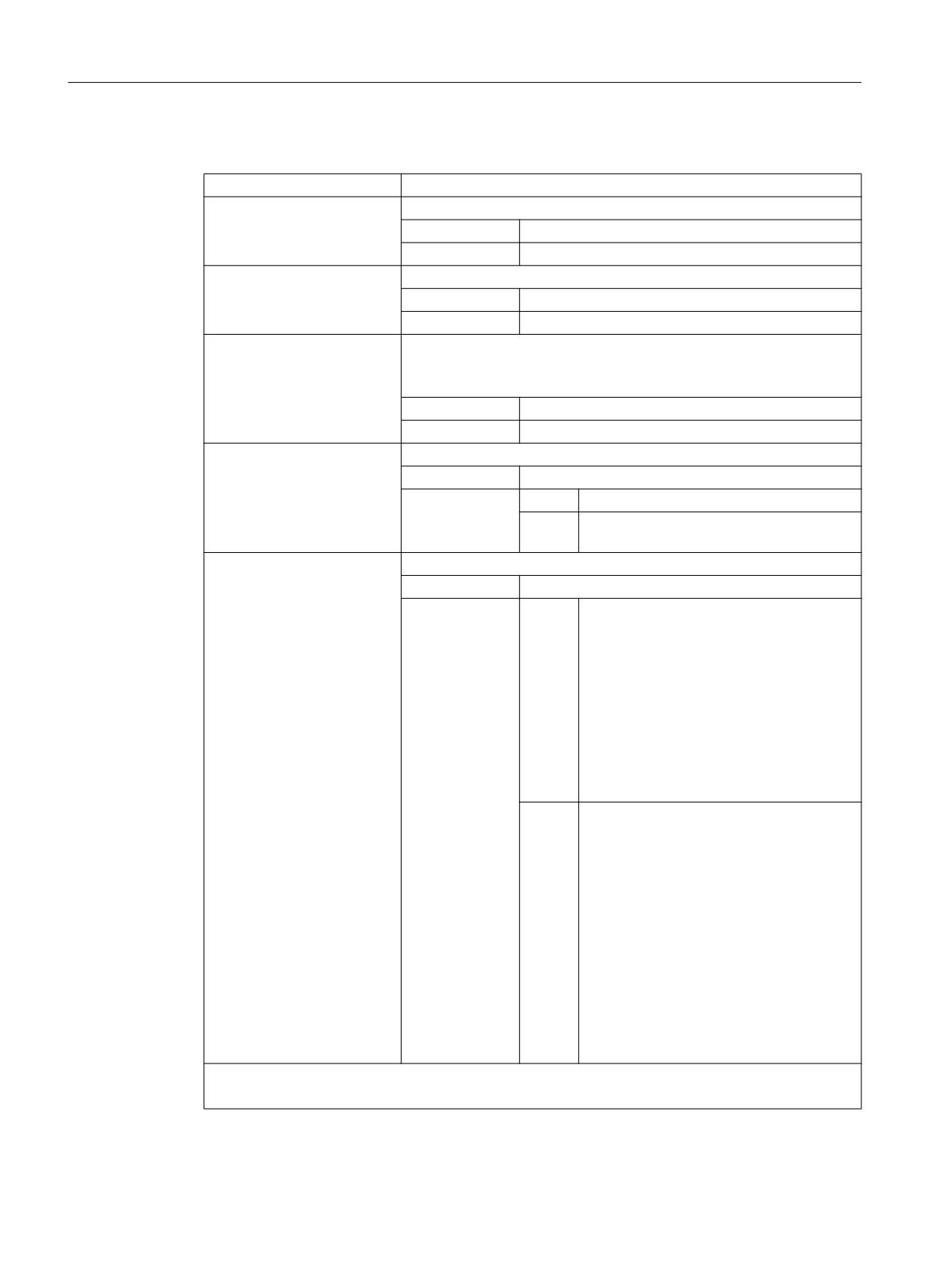
T3: Tangential control - 840D sl only
13.2 Programming
Meaning
TANG(...):
Define tangential coupling
<following axis>:
Axis name of the following axis (rotary axis)
Data type:
AXIS
Range of values:
Channel axis names
<leading axis_1>
Axis names of the leading axes (geometry axes) 1)
<leading axis_2>:
Data type:
AXIS
Range of values:
Geometry axis names of the channel
<coupling factor>:
Factor n of the angle change of the following axis for changing the path
tangent of the leading axes:
Angle changefollowing axis = angle changepath tangent * n
Data type:
REAL
Default value:
1.0
<coordinate system>:
Active coordinate system 2)
Data type:
CHAR
Value:
"B":
Basic coordinate system (default value)
"W":
Workpiece coordinate system (not availa-
ble)
<optimization>:
Optimization type
Data type:
CHAR
Value:
"S":
Standard (default value)
The dynamic response of the rotary axis
has no effect on the leading axes If the dy-
namic response of the rotary axis is greater
than required for tracking, this method is
sufficiently precise. If the dynamic re-
sponse of the rotary axis is not great
enough to follow the change in the path
tangent, the orientation of the rotary axis
will deviate from the target orientation
along an undefined rounding clearance.
"P":
The dynamic response of the rotary axis is
considered in the path planning of the lead-
ing axes.
For this purpose, on activation of the tan-
gential coupling with TANGON(), two addi-
tional parameters must be specified:
● Rounding clearance
● Angular tolerance
See Section "Activating the coupling (TAN-
GON) (Page 614)"
Note
With kinematic transformations, we recom-
mend using optimization method "P."
Note
Default values do not have to be programmed explicitly.
Special functions
612
Function Manual, 12/2018, A5E40874099B AB

T3: Tangential control - 840D sl only
13.2 Programming
1)
Note
As the leading axes for tangential coupling, the geometry axes must be used that travel along the
programmed path in the machine coordinate system (MCS) with reference to the initial position of the
machine. For example, if swivel cycle CYCLE800 is used on a milling machine with a swivel head,
depending on how the cycle is configured, interpolation will be performed in the WCS, e.g. with the
geometry axes X and Y. The tangential coupling, however, must be defined with the geometry axes as
the leading axes, which travel along the programmed path in the MCS. For this purpose, the geometry
axes in the non-swiveled condition of the machine must be used as the leading axes.
2) Note
The basic coordinate system (BCS) must not be rotated with respect to the MCS. For example, if the
BCS is rotated with the ROT command or with the swivel cycle CYCLE800, the tangential control is no
longer correct.
13.2.2
Activating intermediate block generation (TLIFT)
If the tangent change of the following axis at any position along the programmed path of the
leading axes exceeds the limit parameterized in machine data MD37400
$MA_EPS_TLIFT_TANG_STEP, further path planning will depend on the set behavior at
corners. Without use of the predefined procedure TLIFT(...), the path is traversed in
accordance with the rounding behavior programmed in connection with TANG(...) (Page 611)
and TANGON(...) (Page 614).
Activating intermediate block generation
If TLIFT(...) is programmed after TANG(...), an intermediate block automatically generated by
the control is inserted at this point when a corner is detected during preprocessing.
When the program is executed, the leading axes are stopped when the intermediate block is
reached. In the intermediate block, the following axis is rotated with maximum axis dynamics
toward the path tangent of the following block. The leading axes are then traversed further on
the programmed path.
Deactivating intermediate block generation
To deactivate intermediate block generation, the tangential coupling must be defined again
using TANG(...), but without subsequent activation of intermediate block generation by means
of TLIFT(...).
Syntax
TLIFT(<following axis>)
Meaning
TLIFT(...):
Activate corner detection with intermediate block calculation
<following axis>:
Axis name of the following axis (rotary axis)
Data type:
AXIS
Range of values:
Channel axis names
Special functions
Function Manual, 12/2018, A5E40874099B AB
613
T3: Tangential control - 840D sl only
13.2 Programming
Speed of rotation of the following axis
Path axis
If the following axis had already been traversed as a path axis before tangential coupling was
activated, the rotational movement is performed in the intermediate block as a path axis.
If you specify the reference radius with FGREF[<axis>]=0.001, the rotational movement
will be performed with the parameterized maximum axis velocity:
MD32000 $MA_MAX_AX_VELO[<following axis>]
Positioning axis
If the following axis had not yet been traversed as a path axis before tangential coupling was
activated, the rotation is performed in the intermediate block as a positioning axis.
The rotational movement is performed with the parameterized positioning axis velocity:
MD32060 $MA_POS_AX_VELO[<following axis>]
13.2.3
Activating the coupling (TANGON)
Via the predefined procedure TANGON(...), a tangential coupling previously defined with
TANG(...) (Page 611) is activated. The following axis is then continuously aligned with the path
tangent during subsequent travel.
Angle of the following axis
The angle of the following axis with respect to the path tangent depends on the transformation
ratio specified in TANG(...), the offset angle parameterized in the machine data MD37402
$MA_TANG_OFFSET, and the offset angle specified for TANGON(...), which is applied
additively.
Optimization "P"
If the value "P" was specified as the optimization parameter in the definition of the tangential
coupling (TANG(...)), the parameter "rounding clearance" and optionally the parameter
"angular tolerance" must be set when coupling is activated.
If the value 0 is specified as the angular tolerance, only the parameter "rounding clearance"
will be active.
If a value greater than 0 is specified as the angular tolerance, the active rounding clearance
results from the minimum of the parameterized rounding clearance and the rounding clearance
based on the parameterized angular tolerance.
If the dynamic response of the following axis is not sufficient to follow the parameterized
conditions, the path velocity of the leading axes will be reduced accordingly.
Syntax
TANGON(<following axis>, <offset angle>, <rounding clearance>,
<angular tolerance>)
Special functions
614
Function Manual, 12/2018, A5E40874099B AB

T3: Tangential control - 840D sl only
13.2 Programming
Meaning
TANGON(...):
Activate tangential coupling
<following axis>:
Axis name of the following axis (rotary axis)
Data type:
AXIS
Range of values:
Channel axis names
<offset angle>:
Offset angle of following axis with respect to the path tangent
The reference point is the zero point of the rotary axis.
Data type:
REAL
<rounding clearance>:
Maximum permissible rounding clearance
If the rounding clearance is increased due to the dynamic conditions,
the path velocity of the leading axes is reduced.
Data type:
REAL
<angular tolerance>:
Maximum permissible tolerance with respect to the specified angle be-
tween the following axis zero setting and the path tangent
Data type:
REAL
13.2.4
Deactivating the coupling (TANGOF)
Via the predefined procedure TANGOF(...), a tangential coupling defined with TANG(...)
(Page 611) and activated with TANGON(...) (Page 614) is deactivated. The following axis is
then no longer aligned with the path tangent of the leading axis. However, the coupling of the
following axis to the leading axes is retained even after deactivation, which prevents the
following functions, for example:
● Plane change
● Geometry axis switchover
● Definition of a new tangential coupling for the following axis
Final cancellation of the connection of the coupling of the following axis to the leading axes is
not completed until the coupling has been deleted with TANGDEL(...) (Page 616).
Programming
TANGOF(<following axis>)
Meaning
TANGOF(...):
Deactivate a tangential coupling
<following axis>:
Axis name of the following axis (rotary axis)
Data type:
AXIS
Range of values:
Channel axis names
Special functions
Function Manual, 12/2018, A5E40874099B AB
615

T3: Tangential control - 840D sl only
13.2 Programming
13.2.5
Deleting a coupling (TANGDEL)
A tangential coupling defined with TANG(...) (Page 611) will be retained even after deactivation
of the tangential coupling with TANGOF(...) (Page 615). The existing tangential coupling then
continues to prevent, for example, the following functions:
● Plane change
● Geometry axis switchover
● Definition of a new tangential coupling for the following axis
With the predefined procedure TANGDEL(...), the existing tangential coupling is deleted after
the tangential coupling has been deactivated with TANGOF(...).
Syntax
TANGDEL(<following axis>)
Meaning
TANGDEL(...):
Delete a tangential coupling defined with TANG()
Effective:
Non-modal
<following axis>:
Axis name of the following axis whose tangential coupling is to be de-
leted
Data type:
AXIS
Range of values:
Channel axis names
Examples
Leading axis change
Before a new tangential coupling can be defined with another leading axis for the following
axis, the existing tangential coupling must first be deleted.
Program code
Comment
N10 TANG(A, X, Y, 1)
; Define tangential couping for following axis A: A to
X and Y
N20 TANGON(A)
; Activate tangential coupling for following axis A
N30 X10 Y20
N80 TANGOF(A)
; Deactivate tangential coupling for following axis A
N90 TANGDEL(A)
; Delete tangential coupling for following axis A
N120 TANG(A, X, Z)
; Define new tangential coupling for following axis A
N130 TANGON(A)
; Activate new tangential coupling for following axis A
Special functions
616
Function Manual, 12/2018, A5E40874099B AB