SINUMERIK 840D sl. Service - Functions. Manual (2018-2020) - page 74
V2: Preprocessing
25.3 Program call
Program code
Comment
G1 F10 X=VARIABLE*10-56/86EX4+4*SIN(VARIABLE/3)
ENDFOR
; 1 name, only for preprocessing
M17
In order to execute this program normally, the following machine data must specify at least 3
names:
MD28020 $MC_MM_NUM_LUD_NAMES_TOTAL
Six names are required to compile this program after POWER ON.
Preprocessed programs/cycles are stored in the dynamic NC memory. The space required for
each program must be flashed over unmodified as outlined above. Adjustment of the memory
mapping in the static NC memory is required only if bit 6 = 1 is set in the following machine
data:
MD10700 $MN_PREPROCESSING_LEVEL (program processing level)
In this case, the program compilations for which there is insufficient space in the dynamic NC
memory are stored in the static NC memory.
Examples for appropriate machine data settings can be found under "Examples" in the
Subsection "Preprocessing in the dynamic NC memory".
25.3
Program call
Overview
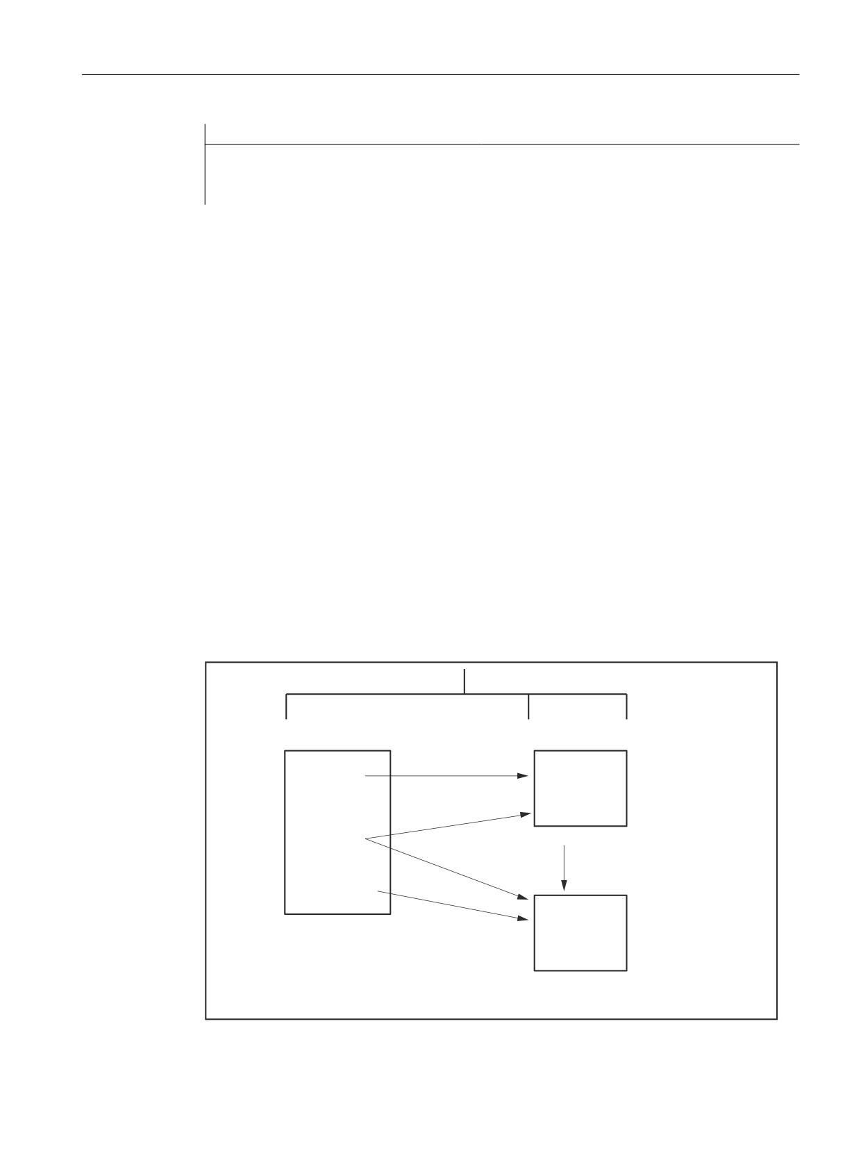
0DLQ SURJUDPV
8VHU F\FOHV
6WDQGDUG F\FOHV
B1B03)B',5
B1B&86B',5
B1B&67B',5
0DLQ SURJUDP
&DOO
&<&/(B63)
$6&,,
ZLWKRXW SUHSURFHVVLQJ
&\FOH
&<&/(
B1B&<&/(B63)
3UHSURFHVVLQJ
&<&/(B&<&
B1B0$,1B63)
&DOO
3UH
ZLWK SUHSURFHVVLQJ
SURFHVVHG
&\FOH
B1B&<&/(B&<&
Special functions
Function Manual, 12/2018, A5E40874099B AB
893
V2: Preprocessing
25.3 Program call
Figure 25-1
Generation and call of preprocessed cycles without parameters
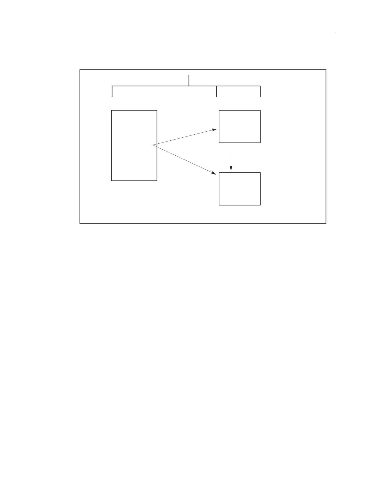
0DLQ SURJUDPV
8VHU F\FOHV
6WDQGDUG F\FOHV
B1B03)B',5
B1B&86B',5
B1B&67B',5
0DLQ SURJUDP
&DOO
$6&,,
&\FOH
ZLWKRXW SUHSURFHVVLQJ
352& &<&/(
5($/ )):
&<&/(
B1B&<&/( B63)
3UHSURFHVVLQJ
&DOO
3UH
ZLWK SUHSURFHVVLQJ
SURFHVVHG
&\FOH
B1B&<&/( B&<&
Figure 25-2
Generation and call of preprocessed cycles with parameters
Call
● Compiled cycle: A compiled cycle is called in exactly the same way as a normal subroutine.
Example: CYCLE
● Preprocessing is activated: The compiled cycle is called instead of the ASCII cycle.
- If the subroutine is called explicitly with extension _SPF, then the ASCII cycle is called
even if a compilation is available.
Example: CYCLE_SPF; ASCII cycle call
- If the subroutine is called explicitly with extension _CYC, then the preprocessed cycle
is called (assuming that it is available). An error message is output if no compilation is
available.
Example: CYCLE_CYC; calls a precompiled cycle
- If bit 5 is set and a file that is not marked with PREPRO is called explicitly with the
extension _CYC, an error message is issued with Alarm 14011.
● If a subroutine is called without explicit extension, an attempt is first made to load the
program. If this is not possible (not marked with PREPRO), an attempt is made to load the
SPF program.
Special functions
894
Function Manual, 12/2018, A5E40874099B AB
V2: Preprocessing
25.4 Constraints
● The change to an external language mode with G291 is rejected and an alarm issued. When
calling a precompiled cycle, an explicit change is made into the Siemens language mode.
● When the subroutine is called, it is checked whether the compiled file is older than the cycle.
If so, the compile file is deleted and an alarm issued. The user must preprocess the cycles
again.
Note
Only cycles without parameters may be called with the extension _SPF or _CYC.
It is not permissible that PUDs are used in cycles that have been preprocessed. The PUDs
are created in the calling main program. At the time of compilation after POWER ON, this
data is not known to the cycles.
The actual program display shows whether the current ASCII cycle or the compilation has
been called (extension _SPF or _CYC).
Call condition
All cycles in the cycle directories must be compiled before preprocessing is activated. Non-
compiled cycles in _N_CUS_DIR and _N_CST_DIR which were loaded after POWER ON, for
example, can only be called through explicit specification of extension _SPF.
If preprocessing is active and bit 5 is set, all programs that do not start with the PREPRO PROC
instruction are not precompiled.
Syntax check
All program errors, which can be corrected using a correction block, are already identified at
the time of preprocessing. In addition, when the program includes branches and check
structures, a check is made to ensure that the branch destinations are present and that
structures are nested correctly.
Branch destinations and labels must be unique in the program.
After the errors detected during preprocessing have been corrected, preprocessing must be
started again by means of an NC POWER ON.
25.4
Constraints
Availability of the "preprocessing" function
The function is an option ("Program pre-processing"), which must be assigned to the hardware
via the license management.
Language scope
The full vocabulary of the NC language is available in the part program.
Special functions
Function Manual, 12/2018, A5E40874099B AB
895
V2: Preprocessing
25.4 Constraints
There are no restrictions on the calculation of measured process variables and in the reaction
to signals from the process and other channels (override, deletion of distance-to-go, motion-
synchronous actions, channel coordination, interrupt processing, etc.).
Axis name
Part programs are compiled independently of channels. For this reason, the geometry and
channel names set in the following machine data must be identical in all channels if they are
used directly in the precompiled cycles:
MD20060 $MC_AXCONF_GEOAX_NAME_TAB (name of the geometry axis in the channel)
MD20080 $MC_AXCONF_CHANAX_NAME_TAB (name of the channel axis in the channel)
Generally speaking, axis names are not used directly in machining cycles since cycles are
written as follows:
● independently of channels and
● independently of the axis names defined on the machine.
The axes to be traversed are addressed indirectly via machine data or transferred as
parameters:
● Indirect axis programming:
- IF $AA_IM[AXNAME($MC_AXCONF_CHANAX_NAME_TAB[4])] > 5
; This branch will pass through if the actual value of the 5th channel axis
; with reference to the machine coordinate system is greater than 5.
- G1 AX[AXNAME($MC-AXCONF-GEOAX-NAME-TAB[0])] = 10
F1000 G90.
; Traverse the 1st geometry axis to the value 10.
ENDIF
● Transfer of axis to be traversed from the main program:
- Cycle definition
PROC DRILL(AXIS DRILL_AXIS)
WHILE $AA_IW[DRILL_AXIS] > -10
G1 G91 F250 AX[DRILL_AXIS] = -1
ENDWHILE
- Call from the main program
DRILL(Z)
Special functions
896
Function Manual, 12/2018, A5E40874099B AB
V2: Preprocessing
25.5 Examples
25.5
Examples
25.5.1
Preprocessing individual files
Program code
Comment
PROC UP1 PREPRO
; Preprocessing if bit 5 = 1
; in PREPROCESSING_LEVEL
N1000 DEF INT COUNTER
N1010 TARGET: G1 G91 COMPON
N1020 G1 X0.001 Y0.001 Z0.001 F100000
N1030 COUNTER=COUNTER+1
N1040 COUNTER=COUNTER-1
N1050 COUNTER=COUNTER+1
N1060 IF COUNTER<=10 GOTOB TARGET
N1070 M30
PROC UP2
N2000 DEF INT VARIABLE, ARRAY[2]
N2010 IF $AN_NCK_Version < 3.4
N2020 SETAL(61000)
N2030 ENDIF
N2040 START:
N2050 FOR VARIABLE = 1 TO 5
N2060 G1 F1000 X=VARIABLE*10-56/86EX4+4*SIN(VARIABLE/3)
N2070 ENDFOR
N2080 M17
PROC MAIN
N10 G0 X0 Y0 Z0
N20 UP1
N30 G0 X10 Y10 Z10
N40 UP2
N50 G0 X100 Y100
N60 UP3
N70 G0 X10 Y10
N80 M30
Sample constellations:
a) Bit 5 = 1
MD10700 $MN_PREPROCESSING_LEVEL=45 ; bit 0, 2, 3, 5
Subprogram UP1 is pretranslated, and the call description is generated.
Subprogram UP2 is not pretranslated, but the call description is generated.
b) Bit 5 = 0
Special functions
Function Manual, 12/2018, A5E40874099B AB
897
V2: Preprocessing
25.5 Examples
MD10700 $MN_PREPROCESSING_LEVEL=13 ; bit 0, 2, 3,
Both subprograms are pretranslated, and the call description is generated.
c) Example of an invalid subprogram with activated compiling:
Program code
Comment
PROC SUB1 PREPRO
G291
; ← Alarm when compiling, G291 not possible
G0 X0 Y0 Z0
M17
25.5.2
Preprocessing in the dynamic NC memory
Machine data for preprocessing only in the dynamic NC memory with selective selection:
Program code
Comment
; Bit 5 = 1 Selective program selection
; Bit 6 =0 no switch to
; static NC memory if
; dynamic NC memory is full
N30 $MN_MM_DRAM_FILE_MEM_SIZE = 800
; Reserve space
N40 $MN_PREPROCESSING_LEVEL = 63
; Bit 0-5 = 1
M17
Machine data for preprocessing in the dynamic NC memory with the option of using the static
NC memory and selective selection:
Program code
Comment
; Bit 5 = 1 Selective program selection
; Bit 6 = 1 switch to static
; NC memory if dynamic NC
; memory full
N30 $MN_MM_DRAM_FILE_MEM_SIZE = 800
; Reserve space
N40 $MN_PREPROCESSING_LEVEL = 127
; Bit 0-6 = 1
M17
Special functions
898
Function Manual, 12/2018, A5E40874099B AB

V2: Preprocessing
25.6 Data lists
25.6
Data lists
25.6.1
Machine data
25.6.1.1
General machine data
Number
Identifier: $MN_
Description
10700
PREPROCESSING_LEVEL
Program preprocessing level
18242
MM_MAX_SIZE_OF_LUD_VALUE
Maximum LUD-variable array size
25.6.1.2
Channelspecific machine data
Number
Identifier: $MC_
Description
28010
MM_NUM_REORG_LUD_MODULES
Number of blocks for local user variables for REORG
(DRAM)
28020
MM_NUM_LUD_NAMES_PER_PROG
Number of local user variables (DRAM)
28040
MM_LUD_VALUES_MEM
Memory size for local user variables (DRAM)
Special functions
Function Manual, 12/2018, A5E40874099B AB
899
V2: Preprocessing
25.6 Data lists
Special functions
900
Function Manual, 12/2018, A5E40874099B AB
W5: 3D tool radius compensation - 840D sl only
26
26.1
Function
26.1.1
Introduction
3D circumferential milling and 3D face milling
3D tool radius compensation (3D-TRC) is used to process contours with tools that can be
controlled in their orientation independently of the tool path and shape.
SINUMERIK provides the 3D-TRC in different variants, which are used in combination with
the following manufacturing processes:
● Circumferential milling (Page 902) for structural components
● Face milling (Page 908) for free-form surfaces
Tool orientation
For the 3D-TRC, a distinction must be made between the two scenarios of a tool with a fixed
orientation and a tool with a changeable orientation.
The tool radius compensation with a fixed tool for circumferential milling is designated as a
2½D-TRC. This is the conventional tool radius compensation. Circumferential milling with a
functionality that goes beyond this scope of performance is not possible for the compensation
with a fixed tool. For circumferential milling, there is only a 3D-TRC if the tool orientation is
changeable. This means, in addition to the 3 degrees of freedom for positioning the tool
(generally 3 linear axes), two additional degrees of freedom (2 rotary axes) are also needed
for setting the tool orientation (5-axis machining).
During face milling, the tool orientation can remain constant or be variable. The advantages
of variable orientation are:
● better approximation of the end contour
● increased chip performance
● more freedom in selecting the shape of the tool
● a wider range of surfaces that can be processed (undercuts)
Note
5D-WRK
The 3D-TRC is also called 5D-TRC below, because 5 degrees of freedom are available in this
case for defining the position of the tool in space relative to the workpiece.
Special functions
Function Manual, 12/2018, A5E40874099B AB
901
W5: 3D tool radius compensation - 840D sl only
26.1 Function
Parameter assignment
The machine and setting data set for the 2D-TRC are also in effect for the 3D-TRC.
Reference:
Function Manual Basic Functions; Chapter "W1: tool offset"
In addition to this, there is special system data that is only relevant to 3D-TRC. See Chapter
"Parameter assignment (Page 916)" regarding settings of this data.
Activation/deactivation
The selection of the 3D-TRC variant is made in the NC program via G commands of Group 22
(tool offset type). The actual activation and deactivation are done via the G commands of Group
7 (tool radius compensation).
See Chapter "Programming (Page 917)".
26.1.2
Circumferential milling
The 3D circumferential milling is used for machining contours with tools having an orientation
that is not constant during processing. Processing is done using the peripheral surface of the
tool. If the tool is cylindrical, ruled surfaces (e.g. cones, cylinders, etc.) are created during this
processing. Other forms of milling machines can also be used, however (e.g. form cutters).
The tool radius compensation needed for this type of processing is an extension of the
conventional 2½D-TRC.
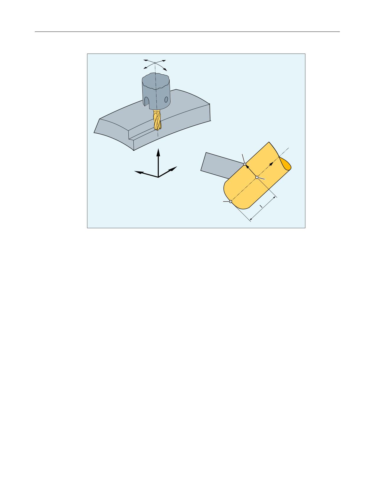
The ratios for 3D circumferential milling are shown in the following figure:
Special functions
902
Function Manual, 12/2018, A5E40874099B AB
W5: 3D tool radius compensation - 840D sl only
26.1 Function
$
%
=
)(
Z
;
<
Z5
)+
)6
FE:
Milling tool machining point
FS:
Milling tool tip
FH:
Milling tool reference point
I:
Insertion depth
w:
Tool vector
wr:
Vector from the milling tool reference point to the milling tool machining point with length of
shank radius R
Figure 26-1
Circumferential milling
Insertion depth
The insertion depth of the milling tool is the distance of the milling tool reference point from
the tip of the tool.
The milling tool reference point is the vertical projection of the milling tool machining point on
the programmed path to the longitudinal axis of the tool.
The position of the machining point on the peripheral surface of the tool is set with the insertion
depth.
Via the address ISD (InSertion Depth), the insertion depth of the tool for circumferential milling
and active 3D tool radius compensation can be changed (see Chapter "Programming
(Page 917)").
Special functions
Function Manual, 12/2018, A5E40874099B AB
903
W5: 3D tool radius compensation - 840D sl only
26.1 Function
26.1.2.1
Corners in circumferential milling
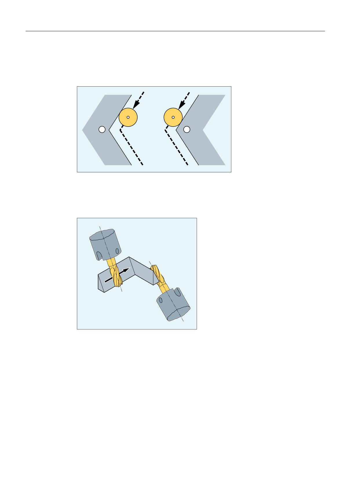
Inside and outside corners are handled separately. The terms inside corner and outside corner
are dependent on the tool orientation.
*
*
① Inside corner
② Outside corner
When the orientation changes at a corner, for example, the corner type may change while
machining is in progress:
Whenever this occurs, the machining operation is aborted with alarm 10770.
Special functions
904
Function Manual, 12/2018, A5E40874099B AB
W5: 3D tool radius compensation - 840D sl only
26.1 Function
26.1.2.2
Behavior at outer corners
At outside corners during circumferential milling with 3D-TRC analogous to the conditions in
the 2½D-TRC, the G commands of Group 18 (corner behavior tool offset) are evaluated:
● G450: Transition circle (tool travels around workpiece corners on a circular path)
Outside corners are treated like circles with a radius of 0, where the circular plane stretches
from the end tangent of the first block and the start tangent of the second block. Thus, an
orientation change during the block transition is also possible. Thus, a block is always
inserted at an outside corner.
In contrast to the solution for the 2½D-TRC, the contour element inserted at an outside
corner is always a circle with a radius of 0, which is affected by the tool radius compensation
like on any other programmed path. It is not possible to insert conical sections in place of
the circles. The address DISC therefore has no relevance in this case and is not evaluated.
● G451: Intersection of equidistant paths (tool backs off from the workpiece corner)
The intersection is determined by extending the offset curves of the two participating blocks
and defining the intersection of the two blocks at the corner in the plane perpendicular to
the tool orientation.
If an intersection is found in the plane perpendicular to the tool, this does not mean that the
curves also intersect in space. Rather the curves in the direction of the tool longitudinal axis
are considered, which are generally a certain distance apart. The positional offset is
eliminated over the entire block length in direction of the tool.
The way this offset is processed in tool direction at outside corners is the same as for inside
corners.
For nearly tangential transitions, the behavior for an active G450 is the same as for G451 (limit
angle can be set via MD20210 $MC_CUTCOM_CORNER_LIMIT). Conversely, if G451 is
active, a circle is also inserted (procedure as for G450) if there is no intersection or if the corner
angle exceeds a specific value (MD20230 $MC_CUTCOM_CURVE_INSERT_LIMIT).
Behavior during orientation changes
The intersection procedure (G451) is not used when at least one block containing a change
to the tool orientation was inserted between the traversing blocks in question. In this case a
circle is always inserted at the corner.
The G commands of Group 27 (too offset for orientation change at outside corners) can be
used to define whether orientation changes, which have been programmed between the two
traversing blocks that form the corner, are executed before the beginning of the inserted circle
set or at the same time.
● ORIC: Orientation changes at outside corners are superimposed on the circle block to be
inserted.
● ORID: Orientation changes are performed before the circle block.
If two or more blocks with orientation changes (e.g. A2=... B2=... C2=...) are programmed
between two traversing blocks and ORIC is active, then the circular block to be inserted is
divided between these intermediate blocks corresponding to the amount of the individual angle
changes. Further programmed intermediate blocks without traversing and orientation motions
are executed at the programmed positions.
If ORID is active, all inserted blocks (both those with and without orientation movement) are
executed at the end of the first of the two traversing blocks. The tangent in the end point of the
Special functions
Function Manual, 12/2018, A5E40874099B AB
905
W5: 3D tool radius compensation - 840D sl only
26.1 Function
first traversing block is used for the offset calculation. The circle block with constant orientation
is inserted immediately before the second traversing block.
See also "Example 1: Orientation change at outside corner during 3D circumferential milling
(Page 932)".
Intermediate blocks without relevant traversing information
Intermediate blocks without relevant traversing information (neither tool orientation nor position
of geometry axes are changed) are permissible. The intersection procedure is applied to the
adjacent blocks as if these intermediate blocks did not exist. In the same manner, tool direction
motions in the tool direction may also be programmed in intermediate blocks.
26.1.2.3
Behavior at inside corners
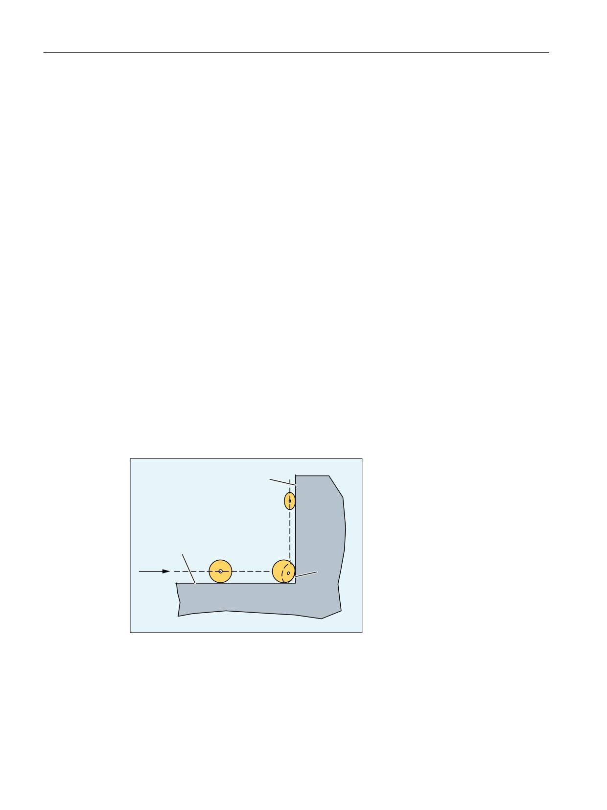
For the 3D-TRC, only adjacent traversing blocks are taken into consideration for the calculation
of the intersecting point.
If the orientation is not changed at the block limit, then the contour need only be considered
in the plane vertical to the tool axis. In this case, the tool cross-section is a circle which touches
the two contours. The geometric relations in this plane are identical to those for 21/2D-TRC.
Behavior during orientation changes
If the orientation changes on a block transition, the tool moves in the inside corner so that it is
constantly in contact with the two blocks forming the corner.
Path segments must be long enough to ensure that the contact points of the tool do not cross
the block limits into other blocks when the orientation changes at an inside corner.
1
1
1
Figure 26-2
Orientation changes at inside corner
When the orientation changes in a block that is one of the two blocks forming the inside corner,
then it is no longer possible to adhere to the programmed relationship between path position
and associated orientation. This is because the orientation must reach its end value even
though the path end position is not reached. This response is identical to the response of
synchronized axes with 21/2 D tool radius compensation.
Special functions
906
Function Manual, 12/2018, A5E40874099B AB

W5: 3D tool radius compensation - 840D sl only
26.1 Function
3URJUDPPHG
SRVLWLRQ
Figure 26-3
Path end position and change in orientation at inside corners
See also "Example 2: Orientation change at inside corner during 3D circumferential milling
(Page 935)".
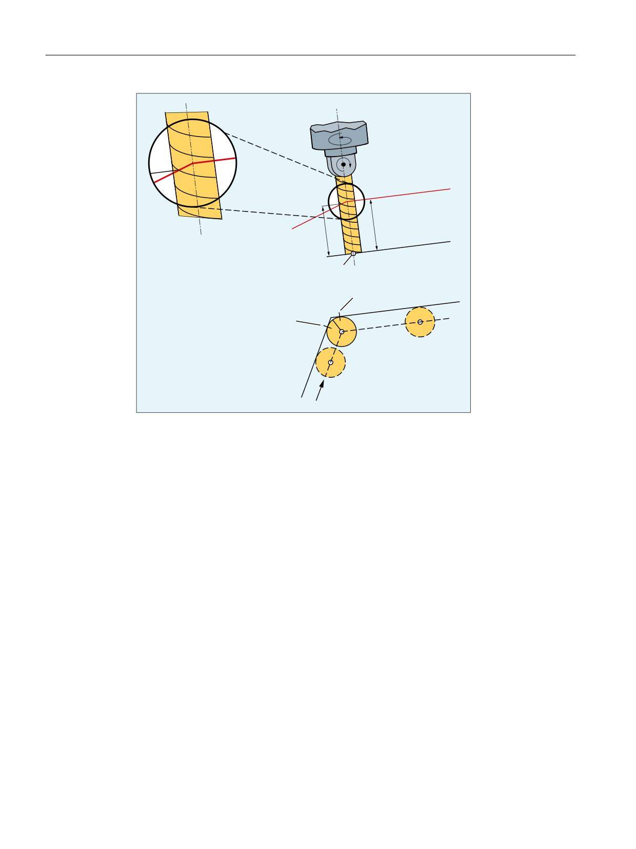
Change in insertion depth
Generally speaking, the contour elements that form an inside corner are not positioned on the
plane perpendicular to the tool. This means that the contact points between the two blocks
and the tool are at different distances from the tool tip.
This means: The insertion depth (ISD) changes abruptly from the 1st to the 2nd block at an
inside corner.
To ensure that this difference in depth is not an abrupt step change, it is distributed continuously
among the blocks involved during interpolation. The depth-compensating motion is executed
in the current tool direction.
This solution prevents the contour from being violated by cylindrical tools if the length of the
tool prevents the cutter contact point on the lateral surface of the cutter leaving the range in
which machining is possible.
Special functions
Function Manual, 12/2018, A5E40874099B AB
907
W5: 3D tool radius compensation - 840D sl only
26.1 Function
,6' QHZ
,6' ROG
)6
QG EORFN
VW EORFN
Figure 26-4
Change in insertion depth
26.1.2.4
Monitoring of path curvature
The path curvature is monitored for an unchangeable orientation in the following way:
1. The contour in each block is projected on the plane that is orthogonal to the tool orientation.
2. Then the curvature of the projection is analyzed. Areas with too much curvature (tool does
not fit in the curve) are cut out.
3. The remaining offset contours overlap each other and thus form the global offset contour.
26.1.3
Face milling
Face milling is used to process curved surfaces of any kind. In this case, the longitudinal axis
of the tool and the surface normal vector are more or less parallel. In contrast, the longitudinal
axis of the tool and the surface normal vector of the surface to be machined in a 3D
circumferential milling operation are at right angles to one another.
Information about the surface to be machined is absolutely essential for face milling operations,
i.e. a description of the linear path in space is not sufficient. The tool shape must also be known
in order to implement the tool offset (the term "Tool radius compensation" is not appropriate
in this case).
The conditions for face milling are shown in the following figure:
Special functions
908
Function Manual, 12/2018, A5E40874099B AB
W5: 3D tool radius compensation - 840D sl only
26.1 Function
Z
)6
5
H
Q)
U
)(
FE:
Milling tool machining point
FS:
Milling tool tip
nF:
Surface normal vector
w:
Tool vector
R:
Shaft radius
r:
Corner radius
e:
Difference between the shank radius R and corner radius r
Figure 26-5
Face milling with a torus cutter
26.1.3.1
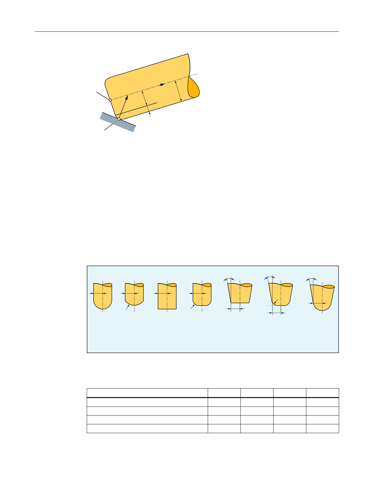
Tool shapes and tool data for face milling
An overview of the tool shapes, which may be used for face milling operations and relevant
tool data are listed in the following. The shape of the tool shaft is not taken into account.
Therefore, the tool types 120 and 155, for example, have an identical effect.
D
D
D
5
5
5
5
U
5
U
U
5
5
%DOO HQG PLOO
&\OLQGULFDO
(QG PLOO
(QG PLOO ZLWK
%HYHO FXWWHU
%HYHO FXWWHU
7DSHUHG
GLH VLQNLQJ
FRUQHU URXQGLQJ
ZLWK FRUQHU URXQGLQJ
GLH VLQNLQJ
PLOOLQJ FXWWHU
FXWWHU
W\SH
W\SH
W\SH
W\SH
W\SH
W\SH
W\SH
R
= shank radius (tool radius)
r
= corner radius
a
= angle between the tool longitudinal axis and upper end of the torus surface
Cutter type
Type No.
R
r
a
Ball end mill
110
> 0
-
-
Cylindrical die-sinking milling cutter
111
> 0
> R
-
End mill, angle head cutter
120, 130
> 0
-
-
End mill, angle head cutter with corner rounding
121, 131
> r
> 0
-
Special functions
Function Manual, 12/2018, A5E40874099B AB
909

W5: 3D tool radius compensation - 840D sl only
26.1 Function
Cutter type
Type No.
R
r
a
Bevel cutter
155
> 0
-
> 0
Bevel cutter with corner rounding
156
> 0
> 0
> 0
Tapered die-sinking cutter
157
> 0
-
> 0
- : is not evaluated.
Tool data
Tool parameters
Tool dimensions
Geometry
Wear
R
$TC_DP6
$TC_DP15
r
$TC_DP7
$TC_DP16
a
$TC_DP11
$TC_DP20
Note
If, in the NC program, a type number is specified that differs from that in the diagram, then the
system automatically uses tool type 110 (ball end mill).
Note
An alarm is output if the tool data limit values are violated.
Geometry and wear values of tool data have an additive effect, i.e. the tool form that is actually
used for the offset calculation is always described by the sum values.
In the CUT3DFD function (differential tool), only the wear value is considered as an offset
value. The geometry values are only necessary in this case for describing the tool form.
Tool length offset
The tool tip (intersecting point between the tool longitudinal axis and the workpiece surface)
is considered the reference point for the length offset.
Tool change
A new tool with changed dimensions (R, r, a) or other form can only be specified during the
first activation of the tool offset (i.e. during the transition from G40 to G41 or G42) or for an
already active offset only for new programming of G41 or G42. This rule does not apply to any
other tool data, e.g. tool lengths, so that tools can be loaded without reprogramming G41 or
G42.
26.1.3.2
Face milling with a specified surface normal vector
Expanded options for orientation programming are provided for 3D face milling.
The tool offset for face milling cannot be calculated simply by specifying the path (e.g. of a line
in space). The surface to be machined must also be known. The necessary information about
the surface is provided to the controller with the surface normal vector.
The surface normal vector at the block beginning is programmed with A4, B4, C4, and the
vector at the block end with A5, B5, C5. Components of the surface normal vectors which are
not programmed are set to zero. The length of a vector programmed in this way is irrelevant.
Special functions
910
Function Manual, 12/2018, A5E40874099B AB
W5: 3D tool radius compensation - 840D sl only
26.1 Function
A vector of zero length (all three components are zero) is ignored, i.e. the direction programmed
beforehand remains valid, no alarm is generated.
If only the start vector is programmed (A4, B4, C4) in a block, then the programmed surface
normal vector remains constant over the entire block. If only the end vector is programmed
(A5, B5, C5), then large-circle interpolation is used to interpolate between the end value of the
preceding block and the programmed end value. If both start and end vectors are programmed,
interpolation according to the large circle principle is also performed between the two
directions. The fact that the start vector may be reprogrammed in a block means that the
direction of the surface normal vector can change irregularly on a block transition. Irregular
transitions of the surface normal vector always occur in cases where there is no tangential
transition between the surfaces (planes) involved, i.e. if they form an edge.
Once a surface normal vector is programmed, it remains valid until a new vector is
programmed. In the basic position, the surface normal vector is set to equal the vector in the
Z direction. This basic setting direction is independent of the active plane (G17 - G19). If
ORIWKS is active, surface normal vectors refer to the active frame, i.e. when the frame is
rotated, the vectors rotate simultaneously. This applies both to programmed orientations and
to those that have been derived from the active plane. If ORIWKS is active, the surface normal
vectors are brought along during a frame change. An orientation modified as the result of frame
rotations is not returned to its original state on switchover from ORIWKS to ORIMKS.
It must be noted that the programmed surface normal vectors may not necessarily be the same
as those used internally. This is always the case if the programmed surface normal vector is
not vertical on the path tangent. A new surface normal vector is then formed, which lies within
the plane spanned by the path tangent and programmed surface normal vector, but which is
vertical on the path tangent vector. This orthogonality is required, because the path tangent
vector and the surface normal vectors (must) always be vertical to one another in a real surface.
However, since the two variables can be programmed independently of one another, they can
contain information that is mutually contradictory. Orthogonalization ensures that the
information contained in the path tangent vector has priority over the data in the surface normal
vector. An alarm is output if the angle between the path tangent vector and the programmed
surface normal vector undershoots the limit value, which is defined in the following machine
data:
MD21084 $MC_CUTCOM_PLANE_PATH_LIMIT (minimal angle between surface normal
vector and path tangent vector)
If a block is shortened (inside corner), then the interpolation range of the surface normal vector
is reduced accordingly, i.e. the end value of the surface normal vector is not reached as it
would be with other interpolation quantities such as, for example, the position of an additional
synchronized axis.
In addition to the usual methods of programming orientation, it is also possible to refer the tool
orientation to the surface normal vector and path tangent vector using the addresses LEAD
(lead or camber angle) and TILT (side angle). The interpretation of the angle data depends on
the setting in MD21094 $MC_ORIPATH_MODE (see Chapter "Path-relative orientation
(ORIPATH, ORIPATHS, ORIROTC) (Page 97)"). The specification of the angle relative to the
surface normal is only an expanded option of orientation programming at the end of the block.
It does not imply that the lead and side angles reach their programmed values before the path
end point is reached.
The resulting tool orientation is determined from the path tangent, surface normal vector, lead
angle and side angle at the end of the block. This orientation is always implemented by the
end of the block, particularly in cases where the block is shortened (at an inside corner). If the
omitted path section is not a straight line in a plane, the lead and side angles generally deviate
Special functions
Function Manual, 12/2018, A5E40874099B AB
911

W5: 3D tool radius compensation - 840D sl only
26.1 Function
from their programmed values at the path end point. This is because the orientation has
changed relative to the surface normal vector or path tangent vector when the absolute
orientation of the tool is the same as at the original path end point.
26.1.3.3
Compensation on path
A special case must be examined with respect to face milling operations, i.e. that the machining
point on the tool surface moves around. This may be the case on a torus cutter whenever
surface normal vector nF and tool vector w become collinear (i.e. the tool is at exact right angles
to the surface) since it is not a single point on the tool that corresponds to this direction, but
the entire circular surface on the tool end face. The contact point is therefore not defined for
this orientation. A path point in which tool longitudinal axis and surface normal are parallel is
therefore referred to below as a singular point or a singularity.
The above case is also meaningful in practical terms, e.g. in cases where a convex surface,
which may have a vertical surface normal (e.g. hemisphere), must be machined with a
perpendicular tool (e.g. face milling with constant orientation). The machining point on the
contour remains fixed, but the machine must be moved to bring the machining point from one
side of the tool to the other.
The problem described is only a borderline case (lead angle β = 0 and side angle y = 0). If the
lead angle β = 0 and the side angle y has a low value, then the tool must be moved very rapidly
(in borderline case in steps) to keep the machining point resulting from the milling conditions
close to the arc-line forming the end face (see the following figure).
In principle, it is resolved by the smoothing of the surface normal and the smoothing of the
contour.
6LQJXODU SRLQW
Figure 26-6
Switching of the processing point on the tool surface in the vicinity of a point in which the
surface normal vector and the tool orientation are parallel.
Singularities do not only occur in isolated points, but can also occur over entire curves. This
is the case, for example, if the curve to be interpolated is a plane curve (i.e. a curve with a
constant osculating plane) and the tool is constantly aligned in parallel to the binormal vector
(perpendicular to the osculating plane). A simple example of this is an arc in the X-Y plane,
which is processed with a tool that is aligned parallel to the Z axis. For paths of this type, the
tool offset is reduced to a tool length compensation. I.e. the tool is positioned in such a way
that its tip lies on the programmed path.
For a jump-like transition between singular and non-singular curves, linear blocks must be
inserted, just as in the handling of individual points, so that the processing point on the tool
Special functions
912
Function Manual, 12/2018, A5E40874099B AB
W5: 3D tool radius compensation - 840D sl only
26.1 Function
can migrate from the tool tip to the periphery (at outside corners or convex surfaces) or the
paths must be shortened to prevent contour violations (at inside corners or concave surfaces).
It is therefore necessary to activate both the smoothing of the contours ("Top Surface" function)
and the smoothing of the surface normal to ensure that the transitions run smoothly.
26.1.3.4
Corners in face milling
Two surfaces that do not tangentially transition into one another form an edge. The paths
defined on the surfaces form a corner. This corner is a point of the edge.
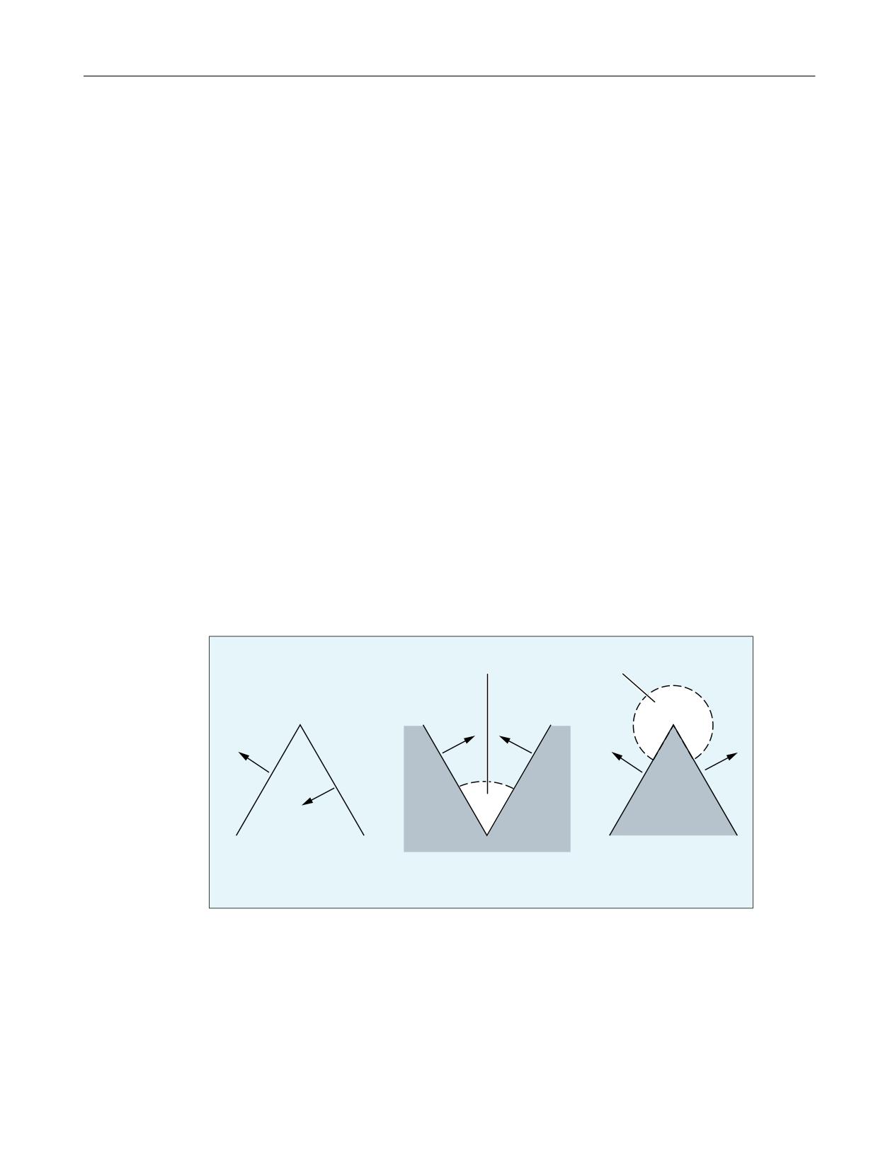
The type of corner (inside or outside corner) is defined by the surface normals of the
participating surfaces and the paths defined on them.
The surface normals of the two surfaces forming the edge may point in opposite directions of
the overall surface (the front edge of one surface is continued on the rear edge of the second
surface), see also the following Figure. Transitions of this type are not allowed and are rejected
with an alarm.
The scalar product of the surface normal vector and (possibly variable) tool orientation on one
corner/path must be positive at each point, i.e. it is not permissible to machine from the rear
face of the surface. If this condition is not fulfilled, an alarm is output. The permissible ranges
of validity of tool orientation for inside and outside corners are illustrated in the following Figure.
These ranges are further restricted by the condition that the angle between the surfaces to be
machined and the "steepest" surface line of the tool surface must not be lower than a particular
machine data setting. The "steepest" surface line is a line at angle a to the tool longitudinal
axis (this line is in the same direction as the tool longitudinal axis on cylindrical tools). This
restriction must be imposed to ensure that the contact point on the tool does not leave the
permissible range.
9DOLG UDQJH RI WRRO RULHQWDWLRQ
,QYDOLG VXUIDFH WUDQVLWLRQ
,QVLGH FRUQHU
2XWVLGH FRUQHU
Figure 26-7
Corners in face milling
It is possible to insert blocks that contain no motion commands (e.g. auxiliary function outputs)
and/or that include motions of geometry axes not involved in the path between two blocks
which contain a path definition. In particular, orientation changes can also be programmed in
such blocks. The only exception applies to the activation and deactivation of the 3D tool radius
compensation function: Intermediate bocks with orientation changes are not permitted
Special functions
Function Manual, 12/2018, A5E40874099B AB
913
W5: 3D tool radius compensation - 840D sl only
26.1 Function
between the activation block and the first corrected block or between the last corrected block
and the deactivation block. Other intermediate block are allowed, however.
26.1.3.5
Behavior at outer corners
In face milling, outside corners are treated like circles with a radius of 0, where the circular
plane stretches from the end tangent of the first block and the start tangent of the second block.
Thus, an orientation change during the block transition is also possible. Thus, a circle is always
inserted as a contour element at an outside corner. The intersecting point process is not
available for face milling.
Behavior during orientation changes
The G commands of Group 27 (too offset for orientation change at outside corners) can be
used to define whether orientation changes, which have been programmed between the two
traversing blocks that form the corner, are executed before the beginning of the inserted circle
set or at the same time.
● ORIC: Orientation changes at outside corners are superimposed on the circle block to be
inserted.
● ORID: Orientation changes are performed before the circle block.
If two or more blocks with orientation changes (e.g. A2=... B2=... C2=...) are programmed
between two traversing blocks and ORIC is active, then the circular block to be inserted is
divided between these intermediate blocks corresponding to the amount of the individual angle
changes. Further programmed intermediate blocks without traversing and orientation motions
are executed at the programmed positions.
If ORID is active, all inserted blocks (both those with and without orientation movement) are
executed at the end of the first of the two traversing blocks. The tangent in the end point of the
first traversing block is used for the offset calculation. The circle block with constant orientation
is inserted immediately before the second traversing block.
See also "Example 1: Orientation change at outside corner during 3D circumferential milling
(Page 932)".
26.1.3.6
Behavior at inside corners
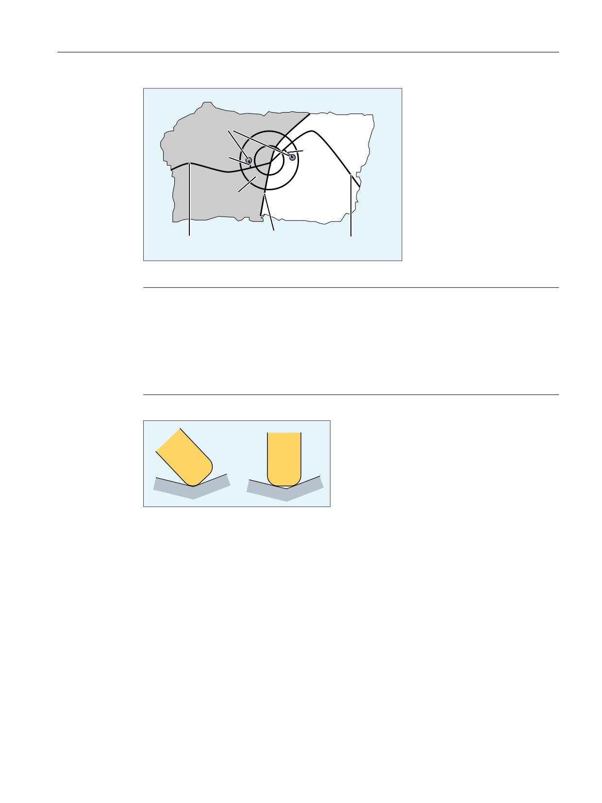
The position of the tool in which it is in contact with the two surfaces forming the corner must
be determined at an inside corner. The contact points must be on the paths defined on both
surfaces. It is not usually possible to solve this problem exactly since, when the tool is moved
along the path on the first surface, it normally touches a point on the second surface which is
not on the path.
For this reason, the tool is not moved along the path on the first surface, but deviates from the
path in such a way as to ensure that the distance between the contact points and the relevant
contours in the position in which the tool contacts both surfaces is minimal, see also the
following Figure.
Special functions
914
Function Manual, 12/2018, A5E40874099B AB
W5: 3D tool radius compensation - 840D sl only
26.1 Function
&RQWDFW SRLQWV
7RRO VXUIDFH
3DWK
3DWK
RIIVHW S
RIIVHW S
7RRO
&XW HGJH RI
3DWK RQ VXUIDFH
3DWK RQ VXUIDFH
ERWK VXUIDFHV
Figure 26-8
Inside corner with face milling (view in direction of longitudinal axis of tool)
Note
The amount by which the contact points deviate from the programmed contour will generally
be small since the explanatory example shown in the Figure, in which the machining point
"changes" the cutter side at an inside corner (the value of the angular difference Ψ about the
tool longitudinal axis between the two contact points on the tool surface is approximately 180°)
is more likely to be the exception (see also the following Figure, on the right). The angle Ψ will
normally stay almost constant so that the distance between the contact points on the tool
surface will be relatively small (see also the following Figure, on the left).
Figure 26-9
Machining at inside corners
The difference between the programmed point on the path and the point actually to be
approached (path offset p) is eliminated linearly over the entire block length. Differences
resulting from inside corners at the block start and block end are overlaid. The current
difference in a path point is always perpendicular to the path and in the surface defined by the
surface normal vector.
If the tool orientation at an inside corner is not constant, the change in orientation is
implemented in the same way as described in Subsection "Behavior at inside corners" for 3D
circumferential milling, i.e. the tool is moved in the corner so that it contacts the two adjacent
surfaces at the block start, block end and at two points 1/3 and 2/3 of the change in orientation.
A 3rd-degree polynomial is used to interpolate between these 4 points.
A variable tool orientation in a block that is shortened owing to an inside corner is also treated
in the same way as described in Subsection "Behavior at inside corners" for 3D milling
(Page 906), i.e. the entire change in orientation is executed in the shortened block.
Consequently, the functional relationship between path tangent, surface normal and tool
orientation also changes. This results in new, previously nonexistent singularities or
Special functions
Function Manual, 12/2018, A5E40874099B AB
915
W5: 3D tool radius compensation - 840D sl only
26.2 Commissioning
impermissible side angles (at points which are virtually singular) occurring in the shortened
block. If this type of situation is detected during processing of an inside corner, the machining
operation is aborted with an alarm. No block division takes place at the singular points since
the compensatory motions this would involve frequently cause contour violations and the
change in machining side on the tool is not generally intended or even foreseen by the user.
The alarm is also output during examination of an inside corner if the singularity occurs in the
second of the two blocks without the transition to the next block being considered. The system
does not therefore detect that a block of this type will form an inside corner in conjunction with
the following block and that the singularity would be eliminated again by the second block
reduction.
Remedy: Create new/different NC program, e.g. with a smaller tolerance.
The surface normal vector nF is not affected by the reduction of a block. This means that in
contrast to the tool orientation, the change in orientation that may need to be executed for this
vector will not be imaged onto the reduced traversing interval. This is necessary because a
surface other than that programmed would be machined. Unlike the tool orientation, no
problems arise as the result of an abrupt change in the surface normal vector at a block
transition since it does not reflect any axis motions.
Analogously to 3D circumferential milling, (see Section "Behavior at inside corners
(Page 906)"), the two traversing blocks that form an inside corner must contain contact points.
There is no evaluation of several traversing blocks (i.e. no bottleneck detection), CDON/CDOF
are not evaluated. If no contact point can be found, the machining operation is aborted with
an alarm (risk of collision).
26.1.3.7
Monitoring of path curvature
The path curvature is only monitored for circumferential milling. As a rule, it is therefore not
detected for CUT3DF* functions when an attempt is made to process a concave surface which
is so intensively curved that machining is not possible with the tool being used. A possible
exception are blocks that are split owing to a singularity. The transition between the two partial
blocks created after the split is then treated like an inside corner. Apart from these special
cases, it is the responsibility of the user to only use tools that make it possible to process every
part of the contour without contour violation. It could be helpful to use the CUT3DFD function
for this, where the differential tool is only minimally different from the original tool.
26.2
Commissioning
26.2.1
Parameter assignment
Minimal angle between path tangent and tool orientation
For the 3D-TRC, the angle between the path tangent and the tool orientation cannot
undershoot a specific limit angle.
This angle is defined in the machine data:
MD21080 $MC_CUTCOM_PARALLEL_ORI_LIMIT
Special functions
916
Function Manual, 12/2018, A5E40874099B AB
W5: 3D tool radius compensation - 840D sl only
26.3 Programming
The lower the value of MD21080, the higher the computation effort generally is, which is
needed to check adherence to the cited conditions. Exceptions apply to linear blocks with
constant orientation.
Minimal angle between surface normal vector and tool orientation
In 3D face milling, the following machine data specifies the minimum angle which the surface
normal vector and tool orientation must form in each point of the path if you are working with
a side angle that is not equal to zero and the tool is not a cherry:
MD21082 $MC_CUTCOM_PLANE_ORI_LIMIT
If this value is undershot, processing is canceled with an alarm.
The lower the value of MD21082, the higher the computation effort generally is, which is
needed to check adherence to the cited conditions.
MD21082 has no effect in linear blocks with constant orientation. In this case, angles of any
size are permitted, even if the side angle is not equal to zero.
Minimal angle between surface normal vector and path tangent vector
During 3D face milling, the following machine data specifies the minimum angle which the
surface normal vector and path tangent vector must form in each point of the path:
MD21084 $MC_CUTCOM_PLANE_PATH_LIMIT
If this value is undershot, processing is canceled with an alarm.
The lower the value of MD21084, the higher the computation effort generally is, which is
needed to check adherence to the cited conditions.
Interpolation of the surface normals via polynomials
In order to use smoothing of the surface normal in 3D face milling, the function "Interpolation
of the surface normal via polynomials" must be enabled:
MD28291 $MC_MM_SMOOTH_SURFACE_NORMALS = TRUE
If MD28291 is not set, processing is canceled with an alarm.
26.3
Programming
26.3.1
Selecting 3D tool radius compensation for 3D circumferential milling (CUT3DC,
CUT3DCD, ISD)
The 3D tool radius compensation (3D TRC) for the 3D circumferential milling without taking
limitation surfaces into account is selected with the modally effective G command CUT3DC or
CUT3DCD.
The actual activation is performed with G41 or G42 The tool radius compensation is
deactivated with G40.
Special functions
Function Manual, 12/2018, A5E40874099B AB
917

W5: 3D tool radius compensation - 840D sl only
26.3 Programming
Syntax
G41/G42 ORIC/ORID ISD=... CUT3DC/CUT3DCD CDOF2 X... Y... Z...
G40 X... Y... Z...
Meaning
CUT3DC:
3D TRC for circumferential milling (only when 5-axis transforma-
tion is active)
CUT3DCD:
3D TRC for circumferential milling referred to a differential tool
(only when 5-axis transformation is active)
The radius difference is specified by the tool parameter
$TC_DP15.
G41/G42 X... Y... Z... :
Activate tool radius compensation
G41:
Tool radius compensation left of the contour
G42:
Tool radius compensation right of the contour
Note:
The activation must be performed in a linear block (G0/G1).
CDOF2:
Deactivate collision detection for 3D circumferential milling
ORIC/ORID:
The behavior for orientation changes at outside corners is speci-
fied via the G commands ORIC and ORID.
ORIC:
Orientation changes at outside corners are superim-
posed on the circle block to be inserted.
ORID:
Orientation changes at outside corners are executed
before the circle block to be inserted.
ISD=<Value>:
With the ISD address, the insertion depth of the tool can be
changed for circumferential milling and active 3D tool radius com-
pensation.
<Value>:
Length of the insertion depth
G40 X... Y... Z... :
Deactivate tool radius compensation
Note:
The deactivation must be performed in a linear block (G0/G1) with
geometry axis movements.
Note
The G commands for selecting the 3D TRC are evaluated in the approach block, i.e. typically
in the block that contains G41 or G42.
G41 or G42 can also be programmed in blocks without traversing movement in geometry axes
relevant for the compensation. In this case, the approach block is the first traversing block
following such a block.
A change of the 3D TRC variant with active tool radius compensation is ignored without alarm.
Special functions
918
Function Manual, 12/2018, A5E40874099B AB
W5: 3D tool radius compensation - 840D sl only
26.3 Programming
Example
Program code
Comment
; Definition of tool D1:
$TC_DP1[1,1]=120
; Type (end mill)
$TC_DP3[1,1]=20
; Length compensation vector
$TC_DP6[1,1]=8
; Radius
N10 X0 Y0 Z0 T1 D1 F12000
; Selection of the tool.
N20 TRAORI(1)
; Activation of the transformation.
N30 G42 ORIC ISD=10 CUT3DC G64 X30
; Activation of the 3D circumferential milling,
; continuous orientation changes at outside corners,
; insertion depth: 10 mm
N40 ORIWKS A30 B15
; Orientation change at a corner through specification of axis po-
sitions.
N50 Y20 A3=1 C3=1
; Traversing block with orientation change,
; specification of the orientation with direction vector.
N60 X50 Y30
; Traversing block with constant orientation.
N70 Y50 A3=0.5 B3=1 C3=5
; Traversing block with orientation change.
N80 M63
; Block without traversing information.
N90 X0 ISD=20
; Traversing block with change of the insertion depth.
N100 G40 Y0
; Deactivation of the tool radius compensation.
N110 M30
Further information
Path and orientation
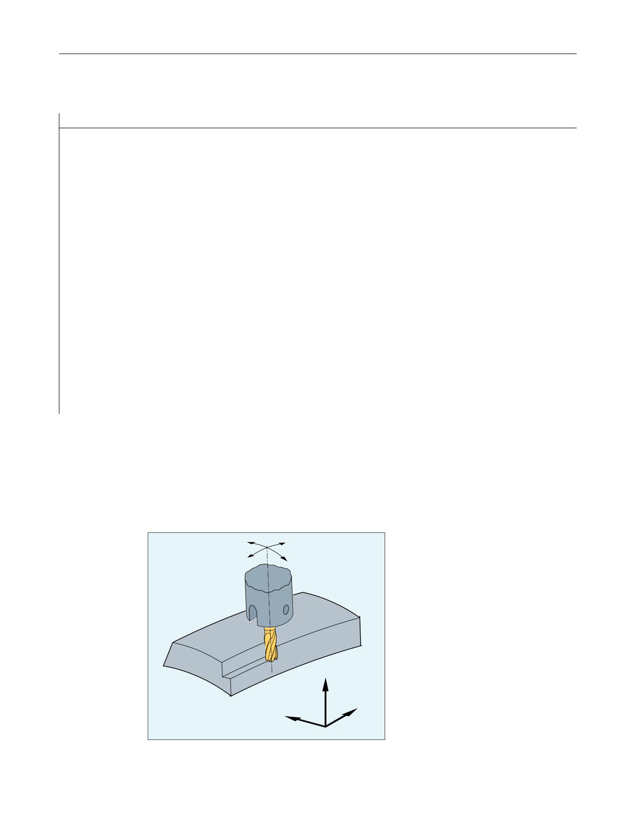
The type of circumferential milling used here is implemented by defining a path (guide line)
and the associated orientation. In this type of machining, the shape of the tool on the path is
not relevant. Only the radius at the tool intervention point is decisive.
$
%
=
;
<
Special functions
Function Manual, 12/2018, A5E40874099B AB
919
W5: 3D tool radius compensation - 840D sl only
26.3 Programming
Figure 26-10
Circumferential milling
Approach behavior
The approach behavior is always NORM for the 3D variant of the tool radius compensation.
Behavior at outside corners
The G commands of group 18 (corner behavior, tool offset) are evaluated at the outside corners
for circumferential milling with 3D TRC in the same way as for the conditions for the 2½D TRC:
● G450: Transition circle (tool travels round workpiece corners on a circular path)
In contrast to the solution for the 2½D TRC, the inserted contour element at an outside
corner is always a circle with a 0 radius, on which the tool radius compensation acts in the
same way as on any other programmed path. It is not possible to insert conics instead of
circles. In this case, the DISC address has no significance and is therefore not evaluated.
● G451: Intersection of equidistant paths (tool backs off from the workpiece corner)
The intersection is determined by extending the offset curves of the two participating blocks
and defining the intersection of the two blocks at the corner in the plane perpendicular to
the tool orientation.
The intersection procedure (G451) is not used when at least one block containing a change
to the tool orientation was inserted between the relevant traversing blocks. In this case, a circle
is always inserted at the corner.
Behavior for changes in orientation at outside corners
The ORIC and ORID G commands are used to determine whether changes in orientation
programmed between two blocks forming the corner are executed before the inserted circle
block (ORID) is processed or at the same time (ORIC).
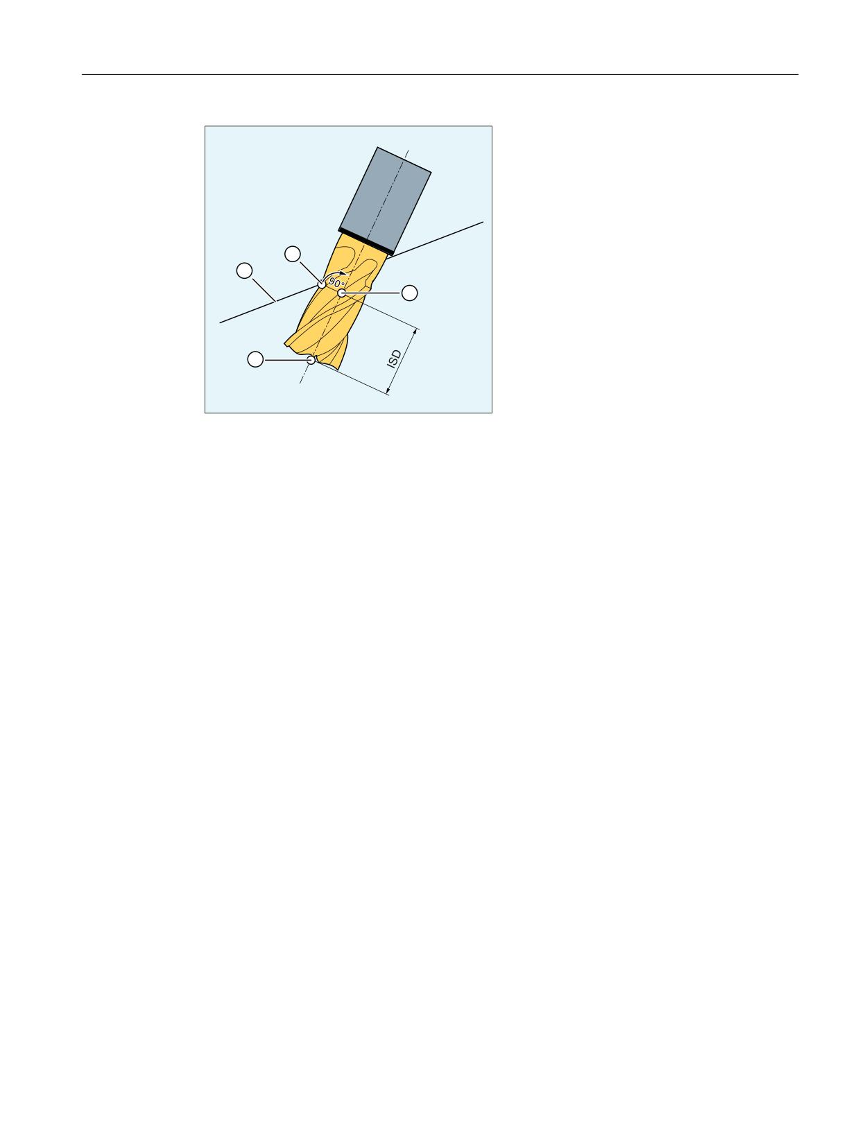
Insertion depth
The insertion depth of the milling tool is the distance of the milling tool reference point from
the tip of the tool.
The milling tool reference point is the vertical projection of the milling tool machining point on
the programmed path to the longitudinal axis of the tool.
The position of the machining point on the peripheral surface of the tool is set with the insertion
depth.
Special functions
920
Function Manual, 12/2018, A5E40874099B AB
W5: 3D tool radius compensation - 840D sl only
26.3 Programming
① Programmed path
② Milling tool machining point
③ Milling tool reference point
④ Milling tool tip
ISD
Insertion depth (InSertion Depth)
Figure 26-11
Insertion depth
Tool radius compensation referred to a differential tool
3D TRC for circumferential milling referred to a differential tool is activated via the CUT3DCD
command. It should be applied if the programmed contour refers to the center-point path of a
standard tool, and a tool other than a differential tool is used for machining. When calculating
the 3D tool radius compensation, only the wear value of the radius of the active tool
($TC_DP15) and any programmed tool offsets OFFN and TOFFR are taken into account. The
basic radius ($TC_DP6) of the active tool is not taken into account.
Pocket milling with inclined side walls for circumferential milling with CUT3DC
In this 3D tool radius compensation, a deviation of the mill radius is compensated by infeed
toward the surface normals to be machined. The plane, in which the milling tool face is located,
remains unchanged if the insertion depth ISD has remained the same. For example, a milling
tool with a smaller radius than a standard tool would not reach the pocket base, which is also
the limitation surface. For automatic tool infeed, this limitation surface must be known to the
control, see Section "3D circumferential milling taking into account a limitation surface
(CUT3DCC, CUT3DCCD) (Page 927)".
Special functions
Function Manual, 12/2018, A5E40874099B AB
921

W5: 3D tool radius compensation - 840D sl only
26.3 Programming
Advanced Surface / Top Surface
Note
When applying tool radius compensation CUT3DCD in combination with the "Advanced
Surface" or "Top Surface" option (requiring a license), the setting recommendations regarding
"Advanced Surface" / "Top Surface" must be observed.
Special test programs are provided in the SIOS portal for checking the set data:
● Test programs for Advanced Surface (https://support.industry.siemens.com/cs/ww/en/view/
78956392)
● Test programs for Top Surface (https://support.industry.siemens.com/cs/ww/en/view/
109738423)
26.3.2
Selecting 3D tool radius compensation for the 3D face milling (CUT3DF,
CUT3DFS, CUT3DFF, CUT3DFD)
The 3D tool radius compensation (3D TRC) for the 3D face milling is selected with the modally
effective G command CUT3DF, CUT3DFS, CUT3DFF or CUT3DFD.
The actual activation is performed with G41 or G42
With 3D face milling, the surface normals of the plane to be machined must be defined in order
to calculate the tool radius compensation. This must be performed in the block with G41 or
G42 via the A4, B4, C4 and A5, B5, C5 addresses.
The tool radius compensation is deactivated with G40.
Syntax
G41/G42 ORIC/ORID CUT3DF/CUT3DFS/CUT3DFF/CUT3DFD X... Y... Z... A4=... B4=...
C4=... A5=... B5=... C5=
G40 X... Y... Z...
Meaning
CUT3DFS:
3D TRC for face milling with constant orientation. The tool
orientation is defined by G17 - G19 and is not influenced by
frames.
CUT3DFF:
3D TRC for face milling with constant orientation. The tool
orientation is the direction defined by G17 - G19 and, in some
case, rotated by a frame.
CUT3DF:
3D TRC for face milling with orientation change (only with
active 5-axes transformation)
Special functions
922
Function Manual, 12/2018, A5E40874099B AB

W5: 3D tool radius compensation - 840D sl only
26.3 Programming
CUT3DFD:
3D TRC for face milling with orientation change referred to a
differential tool (only with active 5-axis transformation)
The radius difference is specified by the tool parameter
$TC_DP15.
Note:
CUT3DFD is only possible in combination with "Smoothing
of surface normals in 3D face milling". This is activated by
calling the "Top Surface" function (requires as license) via
CYCLE832(...).
G41/G42 X... Y... Z... :
Activate tool offset
The behavior with G41 and with G42 is identical for 3D face
milling.
Note:
The activation must be performed in a linear block (G0/G1).
A4/5=... B4/5=... C4/5=...:
Definition of the surface normals of the plane to be machined
A4=... B4=... C4=...:
Definition at start of block
A5=... B5=... C5=...:
Definition at end of block
ORIC/ORID:
The behavior for orientation changes at outside corners is
specified via the G commands ORIC and ORID.
ORIC:
Orientation changes at outside corners are su-
perimposed on the circle block to be inserted.
ORID:
Orientation changes are performed before the
circle block.
G40 X... Y... Z... :
Deactivate tool radius compensation
Note:
The deactivation must be performed in a linear block (G0/G1)
with geometry axis movements.
Note
G41 or G42 can also be programmed in blocks without traversing movement in geometry axes
relevant for the compensation. In this case, the approach block is the first traversing block
following such a block.
A change of the 3D TRC variant with active tool radius compensation is ignored without alarm.
Examples
Example 1: 3D face milling with CUT3DF
Program code
Comment
N10
; Definition of tool D1:
N20 $TC_DP1[1,1]=121
; Tool type (toroidal miller)
N30 $TC_DP3[1,1]=20
; Length compensation
N40 $TC_DP6[1,1]=5
; Radius
N50 $TC_DP7[1,1]=3
; Rounding radius
N60
N70
Special functions
Function Manual, 12/2018, A5E40874099B AB
923

W5: 3D tool radius compensation - 840D sl only
26.3 Programming
Program code
Comment
N80 X0 Y0 Z0 A0 B0 C0 G17 T1 D1 F12000
; Selection of the tool.
N90 TRAORI(1)
; Select orientation transformation.
N100 B4=-1 C4=1
; Definition of the plane.
N110 G41 ORID CUT3DF G64 X10 Y0 Z0
; Activate tool offset.
N120 X30
N130 Y20 A4=1 C4=1
; Outside corner, new plane definition.
N140 B3=1 C3=5
; Change in orientation with ORID.
N150 B3=1 C3=1
; Change in orientation with ORID.
N160 X-10 A5=1 C5=2 ORIC
N170 A3=-2 C3=1
; Change in orientation with ORIC.
N180 A3=-1 C3=1
; Change in orientation with ORIC.
N190 Y-10 A4=-1 C4=3
; New plane definition.
N200 X-20 Y-20 Z10
; Inside corner with previous block.
N210 X-30 Y10 A4=1 C4=1
; Inside corner, new plane definition.
N220 A3=1 B3=0.5 C3=1.7
; Change in orientation with ORIC.
N230 X-20 Y30 A4=1 B4=-2 C4=3 ORID
N240 A3 = 0.5 B3=-0.5 C3=1
; Change in orientation.
N250 X0 Y30 C4=1
; Path movement, new plane,
; orientation with relative programming.
N260 BSPLINE X20 Z15
; Spline begin, relative programming of the orien-
tation
N270 X30 Y25 Z18
; remains active during spline.
N280 X40 Y20 Z13
N290 X45 Y0 PW=2 Z8
N300 Y-20
N310 G2 ORIMKS A30 B45 I-20 X25 Y-40 Z0
; Helix, orientation with axis programming.
N320 G1 X0 A3=-0.123 B3=0.456 C3=2.789 B4=-1 C4=5
; Path movement, orientation, non-constant plane.
B5=-1 C5=2
N330 X-20 G40
; Deactivation of the tool radius compensation.
N340 M30
Example 2: NC program (section) generated from a CAD system with CUT3DFD
Program code
Comment
N01 G710
N03 T="12"
N06 S5305 M03
N07 G642
; Approaching the starting position in the MCS taking the tool length into account.
G00 G90 X-250.62787 Y-38.37944 A=DC(253.12719)
B-12.49543
G00 G90 Z251.80052
; End of positioning in the MCS.
;
Special functions
924
Function Manual, 12/2018, A5E40874099B AB
W5: 3D tool radius compensation - 840D sl only
26.3 Programming
Program code
Comment
TRAORI(1)
; Select orientation transformation.
G500
D1
CYCLE832(0.01, _TOP_SURFACE_SMOOTH_ON + _ORI_FIN-
; Call CYCLE832 with:
ISH, 1)
; Contour tolerance = 0.01 mm,
; Processing type: Top Surface with smoothing,
; Finishing with input of an orientation toler-
ance,
; Orientation tolerance = 1 degree
CUT3DFD
N08 G90 G94
N09 G00 X-269.21195 Y128.32027 Z1.18577
; The blocks N09 to N10 are the fast portion of
A3=-.216361688 B3=.934284397 C3=-.283373051
the approach movement to the workpiece with con-
stant orientation.
N10 G00 X-251.90301 Y53.57752 Z23.85561
N11 G01 X-247.57578 Y34.89183 Z29.52308 F50000.00000
; In the blocks N11 to N21, the slow portion of
the approach movement is realized. The tool is
already close to the workpiece; furthermore, the
mold making settings (e.g. COMPSURF) from the CY-
CLE832 are now active (due to active G01). The
path of this so-called transient phase for the
mold-making behavior should be about 1000 times
the contour tolerance (10 mm in this example).
N12 X-247.69126 Y33.82182 Z24.78219 F1061.00000
N13 X-247.76560 Y33.13299 Z21.73022
N14 X-247.82755 Y32.55897 Z19.18691
N15 X-247.87918 Y32.08062 Z17.06748
N16 X-247.92220 Y31.68200 Z15.30129
N17 X-247.95805 Y31.34981 Z13.82947
A3=-.216361686 B3=.934284391 C3=-.283373071
N18 X-247.98792 Y31.07299 Z12.60295
A3=-.216360662 B3=.934280801 C3=-.283385691
N19 X-248.01282 Y30.84230 Z11.58085
A3=-.216336015 B3=.934194446 C3=-.283689030
N20 X-248.03357 Y30.65006 Z10.72910
A3=-.216233089 B3=.933833626 C3=-.284952647
N21 X-248.05086 Y30.48986 Z10.01931
A5=-.060687572 B5=.974940255 C5=-.214029243
A3=-.215712821 B3=.932005189 C3=-.291263295
N22 G41 X-248.06237 Y30.32400 Z9.36695
; From N22, the surface normal is completely de-
A5=-.060431854 B5=.973045457 C5=-.222554556
fined over the entire block for the first time
A3=-.214974689 B3=.929398552 C3=-.300007025
(i.e. surface normal at the end of the previous
F1061.03295
block N21 is present, thus the surface normal at
the beginning of the block N22 and the surface
normal at the end of the block N22). Thus the
prerequisite for switching on the tool offset
with G41/G42 is fulfilled.
Special functions
Function Manual, 12/2018, A5E40874099B AB
925
W5: 3D tool radius compensation - 840D sl only
26.3 Programming
Program code
Comment
N23 X-248.07130 Y30.15119 Z8.71082
A5=-.060165696 B5=.971048883 C5=-.231179920
A3=-.214177198 B3=.926684940 C3=-.308841625
N24 X-248.07829 Y29.97126 Z8.05094
A5=-.059884286 B5=.968941717 C5=-.239928784
A3=-.213318480 B3=.923853466 C3=-.317789237
N25 X-248.08317 Y29.78487 Z7.38844
A5=-.059584206 B5=.966718449 C5=-.248807482
A3=-.212397895 B3=.920898045 C3=-.326854594
N26 X-248.08578 Y29.59254 Z6.72679
A5=-.059263963 B5=.964380907 C5=-.257793037
A3=-.211418355 B3=.917822366 C3=-.336012474
Note
For 3D face milling with CUT3DFD, the definition of the surface normal is required for activating
the tool offset with G41/G42. Programming of G41/G42 without definition of the surface
normals leads to the output of an alarm.
Further information
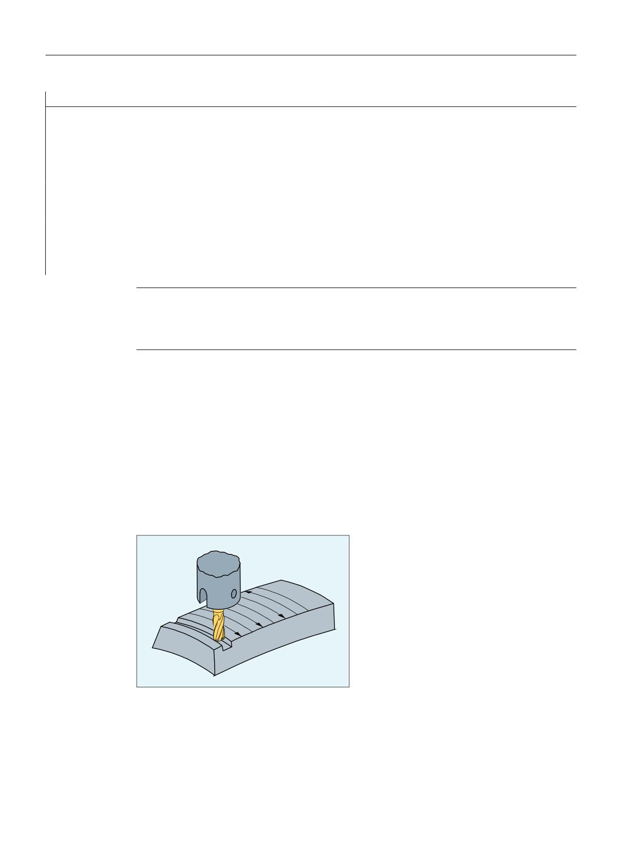
3D face milling
For this type of 3D milling, you require the line-by-line description of the 3D paths on the
workpiece surface. The tool shape and dimensions are taken into account in the calculations,
which are normally performed in CAM. The postprocessor writes to the part program - in
addition to NC blocks - the tool orientations (for active 5-axis transformation) and the G
command for the required 3D tool offset. This means that the machine operator has the
possibility of using tools that are slightly smaller - deviating from the tool used to calculate the
NC paths.
Figure 26-12
Face milling
Approach behavior
The approach behavior is always NORM for the 3D variant of the tool radius compensation.
Special functions
926
Function Manual, 12/2018, A5E40874099B AB
W5: 3D tool radius compensation - 840D sl only
26.3 Programming
Behavior at outside corners
Outside corners are treated as circles with radius 0 for face milling, whereby the circle plane
extends from the end tangent of the first block to the start tangent of the second block. In this
way, the orientation can be changed during block transition. A circle is therefore always
inserted as contour element at an outside corner. The intersection procedure is not available
with face milling.
Behavior for changes in orientation at outside corners
The ORIC and ORID G commands are used to determine whether changes in orientation
programmed between two blocks forming the corner are executed before the inserted circle
block (ORID) is processed or at the same time (ORIC).
Tool radius compensation referred to a differential tool
3D tool radius compensation referring to a differential tool is selected using the CUT3DFD
command. It should be applied if the programmed contour refers to the center-point path of a
standard tool, and a tool other than a differential tool is used for machining. When calculating
the 3D tool radius compensation, only the wear value of the radius of the active tool
($TC_DP15) and any programmed tool offsets OFFN and TOFFR are taken into account. The
basic radius ($TC_DP6) of the active tool is not taken into account.
3D face milling with CUT3DFD is only possible in combination with "Smoothing of surface
normals in 3D face milling". This is activated by calling the "Top Surface" function (requires as
license) via CYCLE832(...). Activation must take place before the tool offset is activated with
G41/G42; not directly before tool intervention, but rather one path length before that, which
corresponds to approx. 1000 times the contour tolerance (e.g. 1000 x 0.01 mm = 10 mm).
Deactivation must be executed in reverse order: First switch off the tool offset with G40, then
deactivate with e.g. CUT2D (or similar) after a path length which corresponds with
approximately 1000 time the contour tolerance.
In order to be able to use the "Smoothing of surface normals in 3D face milling", the
"Interpolation of surface normals via polynomials" function must also be enabled:
MD28291 $MC_MM_SMOOTH_SURFACE_NORMALS = TRUE
Note
For 3D face milling with CUT3DFD in combination with "Top Surface", the setting
recommendations regarding "Top Surface" must be observed.
Special test programs are provided (https://support.industry.siemens.com/cs/ww/en/view/
109738423) in the SIOS portal for checking the set data.
26.3.3
3D circumferential milling taking into account a limitation surface (CUT3DCC,
CUT3DCCD)
In 3D circumferential milling with a continuous or constant change in tool orientation, the tool
center-point path is frequently programmed for a defined standard tool. Because in practice
suitable standard tools are often not available, a tool that does not deviate too much from a
standard tool (≤ 5%) can be used.
Special functions
Function Manual, 12/2018, A5E40874099B AB
927

W5: 3D tool radius compensation - 840D sl only
26.3 Programming
CUT3DCCD takes account of a limitation surface for a real differential tool that the programmed
standard tool would define. The NC program defines the center-point path of a standard tool.
CUT3DCC with the use of cylindrical tools takes account of a limitation surface that the
programmed standard tool would have reached. The NC program defines the contour on the
machining surface.
The surface normal vector of the limitation surface is specified with A4, B4, C4 and A5, B5,
C5 for 3D face milling.
Syntax
G41/G42 CUT3DCCD/CUT3DCC CDOF2 X... Y... Z... A4=... B4=... C4=... A5=... B5=...
C5=
G40 X... Y... Z...
Meaning
CUT3DCCD:
3D TRC for the circumferential milling taking into account a limitation
surface with a differential tool on the tool center-point path: Infeed
to the limitation surface
CUT3DCC:
3D TRC for the circumferential milling taking into account a limitation
surface with 3D radius compensation: Contour on the machining
surface
G41/G42 X... Y... Z... :
Activate tool radius compensation
G41:
Tool radius compensation left of the contour
G42:
Tool radius compensation right of the contour
Note:
The activation must be performed in a linear block (G0/G1).
CDOF2:
Deactivate collision detection for 3D circumferential milling
A4/5=... B4/5=...
Definition of the surface normals of the limitation surface
C4/5=...:
A4=... B4=... C4=...:
Definition at start of block
A5=... B5=... C5=...:
Definition at end of block
G40 X... Y... Z... :
Deactivate tool radius compensation
Note:
The deactivation must be performed in a linear block (G0/G1) with
geometry axis movements.
Note
The G commands for selecting the 3D TRC are evaluated in the approach block, i.e. typically
in the block that contains G41 or G42.
G41 or G42 can also be programmed in blocks without traversing movement in geometry axes
relevant for the compensation. In this case, the approach block is the first traversing block
following such a block.
A change of the 3D TRC variant with active tool radius compensation is ignored without alarm.
Special functions
928
Function Manual, 12/2018, A5E40874099B AB
W5: 3D tool radius compensation - 840D sl only
26.3 Programming
Example
Program code
Comment
N10 $TC_DP1[1,1]=120
; Cylindrical milling tool
N20 $TC_DP6[1,1]=10
N30 $TC_DP15[1,1]=-3
; Processing with cylindrical milling tool and CUT3DCCD
N110 TRAORI
; Activation of the transformation.
N120 A4=0 B4=0 C4=1
; Definition of the surface normal of the
limitation surface at the start of the
block.
N130 X0 Y0 Z0 A0 C0 T1 D1 F20000
N140 X10 Y0 Z0 G41 CUT3DCCD CDOF2 G64
; Activate 3D circumferential milling,
taking into account the limitation sur-
face + switching off collision detection.
N150 X20
N160 X30 A45
; Obtuse angle ==> no infeed
N170 X40 A-45
; Acute angle ==> infeed
N180 X55
N190 Y10 Z10
; Movement in the tool direction.
N200 Y20
N210 C45
; Pure change in orientation.
N220 Y30 C90
N230 A5=-1 B5=0 C5=2 Y40
; Change of the surface.
N240 Y50 G40
; Deactivation of the tool radius compen-
sation.
Further information
Tool type
The tool type (tool parameter $TC_DP1) is evaluated. Only milling tools with cylindrical shank
(cylinder or end mill, toroidal miller and, in the limit case, cylindrical die mill) are permitted. This
corresponds to the tool types 1 - 399, with the exception of the numbers 111 and 155 to 157.
Standard tools with corner rounding
Corner rounding with a standard tool is defined by the tool parameter $TC_DP7. Tool
parameter $TC_DP16 describes the deviation of the corner rounding of the real tool compared
with the standard tool.
Special functions
Function Manual, 12/2018, A5E40874099B AB
929
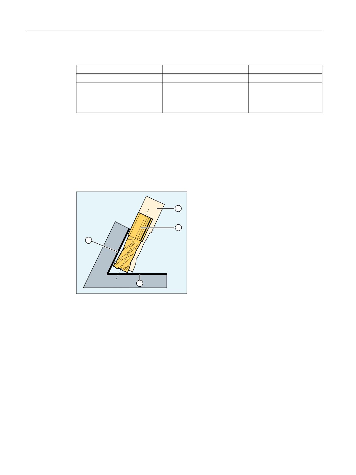
W5: 3D tool radius compensation - 840D sl only
26.3 Programming
Example: Toroidal miller with reduced radius compared to the standard tool
Tool type
Shaft radius (R)
Corner radius (r)
Standard tool with corner rounding
R = $TC_DP6
r = $TC_DP7
Real tool with corner rounding
R' = $TC_DP6 + $TC_DP15 +
r' = $TC_DP7 + $TC_DP16
OFFN
Tool types 121 and 131 toroidal
miller
(end mill with corner rounding)
In this example, both $TC_DP15 + OFFN and $TC_DP16 are negative.
3D TRC with CUT3DCCD: Tool center-point path with infeed up to the limitation surface
If a tool with a smaller radius than the appropriate standard tool is used, machining is continued
using a milling tool, which is fed in in the longitudinal direction until it reaches the bottom (base)
of the pocket. The tool removes as much material from the corner formed by the machining
surface and limitation surface. This involves a machining type combining circumferential and
face milling. Analogous to a tool with reduced radius, for a tool with increased radius, the infeed
is in the opposite direction.
① Standard tool
② Tool with smaller radius infeed up to the limitation surface
③ Limitation surface
④ Machining surface
Contrary to all other tool offsets of G group 22, tool parameter $TC_DP6 specified for
CUT3DCCD has no relevance for the tool radius and does not influence the resulting
compensation. The compensation offset results from the sum of the wear value of the tool
radius (tool parameter $TC_DP15) and a tool offset OFFN programmed to calculate the
perpendicular offset to the limitation surface.
The generated part program does not specify whether the surface to be machined is to the
right or left of the path. It is therefore assumed that the radius is a positive value and the wear
value of the original tool is a negative value. A negative wear value always describes a tool
with a reduced diameter.
Special functions
930
Function Manual, 12/2018, A5E40874099B AB
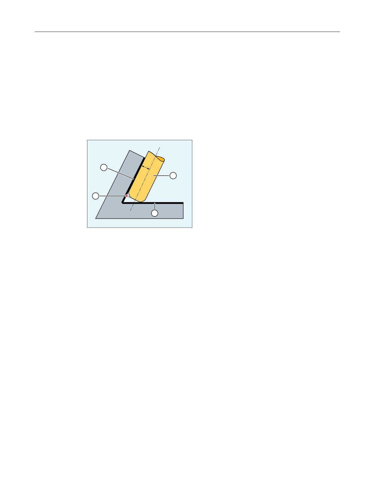
W5: 3D tool radius compensation - 840D sl only
26.3 Programming
Using cylindrical tools
When cylindrical tools are used, infeed is only necessary if the machining surface and the
surface of limitation form an acute angle (less than 90 degrees). If a toroidal miller (end mill
with corner rounding) is used, tool infeed in the longitudinal direction is required for both acute
and obtuse angles.
3D TRC with CUT3DCC: Contour on the machining surface
If CUT3DCC is active with a toroidal miller, the programmed path refers to a fictitious cylindrical
milling tool having the same diameter. The resulting path reference point is shown in the
following diagram for a toroidal miller.
5
① Toroidal miller
② Limitation surface
③ Path reference point
④ Machining surface
R
Shaft radius (tool radius)
The angle between the machining and limitation surfaces may change from an acute to an
obtuse angle and vice versa even within the same block.
The tool actually being used may either be larger or smaller than the standard tool. However,
the resulting corner radius must not be negative and the sign of the resulting tool radius must
be kept.
For CUT3DCC, the NC part program refers to the contour on the machining surface. As for
conventional tool radius compensation, the total tool radius is used that comprises the following
components:
● Tool radius (tool parameter $TC_DP6)
● Wear value (tool parameter $TC_DP15)
● A tool offset OFFN programmed to calculate the perpendicular offset to the limitation surface
The position of the limitation surface is defined from the following difference:
Dimensions of the standard tool - tool radius (tool parameter $TC_DP6)
Special functions
Function Manual, 12/2018, A5E40874099B AB
931
W5: 3D tool radius compensation - 840D sl only
26.5 Examples
Advanced Surface / Top Surface
Note
When applying tool radius compensation CUT3DCC / CUT3DCCD in combination with the
"Advanced Surface" or "Top Surface" function (requiring a license), the setting
recommendations regarding "Advanced Surface" / "Top Surface" must be observed.
Special test programs are provided in the SIOS portal for checking the set data:
● Test programs for Advanced Surface (https://support.industry.siemens.com/cs/ww/en/view/
78956392)
● Test programs for Top Surface (https://support.industry.siemens.com/cs/ww/en/view/
109738423)
26.4
Constraints
Boundary conditions for face milling
Functions with high-order geometry information
Functions with high-order geometry information (e.g. polynomials or spline interpolation)
cannot be used.
Top Surface
3D face milling with CUT3DFD is only possible in conjunction with the "Top Surface" function,
which requires a license.
Bottleneck detection
A "bottleneck detection" is not possible, and therefore the user is solely responsible.
Traversing movements in the orientation direction of the tool
For traversing motion in the orientation direction of the tool, and alarm is displayed and
machining stopped.
26.5
Examples
26.5.1
Example 1: Orientation change at outside corner during 3D circumferential milling
Orientation change at outside corner with ORIC active
Program code
Comment
N10 A0 B0 X0 Y0 Z0 F5000
Special functions
932
Function Manual, 12/2018, A5E40874099B AB
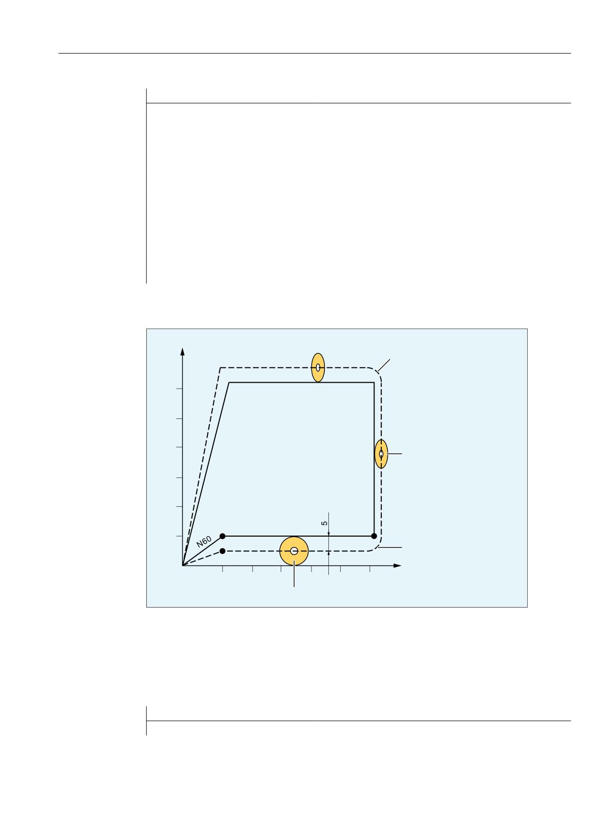
W5: 3D tool radius compensation - 840D sl only
26.5 Examples
Program code
Comment
N20 T1 D1
; Selection of the tool (radius=5).
N30 TRAORI(1)
; Activation of transformation.
N40 CUT3DC
; Selection of 3D TRC for circumferential milling.
N50 ORIC
; Orientation changes at outside corners are super-
imposed on the circle block to be inserted.
N60 G42 X10 Y10
; Activation of TRC.
N70 X60
N80 A3=1 B3=0 C3=1
; change in orientation of external corner gener-
ated from N70 and N90
N90 Y60
N100 X10
N110 G40 X0 Y0
; Deactivation of TRC.
N120 M30
The circular motion and change in orientation are executed in parallel in block N80 (ORIC
active):
<
2XWVLGH FRUQHU ZLWK FRQVWDQW
RULHQWDWLRQ LQVHUWHG EORFN QRW
SURJUDPPHG
1
1
7RRO LQFOLQHG
1
2XWVLGH FRUQHU ZLWK FRQVWDQW
1
1
RULHQWDWLRQ LQVHUWHG EORFN QRW
SURJUDPPHG
;
7RRO YHUWLFDO
Figure 26-13
ORIC: Change in orientation and path movement in parallel
Special case:
Intermediate blocks without traversing and orientation motions are executed at the
programmed positions, e.g. auxiliary functions.
Example:
Program code
Comment
N70 X60
Special functions
Function Manual, 12/2018, A5E40874099B AB
933
W5: 3D tool radius compensation - 840D sl only
26.5 Examples
Program code
Comment
N75 M20
; auxiliary function call
N80 A3=1 B3=0 C3=1
; change in orientation of external corner gener-
ated from N70 and N90
N90 Y60
Blocks N75 and N80 are executed after N70. The circle block is then executed with the current
orientation.
Orientation change at outside corner with ORID active
Program code
Comment
N10 A0 B0 X0 Y0 Z0 F5000
N20 T1 D1
; Selection of the tool (radius=5).
N30 TRAORI(1)
; Activation of transformation.
N40 CUT3DC
; Selection of 3D TRC for circumferential milling.
N50 ORID
; Orientation changes at outside corners are per-
formed on the circle block to be inserted.
N60 G42 X10 Y10
; Activation of TRC.
N70 X60
N80 A3=1 B3=0 C3=1
; change in orientation of external corner gener-
ated from N70 and N90
N90 Y60
N100 X10
N110 G40 X0 Y0
; Deactivation of TRC.
N120 M30
Special functions
934
Function Manual, 12/2018, A5E40874099B AB
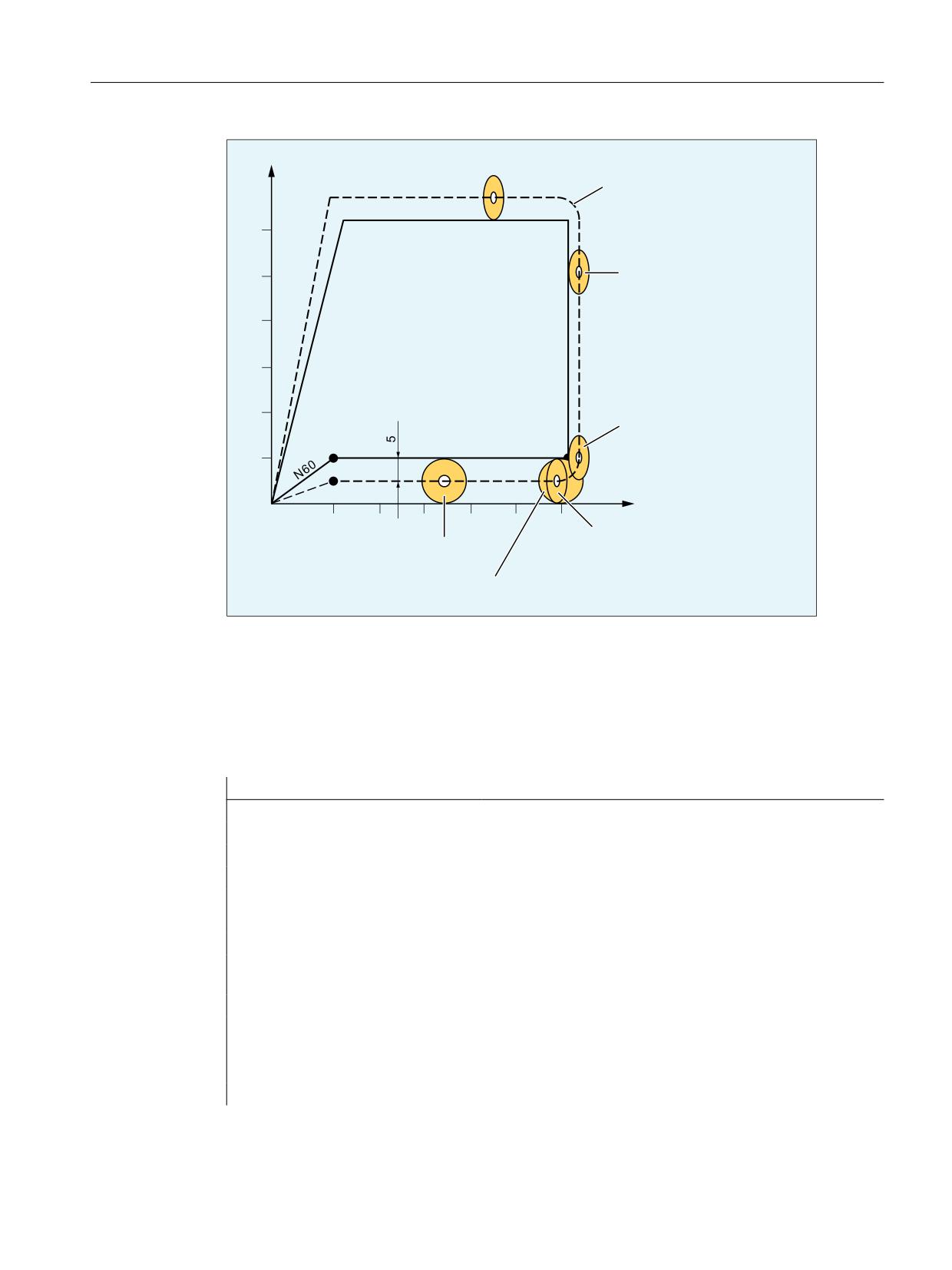
W5: 3D tool radius compensation - 840D sl only
26.5 Examples
<
2XWVLGH FRUQHU ZLWK FRQVWDQW
RULHQWDWLRQ LQVHUWHG EORFN QRW
SURJUDPPHG
1
7RRO LQFOLQHG
1
1
7RRO DW VWDUW SRLQW RI 1
1
1
;
7RRO DW HQG RI 1
7RRO YHUWLFDO
2ULHQWDWLRQ FKDQJH LV SHUIRUPHG LQ
VXFK D ZD\ WKDW WKH WRRO DOZD\V
7RRO DW HQG RI 1
WRXFKHV WKH
HQGSRLQW RI 1
Figure 26-14
ORID: Change in orientation and path movement consecutively
26.5.2
Example 2: Orientation change at inside corner during 3D circumferential milling
Program code
Comment
N10 A0 B0 X0 Y0 Z0 F5000
N20 T1 D1
; Selection of the tool (radius=5).
N30 TRAORI(1)
; Activation of transformation.
N40 CUT3DC
; Selection of 3D TRC for circumferential milling.
N50 ORID
N60 G42 X10 Y10 G451
; Activation of TRC.
N70 Y60
N80 A3=1 B3=0 C3=1
; change in orientation of inside corner generated
from N70 and N90.
N90 X60 Y90
N100 G40 X... Y...
N190 CDOF
N200 M30
Special functions
Function Manual, 12/2018, A5E40874099B AB
935
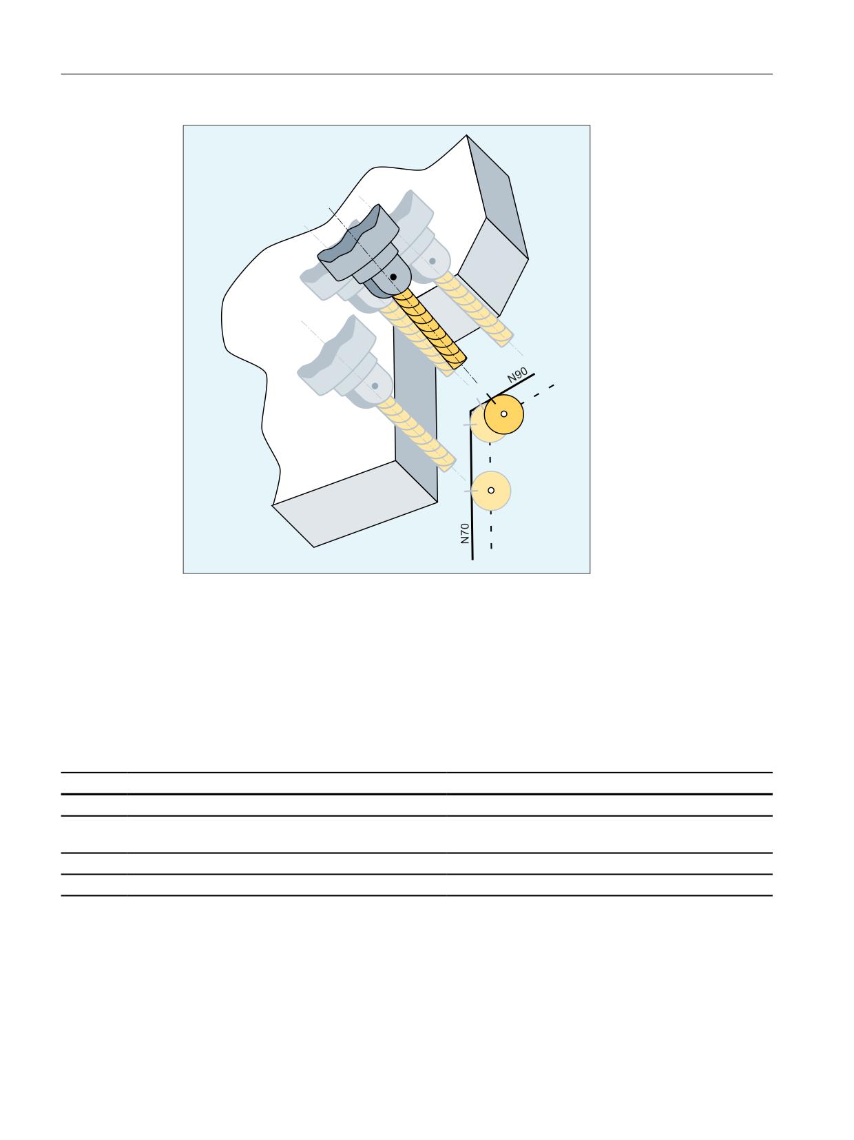
W5: 3D tool radius compensation - 840D sl only
26.6 Data lists
26.6
Data lists
26.6.1
General machine data
Number
Identifier: $MN_
Description
18094
MM_NUM_CC_TDA_PARAM
Number of TDA data
18096
MM_NUM_CC_TOA_PARAM
Number of TOA data, which can be set up per tool and
evaluated by the CC
18100
MM_NUM_CUTTING_EDGES_IN_TOA
Tool offsets per TOA module
18110
MM_NUM_TOA_MODULES
Number of TOA modules
Special functions
936
Function Manual, 12/2018, A5E40874099B AB

W5: 3D tool radius compensation - 840D sl only
26.6 Data lists
26.6.2
Channelspecific machine data
Number
Identifier: $MC_
Description
20110
RESET_MODE_MASK
Definition of the control basic setting after power-up and
RESET / part program end
20120
TOOL_RESET_VALUE
Definition of the tool from which the tool length compen-
sation is selected during run-up and upon RESET or part
program end, dependent upon MD 20110.
20130
CUTTING_EDGE_RESET_VALUE
Definition of tool cutting edge for which tool length com-
pensation is selected during power-up or on reset or
parts program end as a function of MD20110
20140
TRAFO_RESET_VALUE
Definition of transformation block which is selected dur-
ing power-up and or RESET or parts program end as a
function of MD20110
20210
CUTCOM_CORNER_LIMIT
Max. angle for intersection calculation with tool radius
compensation
20220
CUTCOM_MAX_DISC
Behavior of the TRC at outside corners
20230
CUTCOM_CURVE_INSERT_LIMIT
Minimum value for intersection calculation with tool ra-
dius compensation
20240
CUTCOM_MAXNUM_CHECK_BLOCKS
Blocks for predictive contour calculation with tool radius
compensation
20250
CUTCOM_MAXNUM_DUMMY_BLOCKS
Number of blocks without traversing motion for tool ra-
dius compensation
20270
CUTTING_EDGE_DEFAULT
Selected cutting edge after tool change
20610
ADD_MOVE_ACCEL_RESERVE
Acceleration reserve for overlaid motions
21080
CUTCOM_PARALLEL_ORI_LIMIT
Minimal angle between path tangent and tool orientation
for 3D-TRC
21082
CUTCOM_PLANE_ORI_LIMIT
Minimal angle between surface normal vector and tool
orientation (for 3D face milling)
21084
CUTCOM_PLANE_PATH_LIMIT
Minimal angle between surface normal vector and path
tangent vector (for 3D face milling)
22550
TOOL_CHANGE_MODE
New tool offset with M function
22560
TOOL_CHANGE_M_CODE
M function for tool change
28291
MM_SMOOTH_SURFACE_NORMALS
Interpolation of the surface normals via polynomials (for
3D face milling)
Special functions
Function Manual, 12/2018, A5E40874099B AB
937
W5: 3D tool radius compensation - 840D sl only
26.6 Data lists
Special functions
938
Function Manual, 12/2018, A5E40874099B AB
W6: Path length evaluation - 840D sl only
27
27.1
Brief description
Function
With the "Path length evaluation" function, the NC specific machine axis data is made available
as the system and OPI variables, with whose help it is possible to assess the strain on the
machine axes and thereby make an evaluation on the state of the machine's maintenance.
Recorded data
The following data is recorded:
● Total traverse path
● Total travel time
● Total travel count
● Total traverse path at high axis speeds
● Total travel time at high axis speeds
● Travel count at high axis speeds
● Total sum of jerks
● Axis travel time with jerk
● Travel count with jerk
Evaluation
When the function is activated, the selected control data is automatically sent and made
available via the system and OPI variables for evaluation in the part program or synchronized
actions, as with user-specified HMI functions.
Meaning
The data remains saved in the control, so that it may continue to be used after POWER OFF /
ON. Consequently, the actual value of a data item represents the sum of all measured values
since the function was activated.
Special functions
Function Manual, 12/2018, A5E40874099B AB
939

W6: Path length evaluation - 840D sl only
27.3 Parameterization
27.2
Data
The following data is available:
System variable 1)
OPI variable
Meaning
$AA_TRAVEL_DIST
aaTravelDist
Total traverse path:
sum of all set position changes in MCS 2) in [mm] or [deg.].
$AA_TRAVEL_TIME
aaTravelTime
Total travel time:
sum of IPO clock cycles from set position changes in MCS 2) in [s]
(solution: 1 IPO clock cycle)
$AA_TRAVEL_COUNT
aaTravelCount
Total travel count:
a complete machine axis trip is defined by the following succession of
states, as based on set position: standstill > traversing > standstill
$AA_TRAVEL_DIST_HS
aaTravelDistHS
Total traversing distance at high axis velocities 3)
$AA_TRAVEL_TIME_HS
aaTravelTimeHS
Total traversing time at high axis velocities 3)
$AA_TRAVEL_COUNT_HS
aaTravelCountHS
Total number of traversing operations at high axis velocities 3)
$AA_JERK_TOT
aaJerkTotal
Total sum of axis jerks:
Sum of all jerk setpoints in [m/s3] or [deg./ s3].
$AA_JERK_TIME
aaJerkTime
Total travel time with jerk:
sum of IPO clock cycles from jerk setpoint changes in [s] (solution: 1
IPO clock cycle)
$AA_JERK_COUNT
aaJerkCount
Total number of traversing operations with jerk
1) System variables can be read from part programs and synchronized actions
2) MCS: Machine coordinate system
3) Actual machine axis velocity ≥ 80% of the maximum parameterized axis velocity (MD32000 MAX_AX_VELO)
27.3
Parameterization
27.3.1
General activation
The function is generally activated via the NC-specific machine data:
MD18860 $MN_MM_MAINTENANCE_MON (Activate recording of maintenance data)
27.3.2
Data groups
The data has been collected into data groups.
The data groups are activated via the axis-specific machine data:
Special functions
940
Function Manual, 12/2018, A5E40874099B AB

W6: Path length evaluation - 840D sl only
27.4 Examples
MD33060 $MA_MAINTENANCE_DATA (configuration to record maintenance data)
Bit
Value
Activation of the following data: System variable / OPI variable
0
1
● Total traverse path: $AA_TRAVEL_DIST / aaTravelDist
● Total travel time: $AA_TRAVEL_TIME / aaTravelTime
● Total travel count: $AA_TRAVEL_COUNT / aaTravelCount
1
1
● Total traversing distance for high velocities:
$AA_TRAVEL_DIST_HS / aaTravelDistHS
● Total traversing time for high velocities:
$AA_TRAVEL_TIME_HS / aaTravelTimeHS
● Total number of traversing operations at high velocities:
$AA_TRAVEL_COUNT_HS / aaTravelCountHS
2
1
● Total sum of jerks: $AA_JERK_TOT / aaJerkTotal
● Travel time with jerk: $AA_JERK_TIME / aaJerkTime
● Total travel count with jerk:
$AA_JERK_COUNT / aaJerkCount
27.4
Examples
27.4.1
Traversal per part program
Three geometry axes AX1, AX2 and AX3 exist in a machine. For geometry axis AX1, the part
program-driven total traverse path, total travel time and travel count should be calculated.
Parameter assignment
Activation of the overall function:
MD18860 $MN_MM_MAINTENANCE_MON = TRUE
Group activation: "Total travel distance, total travel time and number of travel operations" for
geometry axis AX1:
MD33060 $MA_MAINTENANCE_DATA[AX1] = 1
Programming
To determine the values referred to the part program, the actual value of the system variables
at the beginning of the part program must be saved in a calculation variable. The difference is
acquired at the end of the part program.
Part program (extract):
Program code
Comment
; Current values:
Special functions
Function Manual, 12/2018, A5E40874099B AB
941

W6: Path length evaluation - 840D sl only
27.5 Data lists
Program code
Comment
R10=$AA_TRAVEL_DIST[AX1]
; Total traversing distance AX1
R11=$AA_TRAVEL_TIME[AX1]
; Total traversing time AX1
R12=$AA_TRAVEL_COUNT[AX1]
; Number of traversing operations AX1
; Traversing motion of axes
; Generating the difference:
R10=R10-$AA_TRAVEL_DIST[AX1]
; Traversing distance AX1 in the part pro-
gram
R11=R11-$AA_TRAVEL_TIME[AX1]
; Traversing time AX1 in the part program
R12=R12-$AA_TRAVEL_COUNT[AX1]
; Number of traversing operations AX1 in
the part program
27.5
Data lists
27.5.1
Machine data
27.5.1.1
NC-specific machine data
Number
Identifier: $MN_
Description
18860
MM_MAINTENANCE_MON
Activate recording of maintenance data
27.5.1.2
Axis/spindlespecific machine data
Number
Identifier: $MA_
Description
33060
MAINTENANCE_DATA
Configuration, recording maintenance data
Special functions
942
Function Manual, 12/2018, A5E40874099B AB
Z3: NC/PLC interface signals
28
From Edition 05/2017, a detailed description of the NC/PLC interface signals is provided in the
NC Variables and Interface Signals List Manual.
Special functions
Function Manual, 12/2018, A5E40874099B AB
943
Z3: NC/PLC interface signals
Special functions
944
Function Manual, 12/2018, A5E40874099B AB

Appendix
A
A.1
List of abbreviations
A
O
Output
ADI4
(Analog drive interface for 4 axes)
AC
Adaptive Control
ALM
Active Line Module
ARM
Rotating induction motor
AS
Automation system
ASCII
American Standard Code for Information Interchange: American coding standard for
the exchange of information
ASIC
Application-Specific Integrated Circuit: User switching circuit
ASUB
Asynchronous subprogram
AUXFU
Auxiliary function: Auxiliary function
STL
Statement List
UP
User Program
B
OP
Operating Mode
BAG
Mode group
BCD
Binary Coded Decimals: Decimal numbers encoded in binary code
BERO
Contact-less proximity switch
BI
Binector Input
BICO
Binector Connector
BIN
BINary files: Binary files
BIOS
Basic Input Output System
BCS
Basic Coordinate System
BO
Binector Output
OPI
Operator Panel Interface
C
CAD
Computer-Aided Design
CAM
Computer-Aided Manufacturing
CC
Compile Cycle: Compile cycles
CEC
Cross Error Compensation
CI
Connector Input
CF Card
Compact Flash Card
Special functions
Function Manual, 12/2018, A5E40874099B AB
945

Appendix
A.1 List of abbreviations
C
CNC
Computerized Numerical Control: Computer-Supported Numerical Control
CO
Connector Output
CoL
Certificate of License
COM
Communication
CPA
Compiler Projecting Data: Configuring data of the compiler
CRT
Cathode Ray Tube: picture tube
CSB
Central Service Board: PLC module
CU
Control Unit
CP
Communication Processor
CPU
Central Processing Unit: Central processing unit
CR
Carriage Return
CTS
Clear To Send: Ready to send signal for serial data interfaces
CUTCOM
Cutter radius Compensation: Tool radius compensation
D
DAC
Digital-to-Analog Converter
DB
Data Block (PLC)
DBB
Data Block Byte (PLC)
DBD
Data Block Double word (PLC)
DBW
Data Block Word (PLC)
DBX
Data block bit (PLC)
DDE
Dynamic Data Exchange
DDS
Drive Data Set: Drive data set
DIN
Deutsche Industrie Norm
DIO
Data Input/Output: Data transfer display
DIR
Directory: Directory
DLL
Dynamic Link Library
DO
Drive Object
DPM
Dual Port Memory
DPR
Dual Port RAM
DRAM
Dynamic memory (non-buffered)
DRF
Differential Resolver Function: Differential revolver function (handwheel)
DRIVE-CLiQ
Drive Component Link with IQ
DRY
Dry Run: Dry run feedrate
DSB
Decoding Single Block: Decoding single block
DSC
Dynamic Servo Control / Dynamic Stiffness Control
DW
Data Word
DWORD
Double Word (currently 32 bits)
Special functions
946
Function Manual, 12/2018, A5E40874099B AB

Appendix
A.1 List of abbreviations
E
I
Input
EES
Execution from External Storage
I/O
Input/Output
ENC
Encoder: Actual value encoder
EFP
Compact I/O module (PLC I/O module)
ESD
Electrostatic Sensitive Devices
EMC
ElectroMagnetic Compatibility
EN
European standard
ENC
Encoder: Actual value encoder
EnDat
Encoder interface
EPROM
Erasable Programmable Read Only Memory: Erasable, electrically programmable
read-only memory
ePS Network Services
Services for Internet-based remote machine maintenance
EQN
Designation for an absolute encoder with 2048 sine signals per revolution
ES
Engineering System
ESR
Extended Stop and Retract
ETC
ETC key ">"; softkey bar extension in the same menu
F
FB
Function Block (PLC)
FC
Function Call: Function Block (PLC)
FEPROM
Flash EPROM: Read and write memory
FIFO
First In First Out: Memory that works without address specification and whose data is
read in the same order in which they was stored
FIPO
Fine interpolator
FPU
Floating Point Unit: Floating Point Unit
CRC
Cutter Radius Compensation
FST
Feed Stop: Feedrate stop
FBD
Function Block Diagram (PLC programming method)
FW
Firmware
G
GC
Global Control (PROFIBUS: Broadcast telegram)
GDIR
Global part program memory
GEO
Geometry, e.g. geometry axis
GIA
Gear Interpolation dAta: Gear interpolation data
GND
Signal Ground
GP
Basic program (PLC)
GS
Gear Stage
GSD
Device master file for describing a PROFIBUS slave
Special functions
Function Manual, 12/2018, A5E40874099B AB
947

Appendix
A.1 List of abbreviations
G
GSDML
Generic Station Description Markup Language: XML-based description language for
creating a GSD file
GUD
Global User Data: Global user data
H
HEX
Abbreviation for hexadecimal number
AuxF
Auxiliary function
HLA
Hydraulic linear drive
HMI
Human Machine Interface: SINUMERIK user interface
MSD
Main Spindle Drive
HW
Hardware
I
IBN
Commissioning
ICA
Interpolatory compensation
IM
Interface Module: Interconnection module
IMR
Interface Module Receive: Interface module for receiving data
IMS
Interface Module Send: Interface module for sending data
INC
Increment: Increment
INI
Initializing Data: Initializing data
IPO
Interpolator
ISA
Industry Standard Architecture
ISO
International Standardization Organization
J
JOG
Jogging: Setup mode
K
KV
Gain factor of control loop
Kp
Proportional gain
KÜ
Transformation ratio
LAD
Ladder Diagram (PLC programming method)
L
LAI
Logic Machine Axis Image: Logical machine axes image
LAN
Local Area Network
LCD
Liquid Crystal Display: Liquid crystal display
LED
Light Emitting Diode: Light-emitting diode
LF
Line Feed
Special functions
948
Function Manual, 12/2018, A5E40874099B AB

Appendix
A.1 List of abbreviations
L
PMS
Position Measuring System
LR
Position controller
LSB
Least Significant Bit: Least significant bit
LUD
Local User Data: User data (local)
M
MAC
Media Access Control
MAIN
Main program: Main program (OB1, PLC)
MB
Megabyte
MCI
Motion Control Interface
MCIS
Motion Control Information System
MCP
Machine Control Panel: Machine control panel
MD
Machine Data
MDA
Manual Data Automatic: Manual input
MDS
Motor Data Set: Motor data set
MSGW
Message Word
MCS
Machine Coordinate System
MM
Motor Module
MPF
Main Program File: Main program (NC)
MCP
Machine control panel
N
NC
Numerical Control: Numerical control with block preparation, traversing range, etc.
NCU
Numerical Control Unit: NC hardware unit
NRK
Name for the operating system of the NC
IS
Interface Signal
NURBS
Non-Uniform Rational B-Spline
WO
Work Offset
NX
Numerical Extension: Axis expansion board
O
OB
Organization block in the PLC
OEM
Original Equipment Manufacturer
OP
Operator Panel: Operating equipment
OPI
Operator Panel Interface: Interface for connection to the operator panel
OPT
Options: Options
OLP
Optical Link Plug: Fiber optic bus connector
OSI
Open Systems Interconnection: Standard for computer communications
Special functions
Function Manual, 12/2018, A5E40874099B AB
949

Appendix
A.1 List of abbreviations
P
PIQ
Process Image Output
PII
Process Image Input
PC
Personal Computer
PCIN
Name of the SW for data exchange with the control
PCMCIA
Personal Computer Memory Card International Association:
Plug-in memory card standardization
PCU
PC Unit: PC box (computer unit)
PG
Programming device
PKE
Parameter identification: Part of a PIV
PIV
Parameter identification: Value (parameterizing part of a PPO)
PLC
Programmable Logic Control: Adaptation control
PN
PROFINET
PNO
PROFIBUS user organization
PO
POWER ON
POU
Program Organization Unit
POS
Position/positioning
POSMO A
Positioning Motor Actuator: Positioning motor
POSMO CA
Positioning Motor Compact AC: Complete drive unit with integrated power and control
module as well as positioning unit and program memory; AC infeed
POSMO CD
Positioning Motor Compact DC: Like CA but with DC infeed
POSMO SI
Positioning Motor Servo Integrated: Positioning motor, DC infeed
PPO
Parameter Process data Object: Cyclic data telegram for PROFIBUS DP transmission
and "Variable speed drives" profile
PPU
Panel Processing Unit (central hardware for a panel-based CNC, e.g SINUMERIK
828D)
PROFIBUS
Process Field Bus: Serial data bus
PRT
Program Test
PSW
Program control word
PTP
Point-To-Point: Point-To-Point
PUD
Program global User Data: Program-global user variables
PZD
Process data: Process data part of a PPO
Q
QEC
Quadrant Error Compensation
R
RAM
Random Access Memory: Read/write memory
REF
REFerence point approach function
REPOS
REPOSition function
RISC
Reduced Instruction Set Computer: Type of processor with small instruction set and
ability to process instructions at high speed
ROV
Rapid Override: Input correction
Special functions
950
Function Manual, 12/2018, A5E40874099B AB

Appendix
A.1 List of abbreviations
R
RP
R Parameter, arithmetic parameter, predefined user variable
RPA
R Parameter Active: Memory area in the NC for R parameter numbers
RPY
Roll Pitch Yaw: Rotation type of a coordinate system
RTLI
Rapid Traverse Linear Interpolation: Linear interpolation during rapid traverse motion
RTS
Request To Send: Control signal of serial data interfaces
RTCP
Real Time Control Protocol
S
SA
Synchronized Action
SBC
Safe Brake Control: Safe Brake Control
SBL
Single Block: Single block
SBR
Subroutine: Subprogram (PLC)
SD
Setting Data
SDB
System Data Block
SEA
Setting Data Active: Identifier (file type) for setting data
SERUPRO
SEarch RUn by PROgram test: Block search, program test
SFB
System Function Block
SFC
System Function Call
SGE
Safety-related input
SGA
Safety-related output
SH
Safe standstill
SIM
Single in Line Module
SK
Softkey
SKP
Skip: Function for skipping a part program block
SLM
Synchronous Linear Motor
SM
Stepper Motor
SMC
Sensor Module Cabinet Mounted
SME
Sensor Module Externally Mounted
SMI
Sensor Module Integrated
SPF
Sub Routine File: Subprogram (NC)
PLC
Programmable Logic Controller
SRAM
Static RAM (non-volatile)
TNRC
Tool Nose Radius Compensation
SRM
Synchronous Rotary Motor
LEC
Leadscrew Error Compensation
SSI
Serial Synchronous Interface: Synchronous serial interface
SSL
Block search
STW
Control word
GWPS
Grinding Wheel Peripheral Speed
SW
Software
SYF
System Files: System files
SYNACT
SYNchronized ACTion: Synchronized Action
Special functions
Function Manual, 12/2018, A5E40874099B AB
951

Appendix
A.1 List of abbreviations
T
TB
Terminal Board (SINAMICS)
TCP
Tool Center Point: Tool tip
TCP/IP
Transport Control Protocol / Internet Protocol
TCU
Thin Client Unit
TEA
Testing Data Active: Identifier for machine data
TIA
Totally Integrated Automation
TM
Terminal Module (SINAMICS)
TO
Tool Offset: Tool offset
TOA
Tool Offset Active: Identifier (file type) for tool offsets
TRANSMIT
Transform Milling Into Turning: Coordination transformation for milling operations on
a lathe
TTL
Transistor-Transistor Logic (interface type)
TZ
Technology cycle
U
UFR
User Frame: Work offset
SR
Subprogram
USB
Universal Serial Bus
UPS
Uninterruptible Power Supply
V
VDI
Internal communication interface between NC and PLC
VDI
Verein Deutscher Ingenieure [Association of German Engineers]
VDE
Verband Deutscher Elektrotechniker [Association of German Electrical Engineers]
VI
Voltage Input
VO
Voltage Output
FDD
Feed Drive
W
SAR
Smooth Approach and Retraction
WCS
Workpiece Coordinate System
T
Tool
TLC
Tool Length Compensation
WOP
Workshop-Oriented Programming
WPD
Workpiece Directory: Workpiece directory
TRC
Tool Radius Compensation
T
Tool
TO
Tool Offset
TM
Tool Management
TC
Tool change
Special functions
952
Function Manual, 12/2018, A5E40874099B AB

Appendix
A.1 List of abbreviations
X
XML
Extensible Markup Language
Z
WOA
Work Offset Active: Identifier for work offsets
ZSW
Status word (of drive)
Special functions
Function Manual, 12/2018, A5E40874099B AB
953
Appendix
A.2 Overview
A.2
Overview
*HQHUDO GRFXPHQWDWLRQ
6,180(5,.
6,180(5,.
6,180(5,.
' VO
' VO
'
$GYHUWLVLQJ EURFKXUH
&DWDORJ 1&
&DWDORJ 1&
&DWDORJ 30
6\VWHP 0DQXDO
6\VWHP 0DQXDO
6,180(5,.
' VO
6,180(5,.
' VO
6,180(5,.
'
6,027,21
,QWHOOLJHQW PDFKLQH
&WUO (QHUJ\
ದ 6,180(5,.
'
6,1$0,&6 6
WRRO RSHUDWLRQ
ದ 6,180(5,.
'
%$6,&
8VHU GRFXPHQWDWLRQ
6,180(5,.
6,180(5,.
6,180(5,.
6,180(5,.
6,180(5,.
' VO
' VO
' VO
' VO
'
'
'
'
6,1$0,&6
6,1$0,&6
6
6
2SHUDWLQJ 0DQXDO
3URJUDPPLQJ 0DQXDO
3URJUDPPLQJ 0DQXDO
'LDJQRVWLFV 0DQXDO
'LDJQRVWLFV 0DQXDO
ದ 8QLYHUVDO
ದ )XQGDPHQWDOV
ದ ,62 7XUQLQJ
$ODUPV
$ODUPV
ದ 7XUQLQJ
ದ -RE 3ODQQLQJ
ದ ,62 0LOOLQJ
ದ 0LOOLQJ
ದ 0HDVXULQJ &\FOHV
ದ *ULQGLQJ
0DQXIDFWXUHU VHUYLFH GRFXPHQWDWLRQ
6,180(5,.
6,180(5,.
6,180(5,.
6,180(5,.
6,180(5,.
6,180(5,.
' VO
'
' VO
' VO
'
' VO
6,1$0,&6
6,1$0,&6
6,1$0,&6
6
6
6
(TXLSPHQW 0DQXDO
(TXLSPHQW 0DQXDO
&RPPLVVLRQLQJ 0DQXDO
/LVWV 0DQXDO
/LVWV 0DQXDO
6\VWHP 0DQXDO
ದ 1&8
&RPPLVVLRQLQJ 0DQXDO
ದ &1& 1&. 3/&
ದ 0DFKLQH GDWD
ದ 0DFKLQH GDWD
*XLGHOLQHV IRU
ದ 2SHUDWRU FRPSRQHQWV
6HUYLFH 0DQXDO
'ULYH
ದ ,QWHUIDFH VLJQDOV
ದ ,QWHUIDFH VLJQDOV
FRQILJXULQJ
DQG QHWZRUNLQJ
ದ %DVH VRIWZDUH DQG
ದ 9DULDEOHV
ದ 3DUDPHWHUV
PDFKLQHV
ದ $',
RSHUDWLQJ VRIWZDUH
ದ 9DULDEOHV
0DQXIDFWXUHU VHUYLFH GRFXPHQWDWLRQ
6,180(5,.
6,180(5,.
6,180(5,.
6,180(5,.
6,180(5,.
' VO
' VO
' VO
'
'
6,1$0,&6
6,1$0,&6
6
6
)XQFWLRQ 0DQXDO
)XQFWLRQ 0DQXDO
)XQFWLRQ 0DQXDO
)XQFWLRQ 0DQXDO
&RQILJXUDWLRQ 0DQXDO
ದ %DVLF )XQFWLRQV
7RRO PDQDJHPHQW
6DIHW\ ,QWHJUDWHG
6DIHW\ ,QWHJUDWHG
ದ (0& LQVWDOODWLRQ
ದ ([WHQGHG )XQFWLRQV
JXLGHOLQH
ದ 6SHFLDO )XQFWLRQV
ದ ,QGXVWULDO VHFXULW\
ದ 6\QFKURQL]HG $FWLRQV
ದ ,62 'LDOHFWV
,QIR WUDLQLQJ
(OHFWURQLF GRFXPHQWDWLRQ
6,180(5,.
6,180(5,.
'2&RQ&'
,QGXVWU\ 2QOLQH
,QGXVWU\ 0DOO
6XSSRUW 6,26
7UDLQLQJ GRFXPHQWDWLRQ
0DQXDO
ದ 6LPSOH PLOOLQJ
7RRO DQG
ZLWK 6KRS0LOO
PROG PDNLQJ
ದ 6LPSOH WXUQLQJ
ZLWK 6KRS7XUQ
Special functions
954
Function Manual, 12/2018, A5E40874099B AB
Glossary
Absolute dimensions
A destination for an axis motion is defined by a dimension that refers to the origin of the currently
valid coordinate system. See → Incremental dimension
Acceleration with jerk limitation
In order to optimize the acceleration response of the machine whilst simultaneously protecting
the mechanical components, it is possible to switch over in the machining program between
abrupt acceleration and continuous (jerk-free) acceleration.
Address
An address is the identifier for a certain operand or operand range, e.g. input, output, etc.
Alarms
All → messages and alarms are displayed on the operator panel in plain text with date and time
and the corresponding symbol for the deletion criterion. Alarms and messages are displayed
separately.
1. Alarms and messages in the part program:
Alarms and messages can be displayed in plain text directly from the part program.
2. Alarms and messages from the PLC:
Alarms and messages for the machine can be displayed in plain text from the PLC program.
No additional function block packages are required for this purpose.
Archiving
Reading out of files and/or directories on an external memory device.
Asynchronous subprogram
Part program that can be started asynchronously to (independently of) the current program
status using an interrupt signal (e.g. "Rapid NC input" signal).
Automatic
Operating mode of the controller (block sequence operation according to DIN): Operating
mode for NC systems in which a → subprogram is selected and executed continuously.
Special functions
Function Manual, 12/2018, A5E40874099B AB
955
Glossary
Auxiliary functions
Auxiliary functions enable → part programs to transfer → parameters to the → PLC, which then
trigger reactions defined by the machine manufacturer.
Axes
In accordance with their functional scope, the CNC axes are subdivided into:
● Axes: Interpolating path axes
● Auxiliary axes: Non-interpolating feed and positioning axes with an axis-specific feedrate.
Auxiliary axes are not involved in actual machining, e.g. tool feeder, tool magazine.
Axis address
See → Axis name
Axis name
To ensure clear identification, all channel and → machine axes of the control system must be
designated with unique names in the channel and control system. The → geometry axes are
called X, Y, Z. The rotary axes rotating around the geometry axes → are called A, B, C.
Backlash compensation
Compensation for a mechanical machine backlash, e.g. backlash on reversal for ball screws.
Backlash compensation can be entered separately for each axis.
Backup battery
The backup battery ensures that the → user program in the → CPU is stored so that it is safe
from power failure and so that specified data areas and bit memory, timers and counters are
stored retentively.
Basic axis
Axis whose setpoint or actual value position forms the basis of the calculation of a
compensation value.
Basic Coordinate System
Cartesian coordinate system which is mapped by transformation onto the machine coordinate
system.
The programmer uses axis names of the basic coordinate system in the → part program. The
basic coordinate system exists parallel to the → machine coordinate system if no
→ transformation is active. The difference lies in the → axis names.
Special functions
956
Function Manual, 12/2018, A5E40874099B AB
Glossary
Baud rate
Rate of data transfer (bits/s).
Blank
Workpiece as it is before it is machined.
Block
"Block" is the term given to any files required for creating and processing programs.
Block search
For debugging purposes or following a program abort, the "Block search" function can be used
to select any location in the part program at which the program is to be started or resumed.
Booting
Loading the system program after power ON.
C axis
Axis around which the tool spindle describes a controlled rotational and positioning motion.
C spline
The C spline is the most well-known and widely used spline. The transitions at the interpolation
points are continuous, both tangentially and in terms of curvature. 3rd order polynomials are
used.
Channel
A channel is characterized by the fact that it can process a → part program independently of
other channels. A channel exclusively controls the axes and spindles assigned to it. Part
program runs of different channels can be coordinated through → synchronization.
Circular interpolation
The → tool moves on a circle between specified points on the contour at a given feedrate, and
the workpiece is thereby machined.
CNC
See → NC
Computerized Numerical Control: includes the components → NC, → PLC, HMI, → COM.
Special functions
Function Manual, 12/2018, A5E40874099B AB
957
Glossary
CNC
See → NC
Computerized Numerical Control: includes the components → NC, → PLC, HMI, → COM.
COM
Component of the NC for the implementation and coordination of communication.
Compensation axis
Axis with a setpoint or actual value modified by the compensation value
Compensation table
Table containing interpolation points. It provides the compensation values of the compensation
axis for selected positions on the basic axis.
Compensation value
Difference between the axis position measured by the encoder and the desired, programmed
axis position.
Continuous-path mode
The objective of continuous-path mode is to avoid substantial deceleration of the → path axes
at the part program block boundaries and to change to the next block at as close to the same
path velocity as possible.
Contour
Contour of the → workpiece
Contour monitoring
The following error is monitored within a definable tolerance band as a measure of contour
accuracy. An unacceptably high following error can cause the drive to become overloaded, for
example. In such cases, an alarm is output and the axes are stopped.
Coordinate system
See → Machine coordinate system, → Workpiece coordinate system
CPU
Central processing unit, see → PLC
Special functions
958
Function Manual, 12/2018, A5E40874099B AB
Glossary
CU
Transformation ratio
Curvature
The curvature k of a contour is the inverse of radius r of the nestling circle in a contour point
(k = 1/r).
Cycles
Protected subprograms for execution of repetitive machining operations on the → workpiece.
Data block
1. Data unit of the → PLC that → HIGHSTEP programs can access.
2. Data unit of the → NC: Data blocks contain data definitions for global user data. This data
can be initialized directly when it is defined.
Data word
Two-byte data unit within a → data block.
Diagnostics
1. Operating area of the control.
2. The control has a self-diagnostics program as well as test functions for servicing purposes:
status, alarm, and service displays
Dimensions specification, metric and inches
Position and pitch values can be programmed in inches in the machining program. Irrespective
of the programmable dimensions (G70/G71), the control is set to a basic system.
DRF
Differential Resolver Function: NC function which generates an incremental work offset in
Automatic mode in conjunction with an electronic handwheel.
Drive
The drive is the unit of the CNC that performs the speed and torque control based on the
settings of the NC.
Special functions
Function Manual, 12/2018, A5E40874099B AB
959
Glossary
Dynamic feedforward control
Inaccuracies in the → contour due to following errors can be practically eliminated using
dynamic, acceleration-dependent feedforward control. This results in excellent machining
accuracy even at high → path velocities. Feedforward control can be selected and deselected
on an axis-specific basis via the → part program.
Editor
The editor makes it possible to create, edit, extend, join, and import programs / texts / program
blocks.
Exact stop
When an exact stop statement is programmed, the position specified in a block is approached
exactly and, if necessary, very slowly. To reduce the approach time, → exact stop limits are
defined for rapid traverse and feed.
Exact stop limit
When all path axes reach their exact stop limits, the control responds as if it had reached its
precise destination point. A block advance of the → part program occurs.
External work offset
Work offset specified by the → PLC.
Fast retraction from the contour
When an interrupt occurs, a motion can be initiated via the CNC machining program, enabling
the tool to be quickly retracted from the workpiece contour that is currently being machined.
The retraction angle and the distance retracted can also be parameterized. An interrupt routine
can also be executed following the fast retraction.
Feed override
The programmed velocity is overriden by the current velocity setting made via the → machine
control panel or from the → PLC (0 to 200%). The feedrate can also be corrected by a
programmable percentage factor (1 to 200%) in the machining program.
Finished-part contour
Contour of the finished workpiece. See → Raw part.
Fixed machine point
Point that is uniquely defined by the machine tool, e.g. machine reference point.
Special functions
960
Function Manual, 12/2018, A5E40874099B AB
Glossary
Fixed-point approach
Machine tools can approach fixed points such as a tool change point, loading point, pallet
change point, etc. in a defined way. The coordinates of these points are stored in the control.
The control moves the relevant axes in → rapid traverse, whenever possible.
Frame
A frame is an arithmetic rule that transforms one Cartesian coordinate system into another
Cartesian coordinate system. A frame contains the following components: → work offset,
→ rotation, → scaling, → mirroring.
Geometry
Description of a → workpiece in the → workpiece coordinate system.
Geometry axis
The geometry axes form the 2 or 3-dimensional → workpiece coordinate system in which, in
→ part programs, the geometry of the workpiece is programmed.
Ground
Ground is taken as the total of all linked inactive parts of a device which will not become live
with a dangerous contact voltage even in the event of a malfunction.
Helical interpolation
The helical interpolation function is ideal for machining internal and external threads using form
milling cutters and for milling lubrication grooves.
The helix comprises two motions:
● Circular motion in one plane
● A linear motion perpendicular to this plane
High-level CNC language
The high-level language is used to write NC programs, → synchronized actions, and → cycles.
It provides: control structures → user-defined variables, → system variables, → macro
programming.
High-speed digital inputs/outputs
The digital inputs can be used for example to start fast CNC program routines (interrupt
routines). High-speed, program-driven switching functions can be initiated via the digital CNC
outputs
Special functions
Function Manual, 12/2018, A5E40874099B AB
961
Glossary
HIGHSTEP
Summary of programming options for → PLCs of the AS300/AS400 system.
HW Config
SIMATIC S7 tool for the configuration and parameterization of hardware components within
an S7 project
Identifier
In accordance with DIN 66025, words are supplemented using identifiers (names) for variables
(arithmetic variables, system variables, user variables), subprograms, key words, and words
with multiple address letters. These supplements have the same meaning as the words with
respect to block format. Identifiers must be unique. It is not permissible to use the same
identifier for different objects.
Inch measuring system
Measuring system which defines distances in inches and fractions of inches.
Inclined surface machining
Drilling and milling operations on workpiece surfaces that do not lie in the coordinate planes
of the machine can be performed easily using the function "inclined-surface machining".
Increment
Travel path length specification based on number of increments. The number of increments
can be stored as → setting data or be selected by means of a suitably labeled key (i.e. 10, 100,
1000, 10000).
Incremental dimension
Incremental dimension: A destination for axis traversal is defined by a distance to be covered
and a direction referenced to a point already reached. See → Absolute dimension.
Intermediate blocks
Motions with selected → tool offset (G41/G42) may be interrupted by a limited number of
intermediate blocks (blocks without axis motions in the offset plane), whereby the tool offset
can still be correctly compensated for. The permissible number of intermediate blocks which
the controller reads ahead can be set in system parameters.
Interpolator
Logic unit of the → NC that defines intermediate values for the motion to be carried out in
individual axes based on information on the end positions specified in the part program.
Special functions
962
Function Manual, 12/2018, A5E40874099B AB