SINUMERIK 840D sl. Service - Functions. Manual (2018-2020) - page 82
Basic commissioning and configuration
4.2 Configuration in SINUMERIK Operate
3.
You can make changes in the input window of the folder element.
4.
Press the "OK" softkey to insert the folder element with the settings.
Inserting a new magazine
1.
Position the cursor on the "Active data" folder element.
2.
Navigate with the <Cursor right> and <Cursor down> keys to the folder
element of the tool unit.
3.
Press the "New element" softkey.
A folder element with the standard designation <magazine> is inserted
and the "Magazine" input window opens.
4.
You can make changes in the input window of the folder element.
5.
Press the "OK" softkey to insert the folder element with the settings.
Editing an element
1.
Position the cursor on the "Active data" folder element.
2.
Navigate with the <Cursor right> and <Cursor down> keys to the element
that you want to edit.
3.
Press the <Cursor right> or <INPUT> key.
The input window for the element settings opens.
4.
Enter the desired changes and press the "OK" softkey to confirm the en-
tries.
Note
You define the number of buffer and magazine locations in the input window of the higher-level
<Magazine> folder element with the "Locations" parameter.
Tool management
46
Function Manual, 10/2020, 6FC5397-1HP40-0BA1
Basic commissioning and configuration
4.2 Configuration in SINUMERIK Operate
Activating Data
1.
Press the "Activate data" softkey.
All changed parameterizations are transferred to the NC and activated.
All of the error messages are displayed again, and you have the option of
specifically resolving these by modifying the data.
Note
Once you have made changes to the tool management, the data is marked with "*". This data is
not yet in the NC and so does not have any effect.
If you want to create a tool management that is similar to an already existing element, then you
can save time if you copy the existing elements and insert them at a different position. You have
the option, for example of also copying inactive subtrees into the active tree.
Copying/cutting and pasting elements
1.
Position the cursor on the desired element.
2.
Press the "Copy" softkey.
- OR -
Press the "Cut" softkey.
3.
Position the cursor at the required position and press the "Paste" softkey.
If the element exists already at the desired location, you receive further
insertion options.
4.
Press the "OK" softkey if you wish to attach the element to the tree view as
the next element.
The element is inserted.
Note:
You have the option of changing the name of the element in the associ-
ated input window.
Deleting elements
1.
Place the cursor on the desired element and press the "Delete element"
softkey.
2.
Press the "OK" softkey to confirm the deletion.
The selected object is removed.
Tool management
Function Manual, 10/2020, 6FC5397-1HP40-0BA1
47

Basic commissioning and configuration
4.2 Configuration in SINUMERIK Operate
4.2.3
Parameterizing the tool management
4.2.3.1
Create tool unit
A tool unit is the grouping of tools and magazines to form a unit. A tool unit can be assigned one
or more channels. The tools and magazines must be unique within a tool unit. For a tool unit,
specify the search parameters and the channel in the "TO unit" window.
Directory values
You are currently located under the "Active data" → <tool unit> directory in the "Commissioning"
→ "NC" →"Tool management" operating area.
You can set the following parameters in the "TO unit" window from the tool unit directory:
Parameters
Description
Name
Designation that is displayed in the tree structure.
Channel number
The channel to which the tool unit is assigned.
Tool search
Search strategy:
• Without search strategy
• Active tool
• Shortest way
Empty location search
Search strategy:
• Without search strategy
• First location forwards
• Current location forwards
• Current location backwards
• Last location backwards
• Symmetric current location
•
1:1 exchange
4.2.3.2
Define buffer locations
Buffer locations are spindles, grippers, loaders and transfer locations. All buffer locations are
managed in an internal buffer magazine with the number 9998. The number of buffer locations
is defined from the "Magazine" window. The buffer location type is defined from the "Location"
window.
Directory values
You are currently located under the "Active data" → <tool unit> → <buffer> directory in the
"Commissioning" → "NC" →"Tool management" operating area.
Tool management
48
Function Manual, 10/2020, 6FC5397-1HP40-0BA1

Basic commissioning and configuration
4.2 Configuration in SINUMERIK Operate
You can define the following parameters in the "Magazine" window from the buffer directory:
Parameters
Description
Name
Designation of the buffer magazine
The designation is displayed in the tree structure.
Magazine number
9998 (cannot be changed)
Locations
Number of the buffer locations
Element values
You can change the buffer location type with the parameters in the "Location" window:
Parameters
Description
(Selection menu)
Select a buffer type
• Tool spindle / tool holder
• Loader
• Gripper
• Transfer location
Index
The index counts the locations of a type.
4.2.3.3
Define loading location
Loading location are loading points or loading stations. All loading locations are stored in an
internal loading magazine with the number 9999. The number of loading locations is defined
from the "Magazine" window. The loading location type is defined from the "Location" window.
Directory values
You are currently located under the "Active data" → <tool unit> → <loading magazine> directory
in the "Commissioning" → "NC" →"Tool management" operating area.
You can define the following parameters in the "Magazine" window from the loading magazine
directory:
Parameters
Description
Name
Designation of the loading magazine
The designation is displayed in the tree structure.
Magazine number
9999 (cannot be changed)
Locations
Number of loading locations
Tool management
Function Manual, 10/2020, 6FC5397-1HP40-0BA1
49

Basic commissioning and configuration
4.2 Configuration in SINUMERIK Operate
Element values
You can change the loading location type with the parameters in the "Location" window:
Parameters
Description
(Selection menu)
Select a loading location type:
• Load location
Load locations are areas on the machine at which the direct loading
in the magazine is possible. The tool can be inserted directly into the
magazine at this location. The magazine location to be loaded is
moved to the loading point. For example, chain magazines have
loading points.
• Loading station
A loading station is a location outside the magazine onto which the
tool to be loaded is placed. The tool is then transported from that
location to the magazine via a transport mechanism. Loading sta-
tions are generally used for box or chain magazines.
Index
The index counts the locations of a type.
Note
Loading point 1 is always set automatically as loading/unloading point for spindle 1 (manual
loading point).
4.2.3.4
Create magazine configuration
You can define several magazines in a tool unit. You define the magazine configuration via the
"Magazine" window. The magazine location type is defined from the "Location" window.
Directory values
You are currently located under the "Active data" → <tool unit> → <magazine> directory in the
"Commissioning" → "NC" →"Tool management" operating area.
You can define the following parameters in the "Magazine" window from the magazine directory:
Parameters
Description
Magazine type
Selection menu:
• Chain magazine
• Box magazine
• Revolver
Name
Designation of the magazine.
The designation is displayed in the tree structure.
Magazine number
Specifies the number of the magazine
Locations
Number of magazine locations
Tool management
50
Function Manual, 10/2020, 6FC5397-1HP40-0BA1

Basic commissioning and configuration
4.2 Configuration in SINUMERIK Operate
Parameters
Description
Tool search
Search strategy:
• Without search strategy
• Take from the TOA
• Active tool
• Shortest way
Empty location search
Search strategy:
• Without search strategy
• Take from the TOA
• First location forwards
• Current location forwards
• Current location backwards
• Last location backwards
• Symmetric current location
•
1:1 exchange
Location coding
• Variable
• Fixed-location coded
Location type
Identification for the magazine location type
(Changes the value globally for all locations in the magazine)
Consider adjacent location
• Yes
• No
(Changes the value globally for all locations in the magazine)
Note
If one of the Location type or Consider adjacent location parameters is changed individually and
the value is not identical for all locations, the "Variable" definition appears in the display.
Element values
You can change the magazine location type with the parameters in the "Location" window:
Parameters
Description
Location type
Identification for the magazine location type
Consider adjacent location
• Yes
• No
4.2.3.5
Link assignments
You can establish the mechanical relationship between the individual components of the tool
unit in the "Assignment" window.
Tool management
Function Manual, 10/2020, 6FC5397-1HP40-0BA1
51
Basic commissioning and configuration
4.2 Configuration in SINUMERIK Operate
Element values
You are currently located under the "Active data" → <tool unit> directory in the "Commissioning"
→ "NC" →"Tool management" operating area.
You can link the following parameters with each other from the selection list via the Assignments
element:
• Spindle/gripper/loader for magazine
• Gripper/loader for spindle
• Loading point for magazine
Note
The separation as number of locations from the magazine zero point of the affected magazine
to the internal magazine location must be defined for each magazine assignment.
Example
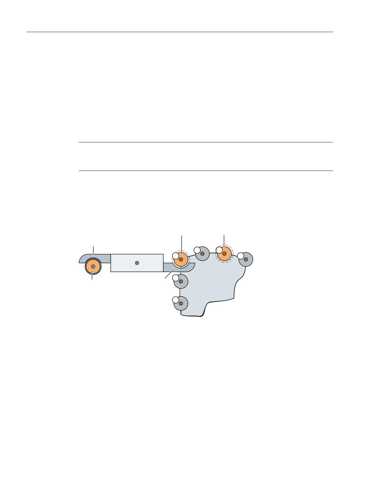
If, for example, tools on a spindle must be replaced from a magazine, the following assignment
can result:
7UDQVIHUBORFDWLRQB
/RDGBVWDWLRQB
*ULSSHUB
/RDGBVWDWLRQB
0DJD]LQHB
6SLQGOHB
*ULSSHUB
Location
Type/Index
1 Tool spindle
Spindle_1
2 Gripper
Gripper_1
3 Gripper
Gripper_2
4 Transfer location
Transfer_location_1
1 Load station
Load_station_1
2 Load station
Load_station_2
Tool management
52
Function Manual, 10/2020, 6FC5397-1HP40-0BA1

Basic commissioning and configuration
4.2 Configuration in SINUMERIK Operate
Parameters
Assignment
Spindle/gripper/loader for
• Tool spindle location 1 for magazine (separation 0)
magazine
• Gripper location 2 for magazine (separation 0)
• Gripper location 3 for magazine (separation 0)
• Transfer location 4 for magazine (separation 0)
Gripper/loader for spindle
• Tool spindle location 1 for gripper 2
• Tool spindle location 1 for gripper 3
Loading point for magazine
• Loading point location 1 for magazine (separation 0)
• Loading point location 2 for magazine (separation 3)
Tool management
Function Manual, 10/2020, 6FC5397-1HP40-0BA1
53
Basic commissioning and configuration
4.2 Configuration in SINUMERIK Operate
Tool management
54
Function Manual, 10/2020, 6FC5397-1HP40-0BA1
Machine data
5
5.1
NC-specific machine data
Table 5-1
$MN_MAXNUM_REPLACEMENT_TOOLS
17500
MAXNUM_REPLACEMENT_TOOLS
MD number
Maximum number of tools in a tool group
Default setting: 0
Min. input limit: 0
Max. input limit: 32
Change becomes effective after: POWER ON
Protection level: 2/7
Unit: -
Data type: DWORD
Meaning:
Only meaningful if tool management function or tool monitoring function are active
0: The number of tools in a tool group is not monitored
3: A maximum of 3 tools can exist in a tool group
This data does not affect memory requirements, but merely has a monitoring function.
Corresponding to...
MD18080 MM_TOOL_MANAGEMENT_MASK
MD20310 TOOL_MANAGEMENT_MASK
Additional references:
Table 5-2
$MN_MAX_TOOLS_PER_MULTITOOL
17504
$MN_MAX_TOOLS_PER_MULTITOOL
MD number
Multitool function. Number of tool locations per multitool
Default setting: 6
Min. input limit: 2
Max. input limit: 72
Change becomes effective after: POWER ON
Protection level: 1/1
Unit: -
Data type: DWORD
Meaning:
"Several tools at a magazine location" function (multitool). Maximum number of locations or
tools per multitool.
Corresponding to...
Additional references:
Table 5-3
$MN_TOOL_UNLOAD_MASK
17510
$MN_TOOL_UNLOAD_MASK
MD number
Behavior of tool data at unloading
Default setting: 0
Min. input limit: 0
Max. input limit: 0xF
Changes effective after Power On
Protection level: 2/7
Unit: -
Data type: DWORD
Tool management
Function Manual, 10/2020, 6FC5397-1HP40-0BA1
55

Machine data
5.1 NC-specific machine data
17510
$MN_TOOL_UNLOAD_MASK
Meaning:
When the tool is unloaded, some tool data can be assigned fixed values:
Bit 0 = 0: Tool status "active" remains unchanged
Bit 0 = 1: Tool status "active" is deleted ($TC_TP8, bit 0)
Bit 1 = 0: Tool status "was in use" remains unchanged
Bit 1 = 1: Tool status "was in use" is deleted ($TC_TP8, bit 7)
Bit 2 = 0: Tool parameter $TC_TP10 remains unchanged
Bit 2 = 1: Tool parameter $TC_TP10 is set to value 0. This means the tool replacement strategy
is reset.
Bit 3 = 0: Tool parameter $TC_TP11 remains unchanged
Bit 3 = 1: Tool parameter $TC_TP11 is set to value 0. This means the assignment to the tool
subgroup is canceled.
If a multitool is unloaded, then also the tools contained in it corresponding to MD
$MN_TOOL_UNLOAD_MASK are unloaded from the magazine location and therefore the tools
states are also changed according to the specifications of the MD. When unloading the MT, the
tools remain in the MT.
Data defined in the MD, which is also defined for the MT - that is previously the MT state
$TC_MTP8, bit 7 "was in use" - is also changed for the unloaded MT.
Corresponding to...
Additional references:
Table 5-4
$MN_TOOL_RESETMON_MASK
17515
$MN_TOOL_RESETMON_MASK
MD number
Behavior of tool data at RESETMON
Default setting: 0x14
Min. input limit: 0
Max. input limit: 0x69F
Changes effective after Power On
Protection level: 2/7
Unit: -
Data type: DWORD
Tool management
56
Function Manual, 10/2020, 6FC5397-1HP40-0BA1

Machine data
5.1 NC-specific machine data
17515
$MN_TOOL_RESETMON_MASK
Meaning:
The RESETMON command specifies in the 5th parameter which tool status is to be reset. If the
5th parameter is omitted, it is replaced with the value from this MD. This value is always used
with PI service "_N_TRESMON".
The bits are assigned like the bits in tool status $TC_TP8[x].
Bit 0 = 0: Tool status "active" remains unchanged
Bit 0 = 1: Tool status "active" is deleted
Bit 1 = 0: Tool status "enabled" remains unchanged
Bit 1 = 1: Tool status "enabled" is set
Bit 2 = 0: Tool status "disabled" remains unchanged
Bit 2 = 1: Tool status "disabled" is deleted if permitted by the monitoring data and the 4th
parameter is set accordingly.
Bit 3 = 0: Tool status "measured" remains unchanged
Bit 3 = 1: Tool status "measured" is set.
Bit 4 = 0: Tool status "prewarning limit" remains unchanged
Bit 4 = 1: Tool status "prewarning limit" is deleted if permitted by the monitoring data and the
4th parameter is set.
Bit 5: Not permitted (tool status "tool being changed")
Bit 6: Not permitted (tool status "tool is fixed-location-coded")
Bit 7 = 0: Tool status "was in use" remains unchanged
Bit 7 = 1: Tool status "was in use" is deleted
Bit 8 = 0 not permitted (tool status "being transported back")
Bit 9: Not permitted
Bit 10 = 0: Tool status "to unload" remains unchanged
Bit 10 = 1: Tool status "to unload" is deleted
Bit 11: Not permitted (tool status "to load")
Bit 12 = 0: Not permitted (tool status "master tool")
Bit 13: Not permitted
Bit 14: 1:1 exchange (not permitted)
Bit 15: Manual tool (not permitted)
Bit 16: Tool is at a disabled magazine location (not permitted)
The default setting corresponds to behavior up to now.
The bits that are not permitted are filtered and hidden by the limit screen.
Corresponding to...
Additional references:
Table 5-5
$MN_TOOL_DEFAULT_DATA_MASK
17520
$MN_TOOL_DEFAULT_DATA_MASK
MD number
Create new tool: Data default setting
Default setting: 0
Min. input limit: 0
Max. input limit: 0x1F
Changes effective after Power On
Protection level: 2/7
Unit: -
Data type: DWORD
Tool management
Function Manual, 10/2020, 6FC5397-1HP40-0BA1
57

Machine data
5.1 NC-specific machine data
17520
$MN_TOOL_DEFAULT_DATA_MASK
Meaning:
When a tool is redefined, some tool data can be assigned fixed default values. This way simple
applications do not need to process data which does not necessarily need to be assigned indi-
vidual values.
Bit 0 = 0: Default value of tool status ($TC_TP8), Bit1=0="not enabled"
Bit 0 = 1: Default value of tool status ($TC_TP8), Bit1=1="enabled"
Bit 1 = 0: Default value of tool status ($TC_TP8), bit 6=0="not fixed-location-coded"
Bit 1 = 1: Default value of tool status ($TC_TP8), bit 6=1="fixed-location-coded"
Bit 2 = 0: The tool is only included in the tool group with the explicit write command for the tool
name. Only then can it be loaded at change using the appropriate programming.
Bit 2 = 1 The tool is automatically included in the tool group when redefined. (Now the tool
change can be performed with the default name ("t"=t no.))
The "tool name" ($TC_TP2) can be hidden to the user. (This only makes sense if replacement
tools are not being used for machining or if the tool name is not explicitly written. Then, data
inconsistency problems could occur.)
Bit 3 = 0: Only with TMMG: Default value of location type ($TC_TP7)=9999=not defined
Bit 3 = 1: Significance, only with TMMG: Default value of location type ($TC_TP7)=1 and asso-
ciated default values of magazine location type (TC_MPP2)=1. All magazine locations can now
accept all tools.
Bit 4 = 0: Only significant with TMMG + active adjacent location consideration: When setting/
resetting the magazine location status "disabled", the magazine location status "overlapping
permitted" remains unchanged.
Bit 4 = 1: Only significant with TMMG + active adjacent location consideration: When setting/
resetting the magazine location status "disabled", the magazine location status "overlapping
permitted" is also automatically set/reset.
If a multitool is generated, then the data defined by MD $MN_TOOL_DEFAULT_DATA_MASK and
for the MT are set to the required values.
Corresponding to...
Additional references:
Table 5-6
$MN_TOOL_DATA_CHANGE_COUNTER
17530
$MN_TOOL_DATA_CHANGE_COUNTER
MD number
Identifying tool data change for HMI
Default setting: 0
Min. input limit: 0
Max. input limit: 0xF
Changes effective after Power On
Protection level: 2/7
Unit: -
Data type: DWORD
Tool management
58
Function Manual, 10/2020, 6FC5397-1HP40-0BA1

Machine data
5.1 NC-specific machine data
17530
$MN_TOOL_DATA_CHANGE_COUNTER
Meaning:
HMI display support. This data allows explicit inclusion/exclusion of individual data in the OPI
variables (block C/S) toolCounter, toolCounterC, toolCounterM to be taken into account.
Bit 0 = 0: Value changes to tool status ($TC_TP8) are not taken into account in toolCounterC.
Bit 0 = 1: Value changes to the tool status ($TC_TP8) are taken into account in toolCounterC.
Bit 1 = 0: Value changes to remaining tool count ($TC_MOP4) are not taken into account in
toolCounterC.
Bit 1 = 1: Value changes to the remaining tool count ($TC_MOP4) are taken into account in
toolCounterC.
Bit 2 = 0: Value changes to the tool data is not taken into account in the tool data update service.
Bit 2 = 1: Value changes to the tool data is taken into account in the tool data update service.
Bit 3 = 0: Value changes to the magazine data is not taken into account in the tool data update
service.
Bit 3 = 1: Value changes to the magazine data is taken into account in the tool data update
service.
Bit 4 = 0: Value changes to the ISO tool offset data are not taken into account in the tool data
update service.
Bit 4 = 1: H10' Value changes to the ISO tool offset data are taken into account in the tool data
update service.
"Value changes to tool status" and "Value changes to remaining tool count" are relative to the
value changes which are caused by internal processes in the NC, as well as to value changes
caused by writing the respective system variables.
Corresponding to...
Additional references:
Table 5-7
$MN_TOOLTYPES_ALLOWED
17540
$MN_TOOLTYPES_ALLOWED
MD number
Permitted tool types
Default setting: 0x3FF
Min. input limit: 0
Max. input limit: 0x3FF
Change becomes effective after: POWER ON
Protection level: 2/7
Unit: -
Data type: DWORD
Tool management
Function Manual, 10/2020, 6FC5397-1HP40-0BA1
59
Machine data
5.1 NC-specific machine data
17540
$MN_TOOLTYPES_ALLOWED
Meaning:
Definition of tool types (see $TC_DP1) permitted in the NC for tool offset selection. This means
tools of any tool type can be loaded to the NC, however, only the tool types specified here can be
defined in the tool determining the offset. A bit value = 1 means that the specified tool type
range is permitted for the offset selection. A bit value = 0 means that the specified tool type
range is not permitted for the offset selection. When an attempt is made to select an offset for
a cutting edge of this type, the selection is rejected and an offset-capable alarm is issued. Value
= 0, 9999 for the tool type means "not defined". In general, it is not possible to select tool
offsets with this value for the tool type.
Bit 0 = 0x1: Tool types 1 to 99 permitted
Bit 1 = 0x2: Tool types 100 to 199 permitted (milling tools)
Bit 2 = 0x4: Tool types 200 to 299 permitted (drilling tools)
Bit 3 = 0x8: Tool types 300 to 399 permitted
Bit 4 = 0x10: Tool types 400 to 499 permitted (grinding tools)
Bit 5 = 0x20: Tool types 500 to 599 permitted (turning tools)
Bit 6 = 0x40: Tool types 600 to 699 permitted
Bit 7 = 0x80: Tool types 700 to 799 permitted
Bit 8 = 0x100: Tool types 800 to 899 permitted
Bit 9 = 0x200: Tool types 900 to 999 permitted
Corresponding to...
MD18100 $MN_NUM_CUTTING_EDGES_IN_TOA
Additional references:
Table 5-8
$MM_TOOL_MANAGEMENT_TRACE_SZ
18074
$MM_TOOL_MANAGEMENT_TRACE_SZ
MD number
Maximum size of the tool management diagnostics ring buffer
Default setting: 25, 25
Min. input limit: 4
Max. input limit: 500
Change becomes effective after: POWER ON
Protection level: 2/7
Unit: -
Data type: DWORD
Meaning:
Number of entries in the diagnostics ring buffer of the tool management.
Index 0 = buffer size of the IPO trace.
Index 1 = buffer size of the prep trace
There is a dedicated IPO trace buffer in each channel, and there is only a prep trace buffer in
channel 1.
The memories are only allocated if bit 0 (0x0001) for a warm restart is at ON - and more precisely
in both MD18080: MM_TOOL_MANAGEMENT_MASK and MD20310: TOOL_MANAGE-
MENT_MASK for each channel.
Trace data is written to the buffer if bit 13 (0x2000) is at ON in MD20310: TOOL_MANAGE-
MENT_MASK for each channel.
Corresponding to...
Additional references:
Tool management
60
Function Manual, 10/2020, 6FC5397-1HP40-0BA1
Machine data
5.1 NC-specific machine data
Table 5-9
$MM_NUM_TOOLHOLDERS
18075
$MM_NUM_TOOLHOLDERS
MD number
Max. number of tool holders per TOA
Default setting: 16
Min. input limit: 1
Max. input limit: 128
Change becomes effective after: POWER ON
Protection level: 2/7
Unit: -
Data type: DWORD
Meaning:
Maximum number of definable tool holders per TO area.
The maximum value is 20. The number 20 is derived from the maximum number of axes per
channel in the 840D sl.
The address extension e of the commands Te=T, Me=6 (*) is the number of the tool holder.
t=T number / tool name - depending on the function, which is activated in the NC.
(*) if the following applies: $MC_TOOL_CHANGE_MODE=1 and
$MC_TOOL_CHANGE_M_CODE=6
In milling machines, the tool holder is generally not a spindle, see also $MC_SPIND_DEF_MAS-
TER_SPIND.
In turning machines, the tool holder is generally not a spindle axis, see also $MC_TOOL_MAN-
AGEMENT_TOOLHOLDER.
Then the following should apply $MN_MM_NUM_TOOLHOLDERS greater or equal to
$MC_SPIND_DEF_MASTER_SPIND/$MC_TOOL_MANAGEMENT_TOOLHOLDER.
If bit 0 = 1 in $MN_MM_TOOL_MANAGEMENT_MASK and $MC_TOOL_MANAGEMENT_MASK is
set (= magazine management (TMMG)) is only applicable for sensible values
$MN_MM_NUM_TOOLHOLDERS less than or equal to $MN_MM_NUM_LOCS_WITH_DISTANCE.
Then, a maximum of $MN_MM_NUM_TOOLHOLDERS buffer locations, type spindle
($TC_MPP1[9998,x]=2) can be defined.
Example: TMMG not active
Assuming $MC_SPIND_DEF_MASTER_SPIND=3, $MN_MM_NUM_TOOLHOLDERS = 3.
Then T1=t, T2=t, T3=t, T=t can be programmed.
Example: TMMG active, milling machine with Me=6 as tool change command
Assuming $MN_MM_NUM_TOOLHOLDERS=14, $MN_MM_NUM_LOCS_WITH_DISTANCE=20,
10 channels are active, all channels have TMMG active and have the same tool and machine data
(=one TO area for all channels). $MC_SPIND_DEF_MASTER_SPIND=1,
,10 for the channels.
Then, in the magazine buffer, up to 14 locations, type "tool holder"/"spindle" can be defined.
In addition, 6 other grippers or similar can be defined.
These locations (a maximum of 20) can be linked to magazines.
T1=t,
T14=t and Tt or M1=6,
M14=6 and M06 can be programmed in the channels
The PLC version used can limit the maximum number of tool holders.
Corresponding to...
Additional references:
Table 5-10
$MM_NUM_LOCS_WITH_DISTANCE
18076
$MM_NUM_LOCS_WITH_DISTANCE
MD number
Max. number of magazine locations per TOA with distance connection
Default setting: 32
Min. input limit: 1
Max. input limit: 128
Change becomes effective after: POWER ON
Protection level: 2/7
Unit: -
Data type: DWORD
Tool management
Function Manual, 10/2020, 6FC5397-1HP40-0BA1
61
Machine data
5.1 NC-specific machine data
18076
$MM_NUM_LOCS_WITH_DISTANCE
Meaning:
The machine data makes sense if the magazine management function TMMG is active - see
$MN_MM_TOOL_MANAGEMENT_MASK, $MC_TOOL_MANAGEMENT_MASK; in each case bit 0
= 1.
Maximum number of magazine locations (spindles, loading locations, etc.) per TOA, that can
have a distance connection to a magazine defined using $TC_MDPx[n,m].
Example: TMMG is active: $MN_MM_NUM_LOCS_WITH_DISTANCE is = 5 and
$MN_MM_NUM_DIST_REL_PER_MAGLOC = 2.
Two TOA units are defined each with three tool holders / spindles, two loading points.
Further, there are two grippers defined in each TO unit.
This means that in total there are 14 locations defined in the buffer magazine / loading magazine
for which distances and assignments should be defined. TO unit 1 has 4 magazines defined, TO
unit 2 has 6 magazines defined.
With the set value of $MN_MM_NUM_LOCS_WITH_DISTANCE = 5, each tool holder and each
loading point can be linked; (see $TC_MDP1 and $TC_MDP2) and up to two grippers can be
additionally assigned to each tool holder ($MN_MM_NUM_DIST_REL_PER_MAGLOC = 2); (see
$TC_MLSR).
As a consequence, a tool holder / a spindle location can have two tables - a distance table to
magazines and an assignment table to grippers and similar locations.
Corresponding to...
Additional references:
Table 5-11
$MM_NUM_DIST_REL_PER_MAGLOC
18077
$MM_NUM_DIST_REL_PER_MAGLOC
MD number
Max. number of magazines in the distance table of a magazine location
Default setting:
Min. input limit: 0
Max. input limit: 64
Change becomes effective after: POWER ON
Protection level: 2/7
Unit: -
Data type: DWORD
Meaning:
The machine data is only active, if the magazine management function, TMMG is active - see
$MN_MM_TOOL_MANAGEMENT_MASK, $MC_TOOL_MANAGEMENT_MASK.
Two quantities are defined with the data:
1.) Max. number of magazines in the distance table of a magazine location (spindle, loading
location, etc.)
2.) Maximum number of locations (gripper, ...) in the connection table of a spindle / tool holder.
Example: $MN_MM_NUM_DIST_REL_PER_MAGLOC = 3.
Two TOA units are defined each with two tool holders / spindles and one loading point each.
Further, four grippers are defined in each TO unit.
TO unit 1 has 4 magazines defined, TO unit 2 has 6 magazines defined.
Then, each tool holder can define up to three distances to the magazines (see $TC_MDP2) and
in addition, can define up to three relationships to grippers ($TC_MLSR).
Corresponding to...
Additional references:
Tool management
62
Function Manual, 10/2020, 6FC5397-1HP40-0BA1
Machine data
5.1 NC-specific machine data
Table 5-12
$MM_MAX_NUM_OF_HIERARCHIES
18078
$MM_MAX_NUM_OF_HIERARCHIES
MD number
Maximum number of definable hierarchies for magazine location types
Default setting: 8
Min. input limit: 0
Max. input limit: 32
Change becomes effective after: POWER ON
Protection level: 2/7
Unit: -
Data type: DWORD
Meaning:
The machine data is only active, if the magazine management function, TMMG is active - see
$MN_MM_TOOL_MANAGEMENT_MASK, $MC_TOOL_MANAGEMENT_MASK.
Maximum number of definable hierarchies for magazine location types
The permissible value of index n of system parameter $TC_MPTH[n,m] is from 0 to
"$MN_MM_MAX_NUM_OF_HIERARCHIES - 1".
(The maximum of index m can be specified using machine data $MN_MM_MAX_HIERACHY_EN-
TRIES.)
A value = 0 means that the "Magazine location type hierarchy" function is not available.
Corresponding to...
Additional references:
Table 5-13
$MM_MAX_HIERARCHY_ENTRIES
18079
$MM_MAX_HIERARCHY_ENTRIES
MD number
Maximum permissible number of entries in a magazine-location-type hierarchy.
Default setting: 8
Min. input limit: 1
Max. input limit: 32
Change becomes effective after: POWER ON
Protection level: 2/7
Unit: -
Data type: DWORD
Meaning:
The machine data is only active, if the magazine management function, TMMG is active - see
$MN_MM_TOOL_MANAGEMENT_MASK, $MC_TOOL_MANAGEMENT_MASK - and if
$MN_MM_MAX_NUM_OF_HIERARCHIES is greater than zero.
Maximum number of entries in a magazine location type hierarchy.
The permissible value of index m of system parameter $TC_MPTH[n,m] is from 0 to
"$MN_MM_MAX_NUM_OF_HIERARCHIES - 1".
(The maximum of index n can be specified using machine data $MN_MM_MAX_NUM_OF_HI-
ERARCHIES.)
A value = 0 means that the "Magazine location type hierarchy" function is not available.
Corresponding to...
Additional references:
Table 5-14
$MM_TOOL_MANAGEMENT_MASK
18080
$MM_TOOL_MANAGEMENT_MASK
MD number
Memory for the tool management is reserved step-by-step
Default setting: 0x2
Min. input limit: 0
Max. input limit: 0xFFFF
Change becomes effective after: POWER ON
Protection level: 1/7
Unit: -
Data type: DWORD
Tool management
Function Manual, 10/2020, 6FC5397-1HP40-0BA1
63

Machine data
5.1 NC-specific machine data
18080
$MM_TOOL_MANAGEMENT_MASK
Meaning:
Activation of the tool management memory with "0" means:
The set tool management data does not occupy any memory, tool management is not available.
Bit 0=1: Memory for data specific to tool management is available; the MDs for reserving mem-
ory must be set accordingly (MD18086 MM_NUM_MAGAZINE_LOCATION, MD18084
MM_NUM_MAGAZINE)
Bit 1=1: Memory is available for monitoring data (TMMO)
Bit 2=1: Memory is available for user data (CC data)
Bit 3=1: Memory is available for considering the adjacent location
Bit 4=1: Memory and function release for PI service _N_TSEARC = "Complex search for tools in
magazine" is available.
Bit 5=1: Wear monitoring active
Bit 6=1: Wear group available
Bit 7=1: Reserve memory for adapter of magazine locations
Bit 8=1: Memory for machining and/or setting up offsets
Bit 9=1: Reserved
Bit 10=1: The multitool function is available. The configuration can be changed by other ma-
chine data.
Bit 10=0: The multitool function is not available. The function version set by other machine data
is not active.
The coded type of memory reservation enables economic use of memory management for the
functionality provided.
Example:
Standard memory reservation for tool management:
MM_TOOL_MANAGEMENT_MASK = 3 (Bit 0 + 1=1) means tool management and tool moni-
toring data is made available
MM_TOOL_MANAGEMENT_MASK = 2 means tool management without tool monitoring func-
tion data
Special cases, errors,...
Table 5-15
$MM_NUM_TOOL
18082
$MM_NUM_TOOL
MD number
Number of tools the NC can manage
Default setting: 30
Min. input limit: 0
Max. input limit: 1500
Changes effective after POWER ON
Protection level: 2/7
Unit: -
Data type: DWORD
Meaning:
The NC can manage as a maximum the number of tools entered in the MD. A tool has at least
one cutting edge.
A buffered (backed-up) user memory is used.
The maximum number of tools possible correspond to the number of cutting edges. The MD
should also be set even if no tool management is being used.
If this machine data is altered the buffered data is lost.
A maximum of 1500 tools are possible per TO unit and in the entire NC.
Special cases, errors,...:
Tool management
64
Function Manual, 10/2020, 6FC5397-1HP40-0BA1

Machine data
5.1 NC-specific machine data
18082
$MM_NUM_TOOL
Corresponding to...
MD18100 MM_NUM_CUTTING_EDGES_IN_TOA
Additional references:
Description of functions: Memory configuration (S7), tool offset (W1)
Table 5-16
$MM_NUM_MULTITOOL
18083
$MM_NUM_MULTITOOL
MD number
Multitool function. Number of multitools that the NC can manage
Default setting: 15
Min. input limit: 0
Max. input limit: 750
Changes effective after POWER ON
Protection level: 1/1
Unit: -
Data type: DWORD
Meaning:
"Several tools at a magazine location (multitool)" function. Number of multitools (multiple
tools) that the NC can manage.
Special cases, errors,...:
Corresponding to...
Additional references:
Table 5-17
$MM_NUM_MAGAZINE
18084
$MM_NUM_MAGAZINE
MD number
Number of magazines the NC can manage
Default setting: 4
Min. input limit: 0
Max. input limit: 64
Changes effective after POWER ON
Protection level: 2/7
Unit: -
Data type: DWORD
Meaning:
Tool management (TMG or TMMG) only if MD tool management and option tool management
are set:
Number of magazines that the NC can manage (active and backg47round magazines).
The buffered memory for the magazines is reserved with this machine data.
Important: One load magazine and one buffer magazine are set up in the tool management for
each TOA unit. These magazines must be taken into account.
Value = 0: Tool management cannot be activated because no data can be created.
Special cases, errors,...:
Corresponding to...
MD18080 MM_TOOL_MANAGEMENT_MASK
MD20310 TOOL_MANAGEMENT_MASK
Additional references:
Description of functions: Memory configuration (S7)
Table 5-18
$MM_NUM_MULTITOOL_LOCATIONS
18085
$MM_NUM_MULTITOOL_LOCATIONS
MD number
Multitool function. Number of multitool locations that the NC can manage
Default setting: 30
Min. input limit: 0
Max. input limit: 1500
Changes effective after POWER ON
Protection level: 1/1
Unit: -
Data type: DWORD
Tool management
Function Manual, 10/2020, 6FC5397-1HP40-0BA1
65
Machine data
5.1 NC-specific machine data
18085
$MM_NUM_MULTITOOL_LOCATIONS
Meaning:
"Several tools at a magazine location (multitool)" function. Number of multitool locations that
the NC can manage.
Special cases, errors,...:
Corresponding to...
Additional references:
Table 5-19
$MM_NUM_MAGAZINE_LOCATION
18086
$MM_NUM_MAGAZINE_LOCATION
MD number
Number of magazine locations the NC can manage
Default setting: 30
Min. input limit: 0
Max. input limit: 1500
Change becomes effective after: POWER ON
Protection level: 2/7
Unit: -
Data type: DWORD
Meaning:
TMMG - only if MD for tool management and tool management option are set:
Number of magazine locations the NC can manage.
The buffered memory for the magazine locations is reserved with this MD.
Important: The number of all buffer locations and loading points must be taken into account
here.
Value = 0: Tool management cannot be activated because no data can be created.
Special cases, errors,...:
Corresponding to...
MD18080 MM_TOOL_MANAGEMENT_MASK
MD20310 TOOL_MANAGEMENT_MASK
Additional references:
Description of functions: Memory configuration (S7)
Table 5-20
$MM_NUM_TOOL_CARRIER
18088
$MM_NUM_TOOL_CARRIER
MD number
Maximum number of defined tool holders
Default setting: 0
Min. input limit: 0
Max. input limit: 600
Change becomes effective after: POWER ON
Protection level: 2/7
Unit: -
Data type: DWORD
Meaning:
Maximum number of definable tool holders for tools that can be oriented in the TO area. The
value is divided by the number of active TO units. The integer result indicates how many tool
holders can be defined per TO unit.
The data to define a tool holder is set using the system variables $TC_CARR1, ...$TC_CARR14.
The data is located in the buffered memory.
Example:
2 channels are active, with one channel per TO unit (=default).
3 holders must be defined in channel 1 and one holder in channel 2. The value to be set is 6
because 6/2 = 3. This means a max. of 3 holder definitions in each TO unit.
Special cases, errors,...:
Corresponding to...
Additional references:
Description of functions: Tool offset (S7)
Tool management
66
Function Manual, 10/2020, 6FC5397-1HP40-0BA1
Machine data
5.1 NC-specific machine data
Table 5-21
$MM_NUM_CC_MAGAZINE_PARAM
18090
$MM_NUM_CC_MAGAZINE_PARAM
MD number
Number of OEM magazine data
Default setting: 0
Min. input limit: 0
Max. input limit: 64
Changes effective after POWER ON
Protection level: 2/2
Unit: -
Data type: DWORD
Meaning:
Number of magazine parameters (of the integer type) that are made available to the user or the
Compile Cycle.
If this machine data is set, the amount of buffered memory required increases by sizeof(int) *
max. number of magazines.
Special cases, errors,...:
Corresponding to...
MD18080 MM_TOOL_MANAGEMENT_MASK
MD18084 MM_NUM_MAGAZINE
Additional references:
Table 5-22
$MM_TYPE_CC_MAGAZINE_PARAM[n]
18091
$MM_TYPE_CC_MAGAZINE_PARAM[n]
MD number
OEM magazine data type
Default setting: 3
Min. input limit: 1
Max. input limit: 6
Change becomes effective after: POWER ON
Protection level: 2/2
Unit: -
Data type: DWORD
Meaning:
Used to assign individual types to the parameters. The array index n can have values between
0 and the value in machine data MD18090 MM_NUM_CC_MAGAZINE_PARAM. Type of maga-
zine-specific user data configured with MD18090 $MN_MM_NUM_CC_MAGAZINE_PARAM. Ev-
ery parameter can be allocated its own type.
The following types are permissible:
Type
Value of the machine data
• BOOL
1
• CHAR
2
• INT
3
• REAL
4
• STRING
5 (not allowed, not supported by the OPI.)
• AXIS
6
• FRAME
not defined
Example:
$MM_TYPE_CC_MAGAZIN_PARAMETER=4
can then be programmed for the parameter $TC_MAPC1[MagNo]=12,325.
A buffered work memory is used. Changing the value can, but does not necessarily, result in
reconfiguration of the buffered memory.
Corresponding to...
MD18090 MM_NUM_CC_MAGAZINE_PARAM
MD18084 MM_NUM_MAGAZINE
Additional references:
Tool management
Function Manual, 10/2020, 6FC5397-1HP40-0BA1
67
Machine data
5.1 NC-specific machine data
Table 5-23
$MM_NUM_CC_MAGLOC_PARAM
18092
$MM_NUM_CC_MAGLOC_PARAM
MD number
Number of OEM magazine location data
Default setting: 0
Min. input limit: 0
Max. input limit: 64
Changes effective after POWER ON
Protection level: 2/2
Unit: -
Data type: DWORD
Meaning:
Number of magazine location data parameters that are available to the user or the compile
cycle. The data type is defined by the machine data MD 18093 $MM_TYPE_CC_MAGLOC_PAR-
AM.
With MD 18092, the amount of buffered memory required increases by sizeof() * max. number
of magazine locations.
Special cases, errors,...:
Corresponding to...
MD18080 MM_TOOL_MANAGEMENT_MASK
MD18086 MM_NUM_MAGAZINE_LOCATION
Additional references:
Table 5-24
$MM_TYPE_CC_MAGLOC_PARAM[n]
18093
$MM_TYPE_CC_MAGLOC_PARAM[n]
MD number
OEM magazine location data type
Default setting: 3
Min. input limit: 1
Max. input limit: 6
Change becomes effective after: POWER ON
Protection level: 2/2
Unit: -
Data type: DWORD
Meaning:
Used to assign individual types to the parameters. The array index n can have values between
0 and the value in MD18092 $MN_MM_NUM_CC_MAGLOC_PARAM. Type of magazine-specific
user data configured with MD18092 $MN_MM_NUM_CC_MAGLOC_PARAM. Every parameter
can be allocated its own type.
The following types are permissible:
Type
Value of the machine data
• BOOL
1
• CHAR
2
• INT
3
• REAL
4
• STRING
5 (not allowed, not supported by the OPI.)
• AXIS
6
• FRAME
not defined
Example:
$MN_MM_TYPE_CC_MAGLOC_PARAM[0]=4
then $TC_MPPC1[MagNo]=12.325 can be programmed for the parameter.
A buffered work memory is used. Changing the value can, but does not necessarily, result in
reconfiguration of the buffered memory.
Corresponding to...
MD18092 MM_NUM_CC_MAGLOC_PARAM
MD18086 MM_NUM_MAGAZINE_LOCATION
Additional references:
Tool management
68
Function Manual, 10/2020, 6FC5397-1HP40-0BA1
Machine data
5.1 NC-specific machine data
Table 5-25
$MM_NUM_CC_TDA_PARAM
18094
$MM_NUM_CC_TDA_PARAM
MD number
Number of OEM tool data
Default setting: 0
Min. input limit: 0
Max. input limit: 64
Changes effective after POWER ON
Protection level: 2/2
Unit: -
Data type: DWORD
Meaning:
Number of tool-specific data that can be created for each tool (of type integer) and are available
to the user or compile cycle.
If this machine data is set, the amount of buffered memory required increases by sizeof(double)
* max. number of tools.
Special cases, errors,...:
Corresponding to...
MD18080 MM_TOOL_MANAGEMENT_MASK
MD18082 MM_NUM_TOOL
Additional references:
Table 5-26
$MM_TYPE_CC_TDA_PARAM[n]
18095
$MM_TYPE_CC_TDA_PARAM[n]
MD number
OEM tool data type
Default setting: 4
Min. input limit: 1
Max. input limit: 6
Change becomes effective after: POWER ON
Protection level: 2/2
Unit: -
Data type: DWORD
Meaning:
Type of tool-specific user data configured with MD18094 $MN_MM_NUM_CC_TDA_PARAM.
Every parameter can be allocated its own type. The following types are permissible:
The following types are permissible:
Type
Value of the machine data
• BOOL
1
• CHAR
2
• INT
3
• REAL
4
• STRING
5 (Permits identifiers of up to 31 characters)
• AXIS
6
• FRAME
not defined
Example:
MD18094: MM_NUM_CC_TDA_PARAM=1
MD18095: MM_TYPE_CC_TDA_PARAM=5
Then "A" can be programmed for parameter $TC_TPC1.
A buffered work memory is used. Changing the value can, but does not necessarily, result in
reconfiguration of the buffered memory.
Corresponding to...
MD18094 MM_NUM_CC_TDA_PARAM
MD18082 MM_NUM_TOOL
Additional references:
Tool management
Function Manual, 10/2020, 6FC5397-1HP40-0BA1
69
Machine data
5.1 NC-specific machine data
Table 5-27
$MM_NUM_CC_TOA_PARAM
18096
$MM_NUM_CC_TOA_PARAM
MD number
Number of data per tool cutting edge for compile cycles
Default setting: 0
Min. input limit: 0
Max. input limit: 64
Change becomes effective after: POWER ON
Protection level: 2/2
Unit: -
Data type: DWORD
Meaning:
Number of TOA data that can be created for each tool (of type Double) and are available to the
user or compile cycle.
If this machine data is set, the amount of buffered memory required increases by sizeof(double)
* max. number of cutting edges.
Special cases, errors,...:
Corresponding to...
MD18080 MM_TOOL_MANAGEMENT_MASK
MD18100 MM_NUM_CUTTING_EDGES_IN_TOA
Additional references:
Table 5-28
$MM_TYPE_CC_TOA_PARAM[n]
18097
$MM_TYPE_CC_TOA_PARAM[n]
MD number
OEM data type per cutting edge
Default setting: 4
Min. input limit: 1
Max. input limit: 6
Change becomes effective after: POWER ON
Protection level: 2/2
Unit: -
Data type: DWORD
Meaning:
Used to assign individual types to the parameters. The array index n can have values between
0 and the value of MD18096 $MN_MM_NUM_CC_TOA_PARAM. Type of cutting-edge-specific
user data configured in MD18096 $MN_MM_NUM_CC_TOA_PARAM. Every parameter can be
allocated its own type.
The following types are permissible:
Type
Value of the machine data
• BOOL
1
• CHAR
2
• INT
3
• REAL
4
• STRING
5 (not allowed, not supported by the OPI.)
• AXIS
6
• FRAME
not defined
Example:
$MM_TYPE_CC_MAGAZIN_PARAMETER=4
can then be programmed for the parameter $TC_MAPC1[MagNo]=12,325.
The buffered work memory is used. Changing the value can, but does not necessarily, result in
reconfiguration of the buffered memory.
Corresponding to...
MD18096 MM_NUM_CC_TOA_PARAM
MD18100 MM_NUM_CUTTING_EDGES_IN_TOA
Additional references:
Tool management
70
Function Manual, 10/2020, 6FC5397-1HP40-0BA1
Machine data
5.1 NC-specific machine data
Table 5-29
$MM_NUM_CC_MON_PARAM
18098
$MM_NUM_CC_MON_PARAM
MD number
Number of monitoring data per tool for compile cycles
Default setting: 0
Min. input limit: 0
Max. input limit: 64
Change becomes effective after: POWER ON
Protection level: 2/2
Unit: -
Data type: DWORD
Meaning:
Number of monitoring data that is created for each tool (of type integer) and is available to the
user or compile cycle.
If this machine data is set, the amount of buffered memory required increases by sizeof(int) *
max. number of cutting edges.
Special cases, errors,...:
Corresponding to...
MD18080 MM_TOOL_MANAGEMENT_MASK
MD18100 MM_NUM_CUTTING_EDGES_IN_TOA
Additional references:
Table 5-30
$MM_TYPE_CC_MON_PARAM[n]
18099
$MM_TYPE_CC_MON_PARAM[n]
MD number
OEM monitor data type
Default setting: 3
Min. input limit: 1
Max. input limit: 6
Change becomes effective after: POWER ON
Protection level: 2/2
Unit: -
Data type: DWORD
Meaning:
User or OEM data in the tool management. Type of the multitool-specific user data $TC_MTPCn
configured with MD18192 $MN_MM_NUM_CC_MULTITOOL_PARAM. Every parameter can be
allocated its own type.
The following types are permissible:
Type
Value of the machine data
• BOOL
1
• CHAR
2
• INT
3
• REAL
4
• STRING
5 (not allowed, not supported by the OPI.)
• AXIS
6
• FRAME
not defined
Example:
$MM_TYPE_CC_MON_PARAM=4
then $TC_MOPC1[MagNo]=12.325 can be programmed for the parameter.
The buffered work memory is used. Changing the value can, but does not necessarily, result in
reconfiguration of the buffered memory.
Corresponding to...
MD18100 MM_NUM_CUTTING_EDGES_IN_TOA
MD18098 MM_NUM_CC_MON_PARAM
Additional references:
Tool management
Function Manual, 10/2020, 6FC5397-1HP40-0BA1
71
Machine data
5.1 NC-specific machine data
Table 5-31
$MM_NUM_CUTTING_EDGES_IN_TOA
18100
$MM_NUM_CUTTING_EDGES_IN_TOA
MD number
Tool cutting edges per TO area
Default setting: 30
Min. input limit: 0
Max. input limit: 3000
Change becomes effective after: POWER ON
Protection level: 2/7
Unit: -
Data type: DWORD
Meaning:
Defines the number of tool cutting edges in a TO area.
For each tool edge approx. 250 bytes per TOA block of the battery-backed memory are reserved
with this machine data irrespective of the tool type.
Tools with type 400-499 cutting edges (=grinding tools) also occupy the location of a cutting
edge.
Example:
Define 10 grinding tools with one cutting edge each.
Then, as a minimum, the following must apply:
MM_NUM_TOOL = 10
MM_NUM_CUTTING_EDGES_IN_TOA = 20
See also MM_NUM_TOOL
A buffered (backed-up) user memory is used.
Special cases, errors,...:
If this machine data is altered the buffered data is lost!
Corresponding to...
Additional references:
Description of functions: Memory configuration (S7)
Table 5-32
$MM_NUM_TOOL_ADAPTER_TYPE2
18103
MM_NUM_TOOL_ADAPTER_TYPE2
MD number
Tool adapter of type 2 in all TO areas (SRAM)
Default setting:
Min. input limit: -
Max. input limit:-
Change becomes effective after: POWER ON
Protection level: 2/7
Unit: -
Data type: DWORD
Meaning:
Number of tool adapters of type 2 (angle head adapter) in all TO areas.
This function can only be used if magazine locations are available in the NCK.
In order to activate the setting, bit 7 (=0x80) must also be set in MD18080
$MN_MM_TOOL_MANAGEMENT_MASK.
Adapter data records or the cutting edge-specific basis dimensions mutually exclude one an-
other.
This means that if adapters of type 2 can be created, then the values of the following parameters
are internally filled by the NCK:
Base length: $TC_DP21, $TC_DP22, $TC_DP23.
Meaning of values:
0: No adapter data definitions are possible.
The cutting edge-specific parameters $TC_DP21-23, DPV3-5 and DPVN3-5 can be written.
> 0: Number of adapter data records.
An additional step following the definition of the data assigns the adapters to the multitool
locations.
In this way, for example, one adapter can be assigned to several multitool locations.
Tool management
72
Function Manual, 10/2020, 6FC5397-1HP40-0BA1
Machine data
5.1 NC-specific machine data
18103
MM_NUM_TOOL_ADAPTER_TYPE2
Special cases, errors,...:
Corresponding to...
Additional references:
MD18080 $MN_MM_TOOL_MANAGEMENT_MASK,
MD18085 $MC_MM_NUM_MULTITOOL_LOCATIONS
Table 5-33
$MM_NUM_TOOL_ADAPTER
18104
$MM_NUM_TOOL_ADAPTER
MD number
Tool adapter in TO area
Default setting: -1
Min. input limit: -1
Max. input limit: 600
Change becomes effective after: POWER ON
Protection level: 2/7
Unit: -
Data type: DWORD
Meaning:
Number of tool adapters in the TO area.
This function can only be used if magazine locations are available in the NC. The tool manage-
ment function must be active. In order to activate the setting, bit 7 (=0x80) must be set in MD
$MN_MM_TOOL_MANAGEMENT _MASK.
Adapter data records and the cutting-edge-specific basis / adapter data records mutually exclude
one another. i.e. when adapter data is defined, then parameters $TC_DP21, $TC_DP22,
$TC_DP23 or their values in NC are available.
-1:
Every magazine location is automatically assigned an adapter.
This means that internally there are just as many adapters foreseen as are foreseen by the
magazine locations set in machine data $MN_MM_NUM_MAGAZINE_LOCATION.
-2
Reserved
0:
No adapter-data definition possible. Cutting-edge-specific parameters $TC_DP21, $TC_DP22
and $TC_DP23 are available in cases where adapters are utilized outside the active TM.
> 0:
Number of adapter data records. By this, adapters can be defined independently of magazine
locations. An additional step following definition of the data assigns the adapters to magazine
locations.
Corresponding to...
MD18080 MM_TOOL_MANAGEMENT_MASK
MD20310 TOOL_MANAGEMENT_MASK
MD18084 MM_NUM_MAGAZINE
MD18086 MM_NUM_MAGAZINE_LOCATION
Additional references:
Table 5-34
$MM_MAX_CUTTING_EDGE_NO
18105
$MM_MAX_CUTTING_EDGE_NO
MD number
Maximum value of D number
Default setting: 9
Min. input limit: 1
Max. input limit: 32000
Change becomes effective after: POWER ON
Protection level: 2/7
Unit: -
Tool management
Function Manual, 10/2020, 6FC5397-1HP40-0BA1
73

Machine data
5.1 NC-specific machine data
18105
$MM_MAX_CUTTING_EDGE_NO
Data type: DWORD
Meaning:
Maximum value of D number.
The maximum number of D numbers per cutting edge is not affected by this.
The monitoring of the D number assignment associated with this value is only effective for new
definitions of D numbers. This means the existing data records are not checked later - if the MD
is changed.
Advisable setting:
$MN_MM_MAX_CUTTING_EDGE_NO equal to $MN_MM_MAX_CUTTING_EDGE_PER_TOOL. If
$MN_MM_MAX_CUTTING_EDGE_NO > $MN_MM_MAX_CUTTING_EDGE_PER_TOOL is set, you
should familiarize yourself with the difference between offset number D and the tool edge
number CE.
See also language commands CHKDNO, CHKDM, GETDNO, SETDNO, DZERO.
The MD can change the memory requirements:
A change from "less than equal to" to "greater than" - or vice versa - in the values of both the
above mentioned MDs can influence the demand for non-buffered memory.
Corresponding to...
MD18106 MM_MAX_CUTTING_EDGE_PER_TOOL
Additional references:
Description of functions: Tool offset (W1)
Table 5-35
$MM_MAX_CUTTING_EDGE_PER_TOOL
18106
$MM_MAX_CUTTING_EDGE_PER_TOOL
MD number
Maximum number of D numbers per tool
Default setting: 9
Min. input limit: 1
Max. input limit: 12
Change becomes effective after: POWER ON
Protection level: 2/7
Unit: -
Data type: DWORD
Meaning:
Maximum number of cutting edges (D offset) per tool (per T number)
This allows greater security with the data definition. A value of 1 can be set if only tools with one
cutting edge are to be used. This will avoid the problem of assigning more than one cutting edge
to the tool when data is defined.
Logically the same value is set for MM_MAX_CUTTING_EDGE_NO as for MM_MAX_CUT-
TING_EDGE_PER_TOOL. If MM_MAX_CUTTING_EDGE_NO is set greater than MM_MAX_CUT-
TING_EDGE_PER_TOOL, you should familiarize yourself with the difference between offset
number D and the tool edge number CE.
See also language commands CHKDNO, CHKDM, GETDNO, SETDNO, DZERO.
The MD can change the memory requirements:
A change from "less than equal to" to "greater than" - or vice versa - in the values of both the
above mentioned MDs can influence the demand for non-buffered memory.
Corresponding to...
MD18105 MM_MAX_CUTTING_EDGE_NO
Additional references:
Description of functions: Tool offset (W1)
Table 5-36
$MM_NUM_SUMCORR
18108
$MM_NUM_SUMCORR
MD number
Additive offsets in the TO area
Default setting: -1
Min. input limit: -1
Max. input limit: 9000
Tool management
74
Function Manual, 10/2020, 6FC5397-1HP40-0BA1
Machine data
5.1 NC-specific machine data
18108
$MM_NUM_SUMCORR
Change becomes effective after: POWER ON
Protection level: 2/7
Unit: -
Data type: DWORD
Meaning:
Total number of additive offsets in NC.
A value of -1 means that the number of additive offsets equals the number of cutting edges *
number of additive offsets per cutting edge.
A value > 0 and < "Number of cutting edges * number of additive offsets per cutting edge"
means that per cutting edge, a maximum "Number of additive offsets per cutting edge" additive
offsets can - but does not need to - be defined, i.e. this provides an option of using the buffered
memory sparingly. Only the cutting edges defined for the explicit data have a additive offset
data record.
Buffered memory is reserved. The memory requirements for additive offset are doubled if "Setup
offset" is also configured and active; see MD $MN_MM__KIND_OF_SUMCORR.
Corresponding to...
MD18100 MM_NUM_CUTTING_EDGE_IN_TOA
MD18110 MM_MAX_SUMCORR_PER_CUTTEDGE
Additional references:
Description of functions: Tool offset (W1)
Table 5-37
$MM_MAX_SUMCORR_PER_CUTTEDGE
18110
$MM_MAX_SUMCORR_PER_CUTTEDGE
MD number
Maximum number of additive offsets per cutting edge
Default setting: 1
Min. input limit: 1
Max. input limit: 6
Change becomes effective after: POWER ON
Protection level: 2/7
Unit: -
Data type: DWORD
Meaning:
Maximum number of additive offsets per cutting edge
The following applies for MM_NUM_SUMCORR > 0:
This data does not define the memory, but is used for monitoring purposes only.
The following applies to MM_NUM_SUMCORR = -1:
This data defines the memory.
Corresponding to...
MD18100 MM_NUM_CUTTING_EDGES_IN_TOA
MD18108 MM_NUM_SUMCORR
Additional references:
Description of functions: Memory configuration (S7)
Table 5-38
$MM_KIND_OF_SUMCORR
18112
$MM_KIND_OF_SUMCORR
MD number
Properties of additive offsets in the TO area
Default setting: 0
Min. input limit: 0
Max. input limit: 0x1F
Change becomes effective after: POWER ON
Protection level: 2/7
Unit: -
Data type: DWORD
Tool management
Function Manual, 10/2020, 6FC5397-1HP40-0BA1
75

Machine data
5.1 NC-specific machine data
18112
$MM_KIND_OF_SUMCORR
Meaning:
Properties of additive offsets in NC.
Bit 0=0: "Additive offsets fine" are saved when the tool data is backed up.
Bit 0=1: "Additive offsets fine" are saved when the tool data is not backed up.
Bit 1=0: Set-up offsets are saved when the tool data is backed up.
Bit 1=1: Set-up offsets are not saved when the tool data is backed up.
Bit 2=0: If the function tool management (TMMG) or tool monitoring (TMMO) are used, then
setting the tool status to "active" has no effect on the "additive offsets fine"/setup offsets already
in use.
Bit 2=1 When the tool status is set to "active", the existing additive offsets are set to the value 0.
This does not influence the setup offsets.
Bit 3=0: If the functions "TMG" = "Adapter" are in use: "Additive offsets fine"/setup offsets are
transformed.
Bit 3=1: "Additive offsets fine"/setup offsets are not transformed.
Bit 4=0: No setting up offset data records.
Bit 4=1: Setting up offset data records are additionally created. The additive offset is thus the
sum of the setting up offset + additive offset fine.
Changing the states of bits 0, 1, 2 and 3 does not alter the memory configuration. Changing the
status of bit 4 causes the buffered memory to be reconfigured with the next POWER ON.
Corresponding to...
MD18100 MM_NUM_CUTTING_EDGES_IN_TOA
MD18108 MM_NUM_SUMCORR
MD18110 MM_MAX_SUMCORR_PER_CUTTEDGE
MD18080 MM_TOOL_MANAGEMENT_MASK
MD20310 MC_TOOL_MANAGEMENT_MASK
MD18086 MM_NUM_MAGAZINE_LOCATION
MD18104 MM_NUM_TOOL_ADAPTER
Additional references:
Description of functions: Tool offset (W1)
Table 5-39
$MM_NUM_CC_MULTITOOL_PARAM
18192
$MM_NUM_CC_MULTITOOL_PARAM
MD number
Number of multitool-specific parameters $TC_MTPCn per multitool
Default setting: 0
Min. input limit: 0
Max. input limit: 64
Change becomes effective after: POWER ON
Protection level: 1/1
Unit: -
Data type: DWORD
Meaning:
Number of multitool-specific parameters $TC_MTPCn, that can be created for each multitool
and that are available to users or the compile cycle.
Corresponding to...
Additional references:
Table 5-40
$MM_TYPE_CC_MULTITOOL_PARAM
18193
$MM_TYPE_CC_MULTITOOL_PARAM
MD number
OEM multitool data type
Default setting: 3, 3, 3, 3
Min. input limit: 1
Max. input limit: 10
Tool management
76
Function Manual, 10/2020, 6FC5397-1HP40-0BA1
Machine data
5.1 NC-specific machine data
18193
$MM_TYPE_CC_MULTITOOL_PARAM
Change becomes effective after: POWER ON
Protection level: 1/1
Unit: -
Data type: DWORD
Meaning:
User or OEM data in the tool management.
Type of the multitool-specific Siemens user data $TC_MTPCn configured using MD18192
$MN_MM_NUM_CC_MULTITOOL_PARAM.
Every parameter can be allocated its own type.
The following types are permissible:
Type
Value of the machine data
• BOOL
1
• CHAR
2
• INT
3
• REAL
4
• STRING
5 (not allowed, not supported by the OPI.)
• AXIS
6
• FRAME
not defined
A buffered work memory is used. Changing the value can result in the reconfiguration of the
buffered memory.
Corresponding to...
MD18192 MM_NUM_CC_MULTITOOL_PARAM
MD18083 MM_NUM_MULTITOOL
Additional references:
Table 5-41
$MM_TYPE_CC_MTLOC_PARAM
18194
$MM_TYPE_CC_MTLOC_PARAM
MD number
Number of OEM multitool location data parameters $TC_MTPPCn per multitool location
Default setting: 3, 3, 3, 3
Min. input limit: 1
Max. input limit: 64
Change becomes effective after: POWER ON
Protection level: 1/1
Unit: -
Data type: DWORD
Meaning:
Number of multitool location-specific parameters $TC_MTPPCn that can be created for each
multitool location and that are available to users or the compile cycle.
Corresponding to...
Additional references:
Table 5-42
$MM_TYPE_CC_MTLOC_PARAM
18195
$MM_TYPE_CC_MTLOC_PARAM
MD number
OEM multitool location data type
Default setting: 3, 3, 3, 3
Min. input limit: 1
Max. input limit: 10
Change becomes effective after: POWER ON
Protection level: 1/1
Unit: -
Data type: DWORD
Tool management
Function Manual, 10/2020, 6FC5397-1HP40-0BA1
77

Machine data
5.1 NC-specific machine data
18195
$MM_TYPE_CC_MTLOC_PARAM
Meaning:
User or OEM data in the tool management.
Type of the multitool location-specific Siemens user data $TC_MTPCn configured using
MD18194 $MN_MM_NUM_CC_MTLOC_PARAM.
Every parameter can be allocated its own type.
The following types are permissible:
Type
Value of the machine data
• BOOL
1
• CHAR
2
• INT
3
• REAL
4
• STRING
5 (not allowed, not supported by the OPI.)
• AXIS
6
• FRAME
not defined
A buffered work memory is used. Changing the value can result in the reconfiguration of the
buffered memory.
Corresponding to...
MD18194 MM_NUM_CC_MTLOC_PARAM
MD18085 MM_NUM_MULTITOOL_LOCATIONS
Additional references:
Tool management
78
Function Manual, 10/2020, 6FC5397-1HP40-0BA1
Machine data
5.2 Channel-specific machine data
5.2
Channel-specific machine data
Table 5-43
$MC_SPIND_DEF_MASTER_SPIND[<channel>]
20090
$MC_SPIND_DEF_MASTER_SPIND[<channel>]
MD number
Initial setting of master spindle in channel
Default setting: 1, 1, …
Min. input limit: 1
Max. input limit: 20
Change becomes effective after: POWER ON
Protection level: 2/7
Unit: -
Data type: BYTE
Meaning:
Definition of master spindle in channel. The number of the spindle is set.
Example:
1 corresponds to spindle S1. When S is programmed, the current master spindle is automatically
addressed.
The SETMS(n) command can be programmed to declare the spindle number as the master
spindle. SETMS declares the spindle defined in the MD to be the master spindle again.
Corresponding to...
Additional references:
Description of functions: Spindles (S1)
Table 5-44
$MC_T_M_ADDRESS_EXT_IS_SPINO[<channel>]
20096
$MC_T_M_ADDRESS_EXT_IS_SPINO[<channel>]
MD number
Meaning of the address extension with T, M tool change
Default setting: FALSE
Min. input limit: -
Max. input limit: -
Change becomes effective after: POWER ON
Protection level: 2/7
Unit:
Data type: Boolean
Meaning:
The MD is only relevant when the "Tool management" function is disabled.
FALSE
The contents of the address extension of the NC addresses T and M "change-command number"
are not evaluated by the NC. The PLC determines the meaning of the programmed extension
TRUE
The address extension of NC addresses T and M "tool change command number" - "tool change
command number" = TOOL_CHANGE_M_CODE with 6 as default value - are interpreted as
spindle number. NC handles the extension essentially the same as the active function "Tool
management".
This means that the programmed D number always refers to the T number of programmed main-
spindle numbers.
Corresponding to...
MD20090 SPIND_DEF_MASTER_SPIND
MD22550 TOOL_CHANGE_MODE
MD22560 TOOL_CHANGE_M_CODE
Additional references:
Tool management
Function Manual, 10/2020, 6FC5397-1HP40-0BA1
79

Machine data
5.2 Channel-specific machine data
Table 5-45
$MC_RESET_MODE_MASK[<channel>]
20110
$MC_RESET_MODE_MASK[<channel>]
MD number
Determination of basic control settings after Reset/TP End
Default setting: 0x0
Min. input limit: 0
Max. input limit: 0x7FFFF
Change becomes effective after: RESET
Protection level: 2/7
Unit: HEX
Data type: DWORD
Meaning:
Definition of the basic PLC setting after booting and reset/end of part program with respect to
the G commands (especially current level and settable work offset), tool length compensation
and transformation by setting the following bits:
Bit 0: Reset mode
Bit 1: Suppress auxiliary function output for tool selection
Bit 2: Selection of the reset response after Power On; e.g. of tool offset
Bit 3: Only of significance without active tool management: Selection of the reset response at
the end of the test mode for active tool offsets. The bit is only of significance if bits 0 and 6 are
set.
It defines to what "current setting for the active tool length compensation" refers;
- the program that was active at the end of test mode
- the program that was active before switching-on test mode
Bit 4: Reserved! Setting is now made via $MC_GCODE_RESET_MODE[.]
Bit 5: Reserved! Setting is now made via $MC_GCODE_RESET_MODE[.]
Bit 6: Reset behavior, "active tool length compensation"
Bit 7: Reset behavior, "active kinematic transformation"
Bit 8: Reset behavior, "coupled-motion axes"
Bit 9: Reset behavior, "tangential tracking"
Bit 10: Reset behavior, "synchronous spindle"
Bit 11: Reset behavior, "revolutional feed rate"
Bit 12: Reset behavior, "geo axis exchange"
Bit 13: Reset behavior, "master value coupling"
Bit 14: Reset behavior, "basic frame"
Bits 4 to 11 are evaluated only if bit 0=1.
Bit 15: Function for electronic gears, not relevant for tool management.
Bit 16=0: After end of program/reset, the number given by the MD SPIND_DEF_MASTER_SPIND
is the number of the master spindle
Bit 16=1: The programmed value of SETMS is retained after end of program/reset
Bit 17=0: After end of program / reset, the tool holder number provided in MD TOOL_MAN-
AGEMENT_TOOLHOLDER is the number of the master tool holder
Bit 17=1: The programmed value of SETMTH is retained after end of program / reset
Bit 18: Reset behavior, "reference axis for G96/G961/G962"
The bits 4 to 11, 16 and 17 are only evaluated for bit 0=1. Bit value=0 is set so that the behavior
applicable up to now is retained with bit 0=1. (The effect of bit 0=0 was and is that the values
programmed for SETMTH/SETMS are retained at end of program.)
Bit 20=1: Reset behavior, "$P_USEKT"
Tool management
80
Function Manual, 10/2020, 6FC5397-1HP40-0BA1

Machine data
5.2 Channel-specific machine data
20110
$MC_RESET_MODE_MASK[<channel>]
Corresponding to...
MD20120 TOOL_RESET_VALUE
MD20130 CUTTING_EDGE_RESET_VALUE
MD20150 GCODE_RESET_VALUES
MD20152 GCODE_RESET_MODE
MD20140 TRAFO_RESET_VALUE
MD20112 START_MODE_MASK
MD20121 TOOL_PRESEL_RESET_VALUE
MD20118 GEOAX_CHANGE_RESET
Additional references:
Description of functions: Coordinate Systems (K2)
Table 5-46
$MC_START_MODE_MASK[<channel>]
20112
$MC_START_MODE_MASK[<channel>]
MD number
Definition of the initial state of the control after part program start
Default setting: 0x400
Min. input limit: 0
Max. input limit: 0x7FFFF
Change becomes effective after: RESET
Protection level: 2/7
Unit: -
Data type: DWORD
Tool management
Function Manual, 10/2020, 6FC5397-1HP40-0BA1
81
Machine data
5.2 Channel-specific machine data
20112
$MC_START_MODE_MASK[<channel>]
Meaning:
Definition of the initial state of the control for part program start with respect to the G com-
mands (especially current level and adjustable work offset), tool length compensation, trans-
formation and axis coupling setting the following bits (only the bits in bold are relevant for tool
management):
Bit 0: Not assigned: $MC_START_MODE_MASK is evaluated every time the part program is
started
Bit 1: Suppress auxiliary function output for tool selection
Bit 4: Start behavior G command "current level"
Bit 5: Start behavior G command "settable work offset"
Bit 6: Starting behavior, "active tool length compensation"
Bit 7: Starting behavior, "active kinematic transformation"
Bit 8: Starting behavior, "coupled-motion axes"
Bit 9: Starting behavior, "tangential tracking"
Bit 10: Starting behavior, "synchronous spindle"
Bit 11: Reserved
Bit 12: Starting behavior, "geo axis exchange"
Bit 13: Starting behavior, "master value coupling"
Bit 14: Starting behavior, "basic frame"
Bit 15: Function for electronic gears, not relevant for tool management.
Bit 16=0: The current value SETMS is retained (depends on the settings in RESET_MODE_MASK)
Bit 16=1: At program start, the spindle defined in MD $MC_SPIND_DEF_MASTER_SPIND is the
master spindle.
Bit 17=0: The current value SETMTH is retained (depends on the settings in RE-
SET_MODE_MASK)
Bit 17=1: At program start, the number defined in MD $MC_Tool_Management_Toolholder is
the number of the master tool holder
Bit 18=1: Reference axis for G96/G961/G962
Bit value=0 is set so that the behavior applicable up to now is retained.
Bit 2: Reserved
Corresponding to...
MD20120 TOOL_RESET_VALUE
MD20130 CUTTING_EDGE_RESET_VALUE
MD20150 GCODE_RESET_VALUES
MD20152 GCODE_RESET_MODE
MD20140 TRAFO_RESET_VALUE
MD20110 RESET_MODE_MASK
MD20121 TOOL_PRESEL_RESET_VALUE
MD20118 GEOAX_CHANGE_RESET
Additional references:
Description of functions: Coordinate Systems (K2)
Table 5-47
$MC_TOOL_RESET_VALUE[<channel>] (only w/o tool management)
20120
$MC_TOOL_RESET_VALUE[<channel>] (only w/o tool management)
MD number
Tool length compensation at power-up (Reset/TP end)
Default setting: 0
Min. input limit: 0
Max. input limit: 32000
Change becomes effective after: RESET
Protection level: 2/7
Unit: -
Tool management
82
Function Manual, 10/2020, 6FC5397-1HP40-0BA1

Machine data
5.2 Channel-specific machine data
20120
$MC_TOOL_RESET_VALUE[<channel>] (only w/o tool management)
Data type: DWORD
Meaning:
Definition of the tool where the tool length compensation is selected at power up and for reset
or TP end depending on MD20110 RESET_MODE_MASK and for TP depending on MD 20112:
START_MODE_MASK.
Corresponding to...
MD20110 RESET_MODE_MASK
MD20112 START_MODE_MASK
Additional references:
Description of functions: Coordinate Systems (K2)
Table 5-48
$MC_TOOL_PRESEL_RESET_VALUE[<channel>] (only w/o tool management)
20121
$MC_TOOL_PRESEL_RESET_VALUE[<channel>] (only w/o tool management)
MD number
Preselect tool on Reset
Default setting: 0
Min. input limit: 0
Max. input limit: 32000
Change becomes effective after: RESET
Protection level: 2/7
Unit: -
Data type: DWORD
Meaning:
Definition of the preselected tool with MD 20310=1. A tool is preselected after power-up and at
reset or end of part program depending on MD20110 and on start of part program depending
on MD20112.
This data is only valid without tool management.
Corresponding to...
MD20110 RESET_MODE_MASK
MD20112 START_MODE_MASK
Additional references:
Description of functions: Coordinate Systems (K2)
Table 5-49
$MC_TOOL_RESET_NAME[<channel>]
20122
$MC_TOOL_RESET_NAME[<channel>]
MD number
Active tool at reset/start with tool management
Default setting: -
Min. input limit: -
Max. input limit: -
Change becomes effective after: RESET
Protection level: 2/7
Unit: -
Data type: STRING
Meaning:
This data is valid only if the TM function is active.
Definition of the tool holder with which the tool length compensation is selected during power
up and for a reset or an end of the part program depending on MD20110 RESET_MODE_MASK
and for a part program start depending on MD20112 START_MODE_MASK.
Corresponding to...
MD20110 RESET_MODE_MASK
MD20112 START_MODE_MASK
MD20124 TOOL_MANAGEMENT_TOOLHOLDER
MD20130 CUTTING_EDGE_RESET_VALUE
Additional references:
Tool management
Function Manual, 10/2020, 6FC5397-1HP40-0BA1
83

Machine data
5.2 Channel-specific machine data
Table 5-50
$MC_USEKT_RESET_VALUE[<channel>]
20123
$MC_USEKT_RESET_VALUE[<channel>]
MD number
Preselected value of $P_USEKT at RESET
Default setting: 0x0,...
Min. input limit: 0
Max. input limit: 0xF
Change becomes effective after: RESET
Protection level: 2/7
Unit:
Data type: DWORD
Meaning:
This data is valid only if the TM function is active.
The system variable $P_USEKT is preassigned with the value of this MD:
- after reset or part program end: depending on $MC_RESET_MODE_MASK
Corresponding to...
MD20110 RESET_MODE_MASK
Additional references:
Table 5-51
$MC_TOOL_MANAGEMENT_TOOLHOLDER[<channel>]
20124
$MC_TOOL_MANAGEMENT_TOOLHOLDER[<channel>]
MD number
Tool holder number
Default setting: 0,0,0,...
Min. input limit: 0
Max. input limit: 16
Change becomes effective after: POWER ON
Protection level: 2/7
Unit: -
Data type: DWORD
Meaning:
This MD is only of significance when tool management is active.
Tool management must know on which tool holder the tool is to be loaded. The data is only
evaluated if the value is greater than zero.
Then, $TC_MPP5 numbers are no longer seen as "spindle numbers", but as tool holder number.
The automatic address extension of T and of M06 is then the value for this MD and no longer the
value of $MC_SPIND_DEF_MASTER_SPIND. The MD is used to define the master tool holder
number to which a tool preparation or a tool change refers.
When determining the tool on the tool holder for the setting "keep old offset" of MD $MC_RE-
SET_MODE_MASK, then reference is also made to this value.
If a machine has several tool holders, but no specific master spindle, then the MD serves as a
default value to determine the tool holder to which the tool should be loaded at a tool change
(reset, start, T="identifier", M06). When defining the magazine locations of internal magazines,
locations, type "spindle" - $TC_MPP1=2=spindle-location - are assigned a "location type index"
($TC_MPP5). This allocates a specific tool holder to the location.
The tool holder with number n can be declared the master tool holder using the language
command SETMTH(n). This means that the offsets of a tool that is loaded to a buffer location,
type "SPINDLE" and with the value $TC_MPP5=n, correct the tool path.
Tool management change to "SPINDLE" locations with $TC_MPP5 not equal to the number of the
master tool holder have no effect on the path.
The command SETMTH is used to declare the tool holder defined in the MD as the master tool
holder again.
Corresponding to...
MD20110 RESET_MODE_MASK
MD20112 START_MODE_MASK
MD20122 TOOL_RESET_NAME
MD20130 CUTTING_EDGE_RESET_VALUE
Additional references:
Description of functions: Coordinate Systems (K2)
Tool management
84
Function Manual, 10/2020, 6FC5397-1HP40-0BA1

Machine data
5.2 Channel-specific machine data
Table 5-52
$MC_TOOL_CARRIER_RESET_VALUE[<channel>]
20126
$MC_TOOL_CARRIER_RESET_VALUE[<channel>]
MD number
Operative tool holder on Reset
Default setting: 0
Min. input limit: 0.0
Max. input limit: -
Change becomes effective after: Reset
Protection level: 2/7
Unit: -
Data type: DWORD
Meaning:
Definition of the tool holder with which the tool length compensation is selected during power
up and for a reset or an end of the part program as a dependency on the machine data $MC_RE-
SET_MODE_MASK and for a main program start as a dependency on the machine data
$MC_START_MODE_MASK.
This data is valid without tool management.
Corresponding to...
MD20110 RESET_MODE_MASK
MD20112 START_MODE_MASK
Additional references:
Description of functions: Tool offset (W1)
Table 5-53
$MC_COLLECT_TOOL_CHANGE[<channel>]
20128
$MC_COLLECT_TOOL_CHANGE[<channel>]
MD number
Tool change commands to the PLC after block search
Default setting: 1
Min. input limit: -
Max. input limit: -
Change becomes effective after: immediately
Protection level: 2/7
Unit: -
Data type: DWORD
Meaning:
This MD is only of significance when magazine management is active.
($MN_MM_TOOL_MANAGEMENT_MASK, $MC_TOOL_MANAGEMENT_MASK)
It determines whether, after a block search with calculation of the tool change command, tool
preparation commands (general tool change commands) are output to the PLC or not.
1: Tool change commands and tool preparation commands are collected and output to the PLC
when the program starts after the search target has been reached
0: All tool/magazine-specific commands, which were collected in the block search, are not
output to the PLC with the subsequent program start! This means that also programmed POSM,
TCI, TCA commands are also not output.
Comment 1:
Without active magazine management the tool change M code is not collected if it is not
assigned to any auxiliary function group. With active magazine management, the machine data
value corresponds to =0
Comment 2:
The value =0 is, e.g. practical, if, after reaching the search target, the collected tool change
commands are output to the PLC in an ASUP program using the commands GETSELT, GETEXTET.
Corresponding to...
MD22560 TOOL_CHANGE_M_CODE
Additional references:
Tool management
Function Manual, 10/2020, 6FC5397-1HP40-0BA1
85
Machine data
5.2 Channel-specific machine data
Table 5-54
$MC_CUTTING_EDGE_RESET_VALUE[<channel>]
20130
$MC_CUTTING_EDGE_RESET_VALUE[<channel>]
MD number
Tool cutting edge length compensation at power-up (Reset/TP end)
Default setting: 0, 0, 0, ...
Min. input limit: 0
Max. input limit: 32000
Change becomes effective after: RESET
Protection level: 2/7
Unit: -
Data type: DWORD
Meaning:
Definition of the tool cutting edge with which the tool length compensation is selected during
power up and for a reset or an end of the part program depending on MD20110 $MC_RE-
SET_MODE_MASK and for a part program start depending on MD20112
$MC_START_MODE_MASK.
When tool management is active and bits 0 and 6 set in $MC_RESET_MODE_MASK, the last
offset of the tool which was active on power-off - generally the tool in the spindle - is operative
after power up
Corresponding to...
MD20110 RESET_MODE_MASK
MD20112 START_MODE_MASK
Additional references:
Description of functions: Coordinate Systems (K2)
Table 5-55
$MC_SUMCORR_RESET_VALUE[<channel>]
20132
$MC_SUMCORR_RESET_VALUE[<channel>]
MD number
Additive offset effective at reset
Default setting: 0, 0, ...
Min. input limit: 0
Max. input limit: 6
Change becomes effective after: RESET
Protection level: 2/7
Unit: -
Data type: DWORD
Meaning:
Definition of the additive offset with which the additive offset is selected during power up and
for a reset or an end of the part program as a dependency on the machine data $MC_RE-
SET_MODE_MASK and for a part program start as a dependency on the machine data
$MC_START_MODE_MASK.
Machine data 18110 $MN_MAX_SUMCORR_PER_CUTTEDGE determines the maximum mean-
ingful value which can be entered.
Corresponding to...
MD20110 RESET_MODE_MASK
MD20112 START_MODE_MASK
Additional references:
Table 5-56
$MC_TRAFO_RESET_VALUE[<channel>]
20140
$MC_TRAFO_RESET_VALUE[<channel>]
MD number
Transformation data record at power up (Reset/TP end)
Default setting: 0
Min. input limit: 0
Max. input limit: 20
Change becomes effective after: RESET
Protection level: 2/7
Unit: -
Data type: BYTE
Meaning:
Definition of the transformation data record selected during power up and for a reset or an end
of the part program depending on MD20110 $MC_RESET_MODE_MASK and for a part program
start depending on MD20112 $MC_START_MODE_MASK.
Tool management
86
Function Manual, 10/2020, 6FC5397-1HP40-0BA1

Machine data
5.2 Channel-specific machine data
20140
$MC_TRAFO_RESET_VALUE[<channel>]
Corresponding to...
MD20110 RESET_MODE_MASK
MD20112 START_MODE_MASK
Additional references:
Description of functions: Axes, coordinate systems,... (K2)
Table 5-57
$MC_GCODE_RESET_VALUES[<channel>][n]
20150
$MC_GCODE_RESET_VALUES[<channel>][n]
MD number
Initial setting of G group
Default setting:{2, 0, 0, 1, 0...}
Min. input limit:-
Max. input limit: -
Change becomes effective after: RESET
Protection level: 2/7
Unit: -
Data type: BYTE
Tool management
Function Manual, 10/2020, 6FC5397-1HP40-0BA1
87

Machine data
5.2 Channel-specific machine data
20150
$MC_GCODE_RESET_VALUES[<channel>][n]
Meaning:
Specification of the G command of every G group that takes effect at:
• Run-up, reset and end of part program depending on MD20110 $MC_RESET_MODE_MASK
• Start of part program depending on MD20112 $MC_START_MODE_MASK.
GCODE_RESET_VALUES[<channel>][<G group index>] = <group-specific number of the G command>
with:
• <G group index> = (number of the G group) - 1
• <Group-specific number of the G command>: Additional information: "NC Programming" Programming
Manual
Machine data
Group
Default value for 840D sl
GCODE_RESET_VALUES[0]
1
2 (G01)
GCODE_RESET_VALUES[1]
2
0 (inactive)
GCODE_RESET_VALUES[2]
3
2 (inactive)
GCODE_RESET_VALUES[3]
4
2 (STARTFIFO)
GCODE_RESET_VALUES[4]
5
0 (inactive)
GCODE_RESET_VALUES[5]
6
1 (G17)
GCODE_RESET_VALUES[6]
7
1 (G40)
GCODE_RESET_VALUES[7]
8
1 (G500)
GCODE_RESET_VALUES[8]
9
0 (inactive)
GCODE_RESET_VALUES[9]
10
1 (G60)
GCODE_RESET_VALUES[10]
11
0 (inactive)
GCODE_RESET_VALUES[11]
12
1 (G601)
GCODE_RESET_VALUES[12]
13
2 (G71)
GCODE_RESET_VALUES[13]
14
1 (G90)
GCODE_RESET_VALUES[14]
15
2 (G94)
GCODE_RESET_VALUES[15]
16
1 (CFC)
GCODE_RESET_VALUES[16]
17
1 (NORM)
GCODE_RESET_VALUES[17]
18
1 (G450)
GCODE_RESET_VALUES[18]
19
1 (BNAT)
GCODE_RESET_VALUES[19]
20
1 (ENAT)
GCODE_RESET_VALUES[20]
21
1 (BRISK)
GCODE_RESET_VALUES[21]
22
1 (CUT2D)
GCODE_RESET_VALUES[22]
23
1 (CDOF)
GCODE_RESET_VALUES[23]
24
1 (FFWOF)
GCODE_RESET_VALUES[24]
25
1 (ORIWKS)
GCODE_RESET_VALUES[25]
26
2 (RMI)
GCODE_RESET_VALUES[26]
27
1 (ORIC)
GCODE_RESET_VALUES[27]
28
1 (WALIMON)
GCODE_RESET_VALUES[28]
29
1 (DIAMOF)
GCODE_RESET_VALUES[29]
30
1 (COMPOF)
GCODE_RESET_VALUES[30]
31
1 (inactive)
GCODE_RESET_VALUES[31]
32
1 (inactive)
GCODE_RESET_VALUES[32]
33
1 (FTCOF)
GCODE_RESET_VALUES[33]
34
1 (OSOF)
GCODE_RESET_VALUES[34]
35
1 (SPOF)
GCODE_RESET_VALUES[35]
36
1 (PDELAYON)
GCODE_RESET_VALUES[36]
37
1 (FNORM)
GCODE_RESET_VALUES[37]
38
1 (SPIF1)
GCODE_RESET_VALUES[38]
39
1 (CCPRECOF)
GCODE_RESET_VALUES[39]
40
1 (CUTCONOF)
GCODE_RESET_VALUES[40]
41
1 (LFOF)
GCODE_RESET_VALUES[41]
42
1 (TCOABS)
GCODE_RESET_VALUES[42]
43
1 (G140)
GCODE_RESET_VALUES[43]
44
1 (G340)
Tool management
88
Function Manual, 10/2020, 6FC5397-1HP40-0BA1

Machine data
5.2 Channel-specific machine data
20150
$MC_GCODE_RESET_VALUES[<channel>][n]
Meaning:
GCODE_RESET_VALUES[44]
45
1 (SPATH)
GCODE_RESET_VALUES[45]
46
1 (LFTXT)
GCODE_RESET_VALUES[46]
47
1 (G290 Sinumerik mode)
GCODE_RESET_VALUES[47]
48
3 (G460)
GCODE_RESET_VALUES[48]
49
1 (CP)
GCODE_RESET_VALUES[49]
50
1 (ORIEULER)
GCODE_RESET_VALUES[50]
51
1 (ORIVECT)
GCODE_RESET_VALUES[51]
52
1 (PAROTOF)
GCODE_RESET_VALUES[52]
53
1 (TOROTOF)
GCODE_RESET_VALUES[53]
54
1 (ORIROTA)
GCODE_RESET_VALUES[54]
55
1 (RTLION)
GCODE_RESET_VALUES[55]
56
1 (TOWSTD)
GCODE_RESET_VALUES[56]
57
1 (FENDNORM)
GCODE_RESET_VALUES[57]
58
1 (RELIEVEON)
GCODE_RESET_VALUES[58]
59
1 (DYNNORM)
GCODE_RESET_VALUES[59]
60
1 (WALCS0)
GCODE_RESET_VALUES[60]
61
1 (ORISOF)
GCODE_RESET_VALUES[61]
62
1 (not defined)
GCODE_RESET_VALUES[69]
70
1 (not defined)
Corresponding
MD20110 RESET_MODE_MASK
to...
MD20112 START_MODE_MASK
Additional refer-
(K1, G2)
ences:
The complete list of all G groups with the G commands contained therein can be found in:
NC Programming Programming Manual
Table 5-58
$MC_GCODE_RESET_MODE[n]
20152
$MC_GCODE_RESET_MODE[n]
MD number
Reset behavior of G groups
Default setting: 0
Min. input limit: -
Max. input limit: -
Change becomes effective after: RESET
Protection level: 2/7
Unit: -
Data type: BYTE
Tool management
Function Manual, 10/2020, 6FC5397-1HP40-0BA1
89
Machine data
5.2 Channel-specific machine data
20152
$MC_GCODE_RESET_MODE[n]
Meaning:
This MD is only evaluated if bit 0 is set in $MC_RESET_MODE_MASK.
This MD is used to define for each entry in MD $MN_GCODE_RESET_VALUES (i.e. for each G
group), whether a setting according to the $MC_GCODE_RESET_VALUES is undertaken again for
a reset/part program end (MD=0) or whether the current setting is retained (MD=1).
Example:
The normal position of the 6th G group (current level) is read from the machine data
$MC_GCODE_RESET_VALUES for each reset / part program end here:
$MC_GCODE_RESET_VALUES[5]=1; reset value of 6th G group is M17
$MC_GCODE_RESET_MODE[5]=0; initial state for the 6th G group after
;reset/part program end according to
;$MC_GCODE_RESET_VALUES[5]
However, if the current setting of the 6th G group (current level) is to be retained beyond reset /
part program end, the following setting is required:
$MC_GCODE_RESET_VALUES[5]=1; reset value of 6th G group is M17
$MC_GCODE_RESET_MODE[5]=1; current setting for the 6th G group
; is also kept after reset/part program end
Corresponding to...
MD20110 RESET_MODE_MASK
MD20112 START_MODE_MASK
Additional references:
Description of functions: Axes, coordinate systems,... (K2)
Table 5-59
$MC_CUTTING_EDGE_DEFAULT
20270
$MC_CUTTING_EDGE_DEFAULT
MD number
Initial state of tool cutting edge without programming
Default setting: 1
Min. input limit: -2
Max. input limit: 32000
Change becomes effective after: POWER ON
Protection level: 2/7
Unit: -
Data type: DWORD
Meaning:
Default tool cutting edge after tool change
If no cutting edge is programmed after a tool change, then the edge number preset in CUT-
TING_EDGE_DEFAULT is applied.
Value = 0: No cutting edge is initially active after a tool change. Cutting-edge selection only
takes place at D programming.
Value = 1: No. of the cutting edge
Value = -1: Cutting edge number of old tool also applies to new tool
Value = -2: Cutting edge (offset) of the old tool remains active until D is programmed.
Example:
MD: CUTTING_EDGE_DEFAULT = 1;
after a tool change, without programming a cutting edge, the first cutting edge is active
Corresponding to...
Additional references:
Description of functions: Tool offset (W1)
Tool management
90
Function Manual, 10/2020, 6FC5397-1HP40-0BA1

Machine data
5.2 Channel-specific machine data
Table 5-60
$MC_SUMCORR_DEFAULT
20272
$MC_SUMCORR_DEFAULT
MD number
Initial state of additive offset without programming
Default setting: 0
Min. input limit: -1
Max. input limit: 6
Change becomes effective after: POWER ON
Protection level: 2/7
Unit: -
Data type: DWORD
Meaning:
The number of the additive offset for the cutting edge that is active when a new cutting-edge
offset is activated without a programmed DL value.
The MD18110 $MN_MM_MAX_SUMCORR_PERCUTTEDGE determines the maximum meaning-
ful value which can be entered.
Value: Meaning
> 0: Number of additive offset
= 0: No additive offset active with D programming
= -1: The additive offset number for the previously programmed D is used.
Corresponding to...
MD20270 CUTTING_EDGE_DEFAULT
Additional references:
Description of functions: Tool offset (W1)
Note
The output of the DL number is controlled by the MD22252 $MC_AUXFU_DL_SYNC_TYPE.
Table 5-61
$MC_TOOL_MANAGEMENT_MASK
20310
$MC_TOOL_MANAGEMENT_MASK
MD number
Channel-specific activation of tool management functions
Default setting: 0x2,...
Min. input limit: 0
Max. input limit: 0xFFFFFF
Change becomes effective after: POWER ON
Protection level: 2/7
Unit: HEX
Data type: DWORD
Meaning:
MD = 0: Tool management inactive
Bit 0=1: Tool management active
The tool management functions are enabled for the current channel.
Bit 1=1: TM monitoring function active
Functions for monitoring tools (tool life and workpiece count) are enabled.
Bit 2=1: OEM functions active
The memory can be used for the user data (see also M 18090 to18098)
Bit 3=1: Adjacent location consideration active
Bit 0 to bit 3 must be set just like MD18080 MM_TOOL_MANAGEMENT_MASK.
Meaning:
Bit 4=1: The PLC has the option to request another T preparation with modified parameters.
Acknowledgement status "2", "7" and "103" is enabled with this bit. This causes the tool selec-
tion to be repeated in the NC
Tool management
Function Manual, 10/2020, 6FC5397-1HP40-0BA1
91

Machine data
5.2 Channel-specific machine data
20310
$MC_TOOL_MANAGEMENT_MASK
Bits 5 to 8
Bit 5 and bit 7 refer to the main spindle
Bit 6 and bit 8 refer to the secondary spindles
Bit 5 = 1: The command output is considered completed if the internal transport acknowledge-
ment + the transport acknowledgement are present, i.e. if the command was received by the
basic PLC program.
Bit 19=1 additionally allows the block change to be prevented (main run) until the required
acknowledgements are received.
Bit 7 = 1: The command output is not considered completed until the end acknowledgement
from the PLC is received, i.e. the command was acknowledged by the PLC user program with
status "1".
Bit 19=1 additionally allows the block change to be prevented (main run) until the required
acknowledgements are received.
Bit 5 and bit 7 (alternatively bit 6 and bit 8) are mutually exclusive!
Only the following combinations are permitted:
Bit 5: …0…1…0
Bit 7: …0…0…1
With the default setting, i.e. bit 5 to 8 = 0, synchronization is performed in the block in which
a cutting edge was first selected.
Setting these bits delays block processing.
Meaning:
Bit 9: Reserved for test purposes
(no command output to the PLC)
can also be used by the machine manufacturer in the test phase, as long as the PLC program
does not yet change tools
Meaning:
Bit 10=1: M06 is delayed until the preparation is taken over by the PLC user program.
The change command is only output when the preparation acknowledgement is received. This
can be, for example status "1" or "105".
Bit 10=0: The change command is output without delay, immediately after the preparation
command.
Meaning:
Bit 11=1: The tool preparation command (PLC command numbers = 2, 4, 5) is carried out even
if the same tool preparation command has taken place! (Commands 4, 5 contain the tool
preparation)
Example: (tool change takes place with M06 (PLC command number=3):
T="Tool1"; Tool preparation
M06; tool change
T="Tool2"; 1st tool preparation after M6 (for the same toolholder)
; is always output to PLC
T="TOOL2"; 2nd tool preparation, is only output as command to PLC if bit 11 = 1
; This tool preparation counts as the first one if the status of the tool has changed since the
previous tool preparation such that it can no longer be used.
A possible reason for this would be, e.g. asynchronous unloading of a tool. This tool preparation
then attempts to select a replacement tool.
Bit 11=0: The preparation command can be output only once for each tool.
Tool management
92
Function Manual, 10/2020, 6FC5397-1HP40-0BA1

Machine data
5.2 Channel-specific machine data
20310
$MC_TOOL_MANAGEMENT_MASK
Meaning:
Bit 12=1: The tool preparation command (PLC command numbers = 2, 4, 5) is carried out even
if the tool is already positioned in the spindle /tool holder.
T="Tool1"; Tool preparation
M06; tool change
T="Tool1"; Tool is already placed on the tool holder
; 1st Tool preparation after M06 (for the same toolholder)
; is only output to PLC if bit 12 = 1
; A tool that cannot be used (e.g. disabled due to tool monitoring) on the tool holder does not
count as if placed on the tool holder. This tool preparation then attempts to select a replacement
tool.
T="TOOL2"; 2nd tool preparation - the following rules applies for bit 11 for output
Bit 12=0: The preparation command is not executed if the tool is already positioned in the
spindle.
Bit 13=1: Trace
For reset, the command output of the NC and the acknowledgements of the PLC are saved in a
trace file (TCTRAxx.mpf, xx=channel no.).
Corresponds with $MN_MM_TOOL_MANAGEMENT_TRACE_SZ..
Bit 14=1: Reset mode
Tool and offset selection according to the settings in MD $MC_RESET_MODE_MASK and
$MC_START_MODE_MASK.
Bit 14=0: No reset mode
Meaning:
Bit 15=1: The tool is not returned if several preparation commands have been issued (Tx->Tx).
Bit 15=0: Tool is returned from possibly defined buffers.
Bit 16=0: T = "Tool name" (identifier only)
Bit 16=1: T = Location number (identifier or location number)
Bit 17=1: Tool life monitoring is controlled by the PLC (DB21.DBX1.3).
Bit 18=1: Activation of monitoring "last tool of tool group"
Bit 18 extends the search for a suitable tool, especially if there are many disabled replacement
tools.
Bit 18=0: No monitoring for "Last tool in tool group"
Bit 19=1: The synchronizations defined by bits 5...8 are relative to the main run block, i.e. there
is no block change until the required acknowledgements are received
Bit 19 in conjunction with bits 5, 6, 7, 8 set delays the block processing.
Bit 19=0: The synchronizations defined by bits 5...8 are relative to the tool management com-
mand output, i.e. there is no block change delay
Meaning:
Bit 20=0: The commands generated on PLC signal "program testing active" are not output to the
PLC. NC acknowledges the commands automatically. Magazine and tool data is not changed.
Bit 20=1: The commands generated for PLC signal "program testing active" are output to the
PLC. Depending on the type of acknowledgement, tool/magazine data can be changed in the
NC. If the acknowledgement parameters for the "target magazine" are set to the same values as
the "source magazine", the tool is not transported and thus no data modified in the NC.
Bit 21=0: Default setting: Ignore the tool status "W" at tool selection
Bit 21=1: Tools with status "W" cannot be selected by another tool change, tool preparation
command, or tool transport (e.g. MVTOOL).
Bit 22=1: "Tool subgroups" function
$TC_TP11[x] is the grouping or selection parameter
Tool management
Function Manual, 10/2020, 6FC5397-1HP40-0BA1
93
Machine data
5.2 Channel-specific machine data
20310
$MC_TOOL_MANAGEMENT_MASK
Bit 23=0: Default setting
The tool management optimally and reliably selects the tool in the main run, i.e. the Interpreter
may have to wait for the end of the tool selection for offset selection.
Bit 23=1: For basic applications
The Interpreter selects the tool itself, i.e. no synchronization is required with the main run for
offset selection. (If the tool becomes no longer useable after selection, but before loading, an
uncorrectable alarm may result.)
Note: If this bit is set, the PLC may not reject tools!
Bit 24=0: Default setting
If the PLC commands 8 and 9 (asynchronous transfer) want to move a tool to a location that is
reserved for another tool, this is rejected and an alarm is issued.
Bit 24=1: If the PLC commands 8 and 9 are to move a tool to a location that is reserved for
another tool with "Reserved for tool from buffer" (bit values="H4"), this is possible. This location
reservation is then removed before the movement is executed ("Reserved for new tool to be
loaded" (bit value="H8") remains effective).
Corresponding to...
MD18080 MM_TOOL_MANAGEMENT_MASK
MD20320 TOOL_TIME_MONITOR_MASK
MD20122 MC_TOOL_RESET_NAME
MD20110 MC_RESET_MODE_MASK
MD20124 MC_TOOL_MANAGEMENT_TOOLHOLDER
MD22560 TOOL_CHANGE_M_CODE
Additional references:
Table 5-62
$MC_TOOL_TIME_MONITOR_MASK
20320
$MC_TOOL_TIME_MONITOR_MASK
MD number
Time monitoring for tool in the tool holder
Default setting: 0x0
Min. input limit: -
Max. input limit: -
Change becomes effective after: POWER ON
Protection level: 2/7
Unit: HEX
Data type: DWORD
Meaning:
Activation of tool time monitoring for tool holder or spindle 1
x.
As soon as the path axes are moved (not for G00, always for G63), the tool time monitoring data
for the tool which is located in the selected tool holder - which is at the same time the master
tool holder - is updated.
Bit 0...x-1: Monitoring of active tool in spindle 1...x
Corresponding to...
Additional references:
Description of functions: Memory configuration (S7)
Table 5-63
$MC_TOOL_CHANGE_MODE
22550
$MC_TOOL_CHANGE_MODE
MD number
New tool offset for M function
Default setting: 0
Min. input limit: 0
Max. input limit: 1
Change becomes effective after: POWER ON
Protection level: 2/7
Unit: -
Tool management
94
Function Manual, 10/2020, 6FC5397-1HP40-0BA1
Machine data
5.2 Channel-specific machine data
22550
$MC_TOOL_CHANGE_MODE
Data type: BYTE
Meaning:
A tool is selected in the program with the T function. The setting in this machine data deter-
mines whether the new tool is loaded immediately on execution of the T function:
MD: TOOL_CHANGE_MODE = 0
The new tool data becomes effective directly when T or D is programmed.
This setting is used mainly for turning machines with tool turret.
If there is no D programmed in the block with T, the tool offset which is defined in $MC_CUT-
TING_EDGE_DEFAULT becomes effective.
MD: TOOL_CHANGE_MODE = 1
The new tool is prepared for changing with the T function. This setting is used mainly on milling
machines with a tool magazine, in order to bring the new tool into the tool change position
without interrupting the machining process. With the M function set in MD 22560:
TOOL_CHANGE_MODE, the old tool is removed from the spindle and the new tool is loaded into
the spindle. According to DIN 66025, this tool change must be programmed with the M function
M06.
Corresponding to...
MD22560 TOOL_CHANGE_M_CODE
Additional references:
Description of functions: Tool offset (W1)
Table 5-64
$MC_TOOL_CHANGE_M_CODE
22560
$MC_TOOL_CHANGE_M_CODE
MD number
M function for tool change
Default setting: 6
Min. input limit: 0
Max. input limit: 99999999
Change becomes effective after: POWER ON
Protection level: 2/7
Unit: -
Data type: DWORD
Meaning:
If the T function is used only to prepare a new tool for a tool change (this setting is used mainly
on milling machines with a tool magazine, in order to bring the new tool into the tool change
position without interrupting the machining process), the tool change must be initiated with an
additional M function. The M function entered in TOOL_CHANGE_M_CODE initiates the tool
change (remove old tool from the spindle and load the new tool in the spindle).
This tool change is required to be programmed with M function M06, in accordance with
DIN66025.
Corresponding to...
MD22550 TOOL_CHANGE_MODE
Additional references:
Functional description for tool offset (W1)
Table 5-65
$MC_TOOL_CHANGE_ERROR_MODE
22562
$MC_TOOL_CHANGE_ERROR_MODE
MD number
Behavior when errors occur at tool change
Default setting: 0x0
Min. input limit: 0
Max. input limit: 0xFF
Change becomes effective after: POWER ON
Protection level: 2/7
Unit: -
Data type: DWORD
Tool management
Function Manual, 10/2020, 6FC5397-1HP40-0BA1
95

Machine data
5.2 Channel-specific machine data
22562
$MC_TOOL_CHANGE_ERROR_MODE
Meaning:
Behavior in the case that faults/problems occur for a programmed tool change.
Bit 0=0: Standard behavior: Stop on faulty NC block
Bit 0=1: If the error occurs in the block containing the tool change preparation command, the
alarm activated by the preparation command (T) is delayed until the program run reaches the
point at which the associated tool change command (M06) is interpreted. Only then is the alarm
output that is triggered by the preparation command. The operator can make corrections in this
block. When execution of the program is continued, the faulty NC block is interpreted again and
the preparatory command is internally executed again automatically.
The value = 1 is only of significance if the setting MD22550 TOOL_CHANGE_MODE = 1 is used.
Bit 1 is only meaningful if magazine management is active.
Bit 1=0: Standard behavior: During the tool-change preparation only those tools are recognized
whose data is assigned to a magazine.
Bit 1=1: Manual tools can be loaded at change.
A tool will also be loaded at change if its data is registered in the NC, but not assigned to a
magazine. In this case, the tool data is automatically assigned to the programmed tool holder.
The user is prompted to place tools into the tool holder or remove tools from it.
Bit 2 Qualifying the offset programming
Bit 2=0: Active D no. > 0 and active D no.=0 results in offset 0
Active D no. > 0 and active D no.=0 result in additive offset 0
Bit 2=1: Active D no. > 0 and active D no.=0 generates an alarm message
Active D no. > 0 and active D no.=0 generates an alarm message
Bits 3 and 4 are only meaningful if tool management is active.
Function:
Control of the behavior of the Init block generation at program start if disabled tool is positioned
on the spindle and needs to be activated.
For further details, see: MD 20112: START_MODE_MASK, MD 20110: RESET_MODE_MASK
At RESET the behavior of "keep disabled tool on spindle active" is not affected by this.
Bit 3=0: Default: If the tool on the spindle is disabled: Generate a tool-change command that
requests a replacement tool. If there is no replacement, then an alarm is produced.
Bit 3=1: The status of the disabled spindle tool is ignored (exception: tools that are not released).
The tool is active. The following part program should be formulated such that no parts are
machined with the disabled tool.
Bit 4=0: Default: An attempt is made to activate the spindle tool or the replacement tool
Bit 4=1: If the tool on the spindle is disabled, T0 is programmed in the start init block.
The following statements are made for the combination of bit 3 and bit 4:
0 / 0: Behavior as before, automatic change at NC start if a disabled tool is in the spindle.
1 / 0: This is not always changed automatically
0 / 1: A T0 is automatically generated for a disabled tool in the spindle at NC Start
1 / 1: No statement
Tool management
96
Function Manual, 10/2020, 6FC5397-1HP40-0BA1

Machine data
5.2 Channel-specific machine data
22562
$MC_TOOL_CHANGE_ERROR_MODE
Bit 5: Reserved
Bit 6=0: Default: with T0 or D0 then precisely only T0 or D0 are programmed. In other words, the
MD $MC_CUTTING_EDGE_DEFAULT, $MC_SUMCORR_DEFAULT define the value of D, DL when
T0 is programmed.
For example, $MC_CUTTING_EDGE_DEFAULT=1, $MC_SUMCORR_DEFAULT=2,
$MC_TOOL_CHANGE_MODE=0 (tool change with T programming)
N10 T0; T no. 0 has active number D1 and DL=2 which results in an offset of zero. If, in addition,
bit 2 is also set:
Programming of
a) T0; to deselect tool
b) D0; for offset deselection
generates an alarm, if
a) At least one of MD $MC_CUTTING_EDGE_DEFAULT, $MC_SUMCORR_DEFAULT is not equal to
zero (T0 D0 DL=0 is the correct programming).
b) The MD $MC_SUMCORR_DEFAULT is not equal to zero (D0 DL=0 is the correct programming).
Bit 6=1: Controls the NC behavior with programming of (x, y, z all greater than zero), if at least
one of MD $MC_CUTTING_EDGE_DEFAULT, $MC_SUMCORR_DEFAULT is not equal to zero.
a) Tx Dy -> T0
with T0 - D0 or D0 DL=0 is automatically programmed in the NC; i.e. values not equal to zero for
MD $MC_CUTTING_EDGE_DEFAULT, $MC_SUMCORR_DEFAULT are processed as if the value
were equal to zero.
b) Tx Dy >T0 Dy, or T0 DL =z, or T0 Dy DL=z, or T0 D0 DL=z explicitly programmed values of D,
DL are not influenced.
c) Dy DL=z -> D0
with D0 - DL=0 is automatically programmed in the NC; i.e. values not equal to zero for MD
$MC_SUMCORR_DEFAULT are processed as if the value were equal to zero.
d) Dy DL=z -> D0 DL=z
explicitly programmed values of DL are not influenced.
If in addition bit 2 is also set:
only T0/D0 have to be programmed for tool/offset deselection and therefore no alarm is output.
The statements regarding $MC_SUMCORR_DEFAULT or DL are only valid if the additive offset
function is active (see $MN_MM_TOOL_MANAGEMENT_MASK, bit 8).
Tool management
Function Manual, 10/2020, 6FC5397-1HP40-0BA1
97

Machine data
5.2 Channel-specific machine data
22562
$MC_TOOL_CHANGE_ERROR_MODE
Bit 7=0: Programming Tx checks whether a tool with the T number x is known in the TO unit of
the channel. If it is not, processing stops in this block and alarm 17190 is issued.
Bit 7=1: Only if tool basic functionality is active ($MC_TOOL_MANAGEMENT_MASK, bit 0.1=0)
and ($MN_MM_TYPE_OF_CUTTING_EDGE=0):
If Tx is programmed, any unknown Tx is first ignored and the alarm for the preparation com-
mand (Tx) is ignored until D selection is interpreted in the program execution. Only then is alarm
17191 output that was triggered by the preparation command. This means that in this block,
the operator could use the D selection to make corrections. When execution of the program is
continued, the faulty NC block is interpreted again and the preparatory command is internally
executed again automatically.
(It is interesting for cutting edge default=0 or =-2 or D0 programming, otherwise when chang-
ing the tool, the D from cutting edge default is deselected.)
This variant can be required if you want to program "Tool number=Location" (turret as tool
holder) without tool management. The turret can only be positioned at a location for which
there is no tool defined (yet).
If bit 0=1 is set, this bit is irrelevant.
Bit 8=0: A tool that is on a disabled magazine location is not taken into account for the tool
selection, i.e. it cannot be selected (default setting).
Bit 8=1: Also a tool that is on a disabled magazine location is taken into account for the tool
selection (corresponds to the earlier behavior).
Bit 9=0: The tool status "to be unloaded" ($TC_TP8[T_No] Bit10=1) is not relevant. (default
setting)
Bit 9=1: A tool that has the status "to be unloaded" ($TC_TP8[T_No] Bit10=1) is not selected
within the scope of T programming.
Bit 9=1: If a multitool or one of the tools on the multitool has the status "to be unloaded"
($TC_MTP8[MT_No] or $TC_TP8[T_No] Bit10=1), the tools on the multitool are not selected
within the scope of T programming.
Additional references:
Description of functions: Tool offset (W1)
Table 5-66
$MC_MM_LINK_TOA_UNIT
28085
$MC_MM_LINK_TOA_UNIT
MD number
Allocation of a TO unit to a channel
Default setting: 1, 2, 3, 4, 5, ...
Min. input limit: 1
Max. input limit: 10
Change becomes effective after: POWER ON
Protection level: 2/7
Unit:
Data type: DWORD
Tool management
98
Function Manual, 10/2020, 6FC5397-1HP40-0BA1

Machine data
5.2 Channel-specific machine data
28085
$MC_MM_LINK_TOA_UNIT
Meaning:
The area T0 includes all tool, magazine, ... data blocks, which the NC knows. The maximum
number of units in the TO area match the maximum number of channels.
If MM_LINK_TOA_UNIT = default, then each channel is individually assigned a TO unit.
The channel is assigned to the TO unit i with MM_LINK_TOA_UNIT = i. It is thus possible to assign
one TO unit to several channels.
Notice
The upper limit value does not imply that the value is always meaningful or without conflict. If
one channel (the first) is active and the other not on a system with a total of 2 channels, the MD
on channel 1 can be formally set to a value of 2. However, the NC cannot work with this setting.
This setting would mean that channel 1 possesses no data blocks for tool offsets since a channel
with Id=2 does not exist.
The NC detects this conflict during power-on or a warm restart and reacts by independently
changing the (incorrect) setting to the default setting for the MD.
Corresponding to...
Additional references:
Description of functions: Memory configuration (S7)
Tool management
Function Manual, 10/2020, 6FC5397-1HP40-0BA1
99

Machine data
5.3 Machine data for function replacement
5.3
Machine data for function replacement
Table 5-67
$MN_TCA_CYCLE_NAME
15710
TCA_CYCLE_NAME
MD number
Name of subprogram for TCA replacement
Default setting: -
Min. input limit: -
Max. input limit: -
Change becomes effective after: POWER ON
Protection level: 7/2
Unit: -
Data type: STRING
Meaning:
Program name for the replacement program when calling the TCA command. If the TCA com-
mand is programmed in a part program block, then the subprogram defined in $MN_TCA_CY-
CLE_NAME is called at the end of the block. The programmed tool can be queried in the re-
placement program using the system variables $C_TS_PROG / $C_TS, the duplo number using
$C_DUPLO_PROG / $C_DUPLO and the tool holder / spindle number using $C_THNO_PROG /
$C_THNO. The system variable $C_TCA returns the value TRUE in the replacement program.
If $MN_TCA_CYCLE_NAME contains an empty string, then the replacement is deactivated (de-
fault setting).
Corresponding to...
Additional references:
Table 5-68
$MN_M_NO_FCT_CYCLE
10715
$MN_M_NO_FCT_CYCLE
MD number
M function to be replaced by a subprogram
Default setting: -1
Min. input limit: -
Max. input limit: -
Change valid after POWER ON
Protection level: 2/4
Unit: -
Data type: DWORD
Tool management
100
Function Manual, 10/2020, 6FC5397-1HP40-0BA1

Machine data
5.3 Machine data for function replacement
10715
$MN_M_NO_FCT_CYCLE
Meaning:
M number with which the subprogram is called.
The name of the subprogram is stored in $MN_M_NO_FCT_CYCLE_NAME[n]. If the M function
defined using $MN_M_NO_FCT_CYCLE[n] is programmed in a part program block, then the
subprogram defined in M_NO_FCT_CYCLE_NAME[n] is started at the end of block.
If the M function is re-programmed in the subprogram, then there is no longer any replacement
by a subprogram call.
$MN_M_NO_FCT_CYCLE[n] acts both in the Siemens mode G290 as well as in the external
language mode G291.
The subprograms configured with $MN_M_NO_FCT_CYCLE_NAME[n] and $MN_T_NO_FCT_CY-
CLE_NAME may not be effective in one block (part program line) at the same time, i.e. max. one
M/T function replacement can be effective per block. Neither an M98 nor a modal subprogram
call may be programmed in the block with the M function replacement.
A subprogram return jump or end of part program is also not permitted. Alarm 14016 is gen-
erated in the case of a conflict.
Constraints:
M functions with a fixed meaning and configurable M functions are checked for competing
settings. A conflict is signaled with an alarm. The following M functions are checked:
- M0 to M5,
- M17, M30,
- M40 to M45,
- M function for selecting spindle/axis mode according to $MC_SPIND_RIGID_TAPPING_M_NR
(default M70)
- M functions for nibbling/punching as configured in $MC_NIBBLE_PUNCH_CODE if activated by
$MC_PUNCHNIB_ACTIVATION.
- for applied external language ($MN_MM_EXTERN_LANGUAGE) M19, M96-M99.
Exception: The M functions defined by $MC_TOOL_CHANGE_M_CODE for the tool change.
Corresponding to...
Additional references:
ISO dialects for SINUMERIK (FBFA)
Table 5-69
$MN_M_NO_FCT_CYCLE_NAME
10716
$MN_M_NO_FCT_CYCLE_NAME
MD number
Subprograms for M function replacement
Default setting: -
Min. input limit: -
Max. input limit: -
Changes effective after Power On
Protection level: 2/4
Unit: -
Data type: STRING
Tool management
Function Manual, 10/2020, 6FC5397-1HP40-0BA1
101
Machine data
5.3 Machine data for function replacement
10716
$MN_M_NO_FCT_CYCLE_NAME
Meaning:
The cycle name is stored in the machine data. This cycle is called if the M function was pro-
grammed from machine datum $MN_M_NO_FCT_CYCLE.
If the M function is programmed in a motion block, then the cycle is executed after the motion.
$MN_M_NO_FCT_CYCLE acts both in the Siemens mode G290 as well as in the external lan-
guage mode G291.
If a T number is programmed in the calling block, the programmed T number
can be queried in the cycle under the variable $P_TOOL.
M and T function replacement may not be effective in one block at the same time, i.e. max. one
M/T function replacement can be effective per block. Neither an M98 nor a modal subprogram
call may be programmed in the block with the M function replacement. A subprogram return
jump or end of part program is also not permitted.
Alarm 14016 is generated in the case of a conflict.
Corresponding to...
MD10715 M_NO_FCT_CYCLE
MD10717 T_NO_FCT_CYCLE_NAME
Additional references:
ISO dialects for SINUMERIK (FBFA)
Table 5-70
$MN_T_NO_FCT_CYCLE_NAME
10717
$MN_T_NO_FCT_CYCLE_NAME
MD number
Name of tool change cycle for T function replacement
Default setting: -
Min. input limit: -
Max. input limit: -
Changes effective after Power On
Protection level: 2/4
Unit: -
Data type: STRING
Meaning:
Cycle name for tool change routine during call via T function.
If a T function is programmed in a part program block, then the subprogram defined in
t_NO_FCT_CYCLE_NAME is called at the end of block.
The programmed T number can be queried in the cycle via the system variables $C_T/
$C_T_PROG as decimal value and via $C_TS / $C_TS / $C_TS_PROG as string (only in tool man-
agement).
$MN_T_NO_FCT_CYCLE_NAME acts both in the Siemens mode G290 as well as in the external
language mode G291.
$MN_M_NO_FCT_CYCLE_NAME and $MN_T_NO_FCT_CYCLE_NAME may not be effective in
one block at the same time, i.e. max. one M/T function replacement can be effective per block.
Neither an M98 nor a modal subprogram call may be programmed in the block with the T
function replacement. A subprogram return jump or end of part program is also not permitted.
Alarm 14016 is generated in the case of a conflict.
Corresponding to...
MD10715 M_NO_FCT_CYCLE
MD10716 M_NO_FCT_CYCLE_NAME
Additional references:
ISO dialects for SINUMERIK (FBFA)
Table 5-71
$MN_M_NO_FCT_CYCLE_PAR
10718
$MN_M_NO_FCT_CYCLE_PAR
MD number
M function replacement with parameters
Default setting: -1
Min. input limit: -
Max. input limit: -
Tool management
102
Function Manual, 10/2020, 6FC5397-1HP40-0BA1
Machine data
5.3 Machine data for function replacement
10718
$MN_M_NO_FCT_CYCLE_PAR
Changes effective after Power On
Protection level: 7/2
Unit: -
Data type: DWORD
Meaning:
If a M function replacement was configured with $MN_M_NO_FCT_CYCLE[n] /
$MN_M_NO_FCT_CYCLE_NAME[n], then $MN_M_NO_FCT_CYCLE_PAR can be used for speci-
fying parameter transfer for one of these M functions per system variable as is the case for the
T function replacement. The parameters stored in the system variables always refer to the part
program line in which the M function to be replaced is programmed.
The following system variables are available:
$C_ME: Address extension of the substituted M function
$C_T_PROG: TRUE if address T has been programmed
$C_T: Value of address T (integer)
$C_TE: Address extension of address T
$C_TS_PROG: TRUE if address TS has been programmed
$C_D_PROG: TRUE if address D has been programmed
$C_D: Value of address D
$C_DL_PROG: TRUE if address DL has been programmed
$C_DL: Value of address DL
Corresponding to...
Additional references:
ISO dialects for SINUMERIK (FBFA)
Table 5-72
$MN_T_NO_FCT_CYCLE_MODE
10719
$MN_T_NO_FCT_CYCLE_MODE
MD number
Parameter assignment for T function replacement
Default setting: 0
Min. input limit: 0
Max. input limit: 7
Changes effective after Power On
Protection level: 7/2
Unit: -
Data type: DWORD
Meaning:
Processing of the substitution program is parameterized in this MD for the tool selection/tool
offset selection.
Bit 0 = 0:
The D or DL number is transferred to the substitution program (default value)
Bit 0 = 1:
The D or DL number is not transferred to the substitution program if the following conditions are
fulfilled: $MC_TOOL_CHANGE_MODE = 1 programming of D/DL with T or M function with which
the tool change cycle is called, in one part program line
Bit 1 = 0:
Execution of substitution subprogram at end of block (default value)
Bit 1 = 1:
Processing of substitution subprogram at start of block
Bit 2 = 0:
Processing of substitution subprogram according to setting for bit 1
Bit 2 = 1:
Execution of substitution subprogram at start of block and end of block
Corresponding to...
Additional references:
ISO dialects for SINUMERIK (FBFA)
Tool management
Function Manual, 10/2020, 6FC5397-1HP40-0BA1
103

Machine data
5.3 Machine data for function replacement
Table 5-73
$MN_D_NO_FCT_CYCLE_NAME
11717
$MN_D_NO_FCT_CYCLE_NAME
MD number
Subprogram name for D function replacement
Default setting: -
Min. input limit: -
Max. input limit: -
Changes effective after Power On
Protection level: 7/2
Unit: -
Data type: STRING
Meaning:
Cycle name for D function replacement routine.
If a D function is programmed in a part program block, the subprogram defined with
$MN_D_NO_FCT_CYCLE_NAME is called in accordance with the machine data
$MN_T_NO_FCT_CYCLE_NAME, $MN_T_NO_FCT_CYCLE_MODE and $MN_M_NO_FCT_CY-
CLE_PAR.
The programmed D number can be queried in the cycle via the system variables $C_D /
$C_D_PROG.
$MN_D_NO_FCT_CYCLE_NAME can only run in Siemens mode (G290).
A maximum of one M/T/D function replacement can be effective for each part program line. A
modal subprogram call may not be programmed in the block with the D function replacement.
It is also not permissible to program a subprogram return jump or end of part program.
Alarm 14016 is generated in the case of a conflict.
Corresponding to...
Additional references:
ISO dialects for SINUMERIK (FBFA)
Tool management
104
Function Manual, 10/2020, 6FC5397-1HP40-0BA1
Machine data
5.4 Machine data for the Siemens user data
5.4
Machine data for the Siemens user data
The numbers of the Siemens machine data are listed in the following. This data is defined by
Siemens and must not be used by users. No detailed description of them is given for this reason.
18200
18201
18202
18203
18204
18205
18206
18207
18208
18209
Multitool machine data
18196
18197
18198
18199
Tool management
Function Manual, 10/2020, 6FC5397-1HP40-0BA1
105
Machine data
5.4 Machine data for the Siemens user data
Tool management
106
Function Manual, 10/2020, 6FC5397-1HP40-0BA1
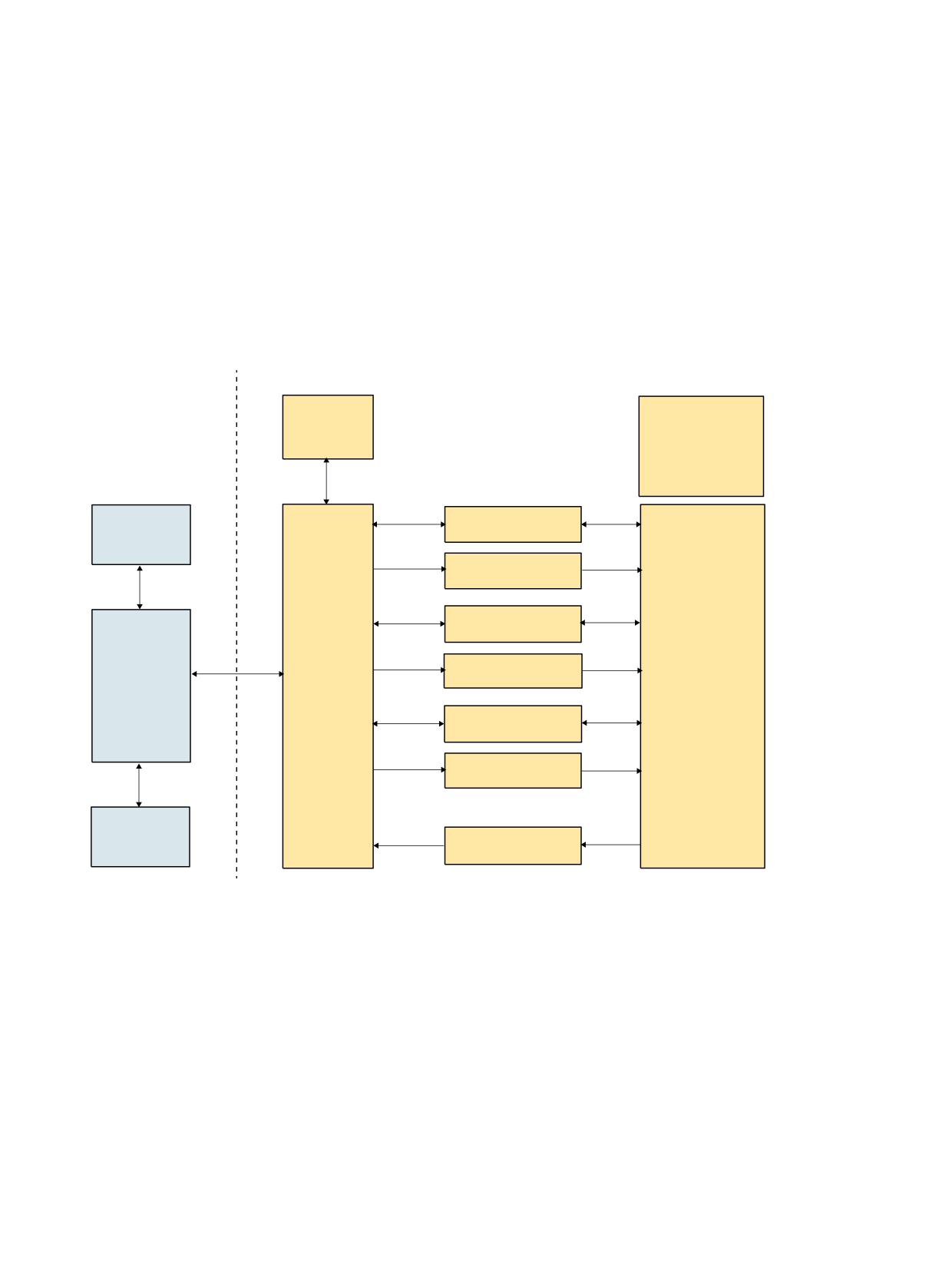
PLC programming
6
6.1
Overview
Overview
1&
3/&
'%
3/& XVHU SURJUDP
,QWHUQDO '% IRU
2%
WRRO PDQDJH
&DOO )%
PHQW
&UHDWH WRRO
PDQDJHPHQW '%V
0DFKLQH GDWD
'% ORDGLQJ XQORDGLQJ
3/& XVHU SURJUDP
FKDLQ ER[ W\SH PDJD]LQH
2%
'%
PXOWLWRRO GDWD
)XQFWLRQV IRU
ORDGLQJ XQORDGLQJ
DQG WRRO FKDQJH
'% FKDQJH SRLQW
VSLQGOH
&DOO )&
7RRO
'%
PXOWLWRRO GDWD
$FNQRZOHGJHPHQW
PDQDJH
%DVLF
VSLQGOH
RI WUDQVIHU VWHSV
PHQW
SURJUDP
)%
'% FKDQJH SRLQW
25
WXUUHW
'%
'%
PXOWLWRRO GDWD
VWDQGDUG HQG
DFNQRZOHGJHPHQW
0DJD]LQH
GDWD
)&
)&
)&
$FNQRZOHGJHPHQW
7UDQVIHU EORFNV
VWDWXV
Figure 6-1
Commissioning the PLC Program
The basic program supplies the tool management interfaces (data blocks DB71-DB73) with
information for the new and old tool. The user must process this data from the active interface
in the user program and ensure that the tools (old and new) are placed on the respectively
associated positions (magazine, location). In order for the tool management to always know
where a tool is located, each time a tool changes location the new location must be transferred
to the tool management via the FC7 or FC8/FC6 acknowledgement status.
Tool management
Function Manual, 10/2020, 6FC5397-1HP40-0BA1
107

PLC programming
6.2 PLC description
6.2
PLC description
6.2.1
Interfaces
Overview
The interfaces in the PLC consist of data blocks that are updated by the basic program. Tasks such
as "Load tool" or "Prepare tool change" are stored for each tool in data blocks along with the
source and target. For the interfaces for a spindle or turret, in addition to the tool numbers
(internal number, which is assigned by the NC when creating a tool), tool size and tool status are
transferred.
If the position of the tool changes (e.g. from magazine to gripper...), the new positions must be
transferred to the tool management on the NC. Three function blocks FC6 (TM_TRANS2), FC7
(TM_REV) and FC8 (TM_TRANS) are provided for this purpose. The PLC programmer can call
these blocks and supply them with the required parameters.
FC18 is available if positioning is performed using an auxiliary axis of the controller.
Commissioning tool management
The precondition for commissioning the PLC is that the NC commissioning has been completed.
The machine data must be correctly and completely set and the magazine configuration loaded.
The basic program sets up the user interface (DB 71 ... DB 73, DB1071 ... DB1073) when it boots.
The information about this - i.e. which magazine, number of loading points - is automatically
entered by the NC. The automatically determined configuration is optionally used or the
configuration runs via data block DB4.
Note
If data blocks DB71...DB73 are already available, the basic program first automatically deletes
them, and then the new data blocks are set up.
Data blocks DB1071 - DB1073 are automatically set up by the basic program for the multitool.
This means that the blocks are also set up if the "Multitool" function has not been set using the
appropriate machine data.
Overview of data blocks
Block number
Length in bytes
Meaning
DB71
4 + 30 BYTE * B
Interface for loading/unloading points
DB72
4 + 48 BYTE * W
Interface for spindle as change position
DB73
4 + 44 BYTE * R
Interface for tool turrets as change position
DB1071
20 BYTE * B
Extended data for the multitool
DB1072
50 BYTE * W
Extended data for the multitool
Tool management
108
Function Manual, 10/2020, 6FC5397-1HP40-0BA1

PLC programming
6.2 PLC description
Block number
Length in bytes
Meaning
DB1073
50 BYTE * R
Extended data for the multitool
DB74
Length depends on configu-
Internal data block for tool management
ration
B = number of loading locations
W= number of spindles as change positions
R= number of turrets
DB71 to DB74 occupy approximately 550 bytes for simple configurations of magazines, buffers
and loading/unloading points.
There is one interface (data record) per data block for each loading/unloading point, spindle and
turret. The data blocks are assigned to the respective tasks.
DB71
DB71 (Page 125) assumes the functions of loading and unloading, positioning and relocating.
The relocating and positioning functions (no matter from which NC channel) are generally
mapped on the 1st interface.
DB72
DB72 (Page 130) is the interface for changing tools into the spindle. This change procedure also
includes preparation of the tool. (Setting: $MC_TOOL_CHANGE_MODE=1)
DB73
DB73 (Page 136) is the interface for tool changes with a circular magazine. (Setting:
$MC_TOOL_CHANGE_MODE=0)
DB1071
DB1071 (Page 141) Loading/unloading the multitool
Loading/unloading, relocating and positioning. The structure is analogous to DB 71.
DB1072
DB72 (Page 142) is the interface for changing tools into the spindle for multitool.
DB1073
DB1073 (Page 146) Loading/unloading with turret for multitool
DB74
DB74 is an internal tool management data block used for communication control. You must not
write to this data block.
Tool management
Function Manual, 10/2020, 6FC5397-1HP40-0BA1
109
PLC programming
6.2 PLC description
For all the interfaces listed here, source and target positions are available for the tools associated
with the machining operation.
FB15 is called in the basic program for communication between the NC and the PLC when tool
management is active. This block informs the user interfaces (DB71 to DB73 and DB1071 to
DB1073) if a tool management function is activated via the part program or operator input.
Interfaces within DB71 to DB73
A bit field for the active/passive status of each interface is contained in bytes 0 and 1 of the
respective data block (DB71 to DB73). DBX 0.0 represents the first interface, DBX 0.1 the second,
etc. A total of 16 interfaces can be addressed. If one of these bits is set to the value = 1 by the tool
management, the associated interface is activated. If set to 0, the interface may not be
processed by the user.
Principle of interfaces DB71-73
No. 8
No. 7
No. 6
No. 5
No. 4
No. 3
No. 2
No. 1
No. 16
No. 15
No. 14
No. 13
No. 12
No. 11
No. 10
No. 9
1st interface
2nd interface
14th interface
15th interface
16th interface
If the value = 1, the user must evaluate the commands at this interface and initiate the necessary
actions (e.g. position magazines, change tools, etc.). After activation, user programmers can
also write access this interface (e.g. in order to delete the "prepare change" bit). Communication
with the tool management is realized exclusively via FC8 or FC7 or FC6, not via DB 71, 72, 73, ...
(the only exception is the fast acknowledgement). For each change to tool positions and/or
status information of an interface request, FC8/FC6 should be called with these modified values.
Further interfaces in the channel interfaces for the ToolMan function
DBD348
T number for tool pre-alarm limit
DBD352
T number for tool limit value
DBD356
T number of the new replacement tool
DBD360
T number of the last replacement tool
Change bits in DBB344
The information can be evaluated within one OB 1 cycle on the basis of a change bit. The PLC can
use this information to derive appropriate measures.
Note
The last replacement tool monitoring must be set in machine data
$MC_TOOL_MANAGEMENT_MASK.
Tool management
110
Function Manual, 10/2020, 6FC5397-1HP40-0BA1

PLC programming
6.2 PLC description
Other signals are as follows:
Channel DB
Tool missing
DBX317.7
from the NC
Do not disable tool (ignore disabled state)
DBX29.7
to the NC
Deactivate wear monitoring
DBX29.6
to the NC
Deactivate workpiece counter
DBX29.5
to the NC
Activate time monitoring by PLC
DBX1.3
to the NC
The function must be set in machine data
$MC_TOOL_MANAGEMENT_MASK
Additional interfaces in the NC interface (DB10) for the tool management function
DB10.DBX105.0
Abort of all tool commands in the NC
The signal is intended for commissioning. While the negative acknowledgment
(status 3) specifically interrupts a command, with DB10.DBX105.0, all NC com-
mands are interrupted, i.e. in all channels.
See also
Signal description of the PLC interface and transfer blocks (Page 124)
6.2.2
Jobs from the NC tool management
Overview
Tasks
Interface
Acknowledgement
Applications, special features
Loading (Page 359)
DB71
FC8/FC6, TaskIdent = 1, TaskIdentNo =
NewToolPlace = target destination of the
interface no.
tool
NewToolMag = target magazine
OldToolPlace = No. of the loading or un-
loading point
OldToolMag = 9999
or:
OldToolMag/OldToolPlace = 0
Status = 1
Unloading (Page 368)
DB71
FC8/FC6, TaskIdent = 1, TaskIdentNo =
NewToolPlace = No. of the loading or un-
interface no.
loading point
NewToolMag = 9999
OldToolPlace = Location of the tool to be
unloaded.
OldToolMag = Magazine No. of the tool to
be unloaded (real or also buffer magazine)
or: OldToolMag/OldToolPlace = 0, status =
1
Tool management
Function Manual, 10/2020, 6FC5397-1HP40-0BA1
111

PLC programming
6.2 PLC description
Tasks
Interface
Acknowledgement
Applications, special features
Relocating (Page 444)
DB71
FC8/FC6, TaskIdent = 1, TaskIdentNo= 1
NewToolPlace = target position of the tool
NewToolMag = target magazine
OldToolPlace source location
OldToolMag = source magazine
Status = 1
Positioning (Page 447)
DB71
FC8/FC6, TaskIdent = 1, TaskIdentNo =
Positioning on loading magazine accord-
interface no.
ing to interface number. Any positioning,
always via interface 1
NewToolPlace = LMG or BL
NewToolMag = 9999 or 9998
OldToolPlace = magazine location to be
positioned
OldToolMag = magazine to be positioned
Status = 5
Prepare change for tool
DB72
FC8/FC6, TaskIdent = 2, TaskIdentNo =
Position NewTL at change point, OldTL re-
in spindle
interface no.
mains in spindle. To complete status 1 in
order that the change command can be
output.
OldToolPlace = BL (spindle)
NewToolPlace = NewTool location
Change in spindle
DB72
FC8/FC6, TaskIdent = 2, TaskIdentNo =
OldTool is unloaded (gripper or directly
interface no.
into magazine), NewTool is loaded to spin-
dle. Status 1 required, so that part pro-
gram processing is continued.
NewToolPlace = BL (spindle)
OldToolPlace = OldTool location
Change with turret
DB73
Normally FC7 or FC8/FC6, TaskIdent = 3,
When turret has finished swiveling, FC 7 is
TaskIdentNo = turret no.
called with turret No. As parameter
ChgdRevNo.
LMG: Loading point
BL: Buffer location
T: Tool
NewToolPlace: FC8/FC6 parameter NewToolMag, NewToolLoc
OldToolPlace: FC8/FC6 parameter OldToolMag, OldToolLoc
Tool management
112
Function Manual, 10/2020, 6FC5397-1HP40-0BA1

PLC programming
6.2 PLC description
6.2.3
Asynchronous transfer
Position changes of tools without task from NC
Tasks
Acknowledgement
Applications, special features
Asynchronous transfer
FC8/FC6, TaskIdent = 4,
General tool transport from the PLC
TaskIdentNo = channel no.
NewToolMag/NewToolLoc = target
Status = 1
OldToolMag/OldToolLoc = source
Asynchronous transfer with location res-
FC8/FC6, TaskIdent = 5,
Tool transport from PLC
ervation for tool transport from a real
TaskIdentNo = channel no.
NewToolMag/NewToolLoc = buffer
magazine into the buffer
Status = 1
OldToolMag/OldToolLoc = source in the
real magazine
Asynchronous transfer without tool
FC8/FC6, TaskIdent = 4,
Communicates the actual magazine po-
movement to align the magazine posi-
TaskIdentNo = channel no.
sition (e.g. after turret cycles) to the NC
tion
Status = 5
NewToolMag/NewToolLoc = actual loca-
tion
OldToolMag/OldToolLoc = change or
loading point
Without NC command: Return OldTool to
FC8/FC6, TaskIdent = 4, TaskIdentNo =
The OldTool may need to be transferred
magazine
channel
asynchronously to the location specified
in the prepare change command to
move the tool from the gripper back to
the magazine.
6.2.4
Definitions of the acknowledgement status
Magazine identifier
Real magazines
The number range from 1 ...9997 is available for the real magazine, defined when generating
the magazine configuration (the numbering must not be ascending).
Buffer magazine
The buffer magazine always has the number 9998. The number of locations in the buffer
magazine is defined using the magazine configuration. The locations with the "spindle / tool
holder" identifier correspond to an interface.
Loading magazine
The loading magazine always has the number 9999. A magazine location corresponds to a
loading point (defined when generating the magazine configuration), every loading point
corresponds to an interface (loading point 1 = interface 1, etc.). Loading point 1 has a special
significance. Every relocation operation, unloading and loading a manual tool and manual
loading, unloading is generally managed via this as basis.
Status value 1 - 10
The status information 1 to 10 (upper limit 10) leads to the command being terminated. As a
consequence, the "active bit" of the interface is reset to 0 and the operation is completed.
Tool management
Function Manual, 10/2020, 6FC5397-1HP40-0BA1
113
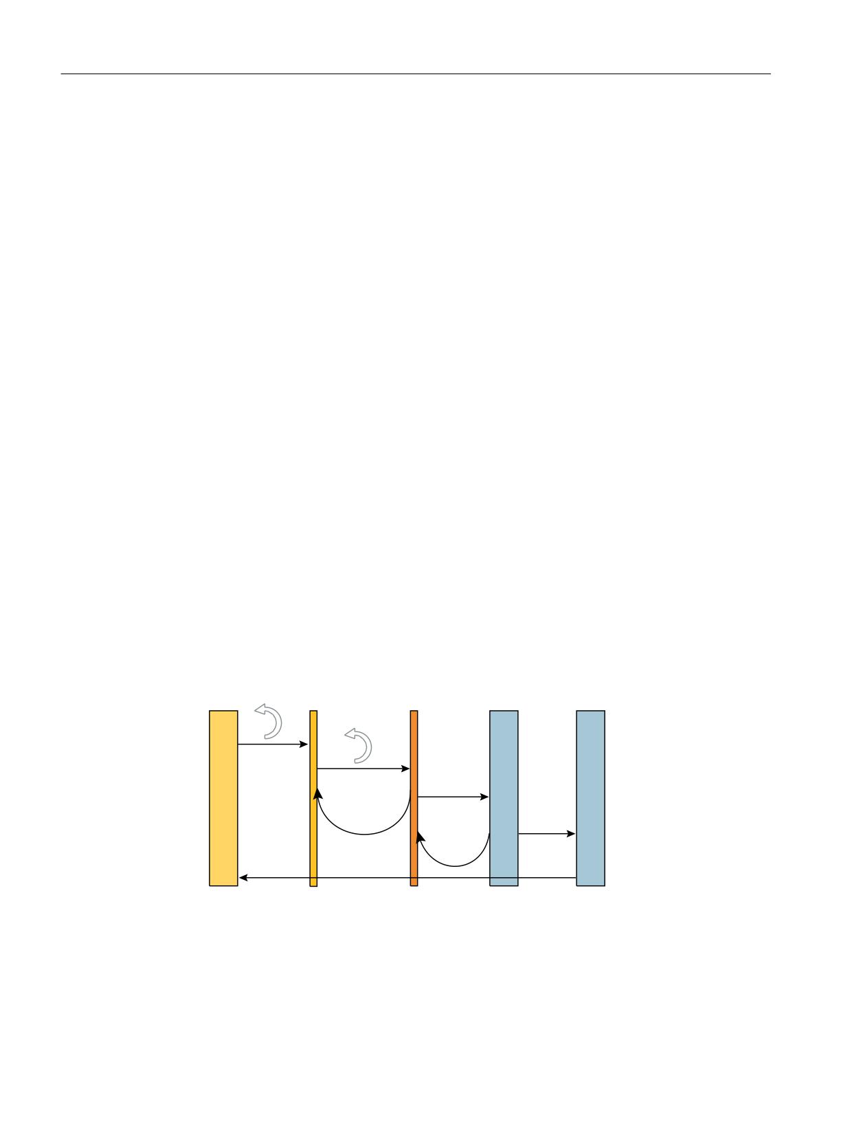
PLC programming
6.2 PLC description
Status value > 100
When acknowledging this status information (FC8/FC6), the "active" bit of the relevant interface
remains at "1". Further processing is required by the user program in the PLC (e.g. continuation
of magazine positioning). This item of status information is generally used to transfer changes
in position of one or both tools while the operation is still in progress.
Synchronization
There are various methods by which the PLC and NC can be synchronized. Synchronization is
forced by MD20310 $MC_ TOOL_MANAGEMENT_MASK using bits 5, 6, 7, 8 and 19. For internal
communication between the PLC and NC, the devices wait for acknowledgement after each
command. Two acknowledgement options are available:
• Transport acknowledgement
The transport acknowledgement indicates to the NC that the issued command has been
accepted by the basic PLC program. Before a new command is output, the system checks
whether the previous command was accepted. If this is not the case, no output is made. The
NC waits for the acknowledgement before a new command is output.
• End acknowledgement
Status feedback signal of the PLC for an NC command that has been accepted with
acknowledgement status 1, 10 or acknowledgement status 3.
Output of the command
Synchronization of the NC and PLC is implemented in three steps:
• The interpolation task from NC has prepared a command on the basis of the programming
and outputs this to the NC-internal image of the VDI interface.
• The NC-internal image of the VDI interface is transferred in the same cycle to the VDI.
• The basic PLC program accepts the command from the VDI interface.
7UDQVSRUW DFNQRZ
OHGJHPHQW JLYHQ"
7UDQVSRUW DFNQRZ
OHGJHPHQW JLYHQ"
&RPPDQG
&RPPDQG
,QWHUQDO WUDQVSRUW
DFNQRZOHGJHPHQW
&RPPDQG
7UDQVSRUW
DFNQRZ
&RPPDQG
OHGJHPHQW
(QG DFNQRZOHGJH
PHQW
1&
1& LQWHUQDO 9',
%DVLF 3/&
3/& XVHU SURJUDP
9',
LPDJH
SURJUDP
,32 7$6.
Figure 6-2
Transport and end acknowledgement
Tool management
114
Function Manual, 10/2020, 6FC5397-1HP40-0BA1
PLC programming
6.2 PLC description
Acknowledgement of output commands
Acknowledgements from the basic PLC program and from the VDI are returned while the
command that has been output is being executed.
• The basic PLC program outputs the transport acknowledgement to the NC once the
command has been accepted.
• An NC-internal transport acknowledgement is issued after the internal VDI image has been
transmitted.
The PLC user program can only process one command at a time. It determines how long it takes
until a command is processed. If the NC provides the command faster than can be processed by
the PLC user program, then the NC is put into the waiting state.
The NC can also output commands which do not originate from the part program over the
interface. Included here are PI services that are synchronously superimposed over the part
program processing.
Completion of the command
Depending on how bits 5-8 and 19 of the MD20310 $MC_TOOL_MNAGEMENT_MASK are set,
the command output is considered to have been completed at various points in time.
• If bit 5 (or bit 6 for the secondary spindle) is set, the command output is completed when the
internal transport acknowledgement and the transport acknowledgement are available. The
command has been accepted by the basic PLC program.
• If bit 7 is set (or 8 for the secondary spindle), this means that the command output is only
completed when the end acknowledgement is received from the PLC.
• If the bits are not set, then the output of the command is considered as being completed
when the NC has output the command to the NC-internal VDI image. This is the default
setting.
Note
From the viewpoint of the tool-change command, the block change can take place as soon
as the NC has output the command.
The set bit 19 in conjunction with set bits 5-8 permit a block change to be prevented as long
as the extended acknowledgements are not present.
Changing the acknowledgement data
When acknowledging a command from the NC, the PLC can change the parameters of this
command in the acknowledgement data.
The following sequence is implemented to allow acknowledged commands from the PLC to be
assigned in the NC:
• Using the ID number in the acknowledgement command (this is tracked by the basic
program), the tool in the NC is determined.
• The data of the current tool location are obtained from the tool.
• This current tool location is checked against the address specified in the command.
Tool management
Function Manual, 10/2020, 6FC5397-1HP40-0BA1
115