SINUMERIK 840D sl. Service - Functions. Manual (2018-2020) - page 90

SINUMERIK Operate user interface
9.1 Configuring the user interface
Creating user-specific texts for the "Machine Functions" window.
If you require an additional possibility of switching on or switching off coolant and tool-specific
functions, then you can program this in the "Program" operating area using the input window
"Machine Functions". You can create the texts and the tooltips for the tool-specific functions
which are used in this window.
Define the texts for the M functions in the file "slstepforms_xxx.ts".
If you require the texts in additional languages, then you must create a separate file for each
language. The only difference in the files is that the file name has the language code "xxx". Use
only the specified language codes.
Further information
Commissioning Manual SINUMERIK Operate; Supported languages
File "slstepforms_xxx.ts "
Tag
Meaning
source
Text identifier for label: SlStepLabels
A maximum of up to four M functions can be defined:
T_LAB_USER_MACHINE_FUNC_1
T_LAB_USER_MACHINE_FUNC_2
T_LAB_USER_MACHINE_FUNC_3
T_LAB_USER_MACHINE_FUNC_4
Text identifier for tooltip: SlStepToolTip
There are 3 tooltips for every machine function x (1 - 4):
T_TT_USER_MACHINE_FUNC_x: standard tooltip if the machine function was not se-
lected.
T_TT_USER_MACHINE_FUNC_x _ON: Tooltip for activated machine function
T_TT_USER_MACHINE_FUNC_x_OFF: Tooltip for deactivated machine function
translation
Text, which is displayed at the user interface.
Label texts: You can only enter texts on one line. The "lines" entry is not applicable.
Tooltip: You can enter multi-line texts. A line break is set using the "%n" character.
chars
Text length
The maximum text length is 30 characters.
lines
Number of lines
The maximum number of lines is three.
remark
Own comment - entry is not displayed at the user interface.
Procedure
1. You can copy the sample file "oem_slstepforms_deu.ts" from the following
directory: /siemens/sinumerik/hmi/template/lng.
2. Save or create the file in the /oem/sinumerik/hmi/lng or /user/sinumerik/hmi/lng directory.
3. Change the file name to "slstepforms_deu.ts".
If you require texts for additional languages, then a separate file must be created for each
language. Save the file with the appropriate language code in the file name.
Tool management
598
Function Manual, 10/2020, 6FC5397-1HP40-0BA1
SINUMERIK Operate user interface
9.1 Configuring the user interface
4. Open the file and define the texts in the <message> and </message> areas.
5. Restart the system.
The file must still be converted into a binary format in order that the texts are displayed during
the program runtime. This data is only converted during power up.
Example of a file "slstepforms_deu.ts"
<?xml version="1.0" encoding="utf-8"?>
<!DOCTYPE TS><TS>
<context>
<name>SlStepLabels</name>
<message>
<source>T_LAB_USER_MACHINE_FUNC_1</source>
<translation>tool-specific function 1</translation>
<chars>20</chars>
</message>
<context>
<name>SlStepToolTip</name>
<!-- tooltips of user machine function 1-->
<message>
<source>T_TT_USER_MACHINE_FUNC_1</source>
<translation>User%nMachine functions 1</translation>
<chars>25</chars>
<lines>3</lines>
</message>
</context
</TS>
9.1.22
Reason for the tool change when reactivating
Function
When reactivating a tool, you have the option of specifying the reason for the tool change, e.g.
to use this information for statistical purposes. The "Reason for Tool Change" selection window
is opened after pressing the "Reactivate" softkey. In a checkbox, you can select the reason for the
tool change. The tool change is entered in a tool parameter to be configured or in a local variable
of the SlCap service.
Tool management
Function Manual, 10/2020, 6FC5397-1HP40-0BA1
599

SINUMERIK Operate user interface
9.1 Configuring the user interface
Tool change reasons
You can adapt or expand the tool change reasons as required. The operating software provides
the following pre-defined texts for the configuration:
Text identifier
Text
TM_DGL_DESIRED_PIECES_ELAPSED
Unit quantity setpoint (desired pieces) elapsed
TM_DGL_TOOL_BREAKAGE
Tool breakage
TM_DGL_CUTTING_EDGE_DAMAGE
Cutting edge damage
TM_DGL_PREMATURE_WEAR
Premature wear
TM_DGL_TYPE_REEQUIPPING
Type reequipping
TM_DGL_TOOL_TRIAL
Tool trial
TM_DGL_PREVENTIVE_CHANGE
Preventive change
<TOOLCHANGEREASON> tag
You configure the function in the <TOOLCHANGEREASON> tag:
Parameter
Designation
Enabled
True - "Reason for tool change" selection window is displayed when reac-
tivating.
False - default value, selection window is not displayed.
OnlyOneReasonAllowed
It is only permissible to select one tool change reason.
UseCapLocalParameter
The reason for the tool change is entered into a local variable of the SlCap
service.
REASONXXX
XXX stands for an internal number. The numbers for the tool change
reason must be clear and unique.
Text
Text identifier of the tool change reason.
Parameter
Parameter identifier of the parameter in which it is entered whether the
tool change reason was selected.
BitMask
Bit mask to enter the reason for the change in the local variable of the
SlCap service. The bit mask is entered as integer value. Bit 0 → 1, bit 1 → 2,
bit 2 → 4
Local variable of the SICap service
The identifier of the local variables is called "/Hmi/ToolEdgeReplacementReason". The variable is
the string type.
The table below lists the most important arguments and their significance:
Argument
Meaning
datetime
Date and time of the event
containerNo
Number of the management area
toaNo
Number of the TO area
toolNo
Tool number
edgeNo
Cutting edge number
toolIdent
Tool name
Tool management
600
Function Manual, 10/2020, 6FC5397-1HP40-0BA1

SINUMERIK Operate user interface
9.1 Configuring the user interface
Argument
Meaning
toolDuplo
Replacement tool number
ncuName
Name of the NCU
reactivationReason
Reason for tool change
monitoringMode
Monitoring type
remainingBefore
Remaining unit quantity/tool lifetime before reactivation
Example 1
The following example uses the texts for the tool change reason, already prepared in the
operating software. In this example, the tool change reason is stored in parameters that still
have to be configured, e.g. the OEM tool data 1, bit 1 and following.
<TOOLCHANGEREASON>
<Enabled value="true" type="bool" />
<REASON1>
<Text value="TM_DGL_DESIRED_PIECES_ELAPSED" type="QString" />
<Parameter value="ToolUser_1_Bit1" type="QString" />
</REASON1>
<REASON2>
<Text value="TM_DGL_TOOL_BREAKAGE" type="QString" />
<Parameter value="ToolUser_1_Bit2" type="QString" />
</REASON2>
<REASON3>
<Text value="TM_DGL_CUTTING_EDGE_DAMAGE" type="QString" />
<Parameter value="ToolUser_1_Bit3" type="QString" />
</REASON3>
<REASON4>
<Text value="TM_DGL_PREMATURE_WEAR" type="QString" />
<Parameter value="ToolUser_1_Bit4" type="QString" />
</REASON4>
<REASON5>
<Text value="TM_DGL_TYPE_REEQUIPPING" type="QString" />
<Parameter value="ToolUser_1_Bit5" type="QString" />
</REASON5>
<REASON6>
<Text value="TM_DGL_TOOL_TRIAL" type="QString" />
<Parameter value="ToolUser_1_Bit6" type="QString" />
</REASON6>
<REASON7>
<Text value="TM_DGL_PREVENTIVE_CHANGE" type="QString" />
<Parameter value="ToolUser_1_Bit7" type="QString" />
</REASON7>
</TOOLCHANGEREASON>
Tool management
Function Manual, 10/2020, 6FC5397-1HP40-0BA1
601
SINUMERIK Operate user interface
9.1 Configuring the user interface
Example 2
Also in this example, the prepared texts for the reason for the change are used. It is only
permitted to enter one reason for the change as a valid entry. The reason for the tool change is
saved in the local variable of the SlCap service.
<TOOLCHANGEREASON>
<Enabled value="true" type="bool" />
<OnlyOneReasonAllowed value="true" type="bool" />
<UseCapLocalParameter value="true" type="bool" />
<REASON1>
<Text value="TM_DGL_DESIRED_PIECES_ELAPSED" type="QString" />
<BitMask value="1" type="int" />
</REASON1>
<REASON2>
<Text value="TM_DGL_TOOL_BREAKAGE" type="QString" />
<BitMask value="2" type="int" />
</REASON2>
<REASON3>
<Text value="TM_DGL_CUTTING_EDGE_DAMAGE" type="QString" />
<BitMask value="4" type="int" />
</REASON3>
<REASON4>
<Text value="TM_DGL_PREMATURE_WEAR" type="QString" />
<BitMask value="8" type="int" />
</REASON4>
<REASON5>
<Text value="TM_DGL_TYPE_REEQUIPPING" type="QString" />
<BitMask value="16" type="int" />
</REASON5>
<REASON6>
<Text value="TM_DGL_TOOL_TRIAL" type="QString" />
<BitMask value="32" type="int" />
</REASON6>
<REASON7>
<Text value="TM_DGL_PREVENTIVE_CHANGE" type="QString" />
<BitMask value="64" type="int" />
</REASON7>
</TOOLCHANGEREASON>
See also
For configuring new parameters, see Configuring list parameters (Page 569).
Tool management
602
Function Manual, 10/2020, 6FC5397-1HP40-0BA1
SINUMERIK Operate user interface
9.1 Configuring the user interface
9.1.23
Configure the code carrier connection
Precondition
Software option
You require the "Tool Ident Connection" option for this function.
Tag <IDENTCONNECTIONCONFIGURATION>
The entries used for configuring the code carrier connection in the tool list of the user interface
are located in the <IDENTCONNECTIONCONFIGURATION> tag. The code carrier connection is
implemented via TDI Ident Connection.
Tool management
Function Manual, 10/2020, 6FC5397-1HP40-0BA1
603
SINUMERIK Operate user interface
9.1 Configuring the user interface
The following functions in the tool list are available:
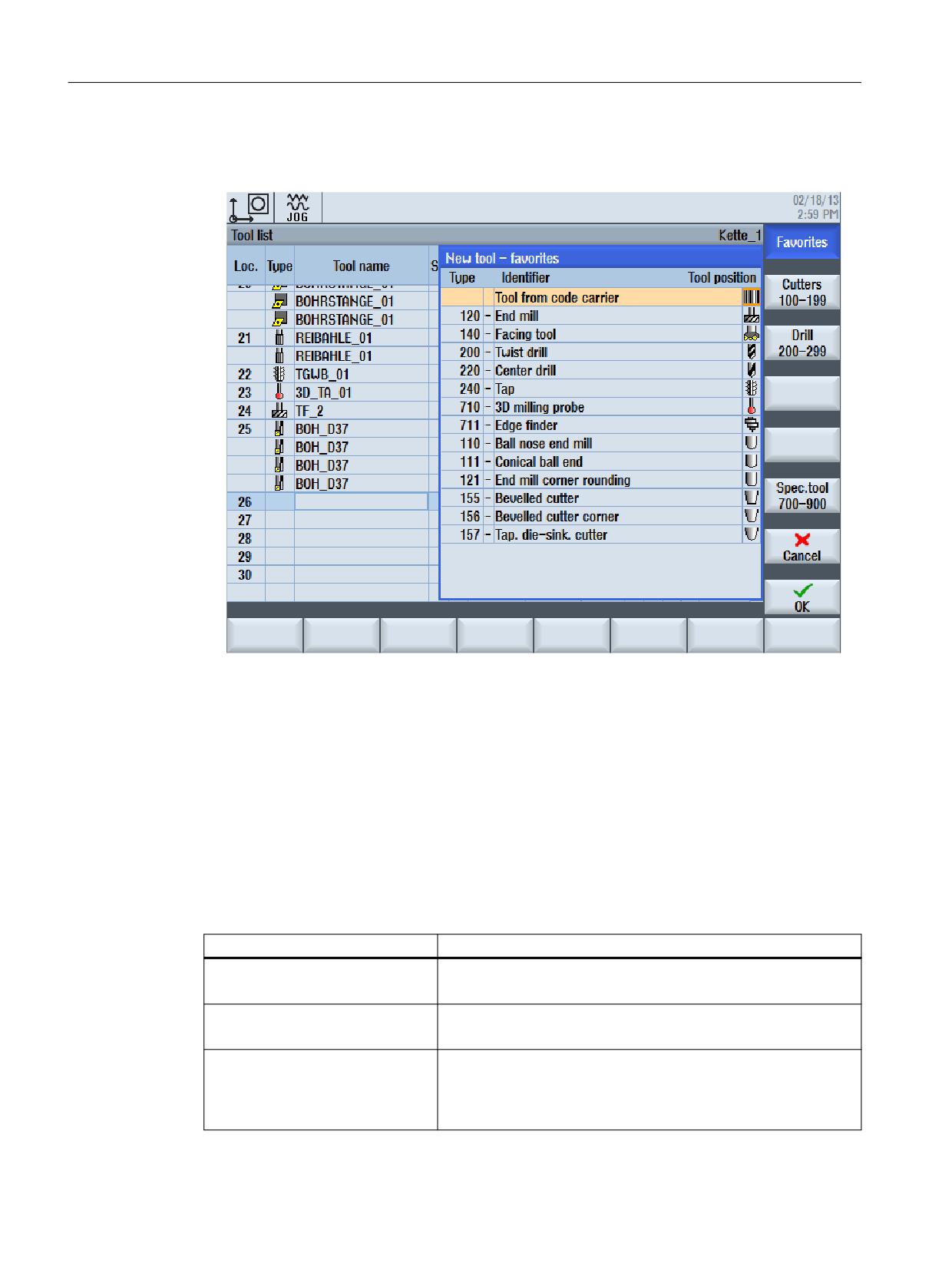
1. Creating tools for the code carrier:
Figure 9-1
New tool from code carrier
The data of the tool are read from the code carrier tool and displayed in the "New Tool"
window. Click OK to create the tool in the NC and to initialize it with the code carrier data.
2. Unloading tools on the code carrier:
The tool is unloaded and the data of the tool is written to the code carrier. The tool can also
be deleted using a setting (see below).
3. Deleting the tool on the code carrier:
The tool is unloaded and the data of the tool is written to the code carrier. The tool is then
deleted from the NC. Using a setting (see below), the "On code carrier" softkey can also be
hidden for deleting a tool.
The following settings can be made:
Entries
Meaning
Enabled
true - Code carrier connection is offered.
false - Code carrier connection is not offered.
ShowInternalMessage
true - Internal messages for error analysis are also displayed.
false - Default setting. No internal messages are displayed.
UnloadWithoutIdentconnection
true - The "On code carrier" function is not offered during unload-
ing. It is only displayed during "Delete tool."
false - Default setting. The "On code carrier" function is offered
during unloading.
Tool management
604
Function Manual, 10/2020, 6FC5397-1HP40-0BA1

SINUMERIK Operate user interface
9.1 Configuring the user interface
Entries
Meaning
UnloadWithDelete
true - The tool is deleted when unloaded to the code carrier. The
"on code carrier" function is not offered for "Delete tool".
false - Default setting. The tool is only unloaded for "Unload to code
carrier" and remains in the NC memory.
OnlyInLoadStation
true - Default setting. Only loaded tools are stored "on code carri-
er"; new tools "from code carrier" can only be created directly in the
magazine.
false - Tools can be created independently of the "from code carri-
er" magazine slot or deleted "on code carrier".
CreateNewToolWithDialog
true - Default setting. Before creating the tool from code carrier,
the tool data is displayed in the "New tool" window.
false - The tool is created directly in the tool list.
ForceSisterToolNumber
true - The sister tool number specified by the code carrier data is
retained when the tool is created.
false - Default setting. The sister tool number is freely assigned.
UseDefaultData
true - The new tool is initialized with the configured default data
before the code carrier data are applied (see tag <NEWTOOLDE-
FAULTVALUECONFIGURATION> Section "Configuring default val-
ues for new tools (Page 581)").
false - Default setting. The new tool is not initialized with the con-
figured default data.
OrderFirstWriteThanUnload
true - During unloading/deletion, the data are first written to the
code carrier and then the tool is unloaded or deleted.
false - Default setting. During unloading/deletion the tool is first
unloaded, then the data are written to the code carrier and finally,
if requested, the tool is deleted.
Example
<IDENTCONNECTIONCONFIGURATION>
<Enabled value="true" type="bool" />
<ShowInternalMessage value="false" type="bool" />
<UnloadWithDelete value="false" type="bool" />
<OnlyInLoadStation value="true" type="bool" />
<CreateNewToolWithDialog value="true" type="bool" />
</IDENTCONNECTIONCONFIGURATION>
More information
More information about tool management with code carriers can be found at Code carrier
connection - Tool Ident Connection (option) (Page 625).
Tool management
Function Manual, 10/2020, 6FC5397-1HP40-0BA1
605
SINUMERIK Operate user interface
9.1 Configuring the user interface
9.1.24
Configuring Save to file
<SAVETOOLDATACONFIGURATION> tag
The entries used for configuring the functions "Save tools to file" or "Create tools from file" are
located in the <SAVETOOLDATACONFIGURATION> tag:
The following functions in the tool list are available:
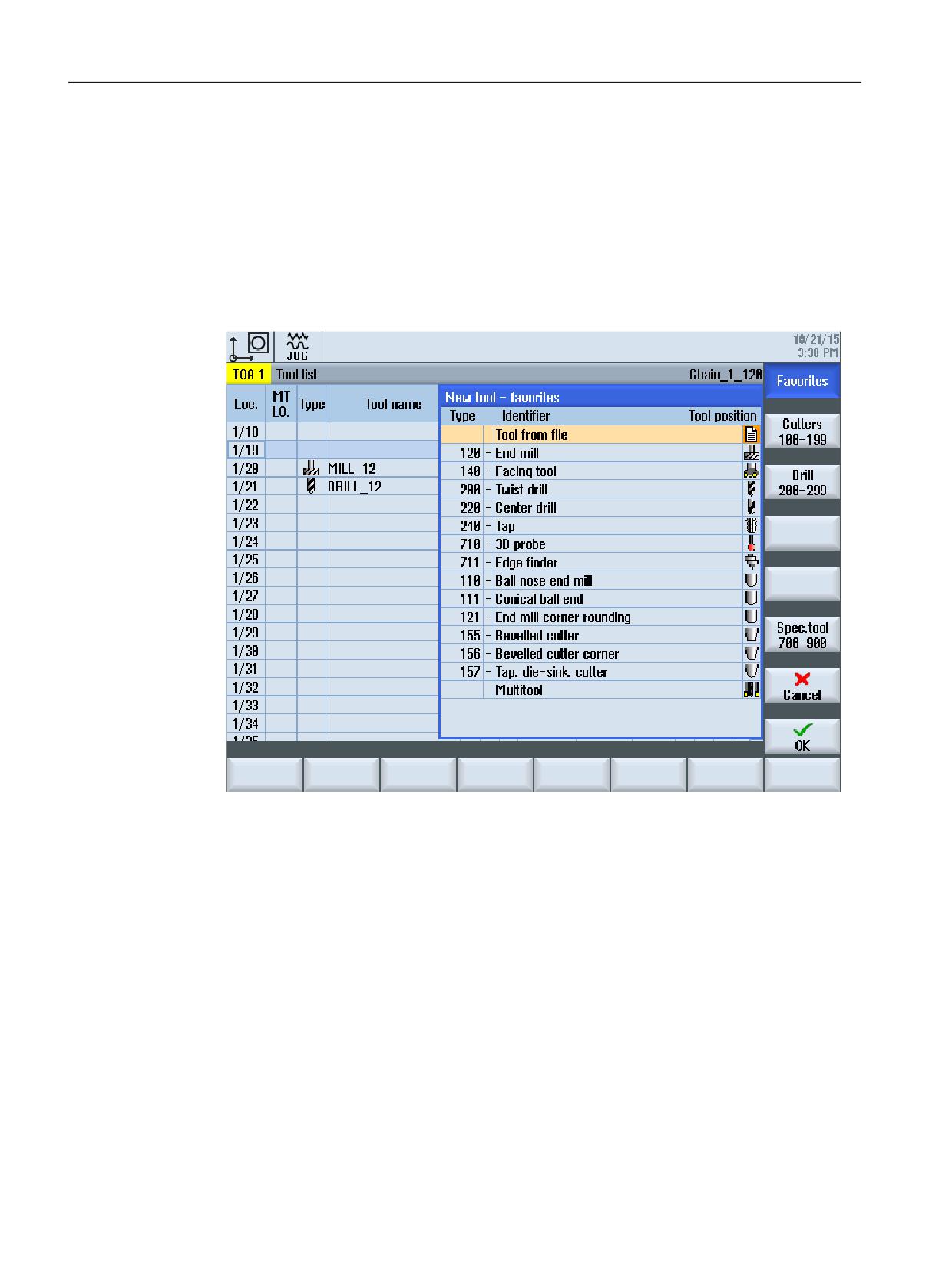
1. Creating tools from file:
Figure 9-2
Tool from file
The data of the tool are read from a file and displayed in the "New Tool" window. Click OK to
create the tool in the NC and to initialize it with the data from the file.
2. Unloading tools into a file:
The tool is unloaded and the data of the tool are written to a file. The tool can also be deleted
using a setting (see below).
3. Deleting the tool in a file:
The tool is unloaded and the data of the tool are written to a file. The tool is then deleted from
the NC. The softkey "In File" can be hidden while the tool is deleted by means of a setting (see
below).
Tool management
606
Function Manual, 10/2020, 6FC5397-1HP40-0BA1

SINUMERIK Operate user interface
9.1 Configuring the user interface
The following settings can be made:
Entries
Meaning
Enabled
true - Tool from/in file is offered.
false - Tool from/in file is not offered.
UnloadWithDelete
true - The tool is deleted when unloaded to a file. The "In File" function is
not offered for "Delete tool."
false - Default setting, on Unload to file the tool is only unloaded and is
kept in the NC memory.
CreateNewToolWithDialog
true - Default setting, before the tool is created from a file, the tool data is
displayed in the "New Tool" window.
false - The tool is created directly in the tool list.
ForceSisterToolNumber
true - The sister tool number specified by the code carrier data is kept when
the tool is created.
false - Default setting, the sister tool number is freely assigned.
UseDefaultData
true - The new tool is initialized with the configured default data before the
data are taken over from the file (see tag <NEWTOOLDEFAULTVALUECON-
FIGURATION> Section "Configuring default values for new tools
(Page 581)").
false - Default setting, the new tool is not initialized with the configured
default data.
Tool management
Function Manual, 10/2020, 6FC5397-1HP40-0BA1
607

SINUMERIK Operate user interface
9.2 Creating OEM texts
9.2
Creating OEM texts
Overview
This section describes how you create OEM texts in a particular language.
The texts are created in the "sltmlistdialog_xxx.ts" file.
A dedicated file must be created for each language. The file names differ by the language code.
For "xxx", set the appropriate language code.
Further information
Commissioning Manual SINUMERIK Operate; Supported languages
Creating texts
All OEM texts from the previous sections, such as the tooltip, can be made language-dependent
by using the OEM text as text identifier under the "source" tag. The translation of the text in the
particular language is entered under the "translation" tag.
Entries
Meaning
source
Text identifier
See 1. Example: Single-line text with new text identifier "MY_NEW_TEXT".
See 2. Example: Double-line text with new text identifier "MY_NEW_TEXT_2_LINES".
translation
Text, which is displayed on the user interface.
You can enter single and multi-line texts. "%n" is used to indicate a line break.
See 1. Example: Single-line text "My new text" is displayed.
See 2. Example: Double-line text "My new - text" is displayed.
chars
Text length
See 1. Example: Text length of 30 characters is specified.
See 2. Example: Text length of 10 characters per line is specified.
lines
Number of lines
See 2. Example: The number of rows is 2.
remark
Own comments - are not displayed.
Procedure
1. You can copy the sample file "oem_sltmlistdialog_eng.ts" from the following
directory: /siemens/sinumerik/hmi/template/lng.
2. Save the file in the /oem/sinumerik/hmi/lng or /user/sinumerik/hmi/lng directory.
3. Change the file name to "sltmlistdialog_eng.ts".
If you wish to create texts for additional languages, then a separate file must be created for
each language. Save the file with the appropriate language code in the file name.
4. Open the file and define the texts in the <message> and </message> areas.
5. Restart the system.
The file must still be converted into a binary format in order that the texts are displayed during
the program runtime. This data is only converted during power up.
Tool management
608
Function Manual, 10/2020, 6FC5397-1HP40-0BA1

SINUMERIK Operate user interface
9.2 Creating OEM texts
9.2.1
Identifiers of the standard texts
Identifiers of the standard texts
With the help of the identifiers, you can change the standard texts of OEM parameters, coolants
and tool-specific functions. This applies to the column header in the tool lists, the tooltip and, if
available, also the designation in the detail displays.
A list of the text identifiers is provided below:
OEM tool parameters
"ToolUser_1" to "ToolUser_10"
"ToolAppl_1" to "ToolAppl_10"
Text identifier of the column heading
Text identifier of the tooltip
TM_HL_TOOL_USER_1 to ...10
TM_TT_TOOL_USER_1 to ...10
TM_HL_TOOL_APPL_1 to ...10
TM_TT_TOOL_APPL_1 to ...10
Text identifiers in tool details
Text identifiers in tool details - all parameters
TM_HL_TOOL_USER_1_DETAILS to ...10_DETAILS
TM_HL_TOOL_USER_1_LONG to ...10_LONG
TM_HL_TOOL_APPL_1_DETAILS to ...10_DETAILS
TM_HL_TOOL_APPL_1_LONG to ...10_LONG
OEM cutting edge parameters
"EdgeUser_1" to "EdgeUser_10"
"EdgeAppl_1" to "EdgeAppl_10"
Text identifier of the column heading
Text identifier of the tooltip
TM_HL_EDGE_USER_1 to ...10
TM_TT_EDGE_USER_1 to ...10
TM_HL_EDGE_APPL_1 to ...10
TM_TT_EDGE_APPL_1 to ...10
Text identifiers in tool details
Text identifiers in tool details - all parameters
TM_HL_EDGE_USER_1_DETAILS to ...10_DETAILS
TM_HL_EDGE_USER_1_LONG to ...10_LONG
TM_HL_EDGE_APPL_1_DETAILS to ...10_DETAILS
TM_HL_EDGE_APPL_1_LONG to ...10_LONG
OEM monitoring parameters
"EdgeSupUser_1" to "EdgeSupUser_10"
"EdgeSupAppl_1" to "EdgeSupAppl_10"
Text identifier of the column heading
Text identifier of the tooltip
TM_HL_EDGE_SUPUSER_1 to ...10
TM_TT_EDGE_SUPUSER_1 to ...10
TM_HL_EDGE_SUPAPPL_1 to ...10
TM_TT_EDGE_SUPAPPL_1 to ...10
Tool management
Function Manual, 10/2020, 6FC5397-1HP40-0BA1
609

SINUMERIK Operate user interface
9.2 Creating OEM texts
Text identifiers in tool details
Text identifiers in tool details - all parameters
TM_HL_EDGE_SUPUSER_1_DETAILS to ...10_DETAILS
TM_HL_EDGE_SUPUSER_1_LONG to ...10_LONG
TM_HL_EDGE_SUPAPPL_1_DETAILS to ...10_DETAILS
TM_HL_EDGE_SUPAPPL_1_LONG to ...10_LONG
OEM multitool parameters
"MultiToolUser_1" to "MultiToolUser_10"
"MultiToolAppl_1" to "MultiToolAppl_10"
Text identifier of the column heading
Text identifier of the tooltip
TM_HL_MULTITOOL_USER_1 to ...10
TM_TT_MULTITOOL_USER_1 to ...10
TM_HL_MULTITOOL_APPL_1 to ...10
TM_TT_MULTITOOL_APPL_1 to ...10
Text identifiers in tool details
Text identifiers in tool details - all parameters
TM_HL_MULTITOOL_USER_1_DETAILS
TM_HL_MULTITOOL_USER_1_LONG to ...10_LONG
to ...10_DETAILS
TM_HL_MULTITOOL_APPL_1_DETAILS
TM_HL_MULTITOOL_APPL_1_LONG to ...10_LONG
to ...10_DETAILS
OEM magazine location parameters
"MagPlaceUser_1" to "MagPlaceUser_10"
"MagPlaceAppl_1" to "MagPlaceAppl_10"
Text identifier of the column heading
Text identifier of the tooltip
TM_HL_MAGPLACE_USER_1 to ...10
TM_TT_MAGPLACE_USER_1 to ...10
TM_HL_MAGPLACE_APPL_1 to ...10
TM_TT_MAGPLACE_APPL_1 to ...10
OEM multitool location parameters
"MultiToolPlaceUser_1" to "MultiToolPlaceUser_10"
"MultiToolPlaceAppl_1" to "MultiToolPlaceAppl_10"
Text identifier of the column heading
Text identifier of the tooltip
TM_HL_MTPLACE_USER_1 to ...10
TM_TT_MTPLACE_USER_1 to ...10
TM_HL_MTPLACE_APPL_1 to ...10
TM_TT_MTPLACE_APPL_1 to ...10
Coolant and tool-specific functions
"Coolant1" and "Coolant2"
Tool management
610
Function Manual, 10/2020, 6FC5397-1HP40-0BA1

SINUMERIK Operate user interface
9.2 Creating OEM texts
"MFunction1" to "MFunction4"
Text identifier of the column heading
Text identifier of the tooltip
No column
TM_TT_STATE_COOL_1 and ...2
TM_HL_MFCT1 to ...4
TM_TT_MFCT1 to ...4
9.2.2
Examples of OEM texts
Example 1 with a single-line and double-line text
<?xml version="1.0" encoding="UTF-8"?>
<!DOCTYPE TS><TS>
<!--
************************************************************ -->
<!--
Definition of OEM texts
<!--
************************************************************ -->
<context>
<name>SlTmListForm</name>
<!--
************************************************************ -->
<!--
enter your text behind this comment -->
<!--
************************************************************ -->
<!--
************************************************************ -->
<!--
1st example of a single-line text -->
<!--
************************************************************ -->
<!-- <message>
<source>MY_NEW_TEXT</source>
<translation>My new text</translation>
<chars>30</chars>
</message>-->
<!--
************************************************************ -->
<!--
2nd example of a double-spaced text -->
<!--
************************************************************ -->
<!--
<message>
<source>MY_NEW_TEXT_2_LINES</source>
<translation>My new%n text</translation>
<remark>My comment to the text</remark>
<chars>10</chars>
<lines>2</lines>
</message>-->
<!--
************************************************************ -->
<!--
enter your text ahead of this comment -->
<!--
************************************************************ -->
</context>
</TS>
Tool management
Function Manual, 10/2020, 6FC5397-1HP40-0BA1
611
SINUMERIK Operate user interface
9.2 Creating OEM texts
Example 2
A new parameter is configured in the following example from Section Configuring list
parameters (Page 569):
<PARAMETERCONFIGURATION>
<EdgeUser_1_Bit0>
<Base value="EdgeUser_1" type="QString" />
<ItemType value="CheckBox" type="QString" />
<DisplayMode value="AnyMode" type="QString" />
<BitMask value="1" type="int" />
<Width value="17" type="int" />
<HeadLine value="TM_HL_EDGE_USER_1_Bit0" type="QString" />
<ToolTip value="TM_TT_EDGE_USER_1_Bit0" type="QString" />
</EdgeUser_1_Bit0>
</PARAMETERCONFIGURATION>
The two texts under HeadLine and ToolTip should be output depending on the language. To do
this, the two text identifiers must be included in the sltmlistdialog_xxx.ts file:
<?xml version="1.0" encoding="UTF-8"?>
<!DOCTYPE TS><TS>
<!--
************************************************************ -->
<!--
Definition of OEM texts
<!--
************************************************************ -->
<context>
<name>SlTmListForm</name>
<!--
************************************************************ -->
<!--
enter your text behind this comment -->
<!--
************************************************************ -->
<!--
************************************************************ -->
<!--
Translate the text for the headline -->
<!--
************************************************************ -->
<message>
<source>TM_HL_EDGE_USER_1_Bit0</source>
<translation>heavy %n tool</translation>
<chars>10</chars>
<lines>2</lines>
</message>
<!--
************************************************************ -->
<!--
Translate the text for the tooltip -->
<!--
************************************************************ -->
<message>
<source>TM_TT_EDGE_USER_1_Bit0</source>
<translation>heavy tool</translation>
<chars>20</chars>
</message>
Tool management
612
Function Manual, 10/2020, 6FC5397-1HP40-0BA1
SINUMERIK Operate user interface
9.2 Creating OEM texts
<!--
************************************************************ -->
<!--
enter your text ahead of this comment -->
<!--
************************************************************ -->
</context>
</TS>
Tool management
Function Manual, 10/2020, 6FC5397-1HP40-0BA1
613
SINUMERIK Operate user interface
9.3 Examples
9.3
Examples
9.3.1
Example: Configuring an OEM tool list
9.3.1.1
Adapting the configuration file
The following excerpt shows the contents of the configuration file:
• Milling technology: sltmlistconfig.xml
• Turning technology: sltmturninglistconfig.xml
The file in this example is stored in the "user/sinumerik/hmi/cfg" directory.
This example describes a configuration of the OEM tool list.
• OEM tool parameter 1 is displayed in column 6.
• A new "Coolant 3" parameter is inserted in column 7 that displays bit 0 from OEM tool
parameter 2.
• OEM cutting edge parameter 1 is displayed in column 8.
Example
"sltmlistconfig.xml" or "sltmturninglistconfig.xml" file:
<?xml version="1.0" encoding="UTF-8" standalone="yes"?>
<CONFIGURATION>
<!-- **** Identifier for the configuration of the lists *** -->
<LISTCONFIGURATION>
<!-- **** OEM tool list *** -->
<SlTmTooloemForm>
<!-- **** Enabling the OEM tool list *** -->
<Enabled value="true" type="bool" />
<!-- **** Columns 1 to 5 have already been assigned default values. *** -->
<!-- **** Column 6 *** -->
<COLUMN6>
<!-- **** For all tool types *** -->
<TOOLTYPE_ALL>
<!-- **** Display OEM tool parameter 1 *** -->
<Item value="ToolUser_1" type="QString" />
</TOOLTYPE_ALL>
</COLUMN6>
<!-- **** Column 7 *** -->
<COLUMN7>
<!-- **** For all tool types *** -->
<TOOLTYPE_ALL>
Tool management
614
Function Manual, 10/2020, 6FC5397-1HP40-0BA1
SINUMERIK Operate user interface
9.3 Examples
<!-- **** Priority tool, own parameter *** -->
<!-- **** Display OEM tool parameter 2 bit 0 *** -->
<Item value="PriorTool" type="QString" />
</TOOLTYPE_ALL>
</COLUMN7>
<!-- **** Column 8 *** -->
<COLUMN8>
<!-- **** For all tool types *** -->
<TOOLTYPE_ALL>
<!-- **** Display OEM cutting edge parameter 1 *** -->
<Item value="EdgeUser_1" type="QString" />
</TOOLTYPE_ALL>
</COLUMN8>
</SlTmTooloemForm>
</LISTCONFIGURATION>
<!-- **** Identifier for the configuration of own parameter *** -->
<PARAMETERCONFIGURATION>
<!-- **** Change OEM tool parameter 1 *** -->
<ToolUser_1>
<!-- **** Column width *** -->
<Width value="36" type="int" />
<!-- **** Type change to unsigned integer *** -->
<DisplayMode value="UnsignedIntegerMode" type="QString" />
</ToolUser_1>
<!-- **** Identifier of own parameter *** -->
<!-- **** Priority tool *** -->
<PriorTool>
<!-- ** New parameter is based on OEM tool parameter 2**-->
<Base value="ToolUser_2" type="QString" />
<!-- **** Bit 0 is evaluated *** -->
<BitMask value="1" type="int" />
<!-- **** Text identifier of the headline *** -->
<HeadLine value="TMO_HL_PRIOR_TOOL" type="QString" />
<!-- **** Text identifier of the tooltip *** -->
<ToolTip value="TMO_TT_PRIOR_TOOL" type="QString" />
<!-- **** Column width *** -->
<!-- **** Recommended widths 640x480 - 19 pixels *** -->
<!-- **** 800x600 - 21, 1024x768 - 17 *** -->
<Width value="19" type="int" />
<!-- **** Display item of the parameter *** -->
<ItemType value="CheckBox" type="QString" />
</PriorTool>
</PARAMETERCONFIGURATION>
</CONFIGURATION>
Tool management
Function Manual, 10/2020, 6FC5397-1HP40-0BA1
615
SINUMERIK Operate user interface
9.3 Examples
9.3.1.2
Adaptation of the customer text file
The following excerpt shows the contents of the "sltmlistdialog_eng.ts" customer text file.
The file in this example is stored in the "user/sinumerik/hmi/lng" directory.
Example
"sltmlistdialog_eng.ts" file:
<?xml version="1.0" encoding="UTF-8"?>
<!DOCTYPE TS><TS>
<!-- ************************************************************** -->
<!-- Definition of OEM texts
-->
<!-- ************************************************************** -->
<context>
<name>SlTmListForm</name>
<!-- ************************************************************** -->
<!-- Enter your text behind this comment
-->
<!-- ************************************************************** -->
<!-- **** OEM tool parameter 1 headline *** -->
<!-- **** Weight *** -->
<message>
<!-- **** Text identifier *** -->
<source>TM_HL_TOOL_USER_1</source>
<!-- **** Text that is output *** -->
<translation>%nweight</translation>
<!-- **** Comment only for the translator *** -->
<remark>priority tool</remark>
<!-- **** Maximum line length in characters *** -->
<!-- **** only for the translator *** -->
<chars>7</chars>
<!-- **** Number of possible lines *** -->
<!-- **** only for the translator *** -->
<lines>2</lines>
</message>
<!-- **** OEM tool parameter 1 tooltip *** -->
<!-- **** weight *** -->
<message>
<source>TM_TT_TOOL_USER_1</source>
<translation>weight of the tool</translation>
<chars>35</chars>
<lines>2</lines>
Tool management
616
Function Manual, 10/2020, 6FC5397-1HP40-0BA1
SINUMERIK Operate user interface
9.3 Examples
</message>
<!-- **** title for user's parameters *** -->
<!-- **** priority tool *** -->
<message>
<source>TMO_HL_PRIOR_TOOL</source>
<translation>V</translation>
<remark>priority tool</remark>
<chars>1</chars>
<lines>2</lines>
</message>
<!-- **** to for user's parameters *** -->
<!-- **** Priority tool *** -->
<message>
<source>TMO_TT_PRIOR_TOOL</source>
<translation>priority tool, %nuse tool preferably< /translation>
<chars>35</chars>
<lines>3</lines>
</message>
<!-- **** OEM cutting edge parameter 1 headline *** -->
<!-- **** Maximum tool width *** -->
<message>
<source>TM_HL_EDGE_USER_1</source>
<translation>maximum%nwidth</translation>
<chars>8</chars>
<lines>2</lines>
</message>
<!-- **** OEM cutting edge parameter 1 tooltip *** -->
<!-- **** Maximum tool width *** -->
<message>
<source>TM_TT_EDGE_USER_1</source>
<translation>maximum width%nof the tool%noverall</translation>
<chars>35</chars>
<lines>2</lines>
</message>
<!-- ************************************************************** -->
<!-- Enter your text ahead of this comment
-->
<!-- ************************************************************** -->
</context>
</TS>
Tool management
Function Manual, 10/2020, 6FC5397-1HP40-0BA1
617
SINUMERIK Operate user interface
9.3 Examples
9.3.2
Example: Configuring magazine location types with names
9.3.2.1
Adapting the configuration file
The following excerpt shows the contents of the configuration file:
• Milling technology: sltmlistconfig.xml
• Turning technology: sltmturninglistconfig.xml
The file in this example is stored in the "user/sinumerik/hmi/cfg" directory.
This example describes a configuration of the location types in the magazine list.
In this example, the magazine location type and the tool location type are to be displayed as a
toggle field with plain texts.
The assignment of the parameters to the columns of the list is made in the
"LISTCONFIGURATION" area. The magazine location type is displayed in column 10. The tool
location type is displayed in column 11.
The texts to the location types are assigned in the "PLACETYPECONFIGURATION" area. The
number of the location type is the number at the end of the "PLACETYPE" identifier.
A text identifier for a toggle box entry and a text identifier for a tooltip can be stored for each
location type.
Example
"sltmlistconfig.xml" or "sltmturninglistconfig.xml" file:
<?xml version="1.0" encoding="UTF-8" standalone="yes"?>
<CONFIGURATION>
<!-- **** Configuration of the lists *** -->
<LISTCONFIGURATION>
<!-- **** Magazine list *** -->
<SlTmToolmagazinForm>
<!-- **** Column 10 *** -->
<COLUMN10>
<!-- **** For all tool types *** -->
<TOOLTYPE_ALL>
<!-- **** Display magazine location type *** -->
<Item value="MagPlaceTypeIdent" type="QString" />
</TOOLTYPE_ALL>
</COLUMN10>
<!-- **** Column 11 *** -->
<COLUMN11>
<!-- **** For all tool types *** -->
<TOOLTYPE_ALL>
<!-- **** Display tool location type *** -->
<Item value="ToolPlaceSpecIdent" type="QString" />
</TOOLTYPE_ALL>
Tool management
618
Function Manual, 10/2020, 6FC5397-1HP40-0BA1
SINUMERIK Operate user interface
9.3 Examples
<!-- **** For all multitools *** -->
<TOOLTYPE_9997>
<!-- **** Display for all multitool location types *** -->
<Item value="MultiToolPlaceSpecIdent" type="QString" />
</TOOLTYPE_9997>
</COLUMN11>
</SlTmToolmagazinForm>
</LISTCONFIGURATION>
<!-- **** Configuration of the magazine location types *** -->
<PLACETYPECONFIGURATION>
<!-- **** Magazine location type 1 *** -->
<PLACETYPE1>
<!-- **** Text identifier of the toggle box entry *** -->
<Text value="TMMP_ITEM_NORMAL_TOOL" type="QString" />
<!-- **** Text identifier of the tooltip *** -->
<Tooltip value="TMMP_TT_NORMAL_TOOL" type="QString" />
</PLACETYPE1>
<!-- **** Magazine location type 2 *** -->
<PLACETYPE2>
<Text value="TMMP_ITEM_HEAVY_TOOL" type="QString" />
<Tooltip value="TMMP_TT_HEAVY_TOOL" type="QString" />
</PLACETYPE2>
<!-- **** Magazine location type 3 *** -->
<PLACETYPE3>
<Text value="TMMP_ITEM_BIG_TOOL" type="QString" />
<Tooltip value="TMMP_TT_BIG_TOOL" type="QString" />
</PLACETYPE3>
<!-- **** Magazine location type 4 *** -->
<PLACETYPE4>
<Text value="TMMP_ITEM_SENSITIVE_TOOL" type="QString" />
<Tooltip value="TMMP_TT_SENSITIVE_TOOL" type="QString" />
</PLACETYPE4>
</PLACETYPECONFIGURATION>
</CONFIGURATION>
9.3.2.2
Adaptation of the customer text file
The following excerpt shows the contents of the "sltmlistdialog_eng.ts" customer text file.
The file in this example is stored in the "user/sinumerik/hmi/lng" directory.
Tool management
Function Manual, 10/2020, 6FC5397-1HP40-0BA1
619
SINUMERIK Operate user interface
9.3 Examples
Example
"sltmlistdialog_eng.ts" file:
<?xml version="1.0" encoding="UTF-8"?>
<!DOCTYPE TS><TS>
<!-- ************************************************************** -->
<!-- Definition of OEM texts
-->
<!-- ************************************************************** -->
<context>
<name>SlTmListForm</name>
<!-- ************************************************************** -->
<!-- Enter your text behind this comment
-->
<!-- ************************************************************** -->
<!-- **** Magazine location type 1 item *** -->
<!--
**** Normal tool *** -->
<message>
<!-- **** Text identifier *** -->
<source>TMMP_ITEM_NORMAL_TOOL</source>
<!-- **** Text that is output *** -->
<translation>normal</translation>
<!-- **** Maximum line length in characters *** -->
<!-- **** only for the translator *** -->
<chars>9</chars>
</message>
<!-- **** Magazine location type 1 tooltip *** -->
<!-- **** Normal tool *** -->
<message>
<source>TMMP_TT_NORMAL_TOOL</source>
<translation>normal tool,%nno restrictions</translation>
<chars>35</chars>
<lines>2</lines>
</message>
<!-- **** Magazine location type 2 item *** -->
<!-- **** Heavy tool *** -->
<message>
<source>TMMP_ITEM_HEAVY_TOOL</source>
<translation>heavy</translation>
<chars>9</chars>
</message>
<!-- **** Magazine location type 2 tooltip *** -->
<!-- **** Heavy tool *** -->
<message>
Tool management
620
Function Manual, 10/2020, 6FC5397-1HP40-0BA1
SINUMERIK Operate user interface
9.3 Examples
<source>TMMP_TT_HEAVY_TOOL</source>
<translation>heavy tool</translation>
<chars>35</chars>
<lines>2</lines>
</message>
<!-- **** Magazine location type 3 item *** -->
<!-- **** Big tool *** -->
<message>
<source>TMMP_TT_BIG_TOOL</source>
<translation>big</translation>
<chars>9</chars>
</message>
<!-- **** Magazine location type 3 tooltip *** -->
<!-- **** Big tool *** -->
<message>
<source>TMMP_TT_BIG_TOOL</source>
<translation>big tool</translation>
<chars>35</chars>
<lines>2</lines>
</message>
<!-- **** Magazine location type 4 item *** -->
<!-- **** Sensitive tool *** -->
<message>
<source>TMMP_ITEM_SENSITIVE_TOOL</source>
<translation>sensitive</translation>
<chars>9</chars>
</message>
<!-- **** Magazine location type 4 tooltip *** -->
<!-- **** Sensitive tool *** -->
<message>
<source>TMMP_TT_SENSITIVE_TOOL</source>
<translation>Notice: Tool can%nbe destroyed easily</translation>
<chars>35</chars>
<lines>2</lines>
</message>
<!-- ************************************************************** -->
<!-- Enter your text ahead of this comment
-->
<!-- ************************************************************** -->
</context>
</TS>
Tool management
Function Manual, 10/2020, 6FC5397-1HP40-0BA1
621
SINUMERIK Operate user interface
9.4 Working with two tool holders
9.4
Working with two tool holders
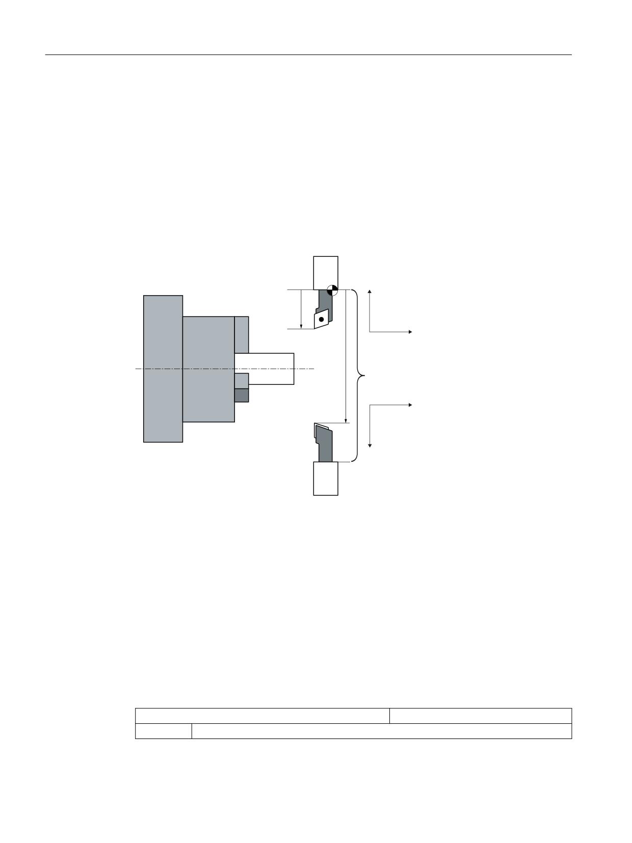
It is possible to work on a single turning machine with two tool holders, both of which are
mounted on an X axis. The tool holders may be revolvers, multifix, or a combination of both. As
both tool adapters are mounted on the same axis it is only possible to machine with one tool. The
workpiece is located between the two tool adapters.
All tools have the same reference point (on tool holder 1) irrespective of which tool holder they
are on. Consequently, the tool lengths of the second tool holder are always longer than the tool
lengths of the first tool holder. The main machining is performed in the negative X axis direction.
7RRO KROGHU
[ :RUNSLHFH FRRUGLQDWH
V\VWHP ZKHQ
VW WRRO KROGHU LV XVHG
/
]
/
/
0'
a/
]
:RUNSLHFH FRRUGLQDWH
V\VWHP ZKHQ
QG WRRO KROGHU LV XVHG
[
7RRO KROGHU
Tool holder definition
The MD52248 REV_2_BORDER_TOOL_LENGTH defines a tool length limit X so that the tools can
be assigned to the two tool holders automatically:
Tool length X < MD52248: Tool belongs to the 1st tool holder
Tool length X ≥ MD52248: Tool belongs to the 2nd tool holder
Additional parameter assignments
For the used mirrorings of the X and Y axes and the offsets of the C axis, the following machine
data has to be configured:
MD24006 $MC_CHSFRAME_RESET_MASK
Active system frames after RESET
Bit 4 = 1
System frame for workpiece reference remains active after RESET
Tool management
622
Function Manual, 10/2020, 6FC5397-1HP40-0BA1

SINUMERIK Operate user interface
9.4 Working with two tool holders
MD24007 $MC_CHSFRAME_RESET_CLEAR_MASK
Clear system frames after RESET
Bit 4 = 0
Do not clear system frame workpiece reference after RESET
MD28082 $MC_MM_SYSTEM_FRAME_MASK
Setting-up system frames (SRAM)
Bit 4 = 1
Workpiece reference ($P_WPFRAME)
MD28083 $MC_MM_SYSTEM_DATAFRAME_MASK
Setting-up data management, system
frames (SRAM)
Bit 4 = 1
Workpiece reference ($P_WPFRAME)
Due to the coordinate system being mirrored, the following machine/setting data must be set:
MD21202 $MC_LIFTFAST_WITH_MIRROR
Lift fast with mirror
= 1
For the determination of the lifting direction, it is also mirrored for active mirroring. The
mirroring of the lifting direction only refers to the direction components perpendicular to
the tool direction.
SD42900 $SC_MIRROR_TOOL_LENGTH
Sign change, tool length when mirroring
= 0
The signs of the tool length components are independent of system frames with mirroring.
SD42910 $SC_MIRROR_TOOL_WEAR
Sign change, tool wear when mirroring
= 1
Inverting the sign mirrors the wear values of the tool length components whose associated
axes are mirrored.
Settings for ShopTurn programs
In ShopTurn, MD21202, SD42900, and SD42910 are automatically set for the necessary
mirroring.
Settings for G code programs
Additional settings must be made if the functions of the second tool holder with mirroring of the
X axis are also to be active for G code programs and tool calls from the T,S,M screenform:
MD10717 $MN_T_NO_FCT_CYCLE_NAME="F_T_REV2"
MD15710 $MN_TCA_CYCLE_NAME="F_T_REV2"
Note
The settings of MD10717 and MD15710 cannot be used if old G code programs are available and
will be used without modification for the second tool holder without mirroring of the X axis.
If transformation TRANSMIT is set up, the necessary mirroring can also be activated
automatically if programmed. For this, the TRANSMIT command must be replaced by a
subprogram (for example, in the manufacturer directory):
Tool management
Function Manual, 10/2020, 6FC5397-1HP40-0BA1
623
SINUMERIK Operate user interface
9.4 Working with two tool holders
MD10712 $MN_NC_USER_CODE_CONF_NAME_TAB[0]="TRANSMIT"
MD10712 $MN_NC_USER_CODE_CONF_NAME_TAB[1]="TRANSM"
Subprogram TRANSMIT.SPF:
PROC TRANSMIT(INT_NR)
F_T_REV2
TRANSM(_NR)
F_T_REV2
RET
Note
In the status display, TRANSM is now displayed instead of TRANSMIT.
General conditions
• The taper turning is not enabled for "working with two tool holders."
• The B-axis function (kinematics) is also not enabled for "working with two tool holders."
Tool management
624
Function Manual, 10/2020, 6FC5397-1HP40-0BA1
Code carrier connection - Tool Ident Connection
(option)
10
10.1
Installation
10.1.1
System requirements
Tool Ident Connection is intended for the SINUMERIK 840D sl target system with SINUMERIK
Operate.
Note
TooI Ident Connection is only available in conjunction with the SINUMERIK Operate operating
software as of SW 4.5 SP2.
PLC interface "ParamTM"
Assignment of the PLC interface for the Parameter area (Page 675)
Functional scope of the PLC interface (K codes) (Page 683)
NCU
• As of NCU 7x0.3
• SINUMERIK Operate as of SW 4.5 SP2
PCU
• PCU 50.5 or higher
• SINUMERIK Operate as of SW 4.5 SP2
Further information
A list of industrial PCs that are compatible with the PCU-Basesoftware can be found under:
Commissioning Manual SINUMERIK 840D sl PCU-Basesoftware
Tool management
An active magazine management is required in order to use the Tool Ident Connection option.
Tool management
Function Manual, 10/2020, 6FC5397-1HP40-0BA1
625
Code carrier connection - Tool Ident Connection (option)
10.1 Installation
Expanding the DB19
If the PLC data block DB19 is not available via the PLC interface for "Tool Ident Connection", then
this must be expanded by "Tool Ident Connection" before commissioning the system for the first
time, see PLC interface in the DB19 (Page 670)
10.1.2
Installation of Tool Ident Connection
Note
We recommend that you generate a system backup before set-up.
According to the system requirement, any additional components required must be installed
first.
The storage medium for software applications is a CompactFlash card with fixed directory
structure. The "Tool Ident Connection" application is stored within this structure in the "addon"
directory.
Hardware configuration for read/write devices
The read/write devices for the tool data are connected to the SINUMERIK 828D as PROFINET IO
devices. The hardware configuration is stored in SDBs. For the SINUMERIK 828D, the bus is
predefined for different standard configurations and entered into preconfigured SDBs. These
SDBs are supplied along with the control.
The SDB must be installed for Balluff devices.
10.1.2.1
Activation of Tool Ident Connection
Configuration files
The following files are available to configure Tool Ident Connection:
Standard configuration files
Directory: CompactFlash card
tdiidentcfg.xml
/siemens/sinumerik/hmi/template\toolidentconnection
toolSpec.xml
wkonvert.mcx
DefToolDat.txt
wkonvert.mcc
systemconfiguration.ini
oem_sltmlistconfig.xml
Tool management
626
Function Manual, 10/2020, 6FC5397-1HP40-0BA1

Code carrier connection - Tool Ident Connection (option)
10.1 Installation
Setup of the Tool Ident Connection option
The following entry must be made in the "systemconfiguration.ini" in the section [services] to
set up the software:
SVCxxx=name:=SlMcisTdiIdentConnectionService,
implementation:=slmcistdiidentconnectionservice.SlMcisTdiIdentConnec
tionService,
process:=SlHmiHost1,
Note
The xxx in SVCxxx must be replaced by the free number of a service. Only numbers as of 200
can be used.
To adapt the Tool Ident Connection configuration function, the systemconfiguration.ini and, if
adapted, the configuration files (from the directory mentioned above) must be copied to the
following directory.
• CompactFlash card: /addon/sinumerik/hmi/cfg
The oem_sltmlistconfig.xml file must be renamed, depending on the technology. This is
explained in the Commissioning Manual IM9, Section "Tool management", Section "Configuring
the user interface".
An exhaustive description of the configuration options of the oem_sltmlistconfig.xml can be
found in Configure the code carrier connection (Page 603).
The files wkonvert.txt, DefToolDat.txt and wkonvert.mcc are configuration files. They must be
compiled after every change with the wkonvert wizard. The result of the compile action is a
wkoonvert.mcx. This must be copied to the appropriate target directory for the settings to take
effect.
10.1.2.2
Installation of Wkonvert wizard
The Wkonvert wizard PC application is available when creating the required conversion rules for
the Tool Ident Connection.
In order to be able to use the Wizard, the application must be installed on the configuring
computer.
Installation procedure
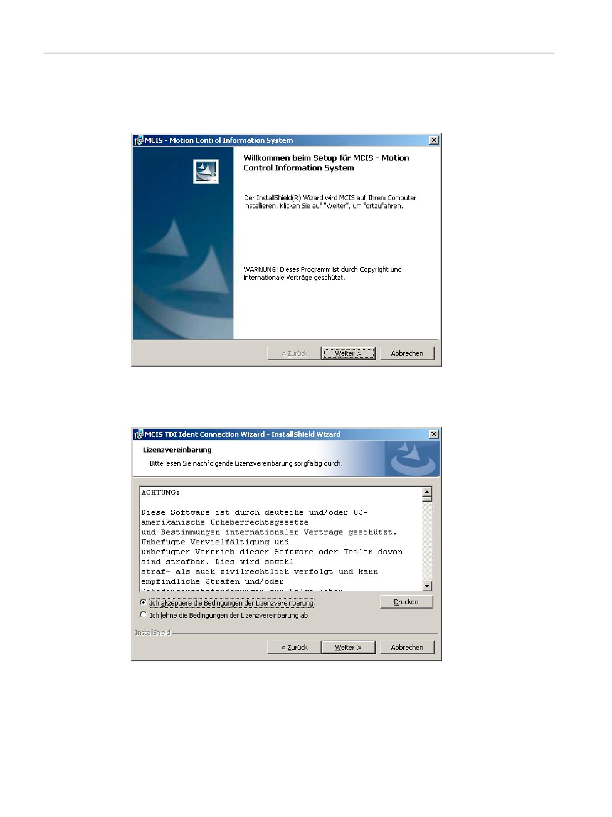
To install the Wkonvert wizard, execute the setup.exe which is on the SINUMERIK CNC Software
DVD.
Tool management
Function Manual, 10/2020, 6FC5397-1HP40-0BA1
627
Code carrier connection - Tool Ident Connection (option)
10.1 Installation
Figure 10-1
Language selection dialog
The individual installation steps follow after selecting the installation language.
Figure 10-2
Preparing setup
After reading the license agreement, this must be accepted. If you are not in agreement with the
license agreement, then setup is exited.
Figure 10-3
License agreement dialog
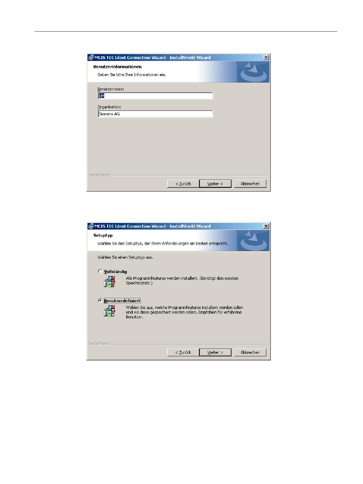
After acknowledging the license agreement, you are prompted for a user name and
organization.
Tool management
628
Function Manual, 10/2020, 6FC5397-1HP40-0BA1
Code carrier connection - Tool Ident Connection (option)
10.1 Installation
Figure 10-4
User information dialog
You can then select either a complete or a user-defined installation.
Figure 10-5
Setup type dialog
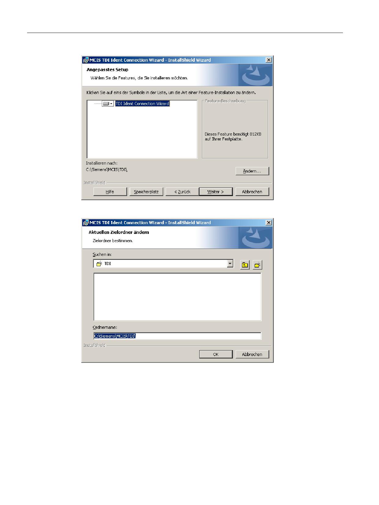
For a user-defined installation, you have the possibility of defining the target directory of the
application.
Tool management
Function Manual, 10/2020, 6FC5397-1HP40-0BA1
629
Code carrier connection - Tool Ident Connection (option)
10.1 Installation
Figure 10-6
Adapted setup dialog
Figure 10-7
Target directory selection dialog
If you have selected a complete installation, click "Next" or click "Next" in the component
selection dialog to begin the installation.
Tool management
630
Function Manual, 10/2020, 6FC5397-1HP40-0BA1
Code carrier connection - Tool Ident Connection (option)
10.1 Installation
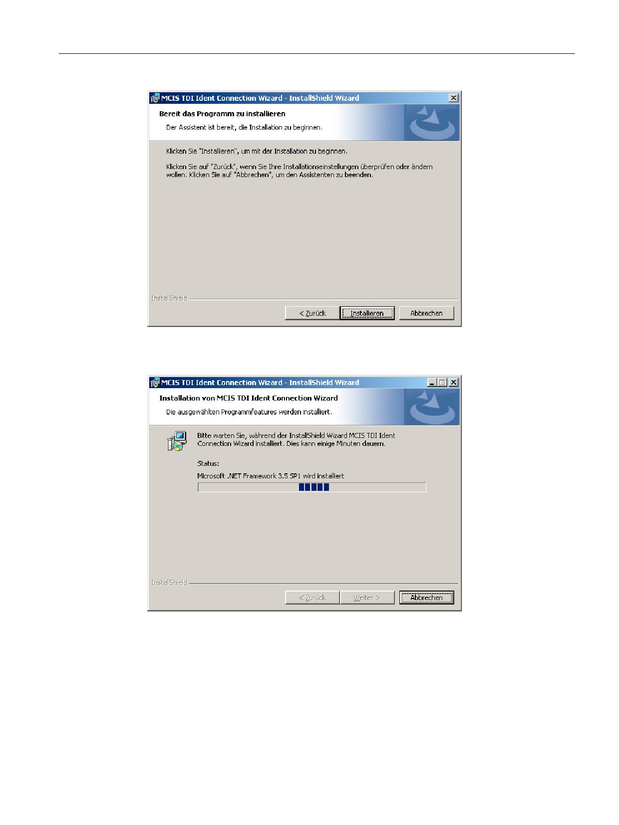
Figure 10-8
Installation dialog
Now click "Install" to start the installation.
Figure 10-9
Installation dialog
When required, setup installs the windows components ".NET Framework" and "Windows
Installer 3.0".
Tool management
Function Manual, 10/2020, 6FC5397-1HP40-0BA1
631
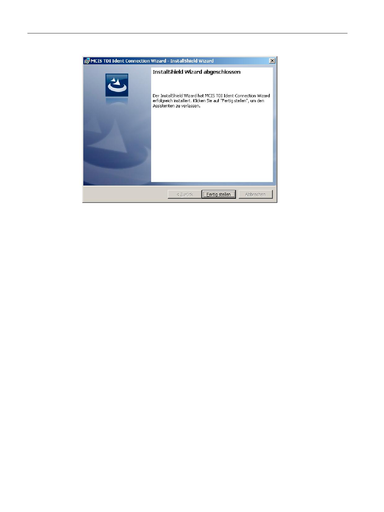
Code carrier connection - Tool Ident Connection (option)
10.1 Installation
Figure 10-10
Completing the installation
When you have successfully run through the setup procedure, the Wkonvert wizard can be
started via Start > Programs > MCIS > TDI > TDI Ident Connection Wizard.
Tool management
632
Function Manual, 10/2020, 6FC5397-1HP40-0BA1
Code carrier connection - Tool Ident Connection (option)
10.2 Configuration
10.2
Configuration
10.2.1
Configuration schematic
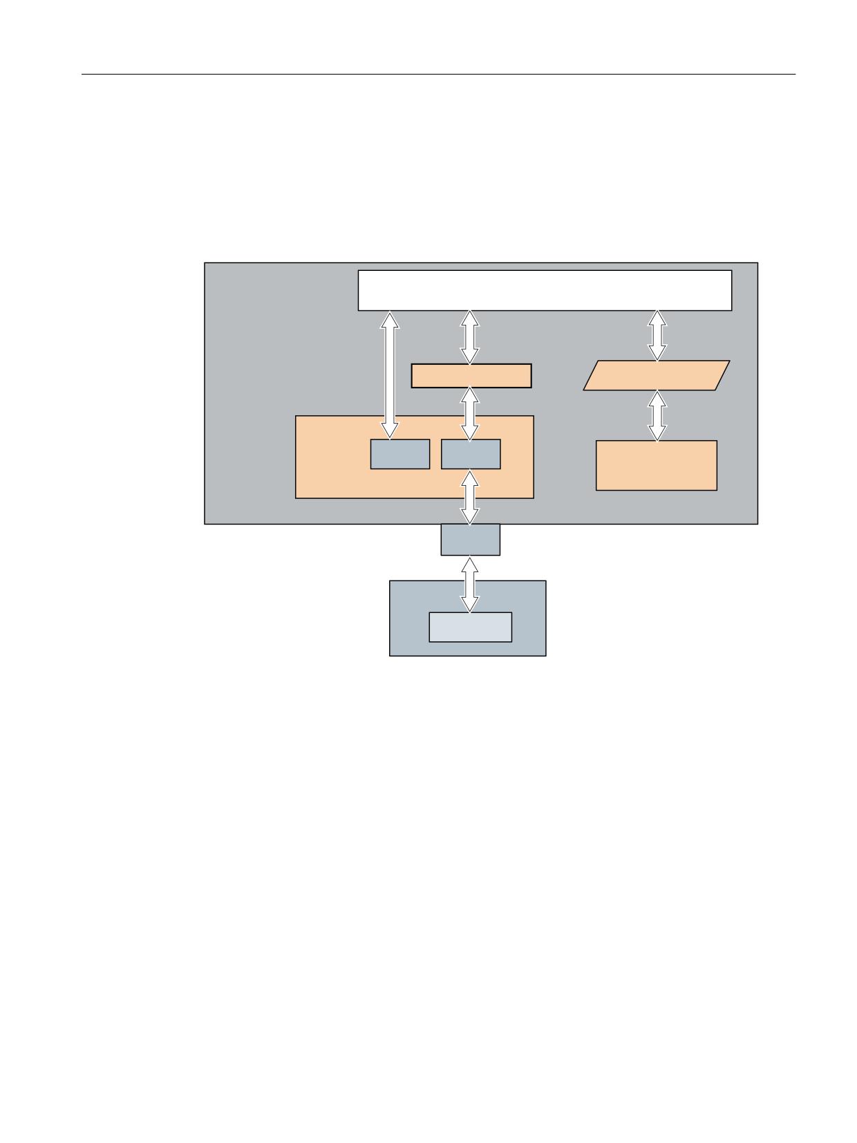
The following figure displays the configuration scheme of Tool Ident Connection:
7RRO ,GHQW &RQQHFWLRQ
'DWD FRQYHUVLRQ
6O7P6HUYLFH
'%
'%[[[
3/&
1&. WRRO
PDQDJHPHQW
6,180(5,.
' VO
6,180(5,. 2SHUDWH
/ '3
&RGH FDUULHU
Figure 10-11
Configuration principle of Tool Ident Connection
10.2.2
Configuration of the tool lists
<IDENTCONNECTIONCONFIGURATION> tag
The entries used for configuring the code carrier connection in the tool list of the user interface
are located in the <IDENTCONNECTIONCONFIGURATION> tag. The code carrier connection is
implemented via Tool Ident Connection.
For additional information on this topic, please refer to Configuring the code carrier connection
(Page 603).
10.2.3
TDIIdentCfg.xml
The following entry must be made in the "systemconfiguration.ini", in Section [services] to
activate the software:
Tool management
Function Manual, 10/2020, 6FC5397-1HP40-0BA1
633
Code carrier connection - Tool Ident Connection (option)
10.2 Configuration
[services]
SVCxxx=name:=SIMcisTdiIdentConnectionService,
implementation:=slmcistdiidentconnectionservice.SIMcisTdiIdentConnec
tionService,
process:=SIHmiHost1, timeout:=5000, shutdowntime:=5000
Note
xxx in SVCxxx must be replaced by the free number of a service.
Tool Ident Connection is parameterized using a configuration file based on xml. This
configuration file allows the integration and parameterization of various read/write devices via
different communication technologies.
Structure
The configuration file is structured as follows:
<?xml version="1.0" encoding="UTP-8"?>
<!-- SIEMENS AG 2010 - GER I IA&DT WEST TSS 7C APC MT - ZN Köln - All rights reserved -->
<!-- Configuration-File for MCIS TDI Ident Connection sl -->
<!-- E-Mail @ kulik.michael@siemens.com -->
<!-- Do not manipulate this file -->
<Configuration>
<Logging>
<ErrorFile size="3" enable="0">/var/tmp/TDIIdentLog.log</ErrorFile>
<TraceFile size="3" enable="0">/var/tmp/TDIIdentTrace.log</TraceFile>
<Logging>
<GlobalParam>
<InterfaceDB>19</InterfaceDB>
<InfaceOffset>250</InfaceOffset>
<DisableInface>false</DisableInface>
<TimeOut>1000</TimeOut>
<InputDB>19</InputDB>
<InputOffset>140</InputOffset>
<OutputDB>19</OutputDB>
<OutputOffset>198</OutputOffset>
</GlobalParam>
<!-- Parametrierung des ParamTM-Interface -->
<ParamTMInterface enable="1">
<InterfaceDB>19</InterfaceDB>
<InfaceOffset>256</InfaceOffset>
<ParamTMInterface>
<!-- Pfadangabe zur mcx-Datei und ToolSpec.xml -->
<Logic>
<!-- Aktivierung wenn TDI IdentConnection auf NCU -->
<mcxPath>/addon/sinumerik/hmi/cfg/wkonvert.mcx</mcxPath>
<specPath>/addon/sinumerik/hmi/cfg/ToolSpec.xml</specPath>
<!-- Aktivierung wenn TDI IdentConnection auf PCU 50.5 -->
Tool management
634
Function Manual, 10/2020, 6FC5397-1HP40-0BA1

Code carrier connection - Tool Ident Connection (option)
10.2 Configuration
<mcxPath>C://Program Files/Siemens/MotionControl/addon/sinumerik/
hmi/cfg/wkonvert.mcx</mcxPath>
<specPath>C://Program Files/Siemens/MotionControl/addon/sinumerik/
hmi/cfg/wkonvert.mcx</specPath>
<Logic>
<MergeMode>
<LoadPlaceNo>1</LoadPlaceNo>
<UnloadPlaceNo>1</UnloadPlaceNo>
</MergeMode>
<!-- Parametrierung des Schreib-/Lesegerätes -->
<!-- Type = 1-> PLC Type = 2 -> USB Type = 3 -> RJ45 -->
<Device Type="1">
<Units>1</Units>
<Data Unit="1">
<DataDB>300</DataDB>
<Offset>0</Offset>
<MaxData>1138</MaxData>
<EOT>0*2F2F</EOT>
</Data>
</Device>
</Configuration>
Description
Note
Depending on whether Tool Ident Connection is activated on an NCU or on a PCU50.5, the
required program lines must be activated in the <Logic> area.
Note
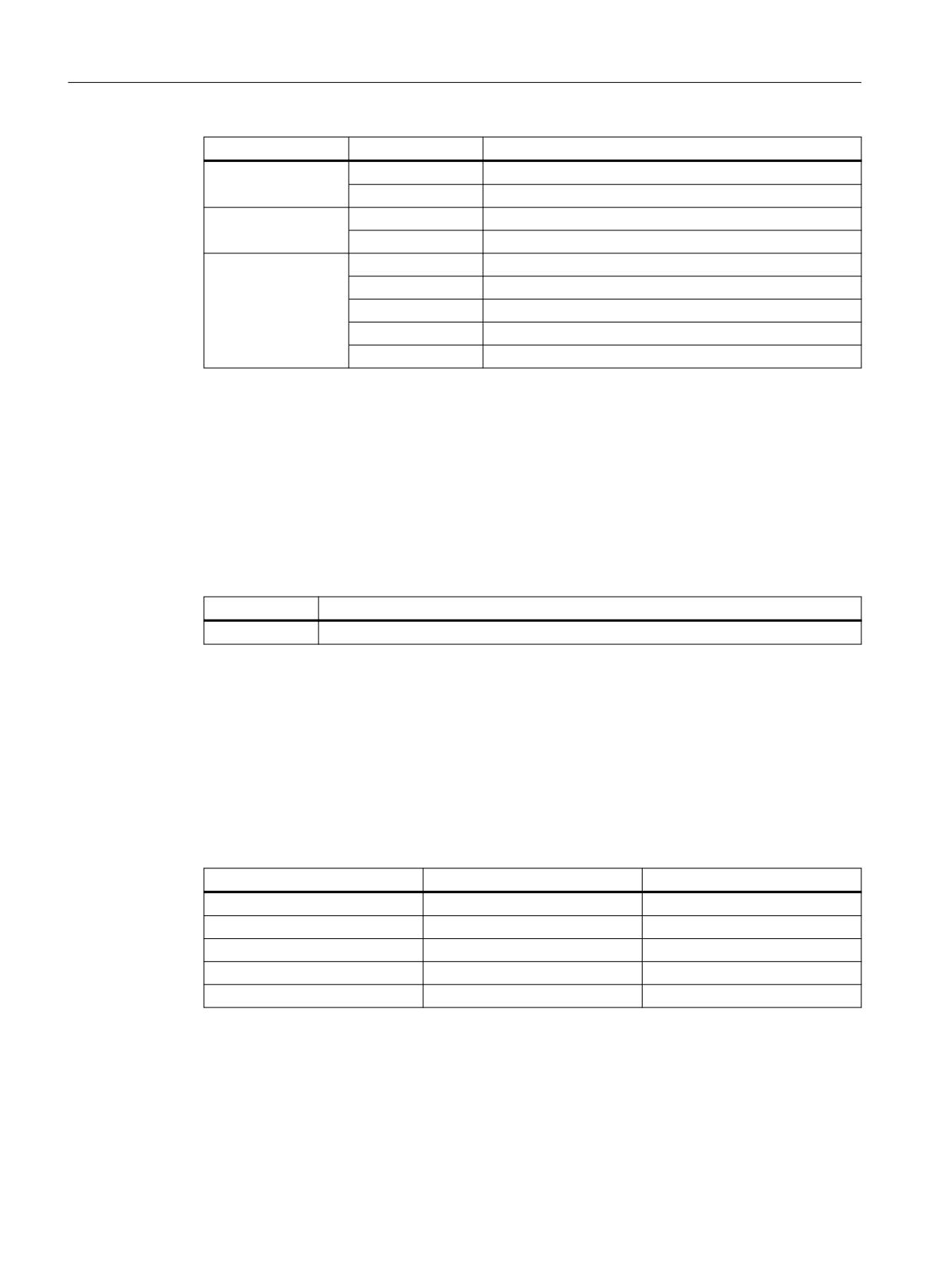
Only the entries - described in the following table - can be changed/used to parameterize and
configure Tool Ident Connection.
Always generate a backup before making any change.
The configuration file can be changed using a text editor, e.g. notepad. It is sub-divided into
various nodes which contain different entries. The sections and their entries are described in the
following table.
Section
Parameter
Significance
GlobalParam
InterfaceDB
Data block information for the PLC interface
InfaceOffset
Offset for the PLC interface
TimeOut
Execution monitoring time
DisableInterface
De/activation of the PLC interface
InputDB
Data block for transfer parameters
InputOffset
Offset for transfer parameters
OutputDB
Data block for return parameters
OutputOffset
Offset for return parameters
Tool management
Function Manual, 10/2020, 6FC5397-1HP40-0BA1
635
Code carrier connection - Tool Ident Connection (option)
10.2 Configuration
Section
Parameter
Significance
Logic
mcxPath
File + path data to the configured mcx file
specPath
File + path data to ToolSpec.xml
MergeMode
LoadPlaceNo
Default loading position
UnloadPlaceNo
Default unloading position
Device
Units
Number of read heads used
Type="1" -> PLC
DataBlock
Data block of the read head
Offset
Offset of the read head data
MaxDataBytes
Maximum data of the read head in bytes
EOT
End of the read head character string
If the execution of the PLC services for Tool Ident Connection is to be canceled because of a
timeout, a longer time can be defined using the "TimeOut" entry. A timeout can e.g. occur, if the
operator does not acknowledge a tool being loaded within the parameterized time window.
The default loading and unloading location number of the loading magazine can be changed
using the entries of "LoadPlaceNo" and "UnloadPlaceNo" using the "MergeMode" parameter.
The "Device" node has the "Type" attribute; the type of the read device being used is saved there.
The attribute defines the entries below this range. The parameters of the range contain the
configuration data of the read/write device.
Overview of the "Type" attribute of the "Device" parameter:
Type
Designation
1
PLC read device → connection via PROFIBUS
10.2.4
Read/write device at the PLC
Configuration of the PLC connection
In the configuration for Tool Ident Connection, the "Type" attribute must be set to significance "1"
for a PLC read/write device. The following parameters must be supplied with valid values below
the node:
Parameter
Data type
Value range
Units
int
1-4
DataBlock
int
0-32767
Offset
int
0-32767
MaxDataBytes
int
0-32767
EOT
string
10 characters
Tool management
636
Function Manual, 10/2020, 6FC5397-1HP40-0BA1
Code carrier connection - Tool Ident Connection (option)
10.2 Configuration
"Device" extract from a configuration file (TDIIdentCfg.xml) with PLC connection:
<Device Type="1">
<Units>1</Units>
<Data Unit="1">
<DataDB>300</DataDB>
<Offset>0</Offset>
<MaxData>140</MaxData>
<EOT>0*2F2F</EOT>
</Data>
<Units>2</Units>
<Data Unit="1">
<DataDB>300</DataDB>
<Offset>0</Offset>
<MaxData>40</MaxData>
<EOT>0*2F2F</EOT>
</Data>
</Device>
10.2.5
Data conversion
The tool data is saved in the code carrier as a sequence of bytes. The PLC user program writes the
code carrier data to the previously defined data block (TDIIdentcfg.xml). The data conversion
accesses the data block and generates the tool data record and vice versa.
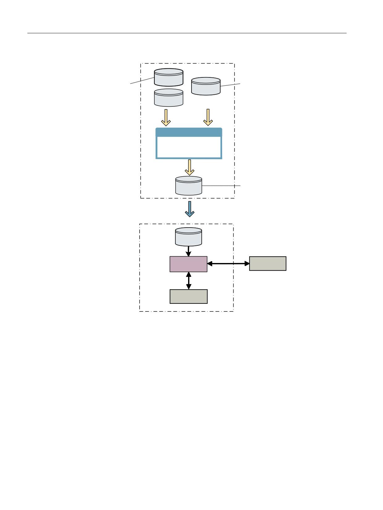
The following figure displays the scheme for the configuration of the conversion rules for Tool
Ident Connection:
Tool management
Function Manual, 10/2020, 6FC5397-1HP40-0BA1
637
Code carrier connection - Tool Ident Connection (option)
10.2 Configuration
&RQILJXUDWLRQ 3&
&RQYHUVLRQ UXOH IURP
:.219(57
0&,6 & VRXUFH WH[W RI WKH
7RRO ,GHQW &RQQHFWLRQ
7;7
FRQYHUVLRQ UXOH
0&&
'HI7RRO'DW W[W
:NRQYHUW ZL]DUG
&RQYHUVLRQ UXOH
:.219(57
0&;
6,180(5,.
' VO
:.219(57
0&;
7RRO ,GHQW
&RGH FDUULHU
&RQQHFWLRQ
7RRO PDQDJHPHQW
6HUYLFH
Figure 10-12
Configuring the conversion rules
Generating conversion rules
As part of the commissioning of Tool Ident Connection, a conversion file must be created with
the Wkonvert wizard application on a configuration PC. The binary file wkonvert.mcx is created.
It contains the conversion rules and default tool data.
Tool management
638
Function Manual, 10/2020, 6FC5397-1HP40-0BA1
Code carrier connection - Tool Ident Connection (option)
10.2 Configuration
The following conversion rules can be processed:
• Conversion rule from Tool Ident Connection
Files: wkonvert.txt and DefToolDat.txt
Benefits: Guarantee of compatibility with earlier versions of Tool Ident Connection
Note
The structure of the wkonvert.txt file is described in Section Structure of the description file
wkonvert.txt (Page 641).
The structure of the DefToolDat.txt file is described in Section Tool data initialization file
DefToolDat.txt (Page 649).
• Conversion rule in the form of source text in the MCIS-C script language.
Benefits: Extended conversion functionality.
Note
If you want Siemens to create a customer-specific conversion rule for Tool Ident Connection,
please contact your Siemens sales partner.
10.2.5.1
Using the Wkonvert wizard
After installation, the Wkonvert wizard can be started via
Start > Programs > MCIS > TDI > TDI Wkonvert Wizard.
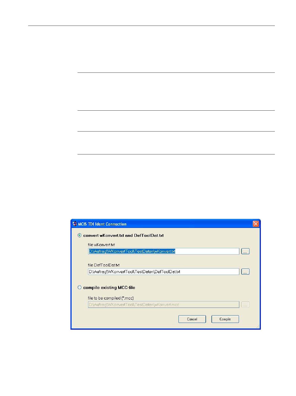
After executing the application, the basic screen form for this application is displayed:
Figure 10-13
Wkonvert wizard screen form
Tool management
Function Manual, 10/2020, 6FC5397-1HP40-0BA1
639
Code carrier connection - Tool Ident Connection (option)
10.2 Configuration
One of the following alternatives can be selected in the basic screen form of the application:
• "convert wKonvert.txt and DefToolDat.txt"
Create conversion rule from Tool Ident Connection (files: wkonvert.txt and DefToolDat.txt).
• "compile existing MCC-file"
Conversion rule is generated in the form of source text in the MCIS-C script language.
The target directory to output the result file wkonvert.mcx corresponds to the directory in which
the wkonvert.txt file is located.
Note
After creating the conversion rule, the mcx file must be copied to the "/addon/sinumerik/appl/"
directory. The operating software must be rebooted in order that the new conversion rule
becomes effective.
10.2.5.2
Messages of the Wkonvert wizard
Messages of the Wkonvert wizard application that can occur while interpreting the wkonvert.txt
and DefToolDat.txt or MCIS-C scripts, are described in this section.
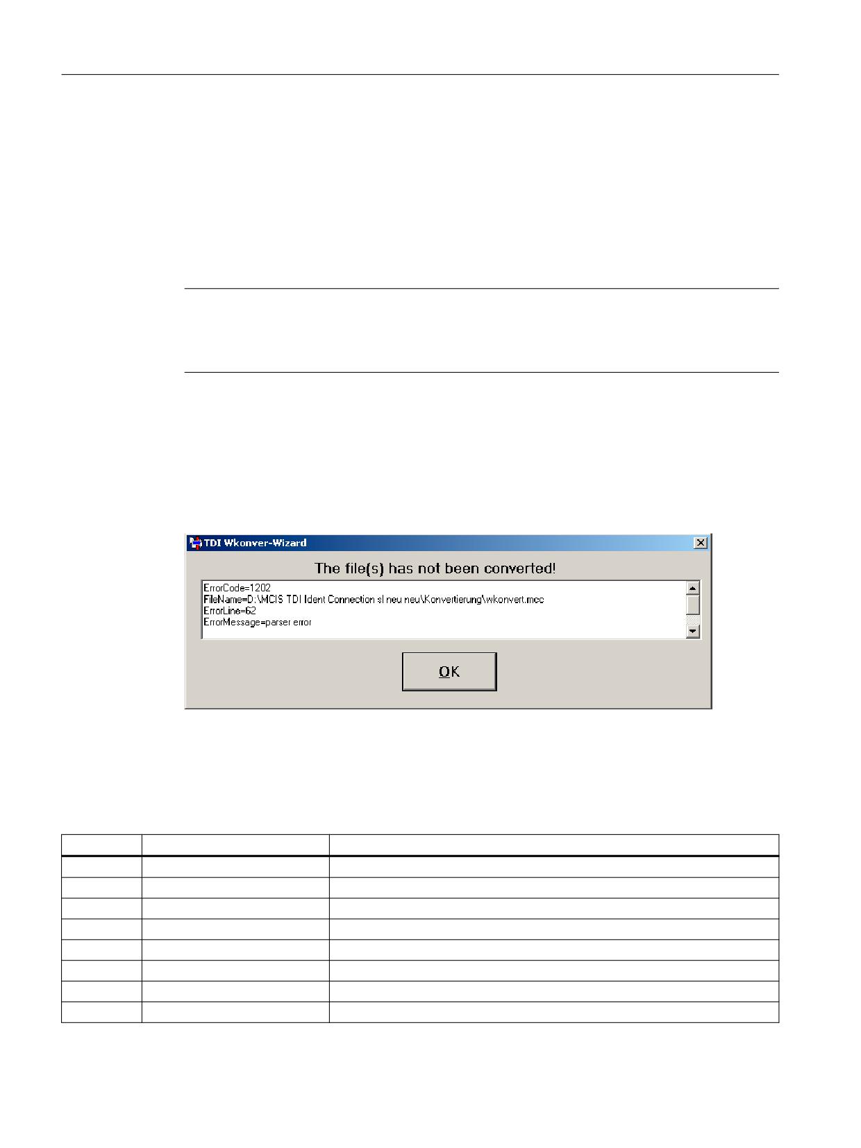
All of the messages are displayed in the final dialog.
Figure 10-14
Final dialog
For error messages, the line as well as the source file, in which the error occurred, as well as
additional information on the error profile are displayed in a text box that can be scrolled. To
resolve the error, the error that has occurred must be removed in the source file.
The following table lists possible error messages:
ErrorCode
ErrorMessage
Meaning
200
File <abcd> could not be read!
File: DefToolDat.txt; file cannot be read. Additional information is specified.
201
Unknown data type.
File: DefToolDat.txt; for one item, no value has been assigned.
202
Line has no value.
File: DefToolDat.txt; "=" missing.
203
Invalid line format.
File: DefToolDat.txt; "[" or "]" missing.
100
File <abcd> could not be read!
File: wKonvert.txt; file cannot be read. Additional information is specified
101
Error in value ‚DataLen’
File: wKonvert.txt; error when specifying the value 'DataLen'.
102
New block before BlockEnd
File: wKonvert.txt; BlockEnd identification missing.
103
Missing block numer <xx>
File: wKonvert.txt; Block <xx> missing.
Tool management
640
Function Manual, 10/2020, 6FC5397-1HP40-0BA1
Code carrier connection - Tool Ident Connection (option)
10.2 Configuration
ErrorCode
ErrorMessage
Meaning
104
Line is empty
File: wKonvert.txt; the specified line is empty.
105
No item number defined
File: wKonvert.txt; the item has no number.
110
Missing item: act=<x>,
File: wKonvert.txt; item numbering is incorrect.
last=<y>.
111
Finishing block number <xx>
File: wKonvert.txt; block number is incorrect.
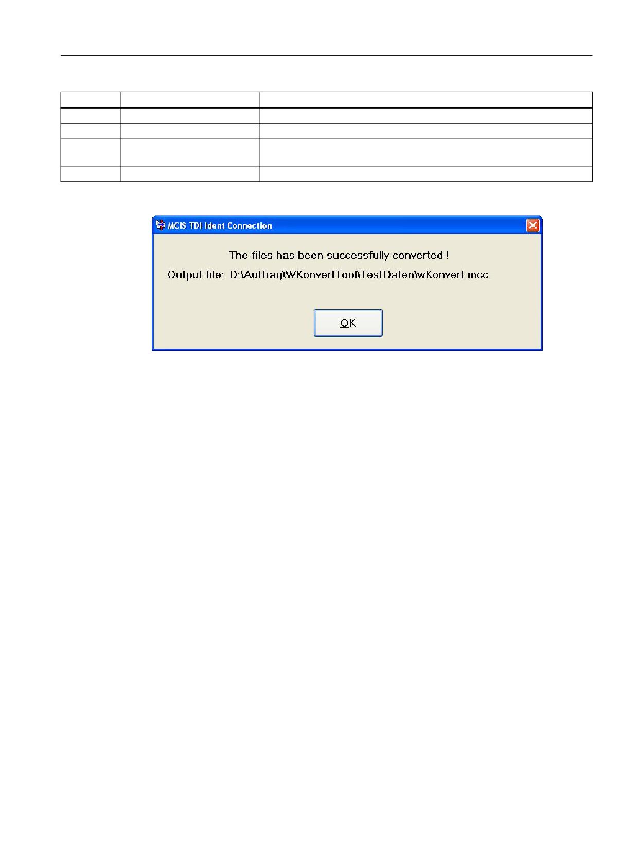
After a successful compilation of the source file(s), the following message is output:
Figure 10-15
MessageBox
10.2.6
Conversion files wkonvert.txt and DefToolDat.txt
For Tool Ident Connection, the conversion rules are used for the files Wkonvert.txt and
DefToolDat.txt. There are also the code carrier data formats: REAL and DOUBLE.
10.2.6.1
Structure of the description file wkonvert.txt
The data on the code carrier is stored in a particular order. A conversion rule in the form of a
description file is provided so that the tool management can read or write this data flow.
This description file consists of correctly defined tool and cutting edge dialog data. Only this
dialog data can actually be processed by the tool management. All the other data on the code
carrier must not be assigned to any dialog variables; they will then not be processed by the
standard version.
Tool Ident Connection enables the connection of optional software components. These
components are used to adapt this special code carrier data to the SINUMERIK standard. This
means that customer-specific code carrier formats can be read and written by the tool manager;
also, special logic can be implemented in the transport operations of the tool data (e.g.
replacement tools can be taken into account in the NC, additional cutting edges can be created,
etc.).
The description file can be generated as an ASCII file using a standard text editor. This description
file is called wkonvert.txt. It represents the precise image of the data which is on the code carrier.
Tool management
Function Manual, 10/2020, 6FC5397-1HP40-0BA1
641

Code carrier connection - Tool Ident Connection (option)
10.2 Configuration
Tool dialog data
The tool dialog data is defined as follows:
Table 10-1
Tool dialog data
Dialog variable
Data type
Designation
Assignment $TC...
T1
String
Tool name, max. 32 characters
$TC_TP2
T2
Integer
Duplo number
$TC_TP1
T3
Integer
Number of cutting edges
$P_TOOLND[tno]
tno=tool number
T4
Integer
Tool size to the left in half locations
$TC_TP3
T5
Integer
Tool size to the right in half locations
$TC_TP4
T6
Integer
Tool size upwards in half locations
$TC_TP5
T7
Integer
Tool size downwards in half locations
$TC_TP6
T8
String
Magazine location type
$TC_TP7 1)
T9
Integer
Tool status
$TC_TP8
T10
Integer
Type of tool monitoring
$TC_TP9
T11
Integer
Type of tool search
$TC_TP11
T12 2)
Integer
Magazine location type
$TC_TP7
1)
The character string which is stored there, is an internal control location type that is assigned to the value in $TC_TP7. This
text is defined via the tool management start-up and stored in the database.
2)
This number corresponds to the string from T8 and should be used as an alternative to T8.
Cutting edge dialog data
Table 10-2
Cutting edge dialog data
Dialog variable
Data type
Designation
Assignment $TC...
C1
Integer
Subtype
$TC_DP1
C4
Integer
Cutting edge position
$TC_DP2
Geometry tool length compensation
C5
Double
Length 1
$TC_DP3
C6
Double
Length 2
$TC_DP4
C7
Double
Length 3
$TC_DP5
Geometry tool radius compensation
C8
Double
Length 1
$TC_DP8
C9
Double
Length 2
$TC_DP9
C10
Double
Radius 1
$TC_DP6
C11
Double
Radius 2
$TC_DP7
C12
Double
Angle 1
$TC_DP10
C13
Double
Angle 2
$TC_DP11
Wear tool length compensation
C14
Double
Length 1
$TC_DP12
C15
Double
Length 2
$TC_DP13
Tool management
642
Function Manual, 10/2020, 6FC5397-1HP40-0BA1

Code carrier connection - Tool Ident Connection (option)
10.2 Configuration
Dialog variable
Data type
Designation
Assignment $TC...
C16
Double
Length 3
$TC_DP14
Wear tool radius compensation
C17
Double
Length 1
$TC_DP17
C18
Double
Length 2
$TC_DP18
C19
Double
Radius 1
$TC_DP15
C20
Double
Radius 2
$TC_DP16
C21
Double
Angle 1
$TC_DP19
C22
Double
Angle 2
$TC_DP20
Base dimension/adapter dimension tool length
compensation
C23
Double
Basic length 1
$TC_DP21
C24
Double
Basic length 2
$TC_DP22
C25
Double
Basic length 3
$TC_DP23
C26
Double
Undercut angle
$TC_DP24
C27
Integer
Reverse insert
$TC_DP25
C28
Integer
Cutting edge number for addressing variables
C29 *)
Integer
Tool life in minutes
$TC_MOP2
C30 *)
Integer
Pre-warning limit for tool life in minutes
$TC_MOP1
C31 *)
Integer
Unit quantity
$TC_MOP4
C32 *)
Integer
Prewarning limit unit quantity
$TC_MOP3
C33
Double
Setpoint tool life in minutes
$TC_MOP11
C34 *)
Integer
Setpoint unit quantity
$TC_MOP13
C35
Double
Pre-warning limit for wear
$TC_MOP5
C36
Double
Wear
$TC_MOP6
C37
Double
Setpoint wear
$TC_MOP15
C38 *)
Double
Tool life in minutes
$TC_MOP2
C39 *)
Double
Pre-warning limit for tool life in minutes
$TC_MOP1
C40 *)
Double
Unit quantity
$TC_MOP4
C41 *)
Double
Prewarning limit unit quantity
$TC_MOP3
C42 *)
Double
Setpoint unit quantity
$TC_MOP13
A1 - A10
Double/String
User tool data
$TC_TPCx
U1 - U10
Double/String
User cutting edge data
$TC_DPCx
S1 - S10
Double/String
User monitoring data
$TC_MOPCx
*)
C38 and C39 can only be used as an alternative to C29 and C30; C40, C41 and C42 can only be used as an alternative to C31,
C32 and C34.
That data on the code carrier, which is not relevant for tool management, but which may not be
changed when writing to the code carrier, is shown in the description file with a hyphen ( - )
instead of the dialog variable (data gaps).
Tool management
Function Manual, 10/2020, 6FC5397-1HP40-0BA1
643
Code carrier connection - Tool Ident Connection (option)
10.2 Configuration
Data types
The following data types are defined for dialog variables:
• Integer: Value range -32768 to +32767
• Double: Floating point - double the accuracy
• String: String made up of ASCII characters
Keywords
The code carrier description file is structured line-by-line, whereby each line starts with one of
the following keywords:
•
Inverted comma
The apostrophe (') marks the beginning of a comment. The characters that follow up to the
end of the line are skipped. Example:
' This is a comment
•
Datalen
DATALEN=CONST | VARIABLE 0x<delimiter>
The following data has a constant (CONST) or a variable (VARIABLE) data length. Data with
variable length is terminated with 0x<delimiter>. Example:
DATALEN=VARIABLE 0x0A ’ variable data length, delimiter LF
•
Item
Item<n>=<line>
<n> := Consecutive number of the code carrier data, ascending from 1 without gaps
<line> := <(max.) Length in bytes> <code carrier data format> <dialog
variable>
<code carrier data format> : See table, Code carrier data formats
<dialog variable> : Assignment to the dialog variable, see table, Cutting edge dialog
data
Example:
Item1 32 ASCII T3 ’ tool identifier
Item2 3 BCD T2 ’ duplo number
•
Bltem
BItem<n>=<line>
<n> := Consecutive number of the code carrier data, ascending from 1 without gaps
<line> := analog Item<n>
Conversion rule for code carrier data <n> within a block. If the code carrier data is assigned
a tool dialog data T<n>, the dialog data is assigned the first value of the code carrier data in
the block.
Example:
BItem1 1 BCD C1 ' subtype
BItem2 1 BCD C4 ' cutting edge position
Tool management
644
Function Manual, 10/2020, 6FC5397-1HP40-0BA1

Code carrier connection - Tool Ident Connection (option)
10.2 Configuration
• Block
Block<n> <repetition rule>
<n> := Consecutive number of block, ascending from 1 without gaps
<repetition rule> := * Item<n>
A block of data BItem<n> follows (up to keyword End_Block<n>) which is stored on the
code carrier according to the <repetition rule>.
In the case of Block <n> * Item <n> Item <n> must be defined before Block <n> .
Example:
Block1 * Item6 ’ Block1 corresponds to repeating the value from
Item6
End_Block<n>
• End_Block
End_Block<n>
<n> := consecutive block number
End identifier for a data block defined with "Block".
Code carrier data formats - <code carrier data format>
The following code-carrier data formats (see Item / BItem) are supported:
Table 10-3
Code carrier data formats
Data format
Explanation
Value range
ASCII
ASCII character set
-
INT
16-bit integer (Intel format)
-32768 to +32767
BCD
Binary-coded decimal number (if necessary, with sign and decimal point):
-
Non-relevant decades are preassigned the value 0, left-justified.
REAL
16-bit floating-point number (Intel format): Accuracy, 7 digits
±1.5×10-45 to ± 3.4×1038
DOUBLE
32-bit floating-point number (Intel format): Accuracy, 15-16 digits
±5.0×10-324 to ±1.7×10308
FPX2
Bit integer (SINUMERIK): Least significant byte at the higher order address
-32768 to +32767
(inverse to the Intel format)
Assignment between code carrier data and dialog data - <dialog variable>
The conversion rule for Item<n> or BItem<n> also contains the assignment to none/one/
several dialog variables, if necessary with a conversion that is explained in detail in this section.
<dialog variable> := <dvar1>[=(<uv>)] [, <dvar2>[=(<uv>)]
[,<dvar3>[&<dvar4>]=(<uv>)]
[,dvarN>[=(<uv>)]
<dvar> :=
T<index> | C<index> | _
T = tool data
C = cutting edge data
index = index within tool / cutting edge dialog data
- = no assignment to a dialog variable
<dvar1>&<dvar2>=
<uv>
Conversion rule applies to <dvar1> and <dvar2>
Tool management
Function Manual, 10/2020, 6FC5397-1HP40-0BA1
645

Code carrier connection - Tool Ident Connection (option)
10.2 Configuration
uv :=
<Tetn>
Tetn := nth tetrad in byte sequence
Byte1, = Tet1 and Tet2
Byte2, = Tet3 and Tet4
Example of the tetrad allocation of the code carrier variables (in BCD format) to dialog variables:
T4=(Tet1), T5=(Tet2), T6=(Tet3), T7=(Tet4)
If the code carrier variable has the value 0x1234, for example, dialog variable T4 is assigned the
value 1, dialog variable T7 the value 4.
10.2.6.2
Examples for the description files wkonvert.txt
After installation, the name of the file is "wkonvert.txt".
Table 10-4
Wkonvert.txt Items
Code carrier
Length
Data for-
Dialog vari-
Comment
variable
(bytes)
mat
able
Item1
32
ASCII
T1
’ Identifier
Item2
3
BCD
T2
’ Duplo
Item3
2
BCD
T4=(Tet1),
’ Tool size: Left, right, top, bottom
T5=(Tet2),
T6=(Tet3),
T7=(Tet4)
Item4
32
ASCII
T8
’ Location type
Item5
2
BCD
T9
’ Status
Item6
1
BCD
T3
’ Qty. Cutting edges
Item7
1
BCD
T10
' Type of tool monitoring
Item8
1
BCD
T11
' Type of tool monitoring
’ Cutting edge data Block1 * Item6
BItem1
2
BCD
C1
’ Subtype, type
BItem2
3
BCD
C4
’ Cutting edge position
' Tool length compensation
BItem3
4
BCD
C5
' Length 1
BItem4
4
BCD
C5
' Length 2
BItem5
4
BCD
C7
' Length 3
' Tool radius compensation
BItem6
4
BCD
C8
' Length 1
BItem7
4
BCD
C9
' Length 2
BItem8
4
BCD
C10
' Radius 1
BItem9
4
BCD
C11
' Radius 2
BItem10
4
BCD
C12
' Angle 1
BItem11
4
BCD
C13
' Angle 2
' Wear length compensation
BItem12
4
BCD
C14
' Length 1
Tool management
646
Function Manual, 10/2020, 6FC5397-1HP40-0BA1

Code carrier connection - Tool Ident Connection (option)
10.2 Configuration
Code carrier
Length
Data for-
Dialog vari-
Comment
variable
(bytes)
mat
able
BItem13
4
BCD
C15
' Length 2
BItem14
4
BCD
C16
' Length 3
' Wear radius compensation
BItem15
4
BCD
C17
' Length 1
BItem16
4
BCD
C18
' Length 2
BItem17
4
BCD
C19
' Radius 1
BItem18
4
BCD
C20
' Radius 2
BItem19
4
BCD
C21
' Angle 1
BItem20
4
BCD
C22
' Angle 2
' Basic dimension length compensation
Bltem21
4
BCD
C23
’ Basic length 1
Bltem22
4
BCD
C24
’ Basic length 2
Bltem23
4
BCD
C25
’ Basic length 3
Bltem24
4
BCD
C26
' Undercut angle
Bltem25
1
BCD
C27
' Reverse insert
Bltem26
2
BCD
C29
’ Tool life in minutes
Bltem27
2
BCD
C30
’ Pre-warning limit tool life
Bltem28
2
BCD
C33
’ Setpoint tool life in minutes
Bltem29
2
BCD
C31
’ Unit quantity
Bltem30
2
BCD
C32
’ Pre-warning limit unit quantity
Bltem31
2
BCD
C32
’ Setpoint unit quantity
End_Block1
Example with tool and cutting edge OEM data as well as data gaps:
Table 10-5
OEM data for Wkonvert.txt
Code carrier
Length
Data for-
Dialog vari-
Comment
variable
(bytes)
mat
able
Item1
32
ASCII
T1
’ Identifier
Item2
3
BCD
T2
’ Duplo
Item3
2
BCD
T4=(Tet1),
’ Tool size: Left, right, top, bottom
T5=(Tet2),
T6=(Tet3),
T7=(Tet4)
Item4
32
ASCII
T8
’ Location type
Item5
2
BCD
T9
’ Status
Item6
1
BCD
T3
’ Qty. Cutting edges
Item7
1
BCD
T10
' Type of tool monitoring
Item8
1
BCD
T11
' Type of tool monitoring
Item9
5
ASCII
-
‘ Tool data gap
Item10
4
BCD
A1
’ Tool OEM data 1
’ Cutting edge data Block1 * Item6
Tool management
Function Manual, 10/2020, 6FC5397-1HP40-0BA1
647

Code carrier connection - Tool Ident Connection (option)
10.2 Configuration
Code carrier
Length
Data for-
Dialog vari-
Comment
variable
(bytes)
mat
able
BItem1
2
BCD
C1
’ Subtype, type
BItem2
1
BCD
C4
’ Cutting edge position
' Tool length compensation
BItem3
4
BCD
C5
' Length 1
BItem4
4
BCD
C5
' Length 2
BItem5
4
BCD
C7
' Length 3
' Tool radius compensation
BItem6
4
BCD
C8
' Length 1
BItem7
4
BCD
C9
' Length 2
BItem8
4
BCD
C10
' Radius 1
BItem9
4
BCD
C11
' Radius 2
BItem10
4
BCD
C12
' Angle 1
BItem11
4
BCD
C13
' Angle 2
' Wear length compensation
BItem12
4
BCD
C14
' Length 1
BItem13
4
BCD
C15
' Length 2
BItem14
4
BCD
C16
' Length 3
' Wear radius compensation
BItem15
4
BCD
C17
' Length 1
BItem16
4
BCD
C18
' Length 2
BItem17
4
BCD
C19
' Radius 1
BItem18
4
BCD
C20
' Radius 2
BItem19
4
BCD
C21
' Angle 1
BItem20
4
BCD
C22
' Angle 2
' Basic dimension length compensation
Bltem21
4
BCD
C23
’ Basic length 1
Bltem22
4
BCD
C24
’ Basic length 2
Bltem23
4
BCD
C25
’ Basic length 3
Bltem24
4
BCD
C26
' Undercut angle
Bltem25
1
BCD
C27
' Reverse insert
Bltem26
2
BCD
C29
’ Tool life in minutes
Bltem27
2
BCD
C30
’ Pre-warning limit tool life
Bltem28
2
BCD
C33
’ Setpoint tool life in minutes
Bltem29
2
BCD
C31
’ Unit quantity
Bltem30
2
BCD
C32
’ Pre-warning limit unit quantity
Bltem31
2
BCD
C32
’ Setpoint unit quantity
Bltem32
4
BCD
U1
’ Cutting edge OEM data 1
Bltem33
3
BCD
-
’ Cutting edge data gap
End_Block1
Tool management
648
Function Manual, 10/2020, 6FC5397-1HP40-0BA1
Code carrier connection - Tool Ident Connection (option)
10.2 Configuration
10.2.6.3
Tool data initialization file DefToolDat.txt
The default data contained in the "DefToolDat.txt" file initializes the tool data that is not available
in the data source for the services of Tool Ident Connection. This situation can occur when
reading data from the code carrier from an import file or from the production host computer. The
data of a default tool with a cutting edge in the known NC-$ syntax is located in this file.
The contents of "DefToolDat.txt" must be adapted by the user when configuring Tool Ident
Connection. By removing the comment character in front of the appropriate optional tool data,
its quantity should be adapted to the existing NC configuration. Also these values assigned to the
tool data in the file can be modified according to the users requirements.
Example of a description file DefToolDat.txt
; Example of a tool default data file.
; NOTICE: Certain data values may not be practical
in this example!
;
;Tool Data
$TC_TP1[1]=1
; Duplo Number
$TC_TP2[1]=1
; Tool Name
$TC_TP3[1]=1
; Tool size left
$TC_TP4[1]=1
; Tool size right
$TC_TP5[1]=1
; Tool size up
$TC_TP6[1]=1
; Tool size low
$TC_TP7[1]=1
; Mag. location type
$TC_TP8[1]=2
; Tool Status
$TC_TP9[1]=0
; Watchdog type
$TC_TP10[1=0
;
;
;OEM Tool Data
;$TC_TPC1[1]=1.0
;$TC_TPC2[1]=2.0
;$TC_TPC3[1]=3.0
;$TC_TPC4[1]=4.0
;$TC_TPC5[1]=5.0
;$TC_TPC6[1]=6.0
;$TC_TPC7[1]=7.0
;$TC_TPC8[1]=8.0
;$TC_TPC9[1]=9.0
;$TC_TPC10[1]=10.0
;
;Cutting Edge Data
Tool management
Function Manual, 10/2020, 6FC5397-1HP40-0BA1
649
Code carrier connection - Tool Ident Connection (option)
10.2 Configuration
$TC_DP1[1,1]=120
;
Tool Sub-Type
$TC_DP2[1,1]=0
;
Cutting Edge Orientation
$TC_DP3[1,1]=0.0
;
Geom Length 1
$TC_DP4[1,1]=0.0
;
Geom Length 2
$TC_DP5[1,1]=0.0
;
Geom Length 3
$TC_DP6[1,1]=0.0
;
Geom Radius 1
$TC_DP7[1,1]=0.0
;
Geom Radius 2
$TC_DP8[1,1]=0.0
;
Geom-Radius Length 1
$TC_DP9[1,1]=0.0
;
Geom-Radius Length 2
$TC_DP10[1,1]=0.0
;
Geom-Radius Angle 1
$TC_DP11[1,1]=0.0
;
Geom-Radius Angle 2
$TC_DP12[1,1]=0.0
;
Wear Length 1
$TC_DP13[1,1]=0.0
;
Wear Length 2
$TC_DP14[1.1] =0.0
;
Wear Length 3
$TC_DP15[1,1]=0.0
;
Wear Radius 1
$TC_DP16[1,1]=0.0
;
Wear Radius 2
$TC_DP17[1,1]=0.0
;
Wear-Radius Length 1
$TC_DP18[1,1]=0.0
;
Wear-Radius Length 2
$TC_DP19[1,1]=0.0
;
Wear-Radius Angle 1
$TC_DP20[1,1]=0.0
;
Wear-Radius Angle 2
$TC_DP21[1,1]=0.0
;
Base Length 1
$TC_DP22[1,1]=0.0
;
Base Length 2
$TC_DP23[1,1]=0.0
;
Base Length 3
$TC_DP24[1,1]=0.0
;
Tool clearance angle
$TC_DP25[1,1]=0
;
Use of tool reversed
;
;OEM Cutting Edge Data
;$TC_DPC1[1,1]=0.0
;$TC_DPC2[1,1]=20.0
;$TC_DPC3[1,1]=30.0
;$TC_DPC4[1,1]=40.0
;$TC_DPC5[1,1]=50.0
;$TC_DPC6[1,1]=60.0
;$TC_DPC7[1,1]=70.0
;$TC_DPC8[1,1]=80.0
;$TC_DPC9[1,1]=90.0
;$TC_DPC10[1,1]=100.0
;
;Edge monitoring Data
$TC_MOP1[1,1]=0.0
;
Prewarning limit [min]
$TC_MOP2[1,1]=0.0
;
DownTime [min]
$TC_MOP3[1,1]=0
;
Prewarning limit [part]
$TC_MOP4[1,1]=0
;
Part countdown
$TC_MOP5[1,1]=0
;
Wear prewarning limit
$TC_MOP6[1,1]=0
;
Wear
$TC_MOP11[1,1]=0
;
Target service life [min]
$TC_MOP13[1,1]=0
;
Target number of parts
$TC_MOP15[1,1]=0
;
Target wear
Tool management
650
Function Manual, 10/2020, 6FC5397-1HP40-0BA1
Code carrier connection - Tool Ident Connection (option)
10.2 Configuration
;OEM edge monitoring data
;$TC_MOPC1[1,1]=0
;$TC_MOPC2[1,1]=0
;$TC_MOPC3[1,1]=0
;$TC_MOPC4[1,1]=0
;$TC_MOPC5[1,1]=0
;$TC_MOPC6[1,1]=0
;$TC_MOPC7[1,1]=0
;$TC_MOPC8[1,1]=0
;$TC_MOPC9[1,1]=0
;$TC_MOPC10[1,1]=0
;
;Location-dependent additive cutting edge offsets
;$TC_SCP13[1,1]=0.0
;$TC_SCP14[1,1]=0.0
;$TC_SCP15[1,1]=0.0
;$TC_SCP16[1,1]=0.0
;$TC_SCP17[1,1]=0.0
;$TC_SCP18[1,1]=0.0
;$TC_SCP19[1,1]=0.0
;$TC_SCP20[1,1]=0.0
;$TC_SCP21[1,1]=0.0
M17
10.2.7
Conversion rule based on the MCIS-C script language
Tool Ident Connection enables conversion rules to be created for the code carrier based on the
MCIS-C script language. Using the script language, the user obtains additional functions to
interpret the data on the code carrier.
Complex code carrier formats can also be processed by using control structures (e.g. if) in
conjunction with relational operators (e.g. >, <).
10.2.7.1
Structure of the conversion rule
The conversion rule is generated as ASCII file with the MCC extension (MCIS-C). The file has the
following structure:
Line
Program code
1
_VersionInfo := "Sample for WKONVERT-Logic";
2
3
TmTool Tool = new TmTool(); // Tool-Object
4
unsigned char ToolArray[0]; // Array-Object
5
6
void DecodeToolData()
7
{
8
Tool.TC_TP2 = readASCII( ToolArray, 2, 10 );
9
10
}
11
Tool management
Function Manual, 10/2020, 6FC5397-1HP40-0BA1
651
Code carrier connection - Tool Ident Connection (option)
10.2 Configuration
12
void EncodeToolData()
13
{
14
writeASCII( ToolArray, 2, 10, Tool.TC_TP2 );
15
16
}
Line 1:
Using the construct _VersionInfo, users can save their own version information
within the conversion rule.
Line 3:
A TmTool object is defined with the name Tool in this line. Using this object, it is
possible to access individual tool / cutting edge data of a tool.
Line 4:
An array object with the ToolArray name is defined in this line. Using this object,
data on the code carrier can be accessed (reading or writing). Initially, the data
carrier size is pre-assigned 0. The actual size of the code carrier is determined
during the run time and can be read with the construct: ToolArray.ArraySize().
Individual bytes of the code carrier are accessed using the construct: ToolArray[off-
set], whereby the value of the offset may assume values from 0 to ToolArray.Ar-
raySize()-1.
In addition to directly accessing the individual bytes of the code carrier, additional
help functions can be used. The help functions are always required if data is to be
read or written in a specific coding (e.g. readBCD() / writeBCD()).
Line 6:
The function with the name DecodeToolData() is always called from Tool Ident
Connection if data has been read from the code carrier. When this function is
called, the array object contains: ToolArray where all of the code carrier data is
saved. The tool object: Tool initially does not contain any data and is "filled" with
data within these functions.
Line 8:
This line represents as example the procedure within the DecodeToolData() func-
tion. Here, the tool identifier - using the help function readASCII() - is read-out of
the code carrier data and assigned to the data element TC_TP2 of the tool data set.
Line 12:
Tool Ident Connection always calls the function with the name EncodeToolData()
if data is to be written to the code carrier. When this function is called, the array
object contains: ToolArray the actual data from the code carrier (this is initially read
each time before writing to the code carrier). The tool object contains data of the
tool, which should be written to the code carrier.
Line 14
This line represents as example the procedure within the EncodeToolData() func-
tion. Here, the tool identifier TC_TP2 is written to the code carrier using the help
function writeASCII(). This line represents as example the procedure within the
EncodeToolData() function. Here, the tool identifier TC_TP2 is written to the code
carrier using the help function writeASCII().
The identifiers used: Tool, ToolArray, DecodeToolData, EncodeToolData must not be changed.
Tool management
652
Function Manual, 10/2020, 6FC5397-1HP40-0BA1

Code carrier connection - Tool Ident Connection (option)
10.2 Configuration
10.2.7.2
Access to tool data
Within the conversion rule, individual tool data can be accessed reading and writing via the tool
object. All of the data elements that are available are listed in this section. The identifiers used
are oriented to the tool manager (e.g. Tool.TC_TP2 - tool identifier). The meaning of the
individual tool data should be taken from the description of the tool management in Section "NC
programming (Page 165)". Cutting edge-related data is accessed by specifying the cutting edge
number (e.g. Tool.TC_DP2[2] - cutting edge position of the cutting edge with cutting edge
number 2).
Identifier
Designation
MCIC-C da-
ta type
Tool-related data
TC_TP1
Duplo number
long
TC_TP2
Tool identifier
string
TC_TP3
Size on left
long
TC_TP4
Size on right
long
TC_TP5
Size above
long
TC_TP6
Size below
long
TC_TP7
Magazine location type
long
TC_TP8
Status
long
TC_TP9
Tool monitoring method
long
TC_TP10
Replacement change strategy
long
TC_TP11
Tool information
long
TC_TP_PROTA
Name for the protection area
string
TC_TP_MAX_VELO
Maximum tool speed
double
TC_TP_MAX_ACC
Maximum tool acceleration
double
Tool-related user data
TC_TPC1
OEM user data 1
double
TC_TPC64
OEM user data 64 (as a double)
double
TC_TPC1Str
OEM user data 1 (as a string)
string
TC_TPC64Str
OEM user data 64 (as a string)
double
Cut parameters
TC_DP1 [EdgeNo]
Tool type
long
TC_DP2 [EdgeNo]
Cutting edge position
double
TC_DP3 [EdgeNo]
Geometry length 1
double
TC_DP4 [EdgeNo]
Geometry length 2
double
TC_DP5 [EdgeNo]
Geometry length 3
double
TC_DP6 [EdgeNo]
Geometry radius
double
TC_DP7 [EdgeNo]
Geometry - corner radius
double
TC_DP8 [EdgeNo]
Geometry length 4
double
TC_DP9 [EdgeNo]
Geometry length 5
double
TC_DP10 [EdgeNo]
Geometry - angle 1
double
TC_DP11 [EdgeNo]
Geometry - angle 2
double
Tool management
Function Manual, 10/2020, 6FC5397-1HP40-0BA1
653

Code carrier connection - Tool Ident Connection (option)
10.2 Configuration
Identifier
Designation
MCIC-C da-
ta type
TC_DP12 [EdgeNo]
Wear - length 1
double
TC_DP13 [EdgeNo]
Wear - length 2
double
TC_DP14 [EdgeNo]
Wear - length 3
double
TC_DP15 [EdgeNo]
Wear - radius
double
TC_DP16 [EdgeNo]
Wear - rounding radius
double
TC_DP17 [EdgeNo]
Wear - projection
double
TC_DP18 [EdgeNo]
Wear - length 5
double
TC_DP19 [EdgeNo]
Wear - angle 1
double
TC_DP20 [EdgeNo]
Wear - angle 2
double
TC_DP22 [EdgeNo]
Adapter - length 1
double
TC_DP23 [EdgeNo]
Adapter - length 2
double
TC_DP24 [EdgeNo]
Adapter - length 3
double
TC_DP25 [EdgeNo]
Clearance angle
double
TC_DPCE [EdgeNo]
Cutting edge number CE
long
TC_DPH [EdgeNo]
H parameter
double
TC_DPV [EdgeNo]
Tool cutting edge orientation
double
TC_DPV3 [EdgeNo]
L1 component of the tool cutting edge orientation
double
TC_DPV4 [EdgeNo]
L2 component of the tool cutting edge orientation
double
TC_DPV5 [EdgeNo]
L3 component of the tool cutting edge orientation
double
TC_DPVN3
L1 component of the orientation normals
double
TC_DPVN4
L2 component of the orientation normals
double
TC_DPVN5
L3 component of the orientation normals
double
TC_DPNT
Number of teeth of this cutting edge
long
TC_DPROT
Basic angle of rotation of cutting edge
double
Note: The TDI Wkonvert-Wizard version 02.03.00.03 and higher is
used to access variable TC_DPROT
Cutting edge supplementary information
TC_DPC1 [EdgeNo]
OEM cutting edge user data 1
double
TC_DPC10 [EdgeNo]
OEM cutting edge user data 10
double
Cutting edge-related tool monitoring
TC_MOP1 [EdgeNo]
Prewarning limit service life
double
TC_MOP2 [EdgeNo]
Residual tool life
double
TC_MOP3 [EdgeNo]
Prewarning limit unit quantity
long
TC_MOP4 [EdgeNo]
Residual unit quantity
long
TC_MOP11 [EdgeNo]
Reference tool life
double
TC_MOP13 [EdgeNo]
Unit quantity reference
long
TC_MOP5 [EdgeNo]
Wear prewarning limit
double
TC_MOP6 [EdgeNo]
Wear actual value
double
TC_MOP15 [EdgeNo]
Wear setpoint
double
User cutting edge monitoring
TC_MOPC1
OEM user cutting edge monitoring[1]
long
Tool management
654
Function Manual, 10/2020, 6FC5397-1HP40-0BA1

Code carrier connection - Tool Ident Connection (option)
10.2 Configuration
Identifier
Designation
MCIC-C da-
ta type
TC_MOPC10
OEM user cutting edge monitoring[10]
long
Help attributes
EDGE_NUM
Number of cutting edges (read only)
long
EDGE_NO [EdgeIdx]
Cutting edge number (read only)
individual
Supplies the cutting edge number of a cutting edge using the cut-
ting edge index.
The cutting edge index is a value between 1 and Tool.EDGE_NUM .
Example: Tool with three cutting edges:1, 3, 5
Tool.EDGE_NUM supplies 3
Tool.EDGE_NO[1] supplies 1
Tool.EDGE_NO[2] supplies 3
Tool.EDGE_NO[3] supplies 5
Tool.TC_DP2[5] cutting edge position of the cutting edge with cut-
ting edge number 5.
10.2.7.3
Auxiliary functions for numerical coding
Tool data can be saved on the code carrier using various codings. The following auxiliary
functions are available when reading and writing this data within MCIS-C:
Note
Syntax
All of these functions always have as the first parameter, the array object: Array and an offset
within this array as second parameter. The offset can assume values between 0 and
ToolArray.ArraySize()-1. For data types with a variable length, the length of the data on the code
carrier is also transferred, (e.g. readASCII(array, offset, length)).
readASCII() / writeASCII()
string
readASCII ( array, offset, length )
writeASCII ( array, offset, length, string [,precision] )
The functions allow ASCII strings to be read and written to. When writing, the string is aligned
"right justified". If the string that is written is longer than the parameter length, then the excess
characters are cut off. If the string is shorter, then the written range is filled with spaces. When
reading, leading spaces and spaces at the end of a line are ignored. The writeASCII() function
contains an optional "precison" parameter with which the number of decimal places can be
specified. If this parameter is not used, then the number of decimal places configured in
SINUMERIK is used.
Examples:
writeASCII ( ToolArray, 0, 5, "ABC" );
readASCII ( ToolArray, 0, 5 ); => "ABC"
Tool management
Function Manual, 10/2020, 6FC5397-1HP40-0BA1
655

Code carrier connection - Tool Ident Connection (option)
10.2 Configuration
Hex value
41
42
43
20
20
Offset
0
1
2
3
4
5
6
7
8
9
10
11
12
13
14
15
writeASCII ( ToolArray, 0, 5, "ABCDEFGH" );
readASCII ( ToolArray, 0, 5 ); => "ABCDE"
Hex value
41
42
43
44
45
Offset
0
1
2
3
4
5
6
7
8
9
10
11
12
13
14
15
writeASCII ( ToolArray, 0, 5, 3.94 );
writeASCII ( ToolArray, 5, 5, 3.94, 0 );
writeASCII ( ToolArray, 10, 5, 3.94, 1 );
readASCII ( ToolArray, 0, 5 ); => "3.94"
readASCII ( ToolArray, 5, 5 ); => "00004"
readASCII ( ToolArray, 10, 5 ); => "003.9"
Hex value
30
33
2E
39
34
30
30
30
30
34
30
30
33
2E
39
Offset
0
1
2
3
4
5
6
7
8
9
10
11
12
13
14
15
readBCD() / writeBCD()
double
readBCD ( array, offset, length )
writeBCD ( array, offset, length, val [,precision] )
The functions allow BCD numbers to be read and written.
Examples:
writeBCD ( ToolArray, 0, 5, 3.11 );
readBCD ( ToolArray, 0, 5 ); => "3.11"
writeBCD ( ToolArray, 5, 5, -47.11 );
readBCD ( ToolArray, 0, 5 ); => "-47.11"
writeBCD ( ToolArray, 10, 5, 4711 );
readBCD ( ToolArray, 10, 5 ); => "4711"
Hex value
B0
00
00
3E
11
D0
00
04
7E
11
B0
00
00
47
11
Offset
0
1
2
3
4
5
6
7
8
9
10
11
12
13
14
15
writeBCD ( ToolArray, 0, 5, -3.1234 );
readBCD ( ToolArray, 0, 5 ); => "-3.12"
writeBCD ( ToolArray, 5, 5, 1.2 );
Tool management
656
Function Manual, 10/2020, 6FC5397-1HP40-0BA1

Code carrier connection - Tool Ident Connection (option)
10.2 Configuration
readBCD ( ToolArray, 5, 5 ); => "1.2"
Hex value
D0
00
00
3E
32
B0
00
04
1E
20
Offset
0
1
2
3
4
5
6
7
8
9
10
11
12
13
14
15
writeBCD ( ToolArray, 0, 4, 3.94 );
readBCD ( ToolArray, 0, 4 ); => "3.94"
writeBCD ( ToolArray, 4, 4, 3.94, 0 );
readBCD ( ToolArray, 4, 4 ); => "4"
writeBCD ( ToolArray, 8, 4, 3.94, 1 );
readBCD ( ToolArray, 8, 4 ); => "3.9"
writeBCD ( ToolArray, 12, 4, 3.94, 2 );
readBCD ( ToolArray, 12, 4 ); => "3.94"
Hex value
B0
00
3E
94
B0
00
00
04
B0
00
03
E9
B0
00
3E
94
Offset
0
1
2
3
4
5
6
7
8
9
10
11
12
13
14
15
readINT() / writeINT()
int
readINT ( array, offset )
writeINT ( array, offset, val )
The functions allow signed 16-bit numbers to be read and written. The data is stored in the S7
format (Big Endian).
Example:
writeINT ( ToolArray, 0, 1 );
readINT ( ToolArray, 0, ); => "1"
writeINT ( ToolArray, 2, 4711 ); // hex: 1267
readINT ( ToolArray, 2 ); => "4711"
writeINT ( ToolArray, 4, -300 ); // hex: FED4
readINT ( ToolArray, 4 ); => "-300"
writeINT ( ToolArray, 6, -1 ); // hex: FFFF
readINT ( ToolArray, 6 ); => "-1"
Hex value
00
01
12
67
FE:
D4
FF
FF
Offset
0
1
2
3
4
5
6
7
8
9
10
11
12
13
14
15
readDINT() / writeDINT()
long
readDINT ( array, offset )
writeDINT ( array, offset, val )
Tool management
Function Manual, 10/2020, 6FC5397-1HP40-0BA1
657

Code carrier connection - Tool Ident Connection (option)
10.2 Configuration
The functions allow signed 32-bit numbers to be read and written. The data is stored in the S7
format (Big Endian).
Example:
writeDINT ( ToolArray, 0, 1234 ); // hex: 4D2
readDINT ( ToolArray, 0, ); => "1234"
writeDINT ( ToolArray, 4, -1234 ); // hex: FFFFFB2E
readDINT ( ToolArray, 4 ); => "-1234"
Hex value
00
00
04
D2
FF
FF
FB
2E
Offset
0
1
2
3
4
5
6
7
8
9
10
11
12
13
14
15
readWORD() / writeWORD()
long
readWORD ( array, offset )
writeWORD ( array, offset, val )
The functions allow unsigned 16-bit numbers to be read and written. The data is stored in the
S7 format (Big Endian).
Example:
writeWORD ( ToolArray, 0, 1 ); // hex: 1
readWORD ( ToolArray, 0, ); => "1"
writeWORD ( ToolArray, 2, 50000 ); // hex: C350
readWORD ( ToolArray, 2, ); => "50000"
Hex value
00
01
C3
50
Offset
0
1
2
3
4
5
6
7
8
9
10
11
12
13
14
15
readDWORD() / writeDWORD()
unsigned long
readDWORD ( array, offset )
writeDWORD ( array, offset, val )
The functions allow unsigned 32-bit numbers to be read and written. The data is stored in the
S7 format (Big Endian).
Example:
writeDWORD ( ToolArray, 0, 12345678 ); // hex: 075BCD15
readDWORD ( ToolArray, 0, ); => "12345678"
writeDWORD ( ToolArray, 4, 987654321 ); // hex: 3ADE68B1
readDWORD ( ToolArray, 4, ); => "987654321"
Tool management
658
Function Manual, 10/2020, 6FC5397-1HP40-0BA1

Code carrier connection - Tool Ident Connection (option)
10.2 Configuration
Hex value
07
5B
CD
15
3A
DE
68
B1
Offset
0
1
2
3
4
5
6
7
8
9
10
11
12
13
14
15
readREAL() / writeREAL()
float
readREAL ( array, offset )
writeREAL ( array, offset, val )
The functions allow 32-bit floating-point numbers to be read and written. The data is stored in
the S7 format (REAL).
Example:
writeREAL ( ToolArray, 0, 3.11f );
readREAL ( ToolArray, 0, ); => "3.11"
writeREAL ( ToolArray, 4, 08.15f );
readREAL ( ToolArray, 4, ); => "08.15"
Hex value
40
47
0A
3D
41
02
66
66
Offset
0
1
2
3
4
5
6
7
8
9
10
11
12
13
14
15
Note
The notation 3.11f ensures that the constant 3.11 is interpreted as 32-bit floating-point number
(float). 64-bit (double) is used as default.
readDOUBLE() / writeDOUBLE()
double
readDOUBLE ( array, offset )
writeDOUBLE ( array, offset, val )
The functions allow 64-bit floating-point numbers to be read and written. The data correspond
to the IEEE 754 standard.
Example:
writeDOUBLE ( ToolArray, 0, 3.11 );
readDOUBLE ( ToolArray, 0, ); => "3.11"
writeDOUBLE ( ToolArray, 8, 08.15 );
readDOUBLE ( ToolArray, 8, ); => "08.15"
Hex value
40
08
E1
47
AE
14
7A
E1
40
20
4C
CC
CC
CC
CC
CD
Offset
0
1
2
3
4
5
6
7
8
9
10
11
12
13
14
15
Tool management
Function Manual, 10/2020, 6FC5397-1HP40-0BA1
659

Code carrier connection - Tool Ident Connection (option)
10.2 Configuration
ReverseByteOrder ()
ReverseByteOrder ( val )
The functions xxxINT(), xxxDINT(), xxxWORD() and xxxDWORD() read and write values in the Big-
Endian format. This corresponds to S7 formats. If values are to be read / written in the Little-
Endian format, then the function ReverseByteOrder() can be used for this purpose.
Example:
writeINT ( ToolArray, 0, 1 );
writeINT ( ToolArray, 2, ReverseByteOrder(1) );
ReverseByteOrder( readINT( ToolArray, 2 ) ); => "1"
writeDINT ( ToolArray, 4, 4711 );
writeDINT ( ToolArray, 8, ReverseByteOrder(4711L) );
ReverseByteOrder( readDINT( ToolArray, 8 ) ); => "4711"
Hex value
00
01
01
00
00
00
12
67
67
12
00
00
Offset
0
1
2
3
4
5
6
7
8
9
10
11
12
13
14
15
Note
The notation 4711L ensures that the constant 4711 is interpreted as 32-bit constant. 16-bit (int)
is used as default.
PlaceTypeToString () / PlaceTypeFromString ()
The location type of a tool (TC_TP7) is always listed as a numeric value in SINUMERIK Operate.
In HMI Advanced, a string value is managed for the location type. The assignment between the
numerical value and the string value is realized in the database WZACCESS.MDB.
To guarantee the compatibility of code carrier formats between HMI-Advanced and SINUMERIK
Operate, the "ToolSpec.xml" configuration file is introduced in Tool Ident Connection. This file
must be saved in the control in the same directory as the mcx file.
Table 10-6
Example, ToolSpec.xml
<!--The following data structure is used to convert the location type
information ($TC_TP7) from a numeric value to a string value and vice versa.
The string comparison is case-sensitive in the conversion from text → code--
>
<ToolSpecConversion>
<ToolSpec code="1" text="normal"/>
<ToolSpec code="2" text="large"/>
<ToolSpec code="3" text="small"/>
</ToolSpecConversion>
Tool management
660
Function Manual, 10/2020, 6FC5397-1HP40-0BA1
Code carrier connection - Tool Ident Connection (option)
10.2 Configuration
The ToolSpec.xml can be accessed within the conversion rule with the
PlaceTypeToString() and PlaceTypeFromString() auxiliary functions.
PlaceTypeToString ( NumType )
PlaceTypeFromString ( StrType )
Example:
PlaceTypeToString ( 1 );
⇒ "normal"
PlaceTypeToString ( 2 );
⇒ "large"
PlaceTypeToString ( 3 );
⇒ "small"
PlaceTypeFromString ("normal" );
⇒ 1
PlaceTypeFromString ("large" );
⇒ 2
PlaceTypeFromString ("small" );
⇒ 3
10.2.7.4
Configuration of ToolSpec.xml
PlaceTypeToString () / PlaceTypeFromString ()
The location type of a tool (TC_TP7) is always listed as a numeric value in SINUMERIK Operate.
A string value is used for the location type in the HM. The assignment between the numeric value
and the string value is performed in the WZACCESS.MDB database.
To guarantee the compatibility of code carrier formats between HMI-Advanced and SINUMERIK
Operate, the "ToolSpec.xml" configuration file is introduced in Tool Ident Connection. This file
must be saved in the control in the same directory as the mcx file.
Example 1:
<!--The following data structure is used to convert the location type
information ($TC_TP7) from a numeric value to a string value and vice
versa. The string comparison is case-sensitive in the conversion from
text → code-->
<ToolSpecConversion>
<ToolSpec code="1" text="normal"/>
<ToolSpec code="2" text="large"/>
<ToolSpec code="3" text="small"/>
</ToolSpecConversion>
The ToolSpec.xml can be accessed within the conversion rule with the
PlaceTypeToString() and PlaceTypeFromString() auxiliary functions.
PlaceTypeToString ( NumType )
PlaceTypeFromString ( StrType )
Example 2:
PlaceTypeToString ( 1 ); ⇒ "normal"
PlaceTypeToString ( 2 ); ⇒ "large"
PlaceTypeToString ( 3 ); ⇒ "small"
PlaceTypeFromString ("normal" ); ⇒ 1
PlaceTypeFromString ("large" );
⇒ 2
PlaceTypeFromString ("small" );
⇒ 3
Tool management
Function Manual, 10/2020, 6FC5397-1HP40-0BA1
661
Code carrier connection - Tool Ident Connection (option)
10.2 Configuration
10.2.7.5
Error handling
Handling errors
The tool data can be checked within one conversion rule based on the MCIS-C script language.
If the tool data check proves negative (e.g.: tool diameter too large, wrong tool type, etc.),
the loading procedure can be aborted with an error message.
The error message appears in field "Error_Code" on the PLC interface.
(See also Table 10-7 Structure of the PLC interface (Page 670))
For the application case described here, the user can use Error_Code from value range 0x80 -
0xFF.
See also Table 10-24
Low byte (YY) of the function error code (Page 698) for error group 0B: Tool conversion error
group in the appendix.
To initiate the error handling described here within the conversion rule, the conversion rule must
be expanded to include the declaration of the Error_Code variable.
Example
Variable
Error_Code
= new variable<int>();
// error code
TmTool
Tool
= new TmTool();
// tool object
unsigned char
ToolArray[0];
// data of the data
carrier
void DecodeToolData()
{
…
int EdgeCount = readBCD( ToolArray, 71, 1 );
if( EdgeCount > 4 )
{
Error_Code = 0xFF;
return;
}
…
}
See also
Function call of the PLC interface (Page 670)
Error codes (Page 694)
PLC interface in the DB19 (Page 670)
Tool management
662
Function Manual, 10/2020, 6FC5397-1HP40-0BA1

Code carrier connection - Tool Ident Connection (option)
10.2 Configuration
10.2.7.6
Description of the MCIS-C script language
In this section, relevant MCIS-C specific subjects are discussed, which must be taken into account
when configuring logical functions.
Keywords
Keywords are reserved for the compiler as language elements and must not be used as names
of classes, variables and functions.
bool
do
if
true
break
double
int
unsigned
case
else
long
void
char
false
return
while
continue
float
string
default
for
switch
Data types
The following table lists all of the data types for the MCIS-C script language, which can be used
for programming:
Data type
Variable
Range of values
bool
1 bit
true / false
char
8 bits
-128 - 127
int
16 bits
-32768 - 32767
long
32 bits
-2147483648 - 2147483647
unsigned char
8 bits
0 - 255
unsigned int
16 bits
0 - 65535
unsigned long
32 bits
0 - 4294967295
float
32 bits
1.175494351e-38 - 3.402823466e+38F
double
64 bits
2.2250738585072014e-308 - 1.7976931348623158e+308
string
up to 64KB
Dynamic up to 64KB
Tool management
Function Manual, 10/2020, 6FC5397-1HP40-0BA1
663
Code carrier connection - Tool Ident Connection (option)
10.2 Configuration
Operators and special characters
The MCIS-C script language supports the following operators and special characters:
!
*
-=
<=
[
}
!=
*=
/
=
]
~
%
+
/=
==
^
%=
++
:
>
^=
&
+=
;
>=
{
&&
,
<
>>
|
&=
-
<<
>>=
|=
(
--
<<=
?
||
)
Special features of the "string" data type
Contrary to the programming language C, MCIS-C has a dynamic string-data type. The data type
is comparable with the string data type of the Java or C# programming languages. A "string" type
variable can include a character string of up to 64KB. Strings can be linked using the ± operator.
Assigning binary data types to a string variable means that the binary value is converted into a
string.
Example:
string s;
s = "Hello"; // s= "Hello"
s = s + " "; // s= "Hello "
s += "World!"; // s= "Hello World!"
10.2.7.7
Help functions in conversion specifications
Standard C++ type conversions
In addition to the script language commands for creating conversion specifications, there are
other standard C ++ commands available. The following commands convert, for example,
strings into numerical data types (Double):
• atof
• _atof_I
• _wtof
• _wtof_I
A detailed description of these commands can be found, for example, in the Microsoft
Knowledge Base.
Tool management
664
Function Manual, 10/2020, 6FC5397-1HP40-0BA1
Code carrier connection - Tool Ident Connection (option)
10.2 Configuration
10.2.8
Examples
Overview
The following source code examples are based on the MCIS-C script language to create
conversion examples for Tool Ident Connection. These examples are included on the data carrier
of the Wkonvert wizard.
Tool management
Function Manual, 10/2020, 6FC5397-1HP40-0BA1
665
Code carrier connection - Tool Ident Connection (option)
10.2 Configuration
SampleWkonvert.mcc
_VersionInfo := "SampleWkonvert.mcc: Example for WKONWERT logic";
TmTool Tool = new TmTool();
// tool object
unsigned char ToolArray[0];
// data of the data carrier
void DecodeToolData()
{
Tool.TC_TP1
= readWORD( ToolArray, 0 );
// Duplo number
byte 00-01
Tool.TC_TP2
= readASCII( ToolArray, 2, 10);
// tool name
byte 02-11
Tool.TC_TP3
= ToolArray[12];
// size to the left
byte 12
Tool.TC_TP4
= ToolArray[13];
// size to the right
byte 13
Tool.TC_TP5
= ToolArray[14];
// size to the top
byte 14
Tool.TC_TP6
= ToolArray[15];
// size to the bottom
byte 15
Tool.TC_TP7
= readINT(ToolArray, 16 );
// location type
byte 16-17
int EdgeCount = readINT(ToolArray, 18 );
// number of cutting edges
byte 18-19
int EdgeIndex;
// running variable for cutting edges
for ( EdgeIndex = 1 ; EdgeIndex <= EdgeCount ; EdgeIndex++ )
{
int EdgeOffset
= 20 + (EdgeIndex-1) * 24;
// offset at the beginning of the particular cutting edge
// 24: Size of the cutting edge data
int EdgeNo
= readINT ( ToolArray, EdgeOffset + 0 );
// cutting edge number byte 20-21
Tool.TC_DP1[EdgeNo]
= readINT ( ToolArray, EdgeOffset + 2 );
// tool type
byte 22-23
Tool.TC_DP2[EdgeNo]
= readREAL( ToolArray, EdgeOffset + 4 );
// cutting edge position
byte 24-27
Tool.TC_DP3[EdgeNo]
= readREAL( ToolArray, EdgeOffset + 8 );
// geometry length 1 byte 28-31
Tool.TC_DP4[EdgeNo]
= readREAL( ToolArray, EdgeOffset + 12 );
// geometry length 2 byte 32-35
Tool.TC_DP5[EdgeNo]
= readREAL( ToolArray, EdgeOffset + 16 );
// geometry length 3 byte 36-39
Tool.TC_DP6[EdgeNo]
= readREAL( ToolArray, EdgeOffset + 20 );
// geometry radius byte 40-43
}
}
void EncodeToolData()
{
writeWORD ( ToolArray, 0, Tool.TC_TP1 );
// Duplo number
byte 00-01
writeASCII( ToolArray, 2, 10, Tool.TC_TP2 );
// tool name
byte 02-11
ToolArray[12]
= Tool.TC_TP3;
// size to the left
byte 12
ToolArray[13]
= Tool.TC_TP4;
// size to the right
byte 13
ToolArray[14]
= Tool.TC_TP5;
// size to the top
byte 14
ToolArray[15]
= Tool.TC_TP6;
// size to the bottom
byte 15
writeINT ( ToolArray, 16, Tool.TC_TP7 );
// location type
byte 16-17
int EdgeCount = Tool.EDGE_NUM;
writeINT
( ToolArray, 18, EdgeCount );
// number of cutting edges
byte 18-19
int EdgeIndex;
for ( EdgeIndex = 1 ; EdgeIndex <= EdgeCount ; EdgeIndex++ )
Tool management
666
Function Manual, 10/2020, 6FC5397-1HP40-0BA1
Code carrier connection - Tool Ident Connection (option)
10.2 Configuration
{
int EdgeNo
= Tool.EDGE_NO[EdgeIndex];
// cutting edge number
int EdgeOffset = 20 + (EdgeIndex-1) * 24;
// offset to the beginning of the particular cutting edge
// 24: Size of the cutting edge data
writeINT
( ToolArray, EdgeOffset + 0, EdgeNo );
// cutting edge number byte 20-21
writeINT
( ToolArray, EdgeOffset + 2, Tool.TC_DP1[EdgeNo] ); // tool type
byte 22-23
writeREAL
( ToolArray, EdgeOffset + 4, Tool.TC_DP2[EdgeNo] ); // cutting edge position
byte 24-27
writeREAL
( ToolArray, EdgeOffset + 8, Tool.TC_DP3[EdgeNo] ); // geometry length 1 byte 28-31
writeREAL
( ToolArray, EdgeOffset + 12, Tool.TC_DP4[EdgeNo] ); // geometry length 2 byte 32-35
writeREAL
( ToolArray, EdgeOffset + 16, Tool.TC_DP5[EdgeNo] ); // geometry length 3 byte 36-39
writeREAL
( ToolArray, EdgeOffset + 20, Tool.TC_DP6[EdgeNo] ); // geometry radius
byte 40-43
}
}
Tool management
Function Manual, 10/2020, 6FC5397-1HP40-0BA1
667