SINUMERIK 840D sl. Service - Functions. Manual (2018-2020) - page 93
Tool offset
3.5 2D tool radius compensation
',6&
',6&
',6&
&RQLF VHFWLRQ
&LUFOH
&RQWRXU DQJOH
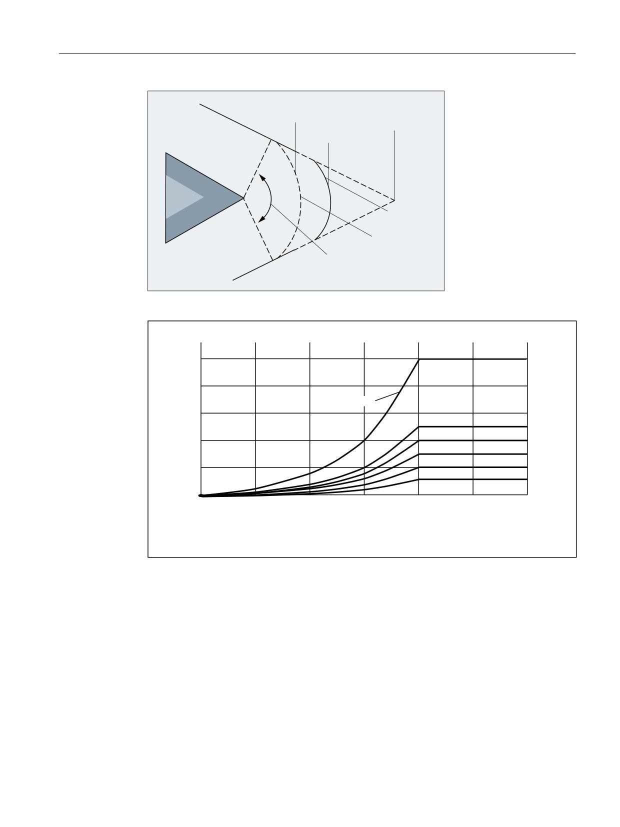
Figure 3-15
Example: Overshoot with DISC= 25
65
',6&
',6&
&RQWRXU
5 UDGLXV
6 WUDYHUVHG RYHUVKRRW
DQJOH>GHJUHHV@
65
QRUPDOL]HG RYHUVKRRW ZLWK UHVSHFW WR WRRO UDGLXV
Figure 3-16
Overshoot with DISC depending on contour angle
G451 (intersection)
If the G451 G command is active, the position (intersection) resulting from the path lines
(straight line, circle or helix only) located at a distance of the tool radius to the programmed
contour (center-point path of the tool) is approached. Splines and polynomials are never
extended.
Tools
Function Manual, 10/2020, 6FC5397-6GP40-0BA1
69
Tool offset
3.5 2D tool radius compensation
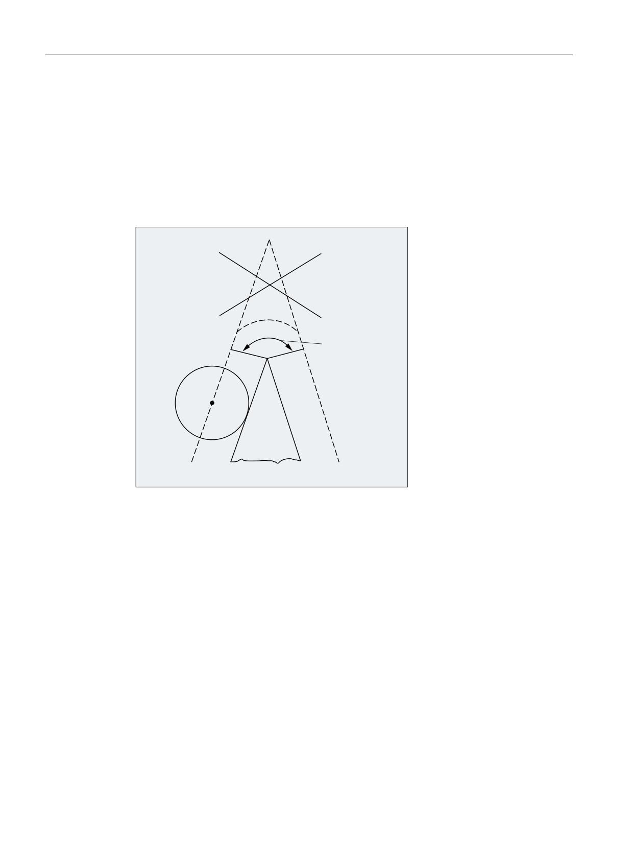
Very pointed outside corners
Where outside corners are very pointed, G451 can result in excessive idle paths. Therefore, the
system switches automatically from G451 (intersection) to G450 (transition circle, with DISC
where appropriate) when outside corners are very pointed.
The threshold angle (contour angle) for this automatic switchover (intersection point →
transition circle) can be specified in the machine data:
MD20210 $MC_CUTCOM_CORNER_LIMIT (Max. angle for compensation blocks with tool radius
compensation).
/RQJ QRQ FXWWLQJ SDWKV
&RQWRXU DQJOH
Figure 3-17
Example of automatic switchover to transition circle
Very flat outside corners
Where outside corners are very flat, the response with G450 (transition circle) and G451
(intersection) becomes increasingly similar. In this case, it is no longer advisable to insert a
transition circle. One reason why it is not permitted to insert a transition circle at these outside
corners with 5-axis machining is that this would impose restrictions on speed in contouring
mode (G64). Therefore, the system switches automatically from G450 (transition circle,
with DISC where appropriate) to G451 (intersection) when outside corners are very flat.
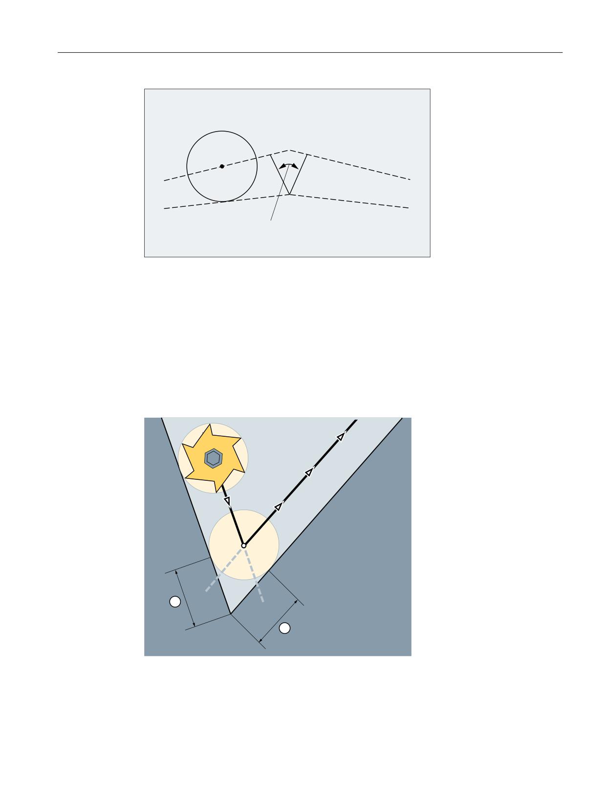
The threshold angle (contour angle) for this automatic switchover (transition circle →
intersection point) can be specified in the machine data:
MD20230 $MC_CUTCOM_CURVE_INSERT_LIMIT (Max. angle for intersection calculation with
tool radius compensation).
Tools
70
Function Manual, 10/2020, 6FC5397-6GP40-0BA1
Tool offset
3.5 2D tool radius compensation
EHORZ FRQWRXU DQJOH
0'
0&B&87&20B&859(B,16(57B/,0,7
1RW D WUDQVLWLRQ FLUFOH EXW LQWHUVHFWLRQ SRLQW
&RQWRXU DQJOH
Figure 3-18
Example of automatic switchover to intersection
3.5.7
Compensation and inner corners
Point of intersection
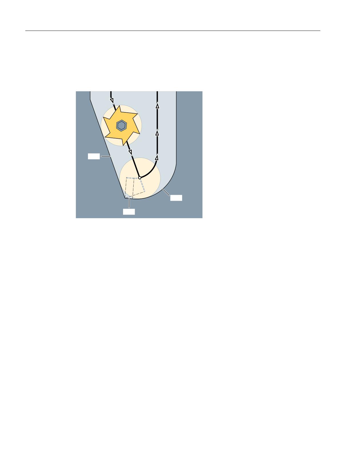
If two consecutive blocks form an inside corner, an attempt is made to find a point at which the
two equidistant paths intersect. If an intersection is found, the programmed contour is
shortened to the intersection:
6
S:
Point of intersection
① First block shortened at end.
② Second block shortened at beginning.
Figure 3-19
Programmed contour is shortened
Tools
Function Manual, 10/2020, 6FC5397-6GP40-0BA1
71
Tool offset
3.5 2D tool radius compensation
No intersection
For inside corners, it is possible that no intersection is found between two consecutive blocks.
In this case, the control automatically checks the next block and attempts to find an intersection
with the equidistant paths of this block:
1
6
1
1
S:
Point of intersection
Figure 3-20
Predictive contour calculation
This automatic check of the next blocks, predictive contour calculation, is always performed
until a number of blocks defined via machine data has been reached:
MD20240 $MC_CUTCOM_MAXNUM_CHECK_BLOCKS (blocks for predictive contour calculation
for TRC)
If no intersection is found within the number of blocks defined for the looking ahead, program
execution is interrupted and an alarm is output.
Tools
72
Function Manual, 10/2020, 6FC5397-6GP40-0BA1
Tool offset
3.5 2D tool radius compensation
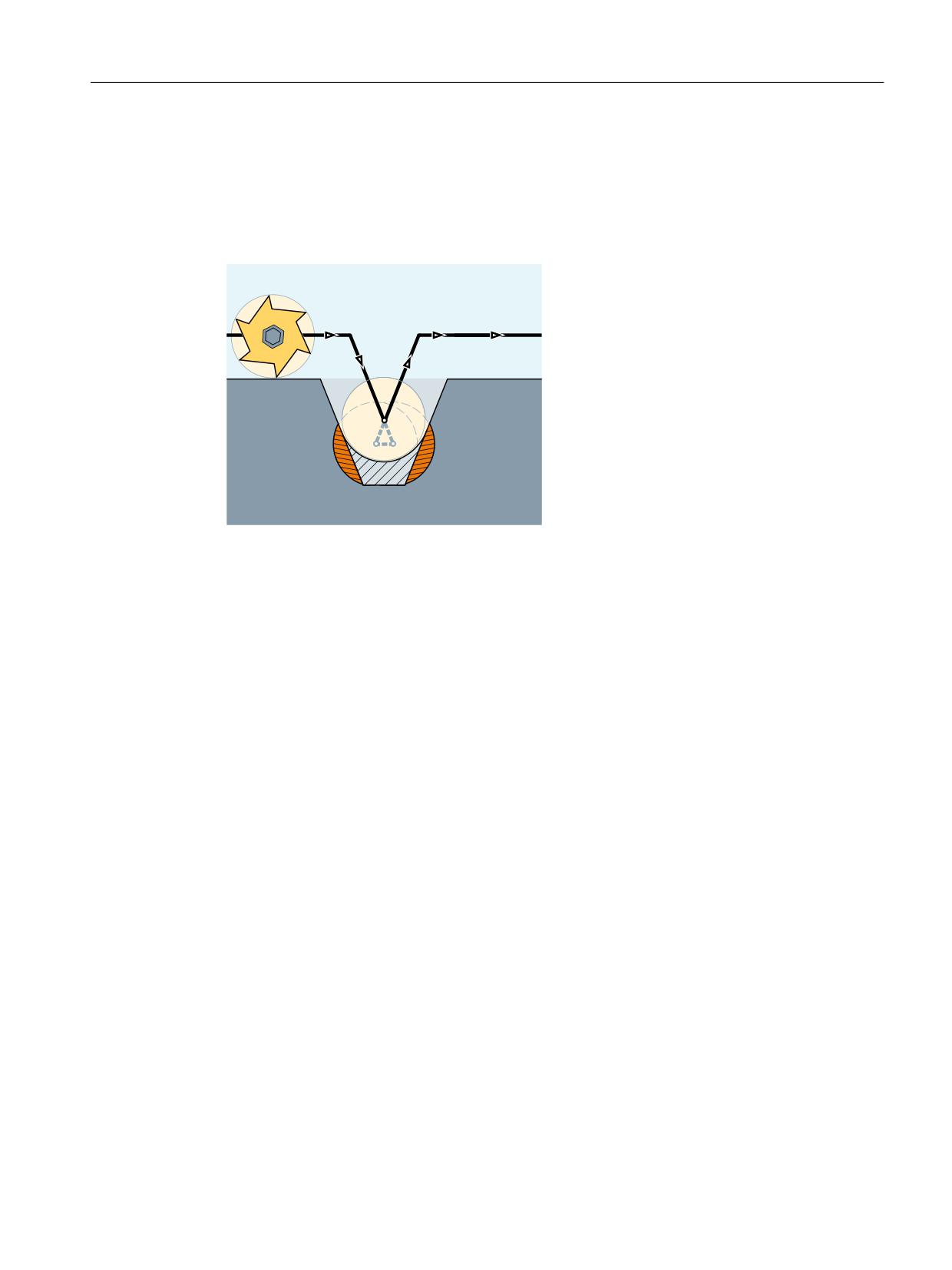
Multiple intersections
With inside corners it is also possible that predictive contour calculation finds multiple
intersections of the equidistant paths in several consecutive blocks. In this case, the last
intersection is always used as the valid intersection. The previous intersection points are not
approached:
6
6
6
Figure 3-21
In this example, the pocket is machined only as much as is possible without causing a
contour violation.
For further information, see also Chapter "Collision monitoring ("bottleneck detection")
(Page 73)".
Special features
Where multiple intersections with the next block are found, the intersection nearest the start of
the next block applies.
3.5.8
Collision monitoring ("bottleneck detection")
3.5.8.1
Function
If tool radius compensation is active, collision monitoring ("bottleneck detection") checks by
predictive contour calculation across a certain number of blocks whether the equidistant paths
of non-consecutive blocks intersect. This look-ahead function allows possible collisions to be
detected in advance and permits the control to actively avoid them.
The maximum number of blocks that are looked at in advance can be set by channel-specific
machine data (see "Parameterization (Page 74)").
If an intersection is detected, the motions programmed between these blocks on the
compensation plane are not executed. Alarm 10763 "The path component of the block in the
compensation plane will become zero" is displayed. This alarm does not interrupt the NC
program, it is only displayed as a warning. The bottleneck is bypassed. All other motions and
executable instructions (M commands, traversal of positioning axes, etc.) contained in the
omitted blocks are executed at the position of the last intersection found in the sequence in
which they are programmed in the NC program.
Tools
Function Manual, 10/2020, 6FC5397-6GP40-0BA1
73
Tool offset
3.5 2D tool radius compensation
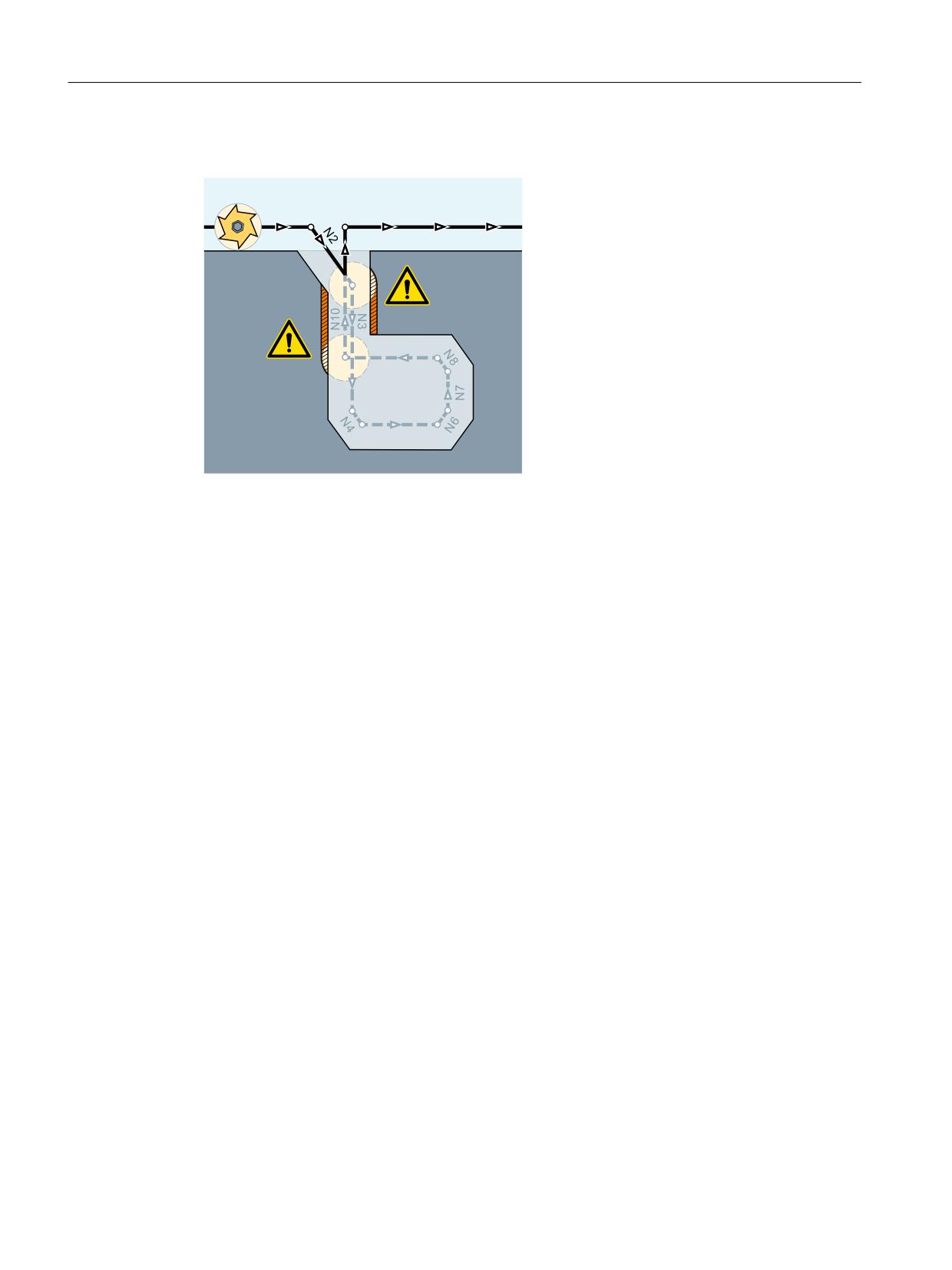
Example:
1
1
1
1
When collision monitoring is active with a predictive contour calculation ≥ 8 blocks, blocks
N3 to N10 are not executed, only alarm 10763 "The path component of the block in the
compensation plane will become zero" is displayed. The control system only runs through blocks
N1, N2 and N11.
Activation / deactivation
The function is activated / deactivated in the NC program with commands of G Group 23.
See "Programming (Page 75)".
3.5.8.2
Parameterization
Maximum number of blocks for predictive contour calculation
The maximum number of blocks to be predictively checked is set in:
MD20240 $MC_CUTCOM_MAXNUM_CHECK_BLOCKS (blocks for predictive contour calculation
for TRC)
Alarm 10763 "The path component of the block in the compensation plane will become zero"
Suppressing an alarm
The display of alarm 10763 "The path component of the block in the correction plane will
become zero" (Page 73) can be suppressed by the following setting:
MD11410 $MN_SUPPRES_ALARM_MASK (mask for support of special alarm outputs), bit 1 = 1
Outputting an alarm and stopping machining
Machining can be stopped by the following setting when alarm 10763 "The path component of
the block in the correction plane will become zero" is output:
Tools
74
Function Manual, 10/2020, 6FC5397-6GP40-0BA1

Tool offset
3.5 2D tool radius compensation
MD11411 $MN_ENABLE_ALARM_MASK (mask for activation of warnings), bit 16 = 1
Stopping the machining has the advantage that the user must actively confirm the skipping of
blocks by NC Start and thus knows that parts of the machining process may not be processed due
to a detected risk of collision.
3.5.8.3
Programming
Collision monitoring ("bottleneck detection") with active tool radius compensation is activated
or deactivated in the NC program with the commands of G group 23.
Syntax
G41/G42 CDON
CDOF/CDOF2
Meaning
CDON:
Activating collision detection ("bottleneck detection")
With CDON it is possible to check over an adjustable (MD20240 (Page 74)) number of
blocks whether the tool paths of non-adjacent or non-sequential blocks intersect. This look-
ahead function allows possible collisions to be detected in advance and permits the control
to actively avoid them.
CDOF:
Deactivating collision detection ("bottleneck detection")
With CDOF, a search is made in the previous traversing block (at inside corners) for a
common intersection for the current block; if necessary the search is extended to even
earlier blocks. If an intersection is found, no further blocks are examined. With outside
corners, an intersection is always found between two consecutive blocks.
Note:
CDOF can be used to avoid the faulty detection of bottlenecks which may occur due to lack
of information in the NC program, for example.
CDOF2:
Deactivating collision detection for 3D circumferential milling
The tool offset direction is determined from adjacent block parts with CDOF2. CDOF2 is only
effective for 3D circumferential milling (CUT3Dx) and has the same meaning as CDOF for all
other types of machining (e.g. CUT2D or CUT3DFD).
3.5.8.4
Supplementary conditions
Program test
To avoid program stops, the tool with the largest radius from the range of used tools should
always be used during the program test.
"Bottleneck detection" due to overhangs at outside corners
When the intersections of non-consecutive blocks are checked, not the programmed original
contours are examined, but the associated calculated equidistant paths. This can result in a
"bottleneck" being falsely detected at outside corners. The reason for this is that the calculated
tool path does not run equidistant to the programmed original contour when DISC > 0.
Tools
Function Manual, 10/2020, 6FC5397-6GP40-0BA1
75
Tool offset
3.5 2D tool radius compensation
RIIVHW FXUYH
2IIVHW FXUYH
ZLWK ',6&
ZKHQ
&LUFOH
',6& ! FRQLF
VHFWLRQ
3.5.8.5
Example
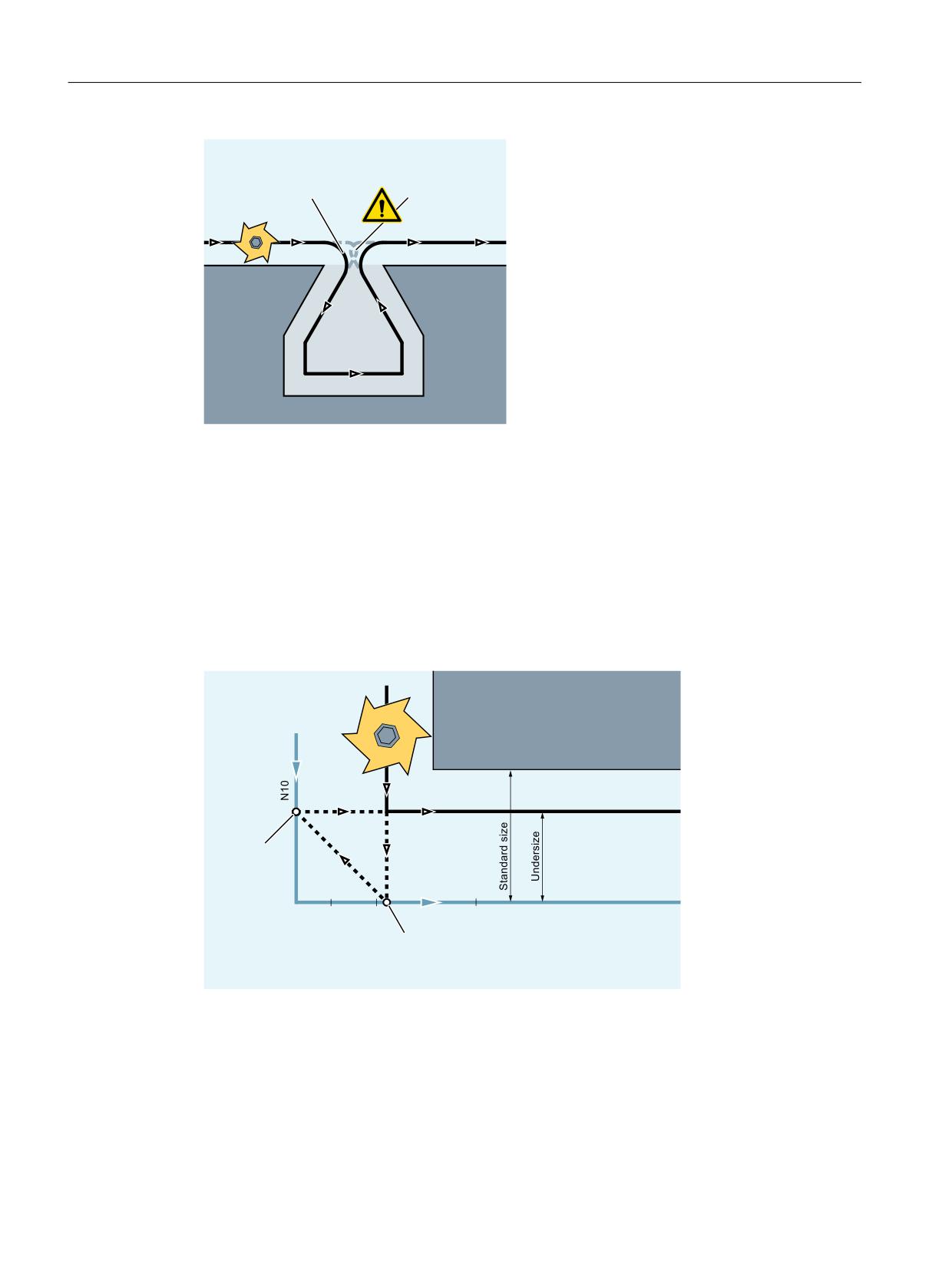
Effect of collision detection using an example
The NC program describes the center point path of a standard tool. The contour for a tool that
is actually used results in undersize, which is shown unrealistically large to demonstrate the
geometric relationships in the following figure.
The control also only has an overview of three blocks in the example:
MD20240 $MC_CUTCOM_MAXNUM_CHECK_BLOCKS = 3
3DUWLDO FRQWRXU
&RPSHQVDWHG
QRPLQDO SDWK
2IIVHW SRLQW
&RPSHQVDW
RIIVHW FXUYH
LQ VWDUWLQJ
LQJ PRWLRQ
SRLQW
RI 1
1
1
1
1
3URJUDPPHG
RULJLQDO SDWK
2IIVHW SRLQW
VWDQGDUG WRRO
LQ HQG SRLQW
RI 1
Since an intersection exists only between the offset curves of the two blocks N10 and N40, the
two blocks N20 and N30 would have to be omitted. In the example, the control does not know
in block N40 if N10 has to be completely processed. Only a single block can therefore be omitted.
With active CDOF2, the compensation motion shown in the figure is executed and not stopped.
In this situation, an active CDOF or CDON would result in an alarm.
Tools
76
Function Manual, 10/2020, 6FC5397-6GP40-0BA1
Tool offset
3.5 2D tool radius compensation
3.5.9
Slot shape recognition (option)
If tool radius correction is active and collision monitoring (Page 73) is switched on, a
programmed slot with a width smaller than the tool diameter is detected as a possible contour
violation and it is omitted from machining. In certain technology-dependent application cases
(e.g. manufacturing deflection lines with a laser cutting machine), however, it is necessary to
machine the slots when the radius of the tool (laser beam) is somewhat larger than the
programmed width of the slot would allow. To give the user this option, the tool radius
correction has been expanded to include the function "slot shape recognition".
Note
The "slot shape recognition" function is an option for SINUMERIK 840D sl that requires a license.
Article number: 6FC5800-0AS18-0YB0
Function
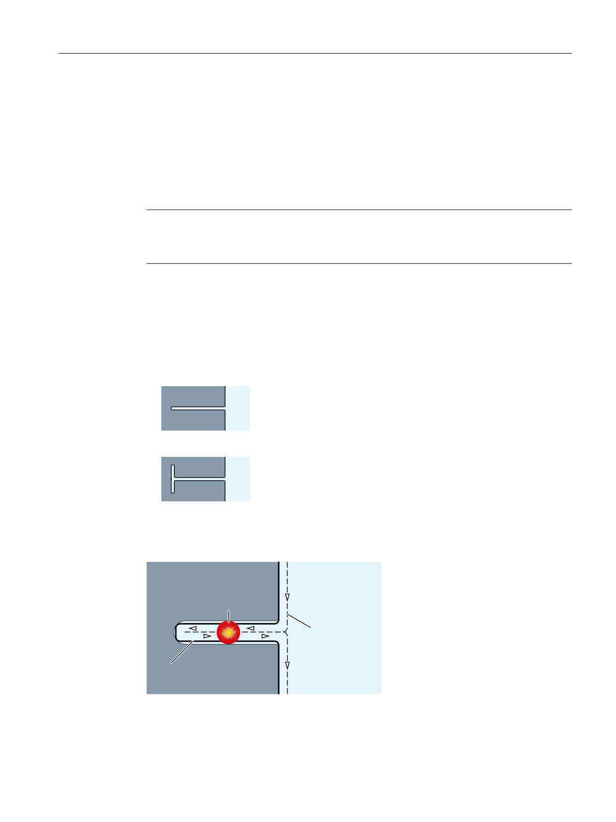
If the "slot shape recognition" function is active, slots that have a predefined shape are
automatically identified and their machining is ensured.
The following are detected:
• I-slot
• T-slot
If the slot width is greater than or equal to the tool diameter, the slot will be traversed as
programmed. If the slot width is smaller than the tool diameter, the equidistant path is
calculated in such a way that the tool traverses along the center of the programmed slot:
:RUNSLHFH
$LU
/DVHU IRFDO SRLQW
(TXLGLVWDQW SDWK
3URJUDPPHG
FRQWRXU
Tools
Function Manual, 10/2020, 6FC5397-6GP40-0BA1
77
Tool offset
3.5 2D tool radius compensation
The following conditions must be met:
• The radius of a new tool (R2) must not exceed the radius of the original tool (R1) by the factor
2:
R2 < 2 * R1
• The slot must have an odd number of blocks.
• The central block must comprise a straight line.
• The radius of the rounding at the start of the slot or the length of the block preceding the slot
must not be less than the difference R2 - R1.
Activation
To activate the function "slot shape recognition", the following channel-specific setting data
must be set to "1":
SD42977 $SC_SLOT_FORM_RECOGN = 1
Parameterization
Number of blocks for predictive feature recognition
The slot shape recognition is only active if the following channel-specific machine data is set to
a value greater than zero:
MD28620 $MC_MM_NUM_FEATURE_BLOCKS > 0
With MD28620, the minimum number of blocks is defined that are considered at any one time
in order to detect the slot shape.
Recommended value: 15 (This corresponds to the number of contour elements for a T-slot with
an arc between the straight lines.)
Example
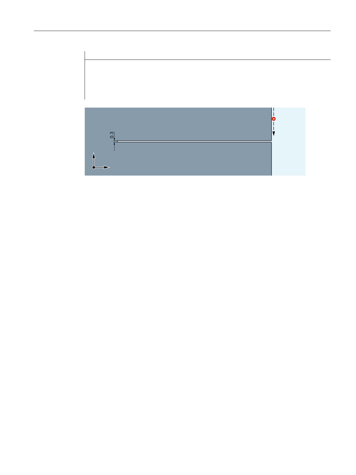
In the following part program section, a deflection line is programmed that will be cut with a
laser beam.
Program code
Comment
N1 G01 G90 G71 F10000
N2 $TC_DP1[1,1] = 120
N3 $TC_DP3[1,1] = 0.0
N4 $TC_DP6[1,1] = 0.2
; Tool radius = 0.2 mm
N6 G91 G41 G01 T=1 D=1
; Activate TRC.
N7 X100.00
N8 Y-24.500
N9 G02 X-0.200 Y-0.200 I-0.200
; Rounding at the start of the deflec-
tion line contour.
N10 G01 X-49.700
N11 G03 X-0.100 Y-0.100 J-0.100
N12 G01 Y-0.100
Tools
78
Function Manual, 10/2020, 6FC5397-6GP40-0BA1
Tool offset
3.5 2D tool radius compensation
Program code
Comment
N13 G03 X0.100 Y-0.100 I0.100
N14 G01 X49.700
N15 G02 X0.200 Y-0.200 J-0.200
; Rounding at the end of the deflec-
tion line contour.
N16 G01 Y-24.500
<
;
If slot shape recognition is inactive (SD42977 $SC_SLOT_FORM_RECOGN = 0), the tool radius
correction will detect and omit the programmed deflection line as an impermissible contour for
the tool used (laser beam) because the slot width is 0.3 mm but the tool has radius 0.2 mm. On
the other hand, if the slot shape recognition is active (SD42977 $SC_SLOT_FORM_RECOGN = 1),
the tool radius correction will detect the programmed deflection line as an I-slot and the laser
beam will cut the deflection line along the center of the programmed slot.
Because, in this example, the slot comprises seven contour elements (4 arcs, 3 straight lines),
the following minimum value must be set in MD28620 $MC_MM_NUM_FEATURE_BLOCK:
MD28620 $MC_MM_NUM_FEATURE_BLOCK ≥ 7
3.5.10
Blocks with variable compensation value
Supplementary conditions
A variable compensation value is permissible for all types of interpolation (including circular and
spine interpolation).
It is also permitted to change the sign (and, therefore, the compensation side).
Tools
Function Manual, 10/2020, 6FC5397-6GP40-0BA1
79
Tool offset
3.5 2D tool radius compensation
3URJUDPPHG FRQWRXU
1
1
1
1
7RRO FHQWHU SRLQW SDWK
1
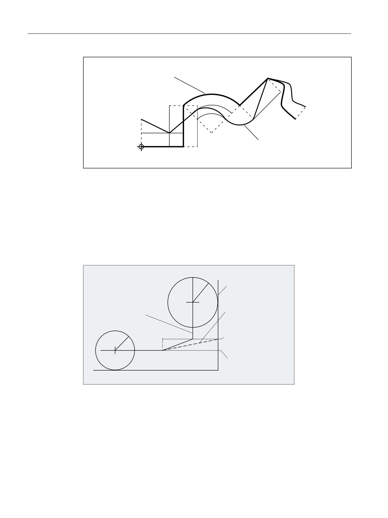
Figure 3-22
Tool radius compensation with variable compensation value
Calculation of intersection
When the intersections in blocks with variable compensation value are calculated, the
intersection of the offset curves (tool paths) is always calculated based on the assumption that
the compensation value is constant.
If the block with the variable compensation value is the first of the two blocks to be examined
in the direction of travel, then the compensation value at the block end is used for the
calculation; the compensation value at the block start is used otherwise.
3URJUDPPHG FRQWRXU
'
1
7KHRUHWLFDO WRRO
7RRO FHQWHU SDWK
FHQWHU SDWK
2YHUULGH ' DW WKH
'
HQG RI EORFN 1
1
1
2YHUULGH ' DW WKH
EHJLQQLQJ RI EORFN 1
Figure 3-23
Intersection calculation with variable compensation value
Restrictions
If during machining on the inside of the circle the compensation radius becomes geater than the
programmed circle radius, then the machining is rejected with the following alarm:
Alarm 10758 "Curvature radius with variable compensation value too small"
Tools
80
Function Manual, 10/2020, 6FC5397-6GP40-0BA1
Tool offset
3.5 2D tool radius compensation
Maintain stability of closed contour
If a radius of two circles is increased slightly, a third block may be necessary in order to maintain
the stability of the closed contour. This is the case if two adjacent blocks, which represent two
possible intersection points for a closed contour, are skipped due to the compensation.
A stable closed contour can be achieved by choosing the first intersection point instead of the
second.
SD42496 $SC_CUTCOM_CLSD_CONT ≠ 0 (response of TRC for closed contour).
In that case, the second intersection point is always reached, even if the block is skipped. A third
block is then not required.
3.5.11
Alarm behavior
Alarm during preprocessing
If a tool radius compensation alarm is output during preprocessing, main-run machining stops
at the next block end reached, i.e. usually at the end of the block currently being interpolated (if
Look Ahead is active, once the axes have come to a stop).
Alarms for preprocessing stop and active tool radius compensation
Tool radius compensation generally requires at least one of the following traversing blocks (even
more for bottlenecks) to determine the end point of a block. Since the preprocessing stop of such
a block is not available, traversing continues to the offset point in the last block. Correspondingly,
the offset point in the start point is approached in the first block after a preprocessing stop.
The contour obtained may deviate considerably from the one that would result without
preprocessing stop. Contour violations in particular are possible. Therefore the following setting
data was introduced:
SD42480 $MC_STOP_CUTCOM_STOPRE (alarm response for TRC and preprocessing stop).
The response of the tool radius compensation remains unchanged compared to the previous
status, and/or an alarm is output for preprocessing stop during active tool radius compensation
and the program is halted, depending on the value.
The user can acknowledge this alarm and continue the NC program with NC start or abort it with
RESET.
Tools
Function Manual, 10/2020, 6FC5397-6GP40-0BA1
81
Tool offset
3.5 2D tool radius compensation
3.5.12
Intersection procedure for polynomials
Function
If two curves with active tool radius compensation form an outside corner, depending on the G
command of the 18th group (corner behavior with tool compensation; G450/G451) and
regardless of the type of curves involved (straight lines, circles, polynomials):
• Either a conic is inserted to bypass the corner
or
• The curves involved are extrapolated to form an intersection.
If no intersection is found with G451 activated, or if the angle formed by the two curves is too
steep, switchover to insert mode is automatic.
The intersection procedure for polynomials is released with the machine data:
MD20256 $MC_CUTCOM_INTERS_POLY_ENABLE (intersection process possible for polynomials)
Note
If this machine data is set to inactive, a block (can be very short) is always inserted (even if
transitions are almost tangential). These short blocks always produce unwanted drops in speed
during G64 operation.
3.5.13
G461/G462 Approach/retract strategy expansion
Function
In certain special geometrical situations, extended approach and retraction strategies,
compared with the previous implementation, are required in order to activate or deactivate tool
radius compensation (see figure below).
Note
The following example describes only the situation for deactivation of tool radius compensation:
The response for approach is virtually identical.
Example
G42 D1 T1
; Tool radius 20 mm
G1 X110 Y0
N10 X0
N20 Y10
N30 G40 X50 Y50
Tools
82
Function Manual, 10/2020, 6FC5397-6GP40-0BA1
Tool offset
3.5 2D tool radius compensation
<
1
7RRO UDGLXV
;
&HQWHU SRLQW SDWK ZLWK
WRRO UDGLXV FRPSHQVDWLRQ
3URJUDPPHG
FRQWRXU
1
1
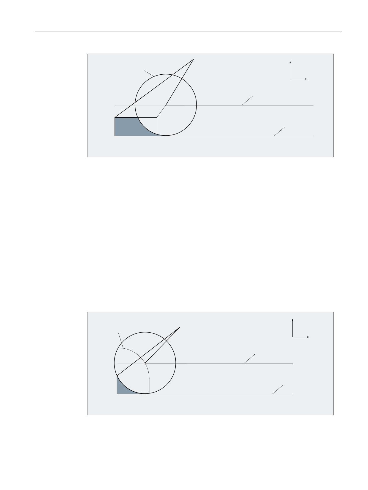
Figure 3-24
Retraction behavior with G460
The last block with active tool radius compensation (N20) is so short that an intersection no
longer exists between the offset curve and the preceding block (or a previous block) for the
current tool radius. An intersection between the offset curves of the following and preceding
blocks is therefore sought, i.e. between N10 and N30 in this example. The curve used for the
retraction block is not a real offset curve, but a straight line from the offset point at the end of
block N20 to the programmed end point of N30. The intersection is approached if one is found.
The colored area in the figure is not machined, although the tool used would be capable of this.
G460
With G460, the approach/retraction strategy is the same as before.
G461
If no intersection is possible between the last TRC block and a preceding block, the offset curve
of this block is extended with a circle whose center point lies at the end point of the uncorrected
block and whose radius is equal to the tool radius.
<
1
$X[LOLDU\ FXUYH
;
&HQWHU SRLQW SDWK ZLWK
WRRO UDGLXV FRPSHQVDWLRQ
3URJUDPPHG
FRQWRXU
1
1
Figure 3-25
Retraction behavior with G461
Tools
Function Manual, 10/2020, 6FC5397-6GP40-0BA1
83

Tool offset
3.5 2D tool radius compensation
The control attempts to cut this circle with one of the preceding blocks. If CDOF is active, the
search is terminated when an intersection is found, i.e. the system does not check for more
intersections with even earlier blocks.
If CDON is active, the search for more intersections continues after the first intersection is found.
An intersection point, which is found in this way, is the new end point of a preceding block and
the start point of the deactivation block. The inserted circle is used exclusively to calculate the
intersection and does not produce a traversing movement.
Note
If no intersection is found, the following alarm is output:
Alarm "10751 Collision danger"
G462
If no intersection is possible between the last TRC block and a preceding block, a straight line is
inserted, on retraction with G462 (basic setting), at the end point of the last block with tool
radius compensation (the block is extended by its end tangent).
<
$X[LOLDU\ FXUYH
1
1
;
&HQWHU SRLQW SDWK
FRUUHFWHG SDWK
3URJUDPPHG
FRQWRXU
1
1
Figure 3-26
Retraction behavior with G462
The search for the intersection is then identical to the procedure for G461.
With G462, the corner generated by N10 and N20 in the sample program is not machined to the
full extent actually possible with the tool used. However, this behavior may be necessary if the
part contour (as distinct from the programmed contour), to the left of N20 in the example, is not
permitted to be violated even with y values greater than 10 mm.
If KONT is active (travel round contour at start or end point), behavior will differ according to
whether the end point is in front of or behind the contour.
Tools
84
Function Manual, 10/2020, 6FC5397-6GP40-0BA1
Tool offset
3.5 2D tool radius compensation
End point in front of contour
If the end point is located in front of the contour, the retraction behavior is the same as
for NORM. This feature does not change, even if the last contour block with G451 is extended with
a straight line or a circle. Additional circumnavigation strategies to avoid a contour violation in
the vicinity of the contour end point are therefore not required.
End point behind contour
If the end point is behind the contour, a circle or straight line is always inserted depending
on G450/G451. In this case, G460-G462 has no effect.
If, in this situation, the last traversing block has no intersection with a preceding block, an
intersection with the inserted contour element or with the linear section from the end point of
the circumnavigation circle to the programmed end point can result.
If the inserted contour element is a circle (G450), and it intersects with the preceding block, this
is the same as the intersection, which would be produced with NORM and G461. In general,
however, a remaining section of the circle still has to be traversed. An intersection calculation is
no longer required for the linear section of the retraction block.
In the second case (if no intersection is found between the inserted contour element and the
preceding blocks), the intersection between the retraction straight line and a preceding block is
approached.
Therefore, when G461 or G462 is active, behavior deviating from G460 can only arise if NORM is
active or if behavior with KONT is identical to NORM due to the geometrical conditions.
Note
The approach behavior is symmetrical to the retraction behavior.
The approach/retraction behavior is determined by the state of the G command in the approach/
retraction block. The approach behavior can therefore be set independently of the retraction
behavior.
Example:
Program for using G461 during approach:
N10 $TC_DP1[1,1]=120
; Milling tool type
N20 $TC_DP6[1,1]=10
; Radius
N30 X0 Y0 F10000 T1 D1
N40 Y20
N50 G42 X50 Y5 G461
N60 Y0 F600
N70 X30
N80 X20 Y-5
N90 X0 Y0 G40
N100 M30
Tools
Function Manual, 10/2020, 6FC5397-6GP40-0BA1
85

Tool offset
3.6 2 1/2 D tool radius compensation
3.5.14
Tools with a relevant tool point direction
The following must be observed for tools with relevant cutting edge position:
• The straight line between the tool edge center points at the block start and block end is used
to calculate intersection points with the approach and retraction block. The difference
between the tool edge reference point and the tool edge center point is superimposed on this
movement.
For approach and/or retraction with KONT, the movement is superimposed in the linear
subblock of the approach or retraction movement. Therefore, the geometric conditions for
tools with or without relevant cutting edge position are identical.
• In circle blocks and in motion blocks containing rational polynomials with a denominator
degree > 4, it is not permitted to change a tool with active tool radius compensation in cases
where the distance between the tool edge center point and the tool edge reference point
changes. With other types of interpolation, it is now possible to change when a
transformation is active (e.g. TRANSMIT).
• For tool radius compensation with variable tool orientation, the transformation from the tool
edge reference point to the tool edge center point can no longer be performed by means of
a simple zero offset. Tools with a relevant cutting edge position are therefore not permitted
for 3D peripheral milling (an alarm is output).
Note
The subject is irrelevant with respect to face milling as only defined tool types without
relevant cutting edge position are permitted for this operation anyway. (A tool with a type,
which has not been explicitly approved, is treated as a ball end mill with the specified radius.
A cutting edge position parameter is ignored).
3.6
2 1/2 D tool radius compensation
The 2½ D tool radius compensation should be used if, when machining inclined surfaces,
the workpiece is to be rotated, and not the tool alignment. This function is activated using
commands CUT2D, CUT2DD, CUT2DF oder CUT2DFD.
Tool length offset
The tool length compensation is always taken into account referred to the machining plane that
is not rotated and is fixed in space.
2½ D tool radius compensation for contour tools
2½ D tool radius compensation for contour tools is activated, if, together with CUT2D, CUT2DD,
CUT2DF or CUT2DFD, one of the two commands G41 (tool radius compensation left of the
contour) or G42 (tool radius compensation right of the contour) is programmed. It is used for
automatic cutting-edge selection in the case of non-axially symmetrical tools that can be used
for piece-by-piece machining of individual contour segments.
Note
If 2½ D tool radius compensation is not activated, a contour tool behaves like a standard tool,
which only has the first cutting edge.
Tools
86
Function Manual, 10/2020, 6FC5397-6GP40-0BA1

Tool offset
3.6 2 1/2 D tool radius compensation
2½ tool radius compensation referred to a differential tool
2½ D tool radius compensation, referred to a differential tool, is activated using theCUT2DD or
CUT2DFD commands. It should be applied if the programmed contour refers to the center point
path of a differential tool, and a tool other than a differential tool is used for machining. When
calculating the 2½ D tool radius compensation, only the wear of the radius of the active tool
($TC_DP_15) and the possibly programmed tool offsetOFFN and TOFFR are taken into account.
The basic radius ($TC_DP6) of the active tool is not taken into account.
Syntax
CUT2D
CUT2DD
CUT2DF
CUT2DFD
Meaning
CUT2D:
Activating the 2½ D radius compensation
CUT2DD:
Activating the 2½ D radius compensation referred to a differential tool
CUT2DF:
Activating 2½ D radius compensation, tool radius compensation relative to the current
frame and/or inclined plane
CUT2DFD:
Activating 2½ D radius compensation, tool radius compensation relative to the current
frame and/or inclined plane
Further information
Contour tools
• Enabling
Tool radius compensation for contour tools is enabled on a channel-specific basis using:
MD28290 $MC_MM_SHAPED_TOOLS_ENABLE
• Tool type
Contour tool types are defined on a channel-specific basis using:
MD20370 $MC_SHAPED_TOOL_TYPE_NO
• Cutting edge
A number of cutting edges (D numbers) can be assigned to each contour tool in any
sequence. The maximum number of cutting edges per tool is parameterized using:
MD18106 $MN_MM_MAX_CUTTING_EDGE_PERTOOL
The first cutting edge of a contour tool is the cutting edge, which is selected when activating
the tool. If, e.g. in a program, using the commands T3 D5, the fifth cutting edge (D5) of the
third tool (T3) is activated, then D5 and the following cutting edges define with one part, or
altogether, the contour tool. The cutting edges located before D5 are ignored.
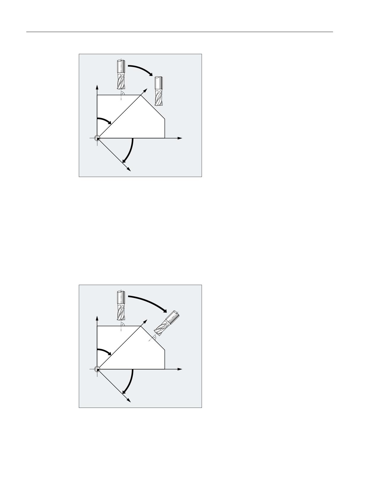
2½ D tool radius compensation without rotating the correction plane (CUT2D, CUT2DD)
If a frame that contains a rotation is programmed, then for CUT2D or CUT2DD, the plane in which
the tool radius compensation (correction plane) takes place is not rotated at the same time.
The tool radius compensation is taken into account, referred to the non rotated machining
plane (G17, G18, G19). The tool length compensation acts relative to the correction plane.
Tools
Function Manual, 10/2020, 6FC5397-6GP40-0BA1
87
Tool offset
3.6 2 1/2 D tool radius compensation
=
=
;
;
For machining inclined surfaces, the tool offsets must be appropriately defined or calculated
based on the functions for "Tool length compensation for tools that can be orientated".
2½ D tool radius compensation with rotation of the compensation plane (CUT2DF,
CUT2DFD)
If a frame is programmed that contains a rotation, then for CUT2DF or CUT2DFD, the plane in
which the tool radius compensation takes place (correction plane) is also rotated. The tool
radius compensation is taken into account, referred to the rotated machining plane (G17, G18,
G19). However, the tool length compensation still acts relative to the non-rotated machining
plane.
Requirement: At the machine, the tool orientation must be able to be adjusted perpendicular
to the rotated machining plane, and set for machining.
=
=
;
;
Tools
88
Function Manual, 10/2020, 6FC5397-6GP40-0BA1
Tool offset
3.7 Keep tool radius compensation constant
Note
The tool length compensation continues to be active relative to the non-rotated working plane.
For further information see the "Tools" Function Manual.
See also
Tool length compensation (Page 15)
3.7
Keep tool radius compensation constant
Meaning
The "Keep tool radius compensation constant" function is used to suppress tool radius
compensation for a number of blocks, whereby a difference between the programmed and the
actual traveled tool center path established by tool radius compensation in the previous blocks
is retained as the offset.
It can be an advantage to use this method when several traversing blocks are required during
line milling in the reversal points, but the contours produced by the tool radius compensation
(bypass strategies) are not wanted.
Activation
The "Keep tool radius compensation constant" function is activated with the G command
CUTCONON (CUTter compensation CONstant ON) and deactivated with the G command
CUTCONOF (CUTter compensation CONstant OFF).
CUTCONON and CUTCONOF form a modal G group.
The basic setting is CUTCONOF.
The function is applied independently of the type of tool radius compensation (2D-WRK, ...).
Normal case
Tool radius compensation is normally active before the compensation suppression and is still
active when the compensation suppression is deactivated again.
In the last traversing block before CUTCONON, the offset point in the block end point is
approached. All following blocks in which compensation suppression is active are traversed
without compensation. However, they are offset by the vector from the end point of the last
offset block to its offset point. These blocks can have any type of interpolation (linear, circular,
polynomial).
The deactivation block of the compensation suppression, i.e. the block that contains
CUTCONOF, is compensated normally. It starts in the offset point of the start point. One linear
Tools
Function Manual, 10/2020, 6FC5397-6GP40-0BA1
89

Tool offset
3.7 Keep tool radius compensation constant
block is inserted between the end point of the previous block, i.e. the last programmed
traversing block with active CUTCONON, and this point.
Circular blocks, for which the circle plane is perpendicular to the compensation plane (vertical
circles), are treated as though they had CUTCONON programmed. This implicit activation of
compensation suppression is automatically canceled in the first traversing block that contains a
traversing motion in the compensation plane and is not such a circle. Vertical circle in this sense
can only occur during circumferential milling.
Example:
N10
; Definition of tool d1
N20 $TC_DP1[1,1] = 110
; Type
N30 $TC_DP6[1,1]=
; Radius
N40
N50 X0 Y0 Z0 G1 G17 T1 D1 F10000
N60
N70 X20 G42 NORM
N80 X30
N90 Y20
N100 X10 CUTCONON
; Activation of the compensation suppression
N110 Y30 KONT
; On deactivation of contour suppression,
insert bypass circle, if necessary
N120 X-10 CUTCONOF
N130 Y20 NORM
; No bypass circle when deactivating the TRC
N140 X0 Y0 G40
N150 M30
Tools
90
Function Manual, 10/2020, 6FC5397-6GP40-0BA1
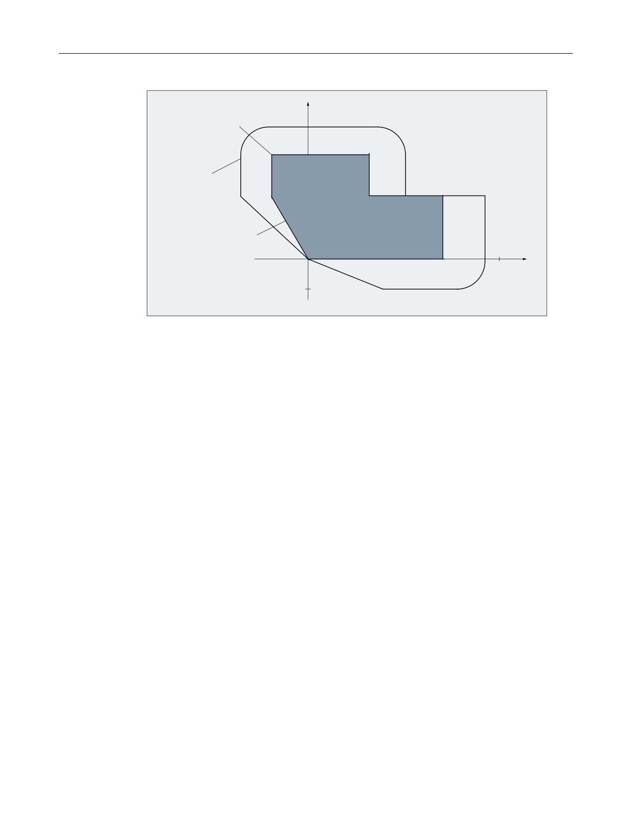
Tool offset
3.7 Keep tool radius compensation constant
<
&RQWRXU ZLWKRXW 75&
1
1
1
&RQWRXU ZLWK 75&
1
1
1
1
1
;
Figure 3-27
Sample program for contour suppression
Special cases
• If tool radius compensation is not active (G40), CUTCONON has no effect. No alarm is
produced. The G command remains active, however.
This is significant if tool radius compensation is to be activated in a later block with G41 or
G42.
• A change from the G command to the 7th G group (tool radius compensation; G40 / G41 /
G42) with active CUTCONON is permissible. A change to G40 is active immediately.
The offset used for traversing the previous blocks is traveled.
• If CUTCONON or CUTCONOF is programmed in a block without traversing in the active
compensation plane, activation is delayed until the next block that has such a traversing
motion.
• If CUTCONON is programmed with active tool radius compensation and not canceled before
the end of the program, the traversing blocks are traversed with the last valid offset.
The same applies for reprogramming of G41 or G42 in the last traversing block of a program.
• If tool radius compensation is activated with G41 or G42 and CUTCONON is also already
active, activation of compensation is delayed until the next traversing block with CUTCONOF.
• When repositioning with CUTCONOF, the 17th G group (approach and retraction behavior
with tool offset; NORM / KONT) is evaluated, i.e. a bypass circle is inserted if necessary for
KONT. A bypass circle is inserted under the same conditions as for activation of tool radius
compensation with G41 or G42.
• The number of blocks with suppressed tool radius compensation is restricted:
MD20252 $MC_CUTCOM_MAXNUM_SUPPR_BLOCKS (Maximum number of blocks with
compensation suppression)
If it is exceeded, machining is aborted and an error message issued.
The restriction is necessary because the internal block processing in the last block before
CUTCONON must be resumed when repositioning.
Tools
Function Manual, 10/2020, 6FC5397-6GP40-0BA1
91
Tool offset
3.8 Tool carriers with orientation capability
• The response after reprogramming G41 or G42 when tool radius compensation is already
active is similar to compensation suppression.
The following deviations apply:
- Only linear blocks are permissible
- A single traversing block that contains G41 or G42 is modified so that it ends at the offset
point of the start point in the following block. Thus it is not necessary to insert an
intermediate block. The same applies to the last block in a sequence of traversing blocks
where each contains G41 or G42.
- The contour is always reapproached with NORM, independent of the G command of the
17th group (approach and retraction behavior with tool offset; NORM / KONT).
• If G41 / G42 is programmed several times in consecutive traversing blocks, all blocks are
machined as for CUTCONON, except for the last one.
• The type of contour suppression is evaluated only in the first traversing block of a sequence
of blocks.
If both CUTCONON and G41 or G42 are programmed in the first block, the response to
deactivating contour suppression is determined by CUTCONON.
Changing from G41 to G42 or vice versa makes sense in this case as a means of changing the
compensation side (left or right of the contour) when restarting.
A change of the compensation side (G41/G42) can also be programmed in a later block, even
if contour suppression is active.
• Collision monitoring and bottleneck detection is deactivated for all blocks with active contour
suppression.
3.8
Tool carriers with orientation capability
3.8.1
General information
The orientation of the tool can vary, e.g. due to retooling, for one single class of machine tools.
When the machine is operating, the orientation that has been set is permanent, however, and
cannot be changed during traversing. For this reason, kinematic orientation transformation (3,
4 or 5axis transformations, TRAORI) is neither necessary nor does it make sense for such
machines. It is however necessary to consider the changes in the tool length components
attributable to the change in the orientation.
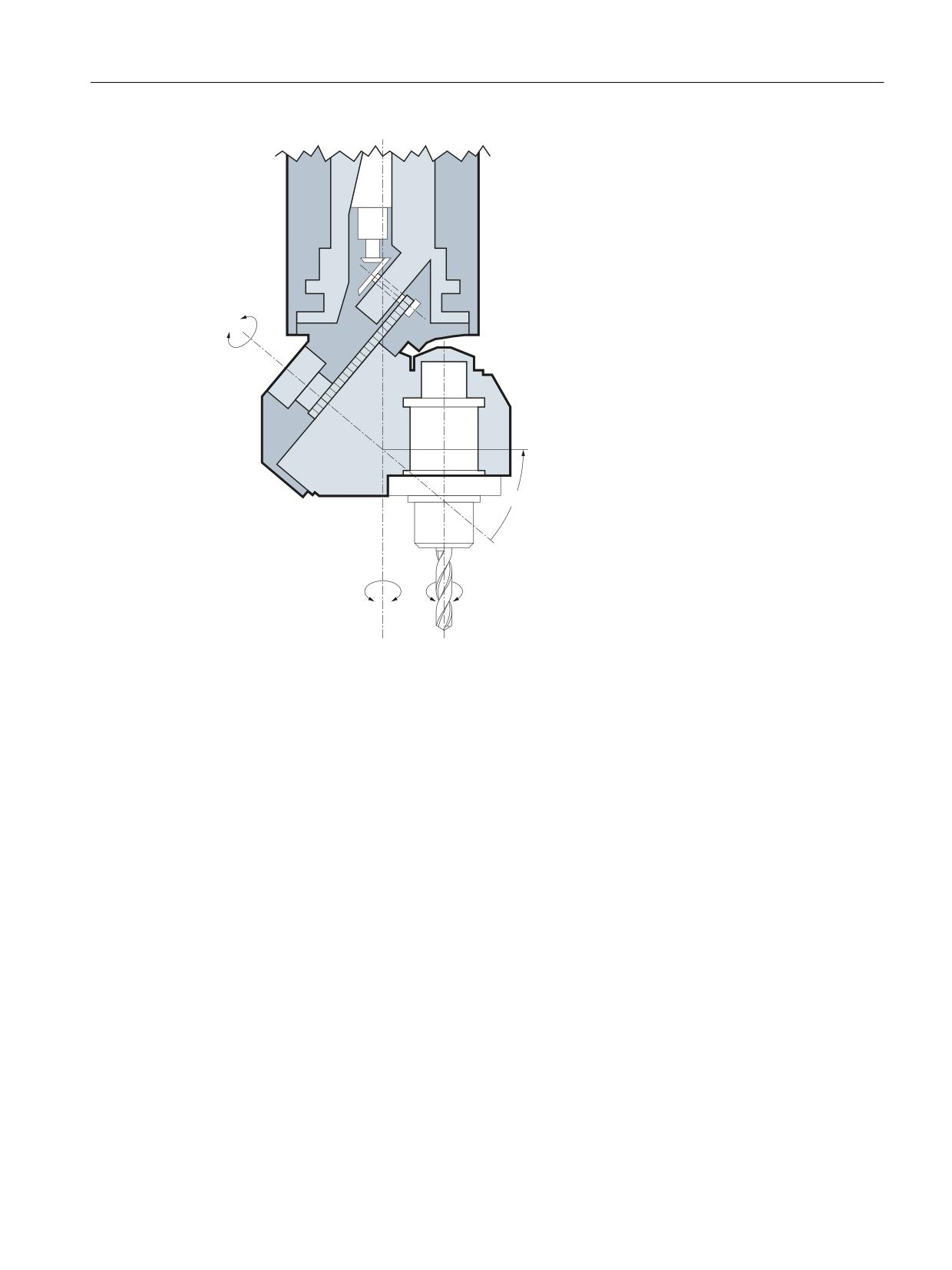
The following figure shows an example of an orientable tool carrier. It shows a Cardan tool carrier
with two axes for the tool orientation:
Tools
92
Function Manual, 10/2020, 6FC5397-6GP40-0BA1
Tool offset
3.8 Tool carriers with orientation capability
$ಿ
˳
&
7RRO D[LV
Figure 3-28
Cardan tool carrier with two axes
Prerequisites
The following data must be available so that the control can take tool offsets for orientable tool
carriers into account:
• Tool data (geometry, wear, etc.)
• Tool carrier data (data for the geometry of the tool carrier with orientation capability)
Tool carrier selection
The tool carrier is selected by programming the address TCARR in the NC program:
TCARR=<m>
<m>: Number of the tool carrier
The tool carrier has an associated tool carrier data block that describes its geometry.
Selection and activation of the tool carrier and its data block has an immediate effect, i.e. starting
with the next traversing block.
Tools
Function Manual, 10/2020, 6FC5397-6GP40-0BA1
93
Tool offset
3.8 Tool carriers with orientation capability
Assignment tool/tool carrier
The tool that was active previously is assigned to the new tool carrier.
Note
From the point of view of the control, tool carrier numbers <m> and tool numbers <n> can be
freely combined. In the real application, however, certain combinations can be ruled out for
machining or mechanical reasons. The control does not check whether the combinations make
sense.
Kinematics of the tool carrier
The kinematics of the tool carrier with orientation capability is described with a total of 33
parameter sets.
The data of the data block can be edited by the user.
Processing tool carrier data blocks
The following options are available for editing the tool carrier data blocks:
• Explicit entry in the tool carrier data block from the NC program
• Automatic acceptance of certain values (angles) from a frame
A requirement for this is that the G command TCOFR (Tool Carrier Orientation FRame) is also
specified when the tool carrier is selected.
The tool orientation used to calculate the tool length is determined again from the frame
active at this time when a tool carrier is changed.
Orientation in Z direction
The G command TOFRAME defines a frame such that the Z direction in this frame is the same as
the current tool orientation.
If no tool carrier or a tool carrier without change in orientation is active, then the following
applies for the Z direction in the new frame:
• With G17, the Z direction in the new frame is the same as the old Z direction.
• With G18, the Z direction in the new frame is the same as the old Y direction.
• With G19, the Z direction in the new frame is the same as the old X direction.
Absolute tool carrier orientation with active frame
The absolute tool carrier orientation is set with the G command TCOABS (Tool Carrier Orientation
ABSolute).
The orientation taken into account for the tool length compensation is independent of the
orientation of the active frame.
Either TCOABS or TCOFR can be valid.
Tools
94
Function Manual, 10/2020, 6FC5397-6GP40-0BA1
Tool offset
3.8 Tool carriers with orientation capability
Frame change
The user can change the frame after selecting the tool. This does not have any effect on the tool
length compensation components.
Angles in the tool carrier data
The programmed angles of rotation stored in the tool carrier data is not affected by the angle of
rotation defined by the frames. When changing from TCOFR to TCOABS, the original
(programmed) angles of rotation in the tool carrier data is reactivated.
Tool radius compensation
Tool radius compensation takes account of the current tool orientation when CUT2D or
CUT3DFS is active.
For the other correction types of G group 22, with the exception of CUT3DC and CUT3DF, the
behavior with respect to the plane used for correction is unchanged. This is determined
independent of the tool orientation from the active frame.
For CUT2DF and CUT3DFF, the compensation plane used for tool radius compensation is
determined from the frame independently of the current tool orientation. The active working
plane (G17/G18/G19) is considered.
CUT3DC and CUT3DF
3D tool offset for circumferential milling and 3D tool offset for face milling with active 5-axis
transformation are not affected by the "Tool carriers with orientation capability" function.
The orientation information is determined by the active kinematic 5-axis transformation.
Limited tool carrier orientation
An alarm is output if an orientation that cannot be reached with the defined tool carrier
kinematic is specified by the frame.
The situation that not every orientation can be achieved is given in the following cases:
• The two rotary axes which are necessary to define the kinematics are not perpendicular to
each other and the tool axis which defines the tool direction is not perpendicular to the
second rotary axis.
• Fewer than two axes are defined.
Non-rotary tool carriers
The tool orientation used internally is dependent only on the basic orientation of the tool and
the active machining plane (G17/G18/G19).
Ambiguities
With two axes, a particular tool orientation defined by the frame can generally be set with two
different rotation angle pairs. Of these two, the control selects the setting with which the rotary
angle is as close as possible to the programmed rotary angle.
Tools
Function Manual, 10/2020, 6FC5397-6GP40-0BA1
95

Tool offset
3.8 Tool carriers with orientation capability
Storing angles in the tool carrier data
In virtually any case where ambiguities may arise, it is necessary to store the approximate angle
expected from the frame in the tool carrier data.
Parameter sets
A complete parameter set for a tool carrier with orientation capability consists of 33 values,
which are stored in the following system variables:
• $TC_CARR1 to $TC_CARR33
In addition, there are system variables at the free disposal of the user and for fine offsets:
• $TC_CARR34 to $TC_CARR65
The significance of the individual parameters is distinguished as follows.
Machine kinematics
$TC_CARR1 to $TC_CARR20 and $TC_CARR23
$TC_CARR18 to $TC_CARR20 define a further vector l4, which is needed to describe the machine
with extended kinematics (both tool and workpiece can be rotated).
$TC_CARR21 and $TC_CARR22 contain the channel-axis names of the rotary axes, the positions
of which can be used to determine the orientation of the tool carrier with orientation capability,
if necessary.
Kinematic type
$TC_CARR23 = <kinematic type>
<Kinematic type>
Meaning
T
Only the (Tool) can be rotated (basic value).
P
Only the workpiece (Part) can be rotated.
M
Both tool and workpiece can be rotated (Mixed mode).
Parameterization of the axes of rotation
$TC_CARR24 to $TC_CARR33
The system variables in $TC_CARR24 to $TC_CARR33 can be used to define offsets, angle
compensations, Hirth tooth system and axis limits.
Components and presetting of the chain/data block
The values $TC_CARR1 to $TC_CARR20 and $TC_CARR24 to $TC_CARR33 in the tool carrier data
block are of NC language format type REAL..
The values $TC_CARR21 and $TC_CARR22 for the axis name of the first rotary axis (v1) and the
second rotary axis (v2) are of NC language format type AXIS.
They are all preset to zero.
The value $TC_CARR23 is initialized with the uppercase letter "T" (only tool can be rotated).
$TC_CARR[0]= 0 has a special significance.
Tools
96
Function Manual, 10/2020, 6FC5397-6GP40-0BA1

Tool offset
3.8 Tool carriers with orientation capability
System variables for tool carriers with orientation capability
$TC_CARR<n>[<m>]
<n>: Parameters 1 ... 33
<m>: Number of the orientable tool carrier
Value range:
1 ... MD18088 $MN_MM_NUM_TOOL_CARRIER (maximum number of
definable tool carriers)
NC variable
Meaning
Data type
Default setting
$TC_CARR1
x component of offset vector l1
REAL
0
$TC_CARR2
y component of offset vector l1
REAL
0
$TC_CARR3
z component of offset vector l1
REAL
0
$TC_CARR4
x component of offset vector l2
REAL
0
$TC_CARR5
y component of offset vector l2
REAL
0
$TC_CARR6
z component of offset vector l2
REAL
0
$TC_CARR7
x component of rotary axis v1
REAL
0
$TC_CARR8
y component of rotary axis v1
REAL
0
$TC_CARR9
z component of rotary axis v1
REAL
0
$TC_CARR10
x component of rotary axis v2
REAL
0
$TC_CARR11
y component of rotary axis v2
REAL
0
$TC_CARR12
z component of rotary axis v2
REAL
0
$TC_CARR13
Angle of rotation α1 (in degrees)
REAL
0
$TC_CARR14
Angle of rotation α2 (in degrees)
REAL
0
$TC_CARR15
x component of offset vector l3
REAL
0
$TC_CARR16
y component of offset vector l3
REAL
0
$TC_CARR17
z component of offset vector l3
REAL
0
$TC_CARR18
x component of offset vector l4
REAL
0
$TC_CARR19
y component of offset vector l4
REAL
0
$TC_CARR20
z component of offset vector l4
REAL
0
$TC_CARR21
Tool carrier of the rotary axis v1
AXIS
0
$TC_CARR22
Axis name of the rotary axis v2
AXIS
0
$TC_CARR23
Kinematic type
CHAR
T
$TC_CARR24
Offset of rotary axis v1
REAL
0
$TC_CARR25
Offset of rotary axis v2
REAL
0
$TC_CARR26
Angle offset of rotary axis v1 (Hirth tooth)
REAL
0
$TC_CARR27
Angle offset of rotary axis v2 (Hirth tooth)
REAL
0
$TC_CARR28
Angle increment of rotary axis v1 (Hirth tooth)
REAL
0
$TC_CARR29
Angle increment of rotary axis v2 (Hirth tooth)
REAL
0
$TC_CARR30
Minimum position of rotary axis v1 (SW limit)
REAL
0
$TC_CARR31
Minimum position of rotary axis v2 (SW limit)
REAL
0
$TC_CARR32
Maximum position of rotary axis v1 (SW limit)
REAL
0
$TC_CARR33
Maximum position of rotary axis v2 (SW limit)
REAL
0
Tools
Function Manual, 10/2020, 6FC5397-6GP40-0BA1
97

Tool offset
3.8 Tool carriers with orientation capability
System variables for the user and for fine offsets
• $TC_CARR34 to $TC_CARR40
Contain parameters, which are freely available to the user.
• $TC_CARR41 to $TC_CARR65
Contain fine offset parameters that can be added to the values in the basic parameters. The
fine offset value assigned to a basic parameter is obtained when the value 40 is added to the
parameter number.
• $TC_CARR47 to $TC_CARR54 and $TC_CARR61 to $TC_CARR63
Not defined and produce an alarm if read or write access is attempted.
NC variable
Meaning
Data type
Default setting
$TC_CARR34
Tool carrier name
STRING[32]
""
$TC_CARR35 *)
Axis name 1
STRING[32]
""
$TC_CARR36 *)
Axis name 2
STRING[32]
""
$TC_CARR37 *)
Identifier
INT
0
$TC_CARR38 *)
Position component X
REAL
0
$TC_CARR39 *)
Position component Y
REAL
0
$TC_CARR40 *)
Position component Z
REAL
0
$TC_CARR41
x comp. fine offset of offset vector l1
REAL
0
$TC_CARR42
y comp. fine offset of offset vector l1
REAL
0
$TC_CARR43
z comp. fine offset of offset vector l1
REAL
0
$TC_CARR44
x comp. fine offset of offset vector l2
REAL
0
$TC_CARR45
y comp. fine offset of offset vector l2
REAL
0
$TC_CARR46
z comp. fine offset of offset vector l2
REAL
0
$TC_CARR55
x comp. fine offset of offset vector l3
REAL
0
$TC_CARR56
y comp. fine offset of offset vector l3
REAL
0
$TC_CARR57
z comp. fine offset of offset vector l3
REAL
0
$TC_CARR58
x comp. fine offset of offset vector l4
REAL
0
$TC_CARR59
y comp. fine offset of offset vector l4
REAL
0
$TC_CARR60
z comp. fine offset of offset vector l4
REAL
0
$TC_CARR64
Offset of fine offset of rotary axis v1
REAL
0
$TC_CARR65
Offset of fine offset of rotary axis v2
REAL
0
*)
The system variables $TC_CARR35 to $TC_CARR40 are used in the measuring cycles as well as ShopMill
and ShopTurn.
3.8.2
Kinematic interaction and machine design
Representation of the kinematic chain
The concept of the kinematic chain is used to describe the kinematic interaction between a
reference point and the tool tip.
Tools
98
Function Manual, 10/2020, 6FC5397-6GP40-0BA1
Tool offset
3.8 Tool carriers with orientation capability
The chain specifies all the data required for the tool carrier data set in a schematic. To describe
the concrete case with a particular kinematic, the relevant components of the chain must be
assigned real vectors, lengths and angles. The chain represents the maximum constellation. In
simpler applications, individual components can be zero (e.g. kinematics with one or no axis of
rotation).
The machine does not have to have axes that rotate the tool and/or workpiece table. The
function can be used even if the orientations are set manually by handwheels or reconfiguration.
The machine design is described by the following parameters:
• Two axes of rotation (v1 and v2), each with one angle of rotation (α1 or α2), which counts
positively for clockwise rotation facing the direction of the rotation vector.
• Up to four offset vectors (l1 to l4) for relevant machine dimensions (axis distances, distances
to machine or tool reference points).
Zero vectors
Vectors v1 and v2 can be zero. The associated angle of rotation (explicitly programmed or
calculated from the active frame) must then also be zero, since the direction of the axis of
rotation is not defined. If this condition is not satisfied, an alarm is produced when the tool carrier
is activated.
Fewer than two axes of rotation
The option not to define an axis of rotation makes sense when the tool carrier to be described can
only rotate the tool in one plane. A sensible minimum data set may, therefore, contain only one
single entry not equal to 0 in the tool carrier data; namely, a value in one of the components of v1
or v2 for describing an axis of rotation parallel to the axis where the angle of rotation α1 or α2 is
determined from one frame.
Further special cases
Vectors v1 and v2 can be colinear. However, the degree of freedom for orientation is lost, i.e. this
type of kinematic is the same as one where only one axis of rotation is defined. All possible
orientations lie on one cone sheath. The conical sheath deforms to a straight line if tool
orientation t and v1 or v2 become colinear. Change of orientation is, therefore, not possible in
this special case. The cone sheath deforms to a circular surface (i.e. all orientations are possible
in one plane), if tool orientation t and v1 or v2 are perpendicular to each other.
It is permissible for the two vectors v1 and v2 to be zero. A change in orientation is then no longer
possible. In this special case, any lengths l1 and l2, which are not equal to zero, act as additional
tool length compensations, in which the components in the individual axes are not affected by
changing the plane (G17 - G19).
Tools
Function Manual, 10/2020, 6FC5397-6GP40-0BA1
99
Tool offset
3.8 Tool carriers with orientation capability
Kinematics data expansions
• Possibility of direct access to existing machine axes in order to define the setting of the tool
carriers via the rotary axis positions.
• Extension of the kinematics with rotary workpiece and on kinematics with rotary tool and
rotary workpiece.
• Possibility to permit only discrete values in a grid for the rotary axis positions (Hirth joints).
The extensions are compatible with earlier software versions and encompass the kinematic data
sets from $TC_CARR18 to $TC_CARR23.
Machine with rotary tool
On machines with rotary tool there is no change in the definition of the kinematics compared to
older software versions. The newly introduced vector l4, in particular, has no significance. Should
the contents of l4 not be zero, this is ignored.
The term "Toolholder with orientation capability" is actually no longer really appropriate for the
new kinematic types, with which the table can also be rotated, either alone or additionally to the
tool. However, it has been kept for reasons of compatibility.
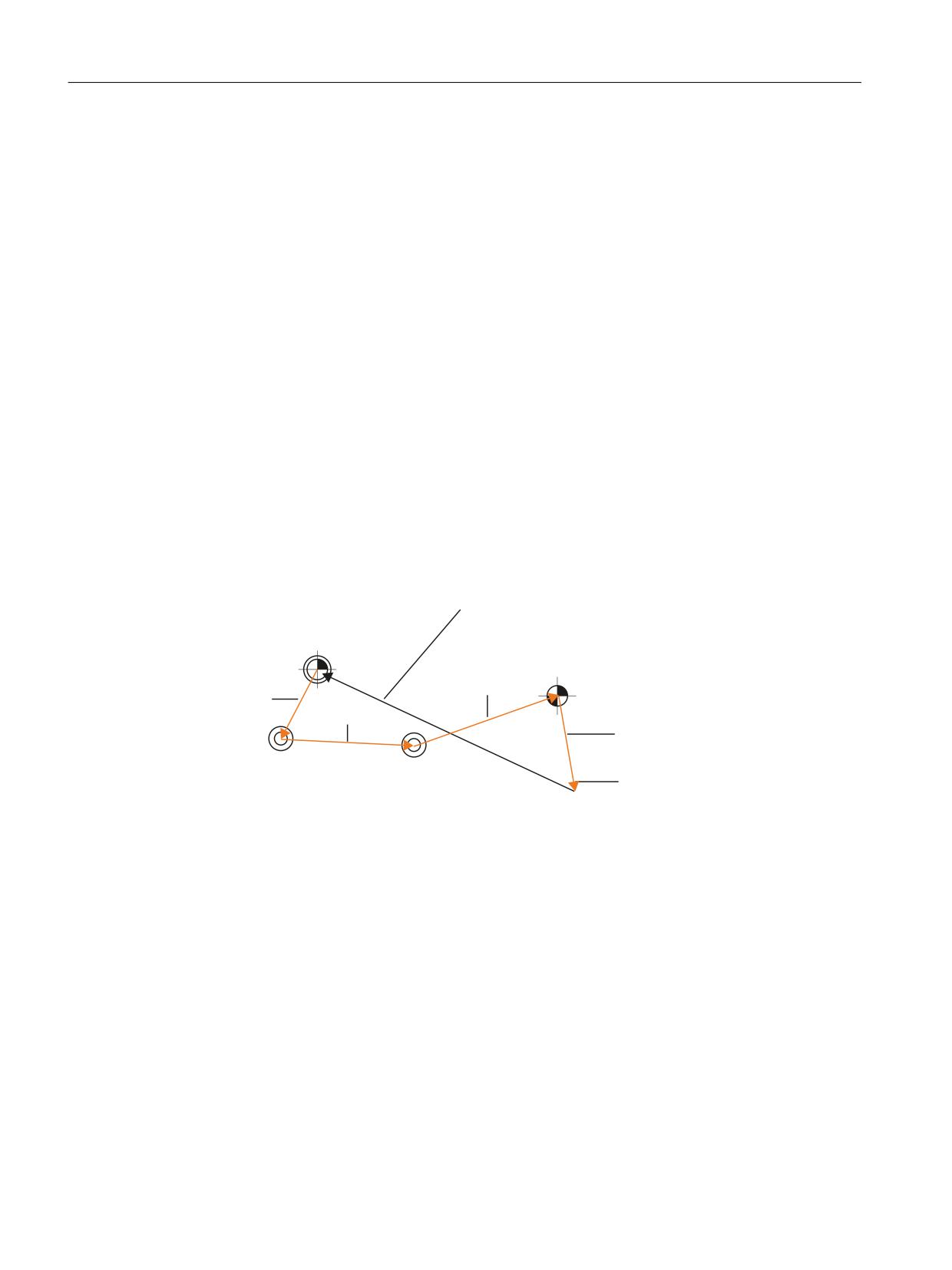
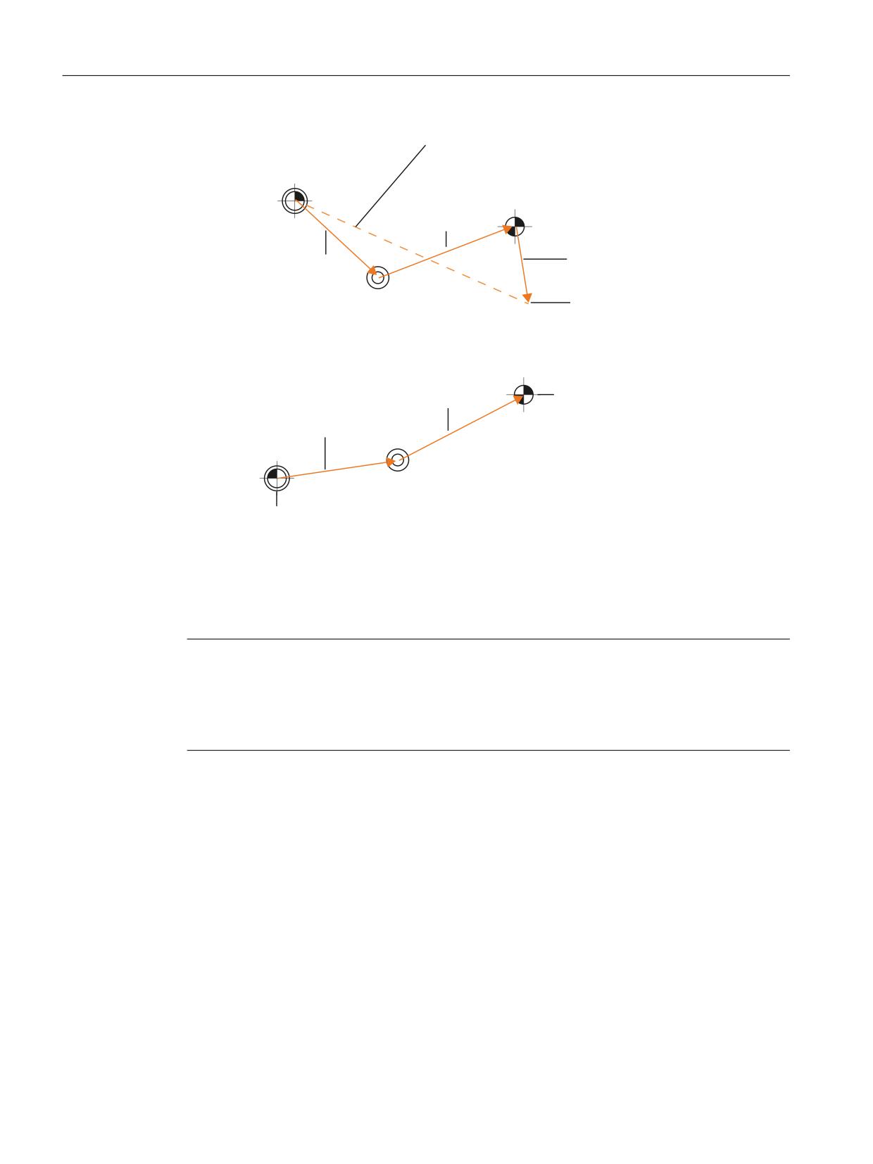
The kinematic chains used to describe the machine with rotary tool (general case) are shown in
the figure below:
5HVXOWLQJ WRRO OHQJWK
7RRO FDUULHU UHIHUHQFH SRLQW
FRPSHQVDWLRQ
6WDUWLQJ SRLQW RI WRRO FDUULHU WRRO
FKDLQ
7RRO UHIHUHQFH SRLQW
,
,
,
7RRO OHQJWK ZHDU WRRO EDVH
GLPHQVLRQ
Y
˞
Y
˞
7RRO WLS
Figure 3-29
Kinematic chain to describe a tool with orientation
Vectors which describe offsets in the rotary head are positive in the direction from the tool tip to
the reference point of the tool carrier.
The following kinematic type is defined for machines with a rotary tool:
Tools
100
Function Manual, 10/2020, 6FC5397-6GP40-0BA1
Tool offset
3.8 Tool carriers with orientation capability
$TC_CARR23 using letter T
Machine with rotary workpiece
On machines with rotary workpiece, the vector l1 has no significance. If it contains a value other
than zero, this is ignored.
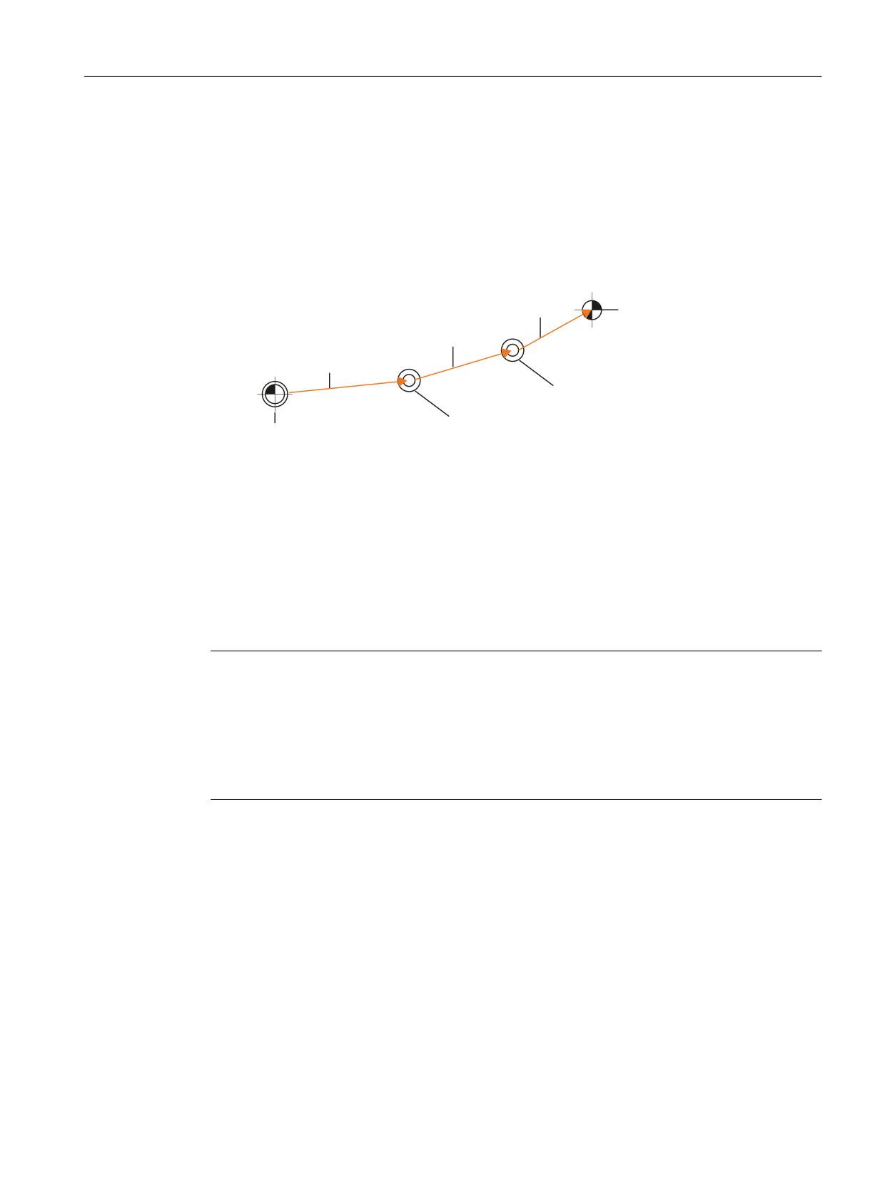
The kinematic chain for machines with rotary workpiece is shown in the figure below.
,
:RUNSLHFH UHIHUHQFH
SRLQW
,
,
Y
˞
Y
˞
0DFKLQH UHIHUHQFH SRLQW
Figure 3-30
Kinematic chain to describe a rotary table
Vectors, which describe offsets in the rotary table, are positive in the direction from the machine
reference point to the table.
The following kinematic type is defined for machines with a rotary workpiece:
$TC_CARR23 using letter P
Note
On machines with rotatable workpiece, it is generally useful if the selected machine reference
point and the reference point of the table are identical. Selecting the reference points in this way
has the advantage that the position of the workpiece zero in the initial state (i.e. with rotary axes
not turned) does not change when the rotary table is activated. The (open) kinematic chain (see
figure) is then closed.
In this special case, therefore, the following formula applies: l2 = - (l3 + l4)
Machines with extended kinematics
On machines with extended kinematics (both tool and workpiece are rotary), it is only possible
to turn each of the components with one axis.
The kinematic of the rotary tool is described with the first axis of rotation (v1) and the two vectors
l1 and l2, that of the rotary table with the second axis of rotation (v2) and the two vectors l3 and
l4. The two kinematic chain components for machines with rotary tool and rotary workpiece are
shown in the figure below.
Tools
Function Manual, 10/2020, 6FC5397-6GP40-0BA1
101
Tool offset
3.8 Tool carriers with orientation capability
5HVXOWLQJ WRRO OHQJWK
FRPSHQVDWLRQ
7RRO FDUULHU UHIHUHQFH SRLQW
7RRO UHIHUHQFH SRLQW
,
7RRO OHQJWK ZHDU WRRO EDVH
,
GLPHQVLRQ
Y
˞
7RRO WLS
5HIHUHQFH SRLQW RI WRRO WDEOH
,
,
Y
˞
0DFKLQH UHIHUHQFH SRLQW
Figure 3-31
Kinematic sequence with extended kinematics
The following kinematic type is defined for machines with a rotary tool and rotary workpiece:
$TC_CARR23 using letter M (extended kinematics)
Note
On machines with extended kinematics it is generally useful, as with machines where only the
table can be rotated, for the machine reference point and the reference point of the table to be
identical. The (open) chain component to describe the table (see figure) is then closed.
In this special case, the following formula applies: l3 = - l4
Rotary tool types T and M
For machine kinematics with a rotary tool (types T and M), the tool carrier component with
orientation capability, which describes the tool or head component (as opposed to the table
component), acts, in conjunction with the active tool, as a new overall tool.
Fine offset
The offset vectors l1 to l4 and the offsets of the axes of rotation v1 and v2 can be represented as the
sum of a basic value and a fine offset. The fine offset parameters assigned to the basic values are
achieved by adding a value of 40 to the index of the basic value.
Example:
Tools
102
Function Manual, 10/2020, 6FC5397-6GP40-0BA1

Tool offset
3.8 Tool carriers with orientation capability
The parameter $TC_CARR5 is assigned to the fine offset $TC_CARR45.
Note
For the significance of the system variables $TC_CARR41 to $TC_CARR65 available for the fine
offset see:
Further information
Programming Manual Advanced; Tool offsets
Activation
The following setting adds the fine offset values to the basic values:
SD42974 $SC_TOCARR_FINE_CORRECTION = 1 (fine offset TCARR on/off)
Constraints
The amount is limited to the permissible fine offset.
The maximum permissible value is defined:
Components
Machine data
• Components of vectors l1 to l4:
MD20188 $MC_TOCARR_FINE_LIM_LIN
• Offsets of the two axes of rotation v1 and v2:
MD20190 $MC_TOCARR_FINE_LIM_ROT
An impermissible fine offset value is only detected upon occurrence of the following conditions:
• A tool carrier capable of orientation which has such a value is activated
• The following setting data is applied at the same time:
SD42974 $SC_TOCARR_FINE_CORRECTION
Description of a rotation
A data set for describing a rotation comprises one vector v1 /v2 to describe the direction of
rotation of the axis of rotation in its initial state and an angle α1/α2. The angle of rotation is
counted positively for clockwise rotation facing the direction of the rotation vector.
The two tool carrier angles α1 and α2 are determined using a frame, independent of the active
plane currently selected (G17 - G19).
The tool orientation in the initial state (both angles α1 and α2 are zero) is (as in the default case):
• G17: Parallel to Z.
• G18: Parallel to Y.
• G19: Parallel to X.
Assigning data to the tool carrier
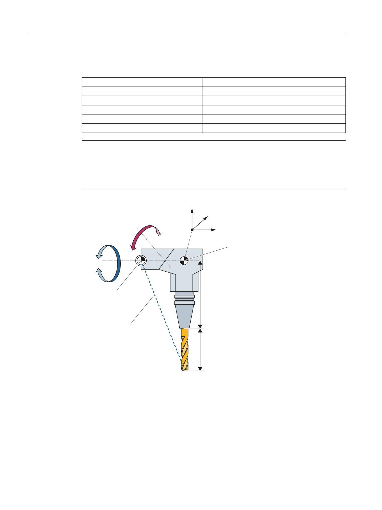
Example of a machine with rotary tool carrier
Tools
Function Manual, 10/2020, 6FC5397-6GP40-0BA1
103
Tool offset
3.8 Tool carriers with orientation capability
The following settings are obtained at the mill head shown for a machine with tool carrier with
orientation capability of kinematic type T:
Component of the offset vector l1 =
(-200, 0, 0)
Component of the offset vector l2 =
(0, 0, 0)
Component of the offset vector l3 =
(-100, 0, 0)
Component of axis of rotation v1 =
(1, 0, 0)
Component of axis of rotation v2 =
(-1, 0, 1)
Tool base dimension of tool reference point
(0, 0, 250)
Note
The tool reference point for the tool base dimension is defined by the reference point at the
machine.
For further information regarding the reference points in the working area, see Function Manual
"Basic Functions", Chapter "Axes, coordinate systems, frames".
=
<
;
Y
7RRO UHIHUHQFH SRLQW
,
,
Y
,
7RRO EDVH GLPHQVLRQ
7RRO FDUULHU UHIHUHQFH SRLQW
5HVXOWLQJ WRRO OHQJWK
FRPSHQVDWLRQ
7RRO OHQJWK ZHDU
Figure 3-32
Assignment of the tool carrier data
Tools
104
Function Manual, 10/2020, 6FC5397-6GP40-0BA1

Tool offset
3.8 Tool carriers with orientation capability
Suitable assumptions were made for the following values in the data set:
• The two axes of rotation intersect at one point.
All components of l2 are therefore zero.
• The first axis of rotation lies in the x/z plane, the second rotary axis is parallel to the x axis.
These conditions define the directions of v1 and v2 (the lengths are irrelevant, provided that
they are not equal to zero).
• The reference point of the tool carrier lies 200 mm in the negative x direction viewed from
the intersection of the two rotary axes.
This condition defines l1 .
Specify associated data set values
The following associated data set values are specified for the tool carrier shown on a machine
with rotary tool carrier:
Description
NC variable
Value
x component of offset vector l1
$TC_CARR1
-200
y component of offset vector l1
$TC_CARR2
0
z component of offset vector l1
$TC_CARR3
0
x component of offset vector l2
$TC_CARR4
0
y component of offset vector l2
$TC_CARR5
0
z component of offset vector l2
$TC_CARR6
0
x component of axis of rotation v1
$TC_CARR7
1
y component of axis of rotation v1
$TC_CARR8
0
z component of axis of rotation v1
$TC_CARR9
0
x component of axis of rotation v2
$TC_CARR10
-1
y component of axis of rotation v2
$TC_CARR11
0
z component of axis of rotation v2
$TC_CARR12
1
Angle of rotation α1 (in degrees)
$TC_CARR13
0
Angle of rotation α2 (in degrees)
$TC_CARR14
0
x component of offset vector l3
$TC_CARR15
-100
y component of offset vector l3
$TC_CARR16
0
z component of offset vector l3
$TC_CARR17
0
Explanations
The tool carrier kinematic chosen in the example is such that the two axes of rotation form an
angle of 45 degrees, which means that the orientation cannot take just any value. In concrete
terms, this example does not permit the display of orientations with negative X components.
x component of the tool base dimension:
0
y component of the tool base dimension:
0
z component of the tool base dimension:
250
Tools
Function Manual, 10/2020, 6FC5397-6GP40-0BA1
105
Tool offset
3.8 Tool carriers with orientation capability
Note
The required data cannot be determined unequivocally from the geometry of the tool carrier, i.e.
the user is free to a certain extent to decide the data to be stored. Thus, for the example, it is
possible to specify only one z component for the tool base dimension up to the second axis. In
this case, l2 would no longer be zero, but would contain the components of the distance
between this point on the second axis and a further point on the first axis. The point on the first
axis can also be selected freely. Depending on the point selected, l1 must be selected such that
the reference point (which can also be selected freely) is reached.
In general: Vector components that are not changed by rotation of an axis can be distributed
over any vectors "before" and "after" rotation.
3.8.3
Tool carrier with kinematic chains
Modeling tool carriers with kinematic chains
On machines whose structures are defined with kinematic chains, machine parts that act as tool
carriers can also be described using kinematic chains. Identical geometry data for kinematic
chains and tool carriers can be managed jointly.
Two kinematic chains are required to define the machine kinematics:
• One chain points from machine zero (zero point of world coordination system) to the
workpiece reference point (workpiece part).
• The other chain points from machine zero to the tool carrier reference point (tool part).
• You will find information about kinematic chains in the Function Manual "Basic functions".
Three different kinematic types are available for tool carriers, which are parametrized via
$TC_CARR23.
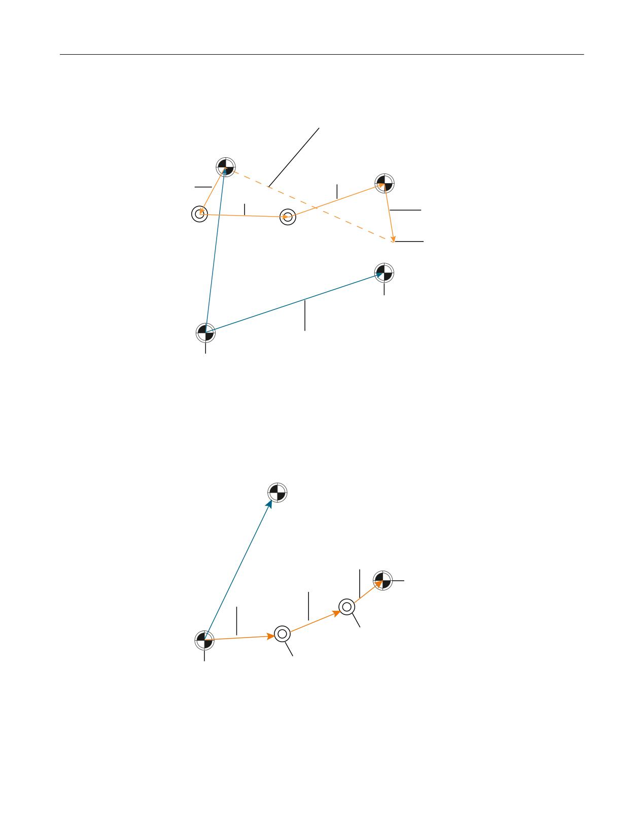
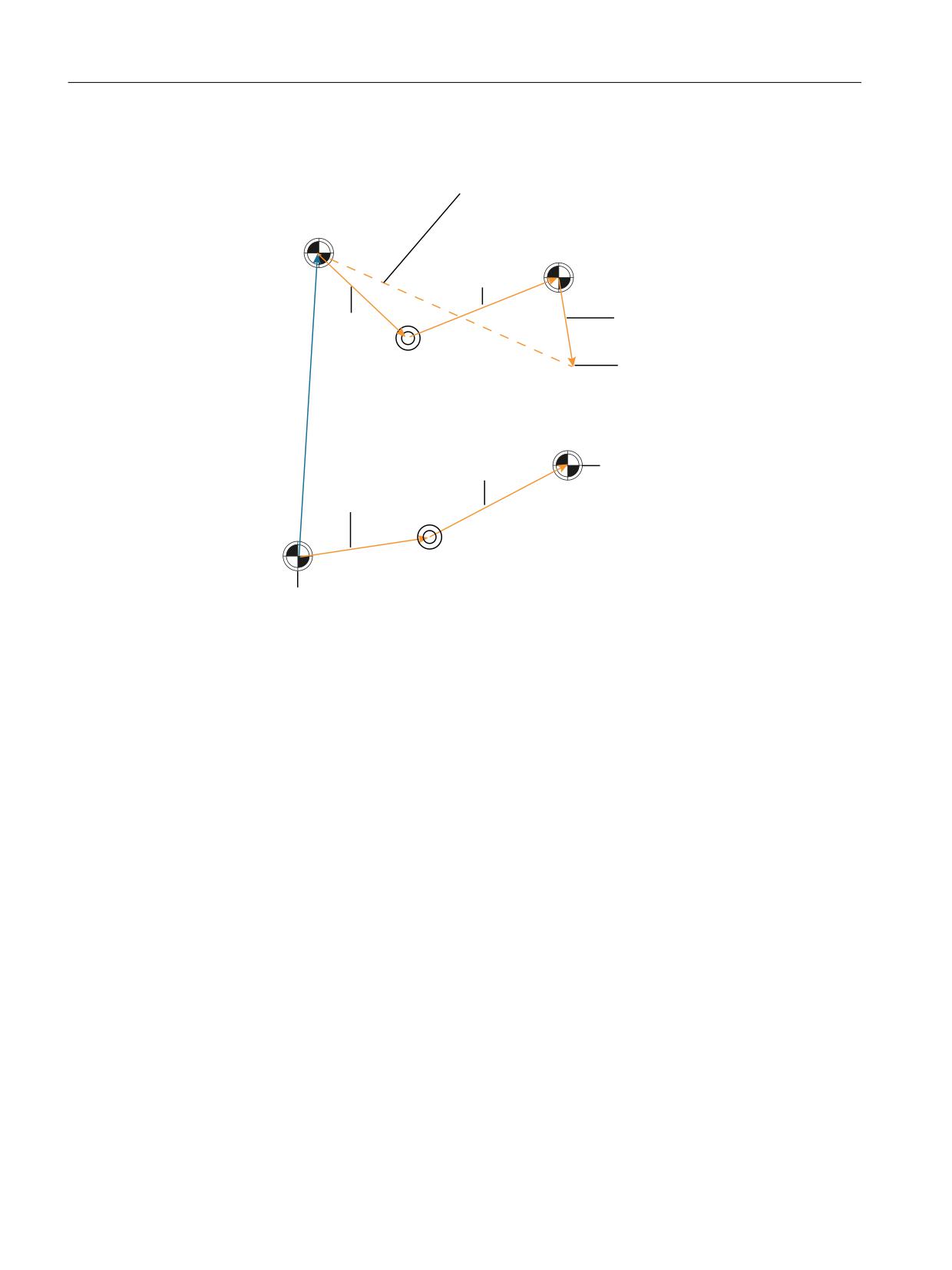
The following graphics show an example of the kinematics of a machine with rotatable tool
(type T) and rotatable workpiece (type P) and the resolved kinematics (type M). The resolved
kinematics (type M) is a combination of both types.
Tools
106
Function Manual, 10/2020, 6FC5397-6GP40-0BA1
Tool offset
3.8 Tool carriers with orientation capability
Example for a rotatable tool
5HVXOWLQJ WRRO OHQJWK
7RRO FDUULHU UHIHUHQFH SRLQW
FRPSHQVDWLRQ
6WDUWLQJ SRLQW RI WRRO FDUULHU WRRO
FKDLQ
7RRO UHIHUHQFH SRLQW
,
,
,
7RRO OHQJWK ZHDU WRRO EDVH
GLPHQVLRQ
Y
˞
Y
˞
7RRO WLS
:RUNSLHFH UHIHUHQFH SRLQW
ZRUNSLHFH FKDLQ
:RUNSLHFH RIIVHW
=HUR SRLQW RI WRRO ZRUOG
FRRUGLQDWH V\VWHP
5227
Orange:
Kinematic chain of the tool carrier
Blue:
Kinematic chain of the machine
Figure 3-33
Tool carrier with rotatable tool
Example of a rotatable workpiece
7RRO UHIHUHQFH SRLQW WRRO
FKDLQ
,
:RUNSLHFH UHIHUHQFH SRLQW
,
ZRUNSLHFH FKDLQ (QG SRLQW
RI NLQHPDWLF FKDLQ
,
Y
˞
Y
˞
=HUR SRLQW RI ZRUOG FRRUGLQDWH
V\VWHP 6WDUWLQJ SRLQW RI WKH
NLQHPDWLF FKDLQ
5227
Orange:
Kinematic chain of the tool carrier
Blue:
Kinematic chain of the machine
Figure 3-34
Tool carrier with rotatable workpiece
Tools
Function Manual, 10/2020, 6FC5397-6GP40-0BA1
107
Tool offset
3.8 Tool carriers with orientation capability
Example of mixed kinematics
5HVXOWLQJ WRRO OHQJWK
7RRO FDUULHU UHIHUHQFH SRLQW
FRPSHQVDWLRQ
6WDUWLQJ SRLQW RI WKH WRRO FKDLQ RI
WKH WRRO FDUULHU
7RRO UHIHUHQFH SRLQW
,
7RRO OHQJWK ZHDU WRRO EDVH
,
GLPHQVLRQ
Y
˞
7RRO WLS
:RUNSLHFH UHIHUHQFH SRLQW
,
ZRUNSLHFH FKDLQ (QG SRLQW RI
NLQHPDWLF FKDLQ
,
Y
˞
=HUR SRLQW RI WKH ZRUOG FRRUGLQDWH V\VWHP
6WDUWLQJ SRLQW RI WKH NLQHPDWLF FKDLQ
5227
DQG VWDUWLQJ SRLQW RI WKH ZRUNSLHFH FKDLQ RI
WKH WRRO FDUULHU
I1 and I2
Offset of the tool chain of the tool carrier
v1
Rotary axis of the tool chain
I3 and I4
Offset of the workpiece chain of the tool carrier
v2
Rotary axis of the tool chain
Figure 3-35
Mixed kinematics
The kinematics of the tool carrier is defined together with the machine kinematics.
Definition of the tool carrier:
• Definition of the characteristics of tool carrier with $TC_CARR_KIN_CNTRL:
- Close tool carrier via kinematic chain, tool chain, and table chain of the tool carrier.
• The starting point of the kinematic chain of the tool carrier is set via system variables
$TC_CARR_KIN_TOOL_START and $TC_CARR_KIN_PART_START (chain element name).
• Definition of the rotary axes of the tool carrier with $TC_CARR21 (Page 92) and $TC_CARR22
• Definition of the tool carrier type with $TC_CARR23 (T, P, or M)
Tools
108
Function Manual, 10/2020, 6FC5397-6GP40-0BA1
Tool offset
3.8 Tool carriers with orientation capability
Definition of the kinematics of the tool carrier:
The workpiece part of a kinematic chain for a tool carrier can be structured as follows, for
example:
• Define the linear axes of the kinematic chain (geometric axes X, Y, and Z).
• Define a kinematic element of type "OFFSET" (=I2) in the X, Y, and Z direction. Corresponds to
$TC_CARR4 - $TC_CARR6.
• Define a kinematic element of type "AXIS_ROT" (=v1) in the X, Y, and Z direction. Corresponds
to $TC_CARR7 - $TC_CARR9.
• Define an element of type "OFFSET" (=I3) in the X, Y, and Z direction. Corresponds to
$TC_CARR15 - $TC_CARR17.
• Define an element of type "AXIS_ROT" (=v2) in the X, Y, and Z direction. Corresponds to
$TC_CARR10 - $TC_CARR12.
• Define an element of type "OFFSET" (=I4) in the X, Y, and Z direction. Corresponds to
$TC_CARR18 - $TC_CARR20.
• If required, definition of a rotary axis offset for axes v1 and v2. The offset is entered in the
system variable $NK_A_OFF, which is assigned to the "AXIS_ROT"-type chain element.
Corresponds to $TC_CARR24 - TC_CARR25.
At least one rotary axis must be defined.
Note
Sign for rotary axis offset
A positive value for the rotary axis offset for the axes of rotation in $TC_CARR24 or $TC_CARR25
is entered in the kinematic chain as a negative value.
Selecting the tool carrier:
The tool carrier is selected with the NC program command in the part program:
TCARR = <name>
Note
Starting point of the kinematic chain
If a starting point for the kinematic chain of the tool carrier (workpiece or tool) has not been
defined via TC_CARR_KIN_PART_START or TC_CARR_KIN_TOOL_START, the ROOT element (world
coordinate system) is automatically defined as the starting point of the chains.
Tools
Function Manual, 10/2020, 6FC5397-6GP40-0BA1
109

Tool offset
3.8 Tool carriers with orientation capability
$TC_CARR_KIN_CNTRL
$TC_CARR_KIN_CNTRL specifies whether the geometry data of a tool carrier are read from
kinematic chain elements or from conventional tool carrier data ($TC_CARRxx). The system
variable is bit-coded.
Syntax
Description
$TC_CARR_KIN_CNTRL[n]
Controls transfer of the geometry data of a machine model defined with kinematic chains to
parameterize a tool carrier. If Bit0 = 1, the data from $TC_CARRxx are ignored but data are taken
from the kinematic chains. It may furthermore be set how the kinematic chain is closed.
Data type: INT
n
Index of the tool carrier; the maximum number of tool carriers can be defined in machine data
MM_NUM_TOOL_CARRIER.
Bit0=1
The tool carrier is parameterized from the kinematic chain elements. The following data of the tool
carrier, including the fine offset, are replaced with geometry data from the kinematic chain ele-
ments:
Conventional tool carrier
Kinematic chain
$TC_CARR1 - TC_CARR3 (offset vector l1)
X, Y, and Z component of the offset vector I1
$TC_CARR4 - TC_CARR6 (offset vector l2)
X, Y, and Z component of the offset vector I2
$TC_CARR7 - TC_CARR9 (axis of rotation direc-
X, Y, and Z component of the axis of rotation v1
tion v1)
$TC_CARR10 - TC_CARR12 (axis of rotation di-
X, Y, and Z component of the axis of rotation v2
rection v2)
$TC_CARR15 - TC_CARR17 (offset vector l3);
X, Y, and Z component of the offset vector I3
$TC_CARR18 - TC_CARR20 (offset vector l4)
X, Y, and Z component of the offset vector I4
$TC_CARR24 - TC_CARR25 (rotary axis offsets)
Bit0=0
The tool carrier parameters are assigned with the data from $TC_CARRxx.
Bit1=1
The content of offset vector I1 is changed in such a way that the end point of the tool chain coincides
with the zero point of the world coordinate system (chain is closed).
Bit2=1
The content of offset vector I4 is changed in such a way that the end point of the workpiece chain
coincides with the zero point of the world coordinate system (chain is closed).
$TC_CARR_KIN_TOOL_START and $TC_CARR_KIN_PART_START
System variables $TC_CARR_KIN_TOOL_START and $TC_CARR_KIN_PART_START define the
starting points of the kinematic chains that are used to parameterize the tool or workpiece part
of a tool carrier. If the system variables are empty, the starting point of each kinematic chain is
the root element of the kinematic description.
The option of parameterizing only part of the kinematic chain that does not start with the root
element makes particular sense and indeed is necessary if the tool carrier is to be deployed in its
Tools
110
Function Manual, 10/2020, 6FC5397-6GP40-0BA1

Tool offset
3.8 Tool carriers with orientation capability
original function as a "tool extension" and not for the static modeling of the complete
transformation kinematics of a machine tool.
Syntax
Description
$TC_CARR_KIN_TOOL_START[n] =
Defines the name of the starting elements of the tool or workpiece chain.
<name>
Data type: STRING
$TC_CARR_KIN_PART_START[n] =
<name>
n
Index of the tool carrier; the maximum number of tool carriers can be defined in ma-
chine data MM_NUM_TOOL_CARRIER.
$TC_CARR_KIN_TOOL_END and $TC_CARR_KIN_PART_END
System variables $TC_CARR_KIN_TOOL_END and $TC_CARR_KIN_PART_END define the end
points of the kinematic chains that are used to parameterize the tool or workpiece part of a tool
carrier. At least one of these two names must be not equal to the null string.
Syntax
Description
$TC_CARR_KIN_TOOL_END[n] =
Defines the name of the end elements of the tool or workpiece chain.
<name>
Data type: STRING
$TC_CARR_KIN_PART_END[n] =
<name>
n
Index of the tool carrier; the maximum number of tool carriers can be defined in ma-
chine data MM_NUM_TOOL_CARRIER.
Simulation with tool carriers capable of orientation (kinematic chain)
Note
Setting machine data for simulation and recording
To ensure that simulation and recording is implemented correctly, set the machine data MD
51226 $MNS_FUNCTION_MASK_SIM Bit 22.
Constraints and notes
• If the system data of the tool carrier (TC_CARRxx) are replaced with data from kinematic chain
elements, the content of system variable $TC_CARRxx is not changed.
• Tool carriers and transformations that were defined with kinematic chains can be active at
the same time. It does not matter how the tool carrier is parametrized (directly from the
system data TC_CARR… or from kinematic chains).
• It must be possible to map the kinematic chains that will be used to parameterize a tool carrier
onto a tool carrier configuration. If this condition is not met, alarm 14149 is triggered.
Tools
Function Manual, 10/2020, 6FC5397-6GP40-0BA1
111

Tool offset
3.8 Tool carriers with orientation capability
Measuring tool carriers from kinematic chains
When measuring the kinematics of a tool carrier and the subsequent offset, the effective offset
vectors have to be modified. Because such an offset vector can in principle be formed from any
number of partial vectors of the kinematic chain supplying the parameter settings, the chain
element to be corrected is not automatically identifiable.
Syntax
Description
$TC_CARR_CORR_ELEM[n, m] = <string>
Name of the next element in the kinematic chain from which the tool carrier
data are to be read. The element is used as the correction element for the
offset vector with index m.
Data type: STRING
n
Index of the tool carrier; the maximum number of tool carriers can be de-
fined in machine data MM_NUM_TOOL_CARRIER.
m
Index of the correction vector (value range 0...3)
These chain elements can be uniquely identified with system variable
$TC_CARR_CORR_ELEM[m, n]. where m is the index of the tool carrier data set and n is the index
of the correction vector (n = 0...3]).
Read out length and direction of the vectors of TCARR
The currently active offset vectors, rotary axis vectors, and rotary axis offsets can be read out via
system variables $PC_TCARR_OFFSET, $PC_TCARR_AX_VECT, and $PC_TCARR_AX_OFFSET. For
more detailed information about offset vectors, see General information (Page 92).
Syntax
Description
$PC_TCARR_OFFSET[m,n] = <value>
Current value of the n-th vector component of offset Im of an active tool
carrier. Maximum 4 offset vectors (l1 to l4) are defined for an active tool
carrier. Vector components can be read out with this system variable.
Data type: DOUBLE
m
Offset vector[m] (where m = 1...4) of the active tool carrier.
n
Vector component n (where 0 ≤ n ≤ 2) of the vector that was selected with
field index m.
Syntax
Description
$PC_TCARR_AX_VECT[m,n] = <value>
Current value of the n-th vector component of rotary axis vm of an active tool
carrier. A maximum of 2 rotation axes (v1 to v2) are defined for an active tool
carrier. Vector components can be read out with this system variable.
Data type: DOUBLE
m
Axis of rotation direction v1, v2, where m = 1...2 of the active tool carrier.
n
Vector component n (where 0 ≤ n ≤ 3) of the vector that was selected with
m.
Tools
112
Function Manual, 10/2020, 6FC5397-6GP40-0BA1
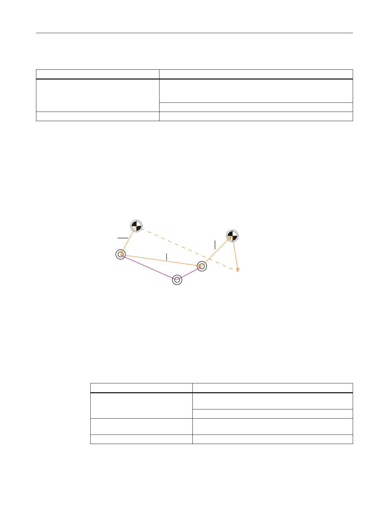
Tool offset
3.8 Tool carriers with orientation capability
Syntax
Description
$PC_TCARR_AX_OFFSET[m] = <value>
Current value of the rotational offset of rotation axes 1 and 2. Maximum 2
rotation axes are defined for an active tool carrier. The positions of the rotary
axes in their initial state can be read out with this system variable.
Data type: DOUBLE
m
Rotary offset where m = 1...2 of the active tool carrier.
Tool carrier with more than two rotary axes
For tool carriers that are defined with more than two rotary axes, the third axis is ignored. It
describes a constant angle (knee-point) between the two axes of rotation. Axis v2 in the example
is not taken into account. Instead, offset I2 is formed.
The relevant rotary axes are defined with the system variable $TC_CARR_KIN_ROTAX_NAME in
the sequence in which they occur in the chain. Up to two rotary axes may be defined.
7RRO FDUULHU UHIHUHQFH SRLQW
6WDUWLQJ SRLQW RI WRRO FDUULHU WRRO
FKDLQ
,
,
,
Y
˞
Y
˞
Y
˞
Figure 3-36
Tool carriers with orientation capability with 3 axes of rotation
The rotary axes are not orientation axes, as used for the 5-axis-transformation.
Defining rotation axes (more than two rotary axes)
If a tool carrier comprises more than two rotation axes, this is defined via the relevant axes using
the system variable $TC_CARR_KIN_ROTAX_NAME. The name of the chain element is entered in
the system variable in this regard. The maximum two rotary axes are defined in the sequence in
which they are defined in the kinematic chain. The entries must begin with the index "0".
Syntax
Description
$TC_CARR_KIN_ROTAX_NAME[n, m] =
Name of the element in the kinematic chain which is to be
<String>
defined as the rotary axis.
Data type: STRING
n
Index of the tool carrier; the maximum number of tool carriers
can be defined in machine data MM_NUM_TOOL_CARRIER.
m
Index of rotary axes (value range 0...1)
Tools
Function Manual, 10/2020, 6FC5397-6GP40-0BA1
113
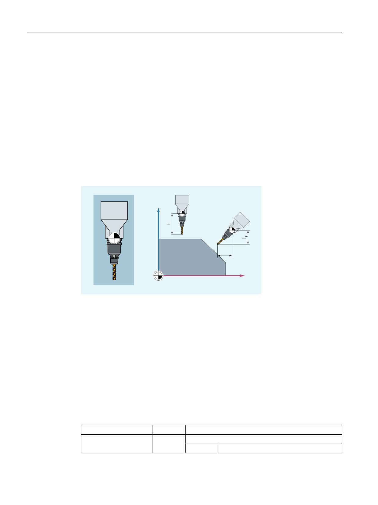
Tool offset
3.8 Tool carriers with orientation capability
Example
You will find a part program for a tool carrier via a kinematic chain under: Example: Tool carrier
with orientation capability via kinematic chain (Page 127).
3.8.4
Programming
3.8.4.1
Tool length compensation for orientable toolholders (TCARR, TCOABS, TCOFR,
TCOFRX, TCOFRY, TCOFRZ)
As the spatial orientation of the tool carrier and thus of the tool changes, its tool length
components also change:
=
7
,
;
T
Tool carrier reference point
I1, I2
Tool length components
After a reset, e.g. through manual setting or change of the tool carrier with a fixed spatial
orientation, the tool length components also have to be determined again. The commands of G
group 42 "tool carrier" are used for this purpose.
Syntax
TCARR=<m>
TCOABS
TCOFR
TCOFRZ/TCOFRY/TCOFRX
Meaning
Element
Type
Meaning
TCARR=<m>
Address
Request tool carrier
<m>
Number of the tool carrier
Tools
114
Function Manual, 10/2020, 6FC5397-6GP40-0BA1

Tool offset
3.8 Tool carriers with orientation capability
Element
Type
Meaning
TCOABS
G com-
Determine tool length components from the orientation of
mand
the current tool carrier
TCOFR
G com-
Determine tool length components from the orientation of
mand
the active frame
TCOFRZ/TCOFRY/
G com-
The TCOFRX/TCOFRY/TCOFRZ command assumes a tool orien-
TCOFRX
mand
ted in the corresponding direction (X/Y/Z) and calculates the
setting angles of the orientable tool carrier so that the tool in
the active frame is oriented in the same direction.
TCOFRZ
The tool oriented in the Z direction is aligned so
that it is also oriented in the Z direction in the
active frame.
TCOFRY
The tool oriented in the Y direction is aligned so
that it is also oriented in the Y direction in the
active frame.
TCOFRX
The tool oriented in the X direction is aligned so
that it is also oriented in the X direction in the
active frame.
Further information
Tool carrier selection (TCARR)
A tool carrier data block is connected to the tool carrier which describes its geometry. If a tool is
active at the time of tool carrier selection, it is assigned to the newly selected tool carrier and the
geometry data of the tool carrier take effect immediately. It is not necessary to change or re-
program the active tool. When a new tool is activated, it is treated as if it was mounted on the
active tool carrier.
With TCARR=0, the active tool carrier is deselected.
Note
The current geometry data of the tool carrier can also be defined in the NC program via the
corresponding system variables (see "Access to tool carrier data blocks").
Note
From the point of view of the control, tool carrier numbers <m> and tool numbers <n> can be
freely combined. In the real application, however, certain combinations can be ruled out for
machining or mechanical reasons. The control does not check whether the combinations make
sense.
Access to tool carrier data blocks
The current geometry data of a tool carrier can be accessed from the NC program as follows:
• Write:
$TC_CARR<n>[<m>]=<Value>
• Read:
<Value>=$TC_CARR<n>[<m>]
(<Value> must be a variable of data type REAL)
Tools
Function Manual, 10/2020, 6FC5397-6GP40-0BA1
115
Tool offset
3.8 Tool carriers with orientation capability
If the referenced tool carrier is not defined, an alarm is displayed.
Setting tool carrier data blocks to zero
All values of all tool carrier data blocks can be deleted from within the part program using one
command:
$TC_CARR1[0] = 0
Individual tool carrier data blocks can be selectively deleted using the predefined procedure
DELTC.
Effect of tool carrier selection
A tool carrier becomes effective when both a tool carrier and a tool have been activated. The
selection of the tool carrier alone has no effect.
The effect of a tool carrier selection depends on the command from the G group 42 (tool carrier),
which was programmed together with TCARR.
Changing the G command from this group causes the tool length components to be recalculated
when a tool carrier is active.
Calculating the tool length compensation from the tool carrier orientation (TCOABS)
TCOABS calculates the tool length compensation from the current orientation angles of the tool
carrier, stored in the system variables $TC_CARR13 and $TC_CARR14. The considered
orientation is independent of the orientation of the active frame.
For the definition of the tool carrier kinematics with system variables, see Chapter "Tool carrier
kinematics" in the NC Programming Manual.
Determining the tool length components from the orientation of the active frame (TCOFR)
With TCOFR, the orientation angles of the tool carrier are determined from the orientation of the
active frame. The values stored in the tool carrier data are not changed, however. These are also
used to resolve the ambiguity that can arise when calculating the rotation angles from a frame
(see following paragraph).
Ambiguities
With two axes, a particular tool orientation defined by the frame can generally be set with two
different rotation angle pairs. Of these two possible positions, the control selects the one in
which the rotation angles are as close as possible to the programmed rotation angles.
Note
In cases where ambiguity may occur, it is usually necessary to store the angles to be expected
from the frame in the tool carrier data.
Tool orientation in the active frame (TCOFRZ/TCOFRY/TCOFRX)
The TCOFRX/TCOFRY/TCOFRZ command assumes an orientation in the X/Y/Z direction for
calculating the tool carrier's setting angles, regardless of the active orientation. The selection of
the machining plane (G17/G18/G19) does not affect the orientation in the active frame.
However, it has an influence on the calculation of the tool length compensation.
Tools
116
Function Manual, 10/2020, 6FC5397-6GP40-0BA1

Tool offset
3.8 Tool carriers with orientation capability
Frame change
The user can change the frame after selecting the tool. This does not have any effect on the tool
length compensation components.
The rotation angles stored in the tool carrier data are not affected by the rotation angles defined
with frames. When changing from TCOFR to TCOABS, the original (programmed) angles of
rotation in the tool carrier data is reactivated.
Recalculation of the tool length compensation
To recalculate the tool length compensation after a frame change, the tool must be selected
again. When the tool length compensation is calculated, the angle of rotation of the tool carrier
is calculated in an intermediate step. Since tool carriers with two axes of rotation generally have
two rotation angle pairs with which the tool orientation can be adapted to the active frame, the
rotation angle values stored in the tool carrier data must at least approximately correspond to
the mechanically set rotation angles.
Note
In virtually any case where ambiguities may arise, it is necessary to store the approximate angle
expected from the frame in the tool carrier data.
Note
The tool orientation must be manually adapted to the active frame.
Note
The control system cannot check the angles of rotation calculated via the frame orientation for
adjustability on the machine. If the machine is designed in such a way that the axes of rotation
of the tool carrier cannot reach the tool orientation calculated by the frame orientation, an alarm
is output.
Note
The combination of tool precision compensation and the functions for tool length offset on
movable tool carriers is not permissible. If both functions are called simultaneously, an error
message is issued.
Note
With TOFRAME it is possible to define a frame based on the orientation direction of the selected
tool carrier.
Tools
Function Manual, 10/2020, 6FC5397-6GP40-0BA1
117

Tool offset
3.8 Tool carriers with orientation capability
Note
When orientation transformation is active (3, 4 or 5-axis transformation), it is possible to select
a tool carrier with an orientation deviating from the zero position without causing output of an
alarm.
Note
With an active frame without rotation, orientation with TCOFRX/TCOFRY/TCOFRZ leads to a trivial
solution, since the tool orientation already points in the X/Y/Z direction.
Orientation in the Z direction (TOFRAME)
With the TOFRAME command of the G group 53 (tool-related frame rotation), it is possible to
define a frame whose Z direction is aligned in parallel to the orientation direction of the selected
tool carrier.
If no tool carrier or a tool carrier without orientation change is active, then the Z direction in the
new frame is as follows:
• The same as the old Z direction with G17.
• The same as the old Y direction with G18.
• The same as the old X direction with G19.
Transfer parameter from standard and measuring cycles
For the transfer parameter of standard and measuring cycles, the following defined value ranges
apply.
For angle values, the following value ranges are defined:
Rotation around ...
Value range
1st geometry axis
-180° ≤ angle ≤ +180°
2nd geometry axis
-90° ≤ angle ≤ +90°
3rd geometry axis
-180° ≤ angle ≤ +180°
Note
When transferring angular values to a standard or measuring cycle, the following should be
carefully observed:
Values smaller than the computational accuracy of the NC must be rounded to zero!
The calculation resolution of the NC for angular positions is defined in the machine data:
MD10210 $MN_INT_INCR_PER_DEG
3.8.4.2
Modifying the orientable tool carrier according to the machine measurement
(CORRTC)
Measured kinematic chain elements of a tool carrier can be written to special correction
elements with the CORRTC function.
Tools
118
Function Manual, 10/2020, 6FC5397-6GP40-0BA1
Tool offset
3.8 Tool carriers with orientation capability
Note
The correction values written with the CORRTC function are not immediately effective in the tool
carrier. The correction values only become active after deselecting the tool carrier, NEWCONF
and selecting the tool carrier.
Syntax
<_Corr_Status> = CORRTC(<_Corr_Vect>, <_Corr_Index>, <_Corr_Mode>,
[ <_No_Alarm>])
Meaning
CORRTC:
Function call
<_Corr_Status>:
Function return value
Data type:
INT
Values:
0
The function was executed without an error.
1
No tool carrier is active.
2
The active tool carrier was not defined with kinematic chains.
10
The <_Corr_Index> call parameter is negative.
11
The <_Corr_Mode> call parameter is negative.
12
Invalid reference to a section of a subchain (_CORR_INDEX).
13
No correction element has been defined in the section referred to by the
_CORR_INDEX parameter ($TC_CARR_CORR_ELEM).
20
The hundreds position of <_CORR_MODE> is invalid. Only the values 0 and 1
are permissible.
21
The thousands position of <_CORR_MODE> is invalid. Only the values 0 and
1 are permissible.
30
For the correction of an offset vector, the deviation from the current value in
at least one coordinate is greater than the maximum value specified by the
setting data SD41612 $SN_CORR_TRAFO_LIN_MAX.
31
The attempt to write a system variable was rejected because of missing write
rights.
<_Corr_Vect>:
Correction vector
The content of the correction vector is defined by the following parameters <_Corr_Index>
and <_Corr_Mode>.
If <_Corr_Status> = 30, the content of the vector is overwritten (see above).
Data type:
REAL
<_Corr_Index>:
Designates the section for which the direction vector of the correction element is to be corrected.
Data type:
INT
Tools
Function Manual, 10/2020, 6FC5397-6GP40-0BA1
119
Tool offset
3.8 Tool carriers with orientation capability
<_Corr_Mode>:
Correction mode
Data type:
INT
The <Corr_Index> parameter is decimal coded (unit to thousands position):
Unit
Reserved
position:
Tens
Specifies how the correction element to which the content of <_Corr_Index>
position:
refers, is to be modified.
xx0x
The correction vector is written immediately to the correction element.
This variant can be used to immediately write the correction element
without the index <n> of the relevant system data
($NK_OFF_DIR[<n>, ...]) having to be known.
xx1x
As 0, but with the difference that the transferred correction value is in-
terpreted in world coordinates.
A difference between variants 0 and 1 can always occur when the kine-
matic chain in the initial state (positions of all rotary axes equal to 0)
contains other rotations.
xx2x
As 1, but with the difference that the correction value refers to the entire
section, i.e. a value is entered in the correction element so that the entire
section reaches the length defined by the correction value.
Hundreds
Specifies how the content of the <_Corr_Vect> parameter is to be interpreted.
position:
x0xx
The transferred correction vector <_Corr_Vect> contains the entire
new length of the correction element or the section to which
the <_Corr_Index> in conjunction with the tens position
of <_Corr_Mode> refers (absolute correction).
x1xx
The transferred correction vector <_Corr_Vect> only contains the dif-
ference compared to the current length of the correction element or the
section to which the <_Corr_Index> in conjunction with the tens po-
sition of <_Corr_Mode> refers (incremental correction).
Thousands
Determines whether or not the maximum permissible correction is to be limited by
position:
the setting data $SN_ CORR_TOCARR_LIN_MAX.
0xxx
Threshold value monitoring is active.
1xxx
The threshold value monitoring is suppressed.
<_No_Alarm>:
Response in the event of an error (return value > 0) (optional)
Data type:
BOOL
Value:
FALSE (de-
In the event of an error, the program execution is stopped and an
fault)
alarm displayed.
TRUE
In the event of an error, the program processing is not stopped and no
alarm is displayed.
Application: User-specific response corresponding to the return value
Further information about CORRTC
The kinematic structure of a tool carrier is described by one (type T and type P) or two (type M)
kinematic chains (subchains), which start from the associated reference point, machine zero or
tool carrier reference point). One of the two chains, the tool chain, ends at the reference point
of the tool, the other chain, the workpiece chain ends in the zero point of the basic coordinate
system.
Tools
120
Function Manual, 10/2020, 6FC5397-6GP40-0BA1
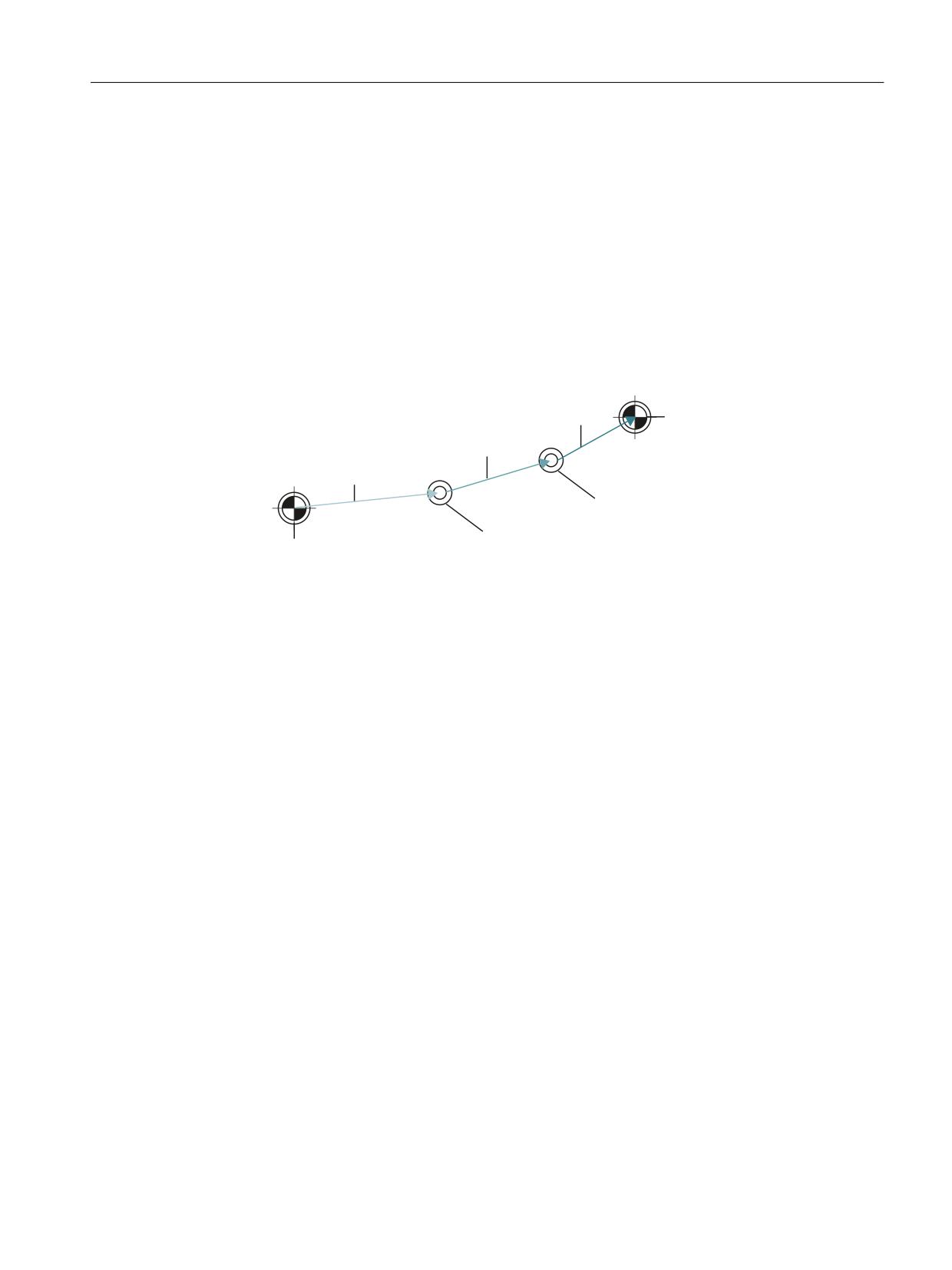
Tool offset
3.8 Tool carriers with orientation capability
The CORRTC function writes axis directions for machines with tool carriers in special correction
elements. A kinematic chain is described, for example, with elements of the type OFFSET, which
are defined via $ NK_TYPE.
CORRTC works with sections
The two subchains can each be divided into a maximum of four sections:
• Section 1 begins at the starting point of the chain and ends at the first rotary axis.
• Section 2 is the section between rotary axis 1 and rotary axis 2.
• Section 3 is the section between rotary axis 2 and the end of the chain.
The following figure shows an orientable tool carrier with 2 rotary axes.
,
6HFWLRQ
:RUNSLHFH UHIHUHQFH SRLQW
ZRUNSLHFH FKDLQ (QG SRLQW
RI NLQHPDWLF FKDLQ
,
6HFWLRQ
,
6HFWLRQ
Y
˞
Y
˞
=HUR SRLQW RI WKH ZRUOG
FRRUGLQDWH V\VWHP
Figure 3-37
CORRTC example
The sections are clearly defined: If the kinematic subchain is executed from its starting point to
its end point, then the first section has the index 1, next has index 2, and so on.
Correction elements
A reference can be made to a constant kinematic chain element (chain element of the type
$NK_TYPE[<n>] = "OFFSET") in each of these sections with the $TC_CARR_CORR_ELEM [, 0 ... 3]
system variables. The correction values determined during the machine measurement are
written to the so designated elements with the CORRTC function.
The sequence of references in $TC_CARR_CORR_ELEM[m, 0 ... 3] must correspond to the
sections described above, that is there can only be one chain element in
$TC_CARR_CORR_ELEM[m, 0] which belongs to the offset vector l1, etc.
The reference value is always the corresponding value effective in the tool carrier active when
CORRTC is called. After selection of the tool carrier, changed contents of the stored kinematic
data have no effect on the method of operation of the CORRTC function.
Tools
Function Manual, 10/2020, 6FC5397-6GP40-0BA1
121
Tool offset
3.8 Tool carriers with orientation capability
3.8.5
Examples
3.8.5.1
Example: Toolholder with orientation capability
Requirement
The following example uses a toolholder, which is described fully by a rotation about the Y axis.
It is therefore sufficient to enter only one value to define the rotary axis (block N20).
Blocks N50 to N70 describe an end mill with radius 5 mm and length 20 mm.
Block N90 defines a rotation of 37 degrees about the Y axis.
Block N120 activates the tool radius compensation and all settings are made to describe the
compensation in the following blocks with a rotation of 37 degrees about the Y axis.
N10
; Definition of toolholder 1
N20 $TC_CARR8[1] = 1
; Component of first rotary axis in Y di-
rection
N30
N40
; Definition of tool offset memory T1/D1
N50 $TC_DP1[1,1] = 120
; End mill
N60 $TC_DP3[1,1] = 20
; Length 1
N70 $TC_DP6[1,1] = 5
; Radius
N80
N90 ROT Y37
; 37-degree rotation about y axis
N100
N110 X0 Y0 Z0 F10000
N120 G42 CUT2DF TCOFR TCARR = 1 T1 D1 X10
N130 X40
N140 Y40
N150 X0
N160 Y0
N170 M30
3.8.5.2
Example of toolholder with orientation capability with rotary table
Use of the MOVT command
For use of the MOVT command it is assumed that the program is running on a 5axis machine, on
which the tool rotates about the Y axis in case of a rotation of the B axis:
N10 TRAORI()
N20 X0 X0 Z0 B45 F2000
; Setting the tool orientation
N30 MOVT=-10
; Infeed movement 10 mm in tool direc-
tion
; (under 45 degrees in the Y-Z plane)
Tools
122
Function Manual, 10/2020, 6FC5397-6GP40-0BA1
Tool offset
3.8 Tool carriers with orientation capability
N40 MOVT=AC(20)
; Retraction in tool direction at dis-
tance of
; 20 mm from the zero point
Machine with rotary table
Complete definition for the use of a toolholder with orientation capability with rotary table:
N10 $TC_DP1[1,1]= 120
N20 $TC_DP3[1,1]= 13
;
Tool length 13 mm
; Definition of toolholder 1:
N30 $TC_CARR1[1] = 0
;
X component of 1st offset vector
N40 $TC_CARR2[1] = 0
;
Y component of 1st offset vector
N50 $TC_CARR3[1] = 0
;
Z component of 1st offset vector
N60 $TC_CARR4[1] = 0
;
X component of 2nd offset vector
N70 $TC_CARR5[1] = 0
;
Y component of 2nd offset vector
N80 $TC_CARR6[1] = -15
;
Z component of 2nd offset vector
N90 $TC_CARR7[1] = 1
;
X components of 1st axis
N100 $TC_CARR8[1] = 0
;
Y components of 1st axis
N110 $TC_CARR9[1] = 0
;
Z components of 1st axis
N120 $TC_CARR10[1] = 0
;
X components of 2nd axis
N130 $TC_CARR11[1] = 1
;
Y components of 2nd axis
N140 $TC_CARR12[1] = 0
;
Z components of 2nd axis
N150 $TC_CARR13[1] = 30
;
Angle of rotation of 1st axis
N160 $TC_CARR14[1] =-30
;
Angle of rotation of 2nd axis
N170 $TC_CARR15[1] = 0
;
X components of 3rd offset vector
N180 $TC_CARR16[1] = 0
;
Y component of 3rd offset vector
N190 $TC_CARR17[1] = 0
;
Z component of 3rd offset vector
N200 $TC_CARR18[1] = 0
;
X component of 4th offset vector
N210 $TC_CARR19[1] = 0
;
Y component of 4th offset vector
N220 $TC_CARR20[1] = 15
;
Z component of 4th offset vector
N230 $TC_CARR21[1] = A
;
Reference for 1st axis
N240 $TC_CARR22[1] = B
;
Reference for 2nd axis
N250 $TC_CARR23[1] = "P"
;
Toolholder type
N260 X0 Y0 Z0 A0 B45 F2000
N270 TCARR=1 X0 Y10 Z0 T1 TCOABS
Tools
Function Manual, 10/2020, 6FC5397-6GP40-0BA1
123
Tool offset
3.8 Tool carriers with orientation capability
N280 PAROT
N290 X0 Y0 Z0
N300 G18 MOVT=AC(20)
N310 G17 X10 Y0 Z0
N320 MOVT=-10
N330 PAROTOF
N340 TCOFR
N350 X10 Y10 Z-13 A0 B0
N360 ROTS X-45 Y45
N370 X20 Y0 Z0 D0
N380 Y20
N390 X0 Y0 Z20
N400 M30
The definition of the toolholder with orientation capability is given in full. The components
which contain the value 0 need not actually be given, as they are preset to zero in any case.
The toolholder is activated in N270.
As $TC_CARR21 and $TC_CARR22 refer to the machine axes A and B and TCOABS is active, the
values in $TC_CARR13 and $TC_CARR14 are ignored, i.e. the axis position A0 B45 is used for the
rotation.
The rotation of the 4th offset vector (length 15 mm in Z direction) around the B axis causes an
offsetting of the zero point by X10.607 [= 15 * sin(45)] and Z-4.393 [= -15 * (1. - cos(45))]. This
zero offset is taken into account by an automatically written basic or system frame so that the
position X10.607 Y10.000 Z8.607 is approached. In the Z direction the tool selection leads to an
additional offset of 13 mm; the Y component is not affected by the table rotation.
N280 defines a rotation in accordance with the rotation of the table of the toolholder with
orientation capability. The new X direction thus points in the direction of the bisecting line in the
4th quadrant, the new Z axis in the direction of the bisecting line in the 1st quadrant.
The zero point is approached in N290, i.e. the machine position X10.607 Y0 Z-4.393, since the
position of the zero point is not changed by the rotation.
N300 traverses in Y to the position Y33.000, since G18 is active and the Y component is not
affected by the active frame. The X and Z positions remain unchanged.
The position X17.678 Y0 Z1.536 is approached in N310.
N320 changes only the Z position to the value -8.464 as a result of the MOVT command. As only
the table can be rotated, the tool orientation remains unchanged parallel to the machine Z
direction, even if the Z direction of the active frame is rotated by 45 degrees.
N330 deletes the basic or system frame; thus the frame definition from N280 is undone.
In N340, TCOFR specifies that the toolholder with orientation capability is to be aligned
according to the active frame. Since a rotation is no longer active in N330 due to the PAROTOF
command, the default setting is applied. The frame offset becomes 0.
N350 thus approaches the position X10 X10 Z0 (= Z-13 + tool length). Notice: Through the
simultaneous programming of both rotary axes A and B the actual position of the toolholder
with orientation capability is made to match that used in N340. The position approached by the
three linear axes is dependent on this position, however.
Tools
124
Function Manual, 10/2020, 6FC5397-6GP40-0BA1

Tool offset
3.8 Tool carriers with orientation capability
In N360, solid angles are used to define a plane whose intersecting lines in the XZ and in the YZ
plane each form an angle of +45 degrees or -45 degrees with the X or Y axis. The plane defined
in such a way therefore has the following position: The surface normal points towards the solid
diagonals.
N370 traverses to the position X20 Y0 Z0 in the new coordinate system. Since the tool is
deselected with D0 at the same time, there is no longer an additional offset in Z. Since the new
X axis lies in the old X-Z plane, this block reaches the machine position X14.142 Y0 Z-14.142.
N380 only traverses on the Y axis in the rotated coordinate system. This leads to a motion of all
three machine axes. The machine position is X5.977 Y16.330 Z-22.307.
N390 approaches a point on the new Z axis. Relative to the machine axes this is thus on the solid
diagonal. All three axes thus reach the position 11.547.
3.8.5.3
Calculation of compensation values on a location-specific and workpiece-specific
basis
Tool with adapter
A tool with adapter and tool carrier with orientation capability is defined in the following
program example. To simplify the overview, only length L1 is different from zero for the additive
and insert offsets and for the adapter in case of the tool itself. The offset vectors of the tool carrier
with orientation capability are all zero.
Program code
Comment
N10 $TC_TP2[1]="MillingTool"
; Name of identifier
N20 $TC_TP7[1]=9
; Location type
N30 $TC_TP8[1]=2
; Status: Enabled and not
blocked
; D corr. D=1
N40 $TC_DP1[1,1]=120
; Tool type - milling
N50 $TC_DP3[1,1]=
; Length offset vector
N60 $TC_DP12[1,1]=
; Wear
N70 $TC_SCP13[1,1]=0.1
; Sum offset DL=1
N80 $TC_ECP13[1,1]=0.01
; Insert offset DL=1
N90 $TC_ADPTT[1]=5
; Adapter transformation
N100 $TC_ADPT1[1]=0.001
; Adapter dimension
; Magazine data
N110 $TC_MAP1[1]=3
; Magazine type: Turret
N120 $TC_MAP2[1]="Turret"
; Name of a magazine
N130 $TC_MAP3[1]=17
; Status of magazine
N140 $TC_MAP6[1]=1
; Dimension - line
N150 $TC_MAP7[1]=2
; Dimension - column -> 2
positions
Tools
Function Manual, 10/2020, 6FC5397-6GP40-0BA1
125

Tool offset
3.8 Tool carriers with orientation capability
Program code
Comment
N160 $TC_MPP1[1,1]=1
; Location type
N170 $TC_MPP2[1,1]=9
; Location type
N180 $TC_MPP4[1,1]=2
; Location status
N190 $TC_MPP7[1,1]=1
; Bring adapter into position
N200 $TC_MPP6[1,1]=1
; T number "MillingTool"
N210 $TC_MAP1[9999]= 7
; Magazine type: Buffer
N220 $TC_MAP2[9999]="Buffer"
; Name of a magazine
N230 $TC_MAP3[9999]=17
; Status of magazine
N240 $TC_MAP6[9999]=1
; Dimension - line
N250 $TC_MAP7[9999]=1
; Dimension - column -> 1
position
N260 $TC_MPP1[9999,1]=2
; Location type
N270 $TC_MPP2[9999,1]=9
; Location type
N280 $TC_MPP4[9999,1]=2
; Location status
N290 $TC_MPP5[9999,1]=1
; Spindle no. 1
N300 $TC_MDP2[1,1]=0
; Distance from spindle to mag.
1
; Definition of tool carrier 1
N310 $TC_CARR10[1]=1
; Component 2. Axis of rotation
in the X direction
N320 $TC_CARR14[1]=45
; Angle of rotation of 2nd axis
N330 $TC_CARR23[1]="T"
; Tool mode
N340 Stopre
N350 $SC_WEAR_TRANSFORM='B101'
N360 T0 D0 DL=0
N370 ROT X30
N380 G90 G1 G17 F10000 X0 Y0 Z0
N390 T="MillingTool" X0 Y0 Z0 TOWSTD
; X 0.000 Y11.110 Z 0.001
N400 T="MillingTool" X0 Y0 Z0 TOWMCS
; X 0.000 Y10.100 Z 1.011
N410 T="MillingTool" X0 Y0 Z0 TOWWCS
; X 0.000 Y 9.595 Z 0.876
N420 TCARR=1 X0 Y0 Z0
; X 0.000 Y 6.636 Z 8.017
N430 G18 X0 Y0 Z0
; X10.100 Y-0.504 Z 0.876
N440 M30
Explanations regarding the example above
Starting at block N390, various methods are used to approach position X0 Y0 Z0. The machine
positions reached are specified in the blocks in comments. After the program a description is
given of how the positions were reached.
N390: The adapter transformation 5 (block N90) transforms length L1 into length L2. Only the
actual adapter dimension is not subject to this transformation. The Y value (L2 with G17) results
from the sum of the tool length (10), tool wear (1), sum offset (0.1), and insert offset (0.01). The
adapter dimension (0.001) is in Z (L1).
Tools
126
Function Manual, 10/2020, 6FC5397-6GP40-0BA1
Tool offset
3.8 Tool carriers with orientation capability
N400: In block N350, bits 0 and 2 are enabled in setting data:
SD42935 $SC_WEAR_TRANSFORM (transformations for tool components)
This means that the tool wear and the insert offset are not subject to the adapter transformation
because of TOWMCS in block N400. The sum of these two compensations is 1.01. The Z position
is, therefore, increased by this amount and the Y position is reduced by this amount compared
with block N390.
TOWWCS is active in N410. The sum of the tool wear and the insert offset is thus effective in the
active workpiece coordinate system. In block N370, a rotation through 30 degrees is activated
around the X axis. The original compensation value of 1.01 in the Z direction thus yields a new
Z component of 0.875 ( = 1.01 * cos(30)) and a new Y component of -0.505 ( = 1.01 * sin(30)).
This yields the dimension specified in the program comment when added to the sum of the tool
length, sum offset and adapter dimension produced in block N390.
In addition, a tool carrier with orientation capability is activated in block N420. This executes a
rotation through 45 degrees about the X axis (see N310 - N330). Since all offset vectors of the
tool carrier are zero, there is no additional work offset. The tool carrier with orientation capability
acts on the sum of the tool length, sum offset and adapter dimension. The resulting vector
component is X0 Y7.141 Z7.142. To this, as in block N410, the sum of tool wear and insert
offset evaluated in WCS is added.
G18 is activated in N430. The components of the tool length sum, sum offset and adapter
dimension are interchanged accordingly. The tool carrier with orientation capability continues
to act on this new vector (rotation through 45 degrees about X axis). The resulting vector
component thereby is X10.100 Y0.0071 Z0.0071. The vector formed from tool wear and
insert offset (X0 Y-0.505 Z0.875) is not affected by the change of plane. The sum of the two
vectors yields the dimension specified in the comment in N430.
3.8.5.4
Example: Tool carrier with orientation capability via kinematic chain
Example of a tool carrier with mixed kinematics (rotatable tool and table)
The example shows a tool carrier that is defined via a kinematic chain. The chain is automatically
closed at the endpoints of the two separate chains (tool and table).
Program code
Comment
; Definition tool carrier 1
N1070 _MIXED_1_S:
N1080 IF (DELOBJ("KIN_CHAIN_ELEM") <> 0)
N1080 IF (DELOBJ("KIN_CHAIN_ELEM") <> 0)
N1090 SETAL(62000)
N1100 ENDIF
N1110 _KIE_CNT = 0
N1120 _CARR_CNT = 1
N1130 TCARR=0
; Deactivate current tool carrier.
N1140 $TC_CARR1[0] = 0
; Delete all tool carrier data.
N1150 $TC_CARR_KIN_CNTRL[_CARR_CNT]=7
; Tool carrier via kinematic chain
; + Close tool and part chain.
N1160 $TC_CARR_KIN_TOOL_START[_CARR_CNT]="Y_AXIS"
; Start element of the tool chain.
Tools
Function Manual, 10/2020, 6FC5397-6GP40-0BA1
127
Tool offset
3.8 Tool carriers with orientation capability
Program code
Comment
N1170
$TC_CARR_KIN_TOOL_END[_CARR_CNT]="B_OFFSET_CORR"
; End element of the tool chain.
N1180
$TC_CARR_KIN_PART_START[_CARR_CNT]="X_AXIS"
; Start element of the part chain.
N1190
$TC_CARR_KIN_PART_END[_CARR_CNT]="END_PART_CHAIN"
; End element of the part chain.
N1200
$TC_CARR21[_CARR_CNT]=B
N1210
$TC_CARR22[_CARR_CNT]=C
N1220
$TC_CARR23[_CARR_CNT]="M"
N1230
$NK_NAME[_KIE_CNT] = "ROOT"
N1240
$NK_PARALLEL[_KIE_CNT]="X_AXIS"
N1250
$NK_TYPE[_KIE_CNT] = "OFFSET"
N1260
$NK_NEXT[_KIE_CNT] = "Y_AXIS"
N1270
_KIE_CNT=_KIE_CNT+1
;***** Start tool chain *****
N1280
$NK_NAME[_KIE_CNT] = "Y_AXIS"
N1290
$NK_TYPE[_KIE_CNT] = "AXIS_LIN"
N1300
$NK_OFF_DIR[_KIE_CNT,1] = 1
N1310
$NK_AXIS[_KIE_CNT] = "Y1"
N1320
$NK_NEXT[_KIE_CNT] = "Z_AXIS"
N1330
_KIE_CNT=_KIE_CNT+1
N1340
$NK_NAME[_KIE_CNT] = "Z_AXIS"
N1350
$NK_TYPE[_KIE_CNT] = "AXIS_LIN"
N1360
$NK_OFF_DIR[_KIE_CNT,2] = 1
N1370
$NK_AXIS[_KIE_CNT] = "Z1"
N1380
$NK_NEXT[_KIE_CNT] = "CLOSE_HEAD"
N1390
_KIE_CNT=_KIE_CNT+1
N1400
$NK_NAME[_KIE_CNT] = "CLOSE_HEAD"
N1410
$NK_TYPE[_KIE_CNT] = "OFFSET"
N1420
$NK_OFF_DIR[_KIE_CNT,0] = 0
N1430
$NK_OFF_DIR[_KIE_CNT,1] = 0
N1440
$NK_OFF_DIR[_KIE_CNT,2] = 0
N1450
$NK_NEXT[_KIE_CNT] = "B_AXIS"
N1460
_KIE_CNT=_KIE_CNT+1
N1470
$NK_NAME[_KIE_CNT] = "B_AXIS"
N1480
$NK_TYPE[_KIE_CNT] = "AXIS_ROT"
N1490
$NK_OFF_DIR[_KIE_CNT,1] = 1
N1500
$NK_OFF_DIR[_KIE_CNT,2] = 1
N1520
$NK_A_OFF[_KIE_CNT] = -27
N1540
$NK_AXIS[_KIE_CNT] = "B1"
N1550
$NK_NEXT[_KIE_CNT] = "B_OFFSET"
N1560
_KIE_CNT=_KIE_CNT+1
N1570
$NK_NAME[_KIE_CNT] = "B_OFFSET"
N1580
$NK_TYPE[_KIE_CNT] = "OFFSET"
N1590
$NK_OFF_DIR[_KIE_CNT,2] = -30.6
N1600
$NK_NEXT[_KIE_CNT] = "B_OFFSET_CORR"
N1610
_KIE_CNT=_KIE_CNT+1
Tools
128
Function Manual, 10/2020, 6FC5397-6GP40-0BA1
Tool offset
3.8 Tool carriers with orientation capability
Program code
Comment
N1620 $NK_NAME[_KIE_CNT] = "B_OFFSET_CORR"
N1630 $NK_TYPE[_KIE_CNT] = "OFFSET"
N1640 $NK_NEXT[_KIE_CNT] = ""
N1650 _KIE_CNT=_KIE_CNT+1
;***** End tool chain *****
;***** Start part chain *****
N1660 $NK_NAME[_KIE_CNT] = "X_AXIS"
N1670 $NK_TYPE[_KIE_CNT] = "AXIS_LIN"
N1680 $NK_OFF_DIR[_KIE_CNT,0] = 1
N1690 $NK_AXIS[_KIE_CNT] = "X1"
N1700 $NK_NEXT[_KIE_CNT] = "C_OFFSET"
N1710 _KIE_CNT=_KIE_CNT+1
N1720 $NK_NAME[_KIE_CNT] = "C_OFFSET"
N1730 $NK_TYPE[_KIE_CNT] = "OFFSET"
N1740 $NK_OFF_DIR[_KIE_CNT,0] = 300
N1750 $NK_OFF_DIR[_KIE_CNT,1] = 150
N1760 $NK_NEXT[_KIE_CNT] = "C_OFFSET_CORR"
N1770 _KIE_CNT=_KIE_CNT+1N1780 $NK_NAME[_KIE_CNT] = "C_OFF-
SET_CORR"
N1790 $NK_TYPE[_KIE_CNT] = "OFFSET"
N1800 $NK_OFF_DIR[_KIE_CNT,0] = 0
N1810 $NK_OFF_DIR[_KIE_CNT,1] = 0
N1820 $NK_OFF_DIR[_KIE_CNT,2] = 0
N1830 $NK_NEXT[_KIE_CNT] = "C_AXIS"
N1840 _KIE_CNT=_KIE_CNT+1
N1850 $NK_NAME[_KIE_CNT] = "C_AXIS"
N1860 $NK_TYPE[_KIE_CNT] = "AXIS_ROT"
N1870 $NK_OFF_DIR[_KIE_CNT,2] = -1
N1890 $NK_A_OFF[_KIE_CNT] = -58
N1910 $NK_AXIS[_KIE_CNT] = "C1"
N1920 $NK_NEXT[_KIE_CNT] = "CLOSE_PART"
N1930 _KIE_CNT=_KIE_CNT+1
N1940 $NK_NAME[_KIE_CNT] = "CLOSE_PART"
N1950 $NK_TYPE[_KIE_CNT] = "OFFSET"
N1960 $NK_OFF_DIR[_KIE_CNT,0] = 0
N1970 $NK_OFF_DIR[_KIE_CNT,1] = 0
N1980 $NK_OFF_DIR[_KIE_CNT,2] = 0
N1990 $NK_NEXT[_KIE_CNT] = "END_PART_CHAIN"
N2000 _KIE_CNT=_KIE_CNT+1
N2010 $NK_NAME[_KIE_CNT] = "END_PART_CHAIN"
N2020 $NK_TYPE[_KIE_CNT] = "OFFSET"
;***** End part chain *****
Tools
Function Manual, 10/2020, 6FC5397-6GP40-0BA1
129
Tool offset
3.8 Tool carriers with orientation capability
3.8.6
Inclined surface machining with 3 + 2 axes
Description of function
Inclined machining with 3 + 2 axes describes an extension of the concept of toolholders with
orientation capability and applies this concept to machines with a rotary table, on which the
orientation of tool and table can be changed simultaneously.
The "Inclined machining with 3 + 2 axes" function is used to machine surfaces with any rotation
with reference to the main planes X/Y (G17), Z/X (G18) and Y/Z (G19).
It is possible to produce any orientation of the tool relative to the workpiece by rotating either
the tool, the workpiece or both the tool and the workpiece.
The software automatically calculates the necessary compensating movements resulting from
the tool lengths, lever arms and the angle of the rotary axis. It is always assumed that the
required orientation is set first and not modified during a machining process such as pocket
milling on an inclined plane.
Furthermore, the following 3 functions are described, which are required for oblique machining:
• Position programming in the direction of the tool orientation independent of an active
frame
• Definition of a frame rotation by specifying the solid angle
• Definition of the component of rotation in tool direction in the programmed frame while
maintaining the remaining frame components
Demarcation to 5-axis transformation
If the required functionality specifies that the TCP (Tool Center Point) does not vary in the event
of reorientation with reference to the workpiece, even during interpolation, the 5axis software
is required.
For more explanations on 5-axis transformations, see:
Further information
Function Manual Transformations; Multi-axis transformation
Specification of the toolholder with orientation capability
The toolholder with orientation capability is represented by a general 5axis kinematic sequence
described by a data block in the tool offset memory with a total of 33 REAL values. For
toolholders that have two rotary axes for setting the orientation (e.g. a millhead), 31 of these
values are constant.
In the current SW version, a data block in the tool offset memory is described with a total of 47
REAL values. For toolholders that have two rotary axes for setting the orientation, 45 of these
values are constant.
The remaining two values are variable and are used to specify the orientation. The constant
values describe offsets and directions and setting options for the rotary axes; the variable values
describe the angles of the rotary axes.
Tools
130
Function Manual, 10/2020, 6FC5397-6GP40-0BA1
Tool offset
3.8 Tool carriers with orientation capability
3.8.7
Machine with rotary work table
System variables
To date, the angles stored in $TC_CARR13 and $TC_CARR14 were used for the calculation of the
active tool length with TCOABS. This still applies if $TC_CARR21 and $TC_CARR22 do not refer
to rotary axes. If $TC_CARR21 or $TC_CARR22 contains a reference to a rotary axis in the
channel, the axis position of the relevant axis at the start of the current block is used as the angle,
rather than the entry in $TC_CARR13 or $TC_CARR14.
A mixed operating mode is permissible, i.e. the angles can be determined from the entry in the
system variables $TC_CARR13 or $TC_CARR14 for one axis, and from the position of a channel
axis for the other.
This makes it possible for machines, on which the axes used to set the tool carrier with
orientation capability are known within the NC, to access their position directly, whereas it was
previously necessary, for example, to read system variable $AA_IM[axis] and write the result of
the read operation to $TC_CARR13/14. In particular, this removes the implicit preprocessing stop
when reading the axis positions.
MD20180
The rotary axis position is used with its programmed or calculated value, when the machine data:
MD20180 $MC_TOCARR_ROT_ANGLE_INCR[i] = 0 (rotary axis increment of the tool carrier that
can be oriented)
If the machine data is not zero however, the position used is the nearest grid point obtained for
a suitable integer value n from the equation:
φ = $MC_TOCARR_ROT_ANGLE_OFFSET[i] + n * $MC_TOCARR_ROT_ANGLE_INCR[i]
This functionality is required if the rotary axes need to be indexed and cannot, therefore, assume
freely-defined positions (e.g. with Hirth tooth systems). System variable $P_TCANG[i] delivers
the approximated valued and system variable $P_TCDIFF[i] the difference between the exact
and the approximated value.
Frame orientation TCOFR
With TCOFR (determination of the angle from the orientation defined by an active frame), the
increments are scaled after determination of the angle from the active frame rotation. If the
requested orientation is not possible due to the machine kinematic, the machining is aborted
with an alarm. This also applies if the target orientation is very close to an achievable orientation.
In particular the alarm in such situations cannot be prevented through the angle approximation.
TCARR frame offset
A frame offset as a result of a tool carrier change becomes effective immediately on selection
of TCARR=
A change in the tool length, on the other hand, only becomes effective
immediately if a tool is active.
Tools
Function Manual, 10/2020, 6FC5397-6GP40-0BA1
131
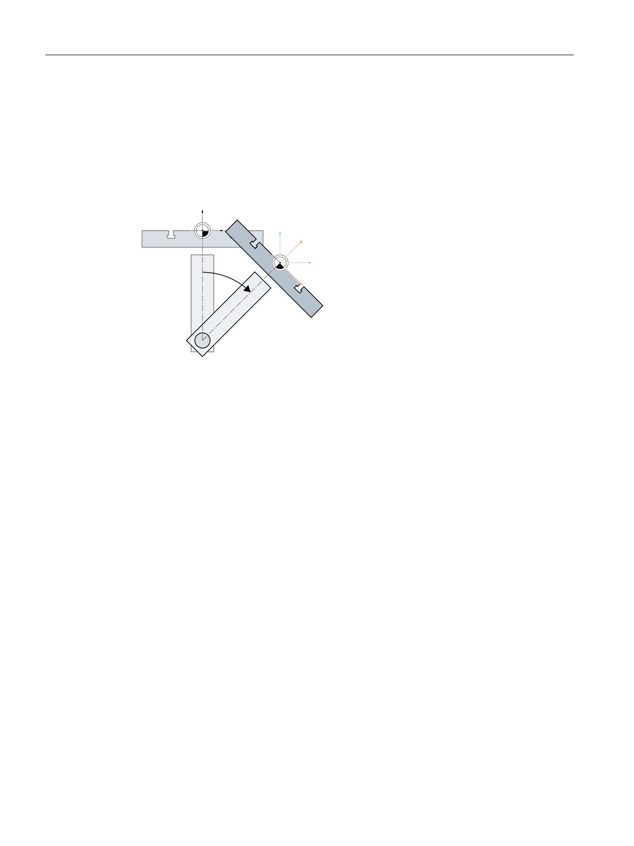
Tool offset
3.8 Tool carriers with orientation capability
TCOFR/TCOABS frame rotation
A frame rotation does not take place on activation and a rotation which is already active is not
changed. As in case T (only the tool can be rotated), the position of the rotary axes used for the
calculation is dependent on the G command TCOFR/TCOABS and determined from the rotation
component of an active frame or from the entries $TC_CARRn.
Activation of a frame changes the position in the workpiece coordinate system accordingly,
without compensating motion by the machine itself. The ratios are shown in the figure below:
2ULJLQDO SRVLWLRQ RI WKH FRRUGLQDWH V\VWHP
&RRUGLQDWH V\VWHP SRVLWLRQ DIWHU
7&$55
&RRUGLQDWH V\VWHP SRVLWLRQ DIWHU
2ULJLQDO
3$527
SRVLWLRQ RI
WKH WDEOH
3RVLWLRQ RI WKH WDEOH
DIWHU URWDWLRQ
Figure 3-38
Work offset on activation of a rotary table with TCARR
Example
On the machine in the figure, the axis of rotation of the table is pointing in the positive Y
direction. The table is rotated by +45 degrees. PAROT defines a frame, which similarly describes
a rotation of 45 degrees about the Y axis. The coordinate system is not rotated relative to the
actual environment (marked in the figure with "Position of the coordinate system after TCARR"),
but is rotated by -45 degrees relative to the defined coordinate system (position after PAROT).
If this coordinate system is defined with ROT Y-45, for example, and if the tool carrier is then
selected with active TCOFR, an angle of +45 degrees will be determined for the axis of rotation
of the tool carrier.
Rotary table
With rotary tables (kinematic types P and M), activation with TCARR similarly does not lead to
an immediate rotation of the coordinate system (see figure), i.e. even though the zero point of
the coordinate system is offset relative to the machine, while remaining fixed relative to the zero
point of the workpiece, the orientation remains unchanged in space.
Activation of kinematic types P and M
With kinematics of type P and M the selection of a tool carrier activates an additive frame (table
offset of the tool carrier with orientation capability), which takes into account the zero point
offset as a result of the rotation of the table.
The work offset can be written to a dedicated system frame $P_PARTFR. For this, the bit 2 must
be set in the machine data:
MD28082 $MC_MM_SYSTEM_FRAME_MASK (system frames (SRAM))
Tools
132
Function Manual, 10/2020, 6FC5397-6GP40-0BA1
Tool offset
3.8 Tool carriers with orientation capability
The basic frame identified by following machine data is then no longer required for the work
offset:
MD20184 $MC_TOCARR_BASE_FRAME_NUMBER (number of the basic frames for taking the
table offset)
Activation of kinematic type M
With kinematics of type M (tool and table are each rotary around one axis), the activation of a
tool carrier with TCARR simultaneously produces a corresponding change in the effective tool
length (if a tool is active) and the work offset.
Rotations
Depending on the machining task, it is necessary to take into account not only a work offset
(whether as frame or as tool length) when using a rotary tool carrier or table, but also a rotation.
However, the activation of an orientable tool carrier never leads directly to a rotation of the
coordinate system.
TOROT
If only the tool can be rotated, a frame whose Z axis points in the direction of the tool can be
defined with TOFRAME or TOROT.
PAROT
If the coordinate system needs to be fixed relative to the workpiece, i.e. not only offset relative
to the original position but also rotated according to the rotation of the table, then PAROT can
be used to activate such a rotation in a similar manner to the situation with a rotary tool.
With PAROT, the translations, scaling and mirroring in the active frame are retained, but the
rotation component is rotated by the rotation component of a tool carrier with orientation
capability corresponding to the table.
PAROT and TOROT take into account the overall change in orientation in cases where the table
or the tool are oriented with two axes of rotation. With mixed kinematics, only the
corresponding component caused by an axis of rotation is considered. It is thus possible, for
example, when using TOROT, to rotate a workpiece such that an oblique plane lies parallel to the
XY plane fixed in space, whereby rotation of the tool must be taken into account in machining
where any holes to be drilled, for example, are not perpendicular to this plane.
Language command PAROT is not rejected if no orientable tool carrier is active. This causes no
changes in the programmed frame.
Note
For further information about the TCARR and TOROT as well as PAROT functions with regard to
channel-specific system frames, see "Basic Functions" Function Manual.
Tools
Function Manual, 10/2020, 6FC5397-6GP40-0BA1
133

Tool offset
3.8 Tool carriers with orientation capability
3.8.8
Procedure when using toolholders with orientation capability
Creating a tool carrier
Setting the number of available tool carrier data sets
The number of available tool carrier data sets in the control system is defined with machine data:
MD18088 $MN_MM_NUM_TOOL_CARRIER (maximum number of definable tool carriers)
The number must be set according to the following rule:
MD18088 $MN_NUM_TOOL_CARRIER =
<highest number of tool carriers required in one channel> *
<number of parameterized channels>
The number of tool carriers parameterized in the machine data is then distributed equally across
the parameterized channels and TO units.
<available number of tool carriers per channel or TO unit> =
MD18088 $MN_NUM_TOOL_CARRIER /
<number of parameterized channels>
Note
For further explanations on definition and assignment of a TO unit to a channel with machine
data MD28085 by machine data $MC_MM_LINK_TOA_UNIT, see:
Further information
Function Manual Basic Functions; Memory configurations
Zero setting of tool carrier data:
You can use the command $TC_CARR1[0] = 0 to zero all values of all data sets.
Individual tool carrier data sets can be deleted selectively with the NC command DELTC or the
PI service _N_DELTCAR.
Accessing the data of a tool carrier:
• Part program
- Write: $TC_CARR<n>[<m>] = <value>
Value <value> is written to parameter <n> of tool carrier <m> .
- Read: <value> = $TC_CARR<n>[<m>]
Parameter <n> of tool carrier <m> is read. If the referenced tool carrier is not defined, an
alarm is displayed.
• OPI interface
The parameters of a tool carrier with orientation capability can be read and written with the
system variables $P_TCANG[<n>].
Data backup
The system variables specified above are saved as part of the general NC data backup.
Tools
134
Function Manual, 10/2020, 6FC5397-6GP40-0BA1
Tool offset
3.8 Tool carriers with orientation capability
Selecting the tool carrier
A tool carrier with number <m> is selected with the TCARR = <m> NC program command
(TCARRTool Carrier).
TCARR = 0 deselects an active tool carrier.
New tool or new tool carrier
When a new tool is activated, it is always treated as if it was mounted on the active tool carrier.
A new tool carrier is activated immediately when it is programmed. It is not necessary to change
tools or reprogram the active tool. The tool carrier (number) and tool (number) are independent
and can be used in any combination.
Tool carrier from G command of group 42
Absolute tool orientation TCOABS (Tool Carrier Orientation ABSolute):
Tool orientation is determined explicitly if the corresponding values are entered in system
variable $TC_CARR13 or $TC_CARR14 and G command TCOABS is activated in G group 42.
Frame tool orientation TCOFR (Tool Carrier Orientation FRame):
Tool orientation can also be determined automatically from the current orientation of an active
frame when selecting a tool, if one of the following G commands is active in G group 42 when
the tool carrier is selected:
• TCOFR or TCOFRZ
The tool carrier with orientation capability is set so that the tool points in the Z direction.
• TCOFRX
The tool carrier with orientation capability is set so that the tool points in the X direction.
• TCOFRY
The tool carrier with orientation capability is set so that the tool points in the Y direction.
The effect of TCOFR is such that, when machining on an inclined surface, tool offsets are
considered implicitly as if the tool were standing vertically on the surface.
Note
The tool orientation is not bound strictly to the frame orientation. When a frame is active and G
command TCOABS is active, you can select a tool, whereby the orientation of the tool is
independent of the orientation of the active frame.
Following tool selection, you can change the frame, which does not affect the components of
tool length compensation. It is then no longer certain that the tool is positioned perpendicular
to the machining plane. You should therefore first check that the intended tool orientation is
maintained on an inclined surface.
When TCOFR, etc., is active, the tool orientation used in the tool length calculation is always
determined from the active frame each time the tool carrier is changed.
Tools
Function Manual, 10/2020, 6FC5397-6GP40-0BA1
135
Tool offset
3.8 Tool carriers with orientation capability
Tool carrier from G command of group 53
The G commands of group 53 (TOFRAME, TOROT, etc.) can be used to define a frame such that
an axis direction (Z, Y or X) in this frame is equal to the current tool orientation.
The G command of group 6 (G17 - G19), which is active at the time TOFRAME is called,
determines the tool orientation.
If no tool carrier is active, or if a tool carrier is active but does not cause the tool orientation to
change, the Z direction in the new frame is:
• The same as the old Z direction with G17.
• The same as the old Y direction with G18.
• The same as the old X direction with G19.
These directions are modified accordingly for rotating tool carriers. The same applies to the new
X and Y directions.
Instead of TOFRAME or TOROT, one of the G commands TOFRAMEX, TOFRAMEY, TOROTX, or
TOROTY can be used. The meanings of the axes are interchanged accordingly.
Group change
Changing the G command from group 42 (TCOABS, TCOFR, etc.) causes recalculation of the tool
length components.
The (programmed) angles of rotation stored in the tool carrier data is not affected, with the result
that the angles originally stored in the tool carrier data is reactivated on a change from TCOFR to
TCOABS.
Read rotary angle (α1 or α2):
The angles currently used to calculate the orientation can be read via system variable
$P_TCANG[n] where n = 1 or n = 2.
If two permissible solutions (i.e. a second valid pair of angles) are available for a particular
orientation, the values can be accessed with $P_TCANG[3] or $P_TCANG[4]. The number of
valid solutions 0 to 2 can be read with $P_TCSOL.
Tool radius compensation with CUT2D or CUT3DFS:
The current tool orientation is included in the tool radius compensation if either CUT2D or
CUT3DFS is active in G group 22 (tool offset type).
For nonrotating tool carriers, the behavior depends solely on the active plane of the G command
of group 6 (G17 - G19) and is, therefore, identical to the previous behavior.
All other tool offset types:
The behavior for all other tool offset types is unchanged.
For CUT2DF and CUT3DFF in particular, the compensation plane used for TRC is determined
from the active frame, independent of the current tool orientation. Allowance is made for the
active plane (G17 - G19) and the behavior is, therefore, the same as before.
The two remaining G commands of group 22, CUT3DC and CUT3DF, are not affected by the tool
carrier functionality because the tool orientation information in these cases is made available by
the active kinematic transformation.
Tools
136
Function Manual, 10/2020, 6FC5397-6GP40-0BA1