SINUMERIK 840D sl. Service - Functions. Manual (2018-2020) - page 66

K12 transformation definitions with kinematic chains
9.2 Commissioning
Example
The call of the first orientation transformation TRAORI(2) in the third channel should be
diverted to the second transformation with kinematic chains.
Program code
Comment
N100 $NT_TRAFO_INDEX[1] = 03021
; 1st transformation with kin. chains,
; 1st orientation transformation for chan-
nel 3
9.2.4.4
$NT_TRAFO_TYPE
Function
The designation of the transformation type must be entered in the system variable.
Syntax
$NT_TRAFO_TYPE[<n>] = "<TrafoType>"
Meaning
$NT_TRAFO_TYPE:
Transformation type
Data type:
STRING
Default value:
""
Value range:
Value
Meaning
"TRAORI_DYN"
Dynamic orientation transformation
with orientation axes
"TRAORI_STAT"
Static orientation transformation with-
out orientation axes
"TRAANG"
Inclined angle transformation without
orientation axes
"TRAANG_K"
Oblique angle transformation
(The extension "_K" distinguishes it
from a conventionally defined
TRAANG transformation)
"TRANSMIT_K"
Face end transformation TRANSMIT
"TRACON_K"
Concatenating transformations
<n>:
System variable or transformation index
Data type:
INT
Range of val-
1, 2, ... (MD18866 $MN_MM_NUM_KIN_TRAFOS - 1)
ues:
<TrafoType>:
Transformation type
Data type:
STRING
Special functions
Function Manual, 12/2018, A5E40874099B AB
341

K12 transformation definitions with kinematic chains
9.2 Commissioning
Example
The first transformation with kinematic chains describes a dynamic orientation transformation
with orientation axes:
Program code
Comment
N100 $NT_TRAFO_TYPE[1] =
; 1st transformation,
"TRAORI_DYN"
; transformation type = "TRAORI_DYN"
9.2.4.5
$NT_T_CHAIN_FIRST_ELEM
Function
The kinematics of a transformation is described by up to two kinematic subchains, which begin
in the respective root element (Page 191), i.e. the first element of the active kinematic chain.
One subchain leads from the root element to the workpiece reference point (see Definition of
kinematic transformations (Page 316)). The other subchain leads to the tool reference point.
If the subchain does not start, as is usual, in the root element, the first element of the active
kinematic subchain can be defined for the tool chain and for the workpiece chain using the
system variables
The name ($NK_NAME (Page 199)) of the element of the kinematic subchain that is currently
active, which defines the starting point of the subchain for the tool reference point, must be
entered in the system variable $NT_T_CHAIN_FIRST_ELEM.
Note
Pure tool kinematics
The first element only has to be defined in $NT_P_CHAIN_FIRST_ELEM in special
circumstances; otherwise the system variable can remain empty. In this case, the ROOT
element is used as the first element.
Syntax
$NT_T_CHAIN_FIRST_ELEM[<n>] = "<ElementName>"
Meaning
$NT_T_CHAIN_FIRST_ELE
Name of the element that defines the starting point of the currently ac-
M:
tive kinematic chain for the tool reference point.
Data type:
STRING
Default value:
""
Value range:
Element names of the currently active kinematic chain
<n>:
System variable or transformation index
Data type:
INT
Value range:
1, 2, ... (MD18866 $MN_MM_NUM_KIN_TRAFOS - 1)
Special functions
342
Function Manual, 12/2018, A5E40874099B AB

K12 transformation definitions with kinematic chains
9.2 Commissioning
<ElementName>:
Name of an element of the currently active kinematic chain
Data type:
STRING
Example
For the first transformation, the name of the element of the kinematic subchain that defines
the starting point of the subchain for the workpiece reference point is "Baseoffset_2":
Program code
Comment
N100 $NT_T_CHAIN_FIRST_ELEM[1] = "Base-
; 1st transformation,
offset_2"
; first element for the tool reference
point
9.2.4.6
$NT_P_CHAIN_FIRST_ELEM
Function
The kinematics of a transformation is described by a maximum of two kinematic subchains,
which begin in the respective root element (Page 191), i.e. the first element of the kinematic
chain that is in effect. One subchain leads from the root element to the tool reference point
(see Definition of kinematic transformations (Page 316)). The other subchain, which is
described here, leads to the workpiece reference point. If the subchain does not start, as is
usual, in the root element, the first element of the active kinematic subchain can be defined
for the tool and workpiece chain using the system variables.
The name ($NK_NAME (Page 199)) of the element of the kinematic chain that is currently in
effect, which defines the starting point of the subchain for the workpiece reference point, must
be entered in the system variable $NT_P_CHAIN_FIRST_ELEM.
Note
Pure workpiece kinematics
The first element only has to be defined in $NT_T_CHAIN_FIRST_ELEM in special
circumstances; otherwise the system variable can remain empty. In this case, the ROOT
element is used as the first element.
Syntax
$NT_P_CHAIN_FIRST_ELEM[<n>] = "<ElementName>"
Meaning
$NT_P_CHAIN_FIRST_ELE
Name of the first element of the kinematic subchain that is currently
M:
active defined at the endpoint of the tool reference point.
Data type:
STRING
Default value:
""
Value range:
Element names of the currently active kinematic chain
Special functions
Function Manual, 12/2018, A5E40874099B AB
343

K12 transformation definitions with kinematic chains
9.2 Commissioning
<n>:
System variable or transformation index
Data type:
INT
Range of val-
1, 2, ... (MD18866 $MN_MM_NUM_KIN_TRAFOS - 1)
ues:
<ElementName>:
Name of an element of the currently active kinematic chain
Data type:
STRING
Example
For the first transformation, the name of the element of the kinematic chain that defines the
end point of the subchain for the workpiece reference point is "TableOffset":
Program code
Comment
N100 $NT_P_CHAIN_FIRST_ELEM[1] = "Base-
; 2nd transformation,
offset"
; element for the workpiece reference
point
9.2.4.7
$NT_T_CHAIN_LAST_ELEM
Function
The kinematics of a transformation is described by a maximum of two kinematic subchains,
which begin in the respective root element (Page 191), i.e. the first element of the kinematic
chain that is in effect. One subchain leads from the root element to the workpiece reference
point (see Definition of kinematic transformations (Page 316)). The other subchain, which is
described here, leads to the tool reference point.
The name ($NT_NAME (Page 339)) of the element of the kinematic chain that is currently in
effect, which defines the end point of the subchains for the tool reference point, must be entered
in the system variable $NT_T_CHAIN_LAST_ELEM.
Note
Pure tool kinematics
If, for pure tool kinematics, the kinematics of the transformation is completely described by the
subchain for the tool reference point, the parameterization of the system variable
$NT_T_CHAIN_LAST_ELEM is sufficient. The system variable for describing the subchain for
the workpiece reference point ($NT_P_CHAIN_LAST_ELEM) can remain blank.
Syntax
$NT_T_CHAIN_LAST_ELEM[<n>] = "<ElementName>"
Special functions
344
Function Manual, 12/2018, A5E40874099B AB

K12 transformation definitions with kinematic chains
9.2 Commissioning
Meaning
$NT_T_CHAIN_LAST_ELEM:
Name of the element of the kinematic chain currently in effect, which
defines the end point for the tool reference point, starting from the root
element.
Data type:
STRING
Default value:
""
Value range:
Element names of the currently active kinematic chain
<n>:
System variable or transformation index
Data type:
INT
Range of val-
1, 2, ... (MD18866 $MN_MM_NUM_KIN_TRAFOS - 1)
ues:
<ElementName>:
Name of an element of the currently active kinematic chain
Data type:
STRING
Example
For the first transformation, the name of the element of the kinematic chain that defines the
end point of the subchain for the tool reference point is "Basetool":
Program code
Comment
N100 $NT_T_CHAIN_LAST_ELEM[1] = "base
; 1st transformation,
tool"
; element for the tool reference point
9.2.4.8
$NT_P_CHAIN_LAST_ELEM
Function
The kinematics of a transformation is described by a maximum of two kinematic subchains,
which begin in the respective root element (Page 191), i.e. the first element of the kinematic
chain that is in effect. One subchain leads from the root element to the tool reference point
(see Definition of kinematic transformations (Page 316)). The other subchain, which is
described here, leads to the workpiece reference point.
The name ($NT_NAME (Page 339)) of the element of the kinematic chain that is currently in
effect, which defines the end point of the subchains for the workpiece reference point, must
be entered in the system variable $NT_P_CHAIN_LAST_ELEM.
Note
Pure workpiece kinematics
If, for pure workpiece kinematics, the kinematics of the transformation is completely described
by the subchain for the workpiece reference point, the parameterization of the system variable
$NT_P_CHAIN_LAST_ELEM is sufficient. The system variable for describing the subchain for
the tool reference point ($NT_T_CHAIN_LAST_ELEM) can remain blank.
Special functions
Function Manual, 12/2018, A5E40874099B AB
345

K12 transformation definitions with kinematic chains
9.2 Commissioning
Syntax
$NT_P_CHAIN_LAST_ELEM[<n>] = "<ElementName>"
Meaning
$NT_P_CHAIN_LAST_ELEM:
Name of the element of the kinematic chain currently in effect, which
defines the end point for the workpiece reference point, starting from
the root element.
Data type:
STRING
Default value:
""
Value range:
Element names of the currently active kinematic chain
<n>:
System variable or transformation index
Data type:
INT
Range of val-
1, 2, ... (MD18866 $MN_MM_NUM_KIN_TRAFOS - 1)
ues:
<ElementName>:
Name of an element of the currently active kinematic chain
Data type:
STRING
Example
For the first transformation, the name of the element of the kinematic chain that defines the
end point of the subchain for the workpiece reference point is "TableOffset":
Program code
Comment
N100 $NT_P_CHAIN_LAST_ELEM[1] = "Ta-
; 2nd transformation,
bleOffset"
; element for the workpiece reference
point
9.2.4.9
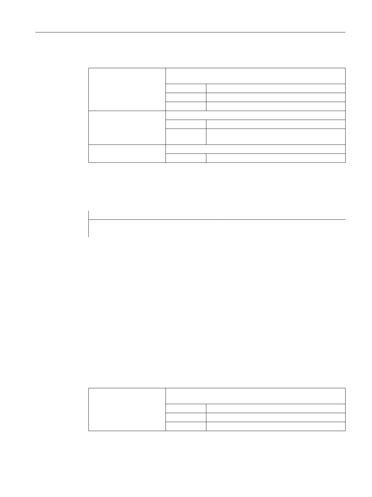
$NT_T_REF_ELEM
Function
The name ($NT_NAME (Page 339)) of the element of the kinematic chain that is currently in
effect, which defines the tool reference position, i.e. the reference point for the tool length
calculation, must be entered in the system variable. The tool reference position is located at
the starting point of the kinematic element.
If no name of an element is entered in the system variable, the tool reference position is
identical to the tool reference point.
Syntax
$NT_T_REF_ELEM[<n>] = "<RefElementName>"
Special functions
346
Function Manual, 12/2018, A5E40874099B AB
K12 transformation definitions with kinematic chains
9.2 Commissioning
Meaning
$NT_T_REF_ELEM:
Name of the element of the kinematic chain that is currently in effect,
which defines the tool reference position.
Data type:
STRING
Default value:
"" (tool reference position = tool reference point)
Value range:
Element names of the currently active kinematic chain
<n>:
System variable or transformation index
Data type:
INT
Range of val-
1, 2, ... (MD18866 $MN_MM_NUM_KIN_TRAFOS - 1)
ues:
<RefElementName>:
Name of an element of the currently active kinematic chain
Data type:
STRING
Example
For the first transformation, the name of the element of the kinematic chain that is currently in
effect, which defines the tool reference position, is "ToolRefPoint":
Program code
Comment
N100 $NT_T_REF_ELEM[1] = "ToolRef-
; 1st transformation,
Point"
; element for the tool reference position
9.2.4.10
$NT_GEO_AX_NAME
Function
A maximum of three names ($NT_NAME (Page 339)) of the elements of the kinematic chain
that is currently in effect, which define the geometry axes (linear axes) of the transformation
type (Page 316) to be parameterized, must be entered in the system variable. The geometry
axes carry out the linear compensating movements, which result from the kinematic
transformation.
Syntax
$NT_GEO_AX_NAME[<n>,<k>] = "<GeoAxElementName>"
Meaning
$NT_GEO_AX_NAME:
Names of the elements of the kinematic chain currently in effect, which
define the geometry axes
Data type:
STRING
Default value:
("", "", "")
Value range:
Element names of the currently active kinematic chain
Special functions
Function Manual, 12/2018, A5E40874099B AB
347
K12 transformation definitions with kinematic chains
9.2 Commissioning
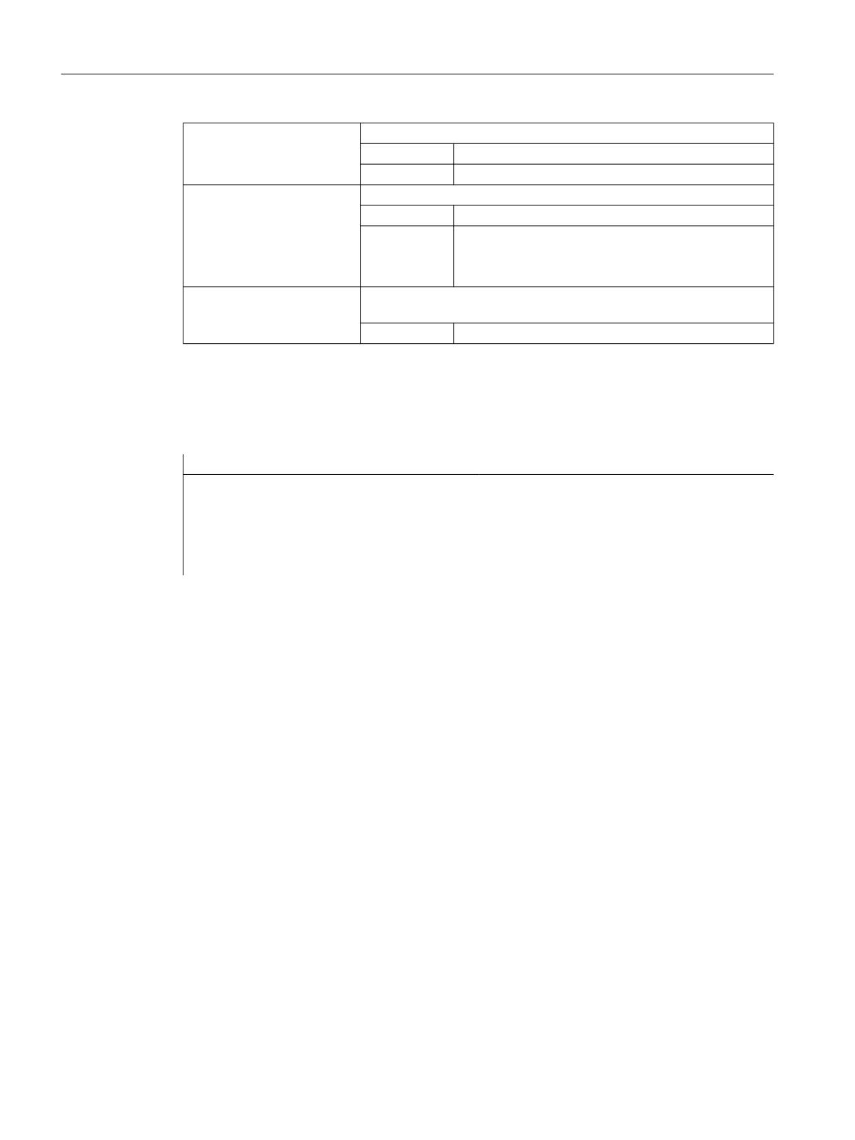
<n>:
System variable or transformation index
Data type:
INT
Value range:
1, 2, ... (MD18866 $MN_MM_NUM_KIN_TRAFOS - 1)
<k>:
Index for the elements that define the geometry axes
Data type:
INT
Range of val-
0: X coordinate (abscissa)
ues:
1: Y coordinate (ordinate)
2: Z coordinate (applicate)
<GeoAxElementName>:
Name of an element of the kinematic chain that is currently in effect,
which defines a geometry axis.
Data type:
STRING
Example
For the first transformation, the names of the elements of the kinematic chain currently in effect,
which define the geometry axes, are "X_AXIS", Y_AXIS" and "Z_AXIS", must be entered.
Program code
Comment
; 1st transformation,
; elements of the geometry axes:
N100 $NT_GEO_AX_NAME[1,0] = "X_AXIS"
; X coordinate (abscissa)
N110 $NT_GEO_AX_NAME[1,1] = "Y_AXIS"
; Y coordinate (ordinate)
N120 $NT_GEO_AX_NAME[1,2] = "Z_AXIS"
; Z coordinate (applicate)
9.2.4.11
$NT_ROT_AX_NAME
Function
A maximum of three names ($NT_NAME (Page 339)) of the elements of the kinematic chain
that is currently in effect, which define the rotary axes of the transformation type (Page 316)
to be parameterized, must be entered in the system variable.
● Orientation transformation: The orientation axes A, B, C
● Face end (TRANSMIT) and cylinder surface transformation (TRACYL): The rotary axis,
which rotates the workpiece and, together with a linear axis, defines the polar coordinate
system.
Order of definitions
The maximum three rotary axes, beginning at Index 0, must be entered in the system variables
in the order in which they are defined in the kinematic chain that is currently in effect.
The kinematic chain must be run through as follows:
1. Starting point: Workpiece reference point
2. Elements of the chain
3. End point: Tool reference point
Special functions
348
Function Manual, 12/2018, A5E40874099B AB

K12 transformation definitions with kinematic chains
9.2 Commissioning
The elements that define the rotary axes must be seamlessly entered in the system variable
with their names, starting at Index 0.
Syntax
$NT_ROT_AX_NAME[<n>,<k>] = "<RotAxElementName>"
Meaning
$NT_ROT_AX_NAME:
Names of the elements of the kinematic chain currently in effect, which
define the rotary axes
Data type:
STRING
Default value:
("", "", "")
Value range:
Element names of the currently active kinematic chain
<n>:
System variable or transformation index
Data type:
INT
Value range:
1, 2, ... (MD18866 $MN_MM_NUM_KIN_TRAFOS - 1)
<k>:
Index for the elements that define the rotary axes
Data type:
INT
Range of val-
0: 1st rotary axis in the definition sequence
ues:
1: 2nd rotary axis in the definition sequence
2: 3rd rotary axis in the definition sequence
<RotAxElementName>:
Name of an element of the kinematic chain that is currently in effect,
which defines a rotary axis.
Data type:
STRING
Example
For the first transformation, the names of the elements of the kinematic chain currently in effect,
which define the rotary axes, are "ROT_AXIS_1", ROT_AXIS_2" and "ROT_AXIS_3" must be
entered.
Program code
Comment
; 1st transformation,
; elements of the rotary axes:
N100 $NT_ROT_AX_NAME[1,0] = "ROT_AXIS_1"
; 1st rotary axis
N110 $NT_ROT_AX_NAME[1,1] = "ROT_AXIS_2"
; 2nd rotary axis
N120 $NT_ROT_AX_NAME[1,2] = "ROT_AXIS_3"
; 3rd rotary axis
Special functions
Function Manual, 12/2018, A5E40874099B AB
349

K12 transformation definitions with kinematic chains
9.2 Commissioning
9.2.4.12
$NT_ROT_AX_OFFSET
Function
System variable $NT_ROT_AX_OFFSET allows you to enter an angle offset for the rotary axes
of the active transformation.
● For TRAORI_K, these are the rotary axes 1, 2, and 3.
● For TRANSMIT_K and TRACYL_K it is rotary axis 1.
Supplementary conditions
● System variable $NT_ROT_AX_OFFSET for Transmit or Tracyl transformations without a
kinematic chain corresponds to machine data $MC_TRANSMIT_ROT_AX_OFFSET_n or
$MC_TRACYL_ROT_AX_OFFSET_n.
● System variable $NT_ROT_AX_OFFSET for orientation transformations without a kinematic
chain corresponds to machine data $MC_TRAFO5_ROT_AX_OFFSET_n.
Syntax
$NT_ROT_AX_OFFSET[<n,m>] = <offset_angle>
Meaning
$NT_ROT_AX_OFFSET
Angle offset for rotary axes
Data type:
REAL
Default value:
-1; content is not evaluated
<n>:
System variable or transformation index
Data type:
INT
Value range:
1, 2, ... (MD18866 $MN_MM_NUM_KIN_TRAFOS - 1)
<m>:
Index of the variable $NT_ROT_AX_CNT; specifies for which rotary axis
the offset is set.
Data type:
INT
Range of values
●
0 ... 2; for orientation transformation
●
1; for TRANSMIT_K and TRACYL_K
Example
Provides the number of rotary axes for the subchain:
Program code
Comment
N100 $NT_ROT_AX_CNT[1,0] = 180
; assigns offset "180 °" to rotary axis
"0" of transformation "1".
Special functions
350
Function Manual, 12/2018, A5E40874099B AB

K12 transformation definitions with kinematic chains
9.2 Commissioning
9.2.4.13
$NT_CLOSE_CHAIN_P
Function
The name ($NT_NAME (Page 339)) of the element of the currently active kinematic chain, at
the end of which the subchain for the workpiece reference point is closed if $NT_CNTRL, Bit
7 == 1, can be entered in the system variable.
If no name is entered in the system variable, the subchain is closed independently of
$NT_CNTRL, Bit 7, at the end of the last element (workpiece reference point).
Syntax
$NT_CLOSE_CHAIN_P[<n>] = "<ElementName>"
Meaning
$NT_CLOSE_CHAIN_P:
Name of the element of the kinematic chain currently in effect, at the
end of which the subchain for the workpiece reference point is closed
Data type:
STRING
Default value:
""
Value range:
Element names of the currently active kinematic chain
<n>:
System variable or transformation index
Data type:
INT
Range of val-
1, 2, ... (MD18866 $MN_MM_NUM_KIN_TRAFOS - 1)
ues:
<ElementName>:
Name of an element of the currently active kinematic chain
Data type:
STRING
Example
For the first transformation, the name of the element of the kinematic chain, at the end of which
the part chain for the workpiece reference point is closed, is: "P_Offset_3"
Program code
Comment
N100 $NT_CLOSE_CHAIN_P[1] = "P_Off-
; 1st transformation,
set_3"
; element for closing the subchain
; to the workpiece reference point
See also
$NT_CNTRL (Page 357)
Special functions
Function Manual, 12/2018, A5E40874099B AB
351

K12 transformation definitions with kinematic chains
9.2 Commissioning
9.2.4.14
$NT_CLOSE_CHAIN_T
Function
The name ($NT_NAME (Page 339)) of the element of the currently active kinematic chain, at
the end of which the subchain for the tool reference point is closed if $NT_CNTRL, Bit 8 == 1
($NT_CNTRL (Page 357)), can be entered in the system variable.
If no name is entered in the system variable, the subchain is closed independently of
$NT_CNTRL, Bit 8, at the end of the last element (tool reference point).
Syntax
$NT_CLOSE_CHAIN_T[<n>] = "<ElementName>"
Meaning
$NT_CLOSE_CHAIN_T:
Name of the element of the kinematic chain currently in effect, at the
end of which the subchain for the tool reference point is closed
Data type:
STRING
Default value:
""
Value range:
Element names of the currently active kinematic chain
<n>:
System variable or transformation index
Data type:
INT
Range of val-
1, 2, ... (MD18866 $MN_MM_NUM_KIN_TRAFOS - 1)
ues:
<ElementName>:
Name of an element of the currently active kinematic chain
Data type:
STRING
Example
For the first transformation, the name of the element of the kinematic chain, at the end of which
the part chain for the tool reference point is closed, is: "T_Offset_3"
Program code
Comment
N100 $NT_CLOSE_CHAIN_T[1] = "T_Off-
; 1st transformation,
set_3"
; element for closing the subchain
; to the tool reference point
Special functions
352
Function Manual, 12/2018, A5E40874099B AB
K12 transformation definitions with kinematic chains
9.2 Commissioning
9.2.4.15
$NT_ROT_OFFSET_FROM_FRAME
Function
In the system variable $NT_ROT_OFFSET_FROM_FRAME it must be entered whether the
programmable offset for orientation axes will be automatically imported from the zero point
offset for the orientation axes, which becomes active upon switch-on of an orientation
transformation.
● TRAORI or TRAORY_DYN:
- If $NT_ROT_OFFSET_FROM_FRAME=1 the following applies:
The offsets for the orientation axes of the 5/6 axis transformation of the rotary axes, for
which the tool orientation is in the basic setting, are automatically defined. Thus, the
offset from an active work offset of the rotary axes, which is active as soon as the
transformation is switched on, is applied.
- If $NT_ROT_OFFSET_FROM_FRAME=0, then the following applies:
The offset of the orientation axes is only applied if the work offsets when switching on
the transformation are kept, i.e. MD10602 $MN_FRAME_GEOAX_CHANGE_MODE is
> 0.
● TRACYL and/or TRANSMIT
- If $NT_ROT_OFFSET_FROM_FRAME=2, the following applies:
Axial offset of the rotary axis is taken into account up to the SZS. SZS is the settable
zero system. The SZS frames contain transformed rotations around the rotary axis.
Note
Automatic application of work offsets
Automatic application of the active work offsets to the offset is mainly only practical for the
polar axis in table kinematics. i.e. for example, in AC kinematics for the C axis. If the offset is
changed for another orientation axis, in particular, the non-polar axis, this changes the
kinematic behavior of the transformation. The can result in the compensatory movement of
the linear axes no longer being correct.
Syntax
$NT_ROT_OFFSET_FROM_FRAME[<n>] = "<ROTOffset>"
Special functions
Function Manual, 12/2018, A5E40874099B AB
353
K12 transformation definitions with kinematic chains
9.2 Commissioning
Meaning
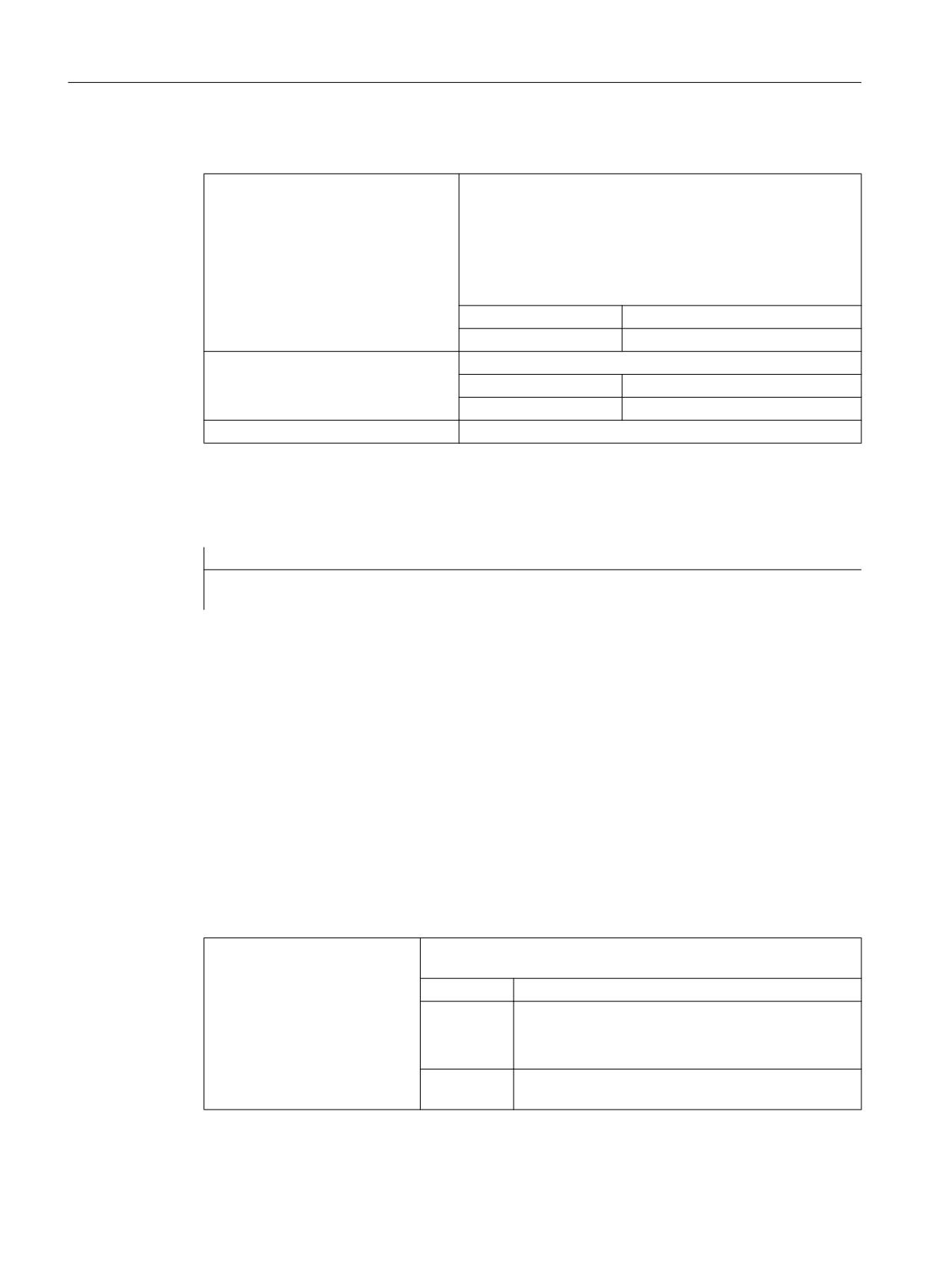
$NT_ROT_OFFSET_FROM_FRAME:
Importing the rotary axis offset from the work offset upon se-
lection of the transformation:
●
0 = Axial offset of the rotary axis is not taken into account.
●
1 = axial offset of the rotary axis is taken into account.
●
2 = Axial offset of the rotary axis is taken into account up
to the SZS or is automatically applied (see above).
Data type:
INT
Default value:
0
<n>:
System variable or transformation index
Data type:
INT
Value range:
0, 1, 2
ROTOffset
Rotary axis offset
Example
The 2nd transformation is assigned the name "B axis":
Program code
Comment
N100 $NT_ROT_OFFSET_FROM_FRAME[1] =
; axial offset of the rotary axis is taken
1
into account.
9.2.4.16
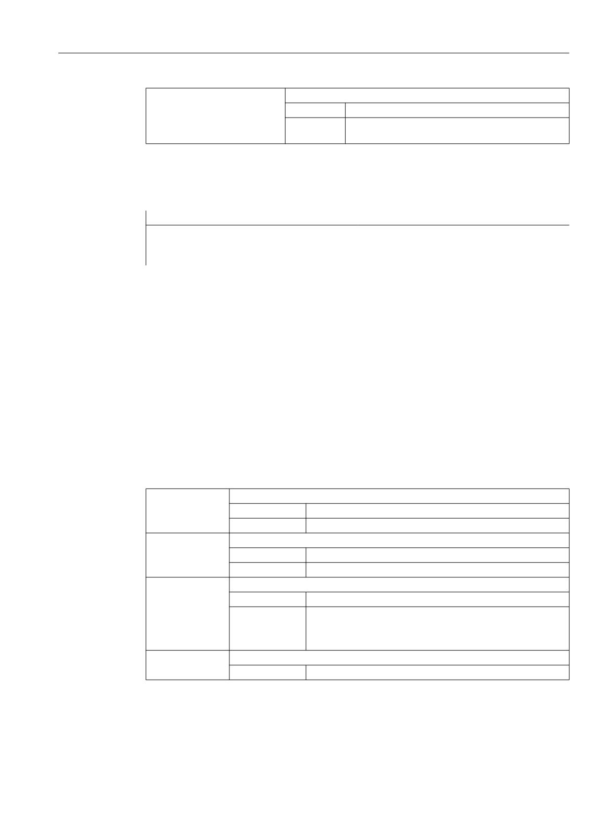
$NT_TRAFO_INCLUDES_TOOL
Function
Information about whether the tool length is to be handled within the transformation or outside
of the transformation must be entered in the system variable.
Syntax
$NT_TRAFO_INCLUDES_TOOL[<n>] = "<>"
Meaning
$NT_TRAFO_INCLUDES_TOOL:
Defines whether the tool length is handled within or outside of the
transformation.
Data type:
BOOL
●
0: Tool length is handled outside of the
transformation.
●
1: Tool length is handled within the transformation.
Default val-
0
ue:
Special functions
354
Function Manual, 12/2018, A5E40874099B AB
K12 transformation definitions with kinematic chains
9.2 Commissioning
<n>:
System variable or transformation index
Data type:
INT
Range of
1, 2, ... (MD18866 $MN_MM_NUM_KIN_TRAFOS -
values:
1)
Example
The 2nd transformation is assigned the name "B axis":
Program code
Comment
N100 $NT_TRAFO_INCLUDE_TOOL[1] =
; 1st transformation,
"1"
; tool length is processed within the
transformation.
9.2.4.17
$NT_AUX_POS
Function
A position vector, e.g. for use in user-specific cycles, can be entered in the system variable.
The system variable is not evaluated in the NC. The values are, however, automatically
recalculated for an inch/metric switchover.
Syntax
$NT_AUX_POS[<n>,<k>] = <Value>
Meaning
$NT_AUX_POS:
User-specific position vector
Data type:
REAL
Default value:
(0.0, 0.0, 0.0)
<n>:
System variable or transformation index
Data type:
INT
Value range:
1, 2, ... (MD18866 $MN_MM_NUM_KIN_TRAFOS - 1)
<k>:
Index of the vector coordinates
Data type:
INT
Range of values:
0: X coordinate (abscissa)
1: Y coordinate (ordinate)
2: Z coordinate (applicate)
<Value>:
Coordinate value
Data type:
REAL
Special functions
Function Manual, 12/2018, A5E40874099B AB
355

K12 transformation definitions with kinematic chains
9.2 Commissioning
Example
A position vector (1.0, 1.0, 1.0) is entered for the first transformation:
Program code
Comment
; 1st transformation,
; position vector:
N100 $NT_AUX_POS[1,0] = 1.0
; X coordinate (abscissa)
N110 $NT_AUX_POS[1,1] = 1.0
; Y coordinate (ordinate)
N120 $NT_AUX_POS[1,2] = 1.0
; Z coordinate (applicate)
9.2.4.18
$NT_IDENT
Function
Up to three user-specific numeric values, analogous to the system variable $TC_CARR37,
can be entered in the system variable as an identifier for the tool carrier or the current
transformation for program management. The system variable is not evaluated in the NC.
Syntax
$NT_IDENT[<n>,<k>] = <Value>
Meaning
$NT_IDENT:
User-specific administration data
Data type:
INT
Default value:
(0, 0, 0)
<n>:
System variable or transformation index
Data type:
INT
Value range:
1, 2, ... (MD18866 $MN_MM_NUM_KIN_TRAFOS - 1)
<k>:
Index of the administration data
Data type:
INT
Range of values:
0, 1, 2
<Value>:
User-specific value
Data type:
INT
Special functions
356
Function Manual, 12/2018, A5E40874099B AB

K12 transformation definitions with kinematic chains
9.2 Commissioning
Example
The following administration data is entered for the first transformation: (1000, 100, 0)
Program code
Comment
; 1st transformation,
; position vector:
N100 $NT_AUX_POS[1,0] = 1000
; identifier: Toolholder
N110 $NT_AUX_POS[1,1] = 100
; identifier: Transformation
N120 $NT_AUX_POS[1,2] = 0
; -
9.2.4.19
$NT_CNTRL
Function
With this system variable, the behavior of the transformation in specific situations can be
influenced using bit code.
Bit
Value
Meaning
0
---
Not assigned
1 - 3
Orientation axes as speed-controlled spindles
Bit 1: 1st orientation axis
Bit 2: 2nd orientation axis
Bit 3: 3rd orientation axis
0
The orientation axis is operated as a speed-controlled axis.
1
The orientation axis is operated as a speed-controlled spindle.
Note
The following scenarios are currently supported:
● Only the 1st orientation axis (Bit 1 = 1) is operated as a speed-controlled spindle
● Only the 3rd orientation axis (Bit 3 = 1) is operated as a speed-controlled
spindle
Some examples are the applications "Turning on milling machines" or "5-axis mill-
ing", in which the third orientation axis is not operated with position control.
Special functions
Function Manual, 12/2018, A5E40874099B AB
357
K12 transformation definitions with kinematic chains
9.2 Commissioning
Bit
Value
Meaning
4 - 6
Orientation axes with Hirth joint
Bit 4: 1st orientation axis
Bit 5: 2nd orientation axis
Bit 6: 3rd orientation axis
0
The orientation axis is not Hirth-coupled.
1
The orientation axis is Hirth-coupled.
Note
● Parameters of the Hirth joint
The following machine data is evaluated for the parameters of the Hirth joint:
- MD30501 $MA_INDEX_AX_NUMERATOR
- MD30502 $MA_INDEX_AX_DENOMINATOR
- MD30503 $MA_INDEX_AX_OFFSET
MD30505 $MA_HIRTH_IS_ACTIVE is not evaluated. I.e. the axis does not
have to be parameterized as a genuine Hirth axis.
● Modulo rotary axes
For modulo rotary axes (MD30310 $MA_ROT_IS_MODULO==TRUE),
MD30330 $MA_MODULO_RANGE is evaluated instead of MD30501
$MA_INDEX_AX_NUMERATOR. The distances of the permitted axis positions
are then calculated for:
Distance = $MA_MODULO_RANGE / $MA_INDEX_AX_DENOMINATOR
MD30503 $MA_INDEX_AX_OFFSET is also evaluated for modulo rotary axes
7
An additional constant element of the type "OFFSET" is automatically NC-internally inserted
into the subchain for the workpiece reference point in such a way that the chain is closed.
0
The element connects the workpiece reference point to the machine zero point.
1
The element connects the end point of the element that is referenced by
$NT_CLOSE_CHAIN_P (Page 351) to the machine zero point.
8
An additional constant element of the type "OFFSET" is automatically NC-internally inserted
into the subchain for the tool reference point in such a way that the chain is closed.
0
The element connects the tool reference point to the machine zero point.
1
The element connects the end point of the element that is referenced by
$NT_CLOSE_CHAIN_T (Page 352) to the machine zero point.
9
The scope of functions of TRANSMIT or TRACYL transformations is specified more precise-
ly. If a center offset axis has been specified via $NT_ROT_AX_NAME, the behavior can be
set.
0
The center offset axis can be interpolated in any way and has no influence on the
transformation.
1
The center offset axis compensates the tool offset in the Y direction. Processing
up to the center of rotation is possible.
10
0
Parameterizes TRACYL without slot side offset.
1
Parameterizes TRACYL with slot side offset.
In connection with bit 9 = 1, you can set whether TRACYL is operated with or
without slot side offset upon activation of the transformation via TRAFOON. The
default setting is slot side offset active
If you are working with slot side offset, $NT_GEO_AX_NAME must contain a ref-
erence to a linear axis (slot side offset axis).
Special functions
358
Function Manual, 12/2018, A5E40874099B AB
K12 transformation definitions with kinematic chains
9.2 Commissioning
Bit
Value
Meaning
11
0
The direction of rotation of the pole axis remains unchanged.
1
The direction of rotation of the pole axis is inverted.
12 ... 15
Reserved for OEM transformations.
16 ... 18
Binary coding using bits 16, 17 and 18 (bits H10000 - H40000) defines how the
channel axes, which are entered in $NT_GEO_AX_NAME [n,1],
$NT_GEO_AX_NAME [n,2] and $NT_GEO_AX_NAME [n,3], are assigned to the
geometry axes. The geometry axis identifiers are assigned in the order (X, Y, Z).
Decimal
Order of the geometry axes
0
X
Y
Z
1
Z
X
Y
2
Y
Z
X
3
Z
Y
X
4
X
Z
Y
5
Y
X
Z
19
0
1
The last kinematic chain element, which defines the tool reference point, must be
a rotary axis. The rotation vector of the rotary axis then defines the Z direction of
the tool coordinate system. The rotation about the tool Z axis that is defined in this
way results from the corresponding definition for the local coordinate system of
an axis in kinematic chains.
If the system variable $NK_A_OFF of this chain element contains a value not equal
to zero, the tool coordinate system is also rotated about the coordinate axis with
this angle.
20
0
The sign of the axis for determining the tool coordinate system in the Z direction
is retained.
1
The sign of the axis for determining the tool coordinate system in the Z direction
is inverted if also bit 19 is set.
Syntax
$NT_CNTRL[<n>] = "<Value>"
Meaning
$NT_CNTRL:
Bit-coded control variable of the transformation ('Bdcbbbaaa0')
Data type:
INT
Default value:
0
<n>:
System variable or transformation index
Data type:
INT
Value range:
1, 2, ... (MD18866 $MN_MM_NUM_KIN_TRAFOS - 1)
<Value>:
Bit-coded control value
Data type:
INT
Special functions
Function Manual, 12/2018, A5E40874099B AB
359

K12 transformation definitions with kinematic chains
9.2 Commissioning
Example
The third orientation axis of the first transformation is Hirth-coupled.
Program code
Comment
N100 $NT_CNTRL[1] = 'B001000000'
; 1st transformation,
9.2.4.20
$NT_ROT_AX_CNT
Function
The system variable $NT_ROT_AX_CNT provides the number of the relevant rotary axes in the
workpiece or in the tool chain. The relevant rotary axes in this sense are the rotary axes that
are defined in the system variable $NT_ROT_AX_Name.
Syntax
$NT_ROT_AX_CNT[<n,m>] = <NumberRotAxes>
Meaning
$NT_ROT_AX_CN
Number of relevant rotary axes of a transformation in the workpiece chain or tool
T:
chain
Data type:
INT
Default value:
-1; content is not evaluated
<n>:
System variable or transformation index
Data type:
INT
Value range:
1, 2, ... (MD18866 $MN_MM_NUM_KIN_TRAFOS - 1)
<m>:
Index of the variable $NT_ROT_AX_CNT; specifies which kinematic chain will be
selected.
Data type:
INT
Value range
●
0; selects the workpiece chain
●
1; selects the tool chain
Example
Provides the number of rotary axes for the subchain:
Program code
Comment
N100 $NT_ROT_AX_CNT[1,0] = 2
; Transformation 1 has two rotary axes.
Special functions
360
Function Manual, 12/2018, A5E40874099B AB

K12 transformation definitions with kinematic chains
9.2 Commissioning
9.2.4.21
$NT_BASE_TOOL_COMP
Function
Using bit-coded system variable $NT_BASE_TOOL_COMP, for each of the geometry axes you
can separately set whether for the base tool an offset is entered in transformation frame
$P_TRAFRAME. This means that when the transformation is selected, no change is made in
the WCS component.
This function is only available if system frame $P_TRAFRAME was configured using MD28082
$MC_MM_SYSTEM_FRAME_MASK bit6.
The system variable is only relevant for TRANSMIT and TRACYL.
Syntax
$NT_BASE_TOOL_COMP[<n>, <m>]
Meaning
$NT_BASE_TOOL_
Bit-coded system variable
COMP:
Data type:
INT
Default value:
<n>:
System variable or transformation index
Data type:
INT
Value range:
1, 2, ... (MD18866 $MN_MM_NUM_KIN_TRAFOS - 1)
<m>:
Bits for coding the offset:
● Bit 0 acts in the direction of the X axis (geometry axis 1)
● Bit 1 acts in the direction of the Y axis (geometry axis 2)
● Bit 2 acts in the direction of the Z axis (geometry axis 3)
Data type:
INT
Example
The 2nd transformation is assigned the name "B axis":
Program code
Comment
N100 $NT_BASE_TOOL_COMP[n,0];
; Transformation "n" is compensated for
in the X-axis direction.
Special functions
Function Manual, 12/2018, A5E40874099B AB
361

K12 transformation definitions with kinematic chains
9.2 Commissioning
9.2.5
Additive system variable for orientation transformation
9.2.5.1
Overview
System variable
Meaning
$NT_BASE_ORIENT
Basic tool orientation
$NT_BASE_ORIENT_NORMAL
Normal vector of the orientation
$NT_ROT_AX_POS
Axis positions of the orientation axes, which are parameterized as
constant rotations
$NT_POLE_LIMIT
End angle tolerance with interpolation through pole
$NT_POLE_TOL
End angle tolerance for pole interpolation
$NT_IGNORE_TOOL_ORIENT
Always take tool orientation from $NT_BASE_ORIENT /
$NT_BASE_ORIENT_NORMAL.
$NT_CORR_ELEM_T
Names of the correction elements in the tool chain that can be
written to by the CORRTRAFO(...) function.
$NT_CORR_ELEM_P
Names of the correction elements in the subchain that can be writ-
ten to by the CORRTRAFO(...) function.
The system variables are described in detail in the following sections.
Note
Element names
The system does not monitor as to whether the element names of the kinematic chain, which
are referenced to parameterize transformation, were allocated a multiple number of times. If
names such as these are available a multiple number of times, then the system data of the
transformation always refer to the corresponding element with the lowest index.
Establish a defined initial state
It is recommended that a defined initial state be generated before parameterizing the kinematic
chain. To do this, the system variables of the kinematic chain should be set to their default
value using function DELOBJ() (Page 215).
Change system variable values
Changes to system variable values of the transformation data $NT_... only become effective
when the NEWCONF machine data becomes effective. This can be done using the softkey
on the user interface in the operating area "Commissioning" > "Machine data " > "Set MD
active", in a program using the NEWCONF command or using a program end reset, channel
reset or a warm or cold restart.
9.2.5.2
$NT_BASE_ORIENT
Function
The rotation vector of the basic tool orientation must be entered in the system variable. The
basic tool orientation is in effect if no tool is selected.
Special functions
362
Function Manual, 12/2018, A5E40874099B AB

K12 transformation definitions with kinematic chains
9.2 Commissioning
Syntax
$NT_BASE_ORIENT[<n>,<k>] = <VectorComp>
Meaning
$NT_BASE_ORIENT:
Rotation vector of the basic tool orientation (X; Y; Z)
Data type:
REAL
Default value:
(0.0, 0.0, 1.0)
Value range:
Direction vector: 1*10-6 < |Vector | ≤ max. REAL value
<n>:
System variable or transformation index
Data type:
INT
Value range:
1, 2, ... (MD18866 $MN_MM_NUM_KIN_TRAFOS - 1)
<k>:
Index of the coordinates
Data type:
INT
Range of val-
0: X coordinate (abscissa)
ues:
1: Y coordinate (ordinate)
2: Z coordinate (applicate)
<VectorComp>:
Coordinate value of the vector component
Data type:
STRING
Example
The rotation vector of the basic tool orientation of the first transformation has the value (1.0,
2.0, 3.0):
Program code
Comment
; 1st transformation,
; vector components:
N100 $NT_BASE_ORIENT[1,0] = 1.0
; X coordinate (abscissa)
N110 $NT_BASE_ORIENT[1,1] = 2.0
; Y coordinate (ordinate)
N120 $NT_BASE_ORIENT[1,2] = 3.0
; Z coordinate (applicate)
9.2.5.3
$NT_BASE_ORIENT_NORMAL
Function
The normal vector of the basic tool orientation must be entered in the system variable. The
system variable or the normal vector of the basic tool orientation is only relevant for
transformations with three degrees of orientation freedom if no tool is selected.
Special functions
Function Manual, 12/2018, A5E40874099B AB
363

K12 transformation definitions with kinematic chains
9.2 Commissioning
Syntax
$NT_BASE_ORIENT_NORMAL[<n>,<k>] = <VectorComp>
$NT_BASE_ORIENT_NORMA
Normal vector of the basic tool orientation (X; Y; Z)
L:
Data type:
REAL
Default value:
(0.0, 1.0, 0.0)
Value range:
Normal vector: 1*10-6 < |Vector | ≤ max. REAL value
<n>:
System variable or transformation index
Data type:
INT
Value range:
1, 2, ... (MD18866 $MN_MM_NUM_KIN_TRAFOS - 1)
<k>:
Index of the coordinates
Data type:
INT
Range of val-
0: X coordinate (abscissa)
ues:
1: Y coordinate (ordinate)
2: Z coordinate (applicate)
<VectorComp>:
Coordinate value of the vector component
Data type:
STRING
Example
The normal vector of the basic tool orientation of the first transformation has the value (2.0,
-1.0, 3.0):
Program code
Comment
; 1st transformation,
; vector components:
N100 $NT_BASE_ORIENT_NORMAL[1,0] =
2.0
; X coordinate (abscissa)
N110 $NT_BASE_ORIENT_NORMAL[1,1] = -1.0
; Y coordinate (ordinate)
N120 $NT_BASE_ORIENT_NORMAL[1,2] =
3.0
; Z coordinate (applicate)
9.2.5.4
$NT_ROT_AX_POS
Function
The positions of the orientation axes, which result from the constant rotations which are
parameterized in elements of the kinematic chain of the type ROT_CONST (Page 209), must
be entered in the system variable. The positions of the orientation axes that are effective due
to this element can thus be described without having to know the kinematic structure of the
transformation or the indices of the associated kinematic elements.
Syntax
$NT_ROT_AX_POS[<n>,<k>] = <OriAxPos>
Special functions
364
Function Manual, 12/2018, A5E40874099B AB

K12 transformation definitions with kinematic chains
9.2 Commissioning
Meaning
$NT_ROT_AX_POS:
Positions of the orientation axes due to the constant rotation
Data type:
REAL
Default value:
(0.0, 0.0, 0.0)
Value range:
- max. REAL value ≤ x ≤ + max. REAL value
<n>:
System variable or transformation index
Data type:
INT
Value range:
1, 2, ... (MD18866 $MN_MM_NUM_KIN_TRAFOS - 1)
<k>:
Index of the orientation axes
Data type:
INT
Value range:
0: 1st orientation axis
1: 2nd orientation axis
2: 3rd orientation axis
<OriAxPos>:
Position value
Data type:
REAL
Example
The positions of the orientation axes, which result from the parameterized constant rotation,
are: (0, 0, 45.0°)
Program code
Comment
; 1st transformation,
; positions of the orientation axes:
N100 $NT_ROT_AX_POS[1,0] =
0
; 1st orientation axis
N110 $NT_ROT_AX_POS[1,1] =
0
; 2nd orientation axis
N120 $NT_ROT_AX_POS[1,2] = 45.0
; 3rd orientation axis
9.2.5.5
$NT_POLE_LIMIT
Function
The maximum permitted angle by which the C axis can deviate from its programmed position
during a large circle interpolation at the end of a block is entered in the system variable.
End angle
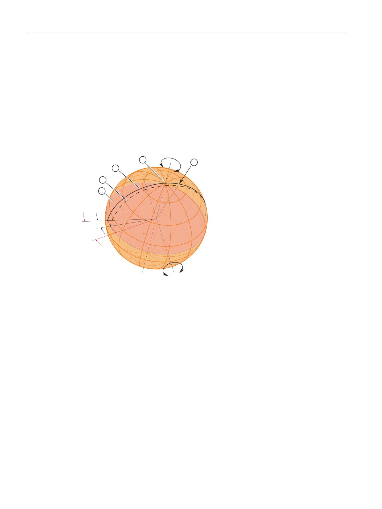
In the 5-axis transformation, the two orientation axes of the tool span a spherical coordinate
system, consisting of meridians and parallels.
If a traversing movement is programmed that is not to pass exactly through the pole, but within
the area near to the pole defined by MD 24530 ($MC_TRAFO5_NON_POLE_LIMIT_n), the
movement will deviate from the specified path because the interpolation runs exactly through
the pole point. As a result, the position at the end point of the fourth axis (pole axis) deviates
from the programmed value.
The system variable specifies the angle by which the pole axis for the 5-axis transformation
can deviate from the programmed value if there is a switchover from the programmed
Special functions
Function Manual, 12/2018, A5E40874099B AB
365
K12 transformation definitions with kinematic chains
9.2 Commissioning
interpolation to the interpolation through the pole point.
If a large deviation results, an error message is displayed (Alarm 14112) and the interpolation
is not carried out.
For a conventional 5 or 6-axis interpolation, a pole position is identified by the fact that the tool
orientation does not change during a rotation of a rotary axis. If a programmed path then runs
in the vicinity of the pole, extremely high traversing speeds can result for individual rotary axes
to maintain the orientation. If the programmed path runs exactly through the pole, this problem
may not arise under certain circumstances.
A pole angle, which defines a tolerance circle about the pole, can be parameterized in the
system variables. If a programmed tool path passes by the pole within the tolerance circle, a
switchover is made from orientation interpolation to linear/rotary axis interpolation.
&
6
(
˞
(
˖
$
①
Pole
②
Equatorial plane
③
Programmed path
④
Path traveled through the pole
⑤
End angle
A
Rotary axis about the X coordinate axis of the WCS
C
Rotary axis about the Z coordinate axis of the WCS
S
Starting point of the interpolation / traversing block
E
Approached end point
E'
Programmed end point
α
End angle
Ω
Maximum permitted end angle ($NT_POLE_LIMIT)
Syntax
$NT_POLE_LIMIT[<n>] = <PoleTolAngle>
Special functions
366
Function Manual, 12/2018, A5E40874099B AB

K12 transformation definitions with kinematic chains
9.2 Commissioning
Meaning
$NT_POLE_LIMIT:
Pole angle
Unit:
Degrees
Data type:
REAL
Default value:
2.0
Value range:
- max. REAL value ≤ x ≤ + max. REAL value
<n>:
System variable or transformation index
Data type:
INT
Range of val-
1, 2, ... (MD18866 $MN_MM_NUM_KIN_TRAFOS - 1)
ues:
<PoleTolAngle>:
Tolerance value
Data type:
REAL
Example
A pole angle of 2.54° is set for the first transformation:
Program code
Comment
N100 $NT_POLE_LIMIT[1] = 2.54
; 1st transformation,
; pole angle
9.2.5.6
$NT_POLE_TOL
Function
The end angle tolerance for interpolation through the pole for the first 5/6-axis transformation
must be entered in the system variable.
The system variable is only evaluated by the generic 5/6-axis transformation.
If the programmed end orientation lies within the polar cone and within the tolerance cone
specified by this MD, the pole axis does not move and retains its start positions. In contrast,
the other rotary axis accepts the programmed angle.
As a result, there is a deviation of the end orientation from the programmed orientation.
Another meaning of this system variable is the handling of the programmed end orientation
for non-perpendicular kinematics. As a rule, not all of the tool orientations can be set for these
machine kinematics. If an orientation that lies outside of the settable range is programmed,
alarm 14112 "Programmed orientation path not possible" is displayed.
Syntax
$NT_POLE_TOL[<n>] = <PoleTolLim>
Special functions
Function Manual, 12/2018, A5E40874099B AB
367
K12 transformation definitions with kinematic chains
9.2 Commissioning
Meaning
$NT_POLE_TOL:
End angle tolerance for pole interpolation
Data type:
REAL
Default value:
0.0
Value range:
0.0 ≤ x ≤ 45.0
<n>:
System variable or transformation index
Data type:
INT
Value range:
1, 2, ... (MD18866 $MN_MM_NUM_KIN_TRAFOS - 1)
<PoleTolLim>:
Angle
Data type:
REAL
Example
An end angle tolerance of 2.54° is defined for the first transformation:
Program code
Comment
N100 $NT_POLE_TOL[1] = 2.54
; 1st transformation,
; end angle tolerance
9.2.5.7
$NT_IGNORE_TOOL_ORIENT
Function
Each tool that is known in the controller has a defined orientation. This tool orientation is
normally used as the basis for the calculations of the movements of the orientation axes. The
system variable can be used to define a situation in which, even with a tool active, it is not the
tool orientation, but the orientation parameterized in the system variables
$NT_BASE_ORIENT (Page 362) and $NT_BASE_ORIENT_NORMAL (Page 363) that is used
for the calculations of the movements of the orientation axes.
Syntax
$NT_IGNORE_TOOL_ORIENT[<n>] = <Value>
Meaning
$NT_IGNORE_TOOL_ORIEN
Switchover to the orientation parameterized in the system variables
T:
$NT_BASE_ORIENT and $NT_BASE_ORIENT_NORMAL for calculat-
ing the movements of the orientation axes
Data type:
BOOL
Default value:
FALSE
<n>:
System variable or transformation index
Data type:
INT
Range of val-
1, 2, ... (MD18866 $MN_MM_NUM_KIN_TRAFOS - 1)
ues:
Special functions
368
Function Manual, 12/2018, A5E40874099B AB

K12 transformation definitions with kinematic chains
9.2 Commissioning
<Value>:
Value
Data type:
BOOL
Example
For the first transformation, the orientation parameterized in the system variables
$NT_BASE_ORIENT and $NT_BASE_ORIENT_NORMAL for calculating the movements of
the orientation axes is activated:
Program code
Comment
N100 $NT_IGNORE_TOOL_ORIENT[1] = TRUE
; 1st transformation,
; orientation as per system variables
9.2.5.8
$NT_CORR_ELEM_T
Function
This system data is used to reference a maximum of 4 constant chain elements ($NK_NAME)
in the tool chain, which are provided for accepting offset values (linear offsets), as they are
determined in measurement cycles, for example. The offset values are calculated by the
function CORRTRAFO (Page 374). This is only important for orientation transformations.
There must always be an orientation axis in the kinematic chain between two of these elements.
This means that all 4 chain elements can only be occupied for 6-axis transformations in which
all 3 orientation axes are defined in the tool chain; whereas, for 5-axis transformations, for
example, this system data can only contain a maximum of three entries.
The entire kinematic chain, from the machine zero point (reference point of the kinematic chain)
to the tool holder, is divided into a maximum of 4 sections by the orientation axes. There can
be a maximum of one correction element in each of these sections. The correction element
with the index n must be located in the nth section (example: $NT_CORR_ELEM_T[k, 1] must
refer to a chain element between the first and second orientation axis of the tool chain).
Syntax
$NT_CORR_ELEM_T[<n>, <k>] = "<CORR_TElementName>"
Meaning
$NT_CORR_ELEM_T:
Names of the elements of the kinematic chain currently in effect.
Data type:
STRING
Default value:
""
Value range:
Element names of the currently active kinematic chain
<n>:
System variable or transformation index
Data type:
INT
Value range:
1, 2, ... (MD18866 $MN_MM_NUM_KIN_TRAFOS - 1)
Special functions
Function Manual, 12/2018, A5E40874099B AB
369
K12 transformation definitions with kinematic chains
9.2 Commissioning
<k>:
Position in the kinematic tool chain
Data type:
INT
Value range:
0...3
<CORR_TElementName>:
Name of an element of the kinematic chain that is currently in effect,
which accepts an offset value (linear offset).
Data type:
STRING
Example
Defines an correction element in the tool chain that is used to include offset values.
Program code
Comment
$NT_CORR_ELEM_T(1,2) = Corr_1;
Refers to a correction element in the tool
chain of transformation "1" and position "2".
9.2.5.9
$NT_CORR_ELEM_P
Function
This system data is used to reference a maximum of 4 constant chain elements ($NK_NAME)
in the part chain, which are provided for accepting offset values (linear offsets), as they are
determined in measurement cycles, for example. The offset values are calculated by the
function CORRTRAFO (Page 374). This is only important for orientation transformations.
There must always be an orientation axis in the kinematic chain between two of these elements.
This means that all 4 chain elements can only be occupied for 6-axis transformations in which
all 3 orientation axes are defined in the tool chain; whereas, for 5-axis transformations, for
example, this system data can only contain a maximum of three entries.
The entire kinematic chain, from the machine zero point (reference point of the kinematic chain)
to the workpiece center point (part), is divided into a maximum of 4 sections by the orientation
axes. There can be a maximum of one correction element in each of these sections. The
correction element with the index n must be located in the nth section (example:
$NT_CORR_ELEM_T[k, 1] must refer to a chain element between the first and second
orientation axis of the part chain).
Syntax
$NT_CORR_ELEM_P[<n>,<m>,<k>] = "<CORR_PElementName>"
Meaning
$NT_CORR_ELEM_P:
Names of the elements of the kinematic chain currently in effect.
Data type:
STRING
Default value:
""
Value range:
Element names of the currently active kinematic chain
Special functions
370
Function Manual, 12/2018, A5E40874099B AB
K12 transformation definitions with kinematic chains
9.2 Commissioning
<n>:
System variable or transformation index
Data type:
INT
Value range:
1, 2, ... (MD18866 $MN_MM_NUM_KIN_TRAFOS - 1)
<k>:
Position in the kinematic tool chain
Data type:
INT
Value range:
0...3
<CORR_PElementName>:
Name of an element of the kinematic chain that is currently in effect, which
accepts an offset value (linear offset).
Data type:
STRING
Example
Defines an correction element in the workpiece chain that is used to accept offset values.
Program code
Comment
$NT_CORR_ELEM_P(1,2) = Corr_1
Refers to a correction element in the work-
piece chain of transformation "1" and posi-
tion "2".
9.2.6
Additive system variable for face transformation (TRANSMIT)
9.2.6.1
Overview
System variable
Meaning
$NT_POLE_SIDE_FIX
Limitation of the working area before and after the pole
Special functions
Function Manual, 12/2018, A5E40874099B AB
371

K12 transformation definitions with kinematic chains
9.2 Commissioning
The system variables are described in detail in the following sections.
Note
Element names
The system does not monitor as to whether the element names of the kinematic chain, which
are referenced to parameterize transformation, were allocated a multiple number of times. If
names such as these are available a multiple number of times, then the system data of the
transformation always refer to the corresponding element with the lowest index.
Establish a defined initial state
It is recommended that a defined initial state be generated before parameterizing the kinematic
chain. To do this, the system variables of the kinematic chain should be set to their default
value using function DELOBJ() (Page 215).
Change system variable values
Changes to system variable values of the transformation data $NT_... only become effective
when the NEWCONF machine data becomes effective. This can be done using the softkey
on the user interface in the operating area "Commissioning" > "Machine data " > "Set MD
active", in a program using the NEWCONF command or using a program end reset, channel
reset or a warm or cold restart.
9.2.6.2
$NT_POLE_SIDE_FIX
Function
Using the system variable, the limitation of the work area must be set before and after the pole.
Syntax
$NT_POLE_SIDE_FIX[<n>] = <POLESIDEFIX>
Meaning
$NT_POLE_SIDE_FIX:
Names of the elements of the kinematic chain currently in effect, which
define the rotary axes
Data type:
INT
Default value:
""
Value range:
Element names of the currently active kinematic
chain
<n>:
System variable or transformation index
Data type:
INT
Range of values:
1, 2, ... (MD18866 $MN_MM_NUM_KIN_TRAFOS -
1)
Special functions
372
Function Manual, 12/2018, A5E40874099B AB

K12 transformation definitions with kinematic chains
9.3 Programming
<PoleSIDEFIX>:
Limiting the work area:
●
0 = no limitation; traversing through the pole is allowed.
●
1 = work area of the linear axis for positions ≥ 0 (if tool length offset
is parallel to linear axis = 0).
●
2 = work area of the linear axis for positions ≤ 0 (if tool length offset
is parallel to linear axis = 0).
Data type:
STRING
Example
For the first transformation, the names of the elements of the kinematic chain currently in effect,
which define the rotary axes, are "ROT_AXIS_1", ROT_AXIS_2" and "ROT_AXIS_3".
Program code
Comment
; 1st transformation,
; elements of the rotary axes:
N100 $NT_ROT_AX_NAME[1,0] = "ROT_AXIS_1"
; 1st rotary axis
N110 $NT_ROT_AX_NAME[1,1] = "ROT_AXIS_2"
; 2nd rotary axis
N120 $NT_ROT_AX_NAME[1,2] = "ROT_AXIS_3"
; 3rd rotary axis
9.3
Programming
9.3.1
Activating a transformation (TRAFOON)
A transformation defined with kinematic chains is activated with the predefined TRAFOON
procedure. The call must be alone in a block.
Note
Alternatively, a transformation defined with kinematic chains can also be activated via
conventional NC commands, such as TRAORI or TRANSMIT. For this purpose, an appropriate
value, not equal to zero, must be entered in the $NT_TRAFO_INDEX system variable.
For further information on $NT_TRAFO_INDEX see "System Variables List Manual".
Syntax
TRAFOON(<Trafoname>,<Diameter>,<k>)
Special functions
Function Manual, 12/2018, A5E40874099B AB
373

K12 transformation definitions with kinematic chains
9.3 Programming
Meaning
TRAFOON:
Procedure for activating a transformation defined with kinematic chains
<Trafoname>:
Name of the transformation data set
Data type:
STRING
Range of val-
All names of transformation data sets defined via $NK_NAME
ues:
(Page 339)
Note:
The name of the transformation data set must be unique. It must only occur once
in $NT_NAME.
<Diameter>:
Reference or working diameter (TRACYL only)
Data type:
REAL
The value must be > 1.
<k>:
Defines the use of the groove side offset (TRACYL only).
Data type:
BOOL
Value:
FALSE
Without groove side offset
TRUE
With groove side offset
Corresponds to the TRACYL transformation type 514 (groove side offset can be
programmed). If <k> is not specified, the parameterized setting of bit 10 in
$NT_CNTRL[<n>] applies.
Example
Program code
Comment
TRAFOON["Trans_1"]
Activates the transformation with the name Trans_1.
9.3.2
Modifying the orientation transformation after the machine measurement
(CORRTRAFO)
For machines with orientation transformations that were defined by means of kinematic chains,
the user can use the predefined CORRTRAFO function in order to modify the offset vectors
or the direction vectors of the orientation axes in the kinematic model of the machine after a
machine measurement.
Syntax
<Corr_Status> = CORRTRAFO(<Corr_Vect>, <Corr_Index>, <Corr_Mode>,
[ <No_Alarm>])
Special functions
374
Function Manual, 12/2018, A5E40874099B AB

K12 transformation definitions with kinematic chains
9.3 Programming
Meaning
CORRTRAFO:
Function call
<Corr_Status>:
Function return value
Data type:
INT
Values:
0
The function was executed without an error.
1
No transformation is active.
2
The currently active transformation is not an orientation trans-
formation.
3
The active orientation transformation was not defined with kin-
ematic chains.
10
The <Corr_Index> call parameter is negative.
11
The <Corr_Mode> call parameter is negative.
12
Invalid reference to a section of a subchain (unit position of
<Corr_Index>). The value must not be greater than the num-
ber of orientation axes in the subchain.
13
Invalid reference to the orientation axis of a subchain (unit po-
sition of <Corr_Index>). The value must be less than the
number of orientation axes in the subchain.
14
Invalid reference to a subchain (tens position of
<Corr_Index>). Only the values 0 and 1 are permissible (ref-
erence to part or tool chain). This error number occurs if the
subchain to which <Corr_Index> refers does not exist.
15
There is no correction element in the section referred to with
the <Corr_Index> parameter ($NT_CORR_ELEM_P or
$NT_CORR_ELEM_T).
20
Invalid correction mode (unit position of <Corr_Mode>). Only
the values 0 and 1 are permissible.
21
Invalid correction mode (tens and/or hundreds position of
<Corr_Mode>). Only the unit position can be not equal to zero
when writing an axis direction.
30
The hundreds position of <Corr_Mode> is invalid. Only the
values 0 and 1 are permissible.
31
The thousands position of <Corr_Mode> is invalid. Only the
values 0 and 1 are permissible.
40
The direction vector that is to be taken as axis direction is the
zero vector. This error can only happen if the thousands posi-
tion of <Corr_Mode> is equal to 0. If the thousands position
of this parameter is equal to 1 (monitoring of the maximum
correction deactivated), the zero vector can also be written.
Special functions
Function Manual, 12/2018, A5E40874099B AB
375
K12 transformation definitions with kinematic chains
9.3 Programming
41
For the correction of an offset vector, the difference to the cur-
rent value in at least one coordinate is greater than the maxi-
mum value specified by the setting data SD41610
$SN_CORR_TRAFO_LIN_MAX. The <Corr_Vect> parame-
ter will be overwritten by an error vector. This also applies when
the processing is aborted with alarm (see <No_Alarm> pa-
rameter).
In the components whose correction value has exceeded the
permissible limit, the error vector has the difference, with the
correct sign, between the determined correction value and the
limit.
The content of the components that have not exceeded their
limit is zero.
42
For the correction of a direction vector, the angular displace-
ment compared to the current direction is greater than the
maximum value specified by the setting data SD41611
$SN_CORR_TRAFO_DIR_MAX.
43
The attempt to write a system variable was rejected because
of missing write rights.
<Corr_Vect>:
Correction vector
The content of the correction vector is defined by the following parameters
<Corr_Index> and <Corr_Mode>.
If <Corr_Status> = 41, the content of the vector is overwritten (see above).
Data type:
REAL
<Corr_Index>:
Section whose correction element is to be modified /
index of the orientation axis whose direction vector is to be modified
Data type:
INT
The <Corr_Index> parameter is decimal coded (unit to tens position):
Unit
Contains the index of the section or the orientation axis in the sub-
position:
chain.
Tens
Refers to the subchain.
position:
0x
Workpiece chain
1x
Tool chain
Special functions
376
Function Manual, 12/2018, A5E40874099B AB
K12 transformation definitions with kinematic chains
9.3 Programming
<Corr_Mode>:
Correction mode
Data type:
INT
The <Corr_Index> parameter is decimal coded (unit to thousands position):
Unit
Specifies which element is to be corrected.
position:
xxx0
Correction of a linear offset vector
xxx1
Correction of the direction vector of an orientation axis
Tens
Specifies how the correction element to which the content of
position:
<Corr_Index> refers, is to be modified.
xx0x
The correction vector is written immediately to the correc-
tion element.
This variant can be used to immediately write the correction
element without the index <n> of the relevant system data
($NK_OFF_DIR[<n>, ...]) having to be known.
xx1x
As 0, but with the difference that the transferred correction
value is interpreted in world coordinates.
A difference between variants 0 and 1 can always occur
when the kinematic chain in the initial state (positions of all
orientation axes equal to 0) contains other rotations.
xx2x
As 1, but with the difference that the correction value refers
to the entire section, i.e. a value is entered in the correction
element so that the entire section reaches the length de-
fined by the correction value.
Note:
The values 1 and 2 are not permissible when writing the direction
vector of an orientation axis.
Hundreds
Specifies how the content of the <Corr_Vect> parameter is to be
position:
interpreted.
x0xx
The transferred correction vector <Corr_Vect> contains
the entire new length of the correction element or the sec-
tion to which the <Corr_Index> in conjunction with the
tens position of <Corr_Mode> refers (absolute correction).
x1xx
The transferred correction vector <Corr_Vect> only con-
tains the difference compared to the current length of the
correction element or the section to which the
<Corr_Index> in conjunction with the tens position of
<Corr_Mode> refers (incremental correction).
Note:
For the correction of the direction vector of an orientation axis, the
content of the hundreds position must be 0.
Thou-
Specifies whether the correction is to be limited by the following
sands
maximum value:
position:
● SD41610 $SN_CORR_TRAFO_LIN_MAX (Page 336)
or
● SD41611 $SN_CORR_TRAFO_DIR_MAX (Page 336)
0xxx
Monitoring of the maximum correction is active.
1xxx
Monitoring of the maximum correction is not active.
Special functions
Function Manual, 12/2018, A5E40874099B AB
377

K12 transformation definitions with kinematic chains
9.3 Programming
<No_Alarm>:
Behavior in the event of an error (return value > 0) (optional)
Data type:
BOOL
Value:
FALSE
In the event of an error, the program processing is stop-
(default)
ped and alarm 14103 is displayed.
TRUE
In the event of an error, the program processing is not
stopped and no alarm is displayed.
Application: User-specific reaction corresponding to the
return value
Note
In the event of an error when the function is called, either an alarm is output or an error number
returned (see <No_Alarm> parameter), so that the user can respond in a suitable way to the
error state. The cause of the error is described in more detail through an alarm parameter. An
error number returned instead of an alarm is identical to the alarm parameter.
See also
Angular deviation for rotation vectors for CORRTRAFO (Page 336)
Further information on CORRTRAFO
The kinematic structure of a machine with orientation transformation is described by one or
two kinematic chains (subchains), starting from the zero point of the world coordinate system.
One of the two chains, the tool chain, ends at the reference point of the tool, the other chain,
the workpiece chain ends in the zero point of the basic coordinate system.
The CORRTRAFO function writes lever arm lengths and axis directions on machines with an
orientation transformation in special correction elements. A kinematic chain is described, for
example, with elements of the type OFFSET, which are defined via $ NK_TYPE.
CORRTRAFO works with sections
The two subchains can each be divided into a maximum of four sections:
● Section 1 begins at the starting point of the chain and ends at the first orientation axis.
● Section 2 is the section between orientation axis 1 and orientation axis 2.
● Section 3 is the section between orientation axis 2 and orientation axis 3.
● Section 4 is the section between orientation axis 3 and the end of the tool or workpiece
chain.
Each section may contain constant chain elements of the type OFFSET or ROT_CONST.
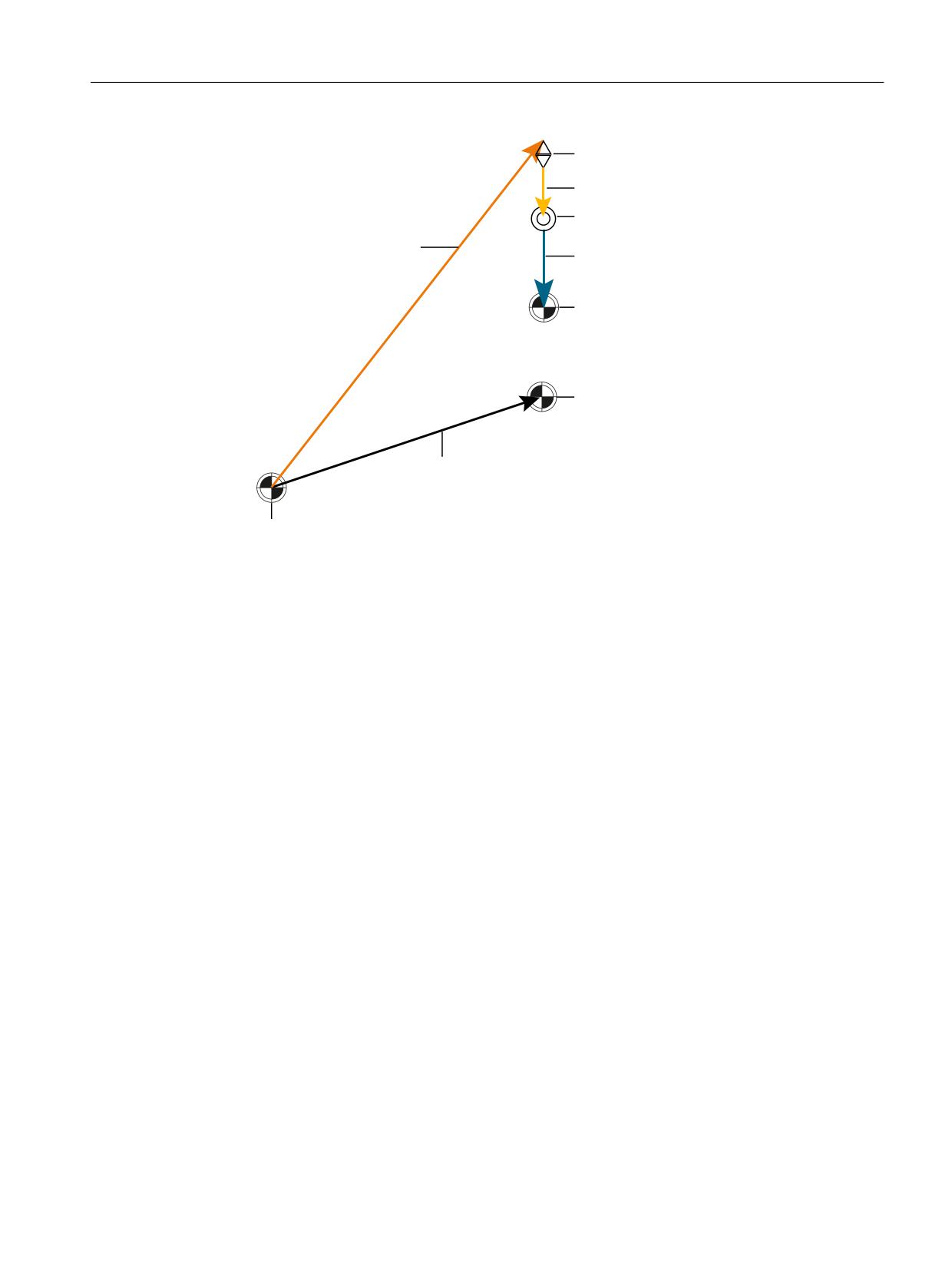
The following figure shows an orientation transformation with 2 orientation axes.
Special functions
378
Function Manual, 12/2018, A5E40874099B AB
K12 transformation definitions with kinematic chains
9.3 Programming
2ULHQWDWLRQ D[LV
6HFWLRQ
,QGH[
2ULHQWDWLRQ D[LV
6HFWLRQ
,QGH[
6HFWLRQ
,QGH[
7RRO UHIHUHQFH SRLQW HQG
SRLQW RI WKH WRRO FKDLQ
:RUNSLHFH UHIHUHQFH
SRLQW
7DEOH RIIVHW
=HUR SRLQW RI WKH ZRUOG
FRRUGLQDWH V\VWHP
Figure 9-7
CORRTRAFO example
The sections are clearly defined: If you run through the kinematic subchain from the starting
point to the end point, the first section has the index 0, the next the index 1, and so on. The
index of the last section is then always equal to the number of orientation axes.
Correction elements
A reference can be made to a constant kinematic chain element (chain element of the type
$NK_TYPE[<n>] = "OFFSET") in each section with the $NT_CORR_ELEM_T[<n>, 0 ... 3] or
$NT_CORR_ELEM_P[<n>, 0 ... 3] system variables. The correction values that were
determined during the machine measurement are written to these elements with the
CORRTRAFO function.
Example with transformation index = 1:
● $NT_CORR_ELEM_T[1,0] = "C_AXIS_OFFSET"; Offset of the C axis (orientation axis 1)
in section 1 is defined as correction element.
● $NT_CORR_ELEM_T[1,1] = "B_AXIS_OFFSET"; Offset of the B axis (orientation axis 2) in
section 2 is defined as correction element.
● $NT_CORR_ELEM_T[1,2] = "BASE_TOOL_OFFSET"; Offset of the B axis from the tool
reference point in section 3 is defined as correction element.
The sequence of the references in $NT_CORR_ELEM_T/P[<n>, 0 ... 3] must correspond to
the sections described above, i.e. only one chain element can be in $NT_CORR_ELEM_T/P
[<n>, 0] which is before the first orientation axis, etc.
The CORRTRAFO function writes the values determined by measuring the machine into the
correction elements defined in this way. The modification of the correction values is defined
in CORRTRAFO via the <Corr_Mode> parameter.
Special functions
Function Manual, 12/2018, A5E40874099B AB
379
K12 transformation definitions with kinematic chains
9.3 Programming
Closing a chain
If bit 7 or bit 8 are set in the $NT_CNTRL[<n>] system variable, additional constant chain
elements that establish a connection from the end point of the chain to the machine zero point
are automatically inserted internally at the end of the workpiece chain (bit 7) or before the
starting point of the tool chain (bit 8) ("close chain").
These automatically inserted elements cannot be written externally, only read (see the
$AC_TRAFO_CORR_ELEM_P/T system variables).
Point to close the tool chain
If the $NT_CLOSE_CHAIN_T system variable is not empty, the tool chain is not closed at the
end point of the chain, but rather at the end point of the designated chain element. Other chain
elements that are behind this point result in a corresponding work offset when the
transformation is activated.
Index of an orientation axis
In addition to the constants offsets between the orientation axes, the direction vectors of the
orientation axes can also be written with the CORRTRAFO function. The index of an orientation
axis is the index that results when the kinematic subchain is run through from the origin to the
end, where the count starts at zero. The index of an orientation axis is therefore always the
same as the index of the preceding section.
The index of an orientation axis can also be determined with the $AC_TRAFO_ORIAX_LOC
system variable.
Maximum permissible change of a chain element
The maximum permissible change of a chain element can be limited by the two setting data
SD41610 $SN_CORR_TRAFO_LIN_MAX for offset vectors and SD41611
$SN_CORR_TRAFO_DIR_MAX for direction vectors of the orientation axes. SD41610
$SN_CORR_TRAFO_LIN_MAX specifies the maximum amount by which each individual
vector component can be changed with regard to its reference value. SD41611
$SN_CORR_TRAFO_DIR_MAX specifies the maximum angle by which the direction of the
axis vector can be changed with regard to its reference value. The reference value is always
the corresponding value that is active in the transformation that is active when CORRTRAFO
is called. This means that the changed content of the kinematic data may have no effect on
the method of operation of the CORRTRAFO function after the activation of the transformation.
Special functions
380
Function Manual, 12/2018, A5E40874099B AB
K12 transformation definitions with kinematic chains
9.4 Examples
9.4
Examples
9.4.1
Settings for TRAORI_DYN
General Information
An example of the basic procedure for parameterizing a transformation with a kinematic chain
via a part program is shown on the basis of a 5-axis machine. All of the system variables,
relevant for kinematic chain, are written to the part program:
● Kinematic chains with $NK_...
● Transformation with kinematic chain $NT_...
Option and machine data
The following option and machine data must be set for the example:
● MD18866 $MN_MM_NUM_KIN_TRAFOS = 2
Transformation with a kinematic chain
Two kinematic chains are defined for the description:
● One kinematic chain points to the workpiece reference point (workpiece coordinate system).
● The second kinematic chain points to the tool reference point.
● The transformation type is "TRAORI_DYN".
Special functions
Function Manual, 12/2018, A5E40874099B AB
381
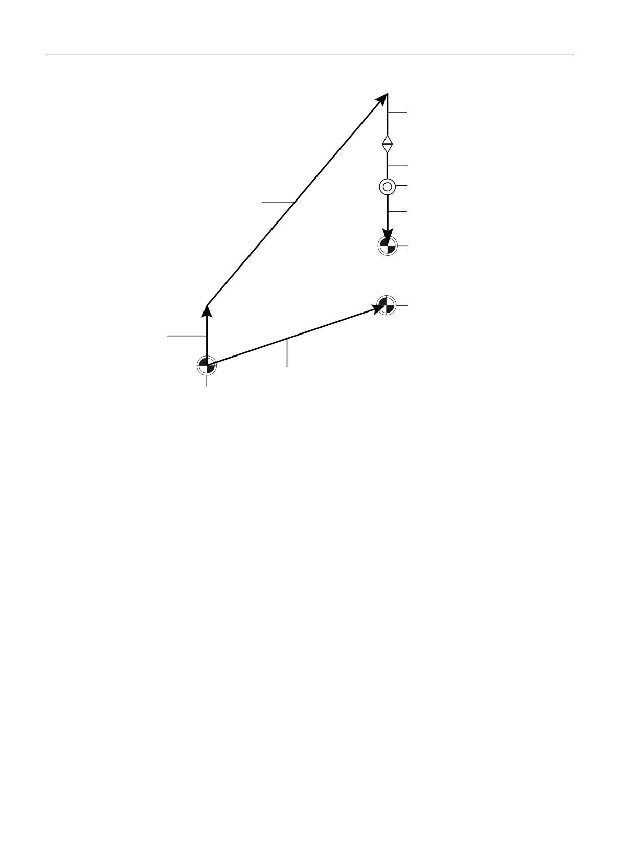
K12 transformation definitions with kinematic chains
9.4 Examples
& D[LV
% D[LV RIIVHW
% D[LV
& D[LV RIIVHW
%DVH WRRO RIIVHW
=HUR SRLQW RI WKH WRRO
FRRUGLQDWH V\VWHP
=HUR SRLQW RI WKH
ZRUNSLHFH FRRUGLQDWH
; < = D[HV
V\VWHP
ZLWK
;
<
=
7DEOH RIIVHW
=HUR SRLQW RI WKH ZRUOG
FRRUGLQDWH V\VWHP
Figure 9-8
Example kinematics for dynamic orientation transformation
The kinematics is created in several steps:
● The two root elements of the kinematic chain are defined:
- $NK_NEXT\[KIE_CNTR] = "X axis"; chain points to the tool reference point.
- $NK_PARALLEL\[KIE_CNTR] = "Table offset"; chain points to the workpiece
reference point.
● The three mutually perpendicular linear axes X, Y and Z are defined starting from the zero
point of the world coordinate system.
- In the rotation vectors $NK_OFF_DIR, which define the axis directions, only the
individual component that is not equal to zero is described. All of the linear axes have
their origin in the same point, because no constant elements are defined between the
individual axes and no zero point offsets have been specified for the axes either.
● The C axis offset is a constant element, which defines the distance between the linear axes
X, Y, Z and the first rotary axis (C axis). The C axis is a rotary axis which points in the Z
direction.
● The B axis offset is a constant element, to which the B axis connects.
● The conclusion is formed by the constant offset "Basetool".
● The kinematic chain to the workpiece reference point is formed by the constant element
"Table offset" of the type Offset.
Special functions
382
Function Manual, 12/2018, A5E40874099B AB
K12 transformation definitions with kinematic chains
9.4 Examples
● The following orientation axes are defined:
- C axis
- B axis
● The following linear compensating axes are defined:
- X axis
- Y axis
- Z axis
Special functions
Function Manual, 12/2018, A5E40874099B AB
383
K12 transformation definitions with kinematic chains
9.4 Examples
9.4.2
Part program for TRAORI_DYN
Example program "5-axis transformation C-B"
Special functions
384
Function Manual, 12/2018, A5E40874099B AB
K12 transformation definitions with kinematic chains
9.4 Examples
Program code
;===========================================================
; Definitions
;===========================================================
N10 DEF INT KIE_CNTR = 0
; counter for elements of the kin. chains
;===========================================================
; deletion of all transformation data sets and kinematic chain elements
;===========================================================
N20 IF (DELOBJ(“TRAFO_DATA”) < 0)
N30
SETAL(61000)
N40 ENDIF
N50 IF (DELOBJ(“KIN_CHAIN_ELEM”) < 0)
N60
SETAL(61001)
N70 ENDIF
;===========================================================
; definition of the root element and of the kinematic chain to the tool
reference point
;===========================================================
N80 $NK_NAME[KIE_CNTR]
= "ROOT"
N90 $NK_TYPE[KIE_CNTR]
= "OFFSET"
N100 $NK_NEXT[KIE_CNTR]
= "X axis"
N110 $NK_PARALLEL[KIE_CNTR]
= "Table offset"
N120 KIE_CNTR = KIE_CNTR + 1
;===========================================================
; Definition of the linear axis in X direction
;===========================================================
N130 $NK_NAME[KIE_CNTR]
= "X axis"
N140 $NK_TYPE[KIE_CNTR]
= "AXIS_LIN"
N150 $NK_NEXT[KIE_CNTR]
= "Y axis"
N160 $NK_AXIS[KIE_CNTR]
= "X1"
N170 $NK_OFF_DIR[KIE_CNTR,0]
= 1.0
N180 KIE_CNTR = KIE_CNTR + 1
;===========================================================
; definition of the linear axis in Y direction
;===========================================================
N190 $NK_NAME[KIE_CNTR]
= "Y axis"
N200 $NK_TYPE[KIE_CNTR]
= "AXIS_LIN"
N210 $NK_NEXT[KIE_CNTR]
= "Z axis"
N220 $NK_AXIS[KIE_CNTR]
= "Y1"
N230 $NK_OFF_DIR[KIE_CNTR,1]
= 1.0
N240 KIE_CNTR = KIE_CNTR + 1
;===========================================================
; Definition of the linear axis in Z direction
;===========================================================
N250 $NK_NAME[KIE_CNTR]
= "Z axis"
N260 $NK_TYPE[KIE_CNTR]
= "AXIS_LIN"
N270 $NK_NEXT[KIE_CNTR]
= "C axis offset"
N280 $NK_AXIS[KIE_CNTR]
= "Z1"
N290 $NK_OFF_DIR[KIE_CNTR,2]
= 1.0
N300 KIE_CNTR = KIE_CNTR + 1
;===========================================================
; definition of the distance between the linear axes and the first rotary
axis
;===========================================================
N310 $NK_NAME[KIE_CNTR]
= "C axis offset"
Special functions
Function Manual, 12/2018, A5E40874099B AB
385
K12 transformation definitions with kinematic chains
9.4 Examples
Program code
N320 $NK_TYPE[KIE_CNTR]
= "OFFSET"
N330 $NK_NEXT[KIE_CNTR]
= "C axis"
N340 $NK_OFF_DIR[KIE_CNTR,0]
= 200.0
N350 $NK_OFF_DIR[KIE_CNTR,2]
= 300.0
N360 KIE_CNTR = KIE_CNTR + 1
;===========================================================
; definition of the C axis in the Z direction - refers to axis C1
;===========================================================
N370 $NK_NAME[KIE_CNTR]
= "C axis"
N380 $NK_TYPE[KIE_CNTR]
= "AXIS_ROT"
N390 $NK_NEXT[KIE_CNTR]
= "B axis offset"
N400 $NK_AXIS[KIE_CNTR]
= "C1"
N410 $NK_OFF_DIR[KIE_CNTR,2]
= 1.0
N420 KIE_CNTR = KIE_CNTR + 1
;===========================================================
; definition of the B axis with an offset between the B and C axes
;===========================================================
N430 $NK_NAME[KIE_CNTR]
= "B axis offset"
N440 $NK_TYPE[KIE_CNTR]
= "OFFSET"
N450 $NK_NEXT[KIE_CNTR]
= "B axis"
N460 $NK_OFF_DIR[KIE_CNTR,2]
= -150.0
N470 KIE_CNTR = KIE_CNTR + 1
N480 $NK_NAME[KIE_CNTR]
= "B axis"
N490 $NK_TYPE[KIE_CNTR]
= "AXIS_ROT"
N500 $NK_NEXT[KIE_CNTR]
= "Base tool"
N510 $NK_AXIS[KIE_CNTR]
= "B1"
N520 $NK_OFF_DIR[KIE_CNTR,0]
= 1.0
N530 KIE_CNTR = KIE_CNTR + 1
;===========================================================
; conclusion of the kinematic chain with an offset
;===========================================================
N540 $NK_NAME[KIE_CNTR]
= "Base tool"
N550 $NK_TYPE[KIE_CNTR]
= "OFFSET"
N560 $NK_NEXT[KIE_CNTR]
= “”
N570 $NK_OFF_DIR[KIE_CNTR,2]
= -50.0
;===========================================================
; definition of the kinematic chain to the table reference point
;===========================================================
N580 KIE_CNTR = KIE_CNTR + 1
N590 $NK_NAME[KIE_CNTR]
= "Table offset"
N600 $NK_TYPE[KIE_CNTR]
= "OFFSET"
N610 $NK_OFF_DIR[KIE_CNTR,0] = 200.0
N620 $NK_OFF_DIR[KIE_CNTR,2]
= 100.0
N630 KIE_CNTR = KIE_CNTR + 1
;===========================================================
; Definition of the transformation (TRAORI)
;===========================================================
N640 $NT_NAME[1]
= "5-axis transformation C-B"
N650 $NT_T_CHAIN_LAST_ELEM[1] = "base tool"
N660 $NT_P_CHAIN_LAST_ELEM[1] = "Table offset"
N670 $NT_TRAFO_TYPE[1]
= “TRAORI_DYN”
;===========================================================
; Definition of the orientation and geometry axes
;===========================================================
Special functions
386
Function Manual, 12/2018, A5E40874099B AB
K12 transformation definitions with kinematic chains
9.4 Examples
Program code
N680 $NT_ROT_AX_NAME[1,0]
= "C axis"
N690 $NT_ROT_AX_NAME[1,1]
= "B axis"
N700 $NT_GEO_AX_NAME[1,0]
= "X axis"
N710 $NT_GEO_AX_NAME[1,1]
= "Y axis"
N720 $NT_GEO_AX_NAME[1,2]
= "Z axis"
End
Special functions
Function Manual, 12/2018, A5E40874099B AB
387
K12 transformation definitions with kinematic chains
9.4 Examples
9.4.3
Part program for TRANSMIT
Example program "5-axis transformation C-B"
Special functions
388
Function Manual, 12/2018, A5E40874099B AB
K12 transformation definitions with kinematic chains
9.4 Examples
Program code
;===========================================================
; Simple example of TRANSMIT with kinematic chain:
;******************************************************
N10
DEF INT _KIE_CNTR
N20
DEF INT _TRA_CNTR
N30
R2 = DELOBJ("TRAFO_DATA")
N40
R2 = DELOBJ("KIN_CHAIN_ELEM")
N50
_KIE_CNTR
= 0
N60
_TRA_CNTR
= 1
; Definition of the kinematic chain
;******************************************************
N70
$NK_NAME[_KIE_CNTR]
= "ROOT"
N80
$NK_TYPE[_KIE_CNTR]
= "OFFSET"
N90
$NK_NEXT[_KIE_CNTR]
= "X-Axis"
N100
$NK_PARALLEL[_KIE_CNTR]
= "C-Axis"
N110
_KIE_CNTR = _KIE_CNTR + 1
N120
$NK_NAME[_KIE_CNTR]
= "X-Axis"
N130
$NK_TYPE[_KIE_CNTR]
= "AXIS_LIN"
N140
$NK_NEXT[_KIE_CNTR]
= "Z-Axis"
N150
$NK_AXIS[_KIE_CNTR]
= "X1"
N160
$NK_OFF_DIR[_KIE_CNTR,0]
= 1.0
N170
_KIE_CNTR = _KIE_CNTR + 1
N180
$NK_NAME[_KIE_CNTR]
= "Z-Axis"
N190
$NK_TYPE[_KIE_CNTR]
= "AXIS_LIN"
N200
$NK_NEXT[_KIE_CNTR]
= "Y-Axis"
N210
$NK_AXIS[_KIE_CNTR]
= "Z1"
N220
$NK_OFF_DIR[_KIE_CNTR,2]
= 1.0
N230
_KIE_CNTR = _KIE_CNTR + 1
N240
$NK_NAME[_KIE_CNTR]
= "Y-Axis"
N250
$NK_TYPE[_KIE_CNTR]
= "AXIS_LIN"
N260
$NK_NEXT[_KIE_CNTR]
= ""
N270
$NK_AXIS[_KIE_CNTR]
= "Y1"
N280
$NK_OFF_DIR[_KIE_CNTR,1]
= 1.0
N290
_KIE_CNTR = _KIE_CNTR + 1
N300
$NK_NAME[_KIE_CNTR]
= "C-Axis"
N310
$NK_TYPE[_KIE_CNTR]
= "AXIS_ROT"
N320
$NK_NEXT[_KIE_CNTR]
= ""
N330
$NK_AXIS[_KIE_CNTR]
= "C1"
N340
$NK_OFF_DIR[_KIE_CNTR,2]
= -1.0
N350
_KIE_CNTR = _KIE_CNTR + 1
; Definition of the kinematic transformation:
;******************************************************
; 1. TRANSMIT 256
;******************************************************
N360
$NT_NAME[_TRA_CNTR]
= "Trafo Transmit_1"
N370
$NT_TRAFO_TYPE[_TRA_CNTR]
= "TRANSMIT_K"
N380
$NT_P_CHAIN_LAST_ELEM[_TRA_CNTR]
= "C-Axis"
N390
$NT_T_CHAIN_LAST_ELEM[_TRA_CNTR]
= "Z-Axis"
N400
$NT_GEO_AX_NAME[_TRA_CNTR,0]
= "X-Axis"
N410
$NT_GEO_AX_NAME[_TRA_CNTR,1]
= ""
N420
$NT_GEO_AX_NAME[_TRA_CNTR,2]
= "Z-Axis"
N430
$NT_ROT_AX_NAME[_TRA_CNTR,0]
= ""
N440
$NT_ROT_AX_NAME[_TRA_CNTR,1]
= "C-Axis"
Special functions
Function Manual, 12/2018, A5E40874099B AB
389
K12 transformation definitions with kinematic chains
9.4 Examples
Program code
N450
$NT_ROT_AX_NAME[_TRA_CNTR,2]
= ""
N460
$NT_ROT_OFFSET_FROM_FRAME[_TRA_CNTR] = 1
N470
$NT_CNTRL[_TRA_CNTR]
= 'H0'
N480
_TRA_CNTR = _TRA_CNTR + 1
; 2nd TRANSMIT 257
;******************************************************
N490
$NT_NAME[_TRA_CNTR]
= "Trafo Transmit_2"
N500
$NT_TRAFO_TYPE[_TRA_CNTR]
= "TRANSMIT_K"
N510
$NT_P_CHAIN_LAST_ELEM[_TRA_CNTR]
= "C-Axis"
N520
$NT_T_CHAIN_LAST_ELEM[_TRA_CNTR]
= "Y-Axis"
N530
$NT_GEO_AX_NAME[_TRA_CNTR,0]
= "X-Axis"
N540
$NT_GEO_AX_NAME[_TRA_CNTR,1]
= "Y-Axis"
N550
$NT_GEO_AX_NAME[_TRA_CNTR,2]
= "Z-Axis"
N560
$NT_ROT_AX_NAME[_TRA_CNTR,0]
= ""
N570
$NT_ROT_AX_NAME[_TRA_CNTR,1]
= "C-Axis"
N580
$NT_ROT_AX_NAME[_TRA_CNTR,2]
= ""
N590
$NT_ROT_OFFSET_FROM_FRAME[_TRA_CNTR] = 1
N600
$NT_CNTRL[_TRA_CNTR]
= 'H200'
; TRANSMIT 257
N610
_TRA_CNTR = _TRA_CNTR + 1
;******************************************************
; Activate kinematic chain and transformation:
;******************************************************
N620
NEWCONF
N630
STOPRE
;*************************************************************************
*************************
End
Special functions
390
Function Manual, 12/2018, A5E40874099B AB
K12 transformation definitions with kinematic chains
9.4 Examples
9.4.4
Part program for TRACYL
Example program "TRACYL"
Special functions
Function Manual, 12/2018, A5E40874099B AB
391
K12 transformation definitions with kinematic chains
9.4 Examples
Program code
;===========================================================
; Simple example of TRACYL with kinematic chain:
;******************************************************
N640
$NK_NAME[_KIE_CNTR]
= "ROOT"
N650
$NK_TYPE[_KIE_CNTR]
= "OFFSET"
N660
$NK_NEXT[_KIE_CNTR]
= "Z-Axis"
N670
$NK_PARALLEL[_KIE_CNTR]
= "C-Axis"
N680
_KIE_CNTR = _KIE_CNTR + 1
N690
$NK_NAME[_KIE_CNTR]
= "Z-Axis"
N700
$NK_TYPE[_KIE_CNTR]
= "AXIS_LIN"
N710
$NK_NEXT[_KIE_CNTR]
= "X-Axis"
N720
$NK_AXIS[_KIE_CNTR]
= "Z1"
N730
$NK_OFF_DIR[_KIE_CNTR,2]
= 1.0
N740
_KIE_CNTR = _KIE_CNTR + 1
N750
$NK_NAME[_KIE_CNTR]
= "X-Axis"
N760
$NK_TYPE[_KIE_CNTR]
= "AXIS_LIN"
N770
$NK_NEXT[_KIE_CNTR]
= "Y-Axis"
N780
$NK_AXIS[_KIE_CNTR]
= "X1"
N790
$NK_OFF_DIR[_KIE_CNTR,0]
= 1.0
N800
_KIE_CNTR = _KIE_CNTR + 1
N810
$NK_NAME[_KIE_CNTR]
= "Y-Axis"
N820
$NK_TYPE[_KIE_CNTR]
= "AXIS_LIN"
N830
$NK_NEXT[_KIE_CNTR]
= ""
N840
$NK_AXIS[_KIE_CNTR]
= "Y1"
N850
$NK_OFF_DIR[_KIE_CNTR,1]
= 1.0
N860
_KIE_CNTR = _KIE_CNTR + 1
N870
$NK_NAME[_KIE_CNTR]
= "C-Axis"
N880
$NK_TYPE[_KIE_CNTR]
= "AXIS_ROT"
N890
$NK_NEXT[_KIE_CNTR]
= ""
N900
$NK_AXIS[_KIE_CNTR]
= "C1"
N910
$NK_OFF_DIR[_KIE_CNTR,2]
= -1.0
; Definition of the kinematic transformation:
;******************************************************
; 1. TRACYL 512
;******************************************************
N920
$NT_NAME[_TRA_CNTR]
= "Trafo Tracyl 512"
N930
$NT_TRAFO_TYPE[_TRA_CNTR]
= "TRACYL_K"
N940
$NT_T_CHAIN_LAST_ELEM[_TRA_CNTR]
= "X-Axis"
N950
$NT_P_CHAIN_LAST_ELEM[_TRA_CNTR]
= "C-Axis"
N960
$NT_GEO_AX_NAME[_TRA_CNTR,0]
= "X-Axis"
N970
$NT_GEO_AX_NAME[_TRA_CNTR,1]
= ""
N980
$NT_GEO_AX_NAME[_TRA_CNTR,2]
= "Z-Axis"
N990
$NT_ROT_AX_NAME[_TRA_CNTR,0]
= ""
N1000
$NT_ROT_AX_NAME[_TRA_CNTR,1]
= "C-Axis"
N1010
$NT_ROT_AX_NAME[_TRA_CNTR,2]
= ""
N1020
$NT_ROT_OFFSET_FROM_FRAME[_TRA_CNTR] = 1
N1030
$NT_CNTRL[_TRA_CNTR]
= 'H0'
N1040
_TRA_CNTR = _TRA_CNTR + 1
; 2nd TRACYL 513
;******************************************************
N1050
$NT_NAME[_TRA_CNTR]
= "Trafo Tracyl 513"
N1060
$NT_TRAFO_TYPE[_TRA_CNTR]
= "TRACYL_K"
N1070
$NT_T_CHAIN_LAST_ELEM[_TRA_CNTR]
= "Y-Axis"
Special functions
392
Function Manual, 12/2018, A5E40874099B AB
K12 transformation definitions with kinematic chains
9.4 Examples
Program code
N1080
$NT_P_CHAIN_LAST_ELEM[_TRA_CNTR]
= "C-Axis"
N1090
$NT_GEO_AX_NAME[_TRA_CNTR,0]
= "X-Axis"
N1100
$NT_GEO_AX_NAME[_TRA_CNTR,1]
= "Y-Axis"
N1110
$NT_GEO_AX_NAME[_TRA_CNTR,2]
= "Z-Axis"
N1120
$NT_ROT_AX_NAME[_TRA_CNTR,0]
= ""
N1130
$NT_ROT_AX_NAME[_TRA_CNTR,1]
= "C-Axis"
N1140
$NT_ROT_AX_NAME[_TRA_CNTR,2]
= ""
N1150
$NT_ROT_OFFSET_FROM_FRAME[_TRA_CNTR] = 1
N1160
$NT_CNTRL[_TRA_CNTR]
= 'H200'
; TRACYL 513
N1170
_TRA_CNTR = _TRA_CNTR + 1
; 3rd TRACYL 514
;******************************************************
N1180
$NT_NAME[_TRA_CNTR]
= "Trafo Tracyl 514"
N1190
$NT_TRAFO_TYPE[_TRA_CNTR]
= "TRACYL_K"
N1200
$NT_T_CHAIN_LAST_ELEM[_TRA_CNTR]
= "Y-Axis"
N1210
$NT_P_CHAIN_LAST_ELEM[_TRA_CNTR]
= "C-Axis"
N1220
$NT_GEO_AX_NAME[_TRA_CNTR,0]
= "X-Axis"
N1230
$NT_GEO_AX_NAME[_TRA_CNTR,1]
= "Y-Axis"
N1240
$NT_GEO_AX_NAME[_TRA_CNTR,2]
= "Z-Axis"
N1250
$NT_ROT_AX_NAME[_TRA_CNTR,0]
= ""
N1260
$NT_ROT_AX_NAME[_TRA_CNTR,1]
= "C-Axis"
N1270
$NT_ROT_AX_NAME[_TRA_CNTR,2]
= ""
N1280
$NT_ROT_OFFSET_FROM_FRAME[_TRA_CNTR] = 1
N1290
$NT_CNTRL[_TRA_CNTR]
= 'H400'
; TRACYL 514
N1300
_TRA_CNTR = _TRA_CNTR + 1
;******************************************************
;Activate kinematic chain and transformation:
;******************************************************
N1310
NEWCONF
N1320
STOPRE
;*************************************************************************
*************************
End
Special functions
Function Manual, 12/2018, A5E40874099B AB
393
K12 transformation definitions with kinematic chains
9.4 Examples
9.4.5
Part program for TRAANG
Example program "TRAANG"
Program code
;===========================================================
; Simple example of TRAANG with kinematic chain
;******************************************************
N2000
$NK_NAME[_KIE_CNTR]
= "ROOT"
N2010
$NK_TYPE[_KIE_CNTR]
= "OFFSET"
N2020
$NK_NEXT[_KIE_CNTR]
= "X-Axis"
N2030
$NK_PARALLEL[_KIE_CNTR]
= ""
N2040
_KIE_CNTR = _KIE_CNTR + 1
N2050
$NK_NAME[_KIE_CNTR]
= "X-Axis"
N2060
$NK_TYPE[_KIE_CNTR]
= "AXIS_LIN"
N2070
$NK_NEXT[_KIE_CNTR]
= "Z-Axis"
N2080
$NK_AXIS[_KIE_CNTR]
= "X1"
N2090
$NK_OFF_DIR[_KIE_CNTR,0]
= COS(20)
N2100
$NK_OFF_DIR[_KIE_CNTR,2]
= SIN(20)
N2110
_KIE_CNTR = _KIE_CNTR + 1
N2120
$NK_NAME[_KIE_CNTR]
= "Z-Axis"
N2130
$NK_TYPE[_KIE_CNTR]
= "AXIS_LIN"
N2140
$NK_NEXT[_KIE_CNTR]
= "Y-Axis"
N2150
$NK_AXIS[_KIE_CNTR]
= "Z1"
N2160
$NK_OFF_DIR[_KIE_CNTR,2]
= 1.0
N2170
_KIE_CNTR = _KIE_CNTR + 1
N2180
$NK_NAME[_KIE_CNTR]
= "Y-Axis"
N2190
$NK_TYPE[_KIE_CNTR]
= "AXIS_LIN"
N2200
$NK_NEXT[_KIE_CNTR]
= ""
N2210
$NK_AXIS[_KIE_CNTR]
= "Y1"
N2220
$NK_OFF_DIR[_KIE_CNTR,1]
= 1.0
N2230
_KIE_CNTR = _KIE_CNTR + 1
; definition of the kinematic transformation:
;******************************************************
; TRRANG
;******************************************************
N2240
$NT_NAME[_TRA_CNTR]
= "Trafo Traang"
N2250
$NT_TRAFO_TYPE[_TRA_CNTR]
= "TRAANG_K"
N2260
$NT_T_CHAIN_LAST_ELEM[_TRA_CNTR]
= "Y-Axis"
N2270
$NT_P_CHAIN_LAST_ELEM[_TRA_CNTR]
= ""
N2280
$NT_GEO_AX_NAME[_TRA_CNTR,0]
= "X-Axis"
N2290
$NT_GEO_AX_NAME[_TRA_CNTR,2]
= "Y-Axis
N2300
$NT_GEO_AX_NAME[_TRA_CNTR,1]
= "Z-Axis"
N2310
$NT_ROT_OFFSET_FROM_FRAME[_TRA_CNTR] = 1
N2320
_TRA_CNTR = _TRA_CNTR + 1
;******************************************************
; Activate kinematic chain and transformation:
;******************************************************
N2330
NEWCONF
N2340
STOPRE
;*************************************************************************
*************************
Special functions
394
Function Manual, 12/2018, A5E40874099B AB
K12 transformation definitions with kinematic chains
9.4 Examples
Program code
End
Special functions
Function Manual, 12/2018, A5E40874099B AB
395
K12 transformation definitions with kinematic chains
9.4 Examples
Special functions
396
Function Manual, 12/2018, A5E40874099B AB
M3: Coupled axes
10
10.1
Coupled motion
10.1.1
Brief description
10.1.1.1
Function
The "coupled motion" function enables the definition of simple axis links between a master
axis and a slave axis, taking into consideration a coupling factor.
Coupled motion has the following features:
● Any axis of the NC can be defined as a master axis.
● Any axis of the NC can be defined as a coupled axis with a specific coupling factor.
● The master axis and coupled motion axis or axes together form a coupled axis grouping.
● Any number of coupled motion axes can be assigned to a master axis.
● A total of 2 leading axes may be assigned to each coupled motion axis.
● A coupled motion axis can be the master axis of a further coupled axis grouping.
● Traversing movements of the master axis are executed in synchronism on all slave axes
based on the coupling factor.
● Coupled motion axes can be moved independently of the master axis while the coupling is
active (overlaid movements).
● The master and coupled motion axes of a coupled axis grouping are defined, and the
coupling switch on/switch off, by programming instructions in the part program or by
synchronized action.
● Coupled motion is also possible in the following manual modes: JOG, JOG REF, JOG INC,
etc.
10.1.1.2
Preconditions
"Coupled motion" function
The "Coupled motion" function is a fixed component of the NC software.
Generic coupling
The coupled motion functionality is also available in the generic coupling.
Special functions
Function Manual, 12/2018, A5E40874099B AB
397
M3: Coupled axes
10.1 Coupled motion
However, for basic operation of generic coupling, the following restrictions apply:
● The maximum number of coupled motion groupings is limited to 4.
● Only 1 leading axes may be assigned to each coupled motion axis.
● Cascading is not possible.
Note
These restrictions do not apply when NC software is supplied with the relevant options of
generic coupling (refer to " Preconditions (Page 470) " in the "Brief description" of generic
coupling).
10.1.2
General functionality
The "Coupled motion" function allows the definition of simple axis couplings. Coupling is
performed from one leading axis to one or more following axes, the so-called coupled motion
axes. A separate coupling factor can be specified for each coupled motion axis.
Coupled axis grouping
The leading axis and all the coupled motion axes assigned to it together form a coupled axis
grouping. If the leading axis is traversed, all coupled motion axes traverse in accordance with
their coupling factors.
A coupled axis grouping can consist of any combination of linear and rotary axes.
Leading axes
Any axis of the NC, including simulated axes, can be used as leading axis.
Coupled axes
Any axis of the NC can be used as coupled motion axis.
Coupling factor
The ratio in which the coupled motion axis moves in relation to the leading axis is specified via
the coupling factor.
Coupling factor K = motion of the coupled motion axis / motion of the leading axis
Negative coupling factors (motion of the coupled motion axis in the opposite direction) are also
permitted.
Special functions
398
Function Manual, 12/2018, A5E40874099B AB
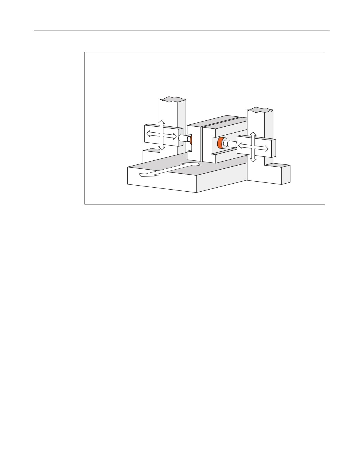
M3: Coupled axes
10.1 Coupled motion
/HDGLQJ D[LV
&RXSOHG PRWLRQ D[LV
&RXSOLQJ IDFWRU
&RXSOHG PRWLRQ JURXS
< D[LV
9 D[LV
&RXSOHG PRWLRQ JURXS
= D[LV
: D[LV
< D[LV
9 D[LV
= D[LV
: D[LV
; D[LV
Figure 10-1
Application example: Two-sided machining
Multiple couplings
Up to 2 leading axes can be assigned to one coupled motion axis. The traversing movement
of the coupled motion axis then results from the sum of the traversing movements of the leading
axes.
Dependent coupled motion axis
A coupled motion axis is a "dependent coupled motion axis" when it traverses as a result of a
leading axis movement.
Independent coupled motion axis
A coupled motion axis is an "independent coupled motion axis" when it traverses as a result
of a direct traverse instruction. The traversing movement resulting from the coupled motion
axis is then the sum total of the traversing movements as a "dependent" and an "independent"
coupled motion axis.
Coupled motion axis as leading axis
A coupled motion axis can at the same time be the leading axis of a further coupled axis
grouping.
Coordinate system
Coupled axis motion is always executed in the base coordinate system (BCS).
Special functions
Function Manual, 12/2018, A5E40874099B AB
399
M3: Coupled axes
10.1 Coupled motion
Activating/deactivating
Coupled motion can be activated/deactivated via the part programs and synchronous actions.
In this context please ensure activating/deactivating is undertaken with the same programming:
● Activate: Part program → Deactivate: Part program
● Activate: Synchronous action → Deactivate: Synchronized action
Synchronization on-the-fly
If switch on is performed while the leading axis is in motion, the coupled motion axis is first
accelerated to the velocity corresponding to the coupling. The position of the leading axis at
the time the velocities of the leading and coupled motion axes are synchronized then serves
as the start position for further coupled motion.
Operating modes
Coupled motion is effective in the AUTOMATIC, MDA and JOG modes.
Reference point approach
The following applies for referencing of axes of a coupled axis grouping:
● Leading axes
When referencing the leading axis of a coupled axis grouping, the coupling to all coupled
motion axes is retained. The coupled motion axes move in synchronism with the leading
axis, as a function of their coupling factors.
● Coupled motion axis: JOG/REF mode
When referencing a coupled motion axis of a coupled axis grouping, the coupling to the
leading axis is cancelled. If the coupling is canceled, the following alarm is displayed:
Alarm 16772 "Channel Channel No. block Block No. Axis Axis No. is following axis, coupling
is opened."
The coupling is not activated again until JOG/REF mode is cancelled.
The display of this alarm can be suppressed using the following machine data:
MD11410 $MN_SUPPRESS_ALARM_MASK, Bit 29 = 1 (mask supporting special alarm
generation)
CAUTION
No coupling
When the coupled motion axis is referenced, the coupling to the leading axis is cancelled.
If referencing is executed immediately with the leading axis, i.e. without changing JOG/
REF mode, the coupled motion axis does not traverse with the leading axis.
● Coupled motion axis: Part program command G74
It is not possible to reference a coupled motion axis of a coupled axis grouping using the
G74 programming instruction.
Special functions
400
Function Manual, 12/2018, A5E40874099B AB
M3: Coupled axes
10.1 Coupled motion
Distance-to-go: Coupled motion axis
The distance-to-go of a coupled motion axis refers to the total residual distance to be traversed
from dependent and independent traversing.
Delete distance-to-go: Coupled motion axis
Delete distance-to-go for a coupled motion axis only results in aborting of the independent
traversing movement of the leading axis.
Response to NC Start
The behavior of the coupled-axis groupings during NC Start depends on the setting in the
machine data:
MD20112 $MC_START_MODE_MASK (definition of initial control settings for NC-START)
Bit
Value
Meaning
8
0
Coupled-axis groupings are maintained in NC Start.
1
Coupled-axis groupings are phased out in NC Start.
Response to RESET/part program end
The behavior of the coupled-axis groupings during RESET/ part program end depends on the
setting in the machine data:
MD20110 $MC_RESET_MODE_MASK (definition of initial control settings after RESET / TP
end)
Bit
Value
Meaning
8
0
Coupled-axis groupings are invalidated on RESET / part program end.
1
Coupled-axis groupings remain active even beyond RESET/part program end.
Note
If with NC RESET or end of part program in a channel, the leading axis is not stopped as well
(cross-channel coupling, command axis, PLC axis, etc.), the requested RESET cannot be
completed.
Because of traversing of the leading axis, the coupled-motion axis is still active for the channel
in which the RESET is requested. With suitable actions (NC RESET in the channel of the
leading axis, stopping of the command or PLC axis), the leading axis must also be stopped in
parallel to the coupled-motion axis.
Special functions
Function Manual, 12/2018, A5E40874099B AB
401
M3: Coupled axes
10.1 Coupled motion
10.1.3
Programming
10.1.3.1
Definition and switch on of a coupled axis grouping (TRAILON)
Definition and switch on of a coupled axis grouping take place simultaneously with the
TRAILON part program command.
Programming
Syntax:
TRAILON(<coupled motion axis>, <leading axis>,
[<coupling factor>])
Effectiveness:
modal
Parameters:
Coupled motion Type: AXIS
axis:
Range of values:All defined axis and spindle names in the channel
Leading axis:
Type: AXIS
Range of values:All defined axis and spindle names in the channel
Coupling factor: The ratio of the traversing movement of the coupled motion axis to the
leading axis is specified via the optional coupling factor:
Coupling factor = Path of the coupled-motion axis/path of the leading
axis
A negative coupling factor results in motion in opposite directions for
the leading and coupled motion axis.
Type: REAL
Range of values:± (2,2 * 10-308 … 1,8 * 10+308)
Default value:
+1.0
Example:
Program code
Comment
TRAILON(V,Y,2)
; Definition and switch on of the coupling of the
coupled-motion axis V with leading axis Y. The
coupling factor is 2.
10.1.3.2
Switch off (TRAILOF)
Switch off of the coupling of a coupled-motion axis with a leading axis takes place through the
TRAILOF part program command.
Programming
Syntax:
TRAILON(<coupled motion axis>, <leading axis>)
TRAILOF(<coupled-motion axis>)
Effectiveness:
modal
Special functions
402
Function Manual, 12/2018, A5E40874099B AB
M3: Coupled axes
10.1 Coupled motion
Parameters:
Coupled motion Type: AXIS
axis:
Range of val- All defined axis and spindle names in the channel
ues:
Leading axis:
Type: AXIS
Range of val- All defined axis and spindle names in the channel
ues:
Example:
Program code
Comment
TRAILOF(V,Y)
;
Deactivation of the coupling of the coupled-motion
;
axis
V to leading axis Y.
10.1.4
Effectiveness of PLC interface signals
Independent coupled motion axis
All the associated channel and axis specific interface signals of the coupled-motion axis are
effective for the independent motion of a coupled-motion axis, e.g.:
● DB21, ... DBX0.3 (Activate DRF)
● DB31, ... DBX0.0 - 0.7 (feedrate override)
● DB31, ... DBX1.3 (axis blocking)
● DB31, ... DBX2.1 (control system enable)
● DB31, ... DBX4.0 - 4.2 (activate handwheel)
● DB31, ... DBX4.3 (feed stop)
●
…
This allows the speed to be changed for the independent motion of a coupled motion axis using
a feedrate override or a DRF offset to be defined using the handwheel in AUTOMATIC and
MDA modes.
Dependent coupled motion axis
With respect to the motion of a coupled motion axis, which is dependent on the leading axis,
only the coupled-motion axis interface signals that effect termination of the motion (e.g. axis-
specific feed stop, axis inhibit, control system enable, etc.) are effective.
Special functions
Function Manual, 12/2018, A5E40874099B AB
403

M3: Coupled axes
10.1 Coupled motion
Leading axis
When a coupled axis grouping is active, the interface signals (IS) of the leading axis are applied
to the appropriate coupled motion axis via the axis coupling, i.e.
● A position offset or feed control action of the leading axis is applied via the coupling factor
to effect an appropriate position offset or feed control action in the coupled motion axis.
● Shutdown of the leading axis as the result of an interface signal (e.g. axis-specific feed
stop, axis inhibit, servo enable, etc.) causes the corresponding coupled motion axis to shut
down.
Position measuring system 1/2 (DB31, ... DBX1.5/1.6))
Switch-over of the position measuring system for the leading and coupled motion axes is not
inhibited for an active coupled axis grouping. The coupling is not canceled.
Recommendation: Switch-over when the coupling is deactivated.
Tracking (DB31, ... DBX1.4)
Activation of tracking for an axis is done via the PLC program by setting the following NC/PLC
interface signals:
DB31, ... DBX2.1 = 0 (control system enable)
DB31, ... DBX1.4 == 1 (tracking mode)
When activating tracking mode for a coupled axis grouping, the specified NC/PLC interface
signals must be set simultaneously for all axes (master and slave axes) of the coupled axis
group.
If tracking mode is activated for the master axis only, a permanent offset results within the
coupling.
Whether and which axis is a leading or a following axis can be seen from the following NC/
PLC interface signals and system variables:
DB31, ... DBX99.0 (leading axis/spindel active)
DB31, ... DBX99.1 (following axis/spindel active)
$AA_COUP_ACT[axis name] (see: Status of coupling)
10.1.5
Status of coupling
The coupling status of an axis can be determined using the following system variables:
$AA_COUP_ACT [axis name]
Value
Meaning
0
No coupling active
1, 2, 3
Tangential tracking
4
Synchronous spindle coupling
8
Coupled motion active
Special functions
404
Function Manual, 12/2018, A5E40874099B AB

M3: Coupled axes
10.1 Coupled motion
Value
Meaning
16
Master value coupling
32
Following axis of electronic gearbox
Note
Only one coupling mode may be active at any given time.
10.1.6
Dynamics limit
The dynamics limit is dependent on the type of activation of the coupled axis grouping:
● Activation in part program
If activation is performed in the part program and all leading axes are active as program
axes in the activating channel, the dynamic response of all coupled-motion axes is taken
into account during traversing of the leading axes to avoid overloading the coupled-motion
axes.
If activation in part program takes place with leading axes that are not active as program
axes in the activating channel ($AA_TYP ≠ 1), then the dynamics of the coupled motion
axes is not considered while traversing the leading axes. This can result in an overload for
coupled motion axes with a dynamic response which is less than that required for the
coupling.
● Activation in synchronized action
If activation is performed in a synchronous action, dynamics of the coupled motion axes is
not taken into account during traversing of the leading axis. This can result in an overload
for coupled motion axes with a dynamic response which is less than that required for the
coupling.
CAUTION
Axis overload
If a coupled motion grouping
● in synchronized actions
● is activated in the part program with leading axes, that are not program axes in the
channel of the coupled motion axes,
it is the special responsibility of the user/machine manufacturer to provide suitable
measures to ensure that an overload of the coupled motion axes does not occur through
traversing of the leading axis.
Special functions
Function Manual, 12/2018, A5E40874099B AB
405
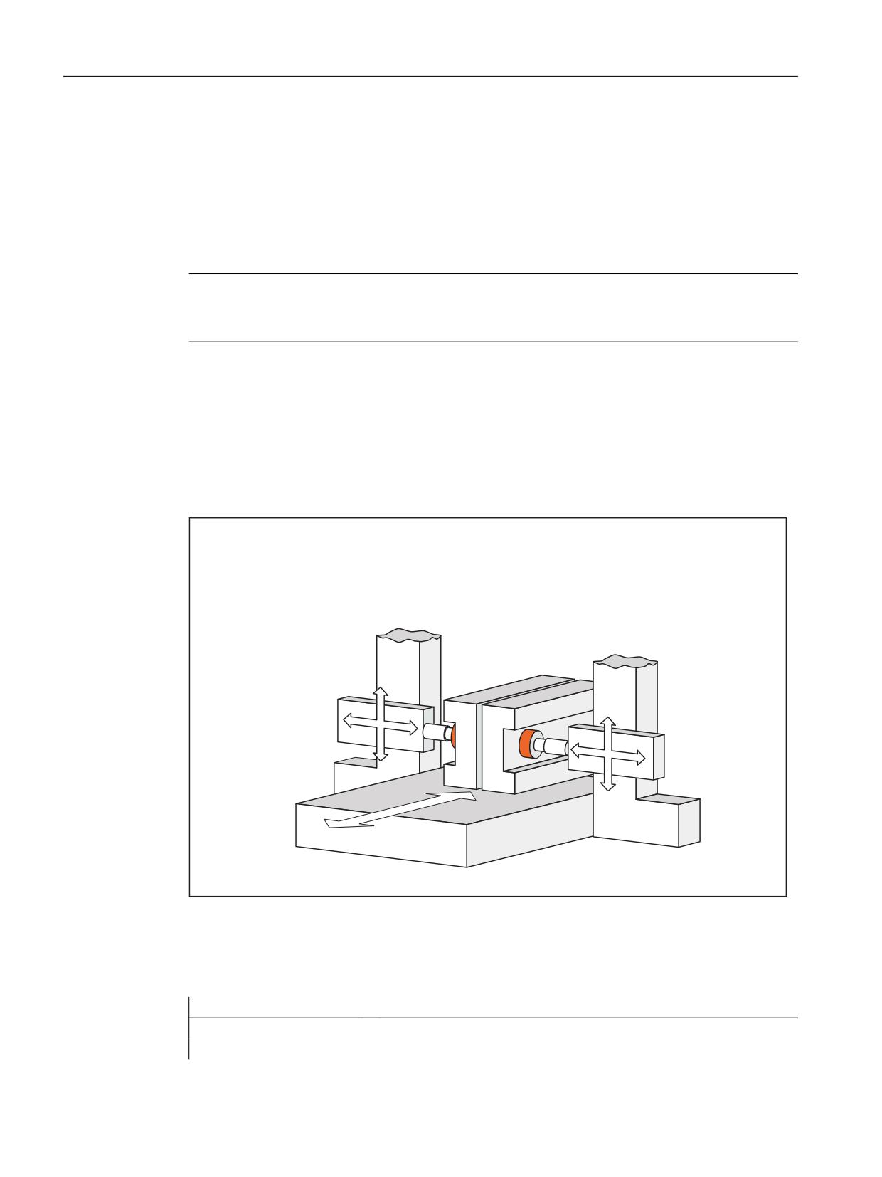
M3: Coupled axes
10.1 Coupled motion
10.1.7
Supplementary conditions
Control system dynamics
It is recommended to align the position control parameters of the leading axis and the coupled
motion axis within a coupled axis group.
Note
Alignment of the position control parameters of the leading axis and the coupled motion axis
can be performed via a parameter set changeover.
10.1.8
Examples
Application Example: Two-sided machining
/HDGLQJ D[LV
&RXSOHG PRWLRQ D[LV
&RXSOLQJ IDFWRU
&RXSOHG PRWLRQ JURXS
< D[LV
9 D[LV
&RXSOHG PRWLRQ JURXS
= D[LV
: D[LV
< D[LV
9 D[LV
= D[LV
: D[LV
; D[LV
Example 1
Example of an NC part program for the axis constellation shown in Fig.:
Program code
Comment
TRAILON(V,Y,1)
; Activation of 1st coupled axis group
TRAILON(W,Z,-1)
; Activation of 2nd coupled axis group
Special functions
406
Function Manual, 12/2018, A5E40874099B AB
M3: Coupled axes
10.2 Curve tables - 840D sl only
Program code
Comment
G0 Z10
; Infeed Z and W axes in opposite axial directions
G0 Y20
; Infeed of Y and V axes in same axis
direction
G1 Y22 V25
; Superimpose dependent and independent movement of coupled
motion axis "V"
TRAILOF(V,Y)
; Deactivate 1st coupled axis group
TRAILOF(W,Z)
; Deactivate 2nd coupled axis group
Example 2
The dependent and independent movement components of a coupled motion axis are added
together for the coupled motion. The dependent component can be regarded as a co-ordinate
offset with reference to the coupled motion axis.
Program code
Comment
N01 G90 G0 X100 U100
;
N02 TRAILON(U,X,1)
; Activation of coupled axis group
N03 G1 F2000 X200
; Dependent movement of U, Upos=200, UTrail=100
N04 U201
; Independent movement, Upos=U201+UTrail=301
N05 X250
; Dependent movement of U, UTrail=UTrail(100)+50=150,
Upos=351
N06 G91 U100
; Independent movement of Upos(351)+U100=451
N07 G90 X0
; Dependent movement of U, Upos=Upos(451)-UTrail(250)=201
N10 TRAILOF(U,X)
10.2
Curve tables - 840D sl only
10.2.1
Product brief
10.2.1.1
Function
The "curve tables" function can be used to define the complex sequence of motions of an axis
in a curve table.
Any axis can be defined as a leading axis and a following axis can be traversed by taking a
curve table into account.
The command variable in these motion sequences is an abstract master value, which is
generated by the control or derived from an external variable (e.g. simulated position of an
axis).
Creating curve tables is performed via part program sequences.
The curve tables in the static NC memory remain valid after the part program has been been
closed or after POWER DOWN.
Special functions
Function Manual, 12/2018, A5E40874099B AB
407
M3: Coupled axes
10.2 Curve tables - 840D sl only
Curve tables can be saved in dynamic NC memory for faster access. Please note that tables
need to be reloaded after run-up.
Axis groupings with curve tables must be reactivated independently of the storage location of
the curve table after POWER ON.
Linear curve table segments are stored in separate areas to save memory space.
10.2.1.2
Preconditions
Memory configuration
Static NC memory
Memory space for curve tables in static NC memory is defined by machine data:
MD18400 $MN_MM_NUM_CURVE_TABS (number of curve tables)
MD18402 $MN_MM_NUM_CURVE_SEGMENTS (number of curve segments)
MD18403 $MN_MM_NUM_CURVE_SEG_LIN (number of linear curve segments)
MD18404 $MN_MM_NUM_CURVE_POLYNOMS (number of curve table polynomials)
Dynamic NC memory
Memory space for curve tables in dynamic NC memory is defined by machine data:
MD18406 $MN_MM_NUM_CURVE_TABS_DRAM (number of curve tables)
MD18408 $MN_MM_NUM_CURVE_SEGMENTS_DRAM (number of curve segments)
MD18409 $MN_MM_NUM_CURVE_SEG_LIN_DRAM (number of linear curve segments)
MD18410 $MN_MM_NUM_CURVE_POLYNOMS_DRAM (number of curve table polynomials)
10.2.2
General functionality
Curve table
A functional relation between a command variable "master value" and an abstract following
value is described in the curve table.
A following variable can be assigned uniquely to each master value within a defined master
value range.
Curve segment
The functional relation can be subdivided into separate sections of the master value axes,
called curve segments.
Within a curve segment, the relation between the master value and following value is generally
described by a polynomial up to the third order. Polynomials up to the 5th degree are also
permissible.
Special functions
408
Function Manual, 12/2018, A5E40874099B AB
M3: Coupled axes
10.2 Curve tables - 840D sl only
Reference:
Programming Manual, Production Planning
Curve segments are used if:
● Polynomes or circles are programmed
● Spline is active
● Compressor is active
● Polynomials or circles are generated internally (chamfer/rounding, approximate positioning
with G643, WRK etc.)
Tool radius compensation
Curve tables are available in which it is possible to specify the tool radius compensation in the
table definition even if polynomial blocks or blocks with no motion for an axis, or jumps for the
following axis, occur in the curve table (G41/G42/G40 in the table definition).
The equidistant curve (tool center point path of tool radius compensation) of a curve consisting
of polynomials can no longer be displayed exactly using polynomials. The associated curve
tables must be approximated stepwise, using polynomials in this case. This means that the
number of segments in the curve table no longer matches the number of programmed
segments. The number of segments required for the curve table is defined by the bend of the
curve. The larger the curvature for the programmed curve, the more segments are required
for the curve table.
On account of tool radius compensation for curve tables, more memory may be required.
Selection option of the memory type should not produce shortage of static NC memory.
Selection of memory type
While defining a curve table, it can be defined whether the curve table is created in the static
or dynamic NC memory.
Note
Table definitions in the static NC memory are available even after control system run-up. Curve
tables of the dynamic NC memory must be redefined after every control system run-up.
10.2.3
Memory organization
Memory configuration
The storage place available for the curve table in the static and dynamic NC memory is defined
during memory configuration (see Section "Memory configuration (Page 411)").
Special functions
Function Manual, 12/2018, A5E40874099B AB
409
M3: Coupled axes
10.2 Curve tables - 840D sl only
Memory optimization
In a curve table with linear segments, the linear segments can be stored efficiently in the
memory only if the two following machine data items are > 0:
MD18403 $MC_MM_NUM_CURVE_SEG_LIN (number of linear curve segments in the static
NC memory)
MD18409 $MC_MM_NUM_CURVE_SEG_LIN_DRAM (number of linear curve segments in
the dynamic NC memory)
If no memory areas are created with this machine data, then the linear segments are stored
as polynomial segments.
Alarm in case of insufficient memory
If memory has been configured for tables with linear and polynomial segments via machine
data and memory for linear segments runs out when generating a linear table, the the memory
for polynomial segments is used for the linear segments (if available). In this case, memory is
"wasted", as a polynomial segment requires an unnecessary amount of memory to store a
linear segment. This circumstance is conveyed through an alarm, which also discloses the
number of unnecessarily used polynomial segments. The alarm only displays awarning and
does not result in the interruption of the program or the generation of the curve table.
If a curve table consists of linear segments and polynomials of a high degree, a memory area
for linear segments and a memory area for polynomial segments is required for the storage of
the curve table. An alarm is output if insufficient memory is available in the relevant areas. The
alarm parameters can be used to detect the resources that are insufficient.
Insufficient memory
If a curve table cannot be created, because sufficient memory is not available, then the newly
created table is deleted immediately after the alarm.
If insufficient is available, then one or more table(s) that is/are no longer required can be deleted
with CTABDEL or, alternatively, memory can be reconfigured via machine data.
Temporary curve table
When a curve table is created, a temporary curve table is set up first in memory, which is then
extended block by block. Finally (CTABEND), the table is checked for consistency. The
temporary table is converted to a table that can be used in a coupling only if it is found to be
consistent.
Same table number
A new curve table may have the same number as an existing table. The new curve table then
overwrites the existing table with the same number. This is done only if the new curve table
does not contain any errors. If an error is detected in the new table, the old table is not
overwritten.
If the user wishes to have the option of overwriting an existing curve table without deleting it
first, then he will need to dimension the table memory so that there is always enough extra
memory to accommodate the table to be overwritten.
Special functions
410
Function Manual, 12/2018, A5E40874099B AB