SINUMERIK 840D sl. Service - Functions. Manual (2018-2020) - page 64
K7: Kinematic chain
5.2 Commissioning
Meaning
$NK_OFF_DIR:
Direction vector (X; Y; Z)
Data type:
REAL
Range of values:
Direction vector: 1*10-6 < |Vector | ≤ max. REAL value
Default value:
(0.0, 0.0, 0.0)
<n>:
System variable or element index
Data type:
INT
Range of values:
0, 1, 2, ... ($MN_MM_MAXNUM_KIN_CHAIN_ELEM - 1)
<k>:
Coordinate index
Data type:
INT
Range of values:
0: X coordinate (abscissa)
1: Y coordinate (ordinate)
2: Z coordinate (applicate)
<value>:
Coordinate value
Data type:
REAL
Range of values:
- max. REAL value ≤ x ≤ + max. REAL value
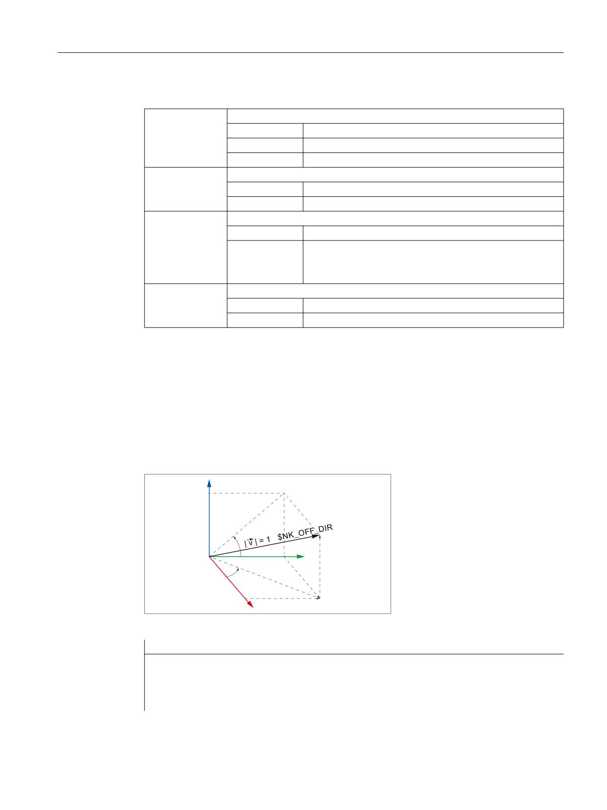
Example
; The linear axis of the 9th element moves along the direction vector. The direction vector is
the unit vector (1; 0; 0), rotated around Z with γ=90° in the X/Y plane, and around X with
α=10° in the Y/Z plane referred to the world coordinate system. The following values result
from this for the individual components (x, y, z) of the direction vector:
● x = cos(γ) * cos(α) = cos(90) * cos(10) = 0.0
● y = sin(γ) * cos(α) = sin(90) * cos(10) ≈ 0.985
● z = sin(α) = sin(10) ≈ 0.174
=
˞
<
]
ˠ
[
;
\
Figure 5-6
Direction vector, general
Program code
Comment
; 9th kinematic element
N100 $NK_OFF_DIR[8,0] = COS(90)*COS(10)
; 0 = X component
N110 $NK_OFF_DIR[8,1] = SIN(90)*COS(10)
; 1 = Y component
N120 $NK_OFF_DIR[8,2] = SIN(10)
; 2 = Z component
Special functions
Function Manual, 12/2018, A5E40874099B AB
203

K7: Kinematic chain
5.2 Commissioning
$NK_AXIS
Function
The name of the machine axis (MD10000 $MN_AXCONF_MACHAX_NAME_TAB) that is to
be assigned to the element should be entered in the system variable.
The output coordinate system of the element results from the input coordinate system offset
by the current position setpoint of the machine axis in the MCS and the offset specified in
$NK_A_OFF. The position setpoint of the machine axis contains all the active work offsets and
corrections.
In accordance with the AXIS_LIN type entered in $NK_TYPE, the machine axis must be a
linear axis:
MD30300 $MA_IS_ROT_AX = 0
Syntax
$NK_AXIS[<n>] = <name>
Meaning
$NK_AXIS:
Machine axis name
Data type:
STRING
Range of values:
Machine axis name
Default value:
"" (empty string)
<n>:
System variable or element index
Data type:
INT
Range of values:
0, 1, 2, ... ($MN_MM_MAXNUM_KIN_CHAIN_ELEM - 1)
<value>:
Machine axis name
Data type:
STRING
Range of values:
Machine axis names
Example
The 9th kinematic element is assigned the machine axis with the name V1 as linear axis.
Program code
Comment
N100 $NK_AXIS[8] = "V1"
; 9th kin. element
; axis = machine axis V1
$NK_A_OFF
Function
An additional work offset can be entered in the system variable for the assigned machine axis
($NK_AXIS). This work offset is only effective within the kinematic chain.
Syntax
$NK_A_OFF[<n>] = <value>
Special functions
204
Function Manual, 12/2018, A5E40874099B AB
K7: Kinematic chain
5.2 Commissioning
Meaning
$NK_A_OFF:
Work offset
Data type:
REAL
Range of values:
- max. REAL value ≤ x ≤ ± max. REAL value
Default value:
0.0
<n>:
System variable or element index
Data type:
INT
Range of values:
0, 1, 2, ... ($MN_MM_MAXNUM_KIN_CHAIN_ELEM - 1)
<value>:
Offset value
Data type:
REAL
Range of values:
- max. REAL value ≤ x ≤ ± max. REAL value
Example
The linear axis zero point of the 9th kinematic element is moved by 30.0 mm compared to the
modelled kinematics.
The unit in which the numerical value is interpreted depends on the current input system (inch/
metric).
Program code
Comment
N100 $NK_A_OFF[8] = 30.0
; 9th kin. element
; Work offset = 30.0 mm
5.2.3.7
Type-dependent variables for $NK_TYPE = "AXIS_ROT"
$NK_OFF_DIR
Function
The direction vector around which the rotary axis $NK_AXIS assigned to the element rotates,
should be entered in the system variable. The output coordinate system is therefore calculated
from the input coordinate system, rotated by the current position value of the rotary axis and
the offset specified in $NK_A_OFF around the direction vector $NK_OFF_DIR.
Supplementary conditions:
● The direction vector must be specified as an absolute value, i.e. in relation to the world
coordinate system.
● The direction vector must be specified so that, in accordance with the "right-hand rule", the
thumb points in the direction of the vector when the rotary axis turns in the positive direction.
● The absolute value of the direction vector must be greater than 1*10-6.
Special functions
Function Manual, 12/2018, A5E40874099B AB
205
K7: Kinematic chain
5.2 Commissioning
Note
Spindle
If the assigned machine axis is a spindle, its position is taken into account in different ways
specific to the function:
● Collision avoidance: Indeterminate position
● Kinematic transformation: depending on the setting in $NT_CNTRL, bit 1-3
- Bit x == 0 → indeterminate position
- Bit x == 1 → current position value + $NK_A_OFF,
Syntax
$NK_OFF_DIR[<n>,<k>] = <value>
Meaning
$NK_OFF_DIR:
Direction vector (X; Y; Z)
Data type:
REAL
Range of values:
Direction vector: 1*10-6 < |Vector | ≤ max. REAL value
Default value:
(0.0, 0.0, 0.0)
<n>:
System variable or element index
Data type:
INT
Range of values:
0, 1, 2, ... ($MN_MM_MAXNUM_KIN_CHAIN_ELEM - 1)
<k>:
Coordinate index
Data type:
INT
Range of values:
0: X coordinate (abscissa)
1: Y coordinate (ordinate)
2: Z coordinate (applicate)
<value>:
Coordinate value
Data type:
REAL
Range of values:
- max. REAL value ≤ x ≤ + max. REAL value
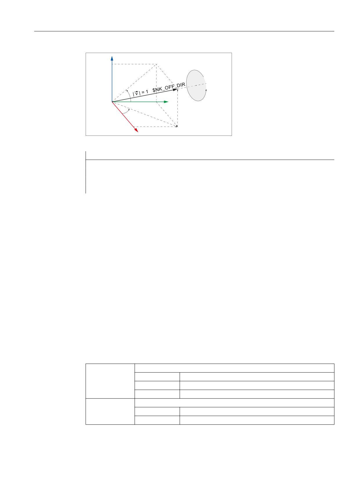
Example
The rotary axis of the 9th element rotates around the direction vector. The direction vector is
the unit vector (1; 0; 0), rotated around Z with γ=90° in the X/Y plane, and around X with
α=10° in the Y/Z plane referred to the world coordinate system. The following values result
from this for the individual components (x, y, z) of the direction vector:
● x = cos(γ) * cos(α) = cos(90) * cos(10) = 0.0
● y = sin(γ) * cos(α) = sin(90) * cos(10) ≈ 0.985
● z = sin(α) = sin(10) ≈ 0.174
Special functions
206
Function Manual, 12/2018, A5E40874099B AB
K7: Kinematic chain
5.2 Commissioning
=
˞
<
]
ˠ
[
;
\
Figure 5-7
Direction vector, general
Program code
Comment
; 9th kinematic element
N100 $NK_OFF_DIR[8,0] = COS(90)*COS(10)
; 0 = X component
N110 $NK_OFF_DIR[8,1] = SIN(90)*COS(10)
; 1 = Y component
N120 $NK_OFF_DIR[8,2] = SIN(10)
; 2 = Z component
$NK_AXIS
Function
The name of the machine axis (MD10000 $MN_AXCONF_MACHAX_NAME_TAB) that is to
be assigned to the element should be entered in the system variable.
The output coordinate system of the element results from the input coordinate system rotated
through the current position setpoint of the machine axis in the MCS and the offset specified
in $NK_A_OFF. The position setpoint of the machine axis contains all the active work offsets
and corrections.
The machine axis type must correspond to the type entered in $NK_TYPE:
In accordance with the AXIS_ROT type entered in $NK_TYPE, the machine axis must be a
rotary axis:
MD30300 $MA_IS_ROT_AX = 1
Syntax
$NK_AXIS[<n>] = <name>
Meaning
$NK_AXIS:
Machine axis name
Data type:
STRING
Range of values:
Machine axis name
Default value:
"" (empty string)
<n>:
System variable or element index
Data type:
INT
Range of values:
0, 1, 2, ... ($MN_MM_MAXNUM_KIN_CHAIN_ELEM - 1)
Special functions
Function Manual, 12/2018, A5E40874099B AB
207
K7: Kinematic chain
5.2 Commissioning
<value>:
Machine axis name
Data type:
STRING
Range of values:
Machine axis names
Example
The 9th kinematic element is assigned the machine axis with the name B1 as rotary axis.
Program code
Comment
N100 $NK_AXIS[8] = "B1"
; 9th kin. element
; axis = machine axis B1
$NK_A_OFF
Function
An additional work offset can be entered in the system variable for the assigned machine axis
($NK_AXIS). This work offset is only effective within the kinematic chain.
Syntax
$NK_A_OFF[<n>] = <value>
Meaning
$NK_A_OFF:
Work offset
Data type:
REAL
Range of values:
- max. REAL value ≤ x ≤ ± max. REAL value
Default value:
0.0
<n>:
System variable or element index
Data type:
INT
Range of values:
0, 1, 2, ... ($MN_MM_MAXNUM_KIN_CHAIN_ELEM - 1)
<value>:
Offset value
Data type:
REAL
Range of values:
- max. REAL value ≤ x ≤ ± max. REAL value
Example
The rotary axis zero point of the 9th kinematic elements is moved through 30.0° compared to
the modelled kinematics.
Program code
Comment
N100 $NK_A_OFF[8] = 30.0
; 9th kin. element
; Work offset = 30.0°
Special functions
208
Function Manual, 12/2018, A5E40874099B AB
K7: Kinematic chain
5.2 Commissioning
5.2.3.8
Type-dependent variables for $NK_TYPE = "ROT_CONST"
$NK_OFF_DIR
Function
The direction vector around which the constant rotation is performed should be entered in the
system variable. The output coordinate system is therefore calculated from the input coordinate
system, rotated through the angle specified in $NK_A_OFF around the direction vector
$NK_OFF_DIR.
Supplementary conditions:
● The direction vector must be specified as an absolute value, i.e. in relation to the world
coordinate system.
● The direction vector must be specified so that, in accordance with the "right-hand rule", the
thumb points in the direction of the vector when the rotary axis turns in the positive direction.
● The absolute value of the direction vector must be greater than 1*10-6.
Syntax
$NK_OFF_DIR[<n>,<k>] = <value>
Meaning
$NK_OFF_DIR:
Direction vector (X; Y; Z)
Data type:
REAL
Range of values:
Direction vector: 1*10-6 < |Vector | ≤ max. REAL value
Default value:
(0.0, 0.0, 0.0)
<n>:
System variable or element index
Data type:
INT
Range of values:
0, 1, 2, ... ($MN_MM_MAXNUM_KIN_CHAIN_ELEM - 1)
<k>:
Coordinate index
Data type:
INT
Range of values:
0: X coordinate (abscissa)
1: Y coordinate (ordinate)
2: Z coordinate (applicate)
<value>:
Coordinate value
Data type:
REAL
Range of values:
- max. REAL value ≤ x ≤ + max. REAL value
Example
The output coordinate system of the 9th Elements therefore arises from the input coordinate
system, rotated through the angle specified in $NK_A_OFF around the direction vector. The
direction vector is the unit vector (1; 0; 0), rotated around Z with γ=90° in the X/Y plane, and
Special functions
Function Manual, 12/2018, A5E40874099B AB
209
K7: Kinematic chain
5.2 Commissioning
around X with α=10° in the Y/Z plane referred to the world coordinate system. The following
values result from this for the individual components (x, y, z) of the direction vector:
● x = cos(γ) * cos(α) = cos(90) * cos(10) = 0.0
● y = sin(γ) * cos(α) = sin(90) * cos(10) ≈ 0.985
● z = sin(α) = sin(10) ≈ 0.174
=
˞
<
]
ˠ
[
;
\
Figure 5-8
ROT_CONST
Program code
Comment
; 9th kinematic element
N100 $NK_OFF_DIR[8,0] = COS(90)*COS(10)
; 0 = X component
N110 $NK_OFF_DIR[8,1] = SIN(90)*COS(10)
; 1 = Y component
N120 $NK_OFF_DIR[8,2] = SIN(10)
; 2 = Z component
$NK_A_OFF
Function
The angle through which the output coordinate system is rotated compared with the input
coordinate system around the direction vector $NK_OFF_DIR should be entered in the system
variable.
Syntax
$NK_A_OFF[<n>] = <value>
Meaning
$NK_A_OFF:
Angle of rotation
Data type:
REAL
Range of values:
- max. REAL value ≤ x ≤ + max. REAL value
Default value:
0.0
<n>:
System variable or element index
Data type:
INT
Range of values:
0, 1, 2, ... ($MN_MM_MAXNUM_KIN_CHAIN_ELEM - 1)
Special functions
210
Function Manual, 12/2018, A5E40874099B AB
K7: Kinematic chain
5.2 Commissioning
<value>:
Angle
Data type:
REAL
Range of values:
- max. REAL value ≤ x ≤ + max. REAL value
Example
The angle of rotation of the 9th kinematic element is 30.0°.
Program code
Comment
N100 $NK_A_OFF[8] = 30.0
; 9th kin. element
; Angle of rotation = 30.0°
5.2.3.9
Type-dependent variables for $NK_TYPE = "OFFSET"
$NK_OFF_DIR
Function
The offset vector by which the output coordinate system is moved compared to the input
coordinate system should be entered in the system variable.
The offset vector must be specified as an absolute value, i.e. in relation to the world coordinate
system.
Syntax
$NK_OFF_DIR[<n>,<k>] = <value>
Meaning
$NK_OFF_DIR:
Offset vector (X; Y; Z)
Data type:
REAL
Range of values:
(- max. REAL value) ≤ x ≤ (+ max. REAL value)
Default value:
(0.0, 0.0, 0.0)
<n>:
System variable or element index
Data type:
INT
Range of values:
0, 1, 2, ... ($MN_MM_MAXNUM_KIN_CHAIN_ELEM - 1)
<k>:
Coordinate index
Data type:
INT
Range of values:
0: X coordinate (abscissa)
1: Y coordinate (ordinate)
2: Z coordinate (applicate)
<value>:
Coordinate value
Data type:
REAL
Range of values:
(- max. REAL value) ≤ x ≤ (+ max. REAL value)
Special functions
Function Manual, 12/2018, A5E40874099B AB
211
K7: Kinematic chain
5.2 Commissioning
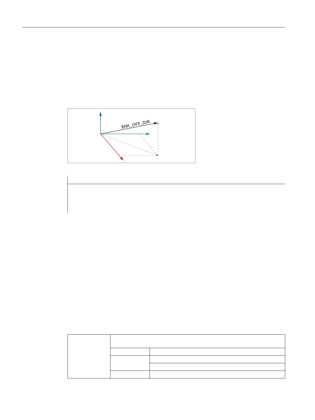
Example
The output coordinate system of the 9th element is obtained from the input coordinate system,
offset through the offset vector (x, y, z) with the following coordinates referred to the world
coordinate system:
● x = 10.0
● y = 20.0
● z = 30.0
=
<
]
[
;
\
Figure 5-9
Offset vector
Program code
Comment
; 9th kinematic element
N100 $NK_OFF_DIR[8,0] = 10.0
; 0 = X component
N110 $NK_OFF_DIR[8,1] = 20.0
; 1 = Y component
N120 $NK_OFF_DIR[8,2] = 30.0
; 2 = Z component
5.2.3.10
Type-dependent variables for $NK_TYPE = "SWITCH"
$NK_SWITCH_INDEX
Function
The switch is emulated using system variables $NK_SWITCH_INDEX and
$NK_SWITCH_POS (see the following paragraph)
Index i must be entered in $NK_SWITCH_INDEX, with which the switch is closed and opened
via system variable $NK_SWITCH[<i>].
Syntax
$NK_SWITCH_INDEX[<n>] = <i>
Meaning
$NK_SWITCH_
Index i, via which the switch is addressed using system variable
INDEX:
$NK_SWITCH[<i>]
Data type:
INT
Range of values:
-1, 0, 1, 2, ... ($MN_MAXNUM_KIN_SWITCHES - 1)
-1: The state of the switch is always CLOSED
Default value:
-1
Special functions
212
Function Manual, 12/2018, A5E40874099B AB

K7: Kinematic chain
5.2 Commissioning
<n>:
System variable or element index
Data type:
INT
Range of values:
0, 1, 2, ... ($MN_MM_MAXNUM_KIN_CHAIN_ELEM - 1)
<i>:
Index value
Data type:
INT
Example
The 9th element of the kinematic chain is a switch, which is activated by system variable
$NK_SWITCH[ 2 ].
Program code
Comment
; 9th element
N100 $NK_SWITCH_INDEX[8] = 2
; Index 2
$NK_SWITCH_POS
Function
A switch is emulated by system variables $NK_SWITCH_INDEX (see the previous paragraph)
and $NK_SWITCH_POS.
In $NK_SWITCH_POS, value p (close value) should be entered, where the switch is brought
into the CLOSED position by system variable $NK_SWITCH[<i>].
Independent of $NK_SWITCH[<i>], the switch has the following states:
● CLOSED: The close value p of the switch, specified in $NK_SWITCH_POS is the same as
the actual value of $NK_SWITCH[<i>].
$NK_SWITCH_POS[<n>] == $NK_SWITCH[<i>]
The previous element of the kinematic chain is connected with the output, i.e. the following
element of the switch specified in $NK_NEXT.
● OPEN: The close value of the switch, specified in $NK_SWITCH_POS, is not the same as
the actual value of $NK_SWITCH[<i>].
$NK_SWITCH_POS[<n>] ≠ $NK_SWITCH[<i>]
The previous element of the kinematic chain is notconnected with the output, i.e. the
following element of the switch specified in $NK_NEXT.
The close value can be freely selected.
Note
Parallel element $NK_PARALLEL
The connection to a parallel element specified in $NK_PARALLEL is not influenced by the
switch. This means that the previous element is always connected to the element in the branch
parallel with the switch.
Syntax
$NK_SWITCH_POS[<n>] = <p>
Special functions
Function Manual, 12/2018, A5E40874099B AB
213
K7: Kinematic chain
5.2 Commissioning
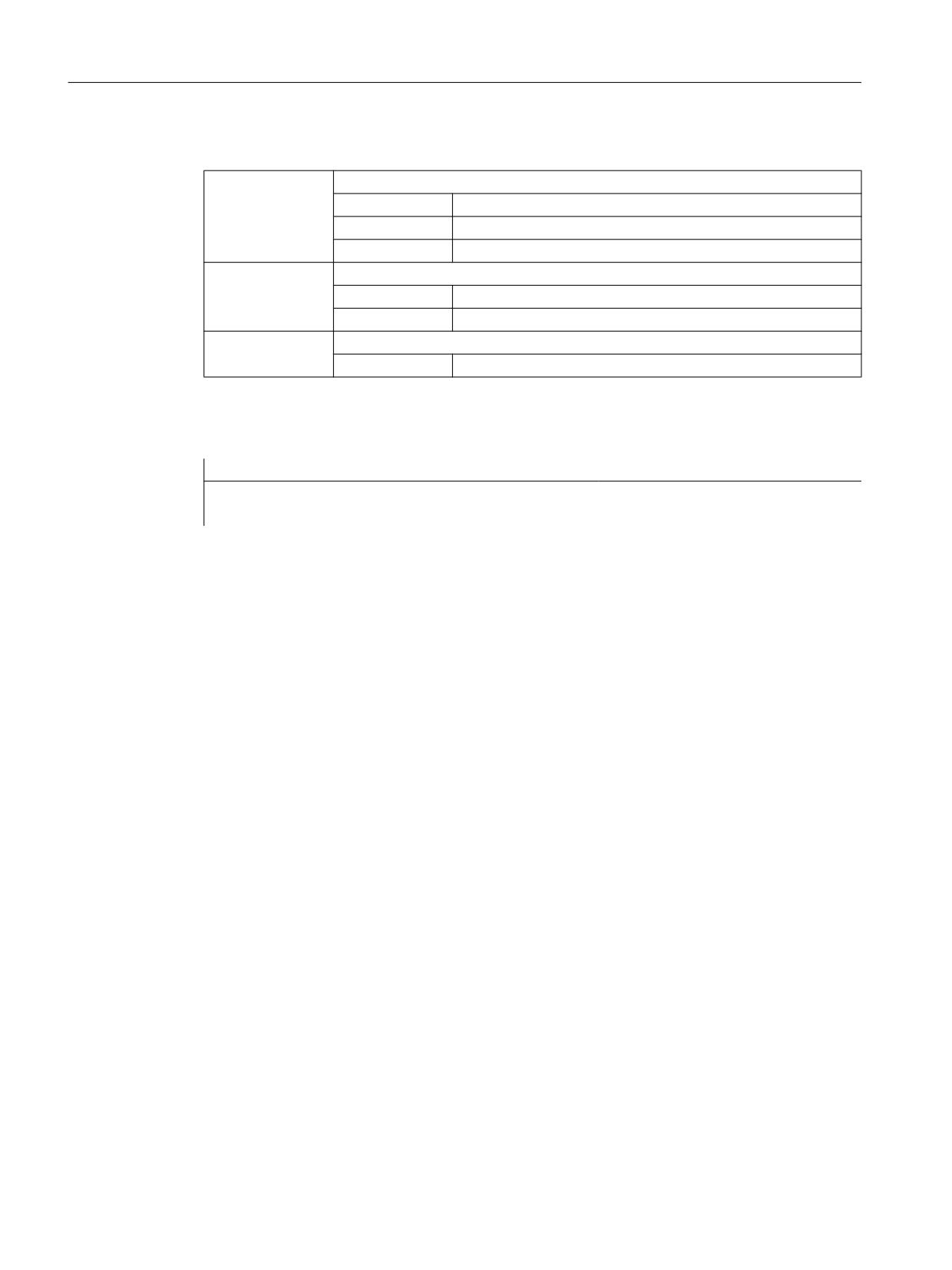
Meaning
$NK_SWITCH_
Close value
POS:
Data type:
INT
Range of values:
0 ≤ x ≤ positive max. INT value
Default value:
0
<n>:
System variable or element index
Data type:
INT
Range of values:
0, 1, 2, ... ($MN_MM_MAXNUM_KIN_CHAIN_ELEM - 1)
<p>:
Value for switch position CLOSED
Data type:
INT
Example
The 9th element of the kinetic chain is a switch, which is closed if $NK_SWITCH[ 3 ] == 1
Program code
Comment
; 9th element
N110 $NK_SWITCH_POS[8] = 1
; switch position = 1
See also
$NK_SWITCH (Page 214)
$MN_MAXNUM_KIN_SWITCHES (Page 197)
$MN_MM_MAXNUM_KIN_CHAIN_ELEM (Page 197)
5.2.3.11
$NK_SWITCH
Function
The switch variable comprises an array of switch positions i. The actual switch positions p
should be entered in this array.
Function
To parameterize (Page 212) a switchi in a kinematic chain, switchiwith index i must be
connected to the switch variable and its switch position p for the CLOSED state assigned to it.
$NK_SWITCH_INDEX[<n>] = <i>
$NK_SWITCH_POS[<n>]
= <p>
Switchi can then be closed and opened via index i of the switch variable:
Close: $NK_SWITCH[<i>] = <p>
Open: $NK_SWITCH[<i>] ≠ <p>
As many switches as required can be connected with an index of the switch variable.
Special functions
214
Function Manual, 12/2018, A5E40874099B AB
K7: Kinematic chain
5.3 Programming
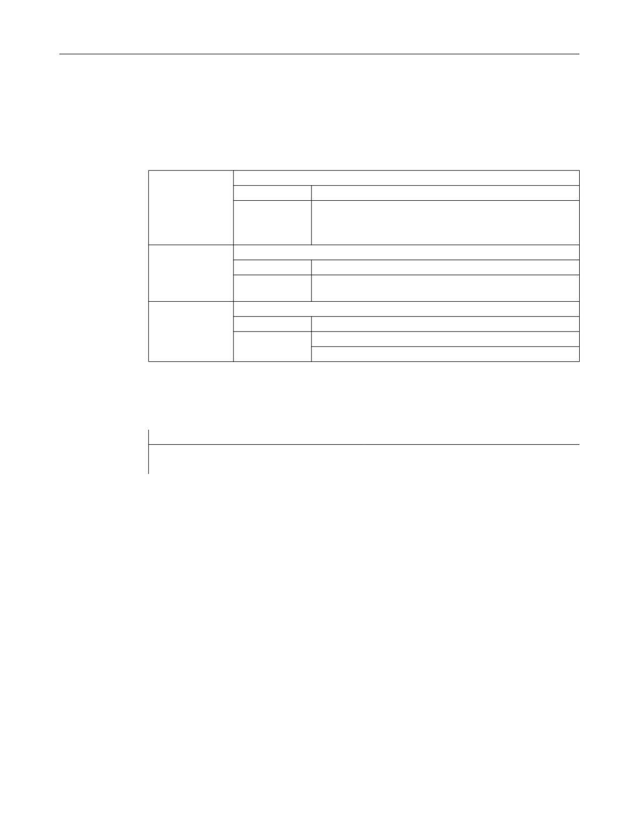
Syntax
$NK_SWITCH[<i>] = <p>
Meaning
$NK_SWITCH<i>:
Switch variable with switch positions i
Data type:
INT
Value range:
-1 ≤x ≤ positive max. INT value
Note
-1: Initial state OPEN
<i>:
Switch index
Data type:
INT
Range of values:
0, 1, 2, ... (MD18882 $MN_MM_MAX_NUM_KIN_SWITCHES
- 1)
<p>:
Switch setting
Data type:
INT
Value range:
-1 ≤x ≤ positive max. INT value
-1: Initial state OPEN
Example
The 9th kinematic element is assigned the name "B axis":
Program code
Comment
N100 $NK_SWITCH[3] = 1
; actual switch position
; for switch [3] = 1
5.3
Programming
5.3.1
Deletion of components (DELOBJ)
The DELOBJ() function "deletes" components by resetting the assigned system variables to
their default values:
● Elements from kinematic chains
● Protection areas, protection area elements and collision pairs
● Transformation data
Syntax
[<RetVal>=] DELOBJ(<CompType>[,,,<NoAlarm>)])
[<RetVal>=] DELOBJ(<CompType>,<Index1>[,,<NoAlarm>])
[<RetVal>=] DELOBJ(<CompType>[,<Index1>][,<Index2>][,<NoAlarm>])
Special functions
Function Manual, 12/2018, A5E40874099B AB
215

K7: Kinematic chain
5.3 Programming
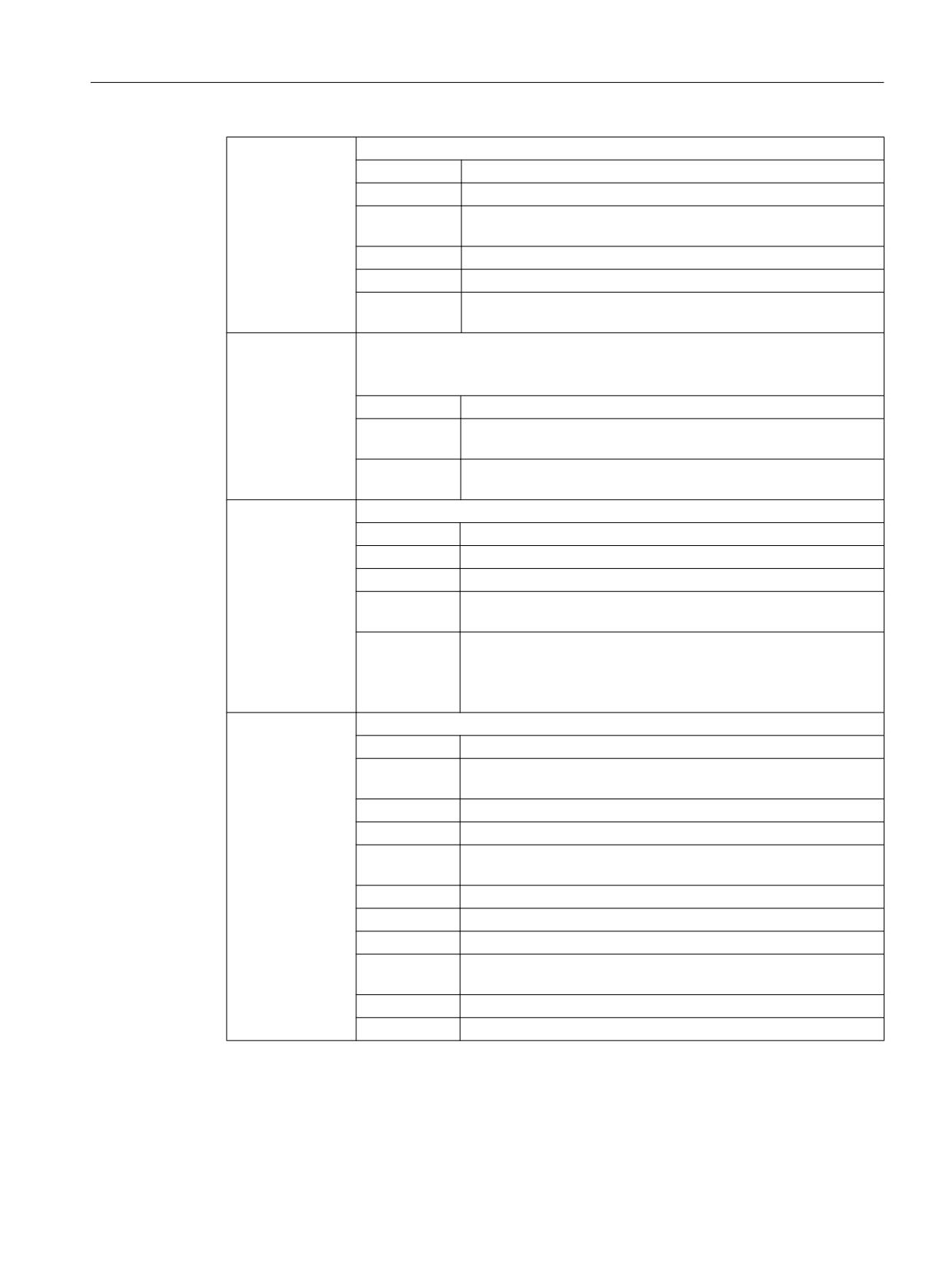
Meaning
DELOBJ:
Deletion of elements from kinematic chains, protection areas, protection area ele-
ments, collision pairs and transformation data
<CompType>:
Component type to be deleted
Data type:
STRING
Value: "KIN_CHAIN_ELEM"
Meaning: System variables of all kinematic elements: $NK_...
Value: "KIN_CHAIN_SWITCH"
Meaning: System variable $NK_SWITCH[<i>]
Value: "KIN_CHAIN_ALL"
Meaning: All kinematic elements and switches.
Is the same as the successive call of DELOBJ with "KIN_CHAIN_ELEM" and
"KIN_CHAIN_SWITCH"
Value: "PROT_AREA"
Meaning: System variables of the protection areas:
● $NP_PROT_NAME
● $NP_CHAIN_NAME
● $NP_CHAIN_ELEM
● $NP_1ST_PROT
Value: "PROT_AREA_ELEM"
Meaning: System variables of the protection area elements of machine protection
areas and/or automatic tool protection areas:
● $NP_NAME
● $NP_NEXT
● $NP_NEXTP
● $NP_COLOR
● $NP_D_LEVEL
● $NP_USAGE
● $NP_TYPE
● $NP_FILENAME
● $NP_PARA
● $NP_OFF
● $NP_DIR
● $NP_ANG
Value: "PROT_AREA_COLL_PAIRS"
Meaning: System variables of the collision pairs:
● $NP_COLL_PAIR
● $NP_SAFETY_DIST
Value: "PROT_AREA_ALL"
Meaning: All protection areas, protection area elements and collision pairs (system
variable $NP_... )
Is the same as the successive call of DELOBJ with "PROT_AREA,"
"PROT_AREA_ELEM," and "PROT_AREA_COLL_PAIRS"
Value: "TRAFO_DATA"
Meaning: System variables of all transformations $NT_...
Special functions
216
Function Manual, 12/2018, A5E40874099B AB
K7: Kinematic chain
5.3 Programming
<Index1>:
Index of the first component to be deleted (optional)
Data type:
INT
Default value:
-1
Range of val-
-1 ≤ x ≤ (maximum number of configured components -1)
ues:
Value
Meaning
0, 1, 2,
Index of the component to be deleted.
-1
All components of the specified type are deleted. <Index2> is not
evaluated.
<Index2>:
Index of the last components to be deleted (optional)
If <Index2> is not programmed, only the system variables of the component refer-
enced in <Index1> are deleted.
Data type:
INT
Default value:
Only the system variables of the component referenced in <In-
dex1> are deleted.
Range of val-
<Index1> < x ≤ (max. number of configured components -1)
ues:
<NoAlarm>:
Alarm suppression (optional)
Data type:
BOOL
Default value:
FALSE
Value
Meaning
FALSE
In the event of an error (<RetVal> < 0), program processing is
stopped and an alarm displayed.
TRUE
In the event of an error, the program processing is not stopped
and no alarm displayed.
Application: User-specific reaction corresponding to the return
value
<RetVal>:
Function return value
Data type:
INT
Range of val-
0, -1, -2, ... -7
ues:
Value
Meaning
0
No error occurred.
-1
Call of the function without parameters. At least parameter
<CompType> must be specified.
-2
<CompType> identifies an unknown component
-3
<Index1> is less than -1
-4
<Index1> is greater than the configured number of components
-5
<Index1> has a value not equal to -1 when deleting a component
group
-6
<Index2> is less than <Index1>
-7
<Index2> is greater than the configured number of components
Special functions
Function Manual, 12/2018, A5E40874099B AB
217
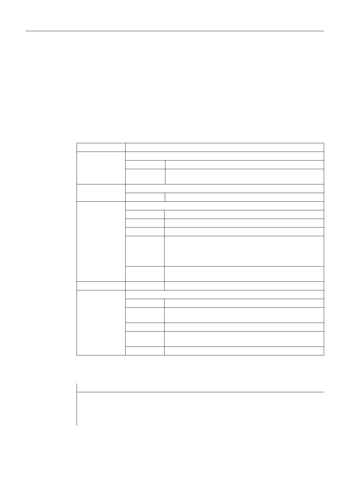
K7: Kinematic chain
5.3 Programming
5.3.2
Index determination by means of names (NAMETOINT)
User-specific names are entered in the system variable arrays of type STRING. Based on the
identifier of the system variables and the name, the NAMETOINT() function determines the
index value belonging to the name under which it is stored in the system variable array.
Syntax
<RetVal> = NAMETOINT(<SysVar>,<Name>[,<NoAlarm>])
Meaning
NAMETOINT:
Determining the system variable index
<SysVar>:
Name of the system variable array of typeSTRING
Data type:
STRING
Range of val-
Name of all NC system variable arrays of type STRING
ues:
<Name>:
Character string or name for which the system variable index is to be determined.
Data type:
STRING
<NoAlarm>:
Alarm suppression (optional)
Data type:
BOOL
Default value:
FALSE
Value
Meaning
TRUE
In the event of an error, the program processing is not stopped
and no alarm displayed.
Application: User-specific reaction corresponding to the return
value
FALSE
In the event of an error (<RetVal> < 0), program processing is
stopped and an alarm displayed.
<RetVal>:
System variable index or error message
Data type:
INT
Range of val-
-1 ≤ x ≤ (max. number of configured components -1)
ues:
Value
Meaning
≥ 0
The sought name has been found under the specified system
variable index.
-1
The sought name has not been found or an error has occurred.
Example
Program code
Comment
DEF INT INDEX
$NP_PROT_NAME[27]="Cover"
INDEX = NAMETOINT("$NP_PROT_NAME","Cover")
; INDEX == 27
Special functions
218
Function Manual, 12/2018, A5E40874099B AB
K7: Kinematic chain
5.4 Example
5.4
Example
5.4.1
Specifications
General Information
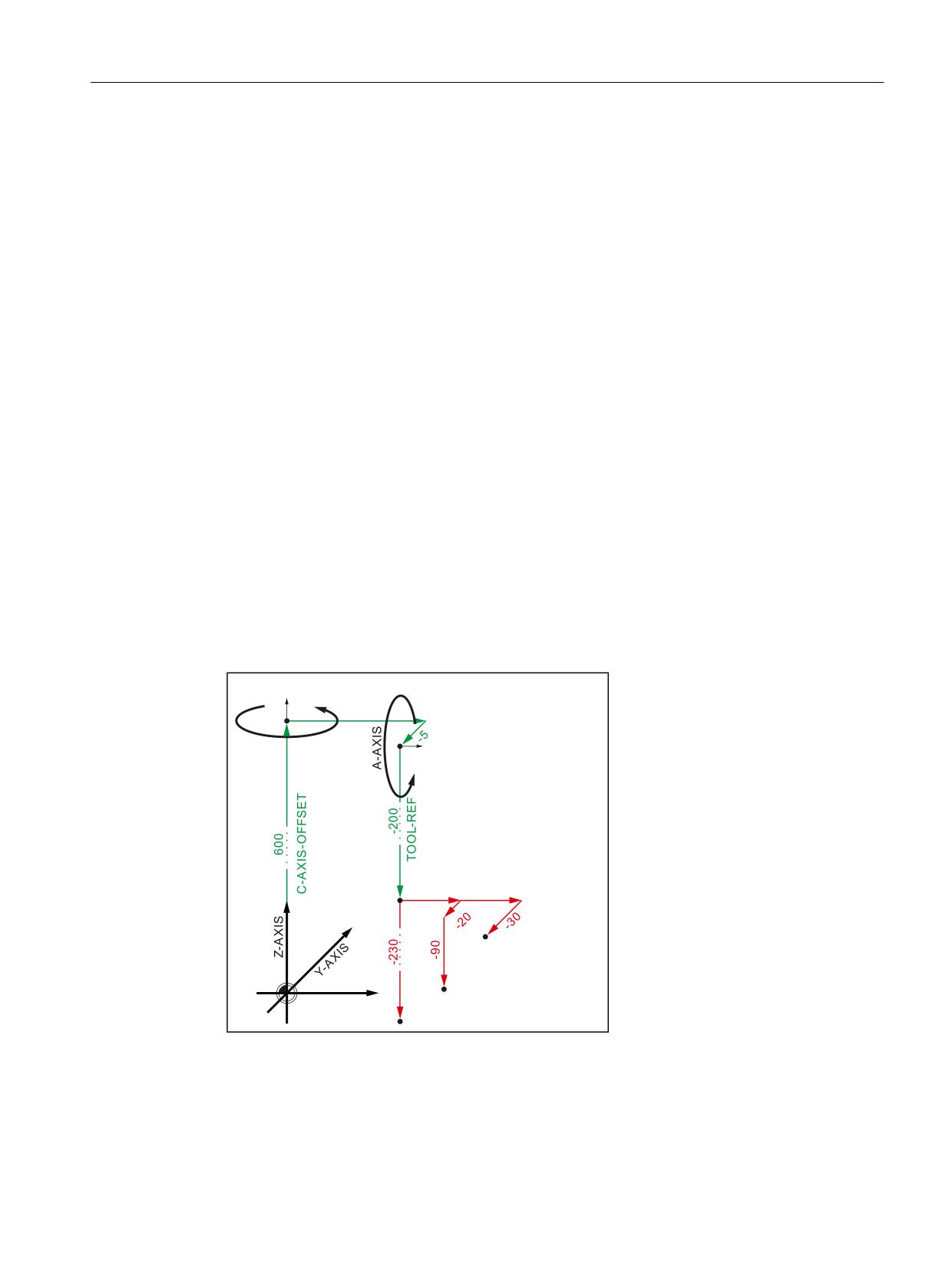
The principle approach when parameterizing a kinematic chain with three switches using a
part program is shown using as example a 5-axis machine with three different tool heads,
which are used alternately. All of the system variables, relevant for kinematic chain, are written
to the part program:
● Kinematic chain $NK_...
Option and machine data
The following option and machine data must be set for the example:
● MD19830 $ON_COLLISION_MASK.Bit 0 = 1
● MD18880 $MN_MM_MAXNUM_KIN_CHAIN_ELEM = 15
Kinematic chain
Schematic representation of the machine kinematics
& $ $;,6
2))6(7
& $
;,6
6
+($'
6
+($'
; $;,6
6
+($'
Special functions
Function Manual, 12/2018, A5E40874099B AB
219
K7: Kinematic chain
5.4 Example
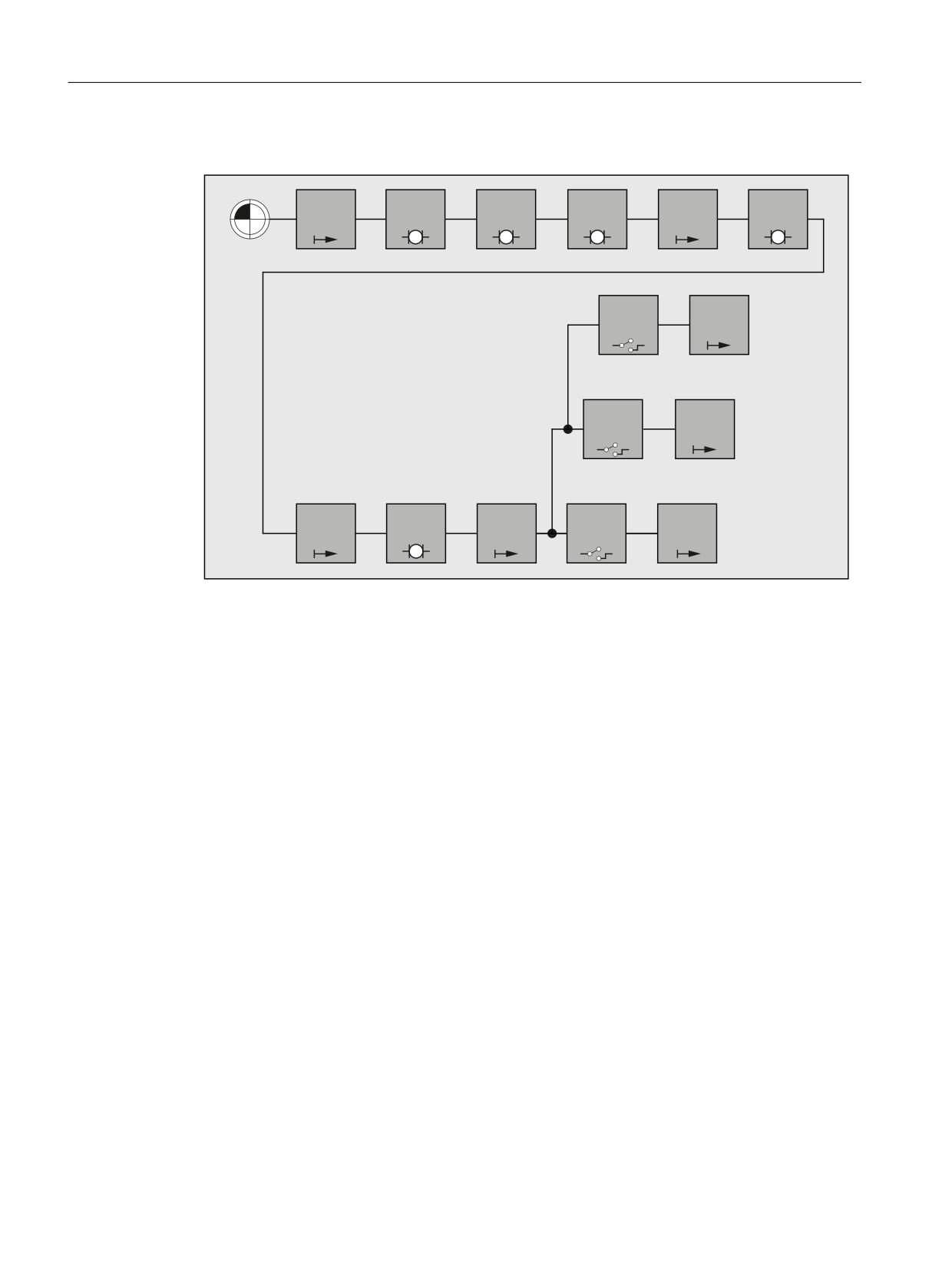
Elements of the kinematic chain
5RRW
; $;,6
<$;,6
= $;,6
& $;,6
& $;,6
2))6(7
$;,6B/,1
$;,6B/,1
$;,6B/,1
2))
$;,6B527
2))6(7
'2&.B3B
+($'
6:,7&+
2))6(7
'2&.B3B
+($'
6:,7&+
2))6(7
& $ $;,6
$ $;,6
722/ 5()
'2&.B3B
+($'
2))
$;,6B527
2))6(7
6:,7&+
2))6(7
2))6(7
The kinematic chain starts with an element of the type "Offset". When completely
parameterizing the collision avoidance, these are assigned to all static protection areas of the
machine
The offset element is followed by the kinematic elements of the linear machine axes X, Y and
Z - as well as the offset and kinematic elements of rotary axes C and A.
The offset element for the reference point of the tool heads is followed by three switches to
switch on and switch off the tool heads. As a result of $NK_INDEX = 3 all three switches refer
to the same switch variable $NK_SWITCH[ 3 ]. As a result of the different switch positions (1,
2, 3), only the subchain of the active tool head is active.
Special functions
220
Function Manual, 12/2018, A5E40874099B AB
K7: Kinematic chain
5.4 Example
5.4.2
Part program of the machine model
Program code
;===========================================================
; Definitions
;===========================================================
N10 DEF INT KIE_CNTR ; COUNTER FOR ELEMENTS OF THE KIN. CHAINS
N20 DEF INT RETVAL
;
;===========================================================
; Initialization of collision data
;===========================================================
; Reset all parameters to their initial values:
N30 RETVAL = DELOBJ("KIN_CHAIN_ELEM")
N40 KIE_CNTR = 0
;
;===========================================================
; Kinematic chain
;===========================================================
; KE1: OFFSET: Root
; ----------------------------------------------------------
N50 $NK_TYPE[KIE_CNTR] = "OFFSET"
N60 $NK_NAME[KIE_CNTR] = "ROOT"
N70 $NK_NEXT[KIE_CNTR] = "X-AXIS"
N80 KIE_CNTR = KIE_CNTR + 1
;
; ----------------------------------------------------------
; Kinematic element: LINEAR AXIS: X axis
; ----------------------------------------------------------
N90 $NK_TYPE[KIE_CNTR] = "AXIS_LIN"
N100 $NK_NAME[KIE_CNTR] = "X-AXIS"
N110 $NK_NEXT[KIE_CNTR] = "Y-AXIS"
N120 $NK_AXIS[KIE_CNTR] = "X1"
;
N130 $NK_OFF_DIR[KIE_CNTR,0] = 1.0
; X
N140 KIE_CNTR = KIE_CNTR + 1
;
; ----------------------------------------------------------
; Kinematic element: LINEAR AXIS: Y axis
; ----------------------------------------------------------
N150 $NK_TYPE[KIE_CNTR] = "AXIS_LIN"
N160 $NK_NAME[KIE_CNTR] = "Y-AXIS"
N170 $NK_NEXT[KIE_CNTR] = "Z-AXIS"
N180 $NK_AXIS[KIE_CNTR] = "Y1"
;
N190 $NK_OFF_DIR[KIE_CNTR,1] = 1.0
; Y
N200 KIE_CNTR = KIE_CNTR + 1
;
; ----------------------------------------------------------
; Kinematic element: LINEAR AXIS: Z axis
; ----------------------------------------------------------
N210 $NK_TYPE[KIE_CNTR] = "AXIS_LIN"
N220 $NK_NAME[KIE_CNTR] = "Z-AXIS"
N230 $NK_NEXT[KIE_CNTR] = "C-AXIS-OFFSET"
N240 $NK_AXIS[KIE_CNTR] = "Z1"
;
Special functions
Function Manual, 12/2018, A5E40874099B AB
221
K7: Kinematic chain
5.4 Example
Program code
N250 $NK_OFF_DIR[KIE_CNTR,2] = 1.0
; Z
N260 KIE_CNTR = KIE_CNTR + 1
;
; ----------------------------------------------------------
; Kinematic element: OFFSET: C axis
; ----------------------------------------------------------
N270 $NK_TYPE[KIE_CNTR] = "OFFSET"
N280 $NK_NAME[KIE_CNTR] = "C-AXIS-OFFSET"
N290 $NK_NEXT[KIE_CNTR] = "C-AXIS"
;
N300 $NK_OFF_DIR[KIE_CNTR,2] = 600.0
; Z direction
N310 KIE_CNTR = KIE_CNTR + 1 ;
;
; ----------------------------------------------------------
; Kinematic element: ROTARY AXIS: C axis
; ----------------------------------------------------------
N320 $NK_TYPE[KIE_CNTR] = "AXIS_ROT"
N330 $NK_NAME[KIE_CNTR] = "C-AXIS"
N340 $NK_NEXT[KIE_CNTR] = "C-A-OFFSET"
N350 $NK_AXIS[KIE_CNTR] = "C1"
;
N360 $NK_OFF_DIR[KIE_CNTR,2] = 1.0
; Z direction
N370 KIE_CNTR = KIE_CNTR + 1
;
; ----------------------------------------------------------
; Kinematic element: OFFSET: C-A axis
; ----------------------------------------------------------
N380 $NK_TYPE[KIE_CNTR] = "OFFSET"
N390 $NK_NAME[KIE_CNTR] = "C-A-OFFSET"
N400 $NK_NEXT[KIE_CNTR] = "A-AXIS"
;
N410 $NK_OFF_DIR[KIE_CNTR,0] = 20.0
; X direction
N420 $NK_OFF_DIR[KIE_CNTR,1] = -5.0
; Y direction
N430 KIE_CNTR = KIE_CNTR + 1
;
; ----------------------------------------------------------
; Kinematic element: ROTARY AXIS: A axis
; ----------------------------------------------------------
N440 $NK_TYPE[KIE_CNTR] = "AXIS_ROT"
N450 $NK_NAME[KIE_CNTR] = "A-AXIS"
N460 $NK_NEXT[KIE_CNTR] = "TOOL-REF"
N470 $NK_AXIS[KIE_CNTR] = "A1"
;
N480 $NK_OFF_DIR[KIE_CNTR,0] = 1.0
; X direction
N490 KIE_CNTR = KIE_CNTR + 1
;
; ----------------------------------------------------------
; Kinematic element: OFFSET: Tool reference
; ----------------------------------------------------------
N500 $NK_TYPE[KIE_CNTR] = "OFFSET"
N510 $NK_NAME[KIE_CNTR] = "TOOL-REF"
N520 $NK_NEXT[KIE_CNTR] = "DOCKING_POINT 1"
;
N530 $NK_OFF_DIR[KIE_CNTR,2] = -200.0
; Z direction
N540 KIE_CNTR = KIE_CNTR + 1
;
Special functions
222
Function Manual, 12/2018, A5E40874099B AB
K7: Kinematic chain
5.4 Example
Program code
; ----------------------------------------------------------
; Kinematic element: Switch 3/1
; ----------------------------------------------------------
N550 $NK_TYPE[KIE_CNTR] = "SWITCH"
N560 $NK_NAME[KIE_CNTR] = "DOCKING_POINT 1"
N570 $NK_NEXT[KIE_CNTR] = "HEAD 1"
N580 $NK_PARALLE[KIE_CNTR] = "DOCKING_POINT 2"
;
N590 $NK_SWITCH_INDEX[KIE_CNTR] = 3
; Index 3
N600 $NK_SWITCH_POS[KIE_CNTR] = 1
; switch position 1
N610 KIE_CNTR = KIE_CNTR + 1
;
; ----------------------------------------------------------
; Kinematic element: Switch 3/2
; ----------------------------------------------------------
N620 $NK_TYPE[KIE_CNTR] = "SWITCH"
N630 $NK_NAME[KIE_CNTR] = "DOCKING_POINT 2"
N640 $NK_NEXT[KIE_CNTR] = "HEAD 2"
N650 $NK_PARALLE[KIE_CNTR] = "DOCKING_POINT 3"
;
N660 $NK_SWITCH_INDEX[KIE_CNTR] = 3
; Index 3
N670 $NK_SWITCH_POS[KIE_CNTR] = 2
; switch position 2
N680 KIE_CNTR = KIE_CNTR + 1
;
; ----------------------------------------------------------
; Kinematic element: Switch 3/3
; ----------------------------------------------------------
N690 $NK_TYPE[KIE_CNTR] = "SWITCH"
N700 $NK_NAME[KIE_CNTR] = "DOCKING_POINT 3"
N710 $NK_NEXT[KIE_CNTR] = "HEAD 3"
N720 $NK_PARALLE[KIE_CNTR] = ""
N730 $NK_SWITCH_INDEX[KIE_CNTR] = 3
; Index 3
N740 $NK_SWITCH_POS[KIE_CNTR] = 3
; switch position 3
N750 KIE_CNTR = KIE_CNTR + 1
;
; ----------------------------------------------------------
; Kinematic element: OFFSET: HEAD 1
; ----------------------------------------------------------
N760 $NK_TYPE[KIE_CNTR] = "OFFSET"
N770 $NK_NAME[KIE_CNTR] = "HEAD 1"
N780 $NK_NEXT[KIE_CNTR] = ""
;
N790 $NK_OFF_DIR[KIE_CNTR,0] = 100
; X direction
N800 $NK_OFF_DIR[KIE_CNTR,1] = -30
; Y direction
N810 KIE_CNTR = KIE_CNTR + 1
;
; ----------------------------------------------------------
; Kinematic element: OFFSET: HEAD 2
; ----------------------------------------------------------
N820 $NK_TYPE[KIE_CNTR] = "OFFSET"
N830 $NK_NAME[KIE_CNTR] = "HEAD 2"
N840 $NK_NEXT[KIE_CNTR] = ""
;
N850 $NK_OFF_DIR[KIE_CNTR,2] = -230
; Z direction
N860 KIE_CNTR = KIE_CNTR + 1
;
Special functions
Function Manual, 12/2018, A5E40874099B AB
223

K7: Kinematic chain
5.5 Data lists
Program code
; ----------------------------------------------------------
; Kinematic element: OFFSET: HEAD 3
; ----------------------------------------------------------
N870 $NK_TYPE[KIE_CNTR] = "OFFSET"
N880 $NK_NAME[KIE_CNTR] = "HEAD 3"
N890 $NK_NEXT[KIE_CNTR] = ""
;
N900 $NK_OFF_DIR[KIE_CNTR,0] = 50
; X direction
N910 $NK_OFF_DIR[KIE_CNTR,1] = -20
; Y direction
N920 $NK_OFF_DIR[KIE_CNTR,2] = -90
; Z direction
N930 KIE_CNTR = KIE_CNTR + 1
End
5.5
Data lists
5.5.1
Machine data
5.5.1.1
NC-specific machine data
Number
Identifier: $MN_
Description
16800
ROOT_KIN_ELEM_NAME
Name of the first element in the kinematic chain
18880
MM_MAXNUM_KIN_CHAIN_ELEM
Maximum number of elements for kinematic chains
18882
MM_MAX_NUM_KIN_SWITCHES
Maximum number of switches for kinematic chains
5.5.2
System variables
Identifier
Description
$NK_NAME
Name of the kinematic element
$NK_NEXT
Name of the next element in the kinematic chain
$NK_PARALLEL
Name of the first element of a parallel branching kinematic chain before the
element
$NK_TYPE
Type of the kinematic element
$NK_OFF_DIR
Depends on $NK_TYPE: Offset or direction vector
$NK_AXIS
Name of the assigned machine axis or object name
$NK_A_OFF
Work offset in the element for linear or rotary axes
$NK_SWITCH_INDEX
Index i, via which the switch is addressed using system variable
$NK_SWITCH[<i>]
$NK_SWITCH_POS
Switch position CLOSED
$NK_SWITCH
Switch variable
Special functions
224
Function Manual, 12/2018, A5E40874099B AB
K8: Geometric machine modeling
6
6.1
Function description
6.1.1
Features
This section describes how the geometry of machine parts can be mapped based on protection
areas and parameterized in the control using system variables for NC functions such as
"collision avoidance".
The system variables are retentatively saved in the NC and can be archived and/or read as
"NC data" via SINUMERIK Operate using the commissioning archive.
By assigning a protective area to an element of the kinematic chain (Page 191) described in
the previous section, the position and motion of the machine part can be clearly described
within the machine space.
Note
Graphic editor
As an alternative to writing the system variables in a part program, the machine can be modeled
from the SINUMERIK Operate user interface:
Operating area: "Commissioning" > "NC" > "Machine model"
Changes to the machine model
The direct changes to the machine model at the system variables only become visible at the
user interface after explicitly requesting that the machine model is recalculated by calling the
PROTA() (Page 294) or PROTS() (Page 295) function.
Changes to the machine model made at the user interface are immediately accepted in the
system variables of the NC. The changes only become active after explicitly requesting that
the machine model is recalculated by calling the PROTA() (Page 294) or PROTS()
(Page 295) function.
Protection area
The protection areas are the central element when geometrically modeling a machine. The
geometric dimensions of a machine part, its reference to the kinematic chain and additional
general features are described by a protection area.
A protection area has the following parameters:
● Name of the protection area
● Name of the kinematic element to which the protection area is assigned
● Type of the protection area
● Name of the first protection area element
Special functions
Function Manual, 12/2018, A5E40874099B AB
225
K8: Geometric machine modeling
6.1 Function description
● Color and transparency of the protection area
● Detail level for the protection area
● Number of NC/PLC interface bits of the protection area
● Initialization status of the protection area
● Address of the geometric data of the machine element to the protected
(only relevant for automatic protection areas)
Each parameter is mapped by a system variable. The individual parameters and/or system
variables are described in detail in Chapter "System variables: Protection areas (Page 235)".
Kinematic chain
The corresponding protection area is assigned to an element of the kinematic chain
(Page 191) in order to map the position and motion of a machine part. The geometric data of
the protection area relates then to the local coordinate system of this kinematic element.
Type of the protection area
The following types of protection areas are available:
● Machine protection areas (type: "MACHINE")
Machine protection areas are used for general machine modeling. They are used to map
stationary and moving machine parts whose geometry is defined once upon commissioning
and no longer changes when the machine is in operation.
● Automatic tool protection areas (type: "TOOL")
Automatic tool protection areas are used to map tools. The geometry of the tool is not
provided directly with this but is produced automatically by the control when the tool is
activated.
See section "Automatic tool protection areas (Page 228)".
Protection area element
Using a protection area element, the geometrical element used is described regarding its
geometrical and general properties.
A protection area element has the following parameters:
● Name of the protection area element
● Name of the following protection area element
● Name of the following protection area element parallel to $NP_NEXT
● Color and transparency of the protection area element
● Detail level for the protection area element
● Use of the protection area element
● Type of the protection area element
● File name of the STL file that contains the geometric data of the protection area element
(only relevant for type "FILE")
● Geometrical parameters of the protection area body
(only relevant for types, "BOX", "SPHERE" or "CYLINDER")
Special functions
226
Function Manual, 12/2018, A5E40874099B AB
K8: Geometric machine modeling
6.1 Function description
● Offset vector of the protection area element local coordinate system
● Direction vector for the rotation of the protection area element local coordinate system
● Angle for the rotation of the protection area element local coordinate system
Each parameter is mapped by a system variable. The individual parameters or system
variables are described in detail in:
● Chapter "System variables: Protection area elements for machine protection areas
(Page 247)"
● Chapter "System variables: Protection area elements for automatic tool protection areas
(Page 268)"
Protection area, protection area elements and kinematic chain
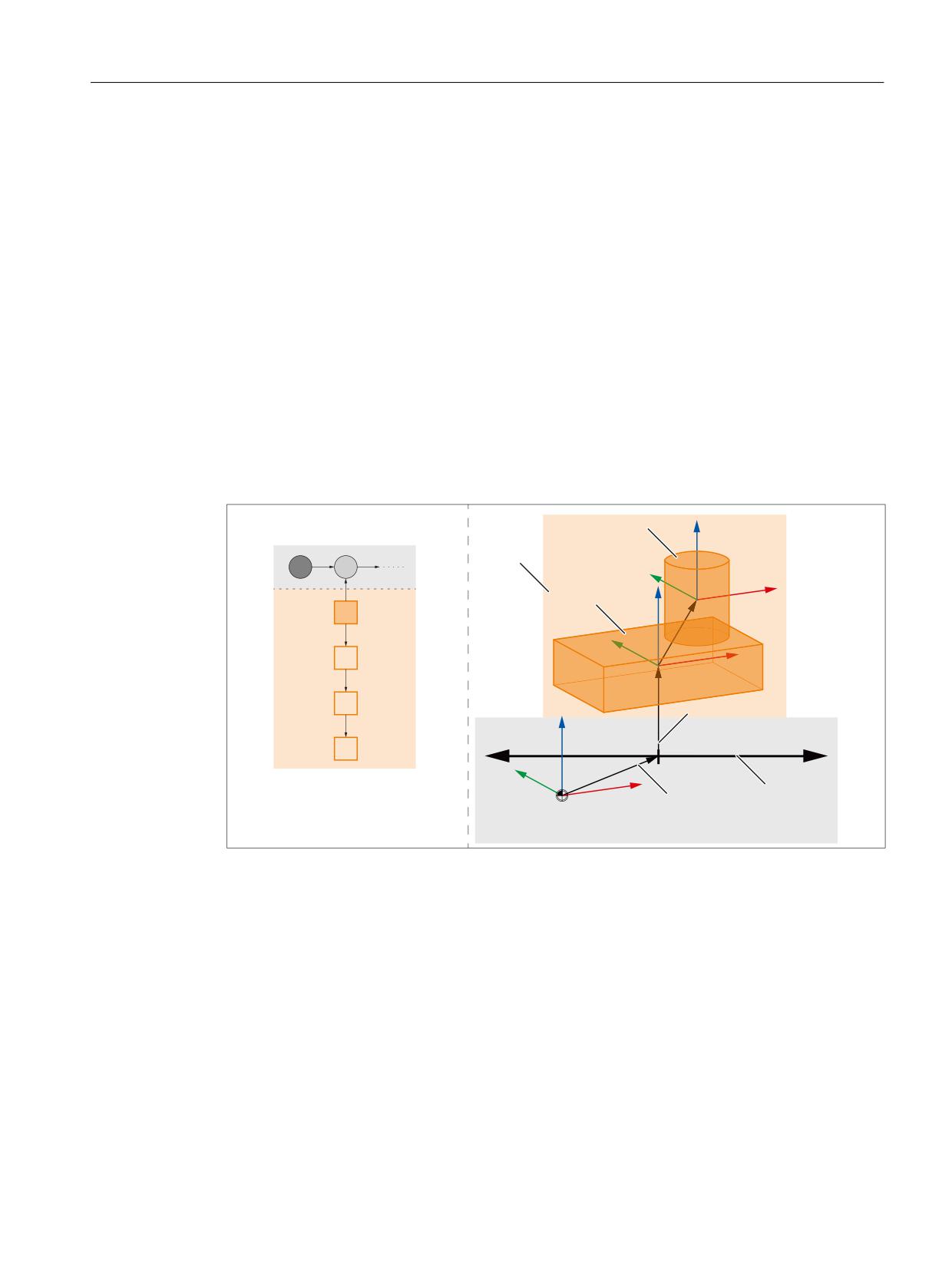
Using an example of a protection area with two protection area elements, the following diagram
shows the interrelationship between the protection area, its protection area elements and the
assignment to an element of the kinematic chain.
VH
.LQHPDWLF FKDLQ
]
V
H
H
\
VH
[
]
V
Y
VH
\
[
VH
VH
=
VH
*HRPHWULF PDFKLQH PRGHOLQJ
<
;
H
H
0DFKLQH FRRUGLQDWH V\VWHP
:RUOG FRRUGLQDWH V\VWHP
e1
Kinematic element 1, type "OFFSET", continuous offset
e2
Kinematic element 2, type "AXIS_LIN", machine axis AX1
s1
Protection area
se1
Protection area element 1, type "FRAME", offset
se2
Protection area element 2, type "BOX"
se3
Protection area element 3, type "CYLINDER"
Figure 6-1
Protection area, protection area elements and kinematic chain
Special functions
Function Manual, 12/2018, A5E40874099B AB
227
K8: Geometric machine modeling
6.1 Function description
6.1.2
Automatic tool protection areas
Unlike machine protection areas whose geometry is defined once during the machine modeling
and then no longer changes, the geometry of a tool protection area can change with every tool
change. As a result the geometry of an automatic tool protection area is not described directly
when the machine model is created, and instead the address (magazine number, magazine
location, etc.) is provided under which the tool data is stored. The following actions are then
carried out automatically by the control.
1. The tool modeling (see "Tool modeling" section below) produces an STL file.
2. A protection area element of the "FILE" type is produced and assigns the STL file.
3. The protection area element is assigned to the protection area (type "TOOL").
Tool definition independent of the tool mounting position
Normally the parameter "$NP_1ST_PROT (Page 239)" remains empty for the definition of a
tool protection area. The name of the protection area element is only entered when the tool is
activated by the control (see above).
In order for there to be a tool definition independently of the tool mounting position, a protection
area element of the "FRAME (Page 254)" type can be assigned via the parameter
"$NP_1ST_PROT" (transformation element). The transformations to align the tool can be
carried out via this additional element. When a tool is activated the name of the internal
protection area element is entered in the parameter "$NP_NEXT (Page 249)" of the
transformation element by the control.
The following rules must be observed:
● The transformation element may only be of the "FRAME" type.
● Only one transformation element may be used for each tool protection area.
● The parameter "$NP_NEXTP" of the transformation element is not evaluated.
Tool reference point
The position of the tool reference point in the machine model is determined by the kinematic
element to which the tool protection area is assigned. In addition the tool reference point can
be offset within the tool protection area by an optional transformation element.
Kinematic transformations
The tool reference point may only be determined via the kinematic chain when defining a
kinematic transformation. Offsets by the transformation element of the tool protection area are
not taken into account.
NOTICE
Determination of the tool reference point for kinematic transformations
Offsets of the tool reference point by the transformation element of the tool protection area
are not taken into account by kinematic transformations.
Special functions
228
Function Manual, 12/2018, A5E40874099B AB
K8: Geometric machine modeling
6.1 Function description
Tool modeling
The model of a tool is created by the control heuristically from the tool data. The tool data used
for this (L1, L2, L3, R) is always the the overall dimensions resulting from the individual
components, e.g. length plus wear, as is also entered in the program processing for tool offset.
Programmable tool offsets
Programmable tool offsets such as OFFN (offset to the programmed contour) are not taken
into account as they may change in any block, even without a tool change.
Special functions
Function Manual, 12/2018, A5E40874099B AB
229
K8: Geometric machine modeling
6.1 Function description
Tool type-dependent model generation
The following tool types are distinguished for the model generation:
●
Milling tool and all other tools that are neither turning tools or grinding tools
- Modeling
The tool is modeled by a cylinder with the height L1 and radius R. If the length L1 is
negative the absolute value of L1 is used for the cylinder height. The sign L1 is taken
into account when positioning the cylinder in the machine model. The cylinder axis is
parallel to L1.
Tool type 110 (ball end mill cutter) and 111 (face cutter) are modeled using half a sphere
or sphere segments.
If the radius is negative the absolute value of the radius is used. If the value for the radius
is less than 1/3 mm, a radius of 1/3 mm is used.
- Positioning
The cylinder is positioned in the machine model using the tool length components L2
and L3.
For milling tools (tool type 100 ... 199) and drilling tools (tool type 200 ... 299) on turning
machines, the cylinder is positioned using the cutting edge position.
Precondition: Cutting edge position == 5 ... 8
●
Grinding tools
- Modeling
Grinding tools (grinding wheel, tool type 400 ... 499) are modeled by a cylinder with the
tool length as the radius and double the tool radius as the height.
- Positioning
The cylinder is positioned in the machine model using the tool lengths L1, L2 and L3.
●
Turning tools
In the case of turning tools only the cutting tips are taken into account in the machine model
but not their connection to the tool reference point.
The following data is taken into account when modeling a cutting tip:
- Tool type
- Cutting edge position
- Cutting edge radius
- Clearance angle
- Holder angle
- Cutting tip length
- Cutting tip width
- Tip thickness (assumption: tip thickness = 10% tip length)
Tool model
A tool is modeled as standard with an accuracy of one third of the collision tolerance
(Page 285). The geometric data of the modeled tool is stored in an internal file in STL format:
● Directory: _N_PROT3D_DIR/_N_TOOL_DIR
● Identifiers: Name of the associated protection area with prefix _N_ and ending with _STL
Special functions
230
Function Manual, 12/2018, A5E40874099B AB
K8: Geometric machine modeling
6.2 Commissioning
The coordinate system of the geometric data always has its origin at the point from which the
tool length offsets point to the tip of the tool.
System variable
All parameters for an automatic tool protection area can be read via System variable
(Page 247).
6.2
Commissioning
6.2.1
General
6.2.1.1
Overview
The commissioning of the "Collision avoidance" function is performed using:
● Machine data
- Specifications for the quantity structure of protection areas, protection area elements,
NC/PLC interface signals, triangles for the geometry modelling
- Creation mode of the machine model
- Creation mode for automatic tool protection areas
● System variables
- Parameterization of the protection areas
- Parameterization of the protection area elements of a protection area
6.2.1.2
Structure of the system variables
The system variables are structured according to the following scheme:
● $NP_<name>[<index_1>]
● $NP_<name>[<index_1>, <index_2>]
General
The system variables to describe the protection areas or protection area elements have the
following properties:
● Prefix: $NP_, (N for NC, P for protection).
● They can be read and written via NC programs.
● They can be stored in archives and loaded to the NC again.
Special functions
Function Manual, 12/2018, A5E40874099B AB
231
K8: Geometric machine modeling
6.2 Commissioning
Data type
STRING
All system variables of the STRING data type have the following properties:
● Maximum string length: 31 characters
● No distinction is made between upper and lower case
Example: "Axis1" is identical to "AXIS1"
● Spaces and special characters are permitted
Example: "Axis1" is not identical to "Axis 1"
● Names that start with two underscores "__" are reserved for system purposes and must
not be used for user-defined names.
Note
Leading space
Since spaces are valid and distinct characters, names that start with a space followed by two
underscores "__" can, in principle, be used for user-defined names. However, because they
can be easily mistaken for system names, this procedure is not recommended.
Index_1
System variables for protection areas
The individual protection areas are addressed via index_1. Index 0 → 1st protection area, index
1 → 2nd protection area, ... m → (m+1) protection area, where m =
($MN_MM_MAXNUM_3D_PROT_AREAS - 1)
All system variables of a protection area have the same index.
System variables for protection areas elements
The individual protection area elements are addressed via index_1. Index 0 → 1st protection
area element, index 1 → 2nd protection area element, ... n → (n+1)th protection area element,
where n = ($MN_MM_MAXNUM_3D_PROT_AREA_ELEM - 1)
All system variables of a protection area element have the same index.
Index_2
Depending on the respective system variables, index_2 has different meanings.
See also
Deletion of components (DELOBJ) (Page 215)
Special functions
232
Function Manual, 12/2018, A5E40874099B AB
K8: Geometric machine modeling
6.2 Commissioning
6.2.1.3
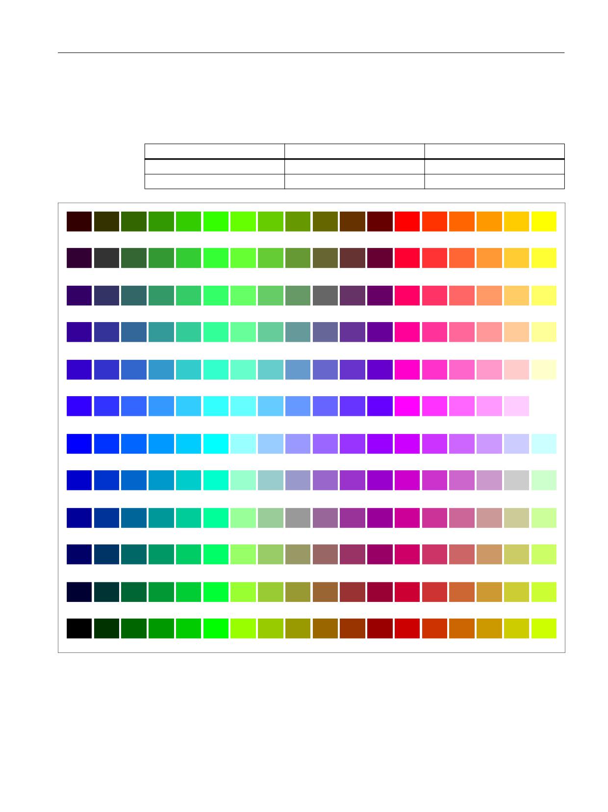
Color chart
The following color chart provides an overview of the RGB color values and the associated
colors. A RGB color value comprises three bytes. One byte per color:
3rd byte
2nd byte
1st byte
Color value for red
Color value for green
Color value for blue
0 - 255D or 0 - FFH
0 - 255D or 0 - FFH
0 - 255D or 0 - FFH
&&
))
))
&&
))
))
))
))
))&&
))))
&&
))
))
&&
))
))
))
))
))&&
))))
&&
))
))
&&
))
))
))
))
))&&
))))
&&
))
))
&&
))
))
))
))
))&&
))))
&&
&&
&&
&&
&&&
))&&
))&&
&&&
&&
&&
&&
&&
)) &&
)) &&
)) &&
)) &&))&&&&
))))&&
))
))
))
))
&&))
))))
))))
&&))
))
))
))
))
))
))
))
))
))
))
))
))
))&&))
))))))
))
))
))
))
&&))
))))
))))
&&))
))
))
))
))
&&
))
&&
))
&&
))
&&
))
&&&&))
&&))))
&&
&&
&&
&&
&&&
))&&
))&&
&&&&
&&
&&
&&
&& && &&
&& &&
&& &&
&& &&
&&&&&&
&&))&&
&&
))
))
&&
&&
&&
&&
&&
&&&&
&&))
&&
))
))
&&
&&
&&
&&
&&
&&&&
&&))
&&
))
))
&&
&&
&&
&&
&&
&&&&
&&))
&&
))
))
&&
&&
&&
&&
&&
&&&&
&&))
Special functions
Function Manual, 12/2018, A5E40874099B AB
233
K8: Geometric machine modeling
6.2 Commissioning
6.2.2
Machine data
6.2.2.1
Maximum number of protection areas
The maximum number of all types of parameterizable protection areas (Page 238) is specified
with the machine data.
MD18890 $MN_MM_MAXNUM_3D_PROT_AREAS = <number>
6.2.2.2
Maximum number of protection area elements for machine protection areas
The maximum number of parameterizable protection area elements for machine protection
areas is specified using machine data ($NP_PROT_TYPE == "MACHINE" (Page 238)).
MD18892 $MN_MM_MAXNUM_3D_PROT_AREA_ELEM = <number>
6.2.2.3
Maximum number of protection area elements for automatic tool protection areas
The maximum number of protection area elements for automatic tool protection areas is
specified with the machine data. For each automatic tool protection area the control precisely
creates one protection area element. As a consequence, using the value parameterized here,
the maximum possible number of parameterizable automatic tool protection areas
($NP_PROT_TYPE == "TOOL" (Page 238)) is also simultaneously defined.
MD18893 $MN_MM_MAXNUM_3D_T_PROT_ELEM = <number>
6.2.2.4
Maximum number of NC/PLC interface signals for the preactivation of protection areas
The machine data communicates to the control the number of NC/PLC interface signals of
interface DB10, DBX234.0 - DBX241.7 actually used (collision avoidance: activate protection
area) with the machine data. The number of interface signals used increases the memory
space required for each part program block. Counting the number of used NC/PLC interface
signal starts at DB10, DBX234.0
MD18897 $MN_MM_MAXNUM_3D_INTERFACE_IN = <number>
References:
A detailed description of the interface signals is provided in the NC Variables and Interface
Signals Parameter Manual.
6.2.2.5
Maximum number of triangles for machine protection areas
With the machine data, the maximum number of triangles for protection area bodies
($NP_TYPE == "FILE" (Page 254)) of machine protection areas ($NP_PROT_TYPE ==
"MACHINE" (Page 238)) to be provided by the control is defined.
MD18895 $MN_MM_MAXNUM_3D_FACETS = <number>
Special functions
234
Function Manual, 12/2018, A5E40874099B AB
K8: Geometric machine modeling
6.2 Commissioning
6.2.2.6
Maximum number of triangles for automatic tool protection areas
With the machine data, the maximum number of triangles for protection area bodies of
automatic tool protection areas to be provided by the control is defined.
MD18894 $MN_MM_MAXNUM_3D_FACETS_INTERN = <number>
The control system automatically models the protection area bodies based on the geometric
data of the tool active at the time of creation. The number of triangles correspondingly
increases:
● as the geometric complexity of the tool increases.
● as the parameterized collision tolerance decreases.
Note
Protection area bodies and collision tolerance
The protection area bodies of automatic tool protection areas are, as standard, created by the
control with a precision of 1/3 of the collision tolerance (Page 285).
6.2.2.7
Creation mode for automatic tool protection areas
The machine data defines how the control creates protection area bodies of automatic tool
protection areas.
MD18899 $MN_PROT_AREA_TOOL_MASK = <mode>
<Mode>
Bit
Val-
Meaning
ue
0
0
Do not apply heuristic model generation
1
Heuristic model generation using tool data
6.2.3
System variables: Protection areas
6.2.3.1
Overview
A protection area is parameterized with the following system variables:
Name
Meaning
$NP_PROT_NAME
Name of the protection area
$NP_CHAIN_ELEM
Name of the kinematic element to which the protection area is as-
signed
$NP_PROT_TYPE
Type of the protection area
$NP_1ST_PROT
Name of the first protection area element
$NP_PROT_COLOR
Color and transparency of the protection area.
$NP_PROT_D_LEVEL
Detail level for the protection area
Special functions
Function Manual, 12/2018, A5E40874099B AB
235
K8: Geometric machine modeling
6.2 Commissioning
Name
Meaning
$NP_BIT_NO
Number of NC/PLC interface bits of the protection area
$NP_INIT_STAT
Initialization status of the protection area
$NP_INDEX
Address of the geometric data of the machine element to be protected
(only relevant for automatic protection areas)
The system variables are described in detail in the following sections.
Note
Establish a defined initial state
It is recommended that a defined initial state be generated before parameterizing the protection
areas. To do this, set the system variables of the protection areas to their default values with
the DELOBJ() (Page 215) function.
Change system variable values
If the value of one of the system variables listed above is changed, the change becomes
immediately visible at the user interface, e.g. SINUMERIK Operate. The machine model of the
NC is only updated after explicitly requesting that the machine model is recalculated by calling
the PROTA() (Page 294) or PROTS() (Page 295) function.
6.2.3.2
$NP_PROT_NAME
Function
Enter the NC-wide unique protection area name in the system variable. The protection area
is referenced via this name, e.g. by a protection area element. The name is also displayed in
the graphical editor of SINUMERIK Operate.
Syntax
$NP_PROT_NAME[<m>] = "<name>"
Meaning
$NP_PROT_NAME:
Name of the protection area
Data type:
STRING
Default value:
"" (empty string)
<m>:
System variable or protection area index
Data type:
INT
Range of values:
0, 1, 2, ... ($MN_MM_3D_MAXNUM_PROT_AREAS - 1)
<name>:
Name of the protection area
Data type:
STRING
Special functions
236
Function Manual, 12/2018, A5E40874099B AB
K8: Geometric machine modeling
6.2 Commissioning
Example
The 6th protection area is assigned the name "Spindle":
Program code
Comment
N100 $NP_PROT_NAME[5] = "Spindle"
; 6. Protection area,
; name = "Spindle"
6.2.3.3
$NP_CHAIN_ELEM
Function
Enter the name of the kinematic element (Page 199) to which the protection area will be
connected in the system variable.
Note
Reference coordinate system
The geometric data of the protection area, starting from the first protection area element
($NP_1ST_PROT (Page 239)), refer to the local coordinate system of the kinematic element,
with which the protection area is connected.
Syntax
$NP_CHAIN_ELEM[<m>] = "<name>"
Meaning
$NP_CHAIN_ELEM:
Name of the kinematic element to which the protection area will be connected
Data type:
STRING
Default value:
"" (empty string)
<m>:
System variable or protection area index
Data type:
INT
Range of values:
0, 1, 2, ... ($MN_MM_3D_MAXNUM_PROT_AREAS - 1)
<name>:
Name of the kinematic element
Data type:
STRING
Range of values:
Names parameterized in $NK_NAME (Page 199)
Example
The 6th protection area is connected to the kinematic element with the name "Z axis":
Program code
Comment
N100 $NP_CHAIN_ELEM[5] = "Z ax-
; 6. Protection area,
is"
; name of the kin. element: "Z axis"
Special functions
Function Manual, 12/2018, A5E40874099B AB
237
K8: Geometric machine modeling
6.2 Commissioning
6.2.3.4
$NP_PROT_TYPE
Function
The protection area type should be entered in the system variable:
● Machine protection area: "MACHINE"
The protection area body is defined using one or several protection area elements.
$NP_1ST_PROT (Page 239) refers to the first protection area element.
● Automatic tool protection area: "TOOL"
The control calculates the dimensions of the protection area body from the tool data.
$NP_INDEX (Page 245) refers to the tool.
● Workholder protection area: "FIXTURE"
● Workpiece protection area: "WORKPIECE"
Syntax
$NP_PROT_TYPE[<m>] = "<type>"
Meaning
$NP_PROT_TYPE:
Type of the protection area
Data type:
STRING
Range of values:
"MACHINE", "TOOL", "FIXTURE", "WORKPIECE"
Default value:
"" (empty string)
<m>:
System variable or protection area index
Data type:
INT
Range of values:
0, 1, 2, ... ($MN_MM_3D_MAXNUM_PROT_AREAS - 1)
<Type>:
Type
Data type:
STRING
Example
The 6th protection area is a machine protection area:
Program code
Comment
N100 $NP_PROT_TYPE[5] = "MACHINE"
; 6. Protection area,
; type = "MACHINE"
Special functions
238
Function Manual, 12/2018, A5E40874099B AB
K8: Geometric machine modeling
6.2 Commissioning
6.2.3.5
$NP_1ST_PROT
Function
Enter the name of the first protection area element (Page 248) in the system variable.
1H[W SURWHFWLRQ DUHD HOHPHQW
13B1(;7
)LUVW SURWHFWLRQ DUHD HOHPHQW
13B 67B3527
6WDUW RI WKH HIIHFWLYH SURWHFWLRQ DUHD HOHPHQW FKDLQ
RI WKH SURWHFWLRQ DUHD
Syntax
$NP_1ST_PROT[<m>] = "<name>"
Meaning
$NP_1ST_PROT:
Name of the first protection area element of the protection area
Data type:
STRING
Range of values:
Names parameterized in $NP_NAME (Page 248)
Default value:
"" (empty string)
<m>:
System variable or protection area index
Data type:
INT
Range of values:
0, 1, 2, ... ($MN_MM_3D_MAXNUM_PROT_AREAS - 1)
<name>:
Protection area name
Data type:
STRING
Automatic tool protection areas, $NP_PROT_TYPE == "TOOL"
For automatic tool protection areas, only the following values are permissible for
$NP_1ST_PROT:
● "" (empty string)
● Name of a protection area element, type "FRAME"
Behavior for value == "" (empty string)
When activating the associated tool, the control creates a protection area element for the tool
with a unique, internal name and protection area body generated from the geometric data of
the tool. The name is assigned system variable $NP_1ST_PROT.
● Protection area "TOOL" : $NP_1ST_PROT = "<internal name>"
The coordinates of the tool protection area refer to the local coordinate system of the kinematic
element to which it is assigned.
Special functions
Function Manual, 12/2018, A5E40874099B AB
239

K8: Geometric machine modeling
6.2 Commissioning
Behavior for value == name of a protection area element, type "FRAME"
When activating the associated tool, the control creates a protection area element for the tool
with a unique, internal name and protection area body generated from the geometric data of
the tool. The name is assigned a system variable $NP_NEXT of the protection area element,
type "FRAME", to which $NP_1ST_PROT refers.
● Protection area "TOOL" : $NP_1ST_PROT = "WKZ_Frame" →
- Protection area element "WKZ_Frame" : $NP_NEXT = "<internal name>"
The coordinates of the tool protection area refer to the local coordinate system of the protection
area element, type "FRAME".
Possible applications: Tool definition independent of the position where it is mounted on the
machine.
Example
The 1st protection area element which makes up the 6th protection area has the name "Spindle
head":
Program code
Comment
N100 $NP_1ST_PROT[5] = "Spindle head"
; 6. Protection area,
; 1. Protection area element =
"spindle box"
6.2.3.6
$NP_PROT_COLOR
Function
Enter the protection area element-specific value for alpha/transparency and color (ARGB) in
the system variable. This value is used for the display of the protection area or protection area
element on the user interface. If a separate value is entered for a protection area element in
$NP_COLOR (Page 251), this is used for the display of the protection area element.
Structure
Alpha/transparency and color are specified as a double word in hexadecimal format:
AARRGGBBH
●
1. - 3. Byte: RGB color value. See Chapter "Color chart (Page 233)".
●
4. Byte: Alpha channel or transparency value
Byte
Meaning
Range of values
OC
1
Blue
0 - 255D or 0 - FFH
GG
2
Green
RR
3
Red
AA
4
Alpha channel or transparency 1)
1) 0 = transparent or not visible, 255D = FFH = not transparent or filled
Special functions
240
Function Manual, 12/2018, A5E40874099B AB
K8: Geometric machine modeling
6.2 Commissioning
Syntax
$NP_PROT_COLOR[<m>] = <value>
Meaning
$NP_PROT_COLOR:
Alpha/transparency and color value of the protection area
Data type:
DWORD
Range of values:
00000000H - FFFFFFFFH
Default value:
0000000H (black, not visible)
<m>:
System variable or protection area index
Data type:
INT
Range of values:
0, 1, 2, ... ($MN_MM_3D_MAXNUM_PROT_AREAS - 1)
<value>:
Transparency and color value
Data type:
DWORD
Example
The 6th protection area is to be displayed half transparent and in a green-blue color on the
user interface:
● AA = 7FH = 127D ≙ 50% transparency
● RR (red) = 00 ≙ no red component
● GG (green) = FFH = 255D ≙ 100% green color component
● BB (blue) = 33H = 51D ≙ 20% blue color component
Program code
Comment
N100 $NP_PROT_COLOR[5] = 'H7F00FF33'
; 6. Protection area,
; alpha/transparency and color
value = H7F00FF33
6.2.3.7
$NP_PROT_D_LEVEL
Function
The detail level as of which the protection area or the protection area elements are displayed
on the user interface is specified via the system variable. If a separate value is entered for a
protection area element in $NP_D_LEVEL (Page 252), this is used for the display of the
protection area element.
Detail level
● Lowest detail level: 0
● Highest detail level: 3
If the detail level x is selected for the display on the HMI, all protection areas and protection
area elements are displayed for which the following applies for the detail level D: D ≤ x
Special functions
Function Manual, 12/2018, A5E40874099B AB
241

K8: Geometric machine modeling
6.2 Commissioning
Syntax
$NP_PROT_D_LEVEL[<m>] = <value>
Meaning
$NP_PROT_D_LEVEL:
Detail level for the protection area
Data type:
INT
Range of val-
0 ≤ D ≤ 3
ues:
Default value:
0
<m>:
System variable or protection area index
Data type:
INT
Range of val-
0, 1, 2, ... ($MN_MM_3D_MAXNUM_PROT_AREAS - 1)
ues:
<value>:
Detail level
Data type:
INT
Example
The 6th protection area is to be displayed as of detail level 3:
Program code
Comment
N100 $NP_PROT_D_LEVEL[5] = 3
; 6. Protection area,
; detail level = 3
6.2.3.8
$NP_BIT_NO
Function
Enter the bit number (0, 1, 2,
63) of the NC/PLC interface signal with which the protection
area is to be connected in system variable $NP_BIT_NO. If the protection area is not to be
connected to an NC/PLC interface signal, enter the value -1.
NC/PLC interface
Activation / deactivation of the protection area can be requested via NC/PLC interface signals
from the PLC user program or this can be used for feedback on the current status to the PLC
user program:
● Requirement: DB10, DBX234.0 - DBX241.7
● Feedback: DB10, DBX226.0 - DBX233.7
Precondition
The status of the protection area must be "preactivated" or "PLC-controlled" in order that the
assigned NC/PLC interface signal of the protection area is taken into account:
$NP_INIT_STAT (Page 244) == "P" (preactivated or PLC-controlled)
Special functions
242
Function Manual, 12/2018, A5E40874099B AB
K8: Geometric machine modeling
6.2 Commissioning
Syntax
$NP_BIT_NO[<m>] = <bit number>
Meaning
$NP_BIT_NO:
Bit number of the interface signal to activate/deactivate the protection area
Data type:
INT
Range of values:
-1, 0, 1, 2, ... ($MN_MM_MAXNUM_3D_INTERFACE_IN - 1)
Default value:
-1 (no interface signal selected)
<m>:
System variable or protection area index
Data type:
INT
Range of values:
0, 1, 2, ... ($MN_MM_3D_MAXNUM_PROT_AREAS - 1)
<Bit number>:
Bit number (0, 1, 2, ... 63) of the 64-bit interface
Data type:
INT
Example
The 6th protection area is assigned to the 18th bit of interface (DB10.DBX236.1):
Program code
Comment
N100 $NP_BIT_NO[5] = 17
; 6. Protection area,
; DB10.DBX236.1
Assignment: Bit number to the interface signal
Bit
DB10,
DB10,
Bit
DB10,
DB10,
Bit
DB10,
DB10,
Bit
DB10,
DB10,
→
(PLC →
(NC →
→
(PLC →
(NC →
→
(PLC →
(NC →
→
(PLC →
(NC →
NC)
PLC)
NC)
PLC)
NC)
PLC)
NC)
PLC)
0
DBX234.0
DBX226.0
8
DBX235.0
DBX227.0
16
DBX236.0
DBX228.0
24
DBX237.0
DBX229.0
1
DBX234.1
DBX226.1
9
DBX235.1
DBX227.1
17
DBX236.1
DBX228.1
25
DBX237.1
DBX229.1
2
DBX234.2
DBX226.2
10
DBX235.2
DBX227.2
18
DBX236.2
DBX228.2
26
DBX237.2
DBX229.2
3
DBX234.3
DBX226.3
11
DBX235.3
DBX227.3
19
DBX236.3
DBX228.3
27
DBX237.3
DBX229.3
4
DBX234.4
DBX226.4
12
DBX235.4
DBX227.4
20
DBX236.4
DBX228.4
28
DBX237.4
DBX229.4
5
DBX234.5
DBX226.5
13
DBX235.5
DBX227.5
21
DBX236.5
DBX228.5
29
DBX237.5
DBX229.5
6
DBX234.6
DBX226.6
14
DBX235.6
DBX227.6
22
DBX236.6
DBX228.6
30
DBX237.6
DBX229.6
7
DBX234.7
DBX226.7
15
DBX235.7
DBX227.7
23
DBX236.7
DBX228.7
31
DBX237.7
DBX229.7
Bit
DB10,
DB10,
Bit
DB10,
DB10,
Bit
DB10,
DB10,
Bit
DB10,
DB10,
→
(PLC →
(NC →
→
(PLC →
(NC →
→
(PLC →
(NC →
→
(PLC →
(NC →
NC)
PLC)
NC)
PLC)
NC)
PLC)
NC)
PLC)
32
DBX238.0
DBX230.0
40
DBX239.0
DBX231.0
48
DBX240.0
DBX232.0
56
DBX241.0
DBX233.0
33
DBX238.1
DBX230.1
41
DBX239.1
DBX231.1
49
DBX240.1
DBX232.1
57
DBX241.1
DBX233.1
34
DBX238.2
DBX230.2
42
DBX239.2
DBX231.2
50
DBX240.2
DBX232.2
58
DBX241.2
DBX233.2
Special functions
Function Manual, 12/2018, A5E40874099B AB
243
K8: Geometric machine modeling
6.2 Commissioning
Bit
DB10,
DB10,
Bit
DB10,
DB10,
Bit
DB10,
DB10,
Bit
DB10,
DB10,
→
(PLC →
(NC →
→
(PLC →
(NC →
→
(PLC →
(NC →
→
(PLC →
(NC →
NC)
PLC)
NC)
PLC)
NC)
PLC)
NC)
PLC)
35
DBX238.3
DBX230.3
43
DBX239.3
DBX231.3
51
DBX240.3
DBX232.3
59
DBX241.3
DBX233.3
36
DBX238.4
DBX230.4
44
DBX239.4
DBX231.4
52
DBX240.4
DBX232.4
60
DBX241.4
DBX233.4
37
DBX238.5
DBX230.5
45
DBX239.5
DBX231.5
53
DBX240.5
DBX232.5
61
DBX241.5
DBX233.5
38
DBX238.6
DBX230.6
46
DBX239.6
DBX231.6
54
DBX240.6
DBX232.6
62
DBX241.6
DBX233.6
39
DBX238.7
DBX230.7
47
DBX239.7
DBX231.7
55
DBX240.7
DBX232.7
63
DBX241.7
DBX233.7
References
A detailed description of the interface signals is provided in the NC Variables and Interface
Signals Parameter Manual
6.2.3.9
$NP_INIT_STAT
Function
Enter the protection area initialization status in the system variable.
The status of a protection area is set to the parameterized initialization status in the following
situations:
● When the control ramps up
● When calling the PROTA (Page 294) function after the protection area has been recreated
during operation by writing the protection-area-specific system variables
● When calling the PROTA (Page 294) function with parameter "R"
● When calling the PROTS (Page 295) function with parameter "R"
Syntax
$NP_INIT_STAT[<m>] = "<status>"
Meaning
$NP_INIT_STAT:
Initialization status of the protection area
Data type:
STRING
Range of values:
"A", "a", "I", "i", "P", "p"
Value
Protection area status
"A"or "a"
Activated
"I"or "i"
Inactive
"P"or "p"
Preactivated or PLC-controlled1)
Default value:
"I" (inactive)
Special functions
244
Function Manual, 12/2018, A5E40874099B AB
K8: Geometric machine modeling
6.2 Commissioning
<m>:
System variable or protection area index
Data type:
INT
Range of values:
0, 1, 2, ... ($MN_MM_MAXNUM_3D_PROT_AREAS - 1)
<Status>:
Initialization status
Data type:
STRING
1) The activation/deactivation is performed via: DB10.DBX234.0 - DBX241.7
Example
The initialization status of the 6th protection area is set to "P" (preactivated or PLC-controlled):
Program code
Comment
N100 $NP_INIT_STAT[5] = "P"
; 6. Protection area,
; initialization status = "P"
The current status depends on the state of the interface signal parameterized in
$NP_BIT_NO (Page 242).
6.2.3.10
$NP_INDEX
Function
For automatic protection areas ($NP_PROT_TYPE (Page 238)), the address, under which the
geometric data of the machine part, tool, etc. to be protected is saved, should be entered in
the system variable. The control then automatically creates the geometrical dimensions of the
protection area from the geometric data.
Example
For example, for an automatic tool protection area ($NP_PROT_TYPE == "TOOL") the
geometrical dimensions of the protection area are created based on the tool data.
Syntax
$NP_INDEX[<m>,<i>] = <value>
Meaning
$NP_INDEX:
Address of the geometric data for the automatic protection areas
Data type:
INT[ 3 ]
<m>:
System variable or protection area index
Data type:
INT
Range of values:
0, 1, 2, ... ($MN_MM_MAXNUM_3D_PROT_AREAS - 1)
Special functions
Function Manual, 12/2018, A5E40874099B AB
245
K8: Geometric machine modeling
6.2 Commissioning
<i>:
Index
The meaning of the system variables $NP_INDEX[<m>,<i>], with i = 0, 1, 2, ...
is dependent on the type ($NP_PROT_TYPE) of the automatic protection area.
See type-specific tables.
Data type:
INT
Range of values:
0, 1, 2
<value>:
Address
Data type:
INT
Type: Automatic tool protection area ($NP_PROT_TYPE == "TOOL")
<i>
<value>
When tool management is active
Without tool management
0
Circular magazine: Tool location number
Spindle number
No circular magazine: Spindle number
1
Magazine number
---
2
TOA area 1)
1) TOA area "1" can be addressed with 0 as well as also with 1.
Example
The 6th protection area is an automatic tool protection area ($NP_PROT_TYPE == "TOOL").
The geometrical dimensions of the protection area should be generated from the geometric
data of the tool at the following tool location:
● Tool location number: 1
● Magazine number: 9998 (spindle 1)
● TOA area: 1
Tool management is active.
Program code
Comment
; The dimensions of the 6th protection area are based on the tool data
; of the tool located at the following position:
N100 $NP_INDEX[5,0] = 1
; Tool location number = 1
N110 $NP_INDEX[5,1] = 9998
; magazine number = 9998 (spin-
dle 1)
N120 $NP_INDEX[5,2] = 1
; TOA area = 1
See also
$NP_PROT_TYPE (Page 238)
Special functions
246
Function Manual, 12/2018, A5E40874099B AB

K8: Geometric machine modeling
6.2 Commissioning
6.2.4
System variables: Protection area elements for machine protection areas
6.2.4.1
Overview
A protection area element of a machine protection area is parameterized with the following
system variables:
Name
Meaning
$NP_NAME
Name of the protection area element
$NP_NEXT
Name of the following protection area element
$NP_NEXTP
Name of the following protection area element parallel to $NP_NEXT
$NP_COLOR
Color and transparency of the protection area element.
$NP_D_LEVEL
Detail level for the protection area element
$NP_USAGE
Use of the protection area element
$NP_TYPE
Type of the protection area element
$NP_FILENAME
File name of the STL file that contains the geometric data of the pro-
tection area element
(only relevant for $NP_TYPE == "FILE")
$NP_PARA
Geometric parameters of the protection area body
(only relevant for $NP_TYPE == "BOX" or "SPHERE" or "CYLINDER")
$NP_OFF
Offset vector of the protection area element local coordinate system
$NP_DIR
Direction vector for the rotation of the protection area element local
coordinate system
$NP_ANG
Angle for the rotation of the protection area element local coordinate
system
The system variables are described in detail in the following sections.
Note
Establish a defined initial state
It is recommended that a defined initial state be generated before parameterizing the protection
area elements. To do this, set the system variables of the protection area elements to their
default values with the DELOBJ() (Page 215) function.
Change system variable values
If the value of one of the system variables listed above is changed, the change becomes
immediately visible at the user interface, e.g. SINUMERIK Operate. The machine model of the
NC is only updated after explicitly requesting that the machine model is recalculated by calling
the PROTA() (Page 294) or PROTS() (Page 295) function.
Special functions
Function Manual, 12/2018, A5E40874099B AB
247

K8: Geometric machine modeling
6.2 Commissioning
6.2.4.2
$NP_NAME
Function
Enter the NC-wide unique protection area element name in the system variable. The protection
area element is referenced via this name. The name is also displayed in the graphical editor
of SINUMERIK Operate.
Syntax
$NK_NAME[<n>] = "<name>"
Meaning
$NP_NAME:
Name of the protection area element
Data type:
STRING
Default value:
"" (empty string)
<n>:
System variable or protection area element index
Data type:
INT
Range of values:
0, 1, 2, ... ($MN_MM_MAXNUM_3D_PROT_AREA_ELEM -
1)
<name>:
Name of the protection area element
Data type:
STRING
Example
The 19th protection area element is assigned the name "Spindle head":
Program code
Comment
N100 $NP_NAME[18] = "Spindle head"
; 19th protection area element,
; name = "Spindle head"
Special functions
248
Function Manual, 12/2018, A5E40874099B AB
K8: Geometric machine modeling
6.2 Commissioning
6.2.4.3
$NP_NEXT
Function
If a protection area is made up of several protection area elements, they must be linked. To
do this, the name of the following protection area element must be entered in the system
variable $NP_NEXT in every protection area element.
1H[W SURWHFWLRQ DUHD HOHPHQW
13B1(;7
)LUVW SURWHFWLRQ DUHD HOHPHQW
13B 67B3527
6WDUW RI WKH HIIHFWLYH SURWHFWLRQ DUHD HOHPHQW FKDLQ
RI WKH SURWHFWLRQ DUHD
If there is no following protection area element, the name must be entered as an empty string
"".
Offset and rotation
An offset and/or rotation in the current protection area element ($NP_OFF (Page 264),
$NP_DIR (Page 265) and $NP_ANG (Page 267)) affects the following protection area element
specified in $NP_NEXT. This means that the specification of the spatial position and orientation
of the following protection area element is relative to the current protection area element.
Syntax
$NK_NEXT[<n>] = "<name>"
Meaning
$NP_NEXT:
Name of the following protection area element
Data type:
STRING
Range of values:
All names contained in $NP_NAME (Page 248)
Default value:
"" (empty string)
<n>:
System variable or protection area element index
Data type:
INT
Range of values:
0, 1, 2, ... ($MN_MM_MAXNUM_3D_PROT_AREA_ELEM -
1)
<name>:
Protection area name
Data type:
STRING
Special functions
Function Manual, 12/2018, A5E40874099B AB
249
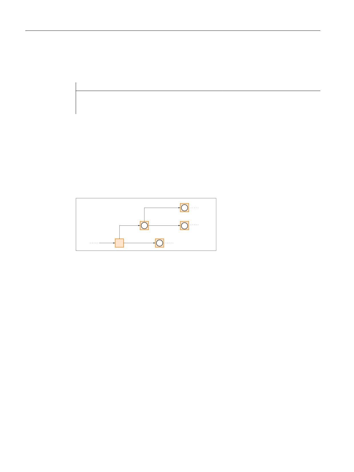
K8: Geometric machine modeling
6.2 Commissioning
Example
The following protection area element with the name "Coolant nozzle 1" is attached to the 19th
protection area element:
Program code
Comment
N100 $NP_NAME[18] = "Coolant nozzle 1"
; 19th protection area element,
; name of the following element:
"Coolant nozzle 1"
6.2.4.4
$NP_NEXTP
Function
The protection area element chain can be branched via the system variable $NP_NEXTP. To
do this, the following protection area elements must be specified in the system variables
$NP_NEXT and $NP_NEXTP in a protection area element. These protection area elements
are then parallel to one another in two separate subchains.
13B1(;73
13B1(;7
13B1(;73
13B1(;7
① Following parallel protection area element
② Following protection area element of the same subchain
Figure 6-2
Protection area elements in parallel subchains
Application example
The separate subchains can be used, for example, to model different machine parts of a
protection area for visualization or collision avoidance. Typically "C" (collision avoidance) is
specified for the protection area element referred to by $NP_NEXT for use in $NP_USAGE
(Page 253), and for the protection area element referred to in $NP_NEXTP, the value “V”
(visualization).
Offset and rotation
An offset and/or rotation in the current protection area element ($NP_OFF (Page 264),
$NP_DIR (Page 265) and $NP_ANG (Page 267)) affects the following protection area element
specified in $NP_NEXTP. This means that the specification of the spatial position and
orientation of the following protection area element is relative to the current protection area
element.
Syntax
$NP_NEXTP[<n>] = "<name>"
Special functions
250
Function Manual, 12/2018, A5E40874099B AB
K8: Geometric machine modeling
6.2 Commissioning
Meaning
$NP_NEXTP:
Name of the branching protection area element
Data type:
STRING
Range of values:
All names contained in $NP_NAME (Page 248)
Default value:
"" (empty string)
<n>:
System variable or protection area element index
Data type:
INT
Range of values:
0, 1, 2, ... ($MN_MM_MAXNUM_3D_PROT_AREA_ELEM -
1)
<name>:
Protection area name
Data type:
STRING
Example
The following parallel protection area element with the name "Coolant nozzle 2" is attached to
the 19th protection area element:
Program code
Comment
N100 $NP_NEXTP[18] = "Coolant nozzle 2"
; 19. Protection area element,
; name of the parallel following
element: "Coolant nozzle 2"
6.2.4.5
$NP_COLOR
Function
Enter the protection area element-specific value for alpha/transparency and color (ARGB) in
the system variable. This value is used for the display of the protection area element on the
user interface. If a specific value is not parameterized for a protection area element, the
protection area-specific value from $NP_PROT_COLOR (Page 240) applies.
Structure
Alpha/transparency and color are specified as a double word in hexadecimal format:
AARRGGBBH
●
1. - 3. Byte: RGB color value. See Chapter "Color chart (Page 233)".
●
4. Byte: Alpha channel or transparency value
Byte
Meaning
Range of values
OC
1
Blue
0 - 255D or 0 - FFH
GG
2
Green
RR
3
Red
AA
4
Alpha channel or transparency 1)
1) 0 = transparent or not visible, 255D = FFH = not transparent or filled
Special functions
Function Manual, 12/2018, A5E40874099B AB
251
K8: Geometric machine modeling
6.2 Commissioning
Syntax
$NP_COLOR[<n>] = <name>
Meaning
$NP_COLOR:
Alpha/transparency and color value of the protection area element
Data type:
DWORD
Range of values:
00000000H - FFFFFFFFH
Default value:
0000000H (black, not visible)
<m>:
System variable or protection area element index
Data type:
INT
Range of values:
0, 1, 2, ... ($MN_MM_MAXNUM_3D_PROT_AREA_ELEM -
1)
<value>:
Transparency and color value
Data type:
DWORD
Example
The 19th protection area is to be displayed half transparent and in a green-blue color on the
user interface:
● AA = 7FH = 127D ≙ 50% transparency
● RR (red) = 00 ≙ no red component
● GG (green) = FFH = 255D ≙ 100% green color component
● BB (blue) = 33H = 51D ≙ 20% blue color component
Program code
Comment
N100 $NP_COLOR[18] = 'H7F00FF33'
; 19. Protection area,
; alpha/transparency and color
value = 'H7F00FF33'
6.2.4.6
$NP_D_LEVEL
Function
The detail level as of which the protection area element is displayed on the user interface is
specified via the system variable. If no value different from the default value is assigned for a
protection area element the protection area-specific value takes effect
$NP_PROT_D_LEVEL (Page 241).
Detail level
● Lowest detail level: 0
● Highest detail level: 3
Special functions
252
Function Manual, 12/2018, A5E40874099B AB
K8: Geometric machine modeling
6.2 Commissioning
If the detail level x is selected for the visualization of the machine model, all protection areas
and protection area elements are displayed for which the following applies for the detail level
D: D ≤ x
Syntax
$NP_D_LEVEL[<n>] = <value>
Meaning
$NP_PROT_D_LEVEL:
Detail level for the protection area element
Data type:
INT
Range of val-
0 ≤ D ≤ 3
ues:
Default value:
0
<m>:
System variable or protection area element index
Data type:
INT
Range of val-
0, 1, 2, ... ($MN_MM_MAXNUM_3D_PROT_AREA_ELEM
ues:
- 1)
<value>:
Detail level
Data type:
INT
Example
The 19th protection area is always to be displayed ⇒ detail level 0:
Program code
Comment
N100 $NP_PROT_D_LEVEL[18] = 0
; 19. Protection area,
; detail level = 0
6.2.4.7
$NP_USAGE
Function
Enter the protection area element usage in the system variable. The usage specifies how the
protection area element is to be considered for the collision avoidance.
● Only visualization, no collision calculation
● Only collision calculation, no visualization
● Visualization and collision calculation
Usage
Meaning
Visualization
The protection area element is displayed in the machine model on the SINUMERIK Operate
user interface
Collision calculation
The protection area element is also taken into account for the collision calculation
Special functions
Function Manual, 12/2018, A5E40874099B AB
253
K8: Geometric machine modeling
6.2 Commissioning
Syntax
$NP_USAGE[<n>] = "<value>"
Meaning
$NP_USAGE:
Use of the protection area element
Data type:
CHAR
Range of values:
"V", "v", "C", "c", "A", "a"
Value
Meaning
"V" or "v"
Only visualization, no collision calculation
"C" or "c"
Only collision calculation, no visualization
"A" or "a"
Visualization and collision calculation
Default value:
"A"
<n>:
System variable or protection area element index
Data type:
INT
Range of values:
0, 1, 2, ... ($MN_MM_MAXNUM_3D_PROT_AREA_ELEM -
1)
<value>:
Usage
Data type:
CHAR
Example
The 19th protection area element is to be displayed at the user interface and included in the
collision calculation:
Program code
Comment
N100 $NP_USAGE[18] = "A"
; 19. Protection area,
; usage = "A"
6.2.4.8
$NP_TYPE
Function
Enter the protection area element type in the system variable.
Type: "FRAME"
A protection area element of the "FRAME" type does not contain any bodies, but defines a
coordinate transformation of the local coordinate system. The coordinate transformation
affects all the following ($NP_NEXT (Page 249)) and/or parallel ($NP_NEXTP (Page 250))
protection area elements. The values of the coordinate transformation are set via:
● Offset: $NP_OFF (Page 264)
● Rotation direction vector: $NP_DIR (Page 265)
● Angle of rotation: $NP_ANG (Page 267)
Special functions
254
Function Manual, 12/2018, A5E40874099B AB
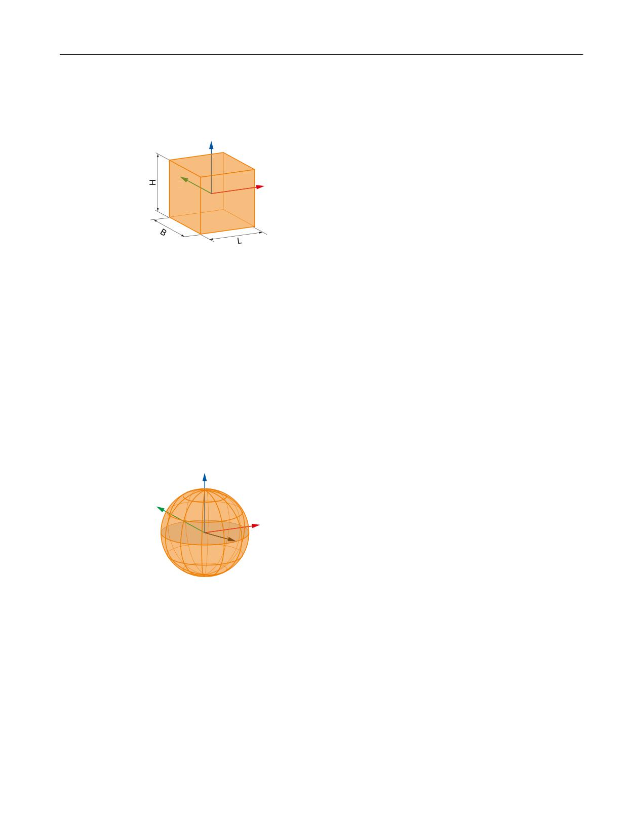
K8: Geometric machine modeling
6.2 Commissioning
No parameters are specified in $NP_PARA (Page 263) for the "FRAME" type.
Type: "BOX"
=
<
;
L
Length in the X direction
B
Width in the Y direction
H
Height in the Z direction
A protection area element of the "BOX" type defines a paraxial box in the local coordinate
system of the protection area element. The mid-point of the box is at the origin of the local
coordinate system. At the same time as the definition of the body, the local coordinate system
can be transformed via the following system variables:
● Offset: $NP_OFF (Page 264)
● Rotation direction vector: $NP_DIR (Page 265)
● Angle of rotation: $NP_ANG (Page 267)
The parameters length, width and height are to be entered in $NP_PARA (Page 263)
Type: "SPHERE"
=
<
;
5
R
Radius of the sphere:
A protection area element of the "SPHERE" type defines a sphere in the local coordinate
system of the protection area element. The mid-point of the sphere is at the origin of the local
coordinate system. At the same time as the definition of the body, the local coordinate system
can be transformed via the following system variables:
● Offset: $NP_OFF (Page 264)
● Rotation direction vector: $NP_DIR (Page 265)
● Angle of rotation: $NP_ANG (Page 267)
Special functions
Function Manual, 12/2018, A5E40874099B AB
255
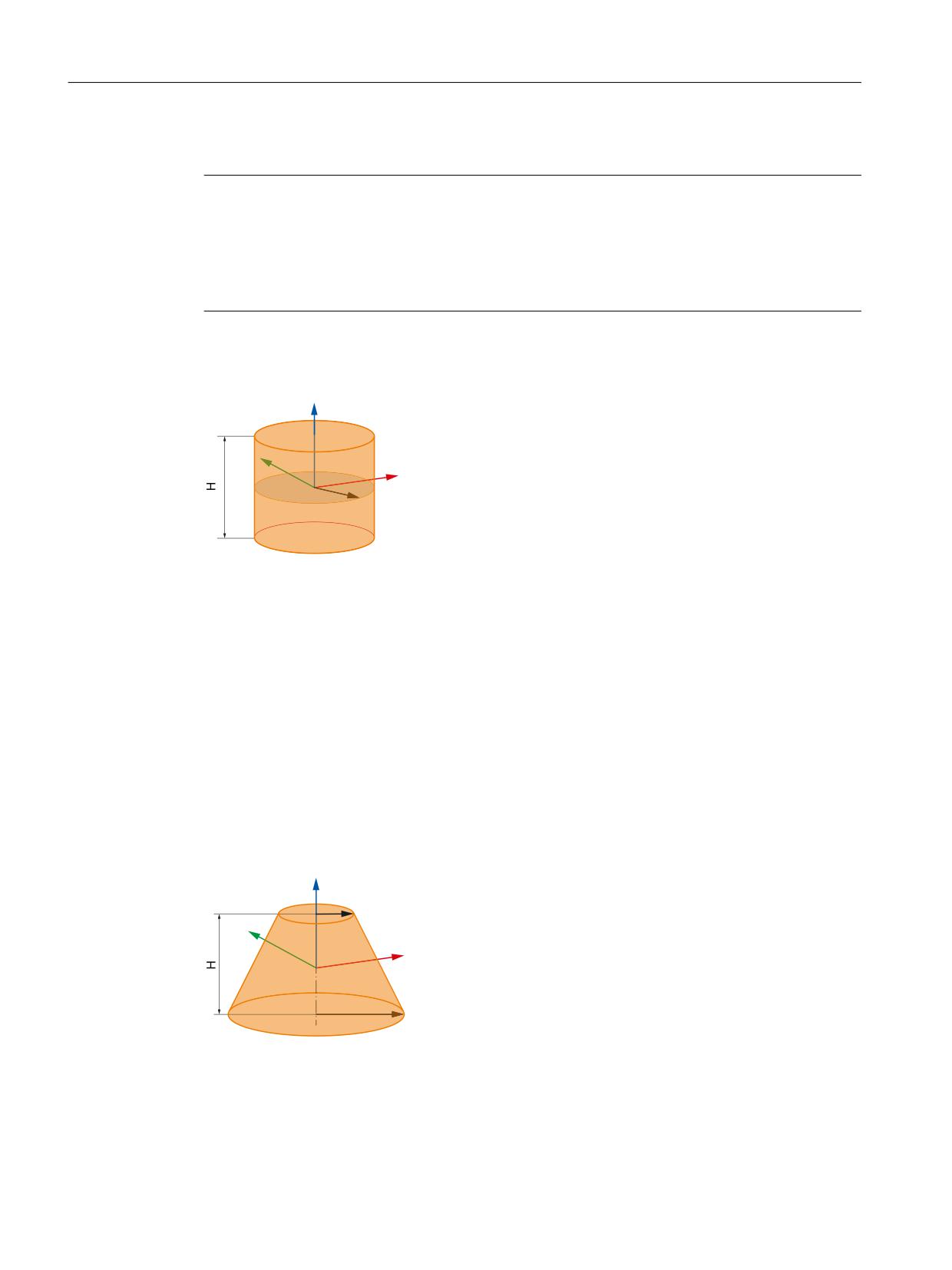
K8: Geometric machine modeling
6.2 Commissioning
The parameter radius is to be entered in $NP_PARA (Page 263)
Note
Rotation
As the center point of the sphere and the starting point of the direction vector are in the
coordinate origin of the local coordinate system of the protection area element, a rotation using
the direction vector $NP_DIR (Page 265) and angle of rotation $NP_ANG (Page 267) has no
effect on the position of the sphere.
Type: "CYLINDER"
=
<
;
5
H
Height in the Z direction
R
Radius in the X/Y plane
A protection area element of the "CYLINDER" type defines a cylinder in the local coordinate
system of the protection area element. The mid-point of the cylinder is at the origin of the local
coordinate system. At the same time as the definition of the body, the local coordinate system
can be transformed via the following system variables:
● Offset: $NP_OFF (Page 264)
● Rotation direction vector: $NP_DIR (Page 265)
● Angle of rotation: $NP_ANG (Page 267)
The parameters height and radius are to be entered in $NP_PARA (Page 263)
Type: "CONE"
=
5
<
;
5
H
Height in the Z direction
R1
Radius 1 in the X/Y plane
R2
Radius 2 in the X/Y plane
Special functions
256
Function Manual, 12/2018, A5E40874099B AB
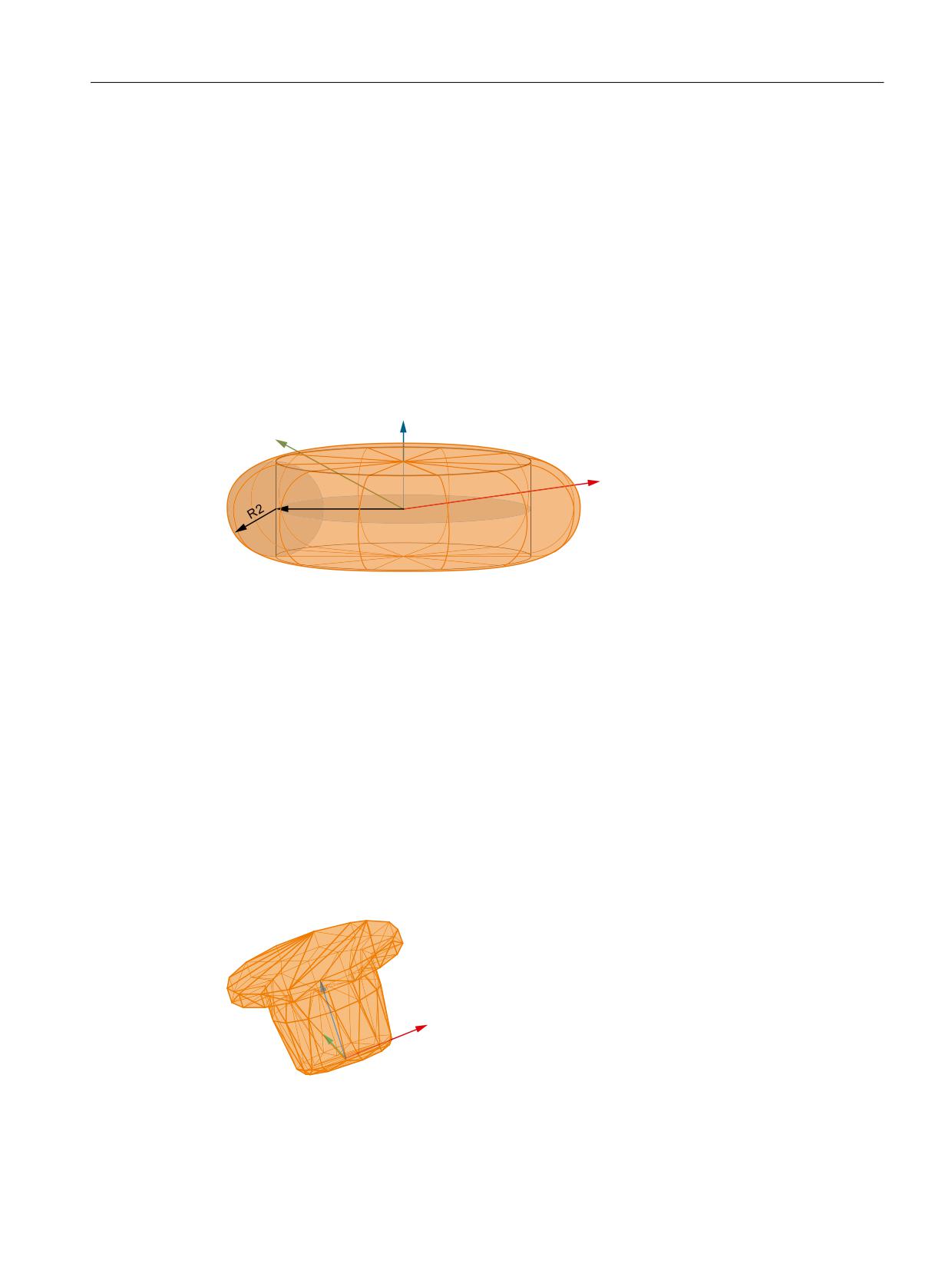
K8: Geometric machine modeling
6.2 Commissioning
A protection area element of the "CONE" type defines a cone in the local coordinate system
of the protection area element. The mid-point of the cone (half cone height on the line of
symmetry of the cone) is at the origin of the local coordinate system. At the same time as the
definition of the body, the local coordinate system can be transformed via the following system
variables:
● Offset: $NP_OFF (Page 264)
● Rotation direction vector: $NP_DIR (Page 265)
● Angle of rotation: $NP_ANG (Page 267)
The parameters height, radius 1, and radius 2 must be entered in $NP_PARA (Page 263)
Type: "TORUS"
=
<
;
5
R1
Major radius (= distance from the center of the circle to the center of the torus in the X/Y plane)
R2
Minor radius (= radius of the circle)
A protection area element of the "TORUS" type defines a filled torus in the local coordinate
system of the protection area element. The shape of a torus can most easily be described by
a circle revolved around an axis that lies in its plane. In contrast to a normal torus, however,
the hole in the middle of a filled torus is filled in. The center of the filled torus lies at the origin
of the local coordinate system. At the same time as the definition of the body, the local
coordinate system can be transformed via the following system variables:
● Offset: $NP_OFF (Page 264)
● Rotation direction vector: $NP_DIR (Page 265)
● Angle of rotation: $NP_ANG (Page 267)
The parameters radius 1 and radius 2 must be entered in $NP_PARA (Page 263)
Type: "FILE"
;
<
Figure 6-3
Example bodies in STL format
A protection area element of the "FILE" type defines a body whose geometry data is contained
in the specified file in STL format (triangular areas), in the local coordinate system of the
Special functions
Function Manual, 12/2018, A5E40874099B AB
257
K8: Geometric machine modeling
6.2 Commissioning
protection area element. The zero point of the body is at the origin of the local coordinate
system. At the same time as the definition of the body, the local coordinate system can be
transformed via the following system variables:
● Offset: $NP_OFF (Page 264)
● Rotation direction vector: $NP_DIR (Page 265)
● Angle of rotation: $NP_ANG (Page 267)
The parameter is to be entered in $NP_FILENAME (Page 258):
Syntax
$NP_TYPE[<n>] = "<type>"
Meaning
$NP_TYPE:
Type of the protection area element
Data type:
STRING
Range of values:
"FRAME", "BOX", "SPHERE", "CYLINDER", "CONE",
"TORUS", "FILE"
Default value:
"" (empty string)
<n>:
System variable or protection area element index
Data type:
INT
Range of values:
0, 1, 2, ... ($MN_MM_MAXNUM_3D_PROT_AREA_ELEM -
1)
<Type>:
Type designation
Data type:
STRING
Example
The 19th protection area element is a cube:
Program code
Comment
N100 $NP_TYPE[18] = "BOX"
; 19. Protection area element,
; type = "Box"
6.2.4.9
$NP_FILENAME
Function
For protection area elements of the "FILE" type ($NP_TYPE (Page 254)), enter the name of
the file that describes the geometry data of the protection area element in the system variable.
The following file types are currently possible:
● STL files
● NPP files
Special functions
258
Function Manual, 12/2018, A5E40874099B AB
K8: Geometric machine modeling
6.2 Commissioning
STL files
An STL file (file extension .STL) must contain a description of the geometry data of a 3D body
using triangles in the STL format (Standard Tessellation Language).
Search path
A search is made in the directories predefined on the CF card for the file entered in the system
variables in the following sequence:
1. /oem/sinumerik/nck/prot_data/machine/3d_data/mm
2. /oem/sinumerik/nck/prot_data/machine/3d_data/inch
Interpretation of the length specifications
Depending on the storage directory, the length specifications contained in the STL file are
interpreted in mm or inches:
● <path>/mm: Interpretation of the length specifications in millimeters
● <path>/inch: Interpretation of the length specifications in inches
Note
Maximum length of the file name
The maximum file name length, including point and the file extension is 49 characters. For
more than 49 characters, an alarm is displayed when generating an archive.
NPP files
An NPP file (file extension .NPP) must contain a description of the geometry data of one or
several protection area elements using NPP system variables (NC Protection Area Primitives).
All geometrical primitives available in the NC can be defined as protection area elements using
an NPP file (see$NP_TYPE (Page 254)).
Search path
A search is made in the directories predefined on the CF card for the file entered in the system
variables in the following sequence:
1. /oem/sinumerik/nck/prot_data/machine/3d_data/mm
2. /oem/sinumerik/nck/prot_data/machine/3d_data/inch
Interpretation of the length specifications
Depending on the storage directory, the length specifications contained in the NPP file are
interpreted in mm or inches:
● <path>/mm: Interpretation of the length specifications in millimeters
● <path>/inch: Interpretation of the length specifications in inches
Special functions
Function Manual, 12/2018, A5E40874099B AB
259

K8: Geometric machine modeling
6.2 Commissioning
NPP file properties
● An NPP file must start with the following comments lines:
;COLLISION AVOIDANCE DATA
;LOC_NP_ROOT_NAME="<root_name>"
● As <root_name>, the name of the first protection area element contained in the NPP file,
specified there under $NP_NAME, must be entered.
● Comment line are lines that start with the ; character
● NPP files are allowed to contain empty lines
Properties of NPP system variables
NPP system variables contained in the NPP file have the following properties:
● Same name, significance and syntax as the corresponding system variables used in NC
programs
● The system variables of the NC are not overwritten by the NPP system variables.
● Within an NPP file, the indices of NPP system variables must be unique.
● The indices of NPP system variables can be the same in various NPP files.
● The indices and the values assigned in the NPP system variables must be constants.
Supplementary conditions
● The values for $NP_COLOR (Page 251), $NP_D_LEVEL (Page 252), $NP_USAGE
(Page 253) are, for the protection area elements defined in the NPP file, inherited from the
protection area element in which they are integrated. As a consequence, all protection area
elements of an NPP file have the same values for these properties.
● For positioning the protection area elements of an NPP file, the same conditions apply as
for positioning the protection area elements with the system variables of the NC
($NP_TYPE (Page 254): "BOX", "SPHERE" and "CYLINDER").
● No additional STL or NPP files are embedded in an NPP file.
Note
Maximum length of the file name
The maximum file name length, including point and the file extension is 49 characters. For
more than 49 characters, an alarm is displayed when generating an archive.
Syntax
$NP_FILENAME[<n>] = "<name>"
Meaning
$NP_FILENAME:
Name of the STL or NPP file
Data type:
STRING
Default value:
"" (empty string)
Special functions
260
Function Manual, 12/2018, A5E40874099B AB

K8: Geometric machine modeling
6.2 Commissioning
<n>:
System variable or protection area element index
Data type:
INT
Value range:
0, 1, 2, ... ($MN_MM_MAXNUM_3D_PROT_AREA_ELEM -
1)
<name>:
Name of the STL or NPP file
Data type:
STRING
Examples
Using an STL file
The geometry data for the 19th protection area element are stored in file
KUEHLDUESE_1.STL:
Program code
Comment
N100 $NP_FILENAME[18] = "KUEHLDU-
; 19th protection area element,
ESE_1.STL"
; file name = "KUEHLDUESE_1.STL"
Using an NPP file
The NPP file "Kopf_A.NPP" file is loaded into the system variables of the NC for the 19th
protection area element. This contains the following three protection area elements "Box-1",
"Sphere-1" and "Cylinder-1".
Program code
Comment
$NP_NAME[18]
= "Head"
; 19th protection area element
$NP_NEXT[18]
= ""
$NP_NEXTP[18] = ""
$NP_TYPE[18]
= "FILE"
$NP_OFF[18,0] =
80.0
$NP_OFF[18,1] = 100.0
$NP_OFF[18,2] = -50.0
$NP_DIR[18,0] =
0.0
$NP_DIR[18,1] =
0.0
$NP_DIR[18,2] =
0.0
$NP_ANG[18]
=
0.0
$NP_COLOR[18]
= 0
; 1)
$NP_D_LEVEL[18] = 0
; 1)
$NP_USAGE[18]
= "A"
; 1)
$NP_FILENAME[18] = "Kopf_A.npp"
; 1) Active for all protection area elements loaded from file Kopf_A.NPP
Content of file "Kopf_A.NPP"
Program code
Comment
;COLLISION AVOIDANCE DATA
; 1st header
;LOC_NP_ROOT_NAME = "Box-1"
; 2nd header
Special functions
Function Manual, 12/2018, A5E40874099B AB
261
K8: Geometric machine modeling
6.2 Commissioning
Program code
Comment
$NP_NAME[0]
=
"Box-1"
; 1st protection area element
$NP_NEXT[0]
=
"Sphere-1"
$NP_NEXTP[0]
=
"Cylinder-1"
$NP_TYPE[0]
=
"BOX"
$NP_PARA[0,0]
=
340
$NP_PARA[0,1]
=
340
$NP_PARA[0,2]
=
340
$NP_OFF[0,0]
=
42
$NP_OFF[0,1]
=
73
$NP_OFF[0,2]
=
-100
$NP_DIR[0,0]
=
0
$NP_DIR[0,1]
=
0
$NP_DIR[0,2]
=
1
$NP_ANG[0]
=
30
$NP_NAME[1]
=
"Sphere-1"
; 2nd protection area element
$NP_NEXT[1]
=
""
$NP_NEXTP[1]
=
""
$NP_TYPE[1]
=
"SPHERE"
$NP_PARA[1,0]
=
20
$NP_PARA[1,1]
=
0
$NP_PARA[1,2]
=
0
$NP_OFF[1,0]
=
170
$NP_OFF[1,1]
=
170
$NP_OFF[1,2]
=
170
$NP_DIR[1,0]
=
0
$NP_DIR[1,1]
=
0
$NP_DIR[1,2]
=
0
$NP_ANG[1]
=
0
$NP_NAME[2]
=
"Cylinder-1"
; 3rd protection area element
$NP_NEXT[2]
=
""
$NP_NEXTP[2]
=
""
$NP_TYPE[2]
=
"CYLINDER"
$NP_PARA[2,0]
=
20
$NP_PARA[2,1]
=
20
$NP_PARA[2,2]
=
0
$NP_OFF[2,0]
=
170
$NP_OFF[2,1]
=
170
$NP_OFF[2,2]
=
170
$NP_DIR[2,0]
=
1
$NP_DIR[2,1]
=
2
$NP_DIR[2,2]
=
3
$NP_ANG[2]
=
73
Special functions
262
Function Manual, 12/2018, A5E40874099B AB
K8: Geometric machine modeling
6.2 Commissioning
6.2.4.10
$NP_PARA
Function
Enter the dimensions of the protection area body according to the type of the protection area
element ($NP_TYPE (Page 254)) in the system variable.
Coordinate system
The local coordinate system in which the position of the protection area body is specified, is
defined by the system variables $NP_OFF (Page 264), $NP_DIR (Page 265), $NP_ANG
(Page 267).
Syntax
$NP_PARA[<n>,<i>] = <value>
Meaning
$NP_PARA:
Parameter values corresponding to the type of the protection area element
Data type:
REAL
Default value:
0.0
<n>:
System variable or protection area element index
Data type:
INT
Value range:
0, 1, 2, ... ($MN_MM_MAXNUM_3D_PROT_AREA_ELEM - 1)
<i>:
Parameter index
Data type:
INT
Value range:
0, 1, 2
Parameter in-
Type of the protection area element
dex
BOX
SPHERE
CYLINDER
CONE
TORUS
0
Length in X
Radius
Height in Z
Height in Z
Radius 1 1)
1
Width in Y
---
Radius 1)
Radius 1 1)
Radius 2
2
Height in Z
---
---
Radius 2 1) 2)
---
<value>:
Parameter value
Data type:
REAL
Value range:
0.0 < x ≤ max. REAL value
1)
Radius in the X/Y plane
2)
Parameter value 0.0 is permissible.
---: Parameters that are not evaluated
Special functions
Function Manual, 12/2018, A5E40874099B AB
263
K8: Geometric machine modeling
6.2 Commissioning
Example
The 19th protection area element is a cube with the dimensions:
● Length: 50.0 in the X axis
● Width: 100.0 in the Y axis
● Height: 75.5 in the Z axis
Program code
Comment
; 19. protection area element
N100 $NP_TYPE[18] = "BOX"
; type = "BOX"
N120 $NP_PARA[18,0] = 50.0
; length in X
=
50.0
N130 $NP_PARA[18,1] = 100.0
; width in Y = 100.0
N140 $NP_PARA[18,2] = 75.5
; height in Z
=
75.5
6.2.4.11
$NP_OFF
Function
The offset vector by which the local coordinate system of the protection area element is moved
compared to the coordinate system of the previous protection area element should be entered
in the system variable.
Syntax
$NP_OFF[<n>,<i>] = <value>
Meaning
$NP_OFF:
Offset vector
Data type:
REAL
Value range:
- max. REAL value ≤ x ≤ + max. REAL value
Default value:
(0.0, 0.0, 0.0)
<m>:
System variable or protection area element index
Data type:
INT
Value range:
0, 1, 2, ... ($MN_MM_MAXNUM_3D_PROT_AREA_ELEM -
1)
<i>:
Coordinate index
Data type:
INT
Value range:
0: X coordinate (abscissa)
1: Y coordinate (ordinate)
2: Z coordinate (applicate)
<value>:
Coordinate value
Data type:
REAL
Value range:
- max. REAL value ≤ x ≤ + max. REAL value
Special functions
264
Function Manual, 12/2018, A5E40874099B AB
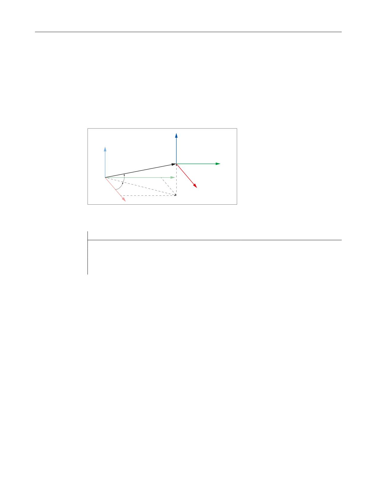
K8: Geometric machine modeling
6.2 Commissioning
Example
The local coordinate system of the 19th The local coordinate system of the protection area
element is moved by the following vector compared to the coordinate system of the previous
protection area element:
● X direction: 25.0
● Y direction: 50.0
● Z direction: 37.25
=
=
13B2))
<
˟
<
]
˞
[
;
\
;
X, Y, Z
Coordinate system of the previous protection area element
X', Y', Z' Coordinate system of the current protection area element
Program code
Comment
; 19. protection area element, offset vector
N100 $NP_OFF[18,0] = 25.0
X = 25.0
N110 $NP_OFF[18,1] = 50.0
Y = 50.0
N120 $NP_OFF[18,2] = 37.25
Z = 37.25
6.2.4.12
$NP_DIR
Function
The direction vector through which the local coordinate system of the protection area element
is rotated compared to the coordinate system of the previous protection area element should
be entered in the system variable. The angle of rotation should be entered in $NP_ANG
(Page 267).
Boundary conditions
● The absolute value of the direction vector must be greater than: 1*10-6
● A work offset parameterized in $NP_OFF (Page 264) is performed before the rotation.
Syntax
$NP_DIR[<n>,<i>] = <value>
Special functions
Function Manual, 12/2018, A5E40874099B AB
265
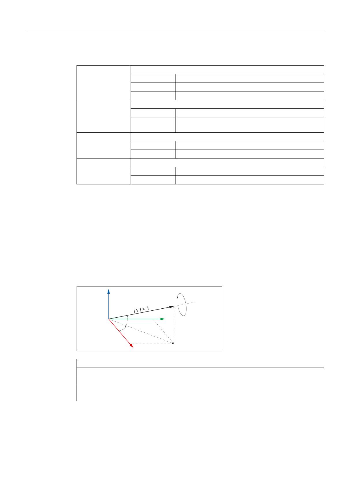
K8: Geometric machine modeling
6.2 Commissioning
Meaning
$NP_DIR:
Direction vector
Data type:
REAL
Range of values:
- max. REAL value ≤ x ≤ ± max. REAL value
Default value:
(0.0, 0.0, 0.0)
<n>:
System variable or protection area element index
Data type:
INT
Range of values:
0, 1, 2, ... ($MN_MM_MAXNUM_3D_PROT_AREA_ELEM -
1)
<i>:
Coordinate index
Data type:
INT
Range of values:
0 → X; 1 → Y: 2 → Z
<value>:
Coordinate value
Data type:
REAL
Range of values:
- max. REAL value ≤ x ≤ ± max. REAL value
Example
The local coordinate system of the 19th protection area element is rotated around the direction
vector compared to the coordinate system of the previous protection area element. The
direction vector is the unit vector (1; 0; 0), rotated through α=90° in the X/Y plane and β=10°
in the Y/Z plane, in relation to the world coordinate system. The following values result from
this for the individual components of the direction vector:
● X component = cos(α) * cos(β) = cos(90) * cos(10) = 0.0
● Y component = sin(α) * cos(β) = sin(90) * cos(10) ≈ 0.985
● Z component = sin(β) = sin(10) ≈ 0.174
=
13B',5
˟
<
]
˞
[
;
\
Program code
Comment
; 19. protection area element, direction vector
N100 $NP_DIR[18.0] = COS(90) * COS(10)
; 0 = X component
N110 $NP_DIR[18.1] = SIN(90) * COS(10)
; 1 = Y component
N120 $NP_DIR[18.2] = SIN(10)
; 2 = Z component
Special functions
266
Function Manual, 12/2018, A5E40874099B AB
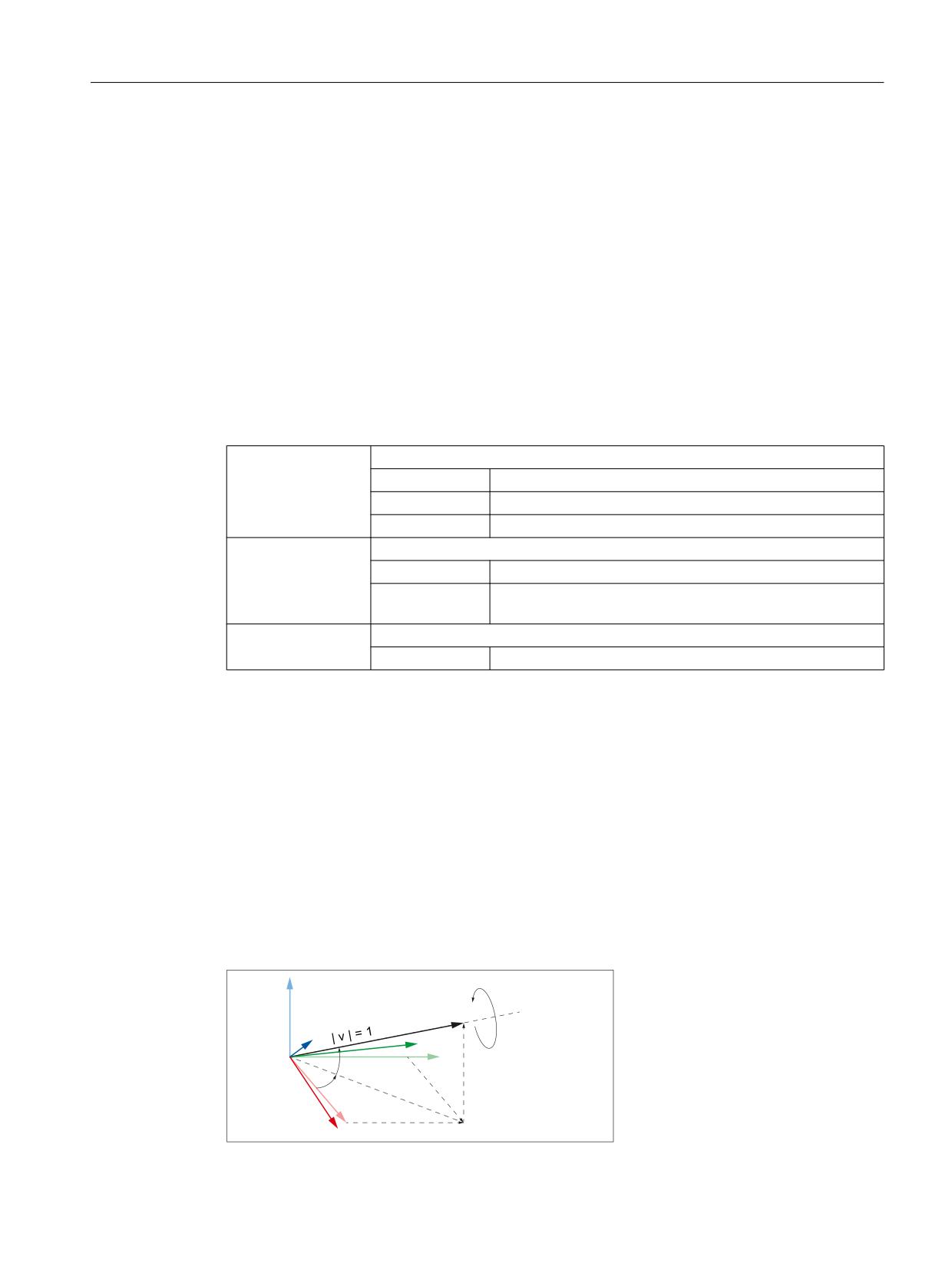
K8: Geometric machine modeling
6.2 Commissioning
6.2.4.13
$NP_ANG
Function
The angle through which the local coordinate system of the protection area element is rotated
around the direction vector ($NP_DIR (Page 265)) compared to the coordinate system of the
previous protection area element should be entered in the system variable.
Syntax
$NP_ANG[<n>] = <value>
Meaning
$NP_ANG:
Angle of rotation
Data type:
REAL
Range of values:
-360° < x ≤ 360°
Default value:
0.0
<n>:
System variable or protection area element index
Data type:
INT
Range of values:
0, 1, 2, ... ($MN_MM_MAXNUM_3D_PROT_AREA_ELEM -
1)
<value>:
Angle
Data type:
REAL
Example
The local coordinate system of the 19th protection area element is rotated by the angle by
δ=45.0° around the direction vector compared to the coordinate system of the previous
protection area element. The direction vector is the unit vector (1; 0; 0), rotated through
α=90° in the X/Y plane and β=10° in the Y/Z plane, in relation to the world coordinate system.
The following values result from this for the individual components of the direction vector:
● X component = cos(α) * cos(β) = cos(90) * cos(10) = 0.0
● Y component = sin(α) * cos(β) = sin(90) * cos(10) ≈ 0.985
● Z component = sin(β) = sin(10) ≈ 0.174
● Angle δ = 45.0°
=
13B$1*
13B',5
R
=
<
˟
<
]
˞
[
;
;
\
Special functions
Function Manual, 12/2018, A5E40874099B AB
267

K8: Geometric machine modeling
6.2 Commissioning
Program code
Comment
; 19. Protection area element, direction vector and angle of rotation
N100 $NP_DIR[18.0] = COS(90)*COS(10)
; 0 = X component
N110 $NP_DIR[18.1] = SIN(90)*COS(10)
; 1 = Y component
N120 $NP_DIR[18.2] = SIN(10)
; 2 = Z component
N130 $NP_ANG[18] = 45.0
; Angle of rotation δ = 45°
6.2.5
System variables: Protection area elements for automatic tool protection areas
The protection area element of an automatic tool protection area is defined using the
subsequent system variables. The control automatically generates the values of the system
variables from the geometric data of the associated tool, and these can only be read.
Name 1)
Meaning
Analog to 2)
$NP_T_NAME[<n>]
Name of the protection area element
$NP_NAME
(Page 248)
$NP_T_TYPE[<n>]
Type of the protection area element
$NP_TYPE
(Page 254)
$NP_T_FILENAME[<n>]
File name of the STL file that contains the geometric
$NP_FILENAME
data of the protection area element
(Page 258)
(only relevant for $NP_T_TYPE == "FILE")
$NP_T_PARA[<n>,<i>]
Geometric parameters of the protection area body
$NP_PARA
(Page 263)
(only relevant for $NP_T_TYPE == "BOX" or
"SPHERE" or "CYLINDER")
$NP_T_OFF[<n>,<i>]
Offset vector of the protection area element local co-
$NP_OFF
ordinate system
(Page 264)
$NP_T_DIR[<n>,<i>]
Direction vector for the rotation of the protection area
$NP_DIR
element local coordinate system
(Page 265)
$NP_T_ANG[<n>]
Angle for the rotation of the protection area element
$NP_ANG
local coordinate system
(Page 267)
1) n = 0, 1, ... ($MN_MM_MAXNUM_3D_T_PROT_ELEM - 1)
2) The system variables of the automatic tool protection areas correspond to those of the machine
protection areas.
Special functions
268
Function Manual, 12/2018, A5E40874099B AB
K8: Geometric machine modeling
6.2 Commissioning
6.2.6
Boundary conditions
Protection area bodies for spindles
For spindles that are not in position-controlled operation, the associated protection area bodies
are only modeled statically. As a result the following boundary conditions must be met when
modeling protection area bodies connected with a spindle as a kinematic element:
● The protection area body must be symmetrical around its axis of rotation.
● The symmetrical axis of the protection area body must lie on the axis of rotation of the
spindle (collinear)
This should be taken into account for all types of protection area bodies:
● The protection area body is a basic geometrical body (sphere, cylinder).
● The protection area body comprises several, geometrical basic bodies.
● The protection area body comprises triangles (STL file).
● The protection area body for an automatic tool protection area is created from the geometric
tool data.
Note
Automatic tool protection areas
Only using tools that are symmetrical around the axis of rotation is recommended for
automatic tool protection areas in connection with spindles.
Following protection areas
The rotational symmetry and collinearity of the protection area body in respect of the axis of
rotation of the spindle must also be complied with for all protection areas that are connected
with elements of the kinematic chain ($NP_NEXT, $NP_NEXTP) following on from the spindle.
Schematic example of such a kinematic chain: ... → (rotary axis/spindle) → (offset) → (linear
axis) → (offset) → ...
Rotary axes
The boundary conditions stated above must also be observed in connection with rotary axes
where these are also operated as spindles.
Tool reference point and kinematic transformation
The position of the associated tool reference point is determined in principle through the
assignment of an automatic tool protection area to an element in the kinematic chain. However,
the position of the tool reference point can be changed through offsets within the automatic
tool protection area via the system variables $NP_T_OFF, $NP_T_DIR and $NP_T_ANG
(Page 268). A change in position for the tool reference point of this type is not captured by the
kinematic transformations. In the context of kinematic transformation it is therefore highly
recommended that no offsets are used for the geometric machine modeling which move the
tool reference point.
Special functions
Function Manual, 12/2018, A5E40874099B AB
269

K8: Geometric machine modeling
6.3 Data lists
6.3
Data lists
6.3.1
Machine data
6.3.1.1
NC-specific machine data
Number
Identifier: $MN_
Description
MD18890 $MN_MM_MAXNUM_3D_PROT_AREAS
Maximum number of protection areas
MD18892 $MN_MM_MAXNUM_3D_PROT_AREA_ELEM
Maximum number of protection area elements
MD18893 $MN_MM_MAXNUM_3D_T_PROT_ELEM
Maximum number of tool protection area elements
MD18897 $MN_MM_MAXNUM_3D_INTERFACE_IN
Maximum number of NC/PLC interface signals for the
preactivation of protection areas
MD18895 $MN_MM_MAXNUM_3D_FACETS
Maximum number of triangles for protection areas
MD18894 $MN_MM_MAXNUM_3D_FACETS_INTERN
Maximum number of triangles for automatic tool pro-
tection areas
MD18899 $MN_PROT_AREA_TOOL_MASK
Creation mode for automatic tool protection areas
6.3.2
System variables
Identifier
Description
$NP_PROT_NAME
Name of the protection area
$NP_CHAIN_ELEM
Name of the kinematic element to which the protection area will be connected
$NP_PROT_TYPE
Type of the protection area
$NP_1ST_PROT
Name of the first protection area element of the protection area
$NP_PROT_COLOR
Transparency and color value of the protection area
$NP_PROT_D_LEVEL
Detail level for the protection area
$NP_BIT_NO
Bit number of the interface signal to activate/deactivate the protection area
$NP_INIT_STAT
Initialization status of the protection area
$NP_INDEX
Array for addressing the effective geometry data
$NP_NAME
Name of the protection area element
$NP_NEXT
Name of the following protection area element
$NP_NEXTP
Name of the branching protection area element
$NP_COLOR
Transparency and color value of the protection area element
$NP_D_LEVEL
Detail level for the protection area element
$NP_USAGE
Usage of the protection area element
$NP_TYPE
Type of the protection area element
$NP_FILENAME
Name of the STL file with the geometry data of the protection area element
body
$NP_PARA
Parameter values corresponding to the type of the protection area element
Special functions
270
Function Manual, 12/2018, A5E40874099B AB

K8: Geometric machine modeling
6.3 Data lists
Identifier
Description
$NP_OFF
Offset vector
$NP_DIR
Direction vector
$NP_ANG
Angle of rotation
Special functions
Function Manual, 12/2018, A5E40874099B AB
271
K8: Geometric machine modeling
6.3 Data lists
Special functions
272
Function Manual, 12/2018, A5E40874099B AB