SINUMERIK 840D sl. Service - Functions. Manual (2018-2020) - page 63
F2: Multi-axis transformations
2.13 Examples
Machine data
; machine kinematics CA' with tool orientation in zero position in the z direction
$MC_TRAFO_TYPE_1 = 148
$MC_TRAFO_GEOAX_ASSIGN_TAB_1[0]=1
$MC_TRAFO_GEOAX_ASSIGN_TAB_1[1]=2
$MC_TRAFO_GEOAX_ASSIGN_TAB_1[2]=3
; angle of second rotary axis
$MC_TRAFO5_NUTATOR_AX_ANGLE_1 = 45
Program
Program code
Comment
; Definition of tool T1
$TC_DP1[1,1] = 120
; Type
$TC_DP2[1,1] = 0
;
$TC_DP3[1,1] = 20
; Z length offset vector G17
$TC_DP4[1,1] = 8.
; Y
$TC_DP5[1,1] = 5.
; X
TRAORI(1)
; Activation of transformation
ORIMKS
; Orientation reference to MCS
G0 X1 Y0 Z0 A0 B0 F20000 G90 G64 T1 D1 G17
; Programming of direction vector
G1 G90
a3 = 0 b3 = 1 c3 = 0
; Programming in Euler angles
G1 G90
a2 = 0 b2 = 0 X0
; Programming of rotary axis motion
G1 X10 Y5 Z20 A90 C90
m30
References:
Programming Manual, Fundamentals
Special functions
Function Manual, 12/2018, A5E40874099B AB
135
F2: Multi-axis transformations
2.13 Examples
2.13.4
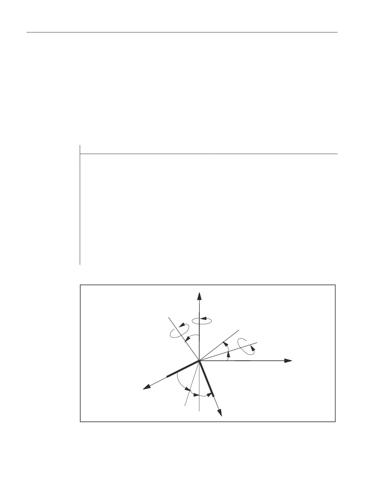
Example for orientation axes
Example 1:
3 orientation axes for the 1st orientation transformation for kinematics with 6 transformed axes.
Rotation must be done in the following sequence:
● firstly about the Z axis.
● then about the Y axis and
● finally about the Z axis again.
The tool vector must point in the X direction.
Program code
Comment
CHANDATA(1)
$MC_TRAFO5_TOOL_VECTOR_1=0
; Tool vector in X direction
$MC_TRAFO5_ORIAX_ASSIGN_TAB_1[0]=4
; Channel index of first orientation axis
$MC_TRAFO5_ORIAX_ASSIGN_TAB_1[1]=5
; Channel index of second orientation ax-
is
$MC_TRAFO5_ORIAX_ASSIGN_TAB_1[2]=6
; Channel index of third orientation axis
$MC_ORIAX_TURN_TAB_1[0]=3
; Z direction
$MC_ORIAX_TURN_TAB_1[1]=2
; Y direction
$MC_ORIAX_TURN_TAB_1[2]=3
; Z direction
CHANDATA(1)
M17
=
=
=
=
$
<
&
%
&
<
<
%
$
<
;VWDUW
$
;WDUJHW
;
%
&
;
;
;
Figure 2-26
3 orientation axes for the 1st orientation transformation for kinematics with 6 transformed
axes
Example 2:
Special functions
136
Function Manual, 12/2018, A5E40874099B AB
F2: Multi-axis transformations
2.13 Examples
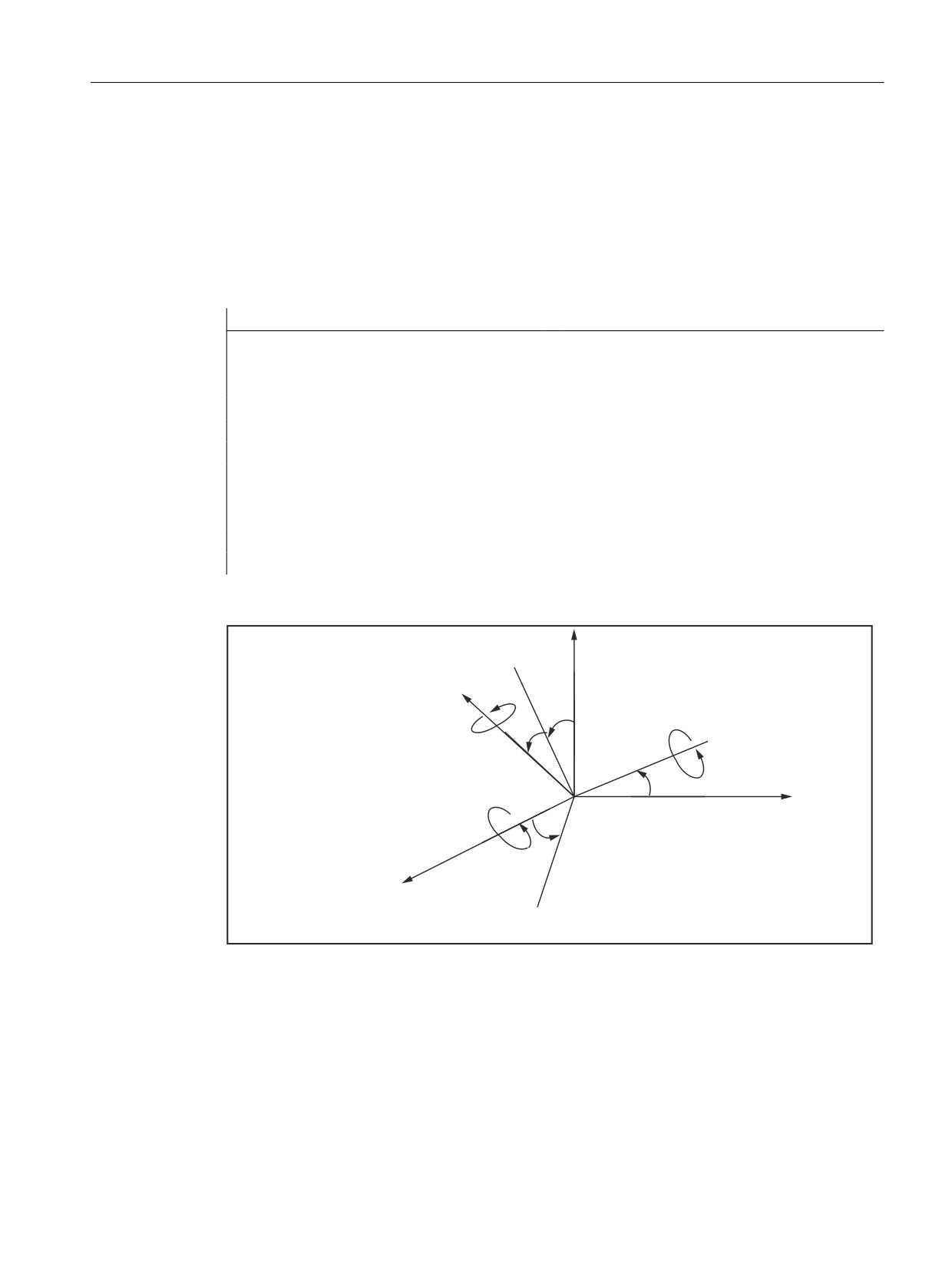
3 orientation axes for the 2nd orientation transformation for kinematics with 5 transformed
axes. Rotation must be done in the following sequence:
● firstly about the X axis.
● then about the Y axis and
● finally about the Z axis.
The tool vector must point in the Z direction.
Program code
Comment
CHANDATA(1)
$MC_TRAFO5_TOOL_VECTOR_2=2
; Tool vector in Z direction
$MC_TRAFO5_ORIAX_ASSIGN_TAB_1[0]=4
; Channel index of first orientation axis
$MC_TRAFO5_ORIAX_ASSIGN_TAB_1[1]=5
; Channel index of second orientation axis
$MC_TRAFO5_ORIAX_ASSIGN_TAB_1[2]=0
; Channel index of third orientation axis
$MC_ORIAX_TURN_TAB_1[0]=1
; X direction
$MC_ORIAX_TURN_TAB_1[1]=2
; Y direction
$MC_ORIAX_TURN_TAB_1[2]=3
; Z direction
CHANDATA(1)
M17
=
=
&
=
$
%
<
<
%
$
<
%
$
;
;
;
Figure 2-27
3 orientation axes for the 2nd orientation transformation for kinematics with 5 transformed
axes
The rotation through angle C2 about the Z" axis is omitted in this case, because the tool vector
orientation can be determined solely from angles A2 and B2 and no further degree of freedom
is available on the machine.
References:
Programming Manual, Production Planning
Special functions
Function Manual, 12/2018, A5E40874099B AB
137
F2: Multi-axis transformations
2.13 Examples
2.13.5
Examples for orientation vectors
2.13.5.1
Example for polynomial interpretation of orientation vectors
Orientation vector in Z-X plane
The orientation vector is programmed directly in the examples below. The resulting movements
of the rotary axes depend on the particular kinematics of the machine.
Program code
Comment
N10 TRAORI
N20 POLY
; Polynomial interpolation is possible.
N30 A3=0 B3=0 C3=1
; Orientation in +Z direction (start vector)
N40 A3=1 B3=0 C3=0
; Orientation in +X direction (end vector)
In N40, the orientation vector is rotated in the Z-X plane which is spanned by the start and end
vector. Here, the PHI angle is interpolated in a line in this plane between the values 0 and 90
degrees (large circle interpolation).
The additional specification of the polynomials for the two angles PHI and PSI means that the
interpolated orientation vector can lies anywhere between the start and end vector.
PHI angle using polynomial PHI
In contrast to the example above, the PHI angle is interpolated using the polynomial PHI(u) =
(90-10)u + 10*u2 between the values 0 and 90 degrees.
The angle PSI is not equal to zero and is interpolated according to the following polynomial:
PSI(u) = -10*u + 10*u2
The maximum "tilt" of the orientation vector from the plane between the start and end vector
is obtained in the middle of the block (u = 1/2).
Program code
Comment
N10 TRAORI
N20 POLY
; Polynomial interpolation is possible.
N30 A3=0 B3=0 C3=1
; Orientation in +Z direction (start vector)
N40 A3=1 B3=0 C3=0
PO[PHI]=(10) ; in +X direction (end vector)
PO[PSI]=(10)
Special functions
138
Function Manual, 12/2018, A5E40874099B AB
F2: Multi-axis transformations
2.13 Examples
2.13.5.2
Example of rotations of orientation vector
Rotations with angle of rotation THETA
In the following example, the angle of rotation is interpolated in linear fashion from starting
value 0 degrees to end value 90 degrees. The angle of rotation changes according to a
parabola or a rotation can be executed without a change in orientation. tool orientation is
rotated from the Y direction to the X direction.
Program code
Comment
N10 TRAORI
; Activation of orientation transformation
N20 G1 X0 Y0 Z0 F5000
;
; Tool orientation
N30 A3=0 B3=0 C3=1 THETA=0
; In Z direction with angle of rotation 0
N40 A3=1 B3=0 C3=0 THETA=90
; In X direction and rotation
; By 90 degrees
N50 A3=0 B3=1 C3=0 PO[THT]=(180,90)
; In Y direction and rotation
; To 180 degrees
N60 A3=0 B3=1 C3=0 THETA=IC(-90)
; Remains constant and rotation
; To 90 degrees
N70 ORIROTT
; Angle of rotation relative to
; change in orientation.
N80 A3=1 B3=0 C3=0 THETA=30
; Rotation vector in angle
; 30 degrees to X-Y plane.
N40 Linear interpolation of angle of rotation from starting value 0 degrees to end value 90
degrees.
N50 The angle of rotation changes from 90 degrees to 180 degrees in accordance with the
parabola.
θ(u) = 90 + u2
N60 A rotation can also be programmed without a change in orientation taking place.
N80 Tool orientation is rotated from the Y direction to the X direction. The change in orientation
takes place in the X-Y plane and the rotation vector describes an angle of 30 degrees to this
plane.
2.13.6
Examples for generic axis transformations
The following example is based on a machine with rotatable tool on which the first rotary axis
is a C axis and the second a B axis (CB kinematics). The basic orientation defined in the
machine data is the bisecting line between the X and Z axes.
Relevant machine data is as follows:
CHANDATA(1)
$MC_TRAFO_TYPE_1 = 24
; General 5-axis transformation
Special functions
Function Manual, 12/2018, A5E40874099B AB
139
F2: Multi-axis transformations
2.13 Examples
; Rotatable tool
$MC_TRAFO5_AXIS1_1[0] = 0.0
$MC_TRAFO5_AXIS1_1[1] = 0.0
$MC_TRAFO5_AXIS1_1[2] = 1,0
; 1. Rotary axis is parallel to Z.
$MC_TRAFO5_AXIS2_1[0] = 0.0
$MC_TRAFO5_AXIS2_1[1] = 1,0
$MC_TRAFO5_AXIS2_1[2] = 0.0
; 2. Rotary axis is parallel to Y.
$MC_TRAFO5_BASE_ORIENT_1[0] = 1.0
$MC_TRAFO5_BASE_ORIENT_1[1] = 0,0
$MC_TRAFO5_BASE_ORIENT_1[2] = 1.0
M30
Example program:
Program code
Comment
N10
$TC_DP1[1,1] = 120
; End mill
N20
$TC_DP3[1,1]= 0
; Length offset vector
N30
N40
; Definition of tool carrier
N50
$TC_CARR7[1] = 1
; Component of the 1st rotary axis
; In the X direction
N60
$TC_CARR11[1] = 1
; Component of the 2nd rotary axis
; In the Y direction
N70
$TC_CARR13[1] = -45
; Angle of rotation of 1st axis
N80
$TC_CARR14[1] = 0
; Angle of rotation of 2nd axis
N90
N100
X0 Y0 Z0 B0 C0 F10000 ORIWKS G17
N110
TRAORI()
; Selection of basic transformation orientation
; from the machine data
N120
C3=1
; Orientation parallel to Z
; Set → B-45 C0
N130
T1 D1
; Basic orientation is now parallel to Z
N140
C3=1
; Orientation parallel to Z
; Set → B0 C0
N150
G19
; Basic orientation is now parallel to X
N160
C3=1
; Orientation parallel to Z
; Set → B-90 C0
N170
G17 TCARR=1 TCOABS
; Basic orientation is now angle-
; halving Y-Z
N180
A3=1
; Orientation parallel to X
; Set → B-90 C-135
N190
B3=1 C3=1
; Orientation parallel to
; basic orientation → B0 C0
N200
TRAORI(,2.0, 3.0, 6.0)
; Pass basic orientation in call
N210
A3=2 B3=3 C3=6
; Orientation parallel to
Special functions
140
Function Manual, 12/2018, A5E40874099B AB

F2: Multi-axis transformations
2.13 Examples
Program code
Comment
; basic orientation → B0 C0
N220
TOFRAME
; Z axis points in the direction
; of the orientation
N230
G91 Z7
; 7 mm in new Z direction
; Traverse → X2 Y3 Z6
N240
C3=1
; Orientation parallel to
; New Z axis → B0 C0
N250
M30
2.13.6.1
Example of a generic 6-axis transformation
Call with parameterization using parameters
Activation of a 6-axis transformation with subsequent orientation changes and traversing:
Program code
Comment
N10 A0 B0 X0 Y0 Z0
N20 TRAORI(1, ,,, 0,0,0, 0,1,0)
; Selection using parameters:
; parameters 5, 6, 7: Orientation vector
; Parameters 8, 9, 10: Orientation normal vec-
tor
N30 T1 D1 X10 Y20 Z30 A3=0.5
; Orientation change, rotation
C3=1 BN3=1 ORIPLANE ORIWKS
; and traversing motion
N40 B3=0.5 C3=1 AN3=-1
; Rotation, constant orientation
M30
Call with parameterization using tool data
Defining a tool, where the orientation, with an orientation vector of (1.0 ; 0.0 ; 0.5) deviates
from the standard. For G17, the orientation vector is in the X-Z plane, and starting from the X
axis in the direction of the Z vector, inclined by 26.565 degrees:
tan-1($TC_DPV5[ 2, 2 ] / $TC_DPV3[ 2, 2 ]) = tan-1(0.5 / 1.01) = tan-1(0.5) = 26.565°
The orientation normal vector is also specified. As only $TC_DPVN4[2,2] is not equal to zero,
it points in the Y direction. Orientation vector and orientation normal vector are perpendicular
to one another. Orthogonalization is not necessary. The programmed orientation normal vector
is not modified.
Program code
Comment
N100 $TC_DP1[2,2]=120
; End mill
N110 $TC_DP3[2,2]= 20
; Length offset vector
N120 $TC_DPV[2,2]= 0
; Tool cutting edge orientation
; Orientation vector tool cutting edge
N130 $TC_DPV3[2,2]= 1
; X component
N140 $TC_DPV4[2,2]= 0
; Y component
N150 $TC_DPV5[2,2]= 0.5
; Z component
; Orientation normal vector
Special functions
Function Manual, 12/2018, A5E40874099B AB
141

F2: Multi-axis transformations
2.13 Examples
Program code
Comment
N160 $TC_DPVN3[2,2]= 0
; X component
N170 $TC_DPVN4[2,2]= 1
; Y component
N180 $TC_DPVN5[2,2]= 0
; Z component
N200 TRAORI( )
; Call with basic orientation
N210 A3=5 C3=10 BN3=1
; Bring rotary axes into the initial state
N220 C3=1
; Orientation in the Z direction ⇒
; Tool rotated through 26.565 degrees
N230 THETA=IC(90)
; Orientation normal vector incremental
; Rotated through 90 degrees. Vector points in nega-
tive X direction
N240 M30
2.13.6.2
Example of a generic 7-axis transformation
Example of a generic 7-axis transformation
Activation of a 7-axis transformation with subsequent orientation changes and traversing:
Program
Comment
N10 TRAFOOF
N20 a0 b0 c0 x0 y0 z0 e=0
N30 $MC_TRAFO5_AXIS1_1[2] = 1
;
1. Rotary axis shows in Z direction
N40 $MC_TRAFO5_AXIS1_2[0] = 1
;
2. Rotary axis shows in X direction
N50 $MC_TRAFO5_AXIS1_3[2] = 1
;
3. Rotary axis shows in Z direction
N60 $MC_TRAFO7_EXT_AXIS1_1[0] = 1
;
7. Axis shows in X direction
N70 $MC_TRAFO_BASE_ORIENT_1[2] = 1
;
Orientation vector
N80 $MC_TRAFO_BASE_ORIENT_NORMAL_1[1] = 1
;
Orientation normal vector
N90 NEWCONF
N100 traori()
N110 G1 t1 d1 x10 y0 z50 c3=1 an3=1 bn3=1
orivect oriwks G19 F10000
N120 G2 y50 z0 b3=1 e=DC(90) CR=50
;
1. Quadrant
N130 G2 y0 z-50 c3=-1 e=DC(180) CR=50
;
2. Quadrant
N140 G2 y-50 z0 b3=-1 e=DC(270) CR=50
;
3. Quadrant
N150 G2 y0 z50 c3=1 e=DC(0) CR=50
;
4. Quadrant
N200 M30
Note
While traversing the quadrant in the example, only the 7th axis turns by 360 degrees. The
machine remains in the fixed position.
Special functions
142
Function Manual, 12/2018, A5E40874099B AB

F2: Multi-axis transformations
2.14 Data lists
2.13.6.3
Example for the modification of rotary axis motion
The machine is a 5-axis machine of machine type 1 (two-axis swivel head with CA kinematics)
on which both rotary axes rotate the tool (transformation type 24). The first rotary axis is a
modulo axis parallel to Z (C axis); the second rotary axis is parallel to Y (B axis) and has a
traversing range from -5 degrees to +185 degrees.
To allow modification at any time, the following machine data has the value 2:
MD21180 $MC_ROT_AX_SWL_CHECK_MODE (check software limits for orientation axes)
N10 X0 Y0 Z0 B0 C0
N20 TRAORI( )
; basic orientation 5-axis transformation
N30 B-1 C10
; Rotary axis positions B-1 and C10
N40 A3=-1 C3=1 ORIWKS
; large circle interpolation in WCS
N50 M30
At the start of block N40 in the example program, the machine is positioned at rotary axis
positions B-1 C10. The programmed end orientation can be achieved with either of the axis
positions B-45 C0 (1st solution) or B45 C180 (2nd solution).
The first solution is selected initially, because it is nearest to the starting orientation and, unlike
the second solution, can be achieved using large circle interpolation (ORIWKS). However, this
position cannot be reached because of the axis limits of the B axis.
The second solution is therefore used instead, i.e. the end position is B45 C180. The end
orientation is achieved by axis interpolation. The programmed orientation path cannot be
followed.
2.14
Data lists
2.14.1
Machine data
2.14.1.1
General machine data
Number
Identifier: $MN_
Description
10620
EULER_ANGLE_NAME_TAB
Name of Euler angles or names of orientation axes
10630
NORMAL_VECTOR_NAME_TAB
Name of normal vectors
10640
DIR_VECTOR_NAME_TAB
Name of direction vectors
10642
ROT_VECTOR_NAME_TAB
Name of rotation vectors
10644
INTER_VECTOR_NAME_TAB
Name of intermediate vector components
10646
ORIENTATION_NAME_TAB
Identifier for programming a 2nd orientation path
10648
NUTATION_ANGLE_NAME
Name of orientation angle
10670
STAT_NAME
Name of position information
Special functions
Function Manual, 12/2018, A5E40874099B AB
143

F2: Multi-axis transformations
2.14 Data lists
Number
Identifier: $MN_
Description
10672
TU_NAME
Name of position information of the axes
10674
PO_WITHOUT_POLY
Permits programming of PO[ ] without POLY having to
be active
2.14.1.2
Channelspecific machine data
Number
Identifier: $MC_
Description
20150
GCODE_RESET_VALUES[n]
Reset G groups
20152
GCODE_RESET_MODE[n]
Setting after RESET/end of part program
20482
COMPRESS_MODE
Mode of the compressor
20621
HANDWH_ORIAX_MAX_INCR_SIZE
Limitation of handwheel increment
20623
HANDWH_ORIAX_MAX_INCR_VSIZE
Orientation velocity overlay
21094
ORIPATH_MODE
Setting for path relative orientation
21100
ORIENTATION_IS_EULER
Angle definition for orientation programming
21102
ORI_DEF_WITH_G_CODE
Definition of orientation angles A2, B2, C2
21104
ORI_IPO_WITH_G_CODE
Definition of interpolation type for orientation
21106
CART_JOG_SYSTEM
Coordinate system for Cartesian JOG
21108
POLE_ORI_MODE
Behavior during large circle interpolation at pole position
21120
ORIAX_TURN_TAB_1[n]
Assignment of rotation of orientation axes about the ref-
erence axes, definition 1 [n = 0..2]
21130
ORIAX_TURN_TAB_2[n]
Assignment of rotation of orientation axes about the ref-
erence axes, definition 2 [n = 0..2]
21132
ORI_DISP_IS_MODULO[n]
Modulo display of the orientation axes positions [n = 0..2]
21134
ORI_DISP_MODULO_RANGE
Size of the module range for the display of the orienta-
tion axes
21136
ORI_DISP_MODULO_RANGE_START
Starting position of the module range for the display of
the orientation axes
21150
JOG_VELO_RAPID_ORI[n]
Rapid traverse in jog mode for orientation axes in the
channel [n = 0..2]
21155
JOG_VELO_ORI[n]
Orientation axis velocity in jog mode [n = 0..2]
21160
JOG_VELO_RAPID_GEO[n]
Rapid traverse in jog mode for geometry axes in the
channel [n = 0..2]
21165
JOG_VELO_GEO[n]
Geometry axis velocity in jog mode [n = 0..2]
21170
ACCEL_ORI[n]
Acceleration for orientation axes [n = 0..2]
21180
ROT_AX_SWL_CHECK_MODE
Check software limits for orientation axes
21186
TOCARR_ROT_OFFSET_FROM_FR
Offset of TOCARR rotary axes
21190
TOFF_MODE
Operation of online offset in tool direction
21194
TOFF_VELO
Speed of online offset in tool direction
21196
TOFF_ACCEL
Acceleration of online offset in tool direction
24100
TRAFO_TYPE_1
Definition of transformation 1 in channel
24110
TRAFO_AXES_IN_1[n]
Axis assignment for transformation 1 [axis index]
Special functions
144
Function Manual, 12/2018, A5E40874099B AB

F2: Multi-axis transformations
2.14 Data lists
Number
Identifier: $MC_
Description
24120
TRAFO_GEOAX_ASSIGN_TAB_1[n]
Assignment geometry axis to channel axis for transfor-
mation 1 [geometry no.]
24200
TRAFO_TYPE_2
Definition of transformation 2 in channel
24210
TRAFO_AXES_IN_2[n]
Axis assignment for transformation 2 [axis index]
24220
TRAFO_GEOAX_ASSIGN_TAB_2[n]
Assignment geometry axis to channel axis for transfor-
mation 2 [geometry no.]
24300
TRAFO_TYPE_3
Definition of transformation 3 in channel
24310
TRAFO_AXES_IN_3[n]
Axis assignment for transformation 3 [axis index]
24320
TRAFO_GEOAX_ASSIGN_TAB_3[n]
Assignment geometry axis to channel axis for transfor-
mation 3 [geometry no.]
24400
TRAFO_TYPE_4
Definition of transformation 4 in channel
24410
TRAFO_AXES_IN_4[n]
Axis assignment for transformation 4 [axis index]
24420
TRAFO_GEOAX_ASSIGN_TAB_4[n]
Assignment geometry axis to channel axis for transfor-
mation 4 [geometry no.]
24430
TRAFO_TYPE_5
Definition of transformation 5 in channel
24432
TRAFO_AXES_IN_5[n]
Axis assignment for transformation 5 [axis index]
24434
TRAFO_GEOAX_ASSIGN_TAB_5[n]
Assignment geometry axis to channel axis for transfor-
mation 5 [geometry no.]
24440
TRAFO_TYPE_6
Definition of transformation 6 in channel
24442
TRAFO_AXES_IN_6[n]
Axis assignment for transformation 6 [axis index]
24444
TRAFO_GEOAX_ASSIGN_TAB_6[n]
Assignment geometry axis to channel axis for transfor-
mation 6 [geometry no.]
24450
TRAFO_TYPE_7
Definition of transformation 7 in channel
24452
TRAFO_AXES_IN_7[n]
Axis assignment for transformation 7 [axis index]
24454
TRAFO_GEOAX_ASSIGN_TAB_7[n]
Assignment geometry axis to channel axis for transfor-
mation 7 [geometry no.]
24460
TRAFO_TYPE_8
Definition of transformation 8 in channel
24462
TRAFO_AXES_IN_8[n]
Axis assignment for transformation 8 [axis index]
24464
TRAFO_GEOAX_ASSIGN_TAB_8[n]
Assignment geometry axis to channel axis for transfor-
mation 8 [geometry no.]
24470
TRAFO_TYPE_9
Definition of transformation 9 in channel
24472
TRAFO_AXES_IN_9[n]
Axis assignment for transformation 9 [axis index]
24474
TRAFO_GEOAX_ASSIGN_TAB_9[n]
Assignment geometry axis to channel axis for transfor-
mation 9 [geometry no.]
24480
TRAFO_TYPE_10
Definition of transformation 10 in channel
24482
TRAFO_AXES_IN_10[n]
Axis assignment for transformation 10 [axis index]
24484
TRAFO_GEOAX_ASSIGN_TAB_10[n]
Assignment geometry axis to channel axis for transfor-
mation 10 [geometry no.]
24500
TRAFO5_PART_OFFSET_1[n]
Offset vector for 5-axis transformation 1 [n = 0.. 2]
24510
TRAFO5_ROT_AX_OFFSET_1[n]
Position offset of rotary axis 1/2 for 5-axis transformation
1 [axis no.]
24520
TRAFO5_ROT_SIGN_IS_PLUS_1[n]
Sign of rotary axis 1/2 for 5-axis transformation 1 [axis
no.]
24530
TRAFO5_NON_POLE_LIMIT_1
Definition of pole range for 5-axis transformation 1
Special functions
Function Manual, 12/2018, A5E40874099B AB
145

F2: Multi-axis transformations
2.14 Data lists
Number
Identifier: $MC_
Description
24540
TRAFO5_POLE_LIMIT_1
End angle tolerance with interpolation through pole for
5-axis transformation 1
24550
TRAFO5_BASE_TOOL_1[n]
Vector of base tool for activation of 5-axis transformation
1 [n = 0.. 2]
24558
TRAFO5_JOINT_OFFSET_PART_1[n]
Vector of kinematic offset in table for 5-axis transforma-
tion 1 [n = 0.. 2]
24560
TRAFO5_JOINT_OFFSET_1[n]
Vector of kinematic offset for 5-axis transformation 1 [n
= 0.. 2]
24561
TRAFO6_JOINT_OFFSET_2_3_1[n]
Vector of kinematic offset for 6-axis transformation
2_3_1
24562
TRAFO5_TOOL_ROT_AX_OFFSET_1[n]
Offset of focus of 1st 5-axis transformation with swiveled
linear axis.
24564
TRAFO5_NUTATOR_AX_ANGLE_1
Angle of 2nd rotary axis for the universal milling head
24570
TRAFO5_AXIS1_1[n]
Vector for the first rotary axis and the first orientation
transformation. [n = 0.. 2]
24572
TRAFO5_AXIS2_1[n]
Vector for the second rotary axis and the first transfor-
mation [n = 0.. 2]
24673
TRAFO5_AXIS3_1[n]
Direction of third rotary axis for general 6-axis transfor-
mation
(Transformer type 24, 40, 56, 57)
24574
TRAFO5_BASE_ORIENT_1[n]
Basic orientation for the first transformation [n = 0.. 2]
24576
TRAFO6_BASE_ORIENT_NORMAL_1[n]
Tool normal vector for the first transformation [n = 0.. 2]
24580
TRAFO5_TOOL_VECTOR_1
Tool vector direction for the first 5-axis transformation 1
24582
TRAFO5_TCARR_NO_1
TCARR number for the first 5-axis transformation 1
24585
TRAFO5_ORIAX_ASSIGN_TAB_1[n]
Assignment of orientation axes to channel axes for ori-
entation transformation 1 [n = 0.. 2]
24590
TRAFO5_ROT_OFFSET_FROM_FR_2
Offset of transf. rotary axes from WO
24594
TRAFO7_EXT_ROT_AX_OFFSET_1
Angle offset of the 1st external rotary axis
24595
TRAFO7_EXT_AXIS1_1
Direction of the 1st external rotary axis
24600
TRAFO5_PART_OFFSET_2[n]
Offset vector for 5-axis transformation 2 [n = 0.. 2]
24610
TRAFO5_ROT_AX_OFFSET_2[n]
Position offset of rotary axis 1/2 for 5-axis transformation
2 [axis no.]
24620
TRAFO5_ROT_SIGN_IS_PLUS_2[n]
Sign of rotary axis 1/2 for 5-axis transformation 2 [axis
no.]
24630
TRAFO5_NON_POLE_LIMIT_2
Definition of pole range for 5-axis transformation 2
24640
TRAFO5_POLE_LIMIT_2
End angle tolerance with interpolation through pole for
5-axis transformation 2
24650
TRAFO5_BASE_TOOL_2[n]
Vector of base tool with activation of 5-axis transforma-
tion 2 [n = 0.. 2]
24658
TRAFO5_JOINT_OFFSET_PART_2[n]
Vector of kinematic offset in table for 5-axis transforma-
tion 2 [n = 0.. 2]
24660
TRAFO5_JOINT_OFFSET_2[n]
Vector of kinematic offset for 5-axis transformation 2 [n
= 0.. 2]
24661
TRAFO6_JOINT_OFFSET_2_3_2[n]
Vector of kinematic offset for 6-axis transformation
2_3_2
Special functions
146
Function Manual, 12/2018, A5E40874099B AB

F2: Multi-axis transformations
2.14 Data lists
Number
Identifier: $MC_
Description
24662
TRAFO5_TOOL_ROT_AX_OFFSET_2[n]
Offset of focus of 2nd 5-axis transformation with swiv-
eled linear axis.
24664
TRAFO5_NUTATOR_AX_ANGLE_2
Angle of the 2nd rotating axis for the universal milling
head
24670
TRAFO5_AXIS1_2[n]
Vector for the first rotary axis and the second orientation
transformation [n = 0.. 2]
24672
TRAFO5_AXIS2_2[n]
Vector for the second rotary axis and the first transfor-
mation [n = 0.. 2]
24673
TRAFO5_AXIS3_2[n]
Direction of third rotary axis for generic 6-axis transfor-
mation (type 24, 40, 56, 57)
24674
TRAFO5_BASE_ORIENT_2[n]
Basic orientation for the second transformation [n = 0..
2]
24676
TRAFO6_BASE_ORIENT_NORMAL_2[n]
Tool normal vector for the second transformation [n = 0..
2]
24680
TRAFO5_TOOL_VECTOR_2
Tool vector direction for the second 5-axis transforma-
tion 2
24682
TRAFO5_TCARR_NO_2
TCARR number for the second 5-axis transformation 2
24685
TRAFO5_ORIAX_ASSIGN_TAB_2[n]
Assignment of orientation axes to channel axes for ori-
entation transformation 2 [n = 0.. 2]
24694
TRAFO7_EXT_ROT_AX_OFFSET_2
Angle offset of the 2nd external rotary axis
24695
TRAFO7_EXT_AXIS1_2
Direction of the 2nd external rotary axis
25294
TRAFO7_EXT_ROT_AX_OFFSET_3
Angle offset of the 3rd external rotary axis
25295
TRAFO7_EXT_AXIS1_3
Direction of the 3rd external rotary axis
25394
TRAFO7_EXT_ROT_AX_OFFSET_4
Angle offset of the 4th external rotary axis
25395
TRAFO7_EXT_AXIS1_4
Direction of the 4th external rotary axis
28580
MM_ORIPATH_CONFIG
Configuration for path relative orientation ORIPATH
2.14.2
Setting data
2.14.2.1
General setting data
Number
Identifier: $SN_
Description
41110
JOG_SET_VELO
Geometry axes
41130
JOG_ROT_AX_SET_VELO
Orientation axes
Special functions
Function Manual, 12/2018, A5E40874099B AB
147

F2: Multi-axis transformations
2.14 Data lists
2.14.2.2
Channelspecific setting data
Number
Identifier $SC_
Description
42475
COMPRESS_CONTOUR_TOL
Maximum contour deviation for the compressor
42476
COMPRESS_ORI_TOL
Maximum angular deviation of the tool orientation for the
compressor
42477
COMPRESS_ORI_ROT_TOL
Maximum angular deviation when rotating the tool for
the compressor
42650
CART_JOG_MODE
Coordinate system for Cartesian manual travel
42660
ORI_JOG_MODE
Definition of virtual kinematics for JOG
42670
ORIPATH_SMOOTH_DIST
Smoothing path of the orientation
42672
ORIPATH_SMOOTH_TOL
Tolerance when smoothing the orientation
42970
AA_OFF_LIMIT
Upper limit for offset value $AA_TOFF
2.14.3
Signals
2.14.3.1
Signals to channel
Signal name
SINUMERIK 840D sl
SINUMERIK 828D
Activate PTP traversal
DB21, … .DBX29.4
-
2.14.3.2
Signals from channel
Signal name
SINUMERIK 840D sl
SINUMERIK 828D
Transformation active
DB21,
DBX33.6
DB330x.DBX1.6
Number of the active G commands of
DB21,
DBB232
-
G group 25
PTP traversal active
DB21,
DBX317.6
-
Online tool length compensation (TOFF) active
DB21,
DBX318.2
-
Online tool length compensation (TOFF): Compensation
DB21,
DBX318.3
-
motion active
Special functions
148
Function Manual, 12/2018, A5E40874099B AB
G1: Gantry axes
3
3.1
Brief description
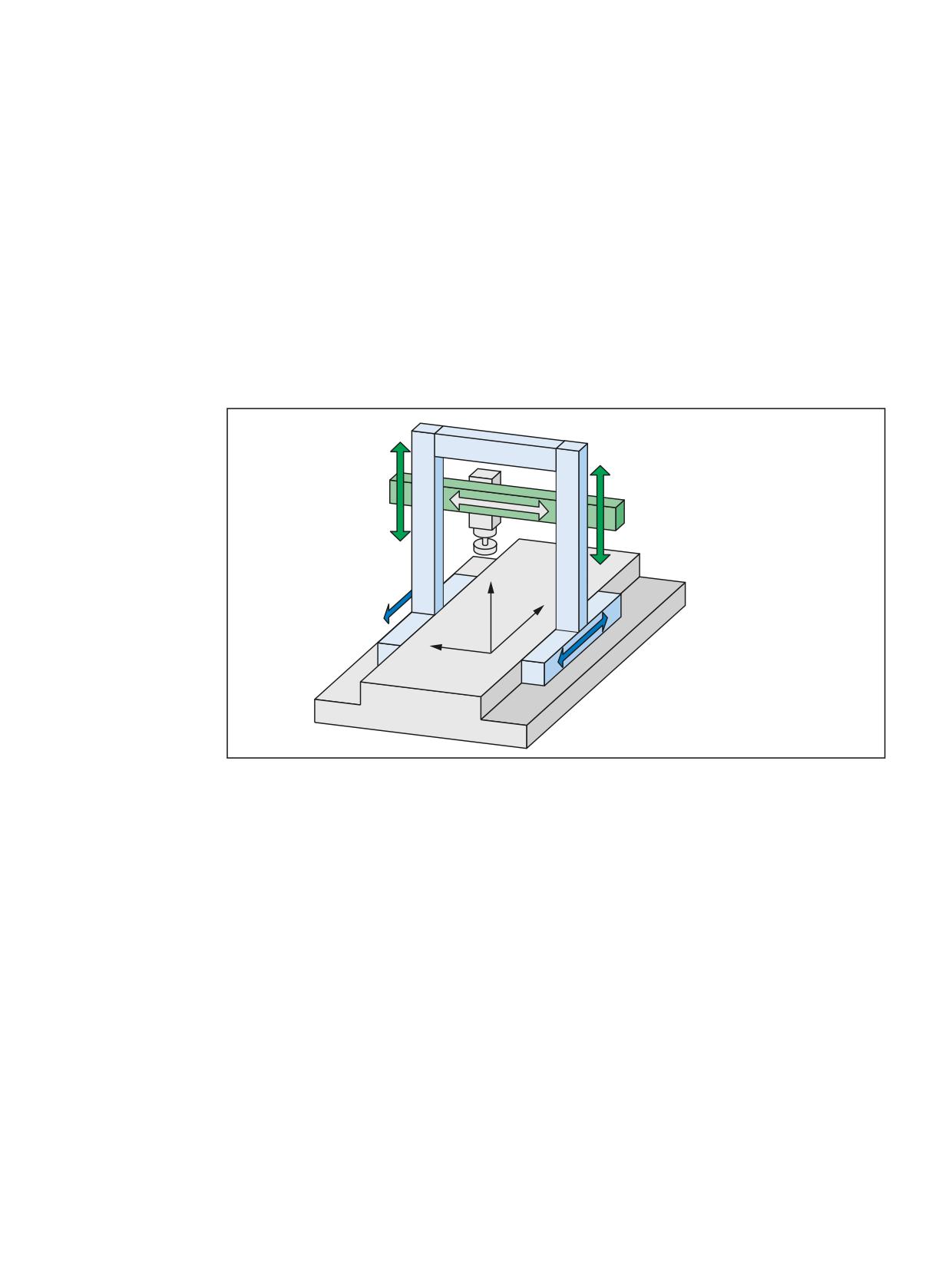
For gantry machines, each of various machine elements, such as the gantry and the transverse
beams, are moved by several axes that operate in parallel. The axes that together move a
machine part, are designated as gantry axes or gantry grouping. Because of the mechanical
structure, the gantry axes are rigidly connected with each other and so must always be
traversed synchronously by the control.
=
=
=
<
=
JDQWU\ JURXSLQJ &URVVEHDPV
=
;
;
<
;
;
JDQWU\ JURXSLQJ *DQWU\
;
Figure 3-1
Example: Gantry-type milling machine with gantry and transverse beams
Guide axis
The guide axis of the gantry grouping is the axis that represents the gantry grouping. Only this
axis is programmed to perform the traversing movements of the gantry grouping.
Synchronous axes
The synchronous axes of the gantry grouping are the axes that because of their coupling with
the guide axis are also automatically traversed by the control. A guide axis can be assigned
any number of synchronous axes.
Synchronization difference
The synchronous operation difference is the deviation of the axial actual value of a
synchronous axis from its ideal position referred to the actual value of the guide axis. The
control continually monitors the synchronous operation difference. A message is displayed if
the alarm limit is exceeded. The complete gantry grouping is stopped when the alarm limit is
exceeded. The limit values can be parameterized as machine data.
Special functions
Function Manual, 12/2018, A5E40874099B AB
149

G1: Gantry axes
3.2 "Gantry axes" function
3.2
"Gantry axes" function
3.2.1
Definition of a gantry grouping
Definition
The axes of a gantry grouping are specified via the following axial machine data:
MD37100 $MA_GANTRY_AXIS_TYPE[AX1] = xy
x
Tens decimal place: Type of gantry axis (guide or synchronous axis)
y
Ones decimal place: ID of the gantry grouping
A maximum of eight gantry groupings (gantry grouping ID: 1 - 8) can be defined. The gantry
grouping ID must be unique in all channels or in all NCUs in accordance with the assigned
axis.
In principle, a gantry grouping can be assigned any number of synchronous axes.
Example
Definition of a gantry grouping with ID=1, guide axis AX1 and synchronous axis AX2
● MD37100 $MA_GANTRY_AXIS_TYPE[AX1] = 01 (guide axis)
● MD37100 $MA_GANTRY_AXIS_TYPE[AX2] = 11 (synchronous axis)
Supplementary conditions
The following supplementary conditions apply to a gantry grouping:
● A gantry grouping must not contain a spindle.
● A synchronous axis must not be a concurrent POS axis.
● A synchronous axis must not belong to a transformation.
● A synchronous axis must not be a following axis of another axis coupling.
● A synchronous axis must not be a guide axis of another axis coupling.
● All axes of a gantry grouping must be of the same axis type, linear or rotary: MD30300
$MA_IS_ROT_AX (rotary axis/spindle)
Note
Drive optimization
At a SINAMICS S120 drive unit, a maximum of three drives can be optimized or measured
at the same time (speed controller optimization / function generator). Therefore, for a
coupling with more than three coupled drives at the same time, we recommend that these
are distributed over several drive units.
Special functions
150
Function Manual, 12/2018, A5E40874099B AB
G1: Gantry axes
3.2 "Gantry axes" function
3.2.2
Monitoring the synchronism difference
Limit values for monitoring
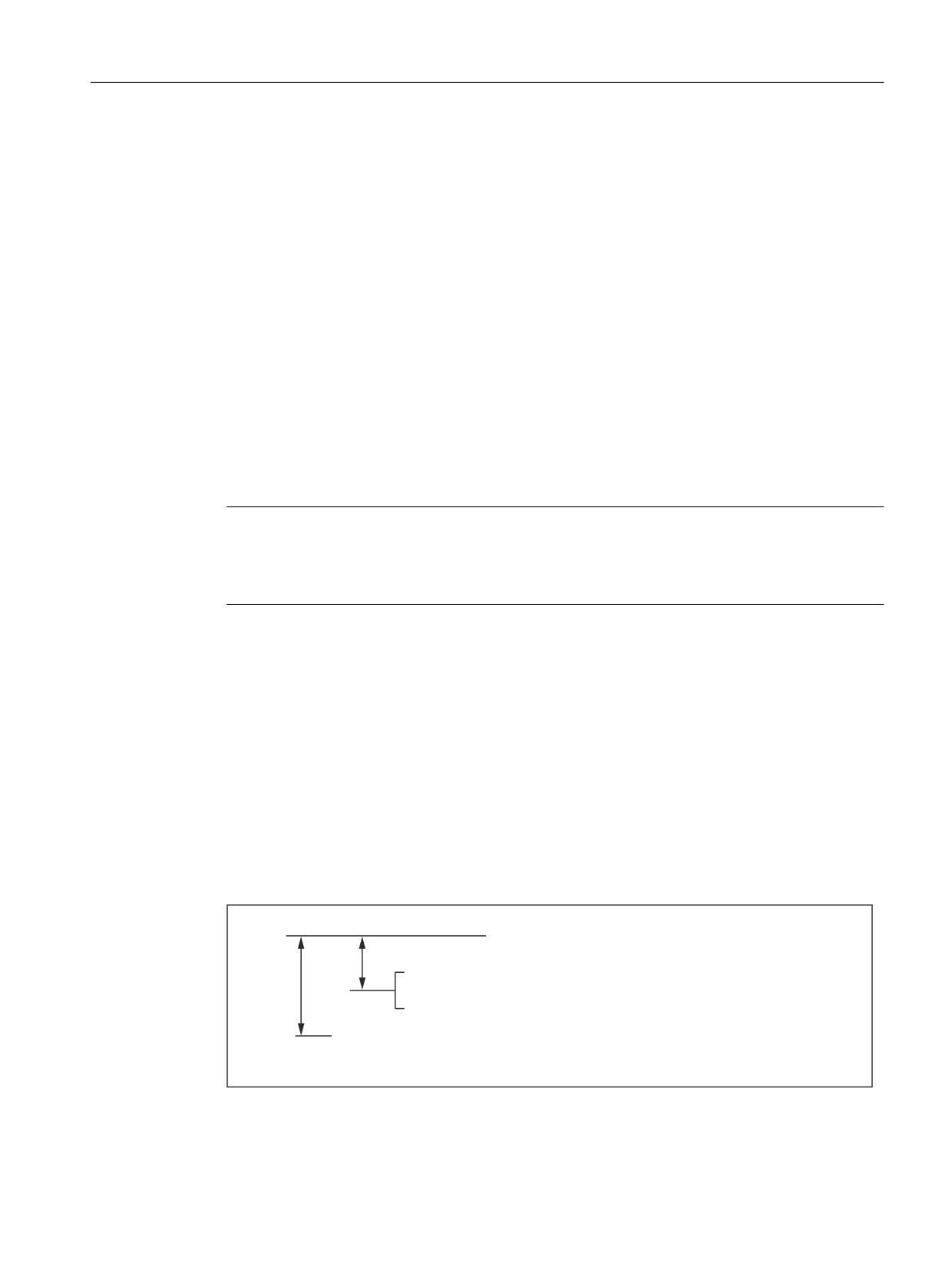
2 limit values can be specified for the synchronism difference.
Gantry warning limit
The gantry warning limit is set using the following machine data:
MD37110 $MA_GANTRY_POS_TOL_WARNING (gantry warning limit)
The "Alarm limit exceeded" message is displayed if the synchronism difference exceeds the
gantry warning limit. In addition, the NC/PLC-interface signal is set:
DB31, ... DBX101.3 = 1 (gantry warning limit exceeded)
After the alarm limit has been fallen below, the message and interface signal are automatically
reset.
Note
Gantry warning limit
If the "Alarm limit exceeded" message is not to be displayed, then a value of 0 should be
entered into MD37110.
Gantry trip limit
The gantry trip limit is set using the following machine data:
● for the synchronized gantry grouping:
MD37120 $MA_GANTRY_POS_TOL_ERROR
● for the non-synchronized gantry grouping:
MD37130 $MA_GANTRY_POS_TOL_REF
Alarm 10653 "Error limit exceeded" is displayed if the synchronism difference exceeds the
gantry trip limit. In addition, the NC/PLC-interface signal is set:
DB31, ... DBX101.2 = 1 (gantry trip limit exceeded)
*DQWU\ WULS OLPLW
6\QFKURQRXV JURXSLQJ 0'
0$B*$175<B326B72/B(5525
1RQ V\QFKURQRXV JURXSLQJ 0'
0$B*$175<B326B72/B5()
*DQWU\ ZDUQLQJ OLPLW
0'
0$B*$175<B326B72/B:$51,1*
The alarm is also displayed if the gantry grouping is jammed (no controller enable, gantry
grouping in the "Hold" state).
Special functions
Function Manual, 12/2018, A5E40874099B AB
151
G1: Gantry axes
3.2 "Gantry axes" function
3.2.3
Extended monitoring of the synchronism difference
Activation of the extended monitoring
An extended monitoring of the synchronism difference can be activated using the following
machine data:
MD37150 $MA_GANTRY_FUNCTION_MASK, Bit 0 = 1
For the extended monitoring, a synchronism difference between the leading and synchronous
axis, obtained when tracking or when the gantry grouping is opened, is taken into account.
The extended monitoring becomes active after the NC boots after the first referencing
(incremental encoder) or synchronization (absolute encoder).
Exceeding the gantry trip limit
If, when the extended monitoring is active, the trip limit of the synchronism difference is
exceeded, Alarm 10653 "Error limit exceeded" is displayed.
In order to be able to reset the alarm, proceed as follows:
1. Deactivating extended monitoring:
MD37150 $MA_GANTRY_FUNCTION_MASK, Bit 0 = 0
2. Deleting the synchronism difference displayed in the machine data:
MD37135 $GANTRY_ACT_POS_TOL_ERROR = 0
3. Cancel alarm
4. Re-reference or re-synchronize the axes of the gantry grouping
5. Reactivating extended monitoring:
MD37150 $MA_GANTRY_FUNCTION_MASK, Bit 0 = 1
3.2.4
Referencing and synchronization of gantry axes
Application
In cases where an incremental measuring system is being used for the guide axis or the
synchronous axis, the measuring systems must be referenced during NC run-up, while
maintaining the axis coupling.
After every axis in the gantry grouping has approached its reference point, any misalignment
that may exist between the axes must be eliminated (gantry synchronization process). Once
this has been done, the NC/PLC interface signal is set:
DB31, ... DBX101.5 = 1 (gantry grouping is synchronized)
For the sequence when referencing or synchronizing gantry axes, see Chapter "Referencing
and synchronization of gantry axes (Page 154)".
Special functions
152
Function Manual, 12/2018, A5E40874099B AB

G1: Gantry axes
3.2 "Gantry axes" function
3.2.5
Control dynamics
Use case
From the user perspective, a gantry grouping is exclusively traversed via the leading axis. The
NC generates the setpoints of the synchronous axes directly from the setpoints of the leading
axis in time synchronism and outputs these to them. To minimize the synchronous operation
differences, the control system dynamics of all axes of a gantry grouping must be set identical
(see Section "Start-up of gantry axes (Page 164)").
Note
Identical control dynamics must be set for all axes of a gantry grouping.
Disturbance characteristic
If faults occur, which cause an axis of the gantry to be stopped, then the complete gantry
grouping is always stopped.
3.2.6
Opening the gantry grouping
Description
The axis coupling within a gantry grouping can be opened (dissolved) using the following
machine data:
MD37140 $MA_GANTRY_BREAK_UP = 1 (invalidate gantry grouping)
CAUTION
No synchronous operation
If the gantry axes remain mechanically coupled, there is a risk of damage to the machine
when the leading or synchronous axes are traversed in this operating state!
When the setting becomes active, the axes of the gantry grouping can be individually traversed
in the JOG, AUTOMATIC and MDA modes.
The monitoring functions of the synchronism difference and/or the alarm and trip limits are not
active.
The NC/PLC interface signal "Gantry grouping is synchronized" is reset:
DB31, ... DBX101.5 = 0
Special functions
Function Manual, 12/2018, A5E40874099B AB
153
G1: Gantry axes
3.3 Referencing and synchronization of gantry axes
3.3
Referencing and synchronization of gantry axes
3.3.1
Introduction
Misalignment after starting
Immediately after the machine is switched on, the leading and synchronous axes may not be
ideally positioned in relation to one another (e.g. misalignment of a gantry). Generally speaking,
this misalignment is relatively small so that the gantry axes can still be referenced.
In special cases (e.g. gantry axes were stopped owing to a disturbance, power failure or
EMERGENCY STOP), the dimensional offset must be checked for permissible tolerance
values and a compensatory motion executed if necessary before the axes are traversed.
To execute this compensatory motion, the gantry grouping must be invalidated by means of
the following machine data:
MD37140 $MA_GANTRY_BREAK_UP (invalidate gantry grouping)
Gantry synchronization process
All gantry axes must first be referenced and then synchronized after the control system is
switched on. During gantry synchronization, all gantry axes approach the reference position
of the gantry grouping in the decoupled state. The reference position of the gantry grouping
for referencing the gantry axes corresponds to the reference position of the leading axis:
MD34100 $MA_REFP_SET_POS (reference point value/destination point for distancecoded
system)
Otherwise, the reference position is the current actual position of the leading axis.
These operations for referencing and synchronizing the gantry axes are executed
automatically in accordance with a special flowchart.
Referencing process
The flowchart for referencing gantry axes using an incremental measuring system is as follows:
Section 1:
Referencing of the leading axis
The axis-specific referencing of the gantry axis will be started by the active machine function
REF upon the leading axis' interface signal from the PLC user program:
DB31, ... DBX4.7/4.6 (traversing key plus/minus)
The leading axis approaches the reference point (operational sequence as for reference point
approach).
References:
Function Manual Basic Functions; Reference Point Approach (R1)
Special functions
154
Function Manual, 12/2018, A5E40874099B AB
G1: Gantry axes
3.3 Referencing and synchronization of gantry axes
The appropriate synchronous axes traverse in synchronism with the leading axis. Interface
signal "Referenced/synchronized" of the leading axis is output to indicate that the reference
point has been reached.
Section 2:
Referencing of the synchronous axes
As soon as the leading axis has approached its reference point, the synchronous axis is
automatically referenced (as for reference point approach).
References:
Function Manual Basic Functions; Reference Point Approach (R1)
The dependency between the leading axis and synchronous axis is inverted in the control for
this phase so that the leading axis now traverses in synchronism with the synchronous axis.
IS "Referenced/synchronized" of the synchronous axis is output to indicate that the reference
point has been reached. The gantry axis dependency then reverts to its previous status. If a
further synchronous axis is defined in the grouping, then this is also referenced in the way
described above.
Section 3:
Gantry synchronization process
Once all axes in the gantry grouping have been referenced, they must be synchronized with
the defined reference position. The actual position of each gantry axis is first compared to the
defined reference position of the leading axis.
Special functions
Function Manual, 12/2018, A5E40874099B AB
155
G1: Gantry axes
3.3 Referencing and synchronization of gantry axes
The next step in the operating sequence depends on the difference calculated between the
actual values of the leading and synchronous axes:
● difference is smaller than the gantry warning limit:
MD37110 $MA_GANTRY_POS_TOL_WARNING (gantry warning limit)
The gantry synchronization process is started automatically. The message
"Synchronization in progress gantry grouping x" is output during this process.
The message "Synchronization running gantry grouping x" can be suppressed with:
MD37150 $MA_GANTRY_FUNCTION_MASK Bit 2 = 1
All gantry axes traverse at a specific position value in the decoupled state at the velocity
set in the machine data:
MD34040 $MA_REFP_VELO_SEARCH_MARKER (creep velocity)
The position value is defined by the leading axis:
MD34100 $MA_REFP_SET_POS (reference point/destination point for distance-
coordinated system)
The absolute encoders and distanced-coded encoders of the leading axis will be set to the
current actual position of the leading axis or to the reference point by the following machine
data:
MD34330 $MA_REFP_STOP_AT_ABS_MARKER (Distancecoded linear measuring
system without destination point)
For this operation, the axes traverse at the same velocity as set for reference point
approach:
MD34070 $MA_REFP_VELO_POS (reference point positioning velocity)
As soon as all gantry axes have reached their target position (ideal position), IS "Gantry
grouping is synchronized" is set to "1" followed by re-activation of the gantry axis coupling.
The position actual value of all axes in the gantry grouping must now be identical. The
gantry synchronization process is now complete.
● Difference is higher than the gantry warning limit for at least one synchronous axis:
IS "Gantry synchronization read to start" is set to "1" and the message "Wait for
synchronization start of gantry grouping x" is output. The gantry synchronization process
is not started automatically in this case, but must be started explicitly by the operator or
from the PLC user program. The process is initiated by IS "Start gantry synchronization"
on the leading axis. The signal is set on the leading axis. The operational sequence is then
the same as that described above.
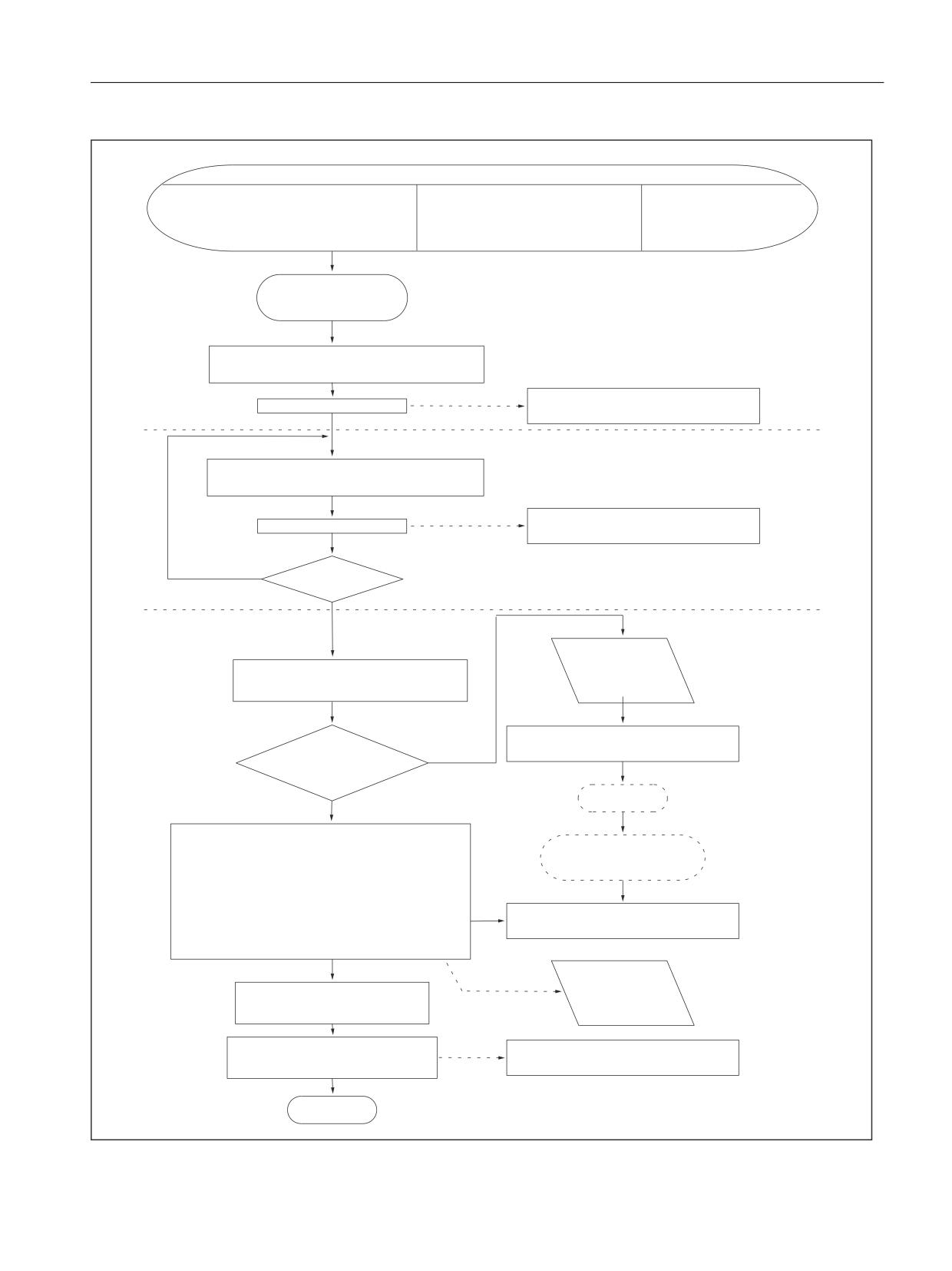
The following flowchart illustrates the referencing and synchronization processes.
Special functions
156
Function Manual, 12/2018, A5E40874099B AB
G1: Gantry axes
3.3 Referencing and synchronization of gantry axes
6WDUW UHIHUHQFLQJ RSHUDWLRQ
&KDQQHO VSHFLILF
$[LV VSHFLILF
IURP SDUW SURJUDP ZLWK
ZLWK ,6 $FWLYDWH UHIHUHQFLQJ
DQG
ZLWK ,6 7UDYHUVLQJ NH\
RI
* DQG D[LV DGGUHVV RI
$FWLYH PDFKLQH IXQFWLRQ 5()
OHDGLQJ D[LV DQG $FWLYH PDFKLQH
OHDGLQJ D[LV
IXQFWLRQ 5()
6HFWLRQ 5HIHUHQFLQJ RI OHDGLQJ
6WDUW 5HIHUHQFLQJ RI
D[LV
JDQWU\ D[HV
/HDGLQJ D[LV DSSURDFKHV UHI SRLQW V\QFKUR
QL]HG D[LV WUDYHUVHV LQ V\QFKURQLVP
WR 3/&
,6
5HIHUHQFHG V\QFKURQL]HG
IRU
5HIHUHQFH SRLQW UHDFKHG
OHDGLQJ D[LV
,QWHUQDO
6HFWLRQ
VWDUW
5HIHUHQFLQJ RI V\QFKURQL]HG D[LV D[HV
6\QFKURQL]HG D[LV DSSURDFKHV UHIHUHQFH
SRLQW OHDGLQJ D[LV WUDYHUVHV LQ V\QFKURQLVP
WR 3/&
,6
5HIHUHQFHG V\QFKURQL]HG
IRU
5HIHUHQFH SRLQW UHDFKHG
V\QFKURQL]HG D[LV
M
1H[W V\QFKUR
QL]HG D[LV
Q
6HFWLRQ
6\QFKURQL]DWLRQ
0HVVDJH :DLW
SURFHVV
IRU V\QFKURQL]DWLRQ
&RPSDULVRQ RI DFWXDO SRVLWLRQV RI
VWDUW
OHDGLQJ DQG V\QFKURQL]HG D[HV
,6
*DQWU\ V\QFKURQL]DWLRQ UHDG\
'HYLDWLRQ
M
WR VWDUWರ
!
0'
0$B*$175<B326B72/B:$51,1*"
6HUYLFLQJ
Q
,QWHUQDO VWDUW
$OO JDQWU\ D[HV WUDYHUVH LQ WKH GHFRXSOHG VWDWH LQ
JDQWU\ V\QFKURQL]HG SRVLWLRQ 0'
2SHUDWRU VWDUWV JDQWU\
0$B5()3B6(7B326 RI WKH OHDGLQJ D[LV :LWK
V\QFKURQL]DWLRQ SURFHVV
DEVROXWH HQFRGHUV DQG GLVWDQFH FRGHG HQFRGHUV
([WHUQDO VWDUW
WKH OHDGLQJ D[LV ZLOO WUDYHUVH VHW YLD 0'
0$B5()3B6723B$7B$%6B0$5.(5
,6
6WDUW JDQWU\ V\QFKURQL]DWLRQ
WKH FXUUHQW DFWXDO SRVLWLRQ RI WKH OHDGLQJ D[LV RU WKH
UHIHUHQFH SRLQW
0HVVDJH
WR 3/&
$OO JDQWU\ D[HV KDYH UHDFKHG
6\QFKURQL]DWLRQ
V\QFKURQL]HG SRVLWLRQ
LQ SURJUHVV
WR 3/&
)RUFHG FRXSOLQJ EHWZHHQ JDQWU\
,6
*DQWU\ JURXSLQJ LV
D[HV LV UHDFWLYDWHG
V\QFKURQL]HG
(QG
Special functions
Function Manual, 12/2018, A5E40874099B AB
157
G1: Gantry axes
3.3 Referencing and synchronization of gantry axes
Figure 3-2
Flowchart for referencing and synchronization of gantry axes
Synchronization process
A synchronization process is always required in the following cases:
● after the reference point approach of all axes included in a grouping,
● if the axes become de-synchronized (s below).
Operational sequence failure
If the referencing process described above is interrupted as a result of disturbances or a
RESET, proceed as follows:
● Abort within section 1 or 2:
Restart reference point with leading axis (see section 1)
● Abort in section 3:
In cases where the gantry axes have not yet been referenced (IS "Referenced/
Synchronized" = 1), the gantry synchronization process can be started again with IS
"Synchronize gantry grouping".
Restart gantry synchronization
Synchronization of the gantry axes can be started with IS "Start gantry synchronization" under
the following conditions only:
● JOG/REF mode must be active. The following interface signal must be set:
DB11, ... DBX5.2 = 1 (active machine function REF)
● DB31, ... DBX 101.5 = 0 (gantry grouping is synchronized)
● All grouping axes operate within the tolerance windows:
DB31, ... DBX 101.4 = 1(gantry synchronization process ready to start)
● Axes are not referenced in the relevant NC channel
DB21, ... DBX33.0 = 0 (referencing active)
If the gantry synchronization process is not started from the referencing process by means of
IS "Start gantry synchronization process", then the reference position is not specified as target
position for the synchronous axes:
MD34100 $MA_REFP_SET_POS (reference point value/destination point for distancecoded
system)
Special functions
158
Function Manual, 12/2018, A5E40874099B AB
G1: Gantry axes
3.3 Referencing and synchronization of gantry axes
Instead, the actual position of the leading axis is specified as the target position and is
approached in the uncoupled state.
Note
For the leading axis, automatic synchronization can be locked using the following NC/PLC
interface signal:
DB31, ... DBX29.5 = 1 (no automatic synchronization process)
This always makes sense if no axis enabling signal has yet been issued for the axes. In this
case, the synchronization process should also be started explicitly with the NC/PLC interface
signal:
DB31, ... DBX29.4 = 1 (start gantry synchronization process)
Loss of synchronization
The gantry grouping becomes desynchronized as a result of:
● "Tracking" the gantry axes
● Loss of the reference position of a gantry axis, e.g. by "Parking" (no measuring system
active)
● Re-referencing of gantry axis
● The gantry grouping is opened (dissolved) by:
MD37140 $MA_GANTRY_BREAK_UP = 0 (invalidate gantry axis grouping)
The corresponding NC/PLC interface signal is reset:
● DB31, ... DBX60.4 or DBX60.5 == 0 (referenced/synchronized 1 or 2 respectively)
● DB31, ... DBX 101.5 == 0 (gantry grouping is synchronized)
If, in operation, gantry grouping synchronization is lost due to a fault, then synchronization can
be restarted using the NC/PLC interface signal:
DB31, ... DBX29.4 == 1 (start gantry synchronization process)
Requirement is that the following applies to all axes of the gantry grouping:
DB31, ... DBX60.4 or DBX60.5 = 1 (referenced/synchronized 1 or 2 respectively)
In this case, the synchronizing axes traverse the current actual position of the leading axis in
the decoupled state.
If, when the gantry grouping is traversing, the signal "Emergency Stop" (DB10, DBX56.2) is
set and again reset, and the gantry axes have drifted apart less than the standstill tolerance
of the synchronous axes, then these are automatically resynchronized. Automatic
synchronization can be suppressed using the NC/PLC interface signal for the leading axis:
DB31, ... DBX29.5 = 1 (no automatic synchronization process)
Special functions
Function Manual, 12/2018, A5E40874099B AB
159

G1: Gantry axes
3.3 Referencing and synchronization of gantry axes
Selecting the reference point
To ensure that the shortest possible paths are traversed when the gantry axes are referenced,
the reference point values from leading and synchronous axes should be the same in the
machine data:
MD34100 $MA_REFP_SET_POS (reference point value/destination point for distancecoded
system)
Allowance for deviations in distance between the zero mark and the reference point must be
made for specific axes via the machine data:
MD34080 $MA_REFP_MOVE_DIST (reference point distance)
MD34090 $MA_REFP_MOVE_DIST_CORR (reference point offset/absolute offset)
Referencing direction selection
The zero mark search direction of the synchronous axis can be defined via the machine data:
MD37150 $MA_GANTRY_FUNCTION_MASK, Bit 1
Bit
Value
Meaning
1
0
Zero mark search direction of the synchronous axis analog to machine data:
MD34010 $MA_REFP_CAM_DIR_IS_MINUS
1
Zero mark search direction of the synchronous axis the same as the leading axis
During referencing, the reference point value of the leading axis is specified as the target
position for all axes in the grouping for the synchronization compensatory motion. This position
is then approached without axis coupling. The absolute encoders and distanced-coded
encoders of the leading axis will be set to the current actual position of the leading axis or to
the reference point by the following machine data:
MD34330 $MA_REFP_STOP_AT_ABS_MARKER (Distancecoded linear measuring system
without destination point)
If only one reference cam is used for the leading and synchronous axes, then this must be
taken into account in the PLC user program.
3.3.2
Automatic synchronization
Automatic synchronization can take place:
● in the referencing mode (see Section "Introduction (Page 154)")
● in other modes, as described below:
If a gantry grouping is switched to follow-up mode, monitoring of the actual values between
the leading and synchronized axes is disabled. The grouping is no longer synchronized as a
result. Independent of axes positions, the following interface signal will be set to 0 (from leading
axis)
DB31, ... DBX101.5 (gantry grouping is synchronous)
If the gantry grouping is switched from follow-up mode to position control mode, axis
synchronism is automatically restored provided the actual-value monitor does not detect a
Special functions
160
Function Manual, 12/2018, A5E40874099B AB
G1: Gantry axes
3.3 Referencing and synchronization of gantry axes
difference between the positions of the leading and synchronized axes greater than the setting
in the machine data:
MD36030 $MA_STANDSTILL_POS_TOL (standstill tolerance)
In this case, a new setpoint is specified for the synchronized axis (axes) without interpolation.
The positional difference detected earlier is then corrected by the position controller. The
correction causes only the synchronized axis (axes) to move.
The motional sequence of the synchronized axis (axes) is analogous to the situation in which
the grouping switches from the "Hold" state to position control mode. In this case, the position
specified by the position controller before the grouping is halted is set again on condition that
the zero speed monitor has not activated alarm 25040 (with follow-up as alarm reaction) in the
meantime.
The same tolerance window is used for this mode of automatic synchronization as for the zero
speed monitoring function:
MD36030 $MA_STANDSTILL_POS_TOL (standstill tolerance)
Parameter rate dependence loads with machine data:
MD36012 $MA_STOP_LIMIT_FACTOR (exact stop coarse/fine and standstill factor)
Note
The following interface signal blocks automatic synchronization in all modes except the
referencing mode:
DB31, ... DBX29.5 (no automatic synchronization)
Should the automatic synchronization be activated at this point, then the following interface
signal must be reset:
DB31, ... DBX29.5 = 0 (no automatic synchronization)
Then switch one of the axes in the gantry grouping from follow-up mode to position-controlled
mode. This is achieved with the interface signals:
DB31, ... DBX1.4 = 1 (follow-up mode)
DB31, ... DBX2.1 = 1 (servo enable)
3.3.3
Points to note
2nd position measuring system per gantry axis
Different types of position measuring systems can be mounted on the gantry axes of a
grouping. Furthermore, each gantry axis is capable of processing two position measuring
systems, it being possible to switch over from one system to the other at any time:
DB31, ... DBX1.5 (position measuring system 1)
DB31, ... DBX1.6 (position measuring system 2)
The maximum tolerance for position actual value switchover should be set to a lower value
than the gantry warning limit:
Special functions
Function Manual, 12/2018, A5E40874099B AB
161
G1: Gantry axes
3.3 Referencing and synchronization of gantry axes
MD36500 $MA_ENC_CHANGE_TOL (Max. tolerance for position actual value switchover)
The two position measuring systems must, however, have been referenced beforehand. The
relevant measuring system must be selected before referencing is initiated. The operational
sequence is then the same as that described above.
Channelspecific referencing
Gantry axes can also be referenced by channel with the following interface signal:
DB21, ... DBX1.0 (activate referencing)
The value of the leading axis' machine data is used for the axis sequence for channel-specific
referencing:
MD34110 $MA_REFP_CYCLE_NR (Axis sequence for channel-specific referencing)
After the reference point of the leading axis has been reached, the synchronized axes are
referenced first as described above.
Referencing from part program with G74
The referencing and synchronization process for gantry axes can also be initiated from the
part program by means of command G74. In this case, only the axis name of the leading axis
may be programmed. The operational sequence is analogous to that described for axis-specific
referencing.
Position measuring system with distancecoded reference marks
In order that reference point approach operations do not have to travel through large distances,
it is possible to use just one position measuring system - or a position measuring system as
2nd measuring system with distance-coded reference marks for gantry axes. In this way the
measuring system is referenced after traversal of a short path (e.g. 20 mm). The procedure
for referencing the gantry axes is the same as that described for the normal incremental
measuring system.
References:
Function Manual Basic Functions; Reference Point Travel (R1)
Absolute encoder
During the course of the synchronization compensatory motion, all axes in the gantry axis
grouping traverse to the reference point value of the leading axis defined in the machine data:
MD34100 $MA_REFP_SET_POS (reference point value/destination point for distancecoded
system)
The absolute encoders and distanced-coded encoders of the leading axis will be set to the
current actual position of the leading axis or to the reference point by the following machine
data:
MD34330 $MA_REFP_STOP_AT_ABS_MARKER (Distancecoded linear measuring system
without destination point)
Special functions
162
Function Manual, 12/2018, A5E40874099B AB

G1: Gantry axes
3.3 Referencing and synchronization of gantry axes
Activation of axis compensations
Compensation functions can be activated for both the leading axis and the synchronized axes.
Compensation values are applied separately for each individual gantry axis. These values
must therefore be defined and entered for the leading axis and the synchronized axes during
start-up.
The compensations do not become operative internally in the control until the axis is referenced
or the gantry grouping synchronized. The following applies:
Compensation type
Takes effect when
PLC interface signal
Backlash compensation
Axis is referenced
"Referenced/Synchronized"
LEC
Axis is referenced
"Referenced/synchronized"
Sag compensation
Gantry grouping is synchron-
"Gantry grouping is synchronized"
ized
Temperature compensation
Gantry grouping is synchron-
"Gantry grouping is synchronized"
ized
If a movement by the synchronized axis (axes) is caused by an active compensation, a travel
command is displayed for the synchronized axis (axes) independently of the leading axis.
Monitoring functions effective
Analogous to normal NC axes, the following monitoring functions do not take effect for gantry
axes until the reference point is reached (IS "Referenced/Synchronized"):
● Working area limits
● Software limit switch
● Protection zones
The axial machine data values are used as monitoring limit values for the synchronized axes
as well.
Multi-channel block search
The cross-channel block search in Program Test mode (SERUPRO "Search Run by Program
test") can be used to simulate the traversal of gantry axis groupings.
Note
Further information regarding multi-channel block search SERUPRO can be found under:
References:
Function Manual, Basic Functions; Mode Group, Channel, Program Mode (K1),
Section: Program test
Special functions
Function Manual, 12/2018, A5E40874099B AB
163
G1: Gantry axes
3.4 Start-up of gantry axes
3.4
Start-up of gantry axes
General
Owing to the forced coupling which is normally present between guide and synchronous gantry
axes, the gantry grouping must be started up as if it were an axis unit. For this reason, the
axial machine data for the guide and synchronous axes must always be defined and entered
jointly.
If the synchronous axis is overloaded due to a weaker dynamic response than the guide axis,
alarm 10656 is displayed.
Special points to be noted with regard to starting up gantry axes are described below.
Traversing direction
As part of the start-up procedure, a check must be made to ensure that the direction of rotation
of the motor corresponds to the desired traversing direction of the axis. Correct with the
following axial machine data:
MD32100 $MA_AX_MOTION_DIR (traversing direction)
Entering gantry trip limits
For the monitoring of the actual position values of the synchronous axis in relation to the actual
position of the guide axis, the limit values for termination, as well as for the guide and
synchronous axes, should be entered corresponding to the specifications of the machine
manufacturer:
● MD37120 $MA_GANTRY_POS_TOL_ERROR (gantry trip limit)
● MD37130 $MA_GANTRY_POS_TOL_REF (gantry shutdown limit when referencing)
Note
The control must then be switched off and then on again because the gantry axis definition
and the trip limit values only take effect after power ON.
Response to setpoint changes and disturbances
Since digital drives respond well to disturbances and setpoint changes, there is no need for a
compensatory control between the gantry axes. However, the gantry axes can only operate
in exact synchronism if the parameters for the control circuits of the guide and synchronous
axes are set to the same dynamic response value.
To ensure the best possible synchronism, the guide axis and synchronous axis must be
capable of the same dynamic response to setpoint changes. The axial control loops (position,
speed and current controllers) should each be set to the optimum value so that disturbances
can be eliminated as quickly and efficiently as possible. The dynamic response adaptation
function in the setpoint branch is provided to allow differing dynamic responses of axes to be
matched without loss of control quality.
Special functions
164
Function Manual, 12/2018, A5E40874099B AB
G1: Gantry axes
3.4 Start-up of gantry axes
Axial optimization
The following control parameters must be set to the optimum axial value for both the guide
axis and the synchronous axis:
● MD32200 $MA_POSCTRL_GAIN (servo gain factor)
● MD32620 $MA_FFW_MODE (feedforward control parameter)
● MD32610 $MA_VELO_FFW_WEIGHT (feedforward control factor for acceleration/speed)
● MD32650 $MA_AX_INERTIA (inertia for torque feedforward control)
● MD32800 $MA_EQUIV_CURRCTRL_TIME (equivalent time constant current control loop
for feedforward control)
● MD32810 $MA_EQUIV_SPEEDCTRL_TIME (equivalent time constant speed control loop
for feedforward control)
References
Extended Functions Function Manual; Compensations (K3)
Same settings
The following control parameters must be set to the same value for the guide axis and
synchronous axis:
● MD33000 $MA_FIPO_TYPE (fine interpolator type)
● MD32400 $MA_AX_JERK_ENABLE (axial jerk limitation)
● MD32410 $MA_AX_JERK_TIME (time constant for the axial jerk filter)
● MD32420 $MA_JOG_AND_POS_JERK_ENABLE (basic position of axial jerk limitation)
● MD32430 $MA_JOG_AND_POS_MAX_JERK (axial jerk)
References
Basic Functions Function Manual; Velocities, Setpoint / Actual Value Systems, Closed-Loop
Control (G2)
Dynamics matching
The guide axis and the coupled synchronous axis must be capable of the same dynamic
response to setpoint changes. The same dynamic response means: The following errors are
equal in magnitude when the axes are operating at the same speed.
The dynamic response adaptation function in the setpoint branch makes it possible to obtain
an excellent match in the response to setpoint changes between axes which have different
dynamic characteristics (control loops). The difference in equivalent time constants between
the dynamically "weakest" axis and the other axis in each case must be specified as the
dynamic response adaptation time constant.
Example
When the speed feedforward control is active, the dynamic response is primarily determined
by the equivalent time constant of the "slowest" speed control loop.
Special functions
Function Manual, 12/2018, A5E40874099B AB
165
G1: Gantry axes
3.4 Start-up of gantry axes
Guide axis
MD32810 $MA_EQUIV_SPEEDCTRL_TIME [n] = 5 ms (equivalent time constant speed
control loop for feedforward control)
Synchronous axis
MD32810 $MA_EQUIV_SPEEDCTRL_TIME [n] = 3 ms
● Time constant of dynamic response adaptation for synchronous axis:
MD32910 $MA_DYN_MATCH_TIME [n] = 5 ms - 3 ms = 2 ms (time constant of dynamic
response adaptation)
The dynamic response adaptation must be activated axially with the machine data:
MD32900 $MA_DYN_MATCH_ENABLE (dynamic response adaptation)
Check of dynamic response adaptation:
The following errors of the guide and synchronous axes must be equal in magnitude when the
axes are operating at the same speed!
For the purpose of fine tuning, it may be necessary to adjust servo gain factors or feedforward
control parameters slightly to achieve an optimum result.
Referencing gantry axes
The positions of the guide and synchronous axes reference points must first be set to almost
identical values.
To ensure that the synchronization compensatory motion of the gantry axes is not started
automatically, the gantry warning limit must be set to 0 at the first start-up before referencing:
MD37100 $MA_GANTRY_POS_TOL (gantry axis definition)
This will prevent a warning message being output during traversing motion.
In cases where an excessively high additional torque is acting on the drives due to
misalignment between the guide and synchronous axes, the gantry grouping must be aligned
before the axes are traversed. After this, the gantry axes must be referenced. For further
details, see:
● Section "Referencing and synchronization of gantry axes (Page 154)"
● References: Basic Functions Function Manual; Reference Point Approach (R1)
After the guide and synchronous axes have been referenced, the difference between them
must be determined by comparing the actual position value (HMI: operating area "Diagnostics"
> "Service axes") and taken into account as the reference point offset:
● MD34080 $MA_REFP_MOVE_DIST (reference point distance)
● MD34090 $MA_REFP_MOVE_DIST_CORR (reference point offset / absolute offset)
The differences in distance between the zero mark and reference point must also be calculated
for each gantry axis and adjusted. They are to be customized, via the following machine data,
in such a way that the actual position values of the guide and synchronous axes are identical
after execution of the compensatory motion:
● MD34080 $MA_REFP_MOVE_DIST (reference point distance)
● MD34090 $MA_REFP_MOVE_DIST_CORR (reference point offset / absolute offset)
Special functions
166
Function Manual, 12/2018, A5E40874099B AB
G1: Gantry axes
3.4 Start-up of gantry axes
Synchronizing gantry axes
The gantry synchronization is activated via the NC/PLC interface signal (see Section
"Referencing and synchronization of gantry axes (Page 152)"):
DB31, ... DBX29.4 = 1 (start synchronization of gantry)
The completion of the synchronization is displayed via the NC/PLC interface signal:
DB31, ... DBX101.5 == 1 (gantry grouping is synchronous)
Once the axes have been synchronized, check that the dimensional offset between the guide
and the synchronous axes is 0. If required, make corrections in the machine data mentioned
above.
Input of gantry warning limit
Once the reference point values for the guide and synchronous axes have been optimized so
that the gantry axes are perfectly aligned with one another after synchronization, the warning
limit values for all axes must be entered in the following machine data:
MD37110 $MA_GANTRY_POS_TOL_WARNING (gantry warning limit)
To do this, the value must be increased incrementally until it is just below the alarm (limit
exceeded) response limit. It is particularly important to check the acceleration phases.
This limit value also determines the position deviation value at which gantry synchronization
is automatically started in the control.
Calculating and activating compensations
In cases where the gantry axes require compensation (backlash, sag, temperature or
leadscrew error), the compensation values for the guide axis and the synchronous axis must
be calculated and entered in the appropriate parameters or tables.
References
Extended Functions Function Manual; Compensations (K3)
Function generator / measuring function
The activation of the function generator and measuring function for a synchronous axis is
aborted with an error message. If an activation of the synchronous axis is absolutely necessary,
e.g. to measure the machine, the guide and the synchronous axes must be temporarily
interchanged.
Special cases
If individual axes have to be activated, the gantry groups must be temporarily canceled. As
the second axis no longer travels in synchronism with the first axis, the activated axis must not
be allowed to traverse beyond the positional tolerance.
Special functions
Function Manual, 12/2018, A5E40874099B AB
167
G1: Gantry axes
3.5 Parameter assignment: Response to faults
If the gantry grouping is canceled, the following points must be noted:
● Always activate the traversing range limits and set them to the lowest possible values
(position tolerance).
● Synchronize the gantry grouping first if possible and then execute a POWER-ON-RESET
without referencing the axes again. This ensures that the traversing range limits always
refer to the same position (i.e. that which was valid on power ON).
● Avoid using the step-change function. Position step changes are only permissible if they
stay within the permitted tolerance.
● Always use an offset of 0 for the function generator and measuring function in contrast to
the recommendations for normal axes.
● Set the amplitudes for function generator and measuring function to such low values that
the activated axis traverses a shorter distance than the position tolerance allows. Always
activate the traversing range limits as a check (see above).
References
Drive Functions Function Manual; Speed Control Loop (DD2)
Start-up support for gantry groupings
The start-up functions of the function generator and measuring are parameterized via the PI
service. The traversing movement starts for all parameterized axes with NC start in JOG mode.
A window is displayed in the "Measuring function and function generator in gantry grouping"
user interface. Two amplitude values, each with an offset and bandwidth, must be entered in
this window. The first amplitude value applies to the measuring axis and the second to the
other coupled axes.
3.5
Parameter assignment: Response to faults
Pulse suppression
The behavior of the gantry grouping with regard to faults that trigger pulse suppression can
be set with the following axis-specific machine data:
Special functions
168
Function Manual, 12/2018, A5E40874099B AB
G1: Gantry axes
3.6 PLC interface signals for gantry axes
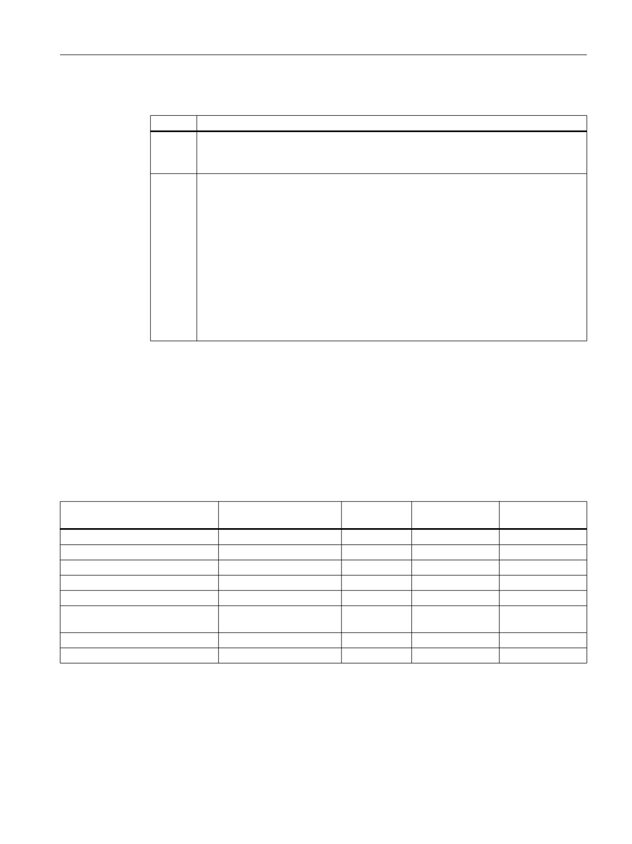
MD30455 $MA_MISC_FUNCTION_MASK, bit 9 = <value>
<value>
Meaning
0
When a fault occurs that triggers the pulse suppression (e.g. measuring-circuit fault), the
pulses in all other axes of the gantry grouping will also be suppressed.
Result: Coast down of all axes of the gantry grouping.
1
When a fault occurs that triggers the pulse suppression (e.g. measuring-circuit fault), the
pulses for only this axis will be suppressed. The other axes of the gantry grouping will be
stopped. The pulses for these axes are also then suppressed. To ensure that the pulses
these axes are not suppressed in advance, especially for axes to be held at the standstill
position (vertical axes), the following drive parameters must be taken into account:
● p1135[0...n] OFF3 ramp-down time
● p1217 holding brake application time
● p1227 zero speed detection monitoring time
● p1228 pulse suppression, delay time
For a detailed description of drive parameters, refer to:
References:
SINAMICS S120/S150 Parameter Manual
3.6
PLC interface signals for gantry axes
Special IS for gantry axes
The special NC/PLC interface signals of the coupled gantry axes are taken via the axial NC/
PLC interface of the leading or synchronized axes. The table below shows all special gantry
NC/PLC interface signals along with their codes and indicates whether the IS is evaluated on
the leading axis or the synchronized axis.
NC/PLC interface signal
Direction of transfer
DB31, ...
Leading axis
Synchronous axis
DBX...
Start gantry synchronization
PLC → NC
29.4
X
No automatic synchronization
PLC → NC
29.5
X
Gantry axis
NC → PLC
101.7
1
1
Gantry leading axis
NC → PLC
101.6
1
0
Gantry grouping is synchronized
NC → PLC
101.5
X
Gantry synchronization ready to
NC → PLC
101.4
X
start
Gantry warning limit exceeded
NC → PLC
101.3
X
Gantry trip limit exceeded
NC → PLC
101.2
X
Effect of axial interface signals on gantry axes
a) Axial interface signals from the PLC to the axis (PLC → NC)
The axial interface signals from the PLC to the axis are always referred to all gantry axes in
the grouping. In this case, all gantry axes (leading and synchronized axis) have equal priority.
Special functions
Function Manual, 12/2018, A5E40874099B AB
169
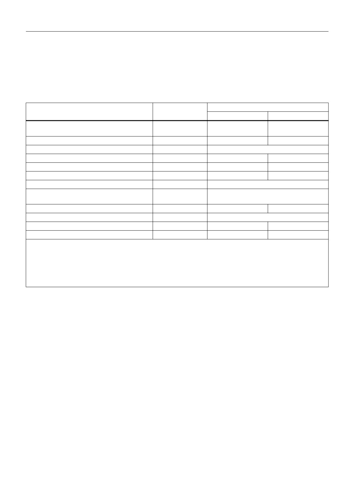
G1: Gantry axes
3.6 PLC interface signals for gantry axes
For example, all axes in the gantry groupings will be simultaneously shut down when the
following interface signal is set to "0" from the leading axis:
DB31, ... DBX2.1 (servo enable)
The following table shows the effect of individual interface signals (from PLC to axis) on gantry
axes:
NC/PLC interface signal
DB31, ... DBX ...
Effect on
Leading axis
Synchronous axis
Axis/spindle disable
1.3
On all axes in gantry
No effect
grouping
Position measuring system 1/2
1.5 and 1.6
Axial 1)
Axial 1)
Controller enable
2.1
On all axes in gantry grouping 2)
Delete distance to go (axial)
2.2
Axial
No effect
Clamping in progress
2.3
Axial
Axial
Reference point value 1-4
2.4 - 2.7
Axial
Axial
Feed stop
4.3
On all axes in gantry grouping
Hardware limit switch plus/minus
12.0 and 12.1
Axial alarm: Brake request on all axes in gantry
grouping
2nd software limit switch plus/minus
12.2 and 12.3
Axial
Axial
Ramp-function generator fast stop (RFGFS)
20.1
On all axes in gantry grouping
Select drive parameter set
21.0 - 21.2
Axial
Axial
Enable Pulses
21.7
Axial
Axial
1) DB31, ... DBX1.5 and 1.6 (position measuring system 1/2)
The switchover between position measuring systems 1 and 2 applies individually for each gantry axis. However, deactivation
of both position measuring systems (known as the parking position) applies as a common signal for all gantry axes.
2) DB31, ... DBX2.1 (controller enable)
If the servo enable signal on one gantry axis is canceled, all axes in the gantry grouping are shut down simultaneously. The
method by which shutdown is implemented (e.g. with fast stop) is identical for all gantry axes.
Either the "Follow-up" state (IS of one gantry axis = 1) or the "Stop" state (IS of all gantry axes
= 0) is activated for all gantry axes, depending on interface signal:
DB31, ... DBX1.4 (follow-up mode)
b) Axial interface signals from the axis to the PLC (NC → PLC)
Each of the axial, axis-to-PLC interface signals for the synchronized axis and the leading axis
is always set on an axis-specific basis and output to the PLC.
Example:
DB31, ... DBX60.4 resp. 60.5 (referenced/synchronized 1/2).
Exception:
When the leading axis is traversed, the interface signal will also be set for the synchronizing
axis:
DB31, ... DBX64.6 and 64.7 (traverse command plus resp. minus)
Special functions
170
Function Manual, 12/2018, A5E40874099B AB
G1: Gantry axes
3.7 Miscellaneous points regarding gantry axes
3.7
Miscellaneous points regarding gantry axes
Manual traversing
It is not possible to traverse a synchronous axis directly by hand in JOG mode. Traverse
commands entered via the traversing keys of the synchronous axis are ignored internally in
the control. Rotation of the handwheel for the synchronous axis has no effect either.
Handwheel override
An overriding motion by means of the handwheel can only be applied to the guide axis in
coupled axis mode. In this case, the synchronous axes traverse in synchronism with the guide
axis.
DRF offset
A DRF offset can only be applied to the guide axis. In this case, the synchronous axes traverse
in synchronism with the guide axis.
Programming in part program
Only the guide axis of a gantry axis grouping may be programmed in the part program. An
alarm is generated while programming a synchronous axis, even when a gantry axis grouping
is released (MD37140 $MA_GANTRY_BREAK_UP = 1).
PLC or command axes
Only the guide axis of the gantry grouping can be traversed by the PLC using FC 18 or as a
command axis by means of synchronized actions.
References:
● Function Manual, Basic Functions, Basic PLC Program (P3)
● Function Manual, Synchronized Actions
PRESET
The PRESET function can only be applied to the guide axis. All axes in the gantry grouping
are reevaluated internally in the control when PRESET is activated. The gantry axes then lose
their reference and synchronization:
DB31, ... DBX101.5 (gantry grouping is synchronized) = 0
Channel assignment of the gantry axes
Please ensure that for a gantry grouping whose guide axis is known in several channels, its
synchronous axes in these channels are also known. If this is not the case, Alarm 10651 is
output with reason 60XX (XX is the objectionable gantry grouping).
Special functions
Function Manual, 12/2018, A5E40874099B AB
171
G1: Gantry axes
3.7 Miscellaneous points regarding gantry axes
Axis interchange
All axes in the gantry grouping are released automatically in response to a RELEASE
command (guide axis).
An axis interchange of the guide axis of a closed gantry grouping is only possible, if all axes
of the grouping are known in the channel in which they are to be transferred, otherwise alarm
10658 is signaled.
No automatic axis interchange and no automatic adjustment of the gantry axis conditions are
undertaken while trying to reconnect a gantry grouping is released with
MD37140 $MA_GANTRY_BREAK_UP = 1. The user is responsible for this. A check of the
axis conditions is conducted after the break up and if necessary, a corresponding alarm 10658
is output.
Note
If a gantry grouping is to be closed again, the user must ensure that all axes of the grouping
are in a channel with a corresponding axis condition.
Default for RESET
In an active gantry grouping, the following machine data parameterization is ignored for the
synchronous axes:
MD30450 $MA_IS_CONCURRENT_POS_AX = 1 (Reset default: neutral axis/channel axis)
The state of the guide axis is assumed. The user is informed about the inappropriate
configuration with display alarm 4300.
Display data
The position actual value display shows the actual values of both the guide axis and the
synchronous axes. The same applies to the service display values in the "Diagnosis" operating
area.
Software limit switch
The software limit switch monitor is processed for the guide axis only. If the guide axis crosses
the limit switch, all axes in the gantry grouping are braked to a standstill.
Special functions
172
Function Manual, 12/2018, A5E40874099B AB
G1: Gantry axes
3.8 Examples
Differences in comparison with the "Coupled motion" function
The main differences between the "gantry axes" and "coupled motion" functions are listed
below:
● The axis coupling between the gantry axes must always be active. Separation of the axis
coupling via part program is therefore not possible for gantry axes. In contrast, the coupled
axis grouping can be separated by means of the part program and the axes then traversed
individually.
● In the "Gantry Axes" function, the difference of the actual position values from the guide
axis and synchronous axis is monitored continuously and the traversing motion is shut down
if there are impermissible deviations. There is no monitoring for the "Coupled motion"
function.
● Gantry axes must remain coupled even during referencing. For this reason, special
procedures are applied for the reference point approach of gantry axes. In contrast, coupled-
motion axes are referenced as individual axes.
● For the gantry axes to traverse without mechanical offset, the synchronous axes must be
set like the guide axes from the control dynamics perspective. In contrast, the "coupled
motion" function permits axes with different dynamic control response characteristics to be
coupled.
References:
Function Manual, Special Functions, Coupled Motion (M3)
Block search with active coupling
Note
For an active coupling, it is recommended to only use block search type 5, "Block search via
program test" (SERUPRO) for a block search.
3.8
Examples
3.8.1
Creating a gantry grouping
Introduction
Setting up gantry grouping, referencing its axes, aligning possible offsets - and finally,
synchronizing the axes involved, are complicated procedures. The individual steps involved
in the process are explained below by an example constellation.
Constellation
Machine axis 1 = gantry leading axis, incremental measuring system
Machine axis 3 = gantry synchronized axis, incremental measuring system
Special functions
Function Manual, 12/2018, A5E40874099B AB
173
G1: Gantry axes
3.8 Examples
Machine data
The following machine data describes the original values at the beginning of the procedure.
Individual settings must be corrected or added later according to the information below.
Gantry machine data
Axis 1
MD37100 $MA_GANTRY_AXIS_TYPE = 1 (gantry axis definition)
MD37110 $MA_GANTRY_POS_TOL_WARNING =0 (gantry warning limit)
MD37120 $MA_GANTRY_POS_TOL_ERROR = e.g. 1 (gantry trip limit)
MD37130 $MA_GANTRY_POS_TOL_REF = e.g. 100 mm (max. misalignment) (gantry
shutdown limit when referencing)
MD37140 $MA_GANTRY_BREAK_UP = 0 (invalidate gantry axis grouping)
Axis 3
MD37100 $MA_GANTRY_AXIS_TYPE= 11
MD37110 $MA_GANTRY_POS_TOL_WARNING = 0
MD37120 $MA_GANTRY_POS_TOL_ERROR = e.g. 1 mm
MD37130 $MA_GANTRY_POS_TOL_REF = e.g. 100 mm (max. misalignment)
MD37140 $MA_GANTRY_BREAK_UP = 0
Reference point machine data (for first encoder each)
Axis 1
MD34000 $MA_REFP_CAM_IS_ACTIVE = TRUE
MD34010 $MA_REFP_CAM_DIR_IS_MINUS = e.g. FALSE
MD34020 $MA_REFP_VELO_SEARCH_CAM =
MD34030 $MA_REFP_MAX_CAM_DIST = corresponds to max. distance traversed
MD34040 $MA_REFP_VELO_SEARCH_MARKER =
MD34050 $MA_REFP_SEARCH_MARKER_REVERSE = e.g. FALSE
MD34060 $MA_REFP_MAX_MARKER_DIST = Difference betw. cam edge and 0 mark
MD34070 $MA_REFP_VELO_POS =
MD34080 $MA_REFP_MOVE_DIST = 0
MD34090 $MA_REFP_MOVE_DIST_CORR = 0
MD34092 $MA_REFP_CAM_SHIFT = 0
MD34100 $MA_REFP_SET_POS = 0
MD34200 $MA_ENC_REFP_MODE = 1
The reference point machine data (for the first encoder) of axis 3 must be specified analogously.
Special functions
174
Function Manual, 12/2018, A5E40874099B AB
G1: Gantry axes
3.8 Examples
3.8.2
Setting the NC-PLC interface
Introduction
An automatic synchronization process when referencing axes must be disabled initially to
prevent damaging/destroying grouping axes that are misaligned.
Disabling of automatic synchronization
The PLC user program sets the following for the axis data block of axis 1:
DB31, ... DBX29.4 = 0 (do not start gantry synchronization)
DB31, ... DBX29.5 = 1 (no automatic synchronization process)
The NC sets the following as a confirmation in the axis block of axis 1:
DB31, ... DBB101.4 = 0 (synchronization process not ready to start)
DB31, ... DBB101.6 = 1 (leading axis LA)
DB31, ... DBB101.7 = 1 (gantry axis)
The PLC user program sets for the axis data block of axis 3:
DB31, ... DBX29.4 = 0 (do not start gantry synchronization)
The NC sets the following as a confirmation in the axis block of axis 3:
DB31, ... DBB101.4 = 0 (synchronization process not ready to start)
DB31, ... DBB101.6 = 0 (synchronized axis GA)
DB31, ... DBB101.7 = 1 (gantry axis)
3.8.3
Commencing start-up
Referencing
The following steps must be taken:
● Select "REF" operating mode
● Start referencing for axis 1 (master axis)
● Wait until message "10654 Channel 1 Waiting for synchronization start" appears.
At this point in time, the NC has prepared axis 1 for synchronization and registers this at the
interface signal:
DB31 DB31, ... DBB101.4 = 1 (synchronization process ready to start)
DB31, ... DBB101.6 = 1 (leading axis LA)
Special functions
Function Manual, 12/2018, A5E40874099B AB
175
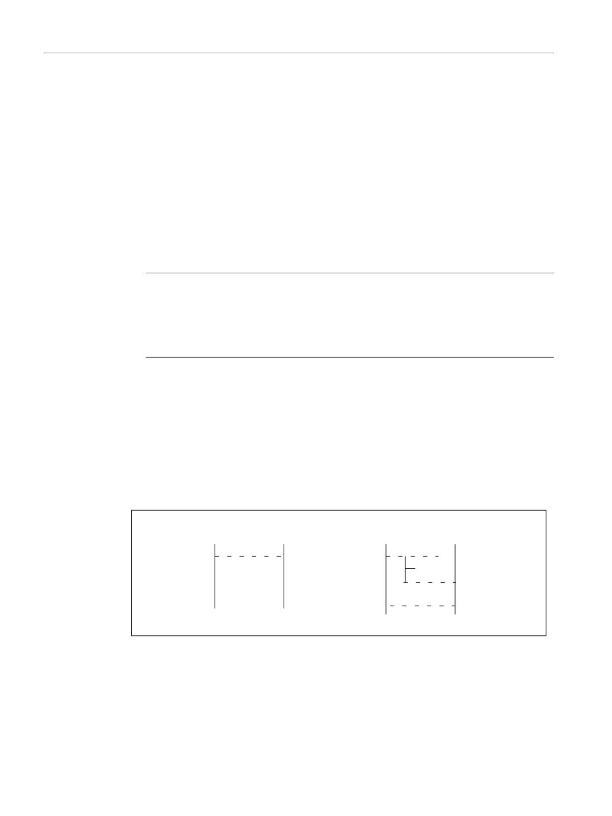
G1: Gantry axes
3.8 Examples
DB31, ... DBB101.7 = 1 (gantry axis)
In addition, the following steps must be taken:
●
RESET
●
Read off values in machine coordinate system:
e. g.
X = 0.941
Y = 0.000
XF = 0.000
●
Enter the X value of master axis 1 with inverted sign in the machine data of slave axis 3:
MD34090 $MA_REFP_MOVE_DIST_CORR = - 0.941 (reference point offset/absolute
offset)
Note
This machine data is effective after power ON. To avoid having to perform a power ON
now, the value can also be entered in the following machine data:
MD34080 $MA_REFP_MOVE_DIST (reference point distance)
This machine data is then valid after a RESET.
●
Start referencing again for axis 1 (master axis) with the modified machine data
●
Wait until message "10654 Channel 1 Waiting for synchronization start" appears
●
At this point in time, the NC has prepared axis 1 for synchronization and registers this at
the interface signal:
DB31 DB31, ... DBB101.4 = 1 (synchronization process ready to start)
DB31, ... DBB101.6 = 1 (leading axis LA)
DB31, ... DBB101.7 = 1 (gantry axis)
●
Examine actual positions of machine. Case A or B might apply:
$
$
$
$
!
!
GLII
5 !
!5
&DVH $
&DVH %
Figure 3-3
Possible results after referencing axis 1 (master axis)
Special functions
176
Function Manual, 12/2018, A5E40874099B AB
G1: Gantry axes
3.8 Examples
If Case A applies, the synchronization process can be started immediately (see "start
synchronization process" step). If Case B applies, the offset "diff" must be calculated and taken
into account:
● Measuring of diff
● By using two appropriate, right-angled reference points R' and R" in the machine bed (right
in picture), the difference in position in JOG can be traversed. The diff offset can then be
read as the difference in the position display. The diff offset must be entered in the machine
data of axis 3 (synchronized axis):
MD34100 $MA_REFP_SET_POS
Continue with 1st step (see above).
● Start gantry synchronization. PLC sets:
DB31, ... DBX29.4 = 1 (start synchronization of gantry)
3.8.4
Setting warning and trip limits
If the gantry grouping is set and synchronized, the following machine data must then be set:
MD37110 $MA_GANTRY_POS_TOL_WARNING (gantry warning limit)
MD37120 $MA_GANTRY_POS_TOL_ERROR (gantry trip limit)
Proceed as follows
● Set the machine data for all axes with a large value to begin with:
MD37120 $MA_GANTRY_POS_TOL_ERROR (gantry trip limit)
● Set a very small value in the machine data:
MD37110 $MA_GANTRY_POS_TOL_WARNING (gantry warning limit)
When you put a heavy, dynamic strain on the axes, the self-canceling alarm "10652 channel
%1 axis %2 gantry warning limit exceeded" will be output repeatedly.
● Now increase the following machine data:
MD37110 $MA_GANTRY_POS_TOL_WARNING (gantry warning limit)
Repeat this until the alarm no longer appears. The interface indicates the status:
DB31, ... DBX101.2 = 0 (gantry trip limit not exceeded)
DB31, ... DBX101.3 = 0 (gantry warning limit not exceeded)
DB31, ... DBX101.4 = 0 (gantry synchronization run not ready to start)
DB31, ... DBX101.5 = 1 (gantry grouping is synchronized)
DB31, ... DBX101.6 = 1 (gantry guide axis)
DB31, ... DBX101.7 = 1 (gantry axis)
If the monitoring still only triggers very sporadically, it is possible to program a edge memory
bit in the PLC user program.
● Enter the value calculated for the warning limit + a small safety provision in the following
machine data:
MD37120 $MA_GANTRY_POS_TOL_ERROR (gantry trip limit)
Error limit values
Values are entered in the following machine data:
Special functions
Function Manual, 12/2018, A5E40874099B AB
177

G1: Gantry axes
3.9 Data lists
MD37110 $MA_GANTRY_POS_TOL_WARNING (gantry warning limit)
MD37120 $MA_GANTRY_POS_TOL_ERROR (gantry trip limit)
MD37130 $MA_GANTRY_POS_TOL_REF (gantry shutdown limit when referencing)
These should have the following scales of magnitude at the end of the customizing process:
0'
0$B*$175<B326B72/B:$51,1*
0'
0$B*$175<B326B72/B(5525
0'
0$B*$175<B326B72/B5()
Note
The same procedure must be followed when starting up a gantry grouping in which the coupled
axes are driven by linear motors and associated measuring systems.
The error limits entered into machine data MD37110 and MD37120 are considered as
additional tolerance values of the actual-value difference of the master and following axis if
the interface bit "Gantry is synchronous" is not present (e.g. to be resynchronized after
canceling alarms without gantry).
3.9
Data lists
3.9.1
Machine data
3.9.1.1
Axis/spindlespecific machine data
Number
Identifier: $MA_
Description
30300
IS_ROT_AX
Rotary axis
32200
POSCTRL_GAIN
KV factor (servo gain)
32400
AX_JERK_ENABLE
Axial jerk limitation
32410
AX_JERK_TIME
Time constant for axial jerk filter
32420
JOG_AND_POS_JERK_ENABLE
Initial setting for axial jerk limitation
32430
JOG_AND_POS_MAX_JERK
Axial jerk
32610
VELO_FFW_WEIGHT
Feedforward control factor for speed feedforward control
32620
FFW_MODE
Feedforward control type
32650
AX_INERTIA
Moment of inertia for torque feedforward control
Special functions
178
Function Manual, 12/2018, A5E40874099B AB

G1: Gantry axes
3.9 Data lists
Number
Identifier: $MA_
Description
32800
EQUIV_CURRCTRL_TIME
Equivalent time constant, current control loop for feed-
forward control
32810
EQUIV_SPEEDCTRL_TIME
Equivalent time constant, speed control loop for feed
forward control
32900
DYN_MATCH_ENABLE
Dynamic adjustment
32910
DYN_MATCH_TIME
Time constant for dynamic response adaptation
33000
FIPO_TYPE
Fine interpolator type
34040
REFP_VELO_SEARCH_MARKER
Shutdown velocity
34070
REFP_VELO_POS
Velocity when approaching the reference point
34080
REFP_MOVE_DIST
Reference point approach distance
34090
REFP_MOVE_DIST_CORR
Reference point offset
34100
REFP_SET_POS
Reference point value
34110
REFP_CYCLE_NR
Axis sequence for channel-specific referencing
34330
REFP_STOP_AT_ABS_MARKER
Distance-coded linear measuring system without desti-
nation point
36012
STOP_LIMIT_FACTOR
Factor, exact stop coarse/fine - and zero speed
36030
STANDSTILL_POS_TOL
Standstill tolerance
36500
ENC_CHANGE_TOL
Maximum tolerance for position actual value switchover
37100
GANTRY_AXIS_TYPE
Gantry axis definition
37110
GANTRY_POS_TOL_WARNING
Gantry warning limit
37120
GANTRY_POS_TOL_ERROR
Gantry shutdown limit
37130
GANTRY_POS_TOL_REF
Gantry shutdown limit when referencing
37140
GANTRY_BREAK_UP
Break up gantry axis grouping
3.9.2
Signals
3.9.2.1
Signals from mode group
Signal name
SINUMERIK 840D sl
SINUMERIK 828D
Active machine function REF
DB11 DBX5.2
DB3100.DBX1.2
3.9.2.2
Signals from channel
Signal name
SINUMERIK 840D sl
SINUMERIK 828D
Referencing active
DB21, ... DBX33.0
DB330x.DBX1.0
Special functions
Function Manual, 12/2018, A5E40874099B AB
179

G1: Gantry axes
3.9 Data lists
3.9.2.3
Signals to axis/spindle
Signal name
SINUMERIK 840D sl
SINUMERIK 828D
Start gantry synchronization
DB31, ... DBX29.4
DB380x.DBX5005.4
No automatic synchronization
DB31, ... DBX29.5
DB380x.DBX5005.5
3.9.2.4
Signals from axis/spindle
Signal name
SINUMERIK 840D sl
SINUMERIK 828D
Referenced/synchronized 1, referenced/synchronized 2
DB31, ... DBX60.4/5
DB390x.DBX0.4/5
Gantry trip limit exceeded
DB31, ... DBX101.2
DB390x.DBX5005.2
Gantry warning limit exceeded
DB31, ... DBX101.3
DB390x.DBX5005.3
Gantry synchronization ready to start
DB31, ... DBX101.4
DB390x.DBX5005.4
Gantry grouping is synchronous
DB31, ... DBX101.5
DB390x.DBX5005.5
Gantry guide axis
DB31, ... DBX101.6
DB390x.DBX5005.6
Gantry axis
DB31, ... DBX101.7
DB390x.DBX5005.7
Special functions
180
Function Manual, 12/2018, A5E40874099B AB
K6: Contour tunnel monitoring
4
4.1
Brief description
4.1.1
Contour tunnel monitoring - 840D sl only
Function
The absolute movement of the tool tip in space is monitored. The function operates channel
specific.
Model
A round tunnel with a definable diameter is defined around the programmed path of a
machining operation. Axis movements are stopped as an option if the path deviation of the
tool tip is greater than the defined tunnel as the result of axis errors.
Response
In the event of a recognized deviation, the system reacts as quick as possible. However, at
least one interpolator clock cycle will pass, before one of the following reactions will occur:
● An alarm is triggered when the tunnel is violated and the axes continue to traverse.
● Violation of the tunnel triggers an alarm and the axis movements are decelerated.
Braking methods
If the monitoring tunnel is violated, one of the following methods can be used to decelerate:
● Deceleration ramp
● Speed setpoint zero and follow-up mode
Use
The function can be used for 2D and 3D paths. For 2D the monitoring surface is defined by
parallel lines to the programmed path. The monitoring area is defined by 2 or 3 geometry axis.
Monitoring of synchronized axes, positioning axes, etc. that are not geometry axes is
performed directly on the machine axis plane with the "Contour monitoring".
Special functions
Function Manual, 12/2018, A5E40874099B AB
181
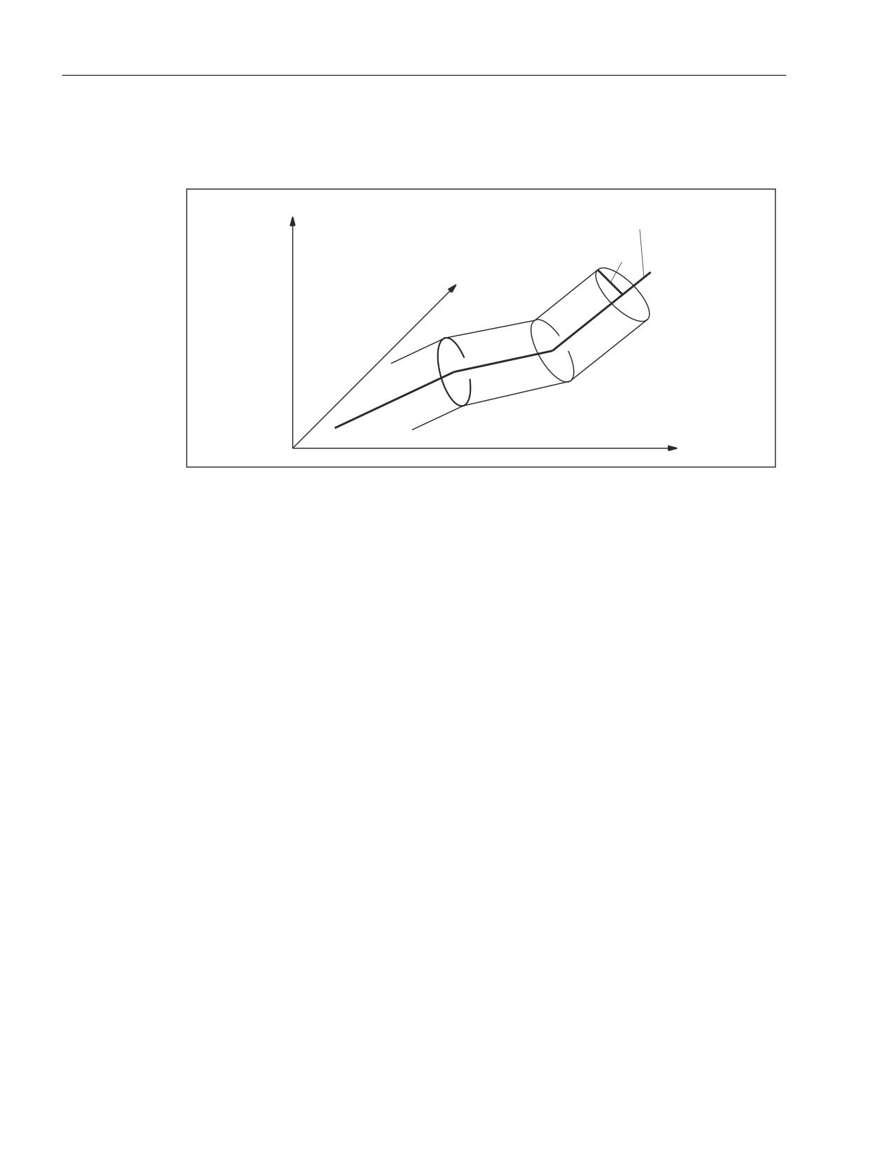
K6: Contour tunnel monitoring
4.1 Brief description
Example
The following figure is a diagram of the monitoring area shown by way of a simple example.
=
&RQWRXU 7RRO WLS SDWK
3HUPLWWHG WROHUDQFH
<
ಱ7XQQHOಯ DURXQG WKH FRQWRXU
WROHUDQFH EDQG
;
Figure 4-1
Position of the contour tunnel around the programmed path
As long as the calculated actual position of the tool tip remains inside the sketched tunnel,
motion continues in the normal way. If the calculated actual position violates the tunnel, an
alarm is triggered (in the default setting) and the axes are stopped by "Ramp Stop". This
response to the violation of the tunnel can be disabled (alarm triggered but movement
continued) or intensified (rapid stop) by means of a machine data setting.
Analysis
The calculated distance between the programmed path and the actual values can be routed
to an analog output to analyze the progression of the contour errors during normal operation
(quality control).
4.1.2
Programmable contour accuracy
Function
As an alternative to the function described in "Contour tunnel monitoring", i.e. monitoring of
the machining accuracy and stopping machining if excessive deviations occur, another function
is offered. With this function, the selected accuracy is always achieved with the path velocity
being reduced if necessary. Detailed information about this function can be found under the
subject "Programmable contour accuracy".
Special functions
182
Function Manual, 12/2018, A5E40874099B AB

K6: Contour tunnel monitoring
4.2 Contour tunnel monitoring - 840D sl only
4.2
Contour tunnel monitoring - 840D sl only
Aim of the monitoring function
The aim of the monitoring function is to stop the movement of the axes if axis deviation causes
the distance between the tool tip (actual value) and the programmed path (setpoint) to exceed
a defined value (tunnel radius).
Tunnel size
The radius of the contour tunnel being monitored around the programmed path must be defined
to implement the monitoring function:
MD21050 $MC_CONTOUR_TUNNEL_TOL (Response threshold for Contour tunnel
monitoring)
If the machine data is set to 0.0, monitoring is not performed. The value of the machine data
is transferred to the control for new configurations.
Parameterizable deceleration behavior
The deceleration behavior for the monitoring response can be set via the following machine
data:
MD21060 $MC_CONTOUR_TUNNEL_REACTION (Reaction upon response of contour
tunnel monitoring)
Value
Meaning
0
Display alarm and continue machining
1
Deceleration according to the deceleration ramps (default setting)
2
Rapid stop (speed setpoint = 0)
Encoder switchover
Switching between two encoder systems usually causes a sudden change in the actual position
of the tool tip. This change resulting from encoder switchover must not be so large as to cause
the tool tip to violate the monitoring tunnel. The radius defined in MD21050 must be higher
than the allowed tolerance on actual value switchover:
MD36500 $MA_ENC_CHANGE_TOL (Max. tolerance for position actual value switchover)
Activation
The monitoring will only become active if the following conditions are met:
● MD21050 is higher than 0.0.
● At least two geometry axes have been defined.
Special functions
Function Manual, 12/2018, A5E40874099B AB
183

K6: Contour tunnel monitoring
4.3 Programmable contour accuracy
Shutting down
Monitoring can be stopped by enabling the machine data setting:
MD21050 = 0.0.
Analysis output
The values of deviation of the actual value of the tool tip from the programmed path can - for
analysis purposes - be output on a fast analog output (accuracy monitoring).
The assignment of an analog output to output the contour error is programmed in machine
data:
MD21070 $MC_CONTOUR_ASSIGN_FASTOUT
Value
Meaning
0
No output (default setting)
1
Output to output 1
2
Output to output 2
…
…
8
Output to output 8
Scale
The tunnel radius set in MD21050 corresponds to a voltage of 10 V at the output.
4.3
Programmable contour accuracy
Function
The function "Programmable contour accuracy" limits the contour errors caused by control
behavior and jerk filter to a specified value by reducing the path velocity on curved contours
by the necessary amount. It allows the user to set a compromise between accuracy and
productivity of a machining.
Note
The "LookAhead" function ensures that the velocity necessary for maintaining the required
contour accuracy is not exceeded at any point along the path.
Configuration
The mode of operation and parameterization of the function is determined by the machine data:
Special functions
184
Function Manual, 12/2018, A5E40874099B AB

K6: Contour tunnel monitoring
4.3 Programmable contour accuracy
MD20470 $MC_CPREC_WITH_FFW (programmable contour accuracy)
Value
Meaning
0
The "Programmable contour accuracy" function has no effect when feedforward control is also
active.
1
The "Programmable contour accuracy" function also acts for feedforward control.
With active feedforward control, the reduction of the path velocity is calculated on the basis of
the effective KV factor with feedforward control.
2
Like 1, the function, however, is parameterized with MD32415 $MA_EQUIV_CPREC_TIME
(time constant for the programmable contour accuracy).
The jerk filter is correctly taken into account. The SD42450 $SC_CONTPREC setting data
determines the permissible contour errors (see "Parameterization").
3
Like for 2, but any contour accuracy programmed with CTOL has priority over SD42450
$SC_CONTPREC.
The jerk filter is correctly taken into account. The programmed CTOL contour tolerance deter-
mines the permissible contour errors (see "Parameterization"). $SC_CONTPREC is only rel-
evant if CTOL was not programmed.
4
The "Programmable contour accuracy" function is active irrespective of the feedforward control
and jerk filter. Only MD32415 $MA_EQUIV_CPREC_TIME is considered in the calculation of
the contour error. All time constants that affect the contour error must be added together and
entered in MD32415 $MA_EQUIV_CPREC_TIME.
5
Like for 4, but any programmed contour accuracy with CTOL has priority over SD42450
$SC_CONTPREC.
For the MD20470 = 2 or 3 functional versions, the control assumes that there is a jerk filter
time constant (MD32410 $MA_AX_JERK_TIME) for which the setting of the control section
with feedforward control produces a negligible contour error. This value must be entered in
the machine data MD32415 $MA_EQUIV_CPREC_TIME (see "Parameterization").
To calculate the contour error based on the set jerk filter type (MD32402
$MA_AX_JERK_MODE), the following value is used:
● For active feedforward control, the difference:
MD32410 $MA_AX_JERK_TIME - MD32415 $MA_$MA_EQUIV_CPREC_TIME
● Without feedforward control, the complete value from MD32410 $MA_AX_JERK_TIME
This procedure allows the commissioning engineer to first change from an initially precise, but
possibly excessively hard, setting by increasing the jerk filter time constants to a softer setting
with a controlled loss of accuracy.
If function "Programmable contour accuracy" is used in combination with jerk filter type "FIR
low pass" (MD32402 $MA_AX_JERK_MODE = 5), memory space must be made available for
the characteristic curve approximation of FIR filters during commissioning with the memory-
configuring machine data MD38020 $MA_MM_CPREC_FIR_POINTS. If no memory is made
available (MD38020 = 0), the function cannot be executed and alarm 10990 is output.
Restrictions:
● The function does not use the "band stop" jerk filter type (MD32402 $MA_AX_JERK_MODE
= 3).
● The MD20470 = 2 or 3 functional versions are primarily intended for use with feedforward
control. If one of the two functional versions is active for switched off feedforward control,
a contour error that results from the Kv factor is added. This reduces the path velocity
significantly faster.
Special functions
Function Manual, 12/2018, A5E40874099B AB
185
K6: Contour tunnel monitoring
4.3 Programmable contour accuracy
Note
The MD20470 = 0 or 1 functional versions are no longer recommended. They only provide
compatibility with older software versions.
Parameterization
Contour accuracy
The maximum contour error for the path of the geometry axes on curved contours is determined
by:
● For MD20470 $MC_CPREC_WITH_FFW = 2 with the setting data:
SD42450 $SC_CONTPREC (contour accuracy)
● For MD20470 $MC_CPREC_WITH_FFW = 3 with the contour tolerance programmed with
CTOL.
The smaller the value and the lower the Kv factor of the geometry axes, the greater the path
feedrate on curved contours is lowered.
Minimum path feedrate
The user can use the following setting data to specify a minimum path feedrate for the
"Programmable contour accuracy" function:
SD42460 $SC_MINFEED (minimum path feed with CPRECON)
The feedrate will not limited below this value, unless a lower F value has been programmed
or the dynamic limitations of the axes force a lower path velocity.
Time constant for the programmable contour accuracy
The equivalent time constant for the MD20470 = 2 or 3 functional versions (see "Configuration")
is entered in the machine data:
MD32415 $MA_EQUIV_CPREC_TIME (time constant for the programmable contour
accuracy)
MD32415 must contain that jerk filter time constant (MD32410 $MA_AX_JERK_TIME) for
which the contour error for active feedforward control is negligibly small.
Programming
The "programmable contour accuracy" can be activated and deactivated in the part program
with the CPRECON and CPRECOF modal G commands.
Example:
Program code
Comment
N10 G0 X0 Y0
N20 CPRECON
; Activate the "programmable contour accuracy".
N30 G1 G64 X100 F10000
; Machining with 10 m/min in the continuous-path mode.
N40 G3 Y20 J10
; Automatic feed limitation in circular block.
Special functions
186
Function Manual, 12/2018, A5E40874099B AB
K6: Contour tunnel monitoring
4.4 Constraints
Program code
Comment
N50 G1 X0
; Feedrate again without limitation (10 m/min).
N100 CPRECOF
; Deactivate the "programmable contour accuracy".
N110 G0 ...
The two CPRECON and CPRECOF modal G commands form G group 39 (programmable
contour accuracy).
Behavior for part program start and after reset / part program end
For part program start and after reset / part program end, the configured control initial setting
acts for the G group 39:
MD20110 $MC_RESET_MODE_MASK (definition of initial control settings after RESET / TP
End)
MD20112 $MC_START_MODE_MASK (definition of the basic setting of the control after part
program start)
Supplementary conditions
Positioning axes
The function considers only the geometry axes of the path. It does not have any effect of the
velocities for the positioning axes.
References
Information about MD32402 $MA_AX_JERK_MODE (filter type for axial jerk limitation) and
MD32410 $MA_AX_JERK_TIME (time constant for the axial jerk filter), see:
● Function Manual, Basic Functions; Acceleration (B2), Section: "Functions" > "Jerk filter
(position setpoint filter, axis-specific)"
Information about CTOL, see:
● Function Manual, Basic Functions; Continuous-Path Mode, Exact Stop, Look Ahead (B1),
Section: "Contour/orientation tolerance"
4.4
Constraints
Availability of the "Contour tunnel monitoring" function
The function is an option ("Contour monitoring with tunnel function"), which must be assigned
to the hardware via the license management.
Special functions
Function Manual, 12/2018, A5E40874099B AB
187

K6: Contour tunnel monitoring
4.5 Data lists
Coupled motion
If coupled motion between two geometry axes is programmed with contour tunnel monitoring,
this always results in activation of the contour tunnel monitoring. In this case, the contour tunnel
monitoring must be switched off before programming the coupled motion:
MD21050 $MC_CONTOUR_TUNNEL_TOL = 0.0
4.5
Data lists
4.5.1
Machine data
4.5.1.1
Channelspecific machine data
Number
Identifier: $MC_
Description
20110
RESET_MODE_MASK
Determination of basic control settings after Reset / TP
End
20112
START_MODE_MASK
Definition of the initial control settings after part program
start
20470
CPREC_WITH_FFW
Programmable contour accuracy
21050
CONTOUR_TUNNEL_TOL
Response threshold for contour tunnel monitoring
21060
CONTOUR_TUNNEL_REACTION
Reaction to response of contour tunnel monitoring
21070
CONTOUR_ASSIGN_FASTOUT
Assignment of an analog output for output of the contour
error
4.5.1.2
Axis/spindlespecific machine data
Number
Identifier: $MA_
Description
32402
AX_JERK_MODE
Filter type for axial jerk limitation
32410
AX_JERK_TIME
Time constant for axial jerk filter
32415
EQUIV_CPREC_TIME
Time constant for the programmable contour accuracy
36500
ENC_CHANGE_TOL
Maximum tolerance for position actual value switchover
Special functions
188
Function Manual, 12/2018, A5E40874099B AB

K6: Contour tunnel monitoring
4.5 Data lists
4.5.2
Setting data
4.5.2.1
Channelspecific setting data
Number
Identifier: $SC_
Description
42450
CONTPREC
Contour accuracy
42460
MINFEED
Minimum path feed for CPRECON
Special functions
Function Manual, 12/2018, A5E40874099B AB
189
K6: Contour tunnel monitoring
4.5 Data lists
Special functions
190
Function Manual, 12/2018, A5E40874099B AB
K7: Kinematic chain
5
5.1
Function description
5.1.1
Characteristics
This section describes how the kinematic structure of a machine can be mapped using a
kinematic chain and parameterized in the control using system variables for NC functions such
as "collision avoidance" or "kinematic transformation".
The system variables are retentively saved in the NC and can be archived and/or read as "NC
data" via SINUMERIK Operate using the commissioning archive.
For functions such as "collision avoidance" which also require a description of the machine
geometry, see Chapter "K8: Geometric machine modeling (Page 225)".
Note
Graphical editor
As an alternative to writing the system variables in a part program, the machine can be modeled
from the SINUMERIK Operate user interface:
Operating area: "Commissioning" > "NC" > "Machine model"
Changes to the machine model
The direct changes to the machine model at the system variables only become visible at the
user interface after explicitly requesting that the machine model is recalculated by calling the
PROTA() (Page 294) or PROTS() (Page 295) function.
Changes to the machine model made at the user interface are immediately accepted in the
system variables of the NC. The changes only become active after explicitly requesting that
the machine model is recalculated by calling the PROTA() (Page 294) or PROTS()
(Page 295) function.
Kinematic structure
The kinematic structure of a machine comprises the following:
● Number and type of the machine axes: Linear or rotary axes
● Arrangement of the machine axes: Position and orientation
● Dependencies of the machine axes to one another: Which machine axis traverses with
which other machine axis.
Special functions
Function Manual, 12/2018, A5E40874099B AB
191
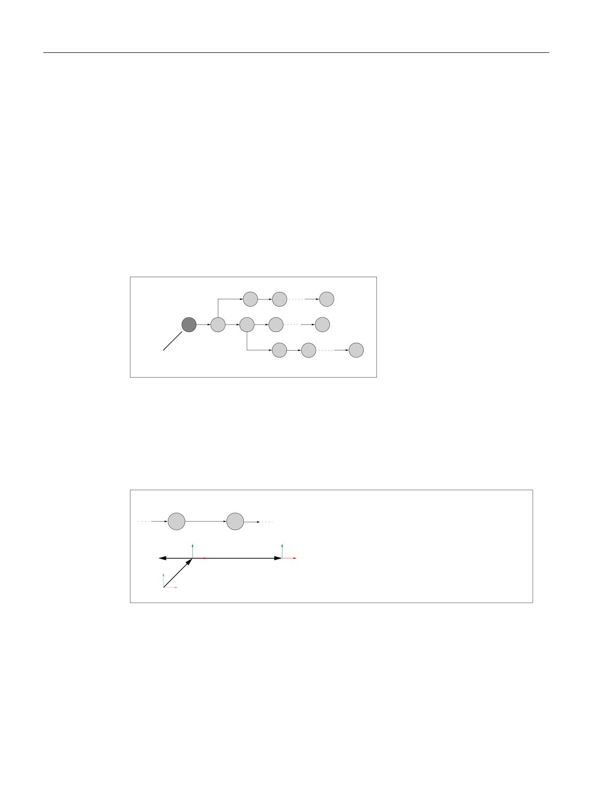
K7: Kinematic chain
5.1 Function description
Kinematic chain
A kinematic structure of a machine is described using a kinematic chain with the following
properties:
● A kinematic chain consists of an arbitrary number of interconnected elements.
● Parallel subchains can branch off from a kinematic chain.
● Only one active kinematic chain is available in the control.
● The active kinematic chain starts with the root element.
● Parameterized elements or subchains that are not connected to the root element or whose
connection points toward the root element, are not part of the currently active kinematic
chain.
● A kinematic chain is defined in the spatially fixed coordinates of the world coordinate system.
3DUDOOHOH 7HLONHWWH
3DUDOOHOH 7HLONHWWH
5RRW (OHPHQW
$QIDQJ GHU ZLUNVDPHQ NLQHPDWLVFKHQ .HWWH
Figure 5-1
Example of a kinematic chain
Element
An element of a kinematic chain basically describes the transformation with which the local
coordinate system of the previous element is mapped in the local coordinate system of the
current element:
Kn-1 ⇒ Tn ⇒ Kn
(OHPHQW
(OHPHQW
HQ
HQ
<Q
<Q
7Q
.[ /RFDO HOHPHQW FRRUGLQDWH V\VWHPV
;Q
.Q
.Q;Q
7UDQVIRUPDWLRQV
<
7Q
7Q &RQVWDQW RIIVHW LQ WKH ; < GLUHFWLRQ
Q
7Q &KDQJHDEOH RIIVHW LQ WKH ; GLUHFWLRQ WKURXJK OLQHDU D[LV
;
Q
.Q
Figure 5-2
Local element coordinate systems
The following constant transformations are possible:
● Offset (type: OFFSET (Page 211))
● Rotation (type: ROT_CONST (Page 209))
Special functions
192
Function Manual, 12/2018, A5E40874099B AB
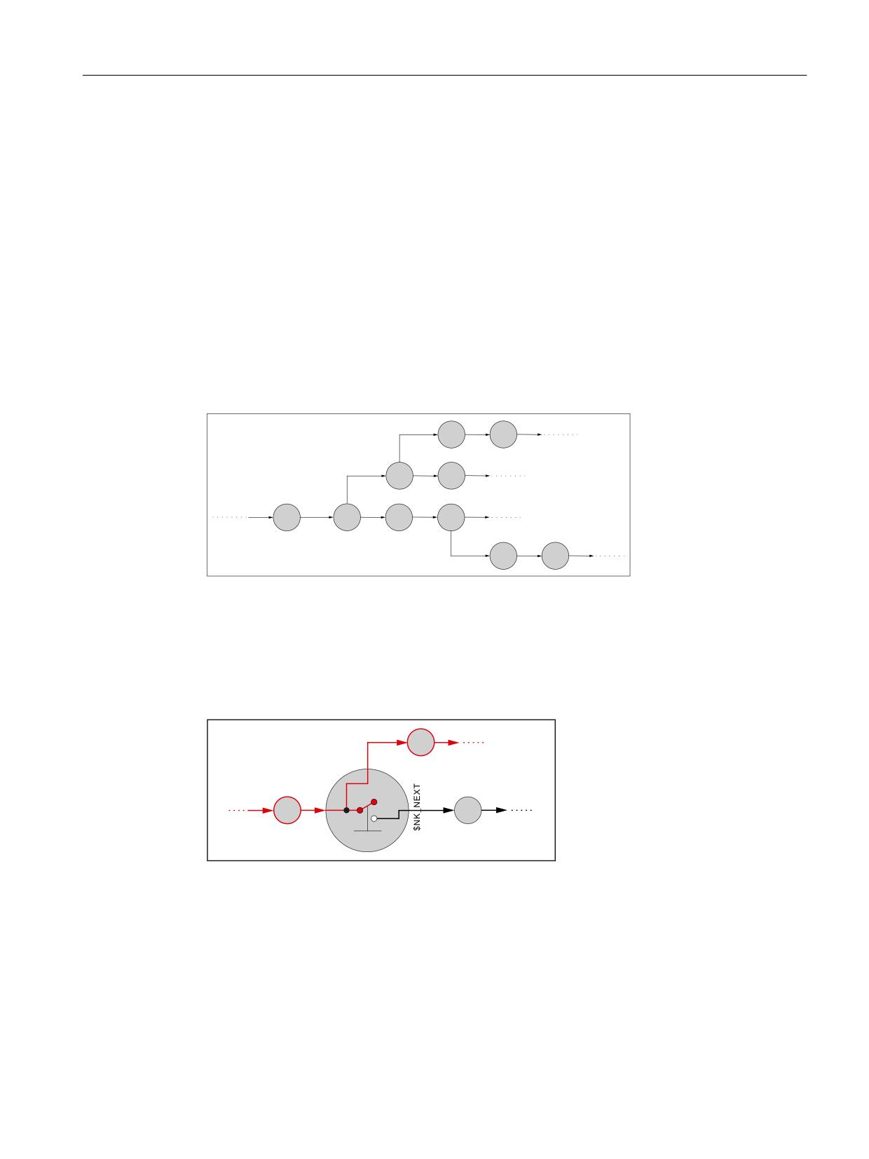
K7: Kinematic chain
5.1 Function description
The following changing transformations, based on the current position values of the machine
axis assigned to the element (linear axis / rotary axis), are possible:
● Offset (type: AXIS_LIN (Page 202))
● Rotation (type: AXIS_ROT (Page 205))
A position or orientation change in an element, e.g. through a position change of the associated
machine axis, affects all the following elements of the chain or parallel subchains.
The maximum number of possible elements can be parameterized using machine data
(Page 197).
Parallel subchains
If a parallel subchain branches off from an element en, then for the kinematics, the branch is
always before the element. For this reason, a change in element en, e.g. a position change of
the associated machine axis, does not affect the subchain branch.
HO
HO
HN
HN
HQ
HQ
HQ
HQ
HP
HP
Figure 5-3
Parallel subchains branching off from elements en and en+2
Switch
A switch is a special element that is not kinematically active (type: SWITCH (Page 212)) in a
kinematic chain, which can assume the CLOSED and OPEN states.
In the OPEN state, the connection from the previous to the following element is interrupted.
HN
1.B
3$5$//(/
V[
HQ
HQ
[
\
Figure 5-4
OPEN state
In the CLOSED state, the previous element is connected to the following element.
Special functions
Function Manual, 12/2018, A5E40874099B AB
193
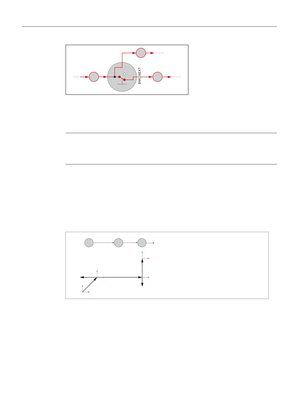
K7: Kinematic chain
5.1 Function description
HN
1.B
3$5$//(/
V[
HQ
HQ
[
\
Figure 5-5
CLOSED state
The switch does not influence the connection to a parallel element.
The maximum number of possible switches can be parameterized usingmachine data
(Page 197).
Note
Local coordinate system
The local coordinate system of a switch is not rotated with respect to the world coordinate
system.
World coordinate system
In order to uniquely describe the kinematic stricture of a machine, all elements of the kinematic
chain - as well as the orientation and offset vectors of the machine axes and the constant
rotation/offsets - are referred to the world coordinate system.
Elements with linear axes do not change the orientation of the following elements. The
orientation and offset vectors of the following elements can therefore refer to the world
coordinate system without further supplementary conditions.
(OHPHQW
(OHPHQW
(OHPHQW
H
H
H
<
;
:RUOG FRRUGLQDWH V\VWHP
7
/RFDO HOHPHQW FRRUGLQDWH V\VWHPV
<
<
7
7UDQVIRUPDWLRQV
;
;
7
&RQVWDQW RIIVHW LQ WKH ; < GLUHFWLRQ
7
&KDQJHDEOH RIIVHW LQ WKH ; GLUHFWLRQ WKURXJK OLQHDU D[LV
7
<
7
&KDQJHDEOH RIIVHW LQ WKH < GLUHFWLRQ WKURXJK OLQHDU D[LV
;
Elements with rotary axes change the orientation of the following elements. This is the reason
that the orientation and offset vectors of the following elements, for a defined initial position of
the previous orientation changing elements, must be referred to the world coordinate system.
Special functions
194
Function Manual, 12/2018, A5E40874099B AB
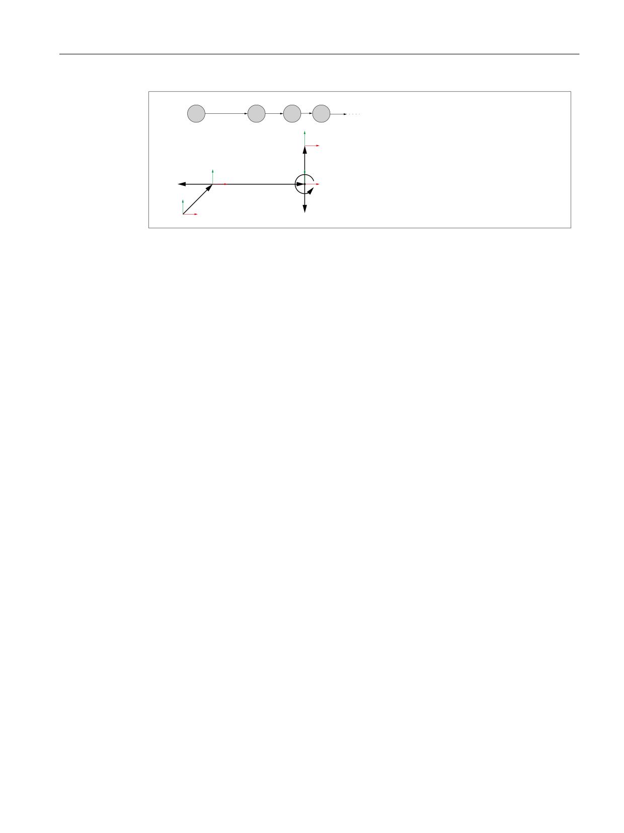
K7: Kinematic chain
5.2 Commissioning
(OHPHQW
(OHPHQW
(OHPHQW (OHPHQW
H
H
H
H
<
;
:RUOG FRRUGLQDWH V\VWHP
ORFDO HOHPHQW FRRUGLQDWH V\VWHPV
7
<
<
7UDQVIRUPDWLRQV
7
7
FRQVWDQW RIIVHW LQ WKH ; < GLUHFWLRQ
;
7
FKDQJLQJ RIIVHW LQ WKH ; GLUHFWLRQ ZLWK D OLQHDU D[LV
;
7
7
FKDQJLQJ URWDWLRQ DURXQG WKH = ZLWK D URWDU\ D[LV
<
7
7
FKDQJLQJ RIIVHW LQ WKH < GLUHFWLRQ ZLWK D OLQHDU D[LV
,QLWLDO SRVLWLRQ 7 URWDU\ D[LV GHJUHH
;
The origin and orientation of the world coordinate system can be freely selected in chain
elements that are defined before the root element. For the active coordinate system after the
root element, the following conditions must be met:
● Origin of the world coordinate system at the machine zero point
● Orientation of the world coordinate system so that the coordinate axes are arranged in the
positive traversing direction of the machine linear main axes
Direction vectors
Within a kinematic chain, the direction vectors, which are used to specify the alignment of the
machine axes, are always specified in absolute terms, i.e. referred to the world coordinate
system.
5.2
Commissioning
5.2.1
General
5.2.1.1
Overview
The commissioning of the "Kinematic chain" function is performed using:
● Machine data
- Specification of the quantity structure
- Specification of the first element in the kinematic chain
● System variables
- Specification of the kinematic properties of an element
- Connection of the element to the kinematic chain
Special functions
Function Manual, 12/2018, A5E40874099B AB
195
K7: Kinematic chain
5.2 Commissioning
5.2.1.2
Structure of the system variables
The system variables are structured according to the following scheme:
● $NK_<Name>[<Index_1>]
● $NK_<Name>[<Index_1>, <Index_2>]
General
The system variables to describe the elements of kinematic chains have the following
properties:
● The prefix for all system variables of the kinematic chain is $NK_, (N for NC, K for kinematic).
● The system variables can be read and written via NC programs.
● The system variables can be stored in archives and loaded to the NC again.
Data type
STRING
All system variables of the STRING data type have the following properties:
● Maximum string length: 31 characters
● No distinction is made between upper and lower case
Example: "Axis1" is identical to "AXIS1"
● Spaces and special characters are permitted
Example: "Axis1" is not identical to "Axis 1"
● Names that start with two underscores "__" are reserved for system purposes and must
not be used for user-defined names.
Note
Leading space
Since spaces are valid and distinct characters, names that start with a space followed by two
underscores "__" can, in principle, be used for user-defined names. However, because they
can be easily mistaken for system names, this procedure is not recommended.
Index_1
The individual elements are addressed via index_1. Index 0 → 1. Element, index 1 → 2.
Element, ... n → (n+1) element, with n = ($MN_MM_MAXNUM_KIN_CHAIN_ELEM - 1)
All system variables of an element have the same index.
Special functions
196
Function Manual, 12/2018, A5E40874099B AB
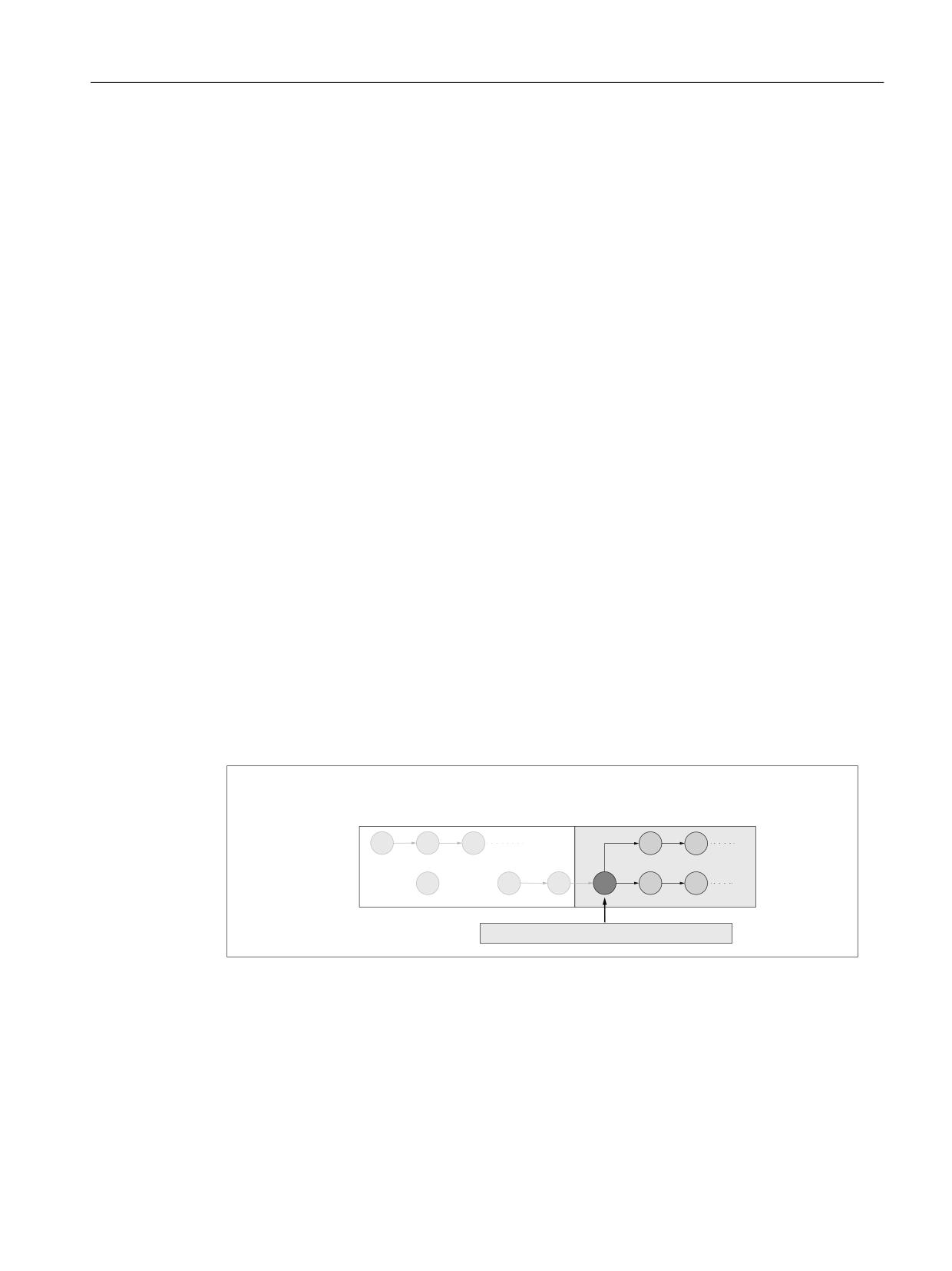
K7: Kinematic chain
5.2 Commissioning
Index_2
For system variables that contain a vector, the coordinates of the vector are addressed via
index_2.
●
0 → X axis
●
1 → Y axis
●
2 → Z axis
5.2.2
Machine data
5.2.2.1
Maximum number of elements
The maximum number of elements for kinematic chains is set using machine data.
MD18880 $MN_MM_MAXNUM_KIN_CHAIN_ELEM = <number>
5.2.2.2
Root element
The following machine data is used to specify the root element, i.e. the first element of the
currently active kinematic chain.
MD16800 $MN_ROOT_KIN_ELEM_NAME = "<element_name>"
All parameterized elements and subchains that are connected to the root element in such a
way that the connection starts at the root element, are part of the currently active kinematic
chain.
Parameterized elements or subchains that are not connected to the root element or whose
connection points towards the root element, are not part of the currently active kinematic chain.
3DUDPHWHUL]HG HOHPHQWV DQG VXEFKDLQV WKDW DUH QRW
(OHPHQWV DQG VXEFKDLQV RI WKH DFWLYH NLQHPDWLF
SDUW RI WKH DFWLYH NLQHPDWLF FKDLQ
FKDLQ
0'
01B5227B.,1B(/(0B1$0(
5.2.2.3
Maximum number of switches
The maximum number of switches for kinematic chains is set with the machine data
MD18882 $MN_MM_MAXNUM_KIN_SWITCHES = <number>
Special functions
Function Manual, 12/2018, A5E40874099B AB
197
K7: Kinematic chain
5.2 Commissioning
5.2.3
System variables
5.2.3.1
Overview
System variables independent of any element
System variable
Meaning
$NK_SWITCH
Switch variable to open and close the switch
Element-specific system variables
Element-specific system variables are subdivided into variables that are independent of the
type and dependent on the type:
● Variables independent of the type
System variable
Meaning
$NK_NAME
Name of the current element en
$NK_NEXT
Name of the next element en+1
$NK_PARALLEL
Name of a branching parallel element ep before the current element
en
$NK_TYPE
Type of the element
● Variables dependent on the type
System variable
Meaning
$NK_OFF_DIR
Offset or direction vector
$NK_AXIS
Machine axis or object name
$NK_A_OFF
Work offset for linear axis or rotary axis
$NK_SWITCH_INDEX
Switch index
$NK_SWITCH_POS
Switch position "CLOSED"
For the following types, variables dependent on the type are evaluated:
System variable
Type
OFFSET
AXIS_LIN
AXIS_ROT
ROT_CON
SWITCH
ST
$NK_OFF_DIR
x
x
x
x
-
$NK_AXIS
-
x
x
-
-
$NK_A_OFF
-
x
x
x
-
$NK_SWITCH_INDEX
-
-
-
-
x
$NK_SWITCH_POS
-
-
-
-
x
Special functions
198
Function Manual, 12/2018, A5E40874099B AB
K7: Kinematic chain
5.2 Commissioning
The system variables are described in detail in the following sections.
Note
Establish a defined initial state
It is recommended that a defined initial state be generated before parameterizing the kinematic
chain. To do this, the system variables of the kinematic chain should be set to their default
value using function DELOBJ() (Page 215).
Change system variable values
If the value of one of the system variables listed above is changed, then the change becomes
immediately visible on the user interface, e.g. SINUMERIK Operate. The machine model of
the NC is only updated after explicitly requesting that the machine model is recalculated by
calling the PROTA() (Page 294) or PROTS() (Page 295) function.
5.2.3.2
$NK_NAME
Function
Enter the NC-wide unique element name in the system variable. The element is referenced
via this name, e.g. within kinematic chains. The name is also displayed in the graphical editor
of SINUMERIK Operate.
Syntax
$NK_NAME[<n>] = "<name>"
Meaning
$NK_NAME:
Name of the element
Data type:
STRING
Default value:
"" (empty string)
<n>:
System variable or element index
Data type:
INT
Range of values:
0, 1, 2, ... ($MN_MM_MAXNUM_KIN_CHAIN_ELEM - 1)
<name>:
Element name, max. string length: 31 characters
Data type:
STRING
Example
The 9th kinematic element is assigned the name "B axis":
Program code
Comment
N100 $NK_NAME[8] = "B axis"
; 9th kinematic element,
; name = "B axis"
Special functions
Function Manual, 12/2018, A5E40874099B AB
199

K7: Kinematic chain
5.2 Commissioning
5.2.3.3
$NK_NEXT
Function
If the element is part of a kinematic chain, the name of the following element should be entered
in the system variable.
Syntax
$NK_NEXT[<n>] = "<name>"
Meaning
NK_NEXT:
Name of the following element
Data type:
STRING
Range of values:
All names contained in $NK_NAME (Page 199)
Default value:
"" "" (empty string)
<n>:
System variable or element index
Data type:
INT
Range of values:
0, 1, 2, ... ($MN_MM_MAXNUM_KIN_CHAIN_ELEM - 1)
<name>:
Element name, max. string length: 31 characters
Data type:
STRING
Example
The 9th kinematic element does not have a following element:
Program code
Comment
N100 $NK_NEXT[8] = ""
; 9. kin. element,
; following element = ""
5.2.3.4
$NK_PARALLEL
Function
The name of the element that branches off before the current element should be entered in
the system variable. The branching element is parallel to the current element. Changes to the
current element, e.g. position changes of the assigned machine axis, have no effect on the
parallel element.
Syntax
$NK_PARALLEL[<n>] = "<name>"
Special functions
200
Function Manual, 12/2018, A5E40874099B AB
K7: Kinematic chain
5.2 Commissioning
Meaning
$NK_PARALLEL:
Name of the parallel element
Data type:
STRING
Range of values:
All names contained in $NK_NAME (Page 199)
Default value:
"" "" (empty string)
<n>:
System variable or element index
Data type:
INT
Range of values:
0, 1, 2, ... ($MN_MM_MAXNUM_KIN_CHAIN_ELEM - 1)
<name>:
Element name, max. string length: 31 characters
Data type:
STRING
Example
The "Offset to the rotary table" element is arranged parallel to the 9th kinematic element:
Program code
Comment
N100 $NK_PARALLEL[8] = "Offset to the rotary
; Parallel to the 9th kin. element,
table"
; name = "Offset to the rotary table"
5.2.3.5
$NK_TYPE
Function
The element type should be entered in the system variable:
Type
Description
AXIS_LIN
The element describes a linear machine axis (linear axis) with direction vector
(Page 202)
$NK_OFF_DIR and work offset $NK_A_OFF.
AXIS_ROT
The element describes a rotary machine axis (rotary axis) with direction vector
(Page 205)
$NK_OFF_DIR and work offset $NK_A_OFF or a spindle.
Note
The position of a spindle is considered differently depending on the function used by
the kinematic chain:
● Collision avoidance: Indeterminate position
● Kinematic transformation: Depending on the setting in $NT_CNTRL, bit 1-3, the
position corresponding to $NK_A_OFF or the speed setpoint is taken into
consideration
ROT_CONST
The element describes a constant rotation around direction vector $NK_OFF_DIR
(Page 209)
and angle $NK_A_OFF.
OFFSET
The element describes a constant linear offset with the offset vector $NK_OFF_DIR.
(Page 211)
SWITCH
The element defines a switch, which is switched using system variable
(Page 212)
$NK_SWITCH (Page 214).
Special functions
Function Manual, 12/2018, A5E40874099B AB
201
K7: Kinematic chain
5.2 Commissioning
Syntax
$NK_TYPE[<n>] = "<Typ>"
Meaning
$NK_TYPE:
Type of the element
Data type:
STRING
Default value:
"" (empty string)
<n>:
System variable or element index
Data type:
INT
Range of values:
0, 1, 2, ... ($MN_MM_MAXNUM_KIN_CHAIN_ELEM - 1)
<Typ>:
Element name, max. string length: 31 characters
Data type:
STRING
Range of values:
"AXIS_LIN", "AXIS_ROT", "ROT_CONST", "OFFSET",
"SWITCH"
Example
The 9th kinematic element is a rotary axis:
Program code
Comment
N100 $NK_TYPE[8] = "AXIS_ROT"
; 9th kin. element
; type = rotary axis
5.2.3.6
Type-dependent variables for $NK_TYPE = "AXIS_LIN"
$NK_OFF_DIR
Function
The direction vector along which the linear axis $NK_AXIS assigned to the element moves,
should be entered in the system variable. The output coordinate system therefore results from
the input coordinate system, offset by the current position value of the linear axis and the work
offset specified in $NK_A_OFF.
Supplementary conditions:
● The direction vector must be specified as an absolute value, i.e. in relation to the world
coordinate system.
● The direction vector must be specified so that it points in the positive traversing direction
of the machine axis.
● The absolute value of the direction vector must be greater than 1*10-6.
Syntax
$NK_OFF_DIR[<n>,<k>] = <value>
Special functions
202
Function Manual, 12/2018, A5E40874099B AB