SINUMERIK 840D sl. Service - Functions. Manual (2018-2020) - page 61

Interface signals
19.2 Interface signals - detailed description
19.2.11
DB1072: Tool management, spindle (multitool)
19.2.11.1
DB1072 DBW(n+0) (distance coding)
DB1072 DBW(n+0)
Distance coding
Signal flow
NC → PLC
Update
Job-controlled
Signal state 1
Type of distance coding of the multitool (corresponds to $TC_MTP_KD)
1 = location number
2 = distance
3 = angle
Signal state 0
No distance coding specified.
Additional information
Start addresses of the spindles:
Spindle 1: n = 0
Spindle 2: n = 50
Spindle 3: n = 100
19.2.11.2
DB1072 DBW(n+2) (multitool location number)
DB1072 DBW(n+2)
Multitool location number
Signal flow
NC → PLC
Update
Job-controlled
Signal state 1
Number of locations of the multitool
Signal state 0
No data regarding the number of locations.
Additional information
Start addresses of the spindles:
Spindle 1: n = 0
Spindle 2: n = 50
Spindle 3: n = 100
19.2.11.3
DB1072 DBW(n+4) (multitool location distance)
DB1072 DBW(n+4)
Multitool location distance
Signal flow
NC → PLC
Update
Job-controlled
Signal state 1
Distance of the MT location to be positioned from the reference location (real value), corre-
sponding to the distance coding
Signal state 1
No data regarding the distance of the MT location to be positioned.
Additional information
Start addresses of the spindles:
Spindle 1: n = 0
Spindle 2: n = 50
Spindle 3: n = 100
PLC
752
Function Manual, 10/2020, 6FC5397-0HP40-0BA1

Interface signals
19.2 Interface signals - detailed description
19.2.11.4
DB1072 DBW(n+8) (multitool number (new tool))
DB1072 DBW(n+8)
Multitool number (new tool)
Signal flow
NC → PLC
Update
Job-controlled
Signal state 1
Internal T number of the (new) multitool.
Signal state 0
No internal T number specified.
Additional information
Start addresses of the spindles:
Spindle 1: n = 0
Spindle 2: n = 50
Spindle 3: n = 100
19.2.11.5
DB1072 DBW(n+10) (multitool location number (new tool))
DB1072 DBW(n+10)
Multitool location number (new tool)
Signal flow
NC → PLC
Update
Job-controlled
Signal state 1
Location number within the multitool (where the new tool is located).
Signal state 0
No location number specified.
Additional information
Start addresses of the spindles:
Spindle 1: n = 0
Spindle 2: n = 50
Spindle 3: n = 100
19.2.11.6
DB1072 DBW(n+12) (multitool number (old tool))
DB1072 DBW(n+12)
Multitool number (old tool)
Signal flow
NC → PLC
Update
Job-controlled
Signal state 1
Internal T number of the (old) multitool.
The T number is entered here if the preparation or the change to a tool is realized within the
same multitool (which, due to a previous change, is located on the tool holder). It is identical
with DB1072 DBW(n + 8)
Signal state 0
No internal T number of the multitool specified.
Additional information
Start addresses of the spindles:
Spindle 1: n = 0
Spindle 2: n = 50
Spindle 3: n = 100
PLC
Function Manual, 10/2020, 6FC5397-0HP40-0BA1
753

Interface signals
19.2 Interface signals - detailed description
19.2.11.7
DB1072 DBW(n+14) (multitool location number (old tool))
DB1072 DBW(n+14)
Multitool location number (old tool)
Signal flow
NC → PLC
Update
Job-controlled
Signal state 1
Location number within the multitool (where the old tool is located).
The location number - where the old tool is located - is entered here if the preparation or the
change to a tool is realized within the same multitool (which, due to a previous change, is
located on the tool holder).
Signal state 0
No multitool location number specified.
Additional information
Start addresses of the spindles:
Spindle 1: n = 0
Spindle 2: n = 50
Spindle 3: n = 100
19.2.11.8
DB1072 DBW(n+16) (new tool: Location type)
DB1072 DBW(n+16)
New tool: Location type
Signal flow
NC → PLC
Update
Job-controlled
Signal state 1
Location type of the new tool (of the programmed tool in the multitool).
Signal state 0
No location type specified.
Additional information
Start addresses of the spindles:
Spindle 1: n = 0
Spindle 2: n = 50
Spindle 3: n = 100
Corresponds with
Tool size: Left, right, top, bottom
19.2.11.9
DB1072 DBW(n+18) (new tool: Size left)
DB1072 DBW(n+18)
New tool: Size left
Signal flow
NC → PLC
Update
Job-controlled
Signal state 1
Specification of the tool size to the left in half locations of the new tool (of the programmed
tool in the multitool)
Signal state 0
No tool size is specified.
Additional information
Start addresses of the spindles:
Spindle 1: n = 0
Spindle 2: n = 50
Spindle 3: n = 100
PLC
754
Function Manual, 10/2020, 6FC5397-0HP40-0BA1

Interface signals
19.2 Interface signals - detailed description
19.2.11.10
DB1072 DBW(n+20) (new tool: Size right)
DB1072 DBW(n+20)
New tool: Size right
Signal flow
NC → PLC
Update
Job-controlled
Signal state 1
Specification of the tool size to the right in half locations of the new tool (of the programmed
tool in the multitool)
Signal state 0
No tool size is specified.
Additional information
Start addresses of the spindles:
Spindle 1: n = 0
Spindle 2: n = 50
Spindle 3: n = 100
19.2.11.11
DB1072 DBW(n+22) (new tool: Size top)
DB1072 DBW(n+22)
New tool: Size top
Signal flow
NC → PLC
Update
Job-controlled
Signal state 1
Specification of the tool size to the top in half locations of the new tool (of the programmed tool
in the multitool)
Signal state 0
No tool size is specified.
Additional information
Start addresses of the spindles:
Spindle 1: n = 0
Spindle 2: n = 50
Spindle 3: n = 100
19.2.11.12
DB1072 DBW(n+24) (new tool: Size bottom)
DB1072 DBW(n+24)
New tool: Size bottom
Signal flow
NC → PLC
Update
Job-controlled
Signal state 1
Specification of the tool size to the bottom in half locations of the new tool (of the programmed
tool in the multitool)
Signal state 0
No tool size is specified.
Additional information
Start addresses of the spindles:
Spindle 1: n = 0
Spindle 2: n = 50
Spindle 3: n = 100
PLC
Function Manual, 10/2020, 6FC5397-0HP40-0BA1
755

Interface signals
19.2 Interface signals - detailed description
19.2.11.13
DB1072 DBW(n+26) (new tool status)
DB1072 DBW(n+26)
Tool status for new tool:
Signal flow
NC → PLC
Update
Job-controlled
Signal state 1
Tool status of the programmed tool in the multitool.
Corresponds to parameter $TC_TP8[T_No]
Bit 0: Active tool
Bit 1: Enable tool
Bit 2: Tool disabled
Bit 3: Measure tool
Bit 4: Prewarning limit reached
Bit 5: Tool is being changed
Bit 6: Tool is fixed-location-coded
Bit 7: Tool was in use
Bit 8: Tool in the buffer
Bit 9: Disabled, but ignore
Bit 10: Tool to be unloaded
Bit 11: Tool to be loaded
Bit 12: Master tool
Bit 13: Reserved
Bit 14: 1:1 exchange
Bit 15: Manual tool
Signal state 0
No tool status displayed.
Additional information
Start addresses of the spindles:
Spindle 1: n = 0
Spindle 2: n = 50
Spindle 3: n = 100
19.2.11.14
DB1072 DBW(n+28) (new tool: internal T number of the NC)
DB1072 DBW(n+28)
New tool: Internal T number of the NC
Signal flow
NC → PLC
Update
Job-controlled
Signal state 1
Display the internal T number of the NC for the new spindle tool (of the programmed tool in the
multitool).
Signal state 0
No internal T number displayed.
Additional information
Start addresses of the spindles:
Spindle 1: n = 0
Spindle 2: n = 50
Spindle 3: n = 100
PLC
756
Function Manual, 10/2020, 6FC5397-0HP40-0BA1

Interface signals
19.2 Interface signals - detailed description
19.2.11.15
DB1072 DBW(n+30) (tool holder)
DB1072 DBW(n+30)
Tool holder
Signal flow
NC → PLC
Update
Job-controlled
Signal state 1
Spindle or toolholder number to which the change refers (the multitool that is to be changed).
Signal state 0
No spindle or toolholder number specified.
Additional information
Start addresses of the spindles:
Spindle 1: n = 0
Spindle 2: n = 50
Spindle 3: n = 100
19.2.11.16
DB1072 DBW(n+32) (original magazine of the new tool)
DB1072 DBW(n+32)
Original magazine of new tool
Signal flow
NC → PLC
Update
Job-controlled
Signal state 1
Magazine that owns the new tool.
Corresponds to NC variables $A_MYMN[T no.]
If the new tool is located in the magazine, then this value is identical with DB72 DBW(n+20).
If the new tool is in the buffer magazine (e.g. gripper) then the magazine No. is entered here
from where the tool originally came.
The new tool has the same owner location as the multitool onto which it is loaded.
Signal state 0
No original magazine specified.
Additional information
Start addresses of the spindles:
Spindle 1: n = 0
Spindle 2: n = 50
Spindle 3: n = 100
19.2.11.17
DB1072 DBW(n+34) (original location of the new tool)
DB1072 DBW(n+34)
Original location of new tool
Signal flow
NC → PLC
Update
Job-controlled
Signal state 1
Location that owns the new tool.
Corresponds to NC variables $A_MYMLNT[T no.]
If the new tool is located in the magazine, then this value is identical with DB72 DBW(n+20).
If the new tool is in the buffer magazine (e.g. gripper) then the magazine No. is entered here
from where the tool originally came.
The new tool has the same owner location as the multitool onto which it is loaded.
PLC
Function Manual, 10/2020, 6FC5397-0HP40-0BA1
757

Interface signals
19.2 Interface signals - detailed description
DB1072 DBW(n+34)
Original location of new tool
Signal state 0
No original location specified.
Additional information
Start addresses of the spindles:
Spindle 1: n = 0
Spindle 2: n = 50
Spindle 3: n = 100
19.2.12
DB1073: Tool management, turret (multitool)
19.2.12.1
DB1073 DBW(n+0) (distance coding)
DB1073 DBW(n+0)
Distance coding
Signal flow
NC → PLC
Update
Job-controlled
Signal state 1
Type of distance coding of the multitool (corresponds to $TC_MTP_KD)
1 = location number
2 = distance
3 = angle
Signal state 0
No distance coding specified.
Additional information
Start addresses of the turrets:
Spindle 1: n = 0
Spindle 2: n = 50
Spindle 3: n = 100
19.2.12.2
DB1073 DBW(n+2) (multitool location number)
DB1073 DBW(n+2)
Multitool location number
Signal flow
NC → PLC
Update
Job-controlled
Signal state 1
Number of locations of the multitool
Signal state 0
Number of locations of the multitool not displayed.
Additional information
Start addresses of the turrets:
Spindle 1: n = 0
Spindle 2: n = 50
Spindle 3: n = 100
PLC
758
Function Manual, 10/2020, 6FC5397-0HP40-0BA1

Interface signals
19.2 Interface signals - detailed description
19.2.12.3
DB1073 DBW(n+4) (multitool location distance)
DB1073 DBW(n+4)
Multitool location distance
Signal flow
NC → PLC
Update
Job-controlled
Signal state 1
Distance of the MT location to be positioned from the reference location (real value). In ac-
cordance with the distance coding.
Signal state 0
No distance specified.
Additional information
Start addresses of the turrets:
Spindle 1: n = 0
Spindle 2: n = 50
Spindle 3: n = 100
19.2.12.4
DB1073 DBW(n+8) (multitool number (new tool))
DB1073 DBW(n+8)
Multitool number (new tool)
Signal flow
NC → PLC
Update
Job-controlled
Signal state 1
Internal T number of the (new) multitool.
Signal state 0
No internal T number of the multitool is specified.
Additional information
Start addresses of the turrets:
Spindle 1: n = 0
Spindle 2: n = 50
Spindle 3: n = 100
19.2.12.5
DB1073 DBW(n+10) (multitool location number (new tool))
DB1073 DBW(n+10)
Multitool location number (new tool)
Signal flow
NC → PLC
Update
Job-controlled
Signal state 1
Location number within the multitool (where the new tool is located).
Signal state 1
No multitool location number specified.
Additional information
Start addresses of the turrets:
Spindle 1: n = 0
Spindle 2: n = 50
Spindle 3: n = 100
PLC
Function Manual, 10/2020, 6FC5397-0HP40-0BA1
759

Interface signals
19.2 Interface signals - detailed description
19.2.12.6
DB1073 DBW(n+12) (multitool number (old tool))
DB1073 DBW(n+12)
Multitool number (old tool)
Signal flow
NC → PLC
Update
Job-controlled
Signal state 1
Internal T number of the (old) multitool.
The T number is entered here if the preparation or the change to a tool is realized within the
same multitool (which, due to a previous change, is located on the tool holder). It is identical
with DB1072 DBW(n + 8)
Signal state 0
No internal T number of the multitool specified.
Additional information
Start addresses of the turrets:
Spindle 1: n = 0
Spindle 2: n = 50
Spindle 3: n = 100
19.2.12.7
DB1073 DBW(n+14) (multitool location number (old tool))
DB1073 DBW(n+14)
Multitool location number (old tool)
Signal flow
NC → PLC
Update
Job-controlled
Signal state 1
Location number within the multitool (where the old tool is located).
The location number - where the old tool is located - is entered here if the preparation or the
change to a tool is realized within the same multitool (which, due to a previous change, is
located on the tool holder).
Signal state 0
No location number specified.
Additional information
Start addresses of the turrets:
Spindle 1: n = 0
Spindle 2: n = 50
Spindle 3: n = 100
19.2.12.8
DB1073 DBW(n+16) (new tool: Location type)
DB1073 DBW(n+16)
New tool: Location type
Signal flow
NC → PLC
Update
Job-controlled
Signal state 1
Location type of the new tool (of the programmed tool in the multitool).
Edge evaluation
Signal(s) updated: Conditional
Additional information
Start addresses of the turrets:
Spindle 1: n = 0
Spindle 2: n = 50
Spindle 3: n = 100
Corresponds with
Tool size: Left, right, top, bottom
PLC
760
Function Manual, 10/2020, 6FC5397-0HP40-0BA1

Interface signals
19.2 Interface signals - detailed description
19.2.12.9
DB1073 DBW(n+18) (new tool: Size left)
DB1073 DBW(n+18)
New tool: Size left
Signal flow
NC → PLC
Update
Job-controlled
Signal state 1
Specification of the tool size to the left in half locations of the new tool (of the programmed
tool in the multitool)
Signal state 1
No tool size is specified.
Additional information
Start addresses of the turrets:
Spindle 1: n = 0
Spindle 2: n = 50
Spindle 3: n = 100
19.2.12.10
DB1073 DBW(n+20) (new tool: Size right)
DB1073 DBW(n+20)
New tool: Size right
Signal flow
NC → PLC
Update
Job-controlled
Signal state 1
Specification of the tool size to the right in half locations of the new tool (of the programmed
tool in the multitool)
Signal state 0
No tool size is specified.
Additional information
Start addresses of the turrets:
Spindle 1: n = 0
Spindle 2: n = 50
Spindle 3: n = 100
19.2.12.11
DB1073 DBW(n+22) (new tool: Size top)
DB1073 DBW(n+22)
New tool: Size top
Signal flow
NC → PLC
Update
Job-controlled
Signal state 1
Specification of the tool size to the top in half locations of the new tool (of the programmed tool
in the multitool)
Signal state 0
No tool size is specified.
Additional information
Start addresses of the turrets:
Spindle 1: n = 0
Spindle 2: n = 50
Spindle 3: n = 100
PLC
Function Manual, 10/2020, 6FC5397-0HP40-0BA1
761

Interface signals
19.2 Interface signals - detailed description
19.2.12.12
DB1073 DBW(n+24) (new tool: Size bottom)
DB1073 DBW(n+24)
New tool: Size bottom
Signal flow
NC → PLC
Update
Job-controlled
Signal state 1
Specification of the tool size to the bottom in half locations of the new tool (of the programmed
tool in the multitool)
Signal state 0
No tool size is specified.
Additional information
Start addresses of the turrets:
Spindle 1: n = 0
Spindle 2: n = 50
Spindle 3: n = 100
19.2.12.13
DB1073 DBW(n+26) (new tool status)
DB1073 DBW(n+26)
Tool status for new tool:
Signal flow
NC → PLC
Update
Job-controlled
Signal state 1
Tool status of the programmed tool in the multitool
Corresponds to parameter $TC_TP8[T_No]
Bit 0: Active tool
Bit 1: Enable tool
Bit 2: Tool disabled
Bit 3: Measure tool
Bit 4: Prewarning limit reached
Bit 5: Tool is being changed
Bit 6: Tool is fixed-location-coded
Bit 7: Tool was in use
Bit 8: Tool in the buffer
Bit 9: Disabled, but ignore
Bit 10: Tool to be unloaded
Bit 11: Tool to be loaded
Bit 12: Master tool
Bit 13: Reserved
Bit 14: 1:1 exchange
Bit 15: Manual tool
Signal state 0
No tool status specified.
Additional information
Start addresses of the turrets:
Spindle 1: n = 0
Spindle 2: n = 50
Spindle 3: n = 100
PLC
762
Function Manual, 10/2020, 6FC5397-0HP40-0BA1

Interface signals
19.2 Interface signals - detailed description
19.2.12.14
DB1073 DBW(n+28) (new tool: internal T number of the NC)
DB1073 DBW(n+28)
New tool: Internal T number of the NC
Signal flow
NC → PLC
Update
Job-controlled
Signal state 1
Display the internal T number of the NC for the new spindle tool (of the programmed tool in the
multitool).
Signal state 0
No internal T number displayed.
Additional information
Start addresses of the turrets:
Spindle 1: n = 0
Spindle 2: n = 50
Spindle 3: n = 100
19.2.12.15
DB1073 DBW(n+30) (tool holder)
DB1073 DBW(n+30)
Tool holder
Signal flow
NC → PLC
Update
Job-controlled
Signal state 1
Spindle or tool holder number to which the change refers (the multitool that is to be changed)
Signal state 0
No spindle or toolholder number specified.
Additional information
Start addresses of the turrets:
Spindle 1: n = 0
Spindle 2: n = 50
Spindle 3: n = 100
19.2.12.16
DB1073 DBW(n+32) (original magazine of the new tool)
DB1073 DBW(n+32)
Original magazine of new tool
Signal flow
NC → PLC
Update
Job-controlled
Signal state 1
Magazine that owns the new tool.
Corresponds to NC variables $A_MYMN[T no.]
If the new tool is located in the magazine, then this value is identical with DB72 DBW(n+20).
If the new tool is in the buffer (e.g. gripper), then the magazine No. is entered here from where
the tool originally came.
The new tool has the same owner location as the multitool onto which it is loaded.
Signal state 0
Magazine that owns the new tool not specified.
Additional information
Start addresses of the turrets:
Spindle 1: n = 0
Spindle 2: n = 50
Spindle 3: n = 100
PLC
Function Manual, 10/2020, 6FC5397-0HP40-0BA1
763

Interface signals
19.2 Interface signals - detailed description
19.2.12.17
DB1073 DBW(n+34) (original location of the new tool)
DB1073 DBW(n+34)
Original location of new tool
Signal flow
NC → PLC
Update
Job-controlled
Signal state 1
Location that owns the new tool.
Corresponds to NC variables $A_MYMLNT[T no.]
If the new tool is located in the magazine, then this value is identical with DB72 DBW(n+20).
If the new tool is in the buffer magazine (e.g. gripper), the number of the magazine from which
the tool originally came is entered here.
The new tool has the same owner location as the multitool onto which it is loaded.
Signal state 0
Location that owns the new tool not specified.
Additional information
Start addresses of the turrets:
Spindle 1: n = 0
Spindle 2: n = 50
Spindle 3: n = 100
PLC
764
Function Manual, 10/2020, 6FC5397-0HP40-0BA1

Preface
Fundamental safety
1
instructions
2
F2: Multi-axis transformations
SINUMERIK
G1: Gantry axes
3
SINUMERIK 840D sl
Special functions
4
K6: Contour tunnel monitoring
K7: Kinematic chain
5
Function Manual
K8: Geometric machine
6
modeling
K9: collision avoidance,
7
internal
K11 Collision avoidance,
8
external
K12 transformation
definitions with kinematic
9
chains
10
M3: Coupled axes
11
R3: Extended stop and retract
S9: Setpoint exchange -
12
840D sl only
T3: Tangential control - 840D
13
sl only
Valid for
Control
T4: Automatic post
SINUMERIK 840D sl / 840DE sl
optimization with AST
14
(option) - only 840D sl
CNC Software Version 4.91
T5: Intelligent Load Control
15
(optional) - 840D sl only
12/2018
A5E40874099B AB
Continued on next page
Table of contents
Preface
5
1
Fundamental safety instructions
31
1.1
General safety instructions
31
1.2
Warranty and liability for application examples
31
1.3
Industrial security
32
2
F2: Multi-axis transformations
35
2.1
Brief description
35
2.1.1
General specifications
35
2.1.2
5-axis Transformation
35
2.1.3
3-axis and 4-axis transformation
37
2.1.4
Orientation transformation with a swiveling linear axis
39
2.1.5
Universal milling head
40
2.1.6
Orientation axes
41
2.1.7
Cartesian manual travel
41
2.1.8
Cartesian PTP travel
42
2.1.9
Generic 5-axis transformation
42
2.1.10
Online tool length offset
42
2.1.11
Activation via parts/program/softkey
42
2.1.12
Orientation compression
43
2.2
5-axis transformation
43
2.2.1
Kinematic transformation
43
2.2.2
Machine types for 5-axis transformation
44
2.2.3
Configuration of a machine for 5-axis transformation
45
2.2.4
Tool orientation
50
2.2.5
Singular positions and handling
54
2.3
3-axis and 4-axis transformations
57
2.4
Transformation with swiveled linear axis
58
2.5
Cardan milling head
64
2.5.1
Fundamentals of cardan milling head
64
2.5.2
Parameterization
66
2.5.3
Traverse of the cardan milling head in JOG mode
67
2.6
Programming of the 3- to 5-axis transformation
68
2.7
Generic 5-axis transformation and variants
69
2.7.1
Functionality
69
2.7.2
Description of machine kinematics
70
2.7.3
Generic orientation transformation variants
71
2.7.4
Parameterization of orientable toolholder data
73
2.7.5
Extension of the generic transformation to six axes - 840D sl only
76
2.7.6
Extension of the generic transformation to 7 axes - 840D sl only
79
2.7.7
Cartesian manual travel with generic transformation
84
Special functions
Function Manual, 12/2018, A5E40874099B AB
11
Table of contents
2.8
Restrictions for kinematics and interpolation
85
2.8.1
Singularities of orientation
86
2.9
Orientation
88
2.9.1
Basic orientation
88
2.9.2
Orientation movements with axis limits
90
2.9.3
Orientation compression
91
2.9.4
Smoothing of the orientation characteristic
95
2.9.4.1
Function
95
2.9.4.2
Commissioning
95
2.9.4.3
Activating/deactivating the orientation characteristic (ORISON, ORISOF)
96
2.9.5
Path-relative orientation (ORIPATH, ORIPATHS, ORIROTC)
97
2.9.6
Programming of orientation polynominals
103
2.9.7
System variable for tool orientation
106
2.10
Orientation axes
108
2.10.1
JOG mode
110
2.10.2
Programming for orientation transformation
111
2.10.3
Programmable offset for orientation axes
113
2.10.4
Orientation transformation and orientable tool holders
114
2.10.5
Modulo display of orientation axes
114
2.11
Orientation vectors
115
2.11.1
Polynomial interpolation of orientation vectors
115
2.11.2
Rotations of orientation vector
119
2.11.3
Extended interpolation of orientation axes
123
2.12
Online tool length offset
127
2.13
Examples
131
2.13.1
Example of a 5-axis transformation
131
2.13.2
Example of a 3-axis and 4-axis transformation
134
2.13.2.1
Example of a 3-axis transformation
134
2.13.2.2
Example of a 4-axis transformation
134
2.13.3
Example of a universal milling head
134
2.13.4
Example for orientation axes
136
2.13.5
Examples for orientation vectors
138
2.13.5.1
Example for polynomial interpretation of orientation vectors
138
2.13.5.2
Example of rotations of orientation vector
139
2.13.6
Examples for generic axis transformations
139
2.13.6.1
Example of a generic 6-axis transformation
141
2.13.6.2
Example of a generic 7-axis transformation
142
2.13.6.3
Example for the modification of rotary axis motion
143
2.14
Data lists
143
2.14.1
Machine data
143
2.14.1.1
General machine data
143
2.14.1.2
Channelspecific machine data
144
2.14.2
Setting data
147
2.14.2.1
General setting data
147
2.14.2.2
Channelspecific setting data
148
2.14.3
Signals
148
2.14.3.1
Signals to channel
148
2.14.3.2
Signals from channel
148
Special functions
12
Function Manual, 12/2018, A5E40874099B AB
Table of contents
3
G1: Gantry axes
149
3.1
Brief description
149
3.2
"Gantry axes" function
150
3.2.1
Definition of a gantry grouping
150
3.2.2
Monitoring the synchronism difference
151
3.2.3
Extended monitoring of the synchronism difference
152
3.2.4
Referencing and synchronization of gantry axes
152
3.2.5
Control dynamics
153
3.2.6
Opening the gantry grouping
153
3.3
Referencing and synchronization of gantry axes
154
3.3.1
Introduction
154
3.3.2
Automatic synchronization
160
3.3.3
Points to note
161
3.4
Start-up of gantry axes
164
3.5
Parameter assignment: Response to faults
168
3.6
PLC interface signals for gantry axes
169
3.7
Miscellaneous points regarding gantry axes
171
3.8
Examples
173
3.8.1
Creating a gantry grouping
173
3.8.2
Setting the NC-PLC interface
175
3.8.3
Commencing start-up
175
3.8.4
Setting warning and trip limits
177
3.9
Data lists
178
3.9.1
Machine data
178
3.9.1.1
Axis/spindlespecific machine data
178
3.9.2
Signals
179
3.9.2.1
Signals from mode group
179
3.9.2.2
Signals from channel
179
3.9.2.3
Signals to axis/spindle
180
3.9.2.4
Signals from axis/spindle
180
4
K6: Contour tunnel monitoring
181
4.1
Brief description
181
4.1.1
Contour tunnel monitoring - 840D sl only
181
4.1.2
Programmable contour accuracy
182
4.2
Contour tunnel monitoring - 840D sl only
183
4.3
Programmable contour accuracy
184
4.4
Constraints
187
4.5
Data lists
188
4.5.1
Machine data
188
4.5.1.1
Channelspecific machine data
188
4.5.1.2
Axis/spindlespecific machine data
188
4.5.2
Setting data
189
4.5.2.1
Channelspecific setting data
189
Special functions
Function Manual, 12/2018, A5E40874099B AB
13
Table of contents
5
K7: Kinematic chain
191
5.1
Function description
191
5.1.1
Characteristics
191
5.2
Commissioning
195
5.2.1
General
195
5.2.1.1
Overview
195
5.2.1.2
Structure of the system variables
196
5.2.2
Machine data
197
5.2.2.1
Maximum number of elements
197
5.2.2.2
Root element
197
5.2.2.3
Maximum number of switches
197
5.2.3
System variables
198
5.2.3.1
Overview
198
5.2.3.2
$NK_NAME
199
5.2.3.3
$NK_NEXT
200
5.2.3.4
$NK_PARALLEL
200
5.2.3.5
$NK_TYPE
201
5.2.3.6
Type-dependent variables for $NK_TYPE = "AXIS_LIN"
202
5.2.3.7
Type-dependent variables for $NK_TYPE = "AXIS_ROT"
205
5.2.3.8
Type-dependent variables for $NK_TYPE = "ROT_CONST"
209
5.2.3.9
Type-dependent variables for $NK_TYPE = "OFFSET"
211
5.2.3.10
Type-dependent variables for $NK_TYPE = "SWITCH"
212
5.2.3.11
$NK_SWITCH
214
5.3
Programming
215
5.3.1
Deletion of components (DELOBJ)
215
5.3.2
Index determination by means of names (NAMETOINT)
218
5.4
Example
219
5.4.1
Specifications
219
5.4.2
Part program of the machine model
221
5.5
Data lists
224
5.5.1
Machine data
224
5.5.1.1
NC-specific machine data
224
5.5.2
System variables
224
6
K8: Geometric machine modeling
225
6.1
Function description
225
6.1.1
Features
225
6.1.2
Automatic tool protection areas
228
6.2
Commissioning
231
6.2.1
General
231
6.2.1.1
Overview
231
6.2.1.2
Structure of the system variables
231
6.2.1.3
Color chart
233
6.2.2
Machine data
234
6.2.2.1
Maximum number of protection areas
234
6.2.2.2
Maximum number of protection area elements for machine protection areas
234
6.2.2.3
Maximum number of protection area elements for automatic tool protection areas
234
6.2.2.4
Maximum number of NC/PLC interface signals for the preactivation of protection areas
234
6.2.2.5
Maximum number of triangles for machine protection areas
234
Special functions
14
Function Manual, 12/2018, A5E40874099B AB
Table of contents
6.2.2.6
Maximum number of triangles for automatic tool protection areas
235
6.2.2.7
Creation mode for automatic tool protection areas
235
6.2.3
System variables: Protection areas
235
6.2.3.1
Overview
235
6.2.3.2
$NP_PROT_NAME
236
6.2.3.3
$NP_CHAIN_ELEM
237
6.2.3.4
$NP_PROT_TYPE
238
6.2.3.5
$NP_1ST_PROT
239
6.2.3.6
$NP_PROT_COLOR
240
6.2.3.7
$NP_PROT_D_LEVEL
241
6.2.3.8
$NP_BIT_NO
242
6.2.3.9
$NP_INIT_STAT
244
6.2.3.10
$NP_INDEX
245
6.2.4
System variables: Protection area elements for machine protection areas
247
6.2.4.1
Overview
247
6.2.4.2
$NP_NAME
248
6.2.4.3
$NP_NEXT
249
6.2.4.4
$NP_NEXTP
250
6.2.4.5
$NP_COLOR
251
6.2.4.6
$NP_D_LEVEL
252
6.2.4.7
$NP_USAGE
253
6.2.4.8
$NP_TYPE
254
6.2.4.9
$NP_FILENAME
258
6.2.4.10
$NP_PARA
263
6.2.4.11
$NP_OFF
264
6.2.4.12
$NP_DIR
265
6.2.4.13
$NP_ANG
267
6.2.5
System variables: Protection area elements for automatic tool protection areas
268
6.2.6
Boundary conditions
269
6.3
Data lists
270
6.3.1
Machine data
270
6.3.1.1
NC-specific machine data
270
6.3.2
System variables
270
7
K9: collision avoidance, internal
273
7.1
Function description
273
7.1.1
Options
273
7.1.2
Characteristics
273
7.1.3
Reaction of the control to a risk of collision
275
7.1.4
State diagram: Protection area
278
7.1.5
Tools
279
7.1.6
Boundary conditions
281
7.2
Commissioning
283
7.2.1
General
283
7.2.1.1
Overview
283
7.2.1.2
Structure of the system variables
283
7.2.2
Machine data
285
7.2.2.1
Collision tolerance
285
7.2.2.2
Safety clearance
285
7.2.2.3
Maximum memory space
286
7.2.2.4
Maximum number of collision pairs
286
Special functions
Function Manual, 12/2018, A5E40874099B AB
15
Table of contents
7.2.2.5
Protection levels for collision avoidance On/Off
287
7.2.3
System variables
287
7.2.3.1
Overview
287
7.2.3.2
$NP_COLL_PAIR
288
7.2.3.3
$NP_SAFETY_DIST
289
7.2.4
Extend system variables
290
7.2.4.1
Overview
290
7.2.4.2
State data
291
7.2.4.3
Memory requirement
291
7.2.4.4
Braking distance estimations
292
7.3
Programming
293
7.3.1
Check for collision pair (COLLPAIR)
293
7.3.2
Request recalculation of the machine model of the collision avoidance (PROTA)
294
7.3.3
Setting the protection zone status (PROTS)
295
7.3.4
Determining the clearance of two protection zones (PROTD)
296
7.4
Example
298
7.4.1
Specifications
298
7.4.2
Part program of the machine model
302
7.5
Data lists
310
7.5.1
Machine data
310
7.5.1.1
NC-specific machine data
310
7.5.2
System variables
310
7.5.3
Signals
311
7.5.3.1
Signals to NC
311
7.5.3.2
Signals from NC
311
7.5.3.3
Signals from channel
312
7.5.3.4
Signals from axis
312
8
K11 Collision avoidance, external
313
8.1
Description of the function
313
8.1.1
Options
313
8.1.2
Characteristics
313
8.2
Commissioning
313
8.2.1
Machine data
313
8.2.1.1
Functions of external collision avoidance
313
8.2.1.2
Preview time
314
8.2.1.3
Preview time step
314
8.2.1.4
Timeout time
314
9
K12 transformation definitions with kinematic chains
315
9.1
Function description
315
9.1.1
Characteristics
315
9.1.2
Definition of kinematic transformations
316
9.1.3
Dynamic orientation transformation TRAORI_DYN
318
9.1.4
Face end transformation TRANSMIT
321
9.1.5
Cylinder surface transformation TRACYL
325
9.1.6
Oblique angle transformation (inclined axis) TRAANG_K
328
9.1.7
Static orientation transformation TRAORI_STAT
329
9.1.8
Concatenating transformations (TRACON_K)
330
9.1.9
Effective transformations upon reset
331
Special functions
16
Function Manual, 12/2018, A5E40874099B AB
Table of contents
9.1.10
Persistent transformations
331
9.1.11
Migration of kinematic transformations
331
9.1.12
Frames for kinematic transformations
333
9.1.13
Tool lengths
333
9.2
Commissioning
334
9.2.1
General
334
9.2.1.1
Overview
334
9.2.1.2
Structure of the system variables
334
9.2.2
Machine data
335
9.2.2.1
Maximum number of transformations with kinematic chains
335
9.2.2.2
Name of the reset transformation
335
9.2.2.3
Activation limit of the real-time dynamic monitoring (linear axes)
336
9.2.2.4
Activation limit of real-time dynamic monitoring (rotary axes)
336
9.2.2.5
Correction value for offset vectors for CORRTRAFO
336
9.2.2.6
Angular deviation for rotation vectors for CORRTRAFO
336
9.2.3
Use of system variables for kinematic transformations
336
9.2.4
System variables for general transformation types
337
9.2.4.1
Overview
337
9.2.4.2
$NT_NAME
339
9.2.4.3
$NT_TRAFO_INDEX
339
9.2.4.4
$NT_TRAFO_TYPE
341
9.2.4.5
$NT_T_CHAIN_FIRST_ELEM
342
9.2.4.6
$NT_P_CHAIN_FIRST_ELEM
343
9.2.4.7
$NT_T_CHAIN_LAST_ELEM
344
9.2.4.8
$NT_P_CHAIN_LAST_ELEM
345
9.2.4.9
$NT_T_REF_ELEM
346
9.2.4.10
$NT_GEO_AX_NAME
347
9.2.4.11
$NT_ROT_AX_NAME
348
9.2.4.12
$NT_ROT_AX_OFFSET
350
9.2.4.13
$NT_CLOSE_CHAIN_P
351
9.2.4.14
$NT_CLOSE_CHAIN_T
352
9.2.4.15
$NT_ROT_OFFSET_FROM_FRAME
353
9.2.4.16
$NT_TRAFO_INCLUDES_TOOL
354
9.2.4.17
$NT_AUX_POS
355
9.2.4.18
$NT_IDENT
356
9.2.4.19
$NT_CNTRL
357
9.2.4.20
$NT_ROT_AX_CNT
360
9.2.4.21
$NT_BASE_TOOL_COMP
361
9.2.5
Additive system variable for orientation transformation
362
9.2.5.1
Overview
362
9.2.5.2
$NT_BASE_ORIENT
362
9.2.5.3
$NT_BASE_ORIENT_NORMAL
363
9.2.5.4
$NT_ROT_AX_POS
364
9.2.5.5
$NT_POLE_LIMIT
365
9.2.5.6
$NT_POLE_TOL
367
9.2.5.7
$NT_IGNORE_TOOL_ORIENT
368
9.2.5.8
$NT_CORR_ELEM_T
369
9.2.5.9
$NT_CORR_ELEM_P
370
9.2.6
Additive system variable for face transformation (TRANSMIT)
371
9.2.6.1
Overview
371
9.2.6.2
$NT_POLE_SIDE_FIX
372
Special functions
Function Manual, 12/2018, A5E40874099B AB
17
Table of contents
9.3
Programming
373
9.3.1
Activating a transformation (TRAFOON)
373
9.3.2
Modifying the orientation transformation after the machine measurement
(CORRTRAFO)
374
9.4
Examples
381
9.4.1
Settings for TRAORI_DYN
381
9.4.2
Part program for TRAORI_DYN
384
9.4.3
Part program for TRANSMIT
388
9.4.4
Part program for TRACYL
391
9.4.5
Part program for TRAANG
394
10
M3: Coupled axes
397
10.1
Coupled motion
397
10.1.1
Brief description
397
10.1.1.1
Function
397
10.1.1.2
Preconditions
397
10.1.2
General functionality
398
10.1.3
Programming
402
10.1.3.1
Definition and switch on of a coupled axis grouping (TRAILON)
402
10.1.3.2
Switch off (TRAILOF)
402
10.1.4
Effectiveness of PLC interface signals
403
10.1.5
Status of coupling
404
10.1.6
Dynamics limit
405
10.1.7
Supplementary conditions
406
10.1.8
Examples
406
10.2
Curve tables - 840D sl only
407
10.2.1
Product brief
407
10.2.1.1
Function
407
10.2.1.2
Preconditions
408
10.2.2
General functionality
408
10.2.3
Memory organization
409
10.2.4
Commissioning
411
10.2.4.1
Memory configuration
411
10.2.4.2
Tool radius compensation
412
10.2.4.3
Specification of memory type
412
10.2.5
Programming
413
10.2.6
Access to table positions and table segments
419
10.2.7
Activation/deactivation
423
10.2.8
Modulo-leading axis special case
424
10.2.9
Behavior in AUTOMATIC, MDA and JOG modes
424
10.2.10
Effectiveness of PLC interface signals
425
10.2.11
Diagnosing and optimizing utilization of resources
425
10.2.12
Supplementary conditions
429
10.2.13
Examples
429
10.3
Master value coupling - 840D sl only
431
10.3.1
Product brief
431
10.3.1.1
Function
431
10.3.1.2
Preconditions
431
10.3.2
General functionality
431
10.3.3
Programming
435
Special functions
18
Function Manual, 12/2018, A5E40874099B AB
Table of contents
10.3.4
Behavior in AUTOMATIC, MDA and JOG modes
439
10.3.5
Effectiveness of PLC interface signals
441
10.3.6
Special characteristics of the axis master value coupling function
441
10.3.7
Supplementary conditions
442
10.4
Electronic gear (EG)
442
10.4.1
Product brief
442
10.4.1.1
Function
442
10.4.1.2
Preconditions
443
10.4.2
Electronic gear (EG)
443
10.4.3
Definition of an EG axis group
451
10.4.4
Activating an EG axis group
452
10.4.5
Deactivating an EG axis group
456
10.4.6
Deleting an EG axis group
457
10.4.7
Interaction between rotation feedrate (G95) and electronic gearbox
458
10.4.8
Response to POWER ON, RESET, operating mode change, block search
458
10.4.9
System variables for electronic gearbox
459
10.4.10
Examples
460
10.4.10.1
Example using linear couplings
460
10.4.10.2
Extended example with non-linear components
464
10.5
Generic coupling
470
10.5.1
Brief description
470
10.5.1.1
Function
470
10.5.1.2
Requirements
470
10.5.2
Fundamentals
474
10.5.2.1
Coupling module
474
10.5.2.2
Keywords and coupling characteristics
475
10.5.2.3
System variables
478
10.5.3
Creating/deleting coupling modules
478
10.5.3.1
Creating a coupling module (CPDEF)
478
10.5.3.2
Delete coupling module (CPDEL)
479
10.5.3.3
Defining leading axes (CPLDEF or CPDEF+CPLA)
480
10.5.3.4
Delete leading axes (CPLDEL or CPDEL+CPLA)
481
10.5.4
Switching coupling on/off
483
10.5.4.1
Switching on a coupling module (CPON)
483
10.5.4.2
Switch off coupling module (CPOF)
483
10.5.4.3
Switching on leading axes of a coupling module (CPLON)
484
10.5.4.4
Switching off leading axes of a coupling module (CPLOF)
485
10.5.4.5
Implicit creation and deletion of coupling modules
486
10.5.5
Programming coupling characteristics
486
10.5.5.1
Coupling rule (CPLNUM, CPLDEN, CPLCTID)
486
10.5.5.2
Coupling relationship (CPLSETVAL)
488
10.5.5.3
Co-ordinate reference (CPFRS):
489
10.5.5.4
Block change behavior (CPBC)
490
10.5.5.5
Synchronized position of the following axis when switching on (CPFPOS+CPON)
492
10.5.5.6
Synchronized position of the leading axis when switching on (CPLPOS)
493
10.5.5.7
Synchronization mode (CPFMSON)
494
10.5.5.8
Behavior of the following axis at switch-on (CPFMON)
496
10.5.5.9
Behavior of the following axis at switch-off (CPFMOF)
497
10.5.5.10
Position of the following axis when switching off (CPFPOS+CPOF)
498
10.5.5.11
Condition at RESET (CPMRESET)
498
10.5.5.12
Condition at parts program start (CPMSTART)
500
Special functions
Function Manual, 12/2018, A5E40874099B AB
19
Table of contents
10.5.5.13
Status during part program start in search run via program test (CPMPRT)
501
10.5.5.14
Offset / scaling (CPLINTR, CPLINSC, CPLOUTTR, CPLOUTSC)
502
10.5.5.15
Synchronism monitoring stage 1 (CPSYNCOP, CPSYNFIP, CPSYNCOV, CPSYNFIV)
505
10.5.5.16
Synchronous operation monitoring stage 2 (CPSYNCOP2, CPSYNFIP2)
509
10.5.5.17
Reaction to stop signals and commands (CPMBRAKE)
513
10.5.5.18
Response to certain NC/PLC interface signals (CPMVDI)
514
10.5.5.19
Alarm suppression (CPMALARM)
518
10.5.6
Coupling cascading
519
10.5.7
Compatibility
520
10.5.7.1
Adaptive cycles
520
10.5.7.2
Coupling types (CPSETTYPE)
521
10.5.7.3
Projected coupling (CPRES)
526
10.5.8
Cross-channel coupling, axis replacement
527
10.5.9
Behavior with rotary axes
527
10.5.10
Behavior during POWER ON,
529
10.5.11
CP SW limit monitoring
530
10.5.11.1
Function
530
10.5.11.2
Parameterization
532
10.5.11.3
Programming
533
10.5.11.4
Boundary conditions
533
10.5.11.5
Examples
534
10.5.12
Disturbance characteristic
535
10.5.12.1
Rapid stop
535
10.5.13
Tracking the deviation from synchronism
536
10.5.13.1
Fundamentals
536
10.5.13.2
Measuring the deviation from synchronism
537
10.5.13.3
Entering the deviation from synchronism directly
540
10.5.13.4
Synchronism correction
540
10.5.13.5
Diagnostics for synchronism correction
541
10.5.13.6
Resetting synchronism correction
542
10.5.13.7
Limitations and constraints
543
10.5.14
Examples
545
10.5.14.1
Programming examples
545
10.5.14.2
Adapt adaptive cycle
546
10.6
Dynamic response of following axis
547
10.6.1
Parameterized dynamic limits
547
10.6.2
Programmed dynamic limits
548
10.6.2.1
Programming (VELOLIMA, ACCLIMA)
548
10.6.2.2
Examples
550
10.6.2.3
System variables
551
10.7
General supplementary conditions
551
10.8
Data lists
552
10.8.1
Machine data
552
10.8.1.1
NC-specific machine data
552
10.8.1.2
Channelspecific machine data
552
10.8.1.3
Axis/spindlespecific machine data
553
10.8.2
Setting data
553
10.8.2.1
Axis/spindle-specific setting data
553
10.8.3
System variables
553
10.8.4
Signals
556
10.8.4.1
Signals to axis/spindle
556
Special functions
20
Function Manual, 12/2018, A5E40874099B AB
Table of contents
10.8.4.2
Signals from axis/spindle
557
11
R3: Extended stop and retract
559
11.1
Brief description
559
11.2
Control-managed ESR - 840D sl only
559
11.2.1
Extended stop and retract (ESR)
559
11.2.2
Drive-independent reactions
561
11.2.3
Power failure detection and bridging
561
11.2.4
NC-controlled extended stop
562
11.2.5
Retract
564
11.2.5.1
Function
564
11.2.5.2
Parameterization: Machine data
565
11.2.5.3
Parameterization: System variable
566
11.2.5.4
Programming (POLF, POLFA, POLFMASK, POLFMLIN)
566
11.2.5.5
Boundary conditions
568
11.2.6
Trigger sources
570
11.2.7
Logic gating functions: Source and reaction linking
571
11.2.8
Activation
572
11.2.9
Configuring aids for ESR
572
11.2.10
Control system response
575
11.2.10.1
Axis behavior depending on the enable signals
575
11.2.10.2
POWER OFF/POWER ON
577
11.2.10.3
Operating mode change, NC Stop, reset
577
11.2.10.4
Part program start, NC start
578
11.2.10.5
Alarm behavior
578
11.2.10.6
Block search, REPOS
579
11.3
ESR executed autonomously in the drive
579
11.3.1
Fundamentals
579
11.3.2
Configuring stopping in the drive
580
11.3.3
Configuring retraction in the drive
582
11.3.4
Configuring generator operation in the drive
583
11.3.5
ESR is enabled via system variable
585
11.3.6
Triggering ESR via system variable
585
11.3.7
Feedback of the ESR status
585
11.3.8
Acknowledge ESR reactions
586
11.3.9
Configuring ESR in the part program
587
11.3.9.1
Stopping (ESRS)
588
11.3.9.2
Retraction (ESRR)
588
11.3.9.3
Boundary conditions
590
11.3.10
ESR and Safety Integrated (840D sl)
591
11.3.11
ESR and Safety Integrated (828D)
592
11.4
Boundary conditions
593
11.5
Examples
594
11.5.1
NC-controlled reactions
594
11.5.2
Retraction while thread cutting
595
11.5.3
Rapid lift using ASUB and fast input
596
11.5.4
Rapid lift, absolute and incremental
596
11.5.5
Lift fast with linear relation of axes
597
11.6
Data lists
597
11.6.1
Machine data
597
Special functions
Function Manual, 12/2018, A5E40874099B AB
21
Table of contents
11.6.1.1
Channelspecific machine data
597
11.6.1.2
Axis/spindlespecific machine data
598
11.6.2
System variables
598
11.6.3
Signals
598
11.6.3.1
Signals to channel
598
11.6.3.2
Signals to axis/spindle
598
11.6.3.3
Signals from axis/spindle
599
12
S9: Setpoint exchange - 840D sl only
601
12.1
Brief description
601
12.2
Startup
603
12.3
Flow diagram
606
12.4
Supplementary conditions
607
12.5
Data lists
608
12.5.1
Machine data
608
12.5.1.1
Axis/spindlespecific machine data
608
13
T3: Tangential control - 840D sl only
609
13.1
Commissioning
610
13.2
Programming
611
13.2.1
Defining coupling (TANG)
611
13.2.2
Activating intermediate block generation (TLIFT)
613
13.2.3
Activating the coupling (TANGON)
614
13.2.4
Deactivating the coupling (TANGOF)
615
13.2.5
Deleting a coupling (TANGDEL)
616
13.3
Limit angle
617
13.4
Supplementary conditions
618
13.5
Examples
618
13.6
Data lists
621
13.6.1
Machine data
621
13.6.1.1
NC-specific machine data
621
13.6.1.2
Axis/spindlespecific machine data
621
13.6.2
Setting data
622
13.6.2.1
Channel-specific setting data
622
13.6.3
System variables
622
14
T4: Automatic post optimization with AST (option) - only 840D sl
623
14.1
Function
623
14.2
Commissioning
625
14.3
Programming
626
14.3.1
Overview
626
14.3.2
CYCLE751 - Open/execute/close optimization session
627
14.3.3
CYCLE752 - Add axis to an optimization session
628
14.3.4
CYCLE753 - Select optimization mode
631
14.3.5
CYCLE754 - Add/remove data set
632
14.3.6
CYCLE755 - Backup/restore data
633
14.3.7
CYCLE756 - Activate optimization results
634
Special functions
22
Function Manual, 12/2018, A5E40874099B AB
Table of contents
14.3.8
CYCLE757 - Save optimization data
635
14.3.9
CYCLE758 - Change a parameter value
639
14.3.10
CYCLE759 - Read parameter value
641
14.3.11
List of the parameters for the automatic servo optimization
642
14.4
Diagnostics
647
14.5
Supplementary conditions
647
14.6
Examples
648
14.6.1
Example 1: Measuring an axis with AST default settings
648
14.6.2
Example 2: Reoptimize the speed controller of an axis
650
14.6.3
Example 3: Reoptimize the speed controller and the position controller of an axis
653
14.6.4
Example 4: Reoptimization of the path interpolation
657
14.6.5
Example 5: Reoptimize the speed control loop to eliminate known periodic disturbance
frequencies
661
14.6.6
Example 6: Measuring an axis without optimization
663
15
T5: Intelligent Load Control (optional) - 840D sl only
667
15.1
Function
667
15.2
Parameterization
668
15.3
Example
671
16
TE01: Installation and activation of loadable compile cycles
673
16.1
Loading compile cycles
674
16.1.1
Loading a compile cycle with SINUMERIK Operate
674
16.1.2
Loading a compile cycle with HMI Advanced
675
16.1.3
Loading a compile cycle from an external computer with WinSCP3
676
16.2
Interface version compatibility
676
16.3
Software version of a compile cycle
678
16.4
Activating the technological functions in the NC
678
16.5
Function-specific startup
679
16.6
Creating alarm texts
679
16.6.1
Creating alarm texts with SINUMERIK Operate
679
16.6.2
Creating alarm texts with HMI Advanced
680
16.7
Upgrading a compile cycle
681
16.8
Deleting a compile cycle
682
16.9
Data lists
683
16.9.1
Machine data
683
16.9.1.1
NC-specific machine data
683
17
TE02: Simulation of Compile Cycles (only HMI Advanced)
685
17.1
Brief description
685
17.1.1
Function
685
17.2
OEM transformations
685
18
TE1: Clearance control - 840D sl only
687
18.1
Brief description
687
Special functions
Function Manual, 12/2018, A5E40874099B AB
23
Table of contents
18.1.1
Brief description
687
18.1.2
Function description
688
18.2
Clearance control
690
18.2.1
Control dynamics
690
18.2.2
Velocity feedforward control
692
18.2.3
Control loop structure
693
18.2.4
Compensation vector
694
18.3
Technological features of clearance control
697
18.4
Sensor collision monitoring
698
18.5
Startup
699
18.5.1
Activating the technological function
699
18.5.2
Configuring the memory
699
18.5.3
Parameterizing the input signals
699
18.5.4
Parameters of the programmable compensation vector
700
18.5.5
Parameter settings for clearance control
702
18.5.6
Starting up clearance control
703
18.6
Programming
705
18.6.1
Activating and deactivating clearance control (CLC)
705
18.6.2
Closed-loop control gain (CLC_GAIN)
710
18.6.3
Limiting the control range (CLC_LIM)
712
18.6.4
Direction-dependent traversing motion disable
714
18.6.5
Voltage offset, can be set on a block-specific basis (CLC_VOFF)
716
18.6.6
Voltage offset definable by synchronized action
716
18.6.7
Selection of the active sensor characteristic (CLC_SEL)
717
18.7
Function-specific display data
718
18.7.1
Channel-specific GUD variables
719
18.7.2
OPI variable
721
18.8
Function-specific alarm texts
722
18.9
Supplementary conditions
722
18.9.1
I/O modules
722
18.9.1.1
External smoothing filters
723
18.9.2
Function-specific supplementary conditions
723
18.10
Data lists
726
18.10.1
Machine data
726
18.10.1.1
NC-specific machine data
726
18.10.1.2
Channelspecific machine data
726
18.10.1.3
Axis/spindlespecific machine data
727
18.10.2
Drive parameters (SINAMICS S120)
727
18.10.3
Signals
728
18.10.3.1
Signals to channel
728
18.10.3.2
Signals from channel
728
19
TE3: Speed/torque coupling, master-slave
729
19.1
Brief description
729
19.2
Coupling diagram
730
19.3
Configuring a coupling
731
Special functions
24
Function Manual, 12/2018, A5E40874099B AB
Table of contents
19.4
Torque compensatory controller
733
19.5
Tension torque
736
19.6
Closing/opening a coupling
739
19.7
Response on activation/deactivation
741
19.8
Supplementary conditions
745
19.8.1
Functional boundary conditions
745
19.8.2
Axial NC/PLC interface signals
747
19.8.3
Interaction with other functions
748
19.9
Examples
754
19.9.1
Master-slave coupling between AX1=Master and AX2=Slave
754
19.9.2
Close coupling via the PLC
754
19.9.3
Closing/separating the coupling via the part program for the SINUMERIK 840D sl
755
19.9.4
Release the mechanical brake
756
19.10
Data lists
757
19.10.1
Machine data
757
19.10.1.1
Axis/spindlespecific machine data
757
19.10.2
System variables
757
19.10.3
Signals
758
19.10.3.1
Signals to axis/spindle
758
19.10.3.2
Signals from axis/spindle
758
20
TE4: Handling transformation package - 840D sl only
759
20.1
Brief description
759
20.2
Kinematic transformation
760
20.3
Definition of terms
760
20.3.1
Units and directions
760
20.3.2
Definition of positions and orientations using frames
761
20.3.3
Definition of a joint
762
20.4
Configuration of a kinematic transformation
763
20.4.1
General machine data
763
20.4.2
Parameterization using geometry data
764
20.5
Descriptions of kinematics
777
20.5.1
3-axis kinematics
777
20.5.2
4-axis kinematics
783
20.5.3
5-axis kinematics
789
20.5.4
6-axis kinematics
793
20.5.5
Special kinematics
794
20.6
Tool orientation
798
20.6.1
Orientation programming for 4-axis kinematics
800
20.6.2
Orientation programming for 5-axis kinematics
802
20.7
Singular positions and how they are handled
803
20.8
Call and application of the transformation
803
20.9
Actual value display
805
20.10
Tool programming
805
Special functions
Function Manual, 12/2018, A5E40874099B AB
25
Table of contents
20.11
Cartesian PTP travel with handling transformation package
806
20.12
Startup
806
20.12.1
General commissioning
806
20.12.2
Function-specific commissioning
806
20.13
Supplementary conditions
808
20.14
Data lists
809
20.14.1
Machine data
809
20.14.1.1
General machine data
809
20.14.1.2
Channelspecific machine data
810
20.14.1.3
Channel-specific machine data for compile cycles
810
20.14.2
Signals
811
20.14.2.1
Signals to channel
811
20.14.2.2
Signals from channel
811
21
TE6: MCS coupling - 840D sl only
813
21.1
Brief description
813
21.2
Description of MCS coupling functions
814
21.2.1
Defining coupling pairs
814
21.2.2
Switching the coupling ON/OFF
815
21.2.3
Tolerance window
816
21.2.4
Memory configuration: Block memory
816
21.3
Description of collision protection
816
21.3.1
Defining protection pairs
816
21.3.2
Switching collision protection ON / OFF
817
21.3.3
Configuring example
818
21.4
User-specific configurations
819
21.5
Special operating states
819
21.6
Boundary conditions
820
21.7
Data lists
821
21.7.1
Machine data
821
21.7.1.1
Channelspecific machine data
821
21.7.1.2
Axis/spindlespecific machine data
821
21.7.2
Signals
822
21.7.2.1
Signals to axis/spindle
822
21.7.2.2
Signals from axis/spindle
822
22
TE7: Continue machining at the contour (retrace support) - 840D sl only
823
22.1
Brief description
823
22.2
Function description
824
22.2.1
Function
824
22.2.2
Definition of terms
826
22.2.3
Functional sequence (principle)
827
22.2.4
Maximum retraceable contour area
830
22.3
Startup
831
22.3.1
Activation
831
22.3.2
Definition of the RESU working plane
831
Special functions
26
Function Manual, 12/2018, A5E40874099B AB
Table of contents
22.3.3
Memory configuration: Block memory
831
22.3.4
Memory configuration: Heap memory
832
22.3.5
RESU main program memory area
833
22.3.6
Storage of the RESU subroutines
834
22.3.7
ASUB enable
834
22.3.8
PLC user program
835
22.4
Programming
836
22.4.1
RESU Start/Stop/Reset (CC_PREPRE)
836
22.5
RESU-specific part programs
837
22.5.1
Overview
837
22.5.2
Main program (CC_RESU.MPF)
838
22.5.3
INI program (CC_RESU_INI.SPF)
839
22.5.4
END program (CC_RESU_END.SPF)
841
22.5.5
Retrace support ASUB (CC_RESU_BS_ASUP.SPF)
841
22.5.6
RESU ASUB (CC_RESU_ASUP.SPF)
842
22.6
Retrace support
843
22.6.1
General information
843
22.6.2
Block search with calculation on contour
843
22.6.3
Reposition
844
22.6.4
Temporal conditions concerning NC start
845
22.6.5
Block search from last main block
845
22.7
Function-specific display data
846
22.7.1
Channel-specific GUD variables
846
22.8
Function-specific alarm texts
847
22.9
Boundary conditions
848
22.9.1
Function-specific supplementary conditions
848
22.9.1.1
Continue machining within subprograms
848
22.9.1.2
Continue machining within program loops
848
22.9.1.3
Machining continuation on full circles
849
22.9.1.4
Automatically generated contour elements
849
22.9.2
Supplementary conditions for standard functions
849
22.9.2.1
Axis replacement
849
22.9.2.2
Traversing movements of the channel axes
849
22.9.2.3
Block numbers
850
22.9.2.4
Block search
850
22.9.2.5
Transformations
850
22.9.2.6
Compensations
851
22.9.2.7
Frames
851
22.9.2.8
Tool offsets
851
22.10
Data lists
852
22.10.1
Machine data
852
22.10.1.1
General machine data
852
22.10.1.2
Channelspecific machine data
852
22.10.2
Signals
853
22.10.2.1
Signals to channel
853
22.10.2.2
Signals from channel
853
23
TE8: Cycle-independent path-synchronous switching signal output - 840D sl only
855
23.1
Brief description
855
Special functions
Function Manual, 12/2018, A5E40874099B AB
27
Table of contents
23.2
Functional description
856
23.2.1
General information
856
23.2.2
Calculating the switching positions
856
23.2.2.1
Block-related switching signal output
856
23.2.2.2
Path length-related switching signal output
858
23.2.3
Calculating the switching instants
859
23.2.4
Switching frequency and switching position distance
859
23.2.5
Approaching switching position
860
23.2.6
Programmed switching position offset
861
23.2.7
Response to part program interruption
861
23.3
Startup
862
23.3.1
Activation
862
23.3.2
Memory configuration
862
23.3.3
Parameterizing the digital on-board outputs
862
23.3.4
Parameterizing the switching signal
863
23.3.5
Parameterization of the geometry axes
863
23.4
Programming
864
23.4.1
Activating the block-related switching signal output (CC_FASTON)
864
23.4.2
Activating the path length-related switching signal output (CC_FASTON_CONT)
865
23.4.3
Deactivation (CC_FASTOFF)
866
23.5
Function-specific alarm texts
866
23.6
Supplementary conditions
867
23.6.1
Block search
867
23.6.2
Transformations
868
23.6.3
Compensations
869
23.6.4
Tool radius compensation (TRC)
869
23.6.5
Continuous-path mode
869
23.6.6
Software cams
870
23.7
Data lists
870
23.7.1
Machine data
870
23.7.1.1
General machine data
870
23.7.1.2
Channelspecific machine data
870
24
TE9: Axis pair collision protection
871
24.1
Brief description
871
24.2
Functional description
871
24.3
Startup
872
24.3.1
Enabling the technology function (option)
872
24.3.2
Activating the technology function
873
24.3.3
Activating the supplementary functions
873
24.3.4
Definition of an axis pair
873
24.3.5
Retraction direction
874
24.3.6
Offset for the machine coordinate systems
874
24.3.7
Protection window
875
24.3.8
Orientation
876
24.3.9
Protection window extension
876
24.3.10
Activating the protection function
877
24.3.11
Axis-specific acceleration
877
Special functions
28
Function Manual, 12/2018, A5E40874099B AB
Table of contents
24.3.12
Monitoring status (GUD)
878
24.3.13
PLC interface: Axis-specific braking operations
879
24.3.14
PLC interface: Axis pair-specific activation of the protection function
879
24.4
Limitations and constraints
880
24.4.1
Axes
880
24.4.2
Axis container
880
24.4.3
Link axes
882
24.4.4
Interpolatory couplings
882
24.5
Examples
883
24.5.1
Collision protection
883
24.5.2
Collision protection and distance limiter
884
24.6
Data lists
886
24.6.1
Option data
886
24.6.2
Machine data
886
24.6.2.1
NC-specific machine data
886
24.6.2.2
Axis/Spindle-specific machine data
886
24.6.3
Signals
886
24.6.3.1
Signals to axis/spindle
886
24.6.4
User data
887
24.6.4.1
Global user data (GUD)
887
25
V2: Preprocessing
889
25.1
Brief description
889
25.2
Program handling
891
25.3
Program call
893
25.4
Constraints
895
25.5
Examples
897
25.5.1
Preprocessing individual files
897
25.5.2
Preprocessing in the dynamic NC memory
898
25.6
Data lists
899
25.6.1
Machine data
899
25.6.1.1
General machine data
899
25.6.1.2
Channelspecific machine data
899
26
W5: 3D tool radius compensation - 840D sl only
901
26.1
Function
901
26.1.1
Introduction
901
26.1.2
Circumferential milling
902
26.1.2.1
Corners in circumferential milling
904
26.1.2.2
Behavior at outer corners
905
26.1.2.3
Behavior at inside corners
906
26.1.2.4
Monitoring of path curvature
908
26.1.3
Face milling
908
26.1.3.1
Tool shapes and tool data for face milling
909
26.1.3.2
Face milling with a specified surface normal vector
910
26.1.3.3
Compensation on path
912
26.1.3.4
Corners in face milling
913
26.1.3.5
Behavior at outer corners
914
Special functions
Function Manual, 12/2018, A5E40874099B AB
29
Table of contents
26.1.3.6
Behavior at inside corners
914
26.1.3.7
Monitoring of path curvature
916
26.2
Commissioning
916
26.2.1
Parameter assignment
916
26.3
Programming
917
26.3.1
Selecting 3D tool radius compensation for 3D circumferential milling (CUT3DC,
CUT3DCD, ISD)
917
26.3.2
Selecting 3D tool radius compensation for the 3D face milling (CUT3DF, CUT3DFS,
CUT3DFF, CUT3DFD)
922
26.3.3
3D circumferential milling taking into account a limitation surface (CUT3DCC,
CUT3DCCD)
927
26.4
Constraints
932
26.5
Examples
932
26.5.1
Example 1: Orientation change at outside corner during 3D circumferential milling
932
26.5.2
Example 2: Orientation change at inside corner during 3D circumferential milling
935
26.6
Data lists
936
26.6.1
General machine data
936
26.6.2
Channelspecific machine data
937
27
W6: Path length evaluation - 840D sl only
939
27.1
Brief description
939
27.2
Data
940
27.3
Parameterization
940
27.3.1
General activation
940
27.3.2
Data groups
940
27.4
Examples
941
27.4.1
Traversal per part program
941
27.5
Data lists
942
27.5.1
Machine data
942
27.5.1.1
NC-specific machine data
942
27.5.1.2
Axis/spindlespecific machine data
942
28
Z3: NC/PLC interface signals
943
A
Appendix
945
A.1
List of abbreviations
945
A.2
Overview
954
Glossary
955
Index
977
Special functions
30
Function Manual, 12/2018, A5E40874099B AB

Fundamental safety instructions
1
1.1
General safety instructions
WARNING
Danger to life if the safety instructions and residual risks are not observed
If the safety instructions and residual risks in the associated hardware documentation are not
observed, accidents involving severe injuries or death can occur.
● Observe the safety instructions given in the hardware documentation.
● Consider the residual risks for the risk evaluation.
WARNING
Malfunctions of the machine as a result of incorrect or changed parameter settings
As a result of incorrect or changed parameterization, machines can malfunction, which in turn
can lead to injuries or death.
● Protect the parameterization (parameter assignments) against unauthorized access.
● Handle possible malfunctions by taking suitable measures, e.g. emergency stop or
emergency off.
1.2
Warranty and liability for application examples
Application examples are not binding and do not claim to be complete regarding configuration,
equipment or any eventuality which may arise. Application examples do not represent specific
customer solutions, but are only intended to provide support for typical tasks.
As the user you yourself are responsible for ensuring that the products described are operated
correctly. Application examples do not relieve you of your responsibility for safe handling when
using, installing, operating and maintaining the equipment.
Special functions
Function Manual, 12/2018, A5E40874099B AB
31
Fundamental safety instructions
1.3 Industrial security
1.3
Industrial security
Note
Industrial security
Siemens provides products and solutions with industrial security functions that support the
secure operation of plants, systems, machines and networks.
In order to protect plants, systems, machines and networks against cyber threats, it is
necessary to implement - and continuously maintain - a holistic, state-of-the-art industrial
security concept. Siemens’ products and solutions constitute one element of such a concept.
Customers are responsible for preventing unauthorized access to their plants, systems,
machines and networks. Such systems, machines and components should only be connected
to an enterprise network or the Internet if and to the extent such a connection is necessary
and only when appropriate security measures (e.g. firewalls and/or network segmentation) are
in place.
For additional information on industrial security measures that may be implemented, please
visit:
Siemens’ products and solutions undergo continuous development to make them more secure.
Siemens strongly recommends that product updates are applied as soon as they are available
and that the latest product versions are used. Use of product versions that are no longer
supported, and failure to apply the latest updates may increase customer’s exposure to cyber
threats.
To stay informed about product updates, subscribe to the Siemens Industrial Security RSS
Feed at:
Further information is provided on the Internet:
Industrial Security Configuration Manual (https://support.industry.siemens.com/cs/ww/en/
view/108862708)
Special functions
32
Function Manual, 12/2018, A5E40874099B AB
Fundamental safety instructions
1.3 Industrial security
WARNING
Unsafe operating states resulting from software manipulation
Software manipulations (e.g. viruses, trojans, malware or worms) can cause unsafe operating
states in your system that may lead to death, serious injury, and property damage.
● Keep the software up to date.
● Incorporate the automation and drive components into a holistic, state-of-the-art industrial
security concept for the installation or machine.
● Make sure that you include all installed products into the holistic industrial security concept.
● Protect files stored on exchangeable storage media from malicious software by with
suitable protection measures, e.g. virus scanners.
● Protect the drive against unauthorized changes by activating the "know-how protection"
drive function.
Special functions
Function Manual, 12/2018, A5E40874099B AB
33
Fundamental safety instructions
1.3 Industrial security
Special functions
34
Function Manual, 12/2018, A5E40874099B AB
F2: Multi-axis transformations
2
2.1
Brief description
2.1.1
General specifications
Transformation data set
A transformation is defined with a specific number of machine data. All machine data of a
transformation data set are marked using the same prefix <x>. With <x> = 1, 2, 3, ... maximum
number of possible transformations in the channel.
Example based on the transformation type of a transformation: MD24100
$MC_TRAFO_TYPE_<x>
● Transformation type of the first transformation: MD24100 $MC_TRAFO_TYPE_1
● Transformation type of the second transformation: MD24100 $MC_TRAFO_TYPE_2
● ...
Axis names
While a transformation is active, the channel, geometry and machine axis names within a
channel must be different.
● MD10000 $MN_AXCONF_MACHAX_NAME_TAB (machine axis name)
● MD20080 $MC_AXCONF_CHANAX_NAME_TAB (channel axis name)
● MD20060 $MC_AXCONF_GEOAX_NAME_TAB (geometry axis name)
2.1.2
5-axis Transformation
Function
The "5-Axis Transformation" machining package is designed for machining sculptured
surfaces that have two rotary axes in addition to the three linear axes X, Y, and Z. This package
thus allows an axially symmetrical tool (milling cutter, laser beam) to be oriented in any desired
relation to the workpiece in the machining space.
The path and path velocity are programmed in the same way as for 3-axis tools. The tool
orientation is programmed additionally in the traversing blocks.
The real-time transformation performs the calculation of the resulting motion of all 5 axes. The
generated machining programs are therefore not machine specific. Kinematic-specific post-
processors are not used for the 5-axis machining operation.
Special functions
Function Manual, 12/2018, A5E40874099B AB
35
F2: Multi-axis transformations
2.1 Brief description
A selection of various transformations is available for adapting the control to various machine
kinematics. Part program commands can be issued in operation to switch over between two
transformations parameterized during start-up.
This package therefore covers the three possible basic machine configurations which differ in
terms of tool and workpiece orientation:
● Orientation of tool with two-axis swivel head (machine type 1)
● Orientation of workpiece with two-axis rotary table (machine type 2)
● Orientation of workpiece and tool with single-axis rotary table and swivel head (machine
type 3)
The calculation also includes tool length compensation.
Since the orientation in relation to the workpiece surface is stored in a separate FRAME, a tool
retraction operation with vertical orientation to the workpiece is also possible.
Tool orientation
Tool orientation can be specified in two ways:
● Machine-related orientation
The machine-related orientation is dependent on the machine kinematics.
● Workpiece-related orientation
The workpiece-related orientation is not dependent on the machine kinematics.
It is programmed by means of:
- Euler angles
- RPY angles
- Vector components
The direction of the tool is described in the workpiece coordinate system with the part
orientation. It is possible to program a specific component of the tool in its orientation to
the workpiece. In most cases, this will be a longitudinal axis of the tool with the tool tip (Tool
Center Point, TCP), which is also referred to as TCP-programming.
System variables for orientation
Part programs and synchronized actions can access the system variables that provide
information on the following, in read only mode:
● End orientation of block (run-in value)
● Setpoint orientation
● Actual value orientation
● Switching between setpoint and actual value orientation
● Status for variables of actual value orientation
Special functions
36
Function Manual, 12/2018, A5E40874099B AB

F2: Multi-axis transformations
2.1 Brief description
Special cases of 5-Axis transformation
The following transformations are to be entered as special cases of the general 5-Axis
transformation:
●
3-axis and 4-axis transformation
There are 2 or 3 linear axes and a rotary axis.
● Swivelling linear axis
One of the rotary axis rotates the 3rd linear axis.
● Universal milling head
The two rotary axes are positioned at a projectable angle in relation to one another.
Knowledge of the general 5-axis transformation is a prerequisite for all of these transformations.
2.1.3
3-axis and 4-axis transformation
Function
The 3- and 4-Axis transformations are distinguished by the following characteristics:
Transformation
Features
3-axis Transformation
2 linear axes
1 rotary axis
4-Axis transformation
3 linear axes
1 rotary axis
Both types of transformation belong to the orientation transformations. Orientation of the tool
must be programmed explicitly. The orientation of the tool is executed in a plane perpendicular
to the rotary axis.
Special functions
Function Manual, 12/2018, A5E40874099B AB
37
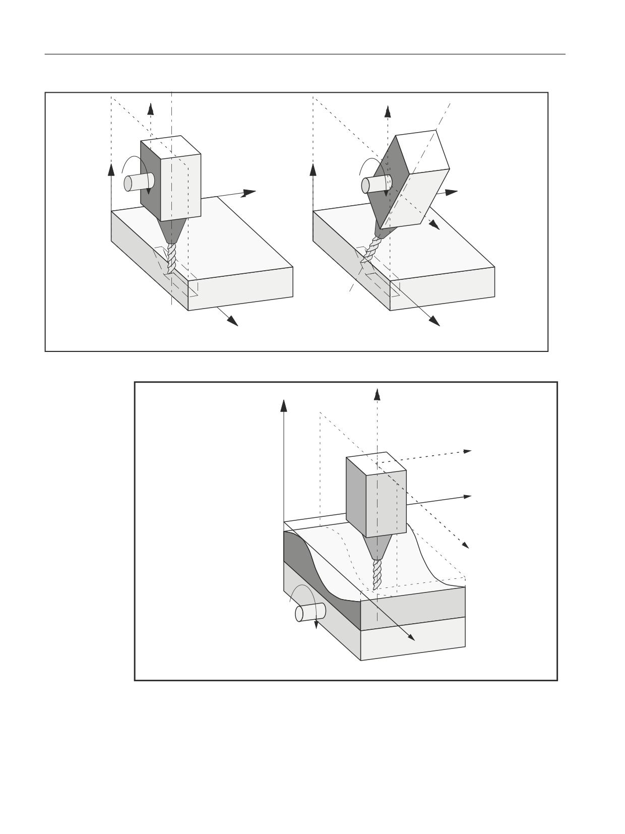
F2: Multi-axis transformations
2.1 Brief description
]
]
%
%
=
=
<
<
[
[
;
;
Figure 2-1
Schematic diagram of 3-axis transformation
]
=
\
<
[
%
;
Figure 2-2
Schematic diagram of a 4-axis transformation with moveable workpiece
Special functions
38
Function Manual, 12/2018, A5E40874099B AB
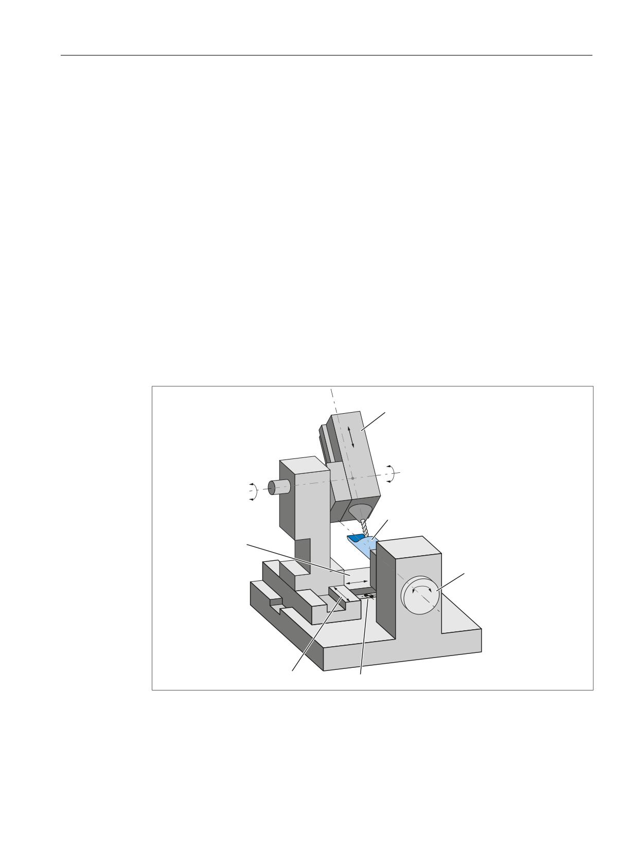
F2: Multi-axis transformations
2.1 Brief description
2.1.4
Orientation transformation with a swiveling linear axis.
Function
The orientation transformation with swiveling linear axis is similar to the 5-axis transformation
of Machine Type 3, though the 3rd linear axis is not always perpendicular to the plane defined
by the other two linear axes.
Features of kinematics
● Kinematics with three linear axes and two orthogonal rotary axes.
● Rotary axes are parallel to two of the three linear axes.
● The first rotary axis is moved by two Cartesian linear axes. It rotates the third linear axis,
which moves the tool. The tool is aligned parallel to the third linear axis.
● The second rotary axis rotates the workpiece.
● The kinematics comprise a moved workpiece and a moved tool.
The following figure shows the interrelations for one of the possible axis sequences, for which
transformation is possible.
6ZLYHOLQJ OLQHDU D[LV
=
5RWDU\ D[LV
$
ZRUNSLHFH
/LQHDU D[LV
5RWDU\ D[LV
;
<
%
/LQHDU D[LV
0DFKLQH ]HUR
Figure 2-3
Schematic diagram of a machine with swiveling linear axis
Special functions
Function Manual, 12/2018, A5E40874099B AB
39
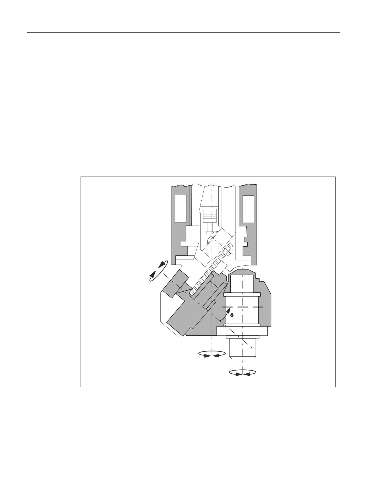
F2: Multi-axis transformations
2.1 Brief description
2.1.5
Universal milling head
Function
A machine tool with a universal milling head has got at least 5 axes:
●
3 linear axes
- for linear movement [X, Y, Z]
- move the machining point to any random position in the working area
●
2 rotary swivelling axes
- are arranged under a configurable angle (mostly 45 Degree)
- enable the tool to define orientations in space
(are limited to a hemisphere in a 45 degree arrangement)
$ D[LV
& D[LV
7RRO D[LV
Figure 2-4
Schematic diagram of a machine tool with universal milling head
Special functions
40
Function Manual, 12/2018, A5E40874099B AB
F2: Multi-axis transformations
2.1 Brief description
2.1.6
Orientation axes
Model for describing change in orientation
There is no such simple correlation between axis motion and change in orientation in case of
robots, hexapodes or nutator kinamatics, as in the case of conventional 5-axes machines.
For this reason, the change in orientation is defined by a model that is created independently
of the actual machine. This model defines three virtual orientation axes which can be visualized
as rotations about the coordinate axes of a rectangular coordinate system.
For the purpose of 6-axis transformation, a third degree of freedom for orientation, describing
the rotation of the tool about itself, has been introduced.
Real-time transformation
The Cartesian coordinates are converted from basic to machine coordinate system by means
of a real-time transformation process.
These Cartesian coordinates comprise:
● Geometry axes
Geometry axes describe the machining point.
● Orientation axes
Orientation axes describe the orientation of a tool in space.
Tool orientation
You can define the orientation of the tool in space as follows using linear interpolation, large
circle interpolation and by means of orientation vectors:
● Direct programming of rotary axis positions A, B, C
5-axis transformation by programming:
- The Euler- or RPY angle in degrees through A2,B2,C2
or
- The direction vector over A3,B3,C3
● Programming using lead angle LEAD and tilt angle TILT
2.1.7
Cartesian manual travel
Function
The "Cartesian manual travel" function allows the reference system for JOG motion to be
selected for one of the following coordinate systems (for both translation and orientation as):
● Basic coordinate system (BCS)
● Workpiece coordinate system (WCS)
● Tool coordinate system (TCS)
Special functions
Function Manual, 12/2018, A5E40874099B AB
41
F2: Multi-axis transformations
2.1 Brief description
2.1.8
Cartesian PTP travel
Function
The "Cartesian PTP Travel" [PTP = Point-to-point movement (Point to Point)] function can be
used to program a position in a cartesian coordinate system (workpiece coordinate system).
The machine however moves in its machine coordinates.
The function can be used, for example, to traverse a singularity. Cartesian positions, supplied
by a CAD system, need not been converted to machine axis values.
It must also be noted that axes take longer to traverse in the Cartesian coordinate system with
active transformation and programmed feedrate than when they are traversed directly.
2.1.9
Generic 5-axis transformation
Function
The generic 5-axis transformation function differs from earlier 5-axis transformation versions
insofar as it is no longer restricted with respect to the directions of rotary axes.
The basic orientation of the tool is no longer predefined in machine data as was the case in
earlier versions of orientation transformations, but can now be programmed freely.
2.1.10
Online tool length offset
Function
The system variable $AA_TOFF[ ] can be used to overlay the effective tool lengths in 3-D in
runtime. For an active orientation transformation (TRAORI) or for an active tool carrier that can
be oriented, these offsets are effective in the particular tool axes.
If the tool orientation changes, the tool length offsets that apply are rotated so that the pivot
point for the orientation movement always refers to the corrected tool tip.
2.1.11
Activation via parts/program/softkey
The machine data relevant to the kinematic transformation has thus far been activated mostly
through POWER ON.
Transformations MDs can also be activated via the part program / softkey and it is not
necessary to boot the control system.
References:
Function Manual, Extended Functions; Kinematic Transformations (M1),
Section: Cartesian PTP travel
Special functions
42
Function Manual, 12/2018, A5E40874099B AB
F2: Multi-axis transformations
2.2 5-axis transformation
2.1.12
Orientation compression
During the execution of NC programs containing blocks with relatively short traverse paths,
the interpolator clock cycle can lead to a reduction in tool path velocity and a corresponding
increase in machining time.
COMPON, COMPCURV, COMPCAD
You can run NC programs with short traverse paths without reducing the tool path velocity by
activating "compressors" COMPON, COMPCURV or COMPCAD. The compressor also
smoothes the programmed movements and consequently tool path velocity.
Programming of direction vectors
Programming of tool orientation that is independent of the kinematics, can be achieved through
programming of direction vectors. NC programs with such direction vectors can be executed
with compressors COMPON, COMPCURV and COMPCAD.
2.2
5-axis transformation
2.2.1
Kinematic transformation
Task of orientation transformation
The task of orientation transformation is to compensate movements of the tool nose, which
result from changes in orientation, by means of appropriate compensating movements of the
geometry axes. The orientation movement is therefore decoupled from the movement on the
workpiece contour. Various machine kinematics each require their own orientation
transformation.
Fields of application
The "5-axis transformation" machining package is provided for machine tools, which have two
additional rotary axes (rotation about the linear axes) in addition to three linear axes X, Y and
Z: This package thus allows an axially symmetrical tool (milling cutter, laser beam) to be
oriented in any desired relation to the workpiece in every point of the machining space.
The workpiece is always programmed in the rectangular workpiece coordinate system; any
programmed or set frames rotate and shift this system in relation to the basic system. The
kinematic transformation then converts this information into motion commands of the real
machine axes.
The kinematic transformation requires information about the design (kinematics) of the
machine, which are stored in machine data.
The kinematic transformation does not act on positioning axes.
Special functions
Function Manual, 12/2018, A5E40874099B AB
43
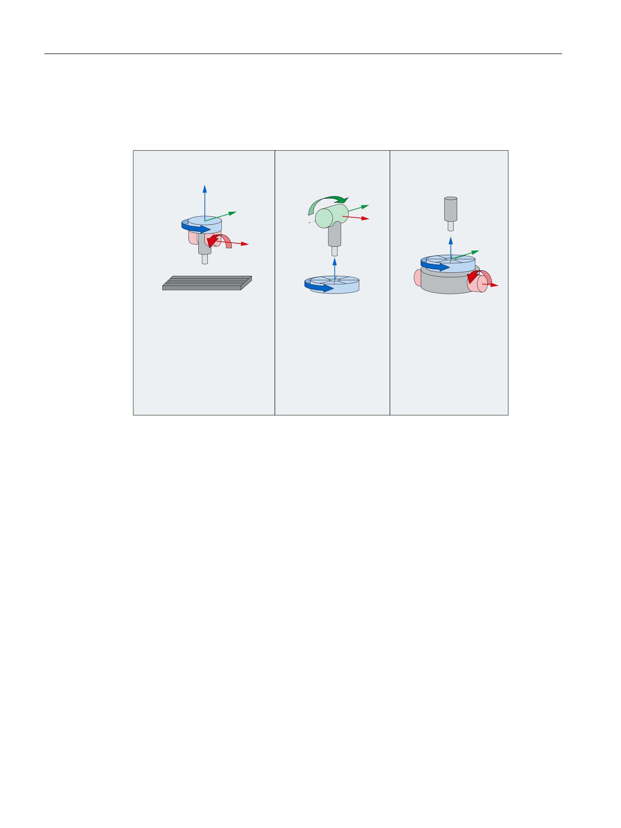
F2: Multi-axis transformations
2.2 5-axis transformation
2.2.2
Machine types for 5-axis transformation
Depending on the orientation capability of tool and workpiece, machines are classified
according to machine types 1, 2 and 3.
6ZLYHO KHDG
6ZLYHO KHDG
6ZLYHO KHDG
5RWDU\ D[HV $ DQG &
5RWDU\ D[LV %
IL[HG
%
=
<
<
&
;
;
=
<
$
=
&
$
&
;
7RRO WDEOH
7RRO WDEOH
7RRO WDEOH
IL[HG
5RWDU\ D[LV &
5RWDU\ D[HV $ DQG &
0DFKLQH W\SH
0DFKLQH W\SH
0DFKLQH W\SH
7ZR D[LV VZLYHO KHDG
6LQJOH D[LV VZLYHO KHDG DQG
7ZR D[LV URWDU\ LQGH[LQJ WDEOH
ZLWK D[LV VHTXHQFH &$
VLQJOH D[LV URWDU\ LQGH[LQJ WDEOH
ZLWK D[LV VHTXHQFH $&
ZLWK D[LV VHTXHQFH %&
7RRO WKDW FDQ EH RULHQWHG
7RRO WKDW FDQ EH RULHQWHG
:RUNSLHFH WKDW FDQ EH RULHQWHG
:RUNSLHFH WKDW FDQ EH RULHQWHG
Figure 2-5
Machine types for 5-axis transformation
Common properties of machine types 1, 2 and 3
● The three linear axes form a right-handed, Cartesian coordinate system.
● The rotary axes are orientated parallel to the linear axes
● The orientation of the rotary axes are vertical, on one another.
● The tool initial state is in the negative Z direction.
Other properties of machine types 1 and 2
● Rotary axis 1 is the 4th machine axis of the transformation
● Rotary axis 1 changes the orientation of rotary axis 2
● Rotary axis 2 is the 5th machine axis of the transformation
● Rotary axis 2 does not change the orientation of rotary axis 1
Other properties of machine type 3
● Rotary axis 1 is the 4th machine axis of the transformation
● Rotary axis 1 rotates the tool
● Rotary axis 2 is the 5th machine axis of the transformation
● Rotary axis 2 rotates the workpiece
Special functions
44
Function Manual, 12/2018, A5E40874099B AB

F2: Multi-axis transformations
2.2 5-axis transformation
Note
Transformations not in accordance with the conditions mentioned here are described in their
own sections
2.2.3
Configuration of a machine for 5-axis transformation
Maximum number of 5-axis transformations per channel
Currently, no more than four 5-axis transformations can be parameterized per channel
Transformation type
The transformation type that is dependent on the machine type is set in machine data:
MD24100 $MC_TRAFO_TYPE_<x> = <transformation type>
where x = 1, 2, ... maximum number of transformations
Axis se-
Machine type 1
Machine type 2
Machine type 3
quence of the
(tool that can be swiveled/
(workpiece that can be
(tool/workpiece that can be
machine
rotated)
swiveled/rotated)
swiveled/rotated)
Transformation type
Transformation type
Transformation type
AB
16
32
48
AC
--- 1)
33
49
BA
18
34
50
BC
--- 1)
35
51
CA
20
--- 1)
--- 1)
CB
21
--- 1)
--- 1)
1) Not a practical combination, as a rotation of the C axis would only correspond to a rotation of the
tool around its own longitudinal axis (symmetrical axis).
Identifying the axis sequence
The axis sequence is identified in the following way:
● AB means: A is 4th axis, B is 5th axis of the transformation
● For machine type 3, the swivel axis of the tool is the 4th axis of the transformation and the
rotary axis of the workpiece is the 5th axis of the transformation.
Axis assignment
In the machine data, the axis assignment at the input of the 5-axis transformation defines which
axis will be mapped by the transformation to which channel axis:
MD24110 $MC_TRAFO_AXES_IN_<x> (axis assignment for transformation x)
Special functions
Function Manual, 12/2018, A5E40874099B AB
45
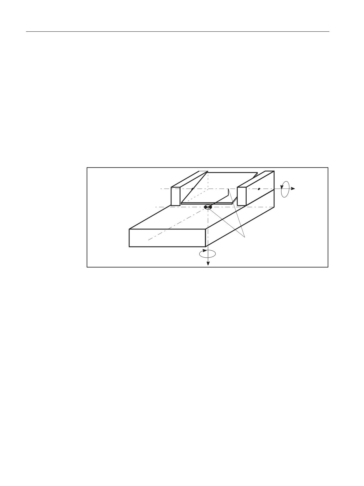
F2: Multi-axis transformations
2.2 5-axis transformation
where x = 1, 2, ... maximum number of transformations
Geometry information
Information concerning machine geometry is required so that the 5-axis transformation can
calculate axis values: This information is stored in the machine data (in this case, for the first
transformation in the channel):
● $MC_TRAFO5_PART_OFFSET_<x> (workpiece-oriented offset)
where x = 1, 2, ... maximum number of transformations in the channel
- Machine type 1:
Vector from machine reference point to table zero point (generally, the zero vector)
- Machine type 2:
Vector from last table swivel joint to zero point of table
%
9HFWRU FRPSRQHQWV RI WKH ODVW
URWDU\ MRLQW RI WDEOH WR ]HUR
SRLQW RI WDEOH
&
Figure 2-6
Machine data MD24500 $MC_TRAFO5_PART_OFFSET_1 for machine type 2
– Machine type 3 (single-axis swivel head and single-axis rotary table)
Vector from joint of rotary table to zero point of table
● $MC_TRAFO5_JOINT_OFFSET_<x> (vector of kinematic offset)
where x = 1, 2, ... maximum number of transformations in the channel
- Machine type 1 and 2:
Vector from the first to the second swivel joint
- Machine type 3:
Vector from machine zero point to the swivel joint of the table
● $MC_TRAFO5_ROT_AX_OFFSET_<x> (position offset of rotary axes 1 / 2 / 3)
where x = 1, 2, ... maximum number of transformations in the channel
Special functions
46
Function Manual, 12/2018, A5E40874099B AB
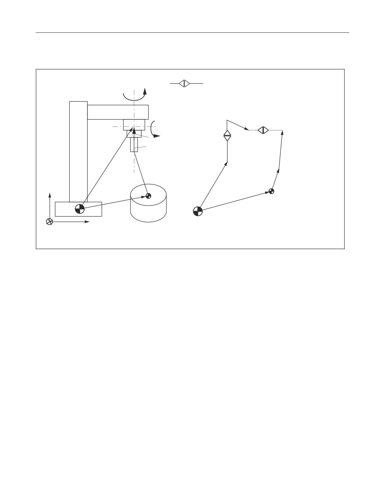
F2: Multi-axis transformations
2.2 5-axis transformation
Examples
',1 V\PERO IRU URWDU\ D[LV
&
$
$
MR
&
WR
W
WR
PR
[
W
PR
[
=
SR
=HUR SRLQW
ZRUNSLHFH WDEOH
SR
0DFKLQH ]HUR
;
<
mo
Position vector in MCS
po
$MC_TRAFO5_PART_OFFSET_<x>[0 ..2]
x
Vector of programmed position in BCS
t
Tool correction vector
to
$MC_TRAFO5_BASE_TOOL_<x>[0 .. 2]
jo
MD24560 $MC_TRAFO5_JOINT_OFFSET_<x>[0 .. 2]
Figure 2-7
Schematic diagram of CA kinematics, moved tool
Special functions
Function Manual, 12/2018, A5E40874099B AB
47
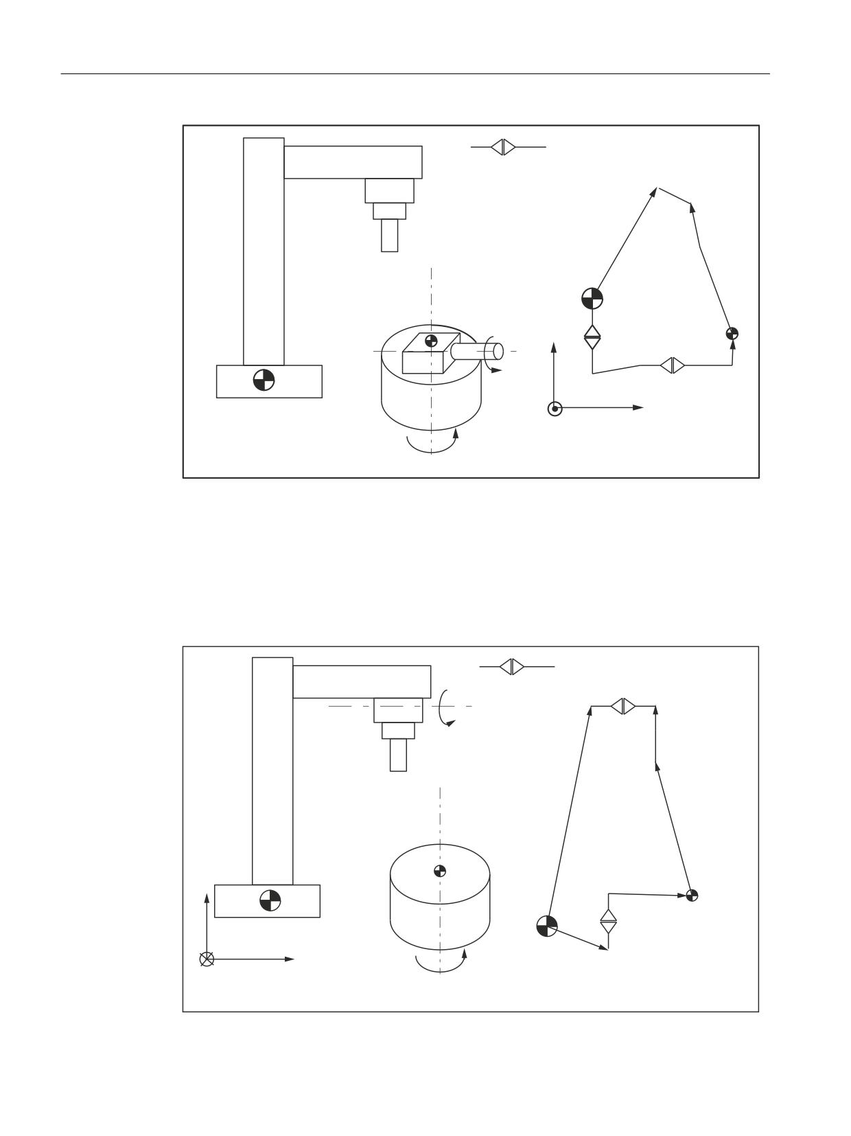
F2: Multi-axis transformations
2.2 5-axis transformation
',1 V\PERO IRU URWDU\ D[LV
WR
PR
W
[
=HUR SRLQW
ZRUNSLHFH WDEOH
&
SR
=
%
%
MR
0DFKLQH ]HUR
<
;
&
mo
Position vector in MCS
po
$MC_TRAFO5_PART_OFFSET_<x>[0 ..2]
x
Vector of programmed position in BCS
t
Tool correction vector
to
$MC_TRAFO5_BASE_TOOL_<x>[0 .. 2]
jo
$MC_TRAFO5_JOINT_OFFSET_<x>[0 .. 2]
Figure 2-8
Schematic diagram of CB kinematics, moved workpiece
',1 V\PERO IRU URWDU\ D[LV
$
$
WR
W
PR
=HUR SRLQW
[
ZRUNSLHFH WDEOH
SR
=
&
0DFKLQH ]HUR
MR
&
;
<
Special functions
48
Function Manual, 12/2018, A5E40874099B AB

F2: Multi-axis transformations
2.2 5-axis transformation
Figure 2-9
Schematic diagram of AC kinematics, moved tool, moved workpiece
Sign handling for rotary axes
The sign handling of rotary axes involved in 5-axis transformation is set in the channel using
machine data:
$MC_TRAFO5_ROT_SIGN_IS_PLUS_<x>[ <n> ] = <value>
where x = 1, 2, ... maximum number of transformations in the channel
<n>
Meaning
0
1st rotary axis
1
2nd rotary axis
2
3rd rotary axis
<Val-
Meaning
ue>
TRUE
The sign is not inverted. The traversing direction is as defined in MD32100 $MA_AX_MO-
TION_DIR.
FALS
The sign is inverted.
E
The machine data is not used to define that the direction of rotation of the rotary axis involved
is changed. Instead, it is specified as to whether the rotary axis, for traversing motion, rotates
in the positive traversing direction in the mathematical positive (counterclockwise) or negative
(clockwise) direction. The consequence when changing this machine data is therefore not a
change in the direction of rotation, but a change in the compensating motion in the linear axes.
However, if a direction vector, and therefore implicitly compensation motion is specified, then
the direction of rotation of the rotary axis involved changes.
This means that at a real machine, the machine data only has to be set to FALSE if, for
traversing motion in the positive traversing direction, the rotary axis rotates in the mathematical
positive direction (counterclockwise).
Special functions
Function Manual, 12/2018, A5E40874099B AB
49
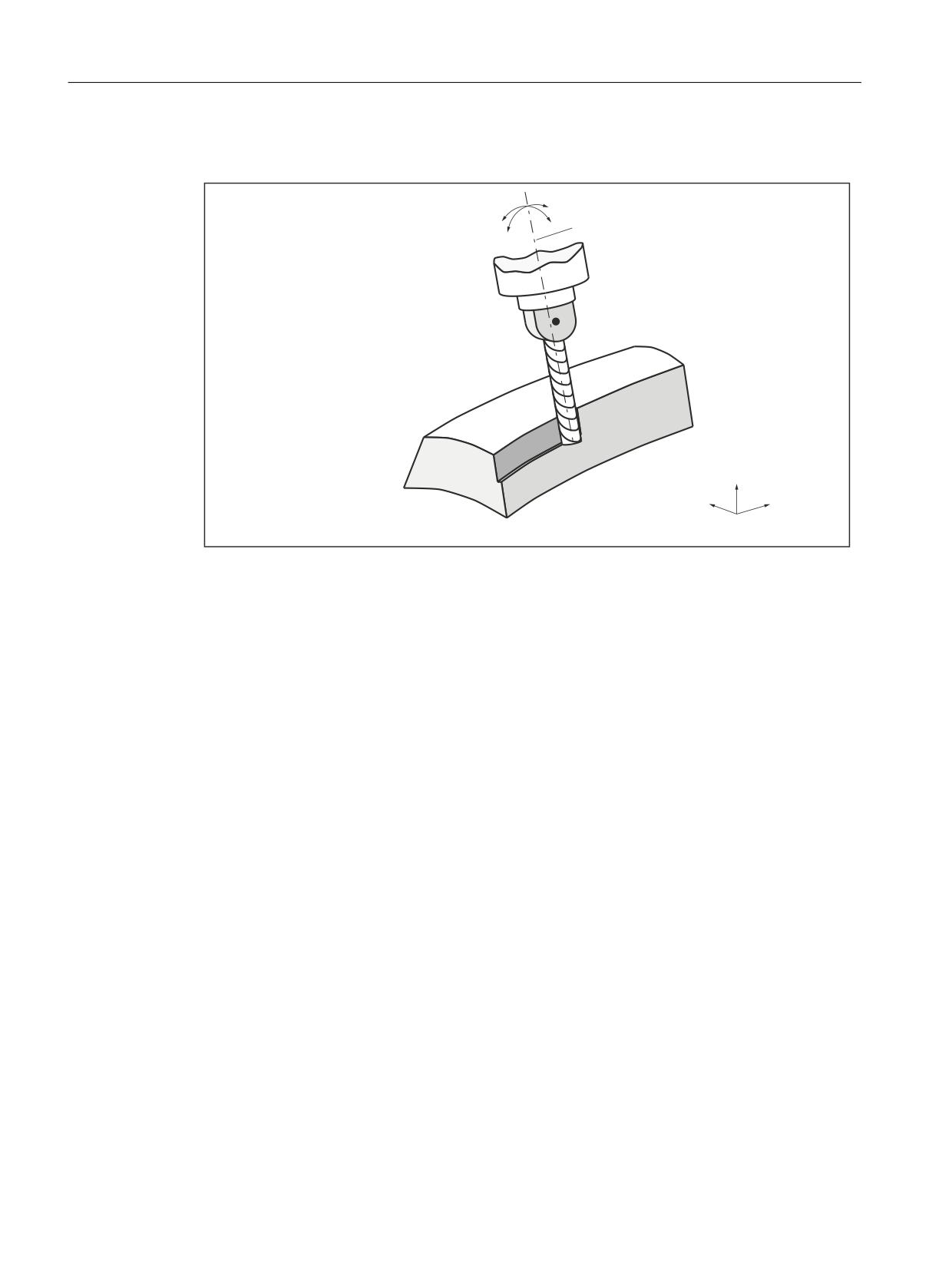
F2: Multi-axis transformations
2.2 5-axis transformation
2.2.4
Tool orientation
$
7RRO D[LV
%
3HULSKHUDO PLOOLQJ
=
<
;
Figure 2-10
Machining of workpieces with 5-axis transformation
Programming
The orientation of the tool can be programmed in a block directly by specifying the rotary axes
or indirectly by specifying the Euler angle, RPY angle and direction vector. The following
options are available:
● directly as rotary axes A, B, C
● indirectly for 5-axis transformation:
via Euler or RPY angles in degrees via A2, B2, C2
● Indirectly for 5-axis transformation via direction vector A3, B3, C3
The identifiers for Euler angles and direction vectors can be set in machine data:
Euler angles via:
MD10620 $MN_EULER_ANGLE_NAME_TAB (name of Euler angles)
Direction vector via:
MD10640 $MN_DIR_VECTOR_NAME_TAB (name of direction vectors)
The tool orientation can be located in any block. Above all, it can be programmed alone in a
block, resulting in a change of orientation in relation to the tool tip which is fixed in its
relationship to the workpiece.
Euler or RPY
The following machine data can be used to switch between Euler and RPY angles:
MD21100 $MC_ORIENTATION_IS_EULER (angle definition for orientation programming)
Special functions
50
Function Manual, 12/2018, A5E40874099B AB
F2: Multi-axis transformations
2.2 5-axis transformation
Orientation reference
A tool orientation at the start of a block can be transferred to the block end in two different
ways:
● in the workpiece coordinate system with command ORIWKS
● in the machine coordinate system with command ORIMKS
ORIWKS command
The tool orientation is programmed in the workpiece coordinate system (WCS) and is thus not
dependent on the machine kinematics.
In the case of a change in orientation with the tool tip at a fixed point in space, the tool moves
along a large arc on the plane stretching from the start vector to the end vector.
ORIMKS command
The tool orientation is programmed in the machine coordinate system and is thus dependent
on the machine kinematics.
In the case of a change in orientation of a tool tip at a fixed point in space, linear interpolation
takes place between the rotary axis positions.
The orientation is selected via NC language commands ORIWKS and ORIMKS.
Special functions
Function Manual, 12/2018, A5E40874099B AB
51
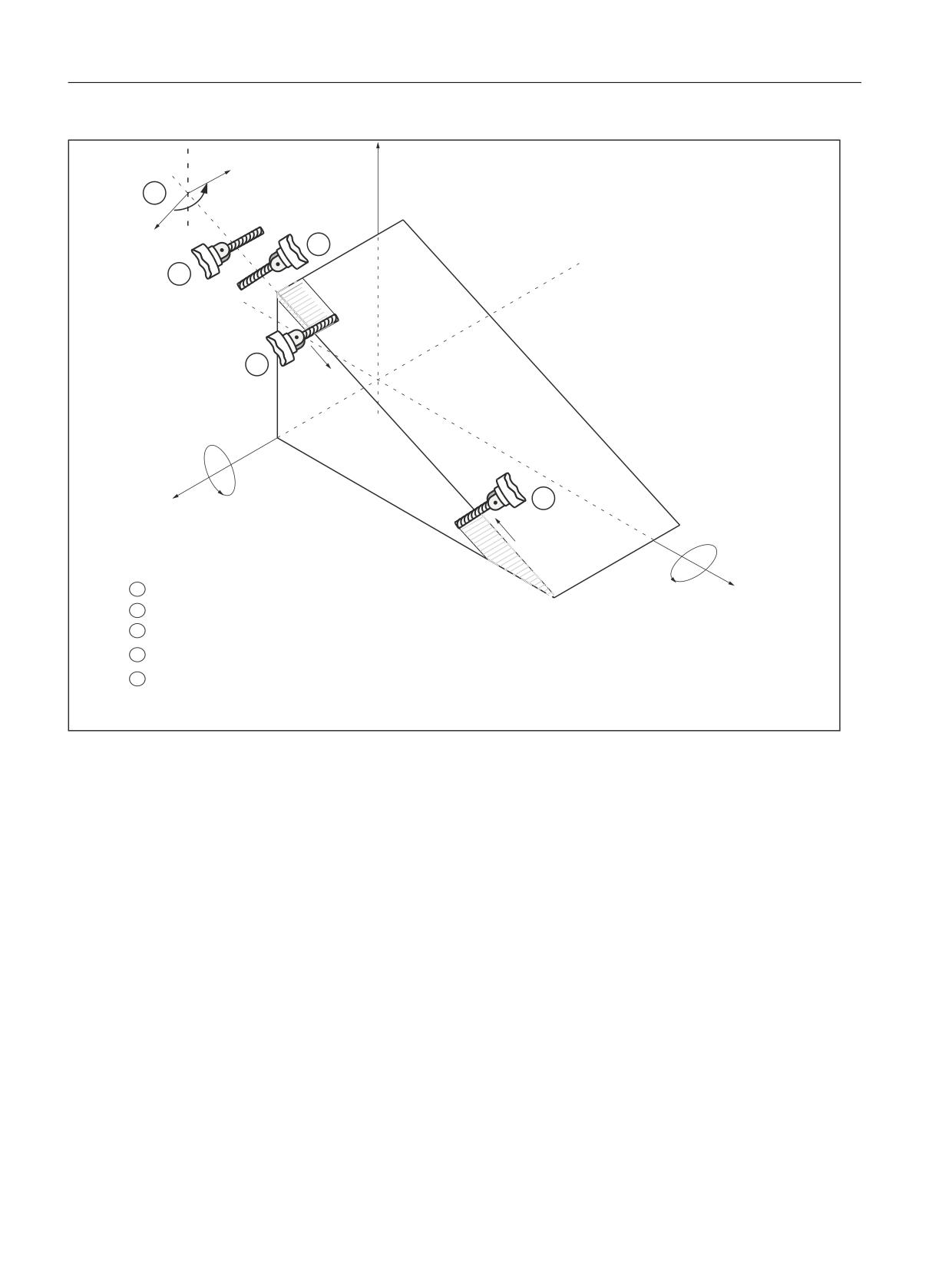
F2: Multi-axis transformations
2.2 5-axis transformation
2
ULHQWDWLRQ
=
¡
2ULHQWDWLRQ
)
)
$
;
%
<
0DFKLQH WKH VXUIDFH ) DORQJ WKH HGJH RI )
5HWUDFW
&KDQJH LQ RULHQWDWLRQ %
¡$
¡
$SSURDFK WKH VXUIDFH )
0DFKLQLQJ RI WKH VXUIDFH ) DORQJ WKH HGJH RI )
Figure 2-11
Change in cutter orientation while machining inclined edges
Special functions
52
Function Manual, 12/2018, A5E40874099B AB
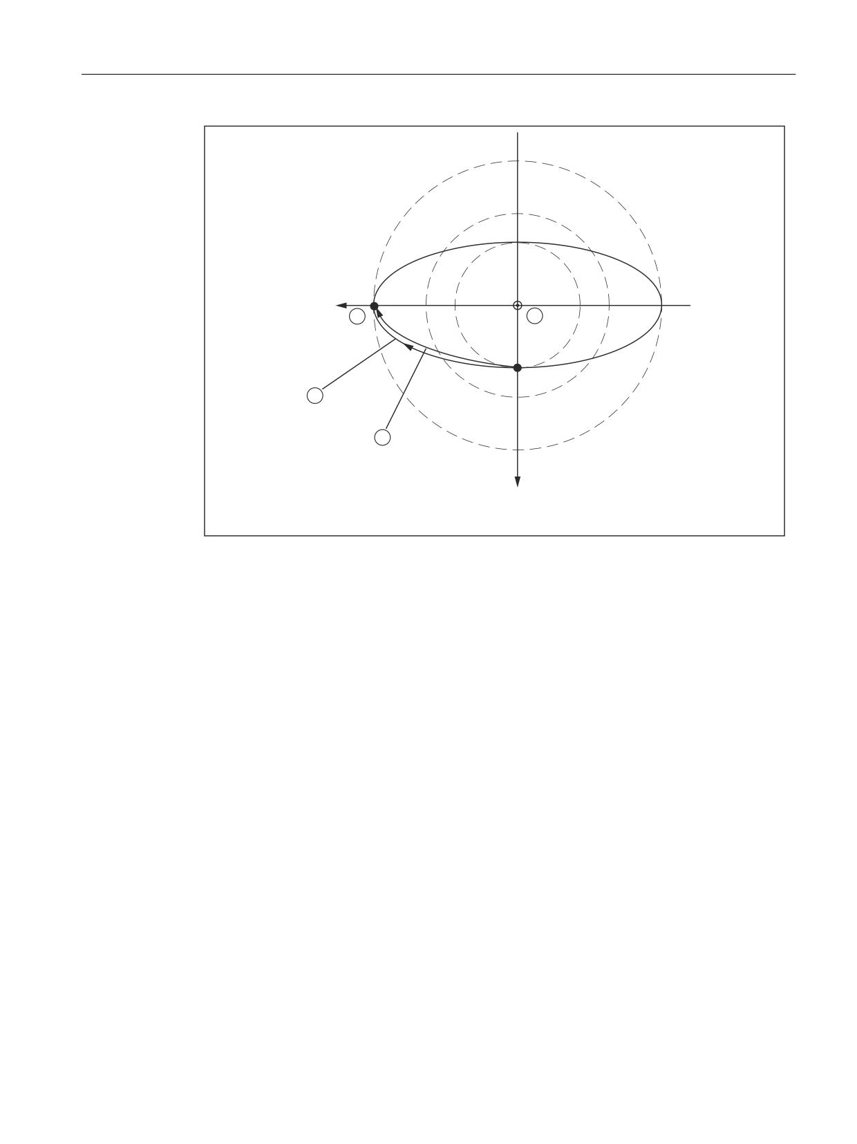
F2: Multi-axis transformations
2.2 5-axis transformation
¡
¡
¡
=
;
ZLWK 25,:.6
ODUJH FLUFOH
ZLWK 25,0.6 OLQHDU LQWHUSRODWLRQ
EHWZHHQ URWDU\ D[HV
<
Figure 2-12
Change in orientation while machining inclined edges
ORIMKS constitutes the basic setting
The basic setting can be changed via the following machine data:
MD20150 MC_GCODE_RESET_VALUES (RESET position of G groups)
MD20150 $MC_GCODE_RESET_VALUES [24] = 1 ⇒ ORIWKS is basic setting
MD20150 $MC_GCODE_RESET_VALUES [24] = 2 ⇒ ORIWKS is basic setting
Illegal tool orientation
If tool position is programmed in relation to the following functions, alarm 12130 "Illegal tool
orientation" is output when Euler angles and direction vectors are selected and the NC program
then stops (this alarm can also occur in connection with G331, G332 and G63).
● G04: Dwell time
● G33: Thread cutting with constant lead
● G74: Approaching a reference point
● G75: Approaching a fixed point
● REPOSL: Repositioning to the contour
● REPOSQ: Repositioning to the contour
● REPOSH: Repositioning to the contour
To remedy this situation, tool orientation can be programmed with axis end values.
Special functions
Function Manual, 12/2018, A5E40874099B AB
53
F2: Multi-axis transformations
2.2 5-axis transformation
Alarm 17630 or 17620 is output for G74 and G75 if a transformation is active and the axes to
be traversed are involved in the transformation. This applies irrespective of orientation
programming.
If the start and end vectors are inverse parallel when ORIWKS is active, then no unique plane
is defined for the orientation programming, resulting in the output of alarm 14120.
If a transformation switch (switch On, switch Off or change transformation) is undertaken, alarm
14400 will be generated.
In the reverse situation, i.e. a tool radius offset is selected or deselected when a transformation
is active, no alarm message is output.
Multiple input of tool orientation
According to DIN 66025, only one tool orientation may be programmed in a block, e.g. with
direction vectors:
N50
A3=1 B3=1 C3=1
If tool orientation is entered multiply, i.e. with direction vectors and with Euler angles, error
message 12240 "Channel X block Y tool orientation xx defined more than once" is displayed
and the NC part program stops.
N60
A3=1 B3=1 C3=1
A2=0 B2=1 C2=3
Tool orientation using orientation vectors
Polynomials can also be programmed for the modification of the orientation vector.
This method produces an extremely smooth change in speed and acceleration at the block
changes for rotary axes when the tool orientation has to be programmed over several blocks.
The interpolation of orientation vectors can be programmed with polynomials up to the 5th
degree. Polynomial interpolation of orientation vectors is described in the "Polynomial
Interpolation of Orientation Vectors" section.
Note
Further explanations of tool orientation using orientation vectors and their handling in machines
are given in:
Reference:
Function Manual, Basic Machine; Tool Offset; Orientable Toolholders (W1)
2.2.5
Singular positions and handling
Extreme velocity increase
If the path runs in close vicinity to a pole (singularity), one or several axes may traverse at a
very high velocity.
Special functions
54
Function Manual, 12/2018, A5E40874099B AB
F2: Multi-axis transformations
2.2 5-axis transformation
Alarm 10910 "Irregular velocity run in a path axis" is then triggered. The programmed velocity
is then reduced to a value, which does not exceed the maximum axis velocity.
Behavior at pole
Unwanted behavior of fast compensating movements can be controlled by making an
appropriate selection of the following machine data (see following Figure):
● MD24530 $MC_TRAFO5_NON_POLE_LIMIT_1 (definition of pole area for 5-axis
transformation 1)
● MD24630 $MC_ TRAFO5_NON_POLE_LIMIT_2 (definition of pole area for 5-axis
transformation 2)
● MD24540 $MC_TRAFO5_POLE_LIMIT_1 (closing angle tolerance for interpolation by pole
for 5-axis transformation)
● MD24640 $MC_TRAFO5_POLE_LIMIT_2 (closing angle tolerance for interpolation by pole
for 5-axis transformation)
Note
Singularities are dealt with differently in SW 5.2 and higher: Only one relevant machine
data item exists, $MC_TRAFO5_POLE_LIMIT (see Section "Singularities of orientation
(Page 86)" or "Programming Manual, Production Planning).
Definition of the pole range for 5-axis transformation
This machine data identifies a limit angle of the 5th axis of the first MD24530
$MC_TRAFO5_NON_POLE_LIMIT_1 or the second MD24630
$MC_TRAFO5_NON_POLE_LIMIT_2 5-axis transformation with the following properties:
If the path runs past the pole at an angle lower than the value set here, it crosses through the
pole.
With the 5-axis transformation, a coordinate system consisting of circles of longitude and
latitude is spanned over a spherical surface by the two orientation axes of the tool.
If, as a result of orientation programming (i.e. the orientation vector is positioned on one plane),
the path passes so close to the pole that the angle is less than the value defined in this machine
data, then a deviation from the specified interpolation is made so that the interpolation passes
through the pole.
End angle tolerance for interpolation by pole for 5-axis transformation
This machine data identifies a limit angle for the 5th axis of the first MD24540
$MC_TRAFO5_NON_POLE_LIMIT_1 or the second MD24640
$MC_TRAFO5_NON_POLE_LIMIT_2 5-axis transformation with the following properties:
With interpolation through the pole point, only the fifth axis moves; the fourth axis remains in
its start position. If a movement is programmed which does not pass exactly through the pole
point, but is to pass within the tolerance defined by the following machine data in the vicinity
Special functions
Function Manual, 12/2018, A5E40874099B AB
55
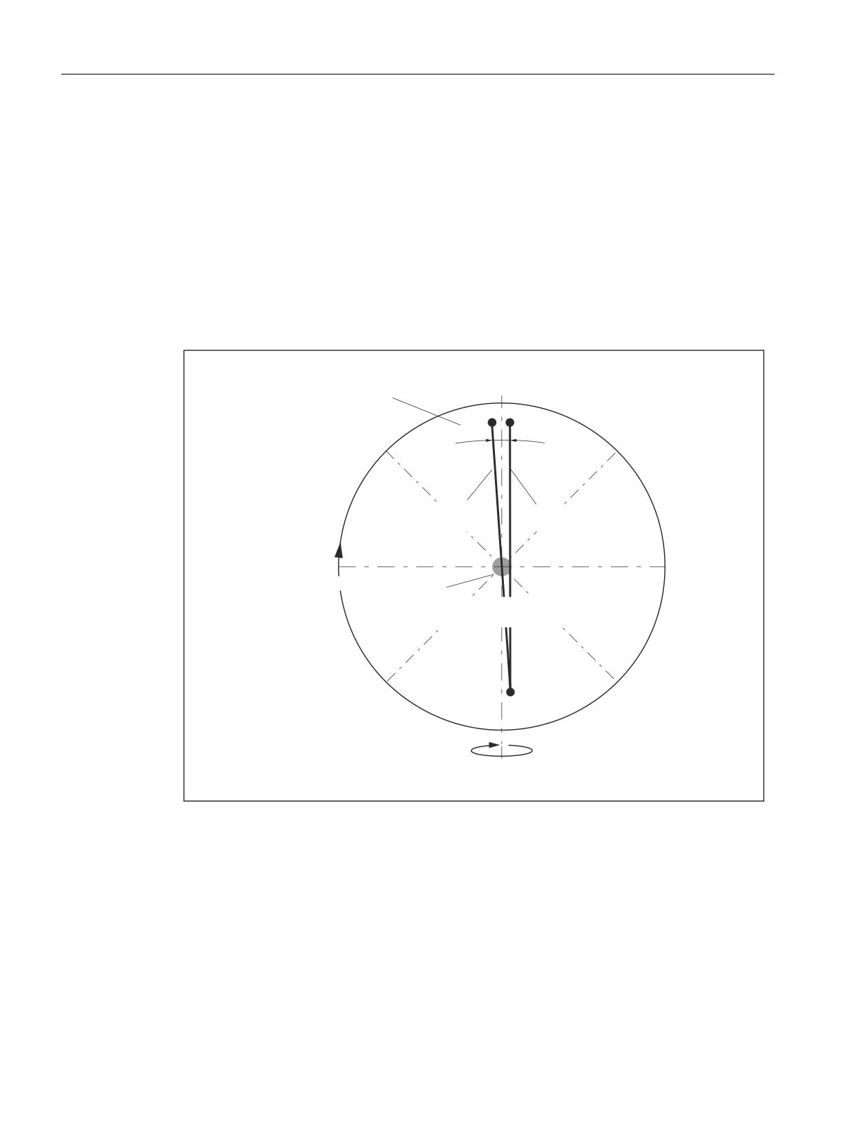
F2: Multi-axis transformations
2.2 5-axis transformation
of the pole, a deviation is made from the specified path because the interpolation runs exactly
through the pole point.
● MD24530 $MC_TRAFO5_NON_POLE_LIMIT_1
● MD24630 $MC_TRAFO5_NON_POLE_LIMIT_2
As a result, the position at the end point of the fourth axis (pole axis) deviates from the
programmed value.
This machine data specifies the angle by which the pole axis may deviate from the programmed
value with a 5-axis transformation if a switchover is made from the programmed interpolation
to interpolation through the pole point. In the case of a greater deviation, an error message is
output and the interpolation is not executed.
0'
0&B75$)2 B32/(B/,0,7B
D
,QWHUSRODWHG
3URJUDPPHG
SDWK
SDWK
WK D[LV 5$
0'
0&B75$)2 B121B32/(B/,0,7B
WK D[LV 5$
Figure 2-13
5-axis transformation; orientation path in pole vicinity. Example for machine type 1: 2-axis
swivel head with rotary axis RA 1 (4th axis of transformation) and rotary axis RA 2 (5th
axis of transformation)
Behavior during large circle interpolation at pole position
The following machine data can be used to set the response for large circle interpolation in
pole position as follows:
MD21108 $MC_POLE_ORI_MODE
Special functions
56
Function Manual, 12/2018, A5E40874099B AB

F2: Multi-axis transformations
2.3 3-axis and 4-axis transformations
Does not define the treatment of changes in orientation during large circle interpolation unless
the starting orientation is equal to the pole orientation or approximates to it and the end
orientation of the block is outside the tolerance circle defined in the following machine data.
● MD24530 $MC_TRAFO5_NON_POLE_LIMIT_1
● MD24630 $MC_TRAFO5_NON_POLE_LIMIT_2
The position of the polar axis is arbitrary in the polar position. For the large circle interpolation,
however, a specified orientation is required for this axis.
The following machine data is coded decimally.
MD21108 $MC_POLE_ORI_MODE
The units define the behavior if start orientation coincides with pole position and the decade
the behavior if start orientation is within the tolerances defined by the following machine data:
● MD24530 $MC_TRAFO5_NON_POLE_LIMIT_1
● MD24630 $MC_TRAFO5_NON_POLE_LIMIT_2
All setting values are described in "Channel-specific Machine Data".
2.3
3-axis and 4-axis transformations
3 and 4-axis transformations are special types of 5-axis transformations, where the tool can
only be orientated in the plane, perpendicular to the rotary axis. They support machine type 1
with movable tool - and type 2 with movable workpiece.
Versions of 3-axis and 4-axis transformation
Machine type
swiveling/
Rotary axis
orientation plane
Transformation
Tool orientation in
rotary
parallel to
type
zero position
1
Tool
X
Y - Z
16
Z
Y
X - Z
18
Z
X - Y
20
Y
Z
X - Y
21
X
any
Any
24 1)
Any
2
workpiece
X
Y - Z
32, 33
Z
Y
X - Z
34, 35
Any
Any
40 1)
Any
1) The rotary axis and the orientation plane can be set, so that the orientation does not change in a
plane, but on a tapered peripheral surface.
Tool orientation in zero position
Tool orientation at the zero position is the position of the tool for active machining plane G17
AND position of the rotary axis 0 degrees
Special functions
Function Manual, 12/2018, A5E40874099B AB
57
F2: Multi-axis transformations
2.4 Transformation with swiveled linear axis
Axis assignments
The three linear axes included in the transformation are assigned to any channel axes via
machine data $MC_TRAFO_GEOAX_ASSIGN_TAB_n[0..2] and
$MC_TRAFO_AXES_IN_n[0..2]. The following must apply for the assignment of channel axes
to geometry axes for the transformation:
$MC_TRAFO_GEOAX_ASSIGN_TAB_n[ 0 ] = $MC_TRAFO_AXES_IN_n[ 0 ]
$MC_TRAFO_GEOAX_ASSIGN_TAB_n[ 1 ] = $MC_TRAFO_AXES_IN_n[ 1 ]
$MC_TRAFO_GEOAX_ASSIGN_TAB_n[ 2 ] = $MC_TRAFO_AXES_IN_n[ 2 ]
The axes with corresponding index must be assigned to each other.
Parameter assignment procedure
● Enter the type of transformation according to the previous table as machine data:
$MC_TRAFO_TYPE_n
● Assign channel axes to the geometry axes of the transformation.
● For a 3-axis transformation, set the values for the axis, which is not required:
- $MC_TRAFO_GEOAX_ASSIGN_TAB_n[<geometry axis>] = 0
- $MC_TRAFO_AXES_IN_n[<geometry axis>] = 0
$MC_TRAFO_AXES_IN_n[ 4 ] = 0; → there is no 2nd rotary axis
● For a 4-axis transformation, set the following for the 3 linear axes
- $MC_TRAFO_GEOAX_ASSIGN_TAB_n[<geometry axis>] = ...
- $MC_TRAFO_AXES_IN_n[<geometry axis>] = ...
$MC_TRAFO_AXES_IN_n[ 4 ] = 0; → there is no 2nd rotary axis
Complete examples of a 3-axis and 4-axis transformation can be found in "Example for 3- and
4-axis Transformation" section.
2.4
Transformation with swiveled linear axis
General information
The "transformation with swiveling linear axis forms" a transformation group of its own. It can
be used when a kinematic as described in the Section "Orientation transformation with a
swiveling linear axis. (Page 39)" is present:
● Three Cartesian linear axes (X, Y, Z) and two orthogonal rotary axes (A, B).
● The rotary axes are parallel to two of the three linear axes.
● The first rotary axis (A) is moved by two Cartesian linear axes. It rotates the third linear axis
(Z) that moves the tool.
● The tool is aligned parallel to the third linear axis (Z).
● The second rotary axis (B) rotates the workpiece.
Special functions
58
Function Manual, 12/2018, A5E40874099B AB
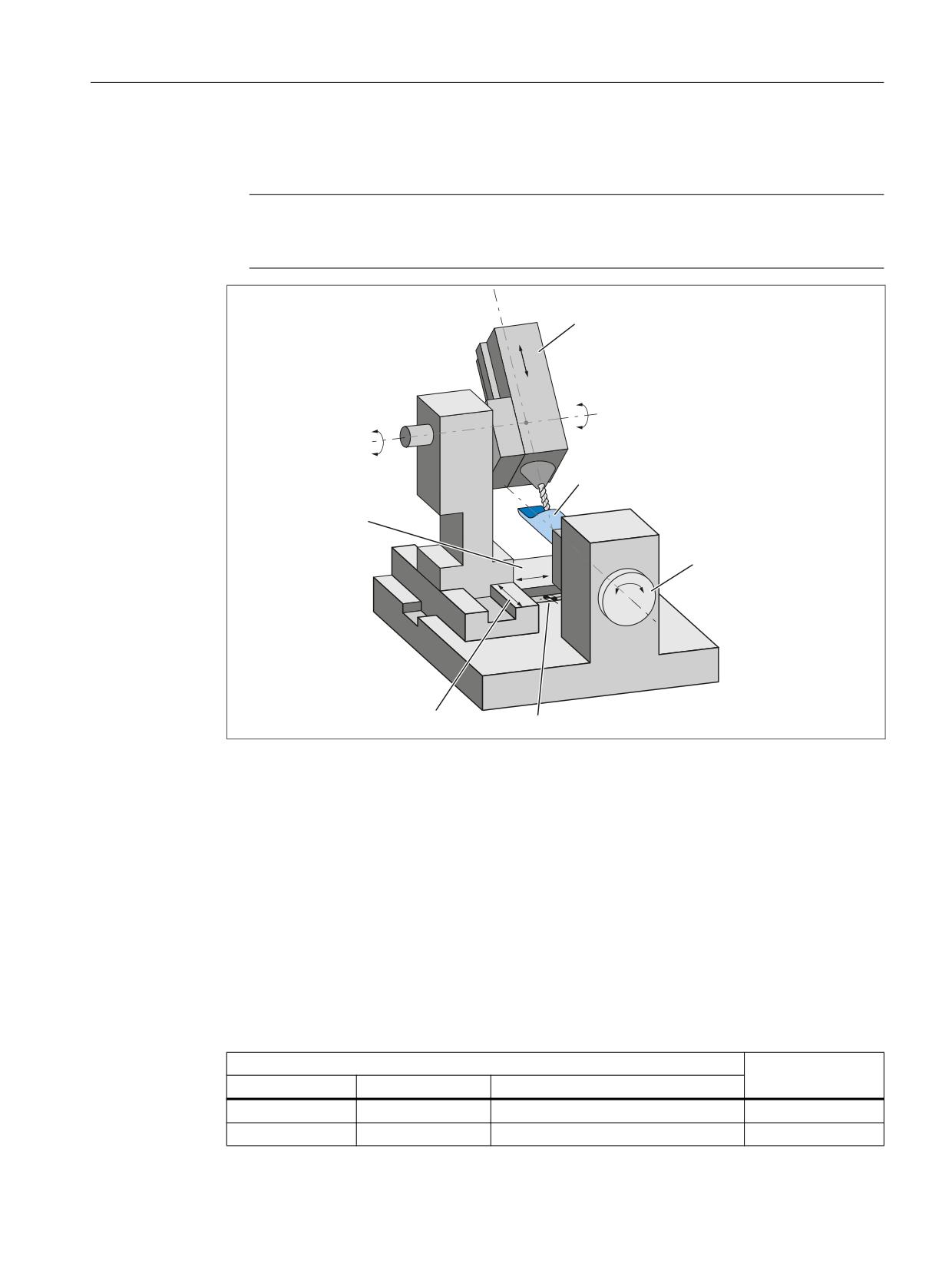
F2: Multi-axis transformations
2.4 Transformation with swiveled linear axis
Additional requirement:
● The first rotary axis (A) may only sweep a very small swivel range (swivel range << ± 90°).
Note
All the axis values used in the text relate to the designations of the example machine in the
following figure "Machine with swiveling linear axis Z"
6ZLYHOLQJ OLQHDU D[LV
=
5RWDU\ D[LV
$
ZRUNSLHFH
/LQHDU D[LV
5RWDU\ D[LV
;
<
%
/LQHDU D[LV
0DFKLQH ]HUR
Figure 2-14
Example: Machine with swiveling linear axis Z
Pole
The transformation with swiveling linear axis has a pole for a tool orientation parallel to the
second rotary axis (B). Singularity occurs in the pole position because the third linear axis (Z)
is parallel to the plane of the first two linear axes (X, Y), thus excluding the possibility of
compensating movements perpendicular to this plane.
Parameterization
Kinematic variants
The kinematic variant of the machine is set in the machine data:
MD24100, ... MD25190 $MC_TRAFO_TYP_n = <type>, with n = 1, 2, 3, ...
Kinematics
<type>
1. Rotary axis
2. rotary axis
swiveled linear axis
Bits 6 - 0
A
B
Z
10,00 000
A
C
Y
10,00 001
Special functions
Function Manual, 12/2018, A5E40874099B AB
59

F2: Multi-axis transformations
2.4 Transformation with swiveled linear axis
Kinematics
<type>
1. Rotary axis
2. rotary axis
swiveled linear axis
Bits 6 - 0
B
A
Z
10,00 010
B
C
X
10,00 011
C
A
Y
10,00 100
C
B
X
10,00 101
Machine kinematics
The machine kinematics is set for the 1st ($MC_TRAFO5 ... _1) and/or 2nd ($MC_TRAFO5 ...
_2) 5-axis transformation in the channel set with the following machine data:
● Vector (po, see following figure) from the second rotary axis to workpiece table zero:
- MD24500 $MC_TRAFO5_PART_OFFSET_1
- MD24600 $MC_TRAFO5_PART_OFFSET_2
● Axis positions of the two rotary axes at the initial position of the machine:
- MD24510 $MC_TRAFO5_ROT_AX_OFFSET_1
- MD24610 $MC_TRAFO5_ROT_AX_OFFSET_2
● Sign with which the rotary axis positions are included in the transformation:
- MD24520 $MC_TRAFO5_ROT_SIGN_IS_PLUS_1
- MD24620 $MC_TRAFO5_ROT_SIGN_IS_PLUS_2
● Vector (jo) from machine zero to the second rotary axis:
- MD24560 $MC_TRAFO5_JOINT_OFFSET_1
- MD24660 $MC_TRAFO5_JOINT_OFFSET_2
● Vector (to) from the toolholder (flange) to the first rotary axis (measured at machine initial
position):
- MD24550 $MC_TRAFO5_BASE_TOOL_1
- MD24650 $MC_TRAFO5_BASE_TOOL_2
● Vector (ro) from machine zero to the first rotary axis (measured at the machine initial
position):
- MD24562 $MC_TRAFO5_TOOL_ROT_AX_OFFSET_1
- MD24662 $MC_TRAFO5_TOOL_ROT_AX_OFFSET_2
Special functions
60
Function Manual, 12/2018, A5E40874099B AB
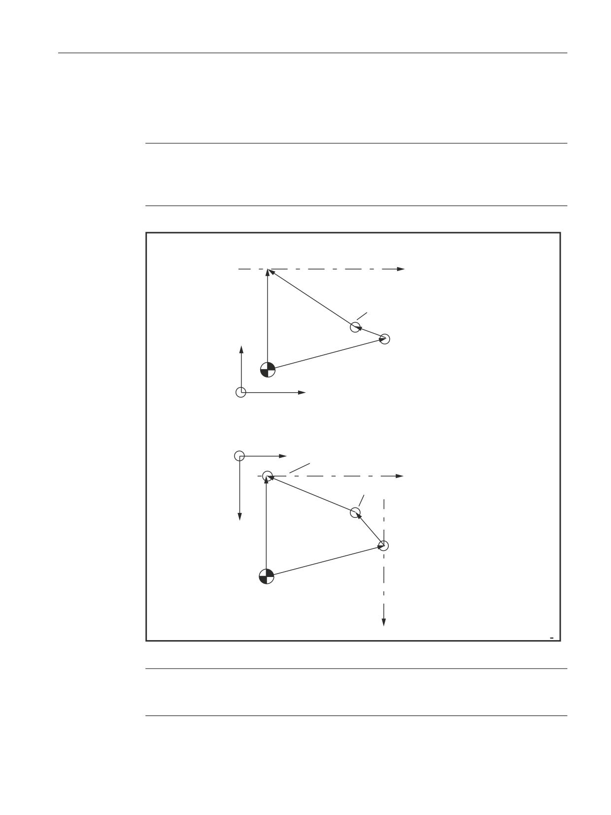
F2: Multi-axis transformations
2.4 Transformation with swiveled linear axis
Determining the machine data values
As an aid for determining the values for the above-mentioned machine data, the following two
sketches clarify the relationships between the vectors.
Note
Requirement
The machine has been traversed so that the toolholding flange aligns with the table zero (*).
Is this is technically not possible, vector to must be corrected by the deviations.
9LHZ DORQJ ; D[LV
5RWDU\ D[LV WKDW VZLYHOV
WKH UG OLQHDU D[LV =
UR
WR
7DEOH ]HUR
SR
5RWDU\ D[LV RI WDEOH
=
MR
0DFKLQH ]HUR
;
<
9LHZ DORQJ = D[LV
<
=
5RWDU\ D[LV WKDW VZLYHOV WKH UG OLQHDU D[LV =
=
WR
:RUNSLHFH ]HUR RQ WDEOH
UR
;
SR
MR
0DFKLQH ]HUR
5RWDU\ D[LV RI WDEOH
Figure 2-15
Projections of the vectors to be set in the machine data
Note
A physically identical point on the 1st rotary axis (e.g. point of intersection between the tool
axis and the 1st rotary axis) must be assumed for both views.
Special functions
Function Manual, 12/2018, A5E40874099B AB
61
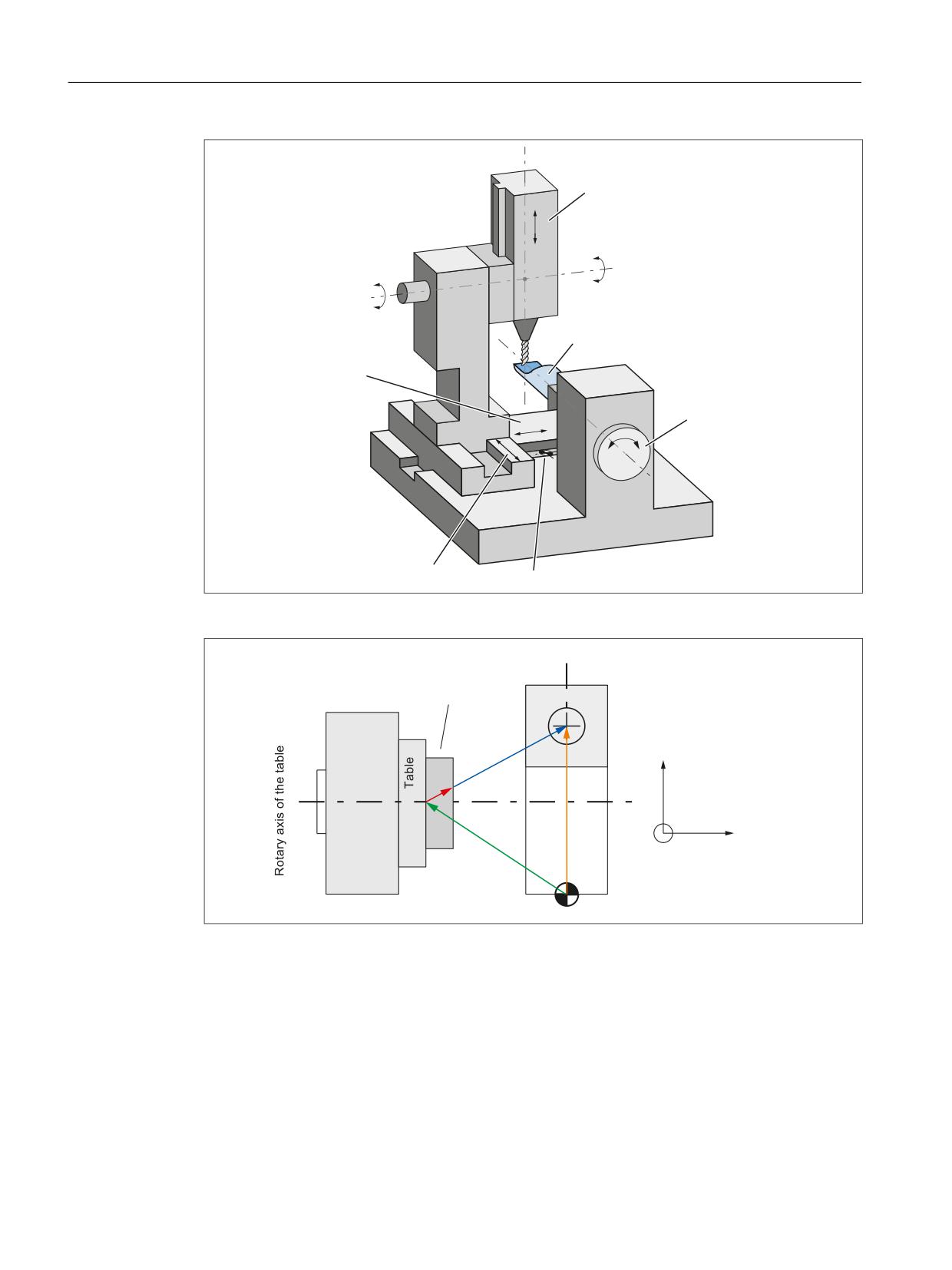
F2: Multi-axis transformations
2.4 Transformation with swiveled linear axis
6ZLYHOLQJ OLQHDU D[LV
=
5RWDU\ D[LV
$
ZRUNSLHFH
/LQHDU D[LV
5RWDU\ D[LV
;
<
%
/LQHDU D[LV
0DFKLQH ]HUR
Figure 2-16
Machine in the zero position
$[LV RI WKH WRRO
)L[WXUH
6WDWRU
9LHZ RSSRVLWH WKH ; D[LV
WR
=
SR
<
UR
]
UR
;
MR
0DFKLQH ]HUR
Figure 2-17
Front view: Vectors for machine in the zero position
Special functions
62
Function Manual, 12/2018, A5E40874099B AB
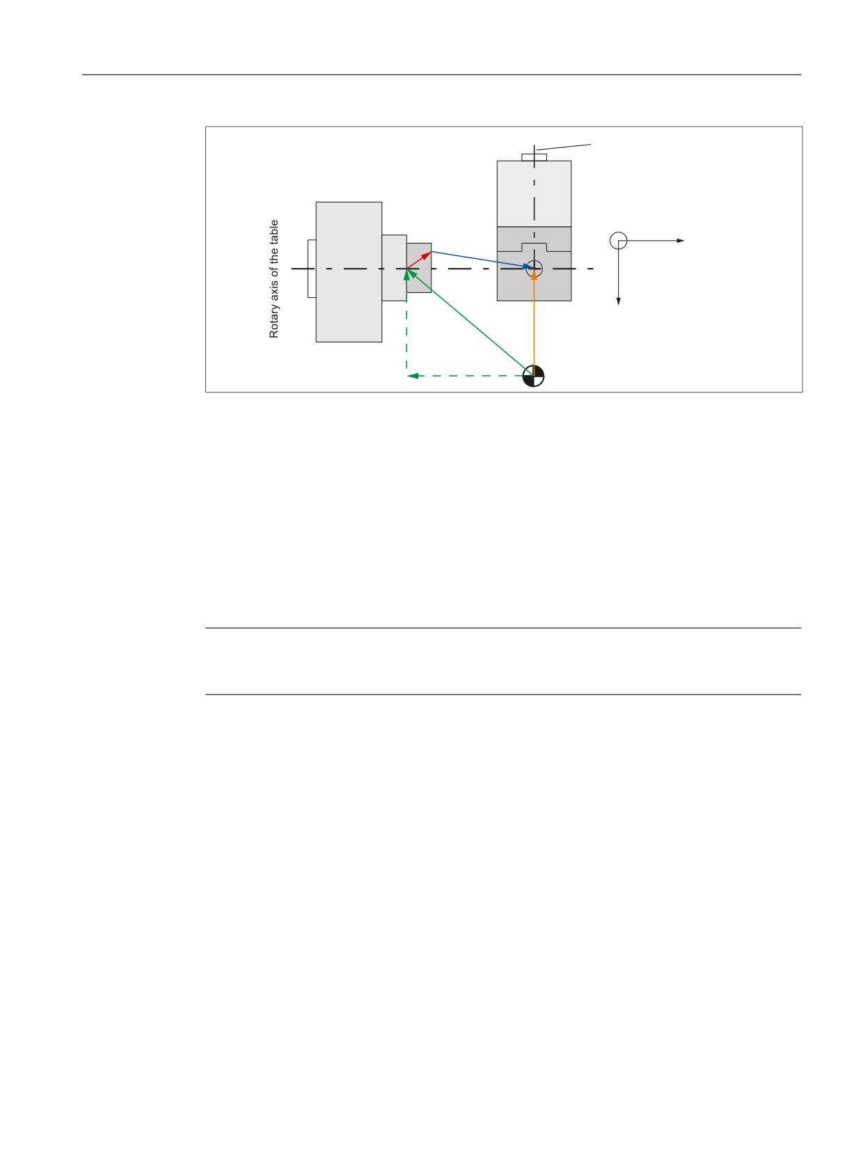
F2: Multi-axis transformations
2.4 Transformation with swiveled linear axis
6ZLYHO D[LV RI WKH
OLQHDU D[LV
9LHZ RSSRVLWH WKH = D[LV
<
=
SR
WR
=
;
MR
UR
MR[
MR\
0DFKLQH ]HUR
Figure 2-18
Top view: Vectors for machine in the zero position
Determination of the machine data values
Perform the following operation:
1. Determine, as shown in the lower part for vector jo in the "Vectors for machine in zero
position" figure, the X and Y components for all vectors.
2. As shown in the upper part for vector ro in the "Vectors for machine in zero position" figure,
determine the Z component for all vectors.
3. Enter the X, Y and Z components of the vectors (po, jo, to, ro) in the relevant machine data.
The procedure can be used all settable kinematic variants.
Note
For the appropriate machine geometry or position of the machine zero, both individual
components as well as complete vectors can become zero.
Programming
The switch on/off of the transformation in the part program or synchronized action is described
in Section "Programming of the 3- to 5-axis transformation (Page 68)".
Tool orientation
For a transformation with swiveling linear axis, the same statements as for the 5-axis
transformation with regard to the tool orientation apply similarly (see Section "Tool
orientation (Page 50)").
Special functions
Function Manual, 12/2018, A5E40874099B AB
63
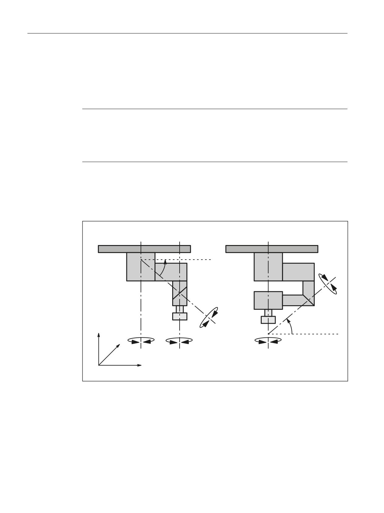
F2: Multi-axis transformations
2.5 Cardan milling head
2.5
Cardan milling head
2.5.1
Fundamentals of cardan milling head
Note
The following description of the cardan milling head transformation has been formulated on
the assumption that the reader has already read and understood the general 5-axis
transformation described in Section "5-axis transformation (Page 43)". Please note that where
no specific statements relating to the cardan milling head are made in the following section,
the statements relating to general 5-axis transformation apply.
Applications
A cardan milling head is used for machining contours of sculptured parts at high feedrates. An
excellent degree of machining accuracy is achieved thanks to the rigidity of the head.
C
ϕ
A’
C
A’
ϕ
z
y
tool
tool
x
Figure 2-19
Schematic representation of the cardan milling head versions
Configuring the nutator angle φ
The angle of the inclined axis can be configured in a machine data:
$MC_TRAFO5_NUTATOR_AX_ANGLE_1: for the first orientation transformation
$MC_TRAFO5_NUTATOR_AX_ANGLE_2: for the second orientation transformation
The angle must lie within the range of 0 degrees to +89 degrees.
Special functions
64
Function Manual, 12/2018, A5E40874099B AB