SINUMERIK 840D sl. Service - Functions. Manual (2018-2020) - page 59

Interface signals
19.2 Interface signals - detailed description
19.2.5.207
DB21, ... DBX387.0 - 7 (status of action 1 - 8)
DB21, ...
Status of action 1 - 8
DBX387.0 - 7
Signal flow
PLC → NC
Update
Cyclic
Signal state 1
The action is enabled.
Signal state 0
The action is inhibited.
Further information
Application: Grinding
Corresponds to
DB21, … DBX391.0 - 7 (enable request for the action on the NC side)
$AC_IN_KEY_G_RUN_OUT[1 ... 8] (enable request of the action 1 - 8 on the NC side)
$AC_IN_KEY_G_RUN_IN[ 1 ... 8 ] (enable of the action 1 - 8 on the PLC side)
Additional information
Function Manual Synchronized Actions
19.2.5.208
DB21, ... DBB388 (index active transformation)
DB21, ... DBB388
Index number of the active transformation in the channel
Signal flow
NC → PLC
Update
Cyclic
More information
If the transformation is active, the interface signal shows the transformer index of the active
transformation.
Example
Program code:
N24100 $MC_TRAFO_TYPE_1=24
N24200 $MC_TRAFO_TYPE_2=513
N24300 $MC_TRAFO_TYPE_3=24
Display in the interface signal:
TRAORI → DBB388=1
TRAORI(2) → DBB388=3
Corresponds with
DB21, … DBX33.6 (transformation active)
19.2.5.209
DB21, ... DBX390.0 - 7 (enable status of input signal 1 - 8)
DB21, ...
Enable status of input signal 1 - 8
DBX390.0 - 7
Signal flow
PLC → NC
Update
Cyclic
Signal state 1
The input signal is enabled.
The enable signal is formed by the NC-side ANDlogic operation of the NC enable signal
$AC_IN_KEY_G_ENABLE[1 ... 8] and the PLC enable signal NOT (DBX386.0 - 7).
PLC
Function Manual, 10/2020, 6FC5397-0HP40-0BA1
613

Interface signals
19.2 Interface signals - detailed description
DB21, ...
Enable status of input signal 1 - 8
DBX390.0 - 7
Signal state 0
The input signal is not enabled.
Further information
Application: Grinding
Corresponds to
DB21, … DBX386.0 - 7 (disabling of input signal 1 - 8)
$AC_IN_KEY_G_ENABLE[1 ... 8] (input signal 1 - 8 enable on the NC side)
$AC_IN_KEY_G_ISENABLE[1 ... 8] (release status of the input signal 1 - 8)
Additional information
Function Manual Synchronized Actions
19.2.5.210
DB21, ... DBX391.0 - 7 (enable request for action 1 - 8)
DB21, ...
Enable request for action 1 - 8
DBX391.0 - 7
Signal flow
NC → PLC
Update
Cyclic
Signal state 1
It has been requested that the action is enabled.
Signal state 0
It has not been requested that the action is enabled.
Further information
Application: Grinding
Corresponds to
DB21, … DBX387.0 - 7 (status of the action 1 - 8)
$AC_IN_KEY_G_RUN_OUT[1 ... 8] (enable request of the action 1 - 8 on the NC side)
$AC_IN_KEY_G_RUN_IN[1 ... 8] (enable of the action 1 - 8 on the PLC side)
Additional information
Function Manual Synchronized Actions
19.2.5.211
DB21, ... DBB392 (selection: Coordinate system for Cartesian manual traversing and
handwheel override in automatic mode in the tool direction (DRF))
DB21, ... DBB392
Selection: Coordinate system for Cartesian manual traversing and handwheel override in
automatic mode in the tool direction (DRF)
Signal flow
PLC → NC
Update
Cyclic
PLC
614
Function Manual, 10/2020, 6FC5397-0HP40-0BA1
Interface signals
19.2 Interface signals - detailed description
DB21, ... DBB392
Selection: Coordinate system for Cartesian manual traversing and handwheel override in
automatic mode in the tool direction (DRF)
Additional information
Selection of the coordinate system for:
• Cartesian manual traversing of the geometry axes in the tool direction (TCS)
• Handwheel override of the geometry axes in the AUTOMATIC mode in the tool direction
(DRF)
Value
Description
0
The function is not selected
1
Manual traversing of the geometry axes in the basic coordinate system (BCS)
2
Manual traversing of the geometry axes in the workpiece coordinate system
(WCS)
3
Manual traversing or handwheel override (DRF) of the geometry axes in the
workpiece coordinate system (WCS)
Additional information
• Function Manual Basic Functions
• FC19: MCP_IFM - transfer of MCP signals to interface (Page 282)
• Function Manual Transformations
• Function Manual Axes and Spindles
19.2.6
DB31, ...: Axis/spindle
19.2.6.1
DB31, ... DBB0 (feedrate override, axis-specific)
DB31, ... DBB0
Feedrate override, axis-specific
Signal flow
PLC → NC
Update
Cyclic
PLC
Function Manual, 10/2020, 6FC5397-0HP40-0BA1
615

Interface signals
19.2 Interface signals - detailed description
DB31, ... DBB0
Feedrate override, axis-specific
Additional information
Binary/Gray coding
The override factors can be specified in the binary or Gray-coded format. The control must be
informed of the used format via the following machine data:
MD12000 $MN_OVR_AX_IS_GRAY_CODE = <Coding>
Binary coding
With binary coding, the value in the interface corresponds to the override factor.
Binary code
Decimal
Override factor
0000 0000
0
0.00
0000 0001
1
0.01
0000 0010
2
0.02
0000 0011
3
0.03
000 0100
4
0.04
0110 0100
100
1.00
1100 1000
200
2.00
Gray coding
The Gray-coded values of the interface are assigned the override factors via the following
machine data:
MD12010 $MN_OVR_FACTOR_AX_SPEED[ <Switch position> - 1 ] = <Override factor>
Switch position
Gray code
Override factor 1)
1
00001
0.00
2
00011
0.01
3
00010
0.02
4
00110
0.04
5
00111
0.06
6
00101
0.08
7
00100
0.10
8
01100
0.20
9
01101
0.30
10
01111
0.40
11
01110
0.50
12
01010
0.60
13
01011
0.70
14
01001
0.75
15
01000
0.80
16
11000
0.85
17
11001
0.90
18
11011
0.95
19
11010
1.00
20
11110
1.05
21
11111
1.10
22
11101
1.15
PLC
616
Function Manual, 10/2020, 6FC5397-0HP40-0BA1
Interface signals
19.2 Interface signals - detailed description
DB31, ... DBB0
Feedrate override, axis-specific
23
11100
1.20
24
10100
1.20
25
10101
1.20
26
10111
1.20
27
10110
1.20
28
10010
1.20
29
10011
1.20
30
10001
1.20
31
10000
1.20
Limitations
• The active override factor is limited internally in the control to 2.00 or 200%.
• The maximum possible override factor can be limited to a value less than 200% with the
following machine data:
MD12100 $MN_OVR_FACTOR_LIMIT_BIN
Notes
The axis-specific feedrate override is not effective with the following functions when cutting
threads: G33, G331, G332, G63
Corresponds to
DB21, ... DBB4 (path feedrate override)
DB31, ... DBB19 (speed override, spindle-specific)
DB31, ... DBX1.7 (override active)
Additional information
Function Manual Axes and Spindles
1) Default values
19.2.6.2
DB31, ... DBX1.0 (drive test travel enable)
DB31, ... DBX1.0
Drive test travel enable
Signal flow
PLC → NC
Update
Cyclic
Signal state 1
The travel enable for the drive test is set, i.e. axis motion for the drive test is enabled.
Signal state 0
The travel enable for the drive test is not set, i.e. axis motion for the drive test is inhibited.
Further information
The signal is the feedback signal for the request:
DB31, ... DBX61.0 == 1 (drive test travel request)
Only the PLC can enable an axis so that it can be traversed.
Corresponds with
DB31, ... DBX61.0 (drive test travel request)
Additional information
SINUMERIK 840D sl Commissioning Manual, CNC Commissioning: NC, PLC, Drive
PLC
Function Manual, 10/2020, 6FC5397-0HP40-0BA1
617

Interface signals
19.2 Interface signals - detailed description
19.2.6.3
DB31, ... DBX1.1 (acknowledge fixed stop reached).
DB31, ... DBX1.1
Acknowledge fixed stop reached
Signal flow
PLC → NC
Update
Cyclic
Signal state 1
Significance when the fixed stop is reached: DB31, ... DBX62.5 (fixed stop reached) == 1
• The axis presses against the fixed stop with the clamping torque.
• The fixed stop monitoring window is activated.
• A block change is executed.
Signal state 0
Significance when the fixed stop is reached: DB31, ... DBX62.5 (fixed stop reached) == 1
• The axis presses against the fixed stop with the clamping torque.
• The fixed stop monitoring window is activate
• A block change is not executed, and the channel message "Wait: HiFu acknowledgment
missing" is displayed
• The function is canceled, alarm "20094 axis %1 Function aborted" is output.
Significance after deselecting the function FXS=0 via the part program:
• The torque limiting and the monitoring of the fixed stop monitoring window are canceled.
Additional information
Irrelevant for MD37060 $MA_FIXED_STOP_ACKN_MASK == 0 or 2
Corresponds with
DB31, ... DBX1.2 (fixed stop sensor)
DB31, ... DBX3.1 (enable travel to fixed stop)
DB31, ... DBX62.4 (activate travel to fixed stop)
DB31, ... DBX62.5 (fixed stop reached)
MD37060 $MA_FIXED_STOP_ACKN_MASK (monitoring PLC acknowledgements for travel to
fixed stop)
Additional information
Function Manual Basic Functions
19.2.6.4
DB31, ... DBX1.2 (fixed stop sensor)
DB31, ... DBX1.2
Sensor for fixed stop
Signal flow
PLC → NC
Update
Cyclic
Signal state 1
Fixed stop has been reached.
Signal state 0
Fixed stop has not been reached.
Additional information
The signal is only active if: MD37040 $MA_FIXED_STOP_BY_SENSOR == 1
Corresponds with
DB31, ... DBX1.1 (acknowledge fixed stop reached).
DB31, ... DBX3.1 (enable travel to fixed stop)
DB31, ... DBX62.4 (activate travel to fixed stop)
DB31, ... DBX62.5 (fixed stop reached)
MD37040 $MA_FIXED_STOP_BY_SENSOR = (fixed stop detection via sensor)
Additional information
Function Manual Axes and Spindles
PLC
618
Function Manual, 10/2020, 6FC5397-0HP40-0BA1

Interface signals
19.2 Interface signals - detailed description
19.2.6.5
DB31, ... DBX1.3 (axis/spindle disable)
DB31, ... DBX1.3
Axis/spindle disable
Signal flow
PLC → NC
Update
Cyclic
PLC
Function Manual, 10/2020, 6FC5397-0HP40-0BA1
619
Interface signals
19.2 Interface signals - detailed description
DB31, ... DBX1.3
Axis/spindle disable
Signal state 1
Axis/spindle disable is requested.
Axis
• Effects with stationary axis:
- No setpoints are output to the position controller, i.e. the axis traversing movement is
disabled. The axis is in closed-loop position control and any remaining following error
is compensated.
- If the axis is traversed via an NC program or manually, the set position and set velocity
are displayed as the actual position and actual velocity on the user interface. With
channel reset or end of program (M30/M2), the display of the actual value is set to the
actual value of the machine axis.
- The travel commands are output to the NC/PLC interface.
• Effects with traversing axis:
- The axis is stopped in compliance with the currently active braking characteristic and an
alarm is displayed. Subsequently, the travel movements of the axis are disabled. Posi-
tion control remains active and holds the axis in the current position.
Spindle
• Effects with open-loop control mode and stationary spindle:
- No setpoints are output to the speed controller, i.e. the spindle traversing movement is
disabled.
- If the spindle is traversed via an NC program or manually, the speed setpoint is displayed
on the user interface as the speed actual value.
• Effects with open-loop control mode and rotating spindle:
- Speed setpoint zero is immediately output to the speed controller.
- The spindle is stopped in compliance with the currently active braking characteristic
and an alarm is displayed. Subsequently, the travel movements of the spindle are dis-
abled. Position control remains active and holds the axis in the current position.
• Effects with positioning mode: See Stationary axis / Traversing axis
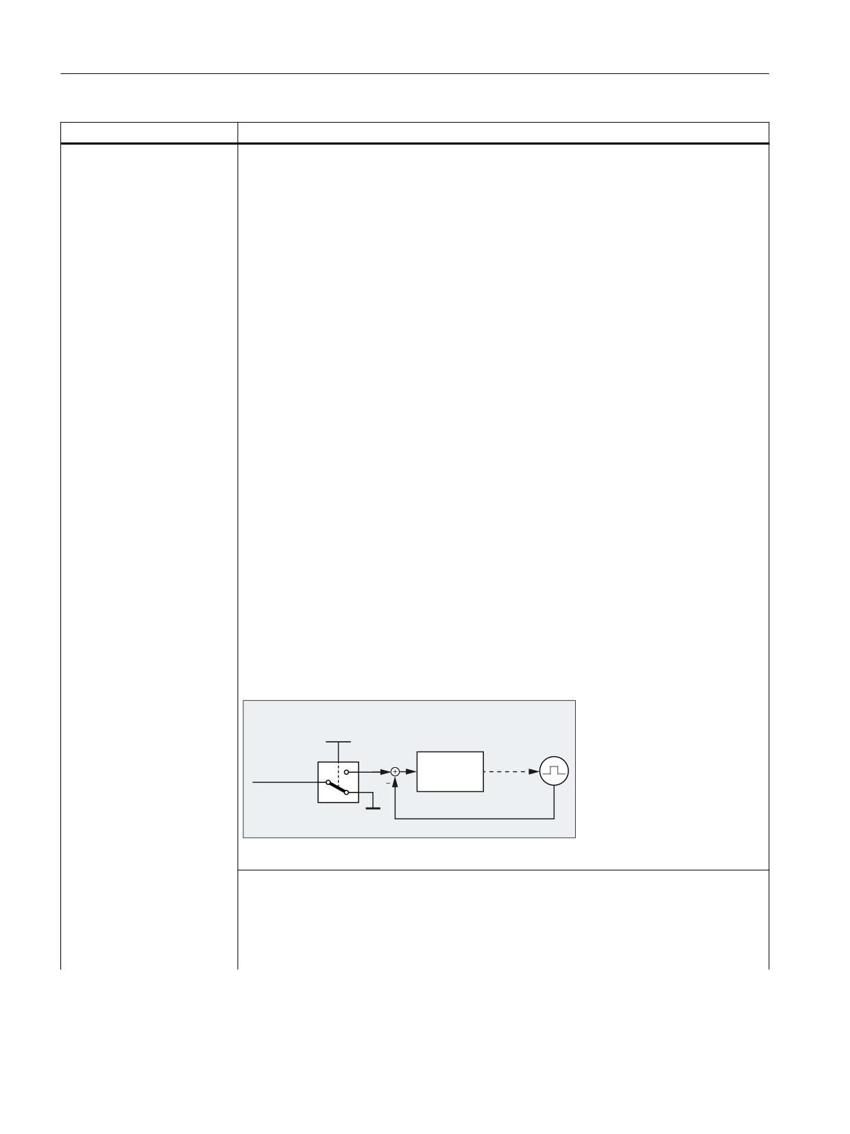
Structure graphic
'%
'%;
$[LV VSLQGOH GLVDEOH
3RVLWLRQ
3RVLWLRQ
VHWSRLQW
FRQWUROOHU
3RVLWLRQ DFWXDO YDOXH
Axis/spindle disable
Note
• If one of the following interface signals is set for a traversing axis/spindle for which the
signal "Axis/spindle disable" is present, the axis/spindle is not stopped:
- DB21, ... DBX12.3, 16.3 or 20.3 (feedrate stop for geometry axes 1, 2 and 3)
- DB21, ... DBX320.3, 324.3 or 328.3 (feedrate stop for orientation axes 1, 2 and 3)
PLC
620
Function Manual, 10/2020, 6FC5397-0HP40-0BA1
Interface signals
19.2 Interface signals - detailed description
DB31, ... DBX1.3
Axis/spindle disable
- DB31, ... DBX4.3 (feedrate stop / spindle stop)
• The axis/spindle can still be switched to the "hold" or "follow up" state with DB31, ... DBX1.4
(follow-up mode).
• An axis cannot be referenced either channel-specifically via DB21, ... DBX1.0 from the NC
program (G74) or axis-specifically (REF machine function).
• If the signal "Axis/spindle disable" is set only briefly for a traversing axis, the axis is stopped
without an alarm. With the next travel request, the axis is traversed to the new position.
Example:
N10 G0 X0 Y0
N20 G1 F1000 X100
N30 Y100
N40 X200
Regarding N20: At position 20 mm, "Axis/spindle lock" is set briefly for axis X ⇒ axis X is
stopped
Regarding N40: Axis X traverses from the last position (approx. 20 mm + braking distance)
to position 200 mm.
• Effects of "Axis/spindle disable" for spindle or axis couplings:
DB31,
DB31, ...
Coupl. 3)
Effect
DBX99.0 1)
DBX99.1 2)
0
0
Off
Setpoints are output
0
1
Off
No setpoint output for following spindle/axis
1
0
Off
No setpoint output for leading spindle/axis
1
1
Off
No setpoint output for leading and following spindle/
axis
0
0
On
Setpoints are output
0
1
On
Axis/spindle disable has no effect on the FS / FA
1
0
On
Axis/spindle disable also has an effect on the FS / FA
1
1
On
No setpoint output
1) Leading spindle/axis active
2) Following spindle/axis active
3) Status of the coupling between leading and following spindle/axis
Signal state 0
There is no request for "axis / spindle disable".
Note
The reset of the signal does not take effect until the axis/spindle is stationary.
• Axis
Setpoints are output to the position controller again immediately after the signal has been
reset. If a travel request is pending, it is executed immediately.
• Spindle
After the reset of the signal, the spindle disable which is still effective internally must be
canceled by an axis-specific reset, channel reset or end of program (M30 / M2). Only then are
setpoints output to the speed controller again.
PLC
Function Manual, 10/2020, 6FC5397-0HP40-0BA1
621

Interface signals
19.2 Interface signals - detailed description
DB31, ... DBX1.3
Axis/spindle disable
Corresponds with
DB31, ... DBX14.1 (activate program test)
DB31, ... DBX63.3 (axis/spindle lock active)
DB21, ... DBX1.7 (activate program test)
DB21, ... DBX33.7 (program test active)
Additional information
Response for synchronous operation:
Function Manual Axes and Spindles
19.2.6.6
DB31, ... DBX1.4 (follow-up mode)
DB31, ... DBX1.4
Follow-up mode
Signal flow
PLC → NC
Update
Cyclic
Signal state 1
Follow-up mode is active:
• The position setpoint is continuously tracked: position setpoint = actual position value
• Feedback signal: DB31, ... DBX61.3 = 1 (follow-up active)
• Standstill and clamping monitoring are not active.
• If an NC program is active when the closed-loop control system is switched on again, a
control-internal repositioning operation is performed (REPOSA: Linear approach with all
axes) to the last programmed position.
Note
Follow-up mode is only useful with a simultaneous reset of the controller enable: DB31, ...
DBX2.1 = 0
Signal state 0
Follow-up mode is not active:
• The position setpoint is not tracked: Position setpoint = programmed set position
• Feedback signal: DB31, ... DBX61.3 = 0 (follow-up not active)
• Standstill and clamping monitoring are active.
Note
If the controller enable is reset (DB31, ... DBX2.1 == 0), the axis is in the "hold" state. Whereby
the set position of the axis is not corrected to the actual position. If the axis is moved in this
state, e.g. manually, the difference between the set position and the actual position increases
constantly (following error). The following error is suddenly corrected to zero when the "Con-
troller enable" is set (speed setpoint jump).
Additional information
If the controller enable is cancelled in the control because of faults, the "hold" state should be
activated for the axis before the NC start after the queued alarms have been successfully
deleted, and the accompanying controller enable set: DB31, ... DBX1.4 = 0 (follow-up mode).
Otherwise, for an NC Start and active follow-up mode, the traversing distance of the previous
NC block would not be executed due to the internal delete distance-to-go.
Notice
During the transition from the "follow-up" state to the "hold" state or when the controller
enable is set in position control, delete distance-to-go is activated in the control. As a conse-
quence, a traversing block in which only this axis is traversed, is terminated directly.
Corresponds with
DB31, ... DBX2.1 (controller enable)
DB31, ... DBX2.3 (clamping in progress)
DB31, ... DBX61.3 (follow-up active)
PLC
622
Function Manual, 10/2020, 6FC5397-0HP40-0BA1

Interface signals
19.2 Interface signals - detailed description
19.2.6.7
DB31, ... DBX1.5 - 6 (position measuring system 1 (PMS1) / position measuring system
2 (PMS2))
DB31, ... DBX1.5 - 6
Position measuring system 1 (PMS1) / position measuring system 2 (PMS2)
Signal flow
PLC → NC
Update
Cyclic
Signal state 1
The position measuring system is active.
Signal state 0
The position measuring system is inactive.
PLC
Function Manual, 10/2020, 6FC5397-0HP40-0BA1
623

Interface signals
19.2 Interface signals - detailed description
DB31, ... DBX1.5 - 6
Position measuring system 1 (PMS1) / position measuring system 2 (PMS2)
Additional information
Bit 6
Bit 5
Effect
(PMS 2)
(PMS 1)
0
1
Position measuring system 1 is active:
• Position control of the machine axis via position measuring system 1.
• Monitoring functions (measuring system, standstill, clamping moni-
toring, contour deviation, etc.) of the machine axis via position meas-
uring system 1.
• If position measuring system 2 exists (MD30200 $MA_NUM_ENCS ==
2), its actual position value is acquired, but not monitored by any of
these functions.
1
0
Position measuring system 2 is active:
• Position control of the machine axis via position measuring system 2.
• Monitoring functions (measuring system, standstill, clamping moni-
toring, contour deviation, etc.) of the machine axis via position meas-
uring system 2.
• If position measuring system 1 exists (MD30200 $MA_NUM_ENCS ==
2), its actual position value is acquired, but not monitored by any of
these functions.
1
1
• Position control of the machine axis via position measuring system 1.
• If position measuring system 2 is available (MD30200
$MA_NUM_ENCS == 2), its actual position value is also acquired.
0
0
Position measuring systems 1 and 2 are inactive ("parking" of the machine
axis):
• There is no actual value acquisition.
• The monitoring of the position measuring system has been deactiva-
ted.
• The following interface signals are reset:
- DB31, ... DBX60.4 / 5 == 0 (referenced/synchronized, encoder 1/2)
- DB31, ... DBX61.5 (position controller active)
- DB31, ... DBX61.6 (speed controller active)
- DB31, ... DBX61.7 (current controller active)
Notes
• If the interface signal of the active position measuring system is reset for a traversing axis,
the axis is stopped with a ramp stop without the controller enable being cancelled inter-
nally.
• If a speed-controlled spindle does not have a position measuring system, the "Controller
enable" interface signal must be set:
DB31, ... DBX2.1 == 1 (controller enable)
• After deactivation of the "parking" state, incremental position measuring systems have to
be referenced to achieve the "referenced" encoder status.
• If the "parking" state is active, the following interface signal is ignored at NC start for this
axis:
DB31, ... DBX60.4 / 5 (referenced/synchronized 1/ 2).
Application examples
PLC
624
Function Manual, 10/2020, 6FC5397-0HP40-0BA1

Interface signals
19.2 Interface signals - detailed description
DB31, ... DBX1.5 - 6
Position measuring system 1 (PMS1) / position measuring system 2 (PMS2)
1. Switching over from position measuring system 1 to positioning measuring system 2 (and
vice versa).
If the axis was referenced in both position measuring systems and the limit frequency of the
used measured value encoder has not been exceeded in the meantime, i.e.
DB31, ... DBX60.4 and 60.5 == 1 (referenced/synchronized 1/2), a new reference point
approach is not required after the switchover.
On switchover, the current difference between position measuring system 1 and 2 is trav-
ersed immediately.
A tolerance band in which the deviation between the two actual values may lie at the
switchover can be specified in the following machine data:
MD36500 $MA_ENC_CHANGE_TOL (maximum tolerance for actual position value switch-
over)
If the actual value difference is greater than the tolerance, switchover is not performed and
alarm 25100 "Measuring system switchover not possible" is displayed.
2. Machine axis is parked:
The position measuring system monitoring is switched off when the measured value en-
coder is removed.
3. Switch off position measuring system:
When the position measuring system 1 or 2 is switched off, the associated interface signal
is reset:
DB31, ... DBX60.4/5 (referenced/synchronized 1/2)
4. Reference point approach:
Reference point approach of the axis is executed with the selected position measuring
system. Every position measuring system must be referenced separately.
Corresponds to
DB31, ... DBX60.4 / .5 (referenced/synchronized 1/2)
DB31, ... DBX61.6 (speed controller active)
DB31, ... DBX2.1 (controller enable)
MD36500 $MA_ENC_CHANGE_TOL (max. tolerance on actual position value switchover)
MD30200 $MA_NUM_ENCS (number of encoders)
Additional information
Function Manual Axes and Spindles
19.2.6.8
DB31, ... DBX1.7 (override active)
DB31, ... DBX1.7
Override active
Signal flow
PLC → NC
Update
Cyclic
Signal state 1
Feedrate/spindle override is active.
Signal state 0
Feedrate/spindle override is not active.
Additional information
The feedrate override factor (DB31, ... DBB0) specified by the NC/PLC interface is activated with
the interface signal.
If the feedrate/spindle override is not active, then independent of the actual switch position,
a value of 1.0 ≙ 100 % is used as override factor in the control. The first switch position is an
exception. Depending on the selected coding, for the first switch position the following factor
applies:
• Binary coding: Override factor = 0
• Gray coding: Override factor = MD12030 $MN_OVR_FACTOR_FEEDRATE[ 0 ]
PLC
Function Manual, 10/2020, 6FC5397-0HP40-0BA1
625

Interface signals
19.2 Interface signals - detailed description
DB31, ... DBX1.7
Override active
Corresponds to
MD12000 $MN_OVR_AX_IS_GRAY_CODE (axis-specific feedrate override switch Gray-coded)
MD12030 $MN_OVR_FACTOR_FEEDRATE (evaluation of the path feedrate override switch)
MD12100 $MN_OVR_FACTOR_LIMIT_BIN (limit for binary coded override switch)
Additional information
Function Manual Basic Functions
19.2.6.9
DB31, ... DBX2.0 (software cams: activation)
DB31, ... DBX2.0
Software cams: Activation
Signal flow
PLC → NC
Update
Cyclic
Signal state 1
A request has been made to activate the output of the minus and plus cam signals of an axis
to the PLC interface.
Signal state 0
A request has not been made to activate the output of the minus and plus cam signals of an axis
to the PLC interface.
Corresponds with
DB10 DBX110.0 - 113.7 (software cams: minus cam signal 1 to 32)
DB10 DBX114.0 - 117.7 (software cams: plus cam signal 1 to 32)
DB31, ... DBX62.0 (software cams active)
Additional information
Function Manual Axes and Spindles
19.2.6.10
DB31, ... DBX2.1 (controller enable)
DB31, ... DBX2.1
Controller enable
Signal flow
PLC → NC
Update
Cyclic
Signal state 1
Controller is enabled.
The position control loop is closed and the axis/spindle is in closed-loop control.
Feedback:
DB31, ... DBX61.5 = 1 (position controller active)
If the axis/spindle was referenced before resetting the interface signal, the axis/spindle does
not have to be re-referenced after the interface signal is set again. Supplementary condition:
The limit frequency of the active measuring system must not be exceeded in the meantime.
Note
If the axis/spindle was moved from its position during the time in which the controller enable
was not set, the behavior when the controller enable is set depends on the interface signal
"follow-up mode":
• DB31, ... DBX1.4 == 1 (follow-up mode)
Position control is performed at the current position
• DB31, ... DBX1.4 == 0 (follow-up mode)
Position control is performed at the last position before the controller enable is reset
PLC
626
Function Manual, 10/2020, 6FC5397-0HP40-0BA1

Interface signals
19.2 Interface signals - detailed description
DB31, ... DBX2.1
Controller enable
Signal state 0
Controller is not enabled.
The behavior when the "controller enable" is removed depends on whether the axis/spindle is
stationary or traversing at this time:
• Axis/spindle stationary:
- The position control loop of the axis is opened.
- For DB31, ... DBX1.4 == 1 (follow-up mode) ⇒ position setpoint = actual position value
- The controller enable on the drive is reset
- The following interface signals are reset:
DB31, ... DBX61.5 = 0 (position controller active)
DB31, ... DBX61.6 = 0 (speed controller active)
DB31, ... DBX61.7 = 0 (current controller active)
• Axis/spindle traverses
- The axis is stopped with rapid stop.
- Alarm 21612 "Controller enable VDI signal reset during motion".
- The position control loop of the axis/spindle is opened.
- Independent of the interface signal DB31, ... DBX1.4 (follow-up mode), the position
setpoint is corrected at the end of the braking operation (position setpoint = actual
position value) and the feedback signal DB31, ... DBX61.3 = 1 (follow-up mode) is set.
- The following interface signals are reset:
DB31, ... DBX61.5 (position controller active)
DB31, ... DBX61.6 (speed controller active)
DB31, ... DBX61.7 (current controller active)
Note
The current set position is retained in the control when "Controller enable" is reset and "Follow-
up mode" (DB31, ... DBX1.4 == 0) is not set. If the axis is moved in this state, e.g. manually, the
difference between the set position and the actual position increases constantly (following
error). The following error is suddenly corrected to zero when the "Controller enable" is set
(speed setpoint jump).
PLC
Function Manual, 10/2020, 6FC5397-0HP40-0BA1
627

Interface signals
19.2 Interface signals - detailed description
DB31, ... DBX2.1
Controller enable
Additional information
Mechanical clamping of an axis
If the axis is positioned at the clamping position, the clamping mechanism is closed. The
controller enable is then reset. Otherwise, the position controller would constantly work
against the clamping, if the axis was moved mechanically from its specified position during the
clamping operation.
When the clamping is removed, the controller enable is set first and then the mechanical
clamping is released.
Note
• Travel request for an axis/spindle without controller enable:
- The axis/spindle is not traversed
- The travel command is output to the interface
- As long as the travel request is present, the axis/spindle is traversed immediately when
the controller enable is set.
• When the controller enable is reset for a traversing geometry axis, this always results in a
contour violation.
Corresponds with
DB31, ... DBX61.3 (follow-up active)
DB31, ... DBX1.4 (follow-up mode)
DB31, ... DBX61.5 (position controller active)
DB31, ... DBX61.6 (speed controller active)
DB31, ... DBX61.7 (current controller active)
MD36620 $MA_SERVO_DISABLE_DELAY_TIME (OFF delay of the controller enable)
MD36610 $MA_AX_EMERGENCY_STOP_TIME (braking ramp time when errors occur)
19.2.6.11
DB31, ... DBX2.2 (spindle reset/delete distance to go)
DB31, ... DBX2.2
Delete distance-to-go/spindle reset
Signal flow
PLC → NC
Update
Cyclic
Edge change 0 → 1
Axis: "Delete-distance-to-go" is requested.
Spindle: Reset is requested
Edge change 1 → 0
No effect.
PLC
628
Function Manual, 10/2020, 6FC5397-0HP40-0BA1

Interface signals
19.2 Interface signals - detailed description
DB31, ... DBX2.2
Delete distance-to-go/spindle reset
Additional information
Axis: Delete distance-to-go
• AUTOMATIC and MDI modes
The interface signal is only active if the axis is traversed as positioning axis. A positioning
axis is decelerated to standstill along its brake characteristic. The distance-to-go of the axis
is deleted.
• JOG mode
The axis is braked down to standstill alone its deceleration characteristic and then a pos-
sible delete distance to go is a deleted.
Note
After the delete distance to go, in an NC program, the following block is prepared again with
the actual axis position. As a consequence, a different contour is traversed along than pro-
grammed in the NC program. Traversing to absolute position G90 in the block after "Delete
distance-to-go" at least allows the programmed position is approached. When traversing using
incremental dimension G91, then the programmed position would not be approached.
Spindle: reset
• Control mode:
- The spindle is stopped
- The NC program is again executed
- The spindle continues to rotate with the next M and S value programmed in the NC
program.
• Oscillation mode:
- Oscillation is interrupted
- The axes continue to traverse
- The NC program continues with the actual gear stage
- The spindle continues to rotate with the next M and S value programmed in the NC
program. The speed obtained from these values (actual S value and the last active gear
stage) could be too high. In this case, the interface signal is set.
DB31, ... DBX83.1
• Positioning mode: The spindle is stopped
• Axis mode: The spindle is stopped
Note
The response for a spindle reset is independent of the setting in machine data:
MD35040 $MA_SPIND_ACTIVE_AFTER_RESET
Dwell time (G4): Delete distance-to-go
During a block with dwell time (G4), the interface signal has no influence on the time that
elapses.
Corresponds with
DB21, ... DBX6.2 (delete distance-to-go)
DB31, ... DBX83.1 (programmed speed too high)
MD35040 $MA_SPIND_ACTIVE_AFTER_RESET (own spindle reset)
Additional information
Function Manual Axes and Spindles
PLC
Function Manual, 10/2020, 6FC5397-0HP40-0BA1
629
Interface signals
19.2 Interface signals - detailed description
19.2.6.12
DB31, ... DBX2.3 (clamping in progress)
DB31, ... DBX2.3
Clamping in progress
Signal flow
PLC → NC
Update
Cyclic
Signal state 1
Clamping in progress.
The clamping monitoring is active.
Signal state 0
Clamping completed.
Standstill monitoring is active.
Corresponds with
MD36050 $MA_CLAMP_POS_TOL (clamping tolerance)
19.2.6.13
DB31, ... DBX2.4 - 7 (reference point value 1 - 4)
DB31, ... DBX2.4 - 7
Reference point value 1-4
Signal flow
PLC → NC
Update
Cyclic
Additional information
When the reference cam is reached, the NC is signaled by the interface which coded reference
cam has been approached.
Actual value = MD34100 $MA_REFP_SET_POS [ <reference point value x> ]
Bit 7
Bit 6
Bit 5
Bit 4
Meaning
0
0
0
0
Reference point value 1
0
0
0
1
Reference point value 1
0
0
1
0
Reference point value 2
0
1
0
0
Reference point value 3
1
0
0
0
Reference point value 4
Notes
• The interface signal must remain set until the reference point is reached or until a new
coded reference cam is approached.
• If the machine axis has reached the reference point, and noreference point value has been
selected, then reference point value 1 is used.
• For length measuring systems with distance-coded reference marks, the interface signal
is irrelevant.
Application example
On a machine tool with large traversing paths, up to four coded reference cams can be dis-
tributed over the distance traveled by the axis; up to four different reference points approach-
ed. This allows the traversing time when referencing to be shortened.
Corresponds with
MD34100 $MA_REFP_SET_POS (reference point value)
Additional information
Function Manual Axes and Spindles
PLC
630
Function Manual, 10/2020, 6FC5397-0HP40-0BA1

Interface signals
19.2 Interface signals - detailed description
19.2.6.14
DB31, ... DBX3.0 (accept external work offset)
DB31, ... DBX3.0
Accept external work offset
Signal flow
PLC→ NC
Update
Cyclic
Signal state 0 → 1
Accepting the values for the external work offset is requested.
Signal state 1 → 0
Accepting the values for the external work offset is not requested.
Additional information
With the interface signal, the value in system variable $AA_ETRANS is transferred into the
frame of the external work offset as external work offset ($P_EXTFRAME, $P_EXTFR):
DB31, ... DBX3.0: 0 → 1 ⇒ $P_EXTFRAME[<axis>] = $P_EXTFR[<axis>] = $AA_ETRANS[<axis>]
Corresponds with ...
$AA_ETRANS[<axis>] (external work offset)
$P_EXTFRAME[<axis>] (active system frame, external frame)
$P_EXTFR[<axis>] (data management frame for external frame)
MD28082 $MC_MM_SYSTEM_FRAME_MASK,bit1 (system frame)
Additional information
Function Manual Axes and Spindles
19.2.6.15
DB31, ... DBX3.1 (enable travel to fixed stop)
DB31, ... DBX3.1
Enable travel to fixed stop
Signal flow
PLC → NC
Update
Cyclic
Signal state 1
Positive feedback to the request to enable travel to the fixed stop with DB31, ... DBX62.4 = 1.
Signal state 0
Negative feedback to the request to enable travel to the fixed stop with DB31, ... DBX62.4 = 1.
Meaning after activating the function "travel to fixed stop" in the NC program (FXS):
• Travel to fixed stop is inhibited.
• The axis is stationary at the start position with reduced torque.
• The channel message "Wait: HiFu acknowledgment missing" is displayed.
Meaning before reaching the fixed stop DB31,
DBX62.5 == 0 (fixed stop reached):
• Travel to fixed stop interrupted.
• Alarm "20094: Axis%1 function was canceled" is displayed.
Meaning after reaching the fixed stop DB31,
DBX62.5 == 1 (fixed stop reached):
• The torque limiting and monitoring of the fixed stop monitoring window are canceled.
Additional information
Irrelevant for MD37060 $MA_FIXED_STOP_ACKN_MASK == 0 or 2
Corresponds with
DB31, ... DBX1.1 (acknowledge fixed stop reached).
DB31, ... DBX1.2 (fixed stop sensor)
DB31, ... DBX62.4 (activate travel to fixed stop)
DB31, ... DBX62.5 (fixed stop reached)
MD37060 $MA_FIXED_STOP_ACKN_MASK (monitoring PLC acknowledgements for travel to
fixed stop)
Additional information
Function Manual Axes and Spindles
PLC
Function Manual, 10/2020, 6FC5397-0HP40-0BA1
631
Interface signals
19.2 Interface signals - detailed description
19.2.6.16
DB31, ... DBX3.2 - 5 (activate fixed feedrate 1 - 4, machine axes)
DB 31, ... DBX3.2 - 5
Activate fixed feedrate 1 - 4, machine axes
Signal flow
PLC → NC
Update
Cyclic
Additional information
With the interface signals, in the JOG mode, the fixed feedrate - parameterized using machine
data - is activated.
Bit 5
Bit 4
Bit 3
Bit 2
Meaning
0
0
0
0
Fixed feedrate not selected
0
0
0
1
Fixed feedrate 1
0
0
1
0
Fixed feedrate 2
0
1
0
0
Fixed feedrate 3
1
0
0
0
Fixed feedrate 4
Instead of the parameterized JOG velocity/ JOG rapid traverse velocity (MD
JOG_VELO_...),
the axis is traversed with the selected fixed feedrate. The traversing direction is specified via the
interface signal:
DB31, ... DBX6 / 7 (traversing keys, minus/plus)
The fixed feedrates are parameterized using the following machine data:
• Linear axes: MD12202 $MN_PERMANENT_FEED
• Rotary axes: MD12204 $MN_PERMANENT_ROT_AX_FEED
Notes
• The fixed feedrate is not used for:
- Spindles
- Positioning axes
- Tapping
• The fixed feedrate is always interpreted as linear feedrate. Switchover to linear feedrate is
performed internally in the control system also when revolutional feedrate is active.
Corresponds with
MD12200 $MN_RUN_OVERRIDE_0 (traversing behavior with override 0)
MD12202 $MN_PERMANENT_FEED (fixed feedrates for linear axes)
MD12204 $MN_PERMANENT_ROT_AX_FEED (fixed feedrates for rotary axes)
MD21150 $MC_JOG_VELO_RAPID_ORI (conventional rapid traverse for orientation axes)
MD21155 $MC_JOG_VELO_ORI (conventional velocity for orientation axes)
MD21160 $MC_JOG_VELO_RAPID_GEO (conventional rapid traverse for geometry axes)
MD21165 $MC_JOG_VELO_GEO (conventional velocity for geometry axes)
MD32010 $MA_JOG_VELO_RAPID (conventional rapid traverse)
MD32020 $MA_JOG_VELO (conventional axis velocity)
Additional information
Function Manual Axes and Spindles
19.2.6.17
DB31, ... DBX3.6 (velocity/spindle speed limiting)
DB31, ... DBX3.6
Velocity/spindle speed limitation
Signal flow
PLC → NC
Update
Cyclic
PLC
632
Function Manual, 10/2020, 6FC5397-0HP40-0BA1
Interface signals
19.2 Interface signals - detailed description
DB31, ... DBX3.6
Velocity/spindle speed limitation
Signal state 1
The velocity/spindle speed limiting is active.
Signal state 0
The velocity/spindle speed limiting is not active.
Additional information
The control limits the velocity/spindle speed to the parameterized limit value:
MD35160 $MA_SPIND_EXTERN_VELO_LIMIT
Corresponds with
MD35100 $MA_SPIND_VELO_LIMIT (maximum spindle speed)
MD35160 $MA_SPIND_EXTERN_VELO_LIMIT (spindle speed limiting from the PLC)
SD43220 $SA_SPIND_MAX_VELO_G26 (programmable upper spindle speed limitation for
G26)
SD43230 $SA_SPIND_MAX_VELO_LIMS (spindle speed limitation for G96/G961/G97)
19.2.6.18
DB31, ... DBX4.0 - 2 (activate handwheel)
DB31, ... DBX4.0 - 2
Activate handwheel
Signal flow
PLC → NC
Update
Cyclic
Additional information
The interface can be interpreted either bit or binary-coded. The definition is realized using
machine data MD11324.
Bit coded: maximum 3 handwheels
Bit 2
Bit 1
Bit 0
Number of the assigned handwheel
0
0
0
No handwheel assignment
0
0
1
1
0
1
0
2
1
0
0
3
Binary coded: maximum 6 handwheels
Bit 2
Bit 1
Bit 0
Number of the assigned handwheel
0
0
0
No handwheel assignment
0
0
1
1
0
1
0
2
0
1
1
3
1
0
0
4
1
0
1
5
1
1
0
6
Note
At any one time, the machine axis can only be assigned to one handwheel. If, for bit coding,
several interface signals are set simultaneously, then the following priority applies: "Hand-
wheel 1" before "Handwheel 2" before "Handwheel 3".
Corresponds with
DB31, ... DBX64.0 - 2 (handwheel active)
MD11324 $MN_HANDWH_VDI_REPRESENTATION (representation of the handwheel number
at the VDI interface)
Additional information
Function Manual Axes and Spindles
PLC
Function Manual, 10/2020, 6FC5397-0HP40-0BA1
633

Interface signals
19.2 Interface signals - detailed description
19.2.6.19
DB31, ... DBX4.3 (feedrate/spindle stop, axis-specific)
DB31, ... DBX4.3
Feedrate/spindle stop, axis-specific
Signal flow
PLC → NC
Update
Cyclic
Signal state 1
Feedrate/spindle stop is active.
Signal state 0
Feedrate/spindle stop is not active.
Further information
Axis
• If the interface signal is set while traversing the axis, then the axis is braked down to
standstill along its braking characteristic. If the axis is in an interpolatory relationship with
other axes, these are also braked.
• After the interface signal has been reset, traversing motion that was stopped is continued.
• The position control is retained and the following error is eliminated.
• If the interface signal is set, and a request is issued to traverse, then the axis is not traversed.
However, the traverse request is kept. When the interface signal is reset, the traverse re-
quest is immediately executed, i.e. the axis is traversed.
• The interface signal is active in all modes.
Thread cutting
Effectiveness
G33, G34, G35
Effective (contour deviations occur)
G331, G332
Effective
G63
Effective
Spindle
• If the interface signal is set while traversing the spindle, then the spindle is braked down to
standstill along its braking characteristic. If the spindle is in an interpolatory relationship
with other spindles, these are also braked.
• After the interface signal has been reset, traversing motion that was stopped is continued.
• During positioning, the position control is retained and the following error is eliminated.
• If the interface signal is set, and a request is issued to move during positioning operation,
then the spindle is not moved. However, the traverse request is kept. When the interface
signal is reset, the traverse request is immediately executed, i.e. the spindle is moved.
• The interface signal is active in all modes.
Note
The interface signal is not active when "Axis/spindle inhibit" (DB31, ... DBX1.3 == 1) is active.
Corresponds to
DB31, ... DBX1.3 (axis/spindle disable)
Further information
Function Manual Axes and Spindles
19.2.6.20
DB31, ... DBX4.4 (traversing key disable)
DB31, ... DBX4.4
Traversing key lock
Signal flow
PLC → NC
Update
Cyclic
Signal state 1
The "Plus" and "Minus" traversing keys are locked.
Signal state 0
The "Plus" and "Minus" traversing keys are enabled.
PLC
634
Function Manual, 10/2020, 6FC5397-0HP40-0BA1

Interface signals
19.2 Interface signals - detailed description
DB31, ... DBX4.4
Traversing key lock
Additional information
Note
If the traversing key disable is activated while traversing, the axis is stopped.
Corresponds with
DB31, ... DBX4.6 - 7 (traversing keys "Plus" / "Minus")
Additional information
Function Manual Axes and Spindles
19.2.6.21
DB31, ... DBX4.5 (rapid traverse override)
DB31, ... DBX4.5
Rapid traverse override
Signal flow
PLC → NC
Update
Cyclic
Signal state 1
When manually traversing the machine axis using the traversing keys, when the interface
signal is set, rapid traverse velocity becomes active (MD32010).
Signal state 0
When manually traversing the machine axis using the traversing keys, the entered JOG velocity
becomes active (SD41110 or MD32020).
Additional information
The signal is only active for continuous or incremental manual traversing in the JOG mode.
The signal is irrelevant:
• for reference point approach (JOG mode)
• in the AUTOMATIC and MDI modes
The rapid traverse velocity can be influenced using the rapid traverse override switch.
Corresponds with
DB31, ... DBX4.6 - 7 (traversing keys "Plus" / "Minus")
SD41110 $SN_JOG_SET_VELO (axis velocity for JOG)
MD32010 $MA_JOG_VELO_RAPID (conventional rapid traverse)
MD32020 $MA_JOG_VELO (conventional axis velocity)
Additional information
Function Manual Axes and Spindles
19.2.6.22
DB31, ... DBX4.6 - 7 ("Plus" / "Minus" traversing keys)
DB31, ... DBX4.6 - 7
Traversing keys "Plus" / "Minus"
Signal flow
PLC → NC
Update
Cyclic
Signal state 1
A request has been made to traverse the machine axis using the traversing key in the positive/
negative axis direction.
Signal state 0
A request has not been made to traverse the machine axis using the traversing key in the
positive/negative axis direction.
PLC
Function Manual, 10/2020, 6FC5397-0HP40-0BA1
635

Interface signals
19.2 Interface signals - detailed description
DB31, ... DBX4.6 - 7
Traversing keys "Plus" / "Minus"
Additional information
There is a request signal for every traversing key and/or axis direction:
Bit 6
Traversing key "Minus" (for traversing in the negative axis direction)
Bit 7
Traversing key "Plus" (for traversing in the positive axis direction)
Depending on the active machine function, as well as the settings for jog and continuous
operation (SD41050 and MD11300), different responses are initiated when the signal changes:
1. Continuous manual travel in the jog mode
The machine axis traverses in the direction concerned to the active limit switch as long as
the interface signal is set to 1.
2. Continuous manual travel in continuous operation
On the first edge change 0 →1 the machine axis starts to traverse in the relevant direction.
This traversing movement still continues when the edge changes from 1 → 0. Any new
signal edge change 0 → 1 (same traversing direction!) stops the traversing movement.
3. Incremental manual travel in the jog mode
With signal 1 the machine axis starts to traverse at the set increment. If the signal changes
to the 0 state before the increment is traversed, then traversing is interrupted. When the
signal state changes to 1 again, traversing is continued. The axis can be stopped and started
several times as described above until it has traversed the complete increment.
4. Incremental manual travel in continuous operation
At the first edge change 0 → 1, the machine axis starts to traverse at the set increment. If
another edge change 0 → 1 is performed with the same traverse signal before the geom-
etry axis has traversed the increment, the traversing movement will be cancelled. The
increment is no longer traversed to the end.
Note
• The interface signal is irrelevant in operating modes:
- AUTOMATIC
- MDI
• If both traversing signals ("plus" and "minus") are set at the same time there is no traversing
or the current traversing is aborted.
• Traversing by means of the traversing keys can be locked via DB31, ... DBX4.4 (traversing
key disable).
Corresponds with
DB31, ... DBX4.4 (traversing key disable)
DB31, ... DBX64.6 - 7 ("Plus" and "Minus" traversing command)
MD11300 $MN_JOG_INC_MODE_LEVELTRIGGRD (INC and REF in jog mode)
SD41050 $SN_JOG_CONT_MODE_LEVELTRIGGRD (jog/continuous operation for JOG, contin-
uous)
Additional information
Function Manual Axes and Spindles
19.2.6.23
DB31, ... DBX5.0 - 6 (machine function request)
DB31, ... DBX5.0 - 6
Machine function request
Signal flow
PLC → NC
Update
Cyclic
Signal state 1
The machine function to manually traverse the machine axis has been requested.
Signal state 0
The machine function to manually traverse the machine axis has not been requested.
PLC
636
Function Manual, 10/2020, 6FC5397-0HP40-0BA1

Interface signals
19.2 Interface signals - detailed description
DB31, ... DBX5.0 - 6
Machine function request
Additional information
There is a request signal for every machine function to manually traverse the machine axis in
the JOG mode.
Bit 0
INC1
Bit 1
INC10
Bit 2
INC100
Bit 3
INC1000
Bit 4
INC10000
Bit 5
INCvar
Bit 6
Continuous manual travel
Incremental manual travel
In addition to five fixed increment sizes (default setting in MD11330: INC1, INC10, INC100,
INC1000 and INC10000), a variable increment size (INCvar) that can be set via the setting data
SD41010 is also available. The distance evaluation of one increment for fixed and variable
increment sizes is performed via the axis-specific machine data MD31090.
When pressing the "Plus" or "Minus" traversing key, or by rotating the electronic handwheel, the
axis starts to traverse in the appropriate direction, corresponding to the number of increments
of the active machine function.
Continuous manual travel
For continuous manual travel, the plus and minus traversing keys are selected to move the axis
continuously and the appropriate direction.
Notes
• If several requests are set simultaneously, no machine function becomes active.
• If an axis is currently being traversed via a machine function, the movement is aborted
through deselection or change of the machine function.
Corresponds with
DB31, ... DBX65.0 - 65.6 (active machine function)
MD11320 $MN_HANDWH_IMP_PER_LATCH (handwheel pulses per detent position)
MD11330 $MN_JOG_INCR_SIZE_TAB (increment size for INC/handwheel)
MD31090 $MA_JOG_INCR_WEIGHT (evaluation of an increment for INC/handwheel)
SD41010 $SN_JOG_VAR_INCR_SIZE (size of the variable increment for JOG)
Additional information
Function Manual Axes and Spindles
19.2.6.24
DB31, ... DBX7.0 (invert handwheel direction of rotation)
DB31, ... DBX7.0
Invert handwheel direction of rotation
Signal flow
PLC → NC
Update
Cyclic
Signal state 1
A request has been made to invert the direction of rotation of the handwheel assigned to the
machine axis.
Signal state 0
A request has not been made to invert the direction of rotation of the handwheel assigned to
the machine axis.
PLC
Function Manual, 10/2020, 6FC5397-0HP40-0BA1
637
Interface signals
19.2 Interface signals - detailed description
DB31, ... DBX7.0
Invert handwheel direction of rotation
Additional information
Note
It is only permissible to change the interface signal when the machine axis is at a standstill.
Application examples
• The direction of movement of the handwheel does not match the expected direction of the
axis.
• A handwheel is assigned to several axes with different orientations.
Corresponds with
DB31, ... DBX67.0 (handwheel direction of rotation inversion active)
Additional information
Function Manual Axes and Spindles
19.2.6.25
DB31, ... DBB8 (request axis/spindle replacement)
DB31, ... DBB8
Axis/spindle exchange request
Signal flow
PLC → NC
Update
Cyclic
Edge change 0 → 1
Request from PLC, switchover axis
Edge change 1 → 0
Acknowledged by the NC
Additional information
From the PLC user program, via DBB8 an axis/spindle exchange can be requested:
• From an NC channel to the PLC
• From the PLC to an NC channel
• From an NC channel to another NC channel
Bit
Meaning
0 ... 3
Name of the channel to which the axis/spindle is to be assigned (binary code).
Example:
The axis should be assigned to channel 2.
Bit 3
Bit 2
Bit 1
Bit 0
Channel
number
0
0
1
0
2
4
Request axis/spindle exchange
0 → 1
Request from PLC
1 → 0
Acknowledged by the NC
5
-
6
-
7
Request "PLC axis"
Corresponds with
DB31, ... DBB68 (Axis/spindle replacement)
MD20070 $MC_AXCONF_MACHAX_USED (machine axis number valid in channel)
MD30550 $MA_AXCONF_ASSIGN_MASTER_CHAN (initial setting of channel for axis replace-
ment)
Additional information
Function Manual Axes and Spindles
PLC
638
Function Manual, 10/2020, 6FC5397-0HP40-0BA1
Interface signals
19.2 Interface signals - detailed description
19.2.6.26
DB31, ... DBX9.0 - (2 select: position controller parameter set)
DB31, ... DBX9.0 - 2
Selection: Position controller parameter set
Signal flow
PLC → NC
Update
Job-controlled
Additional information
Bit 2
Bit 1
Bit 0
Parameter set
0
0
0
1
0
0
1
2
0
1
0
3
0
1
1
4
1
0
0
5
1
0
1
6
1
1
0
6
1
1
1
6
Note
Selecting a position controller parameter set is ignored, for:
MD35590 $MA_PARAMSET_CHANGE_ENABLE == 0
Corresponds with
DB31, ...DBX69.0, .1, ..2 (feedback signal: active position controller parameter set)
Additional information
SINUMERIK 840D sl Commissioning Manual, CNC Commissioning: NC, PLC, drive, "Commis-
sioning NC"
19.2.6.27
DB31, ... DBX9.3 (parameter set definitions disabled by NC)
DB31, ... DBX9.3
Parameter set definitions disabled by NC
Signal flow
PLC → NC
Update
Job-controlled
Signal state 1
The parameter set switchover is disabled.
Signal state 0
The parameter set switchover is enabled.
Corresponds with
DB31, ... DBX9.0, .1, .2
19.2.6.28
DB31, ... DBX10.0 (REPOS delay)
DB31, ... DBX10.0
REPOS delay
Signal flow
PLC → NC
Update
Cyclic
Signal state 1
A REPOS delay is requested.
After a block search, a REPOS offset is applied for this axis. However it is not applied using
the approach block, but rather using the next traversing block in which the axis is program-
med.
Signal state 0
A REPOS delay is not requested.
After a block search, a REPOS offset is applied for this axis using the approach block.
PLC
Function Manual, 10/2020, 6FC5397-0HP40-0BA1
639

Interface signals
19.2 Interface signals - detailed description
DB31, ... DBX10.0
REPOS delay
Additional information
Note
If the machine axes are involved on a path (DB31, ... DBX76.4 == 1 (path axis)), then the
interface signal is not active.
Corresponds with
DB21, ... DBX25.4 (REPOS mode activation)
DB21, ... DBX31.0 - 2 (REPOS mode)
DB21, ... DBX31.4 (REPOS mode change)
DB31, ... DBX72.0 (REPOS delay)
DB21, ... DBX319.0 (REPOS mode change acknowledgment)
DB21, ... DBX319.1 - 3 (active REPOS mode)
DB21, ... DBX319.5 (REPOS acknowledgment delay)
DB31, ... DBX70.0 (REPOS offset)
DB31, ... DBX70.1 (REPOS offset valid)
DB31, ... DBX70.2 (REPOS delay acknowledgment)
DB31, ... DBX76.4 (path axis)
MD11470 $MN_REPOS_MODE_MASK (repositioning properties)
Additional information
Function Manual Basic Functions
19.2.6.29
DB31, ... DBX12.0 (hardware limit switch minus)
DB31, ... DBX12.0
Hardware limit switch minus:
Signal flow
PLC → NC
Update
Cyclic
Signal state 1
The hardware limit switch minus was activated.
Signal state 0
The hardware limit switch minus was not activated.
Additional information
Alarm 21614 "Hardware limit switch -" is displayed, and the axis is stopped.
Corresponds with
MD36600 $MA_BRAKE_MODE_CHOICE (deceleration behavior when the hardware limit
switch responds)
19.2.6.30
DB31, ... DBX12.1 (hardware limit switch plus)
DB31, ... DBX12.1
Hardware limit switch plus
Signal flow
PLC → NC
Update
Cyclic
Signal state 1
Hardware limit switch plus was triggered.
Signal state 0
Hardware limit switch plus was not triggered.
Additional information
Alarm 21614 "Hardware limit switch +" is displayed, and the axis is stopped.
Corresponds with
MD36600 $MA_BRAKE_MODE_CHOICE (deceleration behavior when the hardware limit
switch responds)
PLC
640
Function Manual, 10/2020, 6FC5397-0HP40-0BA1

Interface signals
19.2 Interface signals - detailed description
19.2.6.31
DB31,... DBX12.2 (second software limit switch minus)
DB31, ... DBX12.2
Second software limit switch minus
Signal flow
PLC → NC
Update
Cyclic
Signal state 1
Second software limit switch minus
Signal state 0
The second software limit switch minus was not triggered.
Corresponds with
MD36100 $MA_POS_LIMIT_MINUS (1st software limit switch minus)
MD36120 $MA_POS_LIMIT_MINUS2 (2nd software limit switch minus)
19.2.6.32
DB31, ... DBX12.3 (second software limit switch plus)
DB31, ... DBX12.3
Second software limit switch plus
Signal flow
PLC → NC
Update
Cyclic
Signal state 1
The second software limit switch plus was triggered.
Signal state 0
The second software limit switch plus was not triggered.
Corresponds with
MD36110 $MA_POS_LIMIT_PLUS (1st software limit switch plus)
MD36130 $MA_POS_LIMIT_PLUS2 (2nd software limit switch plus)
19.2.6.33
DB31, ... DBX12.4 (modulo rotary axis: activate traversing range limits)
DB31, ... DBX12.4
Modulo rotary axis: activate traversing range limits
Signal flow
PLC → NC
Update
Cyclic
Signal state 1
Activate traversing range limits (software limit switch, working area limits) for modulo rotary
axes.
Signal state 0
Deactivate traversing range limits for modulo rotary axes.
Additional information
Note
The signal is irrelevant if linear axes/rotary axes do not have modulo functionality.
Application example
Mounted rotary axis with monitoring
Corresponds with
DB31, ... DBX74.4 (modulo rotary axis: traversing range limits active)
Additional information
Function Manual Axes and Spindles
19.2.6.34
DB31, ... DBX12.7 (reference point approach deceleration)
DB31, ... DBX12.7
Deceleration of reference point approach
Signal flow
PLC → NC
Update
Cyclic
Signal state 1
The machine axis is positioned at the reference cam.
PLC
Function Manual, 10/2020, 6FC5397-0HP40-0BA1
641
Interface signals
19.2 Interface signals - detailed description
DB31, ... DBX12.7
Deceleration of reference point approach
Signal state 0
The machine axis is positioned in front of the reference cam.
Additional information
Note
Using a suitable reference cam, which extends from the reference point to the end of the
traversing range, it is recommended to ensure that before the reference point approach, the
machine axis can be located in the range behind the reference cam.
Corresponds with
DB31, ... DBX2.4 - 7 (reference point value 1 to 4)
Additional information
Function Manual Axes and Spindles
19.2.6.35
DB31, ... DBX13.0 - 2 (JOG approach fixed point)
DB31, ... DBX13.0 - 2
JOG fixed point approach
Signal flow
PLC → NC
Update
Cyclic
Additional information
After selecting the "Approach fixed point in JOG" function, the PLC outputs the number of the
fixed point to be approached binary coded to the NC using DB31, ... DBX.0 - 2:
Bit 2
Bit 1
Bit 0
Number of fixed point to be approached
0
0
0
-
0
0
1
1
0
1
0
2
0
1
1
3
1
0
0
4
As soon as the function is active (see DB31, ... DBX75.0 - 2), then the selected machine axis can
be traversed to the corresponding fixed point using either the traversing keys or the hand-
wheel. The fixed points are defined using machine data MD30600.
Corresponds with
DB31, ... DBX75.0 - 2 (JOG approach fixed point active)
DB31, ... DBX75.3 - 5 (JOG approach fixed point reached)
MD30600 $MA_FIX_POINT_POS[<n>] (fixed value positions of the axis)
Additional information
Function Manual Axes and Spindles
19.2.6.36
DB31, ... DBX13.3 (JOG travel to position)
DB31, ... DBX13.3
JOG travel to position
Signal flow
PLC → NC
Update
Cyclic
Signal state 1
The function "Position travel in JOG" is requested:
Signal state 0
The function "Position travel in JOG" is not requested:
PLC
642
Function Manual, 10/2020, 6FC5397-0HP40-0BA1

Interface signals
19.2 Interface signals - detailed description
DB31, ... DBX13.3
JOG travel to position
Additional information
As soon as the function is active (see DB31, ... DBX75.6), then using the traversing keys or the
handwheel, the selected machine axis can be traversed to the position specified with setting
data SD43320.
Application
The function is used for machine tools that are exclusively operated manually, e.g. to approach
drill-holes in precise increments.
Note
The following preconditions applying for the "Position travel in JOG" function:
• The function can only be activated in the JOG mode.
The function cannot be activated if the machine function JOG-REPOS or JOG-REF is active
and in JOG in AUTOMATIC.
• The axis to be traversed must be referenced.
• A kinematic transformation may not be active.
• The axis to be traversed may not be a following axis of an active coupling.
Corresponds with
DB31, ... DBX75.6 (JOG travel to position active)
DB31, ... DBX75.7 (JOG position reached)
SD43320 $SA_JOG_POSITION (JOG position)
Additional information
Function Manual Axes and Spindles
19.2.6.37
DB31, ... DBX14.0 (suppress program test)
DB31, ... DBX14.0
Suppress program test
Signal flow
PLC → NC
Update
Cyclic
Signal state 1
Suppression of the program test (setpoint output locked) is requested.
Signal state 0
Suppression of the program test (setpoint output locked) is not requested.
Additional information
If function "Program test" (PRT) is active in the channel to which the axis currently belongs, the
axis is traversed with internal axis disable. Setpoints are generated but they not output to the
machine axes. Actual value = Setpoint.
If the program test is suppressed for the axis, setpoints are output to the machine axis despite
the function "program test" being active in the channel to which the axis currently belongs.
Automatic transfer of the interface signals
The HMI request signals DB21, ... DBX128.0 / .1 are only transferred from the basic PLC program
to the PLC request signals DB21, ... DBX14.0 / .1 if FB1 parameter MMCToIF is set to TRUE. If
the parameter is not set, the PLC request signals must be set by the PLC user program.
Corresponds with
DB31, ... DBX14.1 (activate program test)
DB31, ... DBX128.0 (suppress program test)
DB31, ... DBX128.1 (activate program test)
Additional information
Function Manual Basic Functions
PLC
Function Manual, 10/2020, 6FC5397-0HP40-0BA1
643
Interface signals
19.2 Interface signals - detailed description
19.2.6.38
DB31, ... DBX14.1 (activate program test)
DB31, ... DBX14.1
Activate program test
Signal flow
PLC → NC
Update
Cyclic
Signal state 1
Activation of the function "program test" (setpoint output locked) is requested.
Signal state 0
Activation of the function "program test" (setpoint output locked) is not requested.
Additional information
If the function "program test" is active, the axis is traversed with internal axis disable. Setpoints
are generated but they not output to the machine axes. Actual value = Setpoint.
Automatic transfer of the interface signals
The HMI request signals DB21, ... DBX128.0 / .1 are only transferred from the basic PLC program
to the PLC request signals DB21, ... DBX14.0 / .1 if FB1 parameter MMCToIF is set to TRUE. If
the parameter is not set, the PLC request signals must be set by the PLC user program.
Corresponds with
DB31, ... DBX14.0 (suppress program test)
DB31, ... DBX128.0 (suppress program test)
DB31, ... DBX128.1 (activate program test)
Additional information
Function Manual Basic Functions
19.2.6.39
DB31, ... DBX16.0 - 2 (actual gear stage)
DB31, ... DBX16.0 - 2
Actual gear stage
Signal flow
PLC → NC
Update
Cyclic
Additional information
If the new gear stage is selected at the machine, the PLC user program sets the following
interface signals as feedback signal to the NC:
• DB31, ... DBX16.0 - 2 (actual gear stage)
• DB31, ... DBX16.3 (gear stage has been changed)
This signals the NC that the correct stage has been successfully selected. The associated pa-
rameter set becomes active in the NC.
Bit 2
Bit 1
Bit 0
Parameter set
Meaning: Parameter set for
No.
---
---
---
0
Axis mode
0
0
0
1
Gear stage 1
0
0
1
Gear stage 1
0
1
0
2
Gear stage 2
0
1
1
3
Gear stage 3
1
0
0
4
Gear stage 4
1
0
1
5
Gear stage 5
1
1
0
Gear stage 5
1
1
1
Gear stage 5
Note
If the PLC user program signals back to the NC with a different actual gear stage than issued by
the NC as the set gear stage requested by the PLC, the gear change is still considered to have
been successfully completed and the actual gear stage that is signaled back is activated in the
NC.
PLC
644
Function Manual, 10/2020, 6FC5397-0HP40-0BA1

Interface signals
19.2 Interface signals - detailed description
DB31, ... DBX16.0 - 2
Actual gear stage
Corresponds with
DB31, ... DBX16.3 (gear stage has been changed)
DB31, ... DBX18.5 (oscillation speed)
DB31, ... DBX82.0 - 2 (set gear stage)
DB31, ... DBX82.3 (change over gear stage)
Additional information
Function Manual Axes and Spindles
19.2.6.40
DB31, ... DBX16.3 (gear stage has been changed)
DB31, ... DBX16.3
Gear is changed over
Signal flow
PLC → NC
Update
Cyclic
Edge change 0 → 1
Gear is changed over
Edge change 1 → 0
No effect.
Additional information
If the new gear stage is selected at the machine, the PLC user program sets the following
interface signals as feedback signal to the NC:
• DB31, ... DBX16.0 - 2 (actual gear stage)
• DB31, ... DBX16.3 = 0 → 1 (gear stage has been changed)
Feedback signal from the NC to the PLC: DB31, ... DBX82.3 = 0 (changeover gear stage)
Feedback signal from the PLC to the NC: DB31, ... DBX16.3 = 0 (gear stage has been changed)
This completes the gear stage change in the control system.
Note
• The interface signal is irrelevant for all spindle modes with the exception of the oscillation
mode.
• If the PLC user program signals back to the NC with a different actual gear stage than issued
by the NC as the set gear stage requested by the PLC, the gear change is still considered to
have been successfully completed and the actual gear stage that is signaled back is acti-
vated in the NC.
Corresponds with
DB31, ... DBX16.0 - 2 (actual gear stage)
DB31, ... DBX82.0 - 2 (set gear stage)
DB31, ... DBX82.3 (change over gear stage)
DB31, ... DBX18.5 (oscillation speed)
Additional information
Function Manual Axes and Spindles
19.2.6.41
DB31, ... DBX16.4 (resynchronize spindle, measuring system 1)
DB31, ... DBX16.4
Resynchronize spindle, measuring system 1
Signal flow
PLC → NC
Update
Cyclic
Edge change 0 → 1
There is an active request to synchronize measuring system 1 of the spindle.
Edge change 1 → 0
No effect.
Additional information
Note
The interface signal is irrelevant for all spindle modes with the exception of the control mode.
PLC
Function Manual, 10/2020, 6FC5397-0HP40-0BA1
645

Interface signals
19.2 Interface signals - detailed description
DB31, ... DBX16.4
Resynchronize spindle, measuring system 1
Corresponds with
DB31, ... DBX60.4 (referenced / synchronized 1)
DB31, ... DBX60.5 (referenced / synchronized 2)
Additional information
Function Manual Axes and Spindles
19.2.6.42
DB31, ... DBX16.5 (resynchronize spindle, measuring system 2)
DB31, ... DBX16.5
Resynchronize spindle, measuring system 2
Signal flow
PLC → NC
Update
Cyclic
Edge change 0 → 1
There is an active request to synchronize measuring system 2 of the spindle.
Edge change 1 → 0
No effect.
Additional information
Note
The interface signal is irrelevant for all spindle modes with the exception of the control mode.
Corresponds with
DB31, ... DBX60.4 (referenced / synchronized 1)
DB31, ... DBX60.5 (referenced / synchronized 2)
Additional information
Function Manual Axes and Spindles
19.2.6.43
DB31, ... DBX16.7 (delete S value)
DB31, ... DBX16.7
Delete S value
Signal flow
PLC → NC
Update
Cyclic
Edge change 0 → 1
There is an active request to delete the S value.
Edge change 1 → 0
No effect.
Additional information
Control mode:
• The spindle is braked via its parameterized braking ramp down to standstill.
Oscillation mode, axis mode, positioning mode:
• Deleting the actual S value has no effect on the actual function. However, if the control
mode is selected again, a new S value must be programmed.
Additional information
Function Manual Axes and Spindles
19.2.6.44
DB31, ... DBX17.4 (resynchronizing the spindle before positioning, measuring
system 1)
DB31, ... DBX17.4
Resynchronizing the spindle before positioning, measuring system 1
Signal flow
PLC → NC
Update
Cyclic
Edge change 0 → 1
There is an active request to resynchronize measuring system 1 before positioning the spindle.
Edge change 1 → 0
No effect.
PLC
646
Function Manual, 10/2020, 6FC5397-0HP40-0BA1

Interface signals
19.2 Interface signals - detailed description
DB31, ... DBX17.4
Resynchronizing the spindle before positioning, measuring system 1
Additional information
Note
The interface signal is irrelevant for all spindle modes with the exception of the positioning
mode.
Corresponds with
DB31, ... DBX60.4 (referenced/synchronized 1)
Additional information
Function Manual Axes and Spindles
19.2.6.45
DB31, ... DBX17.5 (resynchronizing the spindle before positioning, measuring
system 2)
DB31, ... DBX17.5
Resynchronizing the spindle before positioning, measuring system 2
Signal flow
PLC → NC
Update
Cyclic
Edge change 0 → 1
There is an active request to resynchronize measuring system 2 before positioning the spindle.
Edge change 1 → 0
No effect.
Additional information
Note
The interface signal is irrelevant for all spindle modes with the exception of the positioning
mode.
Corresponds with
DB31, ... DBX60.2 (referenced/synchronized 2)
Additional information
Function Manual Axes and Spindles
19.2.6.46
DB31, ... DBX17.6 (invert M3 / M4)
DB31, ... DBX17.6
Invert M3/M4
Signal flow
PLC → NC
Update
Cyclic
Edge change 0 → 1
There is an active request to invert the direction of rotation programmed with M3 / M4.
Edge change 1 → 0
No effect.
Additional information
The direction of rotation of the spindle motor changes for the following functions:
• M3
• M4
• M5
• SPOS/M19/SPOSA from the motion; not effective for SPOS/M19/SPOSA from zero speed
(stationary).
Additional information
Function Manual Basic Functions
19.2.6.47
DB31, ... DBX18.4 (oscillation controlled by the PLC)
DB31, ... DBX18.4
Oscillation controlled by the PLC
Signal flow
PLC → NC
Update
Cyclic
PLC
Function Manual, 10/2020, 6FC5397-0HP40-0BA1
647

Interface signals
19.2 Interface signals - detailed description
DB31, ... DBX18.4
Oscillation controlled by the PLC
Edge change 0 → 1
The "Oscillation of the machine axis controlled by the PLC user program" function is requested.
Edge change 1 → 0
The "Oscillation of the machine axis controlled by the PLC user program" function is not re-
quested.
Additional information
For the "Oscillation of the machine axis controlled by the PLC user program" function the
following system data must be set or parameterized.
• DB31, ... DBX18.4 = 1 (oscillation controlled by the PLC)
• DB31, ... DBX18.5 = 1 (oscillation speed)
• MD35400 $MA_SPIND_OSCILL_DES_VELO = <oscillation speed>
• MD35410 $MA_SPIND_OSCILL_ACCEL = <oscillation acceleration>
• DB31, ... DBX18.6 = ... → 0 → 1 → 0 ... (set direction of rotation clockwise)
• DB31, ... DBX18.7 = ... → 1 → 0 → 1 ... (set direction of rotation counterclockwise)
The direction of rotation when starting and the traversing duration for each direction of rota-
tion must be specified by the PLC user program.
Corresponds with
DB31, ... DBX18.5 (oscillation speed)
DB31, ... DBX18.6 (setpoint direction of rotation, clockwise)
DB31, ... DBX18.7 (setpoint direction of rotation, counterclockwise)
MD35400 $MA_SPIND_OSCILL_DES_VELO (oscillation speed)
MD35410 $MA_SPIND_OSCILL_ACCEL (acceleration when oscillating)
Additional information
• Function Manual Axes and Spindles
• Function Manual Technologies
19.2.6.48
DB31, ... DBX18.5 (oscillation enable)
DB31, ... DBX18.5
Oscillation enable
Signal flow
PLC → NC
Update
Cyclic
Signal state 1
Traversing the spindle in the oscillation mode (oscillation) has been enabled by the NC.
Signal state 0
Traversing the spindle in the oscillation mode (oscillation) has not been enabled by the NC.
Additional information
Note
The interface signal is irrelevant for all spindle modes with the exception of the oscillation
mode.
Corresponds with
DB31, ... DBX16.0 - 2 (actual gear stage)
DB31, ... DBX16.3 (gear stage has been changed)
DB31, ... DBX18.4 (oscillation controlled by the PLC)
DB31, ... DBX18.5 (oscillation enable)
DB31, ... DBX18.6 (setpoint direction of rotation, clockwise)
DB31, ... DBX18.7 (setpoint direction of rotation, counterclockwise)
DB31, ... DBX61.4 (spindle stationary)
DB31, ... DBX82.0 - 2 (set gear stage)
DB31, ... DBX82.3 (change over gear stage)
DB31, ... DBX83.5 (spindle in setpoint range)
DB31, ... DBX84.6 (active spindle mode: oscillating mode)
Additional information
Function Manual Axes and Spindles
PLC
648
Function Manual, 10/2020, 6FC5397-0HP40-0BA1

Interface signals
19.2 Interface signals - detailed description
19.2.6.49
DB31, ... DBX18.6 (oscillation: Clockwise direction of rotation)
DB31, ... DBX18.6
Oscillation: Clockwise direction of rotation
Signal flow
PLC → NC
Update
Cyclic
Signal state 1
Clockwise oscillation direction of rotation is requested.
Signal state 0
Clockwise oscillation direction of rotation is not requested.
Additional information
Note
The interface signal is irrelevant for all spindle modes with the exception of the oscillation
mode.
Corresponds to
DB31, ... DBX16.0 - 2 (actual gear stage)
DB31, ... DBX16.3 (gear stage has been changed)
DB31, ... DBX18.4 (oscillation controlled by the PLC)
DB31, ... DBX18.5 (oscillation enable)
DB31, ... DBX18.7 (setpoint direction of rotation, counterclockwise)
DB31, ... DBX61.4 (spindle stationary)
DB31, ... DBX82.0 - 2 (set gear stage)
DB31, ... DBX82.3 (change over gear stage)
DB31, ... DBX83.5 (spindle in setpoint range)
DB31, ... DBX84.6 (active spindle mode: Oscillation mode)
Additional information
Function Manual Axes and Spindles
19.2.6.50
DB31, ... DBX18.7 (oscillation: Counterclockwise direction of rotation)
DB31, ... DBX18.7
Oscillation: Counterclockwise direction of rotation
Signal flow
PLC → NC
Update
Cyclic
Signal state 1
Counterclockwise oscillation direction of rotation is requested.
Signal state 0
Counterclockwise oscillation direction of rotation is not requested.
Additional information
Note
The interface signal is irrelevant for all spindle modes with the exception of the oscillation
mode.
Corresponds to
DB31, ... DBX16.0 - 2 (actual gear stage)
DB31, ... DBX16.3 (gear stage has been changed)
DB31, ... DBX18.4 (oscillation controlled by the PLC)
DB31, ... DBX18.5 (oscillation enable)
DB31, ... DBX18.6 (setpoint direction of rotation, clockwise)
DB31, ... DBX61.4 (spindle stationary)
DB31, ... DBX82.0 - 2 (set gear stage)
DB31, ... DBX82.3 (change over gear stage)
DB31, ... DBX83.5 (spindle in setpoint range)
DB31, ... DBX84.6 (active spindle mode: Oscillation mode)
Additional information
Function Manual Axes and Spindles
PLC
Function Manual, 10/2020, 6FC5397-0HP40-0BA1
649

Interface signals
19.2 Interface signals - detailed description
19.2.6.51
DB31, ... DBB19 (speed override, spindle-specific)
DB31, ... DBB19
Speed override, spindle-specific
Signal flow
PLC → NC
Update
Cyclic
PLC
650
Function Manual, 10/2020, 6FC5397-0HP40-0BA1

Interface signals
19.2 Interface signals - detailed description
DB31, ... DBB19
Speed override, spindle-specific
Additional information
Binary/Gray coding
The override factors can be specified in the binary or Gray-coded format. The control must be
informed of the used format via the following machine data:
MD12060 $MN_OVR_SPIN_IS_GRAY_CODE = <Coding>
Binary coding
With binary coding, the value in the interface corresponds to the override factor.
Binary code
Decimal
Override factor
0000 0000
0
0.00
0000 0001
1
0.01
0000 0010
2
0.02
0000 0011
3
0.03
000 0100
4
0.04
0110 0100
100
1.00
1100 1000
200
2.00
Gray coding
The Gray-coded values of the interface are assigned the override factors via the following
machine data:
MD12070 $MN_OVR_FACTOR_SPIND_SPEED[ <Switch position> - 1 ] = <Override factor>
Switch position
Gray code
Override factor 1)
1
00001
0.50
2
00011
0.55
3
00010
0.60
4
00110
0.65
5
00111
0.70
6
00101
0.75
7
00100
0.80
8
01100
0.85
9
01101
0.90
10
01111
0.95
11
01110
1.00
12
01010
1.05
13
01011
1.10
14
01001
1.15
15
01000
1.20
16
11000
1.20
17
11001
1.20
18
11011
1.20
19
11010
1.20
20
11110
1.20
21
11111
1.20
22
11101
1.20
PLC
Function Manual, 10/2020, 6FC5397-0HP40-0BA1
651

Interface signals
19.2 Interface signals - detailed description
DB31, ... DBB19
Speed override, spindle-specific
23
11100
1.20
24
10100
1.20
25
10101
1.20
26
10111
1.20
27
10110
1.20
28
10010
1.20
29
10011
1.20
30
10001
1.20
31
10000
1.20
Limitations
• The active override factor is limited internally in the control to 2.00 or 200%.
• The effective override factor is limited to 100% in the "oscillation mode" spindle mode.
• The maximum possible override factor can be limited to a value less than 200% with the
following machine data:
MD12100 $MN_OVR_FACTOR_LIMIT_BIN
Notes
• The spindle-specific speed override is not effective with the following function when cut-
ting threads: G63
• The spindle-specific speed override acts on the programmed values before other limits
(e.g. G26, LIMS...) take effect.
Corresponds to
MD12080 $MN_OVR_REFERENCE_IS_PROG_FEED (override reference velocity)
DB31, ... DBB0 (feedrate override, axis-specific)
DB31, ... DBX1.7 (feedrate/speed override active)
Additional information
Function Manual Axes and Spindles
1) Default values
19.2.6.52
DB31, ... DBX20.1 (ramp-function generator disable)
DB31, ... DBX20.1
Ramp-function generator disable
Signal flow
PLC → NC
Update
Cyclic
Signal state 1
A rapid stop with speed setpoint 0 is requested for the drive. The drive is stopped without a
ramp function (regenerative braking).
Feedback for the triggering of the rapid stop in the drive is via:
DB31, ... DBX92.1 == 1 (ramp-function generator disable active)
Signal state 0
No rapid stop with speed setpoint 0 is requested for the drive.
Additional information
Using drive parameters p0922 and p2038, a PROFIdrive telegram compatible with the "SIMO-
DRIVE 611 universal" interface mode must be set in the drive.
Corresponds with
DB31, ... DBX92.1 (ramp-function generator disable active)
Driver parameter p0922 (IF1 PROFIdrive PZD telegram selection)
Drive parameter p2038 (IF1 PROFIdrive STW/ZSW interface mode)
Additional information
NC: SINUMERIK 840D sl Commissioning Manual, CNC Commissioning: NC, PLC, Drive
Drive: SINAMICS S120/S150 List Manual
PLC
652
Function Manual, 10/2020, 6FC5397-0HP40-0BA1

Interface signals
19.2 Interface signals - detailed description
19.2.6.53
DB31, ... DBX21.0 - 4 (motor/drive data set: selection)
DB31, ... DBX21.0 - 4
Motor/drive data set: Selection
Signal flow
PLC → NC
Update
Cyclic
Additional information
The switchover to a new motor (MDS) and/or to drive data sets (DDS) is requested via the
interface:
Formatting
Formatting the request interface, i.e. which bits are used to address the motor data sets (MDS)
- and which are used to address the drive data sets (DDS) is set via the formatting interface
(DB31, …DBX130.0 - 4).
Main spindle drive
For main spindle drives, the following classification applies:
• MDS[ 0 ] → star operation
• MDS[ 1 ] → delta operation
Switchover time
In principle it is possible to switch over drive parameter sets at any time. However, as torque
jumps can occur when switching over speed controller parameters and motor speed normal-
ization, parameters should only be switched over in stationary states, especially axis standstill.
As soon as the request to switch over to another motor data set is identified, the pulses enable
is reset.
Application examples
• Main spindle drive
For example, it is possible to switch between operating mode 1 (star operation) and op-
erating mode 2 (delta operation) for a main spindle drive (MSD) by switching over the
motor data set.
• Drive parameter set
It may be necessary to switch over the drive parameter set, for:
- Gear stage change
- Changing the measuring circuit
Corresponds with
DB31, ... DBX93.0 - 4 (motor/drive data set: display)
DB31, …DBX130.0 - 4 (motor/drive data set: formatting)
DB31, ... DBX21.5 (motor has been selected)
Additional information
• Function Manual Basic Functions
• SINUMERIK 840D sl Commissioning Manual, CNC Commissioning: NC, PLC, Drive
19.2.6.54
DB31, ... DBX21.5 (motor has been selected)
DB31, ... DBX21.5
Motor being selected
Signal flow
PLC → NC
Update
Cyclic
PLC
Function Manual, 10/2020, 6FC5397-0HP40-0BA1
653

Interface signals
19.2 Interface signals - detailed description
DB31, ... DBX21.5
Motor being selected
Signal state 1
The necessary electrical and/or mechanical switchover operations (e.g. contactor switchover
for star-delta switchover) have been completed.
• It is permissible that the axis traverses again.
• The drive enables the pulses.
Signal state 0
The necessary electrical (e.g. contactor switchover for star-delta switchover) and/or mechan-
ical switchovers have not been completed:
• It is not permissible that the axis traverses.
• The drive does not enable the pulses.
Additional information
The signal must be reset before a request to switch over to a new motor data set (MDS) and/or
drive data set (DDS) (DB31, ... DBX21.0 - 4).
Corresponds with
DB31, ... DBX21.0 - 4 (motor/drive data set: request interface)
DB31, ... DBX93.0 - 4 (motor/drive data set: display interface)
DB31, …DBX130.0 - 4 (motor/drive data set: formatting interface)
Additional information
• Function Manual
• SINUMERIK 840D sl Commissioning Manual, CNC Commissioning: NC, PLC, Drive
19.2.6.55
DB31, ... DBX21.6 (integrator disable, speed controller)
DB31, ... DBX21.6
Integrator disable, speed controller
Signal flow
PLC → NC
Update
Cyclic
Signal state 1
The integrator (I component) of the speed controller is disabled or is to be disabled (P instead
of PI behavior).
Note:
If the speed controller integrator disable is activated, compensatory action may be taken in
certain applications (e.g. if the integrator was already holding a load while stationary).
The drive acknowledges the integrator disable
to the PLC with the interface signal: DB31, ... DBX93.6 (speed controller integrator disabled).
Signal state 0
The integrator (I component) of the speed controller is enabled (PI behavior).
Additional information
If the speed controller integrator disable is activated, compensatory action may be taken, e.g.
if the integrator was already holding a load while stationary.
The feedback signal regarding the speed controller disable is realized from the drive using:
DB31, ... DBX93.6 (integrator disable, speed controller)
Corresponds with
DB31, ... DBX93.6 (integrator disable, speed controller)
Additional information
SINUMERIK 840D sl Commissioning Manual, CNC Commissioning: NC, PLC, Drive
19.2.6.56
DB31, ... DBX21.7 (pulse enable)
DB31, ... DBX21.7
Pulse enable
Signal flow
PLC → NC
Update
Cyclic
Signal state 1
The pulses are enabled for the drive.
PLC
654
Function Manual, 10/2020, 6FC5397-0HP40-0BA1
Interface signals
19.2 Interface signals - detailed description
DB31, ... DBX21.7
Pulse enable
Signal state 0
The pulses are disabled for the drive.
Additional information
The pulses are only enabled in the drive when the drive signals that it is ready:
DB31, ... DBX93.5 == 1 (feedback signal: drive ready)
If the pulse enable is removed during motion (e.g. emergency stop), the axis/spindle is no
longer braked under control. The axis coasts to standstill.
Corresponds with
DB31, ... DBX93.5 (feedback signal: drive ready)
DB31, ... DBX93.7 (feedback signal: Pulses are enabled)
Additional information
SINUMERIK 840D sl Commissioning Manual, CNC Commissioning: NC, PLC, Drive
19.2.6.57
DB31, ... DBB22.0 (SI: SBH/SG deselection)
DB31, ... DBX22.0
SBH / SG deselection
Signal flow
PLC → NC
Update
Job-controlled
Signal state 1
SBH and SG are deselected
Signal state 0
SBH and SG are deselected
Additional information
Function Manual, SINUMERIK Safety Integrated
19.2.6.58
DB31, ... DBB22.1 (SI: SBH deselection)
DB31, ... DBX22.1
SBH deselection
Signal flow
PLC → NC
Update
Job-controlled
Signal state 1
SBH is deselected
Signal state 0
SBH is selected
Additional information
Function Manual, SINUMERIK Safety Integrated
19.2.6.59
DB31, ... DBB22.3 - 4 (SI: SG selection)
DB31, ... DBX22.3 - 4
SG selection
Signal flow
PLC → NC
Update
Job-controlled
Additional information
When the SG function is active, the speed limit value is selected using the interface signals.
Bit 1
Bit 0
Meaning
0
0
Speed limit value for SG1 is selected
0
1
Speed limit value for SG2 is selected
1
0
Speed limit value for SG3 is selected
1
1
Speed limit value for SG4 is selected
Additional information
Function Manual, SINUMERIK Safety Integrated
PLC
Function Manual, 10/2020, 6FC5397-0HP40-0BA1
655

Interface signals
19.2 Interface signals - detailed description
19.2.6.60
DB31, ... DBB23.0 - 2 (gear ratio selection)
DB31, ... DBX23.0 - 2
Gear ratio selection
Signal flow
PLC → NC
Update
Job-controlled
Additional information
Bit 2
Bit 1
Bit 0
Meaning
0
0
0
Gearbox stage 1 is selected
0
0
1
Gearbox stage 2 is selected
0
1
0
Gearbox stage 3 is selected
0
1
1
Gearbox stage 4 is selected
1
0
0
Gearbox stage 5 is selected
1
0
1
Gearbox stage 6 is selected
1
1
0
Gearbox stage 7 is selected
1
1
1
Gearbox stage 8 is selected
Additional information
Function Manual, SINUMERIK Safety Integrated
19.2.6.61
DB31, ... DBB23.4 (SI: SE selection)
DB31, ... DBX23.4
SE selection
Signal flow
PLC → NC
Update
Job-controlled
Additional information
Selection of the safe software limit switch 1 or 2:
Bit 4
Meaning
0
SE2 is selected
1
SE1 is selected
Additional information
Function Manual, SINUMERIK Safety Integrated
19.2.6.62
DB31, ... DBB24.1 (control axis)
DB31, ... DBX24.1
Control axis
Signal flow
PLC → NC
Update
Job-controlled
Signal state 1
The axis-specific "Control axis" function is set using machine data MD30460_$MA_BASE_FUNC-
TION_MASK.
Bit 0 = 1: The axis traverses in speed mode
Signal state 0
Bit 0 = 0: Axis control is not allowed
Additional information
SINUMERIK 840D sl List Manual, machine data
PLC
656
Function Manual, 10/2020, 6FC5397-0HP40-0BA1

Interface signals
19.2 Interface signals - detailed description
19.2.6.63
DB31, …DBX24.2 (MCS coupling: deactivate or do not permit)
DB31, …DBX24.2
MCS coupling: Deactivate or do not permit
Signal flow
PLC → NC
Update
Job-controlled
Signal state 1
Deactivate MCS coupling - or do not permit is requested
Signal state 0
Deactivate MCS coupling - or do not permit is not requested.
Additional information
Notes
• The interface signal is only active if the axis is a slave axis of an MCS coupling
• An active coupling is not deactivated until the relevant axes are stationary.
• If, with the interface signal set, CC_COPON (activate coupling) is programmed, then the
MCS coupling is not activated. No alarm is displayed.
Corresponds with
DB31, …DBX24.2 (MCS coupling: deactivate or do not permit)
DB31, ... DBX24.3 (MCS coupling: activate collision protection)
DB31, ... DBX66.0 (MCS coupling: collision protection active)
DB31, ... DBX97.0 (MCS coupling: slave axis)
DB31, … DBX97.1 (MCS coupling: coupling active)
DB31, ... DBX97.2 (MCS coupling: mirroring active)
DB31, ... DBX97.3 (MCS coupling: offset change)
Additional information
Function Manual Technologies
19.2.6.64
DB31, ... DBX24.3 (MCS coupling: activate collision protection)
DB31, ... DBX24.3
MCS coupling: Activate collision protection
Signal flow
PLC → NC
Update
Cyclic
Signal state 1
Activating the protection function for the axis pair is requested.
Signal state 0
Activating the protection function for the axis pair is not requested.
Additional information
Activation
The protection function is activated if the interface signal for one of the two machine axes of
the axis pair is set.
Deactivation
The protection function is deactivated if the interface signal for both machine axes of the axis
pair is reset.
Corresponds with
DB31, …DBX24.2 (MCS coupling: deactivate or do not permit)
DB31, ... DBX24.3 (MCS coupling: activate collision protection)
DB31, ... DBX66.0 (MCS coupling: collision protection active)
DB31, ... DBX97.0 (MCS coupling: slave axis)
DB31, … DBX97.1 (MCS coupling: coupling active)
DB31, ... DBX97.2 (MCS coupling: mirroring active)
DB31, ... DBX97.3 (MCS coupling: offset change)
Additional information
Function Manual Technologies
PLC
Function Manual, 10/2020, 6FC5397-0HP40-0BA1
657

Interface signals
19.2 Interface signals - detailed description
19.2.6.65
DB31, ... DBX24.4 (master-slave: activate torque compensatory controller)
DB31, ... DBX24.4
Master-slave: activate torque compensatory controller
Signal flow
PLC → NC
Update
Cyclic
Edge change 0 → 1
Activation of the torque compensatory controller is requested.
Edge change 1 → 0
Deactivation of the torque compensatory controller is requested.
Additional information
The torque compensatory controller can be activated for specific axes via the PLC interface
signal DB31, ... DBX24.4.
Preconditions for activation:
• Input of the supplementary speed setpoint is enabled:
MD37254 $MA_MS_TORQUE_CTRL_MODE[<slave axis>] = 1
• The "fine" differential speed is reached:
DB31, ... DBX96.2 == 1
Corresponds with
DB31, ... DBX96.2 (master-slave: fine differential speed)
DB31, ... DBX96.4 (master-slave: compensatory controller active)
MD37254 $MA_MS_TORQUE_CTRL_MODE (interconnection torque compensatory controller)
Additional information
Function Manual Technologies
19.2.6.66
DB31, ... DBX24.5 (setpoint switchover: request drive control)
DB31, ... DBX24.5
Setpoint switchover: request drive control
Signal flow
PLC → NC
Update
Cyclic
Signal state 1
Accepting the drive control is requested.
Signal state 0
Accepting the drive control is not requested.
Additional information
Notes
• If the request to accept the drive control is pending simultaneously in multiple axes,
switchover does not occur. The drive control then remains with the axis in which it is
currently active.
• If no transfer requests are pending when the control powers up, drive control is assigned
by the control to the first of the axes found in the machine data (MD30110
$MA_CTRLOUT_MODULE_NR[<Achse>]) with the same logical drive number.
Corresponds with
DB31, ... DBX96.5 (setpoint switchover: drive control active)
Additional information
Function Manual Axes and Spindles
19.2.6.67
DB31, ... DBX24.7 (master-slave: activate coupling)
DB31, ... DBX24.7
Master-slave: activate coupling
Signal flow
PLC → NC
Update
Cyclic
Edge change 0 → 1
Activation of the master-slave coupling is requested.
Edge change 1 → 0
Deactivation of the master-slave coupling is requested.
PLC
658
Function Manual, 10/2020, 6FC5397-0HP40-0BA1

Interface signals
19.2 Interface signals - detailed description
DB31, ... DBX24.7
Master-slave: activate coupling
Additional information
A master-slave coupling can be activated/deactivated for specific axes via interface signal
DB31, ... DBX24.7.
The following conditions must be satisfied for activating/deactivating a master-slave coupling:
• MD37262 = 0: The master-slave coupling is not continuously active.
• DB31, ... DBX61.5 == 1: Master and slave axis must be in position control.
• DB31, ... DBX61.4 == 1 Master and slave axis must be stationary.
• DB21, ... DBX35.7 == 1: the channels of the master and slave axes must be in the "Reset"
state.
If a condition is not fulfilled, the coupling will not be activated or deactivated. An alarm is not
output and the state of the coupling remains the same. If, at a later point, all conditions are
fulfilled, the coupling will be activated or deactivated depending on the state of the signal.
Corresponds with
DB31, ... DBX35.7 (reset channel status)
DB31, ... DBX61.4 (axis/spindle stationary (n < nmin))
DB31, ... DBX61.5 (position controller active)
DB31, ... DBX96.7 (master-slave: coupling active)
MD37262 $MA_MS_COUPLING_ALWAYS_ACTIVE (permanent master-slave coupling)
Additional information
Function Manual Technologies
19.2.6.68
DB31, ... DBX26.4 (enable following axis override)
DB31, ... DBX26.4
Enable following axis override
Signal flow
PLC → NC
Update
Cyclic
Signal state 1
Additional traversing motion can be overlaid on the following axis.
Signal state 0
The following axis cannot be overlaid and traversed.
Additional information
This signal is required for the flying synchronization of master and slave axes.
As long as the "Enable following axis overlay" signal stays set to "1", the following axis selected
with EGONSYN will traverse to synchronization in the EG coupling group. If the EG axis grouping
includes modulo axes, their position values are reduced in the modulo, thereby ensuring that
they approach the next possible synchronization.
If, for the following axis "Enable following axis overlay" has notbeen set, then the axis it does
not traverse to synchronization. Instead, the program is stopped at the EGONSYN block and the
self-clearing alarm 16771 is issued.
Additional information
Function Manual Axes and Spindles
19.2.6.69
DB31, ... DBX28.0 (oscillation reversal from external)
DB31, ... DBX28.0
Oscillation reversal from external
Signal flow
PLC → NC
Update
Cyclic
Edge change 0 → 1
Brake oscillation motion and move oscillation axis in the opposite direction with the oscillation
axis.
PLC
Function Manual, 10/2020, 6FC5397-0HP40-0BA1
659

Interface signals
19.2 Interface signals - detailed description
DB31, ... DBX28.0
Oscillation reversal from external
Edge change 1 → 0
Continue oscillation without interruption
Additional information
Function Manual Axes and Spindles
19.2.6.70
DB31, ... DBX28.1 (PLC-controlled axis: Reset)
DB31, ... DBX28.1
PLC-controlled axis: Reset
Signal flow
PLC → NC
Update
Cyclic
Edge change 0 → 1
PLC-controlled axis: Reset is requested
Edge change 1 → 0
No effect.
Additional information
NC responses:
• The axis is transitioned into the "Single axis in Reset" status:
$AA_SNGLAX_STAT == 1
• Stopped sequences are canceled.
• Internal axis states are reset.
• Axis specific, machine data active at reset become active.
• Execution is confirmed:
- DB31, ... DBX63.0 (reset executed) == 1
- DB31, ... DBX63.2 (axis stop active) == 0
• Result: The axis is in the reset state.
Note
In conjunction with a channel reset, no axial machine data is active for axes controlled from the
PLC.
Corresponds with
DB31, ... DBX28.7 (PLC-controlled axis)
DB31, ... DBX63.1 (reset executed)
DB31, ... DBX63.2 (axis stop active)
System variable: $AA_SNGLAX_STAT (status of the single axis)
OPI variable: aaSnglAxStat
Additional information
Function Manual Axes and Spindles
19.2.6.71
DB31, ... DBX28.2 (PLC-controlled axis: Resume)
DB31, ... DBX28.2
PLC-controlled axis: Resume
Signal flow
PLC → NC
Update
Cyclic
Edge change 0 → 1
PLC-controlled axis: Resume uninterrupted traversing motion is requested
Edge change 1 → 0
No effect.
PLC
660
Function Manual, 10/2020, 6FC5397-0HP40-0BA1

Interface signals
19.2 Interface signals - detailed description
DB31, ... DBX28.2
PLC-controlled axis: Resume
Additional information
Using the signal, the traversing motion of an axis - controlled from the PLC - which is in the
"Single axis is interrupted" status ($AA_SNGLAX_STAT = 3), is resumed.
NC responses:
• Checks whether, for the axis, an axis-specific alarm with delete criterion "CANCELCLEAR" or
"NCSTARTCLEAR" is present? If yes, then this is deleted.
• Checks whether axis motion can be resumed? If yes, then the axis makes the transition into
the "Single axis is active" state.
$AA_SNGLAX_STAT == 4
• Execution is confirmed:
- DB31,... DBX60.6 (position reached with exact stop coarse) == 0
- DB31, ... DBX60.7 (position reached with exact stop fine) == 0
- DB31, ... DBX63.2 (axis stop active) == 0
- DB31, ... DBX64.6 / 7 (traversing command minus/plus) == 1
• Result: Traversing motion of the axis is resumed.
Note
The signal is ignored in the following cases:
• The axis is not controlled by the PLC.
• The axis is not in the "Single axis is interrupted" status.
• It is not permissible that axis traversing motion resumes due to an active alarm.
Corresponds with
DB31, ... DBX28.6 (PLC-controlled axis: Stop along braking ramp)
DB31, ... DBX28.7 (PLC-controlled axis)
DB31, ... DBX60.6 (position reached with exact stop coarse)
DB31, ... DBX60.7 (position reached with exact stop fine)
DB31, ... DBX63.2 (axis stop active)
DB31, ... DBX64.6 (traversing command "minus")
DB31, ... DBX64.7 (traversing command "plus")
System variable: $AA_SNGLAX_STAT (status of the single axis)
OPI variable: aaSnglAxStat
Additional information
Function Manual Axes and Spindles
19.2.6.72
DB31, ... DBX28.3 (set reversal point)
DB31, ... DBX28.3
Set reversal point
Signal flow
PLC → NC
Update
Cyclic
Signal state 1
Reversal point 2
Signal state 0
Reversal point 1
Additional information
Function Manual Technologies
PLC
Function Manual, 10/2020, 6FC5397-0HP40-0BA1
661

Interface signals
19.2 Interface signals - detailed description
19.2.6.73
DB31, ... DBX28.4 (change reversal point)
DB31, …DBX28.4
Change reversal point
Signal flow
PLC → NC
Update
Cyclic
Signal state 1
The reversal point position can be changed by manually traversing the axis.
In conjunction with DB31, ...DBX28.0 (oscillation reversal from external):
The position at which the axis is braked after "oscillation reversal from external", should be the
new reversal point.
Signal state 0
The reversal point position cannot be changed by manually traversing the axis.
In conjunction with DB31, ...DBX28.0 (oscillation reversal from external):
No change of the reversal point position.
Additional information
The braking position of the axis can be accepted as the new reversal position by means of the
signal DB31, ... DBX28.4 (change reversal position). The signal DB31, ... DBX28.3 (set reversal
point) is ignored, but rather the change affects the last initiated "Oscillation reversal from
external" command.
Note
For the axis, it is not permissible that changing the reversal points via traversing keys or hand-
wheel is active. In this case, display alarm 20081 "Braking position cannot be used as reversal
point - handwheel active "is signaled.
Corresponds with
DB31, ... DBX28.0 (oscillation reversal from external)
DB31, ... DBX28.3 (set reversal point)
Additional information
Function Manual Technologies
19.2.6.74
DB31, ... DBX28.5 (PLC-controlled axis: Stop at the next reversal point)
DB31, ... DBX28.5
PLC-controlled axis: Stop at the next reversal point
Signal flow
PLC → NC
Update
Cyclic
Signal state 1
Interrupt oscillation motion of the PLC-controlled axis at the next reversal point.
Signal state 0
There is no request to interrupt the oscillation motion of the PLC-controlled axis at the next
reversal point.
Corresponds with
DB31, ... DBX28.6 (PLC-controlled axis: Stop along braking ramp)
DB31, ... DBX28.7 (PLC-controlled axis)
Additional information
Function Manual Technologies
19.2.6.75
DB31, ... DBX28.6 (PLC-controlled axis: Stop along braking ramp)
DB31, ... DBX28.6
PLC-controlled axis: Stop along braking ramp
Signal flow
PLC → NC
Update
Cyclic
Signal state 1
PLC-controlled axis: Braking the axis along a braking ramp is requested.
Signal state 0
PLC-controlled axis: Braking the axis along a braking ramp is not requested.
PLC
662
Function Manual, 10/2020, 6FC5397-0HP40-0BA1

Interface signals
19.2 Interface signals - detailed description
DB31, ... DBX28.6
PLC-controlled axis: Stop along braking ramp
Additional information
Using the signal, the traversing motion of an axis - controlled from the PLC - can be stopped.
NC responses:
• The axis is braked down to standstill along its deceleration characteristic.
• The axis is transitioned into the "Single axis is interrupted" status:
$AA_SNGLAX_STAT == 3
• Execution is confirmed:
- DB31,... DBX60.6 (position reached with exact stop coarse) == 1
- DB31, ... DBX60.7 (position reached with exact stop fine) == 1
- DB31, ... DBX63.2 (axis stop active) == 0
- DB31, ... DBX64.6 / 7 ("Plus" / "Minus" traversing command) == 0
• Result: Axis is stopped.
Note
Following axis movements can only be suppressed when the leading axis stops.
Retraction motion triggered by the "Extended stop and retract" function cannot be stopped.
Corresponds with
DB31, ... DBX28.5 (PLC-controlled axis: Stop at the next reversal point)
DB31, ... DBX28.7 (PLC-controlled axis)
DB31, ... DBX60.6 (position reached with exact stop coarse)
DB31, ... DBX60.7 (position reached with exact stop fine)
DB31, ... DBX63.2 (axis stop active)
DB31, ... DBX64.6 (traversing command "minus")
DB31, ... DBX64.7 (traversing command "plus")
System variable: $AA_SNGLAX_STAT (status of the single axis)
OPI variable: aaSnglAxStat
Additional information
Function Manual Axes and Spindles
19.2.6.76
DB31, ... DBX28.7 (request, PLC-controlled axis)
DB31, ... DBX28.7
Request PLC-controlled axis
Signal flow
PLC → NC
Update
Cyclic
Signal state 1
Axis control should be relinquished to the PLC.
Signal state 0
There is no request that axis control is transferred to the PLC.
Additional information
NC responses:
• Checks whether the axis is a main run axis or a neutral axis.
• Checks whether an additional axis may be controlled from the PLC.
• Transfer is confirmed:
- DB31, ... DBX63.1 (PLC controls axis) == 1
- $AA_SNGLAX_STAT == 1
• Result: PLC controls axis.
PLC
Function Manual, 10/2020, 6FC5397-0HP40-0BA1
663

Interface signals
19.2 Interface signals - detailed description
DB31, ... DBX28.7
Request PLC-controlled axis
Corresponds with
DB31, ... DBX63.1 (PLC-controlled axis)
System variable: $AA_SNGLAX_STAT (status of the single axis)
OPI variable: aaSnglAxStat
Additional information
Function Manual Axes and Spindles
19.2.6.77
DB31, ... DBX31.5 (disable synchronization)
DB31, ... DBX31.5
Disable synchronization
Signal flow
PLC → NC
Update
Cyclic
Signal state 1
Synchronous spindle coupling: The PLC blocks synchronization motion for the following spin-
dle specified by offset programming.
Signal state 0
Synchronous spindle coupling: The PLC does not block synchronization motion for the follow-
ing spindle specified by offset programming.
Additional information
When the main run advances to a block with the part program
statement COUPON(<FS>,<LS>,<offset>), then interface signal DB31, ... DBX31.5 (block
synchronization) is evaluated for the following spindle:
• For DB31, ... DBX31.5 == 1, only continuous velocity synchronous operation is established.
The following spindle does not execute any additional movement. The coupling then re-
sponds analogously to a programmed COUPON(<FS>,<LS>).
• For DB31, ... DBX31.5 == 0, the axis only moves through the position offset.
Corresponds with
DB31, ... DBX84.4 (active spindle operating mode: Synchronous operation)
DB31, ... DBX98.1 (coarse synchronous operation)
DB31, ... DBX98.0 (fine synchronous operation)
Additional information
Function Manual Axes and Spindles
19.2.6.78
DB31, ... DBX34.0 - 1 (setpoint limitation)
DB31, ... DBX34.0 - 1
Setpoint limitation
Signal flow
PLC → NC
Update
Cyclic
Further information
With the interface signals, one of the four setpoint speed limits parameterized in MD36933
$MA_SAFE_DES_VELO_LIMIT[0 ... 3] can be activated, irrespective of the active SG stage.
Bit 1
Bit 0
Meaning: Activation of
0
0
MD36933 $MA_SAFE_DES_VELO_LIMIT[ 0 ]
0
1
MD36933 $MA_SAFE_DES_VELO_LIMIT[ 1 ]
1
0
MD36933 $MA_SAFE_DES_VELO_LIMIT[ 2 ]
1
1
MD36933 $MA_SAFE_DES_VELO_LIMIT[ 3 ]
Corresponds with
MD36933 $MA_SAFE_DES_VELO_LIMIT[0 ... 3]
Additional information
Function Manual, Safety Integrated
PLC
664
Function Manual, 10/2020, 6FC5397-0HP40-0BA1

Interface signals
19.2 Interface signals - detailed description
19.2.6.79
DB31, ... DBX60.0 (spindle / rotary axis)
DB31, ... DBX60.0
Spindle
Signal flow
NC → PLC
Update
Cyclic
Signal state 1
The machine axis is operated as a spindle in the following modes:
• Control mode
• Oscillation mode
• Positioning mode
• Tapping with compensating chuck
• Synchronous mode
The interface signals to the axis (DB31, ... DBB12 - DBB15) and from the axis (DB31, ... DBB74
- DBB81) are invalid.
The interface signals to the spindle (DB31, ... DBB16 - DBB19) and from the spindle (DB31, ...
DBB82 - DBB91) are valid.
Signal state 0
The machine axis is operated as rotary axis.
The interface signals to the axis (DB31, ... DBB12 - DBB15) and from the axis (DB31, ... DBB74
- DBB81) are valid.
The interface signals to the spindle (DB31, ... DBB16 - DBB19) and from the spindle (DB31, ...
DBB82 - DBB91) are invalid.
Additional information
If a machine axis is operated alternating as spindle or rotary axis, using the signal it is possible
to identify which mode is currently active.
• Turning machine: Spindle ↔ C axis
• Milling machine: Spindle ↔ rotary axis for rigid tapping
Corresponds with
DB31, ... DBB82 - DBB91
Additional information
Function Manual Axes and Spindles
19.2.6.80
DB31, ... DBX60.1 (NCU link axis active)
DB31, ... DBX60.1
NCU link: Axis active
Signal flow
NC → PLC
Update
Cyclic
Signal state 1
The axis is active as NCU link axis.
Signal state 0
The axis is not active as NCU link axis.
Additional information
The signal is irrelevant for a system with an NCU.
Additional information
• Function Manual Basic Functions
• NCU Equipment Manual
PLC
Function Manual, 10/2020, 6FC5397-0HP40-0BA1
665

Interface signals
19.2 Interface signals - detailed description
19.2.6.81
DB31, ... DBX60.2 (encoder limit frequency exceeded 1)
DB31, ... DBX60.2
Encoder limit frequency exceeded, measuring system 1
Signal flow
NC → PLC
Update
Cyclic
Signal state 1
The encoder frequency limit of measuring system 2 has been exceeded ⇒
• DB31,
DBX60.4 = 0 (referenced/synchronized position measuring system 1)
• DB31,
DBX61.5 = 0 (position controller active)
• DB31,
DBX61.5 = 1 (speed controller active) only for a spindle
• Axis is stopped (fast stop)
Signal state 0
The encoder frequency limit of measuring system 2 has not been exceeded, or after it was
exceeded, the encoder frequency limit for encoder resynchronization was fallen below again:
MD36302 $MA_ENC_FREQ_LIMIT_LOW
Additional information
The encoder frequency limit to be monitored is set using the following machine data:
MD36300 $MA_ENC_FREQ_LIMIT
The monitoring of the encoder frequency limit always refers to the active measuring system
selected in the NC/PLC interface:
DB31, ... DBX1.5 / 6 (position measuring system 1 / 2)
Corresponds with
DB31, ... DBX1.5 (position measuring system 1)
DB31, ... DBX1.6 (position measuring system 2)
MD36300 $MA_ENC_FREQ_LIMIT (encoder frequency limit)
MD36302 $MA_ENC_FREQ_LIMIT_LOW (encoder frequency limit for encoder resynchroniza-
tion)
Additional information
Function Manual Monitoring and Compensating
19.2.6.82
DB31, ... DBX60.3 (encoder frequency limit exceeded, measuring system 2)
DB31, ... DBX60.3
Encoder frequency limit exceeded, measuring system 2
Signal flow
NC → PLC
Update
Cyclic
Signal state 1
The encoder frequency limit of measuring system 2 has been exceeded ⇒
• DB31,
DBX60.5 = 0 (referenced/synchronized position measuring system 2)
• DB31,
DBX61.5 = 0 (position controller active)
• DB31,
DBX61.5 = 1 (speed controller active) only for a spindle
• Axis is stopped (fast stop)
Signal state 0
The encoder frequency limit of measuring system 2 has not been exceeded, or after it was
exceeded, the encoder frequency limit for encoder resynchronization was fallen below again:
MD36302 $MA_ENC_FREQ_LIMIT_LOW
Additional information
The encoder frequency limit to be monitored is set using the following machine data:
MD36300 $MA_ENC_FREQ_LIMIT
The monitoring of the encoder frequency limit always refers to the active measuring system
selected in the NC/PLC interface:
DB31, ... DBX1.5 / 6 (position measuring system 1 / 2)
PLC
666
Function Manual, 10/2020, 6FC5397-0HP40-0BA1

Interface signals
19.2 Interface signals - detailed description
DB31, ... DBX60.3
Encoder frequency limit exceeded, measuring system 2
Corresponds with
DB31, ... DBX1.5 (position measuring system 1)
DB31, ... DBX1.6 (position measuring system 2)
MD36300 $MA_ENC_FREQ_LIMIT (encoder frequency limit)
MD36302 $MA_ENC_FREQ_LIMIT_LOW (encoder frequency limit for encoder resynchroniza-
tion)
Additional information
Function Manual Monitoring and Compensating
19.2.6.83
DB31, ... DBX60.4 (referenced/synchronized 1)
DB31, ... DBX60.4
Referenced / synchronized 1
Signal flow
NC → PLC
Update
Cyclic
Signal state 1
Position measuring system 1 of the machine axis is referenced/synchronized.
Signal state 0
Position measuring system 1 of the machine axis is not referenced/synchronized.
Additional information
Axis
After successful referencing or synchronizing, the interface signal is set
Spindle
The interface signal is set at the latest after one spindle revolution (360 degrees), if the zero
mark was passed or the contactless proximity switch has responded.
Corresponds with
DB31, ... DBX1.6 (position measuring system 2)
DB31, ... DBX2.4 - 7 (reference point value 1 to 4)
DB31, ... DBX12.7 (reference point approach deceleration)
DB31, ... DBX71.4 (position restored encoder 1)
DB31, ... DBX71.5 (position restored encoder 2)
MD34102 $MA_REFP_SYNC_ENCS (measuring system calibration)
Additional information
Function Manual Axes and Spindles
19.2.6.84
DB31, ... DBX60.5 (referenced/synchronized 2)
DB31, ... DBX60.5
Referenced/synchronized 2
Signal flow
NC → PLC
Update
Cyclic
Signal state 1
Position measuring system 2 of the machine axis is referenced/synchronized.
Signal state 0
Position measuring system 2 of the machine axis is not referenced/synchronized.
Additional information
Axis
After successful referencing or synchronizing, the interface signal is set
Spindle
The interface signal is set at the latest after one spindle revolution (360 degrees), if the zero
mark was passed or the contactless proximity switch has responded.
PLC
Function Manual, 10/2020, 6FC5397-0HP40-0BA1
667

Interface signals
19.2 Interface signals - detailed description
DB31, ... DBX60.5
Referenced/synchronized 2
Corresponds with
DB31, ... DBX1.6 (position measuring system 2)
DB31, ... DBX2.4 - 7 (reference point value 1 to 4)
DB31, ... DBX12.7 (reference point approach deceleration)
DB31, ... DBX71.4 (position restored encoder 1)
DB31, ... DBX71.5 (position restored encoder 2)
MD34102 $MA_REFP_SYNC_ENCS (measuring system calibration)
Additional information
Function Manual Axes and Spindles
19.2.6.85
DB31,... DBX60.6 (position reached with exact stop coarse)
DB31, ... DBX60.6
Position reached with exact stop coarse
Signal flow
NC → PLC
Update
Cyclic
Signal state 1
At least one of the following states applies:
• The axis is not traversing, and the actual axis position is within the parameterized exact stop
limit MD36000 $MA_STOP_LIMIT_COARSE
• The control system is in the "Reset" state
• The axis was last programmed as positioning axis or positioning spindle.
• Path motion was terminated with an NC stop.
• The spindle is in closed-loop position control (SPCON/SPOS) and is stationary
• The axis was switched over from closed-loop speed to closed-loop position control
Signal state 0
At least one of the following states applies:
• The axis is traversing
• Traversing motion is pending for the axis
• The actual axis position lies outside the parameterized exact stop limit MD36000
$MA_STOP_LIMIT_COARSE
• The spindle is in closed-loop speed control (SPCOF/SPOSA)
• The axis is in the "Follow-up mode" state
• The axis is in the "Park" state
• The axis was switched over from closed-loop position to closed-loop speed control
Corresponds with
MD36000 $MA_STOP_LIMIT_COARSE (exact stop coarse)
19.2.6.86
DB31, ... DBX60.7 (position reached with exact stop fine)
DB31, ... DBX60.7
Position reached with exact stop fine
Signal flow
NC → PLC
Update
Cyclic
PLC
668
Function Manual, 10/2020, 6FC5397-0HP40-0BA1

Interface signals
19.2 Interface signals - detailed description
DB31, ... DBX60.7
Position reached with exact stop fine
Signal state 1
At least one of the following states applies:
• The axis is not traversing, and the actual axis position is within the parameterized exact stop
limit MD36010 $MA_STOP_LIMIT_FINE
• The control system is in the "Reset" state
• The axis was last programmed as positioning axis or positioning spindle.
• Path motion was terminated with an NC stop.
• The spindle is in closed-loop position control (SPCON/SPOS) and is stationary
• The axis was switched over from closed-loop speed to closed-loop position control
Signal state 0
At least one of the following states applies:
• The axis is traversing
• Traversing motion is pending for the axis
• The actual axis position lies outside the parameterized exact stop limit MD36010
$MA_STOP_LIMIT_FINE
• The spindle is in closed-loop speed control (SPCOF/SPOSA)
• The axis is in the "Follow-up mode" state
• The axis is in the "Park" state
• The axis was switched over from closed-loop position to closed-loop speed control
Corresponds with
MD36010 $MA_STOP_LIMIT_FINE (exact stop fine)
19.2.6.87
DB31, ... DBX61.0 (drive test travel request)
DB31, ... DBX61.0
Drive test travel request
Signal flow
NC → PLC
Update
Cyclic
Signal state 1
The travel enable for the drive test is requested, as the travel conditions for the axis are satisfied:
• The mechanical brake of the axis involved was previously released.
• Axis disable is not active DB31, ... DBX1.3 == 0
The feedback signal is realized using: DB31, ... DBX1.0 == 1
Signal state 0
The travel enable for the drive test is not requested
Corresponds with
DB31, ... DBX1.0 (drive test travel enable)
Additional information
SINUMERIK 840D sl Commissioning Manual, CNC Commissioning: NC, PLC, Drive
19.2.6.88
DB31, ... DBX61.1 (axis-specific alarm)
DB31, ... DBX61.1
Axis-specific alarm
Signal flow
NC → PLC
Update
Cyclic
Signal state 1
An axis-specific alarm is output.
Signal state 0
No alarm
PLC
Function Manual, 10/2020, 6FC5397-0HP40-0BA1
669

Interface signals
19.2 Interface signals - detailed description
DB31, ... DBX61.1
Axis-specific alarm
Additional information
Responses:
• The axis is braked down to standstill along its deceleration characteristic.
• Status of the axis is transitioned into "Single axis alarm is active":
$AA_SNGLAX_STAT == 5
Corresponds with
DB31, ... DBX28.7 (request, PLC-controlled axis)
System variable: $AA_SNGLAX_STAT (status of the single axis)
OPI variable: aaSnglAxStat
Additional information
Function Manual Axes and Spindles
19.2.6.89
DB31, ... DBX61.2 (axis ready)
DB31, ... DBX61.2
NCU link: Axis ready
Signal flow
NC → PLC
Update
Cyclic
Signal state 1
The axis is ready.
Signal state 0
The axis is not ready.
Additional information
The signal is processed on the NCU to which the drive of the axis connected. The axis is not
ready, if, on this NCU an alarm with system response "NC ..." or "Mode group..." or "Channel not
ready" is displayed, which involves this specific axis.
Additional information
Function Manual Basic Functions
19.2.6.90
DB31, ... DBX61.3 (follow-up active)
DB31, ... DBX61.3
Follow-up active
Signal flow
NC → PLC
Update
Cyclic
Signal state 1
The follow-up mode for the axis/spindle is active.
Possible causes:
• The controller enable for the drive has been withdrawn.
- DB31,
DBX2.1 == 0 (controller enable)
– in the control for faults; see under "Additional information"
• Follow-up mode was selected:
- DB31, ... DBX1.4 == 1 (follow-up mode).
- in the control, e.g. when withdrawing the controller enable for a traversing axis
During the follow-up mode: position setpoint = actual position value
Note
The standstill and clamping monitoring are not active.
Signal state 0
The follow-up mode for the axis/spindle is not active.
The standstill and clamping monitoring are active.
PLC
670
Function Manual, 10/2020, 6FC5397-0HP40-0BA1

Interface signals
19.2 Interface signals - detailed description
DB31, ... DBX61.3
Follow-up active
Additional information
Note
In the "Hold" state, the "Follow-up mode active" signal is not set.
Notice
Delete distance-to-go is executed in the control for the following state transitions:
• From the state "Follow-up" into the state "Hold" (DB31, ... DBX1.4 = 1 → 0 (follow-up mode))
• From the state "Follow-up" into the state "Position control" (DB31,
DBX2.1 = 1 (controller
enable))
Corresponds with
DB31, ... DBX2.1 (controller enable)
DB31, ... DBX1.4 (follow-up mode)
Additional information
Diagnostics Manual
19.2.6.91
DB31, ... DBX61.4 (axis/spindle stationary (n < nmin))
DB31, ... DBX61.4
Axis/spindle stationary (n < nmin) (status)
Signal flow
NC → PLC
Update
Cyclic
Signal state 1
The axis/spindle is stationary This means that the actual velocity of the axis or the actual speed
of the spindle is less than or equal to the parameterized limit value:
MD36060 $MA_STANDSTILL_VELO_TOL
Signal state 0
The axis/spindle is not stationary This means that the actual velocity of the axis or the actual
speed of the spindle is greater than the parameterized limit value:
MD36060 $MA_STANDSTILL_VELO_TOL
If a travel command is present, e.g. for a spindle, then the signal is always = 0 - even if the actual
speed lies below that specified in MD36060.
If the interface signal:
DB31, ... DBX61.4 (axis/spindle stationary)
is signaled and there is no closed-loop position control active for the spindle, then at the user
interface, an actual speed of zero is displayed and with the system variable $AA_S[n] zero is
read.
Additional information
The signal is always 0 if, for the axis/spindle, a travel command is present (DB31,
DBX64.6
or .7) - or if the actual velocity of the axis or actual speed of the spindle is less than or equal to
the parameterized limit value.
Corresponds with
MD36060 $MA_STANDSTILL_VELO_TOL (maximum velocity/speed for signal "Axis/spindle sta-
tionary")
19.2.6.92
DB31, ... DBX61.5 (position controller active)
DB31, ... DBX61.5
Position controller active
Signal flow
NC → PLC
Update
Cyclic
Signal state 1
The position controller is active, i.e. the position control loop of the axis/spindle is closed.
PLC
Function Manual, 10/2020, 6FC5397-0HP40-0BA1
671

Interface signals
19.2 Interface signals - detailed description
DB31, ... DBX61.5
Position controller active
Signal state 0
The position controller is not active, i.e. the position control loop of the axis/spindle is not
closed.
The signal is reset if the controller enable (DB31, ... DBX2.1 == 0) is reset by the PLC user
program, or as a result of an internal fault.
Additional information
Spindle without position control
For a spindle without position control, the signal is always 0.
Spindle with position control
For spindles with the option of position control, after activating the position control, e.g.us-
ing SPCON or M70, then the signal is handled the same as for a position-controlled axis.
Vertical axis
For a vertical axis, the holding brake should be activated as soon as the position control is no
longer active (DB31, ... DBX61.5 == 0).
Simulation axis
The output of the signal can also be parameterized for a simulation axis:
MD30350 $MA_SIMU_AX_VDI_OUTPUT = 1
Corresponds with
DB31, ... DBX2.1 (controller enable)
DB31, ... DBX1.4 (follow-up mode)
DB31, ... DBX1.5 and .6 (position measuring systems 1 and 2)
Additional information
Diagnostics Manual
19.2.6.93
DB31, ... DBX61.6 (speed controller active)
DB31, ... DBX61.6
Speed controller active
Signal flow
NC → PLC
Update
Cyclic
Signal state 1
The speed controller is active, i.e. the speed control loop of the axis/spindle is closed.
Signal state 0
The speed controller is not active, i.e. the speed control loop of the axis is not closed.
The speed controller output is cleared.
Additional information
Spindle without position control
If the spindle is not under position control, the signal can be used as a feedback signal for signal
DB31, ... DBX2.1 (controller enable).
Simulation axis
The output of the signal can also be parameterized for a simulation axis:
MD30350 $MA_SIMU_AX_VDI_OUTPUT = 1
Corresponds with
DB31, ... DBX61.5 (position controller active)
19.2.6.94
DB31, ... DBX61.7 (current controller active)
DB31, ... DBX61.7
Current controller active
Signal flow
NC → PLC
Update
Cyclic
Signal state 1
The current controller is active, i.e. the current control loop of the axis/spindle is closed.
PLC
672
Function Manual, 10/2020, 6FC5397-0HP40-0BA1

Interface signals
19.2 Interface signals - detailed description
DB31, ... DBX61.7
Current controller active
Signal state 0
The current controller is not active, i.e. the current control loop of the axis is not closed.
The current controller output, including the injection variables on the control voltage, is
cleared.
Corresponds with
DB31, ... DBX61.5 (position controller active)
DB31, ... DBX61.6 (speed controller active)
19.2.6.95
DB31, ... DBX62.0 (software cams active)
DB31, ... DBX62.0
Software cams active
Signal flow
NC → PLC
Update
Cyclic
Signal state 1
The output of the minus and plus cam signals of an axis to the PLC interface is active.
Signal state 0
The output of the minus and plus cam signals of an axis to the PLC interface is not active.
Corresponds with
DB10 DBX110.0 - 113.7 (software cams: minus cam signal 1 to 32)
DB10 DBX114.0 - 117.7 (software cams: plus cam signal 1 to 32)
DB31, ... DBX2.0 (software cams: activation)
Additional information
Function Manual Axes and Spindles
19.2.6.96
DB31, ... DBX62.1 (handwheel override active)
DB31, ... DBX62.1
Handwheel override active
Signal flow
NC → PLC
Update
Cyclic
Signal state 1
The "Handwheel override in AUTOMATIC mode" function is active for the programmed posi-
tioning axis (FDA[<axis>]).
Signal state 0
The "Handwheel override in automatic mode" function is not active for the programmed po-
sitioning axis.
Additional information
For the positioning axis, the handwheel pulses either act as path definition
(for FDA[<axis>]=0) - or as velocity override (for FDA[<axis>]>0) on the programmed
axis feed.
In the following cases, the override is inactive:
• The positioning axis has reached the programmed target position.
• The distance-to-go has been deleted.
• Reset was initiated.
Note
SINUMERIK 840D sl: The interface signal will also be set if "Handwheel override in automatic
mode" is active with a concurrent positioning axis with FC18.
Corresponds with
DB31, ... DBX2.2 (delete distance-to-go)
Additional information
Function Manual Axes and Spindles
PLC
Function Manual, 10/2020, 6FC5397-0HP40-0BA1
673

Interface signals
19.2 Interface signals - detailed description
19.2.6.97
DB31, ... DBX62.2 (revolutional feedrate active)
DB31, ... DBX62.2
Revolutional feedrate active
Signal flow
NC → PLC
Update
Cyclic
Signal state 1
Revolutional feedrate (G95) is active.
Signal state 0
Revolutional feedrate (G95) is not active.
Further information
The interface signal indicates that in JOG mode or AUTOMATIC mode, the axes traverse as a
positioning axis with revolutional feedrate.
Corresponds with
SD41100 $SN_JOG_REV_IS_ACTIVE (JOG: Revolutional/linear feedrate)
SD41120 $SN_JOG_REV_SET_VELO (revolutional feedrate of the axes JOG)
SD42600 $SC_JOG_FEED_PER_REV_SOURCE (control of the revolutional feedrate in JOG)
SD43300 $SA_ASSIGN_FEED_PER_REV_SOURCE (revolutional feedrate for positioning axes/
spindles)
MD32040 $MA_JOG_REV_VELO_RAPID (revolutional feed rate for JOG with rapid traverse
override)
MD32050 $MA_JOG_REV_VELO (revolutional feed rate for JOG mode)
Additional information
Function Manual Axes and Spindles
19.2.6.98
DB31, ... DBX62.3 (measurement active)
DB31, ... DBX62.3
Measurement active
Signal flow
NC → PLC
Update
Cyclic
Signal state 1
A measuring function is active.
Signal state 0
A measuring function is not active.
Additional information
Interface signal DBX31, ... DBX62.3 shows the instantaneous measurement status of the axis,
and can be evaluated for all measuring functions.
Additional information
Function Manual Technologies
19.2.6.99
DB31, ... DBX62.4 (activate travel to fixed stop)
DB31, ...DBX62.4
Activate travel to fixed stop
Signal flow
NC → PLC
Update
Cyclic
Signal state 1
Request to enable travel to fixed stop.
Signal state 0
No request
Additional information
The feedback signal is realized via DB31, ... DBX3.1 (enable travel to fixed stop)
Corresponds with
DB31, ... DBX3.1 (enable travel to fixed stop)
Additional information
Function Manual Axes and Spindles
PLC
674
Function Manual, 10/2020, 6FC5397-0HP40-0BA1

Interface signals
19.2 Interface signals - detailed description
19.2.6.100
DB31, ... DBX62.5 (fixed stop reached)
DB31, ... DBX62.5
Fixed stop reached
Signal flow
NC → PLC
Update
Cyclic
Signal state 1
Fixed stop has been reached.
Signal state 0
Fixed stop has not been reached.
Additional information
Application example
In order that a programmable clamping torque can be specified, for analog drives, the signal is
used to switch the actuator drive from closed-speed into closed-loop current or torque con-
trolled operation.
Corresponds with
DB31, ... DBX1.1 (acknowledge fixed stop reached).
DB31, ... DBX1.2 (fixed stop sensor)
DB31, ... DBX3.1 (enable travel to fixed stop)
DB31, ... DBX62.4 (activate travel to fixed stop)
DB31, ... DBX62.5 (fixed stop reached)
Additional information
Function Manual Axes and Spindles
19.2.6.101
DB31, ... DBX62.7 (axis container rotation active)
DB31, ... DBX62.7
Axis container: Rotation active
Signal flow
NC → PLC
Update
Cyclic
Signal state 1
An axis container rotation is active for the axis.
Signal state 0
An axis container rotation is not active for the axis.
Additional information
Function Manual Basic Functions
19.2.6.102
DB31, ... DBX63.0 (reset executed)
DB31, ... DBX63.0
Reset executed
Signal flow
NC → PLC
Update
Cyclic
Signal state 1
The PLC-controlled axis is in the reset state.
Signal state 0
The PLC-controlled axis is not in the reset state.
Additional information
Reset status:
• The machine data of the axis is reloaded.
• The axis status is at "Single axis in reset":
$AA_SNGLAX_STAT == 1
• DB31, ... DBX63.2 (axis stop active) == 0
PLC
Function Manual, 10/2020, 6FC5397-0HP40-0BA1
675

Interface signals
19.2 Interface signals - detailed description
DB31, ... DBX63.0
Reset executed
Corresponds with
DB31, ... DBX28.1 (PLC-controlled axis: Reset)
DB31, ... DBX63.2 (axis stop active)
System variable: $AA_SNGLAX_STAT (status of the single axis)
OPI variable: aaSnglAxStat
Additional information
Function Manual Axes and Spindles
19.2.6.103
DB31, ... DBX63.1 (PLC-controlled axis)
DB31, ... DBX63.1
PLC-controlled axis
Signal flow
NC → PLC
Update
Cyclic
Signal state 1
Axis control is transferred to the PLC.
Signal state 0
The axis is controlled by the NC.
Corresponds with
DB31, ... DBX28.7 (request, PLC-controlled axis)
System variable: $AA_SNGLAX_STAT (status of the single axis)
Additional information
Function Manual Axes and Spindles
19.2.6.104
DB31, ... DBX63.2 (axis stop active)
DB31, …DBX63.2
Axis stop active
Signal flow
NC → PLC
Update
Cyclic
Signal state 1
The PLC-controlled axis is stopped as a result of DB31, ... DBX28.6 = 1.
Signal state 0
The PLC-controlled axis is stopped.
Additional information
After stopping, the axis is in the "Single axis is interrupted" status.
$AA_SNGLAX_STAT == 3
Corresponds with
DB31, ... DBX28.6 (PLC-controlled axis: Stop along braking ramp)
DB31, ... DBX28.7 (PLC-controlled axis)
DB31, ... DBX60.6 (position reached with exact stop coarse)
DB31, ... DBX60.7 (position reached with exact stop fine)
System variable: $AA_SNGLAX_STAT (status of the single axis)
OPI variable: aaSnglAxStat
Additional information
Function Manual Axes and Spindles
19.2.6.105
DB31, ... DBX63.3 (axis/spindle disable active)
DB31, ... DBX63.3
Axis/spindle disable active
Signal flow
NC → PLC
Update
Cyclic
Signal state 1
Axis/spindle disable is active.
PLC
676
Function Manual, 10/2020, 6FC5397-0HP40-0BA1
Interface signals
19.2 Interface signals - detailed description
DB31, ... DBX63.3
Axis/spindle disable active
Signal state 0
The axis/spindle disable is not active.
Additional information
An axis / spindle disable is requested via DB31, ... DBX1.3 = 1
Corresponds with
DB31, ... DBX1.3 (axis/spindle disable)
DB31, ... DBX14.1 (activate program test)
DB21, ... DBX1.7 (activate program test)
DB21, ... DBX33.7 (program test active)
Additional information
Response for synchronous operation:
Function Manual Axes and Spindles
19.2.6.106
DB31, ... DBX64.0 - 2 (handwheel active)
DB31, ... DBX64.0 - 2
Handwheel active
Signal flow
NC → PLC
Update
Cyclic
Additional information
The interface can be interpreted either bit or binary-coded. The definition is realized using
machine data MD11324.
Bit coded: maximum 3 handwheels
Bit 2
Bit 1
Bit 0
Number of the assigned handwheel
0
0
0
No handwheel assignment
0
0
1
1
0
1
0
2
1
0
0
3
Binary coded: maximum 6 handwheels
Bit 2
Bit 1
Bit 0
Number of the assigned handwheel
0
0
0
No handwheel assignment
0
0
1
1
0
1
0
2
0
1
1
3
1
0
0
4
1
0
1
5
1
1
0
6
If the assignment is active, the machine axis can be traversed with the handwheel in JOG mode
or a DRF offset can be generated in AUTOMATIC or MDI mode.
Note
At any one time, the machine axis can only be assigned to one handwheel. If, for bit coding,
several interface signals are set simultaneously, then the following priority applies: "Hand-
wheel 1" before "Handwheel 2" before "Handwheel 3".
Corresponds with
DB31, ... DBX4.0 - 2 (activate handwheel)
MD11324 $MN_HANDWH_VDI_REPRESENTATION (representation of the handwheel number
at the VDI interface)
Additional information
Function Manual Axes and Spindles
PLC
Function Manual, 10/2020, 6FC5397-0HP40-0BA1
677

Interface signals
19.2 Interface signals - detailed description
19.2.6.107
DB31, ... DBX64.4 - 5 ("Plus" / "Minus" traversing request)
DB31, ... DBX64.4 - 5
Traversing request "Plus" / "Minus"
Signal flow
NC → PLC
Update
Cyclic
Signal state 1
There is a traversing request for the machine axis.
Signal state 0
There is no traversing request for the machine axis.
Additional information
Depending on the mode selected, the traversing request is initiated in different ways:
• JOG mode
"Plus" or "Minus" traversing key
• REF mode
Traversing key that initiates traversing motion in the direction of the reference point.
• AUTOMATIC or MDI mode
A program block with a traversing operation is executed for a geometry axis.
Bit 4
Traversing command "Minus", travel request in the negative axis direction
Bit 5
Traversing command "Plus" travel request in the positive axis direction
Corresponds with
DB31, ... DBX4.6 - 7 (traversing keys "Plus" / "Minus")
DB31, ... DBX64.6 - 7 ("Plus" / "Minus" traversing command)
Additional information
Function Manual Axes and Spindles
19.2.6.108
DB31, ... DBX64.6 - 7 ("Plus" / "Minus" traversing command)
DB31, ... DBX64.6 - 7
Traversing command "Plus" / "Minus"
Signal flow
NC → PLC
Update
Cyclic
Signal state 1
A travel command is pending for the machine axis
Signal state 0
No travel command is pending for the machine axis
Additional information
The travel command is output depending on MD17900 $MN_VDI_FUNCTION_MASK, bit 0.
Bit 6
Travel command "Minus", for traversing in the negative axis direction
Bit 7
Travel command "Plus", for traversing in the positive axis direction
Application example
Releasing the axis clamp when the traversing command is identified.
Note
For axes where clamping is not released until a drive command is detected, the continuous-
path mode (G64) is not possible.
Corresponds with
DB31, ... DBX4.6 - 7 (traversing keys "Plus" / "Minus")
DB31, ... DBX64.4 - 5 (traversing request "Plus" / "Minus")
MD17900 $MN_VDI_FUNCTION_MASK (setting for VDI signals)
Additional information
Function Manual Axes and Spindles
PLC
678
Function Manual, 10/2020, 6FC5397-0HP40-0BA1
Interface signals
19.2 Interface signals - detailed description
19.2.6.109
DB31, ... DBX65.0 - 6 (active machine function)
DB31, ... DBX65.0 - 6
Active machine function
Signal flow
NC → PLC
Update
Cyclic
Signal state 1
The machine function to manually traverse the machine axis is active.
Signal state 0
The machine function to manually traverse the machine axis is not active .
Additional information
There is a signal for every machine function to manually traverse the machine axis in the JOG
mode.
Bit 0
INC1
Bit 1
INC10
Bit 2
INC100
Bit 3
INC1000
Bit 4
INC10000
Bit 5
INCvar
Bit 6
Continuous manual travel
Note
Depending on the machine function, the response when actuating the traversing key or the
handwheel differs.
Corresponds with
DB31, ... DBX5.0 - 6 (machine function request)
Additional information
Function Manual Axes and Spindles
19.2.6.110
DB31, ... DBX66.0 (MCS coupling: collision protection active)
DB31, …DBX66.0
MCS coupling: Collision protection active
Signal flow
NC → PLC
Update
Job-controlled
Signal state 1
Collision protection is active.
Signal state 0
Collision protection is not active.
Additional information
Note:
The interface signal must be activated with:
MD63543 $MD_CC_PROTECT_OPTIONS, bit 7 = 1
Corresponds with
DB31, …DBX24.2 (MCS coupling: deactivate or do not permit)
DB31, ... DBX24.3 (MCS coupling: activate collision protection)
DB31, ... DBX66.0 (MCS coupling: collision protection active)
DB31, ... DBX97.0 (MCS coupling: slave axis)
DB31, … DBX97.1 (MCS coupling: coupling active)
DB31, ... DBX97.2 (MCS coupling: mirroring active)
DB31, ... DBX97.3 (MCS coupling: offset change)
Additional information
Function Manual Technologies
PLC
Function Manual, 10/2020, 6FC5397-0HP40-0BA1
679
Interface signals
19.2 Interface signals - detailed description
19.2.6.111
DB31, ... DBX67.0 (handwheel direction of rotation inversion active)
DB31, ...DBX67.0
Handwheel direction of rotation inversion active
Signal flow
NC → PLC
Update
Cyclic
Signal state 1
The inversion of the direction of rotation of the handwheel assigned to the machine axis is
active.
Signal state 0
The inversion of the direction of rotation of the handwheel assigned to the machine axis is not
active.
Corresponds with
DB31, ... DBX7.0 (invert handwheel direction of rotation)
Additional information
Function Manual Axes and Spindles
19.2.6.112
DB31, ... DBB68 (status axis/spindle replacement)
DB31, ... DBB68
Status axis/spindle replacement
Signal flow
PLC → NC
Update
Cyclic
Additional information
The current status of an axis with regard to axis/spindle replacement can be read by the PLC
user program via DBB68.
Bit
Meaning
0 ... 3
Name of the channel to which the axis/spindle is assigned (binary code).
Example:
The axis is assigned to channel 2:
Bit 3
Bit 2
Bit 1
Bit 0
Channel
number
0
0
1
0
2
4
New axis type is requested from the PLC.
5
Axis replacement is possible
6
Axis is "neutral axis/spindle".
7
Axis is "PLC axis/spindle".
Corresponds with
DB31, ... DBB8 (request axis/spindle replacement)
MD20070 $MC_AXCONF_MACHAX_USED (machine axis number valid in channel)
MD30550 $MA_AXCONF_ASSIGN_MASTER_CHAN (initial setting of channel for axis replace-
ment)
Additional information
Function Manual Basic Functions
19.2.6.113
DB31, ... DBX69.0 - 2 (active position controller parameter set)
DB31, ... DBX69.0 - 2
Active position controller parameter set
Signal flow
NC → PLC
Update
Job-controlled
PLC
680
Function Manual, 10/2020, 6FC5397-0HP40-0BA1

Interface signals
19.2 Interface signals - detailed description
DB31, ... DBX69.0 - 2
Active position controller parameter set
Additional information
Bit 2
Bit 1
Bit 0
Parameter set
0
0
0
1
0
0
1
2
0
1
0
3
0
1
1
4
1
0
0
5
1
0
1
6
1
1
0
6
1
1
1
6
Note
The interface is irrelevant when the switchover is deactivated
MD35590 $MA_PARAMSET_CHANGE_ENABLE == 0
In this case, the 1st parameter set is always active.
Corresponds with
DB31, ...DBX9.0 - DBX9.2 (selection: position controller parameter set)
19.2.6.114
DB31, ... DBX70.0 (REPOS offset)
DB31, ... DBX70.0
REPOS offset
Signal flow
NC → PLC
Update
Cyclic
Signal state 1
A REPOS offset must be applied for the axis.
Signal state 0
No REPOS offset needs to be applied for the axis.
Corresponds with
DB21, ... DBX25.4 (REPOS mode activation)
DB21, ... DBX31.0 - 2 (REPOS mode)
DB21, ... DBX31.4 (REPOS mode change)
DB21, ... DBX319.0 (REPOS mode change acknowledgment)
DB21, ... DBX319.1 - 3 (active REPOS mode)
DB21, ... DBX319.5 (REPOS acknowledgment delay)
DB31, ... DBX10.0 (REPOS delay)
DB31, ... DBX70.1 (REPOS offset valid)
DB31, ... DBX70.2 (REPOS delay acknowledgment)
DB31, ... DBX72.0 (REPOS delay)
DB31, ... DBX76.4 (path axis)
MD11470 $MN_REPOS_MODE_MASK (repositioning properties)
Additional information
Function Manual Basic Functions
19.2.6.115
DB31, ... DBX70.1 (REPOS offset valid)
DB31, ... DBX70.1
REPOS offset valid
Signal flow
NC → PLC
Update
Cyclic
PLC
Function Manual, 10/2020, 6FC5397-0HP40-0BA1
681