SINUMERIK 840D sl. Service - Functions. Manual (2018-2020) - page 58

Interface signals
19.2 Interface signals - detailed description
19.2.5.41
DB21, ... DBX12.5 (geometry axis 1: rapid traverse override)
DB21, ... DBX12.5
Geometry axis 1: Rapid traverse override
Signal flow
PLC → NC
Update
Cyclic
Signal state 1
When manually traversing the geometry axis using the traversing keys, when the interface
signal is set, rapid traverse velocity becomes active (MD32010).
Signal state 0
When manually traversing the geometry axis using the traversing keys, the entered JOG ve-
locity becomes active (SD41110 or MD32020).
Additional information
The signal is only active for continuous or incremental manual traversing in the JOG mode.
The signal is irrelevant:
• for reference point approach (JOG mode)
• in the AUTOMATIC and MDI modes
The rapid traverse velocity can be influenced using the rapid traverse override switch.
Corresponds with
DB21, ... DBX16.5 (geometry axis 2: rapid traverse override)
DB21, ... DBX20.5 (geometry axis 3: rapid traverse override)
DB21, ... DBX12.6 - 7 (geometry axis 1: traversing keys "Plus" / "Minus")
DB21, ... DBX16.6 - 7 (geometry axis 2: traversing keys "Plus" / "Minus")
DB21, ... DBX20.6 - 7 (geometry axis 3: traversing keys "Plus" / "Minus")
MD32010 $MA_JOG_VELO_RAPID (conventional rapid traverse)
MD32020 $MA_JOG_VELO (conventional axis velocity)
SD41110 $SN_JOG_SET_VELO (axis velocity for JOG)
Additional information
Function Manual Axes and Spindles
19.2.5.42
DB21, ... DBX12.6 - 7 (geometry axis 1: traversing keys "Plus" / "Minus")
DB21, ... DBX12.6 - 7
Geometry axis 1: traversing keys "Plus" / "Minus"
Signal flow
PLC → NC
Update
Cyclic
Signal state 1
A request has been made to traverse the geometry axis using the traversing key in
the positive/negative axis direction.
Signal state 0
A request has not been made to traverse the geometry axis using the traversing key
in the positive/negative axis direction.
PLC
544
Function Manual, 10/2020, 6FC5397-0HP40-0BA1

Interface signals
19.2 Interface signals - detailed description
DB21, ... DBX12.6 - 7
Geometry axis 1: traversing keys "Plus" / "Minus"
Additional information
There is a request signal for every traversing key and/or axis direction:
Bit 6
Traversing key "Minus" (for traversing in the negative axis direction)
Bit 7
Traversing key "Plus" (for traversing in the positive axis direction)
Depending on the active machine function, as well as the settings for jog and con-
tinuous operation (SD41050 and MD11300), different responses are initiated when
the signal changes:
1. Continuous manual travel in the jog mode
The geometry axis traverses in the direction concerned to the active limit switch
as long as the interface signal is set to 1.
2. Continuous manual travel in continuous operation
At the first edge change 0 →1, the geometry axis starts to traverse in the relevant
direction. This traversing movement still continues when the edge changes
from 1 → 0. Any new signal edge change 0 → 1 (same traversing direction!)
stops the traversing movement.
3. Incremental manual travel in the jog mode
With signal 1 the geometry axis starts to traverse at the set increment. If the
signal changes to the 0 state before the increment is traversed, then traversing
is interrupted. When the signal state changes to 1 again, traversing is continued.
The geometry axis can be stopped and started several times as described above
until it has traversed the complete increment.
4. Incremental manual travel in continuous operation
At the first edge change 0 → 1 the geometry axis starts to traverse at the set
increment. If another edge change 0 → 1 is performed with the same traverse
signal before the geometry axis has traversed the increment, the traversing
movement will be cancelled. The increment is no longer traversed to the end.
Note
• The interface signal is irrelevant in operating modes:
- AUTOMATIC
- MDI
• If both traversing signals ("plus" and "minus") are set at the same time there is no
traversing or the current traversing is aborted.
• In contrast to machine axes, for geometry axes, only one geometry axis can be
traversed at any one time using the traversing keys.
• Using DB21, ... DBX12.4, 16.4, 20.4 (geometry axes 1, 2, 3: Traversing key lock)
traversing using traversing keys can be locked.
• In the following cases, the geometry axis cannot be traversed in the JOG oper-
ating mode:
- The geometry axis is already being traversed via the axis-specific interface as
machine axis.
- If another geometry axis is already being traversed with the traversing keys.
PLC
Function Manual, 10/2020, 6FC5397-0HP40-0BA1
545

Interface signals
19.2 Interface signals - detailed description
DB21, ... DBX12.6 - 7
Geometry axis 1: traversing keys "Plus" / "Minus"
Corresponds with
DB21, ... DBX16.6 - 7 (geometry axis 2: traversing keys "Plus" / "Minus")
DB21, ... DBX20.6 - 7 (geometry axis 3: traversing keys "Plus" / "Minus")
DB21, ... DBX12.4 (geometry axis 1: traversing key lock)
DB21, ... DBX16.4 (geometry axis 2: traversing key lock)
DB21, ... DBX20.4 (geometry axis 3: traversing key lock)
DB31, ... DBX4.6 - 7 (traversing keys "Plus" / "Minus")
MD11300 $MN_JOG_INC_MODE_LEVELTRIGGRD (INC and REF in jog mode)
SD41050 $SN_JOG_CONT_MODE_LEVELTRIGGRD (jog/continuous operation for
JOG, continuous)
Additional information
Function Manual Axes and Spindles
19.2.5.43
DB21, ... DBX13.0 - 6 (geometry axis 1: machine function request)
DB21, ... DBX13.0 - 6
Geometry axis 1: machine function request
Signal flow
PLC → NC
Update
Cyclic
Signal state 1
The machine function to manually traverse the geometry axis has been requested.
Signal state 0
The machine function to manually traverse the geometry axis has not been requested.
Additional information
There is a request signal for every machine function to manually traverse the geometry axis in
the JOG mode.
Bit 0
INC1
Bit 1
INC10
Bit 2
INC100
Bit 3
INC1000
Bit 4
INC10000
Bit 5
INCvar
Bit 6
Continuous manual travel
Incremental manual travel
In addition to five fixed increment sizes (default setting in MD11330: INC1, INC10, INC100,
INC1000 and INC10000), a variable increment size (INCvar) that can be set via the setting data
SD41010 is also available. The distance evaluation of one increment for fixed and variable
increment sizes is performed via the axis-specific machine data MD31090.
When pressing the "Plus" or "Minus" traversing key, or by rotating the electronic handwheel, the
geometry axis starts to traverse in the appropriate direction, corresponding to the number of
increments of the active machine function.
Continuous manual travel
For continuous manual travel, the plus and minus traversing keys are selected to move the
geometry axis continuously and the appropriate direction.
Notes
• If several requests are set simultaneously, no machine function becomes active.
• If a geometry axis is currently being traversed via a machine function, the movement is
aborted through deselection or change of the machine function.
PLC
546
Function Manual, 10/2020, 6FC5397-0HP40-0BA1

Interface signals
19.2 Interface signals - detailed description
DB21, ... DBX13.0 - 6
Geometry axis 1: machine function request
Corresponds with
DB21, ... DBX17.0 - 6 (geometry axis 2: machine function request)
DB21, ... DBX21.0 - 6 (geometry axis 3: machine function request)
DB21, ... DBX41.0 - 6 (geometry axis 1: active machine function)
DB21, ... DBX47.0 - 6 (geometry axis 2: active machine function)
DB21, ... DBX53.0 - 6 (geometry axis 3: active machine function)
MD11320 $MN_HANDWH_IMP_PER_LATCH (handwheel pulses per detent position)
MD11330 $MN_JOG_INCR_SIZE_TAB (increment size for INC/handwheel)
MD31090 $MA_JOG_INCR_WEIGHT (evaluation of an increment for INC/handwheel)
SD41010 $SN_JOG_VAR_INCR_SIZE (size of the variable increment for JOG)
Additional information
Function Manual Axes and Spindles
19.2.5.44
DB21, ... DBX15.0 (geometry axis 1: invert handwheel direction of rotation)
DB21, ... DBX15.0
Geometry axis 1: invert handwheel direction of rotation
Signal flow
PLC → NC
Update
Cyclic
Signal state 1
A request has been made to invert the direction of rotation of the handwheel assigned to the
geometry axis.
Signal state 0
A request has not been made to invert the direction of rotation of the handwheel assigned to
the geometry axis.
Additional information
Note
It is only permissible to change the interface signal when the geometry axis is at a standstill.
Application examples
• The direction of movement of the handwheel does not match the expected direction of the
axis.
• A handwheel is assigned to several axes with different orientations.
Corresponds with
DB21, ... DBX19.0 (geometry axis 2: invert handwheel direction of rotation)
DB21, ... DBX23.0 (geometry axis 3: invert handwheel direction of rotation)
DB21, ... DBX43.0 (geometry axis 1: handwheel direction of rotation inversion active)
DB21, ... DBX49.0 (geometry axis 2: handwheel direction of rotation inversion active)
DB21, ... DBX55.0 (geometry axis 3: handwheel direction of rotation inversion active)
Additional information
Function Manual Axes and Spindles
See also
DB21 - DB30, decoded M signals (Page 409)
19.2.5.45
DB21, ... DBX16.0 - 2 (geometry axis 2: activate handwheel)
DB21, ... DBX16.0 - 2
Geometry axis 2: Activate handwheel
Additional information
See DB21, ... DBX12.0 - 2 (geometry axis 1: activate handwheel) (Page 542).
PLC
Function Manual, 10/2020, 6FC5397-0HP40-0BA1
547
Interface signals
19.2 Interface signals - detailed description
19.2.5.46
DB21, ... DBX16.4 (geometry axis 2: traversing key lock)
DB21, ... DBX16.4
Geometry axis 2: Traversing key lock
Additional information
See DB21, ... DB21, ... DBX12.4 (geometry axis 1: traversing key lock) (Page 543).
19.2.5.47
DB21, ... DBX16.5 (geometry axis 2: rapid traverse override)
DB21, ... DBX16.5
Geometry axis 2: Rapid traverse override
Additional information
See DB21, ... DBX12.5 (geometry axis 1: rapid traverse override) (Page 544).
19.2.5.48
DB21, ... DBX16.6 - 7 (geometry axis 2: traversing keys "Plus" / "Minus")
DB21, ... DBX16.6 - 7
Geometry axis 2: traversing keys "Plus" / "Minus"
Additional information
See DB21, ... DBX12.6 - 7 (geometry axis 1: traversing keys "Plus" / "Minus")
(Page 544).
19.2.5.49
DB21, ... DBX17.0 - 6 (geometry axis 2: machine function request)
DB21, ... DBX17.0 - 6
Geometry axis 2: machine function request
Additional information
See DB21, ... DBX13.0 - 6 (geometry axis 1: machine function request) (Page 546).
19.2.5.50
DB21, ... DBX19.0 (geometry axis 2: invert handwheel direction of rotation)
DB21, ... DBX19.0
Geometry axis 2: invert handwheel direction of rotation
Additional information
See DB21, ... DBX15.0 (geometry axis 1: invert handwheel direction of rotation) (Page 547).
19.2.5.51
DB21, ... DBX20.0 - 2 (geometry axis 3: activate handwheel)
DB21, ... DBX20.0 - 2:
Geometry axis 3: Activate handwheel
Additional information
See DB21, ... DBX12.0 - 2 (geometry axis 1: activate handwheel) (Page 542).
19.2.5.52
DB21, ... DBX20.4 (geometry axis 3: traversing key lock)
DB21, ... DBX20.4:
Geometry axis 3: Traversing key lock
Additional information
See DB21, ... DBX12.4 (geometry axis 1: traversing key lock) (Page 543).
PLC
548
Function Manual, 10/2020, 6FC5397-0HP40-0BA1

Interface signals
19.2 Interface signals - detailed description
19.2.5.53
DB21, ... DBX20.5 (geometry axis 3: rapid traverse override)
DB21, ... DBX20.5
Geometry axis 3: Rapid traverse override
Additional information
See DB21, ... DBX12.5 (geometry axis 1: rapid traverse override) (Page 544).
19.2.5.54
DB21, ... DBX20.6 - 7 (geometry axis 3: traversing keys "Plus" / "Minus")
DB21, ... DBX20.6 - 7:
Geometry axis 3: traversing keys "Plus" / "Minus"
Additional information
See DB21, ... DBX12.6 - 7 (geometry axis 1: traversing keys "Plus" / "Minus")
(Page 544).
19.2.5.55
DB21, ... DBX21.0 - 6 (geometry axis 3: machine function request)
DB21, ... DBX21.0 - 6
Geometry axis 3: machine function request
Additional information
See DB21, ... DBX13.0 - 6 (geometry axis 1: machine function request) (Page 546).
19.2.5.56
DB21, ... DBX23.0 (geometry axis 3: invert handwheel direction of rotation)
DB21, ... DBX23.0
Geometry axis 3: invert handwheel direction of rotation
Additional information
See DB21, ... DBX15.0 (geometry axis 1: invert handwheel direction of rotation) (Page 547).
19.2.5.57
DB21, ... DBX24.1 (activate configured stop (CST) using the operating software)
DB21, ... DBX24.1
Activate configured stop (CST) using the operating software
Signal flow
HMI → PLC
Update
Cyclic
Signal state 1
Activation of the configured stop is requested.
Signal state 0
Activation of the configured stop is not requested.
Additional information
"Activate configured stop" (CST) is selected via the SINUMERIK Operate user interface in the
operating area "Automatic" > "Program control" by setting the HMI/PLC interface signal
DB21, … DBX24.1.
Depending on the value of FB1 parameter MMCToIf, the interface signal is transferred from the
basic PLC program to the NC/PLC interface signal DB21, … DBX7.6:
• "TRUE": Transmission"
• "FALSE": No transmission
The default value of the parameter is "TRUE".
Corresponds with
DB21, … DBX7.6 (activate configured stop)
PLC
Function Manual, 10/2020, 6FC5397-0HP40-0BA1
549

Interface signals
19.2 Interface signals - detailed description
19.2.5.58
DB21, ... DBX24.3 (handwheel offset (DRF) requested)
DB21, ... DBX24.3
Handwheel offset (DRF) selected
Signal flow
HMI → PLC
Update
Cyclic
Signal state 1
Handwheel offset (DRF) is selected
Signal state 0
Handwheel offset (DRF) is not selected.
Additional information
As soon as handwheel offset (DRF) is active, the handwheel offset can be changed in AUTO-
MATIC or MDI mode using the handwheel assigned to the axis.
Note
Handwheel offset (DRF) is selected from the SINUMERIK Operate user interface in the operating
area "Automatic" > "Program control" by setting the HMI/PLC interface signal DB21, ... DBX24.3.
The interface signal is transferred according to the value of the FB1 parameter MMCToIf by the
basic PLC program into the NC/PLC interface signal DB21, ... DBX0.3:
• "TRUE": Transmission
• "FALSE": No transmission
The default value of the parameter is "TRUE".
Corresponds with
DB21, ... DBX0.3 (activate handwheel offset (DRF))
Additional information
Function Manual Axes and Spindles
19.2.5.59
DB21, ... DBX24.4 (select NC-associated M01)
DB21, ... DBX24.4
Associated auxiliary function selected
Signal flow
HMI → PLC
Update
Job-controlled
Signal state 1
Associated auxiliary function is selected.
Signal state 0
Associated auxiliary function is not selected.
Additional information
"Associated auxiliary function" (M-1) is selected from the SINUMERIK Operate user interface in
the operating area "Automatic" > "Program control" by setting the HMI/PLC interface signal
DB21, ... DBX24.4.
The interface signal is transferred according to the value of the FB1 parameter MMCToIf by the
basic PLC program into the NC/PLC interface signal DB21, ... DBX30.5:
• "TRUE": Transmission
• "FALSE": No transmission
The default value of the parameter is "TRUE".
Corresponds with
DB21, ... DBX30.5 (activate associated auxiliary function)
DB21, ... DBX318.5 (associated auxiliary function active)
MD22254 $MC_AUXFU_ASSOC_M0_VALUE (additional M function for program stop)
MD22256 $MC_AUXFU_ASSOC_M1_VALUE (additional M function for conditional stop)
Additional information
Function Manual Basic Functions
PLC
550
Function Manual, 10/2020, 6FC5397-0HP40-0BA1

Interface signals
19.2 Interface signals - detailed description
19.2.5.60
DB21, ... DBX24.5 (M01 requested)
DB21, ... DBX24.5
M01 selected
Signal flow
HMI → PLC
Update
Cyclic
Signal state 1
Program control "Conditional stop"M01 is selected.
Signal state 0
Program control "Conditional stop"M01 is not selected.
Additional information
Program control "Conditional stop" M01 is selected from the SINUMERIK Operate user inter-
face: Operating area "Automatic" > "Program control" by setting the HMI/PLC interface signal
DB21, ... DBX24.5.
The interface signal is then transferred according to the value of the FB1 parameter MMCToIf
by the basic PLC program into the NC/PLC interface signal DB21, ... DBX0.5:
• "TRUE": Transmission
• "FALSE": No transmission
The default value of the parameter is "TRUE".
Corresponds with
DB21, ... DBX0.5 (activate M01)
DB21, ... DBX32.5 (M00/M01 active)
Additional information
Function Manual Basic Functions
19.2.5.61
DB21, ... DBX24.6 (dry run feedrate selected)
DB21, ... DBX24.6
Dry run feedrate (DRY) selected
Signal flow
HMI → PLC
Update
Cyclic
Signal state 1
Dry run feedrate (DRY) is selected.
Signal state 0
Dry run feedrate (DRY) is not selected.
Additional information
Note
Dry run feedrate (DRY) is selected from the SINUMERIK Operate user interface in the operating
area "Automatic" > "Program control" by setting the HMI/PLC interface signal DB21, ... DBX24.6.
The interface signal is transferred according to the value of the FB1 parameter MMCToIf by the
basic PLC program into the NC/PLC interface signal DB21, ... DBX0.6:
• "TRUE": Transmission
• "FALSE": No transmission
The default value of the parameter is "TRUE".
Note
The value for the dry run feedrate is set using:
SD42100 $SC_DRY_RUN_FEED
Corresponds with
DB21, ... DBX0.6 (activate dry run (DRY) feedrate)
SD42100 $SC_DRY_RUN_FEED (dry run feedrate)
SD42101 $SC_DRY_RUN_FEED_MODE (mode for dry run velocity)
Additional information
Function Manual Basic Functions
Operating Manual, Turning or Milling or Grinding
PLC
Function Manual, 10/2020, 6FC5397-0HP40-0BA1
551

Interface signals
19.2 Interface signals - detailed description
19.2.5.62
DB21, ... DBX25.3 (feedrate override selected for rapid traverse)
DB21, ... DBX25.3
Feedrate override selected for rapid traverse
Signal flow
HMI → PLC
Update
Cyclic
Signal state 1
Feedrate override is selected for rapid traverse
Signal state 0
Feedrate override is not selected for rapid traverse
Additional information
If there is no dedicated rapid traverse override switch on the machine control panel, you can
then toggle between feedrate override and rapid traverse override. Rapid traverse override can
be selected by selecting feedrate override for rapid traverse at the user interface. The interface
signal is set:
DB21, ... DBX25.3 = 1
The following interface signals are set by the PLC basic program:
• Rapid traverse override active = feedrate override for rapid traverse selected
DB21, ... DBX6.6 = DB21, ... DBX25.3
• Rapid traverse override = feedrate override
DB21, ... DBB5 = DB21, ... DBB4
Override factors> 100% are limited to 100%.
Note
The PLC user program can also initiate the switchover between rapid traverse and feedrate
override. To do this, the following interface signals must be set:
• Rapid traverse override active
DB21, ... DBX6.6 = 1
• Rapid traverse override = feedrate override
DB21, ... DBB5 = DB21, ... DBB4
Corresponds with
DB21, ... DBB4 (feedrate override)
DB21, ... DBB5 (rapid traverse override)
DB21, ... DBX6.6 (rapid traverse override active)
Additional information
Function Manual Basic Functions
19.2.5.63
DB21, ... DBX25.7 (program test (PRT) requested)
DB21, ... DBX25.7
Program test (PRT) selected
Signal flow
HMI → PLC
Update
Cyclic
Signal state 1
Program test (PRT) is selected
Signal state 0
Program test (PRT) is not selected.
PLC
552
Function Manual, 10/2020, 6FC5397-0HP40-0BA1

Interface signals
19.2 Interface signals - detailed description
DB21, ... DBX25.7
Program test (PRT) selected
Additional information
If program test (PRT) is active, the machine axes do not move during the execution of a block
or NC program. However, the axis movements are displayed on the user interface with chang-
ing setpoint position values.
Note
While program test (PRT) is active, all traversing motions take place in the channel depending
on the current mode of the axis:
• Axes: "Axis disable" is active ⇒ no real traversing motions
• Spindles: "Axis disable" is not active ⇒ real traversing motions
Note
Program test (PRT) is selected from the SINUMERIK Operate user interface in the operating area
"Automatic" > "Program control" by setting the HMI/PLC interface signal DB21, ... DBX25.7.
The interface signal is transferred according to the value of the FB1 parameter MMCToIf by the
basic PLC program into the NC/PLC interface signal DB21, ... DBX1.7:
• "TRUE": Transmission
• "FALSE": No transmission
The default value of the parameter is "TRUE".
Notice
Because of the axis disable, the assignment of a tool magazine is not changed while the
program is being tested. The user / machine manufacturer must utilize a suitable PLC user
program to ensure that the NC-internal tool management and the actual assignment of the tool
magazine remain consistent.
Corresponds with
DB21, ... DBX1.7 (activate program test (PRT))
DB21, ... DBX33.7 (program test (PRT) active)
Additional information
Function Manual Basic Functions
19.2.5.64
DB21, ... DBX26.0 ... 7 ("Skip block" (SKP) selected)
DB21, ... DBX26.0 ... 7
"Skip block" (SKP) selected
Signal flow
PLC → NC
Update
Cyclic
Signal state 1
"Skip block" (SKP) of the skip level is selected.
Signal state 0
"Skip block" (SKP) of the skip level is not selected.
PLC
Function Manual, 10/2020, 6FC5397-0HP40-0BA1
553
Interface signals
19.2 Interface signals - detailed description
DB21, ... DBX26.0 ... 7
"Skip block" (SKP) selected
Additional information
Bit 0 ... bit 7 are assigned to the skip levels 0 ... 7.
Note
We recommend that the interface signal is already set before the NC program starts.
Note
For multiple consecutive skip blocks, the blocks are only skipped if the interface signal was
already present before the first skip block of the block sequence was decoded.
Note
"Skip block" (SKP) is selected from the SINUMERIK Operate user interface in the operating area
"Automatic" > "Program control" by setting the HMI/PLC interface signal DB21, ... DBX26.0 ...7.
The interface signal is transferred according to the value of the FB1 parameter MMCToIf by the
basic PLC program into the NC/PLC interface signal DB21, ... DBX2.0 ... 7:
• "TRUE": Transmission
• "FALSE": No transmission
The default value of the parameter is "TRUE".
Corresponds with
DB21, ... DBX2.0 ... 7 (activate "skip block")
Additional information
Function Manual Basic Functions
19.2.5.65
DB21, ... DBX29.0 - 3 (activate fixed feedrate 1 - 4, path/geometry axes)
DB 21, ... DBX29.0 - 3
Activate fixed feedrate 1 - 4, path/geometry axes
Signal flow
PLC → NC
Update
Cyclic
Additional information
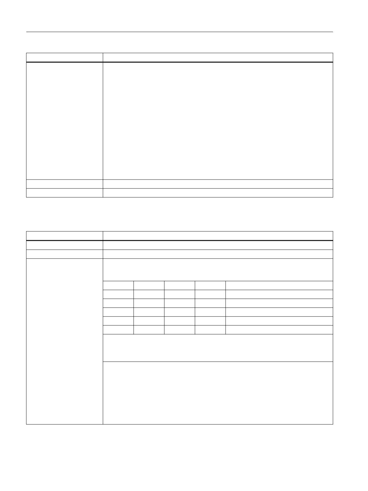
With the interface signals, in the AUTOMATIC mode, instead of the programmed feedrate or
the configured JOG velocities, the fixed feedrate - parameterized using machine data - is acti-
vated.
Bit 3
Bit 2
Bit 1
Bit 0
Meaning
0
0
0
0
Fixed feedrate not selected
0
0
0
1
Fixed feedrate 1
0
0
1
0
Fixed feedrate 2
0
1
0
0
Fixed feedrate 3
1
0
0
0
Fixed feedrate 4
The fixed feedrates are parameterized using the following machine data:
• Linear axes: MD12202 $MN_PERMANENT_FEED
• Rotary axes: MD12204 $MN_PERMANENT_ROT_AX_FEED
Notes
• The fixed feedrate is not used for:
- Spindles
- Positioning axes
- Tapping
• The fixed feedrate is always interpreted as linear feedrate. Switchover to linear feedrate is
performed internally in the control system also when revolutional feedrate is active.
PLC
554
Function Manual, 10/2020, 6FC5397-0HP40-0BA1

Interface signals
19.2 Interface signals - detailed description
DB 21, ... DBX29.0 - 3
Activate fixed feedrate 1 - 4, path/geometry axes
Corresponds with
MD12200 $MN_RUN_OVERRIDE_0 (traversing behavior with override 0)
MD12202 $MN_PERMANENT_FEED (fixed feedrates for linear axes)
MD12204 $MN_PERMANENT_ROT_AX_FEED (fixed feedrates for rotary axes)
Additional information
Function Manual Basic Functions
19.2.5.66
DB21, ... DBX29.4 (activate PTP travel)
DB21, ... DBX29.4
Activate PTP travel
Signal flow
PLC → NC
Edge change 0 → 1
Activate PTP (Point-To-Point) travel
Edge change 1 → 0
Activate CP (Continuous-Path) travel
Additional information
Using this signal, in the the jog mode, you can switch between Cartesian path movement (CP)
and the Cartesian PTP travel.
Note
DB21, ... DBX29.4 is only relevant in the JOG mode when the transformation is active.
Corresponds with
DB21, ... DBX317.6 (PTP travel active)
Additional information
Function Manual Transformations
19.2.5.67
DB21, ... DBX29.5 (tool manager: Deactivate workpiece counter)
DB21, ... DBX29.5
TOOLMAN: Deactivate workpiece counter
Signal flow
PLC → NC
Update
Job-controlled
Signal state 1
Deactivate workpiece counter monitoring is requested.
Signal state 0
Deactivate workpiece counter monitoring is not requested.
Additional information
The workpiece counter monitoring allows workpieces to be counted that depend on the proc-
ess, the workpiece material or other factors. Workpiece counter monitoring can be deactivated
using the interface signal
Corresponds with
SETPIECE (function)
TMPCIT (PI service)
$TC_MOP4 (remaining unit quantity)
$TC_TP9 (type of tool monitoring)
Additional information
Function Manual Tool Management
19.2.5.68
DB21, ... DBX29.6 (tool manager: Deactivating wear monitoring)
DB21, ... DBX29.6
TOOLMAN: Deactivate wear monitoring
Signal flow
PLC → NC
Update
Job-controlled
Signal state 1
Deactivate wear monitoring is requested.
Signal state 0
Deactivate wear monitoring is not requested.
PLC
Function Manual, 10/2020, 6FC5397-0HP40-0BA1
555

Interface signals
19.2 Interface signals - detailed description
DB21, ... DBX29.6
TOOLMAN: Deactivate wear monitoring
Corresponds with
$TC_MOP15 (wear setpoint or additive offset value)
$TC_MOP5 (wear pre-warning limit or additive offset pre-warning limit)
$TC_MOP6 (wear value or additive offset setpoint)
$TC_TP9 (type of tool monitoring)
MD18080 $MN_MM_TOOL_MANAGEMENT_MASK (memory reserved for the tool manage-
ment)
MD20310 TOOL_MANAGEMENT_MASK bit 17 (activation of the tool management functions)
Additional information
Function Manual Tool Management
19.2.5.69
DB21, ... DBX29.7 (tool manager: Tool lock not active)
DB21, ... DBX29.7
TOOLMAN: Tool lock not active
Signal flow
PLC → NC
Update
Job-controlled
Signal state 1
Tool lock notactive.
Signal state 0
Tool lock is active
Additional information
A tool assumes the "locked" state if the actual value of the active monitoring function (work-
piece count, tool life or wear) has reached a value of zero. If the tool is still being used, then it
remains in use (for machining) until the next tool change. After that the tool can no longer be
used.
Using the interface signal, it can be set that the NC does not take the "locked" state into account
when searching for a tool that can be used.
The interface signal is not active if the tool selection is realized using in it blocks (reset and start
mode mask).
Corresponds with
MD22562 $MC_TOOL_CHANGE_ERROR_MODE (response for tool change errors)
Additional information
Function Manual Tool Management
19.2.5.70
DB21 ... DBX30.0 - 2 (activate contour handwheel)
DB21, ... DBX30.0 - 2:
Activate contour handwheel
Signal flow
PLC → NC
Update
Cyclic
PLC
556
Function Manual, 10/2020, 6FC5397-0HP40-0BA1
Interface signals
19.2 Interface signals - detailed description
DB21, ... DBX30.0 - 2:
Activate contour handwheel
Additional information
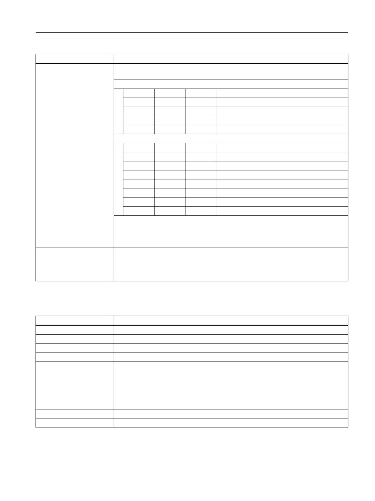
The interface can be interpreted either bit or binary-coded. The definition is realized using
machine data MD11324.
Bit coded: maximum 3 handwheels
Bit 2
Bit 1
Bit 0
Number of the assigned handwheel
0
0
0
No handwheel assignment
0
0
1
1
0
1
0
2
1
0
0
3
Binary coded: maximum 6 handwheels
Bit 2
Bit 1
Bit 0
Number of the assigned handwheel
0
0
0
No handwheel assignment
0
0
1
1
0
1
0
2
0
1
1
3
1
0
0
4
1
0
1
5
1
1
0
6
Note
At any one time, an axis can only be assigned to one handwheel. If, for bit coding, several
interface signals are set simultaneously, then the following priority applies: "Handwheel 1"
before "Handwheel 2" before "Handwheel 3".
Corresponds with
DB21, ... DBX37.0 - 2 (contour handwheel active)
MD11324 $MN_HANDWH_VDI_REPRESENTATION (representation of the handwheel number
at the VDI interface)
Additional information
Function Manual Axes and Spindles
19.2.5.71
DB21, ... DBX30.3 (simulation contour handwheel: Activate)
DB21, ... DBX30.3
Simulation contour handwheel: Activation
Signal flow
PLC → NC
Update
Cyclic
Signal state 1
Activate contour handwheel simulation
Signal state 0
Deactivate contour handwheel simulation
Additional information
During simulation, the feedrate is no longer defined by the contour handwheel, but traversing
occurs with the programmed feedrate on the contour. When deactivated, the actual traversing
motion is braked along the braking ramp.
Note
Simulation is only effective in AUTOMATIC mode and can only be activated when the contour
handwheel is activated.
Corresponds with
DB21, ... DBX30.4 (simulation contour handwheel: Negative direction)
Additional information
Function Manual Axes and Spindles
PLC
Function Manual, 10/2020, 6FC5397-0HP40-0BA1
557

Interface signals
19.2 Interface signals - detailed description
19.2.5.72
DB21, ... DBX30.4 (simulation contour handwheel: Negative direction)
DB21, ... DBX30.4
Simulation contour handwheel: Negative direction
Signal flow
PLC → NC
Update
Cyclic
Signal state 1
When simulating the contour handwheel, it is traversing on the contour in the opposite direc-
tion to the programmed direction.
Signal state 0
When simulating the contour handwheel, it is traversing on the contour in the direction to the
programmed direction.
Additional information
When switching over the traversing direction, the actual traversing motion is braked along the
braking ramp and then traversed in the opposite direction.
Corresponds with
DB21, ... DBX30.3 (simulation contour handwheel: Activate)
Additional information
Function Manual Axes and Spindles
19.2.5.73
DB21, ... DBX30.5 (activate M0 / M1 associated with NC)
DB21, ... DBX30.5
Activate associated auxiliary function
Signal flow
PLC → NC
Update
Job-controlled
Signal state 1
Activation of "Associated auxiliary function" is requested.
Signal state 0
Activation of "Associated auxiliary function" is not requested.
Additional information
"Associated auxiliary function" (M-1) is selected from the SINUMERIK Operate user interface in
the operating area "Automatic" > "Program control" by setting the HMI/PLC interface signal
DB21, ... DBX24.4.
The interface signal is transferred according to the value of the FB1 parameter MMCToIf by the
basic PLC program into the NC/PLC interface signal DB21, ... DBX30.5:
• "TRUE": Transmission
• "FALSE": No transmission
The default value of the parameter is "TRUE".
Corresponds with
DB21, ... DBX24.4 (associated auxiliary function selected)
DB21, ... DBX318.5 (associated auxiliary function active)
MD22254 $MC_AUXFU_ASSOC_M0_VALUE (additional M function for program stop)
MD22256 $MC_AUXFU_ASSOC_M1_VALUE (additional M function for conditional stop)
Additional information
Function Manual Basic Functions
19.2.5.74
DB21, ... DBX30.6 (JOG circular travel)
DB21, ... DBX30.6
JOG circular travel
Signal flow
PLC → NC
Update
Cyclic
Signal state 1
The "Circular travel in JOG" function is requested.
Signal state 0
The "Circular travel in JOG" function is not requested.
PLC
558
Function Manual, 10/2020, 6FC5397-0HP40-0BA1
Interface signals
19.2 Interface signals - detailed description
DB21, ... DBX30.6
JOG circular travel
Additional information
As soon as the function is active (see DB21, ... DBX377.6), the machine operator can simulta-
neously traverse the two geometry axes of the active plane along an arc using the traverse keys
or handwheel.
Application
This function is used for machine tools that are exclusively operated manually.
Note
The following preconditions applying for the "Circular travel in JOG" function:
• The "Circular travel in JOG" function can be activated only in the JOG mode.
The function cannot be activated if the machine functions JOG-REPOS and JOG-REF are
active.
• The axes that participate in traversing must be referenced.
• It is not permissible that the active plane is inclined in space.
Corresponds with
DB21, ... DBX377.6 (JOG circular travel active)
Additional information
Function Manual Axes and Spindles
19.2.5.75
DB21, ... DBX31.0 - 2 (REPOS mode)
DB21, ... DBX31.0 - 2
REPOS mode
Signal flow
PLC → NC
Update
Cyclic
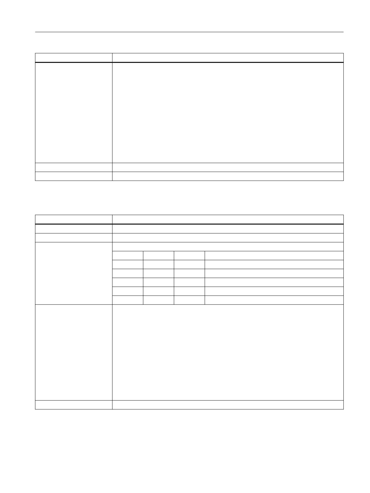
Additional information
Selecting the REPOS mode:
Bit 2
Bit 1
Bit 0
REPOS mode
0
0
0
No REPOS mode active
0
0
1
RMB: Repositioning to start of block
0
1
0
RMI: Repositioning to interrupt point
0
1
1
RME: Repositioning to end of block
1
0
0
RMN: Repositioning to the nearest point on the path
Corresponds with
DB21, ... DBX25.4 (REPOS mode activation)
DB21, ... DBX31.4 (REPOS mode change)
DB31, ... DBX10.0 (REPOS delay)
DB31, ... DBX72.0 (REPOS delay)
DB21, ... DBX319.0 (REPOS mode change acknowledgment)
DB21, ... DBX319.1 - 3 (active REPOS mode)
DB21, ... DBX319.5 (REPOS acknowledgment delay)
DB31, ... DBX70.0 (REPOS offset)
DB31, ... DBX70.1 (REPOS offset valid)
DB31, ... DBX70.2 (REPOS delay acknowledgment)
MD11470 $MN_REPOS_MODE_MASK (repositioning properties)
Additional information
Function Manual Basic Functions
PLC
Function Manual, 10/2020, 6FC5397-0HP40-0BA1
559

Interface signals
19.2 Interface signals - detailed description
19.2.5.76
DB21, ... DBX31.4 (REPOS activation)
DB21, ... DBX31.4
REPOS activation
Signal flow
PLC → NC
Update
Cyclic
Signal state 0 → 1
Request to activate the "REPOS" function for the actual main run block.
The following become active:
• DB21, ... DBX31.0 - 2 (REPOS mode)
• DB31, ... DBX10.0 (REPOS delay)
Signal state 1 → 0
Reset of the last request.
Corresponds with
DB21, ... DBX25.4 (REPOS mode activation)
DB21, ... DBX31.0 - 2 (REPOS mode)
DB31, ... DBX10.0 (REPOS delay)
DB31, ... DBX72.0 (REPOS delay)
DB21, ... DBX319.0 (REPOS mode change acknowledgment)
DB21, ... DBX319.1 - 3 (active REPOS mode)
DB21, ... DBX319.5 (REPOS acknowledgment delay)
DB31, ... DBX70.0 (REPOS offset)
DB31, ... DBX70.1 (REPOS offset valid)
DB31, ... DBX70.2 (REPOS delay acknowledgment)
MD11470 $MN_REPOS_MODE_MASK (repositioning properties)
Additional information
Function Manual Basic Functions
19.2.5.77
DB21, ... DBX31.5 (contour handwheel: invert handwheel direction of rotation)
DB21, ... DBX31.5
Contour handwheel: invert handwheel direction of rotation
Signal flow
PLC → NC
Update
Cyclic
Signal state 1
A request has been made to invert the direction of rotation of the contour handwheel.
Signal state 0
A request has not been made to invert the direction of rotation of the contour handwheel.
Additional information
Note
It is only permissible to change the interface signal when the axis is at a standstill.
Corresponds with
DB21, ... DBX39.5 (Contour handwheel: handwheel direction of rotation inversion active)
Additional information
Function Manual Axes and Spindles
19.2.5.78
DB21, ... DBX32.1 (RESU: retrace mode active)
DB21, ... DBX32.1
RESU: Retrace mode active
Signal flow
NC → PLC
Update
Cyclic
Signal state 1
The retrace mode is active.
Signal state 0
The retrace mode is not active.
PLC
560
Function Manual, 10/2020, 6FC5397-0HP40-0BA1

Interface signals
19.2 Interface signals - detailed description
DB21, ... DBX32.1
RESU: Retrace mode active
Additional information
The interface signal is set, if DB21, ... DBX0.1 == 1
The interface signal is reset, if DB21, ... DBX0.2 == 1
Corresponds with
DB21, ... DBX0.1 (RESU: backward/forward)
DB21, ... DBX0.2 (RESU: start retrace support)
DB21, ... DBX32.1 (RESU: retrace mode active)
DB21, ... DBX32.2 (RESU: retrace support active)
Additional information
Function Manual Technologies
19.2.5.79
DB21, ... DBX32.2 (retrace support active)
DB21, ... DBX32.2
RESU: Retrace support active
Edge evaluation:
No
Signal flow
NC → PLC
Update
Cyclic
Signal state 1
Retrace support active
Signal state 0
Retrace support is not active.
Additional information
The interface signal is set, if DB21, ... DBX0.2 == 1 is identified.
The interface signal is reset if the last action block has been completed.
Corresponds with
DB21, ... DBX0.1 (RESU: backward/forward)
DB21, ... DBX0.2 (RESU: start retrace support)
DB21, ... DBX32.1 (RESU: retrace mode active)
DB21, ... DBX32.2 (RESU: retrace support active)
Additional information
Function Manual Technologies
19.2.5.80
DB21, ... DBX32.3 (action block active)
DB21, ... DBX32.3
Action block active
Signal flow
NC → PLC
Update
Cyclic
Signal state 1
An action block is active / is being executed.
Signal state 0
No action block is active.
Corresponds with
DB21, ... DBX33.4 (block search active)
DB21, ... DBX32.6 (last action block active)
Additional information
Function Manual Basic Functions
19.2.5.81
DB21, ... DBX32.4 (approach block active)
DB21, ... DBX32.4
Approach block active
Signal flow
NC → PLC
Update
Cyclic
PLC
Function Manual, 10/2020, 6FC5397-0HP40-0BA1
561

Interface signals
19.2 Interface signals - detailed description
DB21, ... DBX32.4
Approach block active
Signal state 1
The approach block to continue the NC program for block search, type 2 "Block search with
calculation at the contour" is active.
Signal state 0
No approach block is active.
Additional information
Function Manual Basic Functions
19.2.5.82
DB21, ... DBX32.5 (M00/M01 active)
DB21, ... DBX32.5
M00/M01 active
Signal flow
NC → PLC
Update
Cyclic
Signal state 1
Auxiliary function M00 or M01 is active.
The block in which the auxiliary function is programmed, is executed and the help functions
output.
Program state "stopped"
Signal state 0
Auxiliary function M00 or M01 is not active.
Corresponds with
DB21, ... DBX0.5 (activate M01)
DB21, ... DBX24.5 (M01 selected)
Additional information
Function Manual Basic Functions
19.2.5.83
DB21, ... DBX32.6 (last action block active)
DB21, ... DBX32.6
Last action block active
Signal flow
NC → PLC
Update
Cyclic
Signal state 1
The last action block is active / is being executed.
Signal state 0
The last action block is not active.
Additional information
If the last action block is active, this means that all the action blocks on the NC side have been
processed and the actions on the PLC side (ASUB, FC) or the operator such as overstore, mode
change according to JOG/REPOS are possible. In this way the PLC, for example, can still perform
a tool change before the start of movement.
Action blocks contain the actions collected during "Block search with computation" such as
• Help function outputs H, M00, M01, M..
• Tool programming T, D, DL
• Spindle programming S value, M3/M4/M5/M19, SPOS
• Feed programming, F
Corresponds with
DB21, ... DBX33.4 (block search active)
Additional information
Function Manual Basic Functions
PLC
562
Function Manual, 10/2020, 6FC5397-0HP40-0BA1

Interface signals
19.2 Interface signals - detailed description
19.2.5.84
DB21, ... DBX33.0 (referencing active)
DB21, ... DBX33.0
Referencing active
Signal flow
NC → PLC
Update
Cyclic
Edge change 0 → 1
Referencing is active
Edge change 1 → 0
No effect
Additional information
Feedback signal for the request to activate referencing:
1. DB21, ... DBX1.0: 0 → 1 (request)
2. DB21, ... DBX33.0: 0 → 1 (feedback signal)
Corresponds with
DB21, ... DBX1.0 (activate referencing)
Additional information
Function Manual Axes and Spindles
19.2.5.85
DB21, ... DBX33.2 (revolutional feedrate active)
DB31, ... DBX33.2
Revolutional feedrate active
Signal flow
NC → PLC
Update
Cyclic
Signal state 1
Revolutional feedrate (G95) is active.
Signal state 0
Revolutional feedrate (G95) is not active.
Further information
The interface signal indicates that, in AUTOMATIC mode, path or synchronized axes move at
revolutional feedrate.
Additional information
Function Manual Axes and Spindles
19.2.5.86
DB21, ... DBX33.3 (handwheel override active)
DB21, ... DBX33.3
Handwheel override active
Signal flow
NC → PLC
Update
Cyclic
Signal state 1
The "Handwheel override in automatic mode" function is active for the programmed path axes.
Signal state 0
The function "Handwheel override in automatic mode" is not active for the programmed path
axes.
Additional information
The handwheel pulses of the 1st geometry axis function as a velocity override on the pro-
grammed path velocity.
In the following cases, the override is inactive:
• The path axes have reached the programmed target position.
• The distance-to-go has been deleted.
• Reset was initiated.
Corresponds with
DB21, ... DBX6.2 (delete distance-to-go)
Additional information
Function Manual Axes and Spindles
PLC
Function Manual, 10/2020, 6FC5397-0HP40-0BA1
563

Interface signals
19.2 Interface signals - detailed description
19.2.5.87
DB21, ... DBX33.4 (block search active)
DB21, ...DBX33.4
Block search active
Signal flow
NC → PLC
Update
Cyclic
Signal state 1
The "block search" function is active.
It was selected from the user interface and started using the interface signal:
DB21, ... DBX7.1 (NC Start)
Signal state 0
The "block search" function is not active - or the search target was found.
Corresponds with
DB21, ... DBX7.1 (NC Start)
Additional information
Function Manual Basic Functions
19.2.5.88
DB21, ... DBX33.5 (M02 / M30 active)
DB21, ... DBX33.5
M02 / M30 active
Signal flow
NC → PLC
Update
Cyclic
Signal state 1
End of program M02 / M30 is active.
The interface signal is set after:
• A program reset has been completed (M02, M30 or M17)
Note: If traversing motion is programmed in the block of M02, M30 or M17, then the signal
is only set after all of the axes have reached their target positions.
• Executed the PROG_EVENT program (PROG_EVENT.SPF) after:
- end of program reset (M02 / M30)
- Channel reset
- Warm restart (power on)
- Output of the last action block after a block search
Signal state 0
End of program M02 / M30 is not active
The interface signal is reset or remains reset:
• after the start and while executing an NC program, asynchronous subprogram (ASUB) or
PROG_EVENT program.
Note: The last signal state is kept after the start of a block search with calculation in the
"Program test" mode (SERUPRO).
• After a program cancellation as the result of an alarm.
• During and after executing a channel reset without executing a PROG_EVENT program.
• During and after the control system powers up without executing a PROG_EVENT program.
PLC
564
Function Manual, 10/2020, 6FC5397-0HP40-0BA1

Interface signals
19.2 Interface signals - detailed description
DB21, ... DBX33.5
M02 / M30 active
Additional information
• In the last part program block of an NC program, it is not permissible to program the
following functions:
- Auxiliary functions, which initiate a read-in stop
- Programmed spindle speed (S value), that should be effective beyond the end of pro-
gram (M02 / M30)
• After a program reset has been completed (M02 / M30), then the signal is set to a value of
1 While processing a subsequent PROG_EVENT program, the signal is set to 0, and after
completion of the PROG_EVENT program, is again set to 1.
Note
The signal is not suitable to automatically initiate follow-on functions such as tool counting, bar
feed etc. In order to identify the completion of the previous processing (NC program, ASUB,
PROG_EVENT, etc.) the end of program command (M02 / M30) must be written to its own
dedicated part program block. Command (M02 / M30) or the decoded signal of the M function
can be used as trigger.
Additional information
• Function Manual Basic Functions
• DB21 - DB30, transferred M and S functions: (Page 406) or "DB21 - DB30, decoded M signals
(Page 409)"
19.2.5.89
DB21, … DBX33.6 (transformation active)
DB21, ... DBX33.6
Transformation active
Signal flow
NC → PLC
Update
Cyclic
Signal state 1
A transformation is not active.
Signal state 0
A transformation is not active.
More information
In the channel - in the active NC program - one of the following commands TRANSMIT,
TRACYL, TRAANG or TRAORI has been programmed. The corresponding block has been pro-
cessed and the corresponding transformation is active.
Additional information
• Function Manual Basic Functions
• Function Manual Transformations
Corresponds with
DB21, ... DBB388 (index number of the active transformation in the channel)
19.2.5.90
DB21, ... DBX33.7 (program test active)
DB21, ... DBX33.7
Program test (PRT) active
Signal flow
NC → PLC
Update
Cyclic
Signal state 1
Program test (PRT) is active.
Signal state 0
Program test (PRT) is not active.
PLC
Function Manual, 10/2020, 6FC5397-0HP40-0BA1
565

Interface signals
19.2 Interface signals - detailed description
DB21, ... DBX33.7
Program test (PRT) active
Additional information
If program test (PRT) is active, the machine axes do not move during the execution of a block
or NC program. However, the axis movements are displayed on the user interface with chang-
ing setpoint position values.
Note
While program test (PRT) is active, all traversing motions of the axes, but not the spindles, take
place under "Axis disable."
Note
Program test (PRT) is selected from the SINUMERIK Operate user interface in the operating area
"Automatic" > "Program control" by setting the HMI/PLC interface signal DB21, ... DBX25.7.
The interface signal is transferred according to the value of the FB1 parameter MMCToIf by the
basic PLC program into the NC/PLC interface signal DB21, ... DBX1.7:
• "TRUE": Transmission
• "FALSE": No transmission
The default value of the parameter is "TRUE".
Notice
Because of the axis disable, the assignment of a tool magazine is not changed while the
program is being tested. The user / machine manufacturer must utilize a suitable PLC user
program to ensure that the NC-internal tool management and the actual assignment of the tool
magazine remain consistent.
Corresponds with
DB21, ... DBX1.7 (activate program test (PRT))
DB21, ... DBX25.7 (program test (PRT) requested)
Additional information
Function Manual Basic Functions
19.2.5.91
DB21, ... DBX35.0 (program state "running")
DB21, ... DBX35.0
Program state "running"
Signal flow
NC → PLC
Update
Cyclic
Signal state 1
Program state == "running"
Signal state 0
Program state ≠ "running"
PLC
566
Function Manual, 10/2020, 6FC5397-0HP40-0BA1

Interface signals
19.2 Interface signals - detailed description
DB21, ... DBX35.0
Program state "running"
Additional information
The signal is set after starting the NC program using DB21, ... DBX7.1 = 1.
The signal remains set if NC program execution is stopped using DB21, ... DBX6.1 = 1.
The signal is not reset if NC program execution is stopped as a result of the following events:
• A feedrate disable or spindle disable is active
• DB21, ... DBX6.1 (read-in disable)
• Feedrate override: 0 %
• A spindle and axis monitoring function responds
• Position setpoints are entered in the NC program for axes in the "follow-up mode," for axes
without "controller enable," or for "parking axes"
Program states:
• DB21, ... DBX35.4 (program state "aborted")
• DB21, ... DBX35.3 (program state "interrupted")
• DB21, ... DBX35.2 (program state "stopped")
• DB21, ... DBX35.1 (program state "wait")
• DB21, ... DBX35.0 (program state "running")
Corresponds with
DB21, ... DBX6.1 = 1 (read-in disable)
DB21, ... DBX7.1 = 1 (NC Start)
DB21, ... DBX35.4 (program state "aborted")
DB21, ... DBX35.3 (program state "interrupted")
DB21, ... DBX35.2 (program state "stopped")
DB21, ... DBX35.1 (program state "wait")
Additional information
Function Manual Basic Functions
19.2.5.92
DB21, ... DBX35.1 (program state "wait")
DB21, ... DBX35.1
Program state "Wait"
Signal flow
NC → PLC
Update
Cyclic
Signal state 1
Program state == "wait"
Signal state 0
Program state ≠ "wait"
Additional information
The "Wait" program state is assumed if, in the NC program, with WAIT_M or WAIT_E the system
waits for synchronization with an NC program or another channel.
Program states:
• DB21, ... DBX35.4 (program state "aborted")
• DB21, ... DBX35.3 (program state "interrupted")
• DB21, ... DBX35.2 (program state "stopped")
• DB21, ... DBX35.1 (program state "wait")
• DB21, ... DBX35.0 (program state "running")
PLC
Function Manual, 10/2020, 6FC5397-0HP40-0BA1
567

Interface signals
19.2 Interface signals - detailed description
DB21, ... DBX35.1
Program state "Wait"
Corresponds with
DB21, ... DBX35.4 (program state "aborted")
DB21, ... DBX35.3 (program state "interrupted")
DB21, ... DBX35.2 (program state "stopped")
DB21, ... DBX35.0 (program state "running")
Additional information
Function Manual Basic Functions
19.2.5.93
DB21, ... DBX35.2 (program state "stopped")
DB21, ... DBX35.2
Program state"stopped"
Signal flow
NC → PLC
Update
Cyclic
Signal state 1
Program state == "stopped"
Signal state 0
Program state ≠ "stopped"
Additional information
Events, which lead to the NC program being stopped:
• DB21, ... DBX7.3 (NC Stop)
• DB21, ... DBX7.4 (NC Stop axes plus spindles)
• DB21, ... DBX7.2 (NC Stop at the block limit)
• Programmed command M00 or M01
• Single-block mode
Program states:
• DB21, ... DBX35.4 (program state "aborted")
• DB21, ... DBX35.3 (program state "interrupted")
• DB21, ... DBX35.2 (program state "stopped")
• DB21, ... DBX35.1 (program state "wait")
• DB21, ... DBX35.0 (program state "running")
Corresponds with
DB21, ... DBX7.3 (NC Stop)
DB21, ... DBX7.4 (NC Stop axes plus spindles)
DB21, ... DBX7.2 (NC Stop at the block limit)
DB21, ... DBX35.4 (program state "aborted")
DB21, ... DBX35.3 (program state "interrupted")
DB21, ... DBX35.1 (program state "wait")
DB21, ... DBX35.0 (program state "running")
Additional information
Function Manual Basic Functions
19.2.5.94
DB21, ... DBX35.3 (program state "interrupted")
DB21, ... DBX35.3
Program state "interrupted"
Signal flow
NC → PLC
Update
Cyclic
Signal state 1
Program state == "interrupted"
Signal state 0
Program state ≠ "interrupted"
PLC
568
Function Manual, 10/2020, 6FC5397-0HP40-0BA1

Interface signals
19.2 Interface signals - detailed description
DB21, ... DBX35.3
Program state "interrupted"
Additional information
The signal indicates that the interrupted NC program can be continued with NC start (DB21, ...
DBX7.1 = 1).
For example, the "interrupted" state is assumed if, in the "stopped" state (DB21, ... DBX35.2 ==
1), the system changes from the AUTOMATIC or MDI mode into the JOG mode. After a subse-
quent operating mode change from JOG to AUTOMATIC or MDI, the NC program can be exe-
cuted again from the interruption point using an NC start (DB21, ... DBX7.1 = 1).
Program states:
• DB21, ... DBX35.4 (program state "aborted")
• DB21, ... DBX35.3 (program state "interrupted")
• DB21, ... DBX35.2 (program state "stopped")
• DB21, ... DBX35.1 (program state "wait")
• DB21, ... DBX35.0 (program state "running")
Corresponds with
DB21, ... DBX35.4 (program state "aborted")
DB21, ... DBX35.2 (program state "stopped")
DB21, ... DBX35.1 (program state "wait")
DB21, ... DBX35.0 (program state "running")
Additional information
Function Manual Basic Functions
19.2.5.95
DB21, ... DBX35.4 (program state "aborted")
DB21, ... DBX35.4
Program state "aborted"
Signal flow
NC → PLC
Update
Cyclic
Signal state 1
Program state == "aborted"
Signal state 0
Program state ≠ "aborted"
Additional information
The signal is set in the following cases:
• The actual NC program was selected in the channel, however it was not started.
• The actual NC program was executed in the channel, and aborted using DB21, ... DBX7.7
= 1 (channel reset).
Program states:
• DB21, ... DBX35.4 (program state "aborted")
• DB21, ... DBX35.3 (program state "interrupted")
• DB21, ... DBX35.2 (program state "stopped")
• DB21, ... DBX35.1 (program state "wait")
• DB21, ... DBX35.0 (program state "running")
Corresponds with
DB21, ... DBX7.7 (reset)
DB21, ... DBX35.3 (program state "interrupted")
DB21, ... DBX35.2 (program state "stopped")
DB21, ... DBX35.1 (program state "wait")
DB21, ... DBX35.0 (program state "running")
Additional information
Function Manual Basic Functions
PLC
Function Manual, 10/2020, 6FC5397-0HP40-0BA1
569

Interface signals
19.2 Interface signals - detailed description
19.2.5.96
DB21, ... DBX35.5 (channel state "active")
DB21, ... DBX35.5
Channel state "active"
Signal flow
NC → PLC
Update
Cyclic
Signal state 1
Channel state == "active"
Signal state 0
Channel state ≠ "active"
Additional information
The signal is set in the following cases:
• An NC program is being executed in the Automatic or MDI mode
• At least one axis is being traversed in the JOG mode.
Channel states:
• DB21, ... DBX35.5 (channel state "active")
• DB21, ... DBX35.6 (channel state "interrupted")
• DB21, ... DBX35.7 (channel state "reset")
Corresponds with
DB21, ... DBX35.6 (channel state "interrupted")
DB21, ... DBX35.7 (channel state "reset")
Additional information
Function Manual Basic Functions
19.2.5.97
DB21, ... DBX35.6 (channel state "interrupted")
DB21, ... DBX35.6
Channel state "interrupted"
Signal flow
NC → PLC
Update
Cyclic
Signal state 1
Channel state == "interrupted"
Signal state 0
Channel state ≠ "interrupted"
Additional information
An interruption can be initiated when executing an NC program in the AUTOMATIC or MDA
mode - or in the JOG mode while an axis is traversing as a result of the following events:
• DB21, ... DBX7.3 (NC Stop)
• DB21, ... DBX7.4 (NC Stop axes plus spindles)
• DB21, ... DBX7.2 (NC Stop at the block limit)
• Programmed stop M00 or M01
• Single-block mode
Channel states:
• DB21, ... DBX35.5 (channel state "active")
• DB21, ... DBX35.6 (channel state "interrupted")
• DB21, ... DBX35.7 (channel state "reset")
Corresponds with
DB21, ... DBX7.3 (NC Stop)
DB21, ... DBX7.4 (NC Stop axes plus spindles)
DB21, ... DBX7.2 (NC Stop at the block limit)
DB21, ... DBX35.5 (channel state "active")
DB21, ... DBX35.7 (channel state "reset")
Additional information
Function Manual Basic Functions
PLC
570
Function Manual, 10/2020, 6FC5397-0HP40-0BA1

Interface signals
19.2 Interface signals - detailed description
19.2.5.98
DB21, ... DBX35.7 (channel state "reset")
DB21, ... DBX35.7
Channel state "reset"
Signal flow
NC → PLC
Update
Cyclic
Signal state 1
Channel state == "reset"
Signal state 0
Channel state ≠ "reset"
Additional information
The signal is set in the following cases:
• end of program reset (M02 / M30)
• Channel reset
• Warm restart (power on)
Channel states:
• DB21, ... DBX35.5 (channel state "active")
• DB21, ... DBX35.6 (channel state "interrupted")
• DB21, ... DBX35.7 (channel state "reset")
Corresponds with
DB21, ... DBX35.5 (channel state "active")
DB21, ... DBX35.6 (channel state "interrupted")
Additional information
Function Manual Basic Functions
19.2.5.99
DB21, ... DBX36.2 (all axes that have to be referenced have been referenced)
DB21, ... DBX36.2
All axes that have to be referenced are referenced
Signal flow
NC → PLC
Update
Cyclic
Signal state 1
All axes that must be referenced (linear axes and rotary axes) of the channel are referenced.
The machine data:
MD20700 $MC_REFP_NC_START_LOCK (NC start inhibit without reference point)
is zero.
If two position measuring systems are connected to an axis, that would prevent an NC start,
then the active one must be referenced so that the axis is considered to have been referenced.
An NC Start command for the part program processing is only accepted when this signal is
present.
Axes that have to be referenced are axes, if:
MD34110 $MA_REFP_CYCLE_NR _ = -1
and the axis is not in the parked position (position measuring system inactive and the controller
enable withdrawn).
Signal state 0
One or more axes of the channel that have to be referenced are not referenced.
Additional information
The spindles of the channel have no effect on this interface signal.
Corresponds with
DB31, ... DBX60.4 (referenced / synchronized 1)
DB31, ... DBX60.5 (referenced / synchronized 2)
Additional information
Function Manual Axes and Spindles
PLC
Function Manual, 10/2020, 6FC5397-0HP40-0BA1
571

Interface signals
19.2 Interface signals - detailed description
19.2.5.100
DB21, ... DBX36.3 (all axes stationary)
DB21, ... DBX36.3
All axes stationary
Signal flow
NC → PLC
Update
Cyclic
Signal state 1
All channel axes are stationary - and no other traversing motion is active.
Signal state 0
Not all channel axes are stationary - or other traversing motion is presently active.
Additional information
Criterion for "axis stationary": Interpolator end
Additional information
Function Manual Basic Functions
19.2.5.101
DB21, ... DBX36.4 (interrupt handling active)
DB21, ... DBX36.4
Interrupt handling active
Signal flow
NC → PLC
Update
Cyclic
Signal state 1
Interrupt handling is active.
One or more channels in the mode group are not in the desired operating mode as the result
of an active interrupt routine.
Signal state 0
Interrupt handling is not active.
All channels are operating in the requested mode.
Additional information
Note
The interface signal is notset, if an interrupt is handled in a program mode (AUTOMATIC or
MDI).
Corresponds with
MD11600 $MN_BAG_MASK (definition of the mode group response)
Additional information
Function Manual Basic Functions
19.2.5.102
DB21, ... DBX36.5 (channel ready)
DB21, ... DBX36.5
Channel is ready
Signal flow
NC → PLC
Update
Cyclic
Signal state 1
The channel is ready
Signal state 0
The channel is not ready.
Additional information
The channel is ready to execute an NC program and to traverse axes and spindle that are
assigned to the channel.
Corresponds with
MD11600 $MN_BAG_MASK (definition of the mode group response)
Additional information
Function Manual Basic Functions
PLC
572
Function Manual, 10/2020, 6FC5397-0HP40-0BA1

Interface signals
19.2 Interface signals - detailed description
19.2.5.103
DB21, ... DBX36.6 (channel-specific NC alarm active)
DB21, ... DBX36.6
Channel-specific NC alarm active
Signal flow
NC → PLC
Update
Cyclic
Signal state 1
At least one NC alarm is active in the channel.
Signal state 0
No NC alarm is active in the channel.
Corresponds with
DB21, ... DBX36.7 (NC alarm with machining stop active)
DB10 DBX109.0 (NC alarm active)
Additional information
Diagnostics guide
19.2.5.104
DB21, ... DBX36.7 (NC alarm with machining stop active)
DB21, ... DBX36.7
NC alarm with machining stop is active
Signal flow
NC → PLC
Update
Cyclic
Signal state 1
At least one NC alarm with machining stop is active in the channel.
Signal state 0
No NC alarm with machining stop is active in the channel.
Corresponds with
DB21, ... DBX36.6 (channel-specific NC alarm active)
DB10 DBX109.0 (NC alarm active)
Additional information
Diagnostics guide
19.2.5.105
DB21, ... DBX37.0 - 2 (contour handwheel active)
DB21, ... DBX37.0 - 2
Contour handwheel active
Signal flow
PLC → NC
Update
Cyclic
PLC
Function Manual, 10/2020, 6FC5397-0HP40-0BA1
573
Interface signals
19.2 Interface signals - detailed description
DB21, ... DBX37.0 - 2
Contour handwheel active
Additional information
The interface can be interpreted either bit or binary-coded. The definition is realized using
machine data MD11324.
Bit coded: maximum 3 handwheels
Bit 2
Bit 1
Bit 0
Number of the assigned handwheel
0
0
0
No handwheel assignment
0
0
1
1
0
1
0
2
1
0
0
3
Binary coded: maximum 6 handwheels
Bit 2
Bit 1
Bit 0
Number of the assigned handwheel
0
0
0
No handwheel assignment
0
0
1
1
0
1
0
2
0
1
1
3
1
0
0
4
1
0
1
5
1
1
0
6
Note
At any one time, an axis can only be assigned to one handwheel. If, for bit coding, several
interface signals are set simultaneously, then the following priority applies: "Handwheel 1"
before "Handwheel 2" before "Handwheel 3".
Corresponds with
DB21 ... DBX30.0 - 2 (activate contour handwheel)
MD11324 $MN_HANDWH_VDI_REPRESENTATION (representation of the handwheel number
at the VDI interface)
Additional information
Function Manual Axes and Spindles
19.2.5.106
DB21, ... DBX37.3 (clearance control (CLC): Active)
DB21, ... DBX37.3
Clearance control (CLC):
Signal flow
NC → PLC
Update
Cyclic
Signal state 1
Clearance control (CLC) is active.
Signal state 0
Clearance control (CLC) is not active.
Corresponds with
DB21, ... DBX1.4 (clearance control (CLC): stop)
DB21, ... DBX1.5 (clearance control (CLC): Override)
DB21, ... DBX37.4 (clearance control (CLC): Stop at the lower motion limit)
DB21, ... DBX37.5 (clearance control (CLC): Stop at the upper motion limit)
DB21, ... DBX37.4 - 5 (clearance control (CLC): Motion has stopped)
Additional information
Function Manual Technologies
PLC
574
Function Manual, 10/2020, 6FC5397-0HP40-0BA1

Interface signals
19.2 Interface signals - detailed description
19.2.5.107
DB21, ... DBX37.4 (clearance control (CLC): Stop at the lower motion limit)
DB21, ... DBX37.4
Clearance control (CLC): Stop at the lower motion limit
Signal flow
NC → PLC
Update
Cyclic
Signal state 1
The traversing motion of the clearance-controlled axis, generated by the clearance control, has
reached the lower motion limit and was stopped.
Signal state 0
The traversing motion of the clearance-controlled axis, generated by the clearance control,
has not reached the lower motion limit.
Additional information
The lower motion limit of the clearance control is set in machine data:
MD62505 $MC_CLC_SENSOR_LOWER_LIMIT
The parameterized limit value can be adapted on a block-specific basis by
programming CLC_LIM(...) in the part program.
Note
If, in addition to DB21, ... DBX37.4, DB21, ... DBX37.5 are also simultaneously set, then signal
"DB21, ... DBX37.3 (clearance control (CLC): Active) (Page 574)"is active.
Corresponds with
CLC_LIM(...) ; the control range is limited
DB21, ... DBX37.5 (clearance control (CLC): Stop at the upper motion limit)
DB21, ... DBX37.4 - 5 (clearance control (CLC): Motion has stopped)
MD62505 $MC_CLC_SENSOR_LOWER_LIMIT (lower clearance control motion limit)
Additional information
Function Manual Technologies
19.2.5.108
DB21, ... DBX37.5 (clearance control (CLC): Stop at the upper motion limit)
DB21, ... DBX37.5
Clearance control (CLC): Stop at the upper motion limit
Signal flow
NC → PLC
Update
Cyclic
Signal state 1
The traversing motion of the clearance-controlled axis, generated by the clearance control, has
reached the upper motion limit and was stopped.
Signal state 0
The traversing motion of the clearance-controlled axis, generated by the clearance control,
has not reached the upper motion limit.
Additional information
The upper motion limit of the clearance control is set in machine data:
MD62506 $MC_CLC_SENSOR_UPPER_LIMIT
The parameterized limit value can be adapted on a block-specific basis by
programming CLC_LIM(...) in the part program.
Note
If, in addition to DB21, ... DBX37.5, DB21, ... DBX37.4 are also simultaneously set, then signal
"DB21, ... DBX37.3 (clearance control (CLC): Active) (Page 574)"is active.
Corresponds with
CLC_LIM(...) ; the control range is limited
DB21, ... DBX37.4 (clearance control (CLC): Stop at the lower motion limit)
DB21, ... DBX37.4 - 5 (clearance control (CLC): Motion has stopped)
MD62506 $MC_CLC_SENSOR_UPPER_LIMIT (upper clearance control motion limit)
Additional information
Function Manual Technologies
PLC
Function Manual, 10/2020, 6FC5397-0HP40-0BA1
575

Interface signals
19.2 Interface signals - detailed description
19.2.5.109
DB21, ... DBX37.6 (read-in disable is ignored)
DB21, ... DBX37.6
Read-in disable is ignored
Signal flow
NC → PLC
Update
Cyclic
Signal state 1
Read-in disable (DB21, ... DBX6.1) is ignored.
Signal state 0
Read-in disable (DB21, ... DBX6.1) is not ignored.
Additional information
Read-in disable (DB21, ... DBX6.1) is ignored, if the following applies:
DB21, ... DBX6.1 == 1 (read-in disable) AND actual block has the status "read-in disable inac-
tive"
Read-in disable (DB21, ... DBX6.1) is not ignored, if the following applies:
DB21, ... DBX6.1 == 0 (read-in disable) OR
( DB21, ... DBX6.1 == 1 (read-in disable) AND actual block has the status "read-in
disable active" )
Blocks for which read-in disable is ignored have the status "read-in disable inactive".
The following machine data is used to specify that the read-in disable (DB21, ... DBX6.1) is to
be ignored:
• MD11602 $MN_ASUP_START_MASK, bit 2
• MD20116 $MC_IGNORE_INHIBIT_ASUP
• MD20107 $MC_ PROG_EVENT_IGN_INHIBIT
Corresponds with
DB21, ... DBX37.7 (stop at block end is ignored during single block (SBL))
MD11602 $MN_ASUP_START_MASK, bit 2 (start also permitted if read-in disable is active)
MD20116 $MC_IGNORE_INHIBIT_ASUP (execute interrupt program in spite of read-in disable)
MD20107 $MC_ PROG_EVENT_IGN_INHIBIT (prog events ignore read-in disable)
Additional information
Function Manual Basic Functions
19.2.5.110
DB21, ... DBX37.7 (stop at block end is ignored during single block (SBL))
DB21, ... DBX37.7
Stop at block end is ignored during single block (SBL)
Signal flow
NC → PLC
Update
Cyclic
Signal state 1
Stop at block end is ignored during single block (SBL).
Signal state 0
Stop at block end is not ignored during single block (SBL).
PLC
576
Function Manual, 10/2020, 6FC5397-0HP40-0BA1
Interface signals
19.2 Interface signals - detailed description
DB21, ... DBX37.7
Stop at block end is ignored during single block (SBL)
Additional information
Stop at block end is ignored during single block (SBL), if the following applies:
DB21, ... DBX0.4 == 1 (single block) AND actual block has the status "single block inactive"
Stop at block end is not ignored during single block (SBL), if the following applies:
DB21, ... DBB0.4 == 0 (single block) OR
(DB21, ... DBB0.4 == 1 (single block) AND actual block has the status "single block active")
The following machine data and commands are used to specify that the stop at block end
during single block (DB21, ... DBX0.4) is to be ignored:
• MD10702 $MN_IGNORE_SINGLEBLOCK_MASK (prevent single-block stop)
• MD20117 $MC_IGNORE_SINGLEBLOCK_ASUP (execute interrupt program completely in
spite of single block)
• MD20106 $MC_PROG_EVENT_IGN_SINGLEBLOCK (prog events ignore single block)
• SBLOF (suppress single block), SBLON (neutral single block suppression)
Blocks for which stop at block end during single block is ignored are designated as "single block
inactive".
Corresponds with
DB21, ... DBX0.4 (single block)
DB21, ... DBX37.6 (read-in disable is ignored)
Additional information
Function Manual Basic Functions
19.2.5.111
DB21, ... DBX38.0 (stroke initiation active)
DB21, ... DBX38.0
Stroke initiation active
Signal flow
NC → PLC
Signal state 1
Stroke initiation is active.
Signal state 0
Stroke initiation is not active.
Corresponds with
DB21, ... DBX3.0 (stroke enable)
Additional information
Function Manual Technologies
19.2.5.112
DB21, ... DBX38.1 (manual stroke initiation: Acknowledgment)
DB21, ... DBX38.1
Manual stroke initiation: Acknowledgment
Signal flow
NC → PLC
Signal state 1
Manual stroke has been initiated.
Signal state 0
Manual stroke was not initiated.
Corresponds with
DB21, ... DBX3.0 (stroke enable)
DB21, ... DBX3.1 (manual stroke initiation)
DB21, ... DBX3.5 (manual stroke initiation 2)
DB21, ... DBX38.0 (stroke initiation active)
Additional information
Function Manual Technologies
PLC
Function Manual, 10/2020, 6FC5397-0HP40-0BA1
577

Interface signals
19.2 Interface signals - detailed description
19.2.5.113
DB21, ... DBX39.1 (NC alarm with program stop)
DB21, ... DBX39.1
NC alarm with program stop
Signal flow
NC → PLC
Update
Cyclic
Signal state 1
The interface signal indicates when the program progress is blocked by the presence of an
alarm.
This relates to all alarms generated by stop response:
• Stop on the path with deletion of the ready signal
• Axes are braked
• Immediate stop on the path
• Interpreter is stopped, IPO buffer is still being executed.
• No stop at end of block
Alarms with the following alarm response are also taken into account:
• NC start disable in this channel
• NC start disable in this channel, ASUB starts, where relevant, are permitted
For alarms with this response the interface signal is not set until an NC start has been triggered
and only if the alarm has not yet been acknowledged. In this case, the interface signal is not set
until NC start.
The interface signals are set if the start of an ASUB is refused because of an NC start disable in
this channel.
The interface signal is deleted as soon as alarm responses that activated the signal are no
longer active. This depends on the delete conditions of the alarms.
Signal state 0
No NC alarm with program stop is present in the channel.
Corresponds with
DB10 DBX109.0 (NC alarm present)
DB21, ... DBX36.6 (channel-specific NC alarm present)
DB21, ... DBX36.7 (NC alarm with machining stop present)
Additional information
Diagnostics Manual
19.2.5.114
DB21, ... DBX39.4 (stop at block end due to single block)
DB21, ... DBX39.4
Stop at end of block due to single block
Signal flow
NC → PLC
Update
Cyclic
Signal state 1
Stop at end of block due to single block is active.
Signal state 0
Stop at end of block due to single block is not active.
19.2.5.115
DB21, ... DBX39.5 (Contour handwheel: handwheel direction of rotation inversion
active)
DB21, ... DBX39.5
Contour handwheel: handwheel direction of rotation inversion active
Signal flow
NC → PLC
Update
Cyclic
PLC
578
Function Manual, 10/2020, 6FC5397-0HP40-0BA1

Interface signals
19.2 Interface signals - detailed description
DB21, ... DBX39.5
Contour handwheel: handwheel direction of rotation inversion active
Signal state 1
Inversion of the direction of rotation of the contour handwheel is active.
Signal state 0
Inversion of the direction of rotation of the contour handwheel is not active.
Corresponds with
DB31, ... DBX31.5 (contour handwheel: invert handwheel direction of rotation)
Additional information
Function Manual Axes and Spindles
19.2.5.116
DB21, ... DBX39.6 (configured stop is activated)
DB21, ... DBX39.6
Configured stop is activated
Signal flow
NC → PLC
Update
Cyclic
Signal state 1
The "Configured stop" function was activated internally.
Signal state 0
The "Configured stop" function was not activated internally.
Corresponds with
DB21, … DBX7.6 (activate configured stop)
19.2.5.117
DB21, ... DBX39.7 (stop at block end due to configured stop)
DB21, ... DBX39.7
Stop at end of block due to configured stop
Signal flow
NC → PLC
Update
Cyclic
Signal state 1
Stop at end of block due to configured stop
Signal state 0
Stop at end of block due to configured stop
Corresponds with
DB21, … DBX7.6 (activate configured stop)
DB21, ... DBX39.6 (configured stop is activated)
19.2.5.118
DB21, ... DBX40.0 - 2 (geometry axis 1: handwheel active)
DB21, ... DBX40.0 - 2
Geometry axis 1: handwheel active
Signal flow
NC → PLC
Update
Cyclic
PLC
Function Manual, 10/2020, 6FC5397-0HP40-0BA1
579
Interface signals
19.2 Interface signals - detailed description
DB21, ... DBX40.0 - 2
Geometry axis 1: handwheel active
Additional information
The interface can be interpreted either bit or binary-coded. The definition is realized using
machine data MD11324.
Bit coded: maximum 3 handwheels
Bit 2
Bit 1
Bit 0
Number of the assigned handwheel
0
0
0
No handwheel assignment
0
0
1
1
0
1
0
2
1
0
0
3
Binary coded: maximum 6 handwheels
Bit 2
Bit 1
Bit 0
Number of the assigned handwheel
0
0
0
No handwheel assignment
0
0
1
1
0
1
0
2
0
1
1
3
1
0
0
4
1
0
1
5
1
1
0
6
Note
At any one time, an axis can only be assigned to one handwheel. If, for bit coding, several
interface signals are set simultaneously, then the following priority applies: "Handwheel 1"
before "Handwheel 2" before "Handwheel 3".
Corresponds with
DB21, ... DBX46.0 - 2 (geometry axis 2: handwheel active)
DB21, ... DBX52.0 - 2 (geometry axis 3: handwheel active)
DB21, ... DBX12.0 - 2 (geometry axis 1: activate handwheel)
DB21, ... DBX16.0 - 2 (geometry axis 2: activate handwheel)
DB21, ... DBX20.0 - 2 (geometry axis 3: activate handwheel)
MD11324 $MN_HANDWH_VDI_REPRESENTATION (representation of the handwheel number
at the VDI interface)
Additional information
Function Manual Axes and Spindles
19.2.5.119
DB21, ... DBX40.4 - 5 (geometry axis 1: traversing request "Plus" / "Minus")
DB21, ... DBX40.4 - 5
Geometry axis 1: traversing request "Plus" / "Minus"
Signal flow
NC → PLC
Update
Cyclic
Signal state 1
There is a traversing request available for the geometry axis.
Signal state 0
There is no traversing request available for the geometry axis.
PLC
580
Function Manual, 10/2020, 6FC5397-0HP40-0BA1
Interface signals
19.2 Interface signals - detailed description
DB21, ... DBX40.4 - 5
Geometry axis 1: traversing request "Plus" / "Minus"
Additional information
Depending on the mode selected, the traversing request is initiated in different ways:
• JOG mode
"Plus" or "Minus" traversing key
• REF mode
Traversing key that initiates traversing motion in the direction of the reference point.
• AUTOMATIC or MDI mode
A program block with a traversing operation is executed for a geometry axis.
There is a signal for each axis direction:
Bit 4
Traversing request "Minus" (for traversing in the negative axis direction)
Bit 5
Traversing key "Plus" (for traversing in the positive axis direction)
Corresponds with
DB21, ... DBX46.4 - 5 (geometry axis 2: traversing request "Plus" / "Minus")
DB21, ... DBX52.4 - 5 (geometry axis 3: traversing request "Plus" / "Minus")
DB21, ... DBX12.6 - 7 (geometry axis 1: traversing keys "Plus" / "Minus")
DB21, ... DBX16.6 - 7 (geometry axis 2: traversing keys "Plus" / "Minus")
DB21, ... DBX20.6 - 7 (geometry axis 3: traversing keys "Plus" / "Minus")
DB21, ... DBX40.6 - 7 (geometry axis 1: traversing command "Plus" / "Minus")
DB21, ... DBX46.6 - 7 (geometry axis 2: traversing command "Plus" / "Minus")
DB21, ... DBX52.6 - 7 (geometry axis 3: traversing command "Plus" / "Minus")
Additional information
Function Manual Axes and Spindles
19.2.5.120
DB21, ... DBX40.6 - 7 (geometry axis 1: traversing command "Plus" / "Minus")
DB21, ... DBX40.6 - 7
Geometry axis 1: traversing command "Plus" / "Minus"
Signal flow
NC → PLC
Update
Cyclic
Signal state 1
There is a traversing request for the geometry axis or the geometry axis is traversing.
Signal state 0
There is not a traversing request for the geometry axis or the geometry axis is not traversing.
Additional information
Depending on the setting of MD17900, bit 0, the traversing command is already output if a
"Traversing request" is active (bit 0 = 0) or only if the axis is actually traversing (bit 0 = 1).
There is a signal for each axis direction:
Bit 6
Traversing command "Minus" (for traversing in the negative axis direction)
Bit 7
Traversing command "Plus" (for traversing in the positive axis direction)
Application example
Releasing the axis clamp when the traversing command is identified.
Note
For axes where clamping is not released until a drive command is detected, the continuous-
path mode (G64) is not possible.
PLC
Function Manual, 10/2020, 6FC5397-0HP40-0BA1
581

Interface signals
19.2 Interface signals - detailed description
DB21, ... DBX40.6 - 7
Geometry axis 1: traversing command "Plus" / "Minus"
Corresponds with
DB21, ... DBX46.6 - 7 (geometry axis 2: traversing command "Plus" / "Minus")
DB21, ... DBX52.6 - 7 (geometry axis 3: traversing command "Plus" / "Minus")
DB21, ... DBX12.6 - 7 (geometry axis 1: traversing keys "Plus" / "Minus")
DB21, ... DBX16.6 - 7 (geometry axis 2: traversing keys "Plus" / "Minus")
DB21, ... DBX20.6 - 7 (geometry axis 3: traversing keys "Plus" / "Minus")
DB21, ... DBX40.4 - 5 (geometry axis 1: traversing request "Plus" / "Minus")
DB21, ... DBX46.4 - 5 (geometry axis 2: traversing request "Plus" / "Minus")
DB21, ... DBX52.4 - 5 (geometry axis 3: traversing request "Plus" / "Minus")
MD17900 $MN_VDI_FUNCTION_MASK (setting for VDI signals)
Additional information
Function Manual Axes and Spindles
19.2.5.121
DB21, ... DBX41.0 - 6 (geometry axis 1: active machine function)
DB21, ... DBX41.0 - 6
Geometry axis 1: active machine function
Signal flow
NC → PLC
Update
Cyclic
Signal state 1
The machine function to manually traverse the geometry axis is active.
Signal state 0
The machine function to manually traverse the geometry axis is notactive.
Additional information
There is a signal for every machine function to manually traverse the geometry axis in the JOG
mode.
Bit 0
INC1
Bit 1
INC10
Bit 2
INC100
Bit 3
INC1000
Bit 4
INC10000
Bit 5
INCvar
Bit 6
Continuous manual travel
Note
Depending on the machine function, the response when actuating the traversing key or the
handwheel differs.
Corresponds with
DB21, ... DBX47.0 - 6 (geometry axis 2: active machine function)
DB21, ... DBX53.0 - 6 (geometry axis 3: active machine function)
DB21, ... DBX13.0 - 6 (geometry axis 2: machine function request)
DB21, ... DBX17.0 - 6 (geometry axis 2: machine function request)
DB21, ... DBX21.0 - 6 (geometry axis 3: machine function request)
Additional information
Function Manual Axes and Spindles
19.2.5.122
DB21, ... DBX43.0 (geometry axis 1: handwheel direction of rotation inversion active)
DB21, ... DBX43.0
Geometry axis 1: handwheel direction of rotation inversion active
Signal flow
NC → PLC
Update
Cyclic
PLC
582
Function Manual, 10/2020, 6FC5397-0HP40-0BA1

Interface signals
19.2 Interface signals - detailed description
DB21, ... DBX43.0
Geometry axis 1: handwheel direction of rotation inversion active
Signal state 1
Inversion of the direction of rotation of the handwheel assigned to the geometry axis is active.
Signal state 0
Inversion of the direction of rotation of the handwheel assigned to the geometry axis is not
active.
Corresponds with
DB21, ... DBX49.0 (geometry axis 2: handwheel direction of rotation inversion active)
DB21, ... DBX55.0 (geometry axis 3: handwheel direction of rotation inversion active)
DB21, ... DBX15.0 (geometry axis 1: invert handwheel direction of rotation)
DB21, ... DBX19.0 (geometry axis 2: invert handwheel direction of rotation)
DB21, ... DBX23.0 (geometry axis 3: invert handwheel direction of rotation)
Additional information
Function Manual Axes and Spindles
19.2.5.123
DB21, ... DBX46.0 - 2 (geometry axis 2: handwheel active)
DB21, ... DBX46.0 - 2
Geometry axis 2: handwheel active
Additional information
See DB21, ... DBX40.0 - 2 (geometry axis 1: handwheel active) (Page 579).
19.2.5.124
DB21, ... DBX46.4 - 5 (geometry axis 2: traversing request "Plus" / "Minus")
DB21, ... DBX46.4 - 5
Geometry axis 2: traversing request "Plus" / "Minus"
Additional information
See DB21, ... DBX40.4 - 5 (geometry axis 1: traversing request "Plus" / "Minus") (Page 580).
19.2.5.125
DB21, ... DBX46.6 - 7 (geometry axis 2: traversing command "Plus" / "Minus")
DB21, ... DBX46.6 - 7:
Geometry axis 2: traversing command "Plus" / "Minus"
Additional information
See DB21, ... DBX40.6 - 7 (geometry axis 1: traversing command "Plus" / "Minus") (Page 581).
19.2.5.126
DB21, ... DBX47.0 - 6 (geometry axis 2: active machine function)
DB21, ... DBX47.0 - 6
Geometry axis 2: active machine function
Additional information
See DB21, ... DBX41.0 - 6 (geometry axis 1: active machine function) (Page 582).
19.2.5.127
DB21, ... DBX49.0 (geometry axis 2: handwheel direction of rotation inversion active)
DB21, ... DBX49.0
Geometry axis 2: handwheel direction of rotation inversion active
Additional information
See DB21, ... DBX43.0 (geometry axis 1: handwheel direction of rotation inversion active)
(Page 582).
PLC
Function Manual, 10/2020, 6FC5397-0HP40-0BA1
583
Interface signals
19.2 Interface signals - detailed description
19.2.5.128
DB21, ... DBX52.0 - 2 (geometry axis 3: handwheel active)
DB21, ... DBX52.0 - 2
Geometry axis 3: handwheel active
Additional information
See DB21, ... DBX40.0 - 2 (geometry axis 1: handwheel active) (Page 579).
19.2.5.129
DB21, ... DBX52.4 - 5 (geometry axis 3: traversing request "Plus" / "Minus")
DB21, ... DBX52.4 - 5
Geometry axis 3: traversing request "Plus" / "Minus"
Additional information
See DB21, ... DBX40.4 - 5 (geometry axis 1: traversing request "Plus" / "Minus") (Page 580).
19.2.5.130
DB21, ... DBX52.6 - 7 (geometry axis 3: traversing command "Plus" / "Minus")
DB21, ... DBX52.6 - 7
Geometry axis 3: traversing command "Plus" / "Minus"
Additional information
See DB21, ... DBX40.6 - 7 (geometry axis 1: traversing command "Plus" / "Minus") (Page 581).
19.2.5.131
DB21, ... DBX53.0 - 6 (geometry axis 3: active machine function)
DB21, ... DBX53.0 - 6
Geometry axis 3: active machine function
Additional information
See DB21, ... DBX41.0 - 6 (geometry axis 1: active machine function) (Page 582).
19.2.5.132
DB21, ... DBX55.0 (geometry axis 3: handwheel direction of rotation inversion active)
DB21, ... DBX55.0
Geometry axis 3: handwheel direction of rotation inversion active
Additional information
See DB21, ... DBX43.0 (geometry axis 1: handwheel direction of rotation inversion active)
(Page 582).
19.2.5.133
DB21, ... DBB58, DBB60 - 65 (M-, S-, T-, D-, H-, F fct. change)
DB21, ... DBB58,
M, S, T, D, H, F fct. change
DB21, ... DBB60 - 65
Signal flow
NC → PLC
Update
Job-controlled
Signal state 1
M, S, T, or F information was output to the interface with a new value together with the
associated change signal at the beginning of an OB1 cycle. In this case, the change signal
indicates that the appropriate value is valid.
Signal state 0
The change signals are reset by the PLC basic program at the start of the next OB1 cycle. The
value of the respective data is not valid.
Additional information
Function Manual Basic Functions
PLC
584
Function Manual, 10/2020, 6FC5397-0HP40-0BA1

Interface signals
19.2 Interface signals - detailed description
19.2.5.134
DB21, ... DBX59.0 - 4 (M fct. 1-5 not decoded)
DB21, ... DBX59.0 - 4
M fct. 1-5 not decoded
Signal flow
NC → PLC
Update
Job-controlled
Signal state 1
M function is greater than 99 (for extended address = 0) or for extended address > 0, not
included in the decoding list.
This signal is available - together with the associated M change signal - for one OB1 cycle.
Cause:
• Incorrect M function programmed
• M function not configured in the decoding list of the PLC
Remedy e.g.:
• PLC sets read-in inhibit
• Output of a PLC alarm
Signal state 0
M function less than 99 (for extended address = 0) or for extended address > 0 included in the
decoding list.
19.2.5.135
DB21, ... DBB60 - 64, ... DBB66 - 67 (M-, S-, T-, D-, H-, F fct. Additional quick information
(quick acknowledgment)
DB21, ... DBB60 - 64,
M, S, T, D, H, F fct. Additional quick information (fast acknowledgment)
DB21, ... DBB66 - 67
Signal flow
NC → PLC
Update
Job-controlled
Signal state 1
M, S, T, D, H or F information has been output to the interface with a new value together with
the associated change signal at the beginning of an OB1 cycle.
In this case, the additional info "Quick" indicates the quick help function.
Signal state 0
The change signals are reset by the PLC basic program at the start of the next OB1 cycle.
The value of the respective data is not valid.
19.2.5.136
DB21, ... DBB68 - 97 (M function 1 - 5 and extended address M function 1 - 5 )
DB21, ... DBB68 - 97
M function 1 - 5 and extended address M function 1 - 5
Signal flow
NC → PLC
Update
Job-controlled
Additional information
If an M function change signal (DB21, ... DBB58) is present, then the up to five M functions - that
can be programmed in an NC block - together with the number of the M function and the
extended address are available here.
The M function values remain until they are overwritten by new M functions.
The M function values are deleted by the following events:
• The PLC powers up (boots).
• A new M function is entered.
PLC
Function Manual, 10/2020, 6FC5397-0HP40-0BA1
585

Interface signals
19.2 Interface signals - detailed description
DB21, ... DBB68 - 97
M function 1 - 5 and extended address M function 1 - 5
Corresponds with
DB21, ... DBX58.0 - 4 (changes signals: M function)
MD10715 $MN_M_NO_FCT_CYCLE
MD10716 $MN_M_NO_FCT_CYCLE_NAME
MD10718 $MN_M_NO_FCT_CYCLE_PAR
$C_M (system variable)
Additional information
Function Manual Basic Functions
19.2.5.137
DB21, ... DBB98 - 115 (S function 1 - 3 and extended address S function 1 - 3 )
DB21, ... DBB98 - 115
S function 1 - 3 and extended address S function 1 - 3
Signal flow
NC → PLC
Update
Job-controlled
Additional information
If an S function change signal (DB21, ... DBB60) is present, then the up to three S functions -
that can be programmed in an NC block - together with the number of the S function and the
extended address are available here.
The S function values remain until they are overwritten by new S functions.
The S function values are deleted by the following events:
• The PLC powers up (boots).
• A new S function is entered.
Corresponds with
DB21, ... DBX60.0 - 2 (change signals: S function)
Additional information
Function Manual Basic Functions
19.2.5.138
DB21, ... DBB118 (T function 1)
DB21, ... DBW118 or DBD118
T function 1
Signal flow
NC → PLC
Update
Job-controlled
Additional information
If a T function change signal (DB21, ... DBB61) is present, then number of the T functions,
programmed in the NC block, is made available here.
The T function values remain until they are overwritten by new T functions.
The T function values are deleted by the following events:
• The PLC powers up (boots).
• A new T function is entered.
Corresponds with
MD10717 $MN_T_NO_FCT_CYCLE_NAME (name of the tool change cycle for T function re-
placement)
MD10719 $MN_T_NO_FCT_CYCLE_MODE (parameterization of the T function replacement)
MD22220 $MC_AUXFU_T_SYNC_TYPE (output time of the T functions)
MD22550 $MC_TOOL_CHANGE_MODE (new tool compensation for M function)
$C_T... (system variable)
Additional information
Function Manual Basic Functions
PLC
586
Function Manual, 10/2020, 6FC5397-0HP40-0BA1

Interface signals
19.2 Interface signals - detailed description
19.2.5.139
DB21, ... DBB129 (D function 1)
DB21, ... DBB129
D function 1
Signal flow
NC → PLC
Update
Job-controlled
Additional information
If a D function change signal (DB21, ... DBB62) is present, then the number of the D functions,
programmed in the NC block, is made available.
The D function values remain until they are overwritten by new D functions.
The D function values are deleted by the following events:
• The PLC powers up (boots).
• A new D function is entered.
Corresponds with
MD22250 $MC_AUXFU_D_SYNC_TYPE (output time D functions)
MD22252 $MC_AUXFU_DL_SYNC_TYPE (output time DL functions)
Additional information
Function Manual Basic Functions
19.2.5.140
DB21, ... DBB140 - 157 (H function 1 - 3 and extended address H function 1 - 3 )
DB21, ... DBB140 - 157
H function 1 - 3 and extended address H function 1-3
Signal flow
NC → PLC
Update
Job-controlled
Additional information
If an H function change signal (DB21, ... DBB64) is present, then the up to three H functions -
that can be programmed in an NC block - together with the number of the H function and the
extended address are available here.
The H function values remain until they are overwritten by new H functions.
The H function values are deleted by the following events:
• The PLC powers up (boots).
• A new H function is entered.
Corresponds with
DB21, ... DBX64.0 - 2 (change signals: H function)
MD22110 $MC_AUXFU_H_TYPE_INT (type of H-auxiliary function is an integer)
MD22230 $MC_AUXFU_H_SYNC_TYPE (output time of the H functions)
Additional information
Function Manual Basic Functions
19.2.5.141
DB21, ... DBB158 - 193 (F function 1 - 6 and extended address F function 1 - 6 )
DB21, ... DBB158 - 193
F function 1 - 6 and extended address F function 1 - 6
Signal flow
NC → PLC
Update
Job-controlled
PLC
Function Manual, 10/2020, 6FC5397-0HP40-0BA1
587

Interface signals
19.2 Interface signals - detailed description
DB21, ... DBB158 - 193
F function 1 - 6 and extended address F function 1 - 6
Additional information
If an F function change signal (DB21, ... DBB65) is present, then the up to six F functions - that
can be programmed in an NC block - together with the number of the F function and the
extended address are available here.
The extended address of the F function is generated from the feedrate type (path feed or axis-
specific feed) and the axis names.
• Path feedrate 0
• Axis-specific feedrate: Machine axis number of positioning axis 1, 2, 3, ... maximum num-
ber of machine axes
The F function values remain until they are overwritten by new F functions.
The F function values are deleted by the following events:
• The PLC powers up (boots).
• A new F function is entered.
Corresponds with
MD22240 $MC_AUXFU_F_SYNC_TYPE (output time of F functions)
Additional information
Function Manual Basic Functions
19.2.5.142
DB21, ... DBB194 - 206 (dynamic M functions: M0 - M99)
DB21, ... DBX194.0 - 7 -
Dynamic M functions M0 - M99
DBX206.0 - 3
Signal flow
NC → PLC
Update
Job-controlled
Signal state 1
The associated M function was has been decoded.
Signal state 0
The associated M function has not been decoded or the interface signal has been reset from the
PLC basic program as acknowledgment.
For a general auxiliary function output, the interface signal is reset by the PLC basic program
after OB1 has been completely executed.
For a fast auxiliary function output, the interface signal is reset by the PLC basic program in the
same OB40 cycle.
Additional information
Function Manual Basic Functions
19.2.5.143
DB21, ... DBB208 - 271 (active G command of group 1 to 60)
DB21, ... DBB208 - 271
Active G command of group 1 to 60
Signal flow
NC → PLC
Update
Cyclic
PLC
588
Function Manual, 10/2020, 6FC5397-0HP40-0BA1
Interface signals
19.2 Interface signals - detailed description
DB21, ... DBB208 - 271
Active G command of group 1 to 60
Additional information
The G command displayed in the BCD format or its mnemonic identifier is active in the speci-
fied G group.
DBB
Meaning
208
G group 1: Internal number of the active G command
209
G group 2: Internal number of the active G command
271
G group 64: Internal number of the active G command
Application example
G group 14 ≙ DBB208 + 14 - 1 = DBB221,
Active G commands: DBB221 == 1 ≙ internal number for G commandG90
Bit
7
6
5
4
3
2
1
0
Value
128
64
32
16
8
4
2
1
DBB221
0
0
0
0
0
0
0
1
Special case
For a value of 0, no G command or mnemonic identifier of the G group is active.
Note
In contrast to auxiliary functions, G commands are not output to the PLC subject to acknowl-
edgment, i.e. processing of the part program is continued immediately after the G command
output.
Additional information
• Function Manual Basic Functions
• A complete list of the G groups, G commands and their internal numbers can be found in:
Programming Manual NC Programming
19.2.5.144
DB21, ... DBX272.0 - 273.1 (machine-related protection zone 1 - 10 preactivated)
DB21, ... DBX272.0 - 273.1
Machine-related protection zone 1 - 10 preactivated
Signal flow
NC → PLC
Update
Cyclic
Signal state 1
The machine-related protection zone 1 (...10) is preactivated.
Preactivation is realized in the NC program using command NPROT.
Signal state 0
The machine-related protection zone 1 (...10) is not preactivated.
Additional information
Note
Only a preactivated machine-related protection zone can be activated or deactivated using the
corresponding interface signal:
DB21, ... DBX8.0 - 9.1 (activate machine-related protection zone 1 - 10)
Corresponds with
DB21, ... DBX1.1 (enable protection zones)
DB21, ... DBX8.0 - 9.1 (activate machine-related protection zone 1 - 10)
DB21, ... DBX10.0 - 11.1 (activate channel-specific protection zone 1 - 10)
DB21, ... DBX274.0 - 275.1 (channel-specific protection zone 1 - 10 preactivated)
DB21, ... DBX276.0 - 277.1 (machine-related protection zone 1 - 10 violated)
DB21, ... DBX278.0 - 279.1 (channel-specific protection zone 1 - 10 violated)
Additional information
Function Manual Monitoring and Compensating
PLC
Function Manual, 10/2020, 6FC5397-0HP40-0BA1
589

Interface signals
19.2 Interface signals - detailed description
19.2.5.145
DB21, ... DBX274.0 - 275.1 (channel-specific protection zone 1 - 10 preactivated)
DB21, ... DBX274.0 - 275.1
Channel-related protection zone 1 - 10 preactivated
Signal flow
NC → PLC
Update
Cyclic
Signal state 1
The channel-specific protection zone 1 (...10) is preactivated.
Preactivation is realized in the NC program using command NPROT.
Signal state 0
The channel-specific protection zone 1 (...10) is not preactivated.
Additional information
Note
Only a preactivated channel-specific protection zone can be activated or deactivated using the
corresponding interface signal:
DB21, ... DBX10.0 - 11.1 (activate channel-specific protection zone 1 - 10)
Corresponds with
DB21, ... DBX1.1 (enable protection zones)
DB21, ... DBX8.0 - 9.1 (activate machine-related protection zone 1 - 10)
DB21, ... DBX10.0 - 11.1 (activate channel-specific protection zone 1 - 10)
DB21, ... DBX272.0 - 273.1 (machine-related protection zone 1 - 10 preactivated)
DB21, ... DBX276.0 - 277.1 (machine-related protection zone 1 - 10 violated)
DB21, ... DBX278.0 - 279.1 (channel-specific protection zone 1 - 10 violated)
Additional information
Function Manual Monitoring and Compensating
19.2.5.146
DB21, ... DBX276.0 - 277.1 (machine-related protection zone 1 - 10 violated)
DB21, ... DBX276.0 - 277.1
Machine-related protection zone 1 - 10 violated
Signal flow
NC → PLC
Update
Cyclic
Signal state 1
The activated, machine-related protection zone 1 - 10 wasviolated in the current block or in
the current JOG traversing motion.
The preactivated, machine-related protection zone 1 - 10 would be violated in the current
block if it would be active.
Signal state 0
The activated, machine-related protection zone 1 - 10 was not violated in the current block or
in the current JOG traversing motion.
The preactivated, machine-related protection zone 1 - 10 would not be violated in the current
block if it would be active.
Corresponds with
DB21, ... DBX1.1 (enable protection zones)
DB21, ... DBX8.0 - 9.1 (activate machine-related protection zone 1 - 10)
DB21, ... DBX10.0 - 11.1 (activate channel-specific protection zone 1 - 10)
DB21, ... DBX272.0 - 273.1 (machine-related protection zone 1 - 10 preactivated)
DB21, ... DBX274.0 - 275.1 (channel-specific protection zone 1 - 10 preactivated)
DB21, ... DBX278.0 - 279.1 (channel-specific protection zone 1 - 10 violated)
Additional information
Function Manual Monitoring and Compensating
PLC
590
Function Manual, 10/2020, 6FC5397-0HP40-0BA1

Interface signals
19.2 Interface signals - detailed description
19.2.5.147
DB21, ... DBX278.0 - 279.1 (channel-specific protection zone 1 - 10 violated)
DB21, ... DBX278.0 - 279.1
Channel-specific protection zone 1 - 10 violated
Signal flow
NC → PLC
Update
Cyclic
Signal state 1
The activated, channel-specific protection zone 1 - 10 wasviolated in the current block or in
the current JOG traversing motion.
The preactivated, channel-specific protection zone 1 - 10 would be violated in the current
block if it would be active.
Signal state 0
The activated, channel-specific protection zone 1 - 10 was not violated in the current block or
in the current JOG traversing motion.
The preactivated, channel-specific protection zone 1 - 10 would not be violated in the current
block if it would be active.
Corresponds with
DB21, ... DBX1.1 (enable protection zones)
DB21, ... DBX8.0 - 9.1 (activate machine-related protection zone 1 - 10)
DB21, ... DBX10.0 - 11.1 (activate channel-specific protection zone 1 - 10)
DB21, ... DBX272.0 - 273.1 (machine-related protection zone 1 - 10 preactivated)
DB21, ... DBX274.0 - 275.1 (channel-specific protection zone 1 - 10 preactivated)
DB21, ... DBX276.0 - 277.1 (machine-related protection zone 1 - 10 violated)
Additional information
Function Manual Monitoring and Compensating
19.2.5.148
DB21, ... DBX280.1 (request disabling of synchronized actions)
DB21, ... DBX280.1
Request disabling of synchronized actions
Signal flow
PLC → NC
Update
Job-controlled
Signal state 1
Acceptance of the inhibit signals from the interface in the channel of the NC has been reques-
ted by the PLC user program.
Signal state 0
After the request to accept the inhibit signals from the interface in the channel, the NC ac-
knowledged the acceptance by resetting the request.
Further information
The signal is irrelevant for DB21, … DBX1.2 == 1 (disable all synchronized actions)
Corresponds to
Inhibit signals: DB21, … DBX300.0 - 307.7 (inhibit synchronized action ID/IDS)
DB21, … DBX281.1 (acknowledge synchronized action disabled)
Additional information
Function Manual Synchronized Actions
19.2.5.149
DB21, ... DBX281.1 (acknowledgement of synchronized actions disabled)
DB21, ... DBX281.1
Acknowledgement of synchronized actions disabled
Signal flow
NC → PLC
Update
Job-controlled
Signal state 1
Acceptance of the inhibit signals from the interface in the channel of the NC has been reques-
ted by the PLC user program.
Signal state 0
After the request to accept the inhibit signals from the interface in the channel, the NC ac-
knowledged the acceptance by resetting the request.
PLC
Function Manual, 10/2020, 6FC5397-0HP40-0BA1
591

Interface signals
19.2 Interface signals - detailed description
DB21, ... DBX281.1
Acknowledgement of synchronized actions disabled
Corresponds to
DB21, … DBX280.1 (disable request for synchronized actions)
Additional information
Function Manual Synchronized Actions
19.2.5.150
DB21, … DBX300.0 - 307.7 (disable synchronized action ID/IDS)
DB21, ... DBX300.0 ... 307.7
Disable synchronized actions ID/IDS
Signal flow
PLC → NC
Update
Cyclic
Signal state 1
The synchronized action ID/IDS is inhibited.
Signal state 0
The synchronized action ID/IDS is enabled.
Further information
The signal is irrelevant for DB21, … DBX1.2 == 1 (disable all synchronized actions)
Corresponds to
DB21, … DBX280.1 (disable request for synchronized actions)
Additional information
Function Manual Synchronized Actions
19.2.5.151
DB21, ... DBX308.0 - 315.7 (synchronized actions ID/IDS can be disabled)
DB21, ...
DBX308.0 - 315.7
Synchronized action ID/IDS can be inhibited
Signal flow
PLC → NC
Update
Cyclic
Signal state 1
The synchronized action ID/IDS associated with the inhibit signal can be inhibited.
Signal state 0
The synchronized action ID/IDS associated with the inhibit signal cannot be inhibited.
Corresponds to
DB21, … DBX280.1 (disable request for synchronized actions)
Additional information
Function Manual Synchronized Actions
19.2.5.152
DB21, ... DBB317.1 (workpiece setpoint reached)
DB21, ... DBX317.1
Target number of workpieces reached
Signal flow
NC → PLC
Update
Cyclic
Signal state 1
The number of machined workpieces (actual workpiece total) is equal to the number of work-
pieces to be machined (target [required] number of workpieces):
$AC_ACTUAL_PARTS == $AC_REQUIRED_PARTS
Signal state 0
The number of machined workpieces (actual workpiece total) is not equal to the number of
workpieces to be machined (target [required] number of workpieces):
$AC_ACTUAL_PARTS <> $AC_REQUIRED_PARTS
Corresponds with
MD27880 $MC_PART_COUNTER (activation of workpiece counters)
Additional information
Function Manual Basic Functions
PLC
592
Function Manual, 10/2020, 6FC5397-0HP40-0BA1

Interface signals
19.2 Interface signals - detailed description
19.2.5.153
DB21, ... DBX317.6 (PTP traversing active)
DB21, ... DBX317.6
PTP traversing active
Signal flow
NC → PLC
Edge change 0 → 1
PTP (Point-To-Point) traversing is active.
Edge change 1 → 0
CP (Continuous Path) traversing is active.
Additional information
Note
DB21, ... DBX317.6 is only relevant in the JOG mode when the transformation is active.
Corresponds with
DB21, ... DBX29.4 (activate PTP travel)
Additional information
Function Manual Transformations
19.2.5.154
DB21, ... DBX317.7 (TOOLMAN: Tool missing)
DB21, ... DBX317.7
TOOLMAN: Tool missing
Signal flow
NC → PLC
Update
Job-controlled
Signal state 1
The programmed tool is missing.
Signal state 0
Irrelevant.
Additional information
A tool is either missing or cannot be used.
19.2.5.155
DB21, ... DBX318.0 (ASUB is stopped)
DB21, ... DBX318.0
ASUB is stopped
Signal flow
NC → PLC
Update
Cyclic
Signal state 1
The ASUB is in the "stopped" state.
Note
The ASUB was stopped by the control system before it was completely executed.
Signal state 0
The ASUB is not in the "stopped" state.
Note
For the following events, the signal is always set to 0:
• NC start
• Channel reset
Additional information
The interface signal is only processed in the following states:
• AUTOMATIC or MDI mode:
• Channel state "interrupted"
• Program state"stopped"
Additional information
Function Manual Basic Functions
PLC
Function Manual, 10/2020, 6FC5397-0HP40-0BA1
593

Interface signals
19.2 Interface signals - detailed description
19.2.5.156
DB21, ... DBX318.1 (block search via program test is active (SERUPRO))
DB21, ... DBX318.1
Block search via program test is active (SERUPRO)
Signal flow
NC → PLC
Update
Cyclic
Signal state 1
Block search via program test is active
During processing of the blocks as part of the block search (internal channel state: "Program
test"), the interface signal is set up until the target block is changed to in the main run (program
state: "stopped") .
Signal state 0
Block search via program test is not active
When the target block is changed to in the main run (internal channel state "Program test" is
deselected; stop condition: "Search target found" is displayed), the interface signal is reset.
Additional information
The block search (SERUPRO) can only be activated in AUTOMATIC mode in program state
"Aborted".
Additional information
Function Manual Basic Functions
19.2.5.157
DB21, ... DBX318.2 (online tool length compensation (TOFF) active)
DB21, ... DBX318.2
Online tool length compensation (TOFF) active
Signal flow
NC → PLC
Update
Cyclic
Signal state 1
Online tool length compensation (TOFF) is active.
Signal state 0
Online tool length compensation (TOFF) is not active.
Additional information
Using the online tool length correction, effective tool lengths can be changed in real time so
that the length changes are also considered for changes in orientation of the tool.
Application areas:
• Orientation transformations (TRAORI)
• Orientable toolholder (TCARR)
Corresponds with
DB21, ... DBX318.3 (online tool length compensation (TOFF): Compensation motion active)
Additional information
Function Manual Transformations
19.2.5.158
DB21, ... DBX318.3 (online tool length compensation (TOFF): Compensation motion
active)
DB21, ... DBX318.3
Online tool length compensation (TOFF): Compensation motion active
Signal flow
NC → PLC
Update
Cyclic
Signal state 1
Compensation motion active.
Signal state 0
Compensation motion is not active.
Additional information
If, for active online tool length compensation (DB21, ... DBX318.2 == 1), compensation motion
is active, then the interface signal is set to "1":
DB21, ... DBX318.3 == 1
PLC
594
Function Manual, 10/2020, 6FC5397-0HP40-0BA1

Interface signals
19.2 Interface signals - detailed description
DB21, ... DBX318.3
Online tool length compensation (TOFF): Compensation motion active
Corresponds with
DB21, ... DBX318.2 (online tool length compensation (TOFF) active)
Additional information
Function Manual Transformations
19.2.5.159
DB21, ... DBX318.5 (associated M0 / M1 active)
DB21, ... DBX318.5
Associated auxiliary function is active
Signal flow
NC → PLC
Update
Cyclic
Signal state 1
"Associated auxiliary function" is active.
Signal state 0
Associated auxiliary function is not active.
Additional information
"Associated auxiliary function" (M-1) is selected from the SINUMERIK Operate user interface in
the operating area "Automatic" > "Program control" by setting the HMI/PLC interface signal
DB21, ... DBX24.4.
The interface signal is transferred according to the value of the FB1 parameter MMCToIf by the
basic PLC program into the NC/PLC interface signal DB21, ... DBX30.5:
• "TRUE": Transmission
• "FALSE": No transmission
The default value of the parameter is "TRUE".
Corresponds with
DB21, ... DBX24.4 (associated auxiliary function selected)
DB21, ... DBX30.5 (activate associated auxiliary function)
MD22254 $MC_AUXFU_ASSOC_M0_VALUE (additional M function for program stop)
MD22256 $MC_AUXFU_ASSOC_M1_VALUE (additional M function for conditional stop)
Additional information
Function Manual Basic Functions
19.2.5.160
DB21, ... DBX319.0 (REPOS mode change acknowledgment)
DB21, ... DBX319.0
REPOS mode change acknowledgment
Signal flow
NC → PLC
Update
Cyclic
Signal state 1
The acknowledgment of the REPOS mode change is available.
The interface signal DB21, ... DBX31.4 (REPOS mode change) identified by the NC is acknowl-
edged if the requested REPOS mode DB21, ... DBX31.0-2 and delay signal DB31, ... DBX10.0
were accepted in the NC.
The signal states refer to the actual main run block
Signal state 0
The acknowledgment of the REPOS mode change is not available.
The SERUPRO-ASUB stops automatically before REPOS and DB21, ... DBX31.4 (REPOS mode
change) does not affect the SERUPRO approach.
PLC
Function Manual, 10/2020, 6FC5397-0HP40-0BA1
595
Interface signals
19.2 Interface signals - detailed description
DB21, ... DBX319.0
REPOS mode change acknowledgment
Corresponds with
DB21, ... DBX25.4 (REPOS mode activation)
DB21, ... DBX31.0 - 2 (REPOS mode)
DB21, ... DBX31.4 (REPOS mode change)
DB31, ... DBX10.0 (REPOS delay)
DB31, ... DBX72.0 (REPOS delay)
DB21, ... DBX319.1 - 3 (active REPOS mode)
DB21, ... DBX319.5 (REPOS acknowledgment delay)
DB31, ... DBX70.0 (REPOS offset)
DB31, ... DBX70.1 (REPOS offset valid)
DB31, ... DBX70.2 (REPOS delay acknowledgment)
MD11470 $MN_REPOS_MODE_MASK (repositioning properties)
Additional information
Function Manual Basic Functions
19.2.5.161
DB21, ... DBX319.1 - 3 (active REPOS mode)
DB21, ... DBX319.1 - 3
Active REPOS mode
Signal flow
NC → PLC
Update
Cyclic
Additional information
Active REPOS mode:
Bit 3
Bit 2
Bit 1
Active REPOS approach mode
0
0
0
No REPOS approach mode active
0
0
1
Reposition to start of block RMBBL
0
1
0
Reposition to interrupt point RMIBL
0
1
1
Reposition to end of block RMEBL
1
0
0
Reposition to nearest path point RMNBL
Corresponds with
DB21, ... DBX25.4 (REPOS mode activation)
DB21, ... DBX31.0 - 2 (REPOS mode)
DB21, ... DBX31.4 (REPOS mode change)
DB31, ... DBX10.0 (REPOS delay)
DB31, ... DBX72.0 (REPOS delay)
DB21, ... DBX319.0 (REPOS mode change acknowledgment)
DB21, ... DBX319.5 (REPOS acknowledgment delay)
DB31, ... DBX70.0 (REPOS offset)
DB31, ... DBX70.1 (REPOS offset valid)
DB31, ... DBX70.2 (REPOS delay acknowledgment)
MD11470 $MN_REPOS_MODE_MASK (repositioning properties)
Additional information
Function Manual Basic Functions
PLC
596
Function Manual, 10/2020, 6FC5397-0HP40-0BA1

Interface signals
19.2 Interface signals - detailed description
19.2.5.162
DB21, ... DBX319.5 (REPOS delay)
DB21, ...DBX319.5
REPOS delay
Signal flow
NC → PLC
Update
Cyclic
Signal state 1
A REPOS delay is active.
Signal state 0
A REPOS delay is not active.
Additional information
All axes currently controlled by this channel have either no REPOS offset or their REPOS offsets
are not traversed through.
Corresponds with
DB21, ... DBX25.4 (REPOS mode activation)
DB21, ... DBX31.0 - 2 (REPOS mode)
DB21, ... DBX31.4 (REPOS mode change)
DB31, ... DBX10.0 (REPOS delay)
DB31, ... DBX72.0 (REPOS delay)
DB21, ... DBX319.0 (REPOS mode change acknowledgment)
DB21, ... DBX319.1 - 3 (active REPOS mode)
DB31, ... DBX70.0 (REPOS offset)
DB31, ... DBX70.1 (REPOS offset valid)
DB31, ... DBX70.2 (REPOS delay acknowledgment)
MD11470 $MN_REPOS_MODE_MASK (repositioning properties)
Additional information
Function Manual Basic Functions
19.2.5.163
DB21, ... DBX320.0 - 2 (orientation axis 1: activate handwheel)
DB21, ... DBX320.0 - 2
Orientation axis 1: Activate handwheel
Signal flow
PLC → NC
Update
Cyclic
PLC
Function Manual, 10/2020, 6FC5397-0HP40-0BA1
597
Interface signals
19.2 Interface signals - detailed description
DB21, ... DBX320.0 - 2
Orientation axis 1: Activate handwheel
Additional information
The interface can be interpreted either bit or binary-coded. The definition is realized using
machine data MD11324.
Bit coded: maximum 3 handwheels
Bit 2
Bit 1
Bit 0
Number of the assigned handwheel
0
0
0
No handwheel assignment
0
0
1
1
0
1
0
2
1
0
0
3
Binary coded: maximum 6 handwheels
Bit 2
Bit 1
Bit 0
Number of the assigned handwheel
0
0
0
No handwheel assignment
0
0
1
1
0
1
0
2
0
1
1
3
1
0
0
4
1
0
1
5
1
1
0
6
Note
At any one time, an axis can only be assigned to one handwheel. If, for bit coding, several
interface signals are set simultaneously, then the following priority applies: "Handwheel 1"
before "Handwheel 2" before "Handwheel 3".
Corresponds with
DB21, ... DBX324.0 - 2 (orientation axis 2: activate handwheel)
DB21, ... DBX328.0 - 2 (orientation axis 3: activate handwheel)
DB21, ... DBX332.0 - 2 (orientation axis 1: handwheel active)
DB21, ... DBX336.0 - 2 (orientation axis 2: handwheel active)
DB21, ... DBX340.0 - 2 (orientation axis 3: handwheel active)
MD11324 $MN_HANDWH_VDI_REPRESENTATION (representation of the handwheel number
at the VDI interface)
Additional information
Function Manual Axes and Spindles
19.2.5.164
DB21, ... DBX320.4 (orientation axis 1: traversing key lock)
DB21, ... DBX320.4
Orientation axis 1: Traversing key lock
Signal flow
PLC → NC
Update
Cyclic
Signal state 1
The traversing key lock for the orientation axis is active.
Signal state 0
The traversing key lock for the orientation axis is not active.
Additional information
Note
When the traversing key disable is activated while traversing, then traversing is canceled.
PLC
598
Function Manual, 10/2020, 6FC5397-0HP40-0BA1

Interface signals
19.2 Interface signals - detailed description
DB21, ... DBX320.4
Orientation axis 1: Traversing key lock
Corresponds with
DB21, ... DBX324.4 (orientation axis 2: traversing key lock)
DB21, ... DBX328.4 (orientation axis 3: traversing key lock)
DB21, ... DBX320.6 - 7 (orientation axis 1: traversing keys "Plus" / "Minus")
DB21, ... DBX324.6 - 7 (orientation axis 2: traversing keys "Plus" / "Minus")
DB21, ... DBX328.6 - 7 (orientation axis 3: traversing keys "Plus" / "Minus")
Additional information
Function Manual Axes and Spindles
19.2.5.165
DB21, ... DBX320.5 (orientation axis 1: rapid traverse override)
DB21, ... DBX320.5
Orientation axis 1: Rapid traverse override
Signal flow
PLC → NC
Update
Cyclic
Signal state 1
When manually traversing the orientation axis using the traversing keys, when the interface
signal is set, rapid traverse velocity becomes active (MD32010).
Signal state 0
When manually traversing the orientation axis using the traversing keys, the entered JOG
velocity becomes active (SD41110 or MD32020).
Additional information
The signal is only active for continuous or incremental manual traversing in the JOG mode.
The rapid traverse velocity can be influenced using the rapid traverse override switch.
Corresponds with
DB21, ... DBX324.5 (orientation axis 2: rapid traverse override)
DB21, ... DBX328.5 (orientation axis 3: rapid traverse override)
DB21, ... DBX320.6 - 7 (orientation axis 1: traversing keys "Plus" / "Minus")
DB21, ... DBX324.6 - 7 (orientation axis 2: traversing keys "Plus" / "Minus")
DB21, ... DBX328.6 - 7 (orientation axis 3: traversing keys "Plus" / "Minus")
MD32010 $MA_JOG_VELO_RAPID (conventional rapid traverse)
MD32020 $MA_JOG_VELO (conventional axis velocity)
SD41110 $SN_JOG_SET_VELO (axis velocity for JOG)
Additional information
• Function Manual Axes and Spindles
19.2.5.166
DB21, ... DBX320.6 - 7 (Orientierungsachse 1: traversing keys "Plus" / "Minus")
DB21, ... DBX320.6 - 7
Orientation axis 1: traversing keys "Plus" / "Minus"
Signal flow
PLC → NC
Update
Cyclic
Signal state 1
A request has been made to traverse the orientation axis using the traversing key in the positive/
negative axis direction.
Signal state 0
A request has not been made to traverse the orientation axis using the traversing key in the
positive/negative axis direction.
PLC
Function Manual, 10/2020, 6FC5397-0HP40-0BA1
599

Interface signals
19.2 Interface signals - detailed description
DB21, ... DBX320.6 - 7
Orientation axis 1: traversing keys "Plus" / "Minus"
Additional information
There is a request signal for every traversing key and/or axis direction:
Bit 6
Traversing key "Minus" (for traversing in the negative axis direction)
Bit 7
Traversing key "Plus" (for traversing in the positive axis direction)
Depending on the active machine function, as well as the settings for jog and continuous
operation (SD41050 and MD11300), different responses are initiated when the signal changes:
1. Continuous manual travel in the jog mode
The orientation axis traverses in the direction concerned to the active limit switch as long
as the interface signal is set to 1.
2. Continuous manual travel in continuous operation
At the first edge change 0 →1, the orientation axis starts to traverse in the appropriate
direction. This traversing movement still continues when the edge changes from 1 → 0.
Any new signal edge change 0 → 1 (same traversing direction!) stops the traversing move-
ment.
3. Incremental manual travel in the jog mode
With signal 1 the orientation axis starts to traverse the set increment. If the signal changes
to the 0 state before the increment is traversed, then traversing is interrupted. When the
signal state changes to 1 again, traversing is continued. The orientation axis can be stopped
and started several times as described above until it has traversed the complete increment.
4. Incremental manual travel in continuous operation
At the first edge change 0 → 1 the orientation axis starts to traverse the set increment. If
another edge change 0 → 1 is performed with the same traverse signal before the orien-
tation axis has traversed the increment, the traversing movement will be cancelled. The
increment is no longer traversed to the end.
Note
• The interface signal is irrelevant in operating modes:
- AUTOMATIC
- MDI
• If both traversing signals ("plus" and "minus") are set at the same time there is no traversing
or the current traversing is aborted.
• In contrast to machine axes, for orientation axes, only one orientation axis can be traversed
at any one time using the traversing keys.
• Using DB21, ... DBX320.4, 324.4, 328.4 (orientation axis 1, 2, 3: Traversing key lock)
traversing using traversing keys can be locked.
• In the following cases, the orientation axis cannot be traversed in the JOG operating mode:
- The orientation axis is already being traversed via the axis-specific interface as machine
axis.
- If another orientation axis is already being traversed with the traversing keys.
PLC
600
Function Manual, 10/2020, 6FC5397-0HP40-0BA1
Interface signals
19.2 Interface signals - detailed description
DB21, ... DBX320.6 - 7
Orientation axis 1: traversing keys "Plus" / "Minus"
Corresponds with
DB21, ... DBX324.6 - 7 (orientation axis 2: traversing keys "Plus" / "Minus")
DB21, ... DBX328.6 - 7 (orientation axis 3: traversing keys "Plus" / "Minus")
DB21, ... DBX320.4 (orientation axis 1: traversing key lock)
DB21, ... DBX324.4 (orientation axis 2: traversing key lock)
DB21, ... DBX328.4 (orientation axis 3: traversing key lock)
DB31, ... DBX4.6 - 7 (traversing keys "Plus" / "Minus")
MD11300 $MN_JOG_INC_MODE_LEVELTRIGGRD (INC and REF in jog mode)
SD41050 $SN_JOG_CONT_MODE_LEVELTRIGGRD (jog/continuous operation for JOG, contin-
uous)
Additional information
Function Manual Axes and Spindles
19.2.5.167
DB21, ... DBX321.0 - 6 (orientation axis 1: machine function request)
DB21, ... DBX321.0 - 6
Orientation axis 1: machine function request
Signal flow
PLC → NC
Update
Cyclic
Signal state 1
A request has been made to manually traverse the orientation axis.
Signal state 0
A request has not been made to manually traverse the orientation axis.
Additional information
There is a request signal for every machine function to manually traverse the orientation axis
in the JOG mode.
Bit 0
INC1
Bit 1
INC10
Bit 2
INC100
Bit 3
INC1000
Bit 4
INC10000
Bit 5
INCvar
Bit 6
Continuous manual travel
Incremental manual travel
In addition to five fixed increment sizes (default setting in MD11330: INC1, INC10, INC100,
INC1000 and INC10000), a variable increment size (INCvar) that can be set via the setting data
SD41010 is also available. The distance evaluation of one increment for fixed and variable
increment sizes is performed via the axis-specific machine data MD31090.
When pressing the "Plus" or "Minus" traversing key, or by rotating the electronic handwheel, the
orientation axis starts to traverse in the appropriate direction, corresponding to the number of
increments of the active machine function.
Continuous manual travel
For continuous manual travel, the plus and minus traversing keys are selected to move the
orientation axis continuously and the appropriate direction.
Notes
• If several requests are set simultaneously, no machine function becomes active.
• If an orientation axis is currently being traversed via a machine function, the movement is
aborted through deselection or change of the machine function.
PLC
Function Manual, 10/2020, 6FC5397-0HP40-0BA1
601

Interface signals
19.2 Interface signals - detailed description
DB21, ... DBX321.0 - 6
Orientation axis 1: machine function request
Corresponds with
DB21, ... DBX325.0 - 6 (orientation axis 2: machine function request)
DB21, ... DBX329.0 - 6 (orientation axis 3: machine function request)
DB21, ... DBX333.0 - 6 (orientation axis 1: active machine function)
DB21, ... DBX337.0 - 6 (orientation axis 2: active machine function)
DB21, ... DBX341.0 - 6 (orientation axis 3: active machine function)
MD11320 $MN_HANDWH_IMP_PER_LATCH (handwheel pulses per detent position)
MD11330 $MN_JOG_INCR_SIZE_TAB (increment size for INC/handwheel)
MD31090 $MA_JOG_INCR_WEIGHT (evaluation of an increment for INC/handwheel)
SD41010 $SN_JOG_VAR_INCR_SIZE (size of the variable increment for JOG)
Additional information
Function Manual Axes and Spindles
19.2.5.168
DB21, … DBX323.0 (orientation axis 1: invert handwheel direction of rotation)
DB21, ... DBX323.0
Orientation axis 1: invert handwheel direction of rotation
Signal flow
PLC → NC
Update
Cyclic
Signal state 1
A request has been made to invert the direction of rotation of the assigned handwheel.
Signal state 0
A request has not been made to invert the direction of rotation of the assigned handwheel.
Additional information
Note
It is only permissible to change the interface signal when the orientation axis is at a standstill.
Application examples
• The handwheel direction of rotation should match the axis direction of motion.
• A handwheel is assigned to several axes with different orientations.
Corresponds with
DB21, … DBX327.0 (orientation axis 2: invert handwheel direction of rotation)
DB21, … DBX331.0 (orientation axis 3: invert handwheel direction of rotation)
DB21, ... DBX335.0 (orientation axis 1: handwheel direction of rotation inversion active)
DB21, ... DBX339.0 (orientation axis 2: handwheel direction of rotation inversion active)
DB21, ... DBX343.0 (orientation axis 3: handwheel direction of rotation inversion active)
Additional information
Function Manual Axes and Spindles
19.2.5.169
DB21, ... DBX324.0 - 2 (orientation axis 2: activate handwheel)
DB21, ... DBX324.0 - 2
Orientation axis 2: Activate handwheel
Additional information
See DB21, ... DBX320.0 - 2 (orientation axis 1: activate handwheel) (Page 597).
19.2.5.170
DB21, ... DBX324.4 (orientation axis 2: traversing key lock)
DB21, ... DBX324.4
Orientation axis 2: Traversing key lock
Additional information
See DB21, ... DBX320.4 (orientation axis 1: traversing key lock) (Page 598).
PLC
602
Function Manual, 10/2020, 6FC5397-0HP40-0BA1

Interface signals
19.2 Interface signals - detailed description
19.2.5.171
DB21, ... DBX324.5 (orientation axis 2: rapid traverse override)
DB21, ... DBX324.5
Orientation axis 2: Rapid traverse override
Additional information
See DB21, ... DBX320.5 (orientation axis 1: rapid traverse override) (Page 599).
19.2.5.172
DB21, ... DBX324.6 - 7 (orientation axis 2: traversing keys "Plus" / "Minus")
DB21, ... DBX324.6 - 7
Orientation axis 2: traversing keys "Plus" / "Minus"
Additional information
See DB21, ... DBX320.6 - 7 (Orientierungsachse 1: traversing keys "Plus" / "Minus")
(Page 599).
19.2.5.173
DB21, ... DBX325.0 - 6 (orientation axis 2: machine function request)
DB21, ... DBX325.0 - 6
Orientation axis 2: machine function request
Additional information
See DB21, ... DBX321.0 - 6 (orientation axis 1: machine function request) (Page 601).
19.2.5.174
DB21, … DBX327.0 (orientation axis 2: invert handwheel direction of rotation)
DB21, ... DBX327.0
Orientation axis 2: invert handwheel direction of rotation
Additional information
See DB21, … DBX323.0 (orientation axis 1: invert handwheel direction of rotation) (Page 602).
19.2.5.175
DB21, ... DBX328.0 - 2 (orientation axis 3: activate handwheel)
DB21, ... DBX328.0 - 2
Orientation axis 3: Activate handwheel
Additional information
See DB21, ... DBX320.0 - 2 (orientation axis 1: activate handwheel) (Page 597).
19.2.5.176
DB21, ... DBX328.4 (orientation axis 3: traversing key lock)
DB21, ... DBX328.4
Orientation axis 3: Traversing key lock
Additional information
See DB21, ... DBX320.4 (orientation axis 1: traversing key lock) (Page 598).
19.2.5.177
DB21, ... DBX328.5 (orientation axis 3: rapid traverse override)
DB21, ... DBX328.5
Orientation axis 3: Rapid traverse override
Additional information
See DB21, ... DBX320.5 (orientation axis 1: rapid traverse override) (Page 599).
PLC
Function Manual, 10/2020, 6FC5397-0HP40-0BA1
603
Interface signals
19.2 Interface signals - detailed description
19.2.5.178
DB21, ... DBX328.6 - 7 (orientation axis 3: traversing keys "Plus" / "Minus")
DB21, ... DBX328.6 - 7
Orientation axis 3: traversing keys "Plus" / "Minus"
Additional information
See DB21, ... DBX320.6 - 7 (Orientierungsachse 1: traversing keys "Plus" / "Minus") (Page 599).
19.2.5.179
DB21, ... DBX329.0 - 6 (orientation axis 3: machine function request)
DB21, ... DBX329.0 - 6
Orientation axis 3: machine function request
Additional information
See DB21, ... DBX321.0 - 6 (orientation axis 1: machine function request) (Page 601).
19.2.5.180
DB21, … DBX331.0 (orientation axis 3: invert handwheel direction of rotation)
DB21, ... DBX331.0
Orientation axis 3: invert handwheel direction of rotation
Additional information
See DB21, … DBX323.0 (orientation axis 1: invert handwheel direction of rotation) (Page 602).
19.2.5.181
DB21, ... DBX332.0 - 2 (orientation axis 1: handwheel active)
DB21, ... DBX332.0 - 2
Orientation axis 1: handwheel active
Signal flow
NC → PLC
Update
Cyclic
Additional information
The interface can be interpreted either bit or binary-coded. The definition is realized using
machine data MD11324.
Bit coded: maximum 3 handwheels
Bit 2
Bit 1
Bit 0
Number of the assigned handwheel
0
0
0
No handwheel assignment
0
0
1
1
0
1
0
2
1
0
0
3
Binary coded: maximum 6 handwheels
Bit 2
Bit 1
Bit 0
Number of the assigned handwheel
0
0
0
No handwheel assignment
0
0
1
1
0
1
0
2
0
1
1
3
1
0
0
4
1
0
1
5
1
1
0
6
Note
At any one time, an axis can only be assigned to one handwheel. If, for bit coding, several
interface signals are set simultaneously, then the following priority applies: "Handwheel 1"
before "Handwheel 2" before "Handwheel 3".
PLC
604
Function Manual, 10/2020, 6FC5397-0HP40-0BA1
Interface signals
19.2 Interface signals - detailed description
DB21, ... DBX332.0 - 2
Orientation axis 1: handwheel active
Corresponds with
DB21, ... DBX336.0 - 2 (orientation axis 2: handwheel active)
DB21, ... DBX340.0 - 2 (orientation axis 3: handwheel active)
DB21, ... DBX320.0 - 2 (orientation axis 2: activate handwheel)
DB21, ... DBX324.0 - 2 (orientation axis 2: activate handwheel)
DB21, ... DBX328.0 - 2 (orientation axis 3: activate handwheel)
MD11324 $MN_HANDWH_VDI_REPRESENTATION (representation of the handwheel number
at the VDI interface)
Additional information
Function Manual Axes and Spindles
19.2.5.182
DB21, ... DBX332.4 - 5 (orientation axis 1: traversing request "Plus" / "Minus")
DB21, ... DBX332.4 - 5
Orientation axis 1: traversing request "Plus" / "Minus"
Signal flow
NC → PLC
Update
Cyclic
Signal state 1
There is a traversing request available for the orientation axis.
Signal state 0
There is no traversing request available for the orientation axis.
Additional information
The traversing request is initiated in different ways depending on the operating mode:
• JOG mode
"Plus" or "Minus" traversing key
• REF mode
Traversing key that initiates traversing motion in the direction of the reference point.
• AUTOMATIC or MDI mode
A program block with a traversing operation is executed for an orientation axis.
There is a signal for each axis direction:
Bit 4
Traversing request "Minus" (for traversing in the negative axis direction)
Bit 5
Traversing key "Plus" (for traversing in the positive axis direction)
Corresponds with
DB21, ... DBX336.4 - 5 (orientation axis 2: traversing request "Plus" / "Minus")
DB21, ... DBX340.4 - 5 (orientation axis 3: traversing request "Plus" / "Minus")
DB21, ... DBX320.6 - 7 (orientation axis 1: traversing keys "Plus" / "Minus")
DB21, ... DBX324.6 - 7 (orientation axis 2: traversing keys "Plus" / "Minus")
DB21, ... DBX328.6 - 7 (orientation axis 3: traversing keys "Plus" / "Minus")
DB21, ... DBX332.6 - 7 (orientation axis 1: traversing command "Plus" / "Minus")
DB21, ... DBX336.6 - 7 (orientation axis 2: traversing command "Plus" / "Minus")
DB21, ... DBX340.6 - 7 (orientation axis 3: traversing command "Plus" / "Minus")
Additional information
Function Manual Axes and Spindles
19.2.5.183
DB21, ... DBX332.6 - 7 (orientation axis 1: traversing command "Plus" / "Minus"
DB21, ... DBX332.6 - 7
Orientation axis 1: traversing command "Plus" / "Minus"
Signal flow
NC → PLC
Update
Cyclic
Signal state 1
There is a traversing request for the orientation axis or the orientation axis is traversing.
PLC
Function Manual, 10/2020, 6FC5397-0HP40-0BA1
605

Interface signals
19.2 Interface signals - detailed description
DB21, ... DBX332.6 - 7
Orientation axis 1: traversing command "Plus" / "Minus"
Signal state 0
There is no traversing request for the orientation axis or the orientation axis is not traversing.
Additional information
Depending on the setting of MD17900, bit 0, the traversing command is already output if a
"Traversing request" is active (bit 0 = 0) or only if the axis is actually traversing (bit 0 = 1).
There is a signal for each axis direction:
Bit 6
Traversing command "Minus" (for traversing in the negative axis direction)
Bit 7
Traversing command "Plus" (for traversing in the positive axis direction)
Application example
Releasing the axis clamp when the traversing command is identified.
Note
For axes where clamping is not released until a drive command is detected, the continuous-
path mode (G64) is not possible.
Corresponds with
DB21, ... DBX336.6 - 7 (orientation axis 2: traversing command "Plus" / "Minus")
DB21, ... DBX340.6 - 7 (orientation axis 3: traversing command "Plus" / "Minus")
DB21, ... DBX320.6 - 7 (orientation axis 1: traversing keys "Plus" / "Minus")
DB21, ... DBX324.6 - 7 (orientation axis 2: traversing keys "Plus" / "Minus")
DB21, ... DBX328.6 - 7 (orientation axis 3: traversing keys "Plus" / "Minus")
DB21, ... DBX332.4 - 5 (orientation axis 1: traversing request "Plus" / "Minus")
DB21, ... DBX336.4 - 5 (orientation axis 2: traversing request "Plus" / "Minus")
DB21, ... DBX340.4 - 5 (orientation axis 3: traversing request "Plus" / "Minus")
MD17900 $MN_VDI_FUNCTION_MASK (setting for VDI signals)
Additional information
Function Manual Axes and Spindles
19.2.5.184
DB21, ... DBX333.0 - 6 (orientation axis 1: active machine function)
DB21, ... DBX333.0 - 6
Orientation axis 1: active machine function
Signal flow
NC → PLC
Update
Cyclic
Signal state 1
The machine function to manually traverse the orientation axis is active.
Signal state 0
The machine function to manually traverse the orientation axis is not active.
Additional information
There is a signal for every machine function to manually traverse the orientation axis in the JOG
mode.
Bit 0
INC1
Bit 1
INC10
Bit 2
INC100
Bit 3
INC1000
Bit 4
INC10000
Bit 5
INCvar
Bit 6
Continuous manual travel
Note
Depending on the machine function, the response when actuating the traversing key or the
handwheel differs.
PLC
606
Function Manual, 10/2020, 6FC5397-0HP40-0BA1
Interface signals
19.2 Interface signals - detailed description
DB21, ... DBX333.0 - 6
Orientation axis 1: active machine function
Corresponds with
DB21, ... DBX337.0 - 6 (orientation axis 2: active machine function)
DB21, ... DBX341.0 - 6 (orientation axis 3: active machine function)
DB21, ... DBX321.0 - 6 (orientation axis 2: machine function request)
DB21, ... DBX325.0 - 6 (orientation axis 2: machine function request)
DB21, ... DBX329.0 - 6 (orientation axis 3: machine function request)
Additional information
Function Manual Axes and Spindles
19.2.5.185
DB21, ... DBX336.0 - 2 (orientation axis 2: handwheel active)
DB21, ... DBX336.0 - 2
Orientation axis 2: handwheel active
Additional information
See DB21, ... DBX332.0 - 2 (orientation axis 1: handwheel active) (Page 604).
19.2.5.186
DB21, ... DBX336.4 - 5 (orientation axis 2: traversing request "Plus" / "Minus")
DB21, ... DBX336.4 - 5
Orientation axis 2: traversing request "Plus" / "Minus"
Additional information
See DB21, ... DBX332.4 - 5 (orientation axis 1: traversing request "Plus" / "Minus") (Page 605).
19.2.5.187
DB21, ... DBX336.6 - 7 (orientation axis 2: traversing command "Plus" / "Minus"
DB21, ... DBX336.6 - 7
Orientation axis 2: traversing command "Plus" / "Minus"
Additional information
See DB21, ... DBX332.6 - 7 (orientation axis 1: traversing command "Plus" / "Minus" (Page 605).
19.2.5.188
DB21, ... DBX337.0 - 6 (orientation axis 2: active machine function)
DB21, ... DBX337.0 - 6
Orientation axis 2: active machine function
Additional information
See DB21, ... DBX333.0 - 6 (orientation axis 1: active machine function) (Page 606).
19.2.5.189
DB21, ... DBX340.0 - 2 (orientation axis 3: handwheel active)
DB21, ... DBX340.0 - 2:
Orientation axis 3: handwheel active
Additional information
See DB21, ... DBX332.0 - 2 (orientation axis 1: handwheel active) (Page 604).
19.2.5.190
DB21, ... DBX340.4 - 5 (orientation axis 3: traversing request "Plus" / "Minus")
DB21, ... DBX340.4 - 5:
Orientation axis 3: traversing request "Plus" / "Minus"
Additional information
See DB21, ... DBX332.4 - 5 (orientation axis 1: traversing request "Plus" / "Minus") (Page 605).
PLC
Function Manual, 10/2020, 6FC5397-0HP40-0BA1
607

Interface signals
19.2 Interface signals - detailed description
19.2.5.191
DB21, ... DBX340.6 - 7 (orientation axis 3: traversing command "Plus" / "Minus"
DB21, ... DBX340.6 - 7
Orientation axis 3: traversing command "Plus" / "Minus"
Additional information
See DB21, ... DBX332.6 - 7 (orientation axis 1: traversing command "Plus" / "Minus" (Page 605).
19.2.5.192
DB21, ... DBX341.0 - 6 (orientation axis 3: active machine function)
DB21, ... DBX341.0 - 6
Orientation axis 3: active machine function
Additional information
See DB21, ... DBX333.0 - 6 (orientation axis 1: active machine function) (Page 606).
19.2.5.193
DB21, ... DBX344.0 (TM: tool prewarning limit reached)
DB21, ... DBX344.0
TOOLMAN: Tool prewarning limit reached
Signal flow
PLC → NC
Update
Job-controlled
Signal state 1
The tool prewarning limit has been reached.
Signal state 0
Irrelevant.
Additional information
The T number of the tool, whose prewarning value has been reached, is located in: DBD348
The change signal is active for one OB 1 cycle.
Corresponds with
DB21, ... DBX344.1 tool management change signal: T number for tool limit value
DB21, ... DBX344.2 tool management change signal: T number for the new replacement tool
DB21, ... DBX344.3 tool management change signal: T number of the last replacement tool
DBD348 (T number for tool prewarning limit)
Additional information
Function Manual, Tool Management
19.2.5.194
DB21, ... DBX344.1 (TM: Tool limit value reached)
DB21, ... DBX344.1
TOOLMAN: Tool limit value reached
Signal flow
PLC → NC
Update
Job-controlled
Signal state 1
The tool limit value has been reached
Signal state 0
Irrelevant.
Additional information
The T number of the tool, whose limit value has been reached, is located in: DBD352
The change signal is active for one OB 1 cycle.
Corresponds with
DB21, ... DBX344.0 tool management change signal: T number for tool pre-alarm limit
DB21, ... DBX344.2 tool management change signal: T number for the new replacement tool
DB21, ... DBX344.3 tool management change signal: T number of the last replacement tool
DBD352 (T number for tool limit value)
Additional information
Function Manual, Tool Management
PLC
608
Function Manual, 10/2020, 6FC5397-0HP40-0BA1

Interface signals
19.2 Interface signals - detailed description
19.2.5.195
DB21, ... DBX344.2 (TM: Transition to new replacement tool)
DB21, ... DBX344.2
TOOLMAN: Transition to new replacement tool
Signal flow
PLC → NC
Update
Job-controlled
Signal state 1
A transition is made to a new replacement tool.
Signal state 0
Irrelevant.
Additional information
The T number for the new replacement tool is located in: DBD356
The change signal is active for one OB 1 cycle.
Corresponds with
DB21, ... DBX344.0 tool management change signal: T number for tool pre-alarm limit
DB21, ... DBX344.1 tool management change signal: T number for tool limit value
DB21, ... DBX344.3 tool management change signal: T number of the last replacement tool
DBD356 (T number of the replacement tool)
Additional information
Function Manual, Tool Management
19.2.5.196
DB21, ... DBX344.3 (TM: Last replacement tool of the tool group)
DB21, ... DBX344.3
TOOLMAN: Last replacement tool of the tool group
Signal flow
PLC → NC
Update
Job-controlled
Signal state 1
The last replacement tool of the tool group has been reached
Signal state 0
Irrelevant.
Additional information
The T number of the last replacement tool of the tool group is located in: DBD360
The change signal is active for one OB 1 cycle.
Note
The monitoring for the last replacement tool must be activated in MD20310 $MC_TOOL_MAN-
AGEMENT_MASK, bit 18.
Corresponds with
DB21, ... DBX344.0 tool management change signal: T number for tool pre-alarm limit
DB21, ... DBX344.1 tool management change signal: T number for tool limit value
DB21, ... DBX344.2 tool management change signal: T number for the new replacement tool
DB21, ... DBD360 (T-number of the last replacement tool)
Additional information
Function Manual, Tool Management
19.2.5.197
DB21, ... DBB376 (PROG_EVENT trigger event)
DB21, ...DBB376
PROG_EVENT trigger event
Signal flow
NC → PLC
Update
Cyclic
PLC
Function Manual, 10/2020, 6FC5397-0HP40-0BA1
609

Interface signals
19.2 Interface signals - detailed description
DB21, ...DBB376
PROG_EVENT trigger event
Additional information
The event that initiated the PROG_EVENT is displayed bit-coded.
Bit
Value
Event
0
1
NC start from channel state "reset"
1
1
End of program reset (e.g. M30)
2
1
Channel reset
3
1
Warm restart (power on)
4
1
1. NC start after search
5
1
Safety
6 - 7
---
Reserved, currently always 0
Note
As a minimum, the interface signal must remain for a complete PLC cycle.
Additional information
Function Manual Basic Functions
19.2.5.198
DB21, ... DBX377.0 (collision avoidance: stop)
DB21, ... DBX377.0
Collision avoidance: Stop
Signal flow
NC → PLC
Update
Cyclic
Signal state 1
The collision avoidance has triggered a stop of the traversing motion in the channel.
Signal state 0
The collision avoidance has not triggered a stop of the traversing motions in the channel.
Additional information
Function Manual Monitoring and Compensating
19.2.5.199
DB21, ... DBX377.4 (JOG retract active)
DB21, ... DBX377.4
JOG retract active
Signal flow
NC → PLC
Update
Cyclic
Signal state 1
JOG retract has been selected and is active.
Signal state 0
JOG retract has not been selected.
Corresponds with
DB21, ... DBX377.5 (JOG retract retraction data available)
Additional information
Function Manual Axes and Spindles
19.2.5.200
DB21, ... DBX377.5 (JOG retract retraction data available)
DB21, ... DBX377.5
JOG retract retraction data available
Signal flow
NC → PLC
Update
Cyclic
Signal state 1
Retraction data is available for traversing in the tool direction.
Signal state 0
Retraction data is not available for traversing in the tool direction. JOG retract cannot be se-
lected
PLC
610
Function Manual, 10/2020, 6FC5397-0HP40-0BA1

Interface signals
19.2 Interface signals - detailed description
DB21, ... DBX377.5
JOG retract retraction data available
Additional information
If the signal state is active, then the JOG retract can be selected (user interface or PI service
"RETRAC").
Corresponds with
DB21, ... DBX377.4 (JOG retract active)
Additional information
Function Manual Axes and Spindles
19.2.5.201
DB21, ... DBX377.6 (JOG circular travel active)
DB21, ... DBX377.6
JOG circular travel active
Signal flow
NC → PLC
Update
Cyclic
Signal state 1
The "Circular travel in JOG" function is active.
Signal state 0
The "Circular travel in JOG" function isnot active.
Corresponds with
DB21, ... DBX30.6 (JOG circular travel)
Additional information
Function Manual Axes and Spindles
19.2.5.202
DB21, … DBX378.0 (ASUB active)
DB21, ... DBX378.0
ASUB is active
Signal flow
NC → PLC
Update
Cyclic
Signal state 1
An ASUB is active.
Signal state 0
No ASUB is active.
Additional information
Note
Also outside block FC9, feedback about a running ASUB is realized using the interface signal.
Additional information
Function Manual Basic Functions
19.2.5.203
DB21, … DBX378.1 (stopped ASUB active)
DB21, ... DBX378.1
"Silent" ASUB is active
Signal flow
NC → PLC
Update
Cyclic
Signal state 1
A "silent" ASUB is active.
Signal state 0
No "silent" ASUB is active.
Additional information
A "silent" ASUB is an ASUB where blocks are not displayed on the screen as this has been
suppressed with DISPLOF.
Additional information
Function Manual Basic Functions
PLC
Function Manual, 10/2020, 6FC5397-0HP40-0BA1
611

Interface signals
19.2 Interface signals - detailed description
19.2.5.204
DB21, ... DBX384.0 (enable GOTOS)
DB21, ... DBX384.0
Enable GOTOS
Signal flow
PLC → NC
Update
Cyclic
Signal state 1
A request has been made to enable GOTOS (return jump to the program start) in the channel.
Signal state 0
A request has not been made to enable GOTOS (return jump to the program start) in the
channel.
NC program execution is continued with the next command following GOTOS.
Corresponds with
MD27850 $MC_PROG_NET_TIMER_MODE (impact of the program runtime net counter)
MD27860 $MC_PROCESSTIMER_MODE (activation of the program runtime measurement)
MD27880 $MC_PART_COUNTER (activation of the workpiece counters)
Additional information
Function Manual Basic Functions
19.2.5.205
DB21, ... DBX385.0 - 7 (input signal 1 - 8)
DB21, ...
Input signal 1 - 8
DBX385.0 - 7
Signal flow
PLC → NC
Update
Cyclic
Signal state 1
The value of the input signal is 1 (TRUE).
Signal state 0
The value of the input signal is 0 (FALSE).
Further information
Application: Grinding
Corresponds to
$AC_IN_KEY_G_ENABLE[1 ... 8] (input signal 1 - 8 enable on the NC side)
Additional information
Function Manual Synchronized Actions
19.2.5.206
DB21, ... DBX386.0 - 7 (disabling of input signal 1 - 8)
DB21, ...
Disabling of input signal 1 - 8
DBX386.0 - 7
Signal flow
PLC → NC
Update
Cyclic
Signal state 1
The input signal is inhibited.
Signal state 0
The input signal is enabled.
Further information
Application: Grinding
Corresponds to
DB21, … DBX385.0 - 7 (input signals 1 - 8)
DB21, … DBX387.0 ... 7 (action is enabled)
$AC_IN_KEY_G_ENABLE[1 ... 8] (input signal 1 - 8 enable on the NC side)
Additional information
Function Manual Synchronized Actions
PLC
612
Function Manual, 10/2020, 6FC5397-0HP40-0BA1